DOI 10.1515/joc-2013-0035 J. Opt. Commun. 2013; aop Muhammad Idrees Afridi*, Yousaf Khan, Noaman Ahmad Khan, Jahanzaib Khan and Shahid Latif Simultaneous Demultiplexing and Demodulation of 10 Gbit/s RZ-DPSK Signal using Arrayed Waveguide Gratings Abstract: We propose and demonstrate simultaneous demultiplexing and demodulation of wave length divi- sion multiplexed (WDM) return-to-zero differential phase- shift keying (RZ-DPSK) signal by a standard Arrayed Waveguide Gratings (AWG) at 10 Gbit/s data rate using ITU grid of 100 GHz channel spacing. Simulation results show error free transmission in a distance of 25 km with negligible power penalty and improved receiver sensi- tivity. The propose scheme is cost effective in term of component counts, hence reduces the deployment cost significantly. Keywords: wave length division multiplexing, demod- ulation, demultiplexing, differential phase shift keying, arrayed waveguide gratings PACS ® (2010). ■■ *Corresponding author: Muhammad Idrees Afridi: Department of Electrical Engineering, Iqra National University Hayatabad, Peshawar, Pakistan. E-mail: [email protected] Yousaf Khan, Noaman Ahmad Khan, Jahanzaib Khan, Shahid Latif: Department of Electrical Engineering, Iqra National University Hayatabad, Peshawar, Pakistan 1 Introduction Differential phase shift keying (DPSK) is an attractive modulation format because of its high robustness to non linear propagation [1]. Optical DPSK signal can be de- tected by different kind of receivers. The Common opera- tion among all the receivers is the translation of optical signal into electrical signal by photo diode. In DPSK trans- mission, the information is stored in phase of the signal, which needs to be converted into intensity because photo diode can easily detect variation in amplitude. In recent years, various schemes have been proposed to demodu- late the DPSK signal efficiently at the receiver. Mach Zehnder Delay Interferometer (MZDI) has been widely used for demodulation of DPSK signal in direct detection DPSK receiver [2]. However, MZDI has phase stabilization and practical realization issues due to polarization match- ing and temperature distortion. Optical filters were inves- tigated and reported to achieve DPSK demodulation for being much simpler and more stable component to realize. It has reported that when duo-binary coding is used in- stead of binary coding, the same function can easily be realized with band pass filter having same bandwidth [3, 4]. Demodulation of NRZ-DPSK at 10 Gbit/s and 40 Gbit/s by means of frequency periodic filtering has been also reported [5]. However, all these filtering techniques need an additional DPSK demodulator in WDM system which ultimately increase the system deployment cost. In WDM demultiplexing, signals separation are made by filters, which shows that the signals are filtered in two steps i.e. channel separation with FBG Gaussian shaped filter and then followed by WDM demultiplexer [6]. It is proposed to integrate both these functionalities into a single filter, the one which is integrated in demultiplexer. In this paper, we demonstrate simultaneous de- multiplexing and demodulation of 10 Gbit/s WDM RZ- DPSK signal using an AWG with ITU-grid of 100 GHz channel spacing. Our propose scheme is effective in term of the component counts. With N number of multiplexed channels, this solution only requires 2 numbers of AWGs instead of N numbers of channel selecting filters and N numbers of MZDI. More ever N numbers of standard photo detectors are required instead of N numbers of balanced photo detectors. Compare with conventional demodula- tion schemes of using MZDI or filters, the AWG offers the advantages of low insertion losses, good cross talk levels, polarization insensitivity and high fiber coupling effi- ciency. The simulation model used for evaluation is based on optisystem.v.8.0. The simulation results such as Quality Factor and BER are being analyzed. The rest of the paper is divided in four sections. Section 2 describes the Theory and working principle, Section 3 presents the simulation setup and operation, Section 4 discusses the transmission performance and analysis and finally section 5 summa- rizes the paper with conclusions. (CS6) WDG (210×280mm) DGMetaScience J-2749 JOC pp. 1–6 JOC_d0035-1443 (p. 1) PMU:(idp) 15/7/2013 12 July 2012 2:14 PM 1 2 3 4 5 6 7 8 9 10 11 12 13 14 15 16 17 18 19 20 21 22 23 24 25 26 27 28 29 30 31 32 33 34 35 36 37 38 39 40 41 42 43 44 45 46 47 48 49 50 51 Please supply PACS number Pls verify all affilia- tions

Welcome message from author
This document is posted to help you gain knowledge. Please leave a comment to let me know what you think about it! Share it to your friends and learn new things together.
Transcript

DOI 10.1515/joc-2013-0035 J. Opt. Commun. 2013; aop
Muhammad Idrees Afridi*, Yousaf Khan, Noaman Ahmad Khan, Jahanzaib Khan and Shahid Latif
Simultaneous Demultiplexing and Demodulation of 10 Gbit/s RZ-DPSK Signal using Arrayed Waveguide GratingsAbstract: We propose and demonstrate simultaneous demultiplexing and demodulation of wave length divi-sion multiplexed (WDM) return-to-zero differential phase-shift keying (RZ-DPSK) signal by a standard Arrayed Waveguide Gratings (AWG) at 10 Gbit/s data rate using ITU grid of 100 GHz channel spacing. Simulation results show error free transmission in a distance of 25 km with negli gible power penalty and improved receiver sensi-tivity. The propose scheme is cost effective in term of component counts, hence reduces the deployment cost significantly.
Keywords: wave length division multiplexing, demod-ulation, demultiplexing, differential phase shift keying, arrayed waveguide gratings
PACS® (2010). ■■
*Corresponding author: Muhammad Idrees Afridi: Department of Electrical Engineering, Iqra National University Hayatabad, Peshawar, Pakistan. E-mail: [email protected] Khan, Noaman Ahmad Khan, Jahanzaib Khan, Shahid Latif: Department of Electrical Engineering, Iqra National University Hayatabad, Peshawar, Pakistan
1 IntroductionDifferential phase shift keying (DPSK) is an attractive modulation format because of its high robustness to non linear propagation [1]. Optical DPSK signal can be de-tected by different kind of receivers. The Common opera-tion among all the receivers is the translation of optical signal into electrical signal by photo diode. In DPSK trans-mission, the information is stored in phase of the signal, which needs to be converted into intensity because photo diode can easily detect variation in amplitude. In recent years, various schemes have been proposed to demodu-late the DPSK signal efficiently at the receiver. Mach Zehnder Delay Interferometer (MZDI) has been widely
used for demodulation of DPSK signal in direct detection DPSK receiver [2]. However, MZDI has phase stabilization and practical realization issues due to polarization match-ing and temperature distortion. Optical filters were inves-tigated and reported to achieve DPSK demodulation for being much simpler and more stable component to realize. It has reported that when duo-binary coding is used in-stead of binary coding, the same function can easily be realized with band pass filter having same bandwidth [3, 4]. Demodulation of NRZ-DPSK at 10 Gbit/s and 40 Gbit/s by means of frequency periodic filtering has been also reported [5]. However, all these filtering techniques need an additional DPSK demodulator in WDM system which ultimately increase the system deployment cost. In WDM demultiplexing, signals separation are made by filters, which shows that the signals are filtered in two steps i.e. channel separation with FBG Gaussian shaped filter and then followed by WDM demultiplexer [6]. It is proposed to integrate both these functionalities into a single filter, the one which is integrated in demultiplexer.
In this paper, we demonstrate simultaneous de-multiplexing and demodulation of 10 Gbit/s WDM RZ- DPSK signal using an AWG with ITU-grid of 100 GHz channel spacing. Our propose scheme is effective in term of the component counts. With N number of multiplexed channels, this solution only requires 2 numbers of AWGs instead of N numbers of channel selecting filters and N numbers of MZDI. More ever N numbers of standard photo detectors are required instead of N numbers of balanced photo detectors. Compare with conventional demodula-tion schemes of using MZDI or filters, the AWG offers the advantages of low insertion losses, good cross talk levels, polarization insensitivity and high fiber coupling effi-ciency. The simulation model used for evaluation is based on optisystem.v.8.0. The simulation results such as Quality Factor and BER are being analyzed. The rest of the paper is divided in four sections. Section 2 describes the Theory and working principle, Section 3 presents the simulation setup and operation, Section 4 discusses the transmission performance and analysis and finally section 5 summa-rizes the paper with conclusions.
(CS6) WDG (210×280mm) DGMetaScience J-2749 JOC pp. PB–1 JOC_d0035-1443 (p. PB)PMU:(idp) 15/7/2013 12 July 2012 2:14 PM
(CS6) WDG (210×280mm) DGMetaScience J-2749 JOC pp. 1–6 JOC_d0035-1443 (p. 1)PMU:(idp) 15/7/2013 12 July 2012 2:14 PM
1 2 3 4 5 6 7 8 9
10 11 12 13 14 15 16 17 18 19 20 21 22 23 24 25 26 27 28 29 30 31 32 33 34 35 36 37 38 39 40 41 42 43 44 45 46 47 48 49 50 51
Please supply PACS number
Pls verify all affilia-tions

2 M. I. Afridi et al., Demultiplexing and Demodulation of 10 Gbit/s RZ-DPSK Signal
2 Theory and working principleAWG also known as the phasar (phased array) or wave-guide grating router (WGR) is a key device in WDM optical communication systems, where it performs functions such as wavelength multiplexing and demultiplexing, wave-length filtering, signal routing, and optical cross-connects. It was first devised by M. K. Smith [7]. Figure 1 shows a schematic representation of the N × N AWG. It consists of two input and output concave slab waveguide connected by a dispersive waveguide array with the equal length difference Δ( L) between adjacent array waveguides. Optical waveguides consisting of a silica-based cladding and core in the AWG are fabricated on a substrate of silicon. The operation principle of the AWG multiplexers/demultiplexer is described briefly as follows.
Two slabs have the same function as lenses and arrayed waveguides have the same function as a grating. When optical light is launched into an input waveguide, it spreads out in the first slab and is captured by the arrayed waveguides. After passing through the arrayed wave-guides, each beam of optical light interferes constructively or destructively according to the phase condition. The in-terfering optical light constructively focuses onto one of the output waveguides. An AWG is an imaging system including finite discrete dispersive elements, that is, the arrayed waveguides. Both ends of the array have a tapered structure to reduce crosstalk and insertion loss. In the first slab region, the input waveguide separation is D1, the array waveguide separation is d1, and the radius of curva-ture is f1.
The waveguide parameters in the first and the second slab regions may be different. Therefore, in the second slab region the output waveguide separation is D, the array waveguide separation is d, and the radius of curva-ture is f, respectively. The input light at the position of x1 (x1 is measured in a counter-clockwise direction from the
center of input waveguides) is radiated to the first slab and then excites the arrayed waveguides. The excited electric field amplitude in each array waveguide is ai (i = 1 − N) where N is the total number of array waveguides. After traveling through the arrayed waveguides, the light beams constructively interfere into one focal point x (x is mea-sured in a counter-clockwise direction from the center of the output waveguides) in the second slab. The location of this focal point depends on the signal wavelength because the relative phase delay in each waveguide is given by π λΔ2 /L .
Let us consider the phase delays or retardations for the two light beams passing through the (i − 1)-th and i-th array waveguides. The difference of the total phase retardations for the two light beams passing through the (i − 1)-th and i-th array waveguides must be an integer multiple of 2π in order that two beams constructively interfere at the focal point x. Therefore, we have the inter-ference condition expressed by:
β λ β λ β λ π− + Δ =1 10 0 0
1( ) ( ) ( ) 2s s c
d x dx L mf f
(1)
where βs and βc are the propagation constants in slab region and array waveguide, respectively, m is the diffrac-tion order, λ0 is the center wavelength of WDM system. Since
π πβ β
λ λ
= =0
2 2oreff c cn n
when the condition
β λ πΔ =0( ) 2c L m
As ϕΔ AWG (the phase difference between the adjacent waveguides)
Fig. 1: The Structure of an arrayed waveguide grating demultiplexer
(CS6) WDG (210×280mm) DGMetaScience J-2749 JOC pp. 2–6 JOC_d0035-1443 (p. 2)PMU:(idp) 15/7/2013 12 July 2012 2:14 PM
(CS6) WDG (210×280mm) DGMetaScience J-2749 JOC pp. 3–6 JOC_d0035-1443 (p. 3)PMU:(idp) 15/7/2013 12 July 2012 2:14 PM
1 2 3 4 5 6 7 8 9 10 11 12 13 14 15 16 17 18 19 20 21 22 23 24 25 26 27 28 29 30 31 32 33 34 35 36 37 38 39 40 41 42 43 44 45 46 47 48 49 50 51

M. I. Afridi et al., Demultiplexing and Demodulation of 10 Gbit/s RZ-DPSK Signal 3
πϕ β
λ
ΔΔ = Δ =
0
2 cAWG c
LnL
ππ
λ
Δ=
0
22 cLnm
Simplifying it results as
λΔ
=0cn Lm
(2)
When condition given in 2 is satisfied for λ0, the light input position x1 and the output position x should satisfy the condition
=1 1
1
d x dxf f
(3)
In (2) nc is the effective phase index of the array wave-guide. The above equation means that when light is coupled into the input position x1, the output position x is determined by (3). Usually, the waveguide parameters in the first and the second slab regions are the same (d1 = d and f1 = f ). Therefore, input and output distances are equal as x1 = x. The spatial dispersion of the focal position x with respect to the wavelength λ for the fixed light input position x1 is given by differentiating (1) with respect to λ as
λ λ
Δ Δ≈ −
Δ 0
c
s
x N f Ln d
(4)
where ns is the effective index in the slab region, and Nc is the effective group index of the effective index nc of the array waveguide ( λ λ= − /c c cN n dn d ). The spatial disper-sion of the input-side position x1 with respect to the wave-length λ for the fixed light output position x is given by
λ λ
Δ Δ≈ −
Δ1 1
1 0
c
s
x N f Ln d
The input and output waveguide separations are Δ =1 1Dx and Δ =Dx , respectively, when Δλ is the channel spacing of the WDM signal. Putting these relations into (2) and (3), the wavelength spacing on the output side for a fixed light input position x1 is given by
λ
λΔ =Δ
0out
Ds
c
n dN f L
(5)
And the wavelength spacing on the input side for a fixed light output position x is given by
λλΔ =
Δ1 1 0
in1
Ds
c
n dN f L
(6)
The spatial separation of the mth and (m + 1)th focused beams for the same wavelength is given from (1) as
λ
+= − = 01FSR m m
sX x x
n d(7)
XFSR represents the free spatial range of AWG. The number of available wavelength channels Nch is given by dividing XFSR with the output waveguide separation D as
λ= = 0FSR
chs
X fND n dD
(8)
To analyze to conversion of information from phase into intensity we at de-multiplexer we assume that four optical carrier λ
1, λ 2, λ 3 and λ4 from laser diodes (LD) are launched into AWG. The optical amplitude of four phase modulated signals, E1(t), E2(t), E3(t), and E4(t) denote optical ampli-tude launched from LD1, LD2, LD3 and LD4 can respec-tively can be expressed as
( ) ( )ϕω ω= +1 1 1cos[ cos ]c mE t P t m t (9)
( ) ( )ϕω ω= +2 2 2cos[ cos ]c mE t P t m t (10)
( ) ( )ϕω ω= +3 3 3cos[ cos ]c mE t P t m t (11)
( ) ( )ϕω ω= +4 4 4cos[ cos ]c mE t P t m t (12)
where P1, P2, P3 and P4 denote optical power emitted from LD1, LD2, LD3 and LD4 respectively, ωc1, ωc2, ωc3 and ωc4 denote optical angular frequencies of λ1, λ2, λ3 and λ4 re-spectively, m
ϕ is the phase modulation index, and ωm is
the angular frequency. Under the small-signal modulation condition (9), (10), (11) and (12) can be expanded by first-kind Bessel functions [10].
( ) { ( ) ( )( ) ( )( ) ( ) }
ϕ
ϕ
ϕ
ω
ω ω π
ω ω π−
=
+ + +
+ − −
1 1 0 1
1 1
1 1
cos1cos[ ]21cos[ ]2
c
c m
c m
E t P J m t
J m t
J m t (13)
( ) { ( ) ( )( ) ( )( ) ( ) }
ϕ
ϕ
ϕ
ω
ω ω π
ω ω π−
=
+ + +
+ − −
2 2 0 2
1 2
1 2
cos1cos[ ]21cos[ ]2
c
c m
c m
E t P J m t
J m t
J m t (14)
(CS6) WDG (210×280mm) DGMetaScience J-2749 JOC pp. 2–6 JOC_d0035-1443 (p. 2)PMU:(idp) 15/7/2013 12 July 2012 2:14 PM
(CS6) WDG (210×280mm) DGMetaScience J-2749 JOC pp. 3–6 JOC_d0035-1443 (p. 3)PMU:(idp) 15/7/2013 12 July 2012 2:14 PM
1 2 3 4 5 6 7 8 9
10 11 12 13 14 15 16 17 18 19 20 21 22 23 24 25 26 27 28 29 30 31 32 33 34 35 36 37 38 39 40 41 42 43 44 45 46 47 48 49 50 51

4 M. I. Afridi et al., Demultiplexing and Demodulation of 10 Gbit/s RZ-DPSK Signal
( ) { ( ) ( )( ) ( )( ) ( ) }
ϕ
ϕ
ϕ
ω
ω ω π
ω ω π−
=
+ + +
+ − −
3 3 0 3
1 3
1 3
cos1cos[ ]21cos[ ]2
c
c m
c m
E t P J m t
J m t
J m t (15)
( ) { ( ) ( )( ) ( )( ) ( ) }
ϕ
ϕ
ϕ
ω
ω ω π
ω ω π−
=
+ + +
+ − −
4 4 0 4
1 4
1 4
cos1cos[ ]21cos[ ]2
c
c m
c m
E t P J m t
J m t
J m t (16)
where JN denotes the N th-order first-kind Bessel function. The four phase modulated signal is then sent into an AWG and demultiplexed at channel 3, 6, 9 and 12, respectively. The optical signals after conversion from Phase to inten-sity by AWG can be obtained from (13), (14), (15) and (16) and expressed as;
( ) { ( ) ( )( ) ( )( ) ( ) }
ϕ
ϕ
ϕ
ω
ω ω π
ω ω π− −
=
+ + +
+ − −
1 1 3 0 1
31 1 1
3 1 1 1
0 cos1cos[ ]2
1cos[ ]2
c
c m
c m
E t P T J m t
T J m t
T J m t (17)
( ) { ( ) ( )( ) ( )( ) ( ) }
ϕ
ϕ
ϕ
ω
ω ω π
ω ω π− −
=
+ + +
+ − −
2 2 0 2
61 1 2
6 1 1 2
60 cos1cos[ ]2
1cos[ ]2
c
c m
c m
E t P T J m t
T J m t
T J m t (18)
( ) { ( ) ( )( ) ( )( ) ( ) }
ϕ
ϕ
ϕ
ω
ω ω π
ω ω π− −
=
+ + +
+ − −
3 3 0 3
91 1 3
9 1 1 3
90 cos1cos[ ]2
1cos[ ]2
c
c m
c m
E t P T J m t
T J m t
T J m t (19)
( ) { ( ) ( )( ) ( )( ) ( ) }
ϕ
ϕ
ϕ
ω
ω ω π
ω ω π− −
=
+ + +
+ − −
4 4 0 4
121 1 4
12 1 1 4
120 cos1cos[ ]2
1cos[ ]2
c
c m
c m
E t P T J m t
T J m t
T J m t (20)
where (T30, T31 and T3-1), (T60, T61 and T6-1), (T90, T91 and T9-1) and (T120, T121 and T12-1) are transmittances of CH3, CH6, CH9 and CH12 with respect to optical carrier, first order side band and J_order side band of phase mod-ulated signal, respectively.
3 Simulation setup and operationTo discuss the performance of the proposed WDM-PON system, we establish a model for simulation using Opti-system v.8.0 according to the network architecture as shown in Figure 2. A 10 Gbit/s pseudorandom bit stream (PRBS) data of order 27 − 1 is superimposed by a 5 GHz clock using a combiner. The superimposed signal is exter-nally modulated by a LN-MZM to generate RZ-DPSK data signal. Four continuous light waves, having a launch power of 0 dBm are generated using distributed feedback (DFB) lasers at wavelengths of 1544.42 nm, 1546.91 nm, 1549.31 nm and 1551.72 nm for four different channels re-spectively. They are multiplexed and transmitted over 25 km SSMF. To use AWG as demultiplexer, we can pre-
Fig. 2: Simulation model and experimental set up
(CS6) WDG (210×280mm) DGMetaScience J-2749 JOC pp. 4–6 JOC_d0035-1443 (p. 4)PMU:(idp) 15/7/2013 12 July 2012 2:14 PM
(CS6) WDG (210×280mm) DGMetaScience J-2749 JOC pp. 5–6 JOC_d0035-1443 (p. 5)PMU:(idp) 15/7/2013 12 July 2012 2:14 PM
1 2 3 4 5 6 7 8 9 10 11 12 13 14 15 16 17 18 19 20 21 22 23 24 25 26 27 28 29 30 31 32 33 34 35 36 37 38 39 40 41 42 43 44 45 46 47 48 49 50 51
M. I. Afridi et al., Demultiplexing and Demodulation of 10 Gbit/s RZ-DPSK Signal 5
cisely choose the bandwidth of 55 GHz for (ITU grid, 100 GHz channel spacing) based on detuning principle. A photo diode converts the optical signal into electrical signal which is fed to low pass Bessel filter. Finally, at the output of low pass filter, Optisystem provide visualization tool of BER analyzer.
4 Performance and analysisIn order to evaluate the demultiplexing and demodulation performance of the proposed system we input 4 × 10 Gbit/s RZ-DPSK signals and transmit them over 25 km span of SSMF. Figure 3 shows BER against the received optical power of four individual RZ-DPSK signals.
The individual power penalty measured at 10−9 BER for DPSK down link channels (1, 2, 3 and 4) are 0.7, 0.3, 1.0 and 0.3 dBm, respectively, for a distance of 25 km.
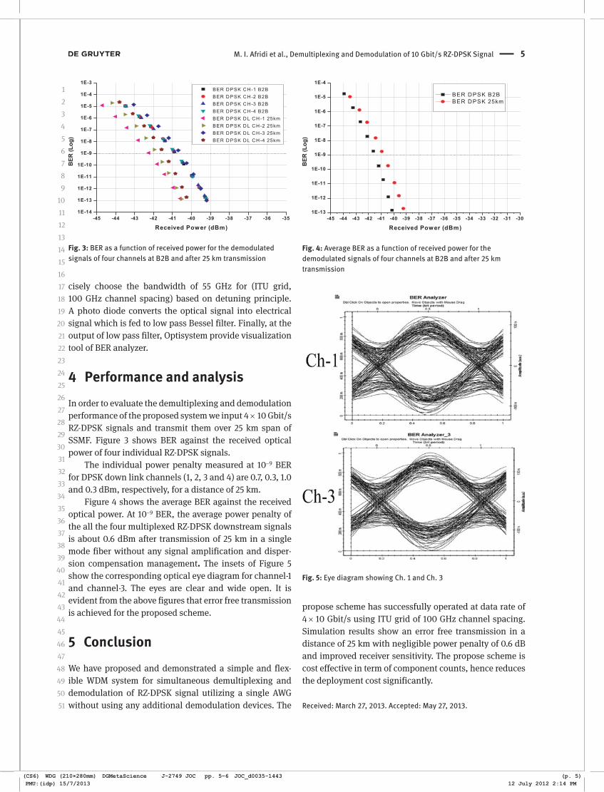
Figure 4 shows the average BER against the received optical power. At 10−9 BER, the average power penalty of the all the four multiplexed RZ-DPSK downstream signals is about 0.6 dBm after transmission of 25 km in a single mode fiber without any signal amplification and disper-sion compensation management. The insets of Figure 5 show the corresponding optical eye diagram for channel-1 and channel-3. The eyes are clear and wide open. It is evident from the above figures that error free transmission is achieved for the proposed scheme.
5 ConclusionWe have proposed and demonstrated a simple and flex-ible WDM system for simultaneous demultiplexing and demodulation of RZ-DPSK signal utilizing a single AWG without using any additional demodulation devices. The
propose scheme has successfully operated at data rate of 4 × 10 Gbit/s using ITU grid of 100 GHz channel spacing. Simulation results show an error free transmission in a distance of 25 km with negligible power penalty of 0.6 dB and improved receiver sensitivity. The propose scheme is cost effective in term of component counts, hence reduces the deployment cost significantly.
Received: March 27, 2013. Accepted: May 27, 2013.
Fig. 3: BER as a function of received power for the demodulated signals of four channels at B2B and after 25 km transmission
Fig. 4: Average BER as a function of received power for the demodulated signals of four channels at B2B and after 25 km transmission
Fig. 5: Eye diagram showing Ch. 1 and Ch. 3
(CS6) WDG (210×280mm) DGMetaScience J-2749 JOC pp. 4–6 JOC_d0035-1443 (p. 4)PMU:(idp) 15/7/2013 12 July 2012 2:14 PM
(CS6) WDG (210×280mm) DGMetaScience J-2749 JOC pp. 5–6 JOC_d0035-1443 (p. 5)PMU:(idp) 15/7/2013 12 July 2012 2:14 PM
1 2 3 4 5 6 7 8 9
10 11 12 13 14 15 16 17 18 19 20 21 22 23 24 25 26 27 28 29 30 31 32 33 34 35 36 37 38 39 40 41 42 43 44 45 46 47 48 49 50 51

6 M. I. Afridi et al., Demultiplexing and Demodulation of 10 Gbit/s RZ-DPSK Signal
References[1] A. H. Gnauck and P.J. Winzer, “Optical Phase-Shift-Keyed
Transmission”, Lightwave Technol. 23, 115‒130 (2005).[2] X. Chen, C. Li, L. Xu, and H.K. Tsang, “DPSK Demodulation
using Mach-Zehnder Delay-Interferometer on Silicon-on-Insulator Integrated with Diffractive Grating Structure”, Asia Optical Fiber Communication and Optoelectronic Exposition and Conference (AOE), pp. 1‒3 (2008).
[3] D. Penninckx, H. Bissessur, et al., “Optical differential phase shift keying (DPSK) direct detection considered as a duobinary signal”, 27th European Conference on Optical Communication (ECOC’01), 3, 456‒457 (2001).
[4] L. Christen, K. Yannick, “Fiber Bragg Grating Balanced DPSK Demodulation”, Laser & Electro-optic Society, LEOS, 563‒564 (2006).
[5] A. D’Errico, R. Proietti, et al., “WDM-DPSK detection by means
of frequency-periodic Gaussian filtering”, Electronics Letters 42, 112‒114 (2006).
[6] G. Contestabile, R. Proietti, et al., “Simultaneous demodulation and clock-recovery of 40 Gbit/s NRZ-DPSK signals using a multiwavelength Gaussian filter”, IEEE Photonics Technology Letters 20, 791‒793 (2008).
[7] M. K. Smit, “New focusing and dispersive planar component based on optical phased array”, Electronics Letters 24, 385‒386 (1988).
[8] N. Calabretta, M. Presi, R. Proietti, G. Contestabile, and E. Ciaramella, “A bidirectional WDM/TDM-PON using DPSK downstream signals and a narrowband AWG”, IEEE Photon. Technol. Lett., 19, 1227‒1229 (2007).
[9] G.P. Agrawal, Fiber-Optic Communication Systems, 3rd edition, p. 347, Wiley Interscience, 2002.
[10] Erwin Kreyszig, Advance Engineering Mathematics, 9th edition, pp. 189‒191.
(CS6) WDG (210×280mm) DGMetaScience J-2749 JOC pp. 6–6 JOC_d0035-1443 (p. 6)PMU:(idp) 15/7/2013 12 July 2012 2:14 PM
(CS6) WDG (210×280mm) DGMetaScience J-2749 JOC pp. PB–1 JOC_d0035-1443 (p. PB)PMU:(idp) 15/7/2013 12 July 2012 2:14 PM
1 2 3 4 5 6 7 8 9 10 11 12 13 14 15 16 17 18 19 20 21 22 23 24 25 26 27 28 29 30 31 32 33 34 35 36 37 38 39 40 41 42 43 44 45 46 47 48 49 50 51
Related Documents