American Institute of Aeronautics and Astronautics 1 Simulink-Based Simulation Architecture for Evaluating Controls for Aerospace Vehicles (SAREC-ASV) David M. Christhilf 1 Lockheed-Martin, Langley Program Office, Hampton, VA, 23681-2199 and Barton J. Bacon 2 NASA-Langley Research Center, Hampton, VA, 23681-2199 The S imulation Ar chitecture for E valuating C ontrols for A eros pace V ehicles (SAREC-ASV) is a Simulink-based approach to providing an engineering quality desktop simulation capability for finding trim solutions, extracting linear models for vehicle analysis and control law development, and generating open-loop and closed-loop time history responses for control system evaluation. It represents a useful level of maturity rather than a finished product. The layout is hierarchical and supports concurrent component development and validation, with support from the Concurrent Versions System (CVS) software management tool. Real Time Workshop (RTW) is used to generate pre-compiled code for substantial component modules, and templates permit switching seamlessly between original Simulink and code compiled for various platforms. Two previous limitations are addressed. Turn around time for incorporating tabular model components was improved through auto-generation of required Simulink diagrams based on data received in XML format. The layout was modified to exploit a Simulink "compile once, evaluate multiple times" capability for zero elapsed time for use in trimming and linearizing. Trim is achieved through a Graphical User Interface (GUI) with a narrow, script definable interface to the vehicle model which facilitates incorporating new models. Nomenclature AVDS = Aviator Visual Design Simulator CVS = Concurrent Versions System DAVE-ML = Dynamic Aerospace Vehicle Exchange Markup Language DeMAID = Design Manager's Aid for Intelligent Decomposition DTD = Document Type Definition GUI = Graphical User Interface GUIDE = Graphical User Interface Development Environment RTW = Real-Time Workshop XML = eXtensible Markup Language MATLAB ® , Simulink ® , and Real-Time Workshop ® are registered trademarks of MathWorks. The use of trademarks or names of manufacturers in the report is for accurate reporting and does not constitute an official endorsement, either expressed or implied, of such products or manufacturers. 1 Research Engineer Staff, Langley Program Office, c/o NASA-LaRC/Mail Stop 308, Member AIAA. 2 Aerospace Technologist, PhD, Dynamic Systems and Control Branch, Mail Stop 308.

Welcome message from author
This document is posted to help you gain knowledge. Please leave a comment to let me know what you think about it! Share it to your friends and learn new things together.
Transcript

American Institute of Aeronautics and Astronautics
1
Simulink-Based Simulation Architecture for Evaluating Controls for Aerospace Vehicles (SAREC-ASV)
David M. Christhilf1 Lockheed-Martin, Langley Program Office, Hampton, VA, 23681-2199
and
Barton J. Bacon2 NASA-Langley Research Center, Hampton, VA, 23681-2199
The Simulation Architecture for Evaluating Controls for Aerospace Vehicles (SAREC-ASV) is a Simulink-based approach to providing an engineering quality desktop simulation capability for finding trim solutions, extracting linear models for vehicle analysis and control law development, and generating open-loop and closed-loop time history responses for control system evaluation. It represents a useful level of maturity rather than a finished product. The layout is hierarchical and supports concurrent component development and validation, with support from the Concurrent Versions System (CVS) software management tool. Real Time Workshop (RTW) is used to generate pre-compiled code for substantial component modules, and templates permit switching seamlessly between original Simulink and code compiled for various platforms. Two previous limitations are addressed. Turn around time for incorporating tabular model components was improved through auto-generation of required Simulink diagrams based on data received in XML format. The layout was modified to exploit a Simulink "compile once, evaluate multiple times" capability for zero elapsed time for use in trimming and linearizing. Trim is achieved through a Graphical User Interface (GUI) with a narrow, script definable interface to the vehicle model which facilitates incorporating new models.
Nomenclature AVDS = Aviator Visual Design Simulator CVS = Concurrent Versions System DAVE-ML = Dynamic Aerospace Vehicle Exchange Markup Language DeMAID = Design Manager's Aid for Intelligent Decomposition DTD = Document Type Definition GUI = Graphical User Interface GUIDE = Graphical User Interface Development Environment RTW = Real-Time Workshop XML = eXtensible Markup Language
MATLAB®, Simulink®, and Real-Time Workshop® are registered trademarks of MathWorks. The use of trademarks or names of manufacturers in the report is for accurate reporting and does not constitute an official endorsement, either expressed or implied, of such products or manufacturers.
1 Research Engineer Staff, Langley Program Office, c/o NASA-LaRC/Mail Stop 308, Member AIAA. 2 Aerospace Technologist, PhD, Dynamic Systems and Control Branch, Mail Stop 308.

American Institute of Aeronautics and Astronautics
2
I. Introduction HE Simulation Architecture for Evaluating Controls for Aerospace Vehicles (SAREC-ASV) may well be viewed as yet another solution to a problem that was solved long ago and has been approached many different
ways over the years. The task of representing vehicle dynamics mathematically, finding parameter values that produce equilibrium solutions, and extracting a linear representation of the vehicle dynamics at that point has not changed substantially. What has changed over the years is the computational hardware capability and the software environment. Early solutions to the problem involved analog circuit patch-boards, machine code and assembly language to directly control every aspect of the computation. Impressive results were obtained using very little storage capacity and computational power. As operating systems and compilers improved, some of the details not directly pertinent to the problem, such as memory management, were taken care of behind the scenes, allowing more direct focus on the vehicle dynamics rather than on the details of implementation. The Nguyen1 1979 F-16 simulation is an example from this period.
Software languages proved to be very versatile, and adaptable to many different problem domains. However, sophisticated tools don't necessarily lead to well organized, maintainable and verifiable implementations. The infamous FORTRAN GOTO type "spaghetti code" is really no worse than some of the cryptic implementations developed in the more modern C, nor worse than ill conceived class structure architectures written in C++. With time there was a shift in emphasis from machine efficiency to human readability. Source code became intended for humans to read, leaving it up to compilers and operating systems to convert that into an efficient implementation. Software tools continued to evolve and also to differentiate. High level special purpose tools specifically targeting simulation were developed. These could be driven by command line, and generate graphical output in a seamless package. An example of a high performance aircraft simulation based on the Advanced Continuous Simulation Language (ACSL) is documented by Buttrill2 et al. in 1992.
A further development was the introduction of a graphical user interface used for assembling simple generic components from vendor supplied libraries. All the bookkeeping details for implementing various continuous and discrete time integration algorithms, at various time steps, were provided. Complex aerodynamic or thrust models could be linked in from external compiled FORTRAN or C sources. To a large extent, the aerospace engineer was relieved from the tedious and error prone aspects of implementation, and freed to concentrate more directly on the vehicle dynamics and control. However, once again the sophistication of the available tools does not necessarily lead to well organized, maintainable and verifiable solutions. Sotack, Chowdhry and Buttrill3 in 1995 (released for publication in 1999) developed a simulation of a High Speed Civil Transport (HSCT) using MATLAB and the graphical companion tool, Simulink. While the system trims, linearizes and matches time histories, a separate version of the simulation was required to be maintained in parallel for each of these three functions. SAREC-ASV, implemented in Simulink, is a derivative of the Sotack HSCT simulation, incorporating lessons learned through continuous improvement over the course of several projects during the last decade. It uses a single version of the simulation for trim, linearization and time histories, with a hierarchical structure designed to enhance readability and maintainability. It also addresses two debilitating aspects of previous implementations, by providing a means to auto-generate table lookup routines to enable faster updates for new wind tunnel data, and by allowing the simulation to be compiled once and evaluated multiple times for zero elapsed time for use in trim and linearization analysis.
Two aspects to be considered in simulation development are scope and fidelity. On the one hand, simulations for training airline or military pilots, or for test pilot evaluation of experimental vehicle response, require high fidelity synchronized real-time operation with detailed cockpit layout, control inceptors and displays, possibly with multiple coordinated visual displays for simulating flight under Visual Flight Rule (VFR) conditions. If a motion base is involved there are man-rated safety concerns as well. A simulation of that scope typically requires a team of developers with a well defined, committee reviewed, officially approved development plan. Any changes made to such a simulation must be requested, approved, documented and verified. On the other hand, a PC based flight simulator video game is much more limited in both scope and fidelity. Flight characteristics such as a tendency to stall at low speed may be a dial-in parameter related to skill level rather than to characteristics of a particular airframe.
For a controls engineer, there is a need for a class of simulation that is limited in scope, but captures true airframe characteristics with sufficient fidelity to be used to derive and evaluate authentic precursor vehicle control laws. The fidelity should be such that control laws can be transferred directly to a full motion-base piloted simulation for evaluation. At the same time, the scope of the design tool must be sufficiently limited that a controls engineer can make changes rapidly without the need for committee approval for each modification. Achieving the
T

American Institute of Aeronautics and Astronautics
3
required fidelity may involve sharing model components, repackaged as needed for the host environment. Control law design and synthesis generally requires extraction of a simplified model, either linear of based on some form of non-linear functional representation. The Jackson C-based 1995 LaRCsim4 Flight Simulation addresses the need for a high fidelity simulation of limited scope. It was developed to be capable of driving a man-in-the-loop simulation while being accessible to a practicing controls engineer to run and modify on a desktop computer. Another approach by Garza and Morelli5 was to use MATLAB, without Simulink, to simulate eight various flight vehicles. The Garza simulations are capable of being run interactively with a joystick input and with either "a pilot view or a 3-D view of the aircraft in motion from an arbitrary vantage point outside the aircraft". The commercial Aviator Visual Design Simulator (AVDS) program is used for generating the display.
In recognition that each national research facility tends to have its own version of software for running simulations, and of the time and expense involved in porting simulation models from one such facility to another, Jackson and Hildreth6 proposed development of an eXtensible Markup Language (XML) based standard to define simulation models such that each facility could host a simulation directly from the standard using automated tools. This emerging standard is formalized in the Dynamic Aerospace Vehicle Exchange Markup Language (DAVE-ML) Document Type Definition (DTD) which was exercised and evaluated in Jackson7 et al. in 2004. SAREC-ASV implements a portion of the DAVE-ML standard, using MATLAB scripts to read and to write XML files that represent tabular data and interpolation routines. SAREC-ASV is not able to address the portion of the DAVE-ML standard used to define equations. The MathWorks Real-Time Workshop (RTW) Embedded Coder provides a means to bridge the gap between a desktop analysis Simulink simulation and a true real-time simulation by allowing Simulink components to be exported as C-code with associated libraries. The Embedded Coder avoids the global variable conflicts which tend to limit the exportability of components generated using only RTW capability, and has been used successfully with the LaRCsim simulation.
II. Specific Background The name SAREC was chosen to be unique, or nearly so, when searching the internet. Subsequently, a number
of organizations with SAREC as their initials posted information about themselves so that today over 221,000 entries are listed by Google. The -ASV was added to the name so that, when listed in quotes as "SAREC-ASV", the results are currently unique. Throughout the rest of this paper, the name will be simply, SAREC. SAREC is not the result of a focused development effort but rather of a decade of continuous improvement over several simulation projects. Similarly, it is considered to now represent a useful level of maturity rather than a completed final product. SAREC and SAREC-based simulations are directly portable to any host computer that has MATLAB and Simulink installed. That is to say, hardware specific considerations are handled by the MATLAB/Simulink installation process, and SAREC can be run entirely within that context. While it is possible to link in components that are written and compiled in languages such as FORTRAN or C, the SAREC approach is to use Simulink diagrams as the source for the entire simulation, with the option to use Real Time Workshop (RTW) to generate machine specific compiled code directly from the Simulink diagrams for various major components such as aerodynamic forces and moments, or an engine model. Real-Time Workshop without the Embedded Coder is sufficient for compiling components for running within Simulink, but not generally for export. The SAREC baseline is currently set up to host an F-16 model based on one available in the text Aircraft Control and Simulation by Stevens and Lewis8. That model in turn is a simplification of the Nguyen1 model mentioned earlier. The intent is to use a non-proprietary model that is simple to use while retaining many aspects required for more complex simulations.
III. Layout The most apparent aspect of SAREC is the organization of the Simulink diagrams and the use of color coding,
signal labeling and signal bundling to achieve a hierarchical system which has comparable levels of abstraction at each level of the hierarchy. The ability to label and bundle signals is actually one of the most beneficial capabilities introduced in Simulink in terms of being able to manage complexity. The signals retain their labeled identities while in the bundles. The SAREC hierarchy is thought to be more intrinsic than arbitrary, in that iterative application of the principles of domain analysis for this problem domain by various analysts might be expected to converge on a similar architecture. At the same time, there is nothing rigid about the hierarchy and it should be adapted to the particular features of each new model. One advantage of starting with a relatively 'clean' layout such as SAREC is that it would actually take a good deal of effort to turn it into a 'spaghetti' configuration.
The hierarchical nature of SAREC supports concurrent development of lower level components, and component testing, by establishing units that are largely independent of each other. The Concurrent Versions System9 (CVS) software management tool is helpful for tracking changes to various components that define the model, and to

American Institute of Aeronautics and Astronautics
4
reconstruct the simulation configuration as it existed at the time that a particular analytical result was generated. SAREC makes use of a Simulink capability to include CVS information directly in the Simulink diagrams. The distinction between CVS and its predecessor, the Revision Control System (RCS), is that CVS provides support for merging work done simultaneously by several developers working independently.
Component testing is accomplished by placing a component in a Simulink library, and then accessing that library component both in a test routine and in the simulation itself. Once a component is verified to have the correct input / output mapping in a test routine, changes are in effect already incorporated into the simulation by means of the library. For cases where several copies of a component, such as an actuator, are used in a simulation, Simulink provides the means to define a mask for the component such that the structure is the same for each copy, but each can be supplied with distinct parameter values via the mask. Each masked copy should be included in the test routine in order to verify both the structure and the parameters for a given component, and the verified masked components would need to be copied from the test routine into the simulation rather than merely being updated through a library.
A. Top Level Diagram The top level Simulink diagram uses a classical layout with controller, sensor and environment blocks, and
feedback signal, represented external to the plant block (Fig. 1). The PilotInputs block consists of a signal generator for pre-programmed inputs for blended multi-surface commands for roll, pitch, yaw and thrust. The Control System block includes a multi-channel signal generator for commands to individual control surfaces, and also defines how the pilot commands are allocated to the various control surfaces and throttle(s). The 'Inports' shown at left, and 'Outports' shown at right permit the simulation to receive input time histories from the MATLAB work space, or to be "called programmatically" from a MATLAB script for zero or more elapsed time. While the Inports can be used for time history inputs, they are more typically used to set reference constants that represent trim conditions, or for providing a means to perturb the trim condition for extracting linear models. Finding trim solutions and extracting linear models also makes use of perturbations to initial conditions for state variables, which are accessed by name and do not require top level Inports.
B. Dominant Diagonal Figure 2 shows the layout of the Open Loop Plant. The components are organized according to a dominant
diagonal approach. The concept is that components are arranged on a diagonal, with forward links oriented to the right and down, and backward links oriented to the left and up. The sequence of components is sorted in order to reduce the number of links that are oriented to the left and up.
The dominant diagonal approach is based on a technique developed by Rogers10 for use in Multidisciplinary Design and Optimization. In the case of the software tool DeMAID11, for Design Manager's Aid for Intelligent Decomposition, the sorting of processes on the diagonal is motivated by reducing the coupling between and among processes during optimizations. For the case of simulation, a backward path indicates the potential for an algebraic loop. Algebraic loops are problematic because they represent equations that cannot be solved numerically on a single pass. Simulink uses an iterative solver to compute solutions for algebraic loops for each simulation time step. Algebraic loops slow execution speed considerably, and usually indicate either some type of incorrect dependency or that an integrator or time delay with fast time constant has been ignored. The presence of an integrator or a time delay will break an algebraic loop, and produce a state variable in the process. In Fig. 2, the output emanating from the Equations of Motion (EOM) block represents the vehicular state vector, and therefore does not form algebraic loops. The feedback signal from the Inertia block represents a zero fuel condition flag. It is used to shut off the modeled flow of fuel at the throttle so that both fuel burn and thrust are adjusted for zero flow. The flag is based on a state variable for fuel status, and does not introduce an algebraic loop. For analysis of aircraft flight performance, the fuel burn state variable can be disabled so that 'steady state' represents a constant mass condition. However, for launch vehicles the change in mass properties due to fuel burn is considered to be important and that modeling capability is included in the SAREC baseline.
C. Forces and Moments Forces and moments are computed in component subsystems, as shown in Fig. 3, and summed together in the
SumOfForces block. In this case there are three components, Aerodynamics, Propulsion and Gravity, that contribute to the sum of forces and moments. Other components, such as landing gear in contact with a runway, could be added here. The Aerodynamics subsystem interpolates forces and moments from data tabulated for various flight conditions and control system inputs. By using a constant reference point for the aerodynamic moments, the Aerodynamics subsystem does not require information about the current location of the center of mass, which

American Institute of Aeronautics and Astronautics
5
simplifies verification of the component implementation. The SumOfForces subsystem transfers the moments from the aerodynamic reference point to the center of mass. Likewise, the Propulsion subsystem computes forces and moments at a propulsion reference location, to be relocated to the center of mass by the SumOfForces subsystem. The Propulsion subsystem is one level above the Engine model, and represents the aggregate effect of possibly multiple engines (or thrusters), as installed on an airframe. Each engine may have its own state variables for turbine speed and/or burner temperature. The Gravity subsystem differs from the other two in that it has no defined reference point. Since the force of gravity is modeled as acting through the center of mass, it generates no moment there. No moment is computed by the Gravity subsystem and none is introduced in the SumOfForces subsystem. This convention might need to change if a gravity gradient were determined to be important for its influence on the orientation of a satellite in orbit. The gravitational acceleration may be modeled in the Environment block as being a function of planetary body, or being variable with altitude. The Stevens and Lewis text (p. 40) makes a distinction between 'gravitation' as a mass attraction effect, and 'gravity' which includes the mass attraction effect and a centrifugal acceleration due to planetary rotation. For the SAREC F-16 model, the acceleration of gravity is a constant.
D. Equations of Motion - Quaternions Figure 4 shows the Simulink diagram for the equations of motion. It is similar to equations of motion that come
with the Simulink Aerospace Toolbox, but this uses a subsystem hierarchy to help clarify the functionality, and accesses a user defined library for treatment of quaternions based on a report by Phillips12 in 2000. The lower left subsystem applies moments to the inertia model about the center of mass to compute body axis angular accelerations, and integrates those to produce body axis rates. The lower right subsystem integrates the quaternion equivalent of the body axis rates to calculate quaternions that define the vehicle orientation. The output from that subsystem is a direction cosine matrix and an Euler representation. Similarly the top left subsystem applies forces to the mass model, along with information about angular rates, to calculate body axis translational accelerations, which are integrated to produce body axis translational rates. The top right subsystem applies information about vehicle orientation, and integrates the body axis rates to produce inertial positions. The reference system currently used in SAREC is flat and non-rotating. A future update for SAREC should provide modeling for an oblate, rotating reference system. The parameters for such a model would be defined in the Environment block external to the plant, but the result would change the state variables computed in the equations of motion.
E. Template - Real Time Workshop Figure 5 depicts a user defined library containing an AeroTemplate block to be 'wired into' the simulation, and
three alternate blocks which have the same input / output argument lists as the AeroTemplate. The Aero block contains Simulink diagrams that define the aerodynamic model. The AeroSOL and the AeroSG blocks represent Simulink 'S-Functions' that are compiled for two different platforms (Solaris and Silicon Graphics). Real-Time Workshop makes use of the contents of the Aero block to generate the compiled versions. The key to the template is that it is a Configurable Subsystem that allows the user to specify a flag which indicates which of the other three blocks will actually be in use. In the case of S-Functions compiled for different platforms, the operating system can be requested to identify itself at the start of a simulation session so that the flag is set appropriately for the host system. The inputs and outputs are fanned out as individual variables rather than bundled so that they are explicitly defined in the intermediate C source code. If the entire simulation is recompiled for each function call during trimming or linearization, the ability to precompile potentially sizeable components such as the Aero or Propulsion blocks can result in considerable run-time savings.
IV. Two Previous Limitations Addressed Two aspects of predecessor Simulink simulation configurations that limited their utility have been at least
partially addressed in SAREC. The first deals with the timeliness of incorporating updates to major components of the model. The second with excessive overhead for repeated calls to evaluate the simulation for zero elapsed time.
A. Auto-generation of Table Lookups In order to be useful, an engineering simulation must be available in a timely manner so that it can be used to
contribute to programmatic objectives. One of the challenges working with a large scale developmental project is to incorporate updates to major components, such as an aerodynamic model, as alternate configurations are tested and new data become available. The High Speed Research program of the mid 1990's is a case in point. Various versions of an aeroservoelastic model for a High Speed Civil Transport class vehicle were made available as

American Institute of Aeronautics and Astronautics
6
FORTRAN source code as the program progressed. Each new release tended to have additional features which required detailed and time consuming changes to the Simulink diagrams.
Recognizing that rehosting functioning simulations from one research facility to another is in general time consuming, expensive, and error prone, Jackson and Hildreth working with the AIAA Modeling and Simulation Technical Committee proposed development of an eXtensible Markup Language (XML) based standard for defining simulation models6. Pursuant to that, the Dynamic Aerospace Vehicle Exchange Markup Language (DAVE-ML) Document Type Definition (DTD) was drafted to define the standard (see appendix). The DTD has provision for defining variables, tables, and equations for use in simulation. The equation definitions are incorporated by reference to an existing MATH-ML standard which can specify both the functionality and the page presentation of equations. SAREC has the capability to incorporate tabular data based on the DAVE-ML standard, but not the equations.
Figure 6 shows a Simulink diagram which consolidates all aerodynamic tables into a single, DAVE-ML based autogenerated subsystem, which is in series with an auxiliary equation subsystem upstream (not shown) and a BuildupEqs subsystem downstream which are both constructed manually. All these components are contained within the Aero block discussed previously. The reason the tables are autogenerated and the equations are not is that tables can be fairly regimented in terms of layout, whereas equations can be much more complex. Even so, manually configuring the tables would be very tedious, time consuming and error prone, depending on the number of tables and variables involved, providing motivation to seek automation.
Figure 7 shows the process involved in converting DAVE-ML specified tables into an autogenerated Simulink block. The DAVE-ML specification allows data to be defined in a hierarchical fashion that includes information about the data. MATLAB data structures permit representation of data in a similar manner, and can be saved as binary (.mat) files. The first step is to package the original data into a MATLAB data structure that is conformal to the DAVE-ML standard. That process is specific to the form in which the data are received, and can be fairly labor intensive. However, fielding the original data will tend to be somewhat labor intensive no matter what scheme is used, and converting the data into a standardized form provides added value both in terms of exportability and in being supported by (still to be developed) standardized tools. Once the data are in the conformal DAVEDAT type data structure, the other steps are generic. MATLAB scripts are available to convert the DAVEDAT data structure into a DAVEDAT.dml file for export, or to receive a DAVEDAT.dml file as an original source. For local use, the conversion to and from DAVEDAT.dml is not necessary. The DAVEDAT data structure must be converted to a REFDAT type data structure for use during simulation. REFDAT requires redundancies not present in DAVEDAT. The final step is to use REFDAT for autogenerating the ASCII .mdl file that defines the Simulink table interpolation subsystem.
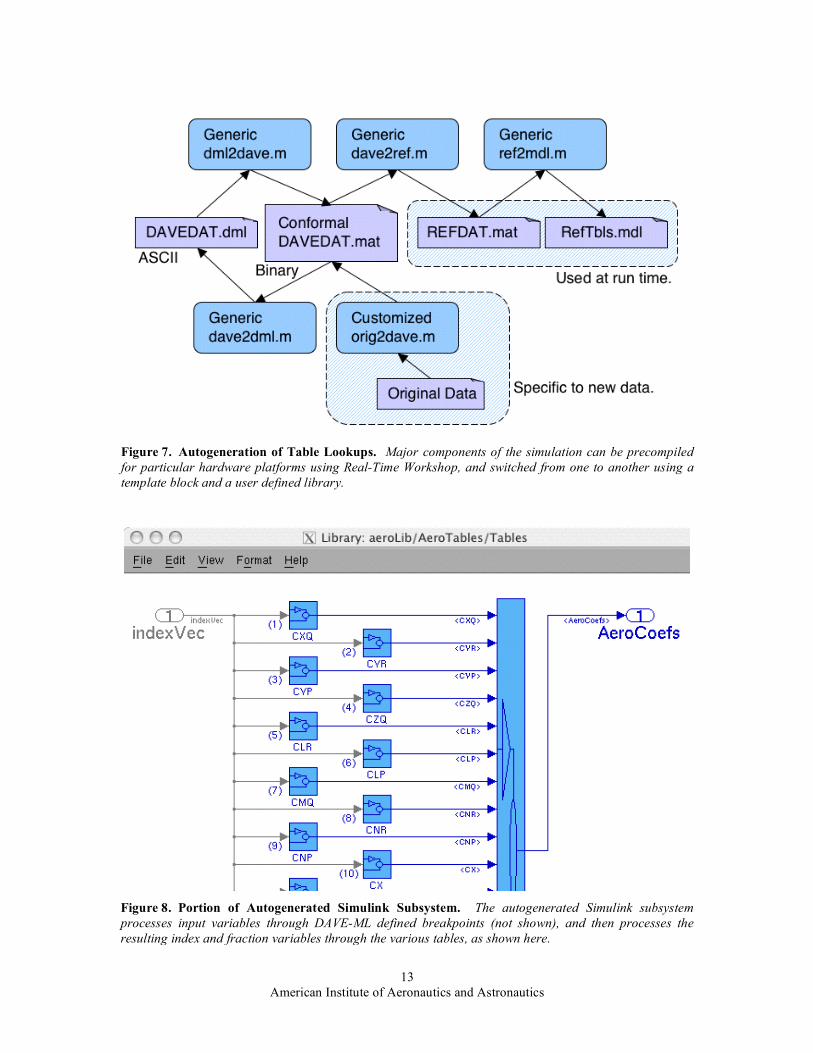
Figure 8 shows a truncated portion of an autogenerated Simulink diagram. The autogenerated system includes a similar diagram having component blocks for each set of breakpoints used. Often several tables are based on the same wind tunnel test, resulting in the data being tabulated for the same values for the independent variables such as angle of attack. The SAREC layout permits such breakpoints to be reused, improving computational efficiency.
B. Compile Once, Evaluate Multiple Times There are at least three ways that a Simulink simulation can be run: 1) using 'start' from a simulation window, or
typing <Ctrl>-T from the window for the MATLAB session, 2) invoking from a MATLAB command line or from a script using the 'sim' command, and 3) invoking from a MATLAB command line or from a script using the "model" command, where 'model' is the name of the simulation. The first method triggers the simulation to start, using existing simulation parameters which includes a flag that may instruct Simulink to look for a data structure for defining initial conditions and input time histories from specified workspace variables. The second and third methods are sometimes referred to as "calling the simulation programmatically." The syntax for the second is: [T,X,Y] = SIM('model',TIMESPAN,OPTIONS,UT); where UT specifies inputs to the system, and OPTIONS may specify things such as initial conditions or type of integration algorithm. Both methods 1 and 2 compile, run and terminate the simulation each time they are used. For generating time histories, the recompilation ensures that any recent changes to the Simulink diagrams are incorporated into the simulation run. Unfortunately, for finding trim solutions or for perturbing inputs and initial conditions for extracting linear models, the recompilation is repeated each of the multiple times that the simulation is evaluated for zero elapsed time even though the only changes are to the inputs and initial conditions. For a large, complex simulation, the overhead of unnecessary recompilation can make the process rather slow.

American Institute of Aeronautics and Astronautics
7
The syntax for the third method is: [sys,x0,str] = model(t,x,u,flag); where three possible values for "flag" are 'compile', 'outputs' and 'term'. The 't', 'x' and 'u' can be used to specify initial conditions for state variables 'x', input time histories 'u', and a vector of time points for which the inputs are defined 't'. The 'sys' output can be several things depending on the 'flag' that is used. If the flag is 'compile', then 'sys' provides information about the number and type of variables used in the simulation. The 'x0' output returns the initial conditions used for the simulation (which are not necessarily defined in the input argument list). The 'str' output variable is key to being able to make use of this command. The sequence in which the state variables are evaluated is not determined until the simulation is compiled. Merely rearranging the blocks in a Simulink window without changing their connections to other blocks can change the sequence in which they are evaluated. The 'str' output variable provides a list of the state variables in the sequence used for evaluation. This is crucial to know, because the 'x' input argument is a simple vector that does not specify the names of the individual state variables.
SAREC makes use of this command in the following way: [dum, dum, XlblShfl] = SAREC_F 16(0, [], [], 'compile'); The XlblShfl variable is then compared to a predefined Xlbl list in order to establish ShflIndx vector which performs a mapping between the predefined list and the list determined during compilation.
Once the simulation is compiled, and the ShflIndx vector is defined, the simulation can be evaluated multiple times for zero elapsed time as: Y_case1 = SAREC_F16(0, X_case1(ShflIndx), U_case1, 'outputs'); Y_case2 = SAREC_F16(0, X_case2(ShflIndx), U_case2, 'outputs'); Y_case3 = SAREC_F16(0, X_case3(ShflIndx), U_case3, 'outputs'); The U inputs and Y outputs refer to the Inports and Outports defined on the top level Simulink diagram. Precursor simulations to SAREC generally used FromWorkspace and ToWorkspace blocks rather than top level Inports and Outports, but the advantage of eliminating redundant recompilations recommends the use of the Inports and Outports.
Once the evaluations are complete, it is necessary to terminate the simulation, as: SAREC_F16([], [], [], 'term') The simulation will be in a frozen state in terms of editing until the compiled session is terminated with the "term" command. In fact, commands to terminate a MATLAB session will not be effective until all compiled models are properly terminated. Since the predefined list of state variables is constant rather than dynamic, it needs to be updated manually any time state variables are added to or deleted from the simulation. The method 3 described here is somewhat involved but once the scripts are written the execution is automatic, and depending on the size of the simulation the run-time savings can be substantial.
Simulink supplied commands for trimming and linearizing may already compile the simulation only once for completing those processes. "Method 3" may already be well known to Simulink users. However, at the time that the SAREC precursors were developed the supplied routines for trim and linearization were too restrictive for the purpose at hand, and only methods 1 and 2 were known. This falls into the category of a lesson learned.
V. Reconfigurable Trim GUI Steady state solutions are useful as initial conditions for generating simulation time histories, but also for
performance analysis and as reference conditions for extracting linear models for assessing dynamics and for developing control laws. SAREC provides a reconfigurable Graphical User Interface (GUI) framework which can be adapted to provide access to various degrees of freedom and constraints, and to various aircraft models, using MATLAB scripts to do the mapping. The GUI was developed using the MathWorks Graphical User Interface Development Environment (GUIDE) tool. In general, layout is defined in a binary (.fig) type file and functionality for the various fields and buttons is defined in a MATLAB script (.m) file. That is not entirely the case, since the MATLAB script redefines some aspects of the layout, and some functionality is defined in the binary file.

American Institute of Aeronautics and Astronautics
8
A. Selectable Degrees-of-Freedom and Constraints The SAREC Trim GUI incorporates two levels of generality. The first is provided by allowing the user to
specify values for a given set of variables and then use check boxes to select which degrees of freedom and which constraints are to be active during the search for a trim solution. Initially the selected equality constraints are violated. An optimizer is used to manipulate the input variables designated as degrees of freedom (left panel in Fig. 9) in order to drive the output variables for the designated constraints to come within a tight tolerance of user defined target values (right panel). Selectable degrees of freedom can be useful for mapping out an achievable trim envelope for the vehicle as modeled. For example, when solving for trim conditions for high speed flight it is useful to fix air speed and allow angle of attack to vary, since angle of attack variations are small. For low speed flight it is more reliable to fix angle of attack and allow airspeed to vary, since airspeed variations are small. For mapping out a series of trim solutions, the SAREC GUI supports updating the starting condition to match a current trim solution, so that an input variable can be incremented to define new trim solutions in the series.
B. Mapping Between GUI Variables and Simulation Variables The SAREC GUI is reconfigurable in that the set of degrees of freedom and the set of constraints available for
selection for trimming are defined by MATLAB scripts which themselves can be selected from the GUI. Note that the GUI configuration for trimming in a turn (Fig. 10) has a different number of degrees of freedom displayed than the configuration for trimming in straight and level flight (Fig. 9). A popup menu permits choosing which trim mapping to use. More configurations can be added by writing more mapping scripts. These mapping scripts not only define the variables displayed in the GUI, but also the variables mapped in the simulation. That allows for different types of controls blending to be driven by, for example, a "roll" command. It also provides a limited interface between the GUI and the aircraft model such that the entire aircraft model can be changed without the need to change the GUI framework. Only the mapping scripts would need to change to accommodate the new aircraft model.
VI. Concluding Remarks SAREC provides a simulation framework that is motivated by reusability. By emphasizing a component-based
architecture, much of the simulation can be retained intact when applying SAREC to a new vehicle model. SAREC does not represent an entirely new way of doing things, but offers advantages as a starting point for developing simulations for new vehicle models as compared to the earlier simulations on which SAREC was based. As a work in progress, SAREC will continue to evolve each time it is used for a new project.
Appendix
A. Web-based Resources Information about DAVE-ML can be found at the following location. http://daveml.nasa.gov http://daveml.nasa.gov/DTDs/1p7b1/DAVEfunc.dtd The Scholarly Technology Group affiliated with Brown University, Providence, RI, maintains the following
web site which contains a web based utility for validating an XML file against its DTD specification file. http://www.stg.brown.edu/pub/xmlvalid/ Current versions of some browsers recognize the hierarchy for DAVE-ML compliant information files,
and present the contents in expandable / collapsible outline form. Information about the 'model' and 'sim' commands in Simulink can be found at the following location. http://www.mathworks.com/access/helpdesk/help/toolbox/simulink/ The link "Simulink Reference" provides access to the slref.pdf file. Searching that file for "model command"
or "sim command" will lead to the appropriate information.

American Institute of Aeronautics and Astronautics
9
References 1Nguyen, Luat T., Ogburn, M. E., Gilbert, Wm. P., Kibler, K. S., Brown, P. W., and Deal, P. L., , “Simulator Study of
Stall/Post-Stall Characteristics of a Fighter Airplane With Relaxed Longitudinal Static Stability,” NASA TP-1538, 1979. 2Buttrill, C. S., Arbuckle, P. D. and Hoffler, K. D., “Simulation Model of a Twin-Tail, High Performance Airplane,” NASA
TM-107601, 1992. 3Sotack, R. A., Chowdhry, R. S., and Buttrill, C. S. “High Speed Civil Transport Aircraft Simulation: Reference-H Cycle 1,”
NASA TM-209530, 1999. 4Jackson, E. B., “Manual for a Workstation-based Generic Flight Simulation Program (LaRCsim) Version 1.4,” NASA
TM-110164, 1995. 5Garza, F. R., and Morelli, E. A., “A Collection of Nonlinear Aircraft Simulations in MATLAB,” NASA TM-212145, 2003. 6Jackson, E. B. and Hildreth, B. L., “Flight dynamic Model Exchange Using XML,” AIAA Modeling and Simulation
Technologies Conference, AIAA-2002-4482, Monterey, CA, 2002. 7Jackson, E. B, Hildreth, B. L., York, B. W. and Cleveland, W. B., “Evaluation of a Candidate Flight Dynamics Model
Simulation Standard Exchange Format,” AIAA Modeling and Simulation Technologies Conference, AIAA-2004-5038, Providence, RI, 2004.
8Stevens, B. L. and Lewis, F. L., Aircraft Control and Simulation, 2nd ed., John Wiley & Sons, Hoboken, NJ, 2003, Chap. 3, and Appendix A.
9Fogel, K., Open Source Development with CVS, The Coriolis Group, Scottssdale, AZ, 1999. 10Rogers, J. L., “Tools and Techniques for Decomposing and Managing Complex Design Projects,” Journal of Aircraft,
Vol. 36, No. 1, 1999, pp. 266-274. 11Rogers, J. L., “DeMAID/GA - An Enhanced Design Manager's Aid For Intelligent Decomposition,” AIAA/NASA/ISSMO
Symposium on Multidisciplinary Analysis and Optimization, AIAA-96-4157-CP, Technical Papers, , Pt. 2, Bellevue, WA, 1996, pp. 1497-1504.
12Phillips, W. F, Hailey, C. E. and Gebert, G. A., “A Review of Attitude Kinematics for Aircraft Flight Simulation,” AIAA Modeling and Simulation Technologies Conference, AIAA-2000-4302, Denver, CO, 2000.

American Institute of Aeronautics and Astronautics
10
Figure 1. Top Level Simulink Diagram. This shows the classic layout used by SAREC, with sensors, control system and environment external to the plant. Inports at left and Outports at right provide the interface for calling the simulation programmatically.
Figure 2. Open Loop Plant. This shows the use of a dominant diagonal approach to organizing components of the Open Loop Plant. Items are sorted to depict a predominantly forward flow of information.

American Institute of Aeronautics and Astronautics
11
Figure 3. Forces And Moments. This shows forces and moments computed from Aerodynamics, Propulsion and Gravity components being summed together in the SumOfForces block.
Figure 4. Equations of Motion. The four subsystem blocks in this figure compute rotational and translational accelerations and rates. State variables are indicated in orange, and derived variables are indicated in black.

American Institute of Aeronautics and Astronautics
12
Figure 5. Aerodynamics Block, Template, and RTW. Major components of the simulation can be precompiled for particular hardware platforms using Real-Time Workshop, and switched from one to another using a template block and a user defined library.
Figure 6. Tables versus Equations. SAREC has capability to autogenerate DAVE-ML specified table lookup layout, contained in the AeroTables block. Equations are segregated either upstream and downstream from the block.
American Institute of Aeronautics and Astronautics
13
Figure 8. Portion of Autogenerated Simulink Subsystem. The autogenerated Simulink subsystem processes input variables through DAVE-ML defined breakpoints (not shown), and then processes the resulting index and fraction variables through the various tables, as shown here.
Figure 7. Autogeneration of Table Lookups. Major components of the simulation can be precompiled for particular hardware platforms using Real-Time Workshop, and switched from one to another using a template block and a user defined library.

American Institute of Aeronautics and Astronautics
14
Figure 9. Trim GUI configured for Straight and Level. The degrees of freedom (left) and constraints (right) can be selected using check boxes.
Figure 10. Trim GUI Configured for Level Turn. The set of degrees of freedom and constraints available for selection via check boxes is defined by selectable mapping functions, which define mapping to particular flight vehicle.
Related Documents