This article appeared in a journal published by Elsevier. The attached copy is furnished to the author for internal non-commercial research and education use, including for instruction at the authors institution and sharing with colleagues. Other uses, including reproduction and distribution, or selling or licensing copies, or posting to personal, institutional or third party websites are prohibited. In most cases authors are permitted to post their version of the article (e.g. in Word or Tex form) to their personal website or institutional repository. Authors requiring further information regarding Elsevier’s archiving and manuscript policies are encouraged to visit: http://www.elsevier.com/copyright

Welcome message from author
This document is posted to help you gain knowledge. Please leave a comment to let me know what you think about it! Share it to your friends and learn new things together.
Transcript
This article appeared in a journal published by Elsevier. The attachedcopy is furnished to the author for internal non-commercial researchand education use, including for instruction at the authors institution
and sharing with colleagues.
Other uses, including reproduction and distribution, or selling orlicensing copies, or posting to personal, institutional or third party
websites are prohibited.
In most cases authors are permitted to post their version of thearticle (e.g. in Word or Tex form) to their personal website orinstitutional repository. Authors requiring further information
regarding Elsevier’s archiving and manuscript policies areencouraged to visit:
http://www.elsevier.com/copyright
Author's personal copy
Simulinks-based heterogeneous multiprocessor SoC design flow for mixedhardware/software refinement and simulation
Sang-Il Han a, Soo-Ik Chae a, Lisane Brisolara b,�, Luigi Carro b, Katalin Popovici c, Xavier Guerin c,Ahmed A. Jerraya c, Kai Huang d, Lei Li d, Xiaolang Yan d
a Seoul National University, South Koreab Informatics Institute, Federal University of Rio Grande do Sul, Brazilc TIMA Laboratory, Franced Institute of Vlsi Design, Zhejiang University, China
a r t i c l e i n f o
Article history:
Received 28 September 2007
Received in revised form
7 August 2008
Accepted 26 August 2008
Keywords:
Simulink
Memory optimization
Codesign
Multiprocessor system-on-chip
System specification
Application to architecture mapping
Simulation
Design space exploration
a b s t r a c t
As a solution for dealing with the design complexity of multiprocessor SoC architectures, we present a
joint Simulink-SystemC design flow that enables mixed hardware/software refinement and simulation
in the early design process. First, we introduce the Simulink combined algorithm/architecture model
(CAAM) unifying the algorithm and the abstract target architecture. From the Simulink CAAM, a
hardware architecture generator produces architecture models at three different abstract levels,
enabling a trade-off between simulation time and accuracy. A multithread code generator produces
memory-efficient multithreaded programs to be executed on the architecture models. To show the
applicability of the proposed design flow, we present experimental results on two real video
applications.
& 2008 Elsevier B.V. All rights reserved.
1. Introduction
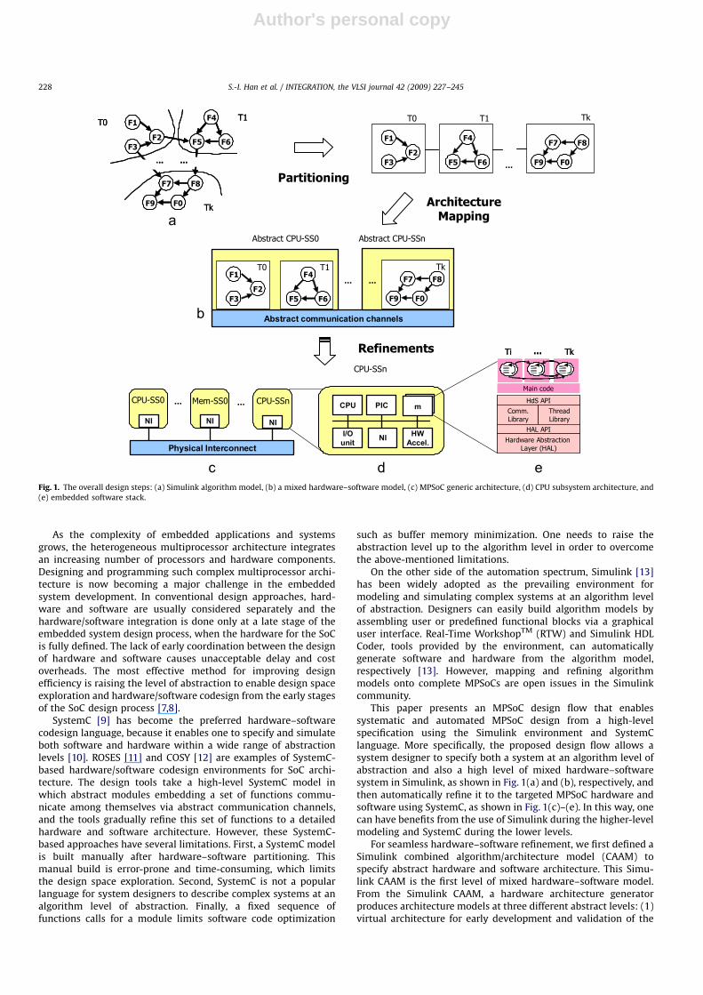
Current embedded systems require flexible and high-perfor-mance architectures to concurrently perform multiple applica-tions. An attractive architecture for these systems can be the useof heterogeneous multiprocessor SoC (MPSoC), which providehighly concurrent computation and flexible programmability [1].Recent platforms such as CT3600TM [2] and CellTM [3] areexamples of heterogeneous multiprocessor architectures with10–20 heterogeneous processors. A network router CRS-1 [4]based on an array of 192 configurable processor cores alsoillustrates this trend.
A typical multiprocessor architecture includes a set of CPU andmemory subsystems (SS) interconnected via a communicationnetwork [5], as depicted in Fig. 1(c). The CPU subsystem includesone or more different kinds of processors (e.g. DSP for data-oriented operations, GPP for control-oriented operations or ASIPfor application-specific computation), specific hardware compo-nents, and specific I/O communication as shown in Fig. 1(d). The
heterogeneity of processors implies the need for multiple soft-ware stacks that may require different computation and commu-nication performance. The software stack is organized in threelayers as shown in Fig. 1(e): application software, hardware-dependent software (HdS), and the hardware abstraction layer(HAL) [6]. The application software may be a multithreadedapplication description, which makes use of high-level primitives(HdS API) to abstract the underlying platform. The HdS, which ismade up of a thread library and specific I/O communicationlibrary, is responsible for providing application software witharchitecture-independent services (HdS API) such as threadscheduling and communication between different threads. TheHAL is responsible for architecture-specific services (HAL API),such as context switching, interrupting service routines, specifichardware components, and specific I/O controls.1
ARTICLE IN PRESS
Contents lists available at ScienceDirect
journal homepage: www.elsevier.com/locate/vlsi
INTEGRATION, the VLSI journal
0167-9260/$ - see front matter & 2008 Elsevier B.V. All rights reserved.
doi:10.1016/j.vlsi.2008.08.003
� Corresponding author. Tel.: +55 53 3275 7431.
E-mail address: [email protected] (L. Brisolara).
1 This work is an expanded paper based on ‘‘Buffer memory optimization for
video codec application modeled in Simulink’’ by Sang-Il Han, Ahmed A. Jerraya
et al., which appeared in the Proceedings of the 2006 Design Automation
Conference (DAC 2006) and ‘‘Simulink-Based MPSoC Design Flow: Case Study of
Motion-JPEG and H.264’’ by Kai Huang, Ahmed A. Jerraya et al., which presented in
the Proceedings of the 2007 Design Automation Conference (DAC 2007).
INTEGRATION, the VLSI journal 42 (2009) 227–245
Author's personal copy
As the complexity of embedded applications and systemsgrows, the heterogeneous multiprocessor architecture integratesan increasing number of processors and hardware components.Designing and programming such complex multiprocessor archi-tecture is now becoming a major challenge in the embeddedsystem development. In conventional design approaches, hard-ware and software are usually considered separately and thehardware/software integration is done only at a late stage of theembedded system design process, when the hardware for the SoCis fully defined. The lack of early coordination between the designof hardware and software causes unacceptable delay and costoverheads. The most effective method for improving designefficiency is raising the level of abstraction to enable design spaceexploration and hardware/software codesign from the early stagesof the SoC design process [7,8].
SystemC [9] has become the preferred hardware–softwarecodesign language, because it enables one to specify and simulateboth software and hardware within a wide range of abstractionlevels [10]. ROSES [11] and COSY [12] are examples of SystemC-based hardware/software codesign environments for SoC archi-tecture. The design tools take a high-level SystemC model inwhich abstract modules embedding a set of functions commu-nicate among themselves via abstract communication channels,and the tools gradually refine this set of functions to a detailedhardware and software architecture. However, these SystemC-based approaches have several limitations. First, a SystemC modelis built manually after hardware–software partitioning. Thismanual build is error-prone and time-consuming, which limitsthe design space exploration. Second, SystemC is not a popularlanguage for system designers to describe complex systems at analgorithm level of abstraction. Finally, a fixed sequence offunctions calls for a module limits software code optimization
such as buffer memory minimization. One needs to raise theabstraction level up to the algorithm level in order to overcomethe above-mentioned limitations.
On the other side of the automation spectrum, Simulink [13]has been widely adopted as the prevailing environment formodeling and simulating complex systems at an algorithm levelof abstraction. Designers can easily build algorithm models byassembling user or predefined functional blocks via a graphicaluser interface. Real-Time WorkshopTM (RTW) and Simulink HDLCoder, tools provided by the environment, can automaticallygenerate software and hardware from the algorithm model,respectively [13]. However, mapping and refining algorithmmodels onto complete MPSoCs are open issues in the Simulinkcommunity.
This paper presents an MPSoC design flow that enablessystematic and automated MPSoC design from a high-levelspecification using the Simulink environment and SystemClanguage. More specifically, the proposed design flow allows asystem designer to specify both a system at an algorithm level ofabstraction and also a high level of mixed hardware–softwaresystem in Simulink, as shown in Fig. 1(a) and (b), respectively, andthen automatically refine it to the targeted MPSoC hardware andsoftware using SystemC, as shown in Fig. 1(c)–(e). In this way, onecan have benefits from the use of Simulink during the higher-levelmodeling and SystemC during the lower levels.
For seamless hardware–software refinement, we first defined aSimulink combined algorithm/architecture model (CAAM) tospecify abstract hardware and software architecture. This Simu-link CAAM is the first level of mixed hardware–software model.From the Simulink CAAM, a hardware architecture generatorproduces architecture models at three different abstract levels: (1)virtual architecture for early development and validation of the
ARTICLE IN PRESS
Fig. 1. The overall design steps: (a) Simulink algorithm model, (b) a mixed hardware–software model, (c) MPSoC generic architecture, (d) CPU subsystem architecture, and
(e) embedded software stack.
S.-I. Han et al. / INTEGRATION, the VLSI journal 42 (2009) 227–245228
Author's personal copy
multithreaded application software, (2) transaction-accuratemodel for fast verification of hardware architecture and OSlibrary, and (3) virtual prototype for accurate system verificationand performance estimation [6]. The design flow is followed by amultithread code generator that builds software stacks executableon the generated architecture models at different abstractionlevels from the Simulink CAAM. The multithread code generatorapplies copy removal and buffer sharing techniques to producememory efficient thread code [14].
The major contribution of this work is proposing an MPSoCdesign flow starting from an algorithm-level specification basedon mixed hardware–software refinement. The secondary con-tribution is the memory optimization techniques applied duringthe multithread code generation and integrated into the proposeddesign flow. Although the current design flow does not supportautomatic parallelization techniques, different architectures andalgorithm mappings can be manually evaluated at a fraction of therequired time for manual work, since designers can easily capturehigh-level mixed hardware–software models from a Simulinkalgorithm model by using the graphical user interface andevaluating the generated target MPSoC at the implementationlevel in a short amount of time. This paper includes experimentalresults and analysis with a Motion-JPEG decoder and an H.264video decoder as test cases to show the effectiveness of theproposed design flow.
The paper is organized as follows. Section 2 describes relatedwork on MPSoC design flow. Section 3 explains the proposeddesign flow and the details of the mixed hardware–softwareabstraction levels. Sections 4 and 5 describe the generation ofhardware architecture model and multithread code generation,respectively. Section 6 summarizes our experimental results andanalysis. Section 7 concludes and highlights directions for futurework.
2. Related work
The MPSoC design environments can be classified according tothe system specification language and refinement methodology.Simulink, which supports high-level system specification, simula-tion, and hardware/software code generation, has been widelyused to specify complex systems at an algorithm level ofabstraction. However, most tools for Simulink-based design havebeen good at automatically generating only software for limitedarchitectures or only hardware at the arithmetic level. Forinstance, RTW can only generate a single-thread C code from aSimulink model, while Simulink HDL Coder can generate anoptimized HDL code only from an arithmetic-level Simulinkmodel [13]. Real-time interface for multiprocessor systems [15],from dSPACE, generates software code from a Simulink/Stateflowmodel for specific multiprocessor systems, composed of severalcommercial-off-the-shelf (COTS) processor boards [15]. Systemgenerator for DSPTM [16] and DSP BuilderTM [17] are high-leveltools for designing multiprocessor systems with hardware logicstargeted to FPGAs from Simulink. Using a similar method, Ou andPrasanna [18] proposed a design space exploration technique forconfigurable multiprocessor platforms. However, in these ap-proaches, the designer needs to explicitly model the target systemwith specific Simulink processor blocks, and the software isrequired to be developed separately from the hardware. On thecontrary, our design flow gradually refines hardware and softwaretogether from a Simulink algorithm model.
SystemC has become the preferred language for hardware/software co-design since it allows description of both hardwareand software components. SystemC, which is based on C/C++,provides the abstraction needed for high-level system modeling
and verification. Such abstraction, primarily at the transactionlevel, allows much faster simulations and analysis and enablesdesign issues to be detected early in the process. Several SystemC-based MPSoC design environments and tools have been proposedin academy and industry. ROSES [11] and GRACE++ [19] areexamples of the SystemC-based environments and methodologiesproposed in the academy. GRACE++ is a simulation framework forthe quantitative evaluation of application-to-platform mappingsby means of an executable performance model, in which the inputapplication model is represented as a set of untimed reactiveSystemC tasks communicating through transaction-level model-ing (TLM) interfaces. The ROSES design methodology addressesthe high-level component-based design, focusing on automaticgeneration of the hardware, software, and co-simulation inter-faces, starting from the SystemC TLM. However, we believe thatSystemC TLM is still too oriented towards hardware designers,instead of system designers, who specify complex systems at analgorithm level of abstraction. Since the granularity and theinternal behaviors of SystemC modules are made manually bydesigners, the sub-module level optimization is limited. On theother hand, our design flow takes a Simulink algorithm model asthe input and generates SystemC models in three abstractionlevels adopted from ROSES, with buffer memory optimizations forfiner-level partitions.
Commercial tools such as ConvergenSC [20], Visual Elite ESC[21], Virtio [22], and Realview [23] are SystemC-based orSystemC-supported hardware/software codesign environments.They integrate processor models (i.e. instruction set simulators(ISS)), hardware IP models and peripheral models and providevirtual platforms that allow software designers to develop thesoftware before the physical board has been implemented. Thesetools also provide a multicore debugging infrastructure formultiprocessor platforms. The virtual platform corresponds tothe hardware architecture of our virtual prototype. However,software designers need to develop software stacks separatelyeach time that architecture is changed, thus the design spaceexploration is somewhat limited as described above. In contrast,our design flow automatically generates hardware and softwaretogether from a Simulink model, allowing easy design spaceexploration without serialization of hardware and softwaredevelopment.
Ptolemy [24] is a well-known development environment forhigh-level system specification and simulation that supportsmultiple models of computation (e.g. SDF, BDF, FSM, etc.).However, it does not provide the refinement methods to designdetailed hardware and software architecture. PeaCE [25] is aPtolemy-based codesign environment that supports hardware andsoftware generation from the mixed dataflow and extended FSMspecification. Peace is a similar approach to our design flow, andalso attempts to generate an SoC architecture from an algorithm-level model. However, PeaCE uses OS simulation models [26] forfast hardware/software co-simulation and performance estima-tion. Our design flow, however, adopts native OS execution [27],which is real OS code execution targeted on the simulation host attransaction-accurate levels. Note that the native OS executionenables not only fast simulation but also fast OS and HWverification. Moreover, our design flow addresses the concernabout buffer memory minimization in generating software codefrom algorithm models with explicit conditionals [14], but Peacedoes not address it [28].
Khan process network (KPN) [29] is a popular algorithmmodeling style for streaming applications [30,31]. Artemis [31]provides a high-level modeling, a simulation environment andautomatic design space exploration to automatically refinehardware/software from coarse-grain KPN. It is based oncoarse-grain processes (or threads), while our approach generates
ARTICLE IN PRESS
S.-I. Han et al. / INTEGRATION, the VLSI journal 42 (2009) 227–245 229
Author's personal copy
coarse-grain threads from fine-grain Simulink blocks with buffermemory optimization. Daedalus [32] is a system-level designenvironment, which takes application specification from sequen-tial code, transforms it in KPNs and uses Sesame [33] modelingand simulation environment to perform system-level architectur-al design space exploration. The MPSoC architecture is composedof IP available in libraries, and a tool called ESPAM [34] is used tosynthesize the system. The sequential input specifications arerestricted to the so-called ‘‘static affine nested loop programs’’.
Recently, UML [35] is being investigated as a system-levellanguage. Kangas et al. [36] propose a UML-based MPSoC designflow that provides an automated path from UML design entry toFPGA prototyping, including the functional verification andautomated architecture exploration. These approaches, however,do not address mixed hardware–software architecture simulationand refinement at various abstraction levels for seamless refine-ment, as we here propose.
Early and accurate performance estimation is an essential stepfor fast design space exploration and performance verification inany MPSoC design methodology. Performance estimation can beachieved by execution-driven simulation, trace-driven simulation,or static analysis. A common approach for execution-drivensimulation is to employ a cycle-accurate (CA) architecture modelwith multiple ISSs (e.g. ConvergenSC [20], Realview [23]). Eventhough this simulation method is reasonably accurate, it is oftentoo slow to be used for design space exploration. To achieve a fastsimulation with less degradation of accuracy, abstract processormodels that can execute time annotated application SW and OSmodels are used instead of ISS, as in [26,27]. In trace-drivensimulation, another approach to further accelerate simulationspeed, execution traces that contain architectural events (e.g.execution cycle, memory accesses) of each processor are firstcollected and then used as inputs to a trace-driven simulator thatinterprets or translates the traces under a given architectureconfiguration to estimate performance [37]. In the proposeddesign flow, we use execution-driven simulations at threedifferent abstraction levels (i.e. cycle accurate, transactionaccurate, and message accurate) to estimate or evaluate perfor-mance for architecture candidates.
In the very early design stage, static multiprocessor schedulingis typically used to quickly evaluate diverse architecture candi-dates. A static multiprocessor scheduling algorithm takes taskboth the dependency graph and execution time of each task asinputs, partitions the input tasks into multiprocessors, andperforms static scheduling to determine the execution times oftasks [38,39]. At present, the proposed design flow uses execu-tion-driven simulation to estimate performance, and static multi-processor scheduling will be integrated to implement automaticdesign space exploration as future work.
In generating multithread software code from the Simulinkalgorithm model, we apply buffer memory optimization techni-ques, which are enabled by raising the abstraction level from thetransaction-level model to the algorithm-level model. Severalprevious studies addressed buffer sharing [28,40] and schedulingtechniques for maximizing buffer sharing [41,42] in softwaregeneration from dataflow specification. However, they did notaddress buffer memory minimization for high-level specificationwith explicit conditionals; our multithread code generator takesthe conditionals into consideration [14].
3. Design flow
Traditional design flow makes use of two separate models:application and architecture. The application is generally specifiedas a model composed of a set of multiple cooperating threads,
each of which performs a subset of the functions of theapplication. These multiple threads are mapped onto the targetarchitecture, which is specified as a set of processor SS thatinteract via a communication network. Our design flow allows thesystem designer to derive these two models in a mixed manner atdifferent abstraction levels from a Simulink algorithm model,supporting design refinement and simulation, as first proposed in[43]. In this section, we give an overview of our design flow andpresent the mixed hardware–software models used during therefinement procedure. Moreover, this section also presents thehardware and software libraries used by the tools integrated intothe proposed design flow.
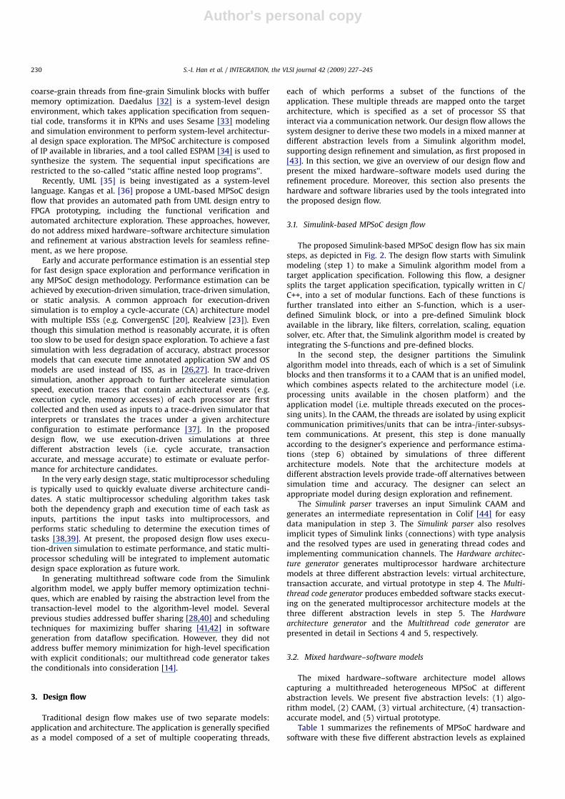
3.1. Simulink-based MPSoC design flow
The proposed Simulink-based MPSoC design flow has six mainsteps, as depicted in Fig. 2. The design flow starts with Simulinkmodeling (step 1) to make a Simulink algorithm model from atarget application specification. Following this flow, a designersplits the target application specification, typically written in C/C++, into a set of modular functions. Each of these functions isfurther translated into either an S-function, which is a user-defined Simulink block, or into a pre-defined Simulink blockavailable in the library, like filters, correlation, scaling, equationsolver, etc. After that, the Simulink algorithm model is created byintegrating the S-functions and pre-defined blocks.
In the second step, the designer partitions the Simulinkalgorithm model into threads, each of which is a set of Simulinkblocks and then transforms it to a CAAM that is an unified model,which combines aspects related to the architecture model (i.e.processing units available in the chosen platform) and theapplication model (i.e. multiple threads executed on the proces-sing units). In the CAAM, the threads are isolated by using explicitcommunication primitives/units that can be intra-/inter-subsys-tem communications. At present, this step is done manuallyaccording to the designer’s experience and performance estima-tions (step 6) obtained by simulations of three differentarchitecture models. Note that the architecture models atdifferent abstraction levels provide trade-off alternatives betweensimulation time and accuracy. The designer can select anappropriate model during design exploration and refinement.
The Simulink parser traverses an input Simulink CAAM andgenerates an intermediate representation in Colif [44] for easydata manipulation in step 3. The Simulink parser also resolvesimplicit types of Simulink links (connections) with type analysisand the resolved types are used in generating thread codes andimplementing communication channels. The Hardware architec-
ture generator generates multiprocessor hardware architecturemodels at three different abstraction levels: virtual architecture,transaction accurate, and virtual prototype in step 4. The Multi-
thread code generator produces embedded software stacks execut-ing on the generated multiprocessor architecture models at thethree different abstraction levels in step 5. The Hardware
architecture generator and the Multithread code generator arepresented in detail in Sections 4 and 5, respectively.
3.2. Mixed hardware–software models
The mixed hardware–software architecture model allowscapturing a multithreaded heterogeneous MPSoC at differentabstraction levels. We present five abstraction levels: (1) algo-rithm model, (2) CAAM, (3) virtual architecture, (4) transaction-accurate model, and (5) virtual prototype.
Table 1 summarizes the refinements of MPSoC hardware andsoftware with these five different abstraction levels as explained
ARTICLE IN PRESS
S.-I. Han et al. / INTEGRATION, the VLSI journal 42 (2009) 227–245230
Author's personal copy
in Sections 3.2.1–3.2.5. The designer can select an appropriateabstraction level during refinement process according to thedesign status and purpose. For example, the software designer can
use virtual architecture to validate a multithreaded program,while the system software designer can select transaction-accurate model to develop device driver of a specific I/O.
ARTICLE IN PRESS
OS library
Partitioning & Mapping
Simulink CAAM
2
Simulink parser
Colif CAAM
3
Multithreadcode generator
5
Simulink algorithm model
• Thread library• Comm. library
Model
Step i
Library
i
Simulink modeling1
Application specification
Simulation &Perform. Estimation
6
Hardwarearchitecture generator
4
• Comp. subsystems• Comm. channels
HW libraryVirtual Architecture
Transaction Accurate Model
Virtual Prototype
Fig. 2. Design flow for multithreaded multiprocessor system.
Table 1Hardware/software refinements with different abstraction levels
Abstraction level Algorithm
model
CAAM Virtual architecture Transaction-accurate
model
Virtual prototype
General Language Simulink Simulink SystemC SystemC SystemC
Main purpose Algorithm
modeling
capturing abstract
architecture
early software
validation
fast mixed HW/SW
validation
accurate system simulation
and evaluation
HW/SW refinement HW–SW
independent
HW–SW partition Abstract HW,
application SW
Communication HW, HdS
SW library
Computation HW, HAL SW
library
Primitives thread primitive Not
determined
Implicit thread_resume context_switch special return instruction
comm. primitive send_data(addr,
data, size)
write_word(addr, data) store instruction
Software stack thread Not
determined
implicit (Thread-SS) thread C code thread C code+HdS thread C code+HdS+HAL
intra-subsystem
comm. channel
implicit (Intra-SS
COMM)
abstract channel SWFIFO SWFIFO
CPU subsystem hardware
architecture
processor Not
determined
implicit (CPU-SS) abstract CPU SS abstract CPU processor ISS
local interconnection abstract channel local bus, bus bridge local bus, bus bridge
memory Implicit SRAM SRAM
peripheral Implicit mailbox, PIC mailbox, PIC
System hardware
architecture
CPU subsystem Not
determined
Implicit abstract CPU SS transaction-accurate CPU
SS
Target CPU SS
inter-subsystem
comm. channel
implicit (Inter-SS
COMM)
abstract channel GFIFO, HWFIFO GFIFO, HWFIFO
memory subsystem Implicit abstract channel SRAM SS, SDRAM SS SRAM SS, SDRAM SS
S.-I. Han et al. / INTEGRATION, the VLSI journal 42 (2009) 227–245 231

Author's personal copy
3.2.1. Algorithm model
The Simulink algorithm model specifies the input of theproposed design flow and represents only the functionality ofthe target system without any architecture decision, as shown inTable 1. The Simulink algorithm model is made up of three kindsof basic components:
� The Simulink Block represents a function that takes n inputsand produces outputs. Examples of Simulink blocks includeuser-defined (S-function), discrete delay and pre-definedblocks such as mathematical operations. We assume that aSimulink block should deliver data to another Simulinkblock(s) only through Simulink links to prevent unintendedside effects by partitioning and scheduling of blocks duringrefinement.� The Simulink Link connects one output port of a block to one or
more input ports of one or more blocks. Each Simulink linkbasically represents a variable called buffer memory.� The Simulink Subsystem can contain blocks, links, and other SS
to represent hierarchical composition and conditionals such asfor-loop iteration or if-then-else structure.
The Simulink algorithm model is independent of hardware–software partitions and described with fine-grain function-levelblocks, while the input specification of SystemC-based design flowis primarily dependent on hardware–software partitions anddescribed with coarse-grain thread-level modules (through theCAAM). With the proposed design flow, a designer can easilyderive mixed hardware–software models with different partitionsand different abstraction levels from the Simulink algorithmmodel. The designer is able to explore more fine-grained andwider design spaces as will be explained.
3.2.2. CAAM
The Simulink CAAM is the first abstraction level, mixedhardware–software model that follows our proposed refinementprocedure. We specify a Simulink CAAM as a three-layeredhierarchical structure, illustrated in Fig. 3. The system layer, asshown in Fig. 3(a), describes a system architecture that is made upof CPU SS and inter-subsystem communication channels. Thesubsystem layer, as shown in Fig. 3(b), describes a CPU subsystemarchitecture that includes a set of threads and intra-subsystemcommunication channels. Finally, the thread layer describes asoftware thread that consists of Simulink blocks and linksbetween them, as shown in Fig. 3(c).
To represent the triple-layered mixed hardware–softwaremodel in Simulink, we defined four kinds of specific Simulink SS:
� CPU-SS is a conceptual representation of CPU subsystem.A CPU-SS is gradually refined to a subsystem, which includesa CPU, local buses, local memories, and peripherals, by theHardware architecture generator in Fig. 2. CPU0 SS is an exampleof CPU-SS in Fig. 3(a) and (b) illustrates the CPU subsystemlayer composed of two threads communicating throughchannels.� Inter-SS COMM is a conceptual representation of communica-
tion channels between CPU SS. An Inter-SS COMM includes oneor more Simulink links, each of which corresponds to a point-to-point channel. Each channel is gradually refined to bothhardware communication channels, by the Hardware architec-
ture generator, and also to software communication port(s) toaccess the channel, by the Multithread code generator. CH4 inFig. 3(a) is an example of Inter-SS COMM.� Thread-SS is a conceptual representation of a software thread.
A Thread-SS is gradually refined to a software thread includingHdS API calls by the Multithread code generator. T0 and T1 inFig. 3(b) are both examples of a Thread-SS. Fig. 3(c) illustratesthe thread layer, where thread T0 is composed of Simulinkblocks.� Intra-SS COMM is a conceptual representation of communica-
tion channels between threads on the same CPU subsystem. Aswith an Inter-SS COMM, an Intra-SS COMM also includes oneor more Simulink links. These Intra-SS COMM channels aregradually refined to OS communication channels by theMultithread code generator. In Fig. 3(b), CH0 and CH1 are bothexamples of an Intra-SS COMM.
To make a thread subsystem, the designer clusters severalSimulink blocks into a Simulink subsystem by using the Simulinkgraphical user interface and then sets the subsystem type to‘‘Thread’’. The designer can make CPU-SS, Inter-SS COMM, andIntra-SS COMM SS in the same way. These SS are normal SimulinkSS that do not affect the original functionality. Thus the designercan verify the functionality of a Simulink CAAM using theSimulink simulation environment.
Following our design flow, a Simulink CAAM is translated intoan equivalent Colif CAAM by the Simulink parser. Colif is an XML-based meta-model proposed in [44], which provides well-defineddata structures and APIs for easy data manipulation duringthe refinement procedure. Colif can represent a generalsystem composed of three entities: modules, channels, and ports.
ARTICLE IN PRESS
CPU1SS
CPUnSS
CPU0SS
CPU-SS
F1
FSWF4
F0
F6
F5
F2 F3
IAS0
IAS1
…
CH0(SWFIFO)
CH1(SWFIFO)
Thread-SS
CH4(GFIFO)Inter-SS COMM
…
Intra-SS COMM
SimulinkBlock
Simulink link
T1T0
CPU0 SS
T0
Simulink port
CPU-SS
…
CH0(SWFIFO)
CH1(SWFIFO)…
Fig. 3. Simulink CAAM: (a) system layer, (b) CPU subsystem layer, and (c) thread layer.
S.-I. Han et al. / INTEGRATION, the VLSI journal 42 (2009) 227–245232
Author's personal copy
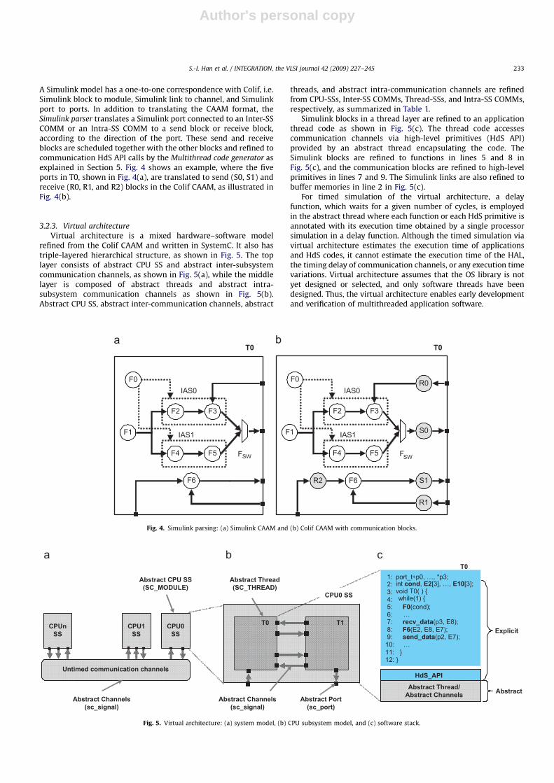
A Simulink model has a one-to-one correspondence with Colif, i.e.Simulink block to module, Simulink link to channel, and Simulinkport to ports. In addition to translating the CAAM format, theSimulink parser translates a Simulink port connected to an Inter-SSCOMM or an Intra-SS COMM to a send block or receive block,according to the direction of the port. These send and receiveblocks are scheduled together with the other blocks and refined tocommunication HdS API calls by the Multithread code generator asexplained in Section 5. Fig. 4 shows an example, where the fiveports in T0, shown in Fig. 4(a), are translated to send (S0, S1) andreceive (R0, R1, and R2) blocks in the Colif CAAM, as illustrated inFig. 4(b).
3.2.3. Virtual architecture
Virtual architecture is a mixed hardware–software modelrefined from the Colif CAAM and written in SystemC. It also hastriple-layered hierarchical structure, as shown in Fig. 5. The toplayer consists of abstract CPU SS and abstract inter-subsystemcommunication channels, as shown in Fig. 5(a), while the middlelayer is composed of abstract threads and abstract intra-subsystem communication channels as shown in Fig. 5(b).Abstract CPU SS, abstract inter-communication channels, abstract
threads, and abstract intra-communication channels are refinedfrom CPU-SSs, Inter-SS COMMs, Thread-SSs, and Intra-SS COMMs,respectively, as summarized in Table 1.
Simulink blocks in a thread layer are refined to an applicationthread code as shown in Fig. 5(c). The thread code accessescommunication channels via high-level primitives (HdS API)provided by an abstract thread encapsulating the code. TheSimulink blocks are refined to functions in lines 5 and 8 inFig. 5(c), and the communication blocks are refined to high-levelprimitives in lines 7 and 9. The Simulink links are also refined tobuffer memories in line 2 in Fig. 5(c).
For timed simulation of the virtual architecture, a delayfunction, which waits for a given number of cycles, is employedin the abstract thread where each function or each HdS primitive isannotated with its execution time obtained by a single processorsimulation in a delay function. Although the timed simulation viavirtual architecture estimates the execution time of applicationsand HdS codes, it cannot estimate the execution time of the HAL,the timing delay of communication channels, or any execution timevariations. Virtual architecture assumes that the OS library is notyet designed or selected, and only software threads have beendesigned. Thus, the virtual architecture enables early developmentand verification of multithreaded application software.
ARTICLE IN PRESS
F1
FSWF4
F0
F6
F5
F2 F3
IAS0
IAS1 F1
FSWF4
F0
F6
F5
F2 F3
IAS0
IAS1
R2
R1
S0
S1
R0
T0 T0
Fig. 4. Simulink parsing: (a) Simulink CAAM and (b) Colif CAAM with communication blocks.
Abstract Thread/Abstract Channels
Untimed communication channels
CPU1SS
CPUnSS
CPU0SS
1:2:3:4:5: F0(cond);6: …7: recv_data(p3, E8); 8: F6(E2, E8, E7);9: send_data(p2, E7);10: …11: }12: }
HdS_API
T1T0
T0
Explicit
AbstractAbstract Port
(sc_port)
Abstract Thread(SC_THREAD)
Abstract CPU SS(SC_MODULE)
Abstract Channels(sc_signal)
Abstract Channels(sc_signal)
CPU0 SS void T0( ) {while(1) {
int cond, E2[3], …, E10[3];port_t∗p0, …, *p3;
Fig. 5. Virtual architecture: (a) system model, (b) CPU subsystem model, and (c) software stack.
S.-I. Han et al. / INTEGRATION, the VLSI journal 42 (2009) 227–245 233

Author's personal copy
3.2.4. Transaction-accurate model
A transaction-accurate model is the next mixed hardware–software model after virtual architecture during the refinementprocedure. In the top layer of this model, CPU SS communicatewith each other via memory SS and cycle accurate (CA)communication channels, as shown in Fig. 6(a). In the middlelayer, a CPU subsystem is made up of an abstract CPU, local buses,local memories, hardware components (e.g. PIC), and commu-nication I/Os (e.g. a mailbox), as depicted in Fig. 6(b). The abstractCPU provides bus functional model (BFM) functions (e.g. write
word, read word) and translates them to SystemC signal-leveltransactions. It also provides low-level primitives (HAL API)(e.g. context switch, interrupt service routine). The abstract CPU canbe used when the target processor is not yet designed or selected.
The software stack consists of application threads and HdSlibrary, as shown in Fig. 6(c). The HdS library is built on the HALAPI and BFM functions provided by the abstract CPU to implementa thread library, a communication library, and a hardware devicedriver. The software stack also includes software communicationchannels refined from abstract intra-subsystem communicationchannels in a virtual architecture. The main code is responsible forcreating the application threads and communication channels byusing the HdS API. The software stack is directly executed on thesimulation host, and thus the transaction-accurate model canaccelerate mixed hardware–software simulations and verifica-tions including the OS library.
For a timed simulation of a transaction-accurate model, theabstract processor provides a delay function, with which theexecution time of each HAL primitive is also annotated. In a timedsimulation of a transaction-accurate model, the execution time ofan application and its HdS are modeled as well as the HALexecution time and the timing delay of communication channels.
However, this simulation model does not consider any variation ofexecution times of software codes.
3.2.5. Virtual prototype
Virtual prototype is a CA SystemC model refined from atransaction-accurate model. In the middle layer, a CPU subsystemis composed with a target processor, local buses, local memories,hardware components, and communication I/Os as shown inFig. 7(b). The target processor model is a CA SystemC model withan ISS that translates load/store instructions into SystemC signal-level transactions.
The software stack for this abstraction level is illustrated inFig. 7(c). It consists of application threads and HdS and HALlibraries. It is executed on the target processor model or board. Inthe virtual prototype, all hardware and software components arerefined explicitly, so a designer verifies the system and estimatesits performance at CA level.
3.3. Hardware and software libraries
We developed a generic signal-level SystemC processorwrapper that supports common functions of processors such ashardware interface, clock synchronization, connection to remotedebugger, loading of binary, etc. We can easily implement aprocessor model by embedding the processor ISS with theSystemC wrapper. At present, our hardware library includes threekinds of processor models: abstract CPU, ARM7, and Xtensa [45].Abstract CPU is an abstract processor model for simulation intransaction-accurate abstraction levels. ARM7 is a popular RISCprocessor suitable for control-intensive application and I/Ocontrols, while Xtensa is a configurable processor that can be
ARTICLE IN PRESS
Abstract CPU(BFM)
Mailbox NetworkInterface
AbstractCPU PIC
CA communication channels
CPU1SS
NI
MemSS
NI
CPUnSS
NI
CPU0SS
NI
Mem
HWAccel.
main
T0 T1 Tn
HdS_API
HAL_API
Comm.Library
MultithreadLibrary
Explicit
Abstract
CPU0 SS
Fig. 6. Transaction-accurate model: (a) system model, (b) CPU subsystem model, and (c) software stack.
HdS_API
HAL_API
Hardware AbstractionLayer (HAL)
Mem
Mailbox NetworkInterface
HWAccel.
ARM7ISS MemPIC
BCA communication channels
CPU1SS
NI
MemSS
NI
CPUnSS
NI
CPU0SS
NI
main
T0 T1 Tn
Comm.Library
MultithreadLibrary
CPU0 SS
Explicit
Fig. 7. Virtual prototype: (a) system model, (b) CPU subsystem model, and (c) software stack.
S.-I. Han et al. / INTEGRATION, the VLSI journal 42 (2009) 227–245234

Author's personal copy
customized to specific applications with an automatic instructionset generator called Xtensa Processor Extension Synthesis (XPRES)[45]. To reduce simulation synchronization overhead in thesimulation, we embedded a processor model as a SystemC processwithin the SystemC simulator.
The hardware library also includes communication, memory,and peripheral SystemC CA models such as AMBA bus, bus bridge,mailbox, hardware FIFO, SRAM, timer, programmable interruptcontroller (PIC), etc. Based on these hardware models, weimplement CPU SS and communication channels. At present, wesupport two inter-subsystem communication protocols: GFIFOand HWFIFO. GFIFO is a communication protocol that transfersdata using a shared memory, a bus, and mailboxes. The datatransfer is divided into two steps. First, the CPU in the sourcesubsystem writes data to a shared memory and sends an event tothe mailbox in the target subsystem. After receiving the event, theCPU in the target subsystem reads the data from the sharedmemory and sends another event to the mailbox in the sourcesubsystem to notify the completion of the read operation. HWFIFOis a communication protocol that transfers data via a hardwareFIFO.
Our OS library includes a thread library to create and scheduleapplication threads and a communication library to implementcommunication protocols: GFIFO, HWFIFO (as mentioned), andSWFIFO. This last is an intra-subsystem communication protocol.It also includes a low-level HAL library including things such as I/O device drivers. The OS library has a small memory footprint(from 4 to 8 kB) and is currently targeted at abstract CPU, ARM7,and Xtensa.
4. Hardware architecture generator
The Hardware architecture generator builds an MPSoC hardwaredescription at each proposed abstraction level in two stages, CPUsubsystem generation and system architecture generation, asshown in the flow illustrated in Fig. 8. In the first stage, theHardware architecture generator produces a set of subsystemmodels, each of which corresponds to a CPU subsystem in theinput Colif CAAM. In the second stage, the Hardware architecture
generator produces a system architecture code that instantiates allCPU SS and communication network(s) between them. Bothstages are unique for the target abstraction level, which meansthat the subsystem and architecture codes generated are differentfor each abstraction level.
The CPU subsystem and system generation stages are ex-plained using an example of virtual prototype generation from aColif CAAM shown in Fig. 9. Fig. 9(a) illustrates a Colif CAAM,which consists of an ARM7 CPU-SS (CPU0), two Xtensa CPU-SSs(CPU1, CPU2), an HWFIFO Inter-SS COMM (CH3), and two GFIFOInter-SS COMMs (CH4, CH5). Note that GFIFO Inter-SS COMMsintroduce a shared memory subsystem to store communicationmessages between CPU SS.
4.1. CPU subsystem generation
The Hardware architecture generator transverses a Colif CAAM andgenerates subsystem architecture codes corresponding to the CPUsubsystem layer of the Colif CAAM. This stage consists of four steps:
ARTICLE IN PRESS
Component 1Component 1
Step i
Model
iColif CAAM (.xml)
…
VP System generation
Makefile
Architecture model
CPU SS1 CPU SS2 CPU SSn System model
Component1
Arch. library
Executable SystemC model
CPU m
peri NI
CPU m
peri NI
CPU m
peri NI
CPU m
peri NI
CPU m
peri NI
CPU m
peri NI
CPUSS1
Communication Network
CPUSS2
CPUSSn
…CPUSS1
Communication Network
CPUSS2
CPUSSn…
VA model
TA model
TA CPU SS generation
VA CPU SS generation
TA System generation
VA System generation
Virtual Prototype
Component inst.
Interconnect inst.
Resource alloc.
Component conn.
1
2
3
4 VP CPU SS generation
Fig. 8. Generation flow for hardware architecture model.
S.-I. Han et al. / INTEGRATION, the VLSI journal 42 (2009) 227–245 235

Author's personal copy
Step 1: Component instantiation—The Hardware architecture
generator instantiates local hardware components (i.e. a CPU,memories, and peripherals) belonging to a CPU subsystem. In theexample presented in Fig. 9, an ARM7 model is instantiated inFig. 9(b) for the CPU0 subsystem from the Colif CAAM of Fig. 9(a)since the type parameter of the subsystem is ARM7. It alsoinstantiates local memories to store software binaries and data, aPIC to deliver interrupts to its CPU, and a mailbox to receivesynchronization events from other SS.
Step 2: Interconnect instantiation—The Hardware architecture
generator instantiates a local bus and a bus bridge. In the presentdesign flow, each CPU subsystem has a 4 MB (mega-byte) localaddress space and the lower 4 MB space is reserved for local bustransactions to access local hardware components. The bus bridgehandles global transactions whose address value is larger than 4 MB.
Step 3: Resource allocation—The Hardware architecture genera-
tor allocates the address space and the interrupt number of eachlocal hardware component.
Step 4: Component connection—The Hardware architecture
generator automatically connects all local hardware componentsto the local bus. It also connects their interrupt signals to the PICinstantiated in Step 1. The generated subsystem code can beconsidered a system-level netlist of local hardware componentswritten in SystemC.
4.2. System generation
In the same way, the Hardware architecture generator producesa system architecture model corresponding to the system layer ofthe input Colif CAAM.
Step 1: Subsystem instantiation—The Hardware architecture
generator instantiates CPU and memory SS. In Fig. 9(b), oneARM7 subsystem, two Xtensa SS, and a shared memory subsystemare instantiated according to the input CAAM in Fig. 9(a). Theshared memory subsystem is used to store communicationmessages for CH4 and CH5 (GFIFO).
Step 2: Interconnect instantiation—The Hardware architecture
generator instantiates global interconnections. In Fig. 9(b), a globalbus and a hardware FIFO are instantiated for CH4 and CH5(GFIFO), and CH3 (HWFIFO), respectively.
Step 3: Resource allocation—The Hardware architecture genera-
tor assigns the global address space to each subsystem. InFig. 9(b), the global address space of the CPU0 subsystem is from4 to 8 MB. The bus bridge in CPU0 subsystem accepts globaltransactions with address values from 4 to 8 MB and responds tothem.
Step 4: Component connection—The Hardware architecture
generator automatically connects all SS to global interconnects.In Fig. 9(b), CPU0 and CPU1 SS are connected via the hardwareFIFO instantiated in step 2. A system architecture code can beconsidered a system-level netlist of SS.
According to the target abstraction level, the Hardware
architecture generator instantiates components at different ab-straction levels, as summarized in Table 1. For example, theHardware architecture generator instantiates an abstract CPUinstead of a target processor model for a transaction-accuratesimulation. To build an executable hardware architecture model,the Hardware architecture generator produces a Makefile thatcompiles the generated subsystem architecture codes, a systemarchitecture code, and then links them with the hardwarearchitecture library, as shown in Fig. 8. The executable architecture
ARTICLE IN PRESS
CH4(GFIFO)
CPU1 (type: Xtensa)
CH3(HWFIFO)
Mailbox
ARM7ISS Mem
Busbridge
PICMem0
Busbridge
Mailbox
XtensaISS Mem
Busbridge
PIC
XtensaISS Mem
MailboxBusbridge
PIC
CPU0 (ARM7)(4MB~8MB)
CH4, CH5 (GFIFO)(1GB~1GB+64MB)
CH3 (HWFIFO)
CPU0 (type: ARM7)
CH0(SWFIFO)
CPU2 (type: Xtensa)
CPU1 (Xtensa)(8MB~12MB)
CPU2 (Xtensa)(12MB~16MB)
T6T4
T5T3
T2
T1
T0
CH1(SHM)
CH6(SWFIFO)
CH7(SWFIFO)
CH5(GFIFO)
bus0
Fig. 9. An example of virtual prototype generation: (a) Simulink CAAM and (b) virtual prototype.
S.-I. Han et al. / INTEGRATION, the VLSI journal 42 (2009) 227–245236
Author's personal copy
model loads the software stacks generated by the Multithread code
generator and simulates the entire system.
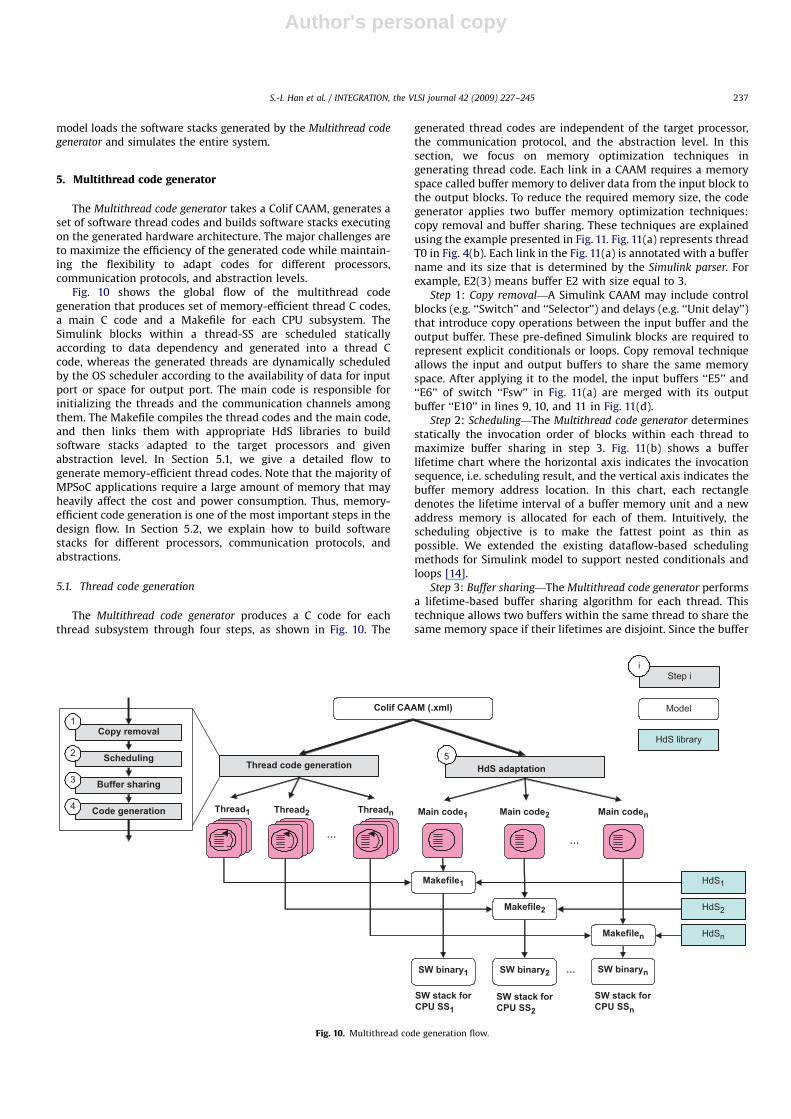
5. Multithread code generator
The Multithread code generator takes a Colif CAAM, generates aset of software thread codes and builds software stacks executingon the generated hardware architecture. The major challenges areto maximize the efficiency of the generated code while maintain-ing the flexibility to adapt codes for different processors,communication protocols, and abstraction levels.
Fig. 10 shows the global flow of the multithread codegeneration that produces set of memory-efficient thread C codes,a main C code and a Makefile for each CPU subsystem. TheSimulink blocks within a thread-SS are scheduled staticallyaccording to data dependency and generated into a thread Ccode, whereas the generated threads are dynamically scheduledby the OS scheduler according to the availability of data for inputport or space for output port. The main code is responsible forinitializing the threads and the communication channels amongthem. The Makefile compiles the thread codes and the main code,and then links them with appropriate HdS libraries to buildsoftware stacks adapted to the target processors and givenabstraction level. In Section 5.1, we give a detailed flow togenerate memory-efficient thread codes. Note that the majority ofMPSoC applications require a large amount of memory that mayheavily affect the cost and power consumption. Thus, memory-efficient code generation is one of the most important steps in thedesign flow. In Section 5.2, we explain how to build softwarestacks for different processors, communication protocols, andabstractions.
5.1. Thread code generation
The Multithread code generator produces a C code for eachthread subsystem through four steps, as shown in Fig. 10. The
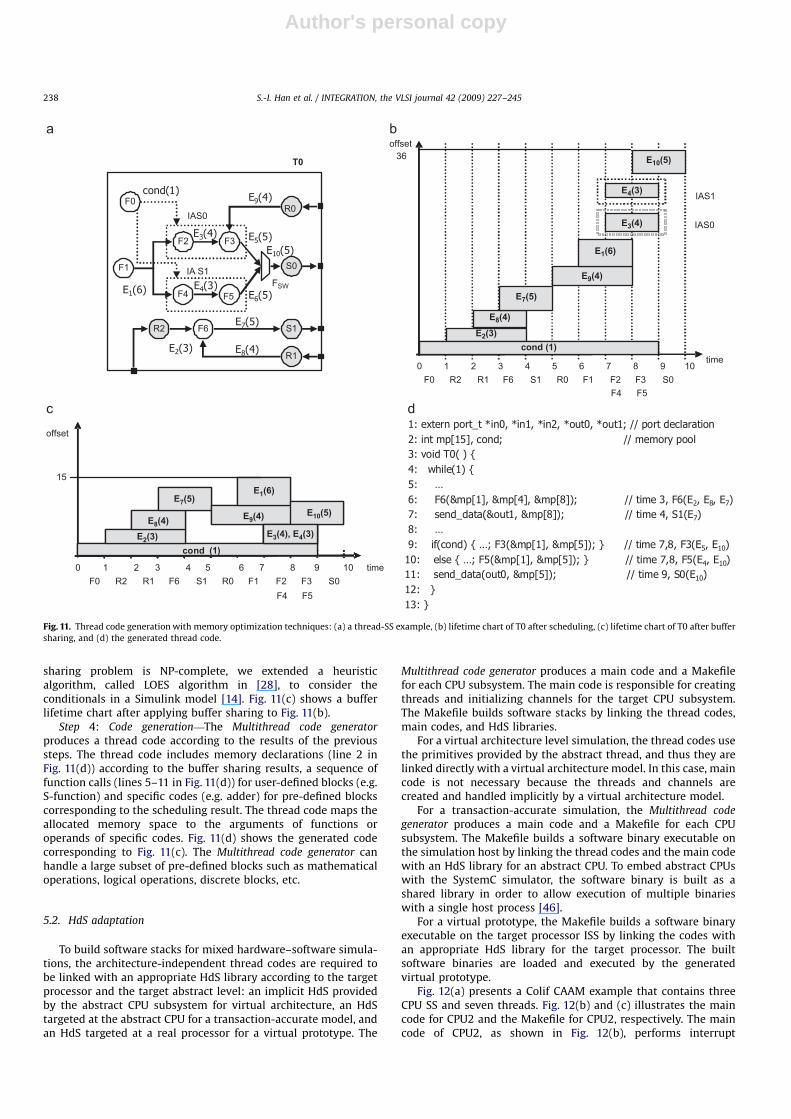
generated thread codes are independent of the target processor,the communication protocol, and the abstraction level. In thissection, we focus on memory optimization techniques ingenerating thread code. Each link in a CAAM requires a memoryspace called buffer memory to deliver data from the input block tothe output blocks. To reduce the required memory size, the codegenerator applies two buffer memory optimization techniques:copy removal and buffer sharing. These techniques are explainedusing the example presented in Fig. 11. Fig. 11(a) represents threadT0 in Fig. 4(b). Each link in the Fig. 11(a) is annotated with a buffername and its size that is determined by the Simulink parser. Forexample, E2(3) means buffer E2 with size equal to 3.
Step 1: Copy removal—A Simulink CAAM may include controlblocks (e.g. ‘‘Switch’’ and ‘‘Selector’’) and delays (e.g. ‘‘Unit delay’’)that introduce copy operations between the input buffer and theoutput buffer. These pre-defined Simulink blocks are required torepresent explicit conditionals or loops. Copy removal techniqueallows the input and output buffers to share the same memoryspace. After applying it to the model, the input buffers ‘‘E5’’ and‘‘E6’’ of switch ‘‘Fsw’’ in Fig. 11(a) are merged with its outputbuffer ‘‘E10’’ in lines 9, 10, and 11 in Fig. 11(d).
Step 2: Scheduling—The Multithread code generator determinesstatically the invocation order of blocks within each thread tomaximize buffer sharing in step 3. Fig. 11(b) shows a bufferlifetime chart where the horizontal axis indicates the invocationsequence, i.e. scheduling result, and the vertical axis indicates thebuffer memory address location. In this chart, each rectangledenotes the lifetime interval of a buffer memory unit and a newaddress memory is allocated for each of them. Intuitively, thescheduling objective is to make the fattest point as thin aspossible. We extended the existing dataflow-based schedulingmethods for Simulink model to support nested conditionals andloops [14].
Step 3: Buffer sharing—The Multithread code generator performsa lifetime-based buffer sharing algorithm for each thread. Thistechnique allows two buffers within the same thread to share thesame memory space if their lifetimes are disjoint. Since the buffer
ARTICLE IN PRESS
Step i
Model
i
Thread code generation
Colif CAAM (.xml)
…
HdS adaptation5
Makefile1
Makefile2
Makefilen
SW binary1
Thread1 Thread2 Threadn
…
Main code1 Main code2 Main coden
SW binary2 SW binaryn…
HdS1
HdS2
HdSn
HdS library
SW stack forCPU SS1
SW stack forCPU SS2
SW stack forCPU SSn
Copy removal
Scheduling
Buffer sharing
Code generation
1
2
3
4
Fig. 10. Multithread code generation flow.
S.-I. Han et al. / INTEGRATION, the VLSI journal 42 (2009) 227–245 237
Author's personal copy
sharing problem is NP-complete, we extended a heuristicalgorithm, called LOES algorithm in [28], to consider theconditionals in a Simulink model [14]. Fig. 11(c) shows a bufferlifetime chart after applying buffer sharing to Fig. 11(b).
Step 4: Code generation—The Multithread code generator
produces a thread code according to the results of the previoussteps. The thread code includes memory declarations (line 2 inFig. 11(d)) according to the buffer sharing results, a sequence offunction calls (lines 5–11 in Fig. 11(d)) for user-defined blocks (e.g.S-function) and specific codes (e.g. adder) for pre-defined blockscorresponding to the scheduling result. The thread code maps theallocated memory space to the arguments of functions oroperands of specific codes. Fig. 11(d) shows the generated codecorresponding to Fig. 11(c). The Multithread code generator canhandle a large subset of pre-defined blocks such as mathematicaloperations, logical operations, discrete blocks, etc.
5.2. HdS adaptation
To build software stacks for mixed hardware–software simula-tions, the architecture-independent thread codes are required tobe linked with an appropriate HdS library according to the targetprocessor and the target abstract level: an implicit HdS providedby the abstract CPU subsystem for virtual architecture, an HdStargeted at the abstract CPU for a transaction-accurate model, andan HdS targeted at a real processor for a virtual prototype. The
Multithread code generator produces a main code and a Makefilefor each CPU subsystem. The main code is responsible for creatingthreads and initializing channels for the target CPU subsystem.The Makefile builds software stacks by linking the thread codes,main codes, and HdS libraries.
For a virtual architecture level simulation, the thread codes usethe primitives provided by the abstract thread, and thus they arelinked directly with a virtual architecture model. In this case, maincode is not necessary because the threads and channels arecreated and handled implicitly by a virtual architecture model.
For a transaction-accurate simulation, the Multithread code
generator produces a main code and a Makefile for each CPUsubsystem. The Makefile builds a software binary executable onthe simulation host by linking the thread codes and the main codewith an HdS library for an abstract CPU. To embed abstract CPUswith the SystemC simulator, the software binary is built as ashared library in order to allow execution of multiple binarieswith a single host process [46].
For a virtual prototype, the Makefile builds a software binaryexecutable on the target processor ISS by linking the codes withan appropriate HdS library for the target processor. The builtsoftware binaries are loaded and executed by the generatedvirtual prototype.
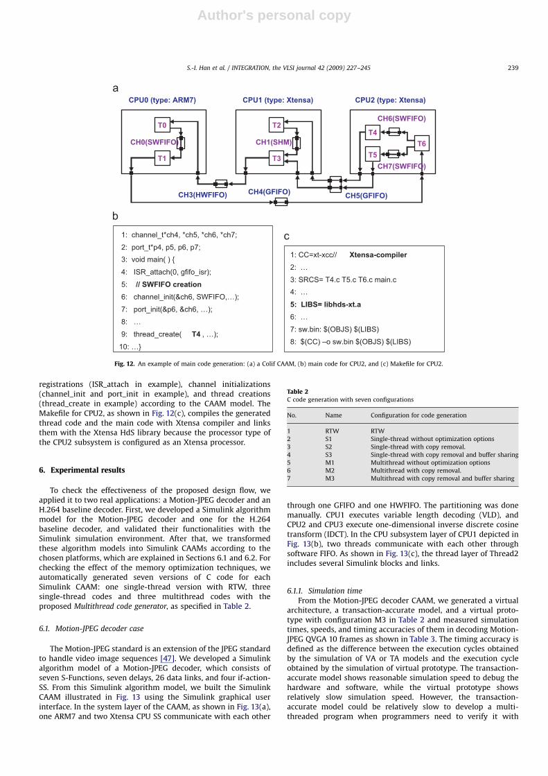
Fig. 12(a) presents a Colif CAAM example that contains threeCPU SS and seven threads. Fig. 12(b) and (c) illustrates the maincode for CPU2 and the Makefile for CPU2, respectively. The maincode of CPU2, as shown in Fig. 12(b), performs interrupt
ARTICLE IN PRESS
F1
FSWF4
F0
F6
F5
F2 F3
IAS0
IA S1
R2
R1
S0
S1
R0
T0
time
offset
cond (1)
0 2 4 8 106
cond (1)
E8(4)E2(3)
E9(4)
E1(6)
E10(5)
15
E3(4), E4(3)
F0 R2 R1 F6 S1 R0 F1 F2 F3 S0F4 F5
1 3 5 7 9
cond (1)
0 2 3 8 106
E2(3)
E8(4)
E7(5)
E9(4)
E1(6)
E3(4)
E4(3)
E10(5)
timecond (1)
IAS1
IAS0
F0 R2 R1 F6 S1 R0 F1 F2 F3 S0F4 F5
offset36
1 4 5 7 9
E7(5)
Fig. 11. Thread code generation with memory optimization techniques: (a) a thread-SS example, (b) lifetime chart of T0 after scheduling, (c) lifetime chart of T0 after buffer
sharing, and (d) the generated thread code.
S.-I. Han et al. / INTEGRATION, the VLSI journal 42 (2009) 227–245238
Author's personal copy
registrations (ISR_attach in example), channel initializations(channel_init and port_init in example), and thread creations(thread_create in example) according to the CAAM model. TheMakefile for CPU2, as shown in Fig. 12(c), compiles the generatedthread code and the main code with Xtensa compiler and linksthem with the Xtensa HdS library because the processor type ofthe CPU2 subsystem is configured as an Xtensa processor.
6. Experimental results
To check the effectiveness of the proposed design flow, weapplied it to two real applications: a Motion-JPEG decoder and anH.264 baseline decoder. First, we developed a Simulink algorithmmodel for the Motion-JPEG decoder and one for the H.264baseline decoder, and validated their functionalities with theSimulink simulation environment. After that, we transformedthese algorithm models into Simulink CAAMs according to thechosen platforms, which are explained in Sections 6.1 and 6.2. Forchecking the effect of the memory optimization techniques, weautomatically generated seven versions of C code for eachSimulink CAAM: one single-thread version with RTW, threesingle-thread codes and three multithread codes with theproposed Multithread code generator, as specified in Table 2.
6.1. Motion-JPEG decoder case
The Motion-JPEG standard is an extension of the JPEG standardto handle video image sequences [47]. We developed a Simulinkalgorithm model of a Motion-JPEG decoder, which consists ofseven S-Functions, seven delays, 26 data links, and four if-action-SS. From this Simulink algorithm model, we built the SimulinkCAAM illustrated in Fig. 13 using the Simulink graphical userinterface. In the system layer of the CAAM, as shown in Fig. 13(a),one ARM7 and two Xtensa CPU SS communicate with each other
through one GFIFO and one HWFIFO. The partitioning was donemanually. CPU1 executes variable length decoding (VLD), andCPU2 and CPU3 execute one-dimensional inverse discrete cosinetransform (IDCT). In the CPU subsystem layer of CPU1 depicted inFig. 13(b), two threads communicate with each other throughsoftware FIFO. As shown in Fig. 13(c), the thread layer of Thread2includes several Simulink blocks and links.
6.1.1. Simulation time
From the Motion-JPEG decoder CAAM, we generated a virtualarchitecture, a transaction-accurate model, and a virtual proto-type with configuration M3 in Table 2 and measured simulationtimes, speeds, and timing accuracies of them in decoding Motion-JPEG QVGA 10 frames as shown in Table 3. The timing accuracy isdefined as the difference between the execution cycles obtainedby the simulation of VA or TA models and the execution cycleobtained by the simulation of virtual prototype. The transaction-accurate model shows reasonable simulation speed to debug thehardware and software, while the virtual prototype showsrelatively slow simulation speed. However, the transaction-accurate model could be relatively slow to develop a multi-threaded program when programmers need to verify it with
ARTICLE IN PRESS
1: channel_t*ch4, *ch5, *ch6, *ch7;
2: port_t*p4, p5, p6, p7;3: void main( ) {
4: ISR_attach(0, gfifo_isr);
5: // SWFIFO creation6: channel_init(&ch6, SWFIFO,…);
7: port_init(&p6, &ch6, …);
8: …
9: thread_create( T4 , …);
10: …}
1: CC=xt-xcc// Xtensa-compiler2: …
3: SRCS= T4.c T5.c T6.c main.c4: …
5: LIBS= libhds-xt.a6: …
7: sw.bin: $(OBJS) $(LIBS)
8: $(CC) –o sw.bin $(OBJS) $(LIBS)
CH4(GFIFO)
CPU1 (type: Xtensa)
CH3(HWFIFO)
CPU0 (type: ARM7)
CH0(SWFIFO)
CPU2 (type: Xtensa)
T6T4
T5T3
T2
T1
T0
CH1(SHM)
CH6(SWFIFO)
CH7(SWFIFO)
CH5(GFIFO)
Fig. 12. An example of main code generation: (a) a Colif CAAM, (b) main code for CPU2, and (c) Makefile for CPU2.
Table 2C code generation with seven configurations
No. Name Configuration for code generation
1 RTW RTW
2 S1 Single-thread without optimization options
3 S2 Single-thread with copy removal.
4 S3 Single-thread with copy removal and buffer sharing
5 M1 Multithread without optimization options
6 M2 Multithread with copy removal.
7 M3 Multithread with copy removal and buffer sharing
S.-I. Han et al. / INTEGRATION, the VLSI journal 42 (2009) 227–245 239

Author's personal copy
various test benches at each modification of the application code.In this case, using the virtual architecture model allows theprogrammers to debug the multithread program at a highsimulation speed. Note that RTW can generate only a single-thread code. The architecture models at different abstractionlevels provide trade-off alternatives between simulation time andaccuracy.
6.1.2. Memory optimization
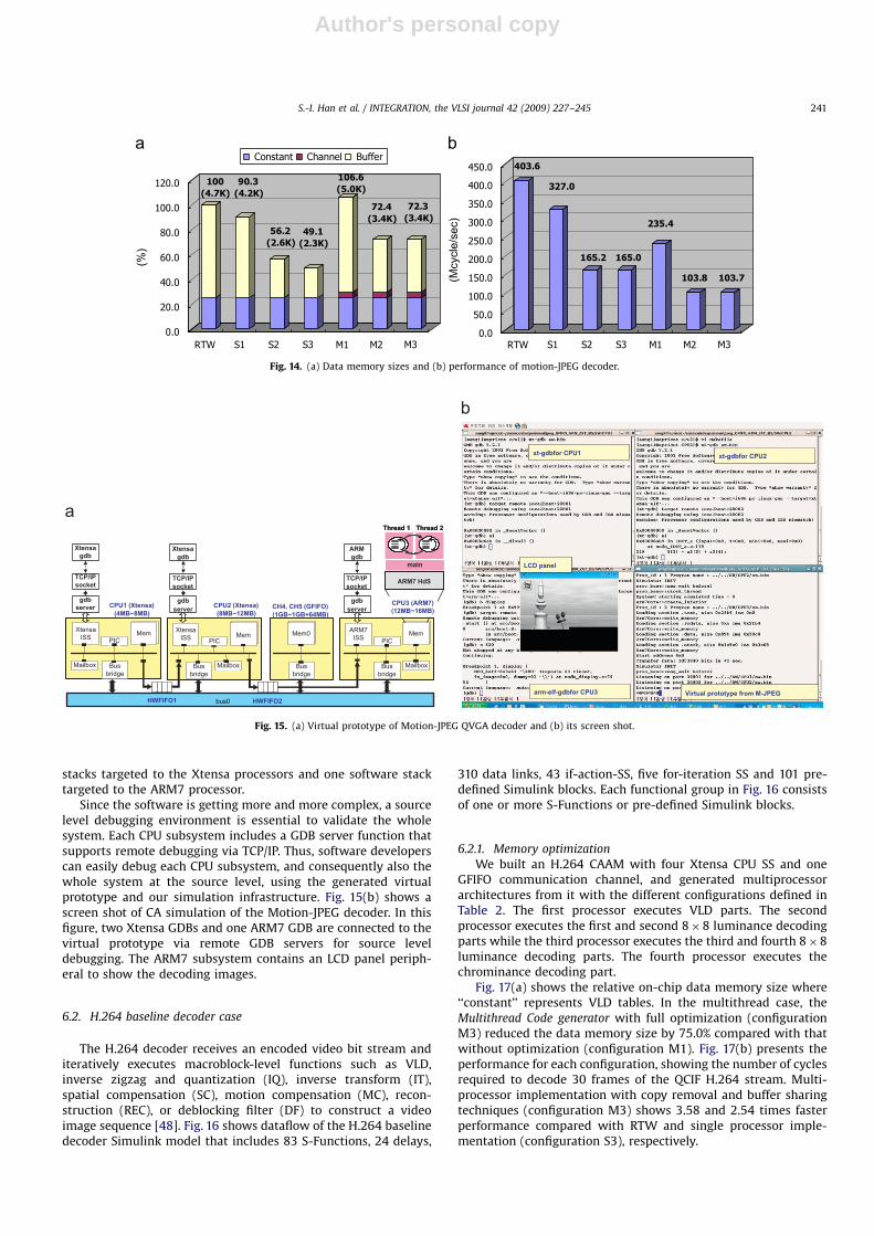
To measure the effects of memory optimization techniques, wegenerated seven platforms from the Motion-JPEG CAAM with thedifferent configurations defined in Table 2, and measured the datamemory sizes and execution times, as shown in Fig. 14. Fig. 14(a)illustrates relative on-chip data memory sizes where ‘‘constant’’and ‘‘channel’’ represent Huffman table and channel datastructures (i.e. channel_t, port_t in Fig. 12(b)), respectively. In thesingle-thread case, the code generator with full optimizations(configuration S3) can reduce the data memory size by 50.9%compared with RTW. In the multithread case, the data memorysize that was generated with full optimizations (configuration
M3) is 34.3% less than that without optimization (configurationM1). Experimental results show that the proposed memoryoptimization techniques can effectively reduce the required datamemory size, for both single-thread and multithread cases.
Fig. 14(b) presents the performance for each configuration,showing the number of cycles required to decode 30 frames of aQVGA JPEG stream. We used an architecture with one Xtensaprocessor subsystem for single-thread cases and three processors(one ARM7 and two Xtensa) for multithread cases. The multi-thread multiprocessor implementation with copy removal andbuffer sharing techniques (configuration M3) shows 3.89 timesand 1.59 times faster performance compared with RTW and singleprocessor implementation (configuration S3), respectively.
6.1.3. Virtual prototype generation
Fig. 15(a) illustrates the virtual prototype automaticallygenerated from the Motion-JPEG decoder Simulink CAAMdepicted in Fig. 13. The virtual prototype consists of one ARM7and two Xtensa CPU SS communicating through one GFIFO andtwo HWFIFOs. The Multithread code generator builds two software
ARTICLE IN PRESS
Fig. 13. Simulink CAAM for Motion-JPEG: (a) system layer, (b) CPU subsystem layer, and (c) thread layer.
Table 3Simulation time (s) and speed (cycle/s) of Motion-JPEG decoder with different abstraction levels
Application RTW Simulink VA TA VP
Motion-JPEG QVGA 10 frame decoding
with one ARM7 and two Xtensa
0.16 s 6.0 s 1.8 s 29 s 1624 s
365 M/s 9.7 M/s 32.5 M/s 2.0 M/s 36 K/s
Timing accuracy (execution cycle) 0% 0% 89.5% 98.6 100%
(N/A) (N/A) (52.3 M) (57.7 M) (58.5 M)
S.-I. Han et al. / INTEGRATION, the VLSI journal 42 (2009) 227–245240
Author's personal copy
stacks targeted to the Xtensa processors and one software stacktargeted to the ARM7 processor.
Since the software is getting more and more complex, a sourcelevel debugging environment is essential to validate the wholesystem. Each CPU subsystem includes a GDB server function thatsupports remote debugging via TCP/IP. Thus, software developerscan easily debug each CPU subsystem, and consequently also thewhole system at the source level, using the generated virtualprototype and our simulation infrastructure. Fig. 15(b) shows ascreen shot of CA simulation of the Motion-JPEG decoder. In thisfigure, two Xtensa GDBs and one ARM7 GDB are connected to thevirtual prototype via remote GDB servers for source leveldebugging. The ARM7 subsystem contains an LCD panel periph-eral to show the decoding images.
6.2. H.264 baseline decoder case
The H.264 decoder receives an encoded video bit stream anditeratively executes macroblock-level functions such as VLD,inverse zigzag and quantization (IQ), inverse transform (IT),spatial compensation (SC), motion compensation (MC), recon-struction (REC), or deblocking filter (DF) to construct a videoimage sequence [48]. Fig. 16 shows dataflow of the H.264 baselinedecoder Simulink model that includes 83 S-Functions, 24 delays,
310 data links, 43 if-action-SS, five for-iteration SS and 101 pre-defined Simulink blocks. Each functional group in Fig. 16 consistsof one or more S-Functions or pre-defined Simulink blocks.
6.2.1. Memory optimization
We built an H.264 CAAM with four Xtensa CPU SS and oneGFIFO communication channel, and generated multiprocessorarchitectures from it with the different configurations defined inTable 2. The first processor executes VLD parts. The secondprocessor executes the first and second 8�8 luminance decodingparts while the third processor executes the third and fourth 8�8luminance decoding parts. The fourth processor executes thechrominance decoding part.
Fig. 17(a) shows the relative on-chip data memory size where‘‘constant’’ represents VLD tables. In the multithread case, theMultithread Code generator with full optimization (configurationM3) reduced the data memory size by 75.0% compared with thatwithout optimization (configuration M1). Fig. 17(b) presents theperformance for each configuration, showing the number of cyclesrequired to decode 30 frames of the QCIF H.264 stream. Multi-processor implementation with copy removal and buffer sharingtechniques (configuration M3) shows 3.58 and 2.54 times fasterperformance compared with RTW and single processor imple-mentation (configuration S3), respectively.
ARTICLE IN PRESS
Fig. 14. (a) Data memory sizes and (b) performance of motion-JPEG decoder.
Virtual prototype from M-JPEG
xt-gdbfor CPU2xt-gdbfor CPU1
arm-elf-gdbfor CPU3
LCD panel
Virtual prototype from M-JPEG
xt-gdbfor CPU2xt-gdbfor CPU1
arm-elf-gdbfor CPU3
LCD panel
Mailbox
XtensaISS Mem
Busbridge
PICMem0
Mailbox
ARM7ISS Mem
PIC
XtensaISS Mem
MailboxBusbridge
Busbridge
Busbridge
CPU1 (Xtensa)(4MB~8MB)
CH4, CH5 (GFIFO)(1GB~1GB+64MB)
HWFIFO1
CPU2 (Xtensa)(8MB~12MB)
gdbserver
TCP/IPsocket
Xtensagdb
gdbserver
TCP/IPsocket
Xtensagdb
gdbserver
TCP/IPsocket
ARMgdb
ARM7 HdS
main
Thread 1 Thread 2
ARM7 HdS
main
Thread 1 Thread 2
CPU3 (ARM7)(12MB~16MB)
PIC
HWFIFO2bus0
Fig. 15. (a) Virtual prototype of Motion-JPEG QVGA decoder and (b) its screen shot.
S.-I. Han et al. / INTEGRATION, the VLSI journal 42 (2009) 227–245 241
Author's personal copy
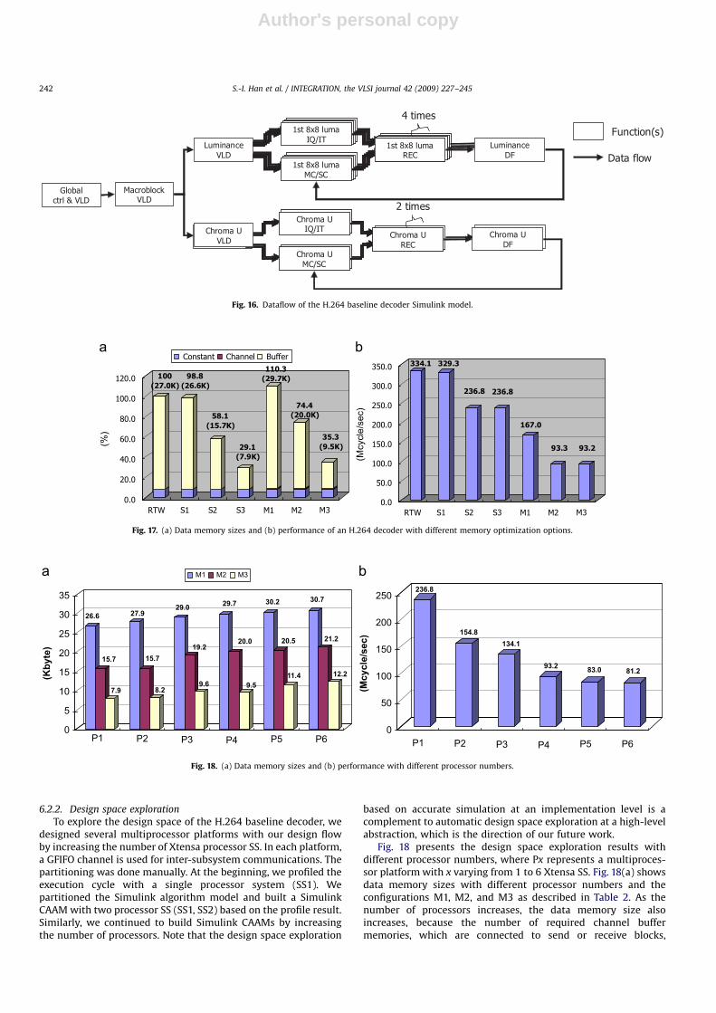
6.2.2. Design space exploration
To explore the design space of the H.264 baseline decoder, wedesigned several multiprocessor platforms with our design flowby increasing the number of Xtensa processor SS. In each platform,a GFIFO channel is used for inter-subsystem communications. Thepartitioning was done manually. At the beginning, we profiled theexecution cycle with a single processor system (SS1). Wepartitioned the Simulink algorithm model and built a SimulinkCAAM with two processor SS (SS1, SS2) based on the profile result.Similarly, we continued to build Simulink CAAMs by increasingthe number of processors. Note that the design space exploration
based on accurate simulation at an implementation level is acomplement to automatic design space exploration at a high-levelabstraction, which is the direction of our future work.
Fig. 18 presents the design space exploration results withdifferent processor numbers, where Px represents a multiproces-sor platform with x varying from 1 to 6 Xtensa SS. Fig. 18(a) showsdata memory sizes with different processor numbers and theconfigurations M1, M2, and M3 as described in Table 2. As thenumber of processors increases, the data memory size alsoincreases, because the number of required channel buffermemories, which are connected to send or receive blocks,
ARTICLE IN PRESS
Fig. 16. Dataflow of the H.264 baseline decoder Simulink model.
Fig. 17. (a) Data memory sizes and (b) performance of an H.264 decoder with different memory optimization options.
0
50
100
150
200
250
0
5
10
15
20
25
30
35
P1
M1 M2 M3
(Kby
te)
(Mcy
cle/
sec)
P2 P3 P4 P5 P6 P1 P2 P3 P4 P5 P6
26.6 27.929.0 29.7 30.2 30.7
15.7 15.719.2
20.0 20.5 21.2
7.9 8.29.6 9.5
11.4 12.2
236.8
154.8134.1
93.2 83.0 81.2
Fig. 18. (a) Data memory sizes and (b) performance with different processor numbers.
S.-I. Han et al. / INTEGRATION, the VLSI journal 42 (2009) 227–245242
Author's personal copy
increases and adds complication to the channel data structure Fig.18(b) presents the performance for each platform with configura-tion M3, showing the number of cycles required to decode 30frames of the QCIF H.264 stream. The multiprocessor platformwith six Xtensa SS (P6) shows 2.91 times faster performancecompared with single processor platform (P1). From the designspace exploration, we found that VLD parts (global, macroblock,luminance, and chrominance VLD in Fig. 16) limit the performancebecause they are sequential, and it does not pay to add extraprocessors.
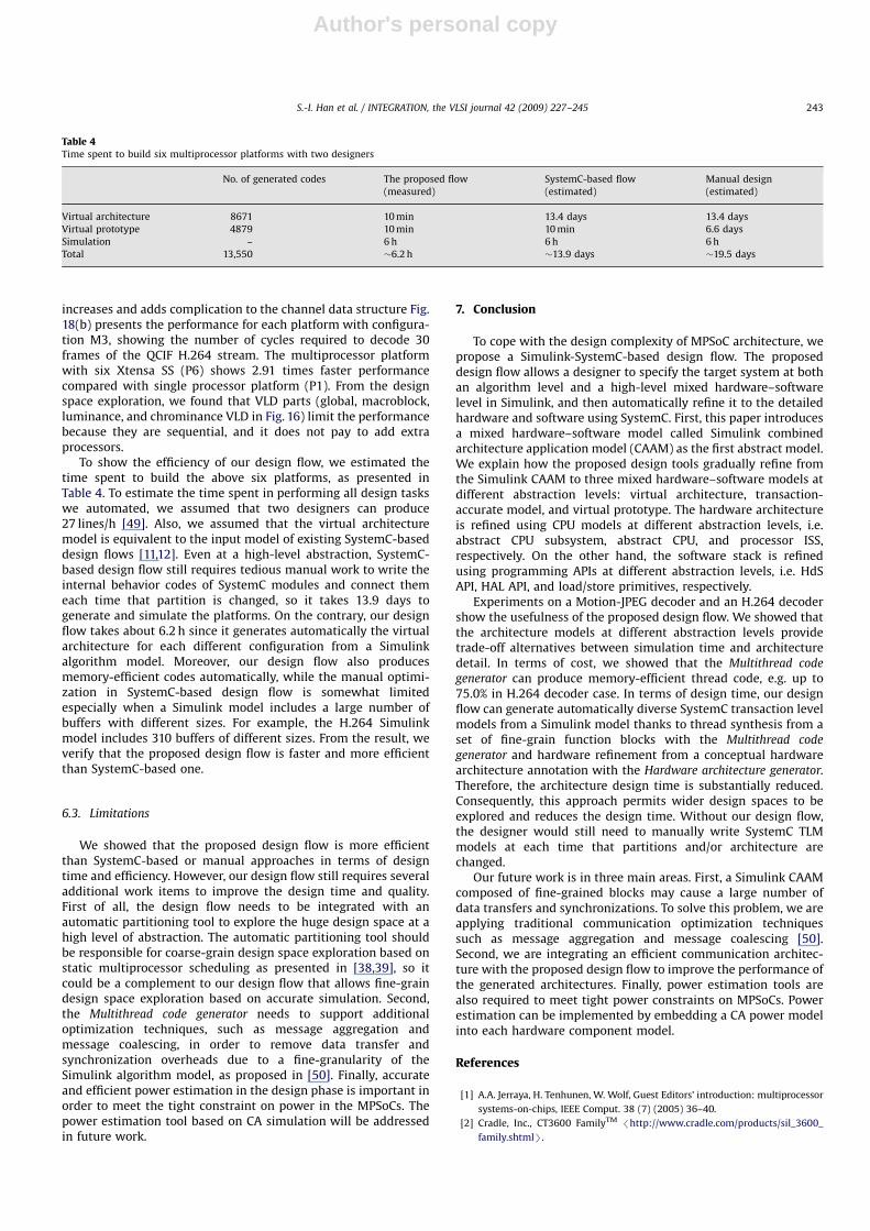
To show the efficiency of our design flow, we estimated thetime spent to build the above six platforms, as presented inTable 4. To estimate the time spent in performing all design taskswe automated, we assumed that two designers can produce27 lines/h [49]. Also, we assumed that the virtual architecturemodel is equivalent to the input model of existing SystemC-baseddesign flows [11,12]. Even at a high-level abstraction, SystemC-based design flow still requires tedious manual work to write theinternal behavior codes of SystemC modules and connect themeach time that partition is changed, so it takes 13.9 days togenerate and simulate the platforms. On the contrary, our designflow takes about 6.2 h since it generates automatically the virtualarchitecture for each different configuration from a Simulinkalgorithm model. Moreover, our design flow also producesmemory-efficient codes automatically, while the manual optimi-zation in SystemC-based design flow is somewhat limitedespecially when a Simulink model includes a large number ofbuffers with different sizes. For example, the H.264 Simulinkmodel includes 310 buffers of different sizes. From the result, weverify that the proposed design flow is faster and more efficientthan SystemC-based one.
6.3. Limitations
We showed that the proposed design flow is more efficientthan SystemC-based or manual approaches in terms of designtime and efficiency. However, our design flow still requires severaladditional work items to improve the design time and quality.First of all, the design flow needs to be integrated with anautomatic partitioning tool to explore the huge design space at ahigh level of abstraction. The automatic partitioning tool shouldbe responsible for coarse-grain design space exploration based onstatic multiprocessor scheduling as presented in [38,39], so itcould be a complement to our design flow that allows fine-graindesign space exploration based on accurate simulation. Second,the Multithread code generator needs to support additionaloptimization techniques, such as message aggregation andmessage coalescing, in order to remove data transfer andsynchronization overheads due to a fine-granularity of theSimulink algorithm model, as proposed in [50]. Finally, accurateand efficient power estimation in the design phase is important inorder to meet the tight constraint on power in the MPSoCs. Thepower estimation tool based on CA simulation will be addressedin future work.
7. Conclusion
To cope with the design complexity of MPSoC architecture, wepropose a Simulink-SystemC-based design flow. The proposeddesign flow allows a designer to specify the target system at bothan algorithm level and a high-level mixed hardware–softwarelevel in Simulink, and then automatically refine it to the detailedhardware and software using SystemC. First, this paper introducesa mixed hardware–software model called Simulink combinedarchitecture application model (CAAM) as the first abstract model.We explain how the proposed design tools gradually refine fromthe Simulink CAAM to three mixed hardware–software models atdifferent abstraction levels: virtual architecture, transaction-accurate model, and virtual prototype. The hardware architectureis refined using CPU models at different abstraction levels, i.e.abstract CPU subsystem, abstract CPU, and processor ISS,respectively. On the other hand, the software stack is refinedusing programming APIs at different abstraction levels, i.e. HdSAPI, HAL API, and load/store primitives, respectively.
Experiments on a Motion-JPEG decoder and an H.264 decodershow the usefulness of the proposed design flow. We showed thatthe architecture models at different abstraction levels providetrade-off alternatives between simulation time and architecturedetail. In terms of cost, we showed that the Multithread code
generator can produce memory-efficient thread code, e.g. up to75.0% in H.264 decoder case. In terms of design time, our designflow can generate automatically diverse SystemC transaction levelmodels from a Simulink model thanks to thread synthesis from aset of fine-grain function blocks with the Multithread code
generator and hardware refinement from a conceptual hardwarearchitecture annotation with the Hardware architecture generator.Therefore, the architecture design time is substantially reduced.Consequently, this approach permits wider design spaces to beexplored and reduces the design time. Without our design flow,the designer would still need to manually write SystemC TLMmodels at each time that partitions and/or architecture arechanged.
Our future work is in three main areas. First, a Simulink CAAMcomposed of fine-grained blocks may cause a large number ofdata transfers and synchronizations. To solve this problem, we areapplying traditional communication optimization techniquessuch as message aggregation and message coalescing [50].Second, we are integrating an efficient communication architec-ture with the proposed design flow to improve the performance ofthe generated architectures. Finally, power estimation tools arealso required to meet tight power constraints on MPSoCs. Powerestimation can be implemented by embedding a CA power modelinto each hardware component model.
References
[1] A.A. Jerraya, H. Tenhunen, W. Wolf, Guest Editors’ introduction: multiprocessor
systems-on-chips, IEEE Comput. 38 (7) (2005) 36–40.
[2] Cradle, Inc., CT3600 FamilyTM /http://www.cradle.com/products/sil_3600_
family.shtmlS.
ARTICLE IN PRESS
Table 4Time spent to build six multiprocessor platforms with two designers
No. of generated codes The proposed flow
(measured)
SystemC-based flow
(estimated)
Manual design
(estimated)
Virtual architecture 8671 10 min 13.4 days 13.4 days
Virtual prototype 4879 10 min 10 min 6.6 days
Simulation – 6 h 6 h 6 h
Total 13,550 �6.2 h �13.9 days �19.5 days
S.-I. Han et al. / INTEGRATION, the VLSI journal 42 (2009) 227–245 243
Author's personal copy
[3] IBM, Inc., CellTM /http://www-128.ibm.com/developerworks/power/cell/S.[4] Cisco, Inc. CRS-1 carrier router system /http://newsroom.cisco.com/dlls/
innovators/index.htmlS.[5] D. Culler, J.P. Singh, A. Gupta, Parallel Computer Architecture: A Hardware/
Software Approach, Morgan Kaufmann, Los Altos, CA, 1998.[6] A.A. Jerraya, A. Bouchhima, F. Petrot, Programming models and HW–SW
interfaces abstraction for multi-processor SoC, in: Proceedings of the DesignAutomation Conference (DAC), San Francisco, July 2006, ACM Press, New York,NY, pp. 280–285.
[7] K. Keutzer, A.R. Newton, J.M. Rabaey, A. Sangiovanni-Vincentelli, System-leveldesign: orthogonalization of concerns and platform-based design, IEEETransactions on Computer-Aided Design of Integrated Circuits and Systems19 (12) (2000) 1523–1543.
[8] A.A. Jerraya, W. Wolf, Hardware/software interface codesign for embeddedsystems, Computer 38 (2005) 63–69.
[9] T. Grotker, S. Liao, G. Martin, S. Swan, System Design with SystemC, KluwerAcademic Publishers, Dordrecht, 2002.
[10] Open SystemC Initiative, available at /http://www.systemc.org/S.[11] W. Cesario, D. Lyonnard, G. Nicolescu, Y. Paviot, Y. Sungjoo, A.A. Jerraya, L.
Gauthier, M. Diaz-Nava, Multiprocessor SoC platforms: a component-baseddesign approach, IEEE Des. Test Comput. 19 (2002) 52–63.
[12] J.-Y. Brunel, W.M. Kruijtzer, H.J.H.N. Kenter, F. Petrot, L. Pasquier, E.A. de Kock,W.J.M. Smits, COSY Communication IP’s, in: Proceedings of the DesignAutomation Conference (DAC), Los Angeles, CA, United States, June 2000./http://ieeexplore.ieee.org/xpl/freeabs_all.jsp?arnumber=855345S.
[13] Mathworks, Inc. /http://www.mathworks.com/products/simulink/S.[14] S.-I. Han, G. Guerin, S.-I. Chae, A.A. Jerraya, Buffer memory optimization for
video codec application modeled in Simulink, in: Proceedings of the DesignAutomation Conference (DAC), San Francisco, ACM Press, New York, July 2006,pp. 689–694.
[15] Dspace, Inc. RTI-MP /http://www.dspaceinc.com/ww/en/inc/home/products/sw/impsw/rtimpblo.cfmS.
[16] Xilinx, Inc., System Generator /http://www.xilinx.com/S.[17] Altera, Inc. DSP Builder /http://www.altera.com/S.[18] J. Ou, V.K. Prasanna, Design space exploration using arithmetic level
hardware–software co-simulation for configurable multi-processor plat-forms, ACM Trans. Embed. Comput. Syst. 2 (3) (2005) 111–137.
[19] T. Kempf, M. Doerper, R. Leupers, G. Ascheid, H. Meyr, T. Kogel, B.Vanthournout, A modular simulation framework for spatial and temporal taskmapping onto multi-processor SoC platforms, in: Proceedings of the Design,Automation and Test in Europe Conference and Exhibition (DATE), 2005.
[20] Coware, Inc. ConvergenSC /http://www.coware.com/S.[21] Summit Design, Inc., Visual Elite ESC /http://www.summit-design.com/
products/ve_system_design.htmlS.[22] Synopsys, Inc., Virtio /http://www.synopsys.com/S.[23] ARM, Inc. RealView MaxSim /http://www.arm.com/products/DevTools/Max-
Sim.htmlS.[24] Ptolemy Project, 2006 /http://ptolemy.eecs.berkeley.edu/S.[25] S. Ha, C. Lee, Y. Yi, S. Kwon, Y.-P. Joo, Hardware–software codesign of
multimedia embedded systems: the PeaCE, in: Proceedings of the IEEEInternational Embedded Real-Time Computing Systems and Applications,2006, pp. 207–214.
[26] Y. Yi, D. Kim, S. Ha, Virtual synchronization technique with OS modeling forfast and time-accurate cosimulation, in: Proceedings of the Design, Automa-tion and Test in Europe (DATE), Munich, Germany, ACM Press, New York, NY,USA, 2003, pp. 1–6.
[27] S. Yoo, G. Nicolescu, L. Gauthier, A.A. Jerraya, Automatic generation of fasttimed simulation models for operating system in SoC design, in: Proceedingsof the Design, Automation and Test in Europe (DATE), Paris, France, March2002, pp. 620–627.
[28] H. Oh, S. Ha, Memory-optimized software synthesis from dataflow programgraphs with large size data samples, EURASIP Journal on Applied SignalProcessing (2003) 514–529.
[29] G. Kahn, D.B. Macqueen, Coroutines and networks of parallel processes, in: B.Gilchrist (Ed.), Information Processing, vol. 77, Proceedings, Toronto, Canada,1977, pp. 993–998.
[30] A.D. Pimentel, L.O. Hertzberger, P. Lieverse, P.V.D. Wolf, E.F. Deprettere,Exploring embedded-systems architectures with artemis, IEEE Comput. 34(11) (2001) 57–63.
[31] B.K. Dwivedi, A. Kumar, M. Balakrishnan, Automatic synthesis of system onchip multiprocessor architectures for process networks, in: Proceedings of theInternational Conference on Hardware/Software Codesign and SystemSynthesis, Sweden, 2004.
[32] M. Thompson, H. Nikolov, T. Stefanov, A.D. Pimentel, C. Erbas, S. Polstra, E.F.Deprettere, A framework for rapid system-level exploration, synthesis, andprogramming of multimedia MP-SoCs, in: Proceedings of the IEEE/ACMInternational Conference on Hardware/Software Codesign and SystemSynthesis, 2007, pp. 9–14.
[33] A.D. Pimentel, C. Erbas, S. Polstra, A systematic approach to exploringembedded system architectures at multiple abstraction levels, IEEE Trans.Comput. 55 (2) (2006) 99–112.
[34] H. Nikolov, T. Stefanov, E. Deprettere, Multi-processor system design withESPAM, in: Proceedings of the International Conference on HW/SW Codesignand System Synthesis (CODES-ISSS), 2006, pp. 211–216.
[35] Object Management Group (OMG), Unified modeling language version 2.0,2004.
[36] T. Kangas, P. Kukkala, H. Orsila, E. Salminen, M. Hannikainen, T.D.Hamalainen, J. Riihimaki, K. Kuusilinna, UML-based multiprocessorSoC design framework, ACM Trans. Embed. Comput. Syst. 5 (2) (2006)281–320.
[37] S. Mohanty, V.K. Prasanna, Rapid system-level performance evaluation andoptimization for application mapping onto SoC architectures, in: IEEEInternational ASIC/SOC Conference, 2002.
[38] R.P. Dick, N.K. Jha, MOGAC: a multiobjective genetic algorithm for hard-ware–software cosynthesis of distributed embedded systems, IEEE Trans.Comput.-Aided Des. Integr. Circuits Syst. 17 (10) (1999) 920–935.
[39] H. Oh, S. Ha, A static scheduling heuristic for heterogeneous processors, in:Proceedings of the Second International EuroPar Conference Proceedings, vol.2, Lyon, France, 1996.
[40] P.K. Murthy, S.S. Bhattacharyya, Shared buffer implementations of signalprocessing systems using lifetime analysis techniques, IEEE Trans. Comput.-Aided Des. Integr. Circuits Syst. 20 (2) (2001) 177–198.
[41] S. Ritz, M. Willems, H. Meyr, Scheduling for optimum data memorycompaction in block diagram oriented software synthesis, in: Proceedingsof the International Conference on Acoustics, Speech, and Signal Processing(ICASSP), Detroit, vol. 4, May 1995, pp. 2651–2653.
[42] F. Balasa, F. Catthoor, H. De Man, Background memory area estimation formultidimensional signal processing systems, IEEE Trans. Comput.-Aided Des.Integr. Circuits Syst. 3 (2) (1995) 157–172.
[43] K. Huang, S.-I. Han, K. Popovici, L. Brisolara, X. Guerin, L. Li, X. Yan, S.-I. Chae,A. Jerraya, L. Carro, Simulink-based MPSoC design flow: case study of motion-JPEG and H.264, in: Proceedings of the 44th ACM/IEEE Design AutomationConference (DAC), San Diego, June 2007, pp. 39–42.
[44] W. Cesario, G. Nicolescu, L. Gauthier, D. Lyonnard, A.A. Jerraya, Colif: a designrepresentation for application-specific multiprocessor SoC, IEEE Des. TestComput. 18 (2) (2001) 18–20.
[45] Tensilica, Inc., Xtensa V /http://www.tensilica.com/S.[46] A. Isotton, 2006. C++ dlopen mini HOWTO /http://tldp.org/HOWTO/C++-dlo-
pen/index.htmlS.[47] G.K. Wallace, The JPEG still picture compression standard, Commun. ACM 34
(4) (1991) 34–43.[48] T. Wiegand, G.J. Sullivan, G. Bjntegaard, A. Luthra, Overview of the H.264/AVC
video coding standard, IEEE Trans. Circuits Syst. Video Technol. 13 (7) (2003)560–576.
[49] W.A. Wood, W.L. Kleb, Exploring XP for scientific research, IEEE Software 20(3) (2003) 30–36.
[50] P. Banerjee, J.A. Chandy, M. Gupta, E.W. Hodges IV, J.G. Holm, A. Lain, D.J.Palermo, S. Ramaswamy, E. Su, The paradigm compiler for distributed-memory multicomputers, IEEE Comput. 28 (10) (1995) 37–47.
Sang-Il Han received the B.S., M.S., and Ph.D. degreesin electrical engineering from the Seoul NationalUniversity, Seoul, Korea, in 1999, 2001, and 2008,respectively. He is currently with the SoC Division, GCTsemiconductor, Seoul, Korea. His research interestsinclude the electronic system level (ESL) designmethodologies, communication architecture design,and high-performance multimedia system design.
Soo-Ik Chae received the B.S. and M.S. degrees inelectrical engineering from the Seoul National Uni-versity, Seoul, Korea, in 1976 and 1978, respectively,and the Ph.D. degree in electrical engineering fromStanford University, Stanford, California, in 1987. Hewas an Instructor in the Electronics Department, KoreaAir-force Academy, from 1978 to 1982. He worked as aManager in the ASIC design group of ZyMOS Corpora-tion and Daewoo Telecom from 1987 to 1990. He joinedthe Inter-University Semi-conductor Research Centerand the Department of Electrical Engineering, SeoulNational University. His research interests are ultra-low-energy circuits, VLSI system designs, multi-media
system design, and system level design methodology. He is also a member of theIEEE.
Lisane Brisolara is graduated from the CatholicUniversity of Pelotas in Computer Science in 1999.She received the M.Sc and Dr. degrees from the FederalUniversity of Rio Grande do Sul, UFRGS, Brazil, in 2002and 2007, respectively, all in Computer Science. She ispresently a professor at the Computer Science Depart-ment at the Federal University of Pelotas (UFPel), incharge of Software Engineering and InformationSystems disciplines at the undergraduate levels. Herresearch interests include embedded systems model-ing, design, validation, automation and test, andembedded software development.
ARTICLE IN PRESS
S.-I. Han et al. / INTEGRATION, the VLSI journal 42 (2009) 227–245244

Author's personal copy
Luigi Carro received the Dr. degree from the Uni-versidade Federal do Rio Grande do Sul (UFRGS), Brazil,in 1996 after a period working at ST-Microelectronics(1989 to 1991), Agrate, Italy, in the R&D group. He ispresently a professor at the Applied InformaticsDepartment at the Informatics Institute of UFRGS. Hisprimary research interests include embedded systemsdesign, validation, automation and test, fault tolerancefor future technologies, and rapid system prototyping.He has advised more than 20 graduate students(Master and Dr. levels). He has published more than150 technical papers on those topics and is the authorof the book ‘‘Digital Systems Design and Prototyping
(2001—in Portuguese) and co-author of Fault-Tolerance Techniques for SRAM-based FPGAs (2006—Springer).
Katalin Popovici received her Engineer Degree inComputer Science from the University of Oradea,Romania in 2004 and her Ph.D. in Micro and NanoElectronics from the Grenoble Institute of Technology,France in 2008. Her research interests include systemlevel modeling and design of MPSoC, programmingmodels, and code generation for embedded multi-media applications. Dr. Katalin Popovici joined TheMathworks, Inc. in April 2008, where she is working asSenior Software Engineer in the Simulink Core devel-opment team.
Xavier Guerin received an M.S. degree in ComputerScience from the Universite Joseph Fourier, Grenoble,France, and is currently a third-year doctorate studentat the SLS Group of the TIMA Laboratory, Grenoble,France. His research interests include Operating Sys-tem architecture, parallel computation, and embeddedsoftware design.
Ahmed Jerraya graduated from the University of Tunisin 1980 and the ‘‘Docteur Ingenieur,’’ and the ‘‘Docteurd’Etat’’ degrees from the University of Grenoble in 1983and 1989, respectively, all in computer sciences. FromApril 1990 to March 1991, he was a Member of theScientific Staff at Nortel in Canada. Dr. Jerraya got thegrade of Research Director within CNRS (FrenchNational Research Center). He was General Chair forDATE Conference in 2001. He is the Director of StrategicDesign Programs at CEA-LETI one of the largestEuropean nanoelectronics research institutes.
Kai Huang was born in November 1980. He receivedBSEE from Nanchang University, China, in 2002. Thenhe obtained Ph.D. in Engineering Circuit and Systemfrom Zhejiang University, China in 2008. Since Sep-tember 2008, he worked as post-Ph.D. in institute ofVLSI design of Zhejiang University. His researchinterests include processor and SoC system-level de-sign methodology and platform.
Lei LI received the Ph.D. degree in Electronic Systemsfrom Zhejiang University in 2007. He was with theinstitute of VLSI design, Zhejiang University and nowhe is affiliated with STMicroelectronics as a designengineer. His research interests include communica-tion systems between multiprocessors, security datatransfer for networks on chip, information encryption/decryption algorithms, and digital circuit design.
Xiaolang Yan was born in January 1947. He obtainedBSEE and MSEE from Zhejiang University, China, in1968 and 1981, respectively. From September 1993 toMay 1994, he was a Visiting Scholar at StanfordUniversity, Palo Alto, CA, USA. From 1994 to 1999, Hewas a professor and dean of Hangzhou Institute ofElectronic Engineering, Hangzhou, China. From Octo-ber 1999 to present, he was a professor, dean ofInformation Science and Engineering College, anddirector of Institute of VLSI Design, Zhejiang University.Prof. Yan’s current research interests include VLSI/SoCdesign, IC design methodology, and design for manu-facturability.
ARTICLE IN PRESS
S.-I. Han et al. / INTEGRATION, the VLSI journal 42 (2009) 227–245 245
Related Documents