International Journal of Scientific & Engineering Research, Volume 7, Issue 2, February-2016 1212 ISSN 2229-5518 IJSER © 2016 http://www.ijser.org Simulation of Four Stroke Internal Combustion Engine Asad Islam 1 , M.Umer Sohail 2 , Syed Mudassir Ali 3 , Ammar-ul-Hassan 4 , Roman Kalvin 5 Abstract— The aim of this paper is to study Premixed combustion computationally via variations in pressure, temperature, velocity and its associated varying swirl ratio in single cylinder during four strokes i.e., (Intake, Compression, Power and Exhaust). The model (single cylinder with one intake and exhaust valve) was generated using ANSYS Design Modeller, was meshed and simulated for Spark Ignition premixed combustion in FLUENT using k-℮ turbulence model. The geometry has the specifications of Bore, Stroke, Connecting rod length, Cylinder capacity, Clearance volume and Speed of 68.5mm, 72.4mm, 165mm, 266.67cc, 29.63cc and 1500rpm respectively. Index Terms— Premixed Combustion, Single cylinder, Spark Ignition, Four Strokes, k-℮ turbulence model, ANSYS Fluent, Design Modeller. —————————— —————————— 1 INTRODUCTION The CFD simulation and analysis of the Internal tion Engines is of considerate importance as far as the manufacturing is concerned. One can easily visualize the contours of velocity during the intake, compression, expansion and exhaust strokes. Furthermore, the trend of parameters like pressure, temperature and their derived param- eters like brake power, indicated power and brake work vs time can be easily understood at different engine speeds before it goes to manufacturing phase. The object of this investigation is to show the working and calculation of brake power by means of a CFD approach. The Otto cycle engine is guarded by restricting the amount of air-fuel mixture entering the cylinder during the intake stroke. The air-fuel ratio is kept steady at any load. The conven- tional method of accomplishing this is to use a single throttle valve in the carburettor. At a constant engine speed, the throttle valve at full load is wide open and the pressure in the intake manifold is near atmospheric. When the throttle valve is gradu- ally closed the output of the engine decreases because of the smaller amount of mixture entering the cylinder. At the same time the pressure in the intake manifold is de- creased and at very low load, this pressure can be far below atmospheric, while the pressure at the end of the exhaust stroke in the cylinder is always close to atmospheric. When the intake valve opens, a higher pressure exists in the cylinder than in the intake manifold and the relatively high-pressure residual gas expands into the intake manifold. Later, as the piston moves downward on the intake stroke, additional work has to be done in order to draw back these exhaust gases into the cylinder before the fresh charge can enter the cylinder. The entire suction stroke of the engine then occurs at the low manifold pressure and the negative work area in a pressure-volume diagram is accordingly large. The intake process of the theoretical Otto cycle for a throt- tled multicylinder engine is shown by path A-I-B-C in Figure 1. In a single cylinder Otto cycle engine the conditions at low load are much better because the pressure in the manifold may build up to atmospheric pressure between the suction strokes and there is no pressure dissimilarity between intake manifold and cylinder when the intake valve opens. Consequently residual gas does not expand into the intake manifold and the pressure in the cylinder decreases gradually during the suction stroke,, The corresponding process is shown by path A-II-B-C, in Figure 1. Compared with the multicylinder engine there is a saving in pumping work proportional to the crosshatched area. By using individual throttle valves for each cylinder of a multicylinder engine, similar conditions as in the single cylin- der engine are obtained. It is expected, that the volume (Vm) between the regular intake valve and the throttle valve controls the saving of pumping work* (See Figure 2) T ———————————————— • 1 Asad Islam has masters degree in Aerospace Engineering from IST, Pakistan, E-mail: [email protected] • 2 M.Umer Sohail is currently pursuing PhD degree program in Aerospace Engineering from IST, Pakistan, E-mail: [email protected] • 3 Syed Mudassir Ali is currently pursuing masters degree program in Mechanical Engineering from NUST, Pakistan E-mail: [email protected] • 4 Ammar-ul-Hassan 5 Roman Kalvin, are pursuing masters degree program in Mechanical Engineering from WEC, Pakistan IJSER

Welcome message from author
This document is posted to help you gain knowledge. Please leave a comment to let me know what you think about it! Share it to your friends and learn new things together.
Transcript
International Journal of Scientific & Engineering Research, Volume 7, Issue 2, February-2016 1212 ISSN 2229-5518
IJSER © 2016 http://www.ijser.org
Simulation of Four Stroke Internal Combustion Engine
Asad Islam1, M.Umer Sohail2, Syed Mudassir Ali3,
Ammar-ul-Hassan4, Roman Kalvin5
Abstract— The aim of this paper is to study Premixed combustion computationally via variations in pressure, temperature, velocity and its associated varying swirl ratio in single cylinder during four strokes i.e., (Intake, Compression, Power and Exhaust). The model (single cylinder with one intake and exhaust valve) was generated using ANSYS Design Modeller, was meshed and simulated for Spark Ignition premixed combustion in FLUENT using k-℮ turbulence model. The geometry has the specifications of Bore, Stroke, Connecting rod length, Cylinder capacity, Clearance volume and Speed of 68.5mm, 72.4mm, 165mm, 266.67cc, 29.63cc and 1500rpm respectively.
Index Terms— Premixed Combustion, Single cylinder, Spark Ignition, Four Strokes, k-℮ turbulence model, ANSYS Fluent, Design Modeller.
—————————— ——————————
1 INTRODUCTION The CFD simulation and analysis of the Internal tion Engines is of considerate importance as far as the manufacturing is concerned. One can easily visualize the contours of velocity during the intake, compression,
expansion and exhaust strokes. Furthermore, the trend of parameters like pressure, temperature and their derived param-eters like brake power, indicated power and brake work vs time can be easily understood at different engine speeds before it goes to manufacturing phase. The object of this investigation is to show the working and calculation of brake power by means of a CFD approach. The Otto cycle engine is guarded by restricting the amount of air-fuel mixture entering the cylinder during the intake stroke. The air-fuel ratio is kept steady at any load. The conven-tional method of accomplishing this is to use a single throttle valve in the carburettor. At a constant engine speed, the throttle valve at full load is wide open and the pressure in the intake manifold is near atmospheric. When the throttle valve is gradu-ally closed the output of the engine decreases because of the smaller amount of mixture entering the cylinder.
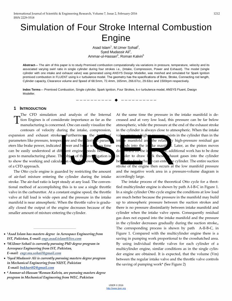
At the same time the pressure in the intake manifold is de-creased and at very low load, this pressure can be far below atmospheric, while the pressure at the end of the exhaust stroke in the cylinder is always close to atmospheric. When the intake valve opens, a higher pressure exists in the cylinder than in the intake manifold and the relatively high-pressure residual gas expands into the intake manifold. Later, as the piston moves downward on the intake stroke, additional work has to be done in order to draw back these exhaust gases into the cylinder before the fresh charge can enter the cylinder. The entire suction stroke of the engine then occurs at the low manifold pressure and the negative work area in a pressure-volume diagram is accordingly large. The intake process of the theoretical Otto cycle for a throt-tled multicylinder engine is shown by path A-I-B-C in Figure 1. In a single cylinder Otto cycle engine the conditions at low load are much better because the pressure in the manifold may build up to atmospheric pressure between the suction strokes and there is no pressure dissimilarity between intake manifold and cylinder when the intake valve opens. Consequently residual gas does not expand into the intake manifold and the pressure in the cylinder decreases gradually during the suction stroke,, The corresponding process is shown by path A-II-B-C, in Figure 1. Compared with the multicylinder engine there is a saving in pumping work proportional to the crosshatched area. By using individual throttle valves for each cylinder of a multicylinder engine, similar conditions as in the single cylin-der engine are obtained. It is expected, that the volume (Vm) between the regular intake valve and the throttle valve controls the saving of pumping work* (See Figure 2)
T
————————————————
• 1Asad Islam has masters degree in Aerospace Engineering from IST, Pakistan, E-mail: [email protected]
• 2M.Umer Sohail is currently pursuing PhD degree program in Aerospace Engineering from IST, Pakistan, E-mail: [email protected]
• 3Syed Mudassir Ali is currently pursuing masters degree program in Mechanical Engineering from NUST, Pakistan E-mail: [email protected]
• 4 Ammar-ul-Hassan 5Roman Kalvin, are pursuing masters degree program in Mechanical Engineering from WEC, Pakistan
IJSER
International Journal of Scientific & Engineering Research, Volume 7, Issue 2, February-2016 1213 ISSN 2229-5518
IJSER © 2016 http://www.ijser.org
Figure 1 Theoretically throtlled Otto Cycle
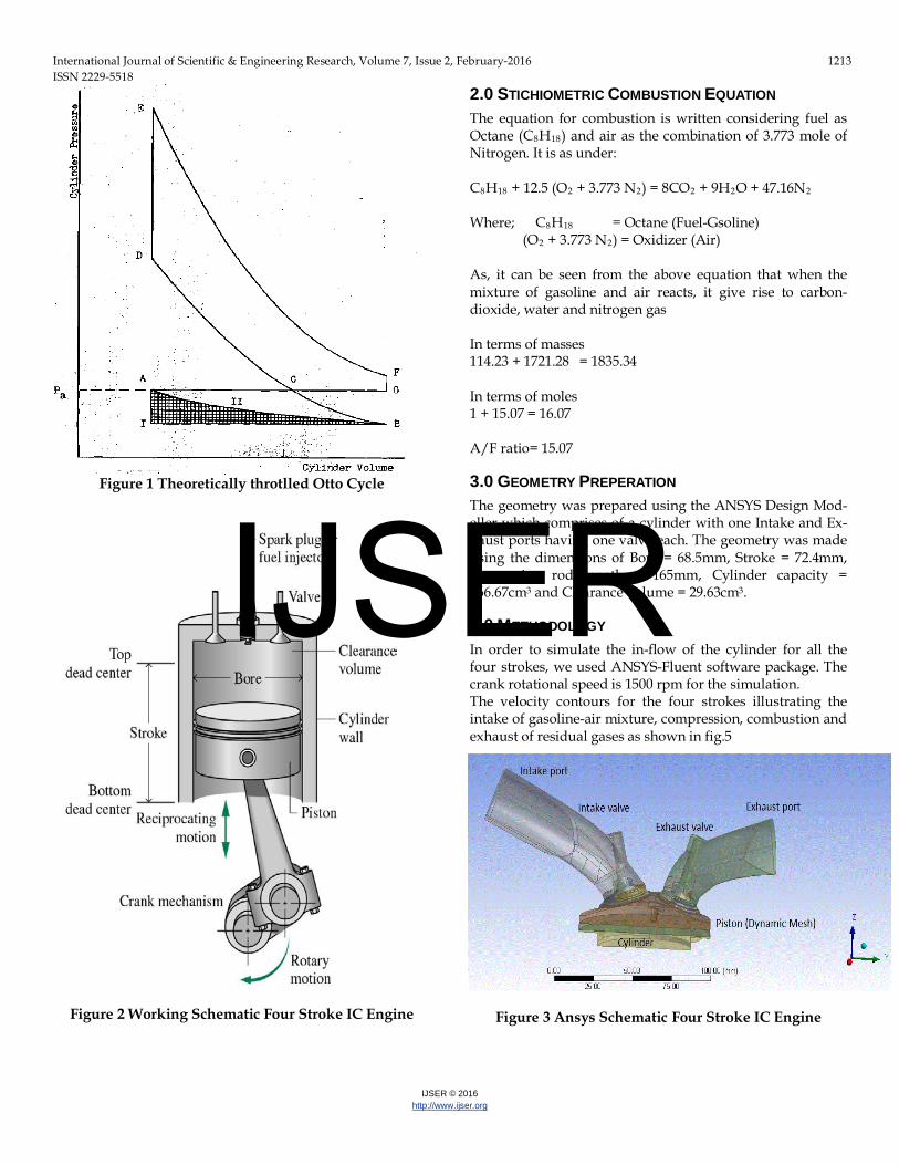
Figure 2 Working Schematic Four Stroke IC Engine
2.0 STICHIOMETRIC COMBUSTION EQUATION The equation for combustion is written considering fuel as Octane (C8H18) and air as the combination of 3.773 mole of Nitrogen. It is as under: C8H18 + 12.5 (O2 + 3.773 N2) = 8CO2 + 9H2O + 47.16N2 Where; C8H18 = Octane (Fuel-Gsoline)
(O2 + 3.773 N2) = Oxidizer (Air) As, it can be seen from the above equation that when the mixture of gasoline and air reacts, it give rise to carbon-dioxide, water and nitrogen gas In terms of masses 114.23 + 1721.28 = 1835.34 In terms of moles 1 + 15.07 = 16.07 A/F ratio= 15.07
3.0 GEOMETRY PREPERATION The geometry was prepared using the ANSYS Design Mod-eller which comprises of a cylinder with one Intake and Ex-haust ports having one valve each. The geometry was made using the dimensions of Bore = 68.5mm, Stroke = 72.4mm, Connecting rod length = 165mm, Cylinder capacity = 266.67cm3 and Clearance volume = 29.63cm3.
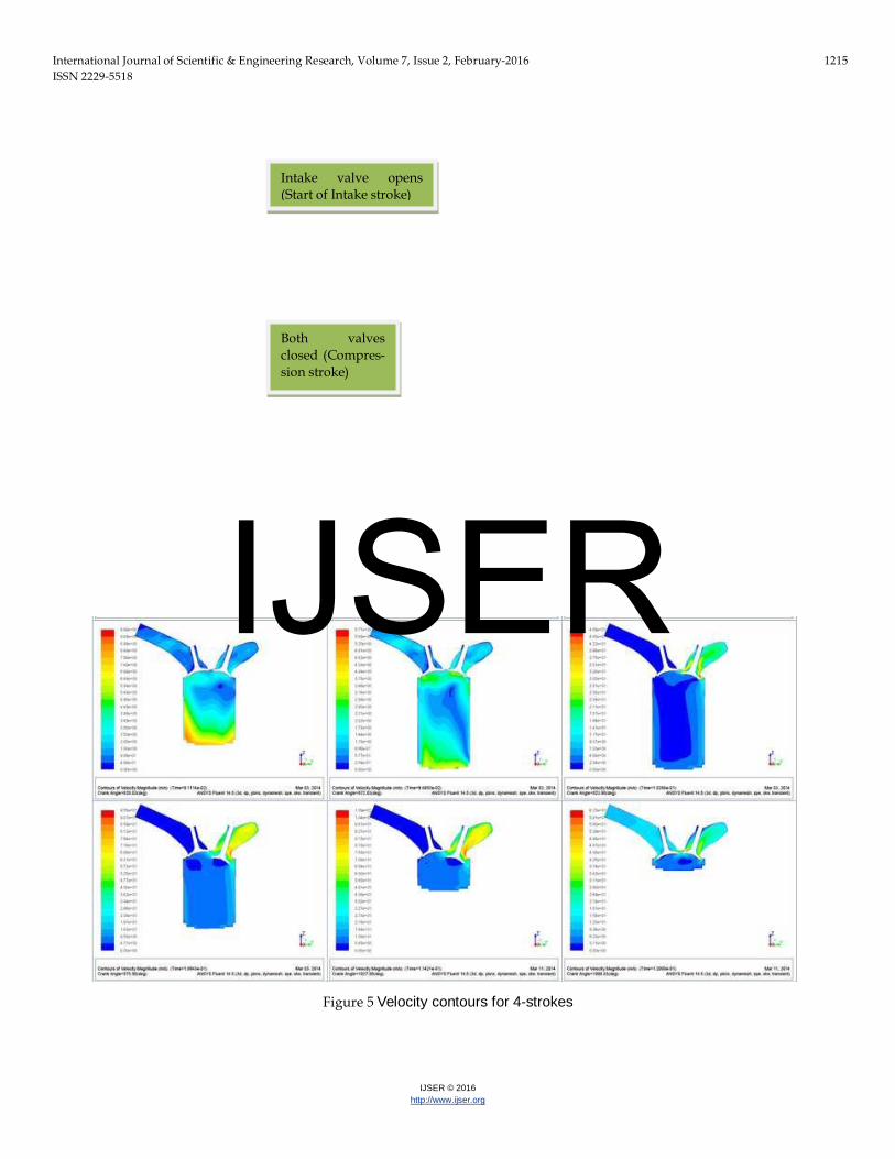
4.0 METHODOLOGY In order to simulate the in-flow of the cylinder for all the four strokes, we used ANSYS-Fluent software package. The crank rotational speed is 1500 rpm for the simulation. The velocity contours for the four strokes illustrating the intake of gasoline-air mixture, compression, combustion and exhaust of residual gases as shown in fig.5
Figure 3 Ansys Schematic Four Stroke IC Engine
IJSER
International Journal of Scientific & Engineering Research, Volume 7, Issue 2, February-2016 1214 ISSN 2229-5518
IJSER © 2016 http://www.ijser.org
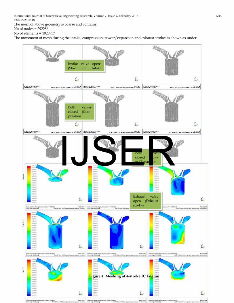
The mesh of above geometry is coarse and contains: No of nodes = 292286 No of elements = 1028957 The movement of mesh during the intake, compression, power/expansion and exhaust strokes is shown as under:
Figure 4: Meshing of 4-stroke IC Engine
Intake valve opens (Start of Intake
Both valves closed (Com-pression
Both valves closed (Pow-er/Expansion
Exhaust valve open (Exhaust stroke)
IJSER
International Journal of Scientific & Engineering Research, Volume 7, Issue 2, February-2016 1215 ISSN 2229-5518
IJSER © 2016 http://www.ijser.org
Figure 5 Velocity contours for 4-strokes
Intake valve opens (Start of Intake stroke)
Both valves closed (Compres-sion stroke)
IJSER
International Journal of Scientific & Engineering Research, Volume 7, Issue 2, February-2016 1216 ISSN 2229-5518
IJSER © 2016 http://www.ijser.org
5.0 RESULTS AND DISCUSSION The energy equation solved in CFD-simulation process results into the following graphs of pressure, temperature, brake work, brake power and indicated power. The crank angles are divided as (360 degree -540 degree) Intake stroke, (540 degree -720 de-gree) Compression stroke, (720 degree -900 degree) Expansion/Power stroke and (900 degree -1080 degree) Exhaust stroke
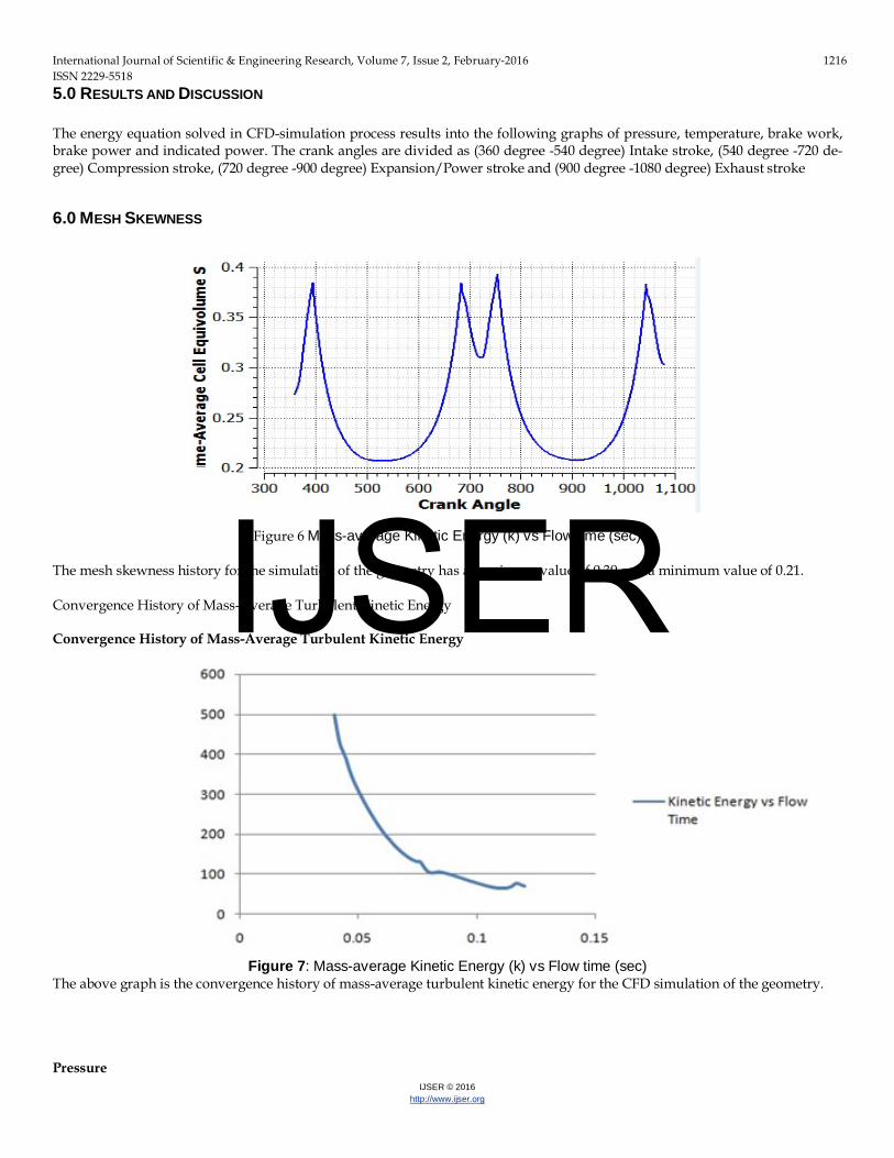
6.0 MESH SKEWNESS
Figure 6 Mass-average Kinetic Energy (k) vs Flow time (sec)
The mesh skewness history for the simulation of the geometry has a maximum value of 0.39 and a minimum value of 0.21. Convergence History of Mass-Average Turbulent Kinetic Energy Convergence History of Mass-Average Turbulent Kinetic Energy
Figure 7: Mass-average Kinetic Energy (k) vs Flow time (sec) The above graph is the convergence history of mass-average turbulent kinetic energy for the CFD simulation of the geometry. Pressure
IJSER
International Journal of Scientific & Engineering Research, Volume 7, Issue 2, February-2016 1217 ISSN 2229-5518
IJSER © 2016 http://www.ijser.org
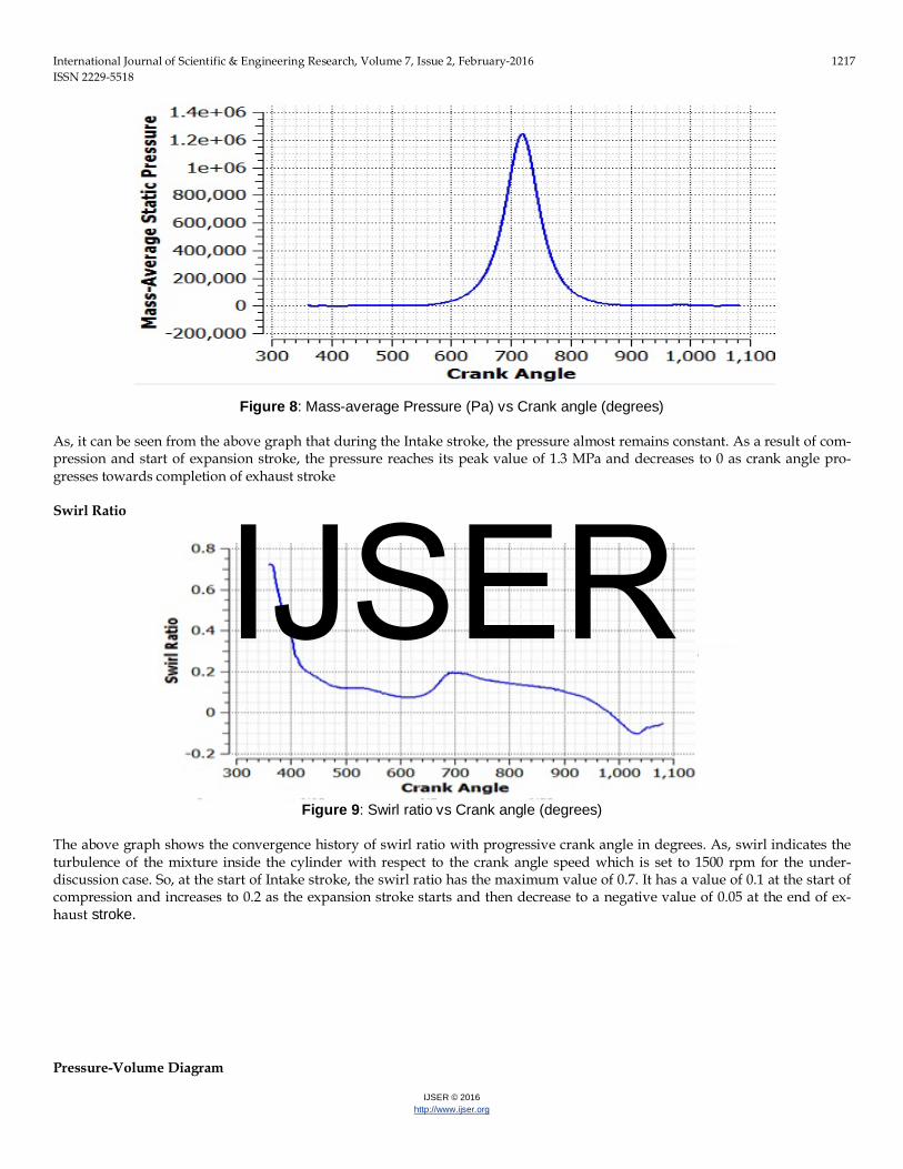
Figure 8: Mass-average Pressure (Pa) vs Crank angle (degrees)
As, it can be seen from the above graph that during the Intake stroke, the pressure almost remains constant. As a result of com-pression and start of expansion stroke, the pressure reaches its peak value of 1.3 MPa and decreases to 0 as crank angle pro-gresses towards completion of exhaust stroke Swirl Ratio
Figure 9: Swirl ratio vs Crank angle (degrees)
The above graph shows the convergence history of swirl ratio with progressive crank angle in degrees. As, swirl indicates the turbulence of the mixture inside the cylinder with respect to the crank angle speed which is set to 1500 rpm for the under-discussion case. So, at the start of Intake stroke, the swirl ratio has the maximum value of 0.7. It has a value of 0.1 at the start of compression and increases to 0.2 as the expansion stroke starts and then decrease to a negative value of 0.05 at the end of ex-haust stroke. Pressure-Volume Diagram
IJSER
International Journal of Scientific & Engineering Research, Volume 7, Issue 2, February-2016 1218 ISSN 2229-5518
IJSER © 2016 http://www.ijser.org
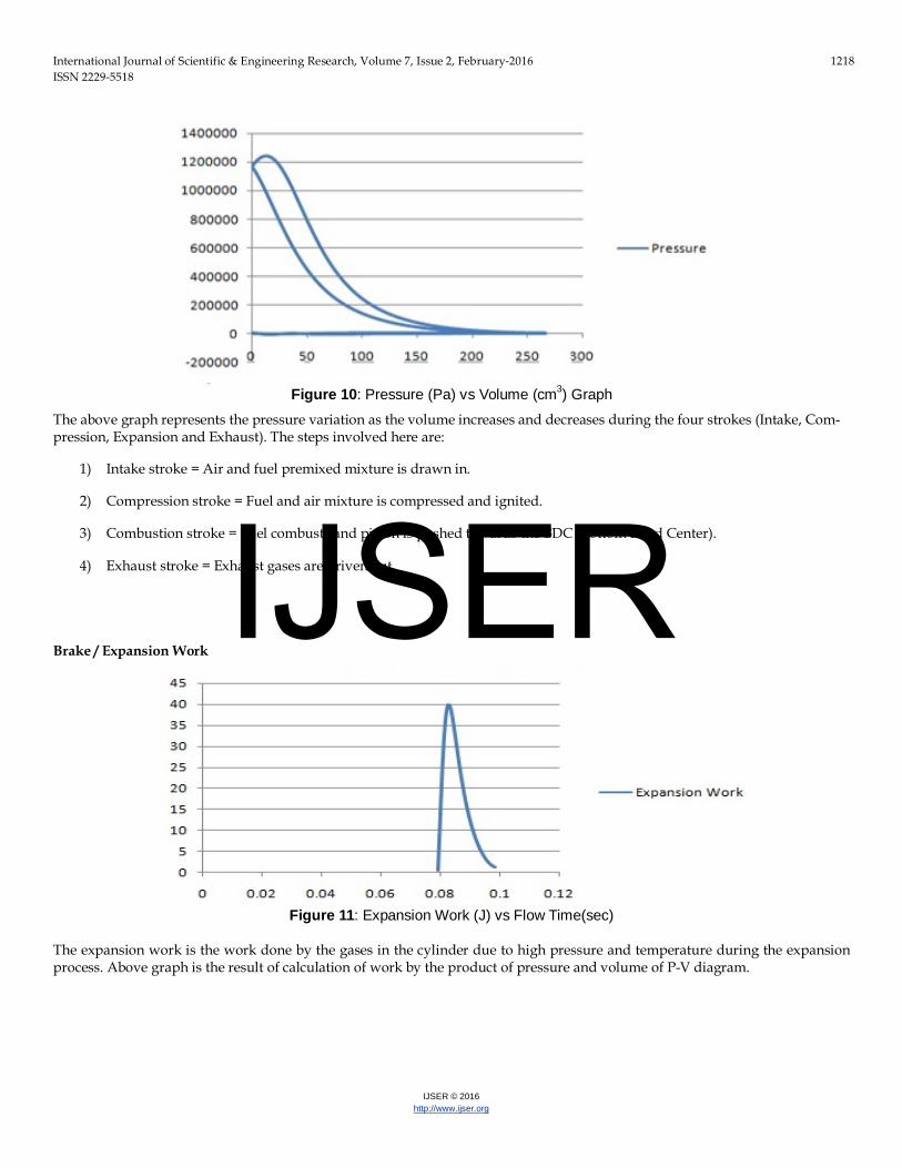
Figure 10: Pressure (Pa) vs Volume (cm3) Graph
The above graph represents the pressure variation as the volume increases and decreases during the four strokes (Intake, Com-pression, Expansion and Exhaust). The steps involved here are:
1) Intake stroke = Air and fuel premixed mixture is drawn in.
2) Compression stroke = Fuel and air mixture is compressed and ignited.
3) Combustion stroke = Fuel combusts and piston is pushed towards the BDC (Bottom Dead Center).
4) Exhaust stroke = Exhaust gases are driven out. Brake / Expansion Work
Figure 11: Expansion Work (J) vs Flow Time(sec)
The expansion work is the work done by the gases in the cylinder due to high pressure and temperature during the expansion process. Above graph is the result of calculation of work by the product of pressure and volume of P-V diagram.
IJSER
International Journal of Scientific & Engineering Research, Volume 7, Issue 2, February-2016 1219 ISSN 2229-5518
IJSER © 2016 http://www.ijser.org
Brake Power
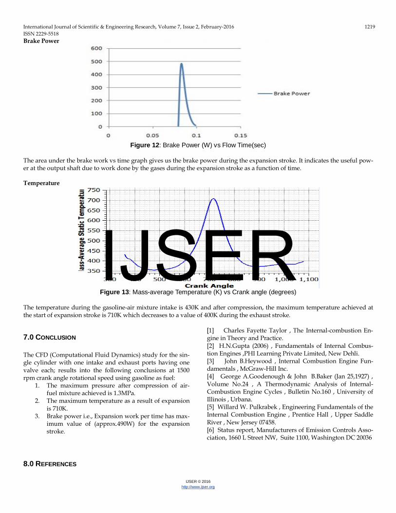
Figure 12: Brake Power (W) vs Flow Time(sec) The area under the brake work vs time graph gives us the brake power during the expansion stroke. It indicates the useful pow-er at the output shaft due to work done by the gases during the expansion stroke as a function of time. Temperature
Figure 13: Mass-average Temperature (K) vs Crank angle (degrees)
The temperature during the gasoline-air mixture intake is 430K and after compression, the maximum temperature achieved at the start of expansion stroke is 710K which decreases to a value of 400K during the exhaust stroke.
7.0 CONCLUSION The CFD (Computational Fluid Dynamics) study for the sin-gle cylinder with one intake and exhaust ports having one valve each; results into the following conclusions at 1500 rpm crank angle rotational speed using gasoline as fuel:
1. The maximum pressure after compression of air-fuel mixture achieved is 1.3MPa.
2. The maximum temperature as a result of expansion is 710K.
3. Brake power i.e., Expansion work per time has max-imum value of (approx.490W) for the expansion stroke.
8.0 REFERENCES
[1] Charles Fayette Taylor , The Internal-combustion En-gine in Theory and Practice. [2] H.N.Gupta (2006) , Fundamentals of Internal Combus-tion Engines ,PHI Learning Private Limited, New Dehli. [3] John B.Heywood , Internal Combustion Engine Fun-damentals , McGraw-Hill Inc. [4] George A.Goodenough & John B.Baker (Jan 25,1927) , Volume No.24 , A Thermodynamic Analysis of Internal-Combustion Engine Cycles , Bulletin No.160 , University of Illinois , Urbana. [5] Willard W. Pulkrabek , Engineering Fundamentals of the Internal Combustion Engine , Prentice Hall , Upper Saddle River , New Jersey 07458. [6] Status report, Manufacturers of Emission Controls Asso-ciation, 1660 L Street NW, Suite 1100, Washington DC 20036
IJSER
Related Documents