Sudan University of Science and Technology College of Engineering Electrical Engineering Simulation of Electrical Power Plant Protection Using ETAP اكا طة توليد كهربائية اية ة بإستخدامETAP A project Submitted in partial fulfillment for the requirement of the degree of B.Sc. (honor) in electrical engineering Prepared by: 1. Mohammed Mahadi Yahia Ibrahim 2. Mohammed Ahmed Elhaj Mohammed 3. Loai Hamid Hamdon Jad Allah 4. Abd Allah Alfadil Mohammed Magbol Supervised By: Dr. Alfadil Zakria Yahia October 2020

Welcome message from author
This document is posted to help you gain knowledge. Please leave a comment to let me know what you think about it! Share it to your friends and learn new things together.
Transcript
Sudan University of Science and Technology
College of Engineering
Electrical Engineering
Simulation of Electrical Power
Plant Protection Using ETAP ة محاية حمطة توليد كهربائية حماكا
ETAPبإستخدام
A project Submitted in partial fulfillment for the requirement
of the degree of B.Sc. (honor) in electrical engineering
Prepared by:
1. Mohammed Mahadi Yahia Ibrahim
2. Mohammed Ahmed Elhaj Mohammed
3. Loai Hamid Hamdon Jad Allah
4. Abd Allah Alfadil Mohammed Magbol
Supervised By:
Dr. Alfadil Zakria Yahia
October 2020
I
اآلية

II
Dedication
To who give our lifes meaning
To our fathers and mothers
To our sisters and brothers
To all researchers who are working to improve the quality of life
To all of them we dedicate this work
III
ACKNOWLEDGEMENTS
We own our deepest gratitude to our advisor, Dr.Al fadil Zakria , for
his invaluable support in getting us started on this project, his constant
generosity in providing the necessary advices to do the work.
We would also like to appreciate all staff members of Department
Electrical Engineering, we really enjoyed to be taught by them in different
subjects.
We would also like to acknowledge all members of Electrical Services
Company especially Mr.Gaafar Khair Allah for his constant support
during preparation of this thesis..
IV
Abstract
The main goal of this thesis is to simulate Electric power generation
network because this network faced by blackouts several times this led to
severe lack of production during blackout times specially when great
amount of load from substations trip or one or more of on service
generators stop suddenly this thesis find the best generators protection
setting specially for over and under voltage fault protection setting and over
and under frequency faults protection setting by using ETAP (Electrical
Transient and Analysis Program) software as an analysis tool to perform
generators protection setting for three different type of generators using for
Sudan Nuclear Plant and draw the power network and simulate
successfully many faults cases and find best generators protection setting.
The new relay setting coordination had been applied to all relays in the five
main substations as a result from this study.
The sequence of operation is improved and as a result the total black outs
frequency is significantly decreased.
V
المستخلص
أل هز انشبكت نكهشبتاشبكت حىنذ انطالت حات هى يحاكاة ا انششوع انهذف انشئس ي هز
إنى مص شذذ ف اإلخاج أثاء أولاث انخعخى خاصت لذ ؤديواخهج امطاع انخاس انكهشبائ عذة يشاث يا
ىاحذة أو أكثش ي يىنذاث انخذيت انخ حخىلف انعذيا خىلف عذد كبش ي انحطاث انفشعت راث انحىنت
فدأة. بحث هزا انششوع عهى أفضم إعذاد نحات انىنذاث خصىصا إلعذاد انحات ي أعطال اندهذ
PATEذ انخفض وأعطال انخشدد انزائذ وأعطال انخشدد انخفض باسخخذاو بشايح انزائذ وأعطال انده
ىنذاث ان)بشايح انخحهم انكهشبائ انعابش( كأداة ححهم ألداء ضبط حات انىنذاث نثالثت أىاع يخخهفت ي
عطال وإعذاد حسخخذو نحطت انسىدا انىوت وسسى شبكت انكهشباء ويحاكاة انعذذ ي حاالث األسىف
أفضم انطشق نحات انىنذاث. حى حطبك حسك إعذاد انشحالث عهى خع انشحالث ف انحطاث
انفشعت انخست انشئست خدت نهز انذساست. حى ححس حسهسم انعهت ، وخدت نزنك ، اخفض إخان عذد
يشاث انخعخى بشكم يهحىظ.
.
VI
TABLE OF CONTENTS Page
I االت
Dedication II
Acknowledgements III
Abstract (English) IV
Abstract (Arabic) V
List of Contents VI
List of Figures VIII
List of Tables X
CHAPTER ONE: INTRODUCTION
1.1 Overview 1
1.2 Problem statement 2
1.3 Objectives 2
1.4 Methodology 2
1.5 Thesis Layout 3
CHAPTER TWO LITERATURE REVIEW
2.1 Introduction 4
2.2 Overview of electrica
5
2.2.1 Electrical three phase system fault type
5
2.3 Protection component 6
2.3.1 Fuses 7
2.3.2 Relays 7
2.3.3 Protection quality 10
2.4 Zones of protection 10
2.5 Protection quality 12
2.5.1 Discrimination 13
2.5.2 Stability 13
2.5.3 Reliability 14
2.5.4 Speed of operation 14
2.5.5 Sensitivity 15
VII
2.6 Generator protection types 15
2.6.1 Overcurrent protection
15
2.6.2 Earth fault protection 16
2.6.3 differential protection 16
CHAPTER THRE GENERATOR PROTECTION
3.1 Introduction 18
3.2 Electrical circuit of Generator
19
3.2.1 Unit auxiliary transformer 20
3.2.2 Generator grounding 20
3.2.3 Generator excitation 22
3.3 Various Faults and Abnormal Operating Conditions 22
3.4 Stator grounding and Earth Faults 23
3.5 Rotor Faults 26
3.5.1 Rotor earth fault protection methods potentiometer Method
26
3.5.2 Rotor shorted turn Protection 29
3.6 Abnormal Operating Conditions 29
3.6.1 Unbalanced Loading 30
3.6.2 Over voltages Protection 31
3.6.3 Under voltage Protection 32
3.6.4 Losses of excitation 33
3.6.5 Under / Over frequency 35
3.6.6 Over fluxing 36
3.7 Back up Protection of Generator 37
CHAPTER FOUR RESULTS AND DISCUSSION
4.1 Introduction 39
4.2 ETAP Software 39
4.3 Short-Circuit Analysis Module of ETAP 39
4.4 Transient Stability Analysis 41
4.5 Sudan Nuclear Power Plant ETAP Circuit 43
4.6.1 Over frequency test 45
4.6.2 Under frequency test 46
4.6.3 Over voltage test 47
4.6.4 Under voltage test 48
4.6.5 Three phase fault test 50
CHAPTER FIVE CONCLUSION AND RECOMMENDATIONS
VIII
5.1 Conclusion 53
.5.2 Recommendations 53
REFERENCES
55
APPENDIX 56
List of figures
Page
2.1 Nuclear Power Generation 4
2.2
Enrichment Process
5
2.3 Type of faults on a three phase system. 7
2.4 Division of power system in to protection zone 11
2.5 CT locations 12
2.6 Overlapping zones of protection system 12
2.7 Typical Power / Time Relationship for Various Fault Types
14
2.8 Traditional over Current curve 15
2.9 Economical CT arrangement for O /C and E/ F 16
2.10 Machine differential protection 17
2.11 Feeder differential protection 17
3.1 Generation system main connection. 18
3.2 Alternator unit auxiliary transformer and main CB. 20
3.3 Methods of generator grounding 21
3.4 Electrical circuit of the exciter of the generator. 22
3.5 Various electrical faults on a turbo-alternator 23
3.6 Various abnormal operating conditions of a turbo- Alternator
25
3.7 Earth fault protection using a relay to measure
secondary current
25
IX
3.8 Earth fault protection using a relay in parallel with
loading resistor
25
3.9 Potentiometer 27
3.10 AC injection 28
3.11 DC injection 28
3.12 Loss of excitation. 34
4.1 Study Case Editor 40
4.2 Short Circuit Report Manager 41
4.3 transient stability case study editor 42
4.4 Single Line Diagram Generation Power Plant 44
4.5 Over Frequency Condition event When Feeders CB
opened and Over Frequency Protection activated
45
4.6 Over Frequency Condition Frequency/Time graph at
Bus2
45
4.7 Under Frequency Condition event and Frequency Relay
Response
46
4.8 Under Frequency Condition Frequency/Time at Bus1
when the network is connected
47
4.9 Over Voltage Condition event and Over Voltage Relay Response
48
4.10 Over Voltage Condition Voltage/Time Graph at Bus2 48
4.11 Under Voltage Condition event and Over Voltage Relay
Response
49
4.12 Under Voltage Condition Voltage/Time Graph at Bus2 49
4.13 Relays Responses to 3-phase Fault at KEYI-2 outgoing Feeder
50
A.1 Frequency relay setting
A.2 Voltage relay setting
A.3 Over current relay setting
X
List of Tables
Table Title Page
A.1 Frequency relay input data
A.2 Voltage relay input data
1
CHAPTER ONE
INTRODUCTION
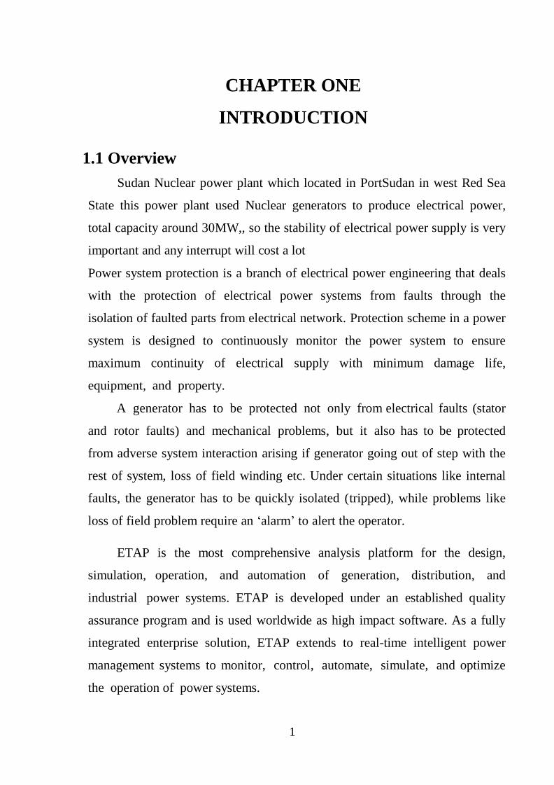
1.1 Overview
Sudan Nuclear power plant which located in PortSudan in west Red Sea
State this power plant used Nuclear generators to produce electrical power,
total capacity around 30MW,, so the stability of electrical power supply is very
important and any interrupt will cost a lot
Power system protection is a branch of electrical power engineering that deals
with the protection of electrical power systems from faults through the
isolation of faulted parts from electrical network. Protection scheme in a power
system is designed to continuously monitor the power system to ensure
maximum continuity of electrical supply with minimum damage life,
equipment, and property.
A generator has to be protected not only from electrical faults (stator
and rotor faults) and mechanical problems, but it also has to be protected
from adverse system interaction arising if generator going out of step with the
rest of system, loss of field winding etc. Under certain situations like internal
faults, the generator has to be quickly isolated (tripped), while problems like
loss of field problem require an „alarm‟ to alert the operator.
ETAP is the most comprehensive analysis platform for the design,
simulation, operation, and automation of generation, distribution, and
industrial power systems. ETAP is developed under an established quality
assurance program and is used worldwide as high impact software. As a fully
integrated enterprise solution, ETAP extends to real-time intelligent power
management systems to monitor, control, automate, simulate, and optimize
the operation of power systems.
2
1.2 Problem Statement
The main purpose of this project is to find best generator setting
parameters due to unstable voltage and frequency on the power grid caused by
high amount of load trip or one or group of generators within parallel
generators trip and simulating protection system of generators using Electrical
power plant generator protection data to help in analyzing the protection system
and find out the best way to protect generators from damage.
1.3 Objectives
The main objective of this thesis is to use ETAP Package in order to
study the effect of disturbances on the generators and describe the form of
protection fitting each disturbance especially voltage and frequency interrupt
on the plant and the implementation of this protection.
1.4 Methodology
The methodology of this thesis under taken as follows:
a) Understanding the previous studies.
b) Read and understanding the generator system and its protection methods
c) Understanding the ETAP software program.
d) Build the proposed system using ETAP software.
e) Evaluate the performance of the proposed system under different
operation condition based on the simulation results.
3
1.5 Thesis layout
This thesis consists of five chapters. Chapter one include overview,
problem statement, objectives and methodology. chapter two will discuss
protection system in general way, Chapter three contains electrical circuit of
generator, various faults, abnormal operating conditions and backup protection
of generator. Chapter four consists simulation results and discussion.
Finally Chapter five includes conclusion and recommendations.
4
CHAPTER TWO
LITERATURE REVIEW
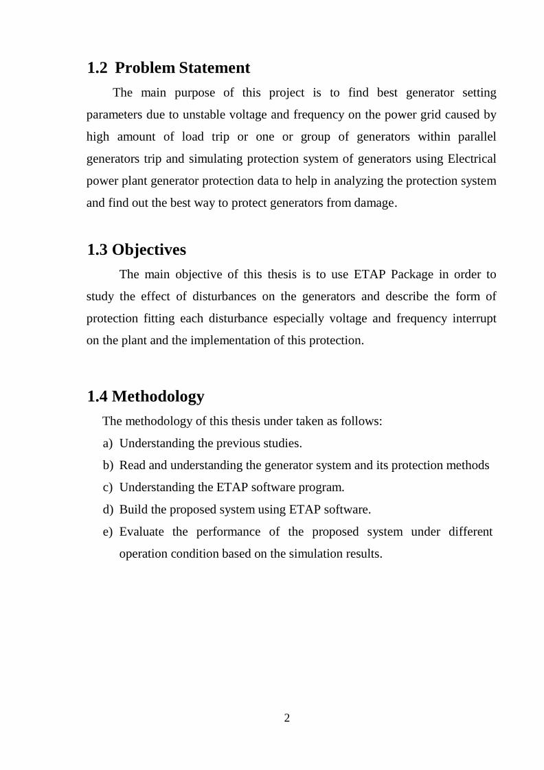
2.1 Introduction
A nuclear reactor produces and controls the release of energy from splitting
the atoms of uranium. Uranium-fuelled nuclear power is a clean and efficient
way of boiling water to make steam which drives turbine generators. Except for
the reactor itself, a nuclear power station works like most coal or gas-fired power
stations.
2.1 Nuclear Power Generation
In a nuclear power plant, many of the components are similar to those in a
fossil-fueled plant, except that the steam boiler is replaced by a Nuclear Steam
Supply System (NSSS). The NSSS consists of a nuclear reactor and all of the
components necessary to produce high pressure steam, which will be used to turn
the turbine for the electrical generator.
Like a fossil-fueled plant, a nuclear power plant boils water to produce
electricity. Unlike a fossil-fueled plant, the nuclear plant‟s energy does not come
from the combustion of fuel, but from the splitting of fuel atoms.
The uranium starts out as ore, and contains a very low percentage (or low
enrichment) of the desired atoms (U-235). The U-235 is a more desirable atom for
fuel, because it is easier to cause the U-235 atoms to fission (split) than the much
more abundant U-238 atoms. Therefore, the fuel fabrication process includes
5
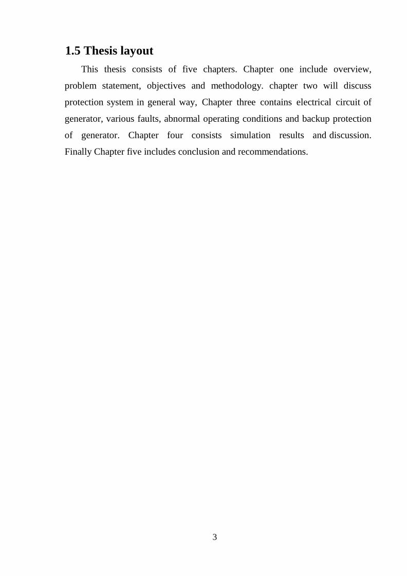
steps to increase the number of U-235 atoms in relation to the number of U-238
atoms (enrichment process).
2.2 Enrichment Process
Once the fuel has been enriched, it is fabricated into ceramic pellets. The
pellets are stacked into 12-foot long, slender metal tubes, generally made of a
zirconium alloy. The tube is called the “fuel cladding.” When a tube is filled with
the uranium pellets, it is pressurized with helium gas, and plugs are installed and
6
welded to seal the tube. The filled rod is called a “fuel rod.” The fuel rods are
bundled together into “fuel assemblies” or “fuel elements.” The completed
assemblies are now ready to be shipped to the plant for installation into the reactor
vessel.
2.2 Overview of electrical fault
Electrical faults usually occur due to breakdown of the insulating media
between live conductors or between a live conductor and earth. This breakdown
may be caused by any one or more of several factors, for example, mechanical
damage, overheating, voltage surges (caused by lightning or switching), ingress of
a conducting medium, ionization of air, and deterioration of the insulating media
due to an unfriendly environment or old age, or misuse of equipment.
Fault currents release an enormous amount of thermal energy, and if not
cleared quickly, may cause fire hazards, extensive damage to equipment and risk
to human life. Faults are classified into two major groups: symmetrical and
unbalanced (asymmetrical). Symmetrical faults involve all three phases and cause
extremely severe fault currents and system disturbances. Unbalanced faults
include phase-to-phase, phase-to-ground, and phase-to-phase-to-ground faults.
They are not as severe as symmetrical faults because not all three phases are
involved. The least severe fault condition is a single phase-to-ground fault with
the transformer neutral earthed through a resistor or reactor. However, if not
cleared quickly, unbalanced faults will usually develop into symmetrical faults.
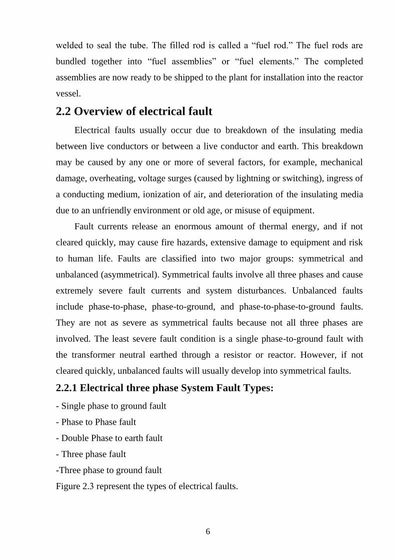
2.2.1 Electrical three phase System Fault Types:
- Single phase to ground fault
- Phase to Phase fault
- Double Phase to earth fault
- Three phase fault
-Three phase to ground fault
Figure 2.3 represent the types of electrical faults.
7
Figure 2.3 Type of faults on a three phase system.
2.3 Protection component
A collection of protection devices (relays, fuses, etc.). Excluded are devices
such as CT‟s, CB‟s, Contactors, etc.
2.3.1 Fuses
Probably the oldest, simplest, cheapest, and most-often used type of
protection device is the fuse. The operation of a fuse is very straightforward: The
thermal energy of the excessive current causes the fuse-element to melt and the
current path is interrupted. Technological developments have made fuses more
predictable, faster, and safer (not to explode) Fuses are very inexpensive and they
can operate totally independently, that is, they do not need a relay with instrument
transformers to tell them when to blow. This makes them especially suitable in
applications like remote ring main units, etc. [1]
2.3.2 Relays
The most versatile and sophisticated type of protection available today, is
undoubtedly the relay/circuit-breaker combination. The relay receives information
regarding the network mainly from the instrument transformers (voltage and
current transformers), detects an abnormal condition by comparing this
information to pre-set values, and gives a tripping command to the circuit-breaker
when such an abnormal condition has been detected. The relay may also be
operated by an external tripping signal, either from other instruments, from a
8
SCADA master, or By human intervention. Relays may be classified according to
the technology used into:
- ELECTROMECHANICAL RELAYS These relays were the earliest forms of relay used for the protection of
power systems, and they date back nearly 100 years. They work on the principle
of a mechanical force causing operation of a relay contact in response to a
stimulus. The mechanical force is generated through current flow in one or more
windings on a magnetic core or cores, hence the term electromechanical relay.
The principle advantage of such relays is that they provide galvanic isolation
between the inputs and outputs in a simple, cheap and reliable form therefore for
simple on/off switching functions where the output contacts have to carry
substantial currents, they are still used. Electromechanical relays can be classified
into several different types as follows:
- Attracted armature
- Moving coil
- Induction
- Thermal
- Motor operated
- Mechanical
- STATIC RELAYS
Introduction of static relays began in the early 1960‟s. Their design is based
on the use of analogue electronic devices instead of coils and magnets to create
the relay characteristic. Early versions used discrete devices such as transistors
and diodes in conjunction with resistors, capacitors, inductors, etc., but advances
in electronics enabled the use of linear and digital integrated circuits in later
versions for signal processing and implementation of logic functions. While basic
circuits may be common to a number of relays, the packaging was still essentially
restricted to a single protection function per case, while complex functions
required several cases of hardware suitably interconnected. User programming
9
was restricted to the basic functions of adjustment of relay characteristic curves.
They therefore can be viewed in simple terms as an analogue electronic
replacement for electromechanical relays, with some additional flexibility in
settings and some saving in space requirements. In some cases, relay burden is
reduced, making for reduced CT/VT output requirements.
- Digital Relays
Digital protection relays introduced a step change in technology.
Microprocessors and microcontrollers replaced analogue circuits used in static
relays to implement relay functions. Early examples began to be introduced into
service around 1980, and, with improvements in processing capacity, can still be
regarded as current technology for many relay applications. However, such
technology will be completely superseded within the next five years by numerical
relays. Compared to static relays, digital relays introduce A/D conversion of all
measured analogue quantities and use a microprocessor to implement the
protection algorithm. The microprocessor may use some kind of counting
technique, or use the Discrete Fourier Transform (DFT) to implement the
algorithm. However, the typical microprocessors used have limited processing
capacity and memory compared to that provided in numerical relays. The
functionality tends therefore to be limited and restricted largely to the protection
function itself. Additional functionality compared to that provided by an
electromechanical or static relay is usually available, typically taking the form of
a wider range of settings, and greater accuracy. A communications link to a
remote computer may also be provided.
- Numerical Relays
The distinction between digital and numerical relay rests on points of fie
technical detail, and is rarely found in areas other than Protection. They can be
viewed as natural developments of digital relays as a result of advances in
technology. Typically, they use a specialized digital signal processor (DSP) as the
computational hardware, together with the associated software tools. The input
10
analogue signals are converted into a digital representation and processed
according to the appropriate mathematical algorithm. Processing is carried out
using a specialized microprocessor that is optimized for signal processing
applications, known as a digital signal processor or DSP for short.
Digital processing of signals in real time requires a very high power
microprocessor. In addition, the continuing reduction in the cost of
microprocessors and related digital devices (memory, I/O, etc.) naturally leads to
an approach where a single item of hardware is used to provide a range of
functions („one-box solution‟ approach). By using multiple microprocessors to
provide the necessary computational performance, a large number of functions
previously implemented in separate items of hardware can now be included
within a single item.
2.3.3 Instrument transformers (CT\VT)
Relays need information from the power network in order to detect an
abnormal condition. This information is obtained via voltage and current
transformers (collectively called instrument transformers), as the normal system
voltages and currents are too high for the relays to handle directly, and the
instrument transformers protect the relay from system
„Spikes‟ to a certain extent.[1]
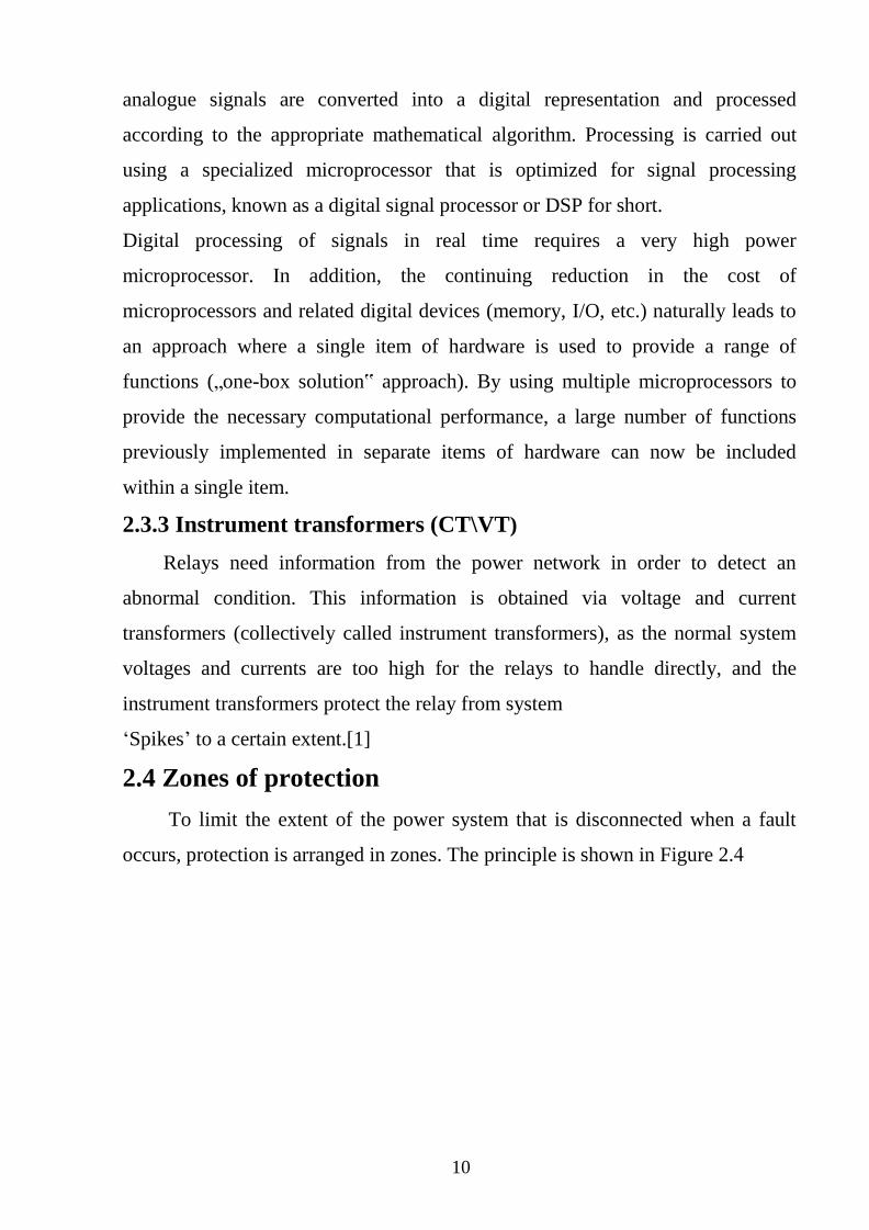
2.4 Zones of protection
To limit the extent of the power system that is disconnected when a fault
occurs, protection is arranged in zones. The principle is shown in Figure 2.4
11
Figure 2.4 Division of Power System into Protection Zone
Ideally, the zones of protection should overlap, so that no part of the power
system is left unprotected. The circuit breaker being included in both zones. For
practical physical and economic reasons, this ideal is not always achieved,
accommodation for current transformers being in some cases available only on
one side of the circuit breakers. This leaves a section between the current
transformers and the circuit breaker that is not completely protected against faults.
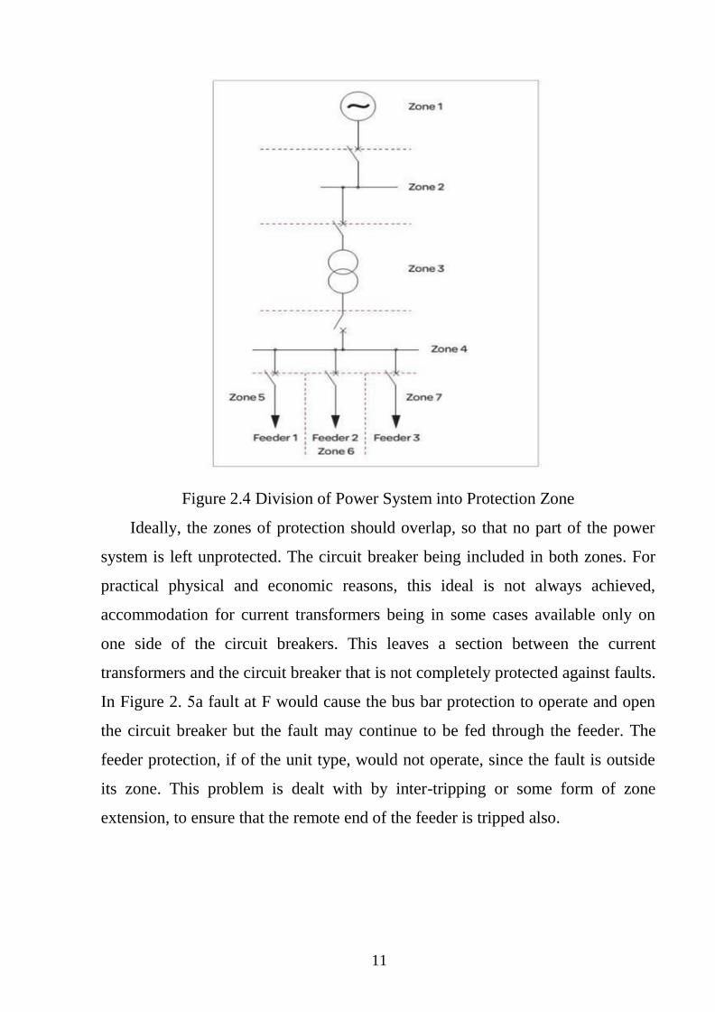
In Figure 2. 5 a fault at F would cause the bus bar protection to operate and open
the circuit breaker but the fault may continue to be fed through the feeder. The
feeder protection, if of the unit type, would not operate, since the fault is outside
its zone. This problem is dealt with by inter-tripping or some form of zone
extension, to ensure that the remote end of the feeder is tripped also.
12
Figure2-5 CT locations
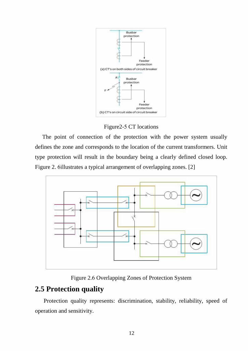
The point of connection of the protection with the power system usually
defines the zone and corresponds to the location of the current transformers. Unit
type protection will result in the boundary being a clearly defined closed loop.
Figure 2. 6 illustrates a typical arrangement of overlapping zones. [2]
Figure 2.6 Overlapping Zones of Protection System
2.5 Protection quality
Protection quality represents: discrimination, stability, reliability, speed of
operation and sensitivity.
13
2.5.1 Discrimination
Discrimination, or selectivity, is the ability of the protection to isolate only the
faulted part of the system, minimizing the impact of the fault on the power
network. Absolute discrimination is only obtained when the protection operates
exclusively within a clearly defined zone. This type of protection is known as
„unit protection‟, as only one unit is exclusively protected for example, a
transformer, or a specific feeder cable. The term „zone protection‟ is also
commonly used. Unit protection can only be achieved when the following
essentials are satisfied:
• Sensing or measuring devices must be installed at each (Electrical) end of the
protected equipment; and • There has to be a means of communication between
the devices at each end, in order to compare electrical conditions and detect a
fault when present.
-The main advantages of unit protection are:
- Only the faulted equipment or part of the network is disconnected, with
minimum disruption to the power network.
- Unit protection operates very fast, limiting damages to equipment and danger to
human life. Fast operation is possible because the presence or absence of a fault is
a very clear-cut case.
- Unit protection is very stable.
- Unit protection is very reliable.
- Unit protection is very sensitive.
-The major disadvantages of unit protection are the following:
- It is very expensive.
- It relies on communication between the relays installed at either end
2.5.2 Stability
Stability, also called security, is the ability of the protection to remain
inoperative for normal load conditions (including normal transients like motor
14
starting). Most stability problems arise from incorrect application of relays and
lack of maintenance.
2.5.3 Reliability
Reliability, or dependability, is the ability of the protection to operate
correctly in case of a fault. Reliability is probably the most important quality of a
protection system
2.5.4 Speed of operation
The longer the fault current is allowed to flow, the greater the damage to
equipment and the higher the risk to personnel. Therefore, protection equipment
has to operate as fast as possible, without compromising on stability. The best
way to achieve this is by applying unit protection schemes. The phase shift
between voltages at different bus bars on the system also increases, and therefore
so does the probability that synchronism will be lost when the system is disturbed
by a fault. The shorter the time a fault is allowed to remain in the system, the
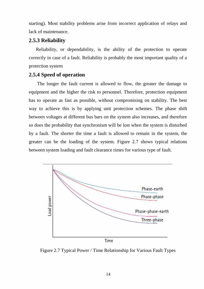
greater can be the loading of the system. Figure 2.7 shows typical relations
between system loading and fault clearance times for various type of fault.
Figure 2.7 Typical Power / Time Relationship for Various Fault Types
15
2.5.5 Sensitivity
The term sensitivity refers to the magnitude of fault current at which
protection operation occurs. A protection relay is said to be sensitive when the
primary operating current is very low. Therefore, the term sensitivity is normally
used in the context of electrical protection for expensive electronic equipment, or
sensitive earth leakage equipment [2]
2.6 Generator protections Types:
-Over current protection
- Earth fault protection
-Differential protection
2.6.1 Over Current Protection
The term “overcurrent” refers to abnormal current flow higher than the normal
value of current flow in an electrical circuit. Uncorrected “overcurrent” can cause
serious safety hazards and costly damage to electrical equipment and property.
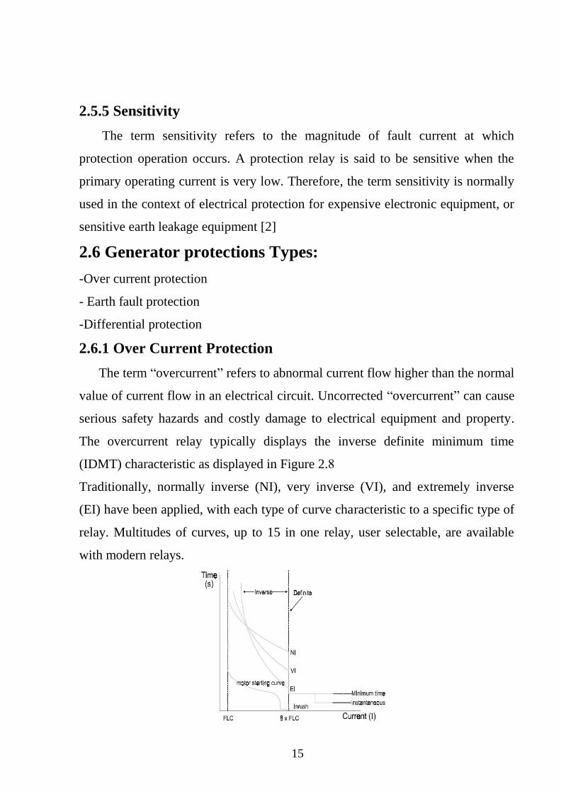
The overcurrent relay typically displays the inverse definite minimum time
(IDMT) characteristic as displayed in Figure 2.8
Traditionally, normally inverse (NI), very inverse (VI), and extremely inverse
(EI) have been applied, with each type of curve characteristic to a specific type of
relay. Multitudes of curves, up to 15 in one relay, user selectable, are available
with modern relays.
16
Figure 2.8 Traditional Over Current Curve
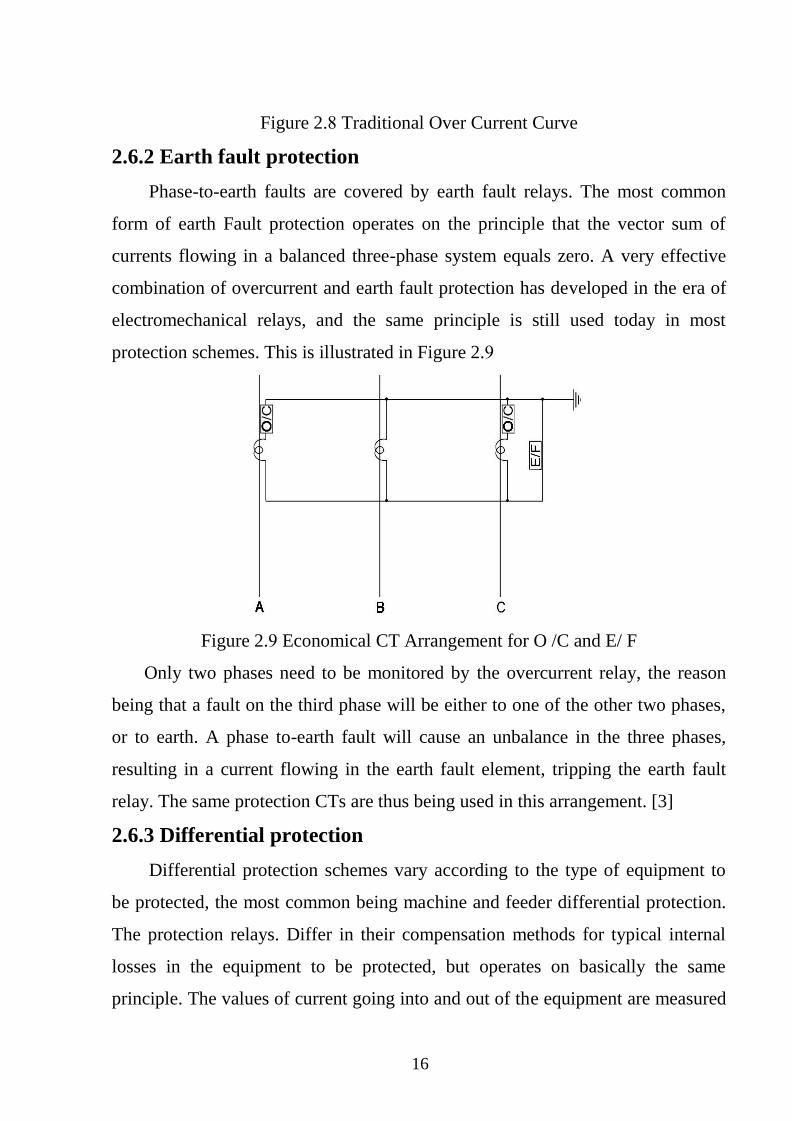
2.6.2 Earth fault protection
Phase-to-earth faults are covered by earth fault relays. The most common
form of earth Fault protection operates on the principle that the vector sum of
currents flowing in a balanced three-phase system equals zero. A very effective
combination of overcurrent and earth fault protection has developed in the era of
electromechanical relays, and the same principle is still used today in most
protection schemes. This is illustrated in Figure 2.9
Figure 2.9 Economical CT Arrangement for O /C and E/ F
Only two phases need to be monitored by the overcurrent relay, the reason
being that a fault on the third phase will be either to one of the other two phases,
or to earth. A phase to-earth fault will cause an unbalance in the three phases,
resulting in a current flowing in the earth fault element, tripping the earth fault
relay. The same protection CTs are thus being used in this arrangement. [3]
2.6.3 Differential protection
Differential protection schemes vary according to the type of equipment to
be protected, the most common being machine and feeder differential protection.
The protection relays. Differ in their compensation methods for typical internal
losses in the equipment to be protected, but operates on basically the same
principle. The values of current going into and out of the equipment are measured
17
and compared. The relay trips if the difference in Current exceeds a pre-set value,
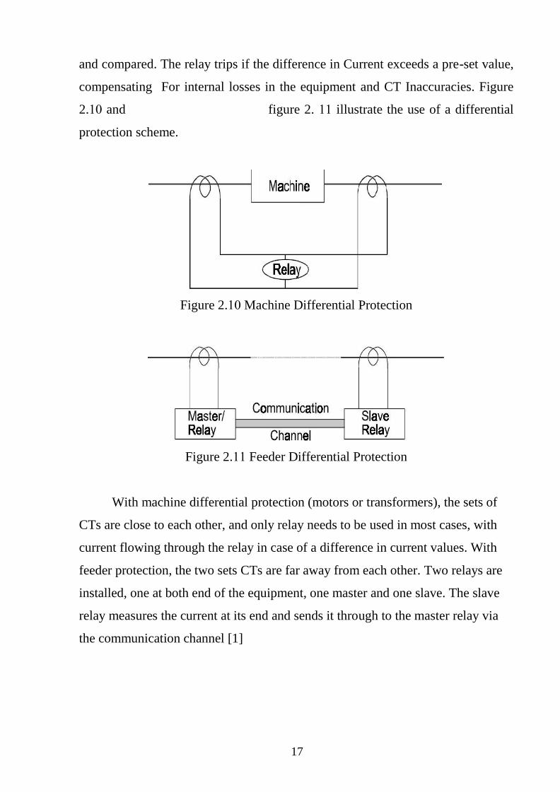
compensating For internal losses in the equipment and CT Inaccuracies. Figure
2.01 and figure 2. 00 illustrate the use of a differential
protection scheme.
Figure 2.01 Machine Differential Protection
Figure 2.00 Feeder Differential Protection
With machine differential protection (motors or transformers), the sets of
CTs are close to each other, and only relay needs to be used in most cases, with
current flowing through the relay in case of a difference in current values. With
feeder protection, the two sets CTs are far away from each other. Two relays are
installed, one at both end of the equipment, one master and one slave. The slave
relay measures the current at its end and sends it through to the master relay via
the communication channel [1]
18
CHAPTER THREE
GENERATOR PROTECTION
3.1 Introduction
A generator is the heart of an electrical power system, as it converts
mechanical energy into its electrical equivalent, which is further distributed at
various voltages. It therefore requires a „prime mover‟ to develop this mechanical
power and this can take the form of steam, gas or water turbines or diesel and gas
engines. Small and medium sized sets may be directly connected to a power
distribution system. A larger set may be associated with an individual transformer,
through which it is coupled to the EHV primary transmission system [2].
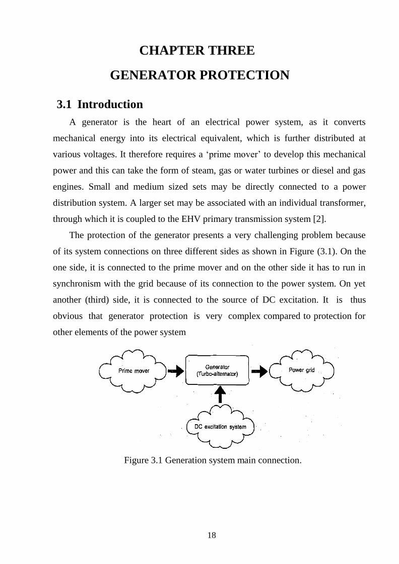
The protection of the generator presents a very challenging problem because
of its system connections on three different sides as shown in Figure (3.1). On the
one side, it is connected to the prime mover and on the other side it has to run in
synchronism with the grid because of its connection to the power system. On yet
another (third) side, it is connected to the source of DC excitation. It is thus
obvious that generator protection is very complex compared to protection for
other elements of the power system
Figure 3.1 Generation system main connection.
19
In the case of a fault on alternator, it is not enough to open the main circuit
breaker or connecting it to the power grid. The high costs associated with large
generating and transforming plants accentuate the need for reliable, high speed
schemes of protection to:
a. Minimize fault damage and so reduce the possible need to replace the plant
(capital outlay).
b. Reduce repair outage time and so minimize the need to run lower merit (less
cost-efficient) plant in order to meet the demand (revenue expenditure).
c. Assist in maintaining system stability.
The degree of protection to be provided for the plant is determined by protection
engineers in consultation with plant designers and system operation engineers, the
objective being to provide a minimum of protection consistent with adequate
coverage of all conditions liable to cause damage or effect continuity of supply.
Before considering in detail the many forms of protection fitted to generators
and transformers, it is desirable to consider the origin and effects of faults and
other system disturbance so that the significance of the protection arrangements
may be appreciated.
3.2 Electrical Circuit of Generator
The electrical circuit of the generator is very simple in spite of the complexity
of the overall system. It is to be noted that the generator is never solidly grounded.
If it were solidly grounded, the single line-to-ground fault current would be
dangerously high apart from the high value of fault current, the resulting
asymmetry in the rotating magnetic field inside the generator would cause
unacceptably large vibration and result mechanical damage to the rotor .Hence, in
order to limit the short circuit, the neutral of the generator is grounded through a
resistance. In order to get a practicable value of the grounding resistor connected
through a step-down transformer, known as grounding transformer [3].
20
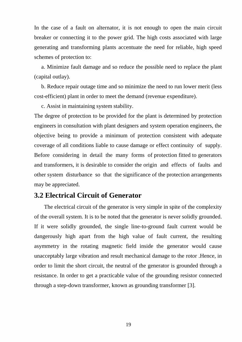
3.2.1 Unit auxiliary transformer
The power plant has a sizeable auxiliary electrical load of its own, of
the order of 10% of the power rating of the generator, which is supplied
through the Unit Auxiliary Transformer (UAT). It is to be noted that these
auxiliaries require power even before the generator can be started, run up to
speed and synchronized with the grid. Hence, there is the switching facility to
energize the UAT directly from the grid [3]
Figure 3.2 show the alternator UAT and main circuit breaker.
Figure 3.2 Alternator unit auxiliary transformer and main CB.
3.2.2 Generator grounding
The neutral point of a generator is usually earthed to facilitate protection
of the stator winding and associated system. Grounding also prevents
damaging transient over-voltages in the event of an arcing earth fault or fero-
resonance. For High Voltage (HV) generators, impedance is usually inserted in
the stator grounding connection to limit the magnitude of earth fault current.
There is a wide variation in the earth fault current chosen, common values
being:
1. Rated current.
2. 200A-400A (low impedance grounding).
21
3. 10A-20A (high impedance grounding).
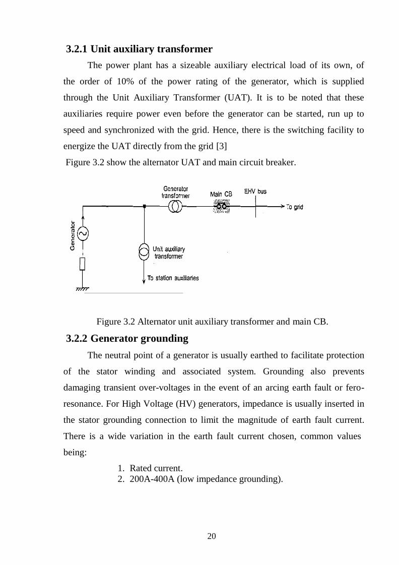
The main methods of impedance-grounding a generator are shown in
Figure 3.3. Low values of earth fault current may limit the damage caused
from a fault, but they simultaneously make detection of a fault towards the
stator winding star point more difficult. Except for special applications, such as
marine, Low Voltage LV generators are normally solidly earthed to comply
with safety requirements. Where a step-up transformer is applied, the generator
and the lower voltage winding of the transformer can be treated as an isolated
system that is not influenced by the grounding requirements of the power
system [1].The main methods of grounding are :
Machine stator windings are surrounded by a mass of earthed metal.
Most probable result of stator winding insulation failure is a phase-earth
fault.
Desirable to earth neutral point of generator to prevent dangerous
transient over voltages during arcing earth fault.
(c)Transformer grounding
Figure 3.3: Methods of generator grounding
22
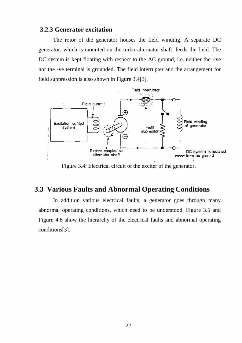
3.2.3 Generator excitation
The rotor of the generator houses the field winding. A separate DC
generator, which is mounted on the turbo-alternator shaft, feeds the field. The
DC system is kept floating with respect to the AC ground, i.e. neither the +ve
nor the -ve terminal is grounded. The field interrupter and the arrangement for
field suppression is also shown in Figure 3.4[3].
Figure 3.4: Electrical circuit of the exciter of the generator.
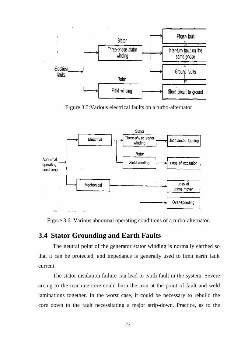
3.3 Various Faults and Abnormal Operating Conditions
In addition various electrical faults, a generator goes through many
abnormal operating conditions, which need to be understood. Figure 3.5 and
Figure 4.6 show the hierarchy of the electrical faults and abnormal operating
conditions[3].
23
Figure 3.5:Various electrical faults on a turbo-alternator
Figure 3.6: Various abnormal operating conditions of a turbo-alternator.
3.4 Stator Grounding and Earth Faults
The neutral point of the generator stator winding is normally earthed so
that it can be protected, and impedance is generally used to limit earth fault
current.
The stator insulation failure can lead to earth fault in the system. Severe
arcing to the machine core could burn the iron at the point of fault and weld
laminations together. In the worst case, it could be necessary to rebuild the
core down to the fault necessitating a major strip-down. Practice, as to the
24
degree of limitation of the earth fault current varies from rated load current to
low values such as 5A.Fault caused by failure of stator winding insulation
Leads to:
Burning of machine core
Welding of laminations
Rebuilding of machine core can be a very expensive process. Generators
connected direct to the distribution network are usually earthed through a
resistor. However, the larger generator–transformer unit (which can be
regarded as isolated from the EHV transmission system) is normally earthed
through the primary winding of a voltage transformer, the secondary winding
being loaded with a low ohmic value resistor. Its reflected resistance is very
high (proportional to the turns ratio squared) and it prevents high transient
over-voltages being produced as a result of an arcing earth fault.
When connected directly through impedance, over-current relays of both
instantaneous and time-delayed type are used. A setting of 10% of the maximum
earth fault current is considered the safest setting, which normally is enough to
avoid spurious operations due to the transient surge currents transmitted through
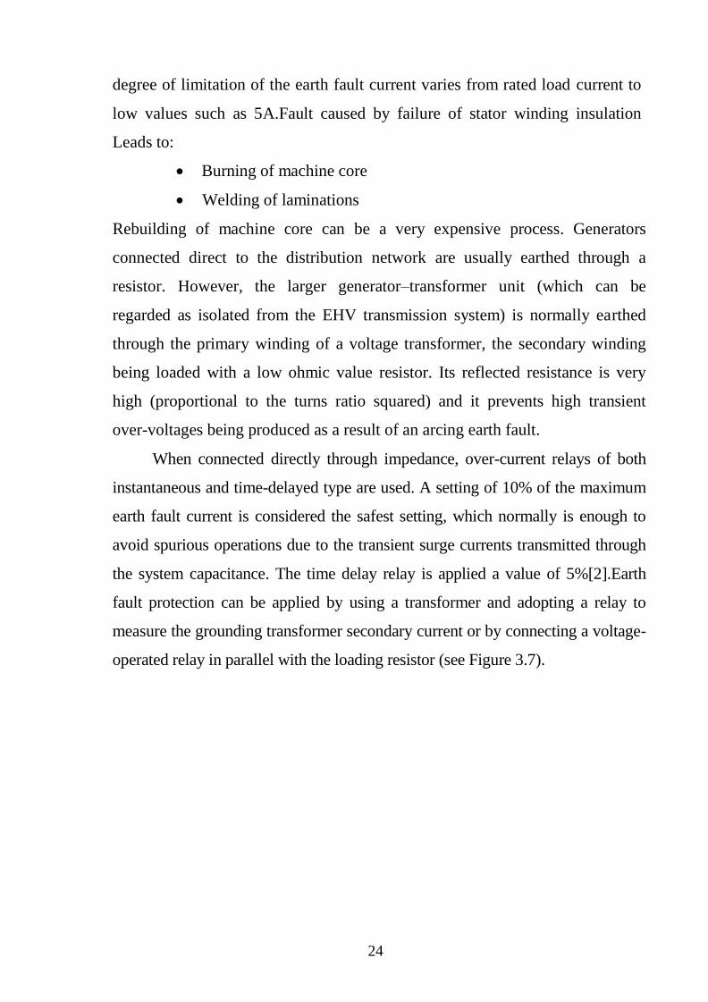
the system capacitance. The time delay relay is applied a value of 5%[2].Earth
fault protection can be applied by using a transformer and adopting a relay to
measure the grounding transformer secondary current or by connecting a voltage-
operated relay in parallel with the loading resistor (see Figure 3.7).
25
Figure 3.7: Earth fault protection using a relay to measure secondary current
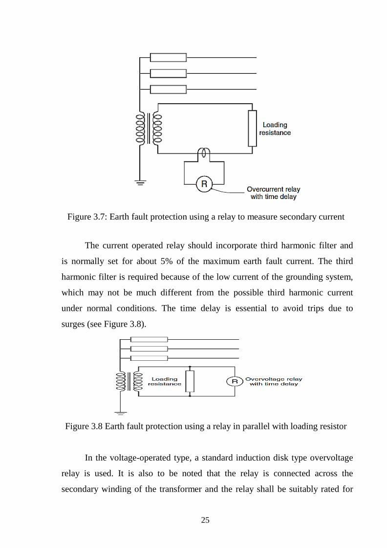
The current operated relay should incorporate third harmonic filter and
is normally set for about 5% of the maximum earth fault current. The third
harmonic filter is required because of the low current of the grounding system,
which may not be much different from the possible third harmonic current
under normal conditions. The time delay is essential to avoid trips due to
surges (see Figure 3.8).
Figure 3.8 Earth fault protection using a relay in parallel with loading resistor
In the voltage-operated type, a standard induction disk type overvoltage
relay is used. It is also to be noted that the relay is connected across the
secondary winding of the transformer and the relay shall be suitably rated for
26
the higher continuous operating voltage. Further, the relay is to be insensitive
for third harmonic current.
Phase-to-phase faults clear of earth are less common. They may occur
on the end coils or on adjacent conductors in the same slot. In the latter case,
the fault would involve earth in a very short time [2].
3.5 Rotor faults
The rotor has a DC supply fed onto its winding which sets up a standing
flux. When this flux is rotated by the prime mover, it cuts the stator winding to
induce current and voltage therein. This DC supply from the exciter need not
be earthed. If an earth fault occurs, no fault current will flow and the machine
can continue to run indefinitely, however, one would be unaware of this
condition. Danger then arises if a second earth fault occurs at another point in
the winding, thereby shorting out portion of the winding. This causes the field
current to increase and be diverted, burning out conductors.
In addition, the fluxes become distorted resulting in unbalanced
mechanical forces on the rotor causing violent vibrations, which may damage
the bearings and even displace the rotor by an amount, which would cause it to
foul the stator. It is therefore important that rotor earth fault protection be
installed. This can be done in a variety of ways[2].
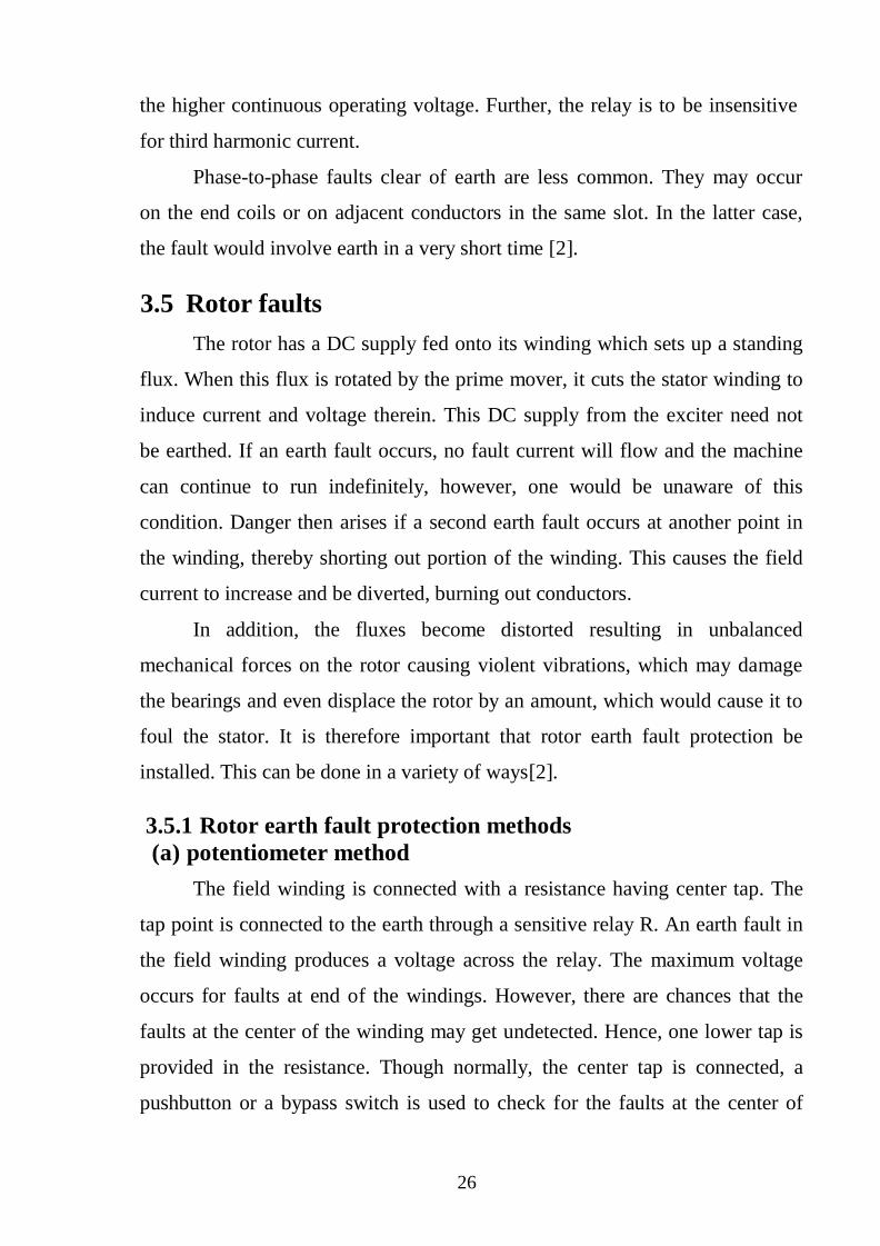
3.5.1 Rotor earth fault protection methods
(a) potentiometer method
The field winding is connected with a resistance having center tap. The
tap point is connected to the earth through a sensitive relay R. An earth fault in
the field winding produces a voltage across the relay. The maximum voltage
occurs for faults at end of the windings. However, there are chances that the
faults at the center of the winding may get undetected. Hence, one lower tap is
provided in the resistance. Though normally, the center tap is connected, a
pushbutton or a bypass switch is used to check for the faults at the center of
27
Winding. A proper operating procedure shall be established to ensure that
this changeover is done at least once in a day (see Figure 3.9)[2].
Figure 3.9 Potentiometer
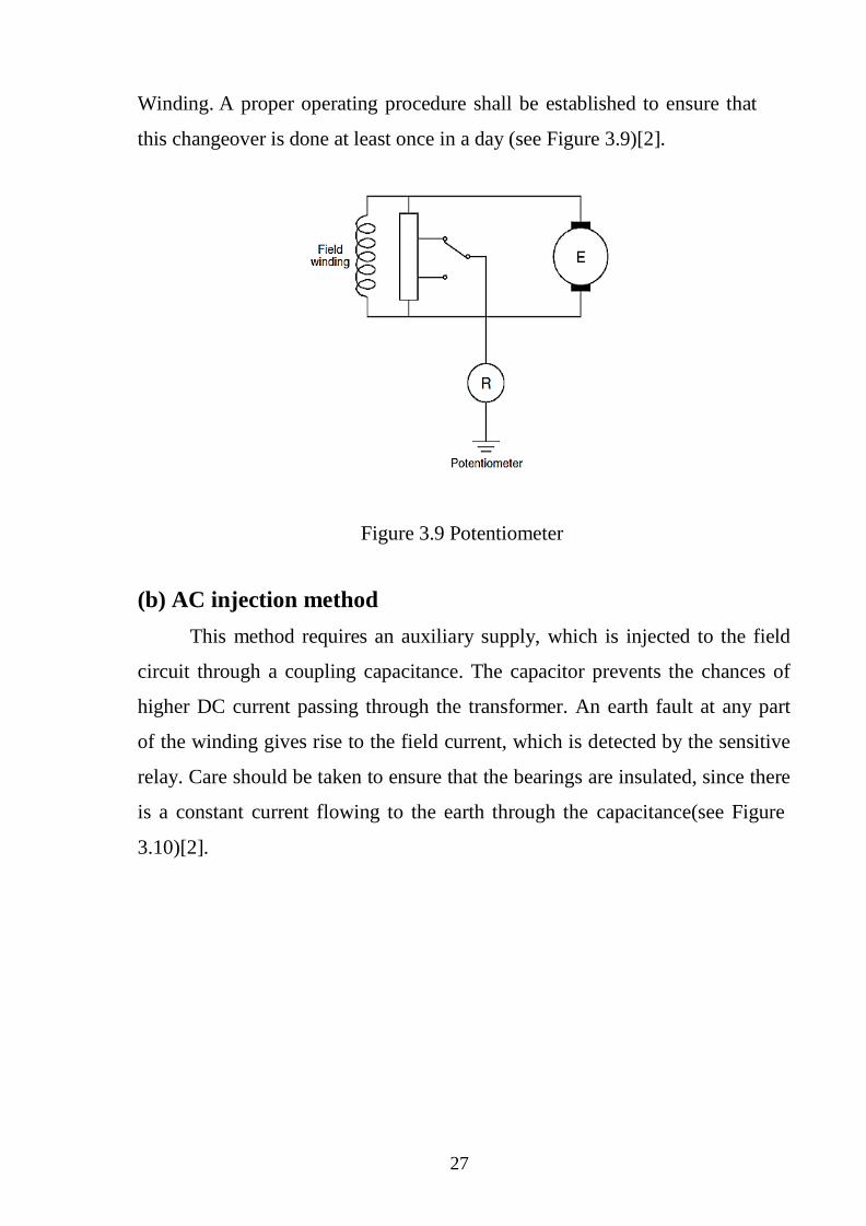
(b) AC injection method
This method requires an auxiliary supply, which is injected to the field
circuit through a coupling capacitance. The capacitor prevents the chances of
higher DC current passing through the transformer. An earth fault at any part
of the winding gives rise to the field current, which is detected by the sensitive
relay. Care should be taken to ensure that the bearings are insulated, since there
is a constant current flowing to the earth through the capacitance(see Figure
3.10)[2].
28
Figure 3.10 AC injection
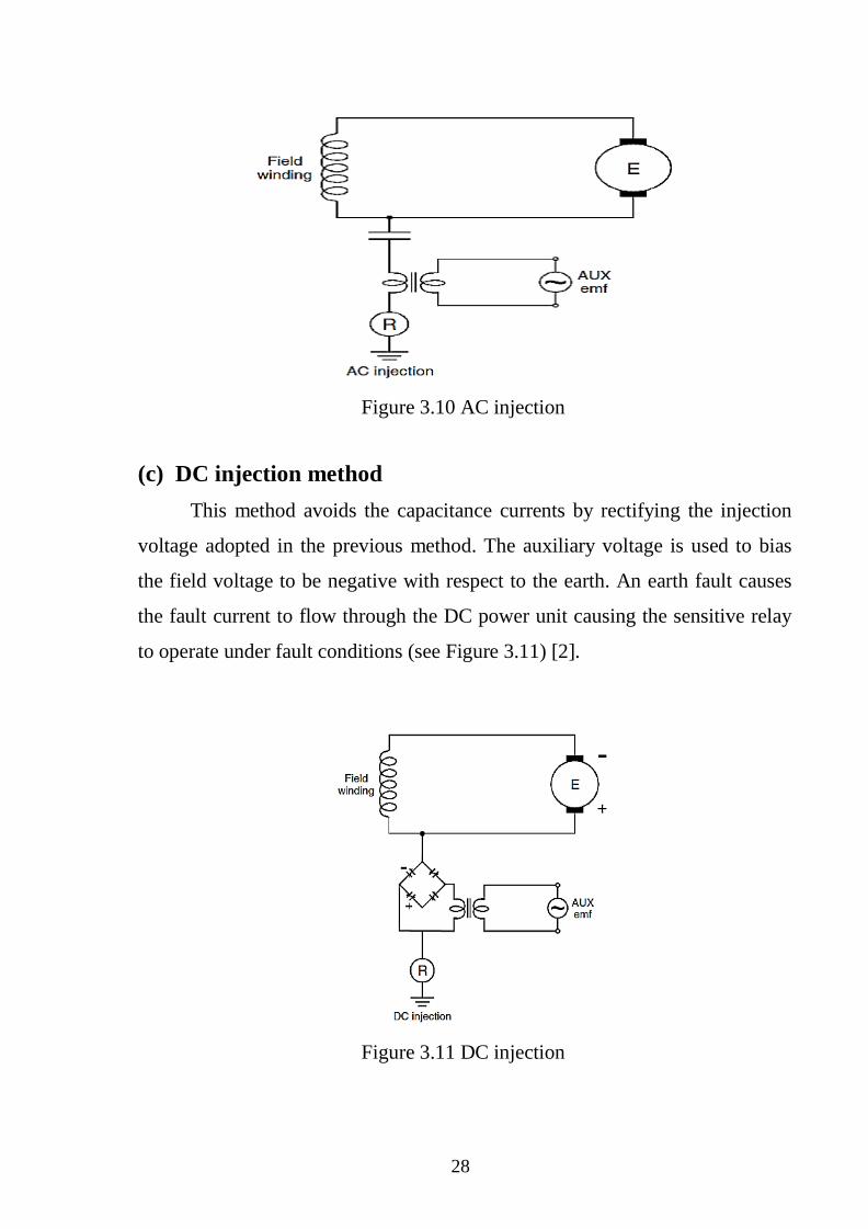
(c) DC injection method
This method avoids the capacitance currents by rectifying the injection
voltage adopted in the previous method. The auxiliary voltage is used to bias
the field voltage to be negative with respect to the earth. An earth fault causes
the fault current to flow through the DC power unit causing the sensitive relay
to operate under fault conditions (see Figure 3.11) [2].
Figure 3.11 DC injection
29
3.5.2 Rotor shorted turn Protection
Shorted section of field winding will result in an unsymmetrical rotor
flux pattern and in potentially damaging rotor vibration. Detection of such an
electrical fault is possible using a probe consisting of a coil placed in the air
gap. The flux pattern of the positive and negative poles is measured and any
significant difference in flux pattern between the poles is indicative of a
shorted turn or turns.
Automated waveform comparison techniques can be used to provide a
protection scheme, or the waveform can be inspected visually at regular
intervals. An immediate shutdown is not normally required unless the effects
of the fault are severe. The fault can be kept under observation until a suitable
shutdown for repair can be arranged. Repair will take some time, since it
means unthreading the rotor and dismantling the winding. Since short-circuited
turns on the rotor may cause damaging vibration and the detection of field
faults for all degrees of abnormality is difficult, the provision of a vibration a
detection scheme is desirable – this forms part of the mechanical protection of
the generator [1].
3.6 Abnormal Operating Conditions
A generator cannot be considered in isolation because of a very large
number of other equipment connected to it. Even though there is no electrical
fault in the generator, if one of its associated equipment develops a fault, then
it has serious implications for the generator. Every auxiliary equipment
connected to the generator is a likely source of trouble. There are a large
number of possible faults, as well as combinations of faults, on these
equipment‟s, that threaten the operation of the generator.
Instances where there is no direct electrical fault in the generator but one
or more of its associated equipment develop a fault or an abnormality,
may lead to an abnormal operating condition, which may or may not be serious.
However, all abnormal operating conditions need to be detected as quickly and
30
2
As sensitively as possible so that the corrective action can be taken and a
possible shutdown averted or anticipated. In the following sections, we consider
some prominent abnormal operating conditions that need to be carefully
considered while providing protection to the generator [3]
3.6.1UnbalancedLoading
A three-phase balanced load produces a reaction field that, to a first
approximation, is constant and rotates synchronously with the rotor field
system. Any unbalanced condition can be resolved into positive, negative and
zero sequence components. The positive sequence component is similar to the
normal balanced load. The zero sequence component produces no main
armature reaction. If there is an unbalanced loading of the generator then the
stator currents have a negative sequence component. The stator field due to
these negative sequence currents rotates at synchronous speed but in a
direction opposite to the direction of the field structure on the rotor.
Thus, if the stator carries unbalanced currents, then it is the rotor, which
is overheated. How long the generator can be allowed to run under unbalanced
loading, depends upon the thermal withstand capacity of the machine, which in
turn depends upon the type of cooling system adopted. The rate of heat
generation is proportional to I22 R while the heat energy is proportional to
I22Rt, where t is the time and I, is negative sequence current. Since the capacity
of a particular machine, to safely dissipate energy, is limited to a certain value
k, we can write
I22Rt=k (3.1)
Assuming R to be a constant, and K = k/R, we get the thermal characteristics
of the machine as
I22
t=K (3.2)
In other words, the time t for which the offending current I can be
allowed to flow should be less than or equal to K/I2.
31
Thus, the current-time characteristic can be written as
T K/I22
(3.4)
Where K is a constant proportion to the thermal capacity of the generator rotor
[3].
3.6.2 Over voltages Protection
Over voltages on a generator may occur due to transient surges on the
network, or prolonged power frequency over voltages may arise from a variety
of conditions. Surge arrestors may be required to protect against transient over
voltages, but relay protection may be used to protect against power frequency
over voltages. A sustained overvoltage condition should not occur for a
machine with a healthy voltage regulator, but it may be caused by the
following contingencies:
a. Defective operation of the automatic voltage regulator when the machine
is in isolated operation.
b. Operation under manual control with the voltage regulator out of service.
A sudden variation of the load, in particular the reactive power
component, will give rise to a substantial change in voltage because of
the large voltage regulation inherent in a typical alternator.
c. Sudden loss of load (due to tripping of outgoing feeders, leaving the set
isolated or feeding a very small load) may cause a sudden rise in terminal
voltage due to the trapped field flux and/or over speed.
Sudden loss of load should only cause a transient overvoltage while the
voltage regulator and governor act to correct the situation. A maladjusted
voltage regulator may trip to manual, maintaining excitation at the value prior
to load loss while the generator supplies little or no load. The terminal voltage
will increase substantially, and in severe cases it would be limited only by the
saturation characteristic of the generator. A rise in speed simply compounds
the problem. If load that is sensitive to over voltages remains connected, the
32
Consequences in term of equipment damage and lost revenue can be severe.
Prolonged over voltages may also occur on isolated networks, or ones with
weak interconnections, due to the fault conditions listed earlier.
For these reasons, it is prudent to provide power frequency over voltage
protection, in the form of a time delayed element, either IDMT or definite
time. The time delay should be long enough to prevent operation during
normal regulator action, and therefore should take account of the type of
Automatic Voltage Regulator (AVR) fitted and its transient response.
Sometimes a high-set element is provided as well, with a very short definite-
time delay or instantaneous setting to provide a rapid trip in extreme
circumstances. The usefulness of this is questionable for generators fitted with
an excitation system other than a static type, because the excitation will decay
in accordance with the open-circuit time constant of the field winding. This
decay can last several seconds. The relay element is arranged to trip both the
main circuit breaker (if not already open) and the excitation; tripping the main
circuit breaker alone is not sufficient [1].
3.6.3Undervoltage Protection
Under voltage protection is rarely fitted to generators. It is sometimes
used as an interlock element for another protection function or scheme, such as
field failure protection or inadvertent energizing protection, where the
abnormality to be detected leads directly or indirectly to an under voltage
condition. A transmission system under voltage condition may arise when
there is insufficient reactive power generation to maintain the system voltage
profile and the condition must be addressed to avoid the possible phenomenon
of system voltage collapse.
However, it should be addressed by the deployment of ‟system
protection‟ schemes. The generation should not be tripped. The greatest case
for under voltage protection being required would be for a generator supplying
33
An isolated power system or to meet Utility demands for connection of
embedded generation. In the case of generators feeding an isolated system,
under voltage may occur for several reasons, typically overloading or failure of
the AVR. In some cases, the performance of generator auxiliary plant fed via a
unit transformer from the generator terminals could be adversely affected by
prolonged under voltage. Where under voltage protection is required, it should
comprise an under voltage element and an associated time delay. Settings must
be chosen to avoid mal-operation during the inevitable voltage dips during
power system fault clearance or associated with motor starting. Transient
reductions in voltage down to 80% or less may be encountered during motor
starting [1].
3.6.4 Losses of
excitation
There are several possible causes due to which field excitation may be
lost, namely:
1- Loss of field to main exciter
2- Accidental tripping of the field breaker
3- Short circuit in the field winding
4- Poor brush contact in the exciter
5- Field circuit breaker latch failure
6- Loss of ac supply to excitation system
Effects
Single generator:
Loses output volts and therefore load.
Parallel generators:
Operate as induction generator (> synch speed).
Flux provided by reactive stator current drawn from
system-leading PF.

34
Slip frequency current induced in rotor - abnormal heating.
35
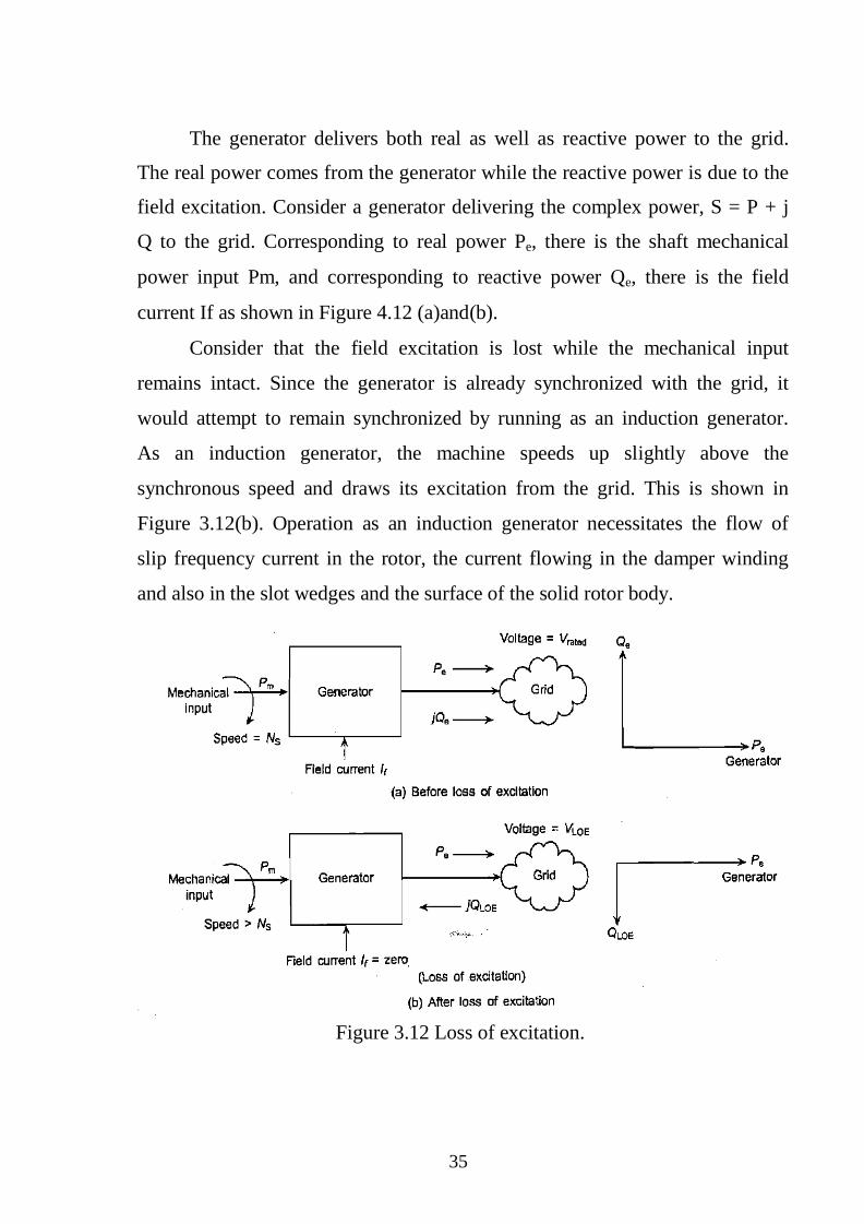
The generator delivers both real as well as reactive power to the grid.
The real power comes from the generator while the reactive power is due to the
field excitation. Consider a generator delivering the complex power, S = P + j
Q to the grid. Corresponding to real power Pe, there is the shaft mechanical
power input Pm, and corresponding to reactive power Qe, there is the field
current If as shown in Figure 4.12 (a)and(b).
Consider that the field excitation is lost while the mechanical input
remains intact. Since the generator is already synchronized with the grid, it
would attempt to remain synchronized by running as an induction generator.
As an induction generator, the machine speeds up slightly above the
synchronous speed and draws its excitation from the grid. This is shown in
Figure 3.12(b). Operation as an induction generator necessitates the flow of
slip frequency current in the rotor, the current flowing in the damper winding
and also in the slot wedges and the surface of the solid rotor body.
Figure 3.12 Loss of excitation.
36
There are two possibilities. Either the grid is able to meet this reactive
power demand fully or meet it partially. If the grid is able to fully satisfy this
demand for reactive power, the machine continues to deliver active power of
Pe, MW but draws reactive power of QLOE MVA and there is no risk of
instability. However, the generator is not designed as an induction machine, so
abnormal heating of the rotor and overloading of the stator winding will take
place.
If the grid were able to meet the reactive power demand only partially
then this would be reflected by a fall of the generator terminal voltage. The
generator would be under excited. There are certain limits on the degree to
which a generator can be operated within the under-excited mode. Therefore,
the operation in case of loss of excitation must be quickly detected and
checked to avert any shutdown of the generator. The simplest method by which
loss of excitation can be detected is to monitor the field current of the
generator. If the field current falls below a threshold, a loss of field signal can
be raised.
A complicating factor in this protection is the slip frequency current
induced in the event of loss of excitation and running. The quantity which
changes most when a generator loses field excitation is the impedance
measured at the stator terminals. On loss of excitation, the terminal voltage
begins to decrease and the current begins to increase, resulting in a decrease of
impedance and also a change of power factor as an induction generator [3].
3.6.5 Under / Over frequency
The governor fitted to the prime mover normally provides protection
against over frequency. Under frequency may occur as a result of overload of
generators operating on an isolated system, or a serious fault on the power
system that results in a deficit of generation compared to load. This may occur
if a grid system suffers a major fault on transmission lines linking two parts of
37
The system, and the system then splits into two. It is likely that one part will
have an excess of generation over load, and the other will have a corresponding
deficit.
Frequency will fall fairly rapidly in the latter part, and the normal
response is load shedding, either by load shedding relays or operator action.
However, prime movers may have to be protected against excessively low
frequency by tripping of the generators concerned. With some prime movers,
operation in narrow frequency bands that lie close to normal running speed
(either above or below) may only be permitted for short periods, together with a
cumulative lifetime duration of operation in such frequency bands. This
typically occurs due to the presence of rotor torsional frequencies in such
frequency bands. In such cases, monitoring of the period of time spent in these
frequency bands is required. A special relay is fitted in such cases, arranged to
provide alarm and trip facilities if either an individual or cumulative period
exceeds a set time [1].
3.6.6Overfluxing
Over fluxing occurs when the ratio of voltage to frequency is too high.
The iron saturates owing to the high flux density and results in stray flux
occurring in components not designed to carry it. Overheating can then occur,
resulting in damage. The problem affects both direct-and indirectly-connected
generators. Either excessive voltage, or low frequency, or a combination of both
can result in over fluxing, a voltage to frequency ratio in excess of transiently,
which is not a problem for the generator. For example, a generator can be
subjected to a transiently high power frequency voltage, at nominal frequency,
immediately after full load rejection. Since the condition would not be sustained,
it only presents a problem for the stability of the transformer differential
protection schemes applied at the power station
38
Sustained over fluxing can arise during run up, if excitation is applied too early
with the AVR in service, or if the generator is run down, with the excitation still
applied. Other over fluxing instances have occurred from loss of the AVR
voltage feedback signal, due to a reference VT problem. Such sustained
conditions must be detected by a dedicated over fluxing protection function
that will raise an alarm and possibly force an immediate reduction in
excitation. Most AVRs‟ have an over fluxing protection facility included. This
may only be operative when the generator is on open circuit, and hence fail to
detect over fluxing conditions due to abnormally low system frequency.
However, this facility is not engineered to protection relay standards, and should
not be solely relied upon to provide over fluxing protection. A separate relay
element is therefore desirable and provided in most modern relays.It is usual to
provide a definite time-delayed alarm setting and an instantaneous or inverse
time-delayed trip setting, to match the withstand characteristics of the protected
generator and transformer. It is very important that the VT reference for over
fluxing protection is not the same as that used for the AVR [1].
3.7 Back up Protection of Generator
Back up protection should always be given in highly rated machine like
synchronous generator or alternator. If faults occurred had not been cleared by
the appropriate protection scheme then back up protection relays should be
operated to clear the fault. Over current relays are generally used for this
purpose. Because the synchronous reactance of modern machine is often
greater than hundred percent, the sustained fault current fed from the machine
into an external fault is invariably below the normal full load current. The
normal IDMTL relays would not prove satisfactory because they are current
settings must be close to the full load and their time sitting short if operation is
to be obtained, resulting in probable lack of discrimination with other over
current relays in the system. Father, the over current relay would most

39
Probably operate for loss of field on the machine, disconnecting it prematurely.
To overcome this problem is it has become customary to apply an over current
relay in combination with under voltage relay, the letter relay controlling the fault
settings of the former.
40
CHAPTER FOUR
RESULTS AND DISCUSSION
4.1 Introduction
Generator protection system was simulated using power system software
called ETAP this program is used to apply on nuclear power plant generators
protection and simulated the faults affect the power generating.
4.2 ETAP Software
In a power system, one of the most critical aspects is the power system
protection. Power system protection involves using protective devices to
ensure that in the case of a short circuit or any electrical fault, system
components are not damaged and as little of the system is such down as
possible. In order to provide an adequate protection for the circuit, these fault
conditions must be simulated and analyzed. This can be achieved using an
appropriate software package such as ETAP software. ETAP is comprehensive
software that allows the user to design and simulate power systems as well as
automatic generation, transmission and distribution schemes.
ETAP generates and simulates software solution for electrical power
systems. ETAP is the most comprehensive electrical engineering software
solution for the design, simulation, operation, and automation of generation,
transmission, distribution, and industrial power systems. ETAP is developed
under an established quality assurance program and is used worldwide as high
impact software. As a fully integrated enterprise solution, ETAP extends to a
real-time power management System to monitor, control, automate, simulate,
and optimize the operation of power systems.
41
4.3 Short-Circuit Analysis Module of ETAP
Short-circuit analysis module of ETAP provide instruction of how to run
ANSI and IEC short- circuit calculations. In addition, there will be a brief look at
study case editors and the alert view function. From the mode toolbar, the
short circuit mode was selected by clicking on which represent the short-circuit
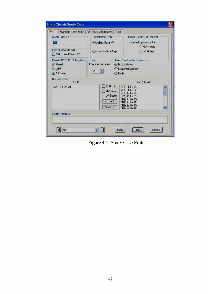
analysis button, editing study case was performed by clicking on This
opened the short-circuit study case editor shown on Figure 4.1, allows to change
calculation criteria and options, and also to choose a bus or multiple buses to be
faulted or to be un-faulted.
Short circuit was run after specifying the faulted and un-faulted buses by
clicking on , the customized fault currents were appeared on the One Line
View (OLV) buses and the contribution of all elements connected to each faulted
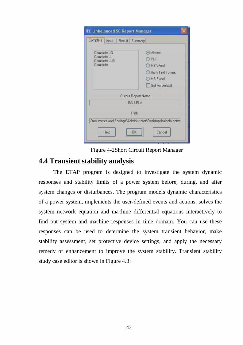
bus-bar. Finally the short circuit report was generated after clicking on , the
reports manager shown in Figure 4.2 was appeared to create different options of
reports.
42
Figure 4.1: Study Case Editor
43
Figure 4-2Short Circuit Report Manager
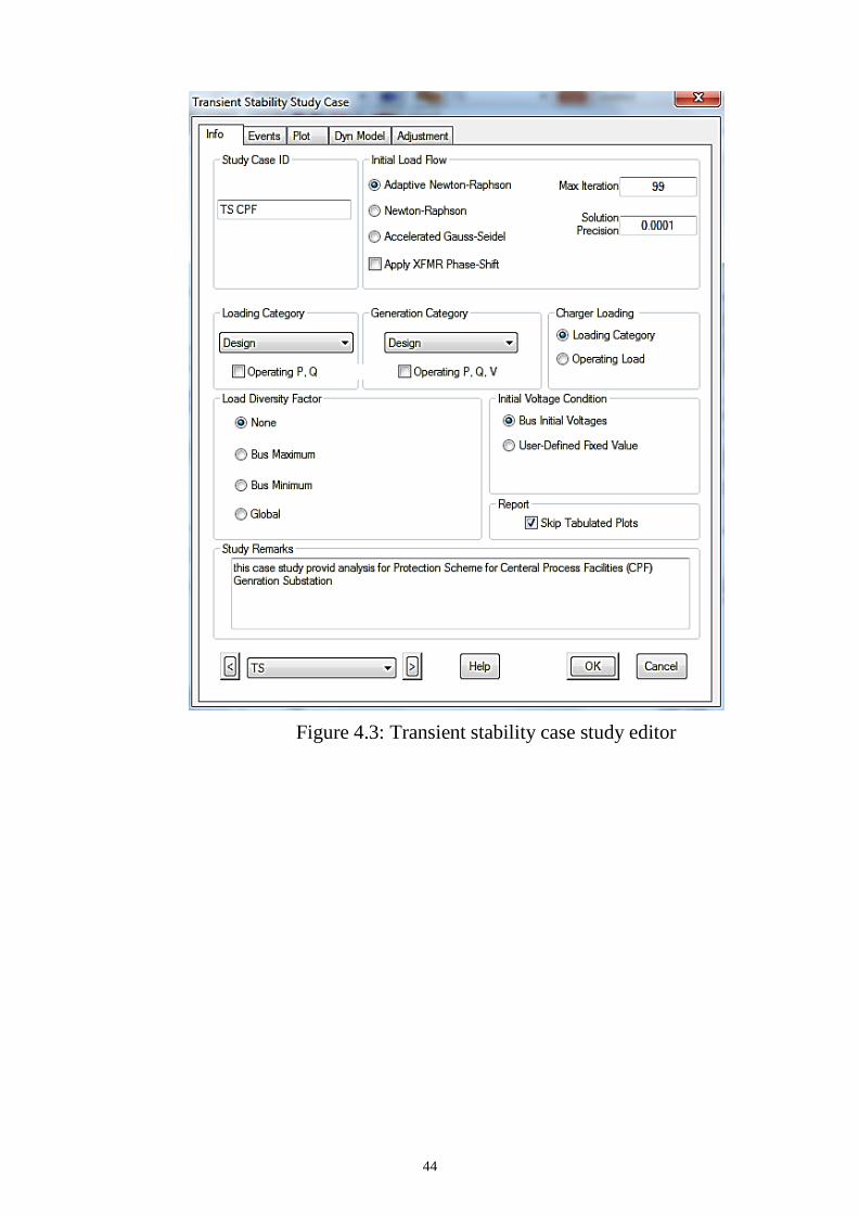
4.4 Transient stability analysis
The ETAP program is designed to investigate the system dynamic
responses and stability limits of a power system before, during, and after
system changes or disturbances. The program models dynamic characteristics
of a power system, implements the user-defined events and actions, solves the
system network equation and machine differential equations interactively to
find out system and machine responses in time domain. You can use these
responses can be used to determine the system transient behavior, make
stability assessment, set protective device settings, and apply the necessary
remedy or enhancement to improve the system stability. Transient stability
study case editor is shown in Figure 4.3:
44
Figure 4.3: Transient stability case study editor
45
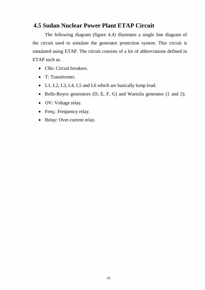
4.5 Sudan Nuclear Power Plant ETAP Circuit
The following diagram (figure 4.4) illustrates a single line diagram of
the circuit used to simulate the generator protection system. This circuit is
simulated using ETAP. The circuit consists of a lot of abbreviations defined in
ETAP such as.
CBs: Circuit breakers.
T: Transformer.
L1, L2, L3, L4, L5 and L6 which are basically lump load.
Rolls-Royce generators (D, E, F, G) and Wartsila generator (1 and 2):
OV: Voltage relay.
Freq.: Frequency relay.
Relay: Over-current relay.
44
Figure 4.4 Single line diagram SNP CPF generation power plant
45
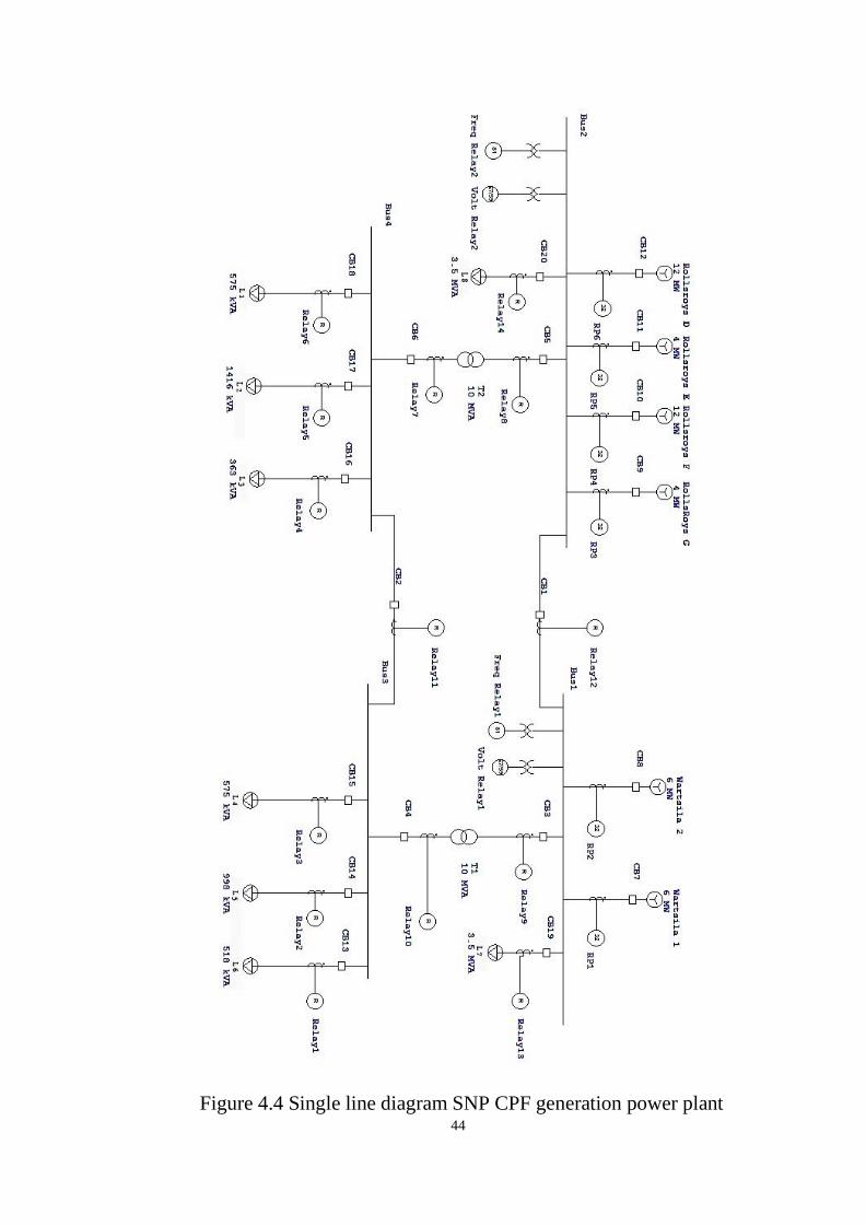
4.6.1 Over frequency test
To simulate over frequency condition ETAP Transient Stability Analysis
is used, and by making a high load rejection event at the 1st
second therefore
the over frequency condition is met. Figure 4.5 below shows over-frequency
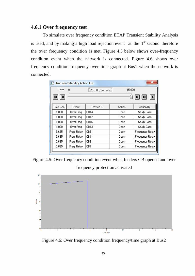
condition event when the network is connected. Figure 4.6 shows over
frequency condition frequency over time graph at Bus1 when the network is
connected.
Figure 4.5: Over frequency condition event when feeders CB opened and over
frequency protection activated
Figure 4.6: Over frequency condition frequency/time graph at Bus2
46
As an observation from above figure, frequency relay is used to trip the
generator after when the frequency exceeds 106% of the rated frequency.
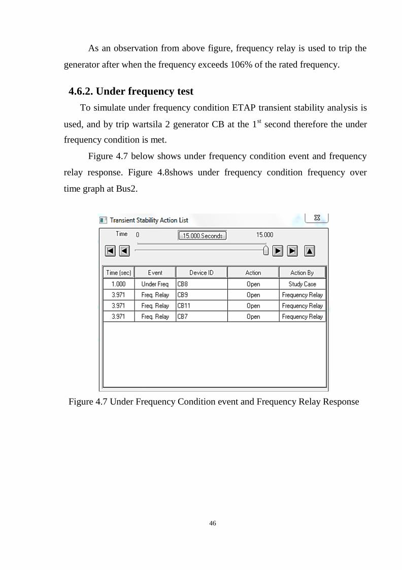
4.6.2. Under frequency test
To simulate under frequency condition ETAP transient stability analysis is
used, and by trip wartsila 2 generator CB at the 1st
second therefore the under
frequency condition is met.
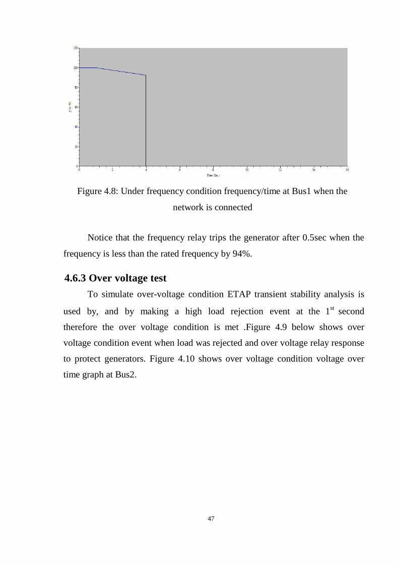
Figure 4.7 below shows under frequency condition event and frequency
relay response. Figure 4.8shows under frequency condition frequency over
time graph at Bus2.
Figure 4.7 Under Frequency Condition event and Frequency Relay Response
47
Figure 4.8: Under frequency condition frequency/time at Bus1 when the
network is connected
Notice that the frequency relay trips the generator after 0.5sec when the
frequency is less than the rated frequency by 94%.
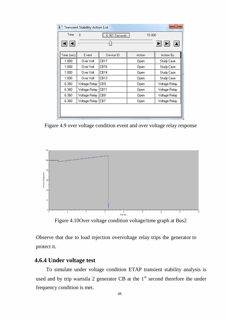
4.6.3 Over voltage test
To simulate over-voltage condition ETAP transient stability analysis is
used by, and by making a high load rejection event at the 1st
second
therefore the over voltage condition is met .Figure 4.9 below shows over
voltage condition event when load was rejected and over voltage relay response
to protect generators. Figure 4.10 shows over voltage condition voltage over
time graph at Bus2.
48
Figure 4.9 over voltage condition event and over voltage relay response
Figure 4.10Over voltage condition voltage/time graph at Bus2
Observe that due to load rejection overvoltage relay trips the generator to
protect it.
4.6.4 Under voltage test
To simulate under voltage condition ETAP transient stability analysis is
used and by trip wartsila 2 generator CB at the 1st
second therefore the under
frequency condition is met.
49
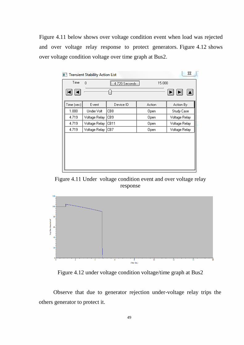
Figure 4.11 below shows over voltage condition event when load was rejected
and over voltage relay response to protect generators. Figure 4.12 shows
over voltage condition voltage over time graph at Bus2.
Figure 4.11 Under voltage condition event and over voltage relay
response
Figure 4.12 under voltage condition voltage/time graph at Bus2
Observe that due to generator rejection under-voltage relay trips the
others generator to protect it.
50
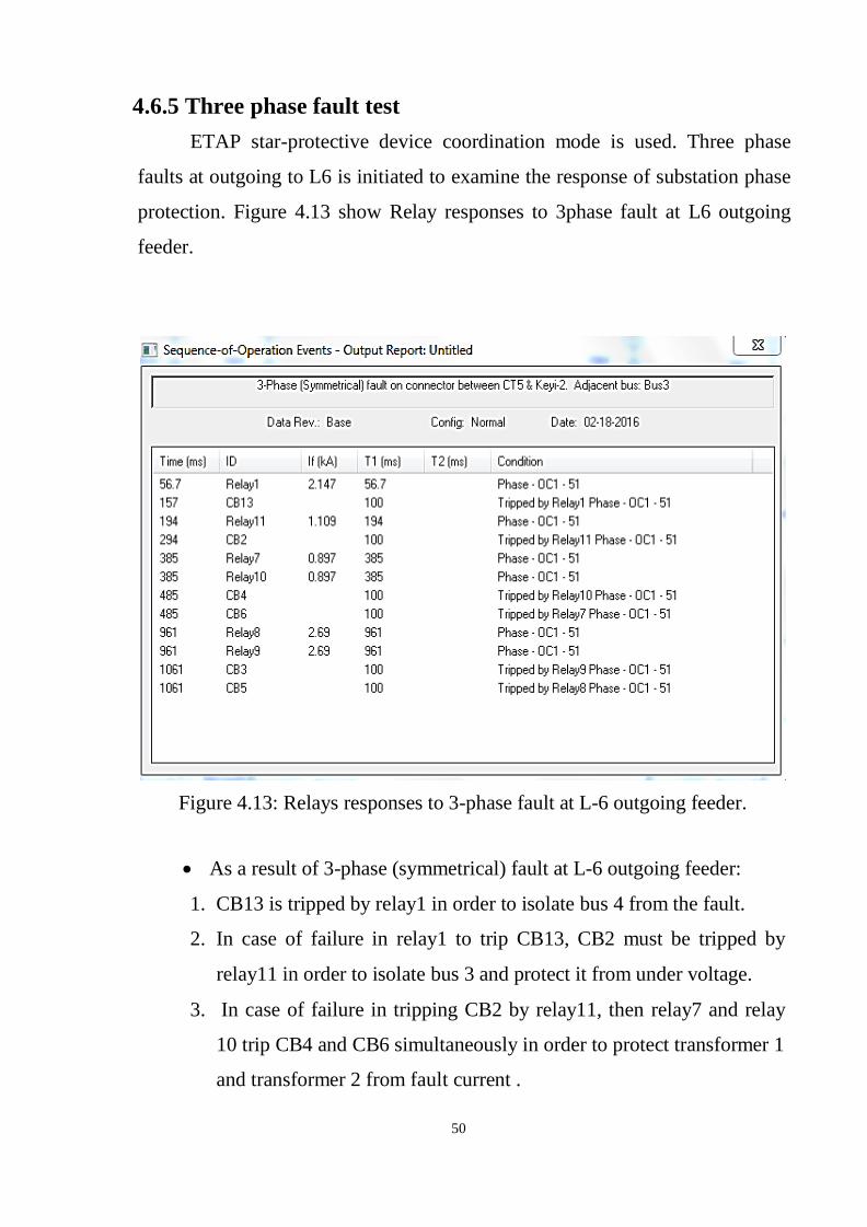
4.6.5 Three phase fault test
ETAP star-protective device coordination mode is used. Three phase
faults at outgoing to L6 is initiated to examine the response of substation phase
protection. Figure 4.13 show Relay responses to 3phase fault at L6 outgoing
feeder.
Figure 4.13: Relays responses to 3-phase fault at L-6 outgoing feeder.
As a result of 3-phase (symmetrical) fault at L-6 outgoing feeder:
1. CB13 is tripped by relay1 in order to isolate bus 4 from the fault.
2. In case of failure in relay1 to trip CB13, CB2 must be tripped by
relay11 in order to isolate bus 3 and protect it from under voltage.
3. In case of failure in tripping CB2 by relay11, then relay7 and relay
10 trip CB4 and CB6 simultaneously in order to protect transformer 1
and transformer 2 from fault current .
51
4. In case of failure in tripping CB4 and CB6 by Relay7 and Relay10
then relay 8 and Relay 9 trip CB3 and CB5 simultaneously in order
to protect generators fault current .
Over frequency condition make an oscillation in the generator speed
which may affect the generator life time if this oscillation continues. Without
occurrence of any action of protection may let to mechanical damages a result
of simulation increase of the frequency to 110% at 4.035 second after load
rejection which is bad and effect in generator life time so that the frequency
relay trip CB7,CB8, CB9 and CB11 and isolate the generators.
Under frequency is opposite of over frequency occurs as response of
suddenly increasing in load or sudden loss of generation this suddenly make
the voltage to decrease and result of high terminal current appear which
makeover heat and damage stator winding. In loss of generation simulation the
frequency decrease to 94% at time 3.971sec which is bad and effect in
generator life time so that the frequency relay trip, CB8, CB9 and CB11 and
isolate the generators.
Over voltage simulation result shows the voltage increase to108% at
time 6.36sec which is bad and effect in generator life time so that the voltage
relay trip ,CB8, CB9 and CB11 and isolate the generators.
Under voltage simulation result shows the voltage decrease to 94% at
time 4.719 sec which is bad and effect in generator life time so that the voltage
relay trip ,CB8, CB9 and CB11 and isolate the generators.
Generator faults are always considered to be serious since they can cause
severe and costly damage to isolation, winding and the core of they can also
produce severe mechanical torsional shock to shaft and coupling, Fault
currents in generator do not cease to flow when generator is tripped from the
system and the field disconnected fault current can continue to flow for many
52
Seconds because of trapped flux within the machine thereby increasing the
amount of damage.
As a result of 3-phase (symmetrical) fault on L-6 outgoing feeder as
example the sequence of over-current relays is correct in order to achieve
discrimination, selectivity and fast response to fault condition. The settings of
relays enable the Protection scheme of substation to Protect generators from all
abnormal condition (over-frequency, under-frequency, over-voltage, under-
voltage and over-current).All relays characteristic attached in Appendix.
53
CHAPTER FIVE
CONCLUSION AND RECOMMENDATINS
5.1Conclusion
Generators require special protection for faults and abnormal operations.
Generator protection is very important in power plant operation. The protection
of generators involves the consideration of more possible abnormal operating
conditions than the protection of any other system element. In unattended
power stations, automatic protection against all harmful abnormal conditions
should be provided.
To achieve the reliability of protection system backup protection should
be installed according to fault type and abnormal condition type. In this thesis
simulation results show that generator protection achieved to all types of faults
and abnormal condition (over and under frequency, over voltage. Also the
simulation results show the relays trip and pickup abnormal conditions to
prevent generator from damage.
The result of simulation show that relay trip and pickup abnormal
conditions to prevent generator from damage.
5.2 Recommendations
The main reason of the damage of power stations is caused due to
damage of the generation units. To make a recommended scenario in protecting
these generating units, the following recommendations must be taken into
account for others researchers to develop an on-line generator monitoring
System using Expert systems technology. This system will correlate generator
diagnostic information from existing sensors to provide operations personnel
with warning of developing generator problems and recommendations for

54
corrective action. Developing the software presents many technical challenges
associate with the requirement for a real-time expert system which can be
readily customized and applied to generators of varying design, manufacture,
and operating environments. A description of the software architecture better to
be implement.
55
REFERENCES
[1] Strauss, “Cobus Electrical Network Automation and Commmunication
Systems”. 2010.
[2]. Domin, J. Lewis Blackburn and Thomas J. “Protective relaying principle
and applications”. 1991.
[3]. Electric, Schneider. Network protection and automation guide. 2014.
[4]. P. M. Anderson, "Power System Protection ", IEEE Press power
engineering series. Mc Graw Hill New York, second addition, 2012.
[5] L.G.Hewitson Mark Brown ,Ramesh Balakrishnan “ Practical power
system protection” first published 2004,copy right 2004,Linacre house ,jordan
hill ,oxford OX2 8DP.
[6] J.B. Gubta, "Switchgear and Protection", S.K. Kataria & Sons, India, New
Delhi, Third Edition, 2013
56
APPENDIX
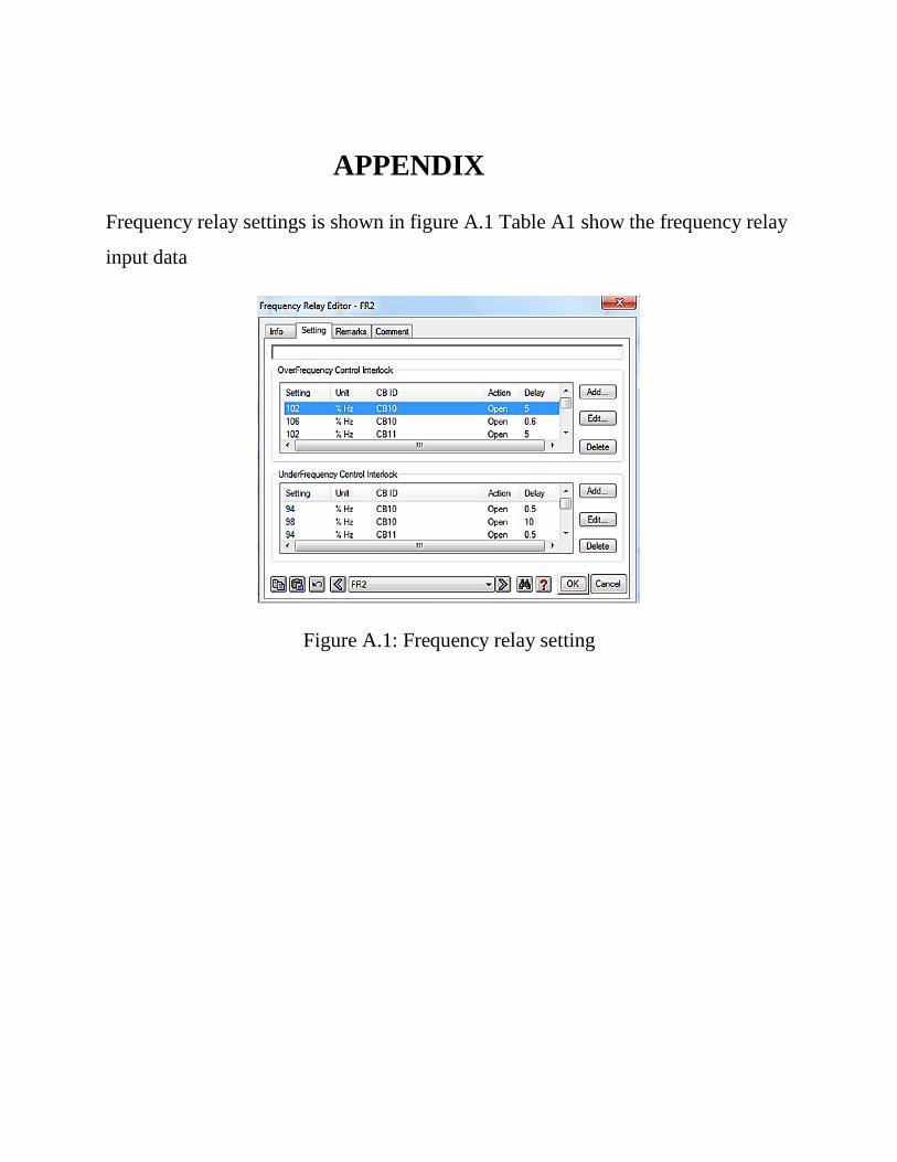
Frequency relay settings is shown in figure A.1 Table A1 show the frequency relay
input data
Figure A.1: Frequency relay setting
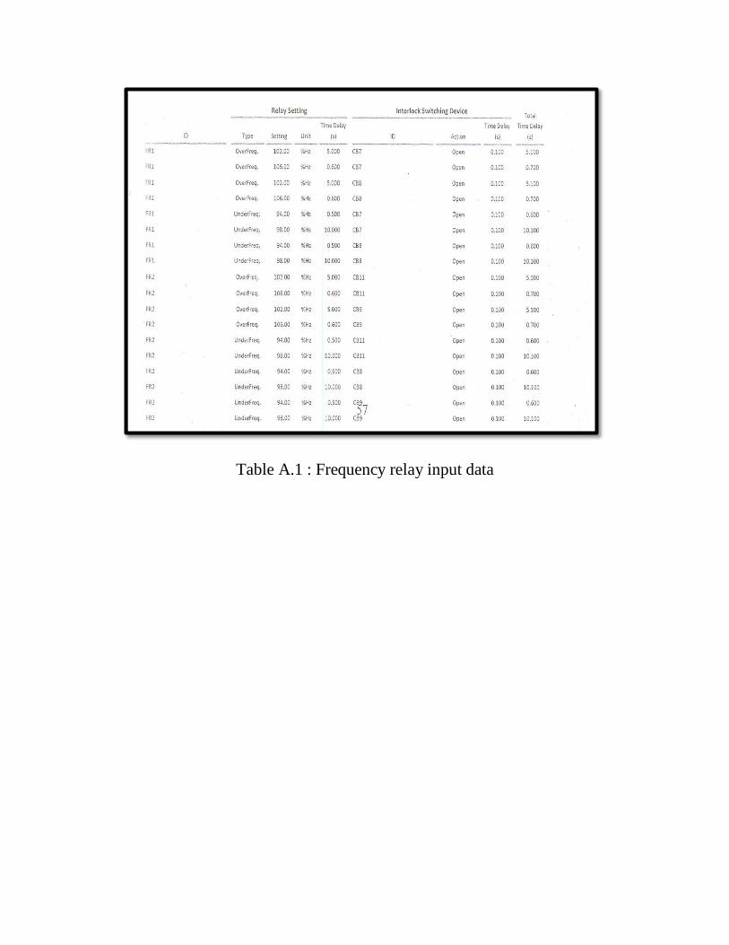
Table A.1 : Frequency relay input data
73
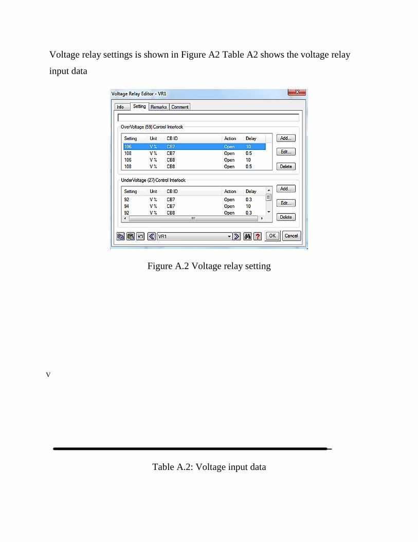
Voltage relay settings is shown in Figure A2 Table A2 shows the voltage relay
input data
Figure A.2 Voltage relay setting
V
Table A.2: Voltage input data
74
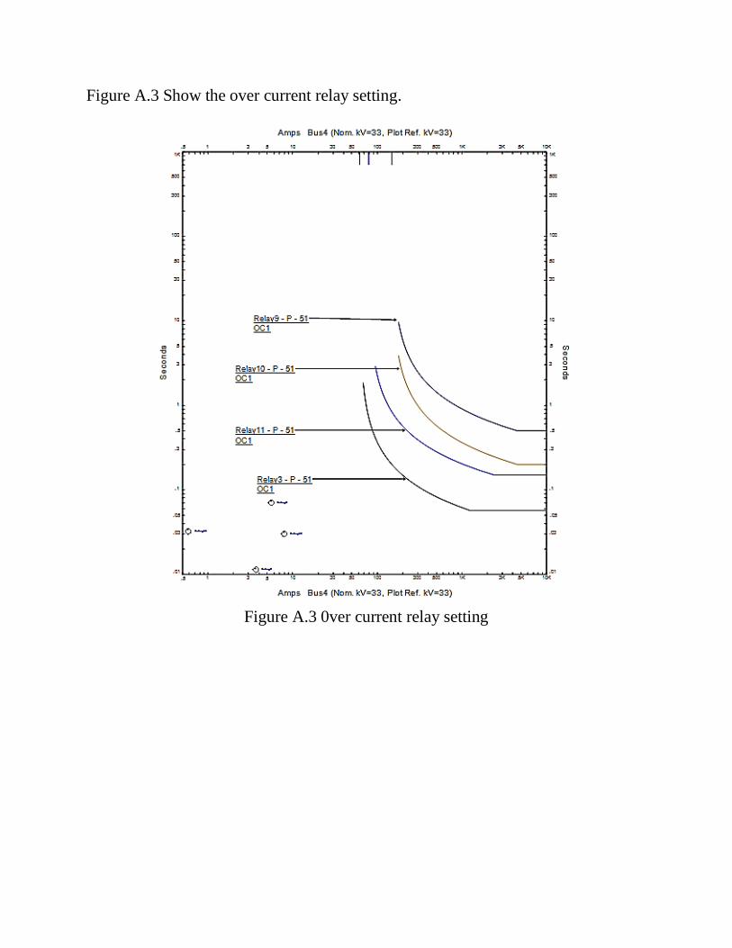
Figure A.3 Show the over current relay setting.
Figure A.3 0ver current relay setting
Related Documents