NISTIR 7444 Simulation Modeling of Emergency Response Facility Based on Software Product Line Technology Goudong Shao Y. Tina Lee

Welcome message from author
This document is posted to help you gain knowledge. Please leave a comment to let me know what you think about it! Share it to your friends and learn new things together.
Transcript
NISTIR 7444
Simulation Modeling of Emergency Response Facility Based on Software
Product Line Technology
Goudong ShaoY. Tina Lee
NISTIR 7444
Simulation Modeling of Emergency Response Facility Based on Software
Product Line Technology
Guodong Shao Y. Tina Lee
Manufacturing Systems Integration Division Manufacturing Engineering Laboratory
August 2007
U.S. Department of Commerce Carlos M. Gutierrez, Secretary
National Institute of Standards and Technology
William Jeffrey, Director
Simulation Modeling of Emergency Response Facility Based on Software Product Line Technology
Guodong Shao
Y. Tina Lee Manufacturing Systems Integration Division
National Institute of Standards and Technology 100 Bureau Drive, MS 8260
Gaithersburg, MD 20899-8260, U.S.A.
ABSTRACT
The development of a simulation model has always been a challenging task; it is time-consuming and requires expertise. Furthermore, most customized simulation models need to be developed from scratch. This paper proposes a more effective, reusable solution. The approach is to develop a Software Product Line (SPL) architecture that explicitly captures the commonality and variability in the family of similar simulation systems. First responders and incident management personnel need better training resources to prepare for possible catastrophic events, including natural disasters and man-made attacks. Live exercises are often very expensive to organize and conduct. With modeling and simulation technology, simulation-based exercise and training models could be developed. These exercise and training models support incident management training and operational activities in a variety of scenarios based on different physical conditions, constraints, available technologies, and capacities of the responder’s facilities. Each emergency responder has an objective, scope, and policy to provide emergency-response support for the incidents. Specific simulation-based exercise and training models are useful to serve different training purposes. The SPL technology enables the simulation system to easily adapt to multiple contexts and allows the simulation system to reconfigure quickly. SPL models can be developed at different levels of scope and depth to suit the emergency responder’s needs. By reusing the system requirement analysis, software architectures and design, the simulation modelers do not have to re-develop the simulation model from scratch. Thus, the development time is shorter, the development cost is lower, and the quality is easily maintained. This paper focuses on the application of SPL technology to simulation systems of emergency facilities, such as hospital emergency rooms, on-site emergency triage stations, decontamination stations, first-aid stations, or ambulances. The paper also introduces a prototype of the SPL member system – a hospital emergency room simulation system that has been developed at the National Institute of Standards and Technology. The detailed modeling of a family of emergency response facility simulation models is performed based on the Product Line UML-based Software engineering (PLUS) method.
1
Keywords: Emergency response, simulation, Software Product Line (SPL), software reuse, United Modeling Language (UML)
1 INTRODUCTION
There is a growing need for improved preparedness of emergency response for both man-made and natural disaster events. Effective emergency response presents a number of challenges to the responsible agencies. One major challenge is the lack of opportunities to train the emergency responders and decision makers in dealing with emergencies (Jain S and McLean C 2003). The responsible agencies have tried to meet these needs through the organization of live exercises, but such events are often difficult to organize and very expensive to conduct. Modeling, simulation, and visualization techniques can help to address this training challenge. As Robinson (Robinson D 2005) suggested, modeling and simulation provide a non-destructive and non-invasive method of observing a system and also provide a way to test multiple inputs and evaluate various outputs. Sullivan identified the importance of disaster simulation and emergency response (Sullivan 1985). Simulation modeling has been identified as one of the leading techniques for helping improve the incident management capabilities (NRC 2002). A recent survey (Jain S and McLean C 2003) indicates that a number of modeling and simulation applications for analyzing aspects of various disaster events exist. The limitations of live exercises can be overcome through use of simulation models that allow emergency response personnel across multiple levels in multiple agencies to be exposed to the same scenario. Simulation models can help the decision makers determine staff and resource levels in hypothetical terrorist attack scenarios. This serves to minimize resources required to process high patient volumes without causing long queues in the emergency room. (Pativivatsiri 2006). Simulation provides an effective and efficient way to train people for preparedness of emergency response for different incident scenarios. Due to various difficulties and obstacles associated with simulation model development, most emergency response organizations do not take advantage of simulation technology. These organizations typically do not have enough resources with the appropriate technical qualifications required to develop simulation models of their operations from scratch. The emergency response simulation models from different responders share many similarities but also have some variations, such as the responder’s functionality, resources, technologies, and facility layout. It is believed that using SPL to develop a family of simulation systems will be a much more beneficial approach compared to the traditional, individual simulation development approach. An SPL is a set of software-intensive systems that share a common, managed set of features satisfying the specific needs of a particular market segment or mission and that are developed from a common set of core assets in a prescribed way. Software product lines are rapidly emerging as a viable and important software development paradigm allowing companies to realize order-of-magnitude improvements in time to market, cost, productivity, quality, and other business drivers. Software-product-line engineering can also enable rapid market entry and flexible response, and provide a capability for mass
2
customization (SEI 2007). Using software-product-line techniques, companies such as Nokia, HP, LSI Logic, Philips, and Cummins have improved time-to-market, engineering costs, portfolio size, and defect rates by factors of 3 to 50 (SPLs 2007). An SPL of emergency-response-facility-simulation systems will aid the development and configuration of the simulation systems. It will help to reduce the costs associated with simulation model construction and thus make simulation technology more affordable and accessible to a wide range of potential emergency responders. It will provide better training to incident management personnel from different responders.
1.1 Problem formulation
Emergency facilities may include hospital emergency rooms (ERs), on-site triage centers, decontamination stations, and first-aid stations. For example, the Red Cross and other emergency response organizations may only require an ambulance as an emergency facility or a temporary on-site tent as an emergency triage station or a simple decontamination station. The emergency facility’s primary goal is just to identify and stabilize the patient for further treatment by another department or hospital. They only provide emergency diagnosis and treatment and then release or transfer the patient for extended care (Amodie J 1995). Simulation models of an emergency response facility/unit allow users to construct a more comprehensive representation of real-world features during disaster response. Each emergency provider has its own objective, scope, and policy to provide emergency-response support for the incidents; specific simulation-based exercise and training models are useful to serve different training purposes. For example, a hospital ER model may be developed to simulate patient flow through the hospital emergency rooms; it would model the deployment of resources, actions for triage, treatment of injured, movement of casualties to other facilities, and transferring patients to another hospital/facility. The model’s logic shall include relevant policies and procedures for emergencies, such as calling in medical staff, using temporary accommodations for the injured, and acquiring needed supplies and equipment. Each simulation system of above-mentioned emergency response facilities consists of a simulation engine. Generic modules of a simulation model include input module, output module, patient arrival module, patient departure module, triage process module, emergency treatment module; and generic test data and scenarios. Some incident management customers require 3-Dimensional (3D) animation for the simulation model, and some simulation models need to provide a log file from the simulation run. Some simulation systems need to read staff schedules from another information system, and others need to provide a document of simulation findings. All hospital emergency rooms being simulated should have the capability to perform lab tests (such as blood and urine tests), x–rays, and ultrasound. Only hospitals can admit a patient for further treatment. The patient arrival being simulated in all the facilities could be either emergency patients who are brought in by an ambulance or walk-in patients who can go to the facility by
3
themselves. The patient departure could be one of the following three cases: discharged, admitted, or re-directed to another facility. The input, output, and data and user interface requirements for the emergency-response-facility-simulation system SPL are identified as follows: Inputs may include the number, location and type of casualties from an emergency incident, the availability of staff at work or standing by (on-call), the availability of resources (own and those that can be acquired quickly from surrounding jurisdictions), the time and resources required for attending to each casualty type, the probabilities of death from different casualty types over time, emergency center location, hospital layout, process stations and station capacities, processing times, patient arrivals rate, staff shifts, medical resources, and symptom-treatment profiles. Outputs may include the operation of the emergency facilities over time including the number of people treated and released, admitted, dead, or waiting for treatment. It may also include the state of the staff and facilities, system utilization, run time interactions, simulated clock time, the number of Emergency Medical Technicians (EMT) and ambulances dispatched over time, and the number of ambulances and casualty arrivals over time.
Data requirements
a) Support data required to build the model (e.g., number of beds, triage level, and flow)
b) Externally manipulated parameters during run-time (e.g., control of the allocation of resources)
c) Primary entities include the patient and facility resource d) Patient arrivals modeled as statistical distributions e) Emergency vehicle arrivals modeled using statistical distributions for their travel
time from an origin to their entry point into the modeled area en-route to their assigned destination
User interface requirements a) 2D or 3D animation display of patient flow and hospital resources queuing and
being processed in an emergency facility b) Data entry capabilities for modifying patient characteristics, generating patient
volumes, generating emergency vehicle starting points and destinations c) Periodic updates of the patient status, patient location, and facility status
1.2 Software product line technology
Software product line is a family of software systems that have some common functionality and some variable functionality. A set of software-intensive systems sharing a common, managed set of features that satisfy the specific needs of a particular market segment or mission and that are developed from a common set of core assets in a prescribed way (Clements and Northrop 2002). It is also referred to as family of systems, software product family, product family, or product line (Gomaa 2004). Each system derived from the SPL consists of the common components of the SPL, tailoring them
4
through various mechanisms such as parameterization or inheritance, adding any new components as needed, and integrating the components based on the SPL architecture. Building a new system becomes more like block selection and assembly process rather than creating one from scratch. The SPL technology addresses the issues of engineering software system families, or collections of similar software systems. The objective of an SPL is to reduce the overall engineering effort required to produce a collection of similar systems by capitalizing on the commonality among systems and by formally managing the variation among systems (Parnas 1976). The development of a simulation model has always been a challenging task; it requires expertise and is very time consuming. Currently, almost every customized simulation model needs to start from scratch; the repetition of simulation modeling work increases development cost. This paper proposes a more effective, reusable solution by using the SPL approach. The SPL architecture that explicitly captures the commonality and variability in the family of these simulation systems is introduced. By reusing the system requirement analysis, software architectures, and design, simulation modelers do not have to re-develop the simulation model anew. The SPL family defines the overall simulation domains that are required for the development of applications of individual family members. The family product line concept could be used to create more robust and better-defined models than defining unique models for each simulation situation encountered (Raffo et al 2000). Each emergency responder organization has its own requirement for the simulation system. The SPL addresses all the different demands of simulation systems. The user’s requirements make each simulation system unique. The SPL of simulation systems is based on the identification of commonality and variability in the domain. The commonality highlights the cohesion of the product line. Reuse is based on the assumption that a common part exists for all the simulation systems. The variability highlights the differences between the simulation systems. The differences are the most characterizing aspects of each simulation system. The identification of commonality and variability is based on the scope and constraints of the simulation system for a specific emergency responder organization. The connection between commonality and variability is ensured by the definition of variation points. A variation point is one or more locations in a software asset at which the variation will occur, and it may be implemented differently in a different simulation system. The following are the advantages of the SPL commonality and variability:
• Commonality allows the reuse of architecture and code so that development effort and time are reduced. Variability decides where the design needs to be flexible.
• The commonality and variability shows the relationships among the family members.
• Options and alternatives need to be identified and evaluated; the variability can be implemented differently based on an individual simulation system requirement.
5
2 SIMULATION SYSTEM PRODUCT LINE COMMONALITY AND VARIABILITY
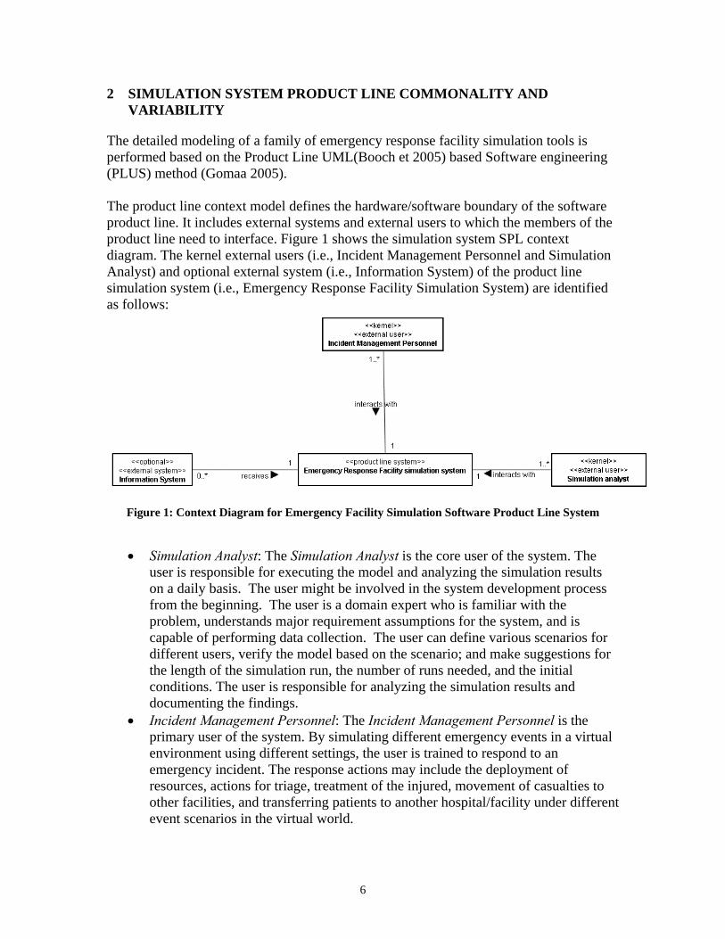
The detailed modeling of a family of emergency response facility simulation tools is performed based on the Product Line UML(Booch et 2005) based Software engineering (PLUS) method (Gomaa 2005). The product line context model defines the hardware/software boundary of the software product line. It includes external systems and external users to which the members of the product line need to interface. Figure 1 shows the simulation system SPL context diagram. The kernel external users (i.e., Incident Management Personnel and Simulation Analyst) and optional external system (i.e., Information System) of the product line simulation system (i.e., Emergency Response Facility Simulation System) are identified as follows:
Figure 1: Context Diagram for Emergency Facility Simulation Software Product Line System
• Simulation Analyst: The Simulation Analyst is the core user of the system. The
user is responsible for executing the model and analyzing the simulation results on a daily basis. The user might be involved in the system development process from the beginning. The user is a domain expert who is familiar with the problem, understands major requirement assumptions for the system, and is capable of performing data collection. The user can define various scenarios for different users, verify the model based on the scenario; and make suggestions for the length of the simulation run, the number of runs needed, and the initial conditions. The user is responsible for analyzing the simulation results and documenting the findings.
• Incident Management Personnel: The Incident Management Personnel is the primary user of the system. By simulating different emergency events in a virtual environment using different settings, the user is trained to respond to an emergency incident. The response actions may include the deployment of resources, actions for triage, treatment of the injured, movement of casualties to other facilities, and transferring patients to another hospital/facility under different event scenarios in the virtual world.
6
• Information System: The Information System is an optional external data system that is used only by certain simulation systems. The external information system is a data repository system that maintains the data required to execute the model. Data maintained may include number of patients, number of resources, and resource schedules among others. The schedules of resources may also be changed/updated in this system.
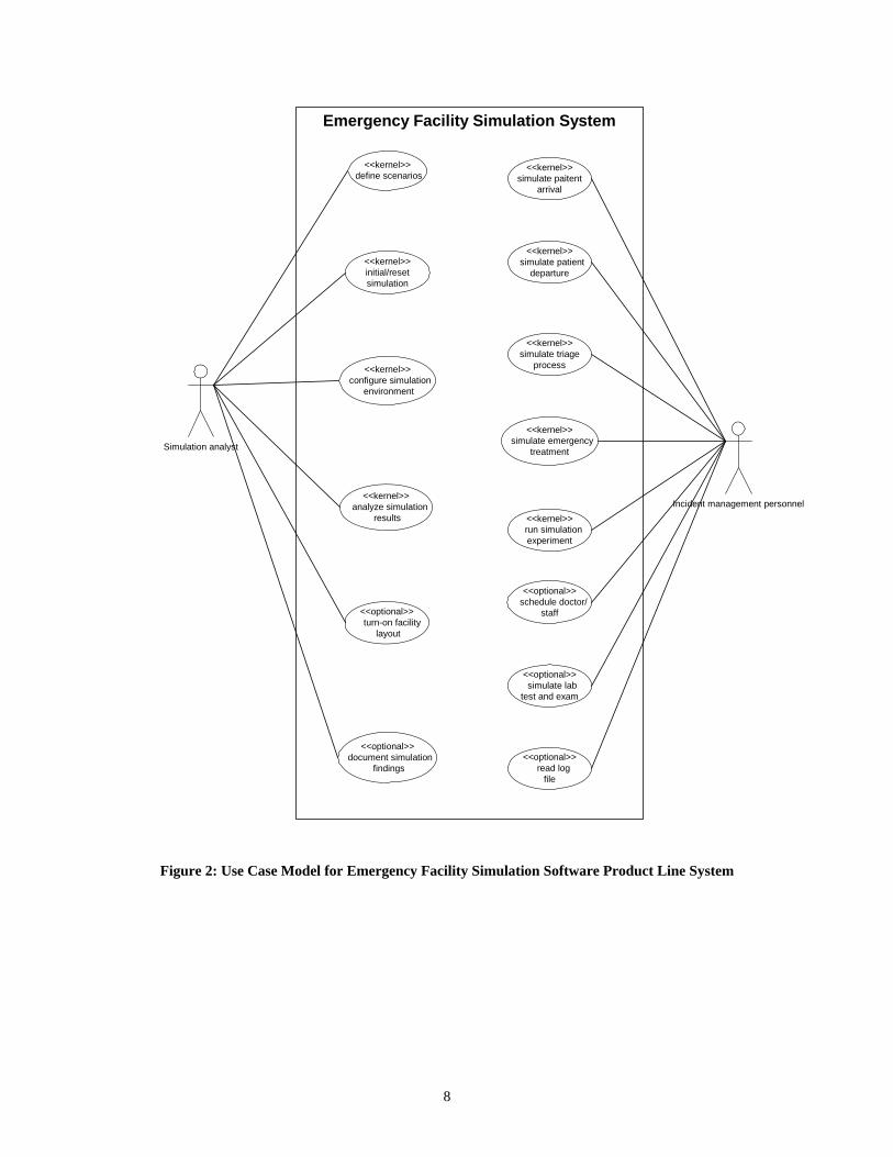
2.1 Use Case Modeling
Depicted in Figure 2 is the SPL use-case model diagram for an emergency facility simulation system. Kernel use cases represent the core of the SPL’s common part that is provided by all SPL members. In general, variability in the SPL is captured from the variation points in the kernel use case. For example, in the simulate emergency treatment use case, treatment can be decontamination only or it can be combined with some other emergency treatments. The majority of variations are addressed by optional use cases, such as simulate lab test and exam and document simulation findings. Since they are optional, only certain SPL members provide these use cases. There are 14 use cases included in the use case model. As samples, a brief introduction of the simulate patient arrival and simulate lab test and exam use cases is provided as follows.
7
Emergency Facility Simulation System
Simulation analyst
<<kernel>> configure simulation
environment
<<kernel>>initial/resetsimulation
<<kernel>> run simulation
experiment
<<optional>> turn-on facility
layout
<<optional>> read log
file
<<kernel>> analyze simulation
results
<<optional>> document simulation
findings
<<kernel>> define scenarios
<<optional>> schedule doctor/
staff
<<kernel>>simulate paitent
arrival
Incident management personnel
<<kernel>>simulate triage
process
<<kernel>> simulate emergency
treatment
<<optional>> simulate labtest and exam
<<kernel>> simulate patient
departure
Figure 2: Use Case Model for Emergency Facility Simulation Software Product Line System
8
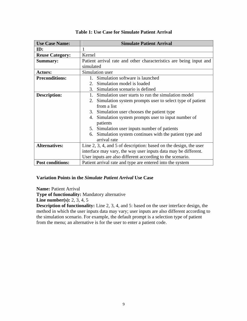
Table 1: Use Case for Simulate Patient Arrival
Use Case Name: Simulate Patient Arrival ID: 1 Reuse Category: Kernel Summary: Patient arrival rate and other characteristics are being input and
simulated Actors: Simulation user Preconditions: 1. Simulation software is launched
2. Simulation model is loaded 3. Simulation scenario is defined
Description: 1. Simulation user starts to run the simulation model 2. Simulation system prompts user to select type of patient
from a list 3. Simulation user chooses the patient type 4. Simulation system prompts user to input number of
patients 5. Simulation user inputs number of patients 6. Simulation system continues with the patient type and
arrival rate Alternatives: Line 2, 3, 4, and 5 of description: based on the design, the user
interface may vary, the way user inputs data may be different. User inputs are also different according to the scenario.
Post conditions: Patient arrival rate and type are entered into the system
Variation Points in the Simulate Patient Arrival Use Case Name: Patient Arrival Type of functionality: Mandatory alternative Line number(s): 2, 3, 4, 5 Description of functionality: Line 2, 3, 4, and 5: based on the user interface design, the method in which the user inputs data may vary; user inputs are also different according to the simulation scenario. For example, the default prompt is a selection type of patient from the menu; an alternative is for the user to enter a patient code.
9
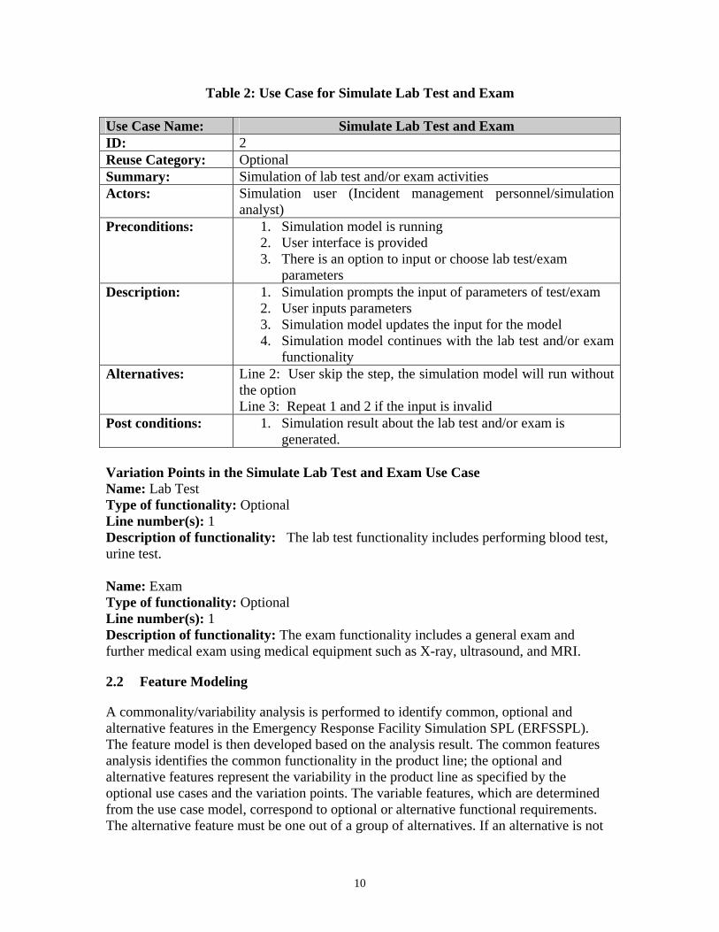
Table 2: Use Case for Simulate Lab Test and Exam
Use Case Name: Simulate Lab Test and Exam ID: 2 Reuse Category: Optional Summary: Simulation of lab test and/or exam activities Actors: Simulation user (Incident management personnel/simulation
analyst) Preconditions: 1. Simulation model is running
2. User interface is provided 3. There is an option to input or choose lab test/exam
parameters Description: 1. Simulation prompts the input of parameters of test/exam
2. User inputs parameters 3. Simulation model updates the input for the model 4. Simulation model continues with the lab test and/or exam
functionality Alternatives: Line 2: User skip the step, the simulation model will run without
the option Line 3: Repeat 1 and 2 if the input is invalid
Post conditions: 1. Simulation result about the lab test and/or exam is generated.
Variation Points in the Simulate Lab Test and Exam Use Case Name: Lab Test Type of functionality: Optional Line number(s): 1 Description of functionality: The lab test functionality includes performing blood test, urine test. Name: Exam Type of functionality: Optional Line number(s): 1 Description of functionality: The exam functionality includes a general exam and further medical exam using medical equipment such as X-ray, ultrasound, and MRI.
2.2 Feature Modeling
A commonality/variability analysis is performed to identify common, optional and alternative features in the Emergency Response Facility Simulation SPL (ERFSSPL). The feature model is then developed based on the analysis result. The common features analysis identifies the common functionality in the product line; the optional and alternative features represent the variability in the product line as specified by the optional use cases and the variation points. The variable features, which are determined from the use case model, correspond to optional or alternative functional requirements. The alternative feature must be one out of a group of alternatives. If an alternative is not
10
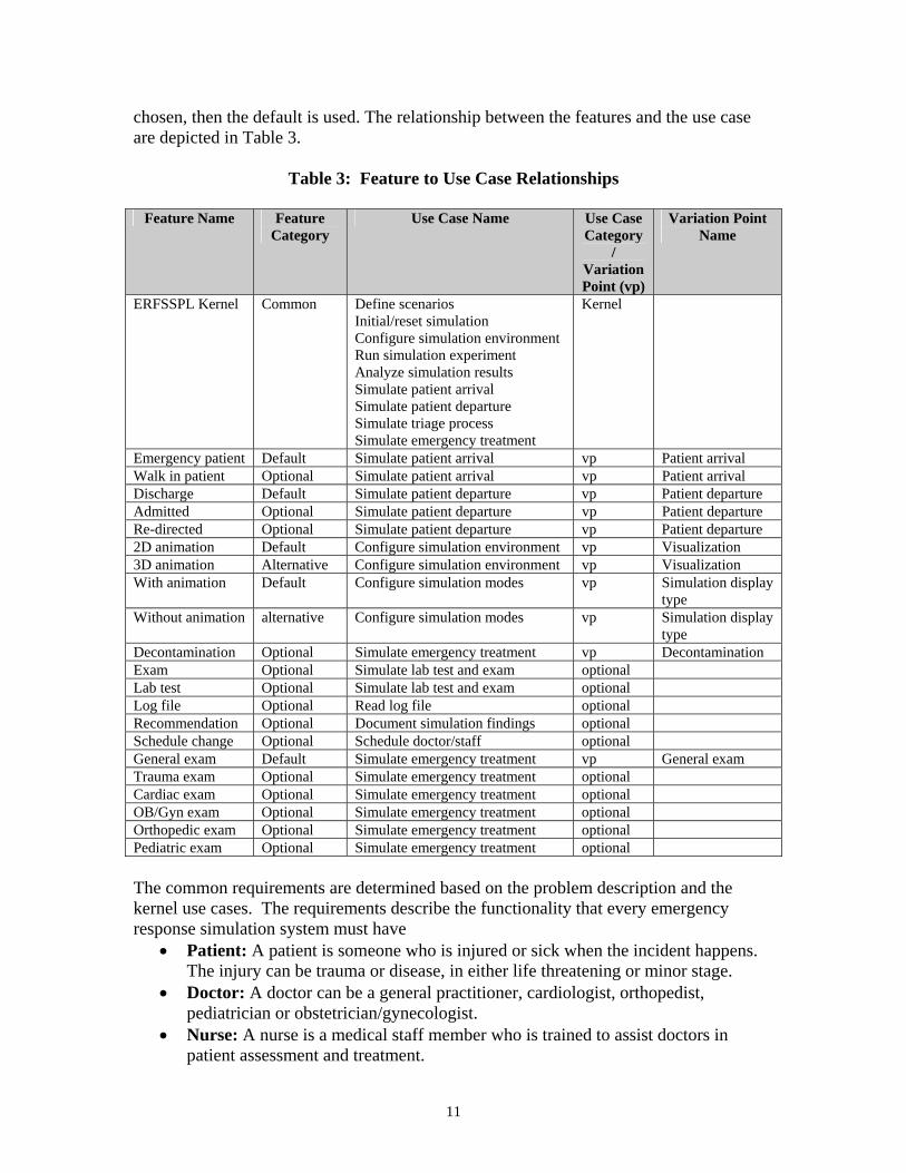
chosen, then the default is used. The relationship between the features and the use case are depicted in Table 3.
Table 3: Feature to Use Case Relationships
Feature Name Feature Category
Use Case Name Use Case Category
/ Variation Point (vp)
Variation Point Name
ERFSSPL Kernel Common Define scenarios Initial/reset simulation Configure simulation environment Run simulation experiment Analyze simulation results Simulate patient arrival Simulate patient departure Simulate triage process Simulate emergency treatment
Kernel
Emergency patient Default Simulate patient arrival vp Patient arrival Walk in patient Optional Simulate patient arrival vp Patient arrival Discharge Default Simulate patient departure vp Patient departure Admitted Optional Simulate patient departure vp Patient departure Re-directed Optional Simulate patient departure vp Patient departure 2D animation Default Configure simulation environment vp Visualization 3D animation Alternative Configure simulation environment vp Visualization With animation Default Configure simulation modes vp Simulation display
type Without animation alternative Configure simulation modes vp Simulation display
type Decontamination Optional Simulate emergency treatment vp Decontamination Exam Optional Simulate lab test and exam optional Lab test Optional Simulate lab test and exam optional Log file Optional Read log file optional Recommendation Optional Document simulation findings optional Schedule change Optional Schedule doctor/staff optional General exam Default Simulate emergency treatment vp General exam Trauma exam Optional Simulate emergency treatment optional Cardiac exam Optional Simulate emergency treatment optional OB/Gyn exam Optional Simulate emergency treatment optional Orthopedic exam Optional Simulate emergency treatment optional Pediatric exam Optional Simulate emergency treatment optional The common requirements are determined based on the problem description and the kernel use cases. The requirements describe the functionality that every emergency response simulation system must have
• Patient: A patient is someone who is injured or sick when the incident happens. The injury can be trauma or disease, in either life threatening or minor stage.
• Doctor: A doctor can be a general practitioner, cardiologist, orthopedist, pediatrician or obstetrician/gynecologist.
• Nurse: A nurse is a medical staff member who is trained to assist doctors in patient assessment and treatment.
11
• Help desk: Help desk is a station that receives patients and prepares patient records, or a meeting place for doctors and nurses.
• Waiting area: Waiting area is a place for patient to queue up and wait for treatment.
• Bed: A bed is a space for patient to be seen and/or stay for further treatment. • Triage: Triage is a process for sorting injured patients into groups based on their
conditions and needs for or likely benefit from immediate medical treatment. Triage is used in hospital emergency rooms and at disaster sites when limited medical resources must be allocated.
• Schedule of resources: Schedule of resources is the planned time that the resource is on duty or occupied.
• Utilization of resources: Utilization of resources is the proportion of the resources, such as staff or facility that is occupied by patients. It should be less than one for the medical center to function well. It is usually represented by the symbol ρ. ρ = λ/μ where λ is the mean arrival rate of patients and μ is the mean service rate. A lower utilization means less queuing for patients.
• Distribution: Probability distribution is used to estimate patient arrival rate, which is the number of arrivals per unit of time, and treatment process time, which is the duration of the last treatment.
• Patient record: Patient record is a patient file that maintains the patient’s information including medical history, symptoms, treatment, and medications.
• User interface: A user interface is an interactive dialog window for the user to input, select, or change simulation parameters for different scenarios.
Some of the other features are described as follows
• Emergency patient: A patient who is in a critical condition due to, for example, trauma or a cardiac event, and needs to be treated immediately. Typically, this patient is brought in by an ambulance.
• Walk-in patient: A patient who is injured or sick but not with a life-threatening condition. The patient enters the hospital, proceeds through a triage process for an initial assessment of his condition.
• Discharge: After initial medical treatment, the patient is released. • Admitted: After initial medical treatment, the patient is kept at the hospital for
further evaluation and treatment, and transferred to an available room for a longer stay.
• Re-directed: After initial medical treatment, the patient is transferred to an alternate facility if all the rooms are occupied at the time or a special care is not available in this facility.
• Exam: The assessment or diagnosis of the patients usually with the help of medical equipment such as x-rays or ultrasound.
• Decontaminate: A type of treatment that eliminates poisonous or otherwise harmful substances, such as noxious chemicals or radioactive material.
• Lab test: The assessment or diagnosis of the patients by analysis on blood, urine, or other bodily fluid or specimen.
12
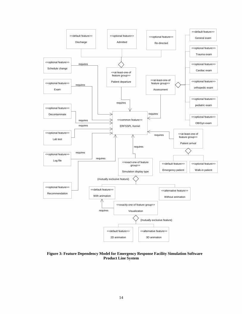
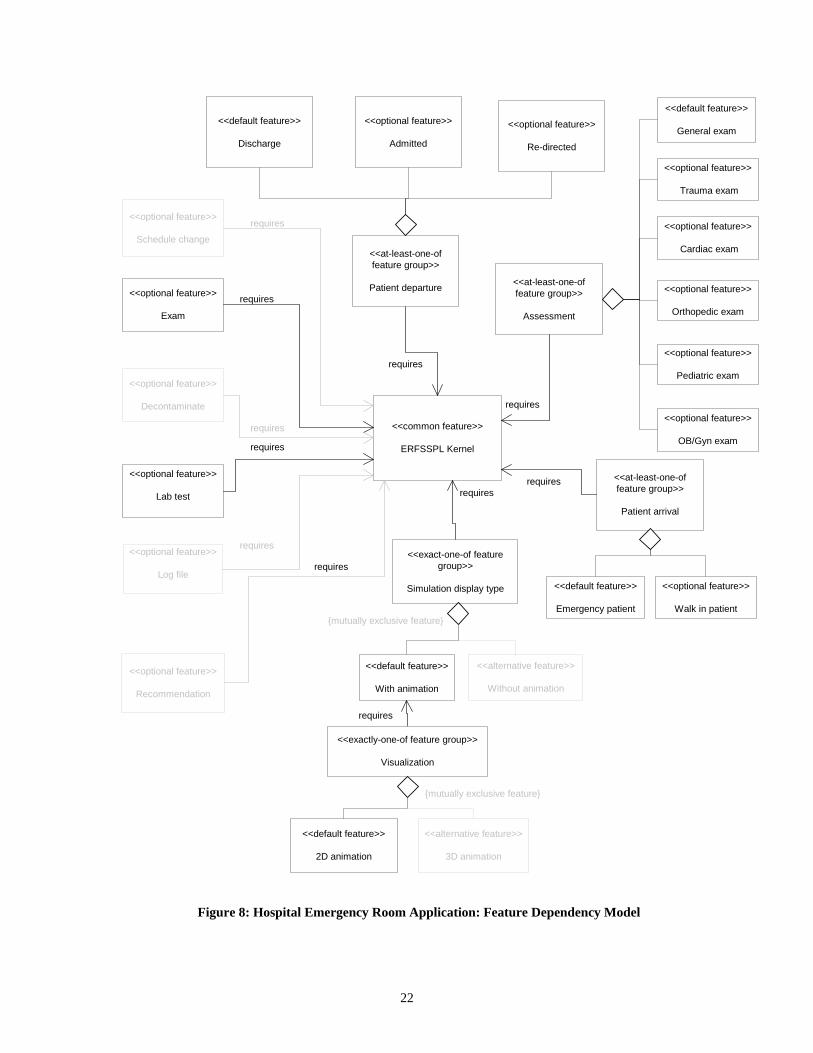
Figure 3 is a feature-dependency model that describes how one feature depends on other features. The root of the feature-dependency hierarchy is the common feature ERFSSPL kernel, which every emergency response simulation system carries. Several optional features require ERFSSPL kernel, include Decontaminate, Exam, Lab test, Log file, Recommendation, Schedule change. Three at-least-one-of feature groups also depend on ERFSSPL kernel: Specialist, Patient Arrival, and Patient departure. Two exactly-one-of feature groups are Visualization; Simulation display type. Each of these groups has two or more features. For example, the Patient departure feature group has the default discharge feature and the optional admitted and re-directed features. For those exactly-one-of feature groups, the default and alternative features are mutually exclusive.
13
<<common feature>>
ERFSSPL Kernel
<<optional feature>>
Exam
<<at-least-one-offeature group>>
Patient departure
<<optional feature>>
Log file
<<optional feature>>
Lab test
<<optional feature>>
Recommendation
<<optional feature>>
Re-directed
<<at-least-one-offeature group>>
Patient arrival
<<optional feature>>
Walk-in patient
<<default feature>>
Emergency patient
<<exact-one-of featuregroup>>
Simulation display type
<<default feature>>
With animation
<<alternative feature>>
Without animation
{mutually exclusive feature}
<<optional feature>>
Admitted
requires
requires
requires
requires
requires
requires
requires
<<exactly-one-of feature group>>
Visualization
<<default feature>>
2D animation
<<alternative feature>>
3D animation
{mutually exclusive feature}
requires
<<default feature>>
Discharge
<<optional feature>>
Schedule change
requires
<<at-least-one-offeature group>>
Assessment
<<optional feature>>
Cardiac exam
<<default feature>>
General exam
requires<<optional feature>>
OB/Gyn exam
<<optional feature>>
pediatric exam
<<optional feature>>
orthopedic exam
<<optional feature>>
Decontaminate
requires
<<optional feature>>
Trauma exam
Figure 3: Feature Dependency Model for Emergency Response Facility Simulation Software Product Line System
14
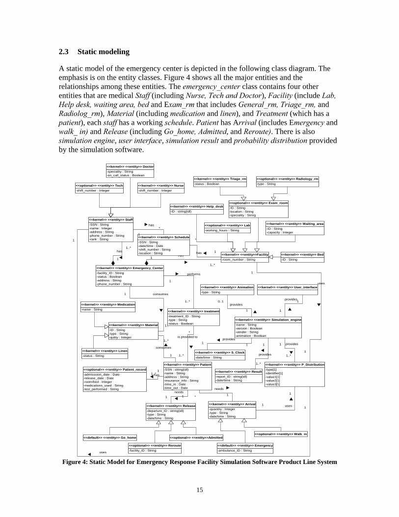
2.3 Static modeling
A static model of the emergency center is depicted in the following class diagram. The emphasis is on the entity classes. Figure 4 shows all the major entities and the relationships among these entities. The emergency_center class contains four other entities that are medical Staff (including Nurse, Tech and Doctor), Facility (include Lab, Help desk, waiting area, bed and Exam_rm that includes General_rm, Triage_rm, and Radiolog_rm), Material (including medication and linen), and Treatment (which has a patient), each staff has a working schedule. Patient has Arrival (includes Emergency and walk_ in) and Release (including Go_home, Admitted, and Reroute). There is also simulation engine, user interface, simulation result and probability distribution provided by the simulation software.
1..*
1
consumes
11..*has
1
1..*
has
-type : String<<optional>> <<entity>> Radiology_rm
-ID : String-capacity : Integer
<<kernel>> <<entity>> Waiting_area
-ID : String<<kernel>> <<entity>> Bed
-room_number : String<<kernel>> <<entity>>Facility
-facility_ID : String-status : Boolean-address : String-phone_number : String
<<kernel>> <<entity>> Emergency_Center
-admisssion_date : Date-release_date : Date-room/bed : Integer-medications_used : String-test_performed : String
<<optional>> <<entity>> Patient_record
-ID : string(idl)<<kernel>> <<entity>> Help_desk
1
1..*has
-SSN : String-name : Integer-address : String-phone_number : String-rank : String
<<kernel>> <<entity>> Staff
-SSN : string(idl)-name : String-address : String-insurance_info : String-time_in : Date-time_out : Date
<<kernel>> <<entity>> Patient
*
1..*
is provided to
-ID : String-location : String-speciality : String
<<optional>> <<entity>> Exam_room
-working_hours : String<<optional>> <<entity>> Lab
-departure_ID : string(idl)-type : String-date/time : String
<<kernel>> <<entity>> Release
-shift_number : Integer<<kernel>> <<entity>> Nurse
-speciality : String-on_call_status : Boolean
<<kernel>> <<entity>> Doctor
-shift_number : Integer<<optional>> <<entity>> Tech
-ID : String-type : String-qutity : Integer
<<kernel>> <<entity>> Material
-name : String<<kernel>> <<entity>> Medication
-status : String<<kernel>> <<entity>> Linen
1
1..*
consumes
-status : Boolean<<kernel>> <<entity>> Triage_rm
-SSN : String-date/time : Date-shift_number : String-location : String
<<kernel>> <<entity>> Schedule1
*has
-quantity : Integer-type : String-date/time : String
<<kernel>> <<entity>> Arrival
11needs
* 1
needs
-type[1]-identifier[1]-value1[1]-value2[1]-value3[1]
<<kernel>> <<entity>> P_Distribution
1
1 uses
1
1
uses
-ambulance_ID : String<<default>> <<entity>> Emergency
<<optional>> <<entity>> Walk_in<<optional>> <<entity>>Admitted
-facility_ID : String<<optional>> <<entity>> Reroute
<<default>> <<entity>> Go_home
<<kernel>> <<entity>> User_interface
-name : String-version : Boolean-vender : String-animation : Boolean
<<kernel>> <<entity>> Simulation_engine
1
1
provides
1
1..*
provides
-type : String<<kernel>> <<entity>> Animation
0..1
1
provides
-report_ID : string(idl)-date/time : String
<<kernel>> <<entity>> Result
1
1..*
provides-date/time : String<<kernel>> <<entity>> S_Clock
11provides
1
1
uses
-treatment_ID : String-type : String-status : Boolean
<<kernel>> <<entity>> treatment
1
1..*
performs
1
*
has
Figure 4: Static Model for Emergency Response Facility Simulation Software Product Line System
15
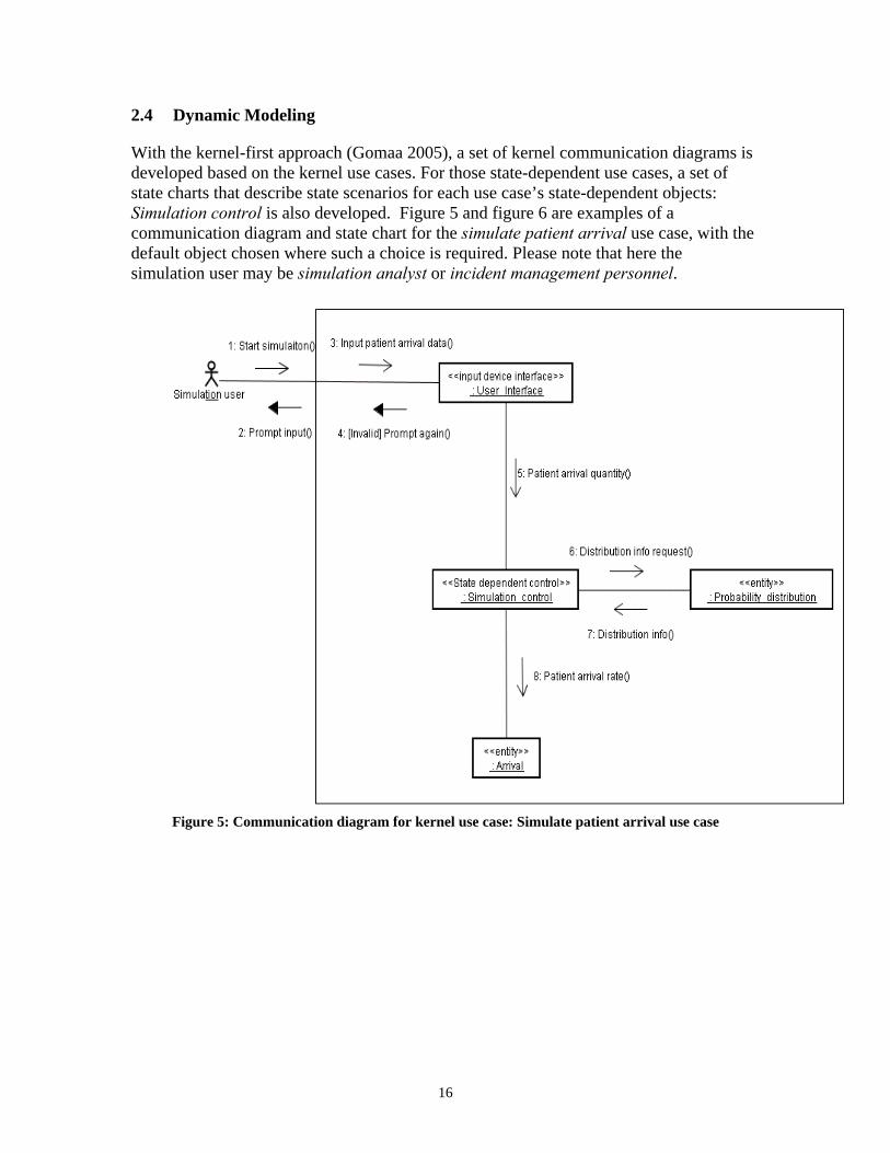
2.4 Dynamic Modeling
With the kernel-first approach (Gomaa 2005), a set of kernel communication diagrams is developed based on the kernel use cases. For those state-dependent use cases, a set of state charts that describe state scenarios for each use case’s state-dependent objects: Simulation control is also developed. Figure 5 and figure 6 are examples of a communication diagram and state chart for the simulate patient arrival use case, with the default object chosen where such a choice is required. Please note that here the simulation user may be simulation analyst or incident management personnel.
Figure 5: Communication diagram for kernel use case: Simulate patient arrival use case
16
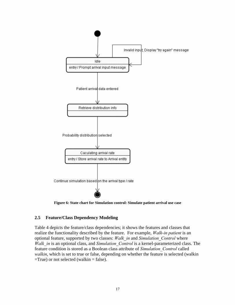
Figure 6: State chart for Simulation control: Simulate patient arrival use case
2.5 Feature/Class Dependency Modeling
Table 4 depicts the feature/class dependencies; it shows the features and classes that realize the functionality described by the feature. For example, Walk-in patient is an optional feature, supported by two classes: Walk_in and Simulation_Control where Walk_in is an optional class, and Simulation_Control is a kernel-parameterized class. The feature condition is stored as a Boolean class attribute of Simulation_Control called walkin, which is set to true or false, depending on whether the feature is selected (walkin =True) or not selected (walkin = false).
17
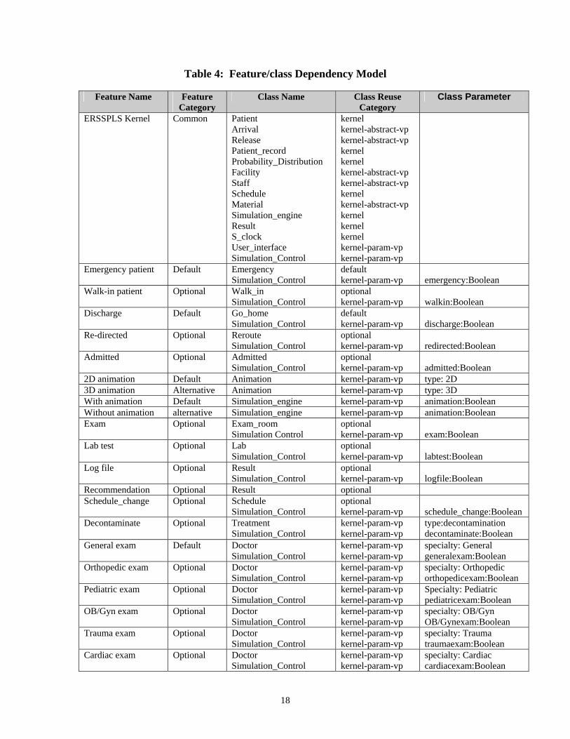
Table 4: Feature/class Dependency Model
Feature Name Feature Category
Class Name Class Reuse Category
Class Parameter
ERSSPLS Kernel Common Patient Arrival Release Patient_record Probability_Distribution Facility Staff Schedule Material Simulation_engine Result S_clock User_interface Simulation_Control
kernel kernel-abstract-vp kernel-abstract-vp kernel kernel kernel-abstract-vp kernel-abstract-vp kernel kernel-abstract-vp kernel kernel kernel kernel-param-vp kernel-param-vp
Emergency patient Default Emergency Simulation_Control
default kernel-param-vp
emergency:Boolean
Walk-in patient Optional Walk_in Simulation_Control
optional kernel-param-vp
walkin:Boolean
Discharge Default Go_home Simulation_Control
default kernel-param-vp
discharge:Boolean
Re-directed Optional Reroute Simulation_Control
optional kernel-param-vp
redirected:Boolean
Admitted Optional Admitted Simulation_Control
optional kernel-param-vp
admitted:Boolean
2D animation Default Animation kernel-param-vp type: 2D 3D animation Alternative Animation kernel-param-vp type: 3D With animation Default Simulation_engine kernel-param-vp animation:Boolean Without animation alternative Simulation_engine kernel-param-vp animation:Boolean Exam Optional Exam_room
Simulation Control optional kernel-param-vp
exam:Boolean
Lab test Optional Lab Simulation_Control
optional kernel-param-vp
labtest:Boolean
Log file Optional Result Simulation_Control
optional kernel-param-vp
logfile:Boolean
Recommendation Optional Result optional Schedule_change Optional Schedule
Simulation_Control optional kernel-param-vp
schedule_change:Boolean
Decontaminate Optional Treatment Simulation_Control
kernel-param-vp kernel-param-vp
type:decontamination decontaminate:Boolean
General exam Default Doctor Simulation_Control
kernel-param-vp kernel-param-vp
specialty: General generalexam:Boolean
Orthopedic exam Optional Doctor Simulation_Control
kernel-param-vp kernel-param-vp
specialty: Orthopedic orthopedicexam:Boolean
Pediatric exam Optional Doctor Simulation_Control
kernel-param-vp kernel-param-vp
Specialty: Pediatric pediatricexam:Boolean
OB/Gyn exam Optional Doctor Simulation_Control
kernel-param-vp kernel-param-vp
specialty: OB/Gyn OB/Gynexam:Boolean
Trauma exam Optional Doctor Simulation_Control
kernel-param-vp kernel-param-vp
specialty: Trauma traumaexam:Boolean
Cardiac exam Optional Doctor Simulation_Control
kernel-param-vp kernel-param-vp
specialty: Cardiac cardiacexam:Boolean
18
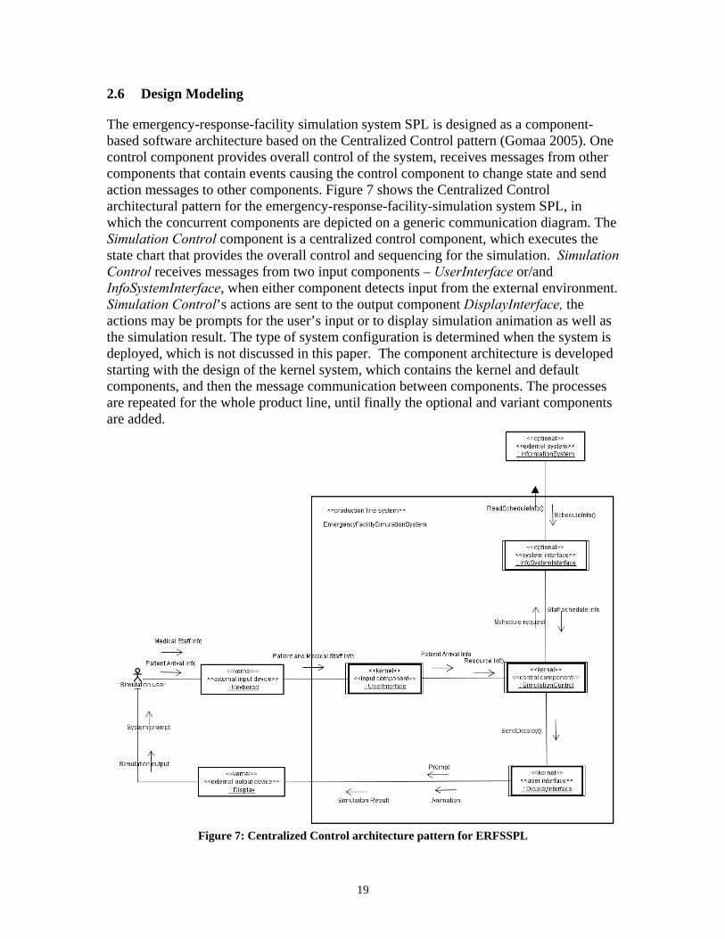
2.6 Design Modeling
The emergency-response-facility simulation system SPL is designed as a component-based software architecture based on the Centralized Control pattern (Gomaa 2005). One control component provides overall control of the system, receives messages from other components that contain events causing the control component to change state and send action messages to other components. Figure 7 shows the Centralized Control architectural pattern for the emergency-response-facility-simulation system SPL, in which the concurrent components are depicted on a generic communication diagram. The Simulation Control component is a centralized control component, which executes the state chart that provides the overall control and sequencing for the simulation. Simulation Control receives messages from two input components – UserInterface or/and InfoSystemInterface, when either component detects input from the external environment. Simulation Control’s actions are sent to the output component DisplayInterface, the actions may be prompts for the user’s input or to display simulation animation as well as the simulation result. The type of system configuration is determined when the system is deployed, which is not discussed in this paper. The component architecture is developed starting with the design of the kernel system, which contains the kernel and default components, and then the message communication between components. The processes are repeated for the whole product line, until finally the optional and variant components are added.
Figure 7: Centralized Control architecture pattern for ERFSSPL
19
3 A PROTOTYPE EMERGENCY ROOM SIMULATION SYSTEM
This section discusses a prototype of a hospital emergency room (ER) simulation system (the ER model) that is a software application derived from the ERFSSPL discussed in previous sections. This prototype emergency room simulation system is a discrete event simulation model of an emergency patient’s flow through a hospital. The purpose of this simulation is to provide a small but realistic model of resources, patients flow, and congestion in the ER of the hospital. The model will demonstrate how the incident affects the dispatch of emergency vehicles to transport of injured to hospital, waiting time in different areas, and the resources needed. The simulation will train incident management personnel and/or hospital management teams to respond to the crises that affect ER flow and evaluate the impact of their decisions by trying out scenarios, the deployment of resources, actions for triage, treatment of injured at the hospitals, and transfer of patients to other hospitals if needed. The prototype simulation model includes trauma rooms, cardiac rooms, specialty treatment rooms, and the ambulatory and ambulance entrances for patient arrival. The model uses an interactive user interface, allowing the user to make modifications to the model parameters. The user may change the patient arrival quantity and the number of trauma and cardiac patients. Users are allowed to add specialists such as pediatricians, orthopedic surgeons, and obstetrician/gynecologists as needed. The arrival of a critical patient such as a cardiac or trauma patient will use extra resources, which normally will cause a backlog of other patients. A scale layout of an ER is used as a background for the model. A bird's-eye view of treatment areas and the flow of patients, staff and support departments such as patient transport are modeled. Required data of the ER's operations is loaded into the model. The model then can be used to analyze the factors such as the arrival of the patients, staffing levels, room layout design and utilization, treatment times at each station, ancillary departments such as lab and imaging, physician practice patterns, and other variables that have an impact on ER operations. The primary entities in the simulation model are patients, medical staff, emergency vehicles, and other resources. Ambulatory patients are modeled as first-in first-out queues. The procedures of hospital ER simulation system development are as follows
• Determine the scope of the ER model within the product family. • Identify and acquire the data required to build the ER model, such as hospital
layout map, number of medical staff, and schedule of the doctors’ shifts. • Determine what parameters may be manipulated externally while the ER model is
running. • Determine the architecture of the ER model based on the product line simulation
models by considering the commonality and variability. • Construct a preliminary design of the ER model and its graphical interface using
SPL approach that allows the system be expanded or adapted to other settings. • Test and improve the hospital simulation system model.
20
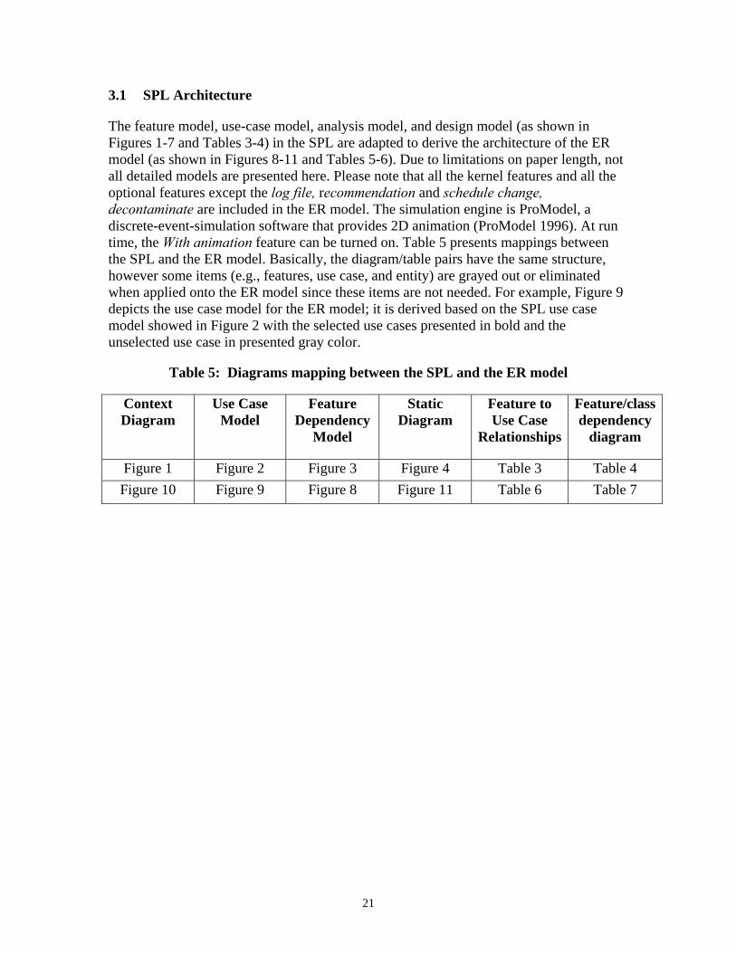
3.1 SPL Architecture
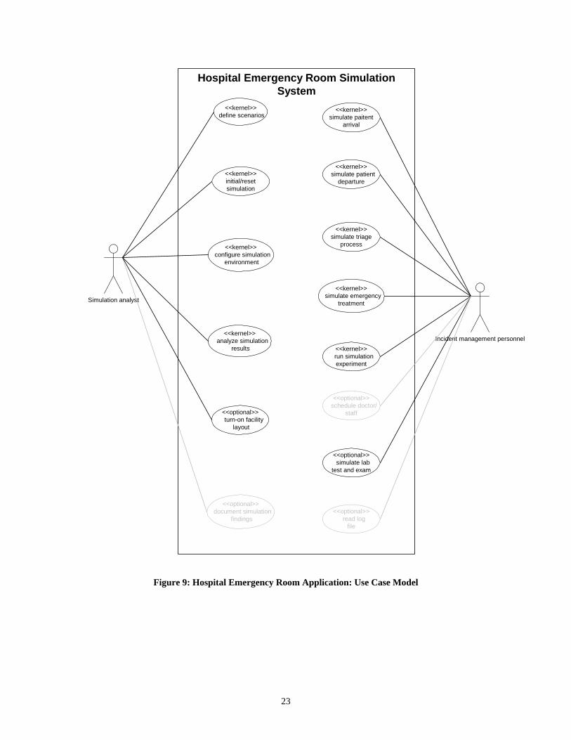
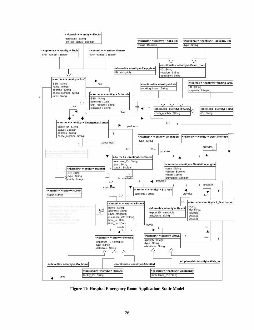
The feature model, use-case model, analysis model, and design model (as shown in Figures 1-7 and Tables 3-4) in the SPL are adapted to derive the architecture of the ER model (as shown in Figures 8-11 and Tables 5-6). Due to limitations on paper length, not all detailed models are presented here. Please note that all the kernel features and all the optional features except the log file, recommendation and schedule change, decontaminate are included in the ER model. The simulation engine is ProModel, a discrete-event-simulation software that provides 2D animation (ProModel 1996). At run time, the With animation feature can be turned on. Table 5 presents mappings between the SPL and the ER model. Basically, the diagram/table pairs have the same structure, however some items (e.g., features, use case, and entity) are grayed out or eliminated when applied onto the ER model since these items are not needed. For example, Figure 9 depicts the use case model for the ER model; it is derived based on the SPL use case model showed in Figure 2 with the selected use cases presented in bold and the unselected use case in presented gray color.
Table 5: Diagrams mapping between the SPL and the ER model
Context Diagram
Use Case Model
Feature Dependency
Model
Static Diagram
Feature to Use Case
Relationships
Feature/class dependency
diagram
Figure 1 Figure 2 Figure 3 Figure 4 Table 3 Table 4 Figure 10 Figure 9 Figure 8 Figure 11 Table 6 Table 7
21
<<common feature>>
ERFSSPL Kernel
<<optional feature>>
Exam
<<at-least-one-offeature group>>
Patient departure
<<optional feature>>
Log file
<<optional feature>>
Lab test
<<optional feature>>
Recommendation
<<optional feature>>
Re-directed
<<at-least-one-offeature group>>
Patient arrival
<<optional feature>>
Walk in patient
<<default feature>>
Emergency patient
<<exact-one-of featuregroup>>
Simulation display type
<<default feature>>
With animation
<<alternative feature>>
Without animation
{mutually exclusive feature}
<<optional feature>>
Admitted
requires
requires
requires
requires
requires
requires
requires
<<exactly-one-of feature group>>
Visualization
<<default feature>>
2D animation
<<alternative feature>>
3D animation
{mutually exclusive feature}
requires
<<default feature>>
Discharge
<<optional feature>>
Schedule change
requires
<<at-least-one-offeature group>>
Assessment
requires
<<optional feature>>
Decontaminate
requires
<<optional feature>>
Cardiac exam
<<default feature>>
General exam
<<optional feature>>
OB/Gyn exam
<<optional feature>>
Pediatric exam
<<optional feature>>
Orthopedic exam
<<optional feature>>
Trauma exam
Figure 8: Hospital Emergency Room Application: Feature Dependency Model
22
Hospital Emergency Room SimulationSystem
Simulation analyst
<<kernel>> configure simulation
environment
<<kernel>>initial/resetsimulation
<<kernel>> run simulation
experiment
<<optional>> turn-on facility
layout
<<optional>> read log
file
<<kernel>> analyze simulation
results
<<optional>> document simulation
findings
<<kernel>> define scenarios
<<optional>> schedule doctor/
staff
<<kernel>>simulate paitent
arrival
Incident management personnel
<<kernel>>simulate triage
process
<<kernel>> simulate emergency
treatment
<<optional>> simulate labtest and exam
<<kernel>> simulate patient
departure
Figure 9: Hospital Emergency Room Application: Use Case Model
23
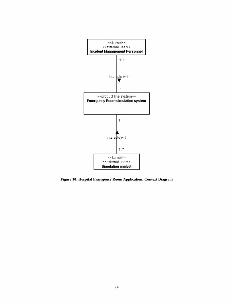
Figure 10: Hospital Emergency Room Application: Context Diagram
24
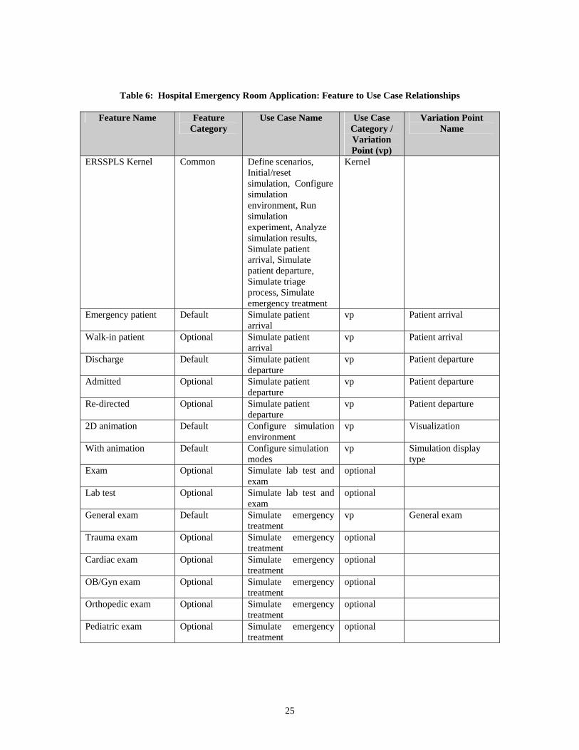
Table 6: Hospital Emergency Room Application: Feature to Use Case Relationships
Feature Name Feature Category
Use Case Name Use Case Category / Variation Point (vp)
Variation Point Name
ERSSPLS Kernel Common Define scenarios, Initial/reset simulation, Configure simulation environment, Run simulation experiment, Analyze simulation results, Simulate patient arrival, Simulate patient departure, Simulate triage process, Simulate emergency treatment
Kernel
Emergency patient Default Simulate patient arrival
vp Patient arrival
Walk-in patient Optional Simulate patient arrival
vp Patient arrival
Discharge Default Simulate patient departure
vp Patient departure
Admitted Optional Simulate patient departure
vp Patient departure
Re-directed Optional Simulate patient departure
vp Patient departure
2D animation Default Configure simulation environment
vp Visualization
With animation Default Configure simulation modes
vp Simulation display type
Exam Optional Simulate lab test and exam
optional
Lab test Optional Simulate lab test and exam
optional
General exam Default Simulate emergency treatment
vp General exam
Trauma exam Optional Simulate emergency treatment
optional
Cardiac exam Optional Simulate emergency treatment
optional
OB/Gyn exam Optional Simulate emergency treatment
optional
Orthopedic exam Optional Simulate emergency treatment
optional
Pediatric exam Optional Simulate emergency treatment
optional
25
1..*
1
consumes
11..*has
1
1..*
has
-type : String<<optional>> <<entity>> Radiology_rm
-ID : String-capacity : Integer
<<kernel>> <<entity>> Waiting_area
-ID : String<<kernel>> <<entity>> Bed
-room_number : String<<kernel>> <<entity>>Facility
-facility_ID : String-status : Boolean-address : String-phone_number : String
<<kernel>> <<entity>> Emergency_Center
-admisssion_date : Date-release_date : Date-room/bed : Integer-medications_used : String-test_performed : String
<<optional> <<entity>> Patient_record
-ID : string(idl)<<kernel>> <<entity>> Help_desk
1
1..*has
-SSN : String-name : Integer-address : String-phone_number : String-rank : String
<<kernel>> <<entity>> Staff
-name : String-address : String-SSN : string(idl)-insurance_info : String-time_in : Date-time_out : Date
<<kernel>> <<entity>> Patient
*
1..*
is provided to
-ID : String-location : String-specilaity : String
<<optional>> <<entity>> Exam_room
-working_hours : String<<optional>> <<entity>> Lab
-departure_ID : string(idl)-type : String-date/time : String
<<kernel>> <<entity>> Release
-shift_number : Integer<<kernel>> <<entity>> Nurse
-speciality : String-on_call_status : Boolean
<<kernel>> <<entity>> Doctor
-shift_number : Integer<<optional>> <<entity>> Tech
-ID : String-type : String-qutity : Integer
<<kernel>> <<entity>> Material
-name : String<<kernel>> <<entity>> Medication
-status : String<<kernel>> <<entity>> Linen
1
1..*
consumes
-status : Boolean<<kernel>> <<entity>> Triage_rm
-SSN : String-date/time : Date-shift_number : String-loccation : String
<<kernel>> <<entity>> Schedule1
*has
-quantity : Integer-type : String-date/time : String
<<kernel>> <<entity>> Arrival
11needs
*1
needs
-type[1]-identifier[1]-value1[1]-value2[1]-value3[1]
<<kernel>> <<entity>> P_Distribution
1
1 uses
1
1
uses
-ambulance_ID : String<<default>> <<entity>> Emergency
<<optional>> <<entity>> Walk_in<<optional>> <<entity>>Admitted
-facility_ID : String<<optional>> <<entity>> Reroute
<<default>> <<entity>> Go_home
<<kernel>> <<entity>> User_interface
-name : String-version : Boolean-vender : String-animation : Boolean
<<kernel>> <<entity>> Simulation_engine
1
1
provides
1
1..*
provides
-type : String<<kernel>> <<entity>> Animation
0..1
1
provides
-report_ID : string(idl)-date/time : String
<<kernel>> <<entity>> Result
1
1..*
provides-date/time : String<<kernel>> <<entity>> S_Clock
11 provides
1
1
uses
-treatment_ID : String-type : String-status : Boolean
<<kernel>> <<entity>> treatment
1
1..*
performs
1
*
has
Figure 11: Hospital Emergency Room Application: Static Model
26
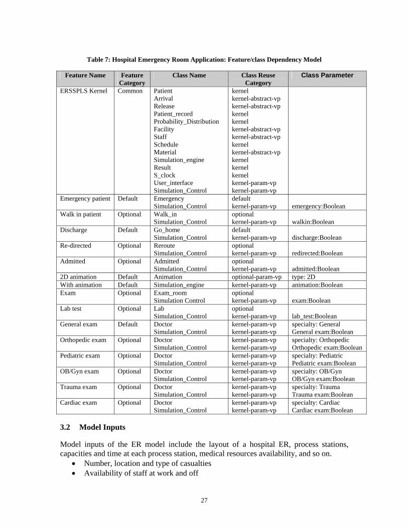
Table 7: Hospital Emergency Room Application: Feature/class Dependency Model
Feature Name Feature
Category Class Name Class Reuse
Category Class Parameter
ERSSPLS Kernel Common Patient Arrival Release Patient_record Probability_Distribution Facility Staff Schedule Material Simulation_engine Result S_clock User_interface Simulation_Control
kernel kernel-abstract-vp kernel-abstract-vp kernel kernel kernel-abstract-vp kernel-abstract-vp kernel kernel-abstract-vp kernel kernel kernel kernel-param-vp kernel-param-vp
Emergency patient Default Emergency Simulation_Control
default kernel-param-vp
emergency:Boolean
Walk in patient Optional Walk_in Simulation_Control
optional kernel-param-vp
walkin:Boolean
Discharge Default Go_home Simulation_Control
default kernel-param-vp
discharge:Boolean
Re-directed Optional Reroute Simulation_Control
optional kernel-param-vp
redirected:Boolean
Admitted Optional Admitted Simulation_Control
optional kernel-param-vp
admitted:Boolean
2D animation Default Animation optional-param-vp type: 2D With animation Default Simulation_engine kernel-param-vp animation:Boolean Exam Optional Exam_room
Simulation Control optional kernel-param-vp
exam:Boolean
Lab test Optional Lab Simulation_Control
optional kernel-param-vp
lab_test:Boolean
General exam Default Doctor Simulation_Control
kernel-param-vp kernel-param-vp
specialty: General General exam:Boolean
Orthopedic exam Optional Doctor Simulation_Control
kernel-param-vp kernel-param-vp
specialty: Orthopedic Orthopedic exam:Boolean
Pediatric exam Optional Doctor Simulation_Control
kernel-param-vp kernel-param-vp
specialty: Pediatric Pediatric exam:Boolean
OB/Gyn exam Optional Doctor Simulation_Control
kernel-param-vp kernel-param-vp
specialty: OB/Gyn OB/Gyn exam:Boolean
Trauma exam Optional Doctor Simulation_Control
kernel-param-vp kernel-param-vp
specialty: Trauma Trauma exam:Boolean
Cardiac exam Optional Doctor Simulation_Control
kernel-param-vp kernel-param-vp
specialty: Cardiac Cardiac exam:Boolean
3.2 Model Inputs
Model inputs of the ER model include the layout of a hospital ER, process stations, capacities and time at each process station, medical resources availability, and so on.
• Number, location and type of casualties • Availability of staff at work and off
27
• Availability of resources • Time and resources required for attending to each casualty type • Hospital location • Process stations • Station capacities • Station processing times • Patient arrivals rate • Hospital shifts • Medical resources • Symptom-treatment profiles
3.3 Model Outputs
Outputs of the ER model include periodic updates of the status of all entities, location of the patient and medical staff, and utilizations of process stations and resources.
• System utilization • Resources utilization • Number of people treated and released, admitted, dead, waiting for treatment over
time • State of the staff and facilities (to determine their capability to deal with another
incident) • Run Time Interactions • Simulation clock time
3.4 Model Logic
The ER model logic includes relevant policies and procedures for emergencies including calling in medical staff, using temporary accommodations for the injured, and acquiring needed supplies and equipment. Figure 12 depicts the model overview. Patients arrive in the ER either through the general entrance or via ambulance. An ambulance is for those patients who are in critical condition, such as trauma and cardiac. The hospital groups patients into different categories based on the severity of their injuries. Trauma or cardiac patients are considered the most critical and need to be treated immediately. Other non-life threatening patients go through a triage process whereby the hospital makes an initial assessment of their injuries. The patient is then transferred to an available room for further exam and treatment. They go through a registration process either before or after the treatment, depending on the severity of their injury. After initial medical treatment, the hospital can release the patient or assign them to a room in the hospital for a longer stay. Because of the limitation of the rooms and beds the hospital has, or if special technology/equipment needed were not available by the hospital, the patient may have to be redirected to an alternate facility.
After a patient is taken into the exam room, the nurse and technician will start the initial assessment or treatment. A medical record is created for the doctors’ review, doctors will then examine the patient and make decisions, and the patient will be moved to the Nurse Unit when all the necessary procedures are done. Generally, most patients are ambulatory
28
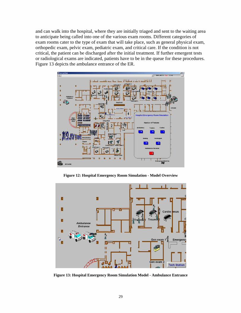
and can walk into the hospital, where they are initially triaged and sent to the waiting area to anticipate being called into one of the various exam rooms. Different categories of exam rooms cater to the type of exam that will take place, such as general physical exam, orthopedic exam, pelvic exam, pediatric exam, and critical care. If the condition is not critical, the patient can be discharged after the initial treatment. If further emergent tests or radiological exams are indicated, patients have to be in the queue for these procedures. Figure 13 depicts the ambulance entrance of the ER.
Figure 12: Hospital Emergency Room Simulation - Model Overview
Figure 13: Hospital Emergency Room Simulation Model - Ambulance Entrance
29
3.5 Analysis of the simulation result
Through the analysis of statistical results of the simulation output, the simulation model of hospital ER can help management to find out potential problems. Incident managers can use the simulation model to do "what-ifs." For instance, they can tell the model how long it takes to perform particular steps in the triage processes, where the processes take place, and the number of staff available. Simulation will show them in a visual way the impact they have on the ER's processes.
• Run the model and observe the values calculated on-screen. • Examine the statistical result and plot/chart of the probabilities for different
scenarios. • Discuss the conclusions as well as any recommendations for improving the
models performance. • Improve quality and efficiency of decision making in case of a true emergency.
Better design of the hospital ER may be tested before actual investments take place.
4 CONCLUSIONS
Simulation can support decision making through all phases of incident management, including prevention, preparedness, response, recovery and mitigation. However, simulations are often developed from scratch, and there is little opportunity for the analyst to build upon the work of others since each simulation is built as a custom solution to a uniquely defined problem. A better solution would be to simplify the design through a re-usable process. This paper proposes to apply the Software Product Line (SPL) technology onto the simulation-based training modules for supporting incident management. The beauty of the SPL is to capitalize on commonality and manage variation in order to reduce the time, effort, cost and complexity of creating and maintaining a product line of similar software systems. This paper discussed the requirements, analysis, and design models for a family of simulation systems of emergency response facility. The modeling of a family of emergency response facility simulation tools is performed based on the Product Line UML-based Software engineering (PLUS) method. UML is used to describe components during the analysis, design, and implementation stages and to capture their characteristics and relationships. This paper also demonstrates reusability by presenting a prototype of the SPL member system: a hospital emergency room simulation system that is derived from the SPL design. It demonstrates how easily the SPL member model can be derived once the SPL architecture had been built. Future work is intended to use SPL to build applications for various emergency response activities that support incident management for different scenarios.
30
31
Disclaimer No approval or endorsement of any commercial product by the National Institute of Standards and Technology is intended or implied. Certain commercial software and related materials are identified in this report to facilitate understanding. Such identification does not imply recommendation or endorsement by the National Institute of Standards and Technology, nor does it imply that the materials or equipment identified are necessarily the best available for the purpose. The work described here was funded by the United States Government and is not subject to copyright. References
[1] D.L. Parnas, 1976. "On the Design and Development of Program Families," IEEE Transactions on Software Engineering, Vol. SE2, No. 1, March 1976, pp. 1-9. [2] D. M. Raffo, 1999 “Getting the Benefits from Software Process Simulation,” Proceedings of the International Conference on Software Engineering and Knowledge Engineering (SEKE’99), Held in Kaiserlautern, Germany [3] Grady Booch, James Rumbaugh, Ivar Jacobson, 2005. “Unified Modeling Language User Guide,” (2nd
Edition) The Addison-Wesley Object Technology Series. [4] Hassan Gomaa, 2005. “Designing Software Product Lines with UML: From Use Cases to Pattern- Based Software Architectures,” Addison-Wesley Object Technology Series. [5] Jeffrey S Amodie, 1995. “Simulation modeling for hospital emergency department resource analysis,” Florida Atlantic University [6] L. Patvivatsiri, 2006. “Simulation Model for Bioterronrism Preparedness in an Emergency Room,” Proceedings of the 2006 Winter Simulation Conference. L. F. Perrone, F.P. Wieland, J. Liu, B. G. Lawson, D. M. Nicol, and R. M. Fujimoto, eds. [7] National Research Council (NRC), 2002. “Making the Nation Safer: The Role of Science and
Technology in Countering Terrorism.” National Academies Press, Washington DC, USA. [8] Paul Clements and Linda Northrop, 2002. “Software Product Lines: Practices and Patterns,” Addison- Wesley. [9] Robinson, C, Brown, D., 2005. “Development of Metrics to Evaluate Effectiveness of Emergency Response Operations,” 10th International Command and Control Research and Technology Symposium. [10] Sanjay Jain, and Charles. R. McLean, 2003. Modeling and Simulation of Emergency Response:
Workshop Report, Relevant Standards and Tools. National Institute of Standards and Technology Internal Report, NISTIR-7071. Available via <http://www.nist.gov/msidlibrary/doc/nistir7071.pdf> .
[11] SEI webpage, 2007. www.sei.cmu.edu/productlines. [12] Sullivan, Thomas J., 1985. “Modeling and Simulation for Emergency Response.” Lawrence Livermore National Laboratory, Report No. UCRL 92001 Preprint. [13] Tullio Vernazza, Stefano De anfilis, Paolo Predonzani, Giancarlo Succi, 2000. “A product line experience in the domain of fund management.” Proceedings of the ICSE 2000 Workshop on Software Product Lines: Economics, Architectures and Implications, Limerick, Ireland, June [14] ProModel Manufacturing Simulation Software Reference Guide, 1996, Orem, UT [15] ProModel Manufacturing Simulation Software User’s Guide, 1996, Orem, UT [16] SPLs webpage, 2007 http://www.softwareproductlines.com/
Related Documents


