SIMULATION, DESIGN AND PRACTICAL IMPLEMENTATION OF A MOBILE WIRELESS AUTONOMOUS SURVEILLANCE SYSTEM T.C. Manjunath* , P.S. Shingare* , S. Janardhanan* * Research Scholars , Interdisciplinary Programme in Systems and Control Engineering , ACRE Building , Indian Institute of Technology Bombay , Maharashtra State, India. Keywords: Driver Units, Actuators, Micro-controller, Parallel Port Interface, Transmitter, Receiver. Abstract: The paper presents the design, implementation of the a unique type of computer controlled wireless mobile surveillance robot equipped with intelligence. Building an experimental autonomous mobile wireless vehicle, which has the ability to perform in real time environments is both a technical and scientific challenge and demands the development of systems for perception, modeling, planning and navigation. Within this scope, this paper describes the construction of a low cost mobile autonomous robot, intended for educational and surveillance purposes. This is a technology demonstration work. The objective of the work is to design, fabricate each part and construct a mobile robot and control it with a computer through wireless link which would accomplish two dimensional motion on a horizontal plane, moving from one place to another, avoiding obstacles in its path of motion by using infra-red sensors and performing the pick and place motion. The work was undertaken as a sponsored consultation based project under the guidance of the author in the institute. 1 INTRODUCTION We are living in the age of automation. Today, things are becoming more and more automated. Automation has taken over the traditionally manually controlled process in almost all the industries. Today, a mobile robot can be designed in order to operate in a wide range of industrial, military, scientific, domestic, humanity and in educational applications. Here, we have designed and implemented such a system and is as follows. 2 DESIGN OF THE MECHANICAL SUBSYSTEM Our aim was to make a mobile robot, which can move on a floor and perform pick and place operation. It’s mechanical set-up has been divided into three parts for ease in understanding the assembly, viz., Movable base assembly, Manipulator with up / down motion, Gripper. 2.1 Movable Base Assembly The mobile base assembly is moving on two wheels fit at the back end of the base and protruding out from side. Castor wheel is fit below acrylic sheet to support base assembly. Acrylic sheet has following properties, viz., Light in weight, Good insulating medium, Can be cut into various shapes and sizes. To drive the system we have to use motors that can give sufficient torque and at the same time they should have sufficient rpm so that the robot can move at a respectable speed. We had following options before us. AC motors, Stepper motors and DC Servo motors. The first option of using a.c. motors was rejected, as it would have required a power to the mobile system from ac mains supply and this would have clearly inhibited the movement of mobile base assembly. Stepper motors are bulky and also consume more power to give same amount of torque as simple DC servomotors. Hence, even this option is rejected. DC servomotors are light weighted and consume less power. Therefore they can be easily driven 446 C. Manjunath T., S. Shingare P. and Janardhanan S. (2004). SIMULATION, DESIGN AND PRACTICAL IMPLEMENTATION OF A MOBILE WIRELESS AUTONOMOUS SURVEILLANCE SYSTEM. In Proceedings of the First International Conference on Informatics in Control, Automation and Robotics, pages 446-454 DOI: 10.5220/0001144504460454 Copyright c SciTePress

Welcome message from author
This document is posted to help you gain knowledge. Please leave a comment to let me know what you think about it! Share it to your friends and learn new things together.
Transcript
SIMULATION, DESIGN AND PRACTICAL IMPLEMENTATION OF A MOBILE WIRELESS
AUTONOMOUS SURVEILLANCE SYSTEM
T.C. Manjunath* , P.S. Shingare* , S. Janardhanan* * Research Scholars , Interdisciplinary Programme in Systems and Control Engineering ,
ACRE Building , Indian Institute of Technology Bombay , Maharashtra State, India.
Keywords: Driver Units, Actuators, Micro-controller, Parallel Port Interface, Transmitter, Receiver.
Abstract: The paper presents the design, implementation of the a unique type of computer controlled wireless mobile surveillance robot equipped with intelligence. Building an experimental autonomous mobile wireless vehicle, which has the ability to perform in real time environments is both a technical and scientific challenge and demands the development of systems for perception, modeling, planning and navigation. Within this scope, this paper describes the construction of a low cost mobile autonomous robot, intended for educational and surveillance purposes. This is a technology demonstration work. The objective of the work is to design, fabricate each part and construct a mobile robot and control it with a computer through wireless link which would accomplish two dimensional motion on a horizontal plane, moving from one place to another, avoiding obstacles in its path of motion by using infra-red sensors and performing the pick and place motion. The work was undertaken as a sponsored consultation based project under the guidance of the author in the institute.
1 INTRODUCTION
We are living in the age of automation. Today, things are becoming more and more automated. Automation has taken over the traditionally manually controlled process in almost all the industries. Today, a mobile robot can be designed in order to operate in a wide range of industrial, military, scientific, domestic, humanity and in educational applications. Here, we have designed and implemented such a system and is as follows.
2 DESIGN OF THE MECHANICAL SUBSYSTEM
Our aim was to make a mobile robot, which can move on a floor and perform pick and place operation. It’s mechanical set-up has been divided into three parts for ease in understanding the assembly, viz., Movable base assembly, Manipulator with up / down motion, Gripper.
2.1 Movable Base Assembly
The mobile base assembly is moving on two wheels fit at the back end of the base and protruding out from side. Castor wheel is fit below acrylic sheet to support base assembly. Acrylic sheet has following properties, viz., Light in weight, Good insulating medium, Can be cut into various shapes and sizes. To drive the system we have to use motors that can give sufficient torque and at the same time they should have sufficient rpm so that the robot can move at a respectable speed. We had following options before us. AC motors, Stepper motors and DC Servo motors. The first option of using a.c. motors was rejected, as it would have required a power to the mobile system from ac mains supply and this would have clearly inhibited the movement of mobile base assembly. Stepper motors are bulky and also consume more power to give same amount of torque as simple DC servomotors. Hence, even this option is rejected. DC servomotors are light weighted and consume less power. Therefore they can be easily driven
446C. Manjunath T., S. Shingare P. and Janardhanan S. (2004).SIMULATION, DESIGN AND PRACTICAL IMPLEMENTATION OF A MOBILE WIRELESS AUTONOMOUS SURVEILLANCE SYSTEM.In Proceedings of the First International Conference on Informatics in Control, Automation and Robotics, pages 446-454DOI: 10.5220/0001144504460454Copyright c© SciTePress
from a small on board dc power supply using a simple electronic driving circuitry. Hence dc servomotors were selected, as they were perfectly suited for our application. Two D.C. Servomotors drives the base assembly on which all electronic component and gripper are mounted. These motors are mounted on the lower surface of acrylic sheet with help of cast aluminum brackets (clamping). The process known as sand casting of the aluminum makes clamping. To smooth the surface after casting, filing and machining have been done on clamping. To achieve the free rotation of the wheels, bearing is fitted in each clamper. Clampers are than attached to the base with the help of nuts and bolts. Since the base has to carry the whole weight of robot, torque at the wheel shafts has to be very high. This is achieved with spur gears. The motor shaft have a self - locking capability, i.e., motor shaft gets locked in the same position where it was when the power supply to the motor is removed.
2.2 Manipulator With Up / Down Motion
A robot manipulator is a mechanical device. To achieve the up / down motion of the gripper the following arrangement has been made. A geared DC servomotor with gearbox (inside) is fitted below the acrylic sheet in the front portion of the robot such that motor shaft is come out from the top surface. Long threaded ms is directly coupled to the motor shaft with the help of nut and bolt. A cuboids of acrylic sheet is internally threaded with same threading as on sliver rod so that it can freely move up or down on ms rod shaft. Gripper is attached to the cuboids with the long bolt and nut.
2.3 Gripper
The Robot being PNP-type has a gripper as the end effecter. The gripper will be of parallel jaw type, which will work on the principle of left-hand / right-hand screw. The LH / RH screw will be made by tapping a brass rod with LH die from one end and RH die from other end so that gripper jaws will move in opposite direction, that is jaws will move either towards each other to grip an object or away from each other to release it. The LH / RH screw will be coupled to a motor shaft via spur gear arrangement.
2.4 Gears
The gears are required for following two reasons:
• For reducing the speed of the robot. • For increasing torque of the motors.
2.5 Specification of Motors / GEARS
BASE MOTORS Torque: 10 kg.cm, Current rating 1A, CW-CCW Motion, Base Motor Speed - 55 r.p.m.
GRIPPER MOTOR Torque: 5kg.cm, Current Rating 0.5A, CW-CCW Motion, Base Motor Speed 55 r.p.m
GEARS Material: Deldrin ( Polyacetal resin), Ratio 1: 4 ----- 12 × 48 teeths, Center : Aluminium Bush with 3 / 8” with 3 nos. screw / tapped holes.
3 THE PC’S SERIAL PORT
This topic looks at serial ports inside the PC, between the connector and the CPU.
PORT ARCHITECTURE The UART ABOUT RS-232 THE MAX 232
A simple way to translate from 5V logic to RS - 232 is to use one of the many chips designed for this purpose. Maxim Semiconductor was the first to offer RS - 232 interface chips that require only a +5V power supply. Many other companies, including Linear Technology, Harris Semiconductor, Texas Instruments, Dallas, Semiconductor, and National Semi-conductor, now have similar chips, as well as dozens of derivatives for just about every conceivable configuration. The chips may be listed in catalogs and data books under Linear, Interface, or Special Function ICs. The original MAX 232 includes two drivers that covert TTL inputs to RS - 232 outputs, and two receivers that accept RS - 232 inputs and translate them to CMOS - compatible outputs. The drivers and receivers also invert the signals.
SIMULATION , DESIGN AND PRACTICAL IMPLEMENTATION OF A MOBILE WIRELESS AUTONOMOUSSURVEILLANCE SYSTEM
447
3.1 Voltages For 5 V TTL And CMOS Logic
Table 1: Voltage levels Parameter TTL
Logic (Volts)
CMOS logic (volts)
74HCT (Volts)
Logic-low output (max)
0.4 0.1 0.1
Logic-high output (min)
2.4 3.5 3.5
Logic-low input (max)
0.8 1 0.8
Logic-high input (min)
2.0 3.5 2.0
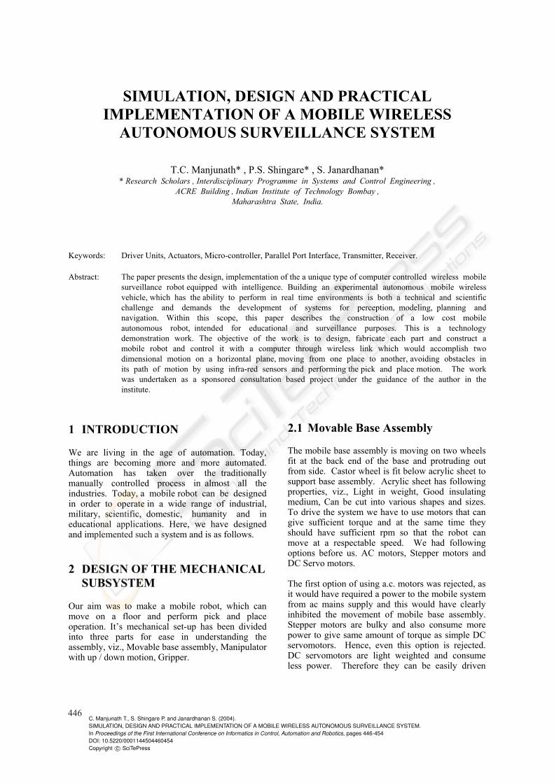
The chip contains two charge - pump voltage converters that act as tiny, unregulated power supplies that enable loaded RS - 232 outputs of + 7V or better. Four external capacitors store energy for the supplies. The recommended value for the capacitors is 1µF or larger. Most of the example circuits in this book use a MAX232A or MAX233, but you can use any converter with the appropriate number of drivers and receivers.
Figure 1: Max 232
4 FM TRANSMITTER
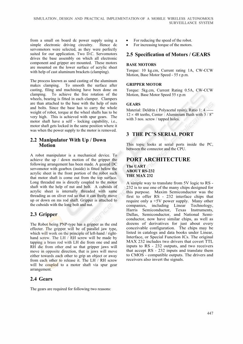
Figure 2: FM Transmitter There are basically two methods of FM generation : 1. Parameter variation method. 2. Indirect method (Armstrong method). The above schematic is for a FM transmitter with 2 W O/P power that can be used b/w 85 and 110MHz. This circuit uses “parameter variation method” of FM generation. In the above circuit, the carrier frequency is very nearly equal to the resonant frequency of an inductance capacitance combination. Thus the carrier frequency is f = (2 ∏ √L1C1)–1. The trimming capacitor C1 is shunted by a voltage variable capacitor Cv. A voltage variable capacitor commonly called a varicap (BB204), is one whose capacitance value depends on the to biasing voltage maintained across it’s electrodes. In the circuit the modulating signal varies the voltage across Cv. As a consequence, the capacitance of Cv changes and causes corresponding change in carrier frequency. Thus at the contractor of transistor Q1 and Q2 we get signal whose instantaneous frequency depends on the instantaneous value of the modulating signal (i.e., FM). This signal is amplified by class push - pull power amplifier formed by Q1 and Q2. Then the amplified signal is coupled to an antenna. In this circuit Q1 and Q2 should be cooled with a heat sink. The 22pf variable capacitor is for the frequency adjustment. The another trimmer must be adjusted to maximum power with minimum SWR and input current. A principal difficulty with this circuit is that when we require the carrier frequency to be
ICINCO 2004 - ROBOTICS AND AUTOMATION
448
maintained constant to a high order of precision over extended period of time. There is certain measure of inconsistency in requiring that a device have a long time frequency stability and yet be able to respond readily to a modulating signal.
5 ANTENNA CONSTRUCTION DETAILS
There are two types of antennas. They are a hi-gain multi-element yagi antenna for long-range transmission and simple open dipole antenna for short-range transmission. Also another very simple type of antenna, called GP antenna or ‘Ground Plane’ antenna, could be used, but GP antenna and a half – wave dipole antenna gives approximately the same range while a half – wave dipole antenna is much simpler to built and easy to erect at a more height than a GP antenna. That is why we are not going into detailed construction of GP antenna.
First, we will describe the hi-gain, 5 - element yagi antenna. A yagi antenna gives much more gain than a dipole both for reception or transmission. Actually a yagi is an array consisting of a driven element (the dipole) and one or more parasitic elements. This type of antenna is relatively unidirectional and the directive gain is improved by the addition of more directors to give directive gains from about 7dB for a three - element yagi to about 15 dB for a five - element yagi. Therefore, it is obvious that if you use a five - element yagi instead of a simple dipole for both transmission and reception range will increase even up to 150%.
For this purpose, you need to construct an ‘open-dipole’ very carefully. This is a directional type antenna and if you use it horizontal, as shown in the figure, it gives a ‘figure of eight’ radiation pattern transmission perpendicular to its length. This way, signal travels much larger distance. Here two telescopic aerials or two ½” or ¾” diameter aluminum rod, each of length defined by 0.475W or 1484mm for 96 MHz application is used as two ‘Dipole Elements’.
Place them on a horizontal plastic or wooden plate and fix with nut - bolts. Insulated ropes instead of nut - bolts to fasten elements with the
plate can be used. This plastic or wooden plate serves two purposes. Firstly it hold two dipole elements in a same horizontal line and secondly it insulates between two elements as well as from the boom. Here you must ensure while constructing that two dipole elements should never come into contact with each other and also with boom. Also two elements should remain in a single straight line. Connect co-axial cable RG 59 (or any other good quality 75 ohms CATV co-axial cable) as shown in the figure.
Center core should be connected to one element (any one) and shielding should be connected to another. In figures, for the sake of clarity, we have shown that RG59 is long stripped and connected to elements. But you should not strip co-axial long. Strip as much needed and connect it just at the 25mm openings of dipole with small screws. Ensure that co-axial shielding or center core does not touch boom. No we shall describe construction details of rest of the yagi. You will need a 1” x 1” square boom with some ½” or ¾” diameter aluminum rod (for dipole and other elements) to build this yagi. We have already discussed how to make the dipole.
Now for fixing this dipole with the boom at appropriate place, you need to drill hole at the boom and at the base plate (plastic or wooden plate). The is clearly shown in the above figure. Ensure that while fixing the dipole with the boom, the but-bolt (placed between two dipole elements, in the 25mm gap) should never come into contact with any dipole element or co-axial cable (as this nut-bolt is electrically connected with bloom). Now fix the rest of the elements, i.e. one reflector and three directors. Drill hole at the boom according to figure and use nut bolts to attach all directors and reflector with boom. It does not matter whether the elements are electrically connected to boom or not. Just they should be parallel to each other and perpendicular to boom. The antenna boom should be kept horizontal in all conditions for best results.
SIMULATION , DESIGN AND PRACTICAL IMPLEMENTATION OF A MOBILE WIRELESS AUTONOMOUSSURVEILLANCE SYSTEM
449
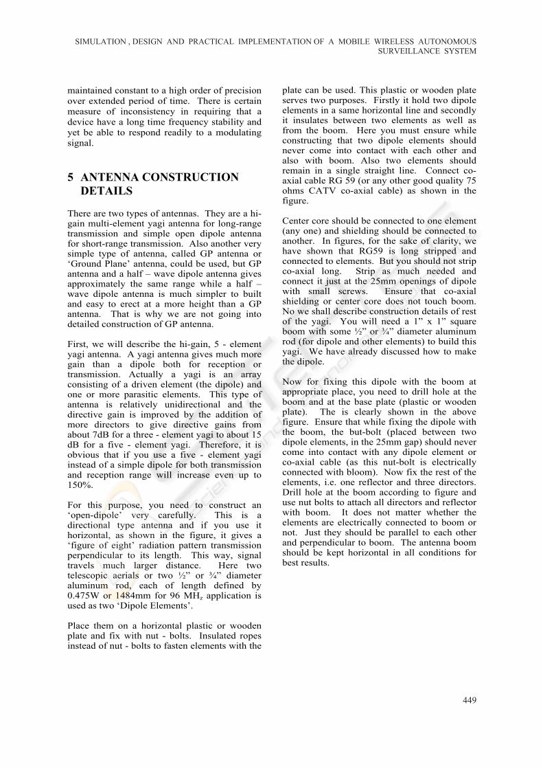
6 IMPORTANT INSTRUCTIONS REGARDING ANTENNA
Table 2: Frequency Range 96MHz f MHz Reflector 1563mm 0.5W Open Dipole 1484mm 0.475WDirector 1 1409mm 0.451WDirector 2 1341mm 0.429WDirector 3 1272mm 0.407W
Antenna should be erected at least at the highest point of a double storey building roof using a PVC pipe, metal pipe or bamboo etc. i.e. antenna height should be at least 30 - 40 feet above ground level.
Direction of maximum radiation is perpendicular to the element in case of dipole antenna, exactly like yagi.
There should be no physical obstruction in front of dipole / yagi and the ‘line of sight’ for transmission should be free.
Use very good quality wire in all cases. Use as much wire as needed, If you use
minimum wire, power loss in the wire would be less and you will get more range.
Television antenna or CATV connection wire should be at least 20 - 30 feet away from dipole antenna; otherwise interference may happen.
Never make a circular or spiral coil of the excess wire as you normally do it in case of a TV receiver. This will decrease range drastically. Cut the excess wire.
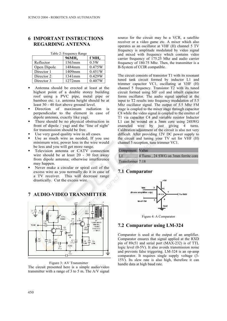
7 AUDIO-VIDEO TRANSMITTER
Figure 3: AV Transmitter The circuit presented here is a simple audio/video transmitter with a range of 3 to 5 m. The A/V signal
source for the circuit may be a VCR, a satellite receiver or a video game etc. A mixer which also operates as an oscillator at VHF (H) channel 5 TV frequency is amplitude modulated by video signal and mixed with frequency which contains video carrier frequency of 175.25 Mhz and audio carrier frequency of 180.75 Mhz. Then, the transmitter is a B-System of CCIR compatible. The circuit consists of transistor T1 with its resonant tuned tank circuit formed by inductor L1 and trimmer capacitor VC1, oscillating at VHF (H) channel 5 frequency. Transistor T2 with its tuned circuit formed using SIF coil and inbuilt capacitor forms oscillator. The audio signal applied at the input to T2 results into frequency modulation of 5.5 Mhz oscillator signal. The output of 5.5 Mhz FM stage is coupled to the mixer stage through capacitor C8 while the video signal is coupled to the emitter of T1 via capacitor C4 and variable resistor Inductor L1 can be wound on a 3mm core using 24SWG enameled wire by just giving 4 turns. Calibration/adjustment of the circuit is also not very difficult. After providing 12V DC power supply to the circuit and tuning your TV set for VHF (H) channel 5 reception, tune trimmer VC1.
Component Value L1 4 Turns , 24 SWG on 3mm ferrite coreTransformer 7:18
7.1 Comparator
Figure 4: A Comparator
7.2 Comparator using LM-324
Comparator is used at the output of an amplifier. Comparator ensures that signal applied at the RXD pin of 89c51 and serial port (MAX-232) is of TTL logic level (0-5V). It also avoids transmission noise and prevents false triggering. LM-324 is an op-amp comparator. It requires single supply voltage (3-15V). Its slew rate is also high, therefore it can handle data at high baud rate.
ICINCO 2004 - ROBOTICS AND AUTOMATION
450
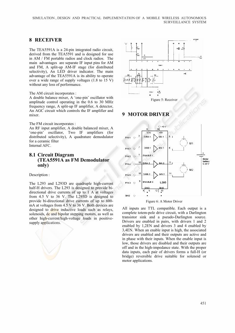
8 RECEIVER
The TEA5591A is a 24-pin integrated radio circuit, derived from the TEA5591 and is designed for use in AM / FM portable radios and clock radios. The main advantages are separate IF input pins for AM and FM, A split-up AM-IF stage (for distributed selectivity), An LED driver indicator. The main advantage of the TEA5591A is its ability to operate over a wide range of supply voltages (1.8 to 15 V) without any loss of performance.
The AM circuit incorporates : A double balance mixer, A ‘one-pin’ oscillator with amplitude control operating in the 0.6 to 30 MHz frequency range, A split-up IF amplifier, A detector, An AGC circuit which controls the IF amplifier and mixer.
The FM circuit incorporates : An RF input amplifier, A double balanced mixer, A ‘one-pin’ oscillator, Two IF amplifiers (for distributed selectivity), A quadrature demodulator for a ceramic filter Internal AFC.
8.1 Circuit Diagram (TEA5591A as FM Demodulator only)
Description :
The L293 and L293D are quadruple high-current half-H drivers. The L293 is designed to provide bi-directional drive currents of up to 1 A at voltages from 4.5 V to 36 V. The L293D is designed to provide bi-directional drive currents of up to 600-mA at voltages from 4.5 V to 36 V. Both devices are designed to drive inductive loads such as relays, solenoids, dc and bipolar stepping motors, as well as other high-current/high-voltage loads in positive-supply applications.
Figure 5: Receiver
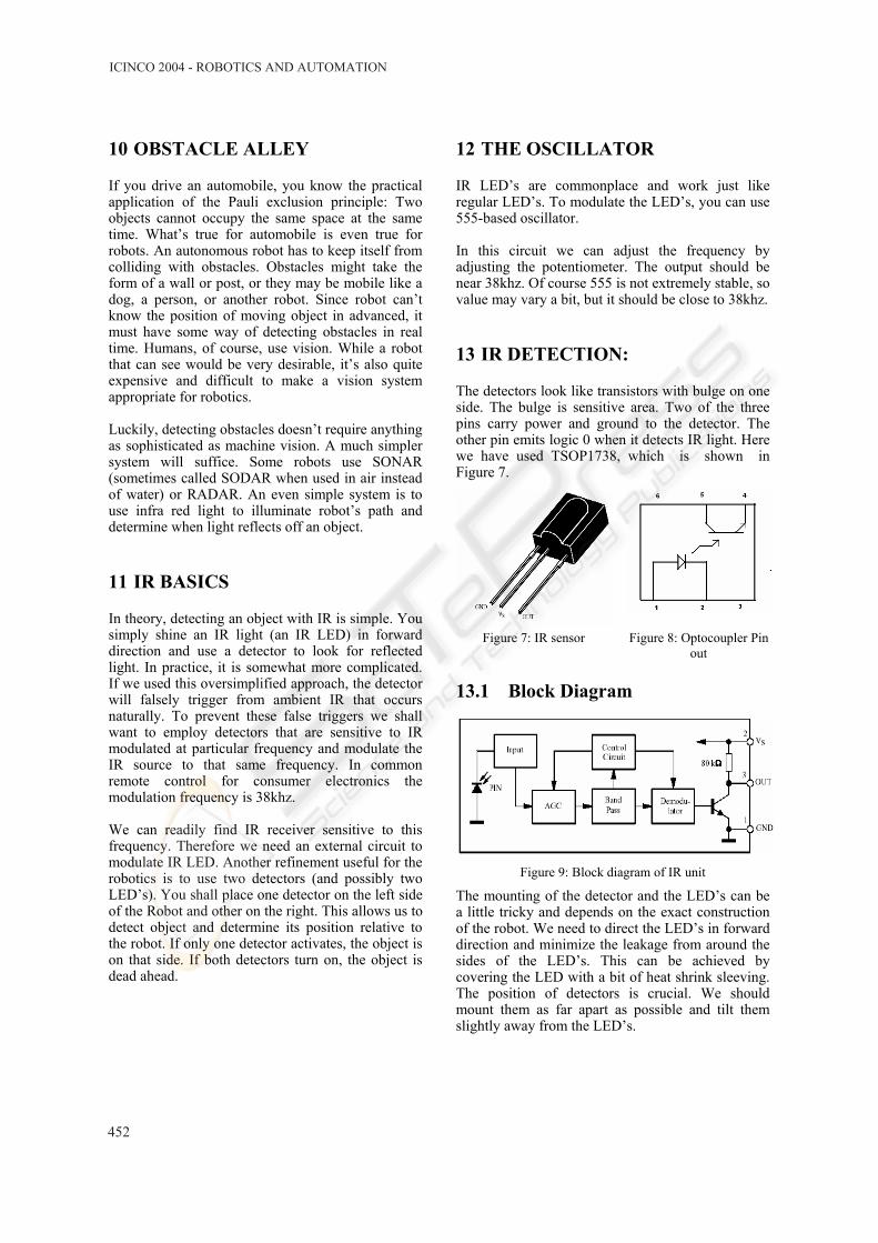
9 MOTOR DRIVER
Figure 6: A Motor Driver
All inputs are TTL compatible. Each output is a complete totem-pole drive circuit, with a Darlington transistor sink and a pseudo-Darlington source. Drivers are enabled in pairs, with drivers 1 and 2 enabled by 1,2EN and drivers 3 and 4 enabled by 3,4EN. When an enable input is high, the associated drivers are enabled and their outputs are active and in phase with their inputs. When the enable input is low, those drivers are disabled and their outputs are off and in the high-impedance state. With the proper data inputs, each pair of drivers forms a full-H (or bridge) reversible drive suitable for solenoid or motor applications.
SIMULATION , DESIGN AND PRACTICAL IMPLEMENTATION OF A MOBILE WIRELESS AUTONOMOUSSURVEILLANCE SYSTEM
451
10 OBSTACLE ALLEY
If you drive an automobile, you know the practical application of the Pauli exclusion principle: Two objects cannot occupy the same space at the same time. What’s true for automobile is even true for robots. An autonomous robot has to keep itself from colliding with obstacles. Obstacles might take the form of a wall or post, or they may be mobile like a dog, a person, or another robot. Since robot can’t know the position of moving object in advanced, it must have some way of detecting obstacles in real time. Humans, of course, use vision. While a robot that can see would be very desirable, it’s also quite expensive and difficult to make a vision system appropriate for robotics.
Luckily, detecting obstacles doesn’t require anything as sophisticated as machine vision. A much simpler system will suffice. Some robots use SONAR (sometimes called SODAR when used in air instead of water) or RADAR. An even simple system is to use infra red light to illuminate robot’s path and determine when light reflects off an object.
11 IR BASICS
In theory, detecting an object with IR is simple. You simply shine an IR light (an IR LED) in forward direction and use a detector to look for reflected light. In practice, it is somewhat more complicated. If we used this oversimplified approach, the detector will falsely trigger from ambient IR that occurs naturally. To prevent these false triggers we shall want to employ detectors that are sensitive to IR modulated at particular frequency and modulate the IR source to that same frequency. In common remote control for consumer electronics the modulation frequency is 38khz. We can readily find IR receiver sensitive to this frequency. Therefore we need an external circuit to modulate IR LED. Another refinement useful for the robotics is to use two detectors (and possibly two LED’s). You shall place one detector on the left side of the Robot and other on the right. This allows us to detect object and determine its position relative to the robot. If only one detector activates, the object is on that side. If both detectors turn on, the object is dead ahead.
12 THE OSCILLATOR
IR LED’s are commonplace and work just like regular LED’s. To modulate the LED’s, you can use 555-based oscillator. In this circuit we can adjust the frequency by adjusting the potentiometer. The output should be near 38khz. Of course 555 is not extremely stable, so value may vary a bit, but it should be close to 38khz.
13 IR DETECTION:
The detectors look like transistors with bulge on one side. The bulge is sensitive area. Two of the three pins carry power and ground to the detector. The other pin emits logic 0 when it detects IR light. Here we have used TSOP1738, which is shown in Figure 7.
Figure 7: IR sensor Figure 8: Optocoupler Pin
out
13.1 Block Diagram
Figure 9: Block diagram of IR unit
The mounting of the detector and the LED’s can be a little tricky and depends on the exact construction of the robot. We need to direct the LED’s in forward direction and minimize the leakage from around the sides of the LED’s. This can be achieved by covering the LED with a bit of heat shrink sleeving. The position of detectors is crucial. We should mount them as far apart as possible and tilt them slightly away from the LED’s.
ICINCO 2004 - ROBOTICS AND AUTOMATION
452
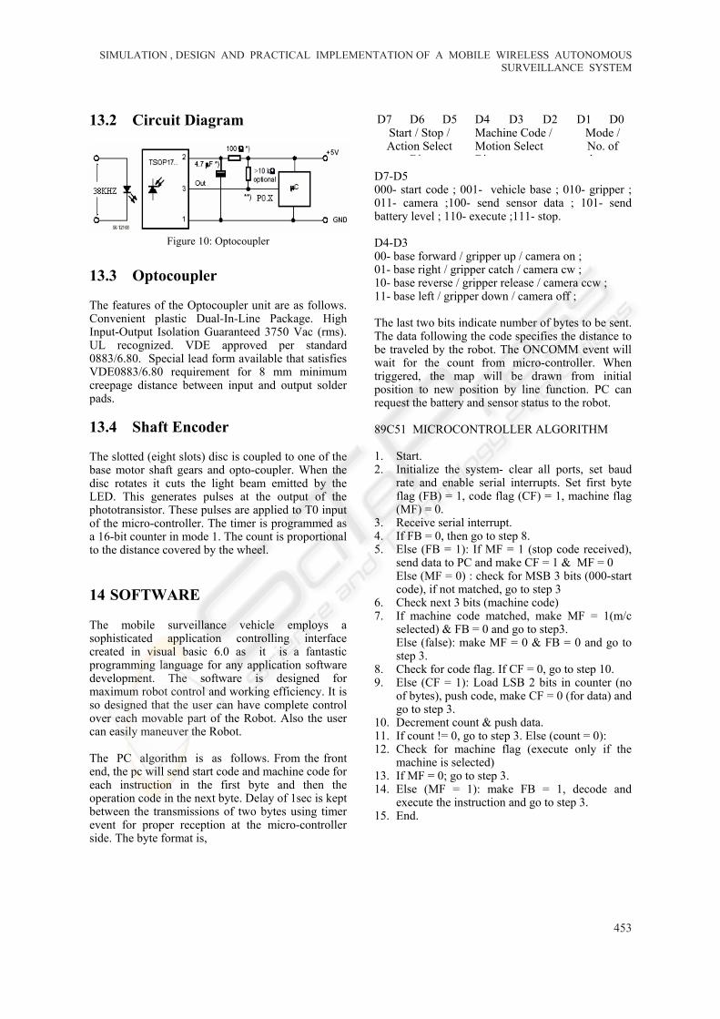
13.2 Circuit Diagram
Figure 10: Optocoupler
13.3 Optocoupler
The features of the Optocoupler unit are as follows. Convenient plastic Dual-In-Line Package. High Input-Output Isolation Guaranteed 3750 Vac (rms). UL recognized. VDE approved per standard 0883/6.80. Special lead form available that satisfies VDE0883/6.80 requirement for 8 mm minimum creepage distance between input and output solder pads.
13.4 Shaft Encoder
The slotted (eight slots) disc is coupled to one of the base motor shaft gears and opto-coupler. When the disc rotates it cuts the light beam emitted by the LED. This generates pulses at the output of the phototransistor. These pulses are applied to T0 input of the micro-controller. The timer is programmed as a 16-bit counter in mode 1. The count is proportional to the distance covered by the wheel.
14 SOFTWARE
The mobile surveillance vehicle employs a sophisticated application controlling interface created in visual basic 6.0 as it is a fantastic programming language for any application software development. The software is designed for maximum robot control and working efficiency. It is so designed that the user can have complete control over each movable part of the Robot. Also the user can easily maneuver the Robot. The PC algorithm is as follows. From the front end, the pc will send start code and machine code for each instruction in the first byte and then the operation code in the next byte. Delay of 1sec is kept between the transmissions of two bytes using timer event for proper reception at the micro-controller side. The byte format is,
D7 D6 D5 D4 D3 D2 D1 D0 Start / Stop / Action Select
Bit
Machine Code / Motion Select Bit
Mode / No. of b t
D7-D5 000- start code ; 001- vehicle base ; 010- gripper ; 011- camera ;100- send sensor data ; 101- send battery level ; 110- execute ;111- stop.
D4-D3 00- base forward / gripper up / camera on ; 01- base right / gripper catch / camera cw ; 10- base reverse / gripper release / camera ccw ; 11- base left / gripper down / camera off ;
The last two bits indicate number of bytes to be sent. The data following the code specifies the distance to be traveled by the robot. The ONCOMM event will wait for the count from micro-controller. When triggered, the map will be drawn from initial position to new position by line function. PC can request the battery and sensor status to the robot.
89C51 MICROCONTROLLER ALGORITHM
1. Start. 2. Initialize the system- clear all ports, set baud
rate and enable serial interrupts. Set first byte flag (FB) = 1, code flag (CF) = 1, machine flag (MF) = 0.
3. Receive serial interrupt. 4. If FB = 0, then go to step 8. 5. Else (FB = 1): If MF = 1 (stop code received),
send data to PC and make CF = 1 & MF = 0 Else (MF = 0) : check for MSB 3 bits (000-start code), if not matched, go to step 3
6. Check next 3 bits (machine code) 7. If machine code matched, make MF = 1(m/c
selected) & FB = 0 and go to step3. Else (false): make MF = 0 & FB = 0 and go to step 3.
8. Check for code flag. If CF = 0, go to step 10. 9. Else (CF = 1): Load LSB 2 bits in counter (no
of bytes), push code, make CF = 0 (for data) and go to step 3.
10. Decrement count & push data. 11. If count != 0, go to step 3. Else (count = 0): 12. Check for machine flag (execute only if the
machine is selected) 13. If MF = 0; go to step 3. 14. Else (MF = 1): make FB = 1, decode and
execute the instruction and go to step 3. 15. End.
SIMULATION , DESIGN AND PRACTICAL IMPLEMENTATION OF A MOBILE WIRELESS AUTONOMOUSSURVEILLANCE SYSTEM
453
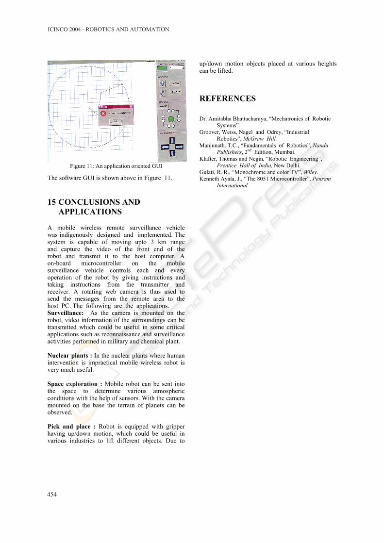
Figure 11: An application oriented GUI
The software GUI is shown above in Figure 11.
15 CONCLUSIONS AND APPLICATIONS
A mobile wireless remote surveillance vehicle was indigenously designed and implemented. The system is capable of moving upto 3 km range and capture the video of the front end of the robot and transmit it to the host computer. A on-board microcontroller on the mobile surveillance vehicle controls each and every operation of the robot by giving instructions and taking instructions from the transmitter and receiver. A rotating web camera is thus used to send the messages from the remote area to the host PC. The following are the applications. Surveillance: As the camera is mounted on the robot, video information of the surroundings can be transmitted which could be useful in some critical applications such as reconnaissance and surveillance activities performed in military and chemical plant. Nuclear plants : In the nuclear plants where human intervention is impractical mobile wireless robot is very much useful. Space exploration : Mobile robot can be sent into the space to determine various atmospheric conditions with the help of sensors. With the camera mounted on the base the terrain of planets can be observed. Pick and place : Robot is equipped with gripper having up/down motion, which could be useful in various industries to lift different objects. Due to
up/down motion objects placed at various heights can be lifted.
REFERENCES
Dr. Amitabha Bhattacharaya, “Mechatronics of Robotic Systems”.
Groover, Weiss, Nagel and Odrey, “Industrial Robotics”, McGraw Hill.
Manjunath. T.C., “Fundamentals of Robotics”, Nandu Publishers, 2nd Edition, Mumbai.
Klafter, Thomas and Negin, “Robotic Engineering”, Prentice Hall of India, New Delhi.
Gulati, R. R., “Monochrome and color TV”, Wiley. Kenneth Ayala, J., “The 8051 Microcontroller”, Penram
International.
ICINCO 2004 - ROBOTICS AND AUTOMATION
454
Related Documents