Abstract—Nowadays, power electronics are widely used in industry for supplying loads with an amplitude and frequency controlled voltage. These systems comprises mainly rectifiers and inverters which, as non-linear loads, produce currents with high harmonic content. In order to fulfil the legislation concerning voltage harmonic distortion it is necessary to put in place corrective actions. Among these corrective actions active filters are one of the most effective. For the design of these filters simulation has been proved to be a very useful tool. In this paper, the simulation by MATLAB/Simulink of an active filter for the reduction of the harmonic distortion is analysed. Two examples are presented: a steel plant and an underground traction system. Index Terms— Active filter, computer simulation, induction furnace, steel plant, metro traction system, THD. I. INTRODUCTION he main requirement of any electric power system is the supply of electricity with a determined power quality and reliability to the minimum possible cost. Due to the increased quality of life, it has taken place a spectacular increase of the number and installed power of non-linear loads, especially of electronic devices used mainly in the control of systems and power hardware. Depending on the nature of these loads, the distortion created can be very high and affect the voltage supplied by the distribution network. In this case, it is highly possible that other loads served from the same network will be affected. For regulating this situation a complete legislation exists at national and supranational levels concerning voltage harmonic distortion. To comply with legislation, corrective actions have to be taken to reduce harmonic distortion to established I. Zamora is with Department of Electrical Engineering-ESI of Bilbao, University of the Basque Country, Spain (e-mail: [email protected]). A. J. Mazón is with Department of Electrical Engineering-ESI of Bilbao, University of the Basque Country, Spain (e-mail: [email protected]). P. Eguia is with Department of Electrical Engineering-ESI of Bilbao, University of the Basque Country, Spain (e-mail: [email protected]). I. Albizu is with Department of Electrical Engineering-ESI of Bilbao, University of the Basque Country, Spain (e-mail: [email protected]). J.K. Sagastabeitia is with Dep. of Electrical Engineering-EUITI of Bilbao, University of the Basque Country, Spain (e-mail: [email protected]). E. Fernández is with Department of Electrical Engineering-ESI of Bilbao, University of the Basque Country, Spain (e-mail: [email protected]). regulated levels. Among the possible corrective actions active filters are one of the most effective. Before taking any corrective action, it is necessary to evaluate the distortion introduced by the installation into the distribution network and the expected reduction when the active filter is in use. In this stage, simulation has been proved to be a useful tool. It allows to quantify the harmonic distortion created by a system and, when a corrective action is introduced, simulation will show the reduction in the distortion. Besides, simulation can be used as a tool for the design of the active filter. The work presented in this paper is based on the simulation of active filters for reducing harmonic distortion created by industrial loads. Simulations have been carried out under the MATLAB/Simulink environment and two examples of industrial harmonic polluting loads are presented: a steel plant and an underground traction system. In order to perform the harmonic analysis of the voltage and current signals present in the industrial systems, a Simulink block has been developed. This block calls an M-file that makes the required calculations and shows graphically the harmonic spectrum of the analysed signal (Fig. 1). The 1 st harmonic is out of scale so that the rest of the harmonics can be visualized properly. The calculated values correspond to peak values. Fig. 1. Harmonic analyser result Simulation by MATLAB/Simulink of active filters for reducing THD created by industrial systems I. Zamora, A. J. Mazon. P. Eguia, I. Albizu, K. J. Sagastabeitia, E. Fernández T

Welcome message from author
This document is posted to help you gain knowledge. Please leave a comment to let me know what you think about it! Share it to your friends and learn new things together.
Transcript

Abstract—Nowadays, power electronics are widely used in
industry for supplying loads with an amplitude and frequencycontrolled voltage. These systems comprises mainly rectifiers andinverters which, as non-linear loads, produce currents with highharmonic content. In order to fulfil the legislation concerningvoltage harmonic distortion it is necessary to put in placecorrective actions. Among these corrective actions active filtersare one of the most effective. For the design of these filterssimulation has been proved to be a very useful tool. In this paper,the simulation by MATLAB/Simulink of an active filter for thereduction of the harmonic distortion is analysed. Two examplesare presented: a steel plant and an underground traction system.
Index Terms— Active filter, computer simulation, inductionfurnace, steel plant, metro traction system, THD.
I. INTRODUCTION
he main requirement of any electric power system is thesupply of electricity with a determined power quality and
reliability to the minimum possible cost. Due to the increasedquality of life, it has taken place a spectacular increase of thenumber and installed power of non-linear loads, especially ofelectronic devices used mainly in the control of systems andpower hardware.
Depending on the nature of these loads, the distortioncreated can be very high and affect the voltage supplied by thedistribution network. In this case, it is highly possible thatother loads served from the same network will be affected.
For regulating this situation a complete legislation exists atnational and supranational levels concerning voltage harmonicdistortion. To comply with legislation, corrective actions haveto be taken to reduce harmonic distortion to established
I. Zamora is with Department of Electrical Engineering-ESI of Bilbao,
University of the Basque Country, Spain (e-mail: [email protected]).A. J. Mazón is with Department of Electrical Engineering-ESI of Bilbao,
University of the Basque Country, Spain (e-mail: [email protected]).P. Eguia is with Department of Electrical Engineering-ESI of Bilbao,
University of the Basque Country, Spain (e-mail: [email protected]).I. Albizu is with Department of Electrical Engineering-ESI of Bilbao,
University of the Basque Country, Spain (e-mail: [email protected]).J.K. Sagastabeitia is with Dep. of Electrical Engineering-EUITI of Bilbao,
University of the Basque Country, Spain (e-mail: [email protected]).E. Fernández is with Department of Electrical Engineering-ESI of Bilbao,
University of the Basque Country, Spain (e-mail: [email protected]).
regulated levels. Among the possible corrective actions activefilters are one of the most effective.
Before taking any corrective action, it is necessary toevaluate the distortion introduced by the installation into thedistribution network and the expected reduction when theactive filter is in use. In this stage, simulation has been provedto be a useful tool. It allows to quantify the harmonicdistortion created by a system and, when a corrective action isintroduced, simulation will show the reduction in thedistortion. Besides, simulation can be used as a tool for thedesign of the active filter.
The work presented in this paper is based on the simulationof active filters for reducing harmonic distortion created byindustrial loads. Simulations have been carried out under theMATLAB/Simulink environment and two examples ofindustrial harmonic polluting loads are presented: a steel plantand an underground traction system.
In order to perform the harmonic analysis of the voltageand current signals present in the industrial systems, aSimulink block has been developed. This block calls an M-filethat makes the required calculations and shows graphically theharmonic spectrum of the analysed signal (Fig. 1). The 1st
harmonic is out of scale so that the rest of the harmonics canbe visualized properly. The calculated values correspond topeak values.
Fig. 1. Harmonic analyser result
Simulation by MATLAB/Simulink of activefilters for reducing THD created by
industrial systemsI. Zamora, A. J. Mazon. P. Eguia, I. Albizu, K. J. Sagastabeitia, E. Fernández
T
Tesi
0-7803-7967-5/03/$17.00 ©2003 IEEE
Tesi
Paper accepted for presentation at 2003 IEEE Bologna Power Tech Conference, June 23th-26th, Bologna, Italy
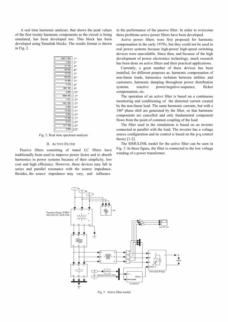
A real time harmonic analyser, that shows the peak valuesof the first twenty harmonic components as the circuit is beingsimulated, has been developed too. This block has beendeveloped using Simulink blocks. The results format is shownin Fig. 2.
Fig. 2. Real time spectrum analyser
II. ACTIVE FILTER
Passive filters consisting of tuned LC filters havetraditionally been used to improve power factor and to absorbharmonics in power systems because of their simplicity, lowcost and high efficiency. However, these devices may fall inseries and parallel resonance with the source impedance.Besides, the source impedance may vary, and influence
in the performance of the passive filter. In order to overcomethese problems active power filters have been developed.
Active power filters were first proposed for harmoniccompensation in the early 1970's, but they could not be used inreal power systems because high-power high-speed switchingdevices were unavailable. Since then, and because of the highdevelopment of power electronics technology, much researchhas been done on active filters and their practical applications.
Currently, a great number of these devices has beeninstalled, for different purposes as: harmonic compensation ofnon-linear loads, harmonics isolation between utilities andcustomers, harmonic damping throughout power distributionsystems, reactive power/negative-sequence, flickercompensation, etc.
The operation of an active filter is based on a continuousmonitoring and conditioning of the distorted current createdby the non-linear load. The same harmonic currents, but with a180º phase shift are generated by the filter, so that harmoniccomponents are cancelled and only fundamental componentflows from the point of common coupling of the load.
The filter used in the simulations is based on an inverterconnected in parallel with the load. The inverter has a voltagesource configuration and its control is based on the p-q controltheory [1-2].
The SIMULINK model for the active filter can be seen inFig. 3. In these figure, the filter is connected to the low voltagewinding of a power transformer.
Fig. 3. Active filter model
III. CASES STUDIES
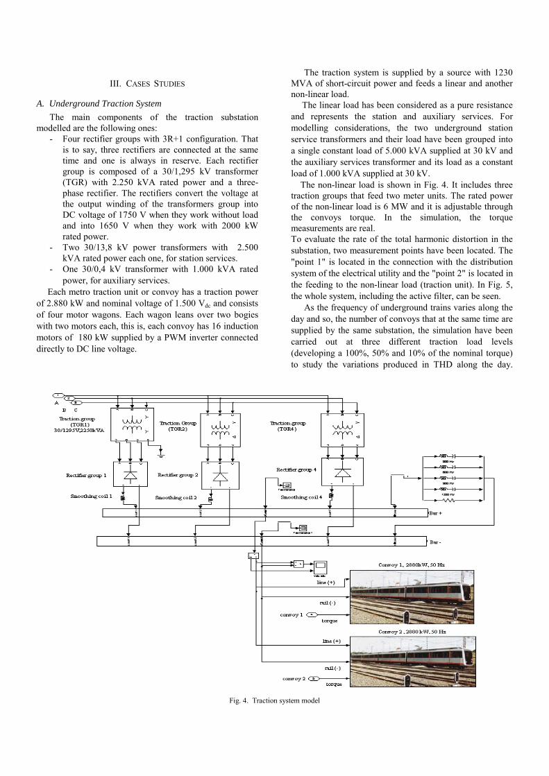
A. Underground Traction SystemThe main components of the traction substation
modelled are the following ones:- Four rectifier groups with 3R+1 configuration. That
is to say, three rectifiers are connected at the sametime and one is always in reserve. Each rectifiergroup is composed of a 30/1,295 kV transformer(TGR) with 2.250 kVA rated power and a three-phase rectifier. The rectifiers convert the voltage atthe output winding of the transformers group intoDC voltage of 1750 V when they work without loadand into 1650 V when they work with 2000 kWrated power.
- Two 30/13,8 kV power transformers with 2.500kVA rated power each one, for station services.
- One 30/0,4 kV transformer with 1.000 kVA ratedpower, for auxiliary services.
Each metro traction unit or convoy has a traction powerof 2.880 kW and nominal voltage of 1.500 Vdc and consistsof four motor wagons. Each wagon leans over two bogieswith two motors each, this is, each convoy has 16 inductionmotors of 180 kW supplied by a PWM inverter connecteddirectly to DC line voltage.
The traction system is supplied by a source with 1230MVA of short-circuit power and feeds a linear and anothernon-linear load.
The linear load has been considered as a pure resistanceand represents the station and auxiliary services. Formodelling considerations, the two underground stationservice transformers and their load have been grouped intoa single constant load of 5.000 kVA supplied at 30 kV andthe auxiliary services transformer and its load as a constantload of 1.000 kVA supplied at 30 kV.
The non-linear load is shown in Fig. 4. It includes threetraction groups that feed two meter units. The rated powerof the non-linear load is 6 MW and it is adjustable throughthe convoys torque. In the simulation, the torquemeasurements are real.To evaluate the rate of the total harmonic distortion in thesubstation, two measurement points have been located. The"point 1" is located in the connection with the distributionsystem of the electrical utility and the "point 2" is located inthe feeding to the non-linear load (traction unit). In Fig. 5,the whole system, including the active filter, can be seen.
As the frequency of underground trains varies along theday and so, the number of convoys that at the same time aresupplied by the same substation, the simulation have beencarried out at three different traction load levels(developing a 100%, 50% and 10% of the nominal torque)to study the variations produced in THD along the day.
Fig. 4. Traction system model

Fig. 5. Complete substation and traction system model
As example, we show the results of the case that bothconvoys are working in steady-state and developing a 100%of the nominal torque each one. Besides, in the “point 1” ofmeasurement (connection with the distribution system) thegraphs of voltage harmonic spectrum are shown, while inthe “point 2” (feeding to the no-linear load) the graphs ofcurrent harmonic spectrum are shown.
The results obtained in the harmonic distortion analysisof voltage at the connection “point 1” without the activefilter are shown in Fig. 6. The THD value corresponding tothe current is 4.85% while the voltage THD is 0.43 %.
It can be seen that the harmonic voltage, generated bythe substation, hardly have weight. This is due to the non-linear load consumption which is about 6 MVA in front ofthe 1234 MVA short circuit power of the source.
The highest harmonics are the 5th (250 Hz) and the 7th(350 Hz) and they are repeated at the 11th (550 Hz) and the13th (650 Hz). These harmonics are characteristic of non-linear loads that include three-phase rectifiers of six pulses.
Fig. 6. Voltage harmonic spectrum in the point 1, without filter
If the harmonic analysis is performed including theactive filter, the results change as can be seen in Fig. 7. TheTHD of the current is reduced from 4.85% to 0.10% andthe voltage THD from 0.43% to 0.31%. The values of thehighest harmonics have been reduced considerably. Butsome new components of low value (harmonics due to theinjection of the filter) can be observed.
Fig. 7. Voltage harmonic spectrum in the point 1,with filter
For the “point 2” of measurement, the results obtainedin the harmonic distortion analysis of current without theactive filter are shown in Fig. 8. It is observed a higherdeformation of the waves than in the case measured in thepoint 1. This distortion is due to the characteristicconsumption of the non-linear load that contains electronicpower devices. The THD value corresponding to the currentis 9.16% while the voltage THD is 0.31%.

Fig. 8. Current harmonic spectrum in the point 2,without filter
If the harmonic analysis is performed including theactive filter (Fig. 9), the THD of the current is reduced from9.16% to 0.35% and the voltage THD from 0.43% to0.31%.
Fig. 9. Current harmonic spectrum in the point 2,with filter
From the whole simulated cases results without and withthe active filter, it can make a comparative analysis:
- The THDI decreases more than 86% in anyone ofthe three cases, which implies a high effectiveness ofthe active filter (TABLE I and TABLE II).
TABLE I. – Results for measurement point 1 (substationinterconnection)
Traction loadlevel
Currentdistortion(THDI %)
Currentdistortion with
active filter(THDI %)
Reduction ofcurrent
distortion(%)
100 % 4,85 0,09 98,1450 % 4,07 0,09 97,7910 % 1,72 0,08 95,35
TABLE II. – Results for measurement point 2 (traction load)
Traction loadlevel
Currentdistortion(THDI %)
Currentdistortion with
active filter(THDI %)
Reduction ofcurrent
distortion(%)
100 % 9,16 0,35 96,1850 % 11,51 0,63 94,5310 % 15,08 2,01 86,67
- The harmonics are decreased almost completely andthe highest value becomes the 11th and 13th order,instead of the 5th and 7th order in the case withoutfiltering. Even harmonics are also observed(included the 0 order harmonic which is the DCcomponent). These harmonics are introduced by theactive filter, but they take worthless and highlyvariable values.
B. Steel PlantThe steel plant substation considered is fed alternatively
from two 30 kV lines switched by means of a disconnector.The electric load of the plant is composed of six inductionfurnaces, temper furnaces and general services.
There are two different types of induction furnaces. Fourfurnaces are of type 1 and the other two of type 2.
Each furnace of type 1 is fed from a 4 MVA three-winding transformer which reduces the voltage from 30 kVto 770 V. The secondary winding feeds a six pulse rectifierand the tertiary feeds another identical rectifier. Therectification has a 12-pulse configuration. Both rectifiersare connected in parallel including filtering coils thatimprove the direct current obtained. A capacitor bank isconnected in parallel with the induction furnace coil toachieve a controllable resonance of the coil. The voltage inthe coils that melt the steel is 2200 V with a frequency of500 Hz and an approximate consumption of 3300 kW.
Each furnace of type 2 is fed from a 5 MVA three-winding transformer. The voltage is reduced to 945 V.Similarly to the type 1 furnace configuration, the secondarywinding feeds a six pulse rectifier and the tertiary feedsanother identical rectifier. The rectification has a 12-pulseconfiguration. Both rectifiers are connected in seriesincluding filtering coils. A capacitor bank is connected inparallel with the induction furnace coil. The approximateconsumption of the coil is 4 MW.
The rectifiers used to get the DC voltage are the cause ofthe injection of current harmonics in the system andconsequently the cause of the voltage distortion. Thecharacteristic harmonics injected by a 12-pulse rectifier areharmonics of order 11th and 13th.
The distribution transformers of the general services andthe temper furnaces consume 1800 kW with a cosφ of 0,85.For simulation purposes they have been modelled as alinear load of these characteristics. This is acceptable astheir consumption is only a little portion of the total powerconsumed in the plant and they do not produce anydistortion. All these elements have been modelled usingexisting SIMULINK blocks contained in theSymPowerSystems blockset.
As there is no induction furnace electrical model, newblocks have been created for the two types of inductionfurnaces (Fig. 10 and 11).

Fig. 10. Type 1 induction furnace model
Fig. 11. Type 2 induction furnace model
The simulation model of the steel plant including theactive filter inserted in parallel with the furnaces can beseen in Fig. 12.
The steel plant has been simulated considering differentlevels of load (one, three and six furnaces working). Firstly,
the voltage harmonic distortion created by the steel planthas been measured. Secondly, after the active filter has beenadded, the distortion has been measured again.
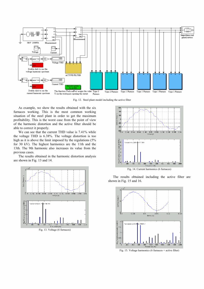
Fig. 12. Steel plant model including the active filter
As example, we show the results obtained with the sixfurnaces working. This is the most common workingsituation of the steel plant in order to get the maximumprofitability. This is the worst case from the point of viewof the harmonic distortion and the active filter should beable to correct it properly.
We can see that the current THD value is 7.41% whilethe voltage THD is 6.38%. The voltage distortion is toohigh as it is above the limit imposed by the regulations (5%for 30 kV). The highest harmonics are the 11th and the13th. The 9th harmonic also increases its value from theprevious cases.
The results obtained in the harmonic distortion analysisare shown in Fig. 13 and 14.
Fig. 13. Voltage (6 furnaces)
Fig. 14. Current harmonics (6 furnaces)
The results obtained including the active filter areshown in Fig. 15 and 16.
Fig. 15. Voltage harmonics (6 furnaces + active filter)

Fig. 16. Current harmonics (6 furnaces + active filter)
The THD of the current is reduced from 7.41% to3.33% and the voltage THD from 6.38% to 3.61%. Thenew value of the voltage distortion is below the limit of 5%.Therefore the active filter is adequate for the steel plant tofulfil the voltage quality requirements.
The 11th and 13th harmonics are still the highestharmonics and the 9th is nearly removed. But there aremany new components introduced by the filter spread overthe spectrum, but they take worthless and highly variablevalues.
Additional results obtained whit one or three furnacesworking are shown in TABLES V and VI.
TABLE V. - Current distortionNo. of
furnacesworking
CurrentTHDI(%)
THDI withactive filter
(%)
Reduction ofTHDI(%)
1 4.47 1.87 58.13 6.91 3.85 44.26 7.41 3.33 55
TABLE VI. – Voltage distortionNo. of
furnacesworking
VoltageTHD(%)
THD withactive filter
(%)
Reduction ofTHD(%)
1 1.04 0.66 36.53 3.23 2.06 36.26 6.38 3.61 43.4
IV. CONCLUSIONS
The use of simulation tools as MATLAB/ Simulink,allows to reproduce the behaviour of the power systems indifferent situations, analyse how the system answers inthese situations and choose the solution that better fit withthe particular problem without additional costs. Besides,active filters with different rated values can be simulated inorder to analyse different reductions of the harmonicdistortion.
By means of the simulation carried out, the voltage andcurrent harmonic distortions created by an undergroundtraction system and a steel plant have been obtained.Moreover, the reduction of the distortion by an active filterhas been simulated for both systems.
V. REFERENCES
[1] H. Akagi, Y. Kanazawa and A. Nabae, “Generalized theory ofinstantaneous reactive power in three-phase circuits”, Int. PowerElectronics Conf., pp. 1375-1386, Tokyo, 1983.
[2] H. Akagi, “New trends in active filters for power conditioning” ,IEEE Trans. Ind. Applications, Vol. 32, No. 6, 1996.
[3] J. Shen, N. Butterworth, "Analysis and design of a three levelPWM converter system for railway-traction applications", IEEProcedings Electric Power Applications, Vol. 144, No. 5, 1999.
[4] K. Al-Haddad, B. Singh and A. Chandra, “A review of active filtersfor power quality improvement”, IEEE Transactions on IndustrialElectronics, Vol. 46, No. 5, pp. 960-971, 1999.
[5] G. Casaravilla, A. Salvia, C. Briozzo and E. Watanabe, “Selectiveactive filter applied to an arc furnace adjusted to harmonicemission limitations”, Latin America T&D IEEE Conference, SanPablo - Brasil, 2002.
[6] P.T. Cheng, . Bhattacharya, D.M. Divan, "Application of dominantharmonic active filter system with 12 pulse nonlinear loads", IEEETransactions on Power Delivery, Vol. 14, No. 2, 1999.
[7] Chih-Ju Chou, Chih-Wen Liu, June-Yown Lee, Kune-Da Lee,“Optimal Planning of Large Passive- Harmonic-Filters Set at HighVoltage Level”, IEEE Transactions on Power Systems, Vol.15, No.1, 2000
[8] Bhim Singh, Kamal Al-Haddad, Ambrish Chandra, “A New ControlApproach to Three-Phase Active Filter for Harmonics and ReactivePower Compensation”, IEEE Transactiones on Power Systems,Vol.13, No.1, 1998.
[9] Carlos V. Nunez-Noriega, George G.Karady, “Five Step- LowFrequency Switching Active Power Filter for Network HarmonicCompensation in Substations”, IEEE Transactions on PowerDelivery, Vol. 14, No.4, 1999.
[10] Thierry Thomas, Kévork Haddad, Géza Joós, Alain Jaafari, “Designand Performance of Active Power Filters”, IEEE IndustryApplications Magazine, 1998.
Related Documents


