SIMULATION BASED OPTIMIZATION OF A DIABATIC DISTILLATION COLUMN Edward Steven Jimenez and Peter Salamon San Diego State University Department of Mathematics United States of America Ricardo Rivero and Consuelo Rendon Instituto Mexicano del Petroleo Mexico Karl Heinz Hoffmann and Markus Schaller Technical University of Chemnitz Germany Bjarne Andresen University of Copenhagen Denmark Abstract Diabatic distillation is a separation process in which heat is transferred inside the column as opposed to classical adiabatic columns where heat is only supplied to the reboiler and extracted from the condenser. Recent works have shown that such diabatic columns dramatically reduce the exergy needed to perform the separation. The present research considers a particular implementation of diabatic columns particularly suitable for retrofitting applications. The implementation uses a single heating fluid circulating in series below the feed tray and a single cooling fluid circulating in series above the feed tray. The optimal control is determined in a simulation-based optimization. This is a difficult optimization because traditional algorithms for optimization invariably get stuck. However, an algorithm based on physical intuition for adjusting the temperature profile can find the optimum. This algorithm does not guarantee convergence in all cases, but usually manages to find the optimum by varying the initial state. The resulting operation is compared to the optimal operation with independent heat transfer to each tray (the completely controlled diabatic column) and to a conventional adiabatic column. In the former comparison, we find how much exergy is lost by circulating a fluid in series rather than using independently adjustable heat exchanges. In the latter, we find the possible savings available by retrofit. The comparisons show that most of the potential exergy savings can be captured by diabatization using the series approach. The potential impact of this technology on the chemical and process industry is enormous since distillation is the single largest energy degrading unit operation worldwide. NOMENCLATURE V i = moles of vapor leaving tray i per minute L i = moles of liquid leaving tray i per minute F = moles of feed per minute x = mole fraction light component x F = x in feed mixture x D = x in distillate

Welcome message from author
This document is posted to help you gain knowledge. Please leave a comment to let me know what you think about it! Share it to your friends and learn new things together.
Transcript
SIMULATION BASED OPTIMIZATION OF A DIABATIC DISTILLATIONCOLUMN
Edward Steven Jimenez and Peter SalamonSan Diego State University
Department of MathematicsUnited States of America
Ricardo Rivero and Consuelo RendonInstituto Mexicano del Petroleo
Mexico
Karl Heinz Hoffmann and Markus SchallerTechnical University of Chemnitz
Germany
Bjarne AndresenUniversity of Copenhagen
Denmark
Abstract
Diabatic distillation is a separation process in which heat is transferred inside the column as opposed toclassical adiabatic columns where heat is only supplied to the reboiler and extracted from the condenser.Recent works have shown that such diabatic columns dramatically reduce the exergy needed to performthe separation. The present research considers a particular implementation of diabatic columnsparticularly suitable for retrofitting applications. The implementation uses a single heating fluidcirculating in series below the feed tray and a single cooling fluid circulating in series above the feedtray. The optimal control is determined in a simulation-based optimization. This is a difficultoptimization because traditional algorithms for optimization invariably get stuck. However, analgorithm based on physical intuition for adjusting the temperature profile can find the optimum. Thisalgorithm does not guarantee convergence in all cases, but usually manages to find the optimum byvarying the initial state. The resulting operation is compared to the optimal operation with independentheat transfer to each tray (the completely controlled diabatic column) and to a conventional adiabaticcolumn. In the former comparison, we find how much exergy is lost by circulating a fluid in seriesrather than using independently adjustable heat exchanges. In the latter, we find the possible savingsavailable by retrofit. The comparisons show that most of the potential exergy savings can be captured bydiabatization using the series approach. The potential impact of this technology on the chemical andprocess industry is enormous since distillation is the single largest energy degrading unit operationworldwide.
NOMENCLATURE
†
Vi = moles of vapor leaving tray i per minute
†
Li = moles of liquid leaving tray i per minute†
F = moles of feed per minute
†
x = mole fraction light component
†
xF = x in feed mixture
†
xD = x in distillate
†
xB = x in bottoms
†
QD = heat removed at condenser
†
QB = heat added at reboiler
†
B = moles of bottoms per minute
†
D = moles of distillate per minute
†
T = absolute temperature
†
Ti = temperature on tray i
†
K = number of trays
†
Cs = coexistence heat capacity
†
˙ m = flow rate of heat exchange fluid
†
˜ T iin = T of heat exchange fluid entering tray i
†
˜ T iout = T of heat exchange fluid leaving tray i
†
U = conductivity
†
A = area
†
L = length of heat exchanger
†
l = distance along heat exchanger
†
Cp = constant pressure heat capacity
†
DSu = total entropy production per minute
†
Qexcessn = unbalanced heat on tray n
†
M = large constant used as penalty multiplier
†
e = small constant used as step size
†
T traysn = vector of temperatures on n trays
INTRODUCTION
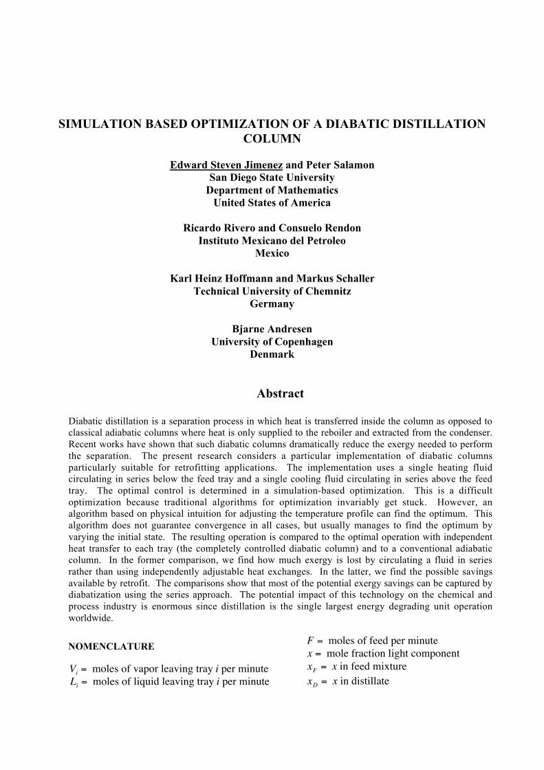
An important way to exergy savings is throughdiabatic distillation. Spreading out the heatingduties of the reboiler and the cooling duties of thecondenser implies potential savings because thereboiler is adding heat at a higher temperature andthe condenser is removing heat at a lowertemperature (see Fig 1). This research measuredexergy loss in terms of entropy production.Exergy is available work and entropy productionrepresents exergy loss.
The San Diego State Thermodynamics ResearchGroup got involved with distillation as an applicationof the Equal Thermodynamic Distance Theorem(Nulton et al, 1985). The thermodynamic length of a
process may be calculated as
†
L = dX t M dXÚwhere X is the vector of extensive quantities in theprocess and M is the metric consisting of secondderivates of entropy with respect to the remainingextensive quantities (Salamon et al, 1980). It wasproven in [2] that minimum dissipation is
achieved in a K-step process when all the stepsare of equal length.
L1
L2
L3
L4
L5
L6
L7
V7
V6
V5
V4
V3
V2
V1
L7
L6
V7
V6L5
L4V5
L3
V4
V3 L2
V2L1
V1
D, XD D, XD
F, Xf F, Xf
Additional
Heat Sinks
And
Heat Sources
QD QD
QB QB
B, XB B, XB
Adiabatic Diabatic
Figure 1: Comparison of an adiabatic column to ageneral diabatic column.
This theorem deals with asymptotic theory oflost work in thermodynamic processes; in thiscase asymptotic corresponds to the limit of verymany trays. The theorem states that minimuminternal dissipation is achieved by having an equalthermodynamic distance between each pair ofadjacent trays. Equal thermodynamic distancesmean that the temperatures should be chosen suchthat:
The total thermodynamic length of adistillation process may be written as
†
Cs
TTi-1
Ti
Û
ı Ù dT =
1K
Cs
TT0
TK
Û
ı Ù dT
Where
†
Cs is the heat capacity of the mixtureunder boiling conditions (Salamon and Nulton,1998). For a K-step process each step must bedesigned to have the thermodynamic length L/K.
Recent works have improved on the EqualThermodynamic Distance Theorem and gavefurther support to the assertion that diabaticdistillation is the way to exergy savings. Twopublications (DeKoeijer et al., 2001; Schaller et
al., 2001) calculated potential savings withoutassuming many trays. A further publication(Schaller et al., 2002) calculated potential savingsincluding heat exchange losses. Three of theseworks used the temperature at each tray as thecontrol variables. A typical distillation columnhas 75 or more trays. This means that these recentworks required the optimization of a 75+dimensional problem.
THE PROBLEM
Serial Heat Exchanger Design
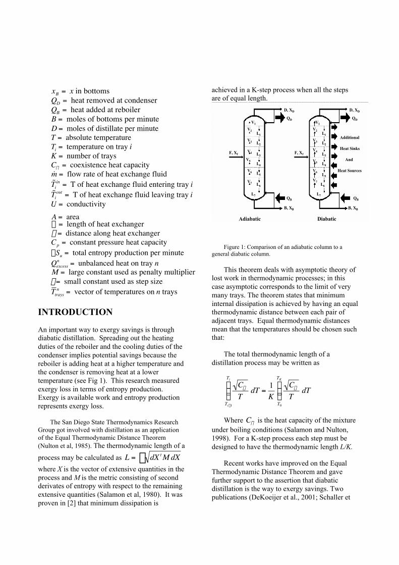
This research concerns the optimal operationof a particular diabatic design with serial heatexchangers (Rivero 1993)
Stripper{
Rectifier{
Reboiler
Condenser
Figure 2: Conventional column retrofitted with serialheat exchangers.
The rectifier is the upper half of the distillationcolumn; the stripper is the lower half of thedistillation column. A serial heat exchanger usedfor cooling is snaked through the rectifier and aseparate serial heat exchanger used for heating issnaked through the stripper.
A heat exchange fluid is pumped through theserial heat exchangers to allow heat to betransferred to or from the column. This particular
diabatic design will allow a conventional columnto be retrofitted with serial heat exchangers. Onlytwo piercings of the outer jacket are required foreach serial heat exchanger, as shown in figure 2.
The sample calculations presented here treatthe mixture of 50% benzene and 50% toluene,which is separated into the distillate containing90% benzene and the bottoms containing 90%toluene.
The Coexistence Curve
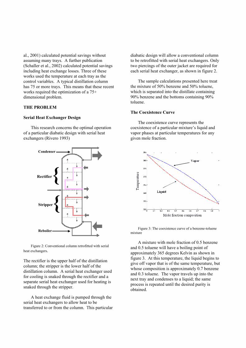
The coexistence curve represents thecoexistence of a particular mixture’s liquid andvapor phases at particular temperatures for anygiven mole fraction.
Figure 3: The coexistence curve of a benzene-toluenemixture
A mixture with mole fraction of 0.5 benzeneand 0.5 toluene will have a boiling point ofapproximately 365 degrees Kelvin as shown infigure 3. At this temperature, the liquid begins togive off vapor that is of the same temperature, butwhose composition is approximately 0.7 benzeneand 0.3 toluene. The vapor travels up into thenext tray and condenses to a liquid; the sameprocess is repeated until the desired purity isobtained.
Calculating the Temperature of the HeatExchanger Fluid
In order for the simulation algorithm tocalculate the optimal parameters it must be able tocalculate the temperature of the serial heatexchanger fluid at any given tray.
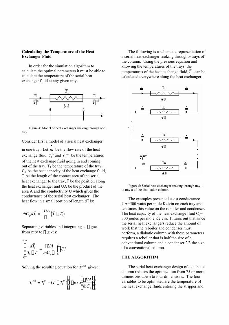
Figure 4: Model of heat exchanger snaking through onetray.
Consider first a model of a serial heat exchanger
in one tray. Let •
m be the flow rate of the heatexchange fluid, inT1
~and outT1
~ be the temperatures
of the heat exchange fluid going in and comingout of the tray, T1 be the temperature of the tray,Cp be the heat capacity of the heat exchange fluid,L be the length of the contact area of the serialheat exchanger to the tray, l be the position alongthe heat exchanger and UA be the product of thearea A and the conductivity U which gives theconductance of the serial heat exchanger. Theheat flow in a small portion of length dl is:
†
˙ m Cpd ˜ T 1 =-UA
L˜ T 1 - T1( )
Separating variables and integrating as l goesfrom zero to L gives:
†
d ˜ T 1˜ T 1 - T1
˜ T 1in
˜ T 1out
Û
ı Ù =
-UA˙ m CpL
dl0
L
Ú
Solving the resulting equation for outT1~
gives:
†
˜ T 1out = ˜ T 1
in + (T1 - ˜ T 1in ) 1- exp -UA
˙ m Cp
Ê
Ë Á Á
ˆ
¯ ˜ ˜
È
Î Í Í
˘
˚ ˙ ˙
.
The following is a schematic representation ofa serial heat exchanger snaking through n trays ofthe column. Using the previous equation andknowing the temperatures of the trays, thetemperatures of the heat exchange fluid,T
~, can be
calculated everywhere along the heat exchanger.
m.
m.
.
m
m
m
m
m
m
. .
.
.
.
AU
AU
AU
AU
T1
T2
Ti
Tn
•Schematic representation of a serial heat exchanger snaking through the column.•The examples presented use AUtray /F=500 W/mol.K , and 10 times this value for the reboiler and the condenser. Cpof the heat exchange fluid=300 J/mol.K. •The required size of the reboiler is about half of the size for a conventional column. The required size of the condenser is about 2/3 the size for a conventional column.
inT1~
inT2~
iniT
~
innT
~
outnT
~
outiT
~
outT2~
outT1~
Figure 5: Serial heat exchanger snaking through tray 1to tray n of the distillation column.
The examples presented use a conductanceUA=500 watts per mole Kelvin on each tray andten times this value on the reboiler and condenser.The heat capacity of the heat exchange fluid Cp=300 joules per mole Kelvin. It turns out that sincethe serial heat exchangers reduce the amount ofwork that the reboiler and condenser mustperform, a diabatic column with these parametersrequires a reboiler that is half the size of aconventional column and a condenser 2/3 the sizeof a conventional column.
THE ALGORITHM
The serial heat exchanger design of a diabaticcolumn reduces the optimization from 75 or moredimensions down to four dimensions. The fourvariables to be optimized are the temperature ofthe heat exchange fluids entering the stripper and
the rectifier, and the flow rates of the fluidsrunning through the stripper and the rectifier.This optimization still proved to be difficult. The75 parameters which represented the temperatureprofile inside the column now had to bedetermined from the highly nonlinear steady stateconditions rather than from optimality. Since, asmentioned above, all the operating characteristicsof the column are conveniently expressed only interms of the temperature profile, it is natural toadd the steady state conditions as penalties. Thisresults in a high dimensional optimization usingour four control variables augmented by thetemperature profile of the column. The objectiveto minimize is then
†
DSu + M Qexcessn( )
nÂ
2,
where uSD is the total entropy production of the
process, nexcessQ is the unbalanced heat on tray n
which must equal zero at the steady state and M isa large constant. Unfortunately, standardoptimization methods such as quasi-Newton couldnot find the optimum. This was due in part to thefact that this is a simulation based optimizationand thus only narrow regions of parameter valuesmake physical sense. It was further complicatedby the “banana function” features of the entropyproduction in the four control parameters whichrequired very high accuracy in the temperatureprofile before the desirable direction to change thefour control variables could be determined.
The algorithm that succeeded in finding thedesired optima was written using MATLAB andis based on pseudo-dynamics rather than penalty-functions. The steady state is found by using the
excess heat nexcessQ at each tray to change the
temperature of the tray according to
,: nexcess
ntrays
ntrays QTT e+=
rr
i.e., the temperature of each tray is changed ineach time step by a small multiple of the excessheat. This converges reasonably well whencompared to other simulation based methods.
RESULTS
The results presented compare a 20-traydiabatic column and a 20-tray adiabatic column.The results discussed include the heating andcooling duties, the tray-by-tray entropyproduction, liquid and vapor flow rates, thetemperature profiles, the sensitivity of entropyproduction as the temperature deviates from theiroptimal values, and the percent of exergy savingsas compared to an adiabatic column.
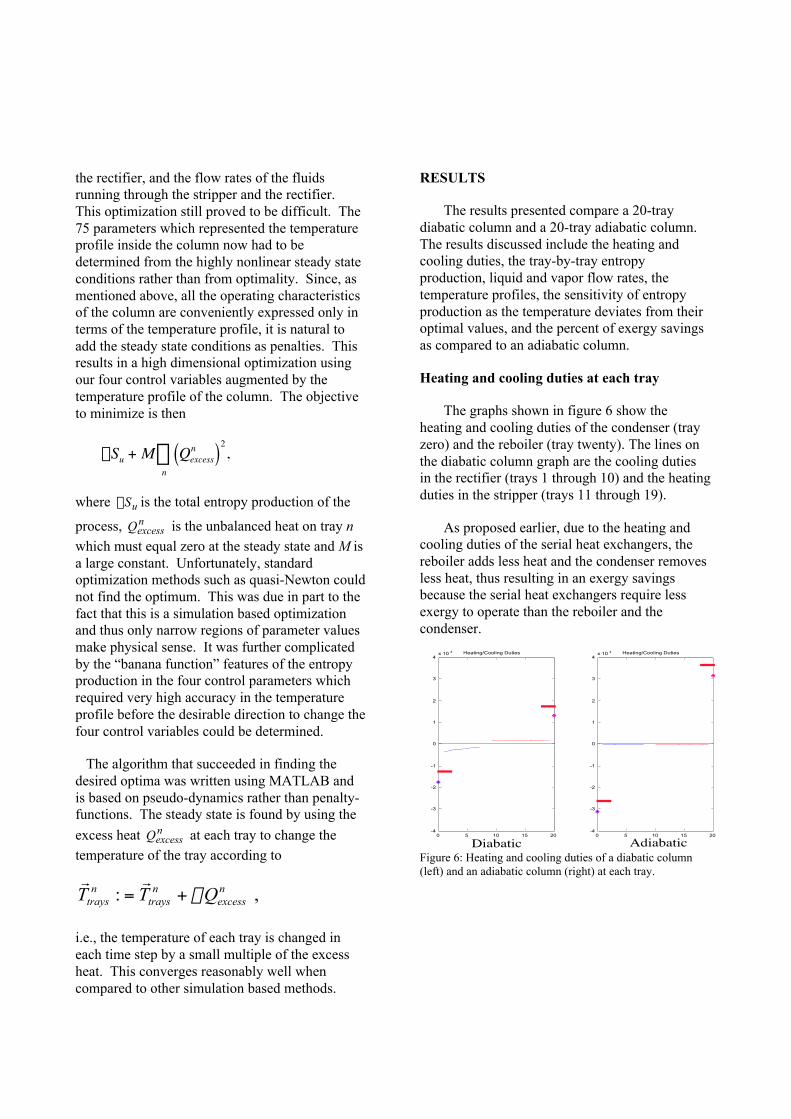
Heating and cooling duties at each tray
The graphs shown in figure 6 show theheating and cooling duties of the condenser (trayzero) and the reboiler (tray twenty). The lines onthe diabatic column graph are the cooling dutiesin the rectifier (trays 1 through 10) and the heatingduties in the stripper (trays 11 through 19).
As proposed earlier, due to the heating andcooling duties of the serial heat exchangers, thereboiler adds less heat and the condenser removesless heat, thus resulting in an exergy savingsbecause the serial heat exchangers require lessexergy to operate than the reboiler and thecondenser.
0 5 10 15 20-4
-3
-2
-1
0
1
2
3
4x 10 4 Heating/Cooling Duties
0 5 10 15 20-4
-3
-2
-1
0
1
2
3
4x 10 4 Heating/Cooling Duties
Diabatic AdiabaticFigure 6: Heating and cooling duties of a diabatic column(left) and an adiabatic column (right) at each tray.
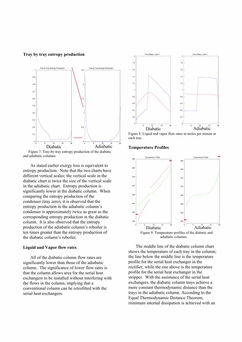
Tray by tray entropy production
0 5 10 15 200
0.1
0.2
0.3
0.4
0.5
0.6
0.7
0.8
0.9
1Tray by Tray Entropy Production
0 5 10 15 200
0.5
1
1.5
2
2.5Tray by Tray Entropy Production
Diabatic Adiabatic Figure 7: Tray-by-tray entropy production of the diabaticand adiabatic columns.
As stated earlier exergy loss is equivalent toentropy production. Note that the two charts havedifferent vertical scales; the vertical scale in thediabatic chart is twice the size of the vertical scalein the adiabatic chart. Entropy production issignificantly lower in the diabatic column. Whencomparing the entropy production of thecondenser (tray zero), it is observed that theentropy production in the adiabatic column’scondenser is approximately twice as great as thecorresponding entropy production in the diabaticcolumn. It is also observed that the entropyproduction of the adiabatic column’s reboiler isten times greater than the entropy production ofthe diabatic column’s reboiler.
Liquid and Vapor flow rates
All of the diabatic column flow rates aresignificantly lower than those of the adiabaticcolumn. The significance of lower flow rates isthat the column allows area for the serial heatexchangers to be installed without interfering withthe flows in the column, implying that aconventional column can be retrofitted with theserial heat exchangers.
5 10 15 200
0.2
0.4
0.6
0.8
1
1.2
1.4
1.6
1.8
2Flow Rates L and V
5 10 15 200
0.2
0.4
0.6
0.8
1
1.2
1.4
1.6
1.8
2Flow Rates L and V
Diabatic AdiabaticFigure 8: Liquid and vapor flow rates in moles per minute ateach tray.
Temperature Profiles
0 5 10 15 20
350
355
360
365
370
375
380
385Temperature Profile
0 5 10 15 20
350
355
360
365
370
375
380
385
Temperature Profile
Diabatic Adiabatic
-- Tray-- Rectifier-- Stripper
Temperature Profiles in Kelvin at Each Tray
Figure 9: Temperature profiles of the diabatic andadiabatic columns.
The middle line of the diabatic column chartshows the temperature of each tray in the column;the line below the middle line is the temperatureprofile for the serial heat exchanger in therectifier, while the one above is the temperatureprofile for the serial heat exchanger in thestripper. With the assistance of the serial heatexchangers, the diabatic column trays achieve amore constant thermodynamic distance than thetrays in the adiabatic column. According to theEqual Thermodynamic Distance Theorem,minimum internal dissipation is achieved with an
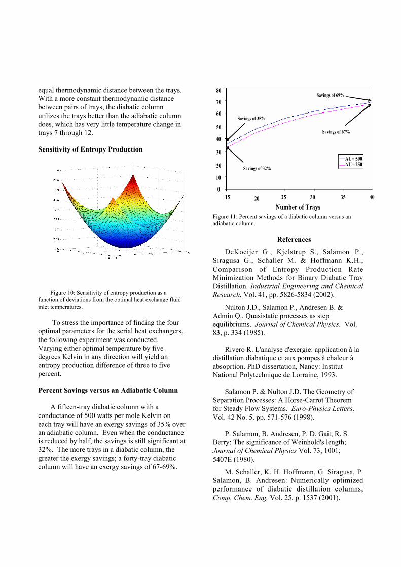
equal thermodynamic distance between the trays.With a more constant thermodynamic distancebetween pairs of trays, the diabatic columnutilizes the trays better than the adiabatic columndoes, which has very little temperature change intrays 7 through 12.
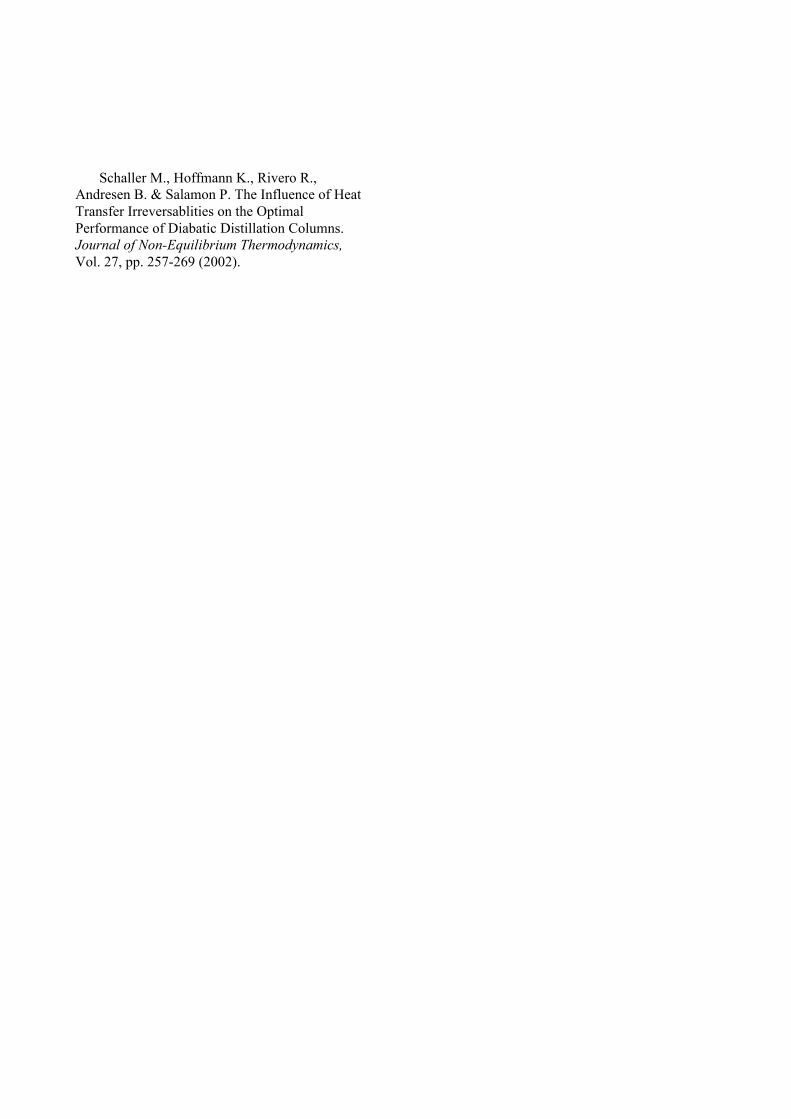
Sensitivity of Entropy Production
Figure 10: Sensitivity of entropy production as afunction of deviations from the optimal heat exchange fluidinlet temperatures.
To stress the importance of finding the fouroptimal parameters for the serial heat exchangers,the following experiment was conducted.Varying either optimal temperature by fivedegrees Kelvin in any direction will yield anentropy production difference of three to fivepercent.
Percent Savings versus an Adiabatic Column
A fifteen-tray diabatic column with aconductance of 500 watts per mole Kelvin oneach tray will have an exergy savings of 35% overan adiabatic column. Even when the conductanceis reduced by half, the savings is still significant at32%. The more trays in a diabatic column, thegreater the exergy savings; a forty-tray diabaticcolumn will have an exergy savings of 67-69%.
Percent Savings Versus an Adiabatic Column
015
10
20
30
40
50
60
70
80
AU= 500AU= 250
Number of Trays20 25 30 35 40
Savings of 32%
Savings of 67%
Savings of 69%
Savings of 35%
Figure 11: Percent savings of a diabatic column versus anadiabatic column.
References
DeKoeijer G., Kjelstrup S., Salamon P.,Siragusa G., Schaller M. & Hoffmann K.H.,Comparison of Entropy Production RateMinimization Methods for Binary Diabatic TrayDistillation. Industrial Engineering and ChemicalResearch, Vol. 41, pp. 5826-5834 (2002).
Nulton J.D., Salamon P., Andresen B. &Admin Q., Quasistatic processes as stepequilibriums. Journal of Chemical Physics. Vol.83, p. 334 (1985).
Rivero R. L'analyse d'exergie: application à ladistillation diabatique et aux pompes à chaleur àabsoprtion. PhD dissertation, Nancy: InstitutNational Polytechnique de Lorraine, 1993.
Salamon P. & Nulton J.D. The Geometry ofSeparation Processes: A Horse-Carrot Theoremfor Steady Flow Systems. Euro-Physics Letters.Vol. 42 No. 5. pp. 571-576 (1998).
P. Salamon, B. Andresen, P. D. Gait, R. S.Berry: The significance of Weinhold's length;Journal of Chemical Physics Vol. 73, 1001;5407E (1980).
M. Schaller, K. H. Hoffmann, G. Siragusa, P.Salamon, B. Andresen: Numerically optimizedperformance of diabatic distillation columns;Comp. Chem. Eng. Vol. 25, p. 1537 (2001).
Schaller M., Hoffmann K., Rivero R.,Andresen B. & Salamon P. The Influence of HeatTransfer Irreversablities on the OptimalPerformance of Diabatic Distillation Columns.Journal of Non-Equilibrium Thermodynamics,Vol. 27, pp. 257-269 (2002).
Related Documents


