Progress In Electromagnetics Research, PIER 101, 189–202, 2010 SIMULATION AND EXPERIMENTAL VERIFICATION OF W-BAND FINITE FREQUENCY SELECTIVE SUR- FACES ON INFINITE BACKGROUND WITH 3D FULL WAVE SOLVER NSPWMLFMA S. Islam, J. Stiens, G. Poesen, and R. Vounckx Laboratory for Micro- and Photonelectronics Department of Electronics and Informatics Vrije Universiteit Brussel Pleinlaan 2, 1050 Brussels, Belgium J. Peeters, I. Bogaert, and D. de Zutter Department of Information Technology (INTEC) Ghent University Sint Pietersnieuwstraat 41, B-9000 Ghent, Belgium W. de Raedt IMEC Department INTEGSYS Kapeldreef 75, B-3001 Heverlee, Belgium Abstract—We present the design, processing and testing of a W-band finite by infinite and a finite by finite Grounded Frequency Selective Surfaces (FSSs) on infinite background. The 3D full wave solver Nondirective Stable Plane Wave Multilevel Fast Multipole Algorithm (NSPWMLFMA) is used to simulate the FSSs. As NSPWMLFMA solver improves the complexity matrix-vector product in an iterative solver from O(N 2 ) to O(N log N ) which enables the solver to simulate finite arrays with faster execution time and manageable memory requirements. The simulation results were verified by comparing them with the experimental results. The comparisons demonstrate the accuracy of the NSPWMLFMA solver. We fabricated the corresponding FSS arrays on quartz substrate with photolithographic etching techniques and characterized the vector S -parameters with a free space Millimeter Wave Vector Network Analyzer (MVNA). Corresponding author: S. Islam ([email protected]).

Welcome message from author
This document is posted to help you gain knowledge. Please leave a comment to let me know what you think about it! Share it to your friends and learn new things together.
Transcript
Progress In Electromagnetics Research, PIER 101, 189–202, 2010
SIMULATION AND EXPERIMENTAL VERIFICATIONOF W-BAND FINITE FREQUENCY SELECTIVE SUR-FACES ON INFINITE BACKGROUND WITH 3D FULLWAVE SOLVER NSPWMLFMA
S. Islam, J. Stiens, G. Poesen, and R. Vounckx
Laboratory for Micro- and PhotonelectronicsDepartment of Electronics and InformaticsVrije Universiteit BrusselPleinlaan 2, 1050 Brussels, Belgium
J. Peeters, I. Bogaert, and D. de Zutter
Department of Information Technology (INTEC)Ghent UniversitySint Pietersnieuwstraat 41, B-9000 Ghent, Belgium
W. de Raedt
IMECDepartment INTEGSYSKapeldreef 75, B-3001 Heverlee, Belgium
Abstract—We present the design, processing and testing of a W-bandfinite by infinite and a finite by finite Grounded Frequency SelectiveSurfaces (FSSs) on infinite background. The 3D full wave solverNondirective Stable Plane Wave Multilevel Fast Multipole Algorithm(NSPWMLFMA) is used to simulate the FSSs. As NSPWMLFMAsolver improves the complexity matrix-vector product in an iterativesolver from O(N2) to O(N log N) which enables the solver to simulatefinite arrays with faster execution time and manageable memoryrequirements. The simulation results were verified by comparingthem with the experimental results. The comparisons demonstratethe accuracy of the NSPWMLFMA solver. We fabricated thecorresponding FSS arrays on quartz substrate with photolithographicetching techniques and characterized the vector S-parameters with afree space Millimeter Wave Vector Network Analyzer (MVNA).
Corresponding author: S. Islam ([email protected]).
190 Islam et al.
1. INTRODUCTION
Highly coherent millimetre wave illumination leads to poor imagequality, disturbed by noise sources in active imaging [1]. As such thedestruction of the coherence level is a prerequisite to obtain sufficientimage quality [2]. The mm-wave coherence controllable diffuser canbe designed with complex grounded FSS array where the elementaryblocks are finite size FSS arrays. For the design of such practicaldiffuser system it is very important to know the characteristic of finiteextent FSS arrays [2, 3].
The FSSs are passive electromagnetic filters formed by periodicthin conducting elements on a dielectric substrate or periodic apertureelements in a conducting sheet [4]. Typically the analyses of FSSs andother planar periodic structures are carried out under the assumptionthat they are infinite in extent, even though the dimensions of practicalFSS structures are necessarily finite. A number of methods, e.g.,mode matching, the moment method [5–9], the spectral-Galerkinapproach [10], and certain approximate methods, are available foranalyzing infinite periodic structures. The problem of scattering frominfinite (i.e., doubly-periodic) FSSs has been researched extensively formany years by using the Floquet theorem that reduces the computationdomain to a single unit cell, and thus reduces the problem to amanageable one. However, this cannot be applied for the moderate sizefinite FSS array problem, which is much more difficult to handle and,to our knowledge, has not been treated in a general way without anyapproximation. Simulations based on the generally applied infinite-array approach do not describe boundary effects and simulation of thefinite array method is computationally too expensive.
There are several method used to simulate finite FSS array.Interactive method deals with a relatively small-size FSS, which istreated via the Spectral-Galerkin method that accounts for all ofthe interactions between the elements in a rigorous way. However,this method is not well-suited for larger surfaces as it places aheavy burden on the CPU memory and time requirements; bothof which become very rapidly unmanageably large with increasingarray size. Truncation methods, based on the plane wave spectral(PWS) decomposition approach are also used to simulate finite FSSarrays. This approach enables to treat the finite FSS problem asthough it were doubly periodic and infinite. In this method afinite FSS array is approximated by an infinite one, which is locallyilluminated. Though the truncation or approximation method is verygeneral-purpose, can handle the problem of a finite FSS illuminatedby an arbitrary excitation, highly efficient for large FSS geometries,
Progress In Electromagnetics Research, PIER 101, 2010 191
memory requirement is relatively low but the method is also prone ofproblems. In some instances, the physical size of the array and thefrequency of operation are such that the infinite periodic assumptionintroduces negligible errors, particularly when the surface is used nearresonance. However, it has been demonstrated [6–8] that, in manyother situations, the truncation effect plays a rather significant rolein altering the current distribution, as they introduce higher cross-polarized components, excite surface waves and cause extraneousradiation. Thus the edge effect must be carefully accounted for inorder to accurately predict the scattering characteristics of a finiteFSS, particularly at out of band frequencies [9].
The finite array simulations should meet a number of criteria:they should be fast executable, they should show boundary effectsand effects of mutual coupling, and they should determine theantenna performance parameters accurately [11, 12]. All attempts atincorporating the finite nature of the array have been hampered bythe limitation of computer memory and execution timing. This isbecause, unlike the periodic problem where it is sufficient to dealwith the unknown currents over a single unit cell, it now becomesnecessary to treat the entire individual currents on each cell as separateunknowns. Full-wave simulation of finite FSS, based on the Maxwellequations, is gaining importance now that technology has reached apoint where many of the quasi-static or high-frequency approximationsare no longer sufficiently accurate. A major drawback of the so-called exact methods is their greed for resources, namely CPU-timeand computer memory. Industry puts a limit to both, inspiring thequest for ever more powerful methods. To overcome the CUP timingand memory requirement the 3D full wave solver Nondirective StablePlane Wave Multilevel Fast Multipole Algorithm (NSPWMLFMA)is used in this work [13–15]. By employing NSPWMLFMA, thecomplexity is reduced from O(N2) to the order of O(N log N) at allfrequencies [15, 16]. In addition to this, the entire implementation(both the setup and the solution of the iterative process), has beenparallelized using an asynchronous algorithm, such that all simulationscan be solved efficiently on a cluster of computers.
In this study, we will compare the simulation results of finite FSSon infinite background (e.g., Fig. 1) obtained with NSPWMLFMA3D solver to experimental results. On the basis of experimental andsimulation results, we wanted to find characteristics that describethe (qualitative) behavior of such finite FSS arrays. In particular,we wanted to find characteristics which eventually will give theopportunity to check the finiteness behavior of the array.

192 Islam et al.
(a) (b)
Figure 1. Finite grounded FSS array: (a) unit cell configuration and(b) finite grounded FSS array on infinite background. The antennasize is smaller (i.e., finite) whereas the background is very large (i.e.,infinite) in compare to the illumination.
This paper is organized as follows: Section 2 describes thedefinition of test cases of finite × infinite and finite × finite FSS arrays.Section 3 presents the fabrication process of FSS arrays. In Section4, the Nondirective Stable Plane Wave Multilevel Fast MultipoleAlgorithm (NSPWMLFMA) solver has been reported. Section 5presents the experimental setup of MVNA for antenna measurementin W-band. In Section 6, the simulation and experimental results offinite arrays are presented. In Section 7, a discussion on simulationand experimental results has been made. Finally in Section 8, someconclusions are drawn on the basis of this comparison results.
2. DEFINATION OF TEST CASES
The structures under consideration are a 4 × 4 cells finite by finiteand a 4 × 22 finite by infinite grounded slot FSS arrays as shown inFigs. 2(a) and (b). The millimeter wave illumination beam spot sizeis limited due to the laser like coherence characteristics of millimeterwave sources. If the antenna size smaller than the illumination beamspot size we can call the antenna finite compared to the illumination.For the sumilation case the 4×4 cells array is not smaller than the 4×12array, because the finite ground plane is taken into account. Hence, inabsolute size, they are equally large (despite the one having fewer slotsthan the other). As a consequence, few commercial solvers are availablefor full wave simulation of such finite array without approximation ofthe edge effects.
The periodicity of the array, i.e., unit cell dimensions are set toA = B = 1250µm and the layout of the structure is shown in Fig. 1(a).The slots are etched in Aluminum backed by metal backed quartz ofdielectric constant 3.78 and loss tangent 0.0001 as shown in Fig. 2. The

Progress In Electromagnetics Research, PIER 101, 2010 193
(a)
(c)
(b)
Figure 2. Finite grounded FSS array simulation with NSPWMLFMAsolver: (a) meshing of finite × infinite array, (b) meshing of finite ×finite array and (c) current distribution of the finite × infinite FSSarray.

194 Islam et al.
substrate thickness is 800µm and the Aluminum thickness is 1.5µm.The meshing used in the 3D NSPWMLFMA solver for the 4 × 22 cellsfinite by infinite and 4 × 4 cell finite by finite grounded FSS arrayssimulation are shown in Figs. 2(a) and (b) respectively. Note that thefinite thickness of Aluminum was not included in the meshing. Atthe time, this is not yet possible with 3D NSPWMLFMA solver andwe used an infinitely thin PEC plate. The illumination beam width isapproximately equal to the of 8 × 8 cells size on the array. The currentdistribution of the finite × infinite FSS array is shown in Fig. 2(c).
2.1. Finite × Infinite Array
Finite × infinite arrays is also called H-plane finite array. Instead ofmodeling a rectangular uniform slot array as being finite in length andwidth direction, the array is modeled as being finite in the H planedirection and infinite in the E plane direction as shown in Fig. 2(a).The array solution is based on the assumption of infinite array plusaddition of edge effects. The infinite background size is 8.6λ × 8.6λi.e., with 1.3 cm × 1.3 cm physical dimensions where total number ofFSS unit cells are 88 (e.g., 4× 22 slots).
2.2. Finite × Finite Array
Finite × finite array is both E-plane and H-plane finite array. In thiscase, the modeling is with a rectangular uniform array as being finiteboth in the E plane and in the H plane directions as shown in Fig. 2(b).The array size is 0.5 cm × 0.5 cm and the background size is 2.5 cm ×2.5 cm. The finite × finite array is with 16 cells (e.g., 4 × 4 slots) andthe background size is same as in the case of finite × infinite array.
3. FABRICATION
The FSS arrays were fabricated on a grounded quartz substrate. Thebasic unit cell of the array is shown in Fig. 1(a). The slots (width:400µm, length: 786µm) are etched in Aluminum on the quartzsubstrate (relative permittivity: 3.78, loss tangent: 0.0001, thickness:800µm). Slot length (786µm) is chosen so that the resonant frequencyis approximately at 85.5 GHz. The maximum number of allowabledefect per square inch was 2. The minimum feature size (i.e., criticaldimension) we measured and controlled in the fabrication process was5.0µm.
Progress In Electromagnetics Research, PIER 101, 2010 195
4. SIMULATION WITH 3D NSPWMLFMA SOLVER
Cassandra is a full-wave three-dimensional solver. Solution isaccelerated through the use of advanced ML-FMA methods, stable atall frequencies. It supports dielectric and perfectly electric conducting,which can be embedded and touch each other. Using an asynchronousparallel framework (Nexus), it is perfectly suitable for simulation ofscattering problems at very large and complicated geometries [17, 18].Cassandra is based upon surface integral equations and thereforerequires a triangular mesh of the geometry. A number of incoming(external) fields are supported, including plane wave, and as well asGaussian beam. The simulation is done by using Boundary IntegralEquations (BIE) and solves them using a Method of Moments (MoM).MoM has O(N2) complexity, which makes large simulations very hard.However, we accelerate the MoM by applying Fast Multipole Methods(MoM). The current algorithm is a hybrid that covers both lowfrequencies (using NSPWMLFMA) and high frequencies (MLFMA)with an elegant transition between them. The broadband FMMalgorithm is based on two distinctive FMM methods. In the FMMtree, interactions between boxes that are larger than approximately0.25λ are treated with the MLFMA. However, the MLFMA becomesunstable if any of the boxes would be smaller than this. As aconsequence, levels where the boxes are smaller than 0.25λ are treatedwith the NSPWMLFMA, which essentially stabilizes the MLFMA butis slightly more expensive in terms of computation requirements (whichexplain why it can’t be used at high frequencies as well). Between thelevels where treatment with the NSPWMLFMA changes to using theMLFMA, a special interpolator is used to do the transition betweenthe two methods. Because the NSPWMLFMA is simply an extensionof the MLFMA (based on a normalization of the terms in its planewave decomposition), this interpolation is particularly elegant, which ispart of the NSPWMLFMA’s appeal. Employing these techniques, thecomplexity is reduced to O(N log N) at all frequencies which gives thefacilities to simulate the moderate and large size finite arrays withoutany approximation [19]. In addition to this, we have parallelized theentire implementation (both the setup and the solution of the iterativeprocess), using an asynchronous algorithm, such that all simulationscan be solved efficiently on a cluster of computers [19].
5. EXPERIMENTAL SETUP
The W-band (75–110 GHz) measurement setup of free space MillimeterWave Vector Network Analyzer (MVNA) is shown in Fig. 3(a). The
196 Islam et al.
(a) (b)
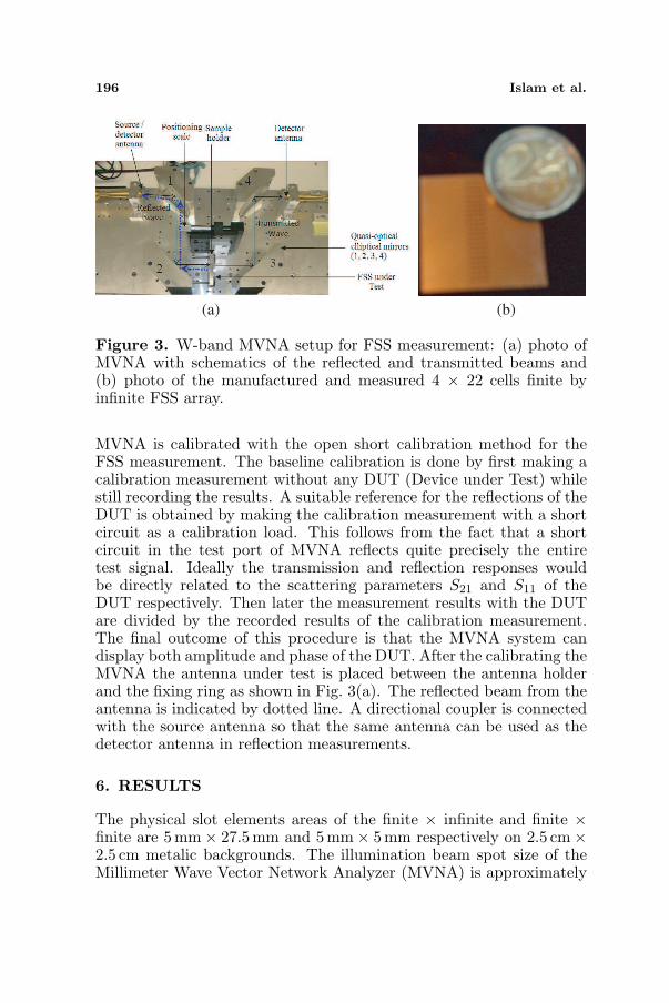
Figure 3. W-band MVNA setup for FSS measurement: (a) photo ofMVNA with schematics of the reflected and transmitted beams and(b) photo of the manufactured and measured 4 × 22 cells finite byinfinite FSS array.
MVNA is calibrated with the open short calibration method for theFSS measurement. The baseline calibration is done by first making acalibration measurement without any DUT (Device under Test) whilestill recording the results. A suitable reference for the reflections of theDUT is obtained by making the calibration measurement with a shortcircuit as a calibration load. This follows from the fact that a shortcircuit in the test port of MVNA reflects quite precisely the entiretest signal. Ideally the transmission and reflection responses wouldbe directly related to the scattering parameters S21 and S11 of theDUT respectively. Then later the measurement results with the DUTare divided by the recorded results of the calibration measurement.The final outcome of this procedure is that the MVNA system candisplay both amplitude and phase of the DUT. After the calibrating theMVNA the antenna under test is placed between the antenna holderand the fixing ring as shown in Fig. 3(a). The reflected beam from theantenna is indicated by dotted line. A directional coupler is connectedwith the source antenna so that the same antenna can be used as thedetector antenna in reflection measurements.
6. RESULTS
The physical slot elements areas of the finite × infinite and finite ×finite are 5 mm× 27.5mm and 5 mm× 5mm respectively on 2.5 cm×2.5 cm metalic backgrounds. The illumination beam spot size of theMillimeter Wave Vector Network Analyzer (MVNA) is approximately
Progress In Electromagnetics Research, PIER 101, 2010 197
1.5 cm. Hence the arrays can be treated as finite by infinite and finiteby finite arrays. A photo of the manufactured and measured 4×22 cellsfinite by infinite FSS array is shown in Fig. 3(b). The measurementand simulation results of the finite × infinite and finite × finite arraysare presented separately below. All the measurements are done withthe quasi optical free space MVNA as shown in Fig. 3(a).
6.1. Finite × Infinite Array
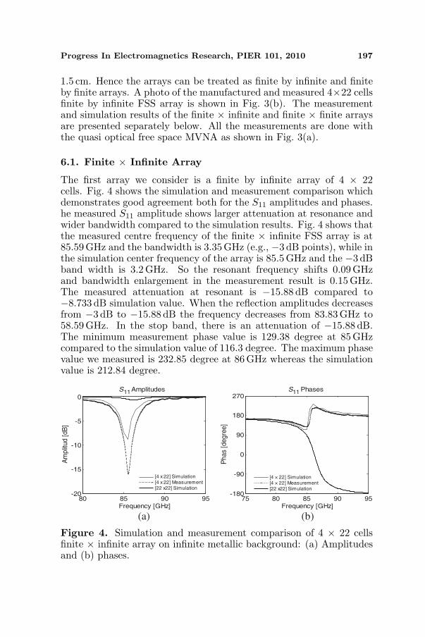
The first array we consider is a finite by infinite array of 4 × 22cells. Fig. 4 shows the simulation and measurement comparison whichdemonstrates good agreement both for the S11 amplitudes and phases.he measured S11 amplitude shows larger attenuation at resonance andwider bandwidth compared to the simulation results. Fig. 4 shows thatthe measured centre frequency of the finite × infinite FSS array is at85.59GHz and the bandwidth is 3.35GHz (e.g., −3 dB points), while inthe simulation center frequency of the array is 85.5 GHz and the −3 dBband width is 3.2 GHz. So the resonant frequency shifts 0.09 GHzand bandwidth enlargement in the measurement result is 0.15 GHz.The measured attenuation at resonant is −15.88 dB compared to−8.733 dB simulation value. When the reflection amplitudes decreasesfrom −3 dB to −15.88 dB the frequency decreases from 83.83 GHz to58.59GHz. In the stop band, there is an attenuation of −15.88 dB.The minimum measurement phase value is 129.38 degree at 85 GHzcompared to the simulation value of 116.3 degree. The maximum phasevalue we measured is 232.85 degree at 86 GHz whereas the simulationvalue is 212.84 degree.
80 85 90 95-20
-15
-10
-5
0
Frequency [GHz]
Am
plit
ud [
dB
]
S Amplitudes
75 80 85 90 95-180
-90
0
90
180
270S Phases
Frequency [GHz]
Phas
[degre
e]
[4 × 22] Simulation[4 × 22] Measurement[22 x22] Simulation
11 11
(a) (b)
[4 x 22] Simulation[4 x 22] Measurement[22 x22] Simulation
Figure 4. Simulation and measurement comparison of 4 × 22 cellsfinite × infinite array on infinite metallic background: (a) Amplitudesand (b) phases.
198 Islam et al.
The measured phase curves show a slight mismatch comparedto the simulation but both of them show the antenna/metalweighted balancing reflection. Simulation phase curve shows largerphase variation than the measurement which indicates that theantenna/metal ratio is slightly higher in measurement case comparedto the simulation. We have shown in the experimental characterizationof finite × infinite array case that the reflection amplitudes and phaseof finite × infinite array is the balancing weighted reflection from theeffective antenna/metal area. The results can be interpreted as follows:the shifting of resonant frequency of the finite array is a function of thenumber of slots in the tangential magnetic field (i.e., Ht) direction andthe effective illuminated background area. For the sake of comparisonwe also added the simulation amplitude and phase curves of infiniteslot FSS array when an ideal plane wave is incident on it. Fig. 4 clearlyshows the difference of infinite and finite array simulations.
6.2. Finite × Finite Array
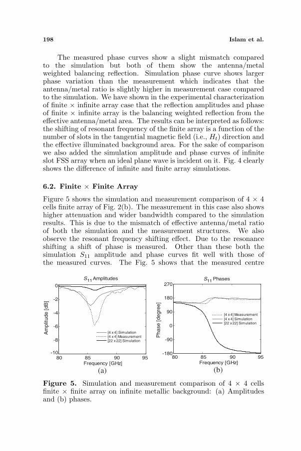
Figure 5 shows the simulation and measurement comparison of 4 × 4cells finite array of Fig. 2(b). The measurement in this case also showshigher attenuation and wider bandwidth compared to the simulationresults. This is due to the mismatch of effective antenna/metal ratioof both the simulation and the measurement structures. We alsoobserve the resonant frequency shifting effect. Due to the resonanceshifting a shift of phase is measured. Other than these both thesimulation S11 amplitude and phase curves fit well with those ofthe measured curves. The Fig. 5 shows that the measured centre
80 85 90 95Frequency [GHz]
S Amplitudes S Phases11 11
(a)
-10
-8
-6
-4
-2
0
Am
plit
ude
[dB
]
-180
-90
0
90
180
270
Phase
[degre
e]
[4 x 4] Simulation[4 x 4] Measurement[22 x 22] Simulation
[4 x 4] Measurement
[4 x 4] Simulation[22 x 22] Simulation
80 85 90 95Frequency [GHz]
(b)
Figure 5. Simulation and measurement comparison of 4 × 4 cellsfinite × finite array on infinite metallic background: (a) Amplitudesand (b) phases.

Progress In Electromagnetics Research, PIER 101, 2010 199
frequency of the finite × finite FSS is 86.15 GHz and −3 dB bandwidthis 2.29 GHz, while the simulation center frequency of the array is85.5GHz, and the reflection amplitude at resonance is−2.91 dB. So thesimulation bandwidth of the finite by finite array is full W-band. Themeasured attenuation at resonant is −5.75 dB in compare to −2.91 dBof simulation value. When the reflection loss decreases from −3 dBto −5.75 dB the frequency increases from 85.16 GHz to 86.15 GHz. Inthe stop band, there is an attenuation of −5.75 dB. The minimummeasured phase value is 146◦ degree at 85.55 GHz in compare to thesimulation value of 149◦ degree at 84 GHz. The maximum phase valuewe measured is 181◦ degree at 87.23 GHz whereas the simulation valueis 182.46 degree. For the comparison purpose it is interesting to addthe simulation amplitude and phase curves of infinite slot FSS array(i.e., 22 × 22 cells array) with ideal plane wave excitation. Fig. 5represents the difference of finite by finite array characterization (e.g.,simulation measurement comparison) and the behavior of its infiniteextent.
7. DISCUSSION ON COMPARISON RESULTS
Except classical measurement errors (e.g., drift error, random errors,systematic errors, error due to multi reflections between the source portand the antenna under measurement, errors due to limited directivityof the directional device etc.), there are several considerations whichwe need to count as the sources of measurement errors. The mainmismatches are illumination beam size variation, beam type mismatchin simulation and measurement and the weighted FSS array/metallicbackground area sensitivity.
(1) It is difficult to get a proper match between the beam sizeconsidered in the simulation (e.g., 1.59 cm) and the beam sizes usedin the measurement. In the simulation the illumination beam size wasconsidered constant though the MVNA beam width varies with thechange of frequency. In the W band (e.g., 75 GHz to 110 GHz) theillumination beam diameter is in the range of 1.59 cm ∼ 1.1 cm. Asthe measurement result of finite array is very much sensitive to antennaarray/effective background area, consequently the measured result willsomehow differ from the simulation.
(2) In the finite FSS arrays simulation instead of finite thick ofAluminum infinitely thin PEC plate was included as it is not yetpossible with 3D NSPWMLFMA solver to simulate finite thick ofAluminum. Moreover, a constant illumination is not realistic with idealshape used in the simulation. Hence, the analysis method introducessome approximations that also cannot be reproduced in the measureof the manufactured antennas.
200 Islam et al.
(3) The FSS response is the weighted balance of the effectiveFSS area and the metallic background as a consequence probabilityto introduce errors in the measurement is high.
(4) Type of illumination beam mismatch is another source oferrors. The simulation was carried out with the Gaussian beamapproximated as plane waves. In the measurement system theillumination of the MVNA source horn antenna radiation is consideras plane wave. So the probability of accurate beam type matching isobviously not negligible.
As we see from the above measurement and simulationcomparisons (e.g., Fig. 4 and Fig. 5) that the larger difference inthe measured S11 amplitudes in compared to the simulation results.In both the finite × infinite and finite × finite the measured S11
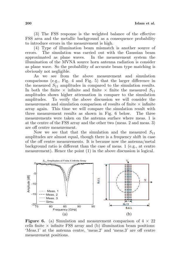
amplitudes shows higher attenuation in compare to the simulationamplitudes. To verify the above discussion we will consider themeasurement and simulation comparison of results of finite × infinitearray again. This time we will compare the simulation result withthree measurement results as shown in Fig. 6 below. The threemeasurements were taken on the antenna surface where meas. 1 isat the centre of the FSS array and the other two (meas. 2 and meas. 3)are off centre measurement.
Now we see that that the simulation and the measured S11
amplitudes are almost equal, though there is a frequency shift in caseof the off centre measurements. It is because now the antenna/metalbackground ratio is different than the case of meas. 1 (e.g., at centremeasurement). Hence the point (1) in the above discussion is logical.
75 80 85 90 95-20
-15
-10
-5
0S Amplitudes of Finite X Infinite Array
Frequency [GHz]
Am
pitu
de [
dB]
Meas. 1
Meas. 2
Meas. 3
Simu.
11
(a) (b)
Figure 6. (a) Simulation and measurement comparison of 4 × 22cells finite × infinite FSS array and (b) illumination beam positions:‘Meas.1’ at the antenna centre, ‘meas.2’ and ‘meas.3’ are off centremeasurement positions.

Progress In Electromagnetics Research, PIER 101, 2010 201
8. CONCLUSION
This study aimed at comparing the simulation and measurementresults of finite and semi-infinite FSS arrays compared to theillumination beam size to investigate the effects of finite array andinfinite beam size on the reflection characteristics of FSSs. As basicelements we chose the grounded FSS arrays. The simulation resultsobtained from 3D full wave solver NSPWMLFMA agree pretty wellwith the experimental results. We have presented a clear view inthe order of magnitudes change of amplitudes and phases when thedimensions of the arrays are finite compared to the illumination beamsize. The full wave simulation results show well agreement with theexperimental results.
ACKNOWLEDGMENT
This work was partially funded by the Vrije Universiteit Brussel (VUB-OZR), and the Flemish Institute for the encouragement of innovationin science and technology (IWT-SBO 231.011114).
REFERENCES
1. Koers, G., “Noise suppression in active millimeter wave imagingsystems,” Ph.D. dissertation, Universiteit Brussel, July 2006.
2. Islam, S., J. Stiens, G. Poesen, I. Jager, and R. Vounckx,“Passive frequency selective surface array as a diffuser fordestroying millimeter wave coherence,” Active and PassiveElectronic Components, Vol. 2008, 2008.
3. Islam, S., J. Stiens, G. Poesen, I. Jager, and R. Vounckx,“Implementation of dynamic hadamard diffuser as a frequencyselective surface for W-band active millimeter wave imaging,”Microwave and Optical Technology Letters, Vol. 51, No. 6, 1440–1444, June 2009.
4. Kastner, R. and R. Mittra, “Iterative analysis of finite-sizedplanar frequency selective surfaces with rectangular patches orperforations,” IEEE Trans. Antennas Propagat., Vol. 35, No. 4,372–378, 1987.
5. Chen, C. C., “Transmission through a conducting screenperforated periodically with apertures,” IEEE Trans. MicrowaveTheory Tech., Vol. 18, No. 9, 627–632, 1970.
6. Chen, C. C., “Diffraction of electromagnetic waves by aconducting screen perforated with circular holes,” IEEE Trans.Microwave Theory Tech., Vol. 19, No. 5, 475–481, 1971.
202 Islam et al.
7. Lee, S. W., “Scattering by dielectric-loaded screen,” IEEE Trans.Antennas Propagat., Vol. 19, No. 5, 656–665, 1971.
8. Montgomery, J. P., “Scattering by an infinite periodic array ofthin conductors on a dielectric sheet,” IEEE Trans. AntennasPropagat., Vol. 23, No. 1, 70–75, 1975.
9. Agrawal, V. D. and W. A. Imbriale, “Design of a dichroicCassegrain subreflector,” IEEE Trans. Antennas Propagat.,Vol. 27, No. 4, 466–473, 1979.
10. Tsao, C. H. and R. Mittra, “Spectral domain analysis of frequencyselective surfaces comprised of periodic arrays of cross dipoles andJerusalem cross,” IEEE Trans. Antennas Propagat., Vol. 32, No. 5,478–486, 1984.
11. Munk, B. A., “Scattering from surface waves on finite FSS,” IEEETrans. Antennas Propagat., Vol. 49, No. 12, 2001.
12. Bekers, D., “Finite antenna arrays: An eigencurrent approach,”Ph.D. dissertation, Technische Universiteit Eindhoven, 2004.
13. Fostier, J. and F. Olyslager, “Full-wave electromagnetic scatteringat extremely large 2D objects,” IET Electronics Letters, Vol. 45,No. 5, 245–246, 2009.
14. Van Den Bulcke, S. and A. Franchois, “A full-wave 2.5D volumeintegral equation solver for 3D millimeter-wave scattering by largeinhomogeneous 2D objects,” IEEE Trans. Antennas Propagat.,Vol. 75, No. 2, 535–545, Feb. 2009.
15. Song, M., T. Weng, and W. C. Chew, “Multilevel fast multipolealgorithm for elastic wave scattering by large three-dimensionalobjects,” Journal of Computational Physics, Vol. 228, No. 3, 921–932, 2009.
16. De Zaeytijd, J., A. Franchois, and J. M. Geffrin, “A newvalue picking regularization strategy — Application to the3D electromagnetic inverse scattering problem,” IEEE Trans.Antennas Propagat., Vol. 57, No. 4, 1133–1149, 2009.
17. Chew, W. C., J. Jin, E. Michielssen, and J. Song, Fast andEfficient Algorithms in Computational Electromagnetics, ArtechHouse, Boston, 2001.
18. Bogaert, I., J. Peeters, and F. Olyslager, “A nondirective planewave MLFMA stable at low frequencies,” IEEE Trans. AntennasPropagat., Vol. 56, 3752–3767, 2008.
19. Wallen, H. and J. Sarvas, “Translation procedures for broadbandMLFMA,” Progress In Electromagnetic Research, PIER 55, 47–78,2005.
Related Documents