AD-A263 554 Research Product 93-04 Models of Morse Code Skill Acquisition: Simulation and Analysis ".DTIC •ELECTE f MAY 0 4 1993 93--09363 february 1993 Automated Instructional Systems Technical Area Training Systems Research Division U.S. Army Research Institute for the Behavioral and Social Sciences Approved for public release; distribution Is unlimited.

Welcome message from author
This document is posted to help you gain knowledge. Please leave a comment to let me know what you think about it! Share it to your friends and learn new things together.
Transcript

AD-A263 554
Research Product 93-04
Models of Morse Code Skill Acquisition:
Simulation and Analysis
".DTIC
•ELECTE fMAY 0 4 1993
93--09363
february 1993
Automated Instructional Systems Technical Area
Training Systems Research Division
U.S. Army Research Institute for the Behavioral and Social Sciences
Approved for public release; distribution Is unlimited.
U.S. ARMY RESEARCH INSTITUTE
FOR THE BEHAVIORAL AND SOCIAL SCIENCES
A Field Operating Agency Under the Jurisdiction
of the Deputy Chief of Staff for Personnel
EDGAR M. JOHNSONActing Director
Research accomplished under contract
for the Department of the Army
Battelle Memorial Institute, Inc.
Technical review by
Mark A. SabolRobert A. Wisher
NOTICES
FINAL DISPOSITION: This Research Product may be destroyed when it is no longer needed.Please do not return it to the U.S. Army Research Institute for the Behavioral and Social Sciences.
NOTE: This Research Product is not to be construed as an official Department of the Armyposition, unless so designated by other authorized documents.

"-.- Form ApprovedREPORT DC WMENTATION PAGE i OMB N 04-0188
PIOIIC recitonng ourden for this collecioon Of inf lOrt n is estimated to a.erage 1 hrour per resoonse. irtluc .- the time lot r•viewing instructions searn-.r- .V. It ti, alt.. $,rel&arne flng&o mar/inalnnlglg the data needeo. and conaotieng ana reviewing the 4Olecneon of ntorrrralon Send comments reoawang •ni% owsoen estlmat- :r in, ,inlet JS)C Ct 1.r
coliection of ionvormafonm, uCing suggeston% tot reaucing trins Droefn t:' h3shington ,eaoquarlef', Ser.ces. Drectorate for information Ooe&at Onl, .nfd R.CI s !1 efti,,iOars1 migniwai, Ste 1204. Arlington, VA 22202-4302. and t1 tre Office of Management and Budget. Paperwot. Reducton Project (0704-0185). Washington. OC OSJ3
1. AGENCY USE ONLY (Leave blank) 2. REPORT DATE 3. REPORT TYPE AND DATES COVERED
1993, Februar7 Final Jun 91 - Dec 914. TITLE AND SUBTITLE 5. FUNDING NUMBERS
Models of Morse Code Skill Acquisition: Simulation and DAAL03-91-C-0034Analysis 62785A
7916. AUTHOR(S) 3302
Fisher, Donald L., University of Massachusetts, and HI
Townsend. James T., Indiana University
7. PERFORIMING ORGANIZATION NAME(S) AND ADDRESS(ES) 8. PERFORMING ORGANIZATION
Battelle Memorial Institute, Inc. REPORT NUMBER
Research Triangle Park, NC
9. SPONSORING/ MONITORING AGENCY NAME(S) AND ADDRESS(ES) 10. SPONSORING/ MONITORING
U.S. Army Research Institute for the Behavioral and AGENCY REPORT NUMBER
Social Sciences ARI Research ProductATTN: PERI-II 93-045001 Eisenhower AvenueAlexandria, VA 22333-5600
11. SUPPLEMENTARY NOTES
Contracting Officer's Representative, Robert A. Wisher
12a. DISTRIBUTION /AVAILABILITY STATEMENT 12b. DISTRIBUTION CODE
Approved for public release;distribution is unlimited.
13. ABSTRACT (Maximum 200 words)
The simulation described in this report predicts details of performance forstudents learning to copy Morse code at high speeds of transmission. Specifically,the model predicts the probability of a correct response, an incorrect response,
a period (no guess) response, no response, and a correct response for each of the
five serial positions in a group. The simulation also predicts the time it takes
to execute both a correct and incorrect response and the time it takes to executea period response. The model was derived from a cognitive analysis of the
information processing demands on students and modeled with order-of-processingdiagrams. A preliminary test was conducted with response data from students at theU.S. Army Intelligence School, Fort Devens, Massachusetts.
14. SUBJECT TERMS 15. NUMBER OF PAGES
.Skill training Cognitive models 110Order of processing Short term memory 16. PRICE CODEInformation processing Morse code
"17. SECURITY CLASSIFICATION 18. SECURITY CLASSIFICATION 19. SECURITY CLASSIFICATION 20. LIMITATION OF ABSTRACTOF REPORT OF THIS PAGE OF ABSTPACT
Unld.iificd Unclassified Unclassified UnlimitedNSN 7540-01-280-5500 Standard Form 298 (Rev 2-89)
i Preuribed by ANSI Sid 139SI-

Research Product 93-04
Models of Morse Code Skill Acquisition:
Simulation and Analysis
Donald L. FisherUniversity of Massachusetts
James T. TownsendIndiana University
Automated Instructional Systems Technical AreaRobert J. Seidel, Chief
Training Systems Research DivisionJack H. Hiller, Director
U.S. Army Research Institute for the Behavioral and Social Sciences5001 Eisenhower Avenue, Alexandria, Virginia 22333-5600
Office, Deputy Chief of Staff for PersonnelDepartment of the Army
February 1993
Army Project Number Manpower, Personnel, and Training2Q162785A791
Approved for public release; distbution is unlimited.
iii

FOREWORD
To ensure that the U.S. Army's soldiers acquire the skillsand knowledge necessary to perform their jobs successfully, theU.S. Army Research Institute for the Behavioral and Social Sci-ences (ARI) performs behavioral research to develop methods oftraining that can improve skill acquisition. Morse code copytraining is one skill area that continues to challenge the re-search community to identify training strategies that can alterthe training attrition pattern, particularly during the speedbuilding phase.
This report describes a quantitative model that simulatesthe perceptual-motor skill responsible for successful Morse codecopy. This model will allow detailed characteristics in theunderlying human information processing mechanics to be simulatedand compared to actual performance. Further application of thismodel might enable the "at-risk" students to be identified earlyin the speed building phase of training and thus designated forspecialized training. In general, this research adds to ourunderstanding of the acquisition of skilled performance.
!EDARM.~ JO SIONActing Director
Acoession For
NTIS GRA&IDTIC TABEUvevoA~n~ced CJustification
v TAVRii 1 au - /.g -
blt Special~

MODELS OF MORSE CODE SKILL ACQUISITION: SIMULATION AND ANALYSIS
EXECUTIVE SUMMARY
Requirement:
The U.S. Army Intelligence School at Fort Devens (USAISO)has been experiencing an unacceptably high rate of attrition.(The attrition rate was recently reduced after the introductionof a new training device.) The Assistant Deputy Chief of Stafffor Training, HQ Training and Doctrine Command (TRADOC), re-quested that the U.S. Army Reseaý:h Institute for the Behavioraland Social Sciences (ARI) examine the problem and pursue a courseof research that could lead to a reduction in the attrition rate.The simulation and analysis of performance and models to differ-entiate between successful students and attrites were importantsteps in the approach.
Procedure:
In a briefing to HQ TRADOC, a cognitive process model of theMorse copy skill was proposed as a means to understand the intri-cacies of the skill. An elaboration of this model was briefed toUSAISD staff. Through a contractual arrangement with the U.S.Army Research Office, researchers developed simulation modelsthat applied tools in queuing networks and order-of-processingdiagrams to the task of a student learning to copy Morse code atprogressively faster speeds.
Findings:
A simulation model was derived from a cognitive analysis ofthe information processing demands on students and modeled withorder-of-processing diagrams. Various assumptions about the"copy behind" phenomenon--not responding until a subsequent char-acter is presented--were made. The model predicts the probabil-ity of a correct response, an incorrect response, a period (noguess) response, no response, and a correct response for each ofthe five serial positions in a group. The simulation also pre-dicts the time it takes to execute both a correct and incorrectresponse and the time it takes to execute a period response. Apreliminary test was conducted with response data from studentsat the U.S. Army Intelligence School, Fort Devens, early in thespeed building phase of training. The models fit the observeddata quite well, with only the predicted response times forincorrect responses much different from the observation.
vii

Utilization of Findings:
These models will be tested with data from students whoeither acquired the skill rapidly or attrited during the speedbuilding phase. This will establish whether response patternsearly in the speed building phase can distinguish the quicklearners from the likely attrites. These findings, in turn, willbe presented to USAISD for consideration in identifying studentsfor specialized training.
viii

MODELS OF MORSE CODE SKILL ACQUISITION: SIMULATION AND ANALYSIS
CONTENTS
Page
INTRODUCTION ...................... ....................... 1
Background ..................... ...................... 1
A MODEL OF MORSE CODE COPY ............... ................ 6
General Copy Behind Model (GenCOPB) ........ ......... 7Limited Copy Behind (LimCOPB) and No Copy
Behind (NoCOPB) Models .......... .............. 11
SIMULATION ................. ..................... ...... 12
States ............................................... 12Transition Rules ............... ................... 19Dependent Variables .............. ................. 27Analysis ................... ....................... 28Model Evaluation ............. .................... 35LimCOPB .................... ....................... 36NoCOPB ................... ........................ 39
CONCLUSION ................... ........................ 41
REFERENCES ................... ........................ 43
APPENDIX A. PARAMETERS OF GenCOPB, LimCOPB,AND NoCOPB MODELS ........ .............. A-i
B. ERROR AND LATENCY CONFUSION MATRICES . . .. B-I
C. THE FORTRAN SIMULATION CODE ... ......... C-I
ix

MODELS OF MORSE CODE SKILL ACQUISITION:SIMULATION AND ANALYSIS
INTRODUCTION
Background
The U.S. Army Intelligence School at Fort Devens, Massachusetts, trains
Morse code copying to about 1,000 individuals per year from the four armed
services. The goal is to train military personnel to copy Morse characters at
the rate of 20 groups per minute (gpm; 1 group equals 5 characters) with 96
percent accuracy. The training has historically had a high rate of attrition,
at times over 30 percent (DOES, 1990). For those who succeed in the basic
Morse course, the training time has a wide degree of individual variability,
ranging from 200 to 1180 hours to achieve proficiency. By far, most training
time is spent in the speed building phase where students try to progress in-
crementally from 6 gpm to 20 gpm. Since attrition is most likely to occur
during speed building and well into the training program, its effect can be
costly.
Although the learning of Morse code has long been a topic of research inpsychology (Bryan and Harter, 1897), the high training attrition persists.
The learning of individual Morse characters is fairly straightforward, but the
ability to copy groups of characters accurately at increasing rates of trans-
mission is difficult to master for many individuals, even after hundreds of
hours of Dractice. It is this difficulty in being unable to progress to a
higher speed, not the lack of motivation or practice, that leads to the costly
attrition.
The copy task requires listening to a sequence of Morse code characters
(each character is itself a sequence of dahs and dits) and responding with the
corresponding character on a standard keyboard. The ability to copy Morse
code characters during rapid rates of transmission (100 characters per minute)
is clearly demanding. To copy at speeds approaching 20 gpm burdens the under-
lying cognitive processes, pushing relevant memories to their limits. It
requires the simultaneous processing of different stimuli, frequently respond-
ing to one character while another is being perceived. Perhaps the memory
capacity of some operators is exceeded, or perhaps the concurrent processing
1

abilities of other operators are pushed too far. Present-day computer technol-
ogy and theoretical frameworks for modeling cognitive processes suggest that a
closer study can be made of the development of proficiency during speed build-
ing than was previously possible. The results of this more extensive analysis
can then lead to prescriptions for overcoming the persistent training barrier.
A closer study of the development of proficiency during speed building
requires a detailed understanding of how accuracy and response time change as
a function of the rate of presentation (groups per minute); the serial posi-
tion of a character within a group; the serial position of a character within
a block; the identity of a character; the confusability of each character with
all other characters; the times to perceive, recognize, and program a response
to a stimulus; the sizes of the various memories involved in processing; and
the "decay" times of the items in these memories. This detailed understanding
can only come from a precise specification of the cognitive activity underly-
ing Morse intercept behavior.
Qualitative Models. Toward this end, several models of processing in
the Morse intercept task have been proposed (Sabol, Wisher and Medici, 1991;
Townsend, 1991; Wisher, Kern and Sabol, 1990). These models all derive from
the two descriptions of processing first presented by Wisher, Kern and Sabol
(1990). Briefly, in their early state cognitive process model, it was assumed
that subjects could execute only one process at a time and that the buffers in
front of the processors were limited to one item at most. In the advanced
state model, Wisher et al. assumed that subjects could execute several
processes simultaneously. In addition, they assumed that the buffer sizes were
greater than one. We want to pay particular attention to this advanced state
model.
In the advanced state model four processes were arranged in series:auditory perception, character recognition, motor organization, and responseexecution. In front of each processor was a buffer that held informationas it was passed along through the system. Each buffer had a limit on thenumber of items that it could hold and items in each buffer could decay over
time. Here decay refers to the natural loss of information if it is not rehearsed.
2

Note that the processing time for each server, decay times for items in each
buffer and capacity limits of each buffer were left unspecified.
At the outset of processing, the stimulus (a sequence of square waves of
sound energy or, more simply, a L )ne sequence) was placed in the auditory
buffer (echoic memory). In the auditory perception stage (which accepted in-
formation from the auditory buffer), it was assumed that the sound energy was
transformed into a string of elements (i.e., that sound energy was transformed
into a string of dits and dahs). These element strings were then passed to
the recognition buffer. In the recognition stage (which accepted items from
the recognition buffer), it was assumed that an element string was recognized
as a character. The character code was passed on to the motor organization
buffer. It was then assumed that the motor program needed to typ'- the par-
ticular character was set u- by the motor organization stage. Finally, the
motor program was passed on to the motor execution buffer where, eventually,
the response was initiated. We should note that the above reflects the
details of just one of the late stage models proposed by Wisher et al.
Several variations on the above were suggested.
Analytic Models. The above qualitative model suggests a number of points
in the processing of stimuli where the operator may have difficulty. However,
it is difficult to test the various hypotheses without being able to predict
how accuracy and response time change a- a function of the changes in zhe in-
dependent variables mentioned above. Towards this end it is necessary to
quantify the model. Unfortunately, this is not by any means an easy task.
Briefly, the model proposed by Wisher et al. (1990) is quite clearly a
queueing model. The literature on queueing models is extensive (e.g., Gross
and Harris, 1985, discuss the basic elements of queueing theory; Rouse, 1980,
reviews queueing networks that have been used to model person-machine
systems). However, the majority of the existing analyses assume that the
queueing system has reached steady state or equilibrium. Such will not be the
case for the behavior of the queueing system in the tasks undertaken by the
Morse intercept operator. In these tasks, the system is unlike±y to reach
equilibrium since five tone sequences are presented one at a time, fellowed by
an interval of time which in many cases is long enougr for the systm to clear
3

itself. And even were the system not to clear itself, the fact that a break
exists between groups makes it impossible to accept the assumption of steady
state. Thus, one needs to undertake a transient analysis of the queueing sys-
tem.
Toivnsend (1990) building on results reported in Fisher and Smith (1987),
shows the form that the analyses must take. Basically, it is necessary to
translate the queueing network into an Order-of-Processing (OP) diagram(Fisher and Goldstein, 1983; Goldstein and Fisher, 1991). Once so translated,
it is possible to obtain closed form expressions for relatively restricted
queueing networks. The analysis for two networks was worked out in detail by
Townsend.
Briefly, in the first network, there were two nodes. A node consists of
a server and a buffer (possibly of size zero). Townsend assumed that the
server at the first node encodes and recognizes the stimulus and the server atthe second node organizes and executes the response. The buffer at the first
node was unlimited in capacity. The buffer at the second node was of size
zero. If an item was encoded and the response server was executing, that item
was held at the encoder and the encoder was prohibited from accepting further
input until the response server completed its execution of the downstream
item. Townsend assumed that n items were present in the first buffer at the
start and that no new items were added to the system. Finally, Townsend as-
sumed that the service times were independent, exponentially distributed
random variables. For this system, he derived analytic expressions for t!
time on average it took to respond to the ith item in the first buffer.
The above system does not contain a mechanism for producing errors.
Thus, by itself, the system cannot be the one that subjects are using since,
among other things, subjects always produce a significant number of errors.
One reasonable way to generate errors is to assume that the subjects can ex-
ecute at most one process in the system at any one time. If an item arrives
while either the encoder or responder is busy, that item gets lost from the
system. In the previous model, the item was simply held at the encoder. For
this new system, Townsend was able to derive both the probability of an error
4
and the time on average it takes to respond, given that a correct response is
made (he assumed that if an item was lost from the system either no response
was made or an incorrect response was made).
Goal and Objectives
Goal. There are many reasons operators may find it difficult to complete
training. One hypothesis (Wisher et al., 1990) is that some operators cannot
simultaneously listen to (encode) an incoming signal at the same time as they
attempt to recognize and respond to other signals that have already arrived.
This ability is referred to as the ability to copy behind. The overall goal
of the work undertaken as part of this effort is to determine the extent to
which the copy behind hypothesis is supported by the data which has been col-
lected in the Morse code copy task.
Objectives. Attainment of the above goal requires the meeting of three
objectives. First, in order adequately to test the copy-behind hypothesis, it
is necessary to model Mor.e code copy behavior. In particular, it is neces-
sary to have a detailed model of the processes, memories, and other cognitive
building blocks involved in the Morse intercept process. As noted above,
Wisher et al. (1990) has proposed a rather extensive qualitative model. What
is needed at this point is a more precise characterization of what exactly is
meant by copy-behind, when exactly a period response will be produced, when no
response will be made, and so on (Objective 1).
Second, once the generic models are available, it is necessary to quan-
tify the behavior of the models. In particular, we were interested in having
the model predict the probability that an operator types a character cor-
rectly, types a character incorrectly, types a character as a period or fails
to type a character. (Periods are typed when an operator realizes that a
character has been transmitted, but is unable to respond quickly enough. The
period serves to maintain the format, i.e., the spacing.) And we were inter-
ested in having the model predict the time that it takes an operator to type a
character correctly, the time that it takes an operator to type a character
incorrectly, and the time that it takes an operator to type a period. As
above, Townsend (1990) has produced analytic expressions for response times
5
and errors for several more simple models than the one developed by Wisher.
What is needed at this point are predictions of the dependent variables for
the more complex model. This can be achieved using either simulation
(Objective 2a) or, where possible, deriving the relevant analytic expressions
(Objective 2b).
Finally, given that the behavior of the models can be quantified, it is
necessary to determine just how well the models fit the data. None of the
models, either the qualitative model proposed by Wisher et al. (1990) or the
quantitative models described by Townsend (1990) has been fit to results.What is needed now is an evaluation of just how well the various quantitative
models do indeed fit the data (Objective 3).
A MODEL OF MORSE CODE COPY
The models of Morse intercept that we developed correspond closely to the
advanced state models proposed by Wisher et al. (1990). To begin, we want to
talk about the most general model (GenCOPB) that we developed, one which al-
lows for copy-behind and large-capacity buffers at each stage. We then want
to describe the two models that we tested. Both assume no buffering of theinput at any stage. The first allows for copy-behind (LimCOPB); the second
does not allow for copy-behind (NoCOPB).
There are a total of 77 parameters in the GenCOPB model, 14 of which are
free and 63 of which are fixed by the data and/or condition. There are a to-
tal of 68 parameters in both the LimCOPB and NoCOPB models, 5 of which are
free and, again, 63 of which are fixed by the data and/or condition. These
parameters are described in detail in Appendix A. They are also described in
context in the material below.
We assume throughout that the various server and decay times are inde-
pendent and that their distribution is well described as a gamma. Briefly,
the density function of a gamma is given by the right hand side of the equa-
tion below:
f(x) x0-a xa- e-/x ]/r(a) if x > 0,
6

=0 otherwise.
The parameter a is referred to as the shape parameter; P is referred to as the
scale parameter. The mean and variance are given by, respectively:
E[X] =
VARIX] = a2
The function, r(a), is equal to a! when a is a nonnegative integer.
General Copy Behind Model (GenCOPB)
The Stages. We begin by developing a very general model, the GenCOPB,
which allows copy behind. Specifically, we assume the existence of three
stages, perception, recognition and execution. Each stage consists of a
"server" (some process) and a "buffer" (some memory). Specifically, we assume
the existence of three servers. We assume the existence of three buffers, one
in front of each of the servers. And we assume that decay can occur in any
one of the three buffers.
We assume that the stages are in series, where the string of tones input
to the perception stage is output as a string of elements (dits and dahs).
This string of elements is input to the recognition stage and output as a
character code. And finally, the character code is input to the execution
stage and output as an actual response.
It will De useful to have a more formal representation for the various
inputs. To begin, note that there are 31 different possible tone inputs, 26
letters and 5 special characters (the 10 digits were not included when fitting
the model and thus are not discussed). Each tone input t. is associated with1
a particular element string ei. Each element string ei is associated with a
particular character code ci. And each character code ci is associated with a
particular response ri. For example, the tone consisting of three 50 ms
pulses is associated with the element string, di-di-dit. The element string
di-di-dit is associated with the code for the character s. And the code for
the character s is associated with the motor program for pressing the letter s
on the keyboard.
7
Given this notation, a signal is output correctly if tone ti is the input
and response ri is the output; a signal is output as an incorrect character if
tone t. is input and response r. is the output (j = 1,...,31, i # j). A sig-2.3
nal is output as a period if tone ti is the input and a period is the output
(a period is indicated by the integer 44). And a signal is output as no
response if tone ti is the input and no response is made to this tone.
The Servers. Implicit in the above discussion of the stages is the fol-
lowing description of the role played by each of the servers. Specifically,
as in the model proposed by Wisher et al. (1990), the perception server maps
sound energy into a string of Morse elements, i.e., dits and dahs. The recog-
nition server maps the string of Morse elements into a character. And the
execution server both organizes a response and executes it.
We made several simplifying assumptions about the distributions of the
service times. To begin, we assumed that the duration Tr of the recognition
process and the duration Te of the execution process did not depend on the
identity of the input to the process or on the output of the process.
Furthermore, given our work with other, similar cognitive tasks, it seemed
reasonable to assume that the durations of the recognition and execution
processes were independent, gamma distributed random variables. We let a r and
Pr represent the shape and scale parameters for the distribution of the dura-tion of the recognition process; and we let ae and 0e represent the shape and
scale parameters for the distribution of the duration of the execution
process. These four parameters were free.
Although we did not assume that the durations of the recognition and ex-
ecution processes depended on the input to these processes, we did assume that
the duration T p(ejIti) of the perception process was dependent on the identity
of the tone sequence ti which was given as input. At this point we do not as-
sume that the perception time depends on the output of the process. However,we believe that such a dependency will be necessary to incorporate in future
8
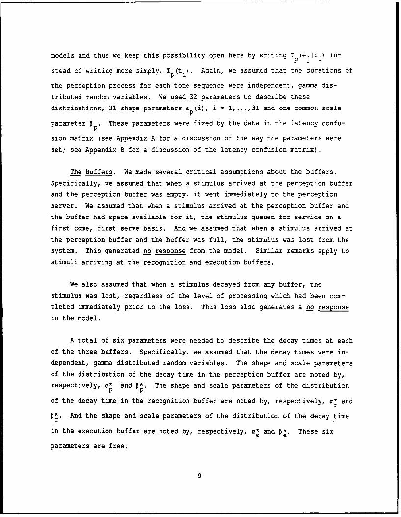
models and thus we keep this possibility open here by writing T p(ej it) in-
stead of writing more simply, T (ti). Again, we assumed that the durations of
the perception process for each tone sequence were independent, gamma dis-
tributed random variables. We used 32 parameters to describe these
distributions, 31 shape parameters a p(i), i = 1,...,31 and one common scale
parameter 0 . These parameters were fixed by the data in the latency confu-
sion matrix (see Appendix A for a discussion of the way the parameters were
set; see Appendix B for a discussion of the latency confusion matrix).
The Buffers. We made several critical assumptions about the buffers.
Specifically, we assumed that when a stimulus arrived at the perception buffer
and the perception buffer was empty, it went immediately to the perception
server. We assumed that when a stimulus arrived at the perception buffer and
the buffer had space available for it, the stimulus queued for service on a
first come, first serve basis. And we assumed that when a stimulus arrived at
the perception buffer and the buffer was full, the stimulus was lost from the
system. This generated no response from the model. Similar remarks apply to
stimuli arriving at the recognition and execution buffers.
We also assumed that when a stimulus decayed from any buffer, the
stimulus was lost, regardless of the level of processing which had been com-
pleted immediately prior to the loss. This loss also generates a no response
in the model.
A total of six parameters were needed to describe the decay times at each
of the three buffers. Specifically, we assumed that the decay times were in-
dependent, gamma distributed random variables. The shape and scale parameters
of the distribution of the decay time in the perception buffer are noted by,
respectively, a* and P*. The shape and scale parameters of the distributionp p
of the decay time in the recognition buffer are noted by, respectively, a* andr
O*. And the shape and scale parameters of the distribution of the decay timer
in the execution buffer are noted by, respectively, a* and 0*. These sixe e
parameters are free.
9

A total of three parameters were needed to describe the capacity size of
the three buffers. Specifically, the capacity sizes of the perception, recog-
nition and execution buffers are noted by, respectively, y p Yr and ye' These
three parameters are free.
Critical Perception Time. We made one critical assumption about the per-ception server, an assumption which produced a period response from the model.
Specifically, we assumed that if the time to perceive the stimulus was longer
than some critical value, say 8, then the model coded the incoming stimulus as
a period. The rationale for doing so is the following. As the time it takes
an operator to perceive a stimulus increases, the data suggest that accuracy
decreases. Thus, rather than make an incorrect response, it may be optimal
for the operator to produce a period as a response (which, during training,
earns the operator a smaller point loss than an incorrect response).
Note that we assume that the duration of the perception process continues
beyond the critical value 6. It is only after the perception process has com-
pleted that a comparison is made between the duration of this process and the
critical value. This may appear counterintuitive at first glance. However,
note that it could well be less time consuming simply to perceive a stimulus
and then determine whether the critical value has been exceeded than concur-
rently both to perceive the incoming stimulus and to monitor the duration of
this process. The exhaustive scanning mechanism proposed by Sternberg (1969)
requires for its justification a similar argument. The critical time was a
free parameter.
Character Errors. Define a character error as a transformation of acharacter (as opposed to period) input at one stage to a character output at
the same stage which is not associated with the input. So, a character error
at the perception stage is a transformation of a tone sequence t. into an ele-1
ment sequence e., where i,j = 1,...,31, i # j. A character error at the
recognition stage is a transformation of an element string ei into a character
code c., where i,j = 1,...,31, i # j. And a character error at the execution
10

stage is a transformation of a character code ci into a response r., where
i,j = 1,...,31, i # j.
We need to consider the possibility of character errors at all three
stages. To begin, consider character errors at the perception stage. When
the duration of the perception server was less than 6, on some trials the per-
ception stage worked correctly (i.e., tone sequence t. was mapped into element
string ei); on other trials it produced a character error. Since there were
31 tone sequences, we need to specify for the perception stage the 31 prob-
abilities p(eiiti), i = 1,...,31. These 31 probabilities were determined by
the error confusion matrix (see Appendix A for a discussion of how the
parameters were estimated; see Appendix B for a discussion of the error confu-
sion matrix). To keep the analysis relatively simple, we grouped the off-
diagonal confusions. Thus, the probability of an incorrect perception
transformation was set equal to 1 - P(eiiti).
Next, we need to consider the possibility of character errors at the
recognition and execution stages. Implicit in the above is the assumption
that all confusions are bundled into the perception stage. That is, we do not
also allow confusions at the recognition or execution stages. This is not be-
cause we believe that such confusions do not occur. Rather, it is because the
preliminary data suggest that the majority of confusions occur at the percep-
tion stage. Of course, if our simplifying assumption is wrong, we should find
the GenCOPB unable to account for significant aspects of the data.
Limited Copy Behind (LimCOPB) and No Copy Behind (NoCOPB) Models
The limited copy behind (LimCOPB) is a special case of the general copy
behind (GenCOPB) model. Specifically, in the LimCOPB model, we assume that
the buffers are of size zero at each of the perception, recognition, and ex-
ecution stages. Note that this means we do not need parameters to describe
the duration of the decay in these three buffers.
11

Strictly speaking, the no copy behind (NOCOPB) model is not a special
case of the GenCOPB model since in the NoCOPB model all downstream processors
are surveyed, not just the processor at the next stage. Specifically, if
there are no items on any one of the perception, recognition or execution
servers, then an arriving item is placed on the perception server. Otherwise,
the arriving item is lost from the system and not recoverable.
SIMULATION
We now want to describe how we simulated the behavior of the three
models, the GenCOPB, LimCOPB, and NoCOPB. Recall that we are interested in
seven dependent variables, four related to accuracy and three related to time.
Specifically, we are interested in simulating the probability of a correct
response, the probability of an incorrect character response, the probability
of an incorrect period response, and the probability of no response. In addi-
tion, we are interested in simulating the time that it takes to make a correct
response, the time that it takes to make a incorrect character response, and
the time that it takes to make an incorrect period response.
Because the general copy-behind model was complex, we decided first to
simulate its behavior. The simulation follows directly from an OP repre-
sentation of processing in such a task (Fisher and Goldstein, 1983; Goldstein
and Fisher, 1991). To begin, we describe the state variables used in the
simulation. We then describe the actual transition rules. Finally, we
describe where in the simulation we obtain the relevant dependent variables.
(Note that we will wait until the discussion of the analytical work to
describe the actual OP diagram.) The source code is listed in Appendix C.
States
Conceptually, it is a straightforward matter to simulate the behavior of
the system we have described. This is because for purposes of the simulation
we can classify the evolution of the system over time into a finite number of
states. Furthermore, the relevant state variables themselves are constant
throughout the duration of any given state. Thus, we can simulate the system
as a series of discrete events.
12

Each state si is defined as a structure consisting of a (y a+ 1) X 5 ar-
rival matrix M a(i), a (y p+ 1) X 5 perception matrix M p(i), a (y r+ 1) X 5
recognition matrix Mr (i), and a (ye+ 2) X 5 execution matrix M e(i) . The first
row of the arrival (perception, recognition, execution) matrix contains infor-
mation on the item currently on the arrival (perception, recognition,
execution) server. The second and subsequent rows contain information on the
items in the arrival (perception, recognition, execution) buffer.
As noted above, the 31 characters are represented by the integers 1 - 31
(and the digits by the numbers 32 - 41). The intercharacter interval is rep-
resented by the number 42. The intergroup interval is represented by the
number 43. The period character is represented by the number 44. Note that
we will refer to the generic entity which passes through the system as an
item, i.e., a tone sequence, element string, character code and response are
all items.
Arrival. Consider just the arrival matrix for state s. It may help
some to display a particular matrix and refer to the entries in the matrix as
we discuss them. To keep things simple, we will display only two rows in the
arrival matrix:
Ma(i): 23 23 1 49 0 (server entries)a 17 17 2 - 0 (buffer entries)
To begin, consider the entries in the first row. The number (23) in the first
column and first row indicates the identity of the tone sequence in state s.i
which is currently on the arrival server. The number (23) in the second
column and first row indicates the identity of the tone sequence which
originally was sent. In the arrival matrix, this entry and the preceding
entry are identical since they reference the same item before any processing
has begun. The entry (1) in the third column and first row indicates the
serial position of the arriving tone sequence in the group in which it was
sent. Since there are five tone sequences in a group, the serial position
13
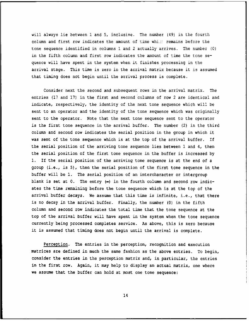
will always lie between 1 and 5, inclusive. The number (49) in the fourth
column and first row indicates the amount of time whi:: remains before the
tone sequence identified in columns 1 and 2 actually arrives. The number (0)
in the fifth column and first row indicates the amount of time the tone se-
quence will have spent in the system when it finishes processing in the
arrival stage. This time is zero in the arrival matrix because it is assumed
that timing does not begin until the arrival process is complete.
Consider next the second and subsequent rows in the arrival matrix. The
entries (17 and 17) in the first and second columns of row 2 are identical and
indicate, respectively, the identity of the next tone sequence which will be
sent to an operator and the identity of the tone sequence which was originally
sent to the operator. Note that the next tone sequence sent to the operator
is the first tone sequence in the arrival buffer. The number (2) in the third
column and second row indicates the serial position in the group in which itwas sent of the tone sequence which is at the top of the arrival buffer. If
the serial position of the arriving tone sequence lies between 1 and 4, then
the serial position of the first tone sequence in the buffer is increased by
1. If the serial position of the arriving tone sequence is at the end of a
group (i.e., is 5), then the serial position of the first tone sequence in the
buffer will be 1. The serial position of an intercharacter or intergroup
blank is set at 0. The entry (in) in the fourth column and second row indic-
ates the time remaining before the tone sequence which is at the top of the
arrival buffer decays. We assume that this time is infinite, i.e., that there
is no decay in the arrival buffer. Finally, the number (0) in the fifth
column and second row indicates the total time that the tone sequence at the
top of the arrival buffer will have spent in the system when the tone sequence
currently being processed completes service. As above, this is zero because
it is assumed that timing does not begin until the arrival is complete.
Perception. The entries in the perception, recognition and execution
matrices are defined in much the same fashion as the above entries. To begin,
consider the entries in the perception matrix and, in particular, the entries
in the first row. Again, it may help to display an actual matrix, one where
we assume that the buffer can hold at most one tone sequence:
14

M (i) 16 16 2 123 650 (server entries)
8 8 4 500 150 (buffer entries)
The number (16) in the first column and first row indicates the identity ofthe tone sequence in state s. which is currently being mapped to an element
1
string. The number (16) in the second column and first row indicates the
identity of the tone sequence which originally was sent. Since the arrival
stage always outputs the same tone sequence which was sent as input, the tone
sequences in the first and second columns are identical in the perception
matrix (as well as the arrival matrix). The entry (2) in the third column and
first row indicates the serial position of the tone sequence being perceived
in the group in which it was sent. The number (123) in the fourth column and
first row indicates the amount of time which remains before the tone sequence
in the process of being perceived actually completes this process. The number
(650) in the fifth column and first row indicates the amount of time the tone
sequence being perceived will have spent in the system when it finishes
processing in the perception stage. This time will be the sum of the times
that it spent in the perception buffer and on the perception server. Thus,
for example, if tone sequence 16 arrived at the perception stage when the
server was occupied, if it took 200 ms to complete the servicing of the tone
sequence currently on the server, and if it took 450 ms to service tone se-
quence 16, then the amount of time tone sequence 16 will have spent in the
system when it finishes processing in the perception stage will be 650 ms.
Consider next the second row in the perception matrix. The entry (8) in
the first column of row 2 indicates the identity of the next tone sequencewhich will be sent to the perception server (i.e., the identity of the first
item in the perception buffer). The entry (8) in the second column of row 2
indicates the identity of the tone sequence in the first row in the perception
buffer which originally was sent to the arrival stage. Again, this is the
same as the entry in the first column and second row since we assume that no
errors are introduced by the arrival stage. The number (4) in the third
column and second row indicates the serial position in the group in which itwas sent of the tone sequence which is at the top of the perception buffer.
15
Note that in this example this number is not simply one more than the cor-
responding number in the first row and third column. What this indicates is
that the third tone sequence in the group must have entered the perception
stage at a time when the buffer was full. Thus, it was lost from the system.
The number (500) in the fourth column and second row indicates the time
remaining before the tone sequence which is at the top of the perception buff-
er decays. Finally, the number (150) in the fifth column and second row
indicates the total time that the tone sequence at the top of the perception
buffer will have spent in the system when the tone sequence currently on the
perception processor completes its service. In this case, tone sequence 8
could have arrived when there was 150 ms left to process of tone sequence 16
(of course, other scenarios could have led to the same time). Similar remarks
would apply to subsequent rows in the perception matrix were we to assume a
larger buffer.
Recognition. Next, consider the entries in the recognition matrix and,
in particular, consider the entries in the first row of the recognition
matrix. Assume that the buffer can hold only one element string:
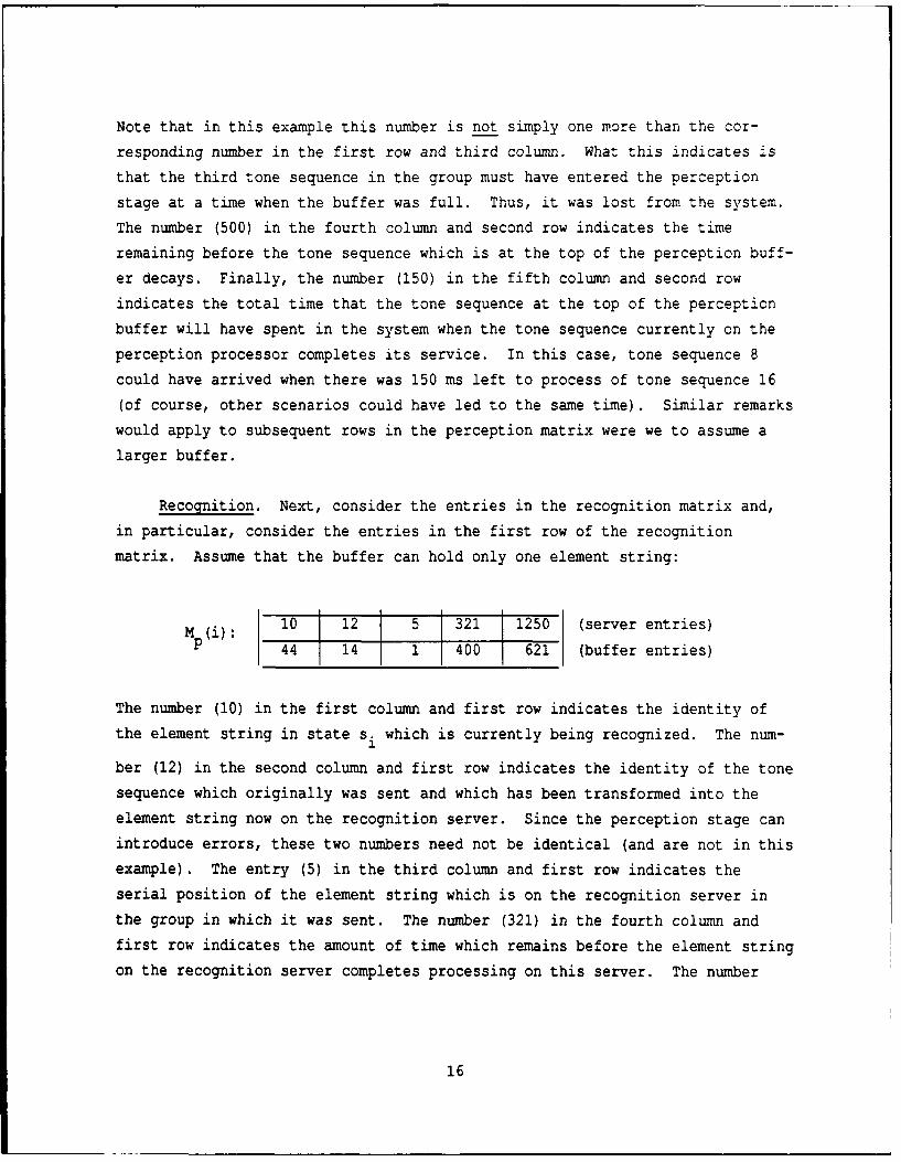
Ml(i): 10 12 5 32. 1250 (server entries)p 44 14 1 400 621 (buffer entries)
The number (10) in the first column and first row indicates the identity of
the element string in state si which is currently being recognized. The num-
ber (12) in the second column and first row indicates the identity of the tone
sequence which originally was sent and which has been transformed into the
element string now on the recognition server. Since the perception stage can
introduce errors, these two numbers need not be identical (and are not in this
example). The entry (5) in the third column and first row indicates the
serial position of the element string which is on the recognition server in
the group in which it was sent. The number (321) in the fourth column and
first row indicates the amount of time which remains before the element string
on the recognition server completes processing on this server. The number
16

(1250) in the fifth cclumn and first row indicates the amount of time the ele-
ment string and associated tone sequence will have spent in the system when
the element string on the recognition server finishes processing. This time
will be the sum of the times that the item spent in the perception and recog-
nition buffers plus the sum of the times it spent on the perception and
recognition servers.
Consider next the second row in the recognition matrix. The entry (44)
in the first column of row 2 indicates the identity of the next element string
which will be sent to the recognition server (i.e., the identity of the first
element string in the recognition buffer). In this particular example, the
entry represents a period response, an indication that the critical time on
the perception server was exceeded for the corresponding tone sequence and
thus the perception server, rather than generating an element string as-
sociated with a character output, generated an element string for a period as
an output. The entry (14) in the second column of row 2 indicates the iden-
tity of the tone sequence originally sent which is now the first element
string in the recognition buffer. The number (1) i:, the third column and
second row indicates the serial position in the group in which it was sent of
the element string which is at the top of the recognition buffer. The number
(400) in the fourth column and second row indicates the time remaining before
the element string which is at the top of the recognition buffer decays.
Finally, the number (621) in the fifth column and second row indicates the to-
tal time that the element string at the top of the recognition buffer (and
associated tone sequence) will have spent in the system when the element
string current on the recognition processor completes its service. Similar
remarks apply to subsequent rows in the recognition matrix were the buffer to
hold more than one element string.
Execution. Finally, consider the entries in the execution matrix and, in
particular, consider the entries in the first row of the execution matrix.
Again, it may be helpful to describe these entries in the context of a par-
ticular example. Assume that the execution buffer can hold only one character
code:
17

M (j) 20 10 3 101 1600 (server entries)e 18 18 4 20 2210 (buffer entries)
The number (20) in the first column and first row indicates the identity ofthe character code in state s. for which a response is currently being or-
ganized. The number (10) in the second column and first row indicates the
identity of the tone sequence which originally was sent and which has been
transformed into element string 20 at the perception stage and character code
20 at the recognition stage. The entry (3) in the third column and first row
indicates the serial position of the character code which is on the execution
server in the group in which it was sent. The number (101) in the fourth
column and first row indicates the amount of time which remains before the
character code on the execution server completes processing on this server.
The number (1600) in the fifth column and first row indicates the amount of
time the character code and its associated element string and tone sequence
will have spent in the system when character code finishes processing in the
execution stage. This time will be the sum of the times that the item spent
in the perception, recognition and execution buffers plus the sum of the times
it spent on the perception, recognition and execution servers.
Consider next the second row in the executicn matrix. The entry (18) inthe first column of row 2 indicates the identity of the next character code
which will be sent to the execution server (i.e., the identity of the first
character code in the execution buffer). The entry (18) in the second column
of row 2 indicates the identity of the tone sequence which through processing
in the perception and recognition stages has been transformed into the charac-
ter code at the top of the execution buffer. The number (4) in the thirdcolumn and second row indicates the serial position in the group in which it
was sent of the character code which is at the top of the execution buffer.
The number (20) in the fourth column and second row indicates the time remain-
ing before the character code which is at the top of the execution buffer
decays. Finally, the number (2210) in the fifth column and second row indic-
ates the total time that the character code at the top of the execution buffer
(and its associated element string and tone sequence) will have spent in the
18

system when the stimulus current on the execution processor completes its
service.
Transition Rules
The simulation of the system requires knowledge of the state variables,
as explained above. It also requires knowledge both of the events which lead
to a transition between states and of the rules used to relate states which
follow one another. We now want to describe these events and rules.
Briefly, a transition between states occurs when an item (i.e., a tone
sequence, element string or character code) completes service or an item
decays. The determination of which item will complete or decay first can bemade in a straightforward fashion from the entries in the fourth column of the
arrival, perception, recognition and execution matrices. Specifically, theminimum time is selected from the set of times consisting both of the arrival,
perception, recognition and execution service times and of the perception,recognition and execution decay times.
Arrival. We now need to specify exactly what changes are made whenanyone of the above events occur. Although quite tedious, the details vary
enough for the different stages to require a relatively complete rendering ofthe transition rules. To begin, consider the arrival stage. The item in the
arrival stage which completes first can be either a character or a blank. Weneed to consider both. And the item which completes first in the arrival
stage can find the perception buffer full or not full. Again, we need to con-
sider both possibilities.
i) Assume that the item which completes first is a character in the ar-
rival stage. An example of a state, say si, where the first item to complete
is a tone sequence in the arrival stage is given below on the left; theentries in the new state, say sj, which follows it are given on the right.
For the sake of simplicity, we assume that the buffers in the perception,recognition and execution stages can hold only one item. And we represent
only the top most item in the arrival buffer:
19

Arrival Stage (si) Arrival Stage (s.)1I
23 23 1 49 0 26* 26* 2* 250* 0
26 26 2 Cl 0 22* 22* 3* 1 0
Perception Stage (si) Perception Stage (sj)
19 19 5 305 600 19 19 5 256* 600- - - - 23* 23* 1*1 1200* 256*
Recognition Stage (s.) Recognition Stage (sj)
14 14 3 200 953 14 14 3 151* 953
11 11 4 780 876 11 11 4 731* 876
Execution Stage (si) Execution Stage (s.)
8 81 1 510 1451 8 8 1 461* 1451
9 9 2 452 1008 9 9 2 403* 1008
As noted above, in order to determine which event completes first, we need to
look at the entries in column four of the matrices defining state s. and find1
the minimum. Doing such, we see that the times remaining on the arrival, per-
ception, recognition and execution servers are respectively 49, 305, 200 and
510 ms. And we see that the times remaining before decay occurs in the ar-
rival, recognition and execution buffers are, respectively, cc, 780 and 452 ms
(the perception buffer is empty, as indicated by the "-"). Thus, the minimum
time to completion or decay is 49 ms, or the remaining arrival time of tone
sequence 23.
The changes in the arrival, perception, recognition and execution
matrices are given on the right in the example state s.. The starred (*)3
entries indicate where changes occur. To begin, consider the change in the
arrival matrix. Since tone sequence 23 completes, we move it off the arrival
server. We move the first tone sequence in the arrival buffer, tone sequence
26, to the arrival server and assign it the appropriate arrival time (say
250). Note that we have displayed only the first two rows of the arrival
20
matrix. However, we are assuming that the arrival buffer contains additional
items, and in particular, contains tone sequence 22 below tone sequence 26.
Thus, we move tone sequence 22 up to the first position in the arrival buffer.
By implication it is the third tone sequence in the current group.
We also need to change the perception matrix. Note that although the
server of the perception matrix is occupied, the buffer of the perception
matrix is empty. Thus, we can put the tone sequence which just arrived (23)
in the buffer of the perception matrix and assign it a decay time, say 1200.
We need to make two additional changes. First, the time remaining to process
the tone sequence on the perception server must be reduced by 49 ms, from 305
to 256 ms. Second, the amount of time the newly arrived tone sequence 23 will
have spent in the perception buffer after the tone sequence currently on the
server completes its execution must be assigned. In this case, this is simply
256 ms. Note that the amount of time that tone sequence 19 will have spent in
the system after it completes processing is unaffected by the completion of
the tone sequence in the arrival stage. Thus, the entry in the perception
matrix in column 5 and row 1 in both states s. and s. is 600.1 3
Finally, we need to decrement the server and decay times in the recogni-
tion and execution matrices. For example, the time remaining until element
string 11 decays in the recognition buffer is 780 ms when we first examine the
system. After tone sequence 23 arrives, 49 ms will have elapsed. Thus the
time remaining until element string 11 decays is reduced from 780 to 731 ms.
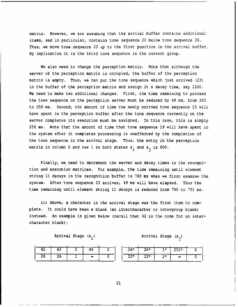
ii) Above, a character in the arrival stage was the first item to com-
plete. It could have been a blank (an intercharacter or intergroup blank)
instead. An example is given below (recall that 42 is the code for an inter-
character blank):
Arrival Stage (si) Arrival Stage (s.)
42 42 0 49 0 26* 26* 1* 250* 0
26 26 1 C 0 22* 22* 2* 0
21

Perception Stage (si) Perception Stage (s.)
19 19 5 305 600 19 19 E 256* 600
Recognition Stage (si) Recognition Stage (sj)
14 14 3 200 953 14 14 3 151* 953
11 _I 4 780 876 11 11 4 731* 876
Execution Stage (si) Execution Stage (s.)
8 8 1 510 1451 8 8 1 461* 1451
9 2 45211008 t 9 9 2 403* 1008
In this example, note that all the times are changed as above and that a new
tone sequence is added to the arrival server. However, the blank is not moved
to the perception buffer since blanks are not processed through the system.
iii) Finally, suppose that the item which completes first is on the ar-
rival server and that the perception buffer is full. Then, we make the
changes indicated below:
Arrival Stage (si) Arrival Stage (s.)
23 23 1 49 0 26* 26* 2* 250* 0
26 26 2 - 0 22* 22* 3* - 0
Perception Stage (si) Perception Stage (sj)
19 19 4 305 600 19 19 4 256* 600
16 16 5 838 403 16 16 5 787* 403
Recognition Stage (si) Recognition Stage (s.)
1 J14 14 2 200 953 14 14 2 151* 953
11 11 3 780 876 11 11 3 731* 876
22

Execution Stage (si) Execution Stage (s.)
8 8 5 510 1451 8 8 5 461* 1451
9 9 1 452 1008 9 9 1 403* 1008
Note that the only difference here is that tone sequence 23 is not added to
the perception buffer since this buffer is already full.
Perception. Next, we need to consider the perception stage. An event
(i.e., a completion or decay) in this stage will drive the transition if
either the item on the perception server completes or an item in the percep-
tion buffer decays before any other service or decay occurs. To begin, assume
that the event which leads to the transition is the completion of the process-
ing of the tone sequence on the perception server. Then, if the duration of
the service is greater than some critical time, we assume that the tone se-
quence on the server is replaced by a period response. For illustrative
purposes, let us assume that this time is 1600 ms. If the duration of the
perception process is less than 1600 ms, then the tone sequence ti on the per-
ception server is replaced with its correct element string, el, with
probability p(riiti) and with an incorrect element string ej (i # j) with
probability 1 - P(riiti). Furthermore, it will be the case that sometimes the
tone sequence on the perception server completes (regardless of its duration)
when the recognition buffer is empty; at other times it will complete when the
recognition buffer is full.
As noted above, it may be the decay of a tone sequence in the perception
buffer (rather than the processing of a tone sequence on the perception serv-
er) that drives the next transition. If this is the case, then we need to
enforce alternative transition rules.
The full set of rules is discussed below.
i) To begin, assume that it is the perception service time which is the
minimum of the times remaining until an item either completes service or
23

decays from a buffer. And assume the perception service time is greater than
the critical time of 1600 ms. Then, the matrices are changed as in the fol-
lowing example:
Arrival Stage (s.) Arrival Stage (s.)
23 23 1 350 7 23 23 1 301 4 026 26 2 0 26 22 2 0
Perception Stage (si) Perception Stage (s.)
1 J
19 19 5 49 1 8 8 8 - -* -* -* -*
Recognition Stage (si) Recognition Stage (sj)
14 14 4 200 953 14 14 4 151* 953- - 44* 19* 5* 731* 151*
Execution Stage (si) Execution Stage (s.)
8 8 2 510 1451 8 8 2 461* 1451
9 9 3 452 1008 9 9 3 403* 1008
There are several things to note. First, the tone sequence 19 on the percep-
tion server now becomes the element string 44 in the recognition buffer (the
string associated with a period response). Second, the actual service time in
the perception stage is greater than 1600 ms and, in this case, is equal to
1888 ms, assuming that no time was spent in the perception buffer.
ii) Assume that the first item to complete or decay is in the perception
stage, as above. However, now assume that the perception service time is less
than the critical perception time of 1600 ms. Then, as noted above, one of
two things can happen. The tone sequence 19 can be transformed correctly into
the element string 19 or it can be transformed into some other element string.
When the element string was transformed incorrectly, we mapped tone sequence 1
24
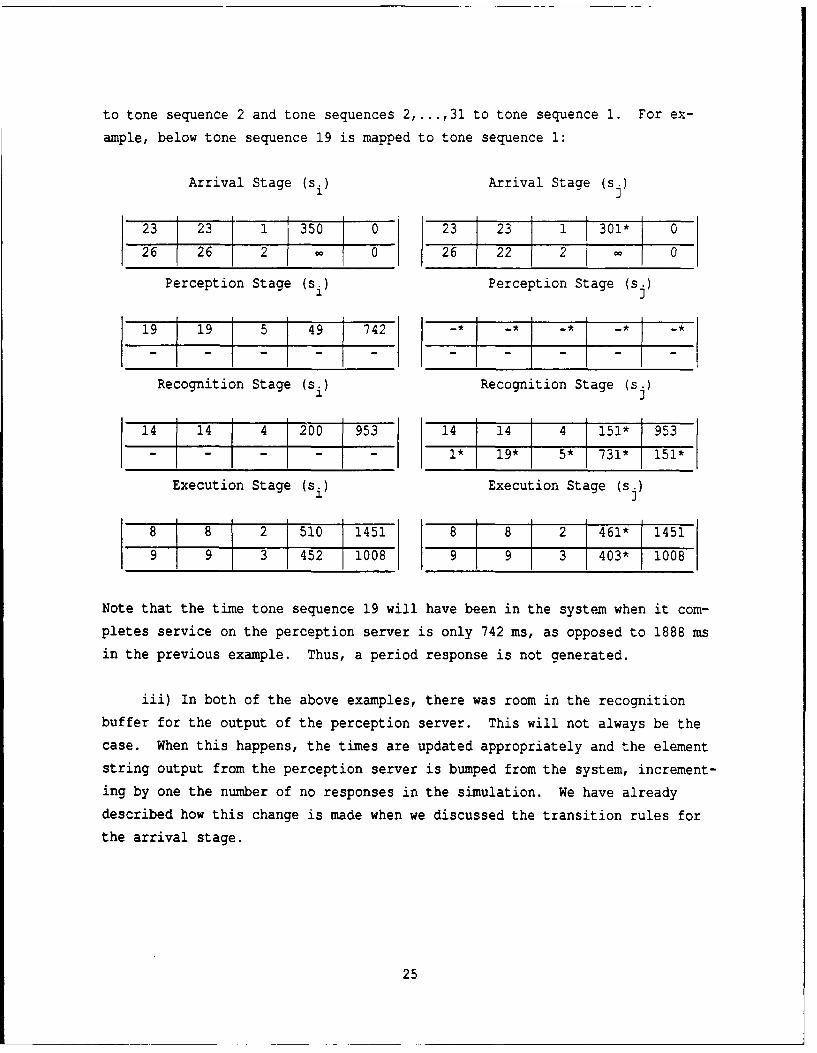
to tone sequence 2 and tone sequences 2,...,31 to tone sequence 1. For ex-
ample, below tone sequence 19 is mapped to tone sequence 1:
Arrival Stage (si) Arrival Stage (s.)
23 23 1 350 0 23 23 1 301* 0
26 26 2 0 26 22 2 _
Perception Stage (si) Perception Stage (s.)
19 19 5 49 742 - * - -* -__
Recognition Stage (si) Recognition Stage (sj)
14 14 4 200 953 14 14 4 151* 953- - - - - 1* 19* 5* 731* 151*
Execution Stage (si) Execution Stage (s.)1 J
8 8 2 510 1451 8 81 2 461* 1451
9 9 3 452 1008 9 9 3 403* 1008
Note that the time tone sequence 19 will have been in the system when it com-
pletes service on the perception server is only 742 ms, as opposed to 1888 ms
in the previous example. Thus, a period response is not generated.
iii) In both of the above examples, there was room in the recognition
buffer for the output of the perception server. This will not always be the
case. When this happens, the times are updated appropriately and the element
string output from the perception server is bumped from the system, increment-
ing by one the number of no responses in the simulation. We have already
described how this change is made when we discussed the transition rules for
the arrival stage.
25
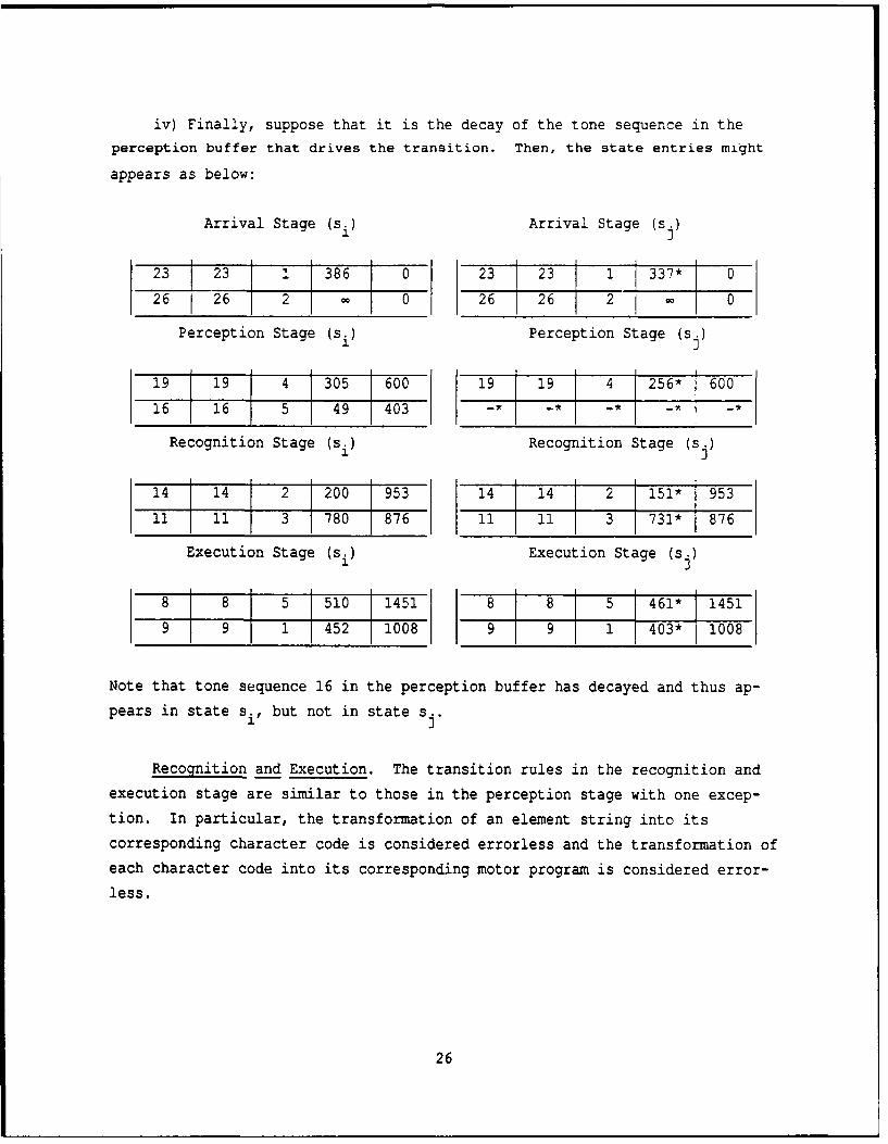
iv) Finally, suppose that it is the decay of the tone sequence in theperception buffer that drives the transition. Then, the state entries might
appears as below:
Arrival Stage (si) Arrival Stage (s.)
23 i23 1 386 0 23 23 1 337* 026 26 2 - 026 26 2 0
Perception Stage (si) Perception Stage (s.)
19 19 41 305 600 19 19 4 256- 600
16 16 5 49 403 -* - - - -*
Recognition Stage (si) Recognition Stage (s.)1 J14 14 2 200 953 14 14 2 151* 953
11 11 3 780 876 11 1II 3 731* 876
Execution Stage (si) Execution Stage (s.)
8 8 5 510 1451 8 8 5 1461* 1451
9 9 1 452 1008 9 9 1 403* 1008
Note that tone sequence 16 in the perception buffer has decayed and thus ap-
pears in state si, but not in state sj.
Recognition and Execution. The transition rules in the recognition and
execution stage are similar to those in the perception stage with one excep-
tion. In particular, the transformation of an element string into its
corresponding character code is considered errorless and the transformation of
each character code into its corresponding motor program is considered error-
less.
26
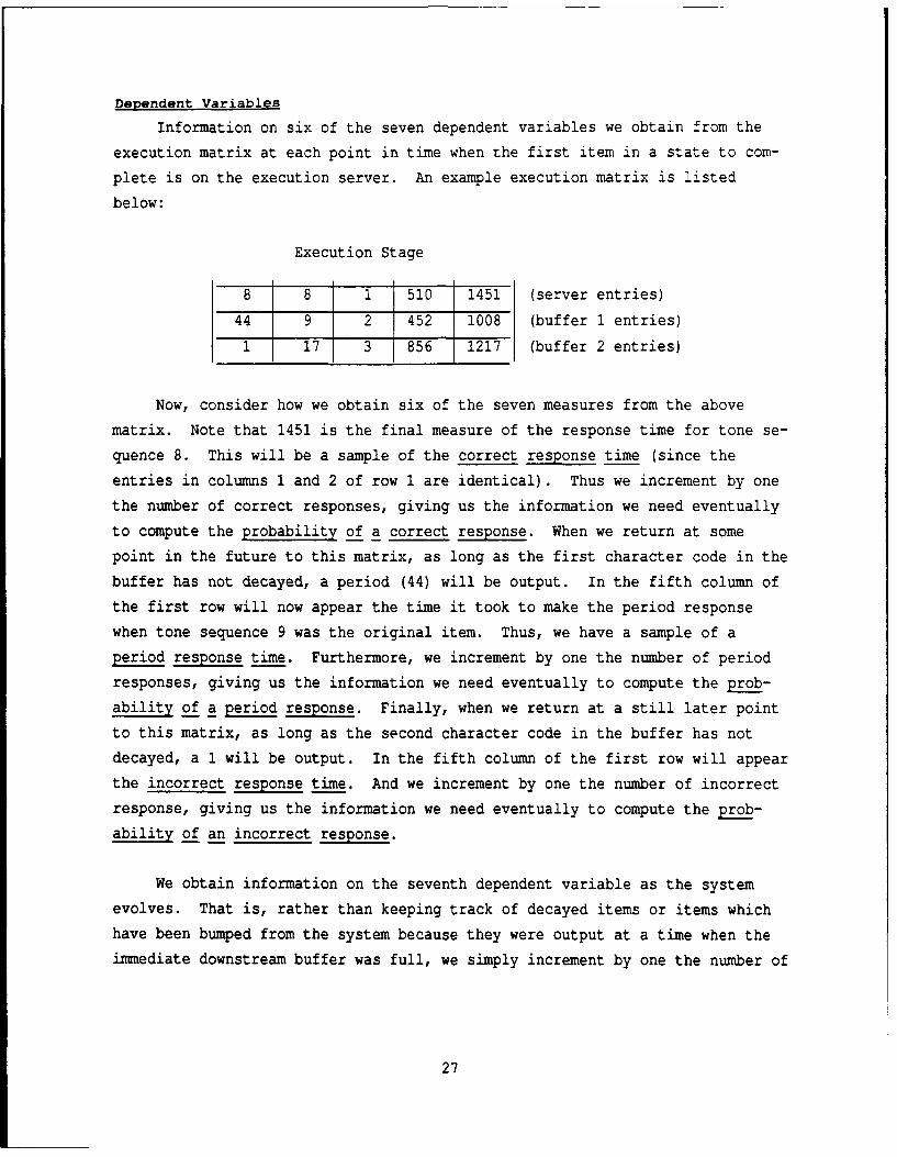
Dependent Variables
Information on six of the seven dependent variables we obtain from the
execution matrix at each point in time when the first item in a state to com-
plete is on the execution server. An example execution matrix is listed
below:
Execution Stage
8 8 1 510 1451 (server entries)
44 9 2 452 1008 (buffer 1 entries)
1 17 3 856 1217 (buffer 2 entries)
Now, consider how we obtain six of the seven measures from the above
matrix. Note that 1451 is the final measure of the response time for tone se-
quence 8. This will be a sample of the correct response time (since the
entries in columns 1 and 2 of row 1 are identical). Thus we increment by one
the number of correct responses, giving us the information we need eventually
to compute the probability of a correct response. When we return at some
point in the future to this matrix, as long as the first character code in the
buffer has not decayed, a period (44) will be output. In the fifth column of
the first row will now appear the time it took to make the period response
when tone sequence 9 was the original item. Thus, we have a sample of a
period response time. Furthermore, we increment by one the number of period
responses, giving us the information we need eventually to compute the prob-
ability of 2 period response. Finally, when we return at a still later point
to this matrix, as long as the second character code in the buffer has not
decayed, a 1 will be output. In the fifth column of the first row will appear
the incorrect response time. And we increment by one the number of incorrect
response, giving us the information we need eventually to compute the prob-
ability of an incorrect response.
We obtain information on the seventh dependent variable as the system
evolves. That is, rather than keeping track of decayed items or items which
have been bumped from the system because they were output at a time when the
immediate downstream buffer was full, we simply increment by one the number of
27
items to which an operator will make no response at the time an item disap-
pears. Thus, we obtain the information we need in order to compute the
probability of no response.
ANALYSIS
Although the simulation as described above yields the desired predic-
tions, it has one weakness (a weakness common to all simulations).
Specifically, it is never truly possible to identify the parameter settings
which maximize the fit of a given model to the data. The best that can be
done with a simulation is to make the search through the parameter space a
relatively fine one, hoping that there exist no unexplored points which would
radically alter the fit of the particular model being simulated. Exact iden-
tification of the parameter settings which maximize the fit can only be done
when closed form expressions can be obtained for the dependent variables of
interest.
Unfortunately, the GenCOPB, LimCOPB and the NoCOPB are themselves ex-
tremely complex models, making it difficult if not impossible to obtain the
desired closed form expressions. And even were one to obtain the expressions,
they themselves might be too unwieldy to work with. The question at this
point is therefore a threefold one. First, in principle can closed form ex-
pressions be obtained for the GenCOPB, LimCOPB and NoCOPB models? Second, if
in principle such expressions can be obtained, are there some experimental
paradigms which, unlike the current paradigm, introduce enough constraints to
make it possible actually to derive these expressions in a reasonable amount
of time? And third, how would one obtain these expressions were such
paradigms to exist?
OP Diagrams
We can answer the first question quite easily. Indeed, it is possible to
obtain closed form expressions for the various expressions in which we have an
interest. In order to prove that this is the case, we first need to describe
the general structure of an OP diagram. Then, we need to show that the state
space of the models we have developed is itself an OP diagram. Once we know
28

the structure of our models is an OP diagram, we can use the work in Fisher
and Goldstein (1983; Goldstein and Fisher, 1991) to obtain the desired expres-
sions given certain auxiliary assumptions.
General Structure. Formally, an OP diagram is a structure <r,',Q> con-
sisting of a set F of processes, set ' of paths, and set Q of states. The set
F consists of n(F) processes, labelled xl,...,Xn(F)* Each state in Q cor-
responds to a partition of the processes in F. The states are labelled
S,1.'"'n(Q). Note that not all partitions of F need be in 12. Each path a in
T consists of a sequence of states. We identify the states on path a, in or-
der, as sa1 Sa2 ... ,isan(a)
Several remarks need to be made about the states. First, the processes
in each state si must be resident in one and only one of four sets, the pre-
active set A(si), the current set C(si), the completed set K(si), or the other
set O(si). Second, the first state along any path must have empty completed
and other sets and at least one process in the current set. Third, the last
state along any path must have empty pre-active and current sets and at least
one process in the completed set.
There are restrictions not only on the character of the sets of states at
the beginning and end of each path, but also restrictions on the character of
states adjacent to one another on a path. These restrictions are displayed
graphically in Figure 1 below:
Figure 1
Pre-Active Current Completed Other
A(si) --- > A(sj) A(si) --- > C(sj) A(si) -v-> K(s.) A(si) - -> O(sj)
C(si) -,-> A(sj) C(si) --- > C(s.) C(si) --- > K(sj) C(si) --- > O(s.)
K(s i) -- A(.,7 K(s i) -- > C(sj K(si) -- > K(sj K(s i) -- > 0(sj
0(s i)-> A(sj 0(si) -- > C(sj 0(si) -ý-> K(sj 0(si) -- > O(sj
29

Note that an arrow, --- >, joining two different sets in adjacent states, say
A(s.) --- > A(sj), means that later set (in this case, the pre-active set A(s.)
can contain processes in the earlier set A(s i). The negated arrow, -7"->, con-
nected two different sets in adjacent states, say C(si) -4-> A(s.), means that
the later set, A(s.), does not contain any elements of the earlier set, C(si).
In words, if state s. is an immediate successor of state s. for some pathD I
in r, then restrictions apply to the four sets which define state s.. First,D
the pre-active set A(s.) of state s. can contain no processes which are not
contained in the pre-active set A(si) of state si. Second, the current set
C(s.) -f state s. can contain no processes in the completed set K(si) of state
si. Third, the completed set K(sj) of state s. must contain every process in1J J
the completed set K(si) of state s. as well as at least one process from the
current set C(Si) of state si. Furthermore, no processes from the pre-active
set A(si) or other set O(si) of state si can appear in the completed set K(sj)
of state s. Finally, the other set O(sj) of state s. can contain no
processes in the pre-active set A(si) or completed set K(si) of state s
If a network is an OP diagram, then using the techniques of Fisher and
Goldstein (1983; Goldstein and Fisher), we can obtain expressions for the be-
havior of the network if two additional conditions are met. First, the number
of states along any path in the OP diagram must be finite. And second, any
process which becomes current in one or more states along a path must even-
tually enter a completed set.
We can easily show that the various models we have described can be rep-
resented as OP diagrams. Briefly, in our particular case, we associate seven
processes with each tone sequence, four service processes (one each for the
arrival, perception, recognition and execution servers) and three decay
processes (one each for the perception, recognition and execution servers).
At the outset, the pre-active set consists of each of the seven processes for
30
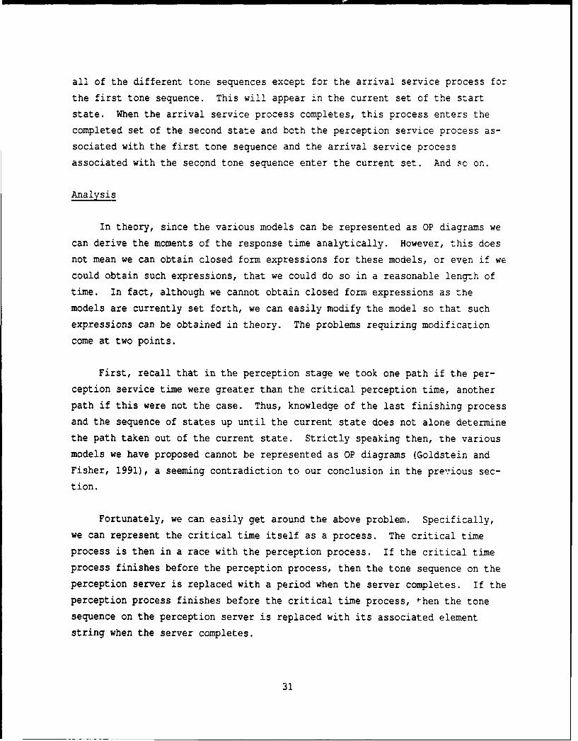
all of the different tone sequences except for the arrival service process for
the first tone sequence. This will appear in the current set of the start
state. When the arrival service process completes, this process enters the
completed set of the second state and both the perception service process as-
sociated with the first tone sequence and the arrival service process
associated with the second tone sequence enter the current set. And so on.
Analysis
In theory, since the various models can be represented as OP diagrams we
can derive the moments of the response time analytically. However, this does
not mean we can obtain closed form expressions for these models, or even if we
could obtain such expressions, that we could do so in a reasonable length of
time. In fact, although we cannot obtain closed form expressions as themodels are currently set forth, we can easily modify the model so that such
expressions can be obtained in theory. The problems requiring modification
come at two points.
First, recall that in the perception stage we took one path if the per-
ception service time were greater than the critical perception time, another
path if this were not the case. Thus, knowledge of the last finishing process
and the sequence of states up until the current state does not alone determine
the path taken out of the current state. Strictly speaking then, the various
models we have proposed cannot be represented as OP diagrams (Goldstein and
Fisher, 1991), a seeming contradiction to our conclusion in the previous sec-
tion.
Fortunately, we can easily get around the above problem. Specifically,
we can represent the critical time itself as a process. The critical time
process is then in a race with the perception process. If the critical time
process finishes before the perception process, then the tone sequence on the
perception server is replaced with a period when the server completes. If the
perception process finishes before the critical time process, then the tone
sequence on the perception server is replaced with its associated element
string when the server completes.
31
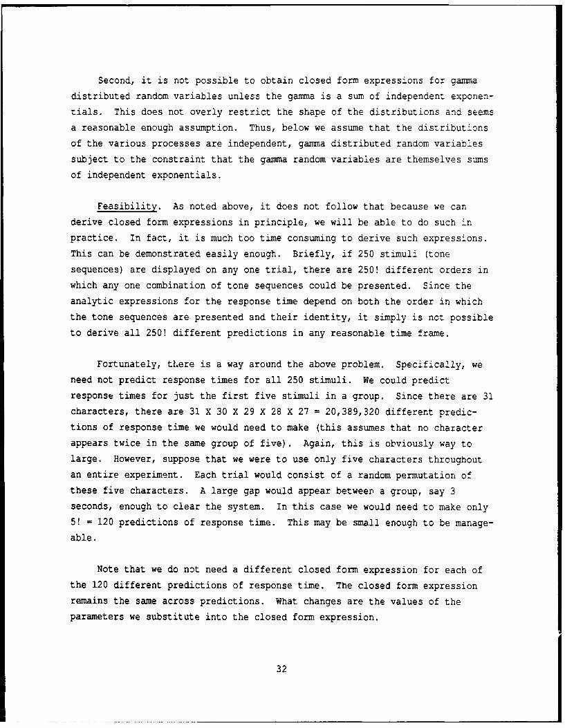
Second, it is not possible to obtain closed form expressions for gamma
distributed random variables unless the gamma is a sum of independent exponen-
tials. This does not overly restrict the shape of the distributions and seems
a reasonable enough assumption. Thus, below we assume that the distributions
of the various processes are independent, gamma distributed random variables
subject to the constraint that the gamma random variables are themselves sums
of independent exponentials.
Feasibility. As noted above, it does not follow that because we can
derive closed form expressions in principle, we will be able to do such in
practice. In fact, it is much too time consuming to derive such expressions.
This can be demonstrated easily enough. Briefly, if 250 stimuli (tone
sequences) are displayed on any one trial, there are 250! different orders in
which any one combination of tone sequences could be presented. Since the
analytic expressions for the response time depend on both the order in which
the tone sequences are presented and their identity, it simply is not possible
to derive all 250! different predictions in any reasonable time frame.
Fortunately, tLere is a way around the above problem. Specifically, we
need not predict response times for all 250 stimuli. We could predict
response times for just the first five stimuli in a group. Since there are 31
characters, there are 31 X 30 X 29 X 28 X 27 = 20,389,320 different predic-
tions of response time we would need to make (this assumes that no character
appears twice in the same group of five). Again, this is obviously way to
large. However, suppose that we were to use only five characters throughout
an entire experiment. Each trial would consist of a random permutation of
these five characters. A large gap would appear between a group, say 3
seconds, enough to clear the system. In this case we would need to make only
5! = 120 predictions of response time. This may be small enough to be manage-
able.
Note that we do not need a different closed form expression for each of
the 120 different predictions of response time. The closed form expression
remains the same across predictions. What changes are the values of the
parameters we substitute into the closed form expression.
32
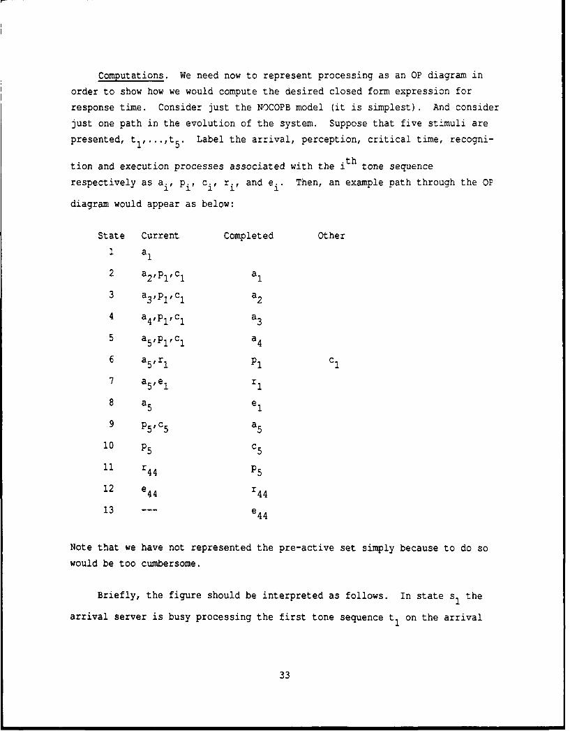
Computations. We need now to represent processing as an OP diagram in
order to show how we would compute the desired closed form expression for
response time. Consider just the NOCOPB model (it is simplest). And consider
just one path in the evolution of the system. Suppose that five stimuli are
presented, tl,...,t 5 . Label the arrival, perception, critical time, recogni-
tion and execution processes associated with the ith tone sequence
respectively as ai, Pi, ci, ri, and ei. Then, an example path through the OP
diagram would appear as below:
State Current Completed Other
1 a1
2 a2 ,PlC 1 a1
3 a3 ,PlC 1 a2
4 a4 ,Plcl a3
5 a5 ,Pl 1,c 1 a4
6 a5,r P1 C
7 a5,e 1 r1
8 a5 e1
9 p5 ,c 5 a5
10 P5 c5
11 r 4 4 P5
12 e4 4 r44
13 --- e44
Note that we have not represented the pre-active set simply because to do so
would be too cumbersome.
Briefly, the figure should be interpreted as follows. In state sI the
arrival server is busy processing the first tone sequence tI on the arrival
33

server. In state s2 this arrival completes (so a1 is placed in the completed
set) and the first tone sequence is passed on to the perception server (pl).
A process (c1 ) is also placed on the perception server and represents the
critical time. And finally, the next arrival (a 2 ) is now placed on the ar-
rival server. Processing continues in this fashion for all five arrivals.
Note that in state s5 we assume that the perception process (p!) com-
pletes before the process (cI) which represents the critical time. Thus c1 is
placed in the other set since its processing is interrupted. Just the op-
posite happens in state s Here the critical perception time associated with
tone sequence t 5 is shorter than the duration of the perception time for the
same tone sequence. Thus, the fifth tone sequence is sent as a period element
string (44) to the recognition server.
It is now a straightforward matter to derive the seven dependent vari-
ables. This requires knowing how to compute the probability that a particular
path is taken and the expected duration of the path. The computations are
reasonably simple if we assume that the durations of the various processes are
independent, exponentially distributed random variables. In this case, we
need only one parameter to describe each process xi, the rate parameter, say
1
The probability of taking a path from the start state up to and including
state s ais simply the product of i conditional probabilities, the first of1
which, P(s 2is i), is the ratio of the rate parameter of the process which
completes when a transition is made from state s to state sa to the sum ofal1 a
the rate parameters of the processes current in state s , the second of
which, P(s Is ), is the ratio of the rate parameter of the process which
34

completes when a transition is made from state s to state s to the sum ofa2 a3
the rate parameters of the processes current in state s , and so on. Thea2
time on average it takes to traverse a path up to and including state sa is a2.
a 1 1sum of i conditional expectations, the first of which, E[T al1a], is the
reciprocal of the sum of the rate parameters in state s , the second ofa1
which, E[T a1a], is the reciprocal of the sum of the rate parameters of the
processes current in state s , and so on.a2
Given the above information, we can go on to compute the moments of the
response time (Fisher and Goldstein, 1983; Goldstein and Fisher, 1991). We
will not develop these computations here since to do so would require a fair
amount of work, work which may well change as we become more familiar with the
sort of model we eventually want to fit.
MODEL EVALUATION
We were most interested in whether the LimCOPB or NoCOPB models better
fit the results. In order to determine this, we performed some preliminary
analyses. Below, we describe these preliminary analyses for the two models.
Briefly, we fit the results from 19 subjects. The subjects were trained
at the US Army Intelligence School, Fort Devons, Massachusetts. The subjects
had completed the character learning phase and were beginning the speed build-
ing phase at the starting rate of six groups per minute (5 characters appeared
in each group). For these subjects, we had for each of the tone sequences ti,
i = 1 - 31, the probability that the subjects made a character response r.,
j = 1,...,31, a period response, or no response. And we had for each of the
tone sequences ti, i = 1 - 31, the time on average that it took the subjects
to make a character response r., j = 1,...,31, or a period response. The
relevant data are given in Appendix B.
35

LimCOPB
Parameter Search. There are five free parameters with the LimCOPB model.
We did not engage in an extensive search of the parameter space since the fit
proved quite good with our initial estimates. Specifically, we found a good
fit with the following parameter settings for a r, Or ae , e and 6:
Process Shape Scale Mean Standard Deviation
Perception Server (parameters determined from data; depended on
individual tone sequence; see Appendix Al
Perception Decay (not applicable since there is no buffer}
Recognition Server 15(a r) 10(o ) 150 39
Recognition Decay {not applicable since there is no buffer]
Execution Server 15(a e) 10( e) 150 39
Execution Decay {not applicable since there is no buffer)
The critical time 8 we set at 1500 ms after trying several alternatives. The
other 63 parameters (32 parameters to describe the arrival times for each
character; 31 parameters to describe the errors) were fixed by the confusion
matrices in Appendix 2.
With the above parameter settings, we ran the simulation. The predicted
and observed probabilities are displayed below. The simulated results are
based on the output from 500 trials:
P(CORRECT), P(INC CHAR), P(PERIOD), P(NO RESP)
Predicted 0.848000 0.064000 0.068000 0.020000
Observed 0.849500 0.049745 0.069752 0.031003
Superficially, the agreement looks reasonable enough. We also obtained
predictions of the relevant response times which are listed below together
with the observations:
RT(CORRECT), RT(INC CHAR), RT(PERIOD), RT(NO RESP)
36

Predicted 1184.7144 1162.0707 1922.2770 0.0000
Observed 1230.8064 1528.5364 2080.2903 0.0000
Again, the match looks good except for the response times to the incorrect
characters.
Incorrect Character Response Times. The fact that we did not fit theresponse times for the incorrect characters arises directly from the way in
which we assign these response times. In particular, note that the time to
process tone sequence ti on the perception server is based on the time
T(riiti) that it takes to make a correct character response. If the percep-
tion process for tone sequence t. takes longer than the critical perception
time, 1500 ms in the above run, then it is assumed to be transformed into the
element string corresponding to the period. Since only times greater than
1500 ms go into the average of the period response time, this response timewill be at least as great as 1500 ms even though the underlying distribution
from which the times were drawn may have a mean much smaller than 1500 ms.
However, the predicted incorrect character response times will equal the cor-
rect character response times since they come from one and the same truncated
distribution.
Specifically, if the perception process for tone sequence t. takes less
than 1500 ms, then the tone sequence is assumed to be transformed correctlyA
with probability p(ri it) and incorrectly with one minus this probability. No
adjustment is made to the incorrect response times however. Thus, we find a
failure to predict the incorrect response times.
We need in future work to extend the LimCOPB model so that it can predict
the incorrect response times. Two possibilities suggest themselves. First,we could introduce a second critical time with a value less than the first
critical time. Thus, say we have 61 and 62' where 61 < 62. Then, a tone se-
quence would be transformed into a period element string if the perception
service time were greater than 62. A tone sequence would be transformed into
37

an incorrect element string if the perception service time were greater than
61 and less than or equal to 6 2* And a tone sequence would be transformed
into the correct, associated element string if the perception service time
were less than or equal to 8
Alternatively, we could assign one distribution to the correct response
times and a second distribution to the incorrect response times. Then, as
above we would assume that any response time greater than the critical
response time eventuated in a period response. Currently, we are exploring
both ways of handling the incorrect character response times.
Serial Position Information. We should note before concluding this sub-
section that the simulation predicts not only the seven dependent variables,
but also serial position information. Below, we see that there there appears
to be a primacy effect, but not a recency effect, within groups of five:
SERIAL POSITION INFORMATION
47 43 40 42 40
This is what we would expect since the first item in a group is more likely to
meet an unoccupied perception server than is the last item in a group.
We also generated predictions of response time across the five serial
positions within a group:
SERIAL POSITION INFORMATION
1142.072 1130.202 1273.773 1170.171 1219.631
Since there is no room in any of the buffers, any item that made it through
the system should have had a clear path all the way. Thus, we would not ex-
pect to see serial position effects. Without further statistical analysis it
is difficult to determine whether the above differences are significant.
38

NoCOPB
Parameter Search. As might be expected, the NoCOPB model fit the results
every bit as well as the LimCOPB model. This is expected since at the slower
rates there is not as much need for copying behind. Below, we list the
results of three runs, one with a critical time of 1600 ms, one with a criti-
cal time of 1400 ms, and one with a critical time of 1300 ms. The first run
is with 8 = 1600:
CRITICAL TIME AT PERCEPTION SERVER = 1600.000
P(CORRECT), P(INC CHAR), P(PERIOD), P(NO RESP)
Predicted 0.892000 0.056000 0.004000 0.048000
Observed 0.849500 0.049745 0.069752 0.031003
RT(CORREC), RT(INC CHR), RT(PERIOD), RT(NO RSP)
Predicted 1204.0682 1220.6215 2086.5015 0.0000
Observed 1230.8064 1528.5364 2080.2903 0.0000
SERIAL POSITION INFORMATION: NUMBER CORRECT
47 43 45 43 45
SERIAL POSITION INFORMATION: CORRECT TIME
1167.336 1214.751 1271.863 1187.347 1180.407
Note that the predicted response times (except for the incorrect characters)
match well the observed response times. However, the observed probability of
a period response (0.06975) is seriously underestimated (0.004).
If we want to increase this probability we need to decrease the critical
perception time, which we do in the run below:
CRITICAL TIME AT PERCEPTION SERVER = 1400.000
P(CORRECT), P(INC CHAR), P(PERIOD), P(NO RESP)
Predicted 0.832000 0.040000 0.068000 0.060000
Observed 0.849500 0.049745 0.069752 0.031003
39

RT(CORREC), RT(INC CHR), RT(PERIOD), RT(NO RSP)
Predicted 1152.5948 1265.1078 1830.5255 0.0000
Observed 1230.8064 1528.5364 2080.2903 0.0000
SERIAL POSITION INFORMATION: NUMBER CORRECT
43 43 42 42 38
SERIAL POSITION INFORMATION: CORRECT TIME
1154.037 1142.396 1125.010 1159.207 1185.682
The predicted probability (0.068) of a period response now matches closely the
observed probability. But note that in raising the predicted probability of a
period response we have lowered the average period response time to the point
where it no longer is closely tied to the observed period response time.
Thus, the model is clearly sensitive to variations in the parameters.
Finally, we would expect even worse fits were we to decrease the critical
response time still further. In the run below, we lower this time to 1300 ms:
CRITICAL TIME AT PERCEPTION SERVER = 1300.000
P(CORRECT), P(INC CHAR), P(PERIOD), P(NO RESP)Predicted 0.724000 0.044000 0.124000 0 '08000
Observed 0.849500 0.049745 0.069752 0.031003
RT(CORREC), RT(INC CHR), RT(PERIO), RT(NO RSP)
Predicted 1169.4633 1225.6049 1854.8347 0.0000
Observed 1230.8064 1528.5364 2080.2903 0.0000
40
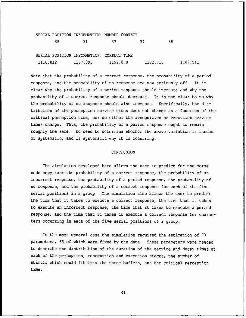
SERIAL POSITION INFORMATION: NUMBER CORRECT
38 31 37 37 38
SERIAL POSITION INFORMATION: CORRECT TIME
1110.812 1167.096 1199.870 1182.710 1187.541
Note that the probability of a correct response, the probability' of a period
response, and the probability of no response are now seriously off. It is
clear why the probability of a period response should increase and why the
probability of a correct response should decrease. It is not clear to us why
the probability of no response should also increase. Specifically, the dis-
tribution of the perception service times does not change as a function of the
critical perception time, nor do either the recognition or execution service
times change. Thus, the probability of a period response ought to remain
roughly the same. We need to determine whether the above variation is random
or systematic, and if systematic why it is occurring.
CONCLUSION
The simulation developed here allows the user to predict for the Morse
code copy task the probability of a correct response, the probability of an
incorrect response, the probability of a period response, the probability of
no response, and the probability of a correct response for each of the five
serial positions in a group. The simulation also allows the user to predict
the time that it takes to execute a correct response, the time that it takes
to execute an incorrect response, the time that it takes to execute a period
response, and the time that it takes to execute a correct response for charac-
ters occurring in each of the five serial positions of a group.
In the most general case the simulation required the estimation of 77
parameters, 63 of which were fixed by the data. These parameters were needed
to describe the distribution of the duration of the service and decay times at
each of the perception, recognition and execution stages, the number of
stimuli which could fit into the three buffers, and the critical perception
time.
41

No models to date have allowed for as wide a specification of input
parameters or for as rich a set of predictions. These models should make it
possible to explore in detail a number of hypotheses about the origins of the
training problems with learning to copy Morse code at higher input rates.
One such hypothesis was tested, in particular, the hypothesis that sub-
jects early in practice could not process two stimuli at the same time (the
copy behind hypothesis). Several variants of the most general model were
created to test this hypothesis. One, the LimCOPB, allowed copy behind; the
other, the NoCOPB, did not. The models fit about equally well. This is not
all that surprising given that copy behind is not particularly useful early on
since the intercharacter interval is relatively large. It still remains to be
determined whether at the faster rates subjects who make it through the train-
ing learn to copy behind whereas those that don't fail to learn this skill.
42

REFERENCES
Bryan, W.L. & Harter, N. (1897). Studies in the psychology and physiology of
the telegraphic language. Psychological Review, 4, 26-53
DOES. (1990). Ability based Morse training. Directorate of Evaluation and
Standardization Report No. 011, 4 Dec 1990, U.S. Army Intelligence
School, Devens, Ft. Devens, Mass.
Fisher, D. L. and Goldstein, W. M. (1983). Stochastic PERT networks as models
of cognition: Derivation of the mean, variance and distribution of reac-
tion time using Order-of-Processing (OP) diagrams. Journal of
Mathematical Psychology, 27, 121-151.
Fisher, D. L. and Smith, J. M. (1987). Transient and equilibrium behavior of
finite, tandem queues. Paper presented at the annual meetings of the
Operations Research Society of America, St. Louis.
Goldstein, W. M. and Fisher, D. L. (1991). Stochastic networks as models of
cognition: Derivation of response time distributions using Order-of-
processing method. Journal of Mathematical Psychology, 35, 214-241.
Gross, D. and Harris, C. M. (1985). Fundamentals of queueing theory (2 nd
edition). New York: John Wiley.
Rouse, W. B. (1980). Systems engineering models of human-machine interaction.
New York: North Holland.
Sabol, M. A., Wisher, R. A. and Medici, C. A. (1991). Reaction time as a
measure of skill development in copying Morse code. Proceedings of the
Annual Meeting of the Military Testing Association. San Antonio, TX: U.S.
Army.
Sternberg, S. (1969). Memory-scanning: Mental processes revealed by reaction
time experiments. American Scientist, 57, 421-457.
43

Townsend, J. T. (in preparation). Initial mathematical models of early Morse
code performance. U.S. Army Research Institute for the Behavioral and
Social Sciences, Technical Report, Alexandria, VA.
Wisher, R. A., Kern, R. P., and Sabol, M. A. Cognitive process model for Morse
intercept: Preliminary plan. Alexandria, VA: U.S. Army Research Institute.
(Unpublished manuscript).
44

APPENDIX A
PARAMETERS OF GenCOPB, LimCOPB AND NoCOPB MODELS
GenCOPB Model. There are a total of 77 parameters in the GenCOPB model.
To begin, consider the determination of the duration of the perception, recog-
nition and execution processes. Thirty-six parameters are needed to describe
the distributions of these three processes, only four of which are free. We
assume that the time T(riilt i) that it takes to generate character r i as a
response, given tone sequence t.i was presented, is the sum of the time
T p(eiilt i) that it takes to perceive a tone sequence t i as element string el,
given that tone sequence t i was presented, plus the time T r that it takes to
recognize element string e, plus the time T. that it takes to organize and ex-
ecute a response.
T(riilt i) = T p(ei iti + T r + Te"
Note that we assume that the recognition process is errorless and that the
duration of this process does not vary from one element string to the next.
Thus, we can drop both the indexed element string e i which is output to the
recognition process and the character code c i which is generated from this
process. Similarly, we assume that the execution process is errorless and
that the duration of this process does not vary from one character code to the
next. Thus, we can drop both the indexed character code c i and the response
r i which is generated from the character code.
Since we assume that the duration T r of the recognition process and dura-
tion T e of the execution process do not depend on the identity of the stimulus
which is being processed, we need only four parameters to describe the dis-
tribution of these durations: a shape parameter a r and scale parameter 0 r for
the recognition stage and a shape parameter a e and scale parameter 0 e for the
execution stage. These four parameters are free.
A - 1
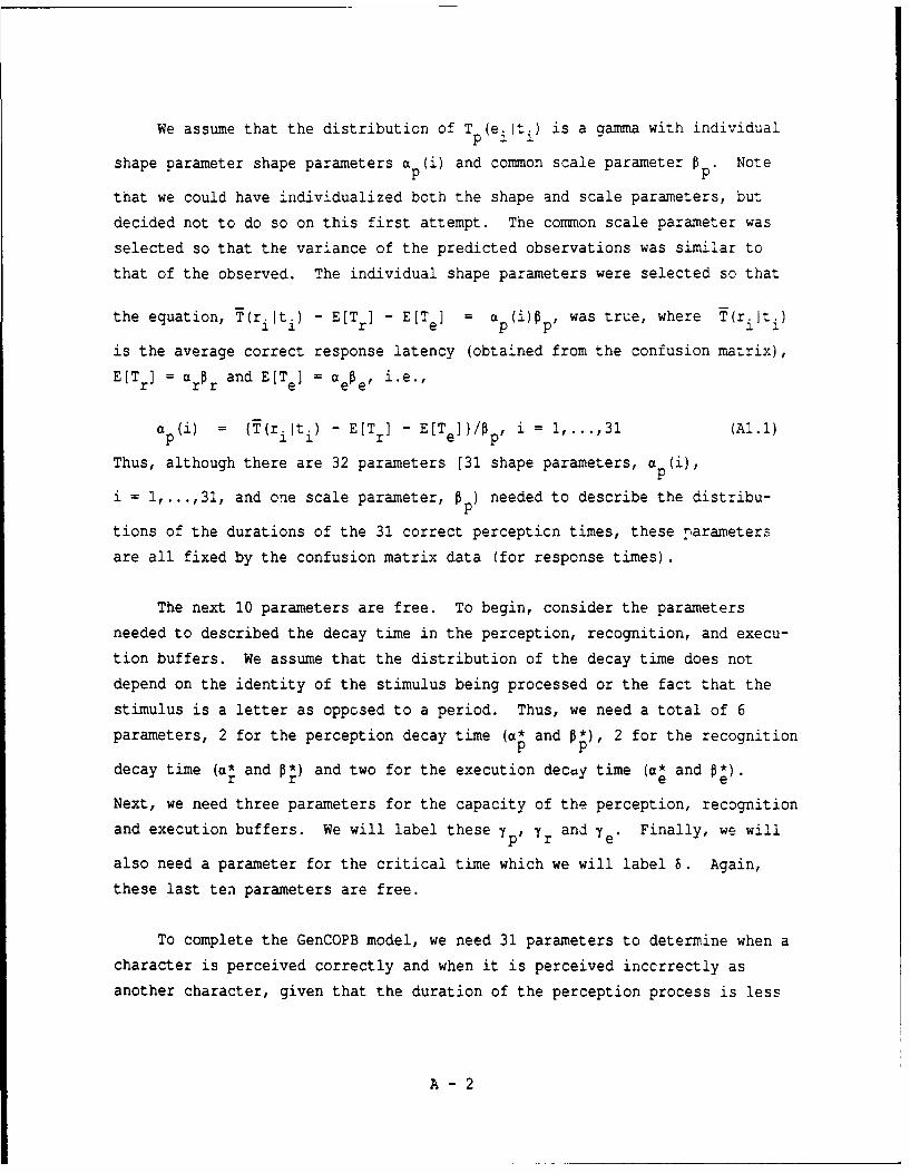
We assume that the distribution of T p(ei it) is a gamma with individual
shape parameter shape parameters a p(i) and common scale parameter p. Note
that we could have individualized both the shape and scale parameters, but
decided not to do so on this first attempt. The common scale parameter was
selected so that the variance of the predicted observations was similar to
that of the observed. The individual shape parameters were selected so that
the equation, T(r iti) - E[Tr] - E[T] = a p(i)W p, was true, where T(riiti)
is the average correct response latency (obtained from the confusion matrix),
E[T r] = a rr and E[T e] = a ee, i.e.,
a p(i) = (T(riiti) - E[T r] - E[T e]}/Op , i = 1,...,31 (A1.1)
Thus, although there are 32 parameters [31 shape parameters, a (i),P
i = 1,...,31, and one scale parameter, p) needed to describe the distribu-
tions of the durations of the 31 correct percepticn times, these parameters
are all fixed by the confusion matrix data (for response times).
The next 10 parameters are free. To begin, consider the parameters
needed to described the decay time in the perception, recognition, and execu-
tion buffers. We assume that the distribution of the decay time does not
depend on the identity of the stimulus being processed or the fact that the
stimulus is a letter as opposed to a period. Thus, we need a total of 6
parameters, 2 for the perception decay time (a* and 0*), 2 for the recognitionp p
decay time (a* and 0) and two for the execution decay time (a* and *).
Next, we need three parameters for the capacity of the perception, recognition
and execution buffers. We will label these yp, Yr and y e' Finally, we will
also need a parameter for the critical time which we will label 6. Again,
these last ten parameters are free.
To complete the GenCOPB model, we need 31 parameters to determine when a
character is perceived correctly and when it is perceived inccrrectly as
another character, given that the duration of the perception process is less
A - 2

than the critical time 8. These parameters are fixed by the data in the con-
fusion matrix (errors). Specifically, the probability p(ei iti) that element
string ei is generated at the perception stage, given that tone sequence ti
was presented and that the duration of the perception process was less than 8,A
is set equal to the observed probability P(riiti) that response ri is made,
given that tone sequence ti was presented. The probability that element
string e. is generated at the perception stage, given that tone sequence t.
was presented (i # j) and that the duration of the perception process was less
than the critical time 6, is simply the complement of the above, i.e., simplyA
1 - p(riiti). In the simulation, the determination on each trial of whether a
correct or incorrect element string was generated was made by sampling from a
uniform [0,1] distribution. If the value sampled lay in the intervalA
[0,p(ri it)], then the tone sequence tiwas transformed into the correct ele-
ment string; otherwise, it was assumed that the element string was incorrect.
No attempt was made to determine which of the incorrect element strings was
produced.
Note that we do not require additional parameters to describe the output
of the recognition and execution stages. This is because we assume that the
probability p(ci lei) that character code ci is generated by the recognition
stage, given that element string ei is input to the recognition stage, is
equal to 1, as is the probability p(ri~ ci) that the execution stage generates
response ri, given that character code ci was generated.
LimCOPB and NoCOPB Models. In order to reduce the number of free
parameters, we made several simplifying assumptions. Specifically, we assumed
that there was no room in the perception, recognition or execution buffers.
And, therefore, the three free buffer size parameters and six free decay
parameters were no longer necessary. Thus, the number of free parameters was
reduced by nine, from 14 to 5. The number of fixed parameters remained at 63.
A - 3
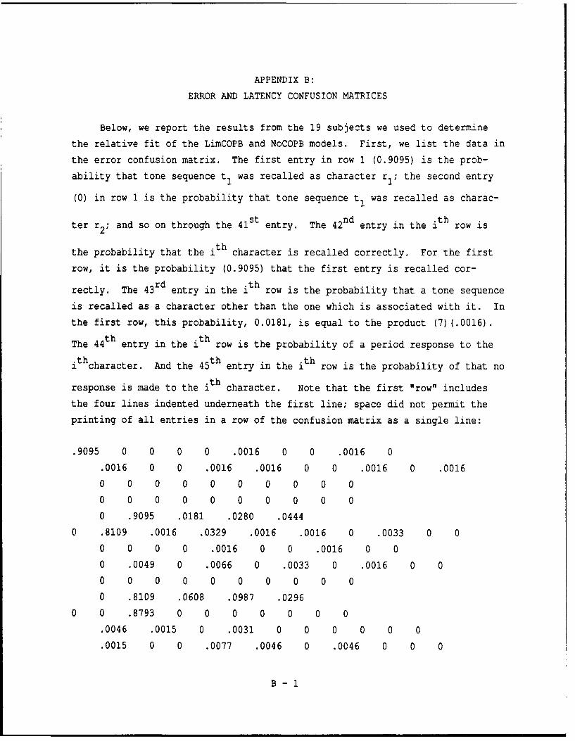
APPENDIX B:
ERROR AND LATENCY CONFUSION MATRICES
Below, we report the results from the 19 subjects we used to determine
the relative fit of the LimCOPB and NoCOPB models. First, we list the data in
the error confusion matrix. The first entry in row 1 (0.9095) is the prob-
ability that tone sequence t1 was recalled as character r1 ; the second entry
(0) in row 1 is the probability that tone sequence t1 was recalled as charac-
ter r 2 ; and so on through the 41st entry. The 42nd entry in the ith row is
the probability that the i th character is recalled correctly. For the first
row, it is the probability (0.9095) that the first entry is recalled cor-
rectly. The 43rd entry in the ith row is the probability that a tone sequence
is recalled as a character other than the one which is associated with it. In
the first row, this probability, 0.0181, is equal to the product (7)(.0016).
The 4 4th entry in the ith row is the probability of a period response to the
th character. And the 45th entry in the ith row is the probability of that no
response is made to the ith character. Note that the first "row" includes
the four lines indented underneath the first line; space did not permit the
printing of all entries in a row of the confusion matrix as a single line:
.9095 0 0 0 0 .0016 0 0 .0016 0
.0016 0 0 .0016 .0016 0 0 .0016 0 .0016
0 0 0 0 0 0 0 0 0 0
0 0 0 0 0 0 0 0 0 0
0 .9095 .0181 .0280 .0444
0 .8109 .0016 .0329 .0016 .0016 0 .0033 0 0
0 0 0 0 .0016 0 0 .0016 0 0
0 .0049 0 .0066 0 .0033 0 .0016 0 0
0 0 0 0 0 0 0 0 0 0
0 .8109 .0608 .0987 .0296
0 0 .8793 0 0 0 0 0 0 0
.0046 .0015 0 .0031 0 0 0 0 0 0
.0015 0 0 .0077 .0046 0 .0046 0 0 0
B - i
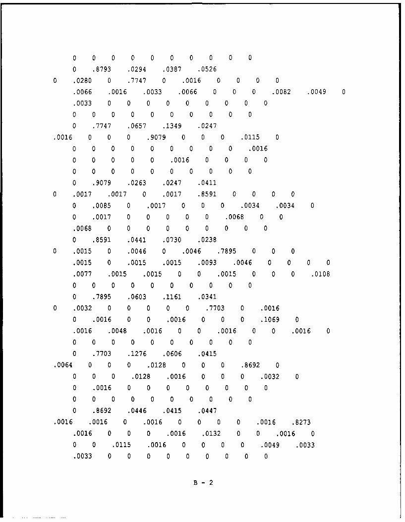
0 0 0 0 0 0 0 0 0 0
0 .8793 .0294 .0387 .0526
0 .0280 0 .7747 0 .0016 0 0 0 0
.0066 .0016 .0033 .0066 0 0 0 .0082 .0049 0
.0033 0 0 0 0 0 0 0 0 0
0 0 0 0 0 0 0 0 0 0
0 .7747 .0657 .1349 .0247
.0016 0 0 0 .9079 0 0 0 .0115 0
0 0 0 0 0 0 0 0 0 .0016
0 0 0 0 0 .0016 0 0 0 0
0 0 0 0 0 0 0 0 0 0
0 .9079 .0263 .0247 .0411
0 .0017 .0017 0 .0017 .8591 0 0 0 0
0 .0085 0 .0017 0 0 0 .0034 .0034 0
0 .0017 0 0 0 0 0 .0068 0 0
.0068 0 0 0 0 0 0 0 0 0
0 .8591 .0441 .0730 .0238
0 .0015 0 .0046 0 .0046 .7895 0 0 0
.0015 0 .0015 .0015 .0093 .0046 0 0 0 0
.0077 .0015 .0015 0 0 .0015 0 0 0 .0108
0 0 0 0 0 0 0 0 0 0
0 .7895 .0603 .1161 .0341
0 .0032 0 0 0 0 0 .7703 0 .0016
0 .0016 0 0 .0016 0 0 0 .1069 0
.0016 .0048 .0016 0 0 .0016 0 0 .0016 0
0 0 0 0 0 0 0 0 0 0
0 .7703 .1276 .0606 .0415
.0064 0 0 0 .0128 0 0 0 .8692 0
0 0 0 .0128 .0016 0 0 0 .0032 0
0 .0016 0 0 0 0 0 0 0 0
0 0 0 0 0 0 0 0 0 0
0 .8692 .0446 .0415 .0447
.0016 .0016 0 .0016 0 0 0 0 .0016 .8273
.0016 0 0 0 .0016 .0132 0 0 .0016 0
0 0 .0115 .0016 0 0 0 0 .0049 .0033
.0033 0 0 0 0 0 0 0 0 0
B - 2

0 .8273 .0526 .0954 .0247
.0016 0 .0016 .0016 0 0 0 .0016 .0016 0
.9298 .0064 0 .0016 0 0 0 .0032 0 0
0 0 0 .0016 .0016 0 .0032 0 0 0
0 0 0 0 0 0 0 0 0 0
0 .9298 .0256 .0207 .0239
0 0 0 0 0 .0016 .0016 0 0 0
.0016 .8581 0 0 .0016 .0080 0 .0048 0 0
0 0 0 0 0 0 0 .0064 0 0
.0016 0 0 0 0 0 0 0 0 0
0 .8581 .0319 .0558 .0542
0 0 0 0 0 0 0 .0033 .0016 0
.0016 0 .9030 .0033 .0099 0 0 0 0 0
0 0 0 0 .0016 0 0 0 0 0
0 0 0 0 0 0 0 0 0 0
0 .9030 .0279 .0461 .0230
0 0 0 0 0 0 0 0 0 0
0 0 .0016 .9260 0 0 0 .0033 .0016 0
0 .0033 0 0 0 0 0 0 0 0
0 0 0 0 0 0 0 0 0 00 .9260 .0148 .0444 .0148
0 .0016 0 0 0 0 .0033 .0016 0 .0016
0 .0016 .0033 0 .8766 .0016 .0016 0 .0033 .0016
0 0 0 0 0 0 0 0 .0197 .0033
0 0 0 0 0 0 0 0 0 0
0 .8766 .0461 .0395 .0378
0 0 0 0 0 .0066 .0016 0 0 .0082
0 0 0 0 0 .8059 0 0 0 0
0 0 .0016 .0033 .0016 0 0 .0033 .0016 .0066
.0016 0 0 0 0 0 0 0 0 0
0 .8059 .0461 .1250 .0230
.0016 0 0 0 0 0 .0016 0 0 0
0 0 0 0 0 0 .9059 .0016 0 0
0 0 .0016 .0032 .0080 .0064 0 0 .0016 0
0 0 0 0 0 0 0 0 0 0
0 .9059 .0287 .0447 .0207
B - 3

.0033 0 0 .0016 0 .0099 0 0 0 0
.0049 .0099 0 0 0 0 0 .8586 0 0
0 0 .0082 0 0 0 0 .0016 0 0
0 0 0 0 0 0 0 0 0 0
0 .8586 .0476 .0609 .0329
.0016 0 0 .0016 0 0 0 .1003 .0214 0
0 0 .0033 0 .0016 0 0 0 .7763 0
.0082 0 0 0 0 0 .0016 0 0 0
0 0 0 0 0 0 0 0 0 0
0 .7763 .1415 .0526 .0296
.0016 0 0 0 .0099 0 0 0 0 0
0 0 .0033 0 0 0 0 .0016 .0016 .9309
0 0 0 0 .0016 0 0 .0016 0 0
0 0 0 0 0 0 0 0 0 0
0 .9309 .0231 .0296 .0164
.0033 0 0 .0066 0 .0016 .0016 0 0 .0033
0 0 0 0 .0016 0 0 0 .0033 0
.7549 .0526 .0099 0 0 0 0 0 0 0.0049 0 0 0 0 0 0 0 0 0
0 .7549 .0921 .1283 .0247
0 .0033 0 0 0 .0016 0 0 0 0
0 0 0 0 .0016 0 .0033 0 .0016 0
.0263 .8372 0 .0016 0 0 0 0 0 .0016
.0016 0 0 0 0 0 0 0 0 0
0 .8372 .0444 .0839 .0345
.0033 0 0 0 .0016 0 .0016 0 0 0
0 0 .0016 0 .0016 0 0 0 0 0
.0049 .0016 .8651 0 0 0 0 0 0 0
.0016 0 0 0 0 0 0 0 0 0
0 .8651 .0214 .0872 .0263
0 .0033 .0016 .0016 .0016 0 0 .0016 0 0
.0033 .0016 0 0 0 .0016 0 0 0 0
0 .0016 0 .8355 .0033 .0033 .0016 .0148 0 0•.0016 0 0 0 0 0 0 0 0 0
0 .8355 .0461 .1020 .0164
0 .0016 .0049 0 0 0 0 0 0 .0016
B - 4

.0066 .0016 0 0 .0016 .0016 .0049 0 0 .0016
.0066 .0016 0 .0049 .8684 0 0 0 0 0
0 0 0 0 0 0 0 0 0 0
0 .8684 .0411 .0625 .0280
.0049 .0016 0 .0016 0 0 .0099 0 0 00 0 0 0 .0016 .0033 .0066 0 0 0
.0016 0 0 .0033 0 .8306 0 .0016 0 .0049
.0049 0 0 0 0 0 0 0 0 0
0 .8306 .0493 .0806 .0395
.0033 0 .0016 0 0 0 0 0 0 0.0033 .0082 0 0 .0016 0 0 0 0 0
0 0 0 0 0 .0016 .8717 0 0 .0016
0 0 0 0 0 0 0 0 0 0
0 .8717 .0279 .0609 .0395
0 0 0 .0016 .0099 .0378 .0016 0 0 0
0 .0230 0 0 0 .0033 0 0 .0016 0
0 .0016 .0016 .0016 0 0 .0016 .7615 0 .0016
.0049 0 0 0 0 0 0 0 0 0
0 .7615 .1036 .1053 .0296
0 .0017 0 0 0 0 0 .0085 0 .0102
0 0 0 0 .0204 0 0 0 .0017 00 0 .0017 0 0 0 0 0 .8846 .0187
0 0 0 0 0 0 0 0 0 0
0 .8846 .0627 .0289 .0238
.0016 .0016 0 .0016 0 0 .0016 .0016 0 .0064
0 0 0 0 .0064 .0064 0 .0016 0 0
0 0 0 0 0 0 0 0 .0064 .7911.0016 0 0 0 0 0 0 0 0 0
0 .7911 .0430 .1260 .0399
0 0 0 0 0 .0115 0 0 0 .0016
0 .0016 0 0 0 0 0 0 0 .0016
.0099 0 .0115 .0016 .0049 .0016 0 0 0 0
.8651 0 0 0 0 0 0 0 0 0
0 .8651 .0477 .0658 .0214
B-5

Next, we present the results from the latency confusion matrix. Note
that the only difference between these results and the results above is that
there is not an entry for the latency of no response.
1048 0 0 0 0 369 0 0 2090 0
779 0 0 1835 317 0 0 303 0 1926
0 0 0 0 0 0 0 0 0 0
0 0 0 0 0 0 0 0 0 0
0 1048 1088.4287 2330 0
0 1233 1001 1274 21193 224 0 1433 0 0
0 0 0 0 311 0 0 2268 0 0
0 1706 0 1248 0 2696 0 2501 0 0
0 0 0 0 0 0 0 0 0 0
0 1233 1916.3907 1953 0
0 0 1135 0 0 0 0 0 0 0
1472 2384 0 1389 0 0 0 0 0 0
92 0 0 1324 1418 0 2283 0 0 0
0 0 0 0 0 0 0 0 0 0
0 1135 1522.1196 2004 0
0 1261 0 1341 0 1101 0 0 0 0
1347 1261 1047 1379 0 0 0 2621 3484 0
1195 0 0 0 0 0 0 0 0 0
0 0 0 0 0 0 0 0 0 0
0 1341 1607.5070 2193 0
973 0 0 0 111 0 0 0 1436 0
0 0 0 0 0 0 0 0 0 1354
0 0 0 0 0 1199 0 0 0 0
0 0 0 0 0 0 0 0 0 0
0 1111 1359.2394 1875 0
0 1916 1485 0 1007 1323 0 0 0 0
0 1737 0 1243 0 0 0 1160 579 00 747 0 0 0 0 0 1582 0 0
1284 0 0 0 0 0 0 0 0 0
0 1323 1364.7726 1874 0
0 887 0 1372 0 1241 1530 0 0 0
1977 0 1737 1297 2008 1397 0 0 0 0
B - 6

1546 1045 1332 0 0 1482 0 0 0 1563
0 0 0 0 0 0 0 0 0 0
0 1530 1545.8831 1980 0
0 935 0 0 0 0 0 1147 0 349
0 2404 0 0 1790 0 0 0 1213 0
836 1011 4253 0 0 1426 0 0 1755 0
0 0 C 0 0 0 0 0 0 0
0 1147 1253.0952 2021 0
946 0 0 0 1213 0 0 01087 0
0 0 0 1566 2082 0 0 0 1268 0
0 827 0 0 0 0 0 0 0 0
0 0 0 0 0 0 0 0 0 0
0 1087 131.8751 2437 0
302 1951 0 2531 0 0 0 0 1023 1232
2041 0 0 0 3988 1289 0 0 5981 0
0 0 884 1524 0 0 0 0 1370 2249
2014 0 0 0 0 0 0 0 0 0
0 1232 161.3530 2169 0
1160 0 1481 941 0 0 0 1054 1535 0
1077 961 0 81 0 0 0 877 0 0
0 0 0 1258 820 0 2888 0 0 0
0 0 0 0 0 0 0 0 0 0
0 1077 1231.5001 1875 0
0 0 0 0 0 941 647 0 0 0
1223 1084 0 0 888 1765 0 1253 0 0
0 0 C 3 0 0 C 22?2 0 0
3048 0 0 0 0 0 0 0 0 0
0 1084 166.6471 1818 0
0 0 0 0 0 0 0 2335 1287 0
564 0 1201 1386 1207 0 0 0 0 0
0 0 0 0 3047 0 0 0 0 0
0 0 0 0 0 0 0 0 0 0
0 1201 1505.4178 2559 0
0 0 0 0 0 0 0 0 0 0
0 0 698 1167 0 0 0 880 1157 0
0 2161 0 0 0 0 0 0 0 0
B - 7

0 0 0 0 0 0 0 0 0 c
0 1167 1326.8674 1921 0
o 458 0 0 0 0 2049 1265 0 2195
0 2919 1282 0 1083 1849 1830 0 2054 1050
0 0 0 0 0 0 0 0 1855 1643
0 0 0 0 0 0 0 0 0 0
0 1083 1774.1836 1955 0
0 0 0 0 0 1597 5384 0 0 1960
0 0 0 0 0 1308 0 0 0 0
0 0 1841 1786 1532 0 0 1840 2885 1714
2286 0 0 0 0 0 0 0 0 0
0 1308 2004.8666 2006 0
1069 0 0 0 0 0 3025 0 0 0
0 0 0 0 0 0 1169 999 0 0
0 0 812 2869 2120 1234 0 0 695 0
0 0 0 0 0 0 0 0 0 0
0 1169 1742.1250 1716 0
738 0 0 1173 0 1744 0 0 0 0
1211 1583 0 0 0 0 0 1220 0 0
0 0 987 0 0 0 0 1123 0 0
0 0 0 0 0 0 0 0 0 0
0 1220 1347.0457 2344 0
1133 0 0 898 0 0 0 1514 1077 0
0 0 1923 0 2122 0 0 0 1193 0
1289 0 0 0 0 0 701 0 0 0
0 0 0 0 0 0 0 0 0 0
0 1193 1429.6855 1945 0
1018 0 0 0 2310 0 0 0 0 0
0 0 1208 0 0 0 0 1035 1162 1195
0 0 0 0 219 0 0 461 0 0
0 0 0 0 0 0 0 0 0 0
0 1195 156.7266 3177 0
1398 0 0 1808 0 1776 1848 0 0 1152
0 0 0 0 2697 0 0 0 2705 0
1605 1296 1700 0 0 0 0 0 0 0
1828 0 0 0 0 0 0 0 0 0
B - 8

0 1605 1503.3225 2118 0
0 1162 0 0 0 511 0 0 0 0
0 0 0 0 2019 0 1709 0 759 0
1731 1177 0 1886 0 0 0 0 0 1576
1966 0 0 0 0 0 0 0 0 0
0 1177 1622.2775 1771 0
896 0 0 0 1546 0 3808 0 0 0
0 0 983 0 2906 0 0 0 0 0
1399 1203 1312 0 0 0 0 0 0 0
1404 0 0 0 0 0 0 0 0 0
0 1312 1616.3990 2166 0
0 1126 1447 867 870 0 0 2203 0 0
1416 2125 0 0 0 1171 0 0 0 0
0 2279 0 1358 3190 1606 943 1339 0 0
3041 0 0 0 0 0 0 0 0 0
0 1358 1602.5048 2055 0
0 957 1355 0 0 0 0 0 0 1706
865 2372 0 0 2023 1146 1734 0 0 1522
1730 3811 0 1992 1157 0 0 0 0 0
0 0 0 0 0 0 0 0 0 0
0 1157 1628.7236 2140 0
1558 1771 0 727 0 0 1776 0 0 00 0 0 0 1901 1308 1699 0 0 0
1986 0 0 1205 0 1338 0 2597 0 1892
1975 0 0 0 0 0 0 0 0 0
0 1338 1703.9824 2095 0
1274 0 1132 0 0 0 0 0 0 0
1619 1516 0 0 2035 0 0 0 0 0
0 0 0 0 0 1256 1303 0 0 1005
0 0 0 0 0 0 0 0 0 0
0 1303 1446.3634 1962 0
0 0 0 648 1293 1395 438 0 0 0
0 1286 0 0 0 1901 0 0 765 0
0 989 2412 2186 0 0 1948 1321 0 935
1419 0 0 0 0 0 0 0 0 0
0 1321 1361.5017 1740 0
B - 9

0 1506 0 0 0 0 0 1131 0 1270
0 0 0 0 1436 0 0 0 2570 0
0 0 6043 0 0 0 0 0 1111 1514
0 0 0 0 0 0 0 0 0 0
0 1111 1548.1082 2201 0
1161 3424 0 1375 0 0 2036 1930 0 1591
0 0 0 0 1283 1940 0 978 0 0
0 0 0 0 0 0 0 0 1449 1373
5232 0 0 0 0 0 0 0 0 0
0 1373 179.7826 2146 0
0 0 0 0 0 1788 0 0 0 2000
0 1278 0 0 0 0 0 0 0 1855
1081 0 1384 902 1136 1043 0 0 0 0
1216 0 0 0 0 0 0 0 0 0
0 1216 1398.9321 1943 0
B - 10

APPENDIX C:
THE FORTRAN SIMULATION CODE
C MOST RECENT UPDATE: 11/21/91 (APPROXIMATE)CC THIS PROGRAM, MORSE.FOR, WRITTEN 8/19/91 ON VAX AT UNIVERSITY OFC MASSACHUSETTS COLLEGE OF ENGINEERING FOR DR. ROBERT WISHERC BY DONALD L. FISHER. THE PROGRAM SIMULATES THE BEHAVIOR OFC AN OPERATOR TRYING TO COPY MORSE CODE.CC THE UNDERLYING MODEL IS ONE IN WHICH THE FOLLOWING ASSUMPTIONS ARE MADE:CC 1) THERE ARE FOUR PROCESSES: ARRIVAL, AUDITORY PERCEPTION, CHARACTERC RECOGNITION AND MOTOR ORGANIZATION AND EXECUTION. THE DURATIONC OF THE ARRIVAL PROCESS IS A CONSTANT EQUAL TO THE DURATIONC OF THE PARTICULAR MORSE CHARACTER THAT IS SENT. THE DURATION OF THEC PERCEPTION, RECOGNITION AND EXECUTION PROCESSES ARE EACH GENERALC GAMMA RANDOM VARIABLES.CC 2) THERE ARE FOUR BUFFERS: THE ARRIVAL BUFFER IS STIMBUF AND ISC UNLIMITED. IT CONTAINS BOTH THE CHARACTER AND INTERCHARACTERC STIMULI. THE PERCEPTION, RECOGNITION AND EXECUTION BUFFERS AREC EACH SPECIFIED BY THE USER IN, RESPECTIVELY, INFO(2,2), INFO(2,3)C AND INFO(2,4). NOTHING DECAYS OUT OF THE ARRIVAL BUFFER. THEC DURATION OF THE DECAY PROCESSES IN THE THREE REMAINING BUFFERSC IS MODELED AS A GENERAL GAMMA RANDOM VARIABLE.CC 3) THE EXECUTION BUFFER HOLDS PERIODS, NOT CHARACTERS. SPECIFICALLY,C IF A STIMULUS EXITS THE RECOGNITION STAGE AND THE EXECTUTION SERVERC IS FULL, THEN THE STIMULUS ENTERS THE EXECUTION BUFFER AS A PERIOD.C THE SIZE OF THE EXECTUTION BUFFER SHOULD BE KEPT RELATIVELY LARGE.C SIMILARLY, BECAUSE WE DO NOT WANT RAPID DECAY OF PERIODS, THE DURATIONC OF A PERIOD IN THE EXECUTION BUFFER SHOULD BE SET RELATIVELY LARGE.CCCCC DEFINE VARIABLES:CC NCHR: NUMBER OF DIFFERENT CHARACTERS IN INPUT STREAM: 26 (JUST LETTERS),C 31 (LETTERS + SPECIAL CHARACTERS), 41 (LETTERS, SPECIALC CHARACTERS AND DIGITS); INITIALIZED IN SUBROUTINE SINVCC NCHRBUF: DIMENSION OF CHRBUF; MUST BE GREATER THAN NGROUP*NREPCC NCNT: SET EQUAL TO INFO(2,1) AT START; INFO(2,1) IS INITIALIZEDC IN THE FILE MORSE.INCC NELEM: NEXT ELEMENT IN STIMULUS BUFFER (STIMBUF); READ IN FROMC SUBROUTINE SINV; ALWAYS START AT ELEMENT 0.C
C - 1

C NGPM: GROUPS PER MINUTE; READ IN FROM SUBROUTINE SINVCC NGROUP: NUMBER OF CHARACTERS IN A GROUPCC NOUT: SET EQUAL TO 1 IF FULL OUTPUT (INFO,STATEC,STATED,STATEX,C STATEP,STATEY) DESIRED; OTHERWISE SET TO 0; READ IN FROMC SUBROUTINE SINVcC NPER: THE NUMBER OF PERIOD RECODINGS PRODUCED WHEN A STIMULUSC LEAVES THE PERCEPTION SERVER.cC NREP: NUMBER OF REPETITIONS OF A GROUPcC NSTIM: NUMBER OF "STIMULI" = 2*NGROUP*NREP (NOTE THAT EVERY CHARACTERC IS FOLLOWED BY EITHER AN INTERCHARACTER BLANK OR AN INTER-C GROUP BLANK); NOTE THAT NELEM CAN REACH NSTIM AS AN UPPERC LIMITCC RCRIT: IF IT TAKES LONGER THAN RCRIT MILLISECONDS TO SERVICE AC STIMULUS IN THE PERCEPTION NODE, THEN THE STIMULUS ISC RECODED AS A PERIOD.CCCCC DEFINE MATRICES:cC ALPHA(2,4), BETA(2,4): IT IS ASSUMED THAT EACH SERVICE TIME AND EACHC DECAY TIME (EXCEPT ARRIVAL) IS A GAMMA RANDOM VARIABLEC WITH PARAMETERS ALPHA (a) AND BETA (b), I.E.,cC -a a-i -x/bC f(x) = [b x e ]/gamma(a).CC IN THIS CONTEXT, THE PARAMETERS FOR THE FOUR SERVICE ANDC DECAY TIMES ARE:CC ARRIVAL TIME : ALPHA(I,1), BETA(I,1) -- ASSUMED CONSTANT;C HOWEVER, COULD CHANGE TO GAMMAC ARRIVAL DECAY: ALPHA(2,1), BETA(2,1) -- ASSUMED UNLIMITED;C AGAIN, COULD CHANGEC PERCEP TIME : ALPHA(1,2), BETA(1,2)C PERCEP DECAY: ALPHA(2,2), BETA(2,2)C RECOG TIME : ALPHA(1,3), BETA(1,3)C RECOG DECAY: ALPHA(2,3), BETA(2,3)C EXEC TIME : ALPHA(1,4), BETA(1,4)C EXEC DECAY: ALPHA(2,4), BETA(2,4)cC CHRBUF(410): PROGRAM WRITTEN TO HANDLE 50 GROUPS OF 5 CHARACTERSC EACH. NOTE THAT STIMBUF HAS BOTH INTERACHARACTER ANDC INTERGROUP BLANKS AND THUS SHOULD BE TWICE AS LARGE ASC CHARBUF. ARRAY OF SIZE 410 BECAUSE EVERY 41 CHARACTERSC IS GUARANTEED TO CONTAIN DIGITS 1 - 41. IF 31 CHARACTERSC IS USED, THEN CHRBUF IS FILLED TO POSITION 31*10 = 310.
C-2

C IF 26 CHARACTERS ARE USED THEN Ar.RAY IS FILLED TO 26*10 = 260.C SINCE 260 IS GREATER THAN STANDARD 50*5 = 250 CHARACTERS,C I WENT WITH THE RATHER ODD 410.cC CONMAT(41,45):CC A) INITIALLY, IN ROW I, COLUMN J IS PROBABILITY THAT CHARACTERC I WAS SENT AND CHARACTER J WAS TYPED. NOTE £HAT PROBABILITIESC IN A ROW SHOULD ADD TO ONE. HOWEVER, THIS DOES NOT MEAN THATC AN ELEMENT IN ROW I IS NEVER MISSED OR TYPED AS A PERIOD.C THIS PROBLEM OCCURS LATER IN PROCESSES (CONMAT IS USED INC THE PERCPETUAL BUFFER). NOTE THAT IN ROW I AND COLUMN 44 IC CONDITIONAL PROBABILITY OF TYPING A PERIOD GIVEN CHARACTERC AND IN ROW I AND COLUMN 45 IS CONDITIONAL PROBABILITY OFC TYPING NOTHING GIVEN CHARACTER I. THE OUTPUT INFORMATIONC ON PERIODS AND NO RESPONSES IS CONTAINED IN KILL: THE NUMBERC OF ENTRIES IN THE PERCEPTION AND RECOGNITION NODES IS THEC NUMBER OF NO RESPONSES; THE NUMBER OF ENTRIES IN THEC EXECUTION NODE IS THE NUMBER OF PERIODS.CC B) AFTER READING IN CONMAT, IF P(JII) IS THE PROBABILITY THATC J IS TYPED WHEN I IS PRESENTED, THEN IN ROW I, COLUMN 1 WEC PLACE P(1iI), IN ROW I, COLUMN 2 WE PLACE P(1lI) + P(21I),C AND SO ON.CC CONFUS(41,41): IN ROW I AND COLUMN J IS THE NUMBER OF TIMES IN THEC SIMULATION THAT CHARACTER J REPLACESCHARACTER I AT THEC END OF SERVICE ON THE PERCEPTION NODE. THIS INFORMATION ISC OBTAINED FROM CONMAT.cC DATERR(41,45): ERROR DATA COMES FROM SUBJECTS. IN ROW I AND COLUMN JC IS PROBABILITY THAT A SUBJECT RESPONDS WITH STIMULUS JC GIVEN SUBJECT HAS BEEN PRESENTED STIMULUS I. I = 1,...,41C SINCE NUMBER OF STIMULI CAN GO UP TO 41. J = I,...,41,C 44,45. J = 44 IS PERIOD RESPONSE. J = 45 IS NO RESPONSE.C J = 42,43 ARE USED AS STIMULUS VALUES (INTERCHARACTER ANDC INTERGROUP BLANKS), NOT RESPONSES. HOWEVER, IN COLUMN 42C I'VE PLACED THE PERCENTAGE CORRECT RESPONSES, I.E., INC DATERR(IA,42) I'VE PLACED DATERR(IA, IA). AND IN COLUMNC 43 I'VE PLACED THE INCORRECT CHARACTER ONLY ERRORS.C THUS, THE PROBABILITIES SUMMED WITHIN A ROW ACROSSC COLUMNS 42 - 45 OUT TO EQUAL 1.CC INFO(2,4): CONTAINS INFORMATION ON PARAMETERS OF ARRIVAL, PERCEPTION,C RECOGNITION AND EXECUTION PROCESSES IN, RESPECTIVELY,C COLUMNS 1, 2, 3 AND 4:CC INFO(I,1) = NUMBER OF CHARACTERS ON ARRIVAL SERVER (1 OR 0)C INFO(2,1) = TOTAL NUMBER OF ARRIVALS IN SESSION LEFT; NOTEC THAT ARRIVALS INCLUDE INTERrHARACTER AND INTER-C GROUP INTERVALScC INFO(1,2) = NUMBER OF CHARACTERS ON PERCEPTION SERVER AND
C-3

C AND IN PERCEPTION BUFFER (E.G., IF THERE IS ONEC CHARACTER CURRENTLY BEING PERCEIVED AND TWOC CHARACTERS IN THE BUFFER, THEN INFO(1,2) = 3)C INFO(2,2) = MAXIMUM NUMBER OF CHARACTERS WHICH CAN BEC SERVICED AND BUFFERED FOR PERCEPTIONCC INFO(1,3) = NUMBER OF CHARACTERS ON EXECUTION SERVER AND INC RECOGNITION BUFFER.C INFO(2,3) = MAXIMUM NUMBER OF CHARACTERS WHICH CAN BEC SERVICED AND BUFFERED FOR RECOGNITION.CC INFO(1,4) = NUMBER OF CHARACTERS ON EXECUTION SERVER AND INC EXECUTION BUFFER.C INFO(2,4) = MAXIMUM NUMBER OF CHARACTERS WHICH CAN BEC SERVICED AND BUFFERED FOR EXECUTION.CC INTERC(15) ,INTERG(15): CONTAINS IN COLUMN I THE INTERCHARACTERC (INTERGROUP) INTERVAL FOR RATES OF, RESPECTIVELY, 6,8,10,12C 14,16,18,20 GROUPS PER MINUTE.CC KEEP(41,46): CONTAINS NUMBER OF TIMES IN KEEP(I,J) CHARACTER J ISC TYPED WHEN CHARACTER I WAS PRESENTED. NOTE THAT ENTRIESC IN KEEP(I,J) CAN BE NO GREATER THAN ENTRIES IN CONFUS(I,J)C BECAUSE CHARACTERS CAN DECAY AT A NODE OR NOT GAIN ENTRYC TO A NODE AFTER THEY ARE CONFUSED IN THE PERCPETION SERVER.C NOTE THAT BEFORE SUBROUTINE SOUT, KEEP(IA,42),KEEP(IA,43)C AND KEEP(IA,45) ARE BLANK; KEEP(IA,44) CONTAINS THE PERIODC COUNT. SUBROUTINE SOUT PUTS INTO KEEP(IA,42) THE ENTRYC IN KEEP(IA,IA), I.E., THE NUMBER OF CORRECT RESPONSE. ITC PUTS INTO KEEP (IA, 43) THE NUMBER OF INCORRECT CHARACTERC CHARACTER RESPONSES. AND IT PUTS INTO KEEP(IA,45) THE NUMBERC OF NO RESPONSES (BY SUMMING OVER KILL(IA,J),J=1,8).CC KEEPSP (5): KEEPSP (I) CONTAINS NUMBER OF CHARACTERS IN ITH POSITIONC IN A GROUP WHICH MADE IT THROUGH EXECUTION STATE. YIELDSC STANDARD SERIAL POSITION CURVES. ONLY CORRECT CHARACTERSC ARE COUNTED.CC KILL(41,8): CONTAINS NUMBER OF TIMES CHARACTER IN ROW IS LOSTC BECAUSE OF BUMPOUT, DECAY OR PERIOD. COLUMNS 1 - 4 CONTAINC ARRIVAL, PERCEPTION, RECOGNITION AND EXECUTION BUMPOUT;C NEXT 4 COLUMNS CONTAIN DECAY. FOR EXAMPLE, IF KILL(11,3) = 4,C THIS MEANS THAT CHARACTER 11 ON LEAVIiNG THE PERCEPTION SERVERC HAS BEEN BUMPED 4 TIMES BECAUSE THE RECOGNITION BUFFER ISC FULL. IF KILL(21,6)=5, THIS MEANS THAT CHARACTER 21 ON THEC PERCEPTION BUFFER HAS DECAYED 5 TIMES BECAUSE THE PERCEPTIONC SERVER IS FULL. NOTHING IS BUMPED OUT FROM THE ARRIVALC QUEUE NOR DOES ANY DECAY OCCUR. FURTHERMORE, NOTHING ISC BUMPED OUT OF THE RECOGNITION BUFFER NOR DOES DECAY WITHC COMPLETE LOSS OCCUR. RATHER, PERIOD IS TYPED. THUS,C IF KILL(10,4) = 6, THIS MEANS THAT SIX PERIODS WEREC TYPED BECAUSE THE CHARACTER BUFFER SPACE IN THE EXECUTIONC BUFFER WAS EXCEEDED. IF KILL(10,8) = 2, THIS MEANS THATC TWO PERIODS WERE TYPED BECAUSE THE DECAY TIME IN THE
C- 4
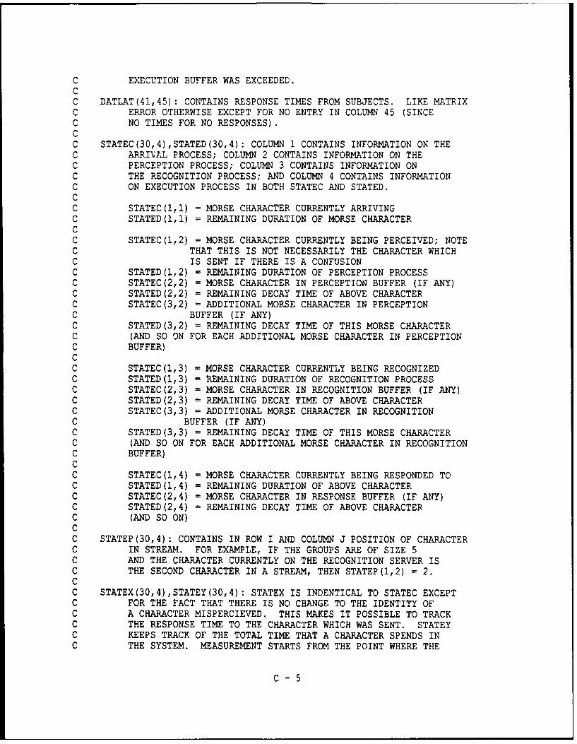
C EXECUTION BUFFER WAS EXCEEDED.CC DATLAT(41,45): CONTAINS RESPONSE TIMES FROM SUBJECTS. LIKE MATRIXC ERROR OTHERWISE EXCEPT FOR NO ENTRY IN COLUMN 45 (SINCEC NO TIMES FOR NO RESPONSES).CC STATEC(30,4),STATED(30,4): COLUMN 1 CONTAINS INFORMATION ON THEC ARRI\AL PROCESS; COLUMN 2 CONTAINS INFORMATION ON THEC PERCEPTION PROCESS; COLUMN 3 CONTAINS INFORMATION ONC THE RECOGNITION PROCESS; AND COLUMN 4 CONTAINS INFORMATIONC ON EXECUTION PROCESS IN BOTH STATEC AND STATED.CC STATEC(I,I) = MORSE CHARACTER CURRENTLY ARRIVINGC STATED(I,1) = REMAINING DURATION OF MORSE CHARACTERCC STATEC(1,2) = MORSE CHARACTER CURRENTLY BEING PERCEIVED; NOTEC THAT THIS IS NOT NECESSARILY THE CHARACTER WHICHC IS SENT IF THERE IS A CONFUSIONC STATED(1,2) = REMAINING DURATION OF PERCEPTION PROCESSC STATEC(2,2) = MORSE CHARACTER IN PERCEPTION BUFFER (IF ANY)C STATED(2,2) = REMAINING DECAY TIME OF ABOVE CHARACTERC STATEC(3,2) = ADDITIONAL MORSE CHARACTER IN PERCEPTIONC BUFFER (IF ANY)C STATED(3,2) = REMAINING DECAY TIME OF THIS MORSE CHARACTERC (AND SO ON FOR EACH ADDITIONAL MORSE CHARACTER IN PERCEPTIONC BUFFER)CC STATEC(1,3) = MORSE CHARACTER CURRENTLY BEING RECOGNIZEDC STATED(1,3) = REMAINING DURATION OF RECOGNITION PROCESSC STATEC(2,3) = MORSE CHARACTER IN RECOGNITION BUFFER (IF ANY)C STATED(2,3) = REMAINING DECAY TIME OF ABOVE CHARACTERC STATEC(3,3) = ADDITIONAL MORSE CHARACTER IN RECOGNITIONC BUFFER (IF ANY)C STATED(3,3) = REMAINING DECAY TIME OF THIS MORSE CHARACTERC (AND SO ON FOR EACH ADDITIONAL MORSE CHARACTER IN RECOGNITIONC BUFFER)cC STATEC(1,4) = MORSE CHARACTER CURRENTLY BEING RESPONDED TOC STATED(1,4) = REMAINING DURATION OF ABOVE CHARACTERC STATEC(2,4) = MORSE CHARACTER IN RESPONSE BUFFER (IF ANY)C STATED(2,4) = REMAINING DECAY TIME OF ABOVE CHARACTERC (AND SO ON)CC STATEP (30,4): CONTAINS IN ROW I AND COLUMN J POSITION OF CHARACTERC IN STREAM. FOR EXAMPLE, IF THE GROUPS ARE OF SIZE 5C AND THE CHARACTER CURRENTLY ON THE RECOGNITION SERVER ISC THE SECOND CHARACTER IN A STREAM, THEN STATEP(1,2) = 2.CC STATEX(30,4),STATEY(30,4): STATEX IS INDENTICAL TO STATEC EXCEPTC FOR THE FACT THAT THERE IS NO CHANGE TO THE IDENTITY OFC A CHARACTER MISPERCIEVED. THIS MAKES IT POSSIBLE TO TRACKC THE RESPONSE TIME TO THE CHARACTER WHICH WAS SENT. STATEYC KEEPS TRACK OF THE TOTAL TIME THAT A CHARACTER SPENDS INC THE SYSTEM. MEASUREMENT STARTS FROM THE POINT WHERE THE
C- 5

C CHARACTER HAS ARRIVED (I.E., MEASUREMENT STARTS WHEN THEC CHARACTER ENTERS THE PERCEPTION QUEUE OR SERVER) ANDC CONTINUES UNTIL THE RESPONSE HAS BEEN EXECUTED.CC STIMBUF(820): STIMBUF CONTAINS THE CHARACTER, INTERCHARACTER CODE ORC INTERGROUP CODE. THE SPACE BETWEEN CHARACTERS IS IDENTIFIEDC BY THE INTEGER 42; THE SPACE BETWEENGROUPSC IS IDENTIFIED BY THE INTEGER 43. THE FIRST CHARACTER APPEARSC IN STIMBUF(1), THE SECOND CHARACTER IN STIMBUF(2), AND SO ON.C NOTE THAT STIMBUF MUST BE TWICE THE SIZE OF CHRBUF.CC STIMDUR(43): CONTAINS DURATIONS OF 1 - 26 LETTERS, 5 SPECIALC CHARACTERS, 10 DIGITS AND BOTH INTERCHARACTER (42) ANDC INTERGROUP (33) INTERVALS. NOTE THAT DURATION OFC INTERCHARACTER AND ITNERGROUP INTERVALS WILL VARY WITH GPM.C THIS WILL SUPERCEDE WHATEVER IS READ INTIALLY INTOC STIMDUR.CC TIME (41,45): CONTAINS IN TIME(I,J) FOR EVERY TIME CHARACTER IC IS SENT AND CHARACTER J IS TYPED A RUNNING SUM OF THEC RESPONSE TIME. AT THE END, IN SUBROUTINE SOUT,C THE AVERAGE IS COMPUTED IN TIME BY DIVIDING TIME (I,J)C BY KEEP(I,J).CC TIMESP (5): TIMESP (I) CONTAINS RESPONSE TIMES OF ALL CORRECTLYC RECOGNIZED CHARACTERS FROM POSITION I IN A GROUP. AT ENDC TIMESP YIELDS AVERAGE. TOTAL OBSERVATIONS FOR ITH CHARACTERC IN STREAM IS KEPT IN KEEPSP(I).CCCCC DEFINE FUNCTIONSCC SGAMMA(...): GENERATES PSEUDO RANDOMC GAMMA RANDOM VARIABLE USING ROUTINE IN AVERILL M. LAW ANDC W. DAVID KELTON, SIMULATION MODELING AND ANALYSIS,C NEW YORK, MCGRAW HILL, 1982, PAGE 257.CCCCC DEFINE SUBROUTINES:CC SARR(... ): THIS CREATES NEXT STATE GIVEN MINIMUM HAS OCCURRED ONC ARRIVAL SERVER. ACTIONS MUST BE TAKEN TO THE INFO ANDC STATE MATRICES FOR BOTH THE ARRIVAL AND PERCEPTION PROCESSES:C A-S) IF THERE ARE MORE ARRIVALS CHANGE STATEC(i,i) TOC STIMBUF(NELEM); CHANGE STATED(i,i) TO RANDOM DURATION.C OTHERWISE STATEC(I,I) = STATED(i,i) = 0.C A-I) IF THERE ARE MORE ARRIVALS DECREMENT INFO(2,1);C OTHERWISE SET INFO(I,I) TO ZERO.C P-S) IF ARRIVIAL IS A CHARACTER (NOT A BLANK TIME) AND
C- 6

C IF THERE IS ROOM IN THE PERCEPTION BUFFER THENC SET STATEC(INFO(1,2)+1,2) = OLD STATEC(I,I); SETC STATED(INFO(1,2)+1,2) = RANDOM DURATION. IFC ARRIVAL IS A CHARACTER AND NO ROOM IN RECOGNITIONC BUFFER, PUT DISPLACED CHARACTER IN KILL DEPOSITORYC P-I) IF ARRIVAL IS A CHARACTER AND IF THERE IS ROOM IN THEC PERCEPTION BUFFER, THEN INFO(1,2) = INFO(1,2) + 1CCC SCHRBUF(...): PUTS INTO CHRBUF(410) RANDOM PERMUTATIONSC OF DIGITS 1 - 41 (CORRESPONDING TO IDENTIFIERS FOR MORSEC CHARACTERS, INCLUDING SPECIAL CHARACTERS)CC SEXEBUF(...): PERFORMS SAME OPERATIONS ASC SPERBUF IN EXECUTION BUFFERCC SGPM(...): PUTS INTO STIMDUR(42) THE INTERCHARACTERC DURATION FROM INTERC(I) WHERE INTERC(i) IS 6 GPM ANDC INTERC(15) IS 20 GPM. SIMILARLY FOR STIMDUR(43) ANDC INTERG(J).CC SMINI(...): IDENTIFIES CHARACTER WITH MINIMUMC REMAINING PROCESSING TINE AND SETS KROW AND KCOL TO THEC ROW AND COLUMN ENTRY IN STATE OF THE DURATION OF THISC CHARACTER. FOR EXAMPLE, SUPPOSE:CC STATED(1,1) = 50, STATED(1,2) = 100, STATED(2,2) = 110,C STATED(1,3) = 200, STATE(1,3) = 120 AND STATE(1,4) = 80cC THEN KROW = 1 AND KCOL = 1 SINCE 50 IS THE MINIMUM DURATION.CC SPER(...): IN STATES WHERE THE MINIMUM DURATION IS IN THEC PERCEPTUAL SERVER, SPER MAKES THE NECESSARY CHANGES. NOTEC THIS IS WHERE A PERIOD IS INTRODUCED. SPECIFICALLY,C IF THE TIME IT TAKES TO PERCEIVE A STIMULUS IS LONGERC THAN SOME TIME RCRIT, THEN THE STIMULUS IS CODED ASC A PERIOD. OTHERWISE (I.E., IF THE SERVICE TIME ISC LESS THAN THE CRITICAL TIME) THEN WE USE THE CONFUSIONC MATRIX TO DETERMINE WHETHER THE CHARACTER IS CODEDC CORRECTLY OR INCORRECTLY.CC SPERBUF(...): IN STATES WHERE THE MINIMUM DURATIONC IF IN THE PERCEPTUAL BUFFER, SPERBUF RF4MOVES THEC MINIMUM DURATION PROCESS FROM STATEC AND STATED AND MOVESC EVERYTHING ABOVE IT UP ONE IN THE QUEUE. FOR EXAMPLE, SUPPOSEC WE HAVE FIVE ITEMS IN THE PERCEPTUAL BUFFER AND ONE ON THEC SERVER. WE APPLY SMINI AND OBTAIN:CC STATED(1,2) = 50, STATED(2,2) = 150, STATED(3,2) = 0,C STATED(4,2) = 170, STATE(5,2) = 120 AND STATE(6,2) = 130.CC SPERBUF MOVES THE THIRD (STATED(4,2)), FOURTH (STATED(5,2))C AND FIFTH (STATED(6,2)) UP ONE AND REPLACES STATE(6,2) WITH 0,C SO THAT WE HAVE:
C- 7

CC STATED(1,2) = 50, STATED(2,2) = 150, STATED(3,2) = 170,C STATED(4,2) = 120, STATE(5,2) = 130 AND STATE(6,2) = 0.CC NOTE THAT THE SAME CHANGES ARE MADE TO STATECCC SPERERR(JTEMPC,CONMAT,CONFUS,SEED): LOOKS AT CONFUSION MATRIX AND DECIDESC WHETHER TO REPLACE CURRENT CHARACTER WHICH HAS JUST BEENC PERCEIVED WITH ANOTHER CHARACTER. FOR EXAMPLE, SUPPOSE THATC THERE WERE FOUR CHARACTERS. SET P(JII) EQUAL TO THEC PROBABILITY OF PERCEIVING J GIVEN I. SUPPOSE P(111) = .4,C P(211) = .3, P(311) = .2 AND P(411) = .1. THEN, IN CONMATC IN ROW 1 WE CODE .4, .7, .9 AND 1.0. WE THEN GENERATEC A VALUE FOR A UNIFORM[0,1] RANDOM VARIABLE AND DETERMINEC WHETHER THIS VALUE IS IN THE INTERVAL [0,.4). IF SO,C THEN THE CHARACTER 1 IS CORRECTLY CODED AS A 1. IF NOT,C THEN WE DETERMINE WHETHER THE VALUE IS IN THE INTERVALC [.4,.7). IF SO, THEN A 2 IS INCORRECTLY CODED AS A l.C AND SO ON.CC SRECBUF(STATEC,STATED,INFO,KROW,KCOL,KILL): PERFORMS SAME OPERATIONS ASC SPERBUF IN RECOGNITION BUFFERCC SSTIM(CHRBUF,STIMBUF,NGROUP,NREP,NSTIM): PUTS FIRST CHARACTER IN CHRBUFC INTO STIMBUF, THEN INTERCHARACTER IDENTIFIER, THEN NEXTC CHARACTER IN CHRBUF, AND SO ON UNTIL NGROUP CHARACTERS HAVEC BEEN PLACED IN STIMBUF, AT WHICH POINT AN INTERGROUPC IDENTIFIER IS PLACED IN STILMBUF. THIS IS REPEATED FORC EACH SUCCEEDING GROUP.CC SSUB(STATEC7 STATED,INFO,KROW,KCOL): SUBTRACTS THE MINIMUM DURATION OF THEC PROCESS FOUND IN SMIN FROM THE DURATION OF EACH OF THEC PROCESSES IN STATED, LEAVING THE REMAINING DURATION FOR EACHC PROCESS. FOR EXAMPLE, AFTER SSUB OPERATION ON THE OUTPUTC OF SMIN ABOVE, WE WOULD HAVE:CC STATED(I,1) = 0, STATED(I,2) = 50, STATED(2,2) = 60,C STATED(1,3) = 150, STATE(1,3) = 120 AND STATE(1,4) = 30.CCCCC TYPE VARIABLES
INTEGER NCHRINTEGER NCHRBUFINTEGER NGPMINTEGER NCNTINTEGER KROW,KCOL !ROW AND COLUMN MARKERS OF MIN DUR IN STATEINTEGER NELEMINTEGER NGROUP,NREP,NSTIMINTEGER NOUTINTEGER NPERINTEGER*4 SEEDREAL RCRIT
C - 8

CCCCC TYPE MATRICES
INTEGER CHRBUF (410)INTEGER CONFUS(41,41)INTEGER INFO(2,4)INTEGER KEEP (41, 46)INTEGER KEEPSP (5)INTEGER KILL(41,8)INTEGER STATEC (30, 4)INTEGER STATEP (30, 4)INTEGER STATEX(30,4)INTEGER STIMBUF (820)REAL ALPHA(2,4),BETA(2,4)REAL CONMAT (41, 45)REAL DATERR(41,45),DATLAT(41,45)REAL INTERC (15) ,INTERG (15)REAL STATED (30, 4)REAL STATEY(30,4)REAL STI1DUR(43)REAL TIME(41,45)REAL TINESP (5)
CCCCC DATA INITIALIZATION STATEMENTS
DATA SEED/98753/DATA CONFUS/1681*0/DATA INFO/8*0/DATA INTERC/1260.,1030.,860. ,729.,624.,537.,466.,405.,353.,C 308.,268.,233.,203.,175.,150./DATA INTERG/2940.,2402.,2008.,1701.,1455.,1254.,1087.,C 945.,824.,718.,626.,545.,473.,408.,350./DATA KEEP/1886*0/DATA KEEPSP/5*0/DATA KILL/328*0/DATA STATEC/120*0/DATA STATED/120*0./DATA STATEP/120*0/DATA TIME/1845*0./DATA TIMESP/5*0./
CC OPEN FILES
OPEN (tNIT=1, FILE=' MORSE. IN' ,STATUS=' OLD' ,READONLY)OPEN (UNIT=2, FILE='MORSE .OUT' ,STATUS=' NEW')OPEN (UNIT=3, FILE='MORSE .DAT' ,STATUS=' OLD' ,READONLY)
CC READ IN MATRIX INFORMATION: SIMULATION AND DATA
CALL SINP (STATEC, STATED, INFO, STIMDUR, ALPHA, BETA,C STATEX,STATEY)CALL SDAT (DATERR,DATLAT, CONMAT)
C - 9

CC BOUNCE BACK HERE FOR SIMULATION USING NEW GPM99 CONTINUECC INITIALIZE VARIABLES
CALL SINV(INFO, NCHR, NCHRBUF,NGPM, NGROUP,NREP,NSTIM, NELEM, NCNT,C NOUT, NPER, RCRIT, KCOPB, SEED)
CC RANDOMIZE INPUT STREAM OF CHARACTERS
CALL SCHRBUF(SEED,CHRBUF,NCHR, NOUT)CC INSERT INTERCHARACTER AND INTERGROUP IDENTIFIERS INTO STREAM
CALL SSTIM(CHRBUF,STIMBUF,NGROUP,NREP,NSTIM, NOUT)CC SET INTERCHARACTER AND INTERGROUP DURATION FOR A PARTICULAR RATE (GROUPSC PER MINUTE)
CALL SGPM(STIMDUR, INTERC, INTERG,NGPM)CC BEGIN CREATING STATES100 CONTINUE !BOUNCE BACK HERE IF MORE STATESC NO MORE STATES IF NOTHING ACTIVE ON SERVERS
IF((INFO(1,1)+INFO(1,2)+INFO(1,3)+INFO(1,4)).EQ.0) GOTO 999CC OBTAIN MINIMUM PROCESSING DURATION
CALL SMINI(STATEC, STATED, INFO, KROW,KCOL,NOUT)CC SUBTRACT MINIMUM PROCESSING DURATION
CALL SSUB(STATEC, STATED, INFO, KROW, KCOL)CC IF ARRIVAL COMPLETES FIRST THEN:
IF(KCOL.EQ.1) THENNELEM = NELEM + 1CALL SARR(STATEC, STATED,INFO, KROW, KCOL, STIMBUF,NELEM,
C KILL, SEED, STIMDUR, ALPHA, BETA, STATEX, STATEY, STATEP,C NOUT,DATLAT,KCOPB)
GO TO 100END IF
CC IF CHARACTER ON PERCEPTION SERVER COMPLETES FIRST THEN:
IF((KCOL.EQ.2).AND.(KROW.EQ.1)) THENCALL SPER(STATEC, STATED, INFO, KROW, KCOL, STIMBUF,NELEM,
C KILL, CONMAT,CONFUS,SEED,ALPHA, BETA, STATEX, STATEY,C STATEP,NOUT,NPER, RCRIT,DATLAT)
GO TO 100END IF
CC IF CHARACTER IN PERCEPTION BUFFER COMPLETES FIRST, THENC SQUASH PERCEPTION BUFFER
IF((KCOL.EQ.2).AND.(KROW.GT.1)) THENCALL SPERBUF(STATEC, STATED, INFO, KROW, KCOL,KILL, STATEX,
C STATEY, STATEP,NOUT)GO TO 100
END IFC
C -10

C IF CHARACTER ON RECOGNITION SERVER COMPLETES FIRST THEN:IF((KCOL.EQ.3).AND.(KROW.EQ.1)) THEN
CALL SREC (STATEC, STATED, INFO, KROW, KCOL, STIMBUF, NELEM,C KILL, SEED,ALPHA,BETA,STATEX,STATEY,STATEP,NOUT,C DATLAT)
GO TO 100END IF
CC IF CHARACTER IN RECOGNITION BUFFER COMPLETES FIRST, THENC SQUASH RECOGNITION BUFFER
IF((KCOL.EQ.3) .AND. (KROW.GT.1)) THENCALL SRECBUF (STATEC, STATED, INFO, KROW, KCOL, KILL, STATEX,
C STATEY, STATEP,NOUT)GO TO 100
END IFCC IF CHARACTER ON EXECUTION SERVER COMPLETES FIRST THEN:
IF((KCOL.EQ.4) .AND. (KROW.EQ.1)) THENCALL SEXE (STATEC, STATED, INFO, KROW, KCOL, STIMBUF, NELEM,
C KEEP, KILL,ALPHA, BETA, STATEX, STATEY, TIME, STATEP, KEEPSP,C TIMESP, NOUT, DATLAT)
GO TO 100END IF
CC IF CHARACTER IN EXECUTION BUFFER COMPLETES FIRST, THENC SQUASH EXECUTION BUFFER
IF((KCOL.EQ.4) .AND. (KROW.GT.1)) THENCALL SEXEBUF (STATEC, STATED, INFO, KROW, KCOL, KILL,
C STATEX, STATEY, STATEP,NOUT)GO TO 100
END IFCC GET HERE WHEN NO MORE STATES999 CONTINUECCC WRITE SELECTED OUTPUT
CALL SOUT (INFO,KEEP,KEEPSP,KILL,CONFUS,TIME,TIMESP,NCHR,NCNT,C NOUT, NGPM, NPER, DATERR,DATLAT, RCRIT, KCOPB)
CC ZERO INPUT TO START SIMULATION AT NEW RATE
CALL SZERO (CONFUS, NCHR, INFO, NCNT, KEEP, KEEPSP, KILL, STATEC,C STATEP, STATEX, STATED, STATEY, TIME, TIMESP, 1'PER)GO TO 99
CC END MAIN
END
C - 11

SUBROUTINE SINVCCCCC
SUBROUTINE SINV (INFO, NCHR, NCHRBUF, NGPM, NGROUP, NREP, NSTIM, NELEM,C NCNT, NOUT, NPER, RCRIT, KCOPB, SEED)INTEGER KCOPBINTEGER NCHRINTEGER NCHRBUFINTEGER NCNTINTEGER NGPMINTEGER NELEMINTEGER NGROUP, NREP, NSTIMINTEGER NOUTINTEGER NPERINTEGER*4 SEEDINTEGER INFO(2,4)REAL RCRIT
8 FORMAT(' ENTER 1 TO CONTINUE, 0 TO STOP =- $10 FORMAT(' ENTER ELEMENT IN STREAM: 0 =12 FORMAT(' ENTER GROUPS PER MINUTE: 6 - 20 =14 FORMAT(' DO YOU WANT FULL OUTPUT: 1/0 = ,S16 FORMAT(' ENTER CRITICAL VALUE IN MS: =-l$18 FORMAT(' ENTER 1 FOR COPY BEH; 0 NO COPB = $C BEGIN MAIN BODY OF PROGRAM
WRITE (5,*)WRITE (5,8)READ (5, *) NSTOPIF(NSTOP.EQ.0) THEN
WRITE (5, *)WRITE(5,*) ' OUTPUT IN FILE MORSE.OUT'WRITE (5, *)STOP
END IFJNCNT = (INFO (2,1) -1) /2 + 1WRITE (5, *)WRITE(5,*) ' NUMBER OF STIMULI IN INPUT STREAM = ',INFO(2,1)WRITE (5,*) ' NUMBER OF CHARACTERS IN INPUT STREAM = ',JNCNT
C ------- NCNTNCNT = INFO (2, 1)
C -------- NELEMNELEM = 0
C -------- NGPMWRITE (5, *)WRITE (5, 12)READ (5, *) NGPMIF((NGPM.LT.6) .OR. (NGPM.GT.20)) THEN
WRITE(5,*) 'GROUP SIZE INCORRECT; STOP PROGRAMSTOP
END IFC ------- RCRIT
WRITE (5,*)
C - 12

WRITE (5,16)READ (5,*) RCRIT
C-------KCOPBWRITE (5, *)WRITE (5, 18)READ(5,*) KCOPB
C ----- NOUTWRITE (5,*)WRITE(5,14)READ (5, *) NOUT
C ----- NGROUPNGROUP = 5
C ----- NREPNREP = 50
C ------ NSTIMNSTIM = 2*NGROUP*NREP
C CHECK THAT THERE ARE NOT TOO MANY STIMULI FOR PROGRAM TO HANDLEIF(INFO(2,1) .GT.NSTIM) THEN
WRITE(5,*) ' NUMBER OF ARRIVING STIMULI TOO LARGE: 'WRITE(5,*) ' INFO(2,1) GT NSTIM = NREP*NGROUPSTOP
END IFC NCHR
NCHR = 31C ------ NCHRBUF
NCHRBUF = 410C CHECK THAT THERE ARE NOT TOO MANY STIMULI THAT MUST BE CONSTRUCTED
IF (NGROUP*NREP.GT.NCHRBUF) THENWRITE(5,*) ' NEED TO ENLARGE MATRICES CHRBUF AND STIMBUFWRITE(5,*) ' SO THAT NGROUP*NREP GT NCHRBUF WHERE CHRBUFWRITE(5,*) ' HAS DIMENSION NCHRBUF AND STIMBUF HAS DIMEN-WRITE(5,*) ' SION 2*NCHRBUF '
STOPEND IF
C ------ NPERNPER = 0RETURNEND
C - 13

SUBROUTINE SINPCCCCC
SUBROUTINE SINP (STATEC, STATED, INFO, STIMDUR, ALPHA, BETA,C STATEX,STATEY)INTEGER INFO(2,4)INTEGER STATEC (30,4),STATEX (30,4)REAL ALPHA(2,4),BETA(2,4)REAL STATED (30,4),STATEY(30,4)REAL STIMDUR(43)
10 FORMAT(IX,414, 10F0.4)12 FORMAT (20 (lX, 12F5.0/))14 FORMAT(8(1X,F7.2))CC BEGIN INPUTTING INFORMATION
DO 100 IA = 1,2READ(1,*) (INFO(IA, J) ,J=-,4)
100 CONTINUEDO 240 IA = 1,2READ(1,*) (ALPHA(IA,J),J=1,4), (BETA(IA,J),J=1,4)
240 CONTINUEDO 110 IA = 1,30DO 110 IB = 1,4STATEC(IA,IB) = 0.STATED(IA, IB) = 0.
110 CONTINUESTATEC(I,1) = 42 !INITIALIZE 0TH STIMULUS TO 42STATED(I,1) = 50. !WITH A DURATION OF 50 MSDO 112 IA = 1,30DO 112 IB = 1,4STATEX(IA,IB) = STATEC(IA,IB)STATEY(IA,IB) = STATED(IA,IB)
112 CONTINUEDO 120 IA = 1,42,3READ(1,*) (STIMDUR(J),J=IA,IA+2)
120 CONTINUEREAD(1,*) STIMDUR(43)
CC OUTPUT INFORMATION TO FILE ON WHAT WAS READ IN
WRITE (5, *)WRITE(5,*) ' WARNING - WARNING : STIM DURATION OF SPEC CHAR WRONGWRITE (5, *)WRITE(2,*) STIMULUS DURATIONS OF 1 - 31 CHARACTERS AND BLANKSWRITE(2,12) (STIMDUR(J) ,J=1,33)WRITE (2, *)WRITE(2,*) DATA IN ALPHA AND BETA AT STARTDO 260 IA = 1,2WRITE(2,14) (ALPHA(IA,J),J=1,4), (BETA(IA,J),J=1,4)
260 CONTINUEWRITE (2, *)WRITE(2,*) PERCEPTION (SERV/DEC): ',ALPHA(1,2)*BETA(1,2),
C - 14

C ALPHA(2,2) *BETA(2,2)WRITE(2,*) ' PERCEPTION (SERV/DEC): ',ALPHA(1,3)*BETA(1,3),C ALPHA (2,3) *BETA (2,3)WRITE(2,*) ' PERCEPTION (SERV/DEC): ',ALPHA(1,4)*BETA(1,4),C ALPHA (2, 4) *BETA (2, 4)WRITE (2, *)WRITE(2,*) ' DATA IN INFO AT STARTDO 220 IA = 1,2WRITE(2,*) (INFO(IA,J),J=1,4)
220 CONTINUEWRITE (2, *)WRITE(2,*) ' INPUT IN STATEC AND STATED AT STARTDO 200 IA 1,5WRITE(2,10) (STATEC(IA,J),J=1,4), (STATED(IA,J),J=1,4)
200 CONTINUEWRITE (2, *)WRITE(2,*) ' INPUT IN STATEX AND STATEY AT START '
DO 210 IA = 1,5WRITE(2,10) (STATEX(IA,J),J=1,4), (STATEY(IA,J),J=1,4)
210 CONTINUECC CHECK ON VALIDITY OF INPUT INFORMATION
DO 400 IA = 1,2DO 400 IB = 1,4IF(ALPHA(IA,IB) .LE.1) THEN
WRITE(5,*) ' ALPHA LESS THAN 1; ALTERNATIVE GAMMA GENERATORWRITE(5,*) ' IS NEEDED; SEE LAW AND KELTON, PAGE 255
STOPEND IF
400 CONTINUERETURNEND
C - 15

SUBROUTINE SDATCCCCC
SUBROUTINE SDAT (DATERR, DATLAT, CONb4AT)REAL CONMAT(41,45)REAL DATERR(41,45),DATLAT(41,45)
10 FORMAT(lX,1OF1O.4)DO 100 IA = 1,41READ(3,1O) (DATERR(IA,J) ,J=1, 45)
100 CONTINUEDO 200 IA =1,41READ (3, 10) (DATIJAT (IA, J), 1=1,45)
200 CONTINUEDO 300 IA =1,41RDEN = DATERR(IA,42) + DATERR(IA,43)IF(RDEN.GT.0) THEN
IF(IA.EQ.1) THENCONMAT(IA,1) = DATERR(IA,42)/RDENCONMAT(IA,2) = 1.0
ELSECONMAT(IA,1) = DATERR(IA,43)/RDENCONMAT(IA,IA) = 1.0
END IFEND IF
300 CONTINUERETURN~END
C - 16
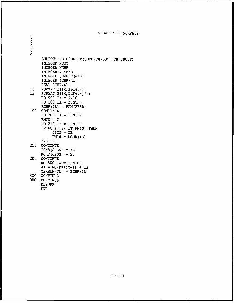
SUBROUTINE SCHRBUFCCCCC
SUBROUTINE SCHRBUF (SEED,CHRBUF,NCHR,NOUT)INTEGER NOUTINTEGER NCHRINTEGER*4 SEEDINTEGER CHRBUF (410)INTEGER ICHR(41)REAL RCHR(41)
10 FORMAT(2(1X,1614,/))12 FORMAT(3(1X,12F6.4,/))
DO 900 IX = 1,10DO 100 IA = 1,NCERRCHR(!A) = RAN(SEED)
100 CONTINUEDO 200 IA = 1,NCHRRMIN = 2.DO 210 lB = 1,NCHRIF(RCHR(IB) .LT.RMIN) THEN
JPOS = lBRMIN = RCHR(IB)
END IF210 CONTINUE
ICHR(JPOS) = IARCHR(u±eOS) = 2.
200 CONTINUEDO 300 IIA = 1,NCHRJA = NCHR*(IX-1) + IACHRBUF(JA) = ICHR(IA)
300 CONTINUE900 CONTINUE
REThRMNEND
C -17

SUBROUTINE SOUTCCCCC
SUBROUTINE SOUT (INFO,KEEP,KEEPSP,KILL,2-ONFUS,TIME,TIMESP,NCHR,C NCNT, NOUT, NGPM, NP ER, DATERR, DATLAT,C RCRIT,KCOPB)INTEGER KCOPBINTEGER NCHR, NCNT, NOUT, NGPM, NPERINTEGER INFO(2,4)INTEGER CONFUS (41, 41)INTEGER KEEP (41,46)INTEGER KEEPSP (5)INTEGER KILL(41,8)REAL RCRITREAL DATERR(41,45) ,DATLAT (41, 45)REAL DATOUT(2,8)REAL PRDERR.(41, 45)REAL PRDOUT(2,8)REAL TIME(41,45)REAL TIMESP (5)
10 FORMAT(1X,1014)12 FORMAT(15(lX,I4))14 FORMAT(lX,I3,1X,F7.4,lX,10013)16 FORMAT(1X,I3,lX,15F7.1/5X,15F7.1/5X,15F7.1)18 FORMAT(1X,10F12.6)20 FORMAT(1X,10F12.4)C INITIALIZE MATRICES, VARIABLES
DO 40 IA = 1,2DO 40 lB = 1,8PRDOUT(IA,IB) = 0.DATOUT(IA,IB) = 0.
40 CONTINUEDO 42 :.A = 1,41DO 42 lB = 1,45PRDERR (IA, IB) = 0.
42 CONTINUEJKEEP = 0JKILL = 0JOFF = 0JPER = 0KPD = 0KPB = 0DO 80 IA = 1,NCHRDO 80 lB = 1,45IF(IB.EQ.44) THEN
JPER = KEEP(IA,44) + JPEREND IFIF(IB.NE.IA) THEN
JOFF = KEEP (IA, IB) + JOFFEND IFJKEEP =KEEP(IA,IB) + JKEEP
C -18
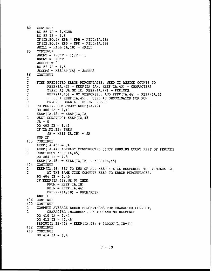
80 CONTINUEDO 85 IA = 1,NCHRDO 85 IB = 1,8IF(IB.EQ.2) KPB = KPB + KILL(IA, IB)IF(IB.EQ.6) KPD = KPD + KILL(IA, IB)JKILL = KILL(IA,IB) + JKILL
85 CONTINUEJNCNT = (NCNT - 1)/2 + 1RNCNT = JNCNTJKEEPS = 0DO 86 IA = 1,5JKEEPS = KEEPSP (IA) + JKEEPS
86 CONTINUEcC FIND PREDICTED ERROR PERCENTAGES: NEED TO ASSIGN COUNTS TOC KEEP (IA, 42) = KEEP (IA, IA), KEEP (IA, 43) = CHARACTERSC TYPED AS JA.NE.IE, KEEP(IA,44) = PERIODS,C KEEP(IA,45) = NO RESPONSES, AND KEEP(IA,46) = KEEP (IA,I)C + ... + KEEP (IA, 45). USED AS DENOMINATOR FOR ROWC ERROR PROBABILITIES IN PRDERRC TO BEGIN, CONSTRUCT KEEP (IA, 42)
DO 400 IA = 1,41KEEP (IA, 42) = KEEP (IA, IA)
C NEXT CONSTRUCT KEEP (IA, 43)JA = 0DO 403 IB = 1,41IF(IA.NE.IB) THEN
JA = KEEP (IA, IB) + JAEND IF
403 CONTINUEKEEP (IA, 43) = JA
C KEEP(IA,44) ALREADY CONSTRUCTED SINCE RUNNING COUNT KEPT OF PERIODSC CONSTRUCT KEEP (IA, 45)
DO 404 IB = 1,8KEEP(IA,45) = KILL(IA,IB) + KEEP(IA,45)
404 CONTINUEC KEEP(IA,46) SET TO SUM OF ALL KEEP + KILL RESPONSES TO STIMULUS IA.C AT THE SAME TIME COMPUTE KEEP TO ERROR PERCENTAGES.
DO 406 IB = 1,45IF (KEEP (IA,46) .NE.0) THEN
RNUM = KEEP (IA, IB)RDEN = KEEP (IA, 46)PRDERR(IA,IB) = RNUM/RDEN
END IF406 CONTINUE400 CONTINUEC COMPUTE AVERAGE ERROR PERCENTAGES FOR CHARACTER CORRECT,C CHARACTER INCORRECT, PERIOD AND NO RESPONSE
DO 410 IA = 1,41DO 412 IB = 42,45PRDOUT(1,IB-41) = KEEP(IA,IB) + PRDOUT(1,IB-41)
412 CONTINUE410 CONTINUE
DO 414 IA = 1,4
C - 19
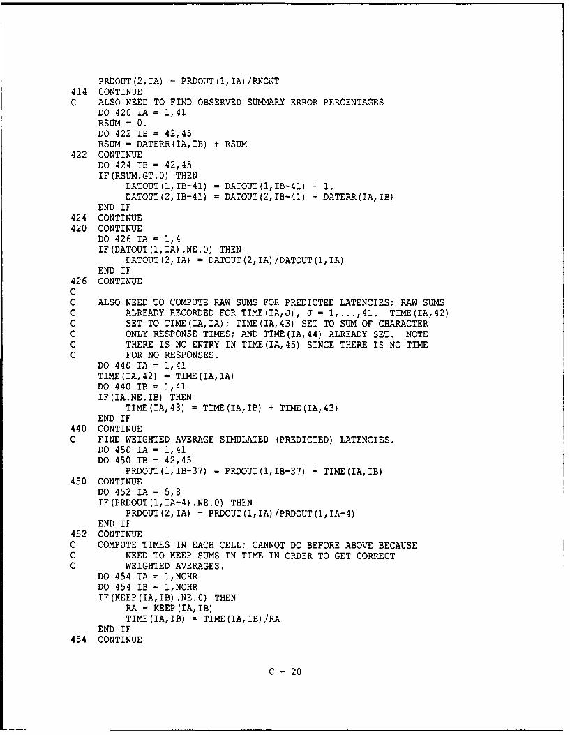
PRDOUT(2,IA) = PRDOUT(1,IA)/RNCNT414 CONTINUEC ALSO NEED TO FIND OBSERVED SUMMARY ERROR PERCENTAGES
DO 420 IA = 1,41RSUM = 0.DO 422 IB = 42,45RSUM = DATERR(IA,IB) + RSUM
422 CONTINUEDO 424 IB = 42,45IF(RSUM.GT.0) THEN
DATOUT(1,IB-41) = DATOUT(1,IB-41) + 1.DATOUT(2,IB-41) = DATOUT(2,IB-41) + DATERR(IA,IB)
END IF424 CONTINUE420 CONTINUE
DO 426 IA = 1,4IF(DATOUT(1,IA) .NE.0) THEN
DATOUT (2, IA) = DATOUT (2, IA)/DATOUT (1, IA)END IF
426 CONTINUECC ALSO NEED TO COMPUTE RAW SUMS FOR PREDICTED LATENCIES; RAW SUMSC ALREADY RECORDED FOR TIME(IA,J), J = 1,...,41. TIME(IA,42)C SET TO TIME(IA,IA); TIME(IA,43) SET TO SUM OF CHARACTERC ONLY RESPONSE TIMES; AND TIME(IA,44) ALREADY SET. NOTEC THERE IS NO ENTRY IN TIME(IA,45) SINCE THERE IS NO TIMEC FOR NO RESPONSES.
DO 440 IA = 1,41TIME(IA,42) = TIME(IA, IA)DO 440 IB = 1,41IF(IA.NE.IB) THEN
TIME(IA,43) = TIME(IA,IB) + TIME(IA,43)END IF
440 CONTINUEC FIND WEIGHTED AVERAGE SIMULATED (PREDICTED) LATENCIES.
DO 450 IA = 1,41DO 450 IB = 42,45
PRDOUT(1,IB-37) = PRDOUT(1,IB-37) + TIME(IA,IB)450 CONTINUE
DO 452 IA = 5,8IF(PRDOUT(1,IA-4) .NE.0) THEN
PRDOUT (2, IA) = PRDOUT (1, IA)/PRDOUT (1, IA-4)END IF
452 CONTINUEC COMPUTE TIMES IN EACH CELL; CANNOT DO BEFORE ABOVE BECAUSEC NEED TO KEEP SUMS IN TIME IN ORDER TO GET CORRECTC WEIGHTED AVERAGES.
DO 454 IA = 1,NCHRDO 454 IB = 1,NCHRIF (KEEP (IA, IB) .NE.0) THEN
RA = KEEP(IA,IB)TIME(IA,IB) = TIME(IA,IB)/RA
END IF454 CONTINUE
C - 20

C FIND AVERAGE OBSERVED LATENCIESDO 460 IA = 1,41DO 464 lB = 42,45IF(DATLAT(IA,IB) .GT.0) THEN
DATOUT(1,IB-37) = DATOUT(1,IB-37) + 1..DATOUT(2,IB-37) = DATOUT(2,IB-37) + DATLAT(IA,IB)
END IFIF(IB.EQ.42) THENEND IF
464 CONTINUE460 CONTINUE
DO 466 IB = 5,8IF(DATOUT(1,IB) .NE.0) THEN
DATOUT(2,IB) = DATOUT(2,IB) /DATOUT(1,IB)END IF
466 CONTINUECC WRITE OUT SUMMARY INFORMATION
RKEEPS = JKEEPSRPC = RKEEPS/RNCNTWRITE (2, *)WRITE(2,*) 'COPY BEHIND = 1, NO COPY BEHIND = 0 ',KCOPBWRITE (2, *)WRITE(2,*) 'GROUPS PER MINUTE (GPM) = ',NGPMWRITE (2, *)WRITE(2,*) 'CRITICAL TIME AT PERC SERVER = ',RCRITWRITE (2, *)WRITE(2,*) ' TOT CHAR, KEEP, KILL = ',31NCNT,JKEEP,JKILLWRITE (2, *)WRITE(2,*) ' TOT CHAR, TOT COR, % COR = ',JNCNT,JKEEPS,RPCWRITE (2, *)WRITE(2,*) P(CORRECT), P(BAD CHAR), P(PERIOD), P(NO RESP)WRITE(2,18) (PRDOUT(2,J),J=1,4)WRITE(2,18) (DATOUT(2,J),J=1,4)WRITE (2, *)WRITE(2,*) RT(CORREC), RT(BAD CHR), RT(PERIO), RT(NO RSP)WRITE(2,20) (PRDOUT(2,J),J=5,8)WRITE(2,20) (DATOUT(2,J),J=5,8)WRITE (2, *)WRITE(2,*) SERIAL POSITION INFORMATION: CORRECT KEEPWRITE(2,*) (KEEPSP(J),J=1,5)DO 88 IA = 1,5RA = KEEPSP (IA)IF (KEEPSP (IA) .NE.0) TIMESP (IA) = TINESP (IA) /RA
88 CONTINUEWRITE (2, *)WRITE(2,*) 'SERIAL POSITION INFORMATION: CORRECT TIMEWRITE(2,*) (TIMESP(J),J=1,5)
CC WRITE OUT DETAILED INFORMATION
IF(NOUT.EQ.0) GO TO 999WRITE (2, *)WRITE(2,*) ' KEEP INFORMATIONDO 90 IA = 1,NCHR
C - 21

WRITE(2,12) (KEEP(IA,J),J=1,45)90 CONTINUE
WRITE (2, *)WRITE(2,*) 'KILL INFORMATIONDO 100 IA =1,NCHR
WRITE(2,10) IA, (KILL(IA,J) ,J=1,8)100 CONTINUE
WRITE (2, *)WRITE(2,*) 'CONFUSION INFORMATION FROM SIMULATIONDO 105 IA = 1,NCHRRSUM = 0.DO 110 lB = 1,NCHRRSUM = CONFUS(IA,IB) + RSUM
110 CONTINUERNUM = CONFUS(IA, IA)IF(RSUM.NE.0) THEN
RPER = RNUM/RSUMWRITE (2,14) IA,RPER, (CONFUS (IA,J) ,J=1,NCHR)
ELSEWRITE(2,*) IA,' RSUM = 0: NO CHARACTERS SENT OR ALL BUMPED
END IF105 CONTINUE
WRITE(2,*)WRITE(2,*) ' RESPONSE TIME INFORMATIONDO 210 IA = 1,NCHRWRITE(2,16) IA, (TIME(IA,J),J=1,NCHR)
210 CONTINUE999 CONTINUECC PERFORM CHECKS ON COMPUTATIONSC CHECK 1
NTOT = 0DO 300 IA = 1,NCHRDO 300 lB = 1,NCHRNTOT = CONFUS(IA,IB) + NTOT
300 CONTINUEIF(NTOT.NE.(JKEEP + JKILL - KPD - KPB - NPER)) THEN
WRITE (2, *)WRITE(2,*) ' CHECK 1 PROBLEMS: CONFUS SUM NE KEEP + KILL-WRITE(2,*) ' KILLPERBUFDECAY - KILLPERBUFBUb4P - # REC PER'WRITE(2,*) ' ',NTOT,JKEEP,JKILL,KPD,KPB,NPERWRITE (5, *)WRITE(5,*) ' CHECK 1 PROBLEMS: CONFUS SUM NE KEEP + KILL-WRITE(5,*) 'KILLPERBUFDECAY - KILLPERBUFBUMP - # REC PER'WRITE(5,*) '',NTOT,JKEEP,JKILL,KPD,KPB,NPER
ELSEWRITE (5, *)WRITE(5,*) ' CHECK 1 OK:WRITE(5,*) ' CONFUS = KEEP + KILL - KPD - KPB - NPER'WRITE(5,*) ' ',NTOT,JKEEP,JKILL,KPD,KPB,NPER
END IFC PERFORM CHECKS ON COMPUTATIONSC CHECK 2
IF(JNCNT.NE. (JKEEP+JKILL)) THEN
C - 22
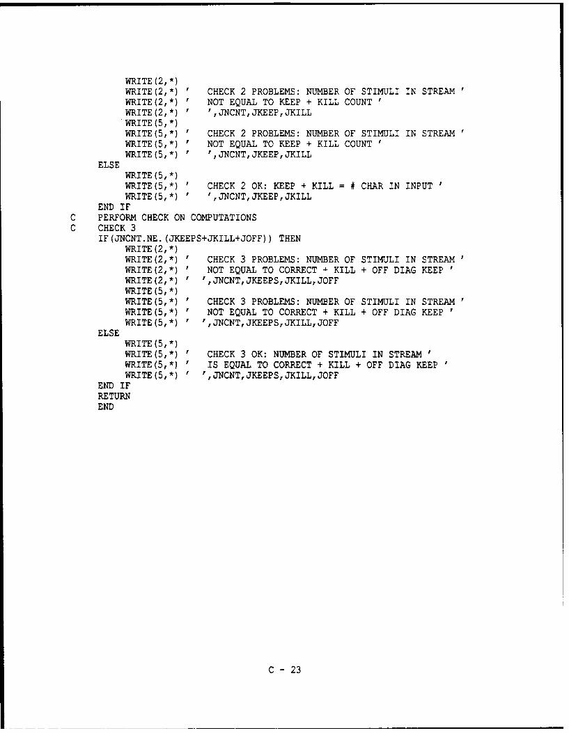
WRITE (2, *)WRITE(2,*) ' CHECK 2 PROBLEMS: NUMBER OF STIMULI IN STREAMWRITE(2,*) ' NOT EQUAL TO KEEP + KILL COUNTWRITE (2, *) ' ,JNCNT, JKEEP, JKILLWRITE (5, *)WRITE(5,*) ' CHECK 2 PROBLEMS: NUMBER OF STIMULI IN STREAMWRITE(5,*) ' NOT EQUAL TO KEEP + KILL COUNTWRITE(5,*) ' ',JNCNT,JKEEP,JKILL
ELSEWRITE (5, *)WRITE(5,*) ' CHECK 2 OK: KEEP + KILL = # CHAR IN INPUT 'WRITE(5,*) ' ',JNCNT,JKEEP,JKILL
END IFC PERFORM CHECK ON COMPUTATIONSC CHECK 3
IF (JNCNT.NE. (JKEEPS+JKILL+JOFF)) THENWRITE (2, *)WRITE(2,*) ' CHECK 3 PROBLEMS: NUMBER OF STIMULI IN STREAMWRITE(2,*) ' NOT EQUAL TO CORRECT •- KILL + OFF DIAG KEEPWRITE(2,*) ' ',JNCNT,JKEEPS,JKILL,JOFFWRITE (5, *)WRITE(5,*) ' CHECK 3 PROBLEMS: NUMBER OF STIMULI IN STREAMWRITE(5,*) ' NOT EQUAL TO CORRECT + KILL + OFF DIAG KEEPWRITE (5,*) ' ',JNCNT, JKEEPS, JKILL, JOFF
ELSEWRITE (5, *)WRITE(5,*) ' CHECK 3 OK: NUMBER OF STIMULI IN STREAMWRITE(5,*) ' IS EQUAL TO CORRECT + KILL + OFF DIAG KEEPWRITE(5,*) ' ',JNCNT,JKEEPS,JKILL,JOFF
END IFRETURNEND
C - 23

SUBROUTINE SSTIMCCCCC
SUBROUTINE SSTIM (CHRBUF, STIMBUF, NGROUP, NREP, NSTIM, NOUT)INTEGER CHRBUF (410) ,STIMBUF(820)INTEGER NGROUP, NREP, NSTIM
10 FORMAT(1X, 2013)JCHR = 0DO 100 IA = 1,NSTIM,2*NGROUPDO 120 lB = IA,IA+2*NGROUP-1,2JCHR = JCHR + 1STIMBUF(IB) = CHRBUF(JCHR)STIMBUF(IB+1) = 42
120 CONTINUESTIMBUF (IA + 2*NGROUP -1) = 43
100 CONTINUEIF(NOUT.EQ.1) THEN
WRITE (2, *)WRITE(2,*) ' DATA IN CHRBUF AT START: ONLY FIRST 10WRITE(2,10) (CHRBUF(J) ,J=1,10)WRITE (2, *)WRITE(2,*) ' DATA IN STIMBUF AT START: ONLY FIRST 20'WRITE(2,10) (STIMBUF(J) ,J=1,20)
END IFRETURNEND
C - 24

SUBROUTINE SMINICCCCC
SUBROUTINE SMINI (STATEC, STATED, INFO, KROW, KCOL,NOUT)INTEGER NOUTINTEGER INFO(2,4)INTEGER STATEC (30,4)REAL STATED(30,4)INTEGER KROW,KCOLRMIN = 10000000.DO 100 IA = 1,4IF(INFO(1,IA) .GT.0) THEN
DO 120 IB = 1, INFO(1,IA)IF(RMIN.GT.STATED(IB,IA)) THEN
KROW = IBKCOL = IARMIN = STATED (KROW,KCOL)
END IF120 CONTINUE
END IF100 CONTINUE
IF(NOUT.EQ.1) THENWRITE(2,*) ' MIN DURATION IN STATE ',KROW,KCOL,RMIN
END IFRETURNEND
C - 25

SUBROUTINE SSUBCCCCC
SUBROUTINE SSUB (STATEC, STATED, INFO, KROW, KCOL)INTEGER INFO(2,4)INTEGER STATEC (30, 4)REAL STATED (30,4)INTEGER KROW,KCOL
2.0 FORMAT(1X,414,1OF1O.4)RMIN = STATED (KROW,KCOL) !THE MINIMUM FOUND IN SMINDO 100 IA = 1,4IF(INFO(1,IA).EQ.O) GOTO 100DO 100 lB = 1,INFO(1, IA)STATED(IB,IA) = STATED(IB,IA) -RMIN
100 CONTINUERETURNEND
C - 26
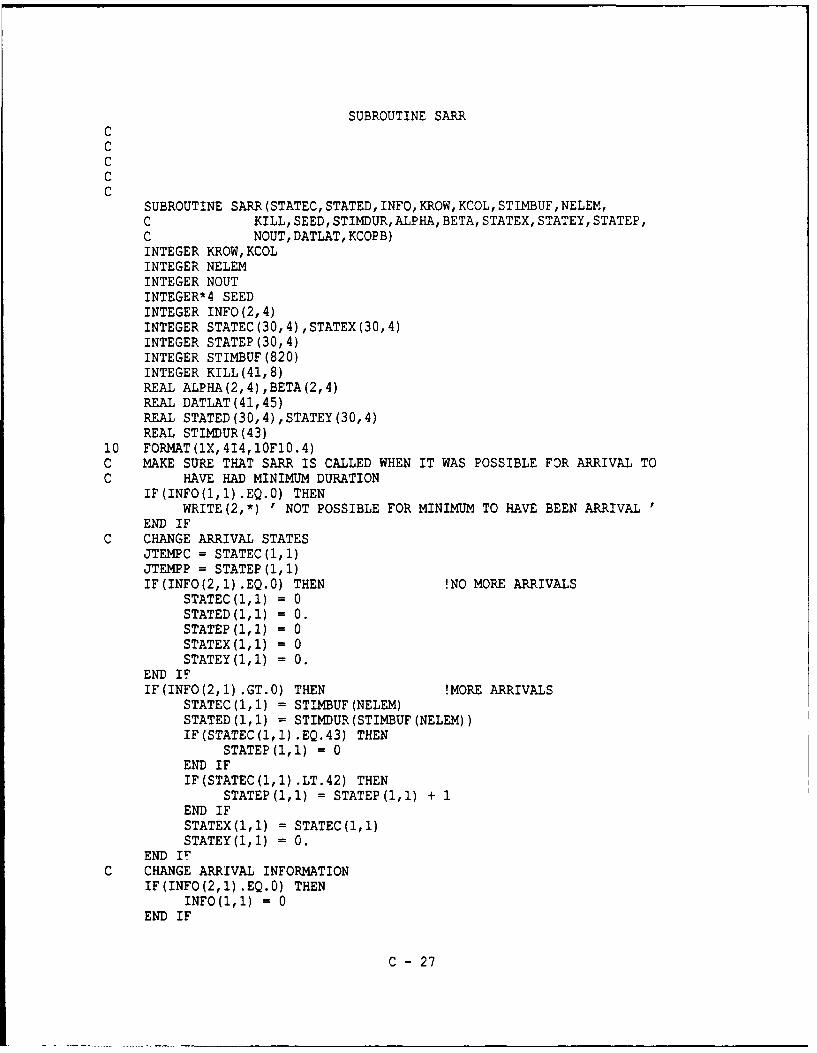
SUBROUTINE SARRCCCCC
SUBROUTINE SARR (STATEC, STATED, INFO, KROW, KCOL, STIMBUF, NELEM,C KILL, SEED, STIMDUR, ALPHA, BETA, STATEX, STATEY, STATEP,C NOUT, DATLAT, KCOPB)INTEGER KROW,KCOLINTEGER NELEMINTEGER NOUTINTEGER*4 SEEDINTEGER INFO (2, 4)INTEGER STATEC (30, 4) ,STATEX(30,4)INTEGER STATEP (30, 4)INTEGER STIMBUF (820)INTEGER KILL(41,8)REAL ALPHA (2, 4) BETA (2, 4)REAL DATLAT(41,45)REAL STATED (30,4) ,STATEY (30,4)REAL STIMDUR(43)
10 FORMAT(lX,414,10F10.4)C MAKE SURE THAT SARR IS CALLED WHEN IT WAS POSSIBLE FOR ARRIVAL TOC HAVE HAD MINIMUM DURATION
IF(INFO(1,l) .EQ.0) THENWRITE(2,*) ' NOT POSSIBLE FOR MINIMUM TO HAVE BEEN ARRIVAL
END IFC CHANGE ARRIVAL STATES
JTEMPC = STATEC(1,1)JTEMPP = STATEP(l,l)IF(INFO(2,1).EQ.0) THEN !NO MORE ARRIVALS
STATEC(1,1) = 0STATED(l,l) = 0.STATEP(1,1) = 0STATEX(1,1) = 0STATEY(1,1) = 0.
END IFIF (INFO (2,1) .GT.0) THEN !MORE ARRIVALS
STATEC(1,1) = STIMBUF (NELEM)STATED(1, 1) = STIMDUR (STIMBUF (NELEM))IF (STATEC (1,1).EQ.43) THEN
STATEP(1,1) = 0END IFIF (STATEC (1,1).LT.42) THEN
STATEP(1,l) = STATEP(1,1) + 1END IFSTATEX(1,1) = STATEC(l,l)STATEY (1, 1) = 0.
END IFC CHANGE ARRIVAL INFORMATION
IF (INFO (2, 1) .EQ.0) THENINFO(l,1) = 0
END IF
C - 27
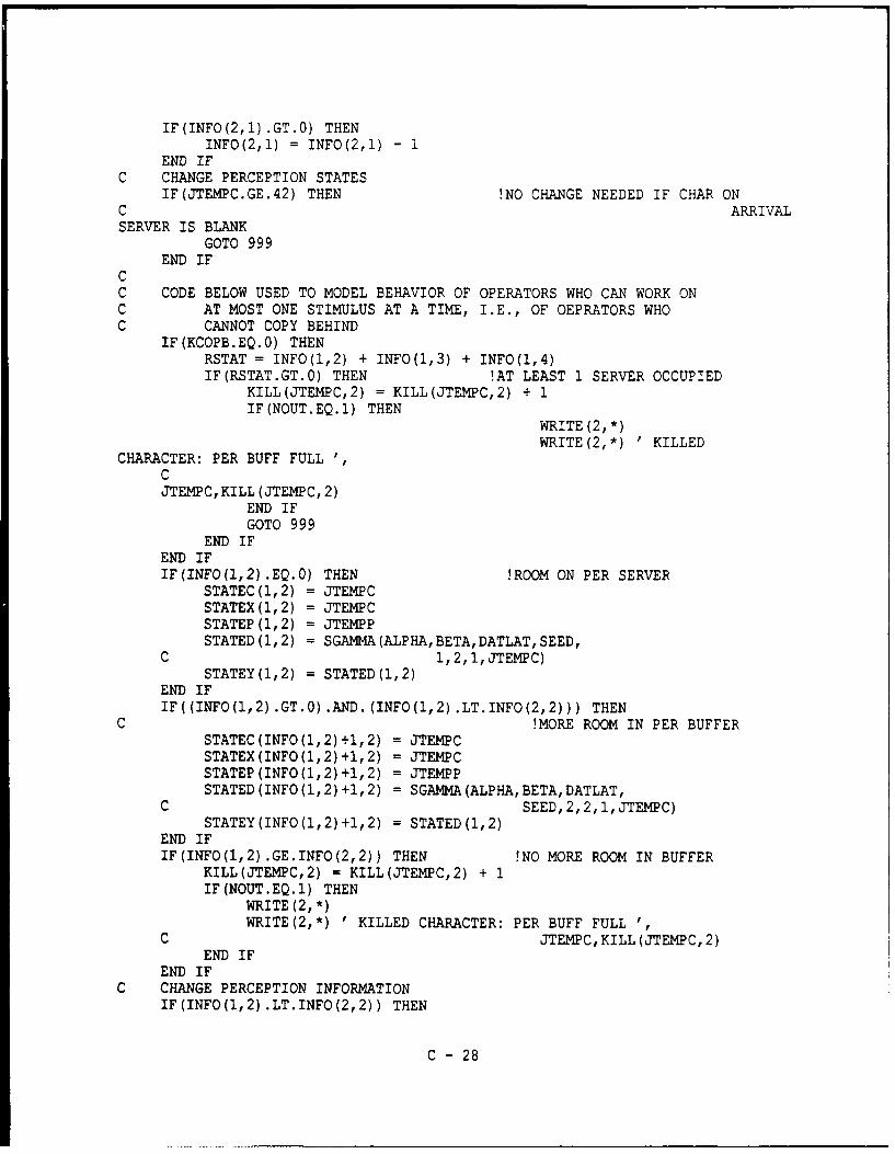
IF(INFO(2,1) .GT.O) THENINFO(2,1) = INFO(2,1) - 1
END IFC CHANGE PERCEPTION STATES
IF(JTEMPC.GE.42) THEN !NO CHANGE NEEDED IF CHAR ONC ARRIVALSERVER IS BLANK
GOTO 999END IF
CC CODE BELOW USED TO MODEL BEHAVIOR OF OPERATORS WHO CAN WORK ONC AT MOST ONE STIMULUS AT A TIME, I.E., OF QEPRATORS WHOC CANNOT COPY BEHIND
IF(KCOPB.EQ.O) THENRSTAT = INFO(1,2) + INFO(1,3) + INFO(1,4)IF(RSTAT.GT.Q) THEN !AT LEAST 1 SERVER OCCUPIED
KILL(JTEMPC,2) = KILL(JTEMPC,2) + 1IF(NOUT.EQ.1) THEN
WRITE (2, *)WRITE(2,*) 'KILLED
CHARACTER: PER BUFF FULL '
CJTEMPC, KILL (JTENPC, 2)
END IFGOTO 999
END IFEND IFIF(INFO(1,2).EQ.0) THEN !ROOM ON PER SERVER
STATEC(1,2) = JTEMPCSTATEX(1,2) = JTEMPCSTATEP(1,2) = JTEMPPSTATED (1,2) = SGANMA (ALPHA, BETA, DATLAT, SEED,
C 1, 2, 1, JTENPC)STATEY(1,2) = STATED(1,2)
END IFIF((INFO(1,2).GT.O).AND.(INFO(1,2).LT.INFO(2,2))) THEN
C !MORE ROOM IN PER BUFFERSTATEC(INFO(1,2)+1,2) = JTEMPCSTATEX(INFO(1,2)+1,2) = JTEMPCSTATEP(INFO(1,2)+1,2) = JTEMPPSTATED (INFO(1,2) +1,2) = SGAMMA(ALPHA,BETA,DATLAT,
C SEED,2,2,1,JTEMPC)STATEY(INFO(1,2)+1,2) = STATED(1,2)
END IFIF(INFO(1,2).GE.INFO(2,2)) THEN !NO MORE ROOM IN BUFFER
KILL(JTEMPC,2) = KILL(JTEMPC,2) + 1IF(NOUT.EQ.1) THEN
WRITE (2, *)WRITE(2,*) 'KILLED CHARACTER: PER BUFF FULL '
C JTEMC, KILL (JTEMPC, 2)END IF
END IFC CHANGE PERCEPTION INFORMATION
IF(INFO(1,2) .LT.INFO(2,2)) THEN
C - 28

INFO(1,2) = INFO(1,2) + 1END IF
999 CONTINUEIF(NOUT.EQ.1) THEN
WRITE (2, *)WRITE(2,*) ' INPUT AFTER SARR CHANGESDO 910 IA = 1,2WRITE(2,10) (INFO(IA,J),J=1,4)
910 CONTINUEDO 900 IA = 1,2WRITE(2,10) (STATEC(IA,J),J=1,4), (STATED(IA,J),J=1,4)
900 CONTINUEDO 902 IA = 1,2WRITE(2,10) (STATEX(IA,J),J=1,4), (STATEY(IA,J),J=1,4)
902 CONTINUEDO 904 IA = 1,2WRITE(2,10) (STATEP(IA,J),J=1,4)
904 CONTINUEEND IFRETURNEND
C - 29

SUBROUTINE SPERCCCCC
SUBROUTINE SPER (STATEC, STATED, INFO, KROW, KCOL, STIMBUF, NELEM,C KILL, CONMAT, CONFUS, SEED, ALPHA, BETA, STATEX, STATEY, STATEP,C NOUT, NPER, RCRIT, DATLAT)INTEGER KROW,KCOLINTEGER NELEMINTEGER NOUTINTEGER NPERINTEGER*4 SEEDINTEGER CONFUS (41,41)INTEGER INFO(2,4)INTEGER STATEC (30,4) , STATEX (30,4)INTEGER STATEP (30,4)INTEGER STIMBUF (820)INTEGER KILL(41,8)REAL RCRITREAL ALPHA(2,4),BETA(2,4)REAL DATLAT(41,45)REAL STATED(30,4),STATEY(30,4)REAL CONMAT(41,45)
10 FORMAT(1X,414,10F10.4)C MAKE SURE THAT SPER IS CALLED WHEN IT WAS POSSIBLE FOR PERCEPTION TOC HAVE HAD MINIMUM DURATION
IF(INFO(1,2).EQ.0) THENWRITE(2,*) ' NOT POSSIBLE FOR MINIMUM TO HAVE BEEN PERCEPTION '
END IFC INITIALIZE VARIABLES
JTEMPC = STATEC(1,2)JTEMPX = STATEX(1,2)JTEMPP = STATEP(1,2)RTEMPY = STATEY(1,2)
C IF THE PERCEPTION TIME IS LONG, THEN A PER TOD WILL BE RECORDEDIF (RTEMPY.GT.RCRIT) THEN
JTEMPC = 44NPER = NPER + 1
END IFC IF PERCEPTION TIME IS LESS THAN RCRIT, THEN GOTO CONFUSION MATRIXC TO CREATE PERCEPTUAL ERRORS, E.G., IF THE CODE -...C IS ON THE PERCEPTION SERVER, THEN WTIH SOME PROBABILITYC THE CODE MIGHT BE PERCEIVED AS, SAY,
IF (RTEMPY.LE.RCRIT) THENCALL SPERERR (JTEMPC, CONMAT, CONFUS, SEED)
END IFC CHANGE PERCEPTION STATES
IF(INFO(1,2).EQ.1) THEN !NOTHING IN PERCEPTION BUFFERSTATEC(1,2) = 0STATED(1,2) = 0.STATEX(1,2) = 0STATEP(1,2) = 0
C - 30

STATEY (1, 2) = 0.END IFIF(INFO(1,2) .GT.1) THEN !MORE IN
PERCEPTION BUFFERSTATEC(1,2) = STATZIC(2,2) !ASSIGN DURATION PERC SERVERSTATED(1,2) = SGAt'ThA(ALPHA,BETA,DATLAT,SEED,
C 1,2,2,jTEMPX)STATEX(1,2) = STATEX(2,2)STATEP(1,2) = STATEP(2,2)STATEY(1,2) = STATEY(2,2) + STATED(1,2)DO 100 IA = 2,INFO(1,2)STATEC(!A,2) = STATEC(IA+1,2)STATED(IA,2) = STATED(IA-t1,2)STATEX(IA,2) = STATEX(IA+1,2)STATEP(IA,2) = STATEP(ILI-1,2)IF(IA.LT.INFO(1,2)) THEN
STATEY(IA,2) = STATEY(IA+1,2) + STATED)(1,2)ELSE
STATEY(IA,2) = 0.END IF
100 CONTINUEEND IF
C CHANGE PERCEPTION INFORMATIONINFO(1,2) = INFO(1,2) -1
C CHANGE RECOGNITION STATESIF(INFO(1,3).LT.INFO(2,3)) THEN !MORE ROOM IN RECOG BUFFER
STATEC(INFO(1,3)+1,3) = JTEMPC !ASSIGN DURATIONSSTATEX (INFO (., 3) +1,3) = JTE14PXSTATEP(.CNFO(1,3)+1,3) = JTEMPPIF(INFO(1,3) .EQ.O) THENSTATED (1,3) = SGAM4MA(ALPHA,BETA,DATLAT, SEED,
C 1, 3,2, JTEDPX)ELSESTATED(INFO(1,3)+1,3) = SGAMMA(ALPHA,BETA,DA-LAT,
C SEED,2,3,2,JTEMPX)END IFSTATEY(INFO(1,3)+1,3) = RLZ~iPiY + STATED(1,3)
END IFIF(INFO(1,3).GE.INFO(2,3)) THEN !NO MORE ROOM IN RECOG BUFFER
KILL(JTEMPX,3) = KILL(JTEMPY.,3) + 1IF(NOUT.EQ.1) THEN
WRITE (2, *)WRITE(2,*) ' KILLED CHARACTER: REC BUFF FULL '
C JTEMPX, KYLL (JTEMPX, 3)END IF
END IFC CHANGE RECOGNITION INFORMATION
IF(INFO(1,3) .LT.INFO(2,3)) THENINFO(1,3) = INFO(1,3) + 1
END IF999 CONTINUE
IF(NOUT.EQ.1) THENWRITE (2, *)WRITE(2,*) ' INPUT AFTER SPER CHANGES
C - 31
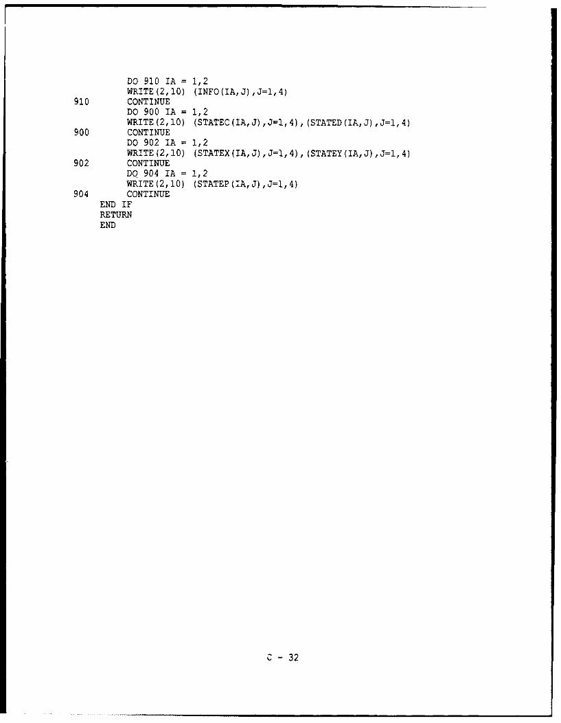
DO 910 IA = 1,2WRITE(2,10) (INFO(IA,J),J=1,4)
910 CONTINUEDO 900 IA = 1,2WRITE(2,10) (STATEC(IA,J),J=1,4), (STATED(IA,J),J=1,4)
900 CONTINUEDO 902 IA = 1,2WRITE(2,10) (STATEX(IA,J),J=1,4), (STATEY(IA,J),J=1,4)
902 CONTINUEDO 904 IA = 1,2WRITE (2, 10) (STATEP (IA, J) , J=l, 4)
904 CONTINUEEND IFRETURNEND
C - 32
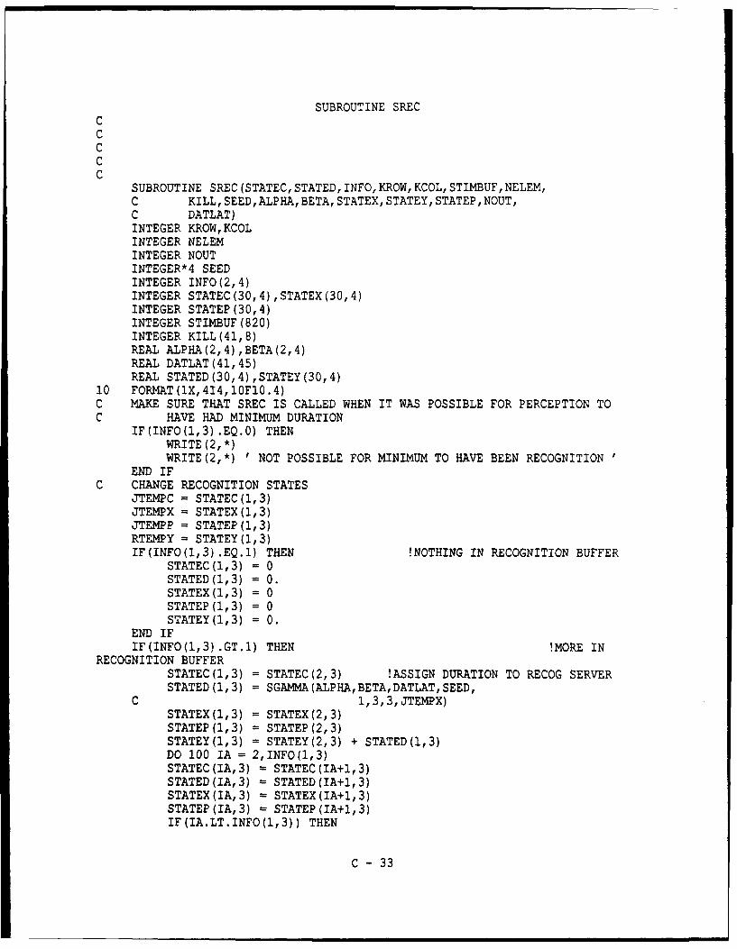
SUBROUTINE SRECCCCCC
SUBROUTINE SREC (STATEC, STATED, INFO, KROW, KCOL, STIMBUF, NELEM,C KILL, SEED, ALPHA, BETA, STATEX, STATEY, STATEP, NOUT,C DATLAT)INTEGER KROW,KCOLINTEGER NELEMINTEGER NOUTINTEGER*4 SEEDINTEGER INFO (2, 4)INTEGER STATEC (30,4), STATEX (30,4)INTEGER STATEP (30,4)INTEGER STIMBUF (820)INTEGER KILL(41,8)REAL ALPHA(2,4) ,BETA(2,4)REAL DATLAT (41, 45)REAL STATED (30, 4) ,STATEY(30,4)
10 FORMAT(1X,414,10F10.4)C MAKE SURE THAT SREC IS CALLED WHEN IT WAS POSSIBLE FOR PERCEPTION TOC HAVE HAD MINIMUM DURATION
IF (INFO (1,3) .EQ.0) THENWRITE (2, *)WRITE(2,*) 'NOT POSSIBLE FOR MINIMUM TO HAVE BEEN RECOGNITION
END IFC CHANGE RECOGNITION STATES
JTEMPC = STATEC(1,3)JTEMPX = STATEX(1,3)JTEMPP =STATEP(1,3)RTEMPY =STATEY(1,3)IF(INFO(1,3).EQ.1) THEN !NOTHING IN RECOGNITION BUFFER
STATEC(1,3) = 0STATED(1,3) = 0.STATEX(1,3) = 0STATEP(1,3) = 0STATEY(1,3) = 0.
END IFIF(INFO(1,3) .GT.1) THEN !MORE IN
RECOGNITION BUFFERSTATEC(1,3) = STATEC(2,3) !ASSIGN DURATION TO RECOG SERVERSTATED (1,3) = SGAMMA(ALPHA,BETA,DATLAT,SEED,
C 1, 3,3, JTEMPX)STATEX(1,3) = STATEX(2,3)STATEP(1,3) = STATEP (2, 3)STATEY(1,3) = STATEY(2,3) + STATED(1,3)DO 100 IA = 2, INFO (1,3)STATEC(IA,3) = STATEC(IA+1,3)STATED(IA,3) = STATED (IA+1,3)STATEX(IA,3) = STATEX(IA+1,3)STATEP(IA,3) = STATEP(IA+1,3)IF(IA.LT.INFO(1,3)) THEN
C - 33

STATEY(IA,3) = STiATEY(IA+1,3) + STATED(1,3)ELSE
STATEY(IA,3) =0.END IF
100 CONTINUEEND IF
C CHANGE RECOGNITION INFORMATIONINFO(1,3) = INFO(1,3) -1
C CHANGE EXECUTION STATESIF (INFO (1,4) .EQ.0) THEN !ROOM ON EXEC SERVER
STATEC(1,4) = JTEMPCSTATEX(1,4) = JTEMPXSTATEP(1,4) = JTEMPPSTATED (1,4) = SGAMMA(ALPHA,BETA,DATLAT,SEED,
C 1, 4, 3, JTEMPX)STATEY(1,4) = RTEMPY + STATED (1,4)
END IFIF((INFO(1,4).GT.0).AND.(INFO(1,4).LT.INFO(2,4))) THEN
C !MORE ROOM IN EXEC BUFFERSTATEC(INFO(1,4)+1,4) = JTEMPCSTATEX(INFO(1,4)+1,4) = JTEMPXSTATEP(INFO(1,4)+1,4) = JTEMPPSTATED(INFO(1,4)+1,4) = SGAMMA(ALPHA,BETA,DATLAT,
C SEED, 2,4, 3, JTEMPX)STATEY(INFO(1,4)+1,4) = RTEMPY 4 STATED(1,4)
END IFIF(INFO(1,4).GE.INFO(2,4)) THEN !NO MORE ROOM IN EXEC BUFFER
KILL(JTEMPX,4) = KILL(JTEMPX,4) 4 1IF(NOUT.EQ.1) THEN
WRITE (2, *)WRITE(2,*) ' KILLED CHARACTER: EXEC BUFF FULL '
C JTEMPX, KILL (JTEMPX, 4)END IF
END IFC CHANGE EXECUTION INFORMATION
IF(INFO(1,4) .LT.INFO(2,4)) THENINFO(1,4) = INFO(1,4) + 1
END IF999 CONTINUE
IF(NOUT.EQ.1) THENWRITE (2, *)WRITE(2,*) ' INPUT AFTER SREC CHANGES'DO 910 IA =1,2WRITE(2,10) (INFO(IA,J),J=1,4)
910 CONTINUEDO 900 IA -1,2WRITE(2,10) (STATEC(IA,J),J=1,4), (STATED(IA,J),J=1,4)
900 CONTINUEDO 902 IA -1,2WRITE(2,10) (STATEX(IA,J),J=1,4), (STATEY(IA,J),J=1,4)
902 CONTINUEDO 904 IA - 1,2WRITE(2,10) (STATEP (IA,J) ,J=1,4)
904 CONTINUE
C - 34

END IFRETURNEND
C - 35

SUBRUOTINE SEXECCCCC
SUBROUTINE SEXE (STATEC, STATED, INFO, KROW, KCOL, STIMBUF, NELEM,C KEEP,KILL,ALPHA,BETA, STATEX,STATEY,TIME, STATEP,C KEEPSP, TIMESP,NOUT,DATLAT)INTEGER KROW,KCOLINTEGER NELEMINTEGER NOUTINTEGER INFO(2,4)INTEGER STATEC (30, 4) ,STATEX(30,4)INTEGER STATEP (30, 4)INTEGER STIMBUF (820)INTEGER KILL(41,8)INTEGER KEEP (41, 46)INTEGER KEEPSP (5)REAL ALPHA(2, 4),BETA(2, 4)REAL DATLAT (41, 45)REAL STATED (30,4), STATEY (30,4)REAL TIME (41,45)REAL TIMESP (5)
10 FORMAT(iX,414,10F10.4)C MAKE SURE THAT SEXE IS CALLED WHEN IT WAS POSSIBLE FOR PERCEPTION TOC HAVE HAD MINIMUM DURATION
IF(INFO(1,4).EQ.0) THENWRITE (2, *)WRITE(2,*) ' NOT POSSIBLE FOR MINIMUM TO HAVE BEEN EXECUTION
END IFCC SAVE INFORMATION ON CHARACTERS WHICH MAKE IT THROUGH RESPONSEC AND INCREMENT RUNING RESPONSE TIMES
KEEP(STATEX(1,4),STATEC(1,4)) = KEEP(STATEX(1,4),STATEC(1,4)) + 1TIME(STATEX(1,4),STATEC(I,4)) = TIME(STATEX(1,4),STATEC(1,4)) +C STATEY(1,4)
CC SAVE SERIAL POSITION INFORMATION FOR CHARACTERS WHICH ARE CORRECTLYC ENTERED
IF(STATEX(1,4) .EQ.STATEC(1,4)) THENKEEPSP(STATEP(1,4)) = KEEPSP(STATEP(1,4)) + 1TIMESP(STATEP(1,4)) = TIMESP(STATEP(1,4)) + STATEY(1,4)
END IFC CHANGE EXECUTION STATES
IF(INFO(1,4).EQ.1) THEN !NOTHING IN EXECUTION BUFFERSTATEC(1,4) = 0STATED(1,4) = 0.STATEX(1,4) = 0STATEP(1,4) = 0STATEY(1,4) = 0.
END IFIF (INFO (1, 4) . GT. 1) THEN !MORE IN
EXECUTION BUFFER
C - 36

STATEC(1,4) =STATEC(2,4)STATED (1,4) = SGAM4A(ALPHA,BETA,DATLAT, SEED,
C 1,4,4,JTENPX)STATEX(1,4) =STATEX(2,4)STATEP(1,4) = STATEP(2,4)STATEY(1,4) = STATEY(2,4) + STATED(1,4)DO 100 IA = 2,INFO(1,4)STATEC(IA,4) = STATEC(IA+1,4)STATED(IA,4) = STATED(IA+1,4)STATEX(IA,4) = STATEX(IA+1,4)STATEP(IA,4) = STATEP(IA+1,4)IF(IA.LT.INFO(1,4)) THEN
STATEY(IA,4) = STATEY(IA+1,4) + STATED(1,4)ELSE
STATEY(IA,4) =0.END IF
100 CONTINUEEND IF
C CHANGE EXECUTION INFORMATIONINFO(1,4) =INFO(1,4) -1IF(NOUT.EQ.1) THEN
WRITE (2, *)WRITE (2, *) ' INPUT AFTER SEXE CHANGES'DO 910 IA = 1,2WRITE(2,10) (INFO (IA, J) , J=1,4)
910 CONTINUEDO 900 IA = 1,2WRITE(2,10) (STATEC(IA,J),J=1,4), (STATED(IA,J),J=1,4)
900 CONTINUEDO 912 IA = 1,2WRITE(2,10) (STATEX(IA,J),J=1,4), (STATEY(IA,J),J=1,4)
912 CONTINUEDO 914 IA = 1,2WRITE(2,10) (STATEP(IA,J) ,J=1,4)
914 CONTINUEEND IFRETURNEND
C - 37

SUBROUTINE SPERBUFCCCCC
SUBROUTINE SPERBUF (STATEC, STATED, INFO, KROW, KCOL, KILL, STATEX,C STATEY, STATEP, NOUT)INTEGER INFO(2,4)INTEGER KROW, KCOLINTEGER NOUTINTEGER KILL(41,8)INTEGER STATEC(30,4) ,STATEX(30,4)INTEGER STATEP (30, 4)REAL STATED (30,4) ,STATEY (30,4)
CC FORMAT STATEMENTS10 FORMAT(1X,4I4,J.X,10F1O.4)CC PLACE DECAYED STIMULUS IN KILL
KILL(STATEX(KROW,KCOL),6) = KILL(STATEX(KROW,KCOL),6) + 1IF(NOUT.EQ.1) THEN
WRITE (2, *)WRITE(2,*) ' KILL DECAY IN PERCEPTION ',STATEX(KROW,KCOL)
END IFCC BEGIN BUFFER. REORGANIZATION
DO 100 IA =KROW, INFO (1, 2)STATEC(IA,2) = STATEC(IA+1,2)STATED(IA,2) = STATED(IA+1,2)STATEX(IA,2) = STATEX(IA+1,2)STATEP(IA,2) - STATEP(IA+1,2)STATEY(IA,2) =STATEY(IA+1,2)
100 CONTINUECC DECREMENT PERCEPTION INFO
INFO (1, 2) =INFO (1, 2) - 1CC OUTPUT
IF(NOUT.EQ.1) THENWRITE (2, *)WRITE(2,*) 'OUTPUT IN STATE AFTER PERCEPTION BUFFER DECAYDO 210 IA = 1,2
210 WRITE(2,10) (STATEC(IA,J),J=1,4), (STATED(IA,J),J=1,4)DO 212 IA = 1,2
212 WRITE(2,10) (STATEX(IA,J),J=1,4), (STATEY(IA,J),J=1,4)DO 214 IA = 1,2
214 WRITE (2, 10) (STATEP (IA, J) , J1,4)END IFRETURNEND
C - 38

SUBROUTINE SRECBUFCCCCC
SUBROUTINE SRECBUF (STATEC, STATED, INFO, KROW, KCOL, KILL, STATEX,C STATEY, STATEP,NOUT)INTEGER INFO(2,4)INTEGER KROW,KCOLINTEGER NOUTINTEGER KILL(41,8)INTEGER STATEC(30,4) ,STATEX(30,4)INTEGER STATEP (30,4)REALJ STATED (30,4) ,STATEY(30,4)
CC FORMAT STATEMENTS10 FOPRMAT(1X,4I4,lX,l0F10.4)CC PLACE DECAYED STIMULUS IN KILL
JA = STATEX(KROW,KCOL)KILL(JA,7) = KILL(JA,7) + 1IF(NOUT.EQ.hI THEN
WRITE (2, *)WRITE(2,*) ' KILL DECAY IN RECOG ',STATFX(KROW,KCOL)
END IFCC BEGINNING OF REORDERING OF RECOGNITION BUFFER
DO 100 IA = KROW,INFO(1,3)STATEC(IA,3) = STATEC(IA+1,3)STATED(IA,3) = STATED(IA+1,3)STATEX(IA,3) = STATEX(IA+l,3)STATEP(IA,3) = STATEP(IA+1,3)STATEY(IA,3) = STATEY(IA+1,3)
100 CONTINUECC DECREMENT RECOGNITION INFO
INFO (1, 3) = INFO (1, 3) - 1CC OUTPUT
IF(NOUT.EQ.1) THENWRITE (2, *)WRITE(2,*) ' OUTPUT IN STATE AFTER RECOGNITION BUFFER DECAYDO 210 IA =1,2
210 WRITE(2,10) (STATEC(IA,J),J=1,4), (STATED(IA,J),J=1,4)DO 212 IA = 1,2
212 WRITE(2,10) (STATEX(IA,J),J=1,4), (STATEY(IA,J),J=1,4)DO 214 IA = 1,2
214 WRITE (2, 10) (STATEP (IA, J) ,J=1, 4)END IFRETURNEND
C - 39

SUBROUTINE SEXEBUFCCCCC
SUBROUTINE SEXEBUF (STATEC, STATED, INFO, KROW, KCOL, KILL, STATEX,C STATEY, STATEP, NOUT)INTEGER INFO(2,4)INTEGER KROW,KCOLINTEGER NOUTINTEGER KILL(41,8)INTEGER STATEC(30,4),STATEX(30,4)INTEGER STATEP (30, 4)REAL STATED (30, 4) ,STATEY (30, 4)
CC FORMAT STATEMENTS10 FORMAT(1X,4I4,10F10.4)CC PLACE DECAYED STIMULUS IN KILL
KILL(STATEX(KROW,KCOL),B) = KILL(STATEX(KROW,KCOL),8) + 1IF(NOUT.EQ.1) THEN
WRITE (2, *)WRITE(2,*) ' KILL DECAY IN EXECUTION ',STATEX(KROW,KCOL)
END IFCC BEGIN BUFFER REORGANIZATION
DO 100 IA = KROW,INFO(1,4)STATEC(IA,4) =STATEC(IA+1,4)STATED(IA,4) = STATED(IA+1,4)STATEX(IA,4) = STATEX(IA+1,4)STATEP(IA,4) = STATEP(IA+1,4)STATEY(IA,4) = STATEY(IA+1,4)
100 CONTINUECC DECREMENT EXECUTION INFO
INFO (1, 4) =INFO ('.,4) - ICC OUTPUT
IF (NOUT.EQ.1) THENWRITE (2, *)WRITE(2,*) ' OUTPUT IN STATE AFTER EXECUTION BUFFER DECAYDO 210 IA = 1,2
210 WRITE(2,10) (STATEC(IA,J),J=1,4), (STATED(IA,J),J=1,4)DO 212 IA = 1,2
212 WRITE(2,10) (STATEX(IA,J),J=1,4), (STATEY(IA,J),J=1,4)DO 214 IA = 1,2
214 WRITE(2,10) (STATEP(IA,J),J=1,4)END IFRETURNEND
C - 40

SUBROUTINE SPERERR
CCCCC
SUBROUTINE SPERERR (JTEMPC, CONMAT, CONFUS, SEED)INTEGER JTEMPCINTEGER*4 SEEDINTEGER CONFUS(41,41)REAL CONMAT (41, 45)RA = RAN (SEED)DO 100 IA = 1,41IF (RA.LE.CONMAT (JTEMPC, IA)) THEN
CONFUS(JTEMPC,IA) = CONFUS(JTEMPC,IA) + IJTEMPC = IAGOTO 110
END IF100 CONTINUE110 CONTINUE
RETURNEND
C - 41

SUBROTJT* iE SGPMCCCCC
SUBROUTINE SGPM(STINDUR, INTERC, INTERG,NGPM)INTEGER NGPMREAL INTERC(15),:NTERG(15)REAL STIMDUR("3)STIMDUR(42, = INTERC(NGPM-5)STIbMDUR(43) = INTERG(NGPM-5)RETURNEND
CCCCC
REAL FUJNCTION SGAMMA (ALPHA1,BETA1, DATLAT, SEED, JROW, JCOL,C JPRO,JCHR)INTEGER*4 SEEDREAL ALPHA,BETAREAL ALPHAl (2, 4) ,BETA'I(2, 4)REAL A,B,D,Q,U1,U2,THETA,W,V,Y,ZREAL DATLAT (41, 45)ALPHA =ALPHA1 (JROW, JCOL)BETA =BETA1(JROW,JCOL)
C ASSIGNING PERCEPTION TIME: PERCEPTION TIME = OBSERVED CORRECT TIME-C RECOGNITION TIME - EXECUTION TIME. BETA(1,2) (VARIANCE FACTOR)C ASSIGNED BEFOREHAND. ONLY A MATTER OF ASSIGNING ALPHAC SO THAT ABOVE EQUAITON HOLDS
IF((JROW.EQ.1) .AND. (JCOLU.EQ.2)) THENRSUB =ALPHA1(1,3)*BETA1(1,3) 4 ALPHA1(1,4)*BETA1(1,4)ALPHA =(DATLAT(JCHR,42) - RSUB)/BETA
END IFA = l./((2.*ALPHA - 1)*5B = ALPHA - LOGO4.)Q = ALPHA + 1./ATHETA -4.5D =1. + LOG(THETA)
10 Ul RAN (SEED)IF(Ul.LE.0) GO TO 10U2 RAN(SEED)V =A*LOG(Ul/ (1. - Ul))Y =ALPHA*EXP(V)Z =U1*U1*U2W =B + Q*V - YIF((W + D - THETA*Z).GE.0) THEN
SGAMMA = Y*BETARETURN
END IFIF(W.GE.LOG(Z)) THEN
SGAMMA - Y*BETA
C -42

RETURNELSE
GO TO 10END IFRETURNEND
C - 43

SUBROUTINE SZEROCCCCC
SUBROUTINE SZERO (CONFUS, NCHR, INFO, NCNT, KEEP, KEEPSP, KILL,C STATEC, STATEP, STATEX, STATED, STATEY, TIME, TIMESP,C NPER)INTEGER NCHRINTEGER NCNTINTEGER NPERINTEGER CONFUS (41, 41)INTEGER INFO (2, 4)INTEGER KEEP (41, 46)INTEGER KEEPSP (5)INTEGER KILL(41,8)INTEGER STATEC (30, 4)INTEGER STATEP (30,4)INTEGER STATEX (30,4)REAL STATED (30,4)REAL STATEY (30, 4)REAL TIME(41,45)REAL TIMESP (5)
C---- NPERNPER = 0
C---- INFOINFO(1,1) = 1INFO(2,1) = NCNT
C - CONFUSDO 100 IA = 1,NCHRDO 100 IB = 1,NCHRCONFUS(IA,IB) = 0
100 CONTINUEC---- KEEP
DO 105 IA = 1,NCHRDO 105 IB = 1,45KEEP(IA,IB) = 0
105 CONTINUEC ---- KEEPSP
DO 110 IA = 1,5KEEPSP(IA) = 0
110 CONTINUEC ---- KILL
DO 120 IA = 1,NCHRDO 120 IB = 1,8KILL(IA,IB) = 0
120 CONTINUEC ---- STATEC,STATEP,STATEX
DO 130 IA - 1,30DO 130 IB = 1,4STATEC (IA, IB) - 0STATEP(IA,IB) = 0STATEX(IA,IB) = 0
C- 44

130 CONTINUEC IN ORDER TO START SIMULATION, WANT FIRST CHARACTER IN ARRIVAL TOC BE A BLANK, 42 OR 43 IS OK
STATEC (1, 1) = 42STATEX(1,1) = 42
C STATED,STATEYDO 140 IA = 1,30DO 140 !B = 1,4STATED(IA,IB) = 0.STATEY(IA, IB) = 0.
140 CONTINUEC IN ORDER TO START SIMULATION, NEED TO ASSIGN A DURATION TO BLANKC SO THAT SMINI DOESN'T THINK EVERYTHING IS FINISHED
STATED(1,1) = 50.STATEY(I,I) = 50.
C---- TIMEDO 150 IA = 1,NCHRDO 150 IB = 1,45TIME(IA,IB) = 0.
15C CONTINUEC ---- TIMESP
DO 160 IA = 1,5TIMESP(IA) = 0.
160 CO(TINUERETURNEND
C- 45
Related Documents