T he Center for the Simulation of Accidental Fires and Explosions at the University of Utah focuses on providing state-of-the-art, science- based tools for the numerical simulation of ac- cidental fires and explosions, especially in the context of handling and storing highly flamma- ble materials. C-SAFE will provide a scalable, high-performance problem-solving environ- ment (PSE) in which fundamental chemistry and engineering physics are fully coupled with non- linear solvers, optimization, computational steering, visualization, and experimental data verification. The availability of simulations us- ing this system will help to better evaluate the risks and safety issues associated with fires and explosions. As this article discusses, we will vali- date and document our five-year product, termed Uintah 5.0, for practical application to accidents involving both hydrocarbon and ener- getic materials. The challenge The ultimate C-SAFE goal is to simulate fires involving a diverse range of accident scenarios, including multiple high-energy devices, complex building–surroundings geometries, and many fuel sources (see www.csafe.utah.edu). During the first five years, however, we will focus on the compu- tation of a specific, well-defined scenario: rapid heating of a container with conventional explo- sives in a pool fire. Such a simulation could be characteristic of the coupled response of explo- sive materials subject to heating from accidental fires. The simulation should be able to predict the coupled fire-structure response through a realistic representation of the relevant physical processes. These processes include fundamental gas- and condensed-phase chemistry, structural mechan- ics, turbulent reacting flows, convective and ra- diative heat transfer, and mass transfer in a time- accurate, full-physics simulation of accidental fires. This simulation will be expansive enough to include the physical and chemical changes in con- tainment vessels and structures, the mechanical stress and rupture of the container, and the chem- istry and physics of organic, metallic, and ener- getic material inside the vessel. Each of these issues provides challenging re- search and simulation problems in its own right. Coupling these processes in a unified computa- tional framework provides an additional level of 64 COMPUTING IN SCIENCE & ENGINEERING S IMULATING A CCIDENTAL F IRES AND E XPLOSIONS The Utah C-SAFE project is a highly multidisciplinary effort to build an integrated, large- scale high-performance simulation framework to simulate accidental fires and explosions involving hydrocarbons, structures, containers, and high-energy materials. THOMAS C. HENDERSON, PATRICK A. MCMURTRY, PHILIP J. SMITH, GREGORY A. VOTH, CHARLES A. WIGHT , AND DAVID W. PERSHING University of Utah 1521-9615/00/$10.00 © 2000 IEEE A SCI A LLIANCE C ENTERS Authorized licensed use limited to: The University of Utah. Downloaded on May 13, 2009 at 14:54 from IEEE Xplore. Restrictions apply.

Welcome message from author
This document is posted to help you gain knowledge. Please leave a comment to let me know what you think about it! Share it to your friends and learn new things together.
Transcript

The Center for the Simulation ofAccidental Fires and Explosions atthe University of Utah focuses onproviding state-of-the-art, science-
based tools for the numerical simulation of ac-cidental fires and explosions, especially in thecontext of handling and storing highly flamma-ble materials. C-SAFE will provide a scalable,high-performance problem-solving environ-ment (PSE) in which fundamental chemistry andengineering physics are fully coupled with non-linear solvers, optimization, computationalsteering, visualization, and experimental dataverification. The availability of simulations us-ing this system will help to better evaluate therisks and safety issues associated with fires andexplosions. As this article discusses, we will vali-date and document our five-year product,termed Uintah 5.0, for practical application toaccidents involving both hydrocarbon and ener-getic materials.
The challenge
The ultimate C-SAFE goal is to simulate firesinvolving a diverse range of accident scenarios,including multiple high-energy devices, complexbuilding–surroundings geometries, and many fuelsources (see www.csafe.utah.edu). During the firstfive years, however, we will focus on the compu-tation of a specific, well-defined scenario: rapidheating of a container with conventional explo-sives in a pool fire. Such a simulation could becharacteristic of the coupled response of explo-sive materials subject to heating from accidentalfires. The simulation should be able to predict thecoupled fire-structure response through a realisticrepresentation of the relevant physical processes.These processes include fundamental gas- andcondensed-phase chemistry, structural mechan-ics, turbulent reacting flows, convective and ra-diative heat transfer, and mass transfer in a time-accurate, full-physics simulation of accidentalfires. This simulation will be expansive enough toinclude the physical and chemical changes in con-tainment vessels and structures, the mechanicalstress and rupture of the container, and the chem-istry and physics of organic, metallic, and ener-getic material inside the vessel.
Each of these issues provides challenging re-search and simulation problems in its own right.Coupling these processes in a unified computa-tional framework provides an additional level of
64 COMPUTING IN SCIENCE & ENGINEERING
SIMULATING ACCIDENTAL FIRESAND EXPLOSIONS
The Utah C-SAFE project is a highly multidisciplinary effort to build an integrated, large-scale high-performance simulation framework to simulate accidental fires and explosionsinvolving hydrocarbons, structures, containers, and high-energy materials.
THOMAS C. HENDERSON, PATRICK A. MCMURTRY, PHILIP J. SMITH, GREGORY A. VOTH, CHARLES A. WIGHT, AND DAVID W. PERSHING
University of Utah
1521-9615/00/$10.00 © 2000 IEEE
A S C I A L L I A N C E C E N T E R S
Authorized licensed use limited to: The University of Utah. Downloaded on May 13, 2009 at 14:54 from IEEE Xplore. Restrictions apply.

MARCH/APRIL 2000 65
sophistication that requires close interaction andintegration among researchers and software en-gineers in all aspects of the project. We will focusheavily on coupling the micro- and meso-scalecontributions to the macroscopic application toprovide full-physics simulation across the breadthof supporting mechanistic disciplines and to effi-ciently utilize ASCI program supercomputers.
As we’ll show, two elements are essential forC-SAFE to achieve its goals:
• A working organizational structure that re-quires and facilitates interactions among dif-ferent research and simulation developmenttasks in different disciplines. These interac-tions focus on integration of research andcode development into a unified PSE.
• A rigorous experimental validation programthat functions at all levels of code develop-ment and integration.
Validation issues and problemspecification
Validation is an ongoing process in all disciplineareas and at all levels of code development. Thisinvolves testing individual submodels as they aredeveloped and validating code on model prob-lems as complexity increases. In addition, we areinvestigating issues of large-scale fire–explosionscenarios to help guide our research efforts inmodel and code development. Figure 1 shows aspecific experimental setup that our validationteam is exploring for taking data to validate simu-lation results and guide simulation development.
This photograph illustrates the explosion of acylindrical steel container filled with explosivematerial. Propane served as the fuel to allow foras much visual information as possible both be-fore and during the explosion. We used sixpropane burners, aimed at the container so as toprovide a uniform heat flux to the container’sbottom. An aluminum shield served as a wind-screen. We took real-time video of the tests fromseveral camera angles and took high-speed video(2,000 frames/second) at a single camera angle. Afast-response pressure transducer measured thepressure in the void space between the explosivematerial and the container wall. We used 23thermocouples to measure temperature at theexplosive–container interface, as well as on thecontainer’s exterior.
For these tests, we used the explosive formu-lation PBX9501, which is a pressed material sup-plied by the Los Alamos National Laboratory in
4 × 4–inch cylindrical pellets. PBX9501 is anHMX-based formulation with an estane binder.HMX (1,3,5,7-octanitrotetrazocene) is the mostpowerful high explosive that is currently used inmilitary weapon systems. We loaded three ofthese pellets into a 12-inch-long, 4-inch nomi-nal-diameter schedule 40 steel pipe; some of thebinder material sealed the interface betweeneach of the three pellets. Two steel end caps weremachined and threaded onto the ends of thepipe. We machined a 1-inch hollow bore downthe center of the pellets to allow for gas genera-tion and provide access for running the internalthermocouple wires.
Aspects of this field experiment important toour simulation development include characteri-zation of the flame, heat transfer to the container,evolution of temperature and pressure within thecontainer, descriptive features of the explosion,and the nature of the container’s rupture.
Simulation development roadmap
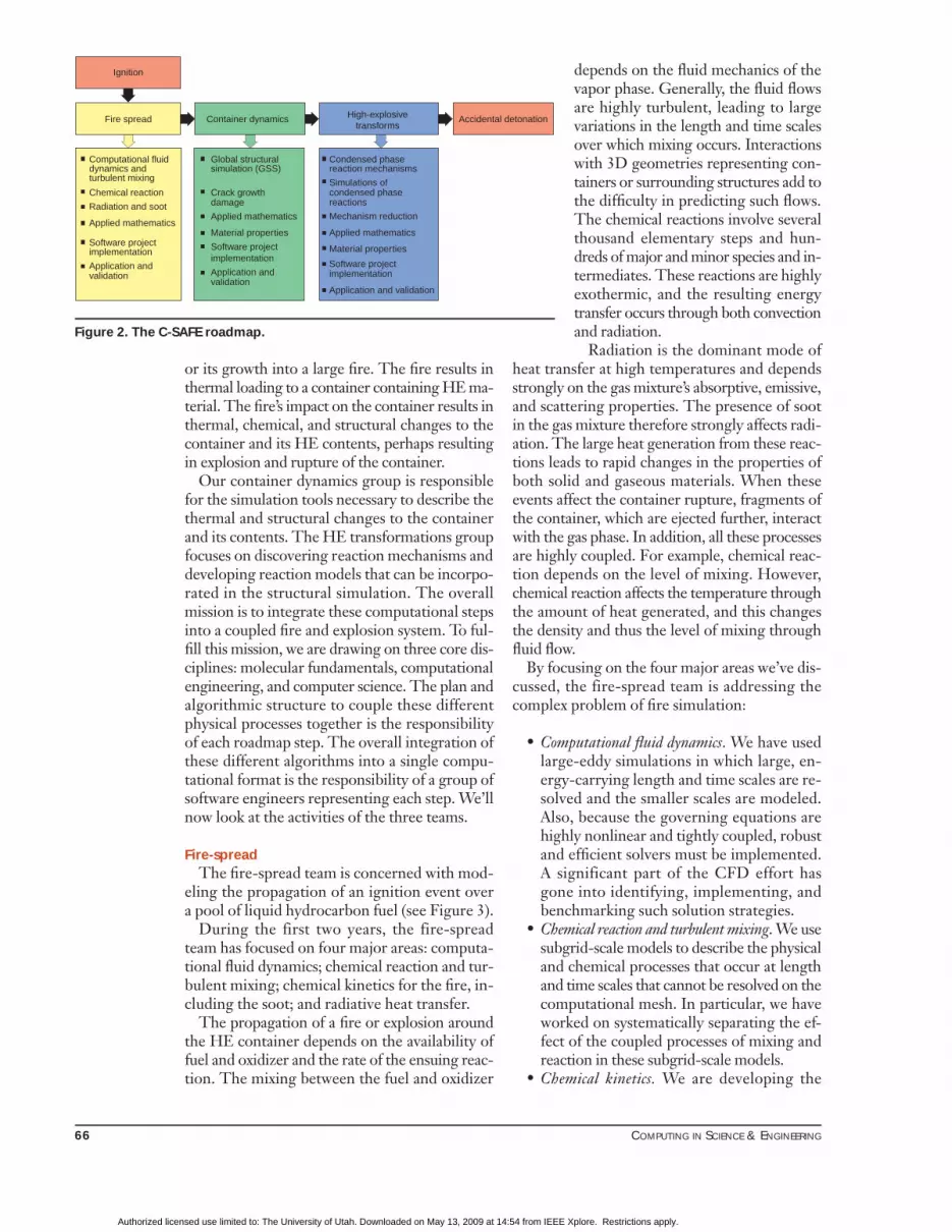
C-SAFE is organized, in part, to mirror thephysical processes that a large-scale simulation ofenergetic materials in fires must account for. Fig-ure 2 illustrates this structure with a simulation de-velopment roadmap, consisting of three distinct,sequential steps that parallel the events in thephysical problem: ignition and fire-spread, con-tainer dynamics, and high-energy (HE) transfor-mations. A fire or explosion initiates with an igni-tion event (which is assumed to occur and which isnot computed in detail). The fire spread compu-tations define the extinction of an ignition event
Figure 1. A field test illustrating the explosion of containedenergetic material caused by heating from a propane fire.
Authorized licensed use limited to: The University of Utah. Downloaded on May 13, 2009 at 14:54 from IEEE Xplore. Restrictions apply.
66 COMPUTING IN SCIENCE & ENGINEERING
or its growth into a large fire. The fire results inthermal loading to a container containing HE ma-terial. The fire’s impact on the container results inthermal, chemical, and structural changes to thecontainer and its HE contents, perhaps resultingin explosion and rupture of the container.
Our container dynamics group is responsiblefor the simulation tools necessary to describe thethermal and structural changes to the containerand its contents. The HE transformations groupfocuses on discovering reaction mechanisms anddeveloping reaction models that can be incorpo-rated in the structural simulation. The overallmission is to integrate these computational stepsinto a coupled fire and explosion system. To ful-fill this mission, we are drawing on three core dis-ciplines: molecular fundamentals, computationalengineering, and computer science. The plan andalgorithmic structure to couple these differentphysical processes together is the responsibilityof each roadmap step. The overall integration ofthese different algorithms into a single compu-tational format is the responsibility of a group ofsoftware engineers representing each step. We’llnow look at the activities of the three teams.
Fire-spreadThe fire-spread team is concerned with mod-
eling the propagation of an ignition event overa pool of liquid hydrocarbon fuel (see Figure 3).
During the first two years, the fire-spreadteam has focused on four major areas: computa-tional fluid dynamics; chemical reaction and tur-bulent mixing; chemical kinetics for the fire, in-cluding the soot; and radiative heat transfer.
The propagation of a fire or explosion aroundthe HE container depends on the availability offuel and oxidizer and the rate of the ensuing reac-tion. The mixing between the fuel and oxidizer
depends on the fluid mechanics of thevapor phase. Generally, the fluid flowsare highly turbulent, leading to largevariations in the length and time scalesover which mixing occurs. Interactionswith 3D geometries representing con-tainers or surrounding structures add tothe difficulty in predicting such flows.The chemical reactions involve severalthousand elementary steps and hun-dreds of major and minor species and in-termediates. These reactions are highlyexothermic, and the resulting energytransfer occurs through both convectionand radiation.
Radiation is the dominant mode ofheat transfer at high temperatures and dependsstrongly on the gas mixture’s absorptive, emissive,and scattering properties. The presence of sootin the gas mixture therefore strongly affects radi-ation. The large heat generation from these reac-tions leads to rapid changes in the properties ofboth solid and gaseous materials. When theseevents affect the container rupture, fragments ofthe container, which are ejected further, interactwith the gas phase. In addition, all these processesare highly coupled. For example, chemical reac-tion depends on the level of mixing. However,chemical reaction affects the temperature throughthe amount of heat generated, and this changesthe density and thus the level of mixing throughfluid flow.
By focusing on the four major areas we’ve dis-cussed, the fire-spread team is addressing thecomplex problem of fire simulation:
• Computational fluid dynamics. We have usedlarge-eddy simulations in which large, en-ergy-carrying length and time scales are re-solved and the smaller scales are modeled.Also, because the governing equations arehighly nonlinear and tightly coupled, robustand efficient solvers must be implemented.A significant part of the CFD effort hasgone into identifying, implementing, andbenchmarking such solution strategies.
• Chemical reaction and turbulent mixing. We usesubgrid-scale models to describe the physicaland chemical processes that occur at lengthand time scales that cannot be resolved on thecomputational mesh. In particular, we haveworked on systematically separating the ef-fect of the coupled processes of mixing andreaction in these subgrid-scale models.
• Chemical kinetics. We are developing the
Material properties
Applied mathematics
Mechanism reduction
reactionscondensed phase
Software project
Application and validation
implementation
dynamics andturbulent mixing
Chemical reaction
Condensed phaseComputational fluidsimulation (GSS)Global structural
Crack growth
Application and
damage
Container dynamicsFire spread
Applied mathematics
implementationSoftware project
Applied mathematics
Radiation and soot
Application and
Material properties
Software projectimplementation
validationvalidation
Ignition
High-explosivetransforms
Simulations of
reaction mechanisms
Accidental detonation
Figure 2. The C-SAFE roadmap.
Authorized licensed use limited to: The University of Utah. Downloaded on May 13, 2009 at 14:54 from IEEE Xplore. Restrictions apply.

MARCH/APRIL 2000 67
chemical-kinetic sets required for the mix-ing and reaction models in two ways. First,the fire-spread team has been building upall necessary tools for first-principles calcu-lations of reaction rates. Second, they havebeen collecting and refining the chemical-kinetic mechanisms developed by leadingresearchers from around the world.
• Radiative heat transfer. We are developingtwo radiation models: discrete ordinates andMonte Carlo methods.
Container dynamicsThe container dynamics team is addressing
the mechanical and thermal response of struc-tures in the fires, including phase transforma-tions and their corresponding energetics. Wehave devoted our first two years’ effort primarilyto global structural simulation and material re-sponse. Together with the fire spread team, wehave selected a one-mesh–integrated-solutionapproach based on the material point method(MPM). The team has formulated a frameworkto treat the solid-to-gas chemical conversion,created and evaluated an initial MPM code, andintegrated it into the PSE. The material re-sponse efforts have focused on determining ma-terial properties through molecular-dynamicssimulations, explicit treatment of cracks througha dynamic-fracture approach, and microme-chanics modeling to bridge the information ob-tained from the molecular simulations and thecontinuum level.
In a Lagrangian finite-element approach, theconvenient treatment of many of the issues justmentioned is problematic. To deal with the largedeformations that structures will experience onhigh loading (such as explosions) and consideringtightly coupling the structural aspects of the sim-ulation to the fire, we selected the MPM. We weresignificantly influenced by the work at Los AlamosNational Laboratory simulating multimaterialflows and fluid–structure interaction,1 and by re-cent MPM developments and extensions.2,3
The MPM is a type of particle-in-cell methodfor simulating problems involving large defor-mations of history-dependent materials. Forproblems that involve large deformations, theconstitutive equations are history dependent, sothat material points must be followed. Tradi-tional Lagrangian formulations (such as finite-element methods) exhibit difficulties with largedeformations that can lead to mesh lockup andentanglement. The MPM avoids this difficultyby describing the complete material state vector
on discrete mass points distributed throughoutthe computational domain so as to accuratelyrepresent the material state.
The original particle-in-cell approach in-volved representing fluid by Lagrangian masspoints on a fixed or adaptive grid.4 The approachsuccessfully tracked interfaces in highly distort-ing flows but exhibited high levels of numericaldissipation, because only the mass distributionwas treated in the material-point frame. This ap-proach’s dissipative properties have been signif-icantly improved by increasing the informationcarried by the particles to the complete state vec-tor. 5 In this extension, the grid no longer con-tains the essential information of the flow, but isused as a computational scratch pad to assist inthe updating of particle information. There arethus no direct particle–particle interactions. Alleffects of material interactions take placethrough the grid. This full-particle-in-cell ap-proach was subsequently adapted to treat sus-pension flows that included elastic particles.6
With the extension of the method to include his-tory-dependent materials (for example, plastic-ity), this technique has come to be known as thematerial-point method. 7
Figure 3. A large-eddy simulation of a 20-m-diameter hydrocarbonpool fire showing 3D mean temperature surfaces (top) and a timesequence of 2D slices through the middle of the pool (bottom).
Authorized licensed use limited to: The University of Utah. Downloaded on May 13, 2009 at 14:54 from IEEE Xplore. Restrictions apply.

68 COMPUTING IN SCIENCE & ENGINEERING
Figure 4 displays simulation results of a pres-surized debond at the interface of concentriccylinders. The object represents a simplified 2Dslice of a rocket motor (case in blue, propellantin red). Initially, the two materials are perfectlybonded, and forces are applied to material pointsnear the bottom of the interface, normal to thesurfaces of each material. This pressurization isintended to be a simplified representation of thepropellant undergoing phase change from solidto gas because of high temperatures. These ap-plied forces, represented by the black arrows,grow in time, and eventually the normal compo-nent of the traction at the interface exceeds nom-inal bond strength between the two materials.When this happens, the debond propagates alongthe interface, as seen in the figure sequence.
Improvements to this simulation currently un-derway include more accurate constitutive mod-eling of the propellant to include damage andpossible viscoelastic response, and incorporationof rigorous fracture mechanics in the propellantand case. 3D simulations of similar configura-tions with plastic response and a continuumdamage model have been run on 1,024 proces-
sors on Blue Mountain atLANL.
Recently, C-SAFE re-searchers have incorporatedfracture and the generation ofnew surface into the MPM.The incorporation of crackgrowth requires a method-ology to impose discontinu-ous displacement and veloc-ity fields on the underlyingmesh. This is accomplishedby a special surface descrip-tion in the MPM that incor-porates a different particle →grid interpolation scheme if a
particle is identified to be in a surface cell. In ad-dition, high-stress gradients near crack tips ne-cessitate adaptive mesh and particle refinementto achieve sufficient resolution for accurate sim-ulations. Particle-refinement algorithms are alsorequired in nondamaged materials to ensure thatnumerical artifacts due to large deformations(leaving no particles in a cell) are avoided.
In our simulations, we base the treatment ofcrack growth on dynamic fracture analysis andthe energy release rate for crack propagation.The criterion for crack growth is when the en-ergy release rate, given by Equations 1 and 2, ex-ceeds the material toughness, Gc:
(1)
(2)
Here δα is the crack opening length, σ is thestress, u is the displacement, and GI and GII arethe energy release rates for mode 1 (normal) andmode 2 (shear) loading. The total energy releaserate is simply the sum of these two contributions.
G r r drII r r+ −→ ∫lim ( , ) ( , )δα θ
δα
δασ δα µ π0
0
1
20
G r r drI + −→ ∫lim ( , ) ( , )δα θθ θ
δα
δασ δα µ π0
0
1
20
0
5
10
15
20
Y
0 Z
0 5 10 15 20
X
Y
Z
Frame 001 1 Sep 1999 Time Step # 100Frame 001 1 Sep 1999 Time Step # 100
0
5
10
15
20Y
0 Z
0 5 10 15 20
X
Y
Z
37545.135579.53361431648.529682.927717.425751.923786.421820.819855.317889.815924.213958.711993.210027.68062.126096.594131.062165.53200
Von MisesStress
Frame 001 1 Sep 1999 Time Step # 1100Frame 001 1 Sep 1999 Time Step # 1100
0
5
10
15
20
Y
0 Z
0 5 10 15 20
X
Y
Z
11337510741810146295505.389548.783592.277635.67167965722.459765.853809.247852.741896.135939.529982.924026.318069.712113.26156.58200
Von MisesStress
Frame 001 1 Sep 1999 Time Step # 1250Frame 001 1 Sep 1999 Time Step # 1250
0
5
10
15
20
Y
0 Z
0 5 10 15 20
X
Y
Z
24745.123453.222161.420869.519577.718285.81699415702.114410.313118.511826.610534.89242.927951.076659.235367.384075.542783.691491.85200
Von MisesStress
Frame 001 1 Sep 1999 Time Step # 1050Frame 001 1 Sep 1999 Time Step # 1050
Figure 4. Simulation of a pres-surized spot at the interfacialsurface of a propellant-filledcontainer. As this simulatedpressure increases, the twoinitially bonded materials sep-arate and the pressurized sur-face propagates along the in-terface. Color map in framesb–d indicate Von Mises stress;arrows represent appliedforces (simulated pressure).(a) (b)
(c) (d)
Authorized licensed use limited to: The University of Utah. Downloaded on May 13, 2009 at 14:54 from IEEE Xplore. Restrictions apply.

MARCH/APRIL 2000 69
The essential element to correctly predictcrack growth in this approach is an accuratevalue of the energy release rate. Simulations per-formed in C-SAFE demonstrated the MPM’sability to capture this behavior from MPM sim-ulations for the energy release rate in a doublecantilever beam. Figure 5 shows the MPM re-sults on a coarse mesh, using a lumped-mass ma-trix formulation. In this case, the MPM resultsunderpredict the exact solution (given by thestraight line). When we used mesh adaptivityand a full-mass matrix, we obtained the exact re-sult. We achieved this result using a dynamicanalysis. We incorporated damping into the con-stitutive model, which let the solution relax tothe static result. Figure 5 shows results in eachcase for two different values of the damping co-efficient µ.
We used a hierarchical tree-structured MPMcell description to achieve adaptivity in this sim-ulation. Refinement was based on the gradientof internal-energy density (kinetic-energy den-sity + strain-energy density).
High-energy transformationsOur high-energy transformations team per-
forms microscale analysis of the relevant physicaland chemical processes. They are focusing initiallyon the HMX energetic material and are directingtheir efforts at coupling molecular dynamics, elec-tronic structure, and statistical mechanics in an in-tegrated fashion to dynamically obtain propertiesfor all materials (condensed phases, vaporizedphases, and structures) in the fire and explosion.Initial work has focused on quantum chemistrycalculations for dimethylnitramine (DMNA) (be-cause it is a reasonable but simpler chemicalmodel for HMX; quantum chemistry calculationsof HMX in both the gas and condensed phases,embedded cluster computations for crystallinematerials, classical molecular-dynamics calcula-tions of DMNA, HMX, and polymer binders;and investigation of reduced kinetic mechanisms.The team has also been adapting their kineticscodes to simulate transient combustion kineticsand developing new methods for evaluating ex-isting thermal-analysis data.
We have used conventional quantum chem-istry codes (Gaussian) to compute differentpossible reaction mechanisms in DMNA andHMX using the B3LYP level of density-func-tional theory (DFT). For DMNA, which is amodel system of HMX, the N-N bond energyhas been determined. Scission of the N-Nbond is believed to be the initial step in de-
composition of most nitramines, includingDMNA and HMX. For DMNA, the computedvalue of 45.8 kcal/mol compares favorably withthe experimental value of 43.5 kcal/mol. Thisprovides a high level of confidence for the the-oretical DFT methods that will be used in fu-ture calculations. At the same level of theory,the N-N bond dissociation energy of HMX ispredicted to be 35.9 kcal/mol (including the ef-fect of zero-point vibrational energy). The gasphase has no barrier to dissociation, suggest-ing that N-N bond scission in condensedHMX is highly reversible.
The HMX molecule forms an eight-sided ringwith two possible conformations (boat or chair,as shown in Figure 6a and 6b). We investigatedthe C-N bond dissociation of the ring as anotherpossible reaction mechanism of HMX in a con-densed phase. For gas-phase calculations of thismechanism, we find that a stable 10-sided ringintermediate is formed, as Figure 6c shows. Thisintermediate is only 11.4 kcal/mol higher in en-ergy than that of the ground-state energy, andcan present itself as an energetically possiblemechanism in a condensed-phase environment.
2.5
2.0
1.5
1.0
0.5
0.0
G/G
ref
140120100806040200t/t ref
Static result
µ = 0.1
µ = 0.05
2.5
2.0
1.5
1.0
0.5
0.0
G/G
ref
140120100806040200t/t
(a)
(b) ref
Static result
µ= 0.2
µ = 1
Figure 5. Ener-gy release rateresults forstatic-fractureanalysis: (a)fixed-grid,lumped massmatrix (straightline is exact re-sult); (b) adap-tive-grid, full-mass matrix.
(a)
(b)
Authorized licensed use limited to: The University of Utah. Downloaded on May 13, 2009 at 14:54 from IEEE Xplore. Restrictions apply.

70 COMPUTING IN SCIENCE & ENGINEERING
The transition state structure between this in-termediate and the ground-state structure yieldsan energy barrier of 48.4 kcal/mol, which is only
11.6 kcal/mol higher in energy than the N-NO2bond dissociation energy.
For HMX, we found that the known accelera-tion of the reaction to a maximum rate at ap-proximately 40% conversion is not due to a de-crease in activation energy, as might be expectedfor a mechanism involving chemical autocataly-sis. Rather, the activation energy is constant withthe extent of reaction, and the acceleration canbe attributed to the reaction model. In essence,the acceleration is caused by the increase in sur-face area of HMX crystals as they are consumed.We have obtained experimental evidence for thisin the form of scanning electron micrographs ofpartially decomposed HMX crystals (see Figure7). These micrographs show that the HMX crys-tals maintain a nearly constant size during ther-mal degradation below the melting point. How-ever, they develop a high degree of porosity thatmakes them resemble sponges.
This kinetic analysis inspired the developmentof a new global model of nucleation kinetics. Inthis model, the thermal decomposition of eachHMX is activated by being located at the surfaceof a crystal or near a spatial defect in the crystal.Although this model is still under development,it shows great promise for providing one con-nection between the microscopic molecular-dynamics simulations and the macroscopic worldof laboratory experiments and combustion en-vironments. This type of process will let us bringtogether models connecting vast time and lengthscales for synthesis, validation, and eventual usein the large-scale fire simulation that is C-SAFE’s ultimate goal.
Computer science and applied math
The computational efforts described in thesethree major steps discussed so far are integratedthrough a strong program emphasis in computerscience and applied math. The computer scienceteam has concentrated efforts in four primary ar-eas: the PSE, visualization, performance, and sci-entific data management. Because the lengthscales we will attempt to resolve in a simulationwill vary over at least five orders of magnitude,the applied math group has focuses on AMR androbust numerical solvers. (The relevant physicsvaries over a much wider range of scales—frommolecular scales to macroscopic scales of metersor more. So, the development of subgrid bridg-ing models from the micromacro range is re-quired to achieve practical range of length scaleseven on massively parallel machines.)
C1
N3
N5
C3N7
C4
N4
C2
N1 O3
N8
N6
N2
O4
O1O2(c)
O7O8
O5
O6
Figure 6. TheHMX molecule:(a) boat form,(b) chair form,and (c) stable 10-sided ring inter-mediate form.
Figure 7. Micrographs of partially decomposed HMX crystals: unre-acted HMX (left), after 50% decomposition (center), and after 80%decomposition (right).
(a)
(b)
(c)
Authorized licensed use limited to: The University of Utah. Downloaded on May 13, 2009 at 14:54 from IEEE Xplore. Restrictions apply.
MARCH/APRIL 2000 71
The PSEAs one of its major goals, C-SAFE will develop
a computational framework within which the dis-parate aspects of the system can come together inan efficient and scalable way. In addition, we areseeking to exploit special opportunities to achievescalability within the distinct steps (such as thehigh-energy transformation group’s molecular-dynamics calculations). The C-SAFE architectureis fairly unique in that it will be implemented di-rectly in the PSE. Modules such as resource man-agement, parallel services, and performance analy-sis will be services provided by Uintah. Othermodules, notably all of the simulation modules,will be components in the Uintah PSE and will beconnected into active simulation scripts using a vi-sual-programming paradigm.
The Uintah PSE is building on the CommonComponent Architecture, which is being definedby the CCA Forum. The CCA Forum is a groupof researchers from national labs and academicinstitutions who are defining a standard for high-performance computing using components.8 Un-der this model, Uintah components will interop-erate with other CCA-compliant components.
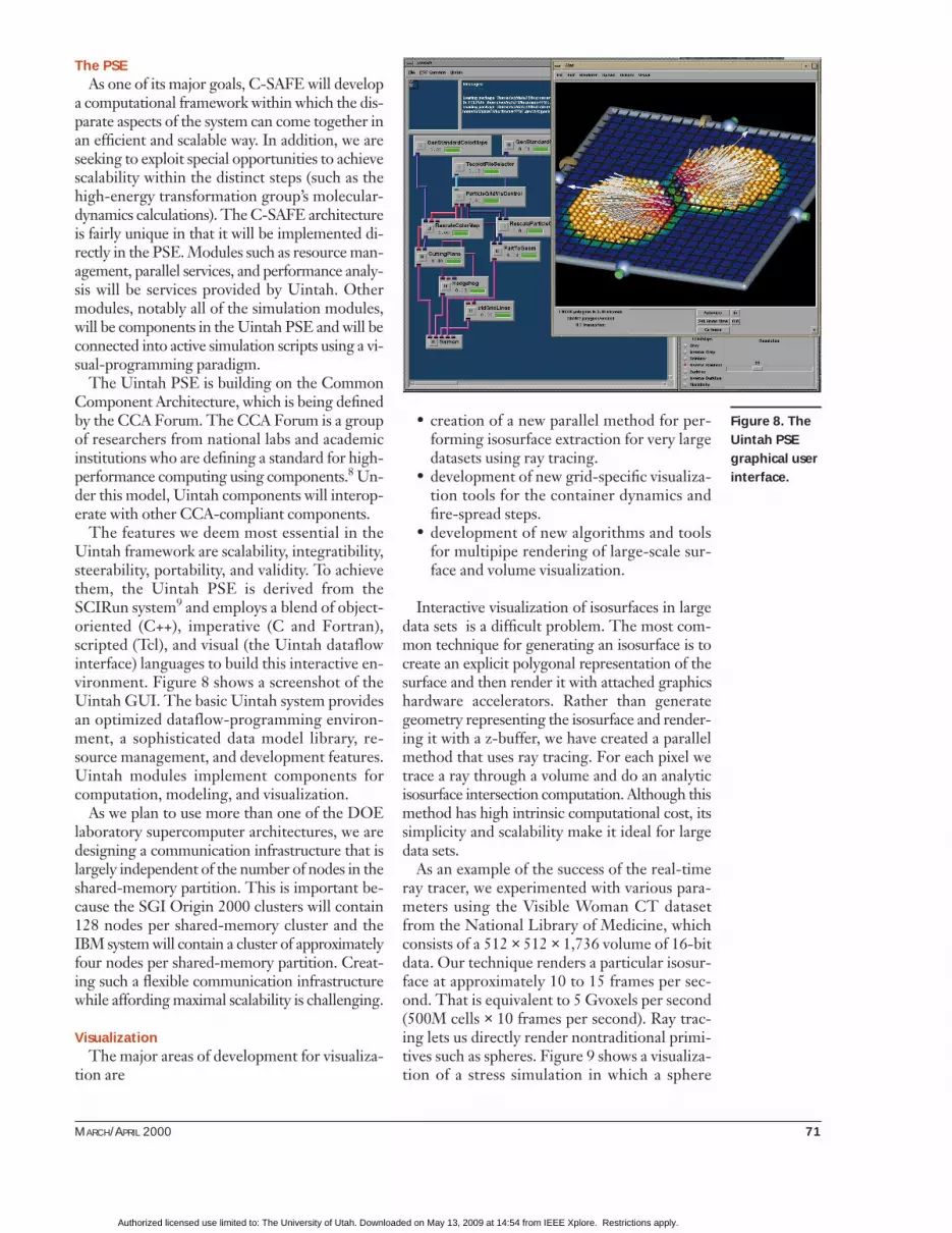
The features we deem most essential in theUintah framework are scalability, integratibility,steerability, portability, and validity. To achievethem, the Uintah PSE is derived from theSCIRun system9 and employs a blend of object-oriented (C++), imperative (C and Fortran),scripted (Tcl), and visual (the Uintah dataflowinterface) languages to build this interactive en-vironment. Figure 8 shows a screenshot of theUintah GUI. The basic Uintah system providesan optimized dataflow-programming environ-ment, a sophisticated data model library, re-source management, and development features.Uintah modules implement components forcomputation, modeling, and visualization.
As we plan to use more than one of the DOElaboratory supercomputer architectures, we aredesigning a communication infrastructure that islargely independent of the number of nodes in theshared-memory partition. This is important be-cause the SGI Origin 2000 clusters will contain128 nodes per shared-memory cluster and theIBM system will contain a cluster of approximatelyfour nodes per shared-memory partition. Creat-ing such a flexible communication infrastructurewhile affording maximal scalability is challenging.
VisualizationThe major areas of development for visualiza-
tion are
• creation of a new parallel method for per-forming isosurface extraction for very largedatasets using ray tracing.
• development of new grid-specific visualiza-tion tools for the container dynamics andfire-spread steps.
• development of new algorithms and toolsfor multipipe rendering of large-scale sur-face and volume visualization.
Interactive visualization of isosurfaces in largedata sets is a difficult problem. The most com-mon technique for generating an isosurface is tocreate an explicit polygonal representation of thesurface and then render it with attached graphicshardware accelerators. Rather than generategeometry representing the isosurface and render-ing it with a z-buffer, we have created a parallelmethod that uses ray tracing. For each pixel wetrace a ray through a volume and do an analyticisosurface intersection computation. Although thismethod has high intrinsic computational cost, itssimplicity and scalability make it ideal for largedata sets.
As an example of the success of the real-timeray tracer, we experimented with various para-meters using the Visible Woman CT datasetfrom the National Library of Medicine, whichconsists of a 512 × 512 × 1,736 volume of 16-bitdata. Our technique renders a particular isosur-face at approximately 10 to 15 frames per sec-ond. That is equivalent to 5 Gvoxels per second(500M cells × 10 frames per second). Ray trac-ing lets us directly render nontraditional primi-tives such as spheres. Figure 9 shows a visualiza-tion of a stress simulation in which a sphere
Figure 8. TheUintah PSEgraphical userinterface.
Authorized licensed use limited to: The University of Utah. Downloaded on May 13, 2009 at 14:54 from IEEE Xplore. Restrictions apply.

72 COMPUTING IN SCIENCE & ENGINEERING
represents each of the 35 million nodes.The visualization group has interacted closely
with the container-dynamics team to develop aUintah PSE visualization tool for MPM particleand mesh visualizations (see Figure 8). MPMuses both gridless (particles) and grid-basedcomputational data structures. Our tool allowsvisualization of both types of data structures byexploiting spatial coherence displayed all in thesame space, as well as temporal coherence pro-vided by differing time steps.
Performance analysisExisting performance-monitoring tools pro-
vide relatively poor support for tuning highlyparallel programs on modern computing plat-forms. In particular, they do not provide infor-mation about crucial communication issues, andin the case of shared-memory machines, they donot provide information about the locality ofmemory reference. Existing tools also provide anextremely clumsy user interface, which makesthem hard to use. More importantly, they collecthuge amounts of data but provide no support tohelp the user understand the aggregate meaningof the data and to reason about the consequencesof algorithmic design decisions. Furthermore,the PSE tools and the performance-tuning toolsheretofore have been separate environments, solarge parallel codes utilize a small fraction of thelarge terascale machines’ peak performance. Also,most applications programmers do not thor-oughly understand the host machine’s architec-ture or what those details might mean in termsof structuring codes for optimal performance.
The C-SAFE performance-analysis effort is cre-ating a performance tool suite that will be tightly
integrated into the Uintah PSE and that uses thevisualization tools to view performance data usedto analyze the programs once they are optimized.The tool development is based on a detailed un-derstanding of the underlying architecture and itseffect on the program’s performance.
Applied mathThe major areas of work here are AMR, time
integration, the solution of very-large-scale lin-ear and nonlinear systems, and sensitivity analysis.
Our work on AMR focuses on structuredAMR (SAMR) because these methods allow reg-ular array access patterns and require no indirectaddressing, and thus better utilize available cacheand memory bandwidth. In addition, the meshoperations needed for parallel implementationare greatly simplified. Finally, AMR methods areinherently dynamic algorithms. Migration ofpatches among processors is necessary to achievea load-balanced computation. Therefore, we willneed mechanisms to estimate local computa-tional loads, share these estimates among proces-sors, rebalance the load, and remap the data.
In the first two years, C-SAFE has been build-ing on top of the SAMRAI (Structured AdaptiveMesh Refinement) code developed at LLNL.SAMRAI provides more comprehensive high-level support for SAMR algorithms. For example,SAMRAI offers packages that implement strate-gies for subcycling in time that are needed for ex-plicit time integration on SAMR grids. Automaticregridding in time is based on Richardson extrap-olation and in space on detection of gradients inthe solution. User-supplied criteria can also drivethese processes. SAMRAI explicitly supports cell-centered, vertex-centered, and staggered data.
For a general-purpose solver library, we havechosen PETSc, developed at Argonne NationalLaboratory. This suite of high-level codes solveslarge-scale linear and nonlinear equations. Tovalidate the solver strategies in PETSc, wetested the code on a model problem that is rep-resentative of problems to be addressed later inC-SAFE simulations. Specifying a temperaturegradient across the cavity induces a thermallydriven flow in a 2D cavity. We tested a multi-grid solver that was almost 40 times faster thanthe single-grid solver that is in use; these prob-lems are representative of pool fire scenarios.Finally, we have worked extensively to formu-late solver strategies that will guide develop-ment of the core nonlinear solver in the UintahPSE. Effective solvers for problems discretizedon block-structured adaptive grids take advan-
Figure 9. Asimulation ofcrack propa-gation visual-ized using35M spheres.This image at512 × 512 pix-els runs ap-proximately15 frames persecond on 60CPUs.
Authorized licensed use limited to: The University of Utah. Downloaded on May 13, 2009 at 14:54 from IEEE Xplore. Restrictions apply.

MARCH/APRIL 2000 73
tage of the grid’s hierarchical nature. Thesesolvers employ multilevel algorithms, whichtreat local problems defined on regions withuniform mesh size. The level solver’s qualitythus determines the multilevel solver’s effec-tiveness. Because a refinement level is the arbi-trary union of rectangular patches, we exploredthese issues by studying problems defined on in-dividual patches.
Software engineeringBecause software engineering is a major aspect
of the project, we plan to have a software engi-neer in each of the simulation developmentroadmap steps (fire-spread, container dynamics,and high-energy transformations), as well as inthe computer science task. Each software engi-neer has two major duties: oversee software de-velopment within the step or task and help mi-grate step modules into the common Uintah PSE.An advisory committee established to managesoftware development will have responsibility forthe overall definition of the Uintah software ar-chitecture, module creation, and migration, andthe adoption and monitoring of software devel-opment and implementation standards. We par-ticipate in the ASCI TriLab Data Models andFormats group, which has been developing acomprehensive underlying mathematics for sci-entific data description, and we have been devel-oping tools to help scientists organize and keeptrack of large-scale simulations involving largenumbers of configuration parameters and datasetsused as input to various software versions of thetask codes, possibly on heterogeneous architec-tures with concomitant visualizations.
See the “Unique features” sidebar for our dis-cussion of the steps we will take on this project incoming years.
Beyond the five years of the current pro-gram, our long-term vision is to be ableto handle large-scale accident scenar-ios, involving, for example, fires in in-
dustrial buildings, effects of explosions and shockwaves on surrounding structures, and combus-tion initiated by impact.
AcknowledgmentsWe thank Ann Torrence as well as all the members of theC-SAFE project team for their valuable contributions. Closecollaborations with DoE laboratory scientists have beenessential in the C-SAFE progress. The US Department ofEnergy supports this work under grant W-7405-ENG-48.
References1. B.A. Kashiwa et al., A Cell-Centered Ice Method for Multiphase Flow
Simulations, Tech. Report LA-UR-93-3922, Los Alamos Nat’l Lab-oratory, Los Alamos, N.M., 1993.
2. D. Sulsky, Z. Chen, and H.L. Schreyer, “A Particle Method forHistory-Dependent Materials,” Computational Methods for Ap-plied Mechanical Eng., Vol. 118, 1994, pp. 179–196.
3. B. Sulsky, S. Zhou, and H.L. Schreyer, “Application of a Particle-in-Cell Method to Solid Mechanics,” Computational PhysicsComm., Vol. 87, 1995, pp. 236–252.
4. F.H. Harlow, “The Particle-in-Cell Computing Method for FluidDynamics,” Methods for Computational Physics, Vol. 3, B. Adler, S.Fernbach, and M. Rotenburg, eds., Academic Press, 1964, pp.319–343.
5. J.U. Brackbill and H.M. Ruppel, “Flip: A Low-Dissipation, Parti-cle-in-Cell Method for Fluid Flows in Two Directions,” J. Compu-tational Physics, Vol. 65, 1986, pp. 314–343.
6. B. Sulsky, S. Zhou, and H.L. Schreyer, “A Particle Method for His-tory-Dependent Materials,” Computational Physics Comm., Vol.118, 1994, pp. 179–196.
7. D. Sulsky and J.U. Brackbill, “A Numerical Method for Suspen-sion Flow,” J. Computational Physics, Vol. 96, 1991, pp. 339–368.
8. R. Armstrong et al., “Toward a Common Component Architec-ture for High Performance Scientific Computing,” Proc. EighthIEEE Int’l Symp. High Performance Distributed Computing, IEEEComputer Soc. Press, Los Alamitos, Calif., 1999, pp. 115–124.
9. S.G. Parker, D.M. Weinstein, and C.R. Johnson, “The SCIRunComputational Steering Software System,” Modern Software Toolsin Scientific Computing, E. Arge, A.M. Bruaset, and H.P. Langtan-gen, eds., Birkhauser Press, Basel, Switzerland, 1997, pp. 1–40.
10. B.A. Kashiwa, M.L. Lewis, and T.L. Wilson, Fluid-Structure Inter-action Modeling, Tech. Report LA-13111-PR, Los Alamitos Nat’lLaboratory, Los Alamos, N.M., 1996.
Thomas C. Henderson is a professor of computer sci-ence at the University of Utah. His professional inter-ests include artificial intelligence, computer vision, androbotics. He received his PhD in computer science fromthe University of Texas. He serves as coeditor-in-chief ofthe Journal of Robotics and Autonomous Systems. Con-tact him at the Univ. of Utah, Computer Science Dept.,50 S. Central Campus Dr., Rm. 3190, Salt Lake City, UT84112-9205; [email protected]; www.cs.utah.edu/~tch.tom.html.
Patrick A. McMurtry is an associate professor of me-chanical engineering at the University of Utah. He hasbeen investigating turbulent mixing processes, devel-oping new mixing models for turbulent flows, and de-vising new techniques to numerically simulate coupledfluid–structure interaction problems. He received hisPhD in mechanical engineering from the University ofWashington. Contact him at the Univ. of Utah, Dept. ofMechanical Eng., 50 S Central Campus Dr., Salt LakeCity, UT 84112-9205;[email protected].
Philip J. Smith is a professor in the Department ofChemical Engineering at the University of Utah. His re-search involves simulation of industrial combustion andreacting-flow processes. He received his PhD in chem-ical engineering from Brigham Young University. Con-
Authorized licensed use limited to: The University of Utah. Downloaded on May 13, 2009 at 14:54 from IEEE Xplore. Restrictions apply.

74 COMPUTING IN SCIENCE & ENGINEERING
tact him at the Univ. of Utah, Dept. of Chemical andFuels Eng., 380 INSCC, 155 S. 1452 E, Salt Lake City,UT 84112-9208; [email protected].
Gregory A. Voth is a professor of chemistry at the Uni-versity of Utah and director of the Henry Eyring Centerfor Computational Chemistry. His research interests in-clude theories of condensed-phase dynamical pro-cesses, proton and hydride transfer reactions in bio-logical and solution-phase systems, high-performancecomputer simulation and modeling, interfacial charge
transfer phenomena at metal and semiconductor elec-trodes, and the dynamics of atoms and molecules onmetal and semiconductor surfaces. He received hisPhD in theoretical chemistry from the California Insti-tute of Technology. Contact him at the Univ. of Utah,Chemistry Dept., 315 S. 1400 East, Salt Lake City, UT84112-0850; [email protected].
Charles A. Wight is a professor of chemistry at the Uni-versity of Utah. His research group carries out experi-mental and computational-modeling studies of ther-
Unique featuresThe C-SAFE program has four unique features that we
have further amplified during our project’s first phase:
• A one-mesh–integrated-solution approach tointegrating the fire with the container and its high-energy contents.
• The inclusion of first-principles molecular dynamicscalculations to compute the fundamental chemistryof the high-energy materials and other reactants un-der specific conditions of the problem.
• Computational steering and system utilization analy-sis in conjunction with an advanced problem-solvingenvironment.
• Integration of experimental testing with actual high-energy materials from the program’s beginning.
One mesh–integrated solution
Owing to its combined Eulerian-Lagrangian treatment ofmass, MPM can combine with a Eulerian hydrocode to pro-vide explicit coupling and treatment of fluid–solid inter-actions. We can do this by using the Eulerian CFD mesh asthe scratch pad mesh for evaluating particle transport pro-cesses in the MPM calculations.1 This combined Eulerian-Lagrangian description lets us treat a number of key physicalprocesses that are problematic in conventional applicationsof finite-volume or finite-element techniques individually.Besides the treatment of large deformations, these includephase transition, chemical transformations, multiple materi-als, interdiffusion, and interface splitting. The tight couplingresults from the use of a general multimaterial formulation(see Figure A) of the governing equations where individualmaterials can be described either in the Eulerian or material-point framework.
In addition to the equations in Figure A, any number ofindividual scalar equations can be associated with each ma-terial. For example, a gas-phase material can contain severalindividual chemical-species reaction-diffusion-convectionequations. Appropriate equations of state and constitutiverelations for material response must be supplied for eachmaterial.
The general multimaterial-continuum solution involves anumber of grid-based operations: using cell-centered, faced-centered, and vertex information (depending on the detailsof chosen solution algorithm). During the finite-volume solu-tion process of the multimaterial equations, we treat advec-tion, diffusion, and most of the source terms sequentially andindividually material-by-material. Coupling occurs directly
Mass
.(A)
(a) Net source of m mass due to phase change
Momentum
(B)
(a) Net source of m momentum due to mass conversion(b) Equilibration pressure(c) Gravitational body force(d) Average material stress(e) Momentum exchange among the different materials
Energy
(C)
(a) Net source of m energy due to mass conversion(b) Average multiphase work(c) Average viscous dissipation(d) Thermal transport by conduction(e) Energy exchange among the different materials
∂∂
+ ∇ = + +
− ∇ + −
⋅
∑
ρ ρ ρ α α τ ε
α θ θ
m mm o m o o m
a
m m
m
b
m o o
c
m o
d
m l m l ll
m
e
et
e U ep v
cp
q R T T
? r 67 4 8 4 6 7 4 8 4 6 7 4 8 4
? 1 2 4 3 4
1 2 4 4 4 4 3 4 4 4 4
( ) ( ) ( )
( )
,
( )
˙ :
( )
2 2
∂∂
+ ∇ = − ∇ +
+ ∇ + −
⋅
∑
ρ ρ ρ α θ ρ
α τ θ θ
m mm m m o m m
a
m p
b
m
c
m o
d
m i m ll
m
e
Ut
U U U g
K U U
r
? r r r 6 7 4 8 4 6 7 8 r }
? 1 2 4 3 4
r r
1 2 4 4 4 4 3 4 4 4 4
( ) ( ) ( )
( )
,
( )
( ) ( )1
∂∂
+ ∇ = ⋅ρ ρ ρ αmm m o m
a
tU? r 6 7 8 ( )
Figure A. Conservation equations of mass, momentum, and energyfor an individual material, m, in a multimaterial environment.
Authorized licensed use limited to: The University of Utah. Downloaded on May 13, 2009 at 14:54 from IEEE Xplore. Restrictions apply.

MARCH/APRIL 2000 75
mal-decomposition reactions in energetic materials(explosives and propellants). When all goes accordingto plan, all of this is accomplished on a milligram scale,without exploding or propelling anything about thelaboratory. He received his PhD in chemistry from theCalifornia Institute of Technology. Contact him at theUniv. of Utah, Chemistry Dept., 315 S. 1400 East, Rm.DOCK, Salt Lake City, UT 84112-0850.
David W. Pershing is Distinguished Professor ofChemical and Fuels Engineering at the University of
Utah and is currently serving as the senior vice presi-dent of academic affairs for the University. He has pub-lished extensively on the formation and control of pol-lutant emissions from fossil-fuel combustion and onthe incineration of solid waste materials. He is the di-rector of the DoE-funded Center for the Simulation ofAccidental Fires and Explosions (C-SAFE). He receivedhis PhD in chemical engineering from the University ofArizona. Contact him at the Univ. of Utah, 201 S. Pres-ident’s Circle, Rm. 205, Salt Lake City, UT 84112-9007;[email protected].
though energy and momentum exchange (the terms e inEquations B and C, which are modeled here through ex-change coefficients) and the overall pressure solution.
To couple the MPM techniques within a finite-volumemultimaterial simulation, the MPM simulation involves bothparticle- and grid-based operations. The state vector of thematerial particle descriptions can advance in parallel withthat of the Eulerian-based calculations. The fluid–structuresimulation becomes tightly coupled through mass, momen-tum, and energy exchange, along with a single-pressure solu-tion that occurs in a common reference frame. In particular,during the MPM solution, information is interpolated be-tween the material points and the mesh. As Figure B shows,at the point in the computation where the material points’force, mass, and velocity exist on the grid, the operationscommon to all phases (that is, the pressure solution andmass, momentum, and energy exchange) are computedsimultaneously.
Preliminary validation of the approach has appeared else-where.1 The initial studies included a solid object falling un-der the action of gravity in an initially quiescent flow fieldand the breaking of an interface between two fluids of dif-ferent density. Here we provide examples that illustrate the
solid-fluid coupling in applications relevant to the effects offires and explosions on structures.
Figure C shows an example of a three-material, tightlycoupled, fluid-structure interaction problem. The initialcondition consists of a deformable box (described by mate-rial points) filled with a reactive solid (described by materialpoints). This “container” is an elastoplastic material that re-sides in a gas-filled domain (Eulerian description). The initialtemperature is a constant value of 300 K throughout thedomain. The boundary temperature at the base of the con-tainer is set to a constant value of 400 K. The reactive mate-rial undergoes a temperature-dependent reaction describedby a progress variable that evolves according to temper-ature as dφ/dt = k exp(-Ea/RT) φ0.8(1 – φ) with the products ofreaction going to the gas-phase Eulerian description. As thesequence in Figure C shows, the conversion of reactive solidto gas results in a pressurization of the container, leading toits deformation and ultimate rupture. The figure clearly illus-trates the effect of this rapid deformation and escaping gaseson the ambient gas-phase field.
First-principles molecular-dynamics calculations
As we’ve described in the main text, the high-energy
Evaluate RHS quantities (e.g. mass,momentum, and energy sources)
Liquid phase (e.g. jet fuel)
Gas phase(e.g. air, COx, NOx)
Solid phase(e.g. steel)
Solid phase(e.g. HMX composite)
Map force, mass, and velocity to grid
Compute A and V on grid
Interpolate to particles
Do particle operations
Map force, mass, and velocity to grid
Compute A and V on grid
Interpolate to particles
Do particle operationsDo advection
Evaluate RHS quantities (e.g. mass,momentum and energy sources)
Do advection
Solve for a single pressure field on the grid.
Exchange mass, momentum and energy on the grid
Eulerian (CFD) Lagrangian (MPM)
Operations common to all phases computed simultaneously
Figure B. A graphical layout of combined Eulerian-MPM solution. Columns represent operations performed independently for each material.Simultaneous operations include mass, momentum, energy transport, and the pressure solution.
Authorized licensed use limited to: The University of Utah. Downloaded on May 13, 2009 at 14:54 from IEEE Xplore. Restrictions apply.

76 COMPUTING IN SCIENCE & ENGINEERING
transformation team is primarily responsible for generatingreliable subgrid-scale descriptions for the chemical-reactionrates and mechanisms for decomposition and combustion ofenergetic materials. The primary parallel-code developmenteffort is a scalable first-principles molecular-dynamics codebased on a local orbitals method. It will let us treat severalthousand HMX molecules for bridging to macroscale models.
Computational steering and system utilization analysis
The computer science and applied math teams willdevelop the Uintah PSE and explore MPI parallelism for Uin-tah. Another major goal is the incorporation of a SAMRAI-based version of MPM within Uintah. Scaling issues and visu-alization methods for the Uintah computation are beingdeveloped. Performance tools that perform data gathering inthe kernel so as to minimize overhead are under develop-ment, as is a visualization tool for performance data. Large-scale simulation management tools are being applied toproblems in C-SAFE. The applied math team is providingmethods for AMR, time integration, solution of very large-scale linear and nonlinear systems, the associated devel-opment of preconditioners and multigrid-multilevel tech-niques, sensitivity analysis, and stiff solvers.
Validation
We are conducting the validation effort at four levels ofcomplexity, starting with fundamental rates and properties,progressing through single-step, coupled-steps, and finally afully integrated multistep experiment.
The fundamental rates and properties needed in the sub-models for each task are primarily the responsibility of indi-vidual investigators, drawing extensively on the literatureand parallel efforts at the national laboratories. The valida-tion team, in conjunction with the computer science team,is exploring Web-accessible methods for comparing bothsubmodels and validation data with other groups aroundthe world working on similar problems. We are conductingpilot efforts with setting up the simpler submodels withshort runtimes from different research groups on a commonserver. As the sophistication level of the models to be com-pared increases, the comparison will need to run on remoteservers, with issues of runtime, access, and security needingto be resolved.
The single-step experiments are designed to answer keyquestions, which initially include
• determining the chemical structure of young soots, us-ing the specialized skills on solid-state nuclear magneticresonance (NMR) at the University of Utah to evaluatealternative hypotheses in the literature on the gas-solidconversion,
• studying the development of porosity in the compositeexplosive due to reactions that take place at the inter-
face between explosive and binder components, and • defining surrogate fuels to represent JP8 and other jet
fuels by mixtures of fuels for which the chemical kineticsare known. The surrogate mixtures must be able to re-produce all important physical and chemical parametersof the jet fuels, including the vapor pressure curves andthe sooting behavior.
Coupled-step experiments that are important for validatingthe integrated model include those addressing the processesoccurring at the interface of the container and the fire to ad-dress issues of the impact of soot deposition on the thermal-radiation boundary conditions. The coupled experiments willinvolve a container, excluding high explosives, placed in asmall-scale (about 1m diameter) pool fire. These experimentswill also provide soots of different maturity for the NMR stud-ies of soot structure and test the adequacy of the representa-tion of aviation fuels (JP4 and JP8) with surrogate fuels.
Finally, we will use the integrated experiments at Thiokolto test uncertain initial conditions, such as the bonding ofthe explosive to the container, as well as to provide phenom-enological observations on the container rupture and a first-order testing of the calculated time to explosion. (TheThiokol Propulsion Group is working with us on the testingof high-explosive materials engulfed in a pool fire.)
Reference1. B.A. Kashiwa et al., A Cell-Centered Ice Method for Multiphase Flow Simula-
tions, Tech. Report LA-UR-93-3922, Los Alamos Nat’l Laboratory, Los
Alamos, N.M., 1993.
Figure C. A sequence from a simulation of an exploding container.The container and its contents have a Lagrangian material-pointdescription. The Eulerian frame describes the surrounding air andproducts of reaction.
Authorized licensed use limited to: The University of Utah. Downloaded on May 13, 2009 at 14:54 from IEEE Xplore. Restrictions apply.
Related Documents