User Training Resource Simulate for Geomagic Design Click to Get Started

Welcome message from author
This document is posted to help you gain knowledge. Please leave a comment to let me know what you think about it! Share it to your friends and learn new things together.
Transcript
Table of Contents Forward Back
User Training Resource
Simulate for Geomagic Design Click to Get Started
Table of Contents Forward Back
Welcome
2
This training resource guide is intended to serve both as a
hands-on learning tool in becoming proficient with Simulate for
Geomagic Design and also as an on-demand reference guide
for accessing information on a specific feature or topic.
Additional help can be found in the program under the Help
menu.
The exercises that are blended within the content of this guide
may be completed in any order desired. However, to get the
most benefit from the exercises, it is suggested you start at the
beginning of the document, read each topic and do the
exercises in the order listed. This will help you better
understand the features in each exercise and also make you a
more proficient Simulate for Geomagic Design user.
Use the page back / forward and Table of Contents buttons to
navigate around the guide. You can also use the scroll wheel on
your mouse or the keyboard arrow keys.
Navigation tools
Table of Contents Forward Back
Table of Contents I
Bodies
Coords
26.Bodies (Material)
27.Bodies (Position and Orientation, Body C.S.)
28.Bodies (Prescribed Motion)
29.Bodies (Initial Conditions)
30.Bodies (Vectors)
31.Bodies (Collision)
33.Coords (Overview)
35.Coords (Detaching/Attaching)
36.Coords (Moving Constraints)
38.Coords (Assembling Bodies) Constraints
39.Constraints (Mapping of CAD constraints)
40.Constraints (Supported Assembly Constraints I)
41.Constraints (Supported Assembly Constraints II)
42.Constraints (Simulate for Geomagic Design)
43.Constraints (Kinematic)
46.Constraints (Degrees of Freedom or DOF)
47.Constraints (Activating/Deactivating)
48.Constraints (Creating) 3
7. Using the documentation
8. Product Overview
9. Classification of Mechanisms – Kinematics
10.Classification of Mechanisms – Dynamics
11.Associativity with Geomagic Design
12.User Interface (Overview)
25.User Interface (Properties List)
Introduction
Table of Contents Forward Back
Table of Contents II
Specialty Constraints
68.Power Transmission (Belts)
69.Power Transmission (Spur Gear)
70.Power Transmission (Bevel Gear)
71.Rod, Rope and Separator
72.Linear Spring/Damper
73.Revolute Spring/Damper
74.Bushings
75.Generic Constraint
Inputs
60. Inputs (Motors)
61. Inputs (Actuators)
62. Inputs (Function Builder)
63. Inputs (Data Tables)
64. Inputs (Interactive Controls)
Redundant Constraints
94.Degrees of Freedom (Background)
95.Redundant Constraints (Example)
96.Redundant Constraints (Parallel Mechanisms)
97.Redundant Constraints (The Problem)
98.Redundant Constraints (What you see vs. What you get)
99.Redundant Constraints (Preventing using Constraints)
100.Redundant Constraints (Preventing using Bushings)
102.Redundant Constraints (Summary)
Meters
65.Meters
4
Table of Contents Forward Back
Table of Contents III
FEA Modeling
147.Introduction
148.Geometry & Restraints
149.Mesh Elements
150.Mesh Element Quality
151.Mesh Control
152.Using Mesh Control
153.FEA Properties (initial mesh)
154.FEA Properties (initial mesh refinement)
155.FEA Accuracy Settings
156.H-Adaptivity Overview (automatic mesh refinement)
157.FEA Post Processing Tools
158.Distributing loads from constraints
159.Prepare a Stress Analysis
160.Assembly Bonding
161.Assembly Bonding (manual vs. automatic)
162.Splitting Faces for Restraint Application
163.Troubleshooting Meshing
Simulation Settings
103.Simulation Settings (Run Control & Playback)
104.Simulation Settings (Run Mode)
105.Simulation Settings (Configuration Tolerances)
108.Simulation Settings (Bond Tolerance)
109.Simulation Settings (Integration)
5
Table of Contents Forward Back
Table of Contents III Exercises
13.Exercise 1 – FourBar
76.Exercise 2 - Geneva Wheel
110.Exercise 3 – Gripper
164.Exercise 4 – Bracket Assembly
Click on an exercise below to see what is covered in that exercise.
6
Table of Contents Forward Back
Using the documentation
• In most instances there is more than one way to perform a task or access a feature. For example, there are at least four different ways to create a constraint. The approach shown in the examples may not be the only way to complete a task.
• Commands prompting for user action are listed in bold type. For example, right-select, choose and drag.
• Program feature names and objects that are to be accessed by the User are listed in bold blue type. For example, Structural Load, Face Normal and Solve FEA.
• General notes and tips, in bold smaller type, are found throughout the example problems. Notes give additional information or clarity on the particular task being performed. Tips offer alternative ways or short cuts to accomplish a task.
• You may find it easier and faster to manipulate the viewing of your model by using the mouse and keyboard:
Pan: Ctrl + press & hold mouse scroll button Zoom: Crtl +Shift + press & hold mouse scroll button Rotate: Press and hold mouse scroll button
• There are two products that make up the motion simulation and FEA tools in Geomagic: Simulate for Geomagic Design and Dynamics for Geomagic Design. This training document and all images within it were developed using Simulate for Geomagic Design. If you are using Dynamics for Geomagic Design, you may see subtle differences in a few dialog boxes, not enough to affect the training experience.
• Throughout much of this documentation, the title “Simulate for Geomagic Design” has been simplified to “Simulate”. So, you may see references to both titles, meaning the same product.
7
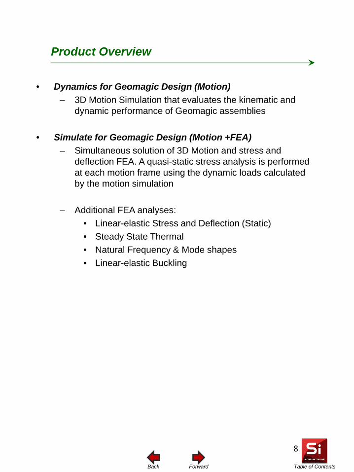
Table of Contents Forward Back
Product Overview
• Dynamics for Geomagic Design (Motion) – 3D Motion Simulation that evaluates the kinematic and
dynamic performance of Geomagic assemblies
• Simulate for Geomagic Design (Motion +FEA) – Simultaneous solution of 3D Motion and stress and
deflection FEA. A quasi-static stress analysis is performed at each motion frame using the dynamic loads calculated by the motion simulation
– Additional FEA analyses:
• Linear-elastic Stress and Deflection (Static) • Steady State Thermal • Natural Frequency & Mode shapes • Linear-elastic Buckling
8
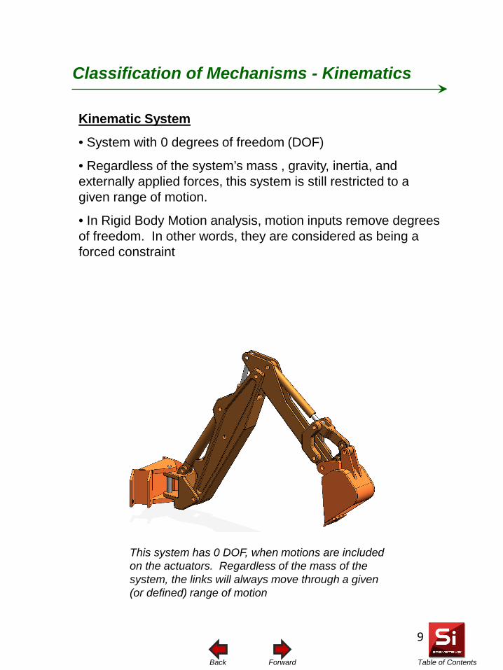
Table of Contents Forward Back
Classification of Mechanisms - Kinematics
Kinematic System
• System with 0 degrees of freedom (DOF)
• Regardless of the system’s mass , gravity, inertia, and externally applied forces, this system is still restricted to a given range of motion.
• In Rigid Body Motion analysis, motion inputs remove degrees of freedom. In other words, they are considered as being a forced constraint
This system has 0 DOF, when motions are included on the actuators. Regardless of the mass of the system, the links will always move through a given (or defined) range of motion
9
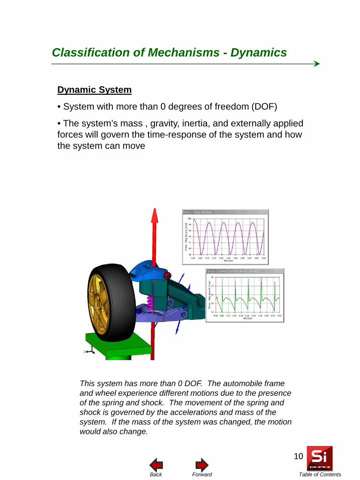
Table of Contents Forward Back
Classification of Mechanisms - Dynamics
Dynamic System
• System with more than 0 degrees of freedom (DOF)
• The system’s mass , gravity, inertia, and externally applied forces will govern the time-response of the system and how the system can move
This system has more than 0 DOF. The automobile frame and wheel experience different motions due to the presence of the spring and shock. The movement of the spring and shock is governed by the accelerations and mass of the system. If the mass of the system was changed, the motion would also change.
10
Table of Contents Forward Back
Associativity with Geomagic Design
• User initiates data transfer from within Geomagic Design • Geometry and constraints transferred to Simulate for
Geomagic Design • Constraints are mapped to corresponding motion constraints • If the Geomagic Design model is updated, only the changes
are transferred back to the motion model
• Simulate for Geomagic Design also supports direct reading of ACIS file formats
11
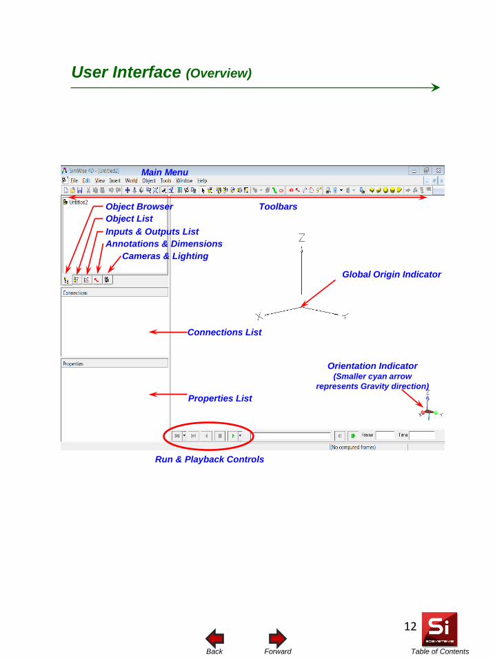
Table of Contents Forward Back
User Interface (Overview)
Main Menu
Toolbars Object Browser Object List Inputs & Outputs List
Cameras & Lighting Annotations & Dimensions
Connections List
Orientation Indicator (Smaller cyan arrow
represents Gravity direction) Properties List
Run & Playback Controls
Global Origin Indicator
12
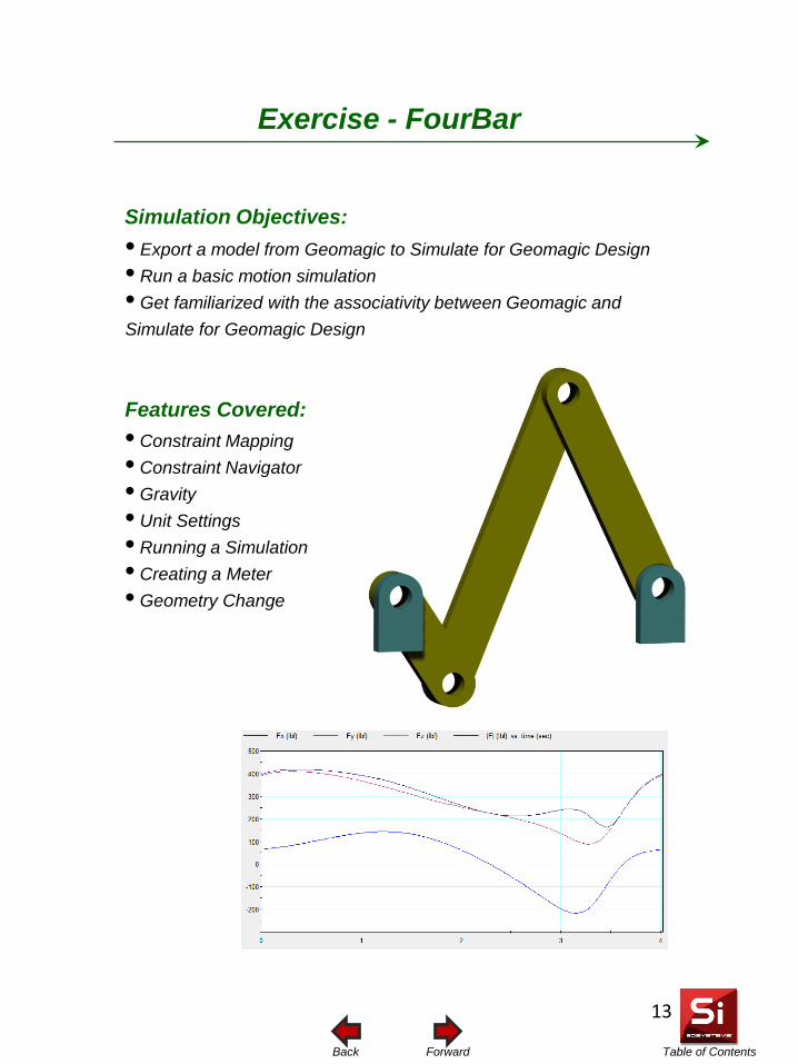
Table of Contents Forward Back
Simulation Objectives: • Export a model from Geomagic to Simulate for Geomagic Design • Run a basic motion simulation • Get familiarized with the associativity between Geomagic and Simulate for Geomagic Design
Features Covered:
Exercise - FourBar
• Constraint Mapping • Constraint Navigator • Gravity • Unit Settings • Running a Simulation • Creating a Meter • Geometry Change
13
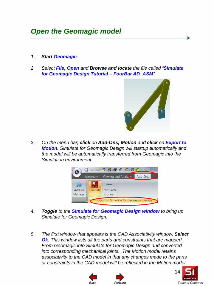
Table of Contents Forward Back
Open the Geomagic model
1. Start Geomagic
2. Select File, Open and Browse and locate the file called “Simulate for Geomagic Design Tutorial – FourBar.AD_ASM”.
3. On the menu bar, click on Add-Ons, Motion and click on Export to Motion. Simulate for Geomagic Design will startup automatically and the model will be automatically transferred from Geomagic into the Simulation environment.
4. Toggle to the Simulate for Geomagic Design window to bring up Simulate for Geomagic Design.
5. The first window that appears is the CAD Associativity window. Select Ok. This window lists all the parts and constraints that are mapped From Geomagic into Simulate for Geomagic Design and converted into corresponding mechanical joints. The Motion model retains associativity to the CAD model in that any changes made to the parts or constraints in the CAD model will be reflected in the Motion model
14
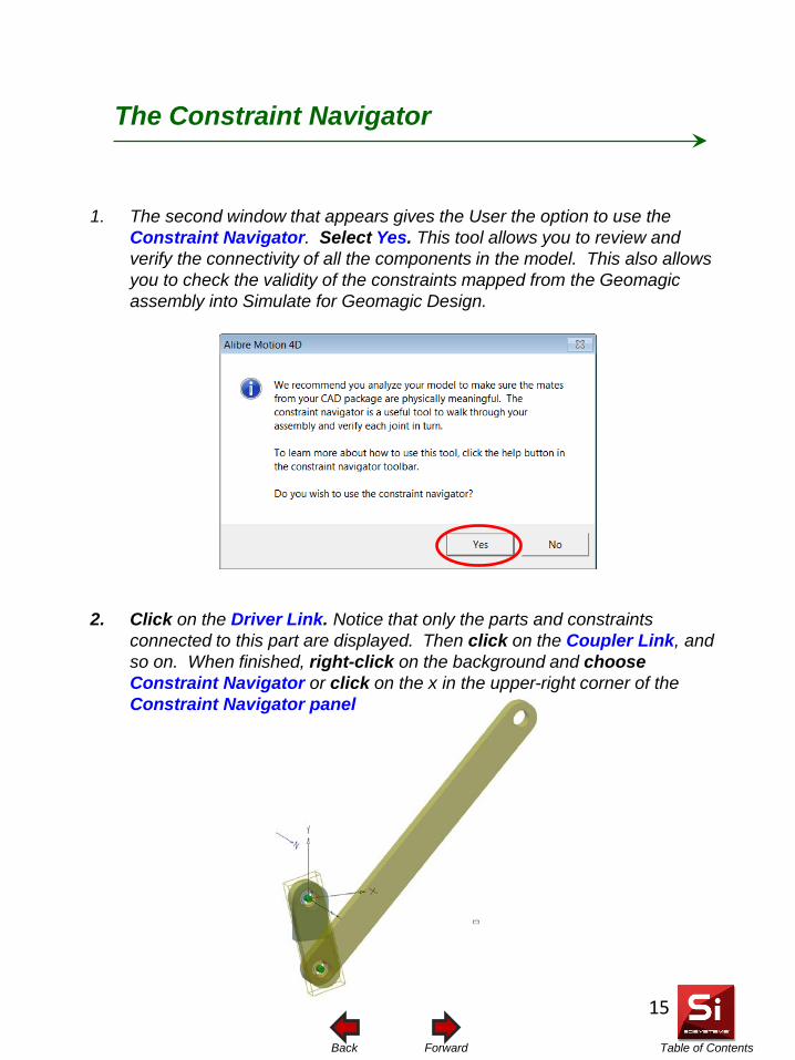
Table of Contents Forward Back
The Constraint Navigator
1. The second window that appears gives the User the option to use the Constraint Navigator. Select Yes. This tool allows you to review and verify the connectivity of all the components in the model. This also allows you to check the validity of the constraints mapped from the Geomagic assembly into Simulate for Geomagic Design.
2. Click on the Driver Link. Notice that only the parts and constraints connected to this part are displayed. Then click on the Coupler Link, and so on. When finished, right-click on the background and choose Constraint Navigator or click on the x in the upper-right corner of the Constraint Navigator panel
15
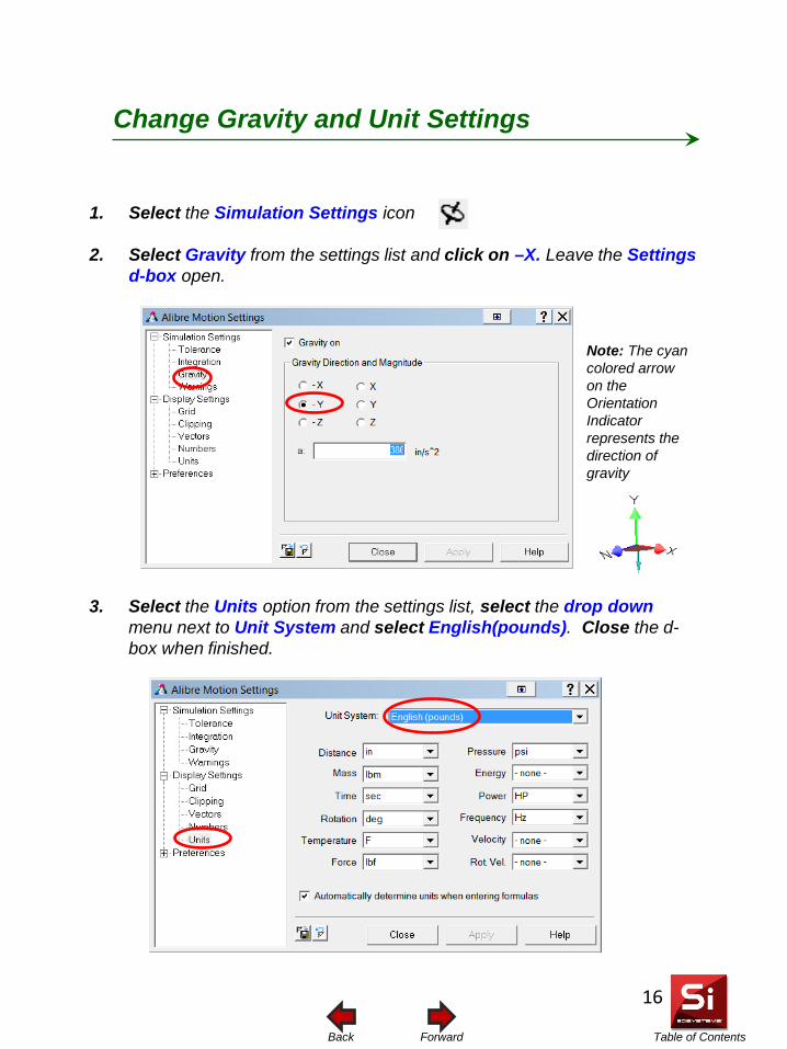
Table of Contents Forward Back
1. Select the Simulation Settings icon
2. Select Gravity from the settings list and click on –X. Leave the Settings d-box open.
3. Select the Units option from the settings list, select the drop down menu next to Unit System and select English(pounds). Close the d-box when finished.
Change Gravity and Unit Settings
Note: The cyan colored arrow on the Orientation Indicator represents the direction of gravity
16
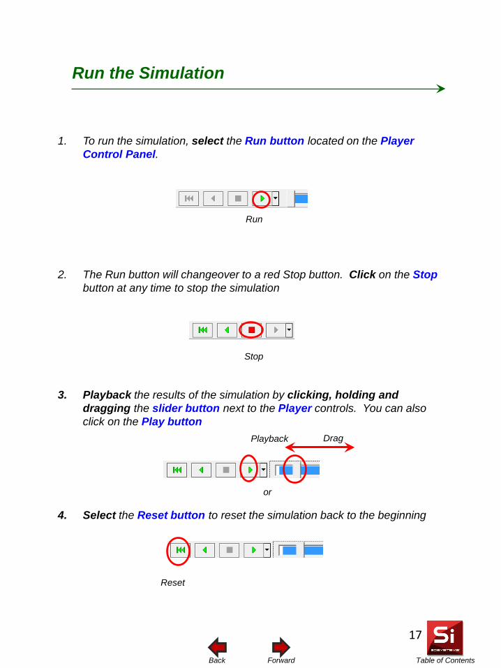
Table of Contents Forward Back
Run the Simulation 1. To run the simulation, select the Run button located on the Player
Control Panel.
2. The Run button will changeover to a red Stop button. Click on the Stop button at any time to stop the simulation
3. Playback the results of the simulation by clicking, holding and dragging the slider button next to the Player controls. You can also click on the Play button
4. Select the Reset button to reset the simulation back to the beginning
or
Run
Stop
Playback
Reset
Drag
17
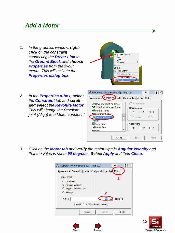
Table of Contents Forward Back
1. In the graphics window, right-click on the constraint connecting the Driver Link to the Ground Block and choose Properties from the flyout menu. This will activate the Properties dialog box.
Add a Motor
3. Click on the Motor tab and verify the motor type is Angular Velocity and that the value is set to 90 deg/sec. Select Apply and then Close.
2. In the Properties d-box, select the Constraint tab and scroll and select the Revolute Motor. This will change the Revolute joint (Align) to a Motor constraint
1
2
18
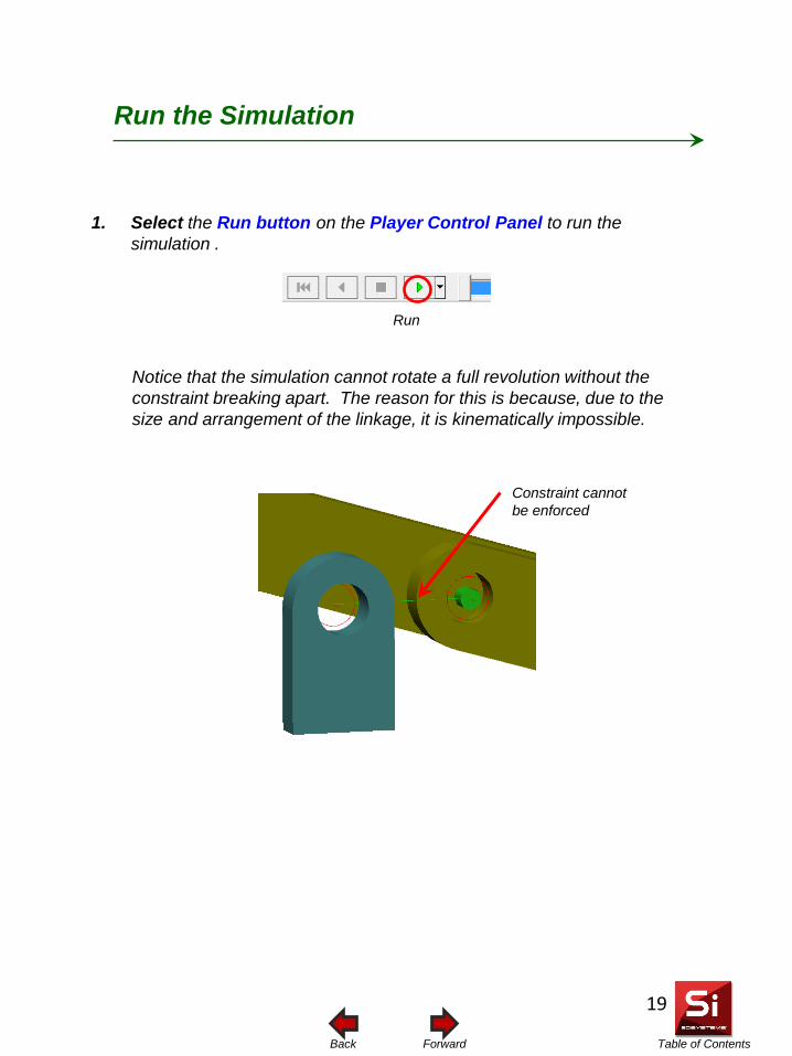
Table of Contents Forward Back
Run the Simulation 1. Select the Run button on the Player Control Panel to run the
simulation .
Run
Notice that the simulation cannot rotate a full revolution without the constraint breaking apart. The reason for this is because, due to the size and arrangement of the linkage, it is kinematically impossible.
Constraint cannot be enforced
19
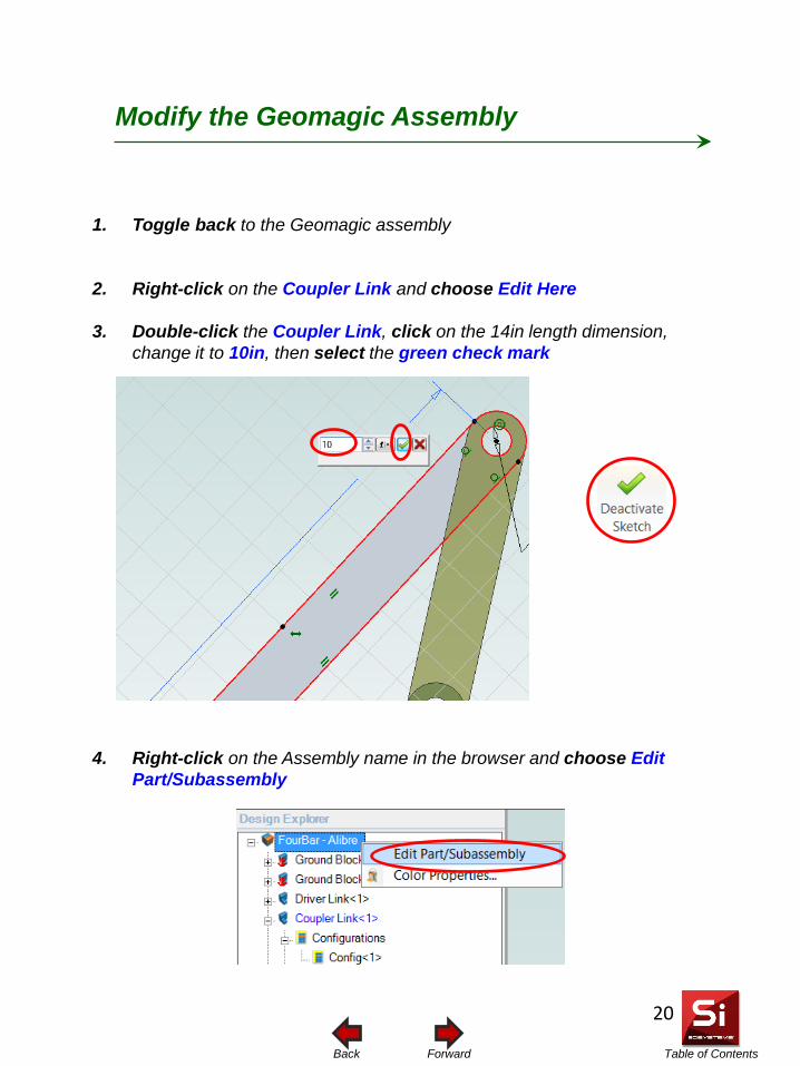
Table of Contents Forward Back
Modify the Geomagic Assembly
1. Toggle back to the Geomagic assembly
2. Right-click on the Coupler Link and choose Edit Here
3. Double-click the Coupler Link, click on the 14in length dimension, change it to 10in, then select the green check mark
4. Right-click on the Assembly name in the browser and choose Edit Part/Subassembly
20
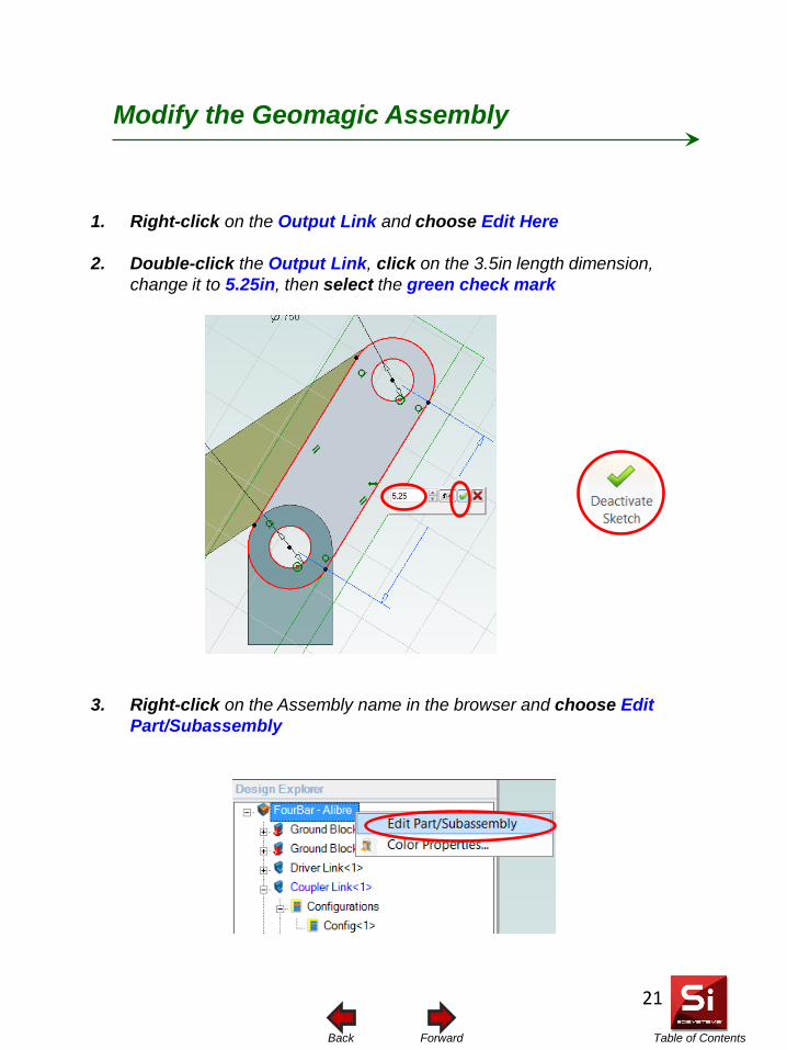
Table of Contents Forward Back
Modify the Geomagic Assembly
1. Right-click on the Output Link and choose Edit Here
2. Double-click the Output Link, click on the 3.5in length dimension, change it to 5.25in, then select the green check mark
3. Right-click on the Assembly name in the browser and choose Edit Part/Subassembly
21
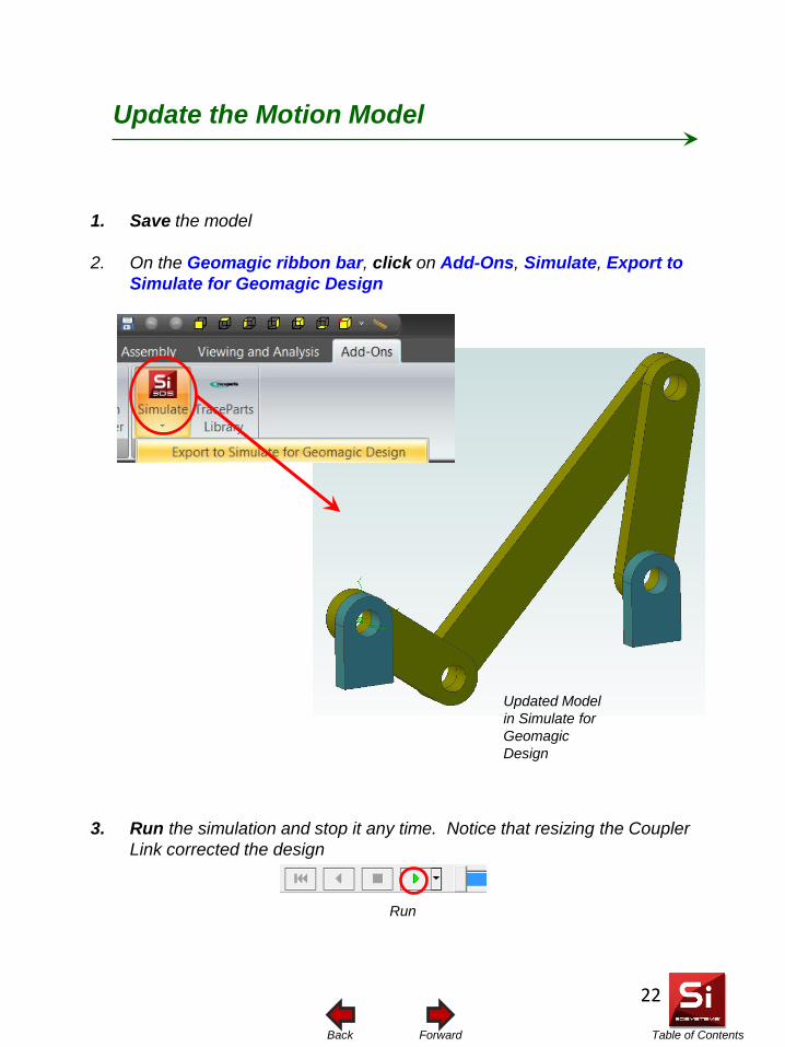
Table of Contents Forward Back
1. Save the model
2. On the Geomagic ribbon bar, click on Add-Ons, Simulate, Export to Simulate for Geomagic Design
3. Run the simulation and stop it any time. Notice that resizing the Coupler Link corrected the design
Update the Motion Model
Updated Model in Simulate for Geomagic Design
Run
22
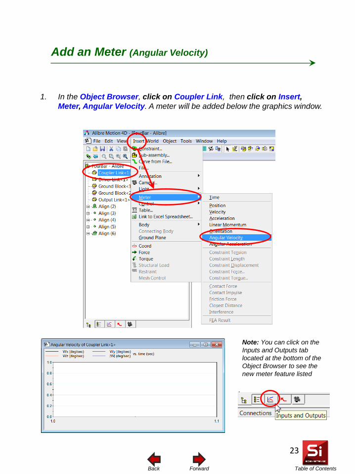
Table of Contents Forward Back
Add an Meter (Angular Velocity)
1. In the Object Browser, click on Coupler Link, then click on Insert, Meter, Angular Velocity. A meter will be added below the graphics window.
Note: You can click on the Inputs and Outputs tab located at the bottom of the Object Browser to see the new meter feature listed
23
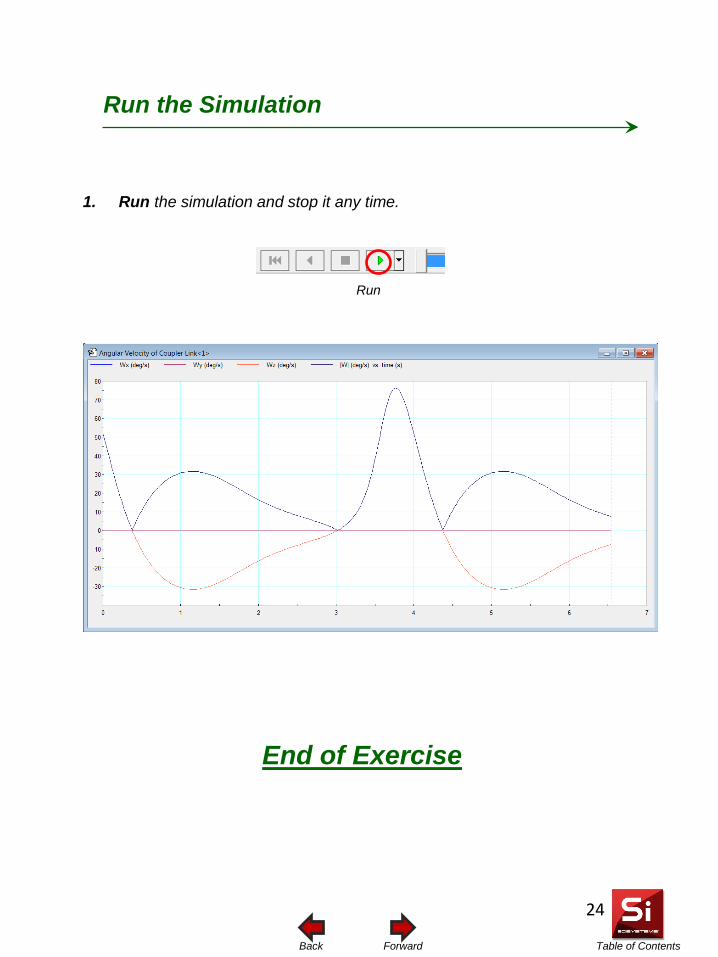
Table of Contents Forward Back
Run the Simulation 1. Run the simulation and stop it any time.
Run
End of Exercise
24
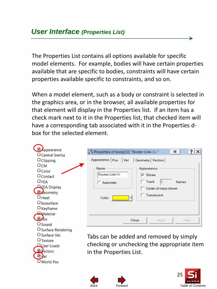
Table of Contents Forward Back
User Interface (Properties List)
The Properties List contains all options available for specific model elements. For example, bodies will have certain properties available that are specific to bodies, constraints will have certain properties available specific to constraints, and so on. When a model element, such as a body or constraint is selected in the graphics area, or in the browser, all available properties for that element will display in the Properties list. If an item has a check mark next to it in the Properties list, that checked item will have a corresponding tab associated with it in the Properties d-box for the selected element.
Tabs can be added and removed by simply checking or unchecking the appropriate item in the Properties List.
25
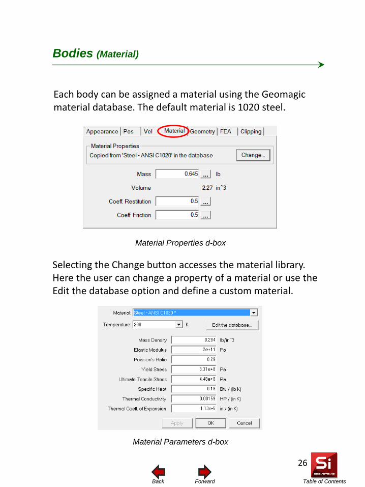
Table of Contents Forward Back
Each body can be assigned a material using the Geomagic material database. The default material is 1020 steel.
Bodies (Material)
Material Properties d-box
Material Parameters d-box
Selecting the Change button accesses the material library. Here the user can change a property of a material or use the Edit the database option and define a custom material.
26
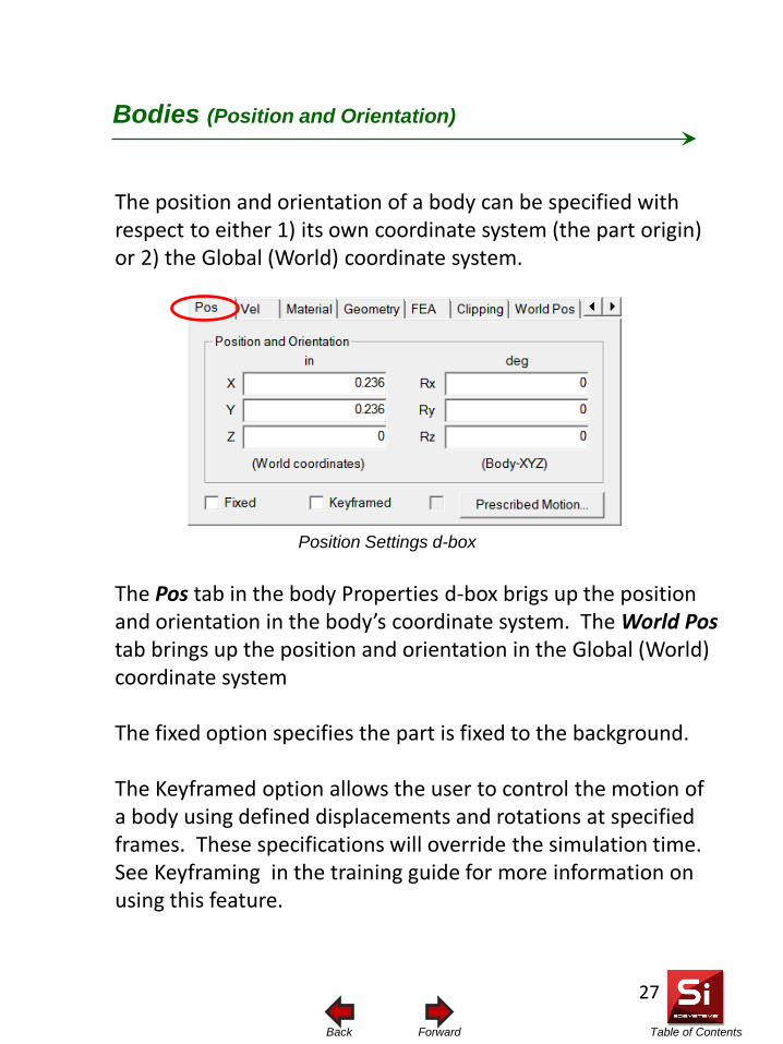
Table of Contents Forward Back
The position and orientation of a body can be specified with respect to either 1) its own coordinate system (the part origin) or 2) the Global (World) coordinate system.
Bodies (Position and Orientation)
Position Settings d-box
The Pos tab in the body Properties d-box brigs up the position and orientation in the body’s coordinate system. The World Pos tab brings up the position and orientation in the Global (World) coordinate system The fixed option specifies the part is fixed to the background. The Keyframed option allows the user to control the motion of a body using defined displacements and rotations at specified frames. These specifications will override the simulation time. See Keyframing in the training guide for more information on using this feature.
27
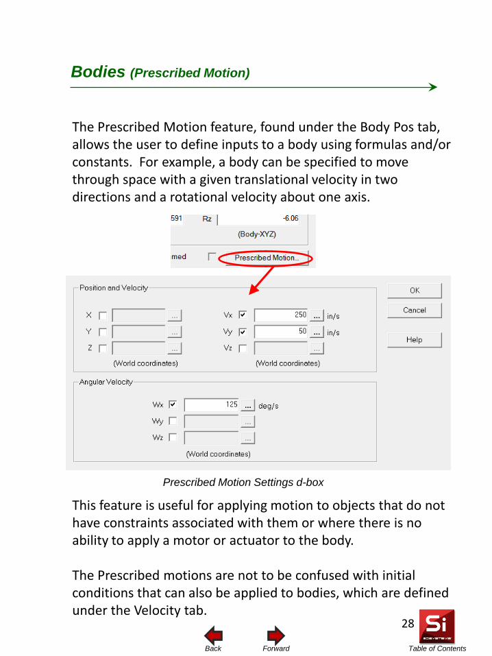
Table of Contents Forward Back
This feature is useful for applying motion to objects that do not have constraints associated with them or where there is no ability to apply a motor or actuator to the body. The Prescribed motions are not to be confused with initial conditions that can also be applied to bodies, which are defined under the Velocity tab.
The Prescribed Motion feature, found under the Body Pos tab, allows the user to define inputs to a body using formulas and/or constants. For example, a body can be specified to move through space with a given translational velocity in two directions and a rotational velocity about one axis.
Bodies (Prescribed Motion)
Prescribed Motion Settings d-box
28
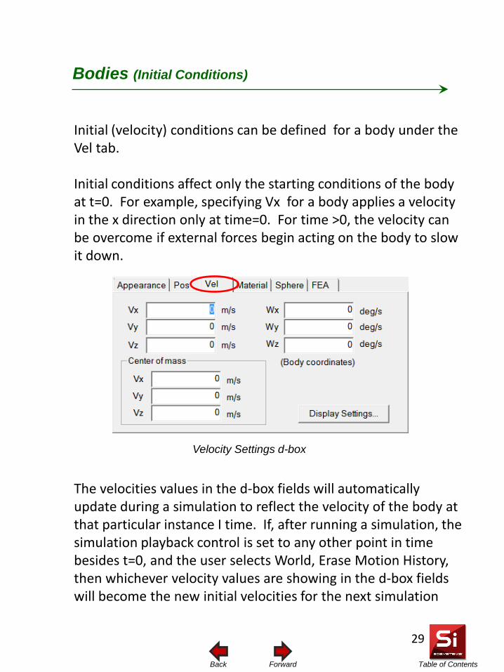
Table of Contents Forward Back
Initial (velocity) conditions can be defined for a body under the Vel tab. Initial conditions affect only the starting conditions of the body at t=0. For example, specifying Vx for a body applies a velocity in the x direction only at time=0. For time >0, the velocity can be overcome if external forces begin acting on the body to slow it down.
Bodies (Initial Conditions)
Velocity Settings d-box
The velocities values in the d-box fields will automatically update during a simulation to reflect the velocity of the body at that particular instance I time. If, after running a simulation, the simulation playback control is set to any other point in time besides t=0, and the user selects World, Erase Motion History, then whichever velocity values are showing in the d-box fields will become the new initial velocities for the next simulation
29
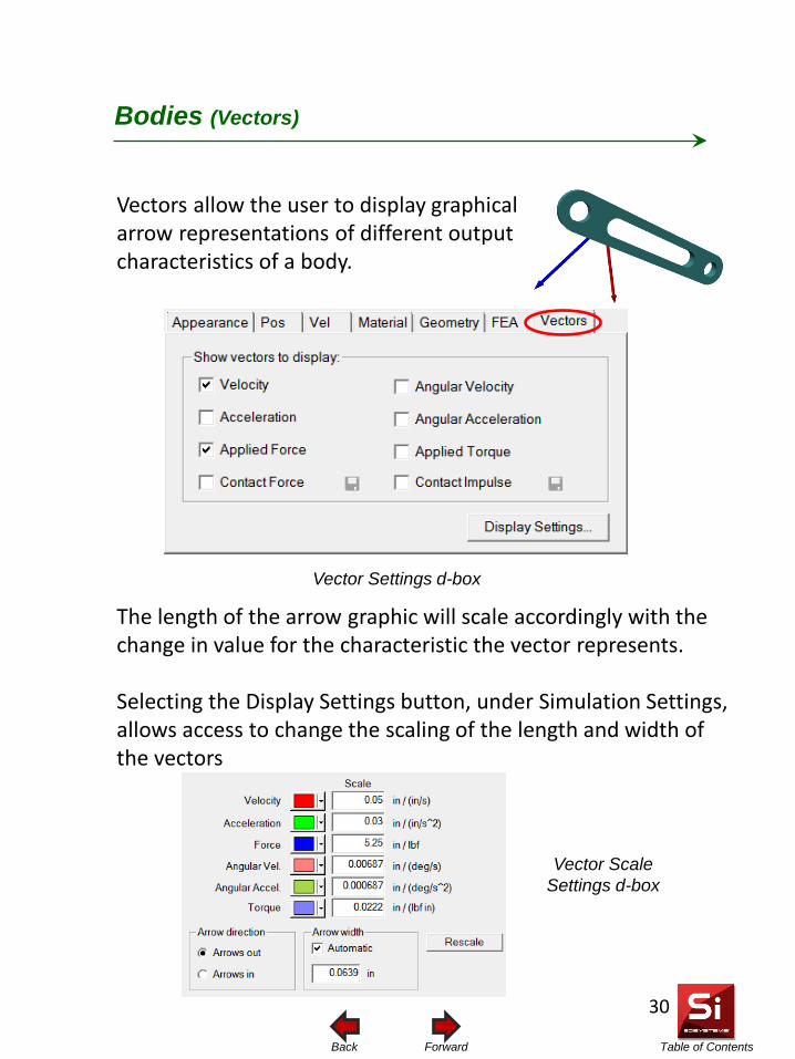
Table of Contents Forward Back
Vectors allow the user to display graphical arrow representations of different output characteristics of a body.
Bodies (Vectors)
Vector Settings d-box
The length of the arrow graphic will scale accordingly with the change in value for the characteristic the vector represents. Selecting the Display Settings button, under Simulation Settings, allows access to change the scaling of the length and width of the vectors
Vector Scale Settings d-box
30
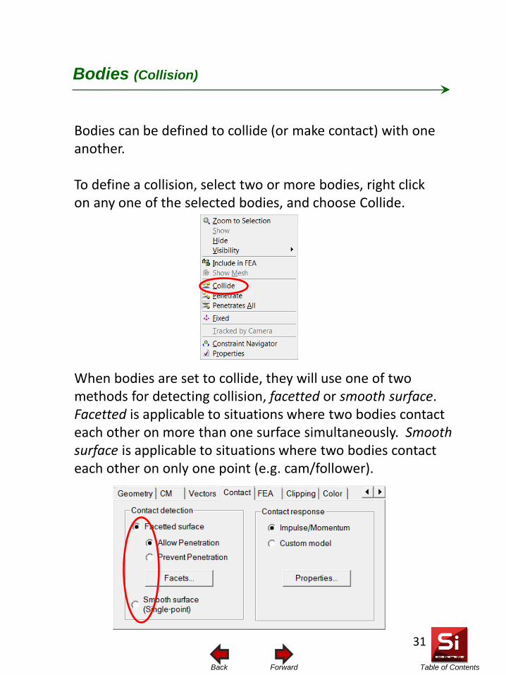
Table of Contents Forward Back
Bodies can be defined to collide (or make contact) with one another. To define a collision, select two or more bodies, right click on any one of the selected bodies, and choose Collide.
Bodies (Collision)
When bodies are set to collide, they will use one of two methods for detecting collision, facetted or smooth surface. Facetted is applicable to situations where two bodies contact each other on more than one surface simultaneously. Smooth surface is applicable to situations where two bodies contact each other on only one point (e.g. cam/follower).
31
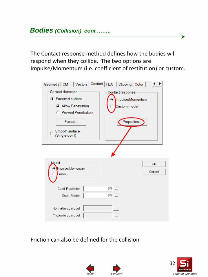
Table of Contents Forward Back
Bodies (Collision) cont ……..
The Contact response method defines how the bodies will respond when they collide. The two options are Impulse/Momentum (i.e. coefficient of restitution) or custom.
Friction can also be defined for the collision
32
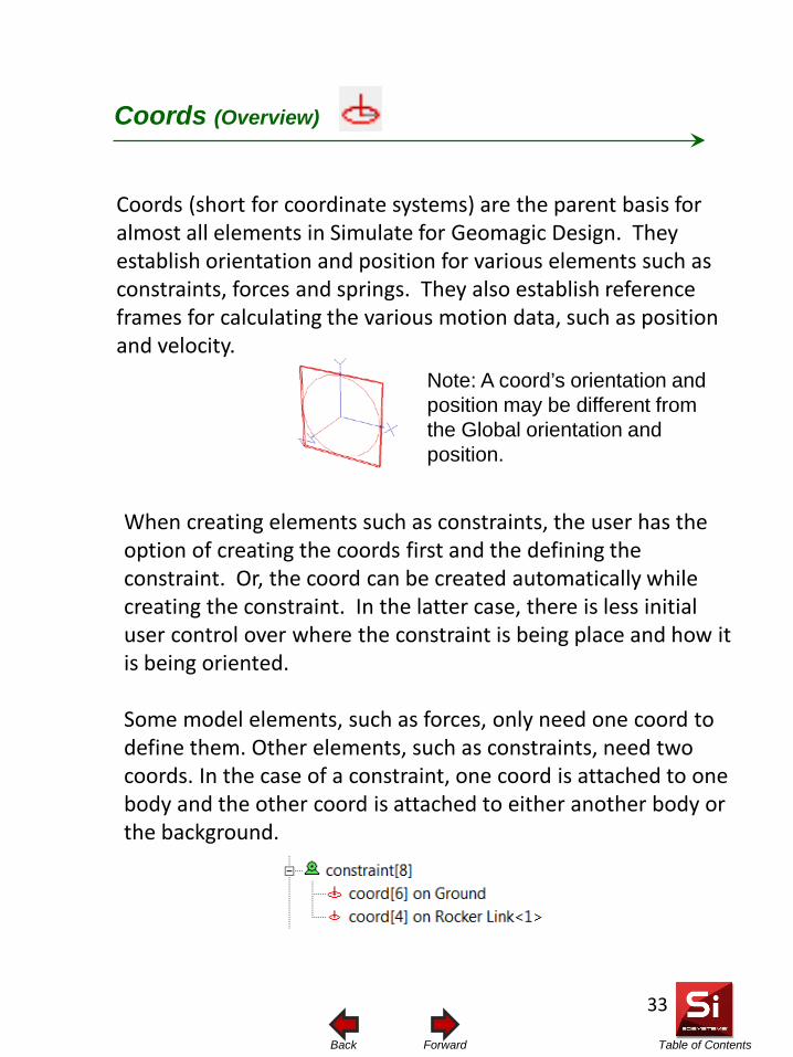
Table of Contents Forward Back
Coords (Overview)
33
Coords (short for coordinate systems) are the parent basis for almost all elements in Simulate for Geomagic Design. They establish orientation and position for various elements such as constraints, forces and springs. They also establish reference frames for calculating the various motion data, such as position and velocity.
When creating elements such as constraints, the user has the option of creating the coords first and the defining the constraint. Or, the coord can be created automatically while creating the constraint. In the latter case, there is less initial user control over where the constraint is being place and how it is being oriented. Some model elements, such as forces, only need one coord to define them. Other elements, such as constraints, need two coords. In the case of a constraint, one coord is attached to one body and the other coord is attached to either another body or the background.
Note: A coord’s orientation and position may be different from the Global orientation and position.
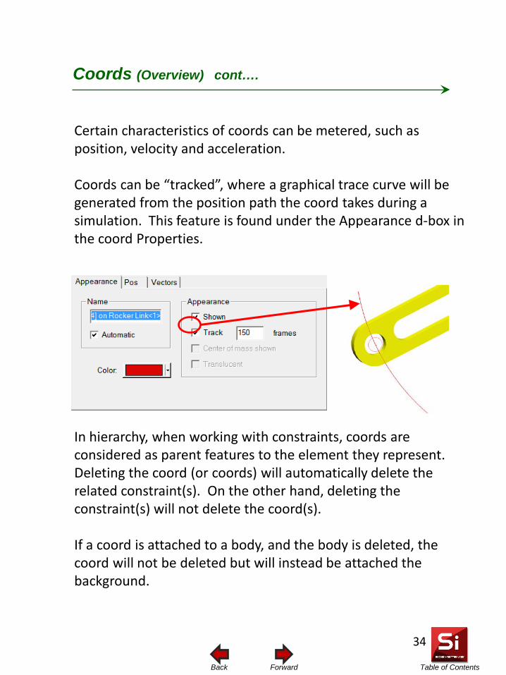
Table of Contents Forward Back
Certain characteristics of coords can be metered, such as position, velocity and acceleration. Coords can be “tracked”, where a graphical trace curve will be generated from the position path the coord takes during a simulation. This feature is found under the Appearance d-box in the coord Properties. In hierarchy, when working with constraints, coords are considered as parent features to the element they represent. Deleting the coord (or coords) will automatically delete the related constraint(s). On the other hand, deleting the constraint(s) will not delete the coord(s). If a coord is attached to a body, and the body is deleted, the coord will not be deleted but will instead be attached the background.
Coords (Overview) cont….
34
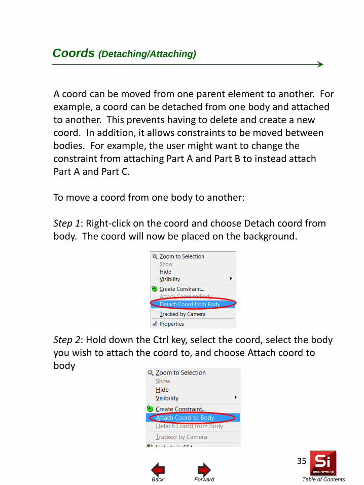
Table of Contents Forward Back
A coord can be moved from one parent element to another. For example, a coord can be detached from one body and attached to another. This prevents having to delete and create a new coord. In addition, it allows constraints to be moved between bodies. For example, the user might want to change the constraint from attaching Part A and Part B to instead attach Part A and Part C. To move a coord from one body to another: Step 1: Right-click on the coord and choose Detach coord from body. The coord will now be placed on the background. Step 2: Hold down the Ctrl key, select the coord, select the body you wish to attach the coord to, and choose Attach coord to body
Coords (Detaching/Attaching)
35
Table of Contents Forward Back
When moving elements such as constraints, that consist of two coords, care must be taken that the correct method is used, as there are different ways the constraint can be moved or rotated. Moving a constraint incorrectly may results in a split constraint
1. By moving or rotating the constraint and then using the “join” feature to reassemble the constraint
2. By moving or rotating one of the coords and then using the “join” feature to reassemble the constraint
3. By moving or rotating both constraint simultaneously.
Coords (Moving Constraints)
36
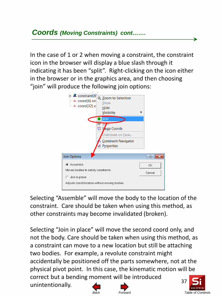
Table of Contents Forward Back
Coords (Moving Constraints) cont…….
In the case of 1 or 2 when moving a constraint, the constraint icon in the browser will display a blue slash through it indicating it has been “split”. Right-clicking on the icon either in the browser or in the graphics area, and then choosing “join” will produce the following join options:
Selecting “Assemble” will move the body to the location of the constraint. Care should be taken when using this method, as other constraints may become invalidated (broken). Selecting “Join in place” will move the second coord only, and not the body. Care should be taken when using this method, as a constraint can move to a new location but still be attaching two bodies. For example, a revolute constraint might accidentally be positioned off the parts somewhere, not at the physical pivot point. In this case, the kinematic motion will be correct but a bending moment will be introduced unintentionally.
37
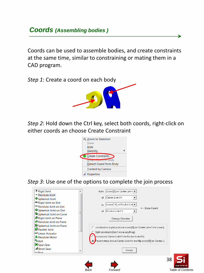
Table of Contents Forward Back
Coords (Assembling bodies )
Coords can be used to assemble bodies, and create constraints at the same time, similar to constraining or mating them in a CAD program. Step 1: Create a coord on each body Step 2: Hold down the Ctrl key, select both coords, right-click on either coords an choose Create Constraint Step 3: Use one of the options to complete the join process
38
Table of Contents Forward Back
• Geomagic Design constraints can be automatically converted (or mapped) into Simulate constraints
• A list showing the mapping formulation of CAD to Simulate constraints can be seen in the sections titled Supported Assembly Constraints I and II
• It is possible that you may not see all CAD constraints
map over to Simulate. There are two reasons for this: 1) It may not be a supported constraint type or 2) it may have been combined with other constraints and formulated into a compound constraint
• Compound constraint: A compound constraint is a single Simulate constraint formulated from two or more CAD assembly constraints. When a model is exported from Geomagic Design into Simulate, Simulate assesses the total degrees of freedom available between the bodies. The Simulate constraint formulated is based on the total degrees of freedom available for the bodies. Geomagic Design stores these as separate constraints, because they need to be editable from a CAD perspective. Simulate, on the other hand, is only concerned with movement and so unites them into one constraint representative of the total DOF.
Constraints (Mapping of CAD constraints)
39
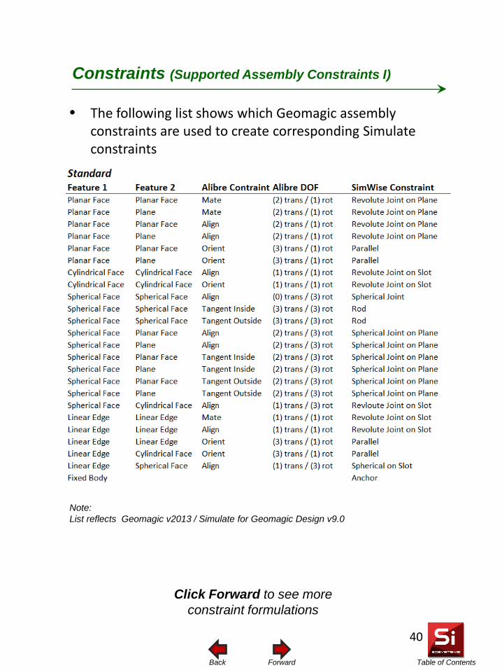
Table of Contents Forward Back
Constraints (Supported Assembly Constraints I)
40
• The following list shows which Geomagic assembly constraints are used to create corresponding Simulate constraints
Note: List reflects Geomagic v2013 / Simulate for Geomagic Design v9.0
Click Forward to see more constraint formulations
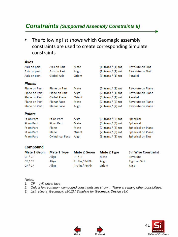
Table of Contents Forward Back
• The following list shows which Geomagic assembly constraints are used to create corresponding Simulate constraints
Constraints (Supported Assembly Constraints II)
41
Notes: 1. CF = cylindrical face 2. Only a few common compound constraints are shown. There are many other possibilities. 3. List reflects Geomagic v2013 / Simulate for Geomagic Design v9.0
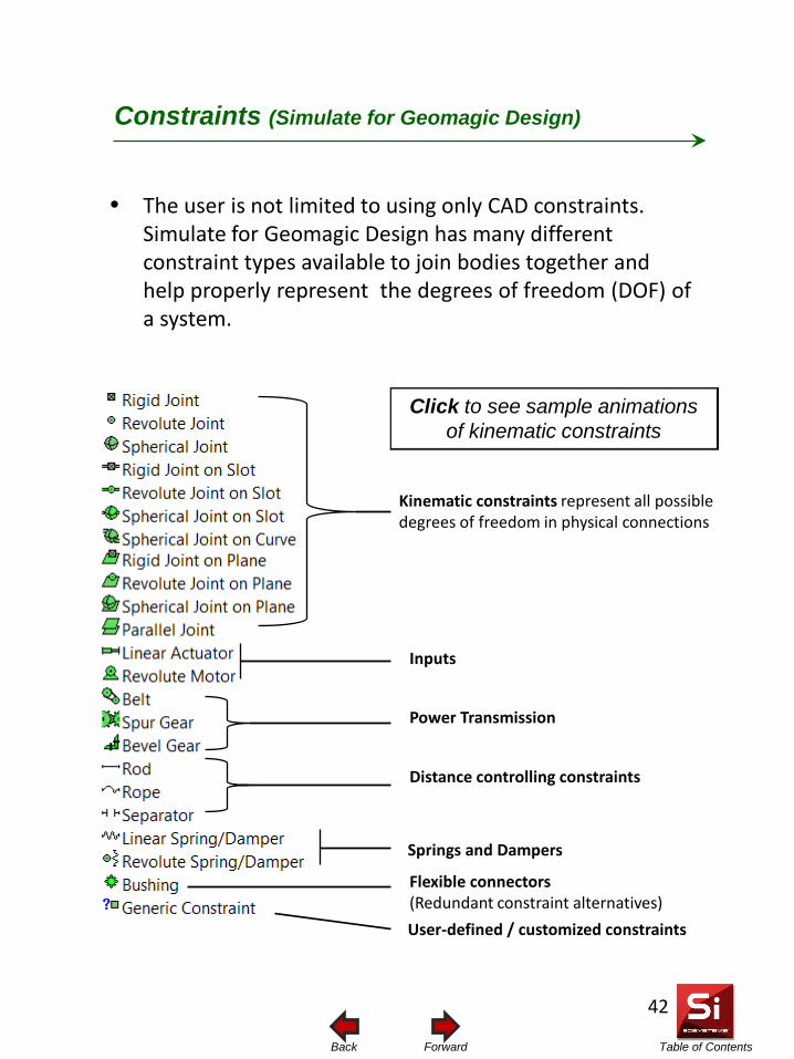
Table of Contents Forward Back
• The user is not limited to using only CAD constraints. Simulate for Geomagic Design has many different constraint types available to join bodies together and help properly represent the degrees of freedom (DOF) of a system.
Constraints (Simulate for Geomagic Design)
Kinematic constraints represent all possible degrees of freedom in physical connections
Inputs
Power Transmission
Distance controlling constraints
Springs and Dampers
Flexible connectors (Redundant constraint alternatives) User-defined / customized constraints
42
Click to see sample animations of kinematic constraints
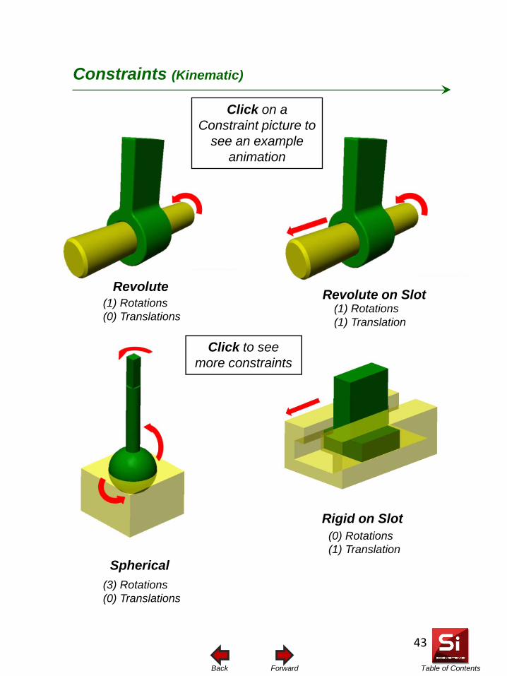
Table of Contents Forward Back
Revolute Revolute on Slot
Spherical
Rigid on Slot
Constraints (Kinematic)
(0) Rotations (1) Translation
(3) Rotations (0) Translations
(1) Rotations (1) Translation
(1) Rotations (0) Translations
43
Click on a Constraint picture to
see an example animation
Click to see more constraints
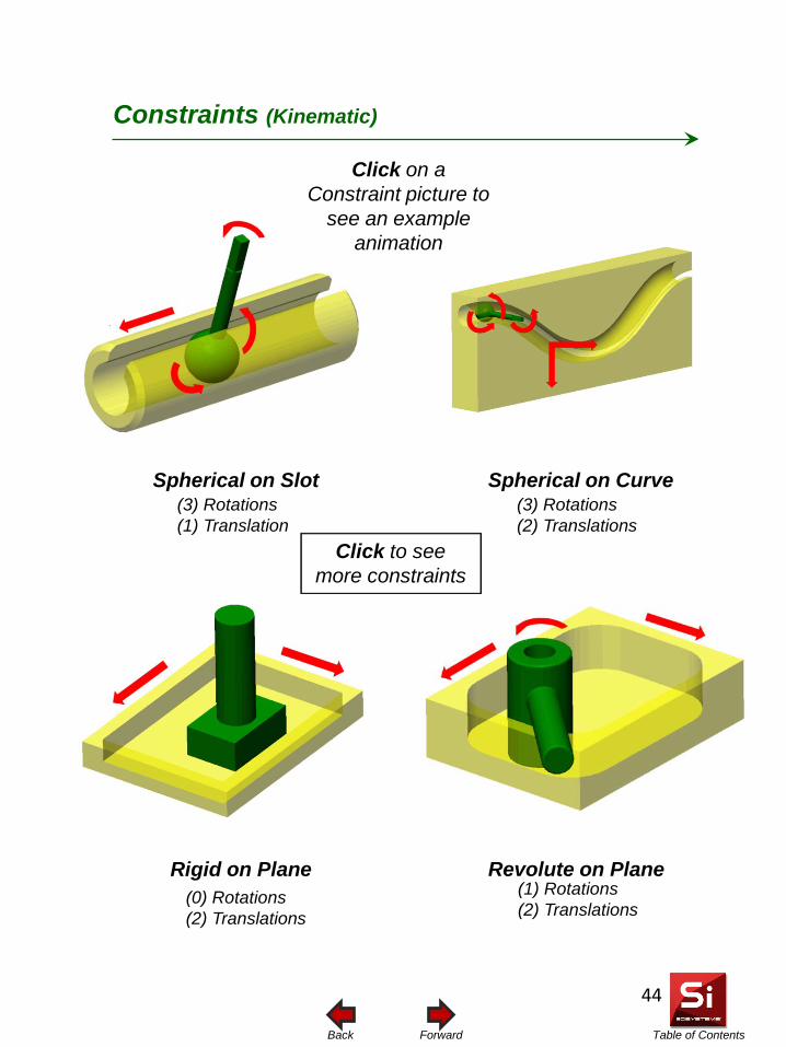
Table of Contents Forward Back
Spherical on Slot
Rigid on Plane
Spherical on Curve
Revolute on Plane
Constraints (Kinematic)
(3) Rotations (1) Translation
(3) Rotations (2) Translations
(0) Rotations (2) Translations
(1) Rotations (2) Translations
44
Click on a Constraint picture to
see an example animation
Click to see more constraints
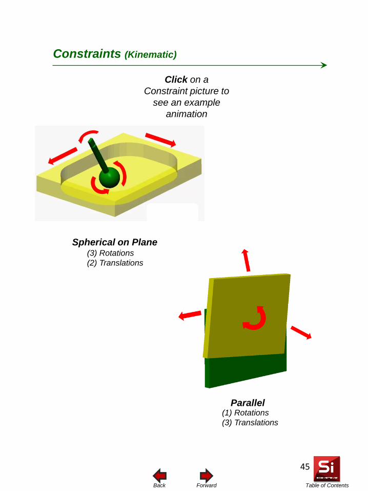
Table of Contents Forward Back
Spherical on Plane
Parallel
Constraints (Kinematic)
(1) Rotations (3) Translations
(3) Rotations (2) Translations
45
Click on a Constraint picture to
see an example animation
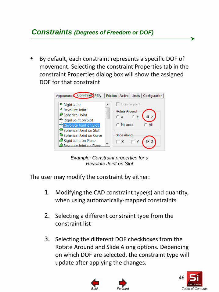
Table of Contents Forward Back
• By default, each constraint represents a specific DOF of movement. Selecting the constraint Properties tab in the constraint Properties dialog box will show the assigned DOF for that constraint
Constraints (Degrees of Freedom or DOF)
Example: Constraint properties for a Revolute Joint on Slot
The user may modify the constraint by either:
1. Modifying the CAD constraint type(s) and quantity, when using automatically-mapped constraints
2. Selecting a different constraint type from the constraint list
3. Selecting the different DOF checkboxes from the Rotate Around and Slide Along options. Depending on which DOF are selected, the constraint type will update after applying the changes.
46
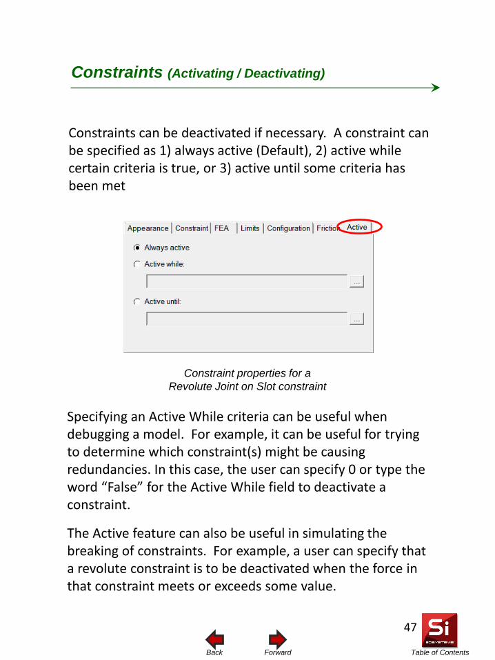
Table of Contents Forward Back
Constraints can be deactivated if necessary. A constraint can be specified as 1) always active (Default), 2) active while certain criteria is true, or 3) active until some criteria has been met
Constraints (Activating / Deactivating)
Constraint properties for a Revolute Joint on Slot constraint
Specifying an Active While criteria can be useful when debugging a model. For example, it can be useful for trying to determine which constraint(s) might be causing redundancies. In this case, the user can specify 0 or type the word “False” for the Active While field to deactivate a constraint.
The Active feature can also be useful in simulating the breaking of constraints. For example, a user can specify that a revolute constraint is to be deactivated when the force in that constraint meets or exceeds some value.
47
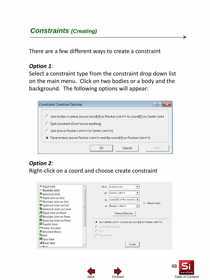
Table of Contents Forward Back
There are a few different ways to create a constraint Option 1: Select a constraint type from the constraint drop down list on the main menu. Click on two bodies or a body and the background. The following options will appear:
Option 2: Right-click on a coord and choose create constraint
Constraints (Creating)
48
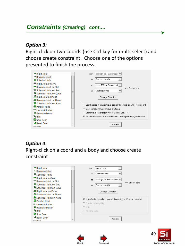
Table of Contents Forward Back
Option 3: Right-click on two coords (use Ctrl key for multi-select) and choose create constraint. Choose one of the options presented to finish the process.
Option 4: Right-click on a coord and a body and choose create constraint
Constraints (Creating) cont….
49
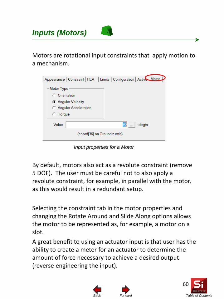
Table of Contents Forward Back
Inputs (Motors)
Input properties for a Motor
Motors are rotational input constraints that apply motion to a mechanism.
By default, motors also act as a revolute constraint (remove 5 DOF). The user must be careful not to also apply a revolute constraint, for example, in parallel with the motor, as this would result in a redundant setup. Selecting the constraint tab in the motor properties and changing the Rotate Around and Slide Along options allows the motor to be represented as, for example, a motor on a slot. A great benefit to using an actuator input is that user has the ability to create a meter for an actuator to determine the amount of force necessary to achieve a desired output (reverse engineering the input).
60
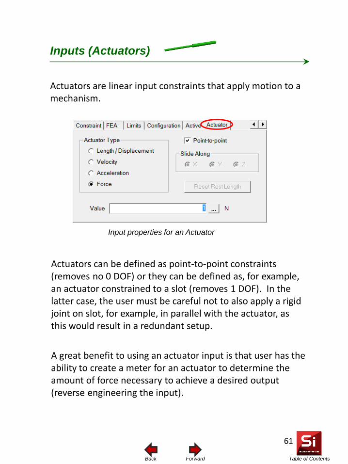
Table of Contents Forward Back
Inputs (Actuators)
Input properties for an Actuator
Actuators are linear input constraints that apply motion to a mechanism.
Actuators can be defined as point-to-point constraints (removes no 0 DOF) or they can be defined as, for example, an actuator constrained to a slot (removes 1 DOF). In the latter case, the user must be careful not to also apply a rigid joint on slot, for example, in parallel with the actuator, as this would result in a redundant setup. A great benefit to using an actuator input is that user has the ability to create a meter for an actuator to determine the amount of force necessary to achieve a desired output (reverse engineering the input).
61
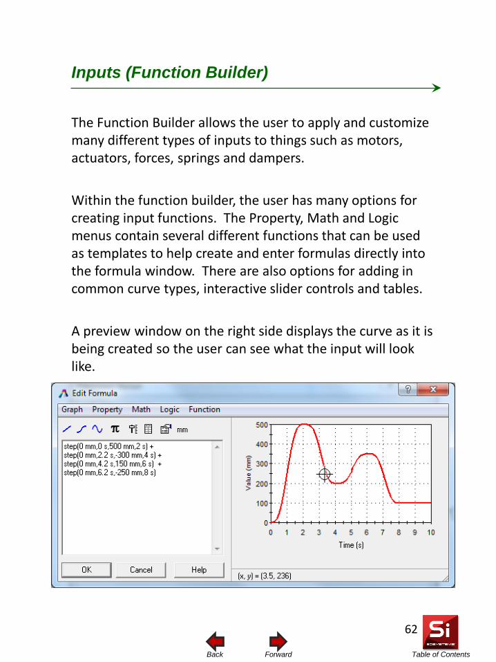
Table of Contents Forward Back
Inputs (Function Builder)
The Function Builder allows the user to apply and customize many different types of inputs to things such as motors, actuators, forces, springs and dampers. Within the function builder, the user has many options for creating input functions. The Property, Math and Logic menus contain several different functions that can be used as templates to help create and enter formulas directly into the formula window. There are also options for adding in common curve types, interactive slider controls and tables. A preview window on the right side displays the curve as it is being created so the user can see what the input will look like.
62
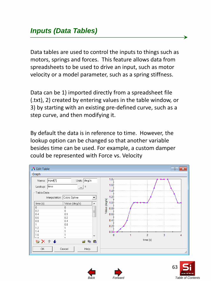
Table of Contents Forward Back
Inputs (Data Tables)
Data tables are used to control the inputs to things such as motors, springs and forces. This feature allows data from spreadsheets to be used to drive an input, such as motor velocity or a model parameter, such as a spring stiffness. Data can be 1) imported directly from a spreadsheet file (.txt), 2) created by entering values in the table window, or 3) by starting with an existing pre-defined curve, such as a step curve, and then modifying it. By default the data is in reference to time. However, the lookup option can be changed so that another variable besides time can be used. For example, a custom damper could be represented with Force vs. Velocity
63
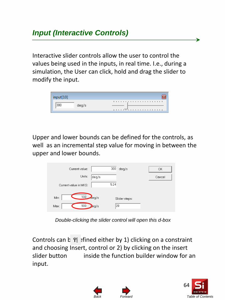
Table of Contents Forward Back
Input (Interactive Controls)
Interactive slider controls allow the user to control the values being used in the inputs, in real time. I.e., during a simulation, the User can click, hold and drag the slider to modify the input. Upper and lower bounds can be defined for the controls, as well as an incremental step value for moving in between the upper and lower bounds. Controls can be defined either by 1) clicking on a constraint and choosing Insert, control or 2) by clicking on the insert slider button inside the function builder window for an input.
Double-clicking the slider control will open this d-box
64
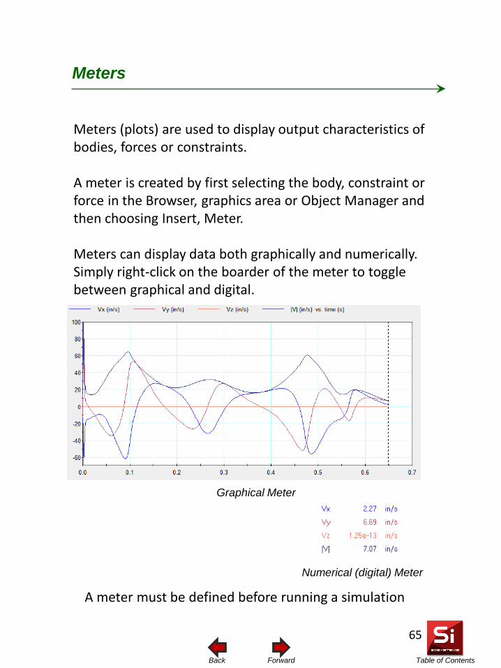
Table of Contents Forward Back
Meters (plots) are used to display output characteristics of bodies, forces or constraints. A meter is created by first selecting the body, constraint or force in the Browser, graphics area or Object Manager and then choosing Insert, Meter. Meters can display data both graphically and numerically. Simply right-click on the boarder of the meter to toggle between graphical and digital.
Meters
A meter must be defined before running a simulation
Graphical Meter
Numerical (digital) Meter
65
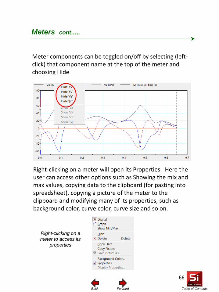
Table of Contents Forward Back
Meter components can be toggled on/off by selecting (left-click) that component name at the top of the meter and choosing Hide
Meters cont…..
Right-clicking on a meter to access its
properties
Right-clicking on a meter will open its Properties. Here the user can access other options such as Showing the mix and max values, copying data to the clipboard (for pasting into spreadsheet), copying a picture of the meter to the clipboard and modifying many of its properties, such as background color, curve color, curve size and so on.
66
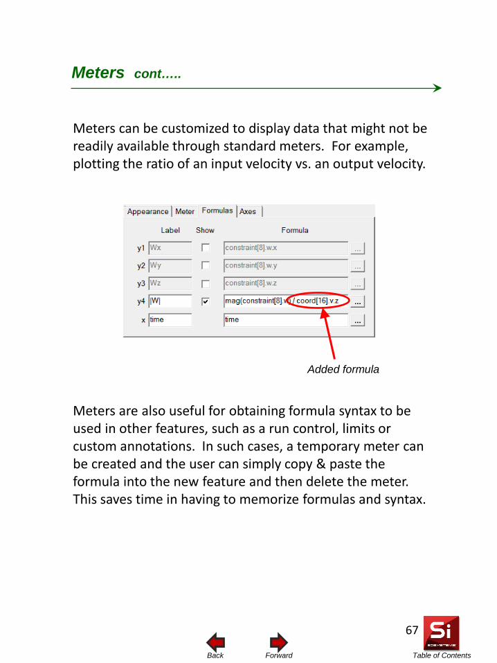
Table of Contents Forward Back
Meters can be customized to display data that might not be readily available through standard meters. For example, plotting the ratio of an input velocity vs. an output velocity.
Meters cont…..
Added formula
Meters are also useful for obtaining formula syntax to be used in other features, such as a run control, limits or custom annotations. In such cases, a temporary meter can be created and the user can simply copy & paste the formula into the new feature and then delete the meter. This saves time in having to memorize formulas and syntax.
67
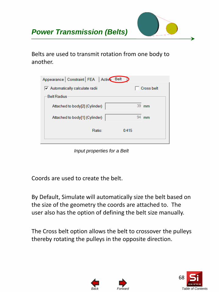
Table of Contents Forward Back
Power Transmission (Belts)
Input properties for a Belt
Belts are used to transmit rotation from one body to another.
Coords are used to create the belt. By Default, Simulate will automatically size the belt based on the size of the geometry the coords are attached to. The user also has the option of defining the belt size manually. The Cross belt option allows the belt to crossover the pulleys thereby rotating the pulleys in the opposite direction.
68
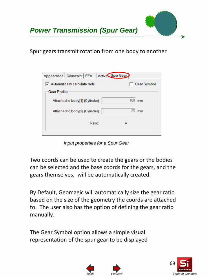
Table of Contents Forward Back
Power Transmission (Spur Gear)
Input properties for a Spur Gear
Spur gears transmit rotation from one body to another
Two coords can be used to create the gears or the bodies can be selected and the base coords for the gears, and the gears themselves, will be automatically created. By Default, Geomagic will automatically size the gear ratio based on the size of the geometry the coords are attached to. The user also has the option of defining the gear ratio manually. The Gear Symbol option allows a simple visual representation of the spur gear to be displayed
69
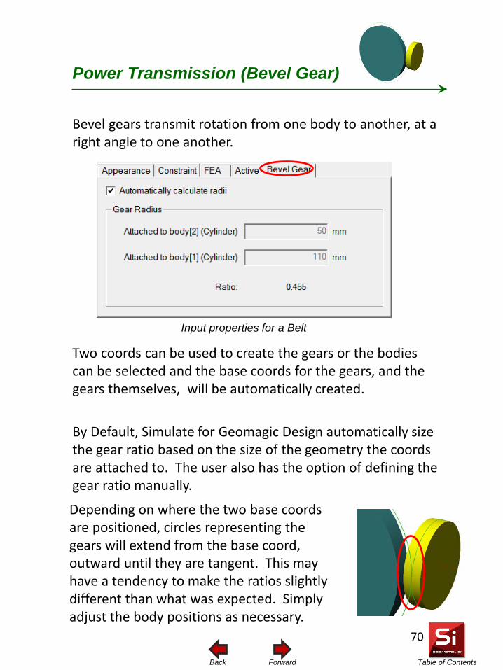
Table of Contents Forward Back
Power Transmission (Bevel Gear)
Input properties for a Belt
Bevel gears transmit rotation from one body to another, at a right angle to one another.
Two coords can be used to create the gears or the bodies can be selected and the base coords for the gears, and the gears themselves, will be automatically created. By Default, Simulate for Geomagic Design automatically size the gear ratio based on the size of the geometry the coords are attached to. The user also has the option of defining the gear ratio manually.
Depending on where the two base coords are positioned, circles representing the gears will extend from the base coord, outward until they are tangent. This may have a tendency to make the ratios slightly different than what was expected. Simply adjust the body positions as necessary.
70
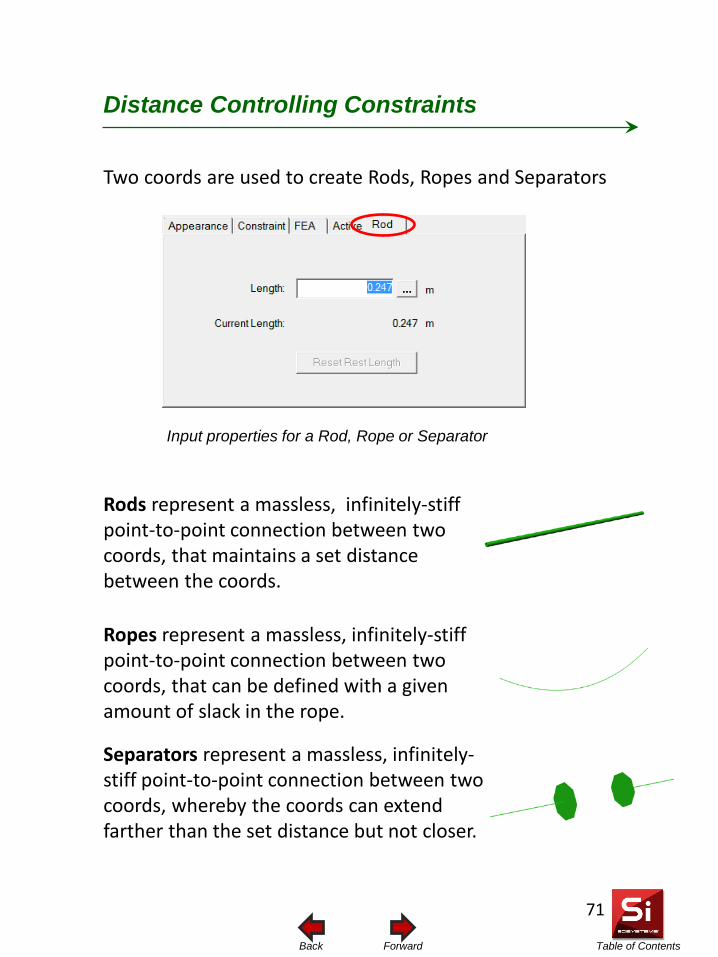
Table of Contents Forward Back
Distance Controlling Constraints
Input properties for a Rod, Rope or Separator
Rods represent a massless, infinitely-stiff point-to-point connection between two coords, that maintains a set distance between the coords.
Two coords are used to create Rods, Ropes and Separators
Ropes represent a massless, infinitely-stiff point-to-point connection between two coords, that can be defined with a given amount of slack in the rope. Separators represent a massless, infinitely-stiff point-to-point connection between two coords, whereby the coords can extend farther than the set distance but not closer.
71
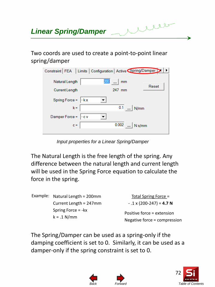
Table of Contents Forward Back
Linear Spring/Damper
Input properties for a Linear Spring/Damper
The Natural Length is the free length of the spring. Any difference between the natural length and current length will be used in the Spring Force equation to calculate the force in the spring.
Two coords are used to create a point-to-point linear spring/damper
The Spring/Damper can be used as a spring-only if the damping coefficient is set to 0. Similarly, it can be used as a damper-only if the spring constraint is set to 0.
Natural Length = 200mm Current Length = 247mm Spring Force = -kx k = .1 N/mm
Total Spring Force = - .1 x (200-247) = 4.7 N
Positive force = extension Negative force = compression
Example:
72
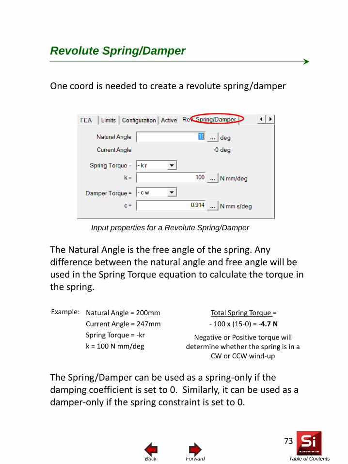
Table of Contents Forward Back
Revolute Spring/Damper
Input properties for a Revolute Spring/Damper
The Natural Angle is the free angle of the spring. Any difference between the natural angle and free angle will be used in the Spring Torque equation to calculate the torque in the spring.
One coord is needed to create a revolute spring/damper
The Spring/Damper can be used as a spring-only if the damping coefficient is set to 0. Similarly, it can be used as a damper-only if the spring constraint is set to 0.
Natural Angle = 200mm Current Angle = 247mm Spring Torque = -kr k = 100 N mm/deg
Total Spring Torque = - 100 x (15-0) = -4.7 N
Example:
Negative or Positive torque will determine whether the spring is in a
CW or CCW wind-up
73
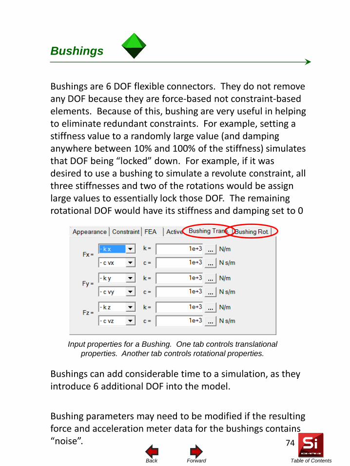
Table of Contents Forward Back
Bushings
Input properties for a Bushing. One tab controls translational properties. Another tab controls rotational properties.
Bushings are 6 DOF flexible connectors. They do not remove any DOF because they are force-based not constraint-based elements. Because of this, bushing are very useful in helping to eliminate redundant constraints. For example, setting a stiffness value to a randomly large value (and damping anywhere between 10% and 100% of the stiffness) simulates that DOF being “locked” down. For example, if it was desired to use a bushing to simulate a revolute constraint, all three stiffnesses and two of the rotations would be assign large values to essentially lock those DOF. The remaining rotational DOF would have its stiffness and damping set to 0
Bushings can add considerable time to a simulation, as they introduce 6 additional DOF into the model. Bushing parameters may need to be modified if the resulting force and acceleration meter data for the bushings contains “noise”.
74
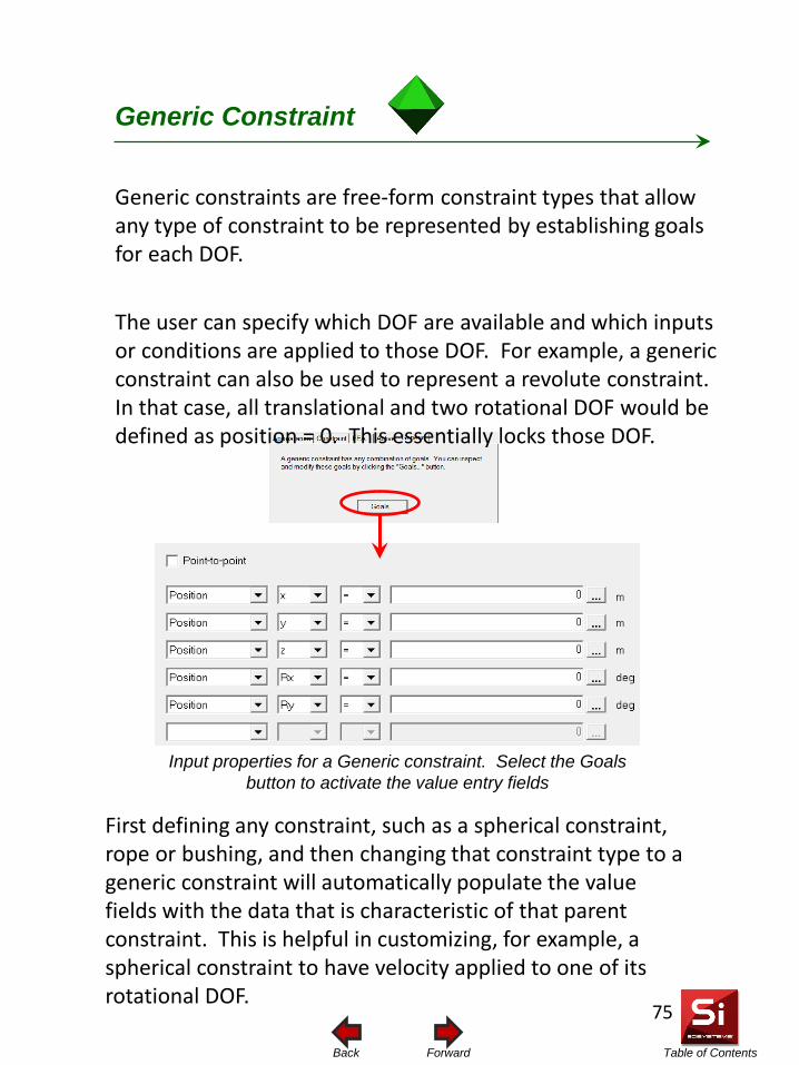
Table of Contents Forward Back
Generic Constraint
Input properties for a Generic constraint. Select the Goals button to activate the value entry fields
Generic constraints are free-form constraint types that allow any type of constraint to be represented by establishing goals for each DOF. The user can specify which DOF are available and which inputs or conditions are applied to those DOF. For example, a generic constraint can also be used to represent a revolute constraint. In that case, all translational and two rotational DOF would be defined as position = 0. This essentially locks those DOF.
First defining any constraint, such as a spherical constraint, rope or bushing, and then changing that constraint type to a generic constraint will automatically populate the value fields with the data that is characteristic of that parent constraint. This is helpful in customizing, for example, a spherical constraint to have velocity applied to one of its rotational DOF.
75
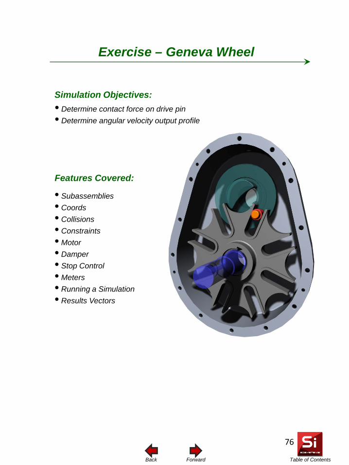
Table of Contents Forward Back
Simulation Objectives: • Determine contact force on drive pin • Determine angular velocity output profile
Features Covered:
• Subassemblies • Coords • Collisions • Constraints • Motor • Damper • Stop Control • Meters • Running a Simulation • Results Vectors
Exercise – Geneva Wheel
76
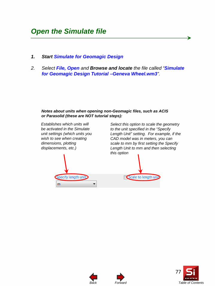
Table of Contents Forward Back
Open the Simulate file
1. Start Simulate for Geomagic Design
2. Select File, Open and Browse and locate the file called “Simulate for Geomagic Design Tutorial –Geneva Wheel.wm3”.
Establishes which units will be activated in the Simulate unit settings (which units you wish to see when creating dimensions, plotting displacements, etc.)
Select this option to scale the geometry to the unit specified in the “Specify Length Unit” setting. For example, if the CAD model was in meters, you can scale to mm by first setting the Specify Length Unit to mm and then selecting this option
Notes about units when opening non-Geomagic files, such as ACIS or Parasolid (these are NOT tutorial steps):
77
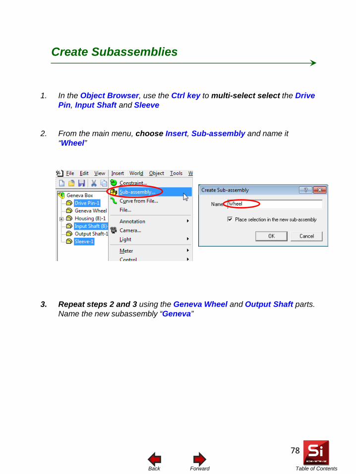
Table of Contents Forward Back
1. In the Object Browser, use the Ctrl key to multi-select select the Drive Pin, Input Shaft and Sleeve
2. From the main menu, choose Insert, Sub-assembly and name it “Wheel”
3. Repeat steps 2 and 3 using the Geneva Wheel and Output Shaft parts. Name the new subassembly “Geneva”
Create Subassemblies
78
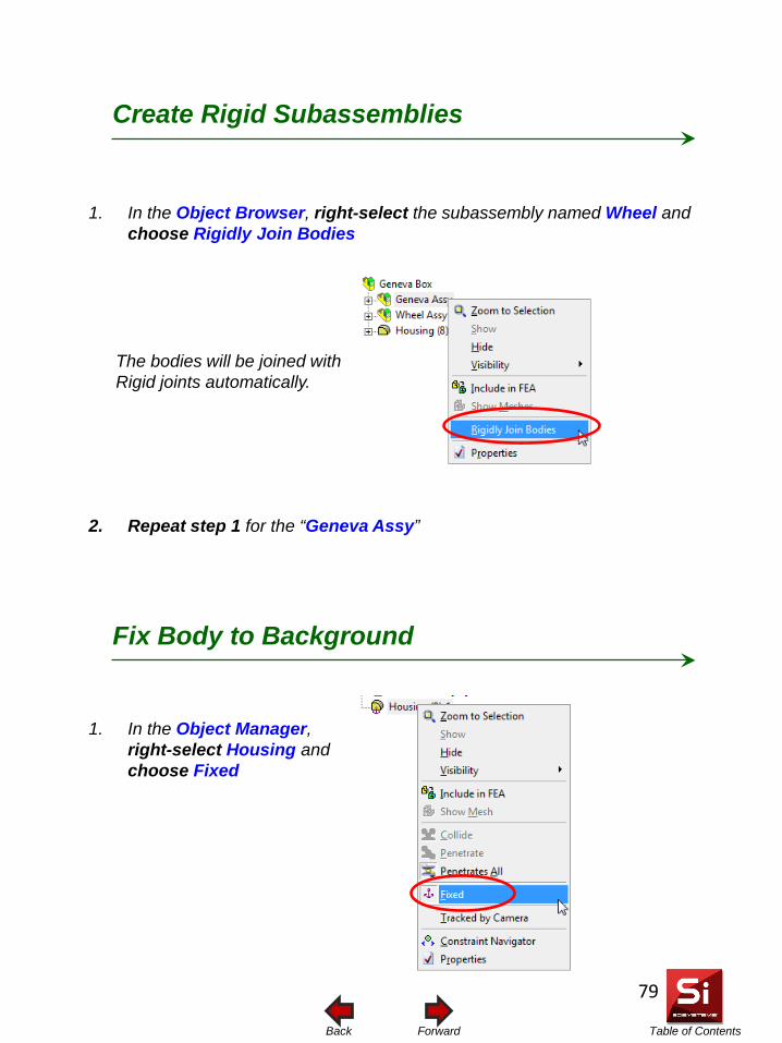
Table of Contents Forward Back
1. In the Object Browser, right-select the subassembly named Wheel and choose Rigidly Join Bodies
2. Repeat step 1 for the “Geneva Assy”
The bodies will be joined with Rigid joints automatically.
1. In the Object Manager, right-select Housing and choose Fixed
Create Rigid Subassemblies
Fix Body to Background
79
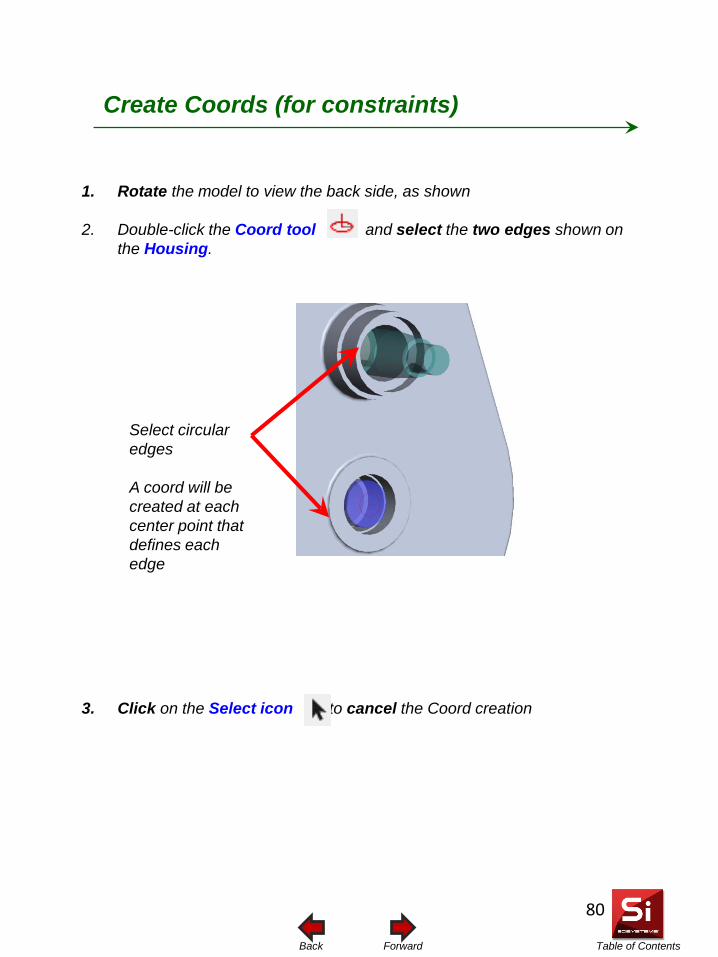
Table of Contents Forward Back
1. Rotate the model to view the back side, as shown
2. Double-click the Coord tool and select the two edges shown on the Housing.
3. Click on the Select icon to cancel the Coord creation
Select circular edges A coord will be created at each center point that defines each edge
Create Coords (for constraints)
80
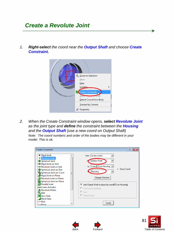
Table of Contents Forward Back
2. When the Create Constraint window opens, select Revolute Joint as the joint type and define the constraint between the Housing and the Output Shaft (use a new coord on Output Shaft)
Note: The coord numbers and order of the bodies may be different in your model. This is ok.
1. Right-select the coord near the Output Shaft and choose Create Constraint.
Create a Revolute Joint
81
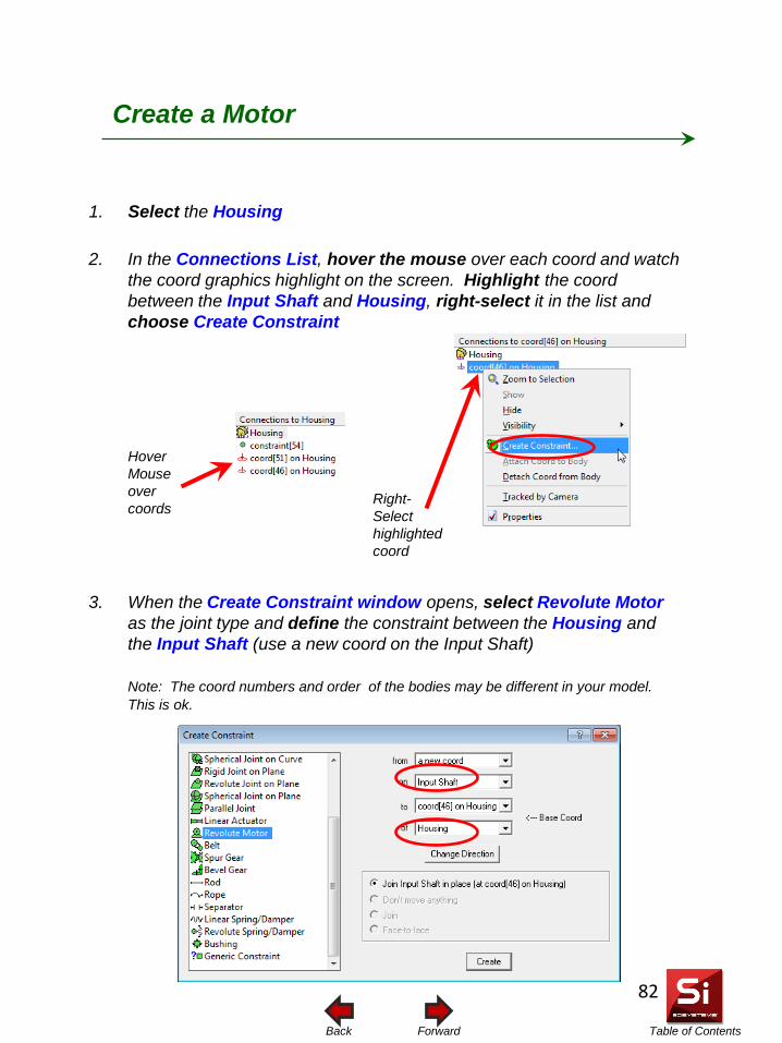
Table of Contents Forward Back
2. In the Connections List, hover the mouse over each coord and watch the coord graphics highlight on the screen. Highlight the coord between the Input Shaft and Housing, right-select it in the list and choose Create Constraint
1. Select the Housing
Create a Motor
Hover Mouse over coords
Right-Select highlighted coord
3. When the Create Constraint window opens, select Revolute Motor as the joint type and define the constraint between the Housing and the Input Shaft (use a new coord on the Input Shaft)
Note: The coord numbers and order of the bodies may be different in your model.
This is ok.
82
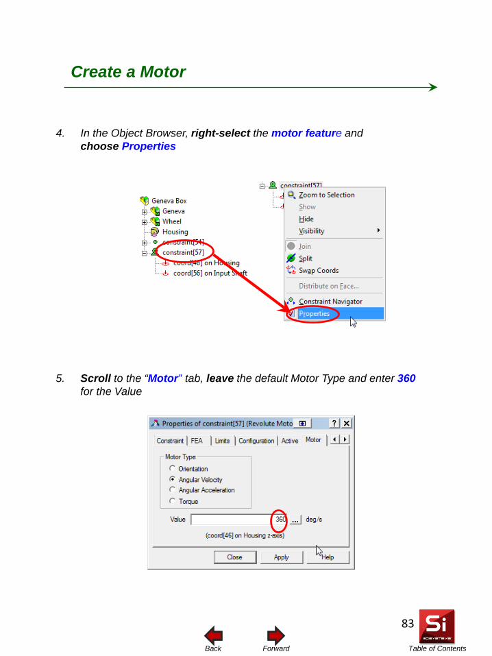
Table of Contents Forward Back
5. Scroll to the “Motor” tab, leave the default Motor Type and enter 360 for the Value
4. In the Object Browser, right-select the motor feature and choose Properties
Create a Motor
83
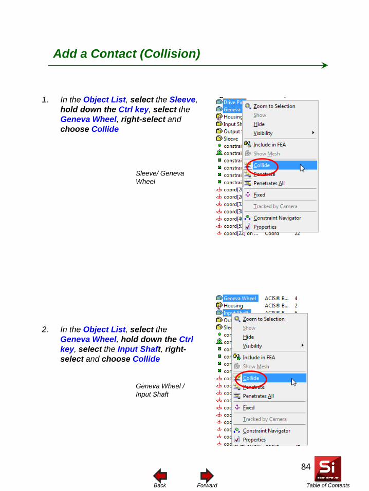
Table of Contents Forward Back
1. In the Object List, select the Sleeve, hold down the Ctrl key, select the Geneva Wheel, right-select and choose Collide
Add a Contact (Collision)
Sleeve/ Geneva Wheel
2. In the Object List, select the Geneva Wheel, hold down the Ctrl key, select the Input Shaft, right-select and choose Collide
Geneva Wheel / Input Shaft
84
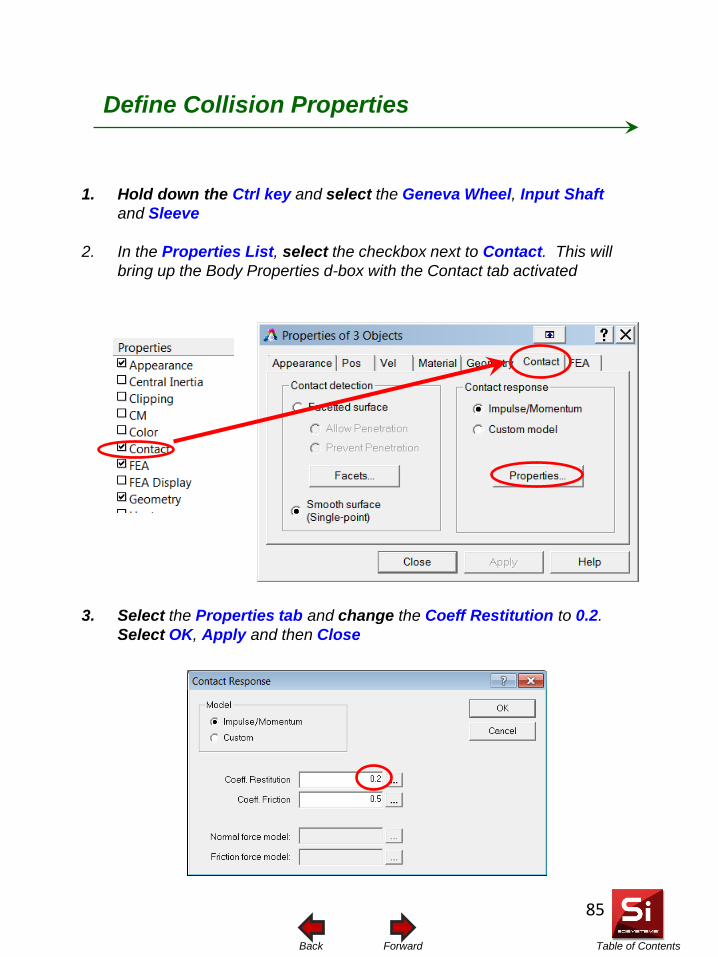
Table of Contents Forward Back
1. Hold down the Ctrl key and select the Geneva Wheel, Input Shaft and Sleeve
2. In the Properties List, select the checkbox next to Contact. This will bring up the Body Properties d-box with the Contact tab activated
3. Select the Properties tab and change the Coeff Restitution to 0.2. Select OK, Apply and then Close
Define Collision Properties
85
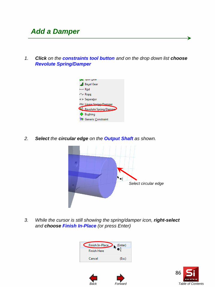
Table of Contents Forward Back
1. Click on the constraints tool button and on the drop down list choose Revolute Spring/Damper
Add a Damper
2. Select the circular edge on the Output Shaft as shown.
Select circular edge
3. While the cursor is still showing the spring/damper icon, right-select and choose Finish In-Place (or press Enter)
86
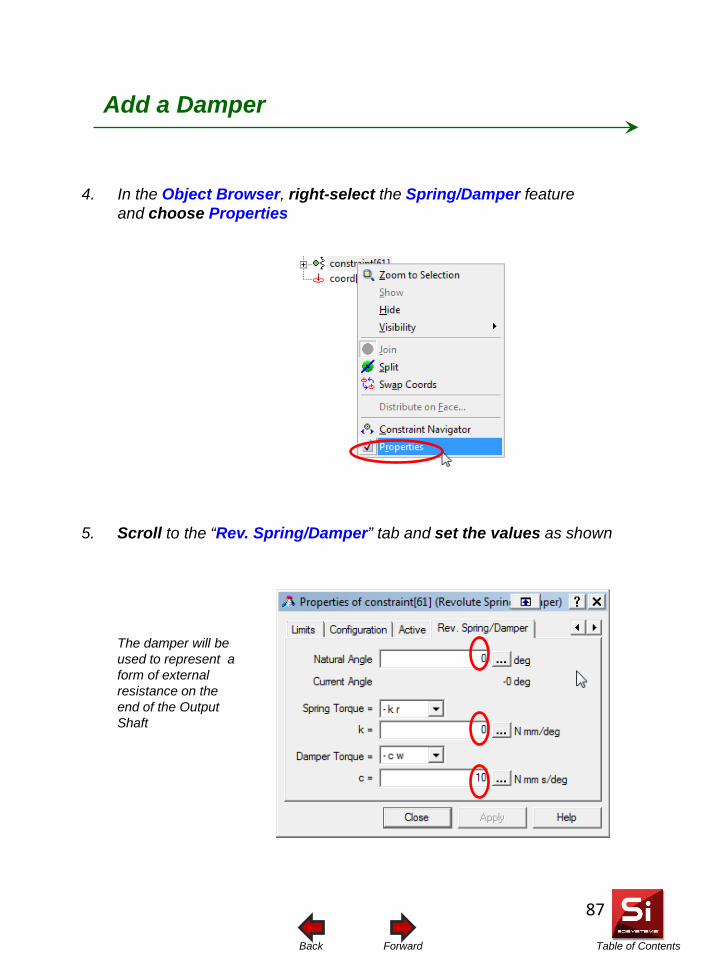
Table of Contents Forward Back
Add a Damper
5. Scroll to the “Rev. Spring/Damper” tab and set the values as shown
4. In the Object Browser, right-select the Spring/Damper feature and choose Properties
The damper will be used to represent a form of external resistance on the end of the Output Shaft
87
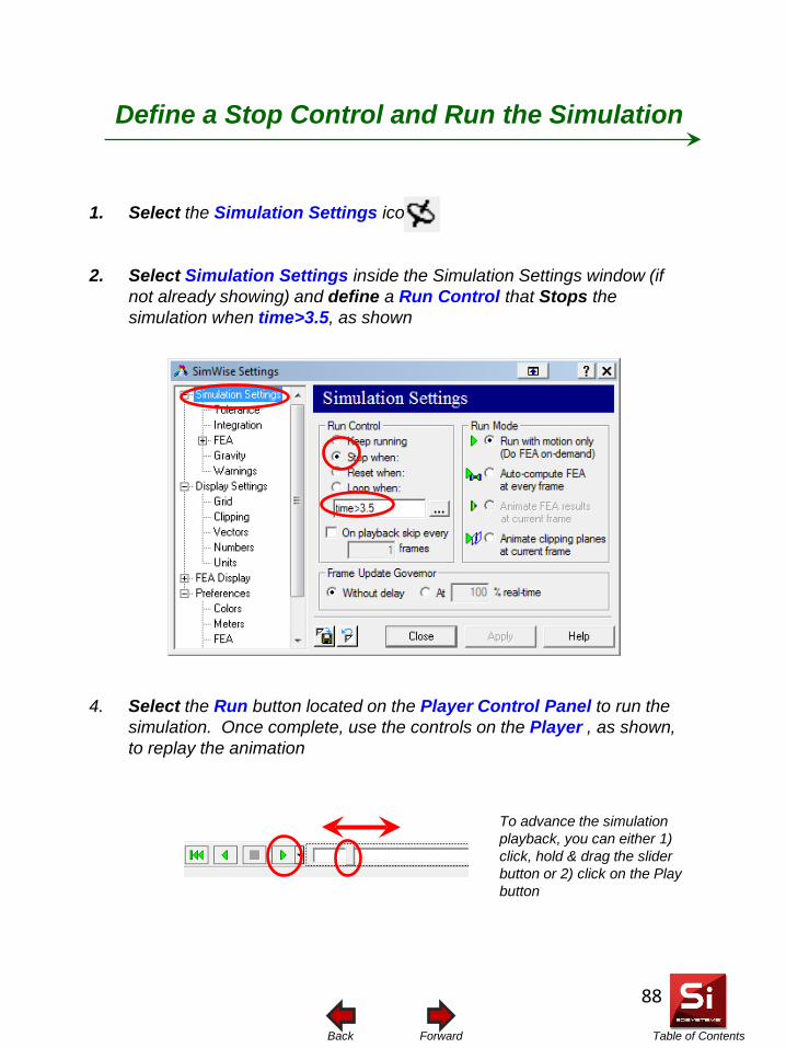
Table of Contents Forward Back
Define a Stop Control and Run the Simulation
1. Select the Simulation Settings icon
2. Select Simulation Settings inside the Simulation Settings window (if not already showing) and define a Run Control that Stops the simulation when time>3.5, as shown
4. Select the Run button located on the Player Control Panel to run the simulation. Once complete, use the controls on the Player , as shown, to replay the animation
To advance the simulation playback, you can either 1) click, hold & drag the slider button or 2) click on the Play button
88
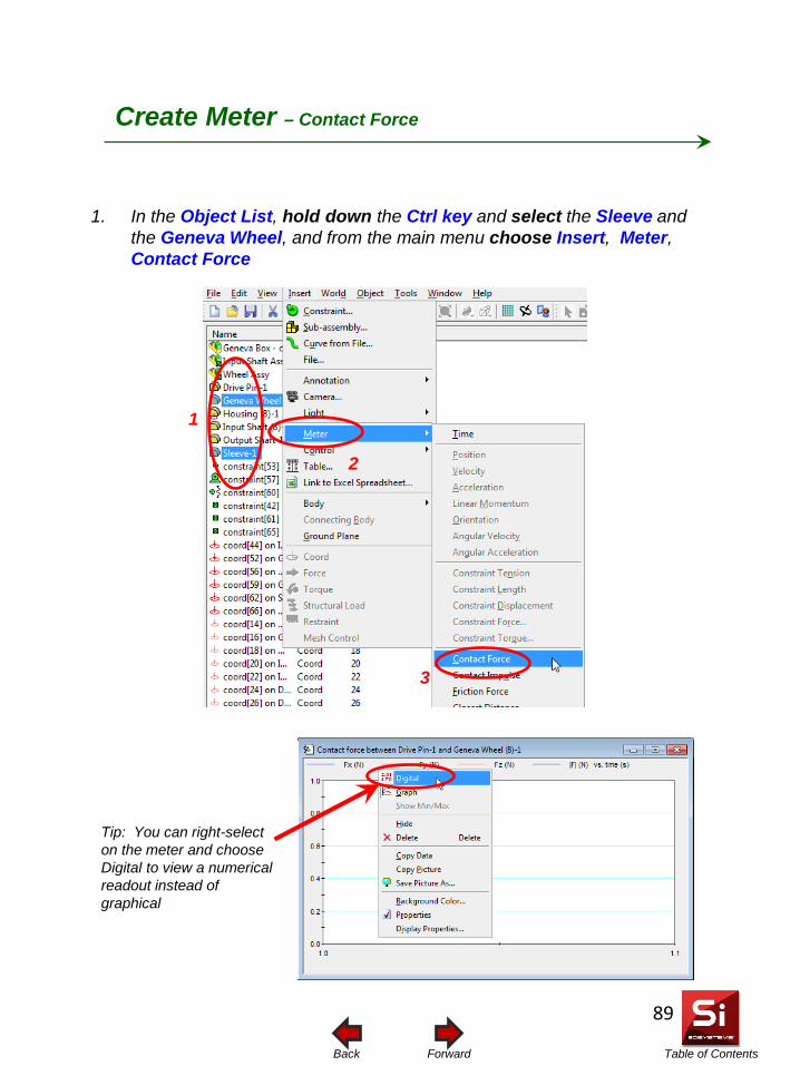
Table of Contents Forward Back
Create Meter – Contact Force
1. In the Object List, hold down the Ctrl key and select the Sleeve and the Geneva Wheel, and from the main menu choose Insert, Meter, Contact Force
Tip: You can right-select on the meter and choose Digital to view a numerical readout instead of graphical
1
2
3
89
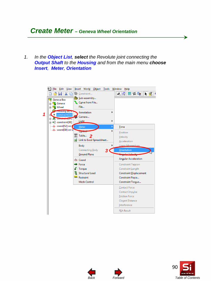
Table of Contents Forward Back
Create Meter – Geneva Wheel Orientation
1. In the Object List, select the Revolute joint connecting the Output Shaft to the Housing and from the main menu choose Insert, Meter, Orientation
1
2
3
90
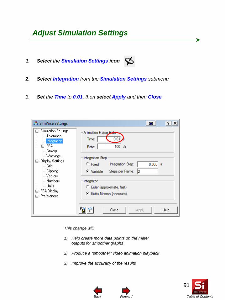
Table of Contents Forward Back
Adjust Simulation Settings
1. Select the Simulation Settings icon
2. Select Integration from the Simulation Settings submenu
3. Set the Time to 0.01, then select Apply and then Close
This change will: 1) Help create more data points on the meter
outputs for smoother graphs
2) Produce a “smoother” video animation playback
3) Improve the accuracy of the results
91
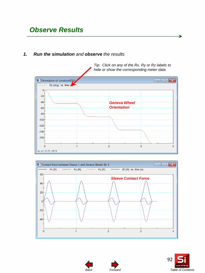
Table of Contents Forward Back
Observe Results
1. Run the simulation and observe the results
Geneva Wheel Orientation
Sleeve Contact Force
Tip: Click on any of the Rx, Ry or Rz labels to hide or show the corresponding meter data
92
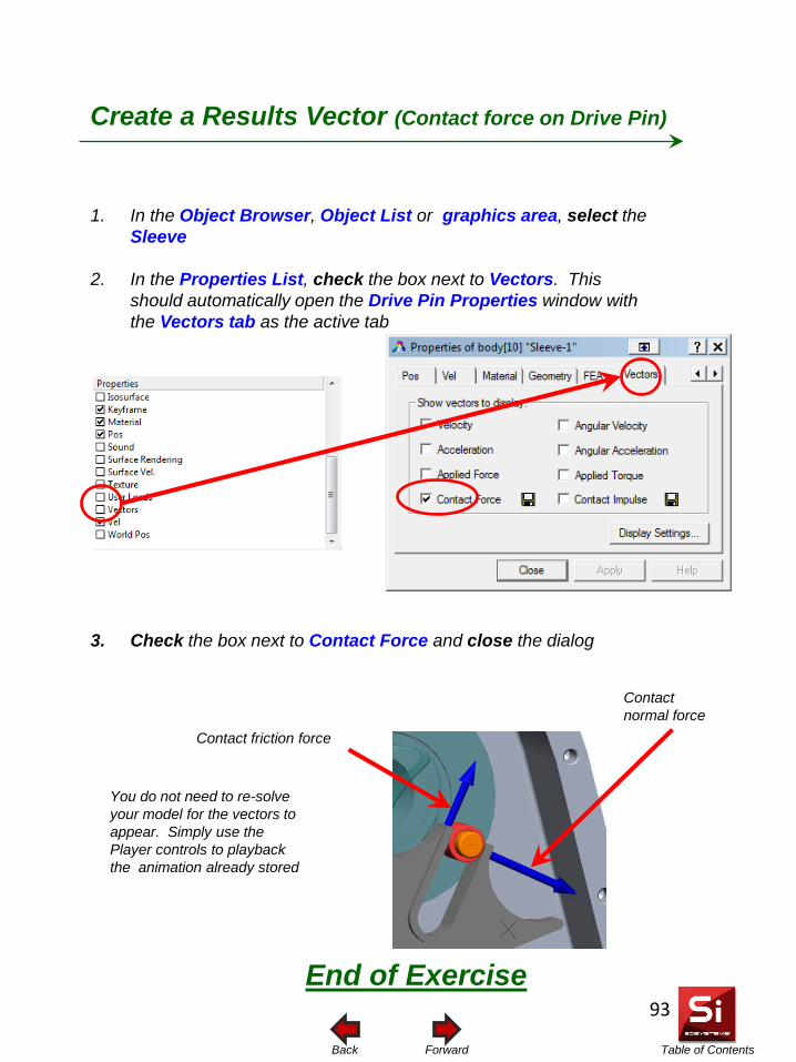
Table of Contents Forward Back
Create a Results Vector (Contact force on Drive Pin)
1. In the Object Browser, Object List or graphics area, select the Sleeve
2. In the Properties List, check the box next to Vectors. This should automatically open the Drive Pin Properties window with the Vectors tab as the active tab
3. Check the box next to Contact Force and close the dialog
You do not need to re-solve your model for the vectors to appear. Simply use the Player controls to playback the animation already stored
Contact friction force
Contact normal force
End of Exercise
93
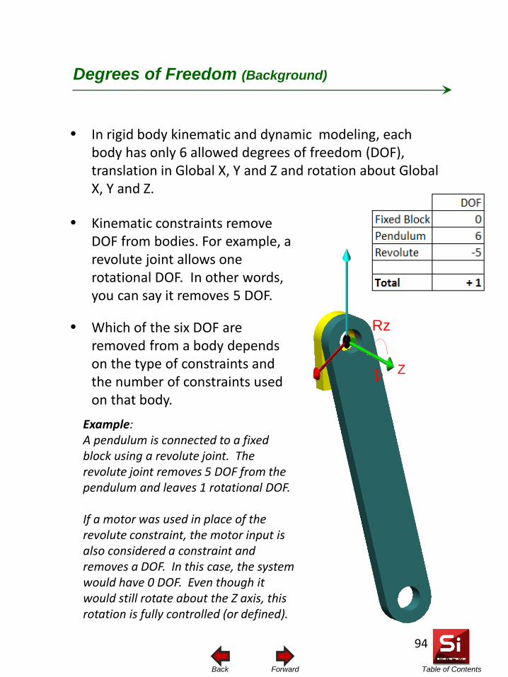
Table of Contents Forward Back
• In rigid body kinematic and dynamic modeling, each body has only 6 allowed degrees of freedom (DOF), translation in Global X, Y and Z and rotation about Global X, Y and Z.
• Kinematic constraints remove DOF from bodies. For example, a revolute joint allows one rotational DOF. In other words, you can say it removes 5 DOF.
• Which of the six DOF are removed from a body depends on the type of constraints and the number of constraints used on that body.
Rz
Z
Example: A pendulum is connected to a fixed block using a revolute joint. The revolute joint removes 5 DOF from the pendulum and leaves 1 rotational DOF. If a motor was used in place of the revolute constraint, the motor input is also considered a constraint and removes a DOF. In this case, the system would have 0 DOF. Even though it would still rotate about the Z axis, this rotation is fully controlled (or defined).
Degrees of Freedom (Background)
94
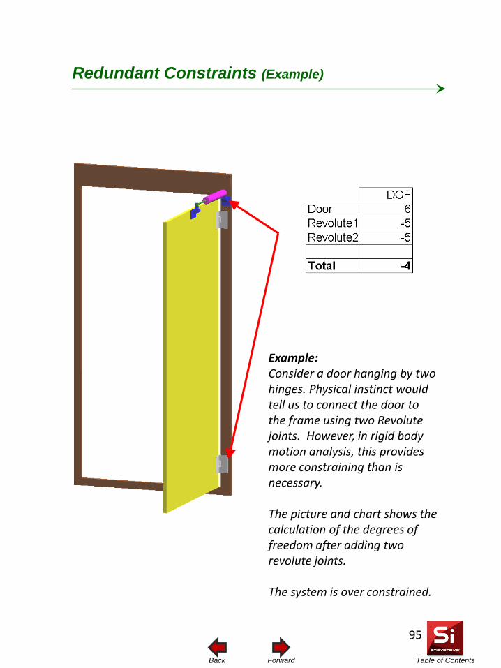
Table of Contents Forward Back
Example: Consider a door hanging by two hinges. Physical instinct would tell us to connect the door to the frame using two Revolute joints. However, in rigid body motion analysis, this provides more constraining than is necessary. The picture and chart shows the calculation of the degrees of freedom after adding two revolute joints. The system is over constrained.
Redundant Constraints (Example)
95
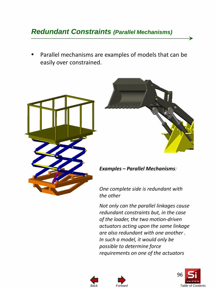
Table of Contents Forward Back
• Parallel mechanisms are examples of models that can be easily over constrained.
Examples – Parallel Mechanisms:
One complete side is redundant with the other
Not only can the parallel linkages cause redundant constraints but, in the case of the loader, the two motion-driven actuators acting upon the same linkage are also redundant with one another . In such a model, it would only be possible to determine force requirements on one of the actuators
Redundant Constraints (Parallel Mechanisms)
96
Table of Contents Forward Back
• The SW constraint equations define the position and orientation for the particular DOFs of the body. Only one set of equations is necessary to define the DOF of a body. When constraint equations are solved for, forces and moments are used to satisfy the solution to these equations. It is these same forces and moments that the user can measure or create meters from.
• Adding in more equations by way of adding more joints creates redundancies. In other words, once constraint becomes redundant with another trying to control the same DOF
• In order to make the simulation solvable, the SW solver will
randomly remove any redundant DOF equations. As a result, there will be no reaction force present in the redundant direction for this constraint.
Redundant Constraints (The Problem)
97
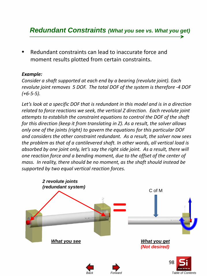
Table of Contents Forward Back
Example: Consider a shaft supported at each end by a bearing (revolute joint). Each revolute joint removes 5 DOF. The total DOF of the system is therefore -4 DOF (+6-5-5).
Let’s look at a specific DOF that is redundant in this model and is in a direction related to force reactions we seek, the vertical Z direction. Each revolute joint attempts to establish the constraint equations to control the DOF of the shaft for this direction (keep it from translating in Z). As a result, the solver allows only one of the joints (right) to govern the equations for this particular DOF and considers the other constraint redundant. As a result, the solver now sees the problem as that of a cantilevered shaft. In other words, all vertical load is absorbed by one joint only, let’s say the right side joint. As a result, there will one reaction force and a bending moment, due to the offset of the center of mass. In reality, there should be no moment, as the shaft should instead be supported by two equal vertical reaction forces.
= 2 revolute joints (redundant system)
C of M
• Redundant constraints can lead to inaccurate force and moment results plotted from certain constraints.
Redundant Constraints (What you see vs. What you get)
What you see What you get (Not desired)
98
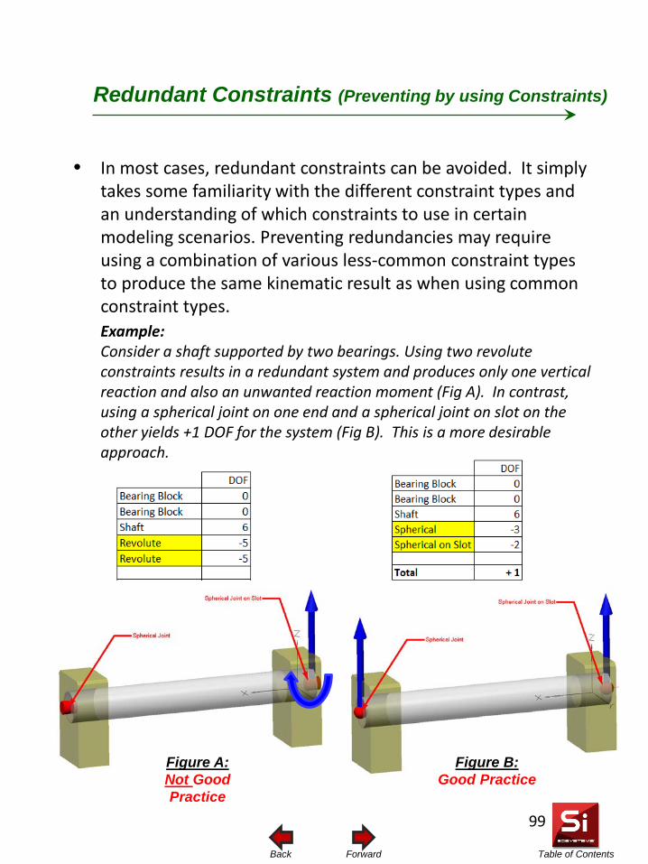
Table of Contents Forward Back
• In most cases, redundant constraints can be avoided. It simply takes some familiarity with the different constraint types and an understanding of which constraints to use in certain modeling scenarios. Preventing redundancies may require using a combination of various less-common constraint types to produce the same kinematic result as when using common constraint types. Example: Consider a shaft supported by two bearings. Using two revolute constraints results in a redundant system and produces only one vertical reaction and also an unwanted reaction moment (Fig A). In contrast, using a spherical joint on one end and a spherical joint on slot on the other yields +1 DOF for the system (Fig B). This is a more desirable approach.
Figure A: Not Good Practice
Figure B: Good Practice
Redundant Constraints (Preventing by using Constraints)
99
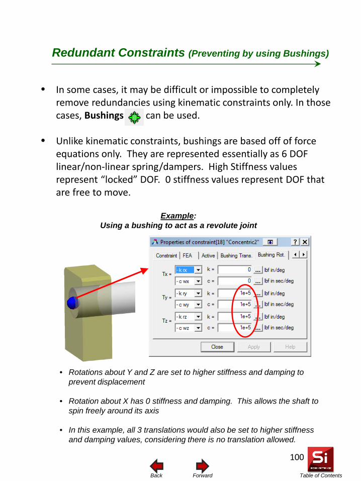
Table of Contents Forward Back
• In some cases, it may be difficult or impossible to completely remove redundancies using kinematic constraints only. In those cases, Bushings can be used.
• Unlike kinematic constraints, bushings are based off of force equations only. They are represented essentially as 6 DOF linear/non-linear spring/dampers. High Stiffness values represent “locked” DOF. 0 stiffness values represent DOF that are free to move.
• Rotations about Y and Z are set to higher stiffness and damping to prevent displacement
• Rotation about X has 0 stiffness and damping. This allows the shaft to spin freely around its axis
• In this example, all 3 translations would also be set to higher stiffness and damping values, considering there is no translation allowed.
Example: Using a bushing to act as a revolute joint
Redundant Constraints (Preventing by using Bushings)
100
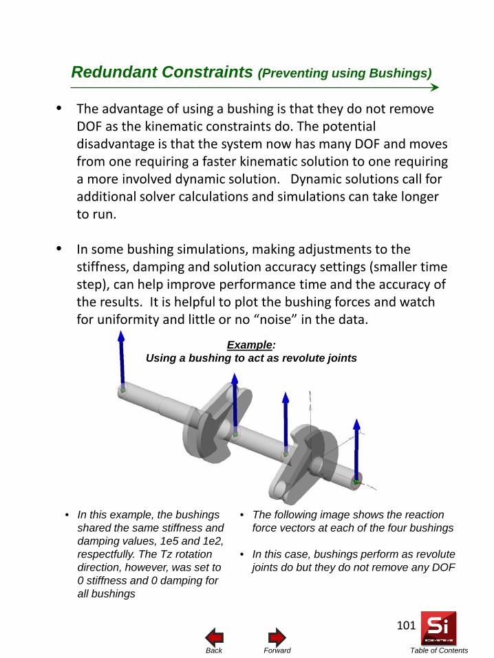
Table of Contents Forward Back
• The advantage of using a bushing is that they do not remove DOF as the kinematic constraints do. The potential disadvantage is that the system now has many DOF and moves from one requiring a faster kinematic solution to one requiring a more involved dynamic solution. Dynamic solutions call for additional solver calculations and simulations can take longer to run.
• In some bushing simulations, making adjustments to the stiffness, damping and solution accuracy settings (smaller time step), can help improve performance time and the accuracy of the results. It is helpful to plot the bushing forces and watch for uniformity and little or no “noise” in the data.
• The following image shows the reaction force vectors at each of the four bushings
• In this case, bushings perform as revolute joints do but they do not remove any DOF
• In this example, the bushings shared the same stiffness and damping values, 1e5 and 1e2, respectfully. The Tz rotation direction, however, was set to 0 stiffness and 0 damping for all bushings
Redundant Constraints (Preventing using Bushings)
Example: Using a bushing to act as revolute joints
101
Table of Contents Forward Back
• Redundant constraints are an issue only if the user needs to determine reaction forces or moments on particular constraints OR the user needs to perform an FEA study using motion-calculated load information.
• A redundant model may cause some constraint directions to yield 0 force readings and can induce reaction moments where there should not be any.
• In preventing redundant constraints, it may be necessary to use a combination of less-common constraints that are not as intuitive as the basic more common constraints. For example, it is not intuitive to use a spherical joint and a spherical joint on slot to constrain a door with two pivoting hinges. But it is a viable approach in rigid body simulation.
• Bushings can be used where it becomes difficult to prevent redundant constraints using kinematic joints. For example, there is no way to constrain a shaft to three bearings using kinematic constraints and not have the system be redundant. The system becomes statically indeterminate. Bushings are force-based constraints and do not remove any DOF.
• In a redundant model, a kinematic simulation can still run and calculations for displacements, velocities and accelerations will be accurate.
Redundant Constraints (Summary)
102
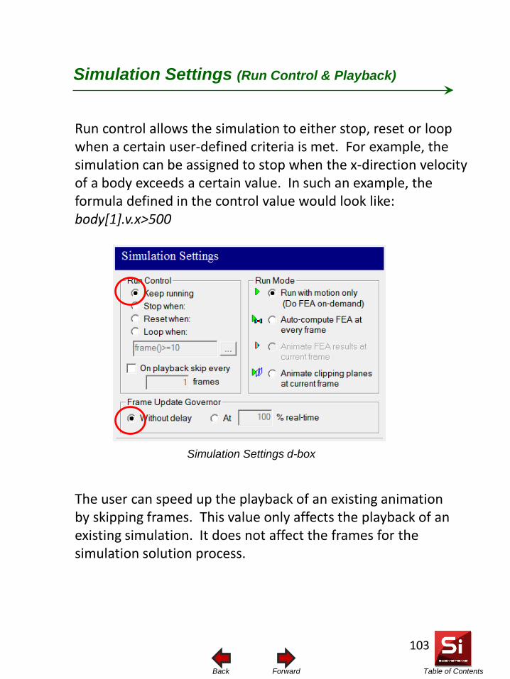
Table of Contents Forward Back
Run control allows the simulation to either stop, reset or loop when a certain user-defined criteria is met. For example, the simulation can be assigned to stop when the x-direction velocity of a body exceeds a certain value. In such an example, the formula defined in the control value would look like: body[1].v.x>500
Simulation Settings (Run Control & Playback)
The user can speed up the playback of an existing animation by skipping frames. This value only affects the playback of an existing simulation. It does not affect the frames for the simulation solution process.
Simulation Settings d-box
103
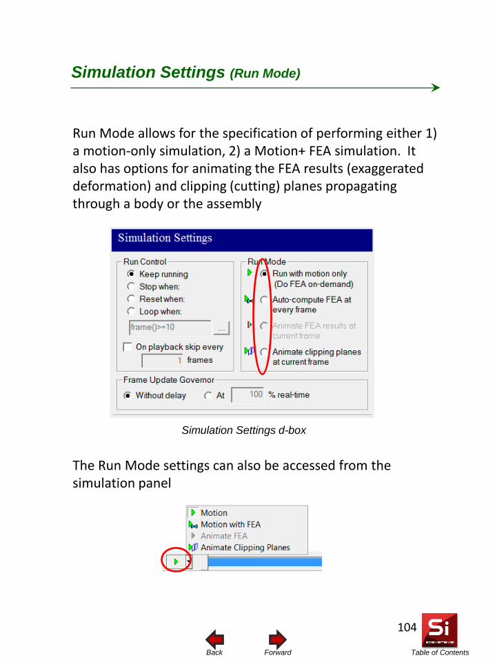
Table of Contents Forward Back
Run Mode allows for the specification of performing either 1) a motion-only simulation, 2) a Motion+ FEA simulation. It also has options for animating the FEA results (exaggerated deformation) and clipping (cutting) planes propagating through a body or the assembly
Simulation Settings (Run Mode)
The Run Mode settings can also be accessed from the simulation panel
Simulation Settings d-box
104
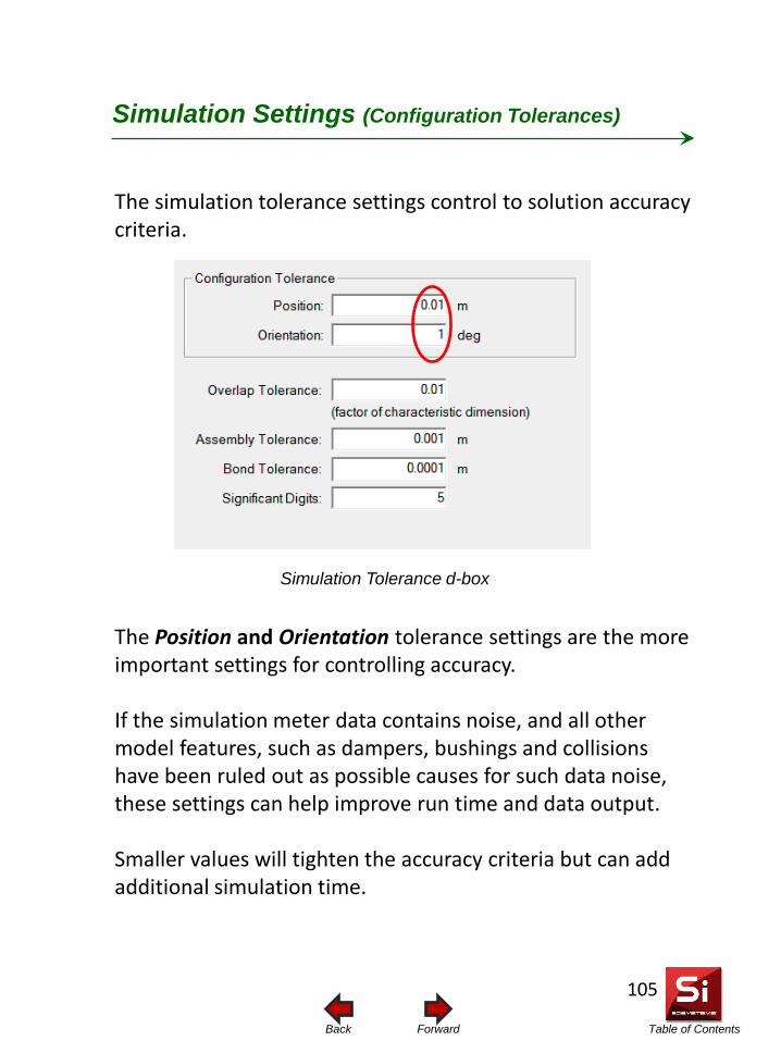
Table of Contents Forward Back
The simulation tolerance settings control to solution accuracy criteria.
Simulation Settings (Configuration Tolerances)
The Position and Orientation tolerance settings are the more important settings for controlling accuracy. If the simulation meter data contains noise, and all other model features, such as dampers, bushings and collisions have been ruled out as possible causes for such data noise, these settings can help improve run time and data output. Smaller values will tighten the accuracy criteria but can add additional simulation time.
Simulation Tolerance d-box
105
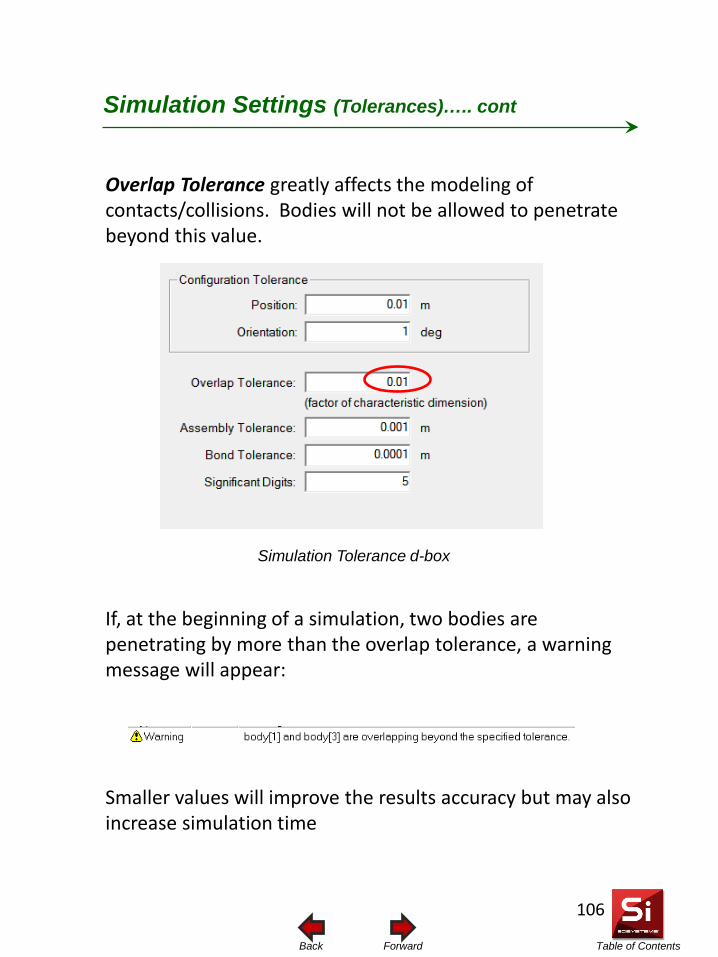
Table of Contents Forward Back
Simulation Settings (Tolerances)….. cont
Overlap Tolerance greatly affects the modeling of contacts/collisions. Bodies will not be allowed to penetrate beyond this value. If, at the beginning of a simulation, two bodies are penetrating by more than the overlap tolerance, a warning message will appear: Smaller values will improve the results accuracy but may also increase simulation time
Simulation Tolerance d-box
106
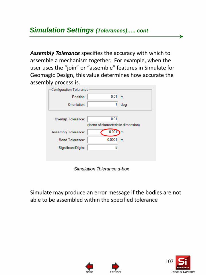
Table of Contents Forward Back
Simulation Settings (Tolerances)….. cont
Assembly Tolerance specifies the accuracy with which to assemble a mechanism together. For example, when the user uses the “join” or “assemble” features in Simulate for Geomagic Design, this value determines how accurate the assembly process is. Simulate may produce an error message if the bodies are not able to be assembled within the specified tolerance
Simulation Tolerance d-box
107

Table of Contents Forward Back
Simulation Settings (Bond Tolerance)
The Bond Tolerance is the maximum amount two bodies can be separated and still be bonded together using the FEA bond option. If the separation is greater than this value, bonding will not take place For the bonding feature to work, there must be a constraint defined between the two bodies to be bonded, even if it is a rigid constraint. Also, the bodies must be included in FEA.
Simulation Tolerance d-box
108
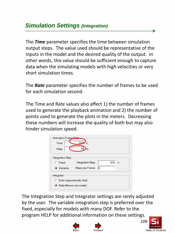
Table of Contents Forward Back
Simulation Settings (Integration)
The Time parameter specifies the time between simulation output steps. The value used should be representative of the inputs in the model and the desired quality of the output. In other words, this value should be sufficient enough to capture data when the simulating models with high velocities or very short simulation times. The Rate parameter specifies the number of frames to be used for each simulation second. The Time and Rate values also affect 1) the number of frames used to generate the playback animation and 2) the number of points used to generate the plots in the meters. Decreasing these numbers will increase the quality of both but may also hinder simulation speed.
The Integration Step and Integrator settings are rarely adjusted by the user. The variable integration step is preferred over the fixed, especially for models with many DOF. Refer to the program HELP for additional information on these settings.
109
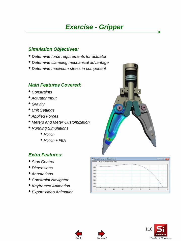
Table of Contents Forward Back
Simulation Objectives: • Determine force requirements for actuator • Determine clamping mechanical advantage • Determine maximum stress in component
Main Features Covered:
Exercise - Gripper
• Stop Control • Dimensions • Annotations • Constraint Navigator • Keyframed Animation • Export Video Animation
Extra Features:
• Constraints • Actuator Input • Gravity • Unit Settings • Applied Forces • Meters and Meter Customization • Running Simulations
• Motion • Motion + FEA
110
Table of Contents Forward Back
Introduction
You will start the tutorial by opening a Simulate model of a Gripper mechanism, which is based on the principals of a four-bar linkage. You will then define the necessary kinematic constraints, and actuator input and external forces. Finally, you will analyze the model for kinematic and structural characteristics.
This tutorial is designed to introduce you to some of the basic capabilities of Simulate for Geomagic Design and help you get acquainted with how to prepare, run, and explore a basic motion and finite element analysis. Although not mandatory, it is highly recommended that you review the section titled FEA Modeling Basics.
111
Table of Contents Forward Back
Whether the Gripper is to be powered hydraulically or pneumatically is irrelevant to the simulation. In either case, there will be an average amount of input force required by the actuator to achieve a specified clamping force. With Simulate for Geomagic Design you will be able to use a reverse-engineering approach by specifying the desired clamping force and then having the simulation calculate the force input requirements at the actuator. An important aspect of the Gripper is the mechanical advantage (or disadvantage) it offers. Whether it is a mechanical advantage or disadvantage will depend on the size and arrangement of the linkages. In the case of a mechanical advantage, a small actuator input force will produce a larger output clamping force. And in the case of a disadvantage, the opposite will be true. With Simulate for Geomagic Design you will be able to easily plot the output vs. input characteristics of the mechanism and determine the overall mechanical advantage. Finally, the strength of the mechanism is important in determining whether or not mechanism components will fail (or deflect too much) while under normal operating conditions. With Simulate for Geomagic Design you will use the “Motion with FEA” feature to perform a simultaneous kinematic motion and Finite Element Analysis on a critical component, being sure to cover all ranges of possible load conditions and determining whether or not the component will reach the point of yielding (onset of failure).
Mechanism Background
112
Table of Contents Forward Back
Open the Simulate model
1. Start Simulate for Geomagic Design
2. Select File, Open and Browse and locate the file called “Simulate for Geomagic Design Tutorial – Gripper.wm3”.
113
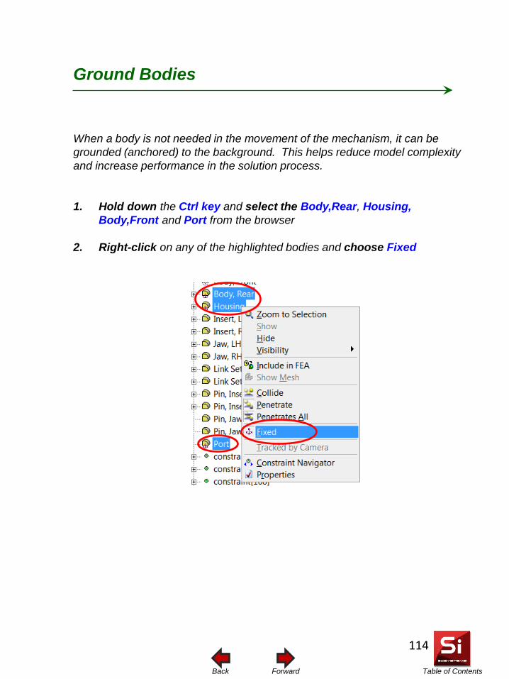
Table of Contents Forward Back
When a body is not needed in the movement of the mechanism, it can be grounded (anchored) to the background. This helps reduce model complexity and increase performance in the solution process.
1. Hold down the Ctrl key and select the Body,Rear, Housing, Body,Front and Port from the browser
2. Right-click on any of the highlighted bodies and choose Fixed
Ground Bodies
114
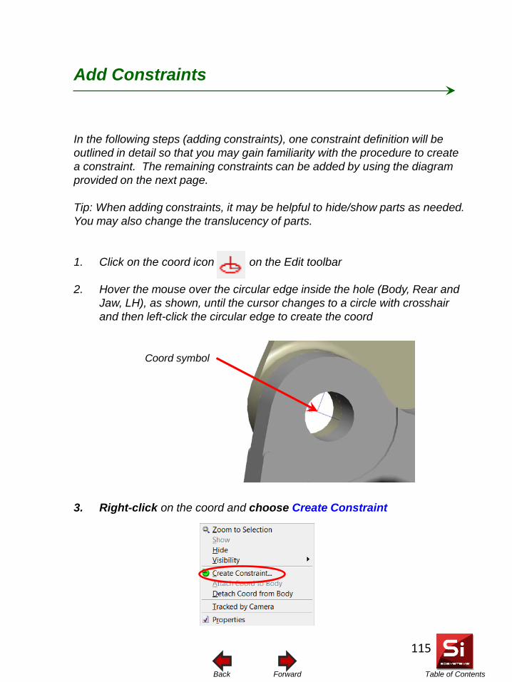
Table of Contents Forward Back
In the following steps (adding constraints), one constraint definition will be outlined in detail so that you may gain familiarity with the procedure to create a constraint. The remaining constraints can be added by using the diagram provided on the next page. Tip: When adding constraints, it may be helpful to hide/show parts as needed. You may also change the translucency of parts.
1. Click on the coord icon on the Edit toolbar
2. Hover the mouse over the circular edge inside the hole (Body, Rear and Jaw, LH), as shown, until the cursor changes to a circle with crosshair and then left-click the circular edge to create the coord
3. Right-click on the coord and choose Create Constraint
Add Constraints
Coord symbol
115
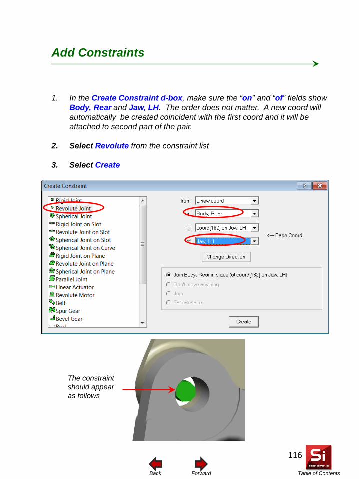
Table of Contents Forward Back
1. In the Create Constraint d-box, make sure the “on” and “of” fields show Body, Rear and Jaw, LH. The order does not matter. A new coord will automatically be created coincident with the first coord and it will be attached to second part of the pair.
2. Select Revolute from the constraint list
3. Select Create
Add Constraints
The constraint should appear as follows
116

Table of Contents Forward Back
The assembly is symmetrical. Therefore, only one side of the assembly will be labeled with the necessary constraints. The constraint types used on the other side are identical to the first. Constraints that have a symmetrical counterpart are marked with an *. When creating the constraints, choose locations that best represent the physical connection center.
Add Constraints
* Body, Rear / Jaw, LH (REVOLUTE)
* Link Set, LH / Shaft (REVOLUTE)
* Link Set, LH / Jaw, LH (REVOLUTE)
Piston / Shaft (RIGID)
* Body, Rear / Pin, Jaw LH (RIGID)
* Insert, LH / Pin, Insert LH (RIGID)
* Jaw, LH / Pin, Insert LH (RIGID)
Shaft / Housing (RIGID ON SLOT)
Created in previous step
117
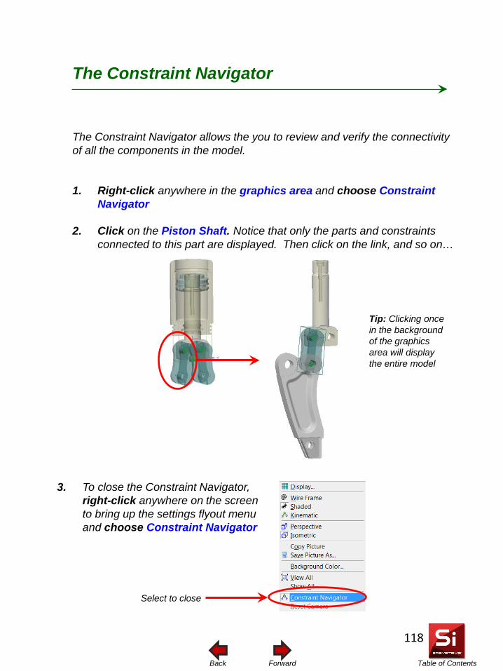
Table of Contents Forward Back
The Constraint Navigator allows the you to review and verify the connectivity of all the components in the model.
1. Right-click anywhere in the graphics area and choose Constraint Navigator
2. Click on the Piston Shaft. Notice that only the parts and constraints connected to this part are displayed. Then click on the link, and so on…
The Constraint Navigator
3. To close the Constraint Navigator, right-click anywhere on the screen to bring up the settings flyout menu and choose Constraint Navigator
Tip: Clicking once in the background of the graphics area will display the entire model
Select to close
118
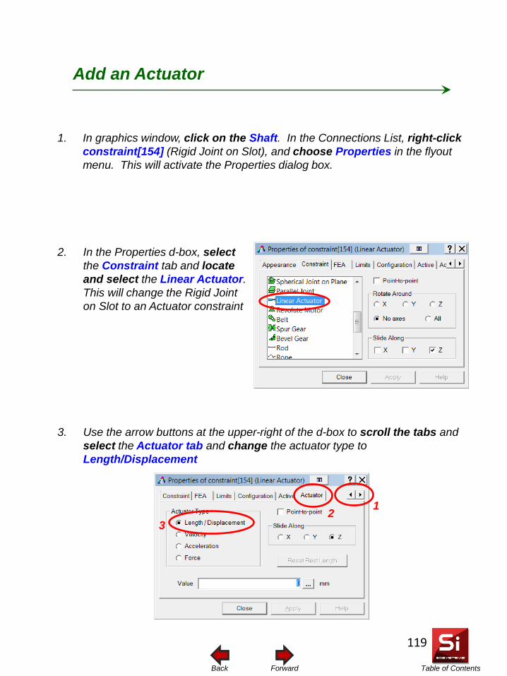
Table of Contents Forward Back
1. In graphics window, click on the Shaft. In the Connections List, right-click constraint[154] (Rigid Joint on Slot), and choose Properties in the flyout menu. This will activate the Properties dialog box.
Add an Actuator
3. Use the arrow buttons at the upper-right of the d-box to scroll the tabs and select the Actuator tab and change the actuator type to Length/Displacement
2. In the Properties d-box, select the Constraint tab and locate and select the Linear Actuator. This will change the Rigid Joint on Slot to an Actuator constraint
1 2 3
119
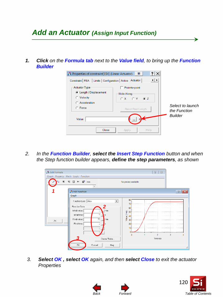
Table of Contents Forward Back
1. Click on the Formula tab next to the Value field, to bring up the Function Builder
Add an Actuator (Assign Input Function)
Select to launch the Function Builder
2. In the Function Builder, select the Insert Step Function button and when the Step function builder appears, define the step parameters, as shown
1
2
3
3. Select OK , select OK again, and then select Close to exit the actuator Properties
120
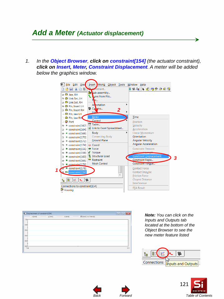
Table of Contents Forward Back
1. In the Object Browser, click on constraint[154] (the actuator constraint), click on Insert, Meter, Constraint Displacement. A meter will be added below the graphics window.
Add a Meter (Actuator displacement)
1
2
3
Note: You can click on the Inputs and Outputs tab located at the bottom of the Object Browser to see the new meter feature listed
121
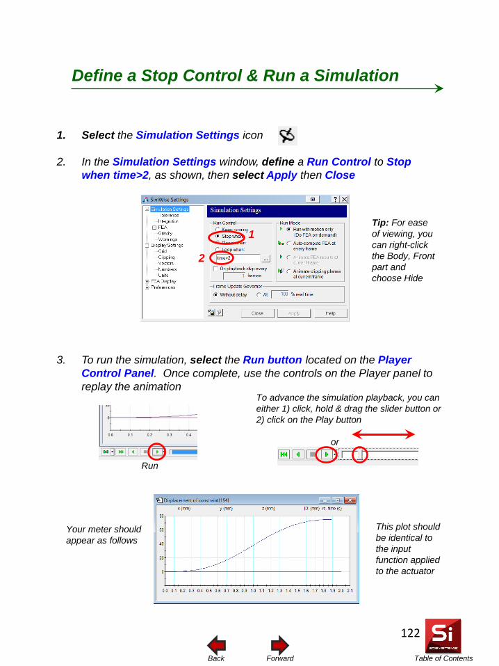
Table of Contents Forward Back
1. Select the Simulation Settings icon
2. In the Simulation Settings window, define a Run Control to Stop when time>2, as shown, then select Apply then Close
3. To run the simulation, select the Run button located on the Player Control Panel. Once complete, use the controls on the Player panel to replay the animation
To advance the simulation playback, you can either 1) click, hold & drag the slider button or 2) click on the Play button
Define a Stop Control & Run a Simulation
or
Your meter should appear as follows
This plot should be identical to the input function applied to the actuator
Run
Tip: For ease of viewing, you can right-click the Body, Front part and choose Hide
1
2
122
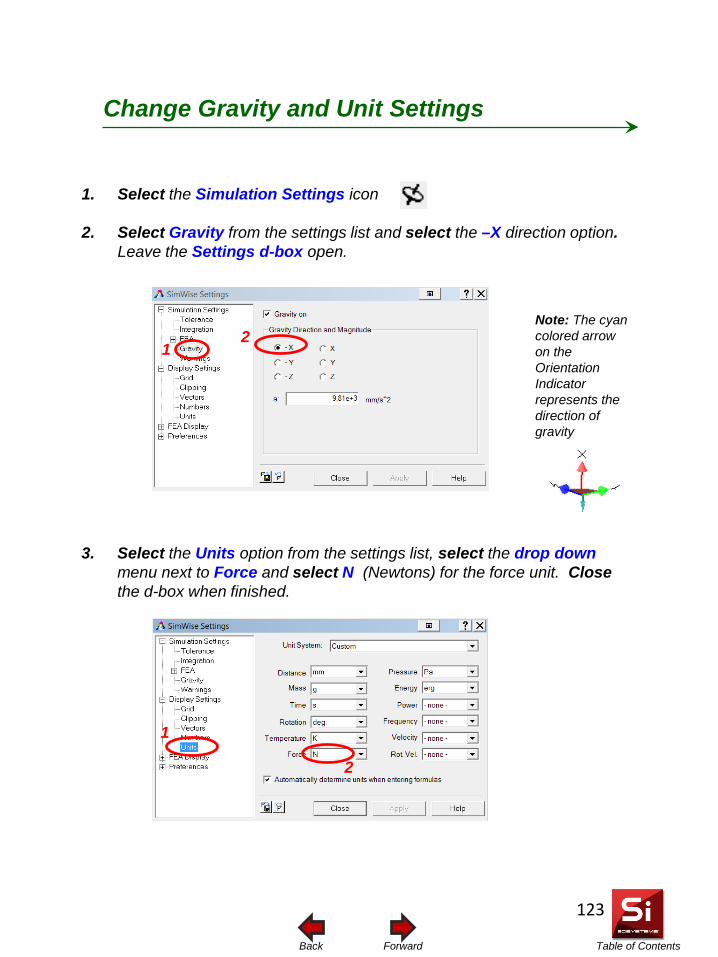
Table of Contents Forward Back
1. Select the Simulation Settings icon
2. Select Gravity from the settings list and select the –X direction option. Leave the Settings d-box open.
3. Select the Units option from the settings list, select the drop down menu next to Force and select N (Newtons) for the force unit. Close the d-box when finished.
Change Gravity and Unit Settings
Note: The cyan colored arrow on the Orientation Indicator represents the direction of gravity
2 1
2
1
123
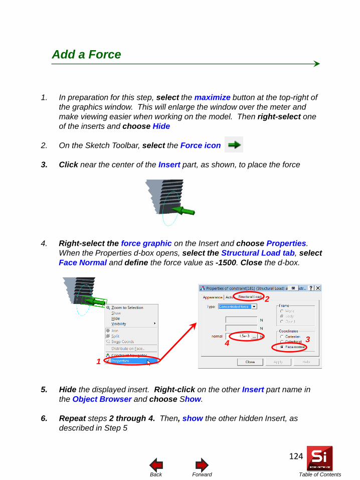
Table of Contents Forward Back
1. In preparation for this step, select the maximize button at the top-right of the graphics window. This will enlarge the window over the meter and make viewing easier when working on the model. Then right-select one of the inserts and choose Hide
2. On the Sketch Toolbar, select the Force icon
3. Click near the center of the Insert part, as shown, to place the force
4. Right-select the force graphic on the Insert and choose Properties. When the Properties d-box opens, select the Structural Load tab, select Face Normal and define the force value as -1500. Close the d-box.
Add a Force
4 3
2
5. Hide the displayed insert. Right-click on the other Insert part name in the Object Browser and choose Show.
6. Repeat steps 2 through 4. Then, show the other hidden Insert, as described in Step 5
1
124
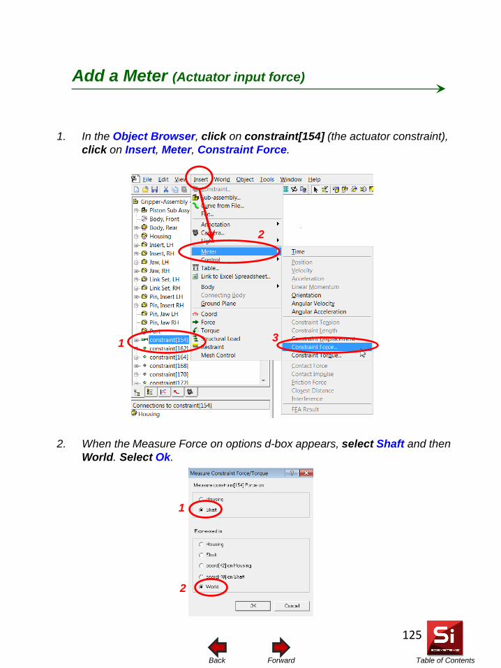
Table of Contents Forward Back
1. In the Object Browser, click on constraint[154] (the actuator constraint), click on Insert, Meter, Constraint Force.
2. When the Measure Force on options d-box appears, select Shaft and then World. Select Ok.
Add a Meter (Actuator input force)
1
2
3
1
2
125
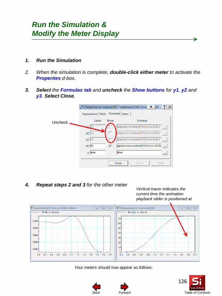
Table of Contents Forward Back
1. Run the Simulation
2. When the simulation is complete, double-click either meter to activate the Properties d-box.
3. Select the Formulas tab and uncheck the Show buttons for y1, y2 and y3. Select Close.
4. Repeat steps 2 and 3 for the other meter
Run the Simulation & Modify the Meter Display
Uncheck
Your meters should now appear as follows:
Vertical tracer indicates the current time the animation playback slider is positioned at
126
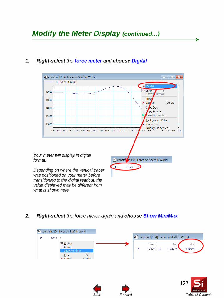
Table of Contents Forward Back
1. Right-select the force meter and choose Digital
2. Right-select the force meter again and choose Show Min/Max
Modify the Meter Display (continued…)
Your meter will display in digital format. Depending on where the vertical tracer was positioned on your meter before transitioning to the digital readout, the value displayed may be different from what is shown here
127
Table of Contents Forward Back
Your digital meter should read a maximum force of 1.53e+4N (15,300 N). This is the amount of actuator input force necessary to achieve a total clamping force of 3,000N (1,500N x 2). Note also there is a minimum input force requirement of 1.28e+4N (12,800 N). The maximum mechanical advantage of the mechanism is therefore:
Output / Input
or 3,000 N/ 15,300N = .2
It is important to note that because the value is less than 1.0, there is actually a mechanical disadvantage. There is more force required by the actuator than there is being produced at the output of the jaws. We also recognize that the relationship between the input and output is not entirely linear. It varies depending on the position of the piston. We can see this by using the minimum force input (1.28e4N) to calculate a mechanical disadvantage value of approximately 0.23.
Actuator Force Requirements and Mechanical Advantage
128
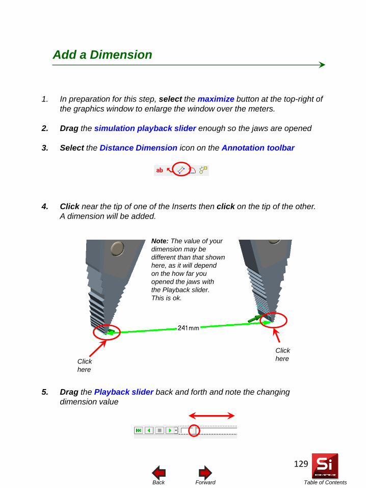
Table of Contents Forward Back
1. In preparation for this step, select the maximize button at the top-right of the graphics window to enlarge the window over the meters.
2. Drag the simulation playback slider enough so the jaws are opened
3. Select the Distance Dimension icon on the Annotation toolbar
4. Click near the tip of one of the Inserts then click on the tip of the other. A dimension will be added.
5. Drag the Playback slider back and forth and note the changing dimension value
Add a Dimension
Note: The value of your dimension may be different than that shown here, as it will depend on the how far you opened the jaws with the Playback slider. This is ok.
Click here Click
here
129
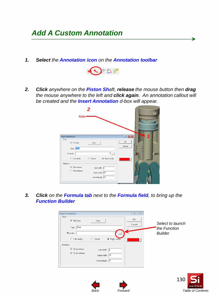
Table of Contents Forward Back
1. Select the Annotation icon on the Annotation toolbar
2. Click anywhere on the Piston Shaft, release the mouse button then drag the mouse anywhere to the left and click again. An annotation callout will be created and the Insert Annotation d-box will appear.
3. Click on the Formula tab next to the Formula field, to bring up the Function Builder
Add A Custom Annotation
Select to launch the Function Builder
1
2
130
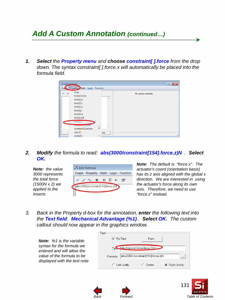
Table of Contents Forward Back
1. Select the Property menu and choose constraint[ ].force from the drop down. The syntax constraint[ ].force.x will automatically be placed into the formula field.
2. Modify the formula to read: abs(3000/constraint[154].force.z)N . Select OK.
3. Back in the Property d-box for the annotation, enter the following text into the Text field: Mechanical Advantage (%1) . Select OK. The custom callout should now appear in the graphics window.
Add A Custom Annotation (continued…)
Note: The default is “force.x”. The actuator's coord (orientation basis) has its z axis aligned with the global x direction. We are interested in using the actuator's force along its own axis. Therefore, we need to use “force.z” instead.
Note: the value 3000 represents the total force (1500N x 2) we applied to the Inserts
Note: %1 is the variable syntax for the formula we entered and will allow the value of the formula to be displayed with the text note
131
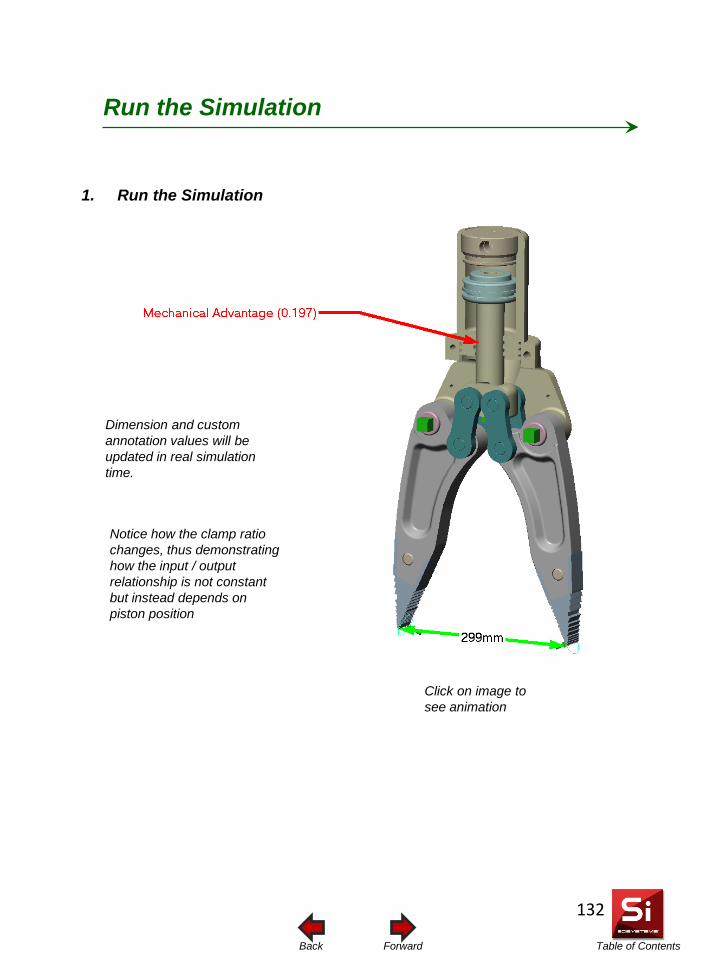
Table of Contents Forward Back
1. Run the Simulation
Dimension and custom annotation values will be updated in real simulation time.
Run the Simulation
Notice how the clamp ratio changes, thus demonstrating how the input / output relationship is not constant but instead depends on piston position
Click on image to see animation
132
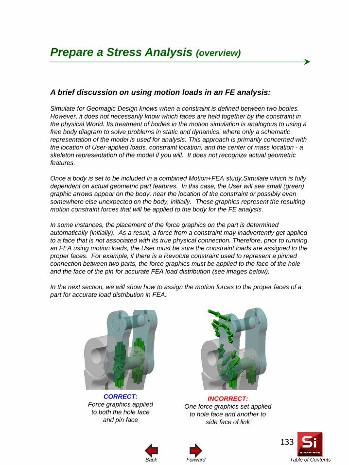
Table of Contents Forward Back
Prepare a Stress Analysis (overview)
A brief discussion on using motion loads in an FE analysis: Simulate for Geomagic Design knows when a constraint is defined between two bodies. However, it does not necessarily know which faces are held together by the constraint in the physical World. Its treatment of bodies in the motion simulation is analogous to using a free body diagram to solve problems in static and dynamics, where only a schematic representation of the model is used for analysis. This approach is primarily concerned with the location of User-applied loads, constraint location, and the center of mass location - a skeleton representation of the model if you will. It does not recognize actual geometric features. Once a body is set to be included in a combined Motion+FEA study,Simulate which is fully dependent on actual geometric part features. In this case, the User will see small (green) graphic arrows appear on the body, near the location of the constraint or possibly even somewhere else unexpected on the body, initially. These graphics represent the resulting motion constraint forces that will be applied to the body for the FE analysis. In some instances, the placement of the force graphics on the part is determined automatically (initially). As a result, a force from a constraint may inadvertently get applied to a face that is not associated with its true physical connection. Therefore, prior to running an FEA using motion loads, the User must be sure the constraint loads are assigned to the proper faces. For example, if there is a Revolute constraint used to represent a pinned connection between two parts, the force graphics must be applied to the face of the hole and the face of the pin for accurate FEA load distribution (see images below). In the next section, we will show how to assign the motion forces to the proper faces of a part for accurate load distribution in FEA.
CORRECT: Force graphics applied to both the hole face
and pin face
INCORRECT: One force graphics set applied
to hole face and another to side face of link
133
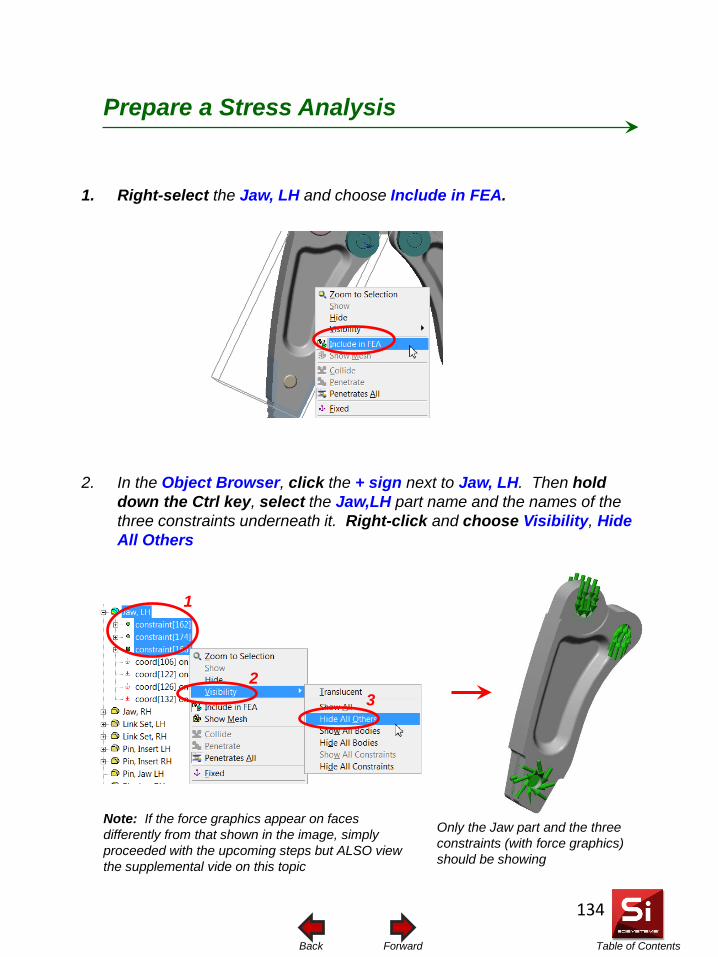
Table of Contents Forward Back
1. Right-select the Jaw, LH and choose Include in FEA.
2. In the Object Browser, click the + sign next to Jaw, LH. Then hold down the Ctrl key, select the Jaw,LH part name and the names of the three constraints underneath it. Right-click and choose Visibility, Hide All Others
Prepare a Stress Analysis
1
2 3
Only the Jaw part and the three constraints (with force graphics) should be showing
Note: If the force graphics appear on faces differently from that shown in the image, simply proceeded with the upcoming steps but ALSO view the supplemental vide on this topic
134
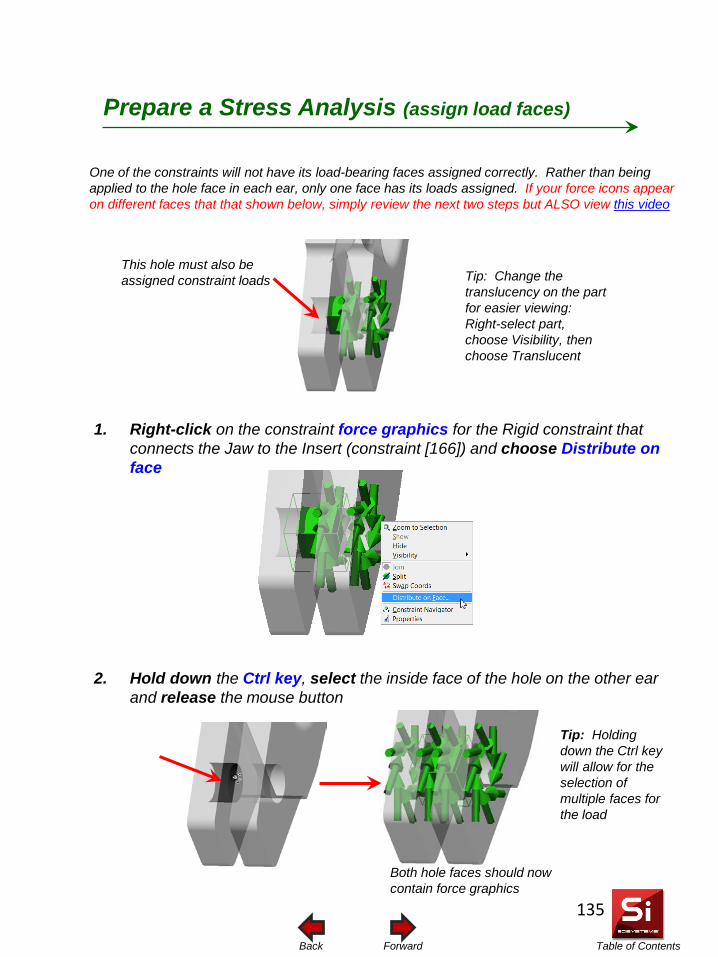
Table of Contents Forward Back
This hole must also be assigned constraint loads
1. Right-click on the constraint force graphics for the Rigid constraint that connects the Jaw to the Insert (constraint [166]) and choose Distribute on face
2. Hold down the Ctrl key, select the inside face of the hole on the other ear and release the mouse button
One of the constraints will not have its load-bearing faces assigned correctly. Rather than being applied to the hole face in each ear, only one face has its loads assigned. If your force icons appear on different faces that that shown below, simply review the next two steps but ALSO view this video
Tip: Change the translucency on the part for easier viewing: Right-select part, choose Visibility, then choose Translucent
Both hole faces should now contain force graphics
Tip: Holding down the Ctrl key will allow for the selection of multiple faces for the load
Prepare a Stress Analysis (assign load faces)
135
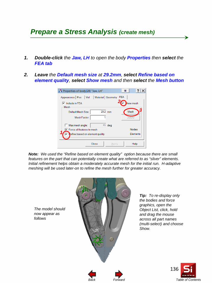
Table of Contents Forward Back
Prepare a Stress Analysis (create mesh)
The model should now appear as follows
1. Double-click the Jaw, LH to open the body Properties then select the FEA tab
2. Leave the Default mesh size at 29.2mm, select Refine based on element quality, select Show mesh and then select the Mesh button
3
1
2
Note: We used the “Refine based on element quality” option because there are small features on the part that can potentially create what are referred to as “sliver” elements. Initial refinement helps obtain a moderately accurate mesh for the initial run. H-adaptive meshing will be used later-on to refine the mesh further for greater accuracy.
Tip: To re-display only the bodies and force graphics, open the Object List, click, hold and drag the mouse across all part names (multi-select) and choose Show.
136
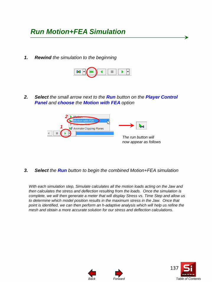
Table of Contents Forward Back
Run Motion+FEA Simulation
The run button will now appear as follows
1. Rewind the simulation to the beginning
2. Select the small arrow next to the Run button on the Player Control Panel and choose the Motion with FEA option
3. Select the Run button to begin the combined Motion+FEA simulation
1
2
With each simulation step, Simulate calculates all the motion loads acting on the Jaw and then calculates the stress and deflection resulting from the loads. Once the simulation is complete, we will then generate a meter that will display Stress vs. Time Step and allow us to determine which model position results in the maximum stress in the Jaw. Once that point is identified, we can then perform an h-adaptive analysis which will help us refine the mesh and obtain a more accurate solution for our stress and deflection calculations.
137
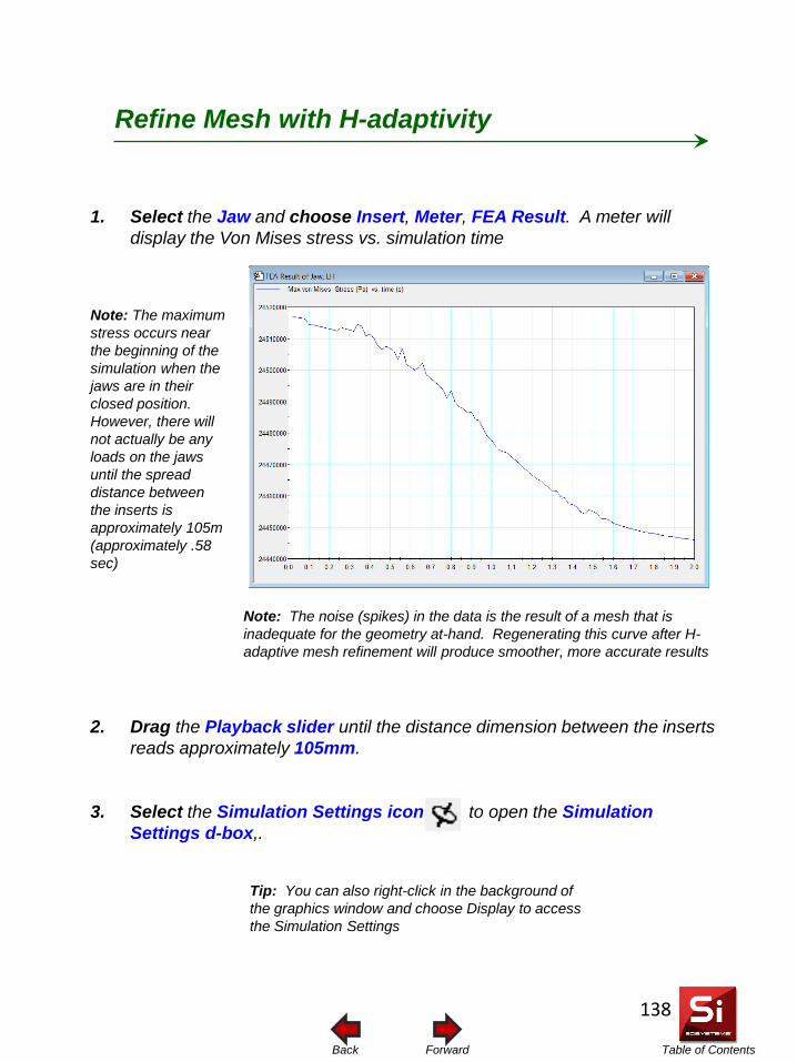
Table of Contents Forward Back
1. Select the Jaw and choose Insert, Meter, FEA Result. A meter will display the Von Mises stress vs. simulation time
2. Drag the Playback slider until the distance dimension between the inserts reads approximately 105mm.
3. Select the Simulation Settings icon to open the Simulation Settings d-box,.
Refine Mesh with H-adaptivity
Note: The maximum stress occurs near the beginning of the simulation when the jaws are in their closed position. However, there will not actually be any loads on the jaws until the spread distance between the inserts is approximately 105m (approximately .58 sec)
Tip: You can also right-click in the background of the graphics window and choose Display to access the Simulation Settings
Note: The noise (spikes) in the data is the result of a mesh that is inadequate for the geometry at-hand. Regenerating this curve after H-adaptive mesh refinement will produce smoother, more accurate results
138
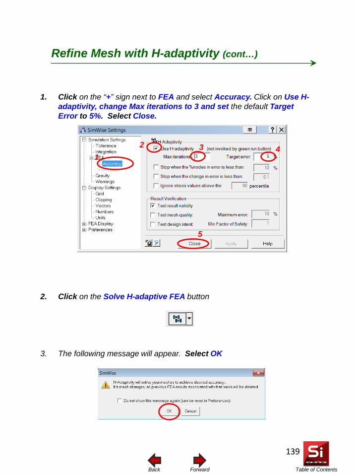
Table of Contents Forward Back
1. Click on the “+” sign next to FEA and select Accuracy. Click on Use H-adaptivity, change Max iterations to 3 and set the default Target Error to 5%. Select Close.
2. Click on the Solve H-adaptive FEA button
3. The following message will appear. Select OK
4 2
5
1
Refine Mesh with H-adaptivity (cont…)
3
139
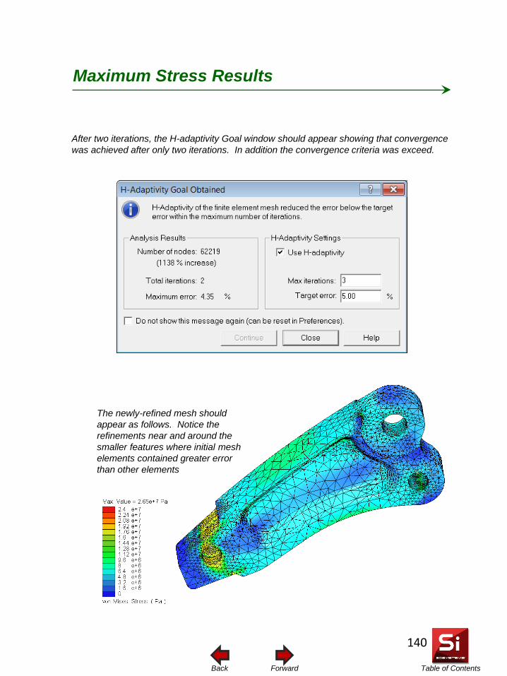
Table of Contents Forward Back
After two iterations, the H-adaptivity Goal window should appear showing that convergence was achieved after only two iterations. In addition the convergence criteria was exceed.
The newly-refined mesh should appear as follows. Notice the refinements near and around the smaller features where initial mesh elements contained greater error than other elements
Maximum Stress Results
140
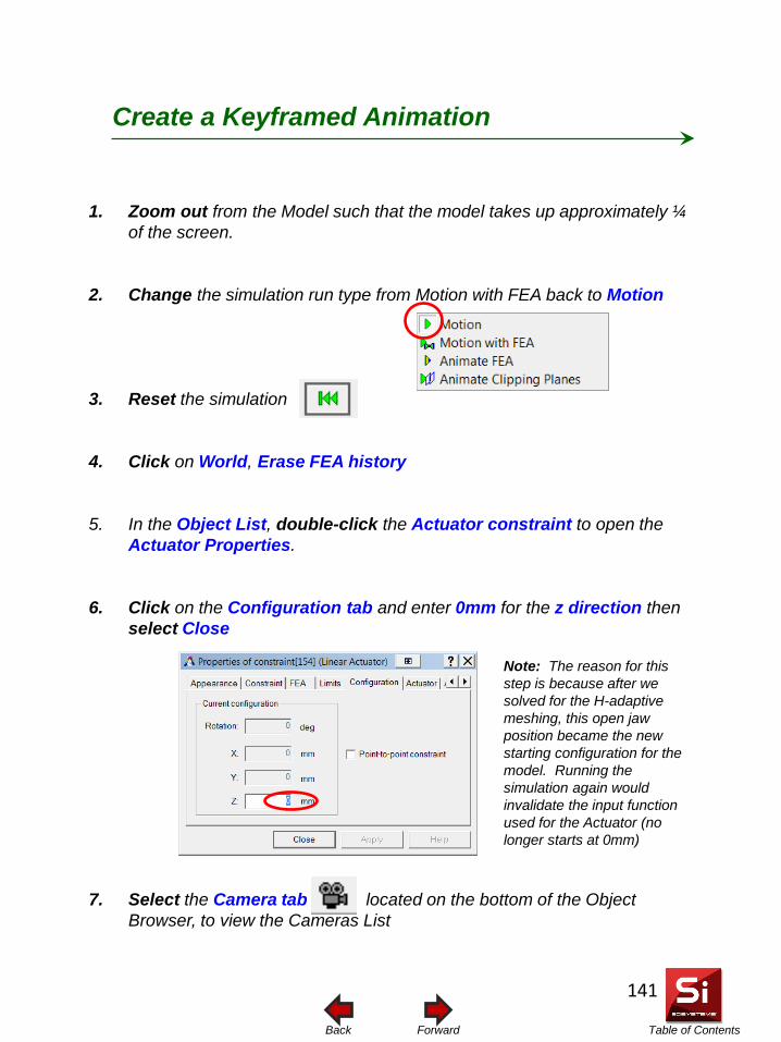
Table of Contents Forward Back
1. Zoom out from the Model such that the model takes up approximately ¼ of the screen.
2. Change the simulation run type from Motion with FEA back to Motion
3. Reset the simulation
4. Click on World, Erase FEA history
5. In the Object List, double-click the Actuator constraint to open the Actuator Properties.
6. Click on the Configuration tab and enter 0mm for the z direction then select Close
7. Select the Camera tab located on the bottom of the Object Browser, to view the Cameras List
Create a Keyframed Animation
Note: The reason for this step is because after we solved for the H-adaptive meshing, this open jaw position became the new starting configuration for the model. Running the simulation again would invalidate the input function used for the Actuator (no longer starts at 0mm)
141
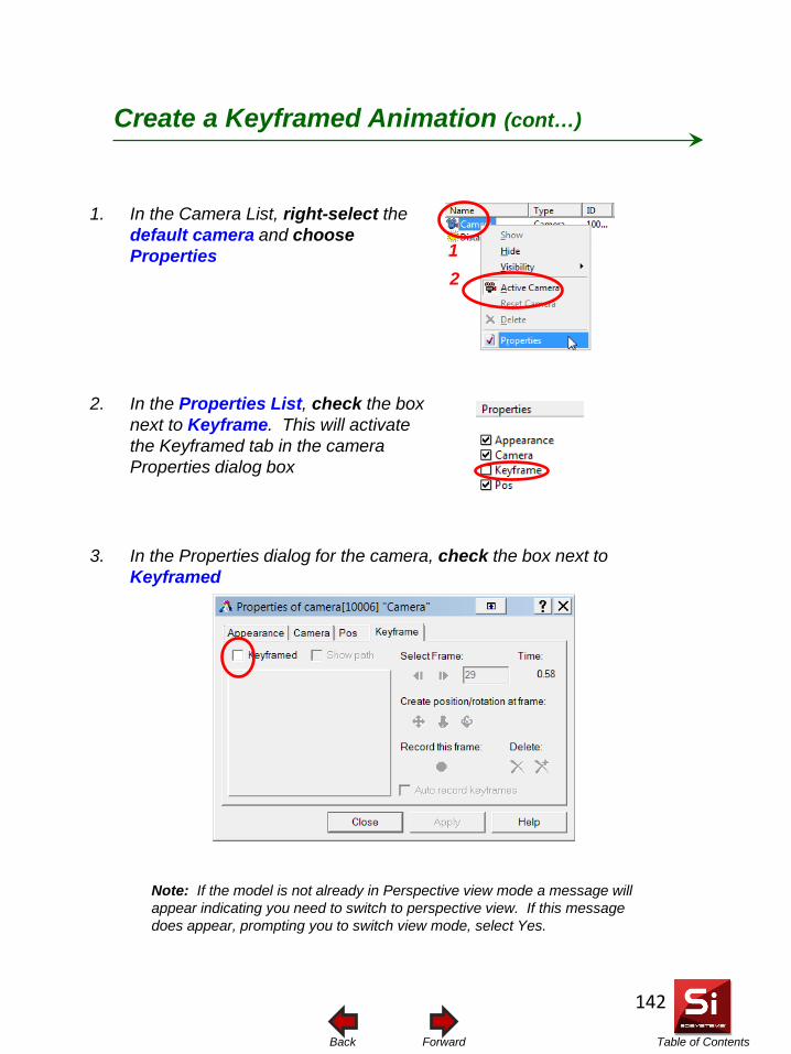
Table of Contents Forward Back
1. In the Camera List, right-select the default camera and choose Properties
2. In the Properties List, check the box next to Keyframe. This will activate the Keyframed tab in the camera Properties dialog box
Note: If the model is not already in Perspective view mode a message will appear indicating you need to switch to perspective view. If this message does appear, prompting you to switch view mode, select Yes.
Create a Keyframed Animation (cont…)
2 1
3. In the Properties dialog for the camera, check the box next to Keyframed
142
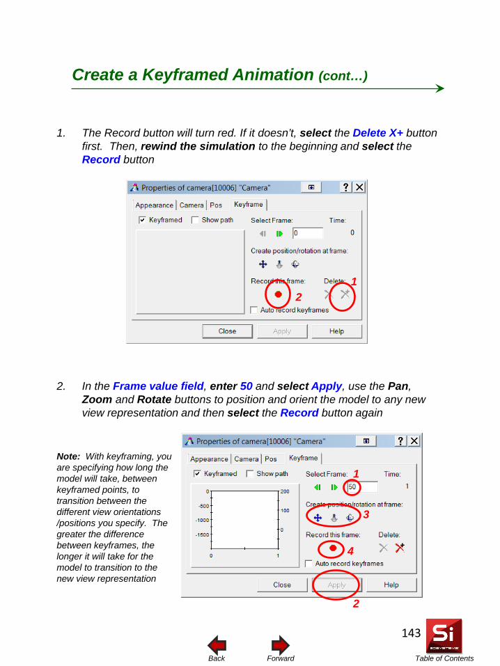
Table of Contents Forward Back
1. The Record button will turn red. If it doesn’t, select the Delete X+ button first. Then, rewind the simulation to the beginning and select the Record button
2. In the Frame value field, enter 50 and select Apply, use the Pan, Zoom and Rotate buttons to position and orient the model to any new view representation and then select the Record button again
2
3
1
1 2
Create a Keyframed Animation (cont…)
4
Note: With keyframing, you are specifying how long the model will take, between keyframed points, to transition between the different view orientations /positions you specify. The greater the difference between keyframes, the longer it will take for the model to transition to the new view representation
143
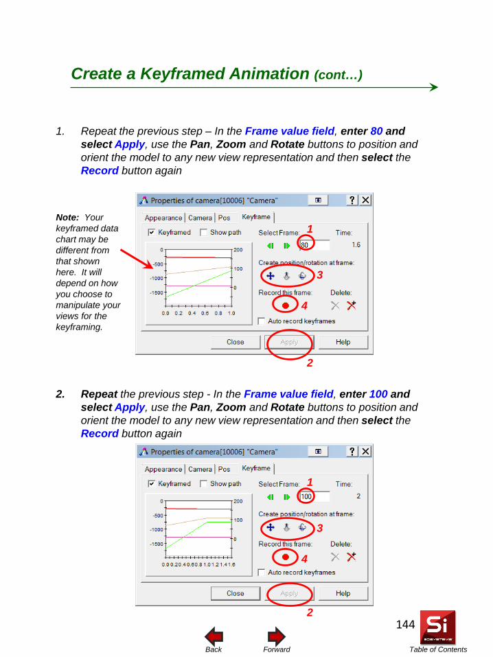
Table of Contents Forward Back
1. Repeat the previous step – In the Frame value field, enter 80 and select Apply, use the Pan, Zoom and Rotate buttons to position and orient the model to any new view representation and then select the Record button again
2. Repeat the previous step - In the Frame value field, enter 100 and select Apply, use the Pan, Zoom and Rotate buttons to position and orient the model to any new view representation and then select the Record button again
Create a Keyframed Animation (cont…)
2
3
1
4
2
3
1
4
Note: Your keyframed data chart may be different from that shown here. It will depend on how you choose to manipulate your views for the keyframing.
144
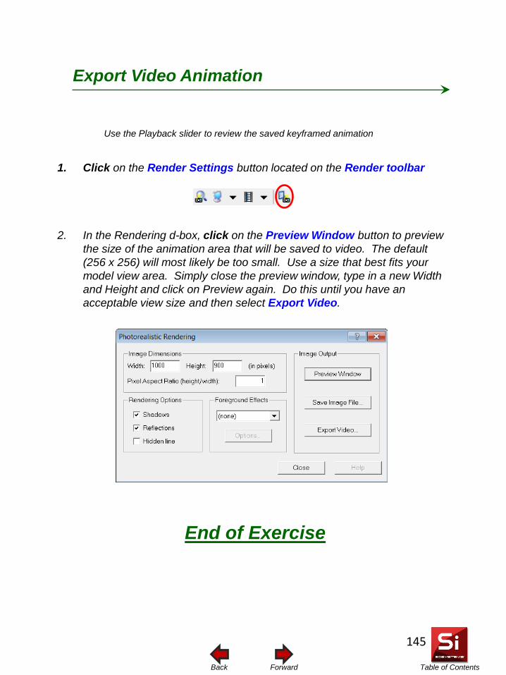
Table of Contents Forward Back
Use the Playback slider to review the saved keyframed animation
End of Exercise
1. Click on the Render Settings button located on the Render toolbar
2. In the Rendering d-box, click on the Preview Window button to preview the size of the animation area that will be saved to video. The default (256 x 256) will most likely be too small. Use a size that best fits your model view area. Simply close the preview window, type in a new Width and Height and click on Preview again. Do this until you have an acceptable view size and then select Export Video.
Export Video Animation
145
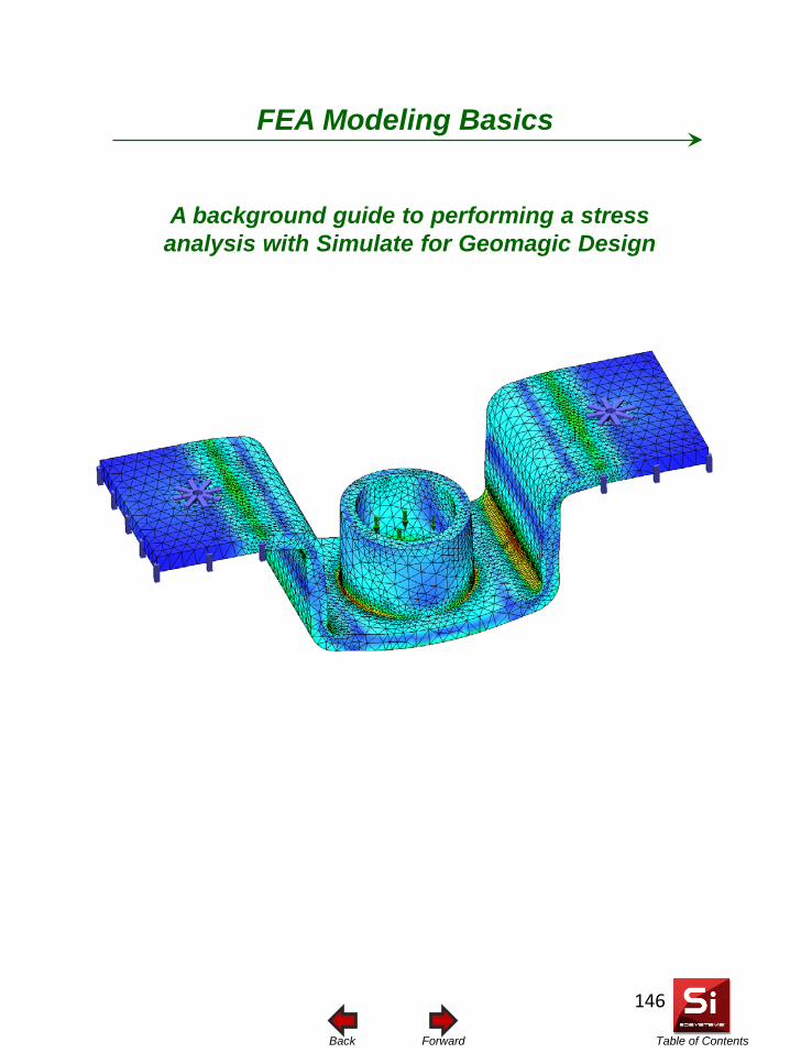
Table of Contents Forward Back
A background guide to performing a stress analysis with Simulate for Geomagic Design
FEA Modeling Basics
146
Table of Contents Forward Back
The information presented in this document serves only as guidelines to choosing the best FEA modeling approach using Simulate for Geomagic Design. The following sections explain things such as the basic operating principals behind Simulate for Geomagic Design, how to build and refine a mesh, and also where and when the various FEA features found in Simulate become applicable. It is assumed the user already has a basic understanding of mechanics of materials, principals of stress, strain and the various failure modes. If necessary, there is a wide array of material available on the market that goes into more depth on these subjects. With any FEA program, accurate results require the geometry, material properties, boundary conditions and mesh be as close as possible to the physical conditions. The mesh process can arguably be considered as the most important of the four criteria and therefore is where the majority of the FEA setup work is typically required.
Introduction Design Simulation Technologies, Inc. will not be held liable for any loss or damages incurred in connection with the use and/or implementation of the material contained in this document. Simulate for Geomagic Design solves problems in linear Finite Element Analysis (FEA), in which the following assumptions are made:
• The relationship to stress over strain is linear and elastic • The deformations are small enough such that they may be approximated as linear • The magnitude, orientation and distribution of the loads does not change during
deformation • Any strain-hardening of the material due to deformation can be neglected
147
Table of Contents Forward Back
Geometry: Unlike kinematic motion simulation where small geometric features such as fillets , rounds and sharp edges do not affect the results of the simulation, the opposite is true when it comes to structural analysis. Certain geometric features can introduce large and undesirable stress concentrations and others can alleviate them. Doing a first-pass analysis on a design without all final design features is acceptable. However, it may become necessary to include such features in subsequent runs if the first pass run shows high stresses in areas where the geometry was left out. Assemblies can distribute loads entirely different from how one might manually apply loads to a single part. Load values and load directions are often overlooked. Bending moments are often introduced but overlooked in single part analysis. Modeling a problem as a single part or an assembly could have a great impact on the ability to achieve good results and one must be sure of the assumptions used to justify either approach. Restraints: Restraints can be applied to vertices, edges and faces. Care should be taken when applying restraints to the model in that the restraint type and location should be representative of the physical setup. The restraints should define the proper degrees of freedom of the physical connection they represent. If you are modeling a single part that is actually part of an assembly, be sure the interaction with the missing part is properly represented with loads or restraints. Over restraining a part or assembly can actually prohibit deformation and act to increase stress. See the section titled Splitting Faces for Restraint Application for information on designating specific areas to apply restraints.
Geometry & Restraints
148
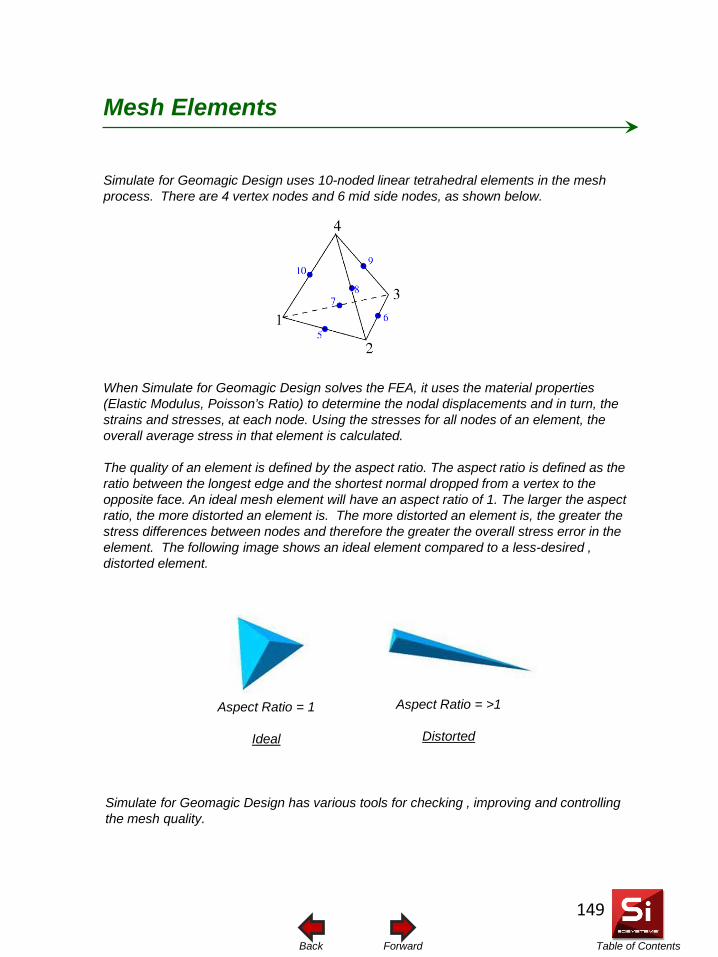
Table of Contents Forward Back
Simulate for Geomagic Design uses 10-noded linear tetrahedral elements in the mesh process. There are 4 vertex nodes and 6 mid side nodes, as shown below. When Simulate for Geomagic Design solves the FEA, it uses the material properties (Elastic Modulus, Poisson’s Ratio) to determine the nodal displacements and in turn, the strains and stresses, at each node. Using the stresses for all nodes of an element, the overall average stress in that element is calculated. The quality of an element is defined by the aspect ratio. The aspect ratio is defined as the ratio between the longest edge and the shortest normal dropped from a vertex to the opposite face. An ideal mesh element will have an aspect ratio of 1. The larger the aspect ratio, the more distorted an element is. The more distorted an element is, the greater the stress differences between nodes and therefore the greater the overall stress error in the element. The following image shows an ideal element compared to a less-desired , distorted element.
Mesh Elements
Aspect Ratio = 1
Ideal
Aspect Ratio = >1
Distorted
Simulate for Geomagic Design has various tools for checking , improving and controlling the mesh quality.
149
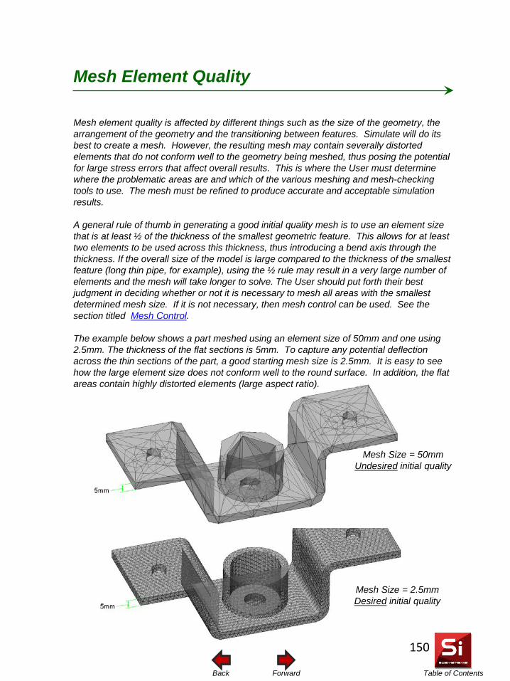
Table of Contents Forward Back
Mesh element quality is affected by different things such as the size of the geometry, the arrangement of the geometry and the transitioning between features. Simulate will do its best to create a mesh. However, the resulting mesh may contain severally distorted elements that do not conform well to the geometry being meshed, thus posing the potential for large stress errors that affect overall results. This is where the User must determine where the problematic areas are and which of the various meshing and mesh-checking tools to use. The mesh must be refined to produce accurate and acceptable simulation results. A general rule of thumb in generating a good initial quality mesh is to use an element size that is at least ½ of the thickness of the smallest geometric feature. This allows for at least two elements to be used across this thickness, thus introducing a bend axis through the thickness. If the overall size of the model is large compared to the thickness of the smallest feature (long thin pipe, for example), using the ½ rule may result in a very large number of elements and the mesh will take longer to solve. The User should put forth their best judgment in deciding whether or not it is necessary to mesh all areas with the smallest determined mesh size. If it is not necessary, then mesh control can be used. See the section titled Mesh Control. The example below shows a part meshed using an element size of 50mm and one using 2.5mm. The thickness of the flat sections is 5mm. To capture any potential deflection across the thin sections of the part, a good starting mesh size is 2.5mm. It is easy to see how the large element size does not conform well to the round surface. In addition, the flat areas contain highly distorted elements (large aspect ratio).
Mesh Element Quality
Mesh Size = 2.5mm Desired initial quality
Mesh Size = 50mm Undesired initial quality
150
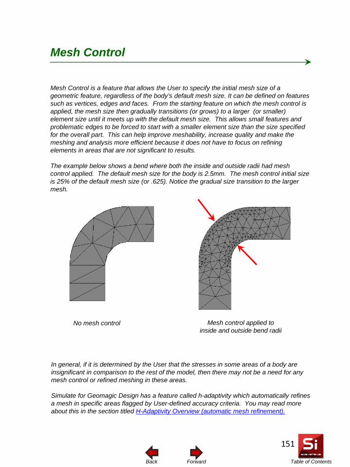
Table of Contents Forward Back
Mesh Control is a feature that allows the User to specify the initial mesh size of a geometric feature, regardless of the body’s default mesh size. It can be defined on features such as vertices, edges and faces. From the starting feature on which the mesh control is applied, the mesh size then gradually transitions (or grows) to a larger (or smaller) element size until it meets up with the default mesh size. This allows small features and problematic edges to be forced to start with a smaller element size than the size specified for the overall part. This can help improve meshability, increase quality and make the meshing and analysis more efficient because it does not have to focus on refining elements in areas that are not significant to results. The example below shows a bend where both the inside and outside radii had mesh control applied. The default mesh size for the body is 2.5mm. The mesh control initial size is 25% of the default mesh size (or .625). Notice the gradual size transition to the larger mesh.
Mesh Control
Mesh control applied to inside and outside bend radii
No mesh control
In general, if it is determined by the User that the stresses in some areas of a body are insignificant in comparison to the rest of the model, then there may not be a need for any mesh control or refined meshing in these areas. Simulate for Geomagic Design has a feature called h-adaptivity which automatically refines a mesh in specific areas flagged by User-defined accuracy criteria. You may read more about this in the section titled H-Adaptivity Overview (automatic mesh refinement).
151
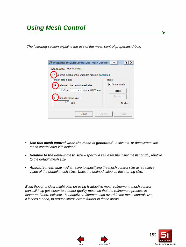
Table of Contents Forward Back
The following section explains the use of the mesh control properties d-box.
Using Mesh Control
Even though a User might plan on using h-adaptive mesh refinement, mesh control can still help get closer to a better quality mesh so that the refinement process is faster and more efficient. H-adaptive refinement can override the mesh control size, if it sees a need, to reduce stress errors further in those areas.
• Use this mesh control when the mesh is generated - activates or deactivates the mesh control after it is defined
• Relative to the default mesh size – specify a value for the initial mesh control, relative to the default mesh size
• Absolute mesh size – Alternative to specifying the mesh control size as a relative
value of the default mesh size. Uses the defined value as the starting size.
152
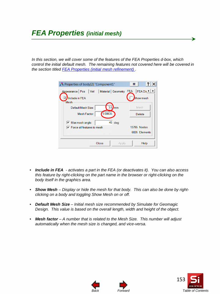
Table of Contents Forward Back
In this section, we will cover some of the features of the FEA Properties d-box, which control the initial default mesh. The remaining features not covered here will be covered in the section titled FEA Properties (initial mesh refinement) .
FEA Properties (initial mesh)
• Include in FEA - activates a part in the FEA (or deactivates it). You can also access this feature by right-clicking on the part name in the browser or right-clicking on the body itself in the graphics area.
• Show Mesh – Display or hide the mesh for that body. This can also be done by right-clicking on a body and toggling Show Mesh on or off.
• Default Mesh Size – Initial mesh size recommended by Simulate for Geomagic Design. This value is based on the overall length, width and height of the object.
• Mesh factor – A number that is related to the Mesh Size. This number will adjust automatically when the mesh size is changed, and vice-versa.
153
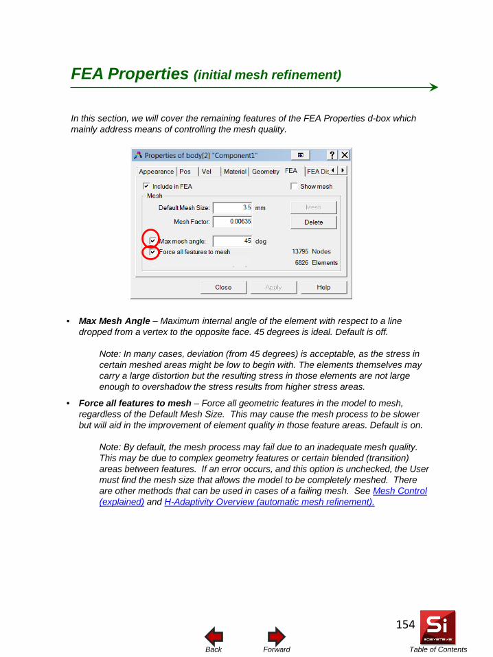
Table of Contents Forward Back
In this section, we will cover the remaining features of the FEA Properties d-box which mainly address means of controlling the mesh quality.
FEA Properties (initial mesh refinement)
• Max Mesh Angle – Maximum internal angle of the element with respect to a line
dropped from a vertex to the opposite face. 45 degrees is ideal. Default is off.
Note: In many cases, deviation (from 45 degrees) is acceptable, as the stress in certain meshed areas might be low to begin with. The elements themselves may carry a large distortion but the resulting stress in those elements are not large enough to overshadow the stress results from higher stress areas.
• Force all features to mesh – Force all geometric features in the model to mesh, regardless of the Default Mesh Size. This may cause the mesh process to be slower but will aid in the improvement of element quality in those feature areas. Default is on.
Note: By default, the mesh process may fail due to an inadequate mesh quality. This may be due to complex geometry features or certain blended (transition) areas between features. If an error occurs, and this option is unchecked, the User must find the mesh size that allows the model to be completely meshed. There are other methods that can be used in cases of a failing mesh. See Mesh Control (explained) and H-Adaptivity Overview (automatic mesh refinement).
154
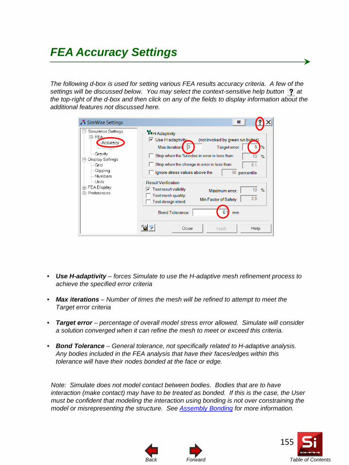
Table of Contents Forward Back
The following d-box is used for setting various FEA results accuracy criteria. A few of the settings will be discussed below. You may select the context-sensitive help button at the top-right of the d-box and then click on any of the fields to display information about the additional features not discussed here.
FEA Accuracy Settings
• Use H-adaptivity – forces Simulate to use the H-adaptive mesh refinement process to
achieve the specified error criteria
• Max iterations – Number of times the mesh will be refined to attempt to meet the Target error criteria
• Target error – percentage of overall model stress error allowed. Simulate will consider a solution converged when it can refine the mesh to meet or exceed this criteria.
• Bond Tolerance – General tolerance, not specifically related to H-adaptive analysis. Any bodies included in the FEA analysis that have their faces/edges within this tolerance will have their nodes bonded at the face or edge.
Note: Simulate does not model contact between bodies. Bodies that are to have interaction (make contact) may have to be treated as bonded. If this is the case, the User must be confident that modeling the interaction using bonding is not over constraining the model or misrepresenting the structure. See Assembly Bonding for more information.
155
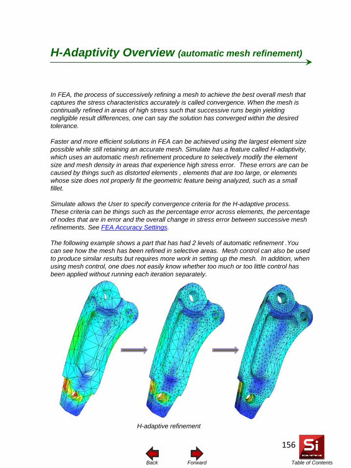
Table of Contents Forward Back
In FEA, the process of successively refining a mesh to achieve the best overall mesh that captures the stress characteristics accurately is called convergence. When the mesh is continually refined in areas of high stress such that successive runs begin yielding negligible result differences, one can say the solution has converged within the desired tolerance. Faster and more efficient solutions in FEA can be achieved using the largest element size possible while still retaining an accurate mesh. Simulate has a feature called H-adaptivity, which uses an automatic mesh refinement procedure to selectively modify the element size and mesh density in areas that experience high stress error. These errors are can be caused by things such as distorted elements , elements that are too large, or elements whose size does not properly fit the geometric feature being analyzed, such as a small fillet. Simulate allows the User to specify convergence criteria for the H-adaptive process. These criteria can be things such as the percentage error across elements, the percentage of nodes that are in error and the overall change in stress error between successive mesh refinements. See FEA Accuracy Settings. The following example shows a part that has had 2 levels of automatic refinement .You can see how the mesh has been refined in selective areas. Mesh control can also be used to produce similar results but requires more work in setting up the mesh. In addition, when using mesh control, one does not easily know whether too much or too little control has been applied without running each iteration separately.
H-Adaptivity Overview (automatic mesh refinement)
H-adaptive refinement
156
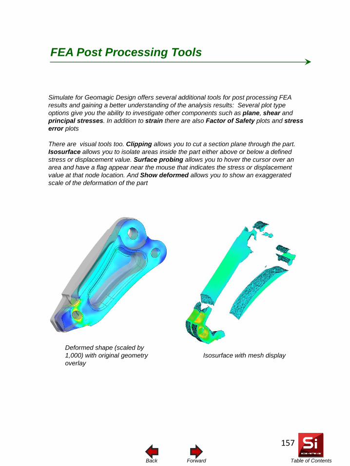
Table of Contents Forward Back
FEA Post Processing Tools
Simulate for Geomagic Design offers several additional tools for post processing FEA results and gaining a better understanding of the analysis results: Several plot type options give you the ability to investigate other components such as plane, shear and principal stresses. In addition to strain there are also Factor of Safety plots and stress error plots There are visual tools too. Clipping allows you to cut a section plane through the part. Isosurface allows you to isolate areas inside the part either above or below a defined stress or displacement value. Surface probing allows you to hover the cursor over an area and have a flag appear near the mouse that indicates the stress or displacement value at that node location. And Show deformed allows you to show an exaggerated scale of the deformation of the part
Deformed shape (scaled by 1,000) with original geometry overlay
Isosurface with mesh display
157
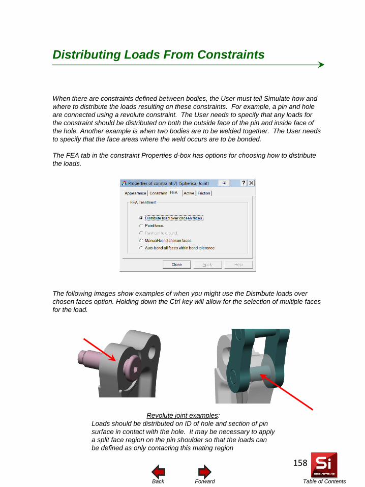
Table of Contents Forward Back
When there are constraints defined between bodies, the User must tell Simulate how and where to distribute the loads resulting on these constraints. For example, a pin and hole are connected using a revolute constraint. The User needs to specify that any loads for the constraint should be distributed on both the outside face of the pin and inside face of the hole. Another example is when two bodies are to be welded together. The User needs to specify that the face areas where the weld occurs are to be bonded.
The FEA tab in the constraint Properties d-box has options for choosing how to distribute the loads.
The following images show examples of when you might use the Distribute loads over chosen faces option. Holding down the Ctrl key will allow for the selection of multiple faces for the load.
Distributing Loads From Constraints
Revolute joint examples: Loads should be distributed on ID of hole and section of pin surface in contact with the hole. It may be necessary to apply a split face region on the pin shoulder so that the loads can be defined as only contacting this mating region
158
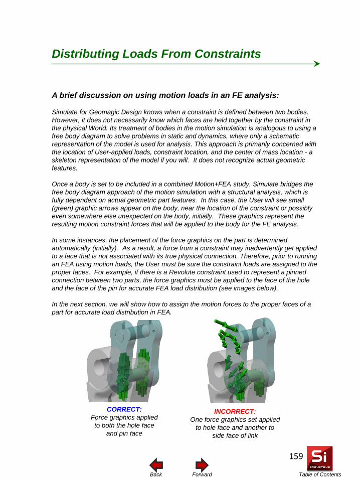
Table of Contents Forward Back
A brief discussion on using motion loads in an FE analysis: Simulate for Geomagic Design knows when a constraint is defined between two bodies. However, it does not necessarily know which faces are held together by the constraint in the physical World. Its treatment of bodies in the motion simulation is analogous to using a free body diagram to solve problems in static and dynamics, where only a schematic representation of the model is used for analysis. This approach is primarily concerned with the location of User-applied loads, constraint location, and the center of mass location - a skeleton representation of the model if you will. It does not recognize actual geometric features. Once a body is set to be included in a combined Motion+FEA study, Simulate bridges the free body diagram approach of the motion simulation with a structural analysis, which is fully dependent on actual geometric part features. In this case, the User will see small (green) graphic arrows appear on the body, near the location of the constraint or possibly even somewhere else unexpected on the body, initially. These graphics represent the resulting motion constraint forces that will be applied to the body for the FE analysis. In some instances, the placement of the force graphics on the part is determined automatically (initially). As a result, a force from a constraint may inadvertently get applied to a face that is not associated with its true physical connection. Therefore, prior to running an FEA using motion loads, the User must be sure the constraint loads are assigned to the proper faces. For example, if there is a Revolute constraint used to represent a pinned connection between two parts, the force graphics must be applied to the face of the hole and the face of the pin for accurate FEA load distribution (see images below). In the next section, we will show how to assign the motion forces to the proper faces of a part for accurate load distribution in FEA.
CORRECT: Force graphics applied to both the hole face
and pin face
INCORRECT: One force graphics set applied
to hole face and another to side face of link
Distributing Loads From Constraints
159
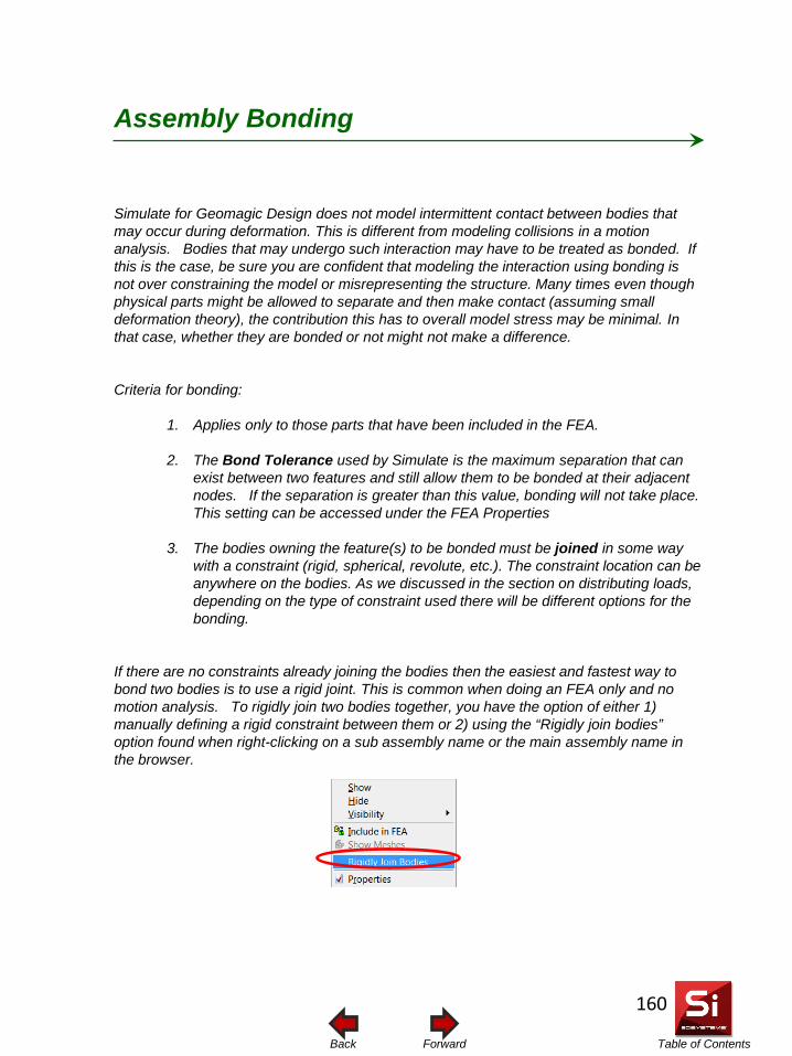
Table of Contents Forward Back
Simulate for Geomagic Design does not model intermittent contact between bodies that may occur during deformation. This is different from modeling collisions in a motion analysis. Bodies that may undergo such interaction may have to be treated as bonded. If this is the case, be sure you are confident that modeling the interaction using bonding is not over constraining the model or misrepresenting the structure. Many times even though physical parts might be allowed to separate and then make contact (assuming small deformation theory), the contribution this has to overall model stress may be minimal. In that case, whether they are bonded or not might not make a difference. Criteria for bonding:
1. Applies only to those parts that have been included in the FEA.
2. The Bond Tolerance used by Simulate is the maximum separation that can exist between two features and still allow them to be bonded at their adjacent nodes. If the separation is greater than this value, bonding will not take place. This setting can be accessed under the FEA Properties
3. The bodies owning the feature(s) to be bonded must be joined in some way with a constraint (rigid, spherical, revolute, etc.). The constraint location can be anywhere on the bodies. As we discussed in the section on distributing loads, depending on the type of constraint used there will be different options for the bonding.
If there are no constraints already joining the bodies then the easiest and fastest way to bond two bodies is to use a rigid joint. This is common when doing an FEA only and no motion analysis. To rigidly join two bodies together, you have the option of either 1) manually defining a rigid constraint between them or 2) using the “Rigidly join bodies” option found when right-clicking on a sub assembly name or the main assembly name in the browser.
Assembly Bonding
160
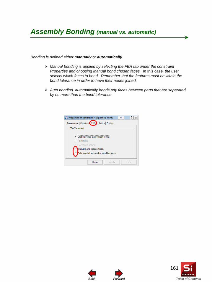
Table of Contents Forward Back
Bonding is defined either manually or automatically.
Manual bonding is applied by selecting the FEA tab under the constraint Properties and choosing Manual bond chosen faces. In this case, the user selects which faces to bond. Remember that the features must be within the bond tolerance in order to have their nodes joined.
Auto bonding automatically bonds any faces between parts that are separated
by no more than the bond tolerance
Assembly Bonding (manual vs. automatic)
161
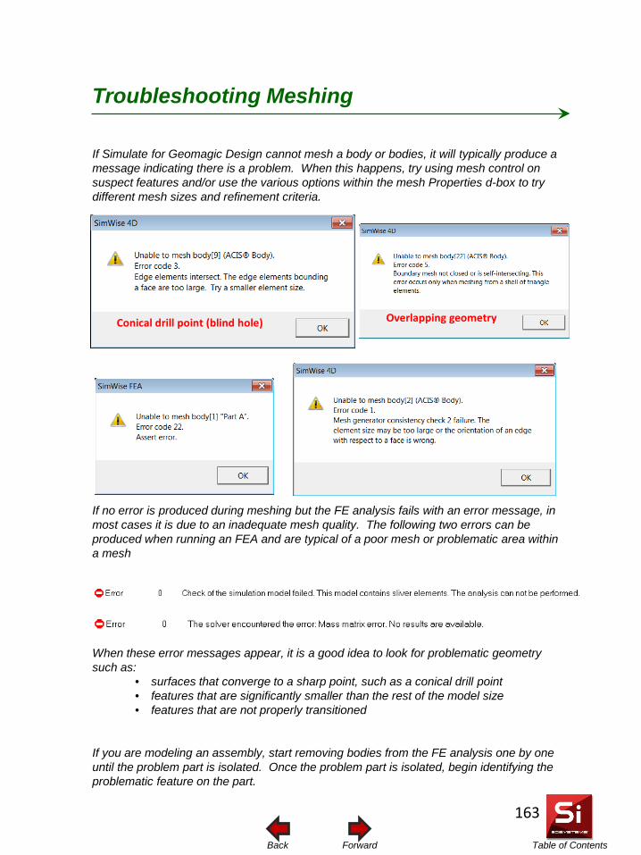
Table of Contents Forward Back
If Simulate for Geomagic Design cannot mesh a body or bodies, it will typically produce a message indicating there is a problem. When this happens, try using mesh control on suspect features and/or use the various options within the mesh Properties d-box to try different mesh sizes and refinement criteria. If no error is produced during meshing but the FE analysis fails with an error message, in most cases it is due to an inadequate mesh quality. The following two errors can be produced when running an FEA and are typical of a poor mesh or problematic area within a mesh When these error messages appear, it is a good idea to look for problematic geometry such as:
• surfaces that converge to a sharp point, such as a conical drill point • features that are significantly smaller than the rest of the model size • features that are not properly transitioned
If you are modeling an assembly, start removing bodies from the FE analysis one by one until the problem part is isolated. Once the problem part is isolated, begin identifying the problematic feature on the part.
Troubleshooting Meshing
Overlapping geometry Conical drill point (blind hole)
163
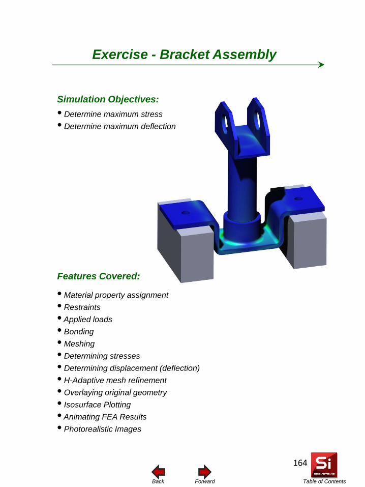
Table of Contents Forward Back
Simulation Objectives: • Determine maximum stress • Determine maximum deflection
Features Covered:
• Material property assignment • Restraints • Applied loads • Bonding • Meshing • Determining stresses • Determining displacement (deflection) • H-Adaptive mesh refinement • Overlaying original geometry • Isosurface Plotting • Animating FEA Results • Photorealistic Images
Exercise - Bracket Assembly
164
Table of Contents Forward Back
Introduction
In this exercise, you will perform a basic stress and deflection analysis on an assembly of parts.
This tutorial is designed to introduce you to some of the basic capabilities of Simulate for Geomagic Design as applied to a structural analysis and help you get acquainted with how to prepare, run, and analyze the results of a finite element analysis.
165
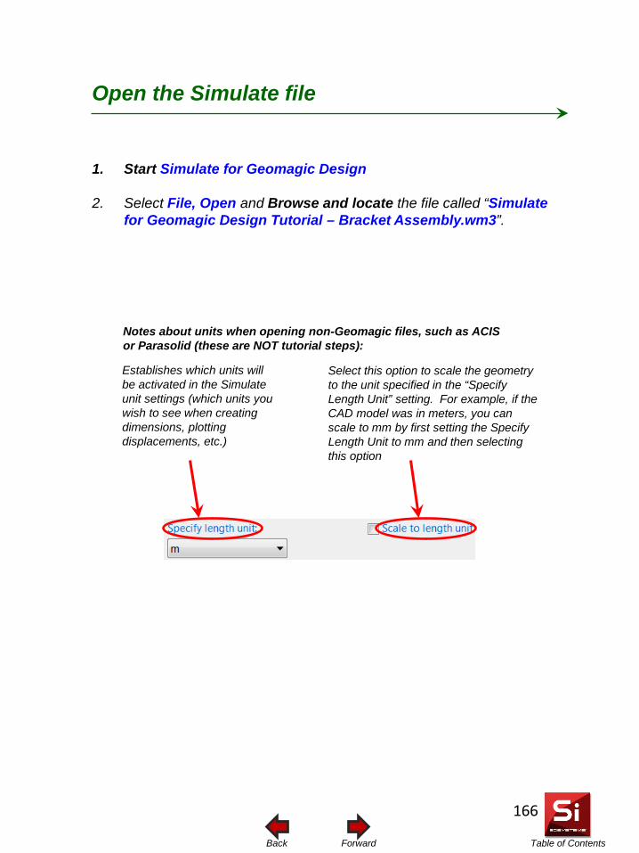
Table of Contents Forward Back
Open the Simulate file
1. Start Simulate for Geomagic Design
2. Select File, Open and Browse and locate the file called “Simulate for Geomagic Design Tutorial – Bracket Assembly.wm3”.
Establishes which units will be activated in the Simulate unit settings (which units you wish to see when creating dimensions, plotting displacements, etc.)
Select this option to scale the geometry to the unit specified in the “Specify Length Unit” setting. For example, if the CAD model was in meters, you can scale to mm by first setting the Specify Length Unit to mm and then selecting this option
Notes about units when opening non-Geomagic files, such as ACIS or Parasolid (these are NOT tutorial steps):
166
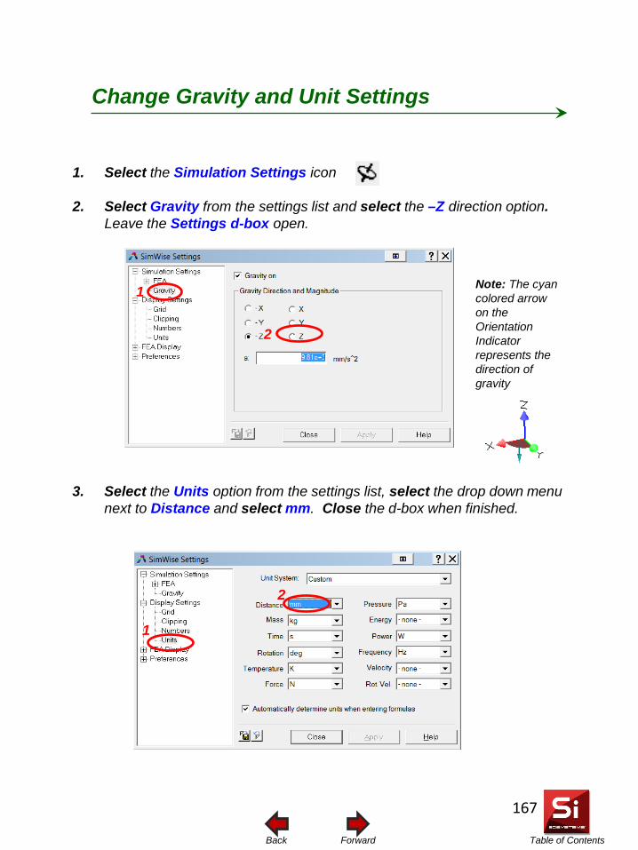
Table of Contents Forward Back
1. Select the Simulation Settings icon
2. Select Gravity from the settings list and select the –Z direction option. Leave the Settings d-box open.
3. Select the Units option from the settings list, select the drop down menu next to Distance and select mm. Close the d-box when finished.
Change Gravity and Unit Settings
Note: The cyan colored arrow on the Orientation Indicator represents the direction of gravity
2
1
2
1
167
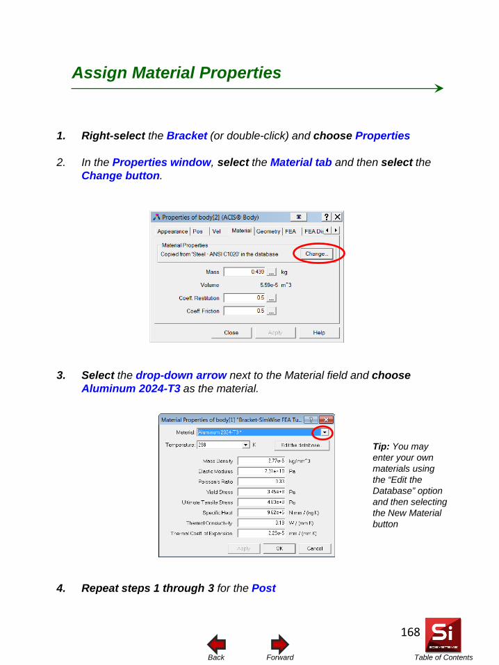
Table of Contents Forward Back
1. Right-select the Bracket (or double-click) and choose Properties
2. In the Properties window, select the Material tab and then select the Change button.
3. Select the drop-down arrow next to the Material field and choose Aluminum 2024-T3 as the material.
4. Repeat steps 1 through 3 for the Post
Assign Material Properties
Tip: You may enter your own materials using the “Edit the Database” option and then selecting the New Material button
168
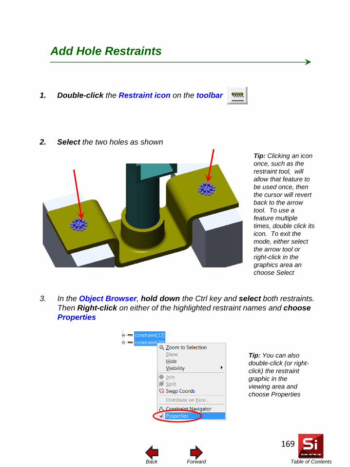
Table of Contents Forward Back
1. Double-click the Restraint icon on the toolbar
2. Select the two holes as shown
Add Hole Restraints
3. In the Object Browser, hold down the Ctrl key and select both restraints. Then Right-click on either of the highlighted restraint names and choose Properties
Tip: Clicking an icon once, such as the restraint tool, will allow that feature to be used once, then the cursor will revert back to the arrow tool. To use a feature multiple times, double click its icon. To exit the mode, either select the arrow tool or right-click in the graphics area an choose Select
Tip: You can also double-click (or right-click) the restraint graphic in the viewing area and choose Properties
169
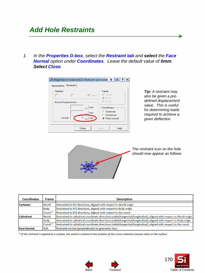
Table of Contents Forward Back
1. In the Properties D-box, select the Restraint tab and select the Face Normal option under Coordinates. Leave the default value of 0mm. Select Close.
Add Hole Restraints
Tip: A restraint may also be given a pre-defined displacement value. This is useful for determining loads required to achieve a given deflection
The restraint icon on the hole should now appear as follows
170
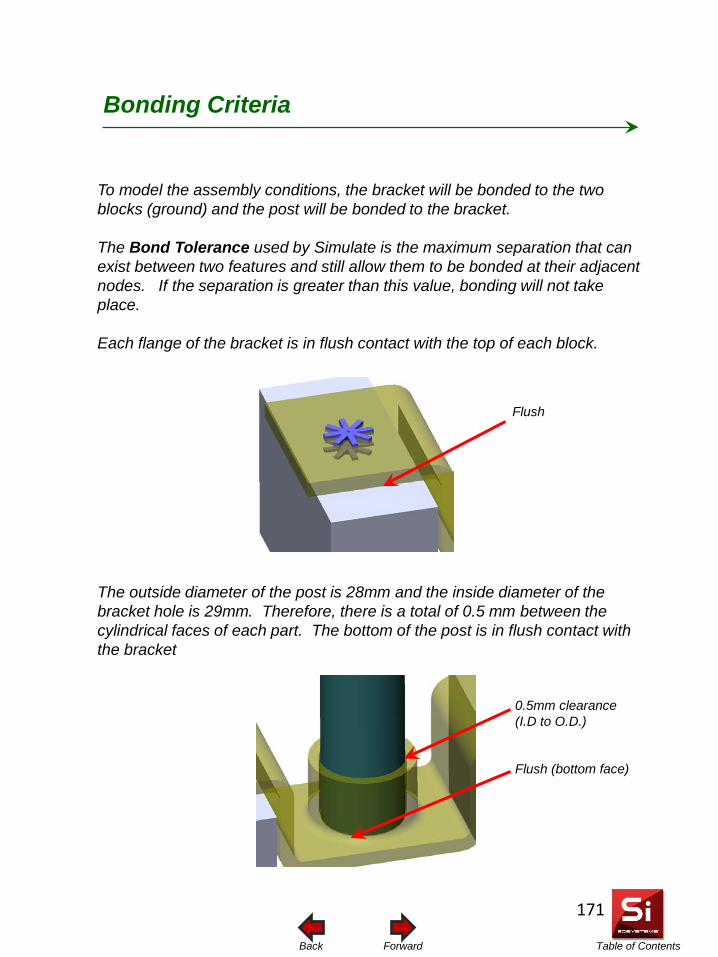
Table of Contents Forward Back
To model the assembly conditions, the bracket will be bonded to the two blocks (ground) and the post will be bonded to the bracket. The Bond Tolerance used by Simulate is the maximum separation that can exist between two features and still allow them to be bonded at their adjacent nodes. If the separation is greater than this value, bonding will not take place. Each flange of the bracket is in flush contact with the top of each block. The outside diameter of the post is 28mm and the inside diameter of the bracket hole is 29mm. Therefore, there is a total of 0.5 mm between the cylindrical faces of each part. The bottom of the post is in flush contact with the bracket
Bonding Criteria
0.5mm clearance (I.D to O.D.)
Flush (bottom face)
Flush
171
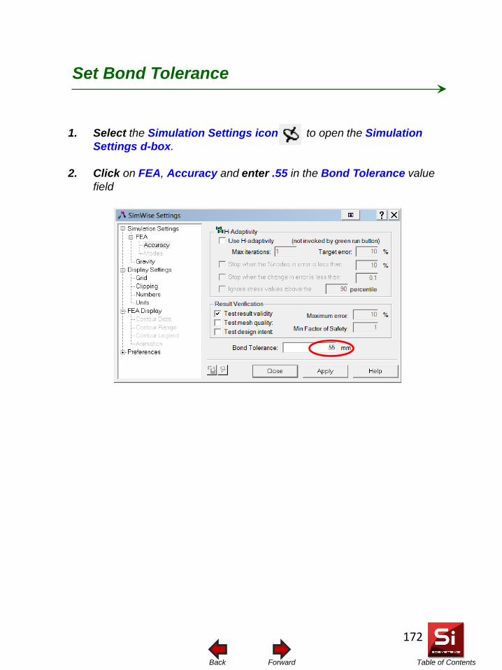
Table of Contents Forward Back
1. Select the Simulation Settings icon to open the Simulation Settings d-box.
2. Click on FEA, Accuracy and enter .55 in the Bond Tolerance value field
Set Bond Tolerance
172
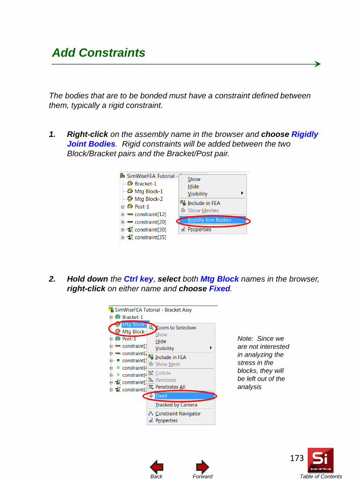
Table of Contents Forward Back
The bodies that are to be bonded must have a constraint defined between them, typically a rigid constraint.
1. Right-click on the assembly name in the browser and choose Rigidly Joint Bodies. Rigid constraints will be added between the two Block/Bracket pairs and the Bracket/Post pair.
2. Hold down the Ctrl key, select both Mtg Block names in the browser, right-click on either name and choose Fixed.
Add Constraints
Note: Since we are not interested in analyzing the stress in the blocks, they will be left out of the analysis
173
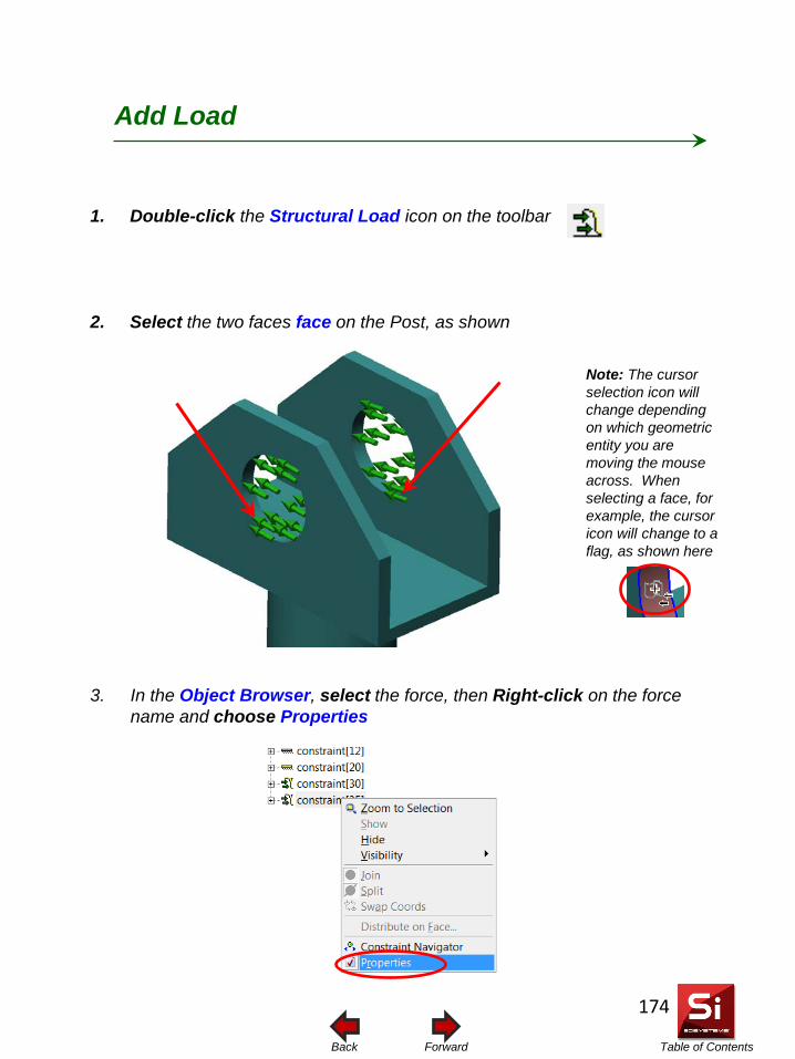
Table of Contents Forward Back
1. Double-click the Structural Load icon on the toolbar
2. Select the two faces face on the Post, as shown
Add Load
3. In the Object Browser, select the force, then Right-click on the force name and choose Properties
Note: The cursor selection icon will change depending on which geometric entity you are moving the mouse across. When selecting a face, for example, the cursor icon will change to a flag, as shown here
174
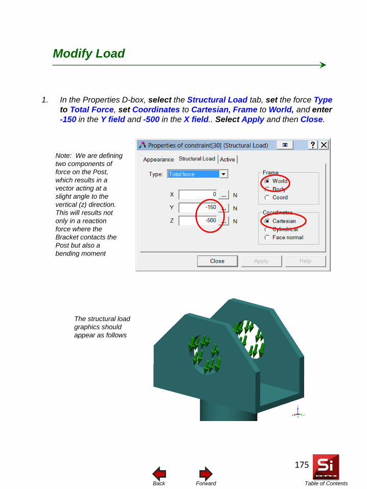
Table of Contents Forward Back
1. In the Properties D-box, select the Structural Load tab, set the force Type to Total Force, set Coordinates to Cartesian, Frame to World, and enter -150 in the Y field and -500 in the X field.. Select Apply and then Close.
Modify Load
The structural load graphics should appear as follows
Note: We are defining two components of force on the Post, which results in a vector acting at a slight angle to the vertical (z) direction. This will results not only in a reaction force where the Bracket contacts the Post but also a bending moment
175
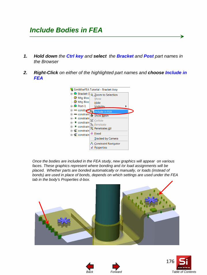
Table of Contents Forward Back
1. Hold down the Ctrl key and select the Bracket and Post part names in the Browser
2. Right-Click on either of the highlighted part names and choose Include in FEA
Include Bodies in FEA
Once the bodies are included in the FEA study, new graphics will appear on various faces. These graphics represent where bonding and /or load assignments will be placed. Whether parts are bonded automatically or manually, or loads (instead of bonds) are used in place of bonds, depends on which settings are used under the FEA tab in the body’s Properties d-box.
176
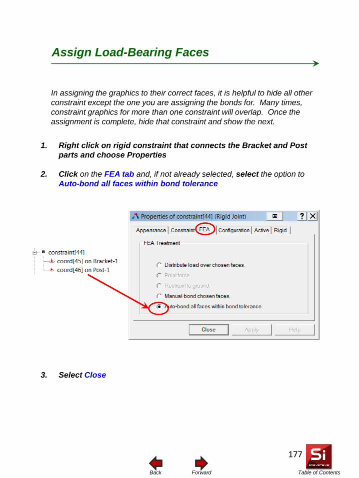
Table of Contents Forward Back
1. Right click on rigid constraint that connects the Bracket and Post parts and choose Properties
2. Click on the FEA tab and, if not already selected, select the option to Auto-bond all faces within bond tolerance
3. Select Close
Assign Load-Bearing Faces
In assigning the graphics to their correct faces, it is helpful to hide all other constraint except the one you are assigning the bonds for. Many times, constraint graphics for more than one constraint will overlap. Once the assignment is complete, hide that constraint and show the next.
177
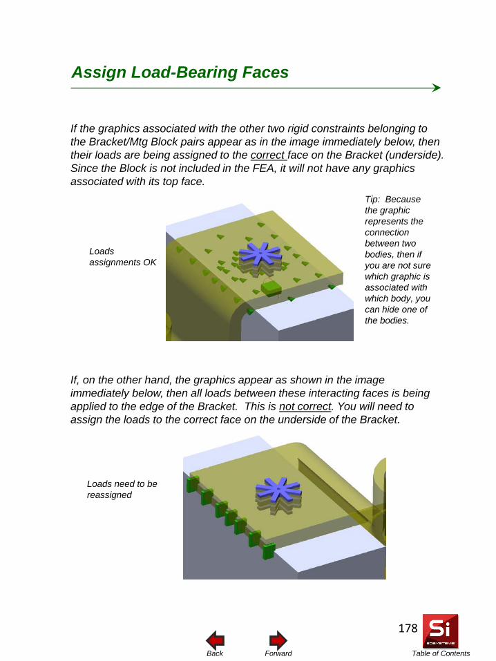
Table of Contents Forward Back
Assign Load-Bearing Faces
If the graphics associated with the other two rigid constraints belonging to the Bracket/Mtg Block pairs appear as in the image immediately below, then their loads are being assigned to the correct face on the Bracket (underside). Since the Block is not included in the FEA, it will not have any graphics associated with its top face. If, on the other hand, the graphics appear as shown in the image immediately below, then all loads between these interacting faces is being applied to the edge of the Bracket. This is not correct. You will need to assign the loads to the correct face on the underside of the Bracket.
Loads assignments OK
Loads need to be reassigned
Tip: Because the graphic represents the connection between two bodies, then if you are not sure which graphic is associated with which body, you can hide one of the bodies.
178
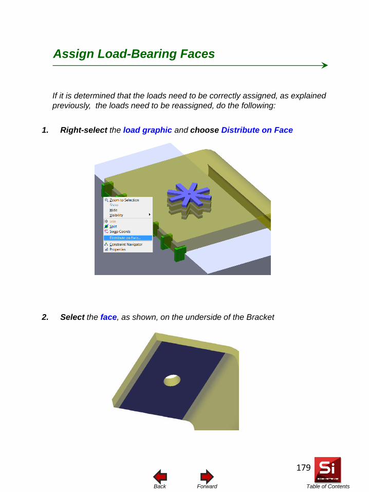
Table of Contents Forward Back
Assign Load-Bearing Faces
1. Right-select the load graphic and choose Distribute on Face
2. Select the face, as shown, on the underside of the Bracket
If it is determined that the loads need to be correctly assigned, as explained previously, the loads need to be reassigned, do the following:
179
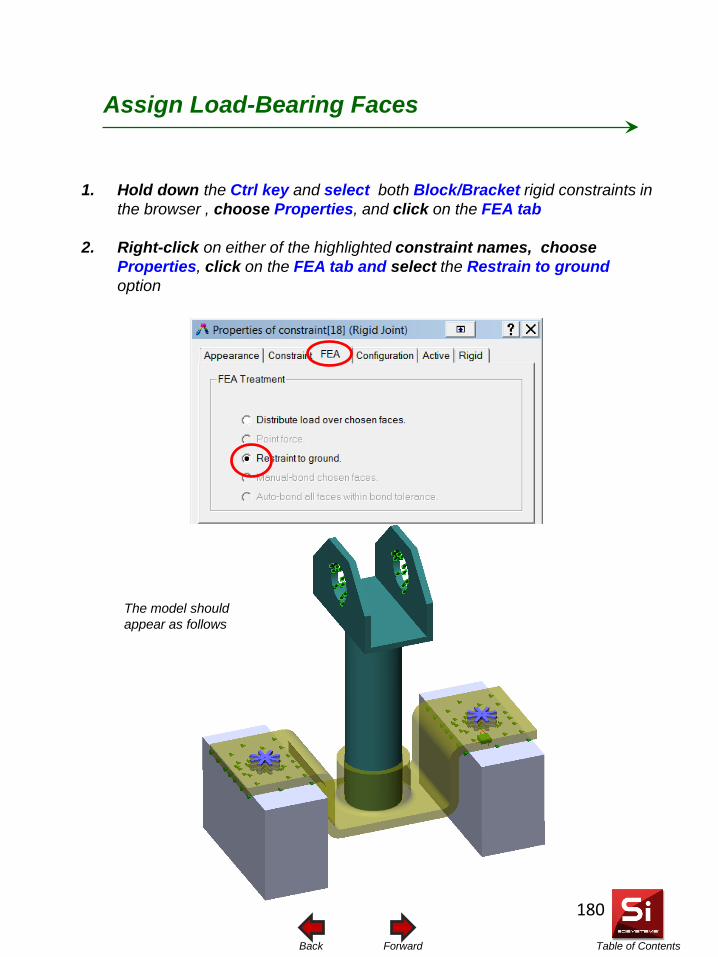
Table of Contents Forward Back
Assign Load-Bearing Faces
1. Hold down the Ctrl key and select both Block/Bracket rigid constraints in the browser , choose Properties, and click on the FEA tab
2. Right-click on either of the highlighted constraint names, choose Properties, click on the FEA tab and select the Restrain to ground option
The model should appear as follows
180
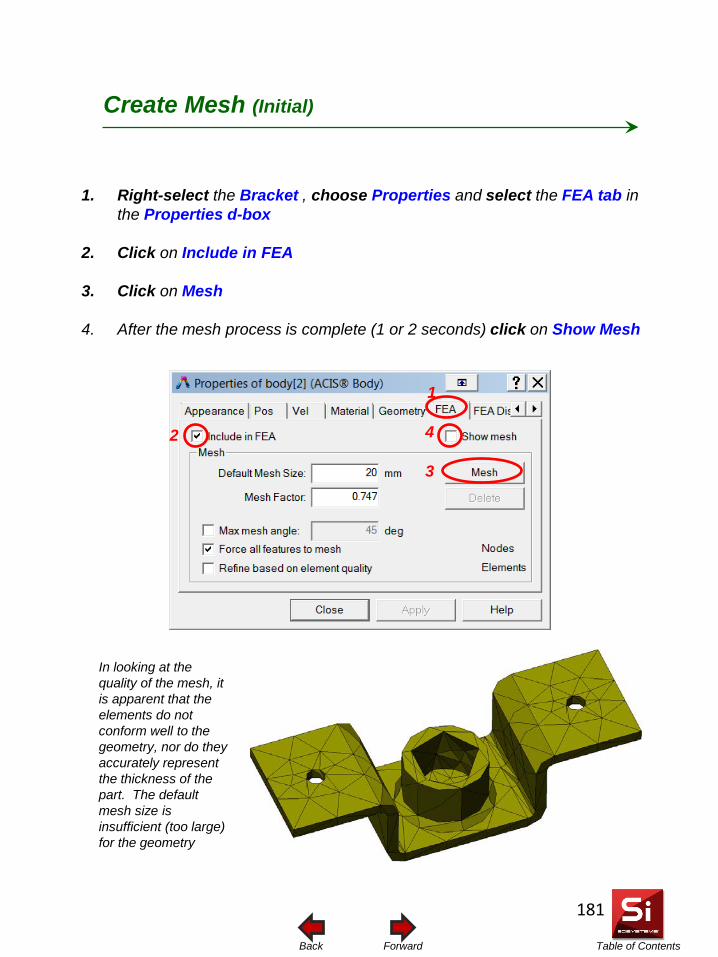
Table of Contents Forward Back
1. Right-select the Bracket , choose Properties and select the FEA tab in the Properties d-box
2. Click on Include in FEA
3. Click on Mesh
4. After the mesh process is complete (1 or 2 seconds) click on Show Mesh
Create Mesh (Initial)
2
3
4
In looking at the quality of the mesh, it is apparent that the elements do not conform well to the geometry, nor do they accurately represent the thickness of the part. The default mesh size is insufficient (too large) for the geometry
1
181
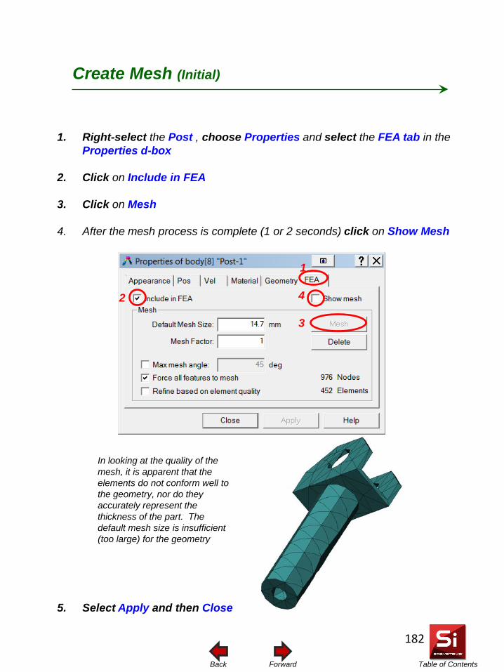
Table of Contents Forward Back
1. Right-select the Post , choose Properties and select the FEA tab in the Properties d-box
2. Click on Include in FEA
3. Click on Mesh
4. After the mesh process is complete (1 or 2 seconds) click on Show Mesh
5. Select Apply and then Close
Create Mesh (Initial)
2
3
4
In looking at the quality of the mesh, it is apparent that the elements do not conform well to the geometry, nor do they accurately represent the thickness of the part. The default mesh size is insufficient (too large) for the geometry
1
182
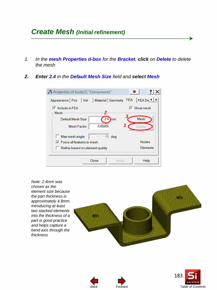
Table of Contents Forward Back
1. In the mesh Properties d-box for the Bracket, click on Delete to delete the mesh
2. Enter 2.4 in the Default Mesh Size field and select Mesh
Create Mesh (Initial refinement)
1
2 3
Note: 2.4mm was chosen as the element size because the part thickness is approximately 4.8mm. Introducing at least two stacked elements into the thickness of a part is good practice and helps capture a bend axis through the thickness
183
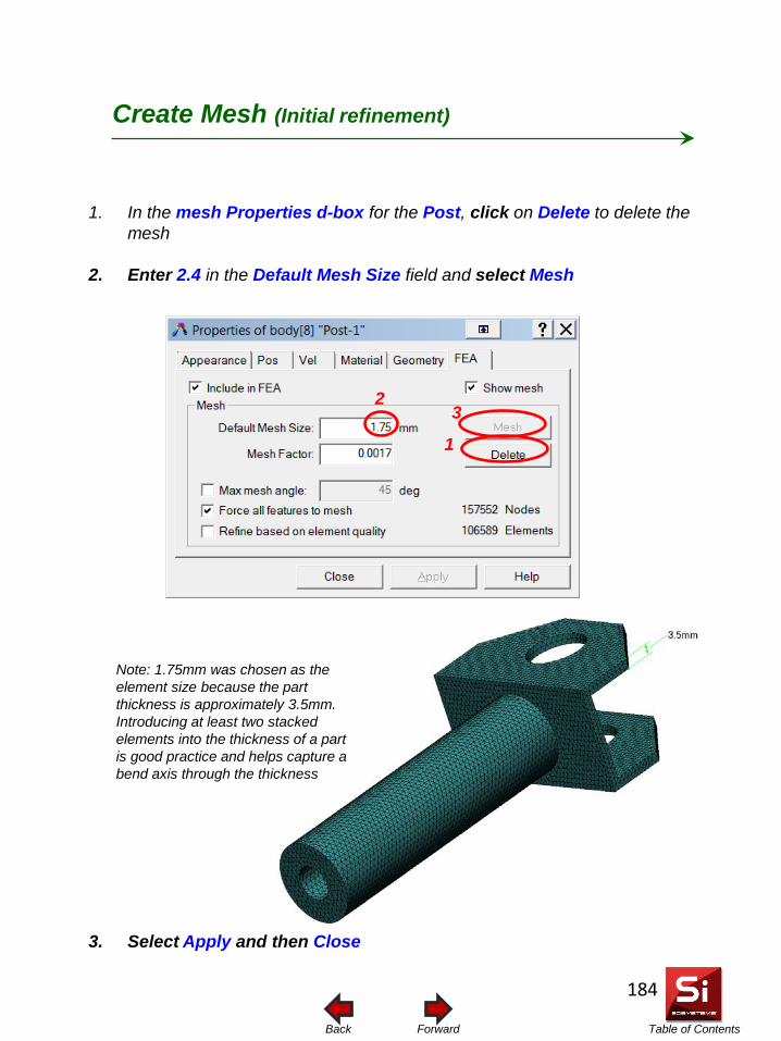
Table of Contents Forward Back
1. In the mesh Properties d-box for the Post, click on Delete to delete the mesh
2. Enter 2.4 in the Default Mesh Size field and select Mesh
3. Select Apply and then Close
Create Mesh (Initial refinement)
1
2 3
Note: 1.75mm was chosen as the element size because the part thickness is approximately 3.5mm. Introducing at least two stacked elements into the thickness of a part is good practice and helps capture a bend axis through the thickness
184
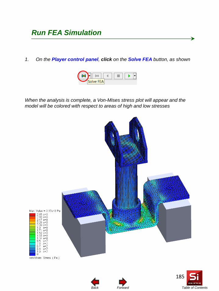
Table of Contents Forward Back
Run FEA Simulation
1. On the Player control panel, click on the Solve FEA button, as shown
When the analysis is complete, a Von-Mises stress plot will appear and the model will be colored with respect to areas of high and low stresses
185
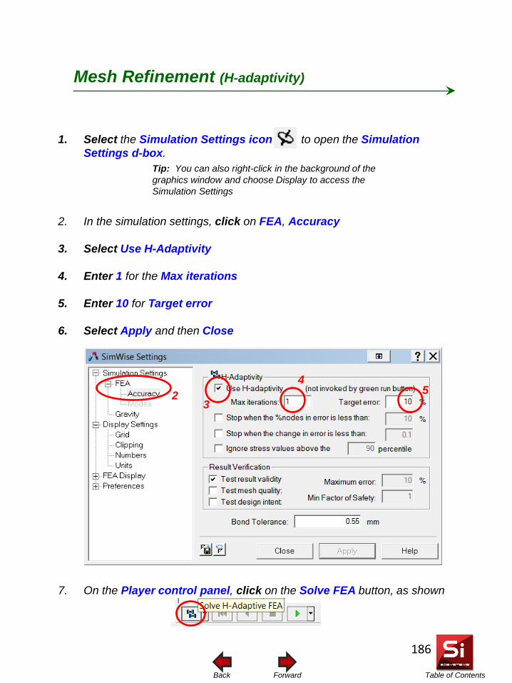
Table of Contents Forward Back
1. Select the Simulation Settings icon to open the Simulation Settings d-box.
2. In the simulation settings, click on FEA, Accuracy
3. Select Use H-Adaptivity
4. Enter 1 for the Max iterations
5. Enter 10 for Target error
6. Select Apply and then Close
7. On the Player control panel, click on the Solve FEA button, as shown
Mesh Refinement (H-adaptivity)
Tip: You can also right-click in the background of the graphics window and choose Display to access the Simulation Settings
2 4
5 3
186
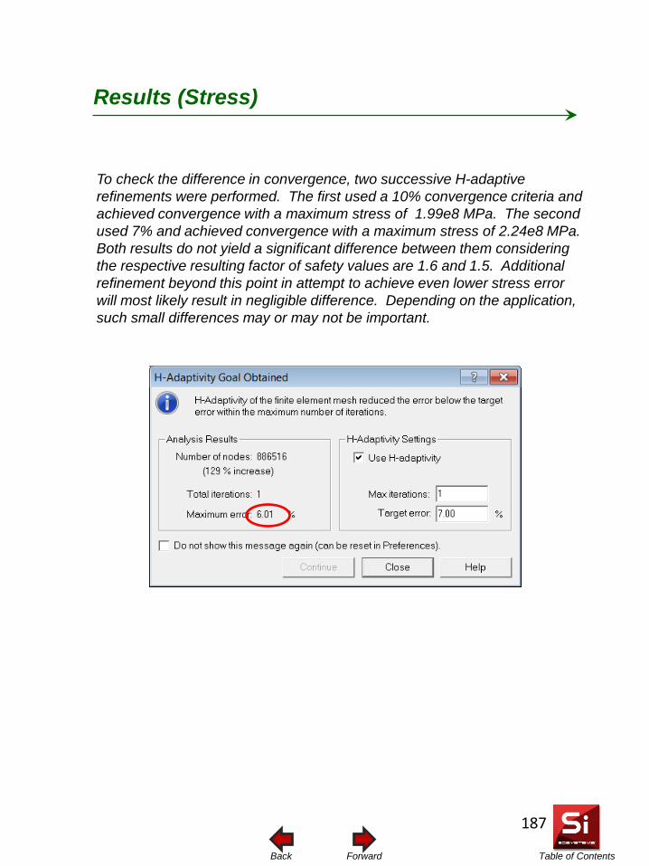
Table of Contents Forward Back
To check the difference in convergence, two successive H-adaptive refinements were performed. The first used a 10% convergence criteria and achieved convergence with a maximum stress of 1.99e8 MPa. The second used 7% and achieved convergence with a maximum stress of 2.24e8 MPa. Both results do not yield a significant difference between them considering the respective resulting factor of safety values are 1.6 and 1.5. Additional refinement beyond this point in attempt to achieve even lower stress error will most likely result in negligible difference. Depending on the application, such small differences may or may not be important.
Results (Stress)
187
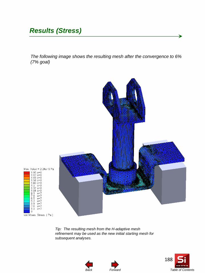
Table of Contents Forward Back
The following image shows the resulting mesh after the convergence to 6% (7% goal)
Results (Stress)
Tip: The resulting mesh from the H-adaptive mesh refinement may be used as the new initial starting mesh for subsequent analyses.
188
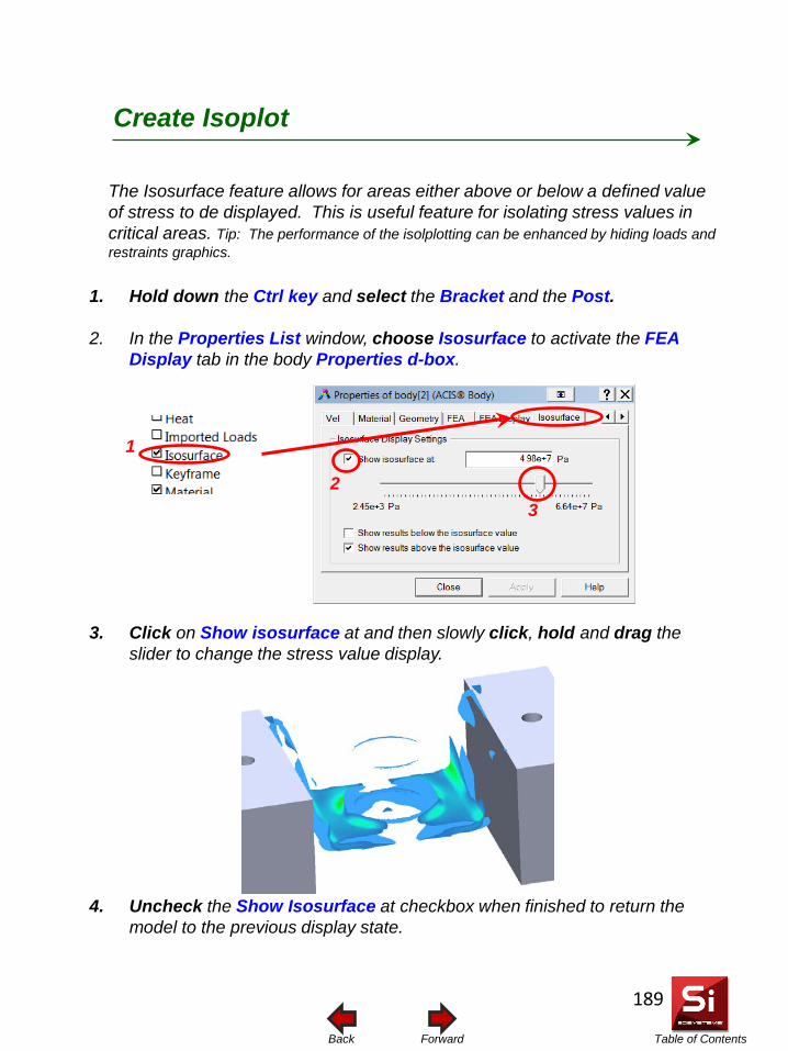
Table of Contents Forward Back
The Isosurface feature allows for areas either above or below a defined value of stress to de displayed. This is useful feature for isolating stress values in critical areas. Tip: The performance of the isolplotting can be enhanced by hiding loads and restraints graphics.
Create Isoplot
1. Hold down the Ctrl key and select the Bracket and the Post.
2. In the Properties List window, choose Isosurface to activate the FEA Display tab in the body Properties d-box.
3. Click on Show isosurface at and then slowly click, hold and drag the slider to change the stress value display.
4. Uncheck the Show Isosurface at checkbox when finished to return the model to the previous display state.
1
2 3
189
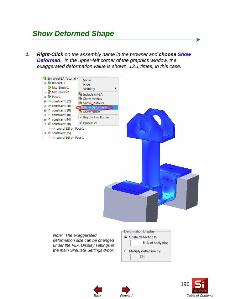
Table of Contents Forward Back
Note: The exaggerated deformation size can be changed under the FEA Display settings in the main Simulate Settings d-box
1. Right-Click on the assembly name in the browser and choose Show Deformed. In the upper-left corner of the graphics window, the exaggerated deformation value is shown, 13.1 times, in this case.
Show Deformed Shape
190
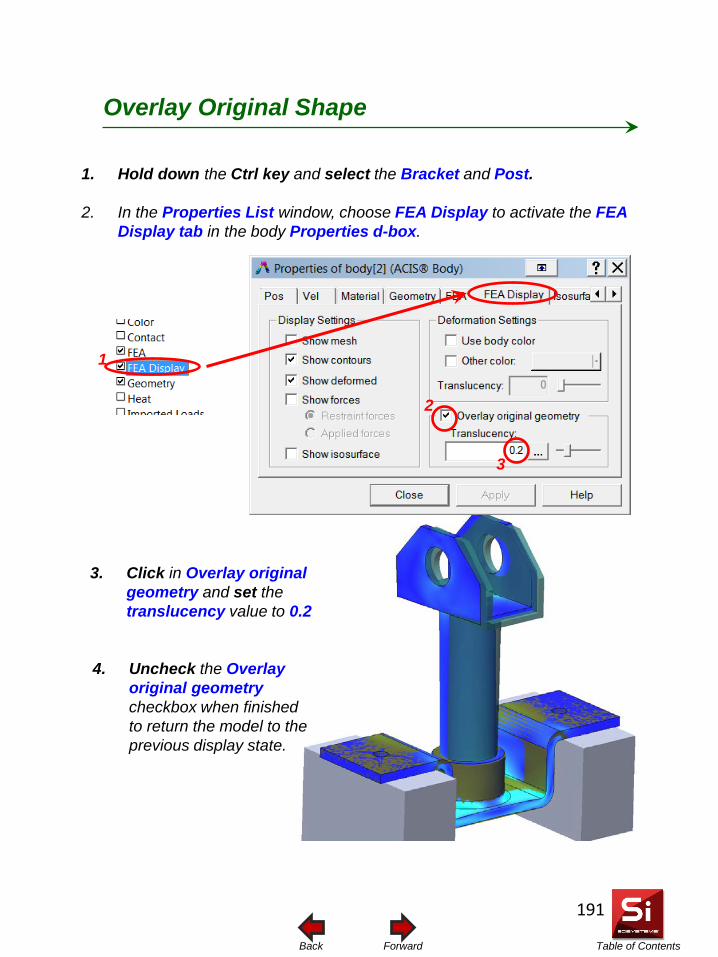
Table of Contents Forward Back
1. Hold down the Ctrl key and select the Bracket and Post.
2. In the Properties List window, choose FEA Display to activate the FEA Display tab in the body Properties d-box.
Overlay Original Shape
1
2
3
3. Click in Overlay original geometry and set the translucency value to 0.2
4. Uncheck the Overlay original geometry checkbox when finished to return the model to the previous display state.
191
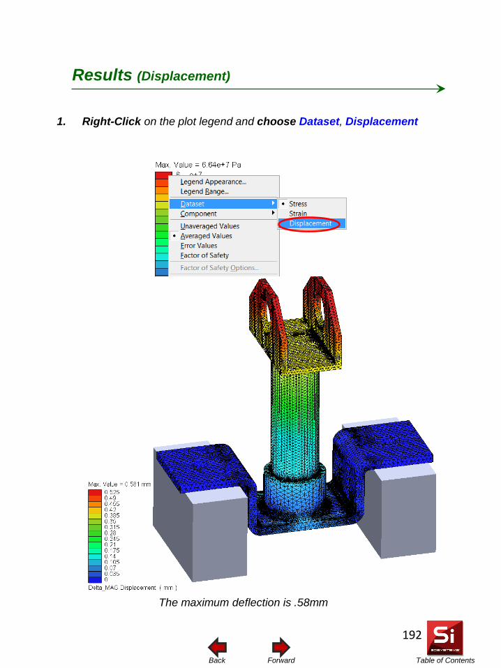
Table of Contents Forward Back
1. Right-Click on the plot legend and choose Dataset, Displacement
Results (Displacement)
The maximum deflection is .58mm
192
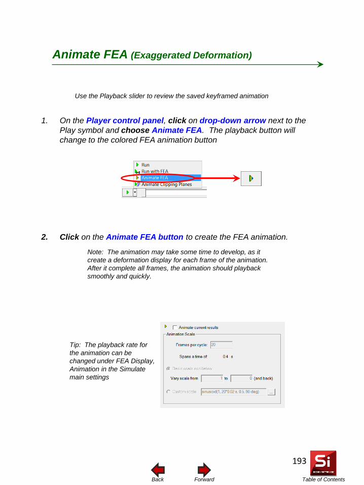
Table of Contents Forward Back
Use the Playback slider to review the saved keyframed animation
1. On the Player control panel, click on drop-down arrow next to the Play symbol and choose Animate FEA. The playback button will change to the colored FEA animation button
2. Click on the Animate FEA button to create the FEA animation.
Animate FEA (Exaggerated Deformation)
Note: The animation may take some time to develop, as it create a deformation display for each frame of the animation. After it complete all frames, the animation should playback smoothly and quickly.
Tip: The playback rate for the animation can be changed under FEA Display, Animation in the Simulate main settings
193
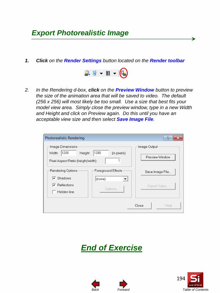
Table of Contents Forward Back
End of Exercise
1. Click on the Render Settings button located on the Render toolbar
2. In the Rendering d-box, click on the Preview Window button to preview the size of the animation area that will be saved to video. The default (256 x 256) will most likely be too small. Use a size that best fits your model view area. Simply close the preview window, type in a new Width and Height and click on Preview again. Do this until you have an acceptable view size and then select Save Image File.
Export Photorealistic Image
194
Related Documents