Simplified Wing Stress Analysis Or A Strut-Braced Monoplane The following references have been used in summarizing the data applied in this article: No. 1—Stress Analysis of Commercial Aircraft (1928), by A. Klemin; No. 2—Elementary Airplane Structural Analysis by Graphic Methods, (1938) by J. P. Eames; No. 3—Air Service Information Circular No. 520, Stress Analysis of Lieut. Phillip's "Alouette" Biplane; No. 4—Procedure Handbook for Aircraft Stress An- alysis (1940), by Nye-Hamilton-Eames; No. 5—Aircraft Structures (1950), by D. J. Peery; No. 6—Aircraft Design (1954), by K. D. Wood; No. 7—ANC-18, Design of Wood Aircraft Structures; No. 8—Civil Aeronautics Manuals, Volume II, (incl. supplements to May 1, 1958). The easiest way to assimilate something new is by reference to an example. Hence, the methods of analysis used in this report will be exemplified by a wing an- alysis of the Corben C-l "Baby Ace." Most EAA members are familiar with this design. Another reason for select- ing this airplane is its general similarity to the design of a majority of homebuilts, namely, a strut-braced, single bay, rectangular wing monoplane. The analysis of this design can be used by substituting values applying to one's own design and thus solve for stresses and design components which will be adequate in strength. This article should make it possible, when applied to a similar design, to determine the maximum stresses to be expected under various conditions of loading and to com- pute sizes of members to withstand such loads. Of more importance, possibly, is the consideration of what it will NOT enable you to do: A—It will NOT provide a method of analysis which will guarantee FAA approval from the analysis alone, without static or sand-bag proof loading, - - and B—It does NOT attempt refinements of procedure en- abling construction of the highest efficiency to stem from its application. A simplified stress analysis considers only that por- tion which is absolutely essential in calculating the re- quirements for a safe structure. Nothing else is possible in a short article of this type. DESIGN DATA It is usual in discussing methods of stress analysis to review basic mechanics and compare the analytical and graphical methods of solution. However, it was felt that this report would be more concise and of more im- mediate use to the amateur constructor by commencing the actual analysis and referring to the type of solution by example. Actual wing analysis should begin by listing pertinent data applying to the design in question. This information is listed in TABLE 1 for the "Baby Ace." The source of some of this information will be covered in appropriate notes following the table: • 12 NOVEMBER 1963 TABLE 1 THE CORBEN C-l "BABY ACE" (Modified version by Paul H. Poberezny) Airfoil section Clark "Y" Gross weight, (Wg) ................ 828 pounds Weight of wings, (Ww) ..... 123 pounds, (See Note 1) Net weight, (Wg-Ww) ............ 705 pounds Total wing span, (S) ............ 25 ft., 9 in. (309 in.) Length of lift strut bay ........ 95 in. (See Note 2) Length of overhang ........... 59.5 in. (See Note 2) Chord of wing ................................ 54 in. Incidence ............................. 1V6 deg. Area, (incl. ailerons) ....................... 112.3 sq. ft. Location of spars from the leading edge: Front spar, in inches—8.COO in.— in % of chord—14.8% Rear spar, in inches—38.375 in.— in % of chord—71.0% Center of pressure in % of chord, (See Note 3): PHAA, (Positive high angle of attack condition) 24% PLAA, (Positive low angle of attack condition) 51% NLAA, (Negative low angle of attack condition) 24% Load factors, (See Note 4): PHAA—4.5 PLAA—4.5 NLAA—2.0 Ratio of chord to beam components, (See Note 5): PHAA— —.30 PLAA— +.15 NLAA— 0 Note 1—The required weights must be computed as close- ly as possible from comparison with similar air- planes or from average figures. An average weight schedule for wings which have been con- structed in wooden designs are: Lightly loaded biplanes--.8 to 1.0 Ib. per sq. ft. Heavily-loaded biplanes—1.0 to 1.2 Ib. per sq. ft. Semi-cantilever monoplanes—1.1 to 1.3 Ib. per sq. ft. Full-cantilever monoplanes—1.2 to 1.5 Ib. per sq. ft. Metal wings for each type would average .1 to .3 Ib. per sq. ft. increase over the above figures. In this design, 1.1 Ibs. per sq. ft. will be used to compute wing weight. Note 2—95 inches is approximately the mean of the ac- tual lift strut bay dimensions for the front spar, (actual—94.66 in.) and the rear spar, (actual— 95.25 in.), while 59.5 in. is close to the mean of the actual overhang for the front spar, (actual— 59.84 in.) and the rear spar, (actual—59.25 in.). Use of the approximate mean values will not materially affect results of the final computa- tions, but will simplify the work. Note 3—The current method most commonly used is to compute the loading based on the elastic axis. However, this is a refinement such as referred

Welcome message from author
This document is posted to help you gain knowledge. Please leave a comment to let me know what you think about it! Share it to your friends and learn new things together.
Transcript
Simplified Wing Stress AnalysisOr A Strut-Braced Monoplane
The following references have been used insummarizing the data applied in this article:
No. 1—Stress Analysis of Commercial Aircraft(1928), by A. Klemin;
No. 2—Elementary Airplane Structural Analysis byGraphic Methods, (1938) by J. P. Eames;
No. 3—Air Service Information Circular No. 520,Stress Analysis of Lieut. Phillip's "Alouette"Biplane;
No. 4—Procedure Handbook for Aircraft Stress An-alysis (1940), by Nye-Hamilton-Eames;
No. 5—Aircraft Structures (1950), by D. J. Peery;No. 6—Aircraft Design (1954), by K. D. Wood;No. 7—ANC-18, Design of Wood Aircraft Structures;No. 8—Civil Aeronautics Manuals, Volume II, (incl.
supplements to May 1, 1958).
The easiest way to assimilate something new is byreference to an example. Hence, the methods of analysisused in this report will be exemplified by a wing an-alysis of the Corben C-l "Baby Ace." Most EAA membersare familiar with this design. Another reason for select-ing this airplane is its general similarity to the designof a majority of homebuilts, namely, a strut-braced, singlebay, rectangular wing monoplane. The analysis of thisdesign can be used by substituting values applying toone's own design and thus solve for stresses and designcomponents which will be adequate in strength.
This article should make it possible, when applied toa similar design, to determine the maximum stresses to beexpected under various conditions of loading and to com-pute sizes of members to withstand such loads. Of moreimportance, possibly, is the consideration of what it willNOT enable you to do:A—It will NOT provide a method of analysis which will
guarantee FAA approval from the analysis alone,without static or sand-bag proof loading, - - and
B—It does NOT attempt refinements of procedure en-abling construction of the highest efficiency to stemfrom its application.A simplified stress analysis considers only that por-
tion which is absolutely essential in calculating the re-quirements for a safe structure. Nothing else is possiblein a short article of this type.
DESIGN DATAIt is usual in discussing methods of stress analysis
to review basic mechanics and compare the analyticaland graphical methods of solution. However, it was feltthat this report would be more concise and of more im-mediate use to the amateur constructor by commencingthe actual analysis and referring to the type of solutionby example.
Actual wing analysis should begin by listing pertinentdata applying to the design in question. This informationis listed in TABLE 1 for the "Baby Ace." The source ofsome of this information will be covered in appropriatenotes following the table: •12 NOVEMBER 1963
TABLE 1THE CORBEN C-l "BABY ACE"
(Modified version by Paul H. Poberezny)Airfoil section Clark "Y"Gross weight, (Wg) . . . . . . . . . . . . . . . . 828 poundsWeight of wings, (Ww) . . . . . 123 pounds, (See Note 1)Net weight, (Wg-Ww) . . . . . . . . . . . . 705 poundsTotal wing span, (S) . . . . . . . . . . . . 25 ft., 9 in. (309 in.)Length of lift strut bay . . . . . . . . 95 in. (See Note 2)Length of overhang . . . . . . . . . . . 59.5 in. (See Note 2)Chord of wing . . . . . . . . . . . . . . . . . . . . . . . . . . . . . . . . 54 in.Incidence . . . . . . . . . . . . . . . . . . . . . . . . . . . . . 1V6 deg.Area, (incl. ailerons) . . . . . . . . . . . . . . . . . . . . . . . 112.3 sq. ft.Location of spars from the leading edge:
Front spar, in inches—8.COO in.—in % of chord—14.8%
Rear spar, in inches—38.375 in.—in % of chord—71.0%
Center of pressure in % of chord, (See Note 3):PHAA, (Positive high angle of attack condition) 24%PLAA, (Positive low angle of attack condition) 51%NLAA, (Negative low angle of attack condition) 24%
Load factors, (See Note 4):PHAA—4.5PLAA—4.5NLAA—2.0
Ratio of chord to beam components, (See Note 5):PHAA— —.30PLAA— +.15NLAA— 0
Note 1—The required weights must be computed as close-ly as possible from comparison with similar air-planes or from average figures. An averageweight schedule for wings which have been con-structed in wooden designs are:
Lightly loaded biplanes--.8 to 1.0 Ib. per sq. ft.Heavily-loaded biplanes—1.0 to 1.2 Ib. per sq. ft.Semi-cantilever monoplanes—1.1 to 1.3 Ib. per
sq. ft.Full-cantilever monoplanes—1.2 to 1.5 Ib. per
sq. ft.Metal wings for each type would average .1 to .3
Ib. per sq. ft. increase over the above figures.In this design, 1.1 Ibs. per sq. ft. will be usedto compute wing weight.
Note 2—95 inches is approximately the mean of the ac-tual lift strut bay dimensions for the front spar,(actual—94.66 in.) and the rear spar, (actual—95.25 in.), while 59.5 in. is close to the mean ofthe actual overhang for the front spar, (actual—59.84 in.) and the rear spar, (actual—59.25 in.).Use of the approximate mean values will notmaterially affect results of the final computa-tions, but will simplify the work.
Note 3—The current method most commonly used is tocompute the loading based on the elastic axis.However, this is a refinement such as referred
to in sub-paragraph B on the first page. Themethod used here, (center of pressure location)uses values obtained from airfoil wind tunneldata from sources referred to in our report No.1, such as NACA Technical Report No. 824, etc.For the PHAA and NLAA conditions the C.P. isconsidered to b2 at the most forward locationgiven in the wind tunnel data charts. For thePLAA condition the C.P. is obtained by observ-ing its location at the point where the lift co-
efficient, (C,) is 25% of its maximum value. Forsome of the most commonly used sections, thevalues following are expressed in % of chordlength from the leading edge:
AirfoilClark YGottingen 398USA 27USA 35BUSA 45NACA M6NACA M12
C.P. Locationfor PHAA & NLAA
30%29%30%27%25%25%
C.P. Locationfor PLAA
51%50%50%49%38%40%40%
Note 4—The load factor to be used is selected by the de-signer. FAA specifies a minimum positive man-euvering load factor of 4.4 for utility aircraft or6.0 for acrobatic. The minimum negative man-euvering load factor is .4 times the positive fac-tor for utility and .5 times the positive factorfor the aerobatic category. A positive load fac-tor of 4.5 is selected for this design, as it is in-tended to be non-aerobatic, thus giving a nega-tive load factor of 1.8 (4.5 x .4). However, to sim-plify computations and err on the safe side, weshall use a value of 2.0.
Note 5—Ratio of chord to beam components are posi-tive ( + ), when chord loads are applied towardthe rear of the drag truss and negative (—),when applied in a forward direction. For thePLAA condition, CAM No. 8 in Appendix B,paragraph .2121 states, "Although no aft actingchordwise loading is specified, the structureshould be capable of sustaining aft chordwiseloads." It has been the practice for many yearsto apply the value given, ( + .15) for this condi-tion in the case of most all wing sections.
SEQUENCE OF WING ANALYSIS
1—Compute the effective span of the wing.2—Compute the normal gross beam loads.3—Compute the normal net beam loads.
4—Compute the normal chord loads.5—Compute distribution of loads between spars.6—Compute moments, shears and reactions on each
spar.7—Compute loads in lift struts.8—Solve for drag truss loads.9—Summarize final total loads in all members.
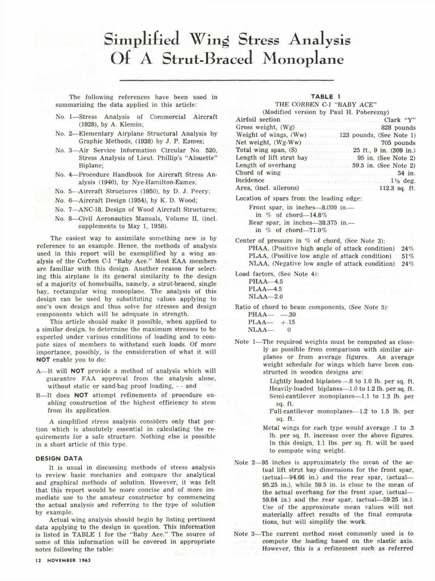
1—Effective Span is the distance from wing tip to wing tipless any portion covered by the fuselage and an allow-ance for tip loss. The full span of the wing is not ef-fective because the lift forces are greatly reduced atthe tips due to air slipping off the tip portion. Thedecrease in effective semi-span, to allow for tip loss,is shown in Fig. 1 for the externally braced wingwhere the distance from the outer strut point to thetip is substantially the same as the wing chord. Alength equal to ¥4 of the overhang, (.25 L,) is sub-tracted from the actual semi-span to obtain the effec-tive semi-span, or:
Effective semi-span, (Se) = (95 + 59.5)—(.25x59.5)= 139.6 in.
2—Normal Gross Beam Load equals gross weight of theairplane divided by the effective span, or:Gross beam load, (Wgb) = Wg/Se x 2 = 828/139.6 x 2 =2.97 Ib. per in.
3—Normal Net Beam Load equals the gross beam loadminus the dead weight of the wings, dead weight ofwings, (Wwd) per inch run is computed by dividingweight of wings, (Ww) by the actual, (not effective)span, (S), or:
Wwd = Ww/S = 123/309 = .4 Ib. per in. run.Net beam load, (Wn) = Wgb—Wwd = 2.97 — .4 =
2.57 Ib. per in. run.Check on work: 2(Wn x Se) + Ww = Wg
2(2.57 x 139.6) + 123 = 840 Ibs.840 Ibs. is 12 Ibs. more than 828 Ibs., but is satisfactory,as it loads the wing more severely and is, therefore,on the safe side.
4—Normal Chord Loads are computed by multiplying thenet beam load by the chord/beam ratio:Flight Net beam Chord/beam Chord load Load Design
ConditionPHAAPLAANLAADive
lood2.572.572.57
—
Rotio.—.30+ .15
0—
per inch—0.77
0.39—
2.28
Factor4.54.5—1
Chord load—3.47
1.76__
2.28For the Dive condition, net weight of the airplane,(705 Ibs.) is distributed uniformly along the actualspan. No load factor is required, hence, 705/3C9 =2.28 Ib. per in. run.
(CONTINUED NEXT MONTH)
Effectivewing tip
Actualwin<; tip
WnbeaFLad
Ww(Wing weight) \k(8e)Effective
Semi-span
LiftStrut
Plane of
side offuselage
SPORT AVIATION 13
PART 3
Simplified Wing Strut Analysis Of I Strut-Braced MonoplaneBrj Noel J. Becar, EAA 725
316 Del Rosa WaySan Mateo, Calif.
THIS REPORT is a continuation ofPart 2 in the December, 1959
issue of SPORT AVIATION, in thatit investigates design procedures forthe structural members analyzed forstresses in that report. The refer-ences consulted in the preparation ofthis paper are as follows:
No. 1—Stress Analysis of Commer-cial Aircraft (1928) by A. Klemin;
No. 2—Procedure Handbook f o rAircraft Stress Analysis (1940) byNye-Hamilton-Eames;
No. 3—ANC-5, Strength of MetalAircraft Elements (1955) by GPO.
No. 4—ANC-18, Design of WoodAircraft Structures (1951) by GPO.
No. 5—Airplane Structures, Vol. 1,3rd edition (1943) by Niles.Design of Lift Struts
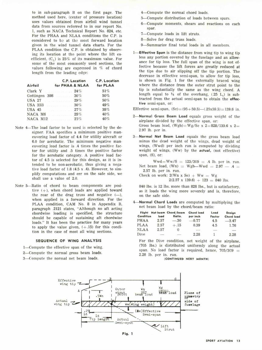
In the previous analysis of thewing, the stresses which were firstobtained in complete form were thoseimposed on the external lift struts.We will, therefore, consider first thedesign procedure for these struts. Inthe following table, "computed stress-es" are the most severe of those list-ed on Table 5 of the preceding ar-ticle.
The Civil Aeronautics Manuals, Vol.11, in CAM No. 3, page 27, specifiesthat a safety factor of 1.5 be imposed,in addition to the load factor, to takecare of variation in individual lotsof material from the test values givenfor strength. This has been done toobtain the values indicated in thelast column of Table A, and will beapplied to other stress values ob-tained from the previous article.
A member carrying compression iscustomarily referred to as a "col-umn", and since the method of endattachment affects the problem con-siderably, the first step is to deter-mine the coefficient of fixity, re-ferred to as "c." "c" equals 1 for pin-ended columns, and "c" equals 2 forrestrained columns such as weldedsections of tubing in a fuselage struc-ture.
The length of the column is ex-tremely important and the ratio L/pis used to designate a column as"short" or "long", based on what iscalled the critical L/p value. Thiscritical value is listed in referencesNo. 1, No. 2 and No. 3, for differentkinds of materials. If the L/p value
is below the "critical" value, it is ashort column. If above, it is consid-ered a long column. L is the length ofthe column in inches and p, (the let-ter "rho" in the Greek alphabet) sym-bolizes the radius of gyration.
The radius of gyration can be com-puted as p = I/A, where, I = mo-ment of inertia of the column sectionand A = cross-sectional area of thecolumn in square inches. Practicallyall of these values can be obtainedfrom tables in various handbooks orreferences, No. 2, No. 3 or No. 5 andtherefore do not have to be computedin practice. The ratio L/p should notexceed 150 and should be kept assmall as possible.
"Local instability" is failure bycrushing of the walls of the column.This occurs when the wall thicknessof the column or tube is too smalla value for its diameter. Tubes do notneed to be investigated for this condi-tion if the diameter (D), divided bythe wall thickness (t), is less than 50.
The sequence of operations neces-sary to select a proper size tube isas follows:1—Arbitrarily choose a standard size
tube.2—Determine whether it is a long or
short column.3—Determine if column should be in-
vestigated for local instability,(D/t over 50).
4—Solve for allowable stress.5—Solve for actual stress.6—Determine the margin of safety.
If margin of safety, (M.S) is nega-tive in value, choose a strongertube and repeat the calculations.If it has an excessively positivemargin, choose a smaller tube inorder to save weight and recalcu-late.
Application of the foregoing to the"Baby Ace" design follows:
Step No. 1—To check for the propersize of streamline tube to be used
for a front strut, we will investigatethe 87 in.—SAE No. 4130 steel tubeoriginally called for, and having a2.697 in. major axis, a 1.143 minoraxis, and a wall thickness of .065 in.From reference No. 2 or No. 3 wefind p of major axis = .4062 and L/p= 87/.4062 = 214. An L/p of 214is greatly in excess of 150 whichshould not be exceeded. However,this plane has short jury struts con-necting the long lift struts to thespar at a point 35 in. inboard fromthe outer strut point so this restraintmakes it possible to compute the valueof L as 52 in. in place of 87 in. If wesubstitute this value in our L/p equa-tion we get: 52/.4062 = 128, whichis obviously satisfactory.
Step No. 2—As the critical L/p val-ue for No. 4130 steel from referenceNo. 1, No. 2 or No. 3 is 91, this isconsidered a long column.
Step No. 3—As D/t = 2/.065 =30.7, this tube will not need to be in-vestigated for local instability as theD/t value is below 50. (The D = 2value is the equivalent round tubediameter from which the streamlinetube is formed, also listed in refer-ences No. 1, No. 2 or No. 3).
Step No. 4—The allowable stress(Fc) for long columns is equal to:Fc = 286x 1Q6
(L/p)2To err on the safe side, we shall
consider L/p =-_ 214, the originalvalue obtained and ignore the actionof the jury struts, hence: Fc =286,000,000/(214)2 = 286,000,000/45,796= 6135 psi.
Step No. 5—The actual stress (fc) isequal to P/A where P is the designstress and A is the area of the tube.Hence, 1506/.3951 = 3812 psi.
Step No. 6—Margin of safety isFc/fc—1 or, 6135/3812—1 = .609and as this is a positive value, it issatisfactory.
(Continued on next page)
TABLE A
Strut
FrontFrontRearRear
Typ« ofStress
CompressionTension
CompressionTension
Condition
NLAAPHAANLAAPLAA
ComputedStress in K
1,0042,260
1931,760
DESIGN STRESS(Comp. stress x 1.
1,5063,390
2892,640
S)
SPORT AVIATION 13
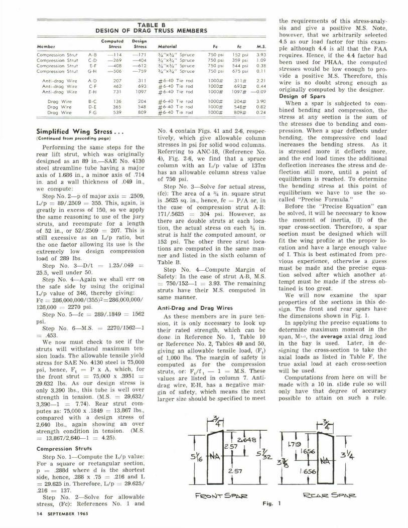
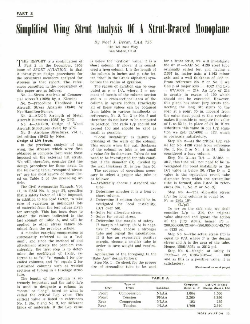
TABLE BDESIGN OF DRAG TRUSS MEMBERS
Member
Compression StrutCompression StrutCompression StrutCompression Strut
Anti-drog WireAnti-drag WireAnti-drag Wire
Drag WireDrag WireDrag Wire
ComputedStress
A-BC-DE-F
G-H
A-DC-FE-H
B-CD-EF-G
— 114—269— 408— 506
207462731
136365539
DesignStress
— 171— 404— 612—759
311693
1097
204548809
Material3/4"xy43/4"x3/43/4"x3/43/i"x%
#6-40#6-40#6-40
#6-40#6-40#6-40
" Spruce" Spruce" Spruce" Spruce
Tie rodTie rodTie rod
Tie rodTie rodTie rod
Fc
750 psi750 psi750 psi750 psi
1000#1000#1000#
1000#1000#1000#
fc
1 52 psi359 psi544 psi675 psi
311#693#
1097#
204*548#809*
M.S.
3.931.090.380.11
2.210.44
—0.09
3 900.820.24
Simplified Wing Stress ...(Continued from preceding page)
Performing the same steps for therear lift strut, which was originallydesigned as an 89 in.—SAE No. 4130steel streamline tube having a majoraxis of 1.686 in., a minor axis of .714in. and a wall thickness of .049 in.,we compute:
Step No. 2—p of major axis = .2509,L/p = 89/.2509 = 355. This, again, isgreatly in excess of 150, so we applythe same reasoning to use of the jurystruts, and recompute for a lengthof 52 in., or 52/.2509 = 207. This isstill excessive as an L/p ratio, butthe one factor allowing its use is theextremely low design compressionload of 289 lbs.
Step No. 3—D/t = 1.25/.049 =25.5, well under 50.
Step No. 4—Again we shall err onthe safe side by using the originalL/p value of 346, thereby giving:Fc = 286,000,000/(355)2 = 286,OCO,000/126,000 = 2270 psi.
Step No. 5—fc = 289/.1849 = 1562psi.
Step No. 6—M.S. = 2270/1562—1= .453.
We now must check to see if thestruts will withstand maximum ten-sion loads. The allowable tensile yieldstress for SAE No. 4130 steel is 75,000psi, hence, Ft = P x A, which, forthe front strut = 75,000 x .3951 =29.632 lbs. As our design stress isonly 3,390 lbs., this tube is well overstrength in tension. (M.S. = 29,632/3,390—1 = 7.74). Rear strut com-putes as: 75,000 x .1849 = 13,867 lbs.,compared with a design stress of2,640 lbs., again showing an overstrength condition in tension. (M.S.= 13,867/2,640—1 = 4.25).
Compression StrutsStep No. 1—Compute the L/p value:
For a square or rectangular section,p = .288d where d is the shortestside, hence, .288 x .75 = .216 and L= 29.625 in. Therefore, L/p = 29.62S/.216 = 137.
Step No. 2—Solve for allowablestress, (Fc): References No. 1 and
No. 4 contain Figs. 41 and 2-6, respec-tively, which give allowable columnstresses in psi for solid wood columns.Referring to ANC-18, (Reference No.4), Fig. 2-6, we find that a sprucecolumn with an L/p value of 137mhas an allowable column stress valueof 750 psi.
Step No. 3—Solve for actual stress,(fc): The area of a % in. square strutis .5625 sq. in., hence, fc = P/A or, inthe case of compression strut A-B:171/.5625 = 304 psi. However, asthere are double struts at each loca-tion, the actual stress on each % in.strut is half the computed amount, or152 psi. The other three strut loca-tions are computed in the same man-ner and listed in the sixth column ofTable B.
Step No. 4—Compute Margin ofSafety: In the case of strut A-B, M.S.= 750/152—1 = 3.93. The remainingstruts have their M.S. computed insame manner.
Anti-Drag and Drag WiresAs these members are in pure ten-
sion, it is only necessary to look uptheir rated strength, which can bedone in Reference No. 1, Table 10or Reference No. 2, Tables 49 and 50,giving an allowable tensile load, (F,)of 1,000 lbs. The margin of safety iscomputed as for the compressionstruts, or: F,/f, — 1 = M.S. Thesevalues are listed in column 7. Anti-drag wire, E-H, has a negative mar-gin of safety, which means the nextlarger size should be specified to meet
the requirements of this stress-analy-sis and give a positive M.S. Note,however, that we arbitrarily selected4.5 as our load factor for this exam-ple although 4.4 is all that the FAArequires. Hence, if the 4.4 factor hadbeen used for PHAA, the computedstresses would be low enough to pro-vide a positive M.S. Therefore, thiswire is no doubt strong enough asoriginally computed by the designer.Design of Spars
When a spar is subjected to com-bined bending and compression, thestress at any section is the sum ofthe stresses due to bending and com-pression. When a spar deflects underbending, the compressive end loadincreases the bending stress. As itis stressed more it deflects more,and the end load times the additionaldeflection increases the stress and de-flection still more, until a point ofequilibrium is reached. To determinethe bending stress at this point ofequilibrium we have to use the so-called "Precise Formula."
Before the "Precise Equation" canbe solved, it will be necessary to knowthe moment of inertia, (I) of thespar cross-section. Therefore, a sparsection must be designed which willfit the wing profile at the proper lo-cation and have a large enough valueof I. This is best estimated from pre-vious experience, otherwise a guessmust be made and the precise equa-tion solved after which another at-tempt must be made if the stress ob-tained is too great.
We will now examine the sparproperties of the sections in this de-sign. The front and rear spars havethe dimensions shown in Fig. 1.
In applying the precise equations todetermine maximum moment in thespan, M'--, the average axial drag loadin the bay is used. Later, in de-signing the cross-section to take theaxial loads as listed in Table F, thetrue axial load at each cross-sectionwill be used.
Computations from here on will bemade with a 10 in. slide rule so willonly have that degree of accuracypossible to attain on such a rule.
14 SEPTEMBER 1965
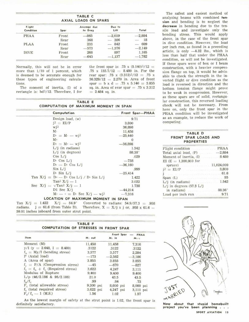
TABLE CAXIAL LOADS ON SPARS
FiightCondition
PHAA
PLAA
DIVE
Spar
FrontRear
FrontRear
FrontRear
Average dueto Drag
—865368233
—573268
—645
Due toLift
—2,019— 386— 842—1,576
897—1,137
Total
—2,884— 18— 609—2,149
1,165—1,782
Normally, this will not be in errormore than 1/10 of 1 percent, whichis deemed to be accurate enough forthese types of engineering calcula-tions.
The moment of inertia, (I) of arectangle is: bd3/12. Therefore, I for
the front spar is: .75 x (5.140)3/12 =.75 x 135.7/12 = 8.480 in. For therear spar: .75 x (3.312)3/12 = .75 x36.329/12 = 2.270 in. Area of frontspar = b x d = .75 x 5.140 = 3.855sq. in. Area of rear spar = .75 x 3.312= 2.484 sq. in.
TABLE ECOMPUTATION OF MAXIMUM MOMENT IN SPAN
Computation
Design load, (w)J2 = EI/Pwj2M-D' = M — wj2M«D- = M- — wj2L/j (in radians)L/j (in degrees)Cos L/jDI Cos L/jD- — D' Cos L/jSin L/jD' Sin L/j
Tan X/j = D= — D> Cos L/j / D> Sin L/jTan2 X/j — 1
Sec X/j = vTan2 X/j — 1Dl Sec X/jM' — * = DI Sec X/j — wj2
LOCATION OF MAXIMUM MOMENT IN SPANTan X/j = 1.422 X/j = 54.9° Converted to radians: 54.9/57.3 = .958radians, j = 61.6 (from Table D). Therefore, X = X/j x j or, .958 x 61.6 =59.01 inches inboard from outer strut point.
TABLE FCOMPUTATION OF STRESSES IN FRONT SPAR
Front Spar—PHAA
9.713,800
36,89811,458
—25,4400
—36,8981.542
88.36C
.029—738
—36,160.999
—25,4141.4223.0221.738
—44,214—7,316
Item Mi outFront Spar — PHAA
Mi in M,--..
Moment (M)y/I (y = 2.648, I = 8.480)fb = My/I (bending stress)P (Axial load)A (Area of spar)ft. = P/A (Compression stress)f t = fh + fc (Required stress)Modulus of RuptureL/p (46/2.186 & 95/2.186)V'tF, (total allowable stress)f t (total required stress)Ft/ f t — 1 (M.S.)
11,458.31223,577—1733.855—453,6229,400
21.0.99
9,300 psi3,622 psi
1.56
11,458.31223,577
—2,5823.855—6704,2479,40043.5
.848,600 psi4,247 psi
1.02
7,316.31222,284
—3,1863.855—8273,1119,40043.5
.738,000 psi3,111 psi
1.57As the lowest margin of safety at the strut point is 1.02, the front spar is
definitely satisfactory.
The safest and easiest method ofanalyzing beams with combined ten-sion and bending is to neglect thedecrease in bending due to the ten-sile load and investigate only thebending stress. This would applyabove, in the case of the front sparin dive condition. However, the loadper inch run, as found in a precedingarticle, is only —4.32 lbs., which isless than half that under the PHAAcondition, so will not be investigated.If these spars were of box or I beamconstruction, with a heavier compres-sion flange on top, it would be advis-able to check the strength in the in-verted flight or dive condition as theload is reversed in direction and thebottom tension flange might proveto be weak in compression. However,as these spars are of solid, rectangu-lar construction, this reversed loadingcheck will not be necessary. Fromhere on, only the front spar in thePHAA condition will be investigatedas an example, to reduce the work ofcomputing.
TABLE DFRONT SPAR LOADS AND
PROPERTIES________
Flight condition PHAATotal axial load, (P) . . . —2,884Moment of inertia, (I) . . . . . 8.480El (E - 1,300,OCO for
spruce) 11,024,000j2 = EI/P . . . . . . . . . . . . . . . . . 3,800j . . . . . . . . . . . . . . 61.6Span (L) . . . . . . . . . . . . 95L/j (in radians) 1.542L/j in degrees (57.3 L/j
i n radians) . . . . . . . 88.36°Load per inch run . . . . . . . . 9.71
Now about that stupid homebuiltproject you've been planning . . .
SPORT AVIATION 15
PART TWO
Simplified Win^ Stress AnalysisOr A Strut-Braced Monoplane
5—Distribution of Load Between Spars in a two-spar de-sign, such as this, is in inverse proportion to spar dis-tance from the center of pressure, at which point thebeam load is assumed to act:
Load on front spar:rear spar location—C.P.________
(in %) rear spar location—front spar location or:for PHAA: 71—24/71—14.8=84% Front spar.
Load on rear spar:C.P.—front spar location_______
(in %) rear spar location—front spar locationPITA A - 9d__IdR/T!__14 Q_1ft«- Root' ci
'v f i ̂ ai opai luuaiivju——nuiil opal iu\.aLluu Ifor PHAA: 24—14.8/71—14.8=16% Rear spar.
For PLAA: Front spar: 71—51/71—14.8 = 35%Rear spar: 51—14.8/71—14.8=65%
For NLAA: Front spar: 71—24/71—14.8 = 84%Rear spar: 24—14.8/71—14.8=16%
or:
BEAM LOADS
FlightCondition
PHAAPHAA
PLAAPLAA
NLAANLAA
Spor
FrontRear
FrontRear
FrontRear
TABLE 2PER INCH RUN ON SPARS
Net loodper in.
on Wing
2.572.57
2.572.57
2.572.57
LoodFactor
4.54.5
4.54.5
2.02.0
% carriedby Spor
84%16%
35%65%
84%16%
Net loadper in. run
9.711.85
4.057.52
—4.32—0.82
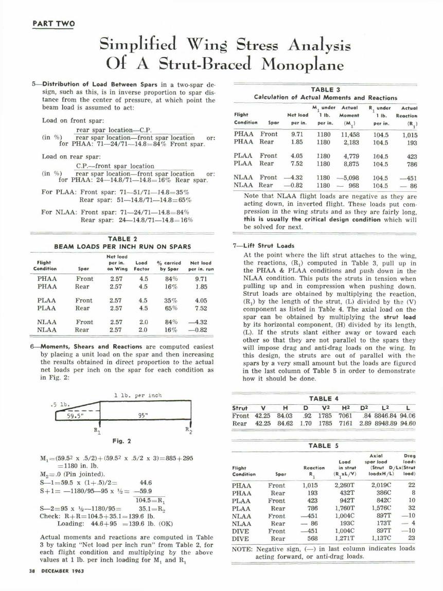
6—Moments, Shears and Reactions are computed easiestby placing a unit load on the spar and then increasingthe results obtained in direct proportion to the actualnet loads per inch on the spar for each condition asin Fig. 2:
1 Ib. per inch
59. 5" 95"
Fig. 2
M1 = (59.52 x .5/2)+ (59.52 x .5/2 x 3) = 885+ 295= 1180 in. Ib.
M2=.0 (Pin jointed).8—1=59.5 x (l + .5)/2= 44.6S+l= —1180/95—95 x »/2 = -59.9
104.5=R1
S—2=95 x %—1180/95= 35.1=R2Check: R+R=104.5 + 35.1 = 139.6 Ib.
Loading: 44.6+95 =139.6 Ib. (OK)
Actual moments and reactions are computed in Table3 by taking "Net load per inch run" from Table 2, foreach flight condition and multiplying by the abovevalues at 1 Ib, per inch loading for Mt and R;
38 DECEMBER 1963
TABLE 3Calculation of Actual Moments and Reactions
FlightCondition
PHAAPHAA
PLAAPLAA
NLAANLAA
Spar
FrontRear
FrontRear
FrontRear
Net loadper in.
9.711.85
4.057.52
—4.32—0.82
M under1 Ib.
per in.
11801180
11801180
11801180
ActualMoment
(Mt)
11,4582,183
4,7798,875
—5,098— 968
R under1 Ib.
per in.
104.5104.5
104.5104.5
104.5104.5
ActualReaction
<v1,015
193
423786
—451— 86
Note that NLAA flight loads are negative as they areacting down, in inverted flight. These loads put com-pression in the wing struts and as they are fairly long,this is usually the critical design condition which willbe solved for next.
7—Lift Strut LoadsAt the point where the lift strut attaches to the wing,the reactions, (R,) computed in Table 3, pull up inthe PHAA & PLAA conditions and push down in theNLAA condition. This puts the struts in tension whenpulling up and in compression when pushing down.Strut loads are obtained by multiplying the reaction,(Rj) by the length of the strut, (L) divided by the (V)component as listed in Table 4. The axial load on thespar can be obtained by multiplying the strut loadby its horizontal component, (H) divided by its length,(L). If the struts slant either away or toward eachother so that they are not parallel to the spars theywill impose drag and anti-drag loads on the wing. Inthis design, the struts are out of parallel with thespars by a very small amount but the loads are figuredin the last column of Table 5 in order to demonstratehow it should be done.
StrutFrontRear
V H42.25 84.0342.25 84.62
TABLED V2.92 1785
1.70 1785
4H*
70617161
D2 L2.84 8846.84
2.89 8948.89
L94.0694.60
FlightCondition Spar
PHAAPHAAPLAAPLAANLAANLAADIVEDIVENOTE:
FrontRear
FrontRear
FrontRear
FrontRear
TABLE
ReactionR!
1,015193423786
—451— 86—451
568
5
Loadin strut
(RjXL/V)
2.260T432T942T
1.760T1.004C
193C1.004C1.271T
Axial Dragspar load load-.
(Strut D/Lx(StrutloodxH/L) load)
2.019C386C842C
1.576C897T173T897T
1.137CNegative sign, ( — ) in last column indicatesacting forward, or anti-drag loads.
228
1032
—10— 4—10
23loads
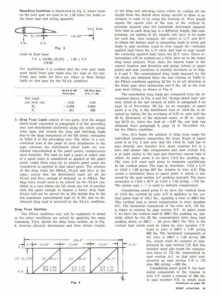
Nose-Dive Condition is illustrated in Fig. 3, where loadson the rear spar are seen to be 1.26 times the loads onthe front spar and acting upwards:
r ,; —— B
- 30.375*T~~*i^>^•
Tail Poat
116 .83"———1
Fig. 3
Load on Rear Spar:F.S. x 116.83 + 30.375 = 1.26 x F.S.
116.83
For equilibrium it is evident that the rear spar loadsmust equal front spar loads plus the load on the tail.Front spar loads for Dive are taken as final designloads on that spar for the NLAA condition.
Net Loadper inch run
M,R,
NLAA ft NDFront Spar
—4.32—5,098— 451
ND Rear Spar(F.S. x 1.26)
5.446,424
568
8—Drag Truss Loads consist of two parts, first the designchord loads computed in paragraph 4 of the precedingtext, and distributed uniformly along the entire actualwing span, and second the drag and anti-drag loadsdue to the drag component of the lift struts, computedin Table 5 of the preceding text. The latter is a con-centrated load at the point of strut attachment to thespar, whereas, the distributed chord loads are con-sidered concentrated at the panel points, (compressionstrut location). The load on half a panel at either sideof a panel point is considered as applied at the panelpoint. Loads from wing tip to nearest panel point areconsidered as applied to that panel point. The solutionof the drag truss for PHAA, PLAA and Dive is thesame, except that the distributed loads act aft forPLAA and Dive instead of forward, as in PHAA. Thedrag truss would need to be solved for the NLAA con-dition in a case where the lift struts are out of parallelwith the spars enough to impose a heavy drag load.NLAA will not be solved for in this design due to thelow maximum concentrated load of 10 Ibs. and no dis-tributed drag load is involved in the NLAA condition.
Drag Truss SolutionThe PHAA condition only will be explained in detail
as the other conditions are solved by applying the samereasoning. First, sketch the drag truss outline, as in Fig.4, showing physical dimensions and then obtain lengths
—J 9.7T—P .s ' [
154.5"(H)46" (H)48" ( K ) 4 5 "
(V) 30.375'
R.3.1/V 1.82H/V 1.52
(L) 56.8"
L/V 1.87H/V 1.58
(I.)
Fig. 4
of the drag and anti-drag wires either by scaling off thelength from the sketch after being careful to draw it ac-curately to scale or by using the formula of: Wire lengthequals the square root of the sum of the vertical di-mension squared plus the horizontal dimension squared.Note that as each drag bay is a different length, this com-putation, (or scaling of the length) will have to be madefor each bay. Also compute the values of L/V and H/Vto obtain the factors used in computing loads in wires andloads in spar sections. Load in wire equals the verticallyapplied load times the L/V ratio, and load in spar equalsthe vertically applied load times the H/V ratio. These re-lationships will be worked out a little later on in the detaildrag truss analysis. Next, show the known loads in thecorrect location and direction and assign letters at panelpoints and spar junctions to identify members as in Figs.5, 6 and 7. The concentrated drag loads imposed by thelift struts are obtained from the last column of Table 5;the PHAA condition applying 22 Ibs. in an aft direction atthe front spar strut connection and 8 Ibs. aft at the rearspar strut fitting, as shown in Fig. 4.
The distributed drag loads are computed from the di-mensions shown in Fig. 4 and the "design chord load" perinch, listed in the last column of table in paragraph 4 onpage 13 of November, '63 SA. As an example, at panelpoint A m Fig. 5, the distributed load of 113.6 Ibs. is ob-tained by taking the tip overhang of 9.75 in. plus half the46 in. dimension of the adjacent panel, or 23 in., equal-ing 32.75 in., times the load of —3.47 Ibs. per inch runobtained from paragraph 4, page 13 of November SA,for the PHAA condition.
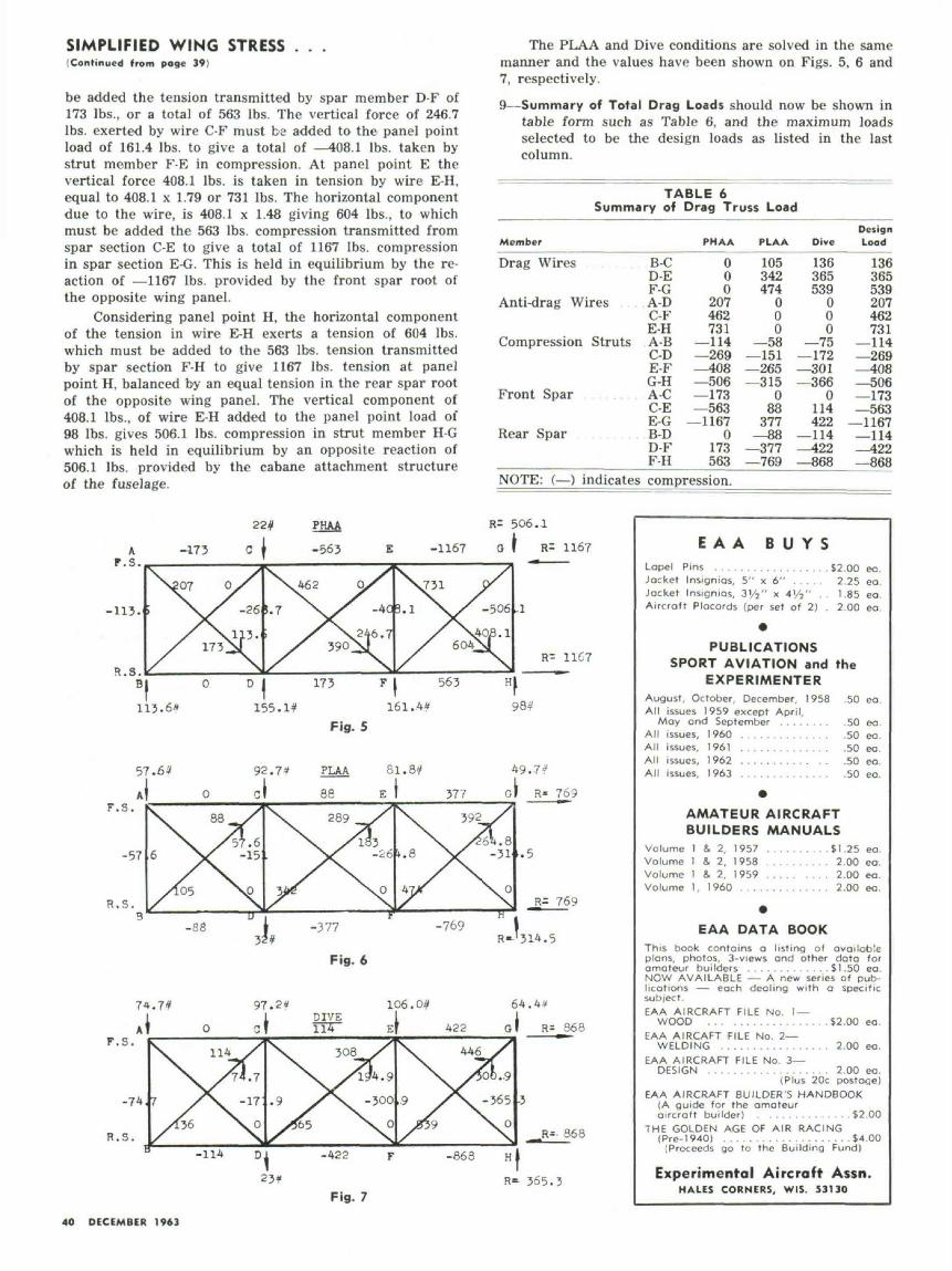
Now, let's begin the solution of drag truss loads forindividual members comprising the truss. Begin at panelpoint B in Fig. 5 and note that the 113.6 Ib. load has topass directly into member B-A, since member B-C is awire and cannot take compression and spar section B-Dis at right angles to the load and therefore cannot take iteither. At panel point A we have 113.6 Ibs. pushing up.The wire A-D must pull down to maintain equilibriumin the vertical plane. The load is, therefore, 113.6 x L/Vor 113.6 x 1.82 giving 207 Ibs. tension in wire A-D. Thisexerts a horizontal force at panel point A which is bal-anced by the spar section A-C pushing outward. The forcenecessary is 113.6 x H/V or 113.6 x 1.52 giving —173 Ibs.The minus sign, (—) is used to indicate compression.
Considering panel point D we have the vertical forceof 113.6 Ibs. exerted by wire A-D in addition to the ver-tical panel load of 155.1 Ibs., equaling a total of 268.7 Ibs.This vertical load is direct compression in strut memberD-C. The horizontal component of the wire A-D, 173 Ibs.is taken in tension by spar section D-F. At panel pointC we have the vertical load of 268.7 Ibs. pushing up, par-tially offset by the 22 Ibs. concentrated strut drag loadpushing down, so 268.7 — 22 gives 246.7 Ibs. This is thevertical load which must be taken by wire member C-F.
Load in wire is 246.7 x 1.87 giving462 Ibs. The horizontal component ofthe wire is 246.7 x 1.58 giving 390Ibs., which must be resisted in com-
" 5.75" pression by spar section C-E. But thismember must also resist the compres-sion force of 173 Ibs. transmitted byspar section A-C, so that total com-pression on spar section C-E is 173plus 390 giving —563 Ibs.
Considering panel point F, the hori-• zontal component of the tension in
1 wire C-F exerts a tension of 390 Ibs.•p- in spar member F-H, to which musl
(Continued on page 40}
SPORT AVIATION 39
SIMPLIFIED WING STRESS . . .(Continued from page 39)
be added the tension transmitted by spar member D-F of173 Ibs., or a total of 563 Ibs. The vertical force of 246.7Ibs. exerted by wire C-F must be added to the panel pointload of 161.4 Ibs. to give a total of —408.1 Ibs. taken bystrut member F-E in compression. At panel point E thevertical force 408.1 Ibs. is taken in tension by wire E-H,equal to 408.1 x 1.79 or 731 Ibs. The horizontal componentdue to the wire, is 408.1 x 1.48 giving 604 Ibs., to whichmust be added the 563 Ibs. compression transmitted fromspar section C-E to give a total of 1167 Ibs. compressionin spar section E-G. This is held in equilibrium by the re-action of —1167 Ibs. provided by the front spar root ofthe opposite wing panel.
Considering panel point H, the horizontal componentof the tension in wire E-H exerts a tension of 604 Ibs.which must be added to the 563 Ibs. tension transmittedby spar section F-H to give 1167 Ibs. tension at panelpoint H, balanced by an equal tension in the rear spar rootof the opposite wing panel. The vertical component of408.1 Ibs., of wire E-H added to the panel point load of98 Ibs. gives 506.1 Ibs. compression in strut member H-Gwhich is held in equilibrium by an opposite reaction of506.1 Ibs. provided by the cabane attachment structureof the fuselage.
The PLAA and Dive conditions are solved in the samemanner and the values have been shown on Figs. 5, 6 and7, respectively.9—Summary of Total Drag Loads should now be shown in
table form such as Table 6, and the maximum loadsselected to be the design loads as listed in the lastcolumn.
TABLE 6Summary of Drag Truss Load
Member
Drag Wires
Anti-drag Wires
Compression Struts
Front Spar
Rear Spar . . . . . . . . .
NOTE: (— ) indicates
B-CD-EF-GA-DC-FE-HA-BC-DE-FG-HA-CC-EE-GB-DD-FF-H
PHAA
000
207462731
—114—269—408—506—173—563
—11670
173563
PLAA
105342474
000
—58—151—265—315
088
377— 88
—377—769
Dive
136365539
000
—75—172—301—366
0114422
—114—422—868
DesignLoad
136365539207462731
—114—269—408—506—173—563
—1167—114—422—868
compression.
22<f PHAA R= 506.1
E -1167 0 f R= 1167
-113.
R= 11C7
113.6*
57.63 92.7* PLAA
Cf 88 E lF.S.
-57
R.S.
Fig. 6
74.7* 64.4*
F.S.
-74
R.S.
Fig. 7
E A A B U Y SLopel Pins . . . . . . . . . . . . . . . . . . $2.00 eo.Jacket Insignios, 5" x 6" . . . . . 2.25 ea.Jacket Insignias, 3'/2" x 4'/2" .. 1.85 ea.Aircraft Placards (per set of 2) 2.00 ea.
PUBLICATIONSSPORT AVIATION and the
EXPERIMENTERAugust, October, December, 1958All issues 1959 except April,
May and September . . . . . . . .All issues, I960 . . . . . . . . . . . . . .All issues, 1961 . . . . . . . . . . . . . .All issues, 1962 . . . . . . . . . . .
.50 ea.
.50 ea.
.50 ea.
.50 eo.
.50 ea.All issues, 1963 . . . . . . . . . . . . . . .50 ea.
AMATEUR AIRCRAFTBUILDERS MANUALS
Volume 1 & 2, 1957 . . . . . . . . . . $ 1.25 ea.Volume 1 & 2, 1958 . . . . . . . . . . 2.00 eo.Volume 1 8. 2, 1959 ..... . . . . 2.00 eo.Volume 1, 1960 . . . . . . . . . . . . . . 2.00 ea.
EAA DATA BOOKThis book contains a listing of availableplans, photos, 3-views ond other data foramateur builders . . . . . . . . . . . . . $1.50 ea.NOW AVAILABLE — A new series of pub-lications — each dealing with a specificsubject.EAA AIRCRAFT FILE No. I —
WOOD .. . . . . . . . . . . . . . . . .$2.00 eaEAA AIRCAFT FILE No. 2—
WELDING . . . . . . . . . . . . . . . . . 2.00 eo.EAA AIRCRAFT FILE No. 3—
DESIGN . . . . . . . . . . . . . . . . . . . 2.00 ea.(Plus 20c postage)
EAA AIRCRAFT BUILDER'S HANDBOOK(A guide for the amateuraircraft builder) . . . . . . . . . . . . . .$2.00
THE GOLDEN AGE OF AIR RACING(Pre-1940) . . . . . . . . . . . . . . . . . . . . $4.00
(Proceeds go to the Building Fund)
Experimental Aircraft Assn.HALES CORNERS, WIS. S3130
40 DECEMBER 1963
Related Documents