Article Simplified Method of Determining Torsional Stability of the Multi-Storey Reinforced Concrete Buildings Prashidha Khatiwada * and Elisa Lumantarna Citation: Khatiwada, P.; Lumantarna, E. Simplified Method of Determining Torsional Stability of the Multi-Storey Reinforced Concrete Buildings. CivilEng 2021, 2, 290–308. https:// doi.org/10.3390/civileng2020016 Academic Editors: Iman Hajirasouliha and Miguel Azenha Received: 28 February 2021 Accepted: 6 April 2021 Published: 12 April 2021 Publisher’s Note: MDPI stays neutral with regard to jurisdictional claims in published maps and institutional affil- iations. Copyright: © 2021 by the authors. Licensee MDPI, Basel, Switzerland. This article is an open access article distributed under the terms and conditions of the Creative Commons Attribution (CC BY) license (https:// creativecommons.org/licenses/by/ 4.0/). Department of Infrastructure Engineering, The University of Melbourne, Parkville, VIC 3010, Australia; [email protected] * Correspondence: [email protected]; Tel.: +61-3-9035-5511 Abstract: This article proposes a simplified method for determining the elastic radius ratio of the multi-storey reinforced concrete building. The elastic radius ratio is the benchmark parameter of the buildings in determining torsional stability during an earthquake. When buildings are torsionally flexible, the torsional component of seismic response amplifies the overall response of the building. Because of the numbers of simplified assumptions such as the adoption of the single-storey model, much of the published articles have a very limited range of application. Quantifying the interaction of different forces in multi-story non-proportional buildings has been the main challenge of these studies. The proposed “shear and bending combination method” solves this by introducing parameters that can determine the relative influence of individual actions. Moreover, the proposed method applies to buildings with all type of structural systems, having asymmetry, and accidental eccentricity. The method is validated through a parametric study consisting of eighty-one building models and using computer analysis. The proposed method and the research findings of this study are useful in determining the torsional stability of the building, in verifying the results of the computer-based analysis, and in optimizing the structural system in the buildings. Keywords: torsion; torsional rigidity; elastic radius ratio; torsional stiffness ratio; shear and flexural translational stiffness; shear and bending torsional stiffness; reinforced concrete building 1. Introduction The torsional stability of the building is considered significant when designing build- ings for seismic actions. When buildings are torsionally flexible/unstable, the torsional component of seismic response may contribute significantly to the overall response of the building. The magnitude and disposition of the translational stiffness offered by the lateral load resisting system in the building are used as the inherent means for providing torsional resistance. In this regard, the reinforced concrete multi-storey buildings are generally provided with moment resisting frame (MRF), cantilever shear walls (SW) or core walls, and the dual or combined system for resisting lateral displacement and torsional rotations. In the MRF system, the reinforced concrete beams and columns are joined rigidly and mainly the shear stiffness of the joint provides resistance to the relative translations and rotations of connected member and the whole building. Whereas in the SW system, shear walls or core walls of relatively large flexural stiffness are provided to resist the transla- tional and torsional response of the building. In the dual system, the above two structural arrangements are combined to further increase the resistance to lateral and torsional dis- placements. Though the combination of MRF and SW system seems easier, the torsional analysis of such multi-storey building structures is difficult compared to the pure MRF and SW systems due to combined shear and bending responses shown by these buildings under the seismic actions. Moment resisting frame deflects predominantly in a shear mode and shear walls deflect predominantly in a bending mode. The interaction between these two modes provided by the multi-storey rigid floors/slabs creates non-uniform interacting forces between these two systems [1]. Therefore, unlike pure MRF and SW buildings and CivilEng 2021, 2, 290–308. https://doi.org/10.3390/civileng2020016 https://www.mdpi.com/journal/civileng

Welcome message from author
This document is posted to help you gain knowledge. Please leave a comment to let me know what you think about it! Share it to your friends and learn new things together.
Transcript

Article
Simplified Method of Determining Torsional Stability of theMulti-Storey Reinforced Concrete Buildings
Prashidha Khatiwada * and Elisa Lumantarna
Citation: Khatiwada, P.; Lumantarna,
E. Simplified Method of Determining
Torsional Stability of the Multi-Storey
Reinforced Concrete Buildings.
CivilEng 2021, 2, 290–308. https://
doi.org/10.3390/civileng2020016
Academic Editors:
Iman Hajirasouliha and
Miguel Azenha
Received: 28 February 2021
Accepted: 6 April 2021
Published: 12 April 2021
Publisher’s Note: MDPI stays neutral
with regard to jurisdictional claims in
published maps and institutional affil-
iations.
Copyright: © 2021 by the authors.
Licensee MDPI, Basel, Switzerland.
This article is an open access article
distributed under the terms and
conditions of the Creative Commons
Attribution (CC BY) license (https://
creativecommons.org/licenses/by/
4.0/).
Department of Infrastructure Engineering, The University of Melbourne, Parkville, VIC 3010, Australia;[email protected]* Correspondence: [email protected]; Tel.: +61-3-9035-5511
Abstract: This article proposes a simplified method for determining the elastic radius ratio of themulti-storey reinforced concrete building. The elastic radius ratio is the benchmark parameter of thebuildings in determining torsional stability during an earthquake. When buildings are torsionallyflexible, the torsional component of seismic response amplifies the overall response of the building.Because of the numbers of simplified assumptions such as the adoption of the single-storey model,much of the published articles have a very limited range of application. Quantifying the interaction ofdifferent forces in multi-story non-proportional buildings has been the main challenge of these studies.The proposed “shear and bending combination method” solves this by introducing parameters thatcan determine the relative influence of individual actions. Moreover, the proposed method appliesto buildings with all type of structural systems, having asymmetry, and accidental eccentricity. Themethod is validated through a parametric study consisting of eighty-one building models and usingcomputer analysis. The proposed method and the research findings of this study are useful indetermining the torsional stability of the building, in verifying the results of the computer-basedanalysis, and in optimizing the structural system in the buildings.
Keywords: torsion; torsional rigidity; elastic radius ratio; torsional stiffness ratio; shear and flexuraltranslational stiffness; shear and bending torsional stiffness; reinforced concrete building
1. Introduction
The torsional stability of the building is considered significant when designing build-ings for seismic actions. When buildings are torsionally flexible/unstable, the torsionalcomponent of seismic response may contribute significantly to the overall response of thebuilding. The magnitude and disposition of the translational stiffness offered by the lateralload resisting system in the building are used as the inherent means for providing torsionalresistance. In this regard, the reinforced concrete multi-storey buildings are generallyprovided with moment resisting frame (MRF), cantilever shear walls (SW) or core walls,and the dual or combined system for resisting lateral displacement and torsional rotations.In the MRF system, the reinforced concrete beams and columns are joined rigidly andmainly the shear stiffness of the joint provides resistance to the relative translations androtations of connected member and the whole building. Whereas in the SW system, shearwalls or core walls of relatively large flexural stiffness are provided to resist the transla-tional and torsional response of the building. In the dual system, the above two structuralarrangements are combined to further increase the resistance to lateral and torsional dis-placements. Though the combination of MRF and SW system seems easier, the torsionalanalysis of such multi-storey building structures is difficult compared to the pure MRFand SW systems due to combined shear and bending responses shown by these buildingsunder the seismic actions. Moment resisting frame deflects predominantly in a shear modeand shear walls deflect predominantly in a bending mode. The interaction between thesetwo modes provided by the multi-storey rigid floors/slabs creates non-uniform interactingforces between these two systems [1]. Therefore, unlike pure MRF and SW buildings and
CivilEng 2021, 2, 290–308. https://doi.org/10.3390/civileng2020016 https://www.mdpi.com/journal/civileng
CivilEng 2021, 2 291
single-storey buildings, the torsional response of multi-storey buildings with the dualsystem is not only governed by the disposition of the elements providing lateral stiffnessbut also by the interaction between the consisted elements and their dynamic responses [1].
The issues with analysis of the torsional response of the dual system have beenrecognized as early as in the forties by Chitty [2]. Multiple attempts were made afterwardsto generate simpler solutions mainly by considering numbers of simplified assumptions:the seismic load is taken by elements of the SW system and gravity load is taken by theMRF system [3,4], considering responses due to only fundamental mode [5], consideringonly two-dimensional motion [6], and idealizing multi-storey building into a single-storeymodel [7–11]. Because of these simplified assumptions, these studies have a very limitedrange of real application; for example: given that the stiffness parameters of the buildingcan vary from floor to floor, using a single storey model resulted in an inaccurate estimationof these parameters. As the computational power and the development of structuralengineering software became more prominent, the more recent studies [12–15] used amulti-storey building model to try to overcome the limitation of the previous studies.However, most of these multi-storey models are based on the assumption of proportionallyvarying stiffness in the building floors which is only true for pure MRF or pure SWbuildings. In the dual system, this assumption is invalid because of the non-uniformratio of the torsional moment to the translational force at each floor levels. Moreover, thesolutions provided by these authors are complex, are of limited applicability, and somelacked validation with the comprehensive analysis.
Despite the limitations, one of the major contributions of these studies is the iden-tification of the major parameters that determine the torsional response of the building.Three parameters: elastic radius ratio also known as torsional stiffness radius ratio (br),normalized eccentricity (er), and normalized accidental eccentricity (eacc,r) are reportedin most of these studies as the major torsional parameter of the building. Out of thesethree parameters, ‘br’ which represents the degree of disposition of the lateral load resistingelements from the center of rigidity (CR), has been used as the benchmark parameter todetermine the torsional stability or stiffness of the buildings. In a recent study, Khatiwadaet al. [16] also observed that ‘er’ is only influential to the torsional response of low-risebuildings and has small to no impact on medium-rise, and high-rise buildings; whereas, ‘br’was found to be equally influential in all three types of buildings. Similarly, Lam et al. [17],observed that increasing ‘br’ by less than 10% has an equal impact on torsional resistance asdecreasing ‘er’ by more than 50%. In contrast to stiffness or strength eccentricity, accidentaleccentricity which induces dynamic effect is present in the structurally symmetric as wellas asymmetric structures [18]. The method proposed in this paper focuses on the fastand accurate manual calculation of the value of ‘br’ by also incorporating the effect ofeccentricity (e) and accidental eccentricity (eacc).
Mostly, computer analysis requiring multi-step complex procedures are used to de-termine the accurate value of ‘br’. One of the widely used methods is quantifying ‘br’ bydetermining the ratio of the uncoupled torsional to translational frequency ratio (also ex-pressed as Ω by many authors) through dynamic analysis [19–21]. Despite being complexand laborious, this method cannot be used directly for the asymmetrical buildings in whichthe coupling of the translational and torsional responses is dominant due to the eccentricity.As finding uncoupled frequencies of such buildings is very difficult [21], recently, theauthors have developed a more robust “static analysis method (SAM)” also known as “gen-eralized force method” [16,22] applicable for symmetric as well as asymmetric buildings.This method requires a two-step static analysis of the building. Despite having difficultieswith complex computer analysis, only a few authors [20,23–25] have published articlesin the manual calculation of ‘br’ value. In a more recent study [25], a manual methodrequiring floor displacement results from computer analysis has been provided. In thisstudy, the displacement of the building at the particular floor levels was used in additionto the details of the building structural system. In [25], an example calculation of the ‘br’value for the mono-symmetric single-storey pure shear wall building was provided and

CivilEng 2021, 2 292
the results were compared with [23,24]. From the comparison, all three methods estimateddifferent values of ‘br’, with [24,25] predicting br < 1, while [23] predicted br > 1. Thisambiguity is mainly due to different authors using different simplifying assumptions suchas only considering pure shear wall or pure frame system, adopting a single storey model,and ignoring the torsional contribution of the individual walls. These methods also lackedproper validation and their application is questionable. Therefore, the main objective ofthis study is to resolve these issues by providing a fast, simple, and reliable method fordetermining ‘br’ and the torsional stability of the building.
In this paper, the proposed “shear and bending combination method (SBCM)” methodis validated through calculation of ‘br’ value in the 81 building models (consisting ofpure SW, pure MRF, and dual system, and buildings with heights in the range of 10 m to115 m) and comparing the results with the “static analysis method (SAM)”. Furthermore,a parametric study is undertaken to find out the effects of several parameters in the ‘br’value such as disposition of the structural elements in the building plan, the magnitudeof lateral stiffness, flexural to shear lateral stiffness ratio (in the dual system), buildingaspect ratio, building height, eccentricity, and accidental eccentricity. The extensive andsuccessful validation of the proposed SBCM method proves that it can be reliably used fordetermining torsional stability of the building, for verifying the results of the computer-based analysis, and in applying the research findings to optimizing structural elementsduring seismic design.
2. Methods and Procedures of Determining Elastic Radius Ratio (br)
Two methods and their procedures for determining the elastic radius ratio (br) arepresented in this paper. The first method which is the shear and bending combinationmethod (SBCM) is proposed in this paper to manually calculate the ‘br’ value. The secondmethod, known as the static analysis method (SAM), has been developed by the authorsin [16,22] and is used for the verification of the proposed method. These methods arediscussed in details in the following sections.
2.1. Shear and Bending Combination Method (SBCM)
The SBCM is proposed in this study to facilitate the easy and fast estimation of theelastic radius ratio (br) of buildings consisting of a pure moment resisting frame (MRF),pure shear wall (SW), and dual or combined structural system. The proposed method isderived based on the assumption that the torsional stiffness in the RC building is providedmainly through shear and bending mechanisms. The procedure of the proposed “SBCM”method is shown by a flowchart in Figure 1.
CivilEng 2021, 2, FOR PEER REVIEW 3
provided. In this study, the displacement of the building at the particular floor levels was used in addition to the details of the building structural system. In [25], an example cal-culation of the ‘br’ value for the mono-symmetric single-storey pure shear wall building was provided and the results were compared with [23,24]. From the comparison, all three methods estimated different values of ‘br’, with [24,25] predicting br < 1, while [23] pre-dicted br > 1. This ambiguity is mainly due to different authors using different simplifying assumptions such as only considering pure shear wall or pure frame system, adopting a single storey model, and ignoring the torsional contribution of the individual walls. These methods also lacked proper validation and their application is questionable. Therefore, the main objective of this study is to resolve these issues by providing a fast, simple, and reliable method for determining ‘br’ and the torsional stability of the building.
In this paper, the proposed “shear and bending combination method (SBCM)” method is validated through calculation of ‘br’ value in the 81 building models (consisting of pure SW, pure MRF, and dual system, and buildings with heights in the range of 10 m to 115 m) and comparing the results with the “static analysis method (SAM)”. Further-more, a parametric study is undertaken to find out the effects of several parameters in the ‘br’ value such as disposition of the structural elements in the building plan, the magnitude of lateral stiffness, flexural to shear lateral stiffness ratio (in the dual system), building aspect ratio, building height, eccentricity, and accidental eccentricity. The extensive and successful validation of the proposed SBCM method proves that it can be reliably used for determining torsional stability of the building, for verifying the results of the computer-based analysis, and in applying the research findings to optimizing structural elements during seismic design.
2. Methods and Procedures of Determining Elastic Radius Ratio (br) Two methods and their procedures for determining the elastic radius ratio (br) are
presented in this paper. The first method which is the shear and bending combination method (SBCM) is proposed in this paper to manually calculate the ‘br’ value. The second method, known as the static analysis method (SAM), has been developed by the authors in [16,22] and is used for the verification of the proposed method. These methods are dis-cussed in details in the following sections.
2.1. Shear and Bending Combination Method (SBCM) The SBCM is proposed in this study to facilitate the easy and fast estimation of the
elastic radius ratio (br) of buildings consisting of a pure moment resisting frame (MRF), pure shear wall (SW), and dual or combined structural system. The proposed method is derived based on the assumption that the torsional stiffness in the RC building is provided mainly through shear and bending mechanisms. The procedure of the proposed “SBCM” method is shown by a flowchart in Figure 1.
Figure 1. The procedure of determining the elastic radius ratio by the proposed shear and bending combination method (SBCM) method. Figure 1. The procedure of determining the elastic radius ratio by the proposed shear and bending combination method(SBCM) method.
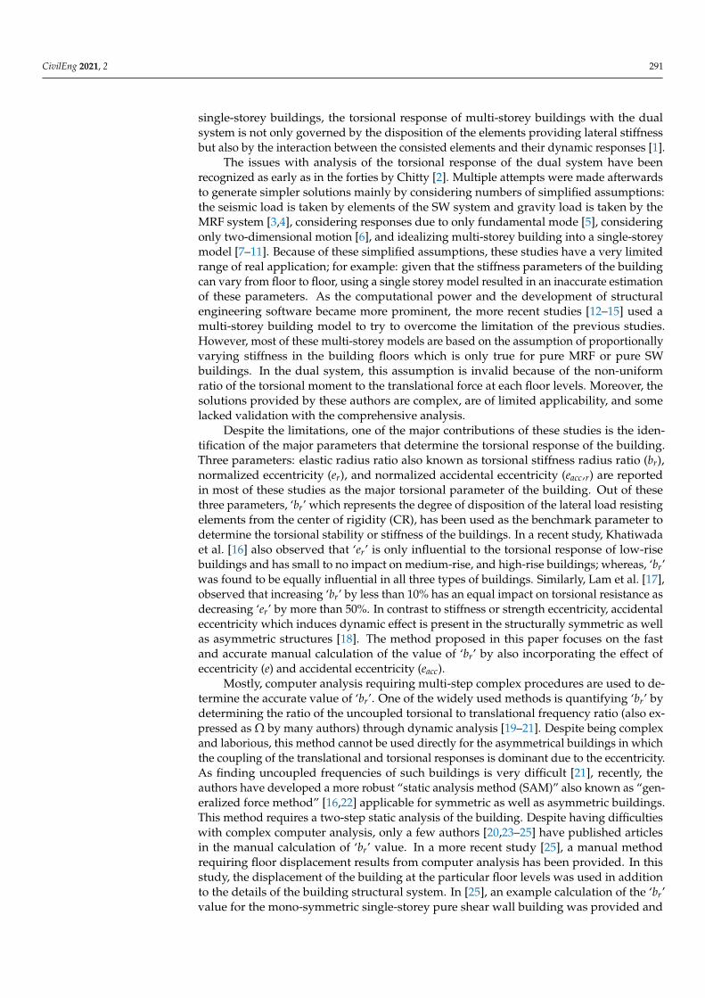
The shear mechanism is developed due to an individual shear wall trying to resisttorsional moment acting about its vertical axis as shown in Figure 2. As this mechanism
CivilEng 2021, 2 293
develops within the structural members, the elastic radius ratio due to this mechanismdoes not depend on the value of eccentricities.
CivilEng 2021, 2, FOR PEER REVIEW 4
The shear mechanism is developed due to an individual shear wall trying to resist torsional moment acting about its vertical axis as shown in Figure 2. As this mechanism develops within the structural members, the elastic radius ratio due to this mechanism does not depend on the value of eccentricities.
Figure 2. Development of torsional stiffness due to the shear mechanism.
The elastic torsional radius due to shear mechanism (bs) can be determined from the square root of the sum of the ratio of torsional stiffness (Kθ) to translational stiffness (K) of each wall or column in the building as shown in Equation (1). In Equation (1), ‘by,S’ is the torsional stiffness radius due to the shear mechanism developed for y-direction of ground motion, and Kx,i is the translational stiffness of element ‘i’ about the x-axis. 𝑏 , = ∑ ,, (1)
The elastic radius ratio due to the shear mechanism (brs) can be determined by divid-ing Equation (1) with the mass radius of gyration of the floor plan of the building. The
mass radius of gyration is equal to Lx
2+Ly2
for rectangular buildings with lengths ‘Lx’ and ‘Ly’, and for other regular and irregular shaped building it can be determined using the coordinate method provided in [26]. 𝑏 , = , = ∑ ,, (2)
For each wall or column ‘i’ with uniform cross-section about its height, the torsional stiffness due to shear (Kθ,si) can be determined from shear modulus (G), torsion constant (J) and effective height (Heff) as shown in Equation (3). Similarly, the translational stiffness (Ki) for y-direction of motion can be determined from Equation (4) based on Young’s mod-ulus (E), second moment of area (I), effective height (Heff), and stiffness factor ‘α’ (equal to 3 for cantilever wall and 12 for columns restrained by building floors). In Equation (3), the shear modulus (G) is interchanged with ‘E/2(1+ν)’. ‘ν’ is the Poisson’s ratio. 𝐾 , = , = ( ) , (3)
𝐾 , = 𝛼 𝐸 𝐼 ,𝐻 , (4)
The effective height (Heff) of walls and columns are determined from Table 1.
Figure 2. Development of torsional stiffness due to the shear mechanism.
The elastic torsional radius due to shear mechanism (bs) can be determined from thesquare root of the sum of the ratio of torsional stiffness (Kθ) to translational stiffness (K) ofeach wall or column in the building as shown in Equation (1). In Equation (1), ‘by,S’ is thetorsional stiffness radius due to the shear mechanism developed for y-direction of groundmotion, and Kx,i is the translational stiffness of element ‘i’ about the x-axis.
by,S =
√∑n
i=1Kθ,si
Kx,i(1)
The elastic radius ratio due to the shear mechanism (brs) can be determined by dividingEquation (1) with the mass radius of gyration of the floor plan of the building. The mass
radius of gyration is equal to√
Lx2+Ly2
12 for rectangular buildings with lengths ‘Lx’ and‘Ly’, and for other regular and irregular shaped building it can be determined using thecoordinate method provided in [26].
bry,S =by,S
r=
1r
√∑n
i=1Kθ,si
Kx,i(2)
For each wall or column ‘i’ with uniform cross-section about its height, the torsionalstiffness due to shear (Kθ,si) can be determined from shear modulus (G), torsion constant (J)and effective height (Heff) as shown in Equation (3). Similarly, the translational stiffness (Ki)for y-direction of motion can be determined from Equation (4) based on Young’s modulus(E), second moment of area (I), effective height (Heff), and stiffness factor ‘α’ (equal to 3 forcantilever wall and 12 for columns restrained by building floors). In Equation (3), the shearmodulus (G) is interchanged with ‘E/2(1 + ν)’. ‘ν’ is the Poisson’s ratio.
Kθ,si =Gi JiHe f f ,i
=Ei Ji
2(1 + υi)He f f ,i(3)
Kx,i =α Ei Ix,i
He f f ,i3 (4)
The effective height (Heff) of walls and columns are determined from Table 1.

CivilEng 2021, 2 294
Table 1. Effective height ‘Heff’ in term of the total height of building ‘H’ and storey height ‘h’.
Conditions Heff
Walls in pure SW system 1 + 0.77 H
Walls in dual system 3.1 H0.5/ log(H)
Columns h
Combining Equations (2)–(4) gives,
bry,S =1r
√√√√ n
∑i=1
He f f ,i2
2α(1 + υi)
JiIx,i
(5)
Equation (5) can be separated into Equations (6) and (7) for walls and columns,respectively. The elastic radius ratio due to shear mechanism in wall ‘bry,Sw’ and columns‘bry,Sc’ can then be combined using Equation (8). ‘bry,S’ determined from Equations (5) and(8) will give the same result.
bry,Sw =1r
√∑nw
i=1
He f f ,i2
6(1 + υi)
JiIwx,i
(6)
bry,Sc =hr
√∑nc
i=11
24(1 + υi)
JiIcx,i
(7)
bry,S=√
b2ry,Sw + b2
ry,Sc (8)
where, ‘nw’ and ‘nc’ is the number of walls and columns in the building, and ‘Iwx,i’ and Icx,i’is the second moment of area of the wall ‘i’ and column ‘i’ about the x-axis, respectively.
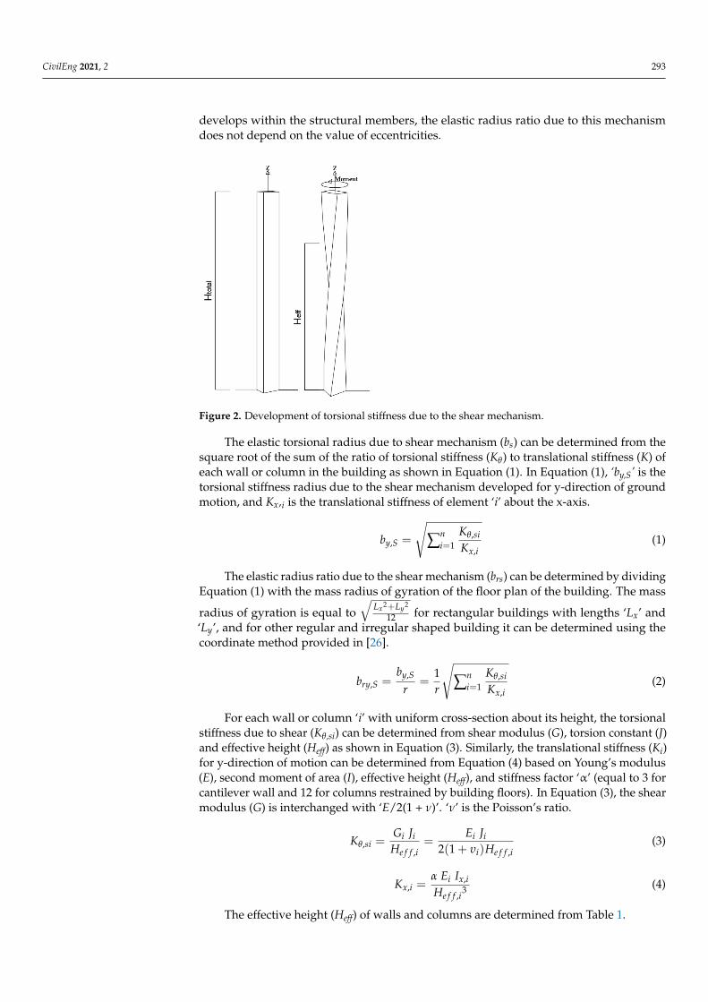
Compared to the shear mechanism, the bending mechanism occurs as a result of thewarping or differential bending of the moment resisting frame or shear walls. The ‘br’ valuedue to bending can be calculated initially about the CM as shown in Equations (9)–(11)for building with SW, MRF and dual system, respectively. This value can be transformedinto the CR by subtracting the square of the normalized eccentricity (er = e/r) as shownin Equation (12). In Equation (12), the ‘1 + e2
acc,r ‘ is introduced to allow for the effectof accidental eccentricity. The derivation of Equation (12) is presented in Appendix A.Equations (9)–(12) presented below represents the equations for the y-direction of earth-quake motion and a similar set of equations can be derived for the x-direction of motion.In the equations, ‘kw,x’ and ‘kf,x = GA/Heff’ are the translational stiffness of the SW andMRF system, ‘xi’ and ‘yi’ are the x and y-coordinates of individual structural elementswith respect to CM of the building as presented in Figure 3, and ‘Px’ is the stiffness ratiodetermined from Equations (13) and (14).
For pure SW system,
b2ry,B,CM = b2
ry,w =∑ Kw,yi yi
2 + ∑ Kw,xi xi2
r2 ∑ Kw,xi=
∑ Iw,yi yi2 + ∑ Iw,xi xi
2
r2 ∑ Iw,xi(9)
For pure MRF system,
b2ry,B,CM = b2
ry, f =∑ K f ,yi yi
2 + ∑ K f ,xi xi2
r2 ∑ K f ,xi=
∑ GAyi y2 + ∑ GA,xi xi2
r2 ∑ GAxi(10)

CivilEng 2021, 2 295
For dual system,
b2ry,B,CM =
Kw,x b2ry,w + K f ,x b2
ry, f(Kw,x + K f ,x
) =b2
ry,w ×Kw,xK f ,x
+ b2ry, f
1 + Kw,xK f ,x
=b2
ry,w × Px + b2ry, f
1 + Px(11)
bry,B =
√√√√ b2ry,B,CM − e2
ry
1 + e2acc,ry
(12)
CivilEng 2021, 2, FOR PEER REVIEW 6
𝑏 , = 𝑏 , , − 𝑒1 + 𝑒 , (12)
Figure 3. Dual system and the equivalent idealized pairs providing torsional stiffness through bending. (a) A dual system with structural details showing the disposition of frames and shear walls. (b) Dual system idealized into pairs of pure SW system (red) and pure moment resisting frame (MRF) system (black) in each direction showing the distances of the ideal-ized elements from the center of mass (CM).
𝑃 = 𝐾 ,𝐾 , = ∑ 3 𝐸 𝐼 ,𝐻 ,∑ 𝐺𝐴 , 𝐻 , = ∑ 3 𝐸 𝐼 ,𝐻 ,∑ 12 𝐸 𝐼 , 𝜆 , ℎ 𝐻 ,= ∑ 𝐸 𝐼 ,(1 + 0.67𝐻)∑ 4 𝐸 𝐼 , 𝜆 , ℎ 13)
𝜆 , = 1 + 2𝐼 ,ℎ𝐼 , 𝑙 , + 𝐼 , 𝑙 , (14)
where, ‘Icx,i’ is the second moment of area of column ‘i’. Similarly, ‘Ibx,i1’ and ‘Ibx,i2’, and ‘ly,i1’ and ‘ly,i2’ are the second moment of areas and lengths of the beams connected to the col-umns, respectively. Moreover, the effective height (Heff) is determined from the total height of the building (H) and is equal to ‘1 + 0.67H’.
Figure 3. Dual system and the equivalent idealized pairs providing torsional stiffness through bending. (a) A dual systemwith structural details showing the disposition of frames and shear walls. (b) Dual system idealized into pairs of pure SWsystem (red) and pure moment resisting frame (MRF) system (black) in each direction showing the distances of the idealizedelements from the center of mass (CM).
Px =Kw,x
K f ,x=
∑nwi=1
3 Ei Iwx,iHe f f ,i
3
∑nci=1
GAx,iHe f f ,i
=∑nw
i=13 Ei Iwx,i
He f f ,i3
∑nci=1
12 Ei Icx,iλi,x h2 He f f ,i
=∑nw
i=1Ei Iwx,i
(1+0.67H)2
∑nci=1
4 Ei Icx,iλi,x h2
(13)
CivilEng 2021, 2 296
λi,x = 1 +2Icx,i
hIbx,i1ly,i1
+Ibx,i2ly,i2
(14)
where, ‘Icx,i’ is the second moment of area of column ‘i’. Similarly, ‘Ibx,i1’ and ‘Ibx,i2’, and‘ly,i1’ and ‘ly,i2’ are the second moment of areas and lengths of the beams connected to thecolumns, respectively. Moreover, the effective height (Heff) is determined from the totalheight of the building (H) and is equal to ‘1 + 0.67H’.
For a symmetrical frame system having uniform size and material properties for allcolumns and all beams, Equation (13) can be simplified into Equation (15).
Px =
(1 +
Icx
Ibx
lh
)h2
4(1 + 0.67H)2∑ Iwx
nc Icx(15)
Finally, the total elastic radius ratio (br) about the CR of the building is determinedby combining the shear component ‘br,S’ (Equation (8)) and the bending component ‘br,B’(Equation (12)) by the square root of the sum of the square method given in Equation (16).
bry=√
b2ry,S + b2
ry,B (16)
2.2. Static Analysis Method (SAM)
The static analysis method (SAM) is the robust method of determining elastic radiusratio ‘br’ based on the static analysis of the building performed in the computer. The methodhas been developed by the authors in [16,22], and the procedure is summarized below.
a. Determining the effective value of pure translational displacement (∆2D) by ap-plying a lateral load at an arbitrary location to the building that is restrained fortorsional rotation,
b. Determining the effective edge displacements: flexible edge displacement (∆max),and stiff edge displacements (∆min) for the same lateral load and location withoutthe torsional restraints,
c. Determining the position of the center of rigidity (CR). CR from a stiff edge is equal
to (∆2D−∆min)·L∆max−∆min
,d. Determining the distance between the applied load and the CR. The distance is
equal to the sum of eccentricity (e) and accidental eccentricity (eacc). The accidentaleccentricity such as 0.05 L or 0.1 L is adopted from the relevant seismic codes.
e. The elastic radius ratio (br) is finally determined by substituting the above parametersin Equation (17).
br =1r
√∆2D · (e + eacc) · L
∆max − ∆min(17)
2.3. Parametric Study
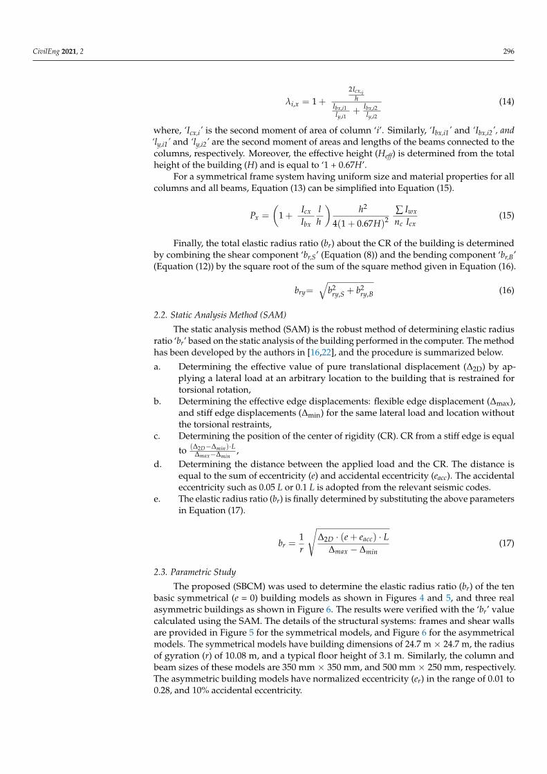
The proposed (SBCM) was used to determine the elastic radius ratio (br) of the tenbasic symmetrical (e = 0) building models as shown in Figures 4 and 5, and three realasymmetric buildings as shown in Figure 6. The results were verified with the ‘br’ valuecalculated using the SAM. The details of the structural systems: frames and shear wallsare provided in Figure 5 for the symmetrical models, and Figure 6 for the asymmetricalmodels. The symmetrical models have building dimensions of 24.7 m × 24.7 m, the radiusof gyration (r) of 10.08 m, and a typical floor height of 3.1 m. Similarly, the column andbeam sizes of these models are 350 mm × 350 mm, and 500 mm × 250 mm, respectively.The asymmetric building models have normalized eccentricity (er) in the range of 0.01 to0.28, and 10% accidental eccentricity.

CivilEng 2021, 2 297CivilEng 2021, 2, FOR PEER REVIEW 8
(a) Model ‘a’ (cross wall at the center) (b) Model ‘b’ (pure MRF) (c) Model ‘c’ (MRF + central core)
(d) Model ‘d’ (MRF + 2 parallel walls) (e) Model ‘e’ (MRF + 2 edge walls) (f) Model ‘f’ (MRF + 2 edge walls + core)
(g) Model ‘g’ (MRF + 4 edge walls) (h) Model ‘h’ (MRF + 4 edge walls + core) (i) Model ‘i’ (MRF + 4 corner walls)
(j) Model ‘j’ (MRF + 4 corner walls + core)
Figure 4. Floor plan and structural details of the symmetrical building models ‘a’ to ‘j’ used for the parametric study. The building dimensions of all the models are the same as the building dimensions provided for building model ‘c’. Figure 4. Floor plan and structural details of the symmetrical building models ‘a’ to ‘j’ used for the parametric study. The
building dimensions of all the models are the same as the building dimensions provided for building model ‘c’.

CivilEng 2021, 2 298CivilEng 2021, 2, FOR PEER REVIEW 9
Figure 5. Structural details of the shear walls used in building models Figure 4a–j.
Figure 6. Structural details of the asymmetrical buildings: (a) Model ‘k’ [16], (b) Model ‘l’ [27], and (c) model ‘m’ [16].
(a) (b)
(c)
Figure 5. Structural details of the shear walls used in building models Figure 4a–j.
CivilEng 2021, 2, FOR PEER REVIEW 9
Figure 5. Structural details of the shear walls used in building models Figure 4a–j.
Figure 6. Structural details of the asymmetrical buildings: (a) Model ‘k’ [16], (b) Model ‘l’ [27], and (c) model ‘m’ [16].
(a) (b)
(c)
Figure 6. Structural details of the asymmetrical buildings: (a) Model ‘k’ [16], (b) Model ‘l’ [27], and (c) model ‘m’ [16].

CivilEng 2021, 2 299
3. Results and Discussion
The SBCM as introduced in this paper, for the calculation of elastic radius ratio (br),has been verified by the comparison of the results obtained from the static analysis method(SAM). Static analysis was performed using a commercial structural engineering softwareSPACE GASS (Version 12.85, SPACE GASS) [28] by applying the horizontal equivalent staticdesign forces calculated as per current code provisions for seismic actions in Australia [29].500-year return period earthquake with seismic hazard factor (Kp) of 0.08’g and site class‘De’ were used. Fifty-seven building models (three sets of eighteen symmetric, and oneset of three asymmetric building models) were used for the verification purpose. Tensymmetrical building models ‘a’ to ‘j’, eight equivalent pure shear wall (SW) models ofmodels ‘c’ to ‘j’ as shown in Figure 4, and three asymmetrical building models as shownin Figure 6 were used. The three sets of each of these models consisted: 4-storey (13.1m height), 10-storey (31.7 m height), and 37 storeys (115.4 m height) buildings. Further24 models (modification of model ‘a’ to ‘j’) were analyzed to see the changes in ‘br’ valuedue to changes in the disposition of the structural elements in the building plan, themagnitude of lateral stiffness, flexural to shear lateral stiffness ratio (in the dual system),building aspect ratio, building height, eccentricity, and accidental eccentricity. Examplecalculations using the proposed “SBCM” method and comparison of the result with “SAM”method, and another manual calculation method [25] for models ‘a’ and ‘b’ are presented inthis section. The example calculation for model ‘g’ is presented in Table A1, and for model‘k’ is presented in Table A2. The results for dual system models ‘c’ to ‘j’ are summarized inTable 2, for SW equivalent models ‘c’ to ‘j’ are summarized in Table 3, and models ‘k’ to ‘m’are summarized in Table 4.
• Model ‘a’ building (pure SW system):
Wall dimension is a1 = 3566.3 mm and t1 = 500 mm. From Figure 5, 2Ix = 2Iy = 1.922 m3
and J = 0.297 m3.For pure SW system with wall at CR, bry,B = bry,B,CM = bry,w = bry,f = 0.H = 13.1 m:From Equation (6),
bry,Sw =1r
√√√√ nw
∑i=1
He f f ,i2
6(1 + υi)
JiIwx,i
=1
10.08
√(1 + 0.77 · 13.1)2
6(1 + 0.2)0.2971.922
= 0.161.
And from Equation (16), bry =√
b2ry,S + b2
ry,B = bry,S = 0.161 < 1 (the building istorsionally unstable/flexible).
As ‘bry’ from SAM is 0.158, the absolute percentage difference is 1.9%.H = 31.7 m:
bry = bry,Sw =He f f
r
√1
6(1 + υi)
JiIwx,i
=(1 + 0.77 · 31.7)
10.08
√1
6(1 + 0.2)0.2971.922
= 0.369.
‘bry’ from ‘SAM’ is also 0.369. As bry < 1, the building is torsionally unstable/flexible.H = 115.4 m:
bry = bry,Sw =(1 + 0.77 · 115.4)(1 + 0.77 · 31.7)
· 0.369 = 1.306 > 1 (torsionally stiff).
‘bry’ from the ‘SAM’ is also equal to 1.306. Whereas, as per [25], ‘bry = 0’ for all threebuilding heights.
• Model ‘b’ building (pure MRF system):
Icx = 0.00125 m4, and J = 0.141 bd3 = 0.00212 m3.
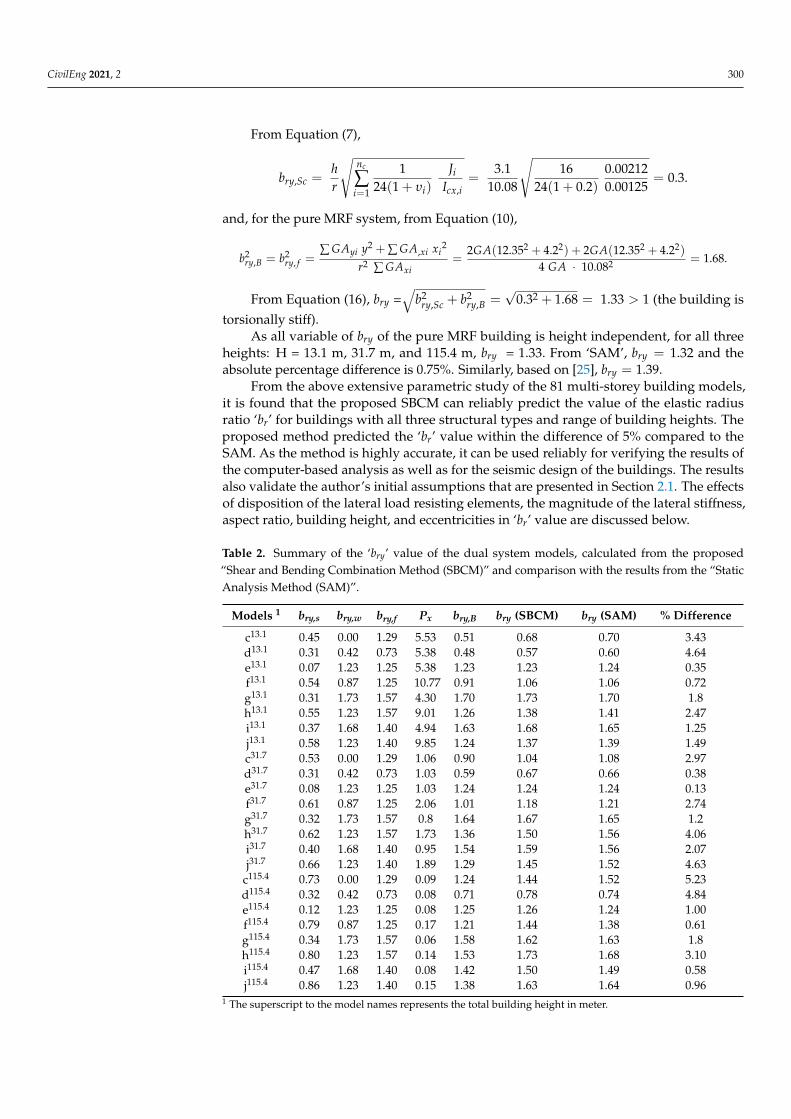
CivilEng 2021, 2 300
From Equation (7),
bry,Sc =hr
√nc
∑i=1
124(1 + υi)
JiIcx,i
=3.1
10.08
√16
24(1 + 0.2)0.002120.00125
= 0.3.
and, for the pure MRF system, from Equation (10),
b2ry,B = b2
ry, f =∑ GAyi y2 + ∑ GA,xi xi
2
r2 ∑ GAxi=
2GA(12.352 + 4.22) + 2GA(12.352 + 4.22)
4 GA · 10.082 = 1.68.
From Equation (16), bry =√
b2ry,Sc + b2
ry,B =√
0.32 + 1.68 = 1.33 > 1 (the building istorsionally stiff).
As all variable of bry of the pure MRF building is height independent, for all threeheights: H = 13.1 m, 31.7 m, and 115.4 m, bry = 1.33. From ‘SAM’, bry = 1.32 and theabsolute percentage difference is 0.75%. Similarly, based on [25], bry = 1.39.
From the above extensive parametric study of the 81 multi-storey building models,it is found that the proposed SBCM can reliably predict the value of the elastic radiusratio ‘br’ for buildings with all three structural types and range of building heights. Theproposed method predicted the ‘br’ value within the difference of 5% compared to theSAM. As the method is highly accurate, it can be used reliably for verifying the results ofthe computer-based analysis as well as for the seismic design of the buildings. The resultsalso validate the author’s initial assumptions that are presented in Section 2.1. The effectsof disposition of the lateral load resisting elements, the magnitude of the lateral stiffness,aspect ratio, building height, and eccentricities in ‘br’ value are discussed below.
Table 2. Summary of the ‘bry’ value of the dual system models, calculated from the proposed“Shear and Bending Combination Method (SBCM)” and comparison with the results from the “StaticAnalysis Method (SAM)”.
Models 1 bry,s bry,w bry,f Px bry,B bry (SBCM) bry (SAM) % Difference
c13.1 0.45 0.00 1.29 5.53 0.51 0.68 0.70 3.43d13.1 0.31 0.42 0.73 5.38 0.48 0.57 0.60 4.64e13.1 0.07 1.23 1.25 5.38 1.23 1.23 1.24 0.35f13.1 0.54 0.87 1.25 10.77 0.91 1.06 1.06 0.72g13.1 0.31 1.73 1.57 4.30 1.70 1.73 1.70 1.8h13.1 0.55 1.23 1.57 9.01 1.26 1.38 1.41 2.47i13.1 0.37 1.68 1.40 4.94 1.63 1.68 1.65 1.25j13.1 0.58 1.23 1.40 9.85 1.24 1.37 1.39 1.49c31.7 0.53 0.00 1.29 1.06 0.90 1.04 1.08 2.97d31.7 0.31 0.42 0.73 1.03 0.59 0.67 0.66 0.38e31.7 0.08 1.23 1.25 1.03 1.24 1.24 1.24 0.13f31.7 0.61 0.87 1.25 2.06 1.01 1.18 1.21 2.74g31.7 0.32 1.73 1.57 0.8 1.64 1.67 1.65 1.2h31.7 0.62 1.23 1.57 1.73 1.36 1.50 1.56 4.06i31.7 0.40 1.68 1.40 0.95 1.54 1.59 1.56 2.07j31.7 0.66 1.23 1.40 1.89 1.29 1.45 1.52 4.63
c115.4 0.73 0.00 1.29 0.09 1.24 1.44 1.52 5.23d115.4 0.32 0.42 0.73 0.08 0.71 0.78 0.74 4.84e115.4 0.12 1.23 1.25 0.08 1.25 1.26 1.24 1.00f115.4 0.79 0.87 1.25 0.17 1.21 1.44 1.38 0.61g115.4 0.34 1.73 1.57 0.06 1.58 1.62 1.63 1.8h115.4 0.80 1.23 1.57 0.14 1.53 1.73 1.68 3.10i115.4 0.47 1.68 1.40 0.08 1.42 1.50 1.49 0.58j115.4 0.86 1.23 1.40 0.15 1.38 1.63 1.64 0.96
1 The superscript to the model names represents the total building height in meter.

CivilEng 2021, 2 301
Table 3. Summary of the ‘bry’ value of the pure shear wall (SW) models, calculated from the proposedshear and bending combination method (SBCM) and comparison with the results from the staticanalysis method (SAM).
Models bry,s bry,w bry (SBCM) bry (SAM) % Difference
c13.1 0.50 0.00 0.50 0.50 0.79d13.1 0.07 0.42 0.42 0.42 0.00e13.1 0.07 1.23 1.23 1.23 0.09f13.1 0.45 0.87 0.97 0.97 0.17g13.1 0.10 1.73 1.74 1.73 0.28h13.1 0.45 1.23 1.31 1.30 0.19i13.1 0.15 1.73 1.74 1.74 0.14j13.1 0.46 1.23 1.31 1.33 1.72c31.7 1.14 0.00 1.14 1.14 0.34d31.7 0.16 0.42 0.45 0.44 0.37e31.7 0.16 1.23 1.24 1.24 0.09f31.7 1.01 0.87 1.33 1.36 1.69g31.7 0.22 1.73 1.75 1.74 0.14h31.7 1.03 1.23 1.60 1.62 1.55i31.7 0.35 1.73 1.77 1.78 0.59j31.7 1.06 1.23 1.62 1.63 0.58
c115.4 4.04 0.00 4.04 4.07 0.54d115.4 0.56 0.42 0.70 0.70 0.36e115.4 0.56 1.23 1.35 1.35 0.08f115.4 3.57 0.87 3.67 3.50 4.92g115.4 0.79 1.73 1.90 1.93 1.47h115.4 3.61 1.23 3.81 3.70 3.08i115.4 1.23 1.73 2.13 2.18 2.59j115.4 3.72 1.23 3.92 3.85 1.82
Table 4. Summary of the ‘bry’ value calculated for the asymmetrical models from the proposed SBCMand comparison with the results from the SAM.
Models bry,s ery eacc,ry bry,w bry,f Px bry,B,CM bry,Bbry
(SBCM)bry
(SAM) % Diff.
k13.1 0.3 0.17 0.24 1.13 1.25 4.3 1.15 1.11 1.15 1.14 0.9l32.8 0.1 0.01 0.31 1.53 1.60 13 1.54 1.47 1.47 1.47 0
m96.8 0.15 0.28 0.32 1.55 1.28 0.1 1.31 1.22 1.23 1.25 1.6
3.1. Effect of the Disposition of the Lateral Load Resisting Elements in the Building Plan
The disposition of the lateral load resisting elements in the building plan was found tobe the major determiner of the ‘br’ value or torsional stiffness in the building. The torsionalstiffness was found to be higher for buildings with walls or frames that are away from theCR. This effect was found in both symmetrical as well as asymmetrical building models.For low-rise and medium-rise buildings, the building with a single open wall at the center,for example, model ‘a’ was found to be torsionally flexible. Likewise, building with wallelements that are nearer to the edges (models ‘e’, ‘g’, and ‘i’) were found to be torsionallystiffer compared with the buildings having the same wall configuration with additionalwalls near the CR of the building (models ‘f’, ‘h’, and ‘j’), and buildings with all wallsnearer to the CR (model ‘d’). Similarly, building with wall elements aligned about bothprinciple directions (models ‘g’ to ‘j’) were found to be more torsionally stiffer comparedto buildings with walls aligned in one direction only (models ‘d’ to ‘f’). Moreover, whenthe models with walls at the four corners (‘i’ and ‘j’) were compared with similar modelswith walls located at the middle of the building edges (‘g’ and ‘h’), the former models werefound to have slightly higher torsional stiffness for the pure SW models and slightly lowertorsional stiffness for the dual system compared to the latter models. As the latter modelscan also prevent lights and ventilations, models with corners walls are recommended.

CivilEng 2021, 2 302
Furthermore, in buildings with pure shear walls, adding frames at the perimeter werefound to increase the torsional stability, for example in model ‘l’.
3.2. Effect of Magnitude of Translational Stiffness (K)
In a pure SW building with multiple walls, and a building with a dual system, thetorsional rigidity of the building was not only found to be controlled by the disposition ofthe structural elements in the floor plan but also by the relative disposition of the lateralstiffness. For example, in model ‘h’, for the same disposition of walls and frames, thetorsional stiffness of the building increased with the decrease in the lateral stiffness of thecentral core wall and vice versa. In model ‘h’, when the translational stiffness of the centralcore wall was doubled and the translational stiffness of other walls were kept unchanged,the ‘br’ value decreased by about 1.4 times. For low-rise buildings (below 10 storey)consisting of central core walls (having ‘n’ times higher translational stiffness compared tothe stiffness of outer walls in the direction of motion considered) to be torsionally stable,the outer walls should be at least (in average) ′r
√(1 + n)/(1 + m)
′distance away from the
CR. Where ‘m’ is the ratio of the translational stiffness of the outer walls, for example: fory-direction of motion m = Kx/Ky. If the ratios ‘m’ and ‘n’, member disposition, and shape ofthe walls are kept unchanged, the increase in stiffness will not affect ‘br’ value. In a dualsystem, the effect of translational stiffness depended on stiffness ratio (P). The effect of theshape of the walls and the effect of flexural to shear stiffness ratio (P) in the dual systemare discussed further in Sections 3.2.1 and 3.2.2, respectively.
3.2.1. Effect of Shape of the Wall
The shape of the shear walls or core walls is found to influence the torsional stiffness inmedium to high-rise buildings. As shear induced torsional stiffness of the closed shaped orsemi-closed core walls (model ‘c’) are higher compared to open and rectangular or crossedwalls (model ‘a’), the closed walls are found to considerably improve the torsional stiffnessof the building. In medium to high-rise buildings, these walls can be placed near the centerof the building, whereas in low-rise buildings such walls should be avoided near the centerof the building.
3.2.2. Effect of Flexural to Shear Stiffness Ratio (P) in Dual System
The torsional stiffness of the dual system was found to be considerably influenced bythe flexural to shear stiffness ratio (P). In the dual buildings with a dominant SW system orhigher value of ‘P’, higher torsional stiffness was observed when the elastic radius ratiodue to the SW system (br,s) is greater than the elastic radius ratio due to the MRF system(br,f). Similarly, in buildings with a dominant MRF system or lower value of ‘P’, a highertorsional stiffness were observed when br,f > br,s.
3.3. Effect of Building Height (H)
The ‘br’ value increased considerably with the increase of the building height for pureshear wall buildings. For example, for model ‘c’, the ‘br’ value increased from 0.8 to 4.1when building height was increased from 13.1 m to 115.4 m. Similarly, in the dual systemwith br,s < br,f, ‘br’ value increased by a small amount and in pure MRF buildings the ‘br’value remained unchanged when building height was increased. Moreover, in a buildingwith a dual system consisting of br,s > br,f, ‘br’ value slightly decreased with the increase ofthe building height. This atypical effect of building height on a different type of structuralsystem was observed mainly due to each system having a different effective height (givenin Table 1).
3.4. Effect of the Aspect Ratio of the Floor Plan of the Building
Aspect ratio is the ratio of the larger to the smaller dimension of the building aboutthe two principal directions. To assess the effect of the aspect ratio (AR) of the floor plan ofthe building, the building models ‘a’ to ‘j’ were transformed into the rectangular building

CivilEng 2021, 2 303
by increasing the length from 24.7 to 74.1 m and moving the position of the walls, whilekeeping the same configuration of the building model shown in Figure 4. As low-risebuildings are found to be comparatively torsionally unstable, 13.1 m height was selected forthe comparison. The comparison of the ‘br’ values for the square (AR = 1) and rectangularbuilding models (AR = 3) are shown in Figure 7.
CivilEng 2021, 2, FOR PEER REVIEW 14
due to the SW system (br,s) is greater than the elastic radius ratio due to the MRF system (br,f). Similarly, in buildings with a dominant MRF system or lower value of ‘P’, a higher torsional stiffness were observed when br,f > br,s.
3.3. Effect of Building Height (H) The ‘br’ value increased considerably with the increase of the building height for pure
shear wall buildings. For example, for model ‘c’, the ‘br’ value increased from 0.8 to 4.1 when building height was increased from 13.1 m to 115.4 m. Similarly, in the dual system with br,s < br,f, ‘br’ value increased by a small amount and in pure MRF buildings the ‘br’ value remained unchanged when building height was increased. Moreover, in a building with a dual system consisting of br,s > br,f, ‘br’ value slightly decreased with the increase of the building height. This atypical effect of building height on a different type of structural system was observed mainly due to each system having a different effective height (given in Table 1).
3.4. Effect of the Aspect Ratio of the Floor Plan of the Building Aspect ratio is the ratio of the larger to the smaller dimension of the building about
the two principal directions. To assess the effect of the aspect ratio (AR) of the floor plan of the building, the building models ‘a’ to ‘j’ were transformed into the rectangular build-ing by increasing the length from 24.7 to 74.1 m and moving the position of the walls, while keeping the same configuration of the building model shown in Figure 4. As low-rise buildings are found to be comparatively torsionally unstable, 13.1 m height was se-lected for the comparison. The comparison of the ‘br’ values for the square (AR = 1) and rectangular building models (AR = 3) are shown in Figure 7.
Figure 7. Comparison of the results of the elastic radius ratio ‘bry’ for the buildings with an aspect ratio (AR) of 1 and 3, and a building height of 13.1 m.
From the chart, it can be seen that the ‘br’ value for rectangular buildings only in-creased for the dual system model ‘d’, and for model ‘e’. This increase was mainly due to the higher increase (3 times) in the distance of the walls from CM compared to the increase in the radius of gyration (only increased by 2.23 times). For all other models, a reduction in ‘br’ values was obtained by increasing the aspect ratio. This is mainly because the dis-tance from the CM to the wall aligned along the length of the building has remained the same, while the radius of gyration increased by 2.23 times. The highest reduction was obtained for models with central core walls (models ‘c’, ‘h’, ‘f’ and ‘j’) due to a relatively higher decrease in the bending torsional stiffness. Therefore, the placement of the core
Figure 7. Comparison of the results of the elastic radius ratio ‘bry’ for the buildings with an aspect ratio (AR) of 1 and 3, anda building height of 13.1 m.
From the chart, it can be seen that the ‘br’ value for rectangular buildings only increasedfor the dual system model ‘d’, and for model ‘e’. This increase was mainly due to thehigher increase (3 times) in the distance of the walls from CM compared to the increase inthe radius of gyration (only increased by 2.23 times). For all other models, a reduction in‘br’ values was obtained by increasing the aspect ratio. This is mainly because the distancefrom the CM to the wall aligned along the length of the building has remained the same,while the radius of gyration increased by 2.23 times. The highest reduction was obtainedfor models with central core walls (models ‘c’, ‘h’, ‘f’ and ‘j’) due to a relatively higherdecrease in the bending torsional stiffness. Therefore, the placement of the core walls atthe center of the low-rise rectangular building is more vulnerable compared to a squarebuilding with an equal floor area.
3.5. Effect of Eccentricity (e) and Accidental Eccentricity (eacc)
As eccentricity causes the coupling of the translational and torsional modes, torsionalstiffness reduces with the increase of the eccentricity. In order to reduce torsion, thedistance between CM and CR need to be reduced [30]. However, the eccentricity onlycaused the bending torsional stiffness to deteriorate, and it has no impact on the torsionalstiffness due to shear. From Table 4, it is seen that the percentage decrease in ‘br’ valuedue to eccentricity in building ‘k’ (13.1 m height) having ‘ery’ of 0.17 is higher compared tobuilding ‘m’ (96.5 m height) having ‘ery’ value of 0.28. This shows that, despite having acomparatively higher ‘ery’ value, building ‘m’ with higher building height had a higher ‘br’value compared to building ‘k’. This is mainly because the torsional stiffness due to shear(which is independent of the eccentricity) increases with height, and it compensates forthe decrease in ‘br’ value due to increased eccentricity. Similarly, the accidental eccentricity(eacc) was found to have a similar effect as eccentricity (e).
4. Conclusions
This study aims to introduce a fast, simple, and reliable manual calculation method(SBCM) for assessing the torsional stability of the multi-storey building under elastic

CivilEng 2021, 2 304
conditions. The simple sets of equations derived in SBCM method are useful for buildingswith a shear wall, a moment resisting frame, and a dual structural system consisting ofhorizontal as well as vertical stiffness irregularity. The proposed method determines thetorsional stability by quantifying the elastic radius ratio of the building. The accuracyand robustness of the proposed method have been verified through the parametric studyconsisting of 81 different multi-storey building models. The proposed method predictedthe elastic radius ratio of the building within the 5% difference to the static analysismethod, a reputed computer analysis method. Based on the parametric study, the followingconclusions can be drawn:
• The disposition of the lateral load resisting elements in the building plan was foundto be the major determiner of the torsional stiffness of the building. The torsionalstiffness is found to be higher for buildings with walls or frames that are locatedaway from the center of rigidity. The highest elastic radius ratio was obtained forbuildings with all walls at the building edges or corners. Moreover, a building withwall elements aligned about both principle directions was found to be more torsionallystiffer compared to a building with walls aligned in one direction only.
• The effect of the magnitude of translational stiffness on torsional stiffness was onlyfound in pure shear wall (SW) building consisting of multiple walls, and in buildingwith a dual structural system. In the pure SW system consisting central core wallalong with other perimeter walls, the torsional stiffness significantly reduced whenthe translational stiffness of the central core wall was increased.
• In the dual system, the flexural to shear stiffness ratio was found to influence thetorsional stiffness. The higher value of the stiffness ratio is beneficial in buildinghaving walls along the edges. On the contrary, a lower stiffness ratio was found to bebeneficial for buildings with core walls positioned near the center of the building.
• Shear torsional stiffness was found to be dependent on the shape of the walls. Forclosed shaped or semi-closed core walls, the torsional stiffness was found to be highercompared to open and rectangular walls. The contribution of these walls were foundto increase with the increase in building height.
• A rectangular building with central core walls were found to be more torsionallyunstable compared to a square building having the same floor area.
• Reduction in torsional stiffness was found with the increase of both strength eccentric-ity and accidental eccentricity. However, their effects were found to reduce with theincrease of building height.
The intention of this proposed method is to verify the dynamic analysis recommendedby the Standards which is based on linear elastic behavior. The effects of non-linearitycan be taken into account by the ductility reduction factor, but how asymmetry affectsthe factor is outside the scope of this study. Similarly, future research is recommended toassess the applicability of this method to other types of lateral loads such as wind load,and building with other structural materials such as steel and timber.
Author Contributions: Conceptualization, P.K. and E.L.; methodology, P.K. and E.L.; software, P.K.;validation, P.K.; formal analysis, P.K.; investigation, P.K.; resources, P.K. and E.L.; data curation, P.K.;writing—original draft preparation, P.K.; writing—review and editing, P.K. and E.L.; visualization,P.K.; supervision, E.L.; project administration, P.K. All authors have read and agreed to the publishedversion of the manuscript.
Funding: This research received no external funding.
Institutional Review Board Statement: Not applicable.
Informed Consent Statement: Not applicable.
Conflicts of Interest: The authors declare no conflict of interest.
CivilEng 2021, 2 305
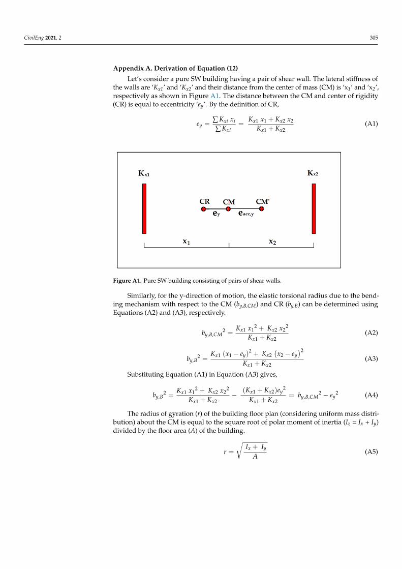
Appendix A. Derivation of Equation (12)
Let’s consider a pure SW building having a pair of shear wall. The lateral stiffness ofthe walls are ‘Kx1’ and ‘Kx2’ and their distance from the center of mass (CM) is ‘x1’ and ‘x2’,respectively as shown in Figure A1. The distance between the CM and center of rigidity(CR) is equal to eccentricity ‘ey’. By the definition of CR,
ey =∑ Kxi xi
∑ Kxi=
Kx1 x1 + Kx2 x2
Kx1 + Kx2(A1)
CivilEng 2021, 2, FOR PEER REVIEW 16
• Reduction in torsional stiffness was found with the increase of both strength eccen-tricity and accidental eccentricity. However, their effects were found to reduce with the increase of building height. The intention of this proposed method is to verify the dynamic analysis recom-
mended by the Standards which is based on linear elastic behavior. The effects of non-linearity can be taken into account by the ductility reduction factor, but how asymmetry affects the factor is outside the scope of this study. Similarly, future research is recom-mended to assess the applicability of this method to other types of lateral loads such as wind load, and building with other structural materials such as steel and timber.
Author Contributions: Conceptualization, P.K. and E.L.; methodology, P.K. and E.L.; software, P.K.; validation, P.K.; formal analysis, P.K.; investigation, P.K.; resources, P.K. and E.L.; data cura-tion, P.K.; writing—original draft preparation, P.K.; writing—review and editing, P.K. and E.L.; vis-ualization, P.K.; supervision, E.L.; project administration, P.K. All authors have read and agreed to the published version of the manuscript.
Funding: This research received no external funding.
Institutional Review Board Statement: Not applicable.
Informed Consent Statement: Not applicable.
Conflicts of Interest: The authors declare no conflict of interest.
Appendix A. Derivation of Equation (12) Let’s consider a pure SW building having a pair of shear wall. The lateral stiffness of
the walls are ‘Kx1’ and ‘Kx2’ and their distance from the center of mass (CM) is ‘x1’ and ‘x2’, respectively as shown in Figure A1. The distance between the CM and center of rigidity (CR) is equal to eccentricity ‘ey’. By the definition of CR, 𝑒 = ∑ 𝐾 𝑥∑ 𝐾 = 𝐾 𝑥 + 𝐾 𝑥𝐾 + 𝐾 (A1)
Figure A1. Pure SW building consisting of pairs of shear walls.
Similarly, for the y-direction of motion, the elastic torsional radius due to the bending mechanism with respect to the CM (by,B,CM) and CR (by,B) can be determined using Equa-tions (A2) and (A3), respectively. 𝑏 , , = 𝐾 𝑥 + 𝐾 𝑥𝐾 + 𝐾 (A2)
Figure A1. Pure SW building consisting of pairs of shear walls.
Similarly, for the y-direction of motion, the elastic torsional radius due to the bend-ing mechanism with respect to the CM (by,B,CM) and CR (by,B) can be determined usingEquations (A2) and (A3), respectively.
by,B,CM2 =
Kx1 x12 + Kx2 x2
2
Kx1 + Kx2(A2)
by,B2 =
Kx1 (x1 − ey)2 + Kx2
(x2 − ey
)2
Kx1 + Kx2(A3)
Substituting Equation (A1) in Equation (A3) gives,
by,B2 =
Kx1 x12 + Kx2 x2
2
Kx1 + Kx2−
(Kx1 + Kx2)ey2
Kx1 + Kx2= by,B,CM
2 − ey2 (A4)
The radius of gyration (r) of the building floor plan (considering uniform mass distri-bution) about the CM is equal to the square root of polar moment of inertia (Iz = Ix + Iy)divided by the floor area (A) of the building.
r =
√Ix + Iy
A(A5)

CivilEng 2021, 2 306
Similarly, the radius of gyration of the building about point CM’ (the position of CMshifted to account for the dynamic effect due to accidental eccentricity) can be determinedusing Equation (A6).
r′ =
√(Ix + Aeacc,y2) + Iy
A=√
r2 + eacc,y2 = r
√1 +
eacc,y2
r2 = r√
1 + eacc,ry2 (A6)
The elastic radius ratio about the CR of the building due to the bending mechanismconsidering the accidental eccentricity can be determined by dividing Equation (A4) byEquation (A6),
bry,B =
√by,B2
r′2=
√by,B,CM
2 − ey2
r2(1 + eacc,ry2
) =
√bry,B,CM
2 − ery2
1 + eacc,ry2 (A7)
Appendix B. Example Calculation of the Elastic Radius Ratio for Building Models ‘g’and ‘k’
Table A1. Calculation of the Elastic Radius Ratio for Building Model ‘g’.
Height Calculation of the Elastic Radius Ratio
H = 13.1 m Size of all columns are 350 mm × 350 mm and size of all beams are 500 mm × 250 mm. Therefore, Icx = 0.00125 m4,Ibx = 0.0026 m4, and J = 0.141bd3 = 0.00212 m3.Size of wall is a3 = 3586.3 mm and t1 = 250 mm. Therefore, Ix = Iy = 0.961 m3 and J = 0.018 m3.From Equations (6) and (7),
bry,Sw = 1r
√nw
∑i=1
He f f ,i2
6(1+υi)Ji
Iwx,i=
3.1·13.10.5log(13.1)10.08
√4
6(1+0.2)0.0180.961 = 0.1
bry,Sc =hr
√nc
∑i=1
124(1+υi)
JiIwx,i
= 3.110.08
√16
24(1+0.2)
(0.002120.00125
)= 0.3.
From Equation (15),
Px =(
1 + IcxIbx
lh
)h2
4He f f ,i2
∑ Iwxnc Icx
=(
1 + 0.001250.0026 ·
8.33.1
)3.12
4(1+0.67·13.1)21.920.02 = 5.5
For equivalent pure SW system, from Equation (9),
b2ry,w =
∑ Iw,yi yi2+∑ Iw,xi xi
2
r2 ∑ Iw,xi= 2(Iw ·12.352)+2(Iw · 12.352)
(2Iw) 10.082 = 3For equivalent pure MRF system, from Equation (10),
b2ry, f =
∑ GAyi y2+∑ GA,xi xi2
r2 ∑ GAxi= 4(4GA·12.352+GA·4.22)
2(4 GA+GA)· 10.082 = 2.47From Equation (11),
b2ry,B = b2
ry,B,CM =b2
ry,w ·Px+b2ry, f
1+Px= 3·5.5+2.47
1+5.5 = 2.9
Now, from Equation (16), bry=√
b2ry,Sw + b2
ry,Sc + b2ry,B =
√0.12 + 0.32 + 2.9 = 1.73
As bry from SAM is 1.7, the absolute percentage difference is 1.8%.The building is torsionally stable/stiff.
H = 31.7 m bry,Sw = 0.12, Px = 0.8, b2ry,w = 3, b2
ry, f = 2.47, b2ry,B = 2.7, and bry = 1.67.
As bry from SAM is 1.65, the absolute percentage difference is 1.2%.H = 115.4 m bry,Sw = 0.16, Px = 0.06, b2
ry,w = 3, b2ry, f = 2.47, b2
ry,B = 2.5, and bry = 1.62.As bry from SAM is 1.63, the absolute percentage difference is 0.61%.

CivilEng 2021, 2 307
Table A2. Calculation of the Elastic Radius Ratio for Building Model ‘k’.
Height Calculation of the Elastic Radius Ratio
H = 13.1 m Size of all columns are 350 mm × 350 mm and size of all beams are 250 mm × 500 mm. Therefore, Icx = 0.00125 m4,Ibx = 0.0026 m4, and J = 0.141bd3 = 0.00212 m3.Walls: Iwx,1 = 9.8 m3, Iwx,2 = 7.7 m3, J1 = 0.06 m3, and J2 = 0.07 m3.Eccentricities: ery = 0.17, and eacc,ry = 0.1 L/r = 2.47/10.08 = 0.24.From Equation (6) and Table 1,
bry,Sw = 1r
√nw
∑i=1
He f f ,i2
6(1+υi)Ji
Iwx,i=
3.1·13.10.5log(13.1)10.08
√1
6(1+0.2)
(0.069.8 + 0.07
7.7
)= 0.05.
From Equation (15),
Px =(
1 + IcxIbx
lh
)h2
4He f f ,i2
∑ Iwxnc Icx
=(
1 + 0.001250.0026 ·
8.33.1
)3.12
4(1+0.67·13.1)21.920.02 = 5.5.
For equivalent pure SW system, from Equation (9),
b2ry,w =
∑ Iw,yi yi2+∑ Iw,xi xi
2
r2 ∑ Iw,xi= 9.8 ·11.352+7.7· 11.352
(9.8+7.7) 10.082 = 1.27.For equivalent pure MRF system, from Equation (10),
b2ry, f =
∑ GAyi y2+∑ GA,xi xi2
r2 ∑ GAxi= (2·4GA·12.352+4·GA·4.22+2·GA·12.352)
2(4 GA+GA)· 10.082 = 1.57.From Equation (11),
b2ry,B,CM =
b2ry,w ·Px+b2
ry, f1+Px
= 1.27·5.5+1.571+5.5 = 1.32.
From Equation (12),
bry,B =
√b2
ry,B,CM−e2ry
1+e2acc,ry
=√
1.32−0.172
1+0.242 = 1.11.
Now, from Equation (16), bry =√
b2ry,Sw + b2
ry,Sc + b2ry,B =
√0.052 + 0.32 + 1.112 = 1.15.
As bry from SAM is 1.14, the absolute percentage difference is 0.9%.The building is torsionally stable/stiff.
References1. Lam, N.T.; Wilson, J.L.; Hutchinson, G.L. Review of the torsional coupling of asymmetrical wall-frame buildings. Eng. Struct.
1997, 19, 233–246.2. Chitty, L. On the cantilever composed of a number of parallel beams interconnected by cross bars. Philos. Mag. Lond. Ser. 1947,
7, 685–699. [CrossRef]3. Csonka, P. Procedure for rectangular sway frames (in Hungarian). In Mérnöki Továbbképz Intézet. Építészet; Tudományos
Könyvkiadó Vállalat: Budapest, Hungary, 1950.4. Beck, H. Ein neues Berechnungsverfahren für gegliederte Scheiben, dargestellt am Beispiel des Vierendelträgers. Der Bauing.
1956, 31, 436–443.5. Miranda, E. Approximate lateral deformation demands in multistory buildings. J. Struct. Eng. 1999, 125, 417–425. [CrossRef]6. Blume, J.A. Dynamic characteristics of multi-story buildings. J. Struct. Div. 1968, 94, 337–402. [CrossRef]7. Tso, W.K.; Zhu, T.J. Design of torsionally unbalanced structural systems based on code provisions I: Ductility demand. Earthq.
Eng. Struct. Dyn. 1992, 21, 609–627. [CrossRef]8. Chandler, A.M.; Duan, X.N. Performance of asymmetric code-designed buildings for serviceability and ultimate limit states.
Earthq. Eng. Struct. Dyn. 1997, 26, 717–735. [CrossRef]9. Gasparini, G.; Silvestri, S.; Trombetti, T. A simple code-like formula for estimating the torsional effects on structures subjected to
earthquake ground motion excitation. In Proceedings of the 14th World Conference on Earthquake Engineering, Beijing, China,12–17 October 2008.
10. Trombetti, T.; Palermo, M.; Silvestri, S.; Gasparini, G. Period shifting effect on the corner displacement magnification of one-storey asymmetric systems. In Proceedings of the 15th World Conference on Earthquake Engineering, Lisbon, Portugal, 24–28September 2012.
11. Lumantarna, E.; Lam, N.; Wilson, J. Displacement-Controlled Behavior of Asymmetrical Single-Story Building Models. J. Earthq.Eng. 2013, 17, 902–917. [CrossRef]
12. Kan, C.L.; Chopra, A.K. Elastic earthquake analysis of a class of torsionally coupled buildings. J. Struct. Div. 1977, 103, 821–838.[CrossRef]
13. Rutenberg, A.; Hsu, T.I.; Tso, W.K. Response spectrum techniques for asymmetric buildings. Earthq. Eng. Struct. Dyn. 1978,6, 427–435. [CrossRef]
14. Harasimowicz, A.P.; Goel, R.K. Seismic code analysis of multi-storey asymmetric buildings. Earthq. Eng. Struct. Dyn. 1998,27, 173–185. [CrossRef]
15. Lin, J.L.; Tsai, K.C. Simplified seismic analysis of asymmetric building systems. Earthq. Eng. Struct. Dyn. 2007, 36, 459–479.[CrossRef]
CivilEng 2021, 2 308
16. Khatiwada, P.; Lumantarna, E.; Lam, N.; Looi, D. Fast Checking of Drift Demand in Multi-Storey Buildings with Asymmetry.Buildings 2021, 11, 13. [CrossRef]
17. Lam, N.; Wilson, J.; Lumantarna, E. Effects of Building Asymmetry in Areas of Low-to-Moderate Seismicity. In Proceedings of the2015 World Congress on Advances in Structural Engineering and Mechanics, Incheon, Korea, 25–29 August 2015; pp. 25–29.
18. Dimova, S.L.; Alashki, I. Seismic design of symmetric structures for accidental torsion. Bull. Earthq. Eng. 2003, 1, 303–320.[CrossRef]
19. De la Llera, J.C.; Chopra, A.K. Estimation of Accidental Torsion Effects for Seismic Design of Buildings. J. Struct. Eng. 1995,121, 102–114. [CrossRef]
20. Wang, Y.; Arnaouti, C.; Guo, S. A simple approximate formulation for the first two frequencies of asymmetric wall–framemulti-storey building structures. J. Sound Vib. 2000, 236, 141–160.
21. Mohamed, O.A.; Mehana, M.S. Assessment of Accidental Torsion in Building Structures Using Static and Dynamic AnalysisProcedures. Appl. Sci. 2020, 10, 5509. [CrossRef]
22. Lumantarna, E.; Menegon, S.J.; Lam, N.; Wilson, J. Simplified approach for multi-storey asymmetrical buildings in regions oflow to moderate seismicity. In Proceedings of the Australasian Structural Engineering Conference, Melbourne, Australia, 11–13November 2020. accepted.
23. Tso, W.K.; Moghadam, A.S. Application of Eurocode 8 torsional provisions to multi-storey buildings. In Proceedings of the 11thEuropean Conference on Earthquake Engineering, Paris, France, 6–11 September 1998.
24. Anastassiadis, K.; Athanatopoulou, A.; Makarios, T. Equivalent static eccentricities in the simplified methods of seismic analysisof buildings. Earthq. Spectra 1998, 14, 1–34. [CrossRef]
25. Makarios, T. Practical calculation of the torsional stiffness radius of multistorey tall buildings. Struct. Des. Tall Spec. Build. 2008,17, 39–65. [CrossRef]
26. Khatiwada, P. Determination of center of mass and radius of gyration of irregular buildings and its application in torsionalanalysis. Int. Res. J. Eng. Technol. 2020, 7, 1–7.
27. Menegon, S.J.; Tsang, H.H.; Lumantarna, E.; Lam, N.T.K.; Wilson, J.L.; Gad, E.F. Framework for seismic vulnerability assessmentof reinforced concrete buildings in Australia. Aust. J. Struct. Eng. 2019, 20, 143–158. [CrossRef]
28. Gass, S. SPACE GASS 12.85; ITS: Victoria, Australia, 2020.29. Standards Australia. AS 1170.4-2007. In Structural Design Actions, Part 4: Earthquake Actions in Australia; Standards Australia:
Sydney, Australia, 2007.30. Botis, M.F.; Cerbu, C. A Method for Reducing of the Overall Torsion for Reinforced Concrete Multi-Storey Irregular Structures.
Appl. Sci. 2020, 10, 5555. [CrossRef]
Related Documents