Simplified Design Procedures for Post-Tensioned Seismic Resistant Timber Walls F. Sarti, A. Palermo, S. Pampanin University of Canterbury, Christchurch, New Zealand SUMMARY: Focusing on a range of standardized sections, this paper provides an overview of simplified design tools developed for post-tensioned Laminated Veneer Lumber (LVL) walls either for the overall seismic design of the structural system, based on Displacement-Based considerations, and for design detailing of the rocking connections, through a section/connection analysis approach. In particular, referring to a moment-rotation behaviour of the critical rocking section/connection, a performance based approach is herein proposed by checking critical performance levels. The intent is to provide practitioner with simplified whilst reliable design tools for a first preliminary design of the wall reinforcements and a quick check of the serviceability and ultimate limit states criteria. Two different charts are used to evaluate the post-tensioning and mild steel bars/devices respectively. The final part of the paper presents a design example for a case-study building, based on the application of the above mentioned design tools. Keywords: seismic design, post-tensioning, timber walls, design charts 1. INTRODUCTION Timber construction has been and is being widely used for residential buildings such as apartments, hotels etc., where short spans are required and several walls can be positioned within the building without interfering with the architectural layout. Among different construction systems, panel construction and solid panel construction systems are the most widespread. In panel construction, the most common form of lateral force resisting system is the use of nailed walls (see Fig. 1.1a-b). These walls have light timber framing, with sheathing of plywood (Buchanan, 2007). Research carried out by (Stewart, 1987, Deam, 1996) showed plywood sheathed walls provide good hysteretic damping (10-15%), but the extensive pinching behaviour due to nail slip severely reduced the overall stiffness of the system. Similar systems have been tested in the United States (Pei et al., 2012), and the results have shown similar damage to the wall nailed connections. An alternative construction technology for multi-storey timber buildings is solid timber construction (Fig. 1.1c). Cross-laminated timber panels carry the loads down to the foundations. Large-format elements act as plates and carry horizontal loads; additional wind girders are therefore unnecessary. Thanks to the cross-banded lay-up, such elements can carry loads in both directions when used horizontally, and elements placed vertically can be used as free-standing components (Kolb, 2008). Quasi-static and dynamic test results highlighted that the layout and design of the joints is strongly influencing the overall behaviour of the structural system. All forces and displacement are concentrated on a rather small region of the panel which can leading to local failure phenomena; therefore, it is confirmed that all the dissipated energy is resulting from the connections and the ductility capacity of the system is limited or controlled by the detailing of these regions (Ceccotti et al., 2006, Ceccotti, 2008).

Welcome message from author
This document is posted to help you gain knowledge. Please leave a comment to let me know what you think about it! Share it to your friends and learn new things together.
Transcript
Simplified Design Procedures for Post-Tensioned
Seismic Resistant Timber Walls
F. Sarti, A. Palermo, S. Pampanin University of Canterbury, Christchurch, New Zealand
SUMMARY: Focusing on a range of standardized sections, this paper provides an overview of simplified design tools
developed for post-tensioned Laminated Veneer Lumber (LVL) walls either for the overall seismic design of the
structural system, based on Displacement-Based considerations, and for design detailing of the rocking
connections, through a section/connection analysis approach. In particular, referring to a moment-rotation
behaviour of the critical rocking section/connection, a performance based approach is herein proposed by
checking critical performance levels.
The intent is to provide practitioner with simplified whilst reliable design tools for a first preliminary design of
the wall reinforcements and a quick check of the serviceability and ultimate limit states criteria. Two different
charts are used to evaluate the post-tensioning and mild steel bars/devices respectively. The final part of the
paper presents a design example for a case-study building, based on the application of the above mentioned
design tools.
Keywords: seismic design, post-tensioning, timber walls, design charts
1. INTRODUCTION
Timber construction has been and is being widely used for residential buildings such as apartments,
hotels etc., where short spans are required and several walls can be positioned within the building
without interfering with the architectural layout. Among different construction systems, panel
construction and solid panel construction systems are the most widespread.
In panel construction, the most common form of lateral force resisting system is the use of nailed walls
(see Fig. 1.1a-b). These walls have light timber framing, with sheathing of plywood (Buchanan, 2007).
Research carried out by (Stewart, 1987, Deam, 1996) showed plywood sheathed walls provide good
hysteretic damping (10-15%), but the extensive pinching behaviour due to nail slip severely reduced
the overall stiffness of the system. Similar systems have been tested in the United States (Pei et al.,
2012), and the results have shown similar damage to the wall nailed connections.
An alternative construction technology for multi-storey timber buildings is solid timber construction
(Fig. 1.1c). Cross-laminated timber panels carry the loads down to the foundations. Large-format
elements act as plates and carry horizontal loads; additional wind girders are therefore unnecessary.
Thanks to the cross-banded lay-up, such elements can carry loads in both directions when used
horizontally, and elements placed vertically can be used as free-standing components (Kolb, 2008).
Quasi-static and dynamic test results highlighted that the layout and design of the joints is strongly
influencing the overall behaviour of the structural system. All forces and displacement are
concentrated on a rather small region of the panel which can leading to local failure phenomena;
therefore, it is confirmed that all the dissipated energy is resulting from the connections and the
ductility capacity of the system is limited or controlled by the detailing of these regions (Ceccotti et
al., 2006, Ceccotti, 2008).
(a) (b) (c)
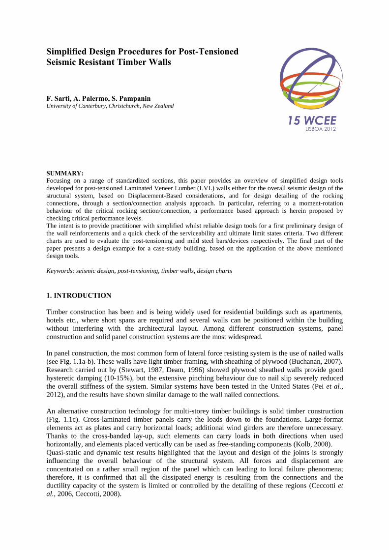
Figure 1.1. (a) Light timber framing building in Canada (c/o A. Buchanan). (b) Typical shear wall geometry
(Buchanan, 2007). (c) Cross-Laminated building in London (c/o Andy Buchanan)
Alternative technologies capable of achieving high-performance minimizing structural damage were
developed and introduced in the 1990s as main outcome of the U.S. PRESSS (PREcast Seismic
Structural System) program coordinated by the University of California, San Diego and culminated
with the pseudo-dynamic test of a large scale five-story test building (Priestley et al., 1999). Among
different connection solutions developed in the PRESSS program, the hybrid system (Fig. 1.2a)
proved to be a promising and efficient solution. The system relies upon the combination of self-
centering and dissipation contributions, provided by unbonded post-tensioning and mild steel
reinforcement respectively. The advantages of this connection are: no damage in structural member,
no post-residual displacement of the structure after the event, replaceability of the dissipaters, which is
the only sacrificial part of the system.
(a) (b) (c)
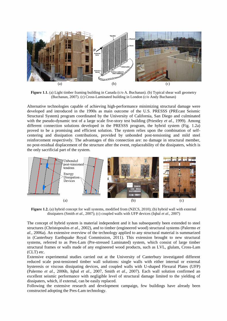
Figure 1.2. (a) hybrid concept for wall systems, modified from (NZCS, 2010); (b) hybrid wall with external
dissipaters (Smith et al., 2007); (c) coupled walls with UFP devices (Iqbal et al., 2007)
The concept of hybrid system is material independent and it has subsequently been extended to steel
structures (Christopoulos et al., 2002), and to timber (engineered wood) structural systems (Palermo et
al., 2006a). An extensive overview of the technology applied to any structural material is summarized
in (Canterbury Earthquake Royal Commission, 2011). This extension brought to new structural
systems, referred to as Pres-Lam (Pre-stressed Laminated) system, which consist of large timber
structural frames or walls made of any engineered wood products, such as LVL, glulam, Cross-Lam
(CLT) etc.
Extensive experimental studies carried out at the University of Canterbury investigated different
reduced scale post-tensioned timber wall solutions: single walls with either internal or external
hysteresis or viscous dissipating devices, and coupled walls with U-shaped Flexural Plates (UFP)
(Palermo et al., 2006b, Iqbal et al., 2007, Smith et al., 2007). Each wall solution confirmed an
excellent seismic performance with negligible level of structural damage limited to the yielding of
dissipaters, which, if external, can be easily replaced.
Following the extensive research and development campaign, few buildings have already been
constructed adopting the Pres-Lam technology.

The world’s first commercial building which adopted this technology is given by the NMIT (Nelson
Marlborough Institute of Technology) building (Fig. 1.3a), constructed in Nelson (Devereux et al.,
2011). The lateral loading system consists of post-tensioned coupled walls in both main directions.
Steel U-shaped Flexural Plates (UFP) (Kelly et al., 1972) link the pairs of structural walls together and
provide additional overturning moment contribution and dissipative capacity to the system.
The Carterton Events Centre (Fig. 1.3b), located 100km north of Wellington, is the second building in
the world adopting the Pres-Lam system (Palermo et al., 2012). Single post-tensioned rocking walls
were designed as the lateral load resisting system. Two post-tensioned high-strength bars (40mm
diameter) provide re-centering contribution, and supplemental dissipation is given by internally
epoxied mild steel rods.
Few other buildings using either Post-tensioned timber walls, and/or frames are either under
construction or in the final design stage (Canterbury Earthquake Royal Commission, 2011).
(a) (b)
Figure 1.3. . (a) NMIT Building (b) Carterton Events Centre
Whilst the advantages of the systems in terms of seismic and structural performance are being
recognized, the short-term cost-effectiveness of Pres-Lam systems has potential for significant
improvement, which would ultimately lead to a wider adoption and implementation in the construction
practice. Previous studies (Smith et al., 2009) highlighted that the increased cost of prefabricated
timber elements, in comparison to steel or concrete counterparts, comes mainly from the cost of the
material, yet a significant portion of the total cost is represented by manufacturing costs which lacks of
a properly implemented prefabrication process similarly to prestressed concrete industry.
On the other hand, buildings implementing these systems can bring some major benefits. Among those
the lighter weight of the material brings important advantages in the design (reduced seismic mass,
foundations) and in construction (crainage, speed, etc.). Needless to remember that higher speed of
construction result into significant reduction in cost.
The present paper suggests suitable standard sections for post-tensioned timber walls. This
standardization process is required for a full “prefabrication” process which would cut costs.
On the basis of a range of standardized sections proposed simplified design tools for post-tensioned
single LVL walls, developed through extensive parametric moment-rotation analyses, are provided.
The simplified procedure is then implemented into a displacement-base design approach in the final
part of the paper.
In the conclusive part, a worked design example on a case study building is provided to show the
application of proposed method, incorporated in a displacement-based design procedure (Priestley et
al., 2007).
2. DESIGN CHARTS METHOD
The present section shows a preliminary design method developed an extended parametric analysis
based on a moment-rotation procedure (see §2.1).
A rocking section with unbonded reinforcement, such as post-tensioning and debonded mild steel,
requires violates conditions of strain compatibility, which is typically assumed in a section analysis
approach, between steel and concrete (or timber). The strain incompatibility of the materials requires
the introduction of an additional member compatibility equation to the two equilibrium conditions.
The main steps of the procedure are briefly summarized below.
2.1. Moment-rotation analysis procedure
The moment-rotation step-by-step procedure for hybrid connections (Fig. 2.1a), originally proposed
for precast concrete by (Pampanin et al., 2001), modified by (Palermo et al., 2008) and later
expanded to timber by (Newcombe et al., 2010) is herein adopted. A brief summary is given in this
section. The procedure, shown in (Fig. 2.1a), is very similar in terms of general flow-chart to a
standard moment-curvature sectional analysis used for concrete sections.
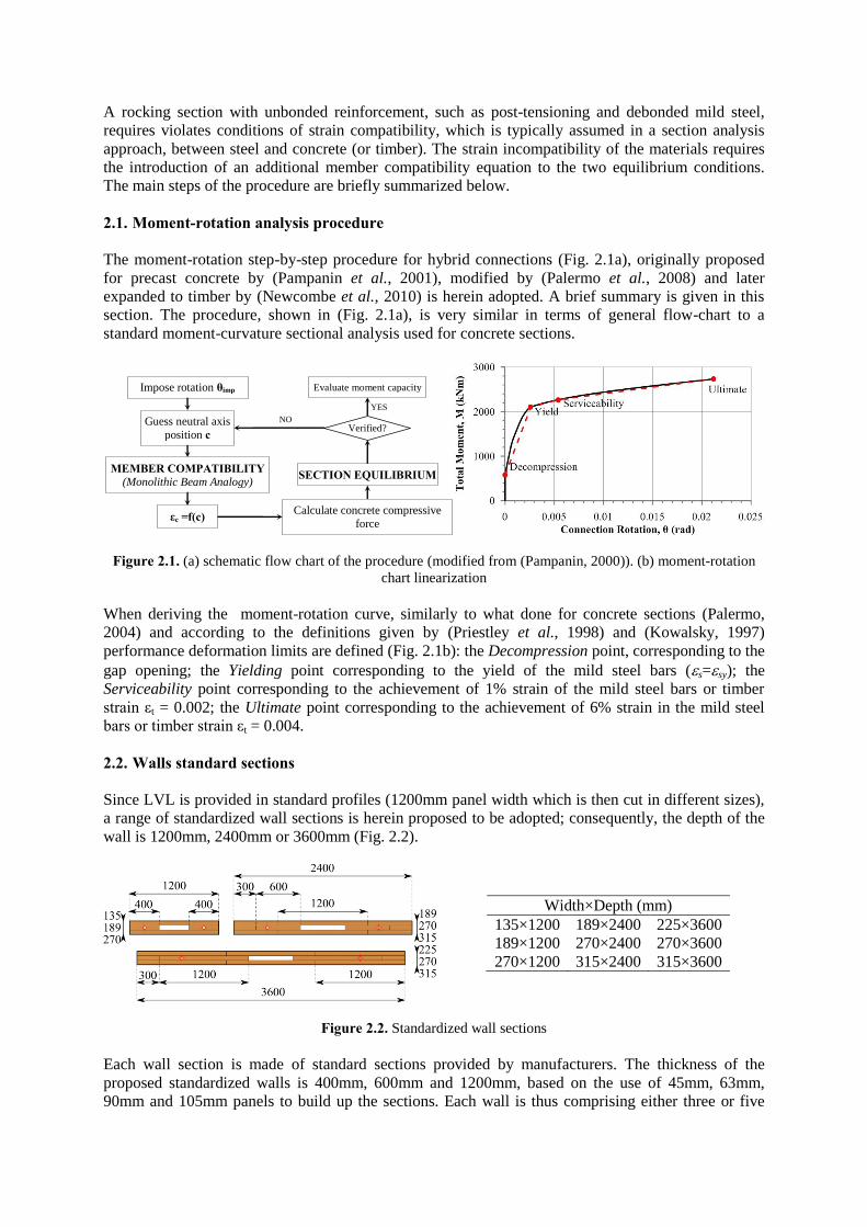
Figure 2.1. (a) schematic flow chart of the procedure (modified from (Pampanin, 2000)). (b) moment-rotation
chart linearization
When deriving the moment-rotation curve, similarly to what done for concrete sections (Palermo,
2004) and according to the definitions given by (Priestley et al., 1998) and (Kowalsky, 1997)
performance deformation limits are defined (Fig. 2.1b): the Decompression point, corresponding to the
gap opening; the Yielding point corresponding to the yield of the mild steel bars (s=sy); the
Serviceability point corresponding to the achievement of 1% strain of the mild steel bars or timber
strain εt = 0.002; the Ultimate point corresponding to the achievement of 6% strain in the mild steel
bars or timber strain εt = 0.004.
2.2. Walls standard sections
Since LVL is provided in standard profiles (1200mm panel width which is then cut in different sizes),
a range of standardized wall sections is herein proposed to be adopted; consequently, the depth of the
wall is 1200mm, 2400mm or 3600mm (Fig. 2.2).
Width×Depth (mm)
135×1200 189×2400 225×3600
189×1200 270×2400 270×3600
270×1200 315×2400 315×3600
Figure 2.2. Standardized wall sections
Each wall section is made of standard sections provided by manufacturers. The thickness of the
proposed standardized walls is 400mm, 600mm and 1200mm, based on the use of 45mm, 63mm,
90mm and 105mm panels to build up the sections. Each wall is thus comprising either three or five
Impose rotation θimp
Guess neutral axis
position c
MEMBER COMPATIBILITY (Monolithic Beam Analogy)
εc =f(c)
YES NO
Calculate concrete compressive
force
C = f(εc,c)
SECTION EQUILIBRIUM
Verified?
Evaluate moment capacity

panels, with different thickness depending on the void space needed for the insertion of the post-
tensioning bars (see Fig. 2.2).
2.3. Materials
Material characteristics of timber as well as of post-tensioining and mild steel are reported in Table
2.1. Different grades of Laminated Veneer Lumber are available on the market. The material
properties of LVL most commonly used and considered in the present work are reported below.
Table 2.1. (a) LVL material properties. (b) Post-tensioning and mild steel material properties Property Unit Char. Value
Modulus of Elasticity E GPa 11
Bending fb MPa 48
Tension parallel to grain ft MPa 30
Compression perp. to grain fp MPa 12
Compression parallel to grain fc MPa 45
Shear in beam fs MPa 6
Property Unit
Char. value
Strands MacAlloy Mild Steel
(Grade300)
Mod. of Elasticity GPa 200 170 210
Yield stress MPa 1520 835 300
Ultimate stress MPa 1860 1030 375
(a) (b)
Either threaded bars or strands can be used as post-tensioning reinforcement. As non-prestressed
reinforcement or additional dissipation devices, either internal or external dissipaters (Fig. 2.3) could
be used.
(a) (b) (c)
Figure 2.3. Mild steel dissipation devices: (a) internal bar; (b) replaceable fused bar; (c) replaceable internal bar
2.4. Structural and sectional parameters
For a given section, as shown in Fig. 2.4, dimensionless parameters are considered in the following
analysis to obtain a general tool capable of evaluating moment capacity for a wide range of solutions.
Figure 2.4. Wall general section with (a) internal and (b) external mild steel bars
Two different moment contributions can be distinguished: post-tensioning and axial, and mild steel
contributions. Each of them is defined through the re-centering ratio λ, defined in Eqn 2.1.
;1 1
p N
s p N
s
M M M MM M M
M ( 2.1 )
Where Mp, MN, Ms are y the post-tensioning, the axial load and the mild steel moment contributions,
respectively
Dimensionless axial force and moments contributions, as well as mechanical reinforcement ratios,
reported in Eqn. 2.2 are used as parameters.
2 2; ; ; ;
p N p ps s ss p N s p
t t t t t
M M A fM A fN
bhf bh f bh f bhf bhf ( 2.2 )
Where b is the width and h the depth of the wall; ft, fs and fp are the characteristic strengths of timber
(in compression), mild steel and post-tensioning steel (in tension) respectively; ωs, ωp, Ap and As are
the post-tensioning and mild steel reinforcements ratios and areas.
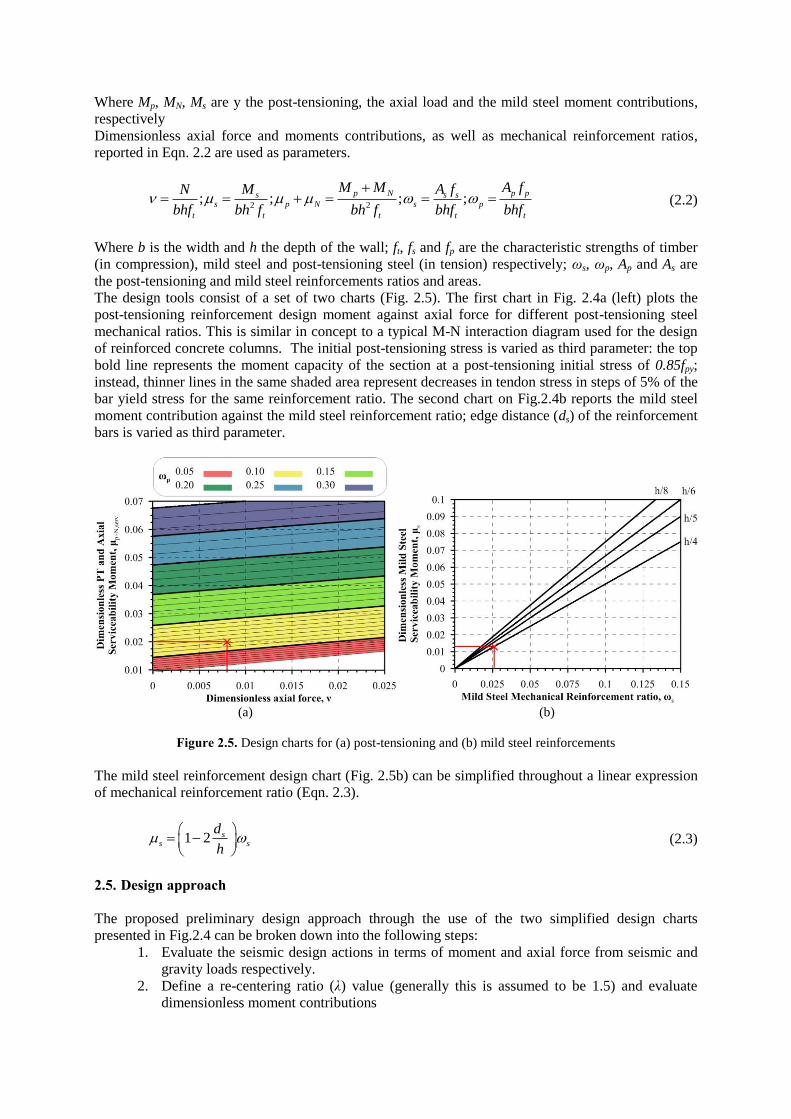
The design tools consist of a set of two charts (Fig. 2.5). The first chart in Fig. 2.4a (left) plots the
post-tensioning reinforcement design moment against axial force for different post-tensioning steel
mechanical ratios. This is similar in concept to a typical M-N interaction diagram used for the design
of reinforced concrete columns. The initial post-tensioning stress is varied as third parameter: the top
bold line represents the moment capacity of the section at a post-tensioning initial stress of 0.85fpy;
instead, thinner lines in the same shaded area represent decreases in tendon stress in steps of 5% of the
bar yield stress for the same reinforcement ratio. The second chart on Fig.2.4b reports the mild steel
moment contribution against the mild steel reinforcement ratio; edge distance (ds) of the reinforcement
bars is varied as third parameter.
(a) (b)
Figure 2.5. Design charts for (a) post-tensioning and (b) mild steel reinforcements
The mild steel reinforcement design chart (Fig. 2.5b) can be simplified throughout a linear expression
of mechanical reinforcement ratio (Eqn. 2.3).
1 2 ss s
d
h
( 2.3 )
2.5. Design approach
The proposed preliminary design approach through the use of the two simplified design charts
presented in Fig.2.4 can be broken down into the following steps:
1. Evaluate the seismic design actions in terms of moment and axial force from seismic and
gravity loads respectively.
2. Define a re-centering ratio (λ) value (generally this is assumed to be 1.5) and evaluate
dimensionless moment contributions

3. Evaluate the required post-tensioning steel and mild steel reinforcement for a given edge
distance
4. Calculate the required area of post-tensioned and mild steel Ap = ωpftbh/fp and
As = ωsftbh/fs.
5. Perform a detailed section behaviour check according to a moment-rotation procedure as
discussed in paragraph 2.1.
3. CASE STUDY BUILDING
According to the simplified design procedure shown in paragraph 2.5, the design steps of case study
building shown in Fig. 3.1 are herein performed. It is assumed that shear post-tensioned rocking
(single) walls are used for the seismic resistance in both directions. Internal gravity frames are used in
the transverse direction, with timber-concrete composite floors spanning 8 m onto them.
Hazard factor Z=0.3 (peak ground acceleration, new proposed hazard level for Christchurch), return
period factor of 1.30 (50 years working life and importance level 3, corresponding to a return period of
the design event of 1000 years), fault factor of 1 (no near field effects), a displacement reduction
factor η of 0.76 (corresponding to equivalent viscous damping of 10%) and soil type C were assumed.
A design drift level of 1.2% was considered.
(a) (b)
Figure 3.1. Case study (a) plan view and (b) transverse section
Step 1- Seismic design actions and gravity loads
The building’s total self-weight is 192 tonnes, and, assuming live load for office buildings of 3kN/m2,
the seismic weight for each floor is 244 tonnes (192t for the roof).
Following a Direct Displacement-Based Design Procedure (DDBD) (Priestley et al., 2007) for the
seismic design of the post-tensioned walls, the structure is converted to a Single Degree of Freedom
(SDOF) equivalent structure.
The equivalent SDOF system has equivalent mass (me) of 1139 tonnes and equivalent height (he) of
15.211m; resulting design displacement (Δd) of 183mm. The resulting equivalent period for the
structure is Teff=1.73s; therefore secant stiffness (ke) of 15022kN/m is resulting, and base moment base
shear are 41709kNm and 2742kN respectively.
A total number of eight post-tensioned walls are assumed in each direction, so the required base shear
and overturning moment for each wall are 343kN and 5214kNm, respectively. Thus, applying a
strength reduction factor of 0.85 on the moment capacity, the amplified shear and moment design-
level demand are 406kN and 6134kN.Each wall has a tributary area for gravity loading of
approximately 1/30 of the total floor area, so the axial load acting on the wall element is assumed to be
400kN.
Step 2 – Moment contributions and dimensionless parameters
At this stage the dimensionless parameters can be evaluated and the simplified design tools presented
in previous paragraphs are used for a preliminary evaluation of the wall reinforcements.
Considering a re-centering ratio λ value of 1.5, resulting moment contributions according to Eqn. 2.1
are Ms = 2454kNm and Mp + MN = 3680kNm. For wall section standard dimensions of 315×3600mm,
the following dimensionless parameters are ν = 0.008, μs = 0.013, μp + μN = 0.020
(from Eqn. 2.2).

Step 3 – Post-tensioning and mild steel reinforcement ratios
The preliminary evaluation through charts of Fig. 2.5 lead to mild steel (assumed edge distance is h/4)
and post-tensioning reinforcement ratios of 0.026 and 0.10 respectively, and a post-tensioning initial
stress of 50%fpy.
Step 4 – Reinforcement areas
The corresponding mild steel and post-tensioning reinforcement areas are As = 3426mm2 and
Ap = 6111mm2. Therefore, 2D50mm post-tensioning rebars and (6+6)D28mm (top + bottom) mild
steel bars are needed.
Step 5 – Detailed checks
The detailed checks through a moment-rotation analysis are now performed to validate the
preliminary design achieved above.
Some parameters which were not taken into account during the parametric study shall now be
evaluated.
For this example the post-tensioning unbonded length is assumed to be equal to the height of the wall
(26100mm), and the mild steel unbonded length is l’ub = 450mm (h/8).
As shown in Fig. 3.2a, mild steel and post-tensioning moment contribution of 2500kNm and
3831kNm respectively are achieved, resulting in a total moment capacity of 6330kNm which satisfies
the (amplified by 1/) demand (M = 6134kNm). Check on re-centering ratio shall be performed as
well; for the design example this results in a value λ = 1.53.
(a) (b)
(c) (d)
Figure 3.2. (a) Moment-rotation chart. (b) Neutral axis depth vs. Drift chart. (c) Stress ratios vs. connection
rotation chart. (d) Quasi push-pull force-drift results for designed wall
The moment capacity at 1.2% wall drift, corresponding to 0.86% connection rotation, satisfies the
moment demand. Neutral axis depth of 43% of the section height is resulting at 0.86% connection
rotation; this means one of mild steel layers is in compression, and post-tensioning reinforcements are
in tension. From the neutral axis depth and the connection rotation stress checks can be performed.
Fig. 3.2c reports the stress ratio for each component; the parameter α in the chart represent the ratio of

either mild steel, post-tensioning steel or timber stresses over their respective yield stresses (see Table
2.1).
As shown in the chart at 1.2% drift (correspoding to 0.86% connection rotation, 0.34% is the elastic
deformation of the wall) the post-tensioing and mild steel reinforcements reached respectively 52%
and 110% of the yield stress, and timber is at 30% of its yield stress. The sectional checks are thus
deemed to be satisfactory.
A push-pull analysis based on lateral force and lateral drift (Fig. 3.2b) is carried out, based on the
moment-rotation behaviour of the section/connection (shown in Fig. 3.2a) in order to confirm the
overall behaviour and evaluate the equivalent viscous damping (ξeq) of the system, given by the sum of
elastic (ξel) and hysteretic damping (ξhyst). Previous research on seismic behaviour of timber structures
have recommended values between 2% and 5% for the elastic damping (Filiatrault et al., 2003,
Christovasilis et al., 2007, Pino et al., 2010), value of 2% is herein conservatively adopted for post-
tensioned timber walls (Newcombe, 2012). The elastic damping is then corrected considering the
relationship shown below (ductility factor μ for the wall is 2.45, a = -0.43for a flag-shape hysteresis).
Hysteretic damping is evaluated as area-based damping (Jacobsen, 1960) (See Eqn. 3.1).
0.430.68 2% 9.9% 11.3%; 2.45 0.68; 9.9%2
a heq el hyst hyst
m m
A
F
( 3.1 )
The equivalent viscous damping value of the structure is thus satisfactory (higher than 10% used to
reduce the displacement design spectrum).
4. CONCLUSIONS
The paper presented a simplified design procedure for post-tensioned timber walls. The proposed
design method, developed through an extended parametric study, is applied to material optimised
standard sections.
The simplification of the design procedure allow for quick evaluation of post-tensioning and dissipater
reinforcement. The procedure has been proved to be robust and reliable through a case study building.
In fact, detailed checks, based on the development of a more accurate moment-rotation section
analysis proved to be consistent with the simplified methodology.
The procedure will be soon detailed for each dissipater types and generalized to other engineered
timber materials, such as glue-lam and cross-lam.
ACKNOWLEDGEMENT The financial support of Structural Timber Innovation Company (STIC) Ltd is gratefully acknowledged.
REFERENCES
Buchanan, A. H. (2007), Timber design guide, New Zealand Timber Industry Federation.
Canterbury Earthquake Royal Commission 2011. Interim Report. Christchurch, New Zealand.
Ceccotti, A. (2008). New Technologies for Construction of Medium-Rise Buildings in Seismic Regions: The
XLAM Case. Structural engineering international : journal of the International Association for Bridge and
Structural Engineering (IABSE), 18:2, 156-165.
Ceccotti, A., Follesa, M., Lauriola, M. P. and Sandhaas, C. (2006). Sofie project - test results on the lateral
resistance of cross-laminated wooden panels. First European Conference on Earthquake Engineering and
Seismology. Geneva, Switzerland
Christopoulos, C., Filiatrault, A., Uang, C.-M. and Folz, B. (2002). Posttensioned Energy Dissipating
Connections for Moment-Resisting Steel Frames. ASCE Journal of Structural Engineering, 129:9, 1111-
1120.
Christovasilis, I. P., Filiatrault, A. and Wanitkorkul, A. 2007. Seismic Testing of a Full-Scale Two-Story Light-
Frame Wood Building : NEESWood Benchmark Test. Development of a Performance-Based Seismic

Design Philosophy for Mid-Rise Woodframe Construction. Buffalo: University of Buffalo.
Deam, B. (1996). The seismic design and behaviour of multi-storey plywood sheathed timber framed shearwalls.
Doctor of Philosophy, University of Canterbury.
Devereux, C. P., Holden, T. J., Buchanan, A. H. and Pampanin, S. (2011). NMIT Arts & Media Building -
Damage Mitigation Using Poat-Tensioned Timber Walls. 9th Pacific Conference on Earthquake
Engineering. Auckland, New Zealand
Filiatrault, A., Isoda, H. and Folz, B. (2003). Hysteretic damping of wood framed buildings. Engineering
Structures, 25:4, 461 - 471.
Iqbal, A., Pampanin, S., Buchanan, A. and Palermo, A. (2007). Improved Seismic Performance of LVL Post-
tensioned Walls Coupled with UFP devices. 8th Pacific Conference on Earthquake Engineering. Singapore
Jacobsen, L. S. (1960). Damping in composite structures. 2nd World Conference on Earthquake Engineering.
Tokyo and Kyoto, Japan
Kelly, J. M., Skinner, R. I. and Heine, A. J. (1972). Mechanisms of Energy Absorbtion in Special Devices for
use in Earthquake Resistant Structures. Bulletin of the New Zealand Society for Eathquake Engineering,
5:3, 63-88.
Kolb, J. (2008), Systems in Timber Engineering, Birkhauser Verlag AG.
Kowalsky, M. J. (1997). Direct Displacement Based Design: a Seismic Design Methodology and its Application
to Concrete Bridges. PhD Dissertation, UCSD.
Newcombe, M. (2012). Seismic design of post-tensioned timber frame and wall buildings. Doctor of Philosophy,
University of Canterbury.
Newcombe, M. P., Cusiel, M., Pampanin, S., Palermo, A. and Buchanan, A. H. (Year). Simplified Design of
Post-tensioned Timber Buildings. CIB W18. Nelson, New Zealand
Nzcs (2010), PRESSS Design Handbook, New Zealand Concrete Society.
Palermo, A. (2004). The use of controlled rocking in the seismic design of bridges PhD Thesis, Politecnico di
Milano.
Palermo, A. and Pampanin, S. (2008). Analysis and simplified design of precast jointed ductile connections.
WCEE. Beijing, China
Palermo, A., Pampanin, S., Buchanan, A. and Newcombe, M. (2006a). Seismic Design of Multi-Storey
Buildings using Laminated Veneer Lumber (LVL). NZ Society of Earthquake Engineering, Annual National
Conference. Wairakei, New Zealand
Palermo, A., Pampanin, S. and Buchanan, A. H. (2006b). Experimental Investigations on LVL Seismic Resistant
Wall and Frame Subassemblies. First European Conference on Earthquake Engineering and Seismology.
Geneva, Switzerland
Palermo, A., Sarti, F., Baird, A. and Dekker, D. (2012). From theory to practice: design, analysis and
construction of dissipative timber rocking post-Tensioning wall system for Carterton Events Centre, New
Zealand. World Conference on Earthquake Engineering. Lisbon, Portugal
Pampanin, S. (2000). Alternative design philosophies and seismic response of precast concrete buildings. PhD
Thesis, Politecnico di Milano.
Pampanin, S., Priestley, N. and Sritharan, S. (2001). Analytical Modelling of the Seismic Behaviour of Precast
Concrete Frames Designed with Ductile Connections. Journal of Earthquake Engineering, 5:3, 329-367.
Pei, S., Van De Lindt, J. W., Wehbe, N., Liu, H. and Paul, J. (2012). Collapse Limits for Wood Frame Shear
Walls: An Experimental Investigation. ASCE Structure Congress 2012. Chicago, Illinois, USA
Pino, D. M., Pampanin, S., Carradine, D., Deam, B. and Buchanan, A. H. (2010). Dynamic Responce of a Multi-
Storey Post-Tensioned Timber Building. 11th World Conference on Timber Engineering. Riva del Garda,
Trentino, Italy
Priestley, M. J. N., Calvi, G. M. and Kowalsky, M. J. (2007), Displacement-Based Seismic Design of Structures,
IUSS Press.
Priestley, M. J. N. and Kowalsky, M. J. (1998). Aspects of drift and ductility capacity of rectangular cantilever
structural walls. Bulletin of New Zealand Society for Earthquake Engineering, 31:2, 73-85.
Smith, T., Fragiacomo, M., Pampanin, S. and Buchanan, A. H. (2009). Construction Time and Cost for Post-
Tensioned Timber Buildings. Proceedings of the Institution of Civil Engineers, Construction Materials:CM4, 9.
Smith, T., Ludwig, F., Pampanin, S., Fragiacomo, M., Buchanan, A., Deam, B. and Palermo, A. (2007). Seismic
Response of Hybrid-LVL Coupled Walls Under Quasi-Static and Pseudo-Dynamic Testing. 2007 New
Zealand Society for Earthquake Engineering Conference. Palmerston North, New Zealand
Stewart, W. (1987). The seismic design of plywood sheathed shear walls. Docor of Philosophy, University of
Canterubry.
Related Documents