Application Report SimpleLink™ Wi-Fi® CC313x, CC323x BLE Coexistence ABSTRACT The 2.4-GHz band is used by many wireless communication standards and proprietary wireless implementations. When two different entities use the same wireless band in close proximity, there must be a coexistence mechanism to avoid significant degradation in performance. This document describes the SimpleLink ™ Wi-Fi ® CC3x3x Bluetooth ® low energy (BLE) coexistence mechanism, and explains how to use it. Table of Contents 1 Introduction............................................................................................................................................................................. 3 1.1 System Block Diagram....................................................................................................................................................... 3 1.2 Terminology and Abbreviations.......................................................................................................................................... 4 2 Requirements.......................................................................................................................................................................... 4 2.1 System Requirements........................................................................................................................................................ 4 2.2 BLE Requirements............................................................................................................................................................. 4 2.3 BLE Connection Parameters..............................................................................................................................................5 2.4 User Application Requirements..........................................................................................................................................5 2.5 Wi-Fi ® Requirements..........................................................................................................................................................5 2.6 System Configurations....................................................................................................................................................... 5 3 Enabling BLE Coexistence Capability................................................................................................................................ 11 3.1 Using the Image Creator.................................................................................................................................................. 11 3.2 Using an API.....................................................................................................................................................................11 3.3 Pad Selection................................................................................................................................................................... 12 4 Test Results........................................................................................................................................................................... 13 4.1 Test Setup Description..................................................................................................................................................... 13 4.2 Test Results – Wi-Fi ® Throughput Impact on BLE Throughput........................................................................................ 15 4.3 Test Results – Wi-Fi ® Throughput Impact on BLE Connection Quality............................................................................ 17 4.4 Test Results – BLE Throughput Impact on Wi-Fi ® Throughput........................................................................................ 19 5 Revision History................................................................................................................................................................... 22 List of Figures Figure 1-1. System Block Diagram.............................................................................................................................................. 3 Figure 2-1. Coexistence Signaling Timing Diagram.....................................................................................................................4 Figure 2-2. BLE Coexistence Block Diagram.............................................................................................................................. 6 Figure 2-3. BLE Coexistence Block Diagram, Dual Antenna....................................................................................................... 7 Figure 2-4. BLE Coexistence With Antenna Diversity and 5-GHz Support................................................................................. 8 Figure 2-5. Dual Antenna BLE Coexistence With Antenna Diversity and 5-GHz Support........................................................... 9 Figure 2-6. BLE Coexistence With Antenna Diversity and 2.4-GHz Support............................................................................ 10 Figure 3-1. Enabling BLE Coexistence From the Image Creator GUI....................................................................................... 11 Figure 4-1. Shared Antenna Test Setup.................................................................................................................................... 14 Figure 4-2. Dual Antenna Test Setup.........................................................................................................................................14 Figure 4-3. BLE Throughput During Wi-Fi® TCP Rx................................................................................................................. 15 Figure 4-4. BLE Throughput During Wi-Fi® TCP Tx................................................................................................................. 16 Figure 4-5. BLE Throughput During Wi-Fi® UDP Rx.................................................................................................................16 Figure 4-6. BLE Throughput During Wi-Fi® UDP Tx................................................................................................................. 17 Figure 4-7. BLE Missed Events, Central Use-Case................................................................................................................... 18 www.ti.com Table of Contents SWRA608A – JANUARY 2019 – REVISED AUGUST 2020 Submit Document Feedback SimpleLink™ Wi-Fi® CC313x, CC323x BLE Coexistence 1 Copyright © 2020 Texas Instruments Incorporated

Welcome message from author
This document is posted to help you gain knowledge. Please leave a comment to let me know what you think about it! Share it to your friends and learn new things together.
Transcript

Application ReportSimpleLink™ Wi-Fi® CC313x, CC323x BLECoexistence
ABSTRACT
The 2.4-GHz band is used by many wireless communication standards and proprietary wirelessimplementations. When two different entities use the same wireless band in close proximity, there must be acoexistence mechanism to avoid significant degradation in performance.
This document describes the SimpleLink™ Wi-Fi® CC3x3x Bluetooth® low energy (BLE) coexistencemechanism, and explains how to use it.
Table of Contents1 Introduction.............................................................................................................................................................................3
1.1 System Block Diagram.......................................................................................................................................................31.2 Terminology and Abbreviations.......................................................................................................................................... 4
2 Requirements..........................................................................................................................................................................42.1 System Requirements........................................................................................................................................................42.2 BLE Requirements............................................................................................................................................................. 42.3 BLE Connection Parameters..............................................................................................................................................52.4 User Application Requirements..........................................................................................................................................52.5 Wi-Fi® Requirements..........................................................................................................................................................52.6 System Configurations....................................................................................................................................................... 5
3 Enabling BLE Coexistence Capability................................................................................................................................ 113.1 Using the Image Creator.................................................................................................................................................. 113.2 Using an API.....................................................................................................................................................................113.3 Pad Selection................................................................................................................................................................... 12
4 Test Results...........................................................................................................................................................................134.1 Test Setup Description..................................................................................................................................................... 134.2 Test Results – Wi-Fi® Throughput Impact on BLE Throughput........................................................................................154.3 Test Results – Wi-Fi® Throughput Impact on BLE Connection Quality............................................................................174.4 Test Results – BLE Throughput Impact on Wi-Fi® Throughput........................................................................................19
5 Revision History................................................................................................................................................................... 22
List of FiguresFigure 1-1. System Block Diagram.............................................................................................................................................. 3Figure 2-1. Coexistence Signaling Timing Diagram.....................................................................................................................4Figure 2-2. BLE Coexistence Block Diagram.............................................................................................................................. 6Figure 2-3. BLE Coexistence Block Diagram, Dual Antenna.......................................................................................................7Figure 2-4. BLE Coexistence With Antenna Diversity and 5-GHz Support................................................................................. 8Figure 2-5. Dual Antenna BLE Coexistence With Antenna Diversity and 5-GHz Support...........................................................9Figure 2-6. BLE Coexistence With Antenna Diversity and 2.4-GHz Support............................................................................ 10Figure 3-1. Enabling BLE Coexistence From the Image Creator GUI....................................................................................... 11Figure 4-1. Shared Antenna Test Setup.................................................................................................................................... 14Figure 4-2. Dual Antenna Test Setup.........................................................................................................................................14Figure 4-3. BLE Throughput During Wi-Fi® TCP Rx................................................................................................................. 15Figure 4-4. BLE Throughput During Wi-Fi® TCP Tx................................................................................................................. 16Figure 4-5. BLE Throughput During Wi-Fi® UDP Rx.................................................................................................................16Figure 4-6. BLE Throughput During Wi-Fi® UDP Tx................................................................................................................. 17Figure 4-7. BLE Missed Events, Central Use-Case...................................................................................................................18
www.ti.com Table of Contents
SWRA608A – JANUARY 2019 – REVISED AUGUST 2020Submit Document Feedback
SimpleLink™ Wi-Fi® CC313x, CC323x BLE Coexistence 1
Copyright © 2020 Texas Instruments Incorporated

Figure 4-8. BLE CRC Errors, Central Use-Case....................................................................................................................... 18Figure 4-9. BLE Connection Losses, Central Use-Case........................................................................................................... 19Figure 4-10. TCP Rx Throughput.............................................................................................................................................. 20Figure 4-11. TCP Tx Throughput............................................................................................................................................... 20Figure 4-12. UDP Rx Throughput.............................................................................................................................................. 21Figure 4-13. UDP Tx Throughput.............................................................................................................................................. 22
List of TablesTable 1-1. Terminology.................................................................................................................................................................4Table 3-1. CC313x Pin Selection for Coexistence..................................................................................................................... 12Table 3-2. CC323x Pin Selection for Coexistence..................................................................................................................... 12
TrademarksSimpleLink™, Texas Instruments™, BoosterPack™, and LaunchPad™ are trademarks of Texas Instruments.Wi-Fi® is a registered trademark of Wi-Fi Alliance.Bluetooth® is a registered trademark of Bluetooth SIG Inc..All other trademarks are the property of their respective owners.
Trademarks www.ti.com
2 SimpleLink™ Wi-Fi® CC313x, CC323x BLE Coexistence SWRA608A – JANUARY 2019 – REVISED AUGUST 2020Submit Document Feedback
Copyright © 2020 Texas Instruments Incorporated

1 IntroductionThe BLE coexistence functionality in the SimpleLink™ CC3x3x family of solutions helps in designing a productthat uses both Wi-Fi® and BLE. Although the mechanism is designed to implement coexistence with any BLEdevice, this document also describes the implementation of the mechanism with Texas Instruments™
SimpleLink™ CC26xx ultra-low power wireless MCU for Bluetooth® low energy.
BLE and Wi-Fi® operate on the same frequencies, and disturb each other’s transmissions and receptions, withno inherent way to avoid it.
Wi-Fi®, however, is more inherently tolerant of time-domain disturbances. With this in mind, the co-existencemechanism gives priority to the BLE entity over the Wi-Fi®, as the Wi-Fi® can often delay its transmission or missa reception, without having any major noticeable effect apparent to the user (to some extent). This is done byconnecting the GPIO used by BLE, to control the RF switch to the Wi-Fi® device. This GPIO goes high duringany BLE RF activity (transmission or reception), signaling the Wi-Fi® to delay pending transmissions until thesignal goes down. A second GPIO may optionally be used when an RF switch is included in the design for asingle-antenna use-case. This second GPIO is used to control the RF switch. See Figure 1-1 for an overview ofthe implementation.
From a Wi-Fi® perspective, the co-existence mechanism resides in ROM, thus it does not require anything fromthe user-application, apart from enabling or disabling it through a user API, or pre-programming it using theprogramming tool.
Because the BLE operates only on the 2.4-GHz band, the co-existence mechanism does not affect the5-GHz band. Wi-Fi® can operate normally on the 5-GHz band while the BLE works on the 2.4-GHz band withoutany mutual interference; thus a co-existence mechanism is not required.
1.1 System Block DiagramThe coexistence mechanism uses a shared antenna between the two 2.4-GHz entities, incorporating an RFswitch to toggle between the two. Figure 1-1 shows a high-level schematic of this configuration.
Simplelink
CC3x30
2,4 GHz
ANT port
Coex
Output GPIO
Coex
Input GPIO
RF Switch
V2V1
RF1
RF2
1
0
0
1
BLE
CC264X
RF2 RF1
V1 V2
2.4 GHz
Ant
BLE
Output
GPIO
2.4 GHZ
ANT port
Figure 1-1. System Block Diagram
The required GPIOs for the coexistence mechanism can be selected from a wide range of available options; thedesign options may be limited when using CC323x device variants, where some GPIOs may be allocated tospecifically required peripherals. See Section 3.3 for details.
www.ti.com Introduction
SWRA608A – JANUARY 2019 – REVISED AUGUST 2020Submit Document Feedback
SimpleLink™ Wi-Fi® CC313x, CC323x BLE Coexistence 3
Copyright © 2020 Texas Instruments Incorporated

1.2 Terminology and AbbreviationsTable 1-1. Terminology
Term DefinitionBLE Bluetooth® Low Energy
WLAN Wireless-LAN
2 Requirements2.1 System RequirementsThe following requirements must be fulfilled for proper system functionality using the coexistence mechanism:• Both devices must share the same I/O supply.• The CC3x3x device must be powered when the other device is powered, though it may remain in any power
state including shutdown.• A pull-down resistor is required on the input pin to the CC3x3x device, so that there is always a defined state
when the other side is off or in power-saving mode. TI recommends also adding a pull-down resistor on theoutput GPIO, for a total of two 100-KΩ pull-down resistors, one on each control pin of the RF switch.
• When the RF calibrations mode is set to Normal, the BLE device must be idle when starting the Wi-Fi® coreto avoid having the calibrations done in conjunction with the coexistence mechanism, which may causeexcessive current due to calibration retries, or possibly failure to initialize altogether if the Wi-Fi® did not getany time allocated for calibrations.
• Some small amount of leakage current is drawn by the pull-down resistors (typically 33 µA for a100-KΩ pull-down resistor at 3.3-V VBAT voltage) while transmitting or receiving from either device, as wellas the current drawn by the RF switch, in a shared antenna design.
2.2 BLE RequirementsThis section refers to the BLE MCU that the CC3x3x device must coexist with. That device should provide thefollowing:• Greater than 20-dB isolation from the Wi-Fi®, either by using an RF switch which provides more than 20-dB
isolation, or by isolation on the board between the two antennas when using a dual antenna configuration.• A control GPIO that wraps the device’s RF activity (padding of more than 100 µS before the RF activity
begins).
Figure 2-1 shows the timing diagram for the coexistence signaling. This figure is not drawn to scale.
2WKHU�GHYLFH¶V�5)�$FWLYLW\�(TX or RX)
Syste
m V
IO L
eve
l
> 100uSec
2WKHU�GHYLFH¶V�RXWSXW�*3,2 2WKHU�GHYLFH¶V�RXWSXW�*3,2
> 20mSec
2WKHU�GHYLFH¶V�5)�$FWLYLW\�(TX or RX)
> 100uSec
< 200mSec
Figure 2-1. Coexistence Signaling Timing Diagram
The duration of the BLE’s RF activity is not explicitly given, but should be kept within reasonable boundaries soas not to impact Wi-Fi® connection.
Introduction www.ti.com
4 SimpleLink™ Wi-Fi® CC313x, CC323x BLE Coexistence SWRA608A – JANUARY 2019 – REVISED AUGUST 2020Submit Document Feedback
Copyright © 2020 Texas Instruments Incorporated

2.3 BLE Connection ParametersThe BLE device can be used as a peripheral or a central, using most of the connection intervals available, whilekeeping in mind that the lower the connection interval is, the more impact it has on the Wi-Fi® side, as the BLEtakes precedence when using the coexistence mechanism.
For optimal Wi-Fi® performance, TI recommends keeping the BLE RF activity periods at least 100 ms apart. Ifthe Wi-Fi® application relies more on transmissions than receptions, this interval can be lowered down to 20 ms.For lower intervals, the Wi-Fi® connection may be impacted; when BLE is receiving, the antenna is still allocatedto it, but it still allows the Wi-Fi® to receive data (in reduced power), while transmissions are not allowed whilethe BLE side is receiving or transmitting.
Also, the shorter the BLE time interval is, the higher impact it has on the overall system current consumption, asit delays the Wi-Fi® core more frequently.
2.4 User Application RequirementsThis section refers to the CC323x device variants which incorporate the internal MCU. The configuredcoexistence I/Os are handled by the internal firmware of the device, and can be considered an extra peripheralwhen enabled; the user configuration can still be destructive, however, if it attempts to override the firmwareconfiguration.
If the user application configures an I/O selected for coexistence purposes prior to starting the Wi-Fi®, the Wi-Fi®will fail to initialize and an error is returned to the user. If the user application configures an I/O after the Wi-Fi®has been started, it will stop the coexistence mechanism from operating properly. Specifically, the pads selectedto be used as the coexistence interface must not be multiplexed to any other functionality (either user GPIO orperipheral).
To prevent disruptions to the user application, maximum flexibility is given to the user to choose the most fittingpads for the coexistence task.
2.5 Wi-Fi® RequirementsThe coexistence mechanism can operate in any supported Wi-Fi® mode (AP, station, P2P, and transceiver). Itdoes not interfere with 5-GHz transmissions; when using 5-GHz channels, the coexistence has no impact on Wi-Fi® performance.
2.6 System ConfigurationsVarious system configurations that include the coexistence mechanisms may be used in the CC3x3x devices.
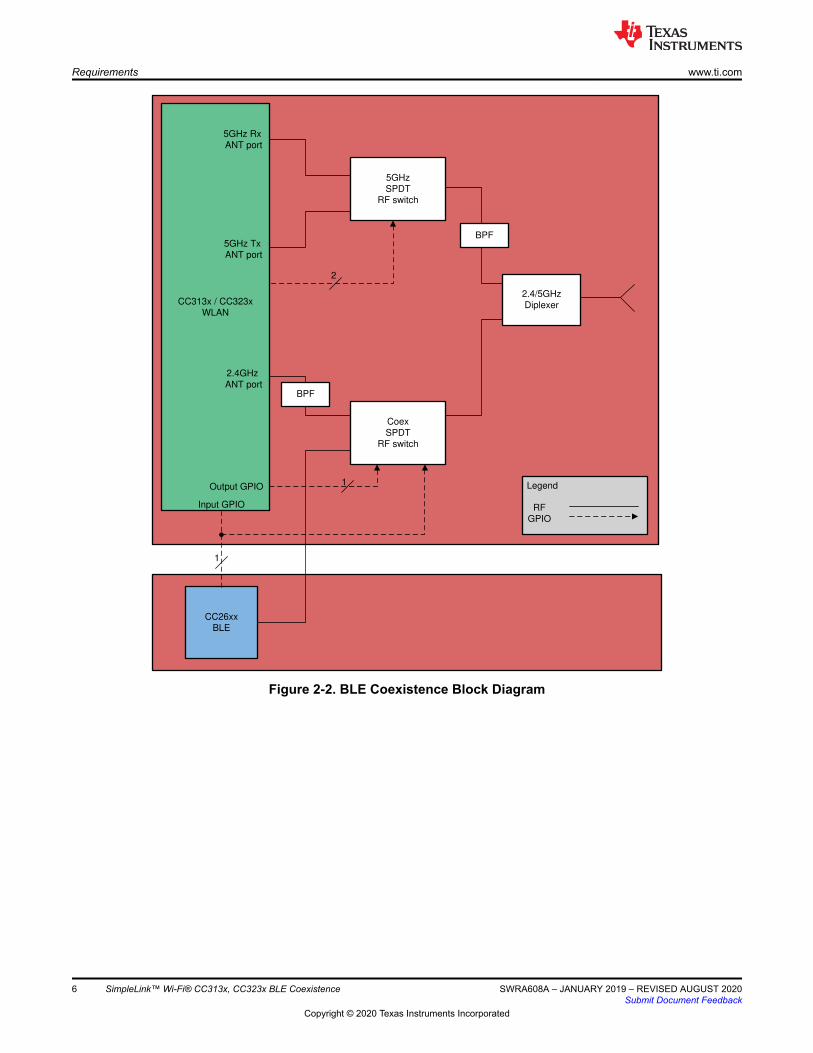
2.6.1 2.4-GHz / 5-GHz Wi-Fi® With BLE Coexistence (CC3x35 only)
This is the default setting for a CC3135/CC3235x device with BLE coexistence enabled. The RF switch musthave at least 20 dB attenuation for the deselected path.
www.ti.com Requirements
SWRA608A – JANUARY 2019 – REVISED AUGUST 2020Submit Document Feedback
SimpleLink™ Wi-Fi® CC313x, CC323x BLE Coexistence 5
Copyright © 2020 Texas Instruments Incorporated
CC313x / CC323x
WLAN
CC26xx
BLE
5GHz
SPDT RF switch
5GHz Rx
ANT port
5GHz Tx
ANT port
2
Coex
SPDT
RF switch
2.4/5GHz
Diplexer
1
1
Legend
RF
GPIO
2.4GHz
ANT portBPF
BPF
Output GPIO
Input GPIO
Figure 2-2. BLE Coexistence Block Diagram
Requirements www.ti.com
6 SimpleLink™ Wi-Fi® CC313x, CC323x BLE Coexistence SWRA608A – JANUARY 2019 – REVISED AUGUST 2020Submit Document Feedback
Copyright © 2020 Texas Instruments Incorporated

2.6.2 2.4-GHz / 5-GHz Wi-Fi® With BLE Coexistence, Dual Antenna (CC3x35 only)
When both the BLE device and the Wi-Fi® device have their own antenna, an RF switch to toggle between themis not required. In this case, only one GPIO is used to signal the Wi-Fi® when the BLE uses the air, during whichthe Wi-Fi® does not initiate new transmissions, but is still capable of data reception.
CC313x / CC323x
WLAN
CC26xx
BLE
5GHz
SPDT RF switch
5GHz Rx
ANT port
5GHz Tx
ANT port
2
2.4/5GHz
Diplexer
1
Legend
RF
GPIO
2.4GHz
ANT portBPF
BPF
Output GPIO
Input GPIO
BLE Antenna
Figure 2-3. BLE Coexistence Block Diagram, Dual Antenna
www.ti.com Requirements
SWRA608A – JANUARY 2019 – REVISED AUGUST 2020Submit Document Feedback
SimpleLink™ Wi-Fi® CC313x, CC323x BLE Coexistence 7
Copyright © 2020 Texas Instruments Incorporated

2.6.3 2.4-GHz / 5-GHz Wi-Fi® With BLE Coexistence, With Antenna Diversity (CC3x35 only)
This configuration includes antenna diversity in conjuncture with BLE coexistence. An additional 2 GPIOs arerequired for the diversity RF switch control. Also, RF degradation occurs due to the RF switches along the RFchain.
CC313x / CC323x
WLAN
CC26xx
BLE
5GHz
SPDT RF switch
5GHz Rx
ANT port
5GHz Tx
ANT port
2
Coex
SPDT
RF switch
2.4/5GHz
Diplexer
1
1
Legend
RF
GPIO
2.4GHz
ANT portBPF
BPF
Output GPIO
Input GPIO
Antenna Selection
SPDT RF Switch
Output GPIOS
Antenna 1
Antenna 2
Figure 2-4. BLE Coexistence With Antenna Diversity and 5-GHz Support
Requirements www.ti.com
8 SimpleLink™ Wi-Fi® CC313x, CC323x BLE Coexistence SWRA608A – JANUARY 2019 – REVISED AUGUST 2020Submit Document Feedback
Copyright © 2020 Texas Instruments Incorporated

CC313x / CC323x
WLAN
CC26xx
BLE
5GHz
SPDT RF switch
5GHz Rx
ANT port
5GHz Tx
ANT port
2
2.4/5GHz
Diplexer
1
Legend
RF
GPIO
2.4GHz
ANT port BPF
BPF
Input GPIO
Antenna Selection
SPDT RF Switch
Output GPIOS
Antenna 1
Antenna 2
BLE Antenna
2
Figure 2-5. Dual Antenna BLE Coexistence With Antenna Diversity and 5-GHz Support
www.ti.com Requirements
SWRA608A – JANUARY 2019 – REVISED AUGUST 2020Submit Document Feedback
SimpleLink™ Wi-Fi® CC313x, CC323x BLE Coexistence 9
Copyright © 2020 Texas Instruments Incorporated

2.6.4 2.4-GHz Only Wi-Fi® With BLE Coexistence and Antenna Diversity Support (CC3x30)
If 5-GHz support is not required, the following scheme allows antenna diversity alongside BLE coexistence.
CC313x / CC323x
WLAN
CC26xx
BLE
1
1
Legend
RF
GPIO
Output GPIO
Input GPIO
Coex
SPDT
RF Switch
Antenna 1
Antenna 2
Antenna
Selection
SPDT RD SwitchBPF
2
5GHz Rx
ANT port
5GHz Tx
ANT port
2.4GHz
ANT port
Output GPIOs
Figure 2-6. BLE Coexistence With Antenna Diversity and 2.4-GHz Support
Requirements www.ti.com
10 SimpleLink™ Wi-Fi® CC313x, CC323x BLE Coexistence SWRA608A – JANUARY 2019 – REVISED AUGUST 2020Submit Document Feedback
Copyright © 2020 Texas Instruments Incorporated

3 Enabling BLE Coexistence Capability3.1 Using the Image CreatorEnabling BLE coexistence can be done from the Image Creator GUI when programming the device. Theselection is done under System Settings → Device → Radio Settings, as shown in Figure 3-1.
Figure 3-1. Enabling BLE Coexistence From the Image Creator GUI
First select the mode:• Off – BLE coexistence is not used (default)• Single antenna – choose this option when the platform includes an RF switch, to share a single antenna
between the BLE and Wi-Fi®. This option requires the allocation of two GPIOs – one is input from the BLEand to the RF switch, the other is an output from the Wi-Fi®to the RF switch (see Figure 1-1).
• Dual antenna – choose this option when the platform has separate antennas for BLE and Wi-Fi®. In thismode, BLE signals Wi-Fi® when it requires the channel, and Wi-Fi® stops ongoing transmissions during thosetimes.
3.2 Using an APIBLE coexistence can be enabled, disabled, or modified using an API from the host. The settings requirerestarting the Wi-Fi® to take effect.
The configuration can be applied using the sl_WlanSet command, with ConfigId ofSL_WLAN_CFG_GENERAL_PARAM_ID and ConfigOpt of WLAN_GENERAL_PARAM_COEX_CONFIG.
The data structure is as follows:
typedef struct{ UINT8 Mode; UINT8 InputPad; UINT8 OutputPad; UINT8 Reserved; UINT32 Options; }SlWlanCoexConfig_t;
www.ti.com Enabling BLE Coexistence Capability
SWRA608A – JANUARY 2019 – REVISED AUGUST 2020Submit Document Feedback
SimpleLink™ Wi-Fi® CC313x, CC323x BLE Coexistence 11
Copyright © 2020 Texas Instruments Incorporated

Mode can accept the following values: 0, 1, and 2 (for disabled, enabled single antenna, and enabled dualantenna, respectively).
The input pad and output pad can accept pad number (only pad numbers, not pin numbers); up to 40, inclusive.The Reserved and Option fields should remain 0.
3.3 Pad SelectionTo allow maximum flexibility for every platform configuration, there are multiple choices for assigning thecoexistence interface on the device pins. These choices differ slightly, based on the device family (CC313xversus CC323x).
Table 3-1 lists the available pins that can be used for coexistence in the CC313x device, and Table 3-2 lists thepins that can be used for coexistence in the CC323x device.
Table 3-1. CC313x Pin Selection for CoexistencePAD Name Pin Number CommentPAD04 59 Output only
PAD05 60
PAD08 63
PAD09 64 Default coexistence input pin on BoosterPack™ module
PAD10 1
PAD12 3 Default coexistence output pin on BoosterPack module
PAD13 4
PAD25 21 Shared with SOP2, output only
PAD26 29 Default for Antenna Selection on BoosterPack module
PAD27 30 Default for Antenna Selection on BoosterPack module
PAD40 18
Table 3-2. CC323x Pin Selection for CoexistencePAD Name Pin Number CommentPAD03 58 Output only. Default coexistence output on LaunchPad™ kit
PAD04 59 Output only
PAD05 60
PAD06 61
PAD08 63
PAD09 64
PAD10 1
PAD11 2 Output only
PAD12 3
PAD13 4
PAD14 5
PAD15 6
PAD16 7
PAD17 8 Output only
PAD22 15
PAD25 21 Shared with SOP2, output only
PAD26 29 Default for Antenna Selection on LaunchPad kit
PAD27 30 Default for Antenna Selection on LaunchPad kit
PAD40 18 Default coexistence input on LaunchPad kit
Enabling BLE Coexistence Capability www.ti.com
12 SimpleLink™ Wi-Fi® CC313x, CC323x BLE Coexistence SWRA608A – JANUARY 2019 – REVISED AUGUST 2020Submit Document Feedback
Copyright © 2020 Texas Instruments Incorporated

4 Test Results4.1 Test Setup DescriptionThis setup checks the ability to receive and send Wi-Fi® traffic without interference with a BLE connectiontransferring data. During the test, both Wi-Fi® and BLE traffic is sent at maximum throughput. The Wi-Fi® RFattenuation is gradually raised while the Wi-Fi® throughput, BLE throughput, BLE events, BLE missing events,BLE CRC errors, and BLE lost connections are monitored.
This section explains the relevant calibrations required to achieve the results shown in this document.
All of the devices (access point, SimpleLink™ Wi-Fi®, and the BLE device) are placed in an RF chamber, andthe connections are made using an RF chain.
4.1.1 BLE Side4.1.1.1 RF Chain
During the test, the RSSI in the BLE device is between –46 to –50 dBm. Between the RF splitter A and the BLEdevice B, there is an attenuation of 16 dB in dual antenna mode. In shared antenna mode, the attenuation is 4dB. This difference in the attenuation creates a situation where the BLE device is protected from Wi-Fi® trafficfrom other sources.
Additionally, the BLE attenuation value is changed according to the coexistence mode. With this attenuator, theuser can change set the attenuation to assure the desired RSSI. The RF splitter A has an attenuation of 12 dB,and the RF splitter B has an attenuation of 6 dB in this setup.
4.1.1.2 Application
When both BLE devices are connected, one of them is central and the other is a peripheral. They transfer datain rate of 1 Mbps and intervals of 100 ms and 50 ms.
This test uses the BLE CC26xx devices, using the example application of the SDK with a few changes. Thesechanges were made to make the BLE device work in the most extreme conditions, to show the ability to assure astable BLE connection. The relevant changes are: the connection interval is set to a single value withoutallowing the BLE device to change, the slave latency is 0, and the connection timeout is set to 3 miss interval.
4.1.2 Wi-Fi® Side
The access point is configured to work in channel 11 with a TX power of 17 dBm, with no security.
Between the access point and the Wi-Fi®, there is a fixed attenuation of 55 dB, including all the elements in theRF chain up to the RF Splitter B. If the coexistence mode is shared antenna, an additional 6 dB attenuation isadded before the RF switch. If the coexistence mode is dual antenna, the attenuation of the RF splitter should be6 db. An extra attenuator may be used if the splitter is not with the relevant attenuation. At the beginning of thetest, start with an attenuation of 67 dB; this extra attenuation is reached using the Wi-Fi® attenuator.
The X-axis of all the result graphs is the Wi-Fi® attenuation between the AP and the SL device.
Figure 4-1 and Figure 4-2 describe the test setups.
Wi-Fi® runs in station mode, TCP RX, TCP TX, UDP RX, and UDP TX traffic (maximum throughput), in allsupported coexistence modes:• Coexistence off• Coexistence on
www.ti.com Test Results
SWRA608A – JANUARY 2019 – REVISED AUGUST 2020Submit Document Feedback
SimpleLink™ Wi-Fi® CC313x, CC323x BLE Coexistence 13
Copyright © 2020 Texas Instruments Incorporated

Figure 4-1. Shared Antenna Test Setup
Figure 4-2. Dual Antenna Test Setup
Test Results www.ti.com
14 SimpleLink™ Wi-Fi® CC313x, CC323x BLE Coexistence SWRA608A – JANUARY 2019 – REVISED AUGUST 2020Submit Document Feedback
Copyright © 2020 Texas Instruments Incorporated

4.2 Test Results – Wi-Fi® Throughput Impact on BLE ThroughputAll tests in this section have the BLE configured to a 100-ms connection interval, and the Wi-Fi® side ismeasured using the CC3235S device.
Figure 4-3 shows that the BLE throughput is impacted when the coexistence mechanism is turned off. With thecoexistence turned on, BLE throughput is hardly impacted by the Wi-Fi® traffic.
Figure 4-3. BLE Throughput During Wi-Fi® TCP Rx
With the coexistence turned off, BLE throughput is heavily impacted by the Wi-Fi® TX traffic. With it turned on,there is hardly any impact on BLE throughput. The knee at high attenuation is caused by the Wi-Fi®disconnecting from the AP.
www.ti.com Test Results
SWRA608A – JANUARY 2019 – REVISED AUGUST 2020Submit Document Feedback
SimpleLink™ Wi-Fi® CC313x, CC323x BLE Coexistence 15
Copyright © 2020 Texas Instruments Incorporated

Figure 4-4. BLE Throughput During Wi-Fi® TCP Tx
When coexistence is turned off, there is a degradation of BLE throughput. This degradation does not occur withthe mechanism turned on, except for a slight degradation when the Wi-Fi® attenuation is low when using sharedantenna (due to RX-RX collisions). The tests conducted with co-existence turned off were using the RF switch,so some attenuation was ensured between the BLE device and the Wi-Fi® access point.
Figure 4-5. BLE Throughput During Wi-Fi® UDP Rx
Test Results www.ti.com
16 SimpleLink™ Wi-Fi® CC313x, CC323x BLE Coexistence SWRA608A – JANUARY 2019 – REVISED AUGUST 2020Submit Document Feedback
Copyright © 2020 Texas Instruments Incorporated

Figure 4-6 shows no impact on BLE throughput when the coexistence mechanism is active, and heavydegradation when the coexistence is inactive.
Figure 4-6. BLE Throughput During Wi-Fi® UDP Tx
4.3 Test Results – Wi-Fi® Throughput Impact on BLE Connection QualityFigure 4-7 shows a large number of missed events counted over a period of ~30 seconds for each Wi-Fi®attenuation when the coexistence mechanism is turned off, especially when the Wi-Fi® is transmitting heavily inlow attenuations.
At high attenuations, the amount of missed events rises with coexistence turned on; this can be attributed to theWi-Fi® rate fallback, causing the Wi-Fi® packets to become longer and get re-transmitted frequently.
www.ti.com Test Results
SWRA608A – JANUARY 2019 – REVISED AUGUST 2020Submit Document Feedback
SimpleLink™ Wi-Fi® CC313x, CC323x BLE Coexistence 17
Copyright © 2020 Texas Instruments Incorporated

Figure 4-7. BLE Missed Events, Central Use-Case
Figure 4-8 shows the high amount of CRC errors in low Wi-Fi® attenuations when coexistence is turned off.Enabling coexistence almost totally eliminates the measured CRC errors.
The accumulated number of CRC per attenuation is measured over a period of 30 seconds.
Figure 4-8. BLE CRC Errors, Central Use-Case
Test Results www.ti.com
18 SimpleLink™ Wi-Fi® CC313x, CC323x BLE Coexistence SWRA608A – JANUARY 2019 – REVISED AUGUST 2020Submit Document Feedback
Copyright © 2020 Texas Instruments Incorporated

Figure 4-9 shows many instances of BLE connection loss when the coexistence mechanism is turned off, with nosuch occurrences when it is turned on.
Figure 4-9. BLE Connection Losses, Central Use-Case
4.4 Test Results – BLE Throughput Impact on Wi-Fi® ThroughputBecause the Simplelink™ BLE coexistence gives priority to BLE activity, it is expected that the Wi-Fi®performance is impacted by the BLE activity. This section shows this impact is very small, and that Wi-Fi® canstill perform well with BLE transferring a large amount of data concurrently.
The tests conducted in this section have the BLE device running throughput in central use-case.
Figure 4-10 shows the baseline TCP Rx throughput, starting at around 18 Mbps, dropping to around 15 Mbpswith BLE coexistence turned on, and dropping gradually in all scenarios when attenuation rises (regardless ofBLE coexistence), as expected.
www.ti.com Test Results
SWRA608A – JANUARY 2019 – REVISED AUGUST 2020Submit Document Feedback
SimpleLink™ Wi-Fi® CC313x, CC323x BLE Coexistence 19
Copyright © 2020 Texas Instruments Incorporated

Figure 4-10. TCP Rx Throughput
With TCP, unlike UDP, because of the retransmission mechanism of the Wi-Fi®, the throughput is hardlyimpacted at all, dropping from 19.3 Mbps (baseline attenuation) to 16.8 Mbps (baseline attenuation) in all co-existence scenarios.
Figure 4-11. TCP Tx Throughput
Test Results www.ti.com
20 SimpleLink™ Wi-Fi® CC313x, CC323x BLE Coexistence SWRA608A – JANUARY 2019 – REVISED AUGUST 2020Submit Document Feedback
Copyright © 2020 Texas Instruments Incorporated

UDP Rx shows a similar trend; the baseline when BLE is off is not far from the throughput when it is on.
Figure 4-12. UDP Rx Throughput
Because Wi-Fi® can delay its transmissions until the antenna is returned to it, and the protocol does not rely onthe TCP acknowledgments, this is the easiest use-case for coexistence. As Figure 4-13 shows, the fact that BLEis running throughput concurrently has hardly any impact on the Wi-Fi® throughput, which in this case is around19 Mbps.
www.ti.com Test Results
SWRA608A – JANUARY 2019 – REVISED AUGUST 2020Submit Document Feedback
SimpleLink™ Wi-Fi® CC313x, CC323x BLE Coexistence 21
Copyright © 2020 Texas Instruments Incorporated

Figure 4-13. UDP Tx Throughput
5 Revision HistoryNOTE: Page numbers for previous revisions may differ from page numbers in the current version.
Changes from Revision * (April 2018) to Revision A (August 2020) Page• Changed the document title and throughout document to include CC3130 and CC3230 devices.....................3
Revision History www.ti.com
22 SimpleLink™ Wi-Fi® CC313x, CC323x BLE Coexistence SWRA608A – JANUARY 2019 – REVISED AUGUST 2020Submit Document Feedback
Copyright © 2020 Texas Instruments Incorporated

IMPORTANT NOTICE AND DISCLAIMER
TI PROVIDES TECHNICAL AND RELIABILITY DATA (INCLUDING DATASHEETS), DESIGN RESOURCES (INCLUDING REFERENCE DESIGNS), APPLICATION OR OTHER DESIGN ADVICE, WEB TOOLS, SAFETY INFORMATION, AND OTHER RESOURCES “AS IS” AND WITH ALL FAULTS, AND DISCLAIMS ALL WARRANTIES, EXPRESS AND IMPLIED, INCLUDING WITHOUT LIMITATION ANY IMPLIED WARRANTIES OF MERCHANTABILITY, FITNESS FOR A PARTICULAR PURPOSE OR NON-INFRINGEMENT OF THIRD PARTY INTELLECTUAL PROPERTY RIGHTS.These resources are intended for skilled developers designing with TI products. You are solely responsible for (1) selecting the appropriate TI products for your application, (2) designing, validating and testing your application, and (3) ensuring your application meets applicable standards, and any other safety, security, or other requirements. These resources are subject to change without notice. TI grants you permission to use these resources only for development of an application that uses the TI products described in the resource. Other reproduction and display of these resources is prohibited. No license is granted to any other TI intellectual property right or to any third party intellectual property right. TI disclaims responsibility for, and you will fully indemnify TI and its representatives against, any claims, damages, costs, losses, and liabilities arising out of your use of these resources.TI’s products are provided subject to TI’s Terms of Sale (www.ti.com/legal/termsofsale.html) or other applicable terms available either on ti.com or provided in conjunction with such TI products. TI’s provision of these resources does not expand or otherwise alter TI’s applicable warranties or warranty disclaimers for TI products.
Mailing Address: Texas Instruments, Post Office Box 655303, Dallas, Texas 75265Copyright © 2020, Texas Instruments Incorporated
Related Documents