Int. J. Communications, Network and System Sciences, 2013, 6, 52-59 http://dx.doi.org/10.4236/ijcns.2013.61006 Published Online January 2013 (http://www.scirp.org/journal/ijcns) Simple GUI Wireless Controller of Quadcopter Dirman Hanafi 1 , Mongkhun Qetkeaw 1 , Rozaimi Ghazali 1 , Mohd Nor Mohd Than 1 , Wahyu Mulyo Utomo 2 , Rosli Omar 1 1 Department of Mechatronic and Robotic Engineering, Faculty of Electrical and Electronic Engineering, University Tun Hussein Onn Malaysia, Batu Pahat, Malaysia 2 Department of Power Engineering, Faculty of Electrical and Electronic Engineering, University Tun Hussein Onn Malaysia, Batu Pahat, Malaysia Email: [email protected] Received October 24, 2012; revised November 26, 2012; accepted December 20, 2012 ABSTRACT This paper presents the development of remotely operated Quadcopter system. The Quadcopter is controlled through a graphical user interface (GUI) where the communication between GUI and Quadcopter is constructed by using wireless communication system. The Quadcopter balancing condition is sensed by FY90 controller and IMU 5DOF sensor. For smooth landing, Quadcopter is equipped with ultrasonic sensor. All signals from sensors are processed by Arduino Uno microcontroller board and output from the Arduino Uno microcontroller board is implemented to control Quadcopter propellers. The GUI is designed using Visual Basic 2008 Express as interfacing communication between the Propor- tional, Integral and Derivative (PID) controller and the Quadcopter system. The experiment shows that the Quadcopter system can hover while maintain it balancing and the stability is guaranteed. Moreover, the developed system is able to cope with load disturbance up to 250 g during the hover position. Maximum operated time of Quadcopter is six minutes using 2200 mAh Lipo battery and operate time can be increased by using largest battery capacity. Keywords: Quadcopter; GUI; Wireless; Arduino Uno; PID Controller 1. Introduction Research and development of unmanned aerial vehicle (UAV) and micro aerial vehicle (MAV) are getting high encouragement nowadays, since the application of UAV and MAV can apply to variety of area such as rescue mission, military, film making, agriculture and others. In US Coast Guard maritime search and rescue mission, UAV that attached with infrared cameras assist the mis- sion to search the target [1]. Quadcopter or quad rotor aircraft is one of the UAV that is major focuses of ac- tive researches in recent years. Compare to terrestrial mobile robot that often possible to limit the model to kinematics, Quadcopter required dynamics in order to account for gravity effect and aerodynamic forces [2]. Quadcopter operated by thrust that produce by four mo- tors that attached to it body. It has four input force and six output states (x, y, z, θ, ψ, ω) and it is an under-ac- tuated system, since this enable Quadcopter to carry more load [3]. Quadcopter has the advantages over the conventional helicopter where the mechanical design is simpler. Besides that, Quadcopter changes direction by manipulating the individual propeller’s speed and does not require cyclic and collective pitch control [3,4]. 2. Related Work Nowadays, studies on UAV has attracted researchers and academia due to its broad of applications. One kind of UAV is Quadcopter. The research related to Quadcopter covers the areas of design, control, stability, communica- tion systems and collision avoidance. The using of GUI for controlling of Quadcopter has been widely used. Reference [5] studied on designing GUI control of UAV based on genetic algorithm (GA). The GUI developed is multi remote control and multi button. Reference [6] learned GUI control of Quadcopter for test purpose. The GUI is analyzed using GA. Reference [7] investigated GUI for convenient detection and control of the leak bottle detection equipment and embedded in ARM processor. Reference [8] focused their study on the 3-DOF attitude control free-flying vehicle. The characteristic to be heavily coupled with inputs and outputs, and the se- rious non-linearity appear in the flying vehicle and due to this non-linear control, multi variable control or optimal control for the attitude control of flying Quadcopter. Reference [9] developed of nonlinear model and non- linear control strategy for a 6-DOF Quadcopter aerial robot. The nonlinear model of Quadcopter aerial robot is Copyright © 2013 SciRes. IJCNS

Welcome message from author
This document is posted to help you gain knowledge. Please leave a comment to let me know what you think about it! Share it to your friends and learn new things together.
Transcript

Int. J. Communications, Network and System Sciences, 2013, 6, 52-59 http://dx.doi.org/10.4236/ijcns.2013.61006 Published Online January 2013 (http://www.scirp.org/journal/ijcns)
Simple GUI Wireless Controller of Quadcopter
Dirman Hanafi1, Mongkhun Qetkeaw1, Rozaimi Ghazali1, Mohd Nor Mohd Than1, Wahyu Mulyo Utomo2, Rosli Omar1
1Department of Mechatronic and Robotic Engineering, Faculty of Electrical and Electronic Engineering, University Tun Hussein Onn Malaysia, Batu Pahat, Malaysia
2Department of Power Engineering, Faculty of Electrical and Electronic Engineering, University Tun Hussein Onn Malaysia, Batu Pahat, Malaysia
Email: [email protected]
Received October 24, 2012; revised November 26, 2012; accepted December 20, 2012
ABSTRACT
This paper presents the development of remotely operated Quadcopter system. The Quadcopter is controlled through a graphical user interface (GUI) where the communication between GUI and Quadcopter is constructed by using wireless communication system. The Quadcopter balancing condition is sensed by FY90 controller and IMU 5DOF sensor. For smooth landing, Quadcopter is equipped with ultrasonic sensor. All signals from sensors are processed by Arduino Uno microcontroller board and output from the Arduino Uno microcontroller board is implemented to control Quadcopter propellers. The GUI is designed using Visual Basic 2008 Express as interfacing communication between the Propor- tional, Integral and Derivative (PID) controller and the Quadcopter system. The experiment shows that the Quadcopter system can hover while maintain it balancing and the stability is guaranteed. Moreover, the developed system is able to cope with load disturbance up to 250 g during the hover position. Maximum operated time of Quadcopter is six minutes using 2200 mAh Lipo battery and operate time can be increased by using largest battery capacity. Keywords: Quadcopter; GUI; Wireless; Arduino Uno; PID Controller
1. Introduction
Research and development of unmanned aerial vehicle (UAV) and micro aerial vehicle (MAV) are getting high encouragement nowadays, since the application of UAV and MAV can apply to variety of area such as rescue mission, military, film making, agriculture and others. In US Coast Guard maritime search and rescue mission, UAV that attached with infrared cameras assist the mis- sion to search the target [1]. Quadcopter or quad rotor aircraft is one of the UAV that is major focuses of ac- tive researches in recent years. Compare to terrestrial mobile robot that often possible to limit the model to kinematics, Quadcopter required dynamics in order to account for gravity effect and aerodynamic forces [2]. Quadcopter operated by thrust that produce by four mo- tors that attached to it body. It has four input force and six output states (x, y, z, θ, ψ, ω) and it is an under-ac- tuated system, since this enable Quadcopter to carry more load [3]. Quadcopter has the advantages over the conventional helicopter where the mechanical design is simpler. Besides that, Quadcopter changes direction by manipulating the individual propeller’s speed and does not require cyclic and collective pitch control [3,4].
2. Related Work
Nowadays, studies on UAV has attracted researchers and academia due to its broad of applications. One kind of UAV is Quadcopter. The research related to Quadcopter covers the areas of design, control, stability, communica- tion systems and collision avoidance.
The using of GUI for controlling of Quadcopter has been widely used. Reference [5] studied on designing GUI control of UAV based on genetic algorithm (GA). The GUI developed is multi remote control and multi button. Reference [6] learned GUI control of Quadcopter for test purpose. The GUI is analyzed using GA. Reference [7] investigated GUI for convenient detection and control of the leak bottle detection equipment and embedded in ARM processor.
Reference [8] focused their study on the 3-DOF attitude control free-flying vehicle. The characteristic to be heavily coupled with inputs and outputs, and the se- rious non-linearity appear in the flying vehicle and due to this non-linear control, multi variable control or optimal control for the attitude control of flying Quadcopter. Reference [9] developed of nonlinear model and non- linear control strategy for a 6-DOF Quadcopter aerial robot. The nonlinear model of Quadcopter aerial robot is
Copyright © 2013 SciRes. IJCNS

D. HANAFI ET AL. 53
based on Newton-Euler formalism. Model derivation comprises determining equations of motion of the Quad- copter in three dimensions and seeking to approximate actuation forces through modeling of the aerodynamic coefficients and electric motor dynamics. Reference [10] is done research on control of Quadcopter by visual tracking using stereo camera. The motion of a Quadcopter is control based on visual feedback and measurement of inertial sensor. In this research, active markers were finely designed to improve visibility under various perspectives. Figure 1 is the structure of Quadcopter controller done in this research. Reference [11] worked on intelligent fuzzy controller of Quadcopter. A fuzzy control is designed and implemented to control a simulation model of the Quad- copter. The inputs are the desired values of the height, roll, pitch and yaw. The outputs are the power of each of the four rotors that is necessary to reach the specifications. Simu- lation results prove the efficiency of this intelligent control strategy. References [12,13] are done research to analyze the dynamic characteristics and PID controller performance of a Quadcopter. This paper is describe the architecture of Quadcopter and analyzes the dynamic model on it. Besides that, this paper also designs a controller which aim to regulate the posture (position and orientation) of the 6-DOF Quadcopter.
3. Quadcopter Model
In this paper the frame of Quadcopter is build using alu- minum plate. It is two layer of shape aluminum plate and connects together with bolts and nuts as this will make the frame of the Quadcopter become rigid and light-weight. Weight of the Quadcopter is proportional with it hover ability. Less weight will increase hover ability of it with minimum power consumption. This Quadcopter frame consist of a minimum area that just enough to place all the parts such as motor, controller board and batteries. Figure 2 shows Quadcopter frame
Figure 1. Schematic of Quadcopter.
(a)
(b)
(c)
Figure 2. (a) Quadcopter frame; (b) Top view; (c) Botom view. mptio develop.
While the physical form of the Quadcopter develop is described in Figure 3.
To produce optimal performance of the Quadcopter, weight and thrust output of each motor used are calcu- lated by using the motor calculation software provided by Motrolfly. These are obtained through key in the pa- rameters of motor, power source and propeller size.
4. Quadcopter Mathematical Model
Schematic dynamical of Quadcopter is represented in
Copyright © 2013 SciRes. IJCNS

D. HANAFI ET AL. 54
Figure 3. Physical form of Quadcopter system. Figure 1 and based this mathematical model of Quad-copter dynamics are derived [14,15].
Where, 1 is sum of the thrust of each motor. Th1, Th2, Th3 and Th4 are thrust generated by front, rear, left and right motor respectively. m is Quadcopter mass, g is the gravity acceleration and is the half length of Quad- copter. x, y and z are the three axis potion.
U
l, and
are three Euler angles representing pitch, roll and yaw. The dynamics formulation of Quadcopter moving
from landing position to a fixed point in the space is given as:
xyz
C C C S S S C C S C S S
R C S S S S C C S S C C S
S C S C C
(1)
where, is a matrix transformation, R
Sin , Sin , Sin ,
Cos , Cos , Cos
S S S
C C C
By applying the force and moment balance laws, Quad- copter motion formulations are given as in Equations (2) till (4).
1 1Cos Sin Cos Sin Sinx u K x m (2)
1 2Sin Sin Cos Cos Siny u K y m (3)
1 Cos Cosz u g K z m 3 (4)
where iK is drag coefficient (assume zero since drag is negligible at low speed).
The angle movement of Quadcopter is illustrated in Figure 4.
The angle d and d are determined as the follow- ing:
1tan dd
d
y y
x x
(5)
1
2 2tan d
d
d d
z z
x x y y
Figure 4. Angle movement of Quadcopter.
Quadcopter has four controller input , and ngl
1U , 2U 3U roll
4U
e, ro. Each of the affects the attitude, rotation in tation in pitch angle and yaw angle respectively.a
And equation of them as given as below:
1 1 2 3 4
2 1 2 3
U Th Th Th Th m
U l Th Th Th Th IU
4 1
3 1 2 3 4 2
4 1 2 3 4 3
U l Th Th Th Th I
U l Th Th Th Th I
(7)
where is thrust generated by four motor,force t ment scaling factor and
iTh o mo
l is the
iI n t
is the m ment of in respect to the axes. The he second deriva-
eac
oertia with
tives of h angle are:
2 4 1U lK I (8)
3 5U lK I2 (9)
1 6U lK I 3
5. Quadcopter Controller
In this paper, to control Quadcopter altid embedded in Arduino
e distance of Quad-
municate
with electronic devices using images rather than text
(10)
tude motion, PID controller has been developed anUno. PID control will maintain thcopter altitude motion based on input from ultrasonic sensor. Ultrasonic sensor will sense the distance between Quadcopter and ground, then send this output signal to Arduino Uno board for controlling the throttle. Figure 5 shows the block diagram of Quadcopter altitude control.
6. Simple GUI Design of Quadcopter Control
The graphical user interface (GUI) is a type of userinterface that allows users to interact or com (6)
Copyright © 2013 SciRes. IJCNS
D. HANAFI ET AL.
Copyright © 2013 SciRes. IJCNS
55
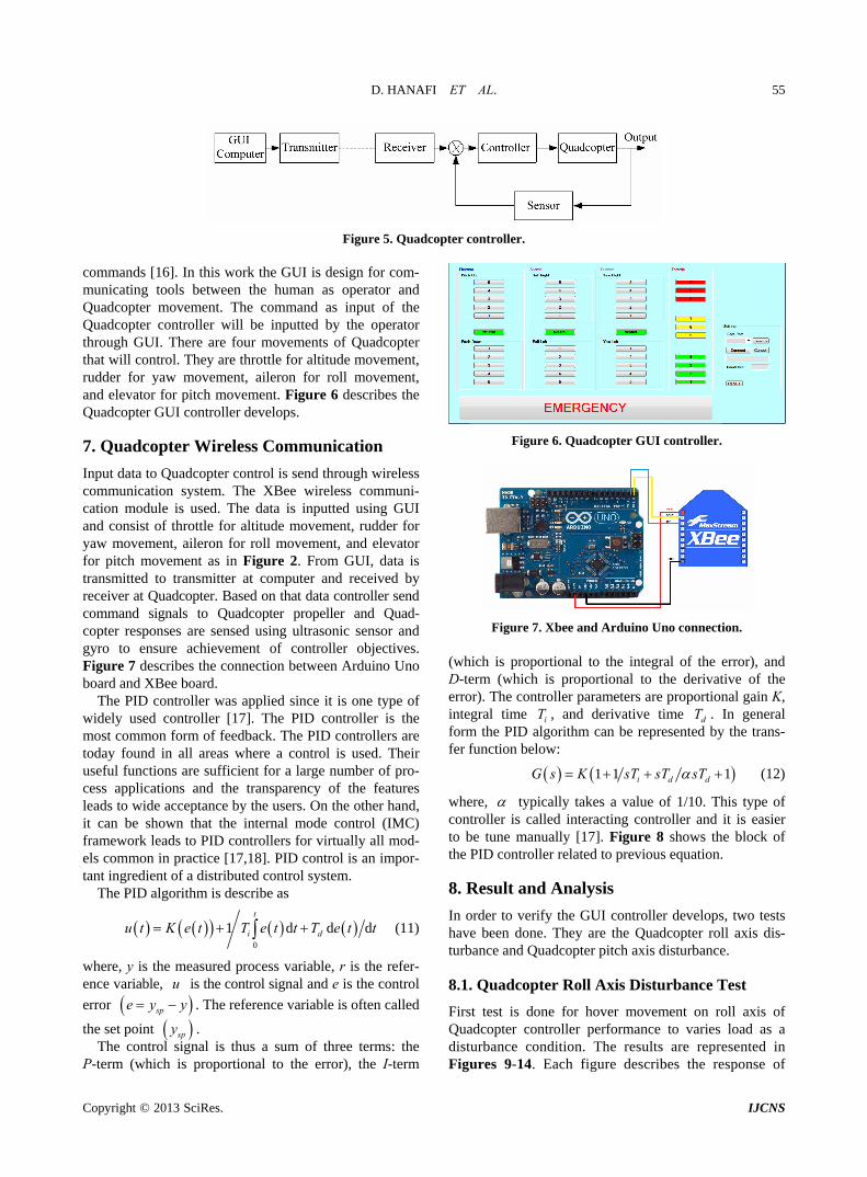
Figure 5. Quadcopter controller. commands [16]. In this work the GUI is de
unicating tools between the human as operator and
unication
ess uni-
[17]. The PID controller is the m
sign for com-
mQuadcopter movement. The command as input of the Quadcopter controller will be inputted by the operator through GUI. There are four movements of Quadcopter that will control. They are throttle for altitude movement, rudder for yaw movement, aileron for roll movement, and elevator for pitch movement. Figure 6 describes the Quadcopter GUI controller develops.
7. Quadcopter Wireless Comm Figure 6. Quadcopter GUI controller.
Input data to Quadcopter control is send through wirelcommunication system. The XBee wireless comm
cation module is used. The data is inputted using GUI and consist of throttle for altitude movement, rudder for yaw movement, aileron for roll movement, and elevator for pitch movement as in Figure 2. From GUI, data is transmitted to transmitter at computer and received by receiver at Quadcopter. Based on that data controller send command signals to Quadcopter propeller and Quad- copter responses are sensed using ultrasonic sensor and gyro to ensure achievement of controller objectives. Figure 7 describes the connection between Arduino Uno board and XBee board.
The PID controller was applied since it is one type of widely used controller
Figure 7. Xbee and Arduino Uno connection. (which is proportional to the integral of the error), and D-term (which is proportional to the derivative the error). ain K,
tegral time , and derivative time . In general
ofThe controller parameters are proportional g
in i d
form the PID algorithm can be represented by the trans-fer function below:
T T
ost common form of feedback. The PID controllers are today found in all areas where a control is used. Their useful functions are sufficient for a large number of pro- cess applications and the transparency of the features leads to wide acceptance by the users. On the other hand, it can be shown that the internal mode control (IMC) framework leads to PID controllers for virtually all mod- els common in practice [17,18]. PID control is an impor- tant ingredient of a distributed control system.
The PID algorithm is describe as
1 1 1i dG s K sT sT sT d (12)
where, typically takes a value of 1/10. This type of controller is called interacting controller and it is easier to be tune manually [17]. Figure 8 shows the the PID controller related to previous equation.
axis dis- axis disturbance.
ad as a d in
se of
block of
8. Result and Analysis
In order to verify the GUI controller develops, two tests have been done. They are the Quadcopter roll
0
1 diu t K e t T e t t d ddT e t t (11)
where, y is the measured process variable, r is thence variable, is the control signal and e is the control
point
t
turbance and Quadcopter pitch e refer-
u
error spe y y . The reference variable is often called 8.1. Quadcopter Roll Axis Disturbance Test
First test is done for hover movement on roll axis of Quadcopter controller performance to varies lo spy
rol signthe set .
The co al is thus a sum of three terms: the nth is oportional to the error), the I-term
disturbance condition. The results are representeFigures 9-14. Each figure describes the responP-term (whic pr

D. HANAFI ET AL. 56
+_
P
I
D
+ +
+Actuator Quadcopter
Error
Feedback
Figure 8. Block of Quadcopter PID controller.
Figure 9. Roll axis hover test response for no load.
Figure 10. Roll axis hover test response for load 100 g load. Quadcopter controller response related to amount of load as a disturbance that is provided to it.
mount of up to 200 g as in Figures 9-12. Even though Quadcopter can maintain it balance and stability till
asome of output data is not in straight line, but most of data are in the range.
For the load 250 g and above, the Quadcopter cannot balance itself as represented in Figures 13 and 14. The
Figure 11. Roll axis hover test response for 150 g load.
Figure 12. Roll axis hover test response for 200 g load.
Figure 13. Roll axis hover test response for 250 g load. responses are spread away and not gather in straight line. Quadcopter is not able to balance itself and lost stabilityIt
esigned for roll axis hover is 200 g.
. means the maximum amount of load of Quadcopter
d
Copyright © 2013 SciRes. IJCNS
D. HANAFI ET AL. 57
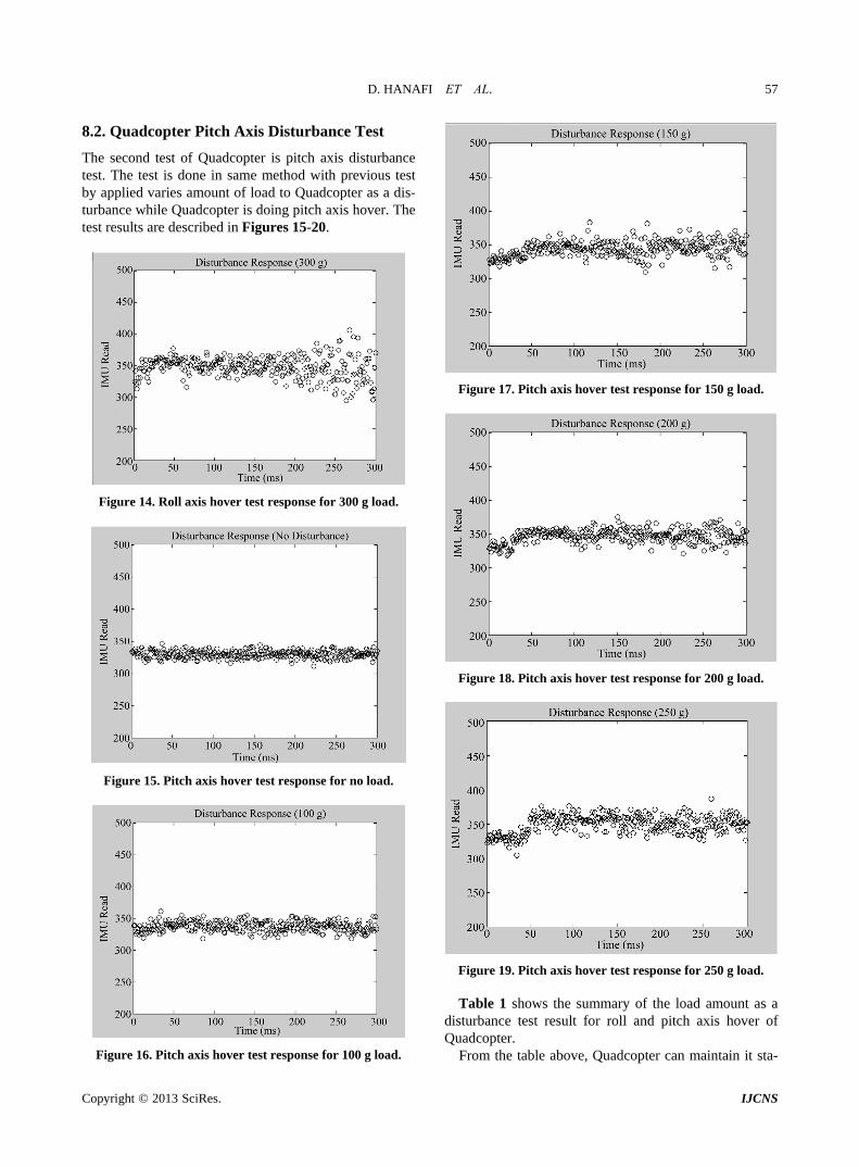
8.2. Quadcopter Pitch Axis Disturbance Test
The second test of Quadcopter is pitch axis disturbance test. The test is done in same method with previous test by applied varies amount of load to Quadcopter as a diturbance while Quadcopter is doing pitch axis hover.
s- The
test results are described in Figures 15-20.
Figure 14. Roll axis hover test response for 300 g load.
Figure 15. Pitch axis hover test response for no load.
Figure 17. Pitch axis hover test response for 150 g load.
Figure 18. Pitch axis hover test response for 200 g load.
Figure 19. Pitch axis hover test response for 250 g load.
Table 1 shows the summary of the load amount as a disturbance test result for roll and pitch axis hover of Quadcopter.
From the table above, Quadcopter can maintain it sta- Figure 16. Pitch axis hover test response for 100 g load.
Copyright © 2013 SciRes. IJCNS

D. HANAFI ET AL. 58
Figure 20. Pitch axis hover test response for 300 g load.
Table 1. Summarize of disturbance test result.
Roll Pitch Load (g)
Hover with stable
100 Yes Yes
150 Yes Yes
200 Yes Yes
250 No Yes
300 No No
bility with load applied up to 200 g for roll axis hover and up to 250 g for pitch axis hover. It means Quadcop-ter designed able to operate in balance and stable condi- tion till 200 g load.
9. Conclusion
Quadcopter and its GUI controller have been successfully constructed and developed. Based the test results
- opter co
the co lance. The Quadcopter develope le to accept load distur- bance undred and fi hoveringposition.
10. Ac wledgemen
This wor been support Office of R h In-novation io d Consultanc RICC)Universiti Tun Hussein On alaysia under ect
o. 1077.
K. Hedrick, “A Mode-Switching PathPlanner for UAV-Assisted Search and Rescue,” Proceed-
IEEE Conference on Decision and Control
- ,
Gc
UI controller able to send the control signal to Quadntroller and Quadcopter controller can tra
mmand signal to maintain its stability and banslate
d ab
up to two h fty grams during
kno ts
k has Commercializat
ed byn an
esearcy (O
n M proj vot. n
REFERENCES [1] A. Ryan and J.
, ing of the 44th
and the European Control, Seville, 12-15 December 2005, pp. 1471-1476. doi:10.1109/CDC.2005.1582366
[2] A. L. Salih, M. Moghavvemil, H. A. F. Mohamed and K. S. Gaeid, “Flight PID Controller Design for a UAV Quad- copter,” Scientific Research and Essays, Vol. 5, No. 23, 2010, pp. 3660-3667.
[3] A. Z. Azfar and D. Hazry, “Simple GUI Design for Moni- toring of a Remotely Operated Quadcopter Unmanned Aerial Vehicle,” Proceeding of the 7th International Col-
g and its Applications (CSPA), 23-27.
rence on System Man and Cybernatics (SMC), 10-13 October 2010, pp. 3200-3204. doi:10.1109/IC
loquium on Signal ProcessinPenang, 4-6 Mach 2011, pp.
[4] K. W. Weng, “Quadcopter,” Robot Head to Toe Maga-zine, Vol. 10, 2011, pp. 1-3.
[5] T. Mori, T. Nonaka and T. Hase, “Design Method of GUI Using Algorithm,” Proceeding of the IEEE International Confe
SMC.2010.5642282
[6] A. Rauf, S. Anwar, M. A. Jaffer and A. A. Shahid, “Auto- mated GUI Test Coverage Analysis Using GA,” Pro-ceeding of the 7th International Conference on Informa-tion Technology: New Generation (ITNG), 12-14 April 2010, pp. 1057-1062. doi:10.1109/ITNG.2010.95
[7] L. Sun, H. Xie and K. Chen, “Design and Realization of GUI-Control for Leak Detection Equipment,” Proceeding of the International Conference on Electronic, Communi- cation and Control (ICECC), 9-11 September 2011, pp. 3638-3641. doi:10.1109/ICECC.2011.6067556
d Quadrotor Aerial Robot,”
[8] D. Park, M.-S. Park and S.-K. Hong, “A Study on the 3-DOF Attitude Control of Free-Flying Vehicle,” Pro-ceeding of the IEEE International Symposium on Indus-trial Electronics (ISIE), Pusan, 12-16 June 2001, Vol. 2, pp. 1260-1265.
[9] A. A. Mian and W. Daobo, “Nonlinear Flight Control Strategy for an UnderactuateProceeding of the IEEE International Conference on Networking, Sensing and Control (ICNSC), Sanya, 6-8 April 2008, pp. 938-942. doi:10.1109/ICNSC.2008.4525351
M. Achtelik, T. Zhang, K. Kuhnlen[10] z and M. Buss, “Vis-ual Tracking and Control of a Quadcopter Using a Stereo Camera System and Inertial Sensors,” Proceeding of the International Conference on Mechatronics and Automa-tion (ICMA), 9-12 August 2009, pp. 2863-2869. doi:10.1109/ICMA.2009.5246421
[11] M. Santos, V. López and F. Morata, “Intelligent Fuzzy Controller of a Quadrotor,” Proceeding of the IEEE In-ternational Conference on Intelligent Systems and Know- ledge Engineering (ISKE), Hangzhou, 15-16 November 2010, pp. 141-146. doi:10.1109/ISKE.2010.5680812
[12] I. Morar and I. Nascu, “Model Simplification of an Un-manned Aerial Vehicle,” Proceeding of the IEEE Interna-tional Conference on Automation Quality and Testing Ro-botics (AQTR), Cluj-Napoca, 24-27 May 2012, pp. 591- 596. doi:10.1109/AQTR.2012.6237779
[13] J. Li and Y. T. Li, “Dynamic Analysis and PID Control for a Quadrotor,” Proceeding of the International Con-
Copyright © 2013 SciRes. IJCNS
D. HANAFI ET AL.
Copyright © 2013 SciRes. IJCNS
59
. 573-578. ference on Mechatronics and Automation (ICMA), Bei-jing, 7-10 August 2011, ppdoi:10.1109/ICMA.2011.5985724
[14] A. K. Cooke, I. D. Cowling, S. D. Erbsloeh and J. F. Whidborne, “Low Cost System Design and Development an Autonomous Rotor Vehicle,” Proceeding of the 22nd International Conference on Unmanned Air Vehicle Sys-tems, Bristol, 16-18 April 2007, pp. 281-289
[15] C. Balas, “Modelling and Linear Control of Quadcopter,”
ing of the 5th ACIS are Engineering Re-
M.S. Thesis, Cranfield University, Cranfield, 2007.
[16] L. Yang, Y. Choi, C. Seo, T. Yang and M. S. Kim, “De-sign of VY: Mini Visual IDE for the Development of
GUI in Embedded Devices,” ProceedInternational Conference on Softwsearch Management & Application, 20-22 August 2007, pp. 625-632. doi:10.1109/SERA.2007.76
[17] M. A. Johnson and M. H. Moradi, “PID Control,” Springer- Verlag, London, 2005.
[18] D. Hanafi, “PID Controller Design for Sem-Active Car
Con-Suspension Based on Model from Intelligent System Iden- tification,” Proceeding of the IEEE International ference on Computer Engineering and Applications (IC-CEA), Bali, 19-21 Mach 2010, pp. 60-63. doi:10.1109/ICCEA.2010.168
Related Documents