SIMOTION Supplement to the FM50-1, FM50-2 and FM 352 Modules _ _____________ _ _____________ _ _____________ _ _____________ _ _____________ _ _____________ Preface Description 1 Function blocks of the FM 350-1 2 Function blocks of the FM 350-2 3 Function Blocks of the FM 352 4 Alarm processing 5 Appendix A SIMOTION Supplement to the FM 350-1, FM 350-2 and FM 352 Modules Function Manual 03/2009 Edition

Welcome message from author
This document is posted to help you gain knowledge. Please leave a comment to let me know what you think about it! Share it to your friends and learn new things together.
Transcript

SIMOTION Supplement to the FM50-1, FM50-2 and FM 352 Modules
____________________________________________________________________________________
Preface
Description
1
Function blocks of the FM 350-1
2
Function blocks of the FM 350-2
3
Function Blocks of the FM 352
4
Alarm processing
5
Appendix
A
SIMOTION
Supplement to the FM 350-1, FM 350-2 and FM 352 Modules
Function Manual
03/2009 Edition

Legal information Legal information Warning notice system
This manual contains notices you have to observe in order to ensure your personal safety, as well as to prevent damage to property. The notices referring to your personal safety are highlighted in the manual by a safety alert symbol, notices referring only to property damage have no safety alert symbol. These notices shown below are graded according to the degree of danger.
DANGER indicates that death or severe personal injury will result if proper precautions are not taken.
WARNING indicates that death or severe personal injury may result if proper precautions are not taken.
CAUTION with a safety alert symbol, indicates that minor personal injury can result if proper precautions are not taken.
CAUTION without a safety alert symbol, indicates that property damage can result if proper precautions are not taken.
NOTICE indicates that an unintended result or situation can occur if the corresponding information is not taken into account.
If more than one degree of danger is present, the warning notice representing the highest degree of danger will be used. A notice warning of injury to persons with a safety alert symbol may also include a warning relating to property damage.
Qualified Personnel The device/system may only be set up and used in conjunction with this documentation. Commissioning and operation of a device/system may only be performed by qualified personnel. Within the context of the safety notes in this documentation qualified persons are defined as persons who are authorized to commission, ground and label devices, systems and circuits in accordance with established safety practices and standards.
Proper use of Siemens products Note the following:
WARNING Siemens products may only be used for the applications described in the catalog and in the relevant technical documentation. If products and components from other manufacturers are used, these must be recommended or approved by Siemens. Proper transport, storage, installation, assembly, commissioning, operation and maintenance are required to ensure that the products operate safely and without any problems. The permissible ambient conditions must be adhered to. The information in the relevant documentation must be observed.
Trademarks All names identified by ® are registered trademarks of the Siemens AG. The remaining trademarks in this publication may be trademarks whose use by third parties for their own purposes could violate the rights of the owner.
Disclaimer of Liability We have reviewed the contents of this publication to ensure consistency with the hardware and software described. Since variance cannot be precluded entirely, we cannot guarantee full consistency. However, the information in this publication is reviewed regularly and any necessary corrections are included in subsequent editions.
Siemens AG Industry Sector Postfach 48 48 90026 NÜRNBERG GERMANY
Ⓟ 03/2009
Copyright © Siemens AG 2009. Technical data subject to change
Supplement to the FM 350-1, FM 350-2 and FM 352 Modules Function Manual, 03/2009 Edition 3
Preface
Contents of the function manual This document is part of the SIMOTION Programming - References documentation package. This documentation is a supplement to the following SIMATIC manuals: ● FM 350-1 Function Module, Installation and Parameter Assignment ● FM 350-2 Counter Module, Installation and Parameter Assignment ● FM 352 Electronic Cam Controller, Installation and Parameter Assignment These documents are included in the SIMOTION SCOUT scope of delivery as electronic documentation. This manual supplement will help you to correctly integrate and commission the FM 350-1, FM 350-2 and FM 352 modules in a SIMOTION system. Differences in handling which result from the software architecture of a SIMOTION system as compared to the software architecture of a SIMATIC system will be described.
Function blocks The function blocks required for communication between the SIMOTION system and the FM 350-1, FM 350-2 and FM 352 modules are included in the command library of the "SIMOTION SCOUT" engineering system.
SIMOTION Documentation An overview of the SIMOTION documentation can be found in a separate list of references. This documentation is included as electronic documentation with the supplied SIMOTION SCOUT. The SIMOTION documentation consists of 9 documentation packages containing approximately 80 SIMOTION documents and documents on related systems (e.g. SINAMICS). The following documentation packages are available for SIMOTION V4.1 SP3: ● SIMOTION Engineering System ● SIMOTION System and Function Descriptions ● SIMOTION Diagnostics ● SIMOTION Programming ● SIMOTION Programming - References ● SIMOTION C ● SIMOTION P350 ● SIMOTION D4xx ● SIMOTION Supplementary Documentation

Preface
Supplement to the FM 350-1, FM 350-2 and FM 352 Modules 4 Function Manual, 03/2009 Edition
Hotline and Internet addresses
Technical support If you have any technical questions, please contact our hotline: Europe / Africa Phone +49 180 5050 222 (subject to charge) Fax +49 180 5050 223 Internet http://www.siemens.com/automation/support-request
Americas Phone +1 423 262 2522 Fax +1 423 262 2200 E-mail mailto:[email protected]
Asia / Pacific Phone +86 1064 719 990 Fax +86 1064 747 474 E-mail mailto:[email protected]
Note Country-specific telephone numbers for technical support are provided under the following Internet address: http://www.siemens.com/automation/service&support Calls are subject to charge, e.g. 0.14 €/min. on the German landline network. Tariffs of other phone companies may differ.
Questions about this documentation If you have any questions (suggestions, corrections) regarding this documentation, please fax or e-mail us at: Fax +49 9131- 98 63315 E-mail mailto:[email protected]

Preface
Supplement to the FM 350-1, FM 350-2 and FM 352 Modules Function Manual, 03/2009 Edition 5
Siemens Internet address The latest information about SIMOTION products, product support, and FAQs can be found on the Internet at: ● General information:
– http://www.siemens.de/simotion (German) – http://www.siemens.com/simotion (international)
● Product support: – http://support.automation.siemens.com/WW/view/en/10805436
Additional support We also offer introductory courses to help you familiarize yourself with SIMOTION. Please contact your regional training center or our main training center at D-90027 Nuremberg, phone +49 (911) 895 3202. Information about training courses on offer can be found at: www.sitrain.com

Preface
Supplement to the FM 350-1, FM 350-2 and FM 352 Modules 6 Function Manual, 03/2009 Edition
Supplement to the FM 350-1, FM 350-2 and FM 352 Modules Function Manual, 03/2009 Edition 7
Table of contents
Preface ...................................................................................................................................................... 3 1 Description................................................................................................................................................. 9
1.1 General part ...................................................................................................................................9 1.2 Product description ......................................................................................................................10 1.3 Installation and connection ..........................................................................................................13 1.4 Inserting function modules into the SIMOTION project ...............................................................14 1.5 Integrating the function blocks in the user project .......................................................................15 1.6 Creating I/O variables ..................................................................................................................16
2 Function blocks of the FM 350-1.............................................................................................................. 17 2.1 Overview of the FM 350-1 function blocks...................................................................................17 2.2 Function block _FM3501_control .................................................................................................18 2.3 Function block _FM3501_diagnostic............................................................................................22 2.4 Data structure of the FM 350-1....................................................................................................23 2.5 Calling function blocks .................................................................................................................27 2.6 Application example for FM 350-1 ...............................................................................................29
3 Function blocks of the FM 350-2.............................................................................................................. 33 3.1 Overview of the FM 350-2 function blocks...................................................................................33 3.2 Function block _FM3502_control .................................................................................................34 3.3 Function block _FM3502_write ....................................................................................................36 3.4 Function block _FM3502_read.....................................................................................................38 3.5 Function block _FM3502_diagnostic............................................................................................40 3.6 Data structures of the FM 350-2 ..................................................................................................42 3.7 Calling function blocks .................................................................................................................47 3.8 Application example for FM 350-2 ...............................................................................................49
4 Function Blocks of the FM 352 ................................................................................................................ 55 4.1 Overview of the FM 352 function blocks......................................................................................55 4.2 Function block _FM352_initialize .................................................................................................56 4.3 Function block _FM352_control ...................................................................................................57 4.4 Function block _FM352_diagnostic..............................................................................................60 4.5 Data structures of the FM 352 .....................................................................................................62 4.5.1 Overview of the FM 352 data structures......................................................................................62 4.5.2 Struct_FM352_ctrlData ................................................................................................................63 4.5.3 Struct_FM352_paraData ..............................................................................................................70 4.5.4 Struct_FM352_diagData ..............................................................................................................72

Table of contents
Supplement to the FM 350-1, FM 350-2 and FM 352 Modules 8 Function Manual, 03/2009 Edition
4.6 Calling function blocks ................................................................................................................ 73 4.7 Application example for FM 352 ................................................................................................. 75
5 Alarm processing ..................................................................................................................................... 81 5.1 Overview of alarm processing..................................................................................................... 81 5.2 Process alarms ........................................................................................................................... 83 5.3 Diagnostic alarms........................................................................................................................ 84
A Appendix.................................................................................................................................................. 87 A.1 SIMOTION and SIMATIC names................................................................................................ 87 A.2 List of abbreviations .................................................................................................................. 104
Index...................................................................................................................................................... 105

Supplement to the FM 350-1, FM 350-2 and FM 352 Modules Function Manual, 03/2009 Edition 9
Description 11.1 General part
This section describes the general similarities and differences in the operation of the function modules (FMs) in a SIMOTION system as compared to a SIMATIC system.
Note This manual is a supplement to the following SIMATIC manuals: • FM 350–1 Function Module Installation and Parameter Assignment • FM 350–2 Counter Function Module Installation and Parameter Assignment • FM 352 Electronic Cam Controller, Installation and Parameter Assignment These documents are included in the SIMOTION SCOUT scope of delivery as electronic documentation!
The following software versions are required for the standard functions described in this documentation: ● SIMOTION SCOUT V4.0 or higher ● SIMOTION Kernel V4.0 or higher ● SIMOTION technology packages V4.0 or higher
Note The following new functions of the FM 350-1 module (order no.:6ES7 350-1AH03-0AE0) are not supported by the function blocks: • Setting/resetting digital outputs DO0 and DO1 • The behavior of digital outputs DO0 and DO1 cannot be changed!

Description 1.2 Product description
Supplement to the FM 350-1, FM 350-2 and FM 352 Modules 10 Function Manual, 03/2009 Edition
1.2 Product description
FM 350-1 counter module The FM 350-1 is a single-channel, high-speed counter module. The module can function in the following counter ranges: ● 0 to 232 - 1 ● -231 to 231 - 1 The maximum input frequency of the counter signals is up to 500 kHz depending on the encoder signal. The FM 350-1 can be used for the following counting and measuring tasks: ● Continuous counting ● Single counting ● Periodic counting ● Frequency measurement ● Period measurement ● Speed measurement You can start and stop the count or measurement process either via the user program (software gate) or via external signals (hardware gate). From release 3 (MLFB no.: 6AG1350-1AH03-2AE0), you can also operate the FM 350-1 in a clock synchronized manner with a suitable interface module (IM) in the ET 200M system.
FM 350-2 counter module The FM 350-2 is an 8-channel counter module with dosing functions. The module can function in the following counter ranges: ● -231 to 231 - 1 The maximum input frequency of the counter signals is up to 10 kHz per counter channel depending on the encoder signal. The FM 350-2 can be used for the following tasks: ● Continuous counting up/down ● Single counting up/down ● Periodic counting up/down ● Frequency measurement ● Speed measurement ● Period measurement ● Dosing You can start and stop the count either via the user program (software gate) or via external signals (hardware gate). The counter, gate and direction signals can be connected directly to the module.

Description 1.2 Product description
Supplement to the FM 350-1, FM 350-2 and FM 352 Modules Function Manual, 03/2009 Edition 11
FM 352 electronic cam controller The FM 352 is a single-channel electronic cam controller. It supports both rotary axes and linear axes. Initiators, incremental encoders or absolute encoders (SSI) can be connected for position sensing. As a slave, the FM 352 can also listen in on the SSI message frame of an absolute encoder. Up to a maximum of 128 position-based or time-based cams can be parameterized. The position-based and time-based cams can be assigned to 32 cam tracks. The first 13 cam tracks are output via the digital outputs on the module.
Function blocks Function blocks are required for controlling the function modules. The function blocks for the SIMOTION system are described in this manual.
Functionality of the function modules The function blocks (FBs) and the function modules (FMs) have the same functionality in a SIMOTION system as in a SIMATIC S7 automation system. However, the execution of data transfers and the handling of FBs have been adapted to the given SIMOTION boundary conditions.

Description 1.2 Product description
Supplement to the FM 350-1, FM 350-2 and FM 352 Modules 12 Function Manual, 03/2009 Edition
Possible fields of application In addition to the possible applications described in the SIMATIC manuals, the FM 350-1, FM 350-2 and FM 352 function modules can also be used in a SIMOTION system. The function modules can be used as centralized modules (on the SIMOTION C2xx only) or as distributed modules (SIMOTION C2xx, SIMOTION P35x and SIMOTION D4xx). Several FM 350-1, FM 350-2 and FM 352 modules can be operated on one SIMOTION device. The following figure shows you how to connect an ET 200M distributed I/O device with IM 153-1 and FM 350-1 or FM 350-2 or FM 352 to a SIMOTION device (e.g. SIMOTION C2xx).
Figure 1-1 Connection of the FMs in an ET 200M to the SIMOTION C2xx device (example of
distributed application)

Description 1.3 Installation and connection
Supplement to the FM 350-1, FM 350-2 and FM 352 Modules Function Manual, 03/2009 Edition 13
1.3 Installation and connection
Overview The following steps need to be carried out in order to commission the FM 350-1, FM 350-2 or FM 352 function modules and to control them from the SIMOTION system:
Distributed application (SIMOTION C2xx, SIMOTION P350, and SIMOTION D4xx) 1. Assemble and wire the ET 200M distributed I/O device complete with power supply (PS),
interface module (IM) and function module (FM). 2. Establish the PROFIBUS connection between the ET 200M and the SIMOTION device. 3. Set the PROFIBUS DP node address on the IM. 4. Switch on the terminating resistor at the first and last bus node.
Note For steps 1 to 4, refer to the ET 200M Distributed I/O manual. This documentation is included in the SIMOTION SCOUT scope of delivery as electronic documentation!
5. Insert the function modules FM 350-1 / FM 350-2 / FM 352 into the SIMOTION project, see chapter Inserting function modules into the SIMOTION project (Page 14).
6. Assign parameters for the FM 350-1, FM 350-2 or FM 352 function module. The following SIMATIC manuals describe how to install the parameter assignment interfaces for the FMs and how to assign the module parameters: – For FM 350-1, refer to the FM 350-1 Function Module, Installation and Parameter
Assignment manual. – For FM 350-2, refer to the FM 350-2 Counter Module, Installation and Parameter
Assignment manual. – For FM 352, refer to the FM 352 Electronic Cam Controller, Installation and Parameter
Assignment manual. 7. Link the function blocks to the SIMOTION project (refer to chapter Integrating the function
blocks in the user project (Page 15)).
Centralized application (SIMOTION C2xx only) 1. For information on planning the mechanical installation and preparing and mounting the
SIMOTION components, refer to the SIMOTION C2xx operating instructions and the SIMATIC S7-300 Automation System, software installation manual. These documents are included in the SIMOTION SCOUT scope of delivery as electronic documentation!
2. To continue, refer to steps 5 to 7 for distributed application.

Description 1.4 Inserting function modules into the SIMOTION project
Supplement to the FM 350-1, FM 350-2 and FM 352 Modules 14 Function Manual, 03/2009 Edition
1.4 Inserting function modules into the SIMOTION project
Requirement The following requirements must be fulfilled in the case of networking via PROFIBUS: 1. You have created a project in SIMOTION SCOUT and have inserted a rack with a
SIMOTION hardware platform in the hardware configuration. 2. You have configured a PROFIBUS subnet (for distributed application only).
Note Consult the SIMOTION SCOUT online help to learn how to create a project and configure a PROFIBUS subnet.
The following requirements must be fulfilled in the case of networking via PROFINET: 1. You have created a project in SIMOTION SCOUT and have inserted and configured a
rack with a PROFINET-ready SIMOTION device in the hardware configuration. 2. You have configured a PROFINET IO system (for distributed application only).
Note Consult the SIMOTION SCOUT online help to learn how to create a project and configure a PROFINET IO system.
Inserting FM 350-1, FM 350-2 or FM 352 (distributed application) The description below is an example of networking via PROFIBUS. 1. In SIMOTION SCOUT, open the User Projects dialog box with the Project > Open menu
command. In this dialog box, select your project and confirm your choice with OK. 2. Open HW Config. 3. In the HW Config window, open the hardware catalog with the View > Catalog menu
command. 4. Open the PROFIBUS DP folder and the ET 200M subfolder in the hardware catalog.
Select, for example, the IM 153-1 interface module (MLFB no.: 6ES7 153-1AA03-0XB0 or a replacement module) there.
5. Use a drag-and-drop operation to place the IM 153-1 I/O device on the PROFIBUS subnet of your project. The Properties - PROFIBUS IM 153-1 Interface dialog box opens. In this dialog box, select the address you set on the IM 153-1 (see ET 200M Distributed I/O Device manual) and confirm with OK. The selected IM 153-1 I/O device is inserted into the project.

Description 1.5 Integrating the function blocks in the user project
Supplement to the FM 350-1, FM 350-2 and FM 352 Modules Function Manual, 03/2009 Edition 15
6. The inserted I/O device must now be fitted with your project modules. To do this, open the FM300 subfolder below the selected I/O device in the hardware catalog and select the relevant FM modules.
Note By default, the diagnostic alarms and process alarms are not enabled. Activate the alarms for each module in the Properties dialog box.
7. Save and compile your project.
1.5 Integrating the function blocks in the user project
Creating the FBs instance in the user project The function blocks are part of the command library of the SIMOTION SCOUT engineering system. For working with the blocks, an instance has to be created in the user project for each function block used. Example: VAR_GLOBAL ... myInstFM3502Ctrl : _FM3502_control; // create FB instance myInstFM3501Ctrl : _FM3501_control; // create FB instance myInstFM352Ctrl : _FM352_control; // create FB instance ... END_VAR
Call (LAD representation) The LAD representation of the individual function blocks can be found in the respective function block descriptions.
Application example The application example is included on the "SIMOTION Utilities & Applications" CD-ROM and is available for various SIMOTION hardware platforms. The "SIMOTION Utilities & Applications" CD-ROM is provided free of charge and part of the SIMOTION SCOUT scope of delivery.

Description 1.6 Creating I/O variables
Supplement to the FM 350-1, FM 350-2 and FM 352 Modules 16 Function Manual, 03/2009 Edition
1.6 Creating I/O variables
Overview Communication between the SIMOTION device and the FM 350-1, FM 350-2 and FM 352 takes place via direct I/O access and data set transfer. For data set transfer, the module address is transferred to the FB as an input parameter. I/O variables are used to address the direct read/write access to the I/O. You can freely assign the names of I/O variables in SIMOTION SCOUT. I/O variables must be specified as ARRAY [0..15] of BYTE. You assign the address settings in the hardware configuration to these I/O variables. The names of the I/O inputs must be transferred to the function blocks as call parameters (periIn). The prepared data for the I/O outputs are provided by the FB as in/out parameters (periOut). The in/out parameter must be supplied with a variable of type ARRAY [0..15] of BYTE. After the block is called, this variable must be assigned to the I/O variables for the I/O outputs (see call example in chapter "Calling the function blocks").
Note The variable for supplying the in/out parameters must not be created as a temporary variable (VAR_TEMP or local variable of a function).
The following example shows how to assign the module addresses to the I/O variables in SIMOTION SCOUT.
Figure 1-2 Address assignment in SIMOTION SCOUT
Note For additional information, see the following sources: • SIMOTION SCOUT online help • Programming manual of the corresponding programming language, e.g.:
– SIMOTION ST, Structured Text programming manual – SIMOTION MCC, Motion Control Chart programming manual – SIMOTION LAD/FBD, Ladder Diagram and Function Block Diagram programming
manual These documents are included in the SIMOTION SCOUT scope of delivery as electronic documentation!
Supplement to the FM 350-1, FM 350-2 and FM 352 Modules Function Manual, 03/2009 Edition 17
Function blocks of the FM 350-1 22.1 Overview of the FM 350-1 function blocks
This section describes the function blocks (FBs) and the data structure required for parameter assignment, control and commissioning of the FM 350-1 module. The function blocks form the software interface between the SIMOTION device and the FMs. They must be called repeatedly (in cycles) from the user program. The following function blocks are available: ● Function block _FM3501_control (Page 18) ● Function block _FM3501_diagnostic (Page 22) SIMOTION SCOUT contains all of the required FBs and data structure Struct_FM3501_fmData of the FM 350-1. The function blocks can be used to control one or more FM 350-1 modules.
Note The SIMOTION identifiers have changed as of V4.0. A comparison of the SIMOTION and SIMATIC identifiers can be found in the appendix SIMOTION and SIMATIC names (Page 87) in the table "SIMOTION and SIMATIC identifiers FM 350-1".

Function blocks of the FM 350-1 2.2 Function block _FM3501_control
Supplement to the FM 350-1, FM 350-2 and FM 352 Modules 18 Function Manual, 03/2009 Edition
2.2 Function block _FM3501_control
Introduction The _FM3501_control function block can be used to control the module and to scan the status of the FM 350-1.
Call (LAD representation)
Parameter description
Table 2- 1 Parameters of the _FM3501_control function block
Name P type 1)
Data type Meaning Actions performed by user
Actions performed by block
periIn IN ARRAY [0 to 15] of BYTE
Transfers I/O inputs of the FM to the FB
I/O variable of the I/O inputs of the FM transferred to the FB
Checked
enableSwGate IN BOOL "SW gate (start/stop)" counter control bit
Sets and resets this Checked
enableStopGate IN BOOL "Stop gate" counter control bit Sets and resets this Checked cntrRange IN BOOL Counter range limit of the FM
FALSE: -231≤ count value < 231-1TRUE: 0 ≤ count value < 232-1
Sets and resets this Checked

Function blocks of the FM 350-1 2.2 Function block _FM3501_control
Supplement to the FM 350-1, FM 350-2 and FM 352 Modules Function Manual, 03/2009 Edition 19
Name P type 1)
Data type Meaning Actions performed by user
Actions performed by block
execResetOpError IN BOOL Acknowledges operator error in the case of a rising edge
Sets and resets this Checked
data IN/OUT Struct_FM3501_fmData
Data structure Entered and checked Checked and entered
setStartValue IN/OUT BOOL Count: Transfers "direct loading" trigger bit 2) Measuring: may not be used.
set Checks and resets this
setPrepStartValue IN/OUT BOOL Count: Transfers "preparatory loading" trigger bit 3) Measuring: Transmission of the lower limit
set Checks and resets this
setCmpValue1 IN/OUT BOOL Count: Transfers "comparison value 1" trigger bit Measuring: Transmission of the upper limit
set Checks and resets this
setCmpValue2 IN/OUT BOOL Count: Transfers "comparison value 2" trigger bit Measuring: Transmission of the update time
set Checks and resets this
resetSyncState IN/OUT BOOL Deletes "synchronization" status bit
set Checks and resets this
resetCntrState IN/OUT BOOL Deletes "zero crossing" status bit set Checks and resets this
periOut IN/OUT ARRAY [0 to 15] of BYTE
Prepared data of the FB for the I/O outputs of the FM 4)
Checked and entered on the I/O variable for the I/O outputs
Entered
errorOperation OUT BOOL An operator error has occurred Checked Sets and resets this
startup OUT BOOL Indicates the startup of the FM Checked Entered 1) Parameter types: IN = input parameter, OUT = output parameter, IN/OUT = in/out parameter 2) The setStartValueparameter specifies that the load value is transmitted to the load register and directly to the counter. 3) The setPrepStartValueparameter specifies that the load value will be stored in the load register only. The load value in
the load register will then be transferred at the next trigger (FM input "DI set" - set counter). The following requirement must be met: - enableReverseSetting= TRUE (element of data structure Struct_FM3501_fmDataor - enableForwardSetting = TRUE (element of data structure Struct_FM3501_fmData
4) Note:The periOutparameter must be supplied with an array of type ARRAY [0..15] of BYTE. Create a local or global array in your program under VAR(do not create a temporary array under VAR_TEMP). After the FB has been called, this array must be assigned to the I/O variable for the I/O outputs of the module. See call example for FM350-1.

Function blocks of the FM 350-1 2.2 Function block _FM3501_control
Supplement to the FM 350-1, FM 350-2 and FM 352 Modules 20 Function Manual, 03/2009 Edition
Functionality The _FM3501_control function block transfers data cyclically from a data structure of type Struct_FM3501_fmData to the FM 350-1. It also reads data from the FM 350-1 and enters this data in the elements of the data structure.
Note Count: The cntrRange input parameter must be set according to the assigned count range limits of the FM 350-1. • cntrRange := FALSE, count range -231 ≤ count value < 231 - 1
– loadValue1, cmpValue1_1, cmpValue2_1 are written from the FB to the FM – actValue1, actCntrValue1 are read from the FM
• cntrRange := TRUE, count range 0 ≤ count value < 232 - 1 – loadValue2, cmpValue1_2, cmpValue2_2 are written from the FB to the FM – actValue2, actCntrValue2 are read from the FM
The same count ranges must be selected in the parameterization tools and in the data structure (cntrRange). Measuring: In measuring modes (frequency measurement, speed measurement, period measurement) the input parameter cntrRange = TRUE must be set.
Task integration (call) The _FM3501_control function block must be called cyclically in the BackgroundTask or in the TimerInterruptTask. Calling in the SystemInterruptTask is not permitted. Calling the function block in the IPOSynchronousTask is not recommended for runtime reasons. You can start a job for the FM 350-1 via the appropriate parameters setStartValue, setPrepStartValue, setCmpValue1, setCmpValue2, resetSyncState, resetCntrState, execResetOpError, enableStopGate or enableSwGate. Depending on the job, the following values must be entered in the data structure before each call: ● during counting: the load value or the comparison value ● during measuring: the lower limit, the upper limit or the update time. Once the job is carried out, the _FM3501_control function block deletes any set in/out parameter (setStartValue, setPrepStartValue, setCmpValue1, setCmpValue2, resetSyncState or resetCntrState). This enables you to recognize that the job has been executed by the FM 350-1.
Startup behavior As soon as the _FM3501_control function block detects that the FM 350-1 is starting up, any pending job is deferred until after the startup is acknowledged. A startup of the FM 350-1 is indicated by output parameter startup=TRUE. Any deferred jobs are carried out once the startup is finished and are therefore not lost.

Function blocks of the FM 350-1 2.2 Function block _FM3501_control
Supplement to the FM 350-1, FM 350-2 and FM 352 Modules Function Manual, 03/2009 Edition 21
Error message during an FB call If an error occurs during an FB call, it is indicated at the errorOperation block parameter. You can read out the error information in the errorIdOperation element of the data structure. You can acknowledge the error using the execResetOpError parameter.
Note No new errors can be signaled until you have acknowledged the error.
Error numbers The following error numbers can be displayed in the errorIdOperation element in the data structure.
Table 2- 2 Error number assignment
Error number Meaning 0 No error 1 Operating mode cannot be started using the SW gate 2 Operating mode cannot be aborted 4 Only permitted if there is a pending output disable (OD)
Function blocks of the FM 350-1 2.3 Function block _FM3501_diagnostic
Supplement to the FM 350-1, FM 350-2 and FM 352 Modules 22 Function Manual, 03/2009 Edition
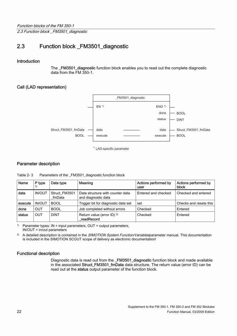
2.3 Function block _FM3501_diagnostic
Introduction The _FM3501_diagnostic function block enables you to read out the complete diagnostic data from the FM 350-1.
Call (LAD representation)
Parameter description
Table 2- 3 Parameters of the _FM3501_diagnostic function block
Name P type 1)
Data type Meaning Actions performed by user
Actions performed by block
data IN/OUT Struct_FM3501_fmData
Data structure with counter data and diagnostic data
Entered and checked Checked and entered
execute IN/OUT BOOL Trigger bit for diagnostic data set set Checks and resets thisdone OUT BOOL Job completed without errors Checked Entered status OUT DINT Return value (error ID) 2)
_readRecord Checked Entered
1) Parameter types: IN = input parameters, OUT = output parameters, IN/OUT = in/out parameters
2) A detailed description is contained in the SIMOTION System Function/Variablesparameter manual. This documentation is included in the SIMOTION SCOUT scope of delivery as electronic documentation!
Functional description Diagnostic data is read out from the _FM3501_diagnostic function block and made available in the associated Struct_FM3501_fmData data structure. The return value (error ID) can be read out at the status output parameter of the function block.

Function blocks of the FM 350-1 2.4 Data structure of the FM 350-1
Supplement to the FM 350-1, FM 350-2 and FM 352 Modules Function Manual, 03/2009 Edition 23
Sequence Data is transferred as follows: 1. If in/out parameter execute = TRUE is set, the diagnostic data is read out from the
FM 350-1. 2. The data are entered in data structure data of the _FM3501_diagnostic function block. 3. The return value (error ID) is copied to the status parameter of FB instance
_FM3501_diagnostic.
Note The return value (error ID) in the status parameter is present for one cycle only. The values 0x7001 and 0x7002 indicate that a data transfer has been initiated and is active.
4. As soon as the function has been executed, in/out parameterexecute is reset.
Note For the diagnostic sequence to be correct, the module address must be entered in the moduleAddress element of the data structure of type Struct_FM3501_fmData.
Task integration (call) The _FM3501_diagnostic function block can be called in the PeripheralFaultTask, BackgroundTask or TimerInterruptTask. For performance reasons, the function block should not be called in the PeripheralFaultTask.
2.4 Data structure of the FM 350-1
Overview The data structure of type Struct_FM3501_fmData contains the control and checkback signals of the FM 350-1 and the diagnostic data. The data structure is used by the _FM3501_control and _FM3501_diagnostic function blocks. Elements of the data structure are accessed using a variable of data type Struct_FM3501_fmData, which you must define yourself. The Struct_FM3501_fmData data structure is shown in the table below.
Note The SIMOTION identifiers have changed as of V4.0. A comparison of the SIMOTION and SIMATIC identifiers can be found in the appendix SIMOTION and SIMATIC names (Page 87) in the table "SIMOTION and SIMATIC identifiers FM 350-1".

Function blocks of the FM 350-1 2.4 Data structure of the FM 350-1
Supplement to the FM 350-1, FM 350-2 and FM 352 Modules 24 Function Manual, 03/2009 Edition
Table 2- 4 Data structure of Struct_FM3501_fmData
Name Type Initial value Counting Measuring General data xxxReserved1 1) BYTE 16#00 Reserved Reserved xxxReserved2 1) BYTE 16#00 Reserved Reserved moduleAddress INT 256 Module address (see hardware
configuration) Module address (see hardware configuration)
xxxReserved3 1) BYTE 16#00 Reserved Reserved Control signals loadValue1 DINT 0 New load value (cntrRange :=
FALSE) -
cmpValue1_1 DINT 0 New comparison value 1 (cntrRange := FALSE)
-
cmpValue2_1 DINT 0 New comparison value 2 (cntrRange := FALSE)
-
loadValue2 UDINT 0 New load value (cntrRange := TRUE)
Lower limit
cmpValue1_2 UDINT 0 New comparison value 1 (cntrRange := TRUE)
Upper limit
cmpValue2_2 UDINT 0 New comparison value 2 (cntrRange := TRUE)
Update time
xxxReserved4 1) BOOL FALSE Reserved Reserved xxxReserved5 1) BOOL FALSE Reserved Reserved xxxReserved6 1) BOOL FALSE Reserved Reserved xxxReserved7 1) BOOL FALSE Reserved Reserved enableForwardSetting BOOL FALSE Enable setting in forward direction - enableReverseSetting BOOL FALSE Enable setting in reverse direction - xxxReserved8 1) BOOL FALSE Reserved Reserved xxxReserved9 1) BOOL FALSE Reserved Reserved enableOutput0 BOOL FALSE Enable output 0 Enable output 0 enableOutput1 BOOL FALSE Enable output 1 Enable output 1 xxxReserved10..15 1) BOOL FALSE Reserved Reserved Checkback signals actValue1 DINT 0 Current load or latch value
(cntrRange := FALSE) -
actCntrValue1 DINT 0 Current count value (cntrRange := FALSE)
-
actValue2 UDINT 0 Current load or latch value (cntrRange := TRUE)
Current measured value
actCntrValue2 UDINT 0 Current count value (cntrRange := TRUE)
Actual count value

Function blocks of the FM 350-1 2.4 Data structure of the FM 350-1
Supplement to the FM 350-1, FM 350-2 and FM 352 Modules Function Manual, 03/2009 Edition 25
Name Type Initial value Counting Measuring errorIdData WORD 16#0000 Specification of the data error Specification of the data error errorIdOperation BYTE 16#00 Operator error (error number) Operator error (error number) xxxReserved16 1) BOOL FALSE Reserved Reserved xxxReserved17 1) BOOL FALSE Reserved Reserved xxxReserved18 1) BOOL FALSE Reserved Reserved xxxReserved19 1) BOOL FALSE Reserved Reserved dataError BOOL FALSE Data error (can be read out via the
parameterization tool or in the "errorIdData" element)
Data error (can be read out via the parameterization tool or in the "errorIdData" element)
xxxReserved20 1) BOOL FALSE Reserved Reserved xxxReserved21 1) BOOL FALSE Reserved Reserved parameterized BOOL FALSE Module parameterized Module parameterized opState BOOL FALSE Counter operation status Counter operation status opDirection BOOL FALSE Count direction status Count direction status zeroCrossing BOOL FALSE Zero crossing status Full scale value overflow BOOL FALSE Status overflow Status overflow underflow BOOL FALSE Status underflow Status underflow synchronized BOOL FALSE Counter synchronization status - stateGate BOOL FALSE Status of the internal gate Status of the internal gate stateSwGate BOOL FALSE SW gate status SW gate status stateSetInput BOOL FALSE Status of digital input "DI set" Status of digital input "DI set" xxxReserved22 1) BOOL FALSE Reserved Reserved stateOfDiStart BOOL FALSE Status of digital input "DI start" Status of digital input "DI start" stateOfDiStop BOOL FALSE Status of digital input "DI stop" Status of digital input "DI stop" stateCompValue1 BOOL FALSE Status of output of comparison value
1 Status of output of comparison value 1
stateCompValue2 BOOL FALSE Status of output of comparison value 2
Status of output of comparison value 2
xxxReserved23..28 1) BOOL FALSE Reserved Reserved xxxReserved29 1) DINT 0 Reserved Reserved xxxReserved30 1) DINT 0 Reserved Reserved Diagnostic data faultModule BOOL FALSE Module fault internFault BOOL FALSE Internal fault extFault BOOL FALSE External fault faultChannel BOOL FALSE Channel fault (for decoding, refer to elements starting with chType) faultExtVoltage BOOL FALSE Auxiliary voltage fault faultConnector BOOL FALSE Front connector invalidConfig BOOL FALSE Parameter assignment missing invalidPara BOOL FALSE Parameter assignment faulty moduleType BYTE 16#00 Module type

Function blocks of the FM 350-1 2.4 Data structure of the FM 350-1
Supplement to the FM 350-1, FM 350-2 and FM 352 Modules 26 Function Manual, 03/2009 Edition
Name Type Initial value Counting Measuring faultSubModule BOOL FALSE Incorrect/missing interface module faultCommunication BOOL FALSE Communication error moduleStop BOOL FALSE RUN/STOP mode display faultWatchdog BOOL FALSE Watchdog (FM) faultIntPower BOOL FALSE Internal power supply fault xxxReserved47 1) BOOL FALSE Reserved xxxReserved48 1) BOOL FALSE Reserved xxxReserved31 1) BOOL FALSE Reserved faultRack BOOL FALSE Rack fault faultDevice BOOL FALSE SIMOTION device fault faultEprom BOOL FALSE EPROM fault faultRam BOOL FALSE RAM fault faultAdc BOOL FALSE ADC fault faultFuse BOOL FALSE Fuse fault lostProcessAlarm BOOL FALSE Process alarm lost xxxReserved32 1) BOOL FALSE Reserved chType BYTE 16#00 Channel type lenDiagData BYTE 16#00 Length of diagnostic data per channel chNumber BYTE 16#00 Channel number groupErrorChannel1 BOOL FALSE Group error channel 1 xxxGroupErrorChannel2 1)
BOOL FALSE Group error channel 2
xxxReserved33...38 1) BOOL FALSE Reserved faultCh1SignalA BOOL FALSE Channel 1, signal A fault faultCh1SignalB BOOL FALSE Channel 1, signal B fault faultCh1SigZero BOOL FALSE Channel 1, signal zero fault faultChannel1 BOOL FALSE Channel 1, fault between channels faultCh1EncSupply BOOL FALSE Channel 1, 5.2 V encoder supply fault xxxReserved39..41 1) BOOL FALSE Reserved xxxReserved42 1) BYTE 16#00 Reserved faultCh2SignalA BOOL FALSE Channel 2, signal A fault faultCh2SignalB BOOL FALSE Channel 2, signal B fault faultCh2SigZero BOOL FALSE Channel 2, signal zero fault faultChannel2 BOOL FALSE Channel 2, fault between channels faultCh2EncSupply BOOL FALSE Channel 2, 5.2 V encoder supply fault xxxReserved43..45 1) BOOL FALSE Reserved xxxReserved46 1) BYTE 16#00 Reserved
1) Variable for internal FB use (not relevant to users)

Function blocks of the FM 350-1 2.5 Calling function blocks
Supplement to the FM 350-1, FM 350-2 and FM 352 Modules Function Manual, 03/2009 Edition 27
2.5 Calling function blocks In order to be able to work with the function blocks in your user project, proceed as follows (the numbers shown in the following program segment correspond to the steps below): 1. Create the function block instance (see the following program segment, e.g. create
instance for FB _FM3501_control). 2. Set up variables for the data structure. 3. Create an array for the in/out parameters of the FB. 4. Call instance of the function block. 5. Transfer input parameters. 6. The output parameters of the FB are accessed with <instance name of FB>. <name of
output parameter>. 7. Data prepared by the FB for the I/O outputs are assigned to the array of the I/O variables
created in step 3.
Note The call example is an extract from the supplied E_FM3501 application example, which is contained on the "SIMOTION Utilities & Applications" CD-ROM. If you wish to control more than one FM 350-1, you must create a new variable for the data structure and FB instances with a new name for each FM 350-1 used.
Call example UNIT E_FM3501;
INTERFACE
VAR_GLOBAL
myDataFM3501 : Struct_FM3501_fmData; // Create variable of data structure
// Following variables are - set by application to activate function;
// - reset by FB to signal completion of function.
(2)
MyLoadStartValue : BOOL; // Load load value directly
MyLoadPrepareStartValue : BOOL; // Load load value in preparation
...
// INPUT VARIABLES
MySetSoftwareGate : BOOL; // Software gate
MyStopGate : BOOL; // Stop gate
...
// OUTPUT VARIABLES
MyOperationError : BOOL; // Error in FB _FB_FM3501_control
MyStateFMStartup : BOOL; // Start-up status
myInstFM3501Ctrl : _FM3501_control; // create FB instance (1)

Function blocks of the FM 350-1 2.5 Calling function blocks
Supplement to the FM 350-1, FM 350-2 and FM 352 Modules 28 Function Manual, 03/2009 Edition
END_VAR
END_INTERFACE
IMPLEMENTATION
PROGRAM ExampleFM3501 // Program in BackroundTask
VAR
FMOutputArray : ARRAY [0..15] of BYTE; // Array for FM output data
END_VAR
(3)
// CALL INSTANCE of _FM3501_control
myInstFM3501Ctrl(
(4)
EnableSwGate := mySetSoftwareGate, // Control software gate
EnableStopGate := myStopGate, // Control internal gate
ExecResetOpError := myResetError, // Acknowledge operator error
CntrRange := TRUE, // Counter range
PeriIn := myPeripheralInputFM3501, // input address
Data := myDataFM3501, // Transfer data structure
PeriOut := FMOutputArray, // FM output data array
(5)
// following IN_OUT parameters are set by the application
// and reset by the FB! (shake-hand-effect)
SetStartValue := myLoadStartValue, // Load counter
SetPrepStartValue := myLoadPrepareStartValue, // Load counter in preparation
setCmpValue1 := myLoadComparisonValue1, // Load new comparison value 1
setCmpValue2 := myLoadComparisonValue2, // Load new comparison value 2
resetSyncState := myResetSyncState, // Reset synchronization bit
resetCntrState := myResetCounterState, // Reset status bit
);
// TRANSFER DATA TO FM
myPeripheralOutputFM3501 := FMOutputArray; // Assign array of FM output data
// to I/O variables
(7)
// EVALUATE AND DISPLAY STATUS MESSAGES
MyStateFMStartup := myInstFM3501Ctrl.startup; // Start-up status
MyOperationError := myInstFM3501Ctrl.errorOperation;
(6)
END_PROGRAM // ExampleFM3501
END_IMPLEMENTATION
Note The PROGRAM ExampleFM3501 must be assigned in the execution system.
Function blocks of the FM 350-1 2.6 Application example for FM 350-1
Supplement to the FM 350-1, FM 350-2 and FM 352 Modules Function Manual, 03/2009 Edition 29
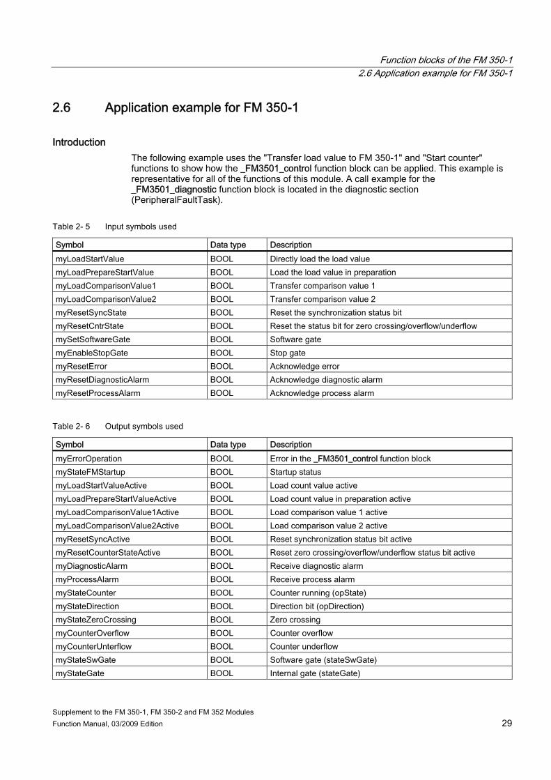
2.6 Application example for FM 350-1
Introduction The following example uses the "Transfer load value to FM 350-1" and "Start counter" functions to show how the _FM3501_control function block can be applied. This example is representative for all of the functions of this module. A call example for the _FM3501_diagnostic function block is located in the diagnostic section (PeripheralFaultTask).
Table 2- 5 Input symbols used
Symbol Data type Description myLoadStartValue BOOL Directly load the load value myLoadPrepareStartValue BOOL Load the load value in preparation myLoadComparisonValue1 BOOL Transfer comparison value 1 myLoadComparisonValue2 BOOL Transfer comparison value 2 myResetSyncState BOOL Reset the synchronization status bit myResetCntrState BOOL Reset the status bit for zero crossing/overflow/underflow mySetSoftwareGate BOOL Software gate myEnableStopGate BOOL Stop gate myResetError BOOL Acknowledge error myResetDiagnosticAlarm BOOL Acknowledge diagnostic alarm myResetProcessAlarm BOOL Acknowledge process alarm
Table 2- 6 Output symbols used
Symbol Data type Description myErrorOperation BOOL Error in the _FM3501_control function block myStateFMStartup BOOL Startup status myLoadStartValueActive BOOL Load count value active myLoadPrepareStartValueActive BOOL Load count value in preparation active myLoadComparisonValue1Active BOOL Load comparison value 1 active myLoadComparisonValue2Active BOOL Load comparison value 2 active myResetSyncActive BOOL Reset synchronization status bit active myResetCounterStateActive BOOL Reset zero crossing/overflow/underflow status bit active myDiagnosticAlarm BOOL Receive diagnostic alarm myProcessAlarm BOOL Receive process alarm myStateCounter BOOL Counter running (opState) myStateDirection BOOL Direction bit (opDirection) myStateZeroCrossing BOOL Zero crossing myCounterOverflow BOOL Counter overflow myCounterUnterflow BOOL Counter underflow myStateSwGate BOOL Software gate (stateSwGate) myStateGate BOOL Internal gate (stateGate)

Function blocks of the FM 350-1 2.6 Application example for FM 350-1
Supplement to the FM 350-1, FM 350-2 and FM 352 Modules 30 Function Manual, 03/2009 Edition
Note Depending on the type of signal used, you should pay attention to the coding plug of the FM 350-1 (for example, position D for 24 V signals). You can either monitor and modify the input and output variables used in the programming example in the INTERFACE section of the unit (under VAR_GLOBAL) using the symbol browser, or you can assign real inputs and outputs to the input and output variables in your unit.
Contents of example When the _FM3501_control function block is called, the control and checkback signals are exchanged cyclically between the SIMOTION device (C230-2, P350, D435) and the FM 350-1. All of the data that are relevant to the module are located in data structure "dataFM3501". Depending on the configuration of the FM 350-1 (operating mode, use of gates, alarm configuration, etc.), the FM 350-1 counts the pulses at the wired encoder signal input if, for example, the value of the "myStateSwGate" input is "TRUE". The counting operation stops if input "myStateSwGate" = FALSE or if input "myEnableStopGate" = TRUE. Transferring the load values Two parameters are available for transferring the load value to the FM 350-1. When the _FM3501_control FB is called, either the "myLoadStartValue" or "myLoadPrepareStartValue" parameter is selected at a rising edge. The "myLoadStartValue" parameter specifies that the load value will be transferred to the load register and directly to the counter (you must set input "myLoadStartValue" = TRUE). The "myLoadPrepareStartValue" parameter specifies that the load value will be stored in the load register only (you must set trigger bit "myLoadPrepareStartValue" = TRUE in your user program). The load value in the load register is then transferred at the next event (FM input "DI set") that sets the counter. The FB must be called until the FB has reset the selected trigger bit ("myLoadStartValue" or "myLoadPrepareStartValue"). The in/out parameter remains set while the transfer is active. If the trigger bit you set has been reset by the _FM3501_control function block, the FM 350-1 has received the load value. Loading comparison values New comparison values are transferred to the FM by setting the "myLoadComparisonValue1" or "myLoadComparisonValue2" inputs (rising edge). Deleting status bits The synchronization status bit is reset by setting the "myResetSyncState" input (rising edge) and the zero crossing/overflow/underflow status bit is reset by setting the "myResetCntrState" input. Process alarm / diagnostic alarm If a process alarm or diagnostic alarm is triggered by the FM 350-1, this is indicated by the "myProcessAlarm" and "myDiagnosticAlarm" variable, respectively. If the "PeripheralFaultFM3501" program is integrated in the PeripheralFaultTask, this task is started and the most important task start information is stored temporarily in the "myAlarmDetails", "myIogAddressIn" and "myAlarmInterrupt" variables. If a diagnostic alarm

Function blocks of the FM 350-1 2.6 Application example for FM 350-1
Supplement to the FM 350-1, FM 350-2 and FM 352 Modules Function Manual, 03/2009 Edition 31
has been signaled, the _FM3501_diagnostic FB is started, which reads out detailed diagnostic information from the module. These diagnostic data are then located in data structure "dataFM3501". Setting the "myResetDiagnosticAlarm" input variable (to acknowledge a diagnostic alarm) or the "myResetProcessAlarm" input variable (to acknowledge a process alarm) acknowledges the respective alarms. The respective states are signaled by the output variables used (see Table "Output symbols used").
Hardware platform The application example is available for various SIMOTION hardware platforms and is intended for distributed use of the FM 350-1.
Note If the application example is not available for your hardware platform, you must adapt the hardware configuration.
Adapting the application example The configuration in the example and its available hardware must be adapted. The following options are available: 1. You can adapt the configuration in the example to the available hardware (PROFIBUS
DP address). 2. You can adapt the configuration of the hardware to the example (PROFIBUS DP
address).
Calling the application example The application example can be found on the "SIMOTION Utilities & Applications" CD-ROM. The "SIMOTION Utilities & Applications" CD-ROM is provided free of charge and part of the SIMOTION SCOUT scope of delivery. 1. Dearchive and open the project containing the application example. 2. Check the hardware configuration: PROFIBUS DP addresses. 3. Check the module addresses (hardware configuration) against the I/O addresses of the
controller in SIMOTION SCOUT and module address in the program (dataFM3501.moduleAddress).
4. Save and compile the example project. Then, you can download the example to the SIMOTION device and switch to RUN mode.

Function blocks of the FM 350-1 2.6 Application example for FM 350-1
Supplement to the FM 350-1, FM 350-2 and FM 352 Modules 32 Function Manual, 03/2009 Edition

Supplement to the FM 350-1, FM 350-2 and FM 352 Modules Function Manual, 03/2009 Edition 33
Function blocks of the FM 350-2 33.1 Overview of the FM 350-2 function blocks
This section describes the function blocks (FBs) and the data structure required for parameter assignment, control and commissioning of the FM 350-2 module. The function blocks form the software interface between the SIMOTION device and the FMs. They must be called repeatedly (in cycles) from the user program. The following function blocks are available: ● Function block _FM3502_control (Page 34) ● Function block _FM3502_write (Page 36) ● Function block _FM3502_read (Page 38) ● Function block _FM3502_diagnostic (Page 40) SIMOTION SCOUT contains all of the required FBs and data structure Struct_FM3502_fmData of the FM 350-2. The function blocks can be used to control one or more FM 350-2 modules.
Note The SIMOTION identifiers have changed as of V4.0. A comparison of the SIMOTION and SIMATIC identifiers can be found in the appendix SIMOTION and SIMATIC names (Page 87) in the table "SIMOTION and SIMATIC identifiers FM 350-2".
Note The online functions of the parameter assignment tool in STEP 7 HW Config can only be used for diagnostic purposes (read-only access to the module). Write access (control function) has no effect. The parameters set by the program can be read out using the parameter assignment tool.

Function blocks of the FM 350-2 3.2 Function block _FM3502_control
Supplement to the FM 350-1, FM 350-2 and FM 352 Modules 34 Function Manual, 03/2009 Edition
3.2 Function block _FM3502_control
Introduction The _FM3502_control function block can be used to control the module and to scan the status of the FM 350-2.
Call (LAD representation)
Parameter description
Table 3- 1 Parameters of the _FM3502_control function block
Name P type 1) Data type Meaning Actions performed by user Actions performed by block
periIn IN ARRAY [0 to 15] of BYTE
Transfers I/O inputs of the FM to the FB
I/O variable of the I/O inputs of the FM transferred to the FB
Checked
periOut IN/OUT ARRAY [0..15] of BYTE
Prepared data of the FB for the I/O outputs of the FM 2)
Checked and entered on the I/O variable for the I/O outputs
Entered
data IN/OUT Struct_FM3502_fmData
Data structure with channel-specific data
Entered and checked Checked and entered
startup OUT BOOL Indicates the startup of the FM
Checked Entered
1) Parameter types: IN = input parameter, OUT = output parameter, IN/OUT = in/out parameter 2) Note:The periOutparameter must be supplied with an array of type ARRAY [0..15] of BYTE. Create a local or global
array in your program under VAR(do not create a temporary array under VAR_TEMP). After the FB has been called, this array must be assigned to the I/O variable for the I/O outputs of the module. See FM 350-2 call example!
Functional description The _FM3502_control function block cyclically transfers the control signals from the control substructure of the data structure of type Struct_FM3502_fmData to the FM 350-2. In addition, it reads the checkback signals from the FM 350-2 and enters these into the checkback substructure of the data structure of type Struct_FM3502_fmData.

Function blocks of the FM 350-2 3.2 Function block _FM3502_control
Supplement to the FM 350-1, FM 350-2 and FM 352 Modules Function Manual, 03/2009 Edition 35
The _FM3502_control function block is absolutely essential for operation of the FM 350-2.
Task integration (call) The_FM3502_control function block must be called cyclically via the BackgroundTask or the TimerInterruptTask. Calling in the SystemInterruptTask is not permitted. Calling the function block in the IPOSynchronousTask is not recommended for runtime reasons. Before the call, you enter the current control signals in the control substructure of the Struct_FM3502_fmData data structure. After the call, the checkback signals are updated in the checkback substructure of the data structure. They can then be processed further. The _FM3502_control function block must be called cyclically for each FM 350-2 integrated in the project.
Startup behavior The _FM3502_control function block performs startup coordination with the FM 350-2. A startup of the FM 350-2 is indicated by output parameter startup = TRUE. After startup has been acknowledged, the control and checkback signals are exchanged with the FM 350-2.

Function blocks of the FM 350-2 3.3 Function block _FM3502_write
Supplement to the FM 350-1, FM 350-2 and FM 352 Modules 36 Function Manual, 03/2009 Edition
3.3 Function block _FM3502_write
Introduction The _FM3502_write function block executes write jobs (for example, loading count values and comparison values) to the FM 350-2.
Call (LAD representation)
Parameter description
Table 3- 2 Parameters of the _FM3502_write function block
Name P type 1) Data type Meaning Actions performed by user Actions performed by block
periIn IN ARRAY [0 to 15] of BYTE
Transfers I/O inputs of the FM to the FB
I/O variable of the I/O inputs of the FM transferred to the FB
Checked
periOut IN/OUT ARRAY [0 to 15] of BYTE
Prepared data of the FB for the I/O outputs of the FM 2)
Checked and entered on the I/O variable for the I/O outputs
Entered
data IN/OUT Struct_FM3502_fmData
Data structure with channel-specific data
Entered and checked Checked and entered
error OUT BOOL Request completed with errors Checked Entered status OUT DINT Error ID 3)_writeRecord Checked Entered
1) Parameter types: IN = input parameter, OUT = output parameter, IN/OUT = in/out parameter 2) Note:The periOutparameter must be supplied with an array of type ARRAY [0..15] of BYTE. Create a local or global
array in your program under VAR(do not create a temporary array under VAR_TEMP). After the FB has been called, this array must be assigned to the I/O variable for the I/O outputs of the module. See FM 350-2 call example!
3) A detailed description is contained in the SIMOTION System Function/Variablesparameter manual. This documentation is included in the SIMOTION SCOUT scope of delivery as electronic documentation!

Function blocks of the FM 350-2 3.3 Function block _FM3502_write
Supplement to the FM 350-1, FM 350-2 and FM 352 Modules Function Manual, 03/2009 Edition 37
Functional description The _FM3502_write function block loads the counters and comparators of the FM 350-2 from the data structure of type Struct_FM3502_fmData by means of a write job. The _FM3502_write function block should only be called when executing write jobs.
Task integration (call) The _FM3502_write function block can be called via the BackgroundTask or the TimerInterruptTask. Calling in the SystemInterruptTask is not permitted. Calling the function block in the IPOSynchronousTask is not recommended for runtime reasons. Before executing a write job, you must supply the appropriate values in the data range associated with the write job. A write job is triggered by assigning the job number in the write.execJobNumber element. The _FM3502_write function block must continue to be called cyclically until the write.execJobNumber element is zero. The last write job must be complete before a new write job can be executed, i.e. write.execJobNumber is deleted.
Note To ensure the correct sequence, the module address must be entered (in "general data") in the moduleAddress element of the data structure of type Struct_FM3502_fmData.
Startup behavior The _FM3502_write function block does not perform startup coordination with the FM 350-2. During the startup phase, job execution is disabled. Any pending jobs are not lost, but they are not executed until the startup has been acknowledged.
Error message during a call If an error occurs during a call, it is reported in the status output parameter.
Note The return value (error ID) in the status parameter is present for one cycle only. The values 0x7001 and 0x7002 indicate that a data transfer has been initiated and is active.

Function blocks of the FM 350-2 3.4 Function block _FM3502_read
Supplement to the FM 350-1, FM 350-2 and FM 352 Modules 38 Function Manual, 03/2009 Edition
3.4 Function block _FM3502_read
Introduction The _FM3502_read function block is used to read out the count values and measured values of the FM 350-2.
Call (LAD representation)
Parameter description
Table 3- 3 Parameters of the _FM3502_read function block
Name P type 1) Data type Meaning Actions performed by user Actions performed by block
periIn IN ARRAY [0 to 15] of BYTE
Transfers I/O inputs of the FM to the FB
I/O variable of the I/O inputs of the FM transferred to the FB
Checked
data IN/OUT Struct_FM3502_fmData
Data structure with channel-specific data
Entered and checked Checked and entered
error OUT BOOL Request completed with errors
Checked Entered
status OUT DINT Error ID 3) _readRecord Checked Entered 1) Parameter types: IN = input parameter, OUT = output parameter, IN/OUT = in/out parameter 2) Note:The periOutparameter must be supplied with an array of type ARRAY [0..15] of BYTE. Create a local or global
array in your program under VAR(do not create a temporary array under VAR_TEMP). After the FB has been called, this array must be assigned to the I/O variable for the I/O outputs of the module. See FM 350-2 call example!
3) A detailed description is contained in the SIMOTION System Function/Variables list manual. This documentation is included in the SIMOTION SCOUT scope of supply as electronic documentation!
Function blocks of the FM 350-2 3.4 Function block _FM3502_read
Supplement to the FM 350-1, FM 350-2 and FM 352 Modules Function Manual, 03/2009 Edition 39
Functional description The _FM3502_read function block executes the read jobs entered in the read.execJobNumber element and transfers the read data to the data structure of type Struct_FM3502_fmData. The _FM3502_read function block should only be called when executing read jobs.
Task integration (call) The _FM3502_read function block can be called via the BackgroundTask or the TimerInterruptTask. Calling in the SystemInterruptTask is not permitted. Calling the function block in the IPOSynchronousTask is not recommended for runtime reasons. A read job is triggered by assigning the job number in the read.execJobNumber element. The _FM3502_read function block must continue to be called cyclically until the read.execJobNumber element is zero. The current read job must be complete before a new read job can be executed, i.e. read.execJobNumber is deleted.
Note To ensure the correct sequence, the module address must be entered (in "general data") in the moduleAddress element of the data structure of type Struct_FM3502_fmData.
Startup behavior The _FM3502_read function block does not perform startup coordination with the FM 350-2. During the startup phase, job execution is disabled. Any pending jobs are not lost, but they are not executed until the startup has been acknowledged.
Error message during a call If an error occurs during a call, it is reported in the status output parameter.
Note An error ID in status is present for one cycle only. The values 0x7001 and 0x7002 indicate that a data transfer has been initiated and is active.

Function blocks of the FM 350-2 3.5 Function block _FM3502_diagnostic
Supplement to the FM 350-1, FM 350-2 and FM 352 Modules 40 Function Manual, 03/2009 Edition
3.5 Function block _FM3502_diagnostic
Introduction The _FM3502_diagnostic function block enables you to read out the complete diagnostic data from the FM 350-2.
Call (LAD representation)
Parameter description
Table 3- 4 Parameters of the _FM3502_diagnostic function block
Name P type 1)
Data type Meaning Actions performed by user
Actions performed by block
data IN/OUT Struct_FM3502_fmData Data structure with channel-specific data
Entered and checked Checked and entered
error OUT BOOL Request completed with errors
Checked Entered
status OUT DINT Return value (error ID) 2) _readRecord
Checked Entered
1) Parameter types: IN = input parameter, OUT = output parameter, IN/OUT = in/out parameter 2) A detailed description is contained in the SIMOTION System Function/Variablesparameter manual. This documentation
is included in the SIMOTION SCOUT scope of delivery as electronic documentation!
Functional description The entire diagnostic data are read out by the _FM3502_diagnostic function block and made available in the diagnostic substructure of the Struct_FM3502_fmData data structure. The return value (error ID) can be read out at the status output parameter of the function block.

Function blocks of the FM 350-2 3.5 Function block _FM3502_diagnostic
Supplement to the FM 350-1, FM 350-2 and FM 352 Modules Function Manual, 03/2009 Edition 41
Sequence Data is transferred as follows: 1. When the _FM3502_diagnostic function block is called, data transfer is enabled and the
data are transferred. You can view the error ID at the status output parameter.
Note The return value (error ID) in the status parameter is present for one cycle only. The values 0x7001 and 0x7002 indicate that a data transfer has been initiated and is active.
2. The data are entered in the data structure of type Struct_FM3502_fmData. 3. The return value (error ID) is provided at the status parameter of the _FM3502_diagnostic
function block. 4. The reading out of diagnostic data is finished when status = 0 is signaled.
Note To ensure the correct sequence, the module address must be entered (in "general data") in the moduleAddress element of the data structure of type Struct_FM3502_fmData.
Task integration (call) The _FM3502_diagnostic function block can be called in the PeripheralFaultTask, BackgroundTask or TimerInterruptTask. For performance reasons, the function block should only be called in the PeripheralFaultTask.

Function blocks of the FM 350-2 3.6 Data structures of the FM 350-2
Supplement to the FM 350-1, FM 350-2 and FM 352 Modules 42 Function Manual, 03/2009 Edition
3.6 Data structures of the FM 350-2
Overview The data structure of type Struct_FM3502_fmData contains all data of the FM 350-2 relevant for operation, as well as diagnostic data. The data structures are used by the the following function blocks: _FM3502_control, _FM3502_write, _FM3502_read and _FM3502_diagnostic. Elements in the data structure are accessed using a variable of data type Struct_FM3502_fmData, which you must define yourself. The Struct_FM3502_fmData data structure is shown in the table below.
Note The SIMOTION identifiers have changed as of V4.0. A comparison of the SIMOTION and SIMATIC identifiers can be found in the appendix SIMOTION and SIMATIC names (Page 87) in the table "SIMOTION and SIMATIC identifiers FM 350-2".
Table 3- 5 Data structure of Struct_FM3502_fmData
Struct_FM3502_fmData Name Type Initial value Comment Write job (data structure) write Struct_FM3502_wrJob Write job elements execJobNumber BYTE 16#00 Number busy BOOL FALSE Write job in progress done BOOL FALSE Write job finished invalid BOOL FALSE Write job not possible unknown BOOL FALSE Write job unknown Read job (data structure) read Struct_FM3502_rdJob Read job elements execJobNumber BYTE 16#00 Number busy BOOL FALSE Read job in progress done BOOL FALSE Read job finished invalid BOOL FALSE Read job not possible unknown BOOL FALSE Read job unknown General data xxxReserved1 1) ARRAY [1..3] of WORD Reserved xxxReserved2 1) WORD 16#0000 Reserved moduleAddress INT 256 Module address xxxReserved3 1) BYTE 16#00 Reserved

Function blocks of the FM 350-2 3.6 Data structures of the FM 350-2
Supplement to the FM 350-1, FM 350-2 and FM 352 Modules Function Manual, 03/2009 Edition 43
Struct_FM3502_fmData Name Type Initial value Comment Control signals (data structure) control Struct_FM3502_control Elements for control signals xxxReserved4..11 1) BOOL FALSE Reserved enableOutput0 BOOL FALSE Output 0 enabled enableOutput1 BOOL FALSE Output 1 enabled enableOutput2 BOOL FALSE Output 2 enabled enableOutput3 BOOL FALSE Output 3 enabled enableOutput4 BOOL FALSE Output 4 enabled enableOutput5 BOOL FALSE Output 5 enabled enableOutput6 BOOL FALSE Output 6 enabled enableOutput7 BOOL FALSE Output 7 enabled setOutput0 BOOL FALSE Set output 0 setOutput1 BOOL FALSE Set output 1 setOutput2 BOOL FALSE Set output 2 setOutput3 BOOL FALSE Set output 3 setOutput4 BOOL FALSE Set output 4 setOutput5 BOOL FALSE Set output 5 setOutput6 BOOL FALSE Set output 6 setOutput7 BOOL FALSE Set output 7 enableSwGate0 BOOL FALSE Open SW gate counter 0 enableSwGate1 BOOL FALSE Open SW gate counter 1 enableSwGate2 BOOL FALSE Open SW gate counter 2 enableSwGate3 BOOL FALSE Open SW gate counter 3 enableSwGate4 BOOL FALSE Open SW gate counter 4 enableSwGate5 BOOL FALSE Open SW gate counter 5 enableSwGate6 BOOL FALSE Open SW gate counter 6 enableSwGate7 BOOL FALSE Open SW gate counter 7 xxxReserved12 1) DWORD 16#0000 0000 Reserved xxxReserved13 1) DWORD 16#0000 0000 Reserved xxxReserved14 1) DWORD 16#0000 0000 Reserved Checkback signals (data structure) checkback Struct_FM3502_checkback Elements for checkback signals xxxReserved15 1) BOOL FALSE Reserved testModePg BOOL FALSE Test mode is selected on the parameter
assignment tool xxxReserved16..17 1) BOOL FALSE Reserved dataError BOOL FALSE Data error
(can be read out via parameterization tool) xxxReserved18..19 1) BOOL FALSE Reserved parameterized BOOL FALSE Module parameterized stateCmpValue0 BOOL FALSE Comparator 0 addressed

Function blocks of the FM 350-2 3.6 Data structures of the FM 350-2
Supplement to the FM 350-1, FM 350-2 and FM 352 Modules 44 Function Manual, 03/2009 Edition
Struct_FM3502_fmData Name Type Initial value Comment stateCmpValue1 BOOL FALSE Comparator 1 addressed stateCmpValue2 BOOL FALSE Comparator 2 addressed stateCmpValue3 BOOL FALSE Comparator 3 addressed stateCmpValue4 BOOL FALSE Comparator 4 addressed stateCmpValue5 BOOL FALSE Comparator 5 addressed stateCmpValue6 BOOL FALSE Comparator 6 addressed stateCmpValue7 BOOL FALSE Comparator 7 addressed cntr0Underflow BOOL FALSE Underflow counter 0 cntr1Underflow BOOL FALSE Underflow counter 1 cntr2Underflow BOOL FALSE Underflow counter 2 cntr3Underflow BOOL FALSE Underflow counter 3 cntr4Underflow BOOL FALSE Underflow counter 4 cntr5Underflow BOOL FALSE Underflow counter 5 cntr6Underflow BOOL FALSE Underflow counter 6 cntr7Underflow BOOL FALSE Underflow counter 7 cntr0Overflow BOOL FALSE Overflow counter 0 cntr1Overflow BOOL FALSE Overflow counter 1 cntr2Overflow BOOL FALSE Overflow counter 2 cntr3Overflow BOOL FALSE Overflow counter 3 cntr4Overflow BOOL FALSE Overflow counter 4 cntr5Overflow BOOL FALSE Overflow counter 5 cntr6Overflow BOOL FALSE Overflow counter 6 cntr7Overflow BOOL FALSE Overflow counter 7 cntr0Reverse BOOL FALSE Reverse counting direction for counter 0 cntr1Reverse BOOL FALSE Reverse counting direction for counter 1 cntr2Reverse BOOL FALSE Reverse counting direction for counter 2 cntr3Reverse BOOL FALSE Reverse counting direction for counter 3 cntr4Reverse BOOL FALSE Reverse counting direction for counter 4 cntr5Reverse BOOL FALSE Reverse counting direction for counter 5 cntr6Reverse BOOL FALSE Reverse counting direction for counter 6 cntr7Reverse BOOL FALSE Reverse counting direction for counter 7 input0 BOOL FALSE Digital input 0 active/not active input1 BOOL FALSE Digital input 1 active/not active input2 BOOL FALSE Digital input 2 active/not active input3 BOOL FALSE Digital input 3 active/not active input4 BOOL FALSE Digital input 4 active/not active input5 BOOL FALSE Digital input 5 active/not active input6 BOOL FALSE Digital input 6 active/not active input7 BOOL FALSE Digital input 7 active/not active output0 BOOL FALSE Digital output 0 active/not active output1 BOOL FALSE Digital output 1 active/not active

Function blocks of the FM 350-2 3.6 Data structures of the FM 350-2
Supplement to the FM 350-1, FM 350-2 and FM 352 Modules Function Manual, 03/2009 Edition 45
Struct_FM3502_fmData Name Type Initial value Comment output2 BOOL FALSE Digital output 2 active/not active output3 BOOL FALSE Digital output 3 active/not active output4 BOOL FALSE Digital output 4 active/not active output5 BOOL FALSE Digital output 5 active/not active output6 BOOL FALSE Digital output 6 active/not active output7 BOOL FALSE Digital output 7 active/not active gate0 BOOL FALSE Internal gate counter 0 open/closed gate1 BOOL FALSE Internal gate counter 1 open/closed gate2 BOOL FALSE Internal gate counter 2 open/closed gate3 BOOL FALSE Internal gate counter 3 open/closed gate4 BOOL FALSE Internal gate counter 4 open/closed gate5 BOOL FALSE Internal gate counter 5 open/closed gate6 BOOL FALSE Internal gate counter 6 open/closed gate7 BOOL FALSE Internal gate counter 7 open/closed opValue0 WORD 16#0000 Depending on assigned count value/measured
value 0...3 (is updated each time the _FM3502_control FB is called)
opValue1 WORD 16#0000 opValue2 WORD 16#0000 opValue3 WORD 16#0000 loadValue0 DINT 0 Load counter 0 directly loadValue1 DINT 0 Load counter 1 directly loadValue2 DINT 0 Load counter 2 directly loadValue3 DINT 0 Load counter 3 directly loadValue4 DINT 0 Load counter 4 directly loadValue5 DINT 0 Load counter 5 directly loadValue6 DINT 0 Load counter 6 directly loadValue7 DINT 0 Load counter 7 directly prepValue0 DINT 0 Load counter 0 in preparation prepValue1 DINT 0 Load counter 1 in preparation prepValue2 DINT 0 Load counter 2 in preparation prepValue3 DINT 0 Load counter 3 in preparation prepValue4 DINT 0 Load counter 4 in preparation prepValue5 DINT 0 Load counter 5 in preparation prepValue6 DINT 0 Load counter 6 in preparation prepValue7 DINT 0 Load counter 7 in preparation cmpValue0 DINT 0 Load comparison value 0 cmpValue1 DINT 0 Load comparison value 1 cmpValue2 DINT 0 Load comparison value 2 cmpValue3 DINT 0 Load comparison value 3

Function blocks of the FM 350-2 3.6 Data structures of the FM 350-2
Supplement to the FM 350-1, FM 350-2 and FM 352 Modules 46 Function Manual, 03/2009 Edition
Struct_FM3502_fmData Name Type Initial value Comment cmpValue4 DINT 0 Load comparison value 4 cmpValue5 DINT 0 Load comparison value 5 cmpValue6 DINT 0 Load comparison value 6 cmpValue7 DINT 0 Load comparison value 7 actCntrValue0 DINT 0 Actual counter value 0 actMeasValue0 DINT 0 Measured value result 0 actCntrValue1 DINT 0 Actual counter value 1 actMeasValue1 DINT 0 Measured value result 1 actCntrValue2 DINT 0 Actual counter value 2 actMeasValue2 DINT 0 Measured value result 2 actCntrValue3 DINT 0 Actual counter value 3 actMeasValue3 DINT 0 Measured value result 3 actCntrValue4 DINT 0 Actual counter value 4 actMeasValue4 DINT 0 Measured value result 4 actCntrValue5 DINT 0 Actual counter value 5 actMeasValue5 DINT 0 Measured value result 5 actCntrValue6 DINT 0 Actual counter value 6 actMeasValue6 DINT 0 Measured value result 6 actCntrValue7 DINT 0 Actual counter value 7 actMeasValue7 DINT 0 Measured value result 7 Diagnostic data (data structure) diagnostic Struct_FM3502_diagInfo Elements for diagnostic data xxxReserved20..23 1) BYTE 16#00 Reserved chType BYTE 16#00 Channel type chInfoLength BYTE 16#00 Length of channel info numOfChannel BYTE 16#00 Number of channels chFault BYTE 16#00 Channel fault vector cntr0Fault BYTE 16#00 Counter 0 fault cntr1Fault BYTE 16#00 Counter 1 fault cntr2Fault BYTE 16#00 Counter 2 fault cntr3Fault BYTE 16#00 Counter 3 fault cntr4Fault BYTE 16#00 Counter 4 fault cntr5Fault BYTE 16#00 Counter 5 fault cntr6Fault BYTE 16#00 Counter 6 fault cntr7Fault BYTE 16#00 Counter 7 fault
1) Variable for internal FB use (not relevant to users)

Function blocks of the FM 350-2 3.7 Calling function blocks
Supplement to the FM 350-1, FM 350-2 and FM 352 Modules Function Manual, 03/2009 Edition 47
3.7 Calling function blocks In order to be able to work with the function blocks in your user project, proceed as follows (the numbers shown in the following program segment correspond to the steps below): 1. Create the function block instance (see the following program segment, e.g. create
instance for FB _FM3502_control). 2. Set up variables for the data structure. 3. Create an array for the in/out parameters of the FB. 4. Call instance of the function block. 5. Transfer input parameters. 6. The output parameters of the FB are accessed with <instance name of FB>.
<name of output parameter>. 7. Data prepared by the FB for the I/O outputs are assigned to the array of the I/O variables
created in step 3.
Note The call example is an extract from the supplied E_FM3502 application example, which is contained on the "SIMOTION Utilities & Applications" CD-ROM. If you wish to control more than one FM 350-2, you must create a new variable for the data structure and FB instances with a new name for each FM 350-2 used.

Function blocks of the FM 350-2 3.7 Calling function blocks
Supplement to the FM 350-1, FM 350-2 and FM 352 Modules 48 Function Manual, 03/2009 Edition
Call example UNIT E_FM3502;
INTERFACE
VAR_GLOBAL
myDataFM3502 : Struct_FM3502_fmData; // variable for data structure (2)
// OUTPUT VARIABLES
myStateFMStartup : BOOL; // Start-up status
myInstFM3502Ctrl : _FM3502_control; // create FB instance (1)
END_VAR
END_INTERFACE
IMPLEMENTATION
PROGRAM ExampleFM3502 // Program in BackgroundTask
// Variables used: see interface area under VAR_GLOBAL
VAR
FMOutputArray : ARRAY [0..15] of BYTE; // Array for FM output data
END_VAR
(3)
// CALL INSTANCE of FB _FB_FM3502_control
myInstFM3502Ctrl
(
(4)
periIn := myPeripheralInputFM3502, // I/O variable of I/O inputs
periOut := FMOutputArray, // FM output data array
data := myDataFM3502 // Data structure
);
(5)
// TRANSFER DATA TO FM
myPeripheralOutputFM3502 := FMOutputArray; // Assign array of FM output
// data to I/O variable
(7)
myStateFMStartup := myInstFM3502Ctrl.startup; // Start-up status (6)
END_PROGRAM // ExampleFM3502
END_IMPLEMENTATION
Note The PROGRAM ExampleFM3502 must be assigned in the execution system.

Function blocks of the FM 350-2 3.8 Application example for FM 350-2
Supplement to the FM 350-1, FM 350-2 and FM 352 Modules Function Manual, 03/2009 Edition 49
3.8 Application example for FM 350-2
Introduction In this example, the FM 350-2 counter module is used to solve two different tasks. Counter channels 0 and 1 will be used to control a filling unit. At the same time, a frequency measurement with limit value check will be performed using counter channel 4.
Filling unit A box will be filled with a certain number of parts from a collection bin. Counter channel 0 counts 10 (0...9) parts and controls the filling valve. Counter channel 1 is used to control the motor that transports the boxes and to count the number of boxes. When the box is in the correct position, the valve is opened and the parts are filled into the box. When the specified number has been reached, the valve is closed and the box transport is initiated. Arriving parts are counted until the next box arrives. While the box is being transported, a new number of parts can be specified. The number of filled parts and the number of boxes can be monitored (in the symbol browser).
Figure 3-1 Example application for the FM 350-2

Function blocks of the FM 350-2 3.8 Application example for FM 350-2
Supplement to the FM 350-1, FM 350-2 and FM 352 Modules 50 Function Manual, 03/2009 Edition
Frequency measurement A frequency measurement (speed of falling parts) is made at counter channel 4 for frequencies up to 10 kHz. The measured frequency is subjected to a limit value check for the lower limit of 1 kHz and upper limit of 9 kHz. The status of the limit values, the measured frequency and the continuously counted pulses can be monitored (in the symbol browser).
FM 350-2 installation and wiring Proceed as follows to install and wire the FM 350-2: 1. Insert the bus connector supplied with the FM 350-2 onto the bus plug. 2. Hook the FM 350-2 onto the rail, pivot the module downwards and bolt it into place (more
detailed instructions can be found in SIMATIC manual FM 350-2 Counter Module Installation and Parameter Assignment).
3. Wire the front connector as shown below (a complete pin assignment for the front connector can be found in SIMATIC manual FM 350-2 Installation and Parameter Assignment).
Figure 3-2 FM 350-2 installation and wiring
Terminal Name Meaning 21 L+ 24 V power supply 22 M Ground 23 A4 Frequency input from 24 V initiator 3 3 A0 Counter pulses for parts from 24 V initiator 1 4 A1 Counter pulses for boxes from 24 V initiator 2 11 I0 Box in position (HW gate) from terminal 4 15 Q0 Actuation of valve for filling parts 16 Q1 Actuation of the motor for box transport
4. Plug the front connector into the FM 350-2 and screw tightly.

Function blocks of the FM 350-2 3.8 Application example for FM 350-2
Supplement to the FM 350-1, FM 350-2 and FM 352 Modules Function Manual, 03/2009 Edition 51
Assigning module parameters Proceed as follows: 1. Open your project in SIMOTION SCOUT. 2. Open the hardware configuration in SIMOTION SCOUT. 3. Configure your hardware station. 4. Double-click FM350-2 to open the Properties dialog box for the module. There you will
see the "General", "Addresses" and "Basic parameters" tabs for the module. 5. Click the Parameters button. The parameter assignment screen forms of the FM 350-2
will open. The parameters for encoders, operating modes, alarm enabling, and outputs are stored for every channel in these screen forms. Under the Edit > Specify channels menu command, you will find the global settings for all of the channels of the FM 350-2.
6. Change the following parameters: Specify channels: – Specify channels 0...7 as single counters! – For USER_TYP2, select data type DWORD and for channel 4, select the "Measured
value" setting instead of "Counter value". Afterwards, click OK to confirm. Channel 0: – Mode: "Single counting" and activation of "Use hardware gate" – Under alarm enable, enter the comparison value "9" (10 parts) (all alarm enables
alarms are deactivated). Channel 4: – Mode: "Frequency measurement" and x10 ms for time window "1" – Under alarm enable, enter "1000000" for the range underflow limit and "9000000" for
the range overflow limit (all alarm enables are deactivated). 7. Transfer the parameter assignment for the FM 350-2 to the hardware configuration using
the File > Save menu command and close the "FM350-2 Counter" window using the File > Exit menu command.
8. Save the hardware configuration with the Station > Save and compile menu command. 9. Download the hardware configuration with the Target system > Download to module
menu command. The red "SF" LED of the FM 350-2 turns on and off after the module parameter assignment is downloaded without errors.

Function blocks of the FM 350-2 3.8 Application example for FM 350-2
Supplement to the FM 350-1, FM 350-2 and FM 352 Modules 52 Function Manual, 03/2009 Edition
Hardware platform The application example is available for various SIMOTION hardware platforms and is intended for distributed use of the FM 350-2.
Note If the application example is not available for your hardware platform, you must adapt the hardware configuration.
Adapting the application example The configuration in the example and its available hardware must be adapted. The following options are available: 1. You can adapt the configuration in the example to the available hardware
(PROFIBUS DP address). 2. You can adapt the configuration of the hardware to the example (PROFIBUS DP
address).
Calling the application example The application example can be found on the "SIMOTION Utilities & Applications" CD-ROM. The "SIMOTION Utilities & Applications" CD-ROM is provided free of charge and part of the SIMOTION SCOUT scope of delivery. 1. Dearchive and open the project containing the application example. 2. Check the hardware configuration: PROFIBUS DP addresses. 3. Check the module addresses (hardware configuration) against the I/O addresses of the
controller in SIMOTION SCOUT and module address in the program (myDataFM3502.moduleAddress).
4. Save and compile the example project. Then, you can download the example to the SIMOTION device and switch to RUN mode.
Input/output symbols
Table 3- 6 Input symbols used
Symbol Data type Description myStartFillup BOOL Start the filling unit myMeasurementFrequency BOOL Start the frequency measurement mySetNewCounterValue BOOL Start to load new quantity myReadActualCounterValue BOOL Start to read current values myChangeChannelActualValue BOOL Read selection of current values
FALSE: Channels 0..3 TRUE: Channels 4..7
myNewQuantity UINT New quantity
Function blocks of the FM 350-2 3.8 Application example for FM 350-2
Supplement to the FM 350-1, FM 350-2 and FM 352 Modules Function Manual, 03/2009 Edition 53
Symbol Data type Description myResetProcessAlarm BOOL Acknowledgement of process alarm myResetDiagnosticAlarm BOOL Acknowledgement of diagnostic alarm
Table 3- 7 Output symbols used
Symbol Data type Description myStateLoad BOOL New quantity loaded myErrorWrite BOOL Error when loading quantity myErrorRead BOOL Error when reading current values myCounterOverflow BOOL Upper frequency limit exceeded myCounterUnderflow BOOL Lower frequency limit fallen below myStateFMStartup UINT Startup status myProcessAlarm BOOL Process alarm myDiagnosticAlarm BOOL Diagnostic alarm
Note You can either monitor and modify the input and output variables used in the programming example in the INTERFACE section of the unit (under VAR_GLOBAL) using the symbol browser, or you can assign real inputs and outputs to the input and output variables in your unit.
Filling unit application sequence The sequence for the "Filling unit" application is reproduced below. 1. Start the filling unit application by setting the "myStartFillup" input.
Output Q1 of the FM 350-2 is set to move the box into position. 2. Actuate 24 V initiator 2 (box in position/box counting pulses) when the box is in position.
A "1" is displayed in data structure "myDataFM3502.checkback.opValue1" (number of boxes). Then the valve is opened via output Q0 of the FM 350-2, and the parts are counted. When you actuate 24 V initiator 1, the number of filled parts is incremented in "myDataFM3502.checkback.opValue0" (number of parts). When 10 parts are reached, the valve is closed and the box transport is activated. The process is repeated when the next box arrives. Proceed as follows to change the number of parts:
3. Enter the new quantity in the "myNewQuantity" input parameter as a control value and activate it. The new quantity is applied with "Immediate control".
4. Set the "mySetNewCounterValue" input to load the new quantity. The "mySetNewCounterValue" input evaluates the rising edge and only then starts a new write job (transfer of new parts is resumed only if the "mySetNewCounterValue" input was set to "FALSE" beforehand). If the new quantity is successfully loaded, the "myStateLoad" output is briefly set.

Function blocks of the FM 350-2 3.8 Application example for FM 350-2
Supplement to the FM 350-1, FM 350-2 and FM 352 Modules 54 Function Manual, 03/2009 Edition
Frequency measurement application sequence The sequence for the "Frequency measurement" application is reproduced below. 1. Start the frequency measurement application by setting the "myMeasurementFrequency"
input. 2. Actuate 24 V initiator 3 (frequency input), for example, by connecting a frequency
generator to it. 3. Set the "myChangeChannelActualValue" input and the "myReadActualCounterValue"
input. As long as these inputs are set, the current values are displayed in data structures "myDataFM3502".counterValue4 to "myDataFM3502".measuringValue7. You have the option of reading the current values of counter channels 0 to 3 by deleting the "myChangeChannelActualValue" input. If the value drops below the lower frequency limit of 1 kHz, this is indicated at the"myCounterUnderflow" output. If the value exceeds the upper frequency limit of 9 kHz, this is indicated at the "myCounterOverflow" output. In addition, you can also read the current values (counter values and measured values) of counter channels 4 to 7.
Diagnostic alarm / process alarm Incorrect wiring can cause errors, which the FM 350-2 displays using the "SF" group error LED and in the "myProcessAlarm" and "myDiagnosticAlarm" variables. In these cases, the FM 350-2 triggers a diagnostic alarm/process alarm, provided the basic parameters are set accordingly (alarm generation: YES; and alarm selection: diagnostic or diagnostic+process). If the "PeripheralFaultFM3502" program is integrated in the PeripheralFaultTask, this task is started and the most important task start information is stored temporarily in the "myAlarmDetails", "myLogBaseAddressIn" and "myAlarmInterrupt" variables. If a diagnostic alarm has been signaled, the _FM3502_diagnostic FB is started, which reads out detailed diagnostic information from the module. These diagnostic data are then located in data structure "myDataFM3502". You can acknowledge the respective alarm by setting the "myResetDiagnosticAlarm" input variable (when acknowledging a diagnostic alarm) or "myResetProcessAlarm" input variable (when acknowledging a process alarm).

Supplement to the FM 350-1, FM 350-2 and FM 352 Modules Function Manual, 03/2009 Edition 55
Function Blocks of the FM 352 44.1 Overview of the FM 352 function blocks
This section describes the function blocks (FBs) and the data structures required for parameter assignment, control and commissioning of the FM 352 module. The function blocks form the software interface between the SIMOTION device and the FMs. They must be called repeatedly (in cycles) from the user program. The following function blocks are available: ● Function block _FM352_initialize (Page 56) ● Function block _FM352_control (Page 57) ● Function block _FM352_diagnostic (Page 60) SIMOTION SCOUT contains all of the required FBs and data structures Struct_FM352_ctrlData, Struct_FM352_diagData and Struct_FM352_paraData of the FM 352. The function blocks can be used to control one or more FM 352 modules.
Note The SIMOTION identifiers have changed as of V4.0. A comparison of the SIMOTION and SIMATIC identifiers can be found in the appendix SIMOTION and SIMATIC names (Page 87) in the table "SIMOTION and SIMATIC identifiers FM 352".
Note The online functions of the parameter assignment tool in STEP 7 HW Config can only be used for diagnostic purposes (read-only access to the module). Write access (control function) has no effect. The parameters set by the program can be read out using the parameter assignment tool.

Function Blocks of the FM 352 4.2 Function block _FM352_initialize
Supplement to the FM 350-1, FM 350-2 and FM 352 Modules 56 Function Manual, 03/2009 Edition
4.2 Function block _FM352_initialize
Introduction The _FM352_initialize function block allows you to initialize the channel data after startup of the FM 352 module.
Call (LAD representation)
Parameter description Table 4- 1 Parameters of the _FM352_initialize function block
Name P type 1) Data type Meaning execute IN BOOL Activation ctrlData IN/OUT Struct_FM352_ctrlData Data structure with channel-specific data done OUT BOOL Function or job executed completely without errors error OUT BOOL Request completed with errors
1) Parameter types: IN/OUT = in/out parameter
Functional description The _FM352_initialize function block initializes the channel data structure: ● Control signals ● Checkback signals ● Trigger bits, done bits and error bits of jobs ● Function switches and their done bits and error bits ● Job management and internal buffers for the _FM352_control function block The data required for _FM352_initialize function block are transferred in variables of the data structure of type Struct_FM352_ctrlData.
Task integration (call) The _FB_FM352_initialize function block must be run through after startup of the SIMOTION system. Therefore, you should call it in the StartupTask or in a self-programmed initialization phase of your user program. In this way you can ensure that your user program does not access outdated data.

Function Blocks of the FM 352 4.3 Function block _FM352_control
Supplement to the FM 350-1, FM 350-2 and FM 352 Modules Function Manual, 03/2009 Edition 57
4.3 Function block _FM352_control
Introduction The _FM352_control function block enables you to do the following: ● Write control signals and read out checkback signals from the FM 352 ● Read and write parameters of the FM 352
Call (LAD representation)
Parameter description
Table 4- 2 Parameters of the _FM352_control function block
Name P type 1) Data type Meaning periIn IN ARRAY [0..15] of BYTE Transfers I/O variable of the I/O inputs of the FM to the FB periOut IN/OUT ARRAY [0..15] of BYTE Prepared data of the FB for the I/O outputs of the FM 2) ctrlData IN/OUT Struct_FM352_ctrlData Data structure with channel-specific data paraData IN/OUT Struct_FM352_paraData Data structure with machine data and output cam data error OUT BOOL Request completed with errors status OUT INT Status
0: FB inactive 1: FB active -1: Error
startup OUT BOOL Indicates the startup of the FM 1) Parameter types: IN = input parameters, OUT = output parameters, IN/OUT = in/out parameters 2) Note:The periOutparameter must be supplied with an array of type ARRAY [0..15] of BYTE. Create a local or global
array in your program under VAR(do not create a temporary array under VAR_TEMP). After the FB has been called, this array must be assigned to the I/O variable for the I/O outputs of the module. Call example for FM 352!

Function Blocks of the FM 352 4.3 Function block _FM352_control
Supplement to the FM 350-1, FM 350-2 and FM 352 Modules 58 Function Manual, 03/2009 Edition
Functional description The _FM352_control function block performs the following activities in the BackgroundTask: ● Reading checkback signals
The FB reads all of the checkback signals of the FM 352 and enters them into the channel data structure. Because the control signals and jobs are not executed until after this step, the checkback signals reflect the status of the module before the block was called.
● Writing control signals The control signals entered in the channel data structure are transferred to the module. Enabling of output cam processing, however, is delayed as long as the trigger for a "Set reference point" job or "Write output cam data" job is set.
● Executing read/write jobs The jobs to be executed are specified in channel data structure Struct_FM352_ctrlData using "trigger bits". More than one job can be activated at the same time. The jobs are executed by the _FM352_control function block in the order received.
Task integration (call) The _FM352_control function block must be called cyclically in the BackgroundTask or in the TimerInterruptTask. Calling in the SystemInterruptTask is not permitted. Read and write jobs are triggered by setting the corresponding trigger bits in the data structure. Calling the function block in the IPOSynchronousTask is not recommended for runtime reasons. To ensure the proper sequence, the module address must be entered (under general data / version switches) in the moduleAddress element of the data structure of type Struct_FM352_ctrlData.
Startup behavior The _FM352_control function block acknowledges the module startup. During this time, status and jobBusy = 1. During the startup phase, job execution is disabled. Any pending jobs are not lost and they will be executed after startup has been acknowledged.

Function Blocks of the FM 352 4.3 Function block _FM352_control
Supplement to the FM 350-1, FM 350-2 and FM 352 Modules Function Manual, 03/2009 Edition 59
Error message during a call You can read out error information in the data structure in the jobErrorId element of the data structure of type Struct_FM352_ctrlData. ● The programming device or PC enables you to read out the diagnostic buffer via the
parameter assignment interface using the Test > Error evaluation menu command. – You will find the error class and the error number along with plain text.
● You can evaluate errors in your program. The following means are available for this purpose: – Return values (status) of the integrated FBs as a group display for errors that occurred
during execution of the FBs. – Error bits of the jobs as a group display for errors that occurred during execution of a
job. – dataError error bit as a group display for an error that has been detected by the
FM 352 during a write job. – Error ID in jobErrorId for the cause of the error during communication between FB and
FM 352. The return values of system functions _writeRecord and _readRecord are entered in jobErrorId. Further information on the system functions is contained in the SIMOTION System Function/Variables parameter manual. This documentation is included in the SIMOTION SCOUT scope of delivery as electronic documentation!
– _FM352_diagnostic function block for reading out the diagnostic buffer of the FM 352. Here you can obtain the causes for errors, for jobs and asynchronous events (operating errors, diagnostic errors).
Note The return value (error ID) in the status parameter is present for one cycle only. The values 0x7001 and 0x7002 indicate that a data transfer has been initiated and is active.

Function Blocks of the FM 352 4.4 Function block _FM352_diagnostic
Supplement to the FM 350-1, FM 350-2 and FM 352 Modules 60 Function Manual, 03/2009 Edition
4.4 Function block _FM352_diagnostic
Introduction The _FM352_diagnostic function block enables you to read out complete diagnostic data from the FM 352.
Call (LAD representation)
Parameter description
Table 4- 3 Parameters of _FM352_diagnostic function block
Name P type 1) Data type Comment enable IN BOOL Enable periIn IN ARRAY [0..15] of BYTE I/O variable for access to I/O inputs from the FM 352 diagData IN/OUT Struct_FM352_diagData Data structure for diagnostic data error OUT BOOL Request completed with errors status OUT INT Return value
0 : FB inactive 1: FB reading data -1 : Error
1) Parameter types: IN = input parameters, OUT = output parameters, IN/OUT = in/out parameters
Functional description The diagnostic data are read out by the _FM352_diagnostic function block and made available to you in the associated Struct_FM352_diagData data structure. The return value (error ID) can be read out at the status output parameter of the function block. The _FM352_diagnostic function block reads the diagnostic data when checkback signal diagDataChanged = TRUE either automatically or per job (diagInformation = TRUE).

Function Blocks of the FM 352 4.4 Function block _FM352_diagnostic
Supplement to the FM 350-1, FM 350-2 and FM 352 Modules Function Manual, 03/2009 Edition 61
Sequence The data are transferred as follows: 1. If the set trigger parameter diagInformation = TRUE or
diagDataChanged = TRUE in the data structure of type Struct_FM352_diagData, the diagnostic data are read out from the FM 352.
2. The data are entered in the data structure of the _FM352_diagnostic function block. 3. The return value (error ID) is provided at the status output parameter of the
_FM352_diagnostic function block.
Note The return value (error ID) in the status parameter is present for one cycle only. The values 0x7001 and 0x7002 indicate that a data transfer has been initiated and is active.
4. As soon as the function has been executed, the trigger parameter is signaled as finished by the transfer.
Note To ensure the proper sequence, the module address must be entered in the moduleAddress element of the data structure of type Struct_FM352_diagData.
Task integration (call) The _FM352_diagnostic function block must be called in the BackgroundTask or TimerInterruptTask. An additional call in the SystemInterruptTask is not permitted. At least two calls (cycles) are required for complete execution of the function. For performance reasons, the function block should only be called in the PeripheralFaultTask.
Job You can read the diagnostic buffer independent of a new entry by setting the diagInformation trigger bit. After the diagnostic buffer is read, the trigger bit is set to FALSE.
Error message during a call If an error occurs during a call, it is reported in the status output parameter (= -1). The return value of the _readRecord system function is entered in the jobErrorId element of the data structure of type Struct_FM352_diagData. Further information on the system function is contained in the SIMOTION System Function/Variables parameter manual. This documentation is included in the SIMOTION SCOUT scope of delivery as electronic documentation!
Note The error ID in the jobErrorId element and the status output parameter is present for one cycle.

Function Blocks of the FM 352 4.5 Data structures of the FM 352
Supplement to the FM 350-1, FM 350-2 and FM 352 Modules 62 Function Manual, 03/2009 Edition
4.5 Data structures of the FM 352
4.5.1 Overview of the FM 352 data structures The data structures contain all data of the FM 352 relevant for operation, as well as diagnostic data. Three different data structures are provided as type declarations for the FM 352. ● Data structure of type Struct_FM352_ctrlData (Page 63) ● Data structure of type Struct_FM352_diagData (Page 72) ● Data structure of type Struct_FM352_paraData (Page 70) These data structures are used by the following function blocks: _FM352_initialize, _FM352_control and _FM352_diagnostic. The elements of the data structure are accessed using a variable of the appropriate data type, which is to be defined by the user.
Note The SIMOTION identifiers have changed as of V4.0. A comparison of the SIMOTION and SIMATIC names of the "Data structure of Struct_FM352_ctrlData", "Data structure of Struct_FM352_paraData" and "Data structure of Struct_FM352_diagData" tables can be found in the appendix SIMOTION and SIMATIC names (Page 87) in the table "SIMOTION and SIMATIC names for FM 352".

Function Blocks of the FM 352 4.5 Data structures of the FM 352
Supplement to the FM 350-1, FM 350-2 and FM 352 Modules Function Manual, 03/2009 Edition 63
4.5.2 Struct_FM352_ctrlData The Struct_FM352_ctrlData data structure is shown in the table below.
Table 4- 4 Data structure of Struct_FM352_ctrlData
Struct_FM352_ctrlData Name Type Initial value Comment General data / version switches moduleAddress INT 256 Module address FmType BOOL TRUE FM 352 V5.0 and higher Control signals enableSimPositive BOOL FALSE Simulation in positive direction enableSimNegative BOOL FALSE Simulation in negative direction enableOutputCam BOOL FALSE Output cam processing enabled enableTrack0Counter BOOL FALSE Counter function of counter output cam track 0
enabled enableTrack1Counter BOOL FALSE Counter function of counter output cam track 1
enabled enableTrack WORD 16#0000 Enable output cam tracks 0 to 15
Bit 0: Track 0 Checkback signals diagDataChanged BOOL FALSE New entry in the diagnostic buffer of the FM 352
(can be read out with _FM352_diagnostic) dataError BOOL FALSE Data error (can be read out using the
parameterization tool) parameterized BOOL FALSE Module parameterized outputCamActive BOOL FALSE Output cam processing running synchronized BOOL FALSE Axis is synchronized measDone BOOL FALSE Length measurement or edge detection is finished dirNegative BOOL FALSE Axis moving in a negative direction dirPositive BOOL FALSE Axis moving in a positive direction hystZone BOOL FALSE Axis is within the hysteresis range floatActValue BOOL FALSE Set actual value on-the-fly executed actPosition DINT 0 Current position of axis (cyclic updating) trackSignals DWORD 16#0000 0000 Current track signals of tracks 0 to 31
Bit 0: Track 0 Function switches enableEdgeDetection BOOL FALSE Edge detection ON enableSimulation BOOL FALSE Simulation ON
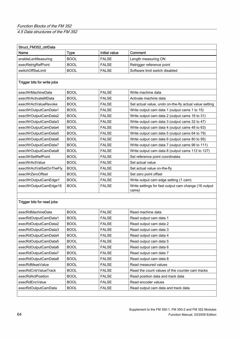
Function Blocks of the FM 352 4.5 Data structures of the FM 352
Supplement to the FM 350-1, FM 350-2 and FM 352 Modules 64 Function Manual, 03/2009 Edition
Struct_FM352_ctrlData Name Type Initial value Comment enableLenMeasuring BOOL FALSE Length measuring ON execRetrigRefPoint BOOL FALSE Retrigger reference point switchOffSwLimit BOOL FALSE Software limit switch disabled Trigger bits for write jobs execWrMachineData BOOL FALSE Write machine data execWrActivateMData BOOL FALSE Activate machine data execWrActValueRevoke BOOL FALSE Set actual value, undo on-the-fly actual value setting execWrOutputCamData1 BOOL FALSE Write output cam data 1 (output cams 1 to 15) execWrOutputCamData2 BOOL FALSE Write output cam data 2 (output cams 16 to 31) execWrOutputCamData3 BOOL FALSE Write output cam data 3 (output cams 32 to 47) execWrOutputCamData4 BOOL FALSE Write output cam data 4 (output cams 48 to 63) execWrOutputCamData5 BOOL FALSE Write output cam data 5 (output cams 64 to 79) execWrOutputCamData6 BOOL FALSE Write output cam data 6 (output cams 80 to 95) execWrOutputCamData7 BOOL FALSE Write output cam data 7 (output cams 96 to 111) execWrOutputCamData8 BOOL FALSE Write output cam data 8 (output cams 112 to 127) execWrSetRefPoint BOOL FALSE Set reference point coordinates execWrActValue BOOL FALSE Set actual value execWrActValSetOnTheFly BOOL FALSE Set actual value on-the-fly execWrZeroOffset BOOL FALSE Set zero point offset execWrOutputCamEdge1 BOOL FALSE Write output cam edge setting (1 cam) execWrOutputCamEdge16 BOOL FALSE Write settings for fast output cam change (16 output
cams) Trigger bits for read jobs execRdMachineData BOOL FALSE Read machine data execRdOutputCamData1 BOOL FALSE Read output cam data 1 execRdOutputCamData2 BOOL FALSE Read output cam data 2 execRdOutputCamData3 BOOL FALSE Read output cam data 3 execRdOutputCamData4 BOOL FALSE Read output cam data 4 execRdOutputCamData5 BOOL FALSE Read output cam data 5 execRdOutputCamData6 BOOL FALSE Read output cam data 6 execRdOutputCamData7 BOOL FALSE Read output cam data 7 execRdOutputCamData8 BOOL FALSE Read output cam data 8 execRdMeasValue BOOL FALSE Read measured values execRdCntrValueTrack BOOL FALSE Read the count values of the counter cam tracks execRdActPosition BOOL FALSE Read position data and track data execRdEncValue BOOL FALSE Read encoder values execRdOutputCamData BOOL FALSE Read output cam data and track data

Function Blocks of the FM 352 4.5 Data structures of the FM 352
Supplement to the FM 350-1, FM 350-2 and FM 352 Modules Function Manual, 03/2009 Edition 65
Struct_FM352_ctrlData Name Type Initial value Comment Done bits for function switches enableEdgeDetectDone BOOL FALSE "Switch edge detection ON or OFF" completed enableSimDone BOOL FALSE "Switch simulation ON or OFF" completed enableLenMeasDone BOOL FALSE "Switch length measurement ON or OFF" completed retrigRefPointDone BOOL FALSE "Switch retrigger reference point ON or OFF"
completed switchOffSwLimDone BOOL FALSE "Switch software limit switch ON or OFF" completed Done bits for write jobs wrMdDone BOOL FALSE "Write machine data" job completed wrActivateMdDone BOOL FALSE "Activate machine data" job completed wrActValueRevokeDone BOOL FALSE "Set actual value, undo on-the-fly actual value
setting" completed wrOutputCamData1Done BOOL FALSE "Write output cam data 1" job completed wrOutputCamData2Done BOOL FALSE "Write output cam data 2" job completed wrOutputCamData3Done BOOL FALSE "Write output cam data 3" job completed wrOutputCamData4Done BOOL FALSE "Write output cam data 4" job completed wrOutputCamData5Done BOOL FALSE "Write output cam data 5" job completed wrOutputCamData6Done BOOL FALSE "Write output cam data 6" job completed wrOutputCamData7Done BOOL FALSE "Write output cam data 7" job completed wrOutputCamData8Done BOOL FALSE "Write output cam data 8" job completed wrRefPointDone BOOL FALSE "Set reference point coordinates" job completed wrActValueDone BOOL FALSE "Set actual value" job completed wrActValSetOnTheFlyDone BOOL FALSE "Set actual value on-the-fly" job completed wrZeroOffsetDone BOOL FALSE "Set zero point offset" job completed wrOutputCamEdge1Done BOOL FALSE "Change 1 output cam" job completed wrOutputCamEdge16Done BOOL FALSE "Change 16 output cams" job completed Done bits for read jobs rdMdDone BOOL FALSE "Read machine data" job completed rdOutputCamData1Done BOOL FALSE "Read output cam data 1" job completed rdOutputCamData2Done BOOL FALSE "Read output cam data 2" job completed rdOutputCamData3Done BOOL FALSE "Read output cam data 3" job completed rdOutputCamData4Done BOOL FALSE "Read output cam data 4" job completed rdOutputCamData5Done BOOL FALSE "Read output cam data 5" job completed rdOutputCamData6Done BOOL FALSE "Read output cam data 6" job completed rdOutputCamData7Done BOOL FALSE "Read output cam data 7" job completed rdOutputCamData8Done BOOL FALSE "Read output cam data 8" job completed rdMeasValueDone BOOL FALSE "Read measured values" job completed

Function Blocks of the FM 352 4.5 Data structures of the FM 352
Supplement to the FM 350-1, FM 350-2 and FM 352 Modules 66 Function Manual, 03/2009 Edition
Struct_FM352_ctrlData Name Type Initial value Comment rdCntrValueTrackDone BOOL FALSE "Read count values of the counter output cam
tracks" job completed rdActPosDone BOOL FALSE "Read position data and track data" job completed rdEncValueDone BOOL FALSE "Read current encoder values" job completed rdOutputCamDataDone BOOL FALSE "Read output cam data and track data" job
completed Error bits for function switches enableEdgeDetectError BOOL FALSE Error during "Switch edge detection ON or OFF" enableSimError BOOL FALSE Error during "Switch simulation ON or OFF" enableLenMeasError BOOL FALSE Error during "Switch length measurement ON or
OFF" retrigRefPointError BOOL FALSE Error during "Switch retrigger reference point ON or
OFF" switchOffSwLimitError BOOL FALSE Error during "Switch software limit switch ON or
OFF" Error bits for write jobs wrMdError BOOL FALSE Error during "Write machine data" job wrActivateMdError BOOL FALSE Error during "Activate machine data" job wrActValueRevokeError BOOL FALSE Error during "Set actual value, undo on-the-fly actual
value setting" job wrOutputCamData1Error BOOL FALSE Error during "Write output cam data 1" job wrOutputCamData2Error BOOL FALSE Error during "Write output cam data 2" job wrOutputCamData3Error BOOL FALSE Error during "Write output cam data 3" job wrOutputCamData4Error BOOL FALSE Error during "Write output cam data 4" job wrOutputCamData5Error BOOL FALSE Error during "Write output cam data 5" job wrOutputCamData6Error BOOL FALSE Error during "Write output cam data 6" job wrOutputCamData7Error BOOL FALSE Error during "Write output cam data 7" job wrOutputCamData8Error BOOL FALSE Error during "Write output cam data 8" job wrSetRefPointError BOOL FALSE Error during "Set reference point coordinates" job wrActValueError BOOL FALSE Error during "Set actual value" job wrActValSetOnTheFlyError BOOL FALSE Error during "Set actual value on-the-fly" job wrZeroOffsetError BOOL FALSE Error during "Set zero point offset" job wrOutputCamEdge1Error BOOL FALSE Error during "Change 1 output cam" job wrOutputCamEdge16Error BOOL FALSE Error during "Change 16 output cams" job Error bits for read jobs rdMdError BOOL FALSE Error during "Read machine data" job rdOutputCamData1Error BOOL FALSE Error during "Read output cam data 1" job

Function Blocks of the FM 352 4.5 Data structures of the FM 352
Supplement to the FM 350-1, FM 350-2 and FM 352 Modules Function Manual, 03/2009 Edition 67
Struct_FM352_ctrlData Name Type Initial value Comment rdOutputCamData2Error BOOL FALSE Error during "Read output cam data 2" job rdOutputCamData3Error BOOL FALSE Error during "Read output cam data 3" job rdOutputCamData4Error BOOL FALSE Error during "Read output cam data 4" job rdOutputCamData5Error BOOL FALSE Error during "Read output cam data 5" job rdOutputCamData6Error BOOL FALSE Error during "Read output cam data 6" job rdOutputCamData7Error BOOL FALSE Error during "Read output cam data 7" job rdOutputCamData8Error BOOL FALSE Error during "Read output cam data 8" job rdMeasValueError BOOL FALSE Error during "Read measured values" job rdCntrValueTrackError BOOL FALSE Error during "Read count values of the counter cam
tracks" job rdActPosError BOOL FALSE Error during "Read position data and track data" job rdEncValueError BOOL FALSE Error during "Read encoder values" job rdOutputCamDataError BOOL FALSE Error during "Read output cam data and track data"
job Job management for _FM352_control function block jobErrorId INT 0 Communication error jobBusy BOOL FALSE At least one job running execJobReset BOOL FALSE Reset all errors and error bits Data for jobs Zero point offset zeroOffset DINT 0 Zero point offset Set actual value actValue DINT 0 Coordinate for "Set actual value" Set actual value on-the-fly actValueSetOnTheFly DINT 0 Coordinate for "Set actual value on-the-fly" Set reference point refPoint DINT 0 Coordinate for "Set reference point" Set output cam edge outputCamNumber INT 0 Output cam numbers for "Change output cam
edges" beginOutputCam DINT 0 Beginning of output cam for "Change output cam
edges" endOutputCam DINT 0 End of output cam for "Change output cam edges" Length/edge measurement beginLenMeasuring DINT 0 Starting value for length/edge measurement endLenMeasuring DINT 0 End value for "length/edge measurement" measRange DINT 0 Length for "length/edge measurement" Read count values cntrValueTrack0 INT 0 Current count value for counter output cam track 0

Function Blocks of the FM 352 4.5 Data structures of the FM 352
Supplement to the FM 350-1, FM 350-2 and FM 352 Modules 68 Function Manual, 03/2009 Edition
Struct_FM352_ctrlData Name Type Initial value Comment cntrValueTrack1 INT 0 Current count value for counter output cam track 1 Read position data and track data actPosition1 DINT 0 Current position of axis
(read with "execRdActPosition" job) actSpeed DINT 0 Current velocity trackState1 DWORD 16#0000 0000 Track ID bits for tracks 0..31 Read encoder data encValue DINT 0 Read encoder values cntrValueByZero DINT 0 Count value at the last zero mark absEncOffset DINT 0 Absolute encoder adjustment Read output cam data and track data outputCamData00_31 DWORD 16#0000 0000 Output cam data 0 to 31 outputCamData32_63 DWORD 16#0000 0000 Output cam data 32 to 63 outputCamData64_95 DWORD 16#0000 0000 Output cam data 64 to 95 outputCamData96_127 DWORD 16#0000 0000 Output cam data 96 to 127 trackState2 DWORD 16#0000 0000 Track ID bits for tracks 0...31 actPosition2 DINT 0 Current position of axis
(read with "execRdOutputCamData" job) Fast output cam change numOfOutputCamsToSet BYTE 16#00 Volume of project data: 0, 1, 2, 3 = max. 16, 32, 64,
128 cams disableDataCheck BOOL FALSE Disable data check Output cam data (data structure) outputCam ARRAY [0..15] of
outputCamType Elements for output cam data
number BYTE 16#00 Output cam number setForceDirection BOOL FALSE "Change force direction of output cam" job setBegin BOOL FALSE "Change beginning of output cam" job setEnd BOOL FALSE "Change end of output cam" job setActuationTime BOOL FALSE "Change actuation time" job deactivate BOOL FALSE Switch off the output cam during the output cam
change posForceDirection BOOL FALSE Force direction positive (plus) negForceDirection BOOL FALSE Force direction negative (minus) beginOutputCam DINT 0 Beginning of output cam endOutputCam DINT 0 End of output cam / ON duration actuationTime UINT 0 Actuation time Variables for FB-internal use (not relevant to users) xxxEnableScom BOOL FALSE Internal use xxxEnableSfct BOOL FALSE Internal use xxxScomDone BOOL FALSE Internal use

Function Blocks of the FM 352 4.5 Data structures of the FM 352
Supplement to the FM 350-1, FM 350-2 and FM 352 Modules Function Manual, 03/2009 Edition 69
Struct_FM352_ctrlData Name Type Initial value Comment xxxSfctDone BOOL FALSE Internal use xxxErrorScom BOOL FALSE Internal use xxxErrorSfct BOOL FALSE Internal use xxxmeasJobErrorId INT 0 Internal use xxxMeasJobBusy BOOL FALSE Internal use xxxActOrder INT 0 Internal use xxxNextOrder INT 0 Internal use xxxDataSetNumber DINT 0 Internal use xxxDataSetLength INT 0 Internal use xxxDataSetStart DINT 0 Internal use xxxEdgeOnOld BOOL FALSE Internal use xxxSimOnOld BOOL FALSE Internal use xxxMeasOnOld BOOL FALSE Internal use xxxReftrOnOld BOOL FALSE Internal use xxxSswOffOld BOOL FALSE Internal use xxxRead BOOL FALSE Internal use xxxError BOOL FALSE Internal use xxxEnableEdgeDetectOld BOOL FALSE Internal use xxxEnableSimOld BOOL FALSE Internal use xxxEnableLenMeasOld BOOL FALSE Internal use xxxRetrigRefPointOld BOOL FALSE Internal use xxxSwitchOffSwLimOld BOOL FALSE Internal use xxxDataSet11 WORD 16#0000 Internal use xxxDataSet12 WORD 16#0000 Internal use xxxControl DWORD 16#00000000 Internal use xxxFeedback0 DWORD 16#00000000 Internal use

Function Blocks of the FM 352 4.5 Data structures of the FM 352
Supplement to the FM 350-1, FM 350-2 and FM 352 Modules 70 Function Manual, 03/2009 Edition
4.5.3 Struct_FM352_paraData The Struct_FM352_paraData data structure is shown in the table below.
Table 4- 5 Data structure Struct_FM352_paraData
Struct_FM352_paraData Name Type Initial value Comment Machine data xxxModuleType1 1) BOOL FALSE 0 for FM 352 enableProcessAlarm BOOL FALSE Enable process alarm: Output cam ON/OFF xxxModuleType2 1) BOOL FALSE 0 for FM 352 minEdgeDistance DINT 0 Minimum edge distance for edge detection unitDimension DINT 1 Dimension system axisType DINT 0 Linear axis = 0
Rotary axis = 1 endRotAxis DINT 100000 End of rotary axis encType DINT 1 Encoder type, message frame length lenPerRevolution DINT 80000 Length per encoder revolution incPerRevolution DINT 500 Increments per encoder revolution cntOfRevolutions DINT 1024 Number of encoder revolutions baudRate DINT 0 Transmission rate refPoint DINT 0 Home position coordinates absEncOffset DINT 0 Absolute encoder adjustment refPointTrigMode DINT 0 Reference point retrigger mode cntrDirection BOOL FALSE Counting direction: 0 = normal, 1 = inverted openCircuit BOOL TRUE Wire break monitoring transmissionError BOOL TRUE Message frame error monitoring missingPulse BOOL TRUE Missing pulse monitoring swLimitStart DINT -100000000 Start of software limit switch swLimitEnd DINT 100000000 End of software limit switch numOfOutputCamsToSet DINT 0 Volume of project data: 0,1,2,3 = max. 16,32,64,128
output cams hysteresis DINT 0 Hysteresis simSpeed DINT 0 Simulation speed ctrlTrackOutputs WORD 16#0000 Track output actuation:
0 = electronic cam controller, 1 = SIMOTION device; Bit number = track number
enableInput3 BOOL FALSE Enable input I3 xxxEnableInput4..10 1) BOOL FALSE Reserved track0CntrOutputCam BOOL FALSE Track 0 is the counter cam track track1CntrOutputCam BOOL FALSE Track 1 is the counter cam track track2CntrOutputCam BOOL FALSE Track 2 is the counter cam track track0CntrLimit DINT 2 Upper count value for counter cam track 0

Function Blocks of the FM 352 4.5 Data structures of the FM 352
Supplement to the FM 350-1, FM 350-2 and FM 352 Modules Function Manual, 03/2009 Edition 71
Struct_FM352_paraData Name Type Initial value Comment track1CntrLimit DINT 2 Upper count value for counter cam track 1 Output cam data for output cams 0 to 15 / 0 to 31 / 0 to 63 / 0 to 127 (data structure) outputCam ARRAY [0..127] of
outputCamData Elements for output cam data
valid BOOL FALSE Output cam valid posForceDirection BOOL FALSE Force direction positive (plus) negForceDirection BOOL FALSE Force direction negative (minus) outputCamType BOOL FALSE FALSE: Position-based cams,
TRUE: Time-based output cam switchOnAlarm BOOL FALSE Process alarm while switching on switchOffAlarm BOOL FALSE Process alarm while switching off trackNumber BYTE 16#00 Track number beginOutputCam DINT 0 Beginning of output cam endOutputCam DINT 0 End of output cam / ON duration actuationTime UINT 0 Actuation time
1) Variable for FB-internal use (not relevant to users)

Function Blocks of the FM 352 4.5 Data structures of the FM 352
Supplement to the FM 350-1, FM 350-2 and FM 352 Modules 72 Function Manual, 03/2009 Edition
4.5.4 Struct_FM352_diagData The Struct_FM352_diagData data structure is shown in the table below. This data structure contains the diagnostic data of the FM 352.
Table 4- 6 Data structure Struct_FM352_diagData
Struct_FM352_diagData Name Type Initial value Comment moduleAddress INT 256 Module address jobErrorId INT 0 Description of errors jobBusy BOOL FALSE At least one job running diagInformation BOOL FALSE Essential to read the diagnostic buffer numOfValidEntries INT 0 Number of valid entries in the list Diagnostic data (data structure) diagnosticEntry ARRAY [1..4] of diagType Elements for diagnostic data incomingAlarm BOOL FALSE Event coming internFault BOOL FALSE Internal fault extFault BOOL FALSE External fault faultClass INT 0 Fault class faultNumber INT 0 Error code chNumber INT 0 Channel number outputCamNumber INT 0 Output cam numbers 0 to 127 with fault class
= output cam data error Variables for FB-internal use (not relevant to users) xxxDataSet ARRAY [0..227] of BYTE Internal use xxxDiagnosis0 Struct_FM352_diagType - Internal use xxxFeedback0 DWORD 16#00000000 Internal use xxxNextOrder INT 0 Internal use xxxDataSetNumber BYTE 16#00 Internal use xxxDataSetLength INT 0 Internal use xxxCntOfBuffers INT 0 Internal use xxxEnableDataSet236 BOOL FALSE Internal use xxxDataSet BOOL FALSE Internal use

Function Blocks of the FM 352 4.6 Calling function blocks
Supplement to the FM 350-1, FM 350-2 and FM 352 Modules Function Manual, 03/2009 Edition 73
4.6 Calling function blocks In order to be able to work with the function blocks in your user project, proceed as follows (the numbers shown in the following program segment correspond to the steps below): 1. Create the function block instance (see the following program segment, e.g. create
instance for FB_FM352_control). 2. Set up variables for the data structure. 3. Create an array for the in/out parameters of the FB. 4. Call instance of the function block. 5. Transfer input parameters. 6. The output parameters of the FB are accessed with <instance name of FB>. <name of
output parameter>. 7. Data prepared by the FB for the I/O outputs are assigned to the array of the I/O variables
created in step 3.
Note The call example is an extract from the supplied E_FM352 application example, which is contained on the "SIMOTION Utilities & Applications" CD-ROM. If you wish to control more than one FM 352, you must create a new variable for the data structure and FB instances with a new name for every FM 352 used.

Function Blocks of the FM 352 4.6 Calling function blocks
Supplement to the FM 350-1, FM 350-2 and FM 352 Modules 74 Function Manual, 03/2009 Edition
Call example UNIT E_FM352;
INTERFACE
VAR_GLOBAL
myDataFM352Ctrl : Struct_FM352_ctrlData ; // variable of data structure
myDataFM352Parameter : Struct_FM352_paraData ; // variable of data structure
(2)
myInstFM352Ctrl : FM352_control ; // create FB instance
END_VAR
(1)
PROGRAM ExampleFM352; // program in background task
END_INTERFACE
IMPLEMENTATION
PROGRAM ExampleFM352
VAR
FMOutputArray : ARRAY [0..15] of BYTE; // Array for FM output data
END_VAR
(3)
// CALL INSTANCE of FB _FB_FM352_control (4)
myInstFM352Ctrl
(
periIn := myPeripheralInputFM352, // variable of I/O inputs
ctrlData := myDataFM352Ctrl, // variable with channel-specific data
paraData := myDataFM352Parameter, // variable with machine and output
// cam data
periOut := FMOutputArray // FM output data array
);
(5)
// TRANSFER DATA TO FM
myPeripheralOutputFM352 := FMOutputArray; // Copy array of FM output
// data to I/O variables
(7)
myStateFMStartup := myInstFM352Ctrl. startup; // Start-up status (6) END_PROGRAM // ExampleFM352
END_IMPLEMENTATION
Note The PROGRAM ExampleFM352 must be assigned in the execution system.

Function Blocks of the FM 352 4.7 Application example for FM 352
Supplement to the FM 350-1, FM 350-2 and FM 352 Modules Function Manual, 03/2009 Edition 75
4.7 Application example for FM 352
Introduction In this example you use a user program to control an output cam controller. Once startup of the FM 352 is complete, the example program transfers stored machine data to the FM 352. The FM 352 is now parameterized for the application example. It then executes a series of steps in response to events. Using the variable tables, you can specify events, monitor the reactions of the module and evaluate the diagnostic buffer. This example will familiarize you with the following block options: ● Submitting several jobs at once ● Mixing read and write jobs ● Reading using a continuous job without waiting for the end of the job ● Evaluating the checkback signals of the block ● Evaluating the checkback signals for an individual job ● Centralized error evaluation by the _FM352_diagnostic function block at the end of the
user program ● Evaluating the diagnostic buffer in conjunction with "dataError"
FM 352 installation and wiring Connect the power supply to the front connector of the FM 352 at terminal 1 "L+" and terminal 2 "M" (24 V).
Assigning module parameters Proceed as follows: 1. Open your project in SIMOTION SCOUT. 2. Open the hardware configuration in SIMOTION SCOUT. 3. Configure your hardware station. 4. You will find the FM 352 module under the corresponding ET 200M. 5. Save the hardware configuration with the Station > Save and compile menu command. 6. Download the hardware configuration with the Target system > Download to module
menu command. The red "SF" LED on the FM 352 turns on and then off if the assigned module parameters have been downloaded without errors.

Function Blocks of the FM 352 4.7 Application example for FM 352
Supplement to the FM 350-1, FM 350-2 and FM 352 Modules 76 Function Manual, 03/2009 Edition
Hardware platform The application example is available for various SIMOTION hardware platforms and is intended for distributed use of the FM 352.
Note If the application example is not available for your hardware platform, you must adapt the hardware configuration.
Adapting the application example The configuration in the example and your available hardware must be adapted. The following options are available: 1. You can adapt the configuration in the example to the available hardware (PROFIBUS
DP address). 2. You can adapt the configuration of the hardware to the example (PROFIBUS DP
address).
Calling the application example The application example can be found on the "SIMOTION Utilities & Applications" CD-ROM. The "SIMOTION Utilities & Applications" CD-ROM is provided free of charge and part of the SIMOTION SCOUT scope of delivery. 1. Dearchive and open the project containing the application example. 2. Check the hardware configuration: PROFIBUS DP addresses. 3. Check the module addresses (hardware configuration) against the I/O addresses of the
controller in SIMOTION SCOUT and module address in the program (myDataFM352Ctrl.moduleAddress).
4. Save and compile the example project. Then, you can download the example to the SIMOTION device and switch to RUN mode.
Default settings for machine and output cam data The following FM 352 data are preset in the program and transferred to the FM at the start of the example (see Starting the example). • Measuring
system: Degrees (4 decimal places)
• Axis: Rotary axis: End of rotary axis: 360.0000 degrees Simulation speed: 360.0000 degrees/min • Encoder: Monitoring: Switch off wire break and missing pulse • Cams:

Function Blocks of the FM 352 4.7 Application example for FM 352
Supplement to the FM 350-1, FM 350-2 and FM 352 Modules Function Manual, 03/2009 Edition 77
No. Valid Track Type Start
[degrees] End
[degrees] Time[ms]
Actuation time[ms]
Effective direction
Process alarm
0 x 0 Distance
0.0000 90.0000 - 0.0 Both None
1 x 0 Distance
180.0000 270.0000 - 0.0 Both None
2 x 1 Distance
0.0000 90.0000 - 2000.0 Both None
3 x 1 Distance
180.0000 270.0000 - 2000.0 Both None
4 x 2 Distance
130.0000 330.0000 - 0.0 Both None
5 x 3 Distance
130.0000 330.0000 - 2000.0 Both None
Application sequence The SIMOTION device (C230-2, P350, D435) is in "RUN" mode. Create a watch table in your project and insert the values from tables "Current cam tracks and output cams", "Switch", "Current actual value" and "Error displays". Default settings in the program The following constants are defined in the E_FM352 unit:
Table 4- 7 Constants
Name Data type Control value Meaning myRefPoint DINT 1000 Reference coordinate myBeginOutputCam0 DINT 1470000 Beginning of output cam 0 myEndOutputCam0 DINT 1920000 End of output cam 0 myBeginOutputCam1 DINT 2000000 Beginning of output cam 1 myEndOutputCam1 DINT 3000000 End of output cam 1
Table 4- 8 Current cam tracks and output cams
Name Data type Meaning myDataFM352Ctrl.synchronized BOOL = TRUE if the axis is synchronized myDataFM352Ctrl.outputCamActive BOOL Output cam processing running myDataFM352Ctrl.trackSignalsCamActive DWORD Current track signals (tracks 0...31) myDataFM352Ctrl.outputCamData00_31 DWORD Output cam identifier bits for output cams
0 to 31 myDataFM352Parameter.outputCam[0].beginOutputCam DINT Beginning of output cam 0 myDataFM352Parameter. outputCam[0].endOutputCam DINT End of output cam 0 myDataFM352Parameter. outputCam[1].beginOutputCam DINT Beginning of output cam 1 myDataFM352Parameter. outputCam[1].endOutputCam DINT End of output cam 1

Function Blocks of the FM 352 4.7 Application example for FM 352
Supplement to the FM 350-1, FM 350-2 and FM 352 Modules 78 Function Manual, 03/2009 Edition
Table 4- 9 Switch
Name Data type Control value Meaning mySwitch BOOL TRUE Input for simulated switch
Table 4- 10 Current actual value
Name Data type Meaning myDataFM352Ctrl.actPosition DINT Current axis position myStepNumber INT Step number
Table 4- 11 Error displays
Name Data type Meaning myError BOOL Group errors myOutputCamError BOOL Output cam errors myDataFM352Ctrl.jobErrorId INT Error code
Starting the example Start the example by setting input myExampleStart = TRUE. Once the program has detected a rising edge at this input, all of the machine data and output cam data required for the example are transferred to the FM and an axis is then started in simulation. You can observe the changes in the actual position (myDataFM352Ctrl.actPosition), output cam data (myDataFM352Ctrl.outputCamData00_31) and track signals (myDataFM352Ctrl.trackSignals). You can also observe the step number of the step sequence (myStepNumber). When output cam 4 is set (130 degrees), parameters for output cams 0 and 1 are reset to the default values (see Table "Constants"). You can see the change in the watch table. The program then waits for an external event. Switch the simulated switch by setting mySwitch = TRUE. The output cam data revert back to the previous values. After this pass, the sequence of steps is executed, the step number is -2 and the simulation is stopped. Error assessment If an error occurs during execution, the step sequence is stopped and the simulation is switched off. Step number -1 is entered.

Function Blocks of the FM 352 4.7 Application example for FM 352
Supplement to the FM 350-1, FM 350-2 and FM 352 Modules Function Manual, 03/2009 Edition 79
User program (sequence steps) The user program executes a sequence of steps as follows: ● Step 99: The program waits in cyclic processing mode for the example to start
(StartupTask has been executed but "exampleStart" = FALSE). ● Step 0: The output cam controller is initialized. Associated data is set to the jobs that are
to be executed when the module is restarted. Module restart can be triggered, for example, by a restart of the C230-2.
● Step 1: The program waits for the set jobs to be executed. ● Step 2: The program continuously reads the output cam ID bits and waits until output cam
4 is set. ● Step 3: Parameters for output cams 0 and 1 are reassigned. To enable you to observe
the change, the output cam data are read out before and after the change and displayed in the watch table.
● Step 4: The program waits for the set jobs to be executed. ● Step 5: Here the program waits for "external" event "Switch ON"
(mySwitch = TRUE), which you can set via the watch table. ● Step 6: When the event occurs, output cams 0 and 1 are reset to the value that was read
out in the initialization step. ● Step 7: The program waits for the set jobs to be executed. At the end of the sequence of steps, the instance of FB _FM352_control and the instance of FB _FM352_diagnostic are called. If the diagnostics detected a message about invalid output cam data, the myOutputCamError output is set.

Function Blocks of the FM 352 4.7 Application example for FM 352
Supplement to the FM 350-1, FM 350-2 and FM 352 Modules 80 Function Manual, 03/2009 Edition

Supplement to the FM 350-1, FM 350-2 and FM 352 Modules Function Manual, 03/2009 Edition 81
Alarm processing 55.1 Overview of alarm processing
Pending error messages are processed and evaluated differently in a SIMOTION system than in a SIMATIC system. By default, the diagnostic alarms and process alarms are not enabled. Activate the alarms for the relevant module in the hardware configuration (refer to Chapter Inserting function modules into the SIMOTION project (Page 14)). If you have parameterized process alarms and/or diagnostic alarms, program the alarm processing sequence in accordance with the flow diagram below.
Figure 5-1 Alarm processing in the FM modules

Alarm processing 5.1 Overview of alarm processing
Supplement to the FM 350-1, FM 350-2 and FM 352 Modules 82 Function Manual, 03/2009 Edition
Alarm evaluation Alarms originating from the I/O are evaluated in the PeripheralFaultTask. When the PeripheralFaultTask is started, the Taskstartinfo is made available, which you can evaluate in the user program. The Taskstartinfo of the PeripheralFaultTask is comparable to the local data of OB40 and OB82 in the SIMATIC system.
Table 5- 1 Meaning of the Taskstartinfo
Task TSI Note DT TSI#startTime Start time of the task UDINT TSI#interruptID Identifies the triggering event:
• _SC_PROCESS_INTERRUPT • _SC_DIAGNOSTIC_INTERRUPT • _SC_STATION_DISCONNECTED • _SC_STATION_RECONNECTED
DINT TSI#logBaseAdrIn Logical base address if a process alarm (PRAL) or a diagnostic alarm (DAL) was caused by an input area on the module, otherwise _SC_INVALID_ADDRESS
DINT TSI#logBaseAdrOut Logical base address if a process alarm (PRAL) or a diagnostic alarm (DAL) was caused by an output area on the module, otherwise _SC_INVALID_ADDRESS
DINT TSI#logDiagAdr Diagnostic address of a DP slave if the alarm was caused by a station failure or station recovery of an associated DP slave, otherwise _SC_INVALID_ADDRESS
PeripheralFaultTask
DWORD TSI#details Detail information (bit fields)

Alarm processing 5.2 Process alarms
Supplement to the FM 350-1, FM 350-2 and FM 352 Modules Function Manual, 03/2009 Edition 83
5.2 Process alarms For the FM modules, you can select which events will trigger a process alarm. The assignment can be made in the parameter assignment screen forms of the configuration package for each module.
Definition of a process alarm If an event needs a response irrespective of the cycle of the SIMOTION device, the relevant FM module can trigger a process alarm.
Events that trigger a process alarm The criteria (events) that trigger process alarms in a SIMOTION system are the same as those in a SIMATIC system. For a more detailed description, refer to the FM 350-1/FM 350-2/FM 352 Installation and Parameter SIMATIC manuals.
Reactions to a process alarm A process alarm causes the following to occur: ● Process data are written in the TSI#details variable in the Taskstartinfo of
PeripheralFaultTask. ● The SIMOTION device goes into STOP mode if a program has not been assigned in the
PeripheralFaultTask. Bit assignment
The TSI#details variable is assigned in the same way as in a SIMATIC system.
Note More information is available in the following SIMATIC manuals: • FM 350-1 Function Module Installation and Parameter Assignment • FM 350-2 Counter Function Module Installation and Parameter Assignment • FM 352 Electronic Cam Controller Installation and Parameter Assignment
Evaluation of process alarms in the FM If a process alarm is triggered, the data in the Taskstartinfo of PeripheralFaultTask are written to the TSI#details variable and made available there.
Note If an event occurs that should trigger a process alarm, but a previous identical event has not yet been acknowledged, a new alarm is not triggered. The new process alarm is lost. Subject to parameter assignment, this can result in a diagnostic alarm ("Process alarm lost").If < 2 ms elapse between two events that should normally both trigger a process alarm, the second process alarm is lost and no diagnostic alarm can be triggered (for FM 350-2 only).
The TSI#details variable is assigned in the same way as in a SIMATIC system.

Alarm processing 5.3 Diagnostic alarms
Supplement to the FM 350-1, FM 350-2 and FM 352 Modules 84 Function Manual, 03/2009 Edition
5.3 Diagnostic alarms
Definition of a diagnostic alarm If the user program is to respond to an internal or external error, you can set the parameters for a diagnostic alarm that will interrupt the cyclical program of the SIMOTION device.
Events that trigger a diagnostic alarm The criteria (events) that trigger diagnostic alarms in a SIMOTION system are the same as in a SIMATIC system. For a more detailed description, refer to the FM 350-1/FM 350-2/FM 352, Installation and Parameter Assignment SIMATIC manuals.
Responses to a diagnostic alarm If a diagnostic alarm is issued, the following occurs: ● Diagnostic data are written to TSI#details variable in the Taskstartinfo of
PeripheralFaultTask. ● The SIMOTION device goes into STOP mode if a program has not been assigned in the
PeripheralFaultTask. ● You can use module-specific FBs to read additional diagnostic data in the
PeripheralFaultTask or BackgroundTask according to FM type. ● The group error LED (SF) of the FM module lights up. The group error LED (SF) is
extinguished as soon as the error has been remedied.
Bit assignment The TSI#details variable is assigned in the same way as in a SIMATIC system.
Note More information is available in the following SIMATIC manuals: • FM 350-1 Function Module Installation and Parameter Assignment • FM 350-2 Counter Function Module Installation and Parameter Assignment • FM 352 Electronic Cam Controller, Installation and Parameter Assignment

Alarm processing 5.3 Diagnostic alarms
Supplement to the FM 350-1, FM 350-2 and FM 352 Modules Function Manual, 03/2009 Edition 85
Evaluation of diagnostic alarms If a diagnostic alarm is triggered, the data in the Taskstartinfo of the PeripheralFaultTask are written to the TSI#details variable. The PeripheralFaultTask is called automatically and provides 4 bytes of diagnostic information for fast analysis. The contents of the diagnostic information are the same as in a SIMATIC system. Additional information can be read out using module-specific FBs. FM 350-1 FB _FM3501_diagnostic reads out 16 bytes of diagnostic data and makes them available in the data structure of type Struct_FM3501_data. The function block can be called in the PeripheralFaultTask, BackgroundTask or TimerInterruptTask. FM 350-2 FB _FM3502_diagnostic reads out 16 bytes of diagnostic data and enters them in the diagnostic substructure of the data structure of type Struct_FM3502_data. The function block can be called in the PeripheralFaultTask, BackgroundTask or TimerInterruptTask. FM 352 FB _FM352_diagnostic reads out all diagnostic data and enters them into the data structure of type Struct_FM352_diagnosticData. The FB must be called in the BackgroundTask or TimerInterruptTask.

Alarm processing 5.3 Diagnostic alarms
Supplement to the FM 350-1, FM 350-2 and FM 352 Modules 86 Function Manual, 03/2009 Edition

Supplement to the FM 350-1, FM 350-2 and FM 352 Modules Function Manual, 03/2009 Edition 87
Appendix AA.1 SIMOTION and SIMATIC names
The tables below contain a comparison of SIMOTION and SIMATIC names.
Table A- 1 SIMOTION and SIMATIC names for FM 350-1
Name in SIMOTION System, V4.0 and higher
(command library in SCOUT)
Name in the SIMATIC system Name in the SIMOTION system up to V3.2
(SIMOTION Function Library) Function block parameters _FM3501_control FC CNT_CTRL (FC 0) _FB_FM3501_control periIn - inputInterface enableSwGate SW_GATE softwareGate enableStopGate GATE_STP stopGate cntrRange - counterRange execResetOpError OT_ERR_A resetOperationError data DB_NO data setStartValue L_DIRECT setStartValue setPrepStartValue L_PREPARE setPrepareStartValue setCmpValue1 T_CMP_V1 setComparisonValue1 setCmpValue2 T_CMP_V2 setComparisonValue2 resetSyncState RES_SYNC resetSyncState resetCntrState RES_ZERO resetCounterState periOut - outputInterface errorOperation OT_ERR operationError startup - startup _FM3501_diagnostic FC DIAG_INF (FC 1) _FB_FM3501_diagnostic data DB_NO data execute IN_DIAG requestDiagnosticData done - - status - returnValue Data structure elements Struct_FM3501_fmData Struct_FM3501_data xxxReserved1 1) FP dedicatedData1 xxxReserved2 1) RESERVED dedicatedData2 moduleAddress MOD_ADR moduleAddress xxxReserved3 1) A_BYTE dedicatedData3 loadValue1 LOAD_VAL loadValue_1

Appendix A.1 SIMOTION and SIMATIC names
Supplement to the FM 350-1, FM 350-2 and FM 352 Modules 88 Function Manual, 03/2009 Edition
Name in SIMOTION System, V4.0 and higher
(command library in SCOUT)
Name in the SIMATIC system Name in the SIMOTION system up to V3.2
(SIMOTION Function Library) cmpValue1_1 CMP_V1 comparisonValue1_1 cmpValue2_1 CMP_V2 comparisonValue2_1 loadValue2 - loadValue_2 cmpValue1_2 - comparisonValue1_2 cmpValue2_2 - comparisonValue2_2 xxxReserved4 1) A_BIT0_0 dedicatedData4 xxxReserved5 1) TFB enableTestMode xxxReserved6 1) A_BIT0_3 dedicatedData5 xxxReserved7 1) A_BIT0_6 dedicatedData6 enableForwardSetting ENSET_UP enableSettingForward enableReverseSetting ENSET_DN enableSettingReverse xxxReserved8 1) A_BIT1_2 dedicatedData7 xxxReserved9 1) A_BIT1_3 dedicatedData8 enableOutput0 CTRL_DQ0 enableOutput0 enableOutput1 CTRL_DQ1 enableOutput1 xxxReserved10..15 1) A_BIT3_0...5 dedicatedData9..14 actValue1 ACT_LOAD actualValue_1 actCntrValue1 ACT_CNTV actualCounterValue_1 actValue2 - actualValue_2 actCntrValue2 - actualCounterValue_2 errorIdData DA_ERR_W dataErrorNumber errorIdOperation OT_ERR_B operationErrorNumber xxxReserved16 1) E_BIT0_0 dedicatedData15 xxxReserved17 1) STS_TFB testMode xxxReserved18 1) E_BIT0_2 dedicatedData16 xxxReserved19 1) E_BIT0_3 dedicatedData17 dataError DATA_ERR dataError xxxReserved20 1) E_BIT0_5 dedicatedData18 xxxReserved21 1) E_BIT0_6 dedicatedData19 parameterized PARA parameterized opState STS_RUN operationState opDirection STS_DIR operationDirection zeroCrossing STS_ZERO zeroCrossing overflow STS_OFLW overflow underflow STS_UFLW underflow synchronized STS_SYNC synchronized stateGate STS_GATE stateGate stateSwGate STS_SW_G stateSoftwareGate stateSetInput STS_SET stateInputSet xxxReserved22 1) E_BIT2_1 dedicatedData20 stateOfDiStart STS_STA stateInputStart

Appendix A.1 SIMOTION and SIMATIC names
Supplement to the FM 350-1, FM 350-2 and FM 352 Modules Function Manual, 03/2009 Edition 89
Name in SIMOTION System, V4.0 and higher
(command library in SCOUT)
Name in the SIMATIC system Name in the SIMOTION system up to V3.2
(SIMOTION Function Library) stateOfDiStop STS_STP stateInputStop stateCompValue1 STS_CMP1 comparisonValue1Reached stateCompValue2 STS_CMP2 comparisonValue2Reached xxxReserved23..28 1) E_BIT3_0...5 dedicatedData21...26 xxxReserved29 1) ACT_CMP1 dedicatedData27 xxxReserved30 1) ACT_CMP2 dedicatedData28 faultModule MDL_DEFECT moduleFault internFault INT_FAULT internalFault extFault EXT_FAULT externalFault faultChannel PNT_INFO channelFault faultExtVoltage EXT_VOLTAGE externalVoltageFault faultConnector FLD_CONNCTR connectorFault invalidConfig NO_CONFIG configFault invalidPara CONFIG_ERR configInvalid moduleType MDL_TYPE moduleType faultSubModule SUB_MDL_ERR submoduleFault faultCommunication COMM_FAULT communicationFault moduleStop MDL_STOP moduleStop faultWatchdog WTCH_DOG_FLT watchdogFault faultIntPower INT_PS_FLT intPowerSupplyFault xxxReserved47 1) PRIM_BATT_FLT dedicatedData45 xxxReserved48 1) BCKUP_BATT_FLT dedicatedData46 xxxReserved31 1) RESERVED_2 dedicatedData29 faultRack RACK_FLT rackFault faultDevice PROC_FLT deviceFault faultEprom EPROM_FLT EPROMFault faultRam RAM_FLT RAMFault faultAdc ADU_FLT ADUFault faultFuse FUSE_FLT fuseFault lostProcessAlarm HW_INTR_FLT processAlarmFault xxxReserved32 1) RESERVED_3 dedicatedData30 chType CH_TYPE channelType lenDiagData LGTH_DIA lengthDiagnosticData chNumber CH_NO channelNumber groupErrorChannel1 GRP_ERR1 groupFault1 xxxGroupErrorChannel2 1) GRP_ERR2 groupFault2 xxxReserved33..38 1) D_BIT7_2...7 dedicatedData31..36 faultCh1SignalA CH1_SIGA channel1SignalAFault faultCh1SignalB CH1_SIGB channel1SignalBFault faultCh1SigZero CH1_SIGZ channel1SignalZeroFault faultChannel1 CH1_BETW channel1ChannelFault
Appendix A.1 SIMOTION and SIMATIC names
Supplement to the FM 350-1, FM 350-2 and FM 352 Modules 90 Function Manual, 03/2009 Edition
Name in SIMOTION System, V4.0 and higher
(command library in SCOUT)
Name in the SIMATIC system Name in the SIMOTION system up to V3.2
(SIMOTION Function Library) faultCh1EncSupply CH1_5V2 channel1EncoderSupplyFault xxxReserved39..41 1) D_BIT8_5...7 dedicatedData37..39 xxxReserved40 1) D_BYTE9 dedicatedData40 faultCh2SignalA CH2_SIGA channel2SignalAFault faultCh2SignalB CH2_SIGB channel2SignalBFault faultCh2SigZero CH2_SIGZ channel2SignalZeroFault faultChannel2 CH2_BETW channel2ChannelFault faultCh2EncSupply CH2_5V2 channel2EncoderSupplyFault xxxReserved43..45 1) D_BIT10_5...7 dedicatedData41..43 xxxReserved46 1) D_BYTE11 dedicatedData44
1) Variable for internal FB use (not relevant to users)
Table A- 2 SIMOTION and SIMATIC names for FM 350-2
Name in SIMOTION System, V4.0 and higher
(command library in SCOUT)
Name in the SIMATIC system Name in the SIMOTION system up to V3.2
(SIMOTION Function Library) Function block parameters _FM3502_control FC CNT2_CTR (FC 2) _FB_FM3502_control periIn - inputInterface data DB_NO data periOut - outputInterface startup - startup _FM3502_write FC CNT2_WR (FC 3) _FB_FM3502_write periIn - inputInterface data DB_NO data periOut - outputInterface error - - status - returnValue _FM3502_read FC CNT2_RD (FC 4) _FB_FM3502_read periIn - inputInterface data DB_NO data error - - status - returnValue _FM3502_diagnostic FC DIAG_RD (FC 5) _FB_FM3502_diagnostic enable - - data DB_NO data error - -

Appendix A.1 SIMOTION and SIMATIC names
Supplement to the FM 350-1, FM 350-2 and FM 352 Modules Function Manual, 03/2009 Edition 91
Name in SIMOTION System, V4.0 and higher
(command library in SCOUT)
Name in the SIMATIC system Name in the SIMOTION system up to V3.2
(SIMOTION Function Library) status - returnValue Data structure elements Struct_FM3502_fmData Struct_FM3502_data write (Struct_FM3502_wrJob) JOB_WR write (Struct_FM3502_writeJob) execJobNumber NO jobNumber busy BUSY busy done DONE done invalid IMPOSS invalid unknown UNKNOWN unknown read (Struct_FM3502_rdJob) JOB_RD read (Struct_FM3502_readJob) execJobNumber NO jobNumber busy BUSY busy done DONE done invalid IMPOSS invalid unknown UNKNOWN unknown xxxReserved1 1) RESERV_0 dedicatedData1 xxxReserved2 1) RESERV_1 dedicatedData2 moduleAddress MOD_ADR moduleAddress xxxReserved3 1) RESERV_2 dedicatedData3 control (Struct_FM3502_control) CONTROL_SIGNALS control (Struct_FM3502_controlSignals) xxxReserved4..11 1) BIT0_0...BIT0_7 dedicatedData4..11 enableOutput0 CTRL_DQ0 enableOutput0 enableOutput1 CTRL_DQ1 enableOutput1 enableOutput2 CTRL_DQ2 enableOutput2 enableOutput3 CTRL_DQ3 enableOutput3 enableOutput4 CTRL_DQ4 enableOutput4 enableOutput5 CTRL_DQ5 enableOutput5 enableOutput6 CTRL_DQ6 enableOutput6 enableOutput7 CTRL_DQ7 enableOutput7 setOutput0 SET_DQ0 setOutput0 setOutput1 SET_DQ1 setOutput1 setOutput2 SET_DQ2 setOutput2 setOutput3 SET_DQ3 setOutput3 setOutput4 SET_DQ4 setOutput4 setOutput5 SET_DQ5 setOutput5 setOutput6 SET_DQ6 setOutput6 setOutput7 SET_DQ7 setOutput7 enableSwGate0 SW_GATE0 softwareGate0 enableSwGate1 SW_GATE1 softwareGate1 enableSwGate2 SW_GATE2 softwareGate2

Appendix A.1 SIMOTION and SIMATIC names
Supplement to the FM 350-1, FM 350-2 and FM 352 Modules 92 Function Manual, 03/2009 Edition
Name in SIMOTION System, V4.0 and higher
(command library in SCOUT)
Name in the SIMATIC system Name in the SIMOTION system up to V3.2
(SIMOTION Function Library) enableSwGate3 SW_GATE3 softwareGate3 enableSwGate4 SW_GATE4 softwareGate4 enableSwGate5 SW_GATE5 softwareGate5 enableSwGate6 SW_GATE6 softwareGate6 enableSwGate7 SW_GATE7 softwareGate7 xxxReserved12 1) CTRL_DWORD1 dedicatedData12 xxxReserved13 1) CTRL_DWORD2 dedicatedData13 xxxReserved14 1) CTRL_DWORD3 dedicatedData14 checkback (Struct_FM3502_checkback)
CHECKBACK_SIGNALS checkback (Struct_FM3502_checkback)
xxxReserved15 1) BIT0_0 dedicatedData15 testModePg STS_TFB testMode xxxReserved16..17 1) BIT0_2...BIT0_3 dedicatedData16...17 dataError DATA_ERR dataError xxxReserved18..19 1) BIT0_5...BIT0_6 dedicatedData18...19 parameterized PARA parameterized stateCmpValue0 STS_CMP0 stateComparisonValue0 stateCmpValue1 STS_CMP1 stateComparisonValue1 stateCmpValue2 STS_CMP2 stateComparisonValue2 stateCmpValue3 STS_CMP3 stateComparisonValue3 stateCmpValue4 STS_CMP4 stateComparisonValue4 stateCmpValue5 STS_CMP5 stateComparisonValue5 stateCmpValue6 STS_CMP6 stateComparisonValue6 stateCmpValue7 STS_CMP7 stateComparisonValue7 cntr0Underflow STS_UFLW0 underflow0 cntr1Underflow STS_UFLW1 underflow1 cntr2Underflow STS_UFLW2 underflow2 cntr3Underflow STS_UFLW3 underflow3 cntr4Underflow STS_UFLW4 underflow4 cntr5Underflow STS_UFLW5 underflow5 cntr6Underflow STS_UFLW6 underflow6 cntr7Underflow STS_UFLW7 underflow7 cntr0Overflow STS_OFLW0 overflow0 cntr1Overflow STS_OFLW1 overflow1 cntr2Overflow STS_OFLW2 overflow2 cntr3Overflow STS_OFLW3 overflow3 cntr4Overflow STS_OFLW4 overflow4 cntr5Overflow STS_OFLW5 overflow5 cntr6Overflow STS_OFLW6 overflow6 cntr7Overflow STS_OFLW7 overflow7 cntr0Reverse STS_DIR0 counter0Reverse

Appendix A.1 SIMOTION and SIMATIC names
Supplement to the FM 350-1, FM 350-2 and FM 352 Modules Function Manual, 03/2009 Edition 93
Name in SIMOTION System, V4.0 and higher
(command library in SCOUT)
Name in the SIMATIC system Name in the SIMOTION system up to V3.2
(SIMOTION Function Library) cntr1Reverse STS_DIR1 counter1Reverse cntr2Reverse STS_DIR2 counter2Reverse cntr3Reverse STS_DIR3 counter3Reverse cntr4Reverse STS_DIR4 counter4Reverse cntr5Reverse STS_DIR5 counter5Reverse cntr6Reverse STS_DIR6 counter6Reverse cntr7Reverse STS_DIR7 counter7Reverse input0 STS_DI0 input0 input1 STS_DI1 input1 input2 STS_DI2 input2 input3 STS_DI3 input3 input4 STS_DI4 input4 input5 STS_DI5 input5 input6 STS_DI6 input6 input7 STS_DI07 input7 output0 STS_DQ0 output0 output1 STS_DQ1 output1 output2 STS_DQ2 output2 output3 STS_DQ3 output3 output4 STS_DQ4 output4 output5 STS_DQ5 output5 output6 STS_DQ6 output6 output7 STS_DQ7 output7 gate0 STS_GATE0 gate0 gate1 STS_GATE1 gate1 gate2 STS_GATE2 gate2 gate3 STS_GATE3 gate3 gate4 STS_GATE4 gate4 gate5 STS_GATE5 gate5 gate6 STS_GATE6 gate6 gate7 STS_GATE7 gate7 opValue0 USER_STAT_WORD0 operatingValue0 opValue1 USER_STAT_WORD1 operatingValue1 opValue2 USER_STAT_WORD2 operatingValue2 opValue3 USER_STAT_WORD3 operatingValue3 loadValue0 LOAD_VAL0 loadValue0 loadValue1 LOAD_VAL1 loadValue1 loadValue2 LOAD_VAL2 loadValue2 loadValue3 LOAD_VAL3 loadValue3 loadValue4 LOAD_VAL4 loadValue4 loadValue5 LOAD_VAL5 loadValue5

Appendix A.1 SIMOTION and SIMATIC names
Supplement to the FM 350-1, FM 350-2 and FM 352 Modules 94 Function Manual, 03/2009 Edition
Name in SIMOTION System, V4.0 and higher
(command library in SCOUT)
Name in the SIMATIC system Name in the SIMOTION system up to V3.2
(SIMOTION Function Library) loadValue6 LOAD_VAL6 loadValue6 loadValue7 LOAD_VAL7 loadValue7 prepValue0 LOAD_PREPARE_VAL0 preparedValue0 prepValue1 LOAD_PREPARE_VAL1 preparedValue1 prepValue2 LOAD_PREPARE_VAL2 preparedValue2 prepValue3 LOAD_PREPARE_VAL3 preparedValue3 prepValue4 LOAD_PREPARE_VAL4 preparedValue4 prepValue5 LOAD_PREPARE_VAL5 preparedValue5 prepValue6 LOAD_PREPARE_VAL6 preparedValue6 prepValue7 LOAD_PREPARE_VAL7 preparedValue7 cmpValue0 CMP_VAL0 comparisonValue0 cmpValue1 CMP_VAL1 comparisonValue1 cmpValue2 CMP_VAL2 comparisonValue2 cmpValue3 CMP_VAL3 comparisonValue3 cmpValue4 CMP_VAL4 comparisonValue4 cmpValue5 CMP_VAL5 comparisonValue5 cmpValue6 CMP_VAL6 comparisonValue6 cmpValue7 CMP_VAL7 comparisonValue7 actCntrValue0 ACT_CNTV0 actualCounterValue0 actMeasValue0 ACT_MSRV0 actualMeasuringValue0 actCntrValue1 ACT_CNTV1 actualCounterValue1 actMeasValue1 ACT_MSRV1 actualMeasuringValue1 actCntrValue2 ACT_CNTV2 actualCounterValue2 actMeasValue2 ACT_MSRV2 actualMeasuringValue2 actCntrValue3 ACT_CNTV3 actualCounterValue3 actMeasValue3 ACT_MSRV3 actualMeasuringValue3 actCntrValue4 ACT_CNTV4 actualCounterValue4 actMeasValue4 ACT_MSRV4 actualMeasuringValue4 actCntrValue5 ACT_CNTV5 actualCounterValue5 actMeasValue5 ACT_MSRV5 actualMeasuringValue5 actCntrValue6 ACT_CNTV6 actualCounterValue6 actMeasValue6 ACT_MSRV6 actualMeasuringValue7 actCntrValue7 ACT_CNTV7 actualCounterValue7 actMeasValue7 ACT_MSRV7 actualMeasuringValue7 diagnostic (Struct_FM3502_diagInfo)
DIAGNOSTIC_INT_INFO diagnostic (DIAGNOSTIC_INT_INFO_TYPE)
xxxReserved20..23 1) BYTE0...BYTE3 dedicatedData20..23 chType BYTE4 channelType chInfoLength BYTE5 lengthChannelInfo numOfChannel BYTE6 numberOfChannel chFault BYTE7 channelFault

Appendix A.1 SIMOTION and SIMATIC names
Supplement to the FM 350-1, FM 350-2 and FM 352 Modules Function Manual, 03/2009 Edition 95
Name in SIMOTION System, V4.0 and higher
(command library in SCOUT)
Name in the SIMATIC system Name in the SIMOTION system up to V3.2
(SIMOTION Function Library) cntr0Fault BYTE8 counter0Fault cntr1Fault BYTE9 counter1Fault cntr2Fault BYTE10 counter2Fault cntr3Fault BYTE11 counter3Fault cntr4Fault BYTE12 counter4Fault cntr5Fault BYTE13 counter5Fault cntr6Fault BYTE14 counter6Fault cntr7Fault BYTE15 counter7Fault
1) Variable for internal FB use (not relevant to users)

Appendix A.1 SIMOTION and SIMATIC names
Supplement to the FM 350-1, FM 350-2 and FM 352 Modules 96 Function Manual, 03/2009 Edition
Table A- 3 SIMOTION and SIMATIC names for FM 352
Name in SIMOTION System, V4.0 and higher
(command library in SCOUT)
Name in the SIMATIC system Name in the SIMOTION system up to V3.2 (SIMOTION Function Library)
Function block parameters _FM352_initialize FC CAM_INIT (FC 0) _FB_FM352_initialize execute - - ctrlData DB_NO controlData done - - error - - _FM352_control FC CAM_CTRL (FC 1) _FB_FM352_control periIn - inputInterface ctrlData DB_NO controlData paraData DB_NO parameterData periOut - outputInterface error - - status - returnValue startup - startup _FM352_diagnostic FC CAM_DIAG (FC 2) _FB_FM352_diagnostic enable - - periIn - inputInterface diagData DB_NO diagnosticData error - - status - returnValue Data structure elements Struct_FM352_ctrlData - Struct_FM352_controlData moduleAddress MOD_ADDR moduleAddress FmType FM_TYPE FMType enableSimNegative DIR_M simulateNegative enableSimPositive DIR_P simulatePositive enableOutputCam CAM_EN enableOutputCam enableTrack0Counter CNTC0_EN enableCounterTrack0 enableTrack1Counter CNTC1_EN enableCounterTrack1 enableTrack TRACK_EN enableTrack diagDataChanged DIAG diagnosticDataModify dataError DATA_ERR dataError parameterized PARA parameterized outputCamActive CAM_ACT outputCamActive synchronized SYNC synchronized measDone MSR_DONE measuringDone dirNegative GO_M negativeDirection

Appendix A.1 SIMOTION and SIMATIC names
Supplement to the FM 350-1, FM 350-2 and FM 352 Modules Function Manual, 03/2009 Edition 97
Name in SIMOTION System, V4.0 and higher
(command library in SCOUT)
Name in the SIMATIC system Name in the SIMOTION system up to V3.2 (SIMOTION Function Library)
dirPositive GO_P positiveDirection hystZone HYS hysteresisZone floatActValue FVAL_DONE floatingActualValue actPosition ACT_POS actualPosition trackSignals TRACK_OUT trackSignals enableEdgeDetection EDGE_ON enableEdgeDetection enableSimulation SIM_ON enableSimulation enableLenMeasuring MSR_ON enableLengthMeasuring execRetrigRefPoint REFTR_ON retriggerReferencePoint switchOffSwLimit SSW_OFF switchOffSoftwareLimit execWrMachineData MDWR_EN writeMachineData execWrActivateMData MD_EN writeActivateMachineData execWrActValueRevoke AVALREM_EN writeActualValueRevoke execWrOutputCamData1 CAM1WR_EN writeOutputCamData1 execWrOutputCamData2 CAM2WR_EN writeOutputCamData2 execWrOutputCamData3 CAM3WR_EN writeOutputCamData3 execWrOutputCamData4 CAM4WR_EN writeOutputCamData4 execWrOutputCamData5 CAM5WR_EN writeOutputCamData5 execWrOutputCamData6 CAM6WR_EN writeOutputCamData6 execWrOutputCamData7 CAM7WR_EN writeOutputCamData7 execWrOutputCamData8 CAM8WR_EN writeOutputCamData8 execWrSetRefPoint REFPT_EN writeReferencePoint execWrActValue AVAL_EN writeActualValue execWrActValSetOnTheFly FVAL_EN writeActualValueSettingOnTheFly execWrZeroOffset ZOFF_EN writeZeroOffset execWrOutputCamEdge1 CH01CAM_EN writeOutputCamEdge1 execWrOutputCamEdge16 CH16CAM_EN writeOutputCamEdge16 execRdMachineData MDRD_EN readMachineData execRdOutputCamData1 CAM1RD_EN readOutputCamData1 execRdOutputCamData2 CAM2RD_EN readOutputCamData2 execRdOutputCamData3 CAM3RD_EN readOutputCamData3 execRdOutputCamData4 CAM4RD_EN readOutputCamData4 execRdOutputCamData5 CAM5RD_EN readOutputCamData5 execRdOutputCamData6 CAM6RD_EN readOutputCamData6 execRdOutputCamData7 CAM7RD_EN readOutputCamData7 execRdOutputCamData8 CAM8RD_EN readOutputCamData8 execRdMeasValue MSRRD_EN readMeasuringValue execRdCntrValueTrack CNTTRC_EN readCounterValueTrack execRdActPosition ACTPOS_EN readActualPosition execRdEncValue ENCVAL_EN readEncoderValue execRdOutputCamData CAMOUT_EN readOutputCamData

Appendix A.1 SIMOTION and SIMATIC names
Supplement to the FM 350-1, FM 350-2 and FM 352 Modules 98 Function Manual, 03/2009 Edition
Name in SIMOTION System, V4.0 and higher
(command library in SCOUT)
Name in the SIMATIC system Name in the SIMOTION system up to V3.2 (SIMOTION Function Library)
xxxEnableScom 1) - scom_en xxxEnableSfct 1) - sfct_en enableEdgeDetectDone EDGE_D enableEdgeDetectionDone enableSimDone SIM_D enableSimulationDone enableLenMeasDone MSR_D enableLengthMeasuringDone retrigRefPointDone REFTR_D retriggerReferencePointDone switchOffSwLimDone SSW_D switchOffSoftwareLimitDone wrMdDone MDWR_D writeMachineDataDone wrActivateMdDone MD_D writeActivateMachineDataDone wrActValueRevokeDone AVALREM_D writeActualValueRevokeDone wrOutputCamData1Done CAM1WR_D writeOutputCamData1Done wrOutputCamData2Done CAM2WR_D writeOutputCamData2Done wrOutputCamData3Done CAM3WR_D writeOutputCamData3Done wrOutputCamData4Done CAM4WR_D writeOutputCamData4Done wrOutputCamData5Done CAM5WR_D writeOutputCamData5Done wrOutputCamData6Done CAM6WR_D writeOutputCamData6Done wrOutputCamData7Done CAM7WR_D writeOutputCamData7Done wrOutputCamData8Done CAM8WR_D writeOutputCamData8Done wrRefPointDone REFPT_D writeReferencePointDone wrActValueDone AVAL_D writeActualValueDone wrActValSetOnTheFlyDone FVAL_D writeActualValueSettingOnTheFlyDone wrZeroOffsetDone ZOFF_D writeZeroOffsetDone wrOutputCamEdge1Done CH01CAM_D writeOutputCamEdge1Done wrOutputCamEdge16Done CH16CAM_D writeOutputCamEdge16Done rdMdDone MDRD_D readMachineDataDone rdOutputCamData1Done CAM1RD_D 1readOutputCamDataDone rdOutputCamData2Done CAM2RD_D readOutputCamData2Done rdOutputCamData3Done CAM3RD_D readOutputCamData3Done rdOutputCamData4Done CAM4RD_D readOutputCamData4Done rdOutputCamData5Done CAM5RD_D readOutputCamData5Done rdOutputCamData6Done CAM6RD_D readOutputCamData6Done rdOutputCamData7Done CAM7RD_D readOutputCamData7Done rdOutputCamData8Done CAM8RD_D readOutputCamData8Done rdMeasValueDone MSRRD_D readMeasuringValueDone rdCntrValueTrackDone CNTTRC_D readCounterValueTrackDone rdActPosDone ACTPOS_D readActualPositionDone rdEncValueDone ENCVAL_D readEncoderValueDone rdOutputCamDataDone CAMOUT_D readOutputCamDataDone xxxScomDone 1) - scom_D xxxSfctDone 1) - sfct_D enableEdgeDetectError EDGE_ERR enableEdgeDetectionError

Appendix A.1 SIMOTION and SIMATIC names
Supplement to the FM 350-1, FM 350-2 and FM 352 Modules Function Manual, 03/2009 Edition 99
Name in SIMOTION System, V4.0 and higher
(command library in SCOUT)
Name in the SIMATIC system Name in the SIMOTION system up to V3.2 (SIMOTION Function Library)
enableSimError SIM_ERR enableSimulationError enableLenMeasError MSR_ERR enableLengthMeasuringError retrigRefPointError REFTR_ERR retriggerReferencePointError switchOffSwLimitError SSW_ERR switchOffSoftwareLimitError wrMdError MDWR_ERR writeMachineDataError wrActivateMdError MD_ERR writeActivateMachineDataError wrActValueRevokeError AVALREM_ERR writeActualValueRevokeError wrOutputCamData1Error CAM1WR_ERR writeOutputCamData1Error wrOutputCamData2Error CAM2WR_ERR writeOutputCamData2Error wrOutputCamData3Error CAM3WR_ERR writeOutputCamData3Error wrOutputCamData4Error CAM4WR_ERR writeOutputCamData4Error wrOutputCamData5Error CAM5WR_ERR writeOutputCamData5Error wrOutputCamData6Error CAM6WR_ERR writeOutputCamData6Error wrOutputCamData7Error CAM7WR_ERR writeOutputCamData7Error wrOutputCamData8Error CAM8WR_ERR writeOutputCamData8Error wrSetRefPointError REFPT_ERR writeReferencePointError wrActValueError AVAL_ERR writeActualValueError wrActValSetOnTheFlyError FVAL_ERR writeActualValueSettingOnTheFlyError wrZeroOffsetError ZOFF_ERR writeZeroOffsetError wrOutputCamEdge1Error CH01CAM_ERR writeOutputCamEdge1Error wrOutputCamEdge16Error CH16CAM_ERR writeOutputCamEdge16Error rdMdError MDRD_ERR readMachineDataError rdOutputCamData1Error CAM1RD_ERR readOutputCamData1Error rdOutputCamData2Error CAM2RD_ERR readOutputCamData2Error rdOutputCamData3Error CAM3RD_ERR readOutputCamData3Error rdOutputCamData4Error CAM4RD_ERR readOutputCamData4Error rdOutputCamData5Error CAM5RD_ERR readOutputCamData5Error rdOutputCamData6Error CAM6RD_ERR readOutputCamData6Error rdOutputCamData7Error CAM7RD_ERR readOutputCamData7Error rdOutputCamData8Error CAM8RD_ERR readOutputCamData8Error rdMeasValueError MSRRD_ERR readMeasuringValueError rdCntrValueTrackError CNTTRC_ERR readCounterValueTrackError rdActPosError ACTPOS_ERR readActualPositionError rdEncValueError ENCVAL_ERR readEncoderValueError rdOutputCamDataError CAMOUT_ERR readOutputCamDataError xxxErrorScom 1) - scom_ERR xxxErrorSfct 1) - sfct_ERR jobErrorId JOB_ERR jobError jobBusy JOBBUSY jobBusy execJobReset JOBRESET jobReset xxxmeasJobErrorId 1) - jobError_M
Appendix A.1 SIMOTION and SIMATIC names
Supplement to the FM 350-1, FM 350-2 and FM 352 Modules 100 Function Manual, 03/2009 Edition
Name in SIMOTION System, V4.0 and higher
(command library in SCOUT)
Name in the SIMATIC system Name in the SIMOTION system up to V3.2 (SIMOTION Function Library)
xxxMeasJobBusy 1) - jobBusy_M xxxActOrder 1) - aktAuftrag xxxNextOrder 1) - naechsterAuftrag xxxDataSetNumber 1) - DS_nummer xxxDataSetLength 1) - DS_laenge xxxDataSetStart 1) - DS_anfang xxxEdgeOnOld 1) - edge_on_alt xxxSimOnOld 1) - sim_on_alt xxxMeasOnOld 1) - msr_on_alt xxxReftrOnOld 1) - reftr_on_alt xxxSswOffOld 1) - ssw_off_alt xxxRead 1) - lesen xxxError 1) - fehler xxxEnableEdgeDetectOld 1) - enableEdgeDetectionDone_OLD xxxEnableSimOld 1) - enableSimulationDone_OLD xxxEnableLenMeasOld 1) - enableLengthMeasuringDone_OLD xxxRetrigRefPointOld 1) - retriggerReferencePointDone_OLD xxxSwitchOffSwLimOld 1) - switchOffSoftwareLimit_D_OLD xxxDataSet11 1) - ds11 xxxDataSet12 1) - ds12 xxxControl 1) - steuer xxxFeedback0 1) - rueck0 zeroOffset ZOFF zeroOffset actValue AVAL actualValue actValueSetOnTheFly FVAL actualValueSettingOnTheFly refPoint REFPT referencePoint outputCamNumber CAM_NO outputCamNumber beginOutputCam CAM_START beginOfOutputCam endOutputCam CAM_END endOfOutputCam beginLenMeasuring BEG_VAL beginOfLengthMeasuring endLenMeasuring END_VAL endOfLengthMeasuring measRange LEN_VAL measuringRange cntrValueTrack0 CNT_TRC0 counterValueTrack0 cntrValueTrack1 CNT_TRC1 counterValueTrack1 actPosition1 ACTPOS actualPosition1 actSpeed ACTSPD actualSpeed trackState1 TRACK_ID trackState1 encValue ENCVAL encoderValue cntrValueByZero ZEROVAL counterValueByZeroCrossing absEncOffset ENC_ADJ offsetOfAbsoluteEncoder outputCamData00_31 CAM_00_31 outputCamData00_31

Appendix A.1 SIMOTION and SIMATIC names
Supplement to the FM 350-1, FM 350-2 and FM 352 Modules Function Manual, 03/2009 Edition 101
Name in SIMOTION System, V4.0 and higher
(command library in SCOUT)
Name in the SIMATIC system Name in the SIMOTION system up to V3.2 (SIMOTION Function Library)
outputCamData32_63 CAM_32_63 outputCamData32_63 outputCamData64_95 CAM_64_95 outputCamData64_95 outputCamData96_127 CAM_96_127 outputCamData96_127 trackState2 TRACK_ID1 trackState2 actPosition2 ACTPOS1 actualPosition2 numOfOutputCamsToSet C_QTY activatedOutputCam disableDataCheck DIS_CHECK disableDataCheck outputCam (Struct_FM352_outCamCtrl) CAM outputCam (outputCamTypeFM352) number CAM_NO number setForceDirection C_EFFDIR changeForceDirection setBegin C_CBEGIN changeBeginOfOutputCam setEnd C_CEND changeEndOfOutputCam setActuationTime C_LTIME changeActuationTime deactivate CAM_OFF deactivate posForceDirection EFFDIR_P forceDirectionPositive negForceDirection EFFDIR_M forceDirectionNegative beginOutputCam CBEGIN beginOfOutputCam endOutputCam CEND endOfOutputCam actuationTime LTIME actuationTime Struct_FM352_paraData - Struct_FM352_parameterData xxxModuleType1 1) PI_MEND moduleType1 enableProcessAlarm PI_CAM enableProcessAlarm xxxModuleType2 1) PI_MSTRT moduleType2 minEdgeDistance EDGEDIST minimumEdgeDistance unitDimension UNITS dimensionUnit axisType AXIS_TYPE axisType endRotAxis ENDROTAX endOfRotaryAxis encType ENC_TYPE encoderType lenPerRevolution DISP_REV lengthPerRevolution incPerRevolution INC_REV incrementsPerRevolution cntOfRevolutions NO_REV numberOfRevolution baudRate BAUDRATE baudrate refPoint REFPT referencePoint absEncOffset ENC_ADJ offsetOfAbsoluteEncoder refPointTrigMode RETR_TYPE referencePointTriggerMode cntrDirection CNT_DIR counterDirection openCircuit MON_WIRE openCircuit transmissionError MON_FRAME transmissionError missingPulse MON_PULSE missingPulse swLimitStart SSW_STRT softwareLimitSwitchBegin swLimitEnd SSW_END softwareLimitSwitchEnd

Appendix A.1 SIMOTION and SIMATIC names
Supplement to the FM 350-1, FM 350-2 and FM 352 Modules 102 Function Manual, 03/2009 Edition
Name in SIMOTION System, V4.0 and higher
(command library in SCOUT)
Name in the SIMATIC system Name in the SIMOTION system up to V3.2 (SIMOTION Function Library)
numOfOutputCamsToSet C_QTY activatedOutputCam hysteresis HYS hysteresis simSpeed SIM_SPD simulationSpeed ctrlTrackOutputs TRACK_OUT trackOutControl enableInput3 EN_IN_I3 enableInput3 xxxEnableInput4..10 1) EN_IN_I4 enableInput4...10 track0CntrOutputCam SPEC_TRC0 counterOutputCamTrack0 track1CntrOutputCam SPEC_TRC1 counterOutputCamTrack1 track2CntrOutputCam SPEC_TRC2 counterOutputCamTrack2 track0CntrLimit CNT_LIM0 counterLimitTrack0 track1CntrLimit CNT_LIM1 counterLimitTrack1 outputCam (Struct_FM352_outCamPara) CAM outputCam
(outputCamData) valid CAMVALID valid posForceDirection EFFDIR_P forceDirectionPositive negForceDirection EFFDIR_M forceDirectionNegative outputCamType CAM_TYPE typeOfOutputCam switchOnAlarm PI_SW_ON switchOnAlarm switchOffAlarm PI_SW_OFF switchOffAlarm trackNumber TRACK_NO trackNumber beginOutputCam CBEGIN beginOfOutputCam endOutputCam CEND endOfOutputCam actuationTime LTIME actuationTime Struct_FM352_diagData - Struct_FM352_diagnosticData moduleAddress MOD_ADDR moduleAddress xxxDataSet 1) - ds xxxDiagnosis0 1) - DIAG0 xxxFeedback0 1) - rueck0 xxxActOrder 1) - aktAuftrag xxxNextOrder 1) - naechsterAuftrag xxxDataSetNumber 1) - DS_nummer xxxDataSetLength 1) - DS_laenge xxxCntOfBuffers 1) - anzPuffer xxxEnableDataSet236 1) - ds236_en xxxDataSet 1) - ds237_en jobErrorId JOB_ERR jobError jobBusy JOBBUSY jobBusy diagInformation DIAGRD_EN diagnosticInformation numOfValidEntries DIAG_CNT numberOfValidEntries diagEntry (Struct_FM352_diagType) DIAG diagnosticEntry (diagnosticData) incomingAlarm STATE alarmIncoming

Appendix A.1 SIMOTION and SIMATIC names
Supplement to the FM 350-1, FM 350-2 and FM 352 Modules Function Manual, 03/2009 Edition 103
Name in SIMOTION System, V4.0 and higher
(command library in SCOUT)
Name in the SIMATIC system Name in the SIMOTION system up to V3.2 (SIMOTION Function Library)
internFault INTF internalFault extFault EXTF externalFault faultClass FCL faultClass faultNumber FNO faultNumber chNumber CH_NO chanNumber outputCamNumber CAM_NO outputCamNumber
1) Variable for internal FB use (not relevant to users)

Appendix A.2 List of abbreviations
Supplement to the FM 350-1, FM 350-2 and FM 352 Modules 104 Function Manual, 03/2009 Edition
A.2 List of abbreviations
Table A- 4 Abbreviations
Abbreviation Meaning ADC Analog-digital converter DI Digital Input DP Distributed I/O EPROM Erasable Programmable Read-Only Memory
(Erasable programmable read-only memory) FB Function block FM Function module IM Interface Module (SIMATIC S7-300 interface module) IN Input parameter IN/OUT In/out parameter LAD Ladder Logic LED Light Emitting Diode (LED displays) OB Organization block OUT Output parameter Programming device/PC
Programming device / Personal computer
PS Power Supply (SIMATIC S7-300 power supply) RAM Random Access Memory SF System Fault (System error) SW Software

Supplement to the FM 350-1, FM 350-2 and FM 352 Modules Function Manual, 03/2009 Edition 105
Index
_ _FM3501_control, 18 _FM3501_diagnostic, 22 _FM3502_control, 34 _FM3502_diagnostic, 40 _FM3502_read, 38 _FM3502_write, 36 _FM352_control, 57 _FM352_diagnostic, 60 _FM352_initialize, 56
A Alarm processing, 81
Bit assignment, 83, 84 Diagnostic alarm, 84 Process alarm, 83
Application example for FM 350-1, 29 Application example for FM 350-2, 49 Application example for FM 352, 75
B Bit assignment, 83, 84
C Calling function blocks
FM 350-1, 27 FM 350-2, 47 FM 352, 73
Centralized application, 13 Connection, 13
D Data structure of the FM 350-1, 23
Struct_FM3501_fmData, 24 Data structure of the FM 350-2, 42
Struct_FM3502_fmData, 42 Diagnostic alarm, 84
Bit assignment, 84 Distributed application, 13
E Error messages (FM 350-1), 21 Error messages (FM 350-2), 37, 39 Error messages (FM 352), 59, 61 Evaluation of process alarms, 83
F FM 352 data structure, 62
Struct_FM352_ctrlData, 63 Struct_FM352_diagData, 72 Struct_FM352_paraData, 70
Function blocks of FM 350-1, 17 _FM3501_control, 18 _FM3501_diagnostic, 22 Call example, 27
Function blocks of FM 350-2, 33 _FM3502_diagnostic, 40 _FM3502_read, 38 _FM3502_write, 36 Call example, 47
Function blocks of FM 352, 55 _FM352_control, 57 _FM352_diagnostic, 60 _FM352_initialize, 56 Call example, 73
I I/O Variables
Creating, 16 Inserting FM into project, 14 Integrating the function blocks, 15
P Parameters of FM 350-1
_FM3501_control, 18 _FM3501_diagnostic, 22
Parameters of FM 350-2 _FM3502_control, 34 _FM3502_diagnostic, 40 _FM3502_read, 38 _FM3502_write, 36

Index
Supplement to the FM 350-1, FM 350-2 and FM 352 Modules 106 Function Manual, 03/2009 Edition
Parameters of FM 352 _FM352_control, 57 _FM352_diagnostic, 60 _FM352_initialize, 56
Possible fields of application, 12 Process alarm, 83
Bit assignment, 83 Product description, 10
R References, 3 Requirements, 9
S Setup, 13 SIMOTION and SIMATIC names, 87 Startup behavior (FM 352), 58 Startup behavior (FM350-1), 20
T Task integration
FB _FM3501_control, 20 FB _FM3501_diagnostic, 23 FB _FM3502_control, 35 FB _FM3502_diagnostic, 41 FB _FM352_control, 58 FB _FM352_diagnostic, 61 FB _FM352_initialize, 56 Function block _FM3502_read, 39 Function block _FM3502_write, 37
Related Documents