Motion Control System siemens.com/simotion SIMOTION Equipment for Production Machines Catalog PM 21 Edition 2017 © Siemens AG 2017

Welcome message from author
This document is posted to help you gain knowledge. Please leave a comment to let me know what you think about it! Share it to your friends and learn new things together.
Transcript
Motion Control System
siemens.com/simotion
SIMOTIONEquipment for Production Machines
CatalogPM 21
Edition2017
© Siemens AG 2017
Motion Control Drives D 31SINAMICS Inverters for Single-Axis Drivesand SIMOTICS Motors
E86060-K5531-A101-A2-7600
SINAMICS G130 D 11Drive Converter Chassis UnitsSINAMICS G150 Drive Converter Cabinet Units
E86060-K5511-A101-A6-7600
SINAMICS S120 D 21.3Chassis Format Unitsand Cabinet ModulesSINAMICS S150Converter Cabinet UnitsPDF (E86060-K5521-A131-A5-7600)
Motion Control Drives D 21.4SINAMICS S120 and SIMOTICS
E86060-K5521-A141-A1-7600
Motion Control NC 62SINUMERIK 840Equipment for Machine Tools
E86060-K4462-A101-A2-7600
SIMATIC ST 70Products forTotally Integrated Automation
E86060-K4670-A101-B5-7600
SIMATIC HMI / ST 80/ST PCPC-based Automation Human Machine Interface SystemsPC-based Automation
E86060-K4680-A101-C4-7600
Industrial Communication IK PISIMATIC NET
E86060-K6710-A101-B8-7600
SITOP KT 10.1Power supplySITOP
E86060-K2410-A101-B2-7600
SITRAIN ITCTraining for Industry
Only available in GermanE86060-K6850-A101-C5
Products for Automation and Drives CA 01Interactive CatalogDVD
E86060-D4001-A510-D7-7600
Industry Mall Information and Ordering Platformon the Internet:
www.siemens.com/industrymall
Related catalogs
PM21_U2.fm Seite 1 Mittwoch, 25. Januar 2017 11:34 11
© Siemens AG 2017
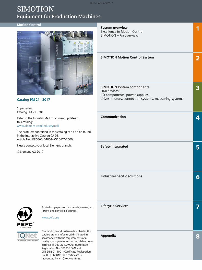
System overviewExcellence in Motion ControlSIMOTION – An overview
1
SIMOTION Motion Control System 2
SIMOTION system componentsHMI devices, I/O components, power supplies, drives, motors, connection systems, measuring systems
3
Communication 4
Safety Integrated 5
Industry-specific solutions 6
Lifecycle Services 7
Appendix 8
SIMOTION Equipment for Production Machines
Motion Control
Catalog PM 21 · 2017
Supersedes: Catalog PM 21 · 2013
Refer to the Industry Mall for current updates of this catalog: www.siemens.com/industrymall
The products contained in this catalog can also be found in the Interactive Catalog CA 01.Article No.: E86060-D4001-A510-D7-7600
Please contact your local Siemens branch.
© Siemens AG 2017
Printed on paper from sustainably managed forests and controlled sources.www.pefc.org
The products and systems described in this catalog are manufactured/distributed in accordance with the requirements of a quality management system which has been certified to DIN EN ISO 9001 (Certificate Registration No. 001258 QM) and DIN EN ISO 14001 (Certificate Registration No. 081342 UM). The certificate is recognized by all IQNet countries.
© Siemens AG 2017
2 Siemens PM 21 · 2017
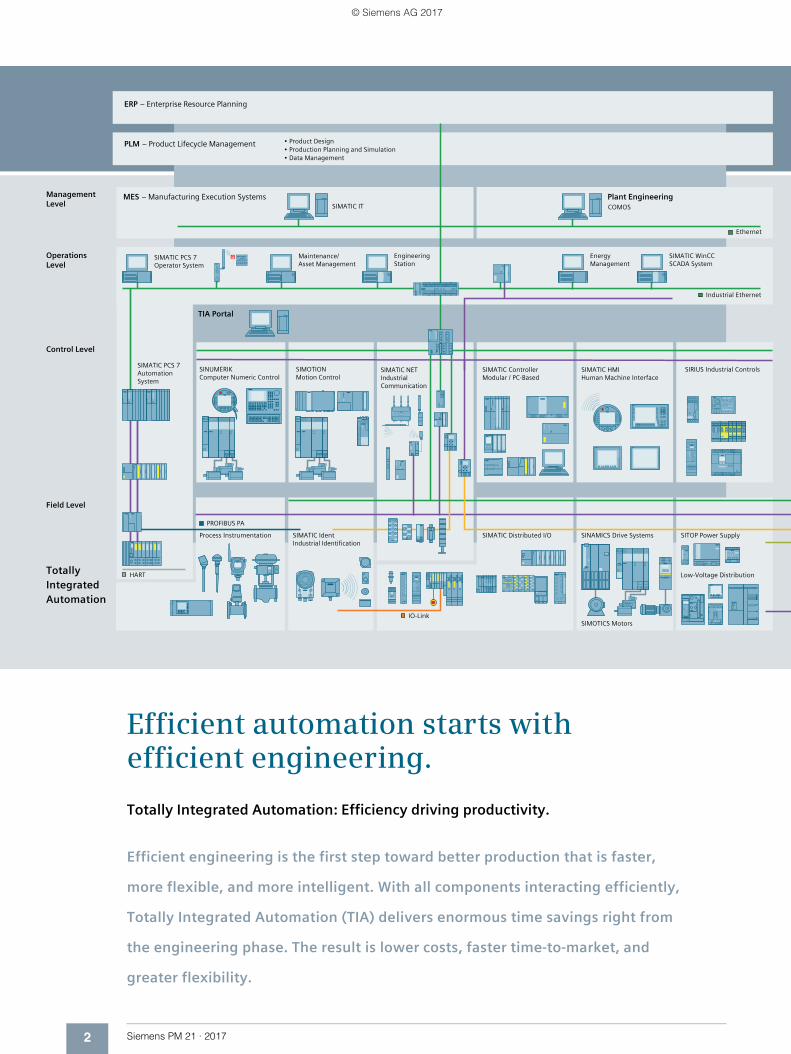
Efficient automation starts with efficient engineering.
Totally Integrated Automation: Efficiency driving productivity.
Efficient engineering is the first step toward better production that is faster,
more flexible, and more intelligent. With all components interacting efficiently,
Totally Integrated Automation (TIA) delivers enormous time savings right from
the engineering phase. The result is lower costs, faster time-to-market, and
greater flexibility.
© Siemens AG 2017
3Siemens PM 21 · 2017
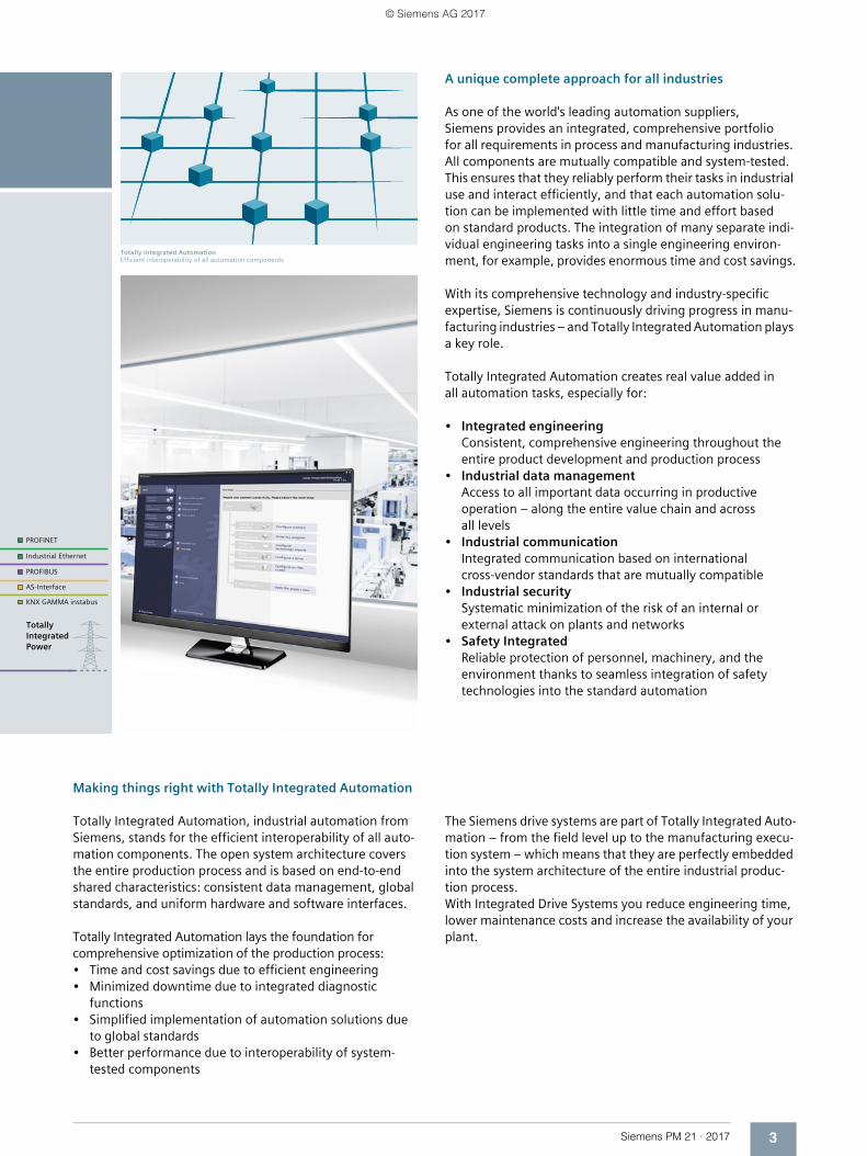
Totally Integrated AutomationEfficient interoperability of all automation components
Making things right with Totally Integrated Automation
Totally Integrated Automation, industrial automation from Siemens, stands for the efficient interoperability of all auto-mation components. The open system architecture covers the entire production process and is based on end-to-end shared characteristics: consistent data management, global standards, and uniform hardware and software interfaces.
Totally Integrated Automation lays the foundation for comprehensive optimization of the production process:• Time and cost savings due to efficient engineering• Minimized downtime due to integrated diagnostic
functions• Simplified implementation of automation solutions due
to global standards• Better performance due to interoperability of system-
tested components
A unique complete approach for all industries
As one of the world's leading automation suppliers, Siemens provides an integrated, comprehensive portfolio for all requirements in process and manufacturing industries. All components are mutually compatible and system-tested. This ensures that they reliably perform their tasks in industrial use and interact efficiently, and that each automation solu-tion can be implemented with little time and effort based on standard products. The integration of many separate indi-vidual engineering tasks into a single engineering environ-ment, for example, provides enormous time and cost savings.
With its comprehensive technology and industry-specific expertise, Siemens is continuously driving progress in manu-facturing industries – and Totally Integrated Automation plays a key role.
Totally Integrated Automation creates real value added in all automation tasks, especially for:
• Integrated engineeringConsistent, comprehensive engineering throughout the entire product development and production process
• Industrial data managementAccess to all important data occurring in productive operation – along the entire value chain and across all levels
• Industrial communicationIntegrated communication based on international cross-vendor standards that are mutually compatible
• Industrial securitySystematic minimization of the risk of an internal or external attack on plants and networks
• Safety IntegratedReliable protection of personnel, machinery, and the environment thanks to seamless integration of safety technologies into the standard automation
The Siemens drive systems are part of Totally Integrated Auto-mation – from the field level up to the manufacturing execu-tion system – which means that they are perfectly embedded into the system architecture of the entire industrial produc-tion process. With Integrated Drive Systems you reduce engineering time, lower maintenance costs and increase the availability of your plant.
© Siemens AG 2017
4 Siemens PM 21 · 2017
www.siemens.com/ids
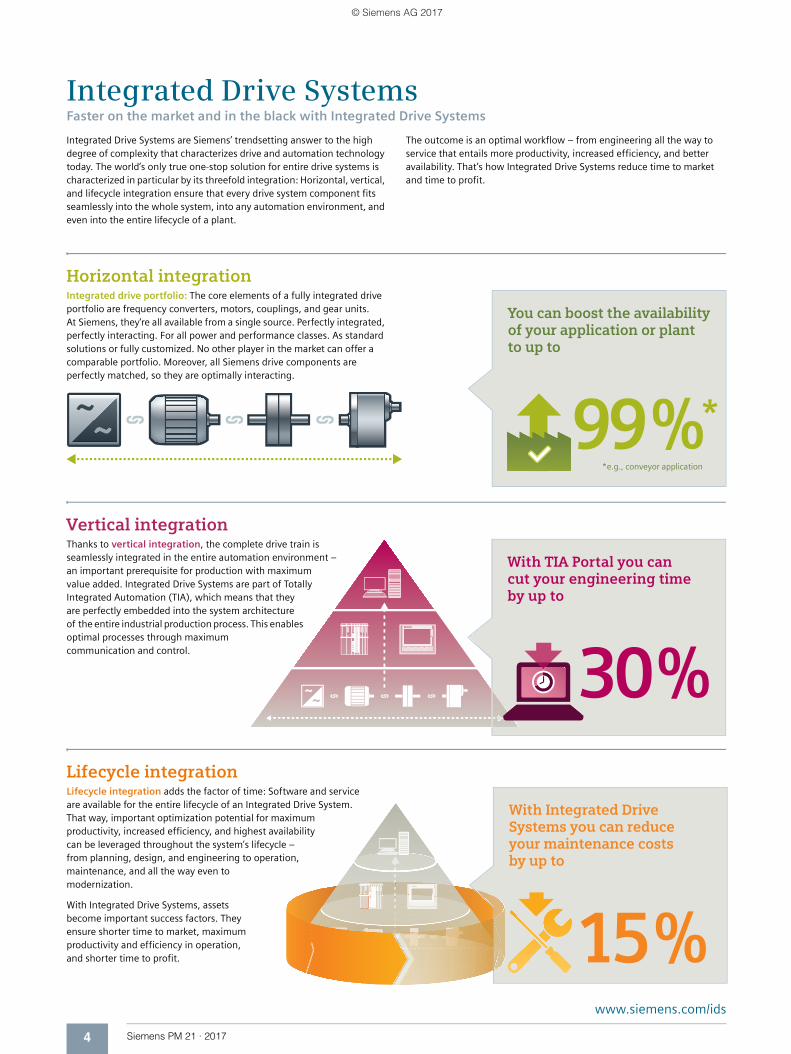
With Integrated Drive Systems you can reduce your main tenance costs by up to
15 %
You can boost the avail ability of your application or plant to up to
99 %**e.g., conveyor application
With TIA Portal you can cut your engineering time by up to
30 %
Integrated Drive SystemsFaster on the market and in the black with Integrated Drive Systems
Integrated Drive Systems are Siemens’ trendsetting answer to the high degree of complexity that characterizes drive and automation technology today. The world’s only true one-stop solution for entire drive systems is characterized in particular by its threefold integration: Horizontal, vertical, and lifecycle integration ensure that every drive system component fits seamlessly into the whole system, into any automation environment, and even into the entire lifecycle of a plant.
The outcome is an optimal workflow – from engineering all the way to service that entails more productivity, increased efficiency, and better availability. That’s how Integrated Drive Systems reduce time to market and time to profit.
Horizontal integrationIntegrated drive portfolio: The core elements of a fully integrated drive portfolio are frequency converters, motors, couplings, and gear units. At Siemens, they‘re all available from a single source. Perfectly integrated, perfectly interacting. For all power and performance classes. As standard solutions or fully customized. No other player in the market can offer a comparable portfolio. Moreover, all Siemens drive components are perfectly matched, so they are optimally interacting.
Vertical integrationThanks to vertical integration, the complete drive train is seamlessly integrated in the entire automation environment – an important prerequisite for production with maximum value added. Integrated Drive Systems are part of Totally Integrated Automation (TIA), which means that they are perfectly embedded into the system architecture of the entire industrial production process. This enables optimal processes through maximum communication and control.
Lifecycle integrationLifecycle integration adds the factor of time: Software and service are available for the entire lifecycle of an Integrated Drive System. That way, important optimization potential for maximum productivity, increased efficiency, and highest availability can be leveraged throughout the system’s lifecycle – from planning, design, and engineering to operation, maintenance, and all the way even to modernization.
With Integrated Drive Systems, assets become important success factors. They ensure shorter time to market, maximum productivity and efficiency in operation, and shorter time to profit.
© Siemens AG 2017
Siemens PM 21 · 2017
11/2 Excellence in Motion Control
1/4 SIMOTION – An overview1/4 The SIMOTION system1/5 Hardware platforms1/7 Runtime system1/8 Engineering system1/9 Standard modules and project generator
System overview
© Siemens AG 2017
1/2 Siemens PM 21 · 2017
System overviewExcellence in Motion Control
1■ Overview
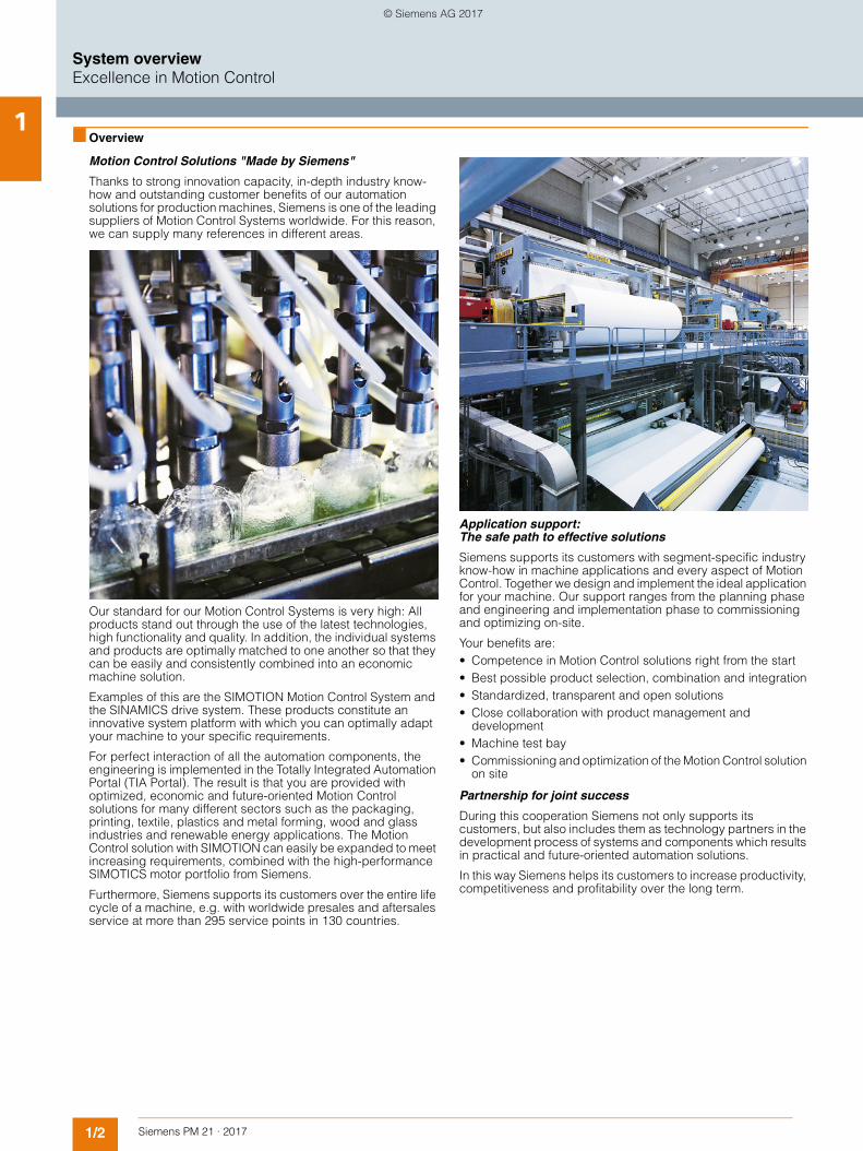
Motion Control Solutions "Made by Siemens"
Thanks to strong innovation capacity, in-depth industry know-how and outstanding customer benefits of our automation solutions for production machines, Siemens is one of the leading suppliers of Motion Control Systems worldwide. For this reason, we can supply many references in different areas.
Our standard for our Motion Control Systems is very high: All products stand out through the use of the latest technologies, high functionality and quality. In addition, the individual systems and products are optimally matched to one another so that they can be easily and consistently combined into an economic machine solution.
Examples of this are the SIMOTION Motion Control System and the SINAMICS drive system. These products constitute an innovative system platform with which you can optimally adapt your machine to your specific requirements.
For perfect interaction of all the automation components, the engineering is implemented in the Totally Integrated Automation Portal (TIA Portal). The result is that you are provided with optimized, economic and future-oriented Motion Control solutions for many different sectors such as the packaging, printing, textile, plastics and metal forming, wood and glass industries and renewable energy applications. The Motion Control solution with SIMOTION can easily be expanded to meet increasing requirements, combined with the high-performance SIMOTICS motor portfolio from Siemens.
Furthermore, Siemens supports its customers over the entire life cycle of a machine, e.g. with worldwide presales and aftersales service at more than 295 service points in 130 countries.
Application support: The safe path to effective solutions
Siemens supports its customers with segment-specific industry know-how in machine applications and every aspect of Motion Control. Together we design and implement the ideal application for your machine. Our support ranges from the planning phase and engineering and implementation phase to commissioning and optimizing on-site.
Your benefits are:• Competence in Motion Control solutions right from the start• Best possible product selection, combination and integration• Standardized, transparent and open solutions• Close collaboration with product management and
development• Machine test bay • Commissioning and optimization of the Motion Control solution
on site
Partnership for joint success
During this cooperation Siemens not only supports its customers, but also includes them as technology partners in the development process of systems and components which results in practical and future-oriented automation solutions.
In this way Siemens helps its customers to increase productivity, competitiveness and profitability over the long term.
© Siemens AG 2017
1/3Siemens PM 21 · 2017
System overviewExcellence in Motion Control
1■ Overview (continued)
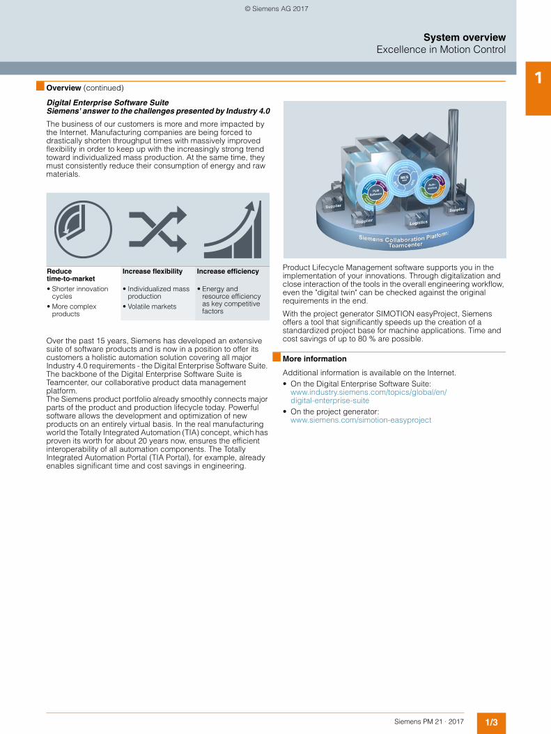
Digital Enterprise Software Suite Siemens' answer to the challenges presented by Industry 4.0
The business of our customers is more and more impacted by the Internet. Manufacturing companies are being forced to drastically shorten throughput times with massively improved flexibility in order to keep up with the increasingly strong trend toward individualized mass production. At the same time, they must consistently reduce their consumption of energy and raw materials.
Over the past 15 years, Siemens has developed an extensive suite of software products and is now in a position to offer its customers a holistic automation solution covering all major Industry 4.0 requirements - the Digital Enterprise Software Suite. The backbone of the Digital Enterprise Software Suite is Teamcenter, our collaborative product data management platform.The Siemens product portfolio already smoothly connects major parts of the product and production lifecycle today. Powerful software allows the development and optimization of new products on an entirely virtual basis. In the real manufacturing world the Totally Integrated Automation (TIA) concept, which has proven its worth for about 20 years now, ensures the efficient interoperability of all automation components. The Totally Integrated Automation Portal (TIA Portal), for example, already enables significant time and cost savings in engineering.
Product Lifecycle Management software supports you in the implementation of your innovations. Through digitalization and close interaction of the tools in the overall engineering workflow, even the "digital twin" can be checked against the original requirements in the end.
With the project generator SIMOTION easyProject, Siemens offers a tool that significantly speeds up the creation of a standardized project base for machine applications. Time and cost savings of up to 80 % are possible.
■ More information
Additional information is available on the Internet. • On the Digital Enterprise Software Suite:
www.industry.siemens.com/topics/global/en/digital-enterprise-suite
• On the project generator: www.siemens.com/simotion-easyproject
Reduce time-to-market • Shorter innovation
cycles• More complex
products
Increase flexibility
• Individualized mass production
• Volatile markets
Increase efficiency
• Energy and resource efficiency as key competitive factors
© Siemens AG 2017
1/4 Siemens PM 21 · 2017
System overviewSIMOTION – An overview
The SIMOTION system1
■ Overview
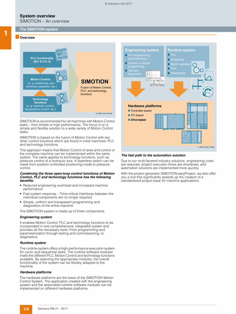
SIMOTION is recommended for all machines with Motion Control tasks – from simple to high-performance. The focus is on a simple and flexible solution to a wide variety of Motion Control tasks.
SIMOTION is based on the fusion of Motion Control with two other control functions which are found in most machines: PLC and technology functions.
This approach means that Motion Control of axes and control of the complete machine can be implemented within the same system. The same applies to technology functions, such as pressure control of a hydraulic axis. A seamless switch can be made from position-controlled positioning mode to pressure control.
Combining the three open-loop control functions of Motion Control, PLC and technology functions has the following benefits:• Reduced engineering overhead and increased machine
performance• Fast system response – Time-critical interfaces between the
individual components are no longer required• Simple, uniform and transparent programming and
diagnostics of the entire machine
The SIMOTION system is made up of three components:
Engineering system
It enables Motion Control, PLC and technology functions to be incorporated in one comprehensive, integrated system and provides all the necessary tools: From programming and parameterization through testing and commissioning, to diagnostics.
Runtime system
The runtime system offers a high-performance execution system for cyclic and sequential tasks. The runtime software modules make the different PLC, Motion Control and technology functions available. By selecting the appropriate modules, the overall functionality of the system can be flexibly adapted to the machine.
Hardware platforms
The hardware platforms are the basis of the SIMOTION Motion Control System. The application created with the engineering system and the associated runtime software modules can be implemented on different hardware platforms.
The fast path to the automation solution
Due to our multi-faceted industry solutions, engineering costs are reduced, project execution times are shortened, and automation solutions are implemented more quickly.
With the project generator SIMOTION easyProject, we also offer you a tool that significantly speeds up the creation of a standardized project base for machine applications.
SIMOTIONMotion Control
PLC functionality(IEC 61131-3)
Fusion of Motion Control,PLC, and technologyfunctions
G_PM10_EN_00125a
Technologyfunctions
(e. g. hydraulic control,temperature control, etc.)
(e. g. positioning, syn- chronous operation, etc.)
Drive-basedPC-basedController-based
Interpolation
CamSynch. operationPositioning
PLC
Test and diagnostics
Graphic or textual programming
For programming, parameterizing, ...
Hardware platforms
Runtime systemEngineering system
G_PM10_EN_00126d
Drive-based
© Siemens AG 2017
1/5Siemens PM 21 · 2017
System overviewSIMOTION – An overview
Hardware platforms1
■ Overview
One concept – 3 platforms
Automation systems are primarily identified by the following characteristics:• System-specific characteristics, e.g. functionality and
engineering• Hardware-dependent characteristics, e.g. performance,
design and expandability
However, mechanical engineering demands vary greatly, depending on the version of the machine in question.
Every hardware platform has its benefits when used in certain applications.
The various platforms can also be combined very easily, which is a particular advantage in modular machines and plants. This is because the individual hardware platforms always have the same system characteristics, i.e. functionality and engineering are always identical, irrespective of the platform used.
PROFIBUS or PROFINET can be used to create the link to the drives and the I/Os remotely.
PROFINET/PROFIBUS can also be used for communication with HMI devices such as SIMATIC HMI or higher-level controllers such as SIMATIC S7. This means that SIMATIC HMI Panels as well as PCs with WinCC can be used as operator systems. Even 3rd party applications communicate with SIMOTION by means of the OPC interface.
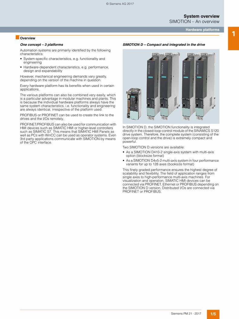
SIMOTION D – Compact and integrated in the drive
In SIMOTION D, the SIMOTION functionality is integrated directly in the closed-loop control module of the SINAMICS S120 drive system. Therefore, the complete system (consisting of the open-loop control and the drive) is extremely compact and powerful.
Two SIMOTION D versions are available:• As a SIMOTION D410-2 single-axis system with multi-axis
option (blocksize format)• As a SIMOTION D4x5-2 multi-axis system in four performance
variants for up to 128 axes (booksize format)
This finely graded performance ensures the highest degree of scalability and flexibility. The field of application ranges from single axes to high-performance multi-axis machines. For visualization and operation, SIMATIC HMI devices can be connected via PROFINET, Ethernet or PROFIBUS depending on the SIMOTION D version. Distributed I/Os are connected via PROFINET or PROFIBUS.
© Siemens AG 2017
1/6 Siemens PM 21 · 2017
System overviewSIMOTION – An overview
Hardware platforms1
■ Overview (continued)
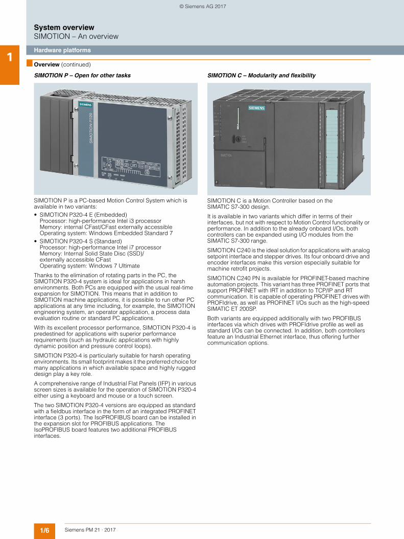
SIMOTION P – Open for other tasks
SIMOTION P is a PC-based Motion Control System which is available in two variants:• SIMOTION P320-4 E (Embedded)
Processor: high-performance Intel i3 processor Memory: internal CFast/CFast externally accessible Operating system: Windows Embedded Standard 7
• SIMOTION P320-4 S (Standard)Processor: high-performance Intel i7 processor Memory: Internal Solid State Disc (SSD)/externally accessible CFast Operating system: Windows 7 Ultimate
Thanks to the elimination of rotating parts in the PC, the SIMOTION P320-4 system is ideal for applications in harsh environments. Both PCs are equipped with the usual real-time expansion for SIMOTION. This means that in addition to SIMOTION machine applications, it is possible to run other PC applications at any time including, for example, the SIMOTION engineering system, an operator application, a process data evaluation routine or standard PC applications.
With its excellent processor performance, SIMOTION P320-4 is predestined for applications with superior performance requirements (such as hydraulic applications with highly dynamic position and pressure control loops).
SIMOTION P320-4 is particularly suitable for harsh operating environments. Its small footprint makes it the preferred choice for many applications in which available space and highly rugged design play a key role.
A comprehensive range of Industrial Flat Panels (IFP) in various screen sizes is available for the operation of SIMOTION P320-4 either using a keyboard and mouse or a touch screen.
The two SIMOTION P320-4 versions are equipped as standard with a fieldbus interface in the form of an integrated PROFINET interface (3 ports). The IsoPROFIBUS board can be installed in the expansion slot for PROFIBUS applications. The IsoPROFIBUS board features two additional PROFIBUS interfaces.
SIMOTION C – Modularity and flexibility
SIMOTION C is a Motion Controller based on the SIMATIC S7-300 design.
It is available in two variants which differ in terms of their interfaces, but not with respect to Motion Control functionality or performance. In addition to the already onboard I/Os, both controllers can be expanded using I/O modules from the SIMATIC S7-300 range.
SIMOTION C240 is the ideal solution for applications with analog setpoint interface and stepper drives. Its four onboard drive and encoder interfaces make this version especially suitable for machine retrofit projects.
SIMOTION C240 PN is available for PROFINET-based machine automation projects. This variant has three PROFINET ports that support PROFINET with IRT in addition to TCP/IP and RT communication. It is capable of operating PROFINET drives with PROFIdrive, as well as PROFINET I/Os such as the high-speed SIMATIC ET 200SP.
Both variants are equipped additionally with two PROFIBUS interfaces via which drives with PROFIdrive profile as well as standard I/Os can be connected. In addition, both controllers feature an Industrial Ethernet interface, thus offering further communication options.
© Siemens AG 2017
1/7Siemens PM 21 · 2017
System overviewSIMOTION – An overview
Runtime system1
■ Overview
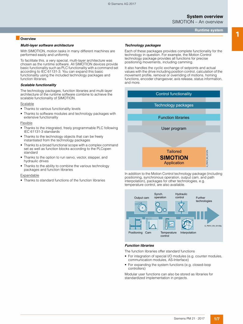
Multi-layer software architecture
With SIMOTION, motion tasks in many different machines are performed easily and uniformly.
To facilitate this, a very special, multi-layer architecture was chosen as the runtime software. All SIMOTION devices provide basic functionality such as PLC functionality with a command set according to IEC 61131-3. You can expand this basic functionality using the included technology packages and function libraries.
Scalable functionality
The technology packages, function libraries and multi-layer architecture of the runtime software combine to achieve the scalable functionality of SIMOTION.
Scalable• Thanks to various functionality levels• Thanks to software modules and technology packages with
extensive functionality
Flexible• Thanks to the integrated, freely programmable PLC following
IEC 61131-3 standards• Thanks to the technology objects that can be freely
instantiated from the technology packages• Thanks to a broad functional scope with a complex command
set as well as function blocks according to the PLCopen standard
• Thanks to the option to run servo, vector, stepper, and hydraulic drives
• Thanks to the ability to combine the various technology packages and function libraries
Expandable• Thanks to standard functions of the function libraries
Technology packages
Each of these packages provides complete functionality for the technology in question. For example, the Motion Control technology package provides all functions for precise positioning movements, including camming.
It also handles the cyclic exchange of setpoints and actual values with the drive including position control, calculation of the movement profile, removal or overriding of motions, homing functions, encoder changeover, axis release, status information, and more.
In addition to the Motion Control technology package (including positioning, synchronous operation, output cam, and path interpolation), packages for other technologies, e.g. temperature control, are also available.
Function libraries
The function libraries offer standard functions• For integration of special I/O modules (e.g. counter modules,
communication modules, AS-Interface)• For expanding the system functions (e.g. closed-loop
controllers)
Modular user functions can also be stored as libraries for standardized implementation in projects.
Tailored
SIMOTIONApplication
Function libraries
Technology packages
Control functionality
User program
G_P
M10
_EN
_001
27b
Interpolation
Hydraulic control Further
technologies
G_PM10_EN_00128a
Synch. operationOutput cam
Temperature control
CamPositioning
© Siemens AG 2017
1/8 Siemens PM 21 · 2017
System overviewSIMOTION – An overview
Engineering system1
■ Overview
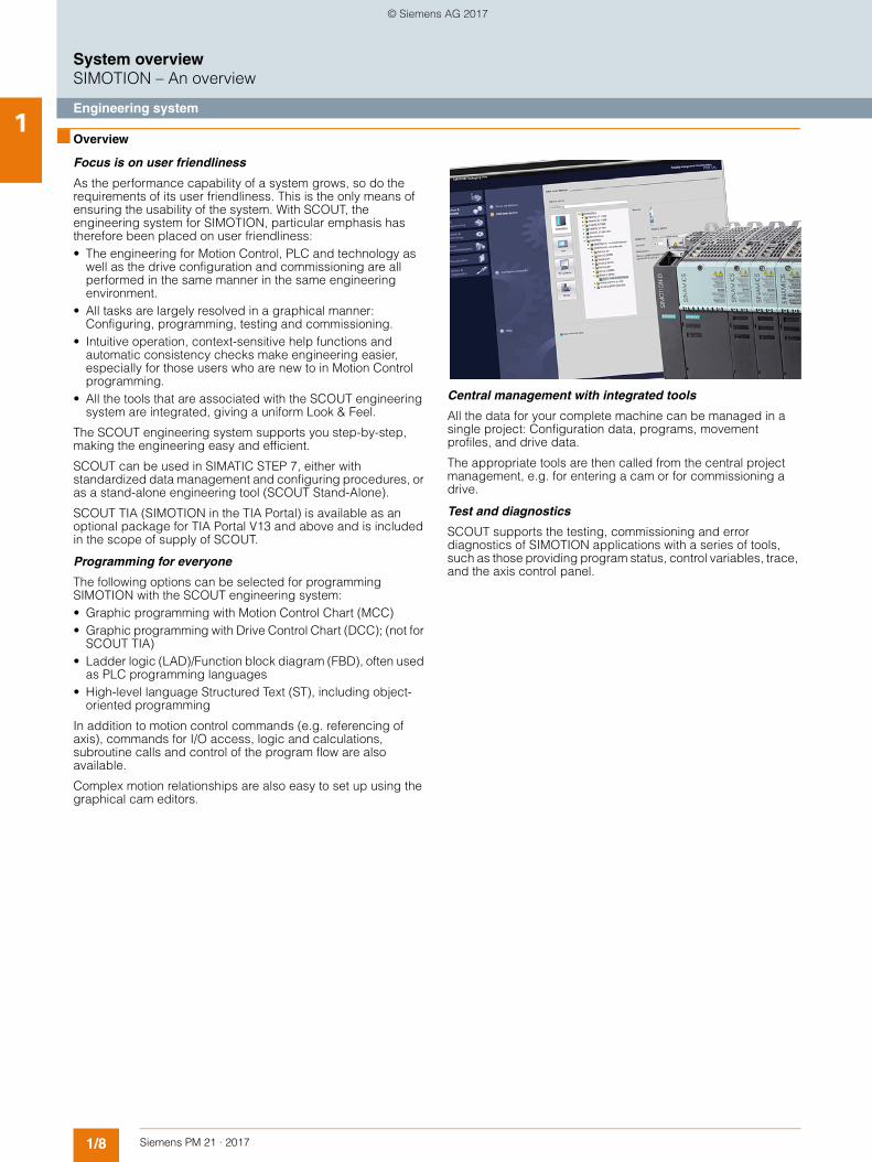
Focus is on user friendliness
As the performance capability of a system grows, so do the requirements of its user friendliness. This is the only means of ensuring the usability of the system. With SCOUT, the engineering system for SIMOTION, particular emphasis has therefore been placed on user friendliness:• The engineering for Motion Control, PLC and technology as
well as the drive configuration and commissioning are all performed in the same manner in the same engineering environment.
• All tasks are largely resolved in a graphical manner: Configuring, programming, testing and commissioning.
• Intuitive operation, context-sensitive help functions and automatic consistency checks make engineering easier, especially for those users who are new to in Motion Control programming.
• All the tools that are associated with the SCOUT engineering system are integrated, giving a uniform Look & Feel.
The SCOUT engineering system supports you step-by-step, making the engineering easy and efficient.
SCOUT can be used in SIMATIC STEP 7, either with standardized data management and configuring procedures, or as a stand-alone engineering tool (SCOUT Stand-Alone).
SCOUT TIA (SIMOTION in the TIA Portal) is available as an optional package for TIA Portal V13 and above and is included in the scope of supply of SCOUT.
Programming for everyone
The following options can be selected for programming SIMOTION with the SCOUT engineering system:• Graphic programming with Motion Control Chart (MCC)• Graphic programming with Drive Control Chart (DCC); (not for
SCOUT TIA) • Ladder logic (LAD)/Function block diagram (FBD), often used
as PLC programming languages• High-level language Structured Text (ST), including object-
oriented programming
In addition to motion control commands (e.g. referencing of axis), commands for I/O access, logic and calculations, subroutine calls and control of the program flow are also available.
Complex motion relationships are also easy to set up using the graphical cam editors.
Central management with integrated tools
All the data for your complete machine can be managed in a single project: Configuration data, programs, movement profiles, and drive data.
The appropriate tools are then called from the central project management, e.g. for entering a cam or for commissioning a drive.
Test and diagnostics
SCOUT supports the testing, commissioning and error diagnostics of SIMOTION applications with a series of tools, such as those providing program status, control variables, trace, and the axis control panel.
© Siemens AG 2017
1/9Siemens PM 21 · 2017
System overviewSIMOTION – An overview
Standard modules and project generator1
■ Overview
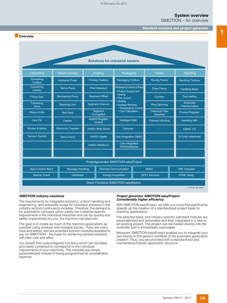
SIMOTION industry solutions
The requirements for integrated solutions, uniform handling and engineering, and adequate scope for individual solutions in the industry sectors continues to increase. Therefore, the demand is for automation concepts which satisfy the customer-specific requirements in the individual industries and can be quickly and safely implemented by you, the machine manufacturer.
The goal is to create as much of the machine applications as possible using modular and reusable blocks. There are many tried and tested, well documented function modules available to you for SIMOTION – the basis for achieving tailored solutions with little cost and effort.
You benefit from preconfigured functions which can be freely and easily combined to correspond to the individual requirements of your machines. The modules are simply parameterized instead of being programmed at considerable expense.
Project generator SIMOTION easyProject: Considerably higher efficiency
With SIMOTION easyProject, we offer you a tool that significantly speeds up the creation of a standardized project base for machine applications.
The selected basic and industry-specific standard modules are parameterized and automated and then integrated in a new or an existing project. The project can be loaded directly into the controller and is immediately executable.
Moreover, SIMOTION easyProject enables you to integrate your own blocks in this generic workflow of the automatic application creation. Thus, you are provided with a standardized and maintenance-friendly application structure.
Projectgenerator SIMOTION easyProject
HTML SetupDPV1 ServicesEnergy AcquisitionInterpreterStartup Check
HMI TemplateOMACEthernet Communication Message HandlingAxis Function Block
Basic Functions SIMOTION easyBasics
Handling
Solutions for industrial sectors
Winder & Splice
Tension Control
Axis FB
Rotary Knife
Traversing Drive
Flying Saw
Converting Library
Converting Toolbox
Hydraulic Press Handling Toolbox
Handling Basic
Product Register
Handling HMI
OMAC 3.0
G-Code Interpreter
TopLoading
Servo Press
Mechanical Press
Blanking Line
Roll Feed
Feeder
Electronic Transfer
Printing Toolbox Roving Frame
Filament Winding
Draw Frame
Comber
Ring Spinning
Packaging Toolbox
Intelligent Belt
Cartoner
…
…
…
…
……
Line Integration OMAC
Chemical Fiber Spinning
Line Integration Weihenstephan
Kinematic Transformation
Packaging Library (LPac)Product Supply and Dosing
Print Standard
Segment Offset
Segment Gravure
AddOn Reel Stand
AddOn Sigate
AddOn WebAccu
Segment Corrugated
AddOn Register Control
Servo Pump
TextilePackagingPrintingMetal FormingConverting
G_PM10_EN_00231
•
Film Control•Sealing•Auxiliary Modules•
Temperature Control•Cam Calculation•
© Siemens AG 2017
1/10 Siemens PM 21 · 2017
System overview
Notes1
© Siemens AG 2017
Siemens PM 21 · 2017
22/2 Overview
2/4 SIMOTION D – Drive-based2/9 SIMOTION D410-2 Control Units2/18 SIMOTION D4x5-2 Control Units2/32 Supplementary components2/32 SIMOTION CX32-2 Controller Extension2/35 CBE30-2 Communication Board2/36 TB30 Terminal Board
2/38 SIMOTION P – PC-based2/38 SIMOTION P320-4 Motion Controller
2/45 SIMOTION C – Controller-based2/45 SIMOTION C240/C240 PN
Motion Controller
2/52 SIMOTION software2/52 Overview
2/53 SIMOTION runtime software2/53 Overview2/56 SIMOTION Kernel2/58 SIMOTION technology packages2/65 SIMOTION PLCopen blocks2/66 Overview of the licensing concept2/68 Ordering of licenses for runtime software
2/71 OPC server2/71 OPC server of SIMOTION and
SIMATIC NET
2/74 SIMOTION IT2/74 Web server functions for service and
diagnostics
2/77 SIMOTION engineering software2/77 Overview2/79 SIMOTION SCOUT2/81 Workbench2/82 Hardware and network configuration2/83 Creation of technology objects2/84 Creation of cams (basic)2/85 Structured Text (ST)2/86 Motion Control Chart (MCC)2/87 Ladder Diagram / Function Block
Diagram (LAD/FBD)2/88 Diagnostics for testing and commissioning2/90 Optional packages for SIMOTION SCOUT2/90 CamTool (graphical cam editor)2/91 Drive Control Chart (DCC)2/92 Options for SIMOTION SCOUT2/92 SIMOTION easyProject project generator2/95 SIMOTION Utilities & Applications2/97 Ordering of engineering software,
information
2/99 Overview of SIMOTION functions
SIMOTION Motion Control System
© Siemens AG 2017
2/2 Siemens PM 21 · 2017
SIMOTION Motion Control SystemOverview
2
Designation Description Page
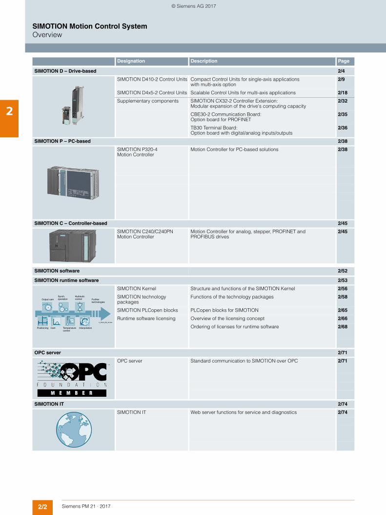
SIMOTION D – Drive-based 2/4
SIMOTION D410-2 Control Units Compact Control Units for single-axis applications with multi-axis option
2/9
SIMOTION D4x5-2 Control Units Scalable Control Units for multi-axis applications 2/18
Supplementary components SIMOTION CX32-2 Controller Extension: Modular expansion of the drive's computing capacity
2/32
CBE30-2 Communication Board: Option board for PROFINET
2/35
TB30 Terminal Board: Option board with digital/analog inputs/outputs
2/36
SIMOTION P – PC-based 2/38
SIMOTION P320-4 Motion Controller
Motion Controller for PC-based solutions 2/38
SIMOTION C – Controller-based 2/45
SIMOTION C240/C240PN Motion Controller
Motion Controller for analog, stepper, PROFINET and PROFIBUS drives
2/45
SIMOTION software 2/52
SIMOTION runtime software 2/53
SIMOTION Kernel Structure and functions of the SIMOTION Kernel 2/56
SIMOTION technology packages
Functions of the technology packages 2/58
SIMOTION PLCopen blocks PLCopen blocks for SIMOTION 2/65
Runtime software licensing Overview of the licensing concept 2/66
Ordering of licenses for runtime software 2/68
OPC server 2/71
OPC server Standard communication to SIMOTION over OPC 2/71
SIMOTION IT 2/74
SIMOTION IT Web server functions for service and diagnostics 2/74
Interpolation
Hydraulic control Further
technologies
G_PM10_EN_00128a
Synch. operationOutput cam
Temperature control
CamPositioning
© Siemens AG 2017
2/3Siemens PM 21 · 2017
SIMOTION Motion Control SystemOverview
2
Designation Description Page
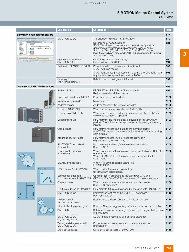
SIMOTION engineering software 2/77
SIMOTION SCOUT The engineering system for SIMOTION 2/79
Description of basic functions SCOUT Workbench, hardware and network configuration, generation of technological objects, generation of cams, Structured Text (ST), Motion Control Chart (MCC), ladder logic/function block diagram (LAD/FBD), diagnostics for testing and commissioning
2/81
Optional packages for SIMOTION SCOUT
CamTool (graphical cam editor) Drive Control Chart (DCC)
2/90 2/91
Options for SIMOTION SCOUT Projects can be created more efficiently with SIMOTION easyProject
2/92
SIMOTION Utilities & Applications – a comprehensive library with applications, examples, tools, scripts, FAQs, ...
2/95
Ordering of engineering software
Selection and ordering data, information 2/97
Overview of SIMOTION functions 2/99
System clocks PROFINET and PROFIBUS DP cycle clocks; System cycles for Motion Control
2/99
Dynamic Servo Control (DSC) Position controller in the drive 2/100
Memory for system data Memory sizes 2/100
Address ranges Address ranges of the Motion Controller 2/100
Drives on SIMOTION Which drives can be operated on SIMOTION? 2/101
Encoders on SIMOTION Which encoders can be directly connected to SIMOTION? Are there other connection options?
2/103
Measuring inputs How many measuring inputs are provided on the SIMOTION platforms? Are there further options for implementing measuring inputs?
2/103
Cam outputs How many onboard cam outputs are provided on the SIMOTION platforms? Are there further options for implementing cam outputs?
2/104
Integrated I/O interfaces How many onboard I/O interfaces are provided? (digital, analog, relay outputs, etc.)
2/105
SIMOTION C centralized I/O modules
How many centralized I/O modules can be added to SIMOTION C?
2/106
Connectable distributed I/O modules
Which distributed I/O modules can be connected over PROFIBUS or PROFINET? Which SINAMICS drive I/O modules can be connected to SIMOTION?
2/106
SIMATIC HMI devices Which HMI devices can be connected to SIMOTION?
2/107
HMI software for SIMOTION Which HMI software can be employed for SIMOTION applications?
2/107
Software for extended communication with SIMOTION
Communication according to the standards OPC and OPC XML-DA, SIMOTION Multipurpose Information Interface
2/107
Communication Which communication interfaces are provided on the SIMOTION platforms?
2/108
PROFIsafe drives on SIMOTION How many PROFIsafe drives can be operated with SIMOTION? 2/111
SIMOTION Kernel Performance features of the SIMOTION Kernel and PLC command set
2/112
Motion Control technology package
Features of the Motion Control technology package 2/114
Other technology packages SIMOTION technology packages for special areas of application 2/115
SIMOTION IT Software options for extending the service and diagnostic functions of SIMOTION
2/115
SIMOTION SCOUT engineering system
SCOUT basic functionality and optional packages 2/116
Testing and diagnostics with SIMOTION SCOUT
Program test functions, trace, comparison function for projects. etc.
2/117
Engineering drives Drive engineering tools for SIMOTION 2/118
© Siemens AG 2017
2/4 Siemens PM 21 · 2017
SIMOTION Motion Control SystemSIMOTION D – Drive-based
2
■ Overview
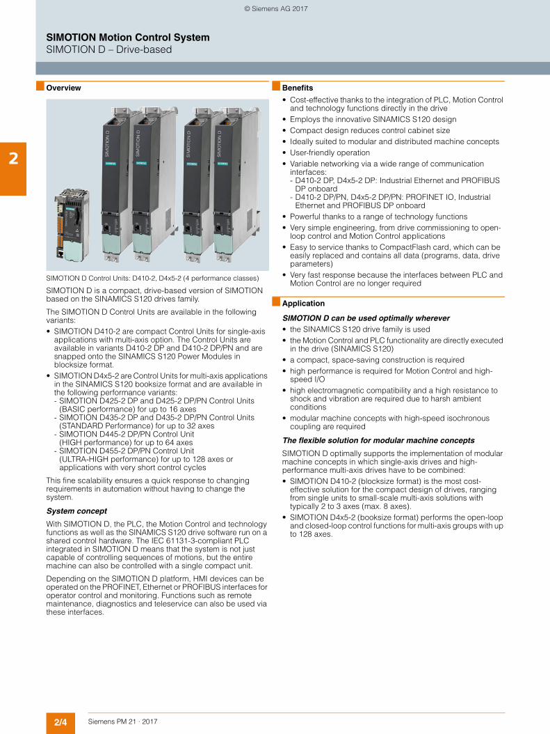
SIMOTION D Control Units: D410-2, D4x5-2 (4 performance classes)
SIMOTION D is a compact, drive-based version of SIMOTION based on the SINAMICS S120 drives family.
The SIMOTION D Control Units are available in the following variants:• SIMOTION D410-2 are compact Control Units for single-axis
applications with multi-axis option. The Control Units are available in variants D410-2 DP and D410-2 DP/PN and are snapped onto the SINAMICS S120 Power Modules in blocksize format.
• SIMOTION D4x5-2 are Control Units for multi-axis applications in the SINAMICS S120 booksize format and are available in the following performance variants:- SIMOTION D425-2 DP and D425-2 DP/PN Control Units
(BASIC performance) for up to 16 axes- SIMOTION D435-2 DP and D435-2 DP/PN Control Units
(STANDARD Performance) for up to 32 axes- SIMOTION D445-2 DP/PN Control Unit
(HIGH performance) for up to 64 axes - SIMOTION D455-2 DP/PN Control Unit
(ULTRA-HIGH performance) for up to 128 axes or applications with very short control cycles
This fine scalability ensures a quick response to changing requirements in automation without having to change the system.
System concept
With SIMOTION D, the PLC, the Motion Control and technology functions as well as the SINAMICS S120 drive software run on a shared control hardware. The IEC 61131-3-compliant PLC integrated in SIMOTION D means that the system is not just capable of controlling sequences of motions, but the entire machine can also be controlled with a single compact unit.
Depending on the SIMOTION D platform, HMI devices can be operated on the PROFINET, Ethernet or PROFIBUS interfaces for operator control and monitoring. Functions such as remote maintenance, diagnostics and teleservice can also be used via these interfaces.
■ Benefits
• Cost-effective thanks to the integration of PLC, Motion Control and technology functions directly in the drive
• Employs the innovative SINAMICS S120 design• Compact design reduces control cabinet size• Ideally suited to modular and distributed machine concepts• User-friendly operation• Variable networking via a wide range of communication
interfaces: - D410-2 DP, D4x5-2 DP: Industrial Ethernet and PROFIBUS
DP onboard- D410-2 DP/PN, D4x5-2 DP/PN: PROFINET IO, Industrial
Ethernet and PROFIBUS DP onboard• Powerful thanks to a range of technology functions• Very simple engineering, from drive commissioning to open-
loop control and Motion Control applications• Easy to service thanks to CompactFlash card, which can be
easily replaced and contains all data (programs, data, drive parameters)
• Very fast response because the interfaces between PLC and Motion Control are no longer required
■ Application
SIMOTION D can be used optimally wherever• the SINAMICS S120 drive family is used • the Motion Control and PLC functionality are directly executed
in the drive (SINAMICS S120) • a compact, space-saving construction is required • high performance is required for Motion Control and high-
speed I/O • high electromagnetic compatibility and a high resistance to
shock and vibration are required due to harsh ambient conditions
• modular machine concepts with high-speed isochronous coupling are required
The flexible solution for modular machine concepts
SIMOTION D optimally supports the implementation of modular machine concepts in which single-axis drives and high-performance multi-axis drives have to be combined: • SIMOTION D410-2 (blocksize format) is the most cost-
effective solution for the compact design of drives, ranging from single units to small-scale multi-axis solutions with typically 2 to 3 axes (max. 8 axes).
• SIMOTION D4x5-2 (booksize format) performs the open-loop and closed-loop control functions for multi-axis groups with up to 128 axes.
© Siemens AG 2017
2/5Siemens PM 21 · 2017
SIMOTION Motion Control SystemSIMOTION D – Drive-based
2
■ Application (continued)
Important applications include:• Packaging machines• Plastic and rubber processing machines• Presses, wire-drawing machines• Textile machines• Printing machines• Wood, glass, ceramics and stone working machines• Converting• Handling devices
Due to the increasing use of servo and vector drives, these machines require a high degree of integration of PLC, Motion Control and technology functions.
With SIMOTION D4x5-2 selected Control Units are also available as SIPLUS version for use under extremely difficult environmental conditions (e.g. in toxic atmospheres).
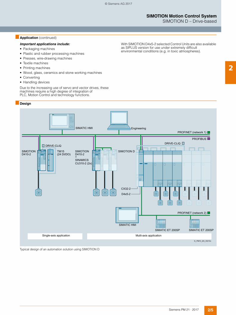
■ Design
Typical design of an automation solution using SIMOTION D
PROFINET (network 2)
PROFINET (network 1)Engineering
Single-axis application Multi-axis application
G_PM10_EN_00213c
SIMATIC ET 200SPSIMATIC ET 200SP
PROFIBUS
SIMATIC HMI
CX32-2
D4x5-2
SIMOTION D
DRIVE-CLiQ
SIMATIC HMI
D410-2SIMOTION
DRIVE-CLiQ
(24 DI/DO)TM15
CU310-2 (2x)SINAMICS+ D410-2 SIMOTION
© Siemens AG 2017
2/6 Siemens PM 21 · 2017
SIMOTION Motion Control SystemSIMOTION D – Drive-based
2
■ Design (continued)
SIMOTION D components and interfaces• Various status/error displays• Onboard digital inputs and outputs• Option slot (receptacle, only for D4x5-2), e.g. for expansion
with additional I/Os with the TB30 Terminal Board• Integrated communications interfaces for linking:
- SINAMICS S120 drive modules- Distributed I/Os- HMI systems- PG/PC- Other Motion Control and automation systems- Other SINAMICS S110/S120 drives with digital setpoint
interface • Slot for CompactFlash card for data backup
Design of a single axis with SIMOTION D410-2
The following components make up a SIMOTION D410-2 single-axis system:• A SIMOTION D410-2 Control Unit, designed for open and
closed-loop control of a single drive • A SINAMICS S120 PM240-2 Power Module in blocksize
format, combined infeed and power unit • Other drive components, such as
- Power supply - Filter - Reactor, etc.
The connection between SIMOTION D410-2 and the SINAMICS S120 Power Module is made with the integrated PM-IF interface or, when the CUA31/CUA32 Control Unit Adapter is used, via DRIVE-CLiQ.
Design of an axis grouping with SIMOTION D410-2
In order to create a multi-axis grouping with SIMOTION D410-2, additional SINAMICS S110/S120 Control Units are connected to the SIMOTION D410-2 by means of PROFINET or PROFIBUS.
Motion control is performed centrally by the SIMOTION D410-2 using the SIMOTION technology objects.
Design of an axis grouping with SIMOTION D4x5-2
The following components comprise a SIMOTION D4x5-2 axis grouping:• A SIMOTION D4x5-2 Control Unit, designed for open and
closed-loop control of a multiple axis grouping• A SINAMICS S120 Line Module (infeed module) • One or more SINAMICS S120 Motor Modules
(power units)• Other drive components, such as
- Power supply - Filter - Reactor, etc.
DRIVE-CLiQ provides the link between the SIMOTION D Control Unit and the SINAMICS S120 drive modules.
Note:SINAMICS S120 PM240-2 Power Modules in blocksize format can be operated on a SIMOTION D4x5-2/CX32-2 with the CUA31/CUA32 Control Unit Adapters.
Expansion using I/O
SIMOTION D can be expanded with the following I/O:• Distributed I/O systems (e.g. SIMATIC ET 200SP) • Drive-based control cabinet I/O (e.g. TM15, TM31 Terminal
Modules, etc.)
■ Function
Basic functionality
The SIMOTION D basic functionality is supplied with the CompactFlash card (CF) and is loaded when the power is switched on. The basic functionality includes:• SIMOTION runtime system
- User-programmable with several languages conforming to IEC 61131
- Various runtime levels (cyclic, sequential, event-driven)
- PLC and arithmetic functionality- Communication and management functions- Motion Control functions (Motion Control Basic)
• SINAMICS S120 drive control- SIMOTION D410-2:
Current/speed control (based on CU310-2, firmware version V4.x) for up to 1 servo axis, 1 vector axis or 1 V/f axis
- SIMOTION D4x5-2: Current/speed control (based on CU320-2, firmware version V4.x) for up to 6 servo axes, 6 vector axes or 12 V/f axes, closed-loop control for infeed (Active Line Module)
• Testing and diagnostic tools
This basic functionality can be expanded with loadable technology packages, if required.
Position-controlled motion control for drives• Integrated drives (SINAMICS Integrated):
The power units are connected over DRIVE-CLiQ or over the integrated PM-IF interface optionally for the SIMOTION D410-2.
• Drives with digital setpoint interface: SIMOTION D enables position-controlled motion control for drives with digital setpoint interfaces via PROFINET IO/PROFIBUS DP with PROFIdrive.
• Drives with analog setpoint interface, e.g. for retrofit or hydraulic applications: The ADI 4 (Analog Drive Interface for 4 Axes) or IM 174 (Interface Module for 4 Axes) module can be used to connect drives with analog ±10 V setpoint interfaces. The IM 174 also makes it possible to connect stepper drives with a pulse direction interface. Both modules are connected over PROFIBUS DP. The following can be connected to one ADI 4 or IM 174 module:- 4 drives- 4 encoders- Digital inputs and outputs
© Siemens AG 2017
2/7Siemens PM 21 · 2017
SIMOTION Motion Control SystemSIMOTION D – Drive-based
2
■ Function (continued)
SIMOTION technology packages
A special feature of SIMOTION is that the basic functionality can be expanded by loading technology packages, such as:• Motion Control with the technology functions:
- POS – Positioning- GEAR – Synchronous operation/electronic gear- CAM – Cam- PATH - Path interpolation
• TControl – Temperature controller• MIIF – Multipurpose Information Interface • Vibration Extinction (VIBX)• OACAMGEN
Since the technology functions have modular licenses, you only pay for what you will actually use.
Performance
Hardware-supported floating-point arithmetic enables complex arithmetic functions to be used effectively.
Fast instruction execution opens up completely new application possibilities in the mid-performance to high-performance range.
Configuring/parameterizing/programming
SIMOTION SCOUT is a powerful and user-friendly engineering tool. It is an integrated system for all engineering steps, from configuring and parameterization, through programming, to testing and diagnostics. Graphical operator prompting, using dialog boxes and wizards, as well as text-based and graphical languages for programming, considerably reduce the familiarization and training periods.
Operator control and monitoring (HMI)
Communication services which support user-friendly data exchange with SIMATIC HMI devices are integrated in the basic functionality of SIMOTION D.
These HMI devices can be connected to SIMOTION D over PROFINET, Industrial Ethernet or PROFIBUS and they are configured using SIMATIC WinCC (TIA Portal).
Version V7.0 and higher of the SCADA system SIMATIC WinCC features a SIMOTION channel which is included as standard on the WinCC DVD.
With the SIMATIC NET communications software, an open, standardized OPC interface is available for accessing SIMOTION from other Windows-based HMI systems.
SIMOTION IT service and diagnostic functions
SIMOTION IT provides SIMOTION D with an integrated web server on which, for example, user-specific web pages can be stored.
Read and write access can be made to the Control Unit variables. Java scripts or applets also allow the implementation of active operation and display functions in the web pages that can be executed on a client PC with an Internet browser.
Process and data communication
Thanks to its integrated interfaces, SIMOTION D supports both process and data communication.
PROFINET IO with IRT is available for exacting Motion Control applications. In addition to cycle clock synchronization, cycle times of minimum 125 µs and safety-related communication (PROFIsafe), the PROFINET interfaces on the SIMOTION D4xx-2 Control Units also support media redundancy (MRP/MRPD).
The SIMOTION SCOUT engineering system is provided for user-friendly communication configuration and diagnostics.
Safety Integrated functions
Highly effective protection of personnel and machinery can be implemented with SIMOTION D thanks to the integrated safety functions of SINAMICS S120.
The integrated safety functions that are currently available are described below. Their functional safety satisfies the require-ments defined in the international standard IEC 61800-5-2 for variable-speed drive systems.
The safety functions integrated into the SINAMICS S120 drive system can be roughly divided into four categories:• Functions for safely stopping a drive
- Safe Torque Off (STO)- Safe Stop1 (SS1)- Safe Stop2 (SS2)- Safe Operating Stop (SOS)
• Functions for safe brake management- Safe Brake Control (SBC)- Safe Brake Test (SBT)
(this diagnostic function exceeds the scope of IEC 61800-5-2)• Functions for safely monitoring the motion of a drive
- Safely Limited Speed (SLS) - Safe Speed Monitor (SSM) - Safe Direction (SDI)
• Functions for safely monitoring the position of a drive- Safely Limited Position (SLP)- Safe Position (SP)
(this function exceeds the scope of IEC 61800-5-2)
Activation of Safety Integrated functions
Safety Integrated functions can be activated by the following methods:• Via terminals on SIMOTION D4x5-2/CX32-2 and on the power
unit (STO, SBC, SS1 only)• Via fail-safe inputs on the TM54F Terminal Module• Via fail-safe inputs on SIMOTION D410-2 • Via PROFINET/PROFIBUS with PROFIsafe.
The SLS and SDI functions can also be activated permanently via parameter assignment.
The Safety Integrated functions are implemented electronically and therefore offer short response times in comparison to solutions with externally implemented monitoring functions.
© Siemens AG 2017
2/8 Siemens PM 21 · 2017
SIMOTION Motion Control SystemSIMOTION D – Drive-based
2
■ Function (continued)
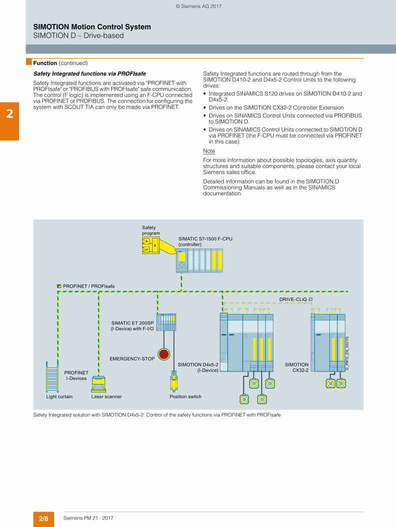
Safety Integrated functions via PROFIsafe
Safety Integrated functions are activated via "PROFINET with PROFIsafe" or "PROFIBUS with PROFIsafe" safe communication. The control (F logic) is implemented using an F-CPU connected via PROFINET or PROFIBUS. The connection for configuring the system with SCOUT TIA can only be made via PROFINET.
Safety Integrated functions are routed through from the SIMOTION D410-2 and D4x5-2 Control Units to the following drives:• Integrated SINAMICS S120 drives on SIMOTION D410-2 and
D4x5-2• Drives on the SIMOTION CX32-2 Controller Extension• Drives on SINAMICS Control Units connected via PROFIBUS
to SIMOTION D.• Drives on SINAMICS Control Units connected to SIMOTION D
via PROFINET (the F-CPU must be connected via PROFINET in this case).
Note
For more information about possible topologies, axis quantity structures and suitable components, please contact your local Siemens sales office.
Detailed information can be found in the SIMOTION D Commissioning Manuals as well as in the SINAMICS documentation.
Safety Integrated solution with SIMOTION D4x5-2: Control of the safety functions via PROFINET with PROFIsafe
Safety program
Light curtain Laser scanner Position switch
EMERGENCY-STOP
PROFINET I-Devices
SIMOTION D4x5-2 (I-Device)
SIMATIC ET 200SP (I-Device) with F-I/O
SIMOTION CX32-2
SIMATIC S7-1500 F-CPU (controller)
G_P
M10
_EN
_002
17b
PROFINET / PROFIsafe
DRIVE-CLiQ
© Siemens AG 2017
2/9Siemens PM 21 · 2017
SIMOTION Motion Control SystemSIMOTION D – Drive-based
SIMOTION D410-2 Control Units
2
■ Overview
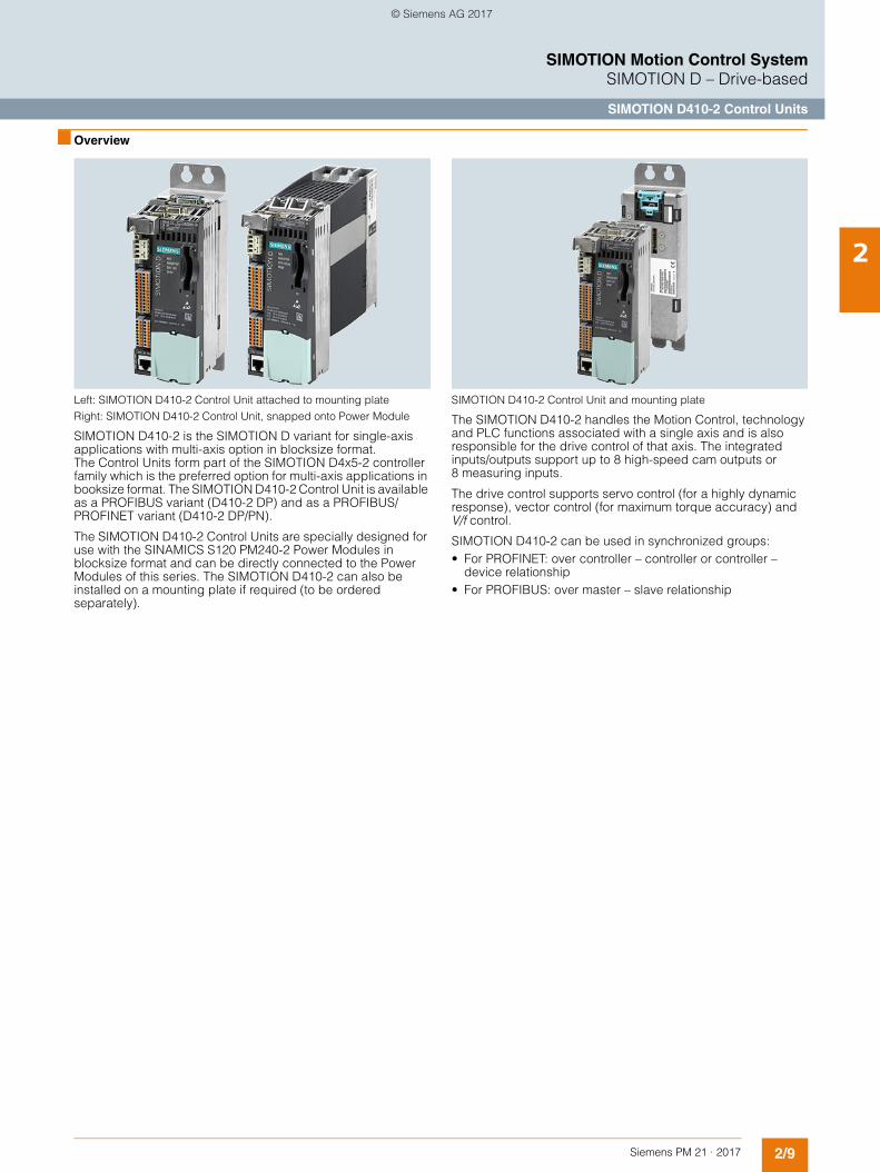
Left: SIMOTION D410-2 Control Unit attached to mounting plateRight: SIMOTION D410-2 Control Unit, snapped onto Power Module
SIMOTION D410-2 is the SIMOTION D variant for single-axis applications with multi-axis option in blocksize format. The Control Units form part of the SIMOTION D4x5-2 controller family which is the preferred option for multi-axis applications in booksize format. The SIMOTION D410-2 Control Unit is available as a PROFIBUS variant (D410-2 DP) and as a PROFIBUS/PROFINET variant (D410-2 DP/PN).
The SIMOTION D410-2 Control Units are specially designed for use with the SINAMICS S120 PM240-2 Power Modules in blocksize format and can be directly connected to the Power Modules of this series. The SIMOTION D410-2 can also be installed on a mounting plate if required (to be ordered separately).
SIMOTION D410-2 Control Unit and mounting plate
The SIMOTION D410-2 handles the Motion Control, technology and PLC functions associated with a single axis and is also responsible for the drive control of that axis. The integrated inputs/outputs support up to 8 high-speed cam outputs or 8 measuring inputs.
The drive control supports servo control (for a highly dynamic response), vector control (for maximum torque accuracy) and V/f control.
SIMOTION D410-2 can be used in synchronized groups:• For PROFINET: over controller – controller or controller –
device relationship• For PROFIBUS: over master – slave relationship
© Siemens AG 2017
2/10 Siemens PM 21 · 2017
SIMOTION Motion Control SystemSIMOTION D – Drive-based
SIMOTION D410-2 Control Units
2
■ Application
SIMOTION D410-2 is the ideal solution when Motion Control for one axis and PLC functionality are required in compact format. However, it can also be used for small multi-axis groupings with typically 2 to 3 axes (max. 8 axes) in blocksize format. With these applications, the SINAMICS Control Units are connected to the SIMOTION D410-2 via PROFINET or PROFIBUS.
Examples of SIMOTION D410-2 applications include:• Autonomous control of single axes• Cross cutters
• Winder applications• Feeder devices/roller infeed/press feeders• Synchronized machining equipment• Compact machine modules, e.g.
- Feeders in post press applications- Shrink wrapping machines
• Small multi-axis groupings (typically 2 to 3 axes) in blocksize format
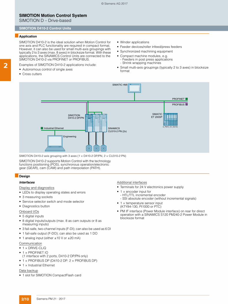
SIMOTION D410-2 axis grouping with 3 axes (1 × D410-2 DP/PN, 2 × CU310-2 PN)
SIMOTION D410-2 supports Motion Control with the technology functions positioning (POS), synchronous operation/electronic gear (GEAR), cam (CAM) and path interpolation (PATH).
■ Design
Interfaces
Display and diagnostics• LEDs to display operating states and errors• 3 measuring sockets • Service selector switch and mode selector• Diagnostics button
Onboard I/Os• 5 digital inputs • 8 digital inputs/outputs (max. 8 as cam outputs or 8 as
measuring inputs)• 3 fail-safe, two-channel inputs (F-DI); can also be used as 6 DI • 1 fail-safe output (F-DO); can also be used as 1 DO • 1 analog input (either ±10 V or ±20 mA)
Communication• 1 × DRIVE-CLiQ• 1 × PROFINET IO
(1 interface with 2 ports, D410-2 DP/PN only)• 1 × PROFIBUS DP (D410-2 DP: 2 × PROFIBUS DP)• 1 × Industrial Ethernet
Data backup• 1 slot for SIMOTION CompactFlash card
Additional interfaces• Terminals for 24 V electronics power supply• 1 × encoder input for
- HTL/TTL incremental encoder- SSI absolute encoder (without incremental signals)
• 1 × temperature sensor input (KTY84-130, Pt1000 or PTC)
• PM IF interface (Power Module interface) on rear for direct operation with a SINAMICS S120 PM240-2 Power Module in blocksize format
SIMATIC ET 200SP
PROFIBUS
SIMATIC HMI
CU310-2 PN (2x)SINAMICS
D410-2 DP/PN SIMOTION
PROFINET
Industrial Ethernet
Engineering
G_PM10_XX_00214b
© Siemens AG 2017
2/11Siemens PM 21 · 2017
SIMOTION Motion Control SystemSIMOTION D – Drive-based
SIMOTION D410-2 Control Units
2
■ Design (continued)
Mounting
SIMOTION D410-2 can be directly plugged into the SINAMICS S120 Power Module in blocksize format.
Alternatively, the SIMOTION D410-2 can be mounted on a mounting plate (to be ordered separately) and connected to the Power Module via DRIVE-CLiQ. In this case, the CUA31/CUA32 Control Unit Adapter has to be connected to the Power Module. No more than one Control Unit Adapter can be connected to the SIMOTION D410-2.
Note:
It is not possible to use the Safety Integrated Extended Functions via the onboard terminals (F-DI, F-DO) when the Power Module is connected via CUA31/CUA32.
Power Modules in AC/AC chassis format are connected to the SIMOTION D410-2 over the DRIVE-CLiQ interface. Motor Modules in booksize format cannot be connected to SIMOTION D410-2.
A SIMOTION D410-2 mounted on the mounting plate can also be operated without a Power Module, e.g. • for hydraulic applications with connected TM31 for the analog
inputs and analog outputs• for the connection of drives with analog ±10 V setpoint
interface (IM 174/ADI 4)• for other drives connected via PROFINET/PROFIBUS in
accordance with the PROFIdrive V4 specification and the application classes 1 to 4 (class 4 both with and without DSC).
Data storage/data backup
The SIMOTION D410-2 Control Units store the retentive process data permanently in a manner that requires no maintenance (refer to technical data for memory size). The real-time clock is backed up for several days via a SuperCap.
The runtime software, user data and user programs are backed up on the SIMOTION CompactFlash card. The retentive process data of the Control Unit can also be stored on this CompactFlash card via system command, e.g. if spare parts are required.
Connectable I/Os
PROFINET IO: (D410-2 DP/PN only)• Certified PROFINET devices• SIMATIC ET 200S/SP/M/MP/eco PN/pro/AL distributed I/Os• SIMATIC HMI
PROFIBUS DP:• Certified PROFIBUS standard slaves (DP-V0, DP-V1, DP-V2)• SIMATIC ET 200S/SP/M/MP/eco/pro/AL distributed I/Os
systems• SIMATIC HMI
DRIVE-CLiQ:
Modules from the SINAMICS range: • Terminal Modules (max. 8), of which
- maximum 3 are TM15, TM41- maximum 8 are TM15 DI/DO, TM31- maximum 1 is TM54F- SMC/SME Sensor Modules (maximum 5 encoder systems
via DRIVE-CLiQ)- DMC20/DME20 DRIVE-CLiQ Hub Module (max. 1)- Motors with DRIVE-CLiQ interface
■ Integration
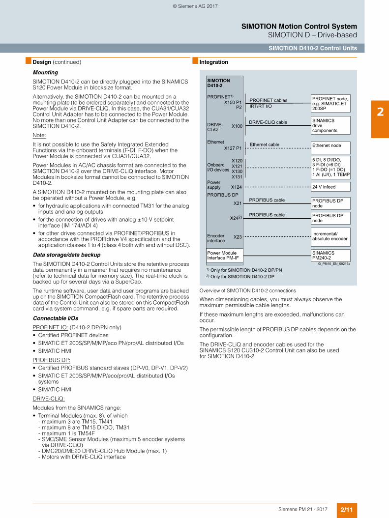
Overview of SIMOTION D410-2 connections
When dimensioning cables, you must always observe the maximum permissible cable lengths.
If these maximum lengths are exceeded, malfunctions can occur.
The permissible length of PROFIBUS DP cables depends on the configuration.
The DRIVE-CLiQ and encoder cables used for the SINAMICS S120 CU310-2 Control Unit can also be used for SIMOTION D410-2.
DRIVE-CLiQ
SIMOTION D410-2
PROFIBUS DP
X127 P1
X124
X21
X242)
X150 P1P2
X23
Power Module Interface PM-IF
Ethernet node
SINAMICS drivecomponents
24 V infeed
Incremental/absolute encoder
PROFIBUS DPnode
DRIVE-CLiQ cable
5 DI, 8 DI/DO,3 F-DI (=6 DI) 1 F-DO (=1 DO) 1 AI (U/I), 1 TEMP
1) Only for SIMOTION D410-2 DP/PN2) Only for SIMOTION D410-2 DP
Ethernet
OnboardI/O devices
Ethernet cable
Powersupply
PROFINET1)PROFINET node, e.g. SIMATIC ET 200SP
PROFINET cablesIRT/RT I/O
PROFIBUS DPnode
Encoderinterface
PROFIBUS cable
PROFIBUS cable
G_PM10_EN_00215a
X100
X120X121X130X131
SINAMICS PM240-2
© Siemens AG 2017
2/12 Siemens PM 21 · 2017
SIMOTION Motion Control SystemSIMOTION D – Drive-based
SIMOTION D410-2 Control Units
2
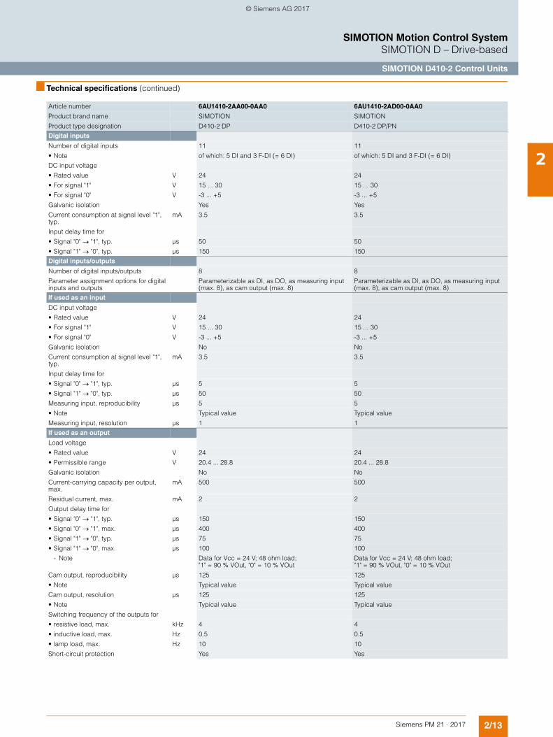
■ Technical specifications
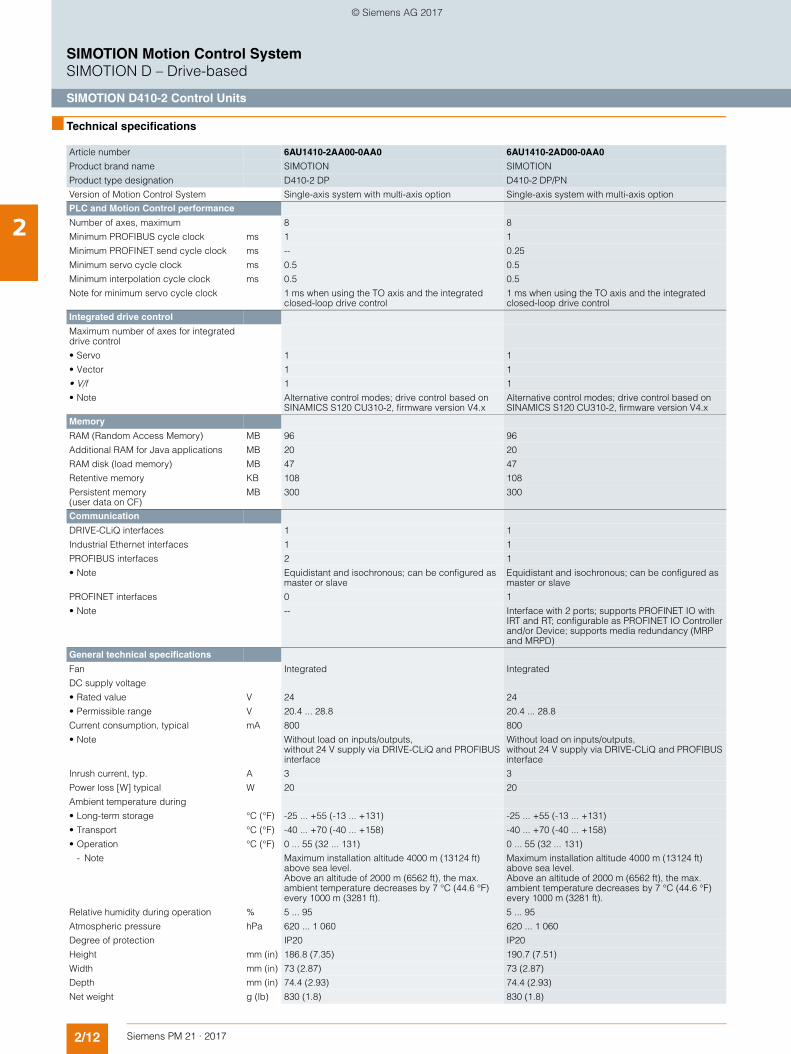
Article number 6AU1410-2AA00-0AA0 6AU1410-2AD00-0AA0
Product brand name SIMOTION SIMOTION
Product type designation D410-2 DP D410-2 DP/PN
Version of Motion Control System Single-axis system with multi-axis option Single-axis system with multi-axis option
PLC and Motion Control performance
Number of axes, maximum 8 8
Minimum PROFIBUS cycle clock ms 1 1
Minimum PROFINET send cycle clock ms -- 0.25
Minimum servo cycle clock ms 0.5 0.5
Minimum interpolation cycle clock ms 0.5 0.5
Note for minimum servo cycle clock 1 ms when using the TO axis and the integrated closed-loop drive control
1 ms when using the TO axis and the integrated closed-loop drive control
Integrated drive control
Maximum number of axes for integrated drive control
• Servo 1 1
• Vector 1 1
• V/f 1 1
• Note Alternative control modes; drive control based on SINAMICS S120 CU310-2, firmware version V4.x
Alternative control modes; drive control based on SINAMICS S120 CU310-2, firmware version V4.x
Memory
RAM (Random Access Memory) MB 96 96
Additional RAM for Java applications MB 20 20
RAM disk (load memory) MB 47 47
Retentive memory KB 108 108
Persistent memory (user data on CF)
MB 300 300
Communication
DRIVE-CLiQ interfaces 1 1
Industrial Ethernet interfaces 1 1
PROFIBUS interfaces 2 1
• Note Equidistant and isochronous; can be configured as master or slave
Equidistant and isochronous; can be configured as master or slave
PROFINET interfaces 0 1
• Note -- Interface with 2 ports; supports PROFINET IO with IRT and RT; configurable as PROFINET IO Controller and/or Device; supports media redundancy (MRP and MRPD)
General technical specifications
Fan Integrated Integrated
DC supply voltage
• Rated value V 24 24
• Permissible range V 20.4 ... 28.8 20.4 ... 28.8
Current consumption, typical mA 800 800
• Note Without load on inputs/outputs, without 24 V supply via DRIVE-CLiQ and PROFIBUS interface
Without load on inputs/outputs, without 24 V supply via DRIVE-CLiQ and PROFIBUS interface
Inrush current, typ. A 3 3
Power loss [W] typical W 20 20
Ambient temperature during
• Long-term storage °C (°F) -25 ... +55 (-13 ... +131) -25 ... +55 (-13 ... +131)
• Transport °C (°F) -40 ... +70 (-40 ... +158) -40 ... +70 (-40 ... +158)
• Operation °C (°F) 0 ... 55 (32 ... 131) 0 ... 55 (32 ... 131)
- Note Maximum installation altitude 4000 m (13124 ft) above sea level. Above an altitude of 2000 m (6562 ft), the max. ambient temperature decreases by 7 °C (44.6 °F) every 1000 m (3281 ft).
Maximum installation altitude 4000 m (13124 ft) above sea level. Above an altitude of 2000 m (6562 ft), the max. ambient temperature decreases by 7 °C (44.6 °F) every 1000 m (3281 ft).
Relative humidity during operation % 5 ... 95 5 ... 95
Atmospheric pressure hPa 620 ... 1 060 620 ... 1 060
Degree of protection IP20 IP20
Height mm (in) 186.8 (7.35) 190.7 (7.51)
Width mm (in) 73 (2.87) 73 (2.87)
Depth mm (in) 74.4 (2.93) 74.4 (2.93)
Net weight g (lb) 830 (1.8) 830 (1.8)
© Siemens AG 2017
2/13Siemens PM 21 · 2017
SIMOTION Motion Control SystemSIMOTION D – Drive-based
SIMOTION D410-2 Control Units
2
■ Technical specifications (continued)
Article number 6AU1410-2AA00-0AA0 6AU1410-2AD00-0AA0
Product brand name SIMOTION SIMOTION
Product type designation D410-2 DP D410-2 DP/PN
Digital inputs
Number of digital inputs 11 11
• Note of which: 5 DI and 3 F-DI (= 6 DI) of which: 5 DI and 3 F-DI (= 6 DI)
DC input voltage
• Rated value V 24 24
• For signal "1" V 15 ... 30 15 ... 30
• For signal "0" V -3 ... +5 -3 ... +5
Galvanic isolation Yes Yes
Current consumption at signal level "1", typ.
mA 3.5 3.5
Input delay time for
• Signal "0" "1", typ. µs 50 50
• Signal "1" "0", typ. µs 150 150
Digital inputs/outputs
Number of digital inputs/outputs 8 8
Parameter assignment options for digital inputs and outputs
Parameterizable as DI, as DO, as measuring input (max. 8), as cam output (max. 8)
Parameterizable as DI, as DO, as measuring input (max. 8), as cam output (max. 8)
If used as an input
DC input voltage
• Rated value V 24 24
• For signal "1" V 15 ... 30 15 ... 30
• For signal "0" V -3 ... +5 -3 ... +5
Galvanic isolation No No
Current consumption at signal level "1", typ.
mA 3.5 3.5
Input delay time for
• Signal "0" "1", typ. µs 5 5
• Signal "1" "0", typ. µs 50 50
Measuring input, reproducibility µs 5 5
• Note Typical value Typical value
Measuring input, resolution µs 1 1
If used as an output
Load voltage
• Rated value V 24 24
• Permissible range V 20.4 ... 28.8 20.4 ... 28.8
Galvanic isolation No No
Current-carrying capacity per output, max.
mA 500 500
Residual current, max. mA 2 2
Output delay time for
• Signal "0" "1", typ. µs 150 150
• Signal "0" "1", max. µs 400 400
• Signal "1" "0", typ. µs 75 75
• Signal "1" "0", max. µs 100 100
- Note Data for Vcc = 24 V; 48 ohm load; "1" = 90 % VOut, "0" = 10 % VOut
Data for Vcc = 24 V; 48 ohm load; "1" = 90 % VOut, "0" = 10 % VOut
Cam output, reproducibility µs 125 125
• Note Typical value Typical value
Cam output, resolution µs 125 125
• Note Typical value Typical value
Switching frequency of the outputs for
• resistive load, max. kHz 4 4
• inductive load, max. Hz 0.5 0.5
• lamp load, max. Hz 10 10
Short-circuit protection Yes Yes
© Siemens AG 2017
2/14 Siemens PM 21 · 2017
SIMOTION Motion Control SystemSIMOTION D – Drive-based
SIMOTION D410-2 Control Units
2
■ Technical specifications (continued)
Article number 6AU1410-2AA00-0AA0 6AU1410-2AD00-0AA0
Product brand name SIMOTION SIMOTION
Product type designation D410-2 DP D410-2 DP/PN
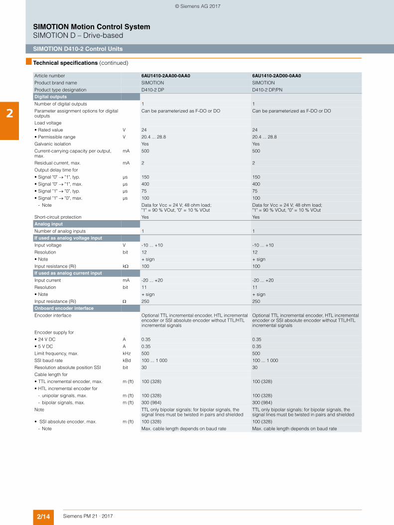
Digital outputs
Number of digital outputs 1 1
Parameter assignment options for digital outputs
Can be parameterized as F-DO or DO Can be parameterized as F-DO or DO
Load voltage
• Rated value V 24 24
• Permissible range V 20.4 ... 28.8 20.4 ... 28.8
Galvanic isolation Yes Yes
Current-carrying capacity per output, max.
mA 500 500
Residual current, max. mA 2 2
Output delay time for
• Signal "0" "1", typ. µs 150 150
• Signal "0" "1", max. µs 400 400
• Signal "1" "0", typ. µs 75 75
• Signal "1" "0", max. µs 100 100
- Note Data for Vcc = 24 V; 48 ohm load; "1" = 90 % VOut, "0" = 10 % VOut
Data for Vcc = 24 V; 48 ohm load; "1" = 90 % VOut, "0" = 10 % VOut
Short-circuit protection Yes Yes
Analog input
Number of analog inputs 1 1
If used as analog voltage input
Input voltage V -10 ... +10 -10 ... +10
Resolution bit 12 12
• Note + sign + sign
Input resistance (Ri) k 100 100
If used as analog current input
Input current mA -20 ... +20 -20 ... +20
Resolution bit 11 11
• Note + sign + sign
Input resistance (Ri) 250 250
Onboard encoder interface
Encoder interface Optional TTL incremental encoder, HTL incremental encoder or SSI absolute encoder without TTL/HTL incremental signals
Optional TTL incremental encoder, HTL incremental encoder or SSI absolute encoder without TTL/HTL incremental signals
Encoder supply for
• 24 V DC A 0.35 0.35
• 5 V DC A 0.35 0.35
Limit frequency, max. kHz 500 500
SSI baud rate kBd 100 ... 1 000 100 ... 1 000
Resolution absolute position SSI bit 30 30
Cable length for
• TTL incremental encoder, max. m (ft) 100 (328) 100 (328)
• HTL incremental encoder for
- unipolar signals, max. m (ft) 100 (328) 100 (328)
- bipolar signals, max. m (ft) 300 (984) 300 (984)
Note TTL only bipolar signals; for bipolar signals, the signal lines must be twisted in pairs and shielded
TTL only bipolar signals; for bipolar signals, the signal lines must be twisted in pairs and shielded
• SSI absolute encoder, max. m (ft) 100 (328) 100 (328)
- Note Max. cable length depends on baud rate Max. cable length depends on baud rate
© Siemens AG 2017
2/15Siemens PM 21 · 2017
SIMOTION Motion Control SystemSIMOTION D – Drive-based
SIMOTION D410-2 Control Units
2
■ Technical specifications (continued)
Article number 6AU1410-2AA00-0AA0 6AU1410-2AD00-0AA0
Product brand name SIMOTION SIMOTION
Product type designation D410-2 DP D410-2 DP/PN
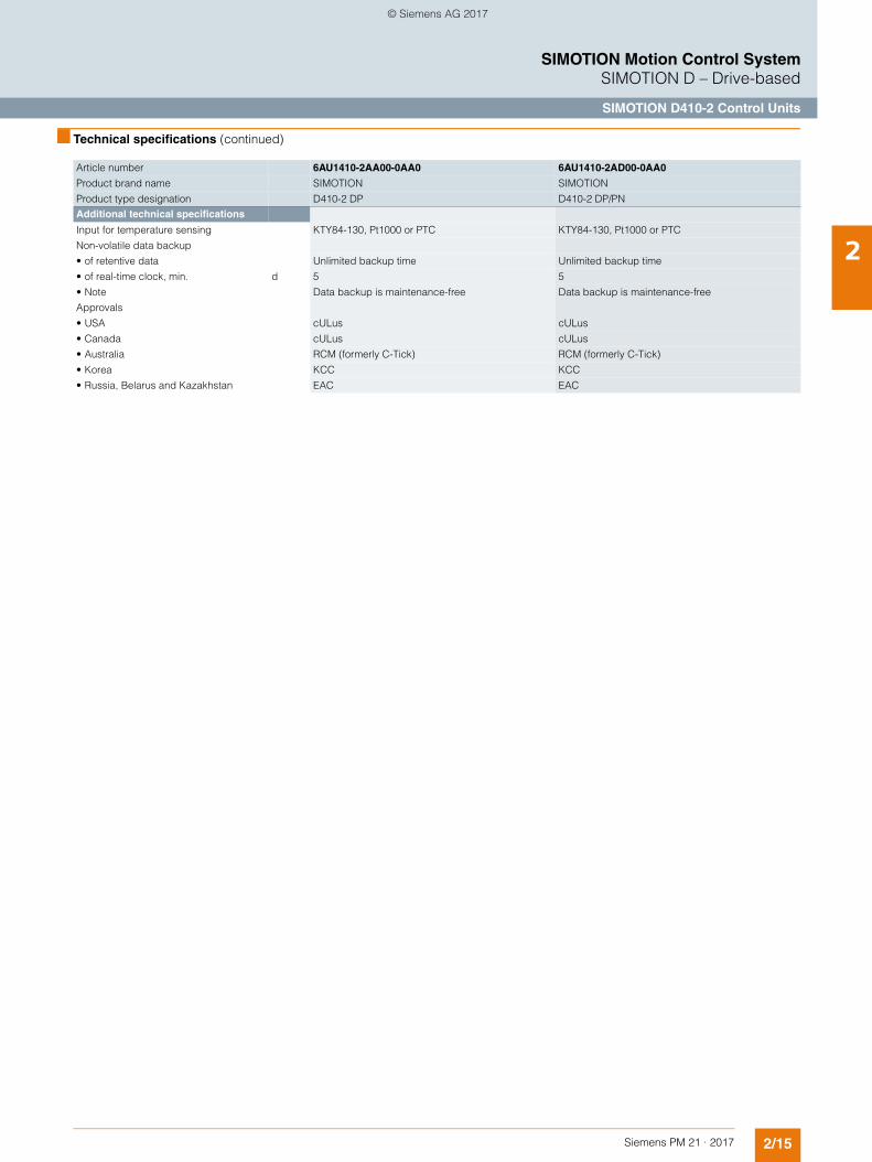
Additional technical specifications
Input for temperature sensing KTY84-130, Pt1000 or PTC KTY84-130, Pt1000 or PTC
Non-volatile data backup
• of retentive data Unlimited backup time Unlimited backup time
• of real-time clock, min. d 5 5
• Note Data backup is maintenance-free Data backup is maintenance-free
Approvals
• USA cULus cULus
• Canada cULus cULus
• Australia RCM (formerly C-Tick) RCM (formerly C-Tick)
• Korea KCC KCC
• Russia, Belarus and Kazakhstan EAC EAC
© Siemens AG 2017
2/16 Siemens PM 21 · 2017
SIMOTION Motion Control SystemSIMOTION D – Drive-based
SIMOTION D410-2 Control Units
2
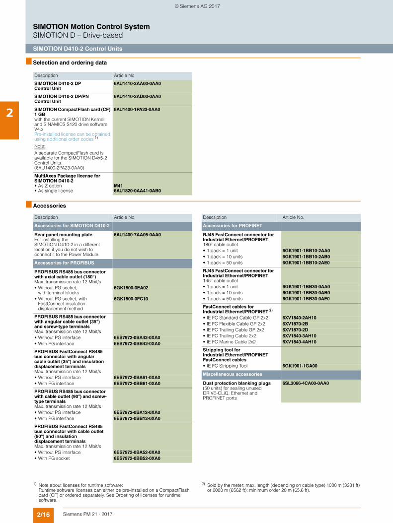
■ Selection and ordering data
■ Accessories
Description Article No.
SIMOTION D410-2 DP Control Unit
6AU1410-2AA00-0AA0
SIMOTION D410-2 DP/PN Control Unit
6AU1410-2AD00-0AA0
SIMOTION CompactFlash card (CF) 1 GBwith the current SIMOTION Kernel and SINAMICS S120 drive software V4.xPre-installed license can be obtained using additional order codes 1)
Note:
A separate CompactFlash card is available for the SIMOTION D4x5-2 Control Units. (6AU1400-2PA23-0AA0)
6AU1400-1PA23-0AA0
MultiAxes Package license for SIMOTION D410-2 • As Z option• As single license
M416AU1820-0AA41-0AB0
Description Article No.
Accessories for SIMOTION D410-2
Rear panel mounting plateFor installing the SIMOTION D410-2 in a different location if you do not wish to connect it to the Power Module.
6AU1400-7AA05-0AA0
Accessories for PROFIBUS
PROFIBUS RS485 bus connector with axial cable outlet (180°) Max. transmission rate 12 Mbit/s
• Without PG socket, with terminal blocks
6GK1500-0EA02
• Without PG socket, with FastConnect insulation displacement method
6GK1500-0FC10
PROFIBUS RS485 bus connector with angular cable outlet (35°) and screw-type terminals Max. transmission rate 12 Mbit/s
• Without PG interface 6ES7972-0BA42-0XA0• With PG interface 6ES7972-0BB42-0XA0
PROFIBUS FastConnect RS485 bus connector with angular cable outlet (35°) and insulation displacement terminals Max. transmission rate 12 Mbit/s
• Without PG interface 6ES7972-0BA61-0XA0• With PG interface 6ES7972-0BB61-0XA0
PROFIBUS RS485 bus connector with cable outlet (90°) and screw-type terminals Max. transmission rate 12 Mbit/s
• Without PG interface 6ES7972-0BA12-0XA0• With PG interface 6ES7972-0BB12-0XA0
PROFIBUS FastConnect RS485 bus connector with cable outlet (90°) and insulation displacement terminals Max. transmission rate 12 Mbit/s
• Without PG interface 6ES7972-0BA52-0XA0• With PG socket 6ES7972-0BB52-0XA0
Accessories for PROFINET
RJ45 FastConnect connector for Industrial Ethernet/PROFINET180° cable outlet
• 1 pack = 1 unit 6GK1901-1BB10-2AA0• 1 pack = 10 units 6GK1901-1BB10-2AB0• 1 pack = 50 units 6GK1901-1BB10-2AE0
RJ45 FastConnect connector for Industrial Ethernet/PROFINET 145° cable outlet
• 1 pack = 1 unit 6GK1901-1BB30-0AA0• 1 pack = 10 units 6GK1901-1BB30-0AB0• 1 pack = 50 units 6GK1901-1BB30-0AE0
FastConnect cables for Industrial Ethernet/PROFINET 2)
• IE FC Standard Cable GP 2x2 6XV1840-2AH10• IE FC Flexible Cable GP 2x2 6XV1870-2B• IE FC Trailing Cable GP 2x2 6XV1870-2D• IE FC Trailing Cable 2x2 6XV1840-3AH10• IE FC Marine Cable 2x2 6XV1840-4AH10
Stripping tool for Industrial Ethernet/PROFINET FastConnect cables
• IE FC Stripping Tool 6GK1901-1GA00
Miscellaneous accessories
Dust protection blanking plugs(50 units) for sealing unused DRIVE-CLiQ, Ethernet and PROFINET ports
6SL3066-4CA00-0AA0
Description Article No.
1) Note about licenses for runtime software: Runtime software licenses can either be pre-installed on a CompactFlash card (CF) or ordered separately. See Ordering of licenses for runtime software.
2) Sold by the meter; max. length (depending on cable type) 1000 m (3281 ft) or 2000 m (6562 ft); minimum order 20 m (65.6 ft).
© Siemens AG 2017
2/17Siemens PM 21 · 2017
SIMOTION Motion Control SystemSIMOTION D – Drive-based
SIMOTION D410-2 Control Units
2
■ More information
More information• about SINAMICS S120 drive components such as Power
Modules, Terminal Modules etc. can be found in Catalog D 21.4 – chapter SINAMICS S120 Drive System, and the Industry Mall under Drive Technology/Converters/AC Low-voltage converters/High performance converters SINAMICS S/....
• about signal and power cables for SINAMICS S120 can be found in Catalog D 21.4 – chapter MOTION-CONNECT connection systems, and the Industry Mall under Drive Technology/Further Components/MOTION-CONNECT connection systems.
• about PROFINET, Industrial Ethernet and PROFIBUS DP can be found in Catalog IK PI and the Industry Mall under Automation Technology/Industrial Communication.
Integrated drive control
The drive control functions integrated in a SIMOTION D410-2 are based on the drive control of a SINAMICS S120 CU310-2 (firmware version V4.x), although there is a slight difference in functionality. For example, the SIMOTION D410-2 does not have a basic positioner function (EPOS), as this is already covered by SIMOTION technology functions.
For more information, refer to the documentation for SIMOTION and SINAMICS.
Licensing notes
SIMOTION D410-2 has an integrated drive control for either a servo, a vector or a V/f axis and is therefore ideal for single-axis applications.
One real axis can be used without license on the Control Unit. Drive axes and virtual axes never require a license.
SIMOTION D410-2 can be extended with additional SINAMICS S110/S120 Control Units (e.g. CU305) and so can also be used for smaller multi-axis applications (e.g. with 2 - 3 axes). A license is required for any additional axes. Where a license is required for a POS axis, the POS single-axis license is the ideal solution. It is better to use the MultiAxes Package D410-2 in the case of GEAR/CAM or more than one POS license.
The axis license with the highest functionality is covered by the inclusive license (a real axis).
The functionality has the following granularity: CAM > GEAR > POS.
Example:
Application with 2 real axes: 1 POS, 1 CAM.
Only a POS license needs to be purchased because the higher-order CAM license is already included.
Licenses are also required for runtime functions subject to licensing, such as SIMOTION IT Virtual Machine. These can be pre-installed on the CompactFlash card (CF card) or ordered separately.
For more information, refer to section Ordering of licenses for runtime software.
SIZER for Siemens Drives engineering tool
With the SIZER for Siemens Drives engineering tool, you can easily configure, for example, the SINAMICS S110 and S120 drive families including SIMOTION. This tool supports you with the engineering of components for a Motion Control task. You can also determine the possible number of axes and the resulting utilization with SIZER for Siemens Drives in accordance with your performance requirements.
For more information about SIZER for Siemens Drives, refer to section Lifecycle Services.
© Siemens AG 2017
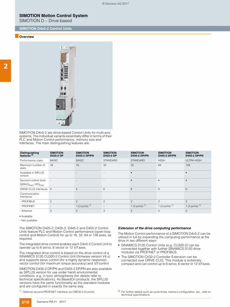
2/18 Siemens PM 21 · 2017
SIMOTION Motion Control SystemSIMOTION D – Drive-based
SIMOTION D4x5-2 Control Units
2
■ Overview
SIMOTION D4x5-2 are drive-based Control Units for multi-axis systems. The individual variants essentially differ in terms of their PLC and Motion Control performance, memory size and interfaces. The main distinguishing features are:
• Available
– Not available
The SIMOTION D425-2, D435-2, D445-2 and D455-2 Control Units feature PLC and Motion Control performance (open-loop control and Motion Control) for up to 16, 32, 64 or 128 axes, as required.
The integrated drive control enables each D4x5-2 Control Unit to operate up to 6 servo, 6 vector or 12 V/f axes.
The integrated drive control is based on the drive control of a SINAMICS S120 CU320-2 Control Unit (firmware version V4.x) and supports servo control (for a highly dynamic response), vector control (for maximum torque accuracy) and V/f control.
SIMOTION D435-2 DP/PN and D455-2 DP/PN are also available as SIPLUS version for use under harsh environmental conditions, e.g. in toxic atmospheres (for details refer to technical specifications). As BasedOn products, the SIPLUS versions have the same functionality as the standard modules and are configured in exactly the same way.
Extension of the drive computing performance
The Motion Control performance of a SIMOTION D4x5-2 can be utilized in full by expanding the computing performance at the drive in two different ways:• SINAMICS S120 Control Units (e.g. CU320-2) can be
connected together with further SINAMICS S120 drive modules via PROFINET or PROFIBUS.
• The SIMOTION CX32-2 Controller Extension can be connected over DRIVE-CLiQ. This module is extremely compact and can control up to 6 servo, 6 vector or 12 V/f axes.
Distinguishing features 2)
SIMOTION D425-2 DP
SIMOTION D425-2 DP/PN
SIMOTION D435-2 DP
SIMOTION D435-2 DP/PN
SIMOTION D445-2 DP/PN
SIMOTION D455-2 DP/PN
Performance class BASIC BASIC STANDARD STANDARD HIGH ULTRA-HIGH
Maximum number of axes
16 16 32 32 64 128
Available in SIPLUS version
– – – • – •
Second runtime level
SERVOFast / IPOFast
– – – • • •
DRIVE-CLiQ interfaces 4 4 6 6 6 6
Communication interfaces
- PROFIBUS 2 2 2 2 2 2
- PROFINET – 1 (3 ports) 1) – 1 (3 ports) 1) 1 (3 ports) 1) 1 (3 ports) 1)
- Ethernet 3 2 3 2 2 2
1) Optional second PROFINET interface via CBE30-2 (4 ports) 2) For further details such as cycle times, memory configuration, etc., refer to technical specifications.
© Siemens AG 2017
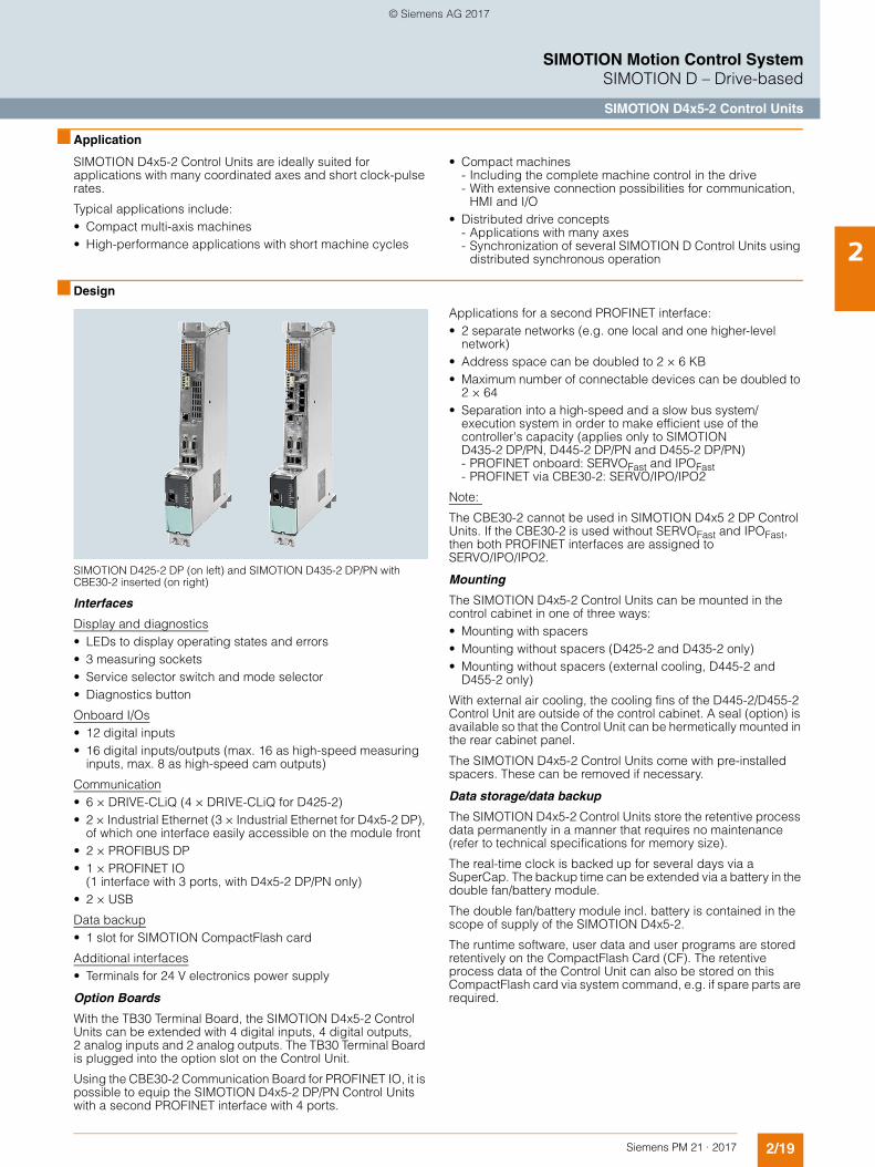
2/19Siemens PM 21 · 2017
SIMOTION Motion Control SystemSIMOTION D – Drive-based
SIMOTION D4x5-2 Control Units
2
■ Application
SIMOTION D4x5-2 Control Units are ideally suited for applications with many coordinated axes and short clock-pulse rates.
Typical applications include:• Compact multi-axis machines• High-performance applications with short machine cycles
• Compact machines- Including the complete machine control in the drive- With extensive connection possibilities for communication,
HMI and I/O• Distributed drive concepts
- Applications with many axes- Synchronization of several SIMOTION D Control Units using
distributed synchronous operation
■ Design
SIMOTION D425-2 DP (on left) and SIMOTION D435-2 DP/PN with CBE30-2 inserted (on right)
Interfaces
Display and diagnostics• LEDs to display operating states and errors• 3 measuring sockets • Service selector switch and mode selector• Diagnostics button
Onboard I/Os• 12 digital inputs• 16 digital inputs/outputs (max. 16 as high-speed measuring
inputs, max. 8 as high-speed cam outputs)
Communication• 6 × DRIVE-CLiQ (4 × DRIVE-CLiQ for D425-2) • 2 × Industrial Ethernet (3 × Industrial Ethernet for D4x5-2 DP),
of which one interface easily accessible on the module front • 2 × PROFIBUS DP• 1 × PROFINET IO
(1 interface with 3 ports, with D4x5-2 DP/PN only)• 2 × USB
Data backup• 1 slot for SIMOTION CompactFlash card
Additional interfaces• Terminals for 24 V electronics power supply
Option Boards
With the TB30 Terminal Board, the SIMOTION D4x5-2 Control Units can be extended with 4 digital inputs, 4 digital outputs, 2 analog inputs and 2 analog outputs. The TB30 Terminal Board is plugged into the option slot on the Control Unit.
Using the CBE30-2 Communication Board for PROFINET IO, it is possible to equip the SIMOTION D4x5-2 DP/PN Control Units with a second PROFINET interface with 4 ports.
Applications for a second PROFINET interface:• 2 separate networks (e.g. one local and one higher-level
network)• Address space can be doubled to 2 × 6 KB • Maximum number of connectable devices can be doubled to
2 × 64• Separation into a high-speed and a slow bus system/
execution system in order to make efficient use of the controller's capacity (applies only to SIMOTION D435-2 DP/PN, D445-2 DP/PN and D455-2 DP/PN)- PROFINET onboard: SERVOFast and IPOFast- PROFINET via CBE30-2: SERVO/IPO/IPO2
Note:
The CBE30-2 cannot be used in SIMOTION D4x5 2 DP Control Units. If the CBE30-2 is used without SERVOFast and IPOFast, then both PROFINET interfaces are assigned to SERVO/IPO/IPO2.
Mounting
The SIMOTION D4x5-2 Control Units can be mounted in the control cabinet in one of three ways:• Mounting with spacers• Mounting without spacers (D425-2 and D435-2 only) • Mounting without spacers (external cooling, D445-2 and
D455-2 only)
With external air cooling, the cooling fins of the D445-2/D455-2 Control Unit are outside of the control cabinet. A seal (option) is available so that the Control Unit can be hermetically mounted in the rear cabinet panel.
The SIMOTION D4x5-2 Control Units come with pre-installed spacers. These can be removed if necessary.
Data storage/data backup
The SIMOTION D4x5-2 Control Units store the retentive process data permanently in a manner that requires no maintenance (refer to technical specifications for memory size).
The real-time clock is backed up for several days via a SuperCap. The backup time can be extended via a battery in the double fan/battery module.
The double fan/battery module incl. battery is contained in the scope of supply of the SIMOTION D4x5-2.
The runtime software, user data and user programs are stored retentively on the CompactFlash Card (CF). The retentive process data of the Control Unit can also be stored on this CompactFlash card via system command, e.g. if spare parts are required.
© Siemens AG 2017
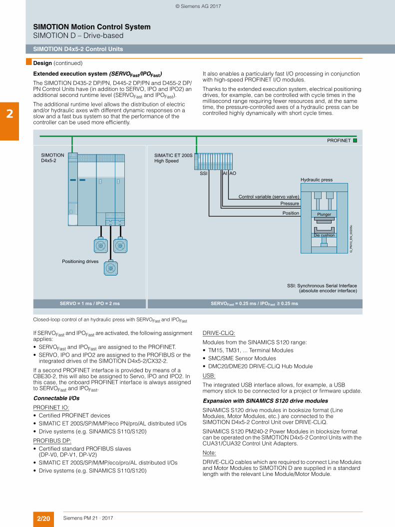
2/20 Siemens PM 21 · 2017
SIMOTION Motion Control SystemSIMOTION D – Drive-based
SIMOTION D4x5-2 Control Units
2
■ Design (continued)
Extended execution system (SERVOFast/IPOFast)
The SIMOTION D435-2 DP/PN, D445-2 DP/PN and D455-2 DP/PN Control Units have (in addition to SERVO, IPO and IPO2) an additional second runtime level (SERVOFast and IPOFast).
The additional runtime level allows the distribution of electric and/or hydraulic axes with different dynamic responses on a slow and a fast bus system so that the performance of the controller can be used more efficiently.
It also enables a particularly fast I/O processing in conjunction with high-speed PROFINET I/O modules.
Thanks to the extended execution system, electrical positioning drives, for example, can be controlled with cycle times in the millisecond range requiring fewer resources and, at the same time, the pressure-controlled axes of a hydraulic press can be controlled highly dynamically with short cycle times.
Closed-loop control of an hydraulic press with SERVOFast and IPOFast
If SERVOFast and IPOFast are activated, the following assignment applies:• SERVOFast and IPOFast are assigned to the PROFINET.• SERVO, IPO and IPO2 are assigned to the PROFIBUS or the
integrated drives of the SIMOTION D4x5-2/CX32-2.
If a second PROFINET interface is provided by means of a CBE30-2, this will also be assigned to Servo, IPO and IPO2. In this case, the onboard PROFINET interface is always assigned to SERVOFast and IPOFast.
Connectable I/Os
PROFINET IO:• Certified PROFINET devices• SIMATIC ET 200S/SP/M/MP/eco PN/pro/AL distributed I/Os• Drive systems (e.g. SINAMICS S110/S120)
PROFIBUS DP:• Certified standard PROFIBUS slaves
(DP-V0, DP-V1, DP-V2)• SIMATIC ET 200S/SP/M/MP/eco/pro/AL distributed I/Os• Drive systems (e.g. SINAMICS S110/S120)
DRIVE-CLiQ:
Modules from the SINAMICS S120 range:• TM15, TM31, ... Terminal Modules• SMC/SME Sensor Modules• DMC20/DME20 DRIVE-CLiQ Hub Module
USB:
The integrated USB interface allows, for example, a USB memory stick to be connected for a project or firmware update.
Expansion with SINAMICS S120 drive modules
SINAMICS S120 drive modules in booksize format (Line Modules, Motor Modules, etc.) are connected to the SIMOTION D4x5-2 Control Unit over DRIVE-CLiQ.
SINAMICS S120 PM240-2 Power Modules in blocksize format can be operated on the SIMOTION D4x5-2 Control Units with the CUA31/CUA32 Control Unit Adapters.
Note:
DRIVE-CLiQ cables which are required to connect Line Modules and Motor Modules to SIMOTION D are supplied in a standard length with the relevant Line Module/Motor Module.
SIMATIC ET 200SHigh Speed
SSI AI AOHydraulic press
Positioning drives
SSI: Synchronous Serial Interface (absolute encoder interface)
Control variable (servo valve)
SERVO = 1 ms / IPO = 2 ms SERVOFast = 0.25 ms / IPOFast ≥ 0.25 ms
Pressure
Position Plunger
Die cushion
G_P
M10
_EN
_002
05c
SIMOTION D4x5-2
PROFINET
© Siemens AG 2017
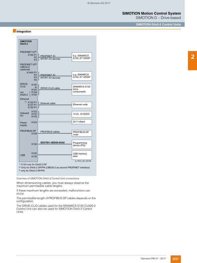
2/21Siemens PM 21 · 2017
SIMOTION Motion Control SystemSIMOTION D – Drive-based
SIMOTION D4x5-2 Control Units
2
■ Integration
Overview of SIMOTION D4x5-2 Control Unit connections
When dimensioning cables, you must always observe the maximum permissible cable lengths.
If these maximum lengths are exceeded, malfunctions can occur.
The permissible length of PROFIBUS DP cables depends on the configuration.
The DRIVE-CLiQ cables used for the SINAMICS S120 CU320-2 Control Unit can also be used for SIMOTION D4x5-2 Control Units.
6ES7901-4BD00-0XA0
notD425-2
Ethernet
USB
Ethernet node
12 DI, 16 DI/DO
SINAMICS S120 drivecomponents
24 V infeed
Programmingdevice (PG)
USB memory stick
PROFIBUS DPnode
DRIVE-CLiQ cable
Ethernet cable
PROFIBUS cables
Onboard I/O
Powersupply
PROFINET IO2) CBE30-2(optional)
e.g. SINAMICS S120, ET 200SP
PROFINET IO IRT/RT I/O devices
e.g. SINAMICS S120, ET 200SP
PROFINET IO IRT/RT I/O devices
G_PM10_EN_00216b
1) X120 only for D4x5-2 DP2) Only for D4x5-2 DP/PN (CBE30-2 as second PROFINET interface)3) only for D4x5-2 DP/PN
DRIVE-CLiQ
X100to
X103X104X105
SIMOTIOND4x5-2
X122X132 X142
X124
X136
PROFIBUS DPX126
X135X125
X150 P1P2P3
X1400 P1P2P3P4
X120 P1 X127 P1 X130 P1
PROFINET IO3)
1)
© Siemens AG 2017
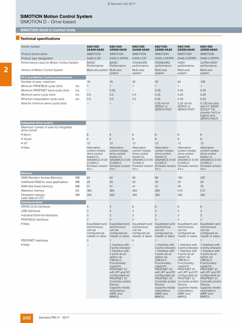
2/22 Siemens PM 21 · 2017
SIMOTION Motion Control SystemSIMOTION D – Drive-based
SIMOTION D4x5-2 Control Units
2
■ Technical specifications
Article number 6AU1425-2AA00-0AA0
6AU1425-2AD00-0AA0
6AU1435-2AA00-0AA0
6AU1435-2AD00-0AA0
6AU1445-2AD00-0AA0
6AU1455-2AD00-0AA0
Product brand name SIMOTION SIMOTION SIMOTION SIMOTION SIMOTION SIMOTION
Product type designation D425-2 DP D425-2 DP/PN D435-2 DP D435-2 DP/PN D445-2 DP/PN D455-2 DP/PN
Performance class for Motion Control System BASIC Performance
BASIC Performance
STANDARD performance
STANDARD performance
HIGH performance
ULTRA-HIGH performance
Version of Motion Control System Multi-axis system Multi-axis system
Multi-axis system
Multi-axis system
Multi-axis system
Multi-axis system
PLC and Motion Control performance
Number of axes, maximum 16 16 32 32 64 128
Minimum PROFIBUS cycle clock ms 1 1 1 1 1 1
Minimum PROFINET send cycle clock ms -- 0.25 -- 0.25 0.25 0.25
Minimum servo cycle clock ms 0.5 0.5 0.5 0.25 0.25 0.25
Minimum interpolation cycle clock ms 0.5 0.5 0.5 0.25 0.25 0.25
Note for minimum servo cycle clock -- -- -- 0.25 ms for SERVO or SERVO-FAST
0.25 ms for SERVO or SERVO-FAST
0.125 ms (only with ET 200SP, SCOUT TIA (version V4.5 or higher) and SERVO-FAST)
Integrated drive control
Maximum number of axes for integrated drive control
• Servo 6 6 6 6 6 6
• Vector 6 6 6 6 6 6
• V/f 12 12 12 12 12 12
• Note Alternative control modes; drive control based on SINAMICS S120 CU320-2, firmware version V4.x
Alternative control modes; drive control based on SINAMICS S120 CU320-2, firmware version V4.x
Alternative control modes; drive control based on SINAMICS S120 CU320-2, firmware version V4.x
Alternative control modes; drive control based on SINAMICS S120 CU320-2, firmware version V4.x
Alternative control modes; drive control based on SINAMICS S120 CU320-2, firmware version V4.x
Alternative control modes; drive control based on SINAMICS S120 CU320-2, firmware version V4.x
Memory
RAM (Random Access Memory) MB 64 64 86 86 160 320
Additional RAM for Java applications MB 20 20 20 20 20 20
RAM disk (load memory) MB 31 31 41 41 56 76
Retentive memory KB 364 364 364 364 512 512
Persistent memory (user data on CF)
MB 300 300 300 300 300 300
Communication
DRIVE-CLiQ interfaces 4 4 6 6 6 6
USB interfaces 2 2 2 2 2 2
Industrial Ethernet interfaces 3 2 3 2 2 2
PROFIBUS interfaces 2 2 2 2 2 2
• Note Equidistant and isochronous; can be configured as master or slave
Equidistant and isochronous; can be configured as master or slave
Equidistant and isochronous; can be configured as master or slave
Equidistant and isochronous; can be configured as master or slave
Equidistant and isochronous; can be configured as master or slave
Equidistant and isochronous; can be configured as master or slave
PROFINET interfaces 0 1 0 1 1 1
• Note -- 1 interface with 3 ports onboard; 1 interface with 4 ports as an option via CBE30-2; Functionality: supports PROFINET IO with IRT and RT; configurable as PROFINET IO Controller and/or Device; supports media redundancy (MRP and MRPD)
-- 1 interface with 3 ports onboard; 1 interface with 4 ports as an option via CBE30-2; Functionality: supports PROFINET IO with IRT and RT; configurable as PROFINET IO Controller and/or Device; supports media redundancy (MRP and MRPD)
1 interface with 3 ports onboard; 1 interface with 4 ports as an option via CBE30-2; Functionality: supports PROFINET IO with IRT and RT; configurable as PROFINET IO Controller and/or Device; supports media redundancy (MRP and MRPD)
1 interface with 3 ports onboard; 1 interface with 4 ports as an option via CBE30-2; Functionality: supports PROFINET IO with IRT and RT; configurable as PROFINET IO Controller and/or Device; supports media redundancy (MRP and MRPD)
© Siemens AG 2017
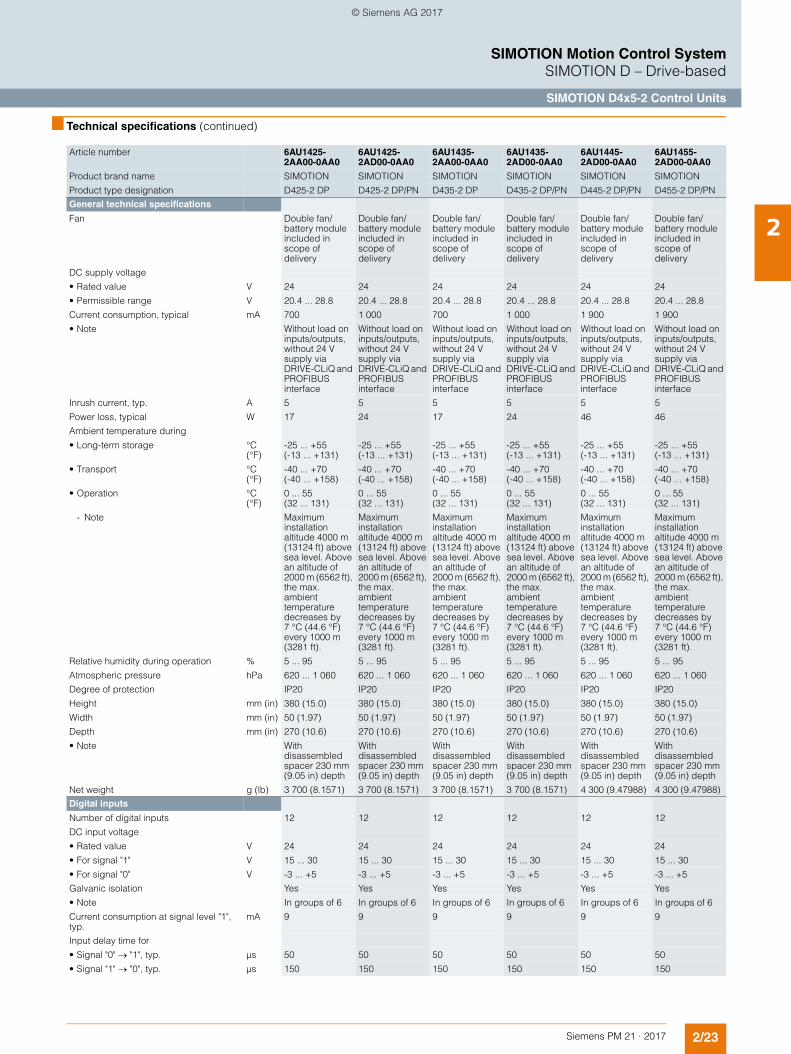
2/23Siemens PM 21 · 2017
SIMOTION Motion Control SystemSIMOTION D – Drive-based
SIMOTION D4x5-2 Control Units
2
■ Technical specifications (continued)
Article number 6AU1425-2AA00-0AA0
6AU1425-2AD00-0AA0
6AU1435-2AA00-0AA0
6AU1435-2AD00-0AA0
6AU1445-2AD00-0AA0
6AU1455-2AD00-0AA0
Product brand name SIMOTION SIMOTION SIMOTION SIMOTION SIMOTION SIMOTION
Product type designation D425-2 DP D425-2 DP/PN D435-2 DP D435-2 DP/PN D445-2 DP/PN D455-2 DP/PN
General technical specifications
Fan Double fan/battery module included in scope of delivery
Double fan/battery module included in scope of delivery
Double fan/battery module included in scope of delivery
Double fan/battery module included in scope of delivery
Double fan/battery module included in scope of delivery
Double fan/battery module included in scope of delivery
DC supply voltage
• Rated value V 24 24 24 24 24 24
• Permissible range V 20.4 ... 28.8 20.4 ... 28.8 20.4 ... 28.8 20.4 ... 28.8 20.4 ... 28.8 20.4 ... 28.8
Current consumption, typical mA 700 1 000 700 1 000 1 900 1 900
• Note Without load on inputs/outputs, without 24 V supply via DRIVE-CLiQ and PROFIBUS interface
Without load on inputs/outputs, without 24 V supply via DRIVE-CLiQ and PROFIBUS interface
Without load on inputs/outputs, without 24 V supply via DRIVE-CLiQ and PROFIBUS interface
Without load on inputs/outputs, without 24 V supply via DRIVE-CLiQ and PROFIBUS interface
Without load on inputs/outputs, without 24 V supply via DRIVE-CLiQ and PROFIBUS interface
Without load on inputs/outputs, without 24 V supply via DRIVE-CLiQ and PROFIBUS interface
Inrush current, typ. A 5 5 5 5 5 5
Power loss, typical W 17 24 17 24 46 46
Ambient temperature during
• Long-term storage °C (°F)
-25 ... +55 (-13 ... +131)
-25 ... +55 (-13 ... +131)
-25 ... +55 (-13 ... +131)
-25 ... +55 (-13 ... +131)
-25 ... +55 (-13 ... +131)
-25 ... +55 (-13 ... +131)
• Transport °C (°F)
-40 ... +70 (-40 ... +158)
-40 ... +70 (-40 ... +158)
-40 ... +70 (-40 ... +158)
-40 ... +70 (-40 ... +158)
-40 ... +70 (-40 ... +158)
-40 ... +70 (-40 ... +158)
• Operation °C (°F)
0 ... 55 (32 ... 131)
0 ... 55 (32 ... 131)
0 ... 55 (32 ... 131)
0 ... 55 (32 ... 131)
0 ... 55 (32 ... 131)
0 ... 55 (32 ... 131)
- Note Maximum installation altitude 4000 m (13124 ft) above sea level. Above an altitude of 2000 m (6562 ft), the max. ambient temperature decreases by 7 °C (44.6 °F) every 1000 m (3281 ft).
Maximum installation altitude 4000 m (13124 ft) above sea level. Above an altitude of 2000 m (6562 ft), the max. ambient temperature decreases by 7 °C (44.6 °F) every 1000 m (3281 ft).
Maximum installation altitude 4000 m (13124 ft) above sea level. Above an altitude of 2000 m (6562 ft), the max. ambient temperature decreases by 7 °C (44.6 °F) every 1000 m (3281 ft).
Maximum installation altitude 4000 m (13124 ft) above sea level. Above an altitude of 2000 m (6562 ft), the max. ambient temperature decreases by 7 °C (44.6 °F) every 1000 m (3281 ft).
Maximum installation altitude 4000 m (13124 ft) above sea level. Above an altitude of 2000 m (6562 ft), the max. ambient temperature decreases by 7 °C (44.6 °F) every 1000 m (3281 ft).
Maximum installation altitude 4000 m (13124 ft) above sea level. Above an altitude of 2000 m (6562 ft), the max. ambient temperature decreases by 7 °C (44.6 °F) every 1000 m (3281 ft).
Relative humidity during operation % 5 ... 95 5 ... 95 5 ... 95 5 ... 95 5 ... 95 5 ... 95
Atmospheric pressure hPa 620 ... 1 060 620 ... 1 060 620 ... 1 060 620 ... 1 060 620 ... 1 060 620 ... 1 060
Degree of protection IP20 IP20 IP20 IP20 IP20 IP20
Height mm (in) 380 (15.0) 380 (15.0) 380 (15.0) 380 (15.0) 380 (15.0) 380 (15.0)
Width mm (in) 50 (1.97) 50 (1.97) 50 (1.97) 50 (1.97) 50 (1.97) 50 (1.97)
Depth mm (in) 270 (10.6) 270 (10.6) 270 (10.6) 270 (10.6) 270 (10.6) 270 (10.6)
• Note With disassembled spacer 230 mm (9.05 in) depth
With disassembled spacer 230 mm (9.05 in) depth
With disassembled spacer 230 mm (9.05 in) depth
With disassembled spacer 230 mm (9.05 in) depth
With disassembled spacer 230 mm (9.05 in) depth
With disassembled spacer 230 mm (9.05 in) depth
Net weight g (lb) 3 700 (8.1571) 3 700 (8.1571) 3 700 (8.1571) 3 700 (8.1571) 4 300 (9.47988) 4 300 (9.47988)
Digital inputs
Number of digital inputs 12 12 12 12 12 12
DC input voltage
• Rated value V 24 24 24 24 24 24
• For signal "1" V 15 ... 30 15 ... 30 15 ... 30 15 ... 30 15 ... 30 15 ... 30
• For signal "0" V -3 ... +5 -3 ... +5 -3 ... +5 -3 ... +5 -3 ... +5 -3 ... +5
Galvanic isolation Yes Yes Yes Yes Yes Yes
• Note In groups of 6 In groups of 6 In groups of 6 In groups of 6 In groups of 6 In groups of 6
Current consumption at signal level "1", typ.
mA 9 9 9 9 9 9
Input delay time for
• Signal "0" "1", typ. µs 50 50 50 50 50 50
• Signal "1" "0", typ. µs 150 150 150 150 150 150
© Siemens AG 2017
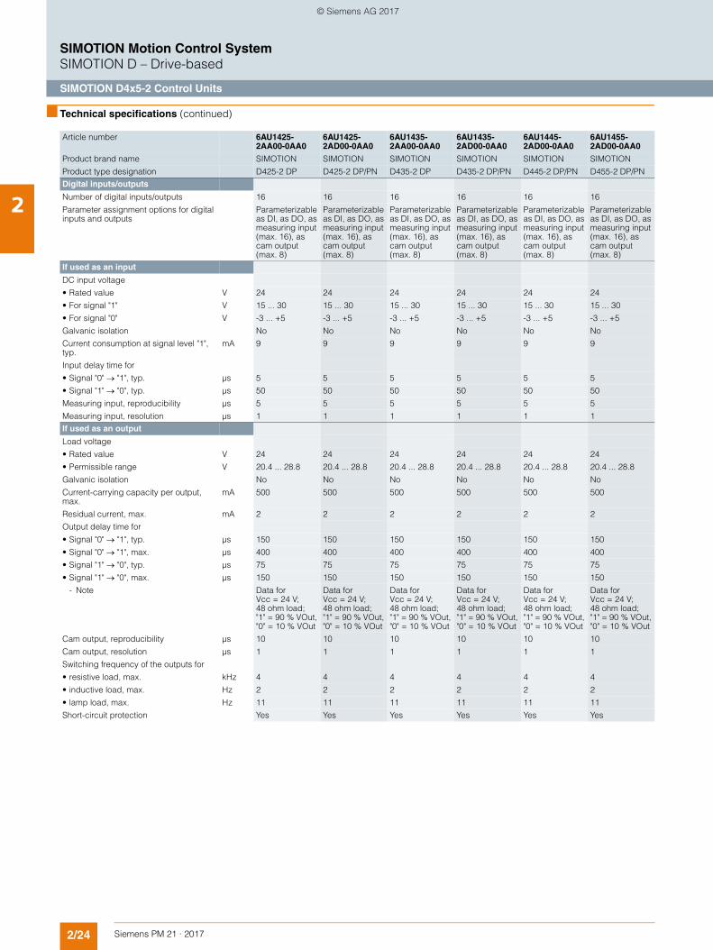
2/24 Siemens PM 21 · 2017
SIMOTION Motion Control SystemSIMOTION D – Drive-based
SIMOTION D4x5-2 Control Units
2
■ Technical specifications (continued)
Article number 6AU1425-2AA00-0AA0
6AU1425-2AD00-0AA0
6AU1435-2AA00-0AA0
6AU1435-2AD00-0AA0
6AU1445-2AD00-0AA0
6AU1455-2AD00-0AA0
Product brand name SIMOTION SIMOTION SIMOTION SIMOTION SIMOTION SIMOTION
Product type designation D425-2 DP D425-2 DP/PN D435-2 DP D435-2 DP/PN D445-2 DP/PN D455-2 DP/PN
Digital inputs/outputs
Number of digital inputs/outputs 16 16 16 16 16 16
Parameter assignment options for digital inputs and outputs
Parameterizable as DI, as DO, as measuring input (max. 16), as cam output (max. 8)
Parameterizable as DI, as DO, as measuring input (max. 16), as cam output (max. 8)
Parameterizable as DI, as DO, as measuring input (max. 16), as cam output (max. 8)
Parameterizable as DI, as DO, as measuring input (max. 16), as cam output (max. 8)
Parameterizable as DI, as DO, as measuring input (max. 16), as cam output (max. 8)
Parameterizable as DI, as DO, as measuring input (max. 16), as cam output (max. 8)
If used as an input
DC input voltage
• Rated value V 24 24 24 24 24 24
• For signal "1" V 15 ... 30 15 ... 30 15 ... 30 15 ... 30 15 ... 30 15 ... 30
• For signal "0" V -3 ... +5 -3 ... +5 -3 ... +5 -3 ... +5 -3 ... +5 -3 ... +5
Galvanic isolation No No No No No No
Current consumption at signal level "1", typ.
mA 9 9 9 9 9 9
Input delay time for
• Signal "0" "1", typ. µs 5 5 5 5 5 5
• Signal "1" "0", typ. µs 50 50 50 50 50 50
Measuring input, reproducibility µs 5 5 5 5 5 5
Measuring input, resolution µs 1 1 1 1 1 1
If used as an output
Load voltage
• Rated value V 24 24 24 24 24 24
• Permissible range V 20.4 ... 28.8 20.4 ... 28.8 20.4 ... 28.8 20.4 ... 28.8 20.4 ... 28.8 20.4 ... 28.8
Galvanic isolation No No No No No No
Current-carrying capacity per output, max.
mA 500 500 500 500 500 500
Residual current, max. mA 2 2 2 2 2 2
Output delay time for
• Signal "0" "1", typ. µs 150 150 150 150 150 150
• Signal "0" "1", max. µs 400 400 400 400 400 400
• Signal "1" "0", typ. µs 75 75 75 75 75 75
• Signal "1" "0", max. µs 150 150 150 150 150 150
- Note Data for Vcc = 24 V; 48 ohm load; "1" = 90 % VOut, "0" = 10 % VOut
Data for Vcc = 24 V; 48 ohm load; "1" = 90 % VOut, "0" = 10 % VOut
Data for Vcc = 24 V; 48 ohm load; "1" = 90 % VOut, "0" = 10 % VOut
Data for Vcc = 24 V; 48 ohm load; "1" = 90 % VOut, "0" = 10 % VOut
Data for Vcc = 24 V; 48 ohm load; "1" = 90 % VOut, "0" = 10 % VOut
Data for Vcc = 24 V; 48 ohm load; "1" = 90 % VOut, "0" = 10 % VOut
Cam output, reproducibility µs 10 10 10 10 10 10
Cam output, resolution µs 1 1 1 1 1 1
Switching frequency of the outputs for
• resistive load, max. kHz 4 4 4 4 4 4
• inductive load, max. Hz 2 2 2 2 2 2
• lamp load, max. Hz 11 11 11 11 11 11
Short-circuit protection Yes Yes Yes Yes Yes Yes
© Siemens AG 2017
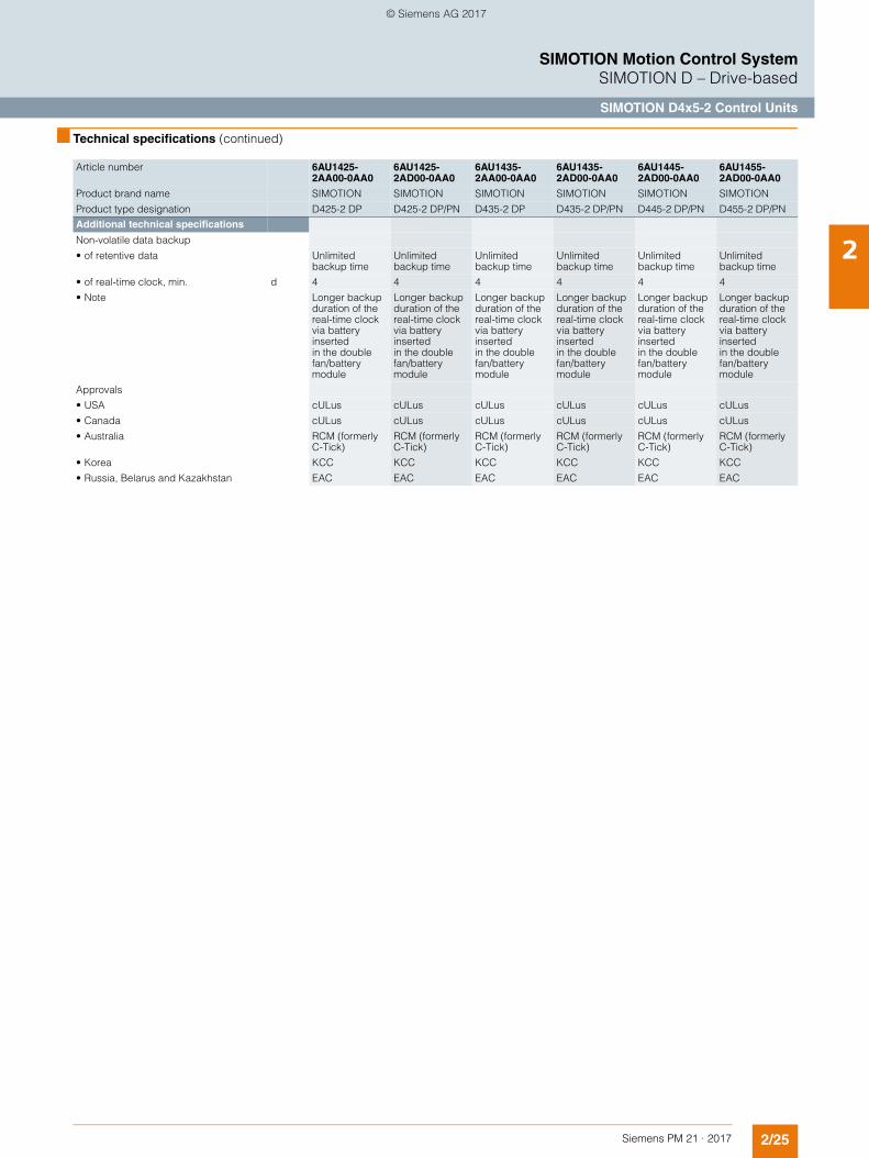
2/25Siemens PM 21 · 2017
SIMOTION Motion Control SystemSIMOTION D – Drive-based
SIMOTION D4x5-2 Control Units
2
■ Technical specifications (continued)
Article number 6AU1425-2AA00-0AA0
6AU1425-2AD00-0AA0
6AU1435-2AA00-0AA0
6AU1435-2AD00-0AA0
6AU1445-2AD00-0AA0
6AU1455-2AD00-0AA0
Product brand name SIMOTION SIMOTION SIMOTION SIMOTION SIMOTION SIMOTION
Product type designation D425-2 DP D425-2 DP/PN D435-2 DP D435-2 DP/PN D445-2 DP/PN D455-2 DP/PN
Additional technical specifications
Non-volatile data backup
• of retentive data Unlimited backup time
Unlimited backup time
Unlimited backup time
Unlimited backup time
Unlimited backup time
Unlimited backup time
• of real-time clock, min. d 4 4 4 4 4 4
• Note Longer backup duration of the real-time clock via battery insertedin the double fan/battery module
Longer backup duration of the real-time clock via battery insertedin the double fan/battery module
Longer backup duration of the real-time clock via battery insertedin the double fan/battery module
Longer backup duration of the real-time clock via battery insertedin the double fan/battery module
Longer backup duration of the real-time clock via battery insertedin the double fan/battery module
Longer backup duration of the real-time clock via battery insertedin the double fan/battery module
Approvals
• USA cULus cULus cULus cULus cULus cULus
• Canada cULus cULus cULus cULus cULus cULus
• Australia RCM (formerly C-Tick)
RCM (formerly C-Tick)
RCM (formerly C-Tick)
RCM (formerly C-Tick)
RCM (formerly C-Tick)
RCM (formerly C-Tick)
• Korea KCC KCC KCC KCC KCC KCC
• Russia, Belarus and Kazakhstan EAC EAC EAC EAC EAC EAC
© Siemens AG 2017
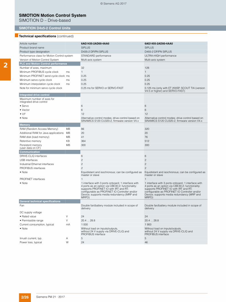
2/26 Siemens PM 21 · 2017
SIMOTION Motion Control SystemSIMOTION D – Drive-based
SIMOTION D4x5-2 Control Units
2
■ Technical specifications (continued)
Article number 6AG1435-2AD00-4AA0 6AG1455-2AD00-4AA0
Product brand name SIPLUS SIPLUS
Product type designation D435-2 DP/PN SIPLUS D455-2 DP/PN SIPLUS
Performance class for Motion Control system STANDARD performance ULTRA-HIGH performance
Version of Motion Control System Multi-axis system Multi-axis system
PLC and Motion Control performance
Number of axes, maximum 32 128
Minimum PROFIBUS cycle clock ms 1 1
Minimum PROFINET send cycle clock ms 0.25 0.25
Minimum servo cycle clock ms 0.25 0.25
Minimum interpolation cycle clock ms 0.25 0.25
Note for minimum servo cycle clock 0.25 ms for SERVO or SERVO-FAST 0.125 ms (only with ET 200SP, SCOUT TIA (version V4.5 or higher) and SERVO-FAST)
Integrated drive control
Maximum number of axes for integrated drive control
• Servo 6 6
• Vector 6 6
• V/f 12 12
• Note Alternative control modes; drive control based on SINAMICS S120 CU320-2, firmware version V4.x
Alternative control modes; drive control based on SINAMICS S120 CU320-2, firmware version V4.x
Memory
RAM (Random Access Memory) MB 86 320
Additional RAM for Java applications MB 20 20
RAM disk (load memory) MB 41 76
Retentive memory KB 364 512
Persistent memory (user data on CF)
MB 300 300
Communication
DRIVE-CLiQ interfaces 6 6
USB interfaces 2 2
Industrial Ethernet interfaces 2 2
PROFIBUS interfaces 2 2
• Note Equidistant and isochronous; can be configured as master or slave
Equidistant and isochronous; can be configured as master or slave
PROFINET interfaces 1 1
• Note 1 interface with 3 ports onboard; 1 interface with 4 ports as an option via CBE30-2; functionality: supports PROFINET IO with IRT and RT; configurable as PROFINET IO Controller and/or Device; supports media redundancy (MRP and MRPD)
1 interface with 3 ports onboard; 1 interface with 4 ports as an option via CBE30-2; functionality: supports PROFINET IO with IRT and RT; configurable as PROFINET IO Controller and/or Device; supports media redundancy (MRP and MRPD)
General technical specifications
Fan Double fan/battery module included in scope of delivery
Double fan/battery module included in scope of delivery
DC supply voltage
• Rated value V 24 24
• Permissible range V 20.4 ... 28.8 20.4 ... 28.8
Current consumption, typical mA 1 000 1 900
• Note Without load on inputs/outputs, without 24 V supply via DRIVE-CLiQ and PROFIBUS interface
Without load on inputs/outputs, without 24 V supply via DRIVE-CLiQ and PROFIBUS interface
Inrush current, typ. A 5 5
Power loss, typical W 24 46
© Siemens AG 2017
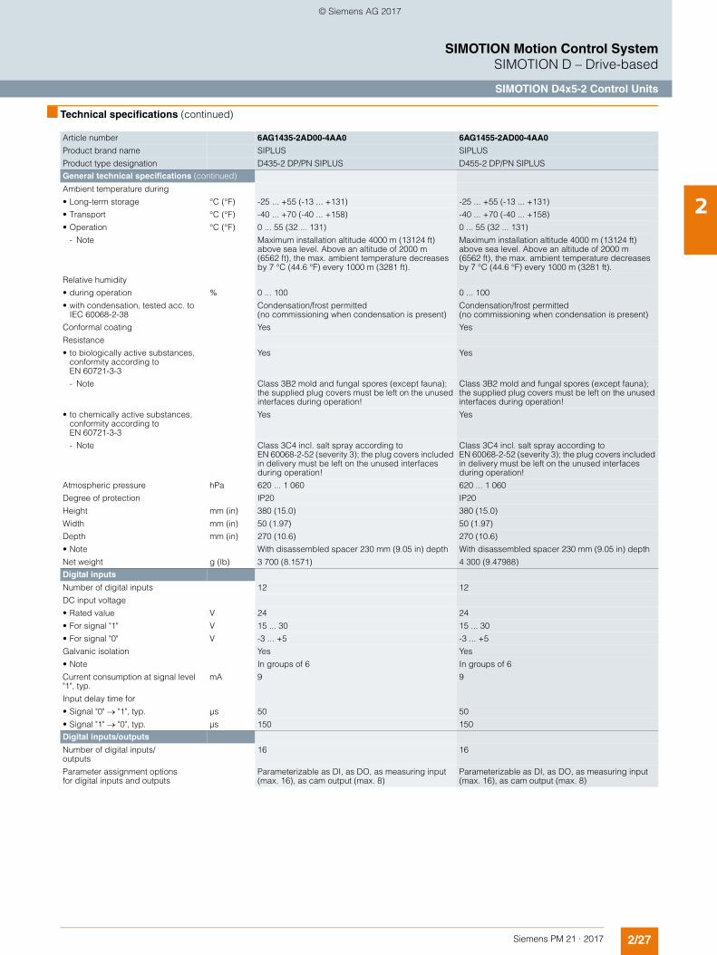
2/27Siemens PM 21 · 2017
SIMOTION Motion Control SystemSIMOTION D – Drive-based
SIMOTION D4x5-2 Control Units
2
■ Technical specifications (continued)
Article number 6AG1435-2AD00-4AA0 6AG1455-2AD00-4AA0
Product brand name SIPLUS SIPLUS
Product type designation D435-2 DP/PN SIPLUS D455-2 DP/PN SIPLUS
General technical specifications (continued)
Ambient temperature during
• Long-term storage °C (°F) -25 ... +55 (-13 ... +131) -25 ... +55 (-13 ... +131)
• Transport °C (°F) -40 ... +70 (-40 ... +158) -40 ... +70 (-40 ... +158)
• Operation °C (°F) 0 ... 55 (32 ... 131) 0 ... 55 (32 ... 131)
- Note Maximum installation altitude 4000 m (13124 ft) above sea level. Above an altitude of 2000 m (6562 ft), the max. ambient temperature decreases by 7 °C (44.6 °F) every 1000 m (3281 ft).
Maximum installation altitude 4000 m (13124 ft) above sea level. Above an altitude of 2000 m (6562 ft), the max. ambient temperature decreases by 7 °C (44.6 °F) every 1000 m (3281 ft).
Relative humidity
• during operation % 0 ... 100 0 ... 100
• with condensation, tested acc. to IEC 60068-2-38
Condensation/frost permitted (no commissioning when condensation is present)
Condensation/frost permitted (no commissioning when condensation is present)
Conformal coating Yes Yes
Resistance
• to biologically active substances, conformity according to EN 60721-3-3
Yes Yes
- Note Class 3B2 mold and fungal spores (except fauna); the supplied plug covers must be left on the unused interfaces during operation!
Class 3B2 mold and fungal spores (except fauna); the supplied plug covers must be left on the unused interfaces during operation!
• to chemically active substances, conformity according to EN 60721-3-3
Yes Yes
- Note Class 3C4 incl. salt spray according to EN 60068-2-52 (severity 3); the plug covers included in delivery must be left on the unused interfaces during operation!
Class 3C4 incl. salt spray according to EN 60068-2-52 (severity 3); the plug covers included in delivery must be left on the unused interfaces during operation!
Atmospheric pressure hPa 620 ... 1 060 620 ... 1 060
Degree of protection IP20 IP20
Height mm (in) 380 (15.0) 380 (15.0)
Width mm (in) 50 (1.97) 50 (1.97)
Depth mm (in) 270 (10.6) 270 (10.6)
• Note With disassembled spacer 230 mm (9.05 in) depth With disassembled spacer 230 mm (9.05 in) depth
Net weight g (lb) 3 700 (8.1571) 4 300 (9.47988)
Digital inputs
Number of digital inputs 12 12
DC input voltage
• Rated value V 24 24
• For signal "1" V 15 ... 30 15 ... 30
• For signal "0" V -3 ... +5 -3 ... +5
Galvanic isolation Yes Yes
• Note In groups of 6 In groups of 6
Current consumption at signal level "1", typ.
mA 9 9
Input delay time for
• Signal "0" "1", typ. µs 50 50
• Signal "1" "0", typ. µs 150 150
Digital inputs/outputs
Number of digital inputs/outputs
16 16
Parameter assignment options for digital inputs and outputs
Parameterizable as DI, as DO, as measuring input (max. 16), as cam output (max. 8)
Parameterizable as DI, as DO, as measuring input (max. 16), as cam output (max. 8)
© Siemens AG 2017
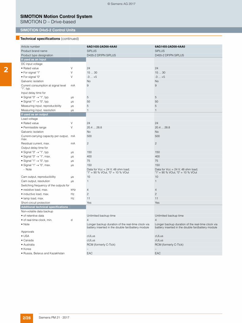
2/28 Siemens PM 21 · 2017
SIMOTION Motion Control SystemSIMOTION D – Drive-based
SIMOTION D4x5-2 Control Units
2
■ Technical specifications (continued)
Article number 6AG1435-2AD00-4AA0 6AG1455-2AD00-4AA0
Product brand name SIPLUS SIPLUS
Product type designation D435-2 DP/PN SIPLUS D455-2 DP/PN SIPLUS
If used as an input
DC input voltage
• Rated value V 24 24
• For signal "1" V 15 ... 30 15 ... 30
• For signal "0" V -3 ... +5 -3 ... +5
Galvanic isolation No No
Current consumption at signal level "1", typ.
mA 9 9
Input delay time for
• Signal "0" "1", typ. µs 5 5
• Signal "1" "0", typ. µs 50 50
Measuring input, reproducibility µs 5 5
Measuring input, resolution µs 1 1
If used as an output
Load voltage
• Rated value V 24 24
• Permissible range V 20.4 ... 28.8 20.4 ... 28.8
Galvanic isolation No No
Current-carrying capacity per output, max.
mA 500 500
Residual current, max. mA 2 2
Output delay time for
• Signal "0" "1", typ. µs 150 150
• Signal "0" "1", max. µs 400 400
• Signal "1" "0", typ. µs 75 75
• Signal "1" "0", max. µs 150 150
- Note Data for Vcc = 24 V; 48 ohm load; "1" = 90 % VOut, "0" = 10 % VOut
Data for Vcc = 24 V; 48 ohm load; "1" = 90 % VOut, "0" = 10 % VOut
Cam output, reproducibility µs 10 10
Cam output, resolution µs 1 1
Switching frequency of the outputs for
• resistive load, max. kHz 4 4
• inductive load, max. Hz 2 2
• lamp load, max. Hz 11 11
Short-circuit protection Yes Yes
Additional technical specifications
Non-volatile data backup
• of retentive data Unlimited backup time Unlimited backup time
• of real-time clock, min. d 4 4
• Note Longer backup duration of the real-time clock via battery inserted in the double fan/battery module
Longer backup duration of the real-time clock via battery inserted in the double fan/battery module
Approvals
• USA cULus cULus
• Canada cULus cULus
• Australia RCM (formerly C-Tick) RCM (formerly C-Tick)
• Korea – –
• Russia, Belarus and Kazakhstan EAC EAC
© Siemens AG 2017
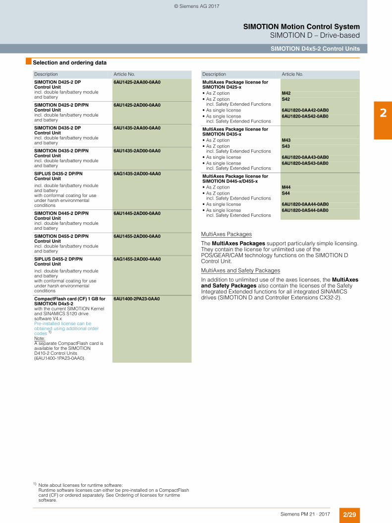
2/29Siemens PM 21 · 2017
SIMOTION Motion Control SystemSIMOTION D – Drive-based
SIMOTION D4x5-2 Control Units
2
■ Selection and ordering data
MultiAxes Packages
The MultiAxes Packages support particularly simple licensing. They contain the license for unlimited use of the POS/GEAR/CAM technology functions on the SIMOTION D Control Unit.
MultiAxes and Safety Packages
In addition to unlimited use of the axes licenses, the MultiAxes and Safety Packages also contain the licenses of the Safety Integrated Extended functions for all integrated SINAMICS drives (SIMOTION D and Controller Extensions CX32-2).
Description Article No.
SIMOTION D425-2 DP Control Unit incl. double fan/battery module and battery
6AU1425-2AA00-0AA0
SIMOTION D425-2 DP/PNControl Unit incl. double fan/battery module and battery
6AU1425-2AD00-0AA0
SIMOTION D435-2 DPControl Unit incl. double fan/battery module and battery
6AU1435-2AA00-0AA0
SIMOTION D435-2 DP/PNControl Unit incl. double fan/battery module and battery
6AU1435-2AD00-0AA0
SIPLUS D435-2 DP/PNControl Unit
incl. double fan/battery module and battery with conformal coating for use under harsh environmental conditions
6AG1435-2AD00-4AA0
SIMOTION D445-2 DP/PNControl Unit incl. double fan/battery module and battery
6AU1445-2AD00-0AA0
SIMOTION D455-2 DP/PNControl Unit incl. double fan/battery module and battery
6AU1455-2AD00-0AA0
SIPLUS D455-2 DP/PNControl Unit
incl. double fan/battery module and battery with conformal coating for use under harsh environmental conditions
6AG1455-2AD00-4AA0
CompactFlash card (CF) 1 GB for SIMOTION D4x5-2with the current SIMOTION Kernel and SINAMICS S120 drive software V4.x Pre-installed license can be obtained using additional order codes 1)
Note:A separate CompactFlash card is available for the SIMOTION D410-2 Control Units (6AU1400-1PA23-0AA0).
6AU1400-2PA23-0AA0
MultiAxes Package license for SIMOTION D425-x• As Z option M42• As Z option
incl. Safety Extended FunctionsS42
• As single license 6AU1820-0AA42-0AB0• As single license
incl. Safety Extended Functions6AU1820-0AS42-0AB0
MultiAxes Package license for SIMOTION D435-x• As Z option M43• As Z option
incl. Safety Extended FunctionsS43
• As single license 6AU1820-0AA43-0AB0• As single license
incl. Safety Extended Functions6AU1820-0AS43-0AB0
MultiAxes Package license for SIMOTION D445-x/D455-x• As Z option M44• As Z option
incl. Safety Extended FunctionsS44
• As single license 6AU1820-0AA44-0AB0• As single license
incl. Safety Extended Functions6AU1820-0AS44-0AB0
Description Article No.
1) Note about licenses for runtime software: Runtime software licenses can either be pre-installed on a CompactFlash card (CF) or ordered separately. See Ordering of licenses for runtime software.
© Siemens AG 2017
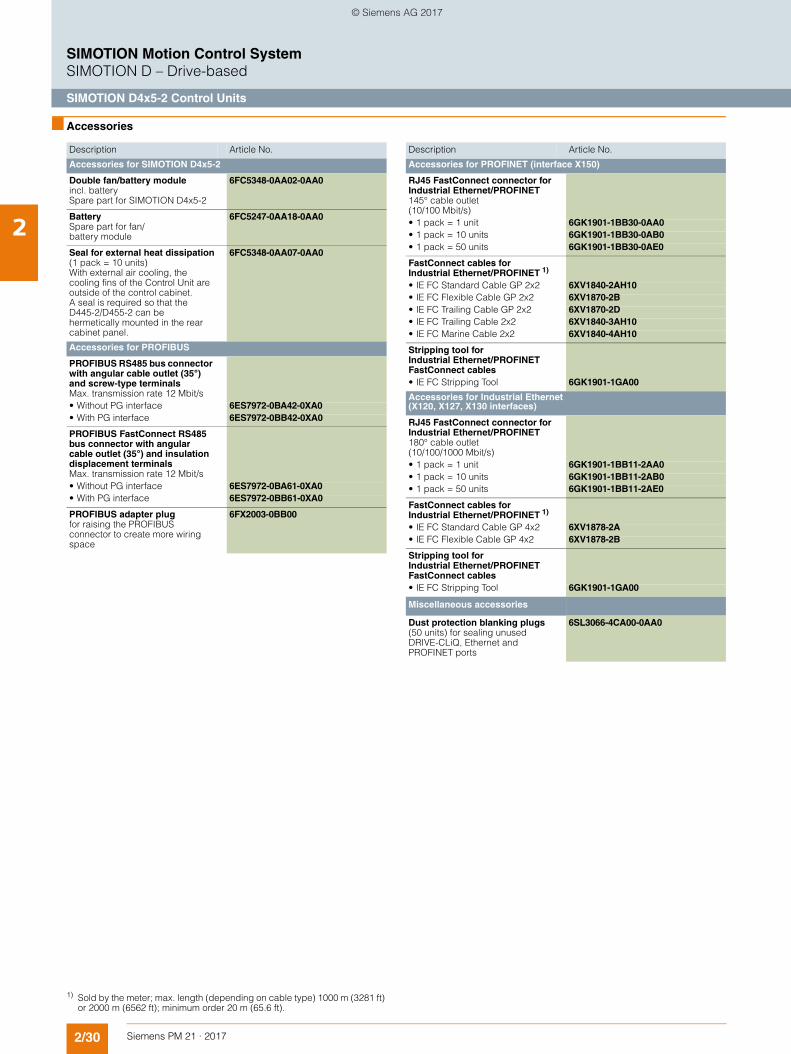
2/30 Siemens PM 21 · 2017
SIMOTION Motion Control SystemSIMOTION D – Drive-based
SIMOTION D4x5-2 Control Units
2
■ Accessories
Description Article No.
Accessories for SIMOTION D4x5-2
Double fan/battery moduleincl. battery Spare part for SIMOTION D4x5-2
6FC5348-0AA02-0AA0
BatterySpare part for fan/battery module
6FC5247-0AA18-0AA0
Seal for external heat dissipation(1 pack = 10 units)With external air cooling, the cooling fins of the Control Unit are outside of the control cabinet.A seal is required so that the D445-2/D455-2 can be hermetically mounted in the rear cabinet panel.
6FC5348-0AA07-0AA0
Accessories for PROFIBUS
PROFIBUS RS485 bus connector with angular cable outlet (35°) and screw-type terminalsMax. transmission rate 12 Mbit/s• Without PG interface 6ES7972-0BA42-0XA0• With PG interface 6ES7972-0BB42-0XA0
PROFIBUS FastConnect RS485 bus connector with angular cable outlet (35°) and insulation displacement terminalsMax. transmission rate 12 Mbit/s• Without PG interface 6ES7972-0BA61-0XA0• With PG interface 6ES7972-0BB61-0XA0
PROFIBUS adapter plug for raising the PROFIBUS connector to create more wiring space
6FX2003-0BB00
Accessories for PROFINET (interface X150)
RJ45 FastConnect connector for Industrial Ethernet/PROFINET145° cable outlet (10/100 Mbit/s) • 1 pack = 1 unit 6GK1901-1BB30-0AA0• 1 pack = 10 units 6GK1901-1BB30-0AB0• 1 pack = 50 units 6GK1901-1BB30-0AE0
FastConnect cables for Industrial Ethernet/PROFINET 1)
• IE FC Standard Cable GP 2x2 6XV1840-2AH10• IE FC Flexible Cable GP 2x2 6XV1870-2B• IE FC Trailing Cable GP 2x2 6XV1870-2D• IE FC Trailing Cable 2x2 6XV1840-3AH10• IE FC Marine Cable 2x2 6XV1840-4AH10
Stripping tool for Industrial Ethernet/PROFINET FastConnect cables• IE FC Stripping Tool 6GK1901-1GA00
Accessories for Industrial Ethernet (X120, X127, X130 interfaces)
RJ45 FastConnect connector for Industrial Ethernet/PROFINET180° cable outlet (10/100/1000 Mbit/s) • 1 pack = 1 unit 6GK1901-1BB11-2AA0• 1 pack = 10 units 6GK1901-1BB11-2AB0• 1 pack = 50 units 6GK1901-1BB11-2AE0
FastConnect cables for Industrial Ethernet/PROFINET 1)
• IE FC Standard Cable GP 4x2 6XV1878-2A• IE FC Flexible Cable GP 4x2 6XV1878-2B
Stripping tool for Industrial Ethernet/PROFINET FastConnect cables• IE FC Stripping Tool 6GK1901-1GA00
Miscellaneous accessories
Dust protection blanking plugs(50 units) for sealing unused DRIVE-CLiQ, Ethernet and PROFINET ports
6SL3066-4CA00-0AA0
Description Article No.
1) Sold by the meter; max. length (depending on cable type) 1000 m (3281 ft) or 2000 m (6562 ft); minimum order 20 m (65.6 ft).
© Siemens AG 2017
2/31Siemens PM 21 · 2017
SIMOTION Motion Control SystemSIMOTION D – Drive-based
SIMOTION D4x5-2 Control Units
2
■ More information
More information• about SINAMICS S120 drive components such as
Line Modules, Motor Modules etc. can be found in Catalog D 21.4 – chapter SINAMICS S120 Drive System, and the Industry Mall under Drive Technology/Converters/AC Low-voltage converters/High performance converters SINAMICS S/....
• about signal and power cables for SINAMICS S120 can be found in Catalog D 21.4 – chapter MOTION-CONNECT connection systems, and the Industry Mall under Drive Technology/Further Components/MOTION-CONNECT connection systems.
• about PROFINET, Industrial Ethernet and PROFIBUS can be found in Catalog IK PI, and the Industry Mall under Automation Technology/Industrial Communication.
Integrated drive control
The drive control functions integrated in SIMOTION D4x5-2 Control Units are based on the drive control of a SINAMICS S120 CU320-2 Control Unit (firmware version V4.x), although there is a slight difference in functionality. For example, the integrated drive control does not have a basic positioner function (EPOS), as this is already covered by SIMOTION technology functions.
For more information, refer to the documentation for SIMOTION and SINAMICS.
SIZER for Siemens Drives engineering tool
With the SIZER for Siemens Drives engineering tool, you can easily configure, for example, the SINAMICS S110 and S120 drive families including SIMOTION. This tool supports you with the engineering of components for a Motion Control task. You can also determine the possible number of axes and the resulting utilization with SIZER for Siemens Drives in accordance with your performance requirements.
For more information about SIZER for Siemens Drives, refer to section Lifecycle Services.
Connectors and cables
The adapter plug (Article No. 6FX2003-0BB00) is required for D4x5-2 when the bus cable has to be looped through the left-hand PROFIBUS interface (X126) (2 PROFIBUS cables wired to the plug) and also• Ethernet interface X120, in the case of D4x5-2 DP or • Port 3 of the PROFINET interface X150 in the case of
D4x5-2 DP/PN
has to be wired to a FastConnect plug. When using the adapter plug, the PROFIBUS connector is higher, which creates extra wiring space.
Ethernet interfaces X120, X127 and X130 support 10, 100 and 1000 Mbit/s. For 1000 Mbit/s, 8-core cables (4x2) must be used as well as the 1000 Mbit version of the 180° FastConnect plug.
The 145° FastConnect plugs cannot be used for Ethernet interface X130 (cable outlet downwards). They also only support a maximum of 100 Mbit/s.
© Siemens AG 2017
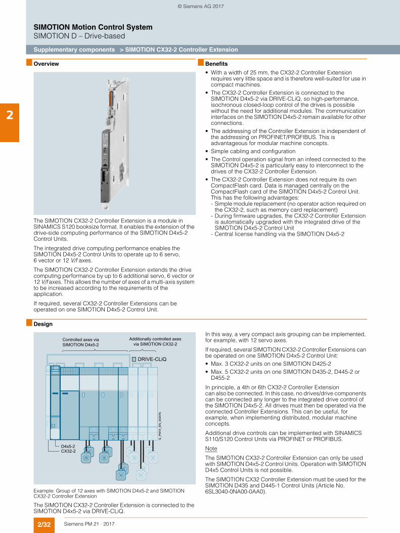
2/32 Siemens PM 21 · 2017
SIMOTION Motion Control SystemSIMOTION D – Drive-based
Supplementary components > SIMOTION CX32-2 Controller Extension
2
■ Overview
The SIMOTION CX32-2 Controller Extension is a module in SINAMICS S120 booksize format. It enables the extension of the drive-side computing performance of the SIMOTION D4x5-2 Control Units.
The integrated drive computing performance enables the SIMOTION D4x5-2 Control Units to operate up to 6 servo, 6 vector or 12 V/f axes.
The SIMOTION CX32-2 Controller Extension extends the drive computing performance by up to 6 additional servo, 6 vector or 12 V/f axes. This allows the number of axes of a multi-axis system to be increased according to the requirements of the application.
If required, several CX32-2 Controller Extensions can be operated on one SIMOTION D4x5-2 Control Unit.
■ Benefits
• With a width of 25 mm, the CX32-2 Controller Extension requires very little space and is therefore well-suited for use in compact machines.
• The CX32-2 Controller Extension is connected to the SIMOTION D4x5-2 via DRIVE-CLiQ, so high-performance, isochronous closed-loop control of the drives is possible without the need for additional modules. The communication interfaces on the SIMOTION D4x5-2 remain available for other connections.
• The addressing of the Controller Extension is independent of the addressing on PROFINET/PROFIBUS. This is advantageous for modular machine concepts.
• Simple cabling and configuration• The Control operation signal from an infeed connected to the
SIMOTION D4x5-2 is particularly easy to interconnect to the drives of the CX32-2 Controller Extension.
• The CX32-2 Controller Extension does not require its own CompactFlash card. Data is managed centrally on the CompactFlash card of the SIMOTION D4x5-2 Control Unit. This has the following advantages: - Simple module replacement (no operator action required on
the CX32-2, such as memory card replacement)- During firmware upgrades, the CX32-2 Controller Extension
is automatically upgraded with the integrated drive of the SIMOTION D4x5-2 Control Unit
- Central license handling via the SIMOTION D4x5-2
■ Design
Example: Group of 12 axes with SIMOTION D4x5-2 and SIMOTION CX32-2 Controller Extension
The SIMOTION CX32-2 Controller Extension is connected to the SIMOTION D4x5-2 via DRIVE-CLiQ.
In this way, a very compact axis grouping can be implemented, for example, with 12 servo axes.
If required, several SIMOTION CX32-2 Controller Extensions can be operated on one SIMOTION D4x5-2 Control Unit: • Max. 3 CX32-2 units on one SIMOTION D425-2• Max. 5 CX32-2 units on one SIMOTION D435-2, D445-2 or
D455-2
In principle, a 4th or 6th CX32-2 Controller Extension can also be connected. In this case, no drives/drive components can be connected any longer to the integrated drive control of the SIMOTION D4x5-2. All drives must then be operated via the connected Controller Extensions. This can be useful, for example, when implementing distributed, modular machine concepts.
Additional drive controls can be implemented with SINAMICS S110/S120 Control Units via PROFINET or PROFIBUS.
Note
The SIMOTION CX32-2 Controller Extension can only be used with SIMOTION D4x5-2 Control Units. Operation with SIMOTION D4x5 Control Units is not possible.
The SIMOTION CX32 Controller Extension must be used for the SIMOTION D435 and D445-1 Control Units (Article No. 6SL3040-0NA00-0AA0).
Additionally controlled axes via SIMOTION CX32-2
Controlled axes via SIMOTION D4x5-2
G_P
M10
_EN
_002
07b
DRIVE-CLiQ
D4x5-2CX32-2
© Siemens AG 2017

2/33Siemens PM 21 · 2017
SIMOTION Motion Control SystemSIMOTION D – Drive-based
Supplementary components > SIMOTION CX32-2 Controller Extension
2
■ Technical specifications
Article number 6AU1432-2AA00-0AA0
Product brand name SIMOTION
Product type designation CX32-2
Version of Motion Control System Controller Extension
Integrated drive control
Maximum number of axes for integrated drive control
• Servo 6
• Vector 6
• V/f 12
• Note Alternative control modes; drive control based on SINAMICS S120 CU320-2, firmware version V4.x
Communication
DRIVE-CLiQ interfaces 4
General technical specifications
Fan No fan
DC supply voltage
• Rated value V 24
• Permissible range V 20.4 ... 28.8
Current consumption, typical mA 300
• Note Without load on inputs/outputs, without 24 V supply via DRIVE-CLiQ interface
Inrush current, typ. A 1.6
Active power loss, typical W 7
Ambient temperature during
• Long-term storage °C (°F) -25 ... +55 (-13 ... +131)
• Transport °C (°F) -40 ... +70 (-40 ... +158)
• Operation °C (°F) 0 ... 55 (32 ... 131)
- Note Maximum installation altitude 4000 m (13124 ft) above sea level. Above an altitude of 2000 m (6562 ft), the max. ambient temperature decreases by 7 °C (44.6 °F) every 1000 m (3281 ft).
Relative humidity during operation % 5 ... 95
Atmospheric pressure hPa 620 ... 1 060
Degree of protection IP20
Height mm (in) 380 (15.0)
Width mm (in) 25 (0.98)
Depth mm (in) 270 (10.6)
• Note With disassembled spacer 230 mm (9.05 in) depth
Net weight g (lb) 2 600 (5.73202)
Digital inputs
Number of digital inputs 6
DC input voltage
• Rated value V 24
• For signal "1" V 15 ... 30
• For signal "0" V -3 ... +5
Galvanic isolation Yes
• Note In groups of 6
Current consumption at signal level "1", typ.
mA 3.5
Input delay time for
• Signal "0" "1", typ. µs 50
• Signal "1" "0", typ. µs 150
Digital inputs/outputs
Number of digital inputs/outputs 4
Parameter assignment options for digital inputs and outputs
Parameterizable as DI, as DO, as measuring input (max. 4)
© Siemens AG 2017
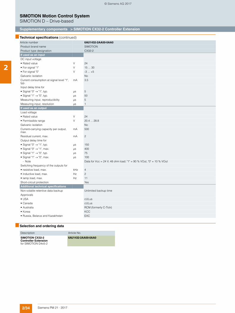
2/34 Siemens PM 21 · 2017
SIMOTION Motion Control SystemSIMOTION D – Drive-based
Supplementary components > SIMOTION CX32-2 Controller Extension
2
■ Technical specifications (continued)
■ Selection and ordering data
Article number 6AU1432-2AA00-0AA0
Product brand name SIMOTION
Product type designation CX32-2
If used as an input
DC input voltage
• Rated value V 24
• For signal "1" V 15 ... 30
• For signal "0" V -3 ... +5
Galvanic isolation No
Current consumption at signal level "1", typ.
mA 3.5
Input delay time for
• Signal "0" "1", typ. µs 5
• Signal "1" "0", typ. µs 50
Measuring input, reproducibility µs 5
Measuring input, resolution µs 1
If used as an output
Load voltage
• Rated value V 24
• Permissible range V 20.4 ... 28.8
Galvanic isolation No
Current-carrying capacity per output, max.
mA 500
Residual current, max. mA 2
Output delay time for
• Signal "0" "1", typ. µs 150
• Signal "0" "1", max. µs 400
• Signal "1" "0", typ. µs 75
• Signal "1" "0", max. µs 100
- Note Data for Vcc = 24 V; 48 ohm load; "1" = 90 % VOut, "0" = 10 % VOut
Switching frequency of the outputs for
• resistive load, max. kHz 4
• inductive load, max. Hz 2
• lamp load, max. Hz 11
Short-circuit protection Yes
Additional technical specifications
Non-volatile retentive data backup Unlimited backup time
Approvals
• USA cULus
• Canada cULus
• Australia RCM (formerly C-Tick)
• Korea KCC
• Russia, Belarus and Kazakhstan EAC
Description Article No.
SIMOTION CX32-2 Controller Extension for SIMOTION D4x5-2
6AU1432-2AA00-0AA0
© Siemens AG 2017
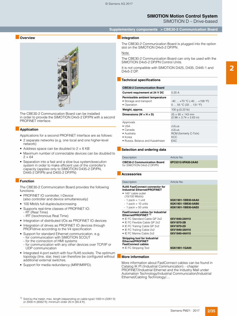
2/35Siemens PM21 · 2017
SIMOTION Motion Control SystemSIMOTION D – Drive-based
Supplementary components > CBE30-2 Communication Board
2
■ Overview
The CBE30-2 Communication Board can be installed in order to provide the SIMOTION D4x5-2 DP/PN with a second PROFINET interface.
■ Application
Applications for a second PROFINET interface are as follows:• 2 separate networks (e.g. one local and one higher-level
network)• Address space can be doubled to 2 × 6 KB • Maximum number of connectable devices can be doubled to
2 × 64• Separation into a fast and a slow bus system/execution
system in order to make efficient use of the controller's capacity (applies only to SIMOTION D435-2 DP/PN, D445-2 DP/PN and D455-2 DP/PN)
■ Function
The CBE30-2 Communication Board provides the following functions:• PROFINET IO controller, I-Device
(also controller and device simultaneously) • 100 Mbit/s full-duplex/autocrossing • Supports real-time classes of PROFINET IO:
- RT (Real Time) - IRT (Isochronous Real Time)
• Integration of distributed I/Os as PROFINET IO devices • Integration of drives as PROFINET IO devices through
PROFIdrive according to the V4 specification • Support for standard Ethernet communication, e.g.
- for communication with SIMOTION SCOUT - for the connection of HMI systems - for communication with any other devices over TCP/IP or
UDP communication • Integrated 4-port switch with four RJ45 sockets. The optimum
topology (line, star, tree) can therefore be configured without additional external switches.
• Support for media redundancy (MRP/MRPD).
■ Integration
The CBE30-2 Communication Board is plugged into the option slot on the SIMOTION D4x5-2 DP/PN.
Note
The CBE30-2 Communication Board can only be used with the SIMOTION D4x5-2 DP/PN Control Units.
It is not compatible with SIMOTION D425, D435, D445-1 and D4x5-2 DP.
■ Technical specifications
■ Selection and ordering data
■ Accessories
■ More information
More information about FastConnect cables can be found in Catalog IK PI (Industrial Communication) – chapter PROFINET/Industrial Ethernet and the Industry Mall under Automation Technology/Industrial Communication/Industrial Ethernet/Cabling Technology/....
1) Sold by the meter; max. length (depending on cable type) 1000 m (3281 ft) or 2000 m (6562 ft); minimum order 20 m (65.6 ft).
CBE30-2 Communication Board
Current requirement at 24 V DC 0.25 A
Permissible ambient temperature• Storage and transport -40 … +70 °C (-40 ... +158 °F)• Operation 0 … 55 °C (32 ... 131 °F)
Weight, approx. 100 g (0.22 lb)
Dimensions (W × H × D) 25 × 95 × 143 mm (0.98 × 3.74 × 5.63 in)
Approvals• USA cULus• Canada cULus• Australia RCM (formerly C-Tick)• Korea KCC• Russia, Belarus and Kazakhstan EAC
Description Article No.
CBE30-2 Communication Boardfor SIMOTION D4x5-2 DP/PN
6FC5312-0FA00-2AA0
Description Article No.
RJ45 FastConnect connector for Industrial Ethernet/PROFINET
• 145° cable outlet (10/100 Mbit/s)
- 1 pack = 1 unit 6GK1901-1BB30-0AA0- 1 pack = 10 units 6GK1901-1BB30-0AB0- 1 pack = 50 units 6GK1901-1BB30-0AE0
FastConnect cables for Industrial Ethernet/PROFINET 1)
• IE FC Standard Cable GP 2x2 6XV1840-2AH10• IE FC Flexible Cable GP 2x2 6XV1870-2B• IE FC Trailing Cable GP 2x2 6XV1870-2D• IE FC Trailing Cable 2x2 6XV1840-3AH10• IE FC Marine Cable 2x2 6XV1840-4AH10
Stripping tool for Industrial Ethernet/PROFINET FastConnect cables
• IE FC Stripping Tool 6GK1901-1GA00
© Siemens AG 2017
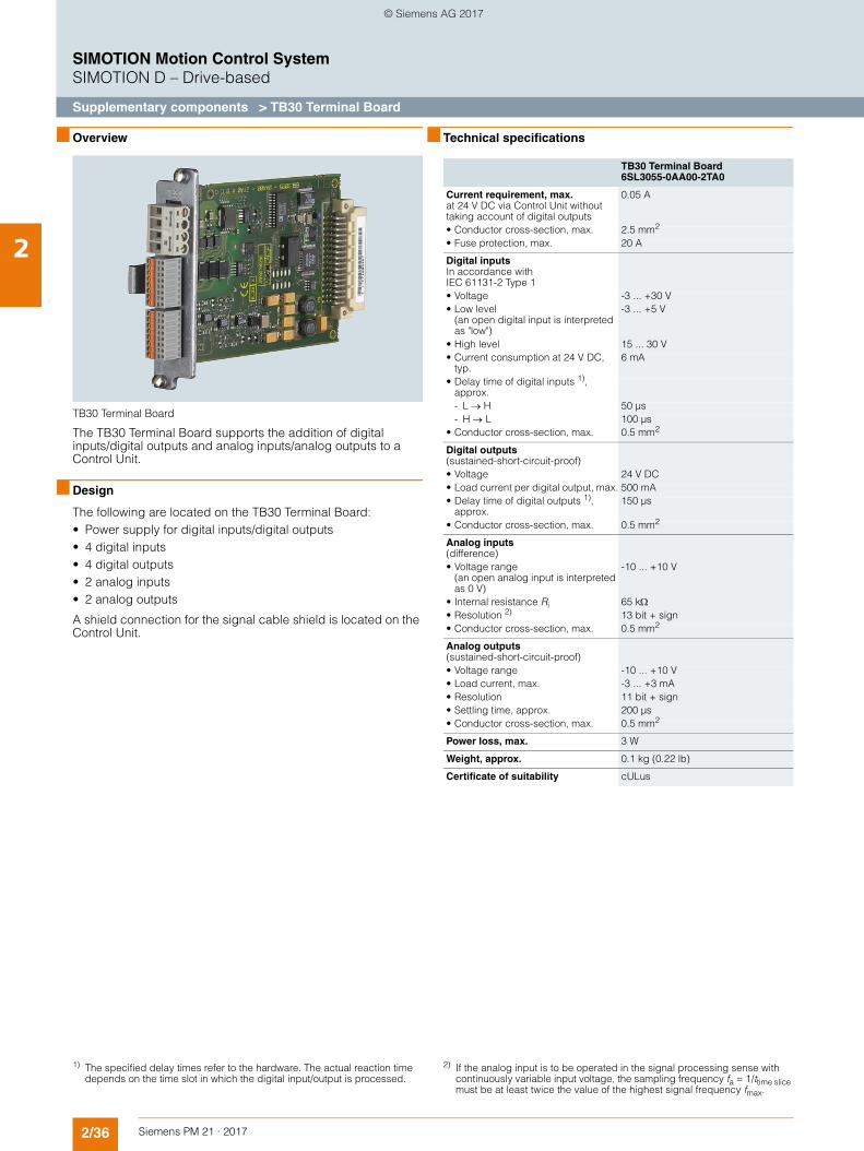
2/36 Siemens PM 21 · 2017
SIMOTION Motion Control SystemSIMOTION D – Drive-based
Supplementary components > TB30 Terminal Board
2
■ Overview
TB30 Terminal Board
The TB30 Terminal Board supports the addition of digital inputs/digital outputs and analog inputs/analog outputs to a Control Unit.
■ Design
The following are located on the TB30 Terminal Board:• Power supply for digital inputs/digital outputs• 4 digital inputs• 4 digital outputs• 2 analog inputs• 2 analog outputs
A shield connection for the signal cable shield is located on the Control Unit.
■ Technical specifications
TB30 Terminal Board6SL3055-0AA00-2TA0
Current requirement, max.at 24 V DC via Control Unit without taking account of digital outputs
0.05 A
• Conductor cross-section, max. 2.5 mm2
• Fuse protection, max. 20 A
Digital inputsIn accordance with IEC 61131-2 Type 1
• Voltage -3 ... +30 V• Low level
(an open digital input is interpreted as "low")
-3 ... +5 V
• High level 15 ... 30 V• Current consumption at 24 V DC,
typ.6 mA
• Delay time of digital inputs 1), approx.
- L H 50 µs- H L 100 µs
• Conductor cross-section, max. 0.5 mm2
Digital outputs(sustained-short-circuit-proof)
• Voltage 24 V DC• Load current per digital output, max. 500 mA• Delay time of digital outputs 1),
approx.150 µs
• Conductor cross-section, max. 0.5 mm2
Analog inputs(difference)
• Voltage range (an open analog input is interpreted as 0 V)
-10 ... +10 V
• Internal resistance Ri 65 k• Resolution 2) 13 bit + sign• Conductor cross-section, max. 0.5 mm2
Analog outputs(sustained-short-circuit-proof)
• Voltage range -10 ... +10 V• Load current, max. -3 ... +3 mA• Resolution 11 bit + sign• Settling time, approx. 200 µs• Conductor cross-section, max. 0.5 mm2
Power loss, max. 3 W
Weight, approx. 0.1 kg (0.22 lb)
Certificate of suitability cULus
1) The specified delay times refer to the hardware. The actual reaction time depends on the time slot in which the digital input/output is processed.
2) If the analog input is to be operated in the signal processing sense with continuously variable input voltage, the sampling frequency fa = 1/ttime slice must be at least twice the value of the highest signal frequency fmax.
© Siemens AG 2017
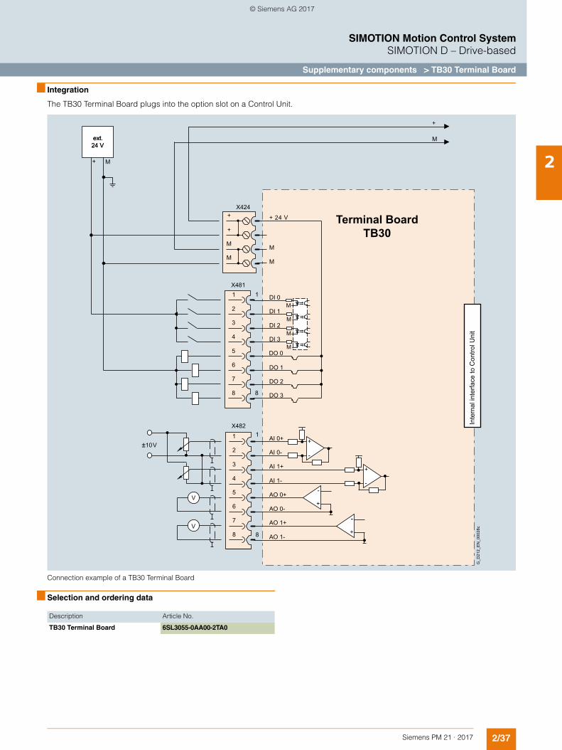
2/37Siemens PM 21 · 2017
SIMOTION Motion Control SystemSIMOTION D – Drive-based
Supplementary components > TB30 Terminal Board
2
■ Integration
The TB30 Terminal Board plugs into the option slot on a Control Unit.
Connection example of a TB30 Terminal Board
■ Selection and ordering data
+ M
+ 24 V
M
X424
M
+
M
+
M
V
V
X4821
8
4
3
2
1
5
6
7
8
±10 V
X48111 DI 0
DI 1
DI 3
DI 2
DO 0
8
DO 1
DO 2
DO 3
AI 0+
AI 0-
AI 1-
AI 1+
AO 0+
AO 0-
AO 1+
AO 1-
4
3
2
5
6
7
8
M
+
Terminal BoardTB30
M
M
M
M
+
-
+
-
+
-
+
-
Inte
rnal
inte
rface
to C
ontro
l Uni
t
ext.24 V
G_D
212_
EN
_000
28c
ext.24 V
-
Description Article No.
TB30 Terminal Board 6SL3055-0AA00-2TA0
© Siemens AG 2017
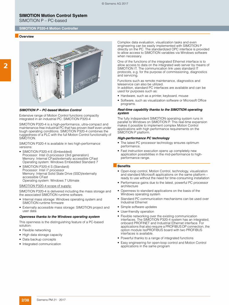
2/38 Siemens PM 21 · 2017
SIMOTION Motion Control SystemSIMOTION P – PC-based
SIMOTION P320-4 Motion Controller
2
■ Overview
SIMOTION P – PC-based Motion Control
Extensive range of Motion Control functions compactly integrated in an industrial PC: SIMOTION P320-4
SIMOTION P320-4 is a high-performance, ultra-compact and maintenance-free industrial PC that has proven itself even under tough operating conditions. SIMOTION P320-4 combines the ruggedness of a PLC with the full Motion Control functionality of SIMOTION.
SIMOTION P320-4 is available in two high-performance versions: • SIMOTION P320-4 E (Embedded)
Processor: Intel i3 processor (3rd generation) Memory: Internal CFast/externally accessible CFast Operating system: Windows Embedded Standard 7
• SIMOTION P320-4 S (Standard) Processor: Intel i7 processor Memory: Internal Solid State Drive (SSD)/externally accessible CFast Operating system: Windows 7 Ultimate
SIMOTION P320-4 scope of supply:
SIMOTION P320-4 is delivered including the mass storage and the associated SIMOTION runtime software.• Internal mass storage: Windows operating system and
SIMOTION runtime firmware • Externally accessible mass storage: SIMOTION project and
user data
Openness thanks to the Windows operating system
This openness is the distinguishing feature of a PC-based solution: • Flexible networking• High data storage capacity • Data backup concepts • Integrated communication
Complex data evaluation, visualization tasks and even engineering can be easily implemented with SIMOTION P directly on the PC. The standardized OPC interface is provided to allow access to SIMOTION variables via Windows software when necessary.
One of the functions of the integrated Ethernet interface is to allow access to data on the integrated web server by means of SIMOTION IT. The communication link uses standard IT protocols, e.g. for the purpose of commissioning, diagnostics and servicing.
Functions such as remote maintenance, diagnostics and teleservice can also be utilized. In addition, standard PC interfaces are available and can be used for purposes such as: • Hardware, such as a printer, keyboard, mouse• Software, such as visualization software or Microsoft Office
programs.
Real-time capability thanks to the SIMOTION operating system
The fully independent SIMOTION operating system runs in parallel to Windows on SIMOTION P. This real-time expansion makes it possible to implement complex Motion Control applications with high performance requirements on the SIMOTION P platform.
High-performance PC technology• The latest PC processor technology ensures optimum
performance.• Fast instruction execution opens up completely new
application possibilities in the mid-performance to high-performance range.
■ Benefits
• Open-loop control, Motion Control, technology, visualization and standard Microsoft applications on the same platform – ready to use without the need for time-consuming installation
• Performance gains due to the latest, powerful PC processor architecture
• Openness to standard applications on the basis of the Windows operating system
• Standard PC communication mechanisms can be used over Industrial Ethernet
• Simple software updates• User-friendly operation • Flexible networking over the existing communication
interfaces. The SIMOTION P320-4 system has an integrated, onboard PROFINET and Industrial Ethernet interface. For applications that also require a PROFIBUS DP connection, the option module IsoPROFIBUS board with two PROFIBUS interfaces is available.
• Powerful thanks to a range of integrated functions • Easy engineering for open-loop control and Motion Control
applications in the same program
© Siemens AG 2017
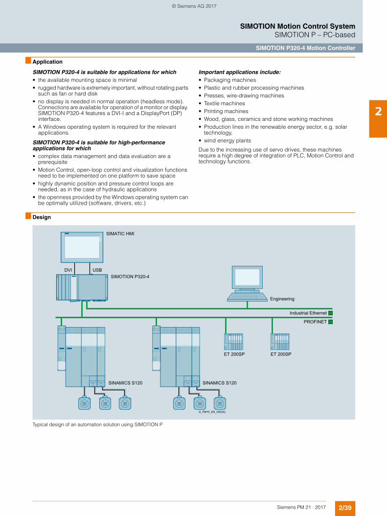
2/39Siemens PM 21 · 2017
SIMOTION Motion Control SystemSIMOTION P – PC-based
SIMOTION P320-4 Motion Controller
2
■ Application
SIMOTION P320-4 is suitable for applications for which• the available mounting space is minimal• rugged hardware is extremely important, without rotating parts
such as fan or hard disk• no display is needed in normal operation (headless mode).
Connections are available for operation of a monitor or display. SIMOTION P320-4 features a DVI-I and a DisplayPort (DP) interface.
• A Windows operating system is required for the relevant applications.
SIMOTION P320-4 is suitable for high-performance applications for which• complex data management and data evaluation are a
prerequisite• Motion Control, open-loop control and visualization functions
need to be implemented on one platform to save space• highly dynamic position and pressure control loops are
needed, as in the case of hydraulic applications• the openness provided by the Windows operating system can
be optimally utilized (software, drivers, etc.)
Important applications include:• Packaging machines• Plastic and rubber processing machines• Presses, wire-drawing machines• Textile machines• Printing machines• Wood, glass, ceramics and stone working machines• Production lines in the renewable energy sector, e.g. solar
technology,• wind energy plants
Due to the increasing use of servo drives, these machines require a high degree of integration of PLC, Motion Control and technology functions.
■ Design
Typical design of an automation solution using SIMOTION P
Engineering
G_PM10_EN_00024c
USBDVI
SIMATIC HMI
SIMOTION P320-4
ET 200SP ET 200SP
SINAMICS S120 SINAMICS S120
PROFINET
Industrial Ethernet
© Siemens AG 2017
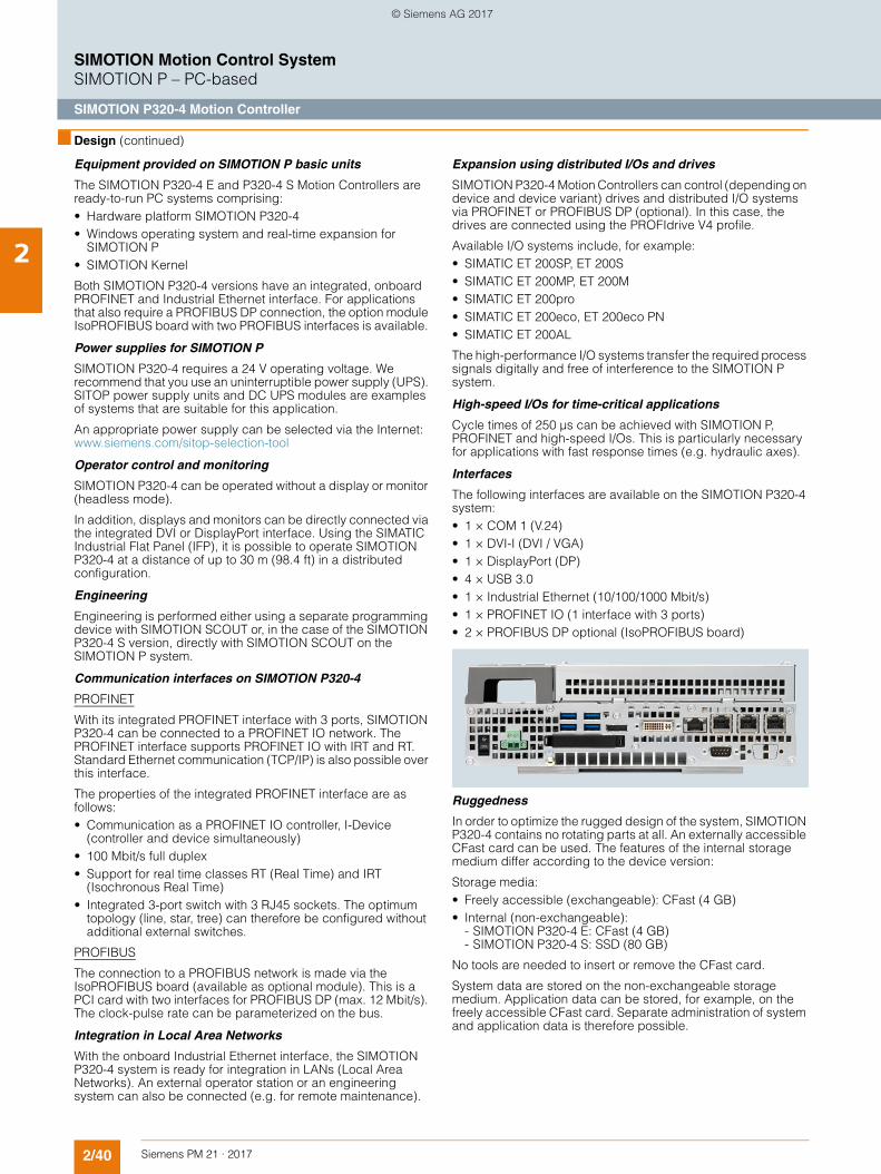
2/40 Siemens PM 21 · 2017
SIMOTION Motion Control SystemSIMOTION P – PC-based
SIMOTION P320-4 Motion Controller
2
■ Design (continued)
Equipment provided on SIMOTION P basic units
The SIMOTION P320-4 E and P320-4 S Motion Controllers are ready-to-run PC systems comprising:• Hardware platform SIMOTION P320-4• Windows operating system and real-time expansion for
SIMOTION P• SIMOTION Kernel
Both SIMOTION P320-4 versions have an integrated, onboard PROFINET and Industrial Ethernet interface. For applications that also require a PROFIBUS DP connection, the option module IsoPROFIBUS board with two PROFIBUS interfaces is available.
Power supplies for SIMOTION P
SIMOTION P320-4 requires a 24 V operating voltage. We recommend that you use an uninterruptible power supply (UPS). SITOP power supply units and DC UPS modules are examples of systems that are suitable for this application.
An appropriate power supply can be selected via the Internet: www.siemens.com/sitop-selection-tool
Operator control and monitoring
SIMOTION P320-4 can be operated without a display or monitor (headless mode).
In addition, displays and monitors can be directly connected via the integrated DVI or DisplayPort interface. Using the SIMATIC Industrial Flat Panel (IFP), it is possible to operate SIMOTION P320-4 at a distance of up to 30 m (98.4 ft) in a distributed configuration.
Engineering
Engineering is performed either using a separate programming device with SIMOTION SCOUT or, in the case of the SIMOTION P320-4 S version, directly with SIMOTION SCOUT on the SIMOTION P system.
Communication interfaces on SIMOTION P320-4
PROFINET
With its integrated PROFINET interface with 3 ports, SIMOTION P320-4 can be connected to a PROFINET IO network. The PROFINET interface supports PROFINET IO with IRT and RT. Standard Ethernet communication (TCP/IP) is also possible over this interface.
The properties of the integrated PROFINET interface are as follows:• Communication as a PROFINET IO controller, I-Device
(controller and device simultaneously)• 100 Mbit/s full duplex • Support for real time classes RT (Real Time) and IRT
(Isochronous Real Time)• Integrated 3-port switch with 3 RJ45 sockets. The optimum
topology (line, star, tree) can therefore be configured without additional external switches.
PROFIBUS
The connection to a PROFIBUS network is made via the IsoPROFIBUS board (available as optional module). This is a PCI card with two interfaces for PROFIBUS DP (max. 12 Mbit/s). The clock-pulse rate can be parameterized on the bus.
Integration in Local Area Networks
With the onboard Industrial Ethernet interface, the SIMOTION P320-4 system is ready for integration in LANs (Local Area Networks). An external operator station or an engineering system can also be connected (e.g. for remote maintenance).
Expansion using distributed I/Os and drives
SIMOTION P320-4 Motion Controllers can control (depending on device and device variant) drives and distributed I/O systems via PROFINET or PROFIBUS DP (optional). In this case, the drives are connected using the PROFIdrive V4 profile.
Available I/O systems include, for example:• SIMATIC ET 200SP, ET 200S• SIMATIC ET 200MP, ET 200M• SIMATIC ET 200pro• SIMATIC ET 200eco, ET 200eco PN• SIMATIC ET 200AL
The high-performance I/O systems transfer the required process signals digitally and free of interference to the SIMOTION P system.
High-speed I/Os for time-critical applications
Cycle times of 250 µs can be achieved with SIMOTION P, PROFINET and high-speed I/Os. This is particularly necessary for applications with fast response times (e.g. hydraulic axes).
Interfaces
The following interfaces are available on the SIMOTION P320-4 system:• 1 × COM 1 (V.24)• 1 × DVI-I (DVI / VGA)• 1 × DisplayPort (DP)• 4 × USB 3.0• 1 × Industrial Ethernet (10/100/1000 Mbit/s)• 1 × PROFINET IO (1 interface with 3 ports)• 2 × PROFIBUS DP optional (IsoPROFIBUS board)
Ruggedness
In order to optimize the rugged design of the system, SIMOTION P320-4 contains no rotating parts at all. An externally accessible CFast card can be used. The features of the internal storage medium differ according to the device version:
Storage media:• Freely accessible (exchangeable): CFast (4 GB)• Internal (non-exchangeable):
- SIMOTION P320-4 E: CFast (4 GB)- SIMOTION P320-4 S: SSD (80 GB)
No tools are needed to insert or remove the CFast card.
System data are stored on the non-exchangeable storage medium. Application data can be stored, for example, on the freely accessible CFast card. Separate administration of system and application data is therefore possible.
© Siemens AG 2017
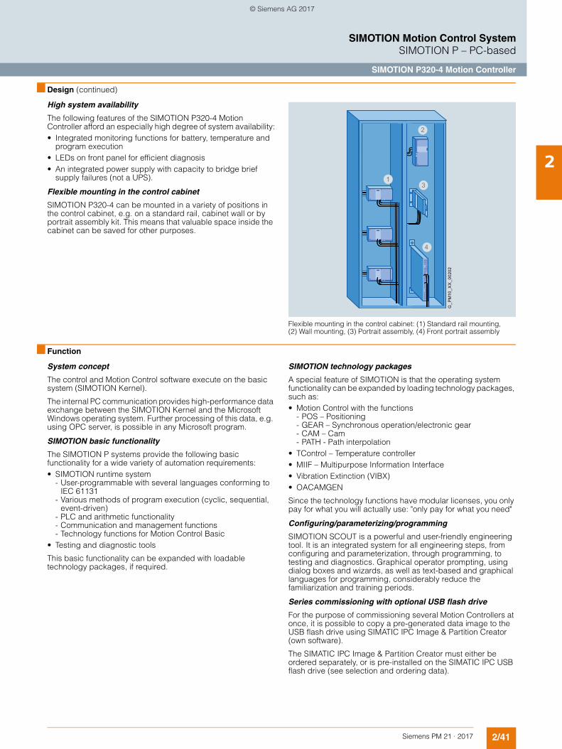
2/41Siemens PM 21 · 2017
SIMOTION Motion Control SystemSIMOTION P – PC-based
SIMOTION P320-4 Motion Controller
2
■ Design (continued)
High system availability
The following features of the SIMOTION P320-4 Motion Controller afford an especially high degree of system availability:• Integrated monitoring functions for battery, temperature and
program execution• LEDs on front panel for efficient diagnosis• An integrated power supply with capacity to bridge brief
supply failures (not a UPS).
Flexible mounting in the control cabinet
SIMOTION P320-4 can be mounted in a variety of positions in the control cabinet, e.g. on a standard rail, cabinet wall or by portrait assembly kit. This means that valuable space inside the cabinet can be saved for other purposes.
Flexible mounting in the control cabinet: (1) Standard rail mounting, (2) Wall mounting, (3) Portrait assembly, (4) Front portrait assembly
■ Function
System concept
The control and Motion Control software execute on the basic system (SIMOTION Kernel).
The internal PC communication provides high-performance data exchange between the SIMOTION Kernel and the Microsoft Windows operating system. Further processing of this data, e.g. using OPC server, is possible in any Microsoft program.
SIMOTION basic functionality
The SIMOTION P systems provide the following basic functionality for a wide variety of automation requirements:• SIMOTION runtime system
- User-programmable with several languages conforming to IEC 61131
- Various methods of program execution (cyclic, sequential, event-driven)
- PLC and arithmetic functionality - Communication and management functions - Technology functions for Motion Control Basic
• Testing and diagnostic tools
This basic functionality can be expanded with loadable technology packages, if required.
SIMOTION technology packages
A special feature of SIMOTION is that the operating system functionality can be expanded by loading technology packages, such as:• Motion Control with the functions
- POS – Positioning- GEAR – Synchronous operation/electronic gear- CAM – Cam - PATH - Path interpolation
• TControl – Temperature controller• MIIF – Multipurpose Information Interface• Vibration Extinction (VIBX)• OACAMGEN
Since the technology functions have modular licenses, you only pay for what you will actually use: "only pay for what you need"
Configuring/parameterizing/programming
SIMOTION SCOUT is a powerful and user-friendly engineering tool. It is an integrated system for all engineering steps, from configuring and parameterization, through programming, to testing and diagnostics. Graphical operator prompting, using dialog boxes and wizards, as well as text-based and graphical languages for programming, considerably reduce the familiarization and training periods.
Series commissioning with optional USB flash drive
For the purpose of commissioning several Motion Controllers at once, it is possible to copy a pre-generated data image to the USB flash drive using SIMATIC IPC Image & Partition Creator (own software).
The SIMATIC IPC Image & Partition Creator must either be ordered separately, or is pre-installed on the SIMATIC IPC USB flash drive (see selection and ordering data).
G_P
M10
_XX
_002
02
4
31
2
© Siemens AG 2017
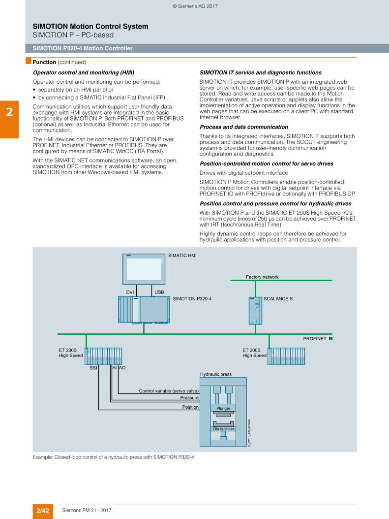
2/42 Siemens PM 21 · 2017
SIMOTION Motion Control SystemSIMOTION P – PC-based
SIMOTION P320-4 Motion Controller
2
■ Function (continued)
Operator control and monitoring (HMI)
Operator control and monitoring can be performed: • separately on an HMI panel or• by connecting a SIMATIC Industrial Flat Panel (IFP).
Communication utilities which support user-friendly data exchange with HMI systems are integrated in the basic functionality of SIMOTION P. Both PROFINET and PROFIBUS (optional) as well as Industrial Ethernet can be used for communication.
The HMI devices can be connected to SIMOTION P over PROFINET, Industrial Ethernet or PROFIBUS. They are configured by means of SIMATIC WinCC (TIA Portal).
With the SIMATIC NET communications software, an open, standardized OPC interface is available for accessing SIMOTION from other Windows-based HMI systems.
SIMOTION IT service and diagnostic functions
SIMOTION IT provides SIMOTION P with an integrated web server on which, for example, user-specific web pages can be stored. Read and write access can be made to the Motion Controller variables. Java scripts or applets also allow the implementation of active operation and display functions in the web pages that can be executed on a client PC with standard Internet browser.
Process and data communication
Thanks to its integrated interfaces, SIMOTION P supports both process and data communication. The SCOUT engineering system is provided for user-friendly communication configuration and diagnostics.
Position-controlled motion control for servo drives
Drives with digital setpoint interface
SIMOTION P Motion Controllers enable position-controlled motion control for drives with digital setpoint interface via PROFINET IO with PROFIdrive or optionally with PROFIBUS DP.
Position control and pressure control for hydraulic drives
With SIMOTION P and the SIMATIC ET 200S High Speed I/Os, minimum cycle times of 250 µs can be achieved over PROFINET with IRT (Isochronous Real Time).
Highly dynamic control loops can therefore be achieved for hydraulic applications with position and pressure control.
Example: Closed-loop control of a hydraulic press with SIMOTION P320-4
Factory network
Hydraulic press
Control variable (servo valve)Pressure
Position Plunger
Die cushion
G_P
M10
_EN
_001
64a
USBDVI
SIMATIC HMI
SIMOTION P320-4
ET 200SHigh Speed
SCALANCE S
PROFINET
SSI AI AO
ET 200SHigh Speed
© Siemens AG 2017
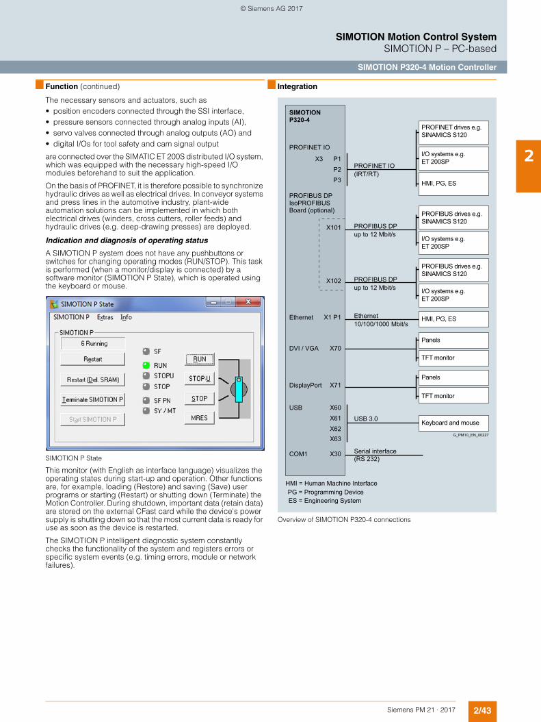
2/43Siemens PM 21 · 2017
SIMOTION Motion Control SystemSIMOTION P – PC-based
SIMOTION P320-4 Motion Controller
2
■ Function (continued)
The necessary sensors and actuators, such as• position encoders connected through the SSI interface,• pressure sensors connected through analog inputs (AI),• servo valves connected through analog outputs (AO) and• digital I/Os for tool safety and cam signal output
are connected over the SIMATIC ET 200S distributed I/O system, which was equipped with the necessary high-speed I/O modules beforehand to suit the application.
On the basis of PROFINET, it is therefore possible to synchronize hydraulic drives as well as electrical drives. In conveyor systems and press lines in the automotive industry, plant-wide automation solutions can be implemented in which both electrical drives (winders, cross cutters, roller feeds) and hydraulic drives (e.g. deep-drawing presses) are deployed.
Indication and diagnosis of operating status
A SIMOTION P system does not have any pushbuttons or switches for changing operating modes (RUN/STOP). This task is performed (when a monitor/display is connected) by a software monitor (SIMOTION P State), which is operated using the keyboard or mouse.
SIMOTION P State
This monitor (with English as interface language) visualizes the operating states during start-up and operation. Other functions are, for example, loading (Restore) and saving (Save) user programs or starting (Restart) or shutting down (Terminate) the Motion Controller. During shutdown, important data (retain data) are stored on the external CFast card while the device's power supply is shutting down so that the most current data is ready for use as soon as the device is restarted.
The SIMOTION P intelligent diagnostic system constantly checks the functionality of the system and registers errors or specific system events (e.g. timing errors, module or network failures).
■ Integration
Overview of SIMOTION P320-4 connections
PROFINET IO(IRT/RT)
Ethernet10/100/1000 Mbit/s
Serial interface(RS 232)
PROFIBUS DPup to 12 Mbit/s
I/O systems e.g. ET 200SP
Keyboard and mouse
Panels
TFT monitor
Panels
TFT monitor
PROFINET drives e.g. SINAMICS S120
I/O systems e.g. ET 200SP
PROFIBUS drives e.g. SINAMICS S120
PROFIBUS DPup to 12 Mbit/s I/O systems e.g.
ET 200SP
PROFIBUS drives e.g. SINAMICS S120
PROFINET IO
PROFIBUS DP IsoPROFIBUS Board (optional)
Ethernet
USB
COM1
DVI / VGA
DisplayPort
PG = Programming DeviceES = Engineering System
HMI = Human Machine Interface
G_PM10_EN_00227
SIMOTION P320-4
X3
X101
X102
X70
X71
X30
X1 P1
P1P2P3
X60X61X62X63
HMI, PG, ES
HMI, PG, ES
USB 3.0
© Siemens AG 2017
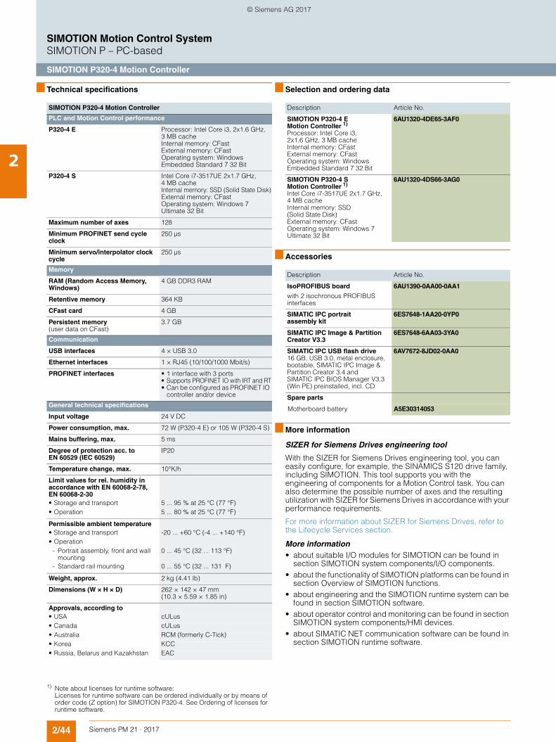
2/44 Siemens PM 21 · 2017
SIMOTION Motion Control SystemSIMOTION P – PC-based
SIMOTION P320-4 Motion Controller
2
■ Technical specifications ■ Selection and ordering data
■ Accessories
■ More information
SIZER for Siemens Drives engineering tool
With the SIZER for Siemens Drives engineering tool, you can easily configure, for example, the SINAMICS S120 drive family, including SIMOTION. This tool supports you with the engineering of components for a Motion Control task. You can also determine the possible number of axes and the resulting utilization with SIZER for Siemens Drives in accordance with your performance requirements.
For more information about SIZER for Siemens Drives, refer to the Lifecycle Services section.
More information• about suitable I/O modules for SIMOTION can be found in
section SIMOTION system components/I/O components.• about the functionality of SIMOTION platforms can be found in
section Overview of SIMOTION functions.• about engineering and the SIMOTION runtime system can be
found in section SIMOTION software.• about operator control and monitoring can be found in section
SIMOTION system components/HMI devices.• about SIMATIC NET communication software can be found in
section SIMOTION runtime software.
SIMOTION P320-4 Motion Controller
PLC and Motion Control performance
P320-4 E Processor: Intel Core i3, 2x1.6 GHz, 3 MB cache Internal memory: CFast External memory: CFast Operating system: Windows Embedded Standard 7 32 Bit
P320-4 S Intel Core i7-3517UE 2x1.7 GHz, 4 MB cache Internal memory: SSD (Solid State Disk)External memory: CFast Operating system: Windows 7 Ultimate 32 Bit
Maximum number of axes 128
Minimum PROFINET send cycle clock
250 µs
Minimum servo/interpolator clock cycle
250 µs
Memory
RAM (Random Access Memory, Windows)
4 GB DDR3 RAM
Retentive memory 364 KB
CFast card 4 GB
Persistent memory(user data on CFast)
3.7 GB
Communication
USB interfaces 4 × USB 3.0
Ethernet interfaces 1 × RJ45 (10/100/1000 Mbit/s)
PROFINET interfaces • 1 interface with 3 ports• Supports PROFINET IO with IRT and RT• Can be configured as PROFINET IO
controller and/or device
General technical specifications
Input voltage 24 V DC
Power consumption, max. 72 W (P320-4 E) or 105 W (P320-4 S)
Mains buffering, max. 5 ms
Degree of protection acc. to EN 60529 (IEC 60529)
IP20
Temperature change, max. 10°K/h
Limit values for rel. humidity in accordance with EN 60068-2-78, EN 60068-2-30
• Storage and transport 5 ... 95 % at 25 °C (77 °F)• Operation 5 ... 80 % at 25 °C (77 °F)
Permissible ambient temperature • Storage and transport -20 ... +60 °C (-4 ... +140 °F)• Operation
- Portrait assembly, front and wall mounting
0 ... 45 °C (32 ... 113 °F)
- Standard rail mounting 0 ... 55 °C (32 ... 131 F)
Weight, approx. 2 kg (4.41 lb)
Dimensions (W × H × D) 262 × 142 × 47 mm (10.3 × 5.59 × 1.85 in)
Approvals, according to• USA cULus• Canada cULus• Australia RCM (formerly C-Tick)• Korea KCC• Russia, Belarus and Kazakhstan EAC
Description Article No.
SIMOTION P320-4 E Motion Controller 1)
Processor: Intel Core i3, 2x1.6 GHz, 3 MB cache Internal memory: CFast External memory: CFast Operating system: Windows Embedded Standard 7 32 Bit
6AU1320-4DE65-3AF0
SIMOTION P320-4 S Motion Controller 1)
Intel Core i7-3517UE 2x1.7 GHz, 4 MB cache Internal memory: SSD (Solid State Disk) External memory: CFast Operating system: Windows 7 Ultimate 32 Bit
6AU1320-4DS66-3AG0
Description Article No.
IsoPROFIBUS board
with 2 isochronous PROFIBUS interfaces
6AU1390-0AA00-0AA1
SIMATIC IPC portrait assembly kit
6ES7648-1AA20-0YP0
SIMATIC IPC Image & Partition Creator V3.3
6ES7648-6AA03-3YA0
SIMATIC IPC USB flash drive16 GB, USB 3.0, metal enclosure,bootable, SIMATIC IPC Image & Partition Creator 3.4 and SIMATIC IPC BIOS Manager V3.3 (Win PE) preinstalled, incl. CD
6AV7672-8JD02-0AA0
Spare parts
Motherboard battery A5E30314053
1) Note about licenses for runtime software: Licenses for runtime software can be ordered individually or by means of order code (Z option) for SIMOTION P320-4. See Ordering of licenses for runtime software.
© Siemens AG 2017
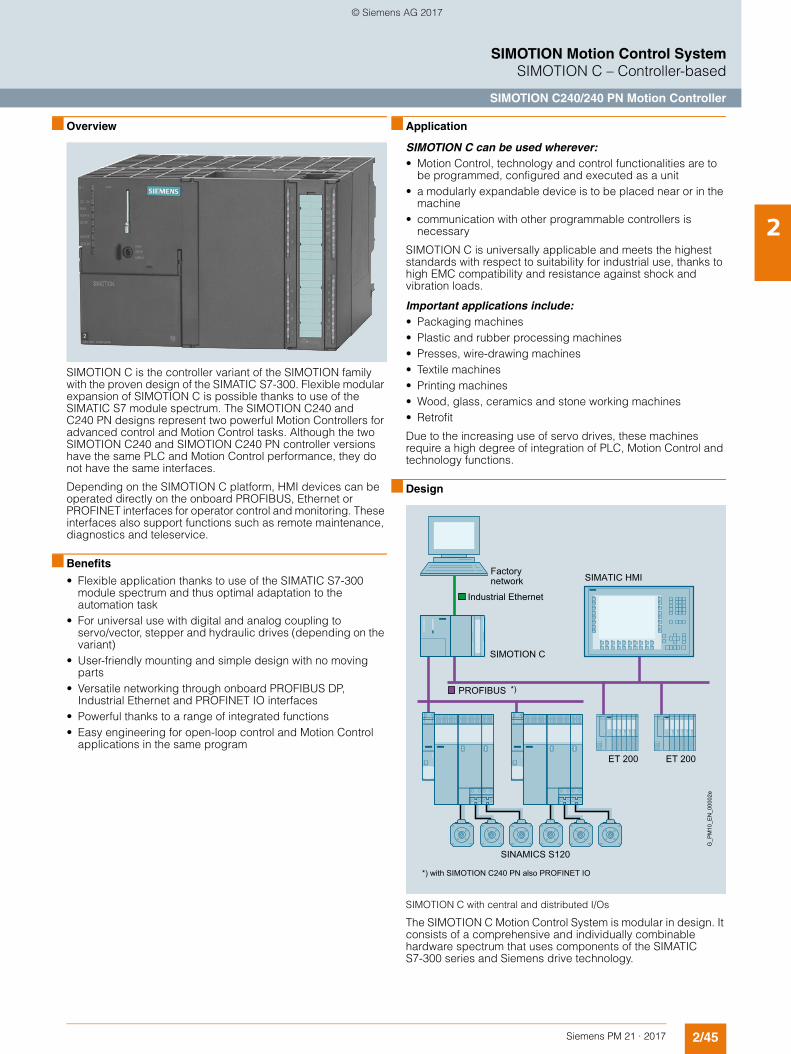
2/45Siemens PM 21 · 2017
SIMOTION Motion Control SystemSIMOTION C – Controller-based
SIMOTION C240/240 PN Motion Controller
2
■ Overview
SIMOTION C is the controller variant of the SIMOTION family with the proven design of the SIMATIC S7-300. Flexible modular expansion of SIMOTION C is possible thanks to use of the SIMATIC S7 module spectrum. The SIMOTION C240 and C240 PN designs represent two powerful Motion Controllers for advanced control and Motion Control tasks. Although the two SIMOTION C240 and SIMOTION C240 PN controller versions have the same PLC and Motion Control performance, they do not have the same interfaces.
Depending on the SIMOTION C platform, HMI devices can be operated directly on the onboard PROFIBUS, Ethernet or PROFINET interfaces for operator control and monitoring. These interfaces also support functions such as remote maintenance, diagnostics and teleservice.
■ Benefits
• Flexible application thanks to use of the SIMATIC S7-300 module spectrum and thus optimal adaptation to the automation task
• For universal use with digital and analog coupling to servo/vector, stepper and hydraulic drives (depending on the variant)
• User-friendly mounting and simple design with no moving parts
• Versatile networking through onboard PROFIBUS DP, Industrial Ethernet and PROFINET IO interfaces
• Powerful thanks to a range of integrated functions• Easy engineering for open-loop control and Motion Control
applications in the same program
■ Application
SIMOTION C can be used wherever:• Motion Control, technology and control functionalities are to
be programmed, configured and executed as a unit • a modularly expandable device is to be placed near or in the
machine • communication with other programmable controllers is
necessary
SIMOTION C is universally applicable and meets the highest standards with respect to suitability for industrial use, thanks to high EMC compatibility and resistance against shock and vibration loads.
Important applications include: • Packaging machines • Plastic and rubber processing machines • Presses, wire-drawing machines • Textile machines • Printing machines • Wood, glass, ceramics and stone working machines • Retrofit
Due to the increasing use of servo drives, these machines require a high degree of integration of PLC, Motion Control and technology functions.
■ Design
SIMOTION C with central and distributed I/Os
The SIMOTION C Motion Control System is modular in design. It consists of a comprehensive and individually combinable hardware spectrum that uses components of the SIMATIC S7-300 series and Siemens drive technology.
Factory network
*) with SIMOTION C240 PN also PROFINET IO
G_P
M10
_EN
_000
02e
SIMOTION C
SINAMICS S120
SIMATIC HMI
ET 200ET 200
Industrial Ethernet
*)PROFIBUS
© Siemens AG 2017
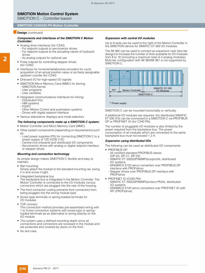
2/46 Siemens PM 21 · 2017
SIMOTION Motion Control SystemSIMOTION C – Controller-based
SIMOTION C240/240 PN Motion Controller
2
■ Design (continued)
Components and interfaces of the SIMOTION C Motion Controller: • Analog drive interfaces (for C240)
- For setpoint outputs to servo/vector drives- For setpoint outputs to the actuating valves of hydraulic
drives- As analog outputs for optional use
• Pulse outputs for controlling stepper drives (for C240)
• Interfaces for incremental/absolute encoders for cyclic acquisition of an actual position value or as freely assignable up/down counter (for C240)
• Onboard I/O for high-speed I/O signals • SIMOTION Micro Memory Card (MMC) for storing:
- SIMOTION Kernel - User programs - User variables
• Integrated communications interfaces for linking: - Distributed I/Os - HMI systems - PG/PC - Other Motion Control and automation systems - Drives with digital setpoint interface
• Various status/error displays and mode selectors
The following components make up a SIMOTION C system:• Motion Controller and Micro Memory Card (MMC)• Other system components (depending on requirements) such
as: - Load power supplies (PS) for connecting SIMOTION C to a
power supply of 120 V/230 V AC- Central (not onboard) and distributed I/O components - Servo/vector drives with analog or digital setpoint interface
or stepper drives
Mounting and connection technology
Its simple design makes SIMOTION C flexible and easy to maintain:• Rail mounting
Simply attach the module to the standard mounting rail, swing it in and screw it tight.
• Integrated backplane bus The backplane bus is integrated in the Motion Controller. The Motion Controller is connected to the I/O modules via bus connectors which are plugged into the rear of the housing.
• The front connector coding prevents front connectors from being plugged into the wrong module type.
• Screw-type terminals or spring-loaded terminals for I/O modules
• TOP connect This connection method provides pre-assembled wiring with 1 to 3-wire connection systems with screw-type or spring-loaded terminals as an alternative to wiring directly on the I/O module.
• This system uses a defined mounting depth since all connections and connectors are recessed in the module and are protected and covered by doors on the front.
• No slot rules.
Expansion with central I/O modules
Up to 8 slots can be used to the right of the Motion Controller in the SIMOTION device for SIMATIC S7-300 I/O modules.
The IM 365 can be used to connect an expansion rack (two-tier design) to increase the number of slots available for I/O modules from 8 to 16 (including a maximum total of 4 analog modules). Multi-tier configuration with IM 360/IM 361 is not supported by SIMOTION C.
SIMOTION C can be mounted horizontally or vertically.
If additional I/O modules are required, the distributed SIMATIC ET 200 I/Os can be connected to a SIMOTION C via PROFIBUS DP or PROFINET IO (for C240 PN).
The number of pluggable I/O modules is also limited by the power required from the backplane bus. The power consumption of all modules which are connected to the same backplane bus must not exceed 1.2 A.
Expansion using distributed I/Os
The following can be used as distributed I/O components: • PROFIBUS DP:
- All certified standard PROFIBUS slaves (DP-V0, DP-V1, DP-V2)
- SIMATIC ET 200S/SP/M/MP/eco/pro/AL distributed I/O systems
- SINAMICS S120 servo converters over PROFIBUS DP interface with PROFIdrive
- Stepper drives over PROFIBUS DP interface with PROFIdrive
• PROFINET IO (C240 PN):- SIMATIC ET 200S/SP/M/MP/pro/eco PN/AL distributed
I/O systems- SINAMICS S120 servo converters over PROFINET IO with
IRT (PROFIdrive)
G_P
M10
_EN
_000
01
Motion Controller
SIMOTION C
PS1) SIMATIC S7-300I/O Modules
1) Power supply
© Siemens AG 2017
2/47Siemens PM 21 · 2017
SIMOTION Motion Control SystemSIMOTION C – Controller-based
SIMOTION C240/240 PN Motion Controller
2
■ Design (continued)
Interfaces
Operation, display and diagnostics• 1 × mode selector• 1 × LED strip for fault and status indicators
Onboard I/O• 18 digital inputs
(C240: of which 2 for local measuring inputs and 4 for global measuring inputs/zero marks, C240 PN: of which 4 for global measuring inputs)
• 8 digital outputs
Drive interfaces (C240)• 1 × setpoint output interface for up to 4 axes (optionally for
analog, stepper or hydraulic drives; also usable as freely assignable analog outputs)
• 4 × encoder inputs for incremental or absolute encoders (can also be used as freely assignable up/down counters)
Communication• 1 × interface for Industrial Ethernet• 2 × interfaces for PROFIBUS DP
(of which one interface is for MPI)• 1 × interface (3 ports) for PROFINET IO (C240 PN)
Data backup• 1 × slot for SIMOTION Micro Memory Card (MMC)
Additional interfaces• Power supply terminals
Data storage/data backup
The SIMOTION C Motion Controller has an integrated non-volatile data memory for storing process variables.
The data is backed up on a SIMOTION Micro Memory Card (MMC).
■ Function
Basic functionality
SIMOTION C provides the following basic functionality for a wide variety of automation requirements:• SIMOTION runtime system
- User-programmable with several languages conforming to IEC 61131
- Various methods of program execution (cyclic, sequential, event-driven)
- PLC and arithmetic functionality - Communication and management functions - Motion Control functions (Motion Control Basic)
• Testing and diagnostic interfaces
This basic functionality can be expanded with loadable technology packages, if required.
SIMOTION technology packages
A special feature of SIMOTION is that the operating system functionality can be expanded by loading technology packages, such as:• Motion Control with the functions:
- POS – Positioning - GEAR – Synchronous operation/electronic gear - CAM – Cam - PATH - Path interpolation
• TControl – Temperature controller • MIIF – Multipurpose Information Interface• Vibration Extinction (VIBX)• OACAMGEN
Since the technology functions have modular licenses, you only pay for what you use.
Configuring/parameterizing/programming
SIMOTION SCOUT is a powerful and user-friendly engineering tool. It is an integrated system for all engineering steps, from configuring and parameterization, through programming, to testing and diagnostics. Graphical operator prompting, using dialog boxes and wizards, as well as text-based and graphical languages for programming, considerably reduce the familiarization and training periods.
Operator control and monitoring (HMI)
Communication utilities which support user-friendly data exchange with HMI devices are integrated in the basic functionality of the SIMOTION C Controller. The HMI devices can be connected to a SIMOTION C via Industrial Ethernet, PROFIBUS or PROFINET (for C240 PN). They are configured by means of SIMATIC WinCC (TIA Portal).
The SIMATIC NET communication software provides an open, standardized OPC interface for accessing SIMOTION from other Windows-based HMI systems.
SIMOTION IT provides SIMOTION C with an integrated web server on which, for example, user-specific web pages can be stored. Read and write access can be made to the Motion Controller variables. Java scripts or applets also allow the implementation of active operation and display functions in the web pages that can be executed on a client PC with an Internet browser.
© Siemens AG 2017
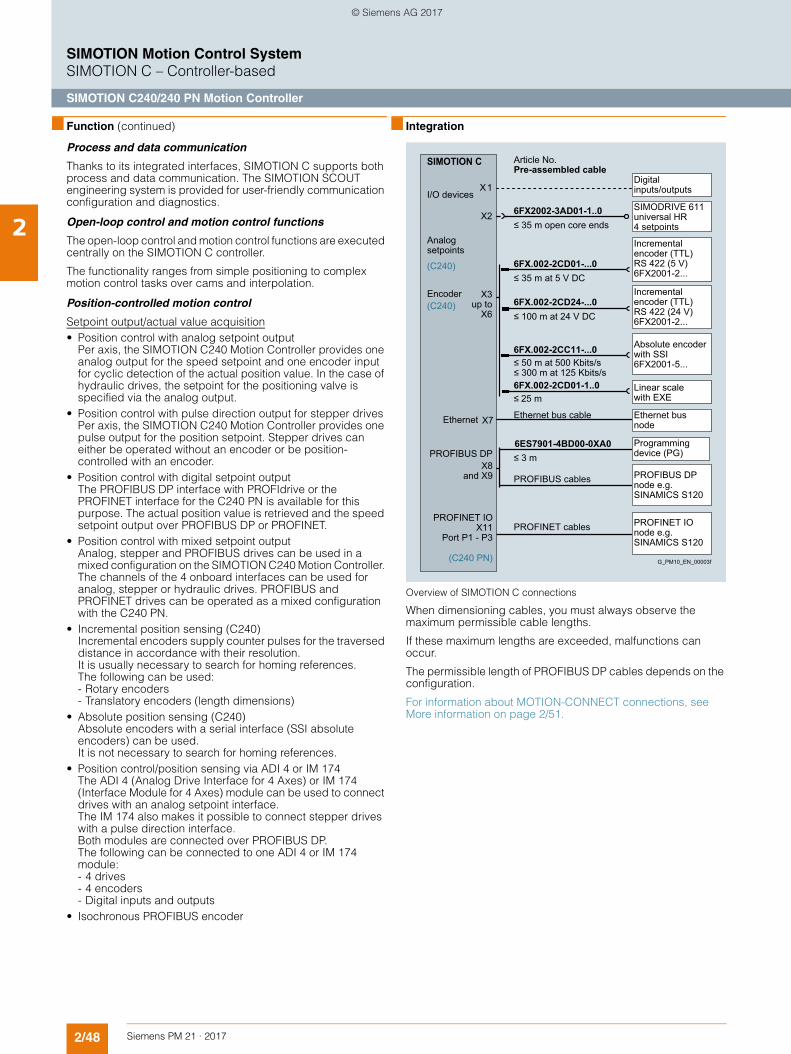
2/48 Siemens PM 21 · 2017
SIMOTION Motion Control SystemSIMOTION C – Controller-based
SIMOTION C240/240 PN Motion Controller
2
■ Function (continued)
Process and data communication
Thanks to its integrated interfaces, SIMOTION C supports both process and data communication. The SIMOTION SCOUT engineering system is provided for user-friendly communication configuration and diagnostics.
Open-loop control and motion control functions
The open-loop control and motion control functions are executed centrally on the SIMOTION C controller.
The functionality ranges from simple positioning to complex motion control tasks over cams and interpolation.
Position-controlled motion control
Setpoint output/actual value acquisition• Position control with analog setpoint output
Per axis, the SIMOTION C240 Motion Controller provides one analog output for the speed setpoint and one encoder input for cyclic detection of the actual position value. In the case of hydraulic drives, the setpoint for the positioning valve is specified via the analog output.
• Position control with pulse direction output for stepper drives Per axis, the SIMOTION C240 Motion Controller provides one pulse output for the position setpoint. Stepper drives can either be operated without an encoder or be position-controlled with an encoder.
• Position control with digital setpoint output The PROFIBUS DP interface with PROFIdrive or the PROFINET interface for the C240 PN is available for this purpose. The actual position value is retrieved and the speed setpoint output over PROFIBUS DP or PROFINET.
• Position control with mixed setpoint output Analog, stepper and PROFIBUS drives can be used in a mixed configuration on the SIMOTION C240 Motion Controller. The channels of the 4 onboard interfaces can be used for analog, stepper or hydraulic drives. PROFIBUS and PROFINET drives can be operated as a mixed configuration with the C240 PN.
• Incremental position sensing (C240)Incremental encoders supply counter pulses for the traversed distance in accordance with their resolution. It is usually necessary to search for homing references. The following can be used: - Rotary encoders - Translatory encoders (length dimensions)
• Absolute position sensing (C240)Absolute encoders with a serial interface (SSI absolute encoders) can be used. It is not necessary to search for homing references.
• Position control/position sensing via ADI 4 or IM 174 The ADI 4 (Analog Drive Interface for 4 Axes) or IM 174 (Interface Module for 4 Axes) module can be used to connect drives with an analog setpoint interface. The IM 174 also makes it possible to connect stepper drives with a pulse direction interface.Both modules are connected over PROFIBUS DP.The following can be connected to one ADI 4 or IM 174 module: - 4 drives - 4 encoders - Digital inputs and outputs
• Isochronous PROFIBUS encoder
■ Integration
Overview of SIMOTION C connections
When dimensioning cables, you must always observe the maximum permissible cable lengths.
If these maximum lengths are exceeded, malfunctions can occur.
The permissible length of PROFIBUS DP cables depends on the configuration.
For information about MOTION-CONNECT connections, see More information on page 2/51.
≤ 50 m at 500 Kbits/s ≤ 300 m at 125 Kbits/s
PROFIBUS cables
PROFINET cables
Ethernet bus cable
≤ 100 m at 24 V DC
X3 up to
X6
X8 and X9
PROFINET IOX11
Port P1 - P3
I/O devices
Encoder
Analog setpoints
Absolute encoder with SSI 6FX2001-5...
Linear scale with EXE
Programming device (PG)
PROFIBUS DP node e.g. SINAMICS S120
PROFINET IO node e.g. SINAMICS S120
Ethernet bus node
Incremental encoder (TTL) RS 422 (24 V) 6FX2001-2...
Incremental encoder (TTL) RS 422 (5 V) 6FX2001-2...
Digital inputs/outputs
≤ 35 m at 5 V DC
Article No.Pre-assembled cable
≤ 35 m open core ends
SIMODRIVE 611 universal HR 4 setpoints
G_PM10_EN_00003f
(C240)
(C240)
(C240 PN)
6FX.002-2CC11-...0
6FX.002-2CD01-1..0
6ES7901-4BD00-0XA0
6FX.002-2CD24-...0
6FX.002-2CD01-...0
6FX2002-3AD01-1..0
≤ 25 m
PROFIBUS DP
SIMOTION C
X1
X2
Ethernet X7
≤ 3 m
© Siemens AG 2017
2/49Siemens PM 21 · 2017
SIMOTION Motion Control SystemSIMOTION C – Controller-based
SIMOTION C240/240 PN Motion Controller
2
■ Technical specifications
PLC and Motion Control performance
Maximum number of axes 32
Minimum PROFIBUS cycle clock 1 ms
Minimum PROFINET send cycle clock (C240 PN only)
0.5 ms
Minimum servo/interpolator clock cycle
0.5 ms
Memory
RAM (Random Access Memory) 67 MB
RAM disk (load memory) 29 MB
Retentive memory 107 KB
Persistent memory (user data on MMC)
48 MB
Communication
Ethernet interfaces 1
PROFIBUS interfaces 2
PROFINET interfaces (C240 PN only)
• 1 interface with 3 ports• Supports PROFINET IO with IRT
and RT• Can be configured as PROFINET IO
controller and/or device
General technical specifications
Supply voltage• Rated value 24 V DC• Permissible range 20.4 ... 28.8 V
Current consumption, typ. 1.2 A
Inrush current, typ. 8.0 A
Power loss 15 W
Permissible ambient temperature• Storage and transport -40 … +70 °C (-40 ... +158 °F)• Operation 0 ... 55 °C (32 ... 131 F)
Permissible relative humidity (without condensation)
5 ... 95 %
Atmospheric pressure 700 ... 1060 hPa
Degree of protection acc. to EN 60529 (IEC 60529)
IP20
Dimensions (W × H × D) 200 × 125 × 118 mm (7.87 × 4.92 × 4.65 in)
Weight• SIMOTION C2xx 1150 g (2.54 lb)• Memory card 16 g (0.56 oz)
Relay outputs 5 (C240)
1 (C240 PN)
of which for• Controller enable (C240 only) 4• READY 1
Electrical specifications• Operational voltage, max. 50 V DC• Max. switching current 1 A• Switching capacity, max. 30 W
Operating cycles• at 24 V, 1 A 3 × 10⁶
PLC and Motion Control performance (continued)
Drive interfaces (C240 only) 4
Can be optionally used for analog, stepper or hydraulic drives, alternatively also as standard analog outputs
When used as an analog output• Voltage range ± 10.5 V• Resolution 16 bit, including sign• Galvanic isolation No• Load impedance 3 kOhm• Cable length, max. 35 m (115 ft)
When used as a pulse output for stepper drives• Output voltage for "1" signal,
IO = -20 mA3.7 V
• Output voltage for "0" signal, IO = 20 mA, max.
1 V
• Load resistance, min. 55• Cable length, max. 50 m (164 ft)• Max. pulse frequency 750 kHz
Integrated digital inputs 18
of which with special functions for:• Measuring input (C240 only) 2• BERO connection
(can also be used as measuring input with C240, can only be used as measuring input with C240 PN)
(all inputs can be used as standard inputs)
4
Input voltage• Rated value 24 V DC• For "1" signal 11 ... 30 V• For signal "0" -3 ... +5 V
Galvanic isolation• Inputs in groups of 18
Input current• For signal "1", min. / typ. 6 mA/8 mA
Input delay (at rated value of input voltage)• 0 1, typ./max. 6 µs/15 µs• 1 0, typ./max. 40 µs/150 µs
Connection of 2-wire BERO Yes• Permitted quiescent current 2 mA
Integrated digital outputs 8• of which for fast cam output, max. 8
Rated load voltage 24 V DC• Permissible range 20.4 ... 28.8 V
Output voltage• For signal "1", max. L+
Galvanic isolation in groups of 8
Output current• For signal "1", minimum current
per channel5 mA
• For signal "0", max. 0.5 mA
Residual current, max. 2 mA
Derated loading• at 40 °C (104 °F) 4 A• at 55 °C (131 °F) 2 A
Switching frequency of the outputs• With resistive load 100 Hz• With inductive load 2 Hz
© Siemens AG 2017
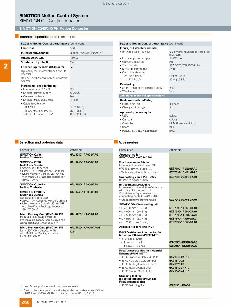
2/50 Siemens PM 21 · 2017
SIMOTION Motion Control SystemSIMOTION C – Controller-based
SIMOTION C240/240 PN Motion Controller
2
■ Technical specifications (continued)
■ Selection and ordering data
■ Accessories
PLC and Motion Control performance (continued)
Lamp load 5 W
Purge energy/channel 400 mJ (not simultaneous)
Output delay, typ. 150 µs
Short-circuit protection Yes
Encoder inputs, max. (C240 only)
Optionally for incremental or absolute encoder
Can be used alternatively as up/down counter
4
Incremental encoder inputs• Interface type (RS 422) 5 V• Encoder power supply 5 V/0.3 A• Galvanic isolation No• Encoder frequency, max. 1 MHz• Cable length, max.- at 1 MHz 10 m (32 ft)- at 500 kHz and 300 mA 25 m (82 ft)- at 500 kHz and 210 mA 35 m (115 ft)
PLC and Motion Control performance (continued)
Inputs, SSI absolute encoder• Interface type (RS 422) 5 V synchronous serial, single- or
multi-turn• Encoder power supply 24 V/0.3 A• Galvanic isolation No• Transfer rate 187.5/375/750/1500 kbit/s• Message length, max. 25 bit• Cable length, max.
- at 187.5 kbit/s 250 m (820 ft)- at 1500 kbit/s 10 m (32.8 ft)
Monitoring• Short-circuit of the sensor supply Yes• Wire break Yes
Additional technical specifications
Real-time clock buffering• Buffer time, typ. 4 weeks• Charging time, typ. 1 h
Approvals, according to• USA cULus• Canada cULus• Australia RCM (formerly C-Tick)• Korea KCC• Russia, Belarus, Kazakhstan EAC
Description Article No.
SIMOTION C240 Motion Controller
6AU1240-1AA00-0AA0
SIMOTION C240 MultiAxes BundleConsists of 1 item each• SIMOTION C240 Motion Controller• Micro Memory Card (MMC) 64 MB
with MultiAxes Package license for SIMOTION C
6AU1240-1AA00-0CA0
SIMOTION C240 PN Motion Controller
6AU1240-1AB00-0AA0
SIMOTION C240 PN MultiAxes Bundle Consists of 1 item each• SIMOTION C240 PN Motion Controller• Micro Memory Card (MMC) 64 MB
with MultiAxes Package license for SIMOTION C
6AU1240-1AB00-0CA0
Micro Memory Card (MMC) 64 MBfor SIMOTION C240/C240 PNPre-installed license can be obtained using additional order codes 1)
6AU1720-1KA00-0AA0
Micro Memory Card (MMC) 64 MBfor SIMOTION C240/C240 PN with MultiAxes Package license for SIMOTION C
6AU1720-1KA00-0AA0-Z
M24
1) See Ordering of licenses for runtime software. 2) Sold by the meter; max. length (depending on cable type) 1000 m
(3281 ft) or 2000 m (6562 ft); minimum order 20 m (65.6 ft).
Description Article No.
Accessories for SIMOTION C240/C240 PN
Front connector 40-pinfor connection of onboard I/Os
• With screw-type contacts 6ES7392-1AM00-0AA0• With spring-loaded contacts 6ES7392-1BM01-0AA0
Connecting comb PS – C2xxfor PS307 power supply
6ES7390-7BA00-0AA0
IM 365 Interface Modulefor expanding the Motion Controller with max. 1 expansion unit, 2 modules with permanent connecting cable (1 m (3.28 ft))
• Standard temperature range 6ES7365-0BA01-0AA0
SIMATIC S7-300 mounting rail • L = 160 mm (6.30 in) 6ES7390-1AB60-0AA0• L = 480 mm (18.9 in) 6ES7390-1AE80-0AA0• L = 530 mm (20.9 in) 6ES7390-1AF30-0AA0• L = 830 mm (32.7 in) 6ES7390-1AJ30-0AA0• L = 2000 mm (78.7 in) 6ES7390-1BC00-0AA0
Accessories for PROFINET
RJ45 FastConnect connector for Industrial Ethernet/PROFINET• 145° cable outlet
- 1 pack = 1 unit 6GK1901-1BB30-0AA0- 1 pack = 10 units 6GK1901-1BB30-0AB0
FastConnect cables for Industrial Ethernet/PROFINET 2)
• IE FC Standard Cable GP 2x2 6XV1840-2AH10• IE FC Flexible Cable GP 2x2 6XV1870-2B• IE FC Trailing Cable GP 2x2 6XV1870-2D• IE FC Trailing Cable 2x2 6XV1840-3AH10• IE FC Marine Cable 2x2 6XV1840-4AH10
Stripping tool for Industrial Ethernet/PROFINET FastConnect cables• IE FC Stripping Tool 6GK1901-1GA00
© Siemens AG 2017
2/51Siemens PM 21 · 2017
SIMOTION Motion Control SystemSIMOTION C – Controller-based
SIMOTION C240/240 PN Motion Controller
2
■ More information
More information• about power supplies can be found in section SIMOTION
system components/Power supplies.• about I/O modules can be found in section SIMOTION system
components/I/O components.• about TOP connect can be found in the Industry Mall under
Automation Technology/Automation Systems/System Cabling/Control Cabinets/SIMATIC TOP connect system cabling.
• about the functionality of SIMOTION platforms can be found in section Overview of SIMOTION functions.
• about runtime software and engineering software can be found in section SIMOTION software.
• about the communication functions of the Motion Controllers can be found in section SIMOTION runtime software.
• about operator control and monitoring can be found in section SIMOTION system components/HMI devices.
• about SIMATIC NET communication software can be found in section SIMOTION runtime software.
• about PROFIBUS DP, Industrial Ethernet and PROFINET can be found in Catalog IK PI and the Industry Mall under Automation Technology/Industrial Communication.
SIZER for Siemens Drives engineering tool
With the SIZER for Siemens Drives engineering tool, you can easily configure, for example, the SINAMICS S120 drive family, including SIMOTION. This tool supports you with the engineering of components for a Motion Control task. You can also determine the possible number of axes and the resulting utilization with SIZER for Siemens Drives in accordance with your performance requirements.
For more information about SIZER for Siemens Drives, refer to section Lifecycle Services.
MOTION-CONNECT connection systems
For more information about MOTION-CONNECT connection systems, refer to • Catalog D 21.4• Interactive Catalog CA 01, and• The Internet at:
www.siemens.com/motion-connectwww.siemens.com/industrymall
© Siemens AG 2017
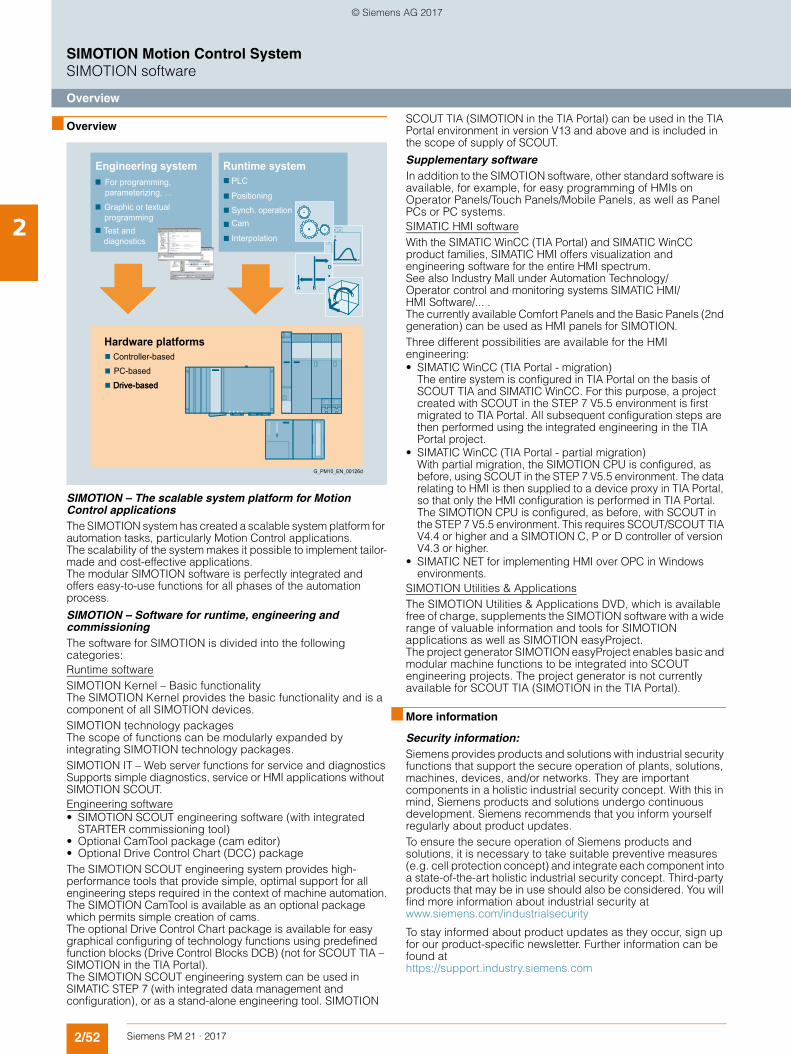
2/52 Siemens PM 21 · 2017
SIMOTION Motion Control SystemSIMOTION software
Overview
2
■ Overview
SIMOTION – The scalable system platform for Motion Control applicationsThe SIMOTION system has created a scalable system platform for automation tasks, particularly Motion Control applications.The scalability of the system makes it possible to implement tailor-made and cost-effective applications.The modular SIMOTION software is perfectly integrated and offers easy-to-use functions for all phases of the automation process.
SIMOTION – Software for runtime, engineering and commissioningThe software for SIMOTION is divided into the following categories:Runtime softwareSIMOTION Kernel – Basic functionality The SIMOTION Kernel provides the basic functionality and is a component of all SIMOTION devices.SIMOTION technology packages The scope of functions can be modularly expanded by integrating SIMOTION technology packages.SIMOTION IT – Web server functions for service and diagnosticsSupports simple diagnostics, service or HMI applications without SIMOTION SCOUT.Engineering software• SIMOTION SCOUT engineering software (with integrated
STARTER commissioning tool)• Optional CamTool package (cam editor)• Optional Drive Control Chart (DCC) packageThe SIMOTION SCOUT engineering system provides high-performance tools that provide simple, optimal support for all engineering steps required in the context of machine automation.The SIMOTION CamTool is available as an optional package which permits simple creation of cams.The optional Drive Control Chart package is available for easy graphical configuring of technology functions using predefined function blocks (Drive Control Blocks DCB) (not for SCOUT TIA – SIMOTION in the TIA Portal). The SIMOTION SCOUT engineering system can be used in SIMATIC STEP 7 (with integrated data management and configuration), or as a stand-alone engineering tool. SIMOTION
SCOUT TIA (SIMOTION in the TIA Portal) can be used in the TIA Portal environment in version V13 and above and is included in the scope of supply of SCOUT.
Supplementary softwareIn addition to the SIMOTION software, other standard software is available, for example, for easy programming of HMIs on Operator Panels/Touch Panels/Mobile Panels, as well as Panel PCs or PC systems.SIMATIC HMI softwareWith the SIMATIC WinCC (TIA Portal) and SIMATIC WinCC product families, SIMATIC HMI offers visualization and engineering software for the entire HMI spectrum. See also Industry Mall under Automation Technology/Operator control and monitoring systems SIMATIC HMI/HMI Software/... .The currently available Comfort Panels and the Basic Panels (2nd generation) can be used as HMI panels for SIMOTION. Three different possibilities are available for the HMI engineering: • SIMATIC WinCC (TIA Portal - migration)
The entire system is configured in TIA Portal on the basis of SCOUT TIA and SIMATIC WinCC. For this purpose, a project created with SCOUT in the STEP 7 V5.5 environment is first migrated to TIA Portal. All subsequent configuration steps are then performed using the integrated engineering in the TIA Portal project.
• SIMATIC WinCC (TIA Portal - partial migration) With partial migration, the SIMOTION CPU is configured, as before, using SCOUT in the STEP 7 V5.5 environment. The data relating to HMI is then supplied to a device proxy in TIA Portal, so that only the HMI configuration is performed in TIA Portal. The SIMOTION CPU is configured, as before, with SCOUT in the STEP 7 V5.5 environment. This requires SCOUT/SCOUT TIA V4.4 or higher and a SIMOTION C, P or D controller of version V4.3 or higher.
• SIMATIC NET for implementing HMI over OPC in Windows environments.
SIMOTION Utilities & ApplicationsThe SIMOTION Utilities & Applications DVD, which is available free of charge, supplements the SIMOTION software with a wide range of valuable information and tools for SIMOTION applications as well as SIMOTION easyProject.The project generator SIMOTION easyProject enables basic and modular machine functions to be integrated into SCOUT engineering projects. The project generator is not currently available for SCOUT TIA (SIMOTION in the TIA Portal).
■ More information
Security information:Siemens provides products and solutions with industrial security functions that support the secure operation of plants, solutions, machines, devices, and/or networks. They are important components in a holistic industrial security concept. With this in mind, Siemens products and solutions undergo continuous development. Siemens recommends that you inform yourself regularly about product updates.To ensure the secure operation of Siemens products and solutions, it is necessary to take suitable preventive measures (e.g. cell protection concept) and integrate each component into a state-of-the-art holistic industrial security concept. Third-party products that may be in use should also be considered. You will find more information about industrial security at www.siemens.com/industrialsecurity
To stay informed about product updates as they occur, sign up for our product-specific newsletter. Further information can be found at https://support.industry.siemens.com
Drive-basedPC-basedController-based
Interpolation
CamSynch. operationPositioning
PLC
Test and diagnostics
Graphic or textual programming
For programming, parameterizing, ...
Hardware platforms
Runtime systemEngineering system
G_PM10_EN_00126d
Drive-based
© Siemens AG 2017
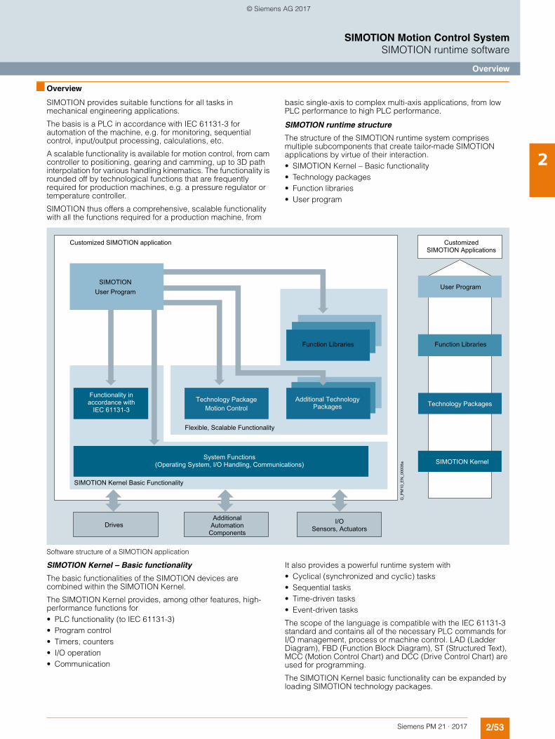
2/53Siemens PM 21 · 2017
SIMOTION Motion Control SystemSIMOTION runtime software
Overview
2
■ Overview
SIMOTION provides suitable functions for all tasks in mechanical engineering applications.
The basis is a PLC in accordance with IEC 61131-3 for automation of the machine, e.g. for monitoring, sequential control, input/output processing, calculations, etc.
A scalable functionality is available for motion control, from cam controller to positioning, gearing and camming, up to 3D path interpolation for various handling kinematics. The functionality is rounded off by technological functions that are frequently required for production machines, e.g. a pressure regulator or temperature controller.
SIMOTION thus offers a comprehensive, scalable functionality with all the functions required for a production machine, from
basic single-axis to complex multi-axis applications, from low PLC performance to high PLC performance.
SIMOTION runtime structure
The structure of the SIMOTION runtime system comprises multiple subcomponents that create tailor-made SIMOTION applications by virtue of their interaction.• SIMOTION Kernel – Basic functionality• Technology packages• Function libraries• User program
Software structure of a SIMOTION application
SIMOTION Kernel – Basic functionality
The basic functionalities of the SIMOTION devices are combined within the SIMOTION Kernel.
The SIMOTION Kernel provides, among other features, high-performance functions for• PLC functionality (to IEC 61131-3)• Program control• Timers, counters• I/O operation• Communication
It also provides a powerful runtime system with • Cyclical (synchronized and cyclic) tasks • Sequential tasks • Time-driven tasks • Event-driven tasks
The scope of the language is compatible with the IEC 61131-3 standard and contains all of the necessary PLC commands for I/O management, process or machine control. LAD (Ladder Diagram), FBD (Function Block Diagram), ST (Structured Text), MCC (Motion Control Chart) and DCC (Drive Control Chart) are used for programming.
The SIMOTION Kernel basic functionality can be expanded by loading SIMOTION technology packages.
I/O Sensors, Actuators
Function Libraries
Drives
SIMOTION Kernel Basic Functionality
Customized SIMOTION Applications
Customized SIMOTION application
SIMOTION Kernel
Function Libraries
Technology Packages
User Program
Functionality in accordance with
IEC 61131-3
System Functions (Operating System, I/O Handling, Communications)
Additional Automation
Components
Additional Technology Packages
Technology Package Motion Control
Flexible, Scalable Functionality
SIMOTION User Program
G_P
M10
_EN
_000
06a
© Siemens AG 2017
2/54 Siemens PM 21 · 2017
SIMOTION Motion Control SystemSIMOTION runtime software
Overview
2
■ Overview (continued)
SIMOTION technology packages
SIMOTION technology packages combine software functions which are required for automation in mechanical engineering in a very wide variety of sectors. They are loaded into the controller during configuration and expand the basic functionality through additional system functions. The functions of the technology packages can be accessed in the SCOUT command library during engineering.
The technology packages enable the generation of technological objects, e.g. technology object "positioning axis", which are all set up, configured and parameterized by the same method.
Motion Control technology package
The comprehensive Motion Control functions in this technology package offer very open and flexible ways of programming applications and provide users with the assurance that they can implement even complex Motion Control applications.
The SIMOTION Motion Control technology package contains the following functions:• Motion Control Basic• POS – Positioning• GEAR – Synchronous operation/electronic gear• CAM – Cam• PATH - Path interpolation• Supplementary technology functions
The technology object functions in the technology package are accessed via additional language commands and system variables, as well as with function blocks in accordance with PLCopen. Programming of motion sequences is therefore simple and integrated.
Technology package for temperature control (TControl)
The SIMOTION technology package for temperature control provides temperature channels with extensive functions. These functions are also accessed via additional language commands and system variables.
Technology package for Drive Control Chart (DCC)
The SIMOTION technology package for Drive Control Chart (DCC) provides a library of "Drive Control Blocks" (DCBs). These blocks can be used to graphically configure open and closed-loop control functions using an optional DCC editor that can be integrated into SCOUT. DCC is not available for SCOUT TIA (SIMOTION in the TIA Portal).
Multipurpose Information Interface (MIIF) technology package
The SIMOTION technology package MIIF functions as a server to permit symbolic access to SIMOTION data and makes them available to clients (e.g. operator panel) via Ethernet.
Vibration extinction (VIBX) technology package
The SIMOTION technology package VIBX provides vibration damping functionality in the form of a setpoint filter that is applied to SIMOTION axes.
OACAMGEN technology package
The SIMOTION technology package OACAMGEN can be used to calculate motion profiles and dimension drives for servo presses.
SIMOTION function libraries for I/O interfacing
These function libraries contain standard functions for integrating intelligent I/O and communication modules. They are a component part of the SCOUT command library and make it extremely easy to integrate modules such as FM 350-1/-2, FM 352, CP 340/341, SIWAREX FTA or identification systems into the SIMOTION user program. Programming examples and standard applications are also available in the SIMOTION Utilities & Applications. The SIMOTION Utilities & Applications are supplied free of charge with SCOUT.
SIMOTION function libraries for technological functions
Designed on the basis of the functions from the Motion Control technology package, a large number of additional standardized, sector-specific technology functions (winder and unwinder functions, for example) are also available.
SIMOTION user program
In the SIMOTION user program, the functions of the technology packages, function libraries and functions of the SIMOTION Kernel are accessed in a uniform manner by means of language commands.
The structure of the SIMOTION application program therefore supports merging of PLC functions with Motion Control functions and technology functions. This simplifies the optimization of motion sequences (no PLC/Motion interface), reducing engineering costs and increases both product quality and machine productivity (machine cycle and output) by eliminating interfaces and dead times.
A SIMOTION application can be programmed in different ways: • The graphical programming languages LAD (Ladder
Diagram), FBD (Function Block Diagram) and MCC (Motion Control Chart) make graphical programming particularly user-friendly.
• Programming can also be performed textually using Structured Text (ST).
• Using the optional technology package for Drive Control Chart (DCC), drive-based open and closed-loop control functions can be easily configured graphically (not for SIMOTION in the TIA Portal).
Deep integration of SINAMICS drives allows:• Easy symbolic assignment of the drives (power units and
encoders), e.g. to a positioning axis • Easy symbolic utilization of the drive peripherals (I/Os, cams,
probes)• Automatic comparison of all relevant characteristic variables
of the complete drive train• Increased uniformity as far as the drive (access to
control/status words and drive data, flexible torque limits, additive torque setpoint)
• Highly-dynamic applications with servo drives thanks to DSC (Dynamic Servo Control) allows position control cycles of 125 µs
• Highly dynamic applications with hydraulic drives with position control cycles and pressure/force control cycles of 250 µs (SIMOTION D455-2 DP/PN with SCOUT TIA: minimum 125 µs)
• Synchronization with drives and modular open-loop controls
© Siemens AG 2017
2/55Siemens PM 21 · 2017
SIMOTION Motion Control SystemSIMOTION runtime software
Overview
2
■ Overview (continued)
Apart from electrical drives, hydraulic drives within a controller or distributed over several controllers can be synchronized with each other. This supports the implementation of integrated automation solutions such as conveyor systems and press lines in the automotive industry, in which both electrical drives (winders, cross cutters, roller feeds) and hydraulic drives (e.g. deep-drawing presses) are implemented in the same system.
The project generator SIMOTION easyProject enables basic and modular machine functions to be integrated into SCOUT engineering projects. The project generator is not currently available for SCOUT TIA (SIMOTION in the TIA Portal).
SIMOTION isochronous mode
In the SIMOTION system, all the components (one or more control units, drives, isochronous I/Os) are synchronized to the communication cycle of the machine, the PROFINET/PROFIBUS DP cycle. The application is also synchronized with this cycle through synchronous application tasks (in the servo and interpolator cycle). Isochronous mode therefore permeates the whole machine application (also in the case of distributed systems) and this provides considerable advantages:• Short response times from terminal to terminal and terminal to
axis• High machine cycle times• Programming of synchronous closed-loop control tasks• High product quality thanks to a deterministic and
reproducible machine response
Modular concepts – Modular machines
SIMOTION supports modular machine concepts and thus reduces engineering and commissioning costs through:• Modular software development with libraries and reusable
modules, • Division into individual machine modules, which are linked, for
example, through distributed synchronous operation (over PROFINET IO with IRT or PROFIBUS DP).
• Reconfiguration of a project during runtime, e.g. via HMI. • Activation/deactivation of PROFINET IO devices/DP slaves
(I/O components) and technology objects (axes, drives, external encoders, probes and cams) during engineering and at runtime.
• Easy, modular configuration of projects using the project generator SIMOTION easyProject.
The modular machine concept means that scalable solutions and large axis line-ups can be achieved. Standardized modules can be easily adapted to special requirements and separately tested. These modules are then easily combined to form individual machine variants.
Communication using Ethernet/PROFINET
The following communication functions are available via Ethernet/PROFINET on all platforms:• I/O communication between SIMOTION and/or SIMATIC
controllers• Communication with SIMOTION devices, SIMATIC CPUs and
non-Siemens devices via UDP and TCP/IP• Communication with programming devices (programming
device functions)• Communication with SIMATIC HMI devices• Communication via OPC UA server to clients on any other
devices• Communication via the SCADA system WinCC • Communication with PCs on which SIMATIC NET OPC is
installed. A prerequisite on the PC side is the SIMATIC NET SOFTNET S7 software.
Communication via PROFIBUS
The communication functions are available via PROFIBUS on all platforms:• I/O communication between SIMOTION and/or SIMATIC
controllers• Communication with programming devices (programming
device functions)• Communication with SIMATIC HMI devices• Communication with PCs on which SIMATIC NET OPC is
installed. A prerequisite on the PC side is the SIMATIC NET SOFTNET S7 software.
SIMOTION IT
SIMOTION IT enables additional communication functions via Industrial Ethernet:• In-depth service and diagnostic functions without the need for
a project and engineering system via the integrated standard web pages of SIMOTION IT
• Diagnostics, commissioning and operation via user-defined web applications
• Communication and application access to process values via OPC XML-DA
• SIMOTION IT Virtual Machine: Integration of individual Java applications into the integrated SIMOTION Java runtime environment, for parallel operation with automation functions.
© Siemens AG 2017
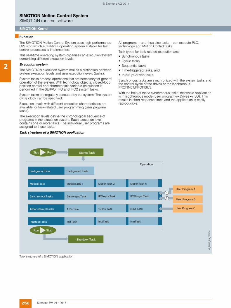
2/56 Siemens PM 21 · 2017
SIMOTION Motion Control SystemSIMOTION runtime software
SIMOTION Kernel
2
■ Function
The SIMOTION Motion Control System uses high-performance CPUs on which a real-time operating system suitable for fast control processes is implemented.
This real-time operating system organizes an execution system comprising different execution levels.
Execution system
The SIMOTION execution system makes a distinction between system execution levels and user execution levels (tasks):
System tasks process operations that are necessary for general operation of the system. With technology objects, closed-loop position control and characteristic variable calculation is performed in the SERVO, IPO and IPO2 system tasks.
System tasks are regularly executed by the system. The system cycle clock can be specified.
Execution levels with different execution characteristics are available for task-related user programming (user program tasks).
The execution levels define the chronological sequence of programs in the execution system. Each execution level contains one or more tasks. The individual user programs are assigned to these tasks.
All programs – and thus also tasks – can execute PLC, technology and Motion Control tasks.
Task types for task-related execution are:• Synchronous tasks• Cyclic tasks• Sequential tasks• Time-triggered tasks, and• Interrupt-driven tasks
Synchronous tasks are synchronized with the system tasks and the control cycle of the drives or the isochronous PROFINET/PROFIBUS.
With the help of these synchronous tasks, the whole application is in isochronous mode (user program Drives I/O). This results in short response times and the application is easily reproducible.
Task structure of a SIMOTION application
Task structure of a SIMOTION application
1
2
G_P
M10
_EN
_000
27a
StartupTaskStop Run
BackgroundTask
MotionTasks
SynchronousTasks
TimerInterruptTasks
InterruptTasks
Background Task
MotionTask 1
Servo-syncTask
1 ms Task
Int1Task
MotionTask 2
IPO-syncTask
10 ms Task
Int2Task
MotionTask n
IPO2-syncTask
x ms Task
IntnTask
ShutdownTask
Run Stop
Operation
User Program A
User Program C
User Program B
© Siemens AG 2017
2/57Siemens PM 21 · 2017
SIMOTION Motion Control SystemSIMOTION runtime software
SIMOTION Kernel
2
■ Function (continued)
The following execution levels are available to the application:
StartupTask
The StartupTask is executed once at the operating mode transition from STOP to RUN; it controls the system start-up.
BackgroundTask
The BackgroundTask is executed cyclically and is used for general PLC tasks. Cycle time monitoring checks the maximum processing time of the BackgroundTask. The BackgroundTask can be compared with the OB1 of a SIMATIC controller.
MotionTasks
MotionTasks are used for motion sequences.
Command sequences in the same Motion Task are usually executed sequentially, for example, the next motion command is only started when the previous command has been completed.
The MotionTasks do not require any CPU time during these waiting times, but respond immediately on receipt of the wait event.
SynchronousTasks
In servo-synchronous user tasks, time-critical terminal-to-terminal responses for I/Os or fast influencing of setpoints can be implemented on the servo level (synchronous to the system cycle SERVO of the technology objects, e.g. position controllers).
The IPO synchronous user tasks are started synchronously immediately before the interpolator cycle IPO or the slower IPO2.
Fast Motion Control reactions can be implemented here, as well as closed-loop control tasks in which the acquisition of actual values and output of setpoints must be synchronized.
The characteristic variables for the technology objects are calculated in system cycles IPO and IPO2.
The user program is therefore synchronized with the control cycle of the drives and with I/O processing. Synchronization ensures short response times and, above all, deterministic and reproducible machine behavior.
DCC tasks
Drive Control Chart (option) uses the above-mentioned SynchronousTasks. In addition, further synchronous execution levels (special tasks for DCC) can be assigned to the blocks.
TimerInterruptTasks
Several time-triggered tasks are available. The call cycles can be parameterized. Periodically repeated tasks are normally placed here.
InterruptTasks
InterruptTasks are used for a fast response to internal events that are signaled using interrupts. InterruptTasks can be activated by system interrupts, such as alarms and timeouts, or by user interrupts.
ShutdownTask
The ShutdownTask is called when there is a transition to STOP mode. The specific behavior for the transition into this system state can be defined here.
The complete instruction set is available for all user tasks. This allows the current positioning command from a MotionTask to be superimposed with an additional movement which was triggered by a UserInterruptTask, for example.
Runtime levels of the technology packages
The execution cycle can be set object-specifically for Motion Control technology objects.
Technology objects are executed in the execution levels SERVO cycle and IPO cycle or IPO2 cycle that are synchronized with the PROFINET or PROFIBUS cycle.• Command evaluation and motion control in the IPO/IPO2
cycle• Position and setpoint control in the SERVO cycle• IPO/IPO2 cycle can be reduced relative to the SERVO cycle to
allow optimization of the system's performance to meet requirements.
The SIMOTION D435-2 DP/PN, D445-2 DP/PN and D455-2 DP/PN Control Units have an additional runtime level (SERVOFast, IPOFast).
This additional runtime level enables the performance of the controller to be utilized more efficiently. Electrical and/or hydraulic axes can be distributed over one slow and one fast bus system depending on the dynamic response required.
Electrical positioning drives, for example, can be controlled with cycle times in the millisecond range requiring fewer resources and, at the same time, the pressure-controlled axes of an hydraulic press can be controlled highly dynamically with short cycle times.
The runtime level (SERVOFast, IPOFast) also enables a particularly fast I/O processing in conjunction with, for example, high-speed PROFINET I/O modules.
Further characteristics of the execution system• Operating states – Run, Stop, StopU (Stop User Program for
test and commissioning functions)• Process images for inputs/outputs, is separate for
BackgroundTask, SynchronousTasks and TimerInterruptTasks• Debug functions such as
- Controlling and monitoring of variables- Display of the program status- Breakpoints and single step- Trace functions
• Kernel updates can be implemented with new SCOUT versions.
© Siemens AG 2017
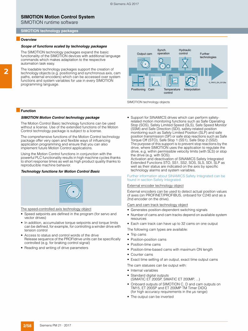
2/58 Siemens PM 21 · 2017
SIMOTION Motion Control SystemSIMOTION runtime software
SIMOTION technology packages
2
■ Overview
Scope of functions scaled by technology packages
The SIMOTION technology packages expand the basic functionality of the SIMOTION devices with additional language commands which makes adaptation to the respective automation task easy.
The loadable technology packages support the creation of technology objects (e.g. positioning and synchronous axis, cam paths, external encoders) which can be accessed over system functions and system variables for use in every SIMOTION programming language.
SIMOTION technology objects
■ Function
SIMOTION Motion Control technology package
The Motion Control Basic technology functions can be used without a license. Use of the extended functions of the Motion Control technology package is subject to a license.
The comprehensive functions of the Motion Control technology package offer very open and flexible ways of influencing application programming and ensure that you can also implement future Motion Control applications.
Using the Motion Control functions in conjunction with the powerful PLC functionality results in high machine cycles thanks to short response times as well as high product quality thanks to reproducible machine behavior.
Technology functions for Motion Control Basic
The speed-controlled axis technology object• Speed setpoints are defined in the program (for servo and
vector drives) • In addition, accumulative torque setpoints and torque limits
can be defined, for example, for controlling a winder drive with tension control
• Access to status and control words of the drive Release sequence of the PROFIdrive units can be specifically controlled (e.g. for braking control signal)
• Reading and writing of drive parameters
• Support for SINAMICS drives which can perform safety-related motion monitoring functions such as Safe Operating Stop (SOS), Safely Limited Speed (SLS), Safe Speed Monitor (SSM) and Safe Direction (SDI), safety-related position monitoring such as Safely Limited Position (SLP) and safe position transmission (SP) or safe stop reactions such as Safe Torque Off (STO), Safe Stop 1 (SS1), Safe Stop 2 (SS2).The purpose of this support is to prevent stop reactions by the drive, where SIMOTION uses the application to regulate the drive, e.g. within permissible velocity limits (with SLS) or stop the drive (e.g. with SOS). Activation and deactivation of SINAMICS Safety Integrated Extended Functions STO, SS1, SS2, SOS, SLS, SDI, SLP as well as their status are indicated on the axis by specific technology alarms and system variables.
Further information about SINAMICS Safety Integrated can be found in section Safety Integrated.
External encoder technology object
External encoders can be used to detect actual position values of axes (on PROFINET/PROFIBUS, onboard for C240 and as a 2nd encoder on the drive).
Cam and cam track technology object• Generates position-dependent switching signals• Number of cams and cam tracks depend on available system
resources• Each cam track can have up to 32 cams on one output
The following cam types are available:• Trip cams • Position-position cams • Position-time cams • Position-time-based cams with maximum ON length • Counter cams • Exact time setting of an output, exact time output cams
The cam statuses can be output with:• Internal variables • Standard digital outputs
(SIMATIC ET 200SP, SIMATIC ET 200MP, ...) • Onboard outputs of SIMOTION C, D and cam outputs on
TM15, ET 200SP and ET 200MP TM Timer DIDQ (for high accuracy requirements in the µs range)
• The output can be inverted
Interpolation
Hydraulic control Further
technologies
G_PM10_EN_00128a
Synch. operationOutput cam
Temperature control
CamPositioning
© Siemens AG 2017
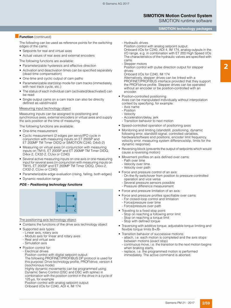
2/59Siemens PM 21 · 2017
SIMOTION Motion Control SystemSIMOTION runtime software
SIMOTION technology packages
2
■ Function (continued)
The following can be used as reference points for the switching edges of the cams:• Setpoints for real and virtual axes • Actual values of real axes and external encoders
The following functions are available:• Parameterizable hysteresis and effective direction • Activation and deactivation times can be specified separately
(dead time compensation) • One-time and cyclic output of cam paths • Parameterizable start/stop mode for cam tracks (immediately,
with next track cycle, etc.) • The status of each individual cam (activated/deactivated) can
be read• Single output cams on a cam track can also be directly
defined as valid/invalid
Measuring input technology object
Measuring inputs can be assigned to positioning and synchronous axes, external encoders or virtual axes and supply the axis position at the time of measuring.
The following functions are available:• One-time measurement • Cyclic measurement (2 edges per servo/IPO cycle in
conjunction with measuring inputs on ET 200SP and ET 200MP TM Timer DIDQ or SIMOTION C240, D4x5-2)
• Measuring on virtual axes (in conjunction with measuring inputs on TM15, ET 200SP and ET 200MP TM Timer DIDQ, D4xx-2, CX32-2, CUxx or C240)
• Several active measuring inputs on one axis or one measuring input for several axes (in conjunction with measuring inputs on TM15, ET 200SP and ET 200MP TM Timer DIDQ, D4xx-2, CX32-2, CUxx or C240)
• Parameterizable edge evaluation (rising, falling, both edges) • Dynamic resolution range
POS – Positioning technology functions
The positioning axis technology object• Contains the functions of the drive axis technology object• Supported axis types:
- Linear axis, rotary axis- Modulo axis for linear and rotary axes- Real and virtual axis- Simulation axis
• Position control for:- Electrical drives
Position control with digital setpoint output:The following PROFINET/PROFIBUS DP protocol is used for this purpose: Drive technology profile, PROFIdrive, version 4 (isochronous mode)Highly dynamic movements can be programmed using Dynamic Servo Control (DSC and DSC with spline) in combination with the position control in the drive in a cycle of 125s, for example Position control with analog setpoint output:Onboard I/Os for C240, ADI 4, IM 174
- Hydraulic drives Position control with analog setpoint output:Onboard I/Os for C240, ADI 4, IM 174, analog outputs in the I/O range, e.g. in combination with ET 200 High Speed I/Os The characteristics of the hydraulic valves are specified with cams
- Stepper motors Position control with pulse direction output for stepper drives:Onboard I/Os for C240, IM 174 Alternatively, stepper drives can be linked with a PROFINET/PROFIBUS interface provided that they support the PROFIdrive profile. Stepper drives can be operated without an encoder or be position-controlled with an encoder.
• Position-controlled positioning: Axes can be manipulated individually without interpolation context by specifying, for example:- Axis name- Position- Velocity- Acceleration/delay, jerk- Transition behavior to next motion
• Speed-controlled operation of positioning axes• Monitoring and limiting (standstill, positioning, dynamic
following error, standstill signal, controlled variables, hardware/software end positions, encoder limit frequency, velocity error, measuring system difference/slip, limits for the dynamic response)
• Reversing block (prevents the output of setpoints which would cause a reversing motion)
• Movement profiles on axis defined over cams:- Path over time- Velocity over time- Velocity over path
• Force and pressure control of an axis:- On-the-fly switchover from position to pressure-controlled
operation and vice versa- Several pressure sensors possible- Pressure difference measurement
• Force and pressure limitation of an axis:• Force and pressure profiles specifiable over cams:
- For closed-loop control and limitation- Force/pressure over time- Force/pressure over path
• Traveling to a fixed stop point:- Stop on reaching a following error limit- Stop on reaching a torque limit- Stop with defined torque
• Traversing with additive torque, adjustable torque limiting and flexible torque limits B+/B-
• Transition behavior of successive motions:- attach, i.e. each motion is completed and the axis stops
between motions (exact stop) - continuous move, i.e. the transition to the next motion begins
when braking starts. - replace, i.e. the programmed motion is performed
immediately. The active command is aborted.
© Siemens AG 2017
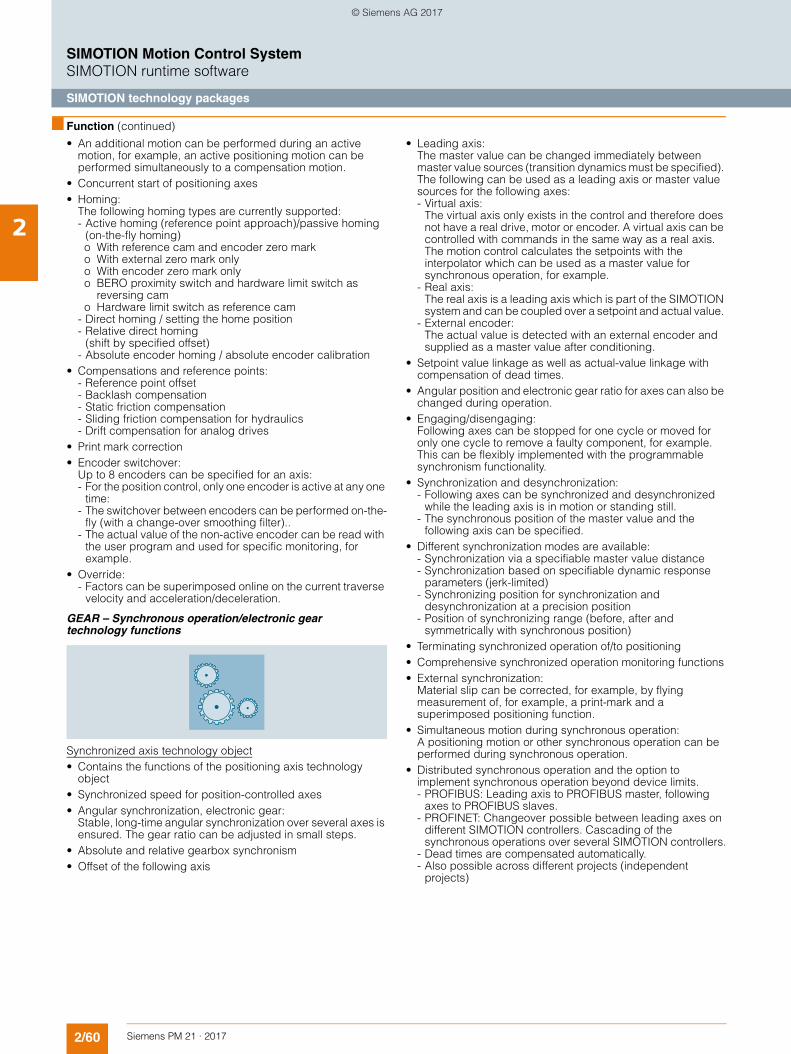
2/60 Siemens PM 21 · 2017
SIMOTION Motion Control SystemSIMOTION runtime software
SIMOTION technology packages
2
■ Function (continued)
• An additional motion can be performed during an active motion, for example, an active positioning motion can be performed simultaneously to a compensation motion.
• Concurrent start of positioning axes• Homing:
The following homing types are currently supported:- Active homing (reference point approach)/passive homing
(on-the-fly homing) o With reference cam and encoder zero mark o With external zero mark only o With encoder zero mark only o BERO proximity switch and hardware limit switch as
reversing cam o Hardware limit switch as reference cam- Direct homing / setting the home position - Relative direct homing
(shift by specified offset)- Absolute encoder homing / absolute encoder calibration
• Compensations and reference points:- Reference point offset- Backlash compensation- Static friction compensation- Sliding friction compensation for hydraulics- Drift compensation for analog drives
• Print mark correction• Encoder switchover:
Up to 8 encoders can be specified for an axis:- For the position control, only one encoder is active at any one
time: - The switchover between encoders can be performed on-the-
fly (with a change-over smoothing filter).. - The actual value of the non-active encoder can be read with
the user program and used for specific monitoring, for example.
• Override:- Factors can be superimposed online on the current traverse
velocity and acceleration/deceleration.
GEAR – Synchronous operation/electronic gear technology functions
Synchronized axis technology object• Contains the functions of the positioning axis technology
object• Synchronized speed for position-controlled axes • Angular synchronization, electronic gear:
Stable, long-time angular synchronization over several axes is ensured. The gear ratio can be adjusted in small steps.
• Absolute and relative gearbox synchronism• Offset of the following axis
• Leading axis: The master value can be changed immediately between master value sources (transition dynamics must be specified). The following can be used as a leading axis or master value sources for the following axes:- Virtual axis:
The virtual axis only exists in the control and therefore does not have a real drive, motor or encoder. A virtual axis can be controlled with commands in the same way as a real axis. The motion control calculates the setpoints with the interpolator which can be used as a master value for synchronous operation, for example.
- Real axis:The real axis is a leading axis which is part of the SIMOTION system and can be coupled over a setpoint and actual value.
- External encoder:The actual value is detected with an external encoder and supplied as a master value after conditioning.
• Setpoint value linkage as well as actual-value linkage with compensation of dead times.
• Angular position and electronic gear ratio for axes can also be changed during operation.
• Engaging/disengaging:Following axes can be stopped for one cycle or moved for only one cycle to remove a faulty component, for example. This can be flexibly implemented with the programmable synchronism functionality.
• Synchronization and desynchronization:- Following axes can be synchronized and desynchronized
while the leading axis is in motion or standing still. - The synchronous position of the master value and the
following axis can be specified. • Different synchronization modes are available:
- Synchronization via a specifiable master value distance- Synchronization based on specifiable dynamic response
parameters (jerk-limited)- Synchronizing position for synchronization and
desynchronization at a precision position- Position of synchronizing range (before, after and
symmetrically with synchronous position)• Terminating synchronized operation of/to positioning• Comprehensive synchronized operation monitoring functions• External synchronization:
Material slip can be corrected, for example, by flying measurement of, for example, a print-mark and a superimposed positioning function.
• Simultaneous motion during synchronous operation:A positioning motion or other synchronous operation can be performed during synchronous operation.
• Distributed synchronous operation and the option to implement synchronous operation beyond device limits.- PROFIBUS: Leading axis to PROFIBUS master, following
axes to PROFIBUS slaves. - PROFINET: Changeover possible between leading axes on
different SIMOTION controllers. Cascading of the synchronous operations over several SIMOTION controllers.
- Dead times are compensated automatically. - Also possible across different projects (independent
projects)
© Siemens AG 2017
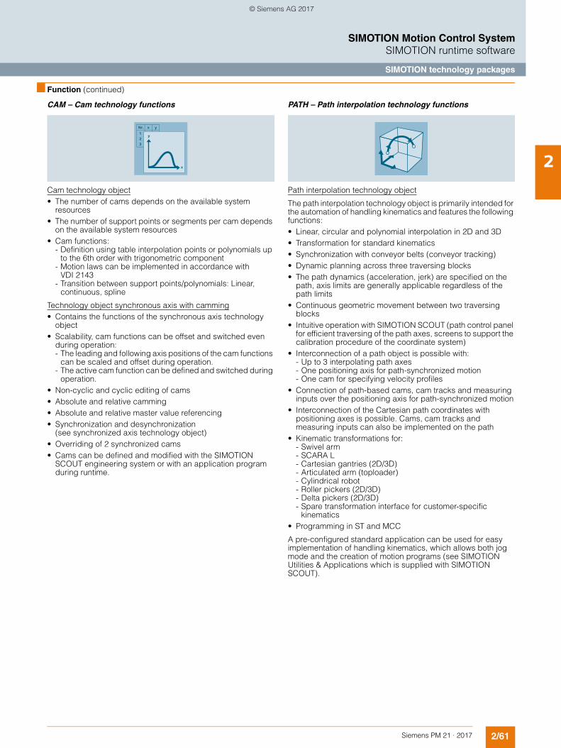
2/61Siemens PM 21 · 2017
SIMOTION Motion Control SystemSIMOTION runtime software
SIMOTION technology packages
2
■ Function (continued)
CAM – Cam technology functions
Cam technology object• The number of cams depends on the available system
resources • The number of support points or segments per cam depends
on the available system resources • Cam functions:
- Definition using table interpolation points or polynomials up to the 6th order with trigonometric component
- Motion laws can be implemented in accordance with VDI 2143
- Transition between support points/polynomials: Linear, continuous, spline
Technology object synchronous axis with camming• Contains the functions of the synchronous axis technology
object• Scalability, cam functions can be offset and switched even
during operation:- The leading and following axis positions of the cam functions
can be scaled and offset during operation. - The active cam function can be defined and switched during
operation. • Non-cyclic and cyclic editing of cams • Absolute and relative camming • Absolute and relative master value referencing • Synchronization and desynchronization
(see synchronized axis technology object)• Overriding of 2 synchronized cams • Cams can be defined and modified with the SIMOTION
SCOUT engineering system or with an application program during runtime.
PATH – Path interpolation technology functions
Path interpolation technology object
The path interpolation technology object is primarily intended for the automation of handling kinematics and features the following functions: • Linear, circular and polynomial interpolation in 2D and 3D• Transformation for standard kinematics• Synchronization with conveyor belts (conveyor tracking)• Dynamic planning across three traversing blocks• The path dynamics (acceleration, jerk) are specified on the
path, axis limits are generally applicable regardless of the path limits
• Continuous geometric movement between two traversing blocks
• Intuitive operation with SIMOTION SCOUT (path control panel for efficient traversing of the path axes, screens to support the calibration procedure of the coordinate system)
• Interconnection of a path object is possible with:- Up to 3 interpolating path axes- One positioning axis for path-synchronized motion - One cam for specifying velocity profiles
• Connection of path-based cams, cam tracks and measuring inputs over the positioning axis for path-synchronized motion
• Interconnection of the Cartesian path coordinates with positioning axes is possible. Cams, cam tracks and measuring inputs can also be implemented on the path
• Kinematic transformations for:- Swivel arm- SCARA L- Cartesian gantries (2D/3D) - Articulated arm (toploader)- Cylindrical robot - Roller pickers (2D/3D) - Delta pickers (2D/3D) - Spare transformation interface for customer-specific
kinematics• Programming in ST and MCC
A pre-configured standard application can be used for easy implementation of handling kinematics, which allows both jog mode and the creation of motion programs (see SIMOTION Utilities & Applications which is supplied with SIMOTION SCOUT).
© Siemens AG 2017
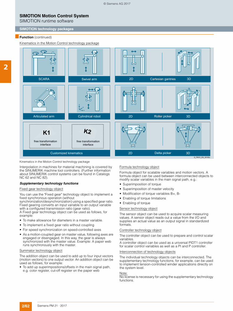
2/62 Siemens PM 21 · 2017
SIMOTION Motion Control SystemSIMOTION runtime software
SIMOTION technology packages
2
■ Function (continued)
Kinematics in the Motion Control technology package
Kinematics in the Motion Control technology package
Interpolation in machines for material machining is covered by the SINUMERIK machine tool controllers. (Further information about SINUMERIK control systems can be found in Catalogs NC 62 and NC 82).
Supplementary technology functions
Fixed gear technology object
You can use the "Fixed gear" technology object to implement a fixed synchronous operation (without synchronization/desynchronization) using a specified gear ratio. Fixed gearing converts an input variable to an output variable with a configured transmission ratio (gear ratio). A Fixed gear technology object can be used as follows, for example:• To make allowance for diameters in a master variable. • To implement a fixed gear ratio without coupling • For speed synchronization on speed-controlled axes• As a motion-coupled gear on master value, following axes are
engaged or disengaged. In this way, the gear is always synchronized with the master value. Example: A paper web runs synchronously with the master.
Summator technology object
The addition object can be used to add up to four input vectors (motion vectors) to one output vector. An addition object can be used as follows, for example:• To add up superimpositions/offsets in the main signal path,
e.g. color register, cut-off register on the paper web
Formula technology object
Formula object for scalable variables and motion vectors. A formula object can be used between interconnected objects to modify scalar variables in the main signal path, e.g.:• Superimposition of torque • Superimposition of master velocity • Modification of torque variables B+, B- • Enabling of torque limitations • Enabling of torque
Sensor technology object
The sensor object can be used to acquire scalar measuring values. A sensor object reads out a value from the I/O and supplies an actual value as an output signal in standardized formats.
Controller technology object
The controller object can be used to prepare and control scalar variables. A controller object can be used as a universal PIDT1 controller for scalar control variables as well as a PI and P controller.
Interconnection of technology objects
The individual technology objects can be interconnected. The supplementary technology functions, for example, can be used to implement tension-controlled winder applications directly on the system level.
Note:No license is necessary for using the supplementary technology functions.
free transformationinterface
free transformationinterface
Customized kinematics
Cylindrical robotArticulated arm
3D2D
3D2D
Delta pickerG_PM10_EN_00190c
Roller picker
3D2D Cartesian gantriesSwivel armSCARA
© Siemens AG 2017
2/63Siemens PM 21 · 2017
SIMOTION Motion Control SystemSIMOTION runtime software
SIMOTION technology packages
2
■ Function (continued)
SIMOTION TControl technology package
TControl – Temperature controller technology functions
Temperature channel technology object
The controller core of the temperature technology package has a DPID structure. Pure heating controllers and cooling controllers as well as combined heating/cooling controllers can be configured and parameterized.
User-assignable functions are available for each temperature channel:• Each temperature channel can either be configured as a
heating or cooling section or as a combined heating/cooling section.
• The controllers either use a PID or DPID control algorithm or use the optional control zone functionality.
• In manual output mode, a replacement value can be output. • You can select the operating mode for each controller channel
separately. In this way, for example, you can switch the output to a fixed control variable.The following operating modes are available:- Closed-loop control for operating setpoint - Actual value acquisition and output of the manual
manipulated variable value - Actual value acquisition and output of "0" - Self tuning
• Actual value acquisition and processing- Plausibility check for each new actual value and correction
before corresponding filter measures - Filtering (by PT1 element)
• Actuating signal preparation and output- Digital, pulse-length modulated actuating signal - Prevention of minimal pulse durations for I/O cycles by
integration of lost pulses - Manual actuating value (for manual output mode) - Output value limitation - Replacement value (calculated dynamically)
• Self-tuning for heating controllers- This ensures fast startup without overshooting and maintains
the setpoint value without lasting system deviations. - Self-tuning can be used in parallel for all desired channels to
ensure optimal parameter acquisition even for strongly coupled temperature sections.
• Monitoring and alarm functions- Actual value monitoring by definition of tolerance bands. The
inner and outer tolerance bands can be defined independently as absolute or relative tolerance bands.
- Measuring circuit monitoring for increased operational safety of a plant
- Plausibility check- Alarm functions
The use of the TControl technology package is clarified by an application example. The application example provides functional expansions, function interfaces to the application and data interfaces to the HMI. It is contained in the Utilities & Applications which are supplied with SIMOTION SCOUT.
SIMOTION technology package for Drive Control Chart (DCC)
Technology functions for Drive Control Chart
With Drive Control Chart (DCC), open-loop and closed-loop control functions can be easily configured graphically. For this purpose, multi-instance function blocks are selected from a block library using drag and drop, and then graphically interconnected and parameterized. The control structures are presented clearly.
DCC is not available for SIMOTION in the TIA Portal (SCOUT TIA).
The block library comprises a large selection of • control blocks, • calculation blocks, and • logic blocks as well as • comprehensive open-loop and closed-loop control functions.
Further functions:• For logically combining, evaluating and acquiring binary
signals, all commonly used logic functions are available for selection including, for example,- AND- XOR- On/Off delays- RS flip-flops or counters
• For monitoring and evaluating numerical values, numerous arithmetic functions are available, such as:- Summation- Divider- Minimum/maximum evaluation
• Apart from the automatic speed control, winders, PI controls, ramp-function generators and wobble generators can easily be configured.
More information about Drive Control Chart (DCC) can be found in section Option packages for SIMOTION SCOUT.
°C
G_PM10_XX_00073
© Siemens AG 2017
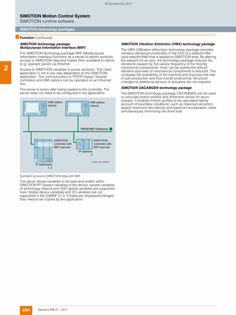
2/64 Siemens PM 21 · 2017
SIMOTION Motion Control SystemSIMOTION runtime software
SIMOTION technology packages
2
■ Function (continued)
SIMOTION technology package Multipurpose Information Interface (MIIF)
The SIMOTION technology package MIIF (Multipurpose Information Interface) functions as a server to permit symbolic access to SIMOTION data and makes them available to clients (e.g. operator panel) via Ethernet.
Access to SIMOTION variables is purely symbolic. The client application is not in any way dependent on the SIMOTION application. The communication is TCP/IP-based. Several controllers and HMI stations can be operated on an Ethernet line.
The server is active after being loaded to the controller. The server does not need to be configured in the application.
Symbolic access to SIMOTION data with MIIF
The server allows variables to be read and written within SIMOTION RT. System variables of the device, system variables of technology objects and UNIT global variables are supported here. Global device variables and I/O variables are not supported in the OAMIIF V1.0. If these are displayed/changed, they need to be copied by the application.
SIMOTION Vibration Extinction (VIBX) technology package
The VIBX (VIBration eXtinction) technology package provides vibration damping functionality in the form of a setpoint filter (axis setpoint filter) that is applied to SIMOTION axes. By altering the setpoint for an axis, the technology package reduces the vibrations caused by the natural frequency of the moving mechanical components. Axes can be positioned without vibration and wear on mechanical components is reduced. This increases the availability of the machine and improves the rate of part production and thus overall productivity. Structural changes or additional sensors or actuators are not required.
SIMOTION OACAMGEN technology package
The SIMOTION technology package OACAMGEN can be used to calculate motion profiles and dimension drives for servo presses. It enables motion profiles to be calculated taking account of boundary conditions, such as maximum eccentric speed, maximum ram velocity and maximum acceleration, while simultaneously minimizing the drive load.
IP addresses 1, 2
IP address 3
HMI station(client)
HMI station(client)
SIMOTION controller with MIIF (server)
SIMOTION controller with MIIF (server)
G_PM10_EN_00199d
PROFINET/Ethernet
© Siemens AG 2017
2/65Siemens PM 21 · 2017
SIMOTION Motion Control SystemSIMOTION runtime software
SIMOTION PLCopen blocks
2
■ Overview
Library containing function blocks certified in accordance with PLCopen
PLCopen is an association of leading PLC manufacturers that was formed for the purpose of defining international standards in the field of PLC programming and promoting their use.
The PLCopen function blocks integrated into the Motion Control Technology Package are designed for use in cyclic programs/tasks; they enable Motion Control programming in a PLC environment. The function blocks can be selected from the SCOUT command library and can therefore be easily used in all SIMOTION programming languages. They should preferably be used in LAD/FBD.
The following certified single-axis and multi-axis PLCopen blocks as well as extended functions are available:
Single-axis function blocks• _MC_Power (axis enables) • _MC_Stop (stop axis) • _MC_Reset (reset axis) • _MC_Home (reference point approach for axes) • _MC_MoveAbsolute (absolute positioning of axes) • _MC_MoveRelative (relative positioning of axes) • _MC_MoveVelocity (traversing axes at a specified velocity) • _MC_MoveAdditive (relative traversal of axis by a defined
path added to the remaining path) • _MC_MoveSuperimposed (relative superimposition of a new
motion in addition to existing motion) • _MC_PositionProfile (traversing axis by a predefined and
specified position/time profile) • _MC_VelocityProfile (traversing axis by a predefined and
specified velocity/time profile) • _MC_ReadActualPosition (read actual position of axis) • _MC_ReadStatus (read status of an axis) • _MC_ReadAxisError (read error of an axis) • _MC_ReadParameter (axis parameter, read LREAL data type) • _MC_ReadBoolParameter (axis parameter, read BOOL data
type) • _MC_WriteParameter (axis parameter, write LREAL data type) • _MC_WriteBoolParameter (axis parameter, write BOOL data
type)
Multi-axis function blocks• _MC_CamIn (insert cam with synchronization)
contains implicit _MC_CamTableSelect (selection of cam) • _MC_CamOut (remove cam with desynchronization)• _MC_GearIn (synchronize)• _MC_GearOut (desynchronize)• _MC_Phasing (phase shift)
Apart from the standard PLCopen functions, the following additional standard axis function is included: • _MC_Jog (continuous or incremental jogging)
© Siemens AG 2017
2/66 Siemens PM 21 · 2017
SIMOTION Motion Control SystemSIMOTION runtime software
Overview of the licensing concept
2
■ Overview
The basic concept: "pay only for what you need"
The functionally scalable licenses for SIMOTION runtime soft-ware and axis-specific licensing result in a simple pricing struc-ture, allowing you to only pay for what you really need.
Runtime licenses are not bound to specific versions and are therefore valid for all firmware versions. In case of a firmware up-date the runtime licenses remain valid. The license key gener-ated from the runtime licenses and the serial number of the memory card or SIMOTION P is stored on the memory card or on SIMOTION P.
How can licenses be obtained for runtime software?
Licenses for SIMOTION runtime software can be obtained as follows:• Pre-installed licenses can be ordered when purchasing a
SIMOTION memory card (SIMOTION C, D) or for SIMOTION P. The article number is expanded with one or more additional order codes (Z options) that specify the re-quired licenses. Alternatively, pre-installed runtime licenses can be ordered using the configurator for SIMOTION runtime licenses in the Industry Mall. Homepage: www.siemens.com/industrymall
• Licenses can be ordered separately, independently of pur-chase of a SIMOTION controller or a SIMOTION memory card. The required software options are assigned to hardware (memory cards or SIMOTION P) by generating a license key over the Internet at:Homepage: www.siemens.com/automation/license Using this method, it is possible to store additional licenses on a memory card.
When do licenses need to be obtained for runtime software?
When configuring using SIMOTION SCOUT, the required licenses are displayed.
A license is required for the runtime software:• When it is used in a machine or a machine component before
it is supplied by the manufacturer• When it is used by the customer on completion of initial com-
missioning• When it is retrofitted following completion of initial commis-
sioning• In large-scale plants that are installed directly at the produc-
tion site without previous initial commissioning by the manu-facturer, on completion of initial commissioning before test op-eration commences.
Unlicensed basic functions
The rights of use for these software components are included when the basic unit is purchased:• SIMOTION Kernel runtime software
The SIMOTION Kernel is already installed on the device.• Technology functions for Motion Control Basic
Use of technology functions for drive axes, single output cams and cam tracks, measuring inputs, and external encoders.
• Technology functions for Drive Control ChartBy installing the optional SCOUT package Drive Control Chart, the technology functions of Drive Control Chart are made available to the SIMOTION runtime system.
• Supplementary technology functionsUse of supplementary technology functions, such as addition objects, formula objects and fixed gears.
• Function libraries for I/O interfacing• Communication functions
This covers SIMATIC S7 communication functions on the SIMOTION side (PG/OP communication to programming de-vices, for engineering and communication to HMI devices and PCs with SIMATIC HMI), SIMOTION IT DIAG and SIMOTION IT OPC XML-DA or OPC UA, as well as UDP and TCP/IP communication.
Motion Control technology functions under license
The Motion Control Basic technology functions can be used without a license. When other technology functions of the Motion Control technology package are used, a license is required for each axis used. Licenses are only necessary for real axes; vir-tual axes and drive axes are not subject to license. A license is obtained for the different axis types using a separate article number for each.
POS, GEAR, CAM axis licenses
Three different axis licenses are available:• POS – Use of the positioning technology function for a created
positioning axis • GEAR – Use of the positioning and synchronous operation
technology functions for a created synchronous axis as well as additional path interpolation for a created path axis
• CAM – Use of the positioning, synchronous operation, path in-terpolation and cam technology functions for a created syn-chronous axis with cam
MultiAxes Packages
The platform-independent MultiAxes Package supports particu-larly simple licensing. It contains the license for unlimited use of the POS/GEAR/CAM technology functions on one SIMOTION Controller. Variably priced, platform-specific packages for C2xx, P320 or D410-2, D425-x, D435-x and D445-x/D455-x are offered in addition to the platform-independent MultiAxes Package.
© Siemens AG 2017
2/67Siemens PM 21 · 2017
SIMOTION Motion Control SystemSIMOTION runtime software
Overview of the licensing concept
2
■ Overview (continued)
Other technology functions which are subject to a license
TControl technology functions
The functions of the TControl technology package are licensed for specific channels in packages, each package containing 8 temperature channels.
Multipurpose Information Interface (MIIF), Vibration Extinction (VIBX) and OACAMGEN technology functions
To use the functions of these technology packages, a separate license is to be obtained for each SIMOTION Controller.
SIMOTION IT communication functions
A license to use these functions must be obtained for each SIMOTION Controller.For version V4.2 and higher of SIMOTION Kernel, a license need be purchased only to cover the use of SIMOTION IT Virtual Ma-chine. The licenses for SIMOTION IT DIAG and SIMOTION IT OPC XML-DA are no longer required.
The license SIMOTION IT Virtual Machine can continue to be used as a combined license for SIMOTION IT DIAG, OPC XML-DA and Virtual Machine in the case of version V4.2 and lower of SIMOTION Kernel.
Safety Integrated functions for SINAMICS S120 which are subject to license
SINAMICS S120 drives with safety functions can be integrated into a SIMOTION D application.
The following must be noted with regard to use of Safety Inte-grated functions:• The Safety Integrated basic functions are unlicensed.• A license for integrated SINAMICS drives (SIMOTION D and
CX32-2 Controller Extensions) is, however, required for each axis with safety functions in the case of Safety Integrated Ex-tended Functions.
• MultiAxes and Safety Packages are available for SIMOTION D4x5-x that, in addition to unlimited use of the axes licenses, also contain the licenses of the Safety Integrated Extended functions for all integrated SINAMICS drives (SIMOTION D and Controller Extensions CX32-2).
Note regarding SIMOTION D410-2
SIMOTION D410-2 has an integrated drive control for either a servo, a vector or a V/f axis and is therefore ideal for single-axis applications.
One real axis can be used without license on the Control Unit. Drive axes and virtual axes never require a license.
SIMOTION D410-2 can be extended with additional SINAMICS S110/S120 Control Units (e.g. CU305) and so can also be used for smaller multi-axis applications (e.g. with 2 to 3 axes). A li-cense is required for any additional axes. Where a license is re-quired for a POS axis, the POS single-axis license is the ideal solution; it is better to use the MultiAxes Package D410-2 in the case of GEAR/CAM or more than one POS license.
The axis license with the highest functionality is covered by the inclusive license (a real axis).
The functionality has the following granularity: CAM > GEAR > POS.
Example:
Application with 2 real axes: 1 POS, 1 CAM. Only a POS license needs to be purchased because the higher-order CAM license is already included.
Licenses are also required for runtime functions such as SIMOTION IT Virtual Machine. These can be pre-installed on the CompactFlash card (CF card) or ordered separately.
© Siemens AG 2017
2/68 Siemens PM 21 · 2017
SIMOTION Motion Control SystemSIMOTION runtime software
Ordering of licenses for runtime software
2
■ Overview
Runtime licenses for SIMOTION C and D
For SIMOTION C and D, licenses for runtime software can be or-dered individually or as pre-installed software (by order code/Z option) on memory card.
In both cases, the license certificate is enclosed.
Runtime licenses for SIMOTION P
Licenses for runtime software can be ordered individually or by means of order code (Z option) for SIMOTION P320-4.
When ordered by means of order code (Z option), the runtime licenses are not pre-installed, the license certificate is enclosed.
Ordering individual licenses
The article numbers can be found in column "Single-user li-cense" in the ordering data table.
If several licenses of the same type are needed, e.g. 3 × POS license, the article number must be repeated for each license.
Example:
A 1 GB CompactFlash card for SIMOTION D4x5-2 has been pur-chased, but without pre-installed runtime licenses. During the configuring process with SIMOTION SCOUT, a message is dis-played to indicate that the following runtime licenses are needed: 1 × POS axis license, 1 × TControl license.
The ordering data table specifies the following:• POS axis license: 6AU1820-1AA20-0AB0• TControl license: 6AU1820-2AA20-0AB0
The required software options are assigned to hardware (mem-ory cards or SIMOTION P) by generating a license key over the Internet at:Homepage: www.siemens.com/automation/license
Ordering pre-installed licenses
To order pre-installed licenses on memory card, the type and number of required licenses must be specified in the order using order codes (Z options). These order codes are added to the ar-ticle number for the SIMOTION memory card.
Step 1: The article number of the SIMOTION memory card must be stated first:• Memory card for SIMOTION C:
Micro memory card 64 MB: 6AU1720-1KA00-0AA0• Memory card for SIMOTION D410-2:
CompactFlash card 1 GB: 6AU1400-1PA23-0AA0• Memory card for SIMOTION D4x5-2:
CompactFlash card 1 GB: 6AU1400-2PA23-0AA0
Step 2: The following order codes must be stated in order to specify the type and quantity of required runtime licenses:
Each order code begins with the characters "-Z" and is listed in the column headed "Order codes for pre-installed licenses" in the ordering data table.
Example 1:
64 MB micro memory card for SIMOTION C240 with• MultiAxes Package license for SIMOTION C2xx:
Article No.: 6AU1720-1KA00-0AA0 -Z M24
Example 2:
1 GB CompactFlash card for SIMOTION D4x5-2 with • 3 POS licenses • 2 CAM licenses • 1 TControl license and • 1 SINAMICS Safety Integrated Extended Functions license:
Article No.: 6AU1400-2PA23-0AA0 -Z P03 + C02 + T01 + F01
Configurator for runtime licenses
An electronic ordering configurator is available in the Industry Mall for ordering SIMOTION hardware with corresponding run-time licenses.
Homepage: www.siemens.com/industrymall
This will guide you step by step through the process of selecting and ordering SIMOTION hardware with pre-installed runtime li-censes.
© Siemens AG 2017
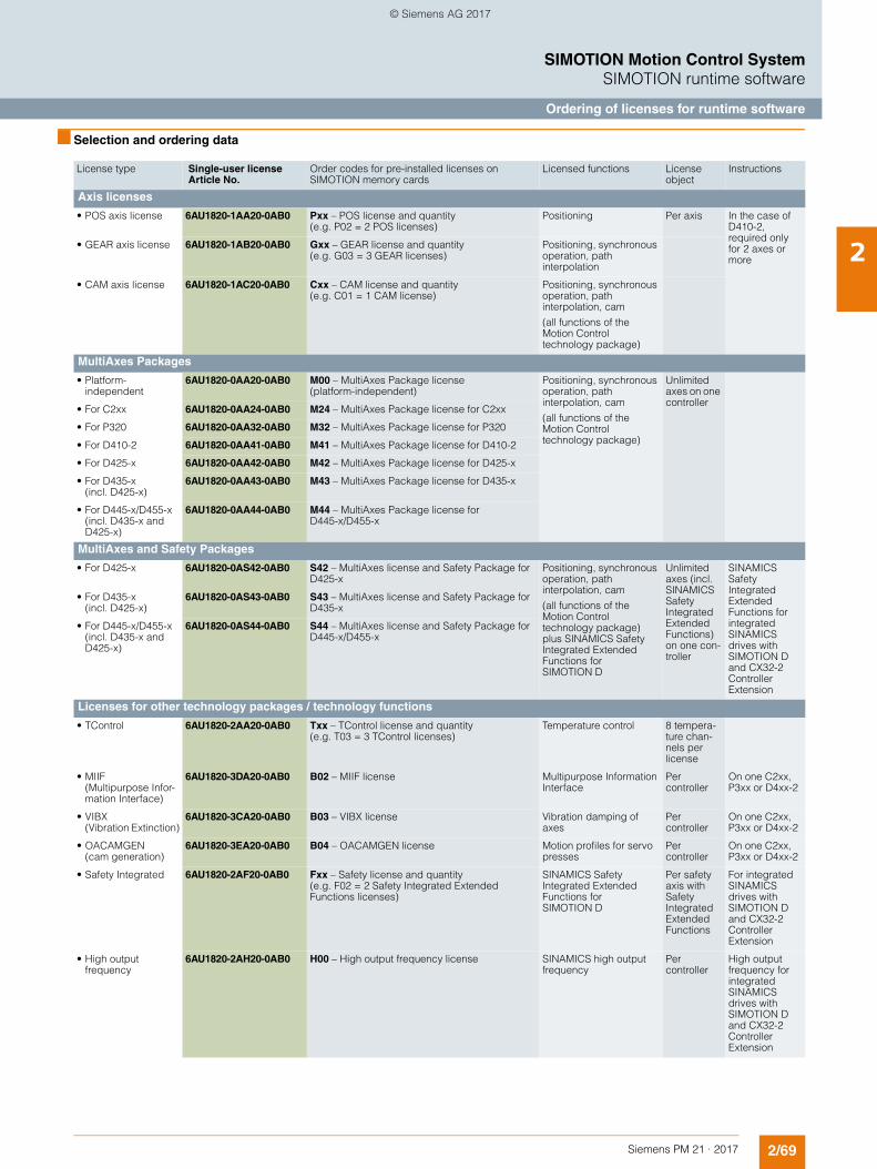
2/69Siemens PM 21 · 2017
SIMOTION Motion Control SystemSIMOTION runtime software
Ordering of licenses for runtime software
2
■ Selection and ordering data
License type Single-user licenseArticle No.
Order codes for pre-installed licenses on SIMOTION memory cards
Licensed functions Licenseobject
Instructions
Axis licenses
• POS axis license 6AU1820-1AA20-0AB0 Pxx – POS license and quantity (e.g. P02 = 2 POS licenses)
Positioning Per axis In the case of D410-2, required only for 2 axes or more
• GEAR axis license 6AU1820-1AB20-0AB0 Gxx – GEAR license and quantity (e.g. G03 = 3 GEAR licenses)
Positioning, synchronous operation, path interpolation
• CAM axis license 6AU1820-1AC20-0AB0 Cxx – CAM license and quantity (e.g. C01 = 1 CAM license)
Positioning, synchronous operation, path interpolation, cam
(all functions of the Motion Control technology package)
MultiAxes Packages
• Platform-independent
6AU1820-0AA20-0AB0 M00 – MultiAxes Package license (platform-independent)
Positioning, synchronous operation, path interpolation, cam
(all functions of the Motion Control technology package)
Unlimited axes on one controller
• For C2xx 6AU1820-0AA24-0AB0 M24 – MultiAxes Package license for C2xx
• For P320 6AU1820-0AA32-0AB0 M32 – MultiAxes Package license for P320
• For D410-2 6AU1820-0AA41-0AB0 M41 – MultiAxes Package license for D410-2
• For D425-x 6AU1820-0AA42-0AB0 M42 – MultiAxes Package license for D425-x
• For D435-x (incl. D425-x)
6AU1820-0AA43-0AB0 M43 – MultiAxes Package license for D435-x
• For D445-x/D455-x (incl. D435-x and D425-x)
6AU1820-0AA44-0AB0 M44 – MultiAxes Package license for D445-x/D455-x
MultiAxes and Safety Packages
• For D425-x 6AU1820-0AS42-0AB0 S42 – MultiAxes license and Safety Package for D425-x
Positioning, synchronous operation, path interpolation, cam
(all functions of the Motion Control technology package) plus SINAMICS Safety Integrated Extended Functions for SIMOTION D
Unlimited axes (incl. SINAMICS SafetyIntegrated Extended Functions) on one con-troller
SINAMICS Safety Integrated Extended Functions for integrated SINAMICS drives with SIMOTION D and CX32-2 Controller Extension
• For D435-x (incl. D425-x)
6AU1820-0AS43-0AB0 S43 – MultiAxes license and Safety Package for D435-x
• For D445-x/D455-x (incl. D435-x and D425-x)
6AU1820-0AS44-0AB0 S44 – MultiAxes license and Safety Package for D445-x/D455-x
Licenses for other technology packages / technology functions
• TControl 6AU1820-2AA20-0AB0 Txx – TControl license and quantity (e.g. T03 = 3 TControl licenses)
Temperature control 8 tempera-ture chan-nels per license
• MIIF (Multipurpose Infor-mation Interface)
6AU1820-3DA20-0AB0 B02 – MIIF license Multipurpose Information Interface
Per controller
On one C2xx, P3xx or D4xx-2
• VIBX (Vibration Extinction)
6AU1820-3CA20-0AB0 B03 – VIBX license Vibration damping of axes
Per controller
On one C2xx, P3xx or D4xx-2
• OACAMGEN (cam generation)
6AU1820-3EA20-0AB0 B04 – OACAMGEN license Motion profiles for servo presses
Per controller
On one C2xx, P3xx or D4xx-2
• Safety Integrated 6AU1820-2AF20-0AB0 Fxx – Safety license and quantity (e.g. F02 = 2 Safety Integrated Extended Functions licenses)
SINAMICS SafetyIntegrated Extended Functions for SIMOTION D
Per safety axis with SafetyIntegrated Extended Functions
For integrated SINAMICS drives with SIMOTION D and CX32-2 Controller Extension
• High output frequency
6AU1820-2AH20-0AB0 H00 – High output frequency license SINAMICS high output frequency
Per controller
High output frequency for integrated SINAMICS drives with SIMOTION D and CX32-2 Controller Extension
© Siemens AG 2017
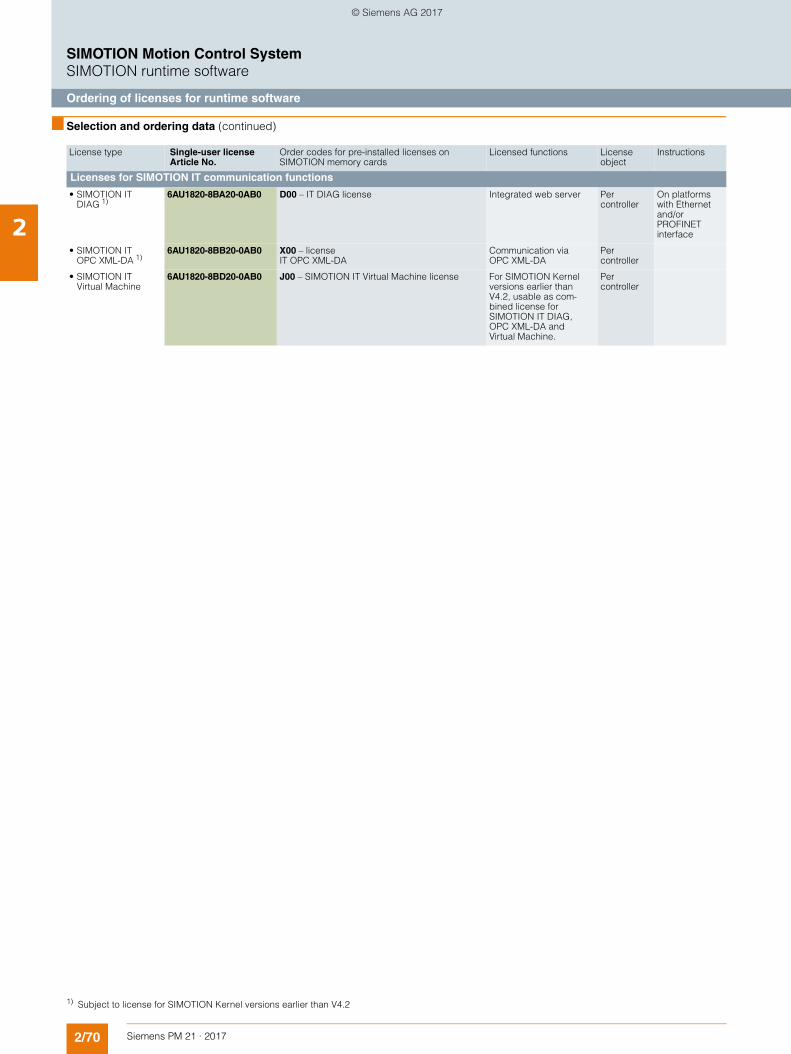
2/70 Siemens PM 21 · 2017
SIMOTION Motion Control SystemSIMOTION runtime software
Ordering of licenses for runtime software
2
■ Selection and ordering data (continued)
License type Single-user licenseArticle No.
Order codes for pre-installed licenses on SIMOTION memory cards
Licensed functions Licenseobject
Instructions
Licenses for SIMOTION IT communication functions
• SIMOTION IT DIAG 1)
6AU1820-8BA20-0AB0 D00 – IT DIAG license Integrated web server Per controller
On platforms with Ethernet and/or PROFINET interface
• SIMOTION IT OPC XML-DA 1)
6AU1820-8BB20-0AB0 X00 – license IT OPC XML-DA
Communication via OPC XML-DA
Per controller
• SIMOTION IT Virtual Machine
6AU1820-8BD20-0AB0 J00 – SIMOTION IT Virtual Machine license For SIMOTION Kernel versions earlier than V4.2, usable as com-bined license for SIMOTION IT DIAG, OPC XML-DA and Virtual Machine.
Per controller
1) Subject to license for SIMOTION Kernel versions earlier than V4.2
© Siemens AG 2017
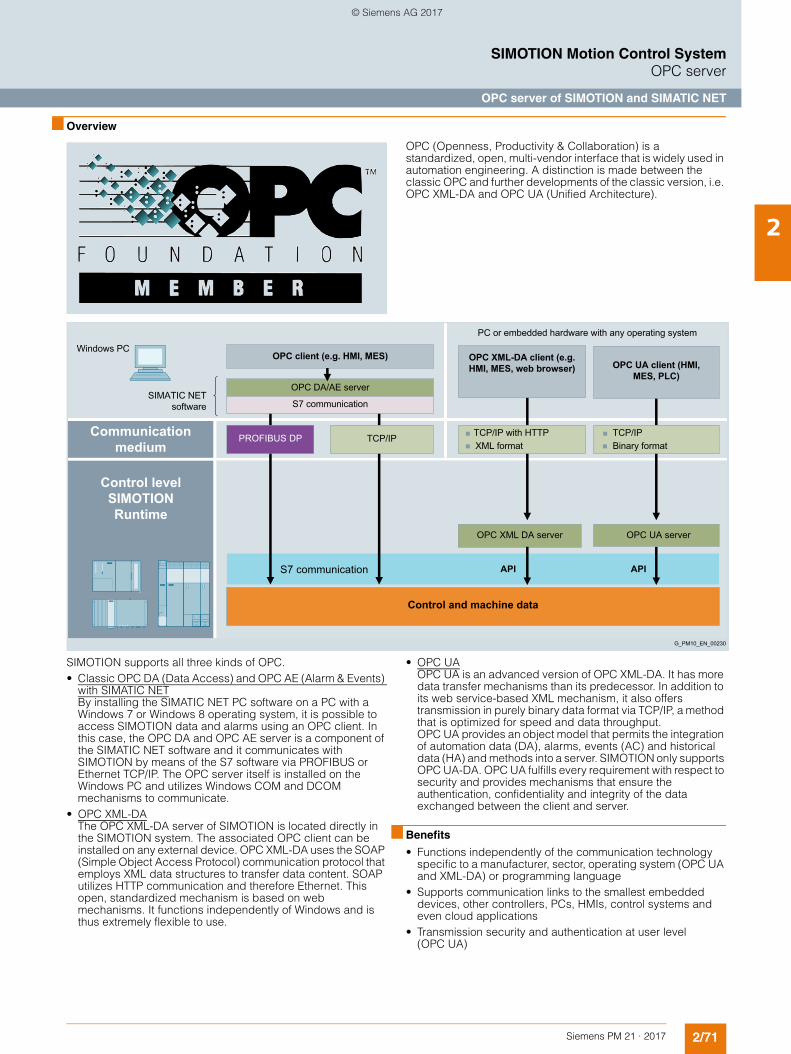
2/71Siemens PM 21 · 2017
SIMOTION Motion Control SystemOPC server
OPC server of SIMOTION and SIMATIC NET
2
■ Overview
OPC (Openness, Productivity & Collaboration) is a standardized, open, multi-vendor interface that is widely used in automation engineering. A distinction is made between the classic OPC and further developments of the classic version, i.e. OPC XML-DA and OPC UA (Unified Architecture).
SIMOTION supports all three kinds of OPC.• Classic OPC DA (Data Access) and OPC AE (Alarm & Events)
with SIMATIC NETBy installing the SIMATIC NET PC software on a PC with a Windows 7 or Windows 8 operating system, it is possible to access SIMOTION data and alarms using an OPC client. In this case, the OPC DA and OPC AE server is a component of the SIMATIC NET software and it communicates with SIMOTION by means of the S7 software via PROFIBUS or Ethernet TCP/IP. The OPC server itself is installed on the Windows PC and utilizes Windows COM and DCOM mechanisms to communicate.
• OPC XML-DAThe OPC XML-DA server of SIMOTION is located directly in the SIMOTION system. The associated OPC client can be installed on any external device. OPC XML-DA uses the SOAP (Simple Object Access Protocol) communication protocol that employs XML data structures to transfer data content. SOAP utilizes HTTP communication and therefore Ethernet. This open, standardized mechanism is based on web mechanisms. It functions independently of Windows and is thus extremely flexible to use.
• OPC UAOPC UA is an advanced version of OPC XML-DA. It has more data transfer mechanisms than its predecessor. In addition to its web service-based XML mechanism, it also offers transmission in purely binary data format via TCP/IP, a method that is optimized for speed and data throughput.OPC UA provides an object model that permits the integration of automation data (DA), alarms, events (AC) and historical data (HA) and methods into a server. SIMOTION only supports OPC UA-DA. OPC UA fulfills every requirement with respect to security and provides mechanisms that ensure the authentication, confidentiality and integrity of the data exchanged between the client and server.
■ Benefits
• Functions independently of the communication technology specific to a manufacturer, sector, operating system (OPC UA and XML-DA) or programming language
• Supports communication links to the smallest embedded devices, other controllers, PCs, HMIs, control systems and even cloud applications
• Transmission security and authentication at user level (OPC UA)
G_PM10_EN_00230
PC or embedded hardware with any operating system
OPC client (e.g. HMI, MES)
OPC DA/AE server
S7 communication
Windows PC
SIMATIC NET software
OPC XML-DA client (e.g. HMI, MES, web browser) OPC UA client (HMI,
MES, PLC)
Control and machine data
Binary formatTCP/IP
XML formatTCP/IP with HTTPTCP/IP
OPC XML DA server OPC UA server
S7 communication API API
Communication medium
Control level SIMOTION Runtime
PROFIBUS DP
© Siemens AG 2017
2/72 Siemens PM 21 · 2017
SIMOTION Motion Control SystemOPC server
OPC server of SIMOTION and SIMATIC NET
2
■ Function
The operating principle of the OPC server in the SIMATIC NET software and of the OPC UA server is described below.Information about the scope of functions of the OPC XML-DA server can be found in section SIMOTION IT.
OPC DA (Data Access) and OPC AE (Alarm & Events) with SIMATIC NET
Programming• Synchronous and asynchronous reading and writing of
variables• Monitoring of variables using the OPC server with a signal to
the client when a change occurs• Transmission of alarms and events to client• Use of batch operations, so a large volume of data can be
processed in a short time
Interfaces• Custom Interface (C++) for high OPC performance• Automation Interface (VB, Excel, Access, Delphi, etc.) for
ease-of-use• Graphics with OCX for configuring instead of programming
Bus systems
Communication over OPC for Industrial Ethernet/PROFINET and PROFIBUS is supported.
Operating systems• For Windows 7 Professional/Ultimate 32/64 bit• For Windows 8.1 Professional 64 bit
Requirements for communication via PROFIBUS• PC/PG with CP 5622 PCI card and license for SOFTNET S7
communication software for PROFIBUS DP, or• PG/Notebook with CP 5711 PCMCIA card and license for
SOFTNET S7 communication software for PROFIBUS DP
OPC on PC and PG
The SOFTNET S7 communication software for PC/PG is available for PROFINET/Industrial Ethernet and PROFIBUS DP. It contains the S7 communication software, the S5-compatible communication functions and the functions for communication with SIMOTION.
For license, see selection and ordering data
OPC UA server in SIMOTION runtime
The SIMOTION runtime software includes an OPC UA server in addition to the OPC XML-DA server. The OPC UA (Unified Architecture) is an extension of the OPC industrial standard. OPC UA is the latest OPC standard that has been designed to ensure secure, reliable multi-vendor, multi-platform communication. It therefore supports data exchange between different operating systems installed on devices of different brands.• Standardized communication via the Internet and firewalls
The OPC UA server integrated in SIMOTION utilizes a TCP-based, optimized, binary protocol to exchange data. In this case, data are transferred via the IANA-registered port 4840. HTTP and web service are also optionally supported. It is sufficient to enable port 4840 in order to transfer data.
• Service-oriented architectureOPC UA defines generic services based on the Service Oriented Architecture (SOA) design paradigm. This architecture provides service providers with requests that can be edited and whose results are returned as responses. A WDSL for describing the services of the kind required for classic web services is no longer necessary. Generic services are already defined and standardized for OPC UA.
• Security conceptTo protect against unauthorized access, the data are encrypted using recognized Internet standards (SSL, TLS, AES). The security mechanisms belong to the standard and are mandatory for manufacturers.
• Scope of functions- Read and write variables (symbolic access)- Browse variables- Subscriptions
• Access to variablesIt is possible to access the following SIMOTION variables:- Device system variables- TO system variables- TO configuration variables- Drive parameters- Global user variables- Interface variables- I/O variables
© Siemens AG 2017
2/73Siemens PM 21 · 2017
SIMOTION Motion Control SystemOPC server
OPC server of SIMOTION and SIMATIC NET
2
■ Integration
A variety of different requirements must be fulfilled in order to set up a communication link from a PC/PG to SIMOTION via OPC with SIMATIC NET:
Requirements for communication via Industrial Ethernet• PC/PG with standard Ethernet interface and SOFTNET S7
communication software for Industrial Ethernet or SOFTNET S7/LEAN for Industrial Ethernet (only 8 connections)
Requirements for communication via PROFIBUS• PC/PG with CP 5612/5622 PCI card and SOFTNET S7
communication software for PROFIBUS DP, or • PG/Notebook with CP 5711 PCMCIA card and SOFTNET S7
communication software for PROFIBUS DP
Use of the OPC XML-DA and OPC UA servers in the SIMOTION runtime software does not require a license.
■ Selection and ordering data
Note
As of SIMOTION Kernel V4.2, the SIMOTION IT function OPC XML-DA is included in the standard firmware of the SIMOTION controllers and does not require a license. For further details, refer to section SIMOTION IT.
■ More information
More information about the SIMATIC NET software package with OPC server can be found in Catalog IK PI and the Industry Mall under Automation Technology/Industrial Communication.
More information about OPC can be found on the Internet at: www.opcfoundation.org
Description Article No.
SIMATIC NET SOFTNET-PB S7 Software for S7 communication including OPC server and configuring software. CD with license key on a USB stick. Can be used in combination with CP5612, CP5622, CP5711
6GK1704-5CW14-0AA0
CP 5711 communications processorCP 5711 communications processor with USB adapter (USB V2.0) for connecting a PG or notebook to PROFIBUS or MPI
6GK1571-1AA00
SIMATIC NET SOFTNET-IE S7 Software for S7 communication including OPC server and configuring software
• DVD with license key on a USB stick 6GK1704-1CW14-0AA0• License key for download
(Email address required for delivery)6GK1704-1CW14-0AK0
SIMATIC NET SOFTNET-IE S7 Lean Software for S7 communication including OPC server and configuring software
• DVD with license key on a USB stick 6GK1704-1LW14-0AA0• License key for download
(Email address required for delivery)6GK1704-1LW14-0AK0
© Siemens AG 2017
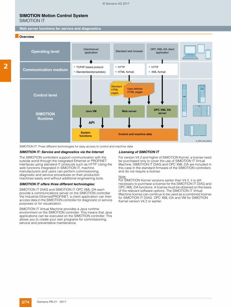
2/74 Siemens PM 21 · 2017
SIMOTION Motion Control SystemSIMOTION IT
Web server functions for service and diagnostics
2
■ Overview
SIMOTION IT: Three different technologies for easy access to control and machine data
SIMOTION IT: Service and diagnostics via the Internet
The SIMOTION controllers support communication with the outside world through the integrated Ethernet or PROFINET interfaces using standard IT protocols such as HTTP. Using the web functions integrated in SIMOTION IT, machine manufacturers and users can perform commissioning, diagnostic and service procedures on their production machines easily and without additional engineering tools.
SIMOTION IT offers three different technologies:
SIMOTION IT DIAG and SIMOTION IT OPC XML-DA each provide a communications server on the SIMOTION controller. Via Industrial Ethernet/PROFINET, a client application can then access data in the SIMOTION controller for diagnostic or service purposes or for visualization.
SIMOTION IT Virtual Machine provides a Java runtime environment on the SIMOTION controller. This means that Java applications can be executed on the SIMOTION controller. This allows you to create your own programs for commissioning, service and preventative maintenance.
Licensing of SIMOTION IT
For version V4.2 and higher of SIMOTION Kernel, a license need be purchased only to cover the use of SIMOTION IT Virtual Machine. SIMOTION IT DIAG and OPC XML-DA are included in this case in the standard firmware of the SIMOTION controllers and do not require a license.
Note:For SIMOTION Kernel versions earlier than V4.2, it is still necessary to purchase a license for the SIMOTION IT DIAG and OPC XML-DA functions. A license must be obtained on the basis of the relevant software options. The SIMOTION IT Virtual Machine license can continue to be used as a combined license for SIMOTION IT DIAG, OPC XML-DA and VM for SIMOTION Kernel version V4.2 or earlier.
G_PM10_EN_00201c
OPC XML-DA client applicationStandard web browser
Client/server application
Standard HTMLpages
User-defined HTML pages
Java VM Web server
Control and machine dataSystem functions
XML format
HTTP
HTML format
HTTP
Standardized/proprietary
TCP/IP based protocol
OPC XML DA server
API
Operating level
Communication medium
Control level
SIMOTION Runtime
© Siemens AG 2017
2/75Siemens PM 21 · 2017
SIMOTION Motion Control SystemSIMOTION IT
Web server functions for service and diagnostics
2
■ Function
SIMOTION IT DIAG (web server)
SIMOTION controllers have a web server integrated into their runtime system. The web pages integrated as standard offer extensive help functions for a variety of applications:• Device information
Detailed information about the firmware versions, hardware components and technology objects of the device
• Diagnostics Information about device resources: CPU load, memory usage, task duration times and operating state, diagnostic buffer, extended diagnostic buffer and technology object alarms, axis overview, watch tables and runtime trace. The diagnostic pages for SIMOTION D also display drive alarms, drive diagnostic buffer and parameters of the integrated SINAMICS drive. The watch tables support simultaneous access to the variables of all accessible SIMOTION controllers in the network (V4.5 and higher).
• Runtime trace Recorded data can be stored on the HMI device (e.g. PC). The supplied Web Trace Viewer offers a wide scope of options for evaluating recorded data: Graphical, with zoom and dual measuring cursor. SIMOTION D offers the Web Trace Viewer as a direct download from the standard web pages. The Web Trace Viewer is compatible with Windows XP and Windows 7 32/64 bit Professional or Ultimate.
• System trace As with the SIMOTION SCOUT engineering system, a distributed trace for recording variables can be configured and started across different controllers in the system.
• Access to the device file systemA web browser can be used to store and access any number of files in a specially provided directory of the file system of the SIMOTION controller. In this way, documentation and service instructions can be stored directly in the controller, for example.
• Project update and firmware update The SIMOTION project as well as the firmware of the SIMOTION controller can be updated from the standard web pages.
• Access protection SIMOTION IT features extensive security functions, such as security levels, user administration and access protection. All protocols (HTTP/HTTPS/FTP/Telnet) can be enabled individually in the SIMOTION SCOUT engineering project.
• User-specific web pages The user can create web pages and save them on the SIMOTION controller.Read and write access to the SIMOTION variables is possible. JavaScript can be used to implement active operation and display functions on the web pages. This is supported by existing JavaScript libraries. All current web technology tools (HTML4/HTML5) can be employed to create user pages.
SIMOTION IT OPC XML-DA
SIMOTION controllers have an OPC XML-DA server integrated into their runtime system. OPC XML-DA is an interface specified by the OPC Foundation and is based on the standard IT protocol HTTP. The data requests of a client are coded in XML symbolically and transmitted to SIMOTION using the HTTP protocol. These are evaluated by the integrated OPC XML DA server and the response is then sent back to the client over the same path.
It is therefore possible, for example, to create HMI applications in different programming languages (C#, Visual Basic, Java, JavaScript) on any client systems independently of the operating system.
The client application only works with the symbolic names of the SIMOTION variables and has thus only a loose link to the SIMOTION SCOUT database. A symbol export, similar to the Windows-based process on the SIMATIC NET OPC DA server, is not required. This ensures that consistency problems between the version of the client application and the project version in SIMOTION are avoided from the beginning.
The OPC XML-DA server offers the following functions for access to the data of the SIMOTION controller:• Read and write access to the SIMOTION variables• Access to diagnostic buffer, extended diagnostic buffer and
technology alarm objects• Symbolic browsing function via all the SIMOTION variables• Intelligent polling of variables using "subscriptions"• Access protection (password-based) can be configured, if
required.
The functionality responds in accordance with the specification of the OPC Foundation "OPC XML-DA Specification Version 1.01".
Note:SIMOTION offers two further access options via OPC. In addition to the method already described via OPC XML-DA, OPC DA and OPC UA are also supported. OPC DA requires that the SIMATIC NET package is installed on the client PC. OPC DA and OPC UA are described in the OPC server section.
More information about OPC can be found on the Internet at www.opcfoundation.org.
© Siemens AG 2017
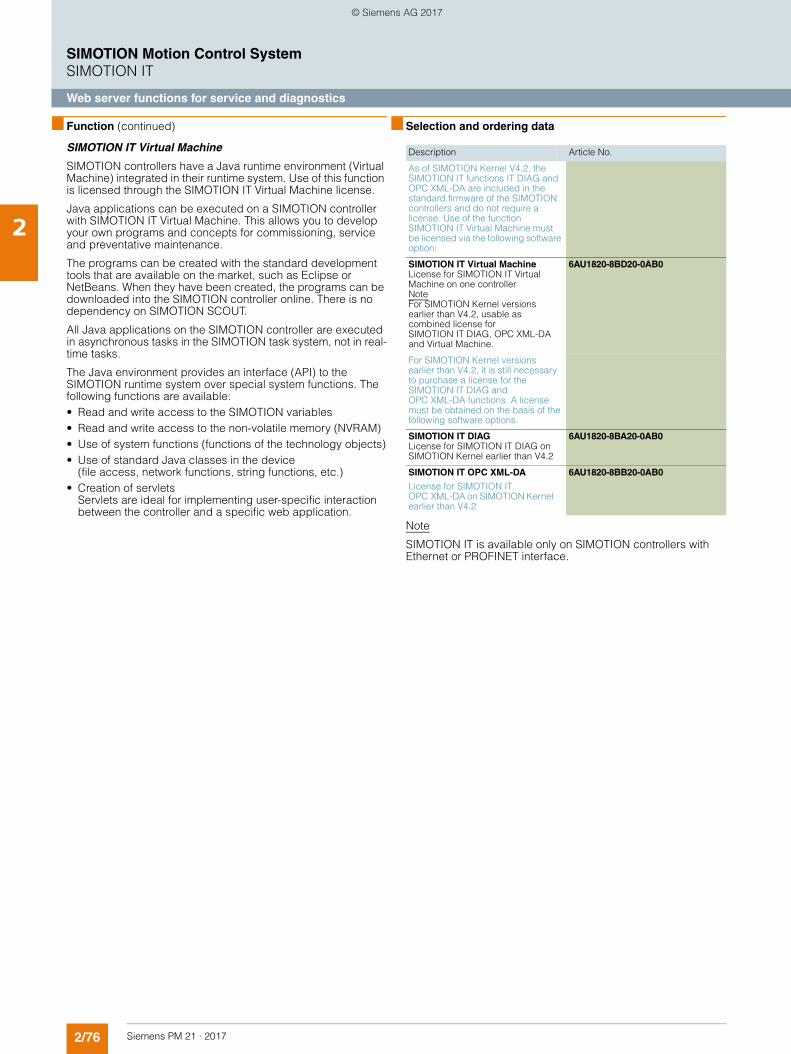
2/76 Siemens PM 21 · 2017
SIMOTION Motion Control SystemSIMOTION IT
Web server functions for service and diagnostics
2
■ Function (continued)
SIMOTION IT Virtual Machine
SIMOTION controllers have a Java runtime environment (Virtual Machine) integrated in their runtime system. Use of this function is licensed through the SIMOTION IT Virtual Machine license.
Java applications can be executed on a SIMOTION controller with SIMOTION IT Virtual Machine. This allows you to develop your own programs and concepts for commissioning, service and preventative maintenance.
The programs can be created with the standard development tools that are available on the market, such as Eclipse or NetBeans. When they have been created, the programs can be downloaded into the SIMOTION controller online. There is no dependency on SIMOTION SCOUT.
All Java applications on the SIMOTION controller are executed in asynchronous tasks in the SIMOTION task system, not in real-time tasks.
The Java environment provides an interface (API) to the SIMOTION runtime system over special system functions. The following functions are available:• Read and write access to the SIMOTION variables • Read and write access to the non-volatile memory (NVRAM)• Use of system functions (functions of the technology objects)• Use of standard Java classes in the device
(file access, network functions, string functions, etc.)• Creation of servlets
Servlets are ideal for implementing user-specific interaction between the controller and a specific web application.
■ Selection and ordering data
Note
SIMOTION IT is available only on SIMOTION controllers with Ethernet or PROFINET interface.
Description Article No.
As of SIMOTION Kernel V4.2, the SIMOTION IT functions IT DIAG and OPC XML-DA are included in the standard firmware of the SIMOTION controllers and do not require a license. Use of the function SIMOTION IT Virtual Machine must be licensed via the following software option:
SIMOTION IT Virtual MachineLicense for SIMOTION IT Virtual Machine on one controllerNoteFor SIMOTION Kernel versions earlier than V4.2, usable as combined license for SIMOTION IT DIAG, OPC XML-DA and Virtual Machine.
6AU1820-8BD20-0AB0
For SIMOTION Kernel versions earlier than V4.2, it is still necessary to purchase a license for the SIMOTION IT DIAG and OPC XML-DA functions. A license must be obtained on the basis of the following software options.
SIMOTION IT DIAGLicense for SIMOTION IT DIAG on SIMOTION Kernel earlier than V4.2
6AU1820-8BA20-0AB0
SIMOTION IT OPC XML-DA
License for SIMOTION IT OPC XML-DA on SIMOTION Kernel earlier than V4.2
6AU1820-8BB20-0AB0
© Siemens AG 2017
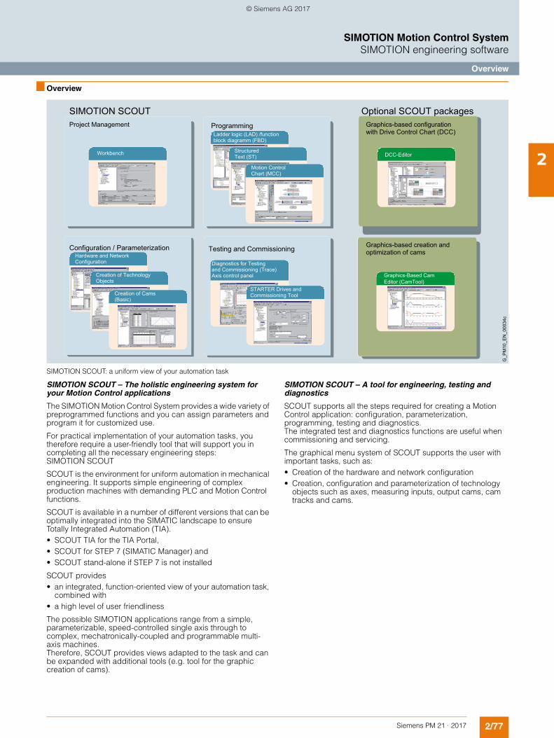
2/77Siemens PM 21 · 2017
SIMOTION Motion Control SystemSIMOTION engineering software
Overview
2
■ Overview
SIMOTION SCOUT: a uniform view of your automation task
SIMOTION SCOUT – The holistic engineering system for your Motion Control applications
The SIMOTION Motion Control System provides a wide variety of preprogrammed functions and you can assign parameters and program it for customized use.
For practical implementation of your automation tasks, you therefore require a user-friendly tool that will support you in completing all the necessary engineering steps: SIMOTION SCOUT
SCOUT is the environment for uniform automation in mechanical engineering. It supports simple engineering of complex production machines with demanding PLC and Motion Control functions.
SCOUT is available in a number of different versions that can be optimally integrated into the SIMATIC landscape to ensure Totally Integrated Automation (TIA).• SCOUT TIA for the TIA Portal,• SCOUT for STEP 7 (SIMATIC Manager) and• SCOUT stand-alone if STEP 7 is not installed
SCOUT provides• an integrated, function-oriented view of your automation task,
combined with • a high level of user friendliness
The possible SIMOTION applications range from a simple, parameterizable, speed-controlled single axis through to complex, mechatronically-coupled and programmable multi-axis machines. Therefore, SCOUT provides views adapted to the task and can be expanded with additional tools (e.g. tool for the graphic creation of cams).
SIMOTION SCOUT – A tool for engineering, testing and diagnostics
SCOUT supports all the steps required for creating a Motion Control application: configuration, parameterization, programming, testing and diagnostics.The integrated test and diagnostics functions are useful when commissioning and servicing.
The graphical menu system of SCOUT supports the user with important tasks, such as:• Creation of the hardware and network configuration • Creation, configuration and parameterization of technology
objects such as axes, measuring inputs, output cams, cam tracks and cams.
Diagnostics for Testingand Commissioning (Trace)Axis control panel
Ladder logic (LAD) /function block diagramm (FBD)
StructuredText (ST)
Hardware and NetworkConfiguration
Creation of TechnologyObjects
Configuration / Parameterization
Programming
Testing and Commissioning
Creation of Cams(Basic)
Motion ControlChart (MCC)
STARTER Drives andCommissioning Tool
G_P
M10
_EN
_000
34c
SIMOTION SCOUTProject Management
Workbench
Optional SCOUT packagesGraphics-based configuration with Drive Control Chart (DCC)
DCC-Editor
Graphics-Based CamEditor (CamTool)
Graphics-based creation and optimization of cams
© Siemens AG 2017
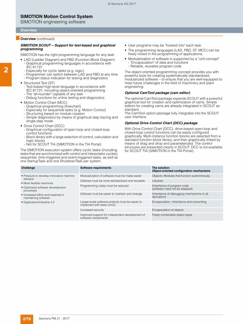
2/78 Siemens PM 21 · 2017
SIMOTION Motion Control SystemSIMOTION engineering software
Overview
2
■ Overview (continued)
SIMOTION SCOUT – Support for text-based and graphical programming
SIMOTION has the right programming language for any task:• LAD (Ladder Diagram) and FBD (Function Block Diagram)
- Graphical programming languages in accordance with IEC 61131
- Especially for cyclic tasks (e.g. logic) - Programmer can switch between LAD and FBD at any time- Program status indication for testing and diagnostics
• Structured Text (ST) - Text-based high-level language in accordance with
IEC 61131; including object-oriented programming- The "all-rounder" capable of any task- Debug functions for online testing and diagnostics
• Motion Control Chart (MCC)- Graphical programming (flowchart)- Especially for sequential tasks (e.g. Motion Control)- Structuring based on module creation - Simple diagnostics by means of graphical step tracing and
single step mode• Drive Control Chart (DCC)
- Graphical configuration of open-loop and closed-loop control functions
- Block library with a large selection of control, calculation and logic blocks
- Not for SCOUT TIA (SIMOTION in the TIA Portal)
The SIMOTION execution system offers cyclic tasks (including tasks that are synchronized with control and interpolator cycles), sequential, time-triggered and event-triggered tasks, as well as one StartupTask and one ShutdownTask per system.
• User programs may be "hooked into" each task. • The programming languages (LAD, FBD, ST, MCC) can be
freely mixed in the programming of applications.• Modularization of software is supported by a "unit concept"
- "Encapsulation" of data and functions- Reliable, reusable program code
The object-oriented programming concept provides you with powerful tools for creating systematically standardized, modularized software – to ensure that you are well-equipped to meet future challenges in the field of machinery and plant engineering.
Optional CamTool package (cam editor)
The optional CamTool package expands SCOUT with a powerful graphical tool for creation and optimization of cams. Simple editors for creating cams are already integrated in SCOUT as standard. The CamTool option package fully integrates into the SCOUT user interface.
Optional Drive Control Chart (DCC) package
With Drive Control Chart (DCC), drive-based open-loop and closed-loop control functions can be easily configured graphically. Multi-instance function blocks are selected from a standard function block library, and then graphically linked by means of drag and drop and parameterized. The control structures are presented clearly in SCOUT. DCC is not available for SCOUT TIA (SIMOTION in the TIA Portal).
Challenge Software requirements The solution: Object-oriented configuration mechanisms
• Pressure to develop innovative machine designs
• More flexible machines
• Optimized software development processes
• Increased effort and expense in maintaining software
• Digitization/Industrie 4.0
Modularization of software must be made easier Objects: Modules that function autonomously
Software must be more standardized and reusable Libraries
Programming outlay must be reduced Inheritance of program code (software need not be adapted)
Software must be easier to maintain and change Inheritance of debugging mechanisms in all derivations
Larger-scale software projects must be easier to implement with fewer errors
Encapsulation, inheritance and overwriting
Increased security Encapsulation of objects
Improved support for independent development of software components
Freely combinable object types
© Siemens AG 2017
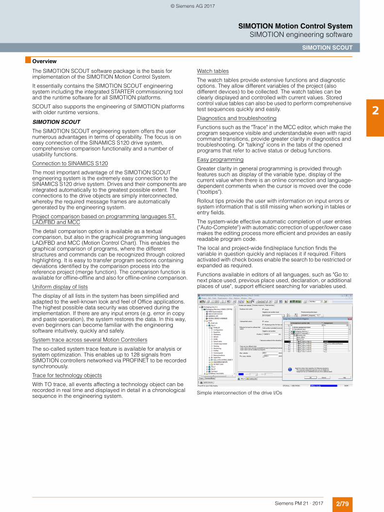
2/79Siemens PM 21 · 2017
SIMOTION Motion Control SystemSIMOTION engineering software
SIMOTION SCOUT
2
■ Overview
The SIMOTION SCOUT software package is the basis for implementation of the SIMOTION Motion Control System.
It essentially contains the SIMOTION SCOUT engineering system including the integrated STARTER commissioning tool and the runtime software for all SIMOTION platforms.
SCOUT also supports the engineering of SIMOTION platforms with older runtime versions.
SIMOTION SCOUT
The SIMOTION SCOUT engineering system offers the user numerous advantages in terms of operability. The focus is on easy connection of the SINAMICS S120 drive system, comprehensive comparison functionality and a number of usability functions.
Connection to SINAMICS S120
The most important advantage of the SIMOTION SCOUT engineering system is the extremely easy connection to the SINAMICS S120 drive system. Drives and their components are integrated automatically to the greatest possible extent. The connections to the drive objects are simply interconnected, whereby the required message frames are automatically generated by the engineering system.
Project comparison based on programming languages ST, LAD/FBD and MCC
The detail comparison option is available as a textual comparison, but also in the graphical programming languages LAD/FBD and MCC (Motion Control Chart). This enables the graphical comparison of programs, where the different structures and commands can be recognized through colored highlighting. It is easy to transfer program sections containing deviations identified by the comparison process into the reference project (merge function). The comparison function is available for offline-offline and also for offline-online comparison.
Uniform display of lists
The display of all lists in the system has been simplified and adapted to the well-known look and feel of Office applications. The highest possible data security was observed during the implementation. If there are any input errors (e.g. error in copy and paste operation), the system restores the data. In this way, even beginners can become familiar with the engineering software intuitively, quickly and safely.
System trace across several Motion Controllers
The so-called system trace feature is available for analysis or system optimization. This enables up to 128 signals from SIMOTION controllers networked via PROFINET to be recorded synchronously.
Trace for technology objects
With TO trace, all events affecting a technology object can be recorded in real time and displayed in detail in a chronological sequence in the engineering system.
Watch tables
The watch tables provide extensive functions and diagnostic options. They allow different variables of the project (also different devices) to be collected. The watch tables can be clearly displayed and controlled with current values. Stored control value tables can also be used to perform comprehensive test sequences quickly and easily.
Diagnostics and troubleshooting
Functions such as the "Trace" in the MCC editor, which make the program sequence visible and understandable even with rapid command transitions, provide greater clarity in diagnostics and troubleshooting. Or "talking" icons in the tabs of the opened programs that refer to active status or debug functions.
Easy programming
Greater clarity in general programming is provided through features such as display of the variable type, display of the current value when there is an online connection and language-dependent comments when the cursor is moved over the code ("tooltips").
Rollout tips provide the user with information on input errors or system information that is still missing when working in tables or entry fields.
The system-wide effective automatic completion of user entries ("Auto-Complete") with automatic correction of upper/lower case makes the editing process more efficient and provides an easily readable program code.
The local and project-wide find/replace function finds the variable in question quickly and replaces it if required. Filters activated with check boxes enable the search to be restricted or expanded as required.
Functions available in editors of all languages, such as "Go to: next place used, previous place used, declaration, or additional places of use", support efficient searching for variables used.
Simple interconnection of the drive I/Os
© Siemens AG 2017
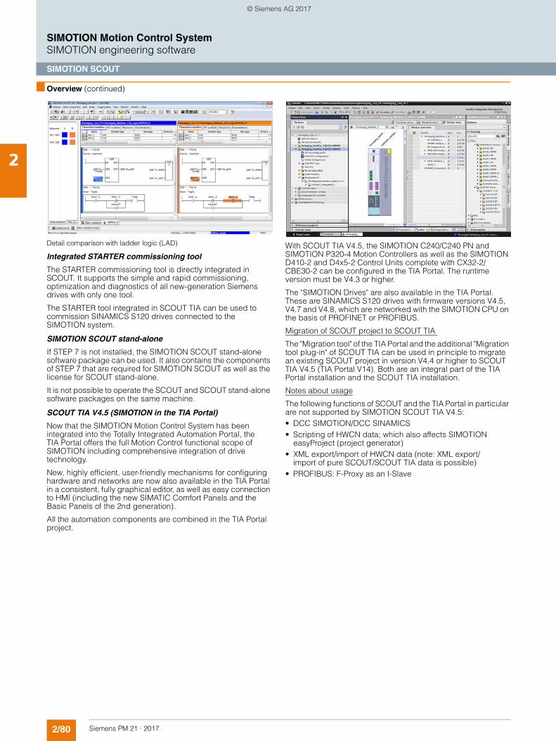
2/80 Siemens PM 21 · 2017
SIMOTION Motion Control SystemSIMOTION engineering software
SIMOTION SCOUT
2
■ Overview (continued)
Detail comparison with ladder logic (LAD)
Integrated STARTER commissioning tool
The STARTER commissioning tool is directly integrated in SCOUT. It supports the simple and rapid commissioning, optimization and diagnostics of all new-generation Siemens drives with only one tool.
The STARTER tool integrated in SCOUT TIA can be used to commission SINAMICS S120 drives connected to the SIMOTION system.
SIMOTION SCOUT stand-alone
If STEP 7 is not installed, the SIMOTION SCOUT stand-alone software package can be used. It also contains the components of STEP 7 that are required for SIMOTION SCOUT as well as the license for SCOUT stand-alone.
It is not possible to operate the SCOUT and SCOUT stand-alone software packages on the same machine.
SCOUT TIA V4.5 (SIMOTION in the TIA Portal)
Now that the SIMOTION Motion Control System has been integrated into the Totally Integrated Automation Portal, the TIA Portal offers the full Motion Control functional scope of SIMOTION including comprehensive integration of drive technology.
New, highly efficient, user-friendly mechanisms for configuring hardware and networks are now also available in the TIA Portal in a consistent, fully graphical editor, as well as easy connection to HMI (including the new SIMATIC Comfort Panels and the Basic Panels of the 2nd generation).
All the automation components are combined in the TIA Portal project.
With SCOUT TIA V4.5, the SIMOTION C240/C240 PN and SIMOTION P320-4 Motion Controllers as well as the SIMOTION D410-2 and D4x5-2 Control Units complete with CX32-2/CBE30-2 can be configured in the TIA Portal. The runtime version must be V4.3 or higher.
The "SIMOTION Drives" are also available in the TIA Portal. These are SINAMICS S120 drives with firmware versions V4.5, V4.7 and V4.8, which are networked with the SIMOTION CPU on the basis of PROFINET or PROFIBUS.
Migration of SCOUT project to SCOUT TIA
The "Migration tool" of the TIA Portal and the additional "Migration tool plug-in" of SCOUT TIA can be used in principle to migrate an existing SCOUT project in version V4.4 or higher to SCOUT TIA V4.5 (TIA Portal V14). Both are an integral part of the TIA Portal installation and the SCOUT TIA installation.
Notes about usage
The following functions of SCOUT and the TIA Portal in particular are not supported by SIMOTION SCOUT TIA V4.5:• DCC SIMOTION/DCC SINAMICS• Scripting of HWCN data; which also affects SIMOTION
easyProject (project generator)• XML export/import of HWCN data (note: XML export/
import of pure SCOUT/SCOUT TIA data is possible)• PROFIBUS: F-Proxy as an I-Slave
© Siemens AG 2017
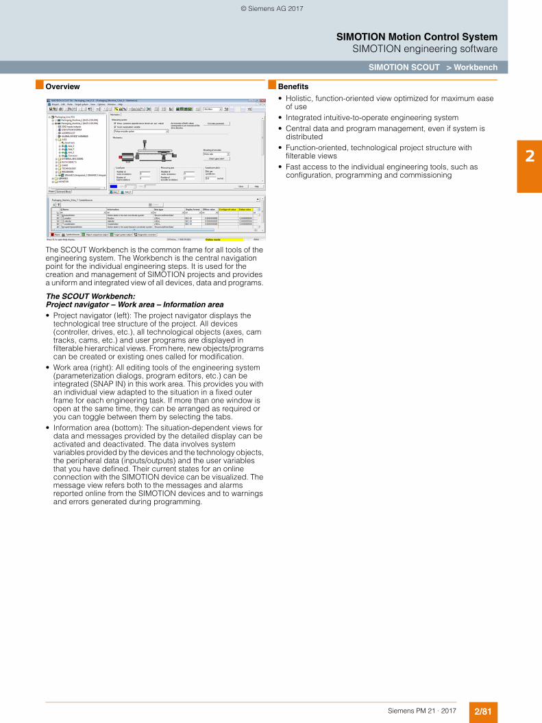
2/81Siemens PM 21 · 2017
SIMOTION Motion Control SystemSIMOTION engineering software
SIMOTION SCOUT > Workbench
2
■ Overview
The SCOUT Workbench is the common frame for all tools of the engineering system. The Workbench is the central navigation point for the individual engineering steps. It is used for the creation and management of SIMOTION projects and provides a uniform and integrated view of all devices, data and programs.
The SCOUT Workbench: Project navigator – Work area – Information area• Project navigator (left): The project navigator displays the
technological tree structure of the project. All devices (controller, drives, etc.), all technological objects (axes, cam tracks, cams, etc.) and user programs are displayed in filterable hierarchical views. From here, new objects/programs can be created or existing ones called for modification.
• Work area (right): All editing tools of the engineering system (parameterization dialogs, program editors, etc.) can be integrated (SNAP IN) in this work area. This provides you with an individual view adapted to the situation in a fixed outer frame for each engineering task. If more than one window is open at the same time, they can be arranged as required or you can toggle between them by selecting the tabs.
• Information area (bottom): The situation-dependent views for data and messages provided by the detailed display can be activated and deactivated. The data involves system variables provided by the devices and the technology objects, the peripheral data (inputs/outputs) and the user variables that you have defined. Their current states for an online connection with the SIMOTION device can be visualized. The message view refers both to the messages and alarms reported online from the SIMOTION devices and to warnings and errors generated during programming.
■ Benefits
• Holistic, function-oriented view optimized for maximum ease of use
• Integrated intuitive-to-operate engineering system• Central data and program management, even if system is
distributed• Function-oriented, technological project structure with
filterable views• Fast access to the individual engineering tools, such as
configuration, programming and commissioning
© Siemens AG 2017
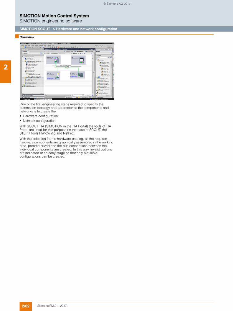
2/82 Siemens PM 21 · 2017
SIMOTION Motion Control SystemSIMOTION engineering software
SIMOTION SCOUT > Hardware and network configuration
2
■ Overview
One of the first engineering steps required to specify the automation topology and parameterize the components and networks is to create the • Hardware configuration • Network configuration
With SCOUT TIA (SIMOTION in the TIA Portal) the tools of TIA Portal are used for this purpose (in the case of SCOUT, the STEP 7 tools HW-Config and NetPro).
With the selection from a hardware catalog, all the required hardware components are graphically assembled in the working area, parameterized and the bus connections between the individual components are created. In this way, invalid options are indicated at an early stage so that only plausible configurations can be created.
© Siemens AG 2017
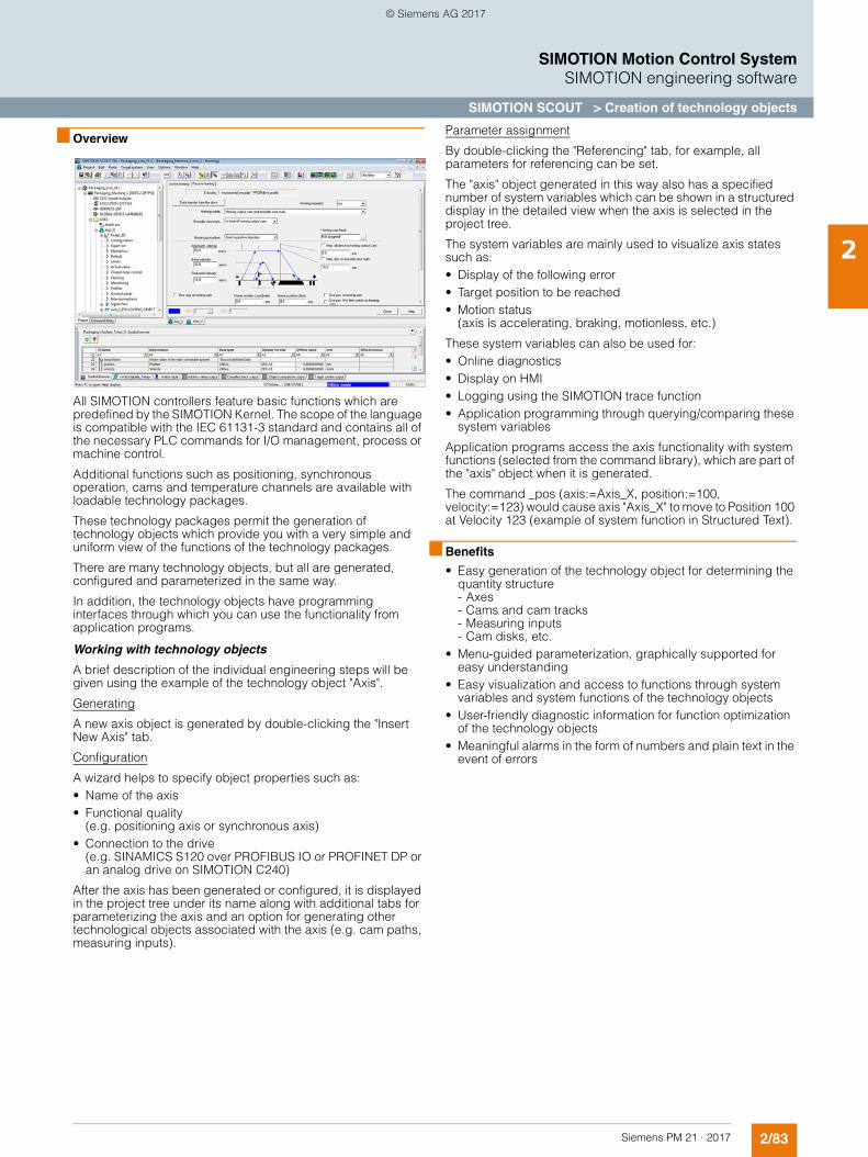
2/83Siemens PM 21 · 2017
SIMOTION Motion Control SystemSIMOTION engineering software
SIMOTION SCOUT > Creation of technology objects
2
■ Overview
All SIMOTION controllers feature basic functions which are predefined by the SIMOTION Kernel. The scope of the language is compatible with the IEC 61131-3 standard and contains all of the necessary PLC commands for I/O management, process or machine control.
Additional functions such as positioning, synchronous operation, cams and temperature channels are available with loadable technology packages.
These technology packages permit the generation of technology objects which provide you with a very simple and uniform view of the functions of the technology packages.
There are many technology objects, but all are generated, configured and parameterized in the same way.
In addition, the technology objects have programming interfaces through which you can use the functionality from application programs.
Working with technology objects
A brief description of the individual engineering steps will be given using the example of the technology object "Axis".
Generating
A new axis object is generated by double-clicking the "Insert New Axis" tab.
Configuration
A wizard helps to specify object properties such as: • Name of the axis • Functional quality
(e.g. positioning axis or synchronous axis) • Connection to the drive
(e.g. SINAMICS S120 over PROFIBUS IO or PROFINET DP or an analog drive on SIMOTION C240)
After the axis has been generated or configured, it is displayed in the project tree under its name along with additional tabs for parameterizing the axis and an option for generating other technological objects associated with the axis (e.g. cam paths, measuring inputs).
Parameter assignment
By double-clicking the "Referencing" tab, for example, all parameters for referencing can be set.
The "axis" object generated in this way also has a specified number of system variables which can be shown in a structured display in the detailed view when the axis is selected in the project tree.
The system variables are mainly used to visualize axis states such as:• Display of the following error• Target position to be reached• Motion status
(axis is accelerating, braking, motionless, etc.)
These system variables can also be used for:• Online diagnostics• Display on HMI• Logging using the SIMOTION trace function• Application programming through querying/comparing these
system variables
Application programs access the axis functionality with system functions (selected from the command library), which are part of the "axis" object when it is generated.
The command _pos (axis:=Axis_X, position:=100, velocity:=123) would cause axis "Axis_X" to move to Position 100 at Velocity 123 (example of system function in Structured Text).
■ Benefits
• Easy generation of the technology object for determining the quantity structure- Axes- Cams and cam tracks- Measuring inputs- Cam disks, etc.
• Menu-guided parameterization, graphically supported for easy understanding
• Easy visualization and access to functions through system variables and system functions of the technology objects
• User-friendly diagnostic information for function optimization of the technology objects
• Meaningful alarms in the form of numbers and plain text in the event of errors
© Siemens AG 2017
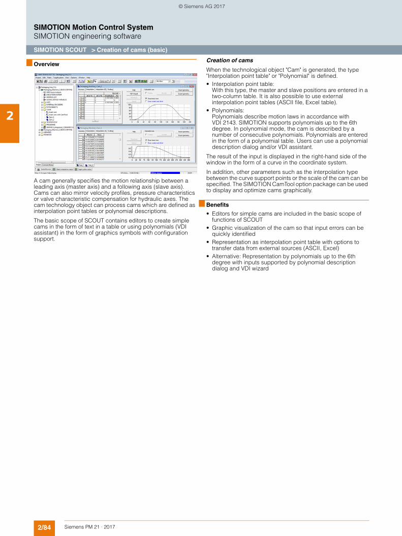
2/84 Siemens PM 21 · 2017
SIMOTION Motion Control SystemSIMOTION engineering software
SIMOTION SCOUT > Creation of cams (basic)
2
■ Overview
A cam generally specifies the motion relationship between a leading axis (master axis) and a following axis (slave axis). Cams can also mirror velocity profiles, pressure characteristics or valve characteristic compensation for hydraulic axes. The cam technology object can process cams which are defined as interpolation point tables or polynomial descriptions.
The basic scope of SCOUT contains editors to create simple cams in the form of text in a table or using polynomials (VDI assistant) in the form of graphics symbols with configuration support.
Creation of cams
When the technological object "Cam" is generated, the type "Interpolation point table" or "Polynomial" is defined.• Interpolation point table:
With this type, the master and slave positions are entered in a two-column table. It is also possible to use external interpolation point tables (ASCII file, Excel table).
• Polynomials:Polynomials describe motion laws in accordance with VDI 2143. SIMOTION supports polynomials up to the 6th degree. In polynomial mode, the cam is described by a number of consecutive polynomials. Polynomials are entered in the form of a polynomial table. Users can use a polynomial description dialog and/or VDI assistant.
The result of the input is displayed in the right-hand side of the window in the form of a curve in the coordinate system.
In addition, other parameters such as the interpolation type between the curve support points or the scale of the cam can be specified. The SIMOTION CamTool option package can be used to display and optimize cams graphically.
■ Benefits
• Editors for simple cams are included in the basic scope of functions of SCOUT
• Graphic visualization of the cam so that input errors can be quickly identified
• Representation as interpolation point table with options to transfer data from external sources (ASCII, Excel)
• Alternative: Representation by polynomials up to the 6th degree with inputs supported by polynomial description dialog and VDI wizard
© Siemens AG 2017
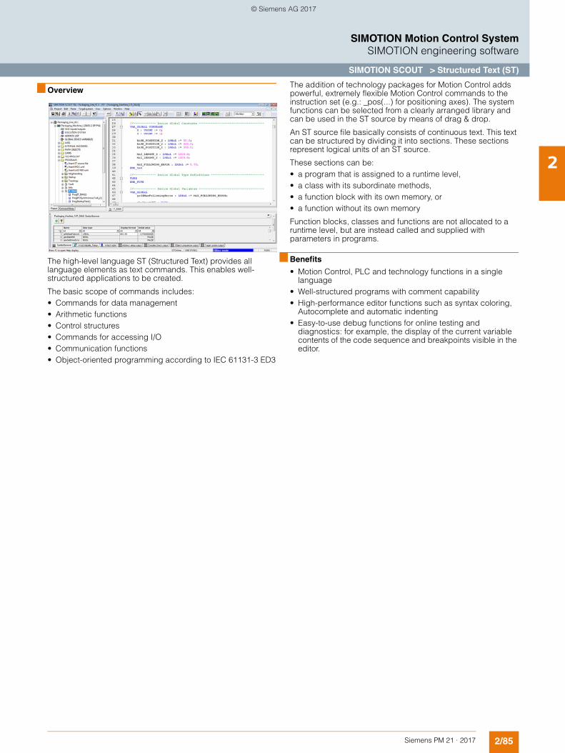
2/85Siemens PM 21 · 2017
SIMOTION Motion Control SystemSIMOTION engineering software
SIMOTION SCOUT > Structured Text (ST)
2
■ Overview
The high-level language ST (Structured Text) provides all language elements as text commands. This enables well-structured applications to be created.
The basic scope of commands includes:• Commands for data management• Arithmetic functions• Control structures• Commands for accessing I/O • Communication functions• Object-oriented programming according to IEC 61131-3 ED3
The addition of technology packages for Motion Control adds powerful, extremely flexible Motion Control commands to the instruction set (e.g.: _pos(...) for positioning axes). The system functions can be selected from a clearly arranged library and can be used in the ST source by means of drag & drop.
An ST source file basically consists of continuous text. This text can be structured by dividing it into sections. These sections represent logical units of an ST source.
These sections can be:• a program that is assigned to a runtime level,• a class with its subordinate methods,• a function block with its own memory, or• a function without its own memory
Function blocks, classes and functions are not allocated to a runtime level, but are instead called and supplied with parameters in programs.
■ Benefits
• Motion Control, PLC and technology functions in a single language
• Well-structured programs with comment capability• High-performance editor functions such as syntax coloring,
Autocomplete and automatic indenting• Easy-to-use debug functions for online testing and
diagnostics: for example, the display of the current variable contents of the code sequence and breakpoints visible in the editor.
© Siemens AG 2017
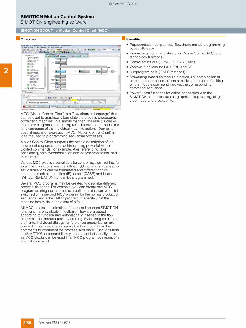
2/86 Siemens PM 21 · 2017
SIMOTION Motion Control SystemSIMOTION engineering software
SIMOTION SCOUT > Motion Control Chart (MCC)
2
■ Overview
MCC (Motion Control Chart) is a "flow diagram language" that can be used to graphically formulate the process procedures in production machines in a simple manner. The result is one or more flow diagrams, comprising MCC blocks that describe the time sequence of the individual machine actions. Due to its special means of expression, MCC (Motion Control Chart) is ideally suited to programming sequential processes.
Motion Control Chart supports the simple description of the movement sequences of machines using powerful Motion Control commands, for example: Axis referencing, axis positioning, cam synchronization and desynchronization, and much more.
Various MCC blocks are available for controlling the machine, for example, conditions must be fulfilled, I/O signals can be read or set, calculations can be formulated and different control structures such as condition (IF), cases (CASE) and loops (WHILE, REPEAT UNTIL) can be programmed.
Several MCC programs may be created to describe different process situations. For example, you can create one MCC program to bring the machine to a defined initial state when it is switched on, a second MCC program for the normal production sequence, and a third MCC program to specify what the machine has to do in the event of a fault.
All MCC blocks – a selection of the most important SIMOTION functions – are available in toolbars. They are grouped according to function and automatically inserted in the flow diagram at the marked point by clicking. By clicking on different elements, individual dialogs for further parameterization are opened. Of course, it is also possible to include individual comments to document the process sequence. Functions from the SIMOTION command library that are not individually offered as MCC blocks can be used in an MCC program by means of a special command.
■ Benefits
• Representation as graphical flowcharts makes programming especially easy
• Hierarchical command library for Motion Control, PLC, and technology functions.
• Control structures (IF, WHILE, CASE, etc.) • Zoom-in functions for LAD, FBD and ST • Subprogram calls (FB/FC/methods)• Structuring based on module creation, i.e. combination of
command sequences to form a module command. Clicking on the module command invokes the corresponding command sequence.
• Powerful test functions for online connection with the SIMOTION controller such as graphical step tracing, single-step mode and breakpoints.
© Siemens AG 2017
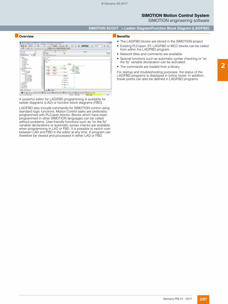
2/87Siemens PM 21 · 2017
SIMOTION Motion Control SystemSIMOTION engineering software
SIMOTION SCOUT > Ladder Diagram/Function Block Diagram (LAD/FBD)
2
■ Overview
A powerful editor for LAD/FBD programming is available for ladder diagrams (LAD) or function block diagrams (FBD).
LAD/FBD also include commands for SIMOTION control using standard logic functions. Motion Control tasks are preferably programmed with PLCopen blocks. Blocks which have been programmed in other SIMOTION languages can be called without problems. User-friendly functions such as "on the fly" variable declarations or automatic syntax checks are available when programming in LAD or FBD. It is possible to switch over between LAD and FBD in the editor at any time. A program can therefore be viewed and processed in either LAD or FBD.
■ Benefits
• The LAD/FBD blocks are stored in the SIMOTION project • Existing PLCopen, ST, LAD/FBD or MCC blocks can be called
from within the LAD/FBD program. • Network titles and comments are available.• Special functions such as automatic syntax checking or "on
the fly" variable declaration can be activated.• The commands are loaded from a library
For startup and troubleshooting purposes, the status of the LAD/FBD programs is displayed in online mode. In addition, break points can also be defined in LAD/FBD programs.
© Siemens AG 2017
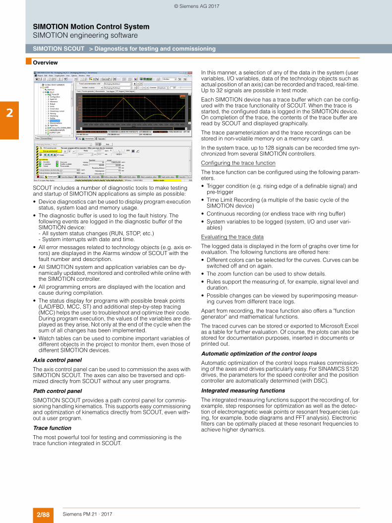
2/88 Siemens PM 21 · 2017
SIMOTION Motion Control SystemSIMOTION engineering software
SIMOTION SCOUT > Diagnostics for testing and commissioning
2
■ Overview
SCOUT includes a number of diagnostic tools to make testing and startup of SIMOTION applications as simple as possible: • Device diagnostics can be used to display program execution
status, system load and memory usage.• The diagnostic buffer is used to log the fault history. The
following events are logged in the diagnostic buffer of the SIMOTION device:- All system status changes (RUN, STOP, etc.)- System interrupts with date and time.
• All error messages related to technology objects (e.g. axis er-rors) are displayed in the Alarms window of SCOUT with the fault number and description.
• All SIMOTION system and application variables can be dy-namically updated, monitored and controlled while online with the SIMOTION controller.
• All programming errors are displayed with the location and cause during compilation.
• The status display for programs with possible break points (LAD/FBD, MCC, ST) and additional step-by-step tracing (MCC) helps the user to troubleshoot and optimize their code. During program execution, the values of the variables are dis-played as they arise, Not only at the end of the cycle when the sum of all changes has been implemented.
• Watch tables can be used to combine important variables of different objects in the project to monitor them, even those of different SIMOTION devices.
Axis control panel
The axis control panel can be used to commission the axes with SIMOTION SCOUT. The axes can also be traversed and opti-mized directly from SCOUT without any user programs.
Path control panel
SIMOTION SCOUT provides a path control panel for commis-sioning handling kinematics. This supports easy commissioning and optimization of kinematics directly from SCOUT, even with-out a user program.
Trace function
The most powerful tool for testing and commissioning is the trace function integrated in SCOUT.
In this manner, a selection of any of the data in the system (user variables, I/O variables, data of the technology objects such as actual position of an axis) can be recorded and traced, real-time. Up to 32 signals are possible in test mode.
Each SIMOTION device has a trace buffer which can be config-ured with the trace functionality of SCOUT. When the trace is started, the configured data is logged in the SIMOTION device. On completion of the trace, the contents of the trace buffer are read by SCOUT and displayed graphically.
The trace parameterization and the trace recordings can be stored in non-volatile memory on a memory card.
In the system trace, up to 128 signals can be recorded time syn-chronized from several SIMOTION controllers.
Configuring the trace function
The trace function can be configured using the following param-eters.• Trigger condition (e.g. rising edge of a definable signal) and
pre-trigger• Time Limit Recording (a multiple of the basic cycle of the
SIMOTION device)• Continuous recording (or endless trace with ring buffer)• System variables to be logged (system, I/O and user vari-
ables)
Evaluating the trace data
The logged data is displayed in the form of graphs over time for evaluation. The following functions are offered here: • Different colors can be selected for the curves. Curves can be
switched off and on again.• The zoom function can be used to show details.• Rules support the measuring of, for example, signal level and
duration.• Possible changes can be viewed by superimposing measur-
ing curves from different trace logs.
Apart from recording, the trace function also offers a "function generator" and mathematical functions.
The traced curves can be stored or exported to Microsoft Excel as a table for further evaluation. Of course, the plots can also be stored for documentation purposes, inserted in documents or printed out.
Automatic optimization of the control loops
Automatic optimization of the control loops makes commission-ing of the axes and drives particularly easy. For SINAMICS S120 drives, the parameters for the speed controller and the position controller are automatically determined (with DSC).
Integrated measuring functions
The integrated measuring functions support the recording of, for example, step responses for optimization as well as the detec-tion of electromagnetic weak points or resonant frequencies (us-ing, for example, bode diagrams and FFT analysis). Electronic filters can be optimally placed at these resonant frequencies to achieve higher dynamics.
© Siemens AG 2017
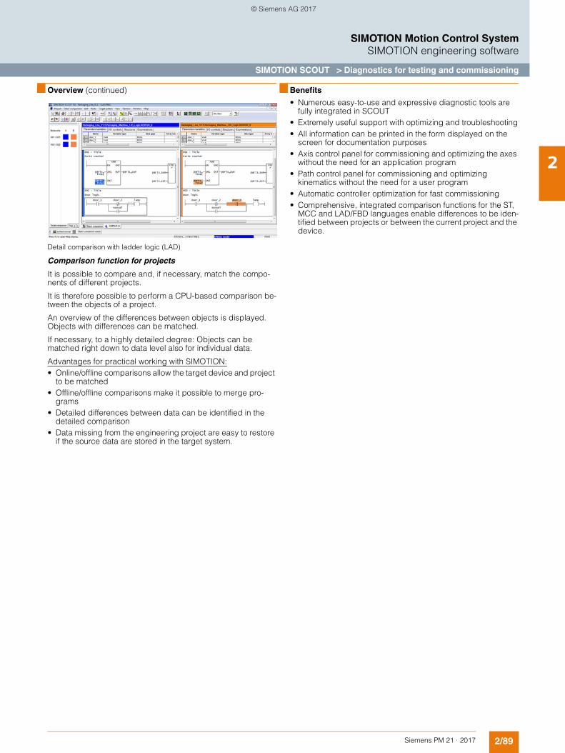
2/89Siemens PM 21 · 2017
SIMOTION Motion Control SystemSIMOTION engineering software
SIMOTION SCOUT > Diagnostics for testing and commissioning
2
■ Overview (continued)
Detail comparison with ladder logic (LAD)
Comparison function for projects
It is possible to compare and, if necessary, match the compo-nents of different projects.
It is therefore possible to perform a CPU-based comparison be-tween the objects of a project.
An overview of the differences between objects is displayed. Objects with differences can be matched.
If necessary, to a highly detailed degree: Objects can be matched right down to data level also for individual data.
Advantages for practical working with SIMOTION:• Online/offline comparisons allow the target device and project
to be matched• Offline/offline comparisons make it possible to merge pro-
grams• Detailed differences between data can be identified in the
detailed comparison• Data missing from the engineering project are easy to restore
if the source data are stored in the target system.
■ Benefits
• Numerous easy-to-use and expressive diagnostic tools are fully integrated in SCOUT
• Extremely useful support with optimizing and troubleshooting• All information can be printed in the form displayed on the
screen for documentation purposes• Axis control panel for commissioning and optimizing the axes
without the need for an application program• Path control panel for commissioning and optimizing
kinematics without the need for a user program• Automatic controller optimization for fast commissioning• Comprehensive, integrated comparison functions for the ST,
MCC and LAD/FBD languages enable differences to be iden-tified between projects or between the current project and the device.
© Siemens AG 2017
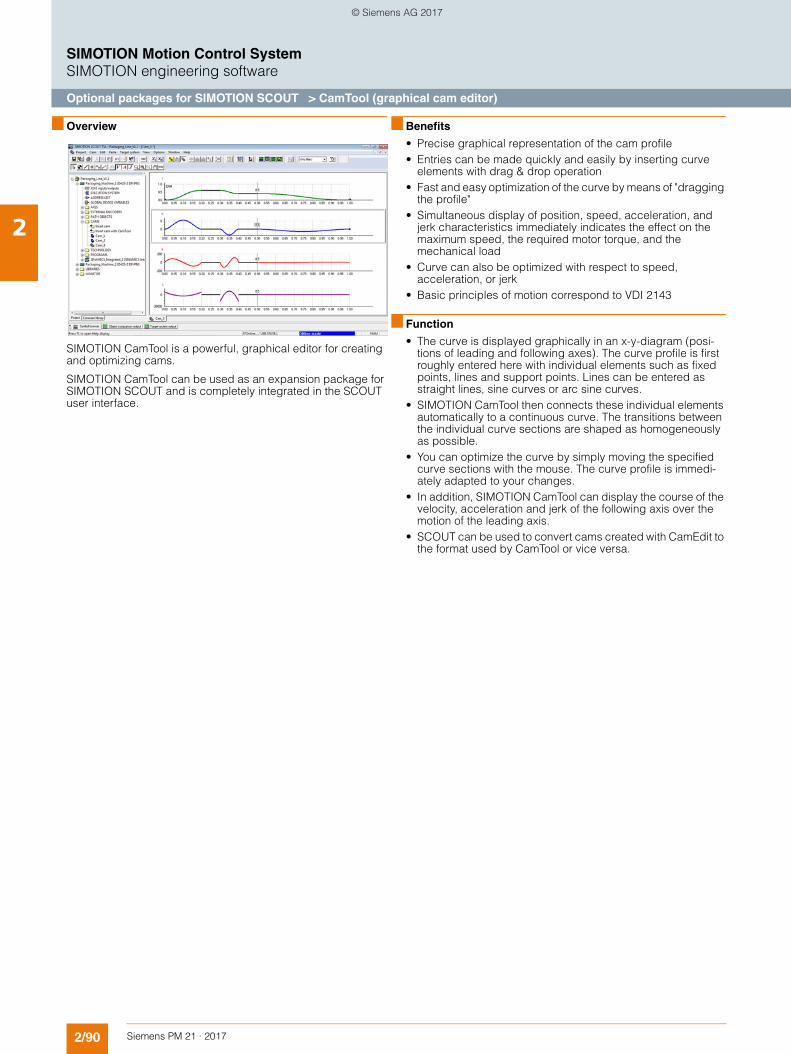
2/90 Siemens PM 21 · 2017
SIMOTION Motion Control SystemSIMOTION engineering software
Optional packages for SIMOTION SCOUT > CamTool (graphical cam editor)
2
■ Overview
SIMOTION CamTool is a powerful, graphical editor for creating and optimizing cams.
SIMOTION CamTool can be used as an expansion package for SIMOTION SCOUT and is completely integrated in the SCOUT user interface.
■ Benefits
• Precise graphical representation of the cam profile• Entries can be made quickly and easily by inserting curve
elements with drag & drop operation• Fast and easy optimization of the curve by means of "dragging
the profile"• Simultaneous display of position, speed, acceleration, and
jerk characteristics immediately indicates the effect on the maximum speed, the required motor torque, and the mechanical load
• Curve can also be optimized with respect to speed, acceleration, or jerk
• Basic principles of motion correspond to VDI 2143
■ Function
• The curve is displayed graphically in an x-y-diagram (posi-tions of leading and following axes). The curve profile is first roughly entered here with individual elements such as fixed points, lines and support points. Lines can be entered as straight lines, sine curves or arc sine curves.
• SIMOTION CamTool then connects these individual elements automatically to a continuous curve. The transitions between the individual curve sections are shaped as homogeneously as possible.
• You can optimize the curve by simply moving the specified curve sections with the mouse. The curve profile is immedi-ately adapted to your changes.
• In addition, SIMOTION CamTool can display the course of the velocity, acceleration and jerk of the following axis over the motion of the leading axis.
• SCOUT can be used to convert cams created with CamEdit to the format used by CamTool or vice versa.
© Siemens AG 2017
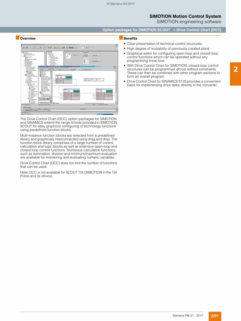
2/91Siemens PM 21 · 2017
SIMOTION Motion Control SystemSIMOTION engineering software
Option packages for SIMOTION SCOUT > Drive Control Chart (DCC)
2
■ Overview
The Drive Control Chart (DCC) option packages for SIMOTION and SINAMICS extend the range of tools provided in SIMOTION SCOUT for easy graphical configuring of technology functions using predefined function blocks.
Multi-instance function blocks are selected from a predefined library and graphically interconnected using drag and drop. The function block library comprises of a large number of control, calculation and logic blocks as well as extensive open-loop and closed-loop control functions. Numerous calculation functions, such as summation, division and minimum/maximum evaluation are available for monitoring and evaluating numeric variables.
Drive Control Chart (DCC) does not limit the number of functions that can be used.
Note: DCC is not available for SCOUT TIA (SIMOTION in the TIA Portal and its drives).
■ Benefits
• Clear presentation of technical control structures • High degree of reusability of previously created plans• Graphical editor for configuring open-loop and closed-loop
control functions which can be operated without any programming know-how
• With Drive Control Chart for SIMOTION, closed-loop control structures can be programmed almost without constraints. These can then be combined with other program sections to form an overall program.
• Drive Control Chart for SINAMICS S120 provides a convenient basis for implementing drive tasks directly in the converter.
© Siemens AG 2017
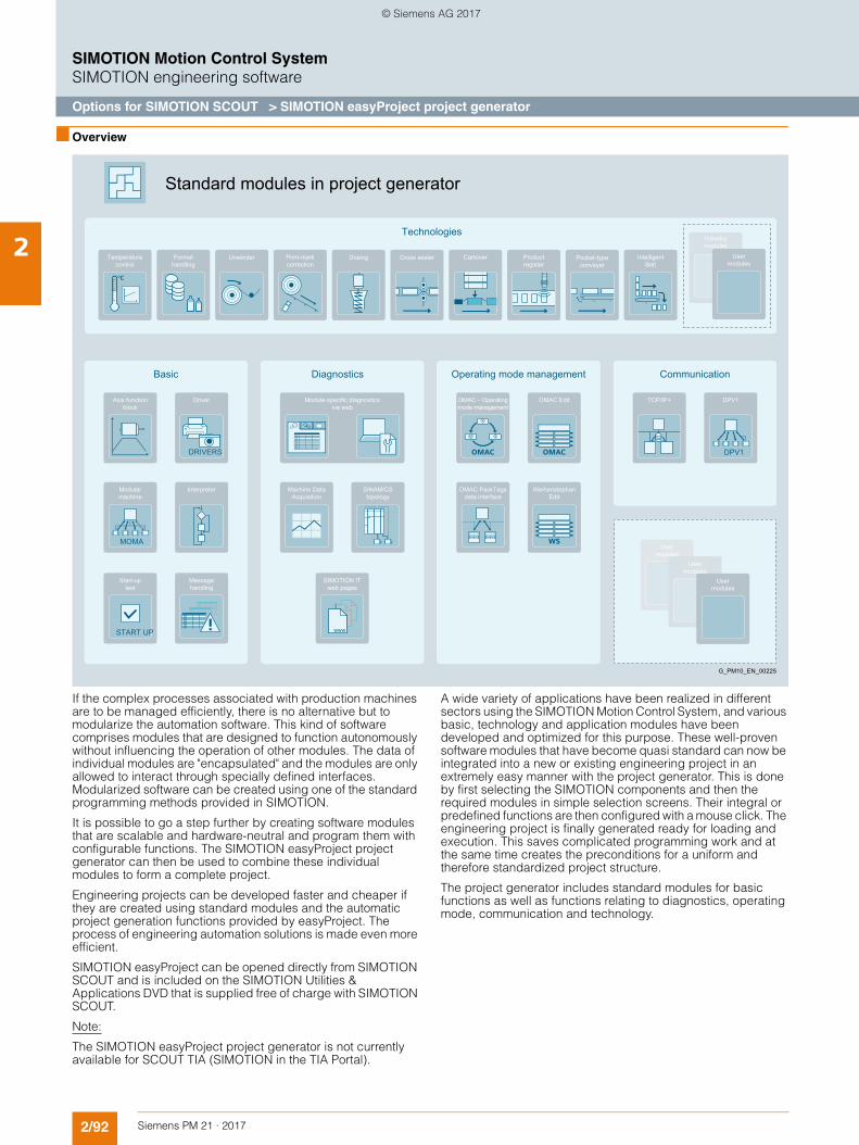
2/92 Siemens PM 21 · 2017
SIMOTION Motion Control SystemSIMOTION engineering software
Options for SIMOTION SCOUT > SIMOTION easyProject project generator
2
■ Overview
If the complex processes associated with production machines are to be managed efficiently, there is no alternative but to modularize the automation software. This kind of software comprises modules that are designed to function autonomously without influencing the operation of other modules. The data of individual modules are "encapsulated" and the modules are only allowed to interact through specially defined interfaces. Modularized software can be created using one of the standard programming methods provided in SIMOTION.
It is possible to go a step further by creating software modules that are scalable and hardware-neutral and program them with configurable functions. The SIMOTION easyProject project generator can then be used to combine these individual modules to form a complete project.
Engineering projects can be developed faster and cheaper if they are created using standard modules and the automatic project generation functions provided by easyProject. The process of engineering automation solutions is made even more efficient.
SIMOTION easyProject can be opened directly from SIMOTION SCOUT and is included on the SIMOTION Utilities & Applications DVD that is supplied free of charge with SIMOTION SCOUT.
Note:
The SIMOTION easyProject project generator is not currently available for SCOUT TIA (SIMOTION in the TIA Portal).
A wide variety of applications have been realized in different sectors using the SIMOTION Motion Control System, and various basic, technology and application modules have been developed and optimized for this purpose. These well-proven software modules that have become quasi standard can now be integrated into a new or existing engineering project in an extremely easy manner with the project generator. This is done by first selecting the SIMOTION components and then the required modules in simple selection screens. Their integral or predefined functions are then configured with a mouse click. The engineering project is finally generated ready for loading and execution. This saves complicated programming work and at the same time creates the preconditions for a uniform and therefore standardized project structure.
The project generator includes standard modules for basic functions as well as functions relating to diagnostics, operating mode, communication and technology.
SINAMICS topology
www
SIMOTION IT web pages
Machine Data Acquisition
Module-specific diagnostics via web
Usermodules
Industrymodules
Intelligent Belt
Pocket-type conveyer
Product register
Print-markcorrection
DosingUnwinder CartonerFormat handling
Cross sealerTemperaturecontrol
Technologies
Usermodules
Usermodules
User modules
Standard modules in project generator
Weihenstephan Edit
DPV1
DPV1OMAC Edit
OMAC PackTags data interface
TCP/IP+OMAC – Operatingmode management
CommunicationOperating mode management
G_PM10_EN_00225
Diagnostics
Message handling
Interpreter
DRIVERS
Driver
START UP
Start-up test
MOMA
Modular machine
Axis functionblock
Basic
© Siemens AG 2017
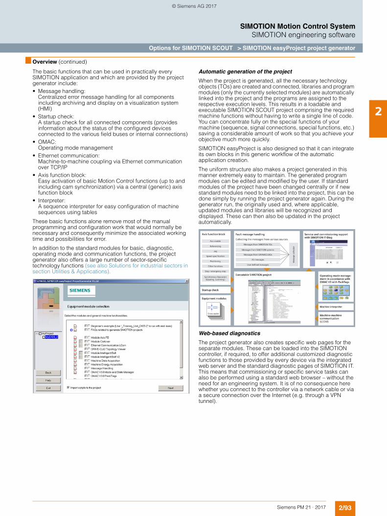
2/93Siemens PM 21 · 2017
SIMOTION Motion Control SystemSIMOTION engineering software
Options for SIMOTION SCOUT > SIMOTION easyProject project generator
2
■ Overview (continued)
The basic functions that can be used in practically every SIMOTION application and which are provided by the project generator include: • Message handling:
Centralized error message handling for all components including archiving and display on a visualization system (HMI)
• Startup check: A startup check for all connected components (provides information about the status of the configured devices connected to the various field buses or internal connections)
• OMAC: Operating mode management
• Ethernet communication: Machine-to-machine coupling via Ethernet communication over TCP/IP
• Axis function block: Easy activation of basic Motion Control functions (up to and including cam synchronization) via a central (generic) axis function block
• Interpreter: A sequence interpreter for easy configuration of machine sequences using tables
These basic functions alone remove most of the manual programming and configuration work that would normally be necessary and consequently minimize the associated working time and possibilities for error.
In addition to the standard modules for basic, diagnostic, operating mode and communication functions, the project generator also offers a large number of sector-specific technology functions (see also Solutions for industrial sectors in section Utilities & Applications).
Automatic generation of the project
When the project is generated, all the necessary technology objects (TOs) are created and connected, libraries and program modules (only the currently selected modules) are automatically linked into the project and the programs are assigned to the respective execution levels. This results in a loadable and executable SIMOTION SCOUT project comprising the required machine functions without having to write a single line of code. You can concentrate fully on the special functions of your machine (sequence, signal connections, special functions, etc.) saving a considerable amount of work so that you achieve your objective much more quickly.
SIMOTION easyProject is also designed so that it can integrate its own blocks in this generic workflow of the automatic application creation.
The uniform structure also makes a project generated in this manner extremely easy to maintain. The generated program modules can be edited and modified by the user. If standard modules of the project have been changed centrally or if new standard modules need to be linked into the project, this can be done simply by running the project generator again. During the generator run, the originally used and, where applicable, updated modules and libraries will be recognized and displayed. These can then also be updated in the project automatically.
Web-based diagnostics
The project generator also creates specific web pages for the separate modules. These can be loaded into the SIMOTION controller, if required, to offer additional customized diagnostic functions to those provided by every device via the integrated web server and the standard diagnostic pages of SIMOTION IT. This means that commissioning or specific service tasks can also be performed using a standard web browser – without the need for an engineering system. It is of no consequence here whether you connect to the controller via a network cable or via a secure connection over the Internet (e.g. through a VPN tunnel).
© Siemens AG 2017
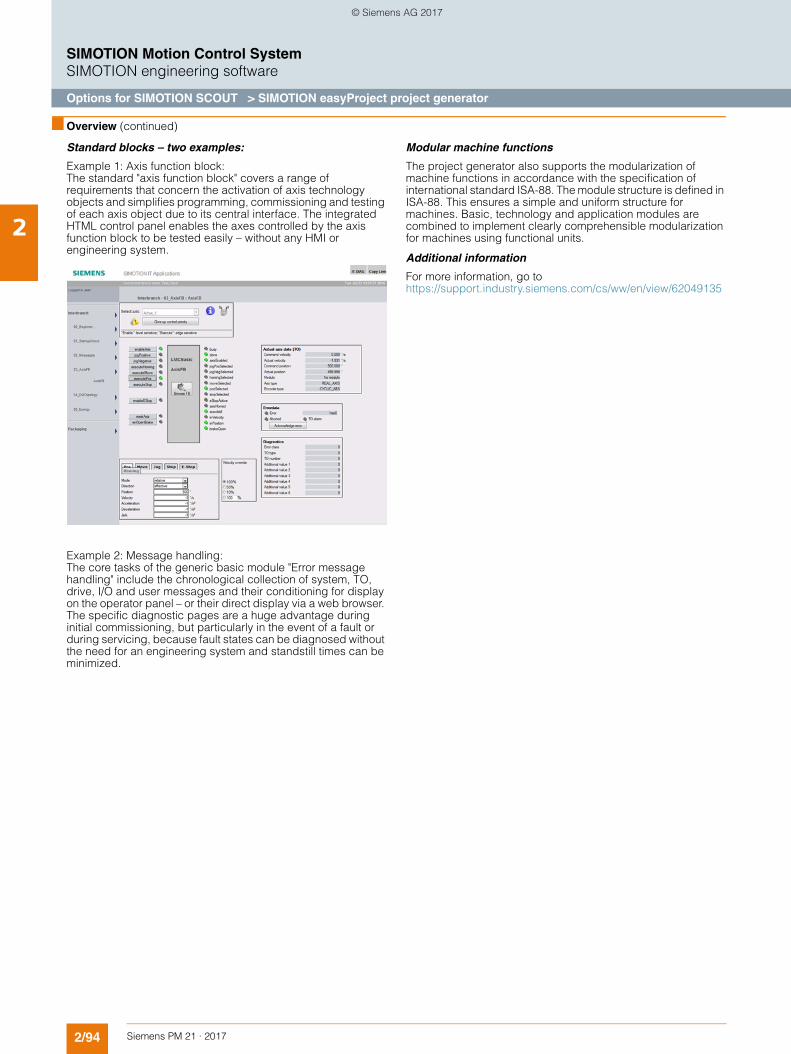
2/94 Siemens PM 21 · 2017
SIMOTION Motion Control SystemSIMOTION engineering software
Options for SIMOTION SCOUT > SIMOTION easyProject project generator
2
■ Overview (continued)
Standard blocks – two examples:
Example 1: Axis function block: The standard "axis function block" covers a range of requirements that concern the activation of axis technology objects and simplifies programming, commissioning and testing of each axis object due to its central interface. The integrated HTML control panel enables the axes controlled by the axis function block to be tested easily – without any HMI or engineering system.
Example 2: Message handling: The core tasks of the generic basic module "Error message handling" include the chronological collection of system, TO, drive, I/O and user messages and their conditioning for display on the operator panel – or their direct display via a web browser. The specific diagnostic pages are a huge advantage during initial commissioning, but particularly in the event of a fault or during servicing, because fault states can be diagnosed without the need for an engineering system and standstill times can be minimized.
Modular machine functions
The project generator also supports the modularization of machine functions in accordance with the specification of international standard ISA-88. The module structure is defined in ISA-88. This ensures a simple and uniform structure for machines. Basic, technology and application modules are combined to implement clearly comprehensible modularization for machines using functional units.
Additional information
For more information, go to https://support.industry.siemens.com/cs/ww/en/view/62049135
© Siemens AG 2017
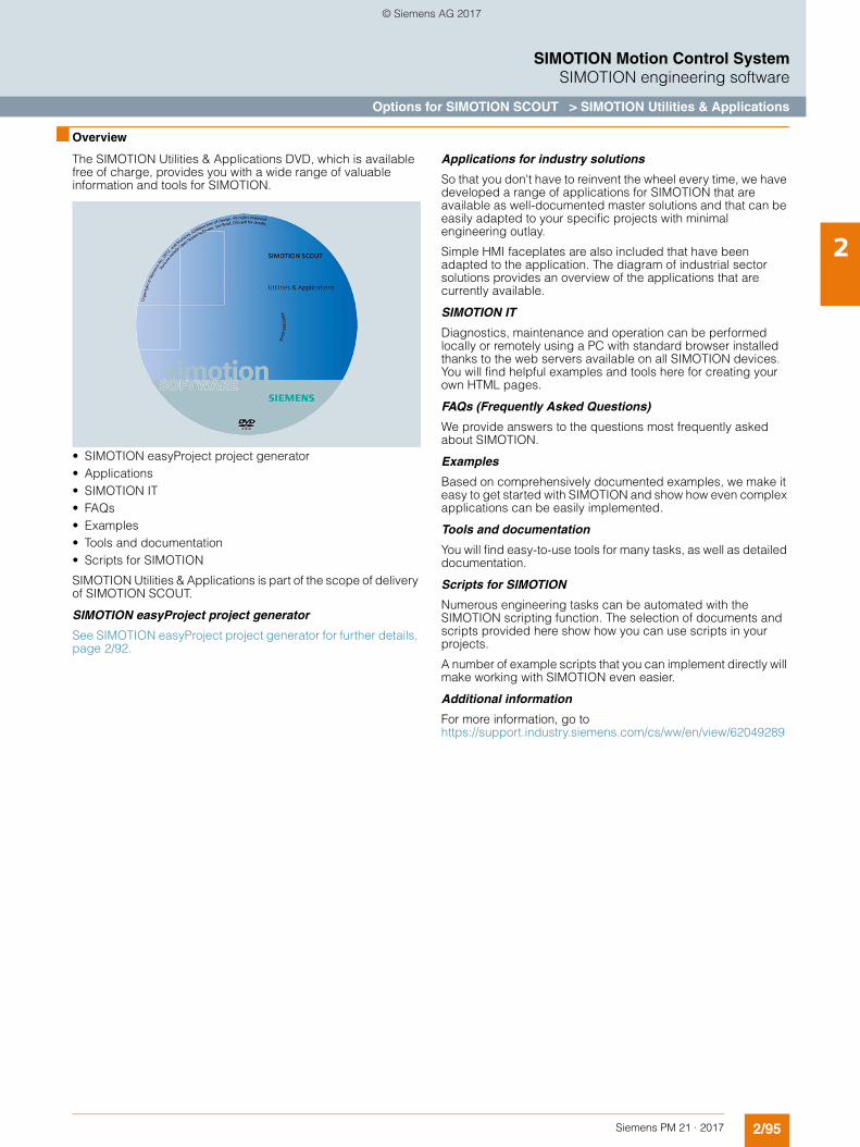
2/95Siemens PM 21 · 2017
SIMOTION Motion Control SystemSIMOTION engineering software
Options for SIMOTION SCOUT > SIMOTION Utilities & Applications
2
■ Overview
The SIMOTION Utilities & Applications DVD, which is available free of charge, provides you with a wide range of valuable information and tools for SIMOTION.
• SIMOTION easyProject project generator• Applications• SIMOTION IT• FAQs• Examples• Tools and documentation• Scripts for SIMOTION
SIMOTION Utilities & Applications is part of the scope of delivery of SIMOTION SCOUT.
SIMOTION easyProject project generator
See SIMOTION easyProject project generator for further details, page 2/92.
Applications for industry solutions
So that you don't have to reinvent the wheel every time, we have developed a range of applications for SIMOTION that are available as well-documented master solutions and that can be easily adapted to your specific projects with minimal engineering outlay.
Simple HMI faceplates are also included that have been adapted to the application. The diagram of industrial sector solutions provides an overview of the applications that are currently available.
SIMOTION IT
Diagnostics, maintenance and operation can be performed locally or remotely using a PC with standard browser installed thanks to the web servers available on all SIMOTION devices. You will find helpful examples and tools here for creating your own HTML pages.
FAQs (Frequently Asked Questions)
We provide answers to the questions most frequently asked about SIMOTION.
Examples
Based on comprehensively documented examples, we make it easy to get started with SIMOTION and show how even complex applications can be easily implemented.
Tools and documentation
You will find easy-to-use tools for many tasks, as well as detailed documentation.
Scripts for SIMOTION
Numerous engineering tasks can be automated with the SIMOTION scripting function. The selection of documents and scripts provided here show how you can use scripts in your projects.
A number of example scripts that you can implement directly will make working with SIMOTION even easier.
Additional information
For more information, go to https://support.industry.siemens.com/cs/ww/en/view/62049289
© Siemens AG 2017
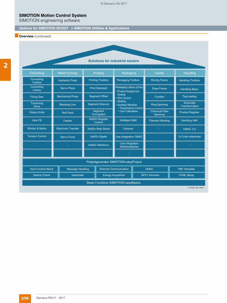
2/96 Siemens PM 21 · 2017
SIMOTION Motion Control SystemSIMOTION engineering software
Options for SIMOTION SCOUT > SIMOTION Utilities & Applications
2
■ Overview (continued)
Projectgenerator SIMOTION easyProject
HTML SetupDPV1 ServicesEnergy AcquisitionInterpreterStartup Check
HMI TemplateOMACEthernet Communication Message HandlingAxis Function Block
Basic Functions SIMOTION easyBasics
Handling
Solutions for industrial sectors
Winder & Splice
Tension Control
Axis FB
Rotary Knife
Traversing Drive
Flying Saw
Converting Library
Converting Toolbox
Hydraulic Press Handling Toolbox
Handling Basic
Product Register
Handling HMI
OMAC 3.0
G-Code Interpreter
TopLoading
Servo Press
Mechanical Press
Blanking Line
Roll Feed
Feeder
Electronic Transfer
Printing Toolbox Roving Frame
Filament Winding
Draw Frame
Comber
Ring Spinning
Packaging Toolbox
Intelligent Belt
Cartoner
…
…
…
…
……
Line Integration OMAC
Chemical Fiber Spinning
Line Integration Weihenstephan
Kinematic Transformation
Packaging Library (LPac)Product Supply and Dosing
Print Standard
Segment Offset
Segment Gravure
AddOn Reel Stand
AddOn Sigate
AddOn WebAccu
Segment Corrugated
AddOn Register Control
Servo Pump
TextilePackagingPrintingMetal FormingConverting
G_PM10_EN_00231
•
Film Control•Sealing•Auxiliary Modules•
Temperature Control•Cam Calculation•
© Siemens AG 2017
2/97Siemens PM 21 · 2017
SIMOTION Motion Control SystemSIMOTION engineering software
Ordering of engineering software, information
2
■ Overview
Scope of supply
SIMOTION SCOUT engineering software (including SCOUT TIA) • SIMOTION SCOUT/SCOUT TIA software• License for SIMOTION SCOUT/SCOUT TIA• Integrated STARTER commissioning tool
Optional packages for SIMOTION SCOUT• Optional CamTool package without license
The license must be ordered separately.• Optional Drive Control Chart (DCC) package without license
The license must be ordered separately; DCC cannot be used with SCOUT TIA (SIMOTION in the TIA Portal).
Documentation• Complete SIMOTION documentation on DVD
Other software• SIMOTION – Utilities & Applications
Free utilities (e.g. calculation tools, optimization tools, etc.) and application examples (ready-to-apply solutions such as winders, cross cutters or handling) as well as the project generator SIMOTION easyProject
• SIMATIC software: A suitable STEP 7 package or TIA Portal Framework must be purchased separately for use with SCOUT.The necessary components of STEP 7 for SIMOTION are integrated in SCOUT stand-alone.
SCOUT V4.5 in the STEP 7 environment (SIMATIC Manager)
Software requirements• Windows 7 Professional or Ultimate (32/64 bit)• SIMATIC STEP 7 V5.5 SP4
(not required for SCOUT stand-alone)
Hardware requirements
Minimum system requirements PG/PC for SCOUT:• As of Pentium V 1.5 GHz, 2 GB RAM (4 GB recommended)• Screen resolution: 1024 × 768 pixels, 16-bit color depth• Free hard disk memory: 3 GB
For an installation of WinCC flexible (ES) integrated in SCOUT, a main memory of 4 GB RAM is recommended.
Use of a programming device or a PC with conventional performance capacity is recommended for processing extensive SIMOTION projects with several modules:• PG or PC with Intel® CoreTM i5-3320M, 3.3 GHz or higher, or
a comparable device• Windows 7 64 bit, 8 GB RAM • Screen resolution: 1920 × 1080 pixels, 32-bit color depth
SCOUT TIA V4.5 (SIMOTION in the TIA Portal)
SCOUT TIA always requires that a TIA Portal Framework is installed beforehand using another TIA Portal client (such as: STEP 7, WinCC, Startdrive).
We recommend that the latest update for TIA Portal is always installed.
System requirements for SIMOTION SCOUT TIA V4.5
The system requirements of the TIA Portal or its client (e.g. STEP 7, WinCC, Startdrive) are applicable, because SCOUT TIA can only be installed in parallel with these.
Any deviating requirements are described in the currently valid readme file.
■ Selection and ordering data
Description Article No.
SIMOTION SCOUT software package Note
Licenses for SIMOTION SCOUT V4.4 are also valid for SIMOTION SCOUT V4.5.
For users with a V4.4 license, it is sufficient to order the software with a trial license.
The licenses can also be used for SCOUT TIA.
SCOUT V4.5 (DVD) On DVD, including SCOUT TIA, STARTER, runtime software and documentationLanguages: English, French, German, Italian• Single license incl. software 6AU1810-1BA45-0XA0• Upgrade incl. software 6AU1810-1BA45-0XE0• Software with trial license 6AU1810-1BA45-0XT7
SCOUT V4.5 (OSD) Online software delivery Email address required for delivery 1) • Single license; key for download 6AU1810-1BA44-0XH5• Upgrade; key for download 6AU1810-1BA44-0XK5• Software with trial license;
software for download6AU1810-1BA45-0XG7
SCOUT V4.5 stand-alone (DVD) On DVD, including SCOUT TIA, STARTER, runtime software and documentationLanguages: English, French, German, Italian• Single license incl. software 6AU1810-1CA45-0XA0• Upgrade incl. software 6AU1810-1CA45-0XE0• Software with trial license 6AU1810-1CA45-0XT7
SCOUT V4.5 stand-alone (OSD) Online software delivery Email address required for delivery 1) • Single license; key for download 6AU1810-1CA44-0XH5• Upgrade; key for download 6AU1810-1CA44-0XK5• Software with trial license;
software for download6AU1810-1CA45-0XG7
Software update serviceRequires latest software version• for SIMOTION SCOUT
(incl. SCOUT TIA)6AU1810-0BA00-0XL0
• for SIMOTION SCOUT stand-alone (incl. SCOUT TIA)
6AU1810-0CA00-0XL0
Optional packages for SIMOTION SCOUT
SIMOTION CamTool V3.0 SP3High-performance graphical cam editorLanguages: English, German• Single license,
with data storage medium6AU1810-0FA30-3XA0
• Upgrade, with data storage medium
6AU1810-0FA30-3XE0
DCC-SIMOTION/SINAMICS V2.4 for SCOUT V4.5 (not for: SCOUT TIA/SIMOTION in the TIA Portal)Graphical configuring with Drive Control ChartDCC editor + DCB libraries for use on SIMOTION and SINAMICS S120• Single engineering license 6AU1810-1JA24-0XA0• Upgrade 6AU1810-1JA24-0XE0
1) Up-to-date information and availability for download, see under: www.siemens.com/tia-online-software-delivery
© Siemens AG 2017
2/98 Siemens PM 21 · 2017
SIMOTION Motion Control SystemSIMOTION engineering software
Ordering of engineering software, information
2
■ More information
Important information about SCOUT, SCOUT stand-alone and SCOUT TIA:The following engineering packages are available to order:• SIMOTION SCOUT: this version can be used only if STEP 7
(SIMATIC Manager) is already installed• SIMOTION SCOUT stand-alone: this version can be used if
STEP 7 (SIMATIC MANAGER) is not installed.
Both delivery versions also include SIMOTION SCOUT TIA as an optional package for the TIA Portal.
The SCOUT license as well as the SCOUT stand-alone license is valid for SCOUT TIA.
SCOUT stand-alone also includes the components of STEP 7 that are required for SIMOTION SCOUT (SIMATIC CPUs cannot be programmed).
Users who switch over from SCOUT stand-alone to SCOUT (or vice versa) must install new software for the relevant SCOUT version and purchase a new license (the license for SCOUT and SCOUT stand-alone are different).
It is not possible to install SCOUT and SCOUT stand-alone "side by side" on the same PC.It is possible to install SCOUT TIA and SCOUT (or SCOUT stand-alone) "side by side" on the same PC if the software version is V4.4 or higher. Only one single SCOUT license is required for "side-by-side" installations.
Compatibility list ofsoftware products in the SIMOTION environment
A number of additional software products can be used in conjunction with SIMOTION SCOUT. It must be ensured that the corresponding versions of these software products are compatible. Please consult the Compatibility list of software products in the SIMOTION environment.
http://support.automation.siemens.com/WW/view/en/18857317
SIMOTION Kernel updates
SIMOTION Kernel updates for all SIMOTION platforms are supplied on SCOUT DVDs and can then be copied from the PG/PC to the SIMOTION Micro Memory Card (SIMOTION C) or SIMOTION CompactFlash card (SIMOTION D) or installed on SIMOTION P320-4.
A PC card adapter is needed to write to the SIMOTION MMC (Micro Memory Card) or the SIMOTION CF (CompactFlash card). Adapters can usually be found in PC shops and at electronics shops.
With the device update tool, SIMOTION offers a user-friendly solution to update SIMOTION devices. SIMOTION D4x5-2 can also be updated using a USB stick.
© Siemens AG 2017
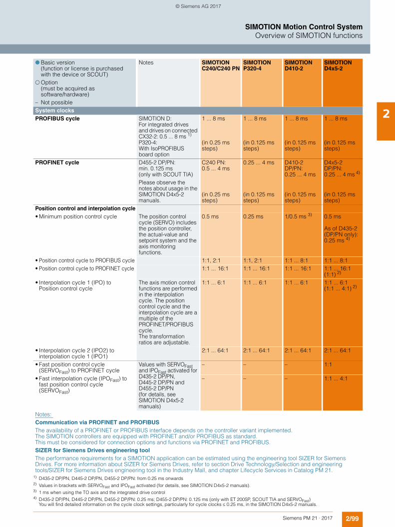
2/99Siemens PM 21 · 2017
SIMOTION Motion Control SystemOverview of SIMOTION functions
2
! Basic version (function or license is purchased with the device or SCOUT)
" Option (must be acquired as software/hardware)
– Not possible
Notes SIMOTION C240/C240 PN
SIMOTION P320-4
SIMOTION D410-2
SIMOTION D4x5-2
System clocks PROFIBUS cycle SIMOTION D:
For integrated drives and drives on connected CX32-2: 0.5 ... 8 ms 1) P320-4: With IsoPROFIBUS board option
1 ... 8 ms (in 0.25 ms steps)
1 ... 8 ms (in 0.125 ms steps)
1 ... 8 ms (in 0.125 ms steps)
1 ... 8 ms (in 0.125 ms steps)
PROFINET cycle D455-2 DP/PN:min. 0.125 ms(only with SCOUT TIA)Please observe the notes about usage in the SIMOTION D4x5-2 manuals.
C240 PN: 0.5 ... 4 ms
(in 0.25 ms steps)
0.25 ... 4 ms
(in 0.125 ms steps)
D410-2 DP/PN: 0.25 ... 4 ms(in 0.125 ms steps)
D4x5-2 DP/PN: 0.25 ... 4 ms 4) (in 0.125 ms steps)
Position control and interpolation cycle• Minimum position control cycle The position control
cycle (SERVO) includes the position controller, the actual-value and setpoint system and the axis monitoring functions.
0.5 ms 0.25 ms 1/0.5 ms 3) 0.5 ms As of D435-2 (DP/PN only):0.25 ms 4)
• Position control cycle to PROFIBUS cycle 1:1, 2:1 1:1, 2:1 1:1 ... 8:1 1:1 ... 8:1• Position control cycle to PROFINET cycle 1:1 ... 16:1 1:1 ... 16:1 1:1 ... 16:1 1:1 ... 16:1
(1:1) 2)
• Interpolation cycle 1 (IPO) to Position control cycle
The axis motion control functions are performed in the interpolation cycle. The position control cycle and the interpolation cycle are a multiple of the PROFINET/PROFIBUS cycle.The transformation ratios are adjustable.
1:1 ... 6:1 1:1 ... 6:1 1:1 ... 6:1 1:1 ... 6:1(1:1 ... 4:1) 2)
• Interpolation cycle 2 (IPO2) to interpolation cycle 1 (IPO1)
2:1 ... 64:1 2:1 ... 64:1 2:1 ... 64:1 2:1 ... 64:1
• Fast position control cycle (SERVOFast) to PROFINET cycle
Values with SERVOFast and IPOFast activated for D435-2 DP/PN, D445-2 DP/PN and D455-2 DP/PN (for details, see SIMOTION D4x5-2 manuals)
– – – 1:1
• Fast interpolation cycle (IPOFast) to fast position control cycle (SERVOFast)
– – – 1:1 ... 4:1
Notes: Communication via PROFINET and PROFIBUSThe availability of a PROFINET or PROFIBUS interface depends on the controller variant implemented. The SIMOTION controllers are equipped with PROFINET and/or PROFIBUS as standard. This must be considered for connection options and functions via PROFINET and PROFIBUS.SIZER for Siemens Drives engineering tool The performance requirements for a SIMOTION application can be estimated using the engineering tool SIZER for Siemens Drives. For more information about SIZER for Siemens Drives, refer to section Drive Technology/Selection and engineering tools/SIZER for Siemens Drives engineering tool in the Industry Mall, and chapter Lifecycle Services in Catalog PM 21.
1) D435-2 DP/PN, D445-2 DP/PN, D455-2 DP/PN: from 0.25 ms onwards2) Values in brackets with SERVOFast and IPOFast activated (for details, see SIMOTION D4x5-2 manuals).3) 1 ms when using the TO axis and the integrated drive control 4) D435-2 DP/PN, D445-2 DP/PN, D455-2 DP/PN: 0.25 ms; D455-2 DP/PN: 0.125 ms (only with ET 200SP, SCOUT TIA and SERVOFast)
You will find detailed information on the cycle clock settings, particularly for cycle clocks 0.25 ms, in the SIMOTION D4x5-2 manuals.
© Siemens AG 2017
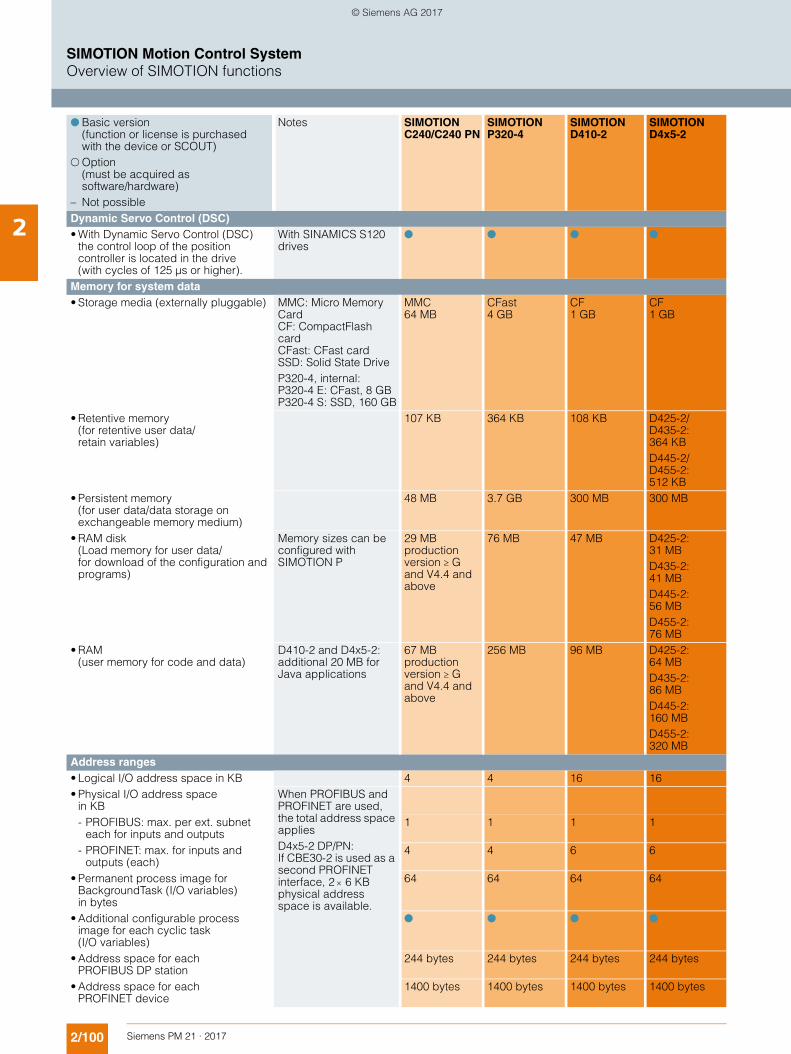
2/100 Siemens PM 21 · 2017
SIMOTION Motion Control SystemOverview of SIMOTION functions
2 Dynamic Servo Control (DSC) • With Dynamic Servo Control (DSC)
the control loop of the position controller is located in the drive (with cycles of 125 µs or higher).
With SINAMICS S120 drives
! ! ! !
Memory for system data • Storage media (externally pluggable) MMC: Micro Memory
Card CF: CompactFlash cardCFast: CFast card SSD: Solid State Drive P320-4, internal: P320-4 E: CFast, 8 GB P320-4 S: SSD, 160 GB
MMC64 MB
CFast 4 GB
CF1 GB
CF1 GB
• Retentive memory (for retentive user data/retain variables)
107 KB 364 KB 108 KB D425-2/D435-2: 364 KBD445-2/D455-2: 512 KB
• Persistent memory (for user data/data storage on exchangeable memory medium)
48 MB 3.7 GB 300 MB 300 MB
• RAM disk (Load memory for user data/for download of the configuration and programs)
Memory sizes can be configured with SIMOTION P
29 MB production version G and V4.4 and above
76 MB 47 MB D425-2:31 MBD435-2:41 MBD445-2:56 MBD455-2:76 MB
• RAM (user memory for code and data)
D410-2 and D4x5-2: additional 20 MB for Java applications
67 MB production version G and V4.4 and above
256 MB 96 MB D425-2:64 MBD435-2:86 MBD445-2:160 MBD455-2:320 MB
Address ranges • Logical I/O address space in KB 4 4 16 16• Physical I/O address space
in KBWhen PROFIBUS and PROFINET are used, the total address space applies D4x5-2 DP/PN: If CBE30-2 is used as a second PROFINET interface, 2 6 KB physical address space is available.
- PROFIBUS: max. per ext. subnet each for inputs and outputs
1 1 1 1
- PROFINET: max. for inputs and outputs (each)
4 4 6 6
• Permanent process image for BackgroundTask (I/O variables) in bytes
64 64 64 64
• Additional configurable process image for each cyclic task (I/O variables)
! ! ! !
• Address space for each PROFIBUS DP station
244 bytes 244 bytes 244 bytes 244 bytes
• Address space for each PROFINET device
1400 bytes 1400 bytes 1400 bytes 1400 bytes
! Basic version (function or license is purchased with the device or SCOUT)
" Option (must be acquired as software/hardware)
– Not possible
Notes SIMOTION C240/C240 PN
SIMOTION P320-4
SIMOTION D410-2
SIMOTION D4x5-2
© Siemens AG 2017
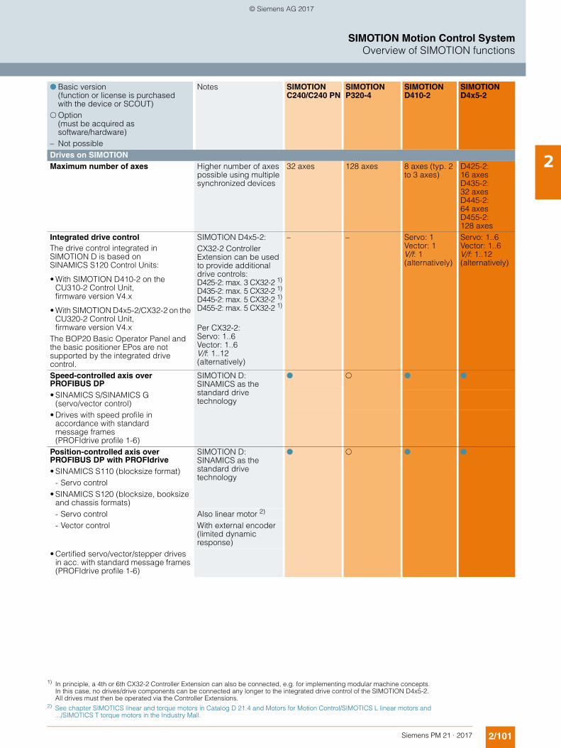
2/101Siemens PM 21 · 2017
SIMOTION Motion Control SystemOverview of SIMOTION functions
2Drives on SIMOTION Maximum number of axes Higher number of axes
possible using multiple synchronized devices
32 axes 128 axes 8 axes (typ. 2 to 3 axes)
D425-2: 16 axes D435-2: 32 axesD445-2: 64 axes D455-2: 128 axes
Integrated drive controlThe drive control integrated in SIMOTION D is based on SINAMICS S120 Control Units:
• With SIMOTION D410-2 on the CU310-2 Control Unit, firmware version V4.x
• With SIMOTION D4x5-2/CX32-2 on the CU320-2 Control Unit, firmware version V4.x
The BOP20 Basic Operator Panel and the basic positioner EPos are not supported by the integrated drive control.
SIMOTION D4x5-2: CX32-2 Controller Extension can be used to provide additional drive controls: D425-2: max. 3 CX32-2 1)
D435-2: max. 5 CX32-2 1)
D445-2: max. 5 CX32-2 1)
D455-2: max. 5 CX32-2 1)
Per CX32-2: Servo: 1..6 Vector: 1..6 V/f: 1..12 (alternatively)
– – Servo: 1Vector: 1V/f: 1 (alternatively)
Servo: 1..6Vector: 1..6V/f: 1..12 (alternatively)
Speed-controlled axis over PROFIBUS DP
SIMOTION D: SINAMICS as the standard drive technology
! " ! !
• SINAMICS S/SINAMICS G (servo/vector control)
• Drives with speed profile in accordance with standard message frames (PROFIdrive profile 1-6)
Position-controlled axis over PROFIBUS DP with PROFIdrive
SIMOTION D: SINAMICS as the standard drive technology
! " ! !
• SINAMICS S110 (blocksize format)- Servo control
• SINAMICS S120 (blocksize, booksize and chassis formats)- Servo control Also linear motor 2)
- Vector control With external encoder (limited dynamic response)
• Certified servo/vector/stepper drives in acc. with standard message frames (PROFIdrive profile 1-6)
! Basic version (function or license is purchased with the device or SCOUT)
" Option (must be acquired as software/hardware)
– Not possible
Notes SIMOTION C240/C240 PN
SIMOTION P320-4
SIMOTION D410-2
SIMOTION D4x5-2
1) In principle, a 4th or 6th CX32-2 Controller Extension can also be connected, e.g. for implementing modular machine concepts. In this case, no drives/drive components can be connected any longer to the integrated drive control of the SIMOTION D4x5-2. All drives must then be operated via the Controller Extensions.
2) See chapter SIMOTICS linear and torque motors in Catalog D 21.4 and Motors for Motion Control/SIMOTICS L linear motors and .../SIMOTICS T torque motors in the Industry Mall.
© Siemens AG 2017
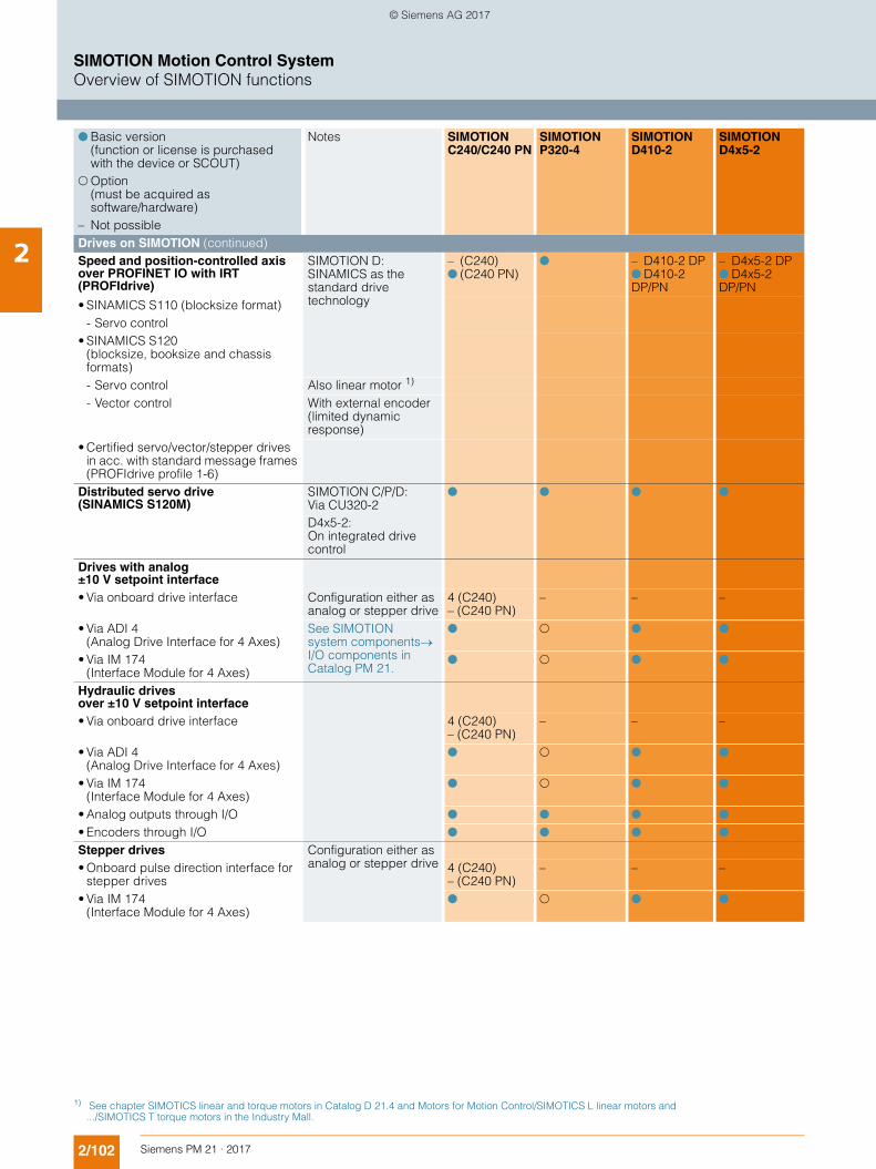
2/102 Siemens PM 21 · 2017
SIMOTION Motion Control SystemOverview of SIMOTION functions
2 Drives on SIMOTION (continued)Speed and position-controlled axis over PROFINET IO with IRT (PROFIdrive)
SIMOTION D: SINAMICS as the standard drive technology
– (C240)! (C240 PN)
! – D410-2 DP ! D410-2 DP/PN
– D4x5-2 DP ! D4x5-2 DP/PN
• SINAMICS S110 (blocksize format)- Servo control
• SINAMICS S120 (blocksize, booksize and chassis formats)- Servo control Also linear motor 1)
- Vector control With external encoder (limited dynamic response)
• Certified servo/vector/stepper drives in acc. with standard message frames (PROFIdrive profile 1-6)
Distributed servo drive (SINAMICS S120M)
SIMOTION C/P/D: Via CU320-2 D4x5-2: On integrated drive control
! ! ! !
Drives with analog ±10 V setpoint interface• Via onboard drive interface Configuration either as
analog or stepper drive4 (C240) – (C240 PN)
– – –
• Via ADI 4 (Analog Drive Interface for 4 Axes)
See SIMOTION system componentsI/O components in Catalog PM 21.
! " ! !
• Via IM 174 (Interface Module for 4 Axes)
! " ! !
Hydraulic drives over ±10 V setpoint interface• Via onboard drive interface 4 (C240)
– (C240 PN)– – –
• Via ADI 4 (Analog Drive Interface for 4 Axes)
! " ! !
• Via IM 174 (Interface Module for 4 Axes)
! " ! !
• Analog outputs through I/O ! ! ! !
• Encoders through I/O ! ! ! !
Stepper drives Configuration either as analog or stepper drive• Onboard pulse direction interface for
stepper drives4 (C240)– (C240 PN)
– – –
• Via IM 174 (Interface Module for 4 Axes)
! " ! !
! Basic version (function or license is purchased with the device or SCOUT)
" Option (must be acquired as software/hardware)
– Not possible
Notes SIMOTION C240/C240 PN
SIMOTION P320-4
SIMOTION D410-2
SIMOTION D4x5-2
1) See chapter SIMOTICS linear and torque motors in Catalog D 21.4 and Motors for Motion Control/SIMOTICS L linear motors and .../SIMOTICS T torque motors in the Industry Mall.
© Siemens AG 2017
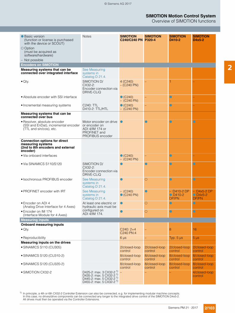
2/103Siemens PM 21 · 2017
SIMOTION Motion Control SystemOverview of SIMOTION functions
2Encoders on SIMOTION Measuring systems that can be connected over integrated interface
See Measuring systems in Catalog D 21.4.
• Qty. SIMOTION D/CX32-2:Encoder connection via DRIVE-CLiQ
4 (C240)– (C240 PN)
– 1 –
• Absolute encoder with SSI interface ! (C240) – (C240 PN)
– ! –
• Incremental measuring systems C240: TTL D410-2: TTL/HTL
! (C240) – (C240 PN)
– ! –
Measuring systems that can be connected over bus• Resolver, absolute encoder
(SSI and EnDat), incremental encoder (TTL and sin/cos), etc.
Motor encoder on drive or encoder on ADI 4/IM 174 or PROFINET and PROFIBUS encoder
! ! ! !
Connection options for direct measuring systems (2nd to 8th encoders and external encoder)• Via onboard interfaces ! (C240)
– (C240 PN)– ! –
• Via SINAMICS S110/S120 SIMOTION D/CX32-2:Encoder connection via DRIVE-CLiQ
! ! ! !
• Isochronous PROFIBUS encoder See Measuring systems in Catalog D 21.4.
! " ! !
• PROFINET encoder with IRT See Measuring systems in Catalog D 21.4.
– (C240) ! (C240 PN)
! – D410-2 DP ! D410-2 DP/PN
– D4x5-2 DP ! D4x5-2 DP/PN
• Encoder on ADI 4 (Analog Drive Interface for 4 Axes)
At least one electric or hydraulic axis must be configured on ADI 4/IM 174.
! " ! !
• Encoder on IM 174 (Interface Module for 4 Axes)
! " ! !
Measuring inputs Onboard measuring inputs• Qty. C240: 2+4
C240 PN:4– 8 16
• Reproducibility 6 µs – Typ. 5 µs 5 µsMeasuring inputs on the drives• SINAMICS S110 (CU305) 2/closed-loop
control2/closed-loop control
2/closed-loop control
2/closed-loop control
• SINAMICS S120 (CU310-2) 8/closed-loop control
8/closed-loop control
8/closed-loop control
8/closed-loop control
• SINAMICS S120 (CU320-2) 8/closed-loop control
8/closed-loop control
8/closed-loop control
8/closed-loop control
• SIMOTION CX32-2 D425-2: max. 3 CX32-2 1)
D435-2: max. 5 CX32-2 1)
D445-2: max. 5 CX32-2 1)
D455-2: max. 5 CX32-2 1)
– – – 4/closed-loop control
! Basic version (function or license is purchased with the device or SCOUT)
" Option (must be acquired as software/hardware)
– Not possible
Notes SIMOTION C240/C240 PN
SIMOTION P320-4
SIMOTION D410-2
SIMOTION D4x5-2
1) In principle, a 4th or 6th CX32-2 Controller Extension can also be connected, e.g. for implementing modular machine concepts. In this case, no drives/drive components can be connected any longer to the integrated drive control of the SIMOTION D4x5-2. All drives must then be operated via the Controller Extensions.
© Siemens AG 2017
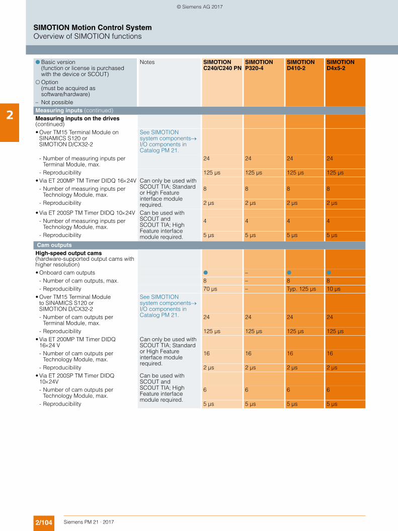
2/104 Siemens PM 21 · 2017
SIMOTION Motion Control SystemOverview of SIMOTION functions
2 Measuring inputs (continued) Measuring inputs on the drives (continued) • Over TM15 Terminal Module on
SINAMICS S120 or SIMOTION D/CX32-2
See SIMOTION system componentsI/O components in Catalog PM 21.
- Number of measuring inputs per Terminal Module, max.
24 24 24 24
- Reproducibility 125 µs 125 µs 125 µs 125 µs• Via ET 200MP TM Timer DIDQ 1624V Can only be used with
SCOUT TIA; Standard or High Feature interface module required.
- Number of measuring inputs per Technology Module, max.
8 8 8 8
- Reproducibility 2 µs 2 µs 2 µs 2 µs
• Via ET 200SP TM Timer DIDQ 1024V Can be used with SCOUT and SCOUT TIA; High Feature interface module required.
- Number of measuring inputs per Technology Module, max.
4 4 4 4
- Reproducibility 5 µs 5 µs 5 µs 5 µs
Cam outputs High-speed output cams(hardware-supported output cams with higher resolution)• Onboard cam outputs ! – ! !
- Number of cam outputs, max. 8 – 8 8- Reproducibility 70 µs – Typ. 125 µs 10 µs
• Over TM15 Terminal Module to SINAMICS S120 or SIMOTION D/CX32-2
See SIMOTION system components I/O components in Catalog PM 21.- Number of cam outputs per
Terminal Module, max.24 24 24 24
- Reproducibility 125 µs 125 µs 125 µs 125 µs• Via ET 200MP TM Timer DIDQ
1624 VCan only be used with SCOUT TIA; Standard or High Feature interface module required.
- Number of cam outputs per Technology Module, max.
16 16 16 16
- Reproducibility 2 µs 2 µs 2 µs 2 µs• Via ET 200SP TM Timer DIDQ
1024VCan be used with SCOUT and SCOUT TIA; High Feature interface module required.
- Number of cam outputs per Technology Module, max.
6 6 6 6
- Reproducibility 5 µs 5 µs 5 µs 5 µs
! Basic version (function or license is purchased with the device or SCOUT)
" Option (must be acquired as software/hardware)
– Not possible
Notes SIMOTION C240/C240 PN
SIMOTION P320-4
SIMOTION D410-2
SIMOTION D4x5-2
© Siemens AG 2017
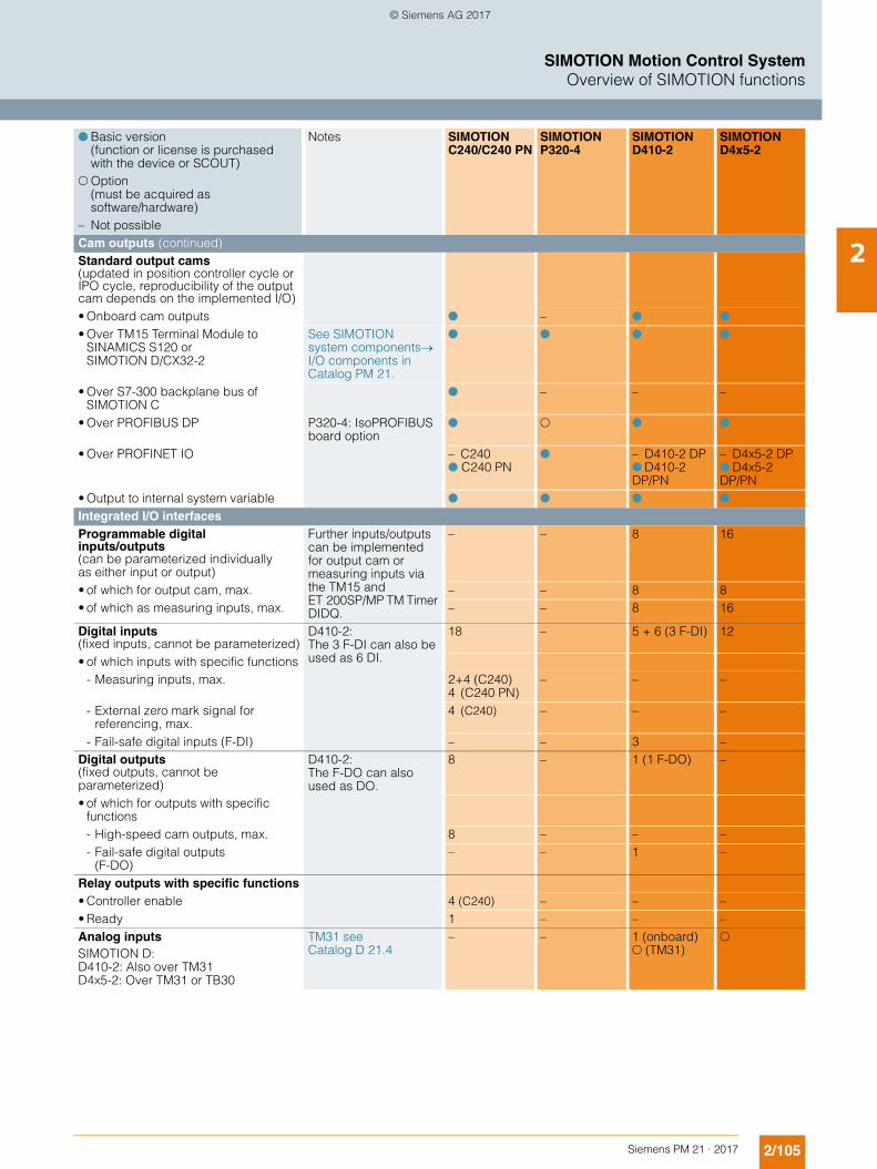
2/105Siemens PM 21 · 2017
SIMOTION Motion Control SystemOverview of SIMOTION functions
2Cam outputs (continued)Standard output cams (updated in position controller cycle or IPO cycle, reproducibility of the output cam depends on the implemented I/O)• Onboard cam outputs ! – ! ! • Over TM15 Terminal Module to
SINAMICS S120 or SIMOTION D/CX32-2
See SIMOTION system components I/O components in Catalog PM 21.
! ! ! !
• Over S7-300 backplane bus of SIMOTION C
! – – –
• Over PROFIBUS DP P320-4: IsoPROFIBUS board option
! " ! !
• Over PROFINET IO – C240 ! C240 PN
! – D410-2 DP ! D410-2 DP/PN
– D4x5-2 DP ! D4x5-2 DP/PN
• Output to internal system variable ! ! ! ! Integrated I/O interfaces Programmable digital inputs/outputs (can be parameterized individually as either input or output)
Further inputs/outputs can be implemented for output cam or measuring inputs via the TM15 and ET 200SP/MP TM Timer DIDQ.
– – 8 16
• of which for output cam, max. – – 8 8• of which as measuring inputs, max. – – 8 16
Digital inputs(fixed inputs, cannot be parameterized)
D410-2: The 3 F-DI can also be used as 6 DI.
18 – 5 + 6 (3 F-DI) 12
• of which inputs with specific functions- Measuring inputs, max. 2+4 (C240)
4 (C240 PN)– – –
- External zero mark signal for referencing, max.
4 (C240) – – –
- Fail-safe digital inputs (F-DI) – – 3 –Digital outputs(fixed outputs, cannot be parameterized)
D410-2: The F-DO can also used as DO.
8 – 1 (1 F-DO) –
• of which for outputs with specific functions- High-speed cam outputs, max. 8 – – –- Fail-safe digital outputs
(F-DO) – – 1 –
Relay outputs with specific functions• Controller enable 4 (C240) – – –• Ready 1 – – –Analog inputs SIMOTION D: D410-2: Also over TM31 D4x5-2: Over TM31 or TB30
TM31 seeCatalog D 21.4
– – 1 (onboard) " (TM31)
"
! Basic version (function or license is purchased with the device or SCOUT)
" Option (must be acquired as software/hardware)
– Not possible
Notes SIMOTION C240/C240 PN
SIMOTION P320-4
SIMOTION D410-2
SIMOTION D4x5-2
© Siemens AG 2017
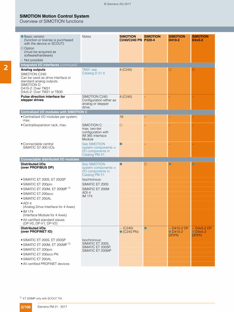
2/106 Siemens PM 21 · 2017
SIMOTION Motion Control SystemOverview of SIMOTION functions
2 Integrated I/O interfaces (continued) Analog outputs SIMOTION C240: Can be used as drive interface or standard analog outputs. SIMOTION D: D410-2: Over TM31 D4x5-2: Over TM31 or TB30
TM31 seeCatalog D 21.4
4 (C240) – " "
Pulse direction interface for stepper drives
SIMOTION C240:Configuration either as analog or stepper drive.
4 (C240) – – –
Centralized I/O modules with SIMOTION C • Centralized I/O modules per system,
max.16 – – –
• Central/expansion rack, max. SIMOTION C: max. two-tier configuration with IM 365 Interface Module
" – – –
• Connectable central SIMATIC S7-300 I/Os
See SIMOTION system componentsI/O components in Catalog PM 21.
! – – –
Connectable distributed I/O modules Distributed I/Os (over PROFIBUS DP)
See SIMOTION system components I/O components in Catalog PM 21.
! " ! !
• SIMATIC ET 200S, ET 200SP Isochronous: • SIMATIC ET 200pro SIMATIC ET 200S• SIMATIC ET 200M, ET 200MP 1) SIMATIC ET 200M
ADI 4 IM 174
• SIMATIC ET 200eco• SIMATIC ET 200AL• ADI 4
(Analog Drive Interface for 4 Axes)• IM 174
(Interface Module for 4 Axes)• All certified standard slaves
(DP-V0, DP-V1, DP-V2)Distributed I/Os (over PROFINET IO)
– (C240)! (C240 PN)
! – D410-2 DP ! D410-2 DP/PN
– D4x5-2 DP ! D4x5-2 DP/PN
• SIMATIC ET 200S, ET 200SP Isochronous: SIMATIC ET 200S, SIMATIC ET 200SP, SIMATIC ET 200MP
• SIMATIC ET 200M, ET 200MP 1) • SIMATIC ET 200pro• SIMATIC ET 200eco PN• SIMATIC ET 200AL• All certified PROFINET devices
! Basic version (function or license is purchased with the device or SCOUT)
" Option (must be acquired as software/hardware)
– Not possible
Notes SIMOTION C240/C240 PN
SIMOTION P320-4
SIMOTION D410-2
SIMOTION D4x5-2
1) ET 200MP only with SCOUT TIA.
© Siemens AG 2017
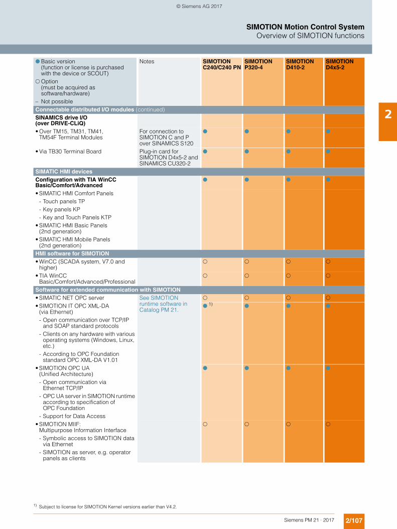
2/107Siemens PM 21 · 2017
SIMOTION Motion Control SystemOverview of SIMOTION functions
2Connectable distributed I/O modules (continued)SINAMICS drive I/O (over DRIVE-CLiQ)• Over TM15, TM31, TM41,
TM54F Terminal ModulesFor connection to SIMOTION C and P over SINAMICS S120
! ! ! !
• Via TB30 Terminal Board Plug-in card forSIMOTION D4x5-2 and SINAMICS CU320-2
! ! ! !
SIMATIC HMI devices Configuration with TIA WinCC Basic/Comfort/Advanced
! ! ! !
• SIMATIC HMI Comfort Panels - Touch panels TP - Key panels KP - Key and Touch Panels KTP
• SIMATIC HMI Basic Panels (2nd generation)
• SIMATIC HMI Mobile Panels (2nd generation)
HMI software for SIMOTION • WinCC (SCADA system, V7.0 and
higher) " " " "
• TIA WinCC Basic/Comfort/Advanced/Professional
" " " "
Software for extended communication with SIMOTION • SIMATIC NET OPC server See SIMOTION
runtime software in Catalog PM 21.
" " " " • SIMOTION IT OPC XML-DA
(via Ethernet)- Open communication over TCP/IP
and SOAP standard protocols- Clients on any hardware with various
operating systems (Windows, Linux, etc.)
- According to OPC Foundation standard OPC XML-DA V1.01
! 1)
! ! !
• SIMOTION OPC UA(Unified Architecture)- Open communication via
Ethernet TCP/IP- OPC UA server in SIMOTION runtime
according to specification of OPC Foundation
- Support for Data Access
! ! ! !
• SIMOTION MIIF: Multipurpose Information Interface- Symbolic access to SIMOTION data
via Ethernet- SIMOTION as server, e.g. operator
panels as clients
" " " "
! Basic version (function or license is purchased with the device or SCOUT)
" Option (must be acquired as software/hardware)
– Not possible
Notes SIMOTION C240/C240 PN
SIMOTION P320-4
SIMOTION D410-2
SIMOTION D4x5-2
1) Subject to license for SIMOTION Kernel versions earlier than V4.2.
© Siemens AG 2017
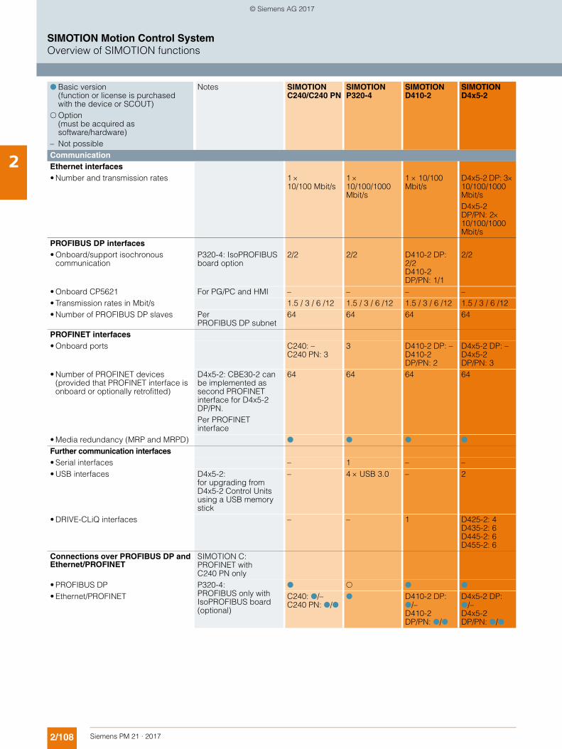
2/108 Siemens PM 21 · 2017
SIMOTION Motion Control SystemOverview of SIMOTION functions
2 Communication Ethernet interfaces• Number and transmission rates 1
10/100 Mbit/s110/100/1000 Mbit/s
1 10/100 Mbit/s
D4x5-2 DP: 310/100/1000 Mbit/sD4x5-2 DP/PN: 210/100/1000 Mbit/s
PROFIBUS DP interfaces• Onboard/support isochronous
communicationP320-4: IsoPROFIBUS board option
2/2 2/2 D410-2 DP: 2/2 D410-2 DP/PN: 1/1
2/2
• Onboard CP5621 For PG/PC and HMI – – – –• Transmission rates in Mbit/s 1.5 / 3 / 6 /12 1.5 / 3 / 6 /12 1.5 / 3 / 6 /12 1.5 / 3 / 6 /12• Number of PROFIBUS DP slaves Per
PROFIBUS DP subnet64 64 64 64
PROFINET interfaces• Onboard ports C240: –
C240 PN: 33 D410-2 DP: –
D410-2 DP/PN: 2
D4x5-2 DP: –D4x5-2 DP/PN: 3
• Number of PROFINET devices (provided that PROFINET interface is onboard or optionally retrofitted)
D4x5-2: CBE30-2 can be implemented as second PROFINET interface for D4x5-2 DP/PN.Per PROFINET interface
64 64 64 64
• Media redundancy (MRP and MRPD) ! ! ! ! Further communication interfaces• Serial interfaces – 1 – –• USB interfaces D4x5-2:
for upgrading from D4x5-2 Control Units using a USB memory stick
– 4 USB 3.0 – 2
• DRIVE-CLiQ interfaces – – 1 D425-2: 4 D435-2: 6 D445-2: 6 D455-2: 6
Connections over PROFIBUS DP and Ethernet/PROFINET
SIMOTION C: PROFINET with C240 PN only
• PROFIBUS DP P320-4: PROFIBUS only with IsoPROFIBUS board (optional)
! " ! ! • Ethernet/PROFINET C240: !/–
C240 PN: !/!! D410-2 DP:
!/–D410-2 DP/PN: !/!
D4x5-2 DP: !/–D4x5-2 DP/PN: !/!
! Basic version (function or license is purchased with the device or SCOUT)
" Option (must be acquired as software/hardware)
– Not possible
Notes SIMOTION C240/C240 PN
SIMOTION P320-4
SIMOTION D410-2
SIMOTION D4x5-2
© Siemens AG 2017
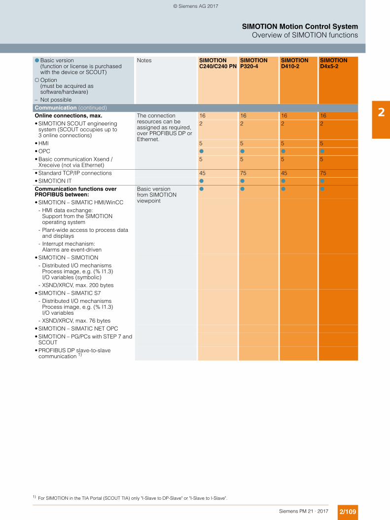
2/109Siemens PM 21 · 2017
SIMOTION Motion Control SystemOverview of SIMOTION functions
2Communication (continued)Online connections, max. The connection
resources can be assigned as required, over PROFIBUS DP or Ethernet.
16 16 16 16• SIMOTION SCOUT engineering
system (SCOUT occupies up to 3 online connections)
2 2 2 2
• HMI 5 5 5 5• OPC ! ! ! ! • Basic communication Xsend /
Xreceive (not via Ethernet)5 5 5 5
• Standard TCP/IP connections 45 75 45 75• SIMOTION IT ! ! ! ! Communication functions over PROFIBUS between:
Basic version from SIMOTION viewpoint
! ! ! !
• SIMOTION – SIMATIC HMI/WinCC - HMI data exchange:
Support from the SIMOTION operating system
- Plant-wide access to process data and displays
- Interrupt mechanism: Alarms are event-driven
• SIMOTION – SIMOTION- Distributed I/O mechanisms
Process image, e.g. (% I1.3) I/O variables (symbolic)
- XSND/XRCV, max. 200 bytes• SIMOTION – SIMATIC S7
- Distributed I/O mechanisms Process image, e.g. (% I1.3) I/O variables
- XSND/XRCV, max. 76 bytes• SIMOTION – SIMATIC NET OPC• SIMOTION – PG/PCs with STEP 7 and
SCOUT• PROFIBUS DP slave-to-slave
communication 1)
! Basic version (function or license is purchased with the device or SCOUT)
" Option (must be acquired as software/hardware)
– Not possible
Notes SIMOTION C240/C240 PN
SIMOTION P320-4
SIMOTION D410-2
SIMOTION D4x5-2
1) For SIMOTION in the TIA Portal (SCOUT TIA) only "I-Slave to DP-Slave" or "I-Slave to I-Slave".
© Siemens AG 2017
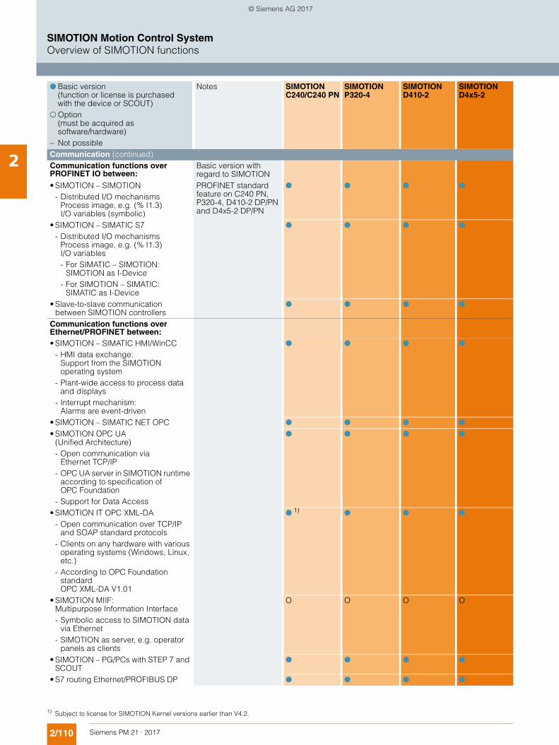
2/110 Siemens PM 21 · 2017
SIMOTION Motion Control SystemOverview of SIMOTION functions
2 Communication (continued)Communication functions over PROFINET IO between:
Basic version with regard to SIMOTION
• SIMOTION – SIMOTION- Distributed I/O mechanisms
Process image, e.g. (% I1.3)I/O variables (symbolic)
PROFINET standard feature on C240 PN, P320-4, D410-2 DP/PN and D4x5-2 DP/PN
! ! ! !
• SIMOTION – SIMATIC S7- Distributed I/O mechanisms
Process image, e.g. (% I1.3)I/O variables- For SIMATIC – SIMOTION:
SIMOTION as I-Device- For SIMOTION – SIMATIC:
SIMATIC as I-Device
! ! ! !
• Slave-to-slave communication between SIMOTION controllers
! ! ! !
Communication functions over Ethernet/PROFINET between:• SIMOTION – SIMATIC HMI/WinCC
- HMI data exchange: Support from the SIMOTION operating system
- Plant-wide access to process data and displays
- Interrupt mechanism: Alarms are event-driven
! ! ! !
• SIMOTION – SIMATIC NET OPC ! ! ! ! • SIMOTION OPC UA
(Unified Architecture)- Open communication via
Ethernet TCP/IP- OPC UA server in SIMOTION runtime
according to specification of OPC Foundation
- Support for Data Access
! ! ! !
• SIMOTION IT OPC XML-DA - Open communication over TCP/IP
and SOAP standard protocols- Clients on any hardware with various
operating systems (Windows, Linux, etc.)
- According to OPC Foundation standard OPC XML-DA V1.01
! 1)
! ! !
• SIMOTION MIIF: Multipurpose Information Interface- Symbolic access to SIMOTION data
via Ethernet- SIMOTION as server, e.g. operator
panels as clients
O O O O
• SIMOTION – PG/PCs with STEP 7 and SCOUT
! ! ! !
• S7 routing Ethernet/PROFIBUS DP ! ! ! !
! Basic version (function or license is purchased with the device or SCOUT)
" Option (must be acquired as software/hardware)
– Not possible
Notes SIMOTION C240/C240 PN
SIMOTION P320-4
SIMOTION D410-2
SIMOTION D4x5-2
1) Subject to license for SIMOTION Kernel versions earlier than V4.2.
© Siemens AG 2017
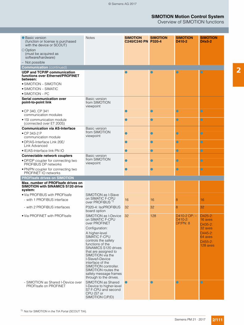
2/111Siemens PM 21 · 2017
SIMOTION Motion Control SystemOverview of SIMOTION functions
2Communication (continued)UDP and TCP/IP communication functions over Ethernet/PROFINET between:• SIMOTION – SIMOTION• SIMOTION – SIMATIC• SIMOTION – PC
! ! ! !
Serial communication over point-to-point link
Basic version from SIMOTION viewpoint
• CP 340, CP 341 communication modules
! ! ! !
• 1SI communication module (connected over ET 200S)
! ! ! !
Communication via AS-Interface Basic version from SIMOTION viewpoint
• CP 343-2 P communication module
! ! ! !
• DP/AS-Interface Link 20E/Link Advanced
! ! ! !
• IE/AS-Interface link PN IO ! ! ! !
Connectable network couplers Basic version from SIMOTION viewpoint
• DP/DP coupler for connecting two PROFIBUS DP networks
! ! ! !
• PN/PN coupler for connecting two PROFINET IO networks
! ! ! !
PROFIsafe drives on SIMOTION Max. number of PROFIsafe drives on SIMOTION with SINAMICS S120 drive system:• Via PROFIBUS with PROFIsafe
- with 1 PROFIBUS interfaceSIMOTION as I-Slave on SIMATIC F-CPU over PROFIBUS 1)
16 16 8 16
- with 2 PROFIBUS interfaces P320-4: IsoPROFIBUS board option
32 32 8 32
• Via PROFINET with PROFIsafe SIMOTION as I-Device on SIMATIC F-CPU over PROFINETConfiguration:A higher-levelSIMATIC F-CPU controls the safety functions of the SINAMICS S120 drives that are assigned to SIMOTION via the I-Slave/I-Device interface of the SIMOTION controller.SIMOTION routes the safety message frames through to the drives.
32 128 D410-2 DP: –D410-2: DP/PN: 8
D425-2:16 axesD435-2:32 axesD445-2:64 axes D455-2:128 axes
- SIMOTION as Shared I-Device over PROFIsafe on PROFINET
SIMOTION as Shared I-Device to higher-level S7 F-CPU and second CPU (S7 or SIMOTION C/P/D)
! ! ! !
! Basic version (function or license is purchased with the device or SCOUT)
" Option (must be acquired as software/hardware)
– Not possible
Notes SIMOTION C240/C240 PN
SIMOTION P320-4
SIMOTION D410-2
SIMOTION D4x5-2
1) Not for SIMOTION in the TIA Portal (SCOUT TIA).
© Siemens AG 2017
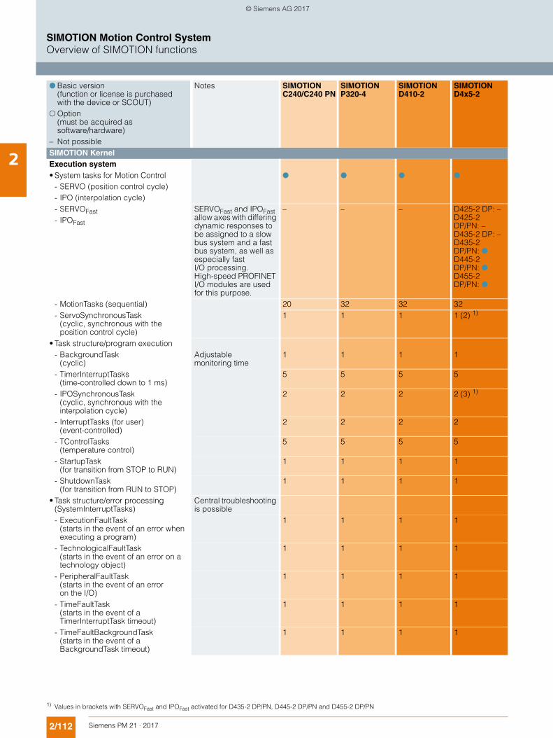
2/112 Siemens PM 21 · 2017
SIMOTION Motion Control SystemOverview of SIMOTION functions
2 SIMOTION Kernel Execution system• System tasks for Motion Control
- SERVO (position control cycle)- IPO (interpolation cycle)
! ! ! !
- SERVOFast- IPOFast
SERVOFast and IPOFast allow axes with differing dynamic responses to be assigned to a slow bus system and a fast bus system, as well as especially fast I/O processing.High-speed PROFINET I/O modules are used for this purpose.
– – – D425-2 DP: – D425-2 DP/PN: – D435-2 DP: – D435-2 DP/PN: ! D445-2 DP/PN: ! D455-2 DP/PN: !
- MotionTasks (sequential) 20 32 32 32- ServoSynchronousTask
(cyclic, synchronous with the position control cycle)
1 1 1 1 (2) 1)
• Task structure/program execution- BackgroundTask
(cyclic)Adjustable monitoring time
1 1 1 1
- TimerInterruptTasks (time-controlled down to 1 ms)
5 5 5 5
- IPOSynchronousTask (cyclic, synchronous with the interpolation cycle)
2 2 2 2 (3) 1)
- InterruptTasks (for user) (event-controlled)
2 2 2 2
- TControlTasks (temperature control)
5 5 5 5
- StartupTask (for transition from STOP to RUN)
1 1 1 1
- ShutdownTask (for transition from RUN to STOP)
1 1 1 1
• Task structure/error processing(SystemInterruptTasks)
Central troubleshooting is possible
- ExecutionFaultTask (starts in the event of an error when executing a program)
1 1 1 1
- TechnologicalFaultTask (starts in the event of an error on a technology object)
1 1 1 1
- PeripheralFaultTask (starts in the event of an error on the I/O)
1 1 1 1
- TimeFaultTask (starts in the event of a TimerInterruptTask timeout)
1 1 1 1
- TimeFaultBackgroundTask(starts in the event of a BackgroundTask timeout)
1 1 1 1
! Basic version (function or license is purchased with the device or SCOUT)
" Option (must be acquired as software/hardware)
– Not possible
Notes SIMOTION C240/C240 PN
SIMOTION P320-4
SIMOTION D410-2
SIMOTION D4x5-2
1) Values in brackets with SERVOFast and IPOFast activated for D435-2 DP/PN, D445-2 DP/PN and D455-2 DP/PN
© Siemens AG 2017
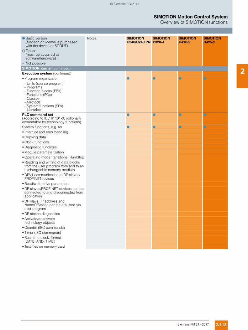
2/113Siemens PM 21 · 2017
SIMOTION Motion Control SystemOverview of SIMOTION functions
2SIMOTION Kernel (continued) Execution system (continued) • Program organization ! ! ! !
- Units (source program)- Programs- Function blocks (FBs)- Functions (FCs)- Classes- Methods- System functions (SFs)- Libraries
PLC command set(according to IEC 61131-3; optionally expandable by technology functions)
! ! ! !
System functions, e.g. for ! ! ! ! • Interrupt and error handling• Copying data• Clock functions• Diagnostic functions• Module parameterization• Operating mode transitions, Run/Stop• Reading and writing of data blocks
from the user program from and to an exchangeable memory medium
• DPV1 communication to DP slaves/PROFINETdevices
• Read/write drive parameters• DP slaves/PROFINET devices can be
connected to and disconnected from application
• DP slave, IP address and NameOfStation can be adjusted via user program
• DP station diagnostics• Activate/deactivate
technology objects• Counter (IEC commands)• Timer (IEC commands)• Real-time clock, format
[DATE_AND_TIME]• Text files on memory card
! Basic version (function or license is purchased with the device or SCOUT)
" Option (must be acquired as software/hardware)
– Not possible
Notes SIMOTION C240/C240 PN
SIMOTION P320-4
SIMOTION D410-2
SIMOTION D4x5-2
© Siemens AG 2017
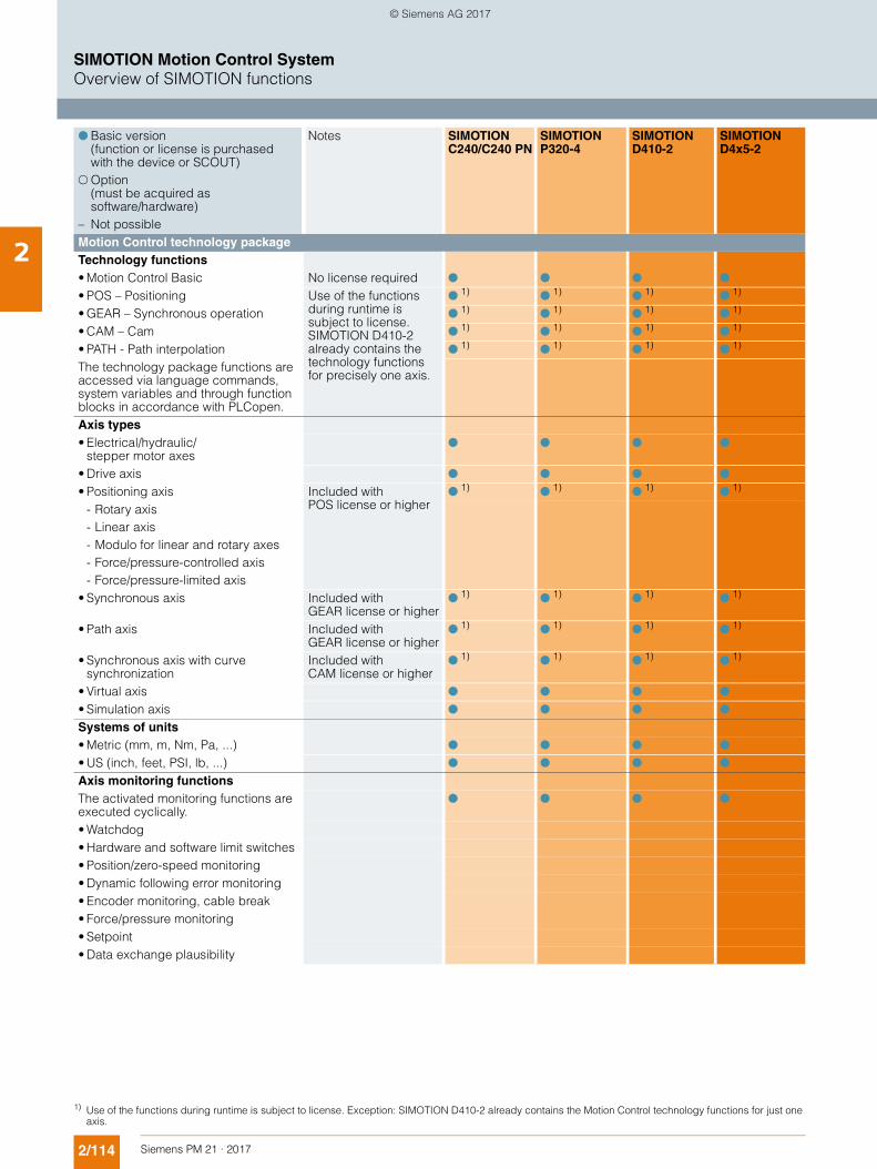
2/114 Siemens PM 21 · 2017
SIMOTION Motion Control SystemOverview of SIMOTION functions
2 Motion Control technology package Technology functions• Motion Control Basic No license required ! ! ! ! • POS – Positioning Use of the functions
during runtime is subject to license. SIMOTION D410-2 already contains the technology functions for precisely one axis.
! 1)
! 1)
! 1)
! 1)
• GEAR – Synchronous operation ! 1)
! 1)
! 1)
! 1)
• CAM – Cam ! 1)
! 1)
! 1)
! 1)
• PATH - Path interpolation ! 1)
! 1)
! 1)
! 1)
The technology package functions are accessed via language commands, system variables and through function blocks in accordance with PLCopen.Axis types• Electrical/hydraulic/
stepper motor axes! ! ! !
• Drive axis ! ! ! ! • Positioning axis Included with
POS license or higher!
1)!
1)!
1)!
1)
- Rotary axis- Linear axis- Modulo for linear and rotary axes- Force/pressure-controlled axis- Force/pressure-limited axis
• Synchronous axis Included with GEAR license or higher
! 1)
! 1)
! 1)
! 1)
• Path axis Included with GEAR license or higher
! 1)
! 1)
! 1)
! 1)
• Synchronous axis with curve synchronization
Included with CAM license or higher
! 1)
! 1)
! 1)
! 1)
• Virtual axis ! ! ! ! • Simulation axis ! ! ! ! Systems of units• Metric (mm, m, Nm, Pa, ...) ! ! ! ! • US (inch, feet, PSI, lb, ...) ! ! ! ! Axis monitoring functionsThe activated monitoring functions are executed cyclically.
! ! ! !
• Watchdog• Hardware and software limit switches• Position/zero-speed monitoring• Dynamic following error monitoring• Encoder monitoring, cable break• Force/pressure monitoring• Setpoint• Data exchange plausibility
! Basic version (function or license is purchased with the device or SCOUT)
" Option (must be acquired as software/hardware)
– Not possible
Notes SIMOTION C240/C240 PN
SIMOTION P320-4
SIMOTION D410-2
SIMOTION D4x5-2
1) Use of the functions during runtime is subject to license. Exception: SIMOTION D410-2 already contains the Motion Control technology functions for just one axis.
© Siemens AG 2017
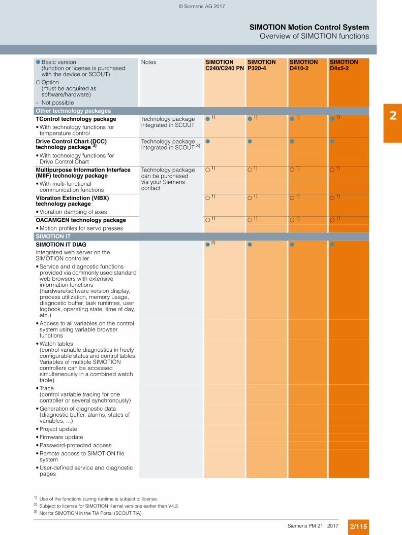
2/115Siemens PM 21 · 2017
SIMOTION Motion Control SystemOverview of SIMOTION functions
2Other technology packages TControl technology package Technology package
integrated in SCOUT!
1)!
1)!
1)!
1)
• With technology functions for temperature control
Drive Control Chart (DCC) technology package 3)
Technology package integrated in SCOUT 3)
! ! ! !
• With technology functions for Drive Control Chart
Multipurpose Information Interface (MIIF) technology package
Technology package can be purchased via your Siemens contact
" 1)
" 1)
" 1)
" 1)
• With multi-functional communication functions
Vibration Extinction (VIBX) technology package
" 1)
" 1)
" 1)
" 1)
• Vibration damping of axesOACAMGEN technology package "
1)"
1)"
1) "
1)
• Motion profiles for servo pressesSIMOTION IT SIMOTION IT DIAGIntegrated web server on the SIMOTION controller
! 2)
! ! !
• Service and diagnostic functions provided via commonly used standard web browsers with extensive information functions (hardware/software version display, process utilization, memory usage, diagnostic buffer, task runtimes, user logbook, operating state, time of day, etc.)
• Access to all variables on the control system using variable browser functions
• Watch tables(control variable diagnostics in freely configurable status and control tables. Variables of multiple SIMOTION controllers can be accessed simultaneously in a combined watch table)
• Trace (control variable tracing for one controller or several synchronously)
• Generation of diagnostic data (diagnostic buffer, alarms, states of variables, ...)
• Project update• Firmware update• Password-protected access• Remote access to SIMOTION file
system• User-defined service and diagnostic
pages
! Basic version (function or license is purchased with the device or SCOUT)
" Option (must be acquired as software/hardware)
– Not possible
Notes SIMOTION C240/C240 PN
SIMOTION P320-4
SIMOTION D410-2
SIMOTION D4x5-2
1) Use of the functions during runtime is subject to license.2) Subject to license for SIMOTION Kernel versions earlier than V4.2.3) Not for SIMOTION in the TIA Portal (SCOUT TIA).
© Siemens AG 2017
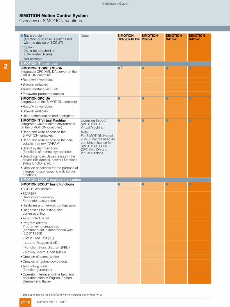
2/116 Siemens PM 21 · 2017
SIMOTION Motion Control SystemOverview of SIMOTION functions
2 SIMOTION IT (continued)SIMOTION IT OPC XML-DAIntegrated OPC XML-DA server on the SIMOTION controller
! 1)
! ! !
• Read/write variables• Browse variables• Trace interface via SOAP• Password-protected accessSIMOTION OPC UAIntegrated on the SIMOTION controller
! ! ! !
• Read/write variables• Browse variables• User authentication and encryptionSIMOTION IT Virtual Machine (integrated Java runtime environment on the SIMOTION controller)• Read and write access to the
SIMOTION variables • Read and write access to the non-
volatile memory (NVRAM)• Use of system functions
(functions of technology objects)• Use of standard Java classes in the
device (file access, network functions, string functions, etc.)
• Creation of servlets for the purpose of integrating user-specific web server functions
Licensing through SIMOTION IT Virtual MachineNote:For SIMOTION Kernel < V4.2, can be used as combined license for SIMOTION IT DIAG, OPC XML-DA and Virtual Machine.
! ! ! !
SIMOTION SCOUT engineering system SIMOTION SCOUT basic functions ! ! ! ! • SCOUT Workbench• STARTER
Drive commissioning/Parameter assignment
• Hardware and network configuration• Diagnostics for testing and
commissioning• Axis control panel• Program editors/
Programming languages (command set in accordance with IEC 61131-3)- Structured Text (ST)- Ladder Diagram (LAD)- Function Block Diagram (FBD)- Motion Control Chart (MCC)
• Creation of cams (basic)• Creation of technology objects• Technology tools
(function generator)• Operator interface, online help and
documentation in English, French, German and Italian
! Basic version (function or license is purchased with the device or SCOUT)
" Option (must be acquired as software/hardware)
– Not possible
Notes SIMOTION C240/C240 PN
SIMOTION P320-4
SIMOTION D410-2
SIMOTION D4x5-2
1) Subject to license for SIMOTION Kernel versions earlier than V4.2.
© Siemens AG 2017
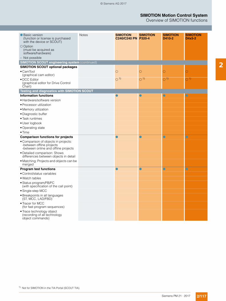
2/117Siemens PM 21 · 2017
SIMOTION Motion Control SystemOverview of SIMOTION functions
2SIMOTION SCOUT engineering system (continued)SIMOTION SCOUT optional packages• CamTool
(graphical cam editor)" " " "
• DCC Editor (graphical editor for Drive Control Chart)
" 1)
" 1)
" 1)
" 1)
Testing and diagnostics with SIMOTION SCOUT Information functions ! ! ! ! • Hardware/software version• Processor utilization• Memory utilization• Diagnostic buffer• Task runtimes• User logbook• Operating state• TimeComparison functions for projects ! ! ! ! • Comparison of objects in projects:
-between offline projects-between online and offline projects
• Detailed comparison: Shows differences between objects in detail
• Matching: Projects and objects can be merged
Program test functions ! ! ! ! • Control/status variables• Watch tables• Status program/FB/FC
(with specification of the call point)• Single-step MCC• Breakpoints in all languages
(ST, MCC, LAD/FBD)• Tracer for MCC
(for fast program sequences)• Trace technology object
(recording of all technologyobject commands)
! Basic version (function or license is purchased with the device or SCOUT)
" Option (must be acquired as software/hardware)
– Not possible
Notes SIMOTION C240/C240 PN
SIMOTION P320-4
SIMOTION D410-2
SIMOTION D4x5-2
1) Not for SIMOTION in the TIA Portal (SCOUT TIA).
© Siemens AG 2017
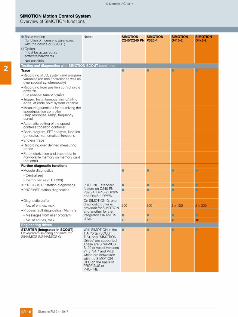
2/118 Siemens PM 21 · 2017
SIMOTION Motion Control SystemOverview of SIMOTION functions
2 Testing and diagnostics with SIMOTION SCOUT (continued)Trace ! ! ! ! • Recording of I/O, system and program
variables (on one controller as well as over several synchronously)
• Recording from position control cycle onwards (n position control cycle)
• Trigger: Instantaneous, rising/falling edge, at code point system variable
• Measuring functions for optimizing the speed/position controller (step response, ramp, frequency curve)
• Automatic setting of the speed controller/position controller
• Bode diagram, FFT analysis, function generator, mathematical functions
• Endless trace• Recording over defined measuring
period• Parameterization and trace data in
non-volatile memory on memory card (optional)
Further diagnostic functions• Module diagnostics ! ! ! !
- Centralized- Distributed (e.g. ET 200)
• PROFIBUS DP station diagnostics PROFINET standard feature on C240 PN, P320-4, D410-2 DP/PN and D4x5-2 DP/PN
! ! ! ! • PROFINET station diagnostics ! ! ! !
• Diagnostic buffer On SIMOTION D, one diagnostic buffer is provided for SIMOTION and another for the integrated SINAMICS drive.
- No. of entries, max. 200 200 2 100 2 200• Process fault diagnostics (Alarm_S)
- Messages from user program ! ! ! ! - No. of entries, max. 40 40 40 40
Engineering drives STARTER (integrated in SCOUT)Drive/commissioning software for SINAMICS S/SINAMICS G
With SIMOTION in the TIA Portal (SCOUT TIA), only "SIMOTION Drives" are supported. These are SINAMICS S120 drives of versions V4.5, V4.7 and V4.8, which are networked with the SIMOTION CPU on the basis of PROFIBUS or PROFINET.
! ! ! !
! Basic version (function or license is purchased with the device or SCOUT)
" Option (must be acquired as software/hardware)
– Not possible
Notes SIMOTION C240/C240 PN
SIMOTION P320-4
SIMOTION D410-2
SIMOTION D4x5-2
© Siemens AG 2017
Siemens PM 21 · 2017
33.1/1 HMI devices
3.2/1 I/O components
3.3/1 Power supplies
3.4/1 Drives
3.5/1 Motors
3.6/1 Connection systems
3.7/1 Measuring systems
SIMOTION system components
© Siemens AG 2017

3/2 Siemens PM 21 · 2017
SIMOTION system components
Notes
3
© Siemens AG 2017
Siemens PM 21 · 2017
3.13.1/2 Introduction3.1/2 Overview3.1/2 SIMATIC HMI devices for Motion Control3.1/3 Configuration at a glance3.1/4 Overview of the SIMATIC Panels for
SIMOTION
3.1/5 Key Panels3.1/5 Overview3.1/5 Benefits3.1/5 Application3.1/5 Design3.1/5 More information
3.1/6 Basic Panels3.1/6 Overview3.1/6 Benefits3.1/6 Application3.1/6 Design3.1/6 More information
3.1/7 Comfort Panels3.1/7 Overview3.1/7 Benefits3.1/7 Application3.1/8 Design3.1/8 More information
3.1/9 Mobile Panels3.1/9 Overview3.1/9 Benefits3.1/9 Application3.1/10 Design3.1/10 More information
3.1/11 HMI software3.1/11 Overview3.1/11 SIMATIC WinCC (TIA Portal)3.1/12 SIMATIC SCADA systems3.1/13 PC-based HMI solutions3.1/13 More information
SIMOTION system components HMI devices
© Siemens AG 2017
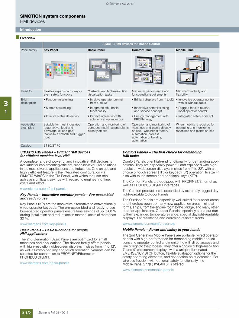
3.1/2 Siemens PM 21 · 2017
SIMOTION system componentsHMI devices
Introduction
31
■ Overview
SIMATIC HMI Panels – Brilliant HMI devices for efficient machine-level HMI
A complete range of powerful and innovative HMI devices is available for implementing efficient, machine-level HMI solutions in the most diverse applications and industries. One unique and highly efficient feature is the integrated configuration via SIMATIC WinCC in the TIA Portal, with which the user can achieve significant savings with regard to engineering time, costs and effort.
www.siemens.com/hmi-panels
Key Panels – Innovative operator panels – Pre-assembled and ready to use
Key Panels (KP) are the innovative alternative to conventionally wired operator keypads. The pre-assembled and ready-to-use bus-enabled operator panels ensure time savings of up to 60 % during installation and reductions in material costs of more than 30 %.
www.siemens.com/key-panels
Basic Panels – Basic functions for simple HMI applications
The 2nd Generation Basic Panels are optimized for small machines and applications. The device family offers panels with high-resolution widescreen displays in sizes from 4" to 12", as well as combined key and touch operation. Variants can be selected for connection to PROFINET/Ethernet or PROFIBUS DP/MPI.
www.siemens.com/basic-panels
Comfort Panels – The first choice for demanding HMI tasks
Comfort Panels offer high-end functionality for demanding appli-cations. They are especially powerful and equipped with high-resolution widescreen displays in sizes from 4" to 22", with a choice of touch screen (TP) or keypad (KP) operation. In size 4" also with touch screen and additional keys (KTP).
The Comfort Panels are equipped with PROFINET/Ethernet as well as PROFIBUS DP/MPI interfaces.
The Comfort product line is expanded by extremely rugged day-light-readable Outdoor Panels.
The Outdoor Panels are especially well suited for outdoor areas and therefore open up many new application areas – oil plat-forms, ships, from the engine room to the bridge, and many other outdoor applications. Outdoor Panels especially stand out due to their expanded temperature range, special daylight-readable displays, UV resistance and corrosion-resistant fronts.
www.siemens.com/comfort-panels
Mobile Panels – Power and safety in your hands
The 2nd Generation Mobile Panels are portable, wired operator panels with high performance for demanding mobile applica-tions and operator control and monitoring with direct access and line of sight to the process. They offer a choice of high-resolution 7" and 9" widescreen displays with a unique illuminated EMERGENCY STOP button, flexible evaluation options for the safety operating elements, and connection point detection. For wireless freedom with optional safety functionality, the Mobile Panel 277(F) IWLAN 8" is offered.
www.siemens.com/mobile-panels
SIMATIC HMI devices for Motion Control
Panel family Key Panel Basic Panel Comfort Panel Mobile Panel
Used for Flexible expansion by key or even safety functions
Cost-efficient, high-resolution visualization tasks
Maximum performance and functionality requirements
Maximum mobility andflexibility
Brief description
• Fast commissioning • Intuitive operator control from 4" to 12"
• Brilliant displays from 4" to 22" • Innovative operator control with or without cable
• Simple networking • Integrated HMI basic functionality
• Innovative commissioning and service concept
• Rugged for site-related local operator control
• Intuitive status detection • Perfect interaction with solutions at optimum cost
• Energy management with PROFIenergy
• Integrated safety concept
Application examples
Suitable for most industries (automotive, food and beverage, oil and gas)thanks to a smooth and rugged front
Operation and monitoring of compact machines and plants directly on site
Operation and monitoring of machines and plants directly on site – whether in factory automation, process automation or building automation
When mobility is required for operating and monitoring machines and plants on-site
Catalog ST 80/ST PC
© Siemens AG 2017
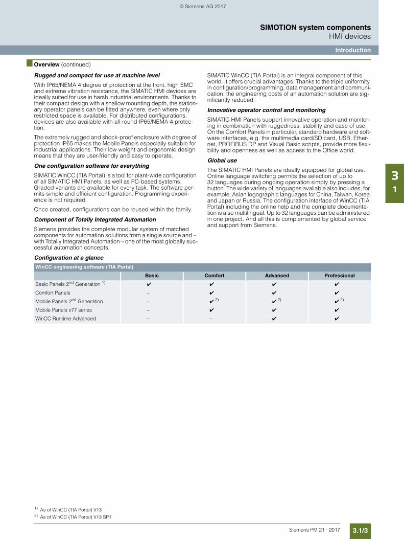
3.1/3Siemens PM 21 · 2017
SIMOTION system componentsHMI devices
Introduction
31
■ Overview (continued)
Rugged and compact for use at machine level
With IP65/NEMA 4 degree of protection at the front, high EMC and extreme vibration resistance, the SIMATIC HMI devices are ideally suited for use in harsh industrial environments. Thanks to their compact design with a shallow mounting depth, the station-ary operator panels can be fitted anywhere, even where only restricted space is available. For distributed configurations, devices are also available with all-round IP65/NEMA 4 protec-tion.
The extremely rugged and shock-proof enclosure with degree of protection IP65 makes the Mobile Panels especially suitable for industrial applications. Their low weight and ergonomic design means that they are user-friendly and easy to operate.
One configuration software for everything
SIMATIC WinCC (TIA Portal) is a tool for plant-wide configuration of all SIMATIC HMI Panels, as well as PC-based systems. Graded variants are available for every task. The software per-mits simple and efficient configuration. Programming experi-ence is not required.
Once created, configurations can be reused within the family.
Component of Totally Integrated Automation
Siemens provides the complete modular system of matched components for automation solutions from a single source and – with Totally Integrated Automation – one of the most globally suc-cessful automation concepts.
SIMATIC WinCC (TIA Portal) is an integral component of this world. It offers crucial advantages. Thanks to the triple uniformity in configuration/programming, data management and communi-cation, the engineering costs of an automation solution are sig-nificantly reduced.
Innovative operator control and monitoring
SIMATIC HMI Panels support innovative operation and monitor-ing in combination with ruggedness, stability and ease of use. On the Comfort Panels in particular, standard hardware and soft-ware interfaces, e.g. the multimedia card/SD card, USB, Ether-net, PROFIBUS DP and Visual Basic scripts, provide more flexi-bility and openness as well as access to the Office world.
Global use
The SIMATIC HMI Panels are ideally equipped for global use. Online language switching permits the selection of up to 32 languages during ongoing operation simply by pressing a button. The wide variety of languages available also includes, for example, Asian logographic languages for China, Taiwan, Korea and Japan or Russia. The configuration interface of WinCC (TIA Portal) including the online help and the complete documenta-tion is also multilingual. Up to 32 languages can be administered in one project. And all this is complemented by global service and support from Siemens.
Configuration at a glance
WinCC engineering software (TIA Portal)
Basic Comfort Advanced Professional
Basic Panels 2nd Generation 1) ✔ ✔ ✔ ✔
Comfort Panels – ✔ ✔ ✔
Mobile Panels 2nd Generation – ✔ 2) ✔ 2) ✔ 2)
Mobile Panels x77 series – ✔ ✔ ✔
WinCC Runtime Advanced – – ✔ ✔
1) As of WinCC (TIA Portal) V132) As of WinCC (TIA Portal) V13 SP1
© Siemens AG 2017
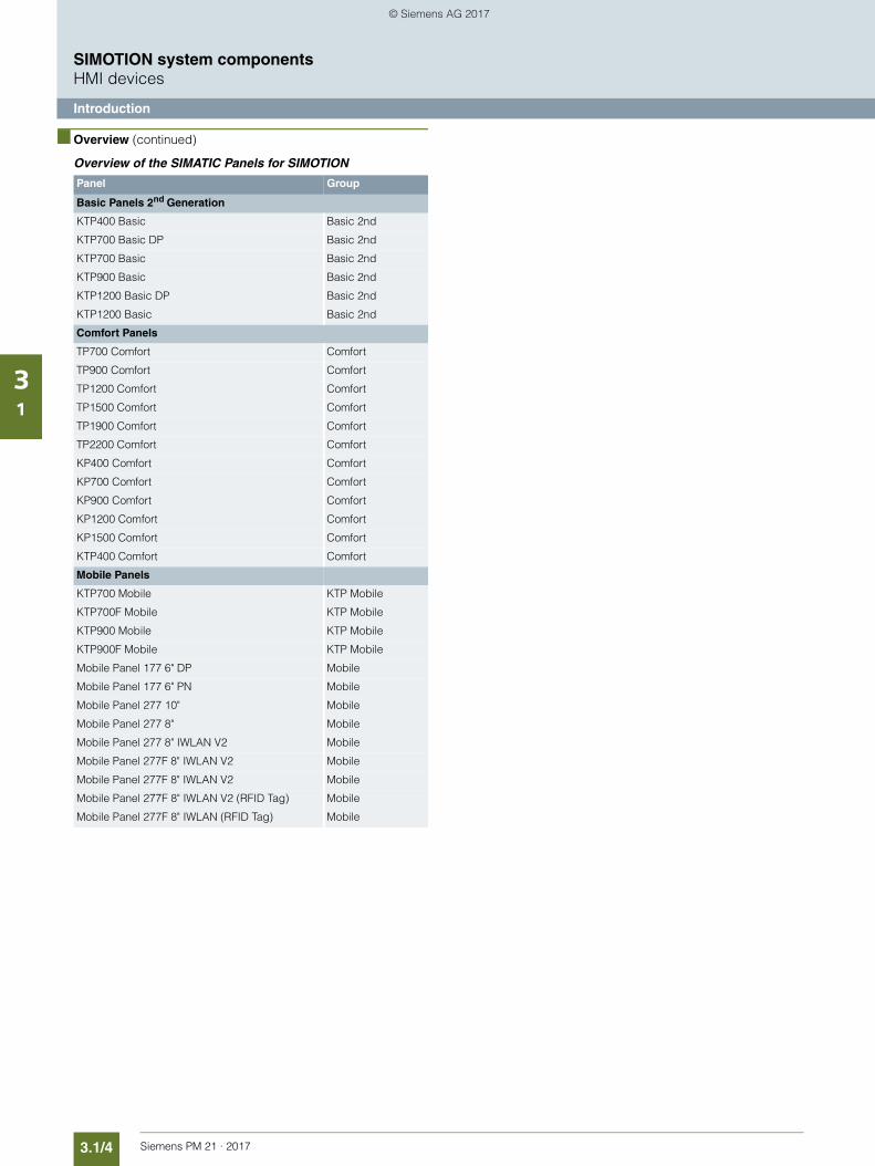
3.1/4 Siemens PM 21 · 2017
SIMOTION system componentsHMI devices
Introduction
31
■ Overview (continued)
Overview of the SIMATIC Panels for SIMOTION
Panel Group
Basic Panels 2nd Generation
KTP400 Basic Basic 2nd
KTP700 Basic DP Basic 2nd
KTP700 Basic Basic 2nd
KTP900 Basic Basic 2nd
KTP1200 Basic DP Basic 2nd
KTP1200 Basic Basic 2nd
Comfort Panels
TP700 Comfort Comfort
TP900 Comfort Comfort
TP1200 Comfort Comfort
TP1500 Comfort Comfort
TP1900 Comfort Comfort
TP2200 Comfort Comfort
KP400 Comfort Comfort
KP700 Comfort Comfort
KP900 Comfort Comfort
KP1200 Comfort Comfort
KP1500 Comfort Comfort
KTP400 Comfort Comfort
Mobile Panels
KTP700 Mobile KTP Mobile
KTP700F Mobile KTP Mobile
KTP900 Mobile KTP Mobile
KTP900F Mobile KTP Mobile
Mobile Panel 177 6" DP Mobile
Mobile Panel 177 6" PN Mobile
Mobile Panel 277 10" Mobile
Mobile Panel 277 8" Mobile
Mobile Panel 277 8" IWLAN V2 Mobile
Mobile Panel 277F 8" IWLAN V2 Mobile
Mobile Panel 277F 8" IWLAN V2 Mobile
Mobile Panel 277F 8" IWLAN V2 (RFID Tag) Mobile
Mobile Panel 277F 8" IWLAN (RFID Tag) Mobile
© Siemens AG 2017
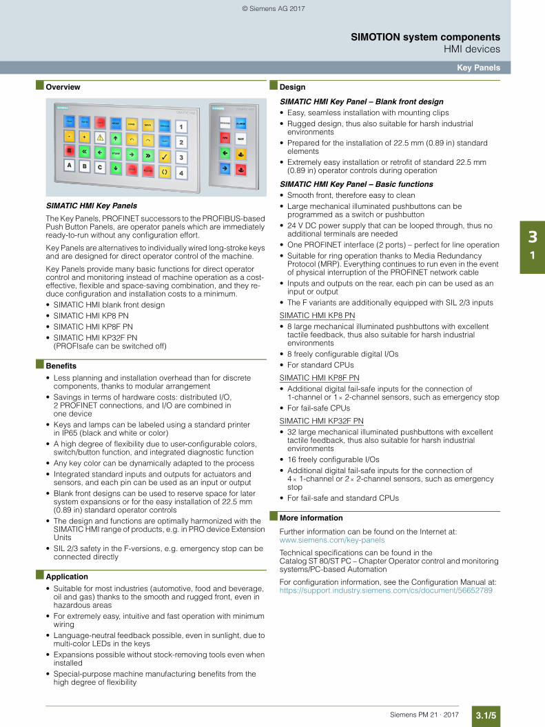
3.1/5Siemens PM 21 · 2017
SIMOTION system componentsHMI devices
Key Panels
31
■ Overview
SIMATIC HMl Key Panels
The Key Panels, PROFINET successors to the PROFIBUS-based Push Button Panels, are operator panels which are immediately ready-to-run without any configuration effort.
Key Panels are alternatives to individually wired long-stroke keys and are designed for direct operator control of the machine.
Key Panels provide many basic functions for direct operator control and monitoring instead of machine operation as a cost-effective, flexible and space-saving combination, and they re-duce configuration and installation costs to a minimum.• SIMATIC HMI blank front design• SIMATIC HMl KP8 PN• SIMATIC HMl KP8F PN• SIMATIC HMl KP32F PN
(PROFIsafe can be switched off)
■ Benefits
• Less planning and installation overhead than for discrete components, thanks to modular arrangement
• Savings in terms of hardware costs: distributed I/O, 2 PROFINET connections, and I/O are combined in one device
• Keys and lamps can be labeled using a standard printer in IP65 (black and white or color)
• A high degree of flexibility due to user-configurable colors, switch/button function, and integrated diagnostic function
• Any key color can be dynamically adapted to the process• Integrated standard inputs and outputs for actuators and
sensors, and each pin can be used as an input or output• Blank front designs can be used to reserve space for later
system expansions or for the easy installation of 22.5 mm (0.89 in) standard operator controls
• The design and functions are optimally harmonized with the SIMATIC HMI range of products, e.g. in PRO device Extension Units
• SIL 2/3 safety in the F-versions, e.g. emergency stop can be connected directly
■ Application
• Suitable for most industries (automotive, food and beverage, oil and gas) thanks to the smooth and rugged front, even in hazardous areas
• For extremely easy, intuitive and fast operation with minimum wiring
• Language-neutral feedback possible, even in sunlight, due to multi-color LEDs in the keys
• Expansions possible without stock-removing tools even when installed
• Special-purpose machine manufacturing benefits from the high degree of flexibility
■ Design
SIMATIC HMI Key Panel – Blank front design• Easy, seamless installation with mounting clips• Rugged design, thus also suitable for harsh industrial
environments• Prepared for the installation of 22.5 mm (0.89 in) standard
elements• Extremely easy installation or retrofit of standard 22.5 mm
(0.89 in) operator controls during operation
SIMATIC HMI Key Panel – Basic functions• Smooth front, therefore easy to clean• Large mechanical illuminated pushbuttons can be
programmed as a switch or pushbutton• 24 V DC power supply that can be looped through, thus no
additional terminals are needed• One PROFINET interface (2 ports) – perfect for line operation• Suitable for ring operation thanks to Media Redundancy
Protocol (MRP). Everything continues to run even in the event of physical interruption of the PROFINET network cable
• Inputs and outputs on the rear, each pin can be used as an input or output
• The F variants are additionally equipped with SIL 2/3 inputs
SIMATIC HMI KP8 PN• 8 large mechanical illuminated pushbuttons with excellent
tactile feedback, thus also suitable for harsh industrial environments
• 8 freely configurable digital I/Os• For standard CPUs
SIMATIC HMI KP8F PN• Additional digital fail-safe inputs for the connection of
1-channel or 1 2-channel sensors, such as emergency stop• For fail-safe CPUs
SIMATIC HMI KP32F PN• 32 large mechanical illuminated pushbuttons with excellent
tactile feedback, thus also suitable for harsh industrial environments
• 16 freely configurable I/Os • Additional digital fail-safe inputs for the connection of
4 1-channel or 2 2-channel sensors, such as emergency stop
• For fail-safe and standard CPUs
■ More information
Further information can be found on the Internet at: www.siemens.com/key-panels
Technical specifications can be found in theCatalog ST 80/ST PC – Chapter Operator control and monitoring systems/PC-based Automation
For configuration information, see the Configuration Manual at: https://support.industry.siemens.com/cs/document/56652789
© Siemens AG 2017
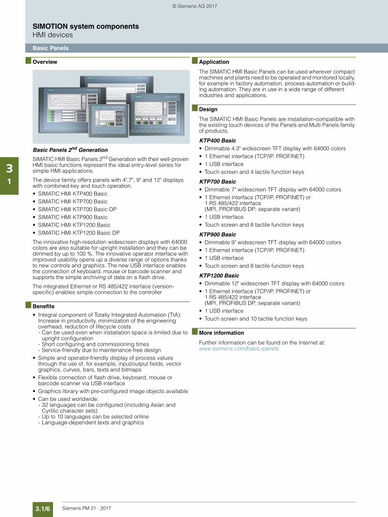
3.1/6 Siemens PM 21 · 2017
SIMOTION system componentsHMI devices
Basic Panels
31
■ Overview
Basic Panels 2nd Generation
SIMATIC HMI Basic Panels 2nd Generation with their well-proven HMI basic functions represent the ideal entry-level series for simple HMI applications.
The device family offers panels with 4",7", 9" and 12" displays with combined key and touch operation.• SIMATIC HMI KTP400 Basic• SIMATIC HMI KTP700 Basic• SIMATIC HMI KTP700 Basic DP• SIMATIC HMI KTP900 Basic• SIMATIC HMI KTP1200 Basic• SIMATIC HMI KTP1200 Basic DP
The innovative high-resolution widescreen displays with 64000 colors are also suitable for upright installation and they can be dimmed by up to 100 %. The innovative operator interface with improved usability opens up a diverse range of options thanks to new controls and graphics. The new USB interface enables the connection of keyboard, mouse or barcode scanner and supports the simple archiving of data on a flash drive.
The integrated Ethernet or RS 485/422 interface (version-specific) enables simple connection to the controller
■ Benefits
• Integral component of Totally Integrated Automation (TIA):Increase in productivity, minimization of the engineering overhead, reduction of lifecycle costs- Can be used even when installation space is limited due to
upright configuration- Short configuring and commissioning times- Service-friendly due to maintenance-free design
• Simple and operator-friendly display of process values through the use of, for example, input/output fields, vector graphics, curves, bars, texts and bitmaps
• Flexible connection of flash drive, keyboard, mouse or barcode scanner via USB interface
• Graphics library with pre-configured image objects available• Can be used worldwide:
- 32 languages can be configured (including Asian and Cyrillic character sets)
- Up to 10 languages can be selected online - Language-dependent texts and graphics
■ Application
The SIMATIC HMI Basic Panels can be used wherever compact machines and plants need to be operated and monitored locally, for example in factory automation, process automation or build-ing automation. They are in use in a wide range of different industries and applications.
■ Design
The SIMATIC HMI Basic Panels are installation-compatible with the existing touch devices of the Panels and Multi Panels family of products.
KTP400 Basic• Dimmable 4.3" widescreen TFT display with 64000 colors• 1 Ethernet interface (TCP/IP, PROFINET)• 1 USB interface• Touch screen and 4 tactile function keys
KTP700 Basic• Dimmable 7" widescreen TFT display with 64000 colors• 1 Ethernet interface (TCP/IP, PROFINET) or
1 RS 485/422 interface (MPI, PROFIBUS DP; separate variant)
• 1 USB interface• Touch screen and 8 tactile function keys
KTP900 Basic• Dimmable 9" widescreen TFT display with 64000 colors• 1 Ethernet interface (TCP/IP, PROFINET)• 1 USB interface• Touch screen and 8 tactile function keys
KTP1200 Basic• Dimmable 12" widescreen TFT display with 64000 colors• 1 Ethernet interface (TCP/IP, PROFINET) or
1 RS 485/422 interface (MPI, PROFIBUS DP; separate variant)
• 1 USB interface• Touch screen and 10 tactile function keys
■ More information
Further information can be found on the Internet at: www.siemens.com/basic-panels
© Siemens AG 2017
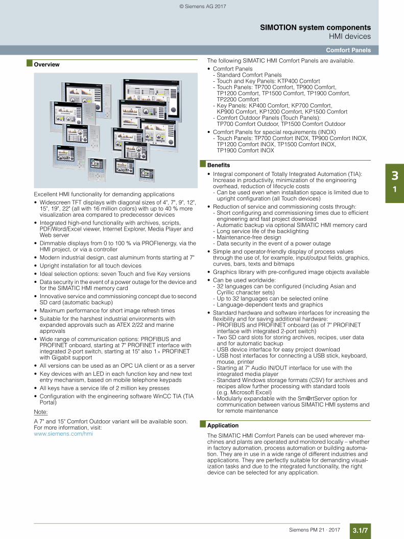
3.1/7Siemens PM 21 · 2017
SIMOTION system componentsHMI devices
Comfort Panels
31
■ Overview
Excellent HMI functionality for demanding applications• Widescreen TFT displays with diagonal sizes of 4", 7", 9", 12",
15", 19", 22" (all with 16 million colors) with up to 40 % more visualization area compared to predecessor devices
• Integrated high-end functionality with archives, scripts, PDF/Word/Excel viewer, Internet Explorer, Media Player and Web server
• Dimmable displays from 0 to 100 % via PROFIenergy, via the HMI project, or via a controller
• Modern industrial design, cast aluminum fronts starting at 7"• Upright installation for all touch devices• Ideal selection options: seven Touch and five Key versions• Data security in the event of a power outage for the device and
for the SIMATIC HMI memory card• Innovative service and commissioning concept due to second
SD card (automatic backup)• Maximum performance for short image refresh times• Suitable for the harshest industrial environments with
expanded approvals such as ATEX 2/22 and marine approvals
• Wide range of communication options: PROFIBUS and PROFINET onboard, starting at 7" PROFINET interface with integrated 2-port switch, starting at 15" also 1 PROFINET with Gigabit support
• All versions can be used as an OPC UA client or as a server• Key devices with an LED in each function key and new text
entry mechanism, based on mobile telephone keypads • All keys have a service life of 2 million key presses• Configuration with the engineering software WinCC TIA (TIA
Portal)
Note:
A 7" and 15" Comfort Outdoor variant will be available soon. For more information, visit: www.siemens.com/hmi
The following SIMATIC HMI Comfort Panels are available.• Comfort Panels
- Standard Comfort Panels- Touch and Key Panels: KTP400 Comfort - Touch Panels: TP700 Comfort, TP900 Comfort,
TP1200 Comfort, TP1500 Comfort, TP1900 Comfort,TP2200 Comfort
- Key Panels: KP400 Comfort, KP700 Comfort,KP900 Comfort, KP1200 Comfort, KP1500 Comfort
- Comfort Outdoor Panels (Touch Panels): TP700 Comfort Outdoor, TP1500 Comfort Outdoor
• Comfort Panels for special requirements (INOX)- Touch Panels: TP700 Comfort INOX, TP900 Comfort INOX,
TP1200 Comfort INOX, TP1500 Comfort INOX,TP1900 Comfort INOX
■ Benefits
• Integral component of Totally Integrated Automation (TIA):Increase in productivity, minimization of the engineering overhead, reduction of lifecycle costs- Can be used even when installation space is limited due to
upright configuration (all Touch devices)• Reduction of service and commissioning costs through:
- Short configuring and commissioning times due to efficient engineering and fast project download
- Automatic backup via optional SIMATIC HMI memory card- Long service life of the backlighting- Maintenance-free design- Data security in the event of a power outage
• Simple and operator-friendly display of process values through the use of, for example, input/output fields, graphics, curves, bars, texts and bitmaps
• Graphics library with pre-configured image objects available • Can be used worldwide:
- 32 languages can be configured (including Asian and Cyrillic character sets)
- Up to 32 languages can be selected online - Language-dependent texts and graphics
• Standard hardware and software interfaces for increasing the flexibility and for saving additional hardware:- PROFIBUS and PROFINET onboard (as of 7" PROFINET
interface with integrated 2-port switch)- Two SD card slots for storing archives, recipes, user data
and for automatic backup- USB device interface for easy project download- USB host interfaces for connecting a USB stick, keyboard,
mouse, printer- Starting at 7" Audio IN/OUT interface for use with the
integrated media player- Standard Windows storage formats (CSV) for archives and
recipes allow further processing with standard tools (e.g. Microsoft Excel)
- Modularly expandable with the Sm@rtServer option for communication between various SIMATIC HMI systems and for remote maintenance
■ Application
The SIMATIC HMI Comfort Panels can be used wherever ma-chines and plants are operated and monitored locally – whether in factory automation, process automation or building automa-tion. They are in use in a wide range of different industries and applications. They are perfectly suitable for demanding visual-ization tasks and due to the integrated functionality, the right device can be selected for any application.
© Siemens AG 2017
3.1/8 Siemens PM 21 · 2017
SIMOTION system componentsHMI devices
Comfort Panels
31
■ Design
KTP400 Comfort• 4.3" widescreen TFT display, resolution 480 272,
16 million colors • 1 PROFINET and 1 PROFIBUS interface• Touch screen and membrane keyboard with 4 tactile function
keys• Innovative successor to the TP 177B 4" Touch Panel
KP400 Comfort • 4.3" widescreen TFT display, resolution 480 272,
16 million colors • 1 PROFINET and 1 PROFIBUS interface• Membrane keyboard with 8 tactile function keys + system
keyboard • Innovative successor to the OP 77B Operator Panel
TP700 Comfort • 7.0" widescreen TFT display, resolution 800 480,
16 million colors • 1 PROFINET (2 ports with integrated switch) and
1 PROFIBUS interface• Touch screen• Innovative successor to the Touch Panels TP 177B/TP 277 and
Multi Panel MP 177 6"
KP700 Comfort • 7.0" widescreen TFT display, resolution 800 480,
16 million colors • 1 PROFINET (2 ports with integrated switch) and
1 PROFIBUS interface• Membrane keyboard with 24 function keys + system keyboard• Innovative successor to the OP 177B/OP 277 6" Operator
Panels
TP900 Comfort • 9.0" widescreen TFT display, resolution 800 480,
16 million colors • 1 PROFINET (2 ports with integrated switch) and
1 PROFIBUS interface• Touch screen • Innovative successor to the MP 277 8" Touch Multi Panel
KP900 Comfort • 9.0" widescreen TFT display, resolution 800 480,
16 million colors • 1 PROFINET (2 ports with integrated switch) and
1 PROFIBUS interface• Membrane keyboard with 26 function keys + system keyboard • Innovative successor to the MP 277 8" Key Multi Panel
TP1200 Comfort • 12.1" widescreen TFT display, resolution 1280 800,
16 million colors • 1 PROFINET (2 ports with integrated switch) and
1 PROFIBUS interface• Touch screen• Innovative successor to the MP 277 10" Touch Multi Panel
KP1200 Comfort • 12.1" widescreen TFT display, resolution 1280 800,
16 million colors • 1 PROFINET (2 ports with integrated switch) and
1 PROFIBUS interface• Membrane keyboard with 34 function keys + system keyboard• Innovative successor to the MP 277 10" Key Multi Panel
TP1500 Comfort • 15.4" widescreen TFT display, resolution 1280 800,
16 million colors • 2 PROFINET (2 ports with integrated switch + additional
interface with Gigabit support) and1 PROFIBUS interface
• Touch screen • Innovative successor to the MP 377 12" Touch Multi Panel
KP1500 Comfort • 15.4" widescreen TFT display, resolution 1280 800,
16 million colors • 2 PROFINET (2 ports with integrated switch + additional
interface with Gigabit support) and 1 PROFIBUS interface • Membrane keyboard with 36 function keys + system keyboard • Innovative successor to the MP 377 12" Key Multi Panel
TP1900 Comfort • 18.5" widescreen TFT display, resolution 1366 768,
16 million colors • 2 PROFINET (2 ports with integrated switch + additional
interface with Gigabit support) and 1 PROFIBUS interface
• Touch screen • Innovative successor to the MP 377 15" Touch Multi Panel
TP2200 Comfort • 21.5" widescreen TFT display, resolution 1920 1080,
16 million colors • 2 PROFINET (2 ports with integrated switch + additional
interface with Gigabit support) and 1 PROFIBUS interface
• Touch screen • Innovative successor to the MP 377 19" Touch Multi Panel
■ More information
Further information can be found on the Internet at: www.siemens.com/comfort-panels
© Siemens AG 2017
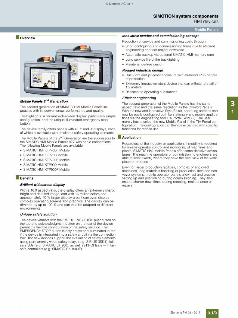
3.1/9Siemens PM 21 · 2017
SIMOTION system componentsHMI devices
Mobile Panels
31
■ Overview
Mobile Panels 2nd Generation
The second generation of SIMATIC HMI Mobile Panels im-presses with its convenience, performance and quality.
The highlights: A brilliant widescreen display, particularly simple configuration, and the unique illuminated emergency stop button.
The device family offers panels with 4", 7" and 9" displays, each of which is available with or without safety operating elements.
The Mobile Panels of the 2nd Generation are the successors to the SIMATIC HMI Mobile Panels x77 with cable connections. The following Mobile Panels are available:• SIMATIC HMI KTP400F Mobile• SIMATIC HMI KTP700 Mobile• SIMATIC HMI KTP700F Mobile• SIMATIC HMI KTP900 Mobile• SIMATIC HMI KTP900F Mobile
■ Benefits
Brilliant widescreen display
With a 16:9 aspect ratio, the display offers an extremely sharp, bright and detailed image, and with 16 million colors and approximately 40 % larger display area it can even display complex operating screens and graphics. The display can be dimmed by up to 100 % and can thus be adapted to different environments.
Unique safety solution
The device variants with the EMERGENCY STOP pushbutton on the top and acknowledgment button on the rear of the device permit the flexible configuration of the safety solution. The EMERGENCY STOP button is only active and illuminated in red if the device is integrated into a safety circuit via the connection box. The new devices support the evaluation of safety elements using permanently wired safety relays (e.g. SIRIUS 3SK1), fail-safe I/Os (e.g. SIMATIC ET 200), as well as PROFIsafe with fail-safe controllers (e.g. SIMATIC S7-1500F).
Innovative service and commissioning concept
Reduction of service and commissioning costs through:• Short configuring and commissioning times due to efficient
engineering and fast project download• Automatic backup via optional SIMATIC HMI memory card• Long service life of the backlighting• Maintenance-free design
Rugged industrial design• Dust-tight and jet-proof enclosure with all-round IP65 degree
of protection• Extremely impact-resistant device that can withstand a fall of
1.2 meters• Resistant to operating substances
Efficient engineering
The second generation of the Mobile Panels has the same aspect ratio and the same resolution as the Comfort Panels. With the new and innovative Style Editor, operating screens can now be easily configured both for stationary and mobile applica-tions via the engineering tool TIA Portal (WinCC). The user merely has to select the new Mobile Panel in the TIA Portal con-figuration. The configuration can then be expanded with specific functions for mobile use.
■ Application
Regardless of the industry or application, if mobility is required for on-site operator control and monitoring of machines and plants, SIMATIC HMI Mobile Panels offer some decisive advan-tages: The machine operators or commissioning engineers are able to work exactly where they have the best view of the work-piece or process.
Even for larger production facilities, complex or enclosed machines, long materials handling or production lines and con-veyor systems, mobile operator panels allow fast and precise setting up and positioning during commissioning. They also ensure shorter downtimes during retooling, maintenance or repairs.
© Siemens AG 2017
3.1/10 Siemens PM 21 · 2017
SIMOTION system componentsHMI devices
Mobile Panels
31
■ Design
KTP700 Mobile• Dimmable 7.0" widescreen TFT display,
resolution 800 480, 1 million colors• 1 Ethernet interface (TCP/IP, PROFINET)• 1 USB interface• 1 SD card slot• Touch screen and 8 tactile function keys, incl. LED• 2 illuminated pushbuttons
KTP700F Mobile• Dimmable 7.0" widescreen TFT display,
resolution 800 480, 16 million colors• 1 Ethernet interface (TCP/IP, PROFINET, PROFIsafe)• 1 USB interface• 1 SD card slot• Touch screen and 8 tactile function keys, incl. LED• 2 illuminated pushbuttons• 1 key-operated switch• 1 three-stage acknowledgment button• 1 EMERGENCY STOP/stop button
KTP900 Mobile• Dimmable 9.0" widescreen TFT display,
resolution 800 480, 16 million colors• 1 Ethernet interface (TCP/IP, PROFINET)• 1 USB interface• 1 SD card slot• Touch screen and 10 tactile function keys, incl. LED• 2 illuminated pushbuttons
KTP900F Mobile• Dimmable 9.0" widescreen TFT display,
resolution 800 480, 16 million colors• 1 Ethernet interface (TCP/IP, PROFINET, PROFIsafe)• 1 USB interface• 1 SD card slot• Touch screen and 10 tactile function keys, incl. LED• 2 illuminated pushbuttons• 1 key-operated switch• 1 three-stage acknowledgment button• 1 EMERGENCY STOP/stop button
■ More information
Further information can be found on the Internet at: www.siemens.com/mobile-panels
© Siemens AG 2017
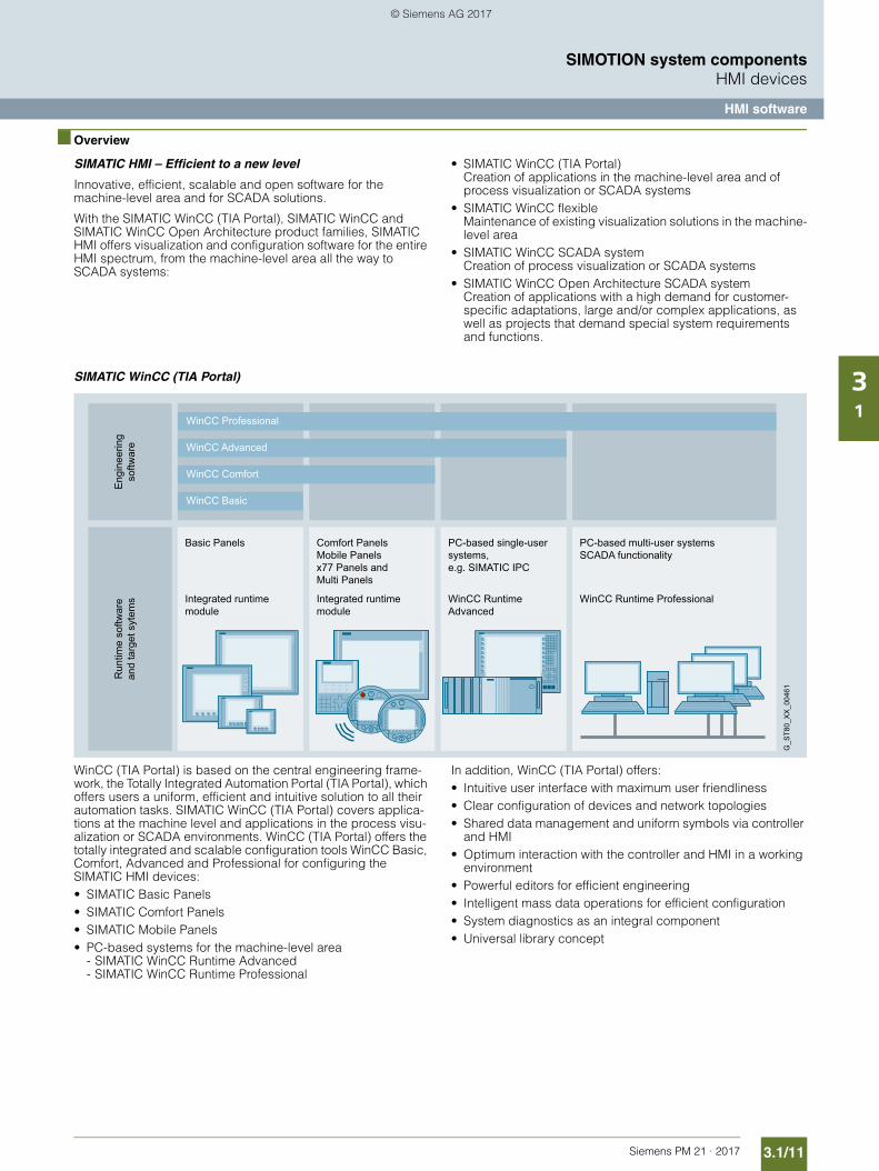
3.1/11Siemens PM 21 · 2017
SIMOTION system componentsHMI devices
HMI software
31
■ Overview
SIMATIC HMI – Efficient to a new level
Innovative, efficient, scalable and open software for the machine-level area and for SCADA solutions.
With the SIMATIC WinCC (TIA Portal), SIMATIC WinCC and SIMATIC WinCC Open Architecture product families, SIMATIC HMI offers visualization and configuration software for the entire HMI spectrum, from the machine-level area all the way to SCADA systems:
• SIMATIC WinCC (TIA Portal) Creation of applications in the machine-level area and of process visualization or SCADA systems
• SIMATIC WinCC flexible Maintenance of existing visualization solutions in the machine-level area
• SIMATIC WinCC SCADA system Creation of process visualization or SCADA systems
• SIMATIC WinCC Open Architecture SCADA system Creation of applications with a high demand for customer-specific adaptations, large and/or complex applications, as well as projects that demand special system requirements and functions.
SIMATIC WinCC (TIA Portal)
WinCC (TIA Portal) is based on the central engineering frame-work, the Totally Integrated Automation Portal (TIA Portal), which offers users a uniform, efficient and intuitive solution to all their automation tasks. SIMATIC WinCC (TIA Portal) covers applica-tions at the machine level and applications in the process visu-alization or SCADA environments. WinCC (TIA Portal) offers the totally integrated and scalable configuration tools WinCC Basic, Comfort, Advanced and Professional for configuring the SIMATIC HMI devices:• SIMATIC Basic Panels• SIMATIC Comfort Panels• SIMATIC Mobile Panels• PC-based systems for the machine-level area
- SIMATIC WinCC Runtime Advanced- SIMATIC WinCC Runtime Professional
In addition, WinCC (TIA Portal) offers:• Intuitive user interface with maximum user friendliness• Clear configuration of devices and network topologies• Shared data management and uniform symbols via controller
and HMI• Optimum interaction with the controller and HMI in a working
environment• Powerful editors for efficient engineering• Intelligent mass data operations for efficient configuration • System diagnostics as an integral component• Universal library concept
Integrated runtime module
PC-based single-user systems, e.g. SIMATIC IPC
Comfort PanelsMobile Panelsx77 Panels and Multi Panels
Run
time
softw
are
and
targ
et s
ytem
s Integrated runtime module
PC-based multi-user systemsSCADA functionality
Basic Panels
Eng
inee
ring
softw
are
G_S
T80_
XX
_004
61
WinCC Basic
WinCC Comfort
WinCC Advanced
WinCC Professional
WinCC Runtime ProfessionalWinCC Runtime Advanced
© Siemens AG 2017
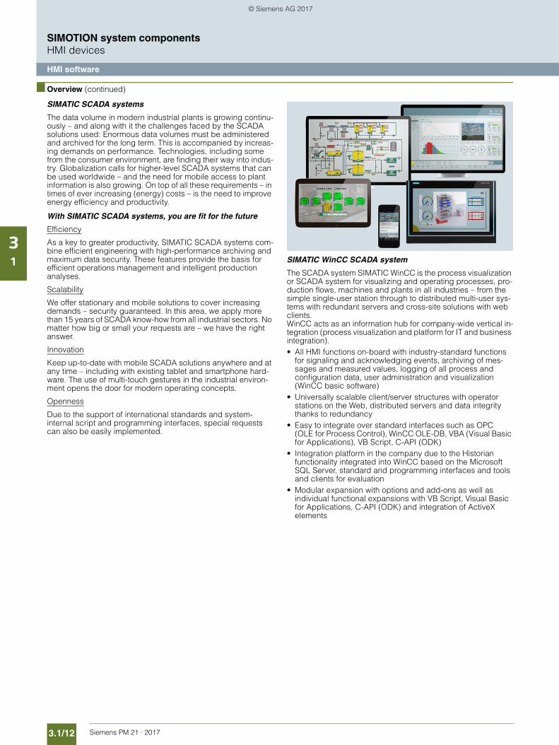
3.1/12 Siemens PM 21 · 2017
SIMOTION system componentsHMI devices
HMI software
31
■ Overview (continued)
SIMATIC SCADA systems
The data volume in modern industrial plants is growing continu-ously – and along with it the challenges faced by the SCADA solutions used: Enormous data volumes must be administered and archived for the long term. This is accompanied by increas-ing demands on performance. Technologies, including some from the consumer environment, are finding their way into indus-try. Globalization calls for higher-level SCADA systems that can be used worldwide – and the need for mobile access to plant information is also growing. On top of all these requirements – in times of ever increasing (energy) costs – is the need to improve energy efficiency and productivity.
With SIMATIC SCADA systems, you are fit for the future
Efficiency
As a key to greater productivity, SIMATIC SCADA systems com-bine efficient engineering with high-performance archiving and maximum data security. These features provide the basis for efficient operations management and intelligent production analyses.
Scalability
We offer stationary and mobile solutions to cover increasing demands – security guaranteed. In this area, we apply more than 15 years of SCADA know-how from all industrial sectors. No matter how big or small your requests are – we have the right answer.
Innovation
Keep up-to-date with mobile SCADA solutions anywhere and at any time – including with existing tablet and smartphone hard-ware. The use of multi-touch gestures in the industrial environ-ment opens the door for modern operating concepts.
Openness
Due to the support of international standards and system-internal script and programming interfaces, special requests can also be easily implemented.
SIMATIC WinCC SCADA system
The SCADA system SIMATIC WinCC is the process visualization or SCADA system for visualizing and operating processes, pro-duction flows, machines and plants in all industries – from the simple single-user station through to distributed multi-user sys-tems with redundant servers and cross-site solutions with web clients. WinCC acts as an information hub for company-wide vertical in-tegration (process visualization and platform for IT and business integration).• All HMI functions on-board with industry-standard functions
for signaling and acknowledging events, archiving of mes-sages and measured values, logging of all process and configuration data, user administration and visualization (WinCC basic software)
• Universally scalable client/server structures with operator stations on the Web, distributed servers and data integrity thanks to redundancy
• Easy to integrate over standard interfaces such as OPC (OLE for Process Control), WinCC OLE-DB, VBA (Visual Basic for Applications), VB Script, C-API (ODK)
• Integration platform in the company due to the Historian functionality integrated into WinCC based on the Microsoft SQL Server, standard and programming interfaces and tools and clients for evaluation
• Modular expansion with options and add-ons as well as individual functional expansions with VB Script, Visual Basic for Applications, C-API (ODK) and integration of ActiveX elements
© Siemens AG 2017
3.1/13Siemens PM 21 · 2017
SIMOTION system componentsHMI devices
HMI software
31
■ Overview (continued)
SIMATIC WinCC Open Architecture SCADA system
The SCADA system SIMATIC WinCC Open Architecture is suit-able for applications with demanding customization require-ments, large and/or complex applications, as well as projects that require special system requirements and functions.
SIMATIC WinCC Open Architecture demonstrates its perfor-mance capability particularly in networked and redundant high-end control systems. From the field level to the control station, from the machine to the company headquarters – integrated, high-performance communication is ensured. In every situation, a high level of availability, reliable information, fast interaction and user friendliness is guaranteed. Applications can also be changed even without interrupting the process. Profitability, effi-ciency and safety are therefore always in equilibrium.
With its disaster recovery system and SIL3 certification, SIMATIC WinCC Open Architecture demonstrates its reliability in a wide range of critical applications. SIMATIC WinCC Open Architec-ture can be used on any platform and is available for Windows, Linux and Solaris.
SIMATIC WinCC Open Architecture is open for independent in-house developments, which means that ideas can be turned into new applications quickly and easily.• Object-orientation supports efficient engineering and flexible
plant expansion• For large, distributed systems with up to 2048 servers• Scalable – from a small single-user system up to a networked,
redundant high-end system• WinCC OA can be used on any platform and is available for
Windows, Linux and Solaris• Hot-standby redundancy and disaster recovery system
assure maximum fail-safety and availability• WinCC OA offers a platform for customer-specific solutions• Extensive driver and interfacing options:
S7, SINAUT, OPC, OPC UA, Modbus, IEC60870-5-101/104, DNP3, BACnet, and many more
• Flexible logging of data either in file-based value archive or in a relational database (ORACLE)
• Modular expansion is possible using options and add-ons as well as individual functional expansions by means of own script language CONTROL, API(C++) and integration of ActiveX elements
PC-based HMI solutions (machine-level / SCADA) with SIMATIC industrial PCs
Our reliable and innovative SIMATIC IPC industrial PCs are the ideal PC hardware platforms. SIMATIC industrial PCs are offered with low-cost software packages for the runtime versions with the SIMATIC WinCC V7, WinCC Runtime Professional or WinCC Runtime Advanced visualization software, as well as the SIMATIC WinAC RTX (F) software controller. The simultaneous purchase of industrial PC and software package results in a price advantage.
■ More information
Further information on SCADA systems can be found on the Internet at: www.siemens.com/scada
Further information on PC-based HMI solutions can be found on the Internet at: www.siemens.com/pc-based and in the Catalog ST 80/ST PC – Chapter HMI Software
© Siemens AG 2017
3.1/14 Siemens PM 21 · 2017
SIMOTION system components
Notes
31
© Siemens AG 2017
Siemens PM 21 · 2017
3.23.2/2 Distributed I/O3.2/2 Overview3.2/2 Perfect communication on all levels 3.2/3 PROFINET3.2/3 PROFIBUS3.2/3 AS-Interface3.2/3 IO-Link3.2/4 Solutions in the control cabinet (IP20)3.2/4 SIMATIC ET 200SP3.2/5 SIMATIC ET 200MP3.2/6 SIMATIC ET 200S3.2/7 SIMATIC ET 200M3.2/8 Solutions without a control cabinet
(IP65/67)3.2/8 SIMATIC ET 200pro3.2/9 SIMATIC ET 200eco PN3.2/10 SIMATIC ET 200eco3.2/11 SIMATIC ET 200AL
3.2/12 Other I/O components3.2/12 Overview3.2/13 SIMATIC S7-300 I/O3.2/14 TM15 Terminal Module3.2/15 ADI 4 Analog Drive Interface
IM 174 Interface Module3.2/16 Function blocks for I/O components
SIMOTION system components I/O components
© Siemens AG 2017
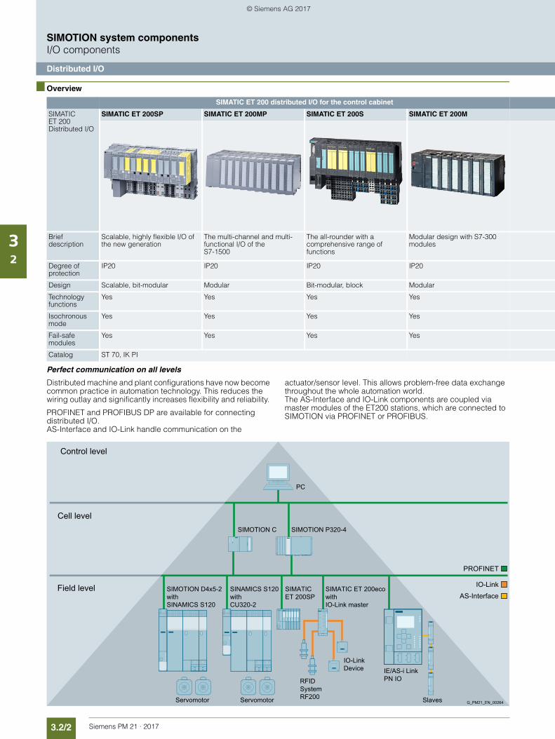
3.2/2 Siemens PM 21 · 2017
SIMOTION system componentsI/O components
Distributed I/O
32
■ Overview
Perfect communication on all levels
Distributed machine and plant configurations have now become common practice in automation technology. This reduces the wiring outlay and significantly increases flexibility and reliability.
PROFINET and PROFIBUS DP are available for connecting distributed I/O. AS-Interface and IO-Link handle communication on the
actuator/sensor level. This allows problem-free data exchange throughout the whole automation world. The AS-Interface and IO-Link components are coupled via master modules of the ET200 stations, which are connected to SIMOTION via PROFINET or PROFIBUS.
SIMATIC ET 200 distributed I/O for the control cabinet
SIMATIC ET 200 Distributed I/O
SIMATIC ET 200SP SIMATIC ET 200MP SIMATIC ET 200S SIMATIC ET 200M
Brief description
Scalable, highly flexible I/O of the new generation
The multi-channel and multi-functional I/O of the S7-1500
The all-rounder with a comprehensive range of functions
Modular design with S7-300 modules
Degree of protection
IP20 IP20 IP20 IP20
Design Scalable, bit-modular Modular Bit-modular, block Modular
Technology functions
Yes Yes Yes Yes
Isochronous mode
Yes Yes Yes Yes
Fail-safe modules
Yes Yes Yes Yes
Catalog ST 70, IK PI
Slaves G_PM21_EN_00264
SIMOTION C
SINAMICS S120 with CU320-2
SIMOTION D4x5-2 with SINAMICS S120
RFID System RF200
IO-Link Device
SIMATIC ET 200eco with IO-Link master
SIMATIC ET 200SP
ServomotorServomotor
Field level
Cell level
Control level
IE/AS-i Link PN IO
SIMOTION P320-4
PC
PROFINET
IO-LinkAS-Interface
© Siemens AG 2017
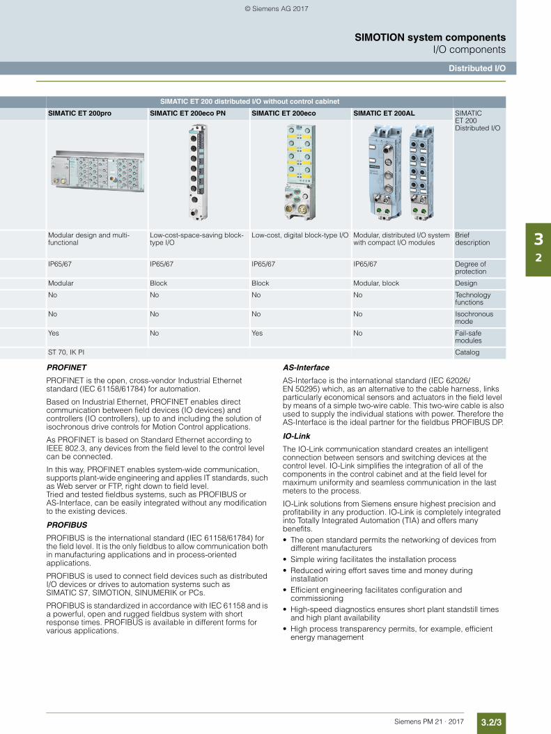
3.2/3Siemens PM 21 · 2017
SIMOTION system componentsI/O components
Distributed I/O
32
PROFINET
PROFINET is the open, cross-vendor Industrial Ethernet standard (IEC 61158/61784) for automation.
Based on Industrial Ethernet, PROFINET enables direct communication between field devices (IO devices) and controllers (IO controllers), up to and including the solution of isochronous drive controls for Motion Control applications.
As PROFINET is based on Standard Ethernet according to IEEE 802.3, any devices from the field level to the control level can be connected.
In this way, PROFINET enables system-wide communication, supports plant-wide engineering and applies IT standards, such as Web server or FTP, right down to field level. Tried and tested fieldbus systems, such as PROFIBUS or AS-Interface, can be easily integrated without any modification to the existing devices.
PROFIBUS
PROFIBUS is the international standard (IEC 61158/61784) for the field level. It is the only fieldbus to allow communication both in manufacturing applications and in process-oriented applications.
PROFIBUS is used to connect field devices such as distributed I/O devices or drives to automation systems such as SIMATIC S7, SIMOTION, SINUMERIK or PCs.
PROFIBUS is standardized in accordance with IEC 61158 and is a powerful, open and rugged fieldbus system with short response times. PROFIBUS is available in different forms for various applications.
AS-Interface
AS-Interface is the international standard (IEC 62026/EN 50295) which, as an alternative to the cable harness, links particularly economical sensors and actuators in the field level by means of a simple two-wire cable. This two-wire cable is also used to supply the individual stations with power. Therefore the AS-Interface is the ideal partner for the fieldbus PROFIBUS DP.
IO-Link
The IO-Link communication standard creates an intelligent connection between sensors and switching devices at the control level. IO-Link simplifies the integration of all of the components in the control cabinet and at the field level for maximum uniformity and seamless communication in the last meters to the process.
IO-Link solutions from Siemens ensure highest precision and profitability in any production. IO-Link is completely integrated into Totally Integrated Automation (TIA) and offers many benefits.• The open standard permits the networking of devices from
different manufacturers• Simple wiring facilitates the installation process• Reduced wiring effort saves time and money during
installation• Efficient engineering facilitates configuration and
commissioning• High-speed diagnostics ensures short plant standstill times
and high plant availability• High process transparency permits, for example, efficient
energy management
SIMATIC ET 200 distributed I/O without control cabinet
SIMATIC ET 200pro SIMATIC ET 200eco PN SIMATIC ET 200eco SIMATIC ET 200AL SIMATIC ET 200 Distributed I/O
Modular design and multi-functional
Low-cost-space-saving block-type I/O
Low-cost, digital block-type I/O Modular, distributed I/O system with compact I/O modules
Brief description
IP65/67 IP65/67 IP65/67 IP65/67 Degree of protection
Modular Block Block Modular, block Design
No No No No Technology functions
No No No No Isochronous mode
Yes No Yes No Fail-safe modules
ST 70, IK PI Catalog
© Siemens AG 2017
3.2/4 Siemens PM 21 · 2017
SIMOTION system componentsI/O components
Distributed I/O
32
■ Overview (continued)
Solutions in the control cabinet (IP20)• SIMATIC ET 200SP:
The SIMATIC ET 200SP distributed I/O system is a scalable and extremely flexible distributed I/O system for interfacing the process signals to a central control system via PROFINET and PROFIBUS. The distributed I/O system is particularly easy to use and, with its compact design, offers maximum economy in the control cabinet. High speed and transmission rates provide significantly stronger performance than conventional systems.
• SIMATIC ET 200MP:The modular SIMATIC ET 200MP I/O system with high channel densities based on the SIMATIC S7-1500 design permits the shortest bus cycle times and fastest response time even with large volumes of data.
• SIMATIC ET 200S:The finely scalable I/O system for control cabinet installation and time-critical applications in particular; including motor starters, safety technology and individual grouping of load groups.
• SIMATIC ET 200M:The modular I/O system with high channel densities based on the SIMATIC S7-300 design.
Distributed I/O in the control cabinet (IP20)
SIMATIC ET 200SP
The scalable SIMATIC ET 200SP I/O system is a highly flexible modular I/O system with IP20 degree of protection. Via Interface Modules with PROFINET or PROFIBUS interface it can exchange I/O data of the connected I/O modules with a higher-level control system. ET 200SP components are available as SIPLUS version for extreme requirements and a high degree of ruggedness.
DesignThe ET 200SP has a very compact design and makes optimum use of the available space in the control cabinet. Depending on the Interface Module used, up to 64 modules, each with a maximum of 16 signals, can be configured. The depth is approx. 75 mm (2.95 in).
ComponentsAn ET 200SP station consists of an Interface Module (IM) for connecting to PROFINET or PROFIBUS, the I/O modules, and a server module that terminates the station. The modules are plugged into passive Base Units (BUs) that in turn are mounted on a standard DIN rail.The Base Units (BUs) connect the modules of the ET 200SP station electrically and mechanically with each other. The terminal box of a Base Unit can be simply replaced in the case of terminal damage, for example.The PROFINET connection is via bus adapters (BAs) on the IM with which the connections and physical characteristics can be selected freely in accordance with the requirements, e.g. RJ45 connector or direct connection. Interface Module: The Interface Module connects the ET 200SP to PROFINET or PROFIBUS and exchanges data between the higher-level controller and the I/O modules. I/O modules: An I/O module determines the function at the terminals. The controller uses the connected sensors to determine the current process state and initiates corresponding responses via the connected actuators. Some I/O modules have expanded functions, which to some extent are also designed as an independent operating mode. I/O modules are divided into various module types, with the fail-safe versions being identified by a preceding "F-" and a yellow module enclosure. The I/O modules are 1, 2, 4, 8 and 16-channel modules and permit the scalable and cost-optimized design of the ET 200SP. Digital and analog input/output modules, technology modules, (counting, positioning, weighing, time-based I/O with µs-precise time stamping of the signals for cam and measuring input applications), communication modules and special modules are available.
Configuration, parameter assignment and diagnosticsThe ET 200SP is configured and parameterized via STEP 7 or the TIA Portal. Depending on the I/O module selected, the user has comprehensive diagnostic information at his disposal.
© Siemens AG 2017
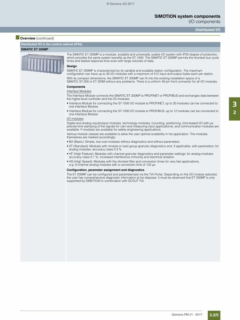
3.2/5Siemens PM 21 · 2017
SIMOTION system componentsI/O components
Distributed I/O
32
■ Overview (continued)
Distributed I/O in the control cabinet (IP20)
SIMATIC ET 200MP
The SIMATIC ET 200MP is a modular, scalable and universally usable I/O system with IP20 degree of protection, which provides the same system benefits as the S7-1500. The SIMATIC ET 200MP permits the shortest bus cycle times and fastest response time even with large volumes of data.
DesignSIMATIC ET 200MP is characterized by its variable and scalable station configuration. The maximum configuration can have up to 30 I/O modules with a maximum of 512 input and output bytes each per station.With its compact dimensions, the SIMATIC ET 200MP can fit into the existing installation space of a SIMATIC S7-300 or ET 200M without any problems. There is a uniform 40-pin front connector for all I/O modules.
ComponentsInterface Modules: The Interface Module connects the SIMATIC ET 200MP to PROFINET or PROFIBUS and exchanges data between the higher-level controller and the I/O modules.• Interface Module for connecting the S7-1500 I/O module to PROFINET; up to 30 modules can be connected to
one Interface Module.• Interface Module for connecting the S7-1500 I/O module to PROFIBUS; up to 12 modules can be connected to
one Interface ModuleI/O modules: Digital and analog input/output modules, technology modules, (counting, positioning, time-based I/O with µs-precise time stamping of the signals for cam and measuring input applications), and communication modules are available. F-modules are available for safety-engineering applications.Various module classes are available to allow the user optimal scalability in his application. The modules themselves are marked accordingly:• BA (Basic): Simple, low-cost modules without diagnostics and without parameters• ST (Standard): Modules with module or load group-granular diagnostics and, if applicable, with parameters; for
analog modules: accuracy class 0.3 %• HF (High Feature): Modules with channel-granular diagnostics and parameter settings; for analog modules:
accuracy class 0.1 %, increased interference immunity and electrical isolation• HS (High Speed): Modules with the shortest filter and conversion times for very fast applications;
e.g. 8-channel analog modules with a conversion time of 125 µs
Configuration, parameter assignment and diagnosticsThe ET 200MP can be configured and parameterized via the TIA Portal. Depending on the I/O module selected, the user has comprehensive diagnostic information at his disposal. It must be observed that ET 200MP is only supported by SIMOTION in combination with SCOUT TIA.
© Siemens AG 2017
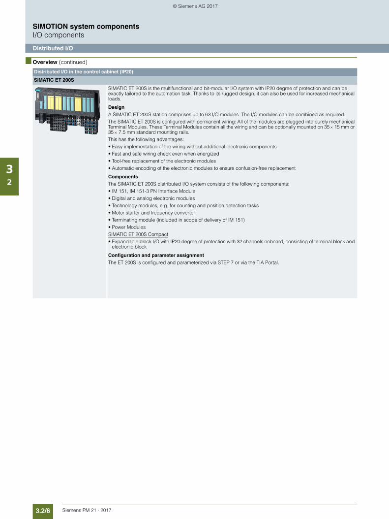
3.2/6 Siemens PM 21 · 2017
SIMOTION system componentsI/O components
Distributed I/O
32
■ Overview (continued)
Distributed I/O in the control cabinet (IP20)
SIMATIC ET 200S
SIMATIC ET 200S is the multifunctional and bit-modular I/O system with IP20 degree of protection and can be exactly tailored to the automation task. Thanks to its rugged design, it can also be used for increased mechanical loads.
DesignA SIMATIC ET 200S station comprises up to 63 I/O modules. The I/O modules can be combined as required. The SIMATIC ET 200S is configured with permanent wiring: All of the modules are plugged into purely mechanical Terminal Modules. These Terminal Modules contain all the wiring and can be optionally mounted on 35 15 mm or 35 7.5 mm standard mounting rails.This has the following advantages:• Easy implementation of the wiring without additional electronic components• Fast and safe wiring check even when energized• Tool-free replacement of the electronic modules• Automatic encoding of the electronic modules to ensure confusion-free replacement
ComponentsThe SIMATIC ET 200S distributed I/O system consists of the following components:• IM 151, IM 151-3 PN Interface Module • Digital and analog electronic modules• Technology modules, e.g. for counting and position detection tasks• Motor starter and frequency converter• Terminating module (included in scope of delivery of IM 151)• Power ModulesSIMATIC ET 200S Compact• Expandable block I/O with IP20 degree of protection with 32 channels onboard, consisting of terminal block and
electronic block
Configuration and parameter assignmentThe ET 200S is configured and parameterized via STEP 7 or via the TIA Portal.
© Siemens AG 2017
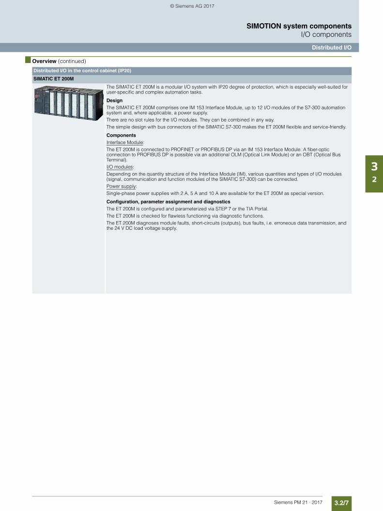
3.2/7Siemens PM 21 · 2017
SIMOTION system componentsI/O components
Distributed I/O
32
■ Overview (continued)
Distributed I/O in the control cabinet (IP20)
SIMATIC ET 200M
The SIMATIC ET 200M is a modular I/O system with IP20 degree of protection, which is especially well-suited for user-specific and complex automation tasks.
DesignThe SIMATIC ET 200M comprises one IM 153 Interface Module, up to 12 I/O modules of the S7-300 automation system and, where applicable, a power supply.There are no slot rules for the I/O modules. They can be combined in any way.The simple design with bus connectors of the SIMATIC S7-300 makes the ET 200M flexible and service-friendly.
ComponentsInterface Module: The ET 200M is connected to PROFINET or PROFIBUS DP via an IM 153 Interface Module. A fiber-optic connection to PROFIBUS DP is possible via an additional OLM (Optical Link Module) or an OBT (Optical Bus Terminal).I/O modules: Depending on the quantity structure of the Interface Module (IM), various quantities and types of I/O modules (signal, communication and function modules of the SIMATIC S7-300) can be connected. Power supply: Single-phase power supplies with 2 A, 5 A and 10 A are available for the ET 200M as special version.
Configuration, parameter assignment and diagnosticsThe ET 200M is configured and parameterized via STEP 7 or the TIA Portal.The ET 200M is checked for flawless functioning via diagnostic functions. The ET 200M diagnoses module faults, short-circuits (outputs), bus faults, i.e. erroneous data transmission, and the 24 V DC load voltage supply.
© Siemens AG 2017
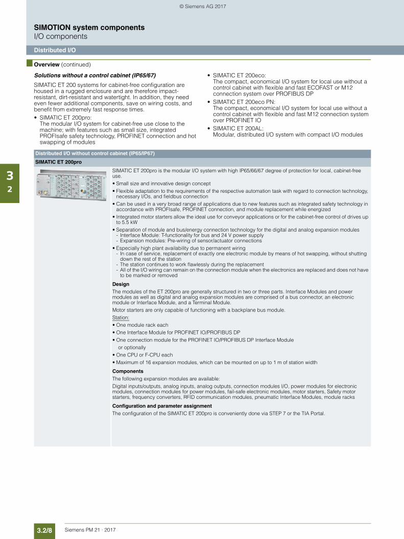
3.2/8 Siemens PM 21 · 2017
SIMOTION system componentsI/O components
Distributed I/O
32
■ Overview (continued)
Solutions without a control cabinet (IP65/67)
SIMATIC ET 200 systems for cabinet-free configuration are housed in a rugged enclosure and are therefore impact-resistant, dirt-resistant and watertight. In addition, they need even fewer additional components, save on wiring costs, and benefit from extremely fast response times.• SIMATIC ET 200pro:
The modular I/O system for cabinet-free use close to the machine; with features such as small size, integrated PROFIsafe safety technology, PROFINET connection and hot swapping of modules
• SIMATIC ET 200eco: The compact, economical I/O system for local use without a control cabinet with flexible and fast ECOFAST or M12 connection system over PROFIBUS DP
• SIMATIC ET 200eco PN: The compact, economical I/O system for local use without a control cabinet with flexible and fast M12 connection system over PROFINET IO
• SIMATIC ET 200AL: Modular, distributed I/O system with compact I/O modules
Distributed I/O without control cabinet (IP65/IP67)
SIMATIC ET 200pro
SIMATIC ET 200pro is the modular I/O system with high IP65/66/67 degree of protection for local, cabinet-free use.• Small size and innovative design concept• Flexible adaptation to the requirements of the respective automation task with regard to connection technology,
necessary I/Os, and fieldbus connection• Can be used in a very broad range of applications due to new features such as integrated safety technology in
accordance with PROFIsafe, PROFINET connection, and module replacement while energized• Integrated motor starters allow the ideal use for conveyor applications or for the cabinet-free control of drives up
to 5.5 kW • Separation of module and bus/energy connection technology for the digital and analog expansion modules
- Interface Module: T-functionality for bus and 24 V power supply- Expansion modules: Pre-wiring of sensor/actuator connections
• Especially high plant availability due to permanent wiring- In case of service, replacement of exactly one electronic module by means of hot swapping, without shutting
down the rest of the station- The station continues to work flawlessly during the replacement- All of the I/O wiring can remain on the connection module when the electronics are replaced and does not have
to be marked or removed
DesignThe modules of the ET 200pro are generally structured in two or three parts. Interface Modules and power modules as well as digital and analog expansion modules are comprised of a bus connector, an electronic module or Interface Module, and a Terminal Module.Motor starters are only capable of functioning with a backplane bus module.Station:• One module rack each• One Interface Module for PROFINET IO/PROFIBUS DP• One connection module for the PROFINET IO/PROFIBUS DP Interface Module
or optionally• One CPU or F-CPU each• Maximum of 16 expansion modules, which can be mounted on up to 1 m of station width
ComponentsThe following expansion modules are available:Digital inputs/outputs, analog inputs, analog outputs, connection modules I/O, power modules for electronic modules, connection modules for power modules, fail-safe electronic modules, motor starters, Safety motor starters, frequency converters, RFID communication modules, pneumatic Interface Modules, module racks
Configuration and parameter assignmentThe configuration of the SIMATIC ET 200pro is conveniently done via STEP 7 or the TIA Portal.
© Siemens AG 2017
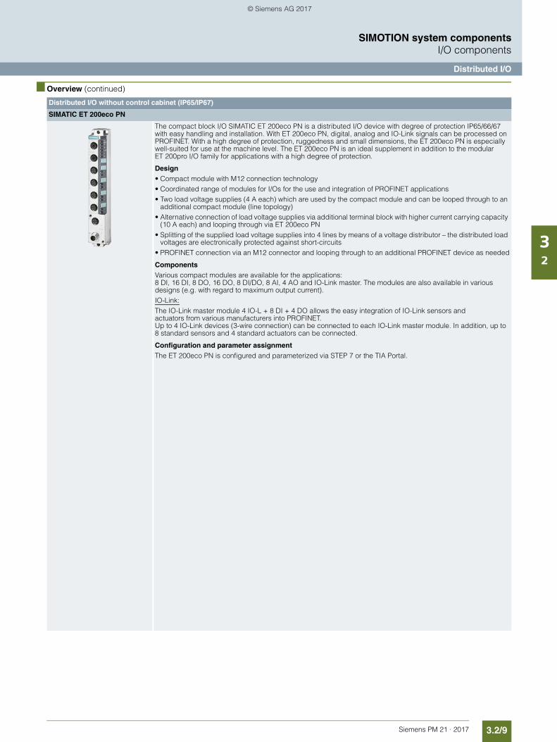
3.2/9Siemens PM 21 · 2017
SIMOTION system componentsI/O components
Distributed I/O
32
■ Overview (continued)
Distributed I/O without control cabinet (IP65/IP67)
SIMATIC ET 200eco PN
The compact block I/O SIMATIC ET 200eco PN is a distributed I/O device with degree of protection IP65/66/67 with easy handling and installation. With ET 200eco PN, digital, analog and IO-Link signals can be processed on PROFINET. With a high degree of protection, ruggedness and small dimensions, the ET 200eco PN is especially well-suited for use at the machine level. The ET 200eco PN is an ideal supplement in addition to the modular ET 200pro I/O family for applications with a high degree of protection.
Design• Compact module with M12 connection technology• Coordinated range of modules for I/Os for the use and integration of PROFINET applications• Two load voltage supplies (4 A each) which are used by the compact module and can be looped through to an
additional compact module (line topology)• Alternative connection of load voltage supplies via additional terminal block with higher current carrying capacity
(10 A each) and looping through via ET 200eco PN• Splitting of the supplied load voltage supplies into 4 lines by means of a voltage distributor – the distributed load
voltages are electronically protected against short-circuits• PROFINET connection via an M12 connector and looping through to an additional PROFINET device as needed
ComponentsVarious compact modules are available for the applications: 8 DI, 16 DI, 8 DO, 16 DO, 8 DI/DO, 8 AI, 4 AO and IO-Link master. The modules are also available in various designs (e.g. with regard to maximum output current).IO-Link: The IO-Link master module 4 IO-L + 8 DI + 4 DO allows the easy integration of IO-Link sensors and actuators from various manufacturers into PROFINET. Up to 4 IO-Link devices (3-wire connection) can be connected to each IO-Link master module. In addition, up to 8 standard sensors and 4 standard actuators can be connected.
Configuration and parameter assignmentThe ET 200eco PN is configured and parameterized via STEP 7 or the TIA Portal.
© Siemens AG 2017
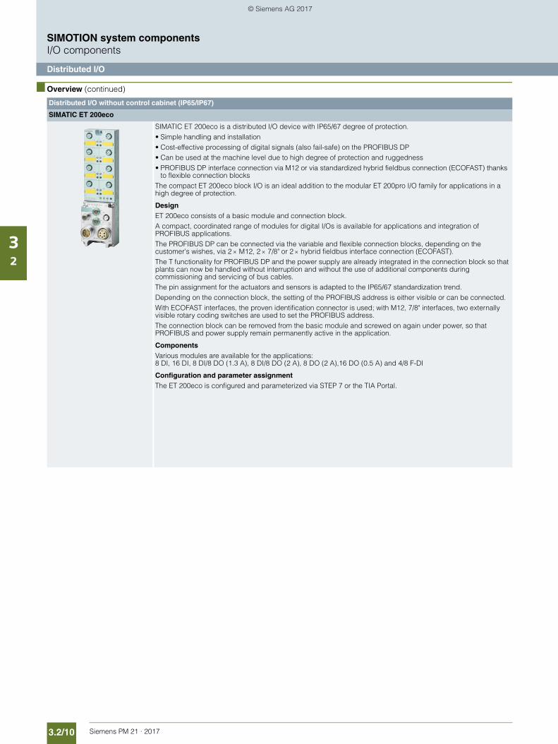
3.2/10 Siemens PM 21 · 2017
SIMOTION system componentsI/O components
Distributed I/O
32
■ Overview (continued)
Distributed I/O without control cabinet (IP65/IP67)
SIMATIC ET 200eco
SIMATIC ET 200eco is a distributed I/O device with IP65/67 degree of protection.• Simple handling and installation• Cost-effective processing of digital signals (also fail-safe) on the PROFIBUS DP• Can be used at the machine level due to high degree of protection and ruggedness• PROFIBUS DP interface connection via M12 or via standardized hybrid fieldbus connection (ECOFAST) thanks
to flexible connection blocksThe compact ET 200eco block I/O is an ideal addition to the modular ET 200pro I/O family for applications in a high degree of protection.
DesignET 200eco consists of a basic module and connection block.A compact, coordinated range of modules for digital I/Os is available for applications and integration of PROFIBUS applications.The PROFIBUS DP can be connected via the variable and flexible connection blocks, depending on the customer's wishes, via 2 M12, 2 7/8" or 2 hybrid fieldbus interface connection (ECOFAST).The T functionality for PROFIBUS DP and the power supply are already integrated in the connection block so that plants can now be handled without interruption and without the use of additional components during commissioning and servicing of bus cables.The pin assignment for the actuators and sensors is adapted to the IP65/67 standardization trend.Depending on the connection block, the setting of the PROFIBUS address is either visible or can be connected.With ECOFAST interfaces, the proven identification connector is used; with M12, 7/8" interfaces, two externally visible rotary coding switches are used to set the PROFIBUS address.The connection block can be removed from the basic module and screwed on again under power, so that PROFIBUS and power supply remain permanently active in the application.
ComponentsVarious modules are available for the applications: 8 DI, 16 DI, 8 DI/8 DO (1.3 A), 8 DI/8 DO (2 A), 8 DO (2 A),16 DO (0.5 A) and 4/8 F-DI
Configuration and parameter assignmentThe ET 200eco is configured and parameterized via STEP 7 or the TIA Portal.
© Siemens AG 2017
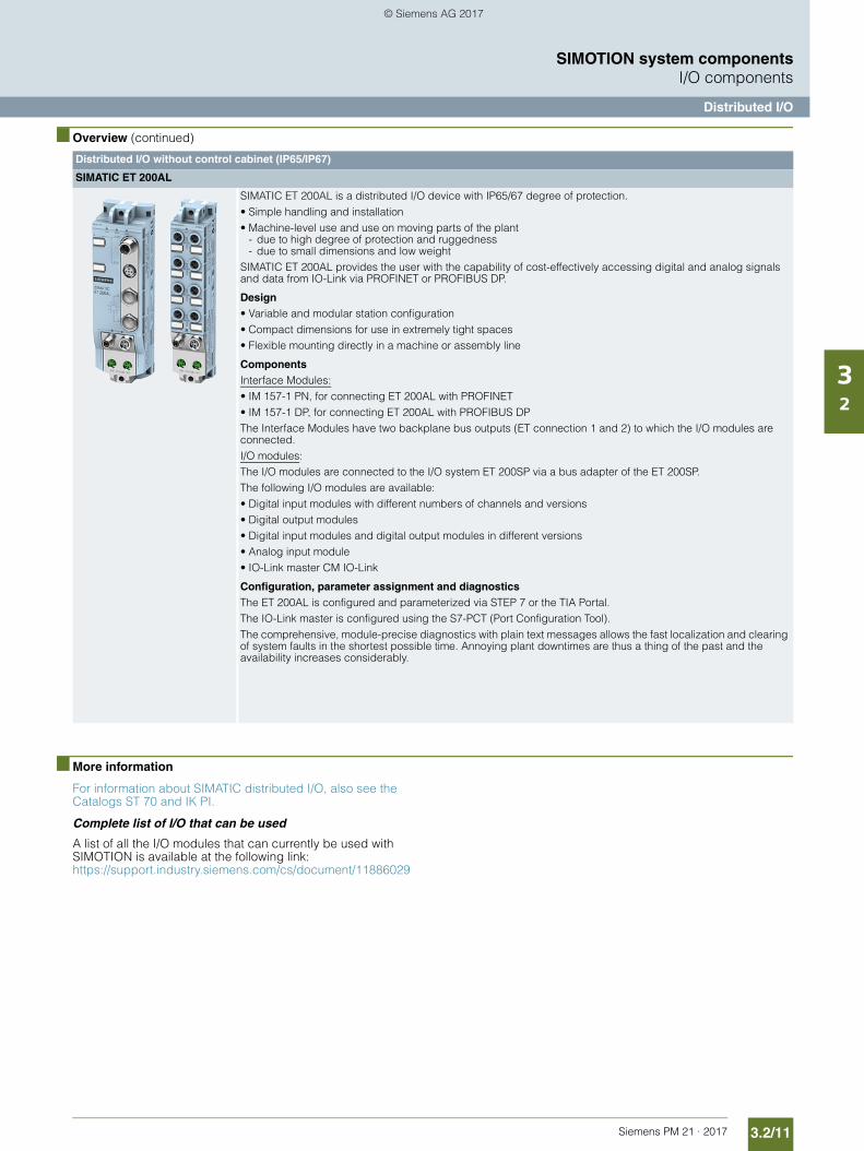
3.2/11Siemens PM 21 · 2017
SIMOTION system componentsI/O components
Distributed I/O
32
■ Overview (continued)
■ More information
For information about SIMATIC distributed I/O, also see the Catalogs ST 70 and IK PI.
Complete list of I/O that can be used
A list of all the I/O modules that can currently be used with SIMOTION is available at the following link: https://support.industry.siemens.com/cs/document/11886029
Distributed I/O without control cabinet (IP65/IP67)
SIMATIC ET 200AL
SIMATIC ET 200AL is a distributed I/O device with IP65/67 degree of protection.• Simple handling and installation• Machine-level use and use on moving parts of the plant
- due to high degree of protection and ruggedness- due to small dimensions and low weight
SIMATIC ET 200AL provides the user with the capability of cost-effectively accessing digital and analog signals and data from IO-Link via PROFINET or PROFIBUS DP.
Design• Variable and modular station configuration• Compact dimensions for use in extremely tight spaces• Flexible mounting directly in a machine or assembly line
ComponentsInterface Modules:• IM 157-1 PN, for connecting ET 200AL with PROFINET• IM 157-1 DP, for connecting ET 200AL with PROFIBUS DPThe Interface Modules have two backplane bus outputs (ET connection 1 and 2) to which the I/O modules are connected.I/O modules: The I/O modules are connected to the I/O system ET 200SP via a bus adapter of the ET 200SP. The following I/O modules are available:• Digital input modules with different numbers of channels and versions• Digital output modules • Digital input modules and digital output modules in different versions• Analog input module• IO-Link master CM IO-Link
Configuration, parameter assignment and diagnosticsThe ET 200AL is configured and parameterized via STEP 7 or the TIA Portal.The IO-Link master is configured using the S7-PCT (Port Configuration Tool).The comprehensive, module-precise diagnostics with plain text messages allows the fast localization and clearing of system faults in the shortest possible time. Annoying plant downtimes are thus a thing of the past and the availability increases considerably.
© Siemens AG 2017
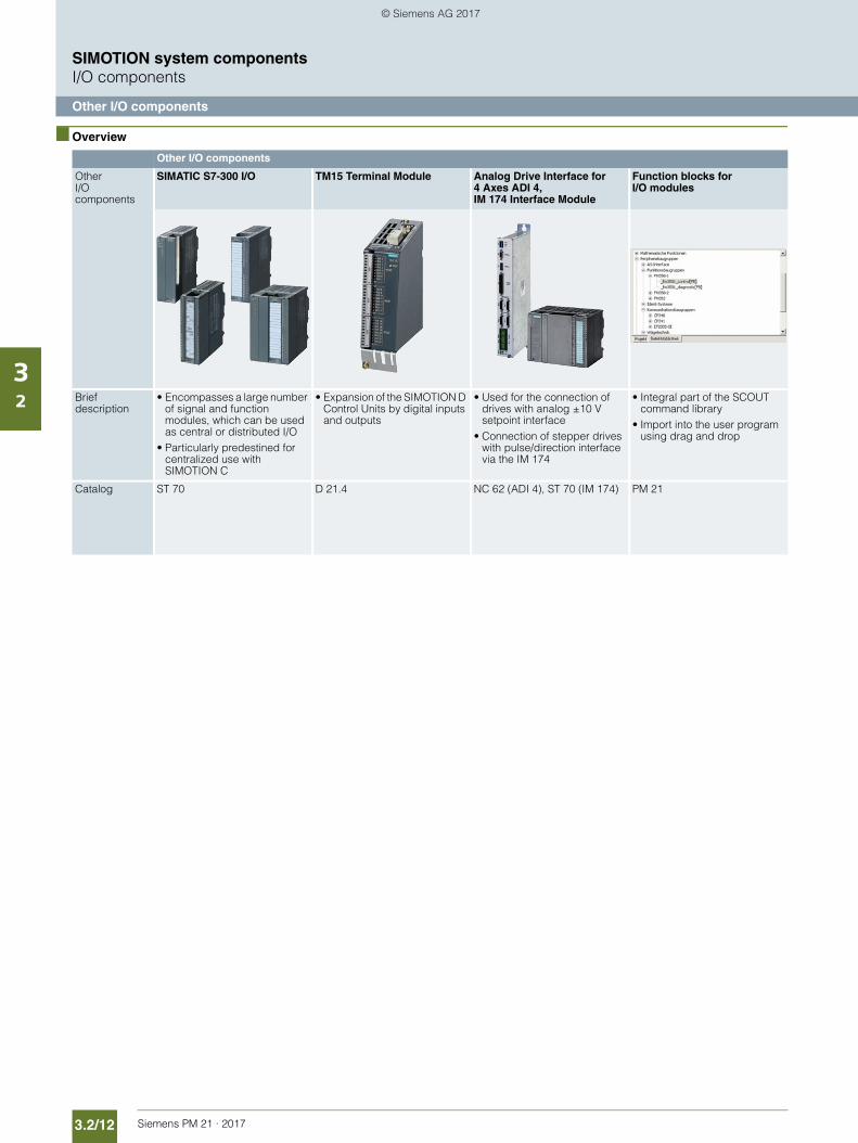
3.2/12 Siemens PM 21 · 2017
SIMOTION system componentsI/O components
Other I/O components
32
■ Overview
Other I/O components
Other I/O components
SIMATIC S7-300 I/O TM15 Terminal Module Analog Drive Interface for 4 Axes ADI 4, IM 174 Interface Module
Function blocks for I/O modules
Brief description
• Encompasses a large number of signal and function modules, which can be used as central or distributed I/O
• Particularly predestined for centralized use with SIMOTION C
• Expansion of the SIMOTION D Control Units by digital inputs and outputs
• Used for the connection of drives with analog ±10 V setpoint interface
• Connection of stepper drives with pulse/direction interface via the IM 174
• Integral part of the SCOUT command library
• Import into the user program using drag and drop
Catalog ST 70 D 21.4 NC 62 (ADI 4), ST 70 (IM 174) PM 21
© Siemens AG 2017
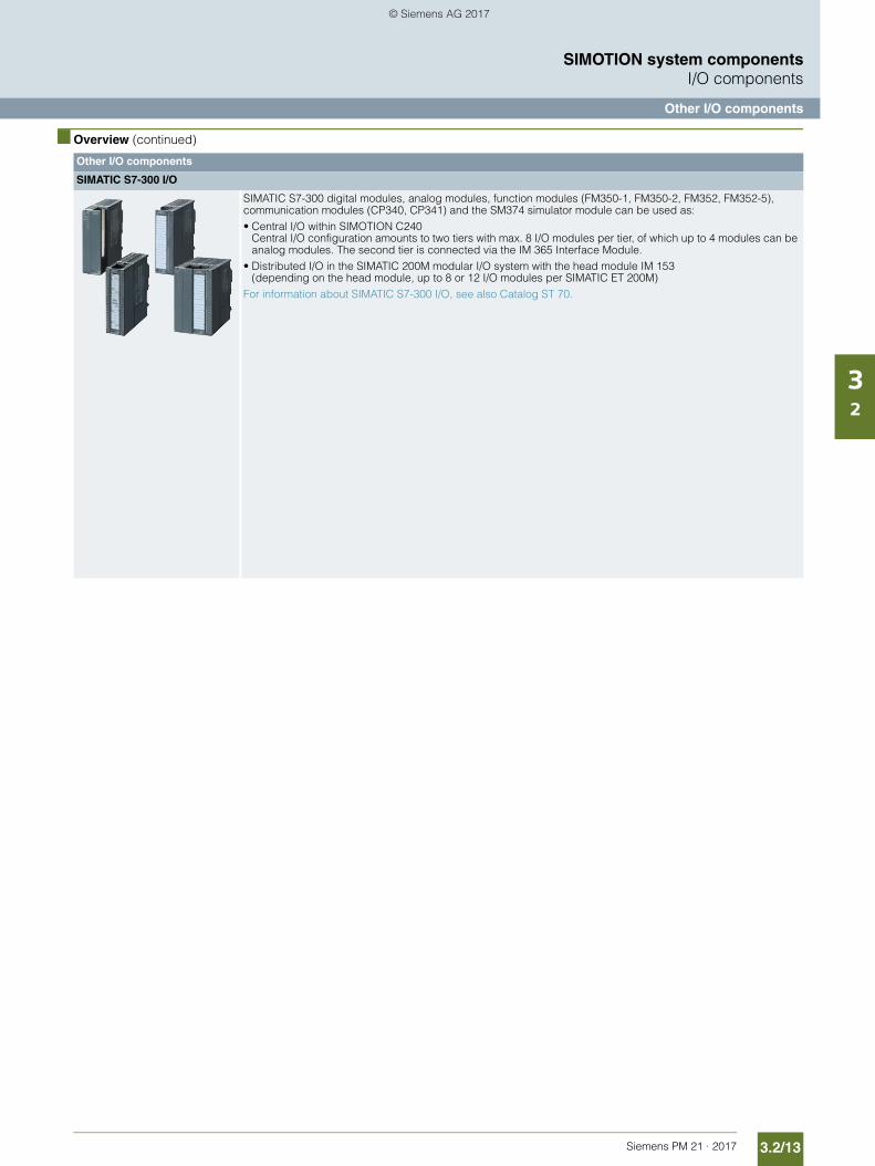
3.2/13Siemens PM 21 · 2017
SIMOTION system componentsI/O components
Other I/O components
32
■ Overview (continued)
Other I/O components
SIMATIC S7-300 I/O
SIMATIC S7-300 digital modules, analog modules, function modules (FM350-1, FM350-2, FM352, FM352-5), communication modules (CP340, CP341) and the SM374 simulator module can be used as:• Central I/O within SIMOTION C240
Central I/O configuration amounts to two tiers with max. 8 I/O modules per tier, of which up to 4 modules can be analog modules. The second tier is connected via the IM 365 Interface Module.
• Distributed I/O in the SIMATIC 200M modular I/O system with the head module IM 153 (depending on the head module, up to 8 or 12 I/O modules per SIMATIC ET 200M)
For information about SIMATIC S7-300 I/O, see also Catalog ST 70.
© Siemens AG 2017
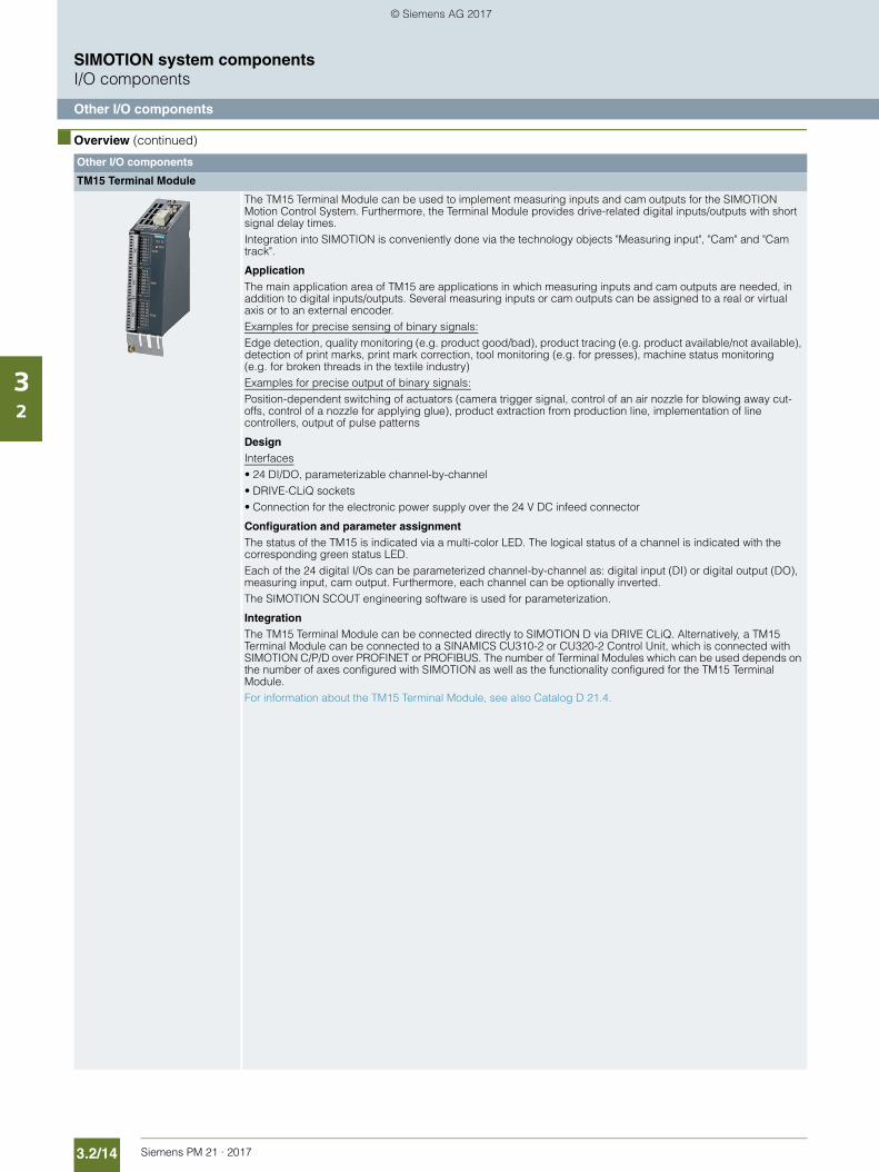
3.2/14 Siemens PM 21 · 2017
SIMOTION system componentsI/O components
Other I/O components
32
■ Overview (continued)
Other I/O components
TM15 Terminal Module
The TM15 Terminal Module can be used to implement measuring inputs and cam outputs for the SIMOTION Motion Control System. Furthermore, the Terminal Module provides drive-related digital inputs/outputs with short signal delay times.Integration into SIMOTION is conveniently done via the technology objects "Measuring input", "Cam" and "Cam track".
ApplicationThe main application area of TM15 are applications in which measuring inputs and cam outputs are needed, in addition to digital inputs/outputs. Several measuring inputs or cam outputs can be assigned to a real or virtual axis or to an external encoder.Examples for precise sensing of binary signals:Edge detection, quality monitoring (e.g. product good/bad), product tracing (e.g. product available/not available), detection of print marks, print mark correction, tool monitoring (e.g. for presses), machine status monitoring (e.g. for broken threads in the textile industry)Examples for precise output of binary signals:Position-dependent switching of actuators (camera trigger signal, control of an air nozzle for blowing away cut-offs, control of a nozzle for applying glue), product extraction from production line, implementation of line controllers, output of pulse patterns
DesignInterfaces• 24 DI/DO, parameterizable channel-by-channel• DRIVE-CLiQ sockets• Connection for the electronic power supply over the 24 V DC infeed connector
Configuration and parameter assignmentThe status of the TM15 is indicated via a multi-color LED. The logical status of a channel is indicated with the corresponding green status LED.Each of the 24 digital I/Os can be parameterized channel-by-channel as: digital input (DI) or digital output (DO), measuring input, cam output. Furthermore, each channel can be optionally inverted.The SIMOTION SCOUT engineering software is used for parameterization.
IntegrationThe TM15 Terminal Module can be connected directly to SIMOTION D via DRIVE CLiQ. Alternatively, a TM15 Terminal Module can be connected to a SINAMICS CU310-2 or CU320-2 Control Unit, which is connected with SIMOTION C/P/D over PROFINET or PROFIBUS. The number of Terminal Modules which can be used depends on the number of axes configured with SIMOTION as well as the functionality configured for the TM15 Terminal Module. For information about the TM15 Terminal Module, see also Catalog D 21.4.
© Siemens AG 2017
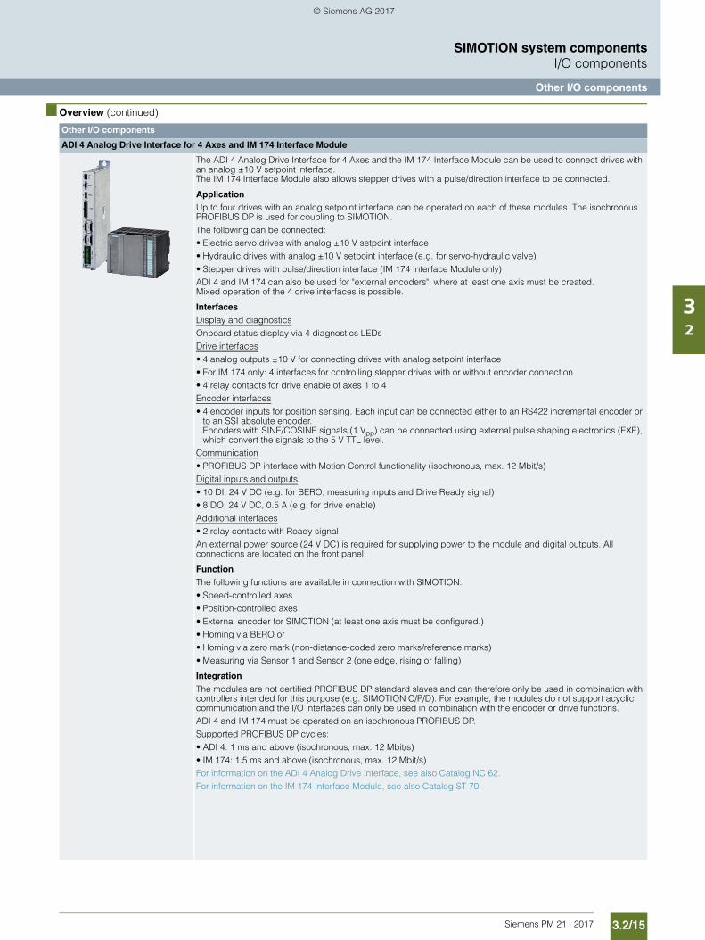
3.2/15Siemens PM 21 · 2017
SIMOTION system componentsI/O components
Other I/O components
32
■ Overview (continued)
Other I/O components
ADI 4 Analog Drive Interface for 4 Axes and IM 174 Interface Module
The ADI 4 Analog Drive Interface for 4 Axes and the IM 174 Interface Module can be used to connect drives with an analog ±10 V setpoint interface. The IM 174 Interface Module also allows stepper drives with a pulse/direction interface to be connected.
ApplicationUp to four drives with an analog setpoint interface can be operated on each of these modules. The isochronous PROFIBUS DP is used for coupling to SIMOTION. The following can be connected:• Electric servo drives with analog ±10 V setpoint interface• Hydraulic drives with analog ±10 V setpoint interface (e.g. for servo-hydraulic valve)• Stepper drives with pulse/direction interface (IM 174 Interface Module only)ADI 4 and IM 174 can also be used for "external encoders", where at least one axis must be created. Mixed operation of the 4 drive interfaces is possible.
InterfacesDisplay and diagnosticsOnboard status display via 4 diagnostics LEDsDrive interfaces• 4 analog outputs ±10 V for connecting drives with analog setpoint interface • For IM 174 only: 4 interfaces for controlling stepper drives with or without encoder connection • 4 relay contacts for drive enable of axes 1 to 4Encoder interfaces• 4 encoder inputs for position sensing. Each input can be connected either to an RS422 incremental encoder or
to an SSI absolute encoder.Encoders with SINE/COSINE signals (1 Vpp) can be connected using external pulse shaping electronics (EXE), which convert the signals to the 5 V TTL level.
Communication• PROFIBUS DP interface with Motion Control functionality (isochronous, max. 12 Mbit/s)Digital inputs and outputs• 10 DI, 24 V DC (e.g. for BERO, measuring inputs and Drive Ready signal) • 8 DO, 24 V DC, 0.5 A (e.g. for drive enable) Additional interfaces• 2 relay contacts with Ready signalAn external power source (24 V DC) is required for supplying power to the module and digital outputs. All connections are located on the front panel.
FunctionThe following functions are available in connection with SIMOTION:• Speed-controlled axes• Position-controlled axes• External encoder for SIMOTION (at least one axis must be configured.)• Homing via BERO or• Homing via zero mark (non-distance-coded zero marks/reference marks)• Measuring via Sensor 1 and Sensor 2 (one edge, rising or falling)
IntegrationThe modules are not certified PROFIBUS DP standard slaves and can therefore only be used in combination with controllers intended for this purpose (e.g. SIMOTION C/P/D). For example, the modules do not support acyclic communication and the I/O interfaces can only be used in combination with the encoder or drive functions.ADI 4 and IM 174 must be operated on an isochronous PROFIBUS DP.Supported PROFIBUS DP cycles:• ADI 4: 1 ms and above (isochronous, max. 12 Mbit/s)• IM 174: 1.5 ms and above (isochronous, max. 12 Mbit/s)For information on the ADI 4 Analog Drive Interface, see also Catalog NC 62. For information on the IM 174 Interface Module, see also Catalog ST 70.
© Siemens AG 2017
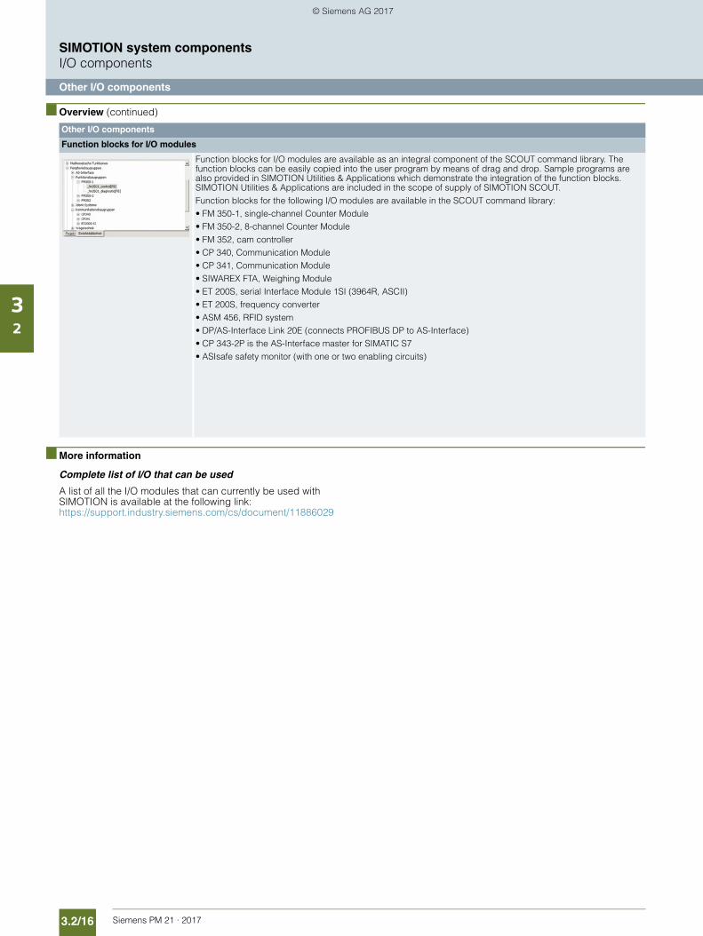
3.2/16 Siemens PM 21 · 2017
SIMOTION system componentsI/O components
Other I/O components
32
■ Overview (continued)
■ More information
Complete list of I/O that can be used
A list of all the I/O modules that can currently be used with SIMOTION is available at the following link: https://support.industry.siemens.com/cs/document/11886029
Other I/O components
Function blocks for I/O modules
Function blocks for I/O modules are available as an integral component of the SCOUT command library. The function blocks can be easily copied into the user program by means of drag and drop. Sample programs are also provided in SIMOTION Utilities & Applications which demonstrate the integration of the function blocks. SIMOTION Utilities & Applications are included in the scope of supply of SIMOTION SCOUT.Function blocks for the following I/O modules are available in the SCOUT command library:• FM 350-1, single-channel Counter Module • FM 350-2, 8-channel Counter Module • FM 352, cam controller • CP 340, Communication Module • CP 341, Communication Module • SIWAREX FTA, Weighing Module• ET 200S, serial Interface Module 1SI (3964R, ASCII) • ET 200S, frequency converter• ASM 456, RFID system• DP/AS-Interface Link 20E (connects PROFIBUS DP to AS-Interface)• CP 343-2P is the AS-Interface master for SIMATIC S7• ASIsafe safety monitor (with one or two enabling circuits)
© Siemens AG 2017
Siemens PM 21 · 2017
3.33.3/2 SITOP power supplies3.3/2 Overview3.3/4 SITOP lite3.3/4 SITOP smart3.3/4 SITOP power supplies in
SIMATIC design3.3/4 SITOP modular3.3/5 SITOP modular,
PSU8600 power supply system3.3/5 SITOP expansion modules3.3/6 SITOP uninterruptible power supplies
(DC UPS)
3.3/6 More information
SIMOTION system components Power supplies
© Siemens AG 2017
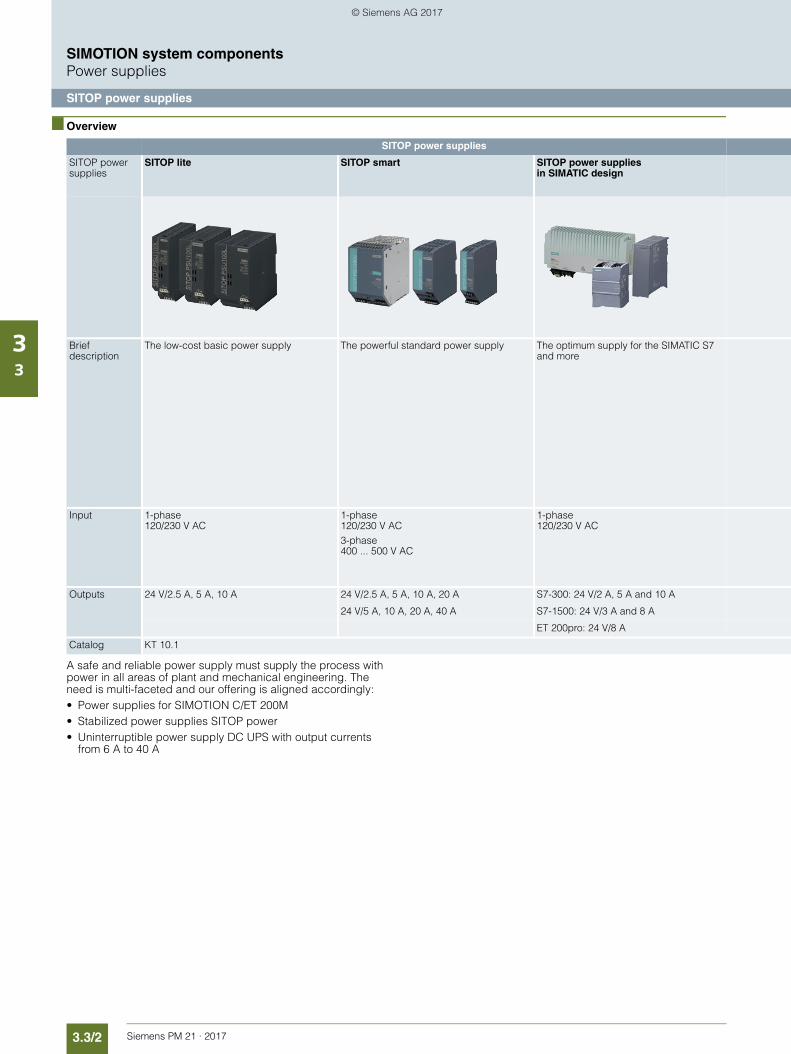
3.3/2 Siemens PM 21 · 2017
SIMOTION system componentsPower supplies
SITOP power supplies
33
■ Overview
A safe and reliable power supply must supply the process with power in all areas of plant and mechanical engineering. The need is multi-faceted and our offering is aligned accordingly:• Power supplies for SIMOTION C/ET 200M• Stabilized power supplies SITOP power• Uninterruptible power supply DC UPS with output currents
from 6 A to 40 A
SITOP power supplies
SITOP power supplies
SITOP lite SITOP smart SITOP power supplies in SIMATIC design
Brief description
The low-cost basic power supply The powerful standard power supply The optimum supply for the SIMATIC S7 and more
Input 1-phase 120/230 V AC
1-phase 120/230 V AC3-phase 400 ... 500 V AC
1-phase 120/230 V AC
Outputs 24 V/2.5 A, 5 A, 10 A 24 V/2.5 A, 5 A, 10 A, 20 A S7-300: 24 V/2 A, 5 A and 10 A
24 V/5 A, 10 A, 20 A, 40 A S7-1500: 24 V/3 A and 8 A
ET 200pro: 24 V/8 A
Catalog KT 10.1
© Siemens AG 2017
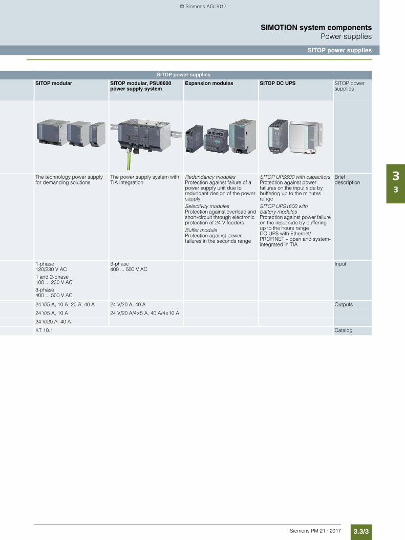
3.3/3Siemens PM 21 · 2017
SIMOTION system componentsPower supplies
SITOP power supplies
33
SITOP power supplies
SITOP modular SITOP modular, PSU8600 power supply system
Expansion modules SITOP DC UPS SITOP power supplies
The technology power supply for demanding solutions
The power supply system with TIA integration
Redundancy modules Protection against failure of a power supply unit due to redundant design of the power supplySelectivity modules Protection against overload and short-circuit through electronic protection of 24 V feedersBuffer module Protection against power failures in the seconds range
SITOP UPS500 with capacitors Protection against power failures on the input side by buffering up to the minutes rangeSITOP UPS1600 with battery modules Protection against power failure on the input side by buffering up to the hours range DC UPS with Ethernet/PROFINET – open and system-integrated in TIA
Brief description
1-phase 120/230 V AC1 and 2-phase 100 ... 230 V AC3-phase 400 ... 500 V AC
3-phase 400 ... 500 V AC
Input
24 V/5 A, 10 A, 20 A, 40 A 24 V/20 A, 40 A Outputs
24 V/5 A, 10 A 24 V/20 A/4 x 5 A, 40 A/4 x 10 A
24 V/20 A, 40 A
KT 10.1 Catalog
© Siemens AG 2017
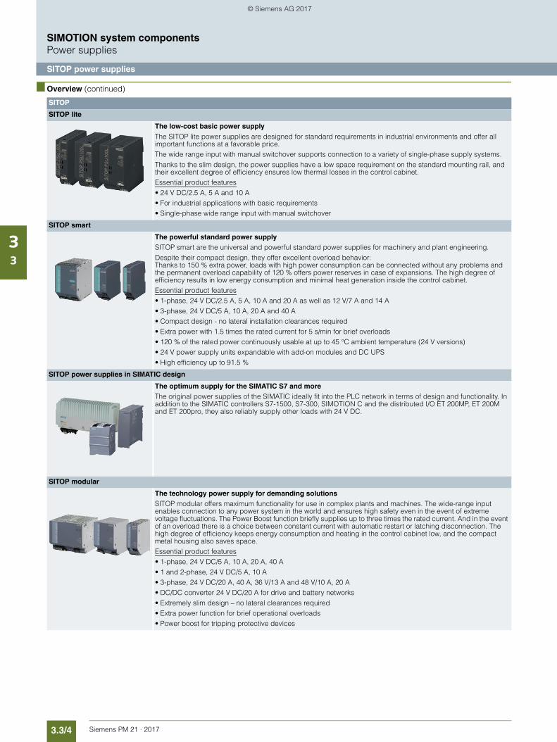
3.3/4 Siemens PM 21 · 2017
SIMOTION system componentsPower supplies
SITOP power supplies
33
■ Overview (continued)
SITOP
SITOP lite
The low-cost basic power supplyThe SITOP lite power supplies are designed for standard requirements in industrial environments and offer all important functions at a favorable price. The wide range input with manual switchover supports connection to a variety of single-phase supply systems. Thanks to the slim design, the power supplies have a low space requirement on the standard mounting rail, and their excellent degree of efficiency ensures low thermal losses in the control cabinet. Essential product features• 24 V DC/2.5 A, 5 A and 10 A• For industrial applications with basic requirements• Single-phase wide range input with manual switchover
SITOP smart
The powerful standard power supplySITOP smart are the universal and powerful standard power supplies for machinery and plant engineering. Despite their compact design, they offer excellent overload behavior: Thanks to 150 % extra power, loads with high power consumption can be connected without any problems and the permanent overload capability of 120 % offers power reserves in case of expansions. The high degree of efficiency results in low energy consumption and minimal heat generation inside the control cabinet. Essential product features• 1-phase, 24 V DC/2.5 A, 5 A, 10 A and 20 A as well as 12 V/7 A and 14 A• 3-phase, 24 V DC/5 A, 10 A, 20 A and 40 A• Compact design - no lateral installation clearances required • Extra power with 1.5 times the rated current for 5 s/min for brief overloads• 120 % of the rated power continuously usable at up to 45 °C ambient temperature (24 V versions)• 24 V power supply units expandable with add-on modules and DC UPS• High efficiency up to 91.5 %
SITOP power supplies in SIMATIC design
The optimum supply for the SIMATIC S7 and moreThe original power supplies of the SIMATIC ideally fit into the PLC network in terms of design and functionality. In addition to the SIMATIC controllers S7-1500, S7-300, SIMOTION C and the distributed I/O ET 200MP, ET 200M and ET 200pro, they also reliably supply other loads with 24 V DC.
SITOP modular
The technology power supply for demanding solutionsSITOP modular offers maximum functionality for use in complex plants and machines. The wide-range input enables connection to any power system in the world and ensures high safety even in the event of extreme voltage fluctuations. The Power Boost function briefly supplies up to three times the rated current. And in the event of an overload there is a choice between constant current with automatic restart or latching disconnection. The high degree of efficiency keeps energy consumption and heating in the control cabinet low, and the compact metal housing also saves space.Essential product features• 1-phase, 24 V DC/5 A, 10 A, 20 A, 40 A• 1 and 2-phase, 24 V DC/5 A, 10 A• 3-phase, 24 V DC/20 A, 40 A, 36 V/13 A and 48 V/10 A, 20 A• DC/DC converter 24 V DC/20 A for drive and battery networks• Extremely slim design – no lateral clearances required• Extra power function for brief operational overloads• Power boost for tripping protective devices
© Siemens AG 2017
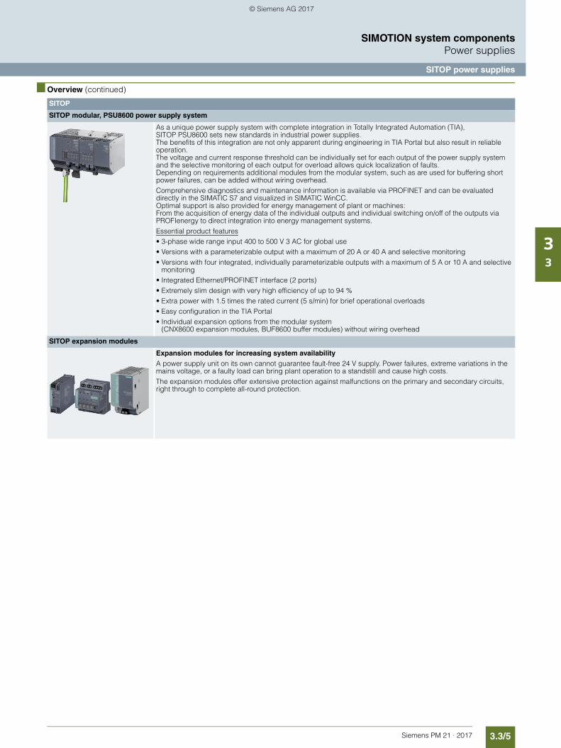
3.3/5Siemens PM 21 · 2017
SIMOTION system componentsPower supplies
SITOP power supplies
33
■ Overview (continued)
SITOP
SITOP modular, PSU8600 power supply system
As a unique power supply system with complete integration in Totally Integrated Automation (TIA), SITOP PSU8600 sets new standards in industrial power supplies. The benefits of this integration are not only apparent during engineering in TIA Portal but also result in reliable operation. The voltage and current response threshold can be individually set for each output of the power supply system and the selective monitoring of each output for overload allows quick localization of faults. Depending on requirements additional modules from the modular system, such as are used for buffering short power failures, can be added without wiring overhead.Comprehensive diagnostics and maintenance information is available via PROFINET and can be evaluated directly in the SIMATIC S7 and visualized in SIMATIC WinCC. Optimal support is also provided for energy management of plant or machines: From the acquisition of energy data of the individual outputs and individual switching on/off of the outputs via PROFIenergy to direct integration into energy management systems. Essential product features• 3-phase wide range input 400 to 500 V 3 AC for global use • Versions with a parameterizable output with a maximum of 20 A or 40 A and selective monitoring• Versions with four integrated, individually parameterizable outputs with a maximum of 5 A or 10 A and selective
monitoring• Integrated Ethernet/PROFINET interface (2 ports)• Extremely slim design with very high efficiency of up to 94 %• Extra power with 1.5 times the rated current (5 s/min) for brief operational overloads• Easy configuration in the TIA Portal• Individual expansion options from the modular system
(CNX8600 expansion modules, BUF8600 buffer modules) without wiring overhead
SITOP expansion modules
Expansion modules for increasing system availabilityA power supply unit on its own cannot guarantee fault-free 24 V supply. Power failures, extreme variations in the mains voltage, or a faulty load can bring plant operation to a standstill and cause high costs.The expansion modules offer extensive protection against malfunctions on the primary and secondary circuits, right through to complete all-round protection.
© Siemens AG 2017
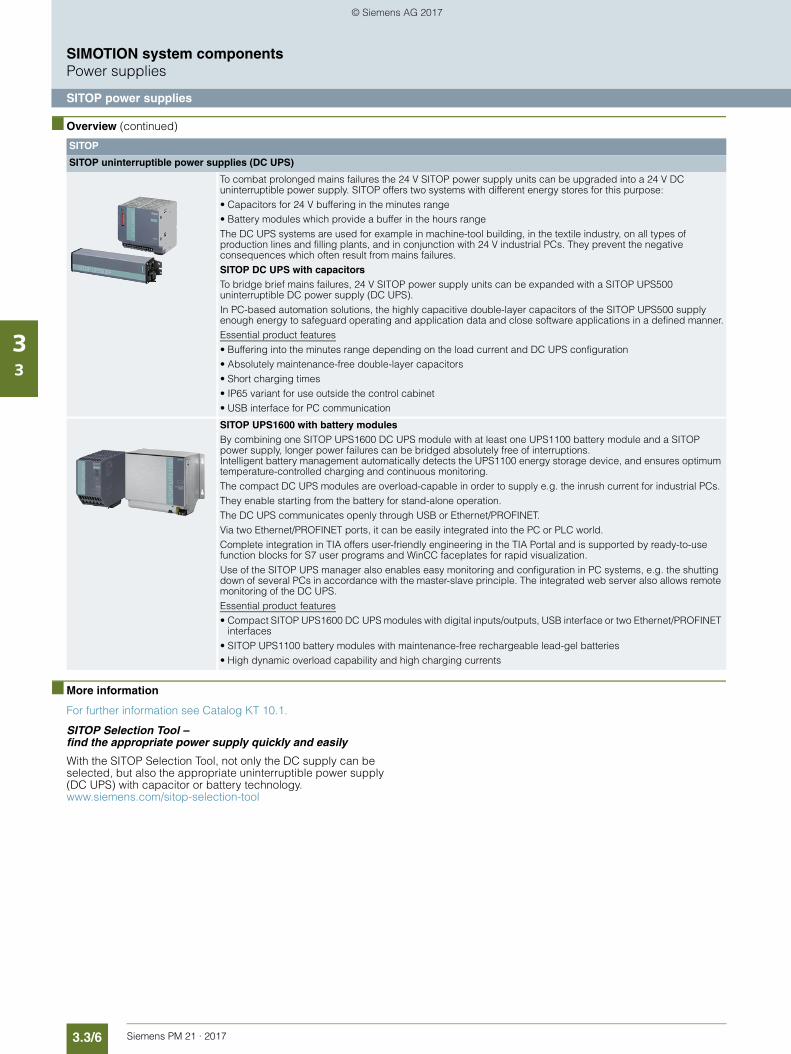
3.3/6 Siemens PM 21 · 2017
SIMOTION system componentsPower supplies
SITOP power supplies
33
■ Overview (continued)
■ More information
For further information see Catalog KT 10.1.
SITOP Selection Tool – find the appropriate power supply quickly and easily
With the SITOP Selection Tool, not only the DC supply can be selected, but also the appropriate uninterruptible power supply (DC UPS) with capacitor or battery technology. www.siemens.com/sitop-selection-tool
SITOP
SITOP uninterruptible power supplies (DC UPS)
To combat prolonged mains failures the 24 V SITOP power supply units can be upgraded into a 24 V DC uninterruptible power supply. SITOP offers two systems with different energy stores for this purpose:• Capacitors for 24 V buffering in the minutes range• Battery modules which provide a buffer in the hours rangeThe DC UPS systems are used for example in machine-tool building, in the textile industry, on all types of production lines and filling plants, and in conjunction with 24 V industrial PCs. They prevent the negative consequences which often result from mains failures.SITOP DC UPS with capacitorsTo bridge brief mains failures, 24 V SITOP power supply units can be expanded with a SITOP UPS500 uninterruptible DC power supply (DC UPS). In PC-based automation solutions, the highly capacitive double-layer capacitors of the SITOP UPS500 supply enough energy to safeguard operating and application data and close software applications in a defined manner.Essential product features• Buffering into the minutes range depending on the load current and DC UPS configuration• Absolutely maintenance-free double-layer capacitors• Short charging times• IP65 variant for use outside the control cabinet• USB interface for PC communication
SITOP UPS1600 with battery modulesBy combining one SITOP UPS1600 DC UPS module with at least one UPS1100 battery module and a SITOP power supply, longer power failures can be bridged absolutely free of interruptions. Intelligent battery management automatically detects the UPS1100 energy storage device, and ensures optimum temperature-controlled charging and continuous monitoring. The compact DC UPS modules are overload-capable in order to supply e.g. the inrush current for industrial PCs. They enable starting from the battery for stand-alone operation. The DC UPS communicates openly through USB or Ethernet/PROFINET. Via two Ethernet/PROFINET ports, it can be easily integrated into the PC or PLC world.Complete integration in TIA offers user-friendly engineering in the TIA Portal and is supported by ready-to-use function blocks for S7 user programs and WinCC faceplates for rapid visualization.Use of the SITOP UPS manager also enables easy monitoring and configuration in PC systems, e.g. the shutting down of several PCs in accordance with the master-slave principle. The integrated web server also allows remote monitoring of the DC UPS. Essential product features• Compact SITOP UPS1600 DC UPS modules with digital inputs/outputs, USB interface or two Ethernet/PROFINET
interfaces• SITOP UPS1100 battery modules with maintenance-free rechargeable lead-gel batteries• High dynamic overload capability and high charging currents
© Siemens AG 2017
Siemens PM 21 · 2017
3.43.4/2 SINAMICS drive family3.4/2 Overview3.4/2 Variants3.4/3 Energy efficiency3.4/3 Platform concept
3.4/4 SINAMICS drives for Motion Control3.4/4 Overview3.4/5 More information
SIMOTION system components Drives
© Siemens AG 2017
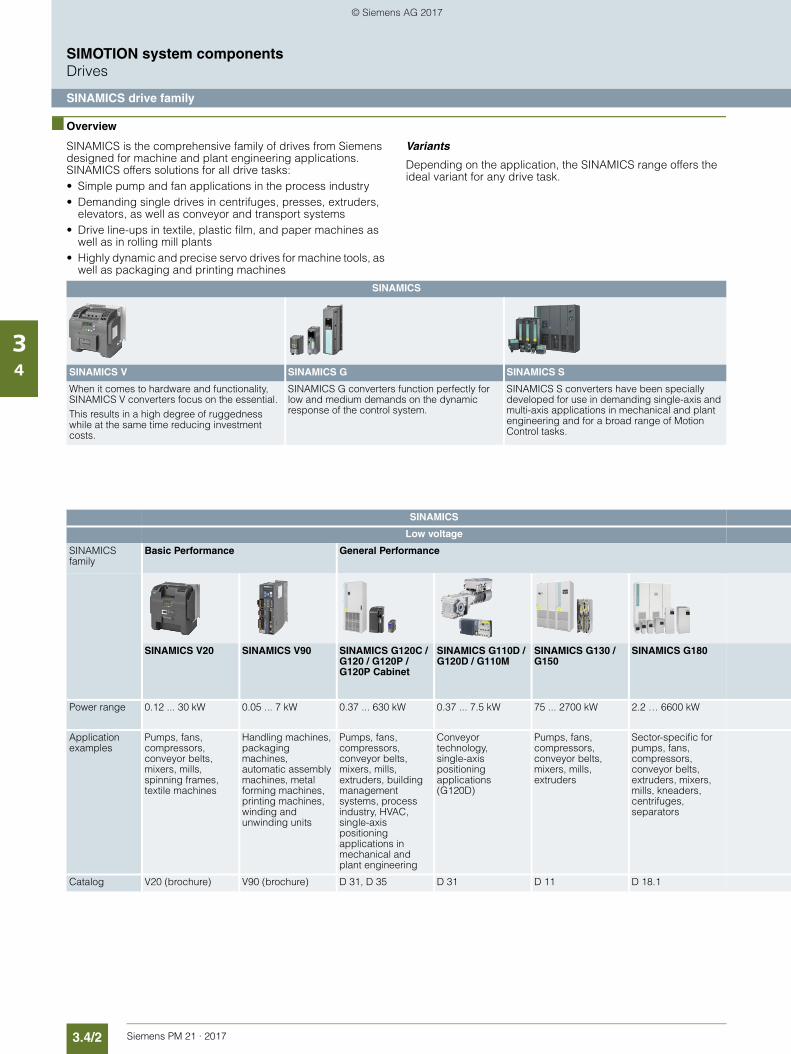
3.4/2 Siemens PM 21 · 2017
SIMOTION system componentsDrives
SINAMICS drive family
34
■ Overview
SINAMICS is the comprehensive family of drives from Siemens designed for machine and plant engineering applications. SINAMICS offers solutions for all drive tasks:• Simple pump and fan applications in the process industry• Demanding single drives in centrifuges, presses, extruders,
elevators, as well as conveyor and transport systems• Drive line-ups in textile, plastic film, and paper machines as
well as in rolling mill plants• Highly dynamic and precise servo drives for machine tools, as
well as packaging and printing machines
Variants
Depending on the application, the SINAMICS range offers the ideal variant for any drive task.
SINAMICS
SINAMICS V SINAMICS G SINAMICS S
When it comes to hardware and functionality, SINAMICS V converters focus on the essential. This results in a high degree of ruggedness while at the same time reducing investment costs.
SINAMICS G converters function perfectly for low and medium demands on the dynamic response of the control system.
SINAMICS S converters have been specially developed for use in demanding single-axis and multi-axis applications in mechanical and plant engineering and for a broad range of Motion Control tasks.
SINAMICS
Low voltage
SINAMICS family
Basic Performance General Performance
SINAMICS V20 SINAMICS V90 SINAMICS G120C / G120 / G120P / G120P Cabinet
SINAMICS G110D / G120D / G110M
SINAMICS G130 / G150
SINAMICS G180
Power range 0.12 ... 30 kW 0.05 ... 7 kW 0.37 ... 630 kW 0.37 ... 7.5 kW 75 ... 2700 kW 2.2 … 6600 kW
Application examples
Pumps, fans, compressors, conveyor belts, mixers, mills, spinning frames, textile machines
Handling machines, packaging machines, automatic assembly machines, metal forming machines, printing machines, winding and unwinding units
Pumps, fans, compressors, conveyor belts, mixers, mills, extruders, building management systems, process industry, HVAC, single-axis positioning applications in mechanical and plant engineering
Conveyor technology, single-axis positioning applications (G120D)
Pumps, fans, compressors, conveyor belts, mixers, mills, extruders
Sector-specific for pumps, fans, compressors, conveyor belts, extruders, mixers, mills, kneaders, centrifuges,separators
Catalog V20 (brochure) V90 (brochure) D 31, D 35 D 31 D 11 D 18.1
© Siemens AG 2017
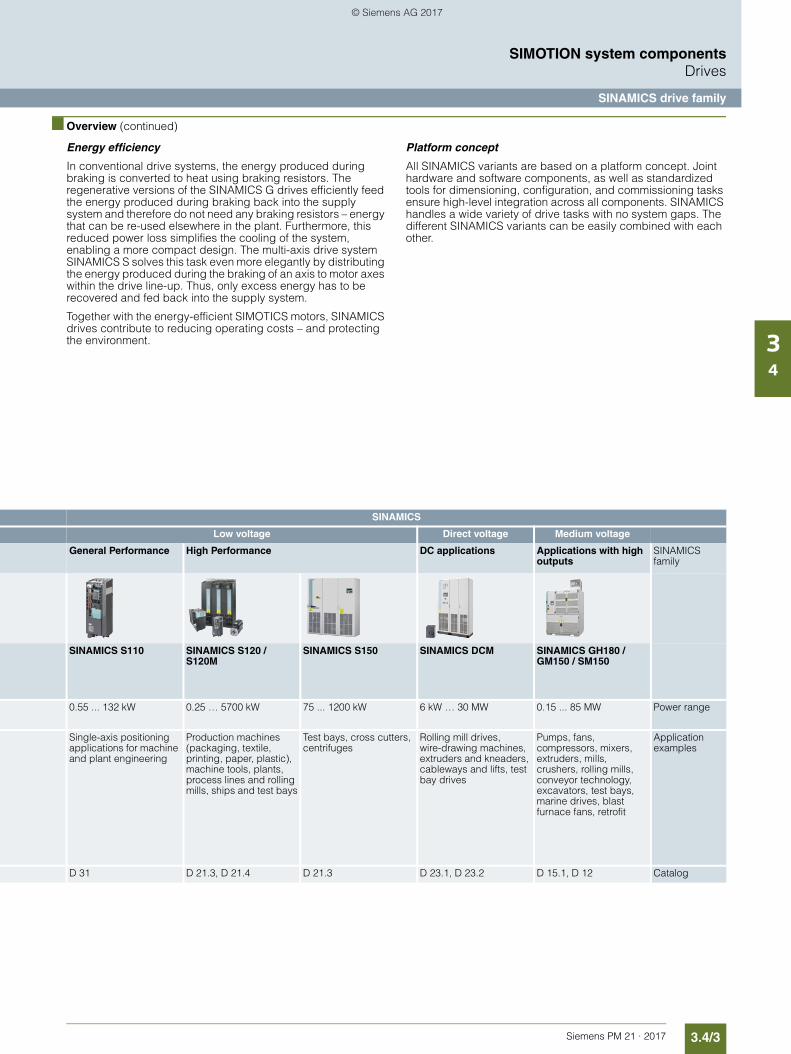
3.4/3Siemens PM 21 · 2017
SIMOTION system componentsDrives
SINAMICS drive family
34
■ Overview (continued)
Energy efficiency
In conventional drive systems, the energy produced during braking is converted to heat using braking resistors. The regenerative versions of the SINAMICS G drives efficiently feed the energy produced during braking back into the supply system and therefore do not need any braking resistors – energy that can be re-used elsewhere in the plant. Furthermore, this reduced power loss simplifies the cooling of the system, enabling a more compact design. The multi-axis drive system SINAMICS S solves this task even more elegantly by distributing the energy produced during the braking of an axis to motor axes within the drive line-up. Thus, only excess energy has to be recovered and fed back into the supply system.
Together with the energy-efficient SIMOTICS motors, SINAMICS drives contribute to reducing operating costs – and protecting the environment.
Platform concept
All SINAMICS variants are based on a platform concept. Joint hardware and software components, as well as standardized tools for dimensioning, configuration, and commissioning tasks ensure high-level integration across all components. SINAMICS handles a wide variety of drive tasks with no system gaps. The different SINAMICS variants can be easily combined with each other.
SINAMICS
Low voltage Direct voltage Medium voltage
General Performance High Performance DC applications Applications with high outputs
SINAMICS family
SINAMICS S110 SINAMICS S120 / S120M
SINAMICS S150 SINAMICS DCM SINAMICS GH180 / GM150 / SM150
0.55 ... 132 kW 0.25 … 5700 kW 75 ... 1200 kW 6 kW … 30 MW 0.15 ... 85 MW Power range
Single-axis positioning applications for machine and plant engineering
Production machines (packaging, textile, printing, paper, plastic), machine tools, plants, process lines and rolling mills, ships and test bays
Test bays, cross cutters, centrifuges
Rolling mill drives, wire-drawing machines, extruders and kneaders, cableways and lifts, test bay drives
Pumps, fans, compressors, mixers, extruders, mills, crushers, rolling mills, conveyor technology, excavators, test bays, marine drives, blast furnace fans, retrofit
Application examples
D 31 D 21.3, D 21.4 D 21.3 D 23.1, D 23.2 D 15.1, D 12 Catalog
© Siemens AG 2017
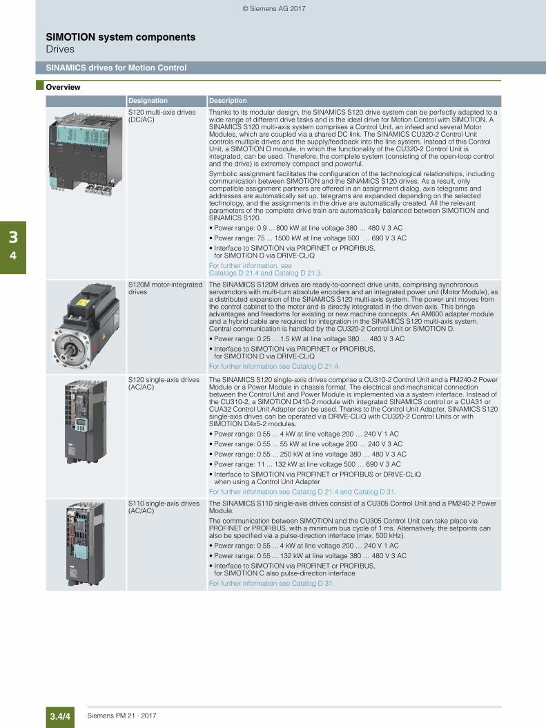
3.4/4 Siemens PM 21 · 2017
SIMOTION system componentsDrives
SINAMICS drives for Motion Control
34
■ Overview
Designation Description
S120 multi-axis drives (DC/AC)
Thanks to its modular design, the SINAMICS S120 drive system can be perfectly adapted to a wide range of different drive tasks and is the ideal drive for Motion Control with SIMOTION. A SINAMICS S120 multi-axis system comprises a Control Unit, an infeed and several Motor Modules, which are coupled via a shared DC link. The SINAMICS CU320-2 Control Unit controls multiple drives and the supply/feedback into the line system. Instead of this Control Unit, a SIMOTION D module, in which the functionality of the CU320-2 Control Unit is integrated, can be used. Therefore, the complete system (consisting of the open-loop control and the drive) is extremely compact and powerful. Symbolic assignment facilitates the configuration of the technological relationships, including communication between SIMOTION and the SINAMICS S120 drives. As a result, only compatible assignment partners are offered in an assignment dialog, axis telegrams and addresses are automatically set up, telegrams are expanded depending on the selected technology, and the assignments in the drive are automatically created. All the relevant parameters of the complete drive train are automatically balanced between SIMOTION and SINAMICS S120.• Power range: 0.9 ... 800 kW at line voltage 380 … 480 V 3 AC• Power range: 75 ... 1500 kW at line voltage 500 … 690 V 3 AC• Interface to SIMOTION via PROFINET or PROFIBUS,
for SIMOTION D via DRIVE-CLiQFor further information, see Catalogs D 21.4 and Catalog D 21.3.
S120M motor-integrated drives
The SINAMICS S120M drives are ready-to-connect drive units, comprising synchronous servomotors with multi-turn absolute encoders and an integrated power unit (Motor Module), as a distributed expansion of the SINAMICS S120 multi-axis system. The power unit moves from the control cabinet to the motor and is directly integrated in the driven axis. This brings advantages and freedoms for existing or new machine concepts. An AM600 adapter module and a hybrid cable are required for integration in the SINAMICS S120 multi-axis system. Central communication is handled by the CU320-2 Control Unit or SIMOTION D.• Power range: 0.25 ... 1.5 kW at line voltage 380 … 480 V 3 AC• Interface to SIMOTION via PROFINET or PROFIBUS,
for SIMOTION D via DRIVE-CLiQFor further information see Catalog D 21.4.
S120 single-axis drives (AC/AC)
The SINAMICS S120 single-axis drives comprise a CU310-2 Control Unit and a PM240-2 Power Module or a Power Module in chassis format. The electrical and mechanical connection between the Control Unit and Power Module is implemented via a system interface. Instead of the CU310-2, a SIMOTION D410-2 module with integrated SINAMICS control or a CUA31 or CUA32 Control Unit Adapter can be used. Thanks to the Control Unit Adapter, SINAMICS S120 single-axis drives can be operated via DRIVE-CLiQ with CU320-2 Control Units or with SIMOTION D4x5-2 modules.• Power range: 0.55 ... 4 kW at line voltage 200 … 240 V 1 AC• Power range: 0.55 ... 55 kW at line voltage 200 … 240 V 3 AC• Power range: 0.55 ... 250 kW at line voltage 380 … 480 V 3 AC• Power range: 11 ... 132 kW at line voltage 500 … 690 V 3 AC• Interface to SIMOTION via PROFINET or PROFIBUS or DRIVE-CLiQ
when using a Control Unit AdapterFor further information see Catalog D 21.4 and Catalog D 31.
S110 single-axis drives (AC/AC)
The SINAMICS S110 single-axis drives consist of a CU305 Control Unit and a PM240-2 Power Module. The communication between SIMOTION and the CU305 Control Unit can take place via PROFINET or PROFIBUS, with a minimum bus cycle of 1 ms. Alternatively, the setpoints can also be specified via a pulse-direction interface (max. 500 kHz).• Power range: 0.55 ... 4 kW at line voltage 200 … 240 V 1 AC• Power range: 0.55 ... 132 kW at line voltage 380 … 480 V 3 AC• Interface to SIMOTION via PROFINET or PROFIBUS,
for SIMOTION C also pulse-direction interfaceFor further information see Catalog D 31.
© Siemens AG 2017
3.4/5Siemens PM 21 · 2017
SIMOTION system componentsDrives
SINAMICS drives for Motion Control
34
■ Overview (continued)
SIMOTION provides functions for controlling and monitoring a SINAMICS drive via the technology object "Axis". The following axis technologies are distinguished during the configuration phase:• Drive axis
Motion Control is performed using a speed setpoint without position control. For a drive axis, any drive that supports telegram 1 or 2 as per the PROFIdrive profile can be used, e.g. a SINAMICS G converter.
• Positioning axis, synchronous axis, path axis Motions are position-controlled. To this end, the drive must provide an actual position value which SIMOTION uses along with other signals to coordinate the axes. SINAMICS S drives must be used for these axes.
■ More information
Further information about SINAMICS is available on the Internet at www.siemens.com/sinamics
Specific application examples and descriptions can be found on the Internet at www.siemens.com/sinamics-applications
© Siemens AG 2017

3.4/6 Siemens PM 21 · 2017
SIMOTION system components
Notes
34
© Siemens AG 2017
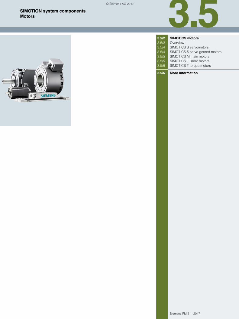
Siemens PM 21 · 2017
3.53.5/2 SIMOTICS motors3.5/2 Overview3.5/4 SIMOTICS S servomotors3.5/4 SIMOTICS S servo geared motors3.5/5 SIMOTICS M main motors3.5/5 SIMOTICS L linear motors3.5/6 SIMOTICS T torque motors
3.5/6 More information
SIMOTION system components Motors
© Siemens AG 2017
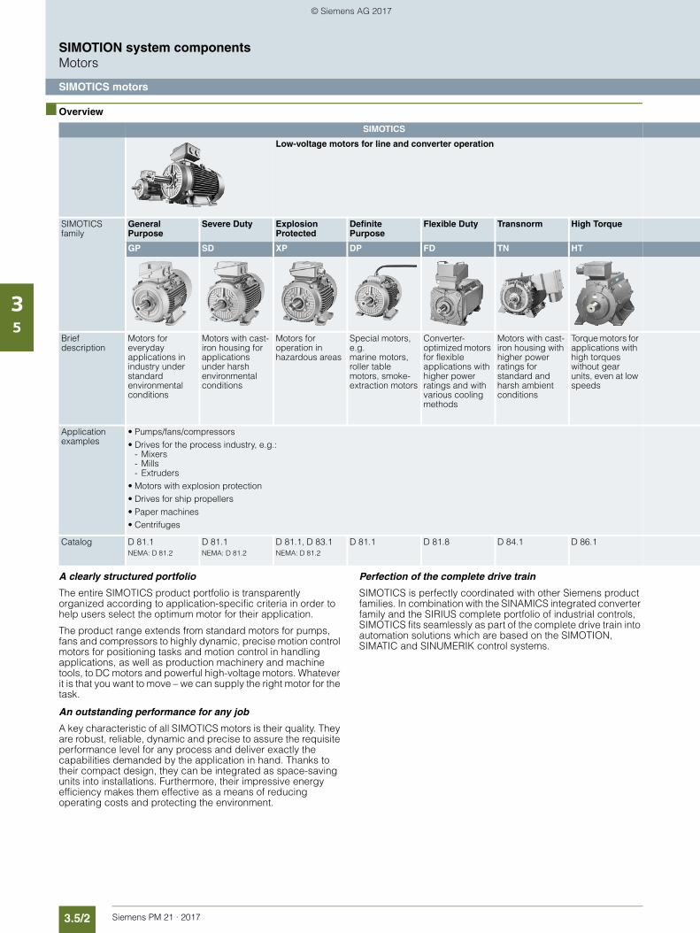
3.5/2 Siemens PM 21 · 2017
SIMOTION system componentsMotors
SIMOTICS motors
35
■ Overview
A clearly structured portfolio
The entire SIMOTICS product portfolio is transparently organized according to application-specific criteria in order to help users select the optimum motor for their application.
The product range extends from standard motors for pumps, fans and compressors to highly dynamic, precise motion control motors for positioning tasks and motion control in handling applications, as well as production machinery and machine tools, to DC motors and powerful high-voltage motors. Whatever it is that you want to move – we can supply the right motor for the task.
An outstanding performance for any job
A key characteristic of all SIMOTICS motors is their quality. They are robust, reliable, dynamic and precise to assure the requisite performance level for any process and deliver exactly the capabilities demanded by the application in hand. Thanks to their compact design, they can be integrated as space-saving units into installations. Furthermore, their impressive energy efficiency makes them effective as a means of reducing operating costs and protecting the environment.
Perfection of the complete drive train
SIMOTICS is perfectly coordinated with other Siemens product families. In combination with the SINAMICS integrated converter family and the SIRIUS complete portfolio of industrial controls, SIMOTICS fits seamlessly as part of the complete drive train into automation solutions which are based on the SIMOTION, SIMATIC and SINUMERIK control systems.
SIMOTICS
Low-voltage motors for line and converter operation
SIMOTICS family
General Purpose
Severe Duty Explosion Protected
Definite Purpose
Flexible Duty Transnorm High Torque
GP SD XP DP FD TN HT
Brief description
Motors for everyday applications in industry under standard environmental conditions
Motors with cast-iron housing for applications under harsh environmental conditions
Motors for operation in hazardous areas
Special motors, e.g. marine motors, roller table motors, smoke-extraction motors
Converter-optimized motors for flexible applications with higher power ratings and with various cooling methods
Motors with cast-iron housing with higher power ratings for standard and harsh ambient conditions
Torque motors for applications with high torques without gear units, even at low speeds
Application examples
• Pumps/fans/compressors• Drives for the process industry, e.g.:
- Mixers- Mills- Extruders
• Motors with explosion protection• Drives for ship propellers• Paper machines• Centrifuges
Catalog D 81.1NEMA: D 81.2
D 81.1NEMA: D 81.2
D 81.1, D 83.1NEMA: D 81.2
D 81.1 D 81.8 D 84.1 D 86.1
© Siemens AG 2017
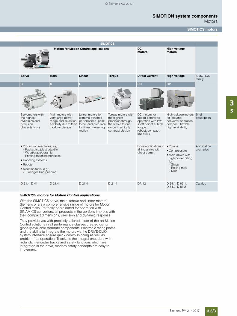
3.5/3Siemens PM 21 · 2017
SIMOTION system componentsMotors
SIMOTICS motors
35
SIMOTICS motors for Motion Control applications
With the SIMOTICS servo, main, torque and linear motors, Siemens offers a comprehensive range of motors for Motion Control tasks. Perfectly coordinated for operation with SINAMICS converters, all products in the portfolio impress with their compact dimensions, precision and dynamic response.
They provide you with precisely tailored, state-of-the-art Motion Control solutions in all performance classes created using globally available standard components. Electronic rating plates and the ability to integrate the motors via the DRIVE-CLiQ system interface ensure quick commissioning as well as problem-free operation. Thanks to the integral encoders with redundant encoder tracks and safety functions which are integrated in the drive, modern safety concepts are easy to implement.
SIMOTICS
DCmotors
High-voltage motors
Servo Main Linear Torque Direct Current High Voltage SIMOTICS family
S M L T DC HV
Servomotors with the highest dynamics and precision characteristics
Main motors with very large power range and selection flexibility due to their modular design
Linear motors for extreme dynamic performance, peak force, and precision for linear traversing motion
Torque motors with the highest precision through the whole torque range in a highly compact design
DC motors for speed-controlled operation with low shaft height at high torque:robust, compact, low-noise
High-voltage motors for line and converter operation: compact, flexible, high availability
Brief description
• Production machines, e.g.:- Packaging/plastic/textile- Wood/glass/ceramic- Printing machines/presses
• Handling systems• Robots• Machine tools, e.g.:
- Turning/milling/grinding
Drive applications in all industries with direct current
• Pumps• Compressors• Main drives with
high power rating for:- Ships- Rolling mills- Mills
Application examples
D 21.4, D 41 D 21.4 D 21.4 D 21.4 DA 12 D 84.1, D 86.1,D 84.9, D 83.2
Catalog
Motors for Motion Control applications
© Siemens AG 2017
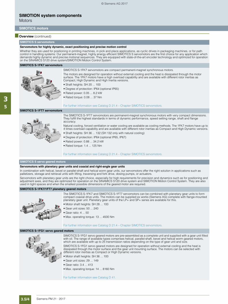
3.5/4 Siemens PM 21 · 2017
SIMOTION system componentsMotors
SIMOTICS motors
35
■ Overview (continued)
SIMOTICS S servomotors
Servomotors for highly dynamic, exact positioning and precise motion controlWhether they are used for positioning in printing machines, in pick and place applications, as cyclic drives in packaging machines, or for path control in handling systems: Our permanent-magnet, highly energy efficient SIMOTICS S servomotors are the first choice for any application which demands highly dynamic and precise motional sequences. They are equipped with state-of-the-art encoder technology and optimized for operation on the SINAMICS S120 drive system/SIMOTION Motion Control System.
SIMOTICS S-1FK7 servomotors
SIMOTICS S-1FK7 servomotors are compact permanent-magnet synchronous motors.The motors are designed for operation without external cooling and the heat is dissipated through the motor surface. The 1FK7 motors have a high overload capability and are available with different rotor inertias as Compact, High Dynamic and High Inertia versions.• Shaft heights: SH 20 ... 100• Degree of protection: IP64 (optional IP65)• Rated power: 0.05 ... 8.2 kW• Rated torque: 0.08 ... 37 Nm
For further information see Catalog D 21.4 – Chapter SIMOTICS servomotors.
SIMOTICS S-1FT7 servomotors
The SIMOTICS S-1FT7 servomotors are permanent-magnet synchronous motors with very compact dimensions. They fulfill the highest standards in terms of dynamic performance, speed setting range, shaft and flange accuracy.Natural cooling, forced ventilation or water cooling are available as cooling methods. The 1FK7 motors have up to 4 times overload capability and are available with different rotor inertias as Compact and High Dynamic versions.• Shaft heights: SH 36 ... 132 (SH 132 only with natural cooling)• Degree of protection: IP64 (optional IP65, IP67)• Rated power: 0.88 ... 34.2 kW • Rated torque: 1.4 ... 125 Nm
For further information see Catalog D 21.4 – Chapter SIMOTICS servomotors.
SIMOTICS S servo geared motors
Servomotors with planetary gear units and coaxial and right-angle gear unitsIn combination with helical, bevel or parallel-shaft and helical worm gear units, our servomotors offer the right solution in applications such as palletizers, storage and retrieval units with lifting, traversing and fork drive, dosing pumps, or actuators.Servomotors with planetary gear units are the right choice, especially for high requirements for precision and dynamics such as for positioning and adjustment axes, and they are optimized for operation on the SINAMICS S120 drive system and SIMOTION Motion Control System. They are also used in tight spaces and when the smallest possible dimensions of the geared motor are required.
SIMOTICS S-1FK7/1FT7 planetary geared motors
The SIMOTICS S-1FK7 and SIMOTICS S-1FT7 servomotors can be combined with planetary gear units to form compact coaxial drive units. The motors can be supplied ex works (Siemens AG) complete with flange-mounted planetary gear unit. Planetary gear units of the LP+ and SP+ series are available for this.• Motor shaft heights: SH 28 ... 100• Gear unit sizes: 50 ... 240• Gear ratio: 4 ... 50• Max. operating torque: 13 ... 4500 Nm
For further information see Catalog D 21.4 – Chapter SIMOTICS servomotors.
SIMOTICS S-1FG1 servo geared motors
SIMOTICS S-1FG1 servo geared motors are pre-assembled as a complete unit and supplied with a gear unit filled with oil. The range of available types comprises helical, parallel-shaft, bevel and helical worm geared motors, which are available with up to 25 transmission ratios depending on the type of gear unit and size.SIMOTICS S-1FG1 servo geared motors are designed for operation without external cooling and the heat is dissipated through the motor surface and the gear unit mounting surface. The motors can be selected with different rotor inertias as Compact or High Dynamic versions.• Motor shaft heights: SH 36 ... 100• Gear unit sizes: 29 ... 149• Gear ratio: 3.4 ... 413• Max. operating torque: 14 ... 8160 Nm
For further information see Catalog D 41.
© Siemens AG 2017
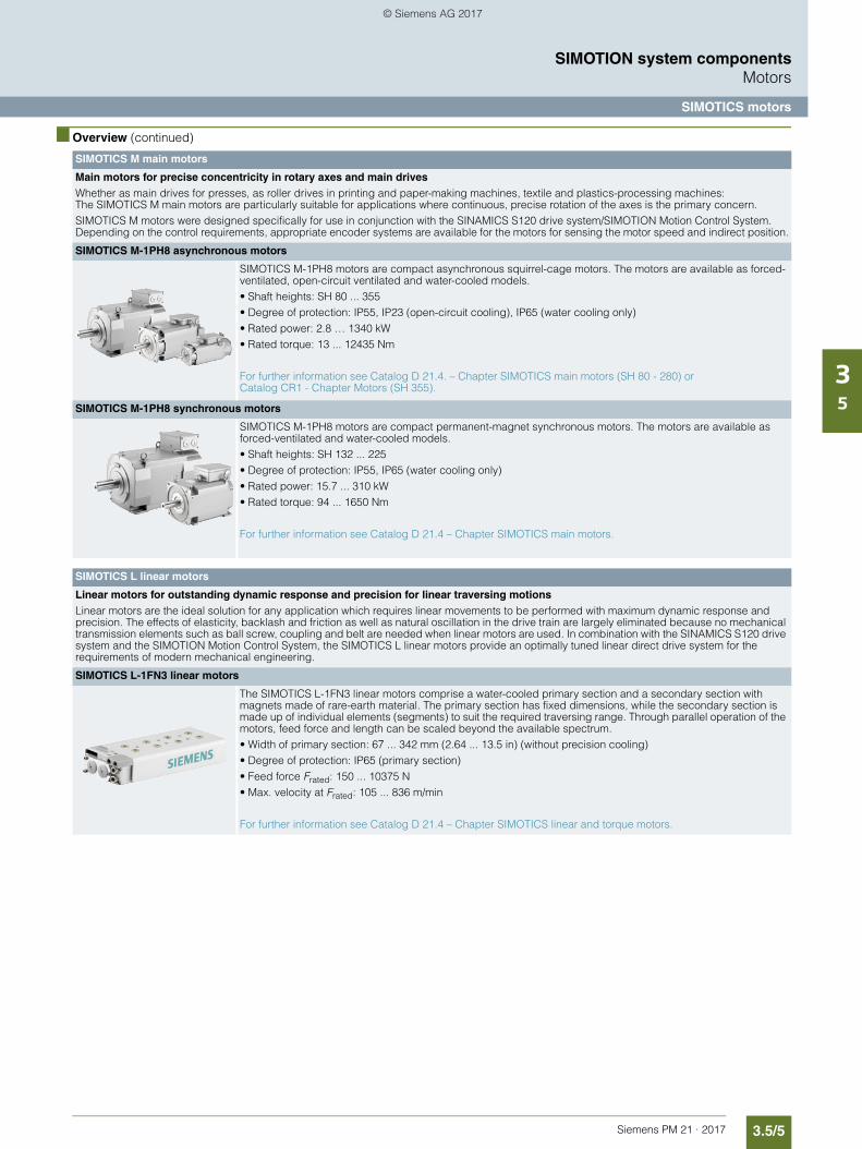
3.5/5Siemens PM 21 · 2017
SIMOTION system componentsMotors
SIMOTICS motors
35
■ Overview (continued)
SIMOTICS M main motors
Main motors for precise concentricity in rotary axes and main drivesWhether as main drives for presses, as roller drives in printing and paper-making machines, textile and plastics-processing machines:The SIMOTICS M main motors are particularly suitable for applications where continuous, precise rotation of the axes is the primary concern.SIMOTICS M motors were designed specifically for use in conjunction with the SINAMICS S120 drive system/SIMOTION Motion Control System. Depending on the control requirements, appropriate encoder systems are available for the motors for sensing the motor speed and indirect position.
SIMOTICS M-1PH8 asynchronous motors
SIMOTICS M-1PH8 motors are compact asynchronous squirrel-cage motors. The motors are available as forced-ventilated, open-circuit ventilated and water-cooled models.• Shaft heights: SH 80 ... 355• Degree of protection: IP55, IP23 (open-circuit cooling), IP65 (water cooling only)• Rated power: 2.8 … 1340 kW• Rated torque: 13 ... 12435 Nm
For further information see Catalog D 21.4. – Chapter SIMOTICS main motors (SH 80 - 280) or Catalog CR1 - Chapter Motors (SH 355).
SIMOTICS M-1PH8 synchronous motors
SIMOTICS M-1PH8 motors are compact permanent-magnet synchronous motors. The motors are available as forced-ventilated and water-cooled models.• Shaft heights: SH 132 ... 225• Degree of protection: IP55, IP65 (water cooling only)• Rated power: 15.7 ... 310 kW• Rated torque: 94 ... 1650 Nm
For further information see Catalog D 21.4 – Chapter SIMOTICS main motors.
SIMOTICS L linear motors
Linear motors for outstanding dynamic response and precision for linear traversing motionsLinear motors are the ideal solution for any application which requires linear movements to be performed with maximum dynamic response and precision. The effects of elasticity, backlash and friction as well as natural oscillation in the drive train are largely eliminated because no mechanical transmission elements such as ball screw, coupling and belt are needed when linear motors are used. In combination with the SINAMICS S120 drive system and the SIMOTION Motion Control System, the SIMOTICS L linear motors provide an optimally tuned linear direct drive system for the requirements of modern mechanical engineering.
SIMOTICS L-1FN3 linear motors
The SIMOTICS L-1FN3 linear motors comprise a water-cooled primary section and a secondary section with magnets made of rare-earth material. The primary section has fixed dimensions, while the secondary section is made up of individual elements (segments) to suit the required traversing range. Through parallel operation of the motors, feed force and length can be scaled beyond the available spectrum.• Width of primary section: 67 ... 342 mm (2.64 ... 13.5 in) (without precision cooling)• Degree of protection: IP65 (primary section)• Feed force Frated: 150 ... 10375 N• Max. velocity at Frated: 105 ... 836 m/min
For further information see Catalog D 21.4 – Chapter SIMOTICS linear and torque motors.
© Siemens AG 2017
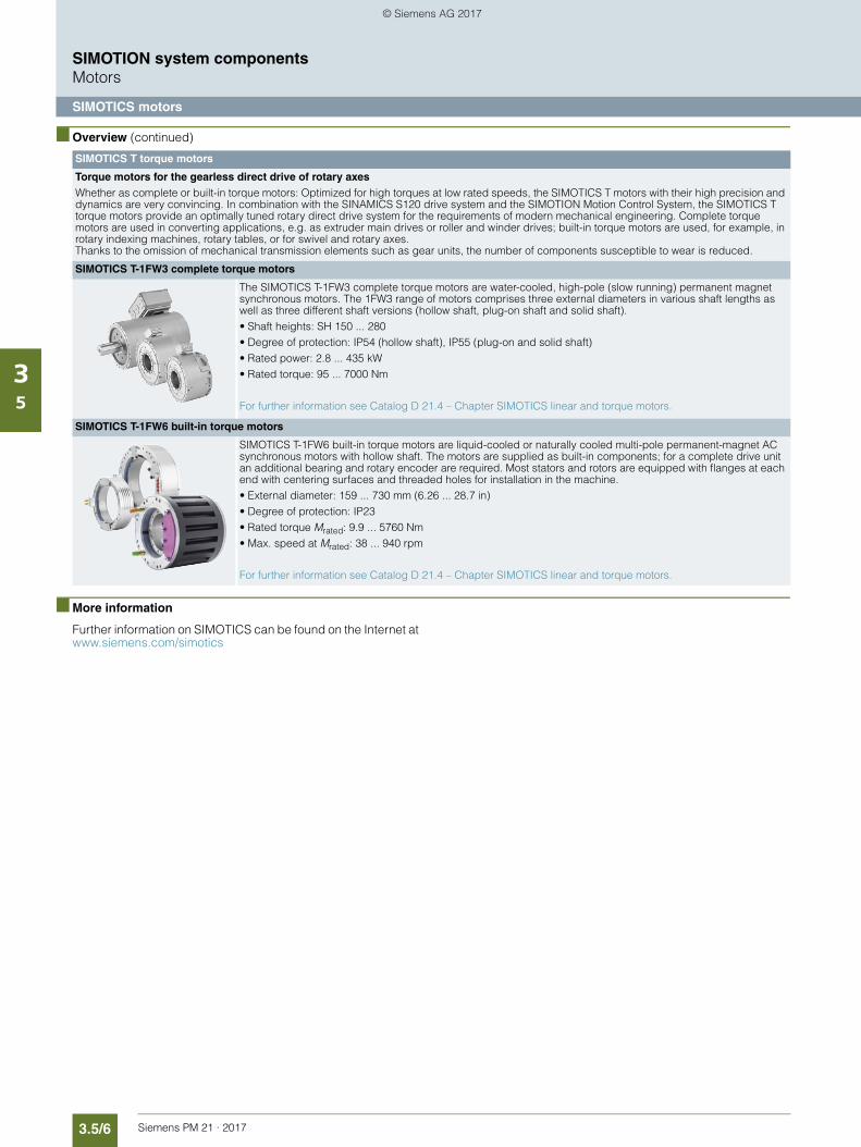
3.5/6 Siemens PM 21 · 2017
SIMOTION system componentsMotors
SIMOTICS motors
35
■ Overview (continued)
■ More information
Further information on SIMOTICS can be found on the Internet at www.siemens.com/simotics
SIMOTICS T torque motors
Torque motors for the gearless direct drive of rotary axesWhether as complete or built-in torque motors: Optimized for high torques at low rated speeds, the SIMOTICS T motors with their high precision and dynamics are very convincing. In combination with the SINAMICS S120 drive system and the SIMOTION Motion Control System, the SIMOTICS T torque motors provide an optimally tuned rotary direct drive system for the requirements of modern mechanical engineering. Complete torque motors are used in converting applications, e.g. as extruder main drives or roller and winder drives; built-in torque motors are used, for example, in rotary indexing machines, rotary tables, or for swivel and rotary axes. Thanks to the omission of mechanical transmission elements such as gear units, the number of components susceptible to wear is reduced.
SIMOTICS T-1FW3 complete torque motors
The SIMOTICS T-1FW3 complete torque motors are water-cooled, high-pole (slow running) permanent magnet synchronous motors. The 1FW3 range of motors comprises three external diameters in various shaft lengths as well as three different shaft versions (hollow shaft, plug-on shaft and solid shaft).• Shaft heights: SH 150 ... 280• Degree of protection: IP54 (hollow shaft), IP55 (plug-on and solid shaft)• Rated power: 2.8 ... 435 kW • Rated torque: 95 ... 7000 Nm
For further information see Catalog D 21.4 – Chapter SIMOTICS linear and torque motors.
SIMOTICS T-1FW6 built-in torque motors
SIMOTICS T-1FW6 built-in torque motors are liquid-cooled or naturally cooled multi-pole permanent-magnet AC synchronous motors with hollow shaft. The motors are supplied as built-in components; for a complete drive unit an additional bearing and rotary encoder are required. Most stators and rotors are equipped with flanges at each end with centering surfaces and threaded holes for installation in the machine.• External diameter: 159 ... 730 mm (6.26 ... 28.7 in)• Degree of protection: IP23• Rated torque Mrated: 9.9 ... 5760 Nm• Max. speed at Mrated: 38 ... 940 rpm
For further information see Catalog D 21.4 – Chapter SIMOTICS linear and torque motors.
© Siemens AG 2017
Siemens PM 21 · 2017
3.63.6/2 MOTION-CONNECT
connection systems3.6/2 Overview3.6/2 More information
SIMOTION system componentsConnection systems
© Siemens AG 2017
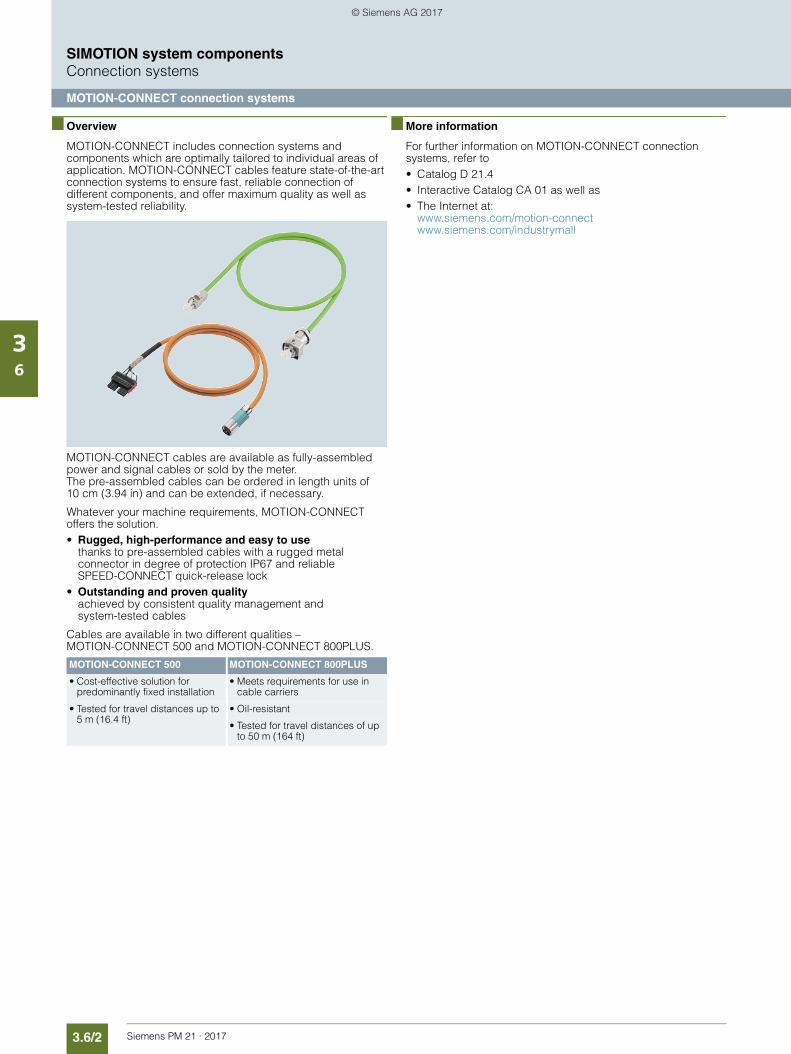
3.6/2 Siemens PM 21 · 2017
SIMOTION system componentsConnection systems
MOTION-CONNECT connection systems
36
■ Overview
MOTION-CONNECT includes connection systems and components which are optimally tailored to individual areas of application. MOTION-CONNECT cables feature state-of-the-art connection systems to ensure fast, reliable connection of different components, and offer maximum quality as well as system-tested reliability.
MOTION-CONNECT cables are available as fully-assembled power and signal cables or sold by the meter. The pre-assembled cables can be ordered in length units of 10 cm (3.94 in) and can be extended, if necessary.
Whatever your machine requirements, MOTION-CONNECT offers the solution.• Rugged, high-performance and easy to use
thanks to pre-assembled cables with a rugged metal connector in degree of protection IP67 and reliable SPEED-CONNECT quick-release lock
• Outstanding and proven qualityachieved by consistent quality management and system-tested cables
Cables are available in two different qualities – MOTION-CONNECT 500 and MOTION-CONNECT 800PLUS.
■ More information
For further information on MOTION-CONNECT connection systems, refer to • Catalog D 21.4• Interactive Catalog CA 01 as well as• The Internet at:
www.siemens.com/motion-connectwww.siemens.com/industrymall
MOTION-CONNECT 500 MOTION-CONNECT 800PLUS
• Cost-effective solution for predominantly fixed installation
• Meets requirements for use in cable carriers
• Tested for travel distances up to 5 m (16.4 ft)
• Oil-resistant
• Tested for travel distances of up to 50 m (164 ft)
© Siemens AG 2017
Siemens PM 21 · 2017
3.73.7/2 Motion Control Encoder
measuring systems3.7/2 Overview3.7/2 Application3.7/2 Design3.7/2 More information
SIMOTION system components Measuring systems
© Siemens AG 2017
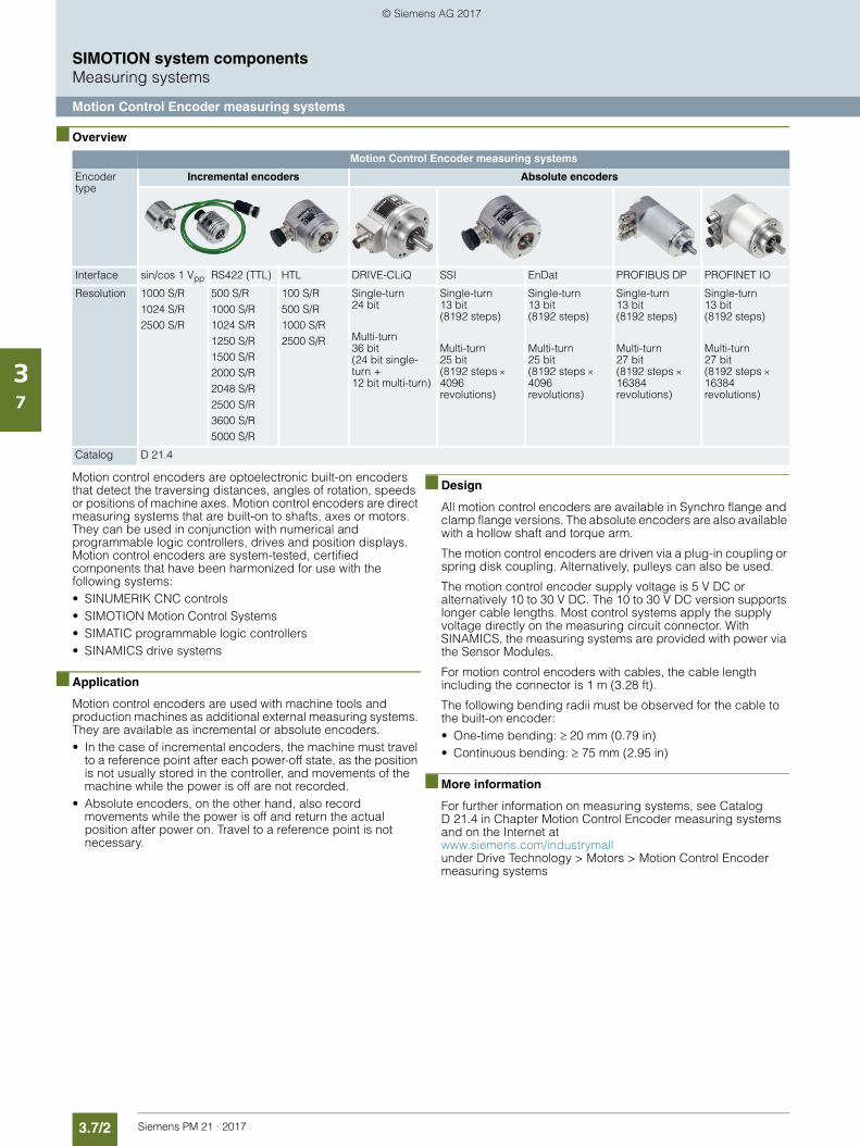
3.7/2 Siemens PM 21 · 2017
SIMOTION system componentsMeasuring systems
Motion Control Encoder measuring systems
37
■ Overview
Motion control encoders are optoelectronic built-on encoders that detect the traversing distances, angles of rotation, speeds or positions of machine axes. Motion control encoders are direct measuring systems that are built-on to shafts, axes or motors. They can be used in conjunction with numerical and programmable logic controllers, drives and position displays. Motion control encoders are system-tested, certified components that have been harmonized for use with the following systems: • SINUMERIK CNC controls• SIMOTION Motion Control Systems• SIMATIC programmable logic controllers• SINAMICS drive systems
■ Application
Motion control encoders are used with machine tools and production machines as additional external measuring systems. They are available as incremental or absolute encoders.• In the case of incremental encoders, the machine must travel
to a reference point after each power-off state, as the position is not usually stored in the controller, and movements of the machine while the power is off are not recorded.
• Absolute encoders, on the other hand, also record movements while the power is off and return the actual position after power on. Travel to a reference point is not necessary.
■ Design
All motion control encoders are available in Synchro flange and clamp flange versions. The absolute encoders are also available with a hollow shaft and torque arm.
The motion control encoders are driven via a plug-in coupling or spring disk coupling. Alternatively, pulleys can also be used.
The motion control encoder supply voltage is 5 V DC or alternatively 10 to 30 V DC. The 10 to 30 V DC version supports longer cable lengths. Most control systems apply the supply voltage directly on the measuring circuit connector. With SINAMICS, the measuring systems are provided with power via the Sensor Modules.
For motion control encoders with cables, the cable length including the connector is 1 m (3.28 ft).
The following bending radii must be observed for the cable to the built-on encoder:• One-time bending: 20 mm (0.79 in)• Continuous bending: 75 mm (2.95 in)
■ More information
For further information on measuring systems, see Catalog D 21.4 in Chapter Motion Control Encoder measuring systems and on the Internet at www.siemens.com/industrymall under Drive Technology > Motors > Motion Control Encoder measuring systems
Motion Control Encoder measuring systems
Encoder type
Incremental encoders Absolute encoders
Interface sin/cos 1 Vpp RS422 (TTL) HTL DRIVE-CLiQ SSI EnDat PROFIBUS DP PROFINET IO
Resolution 1000 S/R1024 S/R2500 S/R
500 S/R1000 S/R1024 S/R1250 S/R1500 S/R2000 S/R2048 S/R2500 S/R3600 S/R5000 S/R
100 S/R500 S/R1000 S/R2500 S/R
Single-turn 24 bit
Multi-turn 36 bit (24 bit single-turn + 12 bit multi-turn)
Single-turn 13 bit (8192 steps)
Multi-turn 25 bit (8192 steps 4096 revolutions)
Single-turn 13 bit (8192 steps)
Multi-turn 25 bit (8192 steps 4096 revolutions)
Single-turn 13 bit (8192 steps)
Multi-turn 27 bit (8192 steps 16384 revolutions)
Single-turn 13 bit (8192 steps)
Multi-turn 27 bit (8192 steps 16384 revolutions)
Catalog D 21.4
© Siemens AG 2017
Siemens PM 21 · 2017
44/2 PROFINET
4/6 PROFINET for SIMOTION and SINAMICS S
4/7 PROFIdrive
4/8 PROFIBUS
4/9 Industrial Ethernet
Communication
© Siemens AG 2017
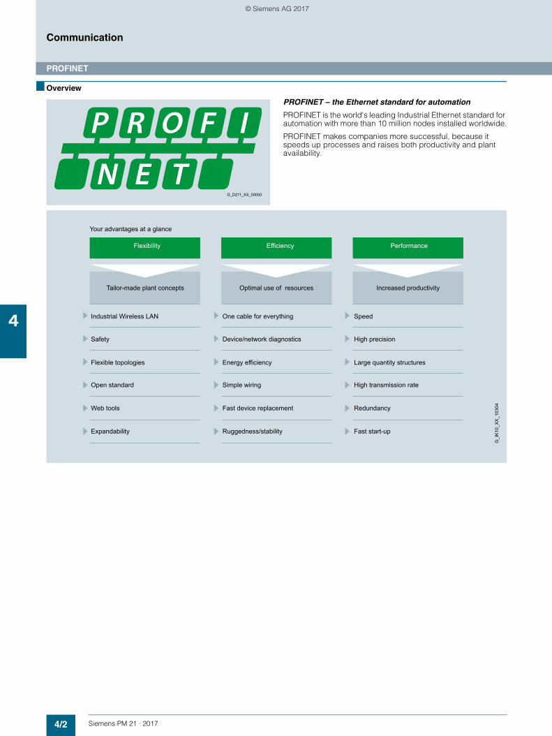
4/2 Siemens PM 21 · 2017
Communication
PROFINET
4
■ Overview
PROFINET – the Ethernet standard for automation
PROFINET is the world's leading Industrial Ethernet standard for automation with more than 10 million nodes installed worldwide.
PROFINET makes companies more successful, because it speeds up processes and raises both productivity and plant availability.
G_D211_XX_00050
Flexibility Efficiency Performance
Your advantages at a glance
Large quantity structures
High precision
Fast start-upExpandability
RedundancyWeb tools
High transmission rateSimple wiringOpen standard
Ruggedness/stability
Fast device replacement
Device/network diagnostics
Energy efficiencyFlexible topologies
Safety
SpeedOne cable for everythingIndustrial Wireless LAN
Increased productivityOptimal use of resourcesTailor-made plant concepts
G_I
K10
_XX
_103
04
© Siemens AG 2017
4/3Siemens PM 21 · 2017
Communication
PROFINET
4
■ Overview (continued)
Flexibility
Short response times and optimized processes are the basic re-quirements for competitiveness in global markets because the product lifecycles are becoming shorter and shorter.
PROFINET ensures maximum flexibility in plant structures and production processes, and it enables you to implement innova-tive machine and plant concepts. For example, mobile devices can also be integrated at locations that are difficult to access.
Flexible topologies
In addition to the linear structure characterized by the estab-lished fieldbuses, PROFINET also enables the use of star, tree and ring topologies. This is made possible by switching technol-ogy via active network components, such as Industrial Ethernet switches and media converters, or by integrating switch func-tionality into the field devices. This results in increased flexibility in the planning of machines and plants, as well as savings in cabling.
The PROFINET network can be installed without any specialist knowledge at all and meets all requirements that are relevant to the industrial environment. The "PROFINET Installations Guide-lines" assist manufacturers and users with network planning, installation and commissioning. Symmetrical copper cables or RFI-resistant fiber-optic cables are used, depending on the application. Devices from different manufacturers are easily con-nected via standardized and rugged plug-in connectors (up to IP65/IP67 degree of protection).
By integrating switch functionality into the devices, linear topol-ogies can be created that are directly oriented toward an exist-ing machine or plant structure. This reduces cabling overhead and cuts down on components such as external switches.
IWLAN
PROFINET also supports wireless communication with Industrial Wireless LAN, thus opening up new fields of application. For example, technologies subject to wear, such as trailing cables, can be replaced and automated guided vehicle systems and mobile operator panels can be used.
Safety
The PROFIsafe safety profile, which has been tried and tested with PROFIBUS and which permits the transmission of standard and safety-related data on a single bus cable, can also be used with PROFINET. No special network components are necessary for fail-safe communication, which means that standard switches and standard network transitions can continue to be used without any restrictions. In addition, fail-safe communica-tion is equally possible via Industrial Wireless LAN (IWLAN).
Open standard
PROFINET, the open vendor-independent standard (IEC 61158/IEC 61784), is supported by PROFIBUS and PROFINET International (PI). It stands for maximum transpar-ency, open IT communication, network security and simultane-ous real-time communication.
Thanks to its openness, PROFINET provides the basis for a stan-dardized automation network in the plant, to which all other ma-chines and devices can be connected. Even the integration of existing plant components, for example using PROFIBUS, presents no problems due to the use of network transitions.
Use of web tools
Thanks to the unrestricted support of TCP/IP, PROFINET permits the use of standard web services in the device, such as web servers. Irrespective of the tool used, information from the auto-mation level can be accessed from virtually any location using a commercially available Internet browser. This considerably sim-plifies commissioning and diagnostics. Users can then decide for themselves how much openness to the IT world they want to allow for their machine or plant. This means that PROFINET can be used simply as an isolated plant network or connected via appropriate security modules, such as the SCALANCE S modules, to the office network or the Internet. In this way, new remote maintenance concepts or the high-speed exchange of production data become possible.
Expandability
On the one hand, PROFINET facilitates the integration of existing systems and networks without any great effort. In this way, PROFINET safeguards investments in existing plant compo-nents that communicate via PROFIBUS and other fieldbuses such as AS-Interface. On the other hand, additional PROFINET nodes can be added at any time. By using additional network components, network infrastructures can be expanded using cabling or wireless methods – even while the plant is operating.
© Siemens AG 2017
4/4 Siemens PM 21 · 2017
Communication
PROFINET
4
■ Overview (continued)
Efficiency
Greater global competition means that companies must use their resources economically and efficiently. This applies in par-ticular to production. This is where PROFINET ensures greater efficiency. Simple engineering guarantees fast commissioning, while reliable devices ensure a high level of plant availability. Comprehensive diagnostic and maintenance concepts help to reduce plant downtimes and keep maintenance costs to a minimum.
One cable for everything
PROFINET permits simultaneous fieldbus communication with isochronous mode and standard IT communication (TCP/IP) on one cable. This real-time communication for the transmission of user/process data and diagnostic data takes place on a single cable. Specific profile communication (PROFIsafe, PROFIdrive and PROFIenergy) can be integrated without any additional ca-bling. This solution offers a wide scope of functions at a low level of complexity.
Device and network diagnostics
By retaining the tried and tested PROFIBUS device model, the same diagnostics information is available with PROFINET. In ad-dition, module-specific and channel-specific data can also be read out from the devices during device diagnosis, enabling faults to be located quickly and easily. Apart from the availability of device information, the reliability of network operation has top priority in the network management.
In existing networks the Simple Network Management Protocol (SNMP) has established itself as the de facto standard for the maintenance and monitoring of the network components and their functions. PROFINET uses this standard and gives users the opportunity to maintain their networks with tools that are familiar to them, such as the SINEMA Server network manage-ment software.
For easier maintenance of PROFINET devices, both on-site and remotely via a secure VPN connection, application-specific web-sites can be set up on the integrated web server of the field devices using the familiar HTML standard.
Energy efficiency
Moving toward the green factory: PROFIenergy is a profile that provides functions and mechanisms for PROFINET field devices that support energy-efficient production.
The profile, which is defined by the PNO and is independent of any manufacturers or devices, enables energy demand and costs to be significantly reduced: Using PROFIenergy, any specific loads that are not currently being used can be switched off. This achieves a noticeable reduction in energy costs during breaks in production. PROFIenergy permits the simple, auto-mated activation and deactivation of technologically related plant components. It is coordinated centrally by means of a higher-level controller and is networked via PROFINET. This ensures that as much energy as possible is saved during long breaks. Temporarily switching off plant components contributes to the even distribution and most efficient use of energy.
The use of PROFIenergy is made easy for the machine builder by its integration into familiar series of products. In addition, PROFIenergy is defined in such a way that the necessary func-tion blocks can easily be integrated into existing automation sys-tems at a later stage.
Simple wiring
Particularly stringent demands are made on the installation of cables in the industrial environment. In addition, there is a requirement to set up industry-standard networks in the shortest possible time without any special knowledge.
With FastConnect, Siemens offers a high-speed installation sys-tem that meets all of these requirements. FastConnect is the standard-compliant, industry-standard cabling system consist-ing of cables, connectors and assembly tools for PROFINET net-works. The time required for connecting terminals is minimized by the simple installation method using just a single tool, while installation errors are prevented by the practical color-coding. Both copper cables and glass fiber optic cables can be easily assembled on site in this way.
Fast device replacement
PROFINET devices are identified by means of a name assigned during configuration. When replacing a defective device, a new device can be recognized from its topology information by the IO controller and a new name can be assigned to it automati-cally. This means that no engineering tool is necessary for the replacement of equipment.
This mechanism can even be used for the initial commissioning of a complete system. This speeds up commissioning, particu-larly in the case of series machines.
Ruggedness
An automation network must be able to withstand most external sources of interference. The use of Switched Ethernet prevents faults in one section of the network from affecting the entire plant network. For areas that are particularly prone to radio frequency interference (RFI), PROFINET allows the use of fiber optic cables.
Performance
Productivity and product quality determine the level of success in the market. Precise motion control, dynamic drives, high-speed controllers and the deterministic synchronization of de-vices are therefore key factors in achieving superior production. They facilitate high production rates and optimum product quality at the same time.
Speed and precision
Fast motion control applications demand precise and determin-istic exchange of data. This is implemented by means of drive controllers using isochronous real time (IRT).
With IRT and isochronous mode, PROFINET permits fast and de-terministic communication. This synchronizes the various cycles of a system (input, network, CPU processing and output), even in the case of parallel TCP/IP traffic. The short cycle times of PROFINET make it possible to raise the productivity of machines and plants and to guarantee the product quality and high level of precision.
The standardized PROFIdrive profile permits vendor-indepen-dent communication between CPUs and drives.
© Siemens AG 2017
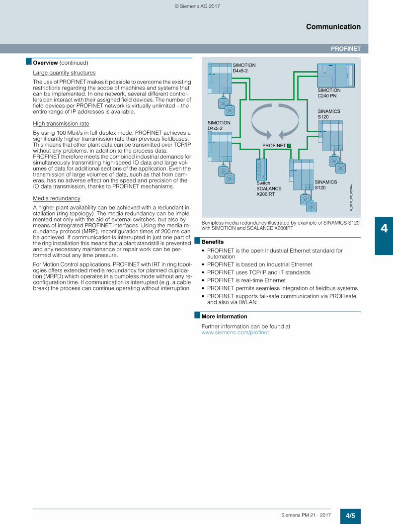
4/5Siemens PM 21 · 2017
Communication
PROFINET
4
■ Overview (continued)
Large quantity structures
The use of PROFINET makes it possible to overcome the existing restrictions regarding the scope of machines and systems that can be implemented. In one network, several different control-lers can interact with their assigned field devices. The number of field devices per PROFINET network is virtually unlimited – the entire range of IP addresses is available.
High transmission rate
By using 100 Mbit/s in full duplex mode, PROFINET achieves a significantly higher transmission rate than previous fieldbuses. This means that other plant data can be transmitted over TCP/IP without any problems, in addition to the process data. PROFINET therefore meets the combined industrial demands for simultaneously transmitting high-speed IO data and large vol-umes of data for additional sections of the application. Even the transmission of large volumes of data, such as that from cam-eras, has no adverse effect on the speed and precision of the IO data transmission, thanks to PROFINET mechanisms.
Media redundancy
A higher plant availability can be achieved with a redundant in-stallation (ring topology). The media redundancy can be imple-mented not only with the aid of external switches, but also by means of integrated PROFINET interfaces. Using the media re-dundancy protocol (MRP), reconfiguration times of 200 ms can be achieved. If communication is interrupted in just one part of the ring installation this means that a plant standstill is prevented and any necessary maintenance or repair work can be per-formed without any time pressure.
For Motion Control applications, PROFINET with IRT in ring topol-ogies offers extended media redundancy for planned duplica-tion (MRPD) which operates in a bumpless mode without any re-configuration time. If communication is interrupted (e.g. a cable break) the process can continue operating without interruption.
Bumpless media redundancy illustrated by example of SINAMICS S120 with SIMOTION and SCALANCE X200IRT
■ Benefits
• PROFINET is the open Industrial Ethernet standard for automation
• PROFINET is based on Industrial Ethernet• PROFINET uses TCP/IP and IT standards• PROFINET is real-time Ethernet• PROFINET permits seamless integration of fieldbus systems• PROFINET supports fail-safe communication via PROFIsafe
and also via IWLAN
■ More information
Further information can be found at www.siemens.com/profinet
G_D
211_
XX
_002
94a
SINAMICS S120
SIMOTION D4x5-2
SIMOTION C240 PN
Switch SCALANCE X200IRT
SINAMICS S120
SIMOTION D4x5-2
PROFINET
© Siemens AG 2017
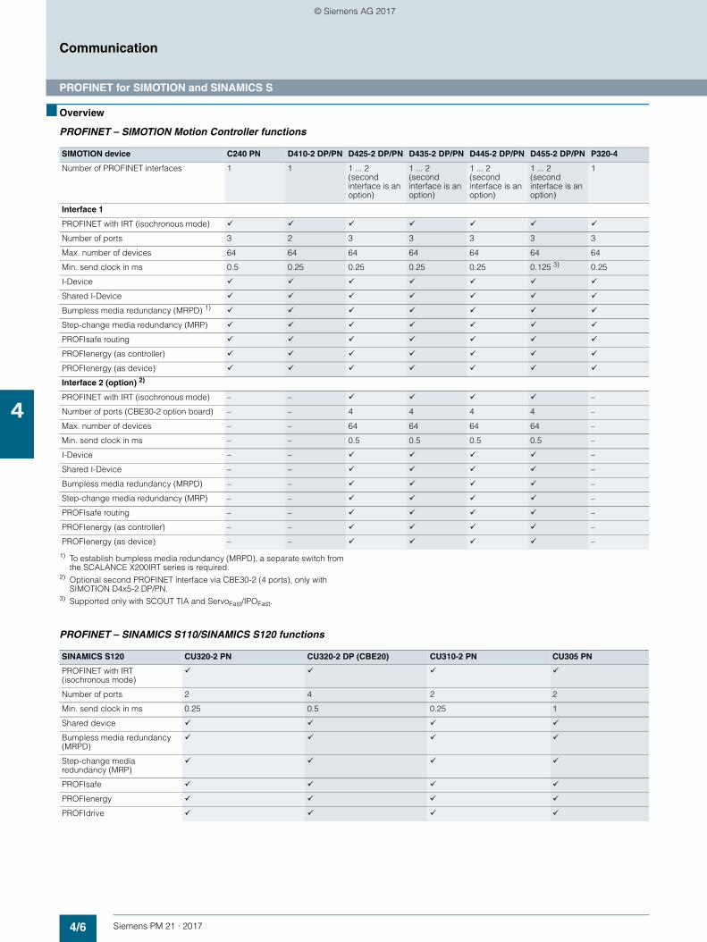
4/6 Siemens PM 21 · 2017
Communication
PROFINET for SIMOTION and SINAMICS S
4
■ Overview
PROFINET – SIMOTION Motion Controller functions
1) To establish bumpless media redundancy (MRPD), a separate switch from the SCALANCE X200IRT series is required.
2) Optional second PROFINET interface via CBE30-2 (4 ports), only with SIMOTION D4x5-2 DP/PN.
3) Supported only with SCOUT TIA and ServoFast/IPOFast.
PROFINET – SINAMICS S110/SINAMICS S120 functions
SIMOTION device C240 PN D410-2 DP/PN D425-2 DP/PN D435-2 DP/PN D445-2 DP/PN D455-2 DP/PN P320-4
Number of PROFINET interfaces 1 1 1 ... 2 (second interface is an option)
1 ... 2 (second interface is an option)
1 ... 2 (second interface is an option)
1 ... 2 (second interface is an option)
1
Interface 1
PROFINET with IRT (isochronous mode)
Number of ports 3 2 3 3 3 3 3
Max. number of devices 64 64 64 64 64 64 64
Min. send clock in ms 0.5 0.25 0.25 0.25 0.25 0.125 3) 0.25
I-Device
Shared I-Device
Bumpless media redundancy (MRPD) 1)
Step-change media redundancy (MRP)
PROFIsafe routing
PROFIenergy (as controller)
PROFIenergy (as device)
Interface 2 (option) 2)
PROFINET with IRT (isochronous mode) – – –
Number of ports (CBE30-2 option board) – – 4 4 4 4 –
Max. number of devices – – 64 64 64 64 –
Min. send clock in ms – – 0.5 0.5 0.5 0.5 –
I-Device – – –
Shared I-Device – – –
Bumpless media redundancy (MRPD) – – –
Step-change media redundancy (MRP) – – –
PROFIsafe routing – – –
PROFIenergy (as controller) – – –
PROFIenergy (as device) – – –
SINAMICS S120 CU320-2 PN CU320-2 DP (CBE20) CU310-2 PN CU305 PN
PROFINET with IRT (isochronous mode)
Number of ports 2 4 2 2
Min. send clock in ms 0.25 0.5 0.25 1
Shared device
Bumpless media redundancy (MRPD)
Step-change media redundancy (MRP)
PROFIsafe
PROFIenergy
PROFIdrive
© Siemens AG 2017
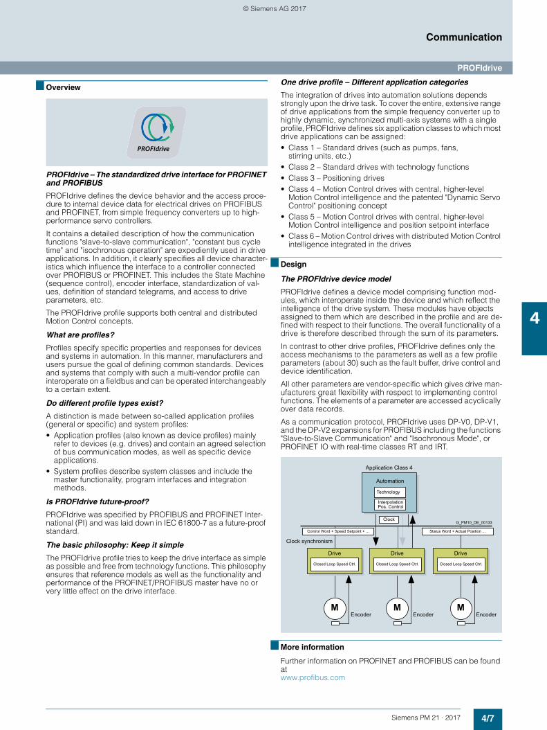
4/7Siemens PM 21 · 2017
Communication
PROFIdrive
4
■ Overview
PROFIdrive – The standardized drive interface for PROFINET and PROFIBUS
PROFIdrive defines the device behavior and the access proce-dure to internal device data for electrical drives on PROFIBUS and PROFINET, from simple frequency converters up to high-performance servo controllers.
It contains a detailed description of how the communication functions "slave-to-slave communication", "constant bus cycle time" and "isochronous operation" are expediently used in drive applications. In addition, it clearly specifies all device character-istics which influence the interface to a controller connected over PROFIBUS or PROFINET. This includes the State Machine (sequence control), encoder interface, standardization of val-ues, definition of standard telegrams, and access to drive parameters, etc.
The PROFIdrive profile supports both central and distributed Motion Control concepts.
What are profiles?
Profiles specify specific properties and responses for devices and systems in automation. In this manner, manufacturers and users pursue the goal of defining common standards. Devices and systems that comply with such a multi-vendor profile can interoperate on a fieldbus and can be operated interchangeably to a certain extent.
Do different profile types exist?
A distinction is made between so-called application profiles (general or specific) and system profiles:• Application profiles (also known as device profiles) mainly
refer to devices (e.g. drives) and contain an agreed selection of bus communication modes, as well as specific device applications.
• System profiles describe system classes and include the master functionality, program interfaces and integration methods.
Is PROFIdrive future-proof?
PROFIdrive was specified by PROFIBUS and PROFINET Inter-national (PI) and was laid down in IEC 61800-7 as a future-proof standard.
The basic philosophy: Keep it simple
The PROFIdrive profile tries to keep the drive interface as simple as possible and free from technology functions. This philosophy ensures that reference models as well as the functionality and performance of the PROFINET/PROFIBUS master have no or very little effect on the drive interface.
One drive profile – Different application categories
The integration of drives into automation solutions depends strongly upon the drive task. To cover the entire, extensive range of drive applications from the simple frequency converter up to highly dynamic, synchronized multi-axis systems with a single profile, PROFIdrive defines six application classes to which most drive applications can be assigned:• Class 1 – Standard drives (such as pumps, fans,
stirring units, etc.)• Class 2 – Standard drives with technology functions• Class 3 – Positioning drives• Class 4 – Motion Control drives with central, higher-level
Motion Control intelligence and the patented "Dynamic Servo Control" positioning concept
• Class 5 – Motion Control drives with central, higher-level Motion Control intelligence and position setpoint interface
• Class 6 – Motion Control drives with distributed Motion Control intelligence integrated in the drives
■ Design
The PROFIdrive device model
PROFIdrive defines a device model comprising function mod-ules, which interoperate inside the device and which reflect the intelligence of the drive system. These modules have objects assigned to them which are described in the profile and are de-fined with respect to their functions. The overall functionality of a drive is therefore described through the sum of its parameters.
In contrast to other drive profiles, PROFIdrive defines only the access mechanisms to the parameters as well as a few profile parameters (about 30) such as the fault buffer, drive control and device identification.
All other parameters are vendor-specific which gives drive man-ufacturers great flexibility with respect to implementing control functions. The elements of a parameter are accessed acyclically over data records.
As a communication protocol, PROFIdrive uses DP-V0, DP-V1, and the DP-V2 expansions for PROFIBUS including the functions "Slave-to-Slave Communication" and "Isochronous Mode", or PROFINET IO with real-time classes RT and IRT.
■ More information
Further information on PROFINET and PROFIBUS can be found at www.profibus.com
G_PM10_DE_00133
Clock synchronism
Status Word + Actual Position ...Control Word + Speed Setpoint + ...
EncoderEncoderEncoderMMM
Closed Loop Speed Ctrl.
Drive
Closed Loop Speed Ctrl.
Drive
Closed Loop Speed Ctrl.
Drive
Clock
Application Class 4
Interpolation Pos. Control
Technology
Automation
© Siemens AG 2017
4/8 Siemens PM 21 · 2017
Communication
PROFIBUS
4
■ Overview
PROFIBUS – The proven, rugged bus system for automation engineering applications
The demands of users for an open, vendor-independent com-munication system resulted in the specification and standardiza-tion of the PROFIBUS protocol.
PROFIBUS defines the technical and functional features of a serial fieldbus system with which distributed programmable field controllers of the low-end (sensor/actuator level) to mid perfor-mance range (cell level) can be networked.
Standardization according to IEC 61158/EN 50170 provides future protection for your investments.
Through the conformity and interoperability test performed by the test laboratories authorized by PROFIBUS & PROFINET In-ternational (PI) and the certification of the devices by PI, the user can rest assured that quality and functionality are also ensured for multi-vendor installations.
PROFIBUS variants
Two different PROFIBUS variants have been defined to fulfill the wide range of different requirements at the field level:• PROFIBUS PA (Process Automation) – the variant for
applications in process automation. PROFIBUS PA uses the intrinsically safe transmission technology specified in IEC 61158-2.
• PROFIBUS DP (Distributed Peripherals) – this variant, which is optimized for speed, is tailored especially for the communication of automation systems with distributed IO stations and drives. PROFIBUS DP is characterized by its very short response times and high degree of fault tolerance and replaces cost-intensive parallel signal transmission with 24 V and the measured value transmission with 0/4 … 20 mA technology.
■ Design
Bus nodes for PROFIBUS DP
PROFIBUS DP distinguishes between two different master classes and one slave class:
DP master class 1
The DP master class 1 is the central component in PROFIBUS DP. The central master station exchanges informa-tion with distributed stations (DP slaves) in a fixed, consistently repeated message cycle.
DP master class 2
Devices of this type (programming, configuration or control de-vices) are used during start-up, for configuring the DP system, for diagnostics or controlling the plant during normal operation. A DP master class 2 can be used, for example, to read the input, output, diagnostics and configuration data of the slaves.
DP slave
A DP slave is an I/O device which receives output information or setpoints from the DP master and sends input information, measured values or actual values to the DP master in response. A DP slave never sends data automatically, it must always be prompted by the DP master.
The volume of input and output data depends on the device and can be up to 244 bytes per DP slave and transfer direction.
■ Function
Functional scope in DP masters and DP slaves
The functional scope can differ between DP masters and DP slaves. The functional scope is different for DP-V0, DP-V1 and DP-V2.
DP-V0 communication functions
The DP-V0 master functions comprise the functions "Configura-tion", "Parameter Assignment", "Read Diagnostics Data" as well as cyclic reading of input data/actual values and writing output data/setpoints.
DP-V1 communication functions
The DP-V1 function expansions make it possible to perform acyclic read and write functions as well as processing cyclic data communication. This type of slave must be supplied with extensive parameterization data during start-up and during nor-mal operation. These acyclically transferred parameterization data are only rarely changed in comparison to the cyclic set-points, actual values, and measured values, and are transferred at lower priority in parallel with the cyclic high-speed user data transfer. Detailed diagnostic information can be transferred in the same way.
DP-V2 communication functions
The extended DP-V2 master functions mainly comprise func-tions for isochronous operation and direct data exchange be-tween DP slaves.• Isochronous mode:
Isochronous mode is implemented by means of an equidistant signal in the bus system. This cyclic, equidistant cycle is sent by the DP master to all bus nodes in the form of a Global Control Telegram. Master and slaves can then synchronize their applications with this signal. The signal jitter between cycles is less than 1µs.
• Slave-to-slave communication:The "publisher/subscriber" model is used to implement slave-to-slave communication. Slaves declared as publishers make their input data/actual values and measured values available to other slaves, the subscribers, for reading. This is performed by sending the response frame to the master as a broadcast. Slave-to-slave communication is therefore a cyclic process.
■ Integration
PROFIBUS for SIMOTION
SIMOTION uses the PROFIBUS protocol PROFIBUS DP. SIMO-TION can be used both as a DP master and a DP slave. The DP-V0, DP-V1 and DP-V2 communication functions are sup-ported.
G_PM10_XX_00144
© Siemens AG 2017
4/9Siemens PM 21 · 2017
Communication
Industrial Ethernet
4
■ Overview
Ethernet is the basic Internet technology for worldwide network-ing. The many possibilities of intranet and Internet, which have been available for office applications for a long time, are now utilized for production automation with Industrial Ethernet.
Apart from the use of information technology, the deployment of distributed automation systems is also on the increase. This en-tails breaking up complex control tasks into smaller, manage-able and drive-based control systems. This increases the de-mand for communication and consequently a comprehensive and powerful communication system.
Industrial Ethernet offers a powerful area and cell network according to the IEEE 802.3 (ETHERNET) standard for industrial applications.
■ Benefits
Ethernet enables a very fast data transfer (10/100 Mbit/s, 1/10 Gbit/s) and at the same time has full-duplex capability. It therefore provides an ideal basis for communication tasks in the industrial field. With a share of over 90 %, Ethernet is the number one network worldwide and offers important features which have essential advantages:• Fast commissioning thanks to the simplest connection method• High availability since existing networks can be extended
without any adverse effects• Almost unlimited communication performance because
scalable performance is available through switching technology and high data rates when required
• Networking of different application areas such as office and production areas
• Company-wide communication based on WAN (Wide Area Network) technology or the Internet
• Investment protection due to continuous compatibility with further developments
• Wireless communication using Industrial Wireless LAN
In order to make Ethernet suitable for industrial applications, considerable expansions with respect to functionality and design are required:• Network components for use in harsh industrial environments• Fast assembly of the RJ45 connectors• Failure protection through redundancy• Expanded diagnostics and message concept• Use of future-oriented network components (e.g. switches)
SIMATIC NET offers corresponding network components and products.
■ Integration
Industrial Ethernet for SIMOTION
SIMOTION can be perfectly integrated into any Industrial Ether-net communication architecture because each SIMOTION de-vice offers at least one Ethernet interface as standard.
Industrial Ethernet is used in SIMOTION for data communica-tion. Cyclic process communication with SINAMICS drives and distributed I/O is implemented over PROFINET IO or PROFIBUS DP and PROFIdrive.
PG/PC/HMI communication• Engineering and diagnostics with SIMOTION SCOUT• Connection of SIMATIC HMI Panels with Ethernet interface
using WinCC Basic/Comfort/Advanced• Open communication of, for example, vendor-specific
HMI tools over OPC server from SIMATIC NET
Standard communication
This uses the basic protocols UDP and TCP/IP, which are also used with Ethernet. SIMOTION offers the corresponding system functions for UDP and TCP/IP communication. This permits data to be exchanged over TCP/IP and UDP communication between:• Different SIMOTION devices• SIMOTION and SIMATIC S7 devices• SIMOTION devices and any other device which uses standard
TCP/IP or UDP communication. Such devices can be any kind of PC with any kind of operating system or other programmable controllers
IT communication
IT communication is performed using protocols which are based on the basic TCP/IP protocol. The most important IT protocols are:• HTTP/HTTPS: Hypertext Transfer Protocol• FTP: File Transfer Protocol• SMTP: Simple Mail Transfer Protocol• SNMP: Simple Network Management Protocol
SIMOTION supports the HTTP/HTTPS and FTP protocols. In addition, the following communication options are available for SIMOTION:• Web pages in the SIMOTION device
A standard Internet browser can be used to access pre-defined web pages with diagnostics information on the SIMOTION device. Furthermore, user-defined web pages can be stored in the SIMOTION device which contain information defined by the user.
• OPC XML-DA SIMOTION offers an OPC XML-DA server integrated into the device. This server supplies process data to SIMOTION. Communication from any external device is performed with the SOAP protocol (in accordance with the specification of the OPC Foundation), which is integrated into the HTTP protocol.
• OPC UA With the further development of the OPC XML-DA standard to OPC UA, SIMOTION is offering a runtime-integrated OPC UA server. This server supplies process data to SIMOTION. OPC UA permits standardized communication between SIMOTION and any external device. TCP/IP with binary data protocol according to the OPC Foundation's specification is used.
© Siemens AG 2017
4/10 Siemens PM 21 · 2017
Communication
Notes
4
© Siemens AG 2017
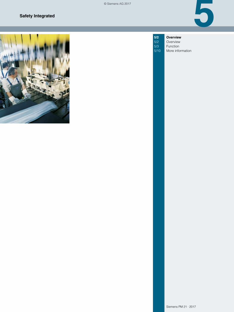
Siemens PM 21 · 2017
55/2 Overview5/2 Overview5/3 Function5/10 More information
Safety Integrated
© Siemens AG 2017
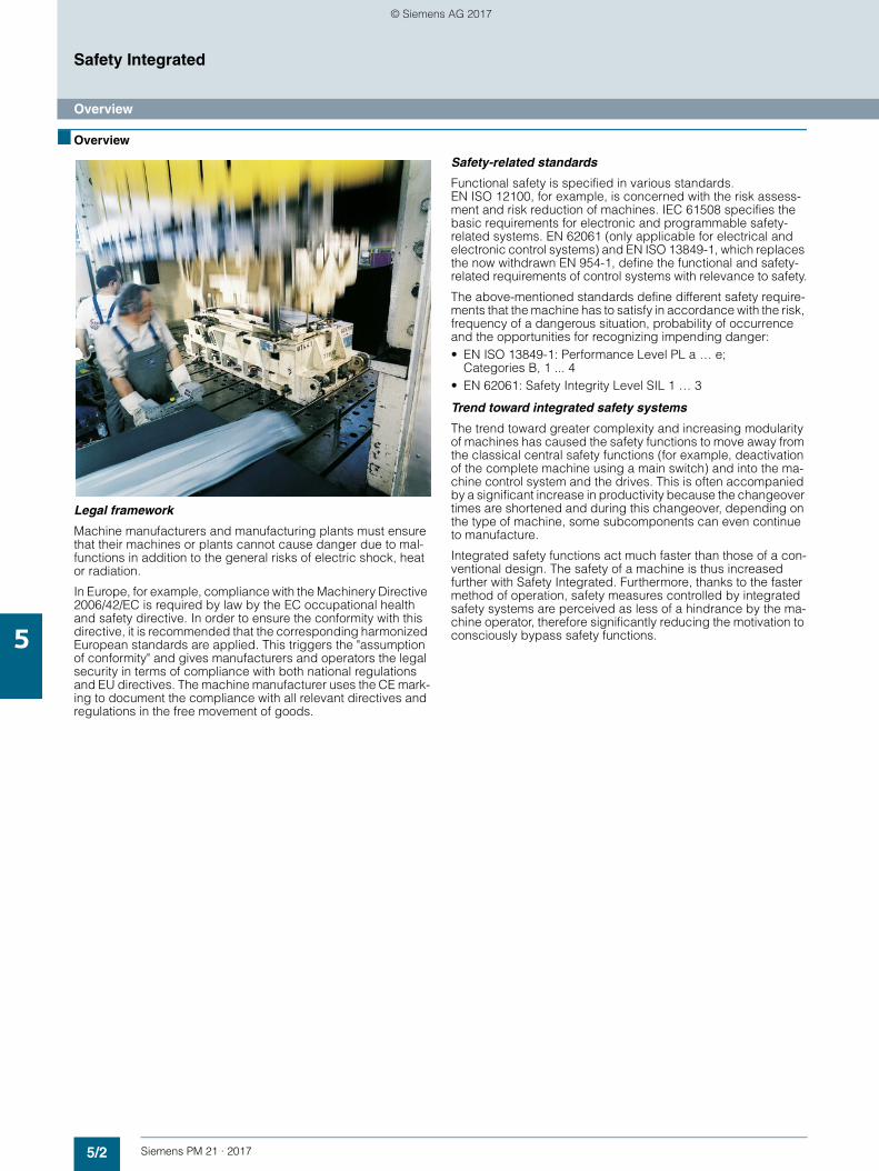
5/2 Siemens PM 21 · 2017
Safety Integrated
Overview
5
■ Overview
Legal framework
Machine manufacturers and manufacturing plants must ensure that their machines or plants cannot cause danger due to mal-functions in addition to the general risks of electric shock, heat or radiation.
In Europe, for example, compliance with the Machinery Directive 2006/42/EC is required by law by the EC occupational health and safety directive. In order to ensure the conformity with this directive, it is recommended that the corresponding harmonized European standards are applied. This triggers the "assumption of conformity" and gives manufacturers and operators the legal security in terms of compliance with both national regulations and EU directives. The machine manufacturer uses the CE mark-ing to document the compliance with all relevant directives and regulations in the free movement of goods.
Safety-related standards
Functional safety is specified in various standards. EN ISO 12100, for example, is concerned with the risk assess-ment and risk reduction of machines. IEC 61508 specifies the basic requirements for electronic and programmable safety-related systems. EN 62061 (only applicable for electrical and electronic control systems) and EN ISO 13849-1, which replaces the now withdrawn EN 954-1, define the functional and safety-related requirements of control systems with relevance to safety.
The above-mentioned standards define different safety require-ments that the machine has to satisfy in accordance with the risk, frequency of a dangerous situation, probability of occurrence and the opportunities for recognizing impending danger:• EN ISO 13849-1: Performance Level PL a … e;
Categories B, 1 ... 4• EN 62061: Safety Integrity Level SIL 1 … 3
Trend toward integrated safety systems
The trend toward greater complexity and increasing modularity of machines has caused the safety functions to move away from the classical central safety functions (for example, deactivation of the complete machine using a main switch) and into the ma-chine control system and the drives. This is often accompanied by a significant increase in productivity because the changeover times are shortened and during this changeover, depending on the type of machine, some subcomponents can even continue to manufacture.
Integrated safety functions act much faster than those of a con-ventional design. The safety of a machine is thus increased further with Safety Integrated. Furthermore, thanks to the faster method of operation, safety measures controlled by integrated safety systems are perceived as less of a hindrance by the ma-chine operator, therefore significantly reducing the motivation to consciously bypass safety functions.
© Siemens AG 2017
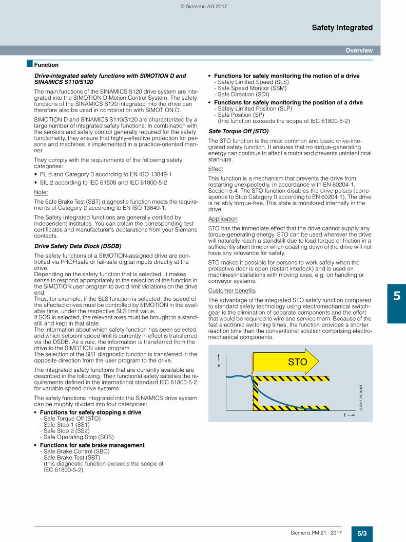
5/3Siemens PM 21 · 2017
Safety Integrated
Overview
5
■ Function
Drive-integrated safety functions with SIMOTION D and SINAMICS S110/S120
The main functions of the SINAMICS S120 drive system are inte-grated into the SIMOTION D Motion Control System. The safety functions of the SINAMICS S120 integrated into the drive can therefore also be used in combination with SIMOTION D.
SIMOTION D and SINAMICS S110/S120 are characterized by a large number of integrated safety functions. In combination with the sensors and safety control generally required for the safety functionality, they ensure that highly-effective protection for per-sons and machines is implemented in a practice-oriented man-ner.
They comply with the requirements of the following safety categories:• PL d and Category 3 according to EN ISO 13849-1• SIL 2 according to IEC 61508 and IEC 61800-5-2
Note:
The Safe Brake Test (SBT) diagnostic function meets the require-ments of Category 2 according to EN ISO 13849-1.
The Safety Integrated functions are generally certified by independent institutes. You can obtain the corresponding test certificates and manufacturer's declarations from your Siemens contacts.
Drive Safety Data Block (DSDB)
The safety functions of a SIMOTION-assigned drive are con-trolled via PROFIsafe or fail-safe digital inputs directly at the drive. Depending on the safety function that is selected, it makes sense to respond appropriately to the selection of the function in the SIMOTION user program to avoid limit violations on the drive end. Thus, for example, if the SLS function is selected, the speed of the affected drives must be controlled by SIMOTION in the avail-able time, under the respective SLS limit value. If SOS is selected, the relevant axes must be brought to a stand-still and kept in that state. The information about which safety function has been selected and which setpoint speed limit is currently in effect is transferred via the DSDB. As a rule, the information is transferred from the drive to the SIMOTION user program. The selection of the SBT diagnostic function is transferred in the opposite direction from the user program to the drive.
The integrated safety functions that are currently available are described in the following. Their functional safety satisfies the re-quirements defined in the international standard IEC 61800-5-2 for variable-speed drive systems.
The safety functions integrated into the SINAMICS drive system can be roughly divided into four categories:• Functions for safely stopping a drive
- Safe Torque Off (STO)- Safe Stop 1 (SS1)- Safe Stop 2 (SS2)- Safe Operating Stop (SOS)
• Functions for safe brake management- Safe Brake Control (SBC)- Safe Brake Test (SBT)
(this diagnostic function exceeds the scope of IEC 61800-5-2)
• Functions for safely monitoring the motion of a drive- Safely Limited Speed (SLS) - Safe Speed Monitor (SSM) - Safe Direction (SDI)
• Functions for safely monitoring the position of a drive- Safely Limited Position (SLP)- Safe Position (SP)
(this function exceeds the scope of IEC 61800-5-2)
Safe Torque Off (STO)
The STO function is the most common and basic drive-inte-grated safety function. It ensures that no torque-generating energy can continue to affect a motor and prevents unintentional start-ups.
Effect
This function is a mechanism that prevents the drive from restarting unexpectedly, in accordance with EN 60204-1, Section 5.4. The STO function disables the drive pulses (corre-sponds to Stop Category 0 according to EN 60204-1). The drive is reliably torque-free. This state is monitored internally in the drive.
Application
STO has the immediate effect that the drive cannot supply any torque-generating energy. STO can be used wherever the drive will naturally reach a standstill due to load torque or friction in a sufficiently short time or when coasting down of the drive will not have any relevance for safety.
STO makes it possible for persons to work safely when the protective door is open (restart interlock) and is used on machines/installations with moving axes, e.g. on handling or conveyor systems.
Customer benefits
The advantage of the integrated STO safety function compared to standard safety technology using electromechanical switch-gear is the elimination of separate components and the effort that would be required to wire and service them. Because of the fast electronic switching times, the function provides a shorter reaction time than the conventional solution comprising electro-mechanical components.
STOv
t
G_D
211_
XX
_003
04
© Siemens AG 2017
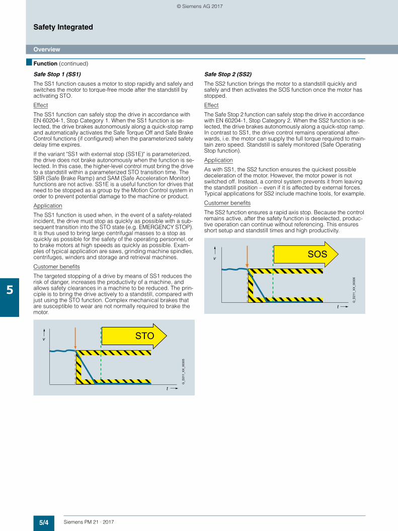
5/4 Siemens PM 21 · 2017
Safety Integrated
Overview
5
■ Function (continued)
Safe Stop 1 (SS1)
The SS1 function causes a motor to stop rapidly and safely and switches the motor to torque-free mode after the standstill by activating STO.
Effect
The SS1 function can safely stop the drive in accordance with EN 60204-1, Stop Category 1. When the SS1 function is se-lected, the drive brakes autonomously along a quick-stop ramp and automatically activates the Safe Torque Off and Safe Brake Control functions (if configured) when the parameterized safety delay time expires.
If the variant "SS1 with external stop (SS1E)" is parameterized, the drive does not brake autonomously when the function is se-lected. In this case, the higher-level control must bring the drive to a standstill within a parameterized STO transition time. The SBR (Safe Brake Ramp) and SAM (Safe Acceleration Monitor) functions are not active. SS1E is a useful function for drives that need to be stopped as a group by the Motion Control system in order to prevent potential damage to the machine or product.
Application
The SS1 function is used when, in the event of a safety-related incident, the drive must stop as quickly as possible with a sub-sequent transition into the STO state (e.g. EMERGENCY STOP). It is thus used to bring large centrifugal masses to a stop as quickly as possible for the safety of the operating personnel, or to brake motors at high speeds as quickly as possible. Exam-ples of typical application are saws, grinding machine spindles, centrifuges, winders and storage and retrieval machines.
Customer benefits
The targeted stopping of a drive by means of SS1 reduces the risk of danger, increases the productivity of a machine, and allows safety clearances in a machine to be reduced. The prin-ciple is to bring the drive actively to a standstill, compared with just using the STO function. Complex mechanical brakes that are susceptible to wear are not normally required to brake the motor.
Safe Stop 2 (SS2)
The SS2 function brings the motor to a standstill quickly and safely and then activates the SOS function once the motor has stopped.
Effect
The Safe Stop 2 function can safely stop the drive in accordance with EN 60204-1, Stop Category 2. When the SS2 function is se-lected, the drive brakes autonomously along a quick-stop ramp. In contrast to SS1, the drive control remains operational after-wards, i.e. the motor can supply the full torque required to main-tain zero speed. Standstill is safely monitored (Safe Operating Stop function).
Application
As with SS1, the SS2 function ensures the quickest possible deceleration of the motor. However, the motor power is not switched off. Instead, a control system prevents it from leaving the standstill position – even if it is affected by external forces. Typical applications for SS2 include machine tools, for example.
Customer benefits
The SS2 function ensures a rapid axis stop. Because the control remains active, after the safety function is deselected, produc-tive operation can continue without referencing. This ensures short setup and standstill times and high productivity.
STOv
t
G_D
211_
XX
_003
05
v
t
G_D
211_
XX
_003
06
SOS
© Siemens AG 2017
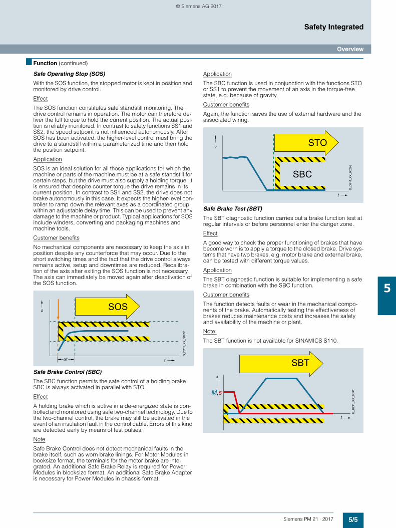
5/5Siemens PM 21 · 2017
Safety Integrated
Overview
5
■ Function (continued)
Safe Operating Stop (SOS)
With the SOS function, the stopped motor is kept in position and monitored by drive control.
Effect
The SOS function constitutes safe standstill monitoring. The drive control remains in operation. The motor can therefore de-liver the full torque to hold the current position. The actual posi-tion is reliably monitored. In contrast to safety functions SS1 and SS2, the speed setpoint is not influenced autonomously. After SOS has been activated, the higher-level control must bring the drive to a standstill within a parameterized time and then hold the position setpoint.
Application
SOS is an ideal solution for all those applications for which the machine or parts of the machine must be at a safe standstill for certain steps, but the drive must also supply a holding torque. It is ensured that despite counter torque the drive remains in its current position. In contrast to SS1 and SS2, the drive does not brake autonomously in this case. It expects the higher-level con-troller to ramp down the relevant axes as a coordinated group within an adjustable delay time. This can be used to prevent any damage to the machine or product. Typical applications for SOS include winders, converting and packaging machines and machine tools.
Customer benefits
No mechanical components are necessary to keep the axis in position despite any counterforce that may occur. Due to the short switching times and the fact that the drive control always remains active, setup and downtimes are reduced. Recalibra-tion of the axis after exiting the SOS function is not necessary. The axis can immediately be moved again after deactivation of the SOS function.
Safe Brake Control (SBC)
The SBC function permits the safe control of a holding brake. SBC is always activated in parallel with STO.
Effect
A holding brake which is active in a de-energized state is con-trolled and monitored using safe two-channel technology. Due to the two-channel control, the brake may still be activated in the event of an insulation fault in the control cable. Errors of this kind are detected early by means of test pulses.
Note
Safe Brake Control does not detect mechanical faults in the brake itself, such as worn brake linings. For Motor Modules in booksize format, the terminals for the motor brake are inte-grated. An additional Safe Brake Relay is required for Power Modules in blocksize format. An additional Safe Brake Adapter is necessary for Power Modules in chassis format.
Application
The SBC function is used in conjunction with the functions STO or SS1 to prevent the movement of an axis in the torque-free state, e.g. because of gravity.
Customer benefits
Again, the function saves the use of external hardware and the associated wiring.
Safe Brake Test (SBT)
The SBT diagnostic function carries out a brake function test at regular intervals or before personnel enter the danger zone.
Effect
A good way to check the proper functioning of brakes that have become worn is to apply a torque to the closed brake. Drive sys-tems that have two brakes, e.g. motor brake and external brake, can be tested with different torque values.
Application
The SBT diagnostic function is suitable for implementing a safe brake in combination with the SBC function.
Customer benefits
The function detects faults or wear in the mechanical compo-nents of the brake. Automatically testing the effectiveness of brakes reduces maintenance costs and increases the safety and availability of the machine or plant.
Note:
The SBT function is not available for SINAMICS S110.
G_D
211_
XX
_002
07
s
t
SOS
∆t
v
t
G_D
211_
XX
_002
76
STO
SBC
G_D
211_
XX
_003
11M,s
t
SBT
© Siemens AG 2017
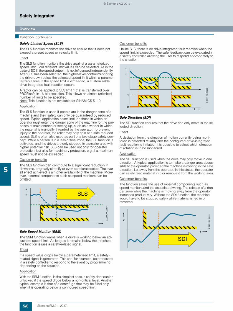
5/6 Siemens PM 21 · 2017
Safety Integrated
Overview
5
■ Function (continued)
Safely Limited Speed (SLS)
The SLS function monitors the drive to ensure that it does not exceed a preset speed or velocity limit.
Effect
The SLS function monitors the drive against a parameterized speed limit. Four different limit values can be selected. As in the case of SOS, the speed setpoint is not influenced independently. After SLS has been selected, the higher-level control must bring the drive down below the selected speed limit within a parame-terizable time. If the speed limit is exceeded, a customizable drive-integrated fault reaction occurs.
A factor can be applied to SLS limit 1 that is transferred over PROFIsafe in 16-bit resolution. This allows an almost unlimited number of limits to be specified. Note: This function is not available for SINAMICS S110.
Application
The SLS function is used if people are in the danger zone of a machine and their safety can only be guaranteed by reduced speed. Typical application cases include those in which an operator must enter the danger zone of the machine for the pur-poses of maintenance or setting up, such as a winder in which the material is manually threaded by the operator. To prevent injury to the operator, the roller may only spin at a safe reduced speed. SLS is often also used as part of a two-stage safety con-cept. While a person is in a less critical zone, the SLS function is activated, and the drives are only stopped in a smaller area with higher potential risk. SLS can be used not only for operator protection, but also for machinery protection, e.g. if a maximum speed must not be exceeded.
Customer benefits
The SLS function can contribute to a significant reduction in downtime, or greatly simplify or even accelerate setup. The over-all effect achieved is a higher availability of the machine. More-over, external components such as speed monitors can be omitted.
Safe Speed Monitor (SSM)
The SSM function warns when a drive is working below an ad-justable speed limit. As long as it remains below the threshold, the function issues a safety-related signal.
Effect
If a speed value drops below a parameterized limit, a safety-related signal is generated. This can, for example, be processed in a safety controller to respond to the event by programming, depending on the situation.
Application
With the SSM function, in the simplest case, a safety door can be unlocked if the speed drops below a non-critical level. Another typical example is that of a centrifuge that may be filled only when it is operating below a configured speed limit.
Customer benefits
Unlike SLS, there is no drive-integrated fault reaction when the speed limit is exceeded. The safe feedback can be evaluated in a safety controller, allowing the user to respond appropriately to the situation.
Safe Direction (SDI)
The SDI function ensures that the drive can only move in the se-lected direction.
Effect
A deviation from the direction of motion currently being moni-tored is detected reliably and the configured drive-integrated fault reaction is initiated. It is possible to select which direction of rotation is to be monitored.
Application
The SDI function is used when the drive may only move in one direction. A typical application is to make a danger area acces-sible to the operator, provided the machine is moving in the safe direction, i.e. away from the operator. In this status, the operator can safely feed material into or remove it from the working area.
Customer benefits
The function saves the use of external components such as speed monitors and the associated wiring. The release of a dan-ger zone while the machine is moving away from the operator increases productivity. Without the SDI function, the machine would have to be stopped safely while material is fed in or removed.
v
t
SLS
G_D
211_
XX
_003
07
t
G_D
211_
XX
_002
09
v
1
0
SDIt
v
G_D
211_
XX
_003
08
© Siemens AG 2017
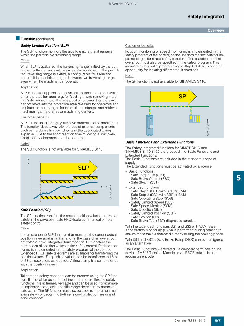
5/7Siemens PM 21 · 2017
Safety Integrated
Overview
5
■ Function (continued)
Safely Limited Position (SLP)
The SLP function monitors the axis to ensure that it remains within the permissible traversing range.
Effect
When SLP is activated, the traversing range limited by the con-figured software limit switches is safely monitored. If the permit-ted traversing range is exited, a configurable fault reaction occurs. It is possible to toggle between two traversing ranges, even when the machine is in operation.
Application
SLP is used for applications in which machine operators have to enter a protection area, e.g. for feeding in and removing mate-rial. Safe monitoring of the axis position ensures that the axis cannot move into the protection area released for operators and so place them in danger, for example, on storage and retrieval machines, gantry cranes or machining centers.
Customer benefits
SLP can be used for highly-effective protection area monitoring. The function does away with the use of external components such as hardware limit switches and the associated wiring expense. Due to the short reaction time following a limit over-shoot, safety clearances can be reduced.
Note:
The SLP function is not available for SINAMICS S110.
Safe Position (SP)
The SP function transfers the actual position values determined safely in the drive over safe PROFIsafe communication to a safety control.
Effect
In contrast to the SLP function that monitors the current actual position value against a limit and, in the case of an overshoot, activates a drive-integrated fault reaction, SP transfers the current actual position values to the safety control. Position mon-itoring is implemented in the safety program of the control. Extended PROFIsafe telegrams are available for transferring the position values. The position values can be transferred in 16-bit or 32-bit resolution, as required. A time stamp is also transferred with the position values.
Application
Tailor-made safety concepts can be created using the SP func-tion. It is ideal for use on machines that require flexible safety functions. It is extremely versatile and can be used, for example, to implement safe, axis-specific range detection by means of safe cams. The SP function can also be used to implement multi-axis safety concepts, multi-dimensional protection areas and zone concepts.
Customer benefits
Position monitoring or speed monitoring is implemented in the safety program of the control, so the user has the flexibility for im-plementing tailor-made safety functions. The reaction to a limit overshoot must also be specified in the safety program. This means a higher initial programming outlay, but it does offer the opportunity for initiating different fault reactions.
Note:
The SP function is not available for SINAMICS S110.
Basic Functions and Extended Functions
The Safety Integrated functions for SIMOTION D and SINAMICS S110/S120 are grouped into Basic Functions and Extended Functions. The Basic Functions are included in the standard scope of supply. The Extended Functions must be activated by a license. • Basic Functions
- Safe Torque Off (STO)- Safe Brake Control (SBC)- Safe Stop 1 (SS1)
• Extended Functions- Safe Stop 1 (SS1) with SBR or SAM- Safe Stop 2 (SS2) with SBR or SAM- Safe Operating Stop (SOS)- Safely Limited Speed (SLS)- Safe Speed Monitor (SSM)- Safe Direction (SDI)- Safely Limited Position (SLP)- Safe Position (SP)- Safe Brake Test (SBT) diagnostic function
With the Extended Functions SS1 and SS2 with SAM, Safe Acceleration Monitoring (SAM) is performed during braking to ensure that a fault is detected already during the braking phase.
With SS1 and SS2, a Safe Brake Ramp (SBR) can be configured as an alternative.
The Basic Functions – activated via on-board terminals on the device, TM54F Terminal Module or via PROFIsafe – do not require an encoder.
SLPs
t
G_D
211_
XX
_003
10
SP
G_D
211_
XX
_003
09a
© Siemens AG 2017
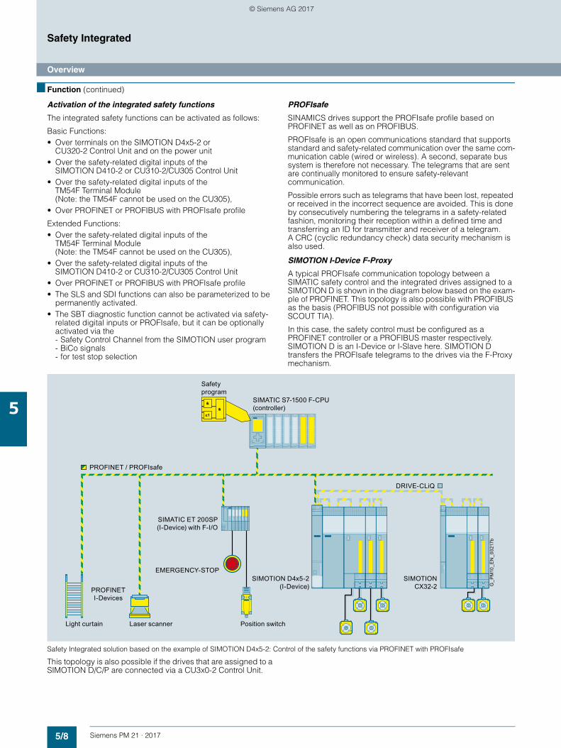
5/8 Siemens PM 21 · 2017
Safety Integrated
Overview
5
■ Function (continued)
Activation of the integrated safety functions
The integrated safety functions can be activated as follows:
Basic Functions: • Over terminals on the SIMOTION D4x5-2 or
CU320-2 Control Unit and on the power unit• Over the safety-related digital inputs of the
SIMOTION D410-2 or CU310-2/CU305 Control Unit• Over the safety-related digital inputs of the
TM54F Terminal Module (Note: the TM54F cannot be used on the CU305),
• Over PROFINET or PROFIBUS with PROFIsafe profile
Extended Functions: • Over the safety-related digital inputs of the
TM54F Terminal Module (Note: the TM54F cannot be used on the CU305),
• Over the safety-related digital inputs of the SIMOTION D410-2 or CU310-2/CU305 Control Unit
• Over PROFINET or PROFIBUS with PROFIsafe profile• The SLS and SDI functions can also be parameterized to be
permanently activated.• The SBT diagnostic function cannot be activated via safety-
related digital inputs or PROFIsafe, but it can be optionally activated via the - Safety Control Channel from the SIMOTION user program - BiCo signals - for test stop selection
PROFIsafe
SINAMICS drives support the PROFIsafe profile based on PROFINET as well as on PROFIBUS.
PROFIsafe is an open communications standard that supports standard and safety-related communication over the same com-munication cable (wired or wireless). A second, separate bus system is therefore not necessary. The telegrams that are sent are continually monitored to ensure safety-relevant communication.
Possible errors such as telegrams that have been lost, repeated or received in the incorrect sequence are avoided. This is done by consecutively numbering the telegrams in a safety-related fashion, monitoring their reception within a defined time and transferring an ID for transmitter and receiver of a telegram. A CRC (cyclic redundancy check) data security mechanism is also used.
SIMOTION I-Device F-Proxy
A typical PROFIsafe communication topology between a SIMATIC safety control and the integrated drives assigned to a SIMOTION D is shown in the diagram below based on the exam-ple of PROFINET. This topology is also possible with PROFIBUS as the basis (PROFIBUS not possible with configuration via SCOUT TIA).
In this case, the safety control must be configured as a PROFINET controller or a PROFIBUS master respectively. SIMOTION D is an I-Device or I-Slave here. SIMOTION D transfers the PROFIsafe telegrams to the drives via the F-Proxy mechanism.
Safety Integrated solution based on the example of SIMOTION D4x5-2: Control of the safety functions via PROFINET with PROFIsafe
This topology is also possible if the drives that are assigned to a SIMOTION D/C/P are connected via a CU3x0-2 Control Unit.
Safety program
Light curtain Laser scanner Position switch
EMERGENCY-STOP
PROFINET I-Devices
SIMOTION D4x5-2 (I-Device)
SIMATIC ET 200SP (I-Device) with F-I/O
SIMOTION CX32-2
SIMATIC S7-1500 F-CPU (controller)
G_P
M10
_EN
_002
17b
PROFINET / PROFIsafe
DRIVE-CLiQ
© Siemens AG 2017
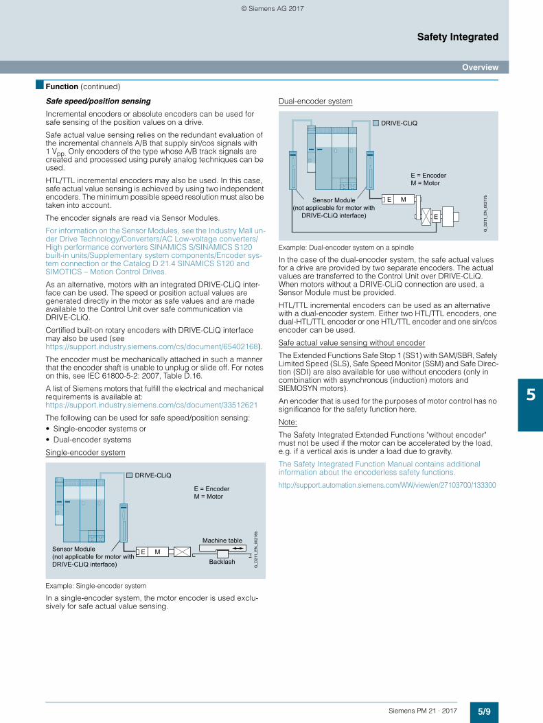
5/9Siemens PM 21 · 2017
Safety Integrated
Overview
5
■ Function (continued)
Safe speed/position sensing
Incremental encoders or absolute encoders can be used for safe sensing of the position values on a drive.
Safe actual value sensing relies on the redundant evaluation of the incremental channels A/B that supply sin/cos signals with 1 Vpp. Only encoders of the type whose A/B track signals are created and processed using purely analog techniques can be used.
HTL/TTL incremental encoders may also be used. In this case, safe actual value sensing is achieved by using two independent encoders. The minimum possible speed resolution must also be taken into account.
The encoder signals are read via Sensor Modules.
For information on the Sensor Modules, see the Industry Mall un-der Drive Technology/Converters/AC Low-voltage converters/High performance converters SINAMICS S/SINAMICS S120 built-in units/Supplementary system components/Encoder sys-tem connection or the Catalog D 21.4 SINAMICS S120 and SIMOTICS – Motion Control Drives.
As an alternative, motors with an integrated DRIVE-CLiQ inter-face can be used. The speed or position actual values are generated directly in the motor as safe values and are made available to the Control Unit over safe communication via DRIVE-CLiQ.
Certified built-on rotary encoders with DRIVE-CLiQ interface may also be used (see https://support.industry.siemens.com/cs/document/65402168).
The encoder must be mechanically attached in such a manner that the encoder shaft is unable to unplug or slide off. For notes on this, see IEC 61800-5-2: 2007, Table D.16.
A list of Siemens motors that fulfill the electrical and mechanical requirements is available at: https://support.industry.siemens.com/cs/document/33512621
The following can be used for safe speed/position sensing:• Single-encoder systems or• Dual-encoder systems
Single-encoder system
Example: Single-encoder system
In a single-encoder system, the motor encoder is used exclu-sively for safe actual value sensing.
Dual-encoder system
Example: Dual-encoder system on a spindle
In the case of the dual-encoder system, the safe actual values for a drive are provided by two separate encoders. The actual values are transferred to the Control Unit over DRIVE-CLiQ. When motors without a DRIVE-CLiQ connection are used, a Sensor Module must be provided.
HTL/TTL incremental encoders can be used as an alternative with a dual-encoder system. Either two HTL/TTL encoders, one dual-HTL/TTL encoder or one HTL/TTL encoder and one sin/cos encoder can be used.
Safe actual value sensing without encoder
The Extended Functions Safe Stop 1 (SS1) with SAM/SBR, Safely Limited Speed (SLS), Safe Speed Monitor (SSM) and Safe Direc-tion (SDI) are also available for use without encoders (only in combination with asynchronous (induction) motors and SIEMOSYN motors).
An encoder that is used for the purposes of motor control has no significance for the safety function here.
Note:
The Safety Integrated Extended Functions "without encoder" must not be used if the motor can be accelerated by the load, e.g. if a vertical axis is under a load due to gravity.
The Safety Integrated Function Manual contains additional information about the encoderless safety functions.
http://support.automation.siemens.com/WW/view/en/27103700/133300E = Encoder M = Motor
Sensor Module (not applicable for motor with DRIVE-CLiQ interface) Backlash
Machine table
G_D
211_
EN
_002
16b
DRIVE-CLiQ
E M
E = Encoder M = Motor
Sensor Module (not applicable for motor with
DRIVE-CLiQ interface)
G_D
211_
EN
_002
17b
DRIVE-CLiQ
E
ME
© Siemens AG 2017
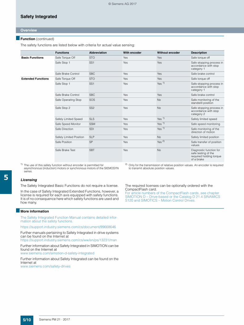
5/10 Siemens PM 21 · 2017
Safety Integrated
Overview
5
■ Function (continued)
The safety functions are listed below with criteria for actual value sensing:
1) The use of this safety function without encoder is permitted for asynchronous (induction) motors or synchronous motors of the SIEMOSYN series.
2) Only for the transmission of relative position values. An encoder is required to transmit absolute position values.
Licensing
The Safety Integrated Basic Functions do not require a license.
In the case of Safety Integrated Extended Functions, however, a license is required for each axis equipped with safety functions. It is of no consequence here which safety functions are used and how many.
The required licenses can be optionally ordered with the CompactFlash card. For article numbers of the CompactFlash cards, see chapter SIMOTION D – Drive-based or the Catalog D 21.4 SINAMICS S120 and SIMOTICS – Motion Control Drives.
■ More information
The Safety Integrated Function Manual contains detailed infor-mation about the safety functions.
https://support.industry.siemens.com/cs/document/99668646
Further manuals pertaining to Safety Integrated in drive systems can be found on the Internet at https://support.industry.siemens.com/cs/ww/en/ps/13231/man
Further information about Safety Integrated in SIMOTION can be found on the Internet at www.siemens.com/simotion-d-safety-integrated
Further information about Safety Integrated can be found on the Internet at www.siemens.com/safety-drives
Functions Abbreviation With encoder Without encoder Description
Basic Functions Safe Torque Off STO Yes Yes Safe torque off
Safe Stop 1 SS1 Yes Yes Safe stopping process in accordance with stop category 1
Safe Brake Control SBC Yes Yes Safe brake control
Extended Functions Safe Torque Off STO Yes Yes Safe torque off
Safe Stop 1 SS1 Yes Yes 1) Safe stopping process in accordance with stop category 1
Safe Brake Control SBC Yes Yes Safe brake control
Safe Operating Stop SOS Yes No Safe monitoring of the standstill position
Safe Stop 2 SS2 Yes No Safe stopping process in accordance with stop category 2
Safely Limited Speed SLS Yes Yes 1) Safely limited speed
Safe Speed Monitor SSM Yes Yes 1) Safe speed monitoring
Safe Direction SDI Yes Yes 1) Safe monitoring of the direction of motion
Safely Limited Position SLP Yes No Safely limited position
Safe Position SP Yes Yes 2) Safe transfer of position values
Safe Brake Test SBT Yes No Diagnostic function for safe testing of the required holding torque of a brake
© Siemens AG 2017
Siemens PM 21 · 2017
66/2 Packaging machines6/2 Overview6/2 Benefits6/3 Design6/3 More information
6/4 Printing presses6/4 Overview6/4 Benefits6/5 Design6/5 More information
6/6 Textile machines6/6 Overview6/6 Benefits6/7 Design6/7 More information
6/8 Converting6/8 Overview6/9 Benefits6/9 Design6/9 More information
6/10 Tire production machines6/10 Overview6/10 Benefits6/11 Design6/11 More information
6/12 Metal forming technology6/12 Overview6/12 Benefits6/13 Design6/13 More information
6/14 Glass production machines6/14 Overview6/14 Benefits6/15 Design6/15 More information
6/16 Handling systems6/16 Overview6/16 Benefits6/17 Design6/17 More information
6/18 Solar production machines6/18 Overview6/19 Benefits6/19 Design6/19 More information
6/20 Ceramics and stone processing machines
6/20 Overview6/21 Benefits6/21 Design
Industry-specific solutions
© Siemens AG 2017
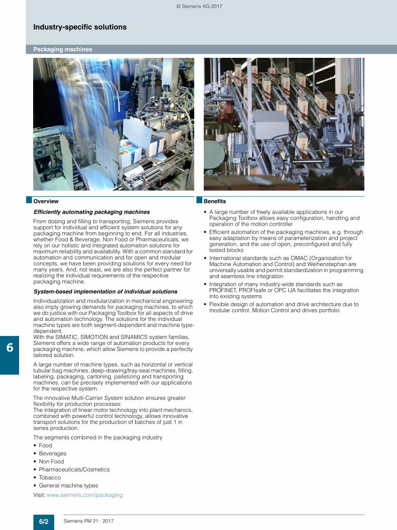
6/2 Siemens PM 21 · 2017
Industry-specific solutions
Packaging machines
6
■ Overview
Efficiently automating packaging machines
From dosing and filling to transporting, Siemens provides support for individual and efficient system solutions for any packaging machine from beginning to end. For all industries, whether Food & Beverage, Non Food or Pharmaceuticals, we rely on our holistic and integrated automation solutions for maximum reliability and availability. With a common standard for automation and communication and for open and modular concepts, we have been providing solutions for every need for many years. And, not least, we are also the perfect partner for realizing the individual requirements of the respective packaging machine.
System-based implementation of individual solutions
Individualization and modularization in mechanical engineering also imply growing demands for packaging machines, to which we do justice with our Packaging Toolbox for all aspects of drive and automation technology. The solutions for the individual machine types are both segment-dependent and machine type-dependent. With the SIMATIC, SIMOTION and SINAMICS system families, Siemens offers a wide range of automation products for every packaging machine, which allow Siemens to provide a perfectly tailored solution.
A large number of machine types, such as horizontal or vertical tubular bag machines, deep-drawing/tray-seal machines, filling, labeling, packaging, cartoning, palletizing and transporting machines, can be precisely implemented with our applications for the respective system.
The innovative Multi-Carrier System solution ensures greater flexibility for production processes: The integration of linear motor technology into plant mechanics, combined with powerful control technology, allows innovative transport solutions for the production of batches of just 1 in series production.
The segments combined in the packaging industry • Food• Beverages• Non Food• Pharmaceuticals/Cosmetics• Tobacco• General machine types
Visit: www.siemens.com/packaging
■ Benefits
• A large number of freely available applications in our Packaging Toolbox allows easy configuration, handling and operation of the motion controller
• Efficient automation of the packaging machines, e.g. through easy adaptation by means of parameterization and project generation, and the use of open, preconfigured and fully tested blocks
• International standards such as OMAC (Organization for Machine Automation and Control) and Weihenstephan are universally usable and permit standardization in programming and seamless line integration
• Integration of many industry-wide standards such as PROFINET, PROFIsafe or OPC UA facilitates the integration into existing systems
• Flexible design of automation and drive architecture due to modular control, Motion Control and drives portfolio
© Siemens AG 2017
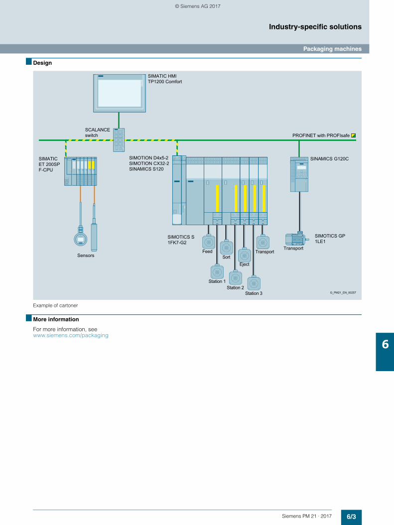
6/3Siemens PM 21 · 2017
Industry-specific solutions
Packaging machines
6
■ Design
Example of cartoner
■ More information
For more information, see www.siemens.com/packaging
Transport
EjectSortSensors
Station 3Station 2
Station 1
FeedTransport
G_PM21_EN_00257
SCALANCE switch
SIMATIC HMI TP1200 Comfort
PROFINET with PROFIsafe
SIMOTICS GP 1LE1
SIMATIC ET 200SP F-CPU
SIMOTION D4x5-2 SIMOTION CX32-2 SINAMICS S120
SINAMICS G120C
SIMOTICS S 1FK7-G2
© Siemens AG 2017
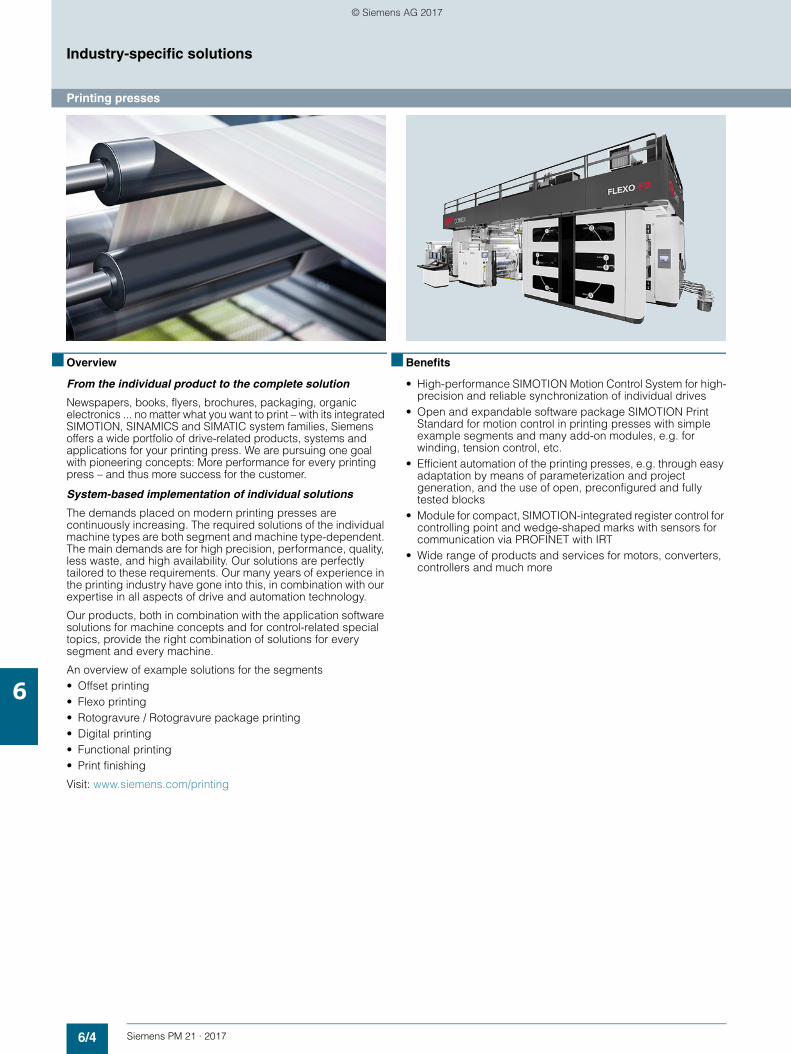
6/4 Siemens PM 21 · 2017
Industry-specific solutions
Printing presses
6
■ Overview
From the individual product to the complete solution
Newspapers, books, flyers, brochures, packaging, organic electronics ... no matter what you want to print – with its integrated SIMOTION, SINAMICS and SIMATIC system families, Siemens offers a wide portfolio of drive-related products, systems and applications for your printing press. We are pursuing one goal with pioneering concepts: More performance for every printing press – and thus more success for the customer.
System-based implementation of individual solutions
The demands placed on modern printing presses are continuously increasing. The required solutions of the individual machine types are both segment and machine type-dependent. The main demands are for high precision, performance, quality, less waste, and high availability. Our solutions are perfectly tailored to these requirements. Our many years of experience in the printing industry have gone into this, in combination with our expertise in all aspects of drive and automation technology.
Our products, both in combination with the application software solutions for machine concepts and for control-related special topics, provide the right combination of solutions for every segment and every machine.
An overview of example solutions for the segments • Offset printing• Flexo printing• Rotogravure / Rotogravure package printing• Digital printing• Functional printing• Print finishing
Visit: www.siemens.com/printing
■ Benefits
• High-performance SIMOTION Motion Control System for high-precision and reliable synchronization of individual drives
• Open and expandable software package SIMOTION Print Standard for motion control in printing presses with simple example segments and many add-on modules, e.g. for winding, tension control, etc.
• Efficient automation of the printing presses, e.g. through easy adaptation by means of parameterization and project generation, and the use of open, preconfigured and fully tested blocks
• Module for compact, SIMOTION-integrated register control for controlling point and wedge-shaped marks with sensors for communication via PROFINET with IRT
• Wide range of products and services for motors, converters, controllers and much more
© Siemens AG 2017
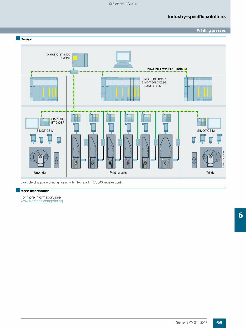
6/5Siemens PM 21 · 2017
Industry-specific solutions
Printing presses
6
■ Design
Example of gravure printing press with integrated TRC3000 register control
■ More information
For more information, see www.siemens.com/printing
Printing unitsUnwinder Winder
G_P
M21
_EN
_002
34a
PROFINET with PROFIsafePROFINET with PROFIsafe
SIMATIC S7-1500 F-CPU
SIMATIC ET 200SP
SIMOTICS MSIMOTICS M
SIMOTION D4x5-2 SIMOTION CX32-2 SINAMICS S120
© Siemens AG 2017
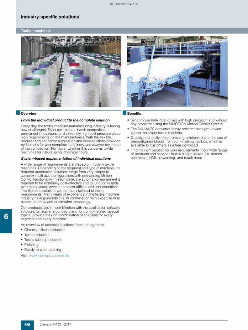
6/6 Siemens PM 21 · 2017
Industry-specific solutions
Textile machines
6
■ Overview
From the individual product to the complete solution
Every day, the textile machine manufacturing industry is facing new challenges: Short-term trends, harsh competition, permanent innovations, and extremely high cost pressure place high requirements on the manufacturers. With the flexible, modular and economic automation and drive solutions provided by Siemens for your complete machinery, you always stay ahead of the competition. No matter whether this concerns textile machines for natural or for chemical fibers.
System-based implementation of individual solutions
A wide range of requirements are placed on modern textile machines. Depending on the segment and type of machine, the required automation solutions range from very simple to complex multi-axis configurations with demanding Motion Control functionality. In each case, the automation equipment is required to be extremely cost-effective and to function reliably over many years, even in the most difficult ambient conditions. The Siemens solutions are perfectly tailored to these requirements. Many years of experience in the textile machine industry have gone into this, in combination with expertise in all aspects of drive and automation technology.
Our products, both in combination with the application software solutions for machine concepts and for control-related special topics, provide the right combination of solutions for every segment and every machine.
An overview of example solutions from the segments• Chemical fiber production• Yarn production• Textile fabric production• Finishing• Ready-to-wear clothing
Visit: www.siemens.com/textile
■ Benefits
• Synchronize individual drives with high precision and without any problems using the SIMOTION Motion Control System
• The SINAMICS converter family provides the right device version for every textile machine.
• Quickly and easily create finishing solutions due to the use of preconfigured blocks from our Finishing Toolbox, which is available to customers as a free download
• Find the right solution for your requirements in our wide range of products and services from a single source, i.e. motors, controllers, HMI, networking, and much more
© Siemens AG 2017
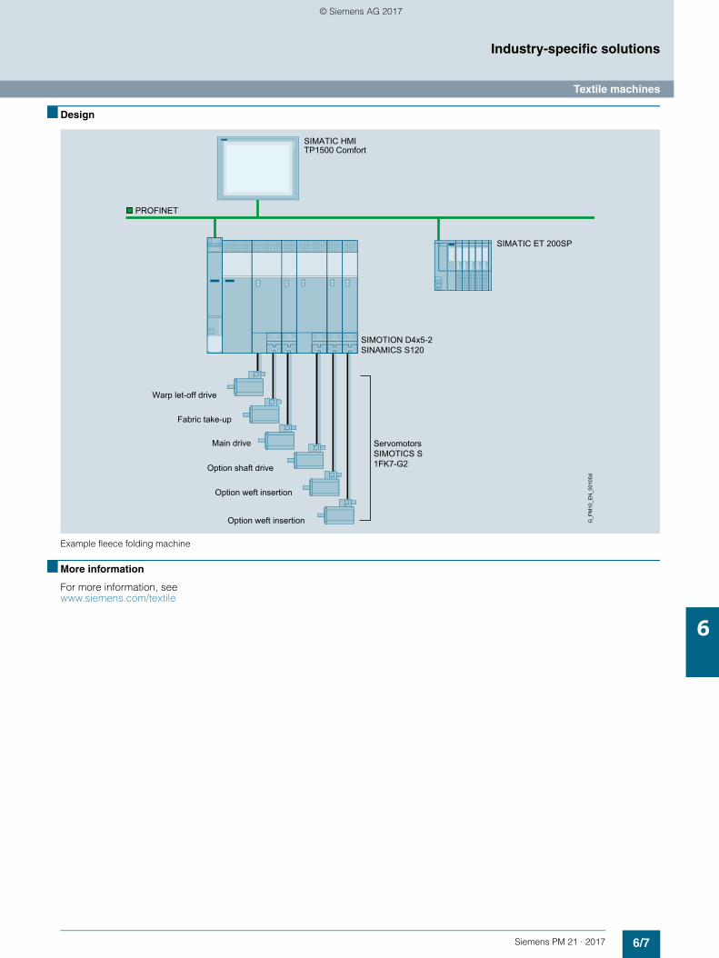
6/7Siemens PM 21 · 2017
Industry-specific solutions
Textile machines
6
■ Design
Example fleece folding machine
■ More information
For more information, see www.siemens.com/textile
ServomotorsSIMOTICS S 1FK7-G2
Warp let-off drive
Fabric take-up
Main drive
Option shaft drive
Option weft insertion
Option weft insertion G_P
M10
_EN
_001
05d
PROFINET
SIMOTION D4x5-2 SINAMICS S120
SIMATIC HMI TP1500 Comfort
SIMATIC ET 200SP
© Siemens AG 2017
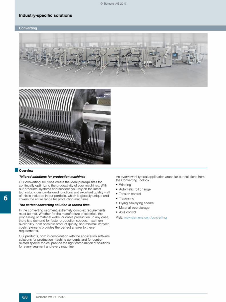
6/8 Siemens PM 21 · 2017
Industry-specific solutions
Converting
6
■ Overview
Tailored solutions for production machines
Our converting solutions create the ideal prerequisites for continually optimizing the productivity of your machines. With our products, systems and services you rely on the latest technology, custom-tailored functions and excellent quality – all of this is included in our portfolio, which is globally unique and covers the entire range for production machines.
The perfect converting solution in record time
In the converting segment, extremely complex requirements must be met. Whether for the manufacture of toiletries, the processing of material webs, or cable production: In any case, there is a demand for faster production speeds, maximum availability, best possible product quality, and minimal lifecycle costs. Siemens provides the perfect answer to these requirements.
Our products, both in combination with the application software solutions for production machine concepts and for control-related special topics, provide the right combination of solutions for every segment and every machine.
An overview of typical application areas for our solutions from the Converting Toolbox• Winding• Automatic roll change• Tension control• Traversing• Flying saw/flying shears• Material web storage• Axis control
Visit: www.siemens.com/converting
© Siemens AG 2017
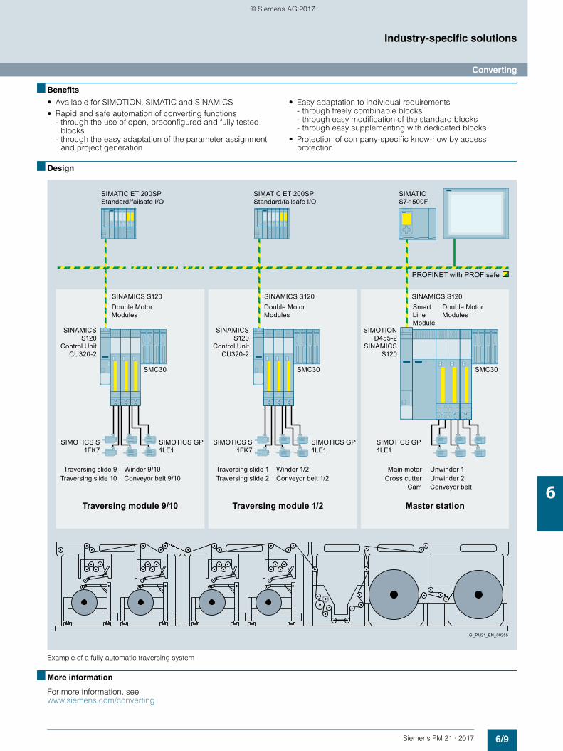
6/9Siemens PM 21 · 2017
Industry-specific solutions
Converting
6
■ Benefits
• Available for SIMOTION, SIMATIC and SINAMICS• Rapid and safe automation of converting functions
- through the use of open, preconfigured and fully tested blocks
- through the easy adaptation of the parameter assignment and project generation
• Easy adaptation to individual requirements- through freely combinable blocks- through easy modification of the standard blocks- through easy supplementing with dedicated blocks
• Protection of company-specific know-how by access protection
■ Design
Example of a fully automatic traversing system
■ More information
For more information, see www.siemens.com/converting
SIMATIC ET 200SP Standard/failsafe I/O
SIMATIC ET 200SP Standard/failsafe I/O
Traversing slide 9Traversing slide 10
Traversing module 9/10
Winder 9/10Conveyor belt 9/10
Double Motor Modules
Double Motor Modules
Traversing slide 1Traversing slide 2
Traversing module 1/2 Master station
Winder 1/2Conveyor belt 1/2
Main motorCross cutter
Cam
Unwinder 1Unwinder 2Conveyor belt
G_PM21_EN_00255
Smart Line Module
Double Motor Modules
PROFINET with PROFIsafe
SINAMICS S120
Control Unit CU320-2
SMC30
SINAMICS S120
Control Unit CU320-2
SIMOTION D455-2
SINAMICS S120
SMC30 SMC30
SIMOTICS S 1FK7
SIMOTICS GP 1LE1
SIMOTICS S 1FK7
SIMOTICS GP 1LE1
SIMOTICS GP 1LE1
SINAMICS S120 SINAMICS S120SINAMICS S120
SIMATIC S7-1500F
© Siemens AG 2017
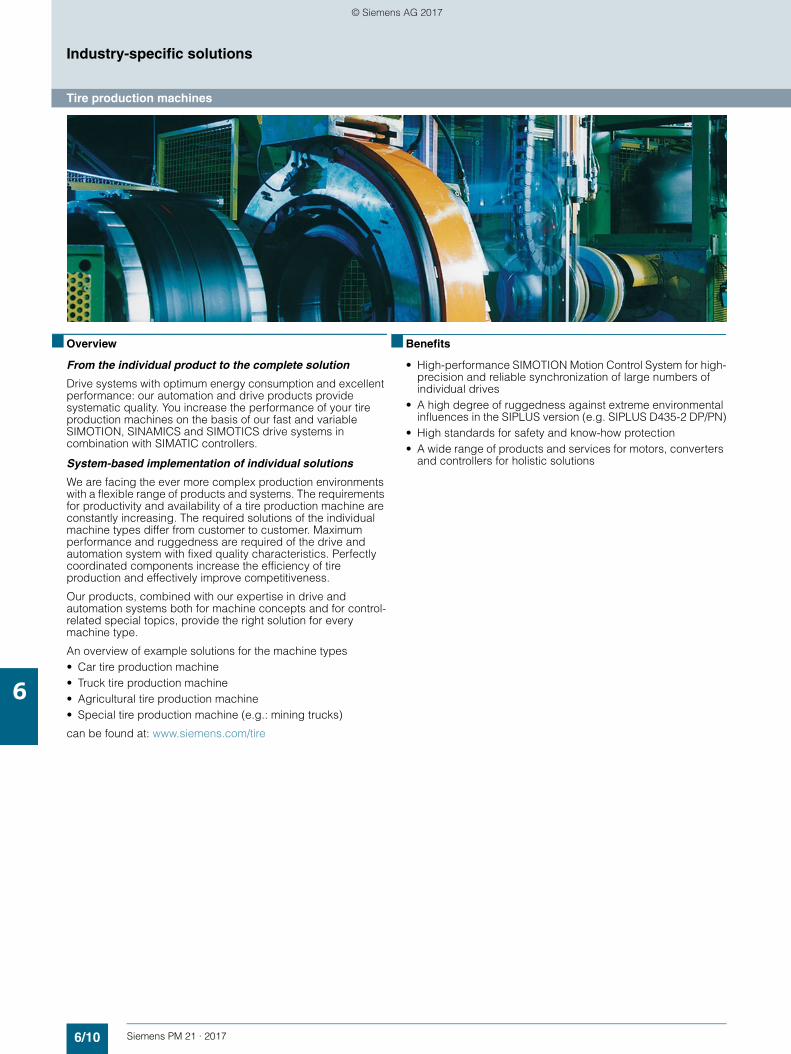
6/10 Siemens PM 21 · 2017
Industry-specific solutions
Tire production machines
6
■ Overview
From the individual product to the complete solution
Drive systems with optimum energy consumption and excellent performance: our automation and drive products provide systematic quality. You increase the performance of your tire production machines on the basis of our fast and variable SIMOTION, SINAMICS and SIMOTICS drive systems in combination with SIMATIC controllers.
System-based implementation of individual solutions
We are facing the ever more complex production environments with a flexible range of products and systems. The requirements for productivity and availability of a tire production machine are constantly increasing. The required solutions of the individual machine types differ from customer to customer. Maximum performance and ruggedness are required of the drive and automation system with fixed quality characteristics. Perfectly coordinated components increase the efficiency of tire production and effectively improve competitiveness.
Our products, combined with our expertise in drive and automation systems both for machine concepts and for control-related special topics, provide the right solution for every machine type.
An overview of example solutions for the machine types• Car tire production machine• Truck tire production machine• Agricultural tire production machine• Special tire production machine (e.g.: mining trucks)
can be found at: www.siemens.com/tire
■ Benefits
• High-performance SIMOTION Motion Control System for high-precision and reliable synchronization of large numbers of individual drives
• A high degree of ruggedness against extreme environmental influences in the SIPLUS version (e.g. SIPLUS D435-2 DP/PN)
• High standards for safety and know-how protection• A wide range of products and services for motors, converters
and controllers for holistic solutions
© Siemens AG 2017
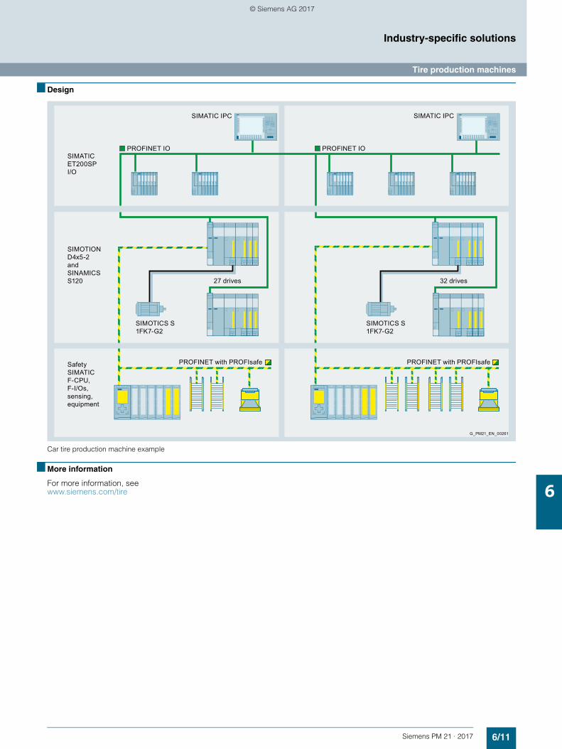
6/11Siemens PM 21 · 2017
Industry-specific solutions
Tire production machines
6
■ Design
Car tire production machine example
■ More information
For more information, see www.siemens.com/tire
G_PM21_EN_00261
27 drives 32 drives
PROFINET with PROFIsafePROFINET with PROFIsafe
SIMOTION D4x5-2 and SINAMICS S120
SIMATIC ET200SP I/O
Safety SIMATIC F-CPU, F-I/Os, sensing, equipment
SIMATIC IPC
PROFINET IO
SIMOTICS S 1FK7-G2
SIMOTICS S 1FK7-G2
SIMATIC IPC
PROFINET IO
© Siemens AG 2017
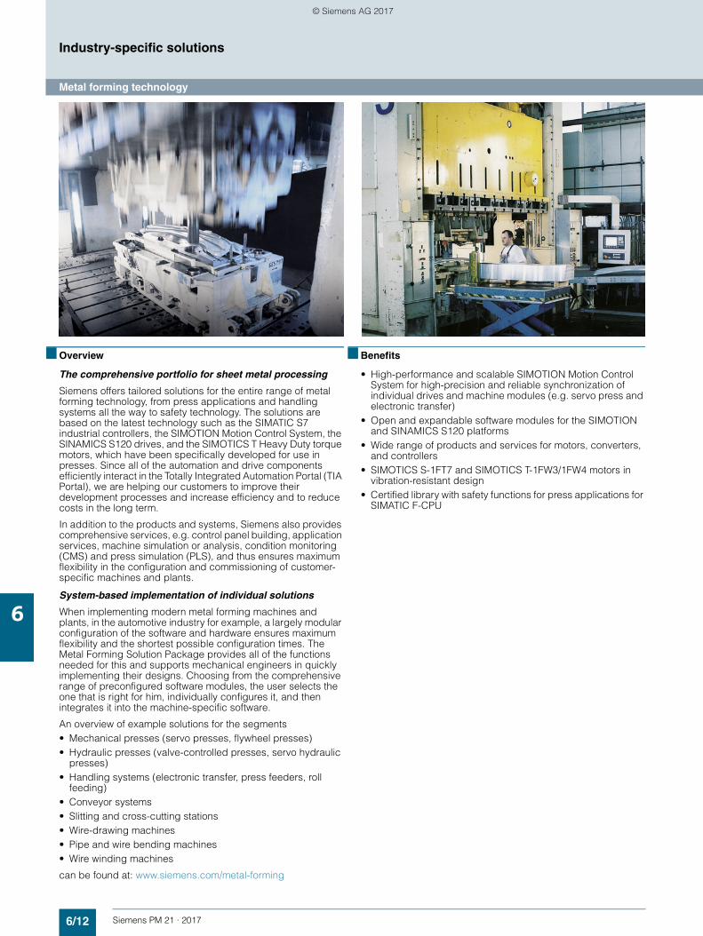
6/12 Siemens PM 21 · 2017
Industry-specific solutions
Metal forming technology
6
■ Overview
The comprehensive portfolio for sheet metal processing
Siemens offers tailored solutions for the entire range of metal forming technology, from press applications and handling systems all the way to safety technology. The solutions are based on the latest technology such as the SIMATIC S7 industrial controllers, the SIMOTION Motion Control System, the SINAMICS S120 drives, and the SIMOTICS T Heavy Duty torque motors, which have been specifically developed for use in presses. Since all of the automation and drive components efficiently interact in the Totally Integrated Automation Portal (TIA Portal), we are helping our customers to improve their development processes and increase efficiency and to reduce costs in the long term.
In addition to the products and systems, Siemens also provides comprehensive services, e.g. control panel building, application services, machine simulation or analysis, condition monitoring (CMS) and press simulation (PLS), and thus ensures maximum flexibility in the configuration and commissioning of customer-specific machines and plants.
System-based implementation of individual solutions
When implementing modern metal forming machines and plants, in the automotive industry for example, a largely modular configuration of the software and hardware ensures maximum flexibility and the shortest possible configuration times. The Metal Forming Solution Package provides all of the functions needed for this and supports mechanical engineers in quickly implementing their designs. Choosing from the comprehensive range of preconfigured software modules, the user selects the one that is right for him, individually configures it, and then integrates it into the machine-specific software.
An overview of example solutions for the segments• Mechanical presses (servo presses, flywheel presses)• Hydraulic presses (valve-controlled presses, servo hydraulic
presses) • Handling systems (electronic transfer, press feeders, roll
feeding)• Conveyor systems• Slitting and cross-cutting stations• Wire-drawing machines• Pipe and wire bending machines• Wire winding machines
can be found at: www.siemens.com/metal-forming
■ Benefits
• High-performance and scalable SIMOTION Motion Control System for high-precision and reliable synchronization of individual drives and machine modules (e.g. servo press and electronic transfer)
• Open and expandable software modules for the SIMOTION and SINAMICS S120 platforms
• Wide range of products and services for motors, converters, and controllers
• SIMOTICS S-1FT7 and SIMOTICS T-1FW3/1FW4 motors in vibration-resistant design
• Certified library with safety functions for press applications for SIMATIC F-CPU
© Siemens AG 2017
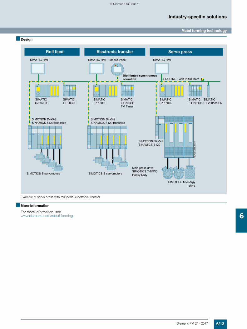
6/13Siemens PM 21 · 2017
Industry-specific solutions
Metal forming technology
6
■ Design
Example of servo press with roll feeds, electronic transfer
■ More information
For more information, see www.siemens.com/metal-forming
Electronic transferRoll feed Servo press
SIMATIC ET 200SP
SIMATIC ET 200SP
SIMOTION D4x5-2 SINAMICS S120 Booksize
SIMOTION D4x5-2 SINAMICS S120 Booksize
SIMOTICS S servomotorsSIMOTICS S servomotors
G_P
M21
_EN
_002
62
SIMATIC S7-1500F
SIMATIC S7-1500F
SIMATIC S7-1500F
SIMATIC ET 200SP TM Timer
SIMATIC ET 200eco PN
Mobile Panel
SIMOTION D4x5-2 SINAMICS S120
Distributed synchronous operation
Main press drive: SIMOTICS T-1FW3 Heavy Duty
SIMOTICS M energy store
PROFINET with PROFIsafe
SIMATIC HMI SIMATIC HMISIMATIC HMI
© Siemens AG 2017
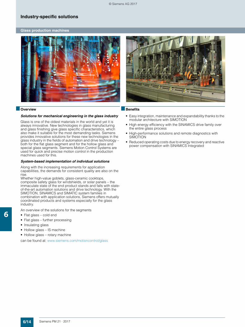
6/14 Siemens PM 21 · 2017
Industry-specific solutions
Glass production machines
6
■ Overview
Solutions for mechanical engineering in the glass industry
Glass is one of the oldest materials in the world and yet it is always innovative. New technologies in glass manufacturing and glass finishing give glass specific characteristics, which also make it suitable for the most demanding tasks. Siemens provides innovative solutions for these new technologies in the glass industry in the fields of automation and drive technology – both for the flat glass segment and for the hollow glass and special glass segments. Siemens Motion Control Systems are used for quick and precise motion control in the production machines used for this.
System-based implementation of individual solutions
Along with the increasing requirements for application capabilities, the demands for consistent quality are also on the rise. Whether high-value goblets, glass-ceramic cooktops, composite safety glass for windshields, or solar panels – the immaculate state of the end product stands and falls with state-of-the-art automation solutions and drive technology. With the SIMOTION, SINAMICS and SIMATIC system families in combination with application solutions, Siemens offers mutually coordinated products and systems especially for the glass industry.
An overview of the solutions for the segments• Flat glass – cold end• Flat glass – further processing• Insulating glass• Hollow glass – IS machine• Hollow glass – rotary machine
can be found at: www.siemens.com/motioncontrol/glass
■ Benefits
• Easy integration, maintenance and expandability thanks to the modular architecture with SIMOTION
• High energy efficiency with the SINAMICS drive family over the entire glass process
• High-performance solutions and remote diagnostics with SIMOTION
• Reduced operating costs due to energy recovery and reactive power compensation with SINAMICS Integrated
© Siemens AG 2017
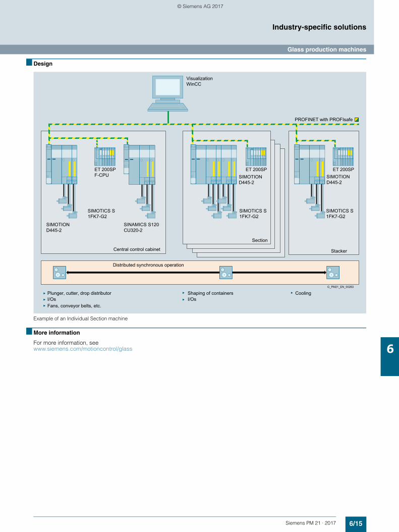
6/15Siemens PM 21 · 2017
Industry-specific solutions
Glass production machines
6
■ Design
Example of an Individual Section machine
■ More information
For more information, see www.siemens.com/motioncontrol/glass
CoolingG_PM21_EN_00263
I/OsShaping of containers
Stacker
Section
Central control cabinet
Distributed synchronous operation
Visualization WinCC
Fans, conveyor belts, etc.I/OsPlunger, cutter, drop distributor
PROFINET with PROFIsafe
SIMOTION D445-2
SIMOTION D445-2
ET 200SP ET 200SPET 200SP F-CPU
SINAMICS S120 CU320-2
SIMOTICS S 1FK7-G2
SIMOTICS S 1FK7-G2
SIMOTICS S 1FK7-G2
SIMOTION D445-2
© Siemens AG 2017
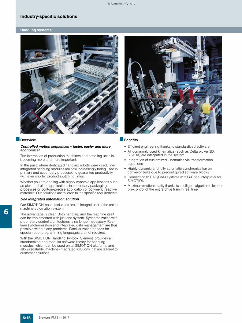
6/16 Siemens PM 21 · 2017
Industry-specific solutions
Handling systems
6
■ Overview
Controlled motion sequences – faster, easier and more economical
The interaction of production machines and handling units is becoming more and more important.
In the past, where dedicated handling robots were used, line-integrated handling modules are now increasingly being used in primary and secondary processes to guarantee productivity with ever shorter product switching times.
Whether you are dealing with highly dynamic applications such as pick-and-place applications in secondary packaging processes or contour-precise application of polymeric reactive materials: Our solutions are tailored to the specific requirements.
One integrated automation solution
Our SIMOTION-based solutions are an integral part of the entire machine automation system.
The advantage is clear: Both handling and the machine itself can be implemented with just one system. Synchronization with proprietary control architectures is no longer necessary. Real-time synchronization and integrated data management are thus possible without any problems. Familiarization periods for special robot programming languages are not required.
With the SIMOTION Handling Toolbox, Siemens provides a standardized and modular software library for handling modules, which can be used on all SIMOTION platforms and allows scalable, machine-integrated solutions that are tailored to customer solutions.
■ Benefits
• Efficient engineering thanks to standardized software• All commonly used kinematics (such as Delta picker 3D,
SCARA) are integrated in the system• Integration of customized kinematics via transformation
equations • Highly dynamic and fully automatic synchronization on
conveyor belts due to preconfigured software blocks• Connection to CAD/CAM systems with G-Code Interpreter for
SIMOTION• Maximum motion quality thanks to intelligent algorithms for the
pre-control of the entire drive train in real time
© Siemens AG 2017
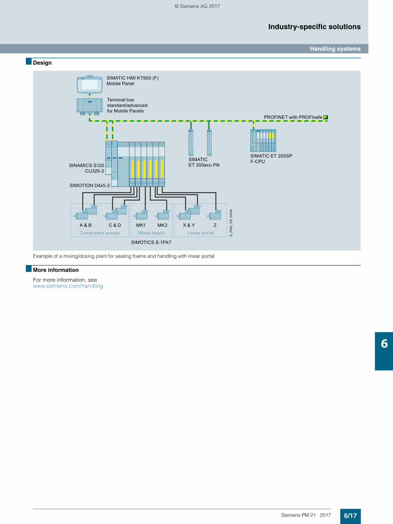
6/17Siemens PM 21 · 2017
Industry-specific solutions
Handling systems
6
■ Design
Example of a mixing/dosing plant for sealing foams and handling with linear portal
■ More information
For more information, see www.siemens.com/handling
SIMATIC HMI KT900 (F) Mobile Panel
A & B X & Y ZC & D MK2MK1
Component pumps Mixed heads Linear portal
Terminal box standard/advanced for Mobile Panels
PROFINET with PROFIsafe
G_P
M21
_EN
_002
58
SIMATIC ET 200SP F-CPU
SINAMICS S120 CU320-2
SIMATIC ET 200eco PN
SIMOTION D4x5-2
SIMOTICS S-1FK7
© Siemens AG 2017
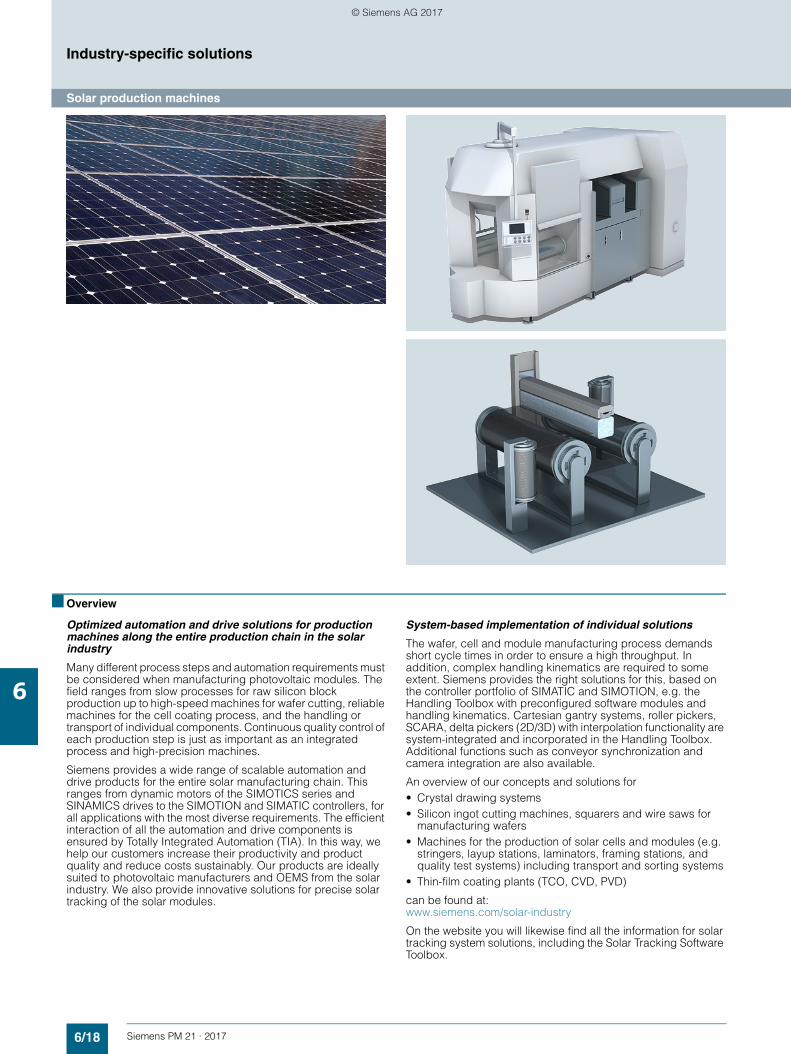
6/18 Siemens PM 21 · 2017
Industry-specific solutions
Solar production machines
6
■ Overview
Optimized automation and drive solutions for production machines along the entire production chain in the solar industry
Many different process steps and automation requirements must be considered when manufacturing photovoltaic modules. The field ranges from slow processes for raw silicon block production up to high-speed machines for wafer cutting, reliable machines for the cell coating process, and the handling or transport of individual components. Continuous quality control of each production step is just as important as an integrated process and high-precision machines.
Siemens provides a wide range of scalable automation and drive products for the entire solar manufacturing chain. This ranges from dynamic motors of the SIMOTICS series and SINAMICS drives to the SIMOTION and SIMATIC controllers, for all applications with the most diverse requirements. The efficient interaction of all the automation and drive components is ensured by Totally Integrated Automation (TIA). In this way, we help our customers increase their productivity and product quality and reduce costs sustainably. Our products are ideally suited to photovoltaic manufacturers and OEMS from the solar industry. We also provide innovative solutions for precise solar tracking of the solar modules.
System-based implementation of individual solutions
The wafer, cell and module manufacturing process demands short cycle times in order to ensure a high throughput. In addition, complex handling kinematics are required to some extent. Siemens provides the right solutions for this, based on the controller portfolio of SIMATIC and SIMOTION, e.g. the Handling Toolbox with preconfigured software modules and handling kinematics. Cartesian gantry systems, roller pickers, SCARA, delta pickers (2D/3D) with interpolation functionality are system-integrated and incorporated in the Handling Toolbox. Additional functions such as conveyor synchronization and camera integration are also available.
An overview of our concepts and solutions for• Crystal drawing systems• Silicon ingot cutting machines, squarers and wire saws for
manufacturing wafers• Machines for the production of solar cells and modules (e.g.
stringers, layup stations, laminators, framing stations, and quality test systems) including transport and sorting systems
• Thin-film coating plants (TCO, CVD, PVD)
can be found at: www.siemens.com/solar-industry
On the website you will likewise find all the information for solar tracking system solutions, including the Solar Tracking Software Toolbox.
© Siemens AG 2017
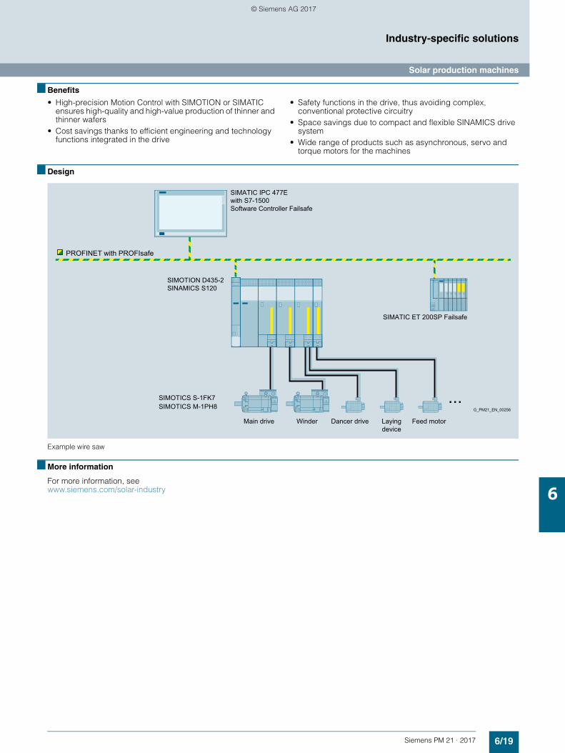
6/19Siemens PM 21 · 2017
Industry-specific solutions
Solar production machines
6
■ Benefits
• High-precision Motion Control with SIMOTION or SIMATIC ensures high-quality and high-value production of thinner and thinner wafers
• Cost savings thanks to efficient engineering and technology functions integrated in the drive
• Safety functions in the drive, thus avoiding complex, conventional protective circuitry
• Space savings due to compact and flexible SINAMICS drive system
• Wide range of products such as asynchronous, servo and torque motors for the machines
■ Design
Example wire saw
■ More information
For more information, see www.siemens.com/solar-industry
PROFINET with PROFIsafe
Winder Dancer drive Laying device
Feed motor
G_PM21_EN_00256
Main drive
SIMATIC ET 200SP Failsafe
SIMATIC IPC 477E with S7-1500 Software Controller Failsafe
SIMOTICS M-1PH8SIMOTICS S-1FK7
SIMOTION D435-2 SINAMICS S120
© Siemens AG 2017
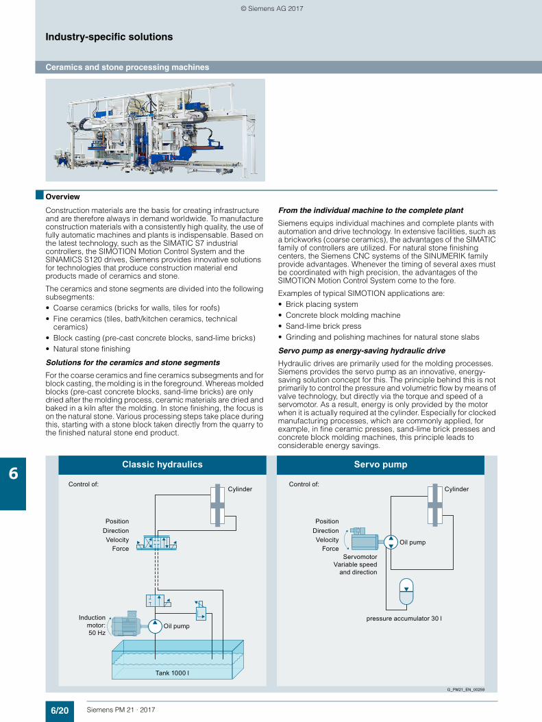
6/20 Siemens PM 21 · 2017
Industry-specific solutions
Ceramics and stone processing machines
6
■ Overview
Construction materials are the basis for creating infrastructure and are therefore always in demand worldwide. To manufacture construction materials with a consistently high quality, the use of fully automatic machines and plants is indispensable. Based on the latest technology, such as the SIMATIC S7 industrial controllers, the SIMOTION Motion Control System and the SINAMICS S120 drives, Siemens provides innovative solutions for technologies that produce construction material end products made of ceramics and stone.
The ceramics and stone segments are divided into the following subsegments:• Coarse ceramics (bricks for walls, tiles for roofs)• Fine ceramics (tiles, bath/kitchen ceramics, technical
ceramics)• Block casting (pre-cast concrete blocks, sand-lime bricks)• Natural stone finishing
Solutions for the ceramics and stone segments
For the coarse ceramics and fine ceramics subsegments and for block casting, the molding is in the foreground. Whereas molded blocks (pre-cast concrete blocks, sand-lime bricks) are only dried after the molding process, ceramic materials are dried and baked in a kiln after the molding. In stone finishing, the focus is on the natural stone. Various processing steps take place during this, starting with a stone block taken directly from the quarry to the finished natural stone end product.
From the individual machine to the complete plant
Siemens equips individual machines and complete plants with automation and drive technology. In extensive facilities, such as a brickworks (coarse ceramics), the advantages of the SIMATIC family of controllers are utilized. For natural stone finishing centers, the Siemens CNC systems of the SINUMERIK family provide advantages. Whenever the timing of several axes must be coordinated with high precision, the advantages of the SIMOTION Motion Control System come to the fore.
Examples of typical SIMOTION applications are:• Brick placing system• Concrete block molding machine• Sand-lime brick press• Grinding and polishing machines for natural stone slabs
Servo pump as energy-saving hydraulic drive
Hydraulic drives are primarily used for the molding processes. Siemens provides the servo pump as an innovative, energy-saving solution concept for this. The principle behind this is not primarily to control the pressure and volumetric flow by means of valve technology, but directly via the torque and speed of a servomotor. As a result, energy is only provided by the motor when it is actually required at the cylinder. Especially for clocked manufacturing processes, which are commonly applied, for example, in fine ceramic presses, sand-lime brick presses and concrete block molding machines, this principle leads to considerable energy savings.
Control of:
Classic hydraulics Servo pump
Control of:
pressure accumulator 30 l
Cylinder Cylinder
Oil pump
Tank 1000 l
Oil pump
G_PM21_EN_00259
Position
Force
DirectionVelocity
Inductionmotor:50 Hz
Servomotor Variable speed
and direction
Position
Force
DirectionVelocity
© Siemens AG 2017
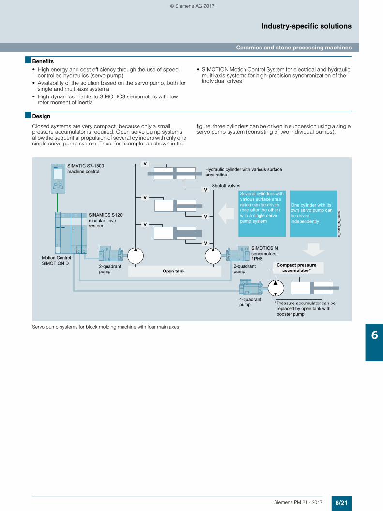
6/21Siemens PM 21 · 2017
Industry-specific solutions
Ceramics and stone processing machines
6
■ Benefits
• High energy and cost-efficiency through the use of speed-controlled hydraulics (servo pump)
• Availability of the solution based on the servo pump, both for single and multi-axis systems
• High dynamics thanks to SIMOTICS servomotors with low rotor moment of inertia
• SIMOTION Motion Control System for electrical and hydraulic multi-axis systems for high-precision synchronization of the individual drives
■ Design
Closed systems are very compact, because only a small pressure accumulator is required. Open servo pump systems allow the sequential propulsion of several cylinders with only one single servo pump system. Thus, for example, as shown in the
figure, three cylinders can be driven in succession using a single servo pump system (consisting of two individual pumps).
Servo pump systems for block molding machine with four main axes
*Pressure accumulator can be replaced by open tank with booster pump
One cylinder with its own servo pump can be driven independently
Several cylinders with various surface area ratios can be driven (one after the other) with a single servo pump system
Hydraulic cylinder with various surface area ratios
SINAMICS S120 modular drive system
SIMATIC S7-1500 machine control
2-quadrant pump
2-quadrant pump
Compact pressure accumulator*
Shutoff valves
Open tank
4-quadrant pump
SIMOTICS M servomotors 1PH8
V
V
V
V
V
V
G_P
M21
_EN
_002
60
Motion Control SIMOTION D
© Siemens AG 2017
6/22 Siemens PM 21 · 2017
Industry-specific solutions
Notes
6
© Siemens AG 2017
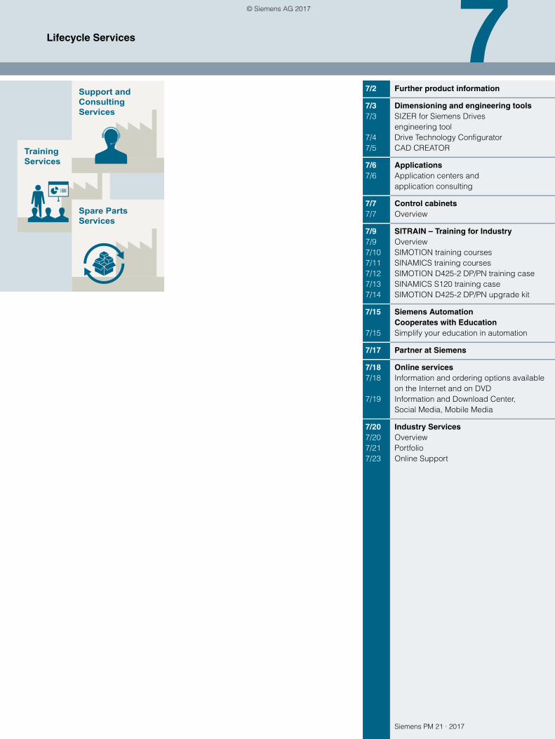
Siemens PM 21 · 2017
TrainingServices
Support andConsultingServices
Spare PartsServices
77/2 Further product information
7/3 Dimensioning and engineering tools 7/3 SIZER for Siemens Drives
engineering tool7/4 Drive Technology Configurator7/5 CAD CREATOR
7/6 Applications7/6 Application centers and
application consulting
7/7 Control cabinets7/7 Overview
7/9 SITRAIN – Training for Industry 7/9 Overview7/10 SIMOTION training courses7/11 SINAMICS training courses7/12 SIMOTION D425-2 DP/PN training case7/13 SINAMICS S120 training case7/14 SIMOTION D425-2 DP/PN upgrade kit
7/15 Siemens Automation Cooperates with Education
7/15 Simplify your education in automation
7/17 Partner at Siemens
7/18 Online services7/18 Information and ordering options available
on the Internet and on DVD7/19 Information and Download Center,
Social Media, Mobile Media
7/20 Industry Services7/20 Overview7/21 Portfolio7/23 Online Support
Lifecycle Services
© Siemens AG 2017
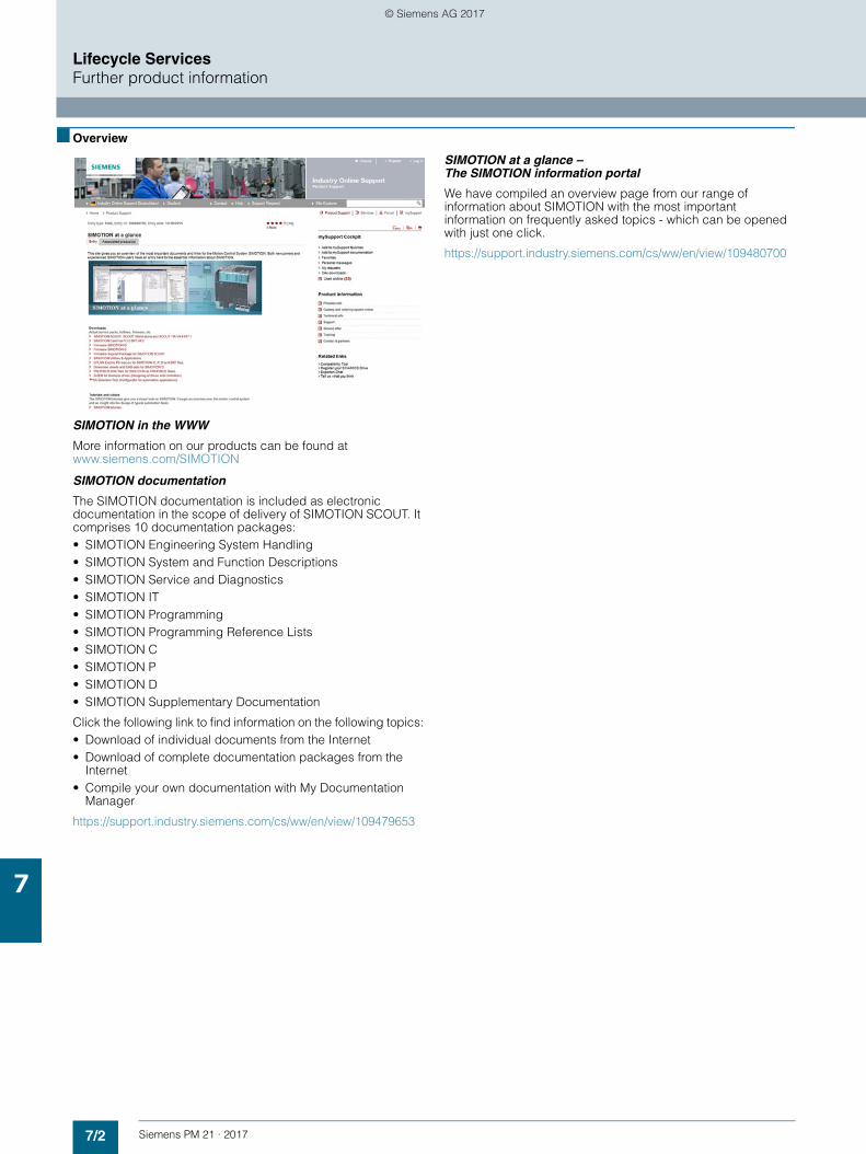
7/2 Siemens PM 21 · 2017
Lifecycle ServicesFurther product information
7
■ Overview
SIMOTION in the WWW
More information on our products can be found at www.siemens.com/SIMOTION
SIMOTION documentation
The SIMOTION documentation is included as electronic documentation in the scope of delivery of SIMOTION SCOUT. It comprises 10 documentation packages:• SIMOTION Engineering System Handling• SIMOTION System and Function Descriptions• SIMOTION Service and Diagnostics• SIMOTION IT• SIMOTION Programming• SIMOTION Programming Reference Lists• SIMOTION C• SIMOTION P• SIMOTION D• SIMOTION Supplementary Documentation
Click the following link to find information on the following topics:• Download of individual documents from the Internet• Download of complete documentation packages from the
Internet• Compile your own documentation with My Documentation
Manager
https://support.industry.siemens.com/cs/ww/en/view/109479653
SIMOTION at a glance – The SIMOTION information portal
We have compiled an overview page from our range of information about SIMOTION with the most important information on frequently asked topics - which can be opened with just one click.
https://support.industry.siemens.com/cs/ww/en/view/109480700
© Siemens AG 2017
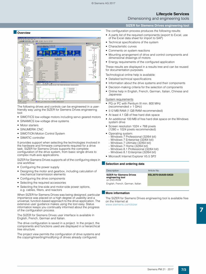
7/3Siemens PM 21 · 2017
Lifecycle ServicesDimensioning and engineering tools
SIZER for Siemens Drives engineering tool
7
■ Overview
The following drives and controls can be engineered in a user-friendly way using the SIZER for Siemens Drives engineering tool:• SIMOTICS low-voltage motors including servo geared motors• SINAMICS low-voltage drive systems• Motor starters• SINUMERIK CNC • SIMOTION Motion Control System• SIMATIC controller
It provides support when selecting the technologies involved in the hardware and firmware components required for a drive task. SIZER for Siemens Drives supports the complete configuration of the drive system, from basic single drives to complex multi-axis applications.
SIZER for Siemens Drives supports all of the configuring steps in one workflow:• Configuring the power supply• Designing the motor and gearbox, including calculation of
mechanical transmission elements• Configuring the drive components• Selecting the required accessories• Selecting the line-side and motor-side power options,
e.g. cables, filters, and reactors
When SIZER for Siemens Drives was being designed, particular importance was placed on a high degree of usability and a universal, function-based approach to the drive application. The extensive user guidance makes using the tool easy. Status information keeps you continually informed about the progress of the configuration process.
The SIZER for Siemens Drives user interface is available in English, French, German and Italian.
The drive configuration is saved in a project. In the project, the components and functions used are displayed in a hierarchical tree structure.
The project view permits the configuration of drive systems and the copying/inserting/modifying of drives already configured.
The configuration process produces the following results:• A parts list of the required components (export to Excel, use
of the Excel data sheet for import to SAP)• Technical specifications of the system• Characteristic curves• Comments on system reactions• Mounting arrangement of drive and control components and
dimensional drawings of motors• Energy requirements of the configured application
These results are displayed in a results tree and can be reused for documentation purposes.
Technological online help is available:• Detailed technical specifications• Information about the drive systems and their components• Decision-making criteria for the selection of components• Online help in English, French, German, Italian, Chinese and
Japanese
System requirements• PG or PC with Pentium III min. 800 MHz
(recommended > 1 GHz)• 512 MB RAM (1 GB RAM recommended)• At least 4.1 GB of free hard disk space• An additional 100 MB of free hard disk space on the Windows
system drive• Screen resolution 1024 × 768 pixels
(1280 × 1024 pixels recommended)• Operating system:
- Windows 7 Professional (32/64 bit)- Windows 7 Enterprise (32/64 bit)- Windows 7 Ultimate (32/64 bit)- Windows 7 Home (32/64 bit)- Windows 8.1 Professional (32/64 bit)- Windows 8.1 Enterprise (32/64 bit)
• Microsoft Internet Explorer V5.5 SP2
■ Selection and ordering data
■ More information
The SIZER for Siemens Drives engineering tool is available free on the Internet at www.siemens.com/sizer
Description Article No.
SIZER for Siemens Drives engineering toolon DVD-ROM
English, French, German, Italian
6SL3070-0AA00-0AG0
© Siemens AG 2017
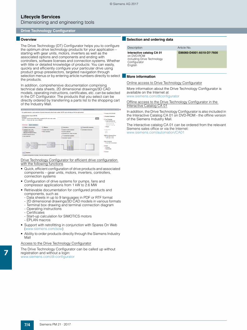
7/4 Siemens PM 21 · 2017
Lifecycle ServicesDimensioning and engineering tools
Drive Technology Configurator
7
■ Overview
The Drive Technology (DT) Configurator helps you to configure the optimum drive technology products for your application – starting with gear units, motors, inverters as well as the associated options and components and ending with controllers, software licenses and connection systems. Whether with little or detailed knowledge of products: You can easily, quickly and efficiently configure your particular drive using product group preselectors, targeted navigation through selection menus or by entering article numbers directly to select the products.
In addition, comprehensive documentation comprising technical data sheets, 2D dimensional drawings/3D CAD models, operating instructions, certificates, etc. can be selected in the DT Configurator. The products that you select can be directly ordered by transferring a parts list to the shopping cart of the Industry Mall.
Drive Technology Configurator for efficient drive configuration with the following functions• Quick, efficient configuration of drive products and associated
components – gear units, motors, inverters, controllers, connection systems
• Configuration of drive systems for pumps, fans and compressor applications from 1 kW to 2.6 MW
• Retrievable documentation for configured products and components, such as- Data sheets in up to 9 languages in PDF or RTF format- 2D dimensional drawings/3D CAD models in various formats- Terminal box drawing and terminal connection diagram- Operating instructions- Certificates- Start-up calculation for SIMOTICS motors- EPLAN macros
• Support with retrofitting in conjunction with Spares On Web (www.siemens.com/sow)
• Ability to order products directly through the Siemens Industry Mall
Access to the Drive Technology Configurator
The Drive Technology Configurator can be called up without registration and without a login: www.siemens.com/dt-configurator
■ Selection and ordering data
■ More information
Online access to Drive Technology Configurator
More information about the Drive Technology Configurator is available on the Internet at www.siemens.com/dtconfigurator
Offline access to the Drive Technology Configurator in the Interactive Catalog CA 01
In addition, the Drive Technology Configurator is also included in the Interactive Catalog CA 01 on DVD-ROM - the offline version of the Siemens Industry Mall.
The interactive catalog CA 01 can be ordered from the relevant Siemens sales office or via the Internet: www.siemens.com/automation/CA01
Description Article No.
Interactive catalog CA 01on DVD-ROMincluding Drive Technology ConfiguratorEnglish
E86060-D4001-A510-D7-7600
© Siemens AG 2017
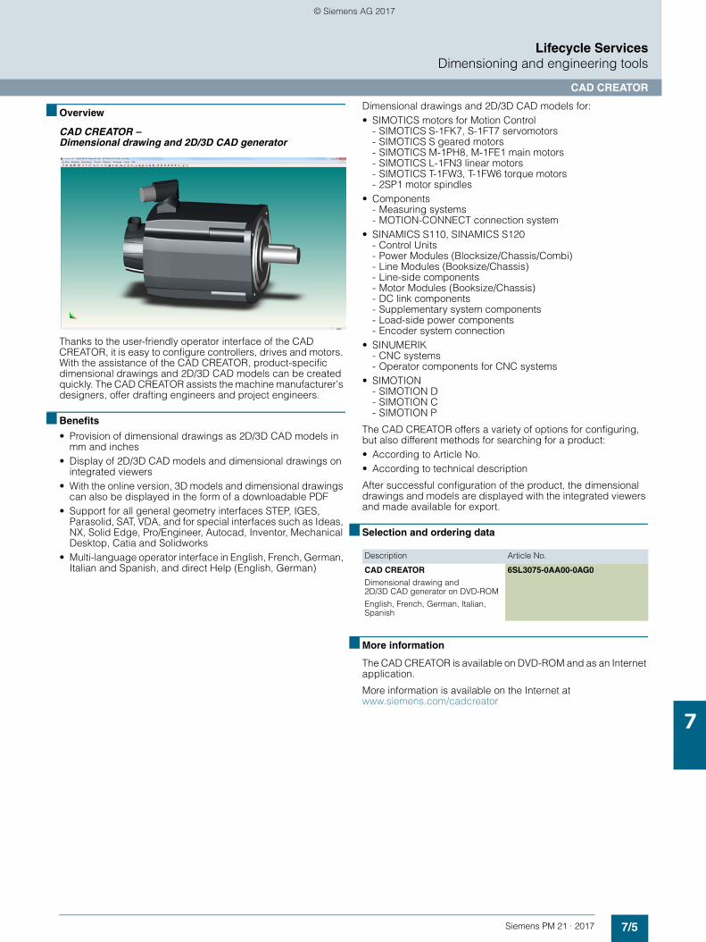
7/5Siemens PM 21 · 2017
Lifecycle ServicesDimensioning and engineering tools
CAD CREATOR
7
■ Overview
CAD CREATOR –Dimensional drawing and 2D/3D CAD generator
Thanks to the user-friendly operator interface of the CAD CREATOR, it is easy to configure controllers, drives and motors. With the assistance of the CAD CREATOR, product-specific dimensional drawings and 2D/3D CAD models can be created quickly. The CAD CREATOR assists the machine manufacturer's designers, offer drafting engineers and project engineers.
■ Benefits
• Provision of dimensional drawings as 2D/3D CAD models in mm and inches
• Display of 2D/3D CAD models and dimensional drawings on integrated viewers
• With the online version, 3D models and dimensional drawings can also be displayed in the form of a downloadable PDF
• Support for all general geometry interfaces STEP, IGES, Parasolid, SAT, VDA, and for special interfaces such as Ideas, NX, Solid Edge, Pro/Engineer, Autocad, Inventor, Mechanical Desktop, Catia and Solidworks
• Multi-language operator interface in English, French, German, Italian and Spanish, and direct Help (English, German)
Dimensional drawings and 2D/3D CAD models for:• SIMOTICS motors for Motion Control
- SIMOTICS S-1FK7, S-1FT7 servomotors- SIMOTICS S geared motors- SIMOTICS M-1PH8, M-1FE1 main motors- SIMOTICS L-1FN3 linear motors- SIMOTICS T-1FW3, T-1FW6 torque motors- 2SP1 motor spindles
• Components- Measuring systems- MOTION-CONNECT connection system
• SINAMICS S110, SINAMICS S120- Control Units- Power Modules (Blocksize/Chassis/Combi)- Line Modules (Booksize/Chassis)- Line-side components- Motor Modules (Booksize/Chassis)- DC link components- Supplementary system components- Load-side power components- Encoder system connection
• SINUMERIK- CNC systems- Operator components for CNC systems
• SIMOTION- SIMOTION D- SIMOTION C- SIMOTION P
The CAD CREATOR offers a variety of options for configuring, but also different methods for searching for a product:• According to Article No.• According to technical description
After successful configuration of the product, the dimensional drawings and models are displayed with the integrated viewers and made available for export.
■ Selection and ordering data
■ More information
The CAD CREATOR is available on DVD-ROM and as an Internet application.
More information is available on the Internet at www.siemens.com/cadcreator
Description Article No.
CAD CREATOR
Dimensional drawing and 2D/3D CAD generator on DVD-ROM
English, French, German, Italian, Spanish
6SL3075-0AA00-0AG0
© Siemens AG 2017
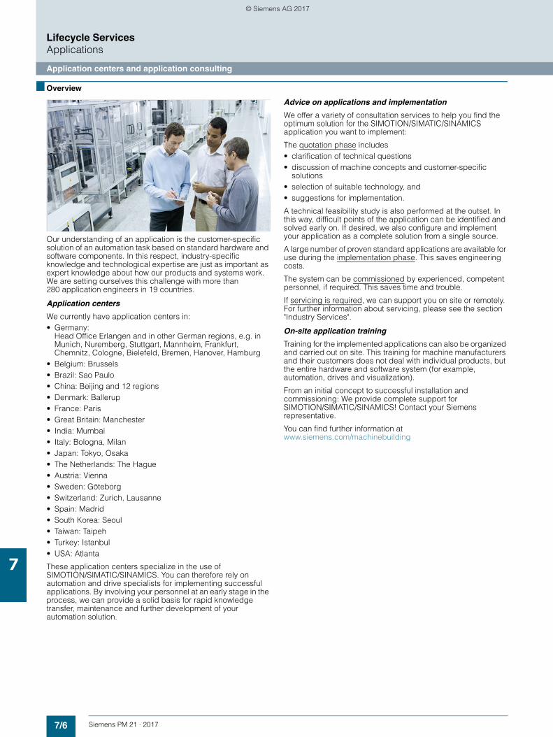
7/6 Siemens PM 21 · 2017
Lifecycle ServicesApplications
Application centers and application consulting
7
■ Overview
Our understanding of an application is the customer-specific solution of an automation task based on standard hardware and software components. In this respect, industry-specific knowledge and technological expertise are just as important as expert knowledge about how our products and systems work. We are setting ourselves this challenge with more than 280 application engineers in 19 countries.
Application centers
We currently have application centers in:• Germany:
Head Office Erlangen and in other German regions, e.g. in Munich, Nuremberg, Stuttgart, Mannheim, Frankfurt, Chemnitz, Cologne, Bielefeld, Bremen, Hanover, Hamburg
• Belgium: Brussels• Brazil: Sao Paulo• China: Beijing and 12 regions• Denmark: Ballerup• France: Paris• Great Britain: Manchester• India: Mumbai• Italy: Bologna, Milan• Japan: Tokyo, Osaka• The Netherlands: The Hague• Austria: Vienna• Sweden: Göteborg• Switzerland: Zurich, Lausanne• Spain: Madrid• South Korea: Seoul• Taiwan: Taipeh• Turkey: Istanbul• USA: Atlanta
These application centers specialize in the use of SIMOTION/SIMATIC/SINAMICS. You can therefore rely on automation and drive specialists for implementing successful applications. By involving your personnel at an early stage in the process, we can provide a solid basis for rapid knowledge transfer, maintenance and further development of your automation solution.
Advice on applications and implementation
We offer a variety of consultation services to help you find the optimum solution for the SIMOTION/SIMATIC/SINAMICS application you want to implement:
The quotation phase includes• clarification of technical questions• discussion of machine concepts and customer-specific
solutions• selection of suitable technology, and• suggestions for implementation.
A technical feasibility study is also performed at the outset. In this way, difficult points of the application can be identified and solved early on. If desired, we also configure and implement your application as a complete solution from a single source.
A large number of proven standard applications are available for use during the implementation phase. This saves engineering costs.
The system can be commissioned by experienced, competent personnel, if required. This saves time and trouble.
If servicing is required, we can support you on site or remotely. For further information about servicing, please see the section "Industry Services".
On-site application training
Training for the implemented applications can also be organized and carried out on site. This training for machine manufacturers and their customers does not deal with individual products, but the entire hardware and software system (for example, automation, drives and visualization).
From an initial concept to successful installation and commissioning: We provide complete support for SIMOTION/SIMATIC/SINAMICS! Contact your Siemens representative.
You can find further information at www.siemens.com/machinebuilding
© Siemens AG 2017
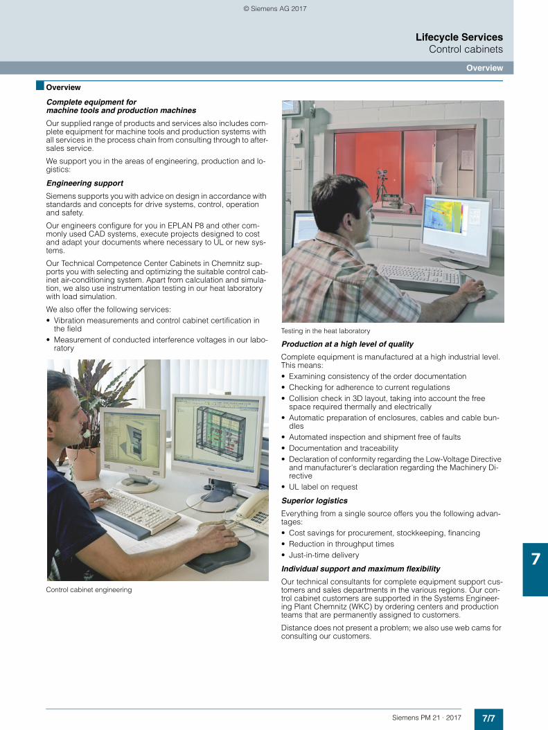
7/7Siemens PM 21 · 2017
Lifecycle ServicesControl cabinets
Overview
7
■ Overview
Complete equipment for machine tools and production machines
Our supplied range of products and services also includes com-plete equipment for machine tools and production systems with all services in the process chain from consulting through to after-sales service.
We support you in the areas of engineering, production and lo-gistics:
Engineering support
Siemens supports you with advice on design in accordance with standards and concepts for drive systems, control, operation and safety.
Our engineers configure for you in EPLAN P8 and other com-monly used CAD systems, execute projects designed to cost and adapt your documents where necessary to UL or new sys-tems.
Our Technical Competence Center Cabinets in Chemnitz sup-ports you with selecting and optimizing the suitable control cab-inet air-conditioning system. Apart from calculation and simula-tion, we also use instrumentation testing in our heat laboratory with load simulation.
We also offer the following services:• Vibration measurements and control cabinet certification in
the field• Measurement of conducted interference voltages in our labo-
ratory
Control cabinet engineering
Testing in the heat laboratory
Production at a high level of quality
Complete equipment is manufactured at a high industrial level. This means:• Examining consistency of the order documentation• Checking for adherence to current regulations• Collision check in 3D layout, taking into account the free
space required thermally and electrically• Automatic preparation of enclosures, cables and cable bun-
dles• Automated inspection and shipment free of faults• Documentation and traceability• Declaration of conformity regarding the Low-Voltage Directive
and manufacturer's declaration regarding the Machinery Di-rective
• UL label on request
Superior logistics
Everything from a single source offers you the following advan-tages:• Cost savings for procurement, stockkeeping, financing• Reduction in throughput times• Just-in-time delivery
Individual support and maximum flexibility
Our technical consultants for complete equipment support cus-tomers and sales departments in the various regions. Our con-trol cabinet customers are supported in the Systems Engineer-ing Plant Chemnitz (WKC) by ordering centers and production teams that are permanently assigned to customers.
Distance does not present a problem; we also use web cams for consulting our customers.
© Siemens AG 2017
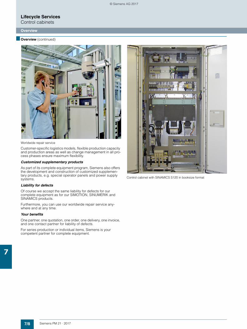
7/8 Siemens PM 21 · 2017
Lifecycle ServicesControl cabinets
Overview
7
■ Overview (continued)
Worldwide repair service
Customer-specific logistics models, flexible production capacity and production areas as well as change management in all pro-cess phases ensure maximum flexibility.
Customized supplementary products
As part of its complete equipment program, Siemens also offers the development and construction of customized supplemen-tary products, e.g. special operator panels and power supply systems.
Liability for defects
Of course we accept the same liability for defects for our complete equipment as for our SIMOTION, SINUMERIK and SINAMICS products.
Furthermore, you can use our worldwide repair service any-where and at any time.
Your benefits
One partner, one quotation, one order, one delivery, one invoice, and one contact partner for liability of defects.
For series production or individual items, Siemens is your competent partner for complete equipment.
Control cabinet with SINAMICS S120 in booksize format
© Siemens AG 2017
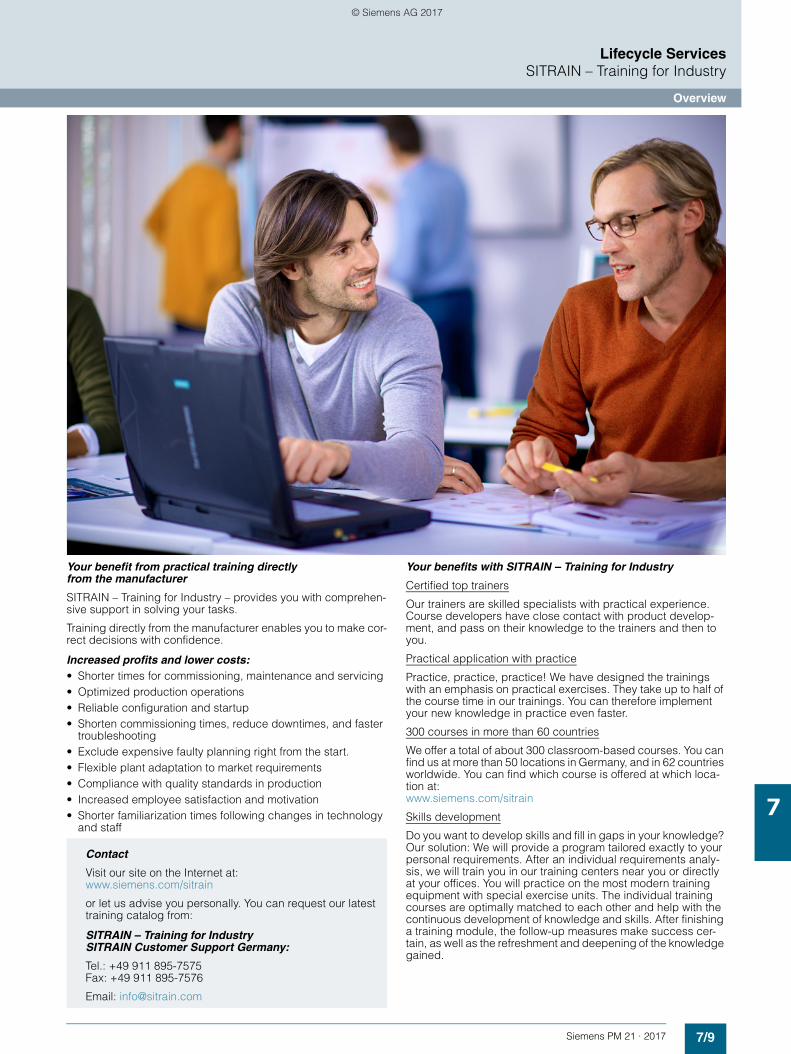
7/9Siemens PM 21 · 2017
Lifecycle ServicesSITRAIN – Training for Industry
Overview
7
Your benefit from practical training directly from the manufacturer
SITRAIN – Training for Industry – provides you with comprehen-sive support in solving your tasks.
Training directly from the manufacturer enables you to make cor-rect decisions with confidence.
Increased profits and lower costs:• Shorter times for commissioning, maintenance and servicing• Optimized production operations• Reliable configuration and startup• Shorten commissioning times, reduce downtimes, and faster
troubleshooting• Exclude expensive faulty planning right from the start.• Flexible plant adaptation to market requirements• Compliance with quality standards in production• Increased employee satisfaction and motivation • Shorter familiarization times following changes in technology
and staff
Your benefits with SITRAIN – Training for Industry
Certified top trainers
Our trainers are skilled specialists with practical experience. Course developers have close contact with product develop-ment, and pass on their knowledge to the trainers and then to you.
Practical application with practice
Practice, practice, practice! We have designed the trainings with an emphasis on practical exercises. They take up to half of the course time in our trainings. You can therefore implement your new knowledge in practice even faster.
300 courses in more than 60 countries
We offer a total of about 300 classroom-based courses. You can find us at more than 50 locations in Germany, and in 62 countries worldwide. You can find which course is offered at which loca-tion at:www.siemens.com/sitrain
Skills development
Do you want to develop skills and fill in gaps in your knowledge? Our solution: We will provide a program tailored exactly to your personal requirements. After an individual requirements analy-sis, we will train you in our training centers near you or directly at your offices. You will practice on the most modern training equipment with special exercise units. The individual training courses are optimally matched to each other and help with the continuous development of knowledge and skills. After finishing a training module, the follow-up measures make success cer-tain, as well as the refreshment and deepening of the knowledge gained.
Contact
Visit our site on the Internet at:www.siemens.com/sitrain
or let us advise you personally. You can request our latest training catalog from:
SITRAIN – Training for Industry SITRAIN Customer Support Germany:
Tel.: +49 911 895-7575Fax: +49 911 895-7576
Email: [email protected]
© Siemens AG 2017
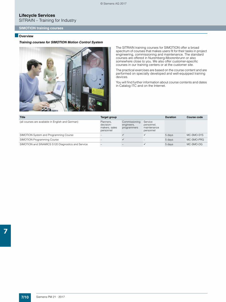
7/10 Siemens PM 21 · 2017
Lifecycle ServicesSITRAIN – Training for Industry
SIMOTION training courses
7
■ Overview
Training courses for SIMOTION Motion Control System
The SITRAIN training courses for SIMOTION offer a broad spectrum of courses that makes users fit for their tasks in project engineering, commissioning and maintenance. The standard courses are offered in Nuremberg-Moorenbrunn or also somewhere close to you. We also offer customer-specific courses in our training centers or at the customer site.
The practical exercises are based on the course content and are performed on specially developed and well-equipped training devices.
You will find further information about course contents and dates in Catalog ITC and on the Internet.
Title Target group Duration Course code
(all courses are available in English and German) Planners, decision-makers, sales personnel
Commissioning engineers, programmers
Service personnel, maintenance personnel
SIMOTION System and Programming Course – 5 days MC-SMO-SYS
SIMOTION Programming Course – – 5 days MC-SMO-PRG
SIMOTION and SINAMICS S120 Diagnostics and Service – – 5 days MC-SMO-DG
© Siemens AG 2017
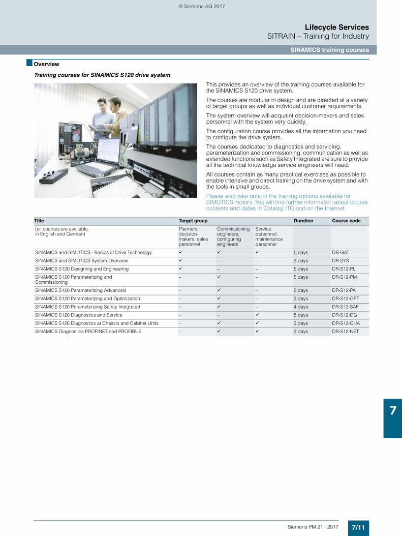
7/11Siemens PM 21 · 2017
Lifecycle ServicesSITRAIN – Training for Industry
SINAMICS training courses
7
■ Overview
Training courses for SINAMICS S120 drive system
This provides an overview of the training courses available for the SINAMICS S120 drive system.
The courses are modular in design and are directed at a variety of target groups as well as individual customer requirements.
The system overview will acquaint decision-makers and sales personnel with the system very quickly.
The configuration course provides all the information you need to configure the drive system.
The courses dedicated to diagnostics and servicing, parameterization and commissioning, communication as well as extended functions such as Safety Integrated are sure to provide all the technical knowledge service engineers will need.
All courses contain as many practical exercises as possible to enable intensive and direct training on the drive system and with the tools in small groups.
Please also take note of the training options available for SIMOTICS motors. You will find further information about course contents and dates in Catalog ITC and on the Internet.
Title Target group Duration Course code
(all courses are available in English and German)
Planners, decision-makers, sales personnel
Commissioning engineers, configuring engineers
Service personnel, maintenance personnel
SINAMICS and SIMOTICS - Basics of Drive Technology 5 days DR-GAT
SINAMICS and SIMOTICS System Overview – – 3 days DR-SYS
SINAMICS S120 Designing and Engineering – – 5 days DR-S12-PL
SINAMICS S120 Parameterizing and Commissioning
– – 5 days DR-S12-PM
SINAMICS S120 Parameterizing Advanced – – 5 days DR-S12-PA
SINAMICS S120 Parameterizing and Optimization – – 3 days DR-S12-OPT
SINAMICS S120 Parameterizing Safety Integrated – – 4 days DR-S12-SAF
SINAMICS S120 Diagnostics and Service – – 5 days DR-S12-DG
SINAMICS S120 Diagnostics at Chassis and Cabinet Units – 3 days DR-S12-CHA
SINAMICS Diagnostics PROFINET and PROFIBUS – 3 days DR-S12-NET
© Siemens AG 2017
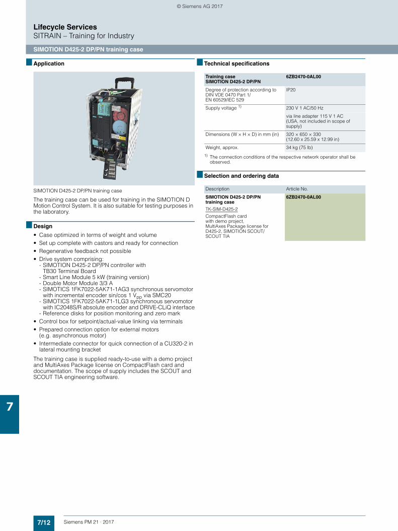
7/12 Siemens PM 21 · 2017
Lifecycle ServicesSITRAIN – Training for Industry
SIMOTION D425-2 DP/PN training case
7
■ Application
SIMOTION D425-2 DP/PN training case
The training case can be used for training in the SIMOTION D Motion Control System. It is also suitable for testing purposes in the laboratory.
■ Design
• Case optimized in terms of weight and volume• Set up complete with castors and ready for connection• Regenerative feedback not possible• Drive system comprising:
- SIMOTION D425-2 DP/PN controller with TB30 Terminal Board
- Smart Line Module 5 kW (training version)- Double Motor Module 3/3 A- SIMOTICS 1FK7022-5AK71-1AG3 synchronous servomotor
with incremental encoder sin/cos 1 Vpp via SMC20- SIMOTICS 1FK7022-5AK71-1LG3 synchronous servomotor
with IC2048S/R absolute encoder and DRIVE-CLiQ interface- Reference disks for position monitoring and zero mark
• Control box for setpoint/actual-value linking via terminals• Prepared connection option for external motors
(e.g. asynchronous motor)• Intermediate connector for quick connection of a CU320-2 in
lateral mounting bracket
The training case is supplied ready-to-use with a demo project and MultiAxes Package license on CompactFlash card and documentation. The scope of supply includes the SCOUT and SCOUT TIA engineering software.
■ Technical specifications
1) The connection conditions of the respective network operator shall be observed.
■ Selection and ordering data
Training case SIMOTION D425-2 DP/PN
6ZB2470-0AL00
Degree of protection according to DIN VDE 0470 Part 1/EN 60529/IEC 529
IP20
Supply voltage 1) 230 V 1 AC/50 Hz
via line adapter 115 V 1 AC (USA, not included in scope of supply)
Dimensions (W × H × D) in mm (in) 320 × 650 × 330 (12.60 x 25.59 x 12.99 in)
Weight, approx. 34 kg (75 lb)
Description Article No.
SIMOTION D425-2 DP/PNtraining case
TK-SIM-D425-2
CompactFlash card with demo project, MultiAxes Package license for D425-2, SIMOTION SCOUT/SCOUT TIA
6ZB2470-0AL00
© Siemens AG 2017
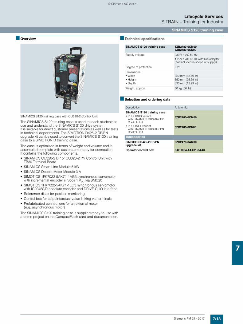
7/13Siemens PM 21 · 2017
Lifecycle ServicesSITRAIN – Training for Industry
SINAMICS S120 training case
7
■ Overview
SINAMICS S120 training case with CU320-2 Control Unit
The SINAMICS S120 training case is used to teach students to use and understand the SINAMICS S120 drive system. It is suitable for direct customer presentations as well as for tests in technical departments. The SIMOTION D425-2 DP/PN upgrade kit can be used to convert the SINAMICS S120 training case to a SIMOTION D training case.
The case is optimized in terms of weight and volume and is assembled complete with castors and ready for connection.It contains the following components:• SINAMICS CU320-2 DP or CU320-2 PN Control Unit with
TB30 Terminal Board• SINAMICS Smart Line Module 5 kW• SINAMICS Double Motor Module 3 A• SIMOTICS 1FK7022-5AK71-1AG3 synchronous servomotor
with incremental encoder sin/cos 1 Vpp via SMC20• SIMOTICS 1FK7022-5AK71-1LG3 synchronous servomotor
with IC2048S/R absolute encoder and DRIVE-CLiQ interface• Reference discs for position monitoring• Control box for setpoint/actual-value linking via terminals• Prefabricated connections for an external motor
(e.g. asynchronous motor)
The SINAMICS S120 training case is supplied ready-to-use with a demo project on the CompactFlash card and documentation.
■ Technical specifications
■ Selection and ordering data
SINAMICS S120 training case 6ZB2480-0CM00 6ZB2480-0CN00
Supply voltage 230 V 1 AC 50 Hz
115 V 1 AC 60 Hz with line adapter (not included in scope of supply)
Degree of protection IP20
Dimensions • Width 320 mm (12.60 in)• Height 650 mm (25.59 in)• Depth 330 mm (12.99 in)
Weight, approx. 30 kg (66 lb)
Description Article No.
SINAMICS S120 training case • PROFIBUS variant
with SINAMICS CU320-2 DP Control Unit
6ZB2480-0CM00
• PROFINET variant with SINAMICS CU320-2 PN Control Unit
6ZB2480-0CN00
Accessories
SIMOTION D425-2 DP/PN upgrade kit
6ZB2470-0AM00
Operator control box 6AG1064-1AA01-0AA0
© Siemens AG 2017
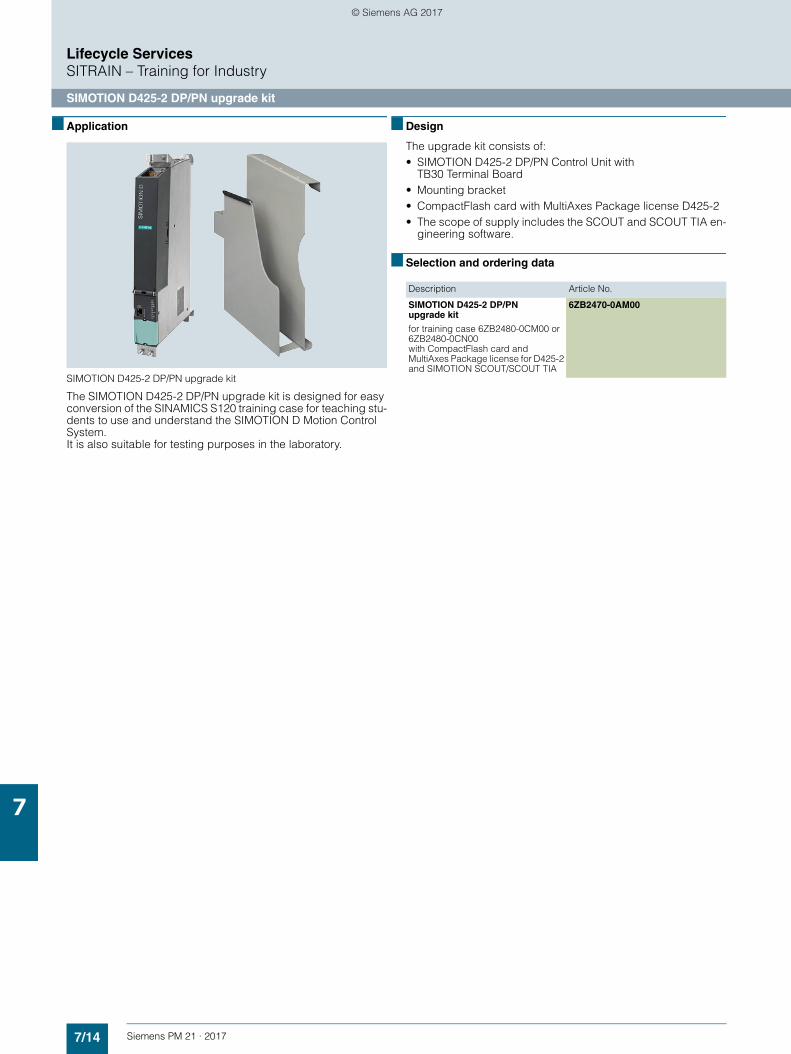
7/14 Siemens PM 21 · 2017
Lifecycle ServicesSITRAIN – Training for Industry
SIMOTION D425-2 DP/PN upgrade kit
7
■ Application
SIMOTION D425-2 DP/PN upgrade kit
The SIMOTION D425-2 DP/PN upgrade kit is designed for easy conversion of the SINAMICS S120 training case for teaching stu-dents to use and understand the SIMOTION D Motion Control System. It is also suitable for testing purposes in the laboratory.
■ Design
The upgrade kit consists of:• SIMOTION D425-2 DP/PN Control Unit with
TB30 Terminal Board• Mounting bracket• CompactFlash card with MultiAxes Package license D425-2• The scope of supply includes the SCOUT and SCOUT TIA en-
gineering software.
■ Selection and ordering data
Description Article No.
SIMOTION D425-2 DP/PN upgrade kit
for training case 6ZB2480-0CM00 or 6ZB2480-0CN00 with CompactFlash card and MultiAxes Package license for D425-2 and SIMOTION SCOUT/SCOUT TIA
6ZB2470-0AM00
© Siemens AG 2017
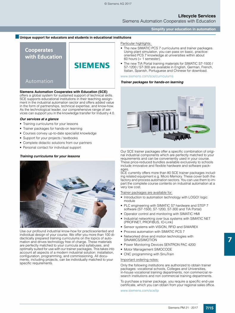
7/15Siemens PM 21 · 2017
Lifecycle ServicesSiemens Automation Cooperates with Education
Simplify your education in automation
7
■ Unique support for educators and students in educational institutions
Siemens Automation Cooperates with Education (SCE) offers a global system for sustained support of technical skills. SCE supports educational institutions in their teaching assign-ment in the industrial automation sector and offers added value in the form of partnerships, technical expertise, and know-how. As the technological leader, our comprehensive range of ser-vices can support you in the knowledge transfer for Industry 4.0.
Our services at a glance• Training curriculums for your lessons• Trainer packages for hands-on learning• Courses convey up-to-date specialist knowledge• Support for your projects / textbooks• Complete didactic solutions from our partners• Personal contact for individual support
Training curriculums for your lessons
Use our profound industrial know-how for practiceoriented and individual design of your course. We offer you more than 100 di-dactically prepared training curriculums on the topics of auto-mation and drives technology free of charge. These materials are perfectly matched to your curricula and syllabuses, and optimally suited for use with our trainer packages. This takes into account all aspects of a modern industrial solution: installation, configuration, programming, and commissioning. All docu-ments, including projects, can be individually matched to your specific requirements.
Particular highlights: • The new SIMATIC PCS 7 curriculums and trainer packages.
Using plant simulation, you can pass on basic, practice-oriented PCS 7 knowledge at universities within about 60 hours (= 1 semester).
• The new TIA Portal training materials for SIMATIC S7-1500 / S7-1200 / S7-300 are available in English, German, French, Italian, Spanish, Portuguese and Chinese for download.
www.siemens.com/sce/curriculums
Trainer packages for hands-on learning
Our SCE trainer packages offer a specific combination of origi-nal industrial components which are perfectly matched to your requirements and can be conveniently used in your course. These price-reduced bundles available exclusively to schools include innovative and flexible hardware and software pack-ages. SCE currently offers more than 80 SCE trainer packages includ-ing related equipment e.g. Micro Memory. These cover both the factory and process automation sectors. You can use them to im-part the complete course contents on industrial automation at a very low cost.
Trainer packages are available for:• Introduction to automation technology with LOGO! logic
module• PLC engineering with SIMATIC S7 hardware and STEP 7
software (S7-1500, S7-1200, S7-300 and TIA Portal)• Operator control and monitoring with SIMATIC HMI• Industrial networking over bus systems with SIMATIC NET
(PROFINET, PROFIBUS, IO-Link)• Sensor systems with VISION, RFID and SIWAREX• Process automation with SIMATIC PCS 7• Networked drive and motion technologies with
SINAMICS/SIMOTION• Power Monitoring Devices SENTRON PAC 4200• Motor Management SIMOCODE• CNC programming with SinuTrain
Important ordering notes:
Only the following institutions are authorized to obtain trainer packages: vocational schools, Colleges and Universities, in-house vocational training departments, non commercial re-search institutions and non commercial training departments.
To purchase a trainer package, you require a specific end-use certificate, which you can obtain from your regional sales office.
www.siemens.com/sce/tp
© Siemens AG 2017
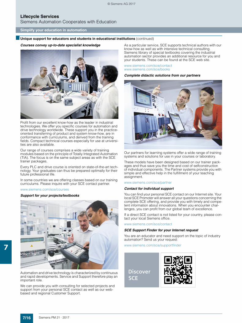
7/16 Siemens PM 21 · 2017
Lifecycle ServicesSiemens Automation Cooperates with Education
Simplify your education in automation
7
■ Unique support for educators and students in educational institutions (continued)
Courses convey up-to-date specialist knowledge
Profit from our excellent know-how as the leader in industrial technologies. We offer you specific courses for automation and drive technology worldwide. These support you in the practice-oriented transferring of product and system know-how, are in conformance with curriculums, and derived from the training fields. Compact technical courses especially for use at universi-ties are also available.
Our range of courses comprises a wide variety of training modules based on the principle of Totally Integrated Automation (TIA). The focus is on the same subject areas as with the SCE trainer packages.
Every PLC and drive course is oriented on state-of-the-art tech-nology. Your graduates can thus be prepared optimally for their future professional life.
In some countries we are offering classes based on our training curriculums. Please inquire with your SCE contact partner.
www.siemens.com/sce/courses
Support for your projects/textbooks
Automation and drive technology is characterized by continuous and rapid developments. Service and Support therefore play an important role.
We can provide you with consulting for selected projects and support from your personal SCE contact as well as our web-based and regional Customer Support.
As a particular service, SCE supports technical authors with our know-how as well as with intensive technical consulting. Siemens library of special textbooks covering the industrial automation sector provides an additional resource for you and your students. These can be found at the SCE web site.
www.siemens.com/sce/contact www.siemens.com/sce/books
Complete didactic solutions from our partners
Our partners for learning systems offer a wide range of training systems and solutions for use in your courses or laboratory.
These models have been designed based on our trainer pack-ages and thus save you the time and cost of selfconstruction of individual components. The Partner systems provide you with simple and effective help in the fulfillment of your teaching assignment.
www.siemens.com/sce/partner
Contact for individual support
You can find your personal SCE contact on our Internet site. Your local SCE Promoter will answer all your questions concerning the complete SCE offering, and provide you with timely and compe-tent information about innovations. When you encounter chal-lenges, you can profit from our global team of excellence.
If a direct SCE contact is not listed for your country, please con-tact your local Siemens office.
www.siemens.com/sce/contact
SCE Support Finder for your Internet request
You are an educator and need support on the topic of industry automation? Send us your request:
www.siemens.com/sce/supportfinder
© Siemens AG 2017
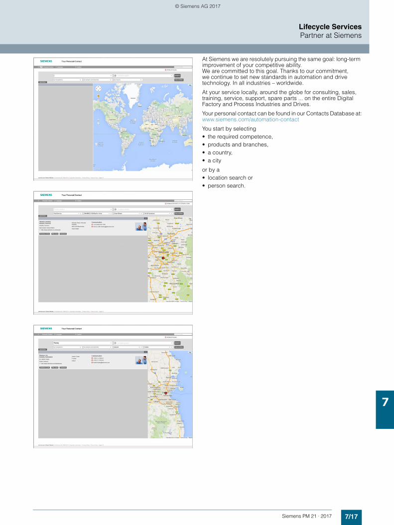
7/17Siemens PM 21 · 2017
Lifecycle ServicesPartner at Siemens
7
At Siemens we are resolutely pursuing the same goal: long-term improvement of your competitive ability. We are committed to this goal. Thanks to our commitment, we continue to set new standards in automation and drive technology. In all industries – worldwide.
At your service locally, around the globe for consulting, sales, training, service, support, spare parts ... on the entire Digital Factory and Process Industries and Drives.
Your personal contact can be found in our Contacts Database at:www.siemens.com/automation-contact
You start by selecting • the required competence, • products and branches, • a country, • a city
or by a• location search or• person search.
© Siemens AG 2017
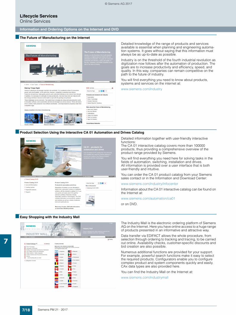
7/18 Siemens PM 21 · 2017
Lifecycle ServicesOnline Services
Information and Ordering Options on the Internet and DVD
7
■ The Future of Manufacturing on the Internet
Detailed knowledge of the range of products and services available is essential when planning and engineering automa-tion systems. It goes without saying that this information must always be as up-to-date as possible.
Industry is on the threshold of the fourth industrial revolution as digitization now follows after the automation of production. The goals are to increase productivity and efficiency, speed, and quality. In this way, companies can remain competitive on the path to the future of industry.
You will find everything you need to know about products, systems and services on the internet at:
www.siemens.com/industry
■ Product Selection Using the Interactive CA 01 Automation and Drives Catalog
Detailed information together with user-friendly interactive functions: The CA 01 interactive catalog covers more than 100000 products, thus providing a comprehensive overview of the product range provided by Siemens.
You will find everything you need here for solving tasks in the fields of automation, switching, installation and drives. All information is provided over a user interface that is both user-friendly and intuitive.
You can order the CA 01 product catalog from your Siemens sales contact or in the Information and Download Center:
www.siemens.com/industry/infocenter
Information about the CA 01 interactive catalog can be found on the Internet at:
www.siemens.com/automation/ca01
or on DVD.
■ Easy Shopping with the Industry Mall
The Industry Mall is the electronic ordering platform of Siemens AG on the Internet. Here you have online access to a huge range of products presented in an informative and attractive way.
Data transfer via EDIFACT allows the whole procedure, from selection through ordering to tracking and tracing, to be carried out online. Availability checks, customer-specific discounts and bid creation are also possible.
Numerous additional functions are provided for your support. For example, powerful search functions make it easy to select the required products. Configurators enable you to configure complex product and system components quickly and easily. CAx data types are also provided here.
You can find the Industry Mall on the Internet at:
www.siemens.com/industrymall
© Siemens AG 2017
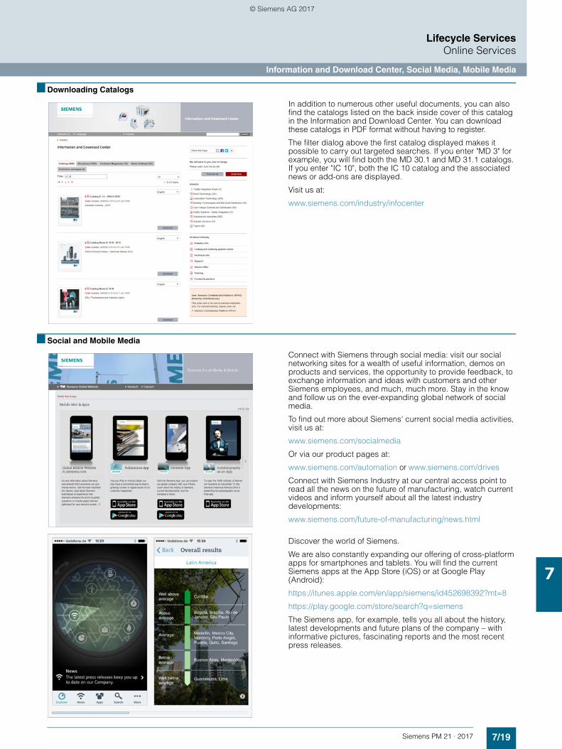
7/19Siemens PM 21 · 2017
Lifecycle ServicesOnline Services
Information and Download Center, Social Media, Mobile Media
7
■ Downloading Catalogs
In addition to numerous other useful documents, you can also find the catalogs listed on the back inside cover of this catalog in the Information and Download Center. You can download these catalogs in PDF format without having to register.
The filter dialog above the first catalog displayed makes it possible to carry out targeted searches. If you enter "MD 3" for example, you will find both the MD 30.1 and MD 31.1 catalogs. If you enter "IC 10", both the IC 10 catalog and the associated news or add-ons are displayed.
Visit us at:
www.siemens.com/industry/infocenter
■ Social and Mobile Media
Connect with Siemens through social media: visit our social networking sites for a wealth of useful information, demos on products and services, the opportunity to provide feedback, to exchange information and ideas with customers and other Siemens employees, and much, much more. Stay in the know and follow us on the ever-expanding global network of social media.
To find out more about Siemens' current social media activities, visit us at:
www.siemens.com/socialmedia
Or via our product pages at:
www.siemens.com/automation or www.siemens.com/drives
Connect with Siemens Industry at our central access point to read all the news on the future of manufacturing, watch current videos and inform yourself about all the latest industry developments:
www.siemens.com/future-of-manufacturing/news.html
Discover the world of Siemens.
We are also constantly expanding our offering of cross-platform apps for smartphones and tablets. You will find the current Siemens apps at the App Store (iOS) or at Google Play (Android):
https://itunes.apple.com/en/app/siemens/id452698392?mt=8
https://play.google.com/store/search?q=siemens
The Siemens app, for example, tells you all about the history, latest developments and future plans of the company – with informative pictures, fascinating reports and the most recent press releases.
© Siemens AG 2017
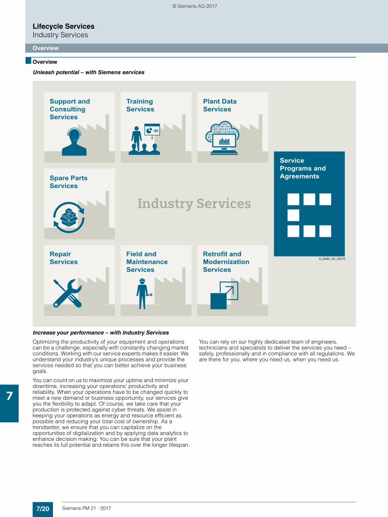
7/20 Siemens PM 21 · 2017
Lifecycle ServicesIndustry Services
Overview
7
■ Overview
Unleash potential – with Siemens services
Increase your performance – with Industry Services
Optimizing the productivity of your equipment and operations can be a challenge, especially with constantly changing market conditions. Working with our service experts makes it easier. We understand your industry’s unique processes and provide the services needed so that you can better achieve your business goals.
You can count on us to maximize your uptime and minimize your downtime, increasing your operations’ productivity and reliability. When your operations have to be changed quickly to meet a new demand or business opportunity, our services give you the flexibility to adapt. Of course, we take care that your production is protected against cyber threats. We assist in keeping your operations as energy and resource efficient as possible and reducing your total cost of ownership. As a trendsetter, we ensure that you can capitalize on the opportunities of digitalization and by applying data analytics to enhance decision making: You can be sure that your plant reaches its full potential and retains this over the longer lifespan.
You can rely on our highly dedicated team of engineers, technicians and specialists to deliver the services you need – safely, professionally and in compliance with all regulations. We are there for you, where you need us, when you need us.
TrainingServices
ServicePrograms andAgreements
Retrofit andModernizationServices
G_DA65_XX_00272RepairServices
Field andMaintenanceServices
Spare PartsServices
Plant DataServices
Support andConsultingServices
© Siemens AG 2017
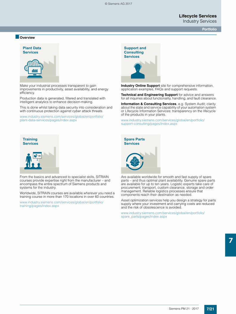
7/21Siemens PM 21 · 2017
Lifecycle ServicesIndustry Services
Portfolio
7
■ Overview
Make your industrial processes transparent to gain improvements in productivity, asset availability, and energy efficiency.
Production data is generated, filtered and translated with intelligent analytics to enhance decision-making.
This is done whilst taking data security into consideration and with continuous protection against cyber attack threats.
www.industry.siemens.com/services/global/en/portfolio/plant-data-services/pages/index.aspx
From the basics and advanced to specialist skills, SITRAIN courses provide expertise right from the manufacturer – and encompass the entire spectrum of Siemens products and systems for the industry.
Worldwide, SITRAIN courses are available wherever you need a training course in more than 170 locations in over 60 countries.
www.industry.siemens.com/services/global/en/portfolio/training/pages/index.aspx
Industry Online Support site for comprehensive information, application examples, FAQs and support requests.
Technical and Engineering Support for advice and answers for all inquiries about functionality, handling, and fault clearance.
Information & Consulting Services, e.g. System Audit; clarity about the state and service capability of your automation system or Lifecycle Information Services; transparency on the lifecycle of the products in your plants.
www.industry.siemens.com/services/global/en/portfolio/support-consulting/pages/index.aspx
Are available worldwide for smooth and fast supply of spare parts – and thus optimal plant availability. Genuine spare parts are available for up to ten years. Logistic experts take care of procurement, transport, custom clearance, storage and order management. Reliable logistics processes ensure that components reach their destination as needed.
Asset optimization services help you design a strategy for parts supply where your investment and carrying costs are reduced and the risk of obsolescence is avoided.
www.industry.siemens.com/services/global/en/portfolio/spare_parts/pages/index.aspx
Plant DataServices
TrainingServices
Support andConsultingServices
Spare PartsServices
© Siemens AG 2017
7/22 Siemens PM 21 · 2017
Lifecycle ServicesIndustry Services
Portfolio
7
■ Overview (continued)
Are offered on-site and in regional repair centers for fast restoration of faulty devices’ functionality.
Also available are extended repair services, which include additional diagnostic and repair measures, as well as emergency services.
www.industry.siemens.com/services/global/en/portfolio/repair_services/pages/index.aspx
Siemens specialists are available globally to provide expert field and maintenance services, including commissioning, functional testing, preventive maintenance and fault clearance.
All services can be included in customized service agreements with defined reaction times or fixed maintenance intervals.
www.industry.siemens.com/services/global/en/portfolio/field_service/pages/index.aspx
Provide a cost-effective solution for the expansion of entire plants, optimization of systems, or upgrading existing products to the latest technology and software, e.g. migration services for automation systems.
Service experts support projects from planning through commissioning and, if desired over the entire extended lifespan, e.g. Retrofit for Integrated Drive Systems for an extended lifetime of your machines and plants.
www.industry.siemens.com/services/global/en/portfolio/retrofit-modernization/pages/index.aspx
A technical Service Program or Agreement enables you to easily bundle a wide range of services into a single annual or multi-year agreement.
You pick the services you need to match your unique requirements or fill gaps in your organization’s maintenance capabilities.Programs and agreements can be customized as KPI-based and/or performance-based contracts.
www.industry.siemens.com/services/global/en/portfolio/service_programs/pages/index.aspx
RepairServices
Field andMaintenanceServices
Retrofit andModernizationServices
ServicePrograms andAgreements
© Siemens AG 2017
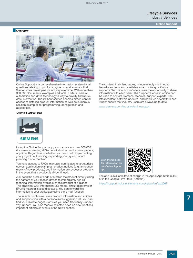
7/23Siemens PM 21 · 2017
Lifecycle ServicesIndustry Services
Online Support
7
■ Overview
Online Support is a comprehensive information system for all questions relating to products, systems, and solutions that Siemens has developed for industry over time. With more than 300,000 documents, examples and tools, it offers users of automation and drive technology a way to quickly find up-to-date information. The 24-hour service enables direct, central access to detailed product information as well as numerous solution examples for programming, configuration and application.
The content, in six languages, is increasingly multimedia-based – and now also available as a mobile app. Online support’s "Technical Forum" offers users the opportunity to share information with each other. The "Support Request" option can be used to contact Siemens’ technical support experts. The latest content, software updates, and news via newsletters and Twitter ensure that industry users are always up to date.
www.siemens.com/industry/onlinesupport
Online Support app
Using the Online Support app, you can access over 300,000 documents covering all Siemens industrial products – anywhere, any time. Regardless of whether you need help implementing your project, fault-finding, expanding your system or are planning a new machine.
You have access to FAQs, manuals, certificates, characteristic curves, application examples, product notices (e.g. announce-ments of new products) and information on successor products in the event that a product is discontinued.
Just scan the product code printed on the product directly using the camera of your mobile device to immediately see all technical information available on this product at a glance. The graphical CAx information (3D model, circuit diagrams or EPLAN macros) is also displayed. You can forward this information to your workplace using the e-mail function.
The search function retrieves product information and articles and supports you with a personalized suggestion list. You can find your favorite pages – articles you need frequently – under "mySupport". You also receive selected news on new functions, important articles or events in the News section.
The app is available free of charge in the Apple App Store (iOS) or in the Google Play Store (Android).
https://support.industry.siemens.com/cs/ww/en/sc/2067
s
Scan the QR code for information on our Online Support app.
© Siemens AG 2017
7/24 Siemens PM 21 · 2017
Lifecycle Services
Notes
7
© Siemens AG 2017
Siemens PM 21 · 2017
88/2 Certificates of suitability8/2 Certificates of suitability (approvals)
8/4 Notes on software8/4 Information on software licensing8/5 Usage and copy rights
8/6 Indexes8/6 Subject index8/13 Article number index
8/14 Conversion tables
8/16 Conditions of sale and delivery
Appendix
© Siemens AG 2017
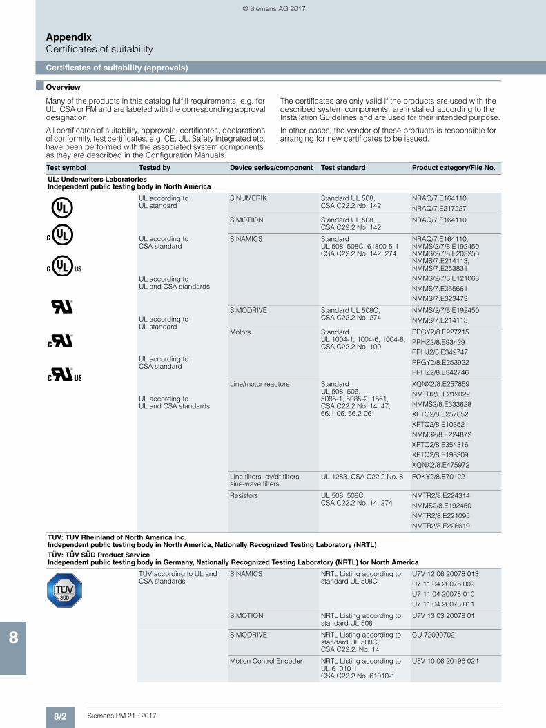
8/2 Siemens PM 21 · 2017
AppendixCertificates of suitability
Certificates of suitability (approvals)
8
■ Overview
Many of the products in this catalog fulfill requirements, e.g. for UL, CSA or FM and are labeled with the corresponding approval designation.
All certificates of suitability, approvals, certificates, declarations of conformity, test certificates, e.g. CE, UL, Safety Integrated etc. have been performed with the associated system components as they are described in the Configuration Manuals.
The certificates are only valid if the products are used with the described system components, are installed according to the Installation Guidelines and are used for their intended purpose.
In other cases, the vendor of these products is responsible for arranging for new certificates to be issued.
Test symbol Tested by Device series/component Test standard Product category/File No.
UL: Underwriters Laboratories Independent public testing body in North America
UL according to UL standard
UL according to CSA standard
UL according to UL and CSA standards
UL according to UL standard
UL according to CSA standard
UL according to UL and CSA standards
SINUMERIK Standard UL 508, CSA C22.2 No. 142
NRAQ/7.E164110NRAQ/7.E217227
SIMOTION Standard UL 508, CSA C22.2 No. 142
NRAQ/7.E164110
SINAMICS Standard UL 508, 508C, 61800-5-1CSA C22.2 No. 142, 274
NRAQ/7.E164110, NMMS/2/7/8.E192450, NMMS/2/7/8.E203250, NMMS/7.E214113, NMMS/7.E253831NMMS/2/7/8.E121068NMMS/7.E355661NMMS/7.E323473
SIMODRIVE Standard UL 508C, CSA C22.2 No. 274
NMMS/2/7/8.E192450NMMS/7.E214113
Motors Standard UL 1004-1, 1004-6, 1004-8, CSA C22.2 No. 100
PRGY2/8.E227215PRHZ2/8.E93429PRHJ2/8.E342747PRGY2/8.E253922PRHZ2/8.E342746
Line/motor reactors Standard UL 508, 506, 5085-1, 5085-2, 1561, CSA C22.2 No. 14, 47, 66.1-06, 66.2-06
XQNX2/8.E257859NMTR2/8.E219022NMMS2/8.E333628XPTQ2/8.E257852XPTQ2/8.E103521NMMS2/8.E224872XPTQ2/8.E354316XPTQ2/8.E198309XQNX2/8.E475972
Line filters, dv/dt filters, sine-wave filters
UL 1283, CSA C22.2 No. 8 FOKY2/8.E70122
Resistors UL 508, 508C, CSA C22.2 No. 14, 274
NMTR2/8.E224314NMMS2/8.E192450NMTR2/8.E221095NMTR2/8.E226619
TUV: TUV Rheinland of North America Inc. Independent public testing body in North America, Nationally Recognized Testing Laboratory (NRTL) TÜV: TÜV SÜD Product Service Independent public testing body in Germany, Nationally Recognized Testing Laboratory (NRTL) for North America
TUV according to UL and CSA standards
SINAMICS NRTL Listing according to standard UL 508C
U7V 12 06 20078 013U7 11 04 20078 009U7 11 04 20078 010U7 11 04 20078 011
SIMOTION NRTL Listing according to standard UL 508
U7V 13 03 20078 01
SIMODRIVE NRTL Listing according to standard UL 508C, CSA C22.2. No. 14
CU 72090702
Motion Control Encoder NRTL Listing according to UL 61010-1 CSA C22.2 No. 61010-1
U8V 10 06 20196 024
© Siemens AG 2017
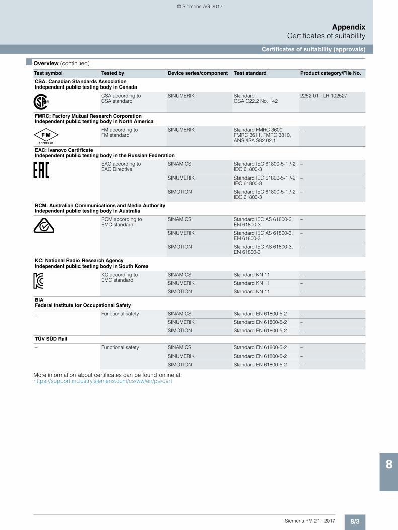
8/3Siemens PM 21 · 2017
AppendixCertificates of suitability
Certificates of suitability (approvals)
8
■ Overview (continued)
More information about certificates can be found online at: https://support.industry.siemens.com/cs/ww/en/ps/cert
Test symbol Tested by Device series/component Test standard Product category/File No.
CSA: Canadian Standards Association Independent public testing body in Canada
CSA according to CSA standard
SINUMERIK Standard CSA C22.2 No. 142
2252-01 : LR 102527
FMRC: Factory Mutual Research Corporation Independent public testing body in North America
FM according to FM standard
SINUMERIK Standard FMRC 3600, FMRC 3611, FMRC 3810, ANSI/ISA S82.02.1
–
EAC: Ivanovo Certificate Independent public testing body in the Russian Federation
EAC according to EAC Directive
SINAMICS Standard IEC 61800-5-1 /-2, IEC 61800-3
–
SINUMERIK Standard IEC 61800-5-1 /-2, IEC 61800-3
–
SIMOTION Standard IEC 61800-5-1 /-2, IEC 61800-3
–
RCM: Australian Communications and Media Authority Independent public testing body in Australia
RCM according to EMC standard
SINAMICS Standard IEC AS 61800-3, EN 61800-3
–
SINUMERIK Standard IEC AS 61800-3, EN 61800-3
–
SIMOTION Standard IEC AS 61800-3, EN 61800-3
–
KC: National Radio Research Agency Independent public testing body in South Korea
KC according to EMC standard
SINAMICS Standard KN 11 –
SINUMERIK Standard KN 11 –
SIMOTION Standard KN 11 –
BIA Federal Institute for Occupational Safety
– Functional safety SINAMICS Standard EN 61800-5-2 –
SINUMERIK Standard EN 61800-5-2 –
SIMOTION Standard EN 61800-5-2 –
TÜV SÜD Rail
– Functional safety SINAMICS Standard EN 61800-5-2 –
SINUMERIK Standard EN 61800-5-2 –
SIMOTION Standard EN 61800-5-2 –
© Siemens AG 2017
8/4 Siemens PM 21 · 2017
AppendixNotes on software
Information on software licensing
8
■ Overview
Software types
Software requiring a license is categorized into types. The following software types have been defined• Engineering software• Runtime software
Engineering software
This includes all software products for creating (engineering) user software, e.g. for configuring, programming, parameterizing, testing, commissioning or servicing. Data generated with engineering software and executable programs can be duplicated for your own use or for use by third-parties free-of-charge.
Runtime software
This includes all software products required for plant/machine operation, e.g. operating system, basic system, system expansions, drivers, etc. The duplication of the runtime software and executable programs created with the runtime software for your own use or for use by third-parties is subject to a charge. You can find information about license fees according to use in the ordering data (e.g. in the catalog). Examples of categories of use include per CPU, per installation, per channel, per instance, per axis, per control loop, per variable, etc. Information about extended rights of use for parameterization/configuration tools supplied as integral components of the scope of delivery can be found in the readme file supplied with the relevant product(s).
License types
Siemens Digital Factory offers various types of software license:• Floating license• Single license• Rental license• Rental floating license• Trial license• Demo license• Demo floating license
Floating license
The software may be installed for internal use on any number of devices by the licensee. Only the concurrent user is licensed. The concurrent user is the person using the program. Use begins when the software is started. A license is required for each concurrent user.
Single license
Unlike the floating license, a single license permits only one installation of the software per license. The type of use licensed is specified in the ordering data and in the Certificate of License (CoL). Types of use include, for example, per instance, per axis, per channel, etc. One single license is required for each type of use defined.
Rental license
A rental license supports the "sporadic use" of engineering software. Once the license key has been installed, the software can be used for a specific period of time (the operating hours do not have to be consecutive). One license is required for each installation of the software.
Rental floating license
The rental floating license corresponds to the rental license, except that a license is not required for each installation of the software. Rather, one license is required per object (for example, user or device).
Trial license
A trial license supports "short-term use" of the software in a non-productive context, e.g. use for testing and evaluation purposes. It can be transferred to another license.
Demo license
The demo license supports the "sporadic use" of engineering software in a non-productive context, for example, use for testing and evaluation purposes. It can be transferred to another license. After the installation of the license key, the software can be operated for a specific period of time, whereby usage can be interrupted as often as required.
One license is required for each installation of the software.
Demo floating license
The demo floating license corresponds to the demo license, except that a license is not required for each installation of the software. Rather, one license is required per object (for example, user or device).
Certificate of license (CoL)
The CoL is the licensee's proof that the use of the software has been licensed by Siemens. A CoL is required for every type of use and must be kept in a safe place.
Downgrading
The licensee is permitted to use the software or an earlier version/release of the software, provided that the licensee owns such a version/release and its use is technically feasible.
Delivery versions
Software is constantly being updated. The following delivery versions• PowerPack• Upgrade
can be used to access updates.
Existing bug fixes are supplied with the ServicePack version.
PowerPack
PowerPacks can be used to upgrade to more powerful software.
The licensee receives a new license agreement and CoL (Certificate of License) with the PowerPack. This CoL, together with the CoL for the original product, proves that the new software is licensed.
A separate PowerPack must be purchased for each original license of the software to be replaced.
Upgrade
An upgrade permits the use of a new version of the software on the condition that a license for a previous version of the product is already held. The licensee receives a new license agreement and CoL with the upgrade. This CoL, together with the CoL for the previous version, proves that the new software is licensed. A separate upgrade must be purchased for each original license of the software to be upgraded.
ServicePack
ServicePacks are used to debug existing products. ServicePacks may be duplicated for the use as prescribed according to the number of existing original licenses.
© Siemens AG 2017
8/5Siemens PM 21 · 2017
AppendixNotes on software
Information on software licensing
8
■ Overview (continued)
License key
Siemens Digital Factory supplies software products with and without license key. The license key serves as an electronic license stamp and is also the "switch" for activating the software (floating license, rental license, etc.) The complete installation of software products requiring license keys includes the program to be licensed (the software) and the license key (which represents the license).
Software Update Service (SUS)
As part of the SUS contract, all software updates for the respective product are made available to you free of charge for a period of one year from the invoice date. The contract will automatically be extended for one year if it is not canceled three months before it expires.
The possession of the current version of the respective software is a basic condition for entering into an SUS contract.
You can download explanations concerning license conditions from
www.siemens.com/automation/salesmaterial-as/catalog/en/terms_of_trade_en.pdf
■ Overview
The "General License Conditions for Software Products for Automation and Drives" are applicable for the delivery of Siemens Digital Factory software products.
Legal notes during setup for new software products
All software products feature a uniform reference to the license conditions. The license conditions are enclosed either with the documentation or in the software pack. When software is downloaded from the Internet, the license contract is displayed before the ordering procedure and must be accepted by the user before downloading can continue.
Notice:
This software is protected by German and/or US copyright law and the regulations of international agreements. Unauthorized reproduction or sale of this software or parts of it is a criminal offense. This will lead to criminal and civil prosecution, and may result in significant fines and/or claims for damages. Prior to installing and using the software, please read the applicable licensing conditions for this software. You will find these in the documentation or packaging.
If you have received this software on a CD/DVD that is marked “Trial version” or accompanying software that is licensed for your use, the software is only permitted to be used for test and validation purposes in accordance with the accompanying conditions for the trial license. To this end, it is necessary that programs, software libraries, etc., are installed on your computer. We therefore urgently recommend that installation is performed on a single-user computer or on a computer that is not used in the production process or for storing important data, since it cannot be completely excluded that existing files will be modified or overwritten. We accept no liability whatsoever for damage and/or data losses that result from this installation or the non-observance of this warning. Every other type of use of this software is only permitted if you are in possession of a valid license from Siemens.
If you are not in possession of a valid license that can be proven by presenting an appropriate Certificate of License/software product certificate, please abort installation immediately and contact a Siemens office without delay to avoid claims for damages.
Software Update Services
Order
To order the Software Update Service, an article number must be specified. The Software Update Service can be ordered when the software products are ordered or at a later date. Subsequent orders require that the ordering party is in possession at least of a single license.
Note:
It is recommended that the Software Update Service is ordered as early as possible. If a new software version of a software product is released for delivery by Siemens, only those customers will receive it automatically who are entered in the appropriate delivery list at Siemens at this time. Previous software versions, or the current software version are not supplied when the Software Update Service is ordered. The Software Update Service requires that the software product is up-to-date at the time of completion of the contract for the Software Update Service.
Delivery
When a Software Update Service is ordered, you will be sent the contractual conditions of this service and the price is due for payment. At the same time, you will be included in a delivery list for the software product to be updated. If Siemens releases a new software version for the corresponding software product for general sale (function or product version), it will be delivered automatically to the goods recipient specified in the delivery address within the contract period.
■ More information
Security note
In the case of software for teleservice or connection to higher-level networks, suitable protection measures must be taken (including industrial security, e.g. network segmentation) to guarantee safe operation of the system. Additional information about Industrial Security can be found in the Internet at
www.siemens.com/industrialsecurity
Usage and copy rights
© Siemens AG 2017
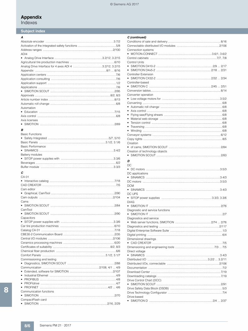
8/6 Siemens PM 21 · 2017
AppendixIndexes
Subject index
8
AAbsolute encoder ....................................................................................3.7/2Activation of the integrated safety functions ...............................................5/8Address ranges ......................................................................................2/100ADI4• Analog Drive Interface ...........................................................3.2/12, 3.2/15Agricultural tire production machines .......................................................6/10Analog Drive Interface for 4 axes ADI 4 ....................................3.2/12, 3.2/15Appendix ........................................................................................8/1 ... 8/16Application centers .....................................................................................7/6Application consulting ................................................................................7/6Application support ....................................................................................1/2Applications ................................................................................................7/6• SIMOTION SCOUT ...............................................................................2/95Approvals .............................................................................................8/2, 8/3Article number index .................................................................................8/13Automatic roll change .................................................................................6/8Automation• Education .............................................................................................7/15Axis control .................................................................................................6/8Axis licenses• SIMOTION ............................................................................................2/69
BBasic Functions• Safety Integrated ...........................................................................5/7, 5/10Basic Panels ..................................................................................3.1/2, 3.1/6Basic Performance• SINAMICS ............................................................................................3.4/2Battery modules• SITOP power supplies with .................................................................3.3/6Beverages ...................................................................................................6/2Buffer module ..........................................................................................3.3/3
CCA 01• Interactive catalog ................................................................................7/18CAD CREATOR ...........................................................................................7/5Cam editor• Graphical, CamTool ..............................................................................2/90Cam outputs ...........................................................................................2/104Cams• SIMOTION SCOUT ...............................................................................2/84CamTool• SIMOTION SCOUT ...............................................................................2/90Capacitors• SITOP power supplies with .................................................................3.3/6Car tire production machines ...................................................................6/10Catalog CA 01 ..........................................................................................7/18CBE30-2 Communication Board ...............................................................2/35Central I/O modules ................................................................................2/106Ceramics processing machines ...............................................................6/20Certificates of suitability .......................................................................8/2, 8/3Chemical fiber production ..........................................................................6/6Comfort Panels ..............................................................................3.1/2, 3.1/7Commissioning and testing• Diagnostics, SIMOTION SCOUT ..........................................................2/88Communication ......................................................................2/108, 4/1 ... 4/9• Extended, software for SIMOTION .....................................................2/107• Industrial Ethernet ..................................................................................4/9• PROFIBUS ..............................................................................................4/8• PROFIdrive .............................................................................................4/7• PROFINET ....................................................................................4/2 ... 4/6Communication functions• SIMOTION ............................................................................................2/70CompactFlash card• SIMOTION ...................................................................................2/16, 2/29
C (continued)Conditions of sale and delivery .................................................................8/16Connectable distributed I/O modules ....................................................2/106Connection systems• MOTION-CONNECT ..................................................................3.6/1, 3.6/2Control cabinets ..................................................................................7/7, 7/8Control Units• SIMOTION D410-2 .....................................................................2/9 ... 2/17• SIMOTION D4x5-2 ...................................................................2/18 ... 2/31Controller Extension• SIMOTION CX32-2 ...................................................................2/32 ... 2/34Controller-based• SIMOTION C ............................................................................2/45 ... 2/51Conversion tables......................................................................................8/14Converter operation• Low-voltage motors for .......................................................................3.5/2Converting ..................................................................................................6/8• Automatic roll change ............................................................................6/8• Axis control .............................................................................................6/8• Flying saw/Flying shears ........................................................................6/8• Material web storage .............................................................................6/8• Tension control .......................................................................................6/8• Traversing ...............................................................................................6/8• Winding ..................................................................................................6/8Conveyor systems ....................................................................................6/12Copy rights .................................................................................................8/5Creation• of cams, SIMOTION SCOUT ................................................................2/84Creation of technology objects• SIMOTION SCOUT ...............................................................................2/83
DDC• DC motors ...........................................................................................3.5/3DC applications• SINAMICS ...........................................................................................3.4/3DC motors ...............................................................................................3.5/3DCM• SINAMICS ...........................................................................................3.4/3DC UPS• SITOP power supplies ..............................................................3.3/3, 3.3/6DIAG• SIMOTION IT ........................................................................................2/76Diagnostic and service functions• SIMOTION IT ..........................................................................................2/7Diagnostics and service• Web server functions, SIMOTION ............................................2/74 ... 2/76Diagnostics and testing ..........................................................................2/117Digital Enterprise Software Suite ................................................................1/3Digital printing ............................................................................................6/4Dimensional drawings• CAD CREATOR ......................................................................................7/5Dimensioning and engineering tools ................................................7/3 ... 7/5Direct voltage• SINAMICS ...........................................................................................3.4/3Distributed I/O ..........................................................................3.2/2 ... 3.2/11Distributed I/Os, connectable ................................................................2/106Documentation ...........................................................................................7/2Download Center ......................................................................................7/19Downloading catalogs ..............................................................................7/19Drive Control Chart (DCC)• SIMOTION SCOUT ...............................................................................2/91Drive Safety Data Block (DSDB) ................................................................5/3Drive Technology Configurator ...................................................................7/4Drive-based• SIMOTION D ..............................................................................2/4 ... 2/37
© Siemens AG 2017
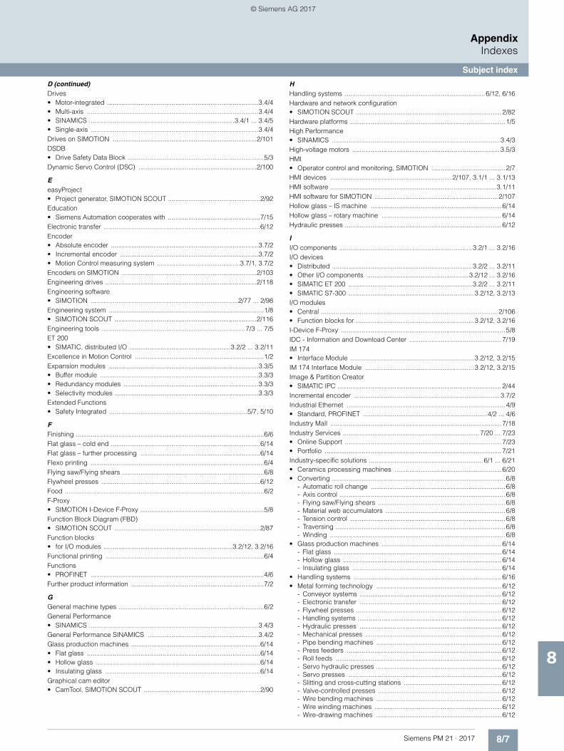
8/7Siemens PM 21 · 2017
AppendixIndexes
Subject index
8
D (continued) Drives• Motor-integrated ..................................................................................3.4/4• Multi-axis .............................................................................................3.4/4• SINAMICS ...............................................................................3.4/1 ... 3.4/5• Single-axis ...........................................................................................3.4/4Drives on SIMOTION ..............................................................................2/101DSDB• Drive Safety Data Block ..........................................................................5/3Dynamic Servo Control (DSC) ................................................................2/100
EeasyProject• Project generator, SIMOTION SCOUT ..................................................2/92Education• Siemens Automation cooperates with ..................................................7/15Electronic transfer .....................................................................................6/12Encoder• Absolute encoder ................................................................................3.7/2• Incremental encoder ...........................................................................3.7/2• Motion Control measuring system .............................................3.7/1, 3.7/2Encoders on SIMOTION .........................................................................2/103Engineering drives ..................................................................................2/118Engineering software• SIMOTION ................................................................................2/77 ... 2/98Engineering system ....................................................................................1/8• SIMOTION SCOUT .............................................................................2/116Engineering tools ..............................................................................7/3 ... 7/5ET 200• SIMATIC, distributed I/O .......................................................3.2/2 ... 3.2/11Excellence in Motion Control ......................................................................1/2Expansion modules .................................................................................3.3/5• Buffer module ......................................................................................3.3/3• Redundancy modules .........................................................................3.3/3• Selectivity modules ..............................................................................3.3/3Extended Functions• Safety Integrated ...........................................................................5/7, 5/10
FFinishing ......................................................................................................6/6Flat glass – cold end .................................................................................6/14Flat glass – further processing .................................................................6/14Flexo printing ..............................................................................................6/4Flying saw/Flying shears .............................................................................6/8Flywheel presses ......................................................................................6/12Food ............................................................................................................6/2F-Proxy• SIMOTION I-Device F-Proxy ...................................................................5/8Function Block Diagram (FBD)• SIMOTION SCOUT ...............................................................................2/87Function blocks• for I/O modules ......................................................................3.2/12, 3.2/16Functional printing ......................................................................................6/4Functions• PROFINET ..............................................................................................4/6Further product information ........................................................................7/2
GGeneral machine types ...............................................................................6/2General Performance• SINAMICS ............................................................................................3.4/3General Performance SINAMICS ............................................................3.4/2Glass production machines ......................................................................6/14• Flat glass ..............................................................................................6/14• Hollow glass .........................................................................................6/14• Insulating glass ....................................................................................6/14Graphical cam editor• CamTool, SIMOTION SCOUT ...............................................................2/90
HHandling systems ............................................................................6/12, 6/16Hardware and network configuration• SIMOTION SCOUT ...............................................................................2/82Hardware platforms ....................................................................................1/5High Performance• SINAMICS ...........................................................................................3.4/3High-voltage motors ................................................................................3.5/3HMI• Operator control and monitoring, SIMOTION ........................................2/7HMI devices ..................................................................2/107, 3.1/1 ... 3.1/13HMI software ..........................................................................................3.1/11HMI software for SIMOTION ...................................................................2/107Hollow glass – IS machine .......................................................................6/14Hollow glass – rotary machine .................................................................6/14Hydraulic presses .....................................................................................6/12
II/O components ........................................................................3.2/1 ... 3.2/16I/O devices• Distributed ............................................................................3.2/2 ... 3.2/11• Other I/O components .......................................................3.2/12 ... 3.2/16• SIMATIC ET 200 ...................................................................3.2/2 ... 3.2/11• SIMATIC S7-300 ....................................................................3.2/12, 3.2/13I/O modules• Central ................................................................................................2/106• Function blocks for ................................................................3.2/12, 3.2/16I-Device F-Proxy .........................................................................................5/8IDC - Information and Download Center ..................................................7/19IM 174• Interface Module ...................................................................3.2/12, 3.2/15IM 174 Interface Module ...........................................................3.2/12, 3.2/15Image & Partition Creator• SIMATIC IPC .........................................................................................2/44Incremental encoder ...............................................................................3.7/2Industrial Ethernet ......................................................................................4/9• Standard, PROFINET ...................................................................4/2 ... 4/6Industry Mall .............................................................................................7/18Industry Services ..........................................................................7/20 ... 7/23• Online Support .....................................................................................7/23• Portfolio ................................................................................................7/21Industry-specific solutions ..............................................................6/1 ... 6/21• Ceramics processing machines ..........................................................6/20• Converting ..............................................................................................6/8
- Automatic roll change .........................................................................6/8- Axis control ..........................................................................................6/8- Flying saw/Flying shears .....................................................................6/8- Material web accumulators .................................................................6/8- Tension control ....................................................................................6/8- Traversing ............................................................................................6/8- Winding ...............................................................................................6/8
• Glass production machines .................................................................6/14- Flat glass ...........................................................................................6/14- Hollow glass ......................................................................................6/14- Insulating glass .................................................................................6/14
• Handling systems ................................................................................6/16• Metal forming technology ....................................................................6/12
- Conveyor systems .............................................................................6/12- Electronic transfer .............................................................................6/12- Flywheel presses ...............................................................................6/12- Handling systems ..............................................................................6/12- Hydraulic presses .............................................................................6/12- Mechanical presses ..........................................................................6/12- Pipe bending machines ....................................................................6/12- Press feeders ....................................................................................6/12- Roll feeds ..........................................................................................6/12- Servo hydraulic presses ....................................................................6/12- Servo presses ...................................................................................6/12- Slitting and cross-cutting stations .....................................................6/12- Valve-controlled presses ...................................................................6/12- Wire bending machines ....................................................................6/12- Wire winding machines .....................................................................6/12- Wire-drawing machines ....................................................................6/12
© Siemens AG 2017
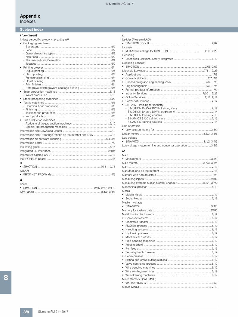
8/8 Siemens PM 21 · 2017
AppendixIndexes
Subject index
8
I (continued) Industry-specific solutions (continued)• Packaging machines
- Beverages ...........................................................................................6/2- Food ....................................................................................................6/2- General machine types .......................................................................6/2- Non Food .............................................................................................6/2- Pharmaceuticals/Cosmetics ................................................................6/2- Tobacco ...............................................................................................6/2
• Printing presses ......................................................................................6/4- Digital printing .....................................................................................6/4- Flexo printing .......................................................................................6/4- Functional printing ...............................................................................6/4- Offset printing ......................................................................................6/4- Print finishing .......................................................................................6/4- Rotogravure/Rotogravure package printing ........................................6/4
• Solar production machines ..................................................................6/18- Wafer production ...............................................................................6/18
• Stone processing machines .................................................................6/20• Textile machines .....................................................................................6/6
- Chemical fiber production ...................................................................6/6- Finishing ..............................................................................................6/6- Textile fabric production ......................................................................6/6- Yarn production ...................................................................................6/6
• Tire production machines .....................................................................6/10- Agricultural tire production machines ...............................................6/10- Special tire production machines ......................................................6/10
Information and Download Center ............................................................7/19Information and Ordering Options on the Internet and DVD ....................7/18Information on software licensing ........................................................8/4, 8/5Information portal ........................................................................................7/2Insulating glass .........................................................................................6/14Integrated I/O interfaces .........................................................................2/105Interactive catalog CA 01 .........................................................................7/18IsoPROFIBUS board .................................................................................2/44IT• SIMOTION ................................................................................2/74 ... 2/76IWLAN• PROFINET, PROFIsafe ............................................................................4/5
KKernel• SIMOTION ........................................................................2/56, 2/57, 2/112Key Panels .....................................................................................3.1/2, 3.1/5
LLadder Diagram (LAD)• SIMOTION SCOUT ...............................................................................2/87License• MultiAxes Package for SIMOTION D ..........................................2/16, 2/29Licensing• Extended Functions, Safety Integrated ................................................5/10Licensing concept• SIMOTION ...................................................................................2/66, 2/67Lifecycle Services ..........................................................................7/1 ... 7/23• Applications ...........................................................................................7/6• Control cabinets ..............................................................................7/7, 7/8• Dimensioning and engineering tools ...........................................7/3 ... 7/5• Engineering tools .........................................................................7/3 ... 7/5• Further product information ...................................................................7/2• Industry Services .....................................................................7/20 ... 7/23• Online Services ...........................................................................7/18, 7/19• Partner at Siemens ...............................................................................7/17• SITRAIN - Training for Industry
- SIMOTION D425-2 DP/PN training case ...........................................7/12- SIMOTION D425-2 DP/PN upgrade kit .............................................7/14- SIMOTION training courses ..............................................................7/10- SINAMICS S120 training case ..........................................................7/13- SINAMICS training courses ...............................................................7/11
Line operation• Low-voltage motors for .......................................................................3.5/2Linear motors .................................................................................3.5/3, 3.5/5Low voltage• SINAMICS .................................................................................3.4/2, 3.4/3Low-voltage motors for line and converter operation ..............................3.5/2
MMain• Main motors ........................................................................................3.5/3Main motors ...................................................................................3.5/3, 3.5/5Mall ...........................................................................................................7/18Manufacturing on the Internet ..................................................................7/18Material web accumulators ........................................................................6/8Measuring inputs ....................................................................................2/103Measuring systems Motion Control Encoder .................................3.7/1, 3.7/2Mechanical presses .................................................................................6/12Media• Mobile Media .......................................................................................7/19• Social Media ........................................................................................7/19Medium voltage• SINAMICS ...........................................................................................3.4/3Memory for system data .........................................................................2/100Metal forming technology .........................................................................6/12• Conveyor systems ................................................................................6/12• Electronic transfer ................................................................................6/12• Flywheel presses ..................................................................................6/12• Handling systems ................................................................................6/12• Hydraulic presses ................................................................................6/12• Mechanical presses .............................................................................6/12• Pipe bending machines .......................................................................6/12• Press feeders .......................................................................................6/12• Roll feeds .............................................................................................6/12• Servo hydraulic presses .......................................................................6/12• Servo presses ......................................................................................6/12• Slitting and cross-cutting stations ........................................................6/12• Valve-controlled presses ......................................................................6/12• Wire bending machines .......................................................................6/12• Wire winding machines ........................................................................6/12• Wire-drawing machines .......................................................................6/12Micro Memory Card (MMC)• for SIMOTION C ...................................................................................2/50Mobile Media ............................................................................................7/19
© Siemens AG 2017
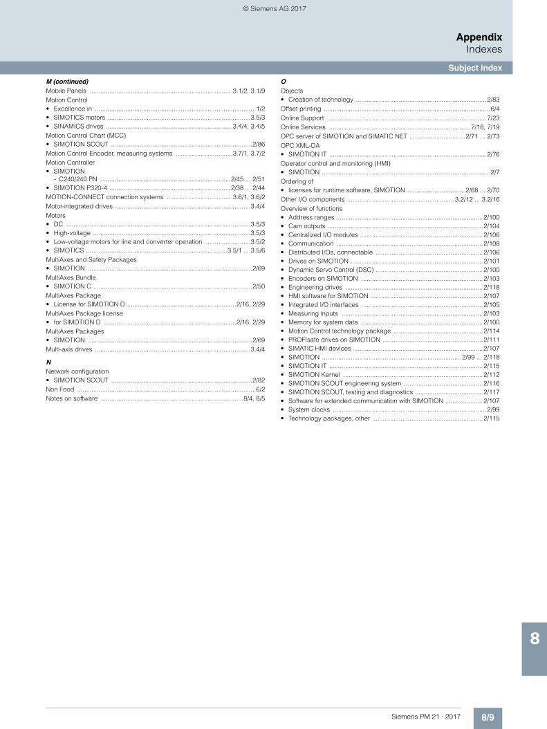
8/9Siemens PM 21 · 2017
AppendixIndexes
Subject index
8
M (continued) Mobile Panels ................................................................................3.1/2, 3.1/9Motion Control• Excellence in ..........................................................................................1/2• SIMOTICS motors ................................................................................3.5/3• SINAMICS drives .......................................................................3.4/4, 3.4/5Motion Control Chart (MCC)• SIMOTION SCOUT ...............................................................................2/86Motion Control Encoder, measuring systems ................................3.7/1, 3.7/2Motion Controller• SIMOTION
- C240/240 PN .........................................................................2/45 ... 2/51• SIMOTION P320-4 ....................................................................2/38 ... 2/44MOTION-CONNECT connection systems .....................................3.6/1, 3.6/2Motor-integrated drives ............................................................................3.4/4Motors• DC .......................................................................................................3.5/3• High-voltage ........................................................................................3.5/3• Low-voltage motors for line and converter operation ..........................3.5/2• SIMOTICS ...............................................................................3.5/1 ... 3.5/6MultiAxes and Safety Packages• SIMOTION ............................................................................................2/69MultiAxes Bundle• SIMOTION C .........................................................................................2/50MultiAxes Package• License for SIMOTION D .............................................................2/16, 2/29MultiAxes Package license• for SIMOTION D ..........................................................................2/16, 2/29MultiAxes Packages• SIMOTION ............................................................................................2/69Multi-axis drives .......................................................................................3.4/4
NNetwork configuration• SIMOTION SCOUT ...............................................................................2/82Non Food ....................................................................................................6/2Notes on software ................................................................................8/4, 8/5
OObjects• Creation of technology .........................................................................2/83Offset printing .............................................................................................6/4Online Support .........................................................................................7/23Online Services ...............................................................................7/18, 7/19OPC server of SIMOTION and SIMATIC NET ...............................2/71 ... 2/73OPC XML-DA• SIMOTION IT ........................................................................................2/76Operator control and monitoring (HMI)• SIMOTION ..............................................................................................2/7Ordering of• licenses for runtime software, SIMOTION ................................2/68 ... 2/70Other I/O components ............................................................3.2/12 ... 3.2/16Overview of functions• Address ranges ..................................................................................2/100• Cam outputs .......................................................................................2/104• Centralized I/O modules ....................................................................2/106• Communication ..................................................................................2/108• Distributed I/Os, connectable ............................................................2/106• Drives on SIMOTION ..........................................................................2/101• Dynamic Servo Control (DSC) ............................................................2/100• Encoders on SIMOTION ....................................................................2/103• Engineering drives .............................................................................2/118• HMI software for SIMOTION ...............................................................2/107• Integrated I/O interfaces ....................................................................2/105• Measuring inputs ...............................................................................2/103• Memory for system data ....................................................................2/100• Motion Control technology package ..................................................2/114• PROFIsafe drives on SIMOTION ........................................................2/111• SIMATIC HMI devices ........................................................................2/107• SIMOTION ..............................................................................2/99 ... 2/118• SIMOTION IT ......................................................................................2/115• SIMOTION Kernel ..............................................................................2/112• SIMOTION SCOUT engineering system ............................................2/116• SIMOTION SCOUT, testing and diagnostics ......................................2/117• Software for extended communication with SIMOTION .....................2/107• System clocks ......................................................................................2/99• Technology packages, other ..............................................................2/115
© Siemens AG 2017
8/10 Siemens PM 21 · 2017
AppendixIndexes
Subject index
8
PPackaging machines ..................................................................................6/2• Beverages ..............................................................................................6/2• Food .......................................................................................................6/2• General machine types ..........................................................................6/2• Non Food ................................................................................................6/2• Pharmaceuticals/Cosmetics ...................................................................6/2• Tobacco ..................................................................................................6/2Panels .......................................................................................3.1/2 ... 3.1/10Partner at Siemens ....................................................................................7/17PC-based• SIMOTION P .............................................................................2/38 ... 2/44PC-based HMI solutions ........................................................................3.1/13Pharmaceuticals/Cosmetics .......................................................................6/2Pipe bending machines ............................................................................6/12Planetary geared motors .........................................................................3.5/4PLCopen blocks• SIMOTION ............................................................................................2/65Portrait assembly kit• SIMATIC IPC .........................................................................................2/44Position sensing, safe .................................................................................5/9Power supplies ...........................................................................3.3/1 ... 3.3/6• SITOP .....................................................................................3.3/1 ... 3.3/6• Technology ..........................................................................................3.3/4Press feeders ............................................................................................6/12Print finishing ..............................................................................................6/4Printing presses ..........................................................................................6/4• Digital printing ........................................................................................6/4• Flexo printing ..........................................................................................6/4• Functional printing ..................................................................................6/4• Offset printing .........................................................................................6/4• Print finishing ..........................................................................................6/4• Rotogravure/Rotogravure package printing ...........................................6/4PROFIBUS ..................................................................................................4/8• IsoPROFIBUS board .............................................................................2/44• PROFIdrive .............................................................................................4/7PROFIdrive ..................................................................................................4/7PROFINET .........................................................................................4/2 ... 4/6• for SIMOTION and SINAMICS S .............................................................4/6• Functions ................................................................................................4/6• PROFIdrive .............................................................................................4/7PROFIsafe ...................................................................................................5/8• PROFINET ..............................................................................................4/5PROFIsafe drives on SIMOTION .............................................................2/111Project generator SIMOTION easyProject ..................................................1/9PSU8600• Power supply system, SITOP modular ......................................3.3/3, 3.3/5
RReady-to-wear clothing ...............................................................................6/6Redundancy modules ..............................................................................3.3/3Roll feeds ..................................................................................................6/12Rotogravure/Rotogravure package printing ...............................................6/4Runtime software licenses• SIMOTION ................................................................................2/68 ... 2/70Runtime software SIMOTION ........................................................2/53 ... 2/70Runtime system ..........................................................................................1/7
SS7-300• SIMATIC, I/O ..........................................................................3.2/12, 3.2/13Safe Brake Control (SBC) ...........................................................................5/5Safe Brake Test (SBT) .................................................................................5/5Safe Direction (SDI) ....................................................................................5/6Safe Operating Stop (SOS) ........................................................................5/5Safe Position (SP) .......................................................................................5/7Safe Speed Monitor (SSM) .........................................................................5/6Safe speed/position sensing ......................................................................5/9Safe Stop (SS1, SS2) ..................................................................................5/4Safe Torque Off (STO) ................................................................................5/3Safely Limited Position (SLP) ......................................................................5/7Safely Limited Speed (SLS) ........................................................................5/6Safety and MultiAxes Packages SIMOTION ............................................2/69Safety engineering .....................................................................................5/2Safety functions ..........................................................................................5/3Safety Integrated ............................................................................5/1 ... 5/10Safety Integrated functions ........................................................................2/7Safety-related standards ............................................................................5/2SCOUT• SIMOTION ................................................................................2/77 ... 2/98Security note ...............................................................................................8/5Selection Tool• SITOP ..................................................................................................3.3/6Selectivity modules ..................................................................................3.3/3Service• Lifecycle Services ......................................................................7/1 ... 7/23Service and diagnostic functions ...............................................................2/7Service and diagnostics• Web server functions, SIMOTION ............................................2/74 ... 2/76Services from Siemens ....................................................................7/20, 7/21Servo geared motors ...............................................................................3.5/4Servo hydraulic presses ...........................................................................6/12Servo presses ...........................................................................................6/12Servomotors ..................................................................................3.5/3, 3.5/4Siemens Automation Cooperates with Education ....................................7/15Siemens services ............................................................................7/20, 7/21SIMATIC• ET 200 distributed I/O ..........................................................3.2/2 ... 3.2/11• HMI .....................................................................................................2/107• HMI devices .........................................................................3.1/2 ... 3.1/10• HMI software .....................................................................................3.1/11• Industrial PCs
- PC-based HMI solutions ................................................................3.1/13• OPC server ...............................................................................2/71 ... 2/73• Panels ..................................................................................3.1/2 ... 3.1/10
- Basic Panels .....................................................................................3.1/6- Comfort Panels .................................................................................3.1/7- Mobile Panels ...................................................................................3.1/9
• S7-300 I/O .............................................................................3.2/12, 3.2/13• SCADA system SIMATIC WinCC .......................................................3.1/11• SCADA system SIMATIC WinCC Open Architecture ........................3.1/11• SITOP power supplies in SIMATIC design ................................3.3/2, 3.3/4• WinCC ...............................................................................................3.1/11• WinCC flexible ...................................................................................3.1/11SIMATIC IPC• Image & Partition Creator .....................................................................2/44• Portrait assembly kit .............................................................................2/44• USB flash drive ....................................................................................2/44SIMOTICS• Motors ....................................................................................3.5/1 ... 3.5/6• Motors for Motion Control ....................................................................3.5/3
© Siemens AG 2017
8/11Siemens PM 21 · 2017
AppendixIndexes
Subject index
8
S (continued) SIMOTION• Axis licenses .........................................................................................2/69• C
- Controller-based ....................................................................2/45 ... 2/51- Micro Memory Card (MMC) ...............................................................2/50- MultiAxes Bundle ...............................................................................2/50- Overview ..............................................................................................1/6
• C240/240 PN- Motion Controller ...................................................................2/45 ... 2/51
• CompactFlash card .....................................................................2/16, 2/29• CX32-2
- Controller Extension ...............................................................2/32 ... 2/34• D
- Drive-based .............................................................................2/4 ... 2/37- Overview ..............................................................................................1/5
• D410-2- Control Units ............................................................................2/9 ... 2/17
• D4x5-2- Control Units ..........................................................................2/18 ... 2/31
• Documentation .......................................................................................7/2• Drives on ............................................................................................2/101• Encoders on .......................................................................................2/103• Engineering software ................................................................2/77 ... 2/98
- Instructions ........................................................................................2/97- Ordering of ........................................................................................2/97
• Further product information ....................................................................7/2• Information portal ...................................................................................7/2• Kernel ...............................................................................2/56, 2/57, 2/112• Licenses for runtime software ..................................................2/68 ... 2/70• Licensing concept, overview .......................................................2/66, 2/67• Motion Control System .............................................................2/1 ... 2/118• MultiAxes and Safety Packages ...........................................................2/69• MultiAxes Packages .............................................................................2/69• OPC server ...............................................................................2/71 ... 2/73• Overview .................................................................................................1/4• Overview of functions .............................................................2/99 ... 2/118• Overview of the licensing concept ..............................................2/66, 2/67• P
- Overview ..............................................................................................1/6- PC-based ..............................................................................2/38 ... 2/44
• P320-4- Motion Controller ...................................................................2/38 ... 2/44
• PLCopen blocks ...................................................................................2/65• PROFINET for SIMOTION .......................................................................4/6• Project generator ...........................................................................1/9, 2/92• Runtime software ......................................................................2/53 ... 2/70• Safety and MultiAxes Packages ...........................................................2/69• Safety Integrated functions ....................................................................2/7• SCOUT .....................................................................................2/77 ... 2/98
- Diagnostics, testing and commissioning ...........................................2/88- easyProject project generator ...........................................................2/92- Utilities & Applications .......................................................................2/95
• SCOUT, CamTool ..................................................................................2/90• SCOUT, creation of cams .....................................................................2/84• SCOUT, creation of technology objects ...............................................2/83• SCOUT, Drive Control Chart (DCC) ......................................................2/91• SCOUT, hardware and network configuration ......................................2/82• SCOUT, Ladder Diagram/Function Block Diagram (LAD/FBD) ...........2/87• SCOUT, Motion Control Chart (MCC) ...................................................2/86• SCOUT, Structured Text (ST) ................................................................2/85• SCOUT, Workbench .............................................................................2/81• SIMOTION D425-2 DP/PN training case ..............................................7/12• SIMOTION D425-2 DP/PN upgrade kit ................................................7/14• SIMOTION I-Device F-Proxy ...................................................................5/8• Software ....................................................................................2/52 ... 2/98• Standard modules ..................................................................................1/9
S (continued) SIMOTION (continued)• Supplementary components
- CBE30-2 Communication Board .......................................................2/35- CX32-2 Controller Extension .................................................2/32 ... 2/34- TB30 Terminal Board ................................................................2/36, 2/37
• System components ..............................................................3.1/1 ... 3.7/2- Distributed I/O ...................................................................3.2/2 ... 3.2/11- HMI devices ......................................................................3.1/1 ... 3.1/13
- Basic Panels ........................................................................3.1/2, 3.1/6- Comfort Panels ....................................................................3.1/2, 3.1/7- HMI software ...............................................................................3.1/11- Key Panels ..........................................................................3.1/2, 3.1/5- Mobile Panels ......................................................................3.1/2, 3.1/9- WinCC engineering software ........................................................3.1/3
- I/O components .................................................................3.2/1 ... 3.2/16- Motion Control Encoder measuring systems .........................3.7/1, 3.7/2- MOTION-CONNECT connection systems ..............................3.6/1, 3.6/2- Other I/O components .....................................................3.2/12 ... 3.2/16- Power supplies ....................................................................3.3/1 ... 3.3/6- SIMOTICS motors ................................................................3.5/1 ... 3.5/6- SINAMICS drives .................................................................3.4/1 ... 3.4/5
• System overview ..........................................................................1/1 ... 1/8- Application support .............................................................................1/2- Digital Enterprise Software Suite .........................................................1/3- Engineering system .............................................................................1/8- Runtime system ...................................................................................1/7- SIMOTION – An overview ....................................................................1/4
- Hardware platforms ..........................................................................1/5
• Technology packages ..............................................2/7, 2/58 ... 2/64, 2/69• Training courses ...................................................................................7/10SIMOTION D425-2 DP/PN training case ..................................................7/12SIMOTION D425-2 DP/PN upgrade kit ....................................................7/14SIMOTION easyProject project generator ................................................2/92SIMOTION IT ..............................................................2/7, 2/74 ... 2/76, 2/115• Communication functions ....................................................................2/70• DIAG ....................................................................................................2/76• OPC XML-DA .......................................................................................2/76• Service and diagnostic functions ...........................................................2/7• Virtual Machine ....................................................................................2/76SIMOTION Motion Control System ...............................................2/1 ... 2/118SINAMICS• Basic Performance ..............................................................................3.4/2• DC applications ..................................................................................3.4/3• DCM ....................................................................................................3.4/3• Direct voltage ......................................................................................3.4/3• Drives .....................................................................................3.4/1 ... 3.4/5• Drives for Motion Control ...........................................................3.4/4, 3.4/5• G ...............................................................................................3.4/2, 3.4/3• General Performance ................................................................3.4/2, 3.4/3• High Performance ...............................................................................3.4/3• Low voltage ...............................................................................3.4/2, 3.4/3• Medium voltage ..................................................................................3.4/3• Motor-integrated drives .......................................................................3.4/4• Multi-axis drives ..................................................................................3.4/4• PROFINET for SINAMICS S ....................................................................4/6• S .............................................................................................3.4/2 ... 3.4/5• SINAMICS S120 training case .............................................................7/13• Single-axis drives ................................................................................3.4/4• Training courses ...................................................................................7/11• V ..........................................................................................................3.4/2SINAMICS S120 training case ..................................................................7/13Single-axis drives ....................................................................................3.4/4
© Siemens AG 2017
8/12 Siemens PM 21 · 2017
AppendixIndexes
Subject index
8
S (continued) SITOP• DC UPS, power supplies ...........................................................3.3/3, 3.3/6• Expansion modules for power supplies ....................................3.3/3, 3.3/5• lite ..............................................................................................3.3/2, 3.3/4• modular ...........................................................................3.3/3, 3.3/4, 3.3/5• Power supplies
- Expansion modules ................................................................3.3/3, 3.3/5• Power supplies in SIMATIC design ...........................................3.3/2, 3.3/4• PSU8600 power supply system ................................................3.3/3, 3.3/5• Selection Tool ......................................................................................3.3/6• smart ..........................................................................................3.3/2, 3.3/4SITOP power supplies ................................................................3.3/1 ... 3.3/6SITRAIN - Training for Industry ...................................................................7/9• SIMOTION D425-2 DP/PN training case ..............................................7/12• SIMOTION D425-2 DP/PN upgrade kit ................................................7/14• SIMOTION training courses .................................................................7/10• SINAMICS S120 training case ..............................................................7/13• SINAMICS training courses ..................................................................7/11SIZER for Siemens Drives engineering tool ................................................7/3Slitting and cross-cutting stations .............................................................6/12Social Media .............................................................................................7/19Software• Engineering software
- SIMOTION, ordering, instructions .....................................................2/97• for extended communication with SIMOTION ....................................2/107• Information on licensing of the ........................................................8/4, 8/5• Notes on ..........................................................................................8/4, 8/5• SIMOTION ................................................................................2/52 ... 2/98• SIMOTION runtime software .....................................................2/53 ... 2/70• WinCC engineering software ...............................................................3.1/3Software Update Services ..........................................................................8/5Solar production machines .......................................................................6/18• Wafer production ..................................................................................6/18Special tire production machines .............................................................6/10Speed sensing, safe ...................................................................................5/9Standard modules ......................................................................................1/9Standards• Safety-related .........................................................................................5/2Stone processing machines .....................................................................6/20Structured Text (ST)• SIMOTION SCOUT ...............................................................................2/85Support• Online Support .....................................................................................7/23Synchronous motors ................................................................................3.5/5System clocks ...........................................................................................2/99System components ...................................................................3.1/1 ... 3.7/2• Distributed I/O ......................................................................3.2/2 ... 3.2/11• HMI devices .........................................................................3.1/1 ... 3.1/13• I/O components ....................................................................3.2/1 ... 3.2/16• Motion Control Encoder measuring systems ............................3.7/1, 3.7/2• MOTION-CONNECT connection systems .................................3.6/1, 3.6/2• Other I/O components ........................................................3.2/12 ... 3.2/16• SIMOTICS motors ...................................................................3.5/1 ... 3.5/6• SINAMICS drives ....................................................................3.4/1 ... 3.4/5System data• Memory for .........................................................................................2/100System overview• Engineering system ................................................................................1/8• Excellence in Motion Control ..................................................................1/2• Hardware platforms ................................................................................1/5• Runtime system ......................................................................................1/7• SIMOTION – An overview .......................................................................1/4System overview, SIMOTION ............................................................1/1 ... 1/8
TTB30 Terminal Board .......................................................................2/36, 2/37Technology package• Motion Control ....................................................................................2/114Technology packages• Other ..................................................................................................2/115• SIMOTION ................................................................2/7, 2/58 ... 2/64, 2/69Technology power supplies .....................................................................3.3/4Tension control ............................................................................................6/8Terminal Board TB30 ........................................................................2/36, 2/37Terminal Module TM15 ...............................................................3.2/12, 3.2/14Testing and commissioning• Diagnostics, SIMOTION SCOUT ..........................................................2/88Testing and diagnostics .........................................................................2/117Textile fabric production .............................................................................6/6Textile machines .........................................................................................6/6• Chemical fiber production ......................................................................6/6• Finishing .................................................................................................6/6• Textile fabric production .........................................................................6/6• Yarn production ......................................................................................6/6TIA Portal ...............................................................................................3.1/11Tire production machines .........................................................................6/10• Agricultural tire production machines ..................................................6/10• Car tire production machines ...............................................................6/10• Special tire production machines ........................................................6/10• Truck tire production machines ............................................................6/10
UUninterruptible power supplies• SITOP DC UPS ....................................................................................3.3/3Update• Software Update Services ......................................................................8/5UPS• SITOP DC UPS power supplies ................................................3.3/3, 3.3/6Usage and copy rights ...............................................................................8/5USB flash drive• SIMATIC IPC .........................................................................................2/44Utilities & Applications• SIMOTION SCOUT ...............................................................................2/95
VValve-controlled presses ..........................................................................6/12Virtual Machine• SIMOTION IT ........................................................................................2/76
WWeb server functions for service and diagnostics• SIMOTION ................................................................................2/74 ... 2/76WinCC• Engineering software ..........................................................................3.1/3WinCC engineering software ...................................................................3.1/3Winding ......................................................................................................6/8Wire bending machines ............................................................................6/12Wire winding machines ............................................................................6/12Wire-drawing machines ............................................................................6/12Workbench• SIMOTION SCOUT ...............................................................................2/81
YYarn production ..........................................................................................6/6
© Siemens AG 2017
8/13Siemens PM 21 · 2017
AppendixIndexes
Article number index
8
6AG1...-... 6AG1064-1AA01-0AA0 .............................................................................7/136AG1435-2AD00-4AA0 ...........................................................2/26, 2/27, 2/286AG1455-2AD00-4AA0 ...........................................................2/26, 2/27, 2/28
6AU12..-... 6AU1240-1AA00-0AA0 .............................................................................2/506AU1240-1AA00-0CA0 .............................................................................2/506AU1240-1AB00-0AA0 .............................................................................2/506AU1240-1AB00-0CA0 .............................................................................2/50
6AU13..-... 6AU1320-4DE65-3AF0 .............................................................................2/446AU1320-4DS66-3AG0 .............................................................................2/446AU1390-0AA00-0AA1 .............................................................................2/44
6AU14..-... 6AU1400-1PA23-0AA0 .............................................................................2/166AU1400-7AA05-0AA0 .............................................................................2/166AU1410-2AA00-0AA0 .............................................................................2/166AU1410-2AD00-0AA0 .............................................................................2/166AU1425-2AA00-0AA0 ..................................................2/22, 2/23, 2/24, 2/256AU1425-2AD00-0AA0 ..................................................2/22, 2/23, 2/24, 2/256AU1432-2AA00-0AA0 .............................................................................2/346AU1435-2AA00-0AA0 ..................................................2/22, 2/23, 2/24, 2/256AU1435-2AD00-0AA0 ..................................................2/22, 2/23, 2/24, 2/256AU1445-2AD00-0AA0 ..................................................2/22, 2/23, 2/24, 2/256AU1455-2AD00-0AA0 ..................................................2/22, 2/23, 2/24, 2/25
6AU17..-... 6AU1720-1KA00-0AA0 .............................................................................2/506AU1720-1KA00-0AA0-Z ..........................................................................2/50
6AU18..-... 6AU1810-0BA00-0XL0 ..............................................................................2/976AU1810-0CA00-0XL0 .............................................................................2/976AU1810-0FA30-3XA0 ..............................................................................2/976AU1810-0FA30-3XE0 ..............................................................................2/976AU1810-1BA44-0XH5 .............................................................................2/976AU1810-1BA44-0XK5 .............................................................................2/976AU1810-1BA45-0XA0 .............................................................................2/976AU1810-1BA45-0XE0 .............................................................................2/976AU1810-1BA45-0XG7 .............................................................................2/976AU1810-1BA45-0XT7 ..............................................................................2/976AU1810-1CA44-0XH5 .............................................................................2/976AU1810-1CA44-0XK5 .............................................................................2/976AU1810-1CA45-0XA0 .............................................................................2/976AU1810-1CA45-0XE0 .............................................................................2/976AU1810-1CA45-0XG7 .............................................................................2/976AU1810-1CA45-0XT7 .............................................................................2/976AU1810-1JA24-0XA0 ..............................................................................2/976AU1810-1JA24-0XE0 ..............................................................................2/976AU1820-0AA41-0AB0 .............................................................................2/166AU1820-8BA20-0AB0 .............................................................................2/766AU1820-8BB20-0AB0 .............................................................................2/766AU1820-8BD20-0AB0 .............................................................................2/76
6AV76..-... 6AV7672-8JD02-0AA0 ..............................................................................2/44
6ES73..-... 6ES7365-0BA01-0AA0 ..............................................................................2/506ES7390-1AB60-0AA0 ..............................................................................2/506ES7390-1AE80-0AA0 ..............................................................................2/506ES7390-1AF30-0AA0 ..............................................................................2/506ES7390-1AJ30-0AA0 ..............................................................................2/506ES7390-1BC00-0AA0 .............................................................................2/506ES7390-7BA00-0AA0 ..............................................................................2/506ES7392-1AM00-0AA0 .............................................................................2/506ES7392-1BM01-0AA0 .............................................................................2/50
6ES76..-... 6ES7648-1AA20-0YP0 ..............................................................................2/446ES7648-6AA03-3YA0 ..............................................................................2/44
6ES79..-... 6ES7972-0BA12-0XA0 .............................................................................2/166ES7972-0BA42-0XA0 .............................................................................2/166ES7972-0BA52-0XA0 .............................................................................2/166ES7972-0BA61-0XA0 .............................................................................2/166ES7972-0BB12-0XA0 .............................................................................2/166ES7972-0BB42-0XA0 .............................................................................2/166ES7972-0BB52-0XA0 .............................................................................2/166ES7972-0BB61-0XA0 .............................................................................2/16
6FC53..-... 6FC5312-0FA00-2AA0 ..............................................................................2/35
6GK15..-... 6GK1500-0EA02 .......................................................................................2/166GK1500-0FC10 .......................................................................................2/166GK1571-1AA00 ......................................................................................2/73
6GK17..-... 6GK1704-1CW14-0AA0 ...........................................................................2/736GK1704-1CW14-0AK0 ...........................................................................2/736GK1704-1LW14-0AA0 ............................................................................2/736GK1704-1LW14-0AK0 ............................................................................2/736GK1704-5CW14-0AA0 ...........................................................................2/73
6GK19..-... 6GK1901-1BB10-2AA0 ............................................................................2/166GK1901-1BB10-2AB0 ............................................................................2/166GK1901-1BB10-2AE0 .............................................................................2/166GK1901-1BB30-0AA0 ..........................................................2/16, 2/35, 2/506GK1901-1BB30-0AB0 ..........................................................2/16, 2/35, 2/506GK1901-1BB30-0AE0 ....................................................................2/16, 2/356GK1901-1GA00 ....................................................................2/16, 2/35, 2/50
6SL30..-... 6SL3055-0AA00-2TA0 ..............................................................................2/376SL3066-4CA00-0AA0 .............................................................................2/166SL3070-0AA00-0AG0 ...............................................................................7/36SL3075-0AA00-0AG0 ...............................................................................7/5
6XV18..-... 6XV1840-2AH10 .....................................................................2/16, 2/35, 2/506XV1840-3AH10 .....................................................................2/16, 2/35, 2/506XV1840-4AH10 .....................................................................2/16, 2/35, 2/506XV1870-2B ............................................................................2/16, 2/35, 2/506XV1870-2D ...........................................................................2/16, 2/35, 2/50
6ZB24..-... 6ZB2470-0AL00 .......................................................................................7/126ZB2470-0AM00 .............................................................................7/13, 7/146ZB2480-0CM00 ......................................................................................7/136ZB2480-0CN00 .......................................................................................7/13
AA5E30314053 ...........................................................................................2/44
EE86060-D4001-A510-D7-7600 ...................................................................7/4
© Siemens AG 2017
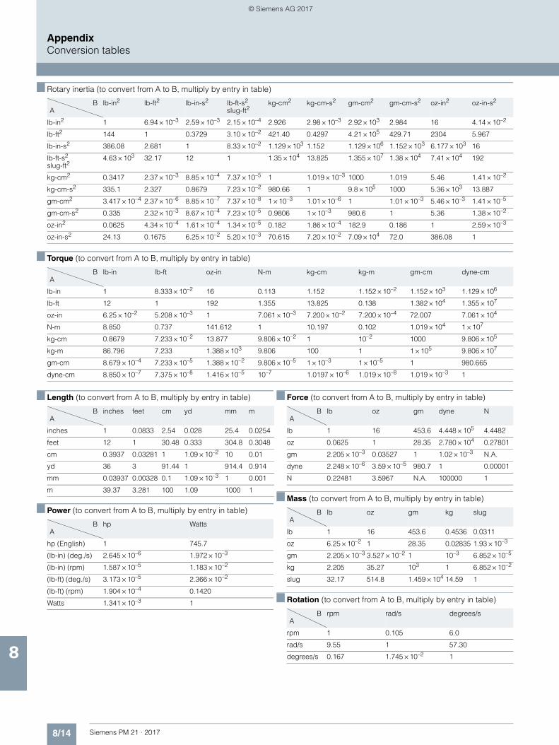
8/14 Siemens PM 21 · 2017
AppendixConversion tables
8
■ Rotary inertia (to convert from A to B, multiply by entry in table)
■ Torque (to convert from A to B, multiply by entry in table)
■ Length (to convert from A to B, multiply by entry in table)
■ Power (to convert from A to B, multiply by entry in table)
■ Force (to convert from A to B, multiply by entry in table)
■ Mass (to convert from A to B, multiply by entry in table)
■ Rotation (to convert from A to B, multiply by entry in table)
B A
lb-in2 lb-ft2 lb-in-s2 lb-ft-s2
slug-ft2kg-cm2 kg-cm-s2 gm-cm2 gm-cm-s2 oz-in2 oz-in-s2
lb-in2 1 6.94 × 10⁻³ 2.59 × 10⁻³ 2.15 × 10⁻⁴ 2.926 2.98 × 10⁻³ 2.92 × 10³ 2.984 16 4.14 × 10⁻²
lb-ft2 144 1 0.3729 3.10 × 10⁻² 421.40 0.4297 4.21 × 10⁵ 429.71 2304 5.967
lb-in-s2 386.08 2.681 1 8.33 × 10⁻² 1.129 × 10³ 1.152 1.129 × 10⁶ 1.152 × 10³ 6.177 × 10³ 16
lb-ft-s2
slug-ft24.63 × 103 32.17 12 1 1.35 × 10⁴ 13.825 1.355 × 10⁷ 1.38 × 10⁴ 7.41 × 10⁴ 192
kg-cm2 0.3417 2.37 × 10⁻³ 8.85 × 10⁻⁴ 7.37 × 10⁻⁵ 1 1.019 × 10⁻³ 1000 1.019 5.46 1.41 × 10⁻²
kg-cm-s2 335.1 2.327 0.8679 7.23 × 10⁻² 980.66 1 9.8 × 10⁵ 1000 5.36 × 10³ 13.887
gm-cm2 3.417 × 10⁻⁴ 2.37 × 10⁻⁶ 8.85 × 10⁻⁷ 7.37 × 10⁻⁸ 1 × 10⁻³ 1.01 × 10⁻⁶ 1 1.01 × 10⁻³ 5.46 × 10⁻³ 1.41 × 10⁻⁵
gm-cm-s2 0.335 2.32 × 10⁻³ 8.67 × 10⁻⁴ 7.23 × 10⁻⁵ 0.9806 1 × 10⁻³ 980.6 1 5.36 1.38 × 10⁻²
oz-in2 0.0625 4.34 × 10⁻⁴ 1.61 × 10⁻⁴ 1.34 × 10⁻⁵ 0.182 1.86 × 10⁻⁴ 182.9 0.186 1 2.59 × 10⁻³
oz-in-s2 24.13 0.1675 6.25 × 10⁻² 5.20 × 10⁻³ 70.615 7.20 × 10⁻² 7.09 × 10⁴ 72.0 386.08 1
B A
lb-in lb-ft oz-in N-m kg-cm kg-m gm-cm dyne-cm
lb-in 1 8.333 × 10⁻² 16 0.113 1.152 1.152 × 10⁻² 1.152 × 10³ 1.129 × 10⁶
lb-ft 12 1 192 1.355 13.825 0.138 1.382 × 10⁴ 1.355 × 10⁷
oz-in 6.25 × 10⁻² 5.208 × 10⁻³ 1 7.061 × 10⁻³ 7.200 × 10⁻² 7.200 × 10⁻⁴ 72.007 7.061 × 10⁴
N-m 8.850 0.737 141.612 1 10.197 0.102 1.019 × 10⁴ 1 × 10⁷
kg-cm 0.8679 7.233 × 10⁻² 13.877 9.806 × 10⁻² 1 10–2 1000 9.806 × 10⁵
kg-m 86.796 7.233 1.388 × 10³ 9.806 100 1 1 × 10⁵ 9.806 × 10⁷
gm-cm 8.679 × 10⁻⁴ 7.233 × 10⁻⁵ 1.388 × 10⁻² 9.806 × 10⁻⁵ 1 × 10⁻³ 1 × 10⁻⁵ 1 980.665
dyne-cm 8.850 × 10⁻⁷ 7.375 × 10⁻⁸ 1.416 × 10⁻⁵ 10–7 1.0197 × 10⁻⁶ 1.019 × 10⁻⁸ 1.019 × 10⁻³ 1
B A
inches feet cm yd mm m
inches 1 0.0833 2.54 0.028 25.4 0.0254
feet 12 1 30.48 0.333 304.8 0.3048
cm 0.3937 0.03281 1 1.09 × 10⁻² 10 0.01
yd 36 3 91.44 1 914.4 0.914
mm 0.03937 0.00328 0.1 1.09 × 10⁻³ 1 0.001
m 39.37 3.281 100 1.09 1000 1
B A
hp Watts
hp (English) 1 745.7
(lb-in) (deg./s) 2.645 × 10⁻⁶ 1.972 × 10⁻³
(lb-in) (rpm) 1.587 × 10⁻⁵ 1.183 × 10⁻²
(lb-ft) (deg./s) 3.173 × 10⁻⁵ 2.366 × 10⁻²
(lb-ft) (rpm) 1.904 × 10⁻⁴ 0.1420
Watts 1.341 × 10⁻³ 1
B A
lb oz gm dyne N
lb 1 16 453.6 4.448 × 10⁵ 4.4482
oz 0.0625 1 28.35 2.780 × 10⁴ 0.27801
gm 2.205 × 10⁻³ 0.03527 1 1.02 × 10⁻³ N.A.
dyne 2.248 × 10⁻⁶ 3.59 × 10⁻⁵ 980.7 1 0.00001
N 0.22481 3.5967 N.A. 100000 1
B A
lb oz gm kg slug
lb 1 16 453.6 0.4536 0.0311
oz 6.25 × 10⁻² 1 28.35 0.02835 1.93 × 10⁻³
gm 2.205 × 10⁻³ 3.527 × 10⁻² 1 10–3 6.852 × 10⁻⁵
kg 2.205 35.27 103 1 6.852 × 10⁻²
slug 32.17 514.8 1.459 × 10⁴ 14.59 1
B A
rpm rad/s degrees/s
rpm 1 0.105 6.0
rad/s 9.55 1 57.30
degrees/s 0.167 1.745 × 10⁻² 1
© Siemens AG 2017
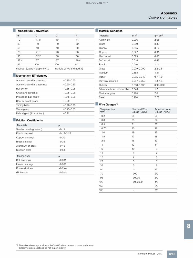
8/15Siemens PM 21 · 2017
AppendixConversion tables
8
■ Temperature Conversion
■ Mechanism Efficiencies
■ Friction Coefficients
1) The table shows approximate SWG/AWG sizes nearest to standard metric sizes; the cross-sections do not match exactly.
■ Material Densities
■ Wire Gauges1)
°F °C °C °F
0 –17.8 –10 14
32 0 0 32
50 10 10 50
70 21.1 20 68
90 32.2 30 86
98.4 37 37 98.4
212 100 100 212
subtract 32 and multiply by 5/9 multiply by 9/5 and add 32
Acme-screw with brass nut ~0.35–0.65
Acme-screw with plastic nut ~0.50–0.85
Ball-screw ~0.85–0.95
Chain and sprocket ~0.95–0.98
Preloaded ball-screw ~0.75–0.85
Spur or bevel-gears ~0.90
Timing belts ~0.96–0.98
Worm gears ~0.45–0.85
Helical gear (1 reduction) ~0.92
Materials
Steel on steel (greased) ~0.15
Plastic on steel ~0.15–0.25
Copper on steel ~0.30
Brass on steel ~0.35
Aluminum on steel ~0.45
Steel on steel ~0.58
Mechanism
Ball bushings <0.001
Linear bearings <0.001
Dove-tail slides ~0.2++
Gibb ways ~0.5++
Material lb-in3 gm-cm3
Aluminum 0.096 2.66
Brass 0.299 8.30
Bronze 0.295 8.17
Copper 0.322 8.91
Hard wood 0.029 0.80
Soft wood 0.018 0.48
Plastic 0.040 1.11
Glass 0.079–0.090 2.2–2.5
Titanium 0.163 4.51
Paper 0.025–0.043 0.7–1.2
Polyvinyl chloride 0.047–0.050 1.3–1.4
Rubber 0.033–0.036 0.92–0.99
Silicone rubber, without filler 0.043 1.2
Cast iron, gray 0.274 7.6
Steel 0.280 7.75
Cross-sectionmm2
Standard WireGauge (SWG)
American WireGauge (AWG)
0.2 25 24
0.3 23 22
0.5 21 20
0.75 20 19
1.0 19 18
1.5 17 16
2.5 15 13
4 13 11
6 12 9
10 9 7
16 7 6
25 5 3
35 3 2
50 0 1/0
70 000 2/0
95 00000 3/0
120 0000000 4/0
150 – 6/0
185 – 7/0
© Siemens AG 2017
8/16 Siemens PM 21 · 2017
Appendix
Conditions of sale and delivery
8
■ 1. General Provisions
By using this catalog you can acquire hardware and software products described therein from Siemens AG subject to the following Terms and Conditions of Sale and Delivery (hereinafter referred to as "T&C"). Please note that the scope, the quality and the conditions for supplies and services, including software products, by any Siemens entity having a registered office outside Germany, shall be subject exclusively to the General Terms and Conditions of the respective Siemens entity. The following T&C apply exclusively for orders placed with Siemens Aktiengesellschaft, Germany.
1.1 For customers with a seat or registered office in GermanyFor customers with a seat or registered office in Germany, the following applies subordinate to the T&C:• the "General Terms of Payment"1) and,• for software products, the "General License Conditions for
Software Products for Automation and Drives for Customers with a Seat or Registered Office in Germany"1) and,
• for other supplies and services, the "General Conditions for the Supply of Products and Services of the Electrical and Electronics Industry"1).
1.2 For customers with a seat or registered office outside GermanyFor customers with a seat or registered office outside Germany, the following applies subordinate to the T&C:• the "General Terms of Payment"1) and,• for software products, the "General License Conditions for
Software Products for Automation and Drives for Customers with a Seat or Registered Office outside of Germany"1) and
• for other supplies and/or services, the "General Conditions for Supplies of Siemens Industry for Customers with a Seat or Registered Office outside of Germany"1).
■ 2. Prices
The prices are in € (Euro) ex point of delivery, exclusive of packaging.The sales tax (value added tax) is not included in the prices. It shall be charged separately at the respective rate according to the applicable statutory legal regulations.Prices are subject to change without prior notice. We will charget the prices valid at the time of delivery.To compensate for variations in the price of raw materials (e.g. silver, copper, aluminum, lead, gold, dysprosium and neodym), surcharges are calculated on a daily basis using the so-called metal factor for products containing these raw materials. A surcharge for the respective raw material is calculated as a supplement to the price of a product if the basic official price of the raw material in question is exceeded.The metal factor of a product indicates the basic official price (for those raw materials concerned) as of which the surcharges on the price of the product are applied, and with what method of calculation. An exact explanation of the metal factor can be downloaded at:www.siemens.com/automation/salesmaterial-as/catalog/en/terms_of_trade_en.pdfTo calculate the surcharge (except in the cases of dysprosium and neodym), the official price from the day prior to that on which the order was received or the release order was effected is used.To calculate the surcharge applicable to dysprosium and neodym ("rare earths"), the corresponding three-month basic average price in the quarter prior to that in which the order was received or the release order was effected is used with a one-month buffer (details on the calculation can be found in the explanation of the metal factor).
■ 3. Additional Terms and Conditions
The dimensions are in mm. In Germany, according to the German law on units in measuring technology, data in inches apply only to devices for export.Illustrations are not binding.Insofar as there are no remarks on the individual pages of this catalog - especially with regard to data, dimensions and weights given - these are subject to change without prior notice.
■ 4. Export regulations
We shall not be obligated to fulfill any agreement if such fulfillment is prevented by any impediments arising out of national or international foreign trade or customs requirements or any embargoes and/or other sanctions.Export of goods listed in this catalog may be subject to licensing requirements. We will indicate in the delivery details whether licenses are required under German, European and US export lists. Goods labeled with "AL" not equal to "N" are subject to European or German export authorization when being exported out of the EU. Goods labeled with "ECCN" not equal to "N" are subject to US re-export authorization. The export indications can be viewed in advance in the description of the respective goods on the Industry Mall, our online catalog system. Only the export labels "AL" and "ECCN" indicated on order confirmations, delivery notes and invoices are authoritative.Even without a label, or with label "AL:N" or "ECCN:N", authori-zation may be required i .a. due to the final disposition and intended use of goods.If you transfer goods (hardware and/or software and/or technology as well as corresponding documentation, regardless of the mode of provision) delivered by us or works and services (including all kinds of technical support) performed by us to a third party worldwide, you must comply with all applicable national and international (re-)export control regulations.If required for the purpose of conducting export control checks, you (upon request by us) shall promptly provide us with all infor-mation pertaining to the particular end customer, final dispo-sition and intended use of goods delivered by us respectively works and services provided by us, as well as to any export control restrictions existing in this relation.The products listed in this catalog may be subject to European/German and/or US export regulations. Any export requiring approval is therefore subject to authorization by the relevant authorities.Errors excepted and subject to change without prior notice.
1) The text of the Terms and Conditions of Siemens AG can be downloaded atwww.siemens.com/automation/salesmaterial-as/catalog/en/terms_of_trade_en.pdf
© Siemens AG 2017
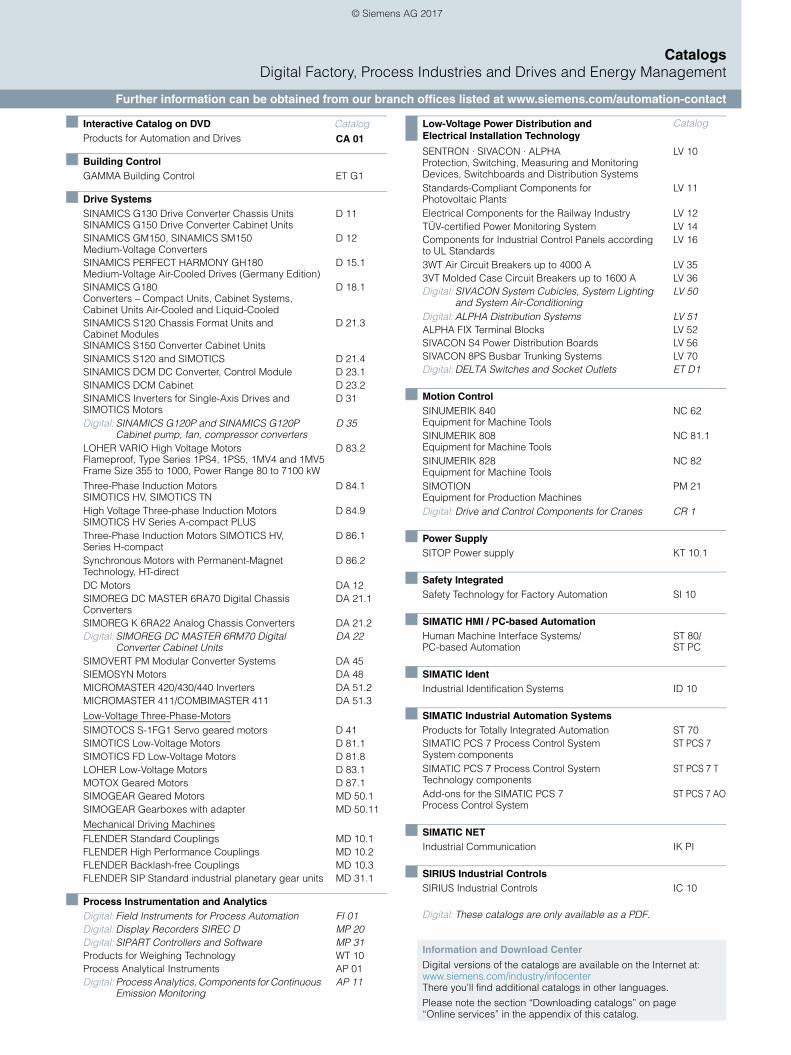
CatalogsDigital Factory, Process Industries and Drives and Energy Management
Further information can be obtained from our branch offices listed at www.siemens.com/automation-contact
Interactive Catalog on DVD CatalogProducts for Automation and Drives CA 01
Building ControlGAMMA Building Control ET G1
Drive SystemsSINAMICS G130 Drive Converter Chassis Units SINAMICS G150 Drive Converter Cabinet Units
D 11
SINAMICS GM150, SINAMICS SM150 Medium-Voltage Converters
D 12
SINAMICS PERFECT HARMONY GH180 Medium-Voltage Air-Cooled Drives (Germany Edition)
D 15.1
SINAMICS G180 Converters – Compact Units, Cabinet Systems, Cabinet Units Air-Cooled and Liquid-Cooled
D 18.1
SINAMICS S120 Chassis Format Units and Cabinet Modules SINAMICS S150 Converter Cabinet Units
D 21.3
SINAMICS S120 and SIMOTICS D 21.4SINAMICS DCM DC Converter, Control Module D 23.1SINAMICS DCM Cabinet D 23.2SINAMICS Inverters for Single-Axis Drives and SIMOTICS Motors
D 31
Digital: SINAMICS G120P and SINAMICS G120P Cabinet pump, fan, compressor converters
D 35
LOHER VARIO High Voltage Motors Flameproof, Type Series 1PS4, 1PS5, 1MV4 and 1MV5Frame Size 355 to 1000, Power Range 80 to 7100 kW
D 83.2
Three-Phase Induction Motors SIMOTICS HV, SIMOTICS TN
D 84.1
High Voltage Three-phase Induction Motors SIMOTICS HV Series A-compact PLUS
D 84.9
Three-Phase Induction Motors SIMOTICS HV, Series H-compact
D 86.1
Synchronous Motors with Permanent-Magnet Technology, HT-direct
D 86.2
DC Motors DA 12SIMOREG DC MASTER 6RA70 Digital Chassis Converters
DA 21.1
SIMOREG K 6RA22 Analog Chassis Converters DA 21.2Digital: SIMOREG DC MASTER 6RM70 Digital
Converter Cabinet UnitsDA 22
SIMOVERT PM Modular Converter Systems DA 45SIEMOSYN Motors DA 48MICROMASTER 420/430/440 Inverters DA 51.2MICROMASTER 411/COMBIMASTER 411 DA 51.3
Low-Voltage Three-Phase-MotorsSIMOTOCS S-1FG1 Servo geared motors D 41SIMOTICS Low-Voltage Motors D 81.1SIMOTICS FD Low-Voltage Motors D 81.8LOHER Low-Voltage Motors D 83.1MOTOX Geared Motors D 87.1SIMOGEAR Geared Motors MD 50.1SIMOGEAR Gearboxes with adapter MD 50.11
Mechanical Driving MachinesFLENDER Standard Couplings MD 10.1FLENDER High Performance Couplings MD 10.2FLENDER Backlash-free Couplings MD 10.3FLENDER SIP Standard industrial planetary gear units MD 31.1
Process Instrumentation and AnalyticsDigital: Field Instruments for Process Automation FI 01Digital: Display Recorders SIREC D MP 20Digital: SIPART Controllers and Software MP 31Products for Weighing Technology WT 10Process Analytical Instruments AP 01Digital: Process Analytics, Components for Continuous
Emission MonitoringAP 11
Low-Voltage Power Distribution and Electrical Installation Technology
Catalog
SENTRON · SIVACON · ALPHA Protection, Switching, Measuring and Monitoring Devices, Switchboards and Distribution Systems
LV 10
Standards-Compliant Components for Photovoltaic Plants
LV 11
Electrical Components for the Railway Industry LV 12TÜV-certified Power Monitoring System LV 14Components for Industrial Control Panels according to UL Standards
LV 16
3WT Air Circuit Breakers up to 4000 A LV 353VT Molded Case Circuit Breakers up to 1600 A LV 36Digital: SIVACON System Cubicles, System Lighting
and System Air-ConditioningLV 50
Digital: ALPHA Distribution Systems LV 51ALPHA FIX Terminal Blocks LV 52SIVACON S4 Power Distribution Boards LV 56SIVACON 8PS Busbar Trunking Systems LV 70Digital: DELTA Switches and Socket Outlets ET D1
Motion ControlSINUMERIK 840Equipment for Machine Tools
NC 62
SINUMERIK 808 Equipment for Machine Tools
NC 81.1
SINUMERIK 828 Equipment for Machine Tools
NC 82
SIMOTIONEquipment for Production Machines
PM 21
Digital: Drive and Control Components for Cranes CR 1
Power SupplySITOP Power supply KT 10.1
Safety IntegratedSafety Technology for Factory Automation SI 10
SIMATIC HMI / PC-based AutomationHuman Machine Interface Systems/PC-based Automation
ST 80/ ST PC
SIMATIC IdentIndustrial Identification Systems ID 10
SIMATIC Industrial Automation SystemsProducts for Totally Integrated Automation ST 70SIMATIC PCS 7 Process Control System System components
ST PCS 7
SIMATIC PCS 7 Process Control System Technology components
ST PCS 7 T
Add-ons for the SIMATIC PCS 7 Process Control System
ST PCS 7 AO
SIMATIC NETIndustrial Communication IK PI
SIRIUS Industrial Controls SIRIUS Industrial Controls IC 10
Digital: These catalogs are only available as a PDF.
Information and Download Center
Digital versions of the catalogs are available on the Internet at:www.siemens.com/industry/infocenter There you’ll find additional catalogs in other languages.
Please note the section “Downloading catalogs” on page “Online services” in the appendix of this catalog.
© Siemens AG 2017
Get more informationMotion Control System SIMOTION:www.siemens.com/simotion
Local partners worldwide:www.siemens.com/automation-contact
Siemens AGDigital Factory DivisionPostfach 31 8091050 ERLANGENGERMANY
© Siemens AG 2017Subject to change without prior noticeArticle No. E86060-K4921-A101-A4-7600V6.MKKATA.PMA.101 / Dispo 09405KG 0217 8. AUM 268 EnPrinted in Germany
The information provided in this catalog contains merely general descriptions or characteristics of performance which in case of actual use do not always apply as described or which may change as a result of further development of the products. An obligation to provide the respective characteristics shall only exist if expressly agreed in the terms of contract. Availability and technical specifications are subject to change without notice.
All product designations may be trademarks or product names of Siemens AG or supplier companies whose use by third parties for their own purposes could violate the rights of the owners.
Token fee: 5.00 €
Scan the QR code for information on SIMOTION.
Security informationSiemens provides products and solutions with industrial security functions that support the secure operation of plants, systems, machines and networks.
In order to protect plants, systems, machines and networks against cyber threats, it is necessary to implement – and continuously maintain – a holistic, state-of-the-art indus-trial security concept. Siemens’ products and solutions only form one element of such a concept.
Customer is responsible to prevent unauthorized access to its plants, systems, machines and networks. Systems, machines and components should only be connected to the enterprise network or the internet if and to the extent necessary and with appropriate security measures (e.g. use of firewalls and network segmentation) in place.
Additionally, Siemens’ guidance on appropriate security measures should be taken into account. For more informa-tion about industrial security, please visit www.siemens.com/industrialsecurity
Siemens’ products and solutions undergo continuous development to make them more secure. Siemens strongly recommends to apply product updates as soon as available and to always use the latest product versions. Use of product versions that are no longer supported, and failure to apply latest updates may increase customer’s exposure to cyber threats.
To stay informed about product updates, subscribe to the Siemens Industrial Security RSS Feed under www.siemens.com/industrialsecurity
© Siemens AG 2017
Related Documents


