SIME Brakes Industrial Braking Systems A L T R A I N D U S T R I A L M O T I O N

Welcome message from author
This document is posted to help you gain knowledge. Please leave a comment to let me know what you think about it! Share it to your friends and learn new things together.
Transcript
SIME Brakes Industrial Braking Systems
A L T R A I N D U S T R I A L M O T I O N
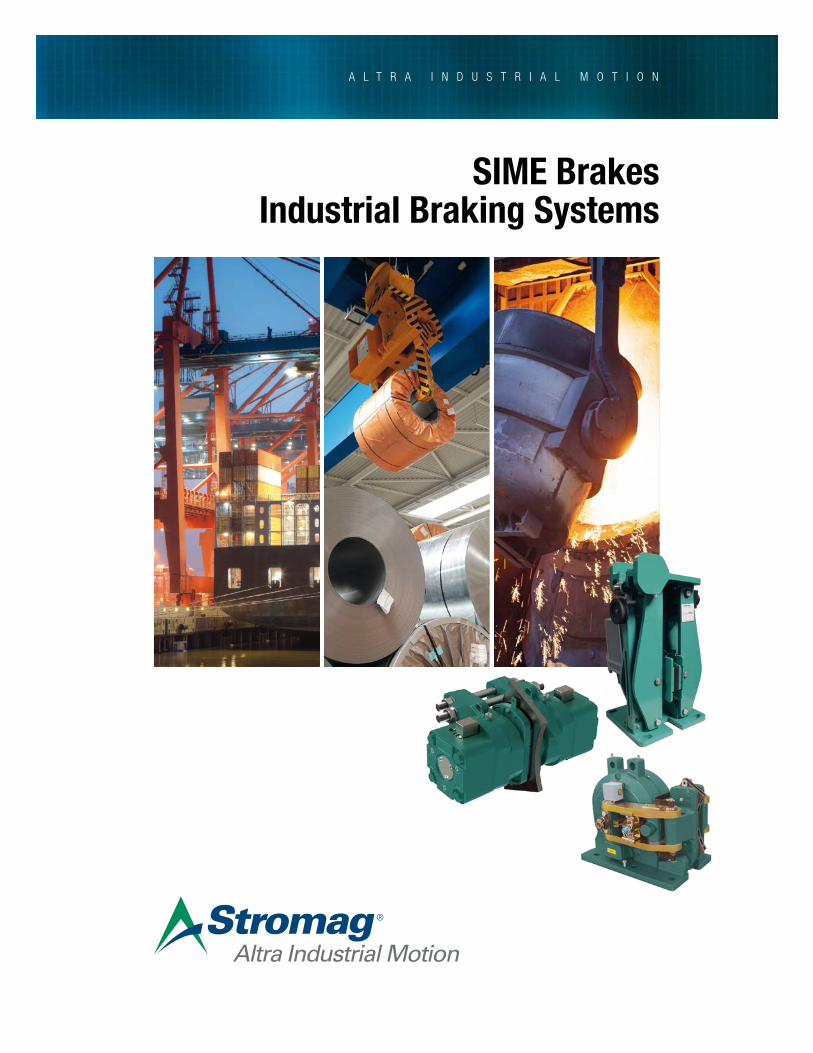
Altra is a leading global designer and manufacturer of quality power transmission and motion control products utilized on a wide variety of industrial drivetrain applications. Altra clutches and brakes, couplings, gearing and PT component product lines are marketed under the industries most well known manufacturing brands. Each brand is committed to the guiding principles of operational excellence, continuous improvement and customer satisfaction. Highly-engineered Altra solutions are sold in over 70 countries and utilized in a variety of major industrial markets, including food processing, material handling, packaging machinery, mining, energy, automotive, primary metals, turf and garden and many others.
Altra’s leading brands include Ameridrives, Bauer Gear Motor, Bibby Turboflex, Boston Gear, Delroyd Worm Gear, Formsprag Clutch, Guardian Couplings, Huco, Industrial Clutch, Inertia Dynamics, Kilian, Lamiflex Couplings, Marland Clutch, Matrix, Nuttall Gear, Stieber, Stromag, Svendborg Brakes, TB Wood’s, Twiflex, Warner Electric, Warner Linear and Wichita Clutch.
VISIT US ON THE WEB AT ALTRAMOTION.COM
Altra Industrial Motion
StromagFounded in 1932, Stromag has grown to become a globally recognized leader in the development and manufacture of innovative power transmission components for industrial drivetrain applications. Stromag engineers utilize the latest design technologies and materials to provide creative, energy-efficient solutions that meet their customer’s most challenging requirements.
Stromag’s extensive product range includes flexible couplings, disc brakes, limit switches, an array of hydraulically, pneumatically, and electrically actuated brakes, and a complete line of electric, hydraulic and pneumatic clutches.
Stromag engineered solutions improve drivetrain performance in a variety of key markets including energy, off-highway, metals, marine, transportation, printing, textiles, and material handling on applications such as wind turbines, conveyor systems, rolling mills, agriculture and construction machinery, municipal vehicles, forklifts, cranes, presses, deck winches, diesel engines, gensets and stage machinery.
VISIT US ON THE WEB A STROMAG.COM
3P-8518-SG | BRC10141-01-C 2/18 SIME Brakes Stromag +33 (0)1 49 90 32 20
With more than 60 years of experience, Stromag provide high efficiency braking systems to equip steel industries, nuclear plants, port cranes, offshore winches and mass transports throughout the world.
Quality and innovation have always been the two essential features in the development of the company. Therefore Stromag provide disc brakes certified by recognized authorities such as DNV, ABS, TUV, Loyd’s Register and EDF.
In 2016, ISO 9001 certification of our Quality management system was renewed under the version V2008 and our Safety management system was awarded OHSAS 18001 - V2007 certification.
Whatever the application, Stromag meet the global supply requirements with standard or fully customised braking systems solutions.
SIME BrakesSECURITY - QUALITY - RELIABILITY
4 SIME Brakes Stromag +33 (0)1 49 90 32 20 P-8518-SG | BRC10141-01-C 2/18
BENEFITS
• A team of experts at your disposal • Reactivity of the interventions • Study of the specific requirements• Secured installation
• Optimal operation of the braking systems• Preventive maintenance• Expertise sustainability
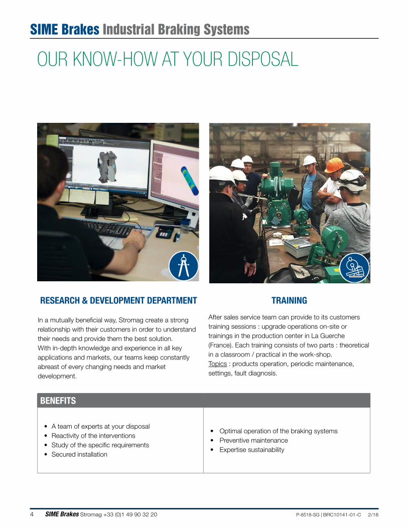
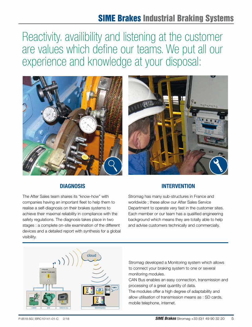
OUR KNOW-HOW AT YOUR DISPOSAL
RESEARCH & DEVELOPMENT DEPARTMENT
In a mutually beneficial way, Stromag create a strong relationship with their customers in order to understand their needs and provide them the best solution.With in-depth knowledge and experience in all key applications and markets, our teams keep constantly abreast of every changing needs and market development.
TRAINING
After sales service team can provide to its customers training sessions : upgrade operations on-site or trainings in the production center in La Guerche (France). Each training consists of two parts : theoretical in a classroom / practical in the work-shop.Topics : products operation, periodic maintenance, settings, fault diagnosis.
SIME Brakes Industrial Braking Systems
5P-8518-SG | BRC10141-01-C 2/18 SIME Brakes Stromag +33 (0)1 49 90 32 20
Stromag developed a Monitoring system which allows to connect your braking system to one or several monitoring modules. CAN Bus enables an easy connection, transmission and processing of a great quantity of data. The modules offer a high degree of adaptability and allow utilisation of transmission means as : SD cards, mobile telephone, internet.
online>>
C3BSH SH5 SIDEOS One MAINTENANCE
cloud
@SMS
Reactivity. availibility and listening at the customer are values which define our teams. We put all our experience and knowledge at your disposal:
DIAGNOSIS
The After Sales team shares its “know-how” with companies having an important fleet to help them to realise a self-diagnosis on their brakes systems to achieve their maximal reliability in compliance with the safety regulations. The diagnosis takes place in two stages : a complete on-site examination of the different devices and a detailed report with synthesis for a global visibility.
INTERVENTION
Stromag has many sub-structures in France and worldwide ; these allow our After Sales Service Department to operate very fast in the customer sites.Each member or our team has a qualified engineering background which means they are totally able to help and advise customers technically and commercially.
SIME Brakes Industrial Braking Systems
6 SIME Brakes Stromag +33 (0)1 49 90 32 20 P-8518-SG | BRC10141-01-C 2/18
Hydraulic
emergency brakes
Hydraulic
Power Packs
Disc brakes
with thrustor
Drums &
couplings
Discs &
couplings
Drum brakes
with thrustor
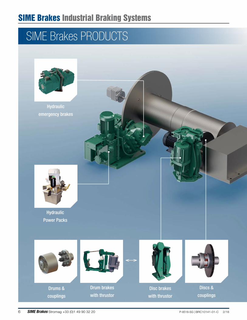
SIME Brakes PRODUCTS
SIME Brakes Industrial Braking Systems
7P-8518-SG | BRC10141-01-C 2/18 SIME Brakes Stromag +33 (0)1 49 90 32 20
Electromagnetic
service brakes
Electromagnetic
emergency brakes
Electrical
power unitsSafety systems
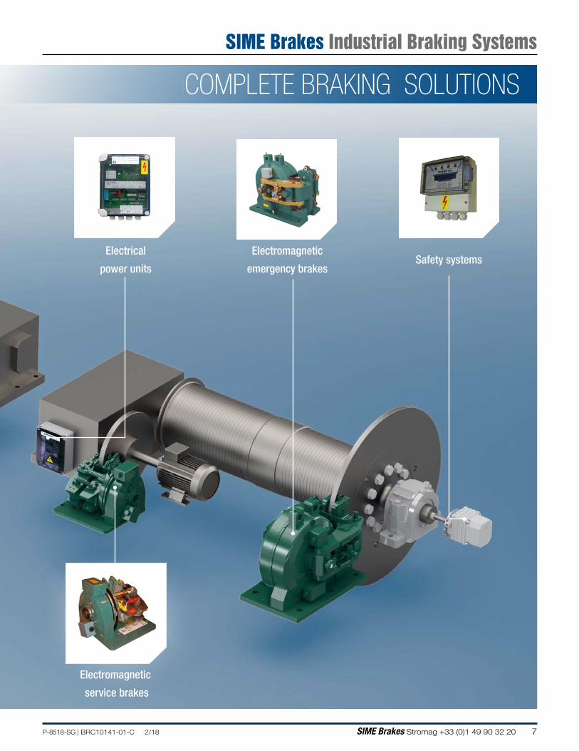
COMPLETE BRAKING SOLUTIONS
SIME Brakes Industrial Braking Systems
8 SIME Brakes Stromag +33 (0)1 49 90 32 20 P-8518-SG | BRC10141-01-C 2/18
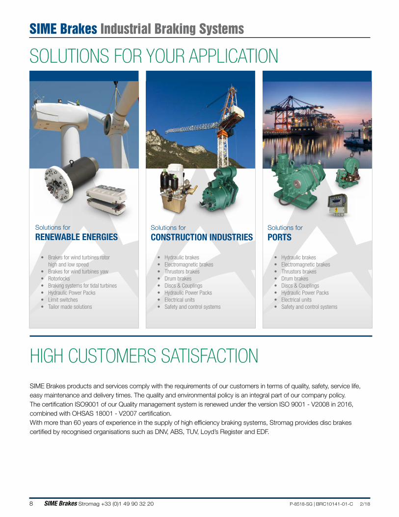
SOLUTIONS FOR YOUR APPLICATION
Solutions for
RENEWABLE ENERGIES
• Brakes for wind turbines rotorhigh and low speed
• Brakes for wind turbines yaw• Rotorlocks• Braking systems for tidal turbines• Hydraulic Power Packs• Limit switches• Tailor made solutions
Solutions for
CONSTRUCTION INDUSTRIES
• Hydraulic brakes• Electromagnetic brakes• Thrustors brakes• Drum brakes• Discs & Couplings• Hydraulic Power Packs• Electrical units• Safety and control systems
Solutions for
PORTS
• Hydraulic brakes• Electromagnetic brakes• Thrustors brakes• Drum brakes• Discs & Couplings• Hydraulic Power Packs• Electrical units• Safety and control systems
HIGH CUSTOMERS SATISFACTIONSIME Brakes products and services comply with the requirements of our customers in terms of quality, safety, service life, easy maintenance and delivery times. The quality and environmental policy is an integral part of our company policy.The certification ISO9001 of our Quality management system is renewed under the version ISO 9001 - V2008 in 2016, combined with OHSAS 18001 - V2007 certification.With more than 60 years of experience in the supply of high efficiency braking systems, Stromag provides disc brakes certified by recognised organisations such as DNV, ABS, TUV, Loyd’s Register and EDF.
SIME Brakes Industrial Braking Systems
9P-8518-SG | BRC10141-01-C 2/18 SIME Brakes Stromag +33 (0)1 49 90 32 20
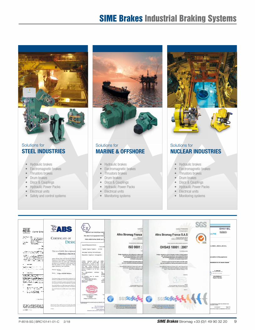
Solutions for
STEEL INDUSTRIES
• Hydraulic brakes• Electromagnetic brakes• Thrustors brakes• Drum brakes• Discs & Couplings• Hydraulic Power Packs• Electrical units• Safety and control systems
Solutions for
MARINE & OFFSHORE
• Hydraulic brakes• Electromagnetic brakes• Thrustors brakes• Drum brakes• Discs & Couplings• Hydraulic Power Packs• Electrical units• Monitoring systems
Solutions for
NUCLEAR INDUSTRIES
• Hydraulic brakes• Electromagnetic brakes• Thrustors brakes• Drum brakes• Discs & Couplings• Hydraulic Power Packs• Electrical units• Monitoring systems
CERTIFICATE . NUMBER
12-GE871068-PDA
ABS TECHNICAL OFFICE
Genoa Engineering .
DATE
13 August 2012
CERTIFICATE OF
DESIGN.AsSESSMENT
This is to Çertify that a representative of tliis Bureau did, at the request of STROMAG FRANCE - LA GUERCHE SUR L'AUBOIS
assess design plans and data for the- belowJisted product. This assessment is a representation by the Bureau as to the degree of compliânce the design exhibits with applicable sections of thé Rules. This assessment does not waive unit certification or classification procedures required by ABS Rules for products to be installed in ABS classed vessels or facilities. This certificate, by itself, does not reflect that the product is Type Approved. The scope and limitations of this assessment are detailed on the pages attached to this certificate. -
PRODUCT: Brake
MODEL: Caliper SH18B Offshore
This Product Design Assessment (PDA) Certificate I2-GE871068-PDA, dated 13/Aug/2012 remains valid until 12/Aug/2017 or until the Rules or specifications used in the assessment are revised (whichever occurs first).
This PDA is intended for a product to be installèd on aü ABS classed vesse!, MODU 9r facility which is in existence or under ccintract for construction on the date of the ABS· Rules or specifications used to evaluate the Product.
Use of the Product on an ABS classed vesse!, MODU or facility which is contracted after the validity date of the ABS Rules and specifications used to evaluate the Product, will require re-evaluation of the PDA.,
Use of the Product for.non ÀBS classed vessels, MODUs or facilities is to be to an agreement between the manufacturer- and intendedcl
. . .
Lucio Trevi:.:éin Engineer
NOTE: This t..:enilic..1te cvidcm:cs compli .:mcc with one or more of the Rulc.s, Guides, standards or othcr i;ritcria of ABS or a statutof)', industrial or manufo,LUrcrS slamlanls. il is issucd solcly for the use . of ABS, its commiuccs. ils dicntS or othcr authorizccf cmitics. Anr signilic:im changes to 1he aforcmcn1ioncd product without appro\'al fmm ABS will rcsult in this ccnificalc becomîng nul\ :md rnid.
This n::rtific.nc is gon-rncd by the 1crms and conditions as conl:lincd in ABS Rulc-s l-l-A)/5.9 Tcrm.s :md Conditions of the Rcqucst for Procuct Type Approval and Agrccmcnt.(2010).
AB258(0110)
SIME Brakes Industrial Braking Systems
10 SIME Brakes Stromag +33 (0)1 49 90 32 20 P-8518-SG | BRC10141-01-C 2/18
Content
SIME Brakes Industrial Braking Systems
11P-8518-SG | BRC10141-01-C 2/18 SIME Brakes Stromag +33 (0)1 49 90 32 20
CONTENT
SERVICE BRAKES 12
ELECTROMAGNETIC SERVICE BRAKES 15
DRUM BRAKES 27
HYDRAULIC SERVICE BRAKES 37
THRUSTOR SERVICE BRAKES 41
EMERGENCY BRAKES 48
ELECTROMAGNETIC EMERGENCY BRAKES 51
HYDRAULIC EMERGENCY BRAKES TYPE SH 57
HYDRAULIC EMERGENCY BRAKES TYPES SHD / TH 85
ELECTRICAL POWER UNITS 100
HYDRAULIC POWER PACKS 118
CONTROL AND SAFETY SYSTEMS 134
DISCS & DRUMS 150
DISC COUPLINGS 164
BARREL-ROLLER COUPLINGS 196
Content
SIME Brakes Industrial Braking Systems
12 SIME Brakes Stromag +33 (0)1 49 90 32 20 P-8518-SG | BRC10141-01-C 2/18
Service Brakes
SIME Brakes Industrial Braking Systems
SERVICE BRAKES
13P-8518-SG | BRC10141-01-C 2/18 SIME Brakes Stromag +33 (0)1 49 90 32 20
Service Brakes
SIME Brakes Industrial Braking Systems
FREINS HYDRAULIQUESCouple de Freinage (kN.m)
0 2 4 6 8 10 12 14 16 18 20 22 24 26
2TB-3TB-4TBdisques Ø445 à 995
1TSA-1TXAdisques Ø625 à 995
FREINS ÉLECTROMAGNÉTIQUESCouple de Freinage (kN.m)
0 2 4 6 8 10 12 14 16 18 20 22 24 26
645-650-660 5K / 45 Kdisques Ø175 à 625
1CA2-2CA23CA2-4CA2disques Ø445 à 995
FREINS À MÂCHOIRESCouple de Freinage (kN.m)
0 2 4 6 8 10 12 14 16 18 20 22 24 26
FNS-VSSDBpoulies Ø160 à 710
FED-Apoulies Ø150 à 750
FREINS À VÉRINCouple de Freinage (kN.m)
0 2 4 6 8 10 12 14 16 18 20 22 24 26
TDXB I et II FAV 10 à 50disques Ø220 à 995
HYDRAULIC BRAKESBraking torque (kN.m)
0 2 4 6 8 10 12 14 16 18 20 22 24 26
2TB-3TB-4TBdiscs Ø445 to 995
1TSA-1TXAdiscs Ø625 to 995
ELECTROMAGNETIC BRAKESBraking torque (kN.m)
0 2 4 6 8 10 12 14 16 18 20 22 24 26
645-650-660 5K / 45 Kdiscs Ø175 to 625
1CA2-2CA23CA2-4CA2discs Ø445 to 995
DRUM BRAKESBraking torque (kN.m)
0 2 4 6 8 10 12 14 16 18 20 22 24 26
FNS-VSSDBdrums Ø160 to 710
FED-Adrums Ø150 to 750
THRUSTOR BRAKESBraking torque (kN.m)
0 2 4 6 8 10 12 14 16 18 20 22 24 26
TDXB I and II FAV 10 to 50discs Ø220 to 995
14 SIME Brakes Stromag +33 (0)1 49 90 32 20 P-8518-SG | BRC10141-01-C 2/18
APPLICATIONS
• STEEL CRANES• PORT CRANES• NUCLEAR CRANES• MASS TRANSPORTS
ECONOMIC
COMPACT
RELIABLE
EASY MAINTENANCE
Service Brakes
SIME Brakes Industrial Braking Systems
15P-8518-SG | BRC10141-01-C 2/18 SIME Brakes Stromag +33 (0)1 49 90 32 20
Braking torque (kN.m)
0 0.5 1 2 3 4 5 6 70 8 9 10 11 12
650 - 660
645
5K - 5D
45K - 45D
4CA2
3CA2
2CA2
1CA2
MAIN CHARACTERISTICS OPTIONS
• FAILSAFE BRAKE BY SPRING APPLICATION • ELECTROMAGNETIC RELEASE• OPENING PROVING SWITCH
• MECHANICAL RELEASE LEVER • HYDRAULIC RELEASE• CLOSING PROVING SWITCH• MANUAL RELEASE CONTROL SWITCH• HIGH TEMPERATURE, IRON AND STEEL CONDITIONS
645-650-660
• Association with discs Ø175 to 625
• Manual wear compensation
• Option:
Mounting on a vertical axis disc
5K - 5D45K - 45D
• Association with discs Ø315 to 625
• Automatic wear compensation
• Option:
Mounting on a vertical axis disc
4CA2 - 3CA22CA2 - 1CA2
• Association with discs Ø445 to 995
• Automatic wear compensation
• Left and right hand calipers
• Option: Manual wear compensation
ELECTROMAGNETIC SERVICE BRAKESService Brakes
SIME Brakes Industrial Braking Systems
16 SIME Brakes Stromag +33 (0)1 49 90 32 20 P-8518-SG | BRC10141-01-C 2/18
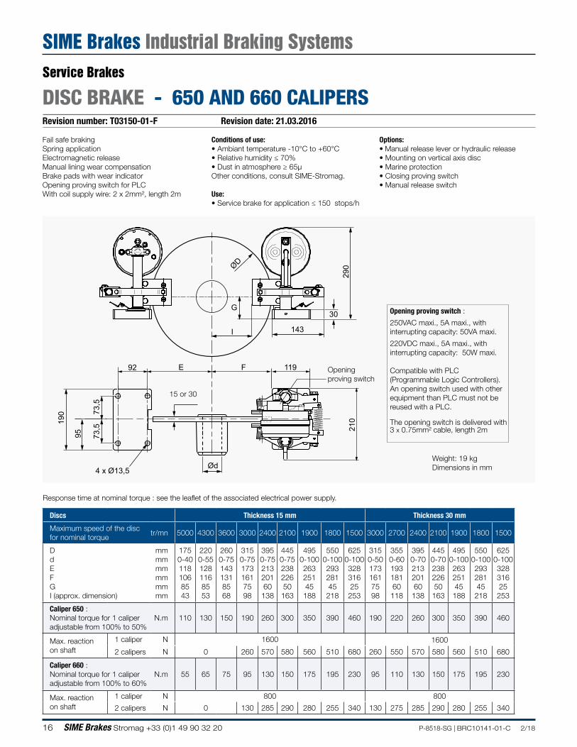
Revision number: T03150-01-F Revision date: 21.03.2016
DISC BRAKE - 650 AND 660 CALIPERS
Conditions of use:• Ambiant temperature -10°C to +60°C• Relative humidity ≤ 70%• Dust in atmosphere ≥ 65µOther conditions, consult SIME-Stromag.
Use:• Service brake for application ≤ 150 stops/h
Options:• Manual release lever or hydraulic release• Mounting on vertical axis disc• Marine protection• Closing proving switch• Manual release switch
Fail safe brakingSpring applicationElectromagnetic releaseManual lining wear compensationBrake pads with wear indicatorOpening proving switch for PLCWith coil supply wire: 2 x 2mm², length 2m
Weight: 19 kgDimensions in mm
Response time at nominal torque : see the leaflet of the associated electrical power supply.
15 or 30
290
30
143
ØD
G
I
210
119FE92
190
95 73,5
73,5
4 x Ø13,5 Ød
Opening proving switch :
250VAC maxi., 5A maxi., withinterrupting capacity: 50VA maxi.
220VDC maxi., 5A maxi., with interrupting capacity: 50W maxi.
Compatible with PLC(Programmable Logic Controllers).An opening switch used with other equipment than PLC must not be reused with a PLC.
The opening switch is delivered with 3 x 0.75mm² cable, length 2m
Opening proving switch
Discs Thickness 15 mm Thickness 30 mm
Maximum speed of the disc for nominal torque
tr/mn 5000 4300 3600 3000 2400 2100 1900 1800 1500 3000 2700 2400 2100 1900 1800 1500
D d E F G I (approx. dimension)
mm mm mm mm mm mm
175 0-40 118 106 85 43
220 0-55 128 116 85 53
260 0-75 143 131 85 68
315 0-75 173 161 75 98
395 0-75 213 201 60 138
445 0-75 238 226 50 163
495 0-100 263 251 45 188
550 0-100 293 281 45 218
625 0-100 328 316 25 253
315 0-50 173 161 75 98
355 0-60 193 181 60 118
395 0-70 213 201 60 138
445 0-70 238 226 50 163
495 0-100 263 251 45 188
550 0-100 293 281 45 218
625 0-100 328 316 25 253
Caliper 650 : Nominal torque for 1 caliper adjustable from 100% to 50%
N.m 110 130 150 190 260 300 350 390 460 190 220 260 300 350 390 460
Max. reaction on shaft
1 caliper N 1600 1600
2 calipers N 0 260 570 580 560 510 680 260 550 570 580 560 510 680
Caliper 660 : Nominal torque for 1 caliper adjustable from 100% to 60%
N.m 55 65 75 95 130 150 175 195 230 95 110 130 150 175 195 230
Max. reaction on shaft
1 caliper N 800 800
2 calipers N 0 130 285 290 280 255 340 130 275 285 290 280 255 340
Service Brakes
SIME Brakes Industrial Braking Systems
17P-8518-SG | BRC10141-01-C 2/18 SIME Brakes Stromag +33 (0)1 49 90 32 20
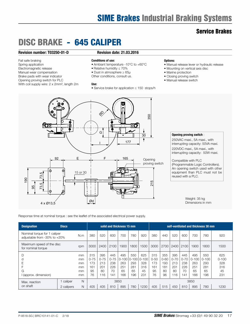
Revision number: T03250-01-D Revision date: 21.03.2016
DISC BRAKE - 645 CALIPER
Conditions of use:• Ambiant temperature -10°C to +60°C• Relative humidity ≤ 70%• Dust in atmosphere ≥ 65µOther conditions, consult us.
Use:• Service brake for application ≤ 150 stops/h
Options:• Manual release lever or hydraulic release• Mounting on vertical axis disc• Marine protection• Closing proving switch• Manual release switch
Fail safe brakingSpring applicationElectromagnetic releaseManual wear compensationBrake pads with wear indicatorOpening proving switch for PLCWith coil supply wire: 2 x 2mm², length 2m
15 or 30
350
30
177
ØD
G
I
215
165FE92
190
95 73,5
73,5
4 x Ø13,5 ØdWeight: 35 kgDimensions in mm
Designation Discs solid and thickness 15 mm self-ventilated and thickness 30 mm
Nominal torque for 1 caliper adjustable from -30% to +20%
N.m 380 520 600 700 780 920 380 440 520 600 700 780 920
Maximum speed of the disc for nominal torque
rpm 3000 2400 2100 1900 1800 1500 3000 2700 2400 2100 1900 1800 1500
D d E F G I (approx. dimension)
mm mm mm mm mm mm
315 0-75 173 161 95 76
395 0-75 213 201 80 116
445 0-75 238 226 70 141
495 0-100 263 251 65 166
550 0-100 293 281 65 196
625 0-100 328 316 45 231
315 0-50 173 161 95 76
355 0-60 193 181 80 96
395 0-70 213 201 80 116
445 0-70 238 226 70 141
495 0-100 263 251 65 166
550 0-100 293 281 65 196
625 0-100 328 316 45 231
Max. reaction on shaft
1 caliper N 3850 3850
2 calipers N 405 405 810 895 780 1230 405 515 450 810 895 780 1230
Opening proving switch :
250VAC maxi., 5A maxi., withinterrupting capacity: 50VA maxi.
220VDC maxi., 5A maxi., with interrupting capacity: 50W maxi.
Compatible with PLC(Programmable Logic Controllers).An opening switch used with other equipment than PLC must not be reused with a PLC.
Opening proving switch
Response time at nominal torque : see the leaflet of the associated electrical power supply.
Service Brakes
SIME Brakes Industrial Braking Systems
18 SIME Brakes Stromag +33 (0)1 49 90 32 20 P-8518-SG | BRC10141-01-C 2/18
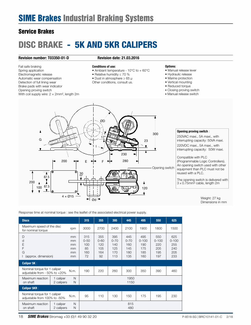
Revision number: T03350-01-D Revision date: 21.03.2016
DISC BRAKE - 5K AND 5KR CALIPERS
Fail safe brakingSpring applicationElectromagnetic releaseAutomatic wear compensationDetection of full lining wearBrake pads with wear indicatorOpening proving switchWith coil supply wire: 2 × 2mm², length 2m
Conditions of use:• Ambiant temperature - 10°C to + 60°C• Relative humidity ≤ 70 %• Dust in atmosphere ≥ 65 µOther conditions, consult us.
Options:• Manual release lever• Hydraulic release• Marine protection• Vertical mounting• Reduced torque• Closing proving switch• Manual release switch
Opening switch
Opening proving switch :
250VAC maxi., 5A maxi., withinterrupting capacity: 50VA maxi.
220VDC maxi., 5A maxi., with interrupting capacity: 50W maxi.
Compatible with PLC(Programmable Logic Controllers).An opening switch used with other equipment than PLC must not be reused with a PLC.
The opening switch is delivered with 3 x 0.75mm² cable, length 2m
Discs 315 355 395 445 495 550 625
Maximum speed of the disc for nominal torque
rpm 3000 2700 2400 2100 1900 1800 1500
D d E F G l (approx. dimension)
mm mm mm mm mm mm
315 0-50 100 85
160 72
355 0-60 120 105 164 92
395 0-70 140 125 170 113
445 0-70 160 145 180 135
495 0-100 190 175 185 160
550 0-100 220 205 195 197
625 0-100 255 240 205 233
Caliper 5K :
Nominal torque for 1 caliper adjustable from - 50% to +20%
N.m. 190 220 260 300 350 390 460
Maximum reaction on shaft
1 caliper 2 calipers
N N
1950 1150
Caliper 5KR :
Nominal torque for 1 caliper adjustable from 100% to -50%
N.m. 95 110 130 150 175 195 230
Maximum reaction on shaft
1 caliper 2 calipers
N N
815 480
Response time at nominal torque : see the leaflet of the associated electrical power supply.
Weight: 27 kgDimensions in mm
Ød
30
4 × Ø15
17°
200
100 87.5
87.5
FE200 280
230
23
300
ØD
l
G
120
Service Brakes
SIME Brakes Industrial Braking Systems
19P-8518-SG | BRC10141-01-C 2/18 SIME Brakes Stromag +33 (0)1 49 90 32 20
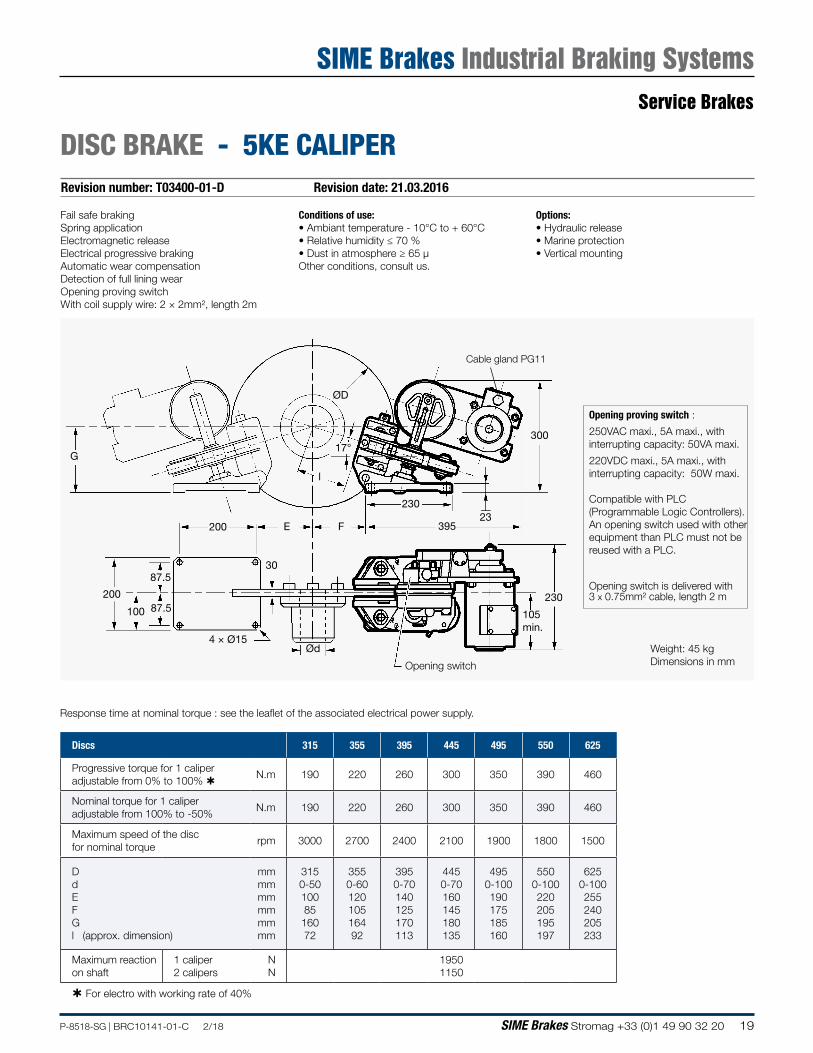
Revision number: T03400-01-D Revision date: 21.03.2016
DISC BRAKE - 5KE CALIPER
Weight: 45 kgDimensions in mm
Fail safe brakingSpring applicationElectromagnetic releaseElectrical progressive brakingAutomatic wear compensationDetection of full lining wearOpening proving switchWith coil supply wire: 2 × 2mm², length 2m
Conditions of use:• Ambiant temperature - 10°C to + 60°C• Relative humidity ≤ 70 %• Dust in atmosphere ≥ 65 µOther conditions, consult us.
Options:• Hydraulic release• Marine protection• Vertical mounting
Opening switch
Cable gland PG11
Response time at nominal torque : see the leaflet of the associated electrical power supply.
Discs 315 355 395 445 495 550 625
Progressive torque for 1 caliper adjustable from 0% to 100%
N.m 190 220 260 300 350 390 460
Nominal torque for 1 caliper adjustable from 100% to -50%
N.m 190 220 260 300 350 390 460
Maximum speed of the disc for nominal torque
rpm 3000 2700 2400 2100 1900 1800 1500
D d E F G l (approx. dimension)
mm mm mm mm mm mm
315 0-50 100 85
160 72
355 0-60 120 105 164 92
395 0-70 140 125 170 113
445 0-70 160 145 180 135
495 0-100 190 175 185 160
550 0-100 220 205 195 197
625 0-100 255 240 205 233
Maximum reaction on shaft
1 caliper 2 calipers
N N
1950 1150
For electro with working rate of 40%
Opening proving switch :
250VAC maxi., 5A maxi., withinterrupting capacity: 50VA maxi.
220VDC maxi., 5A maxi., with interrupting capacity: 50W maxi.
Compatible with PLC(Programmable Logic Controllers).An opening switch used with other equipment than PLC must not be reused with a PLC.
Opening switch is delivered with 3 x 0.75mm² cable, length 2 m
30
4 × Ø15
17°
200
100 87.5
87.5
FE200
230
ØD
l
395
300
G
230
23
Ød
105 min.
Service Brakes
SIME Brakes Industrial Braking Systems
20 SIME Brakes Stromag +33 (0)1 49 90 32 20 P-8518-SG | BRC10141-01-C 2/18
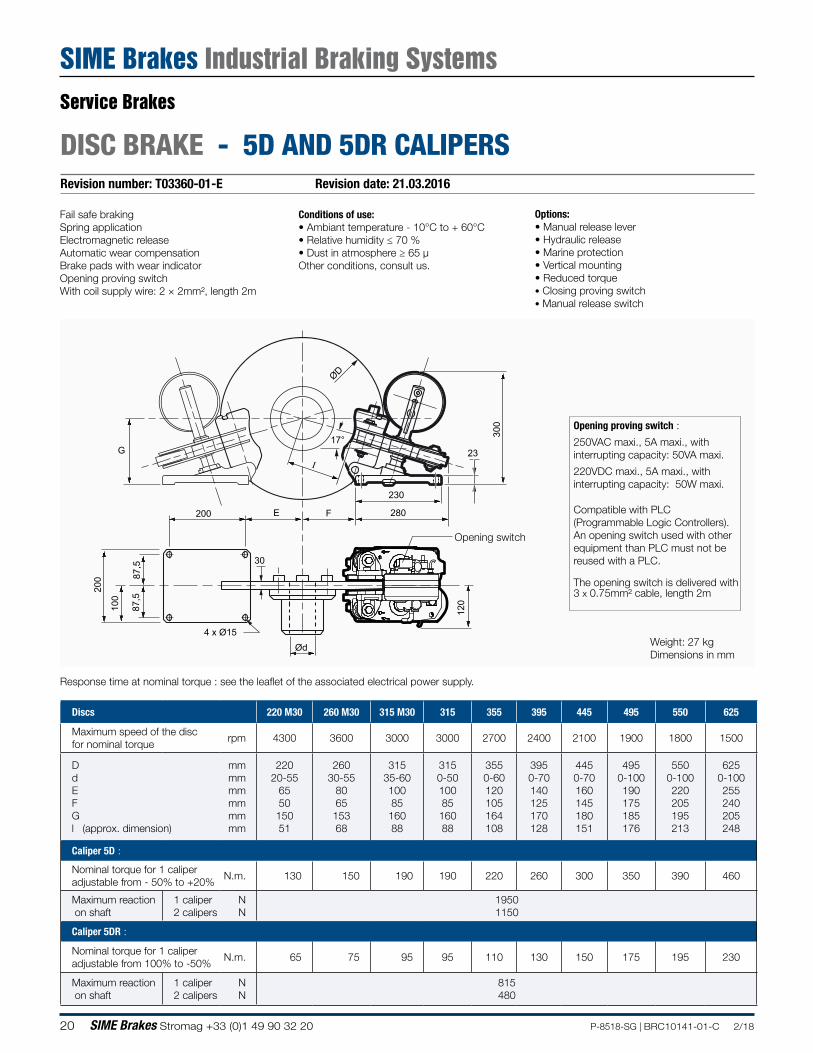
Revision number: T03360-01-E Revision date: 21.03.2016
DISC BRAKE - 5D AND 5DR CALIPERS
Fail safe brakingSpring applicationElectromagnetic releaseAutomatic wear compensationBrake pads with wear indicatorOpening proving switchWith coil supply wire: 2 × 2mm², length 2m
Conditions of use:• Ambiant temperature - 10°C to + 60°C• Relative humidity ≤ 70 %• Dust in atmosphere ≥ 65 µOther conditions, consult us.
Options:• Manual release lever• Hydraulic release• Marine protection• Vertical mounting• Reduced torque• Closing proving switch• Manual release switch
Opening switch
ØD
G12
0
Ød4 x Ø15
200
100
87,5
87,5
200 E F 280
230
23
300
I
17°
30
Opening proving switch :
250VAC maxi., 5A maxi., withinterrupting capacity: 50VA maxi.
220VDC maxi., 5A maxi., with interrupting capacity: 50W maxi.
Compatible with PLC(Programmable Logic Controllers).An opening switch used with other equipment than PLC must not be reused with a PLC.
The opening switch is delivered with 3 x 0.75mm² cable, length 2m
Discs 220 M30 260 M30 315 M30 315 355 395 445 495 550 625
Maximum speed of the disc for nominal torque
rpm 4300 3600 3000 3000 2700 2400 2100 1900 1800 1500
D d E F G l (approx. dimension)
mm mm mm mm mm mm
220 20-55
65 50 150 51
260 30-55
80 65
153 68
315 35-60 100 85
160 88
315 0-50 100 85 160 88
355 0-60 120 105 164 108
395 0-70 140 125 170 128
445 0-70 160 145 180 151
495 0-100 190 175 185 176
550 0-100 220 205 195 213
625 0-100 255 240 205 248
Caliper 5D :
Nominal torque for 1 caliper adjustable from - 50% to +20%
N.m. 130 150 190 190 220 260 300 350 390 460
Maximum reaction on shaft
1 caliper 2 calipers
N N
1950 1150
Caliper 5DR :
Nominal torque for 1 caliper adjustable from 100% to -50%
N.m. 65 75 95 95 110 130 150 175 195 230
Maximum reaction on shaft
1 caliper 2 calipers
N N
815 480
Response time at nominal torque : see the leaflet of the associated electrical power supply.
Weight: 27 kgDimensions in mm
Service Brakes
SIME Brakes Industrial Braking Systems
21P-8518-SG | BRC10141-01-C 2/18 SIME Brakes Stromag +33 (0)1 49 90 32 20
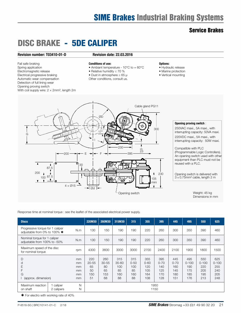
Revision number: T03410-01-D Revision date: 22.03.2016
DISC BRAKE - 5DE CALIPER
Weight: 45 kgDimensions in mm
Fail safe brakingSpring applicationElectromagnetic releaseElectrical progressive brakingAutomatic wear compensationDetection of full lining wearOpening proving switchWith coil supply wire: 2 × 2mm², length 2m
Conditions of use:• Ambiant temperature - 10°C to + 60°C• Relative humidity ≤ 70 %• Dust in atmosphere ≥ 65 µOther conditions, consult us.
Options:• Hydraulic release• Marine protection• Vertical mounting
Response time at nominal torque : see the leaflet of the associated electrical power supply.
Discs 220M30 260M30 315M30 315 355 395 445 495 550 625
Progressive torque for 1 caliper adjustable from 0% to 100%
N.m 130 150 190 190 220 260 300 350 390 460
Nominal torque for 1 caliper adjustable from 100% to -50%
N.m 130 150 190 190 220 260 300 350 390 460
Maximum speed of the disc for nominal torque
rpm 4300 3600 3000 3000 2700 2400 2100 1900 1800 1500
D d E F G l (approx. dimension)
mm mm mm mm mm mm
220 20-55
65 50
150 51
260 30-55
80 65
153 68
315 35-60 100 85
160 88
315 0-50 100 85 160 88
355 0-60 120 105 164 108
395 0-70 140 125 170 128
445 0-70 160 145 180 151
495 0-100 190 175 185 176
550 0-100 220 205 195 213
625 0-100 255 240 205 248
Maximum reaction on shaft
1 caliper 2 calipers
N N
1950 1150
For electro with working rate of 40%
Opening proving switch :
250VAC maxi., 5A maxi., withinterrupting capacity: 50VA maxi.
220VDC maxi., 5A maxi., with interrupting capacity: 50W maxi.
Compatible with PLC(Programmable Logic Controllers).An opening switch used with other equipment than PLC must not be reused with a PLC.
Opening switch is delivered with 3 x 0.75mm² cable, length 2 m
4 × Ø15
G
200
100 87.5
87.5
Ød
30
395FE200
230
105 mini
23023
300
ØD
17°
l
Opening switch
Cable gland PG11
Service Brakes
SIME Brakes Industrial Braking Systems
22 SIME Brakes Stromag +33 (0)1 49 90 32 20 P-8518-SG | BRC10141-01-C 2/18
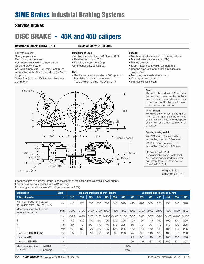
Revision number: T00140-01-I Revision date: 21.03.2016
DISC BRAKE - 45K and 45D calipers
Conditions of use :• Ambiant temperature -20°C to + 60°C• Relative humidity ≤ 70 %• Dust in atmosphere ≥ 65 µOther conditions, consult us.
Use:• Service brake for application ≤ 600 cycles / h
Possibility of quick manoeuvres :1000 cycles/h during 15s every 2 mn
Options:• Mechanical release lever or hydraulic release• Manual wear compensation (RM)• Marine protection• SIDHT steel industry high temperature• Bearing brackets for mounting in place of a
caliper 645.• Mounting on a vertical axis disc.• Closing proving switch• Manual release switch
Fail safe brakingSpring applicationElectromagnetic releaseAutomatic linings wear compensationOpening proving switchCoil with supply wire: 2 × 2mm², length 2mAssociation with 30mm thick discs (or 15mm in option)Shoes DIN (caliper 45D) for discs thickness 30mm only.
2 holes Ø15
Opening switch
inner Ø 40
Ød
ØD
G
l
317
23
385
137 max.
265
FE200
87.5
87.5117.5
235
15 or 30
2 oblongs Ø15
17°
255 max.
L
Response time at nominal torque : see the leaflet of the associated electrical power supply. Caliper delivered in standard with WS1-5 lining.For energy applications. use WS1-3 (torque loss of 20%).
Nota :The 45K-RM and 45D-RM calipers (manual wear compensation option) have the same overall dimensions as the 45K and 45D calipers with auto-matic wear compensation.
ATTENTIONFor discs Ø315 to 395, the length of 137 max. is higher than the length L of the standard hub. Provide space at the rear of the hub by means of a spacer.
Designation Discs solid and thickness 15 mm (option) ventilated and thickness 30 mm
D Disc diameter mm 315 355 395 445 495 550 625 315 355 395 445 495 550 625
Nominal torque for 1 caliper adjustable from -30% to +20%
N.m 410 470 560 650 750 840 990 410 470 560 650 750 840 990
Maximum speed of the disc for nominal torque
r.p.m. 3000 2700 2400 2100 1900 1800 1500 3000 2700 2400 2100 1900 1800 1500
d mm 0-75 0-75 0-75 0-75 0-100 0-100 0-100 0-50 0-60 0-70 0-70 0-100 0-100 0-100
E mm 100 120 140 160 190 220 255 100 120 140 160 190 220 255
F mm 50 70 90 110 140 170 205 50 70 90 110 140 170 205
G mm 160 164 170 180 185 195 205 160 164 170 180 185 195 205
I (calipers 45K. 45K-RM) mm 75 95 116 138 168 200 236 75 95 116 138 168 200 236
I (caliper 45D) mm 75 95 116 138 168 200 236
I (caliper 45D-RM) mm 96 116 137 159 189 221 257
Maximum reaction on shaft
1 Caliper N 4200
2 Calipers N 2450
Opening proving switch :
250VAC maxi., 5A maxi., withinterrupting capacity: 50VA maxi.
220VDC maxi., 5A maxi., with interrupting capacity: 50W maxi.
Compatible with PLC(Programmable Logic Controllers).An opening switch used with other equipment than PLC must not be reused with a PLC.
Weight: 41 kgDimensions in mm
Service Brakes
SIME Brakes Industrial Braking Systems
23P-8518-SG | BRC10141-01-C 2/18 SIME Brakes Stromag +33 (0)1 49 90 32 20
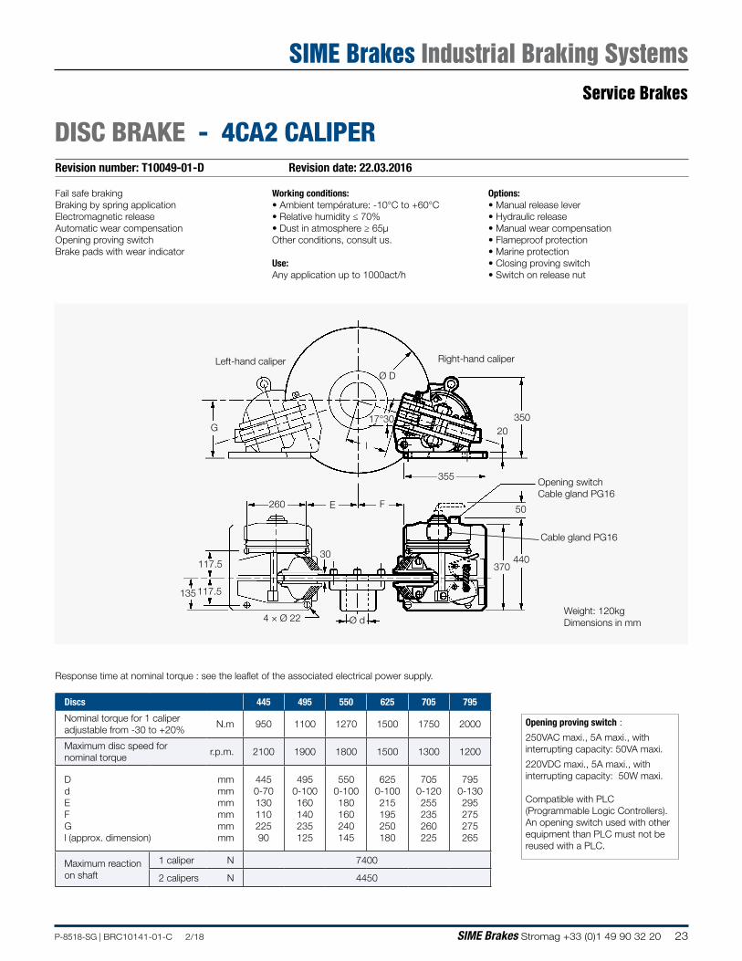
Revision number: T10049-01-D Revision date: 22.03.2016
DISC BRAKE - 4CA2 CALIPER
Options:• Manual release lever• Hydraulic release• Manual wear compensation• Flameproof protection• Marine protection• Closing proving switch• Switch on release nut
Working conditions:• Ambient température: -10°C to +60°C• Relative humidity ≤ 70%• Dust in atmosphere ≥ 65µOther conditions, consult us.
Use:Any application up to 1000act/h
Fail safe brakingBraking by spring applicationElectromagnetic releaseAutomatic wear compensationOpening proving switchBrake pads with wear indicator
l
Right-hand caliperLeft-hand caliper
G
Ø D
440370
30
35020
355
50
Ø d
117.5
117.5
135
E F260
Opening switchCable gland PG16
4 × Ø 22
17°30
Cable gland PG16
Opening proving switch :
250VAC maxi., 5A maxi., withinterrupting capacity: 50VA maxi.
220VDC maxi., 5A maxi., with interrupting capacity: 50W maxi.
Compatible with PLC(Programmable Logic Controllers).An opening switch used with other equipment than PLC must not be reused with a PLC.
Response time at nominal torque : see the leaflet of the associated electrical power supply.
Discs 445 495 550 625 705 795
Nominal torque for 1 caliper adjustable from -30 to +20%
N.m 950 1100 1270 1500 1750 2000
Maximum disc speed for nominal torque
r.p.m. 2100 1900 1800 1500 1300 1200
D d E F G l (approx. dimension)
mm mm mm mm mm mm
445 0-70 130 110 225 90
495 0-100 160 140 235 125
550 0-100 180 160 240 145
625 0-100 215 195 250 180
705 0-120 255 235 260 225
795 0-130 295 275 275 265
Maximum reaction on shaft
1 caliper N 7400
2 calipers N 4450
Weight: 120kgDimensions in mm
Service Brakes
SIME Brakes Industrial Braking Systems
24 SIME Brakes Stromag +33 (0)1 49 90 32 20 P-8518-SG | BRC10141-01-C 2/18
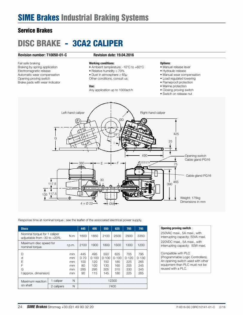
Revision number: T10050-01-C Revision date: 19.04.2016
DISC BRAKE - 3CA2 CALIPER
Opening proving switch :
250VAC maxi., 5A maxi., withinterrupting capacity: 50VA maxi.
220VDC maxi., 5A maxi., with interrupting capacity: 50W maxi.
Compatible with PLC(Programmable Logic Controllers).An opening switch used with other equipment than PLC must not be reused with a PLC.
Weight: 175kgDimensions in mm
Options:• Manual release lever• Hydraulic release• Manual wear compensation• Load regulated lowering• Flameproof protection• Marine protection• Closing proving switch• Switch on release nut
Working conditions:• Ambient température: -10°C to +60°C• Relative humidity ≤ 70%• Dust in atmosphere ≥ 65µOther conditions, consult us.
Use:Any application up to 1000act/h
Fail safe brakingBraking by spring applicationElectromagnetic releaseAutomatic wear compensationOpening proving switchBrake pads with wear indicator
Opening switchCable gland PG16
l
ØD
30
4 × Ø 22 Ød
117.5
117.5135
G
360 E F
425
25
490
75
390465
19°3
Right-hand caliperLeft-hand caliper
Cable gland PG16
Response time at nominal torque : see the leaflet of the associated electrical power supply.
Discs 445 495 550 625 705 795
Nominal torque for 1 caliper adjustable from -30 to +20%
N.m 1600 1850 2100 2500 2900 3350
Maximum disc speed for nominal torque
r.p.m. 2100 1900 1800 1500 1300 1200
D d E F G l (approx. dimension)
mm mm mm mm mm mm
445 0-70 100 80 285 90
495 0-100 120 100 295 115
550 0-100 150 130 305 145
625 0-100 185 165 315 180
705 0-120 225 205 330 225
795 0-130 265 245 345 265
Maximum reaction on shaft
1 caliper N 12300
2 calipers N 7400
Service Brakes
SIME Brakes Industrial Braking Systems
25P-8518-SG | BRC10141-01-C 2/18 SIME Brakes Stromag +33 (0)1 49 90 32 20
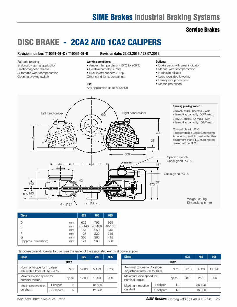
Revision number: T10051-01-C / T10065-01-B Revision date: 22.03.2016 / 23.07.2012
DISC BRAKE - 2CA2 AND 1CA2 CALIPERS
Options:• Brake pads with wear indicator• Manual wear compensation• Hydraulic release• Load regulated lowering• Flameproof protection• Marine protection.
Working conditions:• Ambient température: -10°C to +60°C• Relative humidity ≤ 70%• Dust in atmosphere ≥ 65µOther conditions, consult us.
Use:Any application up to 600act/h
Fail safe brakingBraking by spring applicationElectromagnetic releaseAutomatic wear compensationOpening proving switch
ØD
19°30
Right hand caliper
25
140
140165
4 × Ø 27
440 E F
Ød
560
137
Cable gland PG16
551470
496
G
Opening switchCable gland PG16
42
l
Left hand caliper
Weight: 310kgDimensions in mm
Response time at nominal torque : see the leaflet of the associated electrical power supply.
Discs 625 795 995
2CA2
Nominal torque for 1 caliper adjustable from -30 to +20%
N.m 3 800 5 150 6 700
Maximum disc speed for nominal torque
r.p.m. 1 500 1 200 900
Maximum reaction on shaft
1 caliper N 18 600
2 calipers N 12 600
Discs 625 795 995
1CA2
Nominal torque for 1 caliper adjustable from -50 to 100%
N.m 6 610 8 800 11 370
Maximum disc speed for nominal torque
r.p.m. 310 250 200
Maximum reaction on shaft
1 caliper N 25 700
2 calipers N 16 300
Discs 625 795 995
D d E F G l (approx. dimension)
mm mm mm mm mm mm
625 40-140
157 127 353 174
795 40-180
250 220 385 268
995 40-180
345 315 415 368
Opening proving switch :
250VAC maxi., 5A maxi., withinterrupting capacity: 50VA maxi.
220VDC maxi., 5A maxi., with interrupting capacity: 50W maxi.
Compatible with PLC(Programmable Logic Controllers).An opening switch used with other equipment than PLC must not be reused with a PLC.
Service Brakes
SIME Brakes Industrial Braking Systems
26 SIME Brakes Stromag +33 (0)1 49 90 32 20 P-8518-SG | BRC10141-01-C 2/18
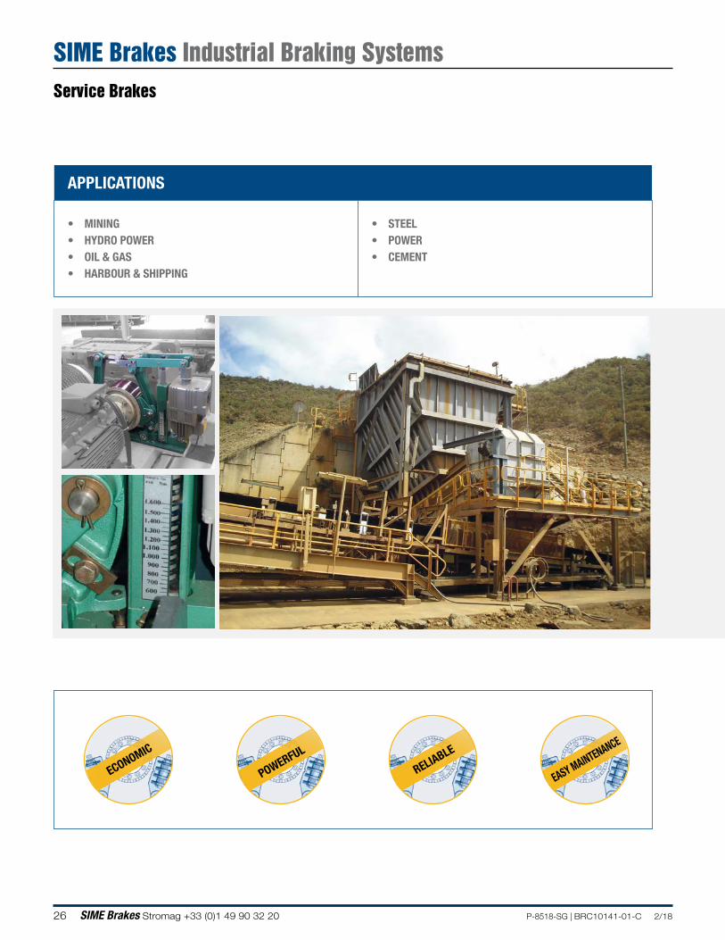
APPLICATIONS
• MINING• HYDRO POWER• OIL & GAS• HARBOUR & SHIPPING
• STEEL • POWER• CEMENT
ECONOMIC
POWERFUL
RELIABLE
EASY MAINTENANCE
Service Brakes
SIME Brakes Industrial Braking Systems
27P-8518-SG | BRC10141-01-C 2/18 SIME Brakes Stromag +33 (0)1 49 90 32 20
Braking torque (kN.m)
0 0.5 1 2 3 4 5 6 7 8 9 10 11 12
SDB
FNS-VS
FED-A
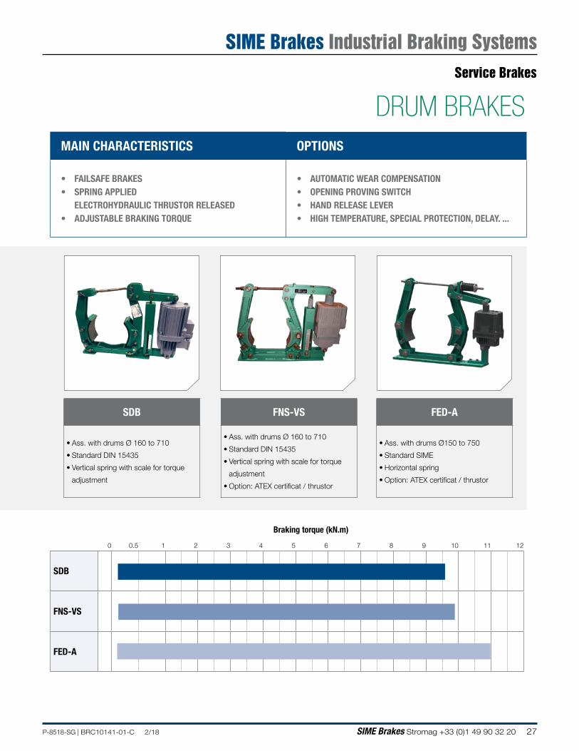
MAIN CHARACTERISTICS OPTIONS
• FAILSAFE BRAKES• SPRING APPLIED
ELECTROHYDRAULIC THRUSTOR RELEASED• ADJUSTABLE BRAKING TORQUE
• AUTOMATIC WEAR COMPENSATION • OPENING PROVING SWITCH• HAND RELEASE LEVER• HIGH TEMPERATURE, SPECIAL PROTECTION, DELAY. ...
FED-A
• Ass. with drums Ø150 to 750
• Standard SIME
• Horizontal spring
• Option: ATEX certificat / thrustor
FNS-VS
• Ass. with drums Ø 160 to 710
• Standard DIN 15435
• Vertical spring with scale for torque
adjustment
• Option: ATEX certificat / thrustor
SDB
• Ass. with drums Ø 160 to 710
• Standard DIN 15435
• Vertical spring with scale for torque
adjustment
DRUM BRAKESService Brakes
SIME Brakes Industrial Braking Systems

28 SIME Brakes Stromag +33 (0)1 49 90 32 20 P-8518-SG | BRC10141-01-C 2/18
NOTES
29P-8518-SG | BRC10141-01-C 2/18 SIME Brakes Stromag +33 (0)1 49 90 32 20
Revision number: T10110-01-D Revision date: 31.10.2017
DRUM BRAKE - SDB BRAKES
Standard DIN 15435Standard voltage 230/400 VAC 50Hz
Self lubricated bushings at main hinge pointsBrake shoe auto-aligning deviceGalvanized steel spindles and hingesNon abestos organic liningsScale for torque adjustment
Operating conditions
• Ambient temperature : -20°C to 50°C• Relative humidity no higher than 90%
i
k k
h1H
E A
F
i
b
n
NM
C
ØD
4 x Ød
G1 G2
BRAKE TYPE THRUSTOR TORQUE (N.m.) WEIGHT
(kg)
DIMENSIONS (mm)
min. max. A b C D d E F G1 G2 H h1 i k n
SDB 160 TS 230/5 80 160 28 428 65 160 160 14 140 85 145 195 418 132 55 130 8
SDB 200TS 230/5 110 260 35
470 70 160 200 14 172 90 165 255 490 160 55 145 10TS 300/5 140 380 38
SDB 250TS 230/5 140 300 45
53390
160250 18 202 110 200 290 583 190 65 180 12TS 300/5 180 380 48
TS 500/6 300 600 53 570 195
SDB 315
TS 230/5 180 340 70
670 110
160
315 18 253 115 245 330 585 230 80 220 14TS 300/5 250 500 70
195TS 500/6 315 770 75
TS 800/6 630 1200 80
SDB 400TS 500/6 400 960 138
695140
195400 22 310 160 310 420
715280 100 270 14TS 800/6 630 1500 140
TS 1210/6 1000 2400 155 810 240 775
SDB 500TS 800/6 800 1920 176
925 180 240 500 22 380 180 365 535
803
340 130 325 21TS 1210/6 1250 3000 204830
TS 2010/6 2000 4800 204
SDB 630TS 1210/6 1800 3780 310
1150 225 240 630 27 465 220 450 600 1025 420 170 400 20TS 2010/6 2500 6000 310
TS 3010/6 4000 8500 315
SDB 710TS 2010/6 3150 6000 435
1180 225 240 710 27 520 240 500 630 1135 470 190 450 25TS 3010/6 5000 9600 441
Service Brakes
SIME Brakes Industrial Braking Systems
30 SIME Brakes Stromag +33 (0)1 49 90 32 20 P-8518-SG | BRC10141-01-C 2/18
Revision number: T03109-01-E Revision date: 27.07.2016
DRUM BRAKE - FNS-VS 160 TO 400 BRAKES
AT High temperatureBT Low temperatureATEX Certificat ATEX / ThrustorBI Stainless steel boltsCSA Opening proving switchDD Lining wear indicatorsDM Hand release lever
LM Locking lever to hold the brake open PE Special paint : color / > C3MPL Padlock for the locking leverPR Reduced torqueRA Automatic lining wear compensationVD Descent valve
Brake not fitted with the thrustor
Standard DIN 15435Spring applicationThrustor releaseProtection level : C3MVoltage : 230 / 400V 50 HzOther voltages, consult us.
For higher torque, please consult us. Some types may present little differences in the form with the drawing
A1
A4
H1max.H2
H3
A2A3
K K
JI
GD3 (x4)
B1
F
C B
D1
Spa
ce fo
r sh
oe re
mov
al
View with thrustor View without thrustor
BRAKE TYPE
THRUSTOR VS
TORQUE N.m. WEIGHT kg
DRUM WIDTH
SHOE WIDTH
DIMENSIONS
min. max. B1 D1 D3 H3 I K A1 A2 A3 A4 B C F G H1 H2 J
160 I-256 118 235 28 60 65 160 11 130 55 120 614 420 140 177 116 160 110 20 424 364 90
200I-256 125 250 29
75 70 200 14 160 55 145664
510 185 178 116 160 125 19405
355 90I-356 188 375 34 674 497
250I-256 128 255 35
95 90 250 18 190 65 180710
580 220 210 116 160 130 13425
413 100I-356 235 470 40 760 499
315
I-356 275 550 59
118 110 315 18 230 80 220
769
690 260 223 159
160
180 18
595
588 120II-506 438 875 62 820 195 620
II-806 700 1400 63 820 195 635
400
II-506 450 900 85
150 140 400 22 280 100 270
980
800 310 307
159 195
210 18
710
704 150II-806 760 1520 87 990 159 195 710
III-1306 1350 2700 107 975 164 240 775
Service Brakes
SIME Brakes Industrial Braking Systems
31P-8518-SG | BRC10141-01-C 2/18 SIME Brakes Stromag +33 (0)1 49 90 32 20
Revision number: T03109-01-E Revision date: 27.07.2016
DRUM BRAKE - FNS-VS 500 TO 710 BRAKES
For higher torque, please consult us. Some types may present little differences in the form with the drawing
AT High temperatureBT Low temperatureATEX Certificat ATEX / ThrustorBI Stainless steel boltsCSA Opening proving switchDD Lining wear indicatorsDM Hand release lever
LM Locking lever to hold the brake open PE Special paint : color / > C3MPL Padlock for the locking leverPR Reduced torqueRA Automatic lining wear compensationVD Descent valve
Brake not fitted with the thrustor
Standard DIN 15435Spring applicationThrustor releaseProtection level : C3MVoltage : 230 / 400V 50 HzOther voltages, consult us.
A1
A4
H1max.H2
H3
A2A3
K K
JI
GD3 (x4)
B1
F
C B
D1
Spa
ce fo
r sh
oe re
mov
al
View with thrustor View without thrustor
BRAKE TYPE
THRUSTOR VS
TORQUE N.m. WEIGHT kg
DRUM WIDTH
SHOE WIDTH
DIMENSIONS
min. max. B1 D1 D3 H3 I K A1 A2 A3 A4 B C F G H1 H2 J
500
II-806 800 1600 125
190 180 500 22 340 130 325
1039
940 365
312
190
195
250 23 820 803 180III-1306 1325 2650 145 1060 325 240
III-2006 2125 4250 147 1060 325 240
630
III-1306 1450 2900 240
236 225 630 27 420 170 400
1240
1150 460
435
230 240 305 23 955 940 220III-2006 2325 4650 242 1240 435
III-3006 3725 7450 244 1240 435
III-3012 3875 7750 258 1325 427
710
III-2006 2875 5750 323
265 255 710 27 470 190 450
1405
1280 510 470 250 240 340 29 1085 1067 250III-3006 4300 8600 324 1405
III-3012 4950 9900 338 1570
Service Brakes
SIME Brakes Industrial Braking Systems
32 SIME Brakes Stromag +33 (0)1 49 90 32 20 P-8518-SG | BRC10141-01-C 2/18
Revision number: T03409-01-H Revision date: 14.06.2016
DRUM BRAKE - FED-A 150 BRAKE
AT High temperatureBT Low temperatureATEX Certificat ATEX / ThrustorBI Stainless steel boltsCSA Opening proving switchDD Lining wear indicatorsDM Hand release lever
LM Locking lever to hold the brake open PE Special paint : color / > C3MPL Padlock for the locking leverPR Reduced torqueRA Automatic lining wear compensationVD Descent valve
Brake not fitted with the thrustor
Standard SIMESpring applicationThrustor releaseProtection level : C3MVoltage : 230 / 400V 50 HzOther voltages, consult us.
For shoe removal
A1
A4 B
C
J
H1max
Ø D3A2
A3
K K
B1F
H3
H2
I
I
X
X
G
D1
Some types may present little differences in the form with the drawing.
BRAK
E TY
PE
THRU
STOR
VS
TORQUE N.m.WEIGHT
kg
WIDTHDIMENSIONS
DRUM SHOE
min. max.B1 D1 D3 H3 A1 A2 A3 A4 B C F G H1 H2 I J K X
150 I-256 65 130 24 80 65 150 11 125 577 400 120 201 73 160 70 10 411 351 57.5 160 90 67.5
Service Brakes
SIME Brakes Industrial Braking Systems
33P-8518-SG | BRC10141-01-C 2/18 SIME Brakes Stromag +33 (0)1 49 90 32 20
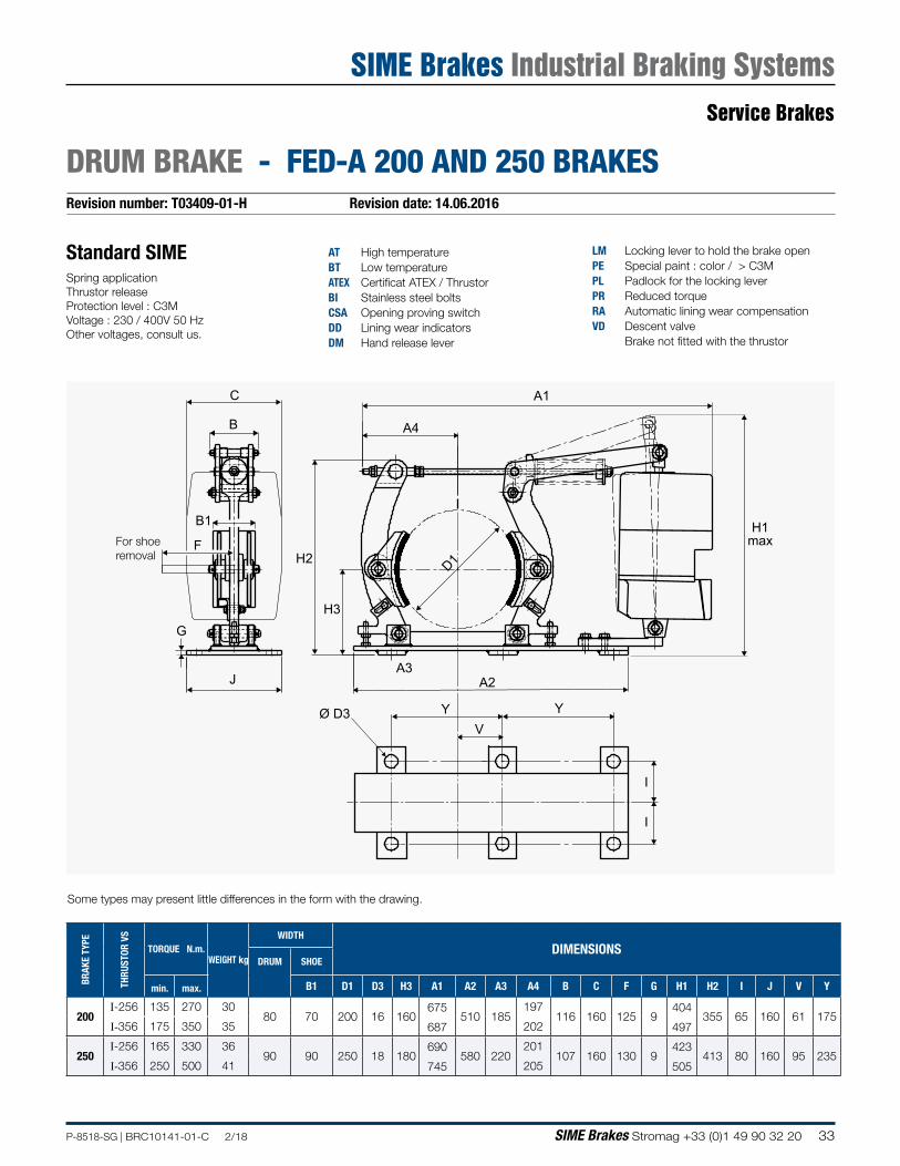
Revision number: T03409-01-H Revision date: 14.06.2016
DRUM BRAKE - FED-A 200 AND 250 BRAKES
AT High temperatureBT Low temperatureATEX Certificat ATEX / ThrustorBI Stainless steel boltsCSA Opening proving switchDD Lining wear indicatorsDM Hand release lever
LM Locking lever to hold the brake open PE Special paint : color / > C3MPL Padlock for the locking leverPR Reduced torqueRA Automatic lining wear compensationVD Descent valve
Brake not fitted with the thrustor
Standard SIMESpring applicationThrustor releaseProtection level : C3MVoltage : 230 / 400V 50 HzOther voltages, consult us.
Some types may present little differences in the form with the drawing.
For shoe removal
A1
A4B
C
B1
F
J
G
H1max
D1
A2A3
YYV
H3
H2
Ø D3
I
I
BRAK
E TY
PE
THRU
STOR
VS
TORQUE N.m.WEIGHT kg
WIDTH
DIMENSIONSDRUM SHOE
min. max. B1 D1 D3 H3 A1 A2 A3 A4 B C F G H1 H2 I J V Y
200I-256 135 270 30
80 70 200 16 160675
510 185197
116 160 125 9404
355 65 160 61 175I-356 175 350 35 687 202 497
250I-256 165 330 36
90 90 250 18 180690
580 220201
107 160 130 9423
413 80 160 95 235I-356 250 500 41 745 205 505
Service Brakes
SIME Brakes Industrial Braking Systems
34 SIME Brakes Stromag +33 (0)1 49 90 32 20 P-8518-SG | BRC10141-01-C 2/18
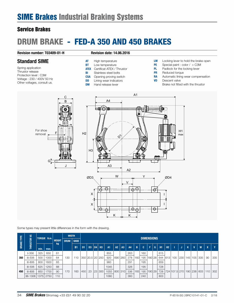
Revision number: T03409-01-H Revision date: 14.06.2016
DRUM BRAKE - FED-A 350 AND 450 BRAKES
AT High temperatureBT Low temperatureATEX Certificat ATEX / ThrustorBI Stainless steel boltsCSA Opening proving switchDD Lining wear indicatorsDM Hand release lever
LM Locking lever to hold the brake open PE Special paint : color / > C3MPL Padlock for the locking leverPR Reduced torqueRA Automatic lining wear compensationVD Descent valve
Brake not fitted with the thrustor
Standard SIMESpring applicationThrustor releaseProtection level : C3MVoltage : 230 / 400V 50 HzOther voltages, consult us.
Some types may present little differences in the form with the drawing.
For shoe removal
A1
A4B
B1
C
G
F
A2A3
YW
V
H3
H2D1
H1max
ØD3 ØD4
J
K K
X I
IX
BRAK
E TY
PE
THRU
STOR
VS
TORQUE N.m.WEIGHT
kg
WIDTHDIMENSIONS
DRUM SHOE
min. max. B1 D1 D3 D4 H3 A1 A2 A3 A4 B C F G H1 H2 I J K V W X Y
350
I-356 325 650 61
130 110 350 20.5 20 250
855
690 260
263
160
160
180 28
615
613 105 230 145 105 335 90 335II-506 500 1000 64 920 278 195 644
II-806 800 1600 65 960 291 195 659
450
II-506 625 1250 88
170 160 450 23 23 300
1045
800 310
326
165
195
190 29
728
724 107.5 270 190 238 603 110 302II-806 850 1700 90 1055 336 195 728
III-1306 1375 2750 110 1080 360 240 803
Service Brakes
SIME Brakes Industrial Braking Systems
35P-8518-SG | BRC10141-01-C 2/18 SIME Brakes Stromag +33 (0)1 49 90 32 20
Revision number: T03409-01-H Revision date: 14.06.2016
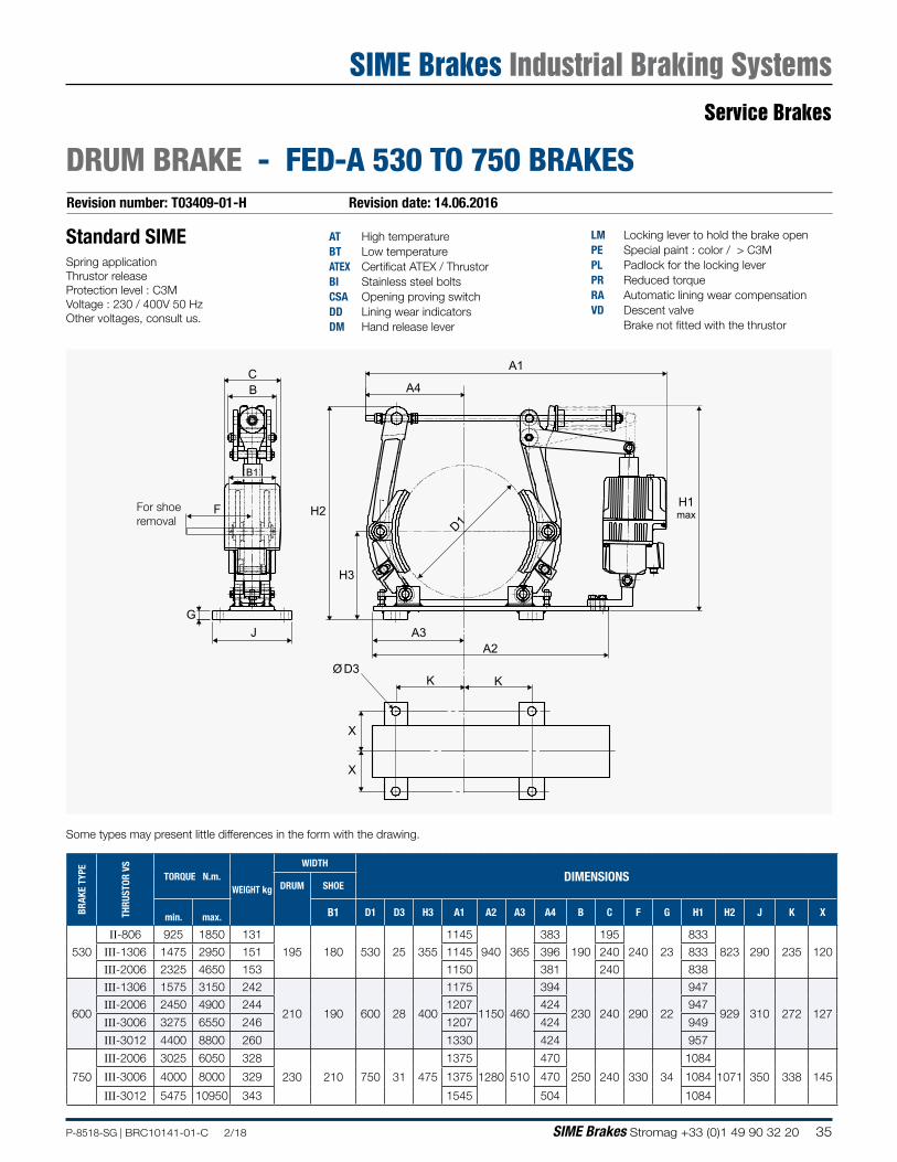
DRUM BRAKE - FED-A 530 TO 750 BRAKES
AT High temperatureBT Low temperatureATEX Certificat ATEX / ThrustorBI Stainless steel boltsCSA Opening proving switchDD Lining wear indicatorsDM Hand release lever
LM Locking lever to hold the brake open PE Special paint : color / > C3MPL Padlock for the locking leverPR Reduced torqueRA Automatic lining wear compensationVD Descent valve
Brake not fitted with the thrustor
Standard SIMESpring applicationThrustor releaseProtection level : C3MVoltage : 230 / 400V 50 HzOther voltages, consult us.
A1
A4B
B1
C
G
F
A2A3
H3
H2H1max
Ø D3
J
K K
X
X
D1
BRAK
E TY
PE
THRU
STOR
VS
TORQUE N.m.WEIGHT kg
WIDTHDIMENSIONS
DRUM SHOE
min. max. B1 D1 D3 H3 A1 A2 A3 A4 B C F G H1 H2 J K X
530
II-806 925 1850 131
195 180 530 25 355
1145
940 365
383
190
195
240 23
833
823 290 235 120III-1306 1475 2950 151 1145 396 240 833
III-2006 2325 4650 153 1150 381 240 838
600
III-1306 1575 3150 242
210 190 600 28 400
1175
1150 460
394
230 240 290 22
947
929 310 272 127III-2006 2450 4900 244 1207 424 947
III-3006 3275 6550 246 1207 424 949
III-3012 4400 8800 260 1330 424 957
750
III-2006 3025 6050 328
230 210 750 31 475
1375
1280 510
470
250 240 330 34
1084
1071 350 338 145III-3006 4000 8000 329 1375 470 1084
III-3012 5475 10950 343 1545 504 1084
Some types may present little differences in the form with the drawing.
For shoe removal
Service Brakes
SIME Brakes Industrial Braking Systems
36 SIME Brakes Stromag +33 (0)1 49 90 32 20 P-8518-SG | BRC10141-01-C 2/18
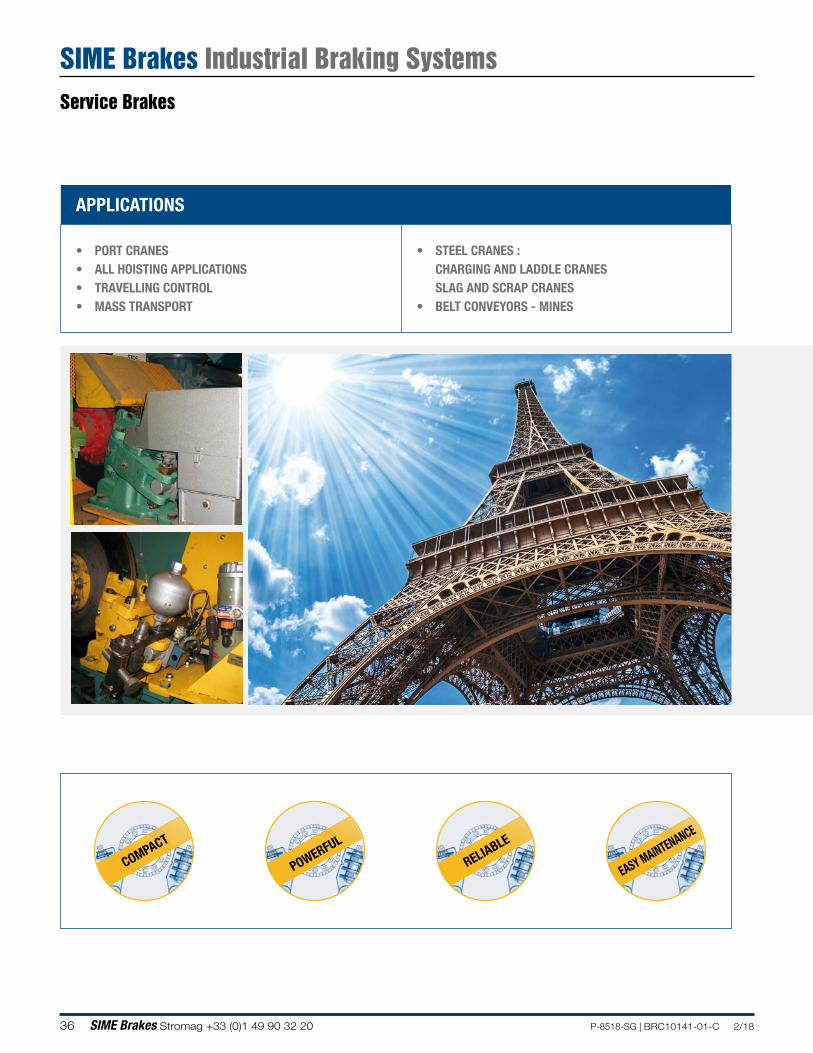
APPLICATIONS
• PORT CRANES• ALL HOISTING APPLICATIONS• TRAVELLING CONTROL• MASS TRANSPORT
• STEEL CRANES : CHARGING AND LADDLE CRANESSLAG AND SCRAP CRANES
• BELT CONVEYORS - MINES
COMPACT
POWERFUL
RELIABLE
EASY MAINTENANCE
Service Brakes
SIME Brakes Industrial Braking Systems
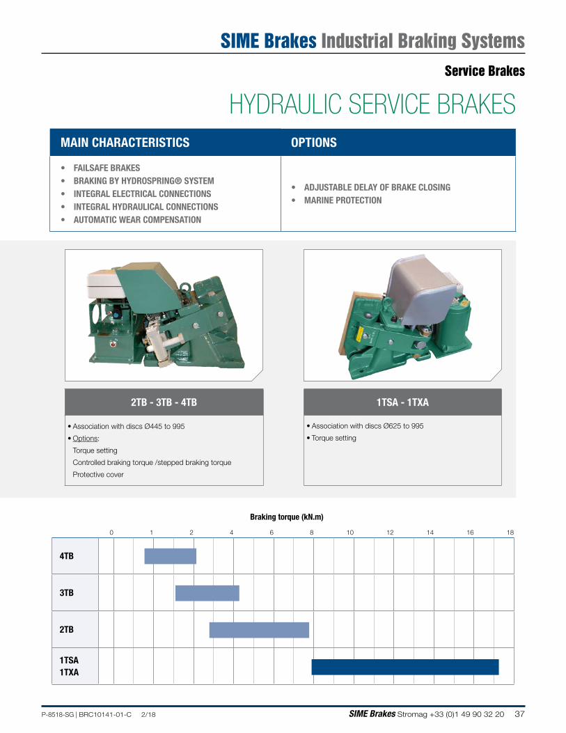
37P-8518-SG | BRC10141-01-C 2/18 SIME Brakes Stromag +33 (0)1 49 90 32 20
Braking torque (kN.m)
0 1 2 4 6 8 10 12 14 16 18
4TB
3TB
2TB
1TSA1TXA
MAIN CHARACTERISTICS OPTIONS
• FAILSAFE BRAKES• BRAKING BY HYDROSPRING® SYSTEM• INTEGRAL ELECTRICAL CONNECTIONS • INTEGRAL HYDRAULICAL CONNECTIONS • AUTOMATIC WEAR COMPENSATION
• ADJUSTABLE DELAY OF BRAKE CLOSING• MARINE PROTECTION
2TB - 3TB - 4TB
• Association with discs Ø445 to 995
• Options:
Torque setting
Controlled braking torque /stepped braking torque
Protective cover
1TSA - 1TXA
• Association with discs Ø625 to 995
• Torque setting
HYDRAULIC SERVICE BRAKESService Brakes
SIME Brakes Industrial Braking Systems
38 SIME Brakes Stromag +33 (0)1 49 90 32 20 P-8518-SG | BRC10141-01-C 2/18
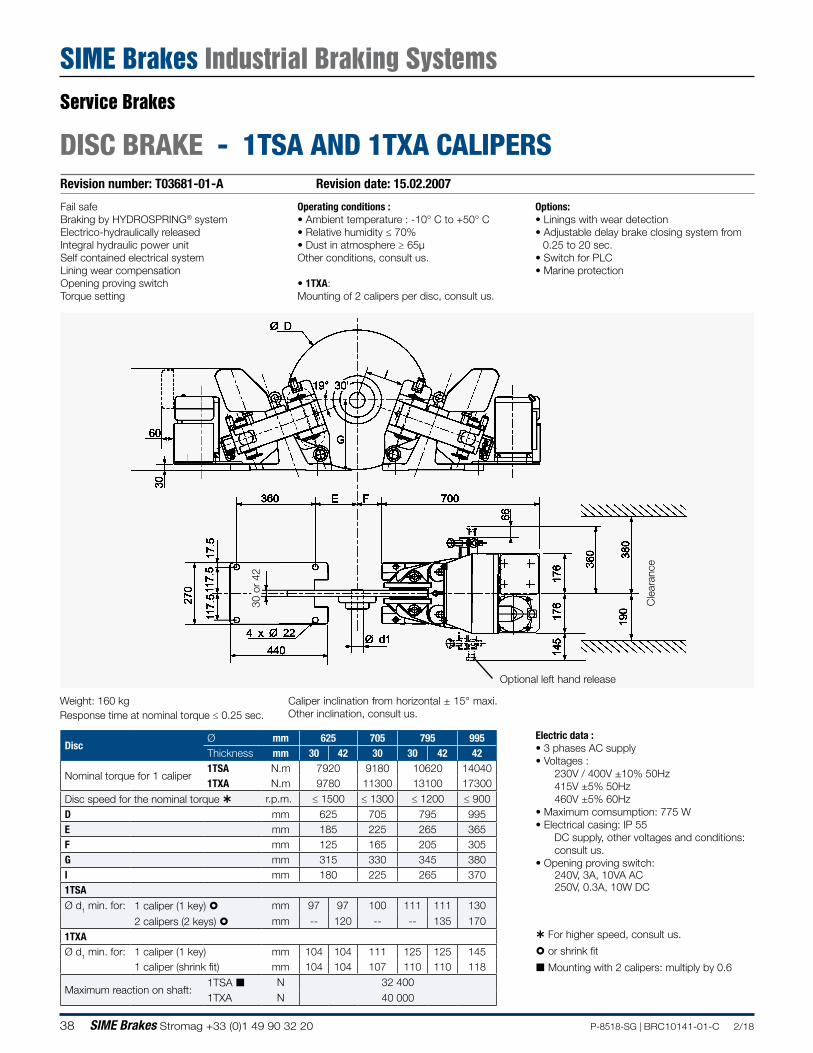
Revision number: T03681-01-A Revision date: 15.02.2007
DISC BRAKE - 1TSA AND 1TXA CALIPERS
Operating conditions :• Ambient temperature : -10° C to +50° C• Relative humidity ≤ 70%• Dust in atmosphere ≥ 65µOther conditions, consult us.
• 1TXA: Mounting of 2 calipers per disc, consult us.
Fail safeBraking by HYDROSPRING® systemElectrico-hydraulically releasedIntegral hydraulic power unitSelf contained electrical systemLining wear compensationOpening proving switchTorque setting
Mounting with 2 calipers: multiply by 0.6
For higher speed, consult us.
or shrink fit
Weight: 160 kgResponse time at nominal torque ≤ 0.25 sec.
Optional left hand release
Electric data :• 3 phases AC supply• Voltages :
230V / 400V ±10% 50Hz415V ±5% 50Hz460V ±5% 60Hz
• Maximum comsumption: 775 W• Electrical casing: IP 55
DC supply, other voltages and conditions: consult us.
• Opening proving switch:240V, 3A, 10VA AC250V, 0.3A, 10W DC
Options:• Linings with wear detection• Adjustable delay brake closing system from
0.25 to 20 sec.• Switch for PLC• Marine protection
Cle
aran
ce
30 o
r 42
DiscØ mm 625 705 795 995Thickness mm 30 42 30 30 42 42
Nominal torque for 1 caliper1TSA N.m 7920 9180 10620 140401TXA N.m 9780 11300 13100 17300
Disc speed for the nominal torque r.p.m. ≤ 1500 ≤ 1300 ≤ 1200 ≤ 900D mm 625 705 795 995E mm 185 225 265 365F mm 125 165 205 305G mm 315 330 345 380I mm 180 225 265 3701TSAØ d1 min. for: 1 caliper (1 key) mm 97 97 100 111 111 130
2 calipers (2 keys) mm -- 120 -- -- 135 1701TXAØ d1 min. for: 1 caliper (1 key) mm 104 104 111 125 125 145
1 caliper (shrink fit) mm 104 104 107 110 110 118
Maximum reaction on shaft:1TSA N 32 4001TXA N 40 000
Caliper inclination from horizontal ± 15° maxi.Other inclination, consult us.
Service Brakes
SIME Brakes Industrial Braking Systems
39P-8518-SG | BRC10141-01-C 2/18 SIME Brakes Stromag +33 (0)1 49 90 32 20
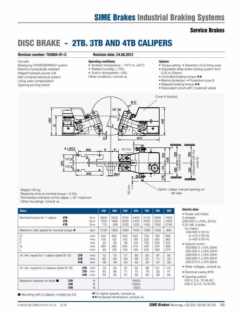
Revision number: T03664-01-C Revision date: 24.08.2012
DISC BRAKE - 2TB. 3TB AND 4TB CALIPERS
Fail safeBraking by HYDROSPRING® systemElectrico-hydraulically releasedIntegral hydraulic power unitSelf contained electrical systemLining wear compensationOpening proving switch
Weight:160 kgResponse time at nominal torque ≤ 0.25sPermissible inclination of the caliper ± 45° maximumOther mountings: consult us.
Options:• Torque setting • Detection of full lining wear• Adjustable delay brake closing system from
0.25 to 20secs• Controlled braking torque • Marine protection • Protective cover K• Stepped braking torque • Redundant circuit with 2 solenoid valves
Mounting with 2 calipers, multiply by 0.6
60 m
in.
For higher speeds, consult us. Increased dimensions, consult us.
Option: caliper manual opening on left side
Operating conditions:• Ambient temperature : -10°C to +50°C• Relative humidity ≤ 70%• Dust in atmosphere ≥ 65µOther conditions, consult us.
Cover K (option)
60 min.
Electric data:• Power unit motor:3 phases:230/400 V ±10%, 50 Hz,0.37 kW, 4 poles for mains: 230/400 V 50 Hz or 415 V 50 Hz or 460 V 60 Hz
• Options motor: 400/690 V ±10% 50Hz 255/440 V ±10% 50Hz 290/500 V ±10% 50Hz 280/480 V ±10% 60Hz 330/575 V ±10% 60Hz
• Other voltages, consult us.
• Electrical casing IP55
• Opening switch: 240 V, 3 A, 10 VA AC 250 V, 0.3 A, 10 W DC
(cle
aran
ce w
ith th
e co
ver
K)
(cle
aran
ce)
Discs 445 495 550 625 705 795 995
Nominal torque for 1 caliper: 2TB N.m 2800 3250 3700 4400 5100 5900 7800 3TB N.m 1550 1800 2050 2450 2850 3250 4300 4TB N.m 775 900 1030 1230 1430 1630 2150
Maximum disc speed for nominal torque rpm 2100 1900 1800 1500 1300 1200 900
D mm 445 495 550 625 705 795 995E mm 100 120 150 185 225 265 365F mm 40 60 90 125 165 205 305G mm 285 295 305 315 330 345 380L mm 90 130 145 180 225 265 370
d1 min. keyed for 1 caliper (steel St 70): 2TB mm 73 75 77 80 82 87 92 3TB mm 60 62 63 66 67 71 76 4TB mm 48 49 50 52 53 57 58
d1 min. keyed for 2 calipers (steel St 70): 2TB mm 79 83 87 92 96 101 110 3TB mm 65 68 71 75 79 82 91 4TB mm 53 55 57 60 63 66 69
Maximum reaction on shaft : 2TB N 18000 3TB N 10000 4TB N 5000
Service Brakes
SIME Brakes Industrial Braking Systems
40 SIME Brakes Stromag +33 (0)1 49 90 32 20 P-8518-SG | BRC10141-01-C 2/18
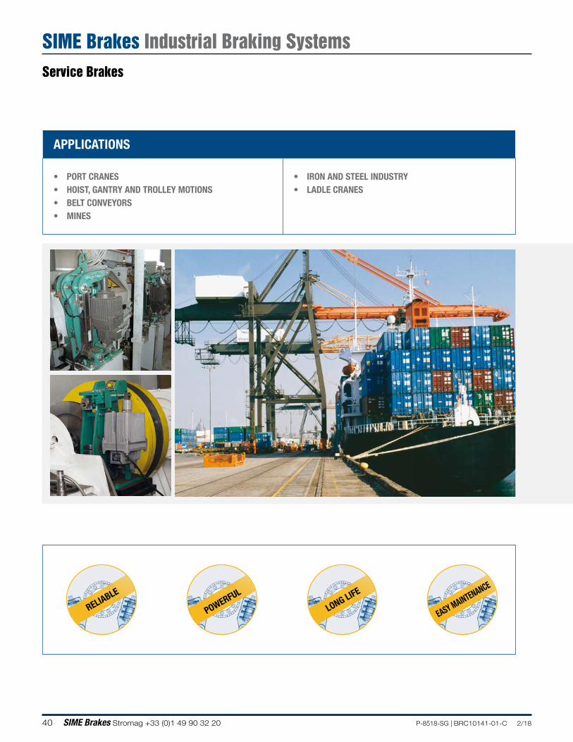
APPLICATIONS
• PORT CRANES• HOIST, GANTRY AND TROLLEY MOTIONS• BELT CONVEYORS• MINES
• IRON AND STEEL INDUSTRY• LADLE CRANES
RELIABLE
POWERFUL
LONG LIFE
EASY MAINTENANCE
Service Brakes
SIME Brakes Industrial Braking Systems
41P-8518-SG | BRC10141-01-C 2/18 SIME Brakes Stromag +33 (0)1 49 90 32 20
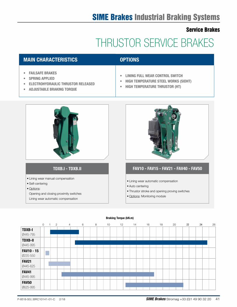
MAIN CHARACTERISTICS OPTIONS
• FAILSAFE BRAKES• SPRING APPLIED• ELECTROHYDRAULIC THRUSTOR RELEASED• ADJUSTABLE BRAKING TORQUE
• LINING FULL WEAR CONTROL SWITCH• HIGH TEMPERATURE STEEL WORKS (SIDHT)• HIGH TEMPERATURE THRUSTOR (HT)
FAV10 - FAV15 - FAV21 - FAV40 - FAV50
• Lining wear automatic compensation
• Auto centering
• Thrustor stroke and opening proving switches
• Options: Monitoring module
TDXB.I - TDXB.II
• Lining wear manual compensation
• Self-centering
• Options:
Opening and closing proximity switches
Lining wear automatic compensation
THRUSTOR SERVICE BRAKES
Braking Torque (kN.m)
0 1 2 4 6 8 10 12 14 16 18 20 22 24 26
TDXB-IØ445-795
TDXB-IIØ445-995
FAV10 - 15Ø220-550
FAV21Ø445-625
FAV41Ø445-995
FAV50Ø625-995
Service Brakes
SIME Brakes Industrial Braking Systems
42 SIME Brakes Stromag +33 (0)1 49 90 32 20 P-8518-SG | BRC10141-01-C 2/18
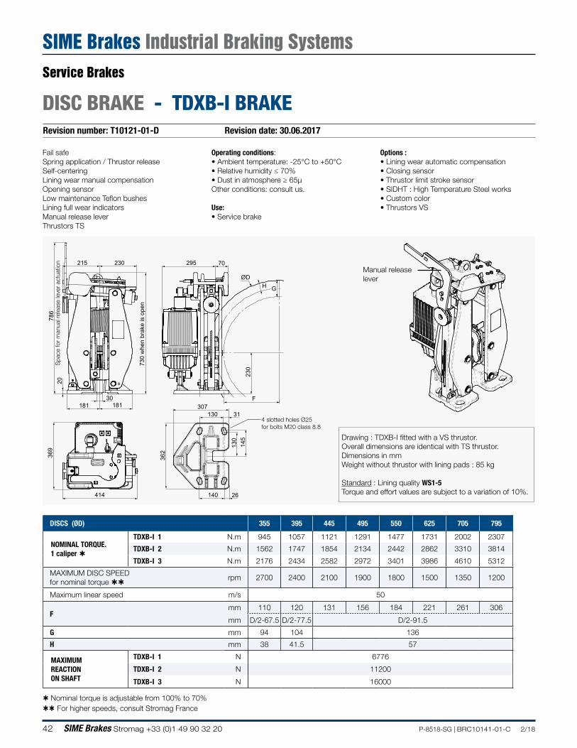
Revision number: T10121-01-D Revision date: 30.06.2017
DISC BRAKE - TDXB-I BRAKE
Fail safeSpring application / Thrustor releaseSelf-centeringLining wear manual compensationOpening sensorLow maintenance Teflon bushesLining full wear indicatorsManual release leverThrustors TS
Operating conditions:• Ambient temperature: -25°C to +50°C• Relative humidity ≤ 70%• Dust in atmosphere ≥ 65µOther conditions: consult us.
Use:• Service brake
Options :• Lining wear automatic compensation• Closing sensor• Thrustor limit stroke sensor• SIDHT : High Temperature Steel works • Custom color• Thrustors VS
Nominal torque is adjustable from 100% to 70% For higher speeds, consult Stromag France
DISCS (ØD) 355 395 445 495 550 625 705 795
NOMINAL TORQUE. 1 caliper
TDXB-I 1 N.m 945 1057 1121 1291 1477 1731 2002 2307
TDXB-I 2 N.m 1562 1747 1854 2134 2442 2862 3310 3814
TDXB-I 3 N.m 2176 2434 2582 2972 3401 3986 4610 5312
MAXIMUM DISC SPEED for nominal torque
rpm 2700 2400 2100 1900 1800 1500 1350 1200
Maximum linear speed m/s 50
Fmm 110 120 131 156 184 221 261 306
mm D/2-67.5 D/2-77.5 D/2-91.5
G mm 94 104 136
H mm 38 41.5 57
MAXIMUM REACTION ON SHAFT
TDXB-I 1 N 6776
TDXB-I 2 N 11200
TDXB-I 3 N 16000
Drawing : TDXB-I fitted with a VS thrustor.Overall dimensions are identical with TS thrustor.Dimensions in mmWeight without thrustor with lining pads : 85 kg
Standard : Lining quality WS1-5Torque and effort values are subject to a variation of 10%.
Manual release lever
Service Brakes
SIME Brakes Industrial Braking Systems
30
20
786
730
whe
n br
ake
is o
pen
181 181
215 230
230
F
G
295 70
ØDH
369
414
130
140
307 31
130
1
45
26
362
4 slotted holes Ø25for bolts M20 class 8.8
Spa
ce fo
r m
anua
l rel
ease
leve
r ac
tuat
ion
43P-8518-SG | BRC10141-01-C 2/18 SIME Brakes Stromag +33 (0)1 49 90 32 20
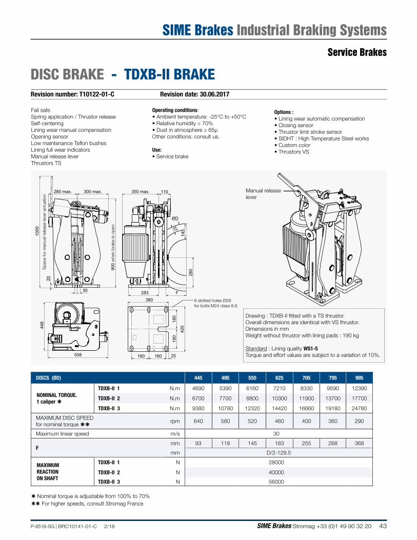
DISC BRAKE - TDXB-II BRAKERevision number: T10122-01-C Revision date: 30.06.2017
Fail safeSpring application / Thrustor releaseSelf-centeringLining wear manual compensationOpening sensorLow maintenance Teflon bushesLining full wear indicatorsManual release leverThrustors TS
Operating conditions:• Ambient temperature: -25°C to +50°C• Relative humidity ≤ 70%• Dust in atmosphere ≥ 65µOther conditions: consult us.
Use:• Service brake
Options :• Lining wear automatic compensation• Closing sensor• Thrustor limit stroke sensor• SIDHT : High Temperature Steel works • Custom color• Thrustors VS
Nominal torque is adjustable from 100% to 70% For higher speeds, consult Stromag France
DISCS (ØD) 445 495 550 625 705 795 995
NOMINAL TORQUE. 1 caliper
TDXB-II 1 N.m 4690 5390 6160 7210 8330 9590 12390
TDXB-II 2 N.m 6700 7700 8800 10300 11900 13700 17700
TDXB-II 3 N.m 9380 10780 12320 14420 16660 19180 24780
MAXIMUM DISC SPEED for nominal torque
rpm 640 580 520 460 400 360 290
Maximum linear speed m/s 30
Fmm 93 118 145 183 255 268 368
mm D/2-129.5
MAXIMUM REACTION ON SHAFT
TDXB-II 1 N 28000
TDXB-II 2 N 40000
TDXB-II 3 N 56000
Drawing : TDXB-II fitted with a TS thrustor.Overall dimensions are identical with VS thrustor.Dimensions in mmWeight without thrustor with lining pads : 190 kg
Standard : Lining quality WS1-5Torque and effort values are subject to a variation of 10%.
Manual release lever
Service Brakes
SIME Brakes Industrial Braking Systems
30
20
100
0
900
whe
n br
ake
is o
pen
280 max. 300 max.
145
280
F
350 max. 110
ØD
57
448
558 160
380
180
420
25
283
180
160
6 slotted holes Ø28for bolts M24 class 8.8
Spa
ce fo
r m
anua
l rel
ease
leve
r ac
tuat
ion
44 SIME Brakes Stromag +33 (0)1 49 90 32 20 P-8518-SG | BRC10141-01-C 2/18
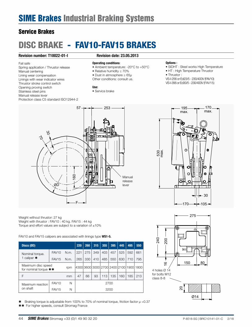
Revision number: T10022-01-I Revision date: 23.05.2013
DISC BRAKE - FAV10-FAV15 BRAKES
195max.
170max.
530
max
.
30
170 105
275
240
200
16 150 80
25357
160
F
ØD
70
30
20
Ø14
Fail safeSpring application / Thrustor releaseManual centeringLining wear compensationLinings with wear indicator wiresThrustor stroke control switchOpening proving switchStainless steel pinsManual release leverProtection class C5 standard ISO12944-2
Operating conditions:• Ambient temperature: -20°C to +50°C• Relative humidity ≤ 70%• Dust in atmosphere ≥ 65µOther conditions: consult us.
Use:• Service brake
Options :• SIDHT : Steel works High Temperature• HT : High Temperature Thrustor • Thrustor :VS-I-256 or Ed23/5 - 230/400V (FAV10)VS-I-356 or Ed30/5 - 230/400V (FAV15)
Weight without thrustor: 27 kgWeight with thrustor : FAV10 : 40 kg. FAV15 : 44 kgTorque and effort values are subject to a variation of ±10%
Braking torque is adjustable from 100% to 70% of nominal torque, friction factor µ =0.37 For higher speeds, consult Stromag France
4 holes Ø 14for bolts M12 class 8-8
FAV10 and FAV15 calipers are associated with linings type WS1-5.
Discs (ØD) 220 260 315 355 395 445 495 550
Nominal torque. 1 caliper
FAV10 N.m. 221 275 349 403 457 525 592 661
FAV15 N.m. 265 330 410 485 550 630 710 795
Maximum disc speed for nominal torque
rpm 4300 3600 3000 2700 2400 2100 1900 1800
F mm 47 66 93 113 135 160 185 213
Maximum reaction on shaft
FAV10 N 2700
FAV15 N 3200
Manualreleaselever
Service Brakes
SIME Brakes Industrial Braking Systems
195max.
170max.
530
max
.
30
170 105
275
240
200
16 150 80
25357
160
F
ØD
70
30
20
Ø14
45P-8518-SG | BRC10141-01-C 2/18 SIME Brakes Stromag +33 (0)1 49 90 32 20
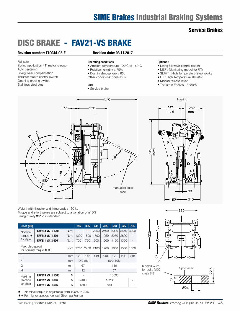
DISC BRAKE - FAV21-VS BRAKERevision number: T10044-02-E Revision date: 08.11.2017
Fail safeSpring application / Thrustor releaseAuto centeringLining wear compensationThrustor stroke control switchOpening proving switchStainless steel pins
Operating conditions:• Ambient temperature: -20°C to +50°C• Relative humidity ≤ 70%• Dust in atmosphere ≥ 65µOther conditions: consult us
Use:• Service brake
Options :• Lining full wear control switch• MSF : Monitoring modul for FAV• SIDHT : High Temperature Steel works • HT : High Temperature Thrustor • Manual release lever• Thrustors Ed50/6 - Ed80/6
manual release lever
Hauling
6 holes Ø 24for bolts M20 class 8.8
Weight with thrustor and lining pads : 130 kg Torque and effort values are subject to a variation of ±10%Lining quality WS1-5 in standard.
Nominal torque is adjustable from 100% to 70% For higher speeds, consult Stromag France
Spot faced
Discs (ØD) 355 395 445 495 550 625 705
Nominal torque . 1 caliper
FAV213 VS II 1306 N.m. - - 2260 2590 2990 3450 4000
FAV212 VS II 806 N.m. 1300 1500 1700 1950 2250 2600 -
FAV211 VS II 506 N.m. 700 750 900 1000 1150 1350 -
Max. disc speed for nominal torque
rpm 2700 2400 2100 1900 1800 1500 1500
F mm 122 142 118 143 170 208 248
F mm (D/2-56) (D/2-105)
G mm 67 136
H mm 32 57
Maximum reaction on shaft
FAV213 VS II 1306 N - 13600
FAV212 VS II 806 N 9100 10200 -
FAV211 VS II 506 N 4500 5300 -
Service Brakes
SIME Brakes Industrial Braking Systems
46 SIME Brakes Stromag +33 (0)1 49 90 32 20 P-8518-SG | BRC10141-01-C 2/18
Revision number: T03524-02-D Revision date: 08.11.2017
DISC BRAKE - FAV41-VS BRAKE
Fail safeSpring application / Thrustor releaseAuto centeringLining wear compensationThrustor stroke control switchOpening proving switchStainless steel pinsManual release lever for FAV411/412-VSManual release system for FAV413-VS
Operating conditions:• Ambient temperature: -20°C to +50°C• Relative humidity ≤ 70%• Dust in atmosphere ≥ 65µOther conditions: consult us
Use:• Service brake
Options :• Lining full wear control switch• MSF : Monitoring modul for FAV• SIDHT : High Temperature Steel works • HT : High Temperature Thrustor • Thrustors : Ed301/10 - Ed201/10 - Ed121/10
Nominal torque is adjustable from 100% to 70% For higher speeds, consult Stromag France
Weight without thrustor : 180 kg / Weight with thrustor : 222 kgTorque and effort values are subject to a variation of ±10%The disc run-out must not exceed 0.08 % of the maximum radiusand the disc axial displacement must be smaller than 0.5 mm.Lining quality WS1-5 in standard.
Handling
2 threads M16(for on-site positionning)
Manual release sytem (FAV413-VS).Same dimensions for lever (FAV411/412-VS)
6 holes Ø 28for bolts M24 class 8.8
Spot faced
Discs (ØD) 445 495 550 625 705 795 995
Nominal torque. 1 caliper (N.m)
FAV413 VS-III-3010 FAV412 VS-III-2010 FAV411 VS-III-1310
- -
2650
- 4960 3050
- 5650 3500
9700 6600 4100
11200 7650 4750
12950 8800 5450
16700 - -
Maximum disc speed for nominal torque (rpm)
2100 1900 1800 1500 1300 1200 900
F (mm) ( F=D/2-130 ) 93 118 145 183 223 268 368
Maximum reaction on shaft (N)
FAV413 VS-III-3010 FAV412 VS-III-2010 FAV411 VS-III-1310
38000 26000 16000
Service Brakes
SIME Brakes Industrial Braking Systems
47P-8518-SG | BRC10141-01-C 2/18 SIME Brakes Stromag +33 (0)1 49 90 32 20
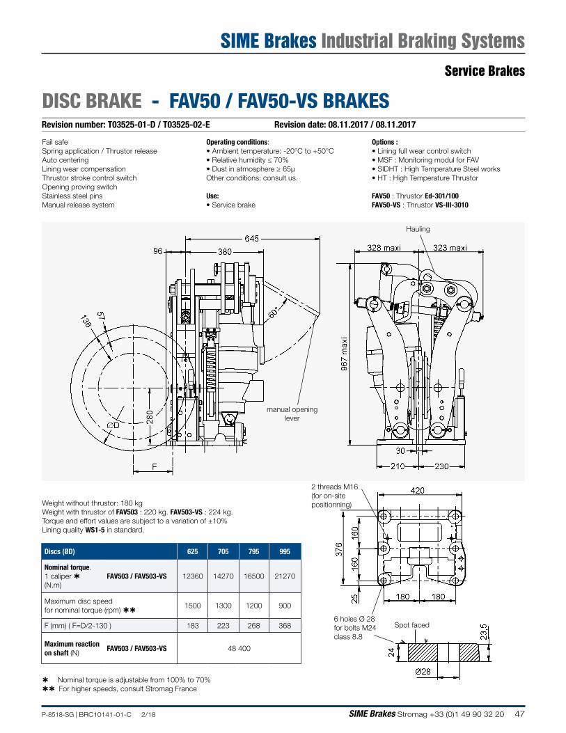
Revision number: T03525-01-D / T03525-02-E Revision date: 08.11.2017 / 08.11.2017
DISC BRAKE - FAV50 / FAV50-VS BRAKES
Fail safeSpring application / Thrustor releaseAuto centeringLining wear compensationThrustor stroke control switchOpening proving switchStainless steel pinsManual release system
Operating conditions:• Ambient temperature: -20°C to +50°C• Relative humidity ≤ 70%• Dust in atmosphere ≥ 65µOther conditions: consult us.
Use:• Service brake
Options :• Lining full wear control switch• MSF : Monitoring modul for FAV• SIDHT : High Temperature Steel works • HT : High Temperature Thrustor
FAV50 : Thrustor Ed-301/100FAV50-VS : Thrustor VS-III-3010
Weight without thrustor: 180 kgWeight with thrustor of FAV503 : 220 kg. FAV503-VS : 224 kg. Torque and effort values are subject to a variation of ±10%Lining quality WS1-5 in standard.
manual opening lever
Hauling
6 holes Ø 28for bolts M24class 8.8
2 threads M16 (for on-site positionning)
Spot faced
Discs (ØD) 625 705 795 995
Nominal torque. 1 caliper (N.m)
FAV503 / FAV503-VS 12360 14270 16500 21270
Maximum disc speed for nominal torque (rpm)
1500 1300 1200 900
F (mm) ( F=D/2-130 ) 183 223 268 368
Maximum reaction on shaft (N)
FAV503 / FAV503-VS 48 400
Nominal torque is adjustable from 100% to 70% For higher speeds, consult Stromag France
Service Brakes
SIME Brakes Industrial Braking Systems
48 SIME Brakes Stromag +33 (0)1 49 90 32 20 P-8518-SG | BRC10141-01-C 2/18
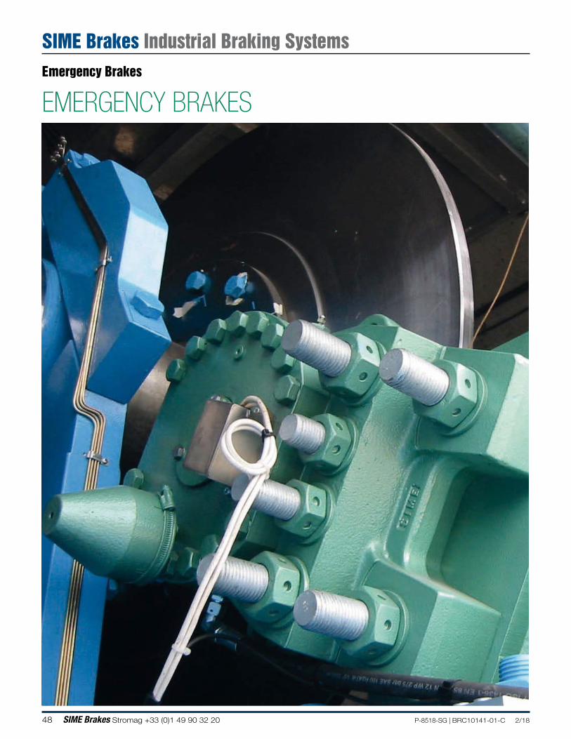
EMERGENCY BRAKESEmergency Brakes
SIME Brakes Industrial Braking Systems
49P-8518-SG | BRC10141-01-C 2/18 SIME Brakes Stromag +33 (0)1 49 90 32 20
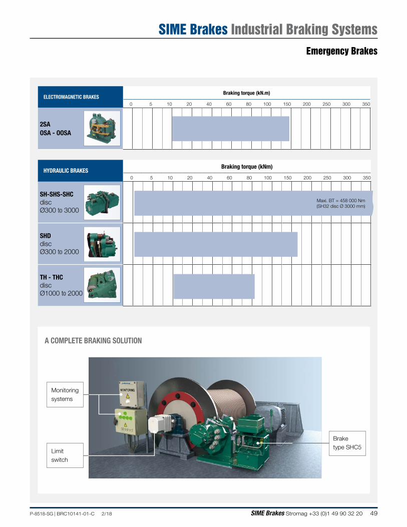
ELECTROMAGNETIC BRAKESBraking torque (kN.m)
0 5 10 20 40 60 80 100 150 200 250 300 350
2SAOSA - OOSA
HYDRAULIC BRAKESBraking torque (kNm)
0 5 10 20 40 60 80 100 150 200 250 300 350
SH-SHS-SHCdiscØ300 to 3000
SHDdiscØ300 to 2000
TH - THCdiscØ1000 to 2000
Maxi. BT = 458 000 Nm(SH32 disc Ø 3000 mm)
A COMPLETE BRAKING SOLUTION
Braketype SHC5
Monitoringsystems
Limitswitch
Emergency Brakes
SIME Brakes Industrial Braking Systems
50 SIME Brakes Stromag +33 (0)1 49 90 32 20 P-8518-SG | BRC10141-01-C 2/18
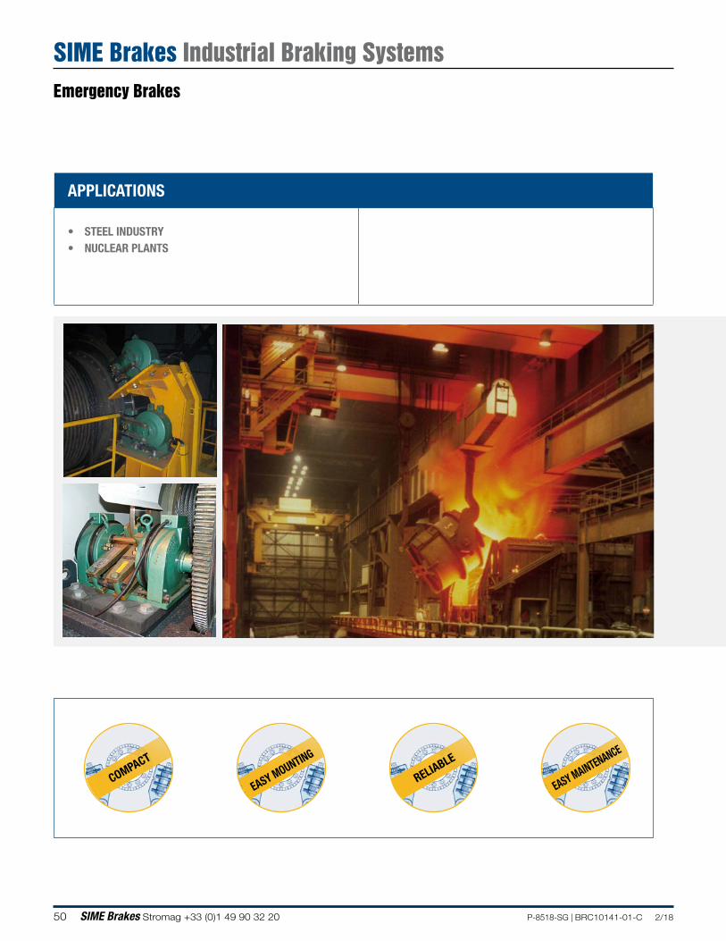
APPLICATIONS
• STEEL INDUSTRY• NUCLEAR PLANTS
COMPACT
EASY MOUNTING
RELIABLE
EASY MAINTENANCE
Emergency Brakes
SIME Brakes Industrial Braking Systems
51P-8518-SG | BRC10141-01-C 2/18 SIME Brakes Stromag +33 (0)1 49 90 32 20
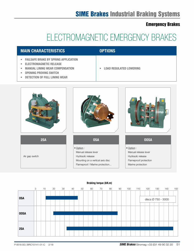
Braking torque (kN.m)
0 10 20 30 40 50 60 70 80 90 100 110 120 130 140 150
OSA
OOSA
2SA
discs Ø 750 - 3000
MAIN CHARACTERISTICS OPTIONS
• FAILSAFE BRAKE BY SPRING APPLICATION • ELECTROMAGNETIC RELEASE• MANUAL LINING WEAR COMPENSATION• OPENING PROVING SWITCH• DETECTION OF FULL LINING WEAR
• LOAD REGULATED LOWERING
2SA
Air gap switch
OSA
• Option :
Manual release lever
Hydraulic release
Mounting on a vertical axis disc
Flameproof / Marine protection...
OOSA
• Option :
Manual release lever
Hydraulic release
Flameproof protection
Marine protection
ELECTROMAGNETIC EMERGENCY BRAKES
Emergency Brakes
SIME Brakes Industrial Braking Systems
52 SIME Brakes Stromag +33 (0)1 49 90 32 20 P-8518-SG | BRC10141-01-C 2/18
Revision number: T03750-01-F Revision date: 22.03.2016
DISC BRAKE - OSA CALIPER
Options:• Manual release lever• Hydraulic release• Load regulated lowering• Flameproof protection• Marine protection• Mounting on a vertical axis disc
Operating conditions:• Ambiant temperature: -10°C to +60°C• Relative humidity ≤ 70%• Dust in atmosphere ≥ 65µOther conditions, consult us.
Use:The brake should be applied only in case of emergency stop, overspeed or shutdown of electric mains.
Fail safe brakingBraking by spring applicationElectromagnetic releaseManual lining wear compensationDetection of full lining wearOpening proving switch
155
6825 70
45030
465
80 m
ini
ØD
G 26°30
25
F
400
185
5 x M30
46
60
9090
370
115
55
27.5 285340
Sole plate
Right hand caliper
Sole plate location - top view
Nota: the left or right hand positionning is to be precised
160
0.40.2
12t
t12
1030
Support and disc installation
CALIPER centre line
DISC:steel S235JR or S355JRStandardNF EN10025
Opening proving switch :
250VAC maxi., 5A maxi., with interrupting capacity : 50VA maxi
220VDC maxi., 5A maxi., with interrupting capacity : 50W maxi
Compatible with PLC (Programmable Logic Controllers).An opening switch used with other equipment than PLC must not be reused with a PLC.
Response time at nominal torque : see the leaflet of the associated electrical power supply. Force values are subject to a variation of ±10%.
Ü US2-1: disc temperature during one braking ≤ 150°C US2-5: disc temperature during one braking ≤ 350°C. optional. consult us.
DesignationCaliper OSA
Lining Ü US2-1
Braking force BF Static N 27 900
Dynamic N 31 000
Linear speed of the disc m/s ≤ 10
Dynamic braking torque BT (N.m) for 1 caliper and disc ØD (mm)
1000 mm 1200 mm 1500 mm 2000 mm
N.m N.m N.m N.m
13 400 16 500 21 100 28 900
BT for other ØD (mm) N.m BT = BF (D/2000 - 0.068)
F mm F = (0.4475 × ØD) - 150
G mm G = 196 + (0.2231 × ØD)
Weight: 200 kgDimensions in mm
OS = Opening switch, cable gland PG16
C = Cable gland PG16
OSC
Emergency Brakes
SIME Brakes Industrial Braking Systems
53P-8518-SG | BRC10141-01-C 2/18 SIME Brakes Stromag +33 (0)1 49 90 32 20
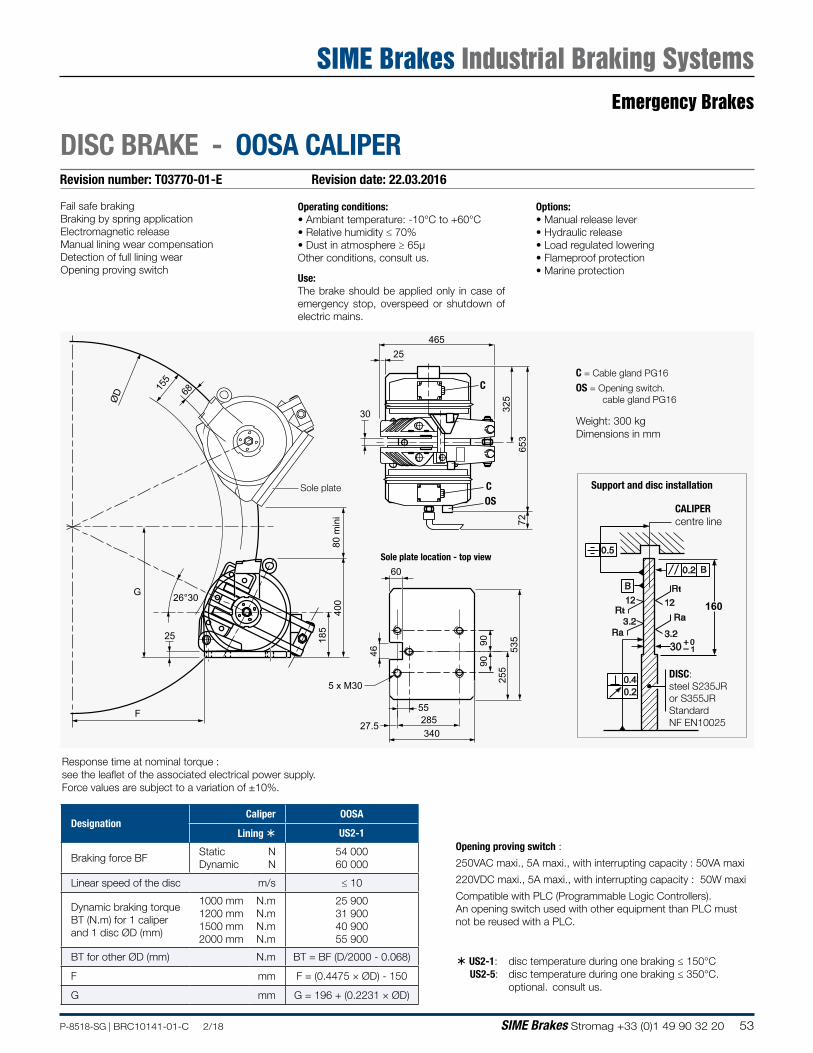
Revision number: T03770-01-E Revision date: 22.03.2016
DISC BRAKE - OOSA CALIPER
160
0.40.2
12t
t12
1030
Support and disc installation
CALIPER centre line
DISC:steel S235JR or S355JRStandardNF EN10025
Opening proving switch :
250VAC maxi., 5A maxi., with interrupting capacity : 50VA maxi
220VDC maxi., 5A maxi., with interrupting capacity : 50W maxi
Compatible with PLC (Programmable Logic Controllers).An opening switch used with other equipment than PLC must not be reused with a PLC.
Response time at nominal torque : see the leaflet of the associated electrical power supply. Force values are subject to a variation of ±10%.
Ü US2-1: disc temperature during one braking ≤ 150°C US2-5: disc temperature during one braking ≤ 350°C. optional. consult us.
Weight: 300 kgDimensions in mm
Options:• Manual release lever• Hydraulic release• Load regulated lowering• Flameproof protection• Marine protection
Operating conditions:• Ambiant temperature: -10°C to +60°C• Relative humidity ≤ 70%• Dust in atmosphere ≥ 65µOther conditions, consult us.
Use:The brake should be applied only in case of emergency stop, overspeed or shutdown of electric mains.
Fail safe brakingBraking by spring applicationElectromagnetic releaseManual lining wear compensationDetection of full lining wearOpening proving switch
155
68
ØD
80 m
ini
G 26°30
25
F
400
185
5 x M30
46
60
9090
535
255
55
27.5 285340
25
7265
3
325
30
465
Sole plate
Sole plate location - top view
OS = Opening switch. cable gland PG16
C = Cable gland PG16
OSC
C
DesignationCaliper OOSA
Lining Ü US2-1
Braking force BF Static Dynamic
N N
54 000 60 000
Linear speed of the disc m/s ≤ 10
Dynamic braking torque BT (N.m) for 1 caliper and 1 disc ØD (mm)
1000 mm 1200 mm 1500 mm 2000 mm
N.m N.m N.m N.m
25 900 31 900 40 900 55 900
BT for other ØD (mm) N.m BT = BF (D/2000 - 0.068)
F mm F = (0.4475 × ØD) - 150
G mm G = 196 + (0.2231 × ØD)
Emergency Brakes
SIME Brakes Industrial Braking Systems

54 SIME Brakes Stromag +33 (0)1 49 90 32 20 P-8518-SG | BRC10141-01-C 2/18
NOTES
55P-8518-SG | BRC10141-01-C 2/18 SIME Brakes Stromag +33 (0)1 49 90 32 20
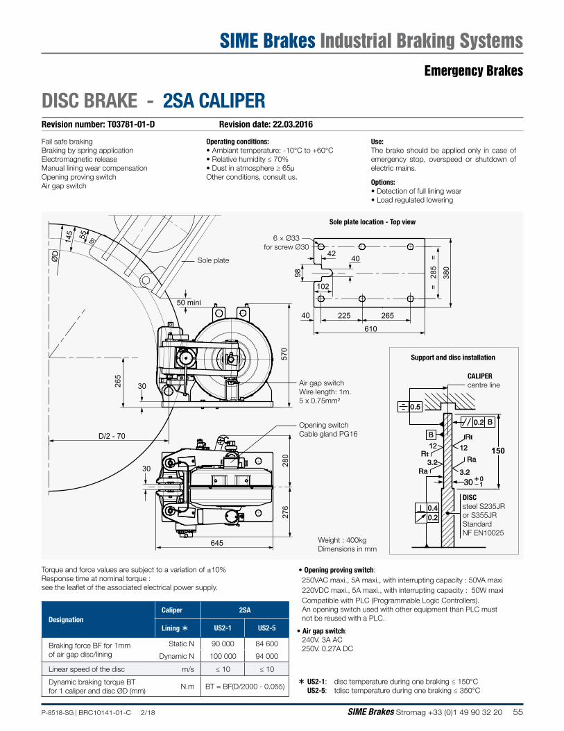
Revision number: T03781-01-D Revision date: 22.03.2016
DISC BRAKE - 2SA CALIPER
Use:The brake should be applied only in case of emergency stop, overspeed or shutdown of electric mains.
Options:• Detection of full lining wear• Load regulated lowering
Operating conditions:• Ambiant temperature: -10°C to +60°C• Relative humidity ≤ 70%• Dust in atmosphere ≥ 65µOther conditions, consult us.
Fail safe brakingBraking by spring applicationElectromagnetic releaseManual lining wear compensationOpening proving switchAir gap switch
Support and disc installation
Ü US2-1: disc temperature during one braking ≤ 150°C US2-5: tdisc temperature during one braking ≤ 350°C
DesignationCaliper 2SA
Lining Ü US2-1 US2-5
Braking force BF for 1mm of air gap disc/lining
Static N 90 000 84 600
Dynamic N 100 000 94 000
Linear speed of the disc m/s ≤ 10 ≤ 10
Dynamic braking torque BTfor 1 caliper and disc ØD (mm)
N.m BT = BF(D/2000 - 0.055)
• Opening proving switch:250VAC maxi., 5A maxi., with interrupting capacity : 50VA maxi220VDC maxi., 5A maxi., with interrupting capacity : 50W maxiCompatible with PLC (Programmable Logic Controllers).An opening switch used with other equipment than PLC must not be reused with a PLC.
• Air gap switch:240V. 3A AC250V. 0.27A DC
150
0.40.2
12t
t12
1030
DISCsteel S235JR or S355JRStandard NF EN10025
Torque and force values are subject to a variation of ±10%Response time at nominal torque : see the leaflet of the associated electrical power supply.
CALIPER centre line
645
D/2 - 70
30
30
50 mini
55
ØD
276
610
225
102
26540
= 2
85
=
380
9828
0
145
265
570
4042
6 × Ø33for screw Ø30
Sole plate
Air gap switchWire length: 1m.5 x 0.75mm²
Sole plate location - Top view
Opening switchCable gland PG16
Weight : 400kgDimensions in mm
Emergency Brakes
SIME Brakes Industrial Braking Systems
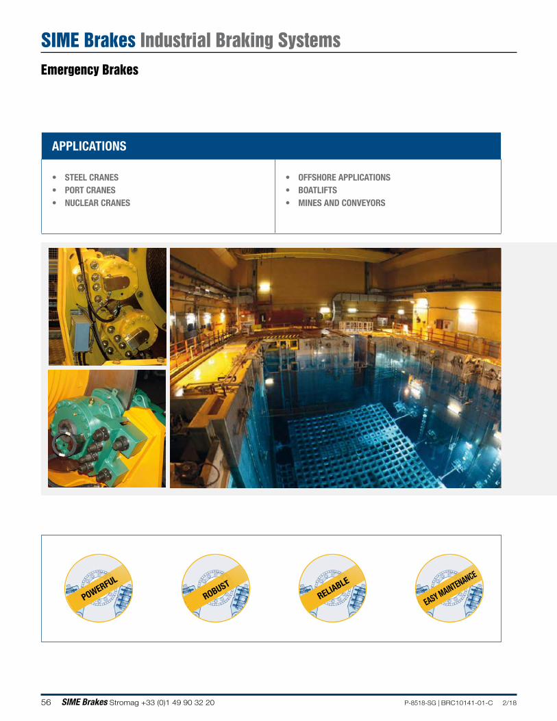
56 SIME Brakes Stromag +33 (0)1 49 90 32 20 P-8518-SG | BRC10141-01-C 2/18
APPLICATIONS
• STEEL CRANES• PORT CRANES• NUCLEAR CRANES
• OFFSHORE APPLICATIONS• BOATLIFTS• MINES AND CONVEYORS
POWERFUL
ROBUSTRELIABLE
EASY MAINTENANCE
Emergency Brakes
SIME Brakes Industrial Braking Systems
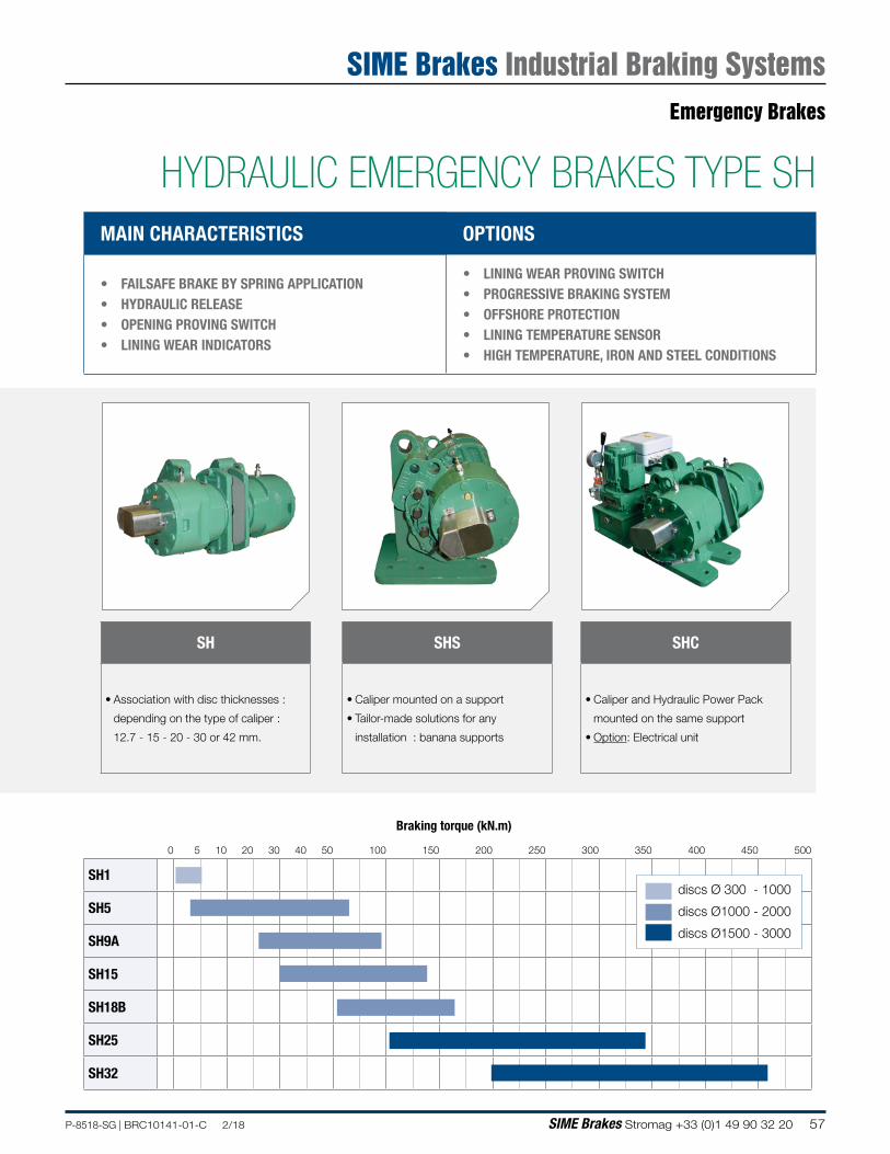
57P-8518-SG | BRC10141-01-C 2/18 SIME Brakes Stromag +33 (0)1 49 90 32 20
Braking torque (kN.m)
0 5 10 20 30 40 50 100 150 200 250 300 350 400 450 500
SH1
SH5
SH9A
SH15
SH18B
SH25
SH32
discs Ø 300 - 1000
discs Ø1000 - 2000
discs Ø1500 - 3000
MAIN CHARACTERISTICS OPTIONS
• FAILSAFE BRAKE BY SPRING APPLICATION • HYDRAULIC RELEASE• OPENING PROVING SWITCH• LINING WEAR INDICATORS
• LINING WEAR PROVING SWITCH • PROGRESSIVE BRAKING SYSTEM• OFFSHORE PROTECTION• LINING TEMPERATURE SENSOR• HIGH TEMPERATURE, IRON AND STEEL CONDITIONS
SH
• Association with disc thicknesses :
depending on the type of caliper :
12.7 - 15 - 20 - 30 or 42 mm.
SHS
• Caliper mounted on a support
• Tailor-made solutions for any
installation : banana supports
SHC
• Caliper and Hydraulic Power Pack
mounted on the same support
• Option: Electrical unit
HYDRAULIC EMERGENCY BRAKES TYPE SH
Emergency Brakes
SIME Brakes Industrial Braking Systems
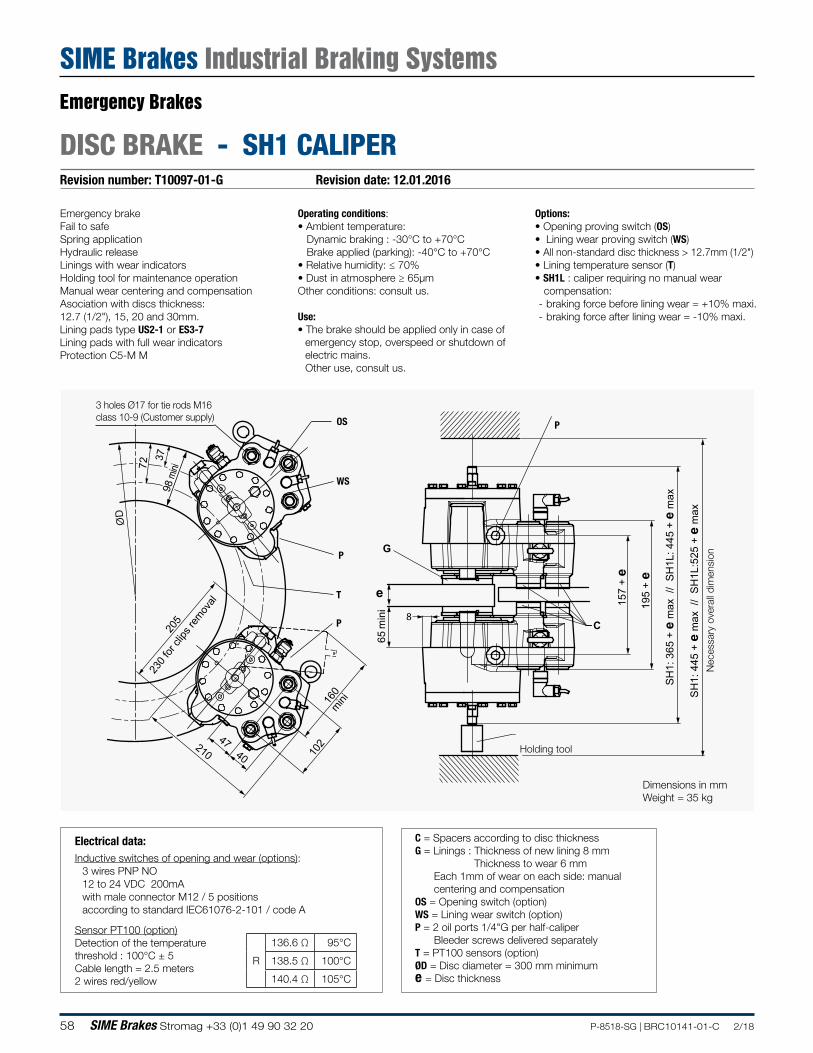
58 SIME Brakes Stromag +33 (0)1 49 90 32 20 P-8518-SG | BRC10141-01-C 2/18
Revision number: T10097-01-G Revision date: 12.01.2016
DISC BRAKE - SH1 CALIPER
Emergency brakeFail to safeSpring applicationHydraulic releaseLinings with wear indicatorsHolding tool for maintenance operationManual wear centering and compensationAsociation with discs thickness: 12.7 (1/2"), 15, 20 and 30mm.Lining pads type US2-1 or ES3-7Lining pads with full wear indicatorsProtection C5-M M
Operating conditions:• Ambient temperature: Dynamic braking : -30°C to +70°C Brake applied (parking): -40°C to +70°C• Relative humidity: ≤ 70%• Dust in atmosphere ≥ 65µmOther conditions: consult us.
Use:• The brake should be applied only in case of
emergency stop, overspeed or shutdown of electric mains.Other use, consult us.
Options:• Opening proving switch (OS)• Lining wear proving switch (WS)• All non-standard disc thickness > 12.7mm (1/2")• Lining temperature sensor (T)• SH1L : caliper requiring no manual wear compensation:
- braking force before lining wear = +10% maxi. - braking force after lining wear = -10% maxi.
Electrical data:Inductive switches of opening and wear (options):
3 wires PNP NO12 to 24 VDC 200mAwith male connector M12 / 5 positionsaccording to standard IEC61076-2-101 / code A
Sensor PT100 (option)Detection of the temperaturethreshold : 100°C ± 5 Cable length = 2.5 meters2 wires red/yellow
C = Spacers according to disc thicknessG = Linings : Thickness of new lining 8 mm Thickness to wear 6 mm
Each 1mm of wear on each side: manual centering and compensation
OS = Opening switch (option) WS = Lining wear switch (option)P = 2 oil ports 1/4"G per half-caliper
Bleeder screws delivered separatelyT = PT100 sensors (option)ØD = Disc diameter = 300 mm minimume = Disc thickness
R
136.6 Ω 95°C
138.5 Ω 100°C
140.4 Ω 105°C
157
+ e
195
+ e
65
min
i
SH
1: 3
65 +
e m
ax /
/ S
H1L
: 445
+ e
max
SH
1: 4
45 +
e m
ax /
/ S
H1L
:525
+ e
max
37
ØD
72
98
mini
C
G
e
8
160
mini
205
102 210
47 40
230 f
or cl
ips re
moval
Dimensions in mmWeight = 35 kg
Nec
essa
ry o
vera
ll di
men
sion
3 holes Ø17 for tie rods M16class 10-9 (Customer supply)
P
Holding tool
OS
WS
T
P
P
Emergency Brakes
SIME Brakes Industrial Braking Systems
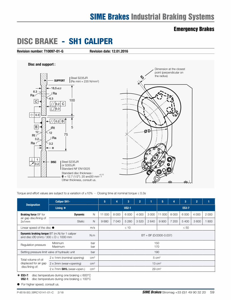
59P-8518-SG | BRC10141-01-C 2/18 SIME Brakes Stromag +33 (0)1 49 90 32 20
Revision number: T10097-01-G Revision date: 12.01.2016
DISC BRAKE - SH1 CALIPER
75
100
18,5 ±0,2
5
1
0.2
0.2
0.2
0.3
12
t
t12
6.3
6.3
e
0.3
3.2
3.2
Disc and support :
SUPPORT
Dimension at the closestpoint (perpendicular onthe radius)
Steel S235JR(Re mini = 235 N/mm2)
Steel S235JR or S355JRStandard NF EN10025
Standard disc thickness :e = 12.7 (1/2"). 20 and30 mm
+0.15− 3
Other thickness, consult us.
5
Ø D
DISC
Torque and effort values are subject to a variation of ±10% - Closing time at nominal torque ≤ 0.3s
ES3-7: disc temperature during one braking ≤ 600°C US2-1: disc temperature during one braking ≤ 100°C
For higher speed, consult us.
DesignationCaliper SH1- 5 4 3 2 1 5 4 3 2 1
Lining US2-1 ES3-7
Braking force BF for air gap disc/lining of 2x1mm
Dynamic N 11 000 8 000 6 000 4 000 3 000 11 000 8 000 6 000 4 000 2 000
Static N 9 680 7 040 5 280 3 520 2 640 9 900 7 200 5 400 3 600 1 800
Linear speed of the disc m/s ≤ 10 ≤ 50
Dynamic braking torque BT (m.N) for 1 caliper and disc ØD (mm) / 300 ≤ D ≤ 1000 mm
N.m BT = BF (D/2000-0.037)
Regulation pressureMinimum Maximum
bar bar
150170
Setting pressure limit valve of hydraulic unit bar 190
Total volume of oil displaced for air gap disc/lining of:
2 x 1mm (nominal opening) cm3 5 cm3
2 x 3mm (wear+opening) cm3 13 cm3
2 x 7mm SH1L (wear+open.) cm3 29 cm3
Emergency Brakes
SIME Brakes Industrial Braking Systems
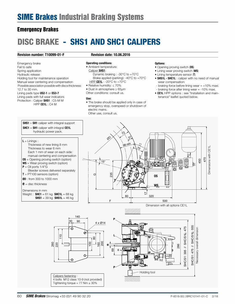
60 SIME Brakes Stromag +33 (0)1 49 90 32 20 P-8518-SG | BRC10141-01-C 2/18
Revision number: T10099-01-F Revision date: 10.06.2016
DISC BRAKE - SHS1 AND SHC1 CALIPERS
450
470
500
320 80
F
G
15°
70
160
220
2
60
140
4 x Ø14 90 30
110
200
100
286
69
SH
C/S
1: 3
95 /
/ S
HC
/S1L
: 475
SH
C/S
1: 4
75 /
/ S
HC
/S1L
: 555
37ØD72
98 mini
L
e
8
17
235
P
P
Emergency brakeFail to safeSpring applicationHydraulic releaseHolding tool for maintenance operation Manual wear centering and compensation Possible association possible with discs thickness: 12.7 to 30 mm.Lining pads type US2-1 or ES3-7Lining pads with full wear indicatorsProtection : Caliper SHS1 : C5-M M HPP CE1L : C4 M
Operating conditions:• Ambient temperature: Caliper SHS1: Dynamic braking : -30°C to +70°C Brake applied (parking): -40°C to +70°C HPP CE1L : -20°C to +70°C• Relative humidity: ≤ 70%• Dust in atmosphere ≥ 65µmOther conditions: consult us.
Use:• The brake should be applied only in case of
emergency stop, overspeed or shutdown of electric mains.Other use, consult us.
Options:• Opening proving switch (OS)• Lining wear proving switch (WS)• Lining temperature sensor (T) • SHS1L - SHC1L : caliper with no need of manual
wear compensation: - braking force before lining wear = +10% maxi. - braking force after lining wear = -10% maxi.
• CE1L HPP options : see "Installation and main-tenance" leaflet quoted below.
Dimensions in mmWeight : SHC1 = 61 kg SHC1L = 68 kg SHS1 = 39 kg SHS1L = 46 kg
Nec
essa
ry o
vera
ll di
men
sion
L = Linings : Thickness of new lining 8 mmThickness to wear 6 mmEach 1 mm of wear on each side: manual centering and compensation
OS = Opening proving switch (option)WS = Wear proving switch (option)P = Oil ports 1/4"G
Bleeder screws delivered separatelyT = PT100 sensors (option)
ØD : from 300 to 1000 mm
e = disc thickness
Holding tool
Dim
ensi
ons
with
CE
1L
TOS
WS
Dimension with all options CE1L
Calipers fastening :4 bolts M12 class 10-9 (not provided) Tightening torque = 77 Nm ± 30%
SHS1 = SH1 caliper with integral support
SHC1 = SH1 caliper with integral CE1L hydraulic power pack.
Emergency Brakes
SIME Brakes Industrial Braking Systems
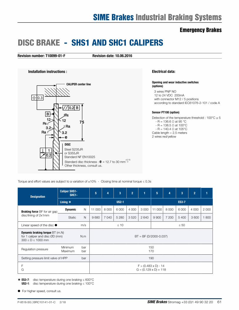
61P-8518-SG | BRC10141-01-C 2/18 SIME Brakes Stromag +33 (0)1 49 90 32 20
Revision number: T10099-01-F Revision date: 10.06.2016
DISC BRAKE - SHS1 AND SHC1 CALIPERS
75
1
0.2
0.2
12t
t12
0.3
e
Installation instructions :
DISC
Steel S235JR or S355JRStandard NF EN10025
Torque and effort values are subject to a variation of ±10% - Closing time at nominal torque ≤ 0.3s
Standard disc thickness : e = 12.7 to 30 mm+0.15− 3
Other thickness, consult us.
ES3-7: disc temperature during one braking ≤ 600°C US2-1: disc temperature during one braking ≤ 100°C
For higher speed, consult us.
CALIPER center line
Electrical data:
Opening and wear inductive switches(options)
3 wires PNP NO12 to 24 VDC 200mAwith connector M12 / 5 positionsaccording to standard IEC61076-2-101 / code A
Sensor PT100 (option)
Detection of the temperature threshold : 100°C ± 5 - R = 136.6 Ω at 95 °C - R = 138.5 Ω at 100°C - R = 140.4 Ω at 105°CCable length = 2.5 meters2 wires red/yellow
Designation
Caliper SHS1- SHC1-
5 4 3 2 1 5 4 3 2 1
Lining US2-1 ES3-7
Braking force BF for air gap disc/lining of 2x1mm
Dynamic N 11 000 8 000 6 000 4 000 3 000 11 000 8 000 6 000 4 000 2 000
Static N 9 680 7 040 5 280 3 520 2 640 9 900 7 200 5 400 3 600 1 800
Linear speed of the disc m/s ≤ 10 ≤ 50
Dynamic braking torque BT (m.N) for 1 caliper and disc ØD (mm) 300 ≤ D ≤ 1000 mm
N.m BT = BF (D/2000-0.037)
Regulation pressureMinimum Maximum
bar bar
150170
Setting pressure limit valve of HPP bar 190
F G
F = (0.483 x D) - 14 G = (0.129 x D) + 118
Emergency Brakes
SIME Brakes Industrial Braking Systems
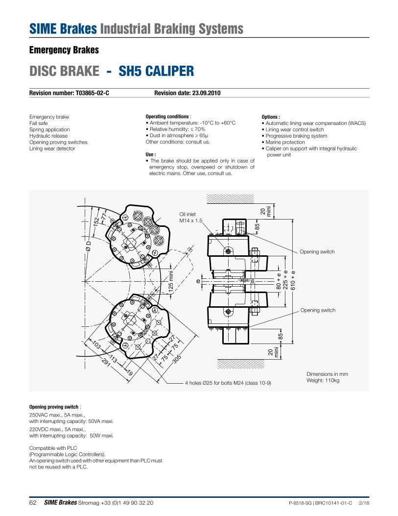
62 SIME Brakes Stromag +33 (0)1 49 90 32 20 P-8518-SG | BRC10141-01-C 2/18
Revision number: T03865-02-C Revision date: 23.09.2010
DISC BRAKE - SH5 CALIPER
Emergency brakeFail safeSpring applicationHydraulic releaseOpening proving switchesLining wear detector
Operating conditions :• Ambient temperature: -10°C to +60°C• Relative humidity: ≤ 70%• Dust in atmosphere ≥ 65µOther conditions: consult us.
Use :• The brake should be applied only in case of
emergency stop, overspeed or shutdown of electric mains. Other use, consult us.
Options :• Automatic lining wear compensation (WACS)• Lining wear control switch• Progressive braking system• Marine protection• Caliper on support with integral hydraulic
power unit
610
+ e
225
+ e
e80
+ e
Ø D
152 77
125
min
i
27
27 7575
305
19
113
103
291
85
20 min
i
85
6
20 min
i
4 holes Ø25 for bolts M24 (class 10-9)
Oil inletM14 x 1.5
Opening switch
Opening switch
Opening proving switch :
250VAC maxi., 5A maxi., with interrupting capacity: 50VA maxi.
220VDC maxi., 5A maxi., with interrupting capacity: 50W maxi.
Compatible with PLC(Programmable Logic Controllers).An opening switch used with other equipment than PLC must not be reused with a PLC.
Dimensions in mmWeight: 110kg
Emergency Brakes
SIME Brakes Industrial Braking Systems
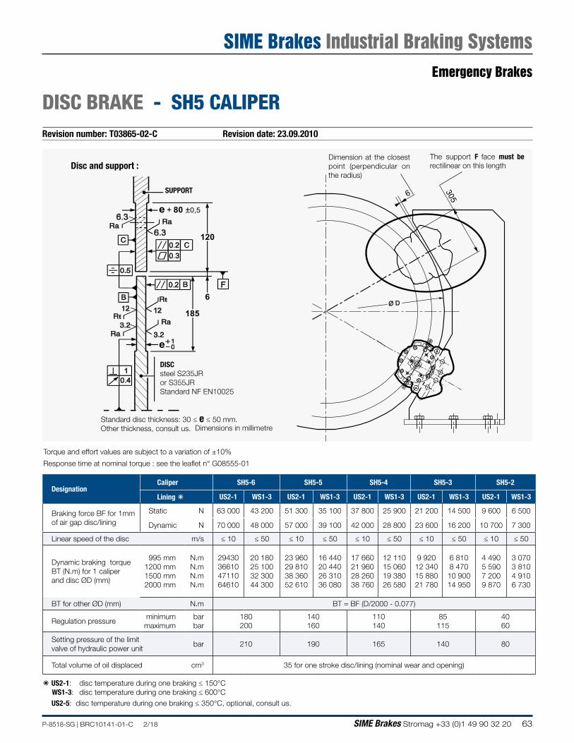
63P-8518-SG | BRC10141-01-C 2/18 SIME Brakes Stromag +33 (0)1 49 90 32 20
Revision number: T03865-02-C Revision date: 23.09.2010
DISC BRAKE - SH5 CALIPER
120
e + 80 ±0,5
6
185
F
e
SUPPORT
DISCsteel S235JRor S355JRStandard NF EN10025
Standard disc thickness: 30 ≤ e ≤ 50 mm.Other thickness, consult us.
6 305
Ø D
Dimension at the closest point (perpendicular on the radius)
The support F face must be rectilinear on this length
Dimensions in millimetre
Disc and support :
á US2-1: disc temperature during one braking ≤ 150°C WS1-3: disc temperature during one braking ≤ 600°C US2-5: disc temperature during one braking ≤ 350°C, optional, consult us.
DesignationCaliper SH5-6 SH5-5 SH5-4 SH5-3 SH5-2
Lining á US2-1 WS1-3 US2-1 WS1-3 US2-1 WS1-3 US2-1 WS1-3 US2-1 WS1-3
Braking force BF for 1mm of air gap disc/lining
Static N 63 000 43 200 51 300 35 100 37 800 25 900 21 200 14 500 9 600 6 500
Dynamic N 70 000 48 000 57 000 39 100 42 000 28 800 23 600 16 200 10 700 7 300
Linear speed of the disc m/s ≤ 10 ≤ 50 ≤ 10 ≤ 50 ≤ 10 ≤ 50 ≤ 10 ≤ 50 ≤ 10 ≤ 50
Dynamic braking torque BT (N.m) for 1 caliper and disc ØD (mm)
995 mm 1200 mm 1500 mm 2000 mm
N.m N.m N.m N.m
29430 36610 47110 64610
20 180 25 100 32 300 44 300
23 960 29 810 38 360 52 610
16 440 20 440 26 310 36 080
17 660 21 960 28 260 38 760
12 110 15 060 19 380 26 580
9 920 12 340 15 880 21 780
6 810 8 470 10 900 14 950
4 490 5 590 7 200 9 870
3 070 3 810 4 910 6 730
BT for other ØD (mm) N.m BT = BF (D/2000 - 0.077)
Regulation pressureminimum maximum
bar bar
180 200
140 160
110 140
85 115
40 60
Setting pressure of the limit valve of hydraulic power unit
bar 210 190 165 140 80
Total volume of oil displaced cm3 35 for one stroke disc/lining (nominal wear and opening)
Torque and effort values are subject to a variation of ±10%
Response time at nominal torque : see the leaflet n° G08555-01
Emergency Brakes
SIME Brakes Industrial Braking Systems
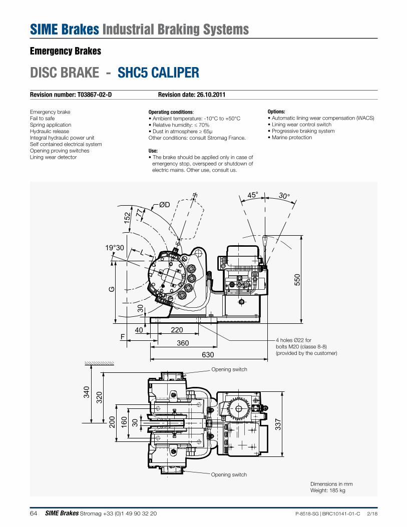
64 SIME Brakes Stromag +33 (0)1 49 90 32 20 P-8518-SG | BRC10141-01-C 2/18
Revision number: T03867-02-D Revision date: 26.10.2011
DISC BRAKE - SHC5 CALIPER
Emergency brakeFail to safeSpring applicationHydraulic releaseIntegral hydraulic power unitSelf contained electrical systemOpening proving switchesLining wear detector
Operating conditions:• Ambient temperature: -10°C to +50°C• Relative humidity: ≤ 70%• Dust in atmosphere ≥ 65µOther conditions: consult Stromag France.
Use:• The brake should be applied only in case of
emergency stop, overspeed or shutdown of electric mains. Other use, consult us.
Options:• Automatic lining wear compensation (WACS)• Lining wear control switch• Progressive braking system• Marine protection
ØD
77
152
19°30 L
G
30
340
320
200
337
160
30
40 220
360630
F
550
45° 30°
4 holes Ø22 for bolts M20 (classe 8-8) (provided by the customer)
Opening switch
Opening switch
Dimensions in mmWeight: 185 kg
Emergency Brakes
SIME Brakes Industrial Braking Systems
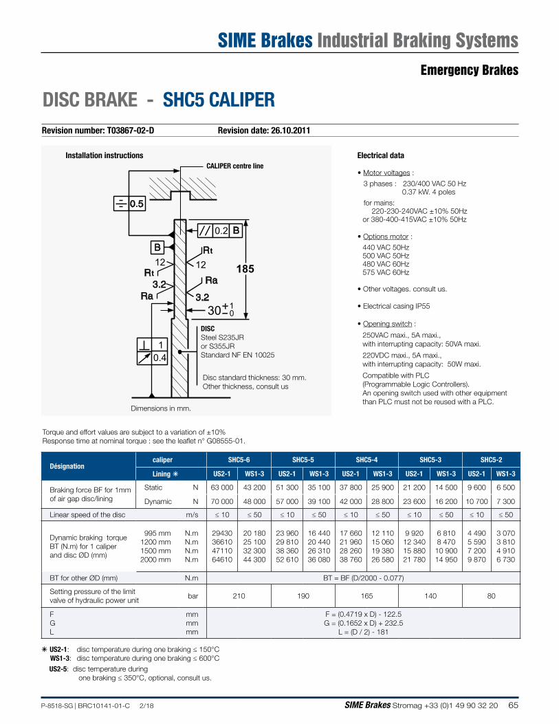
65P-8518-SG | BRC10141-01-C 2/18 SIME Brakes Stromag +33 (0)1 49 90 32 20
Revision number: T03867-02-D Revision date: 26.10.2011
DISC BRAKE - SHC5 CALIPER
Installation instructionsCALIPER centre line
Disc standard thickness: 30 mm.Other thickness, consult us
Electrical data
• Motor voltages :
3 phases : 230/400 VAC 50 Hz 0.37 kW. 4 poles
for mains: 220-230-240VAC ±10% 50Hz
or 380-400-415VAC ±10% 50Hz
• Options motor :
440 VAC 50Hz500 VAC 50Hz480 VAC 60Hz575 VAC 60Hz
• Other voltages. consult us.
• Electrical casing IP55
• Opening switch :
250VAC maxi., 5A maxi., with interrupting capacity: 50VA maxi.
220VDC maxi., 5A maxi., with interrupting capacity: 50W maxi.
Compatible with PLC(Programmable Logic Controllers).An opening switch used with other equipment than PLC must not be reused with a PLC.
Dimensions in mm.
185
1
0.2
0.4
12t
t12
1030
DISCSteel S235JR or S355JRStandard NF EN 10025
Torque and effort values are subject to a variation of ±10%Response time at nominal torque : see the leaflet n° G08555-01.
á US2-1: disc temperature during one braking ≤ 150°C WS1-3: disc temperature during one braking ≤ 600°C
US2-5: disc temperature during one braking ≤ 350°C, optional, consult us.
Désignationcaliper SHC5-6 SHC5-5 SHC5-4 SHC5-3 SHC5-2
Lining á US2-1 WS1-3 US2-1 WS1-3 US2-1 WS1-3 US2-1 WS1-3 US2-1 WS1-3
Braking force BF for 1mm of air gap disc/lining
Static N 63 000 43 200 51 300 35 100 37 800 25 900 21 200 14 500 9 600 6 500
Dynamic N 70 000 48 000 57 000 39 100 42 000 28 800 23 600 16 200 10 700 7 300
Linear speed of the disc m/s ≤ 10 ≤ 50 ≤ 10 ≤ 50 ≤ 10 ≤ 50 ≤ 10 ≤ 50 ≤ 10 ≤ 50
Dynamic braking torque BT (N.m) for 1 caliper and disc ØD (mm)
995 mm 1200 mm 1500 mm 2000 mm
N.m N.m N.m N.m
29430 36610 47110 64610
20 180 25 100 32 300 44 300
23 960 29 810 38 360 52 610
16 440 20 440 26 310 36 080
17 660 21 960 28 260 38 760
12 110 15 060 19 380 26 580
9 920 12 340 15 880 21 780
6 810 8 470 10 900 14 950
4 490 5 590 7 200 9 870
3 070 3 810 4 910 6 730
BT for other ØD (mm) N.m BT = BF (D/2000 - 0.077)
Setting pressure of the limit valve of hydraulic power unit
bar 210 190 165 140 80
FGL
mmmmmm
F = (0.4719 x D) - 122.5G = (0.1652 x D) + 232.5
L = (D / 2) - 181
Emergency Brakes
SIME Brakes Industrial Braking Systems
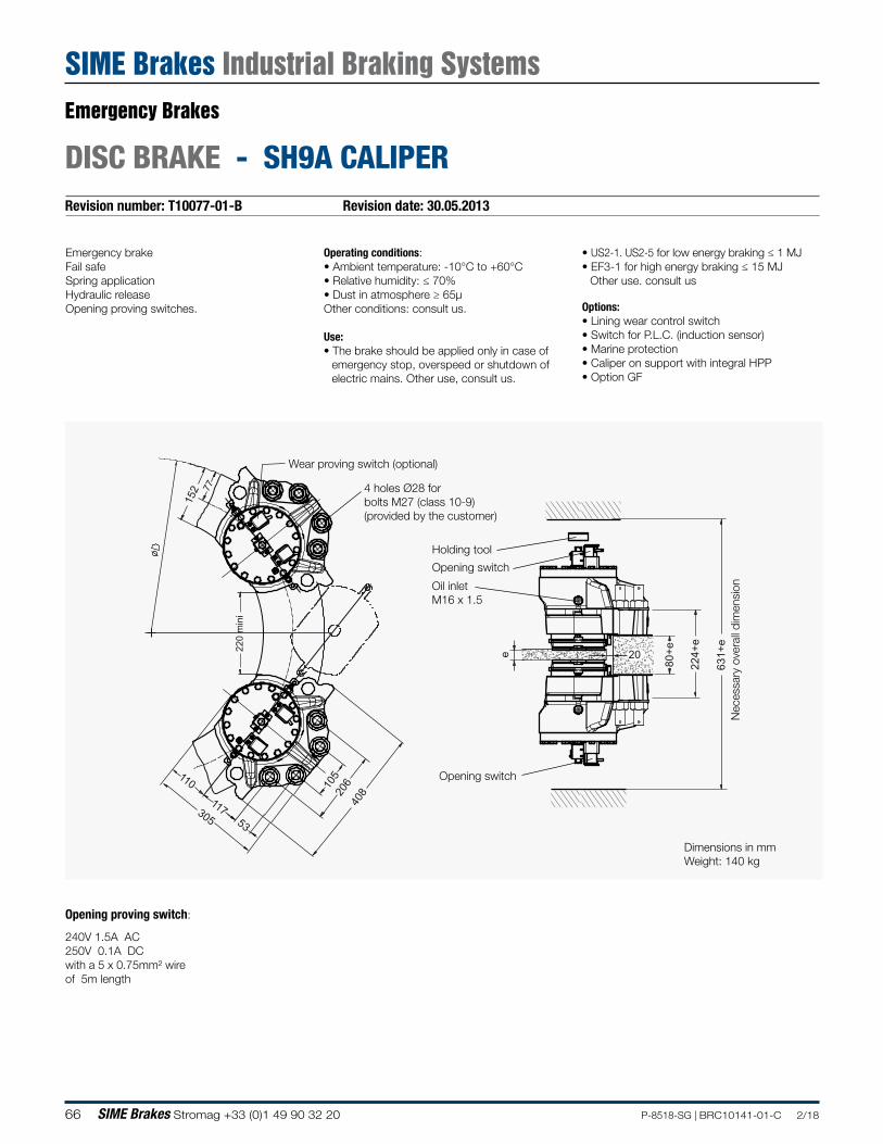
66 SIME Brakes Stromag +33 (0)1 49 90 32 20 P-8518-SG | BRC10141-01-C 2/18
Revision number: T10077-01-B Revision date: 30.05.2013
DISC BRAKE - SH9A CALIPER
Emergency brakeFail safeSpring applicationHydraulic releaseOpening proving switches.
Operating conditions:• Ambient temperature: -10°C to +60°C• Relative humidity: ≤ 70%• Dust in atmosphere ≥ 65µOther conditions: consult us.
Use:• The brake should be applied only in case of
emergency stop, overspeed or shutdown of electric mains. Other use, consult us.
• US2-1. US2-5 for low energy braking ≤ 1 MJ• EF3-1 for high energy braking ≤ 15 MJ
Other use. consult us
Options:• Lining wear control switch• Switch for P.L.C. (induction sensor)• Marine protection• Caliper on support with integral HPP• Option GF
Dimensions in mmWeight: 140 kg
220
min
i
152 77
110
117305 53
105
206
408
80+e
224+
e
631+
e
e 20
Oil inletM16 x 1.5
4 holes Ø28 for bolts M27 (class 10-9)(provided by the customer)
Opening switch
Wear proving switch (optional)
Nec
essa
ry o
vera
ll di
men
sion
Opening switch
Holding tool
Opening proving switch:
240V 1.5A AC250V 0.1A DCwith a 5 x 0.75mm² wire of 5m length
Emergency Brakes
SIME Brakes Industrial Braking Systems
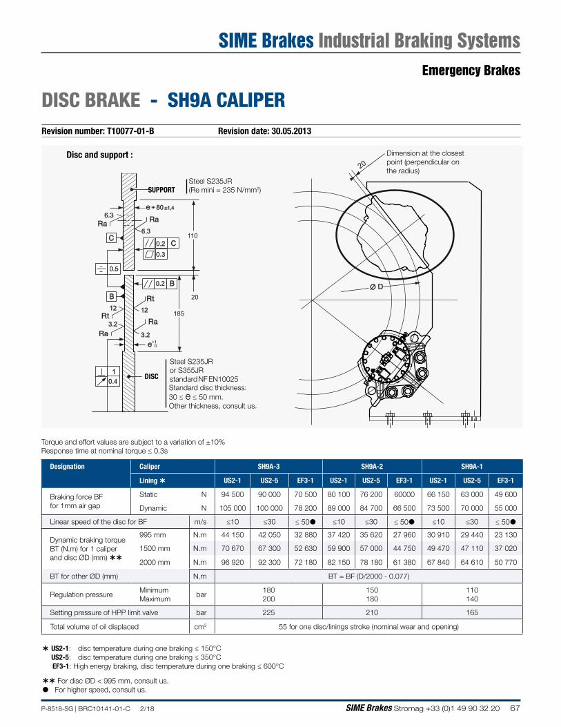
67P-8518-SG | BRC10141-01-C 2/18 SIME Brakes Stromag +33 (0)1 49 90 32 20
Revision number: T10077-01-B Revision date: 30.05.2013
DISC BRAKE - SH9A CALIPER
Designation Caliper SH9A-3 SH9A-2 SH9A-1
Lining US2-1 US2-5 EF3-1 US2-1 US2-5 EF3-1 US2-1 US2-5 EF3-1
Braking force BF for 1mm air gap
Static N 94 500 90 000 70 500 80 100 76 200 60000 66 150 63 000 49 600
Dynamic N 105 000 100 000 78 200 89 000 84 700 66 500 73 500 70 000 55 000
Linear speed of the disc for BF m/s ≤10 ≤30 ≤ 50 ≤10 ≤30 ≤ 50 ≤10 ≤30 ≤ 50
Dynamic braking torque BT (N.m) for 1 caliper and disc ØD (mm)
995 mm N.m 44 150 42 050 32 880 37 420 35 620 27 960 30 910 29 440 23 130
1500 mm N.m 70 670 67 300 52 630 59 900 57 000 44 750 49 470 47 110 37 020
2000 mm N.m 96 920 92 300 72 180 82 150 78 180 61 380 67 840 64 610 50 770
BT for other ØD (mm) N.m BT = BF (D/2000 - 0.077)
Regulation pressureMinimum Maximum
bar180 200
150 180
110 140
Setting pressure of HPP limit valve bar 225 210 165
Total volume of oil displaced cm3 55 for one disc/linings stroke (nominal wear and opening)
Torque and effort values are subject to a variation of ±10%Response time at nominal torque ≤ 0.3s
For disc ØD < 995 mm, consult us. For higher speed, consult us.
US2-1: disc temperature during one braking ≤ 150°C US2-5: disc temperature during one braking ≤ 350°C EF3-1: High energy braking, disc temperature during one braking ≤ 600°C
Standard disc thickness: 30 ≤ e ≤ 50 mm.Other thickness, consult us.
Dimension at the closest point (perpendicular on the radius)
185
110
e + 80 ±1,4
20
1
0.2
0.2
0.4
0.3
12
t
t12
6.3
6.3
e
0.5
3.2
3.2
+10
20
Ø D
Disc and support :
SUPPORT
DISC
Steel S235JR(Re mini = 235 N/mm2)
Steel S235JRor S355JRstandard NF EN10025
Emergency Brakes
SIME Brakes Industrial Braking Systems
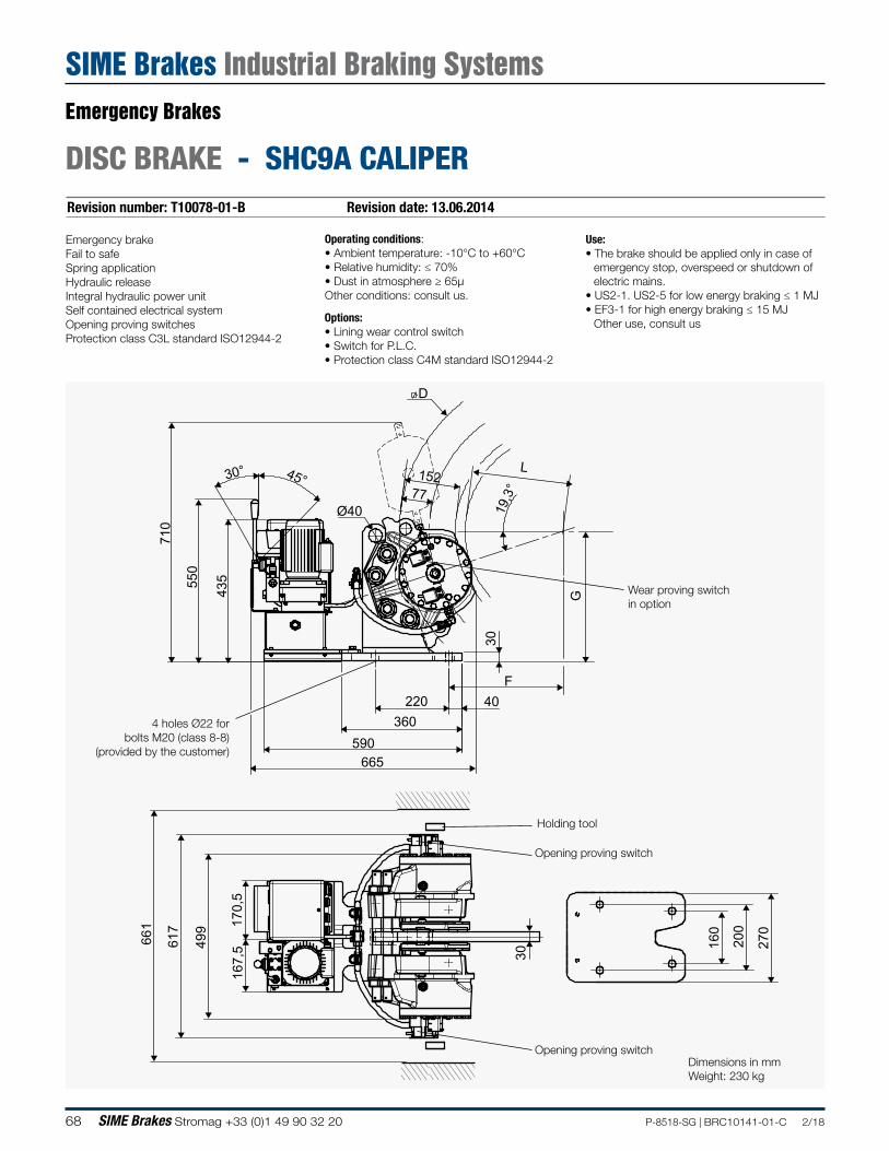
68 SIME Brakes Stromag +33 (0)1 49 90 32 20 P-8518-SG | BRC10141-01-C 2/18
Revision number: T10078-01-B Revision date: 13.06.2014
DISC BRAKE - SHC9A CALIPER
Operating conditions:• Ambient temperature: -10°C to +60°C• Relative humidity: ≤ 70%• Dust in atmosphere ≥ 65µOther conditions: consult us.
Options:• Lining wear control switch• Switch for P.L.C.• Protection class C4M standard ISO12944-2
Use:• The brake should be applied only in case of
emergency stop, overspeed or shutdown of electric mains.
• US2-1. US2-5 for low energy braking ≤ 1 MJ• EF3-1 for high energy braking ≤ 15 MJ
Other use, consult us
Emergency brakeFail to safeSpring applicationHydraulic releaseIntegral hydraulic power unitSelf contained electrical systemOpening proving switchesProtection class C3L standard ISO12944-2
4 holes Ø22 for bolts M20 (class 8-8)
(provided by the customer)
Opening proving switch
Wear proving switch in option
Opening proving switch
590
40220360
30
550
665
710
435
45°30° L15277
D
19,3
°
F
617
499
270
160
200
30
170,
516
7,5
Ø40
G
661
Holding tool
Dimensions in mmWeight: 230 kg
Emergency Brakes
SIME Brakes Industrial Braking Systems
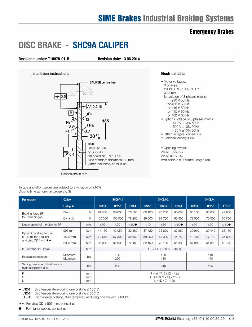
69P-8518-SG | BRC10141-01-C 2/18 SIME Brakes Stromag +33 (0)1 49 90 32 20
Revision number: T10078-01-B Revision date: 13.06.2014
DISC BRAKE - SHC9A CALIPER
Electrical data
• Motor voltages: 3 phases:
230/400 V ±10%. 50 Hz 0.37 kW for voltage of 3 phases mains: 230 V 50 Hz or 400 V 50 Hz or 415 V 50 Hz or 440 V 60 Hz or 460 V 60 Hz• Options voltage of 3 phases mains: 440 V ±10% 50Hz 500 V ±10% 50Hz 480 V ±10% 60Hz• Other voltages, consult us.• Electrical casing IP55
• Opening switch:240V. 1.5A AC220V. 0.1A DCwith cable 5 x 0.75mm2 length 5m
185
1
0.2
0.4
12t
t12
1030
Installation instructions
CALIPER centre line
Disc standard thickness: 30 mm.Other thickness, consult us
Dimensions in mm.
DISCSteel S235JR or S355JRStandard NF EN 10025
For disc ØD < 995 mm, consult us
Torque and effort values are subject to a variation of ±10%Closing time at nominal torque ≤ 0.3s
US2-1: disc temperature during one braking ≤ 150°C US2-5: disc temperature during one braking ≤ 350°C EF3-1: High energy braking, disc temperature during one braking ≤ 600°C
For higher speed, consult us.
Designation Caliper SHC9A-3 SHC9A-2 SHC9A-1
Lining US2-1 US2-5 EF3-1 US2-1 US2-5 EF3-1 US2-1 US2-5 EF3-1
Braking force BF for 1mm air gap
Static N 94 500 90 000 70 500 80 100 76 200 60 000 66 150 63 000 49 600
Dynamic N 105 000 100 000 78 200 89 000 84 700 66 500 73 500 70 000 55 000
Linear speed of the disc for BF m/s ≤10 ≤30 ≤ 50 ≤10 ≤30 ≤ 50 ≤10 ≤30 ≤ 50
Dynamic braking torque BT (N.m) for 1 caliper and disc ØD (mm)
995 mm N.m 44 150 42 050 32 880 37 420 35 620 27 960 30 910 29 440 23 130
1500 mm N.m 70 670 67 300 52 630 59 900 57 000 44 750 49 470 47 110 37 020
2000 mm N.m 96 920 92 300 72 180 82 150 78 180 61 380 67 840 64 610 50 770
BT for other ØD (mm) N.m BT = BF (D/2000 - 0.077)
Regulation pressureMinimum Maximum
bar180 200
150 180
110 140
Setting pressure of limit valve of hydraulic power unit
bar 225 210 165
F G L
mm mm mm
F = (0.4719 x D) - 113 G = (0.1652 x D) + 236.7
L = (D / 2) - 190
Emergency Brakes
SIME Brakes Industrial Braking Systems
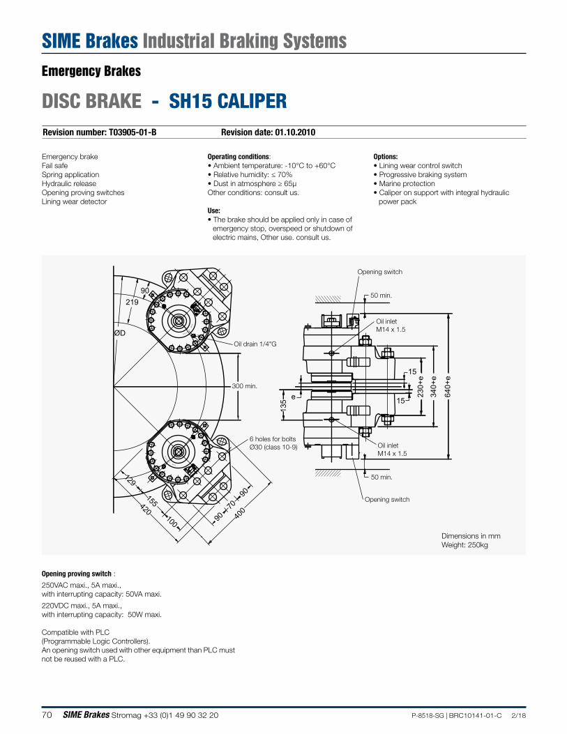
70 SIME Brakes Stromag +33 (0)1 49 90 32 20 P-8518-SG | BRC10141-01-C 2/18
Revision number: T03905-01-B Revision date: 01.10.2010
DISC BRAKE - SH15 CALIPER
Emergency brakeFail safeSpring applicationHydraulic releaseOpening proving switchesLining wear detector
Operating conditions:• Ambient temperature: -10°C to +60°C• Relative humidity: ≤ 70%• Dust in atmosphere ≥ 65µOther conditions: consult us.
Use:• The brake should be applied only in case of
emergency stop, overspeed or shutdown of electric mains, Other use. consult us.
Options:• Lining wear control switch• Progressive braking system• Marine protection• Caliper on support with integral hydraulic
power pack
MEIN
RIE
ST UD
SI
ME
IN
RIEST
UD
SI
640+
e
e
15
230+
e
340+
e
135 15
400
90
90
70100
155420
129
90
ØD
219
300 min.
6 holes for bolts Ø30 (class 10-9)
50 min.
50 min.
Oil drain 1/4"G
Oil inletM14 x 1.5
Oil inletM14 x 1.5
Opening switch
Opening switch
Dimensions in mmWeight: 250kg
Opening proving switch :
250VAC maxi., 5A maxi., with interrupting capacity: 50VA maxi.
220VDC maxi., 5A maxi., with interrupting capacity: 50W maxi.
Compatible with PLC(Programmable Logic Controllers).An opening switch used with other equipment than PLC must not be reused with a PLC.
Emergency Brakes
SIME Brakes Industrial Braking Systems
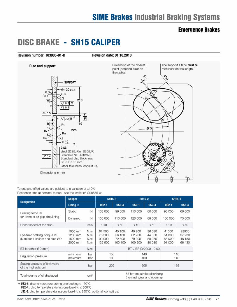
71P-8518-SG | BRC10141-01-C 2/18 SIME Brakes Stromag +33 (0)1 49 90 32 20
Revision number: T03905-01-B Revision date: 01.10.2010
DISC BRAKE - SH15 CALIPER
Dimension at the closest point (perpendicular on the radius)
The support F face must be rectilinear on the length.
225
210
30
10
1
0.2
0.2
0.4
0.3
12t
t12
10
6.3
6.30.5e
e
F
10 400
Ø D
MEIN
RIE
ST UD
SI
Disc and support
Standard disc thickness: 30 ≤ e ≤ 50 mm.Other thickness, consult us.
DISCsteel S235JR or S355JRStandard NF EN10025
SUPPORT
Dimensions in mm
à US2-1: disc temperature during one braking ≤ 150°CUS2-4 : disc temperature during one braking ≤ 600°CUS2-5: disc temperature during one braking ≤ 350°C, optional, consult us.
DesignationCaliper SH15-3 SH15-2 SH15-1
Lining à US2-1 US2-4 US2-1 US2-4 US2-1 US2-4
Braking force BF for 1mm of air gap disc/lining
Static N 133 000 99 000 110 000 80 000 90 000 66 000
Dynamic N 150 000 110 000 120 000 88 000 100 000 73 000
Linear speed of the disc m/s ≤ 10 ≤ 50 ≤ 10 ≤ 50 ≤ 10 ≤ 50
Dynamic braking torque BT (N.m) for 1 caliper and disc ØD
1000 mm 1200 mm 1500 mm 2000 mm
N.m N.m N.m N.m
61 500 76 500 99 000 136 500
45 100 56 100 72 600 100 100
49 200 62 200 79 200 109 200
36 080 44 880 58 080 80 080
41000 51 000 66 000 91 000
29930 37 230 48 180 66 430
BT for other ØD (mm) N.m BT = BF (D/2000 - 0.09)
Regulation pressureminimum maximum
bar bar
150 180
140 160
110 140
Setting pressure of limit valve of the hydraulic unit
bar 205 205 165
Total volume of oil displaced cm3 85 for one stroke disc/lining (nominal wear and opening)
Torque and effort values are subject to a variation of ±10%Response time at nominal torque : see the leaflet n° G08555-01
Emergency Brakes
SIME Brakes Industrial Braking Systems
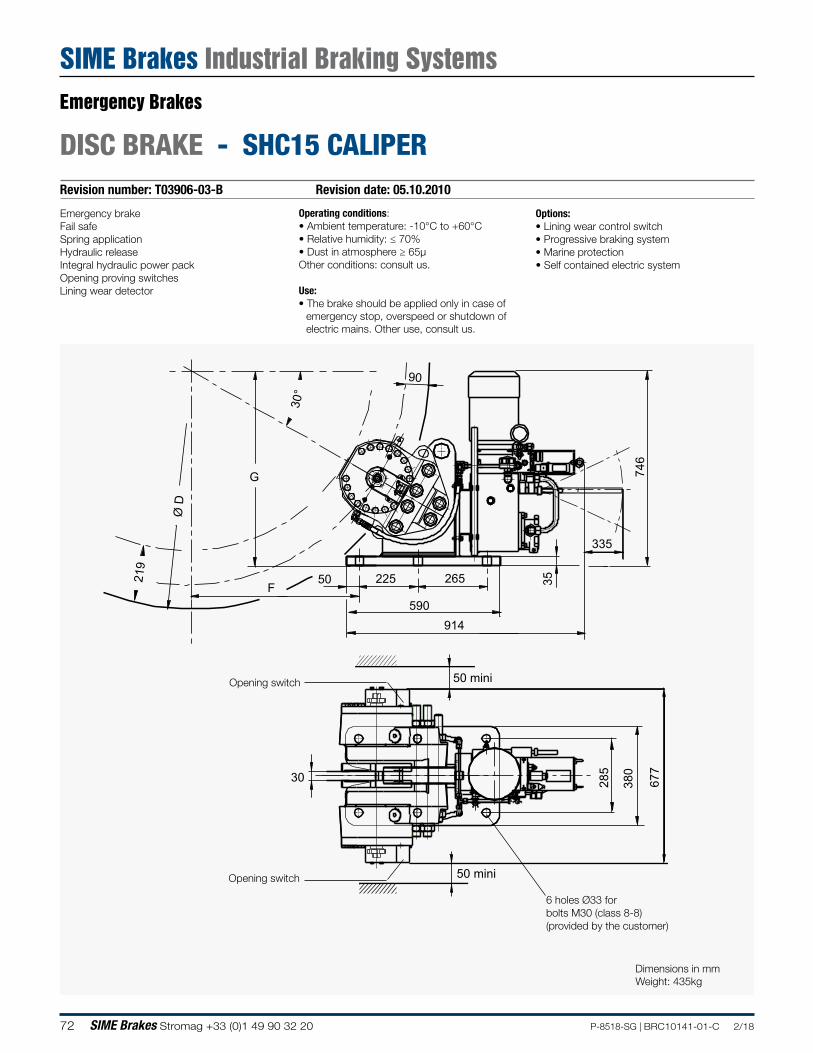
72 SIME Brakes Stromag +33 (0)1 49 90 32 20 P-8518-SG | BRC10141-01-C 2/18
Revision number: T03906-03-B Revision date: 05.10.2010
DISC BRAKE - SHC15 CALIPER
Emergency brakeFail safeSpring applicationHydraulic releaseIntegral hydraulic power packOpening proving switchesLining wear detector
Operating conditions:• Ambient temperature: -10°C to +60°C• Relative humidity: ≤ 70%• Dust in atmosphere ≥ 65µOther conditions: consult us.
Use:• The brake should be applied only in case of
emergency stop, overspeed or shutdown of electric mains. Other use, consult us.
Options:• Lining wear control switch• Progressive braking system• Marine protection• Self contained electric system
F
G
38030
746
3550 225 265
590914
219
90
Ø D
30°
50 mini
677
50 mini
335
285
Opening switch
6 holes Ø33 for bolts M30 (class 8-8) (provided by the customer)
Opening switch
Dimensions in mmWeight: 435kg
Emergency Brakes
SIME Brakes Industrial Braking Systems
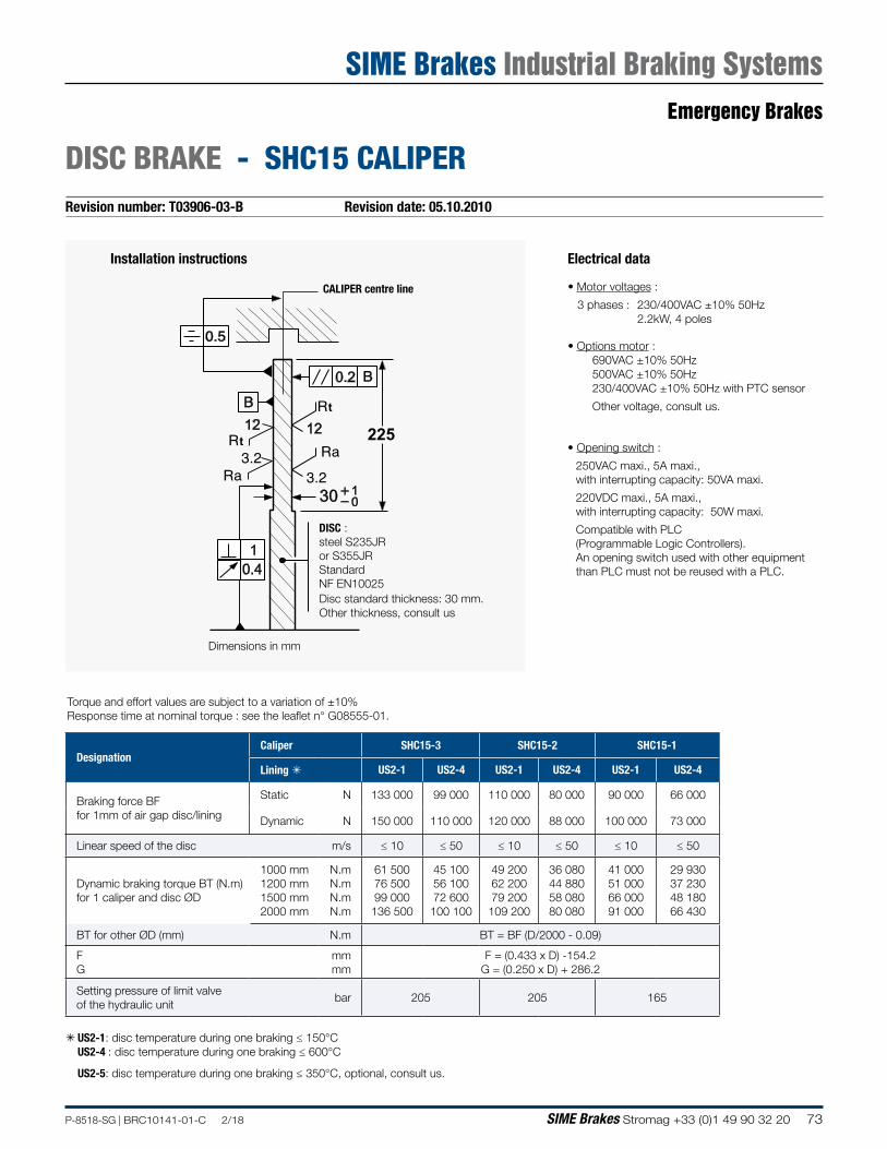
73P-8518-SG | BRC10141-01-C 2/18 SIME Brakes Stromag +33 (0)1 49 90 32 20
Revision number: T03906-03-B Revision date: 05.10.2010
DISC BRAKE - SHC15 CALIPER
Electrical data
• Motor voltages :
3 phases : 230/400VAC ±10% 50Hz 2.2kW, 4 poles
• Options motor : 690VAC ±10% 50Hz500VAC ±10% 50Hz230/400VAC ±10% 50Hz with PTC sensor
Other voltage, consult us.
• Opening switch :
250VAC maxi., 5A maxi., with interrupting capacity: 50VA maxi.
220VDC maxi., 5A maxi., with interrupting capacity: 50W maxi.
Compatible with PLC(Programmable Logic Controllers).An opening switch used with other equipment than PLC must not be reused with a PLC.
CALIPER centre line
Installation instructions
225
1
0.2
0.4
12t
t12
1030
Disc standard thickness: 30 mm.Other thickness, consult us
Torque and effort values are subject to a variation of ±10%Response time at nominal torque : see the leaflet n° G08555-01.
DISC :steel S235JR or S355JRStandard NF EN10025
Dimensions in mm
à US2-1: disc temperature during one braking ≤ 150°CUS2-4 : disc temperature during one braking ≤ 600°C
US2-5: disc temperature during one braking ≤ 350°C, optional, consult us.
DesignationCaliper SHC15-3 SHC15-2 SHC15-1
Lining à US2-1 US2-4 US2-1 US2-4 US2-1 US2-4
Braking force BF for 1mm of air gap disc/lining
Static N 133 000 99 000 110 000 80 000 90 000 66 000
Dynamic N 150 000 110 000 120 000 88 000 100 000 73 000
Linear speed of the disc m/s ≤ 10 ≤ 50 ≤ 10 ≤ 50 ≤ 10 ≤ 50
Dynamic braking torque BT (N.m) for 1 caliper and disc ØD
1000 mm 1200 mm 1500 mm 2000 mm
N.m N.m N.m N.m
61 500 76 500 99 000 136 500
45 100 56 100 72 600 100 100
49 200 62 200 79 200 109 200
36 080 44 880 58 080 80 080
41 000 51 000 66 000 91 000
29 930 37 230 48 180 66 430
BT for other ØD (mm) N.m BT = BF (D/2000 - 0.09)
FG
mm mm
F = (0.433 x D) -154.2G = (0.250 x D) + 286.2
Setting pressure of limit valve of the hydraulic unit
bar 205 205 165
Emergency Brakes
SIME Brakes Industrial Braking Systems
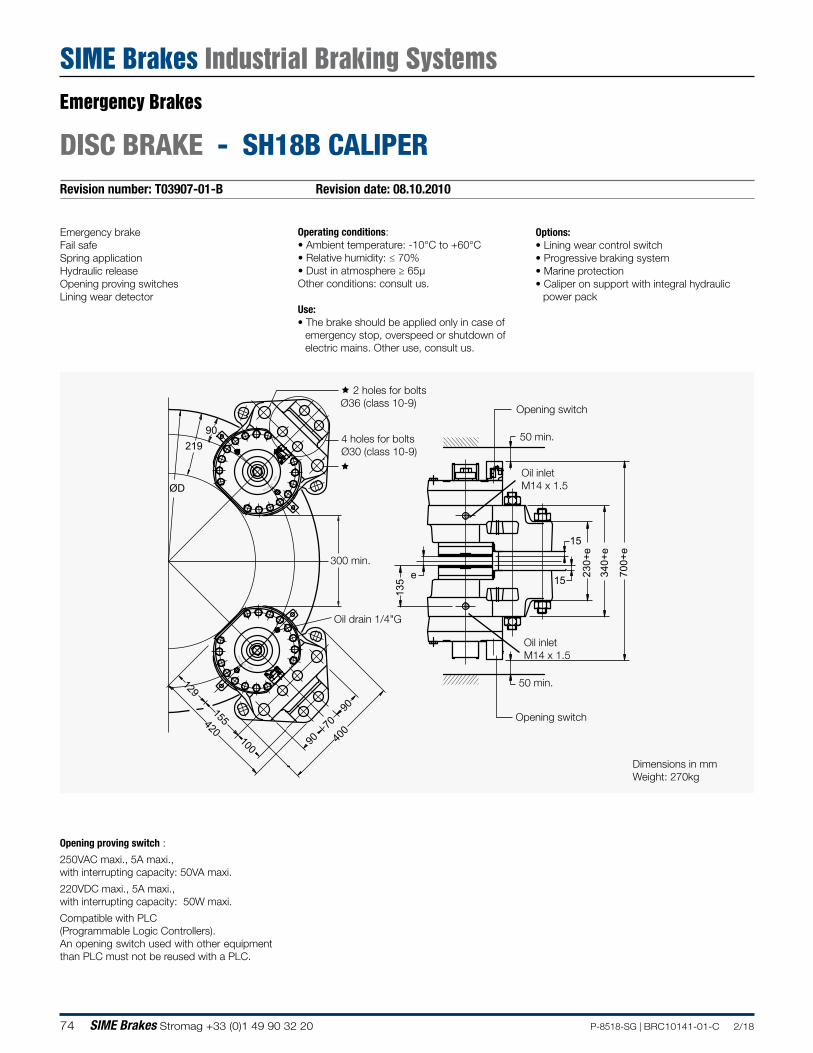
74 SIME Brakes Stromag +33 (0)1 49 90 32 20 P-8518-SG | BRC10141-01-C 2/18
Revision number: T03907-01-B Revision date: 08.10.2010
DISC BRAKE - SH18B CALIPER
Emergency brakeFail safeSpring applicationHydraulic releaseOpening proving switchesLining wear detector
Operating conditions:• Ambient temperature: -10°C to +60°C• Relative humidity: ≤ 70%• Dust in atmosphere ≥ 65µOther conditions: consult us.
Use:• The brake should be applied only in case of
emergency stop, overspeed or shutdown of electric mains. Other use, consult us.
Options:• Lining wear control switch• Progressive braking system• Marine protection• Caliper on support with integral hydraulic
power pack
MEIN
RIE
ST UD
SI
MEIN
RIEST
UD
SI
700+
e
e
15
230+
e
340+
e
135 15
400
90
90
70100
155420
129
90
ØD
219
Dimensions in mmWeight: 270kg
300 min.
50 min.
50 min.
Oil drain 1/4"G
Oil inletM14 x 1.5
Oil inletM14 x 1.5
Opening switch
4 holes for bolts Ø30 (class 10-9)
2 holes for bolts Ø36 (class 10-9)
Opening switch
Opening proving switch :
250VAC maxi., 5A maxi., with interrupting capacity: 50VA maxi.
220VDC maxi., 5A maxi., with interrupting capacity: 50W maxi.
Compatible with PLC(Programmable Logic Controllers).An opening switch used with other equipment than PLC must not be reused with a PLC.
Emergency Brakes
SIME Brakes Industrial Braking Systems
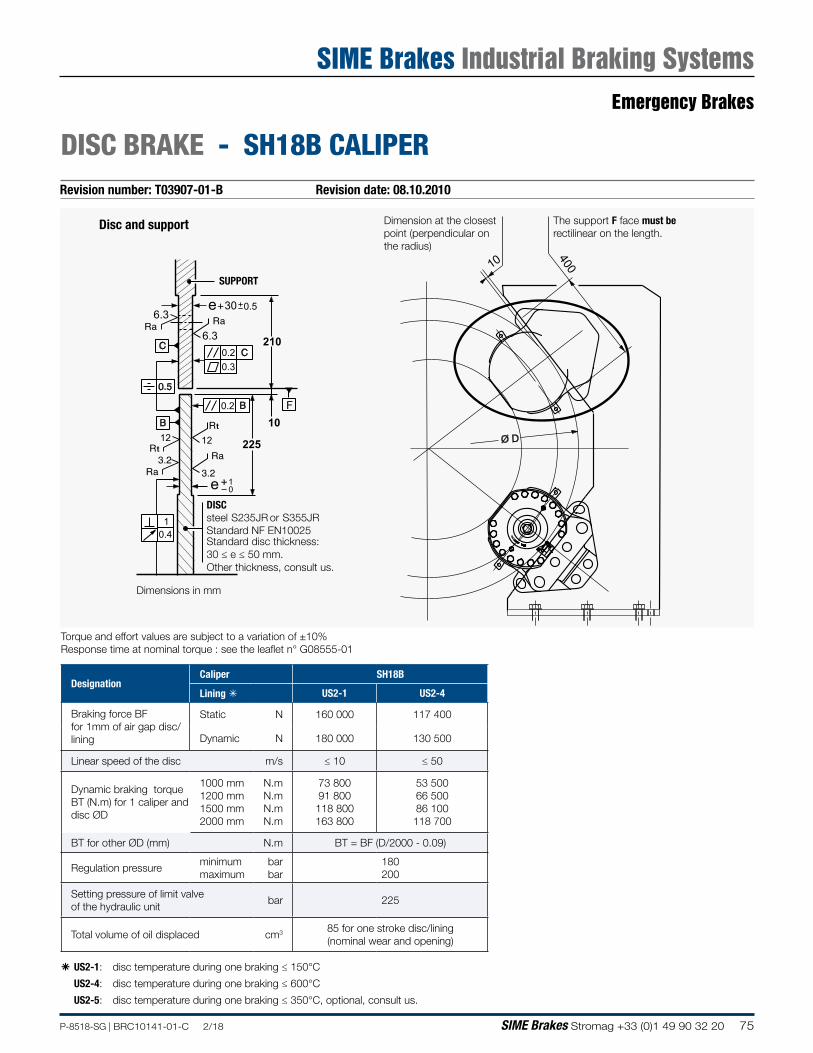
75P-8518-SG | BRC10141-01-C 2/18 SIME Brakes Stromag +33 (0)1 49 90 32 20
Revision number: T03907-01-B Revision date: 08.10.2010
DISC BRAKE - SH18B CALIPER
Torque and effort values are subject to a variation of ±10%Response time at nominal torque : see the leaflet n° G08555-01
â US2-1: disc temperature during one braking ≤ 150°C
US2-4: disc temperature during one braking ≤ 600°C
US2-5: disc temperature during one braking ≤ 350°C, optional, consult us.
DesignationCaliper SH18B
Lining à US2-1 US2-4
Braking force BF for 1mm of air gap disc/lining
Static N 160 000 117 400
Dynamic N 180 000 130 500
Linear speed of the disc m/s ≤ 10 ≤ 50
Dynamic braking torque BT (N.m) for 1 caliper and disc ØD
1000 mm 1200 mm 1500 mm 2000 mm
N.m N.m N.m N.m
73 800 91 800 118 800 163 800
53 500 66 500 86 100 118 700
BT for other ØD (mm) N.m BT = BF (D/2000 - 0.09)
Regulation pressureminimum maximum
bar bar
180 200
Setting pressure of limit valve of the hydraulic unit
bar 225
Total volume of oil displaced cm3 85 for one stroke disc/lining (nominal wear and opening)
Dimension at the closest point (perpendicular on the radius)
The support F face must be rectilinear on the length.
225
210
30
10
1
0.2
0.2
0.4
0.3
12t
t12
10
6.3
6.30.5e
e
F
10 400
Ø D
MEIN
RIE
ST UD
SI
Disc and support
Standard disc thickness: 30 ≤ e ≤ 50 mm.Other thickness, consult us.
DISCsteel S235JR or S355JRStandard NF EN10025
SUPPORT
Dimensions in mm
Emergency Brakes
SIME Brakes Industrial Braking Systems
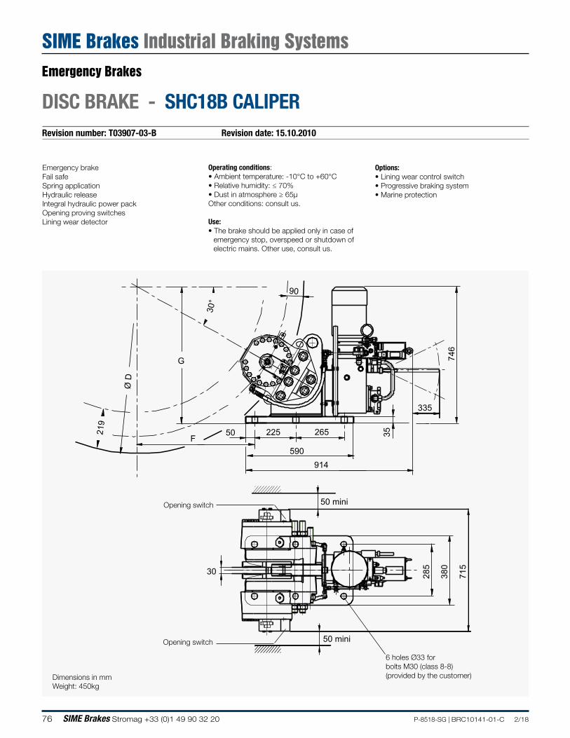
76 SIME Brakes Stromag +33 (0)1 49 90 32 20 P-8518-SG | BRC10141-01-C 2/18
Revision number: T03907-03-B Revision date: 15.10.2010
DISC BRAKE - SHC18B CALIPER
Emergency brakeFail safeSpring applicationHydraulic releaseIntegral hydraulic power packOpening proving switchesLining wear detector
Operating conditions:• Ambient temperature: -10°C to +60°C• Relative humidity: ≤ 70%• Dust in atmosphere ≥ 65µOther conditions: consult us.
Use:• The brake should be applied only in case of
emergency stop, overspeed or shutdown of electric mains. Other use, consult us.
Options:• Lining wear control switch• Progressive braking system• Marine protection
F
G
38030
746
3550 225 265
590914
219
90
Ø D
30°
50 mini
715
50 mini
335
285
Opening switch
6 holes Ø33 for bolts M30 (class 8-8) (provided by the customer)
Opening switch
Dimensions in mmWeight: 450kg
Emergency Brakes
SIME Brakes Industrial Braking Systems
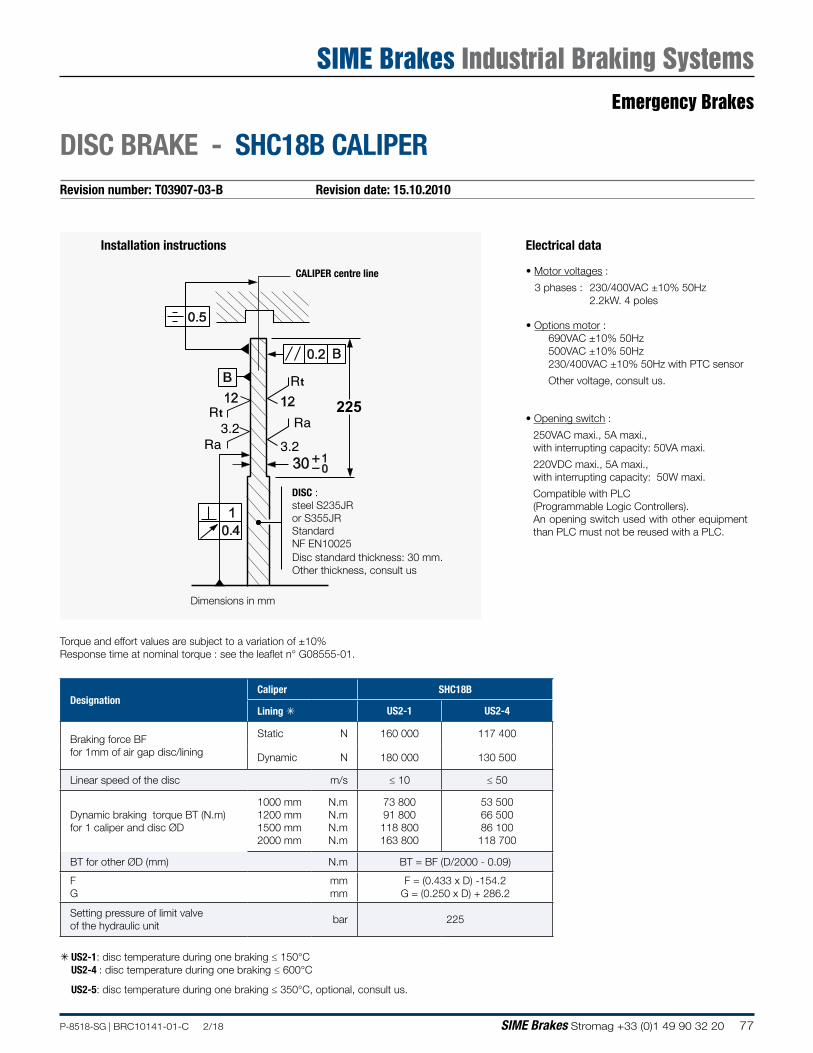
77P-8518-SG | BRC10141-01-C 2/18 SIME Brakes Stromag +33 (0)1 49 90 32 20
Revision number: T03907-03-B Revision date: 15.10.2010
DISC BRAKE - SHC18B CALIPER
Electrical data
• Motor voltages :
3 phases : 230/400VAC ±10% 50Hz 2.2kW. 4 poles
• Options motor : 690VAC ±10% 50Hz500VAC ±10% 50Hz230/400VAC ±10% 50Hz with PTC sensor
Other voltage, consult us.
• Opening switch :
250VAC maxi., 5A maxi., with interrupting capacity: 50VA maxi.
220VDC maxi., 5A maxi., with interrupting capacity: 50W maxi.
Compatible with PLC(Programmable Logic Controllers).An opening switch used with other equipment than PLC must not be reused with a PLC.
CALIPER centre line
Installation instructions
225
1
0.2
0.4
12t
t12
1030
Disc standard thickness: 30 mm.Other thickness, consult us
Torque and effort values are subject to a variation of ±10%Response time at nominal torque : see the leaflet n° G08555-01.
DISC :steel S235JR or S355JRStandard NF EN10025
Dimensions in mm
à US2-1: disc temperature during one braking ≤ 150°CUS2-4 : disc temperature during one braking ≤ 600°C
US2-5: disc temperature during one braking ≤ 350°C, optional, consult us.
DesignationCaliper SHC18B
Lining à US2-1 US2-4
Braking force BF for 1mm of air gap disc/lining
Static N 160 000 117 400
Dynamic N 180 000 130 500
Linear speed of the disc m/s ≤ 10 ≤ 50
Dynamic braking torque BT (N.m) for 1 caliper and disc ØD
1000 mm 1200 mm 1500 mm 2000 mm
N.m N.m N.m N.m
73 800 91 800 118 800 163 800
53 500 66 500 86 100 118 700
BT for other ØD (mm) N.m BT = BF (D/2000 - 0.09)
FG
mm mm
F = (0.433 x D) -154.2G = (0.250 x D) + 286.2
Setting pressure of limit valve of the hydraulic unit
bar 225
Emergency Brakes
SIME Brakes Industrial Braking Systems
78 SIME Brakes Stromag +33 (0)1 49 90 32 20 P-8518-SG | BRC10141-01-C 2/18
Revision number: T03915-01-B Revision date: 21.10.2010
DISC BRAKE - SH25 CALIPER
590
+
475+
55
e
ee e6535
8+
45 min.
65
370
460
=
=
76.4
259100
195520
155
129
ØD
285
min.210
45 min.
Emergency brakeFail safeSpring applicationHydraulic releaseOpening proving switchesLining wear detector
Operating conditions:• Ambient temperature: -10°C to +60°C• Relative humidity: ≤ 70%• Dust in atmosphere ≥ 65µOther conditions: consult us.
Use:• The brake should be applied only in case of
emergency stop, overspeed or shutdown of electric mains. Other use, consult us.
Options:• Lining wear control switch• Progressive braking system• Marine protection• Caliper on support with integral hydraulic
power pack
4 holes Ø45 for bolts M42 (class 10-9)
Oil drain 1/4"G
Oil inlet 1/2"G
Oil inlet 1/2"G
Opening switch
2 holes Ø39 for bolts M36 (class 10-9)
Oil drain 1/4"G
Opening switch
Standard disc thickness :
30 ≤ e ≤ 50 mm.Other thickness.
consult us.
Opening proving switch :
250VAC maxi., 5A maxi., with interrupting capacity: 50VA maxi.
220VDC maxi., 5A maxi., with interrupting capacity: 50W maxi.
Compatible with PLC(Programmable LogicControllers).An opening switch used with other equipment than PLC must not be reused with a PLC.
Dimensions in mmWeight : 440kg
Emergency Brakes
SIME Brakes Industrial Braking Systems
79P-8518-SG | BRC10141-01-C 2/18 SIME Brakes Stromag +33 (0)1 49 90 32 20
Revision number: T03915-01-B Revision date: 21.10.2010
DISC BRAKE - SH25 CALIPER
300
250
130
19
1
0.2
0.2
0.4
0.3
12t
t12
10
6.3
6.30.5
e
e
F
Disc and support
SUPPORT
DISCsteel S235JR or S355JRStandard NF EN10025Standard disc thickness: 30 ≤ e ≤ 50 mm.Other thickness, consult us.
Dimensions in mm.
19 460
Ø D
Dimension at the closest point (perpendicular on the radius)
The support F face mustbe rectilinear on this length
DesignationCaliper SH25-2 SH25-1
Lining á US2-1 US2-4 US2-1 US2-4
Braking force BF for 1mm of air gap disc/lining
Static N N 225 000 165 000 160 000 120 000
Dynamic N N 250 000 184 000 180 000 134 000
Linear speed of the disc m/s ≤ 10 ≤ 50 ≤ 10 ≤ 50
Dynamic braking torque BT (N.m) for 1 caliper and disc ØD (mm)
1500 mm 2000 mm 2500 mm 3000 mm
N.m N.m N.m N.m
155 250 217 750 280 250 342 750
114 260 160 260 206 260 252 260
111 780 156 780 201 780 246 780
83 210 116 710 150 210 183 710
BT for other ØD (mm) N.m BT = BF (D/2000 - 0.129)
Regulation pressureminimum bar 180 140
maximum bar 200 160
Setting pressure limit valve of hydraul. Unit bar 225 205
Total volume of oil displaced cm3 140 for one stroke disc/lining (nominal wear and opening)
Torque and effort values are subject to a variation of ±10%Response time at nominal torque : see the leaflet n° G08555-01
â US2-1: disc temperature during one braking ≤ 150°C US2-4: disc temperature during one braking ≤ 600°C US2-5: tdisc temperature during one braking ≤ 350°C, optional, consult us.
Emergency Brakes
SIME Brakes Industrial Braking Systems
80 SIME Brakes Stromag +33 (0)1 49 90 32 20 P-8518-SG | BRC10141-01-C 2/18
Revision number: T03916-02-C Revision date: 15.06.2011
DISC BRAKE - SHC25 CALIPER
Emergency brakeFail safeSpring applicationHydraulic releaseIntegral hydraulic power unitOpening proving switchesLining wear detector
Operating conditions:• Ambient temperature: -10°C to +60°C• Relative humidity: ≤ 70%• Dust in atmosphere ≥ 65µOther conditions: consult us.
Use:• The brake should be applied only in case of
emergency stop, overspeed or shutdown of electric mains. Other use, consult us.
Options:• Lining wear control switch• Progressive braking system• Marine protection• Self contained electric system
6 holes Ø45 for bolts M42 (class 8-8) (provided by the customer)
Opening proving switch
Opening proving switch
F
G
420
735
725
30
751
40180 290 290
820
1055
285
129
Ø D
30°
335
320
45 mini
45 mini
Dimensions in mmWeight: 770 kg
Emergency Brakes
SIME Brakes Industrial Braking Systems
81P-8518-SG | BRC10141-01-C 2/18 SIME Brakes Stromag +33 (0)1 49 90 32 20
Revision number: T03916-02-B Revision date: 15.06.2011
DISC BRAKE - SHC25 CALIPER
300
1
0.2
0.4
12t
t12
1030
CALIPER centre line
DISCsteel S235JR or S355JRStandard NF EN10025
Disc standard thickness: 30 mm.Other thickness, consult us
Dimensions in mm
Installation instructions Electrical data
• Motor voltages :
3 phases : 230/400VAC ±10% 50Hz 2.2kW. 4 poles
• Options motor : 690VAC ±10% 50Hz500VAC ±10% 50Hz230/400VAC ±10% 50Hz with PTC sensor.
Other voltage, consult us.
• Opening switch :
250VAC maxi., 5A maxi., with interrupting capacity: 50VA maxi.
220VDC maxi., 5A maxi., with interrupting capacity: 50W maxi.
Compatible with PLC(Programmable Logic Controllers).An opening switch used with other equipment than PLC must not be reused with a PLC.
Torque and effort values are subject to a variation of ±10%Response time at nominal torque : see the leaflet n° G08555-01.
á US2-1 : disc temperature during one braking ≤ 150°C US2-4 : disc temperature during one braking ≤ 600°C
US2-5 : disc temperature during one braking ≤ 350°C, optional, consult us.
DesignationCaliper SHC25-2 SHC25-1
Lining á US2-1 US2-4 US2-1 US2-4
Braking force BF for 1mm of air gap disc/lining
Static N 225 000 165 000 160 000 120 000
Dynamic N 250 000 184 000 180 000 134 000
Linear speed of the disc m/s ≤ 10 ≤ 50 ≤ 10 ≤ 50
Dynamic braking torque BF (N.m) for 1 caliper and a disc ØD (mm)
1500 mm N.m 155 250 114 260 111 780 83 210
2000 mm N.m 217 750 160 260 156 780 116 710
2500 mm N.m 280 250 206 260 201 780 150 210
3000 mm N.m 342 750 252 260 246 780 183 710
BT for other ØD (mm) N.m BT = BF (D/2000 - 0.129)
F mm F = (0.433 x D) - 62
G mm G = (0.250 x D) + 390
Maximum setting pressure limit valve of hydraulic power unit
bar 225 205
Emergency Brakes
SIME Brakes Industrial Braking Systems
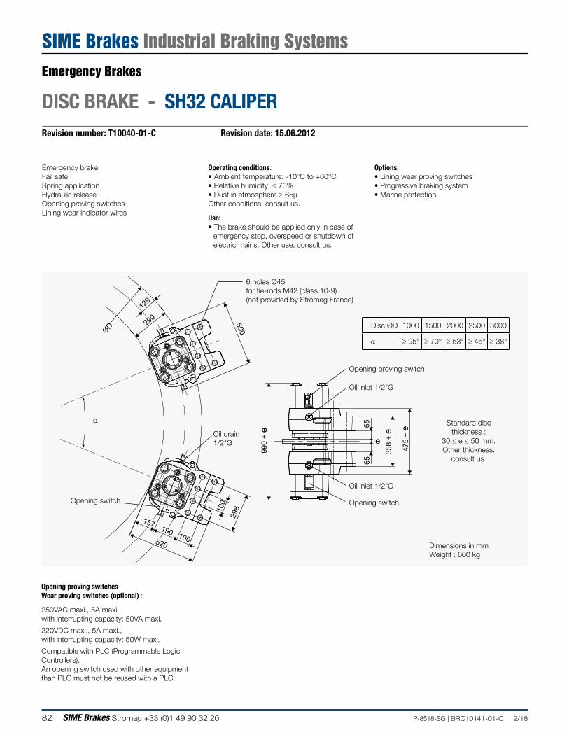
82 SIME Brakes Stromag +33 (0)1 49 90 32 20 P-8518-SG | BRC10141-01-C 2/18
Revision number: T10040-01-C Revision date: 15.06.2012
DISC BRAKE - SH32 CALIPER
Emergency brakeFail safeSpring applicationHydraulic releaseOpening proving switchesLining wear indicator wires
Operating conditions:• Ambient temperature: -10°C to +60°C• Relative humidity: ≤ 70%• Dust in atmosphere ≥ 65µOther conditions: consult us.
Use:• The brake should be applied only in case of
emergency stop, overspeed or shutdown of electric mains. Other use, consult us.
Options:• Lining wear proving switches• Progressive braking system• Marine protection
ØD
129
290 500
100
298
100190
157
520
990
+ e
475
+ e
358
+ e
e
6565
α
6 holes Ø45 for tie-rods M42 (class 10-9)(not provided by Stromag France)
Oil drain 1/2"G
Oil inlet 1/2"G
Oil inlet 1/2"G
Standard disc thickness :
30 ≤ e ≤ 50 mm.Other thickness.
consult us.
Opening proving switch
Opening switchOpening switch
Disc ØD 1000 1500 2000 2500 3000
α ≥ 95° ≥ 70° ≥ 53° ≥ 45° ≥ 38°
Dimensions in mmWeight : 600 kg
Opening proving switchesWear proving switches (optional) :
250VAC maxi., 5A maxi.,with interrupting capacity: 50VA maxi.
220VDC maxi., 5A maxi.,with interrupting capacity: 50W maxi.
Compatible with PLC (Programmable LogicControllers).An opening switch used with other equipment than PLC must not be reused with a PLC.
Emergency Brakes
SIME Brakes Industrial Braking Systems
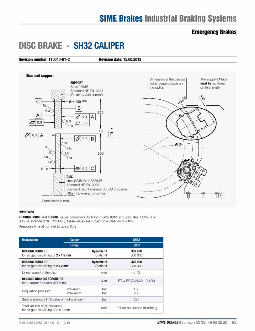
83P-8518-SG | BRC10141-01-C 2/18 SIME Brakes Stromag +33 (0)1 49 90 32 20
Revision number: T10040-01-C Revision date: 15.06.2012
DISC BRAKE - SH32 CALIPER
IMPORTANT
BRAKING FORCE and TORQUE values correspond to lining quality US2-1 and disc steel S235JR or S355JR (standard NF EN10025), these values are subject to a variation of ±10%.
Response time at nominal torque ≤ 0.3s
Designation Caliper SH32
Lining US2-1
BRAKING FORCE BF for air gap disc/lining of 2 x 1.5 mm
Dynamic N Static N
333 800 300 000
BRAKING FORCE BF for air gap disc/lining of 2 x 2 mm
Dynamic N Static N
320 000 288 000
Linear speed of the disc m/s ≤ 10
DYNAMIC BRAKING TORQUE BT for 1 caliper and disc ØD (mm)
N.m BT = BF (D/2000 - 0.129)
Regulation pressureminimum maximum
bar bar
180 200
Setting pressure limit valve of hydraulic unit bar 225
Total volume of oil displaced for air gap disc/lining of 2 x 2 mm
cm3 191 for one stroke disc/lining
t
e + 130 ±0,5
A A
A
C
C
B
B
250
300
t
12
12
6.3
6.3
e 10
0,2
0,30,3
0,30,3
0,5
19F
SUPPORTSteel 235JRStandard NF EN10025(Re min = 235 N/mm2)
DISCsteel S235JR or S355JRStandard NF EN10025Standard disc thickness: 30 ≤ e ≤ 50 mm.Other thickness, consult us.
19
460
Ø D
Dimension at the closest point (perpendicular on the radius)
Disc and support
Dimensions in mm.
The support F face must be rectilinear on this length
Emergency Brakes
SIME Brakes Industrial Braking Systems
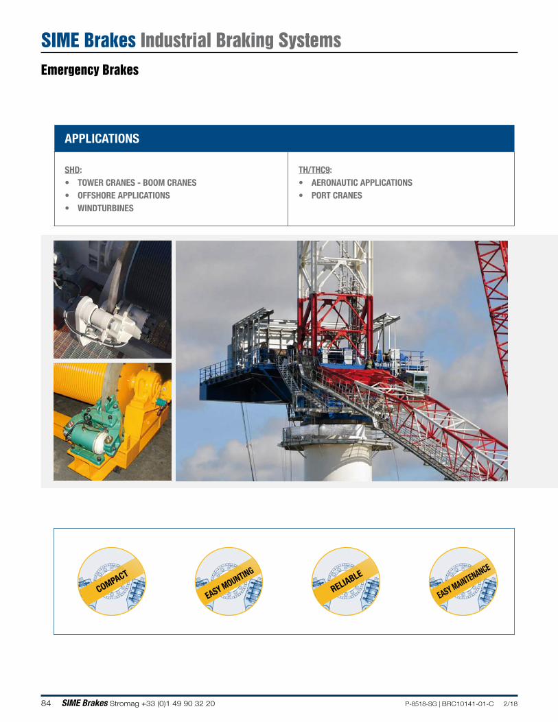
84 SIME Brakes Stromag +33 (0)1 49 90 32 20 P-8518-SG | BRC10141-01-C 2/18
APPLICATIONS
SHD: • TOWER CRANES - BOOM CRANES• OFFSHORE APPLICATIONS• WINDTURBINES
TH/THC9:• AERONAUTIC APPLICATIONS• PORT CRANES
COMPACT
EASY MOUNTING
RELIABLE
EASY MAINTENANCE
Emergency Brakes
SIME Brakes Industrial Braking Systems
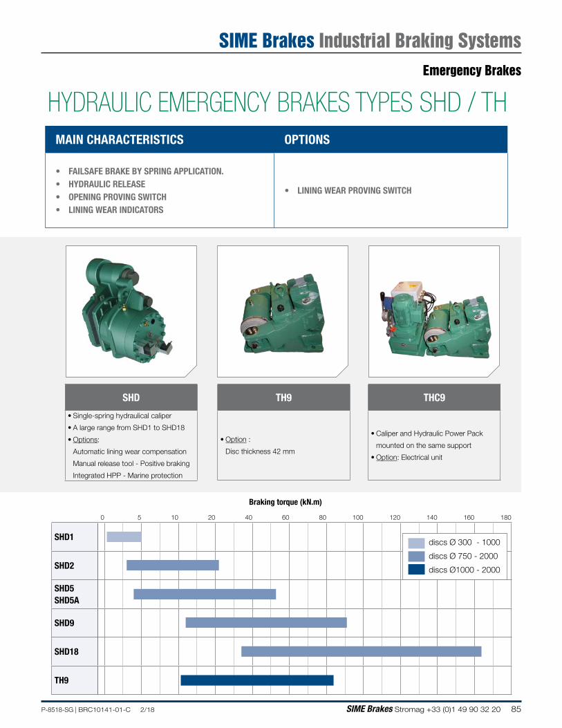
85P-8518-SG | BRC10141-01-C 2/18 SIME Brakes Stromag +33 (0)1 49 90 32 20
Braking torque (kN.m)
0 5 10 20 40 60 80 100 120 140 160 180
SHD1
SHD2
SHD5 SHD5A
SHD9
SHD18
TH9
discs Ø 300 - 1000
discs Ø 750 - 2000
discs Ø1000 - 2000
MAIN CHARACTERISTICS OPTIONS
• FAILSAFE BRAKE BY SPRING APPLICATION. • HYDRAULIC RELEASE• OPENING PROVING SWITCH• LINING WEAR INDICATORS
• LINING WEAR PROVING SWITCH
SHD
• Single-spring hydraulical caliper
• A large range from SHD1 to SHD18
• Options:
Automatic lining wear compensation
Manual release tool - Positive braking
Integrated HPP - Marine protection
TH9
• Option :
Disc thickness 42 mm
THC9
• Caliper and Hydraulic Power Pack
mounted on the same support
• Option: Electrical unit
HYDRAULIC EMERGENCY BRAKES TYPES SHD / THEmergency Brakes
SIME Brakes Industrial Braking Systems
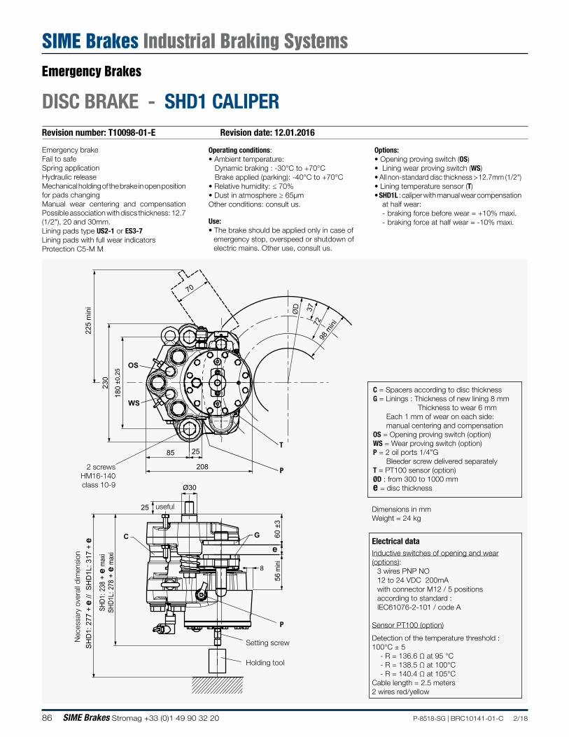
86 SIME Brakes Stromag +33 (0)1 49 90 32 20 P-8518-SG | BRC10141-01-C 2/18
Revision number: T10098-01-E Revision date: 12.01.2016
DISC BRAKE - SHD1 CALIPER
Emergency brakeFail to safeSpring applicationHydraulic releaseMechanical holding of the brake in open position for pads changingManual wear centering and compensation Possible association with discs thickness: 12.7 (1/2"), 20 and 30mm.Lining pads type US2-1 or ES3-7Lining pads with full wear indicatorsProtection C5-M M
Operating conditions:• Ambient temperature: Dynamic braking : -30°C to +70°C Brake applied (parking): -40°C to +70°C• Relative humidity: ≤ 70%• Dust in atmosphere ≥ 65µmOther conditions: consult us.
Use:• The brake should be applied only in case of
emergency stop, overspeed or shutdown of electric mains. Other use, consult us.
Options:• Opening proving switch (OS)• Lining wear proving switch (WS)• All non-standard disc thickness > 12.7mm (1/2")• Lining temperature sensor (T)• SHD1L : caliper with manual wear compensation
at half wear: - braking force before wear = +10% maxi. - braking force at half wear = -10% maxi.
70
208
±0,2
5
225
min
i
25 85
37
e
Ø30
56
mini
60
±3
25
SHD
1: 2
38 +
e m
axi
SHD
1L: 2
78 +
e m
axi
SH
D1:
277
+ e
// S
HD
1L: 3
17 +
e
180
ØD
8
230
98 m
ini
72
C G
OS
WS
C = Spacers according to disc thicknessG = Linings : Thickness of new lining 8 mm
Thickness to wear 6 mmEach 1 mm of wear on each side: manual centering and compensation
OS = Opening proving switch (option)WS = Wear proving switch (option)P = 2 oil ports 1/4"G
Bleeder screw delivered separatelyT = PT100 sensor (option)ØD : from 300 to 1000 mme = disc thickness
2 screws HM16-140class 10-9
P
P
T
Setting screw
Holding tool
useful
Nec
essa
ry o
vera
ll di
men
sion
Dimensions in mmWeight = 24 kg
Electrical dataInductive switches of opening and wear(options):
3 wires PNP NO12 to 24 VDC 200mAwith connector M12 / 5 positionsaccording to standard :IEC61076-2-101 / code A
Sensor PT100 (option)
Detection of the temperature threshold : 100°C ± 5 - R = 136.6 Ω at 95 °C - R = 138.5 Ω at 100°C - R = 140.4 Ω at 105°CCable length = 2.5 meters2 wires red/yellow
Emergency Brakes
SIME Brakes Industrial Braking Systems
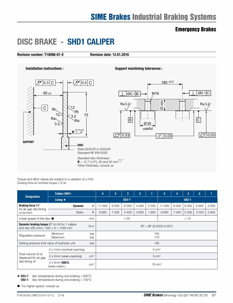
87P-8518-SG | BRC10141-01-C 2/18 SIME Brakes Stromag +33 (0)1 49 90 32 20
Revision number: T10098-01-E Revision date: 12.01.2016
DISC BRAKE - SHD1 CALIPER
0,5
75Rt
Ra
Rt
Ra
12
12
3.2
3.2
e
C
C0,3 C
±0,15 neuf−3 usé
60 ±3
Installation instructions :
SUPPORTDISC Steel S235JR or S355JRStandard NF EN10025
180 ±0,2
Ø 30
0,03
Ø0,1 B Ø0,1 C
B C
Ra 3,2Ra 3,2
0,030,03
M16
useful
25 m
ini
Support machining tolerances :
Standard disc thickness :e = 12.7 (1/2"), 20 and 30 mm
+0.15− 3
Other thickness, consult us.
Torque and effort values are subject to a variation of ±10% Closing time at nominal torque ≤ 0.3s
ES3-7: disc temperature during one braking ≤ 600°C US2-1: disc temperature during one braking ≤ 100°C
For higher speed, consult us.
DesignationCaliper SHD1- 5 4 3 2 1 5 4 3 2 1
Lining ES3-7 US2-1
Braking force BF for air gap disc/lining of 2x1mm
Dynamic N 11 000 8 000 6 000 4 000 2 000 11 000 8 000 6 000 4 000 3 000
Static N 9 900 7 200 5 400 3 600 1 800 9 680 7 040 5 280 3 520 2 640
Linear speed of the disc m/s ≤ 50 ≤ 10
Dynamic braking torque BT (m.N) for 1 caliper and disc ØD (mm) / 300 ≤ D ≤ 1000 mm
N.m BT = BF (D/2000-0.037)
Regulation pressureMinimum Maximum
bar bar
150170
Setting pressure limit valve of hydraulic unit bar 190
Total volume of oil displaced for air gap disc/lining of:
2 x 1mm (nominal opening) 5 cm3
2 x 2mm (wear+opening) cm3 9 cm3
2 x 4mm SHD1L (wear+open.)
cm3 18 cm3
Emergency Brakes
SIME Brakes Industrial Braking Systems
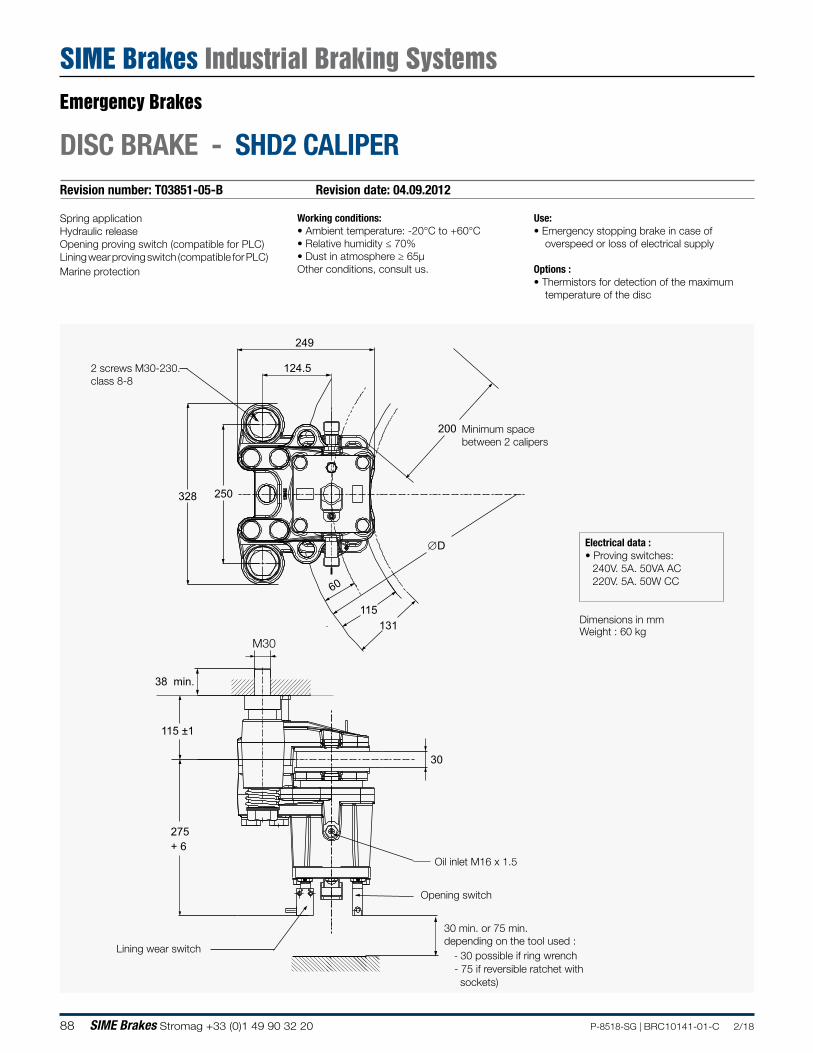
88 SIME Brakes Stromag +33 (0)1 49 90 32 20 P-8518-SG | BRC10141-01-C 2/18
Revision number: T03851-05-B Revision date: 04.09.2012
DISC BRAKE - SHD2 CALIPER
Spring applicationHydraulic releaseOpening proving switch (compatible for PLC)Lining wear proving switch (compatible for PLC)Marine protection
Working conditions:• Ambient temperature: -20°C to +60°C• Relative humidity ≤ 70%• Dust in atmosphere ≥ 65µOther conditions, consult us.
Use:• Emergency stopping brake in case of
overspeed or loss of electrical supply
Options :• Thermistors for detection of the maximum
temperature of the disc
Minimum space between 2 calipers
124.5
249
∅D
328 250
38 min.
115 ±1
275+ 6
30
60
131115
200
2 screws M30-230.class 8-8
Oil inlet M16 x 1.5
Opening switch
Lining wear switch
M30
30 min. or 75 min.depending on the tool used :
- 30 possible if ring wrench- 75 if reversible ratchet with sockets)
Dimensions in mmWeight : 60 kg
Electrical data :• Proving switches:
240V. 5A. 50VA AC220V. 5A. 50W CC
Emergency Brakes
SIME Brakes Industrial Braking Systems
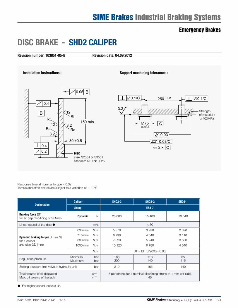
89P-8518-SG | BRC10141-01-C 2/18 SIME Brakes Stromag +33 (0)1 49 90 32 20
Revision number: T03851-05-B Revision date: 04.09.2012
DISC BRAKE - SHD2 CALIPER
0.05
150 min.
0.4
0.40.2
Rt
Ra
Rt
Ra
12
12
3.2
3.2
30 0.5
B
B
DISC steel S235J or S355JStandard NF EN10025
250 0.2
∅75
0.03
0.03/C
∅0.1/C ∅0.1/C
C 2 x
C
3.2
useful
Strength of material : ≥ 400MPa
on
Response time at nominal torque < 0.3sTorque and effort values are subject to a variation of ± 10%
Installation instructions : Support machining tolerances :
DesignationCaliper SHD2-3 SHD2-2 SHD2-1
Lining ES3-7
Braking force BF for air gap disc/lining of 2x1mm
Dynamic N 23 000 15 400 10 540
Linear speed of the disc m/s < 50
Dynamic braking torque BT (m.N) for 1 caliper and disc ØD (mm)
630 mm N.m 5 870 3 930 2 690
710 mm N.m 6 790 4 540 3 110
800 mm N.m 7 820 5 240 3 580
1000 mm N.m 10 120 6 780 4 640
N.m BT = BF (D/2000 - 0.06)
Regulation pressureMinimum Maximum
bar bar
180200
110140
85115
Setting pressure limit valve of hydraulic unit bar 210 165 140
Total volume of oil displacedMax. oil volume of the jack
cm3
cm38 per stroke (for a nominal disc/lining stroke of 1 mm per side)
45
For higher speed, consult us.
Emergency Brakes
SIME Brakes Industrial Braking Systems
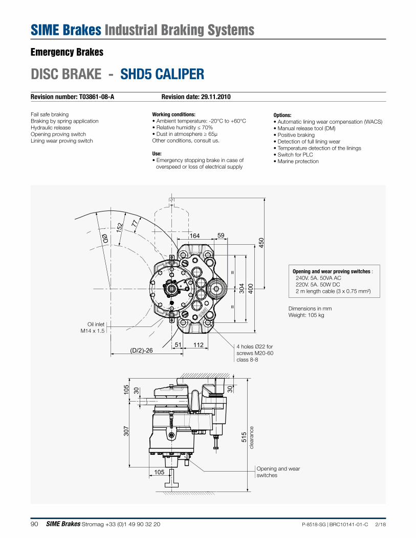
90 SIME Brakes Stromag +33 (0)1 49 90 32 20 P-8518-SG | BRC10141-01-C 2/18
307
1
05
30
515
30
112 51
164 59
(D/2)-26
450
304
4
00
=
=
ØD
77
152
105
Revision number: T03861-08-A Revision date: 29.11.2010
DISC BRAKE - SHD5 CALIPER
Fail safe brakingBraking by spring applicationHydraulic releaseOpening proving switchLining wear proving switch
Working conditions:• Ambient temperature: -20°C to +60°C• Relative humidity ≤ 70%• Dust in atmosphere ≥ 65µOther conditions, consult us.
Use:• Emergency stopping brake in case of
overspeed or loss of electrical supply
Options:• Automatic lining wear compensation (WACS)• Manual release tool (DM)• Positive braking• Detection of full lining wear• Temperature detection of the linings• Switch for PLC• Marine protection
Oil inletM14 x 1.5
Opening and wearswitches
4 holes Ø22 for screws M20-60 class 8-8
clea
ranc
e
Dimensions in mmWeight: 105 kg
Opening and wear proving switches : 240V. 5A. 50VA AC 220V. 5A. 50W DC 2 m length cable (3 x 0.75 mm²)
Emergency Brakes
SIME Brakes Industrial Braking Systems
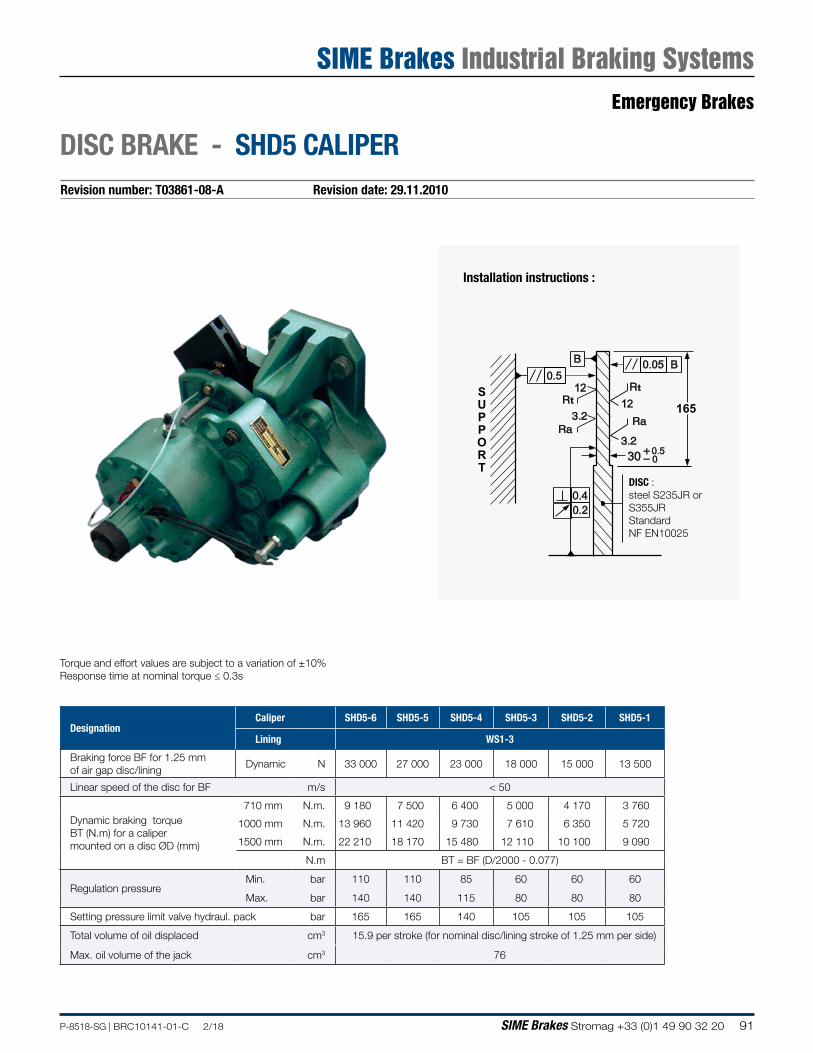
91P-8518-SG | BRC10141-01-C 2/18 SIME Brakes Stromag +33 (0)1 49 90 32 20
Torque and effort values are subject to a variation of ±10%Response time at nominal torque ≤ 0.3s
DesignationCaliper SHD5-6 SHD5-5 SHD5-4 SHD5-3 SHD5-2 SHD5-1
Lining WS1-3
Braking force BF for 1.25 mm of air gap disc/lining
Dynamic N 33 000 27 000 23 000 18 000 15 000 13 500
Linear speed of the disc for BF m/s < 50
Dynamic braking torque BT (N.m) for a caliper mounted on a disc ØD (mm)
710 mm N.m. 9 180 7 500 6 400 5 000 4 170 3 760
1000 mm N.m. 13 960 11 420 9 730 7 610 6 350 5 720
1500 mm N.m. 22 210 18 170 15 480 12 110 10 100 9 090
N.m BT = BF (D/2000 - 0.077)
Regulation pressureMin. bar 110 110 85 60 60 60
Max. bar 140 140 115 80 80 80
Setting pressure limit valve hydraul. pack bar 165 165 140 105 105 105
Total volume of oil displaced cm3 15.9 per stroke (for nominal disc/lining stroke of 1.25 mm per side)
Max. oil volume of the jack cm3 76
Revision number: T03861-08-A Revision date: 29.11.2010
DISC BRAKE - SHD5 CALIPER
165
0.40.2
12t
t12
00.530
0.050.5
SUPPORT
DISC :steel S235JR or S355JRStandard NF EN10025
Installation instructions :
Emergency Brakes
SIME Brakes Industrial Braking Systems
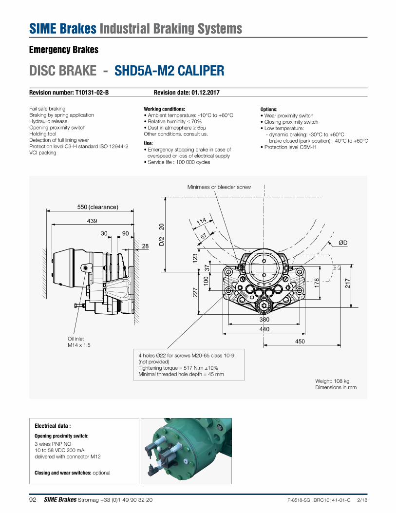
92 SIME Brakes Stromag +33 (0)1 49 90 32 20 P-8518-SG | BRC10141-01-C 2/18
Revision number: T10131-02-B Revision date: 01.12.2017
DISC BRAKE - SHD5A-M2 CALIPER
Fail safe brakingBraking by spring applicationHydraulic releaseOpening proximity switchHolding toolDetection of full lining wearProtection level C3-H standard ISO 12944-2VCI packing
Working conditions:• Ambient temperature: -10°C to +60°C• Relative humidity ≤ 70%• Dust in atmosphere ≥ 65µOther conditions. consult us.
Use:• Emergency stopping brake in case of
overspeed or loss of electrical supply• Service life : 100 000 cycles
Options:• Wear proximity switch• Closing proximity switch• Low temperature:
- dynamic braking: -30°C to +60°C- brake closed (park position): -40°C to +60°C
• Protection level C5M-H
100
227
123
D/2
– 2
0
ØD
37
217
178
30
28
90
439
550 (clearance)
57
114
450
380440
Oil inletM14 x 1.5
4 holes Ø22 for screws M20-65 class 10-9(not provided)Tightening torque = 517 N.m ±10%Minimal threaded hole depth = 45 mm
Minimess or bleeder screw
Electrical data :
Opening proximity switch:
3 wires PNP NO 10 to 58 VDC 200 mAdelivered with connector M12
Closing and wear switches: optional
Weight: 108 kgDimensions in mm
Emergency Brakes
SIME Brakes Industrial Braking Systems
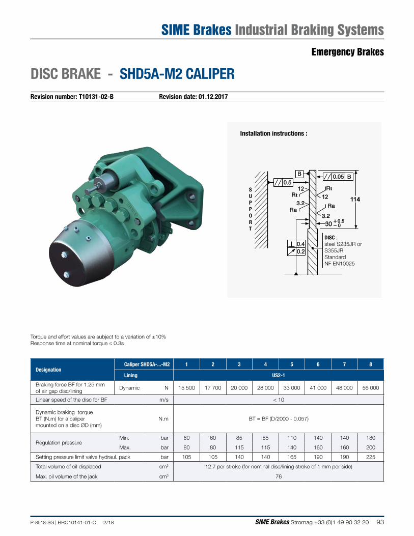
93P-8518-SG | BRC10141-01-C 2/18 SIME Brakes Stromag +33 (0)1 49 90 32 20
Torque and effort values are subject to a variation of ±10%Response time at nominal torque ≤ 0.3s
DesignationCaliper SHD5A-...-M2 1 2 3 4 5 6 7 8
Lining US2-1
Braking force BF for 1.25 mm of air gap disc/lining
Dynamic N 15 500 17 700 20 000 28 000 33 000 41 000 48 000 56 000
Linear speed of the disc for BF m/s < 10
Dynamic braking torque BT (N.m) for a caliper mounted on a disc ØD (mm)
N.m BT = BF (D/2000 - 0.057)
Regulation pressureMin. bar 60 60 85 85 110 140 140 180
Max. bar 80 80 115 115 140 160 160 200
Setting pressure limit valve hydraul. pack bar 105 105 140 140 165 190 190 225
Total volume of oil displaced cm3 12.7 per stroke (for nominal disc/lining stroke of 1 mm per side)
Max. oil volume of the jack cm3 76
Revision number: T10131-02-B Revision date: 01.12.2017
DISC BRAKE - SHD5A-M2 CALIPER
114
0.40.2
12t
t12
00.530
0.050.5
DISC :steel S235JR or S355JRStandard NF EN10025
Installation instructions :
SUPPORT
Emergency Brakes
SIME Brakes Industrial Braking Systems
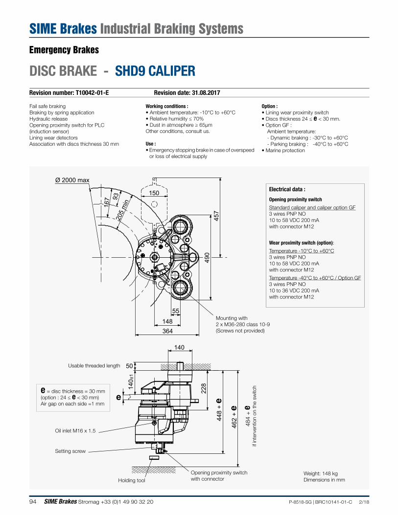
94 SIME Brakes Stromag +33 (0)1 49 90 32 20 P-8518-SG | BRC10141-01-C 2/18
Revision number: T10042-01-E Revision date: 31.08.2017
DISC BRAKE - SHD9 CALIPER
Fail safe brakingBraking by spring applicationHydraulic releaseOpening proximity switch for PLC(induction sensor)Lining wear detectorsAssociation with discs thichness 30 mm
Working conditions :• Ambient temperature: -10°C to +60°C• Relative humidity ≤ 70%• Dust in atmosphere ≥ 65µmOther conditions, consult us.
Use :• Emergency stopping brake in case of overspeed
or loss of electrical supply
Option :• Lining wear proximity switch• Discs thickness 24 ≤ e < 30 mm.• Option GF :
Ambient temperature: - Dynamic braking : -30°C to +60°C- Parking braking : -40°C to +60°C
• Marine protection
Oil inlet M16 x 1.5
Setting screw
Opening proximity switch with connector
e = disc thickness = 30 mm(option : 24 ≤ e < 30 mm)Air gap on each side =1 mm
Usable threaded length
Mounting with2 x M36-280 class 10-9(Screws not provided)
Weight: 148 kg Dimensions in mmHolding tool
148
150
93
Ø 2000 max
364
457
140
50
228
448
+ ee
140±
1
55
490
167
205
min
462
+ e
484
+ e
if
inte
rven
tion
on th
e sw
itch
Electrical data :
Opening proximity switch
Standard caliper and caliper option GF3 wires PNP NO 10 to 58 VDC 200 mAwith connector M12
Wear proximity switch (option):
Temperature -10°C to +60°C3 wires PNP NO 10 to 58 VDC 200 mAwith connector M12
Temperature -40°C to +60°C / Option GF3 wires PNP NO 10 to 36 VDC 200 mAwith connector M12
Emergency Brakes
SIME Brakes Industrial Braking Systems
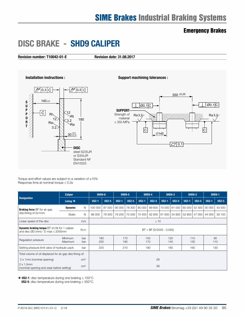
95P-8518-SG | BRC10141-01-C 2/18 SIME Brakes Stromag +33 (0)1 49 90 32 20
Revision number: T10042-01-E Revision date: 31.08.2017
DISC BRAKE - SHD9 CALIPER
DISCsteel S235JR or S355JRStandard NF EN10025
0,5
180Rt
Ra
Rt
Ra
12
12
3.2
3.2
30
C
C0,3 C
+0,5-0,15
140 ±1SUPPORT
Torque and effort values are subject to a variation of ±10%Response time at nominal torque ≤ 0.3s
â US2-1: disc temperature during one braking ≤ 150°CUS2-5: disc temperature during one braking ≤ 350°C.
DesignationCaliper SHD9-6 SHD9-5 SHD9-4 SHD9-3 SHD9-2 SHD9-1
Lining â US2-1 US2-5 US2-1 US2-5 US2-1 US2-5 US2-1 US2-5 US2-1 US2-5 US2-1 US2-5
Braking force BF for air gap disc/lining of 2x1mm
Dynamic N 100 000 87 000 90 000 78 300 80 000 69 600 70 000 61 000 60 000 52 300 50 000 43 500
Static N 88 000 78 300 79 200 70 500 70 400 62 600 61 600 54 900 52 800 47 000 44 000 39 100
Linear speed of the disc m/s ≤ 10
Dynamic braking torque BT (m.N) for 1 caliper and disc ØD (mm) / D max ≤ 2000mm
N.m BT = BF (D/2000 - 0.093)
Regulation pressureMinimum Maximum
bar bar
180 200
170 190
150 170
120 140
110 130
90 110
Setting pressure limit valve of hydraulic pack bar 220 210 190 160 160 130
Total volume of oil displaced for air gap disc/lining of:
2 x 1mm (nominal opening) cm3 28
2 x 1.5mm (nominal opening and wear before setting)
cm3 39
Installation instructions : Support machining tolerances :
SUPPORTStrength of
material ≥ 350 MPa
350 ±0,25
∅145
0,1
Ø0,1 C Ø0,1 C
C C
Ra 3,2Ra 3,2
Emergency Brakes
SIME Brakes Industrial Braking Systems
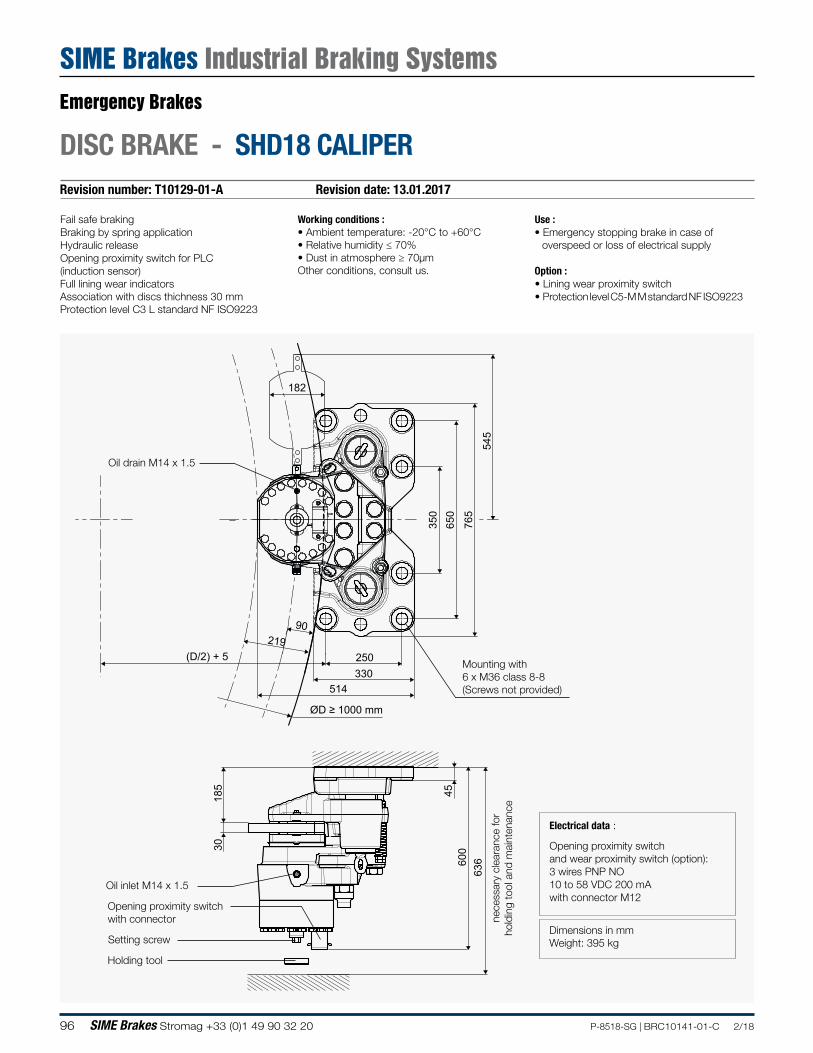
96 SIME Brakes Stromag +33 (0)1 49 90 32 20 P-8518-SG | BRC10141-01-C 2/18
Revision number: T10129-01-A Revision date: 13.01.2017
DISC BRAKE - SHD18 CALIPER
Fail safe brakingBraking by spring applicationHydraulic releaseOpening proximity switch for PLC(induction sensor)Full lining wear indicatorsAssociation with discs thichness 30 mmProtection level C3 L standard NF ISO9223
Working conditions :• Ambient temperature: -20°C to +60°C• Relative humidity ≤ 70%• Dust in atmosphere ≥ 70µmOther conditions, consult us.
Use :• Emergency stopping brake in case of
overspeed or loss of electrical supply
Option :• Lining wear proximity switch• Protection level C5-M M standard NF ISO9223
350
6
50
765
545
250 330
182
514
(D/2) + 5
600
6
36
185
45
30
21990
ØD ≥ 1000 mm
Oil inlet M14 x 1.5
Oil drain M14 x 1.5
Setting screw
Opening proximity switch with connector
Mounting with6 x M36 class 8-8(Screws not provided)
Dimensions in mmWeight: 395 kg
Holding tool
Electrical data :
Opening proximity switchand wear proximity switch (option):3 wires PNP NO 10 to 58 VDC 200 mAwith connector M12
nece
ssar
y cl
eara
nce
for
hold
ing
tool
and
mai
nten
ance
Emergency Brakes
SIME Brakes Industrial Braking Systems
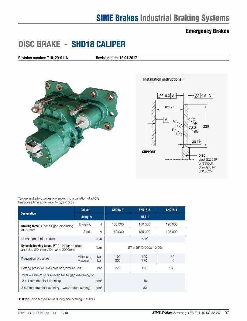
97P-8518-SG | BRC10141-01-C 2/18 SIME Brakes Stromag +33 (0)1 49 90 32 20
Revision number: T10129-01-A Revision date: 13.01.2017
DISC BRAKE - SHD18 CALIPER
Torque and effort values are subject to a variation of ±10%Response time at nominal torque ≤ 0.3s
â US2-1: disc temperature during one braking ≤ 150°C
Installation instructions :
DISCsteel S235JR or S355JRStandard NF EN10025
0,5
225Rt
Ra
Rt
Ra
12
12
3.2
3.2
30
A
A0,3 A
+0,5-0,15
185 ±1
SUPPORT
DesignationCaliper SHD18-3 SHD18-2 SHD18-1
Lining â US2-1
Braking force BF for air gap disc/lining of 2x1mm
Dynamic N 180 000 150 000 120 000
Static N 162 000 135 000 108 000
Linear speed of the disc m/s ≤ 10
Dynamic braking torque BT (m.N) for 1 caliper and disc ØD (mm) / D max ≤ 2000mm
N.m BT = BF (D/2000 - 0.09)
Regulation pressureMinimum Maximum
bar bar
195 205
160 170
130 140
Setting pressure limit valve of hydraulic unit bar 225 190 160
Total volume of oil displaced for air gap disc/lining of:
2 x 1 mm (nominal opening) cm3 48
2 x 2 mm (nominal opening + wear before setting) cm3 82
Emergency Brakes
SIME Brakes Industrial Braking Systems
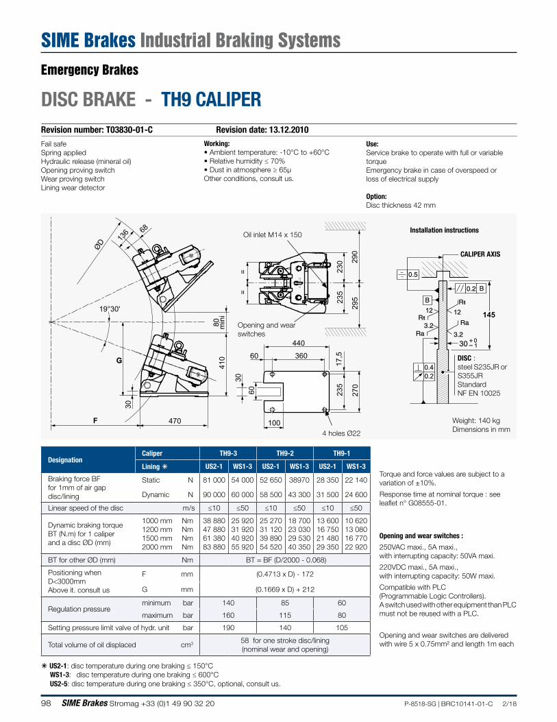
98 SIME Brakes Stromag +33 (0)1 49 90 32 20 P-8518-SG | BRC10141-01-C 2/18
Revision number: T03830-01-C Revision date: 13.12.2010
DISC BRAKE - TH9 CALIPER
Use:Service brake to operate with full or variable torqueEmergency brake in case of overspeed or loss of electrical supply
Option:Disc thickness 42 mm
Working:• Ambient temperature: -10°C to +60°C• Relative humidity ≤ 70%• Dust in atmosphere ≥ 65µOther conditions, consult us.
Fail safeSpring appliedHydraulic release (mineral oil)Opening proving switchWear proving switchLining wear detector
290
295
ØD
410
80 min
i
30
19°30'
G 360
F 470
230
235
440
100
270
=
235
=
17,5
30
136
60
60
68Oil inlet M14 x 150
4 holes Ø22
Opening and wear switches are delivered with wire 5 x 0.75mm² and length 1m each
Installation instructions
DISC :steel S235JR or S355JRStandardNF EN 10025
Opening and wear switches
Weight: 140 kgDimensions in mm
DesignationCaliper TH9-3 TH9-2 TH9-1
Lining á US2-1 WS1-3 US2-1 WS1-3 US2-1 WS1-3
Braking force BF for 1mm of air gap disc/lining
Static N 81 000 54 000 52 650 38970 28 350 22 140
Dynamic N 90 000 60 000 58 500 43 300 31 500 24 600
Linear speed of the disc m/s ≤10 ≤50 ≤10 ≤50 ≤10 ≤50
Dynamic braking torque BT (N.m) for 1 caliper and a disc ØD (mm)
1000 mm 1200 mm 1500 mm 2000 mm
Nm Nm Nm Nm
38 880 47 880 61 380 83 880
25 920 31 920 40 920 55 920
25 270 31 120 39 890 54 520
18 700 23 030 29 530 40 350
13 600 16 750 21 480 29 350
10 620 13 080 16 770 22 920
BT for other ØD (mm) Nm BT = BF (D/2000 - 0.068)
Positioning when D<3000mm Above it. consult us
F mm (0.4713 x D) - 172
G mm (0.1669 x D) + 212
Regulation pressureminimum bar 140 85 60
maximum bar 160 115 80
Setting pressure limit valve of hydr. unit bar 190 140 105
Total volume of oil displaced cm3 58 for one stroke disc/lining (nominal wear and opening)
á US2-1: disc temperature during one braking ≤ 150°C WS1-3: disc temperature during one braking ≤ 600°C US2-5: disc temperature during one braking ≤ 350°C, optional, consult us.
Torque and force values are subject to a variation of ±10%.
Response time at nominal torque : see leaflet n° G08555-01.
Opening and wear switches :
250VAC maxi., 5A maxi.,with interrupting capacity: 50VA maxi.
220VDC maxi., 5A maxi.,with interrupting capacity: 50W maxi.
Compatible with PLC(Programmable Logic Controllers).A switch used with other equipment than PLC must not be reused with a PLC.
CALIPER AXIS
145
0.40.2
12t
t12
1030
Emergency Brakes
SIME Brakes Industrial Braking Systems
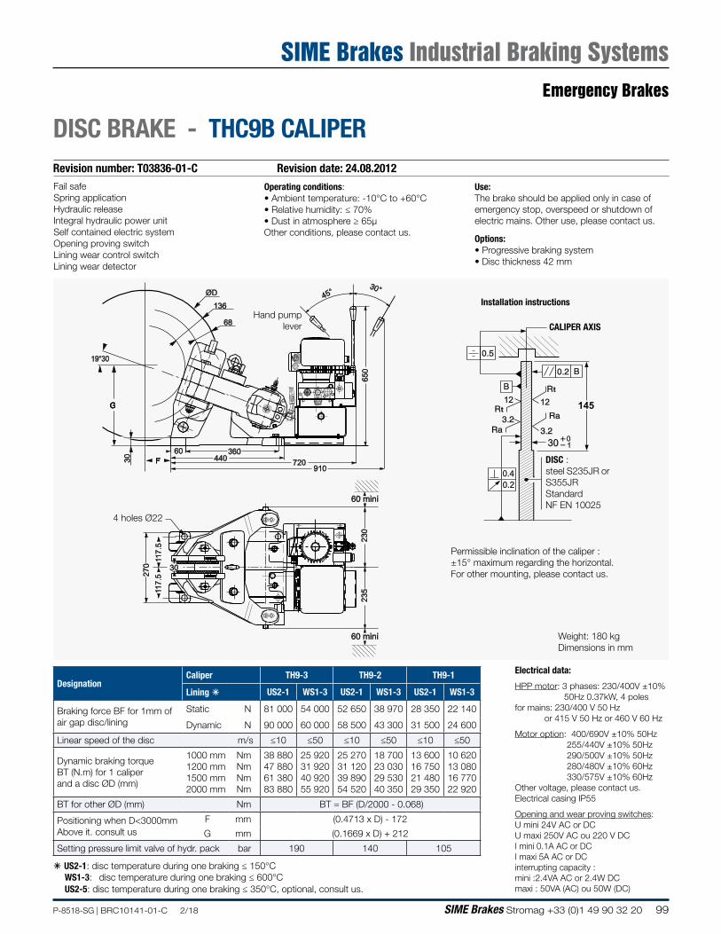
99P-8518-SG | BRC10141-01-C 2/18 SIME Brakes Stromag +33 (0)1 49 90 32 20
Revision number: T03836-01-C Revision date: 24.08.2012
DISC BRAKE - THC9B CALIPER
Use:The brake should be applied only in case of emergency stop, overspeed or shutdown of electric mains. Other use, please contact us.
Options:• Progressive braking system• Disc thickness 42 mm
Operating conditions:• Ambient temperature: -10°C to +60°C• Relative humidity: ≤ 70%• Dust in atmosphere ≥ 65µOther conditions, please contact us.
Fail safeSpring applicationHydraulic releaseIntegral hydraulic power unitSelf contained electric systemOpening proving switchLining wear control switchLining wear detector
650
60 360440 720
910
45°30°ØD
136
68
19°30
G
F30
230
235
117.
527
011
7.5
30
60 mini
60 mini
Installation instructionsHand pump
lever
4 holes Ø22
Permissible inclination of the caliper :±15° maximum regarding the horizontal.For other mounting, please contact us.
CALIPER AXIS
145
0.40.2
12t
t12
1030
DISC :steel S235JR or S355JRStandardNF EN 10025
Weight: 180 kgDimensions in mm
DesignationCaliper TH9-3 TH9-2 TH9-1
Lining á US2-1 WS1-3 US2-1 WS1-3 US2-1 WS1-3
Braking force BF for 1mm of air gap disc/lining
Static N 81 000 54 000 52 650 38 970 28 350 22 140
Dynamic N 90 000 60 000 58 500 43 300 31 500 24 600
Linear speed of the disc m/s ≤10 ≤50 ≤10 ≤50 ≤10 ≤50
Dynamic braking torque BT (N.m) for 1 caliper and a disc ØD (mm)
1000 mm 1200 mm 1500 mm 2000 mm
Nm Nm Nm Nm
38 880 47 880 61 380 83 880
25 920 31 920 40 920 55 920
25 270 31 120 39 890 54 520
18 700 23 030 29 530 40 350
13 600 16 750 21 480 29 350
10 620 13 080 16 770 22 920
BT for other ØD (mm) Nm BT = BF (D/2000 - 0.068)
Positioning when D<3000mmAbove it. consult us
F mm (0.4713 x D) - 172
G mm (0.1669 x D) + 212
Setting pressure limit valve of hydr. pack bar 190 140 105
á US2-1: disc temperature during one braking ≤ 150°C WS1-3: disc temperature during one braking ≤ 600°C US2-5: disc temperature during one braking ≤ 350°C, optional, consult us.
Electrical data:
HPP motor: 3 phases: 230/400V ±10% 50Hz 0.37kW, 4 polesfor mains: 230/400 V 50 Hz or 415 V 50 Hz or 460 V 60 Hz
Motor option: 400/690V ±10% 50Hz 255/440V ±10% 50Hz 290/500V ±10% 50Hz 280/480V ±10% 60Hz 330/575V ±10% 60HzOther voltage, please contact us.Electrical casing IP55
Opening and wear proving switches:U mini 24V AC or DCU maxi 250V AC ou 220 V DCI mini 0.1A AC or DCI maxi 5A AC or DCinterrupting capacity :mini :2.4VA AC or 2.4W DCmaxi : 50VA (AC) ou 50W (DC)
Emergency Brakes
SIME Brakes Industrial Braking Systems
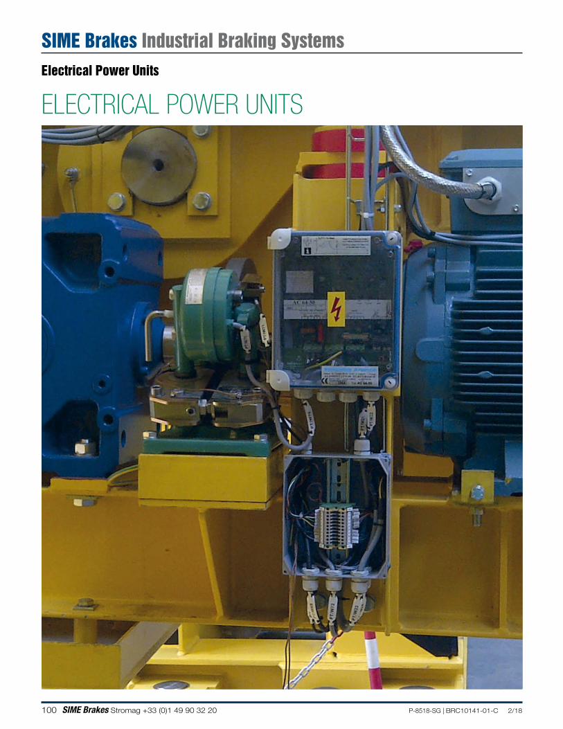
100 SIME Brakes Stromag +33 (0)1 49 90 32 20 P-8518-SG | BRC10141-01-C 2/18
ELECTRICAL POWER UNITS
Electrical Power Units
SIME Brakes Industrial Braking Systems
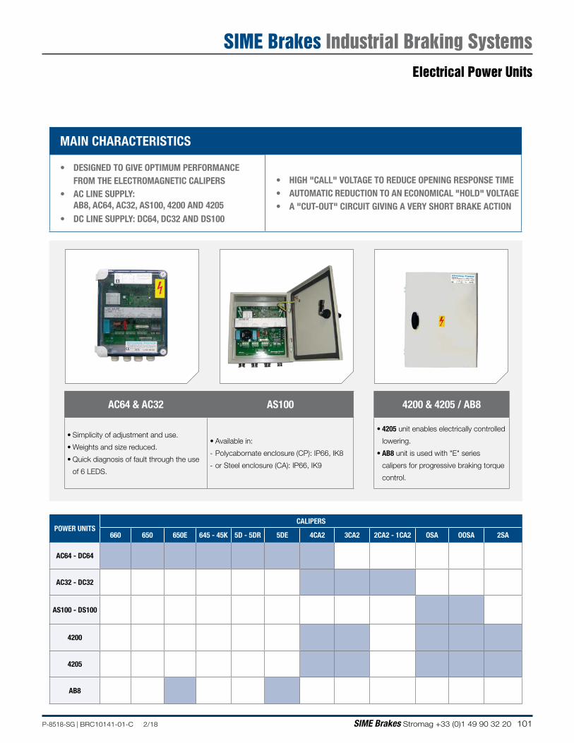
101P-8518-SG | BRC10141-01-C 2/18 SIME Brakes Stromag +33 (0)1 49 90 32 20
MAIN CHARACTERISTICS
• DESIGNED TO GIVE OPTIMUM PERFORMANCE FROM THE ELECTROMAGNETIC CALIPERS
• AC LINE SUPPLY: AB8, AC64, AC32, AS100, 4200 AND 4205
• DC LINE SUPPLY: DC64, DC32 AND DS100
• HIGH "CALL" VOLTAGE TO REDUCE OPENING RESPONSE TIME• AUTOMATIC REDUCTION TO AN ECONOMICAL "HOLD" VOLTAGE• A "CUT-OUT" CIRCUIT GIVING A VERY SHORT BRAKE ACTION
AC64 & AC32 AS100
• Simplicity of adjustment and use.
• Weights and size reduced.
• Quick diagnosis of fault through the use
of 6 LEDS.
• Available in:
- Polycabornate enclosure (CP): IP66, IK8
- or Steel enclosure (CA): IP66, IK9
4200 & 4205 / AB8
• 4205 unit enables electrically controlled
lowering.
• AB8 unit is used with "E" series
calipers for progressive braking torque
control.
POWER UNITSCALIPERS
660 650 650E 645 - 45K 5D - 5DR 5DE 4CA2 3CA2 2CA2 - 1CA2 OSA OOSA 2SA
AC64 - DC64
AC32 - DC32
AS100 - DS100
4200
4205
AB8
Electrical Power Units
SIME Brakes Industrial Braking Systems
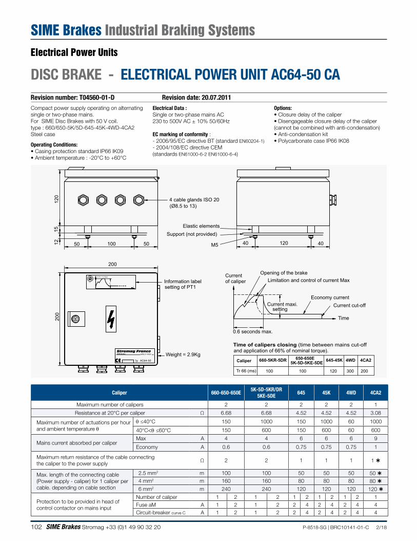
102 SIME Brakes Stromag +33 (0)1 49 90 32 20 P-8518-SG | BRC10141-01-C 2/18
Revision number: T04560-01-D Revision date: 20.07.2011
DISC BRAKE - ELECTRICAL POWER UNIT AC64-50 CA
Electrical Data :Single or two-phase mains AC230 to 500V AC ± 10% 50/60Hz
EC marking of conformity :- 2006/95/EC directive BT (standard EN60204-1)- 2004/108/EC directive CEM(standards EN61000-6-2 EN61000-6-4)
Compact power supply operating on alternating single or two-phase mains.For SIME Disc Brakes with 50 V coil.type : 660/650-5K/5D-645-45K-4WD-4CA2Steel case
Operating Conditions:• Casing protection standard IP66 IK09• Ambient temperature : -20°C to +60°C
Options:• Closure delay of the caliper• Disengageable closure delay of the caliper(cannot be combined with anti-condensation)• Anti-condensation kit• Polycarbonate case IP66 IK08
15
501212
0
200
200
100 50
PT1
40 120 40M5
4 cable glands ISO 20
Support (not provided)
.
Weight = 2.9Kg
Information label
Elastic elements
Stromag FranceSIME Brakes safety in motion
50%
100%0%
PT1
20%
80%
(Ø8.5 to 13)
% PT1 = % I Maxi
0%
100%
t setting of PT1
660-5KR-5DR 645-45K650-650E 4CA2
Tr 66 (ms) 100 100 120 200
5K-5D-5KE-5DE
300
4WDCaliper
Time of calipers closing (time between mains cut-offand application of 66% of nominal torque).
Limitation and control of current Max
Current maxi.
Opening of the brake
Economy current
Currentof caliper
Time
Current cut-off
0.6 seconds max.
setting
Typ. AC64-50
Caliper 660-650-650E5K-5D-5KR/DR
5KE-5DE645 45K 4WD 4CA2
Maximum number of calipers 2 2 2 2 2 1
Resistance at 20°C per caliper Ω 6.68 6.68 4.52 4.52 4.52 3.08
Maximum number of actuations per hour and ambient temperature θ
θ ≤40°C 150 1000 150 1000 60 1000
40°C<θ ≤60°C 150 600 150 600 60 600
Mains current absorbed per caliper Max A 4 4 6 6 6 9
Economy A 0.6 0.6 0.75 0.75 0.75 1
Maximum return resistance of the cable connectingthe caliper to the power supply
Ω 2 2 1 1 1 1
Max. length of the connecting cable (Power supply - caliper) for 1 caliper per cable. depending on cable section
2.5 mm2 m 100 100 50 50 50 50 4 mm2 m 160 160 80 80 80 80 6 mm2 m 240 240 120 120 120 120
Protection to be provided in head of control contactor on mains input
Number of caliper 1 2 1 2 1 2 1 2 1 2 1 Fuse aM A 1 2 1 2 2 4 2 4 2 4 4 Circuit-breaker curve C A 1 2 1 2 2 4 2 4 2 4 4
Electrical Power Units
SIME Brakes Industrial Braking Systems
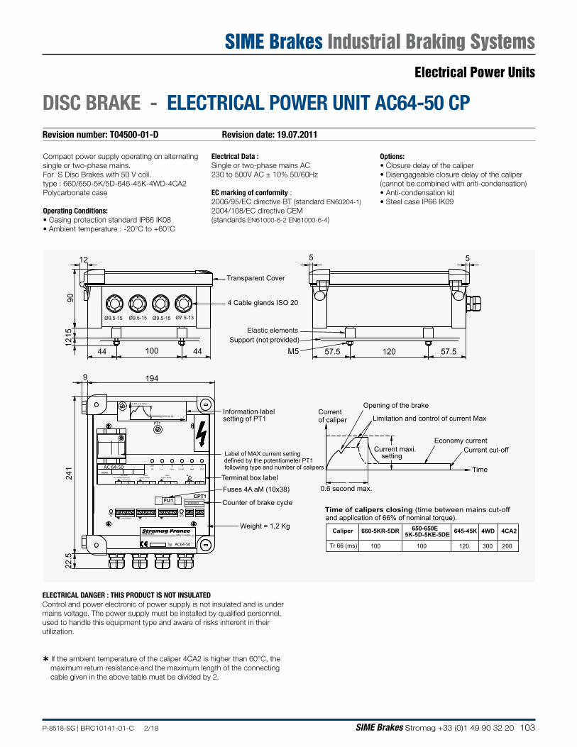
103P-8518-SG | BRC10141-01-C 2/18 SIME Brakes Stromag +33 (0)1 49 90 32 20
Revision number: T04500-01-D Revision date: 19.07.2011
DISC BRAKE - ELECTRICAL POWER UNIT AC64-50 CP
Electrical Data :Single or two-phase mains AC230 to 500V AC ± 10% 50/60Hz
EC marking of conformity :2006/95/EC directive BT (standard EN60204-1)2004/108/EC directive CEM(standards EN61000-6-2 EN61000-6-4)
Compact power supply operating on alternating single or two-phase mains.For S Disc Brakes with 50 V coil.type : 660/650-5K/5D-645-45K-4WD-4CA2Polycarbonate case
Operating Conditions:• Casing protection standard IP66 IK08• Ambient temperature : -20°C to +60°C
Options:• Closure delay of the caliper• Disengageable closure delay of the caliper(cannot be combined with anti-condensation)• Anti-condensation kit• Steel case IP66 IK09
22.5
194
241
9
57.5 120 57.544 100 44
1215
90
12 5 5
PT1
M5
.
660-5KR-5DR 645-45K650-650E 4CA2
Tr 66 (ms) 100 100 120 200
5K-5D-5KE-5DE
300
4WD
Line Voltage Netz-Red
POWERON
safety in motionStromag France
FUSEFAULT
Cut-off
SIME Brakes
Line Voltage + - -+
PINCECaliper Zange
230-500VAC
SECTEUR
321
+
54
FU1
Caliper Zange
T1UAC
-
76
OK I >>
T3
-
PINCE
+
98
Fault
CPT11000000
12
UT3
90°C
O >>
1110
MAX
U
13
ECO
PT1
20
0
80
0%
50
PT150
0100
% PT1 = % I Maxi100%
80%
100%0%
50%
20%
PT1
t
Ø9.5-15 Ø9.5-15 Ø9.5-15 Ø7.5-13
Information labelsetting of PT1
00000
Typ.
AC 64-50
AC64-50
Label of MAX current setting
Caliper
Time of calipers closing (time between mains cut-offand application of 66% of nominal torque).
following type and number of calipersdefined by the potentiometer PT1
Terminal box label
4 Cable glands ISO 20
Support (not provided)
Limitation and control of current Max
Current maxi.
Opening of the brake
Economy current
Currentof caliper
Time
Current cut-off
Weight = 1,2 Kg
Transparent Cover
0.6 second max.
Counter of brake cycle
Fuses 4A aM (10x38)
Elastic elements
setting
ELECTRICAL DANGER : THIS PRODUCT IS NOT INSULATEDControl and power electronic of power supply is not insulated and is under mains voltage. The power supply must be installed by qualified personnel, used to handle this equipment type and aware of risks inherent in their utilization.
If the ambient temperature of the caliper 4CA2 is higher than 60°C, the maximum return resistance and the maximum length of the connecting cable given in the above table must be divided by 2.
Electrical Power Units
SIME Brakes Industrial Braking Systems
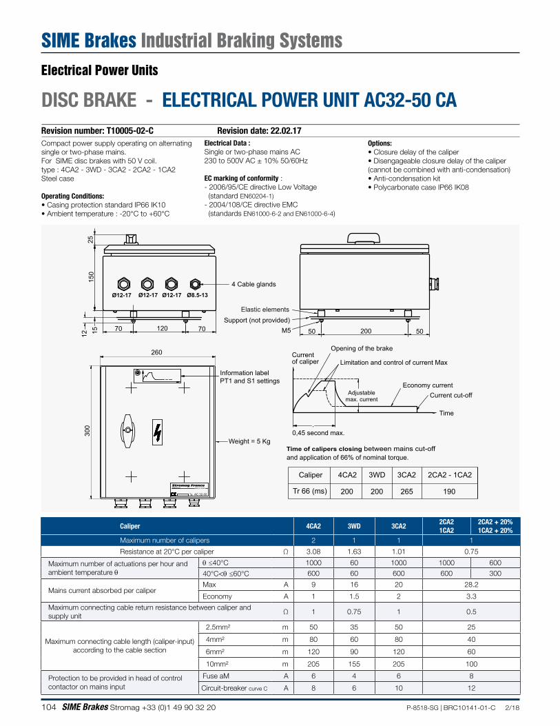
104 SIME Brakes Stromag +33 (0)1 49 90 32 20 P-8518-SG | BRC10141-01-C 2/18
Revision number: T10005-02-C Revision date: 22.02.17
DISC BRAKE - ELECTRICAL POWER UNIT AC32-50 CA
Electrical Data :Single or two-phase mains AC230 to 500V AC ± 10% 50/60Hz
EC marking of conformity :- 2006/95/CE directive Low Voltage (standard EN60204-1)- 2004/108/CE directive EMC (standards EN61000-6-2 and EN61000-6-4)
Compact power supply operating on alternating single or two-phase mains.For SIME disc brakes with 50 V coil.type : 4CA2 - 3WD - 3CA2 - 2CA2 - 1CA2Steel case
Operating Conditions:• Casing protection standard IP66 IK10• Ambient temperature : -20°C to +60°C
Options:• Closure delay of the caliper• Disengageable closure delay of the caliper(cannot be combined with anti-condensation)• Anti-condensation kit• Polycarbonate case IP66 IK08
150
M5
25
260
300
12
70 7012015 20050 50
.
Ø12-17 Ø12-17 Ø12-17 Ø8.5-13
Time of calipers closing between mains cut-offand application of 66% of nominal torque.
4 Cable glands
Support (not provided)
Limitation and control of current Max
Adjustablemax. current
Opening of the brake
Economy current
Currentof caliper
Time
Current cut-off
Weight = 5 Kg0,45 second max.
Elastic elements
safety in motionStromag FranceSIME Brakes
AC 32-50Typ.
Information label PT1 and S1 settings
Caliper
Tr 66 (ms)
2CA2 - 1CA23CA2
265 190
4CA2
200
3WD
200
Caliper 4CA2 3WD 3CA22CA21CA2
2CA2 + 20%1CA2 + 20%
Maximum number of calipers 2 1 1 1
Resistance at 20°C per caliper Ω 3.08 1.63 1.01 0.75
Maximum number of actuations per hour and ambient temperature θ
θ ≤40°C 1000 60 1000 1000 600
40°C<θ ≤60°C 600 60 600 600 300
Mains current absorbed per caliper Max A 9 16 20 28.2
Economy A 1 1.5 2 3.3
Maximum connecting cable return resistance between caliper and supply unit
Ω 1 0.75 1 0.5
Maximum connecting cable length (caliper-input) according to the cable section
2.5mm² m 50 35 50 25
4mm² m 80 60 80 40
6mm² m 120 90 120 60
10mm² m 205 155 205 100
Protection to be provided in head of control contactor on mains input
Fuse aM A 6 4 6 8
Circuit-breaker curve C A 8 6 10 12
Electrical Power Units
SIME Brakes Industrial Braking Systems
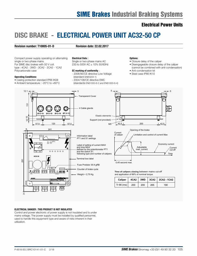
105P-8518-SG | BRC10141-01-C 2/18 SIME Brakes Stromag +33 (0)1 49 90 32 20
Revision number: T10005-01-D Revision date: 22.02.2017
DISC BRAKE - ELECTRICAL POWER UNIT AC32-50 CP
Electrical Data :Single or two-phase mains AC230 to 500V AC ± 10% 50/60Hz
EC marking of conformity :- 2006/95/CE directive Low Voltage (standard EN60204-1)- 2004/108/CE directive EMC (standards EN61000-6-2 and EN61000-6-4)
Compact power supply operating on alternating single or two-phase mains.For SIME disc brakes with 50 V coil.type : 4CA2 - 3WD - 3CA2 - 2CA2 - 1CA2Polycarbonate case
Operating Conditions:• Casing protection standard IP66 IK08• Ambient temperature : -20°C to +60°C
Options:• Closure delay of the caliper• Disengageable closure delay of the caliper (cannot be combined with anti-condensation)• Anti-condensation kit• Steel case IP66 IK10
12.1
131
1512
57,5 120 57,5
5 53
Ø13-19 Ø13-19 Ø13-19 Ø7.5-13
M5
and time MAX
and the switch S1
.
200 42,542,5
Time of calipers closing between mains cut-offand application of 66% of nominal torque.
defined by the potentiometer PT1
Terminal box label
4 Cable glands
Support (not provided)
Limitation and control of current Max
Adjustablemax. current
Opening of the brake
Economy current
Currentof caliper
Time
Current cut-off
Weight = 2,75 Kg
Transparent Cover
0,45 second max.
Counter of brake cycle
Fuse Protistor 30 A gRB
Elastic elements
Label of setting of current MAX
following type and number of calipers
Information labelPT1 and S1 settings
291
31
2419
safety in motionStromag FranceSIME Brakes
1000
50
Typ.
S1 PT1
POWERON FAULT
FUSE
FU1
Caliper
Tr 66 (ms)
2CA2 - 1CA23CA2
265 190
4CA2
200
3WD
200
AC32-50
AC32-50
ELECTRICAL DANGER : THIS PRODUCT IS NOT INSULATEDControl and power electronic of power supply is not insulated and is under mains voltage. The power supply must be installed by qualified personnel, used to handle this equipment type and aware of risks inherent in their utilization.
Electrical Power Units
SIME Brakes Industrial Braking Systems

106 SIME Brakes Stromag +33 (0)1 49 90 32 20 P-8518-SG | BRC10141-01-C 2/18
Revision number: T10035-02-B Revision date: 19.10.2015
DISC BRAKE - ELECTRICAL POWER UNIT AS100-50 CA
Electrical Data :Single or two-phase mains AC230 to 500V AC ± 10% 50/60Hz
EC marking of conformity :- 2006/95/CE directive Low Voltage (standard EN60204-1)- 2004/108/CE directive EMC (standards EN61000-6-2 and EN61000-6-4)
Compact power supply operating on alternating single or two-phase mains.For SIME disc brakes with 50 V coil.type : OSA - OOSASteel case
Operating Conditions:• Casing protection standard IP66 IK10• Ambient temperature : -20°C to +60°C
Options:• Closure delay of the caliper• Disengageable closure delay of the caliper(cannot be combined with anti-condensation)• Anti-condensation kit• Steel case IP66 IK08
260
300
150
12 70 70120
15
20050 50
25
Stromag France
Ø12-17 Ø12-17 Ø12-17 Ø8.5-13
4 cable glands
Support (not provided)
M5
Elastic elements
Current Max adjustable by S2
.
0,45 second
Current of caliper
and the application of 66% of nominal torque.Time of calipers closing between the mains cut-off
Caliper
Tr 66 (ms)
Weight = 5Kg
Label of information S2 setting
0SA
160
00SA
160
Control of current Max
Opening of the caliper
Current cut-off
Controlled economycurrent
time
AS100-50
Caliper OSA OOSA
Maximum number of calipers 1 2 1Resistance at 20°C per electromagnet Ω 1.01 1.01 1.01
Maximum number of actuations per hour and ambient temperature θ θ ≤60°C 100 100 100
Mains current absorbed Max A 28 36 36 Economy A 3.5 3.6 3.6
Maximum connecting cable return resistance between caliper and supply unit
Ω 3.5 1 1
Maximum connecting cable length (caliper input) according to the cable section
2.5 mm² m 170 50 50
4 mm² m 275 80 806 mm² m 415 120 12010 mm² m 715 205 205
Protection to be provided in head of control contactor on mains input
Fuse aM A 6 8 8Circuit-breaker curve C A 16 16 16
Electrical Power Units
SIME Brakes Industrial Braking Systems
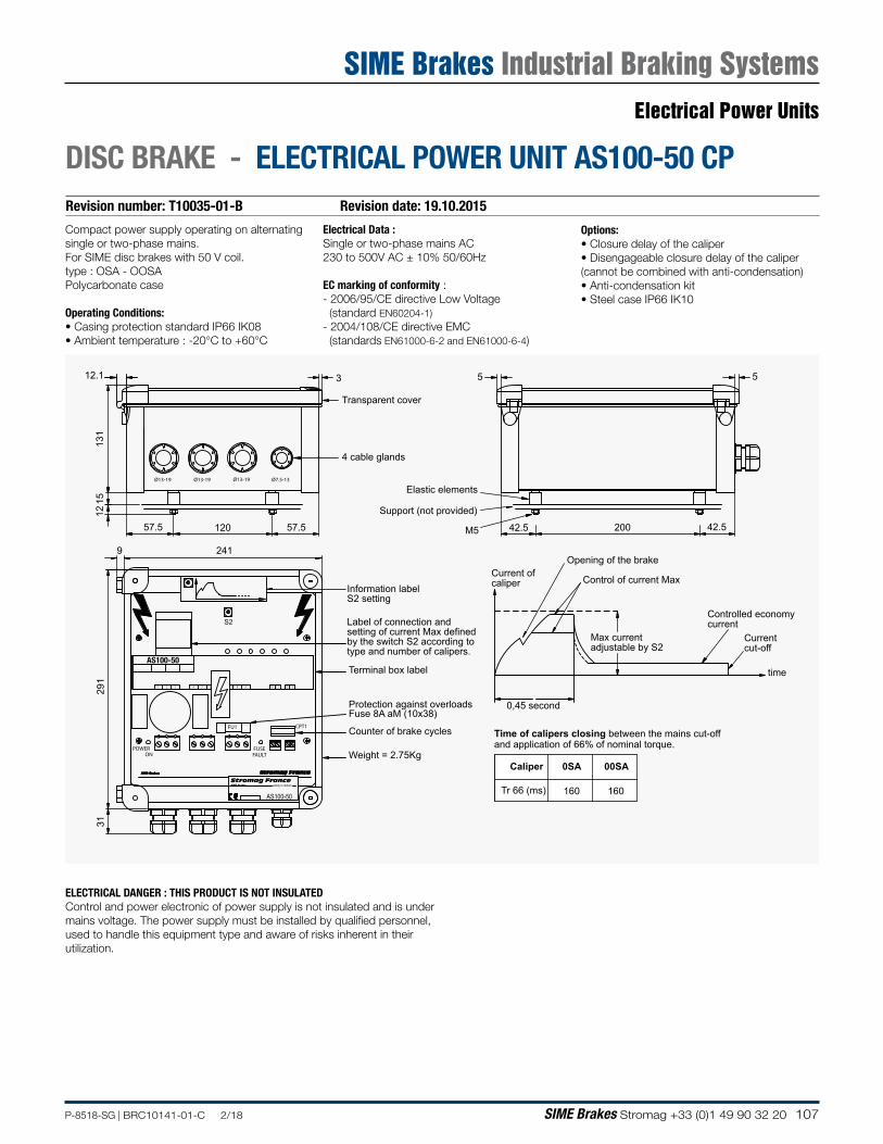
107P-8518-SG | BRC10141-01-C 2/18 SIME Brakes Stromag +33 (0)1 49 90 32 20
Revision number: T10035-01-B Revision date: 19.10.2015
DISC BRAKE - ELECTRICAL POWER UNIT AS100-50 CP
ELECTRICAL DANGER : THIS PRODUCT IS NOT INSULATEDControl and power electronic of power supply is not insulated and is under mains voltage. The power supply must be installed by qualified personnel, used to handle this equipment type and aware of risks inherent in their utilization.
Electrical Data :Single or two-phase mains AC230 to 500V AC ± 10% 50/60Hz
EC marking of conformity :- 2006/95/CE directive Low Voltage (standard EN60204-1)- 2004/108/CE directive EMC (standards EN61000-6-2 and EN61000-6-4)
Compact power supply operating on alternating single or two-phase mains.For SIME disc brakes with 50 V coil.type : OSA - OOSAPolycarbonate case
Operating Conditions:• Casing protection standard IP66 IK08• Ambient temperature : -20°C to +60°C
Options:• Closure delay of the caliper• Disengageable closure delay of the caliper(cannot be combined with anti-condensation)• Anti-condensation kit• Steel case IP66 IK10
291
31
200
131
57.5
241
57.5
9
120 42.5 42.5
12.1 3
1215
5 5
Max current adjustable by S2
.
0,45 second
Current ofcaliper
and application of 66% of nominal torque.Time of calipers closing between the mains cut-off
Caliper
Tr 66 (ms)
Protection against overloads
Counter of brake cycles
Fuse 8A aM (10x38)
Terminal box label
Weight = 2.75Kg
Ø13-19
4 cable glands
Transparent cover
Ø13-19 Ø13-19 Ø7.5-13
Support (not provided)
M5
safety in motionStromag FranceSIME Brakes
1110 1312
Information label S2 setting
Elastic elements
0SA
160
00SA
160
1 2 3 84 5 6 9
Label of connection and setting of current Max definedby the switch S2 according totype and number of calipers.
0
3
2
1
1
2
3
0 Control of current Max
Opening of the brake
Current cut-off
Controlled economycurrent
time
S2
POWERON FAULT
FUSE
FU1 CPT1
AS100-50
AS100-50
Electrical Power Units
SIME Brakes Industrial Braking Systems
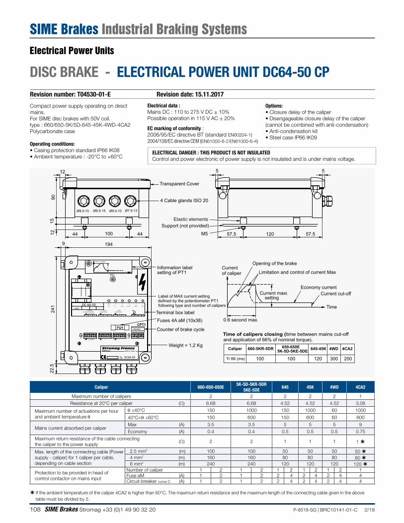
108 SIME Brakes Stromag +33 (0)1 49 90 32 20 P-8518-SG | BRC10141-01-C 2/18
Revision number: T04530-01-E Revision date: 15.11.2017
DISC BRAKE - ELECTRICAL POWER UNIT DC64-50 CP
Electrical data :Mains DC : 110 to 275 V DC ± 10%Possible operation in 115 V AC ± 20%
EC marking of conformity :2006/95/EC directive BT (standard EN60204-1)2004/108/EC directive CEM (EN61000-6-2 EN61000-6-4)
Compact power supply operating on direct mains.For SIME disc brakes with 50V coil.type : 660/650-5K/5D-645-45K-4WD-4CA2Polycarbonate case
Operating conditions:• Casing protection standard IP66 IK08• Ambient temperature : -20°C to +60°C
Options:• Closure delay of the caliper• Disengageable closure delay of the caliper(cannot be combined with anti-condensation)• Anti-condensation kit• Steel case IP66 IK09
57.5 120 57.544 100 441215
90
12 5 5
M5
.
660-5KR-5DR 645-45K650-650E 4CA2
Tr 66 (ms) 100 100 120 2005K-5D-5KE-5DE
300
4WD
Ø9.5-15 Ø9.5-15 Ø9.5-15 Ø7.5-13
Information labelsetting of PT1
Label of MAX current setting
Caliper
Time of calipers closing (time between mains cut-offand application of 66% of nominal torque).
following type and number of calipersdefined by the potentiometer PT1
Terminal box label
4 Cable glands ISO 20
Support (not provided)
Limitation and control of current Max
Current maxi.
Opening of the brake
Economy current
Currentof caliper
Time
Current cut-off
Weight = 1,2 Kg
Transparent Cover
0.6 second max.
Counter of brake cycle
Fuses 4A aM (10x38)
Elastic elements
setting
22.5
194
241
9
PT1
Line Voltage Netz-Red
POWERON
safety in motionStromag France
FUSEFAULT
Cut-o
SIME Brakes
Line Voltage + - -+
PINCECaliper Zange
220-250VDC
SECTEUR
321
+
54
FU1
Caliper Zange
T1UAC
-
76
OK I >>
T3
-
PINCE
+
98
Fault
CPT11000000
12
UT3
90°C
O >>
1110
MAX
U
13
ECO
20 80
0%
50
PT150
0100
% PT1 = % I Maxi100%
80%
100%0%
50%
20%
PT1
t
00000
Typ.
DC 64-50
DC64-50
Caliper 660-650-650E5K-5D-5KR-5DR
5KE-5DE645 45K 4WD 4CA2
Maximum number of calipers 2 2 2 2 2 1Resistance at 20°C per caliper (Ω) 6.68 6.68 4.52 4.52 4.52 3.08
Maximum number of actuations per hour and ambient temperature θ
θ ≤40°C 150 1000 150 1000 60 1000
40°C<θ ≤60°C 150 600 150 600 60 600
Mains current absorbed per caliper Max (A) 3.5 3.5 5 5 5 9 Economy (A) 0.4 0.4 0.5 0.5 0.5 0.75
Maximum return resistance of the cable connectingthe caliper to the power supply
(Ω) 2 2 1 1 1 1
Max. length of the connecting cable (Power supply - caliper) for 1 caliper per cable, depending on cable section
2.5 mm2 (m) 100 100 50 50 50 50 4 mm2 (m) 160 160 80 80 80 80 6 mm2 (m) 240 240 120 120 120 120
Protection to be provided in head of control contactor on mains input
Number of caliper 1 2 1 2 1 2 1 2 1 2 1 Fuse aM (A) 1 2 1 2 2 4 2 4 2 4 4 Circuit-breaker curve C (A) 1 2 1 2 2 4 2 4 2 4 4
If the ambient temperature of the caliper 4CA2 is higher than 60°C. The maximum return resistance and the maximum length of the connecting cable given in the above table must be divided by 2.
ELECTRICAL DANGER : THIS PRODUCT IS NOT INSULATEDControl and power electronic of power supply is not insulated and is under mains voltage.
Electrical Power Units
SIME Brakes Industrial Braking Systems
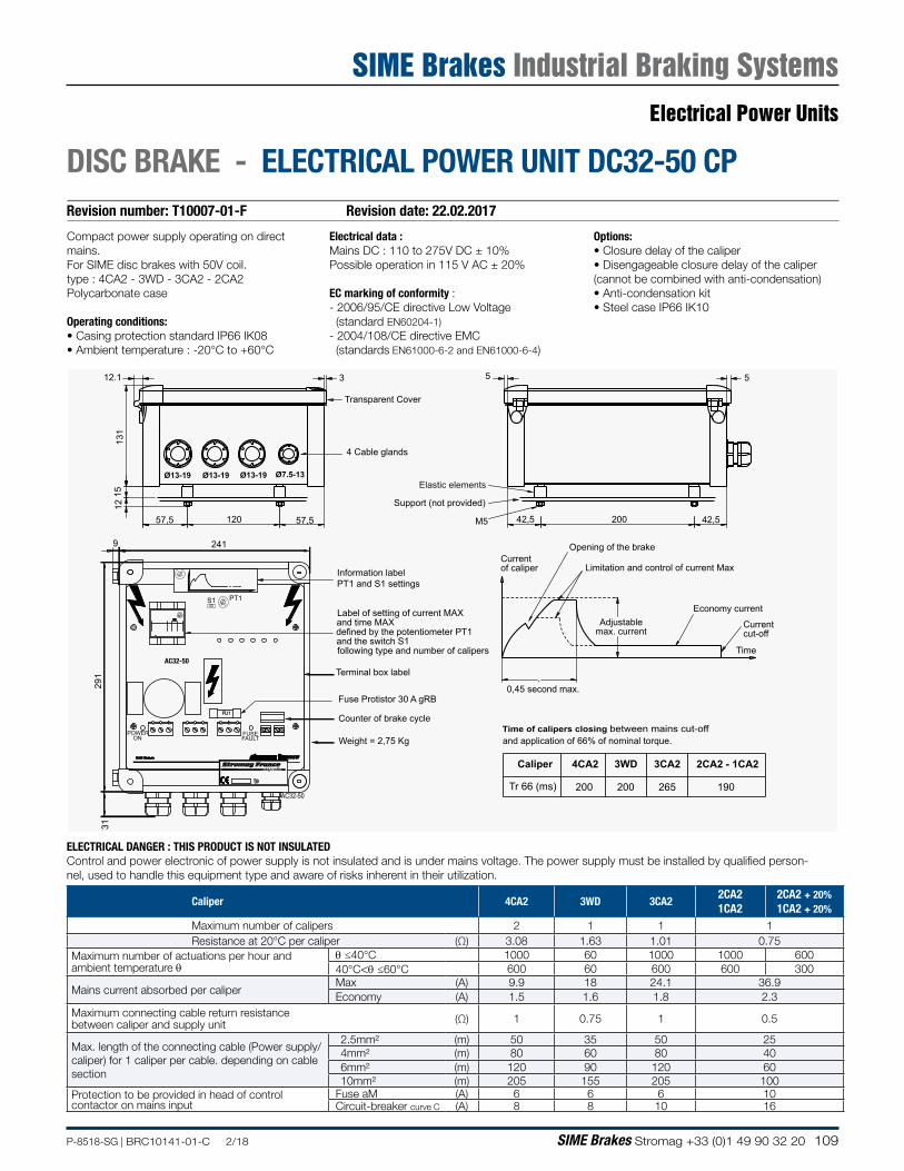
109P-8518-SG | BRC10141-01-C 2/18 SIME Brakes Stromag +33 (0)1 49 90 32 20
Revision number: T10007-01-F Revision date: 22.02.2017
DISC BRAKE - ELECTRICAL POWER UNIT DC32-50 CP
Electrical data :Mains DC : 110 to 275V DC ± 10%Possible operation in 115 V AC ± 20%
EC marking of conformity :- 2006/95/CE directive Low Voltage (standard EN60204-1)- 2004/108/CE directive EMC (standards EN61000-6-2 and EN61000-6-4)
Compact power supply operating on direct mains.For SIME disc brakes with 50V coil.type : 4CA2 - 3WD - 3CA2 - 2CA2Polycarbonate case
Operating conditions:• Casing protection standard IP66 IK08• Ambient temperature : -20°C to +60°C
Options:• Closure delay of the caliper• Disengageable closure delay of the caliper(cannot be combined with anti-condensation)• Anti-condensation kit• Steel case IP66 IK10
12.1
131
1512
57,5 120 57,5
5 53
Ø13-19 Ø13-19 Ø13-19 Ø7.5-13
M5
and time MAX
and the switch S1
.
200 42,542,5
Time of calipers closing between mains cut-offand application of 66% of nominal torque.
defined by the potentiometer PT1
Terminal box label
4 Cable glands
Support (not provided)
Limitation and control of current Max
Adjustablemax. current
Opening of the brake
Economy current
Currentof caliper
Time
Current cut-off
Weight = 2,75 Kg
Transparent Cover
0,45 second max.
Counter of brake cycle
Fuse Protistor 30 A gRB
Elastic elements
Label of setting of current MAX
following type and number of calipers
Information labelPT1 and S1 settings
291
31
2419
safety in motionStromag FranceSIME Brakes
1000
50
Typ.
S1 PT1
POWERON FAULT
FUSE
FU1
Caliper
Tr 66 (ms)
2CA2 - 1CA23CA2
265 190
4CA2
200
3WD
200
AC32-50
AC32-50
Caliper 4CA2 3WD 3CA22CA21CA2
2CA2 + 20%1CA2 + 20%
Maximum number of calipers 2 1 1 1Resistance at 20°C per caliper (Ω) 3.08 1.63 1.01 0.75
Maximum number of actuations per hour and ambient temperature θ
θ ≤40°C 1000 60 1000 1000 600 40°C<θ ≤60°C 600 60 600 600 300
Mains current absorbed per caliper Max (A) 9.9 18 24.1 36.9 Economy (A) 1.5 1.6 1.8 2.3
Maximum connecting cable return resistance between caliper and supply unit (Ω) 1 0.75 1 0.5
Max. length of the connecting cable (Power supply/caliper) for 1 caliper per cable. depending on cable section
2.5mm² (m) 50 35 50 254mm² (m) 80 60 80 406mm² (m) 120 90 120 6010mm² (m) 205 155 205 100
Protection to be provided in head of control contactor on mains input
Fuse aM (A) 6 6 6 10 Circuit-breaker curve C (A) 8 8 10 16
ELECTRICAL DANGER : THIS PRODUCT IS NOT INSULATEDControl and power electronic of power supply is not insulated and is under mains voltage. The power supply must be installed by qualified person-nel, used to handle this equipment type and aware of risks inherent in their utilization.
Electrical Power Units
SIME Brakes Industrial Braking Systems
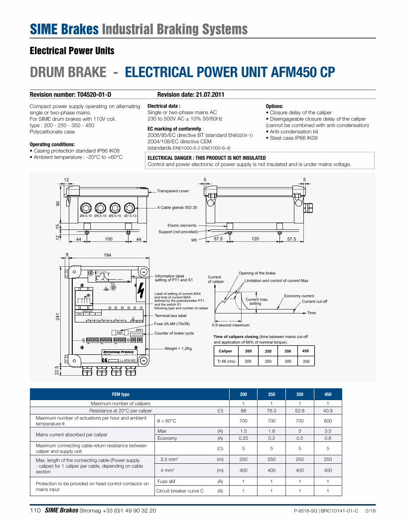
110 SIME Brakes Stromag +33 (0)1 49 90 32 20 P-8518-SG | BRC10141-01-C 2/18
Revision number: T04520-01-D Revision date: 21.07.2011
DRUM BRAKE - ELECTRICAL POWER UNIT AFM450 CP
Electrical data :Single or two-phase mains AC 230 to 500V AC ± 10% 50/60Hz
EC marking of conformity :2006/95/EC directive BT (standard EN60204-1)2004/108/EC directive CEM(standards EN61000-6-2 EN61000-6-4)
Compact power supply operating on alternating single or two-phase mains.For SIME drum brakes with 110V coil.type : 200 - 250 - 350 - 450Polycarbonate case
Operating conditions:• Casing protection standard IP66 IK08• Ambient temperature : -20°C to +60°C
Options:• Closure delay of the caliper• Disengageable closure delay of the caliper(cannot be combined with anti-condensation)• Anti-condensation kit• Steel case IP66 IK09
FEM type 200 250 350 450
Maximum number of calipers 1 1 1 1
Resistance at 20°C per caliper (Ω) 88 76.3 52.8 40.9
Maximum number of actuations per hour and ambient temperature θ θ ≤ 60°C 700 700 700 600
Mains current absorbed per caliper Max (A) 1.5 1.8 3 3.5
Economy (A) 0.25 0.3 0.5 0.6
Maximum connecting cable return resistance between caliper and supply unit
(Ω) 5 5 5 5
Max. length of the connecting cable (Power supply - caliper) for 1 caliper per cable, depending on cable section
2.5 mm2 (m) 250 250 250 250
4 mm2 (m) 400 400 400 400
Protection to be provided on head control contactor on mains input
Fuse aM (A) 1 1 1 1
Circuit-breaker curve C (A) 1 1 1 1
ELECTRICAL DANGER : THIS PRODUCT IS NOT INSULATEDControl and power electronic of power supply is not insulated and is under mains voltage.
194
57.5 120 57.544 100 441215
90
12 5 5
M5
S1
PT1
22.5
241
9
Information label
Fuse 2A aM (10x38)
setting of PT1 and S1
Current max. setting
200 350250 450
Tr 66 (ms) 200 250 300 250
Label of setting of current MAX
Terminal box label
4 Cable glands ISO 20
Limitation and control of current Max
Opening of the brake
Economy current
Currentof caliper
Time
Current cut-off
Weight = 1,2Kg
Time of calipers closing (time between mains cut-off and application of 66% of nominal torque).
Transparent cover
0.9 second maximum
following type and number of caliper
defined by the potentiometer PT1
Counter of brake cycle
Caliper
Support (not provided)Elastic elements
and the switch S1
and time of current MAX
.Line Voltage Netz-Red
POWERON
safety in motionStromag France
FUSEFAULT
Cut-off
SIME Brakes
Line Voltage + - -+
PINCECaliper Zange
230-500VAC
SECTEUR
321
+
54
FU1
Caliper Zange
T1UAC
-76
OK I >>
T3
-
PINCE
+98
Fault
CPT11000000
12
UT3
90°C
O >>
1110
MAX
U
13
ECO
PT150
0100
Ø9.5-15 Ø9.5-15 Ø9.5-15 Ø7.5-13
80%
PT1100%0%
20%
50%
% PT1 = % I Maxi
0%
100%
t
OFFON
20
0
80
100%
50
S1
00000
Typ.
AFM 450
Electrical Power Units
SIME Brakes Industrial Braking Systems
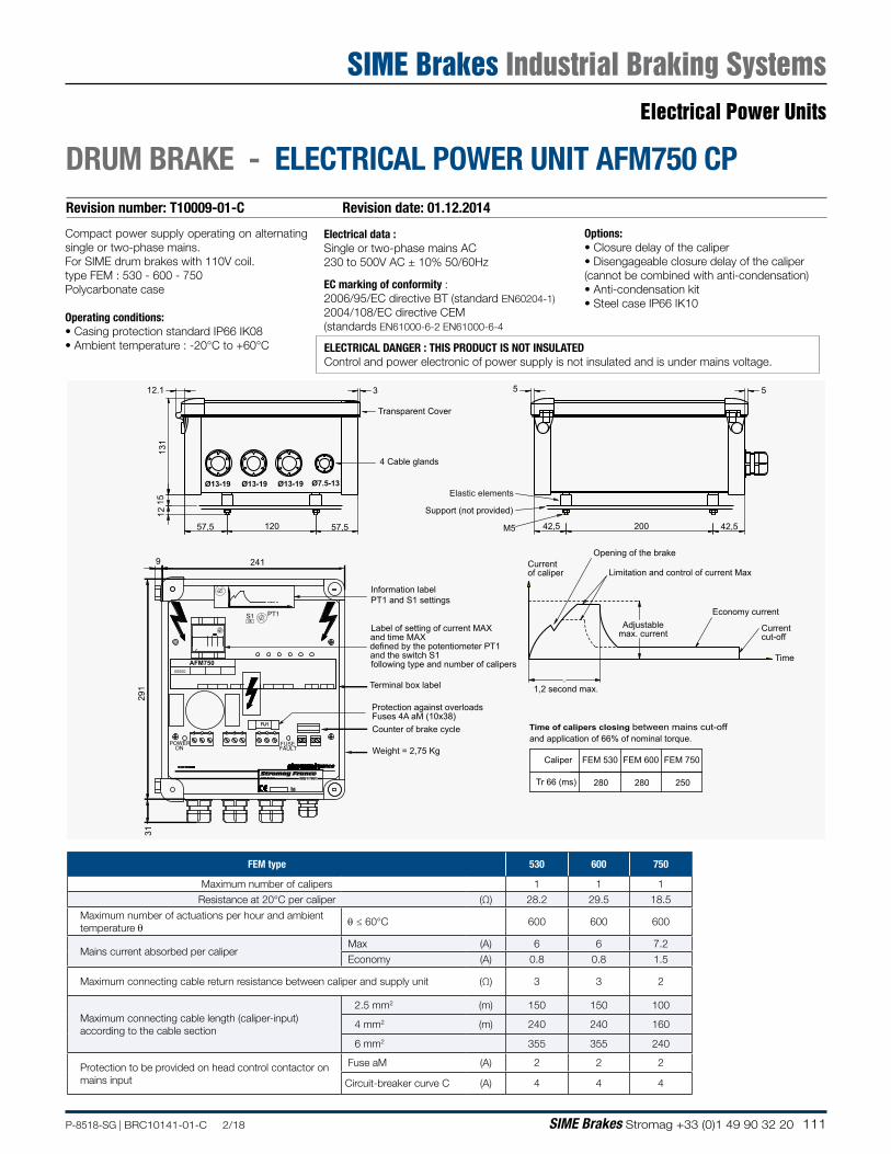
111P-8518-SG | BRC10141-01-C 2/18 SIME Brakes Stromag +33 (0)1 49 90 32 20
Revision number: T10009-01-C Revision date: 01.12.2014
DRUM BRAKE - ELECTRICAL POWER UNIT AFM750 CP
FEM type 530 600 750
Maximum number of calipers 1 1 1
Resistance at 20°C per caliper (Ω) 28.2 29.5 18.5
Maximum number of actuations per hour and ambient temperature θ θ ≤ 60°C 600 600 600
Mains current absorbed per caliper Max (A) 6 6 7.2
Economy (A) 0.8 0.8 1.5
Maximum connecting cable return resistance between caliper and supply unit (Ω) 3 3 2
Maximum connecting cable length (caliper-input) according to the cable section
2.5 mm2 (m) 150 150 100
4 mm2 (m) 240 240 160
6 mm2 355 355 240
Protection to be provided on head control contactor on mains input
Fuse aM (A) 2 2 2
Circuit-breaker curve C (A) 4 4 4
Electrical data :Single or two-phase mains AC 230 to 500V AC ± 10% 50/60Hz
EC marking of conformity :2006/95/EC directive BT (standard EN60204-1)2004/108/EC directive CEM(standards EN61000-6-2 EN61000-6-4
Compact power supply operating on alternating single or two-phase mains.For SIME drum brakes with 110V coil.type FEM : 530 - 600 - 750Polycarbonate case
Operating conditions:• Casing protection standard IP66 IK08• Ambient temperature : -20°C to +60°C
Options:• Closure delay of the caliper• Disengageable closure delay of the caliper(cannot be combined with anti-condensation)• Anti-condensation kit• Steel case IP66 IK10
AFM750
ELECTRICAL DANGER : THIS PRODUCT IS NOT INSULATEDControl and power electronic of power supply is not insulated and is under mains voltage.
12.1
131
1512
57,5 120 57,5
5 53
00000
Ø13-19 Ø13-19 Ø13-19 Ø7.5-13
M5
and time MAX
and the switch S1
.
200 42,542,5
Time of calipers closing between mains cut-offand application of 66% of nominal torque.
defined by the potentiometer PT1
Terminal box label
4 Cable glands
Support (not provided)
Limitation and control of current Max
Adjustablemax. current
Opening of the brake
Economy current
Currentof caliper
Time
Currentcut-off
Weight = 2,75 Kg
Transparent Cover
1,2 second max.
Counter of brake cycleFuses 4A aM (10x38)
Elastic elements
Label of setting of current MAX
following type and number of calipers
Protection against overloads
Information labelPT1 and S1 settings
FEM 530 FEM 600 FEM 750Caliper
Tr 66 (ms) 280 280 250
291
31
2419
safety in motionStromag FranceSIME Brakes
1000
50
Typ.
Electrical Power Units
SIME Brakes Industrial Braking Systems
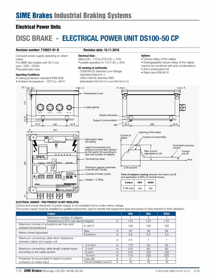
112 SIME Brakes Stromag +33 (0)1 49 90 32 20 P-8518-SG | BRC10141-01-C 2/18
Revision number: T10037-01-B Revision date: 15.11.2016
DISC BRAKE - ELECTRICAL POWER UNIT DS100-50 CP
Electrical Data :Mains DC : 110 to 275V DC ± 10%Possible operation in 115 V AC ± 20%
EC marking of conformity :- 2006/95/CE directive Low Voltage (standard EN60204-1)- 2004/108/CE directive EMC (standards EN61000-6-2 and EN61000-6-4)
Compact power supply operating on direct mains.For SIME disc brakes with 50 V coiltype : OSA - OOSAPolycarbonate case
Operating Conditions:• Casing protection standard IP66 IK08• Ambient temperature : -20°C to +60°C
Options:• Closure delay of the caliper• Disengageable closure delay of the caliper(cannot be combined with anti-condensation)• Anti-condensation kit• Steel case IP66 IK10
291
31
200
131
57.5
241
57.5
9
120 42.5 42.5
12.1 3
1215
5 5
Max current adjustable by S2
.
0,45 second
Current ofcaliper
and application of 66% of nominal torque.Time of calipers closing between the mains cut-off
Caliper
Tr 66 (ms)
Protection against overloads
Counter of brake cycles
Fuse 8A aM (10x38)
Terminal box label
Weight = 2.75Kg
Ø13-19
4 cable glands
Transparent cover
Ø13-19 Ø13-19 Ø7.5-13
Support (not provided)
M5
safety in motionStromag FranceSIME Brakes
1110 1312
Information label S2 setting
Elastic elements
0SA
160
00SA
160
1 2 3 84 5 6 9
Label of connection and setting of current Max definedby the switch S2 according totype and number of calipers.
0
3
2
1
1
2
3
0 Control of current Max
Opening of the brake
Current cut-off
Controlled economycurrent
time
S2
POWERON FAULT
FUSE
FU1 CPT1
AS100-50
AS100-50
Caliper OSA 0SA OOSAMaximum number of calipers 1 2 1Resistance at 20°C per electromagnet Ω 1.01 1.01 1.01
Maximum number of actuations per hour and ambient temperature θ θ ≤60°C 100 100 100
Mains current absorbed Max A 33 38 38 Economy A 2.6 3.3 3.3
Maximum connecting cable return resistance between caliper and supply unit
Ω 3.5 1 1
Maximum connecting cable length (caliper-input) according to the cable section
2.5 mm² m 170 50 504 mm² m 275 80 806 mm² m 415 120 12010 mm² m 715 205 205
Protection to be provided in head of control contactor on mains input
Fuse aM A 8 8 8 Circuit-breaker curve C A 16 16 16
ELECTRICAL DANGER : THIS PRODUCT IS NOT INSULATEDControl and power electronic of power supply is not insulated and is under mains voltage. The power supply must be installed by qualified personnel. used to handle this equipment type and aware of risks inherent in their utilization.
Electrical Power Units
SIME Brakes Industrial Braking Systems
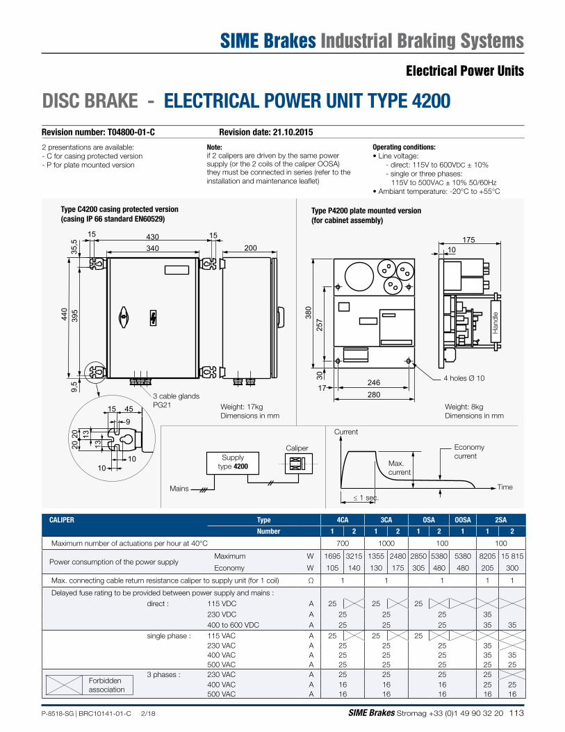
113P-8518-SG | BRC10141-01-C 2/18 SIME Brakes Stromag +33 (0)1 49 90 32 20
430340
15 15
2013
13
20
1010
15 45
9
9,5
440
395
35,5 200
175
380
257
30
24617
280
10
Revision number: T04800-01-C Revision date: 21.10.2015
DISC BRAKE - ELECTRICAL POWER UNIT TYPE 4200
2 presentations are available:- C for casing protected version- P for plate mounted version
Operating conditions:• Line voltage: - direct: 115V to 600VDC ± 10% - single or three phases: 115V to 500VAC ± 10% 50/60Hz• Ambiant temperature: -20°C to +55°C
Note:if 2 calipers are driven by the same power supply (or the 2 coils of the caliper OOSA) they must be connected in series (refer to the installation and maintenance leaflet)
Weight: 17kgDimensions in mm
Type C4200 casing protected version(casing IP 66 standard EN60529)
3 cable glands PG21 Weight: 8kg
Dimensions in mm
4 holes Ø 10
CaliperSupply
type 4200
Mains
Max.current
Economy current
Time
Current
≤ 1 sec.
Type P4200 plate mounted version(for cabinet assembly)
Han
dle
CALIPER Type 4CA 3CA OSA OOSA 2SA
Number 1 2 1 2 1 2 1 1 2
Maximum number of actuations per hour at 40°C 700 1000 100 100
Power consumption of the power supplyMaximum W 1695 3215 1355 2480 2850 5380 5380 8205 15 815
Economy W 105 140 130 175 305 480 480 205 300
Max. connecting cable return resistance caliper to supply unit (for 1 coil) Ω 1 1 1 1 1
Delayed fuse rating to be provided between power supply and mains :direct : 115 VDC A 25 25 25
230 VDC A 25 25 25 35400 to 600 VDC A 25 25 25 35 35
single phase : 115 VAC A 25 25 25230 VAC A 25 25 25 35400 VAC A 25 25 25 35 35500 VAC A 25 25 25 25 25
3 phases : 230 VAC A 25 25 25 25400 VAC A 16 16 16 25 25500 VAC A 16 16 16 16 16
Forbiddenassociation
Electrical Power Units
SIME Brakes Industrial Braking Systems
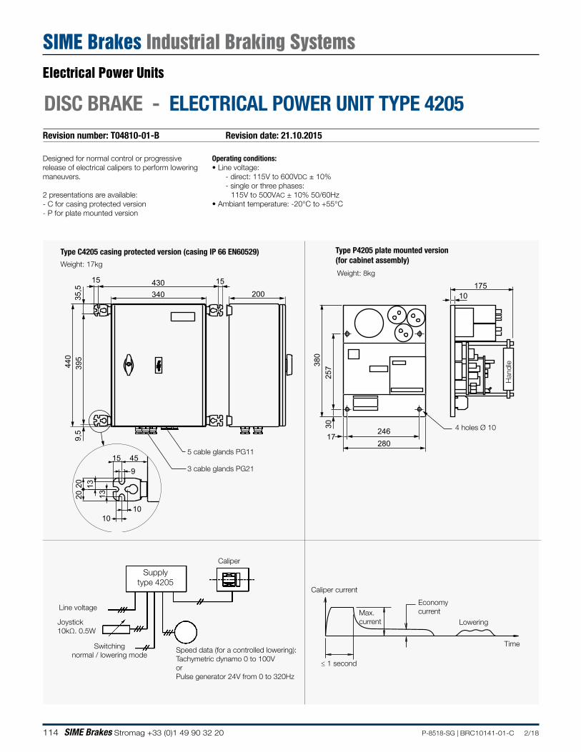
114 SIME Brakes Stromag +33 (0)1 49 90 32 20 P-8518-SG | BRC10141-01-C 2/18
Revision number: T04810-01-B Revision date: 21.10.2015
DISC BRAKE - ELECTRICAL POWER UNIT TYPE 4205
Designed for normal control or progressive release of electrical calipers to perform lowering maneuvers.
2 presentations are available:- C for casing protected version- P for plate mounted version
Operating conditions:• Line voltage: - direct: 115V to 600VDC ± 10% - single or three phases: 115V to 500VAC ± 10% 50/60Hz• Ambiant temperature: -20°C to +55°C
Type P4205 plate mounted version (for cabinet assembly)
Type C4205 casing protected version (casing IP 66 EN60529)
≤ 1 second
430340
15 15
2013
13
20
1010
15 45
9
9,5
440
395
35,5 200
175
380
257
30
24617
280
10
Weight: 17kg
3 cable glands PG21
4 holes Ø 10
Weight: 8kg
Time
Economy current
Lowering
Caliper current
Max. current
5 cable glands PG11
Han
dle
Speed data (for a controlled lowering):Tachymetric dynamo 0 to 100VorPulse generator 24V from 0 to 320Hz
Joystick10kΩ. 0.5W
Line voltage
Caliper
Switchingnormal / lowering mode
Supplytype 4205
Electrical Power Units
SIME Brakes Industrial Braking Systems
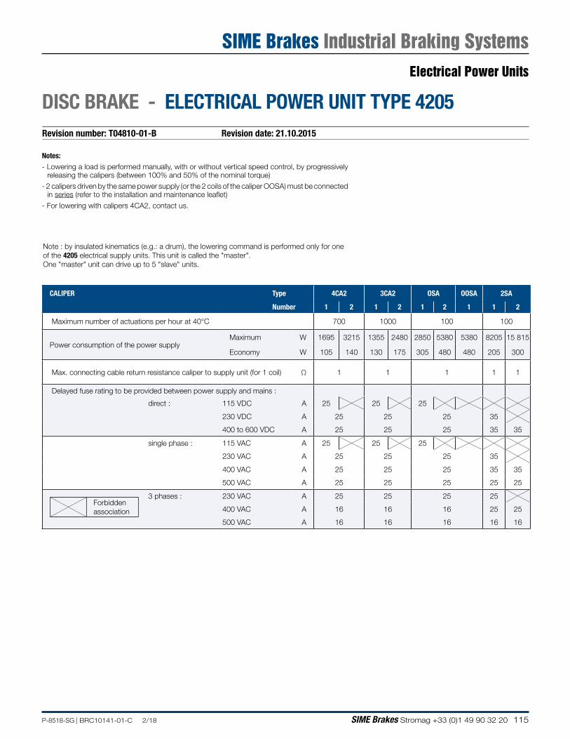
115P-8518-SG | BRC10141-01-C 2/18 SIME Brakes Stromag +33 (0)1 49 90 32 20
Revision number: T04810-01-B Revision date: 21.10.2015
DISC BRAKE - ELECTRICAL POWER UNIT TYPE 4205
Note : by insulated kinematics (e.g.: a drum), the lowering command is performed only for one of the 4205 electrical supply units. This unit is called the "master". One "master" unit can drive up to 5 "slave" units.
Notes:- Lowering a load is performed manually, with or without vertical speed control, by progressively
releasing the calipers (between 100% and 50% of the nominal torque)
- 2 calipers driven by the same power supply (or the 2 coils of the caliper OOSA) must be connected in series (refer to the installation and maintenance leaflet)
- For lowering with calipers 4CA2, contact us.
CALIPER Type 4CA2 3CA2 OSA OOSA 2SA
Number 1 2 1 2 1 2 1 1 2
Maximum number of actuations per hour at 40°C 700 1000 100 100
Power consumption of the power supplyMaximum W 1695 3215 1355 2480 2850 5380 5380 8205 15 815
Economy W 105 140 130 175 305 480 480 205 300
Max. connecting cable return resistance caliper to supply unit (for 1 coil) Ω 1 1 1 1 1
Delayed fuse rating to be provided between power supply and mains :
direct : 115 VDC A 25 25 25
230 VDC A 25 25 25 35
400 to 600 VDC A 25 25 25 35 35
single phase : 115 VAC A 25 25 25
230 VAC A 25 25 25 35
400 VAC A 25 25 25 35 35
500 VAC A 25 25 25 25 25
3 phases : 230 VAC A 25 25 25 25
400 VAC A 16 16 16 25 25
500 VAC A 16 16 16 16 16
Forbiddenassociation
Electrical Power Units
SIME Brakes Industrial Braking Systems
116 SIME Brakes Stromag +33 (0)1 49 90 32 20 P-8518-SG | BRC10141-01-C 2/18
NOTES
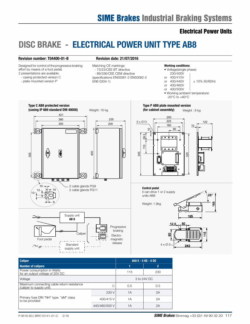
117P-8518-SG | BRC10141-01-C 2/18 SIME Brakes Stromag +33 (0)1 49 90 32 20
Working conditions:• Voltage(single phase) 230/400V or 400/415V or 400/440V ± 10% 50/60Hzor 400/460V or 400/500V • Working ambient temperature: -20°C to +60°C
Revision number: T04400-01-B Revision date: 21/07/2016
DISC BRAKE - ELECTRICAL POWER UNIT TYPE AB8
Designed for control of the progressive brakingeffort by means of a foot pedal.2 presentations are available:
- casing protected version C- plate mounted version P
Matching CE markings:- 73/23/CEE BT directive- 89/336/CEE CEM directive
(specifications EN50081-2 EN50082-2 EN6 0204-1)
Caliper 650 E - 5 KE - 5 DE
Number of calipers 1 2Power consumption in Wattsfor an output voltage of 20V DC 115 230
Voltage 3 to 24V DC
Maximum connecting cable return resistance(caliper to supply unit) Ω 0.5 0.5
Primary fuse DIN "NH" type. "aM" classto be provided
230 V 1A 2A
400/415 V 1A 2A
440/460/500 V 1A 2A
1234567810
90180225
345
110
59.5
10
325
10
250122
400
200235
355
421390300
1010
13
9
132 cable glands PG92 cable glands PG11
8 x Ø10
Weight: 16 kg Weight : 8 kg
4 x Ø 9
Weight: 1.9kg
Control pedal:it can drive 1 or 2 supply units AB8
Type C AB8 protected version(casing IP 669 standard DIN 40050)
Type P AB8 plate mounted version(for cabinet assembly)
Electro-magnetic release
Progressive braking
Caliper
Foot pedal
Supply unitAB 8
Standard supply unit
Electrical Power Units
SIME Brakes Industrial Braking Systems
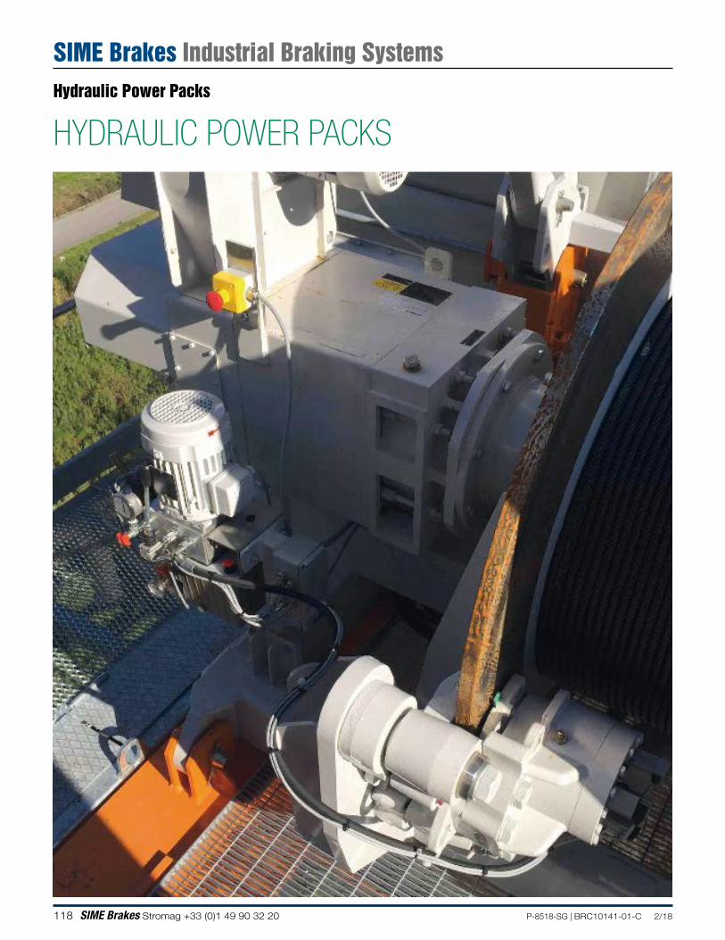
118 SIME Brakes Stromag +33 (0)1 49 90 32 20 P-8518-SG | BRC10141-01-C 2/18
HYDRAULIC POWER PACKSHydraulic Power Packs
SIME Brakes Industrial Braking Systems
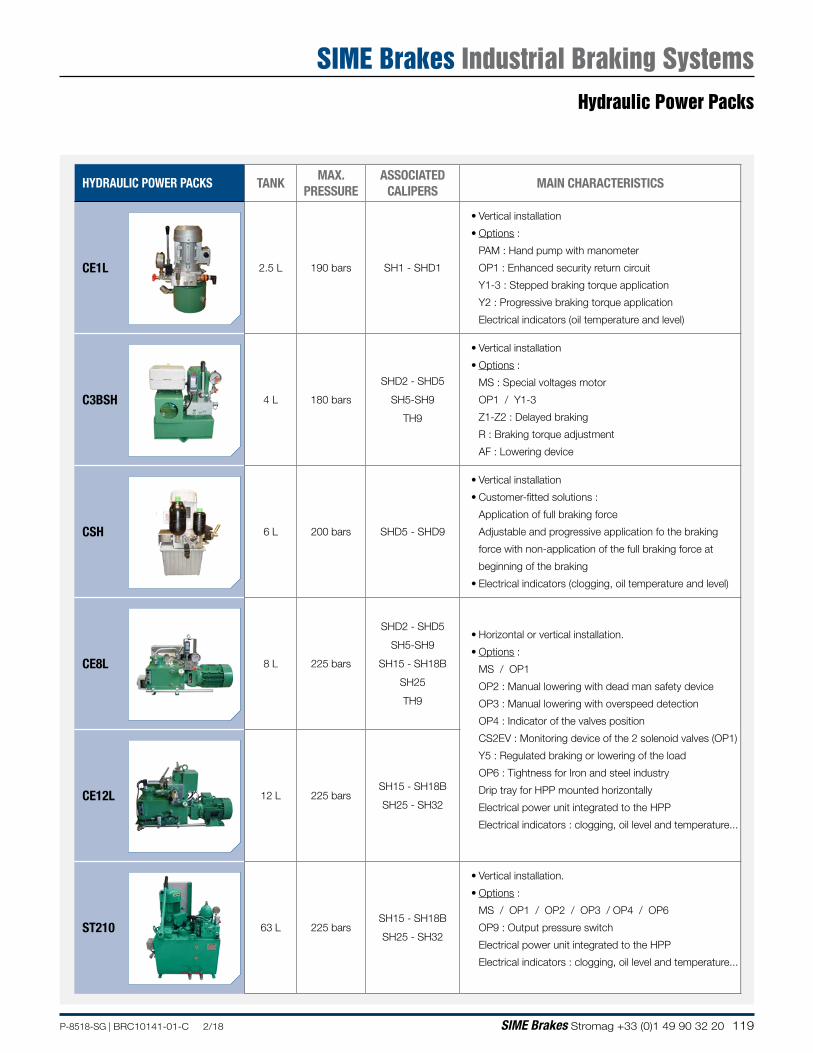
119P-8518-SG | BRC10141-01-C 2/18 SIME Brakes Stromag +33 (0)1 49 90 32 20
HYDRAULIC POWER PACKS TANKMAX.
PRESSURE ASSOCIATED
CALIPERSMAIN CHARACTERISTICS
CE1L 2.5 L 190 bars SH1 - SHD1
• Vertical installation
• Options :
PAM : Hand pump with manometer
OP1 : Enhanced security return circuit
Y1-3 : Stepped braking torque application
Y2 : Progressive braking torque application
Electrical indicators (oil temperature and level)
C3BSH 4 L 180 bars
SHD2 - SHD5
SH5-SH9
TH9
• Vertical installation
• Options :
MS : Special voltages motor
OP1 / Y1-3
Z1-Z2 : Delayed braking
R : Braking torque adjustment
AF : Lowering device
CSH 6 L 200 bars SHD5 - SHD9
• Vertical installation
• Customer-fitted solutions :
Application of full braking force
Adjustable and progressive application fo the braking
force with non-application of the full braking force at
beginning of the braking
• Electrical indicators (clogging, oil temperature and level)
CE8L 8 L 225 bars
SHD2 - SHD5
SH5-SH9
SH15 - SH18B
SH25
TH9
• Horizontal or vertical installation.
• Options :
MS / OP1
OP2 : Manual lowering with dead man safety device
OP3 : Manual lowering with overspeed detection
OP4 : Indicator of the valves position
CS2EV : Monitoring device of the 2 solenoid valves (OP1)
Y5 : Regulated braking or lowering of the load
OP6 : Tightness for Iron and steel industry
Drip tray for HPP mounted horizontally
Electrical power unit integrated to the HPP
Electrical indicators : clogging, oil level and temperature...
CE12L 12 L 225 barsSH15 - SH18B
SH25 - SH32
ST210 63 L 225 barsSH15 - SH18B
SH25 - SH32
• Vertical installation.
• Options :
MS / OP1 / OP2 / OP3 / OP4 / OP6
OP9 : Output pressure switch
Electrical power unit integrated to the HPP
Electrical indicators : clogging, oil level and temperature...
Hydraulic Power Packs
SIME Brakes Industrial Braking Systems
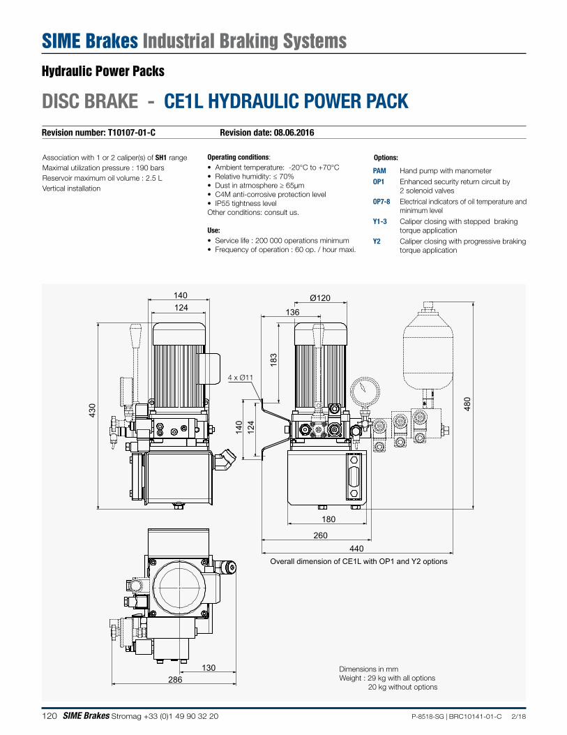
120 SIME Brakes Stromag +33 (0)1 49 90 32 20 P-8518-SG | BRC10141-01-C 2/18
Revision number: T10107-01-C Revision date: 08.06.2016
DISC BRAKE - CE1L HYDRAULIC POWER PACK
Association with 1 or 2 caliper(s) of SH1 rangeMaximal utilization pressure : 190 barsReservoir maximum oil volume : 2.5 LVertical installation
Operating conditions:• Ambient temperature: -20°C to +70°C• Relative humidity: ≤ 70%• Dust in atmosphere ≥ 65µm• C4M anti-corrosive protection level• IP55 tightness levelOther conditions: consult us.
Use:• Service life : 200 000 operations minimum• Frequency of operation : 60 op. / hour maxi.
Options:
PAM Hand pump with manometerOP1 Enhanced security return circuit by
2 solenoid valvesOP7-8 Electrical indicators of oil temperature and
minimum levelY1-3 Caliper closing with stepped braking
torque applicationY2 Caliper closing with progressive braking
torque application
430
260
180
440
286130
140124
Overall dimension of CE1L with OP1 and Y2 options
140
183
480
124
Ø120
136
Dimensions in mmWeight : 29 kg with all options 20 kg without options
4 x Ø11
Hydraulic Power Packs
SIME Brakes Industrial Braking Systems
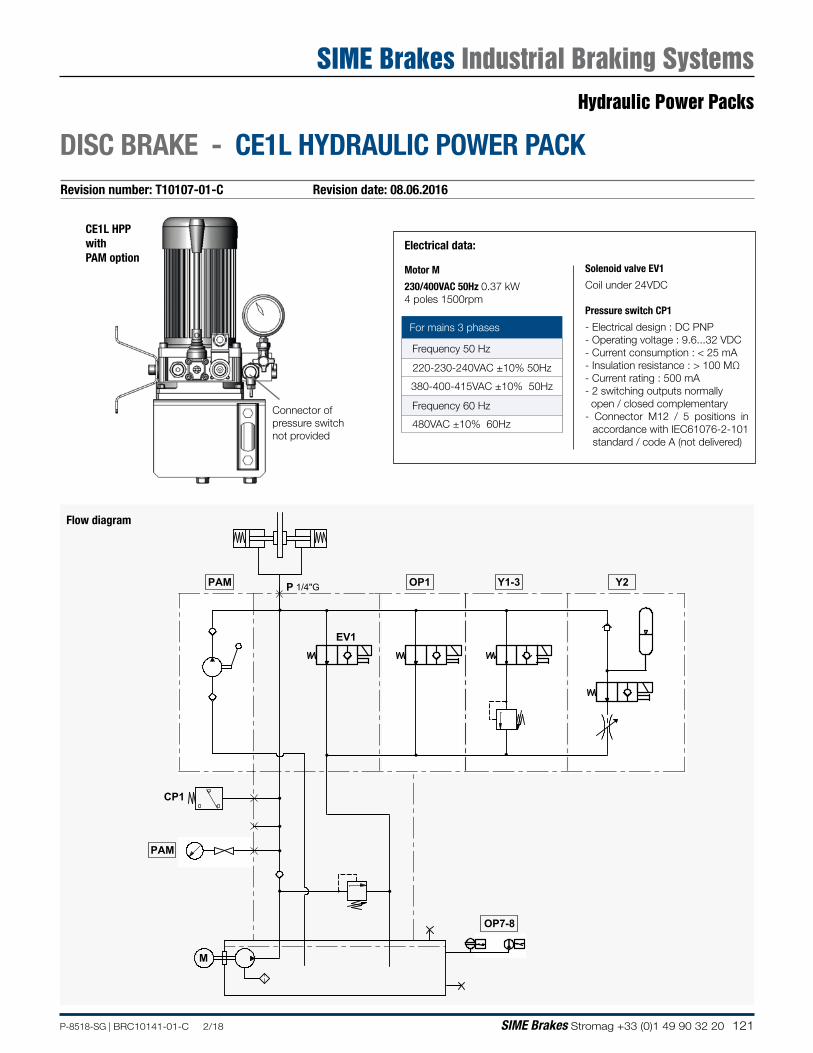
121P-8518-SG | BRC10141-01-C 2/18 SIME Brakes Stromag +33 (0)1 49 90 32 20
Revision number: T10107-01-C Revision date: 08.06.2016
DISC BRAKE - CE1L HYDRAULIC POWER PACK
CE1L HPP with PAM option
Electrical data:
Motor M
230/400VAC 50Hz 0.37 kW 4 poles 1500rpm
Solenoid valve EV1
Coil under 24VDC
Pressure switch CP1
- Electrical design : DC PNP- Operating voltage : 9.6...32 VDC - Current consumption : < 25 mA- Insulation resistance : > 100 MΩ- Current rating : 500 mA- 2 switching outputs normally open / closed complementary- Connector M12 / 5 positions in
accordance with IEC61076-2-101 standard / code A (not delivered)
For mains 3 phases
Frequency 50 Hz
220-230-240VAC ±10% 50Hz
380-400-415VAC ±10% 50Hz
Frequency 60 Hz
480VAC ±10% 60Hz Connector ofpressure switchnot provided
M
PAM
PAM
P OP1
OP7-8
CP1
EV1
Y1-3 Y21/4"G
Flow diagram
Hydraulic Power Packs
SIME Brakes Industrial Braking Systems
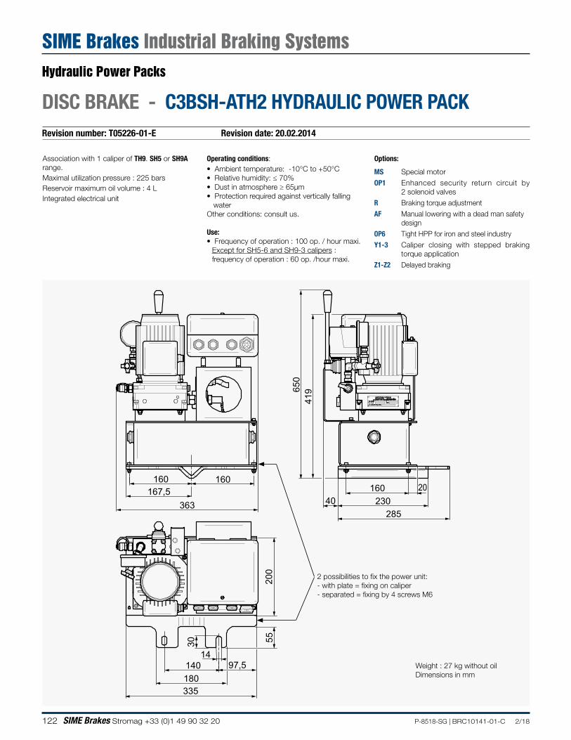
122 SIME Brakes Stromag +33 (0)1 49 90 32 20 P-8518-SG | BRC10141-01-C 2/18
Revision number: T05226-01-E Revision date: 20.02.2014
DISC BRAKE - C3BSH-ATH2 HYDRAULIC POWER PACK
Association with 1 caliper of TH9. SH5 or SH9A range.Maximal utilization pressure : 225 barsReservoir maximum oil volume : 4 LIntegrated electrical unit
Operating conditions:• Ambient temperature: -10°C to +50°C• Relative humidity: ≤ 70%• Dust in atmosphere ≥ 65µm• Protection required against vertically falling
waterOther conditions: consult us.
Use:• Frequency of operation : 100 op. / hour maxi.
Except for SH5-6 and SH9-3 calipers : frequency of operation : 60 op. /hour maxi.
Options:
MS Special motorOP1 Enhanced security return circuit by
2 solenoid valvesR Braking torque adjustmentAF Manual lowering with a dead man safety
designOP6 Tight HPP for iron and steel industryY1-3 Caliper closing with stepped braking
torque applicationZ1-Z2 Delayed braking
Weight : 27 kg without oilDimensions in mm
2 possibilities to fix the power unit:- with plate = fixing on caliper - separated = fixing by 4 screws M6
363
160 160
40 230285
650
419
167,5
335
160
200
55
14
30
140 97,5 180
20
Hydraulic Power Packs
SIME Brakes Industrial Braking Systems
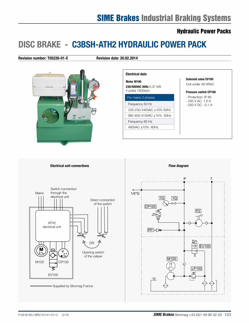
123P-8518-SG | BRC10141-01-C 2/18 SIME Brakes Stromag +33 (0)1 49 90 32 20
Revision number: T05226-01-E Revision date: 20.02.2014
DISC BRAKE - C3BSH-ATH2 HYDRAULIC POWER PACK
Electrical data
Motor M100
230/400VAC 50Hz 0.37 kW 4 poles 1500rpm
Solenoid valve EV100
Coil under 48 VRAC
Pressure switch CP100
- Protection: IP 65- 240 V AC. 1.5 A- 250 V DC - 0.1 A
For mains 3 phases
Frequency 50 Hz
220-230-240VAC ±10% 50Hz
380-400-415VAC ±10% 50Hz
Frequency 60 Hz
480VAC ±10% 60Hz
1G 1Q
PP
CP100
P T
1/4"G
EV100
LP100
M100
P2
Px 1
M3
OR
MainsSwitch connection through the electrical unit
M100
EV100
CP100
Opening switch of the caliper
ATH2 electrical unit
Direct connection of the switch
Supplied by Stromag France
Flow diagramElectrical unit connections
Hydraulic Power Packs
SIME Brakes Industrial Braking Systems
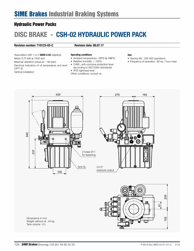
124 SIME Brakes Stromag +33 (0)1 49 90 32 20 P-8518-SG | BRC10141-01-C 2/18
Revision number: T10123-02-C Revision date: 06.07.17
DISC BRAKE - CSH-02 HYDRAULIC POWER PACK
Association with 1 or 2 SHD9-4-03 caliper(s) Motor 0.75 kW at 1500 rpmMaximal utilization pressure : 190 barsElectrical indicators of oil temperature and level (OP7-8)Vertical installation
Operating conditions:• Ambient temperature: -10°C to +50°C• Relative humidity: ≤ 100%• C4M L anti-corrosive protection level
(according to ISO12944 standards)• IP55 tightness levelOther conditions: consult us.
Use:• Service life : 200 000 operations• Frequency of operation : 60 op. / hour maxi.
Dimensions in mmWeight without oil : 43 kgTank volume : 6 L
205
164 270
155
61
100
540
237
420
G1/2"pressure output
2 holes Ø11for fastening
Tank 6L
Hydraulic Power Packs
SIME Brakes Industrial Braking Systems
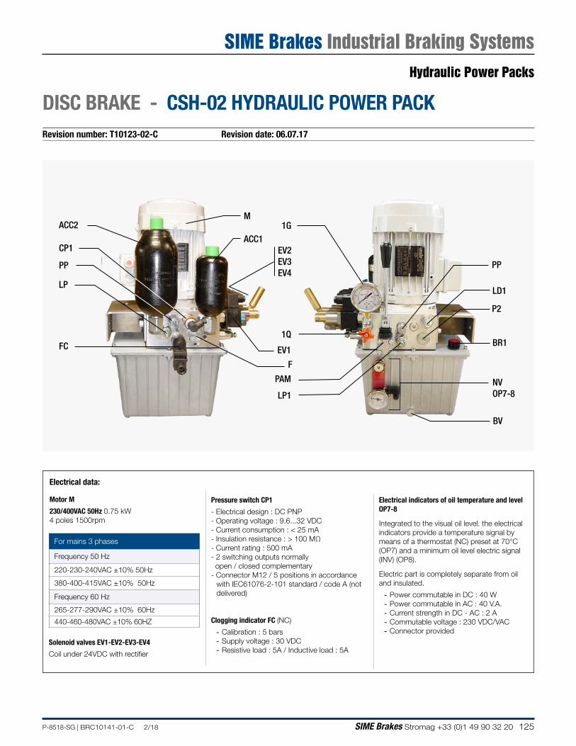
125P-8518-SG | BRC10141-01-C 2/18 SIME Brakes Stromag +33 (0)1 49 90 32 20
Revision number: T10123-02-C Revision date: 06.07.17
DISC BRAKE - CSH-02 HYDRAULIC POWER PACK
Motor M
230/400VAC 50Hz 0.75 kW 4 poles 1500rpm
Pressure switch CP1
- Electrical design : DC PNP- Operating voltage : 9.6...32 VDC - Current consumption : < 25 mA- Insulation resistance : > 100 MΩ- Current rating : 500 mA- 2 switching outputs normally open / closed complementary- Connector M12 / 5 positions in accordance
with IEC61076-2-101 standard / code A (not delivered)
Clogging indicator FC (NC)
- Calibration : 5 bars - Supply voltage : 30 VDC - Resistive load : 5A / Inductive load : 5A
For mains 3 phases
Frequency 50 Hz
220-230-240VAC ±10% 50Hz
380-400-415VAC ±10% 50Hz
Frequency 60 Hz
265-277-290VAC ±10% 60Hz
440-460-480VAC ±10% 60HZ
Solenoid valves EV1-EV2-EV3-EV4
Coil under 24VDC with rectifier
CP1
LP1
LD1
PP
NVOP7-8
LP
ACC1
ACC2
PAM
FC EV1
M
EV2EV3EV4
PP
P2
1G
1QBR1
BV
F
Electrical indicators of oil temperature and level OP7-8
Integrated to the visual oil level. the electrical indicators provide a temperature signal by means of a thermostat (NC) preset at 70°C (OP7) and a minimum oil level electric signal (INV) (OP8).
Electric part is completely separate from oil and insulated.
- Power commutable in DC : 40 W - Power commutable in AC : 40 V.A. - Current strength in DC - AC : 2 A - Commutable voltage : 230 VDC/VAC - Connector provided
Electrical data:
Hydraulic Power Packs
SIME Brakes Industrial Braking Systems
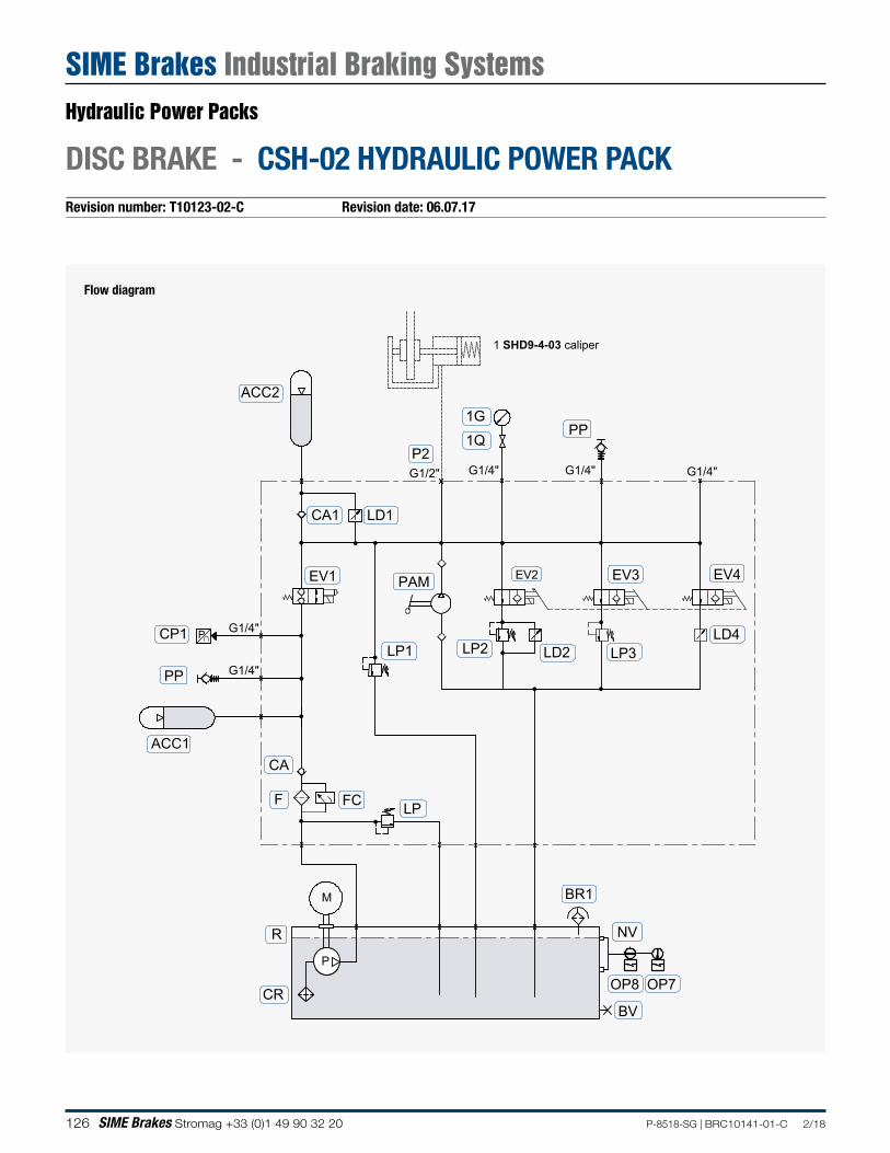
126 SIME Brakes Stromag +33 (0)1 49 90 32 20 P-8518-SG | BRC10141-01-C 2/18
Revision number: T10123-02-C Revision date: 06.07.17
DISC BRAKE - CSH-02 HYDRAULIC POWER PACK
Flow diagram
F
R
CR
LP
LP1CP1
PP
EV2 EV3
LP2 LP3LD2
EV4
LD4
ACC2
BR1
ACC1CA
1G
1Q
M
PP
G1/4"G1/2" G1/4"G1/4"
G1/4"
G1/4"
LD1CA1
FC
P∩
EV1
P
OP7OP8
BV
NV
P2
PAM
1 SHD9-4-03 caliper
Hydraulic Power Packs
SIME Brakes Industrial Braking Systems

127P-8518-SG | BRC10141-01-C 2/18 SIME Brakes Stromag +33 (0)1 49 90 32 20
NOTES
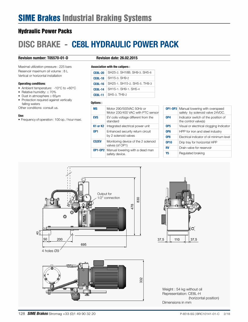
128 SIME Brakes Stromag +33 (0)1 49 90 32 20 P-8518-SG | BRC10141-01-C 2/18
Revision number: T05570-01-D Revision date: 26.02.2015
DISC BRAKE - CE8L HYDRAULIC POWER PACK
332
50 37,5 37,5110200695
40
830
478
Weight : 54 kg without oilRepresentation: CE8L-H (horizontal position)Dimensions in mm
4 holes Ø9
Maximal utilization pressure : 225 barsReservoir maximum oil volume : 8 LVertical or horizontal installation
Operating conditions:• Ambient temperature: -10°C to +60°C• Relative humidity: ≤ 70%• Dust in atmosphere ≥ 65µm• Protection required against vertically falling watersOther conditions: consult us.
Use:• Frequency of operation : 100 op. / hour maxi.
MS Motor 290/500VAC 50Hz or Motor 230/400 VAC with PTC sensor
EVS EV coils voltage different from the standard
K1 or K2 Integrated electrical power unit
OP1 Enhanced security return circuit by 2 solenoid valves
CS2EV Monitoring device of the 2 solenoid valves (of OP1)
OP1-OP2 Manual lowering with a dead man safety device.
Association with the calipers :
CE8L-20 SH25-2. SH18B. SH9-3. SH5-6
CE8L-18 SH15-3. SH9-2
CE8L-16 SH25-1. SH15-2. SH5-5. TH9-3
CE8L-14 SH15-1. SH9-1. SH5-4
CE8L-11 SH5-3. TH9-2
OP1-OP3 Manual lowering with overspeed safety by solenoid valve 24VDC.
OP4 Indicator switch of the position of the control valve(s)
OP5 Visual or electrical clogging Indicator
OP6 HPP for iron and steel industry
OP8 Electrical indicator of oil minimum level
OP10 Drip tray for horizontal HPP
RV Drain valve for reservoir
Y5 Regulated braking
Options :
Output for 1/2" connection
Hydraulic Power Packs
SIME Brakes Industrial Braking Systems
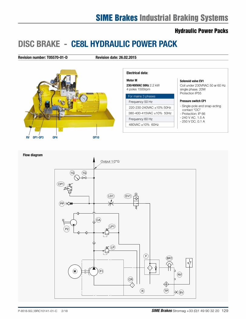
129P-8518-SG | BRC10141-01-C 2/18 SIME Brakes Stromag +33 (0)1 49 90 32 20
Revision number: T05570-01-D Revision date: 26.02.2015
DISC BRAKE - CE8L HYDRAULIC POWER PACK
M
1G 1Q
PP
EV1
CP1
P1
LP
CR
R
F
LP1P2
CA
BR1
NV
BV
q
TP
LD1
Output 1/2"G
Flow diagram
Electrical data:
Motor M
230/400VAC 50Hz 2.2 kW 4 poles 1500rpm
Solenoid valve EV1Coil under 230VRAC 50 or 60 Hzsingle phase. 20WProtection IP55
Pressure switch CP1
- Single-pole and snap-acting contact "OC"
- Protection: IP 66- 240 V AC. 1.5 A- 250 V DC. 0.1 A
For mains 3 phases
Frequency 50 Hz
220-230-240VAC ±10% 50Hz
380-400-415VAC ±10% 50Hz
Frequency 60 Hz
480VAC ±10% 60Hz
OP10OP4RV OP1-OP3
Hydraulic Power Packs
SIME Brakes Industrial Braking Systems
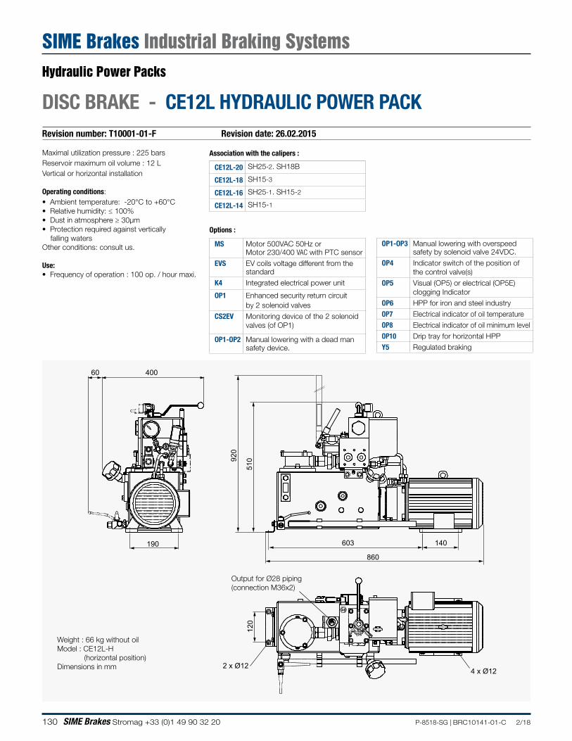
130 SIME Brakes Stromag +33 (0)1 49 90 32 20 P-8518-SG | BRC10141-01-C 2/18
Revision number: T10001-01-F Revision date: 26.02.2015
DISC BRAKE - CE12L HYDRAULIC POWER PACK
Maximal utilization pressure : 225 barsReservoir maximum oil volume : 12 LVertical or horizontal installation
Operating conditions:• Ambient temperature: -20°C to +60°C• Relative humidity: ≤ 100%• Dust in atmosphere ≥ 30µm• Protection required against vertically falling watersOther conditions: consult us.
Use:• Frequency of operation : 100 op. / hour maxi.
MS Motor 500VAC 50Hz or Motor 230/400 VAC with PTC sensor
EVS EV coils voltage different from the standard
K4 Integrated electrical power unit
OP1 Enhanced security return circuit by 2 solenoid valves
CS2EV Monitoring device of the 2 solenoid valves (of OP1)
OP1-OP2 Manual lowering with a dead man safety device.
Association with the calipers :
CE12L-20 SH25-2. SH18B
CE12L-18 SH15-3
CE12L-16 SH25-1. SH15-2
CE12L-14 SH15-1
OP1-OP3 Manual lowering with overspeed safety by solenoid valve 24VDC.
OP4 Indicator switch of the position ofthe control valve(s)
OP5 Visual (OP5) or electrical (OP5E) clogging Indicator
OP6 HPP for iron and steel industryOP7 Electrical indicator of oil temperatureOP8 Electrical indicator of oil minimum levelOP10 Drip tray for horizontal HPPY5 Regulated braking
Options :
400
190
510
603 140
860
120
2 x Ø124 x Ø12
920
60
Output for Ø28 piping(connection M36x2)
Weight : 66 kg without oilModel : CE12L-H (horizontal position)Dimensions in mm
Hydraulic Power Packs
SIME Brakes Industrial Braking Systems
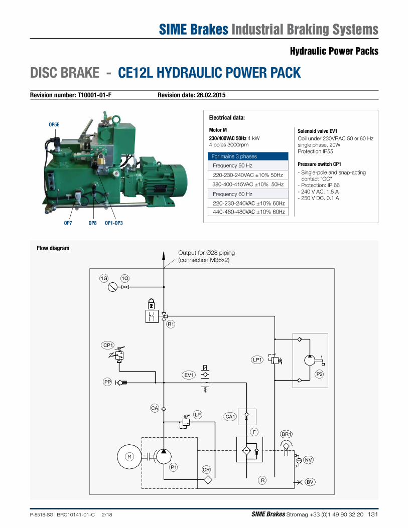
131P-8518-SG | BRC10141-01-C 2/18 SIME Brakes Stromag +33 (0)1 49 90 32 20
Revision number: T10001-01-F Revision date: 26.02.2015
DISC BRAKE - CE12L HYDRAULIC POWER PACK
Flow diagram
Electrical data:
Motor M
230/400VAC 50Hz 4 kW 4 poles 3000rpm
Solenoid valve EV1Coil under 230VRAC 50 or 60 Hzsingle phase, 20WProtection IP55
Pressure switch CP1
- Single-pole and snap-acting contact "OC"
- Protection: IP 66- 240 V AC. 1.5 A- 250 V DC. 0.1 A
For mains 3 phases
Frequency 50 Hz
220-230-240VAC ±10% 50Hz
380-400-415VAC ±10% 50Hz
Frequency 60 Hz
220-230-240VAC ±10% 60Hz
440-460-480VAC ±10% 60Hz
1G
R1
CP1
PP
CA
P1
LP
CR
R
F
EV1
LP1
P2
1Q
NV
BV
BR1
CA1
Output for Ø28 piping(connection M36x2)
OP5E
OP8OP7 OP1-OP3
Hydraulic Power Packs
SIME Brakes Industrial Braking Systems
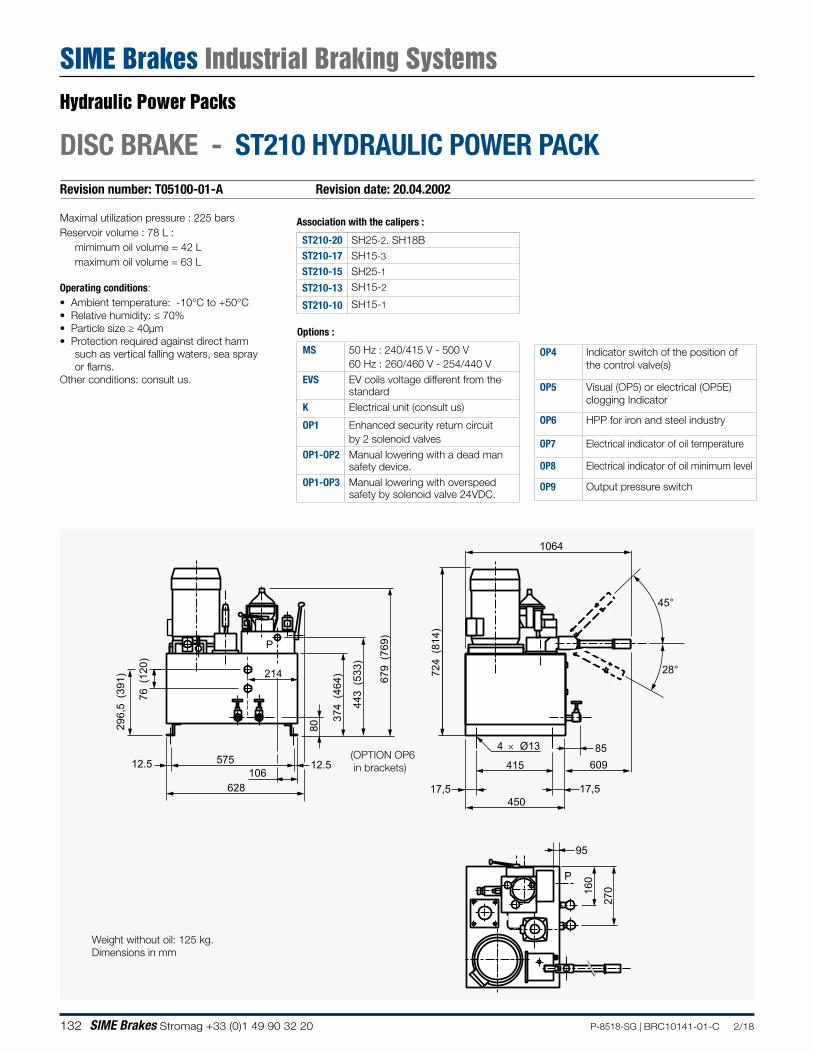
132 SIME Brakes Stromag +33 (0)1 49 90 32 20 P-8518-SG | BRC10141-01-C 2/18
Revision number: T05100-01-A Revision date: 20.04.2002
DISC BRAKE - ST210 HYDRAULIC POWER PACK
95
P
57512.5 12.5106
628
296,
5 (3
91)
80
27016
0
374
(464
)
443
(533
)
679
(769
)
P
415
4 × Ø13
17,5 17,5450
85
1064
724
(814
)
609
45°
28°
76 (
120)
214
(OPTION OP6 in brackets)
Weight without oil: 125 kg.Dimensions in mm
Maximal utilization pressure : 225 barsReservoir volume : 78 L :
mimimum oil volume = 42 Lmaximum oil volume = 63 L
Operating conditions:• Ambient temperature: -10°C to +50°C• Relative humidity: ≤ 70%• Particle size ≥ 40µm• Protection required against direct harm
such as vertical falling waters, sea spray or flams.
Other conditions: consult us.
MS 50 Hz : 240/415 V - 500 V 60 Hz : 260/460 V - 254/440 V
EVS EV coils voltage different from the standard
K Electrical unit (consult us)
OP1 Enhanced security return circuit by 2 solenoid valves
OP1-OP2 Manual lowering with a dead man safety device.
OP1-OP3 Manual lowering with overspeed safety by solenoid valve 24VDC.
Association with the calipers :
ST210-20 SH25-2. SH18BST210-17 SH15-3
ST210-15 SH25-1
ST210-13 SH15-2
ST210-10 SH15-1
OP4 Indicator switch of the position of the control valve(s)
OP5 Visual (OP5) or electrical (OP5E) clogging Indicator
OP6 HPP for iron and steel industry
OP7 Electrical indicator of oil temperature
OP8 Electrical indicator of oil minimum level
OP9 Output pressure switch
Options :
Hydraulic Power Packs
SIME Brakes Industrial Braking Systems
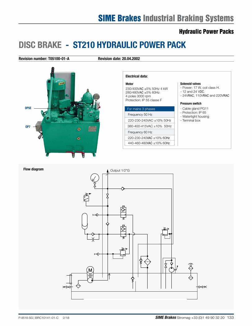
133P-8518-SG | BRC10141-01-C 2/18 SIME Brakes Stromag +33 (0)1 49 90 32 20
Revision number: T05100-01-A Revision date: 20.04.2002
DISC BRAKE - ST210 HYDRAULIC POWER PACK
M
Flow diagram
Electrical data:
Motor
230/400VAC ±5% 50Hz 4 kW280/480VAC ±5% 60Hz 4 poles 3000 rpmProtection: IP 55 classe F
Solenoid valves- Power: 17 W, coil class H.- 12 and 24 VDC.- 24VRAC, 110VRAC and 220VRAC
Pressure switch
- Cable gland PG11- Protection: IP 65- Watertight housing - Terminal box
For mains 3 phases
Frequency 50 Hz
220-230-240VAC ±10% 50Hz
380-400-415VAC ±10% 50Hz
Frequency 60 Hz
220-230-240VAC ±10% 60Hz
440-460-480VAC ±10% 60Hz
Output 1/2"G
OP5E
OP7
Hydraulic Power Packs
SIME Brakes Industrial Braking Systems
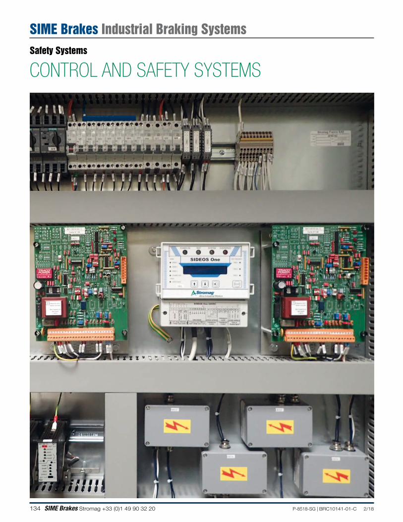
134 SIME Brakes Stromag +33 (0)1 49 90 32 20 P-8518-SG | BRC10141-01-C 2/18
CONTROL AND SAFETY SYSTEMSSafety Systems
SIME Brakes Industrial Braking Systems
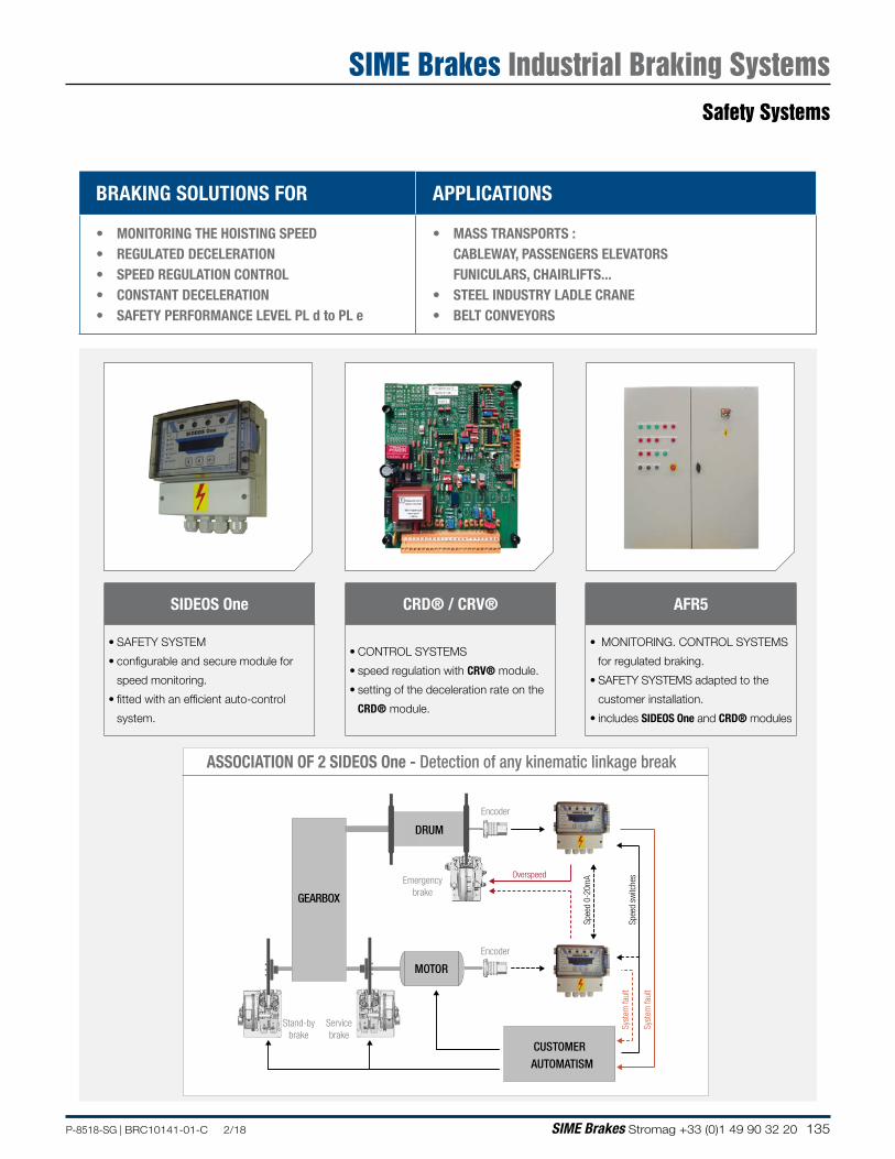
135P-8518-SG | BRC10141-01-C 2/18 SIME Brakes Stromag +33 (0)1 49 90 32 20
BRAKING SOLUTIONS FOR APPLICATIONS
• MONITORING THE HOISTING SPEED• REGULATED DECELERATION • SPEED REGULATION CONTROL• CONSTANT DECELERATION• SAFETY PERFORMANCE LEVEL PL d to PL e
• MASS TRANSPORTS : CABLEWAY, PASSENGERS ELEVATORSFUNICULARS, CHAIRLIFTS...
• STEEL INDUSTRY LADLE CRANE• BELT CONVEYORS
AFR5
• MONITORING. CONTROL SYSTEMS
for regulated braking.
• SAFETY SYSTEMS adapted to the
customer installation.
• includes SIDEOS One and CRD® modules
CRD® / CRV®
• CONTROL SYSTEMS
• speed regulation with CRV® module.
• setting of the deceleration rate on the
CRD® module.
SIDEOS One
• SAFETY SYSTEM
• configurable and secure module for
speed monitoring.
• fitted with an efficient auto-control
system.
Syst
em fa
ult
Overspeed
Syst
em fa
ult
MOTOR
GEARBOX
DRUM
CUSTOMERAUTOMATISM
Servicebrake
Stand-bybrake
Emergencybrake
Encoder
Spee
d 0-
20m
A
Spee
d sw
itche
s
Encoder
ASSOCIATION OF 2 SIDEOS One - Detection of any kinematic linkage break
Safety Systems
SIME Brakes Industrial Braking Systems
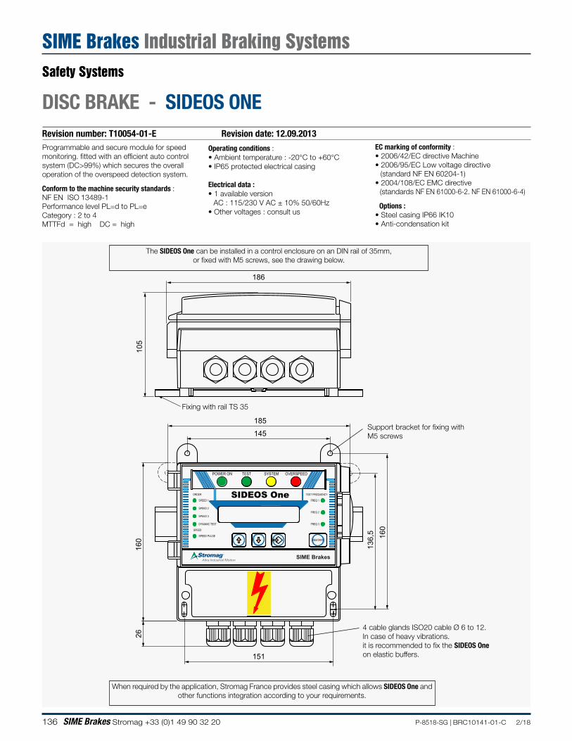
136 SIME Brakes Stromag +33 (0)1 49 90 32 20 P-8518-SG | BRC10141-01-C 2/18
Revision number: T10054-01-E Revision date: 12.09.2013
DISC BRAKE - SIDEOS ONE
Programmable and secure module for speed monitoring. fitted with an efficient auto control system (DC>99%) which secures the overall operation of the overspeed detection system.
Conform to the machine security standards :NF EN ISO 13489-1 Performance level PL=d to PL=e Category : 2 to 4 MTTFd = high DC = high
Operating conditions :• Ambient temperature : -20°C to +60°C• IP65 protected electrical casing
Electrical data :• 1 available version AC : 115/230 V AC ± 10% 50/60Hz• Other voltages : consult us
EC marking of conformity :• 2006/42/EC directive Machine• 2006/95/EC Low voltage directive
(standard NF EN 60204-1)• 2004/108/EC EMC directive
(standards NF EN 61000-6-2. NF EN 61000-6-4)
Options :• Steel casing IP66 IK10• Anti-condensation kit
SPEED 3
SPEED PULSE
DYNAMIC TEST
SPEED
RESTART
FREQ 3
SYSTEM
SIDEOS OneSPEED 2
SPEED 1
ORDER
POWER ON TEST OVERSPEED
TEST FREQUENCY
FREQ 1
FREQ 2
186
105
160
26
160
151
145
185
136,
5
SIME Brakes
Fixing with rail TS 35
4 cable glands ISO20 cable Ø 6 to 12.In case of heavy vibrations. it is recommended to fix the SIDEOS One on elastic buffers.
Support bracket for fixing with M5 screws
When required by the application, Stromag France provides steel casing which allows SIDEOS One and other functions integration according to your requirements.
The SIDEOS One can be installed in a control enclosure on an DIN rail of 35mm, or fixed with M5 screws, see the drawing below.
Safety Systems
SIME Brakes Industrial Braking Systems
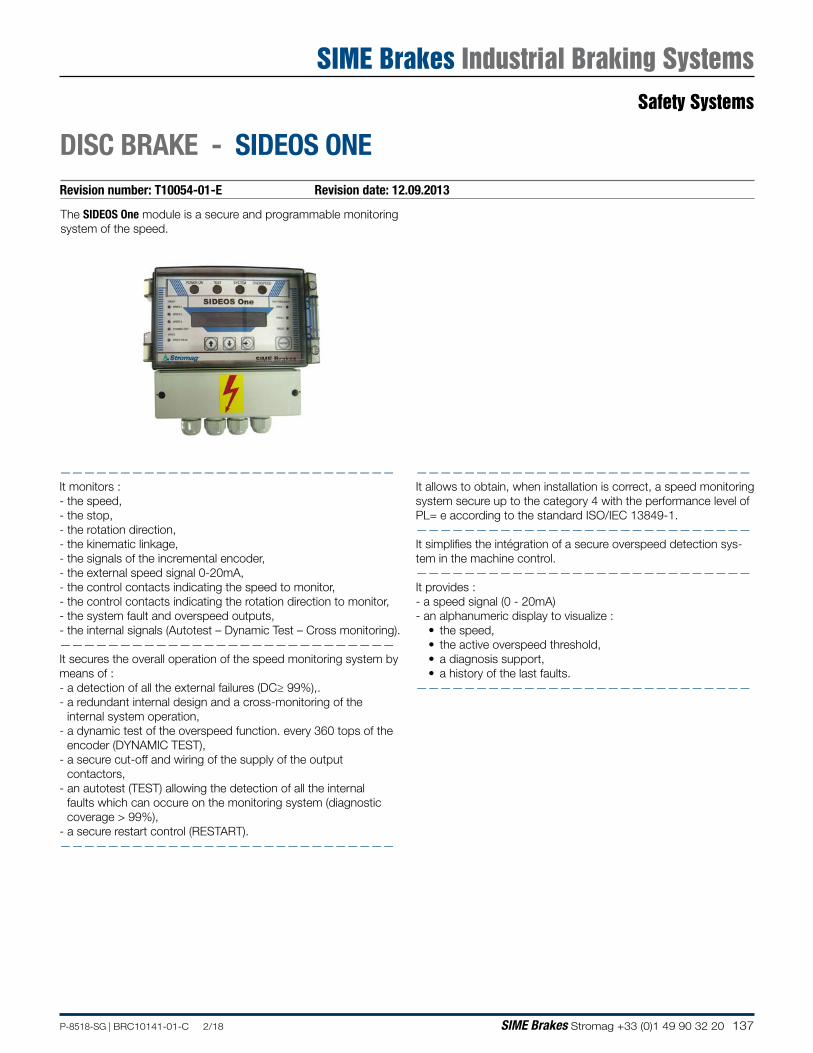
137P-8518-SG | BRC10141-01-C 2/18 SIME Brakes Stromag +33 (0)1 49 90 32 20
Revision number: T10054-01-E Revision date: 12.09.2013
DISC BRAKE - SIDEOS ONE
The SIDEOS One module is a secure and programmable monitoring system of the speed.
————————————————————————————It monitors : - the speed,- the stop,- the rotation direction,- the kinematic linkage,- the signals of the incremental encoder,- the external speed signal 0-20mA,- the control contacts indicating the speed to monitor,- the control contacts indicating the rotation direction to monitor,- the system fault and overspeed outputs,- the internal signals (Autotest – Dynamic Test – Cross monitoring).————————————————————————————It secures the overall operation of the speed monitoring system by means of :- a detection of all the external failures (DC≥ 99%),.- a redundant internal design and a cross-monitoring of the
internal system operation,- a dynamic test of the overspeed function. every 360 tops of the
encoder (DYNAMIC TEST),- a secure cut-off and wiring of the supply of the output
contactors,- an autotest (TEST) allowing the detection of all the internal
faults which can occure on the monitoring system (diagnostic coverage > 99%),
- a secure restart control (RESTART).————————————————————————————
————————————————————————————It allows to obtain, when installation is correct, a speed monitoring system secure up to the category 4 with the performance level of PL= e according to the standard ISO/IEC 13849-1.————————————————————————————It simplifies the intégration of a secure overspeed detection sys-tem in the machine control.————————————————————————————It provides :- a speed signal (0 - 20mA)- an alphanumeric display to visualize :
• the speed, • the active overspeed threshold,• a diagnosis support, • a history of the last faults.
————————————————————————————
Safety Systems
SIME Brakes Industrial Braking Systems
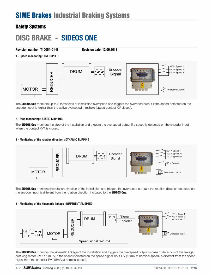
138 SIME Brakes Stromag +33 (0)1 49 90 32 20 P-8518-SG | BRC10141-01-C 2/18
Revision number: T10054-01-E Revision date: 12.09.2013
DISC BRAKE - SIDEOS ONE
1 - Speed monitoring : OVERSPEED
The SIDEOS One monitors up to 3 thresholds of installation overspeed and triggers the overpeed output if the speed detected on the encoder input is higher than the active overspeed threshold (speed contact KV closed).
2 - Stop monitoring : STATIC SLIPPING
The SIDEOS One monitors the stop of the installation and triggers the overspeed output if a speed is detected on the encoder input when the contact KV1 is closed.
3 - Monitoring of the rotation direction : DYNAMIC SLIPPING
The SIDEOS One monitors the rotation direction of the installation and triggers the overspeed output if the rotation direction detected on the encoder input is different from the rotation direction indicated to the SIDEOS One.
4 - Monitoring of the kinematic linkage : DIFFERENTIAL SPEED
The SIDEOS One monitors the kinematic linkage of the installation and triggers the overspeed output in case of detection of the linkage breaking motor GV / drum PV, if the speed indicated on the speed signal input GV (15mA at nominal speed) is different from the speed signal from the encoder PV (15mA at nominal speed).
Signal
RE
DU
CE
R
MOTOR
DRUM KV3= Speed 3Encoder KV2= Speed 2
KV1= Speed 1
Overspeed output
SignalEncoder
MOTOR RE
DU
CE
R DRUM
Overspeed output
KV2 = Speed PVKV3 = Speed GV
KD = Descent
KV1 = Speed 1
Signal
RE
DU
CE
R
MOTOR
DRUM Encoder
U/I
F
Speed signal 0-20mA
Overspeed output
KV3 = Speed 3
KV1 = Speed 1KV2 = Speed 2
Safety Systems
SIME Brakes Industrial Braking Systems

139P-8518-SG | BRC10141-01-C 2/18 SIME Brakes Stromag +33 (0)1 49 90 32 20
NOTES
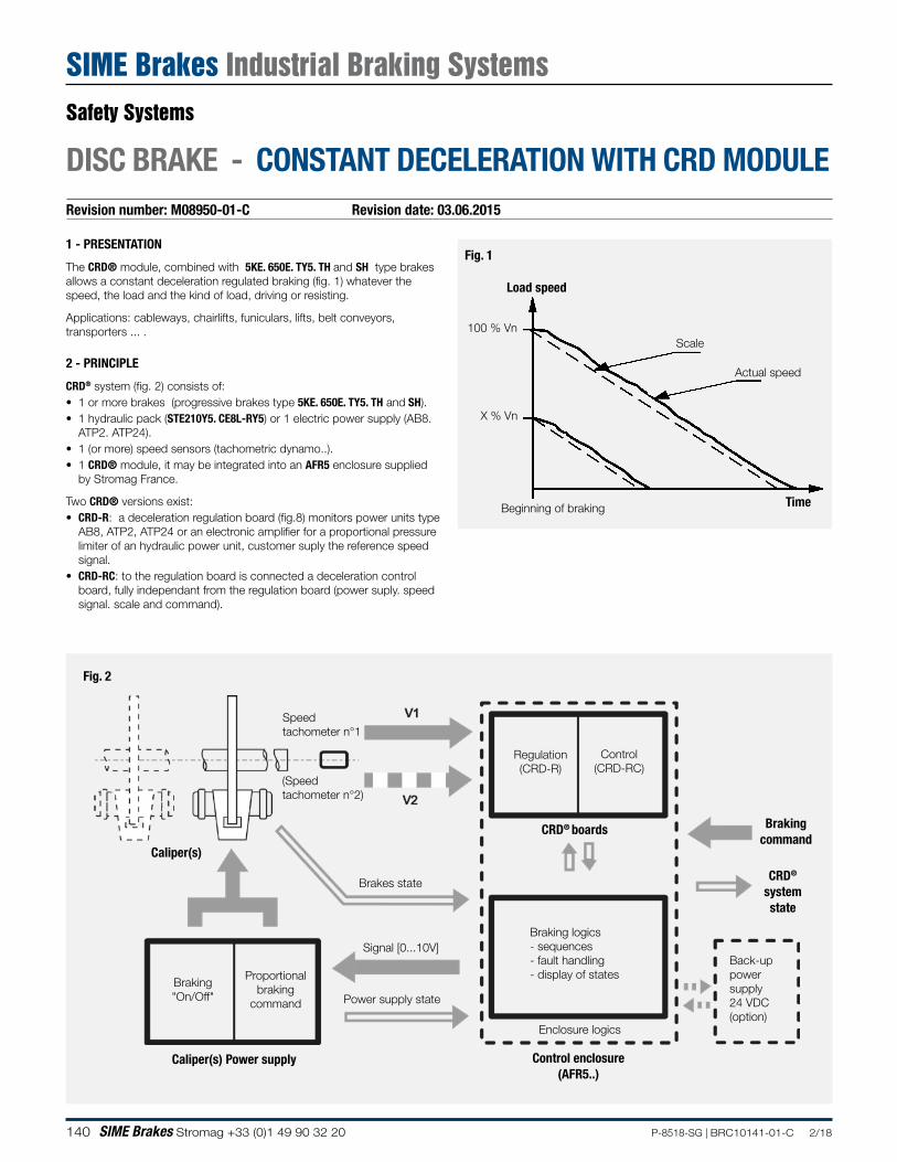
140 SIME Brakes Stromag +33 (0)1 49 90 32 20 P-8518-SG | BRC10141-01-C 2/18
Revision number: M08950-01-C Revision date: 03.06.2015
DISC BRAKE - CONSTANT DECELERATION WITH CRD MODULE
1 - PRESENTATION
The CRD® module, combined with 5KE. 650E. TY5. TH and SH type brakes allows a constant deceleration regulated braking (fig. 1) whatever the speed, the load and the kind of load, driving or resisting.
Applications: cableways, chairlifts, funiculars, lifts, belt conveyors, transporters ... .
2 - PRINCIPLE
CRD® system (fig. 2) consists of:• 1 or more brakes (progressive brakes type 5KE. 650E. TY5. TH and SH).• 1 hydraulic pack (STE210Y5. CE8L-RY5) or 1 electric power supply (AB8.
ATP2. ATP24).• 1 (or more) speed sensors (tachometric dynamo..).• 1 CRD® module, it may be integrated into an AFR5 enclosure supplied
by Stromag France.
Two CRD® versions exist:• CRD-R: a deceleration regulation board (fig.8) monitors power units type
AB8, ATP2, ATP24 or an electronic amplifier for a proportional pressure limiter of an hydraulic power unit, customer suply the reference speed signal.
• CRD-RC: to the regulation board is connected a deceleration control board, fully independant from the regulation board (power suply. speed signal. scale and command).
Fig. 1
TimeBeginning of braking
100 % Vn
X % Vn
Fig. 2
Caliper(s)
Braking logics- sequences- fault handling- display of states
Brakingcommand
Back-uppowersupply24 VDC(option)
Control enclosure(AFR5..)
Signal [0...10V]
Proportionalbraking
command
Caliper(s) Power supply
Regulation(CRD-R)
CRD® boards
Control(CRD-RC)
Braking"On/Off"
CRD®
systemstate
Power supply state
Brakes state
Enclosure logics
Speed tachometer n°1
(Speed tachometer n°2)
Load speed
Scale
Actual speed
Safety Systems
SIME Brakes Industrial Braking Systems
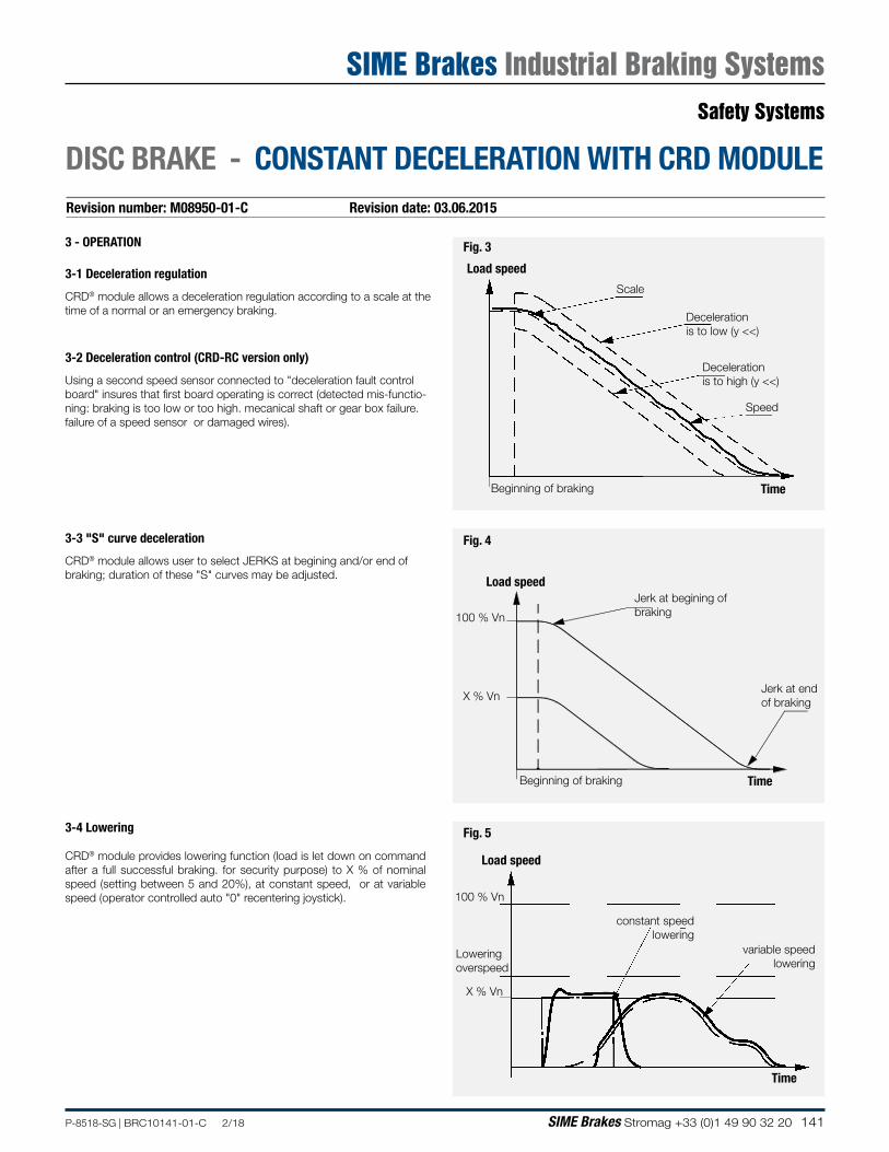
141P-8518-SG | BRC10141-01-C 2/18 SIME Brakes Stromag +33 (0)1 49 90 32 20
Revision number: M08950-01-C Revision date: 03.06.2015
DISC BRAKE - CONSTANT DECELERATION WITH CRD MODULE
3 - OPERATION
3-1 Deceleration regulation
CRD® module allows a deceleration regulation according to a scale at the time of a normal or an emergency braking.
3-2 Deceleration control (CRD-RC version only)
Using a second speed sensor connected to "deceleration fault control board" insures that first board operating is correct (detected mis-functio-ning: braking is too low or too high. mecanical shaft or gear box failure. failure of a speed sensor or damaged wires).
3-4 Lowering
CRD® module provides lowering function (load is let down on command after a full successful braking. for security purpose) to X % of nominal speed (setting between 5 and 20%), at constant speed, or at variable speed (operator controlled auto "0" recentering joystick).
3-3 "S" curve deceleration
CRD® module allows user to select JERKS at begining and/or end of braking; duration of these "S" curves may be adjusted.
Fig. 3
TimeBeginning of braking
Load speed
Scale
Decelerationis to low (y <<)
Decelerationis to high (y <<)
Speed
Fig. 5
Time
Load speed
100 % Vn
X % Vn
constant speed lowering
variable speed lowering
Loweringoverspeed
Fig. 4
Load speed
Beginning of braking
100 % Vn
X % Vn
Time
Jerk at begining of braking
Jerk at end of braking
Safety Systems
SIME Brakes Industrial Braking Systems
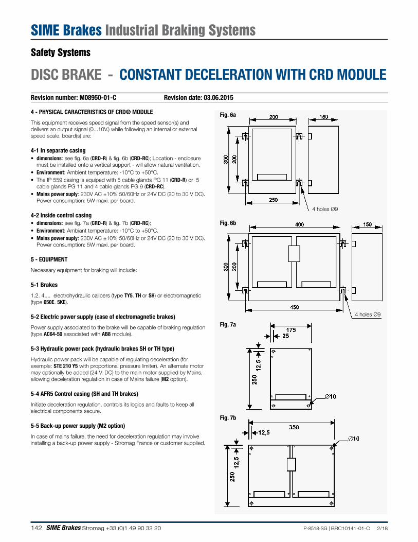
142 SIME Brakes Stromag +33 (0)1 49 90 32 20 P-8518-SG | BRC10141-01-C 2/18
Revision number: M08950-01-C Revision date: 03.06.2015
DISC BRAKE - CONSTANT DECELERATION WITH CRD MODULE
4 - PHYSICAL CARACTERISTICS OF CRD® MODULE
This equipment receives speed signal from the speed sensor(s) and delivers an output signal (0...10V.) while following an internal or external speed scale. board(s) are:
4-1 In separate casing• dimensions: see fig. 6a (CRD-R) & fig. 6b (CRD-RC); Location - enclosure
must be installed onto a vertical support - will allow natural ventilation.• Environment: Ambient temperature: -10°C to +50°C.• The IP 559 casing is equiped with 5 cable glands PG 11 (CRD-R) or 5
cable glands PG 11 and 4 cable glands PG 9 (CRD-RC).• Mains power suply: 230V AC ±10% 50/60Hz or 24V DC (20 to 30 V DC).
Power consumption: 5W maxi. per board. 4-2 Inside control casing• dimensions: see fig. 7a (CRD-R) & fig. 7b (CRD-RC);• Environment: Ambiant temperature: -10°C to +50°C.• Mains power suply: 230V AC ±10% 50/60Hz or 24V DC (20 to 30 V DC).
Power consumption: 5W maxi. per board.
5 - EQUIPMENT
Necessary equipment for braking will include:
5-1 Brakes
1.2. 4.... electrohydraulic calipers (type TY5. TH or SH) or electromagnetic (type 650E. 5KE).
5-2 Electric power supply (case of electromagnetic brakes)
Power supply associated to the brake will be capable of braking regulation (type AC64-50 associated with AB8 module).
5-3 Hydraulic power pack (hydraulic brakes SH or TH type)
Hydraulic power pack will be capable of regulating deceleration (for exemple: STE 210 Y5 with proportional pressure limiter). An alternate motor may optionally be added (24 V. DC) to the main motor supplied by Mains, allowing deceleration regulation in case of Mains failure (M2 option).
5-4 AFR5 Control casing (SH and TH brakes)
Initiate deceleration regulation, controls its logics and faults to keep all electrical components secure.
5-5 Back-up power supply (M2 option)
In case of mains failure, the need for deceleration regulation may involve installing a back-up power supply - Stromag France or customer supplied.
Fig. 6a
Fig. 7a
Fig. 7b
4 holes Ø9
Fig. 6b
4 holes Ø9
Safety Systems
SIME Brakes Industrial Braking Systems
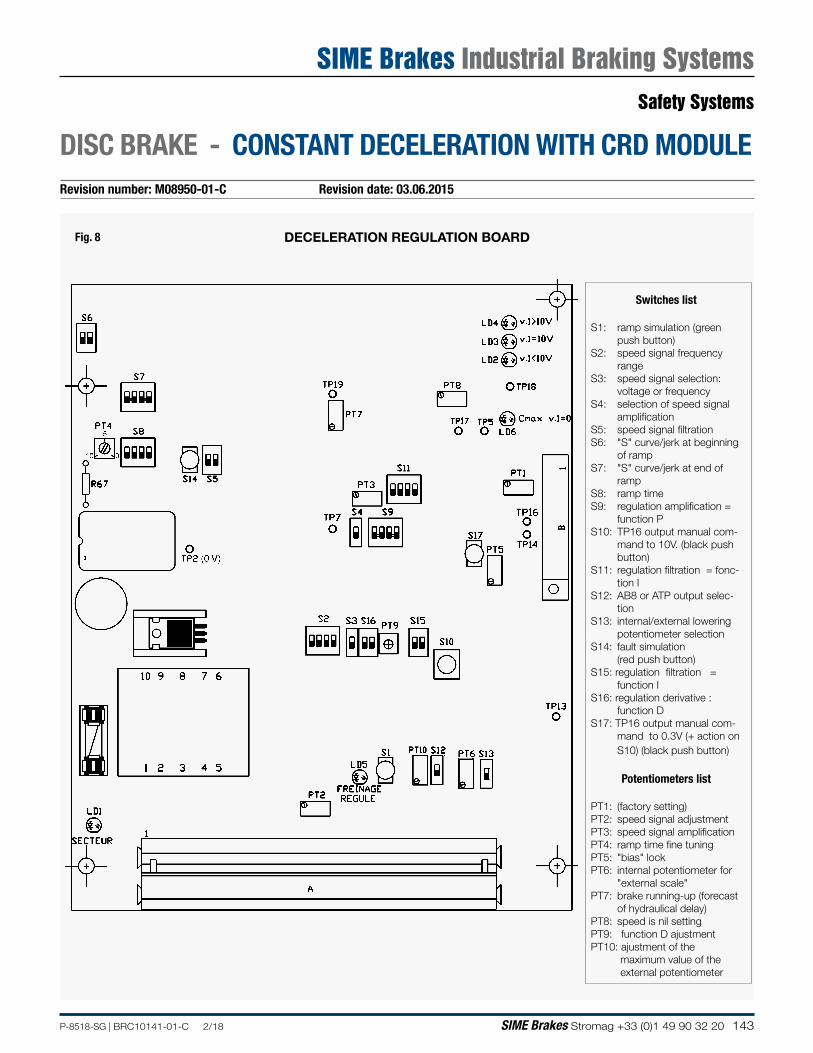
143P-8518-SG | BRC10141-01-C 2/18 SIME Brakes Stromag +33 (0)1 49 90 32 20
Revision number: M08950-01-C Revision date: 03.06.2015
DISC BRAKE - CONSTANT DECELERATION WITH CRD MODULE
Fig. 8 DECELERATION REGULATION BOARD
Switches list
S1: ramp simulation (green push button)
S2: speed signal frequency range
S3: speed signal selection: voltage or frequency
S4: selection of speed signal amplification
S5: speed signal filtration S6: "S" curve/jerk at beginning
of rampS7: "S" curve/jerk at end of
rampS8: ramp timeS9: regulation amplification = function PS10: TP16 output manual com-
mand to 10V. (black push button)
S11: regulation filtration = fonc-tion I
S12: AB8 or ATP output selec-tion
S13: internal/external lowering potentiometer selection
S14: fault simulation (red push button)S15: regulation filtration =
function IS16: regulation derivative :
function DS17: TP16 output manual com-
mand to 0.3V (+ action on S10) (black push button)
Potentiometers list
PT1: (factory setting)PT2: speed signal adjustmentPT3: speed signal amplificationPT4: ramp time fine tuningPT5: "bias" lock PT6: internal potentiometer for
"external scale"PT7: brake running-up (forecast
of hydraulical delay)PT8: speed is nil settingPT9: function D ajustment PT10: ajustment of the maximum value of the external potentiometer
Safety Systems
SIME Brakes Industrial Braking Systems
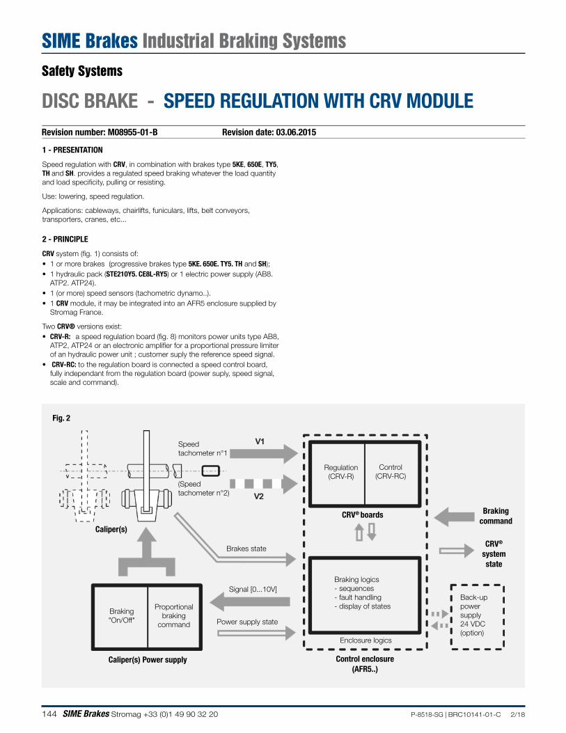
144 SIME Brakes Stromag +33 (0)1 49 90 32 20 P-8518-SG | BRC10141-01-C 2/18
Revision number: M08955-01-B Revision date: 03.06.2015
DISC BRAKE - SPEED REGULATION WITH CRV MODULE
1 - PRESENTATION
Speed regulation with CRV, in combination with brakes type 5KE, 650E, TY5, TH and SH. provides a regulated speed braking whatever the load quantity and load specificity, pulling or resisting.
Use: lowering, speed regulation.
Applications: cableways, chairlifts, funiculars, lifts, belt conveyors, transporters, cranes, etc...
2 - PRINCIPLE
CRV system (fig. 1) consists of:• 1 or more brakes (progressive brakes type 5KE. 650E. TY5. TH and SH);• 1 hydraulic pack (STE210Y5. CE8L-RY5) or 1 electric power supply (AB8.
ATP2. ATP24).• 1 (or more) speed sensors (tachometric dynamo..).• 1 CRV module, it may be integrated into an AFR5 enclosure supplied by
Stromag France.
Two CRV® versions exist:• CRV-R: a speed regulation board (fig. 8) monitors power units type AB8,
ATP2, ATP24 or an electronic amplifier for a proportional pressure limiter of an hydraulic power unit ; customer suply the reference speed signal.
• CRV-RC: to the regulation board is connected a speed control board, fully independant from the regulation board (power suply, speed signal, scale and command).
Fig. 2
Caliper(s)
Braking logics- sequences- fault handling- display of states
Brakingcommand
Back-uppowersupply24 VDC(option)
Control enclosure(AFR5..)
Signal [0...10V]
Proportionalbraking
command
Caliper(s) Power supply
Regulation(CRV-R)
CRV® boards
Control(CRV-RC)
Braking"On/Off"
CRV®
systemstate
Power supply state
Brakes state
Enclosure logics
Speed tachometer n°1
(Speed tachometer n°2)
Safety Systems
SIME Brakes Industrial Braking Systems
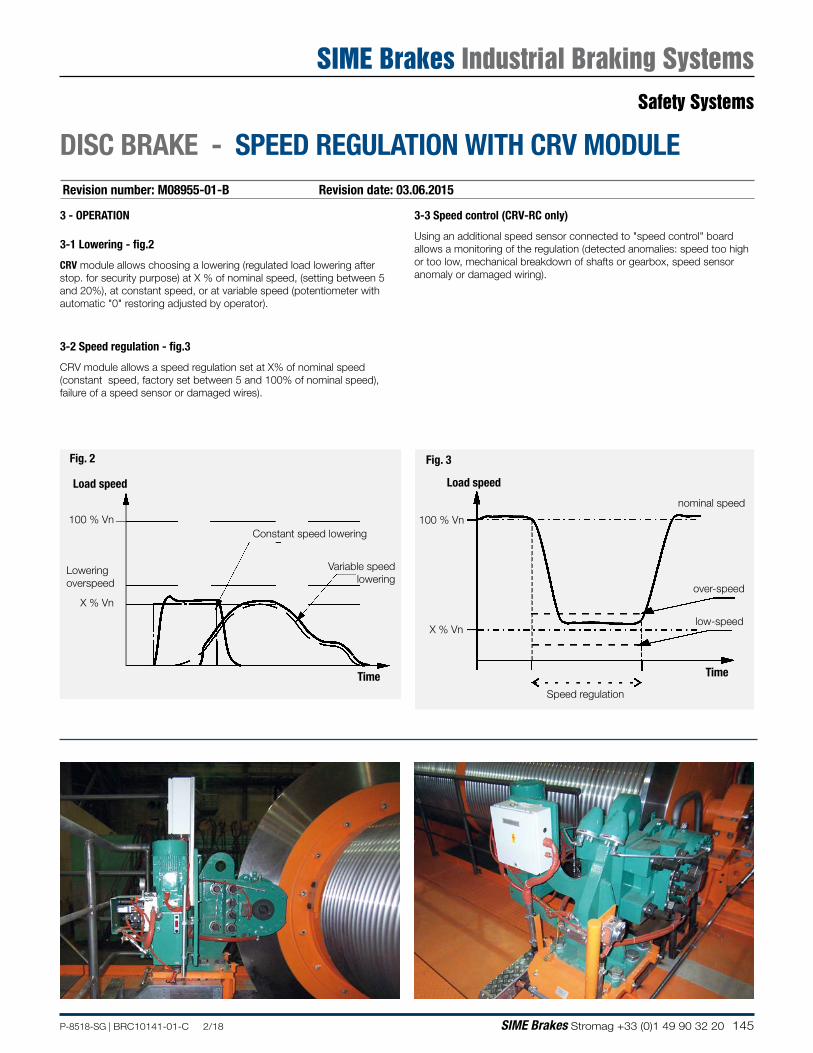
145P-8518-SG | BRC10141-01-C 2/18 SIME Brakes Stromag +33 (0)1 49 90 32 20
Revision number: M08955-01-B Revision date: 03.06.2015
DISC BRAKE - SPEED REGULATION WITH CRV MODULE
3 - OPERATION
3-1 Lowering - fig.2
CRV module allows choosing a lowering (regulated load lowering after stop. for security purpose) at X % of nominal speed, (setting between 5 and 20%), at constant speed, or at variable speed (potentiometer with automatic "0" restoring adjusted by operator).
3-2 Speed regulation - fig.3
CRV module allows a speed regulation set at X% of nominal speed (constant speed, factory set between 5 and 100% of nominal speed), failure of a speed sensor or damaged wires).
Fig. 2
Time
Load speed
100 % Vn
X % Vn
Variable speed lowering
Lowering overspeed
Constant speed lowering
Fig. 3
Load speed
100 % Vn
X % Vn
over-speed
nominal speed
low-speed
Speed regulation
Time
3-3 Speed control (CRV-RC only)
Using an additional speed sensor connected to "speed control" board allows a monitoring of the regulation (detected anomalies: speed too high or too low, mechanical breakdown of shafts or gearbox, speed sensor anomaly or damaged wiring).
Safety Systems
SIME Brakes Industrial Braking Systems
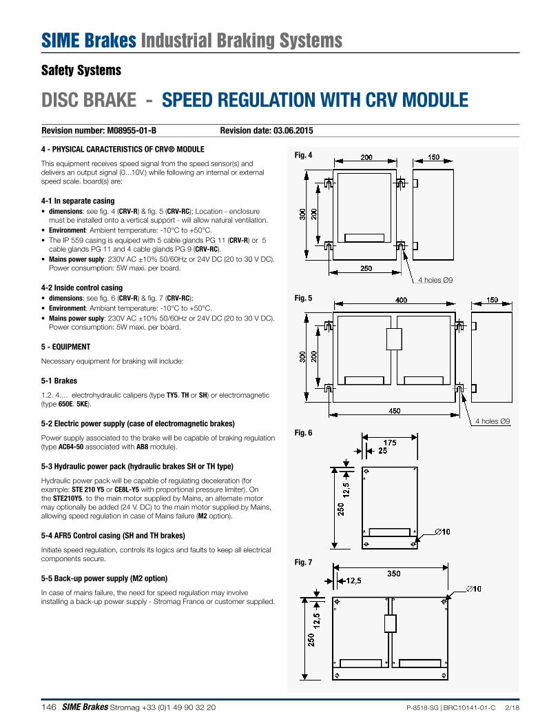
146 SIME Brakes Stromag +33 (0)1 49 90 32 20 P-8518-SG | BRC10141-01-C 2/18
4 - PHYSICAL CARACTERISTICS OF CRV® MODULE
This equipment receives speed signal from the speed sensor(s) and delivers an output signal (0...10V.) while following an internal or external speed scale. board(s) are:
4-1 In separate casing• dimensions: see fig. 4 (CRV-R) & fig. 5 (CRV-RC); Location - enclosure
must be installed onto a vertical support - will allow natural ventilation.• Environment: Ambient temperature: -10°C to +50°C.• The IP 559 casing is equiped with 5 cable glands PG 11 (CRV-R) or 5
cable glands PG 11 and 4 cable glands PG 9 (CRV-RC).• Mains power suply: 230V AC ±10% 50/60Hz or 24V DC (20 to 30 V DC).
Power consumption: 5W maxi. per board. 4-2 Inside control casing• dimensions: see fig. 6 (CRV-R) & fig. 7 (CRV-RC);• Environment: Ambiant temperature: -10°C to +50°C.• Mains power suply: 230V AC ±10% 50/60Hz or 24V DC (20 to 30 V DC).
Power consumption: 5W maxi. per board.
5 - EQUIPMENT
Necessary equipment for braking will include:
5-1 Brakes
1.2. 4.... electrohydraulic calipers (type TY5. TH or SH) or electromagnetic (type 650E. 5KE).
5-2 Electric power supply (case of electromagnetic brakes)
Power supply associated to the brake will be capable of braking regulation (type AC64-50 associated with AB8 module).
5-3 Hydraulic power pack (hydraulic brakes SH or TH type)
Hydraulic power pack will be capable of regulating deceleration (for example: STE 210 Y5 or CE8L-Y5 with proportional pressure limiter). On the STE210Y5. to the main motor supplied by Mains, an alternate motor may optionally be added (24 V. DC) to the main motor supplied by Mains, allowing speed regulation in case of Mains failure (M2 option).
5-4 AFR5 Control casing (SH and TH brakes)
Initiate speed regulation, controls its logics and faults to keep all electrical components secure.
5-5 Back-up power supply (M2 option)
In case of mains failure, the need for speed regulation may involve installing a back-up power supply - Stromag France or customer supplied.
Fig. 4
Fig. 6
Fig. 7
4 holes Ø9
Fig. 5
4 holes Ø9
Revision number: M08955-01-B Revision date: 03.06.2015
DISC BRAKE - SPEED REGULATION WITH CRV MODULE
Safety Systems
SIME Brakes Industrial Braking Systems
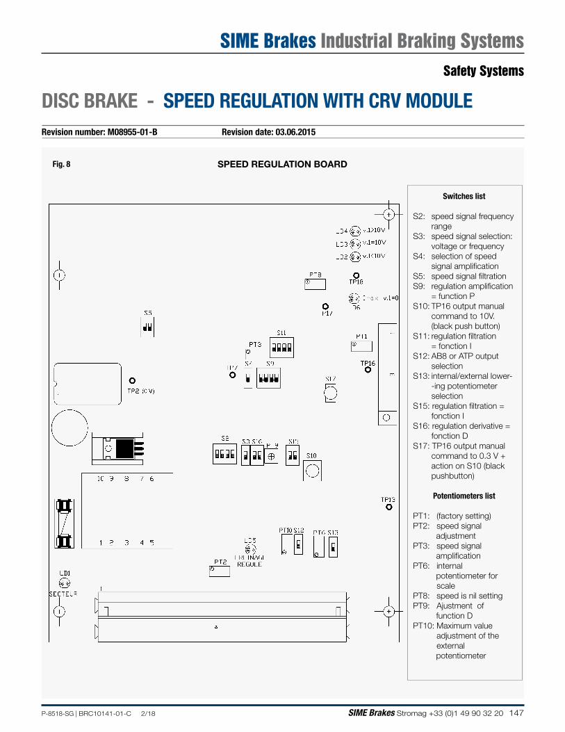
147P-8518-SG | BRC10141-01-C 2/18 SIME Brakes Stromag +33 (0)1 49 90 32 20
Fig. 8 SPEED REGULATION BOARD
Revision number: M08955-01-B Revision date: 03.06.2015
DISC BRAKE - SPEED REGULATION WITH CRV MODULE
Switches list
S2: speed signal frequency range
S3: speed signal selection: voltage or frequency
S4: selection of speed signal amplification
S5: speed signal filtration S9: regulation amplification
= function PS10: TP16 output manual
command to 10V. (black push button)
S11: regulation filtration = fonction IS12: AB8 or ATP output
selectionS13: internal/external lower-
-ing potentiometer selection
S15: regulation filtration = fonction I
S16: regulation derivative = fonction D
S17: TP16 output manual command to 0.3 V + action on S10 (black pushbutton)
Potentiometers list
PT1: (factory setting)PT2: speed signal adjustmentPT3: speed signal amplificationPT6: internal potentiometer for
scalePT8: speed is nil settingPT9: Ajustment of function DPT10: Maximum value
adjustment of the external
potentiometer
Safety Systems
SIME Brakes Industrial Braking Systems
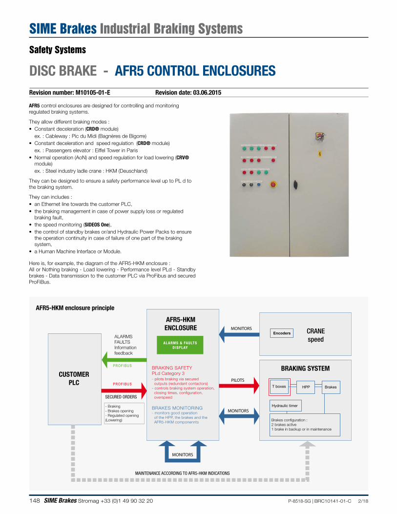
148 SIME Brakes Stromag +33 (0)1 49 90 32 20 P-8518-SG | BRC10141-01-C 2/18
DISC BRAKE - AFR5 CONTROL ENCLOSURES
AFR5 control enclosures are designed for controlling and monitoring regulated braking systems.
They allow different braking modes :• Constant deceleration (CRD® module)
ex. : Cableway : Pic du Midi (Bagnères de Bigorre)• Constant deceleration and speed regulation (CRD® module)
ex. : Passengers elevator : Eiffel Tower in Paris• Normal operation (AoN) and speed regulation for load lowering (CRV®
module)ex. : Steel industry ladle crane : HKM (Deuschland)
They can be designed to ensure a safety performance level up to PL d to the braking system.
They can includes : • an Ethernet line towards the customer PLC,• the braking management in case of power supply loss or regulated
braking fault, • the speed monitoring (SIDEOS One),• the control of standby brakes or/and Hydraulic Power Packs to ensure
the operation continuity in case of failure of one part of the braking system,
• a Human Machine Interface or Module.
Here is, for example, the diagram of the AFR5-HKM enclosure : All or Nothing braking - Load lowering - Performance level PLd - Standby brakes - Data transmission to the customer PLC via ProFibus and secured ProFiBus.
MONITORS
MONITORS
MONITORS
MAINTENANCE ACCORDING TO AFR5-HKM INDICATIONS
PILOTS
ALARMSFAULTSInformationfeedback
AFR5-HKMENCLOSURE
CUSTOMERPLC
SECURED ORDERS
- Braking- Brakes opening- Regulated opening(Lowering)
PROFIBUS
PROFIBUS
ALARMS & FAULTSDISPLAY
CRANEspeed
Encoders
BRAKING SYSTEM
BrakesT boxes HPP
Hydraulic timer
Brakes configuration :2 brakes active1 brake in backup or in maintenance
BRAKING SAFETY PLd Category 3- pilots braking via secured outputs (redundant contactors)- controls braking system operation, closing times, configuration, overspeed
BRAKES MONITORING- monitors good operation of the HPP, the brakes and the AFR5-HKM componennts
Revision number: M10105-01-E Revision date: 03.06.2015
AFR5-HKM enclosure principle
Safety Systems
SIME Brakes Industrial Braking Systems
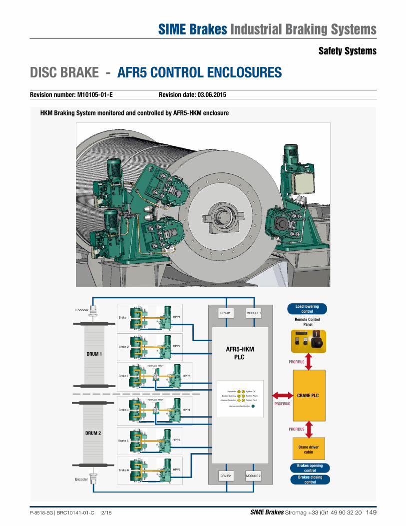
149P-8518-SG | BRC10141-01-C 2/18 SIME Brakes Stromag +33 (0)1 49 90 32 20
DISC BRAKE - AFR5 CONTROL ENCLOSURESRevision number: M10105-01-E Revision date: 03.06.2015
Remote Control Panel
CRANE PLC
Crane drivercabin
Encoder
Encoder
DRUM 2
HPP6Brake 6
HPP5Brake 5
HYDRAULIC TIMER
HPP4Brake 44
DRUM 1
HPP1Brake 1
HPP2Brake 2
HYDRAULIC TIMER
HPP3Brake 33
CRV-R2 MODULE 2
AFR5-HKMPLC
rCRV-R1 MODULE 1
Lowering Operation
Brakes Opening
Power ON
System Alarm
System Fault
System OK
Internal reset fault button PROFIBUS
PROFIBUS
PROFIBUS
Load loweringcontrol
Brakes openingcontrol
Brakes closingcontrol
HKM Braking System monitored and controlled by AFR5-HKM enclosure
Safety Systems
SIME Brakes Industrial Braking Systems
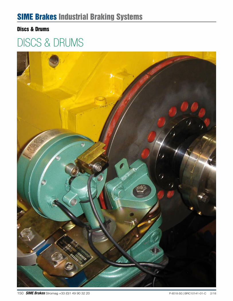
150 SIME Brakes Stromag +33 (0)1 49 90 32 20 P-8518-SG | BRC10141-01-C 2/18
DISCS & DRUMSDiscs & Drums
SIME Brakes Industrial Braking Systems
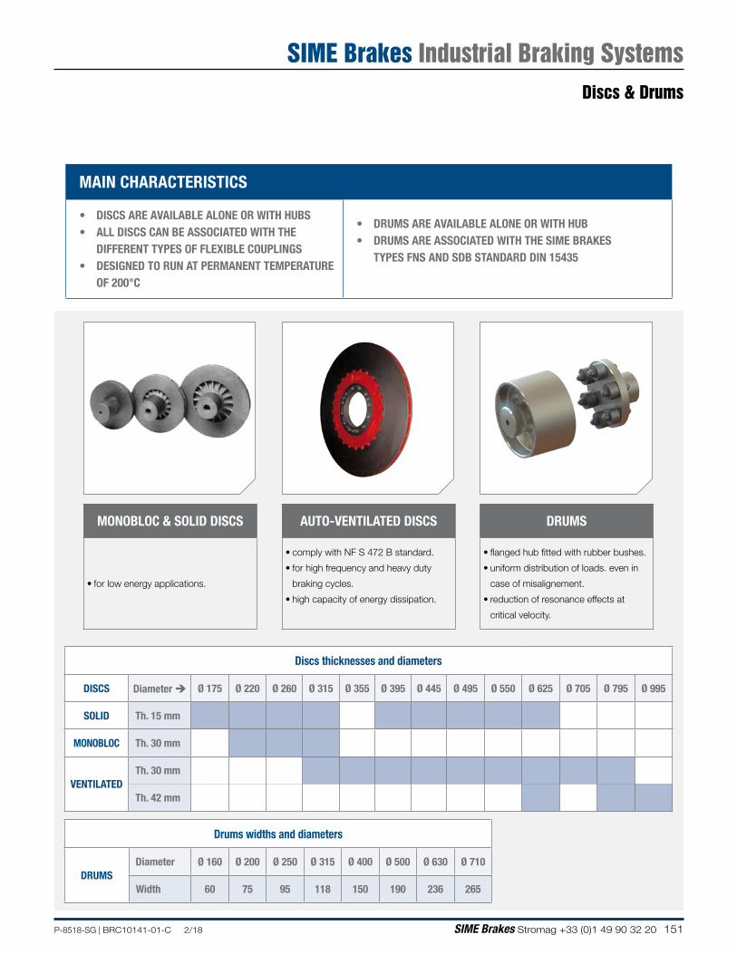
151P-8518-SG | BRC10141-01-C 2/18 SIME Brakes Stromag +33 (0)1 49 90 32 20
MAIN CHARACTERISTICS
• DISCS ARE AVAILABLE ALONE OR WITH HUBS• ALL DISCS CAN BE ASSOCIATED WITH THE
DIFFERENT TYPES OF FLEXIBLE COUPLINGS• DESIGNED TO RUN AT PERMANENT TEMPERATURE
OF 200°C
• DRUMS ARE AVAILABLE ALONE OR WITH HUB• DRUMS ARE ASSOCIATED WITH THE SIME BRAKES
TYPES FNS AND SDB STANDARD DIN 15435
Discs thicknesses and diameters
DISCS Diameter Ø 175 Ø 220 Ø 260 Ø 315 Ø 355 Ø 395 Ø 445 Ø 495 Ø 550 Ø 625 Ø 705 Ø 795 Ø 995
SOLID Th. 15 mm
MONOBLOC Th. 30 mm
VENTILATEDTh. 30 mm
Th. 42 mm
Drums widths and diameters
DRUMS Diameter Ø 160 Ø 200 Ø 250 Ø 315 Ø 400 Ø 500 Ø 630 Ø 710
Width 60 75 95 118 150 190 236 265
DRUMS
• flanged hub fitted with rubber bushes.
• uniform distribution of loads. even in
case of misalignement.
• reduction of resonance effects at
critical velocity.
AUTO-VENTILATED DISCS
• comply with NF S 472 B standard.
• for high frequency and heavy duty
braking cycles.
• high capacity of energy dissipation.
MONOBLOC & SOLID DISCS
• for low energy applications.
Discs & Drums
SIME Brakes Industrial Braking Systems
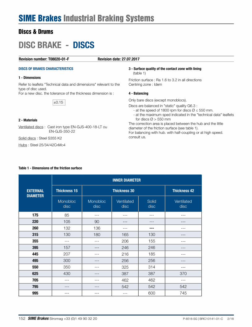
152 SIME Brakes Stromag +33 (0)1 49 90 32 20 P-8518-SG | BRC10141-01-C 2/18
Revision number: T08020-01-F Revision date: 27.07.2017
DISC BRAKE - DISCS
DISCS OF BRAKES CHARACTERISTICS
1 - Dimensions
Refer to leaflets "Technical data and dimensions" relevant to the type of disc used.For a new disc. the tolerance of the thickness dimension is :
±0.15
2 - Materials
Ventilated discs : Cast iron type EN-GJS-400-18-LT ou EN-GJS-350-22
Solid discs : Steel S355 K2
Hubs : Steel 25/34/42CrMo4
3 - Surface quality of the contact zone with lining (table 1)
Friction surface : Ra 1.6 to 3.2 in all directionsCentring zone : Idem
4 - Balancing
Only bare discs (except monoblocs).
Discs are balanced in "static" quality G6.3 : - at the speed of 1800 rpm for discs Ø ≤ 550 mm. - at the maximum sped indicated in the "technical data" leaflets for discs Ø > 550 mm
The correction area is placed between the hub and the little diameter of the friction surface (see table 1).For balancing with hub. with half-coupling or at high speed. consult us.
Table 1 - Dimensions of the friction surface
EXTERNAL DIAMETER
INNER DIAMETER
Thickness 15 Thickness 30 Thickness 42
Monobloc disc
Monobloc disc
Ventilated disc
Solid disc
Ventilated disc
175 85 --- --- --- ---
220 105 90 --- --- ---
260 132 136 --- --- ---
315 130 180 165 130 ---
355 --- --- 206 155 ---
395 157 --- 246 246 ---
445 207 --- 216 185 ---
495 300 --- 256 256 ---
550 350 --- 325 314 ---
625 430 --- 387 387 370
705 --- --- 462 462 ---
795 --- --- 542 542 542
995 --- --- --- 600 745
Discs & Drums
SIME Brakes Industrial Braking Systems
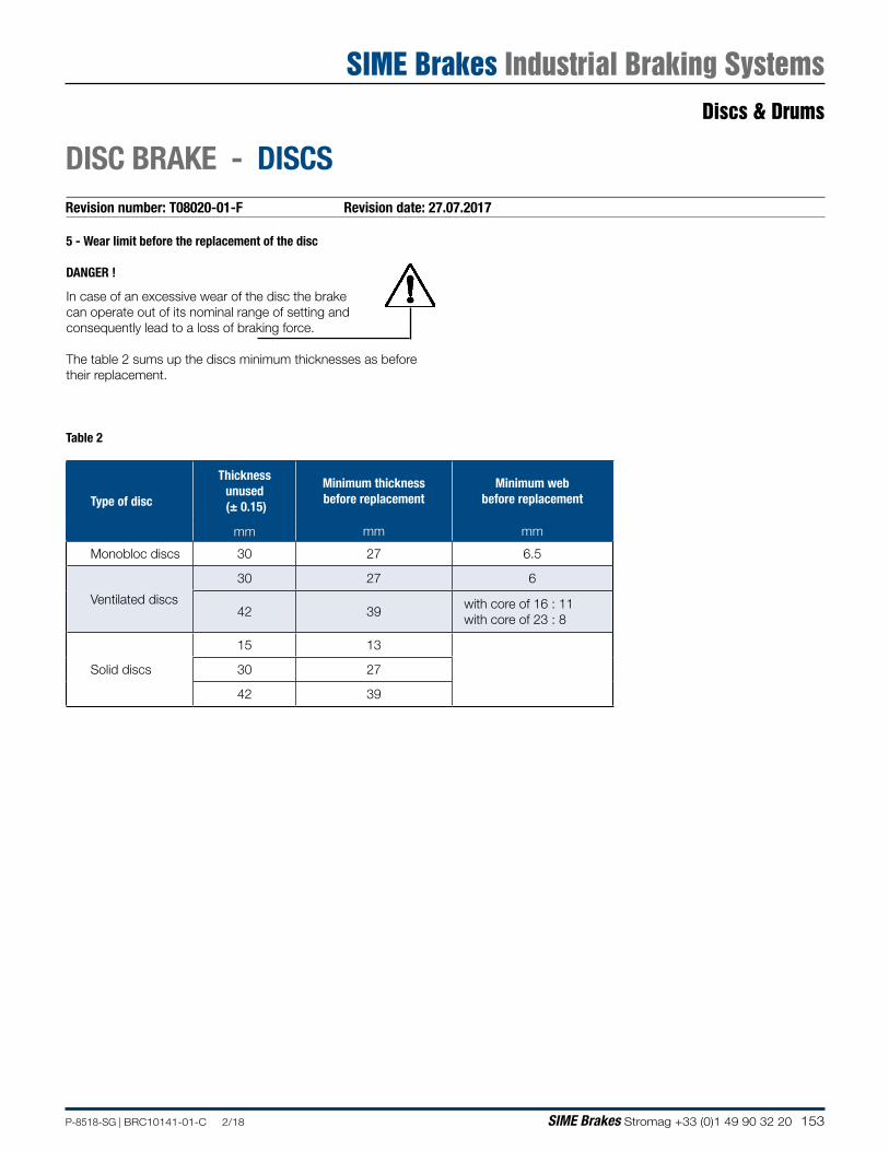
153P-8518-SG | BRC10141-01-C 2/18 SIME Brakes Stromag +33 (0)1 49 90 32 20
5 - Wear limit before the replacement of the disc
DANGER !
In case of an excessive wear of the disc the brake can operate out of its nominal range of setting and consequently lead to a loss of braking force.
The table 2 sums up the discs minimum thicknesses as before their replacement.
DISC BRAKE - DISCSRevision number: T08020-01-F Revision date: 27.07.2017
Type of disc
Thickness unused (± 0.15)
Minimum thickness before replacement
Minimum web before replacement
mm mm mm
Monobloc discs 30 27 6.5
Ventilated discs
30 27 6
42 39with core of 16 : 11 with core of 23 : 8
Solid discs
15 13
30 27
42 39
Table 2
Discs & Drums
SIME Brakes Industrial Braking Systems
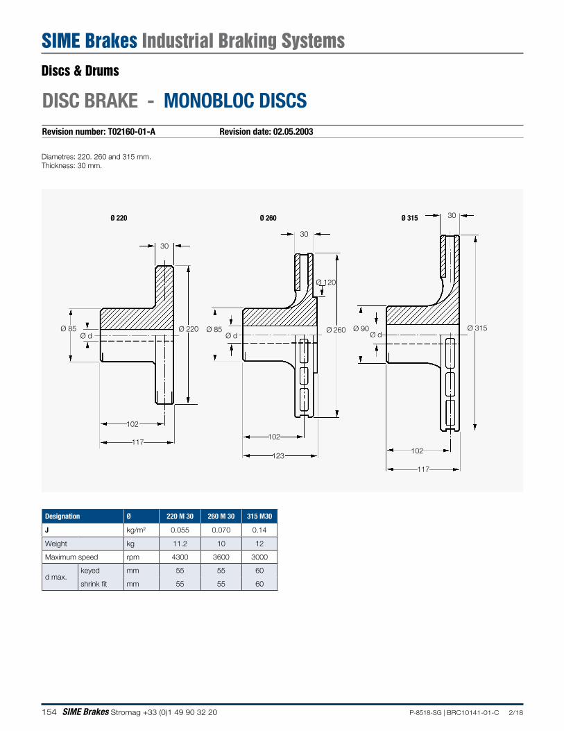
154 SIME Brakes Stromag +33 (0)1 49 90 32 20 P-8518-SG | BRC10141-01-C 2/18
Revision number: T02160-01-A Revision date: 02.05.2003
DISC BRAKE - MONOBLOC DISCS
Diametres: 220. 260 and 315 mm.Thickness: 30 mm.
102
30
30
30
Ø 315
102
117
123
117
102
Ø 85Ø d Ø d
Ø 85Ø d
Ø 220 Ø 260
Ø 120
Ø 90
Ø 220 Ø 260 Ø 315
Designation Ø 220 M 30 260 M 30 315 M30
J kg/m² 0.055 0.070 0.14
Weight kg 11.2 10 12
Maximum speed rpm 4300 3600 3000
d max.keyed mm 55 55 60
shrink fit mm 55 55 60
Discs & Drums
SIME Brakes Industrial Braking Systems
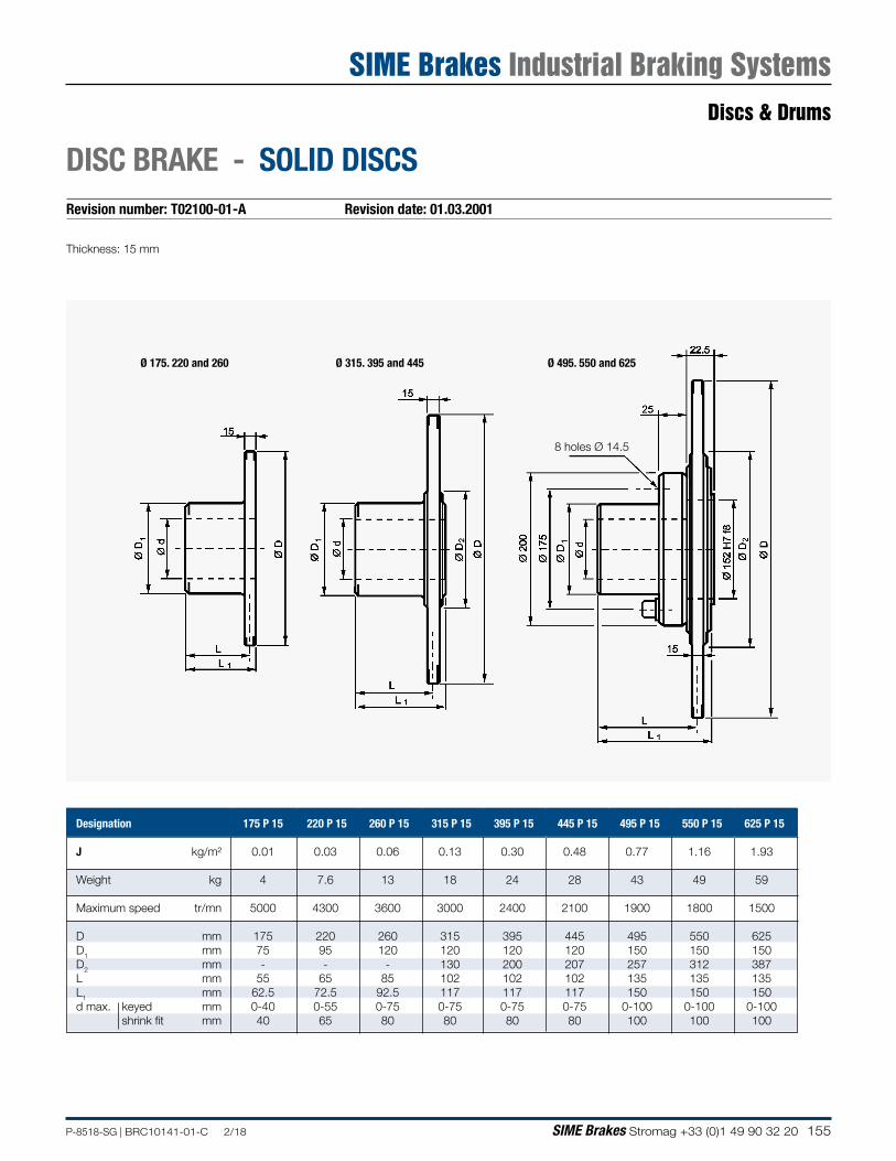
155P-8518-SG | BRC10141-01-C 2/18 SIME Brakes Stromag +33 (0)1 49 90 32 20
Revision number: T02100-01-A Revision date: 01.03.2001
DISC BRAKE - SOLID DISCS
Thickness: 15 mm
8 holes Ø 14.5
Ø 495. 550 and 625Ø 315. 395 and 445Ø 175. 220 and 260
Discs & Drums
SIME Brakes Industrial Braking Systems
Designation 175 P 15 220 P 15 260 P 15 315 P 15 395 P 15 445 P 15 495 P 15 550 P 15 625 P 15
J kg/m² 0.01 0.03 0.06 0.13 0.30 0.48 0.77 1.16 1.93
Weight kg 4 7.6 13 18 24 28 43 49 59
Maximum speed tr/mn 5000 4300 3600 3000 2400 2100 1900 1800 1500
D mm 175 220 260 315 395 445 495 550 625D1 mm 75 95 120 120 120 120 150 150 150D2 mm - - - 130 200 207 257 312 387L mm 55 65 85 102 102 102 135 135 135L1 mm 62.5 72.5 92.5 117 117 117 150 150 150d max. keyed mm 0-40 0-55 0-75 0-75 0-75 0-75 0-100 0-100 0-100 shrink fit mm 40 65 80 80 80 80 100 100 100
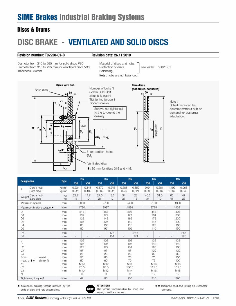
156 SIME Brakes Stromag +33 (0)1 49 90 32 20 P-8518-SG | BRC10141-01-C 2/18
Revision number: T02220-01-B Revision date: 26.11.2010
DISC BRAKE - VENTILATED AND SOLID DISCS
Diameter from 315 to 995 mm for solid discs P30Diameter from 315 to 795 mm for ventilated discs V30Thickness : 30mm
Rou
gh c
ast
Bare discs(not drilled. not bored)
Discs with hub
3 extraction holes Ød3
: 30 mm for discs 315 and 445.
Solid disc
Ventilated disc
Number of bolts NScrew CHc Ød1 class 8-8, nut HTightening torque βZinced screws Note :
Drilled discs can be delivered without hub on demand for customer adaptation.
Maximum braking torque allowed by the bolts of disc and hub assembling.
Screws not tightened to the torque at the delivery
Material of discs and hubs Protection of discs see leaflet T08020-01BalancingNote : hubs are not balanced.
ATTENTION !The torque transmissible by shaft and keying must be checked.
Tolerance on d and keying on Customer demand.
Designation Type315 355 395 445 495
P30 V30 P30 V30 P30 V30 P30 V30 P30 V30
J Disc + hub Bare disc
kg.m² kg.m²
0.234 0.225
0.148 0.139
0.379 0.362
0.243 0.226
0.588 0.56
0.352 0.324
0.94 0.896
0.581 0.537
1.492 1.367
0.968 0.843
WeightDisc + hub Bare disc
kg kg
21.7 17
14.7 10
27.5 21
18.5 12
34 27
23 16
46.5 34
31.5 19
65 41
47 23
Maximum speed rpm 3000 2700 2400 2100 1900
Maximum braking torque N.m 1720 2987 4594 8798 14321
D D1 D2 D3 D4 D5
mm mm mm mm mm mm
315 139 125 105 85 80
355 172 145 125 105 95
395 177 165 140 115 105
445 184 175 146 120 110
495 230 220 190 160 150
D6 D7
mm mm
- -
- -
- -
173 151
- -
246 171
- -
- -
- -
256 226
L L1 L2 L3 L4 Bore keyed maxi. d shrink fit d1 d2 d3 N
mm mm mm mm mm mm mm mm mm mm
102 107 127 87 28 50 50
M10 76.5 M10
9
102 107 129 87 28 60 60
M12 96.5 M12
9
102 107 131 87 28 70 70
M14 106.5 M14
9
135 140 166 120 30 75 75
M16 111.5 M16 12
135 140 168 120 38 100 100 M18
151.5 M18 12
Tightening torque β N.m 49 86 135 210 290
Discs & Drums
SIME Brakes Industrial Braking Systems
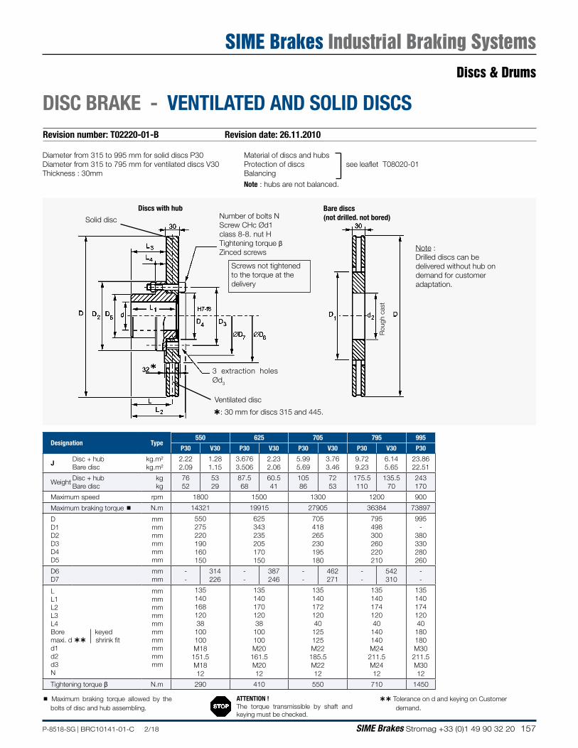
157P-8518-SG | BRC10141-01-C 2/18 SIME Brakes Stromag +33 (0)1 49 90 32 20
Diameter from 315 to 995 mm for solid discs P30Diameter from 315 to 795 mm for ventilated discs V30Thickness : 30mm
Rou
gh c
ast
Bare discs(not drilled. not bored)
Discs with hub
3 extraction holes Ød3
: 30 mm for discs 315 and 445.
Solid disc
Ventilated disc
Number of bolts NScrew CHc Ød1 class 8-8. nut HTightening torque βZinced screws Note :
Drilled discs can be delivered without hub on demand for customer adaptation.
Maximum braking torque allowed by the bolts of disc and hub assembling.
Screws not tightened to the torque at the delivery
Material of discs and hubs Protection of discs see leaflet T08020-01BalancingNote : hubs are not balanced.
ATTENTION !The torque transmissible by shaft and keying must be checked.
Tolerance on d and keying on Customer demand.
Revision number: T02220-01-B Revision date: 26.11.2010
DISC BRAKE - VENTILATED AND SOLID DISCS
Designation Type550 625 705 795 995
P30 V30 P30 V30 P30 V30 P30 V30 P30
J Disc + hub Bare disc
kg.m² kg.m²
2.22 2.09
1.28 1.15
3.676 3.506
2.23 2.06
5.99 5.69
3.76 3.46
9.72 9.23
6.14 5.65
23.86 22.51
WeightDisc + hub Bare disc
kg kg
76 52
53 29
87.5 68
60.5 41
105 86
72 53
175.5 110
135.5 70
243 170
Maximum speed rpm 1800 1500 1300 1200 900
Maximum braking torque N.m 14321 19915 27905 36384 73897
D D1 D2 D3 D4 D5
mm mm mm mm mm mm
550 275 220 190 160 150
625 343 235 205 170 150
705 418 265 230 195 180
795 498 300 260 220 210
995 -
380 330 280 260
D6 D7
mm mm
- -
314 226
- -
387 246
- -
462 271
- -
542 310
- -
L L1 L2 L3 L4 Bore keyed maxi. d shrink fit d1 d2 d3 N
mm mm mm mm mm mm mm mm mm mm
135 140 168 120 38
100 100 M18
151.5 M18 12
135 140 170 120 38
100 100 M20
161.5 M20 12
135 140 172 120 40
125 125 M22
185.5 M22 12
135 140 174 120 40
140 140 M24
211.5 M24 12
135 140 174 120 40 180 180 M30
211.5 M30 12
Tightening torque β N.m 290 410 550 710 1450
Discs & Drums
SIME Brakes Industrial Braking Systems
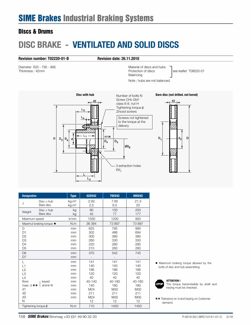
158 SIME Brakes Stromag +33 (0)1 49 90 32 20 P-8518-SG | BRC10141-01-C 2/18
Revision number: T02220-01-B Revision date: 26.11.2010
DISC BRAKE - VENTILATED AND SOLID DISCS
Material of discs and hubs Protection of discs see leaflet T08020-01Balancing
Note : hubs are not balanced.
Diameter 625 - 795 - 995Thickness : 42mm
Disc with hub
3 extraction holes Ød3
Bare disc (not drilled. not bored)
42 42
DDD DD D D
L
L
L
LL
d dH7-f812
2
3
3
4
4
5 1 2
ØD6
Number of bolts NScrew CHc Ød1 class 8-8. nut HTightening torque βZinced screws
Screws not tightened to the torque at the delivery
Designation Type 625V42 795V42 995V42
JDisc + hub Bare disc
kg.m² kg.m²
2.92 2,5
7.85 6,5
21.3 20
WeightDisc + hub Bare disc
kg kg
90 45
150 77
250 177
Maximum speed tr/mn 1500 1200 900Maximul braking torque N.m 36 384 73 897 73 897D D1 D2 D3 D4 D5
mm mm mm mm mm mm
625 302 300 260 220 210
795 486 380 330 280 260
995 694 380 330 280 260
D6 D7
mm mm
370 -
542 -
745 -
L L1 L2 L3 L4 Bore keyed maxi. d shrink fitd1 d2 d3 N
mm mm mm mm mm mm mm mm mm mm
141 140 186 120 40
40-140 140 M24 211 M24 12
141 140 186 120 40
40-180 180 M30 211 M30 12
141 140 186 120 40
40-180 180 M30 211 M30 12
Tightening torque β N.m 710 1450 1450
Maximum braking torque allowed by the bolts of disc and hub assembling.
ATTENTION !The torque transmissible by shaft and keying must be checked.
Tolerance on d and keying on Customer demand.
Discs & Drums
SIME Brakes Industrial Braking Systems

159P-8518-SG | BRC10141-01-C 2/18 SIME Brakes Stromag +33 (0)1 49 90 32 20
NOTES
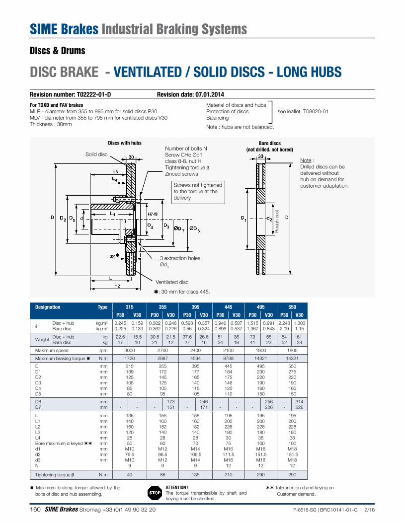
160 SIME Brakes Stromag +33 (0)1 49 90 32 20 P-8518-SG | BRC10141-01-C 2/18
Revision number: T02222-01-D Revision date: 07.01.2014
DISC BRAKE - VENTILATED / SOLID DISCS - LONG HUBS
ß: 30 mm for discs 445.
Discs with hubs
3 extraction holes Ød3
Rou
gh c
ast
Bare discs(not drilled. not bored)
Solid disc
Ventilated disc
Note :Drilled discs can be delivered without hub on demand for customer adaptation.
Number of bolts NScrew CHc Ød1 class 8-8. nut HTightening torque βZinced screws
For TDXB and FAV brakes MLP - diameter from 355 to 995 mm for solid discs P30MLV - diameter from 355 to 795 mm for ventilated discs V30Thickness : 30mm
Material of discs and hubs Protection of discs see leaflet T08020-01Balancing
Note : hubs are not balanced.
Screws not tightened to the torque at the delivery
Designation Type 315 355 395 445 495 550
P30 V30 P30 V30 P30 V30 P30 V30 P30 V30 P30 V30
JDisc + hub Bare disc
kg.m² kg.m²
0.245 0.225
0.159 0.139
0.382 0.362
0.246 0.226
0.593 0.56
0.357 0.324
0.946 0.896
0.587 0.537
1.515 1.367
0.991 0.843
2.243 2.09
1.303 1.15
WeightDisc + hub Bare disc
kg kg
22.5 17
15.5 10
30.5 21
21.5 12
37.6 27
26.6 16
51 34
36 19
73 41
55 23
84 52
61 29
Maximum speed rpm 3000 2700 2400 2100 1900 1800
Maximum braking torque N.m 1720 2987 4594 8798 14321 14321
D D1 D2 D3 D4 D5
mm mm mm mm mm mm
315 139 125 105 85 80
355 172 145 125 105 95
395 177 165 140 115 105
445 184 175 146 120 110
495 230 220 190 160 150
550 275 220 190 160 150
D6 D7
mm mm
- -
- -
- -
173 151
- -
246 171
- -
- -
- -
256 226
- -
314 226
L L1 L2 L3 L4 Bore maximum d keyed d1 d2 d3 N
mm mm mm mm mm mm mm mm mm
135 140 160 120 28 50
M10 76.5 M10
9
155 160 182 140 28 60
M12 96.5 M12
9
155 160 182 140 28 70
M14 106.5 M14
9
195 200 226 180 30 75
M16 111.5 M16 12
195 200 228 180 38 100 M18
151.5 M18 12
195 200 228 180 38
100 M18
151.5 M18 12
Tightening torque β N.m 49 86 135 210 290 290
Maximum braking torque allowed by the bolts of disc and hub assembling.
ATTENTION !The torque transmissible by shaft and keying must be checked.
Tolerance on d and keying on Customer demand.
Discs & Drums
SIME Brakes Industrial Braking Systems
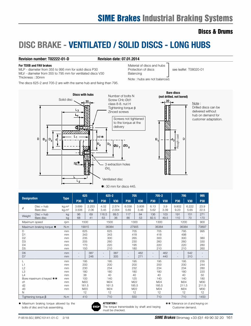
161P-8518-SG | BRC10141-01-C 2/18 SIME Brakes Stromag +33 (0)1 49 90 32 20
Revision number: T02222-01-D Revision date: 07.01.2014
DISC BRAKE - VENTILATED / SOLID DISCS - LONG HUBS
ß: 30 mm for discs 445.
Discs with hubs
3 extraction holes Ød3
Rou
gh c
ast
Bare discs(not drilled. not bored)
Solid disc
Ventilated disc
Note :Drilled discs can be delivered without hub on demand for customer adaptation.
Number of bolts NScrew CHc Ød1 class 8-8. nut HTightening torque βZinced screws
For TDXB and FAV brakesMLP - diameter from 355 to 995 mm for solid discs P30MLV - diameter from 355 to 795 mm for ventilated discs V30Thickness : 30mm
Material of discs and hubs Protection of discs see leaflet T08020-01Balancing
Note : hubs are not balanced.
Screws not tightened to the torque at the delivery
The discs 625-2 and 705-2 are with the same hub and fixing than 795.
Maximum braking torque allowed by the bolts of disc and hub assembling.
ATTENTION !The torque transmissible by shaft and keying must be checked.
Tolerance on d and keying on Customer demand.
Designation Type625 625-2 705 705-2 795 995
P30 V30 P30 V30 P30 V30 P30 V30 P30 V30 P30
JDisc + hub Bare disc
kg.m² kg.m²
3.699 3.506
2.253 2.06
4.02 3.45
2.574 2.004
6.038 5.69
3.808 3.46
6.13 5.62
3.9 3.39
9.802 9.23
6.222 5.65
23.9 22.5
WeightDisc + hub Bare disc
kg kg
96 68
69 41
116.5 63
89.5 36
117 86
84 53
136 82.5
103 49.5
191 110
151 70
271 170
Maximum speed rpm 1500 1500 1300 1300 1200 900
Maximum braking torque N.m 19915 36384 27905 36384 36384 73897
D D1 D2 D3 D4 D5
mm mm mm mm mm mm
625 343 235 205 170 150
625 343 300 260 220 210
705 418 265 230 195 180
705 418 300 260 220 210
795 498 300 260 220 210
995 -
380 330 280 260
D6 D7
mm mm
- -
387 246
- -
387 305
- -
462 271
- -
462 440
- -
542 310
- -
L L1 L2 L3 L4 Bore maximum d keyed d1 d2 d3 N
mm mm mm mm mm mm mm mm mm
195 200 230 180 38 100 M20
161.5 M20 12
195 200 234 180 40 140 M24
161.5 M24 12
195 200 232 180 40 125 M22
185.5 M22 12
195 200 234 180 40
140 M24
185.5 M24 12
195 200 234 180 40
140 M24
211.5 M24 12
235 244 280 220 50 180 M30
211.5 M30 12
Tightening torque β N.m 410 710 550 710 710 1450
Discs & Drums
SIME Brakes Industrial Braking Systems
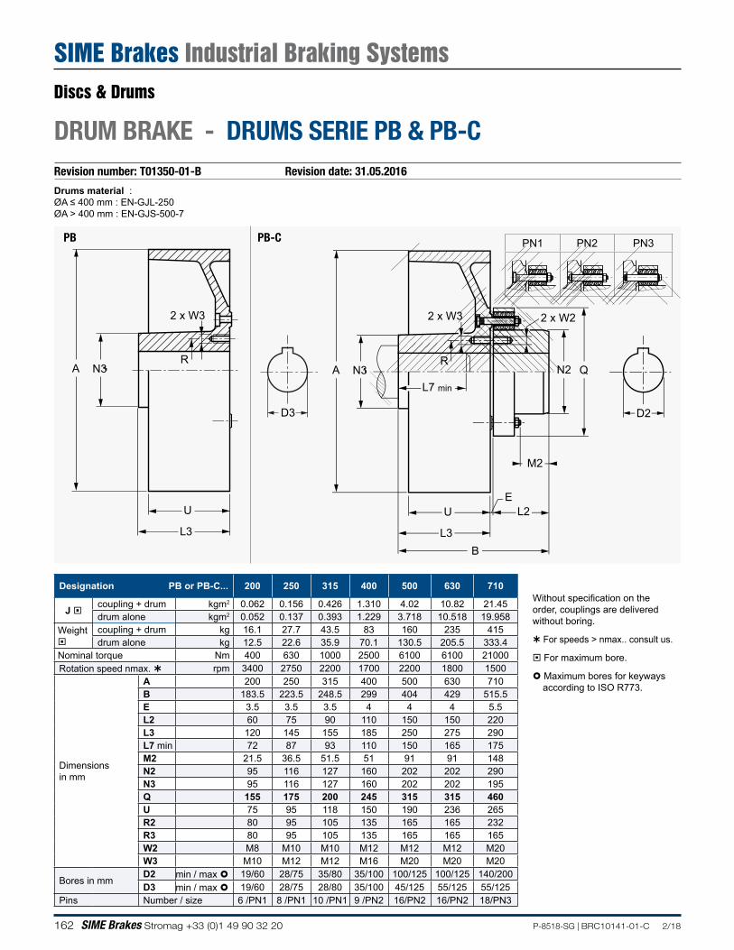
162 SIME Brakes Stromag +33 (0)1 49 90 32 20 P-8518-SG | BRC10141-01-C 2/18
Revision number: T01350-01-B Revision date: 31.05.2016
Drums material :ØA ≤ 400 mm : EN-GJL-250ØA > 400 mm : EN-GJS-500-7
DRUM BRAKE - DRUMS SERIE PB & PB-C
Designation PB or PB-C... 200 250 315 400 500 630 710
J coupling + drum kgm2 0.062 0.156 0.426 1.310 4.02 10.82 21.45drum alone kgm2 0.052 0.137 0.393 1.229 3.718 10.518 19.958
Weight
coupling + drum kg 16.1 27.7 43.5 83 160 235 415drum alone kg 12.5 22.6 35.9 70.1 130.5 205.5 333.4
Nominal torque Nm 400 630 1000 2500 6100 6100 21000Rotation speed nmax. rpm 3400 2750 2200 1700 2200 1800 1500
Dimensions in mm
A 200 250 315 400 500 630 710B 183.5 223.5 248.5 299 404 429 515.5E 3.5 3.5 3.5 4 4 4 5.5L2 60 75 90 110 150 150 220L3 120 145 155 185 250 275 290L7 min 72 87 93 110 150 165 175M2 21.5 36.5 51.5 51 91 91 148N2 95 116 127 160 202 202 290N3 95 116 127 160 202 202 195Q 155 175 200 245 315 315 460U 75 95 118 150 190 236 265R2 80 95 105 135 165 165 232R3 80 95 105 135 165 165 165W2 M8 M10 M10 M12 M12 M12 M20W3 M10 M12 M12 M16 M20 M20 M20
Bores in mmD2 min / max 19/60 28/75 35/80 35/100 100/125 100/125 140/200D3 min / max 19/60 28/75 28/80 35/100 45/125 55/125 55/125
Pins Number / size 6 /PN1 8 /PN1 10 /PN1 9 /PN2 16/PN2 16/PN2 18/PN3
Without specification on the order, couplings are delivered without boring.
For speeds > nmax.. consult us.
For maximum bore.
Maximum bores for keyways according to ISO R773.
D3
A N3L7 min
R
2 x W3 2 x W2
N2 Q
M2
EL2
BL3
U
D2
A N3
2 x W3
L3
U
R
PN1 PN2 PN3PB PB-C
Discs & Drums
SIME Brakes Industrial Braking Systems
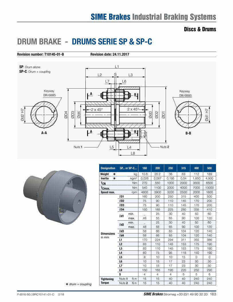
163P-8518-SG | BRC10141-01-C 2/18 SIME Brakes Stromag +33 (0)1 49 90 32 20
Revision number: T10145-01-B Revision date: 24.11.2017
DRUM BRAKE - DRUMS SERIE SP & SP-C
Designation SP... or SP-C... 160 200 250 315 400 500
Weight kg 10.8 20.2 36 63 112 189Inertia kgm2 0,026 0,067 0,195 0,54 1,850 4,900
TCN Nm 270 550 1000 2000 3500 6500
TCmax. Nm 540 1100 2000 4000 7000 13000
Speed max. rpm 4800 3900 3200 2500 2000 1600
Dimensions in mm
ØD1 160 200 250 315 400 500ØD2 75 90 110 145 170 200ØD3 75 90 110 145 170 200ØD4 150 185 225 280 335 410
Ød1 min. _ 25 30 40 50 60max. 48 55 65 90 100 120
Ød2min. _ 25 30 40 50 60max. 48 55 65 90 100 120
Ød3 58 66 83 104 120 140Ød4 58 66 83 104 120 140L1 170 224 294 311 355 386L2 83 110 145 153 175 190L3 83 110 145 153 175 190L4 60 75 95 118 150 190L5 8 10 10 15 0 0L6 10 15 17 23 30 30L7 10 15 17 23 30 30L8 150 165 195 220 250 290S 4 4 4 5 5 6
TighteningTorque
Nuts 1 N.m 15 15 40 40 240 240Nuts 2 N.m 15 15 40 40 240 240 drum + coupling
L1
L2 L3S
L5 L4
L8Ø
D2
ØD
3
ØD
1
ØD
4
L7 L6
Ød3
Ød4
2 x 45° 2 x 45°
A
A
B
B
Ød2
H7
A-A
DIN 6885
Ød1
H7
B-B
DIN 6885Keyway Keyway
Nuts 1 Nuts 2
SP: Drum alone
SP-C: Drum + coupling
Discs & Drums
SIME Brakes Industrial Braking Systems
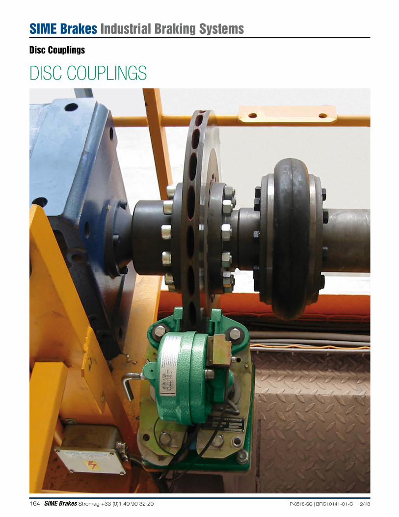
164 SIME Brakes Stromag +33 (0)1 49 90 32 20 P-8518-SG | BRC10141-01-C 2/18
DISC COUPLINGSDisc Couplings
SIME Brakes Industrial Braking Systems
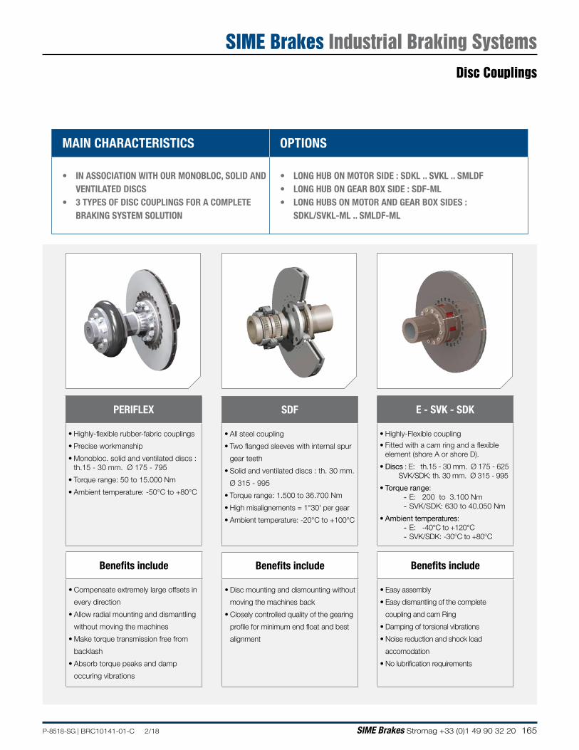
165P-8518-SG | BRC10141-01-C 2/18 SIME Brakes Stromag +33 (0)1 49 90 32 20
MAIN CHARACTERISTICS OPTIONS
• IN ASSOCIATION WITH OUR MONOBLOC, SOLID AND VENTILATED DISCS
• 3 TYPES OF DISC COUPLINGS FOR A COMPLETE BRAKING SYSTEM SOLUTION
• LONG HUB ON MOTOR SIDE : SDKL .. SVKL .. SMLDF• LONG HUB ON GEAR BOX SIDE : SDF-ML• LONG HUBS ON MOTOR AND GEAR BOX SIDES :
SDKL/SVKL-ML .. SMLDF-ML
E - SVK - SDK
• Highly-Flexible coupling
• Fitted with a cam ring and a flexible element (shore A or shore D).
• Discs : E: th.15 - 30 mm. Ø 175 - 625 SVK/SDK: th. 30 mm. Ø 315 - 995
• Torque range: - E: 200 to 3.100 Nm - SVK/SDK: 630 to 40.050 Nm
• Ambient temperatures: - E: -40°C to +120°C - SVK/SDK: -30°C to +80°C
Benefits include
• Easy assembly
• Easy dismantling of the complete
coupling and cam Ring
• Damping of torsional vibrations
• Noise reduction and shock load
accomodation
• No lubrification requirements
PERIFLEX
• Highly-flexible rubber-fabric couplings
• Precise workmanship
• Monobloc. solid and ventilated discs : th.15 - 30 mm. Ø 175 - 795
• Torque range: 50 to 15.000 Nm
• Ambient temperature: -50°C to +80°C
Benefits include
• Compensate extremely large offsets in
every direction
• Allow radial mounting and dismantling
without moving the machines
• Make torque transmission free from
backlash
• Absorb torque peaks and damp
occuring vibrations
SDF
• All steel coupling
• Two flanged sleeves with internal spur
gear teeth
• Solid and ventilated discs : th. 30 mm.
Ø 315 - 995
• Torque range: 1.500 to 36.700 Nm
• High misalignements = 1°30' per gear
• Ambient temperature: -20°C to +100°C
Benefits include
• Disc mounting and dismounting without
moving the machines back
• Closely controlled quality of the gearing
profile for minimum end float and best
alignment
Disc Couplings
SIME Brakes Industrial Braking Systems
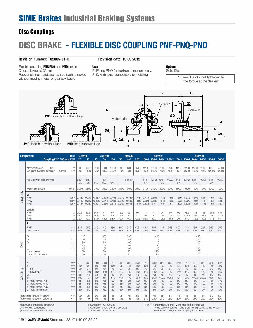
166 SIME Brakes Stromag +33 (0)1 49 90 32 20 P-8518-SG | BRC10141-01-C 2/18
Designation Disc 315V30 355V30 395V30 445V30 495V30 Coupling PNF. PNQ and PND 25 50 25 50 100 50 100 200 100-1 100-2 200-1 200-2 100-1 100-2 200-1 200-2 300-1 300-2
Nominal torque Cn N.m 300 600 300 600 1200 600 1200 2500 1200 1200 2500 2500 1200 1200 2500 2500 4000 4000Coupling Maximum torque Cmax N.m 900 1800 900 1800 3600 1800 3600 7500 3600 3600 7500 7500 3600 3600 7500 7500 12000 12000
For use with calipers type 650- 645- 5K 645-5K 645- 4CA2 645- 4CA2 645- 4CA2 645- 4CA2 645- 4CA2 5K 5K 650 650 645 5K 5K 5K 5K 5K
Maximum speed tr/mn 3000 2500 2700 2500 2500 2400 2400 2000 2100 2100 2000 2000 1900 1900 1900 1900 1900 1900
J:PNF kgm² 0.180 0.240 0.283 0.333 0.456 0.370 0.589 1.08 0.776 0.656 1.475 1.545 1.266 1.272 1.655 1.68 1.60 1.62PNQ kgm² 0.182 0.252 0.286 0.344 0.483 0.382 0.616 1.116 0.803 0.683 1.516 1.586 1.293 1.299 1.696 1.721 1.64 1.65PND kgm² 0.187 0.267 0.291 0.360 0.512 0.397 0.645 1.140 0.832 0.71 1.541 1.61 1.322 1.328 1.721 1.746 1.66 1.67
Weight:PNF kg 29.3 35.5 34.8 43 57 45.5 63 93 74 71 94 96 95 98.5 118 128 128.5 131PNQ kg 31.3 38.5 36.8 46 67 48.5 73 103 84 81 104 106 105 108.5 128 138.5 140 142.5PND kg 32.4 40.7 37.9 48.2 68.7 50.7 74.7 107.5 85.7 82.7 108.5 110.5 106.7 110 132.5 142.5 141.5 144
PNF mm 315 350 315 340 380 340 380 402 413 515 435 568 400 443 435 525 562 582PNQ. PND mm 366 393 366 383 445 383 445 467 478 580 500 633 465 508 500 590 622 642
D mm 315 355 395 445 495D2 mm 125 145 165 175 220D5 mm 80 95 105 110 150L mm 102 102 102 135 135L1 mm 107 107 107 140 140d max. keyed mm 50 60 70 70 100d max. for shrink fit mm 50 60 70 70 100
d3 mm 210 263 210 263 310 263 310 370 310 310 370 370 310 310 370 370 402 402d4 mm 80 95 80 95 125 95 125 150 125 125 150 150 125 125 150 150 160 160k PNF mm 59 67 59 67 75 67 75 85 75 75 85 85 75 75 85 85 95 95k PNQ. PND mm 110 110 110 110 140 110 140 150 140 140 150 150 140 140 150 150 155 155O mm 38 44 38 44 42 44 42 48 42 42 46 46 42 42 46 46 50 50p mm 138 161 138 151 178 151 178 192.5 178 280 192.5 325.5 165 208 192.5 282.5 305 325d1 max. keyed PNF mm 55 65 55 65 90 65 90 100 90 90 100 100 90 90 100 100 110 110d1 max. keyed PNQ mm 55 65 55 65 90 65 90 100 90 90 100 100 90 90 100 100 110 110d1 max. keyed PND mm 55 65 55 65 85 65 85 100 85 85 100 100 85 85 100 100 110 110d1 max. for shrink fit mm 50 60 50 60 80 60 80 90 80 80 90 90 80 80 90 90 100 100
Tightening torque on screw 1 N.m 20 25 20 25 45 25 45 55 45 45 55 55 45 45 55 55 60 60Tightening torque on screw 2 N.m 49 49 86 86 86 135 135 135 210 210 210 210 290 290 290 290 290 290
Maximum permissible torque Ct >300 start/h : Ct=Cn/2.5 NOTA : For shrink fit, k and are modified (consult us)and working conditions ≤300 start/h à 120 start/h : Ct=Cn/2 At the delivery, screws 1 and 2 are not tightened to the torque(ambient temperature ≤ 40°C) ≤120 start/h : Ct=Cn/1.5 In each case : engine start coupling Cd<Cmax
Revision number: T02805-01-D Revision date: 15.05.2012
DISC BRAKE - FLEXIBLE DISC COUPLING PNF-PNQ-PND
Flexible coupling PNF. PNQ and PND seriesDiscs thickness: 30mmRubber element and disc can be both removed without moving motor or gearbox back.
Use:PNF and PNQ for horizontal motions only.PND with lugs. compulsory for hoisting.
Option:Solid Disc
PNF: short hub without lugsMotor side
Screw 2
PNQ: long hub without lugs PND: long hub with lugs
Screw 1
Screws 1 and 2 not tightened tothe torque at the delivery
Dis
cC
oupl
ing
Ass
embl
y
Disc Couplings
SIME Brakes Industrial Braking Systems
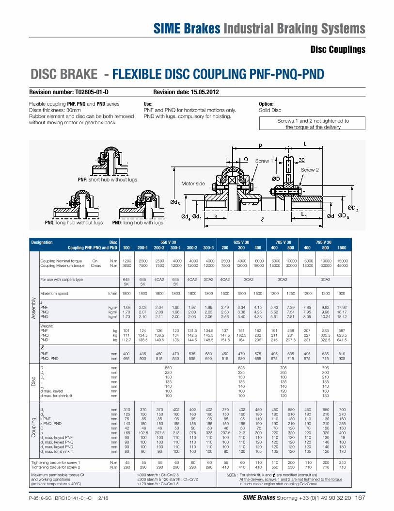
167P-8518-SG | BRC10141-01-C 2/18 SIME Brakes Stromag +33 (0)1 49 90 32 20
Revision number: T02805-01-D Revision date: 15.05.2012
DISC BRAKE - FLEXIBLE DISC COUPLING PNF-PNQ-PND
Flexible coupling PNF. PNQ and PND seriesDiscs thickness: 30mmRubber element and disc can be both removed without moving motor or gearbox back.
Use:PNF and PNQ for horizontal motions only.PND with lugs. compulsory for hoisting.
Option:Solid Disc
PNF: short hub without lugsMotor side
Screw 2
PNQ: long hub without lugs PND: long hub with lugs
Screw 1
Screws 1 and 2 not tightened tothe torque at the delivery
Designation Disc 550 V 30 625 V 30 705 V 30 795 V 30 Coupling PNF. PNQ and PND 100 200-1 200-2 300-1 300-2 300-3 200 300 400 400 800 400 800 1500
Coupling Nominal torque Cn N.m 1200 2500 2500 4000 4000 4000 2500 4000 6000 6000 10000 6000 10000 15000Coupling Maximum torque Cmax N.m 3600 7500 7500 12000 12000 12000 7500 12000 18000 18000 30000 18000 30000 45000
For use with calipers type 645 645 4CA2 645 4CA2 3CA2 4CA2 3CA2 3CA2 3CA2 5K 5K 5K
Maximum speed tr/mn 1800 1800 1800 1800 1800 1800 1500 1500 1500 1300 1250 1200 1200 900
J:PNF kgm² 1.68 2.03 2.04 1.95 1.97 1.99 2.49 3.34 4.15 5.43 7.39 7.85 9.82 17.92PNQ kgm² 1.70 2.07 2.08 1.98 2.00 2.03 2.53 3.38 4.25 5.52 7.54 7.95 9.96 18.17PND kgm² 1.73 2.10 2.11 2.00 2.03 2.06 2.56 3.40 4.33 5.61 7.81 8.05 10.24 18.42
Weight:PNF kg 101 124 126 123 131.5 134.5 137 151 182 191 258 207 283 587PNQ kg 111 134.5 136.5 134 142.5 145.5 147.5 162.5 202 211 281 227 305.5 623.5PND kg 112.7 138.5 140.5 136 144.5 148.5 151.5 164 206 215 297.5 231 322.5 641.5
PNF mm 400 435 450 470 535 580 450 470 575 495 635 495 635 810PNQ. PND mm 465 500 515 530 595 640 515 530 655 575 715 575 715 905
D mm 550 625 705 795D2 mm 220 235 265 300D5 mm 150 150 180 210L mm 135 135 135 135L1 mm 140 140 140 140d max. keyed mm 100 100 120 130d max. for shrink fit mm 100 100 120 130
d3 mm 310 370 370 402 402 402 370 402 450 450 550 450 550 700d4 mm 125 150 150 160 160 160 150 160 180 180 210 180 210 270k PNF mm 75 85 85 95 95 95 85 95 110 110 130 110 130 160k PNQ. PND mm 140 150 150 155 155 155 150 155 190 190 210 190 210 255O mm 42 46 46 50 50 50 46 50 70 70 120 70 120 150p mm 165 192.5 207.5 213 278 323 207.5 213 300 220 320 220 320 400d1 max. keyed PNF mm 90 100 100 110 110 110 100 110 110 110 130 110 130 18d1 max. keyed PNQ mm 90 100 100 110 110 110 100 110 120 120 120 120 140 180d1 max. keyed PND mm 90 100 100 110 110 110 100 110 120 120 120 120 140 180d1 max. for shrink fit mm 80 90 90 100 100 100 80 100 105 105 120 105 120 170
Tightening torque for screw 1 N.m 45 55 55 60 60 60 55 60 110 110 200 110 200 240Tightening torque for screw 2 N.m 290 290 290 290 290 290 410 410 410 550 550 710 710 710
Maximum permissible torque Ct >300 start/h : Ct=Cn/2.5 NOTA : For shrink fit, k and are modified (consult us)and working conditions ≤300 start/h à 120 start/h : Ct=Cn/2 At the delivery, screws 1 and 2 are not tightened to the torque(ambient temperature ≤ 40°C) ≤120 start/h : Ct=Cn/1.5 In each case : engine start coupling Cd<Cmax
Dis
cC
oupl
ing
Ass
embl
y
Disc Couplings
SIME Brakes Industrial Braking Systems
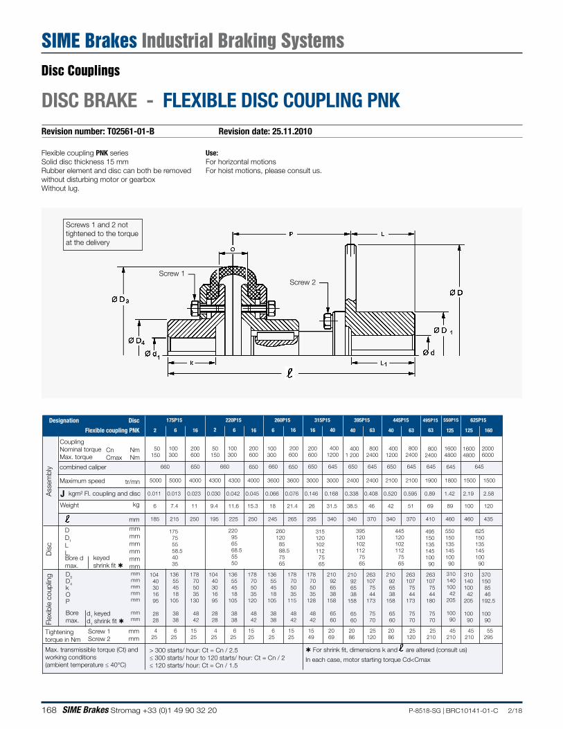
168 SIME Brakes Stromag +33 (0)1 49 90 32 20 P-8518-SG | BRC10141-01-C 2/18
Revision number: T02561-01-B Revision date: 25.11.2010
DISC BRAKE - FLEXIBLE DISC COUPLING PNK
Flexible coupling PNK seriesSolid disc thickness 15 mmRubber element and disc can both be removed without disturbing motor or gearboxWithout lug.
Screw 2Screw 1
50 150
2
100 300
6
200 600
50 150
100 300
6
200 600
100 300
6
200 600
16
200 600
16
400 1200
40
4001 200
40
800 2400
63
400 1200
800 2400
660 660 650 660 650 650 645 650 645 650 645
CnCmax
NmNm
5000 5000
650
4000 4300 4300 4000 3600 3600 3000 3000 2400 2400 2100 2100
0.011 0.013 0.023 0.030 0.042 0.045 0.066 0.076 0.146 0.168 0.338 0.408 0.520 0.595
Weight kg 6 7.4 11 9.4 11.6 15.3 18 21.4 26 31.5 38.5 46 42 51
185 215 250 195 225 250 245 265 295 340 340 370 340 370
220 95 65 68.5 55 50
260 120 85 88.5 75 65
315 120 102 112 75 65
395 120 102 112 75 65
445 120 102 112 75 65
Tightening torque in Nm
Max. transmissible torque (Ct) and working conditions(ambient temperature ≤ 40°C)
> 300 starts/ hour: Ct = Cn / 2.5≤ 300 starts/ hour to 120 starts/ hour: Ct = Cn / 2≤ 120 starts/ hour: Ct = Cn / 1.5
175 75 55 58.5 40 35
16 16 40 63
4 25
6 25
15 25
4 25
6 25
15 25
6 25
15 25
15 49
20 69
20 86
25 120
20 86
25 120
CouplingNominal torqueMax. torque
combined caliper
tr/mnMaximum speed
For shrink fit, dimensions k and are altered (consult us)
J
800 2400
645
1900
0.89
69
410
63
495150135145100
90
25 210
550150135145100
90
645
1800
1.42
89
460
125
550P15
45 210
645
1500
2.19
100
460
625 150 135 145 100 90
45 210
1500
2.58
120
435
55 295
625P15495P15445P15395P15315P15260P15220P15175P15DiscDesignation
Flexible coupling PNK
Dis
cA
ssem
bly
Flex
ible
cou
plin
g
2
1600 4800
2000 6000
125 160
1600 4800
mm
DD1
LL1 keyed
shrink fit Bore dmax.D3D4kOP
d1 keyedd1 shrink fit
Boremax.
Screw 1Screw 2
mmmm
kgm² Fl. coupling and disc
mmmmmmmmmmmmmmmmmmmmmm
mmmm
In each case, motor starting torque Cd<Cmax
104 40 30 16 95
28 28
136 55 45 18
105
38 38
178 70 50 35
130
48 42
104 40 30 16 95
28 28
136554518
105
38 38
178705035
120
48 42
136 55 45 18
105
38 38
178 70 50 35
115
48 42
178 70 50 35
128
48 42
210 92 65 38
158
65 60
210 92 65 38
158
65 60
263 107
75 44
173
75 70
210 92 65 38
158
65 60
263 107
75 44
173
75 70
263 107
75 44
180
75 70
310 140 100
42 205
100 90
310 140 100
42 205
100 90
370 150 85 46 192.5
100 90
Use:For horizontal motionsFor hoist motions, please consult us.
Screws 1 and 2 not tightened to the torque at the delivery
Disc Couplings
SIME Brakes Industrial Braking Systems
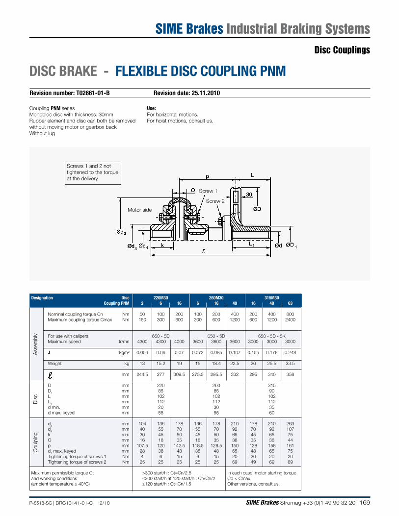
169P-8518-SG | BRC10141-01-C 2/18 SIME Brakes Stromag +33 (0)1 49 90 32 20
Revision number: T02661-01-B Revision date: 25.11.2010
DISC BRAKE - FLEXIBLE DISC COUPLING PNM
Use:For horizontal motions.For hoist motions, consult us.
Coupling PNM series Monobloc disc with thickness: 30mmRubber element and disc can both be removed without moving motor or gearbox backWithout lug
Designation Disc 220M30 260M30 315M30 Coupling PNM 2 6 16 6 16 40 16 40 63
Nominal coupling torque Cn Nm 50 100 200 100 200 400 200 400 800 Maximum coupling torque Cmax Nm 150 300 600 300 600 1200 600 1200 2400
For use with calipers 650 - 5D 650 - 5D 650 - 5D - 5K Maximum speed tr/mn 4300 4300 4000 3600 3600 3600 3000 3000 3000
J kgm² 0.056 0.06 0.07 0.072 0.085 0.107 0.155 0.178 0.248
Weight kg 13 15.2 19 15 18.4 22.5 20 25.5 33.5
mm 244.5 277 309.5 275.5 295.5 332 295 340 358
D mm 220 260 315 D1 mm 85 85 90 L mm 102 102 102 L1 mm 112 112 112 d min. mm 20 30 35 d max. keyed mm 55 55 60 d3 mm 104 136 178 136 178 210 178 210 263 d4 mm 40 55 70 55 70 92 70 92 107 k mm 30 45 50 45 50 65 45 65 75 O mm 16 18 35 18 35 38 35 38 44 p mm 107.5 120 142.5 118.5 128.5 150 128 158 161 d1 max. keyed mm 28 38 48 38 48 65 48 65 75 Tightening torque of screws 1 Nm 4 6 15 6 15 20 20 20 20 Tightening torque of screws 2 Nm 25 25 25 25 25 69 49 69 69
Maximum permissible torque Ct >300 start/h : Ct=Cn/2.5 In each case, motor starting torqueand working conditions ≤300 start/h at 120 start/h : Ct=Cn/2 Cd < Cmax(ambient temperature ≤ 40°C) ≤120 start/h : Ct=Cn/1.5 Other versions, consult us.
Cou
lpin
gA
ssem
bly
Dis
c
Motor side
Screw 2
Screw 1
Screws 1 and 2 not tightened to the torque at the delivery
Disc Couplings
SIME Brakes Industrial Braking Systems
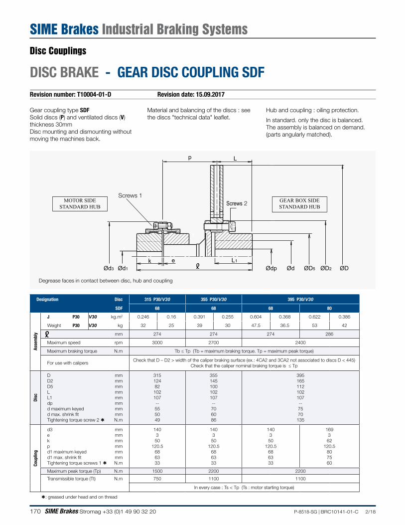
170 SIME Brakes Stromag +33 (0)1 49 90 32 20 P-8518-SG | BRC10141-01-C 2/18
Revision number: T10004-01-D Revision date: 15.09.2017
DISC BRAKE - GEAR DISC COUPLING SDF
Gear coupling type SDFSolid discs (P) and ventilated discs (V) thickness 30mmDisc mounting and dismounting without moving the machines back.
Material and balancing of the discs : see the discs "technical data" leaflet.
Hub and coupling : oiling protection.
In standard. only the disc is balanced.The assembly is balanced on demand. (parts angularly matched).
p L
Ød3 Ød1
k e L1
ØDØD2ØD5ØdØdp
Screws 2Screws 1
Degrease faces in contact between disc, hub and coupling
MOTOR SIDESTANDARD HUB
GEAR BOX SIDESTANDARD HUB
Designation Disc 315 P30/V30 355 P30/V30 395 P30/V30
SDF 68 68 68 80
Asse
mbl
y
J P30 V30 kg.m2 0.246 0.16 0.391 0.255 0.604 0.368 0.622 0.386
Weight P30 V30 kg 32 25 39 30 47.5 36.5 53 42
ℓ mm 274 274 274 286
Maximum speed rpm 3000 2700 2400
Maximum braking torque N.m Tb ≤ Tp (Tb = maximum braking torque. Tp = maximum peak torque)
For use with calipersCheck that D – D2 > width of the caliper braking surface (ex.: 4CA2 and 3CA2 not associated to discs D < 445)
Check that the caliper nominal braking torque is ≤ Tp
Disc
D D2 D5 L L1 dp d maximum keyed d max. shrink fit Tightening torque screw 2
mm mm mm mm mm mm mm mm N.m
315 124 82 102 107 -- 55 50 49
355 145 100 102 107 -- 70 60 86
395 165 112 102 107 -- 75 70
135
Coup
ling
d3 e k p d1 maximum keyed d1 max. shrink fit Tightening torque screws 1
mm mm mm mm mm mm N.m
140 3 50
120.5 68 63 33
140 3 50
120.5 68 63 33
140 3
50 120.5
68 63 33
169 3
62 120.5
80 75 60
Maximum peak torque (Tp) N.m 1500 2200 2200
Transmissible torque (Tt) N.m 750 1100 1100
In every case : Ts < Tp (Ts : motor starting torque)
: greased under head and on thread
Disc Couplings
SIME Brakes Industrial Braking Systems
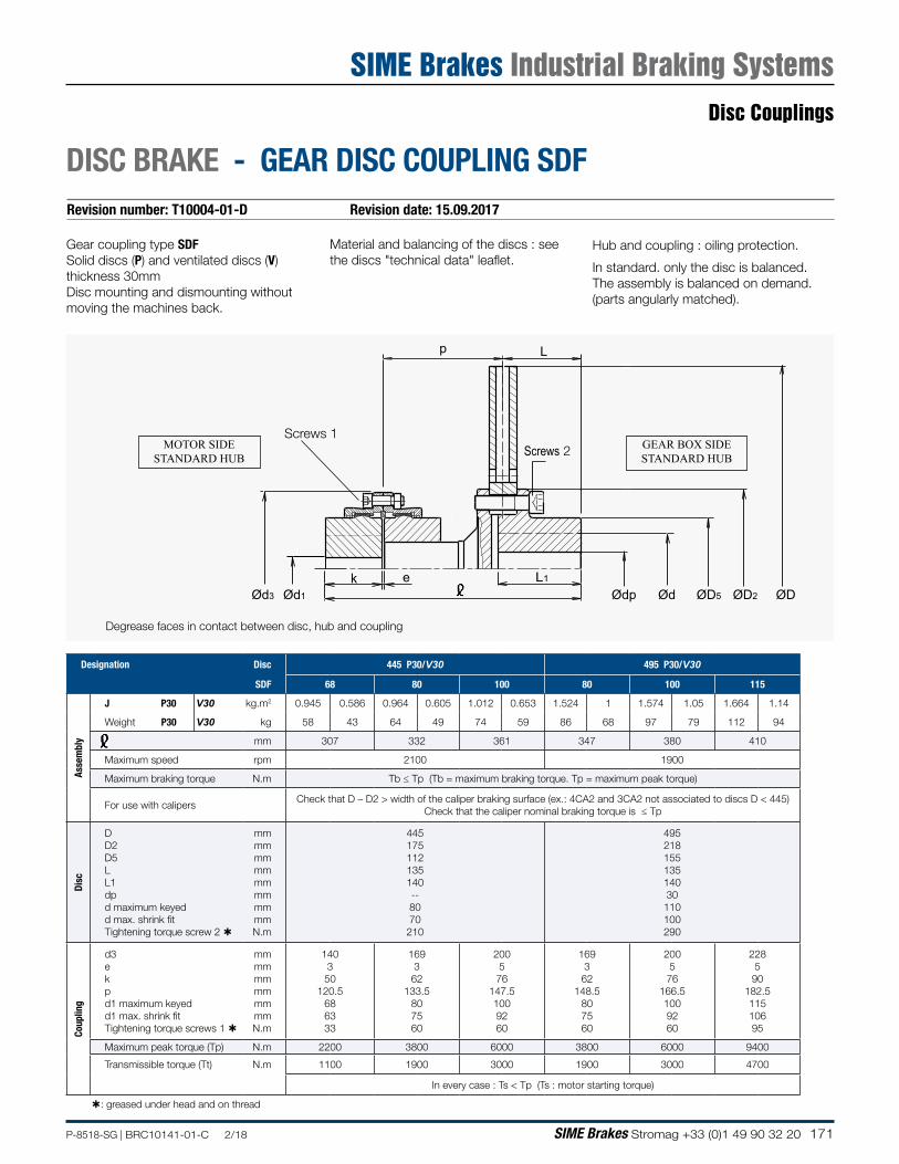
171P-8518-SG | BRC10141-01-C 2/18 SIME Brakes Stromag +33 (0)1 49 90 32 20
Revision number: T10004-01-D Revision date: 15.09.2017
DISC BRAKE - GEAR DISC COUPLING SDF
Gear coupling type SDFSolid discs (P) and ventilated discs (V) thickness 30mmDisc mounting and dismounting without moving the machines back.
Material and balancing of the discs : see the discs "technical data" leaflet.
Hub and coupling : oiling protection.
In standard. only the disc is balanced.The assembly is balanced on demand. (parts angularly matched).
p L
Ød3 Ød1
k e L1
ØDØD2ØD5ØdØdp
Screws 2Screws 1
Degrease faces in contact between disc, hub and coupling
MOTOR SIDESTANDARD HUB
GEAR BOX SIDESTANDARD HUB
Designation Disc 445 P30/V30 495 P30/V30
SDF 68 80 100 80 100 115
Asse
mbl
y
J P30 V30 kg.m2 0.945 0.586 0.964 0.605 1.012 0.653 1.524 1 1.574 1.05 1.664 1.14
Weight P30 V30 kg 58 43 64 49 74 59 86 68 97 79 112 94
ℓ mm 307 332 361 347 380 410
Maximum speed rpm 2100 1900
Maximum braking torque N.m Tb ≤ Tp (Tb = maximum braking torque. Tp = maximum peak torque)
For use with calipersCheck that D – D2 > width of the caliper braking surface (ex.: 4CA2 and 3CA2 not associated to discs D < 445)
Check that the caliper nominal braking torque is ≤ Tp
Disc
D D2 D5 L L1 dp d maximum keyed d max. shrink fit Tightening torque screw 2
mm mm mm mm mm mm mm mm N.m
445 175 112 135 140 -- 80 70
210
495 218 155 135 140 30 110 100 290
Coup
ling
d3 e k p d1 maximum keyed d1 max. shrink fit Tightening torque screws 1
mm mm mm mm mm mm N.m
140 3 50
120.5 68 63 33
169 3
62 133.5
80 75 60
200 5 76
147.5 100 92 60
169 3
62 148.5
80 75 60
200 5
76 166.5 100 92 60
228 5 90
182.5 115 106 95
Maximum peak torque (Tp) N.m 2200 3800 6000 3800 6000 9400
Transmissible torque (Tt) N.m 1100 1900 3000 1900 3000 4700
In every case : Ts < Tp (Ts : motor starting torque)
: greased under head and on thread
Disc Couplings
SIME Brakes Industrial Braking Systems
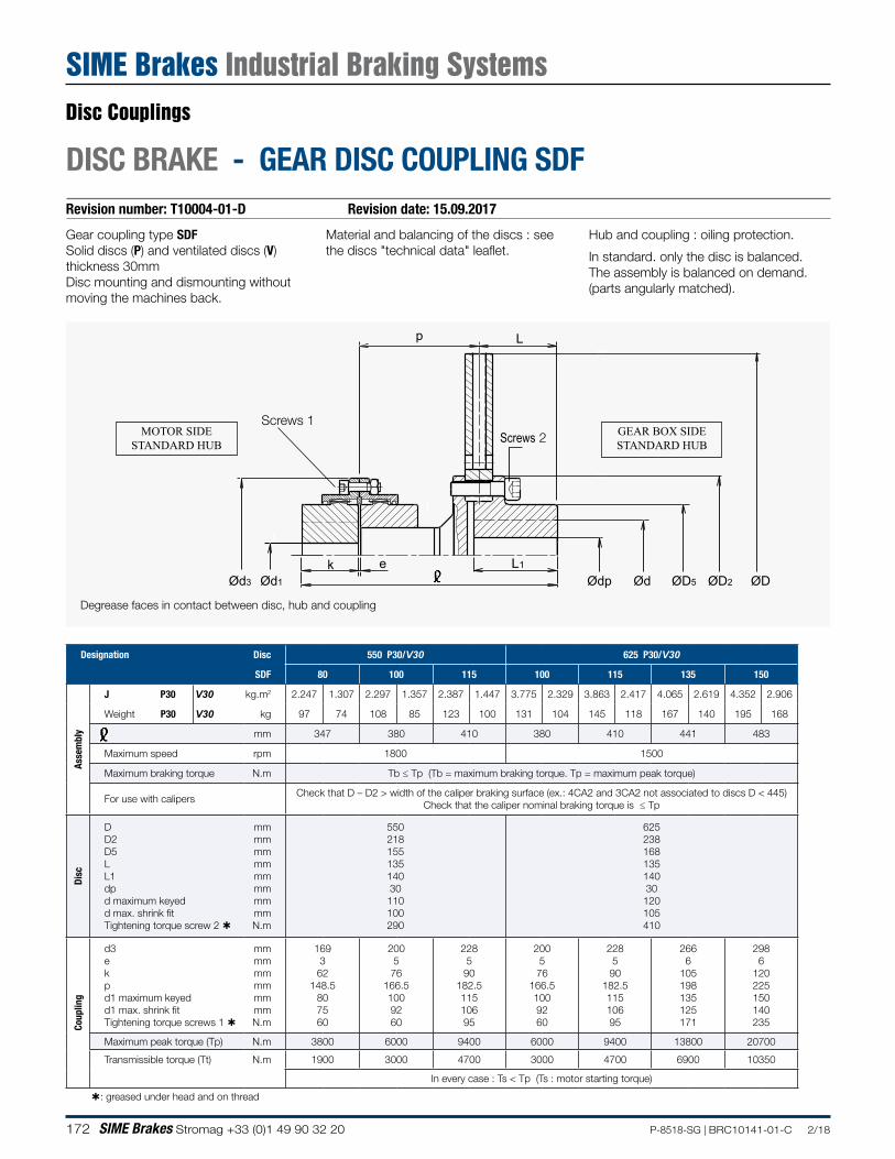
172 SIME Brakes Stromag +33 (0)1 49 90 32 20 P-8518-SG | BRC10141-01-C 2/18
Revision number: T10004-01-D Revision date: 15.09.2017
DISC BRAKE - GEAR DISC COUPLING SDF
Gear coupling type SDFSolid discs (P) and ventilated discs (V) thickness 30mmDisc mounting and dismounting without moving the machines back.
Material and balancing of the discs : see the discs "technical data" leaflet.
Hub and coupling : oiling protection.
In standard. only the disc is balanced.The assembly is balanced on demand. (parts angularly matched).
p L
Ød3 Ød1
k e L1
ØDØD2ØD5ØdØdp
Screws 2Screws 1
Degrease faces in contact between disc, hub and coupling
MOTOR SIDESTANDARD HUB
GEAR BOX SIDESTANDARD HUB
Designation Disc 550 P30/V30 625 P30/V30
SDF 80 100 115 100 115 135 150
Asse
mbl
y
J P30 V30 kg.m2 2.247 1.307 2.297 1.357 2.387 1.447 3.775 2.329 3.863 2.417 4.065 2.619 4.352 2.906
Weight P30 V30 kg 97 74 108 85 123 100 131 104 145 118 167 140 195 168
ℓ mm 347 380 410 380 410 441 483
Maximum speed rpm 1800 1500
Maximum braking torque N.m Tb ≤ Tp (Tb = maximum braking torque. Tp = maximum peak torque)
For use with calipersCheck that D – D2 > width of the caliper braking surface (ex.: 4CA2 and 3CA2 not associated to discs D < 445)
Check that the caliper nominal braking torque is ≤ Tp
Disc
D D2 D5 L L1 dp d maximum keyed d max. shrink fit Tightening torque screw 2
mm mm mm mm mm mm mm mm N.m
550 218 155 135 140 30
110 100 290
625 238 168 135 140 30
120 105 410
Coup
ling
d3 e k p d1 maximum keyed d1 max. shrink fit Tightening torque screws 1
mm mm mm mm mm mm N.m
169 3
62 148.5
80 75 60
200 5
76 166.5 100 92 60
228 5
90 182.5 115 106 95
200 5 76
166.5 100 92 60
228 5 90
182.5 115 106 95
266 6
105 198 135 125 171
298 6
120 225 150 140 235
Maximum peak torque (Tp) N.m 3800 6000 9400 6000 9400 13800 20700
Transmissible torque (Tt) N.m 1900 3000 4700 3000 4700 6900 10350
In every case : Ts < Tp (Ts : motor starting torque)
: greased under head and on thread
Disc Couplings
SIME Brakes Industrial Braking Systems
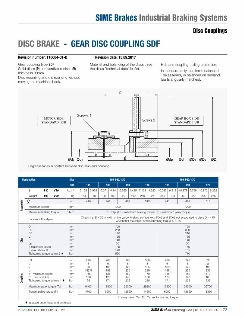
173P-8518-SG | BRC10141-01-C 2/18 SIME Brakes Stromag +33 (0)1 49 90 32 20
Revision number: T10004-01-D Revision date: 15.09.2017
DISC BRAKE - GEAR DISC COUPLING SDF
Gear coupling type SDFSolid discs (P) and ventilated discs (V) thickness 30mmDisc mounting and dismounting without moving the machines back.
Material and balancing of the discs : see the discs "technical data" leaflet.
Hub and coupling : oiling protection.
In standard. only the disc is balanced.The assembly is balanced on demand. (parts angularly matched).
p L
Ød3 Ød1
k e L1
ØDØD2ØD5ØdØdp
Screws 2Screws 1
Degrease faces in contact between disc, hub and coupling
MOTOR SIDESTANDARD HUB
GEAR BOX SIDESTANDARD HUB
Designation Disc 705 P30/V30 795 P30/V30
SDF 115 135 150 170 135 150 170
Asse
mbl
y
J P30 V30 kg.m2 6.165 3.935 6.37 4.14 6.655 4.425 7.153 4.923 10.092 6.512 10.378 6.798 10.872 7.292
Weight P30 V30 kg 173 140 196 163 223 190 259 226 233 193 260 220 295 255
ℓ mm 410 441 483 513 441 483 513
Maximum speed rpm 1300 1200
Maximum braking torque N.m Tb ≤ Tp (Tb = maximum braking torque. Tp = maximum peak torque)
For use with calipersCheck that D – D2 > width of the caliper braking surface (ex.: 4CA2 and 3CA2 not associated to discs D < 445)
Check that the caliper nominal braking torque is ≤ Tp
Disc
D D2 D5 L L1 dp d maximum keyed d max. shrink fit Tightening torque screw 2
mm mm mm mm mm mm mm mm N.m
705 268 190 135 140 30
135 120 550
795 300 216 135 140 30 150 135 710
Coup
ling
d3 e k p d1 maximum keyed d1 max. shrink fit Tightening torque screws 1
mm mm mm mm mm mm N.m
228 5 90
182.5 115 106 95
266 6
105 198 135 125 171
298 6
120 225 150 140 235
330 8
135 239 170 160 235
266 6
105 198 135 125 171
298 6
120 225 150 140 235
330 8
135 239 170 160 235
Maximum peak torque (Tp) N.m 9400 13800 25300 29200 13800 25300 36700
Transmissible torque (Tt) N.m 4700 6900 12650 14600 6900 12650 18350
In every case : Ts < Tp (Ts : motor starting torque)
: greased under head and on thread
Disc Couplings
SIME Brakes Industrial Braking Systems
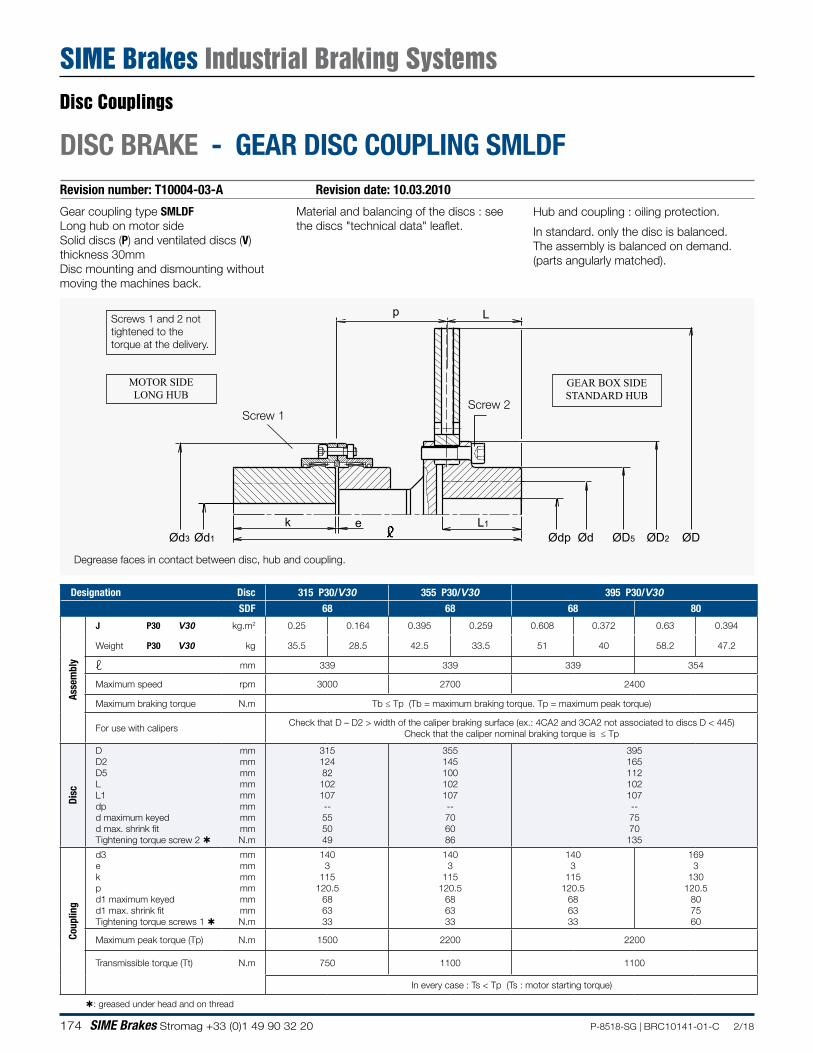
174 SIME Brakes Stromag +33 (0)1 49 90 32 20 P-8518-SG | BRC10141-01-C 2/18
Revision number: T10004-03-A Revision date: 10.03.2010
DISC BRAKE - GEAR DISC COUPLING SMLDF
Gear coupling type SMLDFLong hub on motor sideSolid discs (P) and ventilated discs (V) thickness 30mmDisc mounting and dismounting without moving the machines back.
Material and balancing of the discs : see the discs "technical data" leaflet.
Hub and coupling : oiling protection.
In standard. only the disc is balanced.The assembly is balanced on demand. (parts angularly matched).
p L
Ød3 Ød1
k e L1
ØDØD2ØD5ØdØdp
Screw 2Screw 1
Degrease faces in contact between disc, hub and coupling.
Screws 1 and 2 not tightened to the torque at the delivery.
MOTOR SIDELONG HUB
GEAR BOX SIDESTANDARD HUB
Designation Disc 315 P30/V30 355 P30/V30 395 P30/V30SDF 68 68 68 80
Asse
mbl
y
J P30 V30 kg.m2 0.25 0.164 0.395 0.259 0.608 0.372 0.63 0.394
Weight P30 V30 kg 35.5 28.5 42.5 33.5 51 40 58.2 47.2
ℓ mm 339 339 339 354
Maximum speed rpm 3000 2700 2400
Maximum braking torque N.m Tb ≤ Tp (Tb = maximum braking torque. Tp = maximum peak torque)
For use with calipersCheck that D – D2 > width of the caliper braking surface (ex.: 4CA2 and 3CA2 not associated to discs D < 445)
Check that the caliper nominal braking torque is ≤ Tp
Disc
D D2 D5 L L1 dp d maximum keyed d max. shrink fit Tightening torque screw 2
mm mm mm mm mm mm mm mm N.m
315 124 82 102 107 -- 55 50 49
355 145 100 102 107 -- 70 60 86
395 165 112 102 107 -- 75 70 135
Coup
ling
d3 e k p d1 maximum keyed d1 max. shrink fit Tightening torque screws 1
mm mm mm mm mm mm N.m
140 3
115 120.5
68 63 33
140 3
115 120.5
68 63 33
140 3
115 120.5
68 63 33
169 3
130 120.5
80 75 60
Maximum peak torque (Tp) N.m 1500 2200 2200
Transmissible torque (Tt) N.m 750 1100 1100
In every case : Ts < Tp (Ts : motor starting torque)
: greased under head and on thread
Disc Couplings
SIME Brakes Industrial Braking Systems
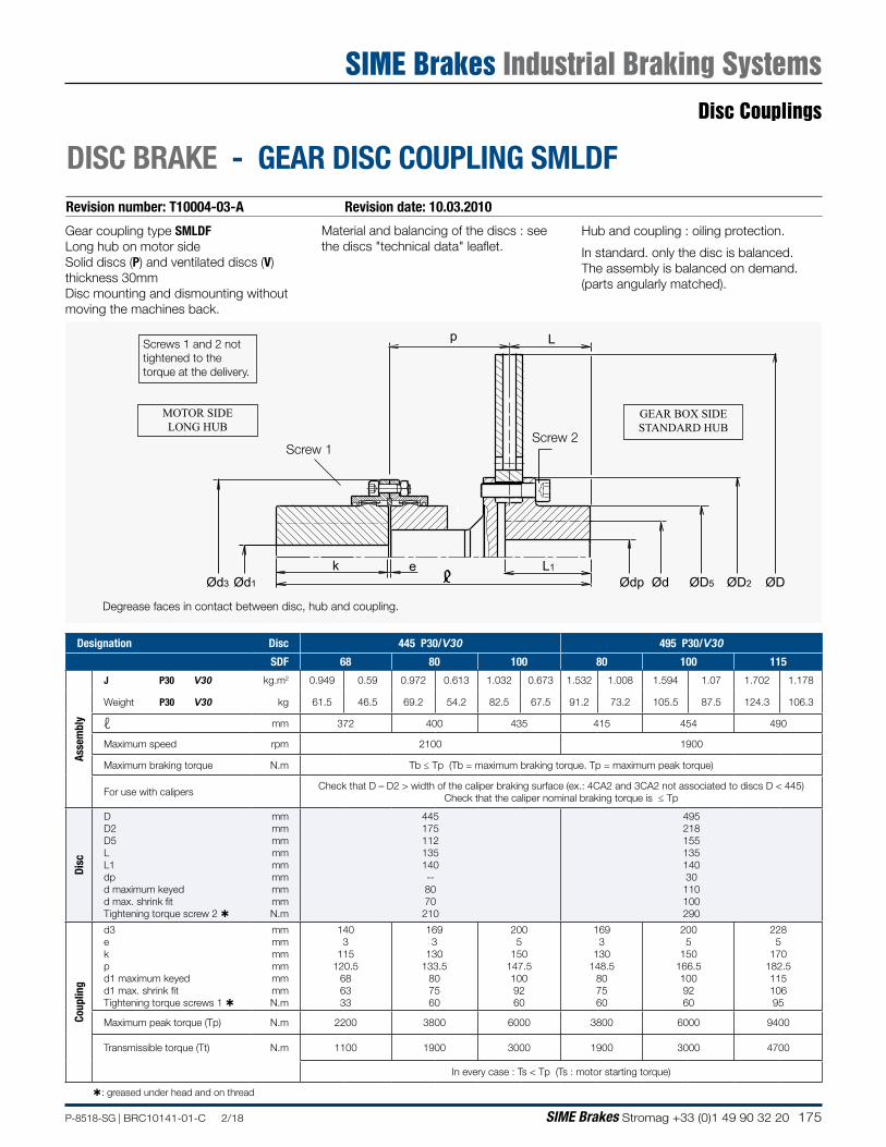
175P-8518-SG | BRC10141-01-C 2/18 SIME Brakes Stromag +33 (0)1 49 90 32 20
Revision number: T10004-03-A Revision date: 10.03.2010
DISC BRAKE - GEAR DISC COUPLING SMLDF
Gear coupling type SMLDFLong hub on motor sideSolid discs (P) and ventilated discs (V) thickness 30mmDisc mounting and dismounting without moving the machines back.
Material and balancing of the discs : see the discs "technical data" leaflet.
Hub and coupling : oiling protection.
In standard. only the disc is balanced.The assembly is balanced on demand. (parts angularly matched).
p L
Ød3 Ød1
k e L1
ØDØD2ØD5ØdØdp
Screw 2Screw 1
Degrease faces in contact between disc, hub and coupling.
Screws 1 and 2 not tightened to the torque at the delivery.
MOTOR SIDELONG HUB
GEAR BOX SIDESTANDARD HUB
Designation Disc 445 P30/V30 495 P30/V30SDF 68 80 100 80 100 115
Asse
mbl
y
J P30 V30 kg.m2 0.949 0.59 0.972 0.613 1.032 0.673 1.532 1.008 1.594 1.07 1.702 1.178
Weight P30 V30 kg 61.5 46.5 69.2 54.2 82.5 67.5 91.2 73.2 105.5 87.5 124.3 106.3
ℓ mm 372 400 435 415 454 490
Maximum speed rpm 2100 1900
Maximum braking torque N.m Tb ≤ Tp (Tb = maximum braking torque. Tp = maximum peak torque)
For use with calipersCheck that D – D2 > width of the caliper braking surface (ex.: 4CA2 and 3CA2 not associated to discs D < 445)
Check that the caliper nominal braking torque is ≤ Tp
Disc
D D2 D5 L L1 dp d maximum keyed d max. shrink fit Tightening torque screw 2
mm mm mm mm mm mm mm mm N.m
445 175 112 135 140 -- 80 70 210
495 218 155 135 140 30
110 100 290
Coup
ling
d3 e k p d1 maximum keyed d1 max. shrink fit Tightening torque screws 1
mm mm mm mm mm mm N.m
140 3
115 120.5
68 63 33
169 3
130 133.5
80 75 60
200 5
150 147.5 100 92 60
169 3
130 148.5
80 75 60
200 5
150 166.5 100 92 60
228 5
170 182.5 115 106 95
Maximum peak torque (Tp) N.m 2200 3800 6000 3800 6000 9400
Transmissible torque (Tt) N.m 1100 1900 3000 1900 3000 4700
In every case : Ts < Tp (Ts : motor starting torque)
: greased under head and on thread
Disc Couplings
SIME Brakes Industrial Braking Systems
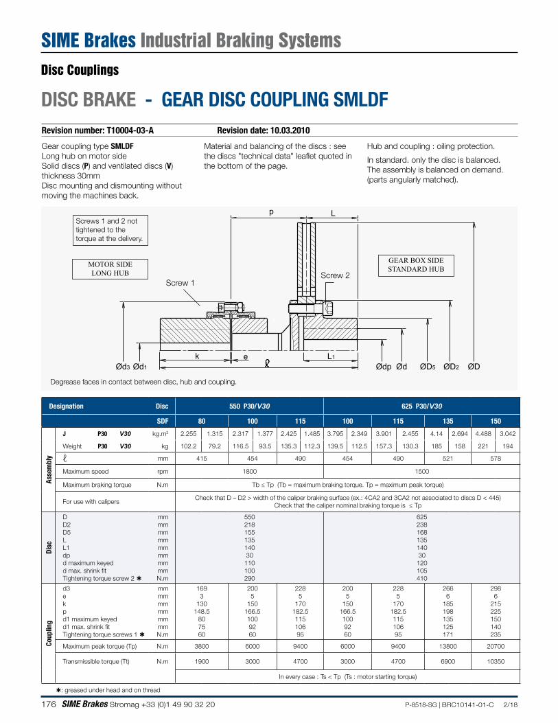
176 SIME Brakes Stromag +33 (0)1 49 90 32 20 P-8518-SG | BRC10141-01-C 2/18
Revision number: T10004-03-A Revision date: 10.03.2010
DISC BRAKE - GEAR DISC COUPLING SMLDF
Gear coupling type SMLDFLong hub on motor sideSolid discs (P) and ventilated discs (V) thickness 30mmDisc mounting and dismounting without moving the machines back.
Material and balancing of the discs : see the discs "technical data" leaflet quoted in the bottom of the page.
Hub and coupling : oiling protection.
In standard. only the disc is balanced.The assembly is balanced on demand. (parts angularly matched).
p L
Ød3 Ød1
k e L1
ØDØD2ØD5ØdØdp
Screw 2Screw 1
Degrease faces in contact between disc, hub and coupling.
Screws 1 and 2 not tightened to the torque at the delivery.
MOTOR SIDELONG HUB
GEAR BOX SIDESTANDARD HUB
Designation Disc 550 P30/V30 625 P30/V30
SDF 80 100 115 100 115 135 150
Asse
mbl
y
J P30 V30 kg.m2 2.255 1.315 2.317 1.377 2.425 1.485 3.795 2.349 3.901 2.455 4.14 2.694 4.488 3.042
Weight P30 V30 kg 102.2 79.2 116.5 93.5 135.3 112.3 139.5 112.5 157.3 130.3 185 158 221 194
ℓ mm 415 454 490 454 490 521 578
Maximum speed rpm 1800 1500
Maximum braking torque N.m Tb ≤ Tp (Tb = maximum braking torque. Tp = maximum peak torque)
For use with calipersCheck that D – D2 > width of the caliper braking surface (ex.: 4CA2 and 3CA2 not associated to discs D < 445)
Check that the caliper nominal braking torque is ≤ Tp
Disc
D D2 D5 L L1 dp d maximum keyed d max. shrink fit Tightening torque screw 2
mm mm mm mm mm mm mm mm N.m
550 218 155 135 140 30
110 100 290
625 238 168 135 140 30
120 105 410
Coup
ling
d3 e k p d1 maximum keyed d1 max. shrink fit Tightening torque screws 1
mm mm mm mm mm mm N.m
169 3
130 148.5
80 75 60
200 5
150 166.5 100 92 60
228 5
170 182.5 115 106 95
200 5
150 166.5 100 92 60
228 5
170 182.5 115 106 95
266 6
185 198 135 125 171
298 6
215 225 150 140 235
Maximum peak torque (Tp) N.m 3800 6000 9400 6000 9400 13800 20700
Transmissible torque (Tt) N.m 1900 3000 4700 3000 4700 6900 10350
In every case : Ts < Tp (Ts : motor starting torque)
: greased under head and on thread
Disc Couplings
SIME Brakes Industrial Braking Systems
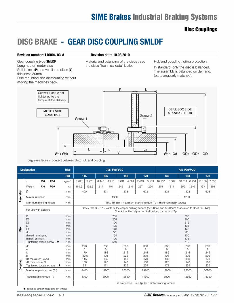
177P-8518-SG | BRC10141-01-C 2/18 SIME Brakes Stromag +33 (0)1 49 90 32 20
Revision number: T10004-03-A Revision date: 10.03.2010
DISC BRAKE - GEAR DISC COUPLING SMLDF
Gear coupling type SMLDFLong hub on motor sideSolid discs (P) and ventilated discs (V) thickness 30mmDisc mounting and dismounting without moving the machines back.
Material and balancing of the discs : see the discs "technical data" leaflet.
Hub and coupling : oiling protection.
In standard. only the disc is balanced.The assembly is balanced on demand. (parts angularly matched).
p L
Ød3 Ød1
k e L1
ØDØD2ØD5ØdØdp
Screw 2Screw 1
Degrease faces in contact between disc, hub and coupling.
Screws 1 and 2 not tightened to the torque at the delivery.
MOTOR SIDELONG HUB
GEAR BOX SIDESTANDARD HUB
Designation Disc 705 P30/V30 795 P30/V30
SDF 115 135 150 170 135 150 170
Asse
mbl
y
J P30 V30 kg.m2 6.203 3.973 6.445 4.215 6.791 4.561 7.419 5.189 10.167 6.587 10.514 6.934 11.138 7.558
Weight P30 V30 kg 185.3 152.3 214 181 249 216 297 264 251 211 286 246 333 293
ℓ mm 490 521 578 623 521 578 623
Maximum speed rpm 1300 1200
Maximum braking torque N.m Tb ≤ Tp (Tb = maximum braking torque. Tp = maximum peak torque)
For use with calipersCheck that D – D2 > width of the caliper braking surface (ex.: 4CA2 and 3CA2 not associated to discs D < 445)
Check that the caliper nominal braking torque is ≤ Tp
Disc
D D2 D5 L L1 dp d maximum keyed d max. shrink fit Tightening torque screw 2
mm mm mm mm mm mm mm mm N.m
705 268 190 135 140 30
135 120 550
795 300 216 135 140 30 150 135 710
Coup
ling
d3 e k p d1 maximum keyed d1 max. shrink fit Tightening torque screws 1
mm mm mm mm mm mm N.m
228 5
170 182.5 115 106 95
266 6
185 198 135 125 171
298 6
215 225 150 140 235
330 8
245 239 170 160 235
266 6
185 198 135 125 171
298 6
215 225 150 140 235
330 8
245 239 170 160 235
Maximum peak torque (Tp) N.m 9400 13800 25300 29200 13800 25300 36700
Transmissible torque (Tt) N.m 4700 6900 12650 14600 6900 12650 18350
In every case : Ts < Tp (Ts : motor starting torque)
: greased under head and on thread
Disc Couplings
SIME Brakes Industrial Braking Systems
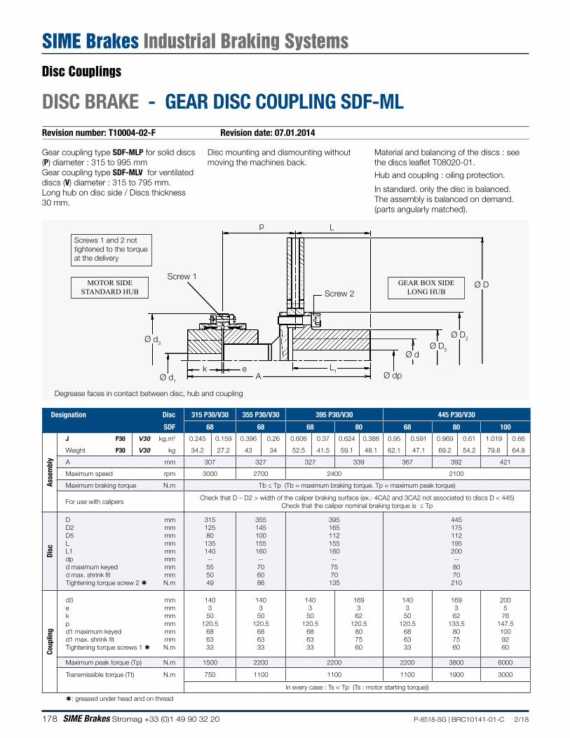
178 SIME Brakes Stromag +33 (0)1 49 90 32 20 P-8518-SG | BRC10141-01-C 2/18
Revision number: T10004-02-F Revision date: 07.01.2014
DISC BRAKE - GEAR DISC COUPLING SDF-ML
Screw 2
Screw 1
p
Ø d1
Ø d3
Ø D
Ø D2
Ø D5Ø d
Ø dpL1e
L
k
Material and balancing of the discs : see the discs leaflet T08020-01.
Hub and coupling : oiling protection.
In standard. only the disc is balanced.The assembly is balanced on demand. (parts angularly matched).
Gear coupling type SDF-MLP for solid discs (P) diameter : 315 to 995 mmGear coupling type SDF-MLV for ventilated discs (V) diameter : 315 to 795 mm.Long hub on disc side / Discs thickness 30 mm.
Degrease faces in contact between disc, hub and coupling
Screws 1 and 2 not tightened to the torque at the delivery
MOTOR SIDESTANDARD HUB
GEAR BOX SIDELONG HUB
A
Disc mounting and dismounting without moving the machines back.
Designation Disc 315 P30/V30 355 P30/V30 395 P30/V30 445 P30/V30
SDF 68 68 68 80 68 80 100
Asse
mbl
y
J P30 V30 kg.m2 0.245 0.159 0.396 0.26 0.606 0.37 0.624 0.388 0.95 0.591 0.969 0.61 1.019 0.66
Weight P30 V30 kg 34.2 27.2 43 34 52.5 41.5 59.1 48.1 62.1 47.1 69.2 54.2 79.8 64.8
A mm 307 327 327 339 367 392 421
Maximum speed rpm 3000 2700 2400 2100
Maximum braking torque N.m Tb ≤ Tp (Tb = maximum braking torque. Tp = maximum peak torque)
For use with calipersCheck that D – D2 > width of the caliper braking surface (ex.: 4CA2 and 3CA2 not associated to discs D < 445)
Check that the caliper nominal braking torque is ≤ Tp
Disc
D D2 D5 L L1 dp d maximum keyed d max. shrink fit Tightening torque screw 2
mm mm mm mm mm mm mm mm N.m
315 125 80 135 140 -- 55 50 49
355 145 100 155 160 -- 70 60 86
395 165 112 155 160 -- 75 70 135
445 175 112 195 200 -- 80 70
210
Coup
ling
d3 e k p d1 maximum keyed d1 max. shrink fit Tightening torque screws 1
mm mm mm mm mm mm N.m
140 3 50
120.5 68 63 33
140 3
50 120.5
68 63 33
140 3 50
120.5 68 63 33
169 3 62
120.5 80 75 60
140 3 50
120.5 68 63 33
169 3
62 133.5
80 75 60
200 5
76 147.5 100 92 60
Maximum peak torque (Tp) N.m 1500 2200 2200 2200 3800 6000
Transmissible torque (Tt) N.m 750 1100 1100 1100 1900 3000
In every case : Ts < Tp (Ts : motor starting torque))
: greased under head and on thread
Disc Couplings
SIME Brakes Industrial Braking Systems
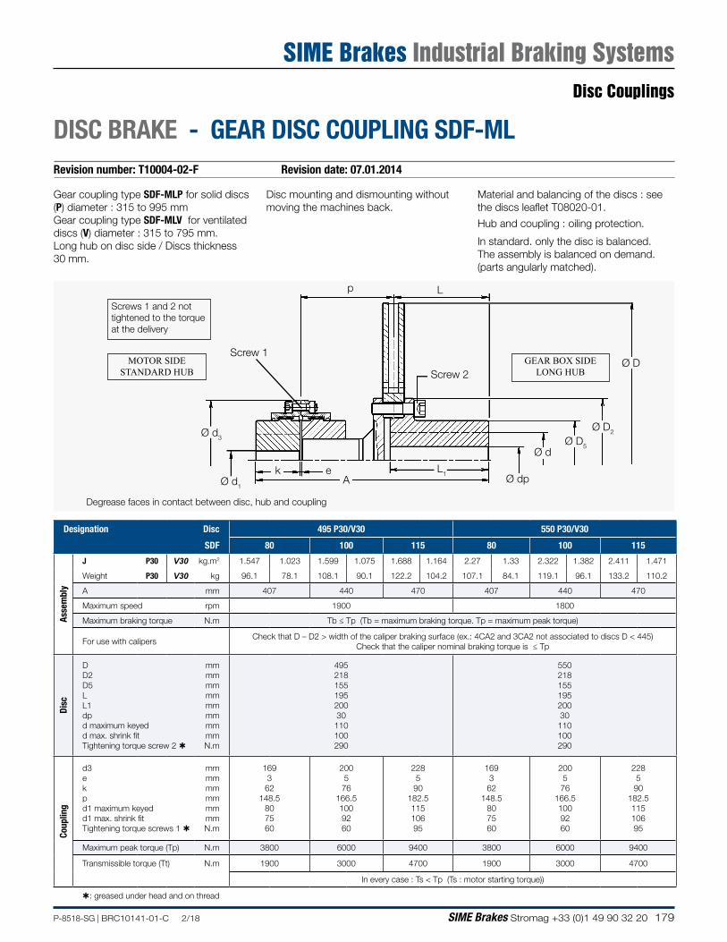
179P-8518-SG | BRC10141-01-C 2/18 SIME Brakes Stromag +33 (0)1 49 90 32 20
Revision number: T10004-02-F Revision date: 07.01.2014
DISC BRAKE - GEAR DISC COUPLING SDF-ML
Screw 2
Screw 1
p
Ø d1
Ø d3
Ø D
Ø D2
Ø D5Ø d
Ø dpL1e
L
k
Material and balancing of the discs : see the discs leaflet T08020-01.
Hub and coupling : oiling protection.
In standard. only the disc is balanced.The assembly is balanced on demand. (parts angularly matched).
Gear coupling type SDF-MLP for solid discs (P) diameter : 315 to 995 mmGear coupling type SDF-MLV for ventilated discs (V) diameter : 315 to 795 mm.Long hub on disc side / Discs thickness 30 mm.
Degrease faces in contact between disc, hub and coupling
Screws 1 and 2 not tightened to the torque at the delivery
MOTOR SIDESTANDARD HUB
GEAR BOX SIDELONG HUB
A
Disc mounting and dismounting without moving the machines back.
Designation Disc 495 P30/V30 550 P30/V30
SDF 80 100 115 80 100 115
Asse
mbl
y
J P30 V30 kg.m2 1.547 1.023 1.599 1.075 1.688 1.164 2.27 1.33 2.322 1.382 2.411 1.471
Weight P30 V30 kg 96.1 78.1 108.1 90.1 122.2 104.2 107.1 84.1 119.1 96.1 133.2 110.2
A mm 407 440 470 407 440 470
Maximum speed rpm 1900 1800
Maximum braking torque N.m Tb ≤ Tp (Tb = maximum braking torque. Tp = maximum peak torque)
For use with calipersCheck that D – D2 > width of the caliper braking surface (ex.: 4CA2 and 3CA2 not associated to discs D < 445)
Check that the caliper nominal braking torque is ≤ Tp
Disc
D D2 D5 L L1 dp d maximum keyed d max. shrink fit Tightening torque screw 2
mm mm mm mm mm mm mm mm N.m
495 218 155 195 200 30 110 100 290
550 218 155 195 200 30
110 100 290
Coup
ling
d3 e k p d1 maximum keyed d1 max. shrink fit Tightening torque screws 1
mm mm mm mm mm mm N.m
169 3 62
148.5 80 75 60
200 5 76
166.5 100 92 60
228 5 90
182.5 115 106 95
169 3 62
148.5 80 75 60
200 5 76
166.5 100 92 60
228 5
90 182.5 115 106 95
Maximum peak torque (Tp) N.m 3800 6000 9400 3800 6000 9400
Transmissible torque (Tt) N.m 1900 3000 4700 1900 3000 4700
In every case : Ts < Tp (Ts : motor starting torque))
: greased under head and on thread
Disc Couplings
SIME Brakes Industrial Braking Systems
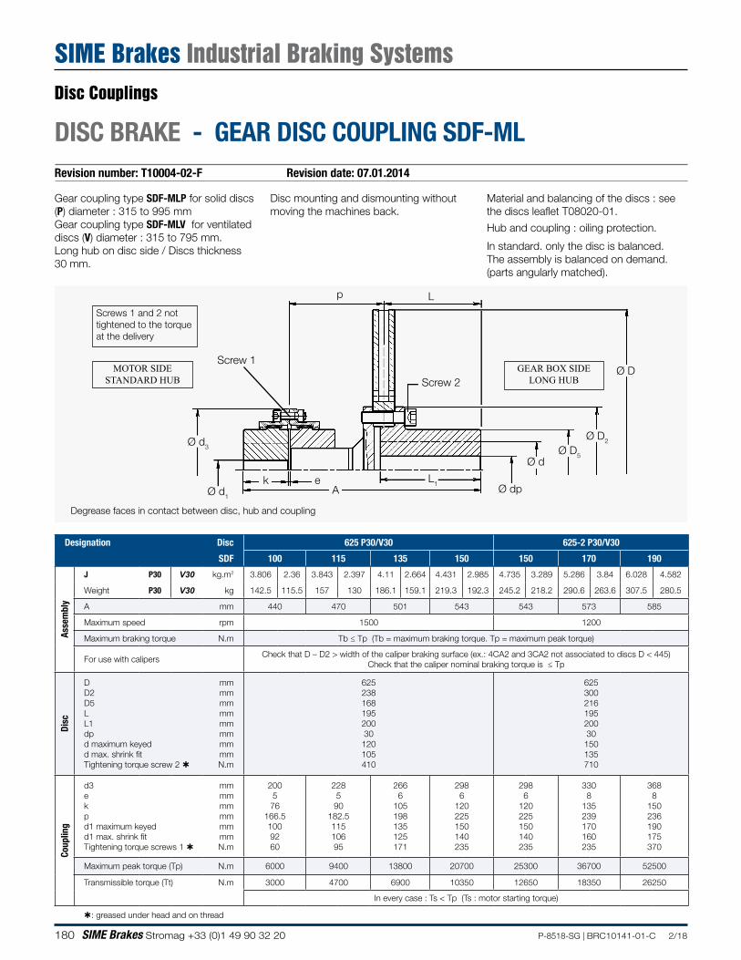
180 SIME Brakes Stromag +33 (0)1 49 90 32 20 P-8518-SG | BRC10141-01-C 2/18
Revision number: T10004-02-F Revision date: 07.01.2014
DISC BRAKE - GEAR DISC COUPLING SDF-ML
Screw 2
Screw 1
p
Ø d1
Ø d3
Ø D
Ø D2
Ø D5Ø d
Ø dpL1e
L
k
Material and balancing of the discs : see the discs leaflet T08020-01.
Hub and coupling : oiling protection.
In standard. only the disc is balanced.The assembly is balanced on demand. (parts angularly matched).
Gear coupling type SDF-MLP for solid discs (P) diameter : 315 to 995 mmGear coupling type SDF-MLV for ventilated discs (V) diameter : 315 to 795 mm.Long hub on disc side / Discs thickness 30 mm.
Degrease faces in contact between disc, hub and coupling
Screws 1 and 2 not tightened to the torque at the delivery
MOTOR SIDESTANDARD HUB
GEAR BOX SIDELONG HUB
A
Disc mounting and dismounting without moving the machines back.
Designation Disc 625 P30/V30 625-2 P30/V30
SDF 100 115 135 150 150 170 190
Asse
mbl
y
J P30 V30 kg.m2 3.806 2.36 3.843 2.397 4.11 2.664 4.431 2.985 4.735 3.289 5.286 3.84 6.028 4.582
Weight P30 V30 kg 142.5 115.5 157 130 186.1 159.1 219.3 192.3 245.2 218.2 290.6 263.6 307.5 280.5
A mm 440 470 501 543 543 573 585
Maximum speed rpm 1500 1200
Maximum braking torque N.m Tb ≤ Tp (Tb = maximum braking torque. Tp = maximum peak torque)
For use with calipersCheck that D – D2 > width of the caliper braking surface (ex.: 4CA2 and 3CA2 not associated to discs D < 445)
Check that the caliper nominal braking torque is ≤ Tp
Disc
D D2 D5 L L1 dp d maximum keyed d max. shrink fit Tightening torque screw 2
mm mm mm mm mm mm mm mm N.m
625 238 168 195 200 30
120 105 410
625 300 216 195 200 30
150 135 710
Coup
ling
d3 e k p d1 maximum keyed d1 max. shrink fit Tightening torque screws 1
mm mm mm mm mm mm N.m
200 5 76
166.5 100 92 60
228 5
90 182.5 115 106 95
266 6
105 198 135 125 171
298 6
120 225 150 140 235
298 6
120 225 150 140 235
330 8
135 239 170 160 235
368 8
150 236 190 175 370
Maximum peak torque (Tp) N.m 6000 9400 13800 20700 25300 36700 52500
Transmissible torque (Tt) N.m 3000 4700 6900 10350 12650 18350 26250
In every case : Ts < Tp (Ts : motor starting torque)
: greased under head and on thread
Disc Couplings
SIME Brakes Industrial Braking Systems
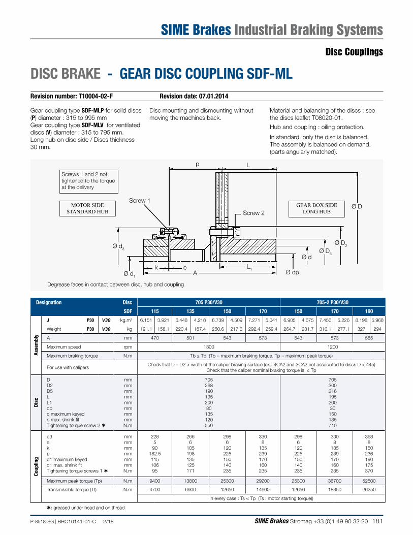
181P-8518-SG | BRC10141-01-C 2/18 SIME Brakes Stromag +33 (0)1 49 90 32 20
Revision number: T10004-02-F Revision date: 07.01.2014
DISC BRAKE - GEAR DISC COUPLING SDF-ML
Screw 2
Screw 1
p
Ø d1
Ø d3
Ø D
Ø D2
Ø D5Ø d
Ø dpL1e
L
k
Material and balancing of the discs : see the discs leaflet T08020-01.
Hub and coupling : oiling protection.
In standard. only the disc is balanced.The assembly is balanced on demand. (parts angularly matched).
Gear coupling type SDF-MLP for solid discs (P) diameter : 315 to 995 mmGear coupling type SDF-MLV for ventilated discs (V) diameter : 315 to 795 mm.Long hub on disc side / Discs thickness 30 mm.
Degrease faces in contact between disc, hub and coupling
Screws 1 and 2 not tightened to the torque at the delivery
MOTOR SIDESTANDARD HUB
GEAR BOX SIDELONG HUB
A
Disc mounting and dismounting without moving the machines back.
Designation Disc 705 P30/V30 705-2 P30/V30
SDF 115 135 150 170 150 170 190
Asse
mbl
y
J P30 V30 kg.m2 6.151 3.921 6.448 4.218 6.739 4.509 7.271 5.041 6.905 4.675 7.456 5.226 8.198 5.968
Weight P30 V30 kg 191.1 158.1 220.4 187.4 250.6 217.6 292.4 259.4 264.7 231.7 310.1 277.1 327 294
A mm 470 501 543 573 543 573 585
Maximum speed rpm 1300 1200
Maximum braking torque N.m Tb ≤ Tp (Tb = maximum braking torque. Tp = maximum peak torque)
For use with calipersCheck that D – D2 > width of the caliper braking surface (ex.: 4CA2 and 3CA2 not associated to discs D < 445)
Check that the caliper nominal braking torque is ≤ Tp
Disc
D D2 D5 L L1 dp d maximum keyed d max. shrink fit Tightening torque screw 2
mm mm mm mm mm mm mm mm N.m
705 268 190 195 200 30
135 120 550
705 300 216 195 200 30 150 135 710
Coup
ling
d3 e k p d1 maximum keyed d1 max. shrink fit Tightening torque screws 1
mm mm mm mm mm mm N.m
228 5 90
182.5 115 106 95
266 6
105 198 135 125 171
298 6
120 225 150 140 235
330 8
135 239 170 160 235
298 6
120 225 150 140 235
330 8
135 239 170 160 235
368 8
150 236 190 175 370
Maximum peak torque (Tp) N.m 9400 13800 25300 29200 25300 36700 52500
Transmissible torque (Tt) N.m 4700 6900 12650 14600 12650 18350 26250
In every case : Ts < Tp (Ts : motor starting torque))
: greased under head and on thread
Disc Couplings
SIME Brakes Industrial Braking Systems
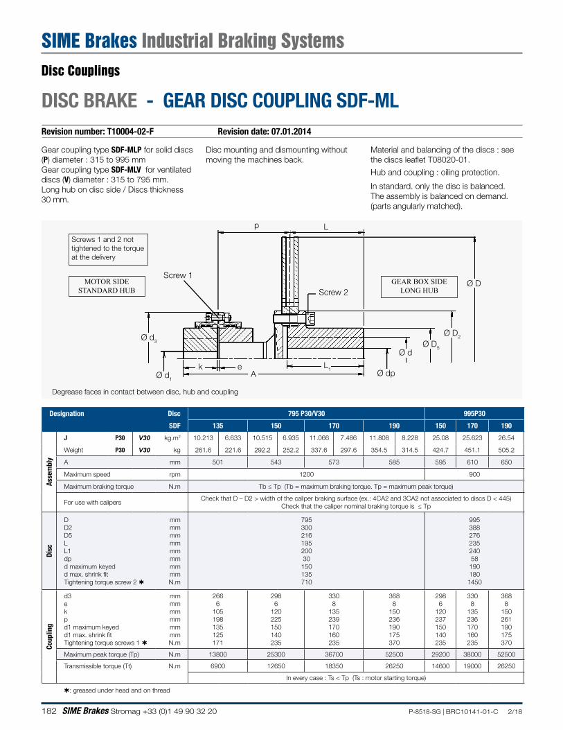
182 SIME Brakes Stromag +33 (0)1 49 90 32 20 P-8518-SG | BRC10141-01-C 2/18
Revision number: T10004-02-F Revision date: 07.01.2014
DISC BRAKE - GEAR DISC COUPLING SDF-ML
Screw 2
Screw 1
p
Ø d1
Ø d3
Ø D
Ø D2
Ø D5Ø d
Ø dpL1e
L
k
Material and balancing of the discs : see the discs leaflet T08020-01.
Hub and coupling : oiling protection.
In standard. only the disc is balanced.The assembly is balanced on demand. (parts angularly matched).
Gear coupling type SDF-MLP for solid discs (P) diameter : 315 to 995 mmGear coupling type SDF-MLV for ventilated discs (V) diameter : 315 to 795 mm.Long hub on disc side / Discs thickness 30 mm.
Degrease faces in contact between disc, hub and coupling
Screws 1 and 2 not tightened to the torque at the delivery
MOTOR SIDESTANDARD HUB
GEAR BOX SIDELONG HUB
A
Disc mounting and dismounting without moving the machines back.
Designation Disc 795 P30/V30 995P30
SDF 135 150 170 190 150 170 190
Asse
mbl
y
J P30 V30 kg.m2 10.213 6.633 10.515 6.935 11.066 7.486 11.808 8.228 25.08 25.623 26.54
Weight P30 V30 kg 261.6 221.6 292.2 252.2 337.6 297.6 354.5 314.5 424.7 451.1 505.2
A mm 501 543 573 585 595 610 650
Maximum speed rpm 1200 900
Maximum braking torque N.m Tb ≤ Tp (Tb = maximum braking torque. Tp = maximum peak torque)
For use with calipersCheck that D – D2 > width of the caliper braking surface (ex.: 4CA2 and 3CA2 not associated to discs D < 445)
Check that the caliper nominal braking torque is ≤ Tp
Disc
D D2 D5 L L1 dp d maximum keyed d max. shrink fit Tightening torque screw 2
mm mm mm mm mm mm mm mm N.m
795 300 216 195 200 30 150 135 710
995 388 276 235 240 58
190 180
1450
Coup
ling
d3 e k p d1 maximum keyed d1 max. shrink fit Tightening torque screws 1
mm mm mm mm mm mm N.m
266 6
105 198 135 125 171
298 6
120 225 150 140 235
330 8
135 239 170 160 235
368 8
150 236 190 175 370
298 6
120 237 150 140 235
330 8
135 236 170 160 235
368 8
150 261 190 175 370
Maximum peak torque (Tp) N.m 13800 25300 36700 52500 29200 38000 52500
Transmissible torque (Tt) N.m 6900 12650 18350 26250 14600 19000 26250
In every case : Ts < Tp (Ts : motor starting torque)
: greased under head and on thread
Disc Couplings
SIME Brakes Industrial Braking Systems
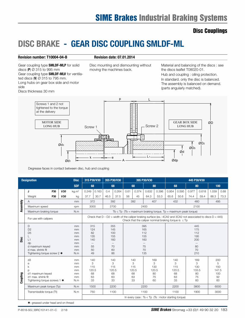
183P-8518-SG | BRC10141-01-C 2/18 SIME Brakes Stromag +33 (0)1 49 90 32 20
Revision number: T10004-04-B Revision date: 07.01.2014
DISC BRAKE - GEAR DISC COUPLING SMLDF-ML
Disc mounting and dismounting without moving the machines back.
p L
Ød3
Ød1k e L1
ØD
ØD2
ØD5
Ød
ØdpA
Screw 2Screw 1
Gear coupling type SMLDF-MLP for solid discs (P) Ø 315 to 995 mmGear coupling type SMLDF-MLV for ventila-ted discs (V) Ø 315 to 795 mm.Long hubs on gear box side and motor sideDiscs thickness 30 mm
Degrease faces in contact between disc, hub and coupling
Screws 1 and 2 not tightened to the torque at the delivery
MOTOR SIDELONG HUB
GEAR BOX SIDELONG HUB
Material and balancing of the discs : see the discs leaflet T08020-01.Hub and coupling : oiling protection.In standard. only the disc is balanced.The assembly is balanced on demand. (parts angularly matched).
Designation Disc 315 P30/V30 355 P30/V30 395 P30/V30 445 P30/V30
SDF 68 68 68 80 68 80 100
Asse
mbl
y
J P30 V30 kg.m2 0.249 0.163 0.4 0.264 0.61 0.374 0.632 0.396 0.954 0.595 0.977 0.618 1.039 0.68
Weight P30 V30 kg 37.7 30.7 46.5 37.5 56 45 64.3 53.3 65.6 50.6 74.4 59.4 88.3 73.3
A mm 372 392 392 407 432 460 495
Maximum speed rpm 3000 2700 2400 2100
Maximum braking torque N.m Tb ≤ Tp (Tb = maximum braking torque. Tp = maximum peak torque)
For use with calipersCheck that D – D2 > width of the caliper braking surface (ex.: 4CA2 and 3CA2 not associated to discs D < 445)
Check that the caliper nominal braking torque is ≤ Tp
Disc
D D2 D5 L L1 dp d maximum keyed d max. shrink fit Tightening torque screw 2
mm mm mm mm mm mm mm mm N.m
315 124 82 135 140 -- 55 50 49
355 145 100 155 160 -- 70 60 86
395 165 112 155 160 -- 75 70
135
445 175 112 195 200 -- 80 70 210
Coup
ling
d3 e k p d1 maximum keyed d1 max. shrink fit Tightening torque screws 1
mm mm mm mm mm mm N.m
140 3
115 120.5
68 63 33
140 3
115 120.5
68 63 33
140 3
115 120.5
68 63 33
169 3
130 120.5
80 75 60
140 3
115 120.5
68 63 33
169 3
130 133.5
80 75 60
200 5
150 147.5 100 92 60
Maximum peak torque (Tp) N.m 1500 2200 2200 2200 3800 6000
Transmissible torque (Tt) N.m 750 1100 1100 1100 1900 3000
In every case : Ts < Tp (Ts : motor starting torque)
: greased under head and on thread
Disc Couplings
SIME Brakes Industrial Braking Systems
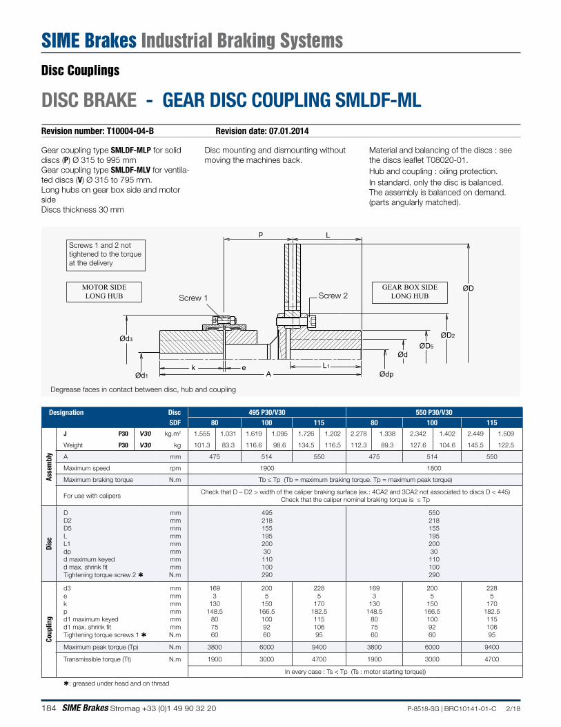
184 SIME Brakes Stromag +33 (0)1 49 90 32 20 P-8518-SG | BRC10141-01-C 2/18
Revision number: T10004-04-B Revision date: 07.01.2014
DISC BRAKE - GEAR DISC COUPLING SMLDF-ML
Disc mounting and dismounting without moving the machines back.
p L
Ød3
Ød1k e L1
ØD
ØD2
ØD5
Ød
ØdpA
Screw 2Screw 1
Gear coupling type SMLDF-MLP for solid discs (P) Ø 315 to 995 mmGear coupling type SMLDF-MLV for ventila-ted discs (V) Ø 315 to 795 mm.Long hubs on gear box side and motor sideDiscs thickness 30 mm
Degrease faces in contact between disc, hub and coupling
Screws 1 and 2 not tightened to the torque at the delivery
MOTOR SIDELONG HUB
GEAR BOX SIDELONG HUB
Material and balancing of the discs : see the discs leaflet T08020-01.Hub and coupling : oiling protection.In standard. only the disc is balanced.The assembly is balanced on demand. (parts angularly matched).
Designation Disc 495 P30/V30 550 P30/V30SDF 80 100 115 80 100 115
Asse
mbl
y
J P30 V30 kg.m2 1.555 1.031 1.619 1.095 1.726 1.202 2.278 1.338 2.342 1.402 2.449 1.509
Weight P30 V30 kg 101.3 83.3 116.6 98.6 134.5 116.5 112.3 89.3 127.6 104.6 145.5 122.5
A mm 475 514 550 475 514 550
Maximum speed rpm 1900 1800
Maximum braking torque N.m Tb ≤ Tp (Tb = maximum braking torque. Tp = maximum peak torque)
For use with calipersCheck that D – D2 > width of the caliper braking surface (ex.: 4CA2 and 3CA2 not associated to discs D < 445)
Check that the caliper nominal braking torque is ≤ Tp
Disc
D D2 D5 L L1 dp d maximum keyed d max. shrink fit Tightening torque screw 2
mm mm mm mm mm mm mm mm N.m
495 218 155 195 200 30
110 100 290
550 218 155 195 200 30 110 100 290
Coup
ling
d3 e k p d1 maximum keyed d1 max. shrink fit Tightening torque screws 1
mm mm mm mm mm mm N.m
169 3
130 148.5
80 75 60
200 5
150 166.5 100 92 60
228 5
170 182.5 115 106 95
169 3
130 148.5
80 75 60
200 5
150 166.5 100 92 60
228 5
170 182.5 115 106 95
Maximum peak torque (Tp) N.m 3800 6000 9400 3800 6000 9400
Transmissible torque (Tt) N.m 1900 3000 4700 1900 3000 4700
In every case : Ts < Tp (Ts : motor starting torque))
: greased under head and on thread
Disc Couplings
SIME Brakes Industrial Braking Systems
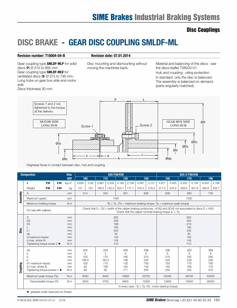
185P-8518-SG | BRC10141-01-C 2/18 SIME Brakes Stromag +33 (0)1 49 90 32 20
Revision number: T10004-04-B Revision date: 07.01.2014
DISC BRAKE - GEAR DISC COUPLING SMLDF-ML
Disc mounting and dismounting without moving the machines back.
p L
Ød3
Ød1k e L1
ØD
ØD2
ØD5
Ød
ØdpA
Screw 2Screw 1
Gear coupling type SMLDF-MLP for solid discs (P) Ø 315 to 995 mmGear coupling type SMLDF-MLV for ventilated discs (V) Ø 315 to 795 mm.Long hubs on gear box side and motor sideDiscs thickness 30 mm
Degrease faces in contact between disc, hub and coupling
Screws 1 and 2 not tightened to the torque at the delivery
MOTOR SIDELONG HUB
GEAR BOX SIDELONG HUB
Material and balancing of the discs : see the discs leaflet T08020-01.Hub and coupling : oiling protection.In standard. only the disc is balanced.The assembly is balanced on demand. (parts angularly matched).
Designation Disc 625 P30/V30 625-2 P30/V30SDF 100 115 135 150 150 170 190
Asse
mbl
y
J P30 V30 kg.m2 3.826 2.38 3.881 2.435 4.185 2.739 4.567 3.121 4.871 3.425 5.552 4.106 6.552 5.106
Weight P30 V30 kg 151 124 169.3 142.3 204.1 177.1 245.3 218.3 271.2 244.2 328.6 301.6 360.6 333.7
A mm 514 550 581 638 638 683 730
Maximum speed rpm 1500 1200
Maximum braking torque N.m Tb ≤ Tp (Tb = maximum braking torque. Tp = maximum peak torque)
For use with calipersCheck that D – D2 > width of the caliper braking surface (ex.: 4CA2 and 3CA2 not associated to discs D < 445)
Check that the caliper nominal braking torque is ≤ Tp
Disc
D D2 D5 L L1 dp d maximum keyed d max. shrink fit Tightening torque screw 2
mm mm mm mm mm mm mm mm N.m
625 238 168 195 200 30 120 105 410
625 300 216 195 200 30
150 135 710
Coup
ling
d3 e k p d1 maximum keyed d1 max. shrink fit Tightening torque screws 1
mm mm mm mm mm mm N.m
200 5
150 166.5 100 92 60
228 5
170 182.5 115 106 95
266 6
185 198 135 125 171
298 6
215 225 150 140 235
298 6
215 225 150 140 235
330 8
245 239 170 160 235
368 8
295 236 190 175 370
Maximum peak torque (Tp) N.m 6000 9400 13800 20700 25300 36700 52500
Transmissible torque (Tt) N.m 3000 4700 6900 10350 12650 18350 26250
In every case : Ts < Tp (Ts : motor starting torque)
: greased under head and on thread
Disc Couplings
SIME Brakes Industrial Braking Systems
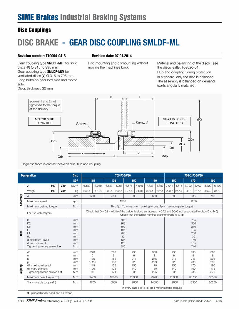
186 SIME Brakes Stromag +33 (0)1 49 90 32 20 P-8518-SG | BRC10141-01-C 2/18
Revision number: T10004-04-B Revision date: 07.01.2014
DISC BRAKE - GEAR DISC COUPLING SMLDF-ML
Disc mounting and dismounting without moving the machines back.
p L
Ød3
Ød1k e L1
ØD
ØD2
ØD5
Ød
ØdpA
Screw 2Screw 1
Gear coupling type SMLDF-MLP for solid discs (P) Ø 315 to 995 mmGear coupling type SMLDF-MLV for ventilated discs (V) Ø 315 to 795 mm.Long hubs on gear box side and motor sideDiscs thickness 30 mm
Degrease faces in contact between disc, hub and coupling
Screws 1 and 2 not tightened to the torque at the delivery
MOTOR SIDELONG HUB
GEAR BOX SIDELONG HUB
Material and balancing of the discs : see the discs leaflet T08020-01.Hub and coupling : oiling protection.In standard. only the disc is balanced.The assembly is balanced on demand. (parts angularly matched).
Designation Disc 705 P30/V30 705-2 P30/V30
SDF 115 135 150 170 150 170 190
Asse
mbl
y
J P30 V30 kg.m2 6.189 3.959 6.523 4.293 6.875 4.645 7.537 5.307 7.041 4.811 7.722 5.492 8.722 6.492
Weight P30 V30 kg 203.4 170.4 238.4 205.4 276.6 243.6 330.4 297.4 290.7 257.7 348.1 315.1 380.2 347.2
A mm 550 581 638 683 638 683 730
Maximum speed rpm 1300 1200
Maximum braking torque N.m Tb ≤ Tp (Tb = maximum braking torque. Tp = maximum peak torque)
For use with calipersCheck that D – D2 > width of the caliper braking surface (ex.: 4CA2 and 3CA2 not associated to discs D < 445)
Check that the caliper nominal braking torque is ≤ Tp
Disc
D D2 D5 L L1 dp d maximum keyed d max. shrink fit Tightening torque screw 2
mm mm mm mm mm mm mm mm N.m
705 268 190 195 200 30
135 120 550
705 300 216 195 200 30 150 135 710
Coup
ling
d3 e k p d1 maximum keyed d1 max. shrink fit Tightening torque screws 1
mm mm mm mm mm mm N.m
228 5
170 182.5 115 106 95
266 6
185 198 135 125 171
298 6
215 225 150 140 235
330 8
245 239 170 160 235
298 6
215 225 150 140 235
330 8
245 239 170 160 235
368 8
295 236 190 175 370
Maximum peak torque (Tp) N.m 9400 13800 25300 29200 25300 36700 52500
Transmissible torque (Tt) N.m 4700 6900 12650 14600 12650 18350 26250
In every case : Ts < Tp (Ts : motor starting torque))
: greased under head and on thread
Disc Couplings
SIME Brakes Industrial Braking Systems
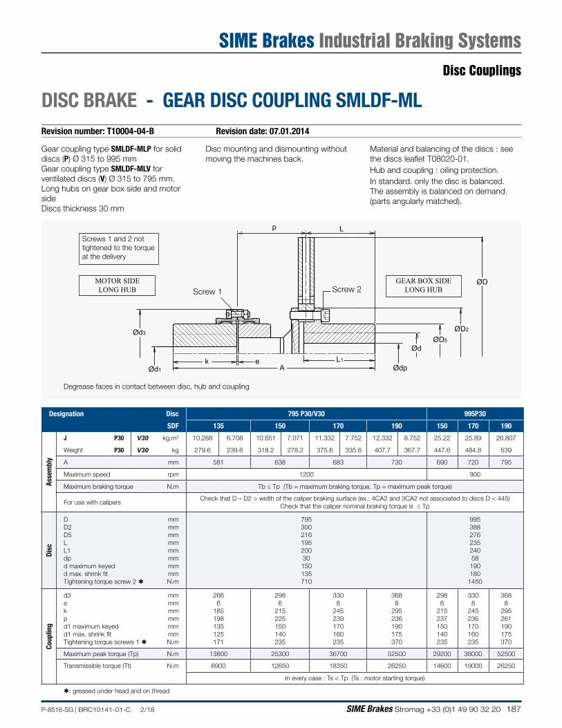
187P-8518-SG | BRC10141-01-C 2/18 SIME Brakes Stromag +33 (0)1 49 90 32 20
Revision number: T10004-04-B Revision date: 07.01.2014
DISC BRAKE - GEAR DISC COUPLING SMLDF-ML
Disc mounting and dismounting without moving the machines back.
p L
Ød3
Ød1k e L1
ØD
ØD2
ØD5
Ød
ØdpA
Screw 2Screw 1
Gear coupling type SMLDF-MLP for solid discs (P) Ø 315 to 995 mmGear coupling type SMLDF-MLV for ventilated discs (V) Ø 315 to 795 mm.Long hubs on gear box side and motor sideDiscs thickness 30 mm
Degrease faces in contact between disc, hub and coupling
Screws 1 and 2 not tightened to the torque at the delivery
MOTOR SIDELONG HUB
GEAR BOX SIDELONG HUB
Material and balancing of the discs : see the discs leaflet T08020-01.Hub and coupling : oiling protection.In standard. only the disc is balanced.The assembly is balanced on demand. (parts angularly matched).
Designation Disc 795 P30/V30 995P30
SDF 135 150 170 190 150 170 190
Asse
mbl
y
J P30 V30 kg.m2 10.288 6.708 10.651 7.071 11.332 7.752 12.332 8.752 25.22 25.89 26.807
Weight P30 V30 kg 279.6 239.6 318.2 278.2 375.6 335.6 407.7 367.7 447.6 484.8 539
A mm 581 638 683 730 690 720 795
Maximum speed rpm 1200 900
Maximum braking torque N.m Tb ≤ Tp (Tb = maximum braking torque. Tp = maximum peak torque)
For use with calipersCheck that D – D2 > width of the caliper braking surface (ex.: 4CA2 and 3CA2 not associated to discs D < 445)
Check that the caliper nominal braking torque is ≤ Tp
Disc
D D2 D5 L L1 dp d maximum keyed d max. shrink fit Tightening torque screw 2
mm mm mm mm mm mm mm mm N.m
795 300 216 195 200 30 150 135 710
995 388 276 235 240 58 190 180 1450
Coup
ling
d3 e k p d1 maximum keyed d1 max. shrink fit Tightening torque screws 1
mm mm mm mm mm mm N.m
266 6
185 198 135 125 171
298 6
215 225 150 140 235
330 8
245 239 170 160 235
368 8
295 236 190 175 370
298 6
215 237 150 140 235
330 8
245 236 170 160 235
368 8
295 261 190 175 370
Maximum peak torque (Tp) N.m 13800 25300 36700 52500 29200 38000 52500
Transmissible torque (Tt) N.m 6900 12650 18350 26250 14600 19000 26250
In every case : Ts < Tp (Ts : motor starting torque)
: greased under head and on thread
Disc Couplings
SIME Brakes Industrial Braking Systems
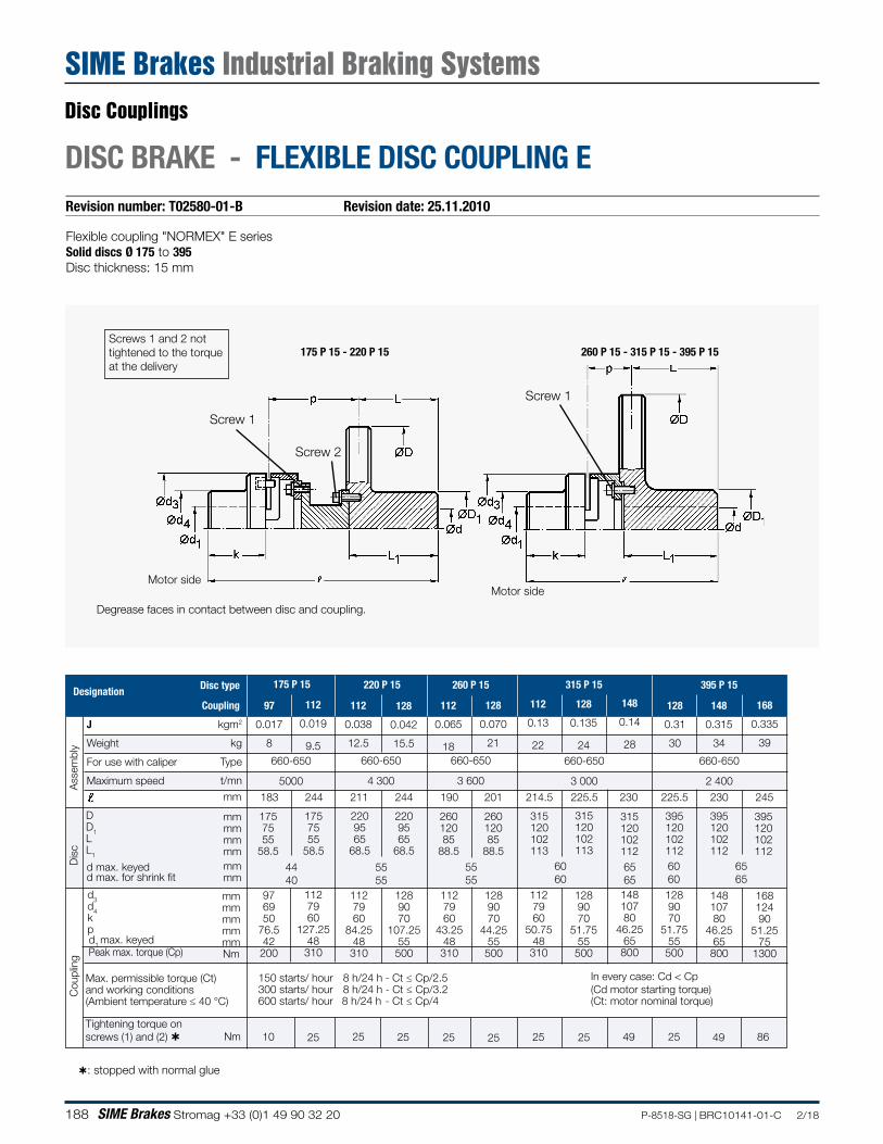
188 SIME Brakes Stromag +33 (0)1 49 90 32 20 P-8518-SG | BRC10141-01-C 2/18
Revision number: T02580-01-B Revision date: 25.11.2010
DISC BRAKE - FLEXIBLE DISC COUPLING E
Flexible coupling "NORMEX" E seriesSolid discs Ø 175 to 395Disc thickness: 15 mm
260 P 15 - 315 P 15 - 395 P 15175 P 15 - 220 P 15
: stopped with normal glue
Motor side
Screw 2
Screw 1
Motor side
Degrease faces in contact between disc and coupling.
Screw 1
26012085
88.5
2209565
68.5
2209565
68.5
315120102113
128
0.135
24
Designation175 P 15
97
0.017
8
1757555
58.5
112
0.019
9.5
1757555
58.5
112
0.038
12.5
128
0.042
15.5
260 P 15
112
0.065
18
26012085
88.5
128
0.070
21
315 P 15
112
0.13
22
315120102113
220 P 15
148
0.14
28
315120102112
395 P 15
128
0.31
30
395120102112
148
0.315
34
395120102112
168
0.335
39
395120102112
183 244 211 245230225.5230225.5214.5201190244
4440
5555
6060
5555
6565
6060
6565
1289070
51.7555500
976950
76.542200
1127960
127.2548310
1127960
84.2548
310
1289070
107.2555500
1127960
43.2548310
1289070
44.2555500
1127960
50.7548310
14810780
46.2565800
1289070
51.7555500
14810780
46.2565800
16812490
51.2575
1300
Ass
embl
yD
isc
150 starts/ hour 8 h/24 h - Ct ≤ Cp/2.5300 starts/ hour 8 h/24 h - Ct ≤ Cp/3.2600 starts/ hour 8 h/24 h - Ct ≤ Cp/4
J
Weight
For use with caliper
Maximum speed
Max. permissible torque (Ct)and working conditions(Ambient temperature ≤ 40 °C)
Tightening torque on screws (1) and (2) Nm
660-650
3 600
660-650
4 300
660-650
5000
660-650
3 000
660-650
2 400
d3d4kp
DD1LL1
mmmmmmmmmmNm
Disc type
Coupling
mmmmmmmm
kgm2
kg
Type
t/mn
Cou
plin
g
d max. keyedd max. for shrink fit
d1 max. keyed
mmmm
mm
2510 25 25 25 25 25 25 49 25 49 86
Peak max. torque (Cp)
In every case: Cd < Cp(Cd motor starting torque)(Ct: motor nominal torque)
Screws 1 and 2 not tightened to the torque at the delivery
Disc Couplings
SIME Brakes Industrial Braking Systems
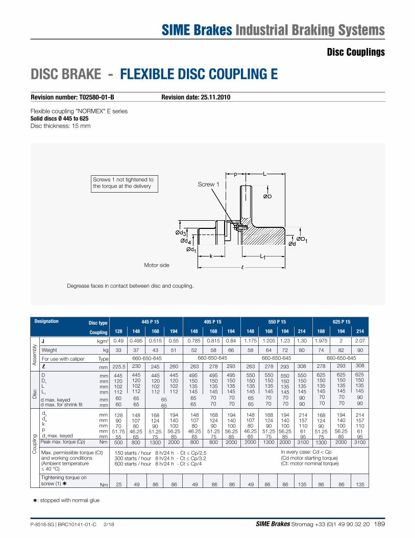
189P-8518-SG | BRC10141-01-C 2/18 SIME Brakes Stromag +33 (0)1 49 90 32 20
Revision number: T02580-01-B Revision date: 25.11.2010
DISC BRAKE - FLEXIBLE DISC COUPLING E
Flexible coupling "NORMEX" E seriesSolid discs Ø 445 to 625Disc thickness: 15 mm
Degrease faces in contact between disc and coupling.
: stopped with normal glue
Screw 1
Motor side
Designation
J
Weight
For use with caliper
Max. permissible torque (Ct) and working conditions(Ambient temperature≤ 40 °C)
DD1LL1
660-650-645
Disc type
Coupling
kgm2
kg
Type
150 starts / hour 8 h/24 h - Ct ≤ Cp/2.5300 starts / hour 8 h/24 h - Ct ≤ Cp/3.2600 starts / hour 8 h/24 h - Ct ≤ Cp/4
mmmmmmmm
445120102112
445120102112
230
445120102112
245
6565
660-650-645
445120102112
260
495150135145
263
6565
495150135145
278
550150135145
293
625150135145
625150135145
308
550150135145
308
9090
495150135145
293
550150135145
278
550150135145
263
660-650-645 660-650-645
293Ass
embl
y
168
1.975
74
194
2
82
214
2.07
90
214
1.30
80
194
1.23
72
168
1.205
64
148
1.175
58
194
0.84
66
168
0.815
58
148
0.785
52
194
0.55
51
168
0.515
43
148
0.495
37
128
0.49
33
445 P 15 495 P 15 550 P 15 625 P 15
7070
7070
7070
7070
6565
7070
9090
7070
625150135145
278
Tightening torque on screw (1) Nm 25 49 86 86 49 86 86 86 8686 49 135 86 135
Peak max. torque (Cp)
d3d4kp
1289070
51.7555
500
16812490
51.2575
1300
194140100
56.2585
2000
14810780
46.2565800
16812490
51.2575
800
194140100
56.2585
2000
194140100
56.2585
2000
2141571106195
3100
2141571106195
3100
194140100
56.2585
2000
16812490
51.2575
1300
14810780
46.2565
2000
mmmmmmmmmmNm
d1 max. keyed
14810780
46.2565
800
16812490
51.2575
1300
225.5
6060
6565
Cou
plin
gD
isc
mm
d max. keyedd max. for shrink fit
mmmm
In every case: Cd < Cp(Cd motor starting torque)(Ct: motor nominal torque)
Screws 1 not tightened to the torque at the delivery
Disc Couplings
SIME Brakes Industrial Braking Systems
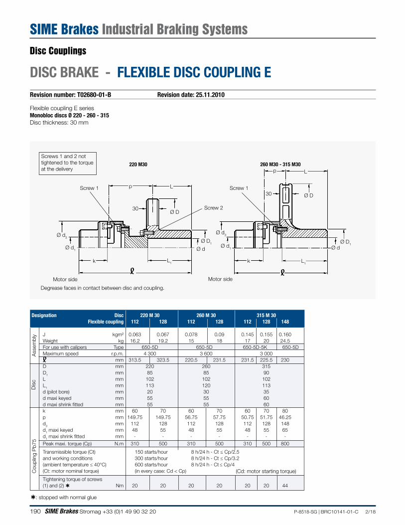
190 SIME Brakes Stromag +33 (0)1 49 90 32 20 P-8518-SG | BRC10141-01-C 2/18
Revision number: T02680-01-B Revision date: 25.11.2010
DISC BRAKE - FLEXIBLE DISC COUPLING E
Designation Disc 220 M 30 260 M 30 315 M 30 Flexible coupling 112 128 112 128 112 128 148
J kgm² 0.063 0.067 0.078 0.09 0.145 0.155 0.160 Weight kg 16.2 19.2 15 18 17 20 24.5 For use with calipers Type 650-5D 650-5D 650-5D-5K 650-5D Maximum speed r.p.m. 4 300 3 600 3 000 mm 313.5 323.5 220.5 231.5 231.5 225.5 230 D mm 220 260 315 D1 mm 85 85 90 L mm 102 102 102 L1 mm 113 120 113 d (pilot bore) mm 20 30 35 d maxi keyed mm 55 55 60 d maxi shrink fitted mm 55 55 60 k mm 60 70 60 70 60 70 80 p mm 149.75 149.75 56.75 57.75 50.75 51.75 46.25 d3 mm 112 128 112 128 112 128 148 d1 maxi keyed mm 48 55 48 55 48 55 65 d1 maxi shrink fitted mm - - - - - - - Peak maxi. torque (Cp) N.m 310 500 310 500 310 500 800
Transmissible torque (Ct) 150 starts/hour 8 h/24 h - Ct ≤ Cp/2.5 and working conditions 300 starts/hour 8 h/24 h - Ct ≤ Cp/3.2 (ambient temperature ≤ 40°C) 600 starts/hour 8 h/24 h - Ct ≤ Cp/4 (Ct: motor nominal torque) (in every case: Cd < Cp)
Tightening torque of screws (1) and (2) Nm 20 20 20 20 20 20 44
L
k L1
Ø d
L
Ø D
L1
30
k
Ø d1
Ø d3
p
Ø D
Ø D1Ø d1
Ø d3
Ø d
30
Ø D1
Screw 1
Screw 2
Screw 1
220 M30 260 M30 - 315 M30
Ass
embl
yD
isc
Cou
plin
g P
b75
p
Flexible coupling E seriesMonobloc discs Ø 220 - 260 - 315Disc thickness: 30 mm
Motor sideMotor side
Degrease faces in contact between disc and coupling.
(Cd: motor starting torque)
: stopped with normal glue
Screws 1 and 2 not tightened to the torque at the delivery
Disc Couplings
SIME Brakes Industrial Braking Systems
191P-8518-SG | BRC10141-01-C 2/18 SIME Brakes Stromag +33 (0)1 49 90 32 20
DISC BRAKE - FLEXIBLE DISC COUPLING SVK AND SDKRevision number: T02810-01-A Revision date: 15.01.2004
Flexible couplings series SVK and SDKVentilated Discs thickness : 30 mmDisc mounting and dismounting without moving the machines back
• Rubber element V• Rubber element D(specify type of rubber element with order)
Screws greased under head and on thread.
Degrease faces in contact between disc and coupling.
Cd: motor starting torque. In all cases. Cd < Cmax
Option:• Solid disc
MOTOR SIDE
s
m n
sØa Øb Øc Ød1
p L
ØD2
ØD
ØD5Ød
L1L2
Screw 1 Screw 2
Disc Ø V30 315 315 355 395 445 445 495 550 550 625 705 705 795 705 795
Flexible coupling SVK/SDK 125 145 170 200 230 260 300 400
Asse
mbl
y
J kg.m² 0.159 0.174 0.26 0.404 0.633 0.704 1.183 1.495 1.713 2.663 4.193 4.53 6.91 6.524 8.904Weight kg 20 24 28 36 45 53 77 83 109 117 128 147 210 222 286
For use with calipers 650-5 650-5650-5 645
650-5 645
650-5 645
650-5 645
650-5645-4
650-5645-4-3
650-5645-4-3
650-5645-4-3
4-34-32TB
4-32TB
1TSA2TB
1TSAMaximum speed r.p.m. 3000 3000 2700 2400 2100 2100 1800 1800 1800 1500 1300 1300 1200 1300 1200L2 244 264.5 264.5 278 311 336 350 350 386.5 386.5 386.5 417.5 417.5 464 464
Disc
ØD mm 315 315 355 395 445 445 495 550 550 625 705 705 795 705 795ØD2 mm 125 125 145 165 175 175 220 220 220 235 265 265 300 265 300ØD5 mm 80 80 95 105 110 110 150 150 150 150 180 180 210 180 210Ød max keyed or shrink fit
mm 50 50 60 70 70 70 100 100 100 100 120 120 130 120 130
L mm 102 102 102 102 135 135 135 135 135 135 135 135 135 135 135L1 mm 107 107 107 107 140 140 140 140 140 140 140 140 140 140 140
Coup
ling
Øa mm 129 153 153 170 170 210 230 230 260 260 260 300 300 400 400Øb mm 100 121 121 137 137 161 184 184 212 212 212 248 248 328 328Øc mm 80 100 100 112 112 126 140 140 168 168 168 190 190 240 240Ød1 max keyed mm 55 70 70 80 80 90 100 100 120 120 120 125 125 150 150m mm 66 75 75 85 85 100 105 105 125 125 125 145 145 175 175n mm 63 74.5 74.5 78 78 88 97 97 113.5 113.5 113.5 124.5 124.5 141 141p mm 76 87.5 87.5 91 91 101 110 110 126.5 126.5 126.5 137.5 137.5 154 154s mm 6 6.5 6.5 7.5 7.5 8.5 9.5 9.5 9.5 9.5 9.5 10 10 10.5 10.5 Max. torque Rubber
element V 630 1050 1660 2880 4500 7200 10400 23400
Cmax in Nm D 1110 1800 2850 4950 7740 11940 17550 40050
Transmissible torque (Ct)(Ct: motor nominal torque)
Ct ≤ Cmax/kCd < Cmax
k min.temperature:rate:
k=3 < 40°c≤ 120starts/h
k=4 < 80°c≤ 240starts/h
k=6 ≤ 80°C≤ 600starts/h
Tightening torque
Screw 1 Nm 45 45 45 75 75 185 185 185 370 370 370 370 370 640 640Screw 2 Nm 49 49 86 135 210 210 290 290 290 410 550 550 710 550 710
Disc Couplings
SIME Brakes Industrial Braking Systems
192 SIME Brakes Stromag +33 (0)1 49 90 32 20 P-8518-SG | BRC10141-01-C 2/18
Revision number: T02815-01-A Revision date: 15.01.2004
DISC BRAKE - FLEXIBLE DISC COUPLING SVKL AND SDKL
Flexible couplings series SVKL and SDKLVentilated Discs thickness : 30 mmDisc mounting and dismounting without moving the machines back
• Rubber element V• Rubber element D(specify type of rubber element with order)
Screws greased under head and on thread.
Degrease faces in contact between disc and coupling.
Cd: motor starting torque. In all cases, Cd < Cmax
Option:• Solid disc
MOTOR SIDE
s
m n
sØa Øb Øc Ød1
p L
ØD2
ØD
ØD5Ød
L1L2
Screw 1 Screw 2
Disc Ø V30 315 315 355 395 445 445 495 550 550 625 705 705 795 705 795
Flexible coupling SVKL/SDKL 125 145 170 200 230 260 300 400
Asse
mbl
y
J kg.m² 0.161 0.177 0.26 0.41 0.64 0.709 1.2 1.512 1.76 2.71 4.24 4.59 6.97 6.788 9.168Weight kg 21.5 26 30 40 49 55.5 84 90 122 130 141 160 223 259 323
For use with calipers 650-5 650-5650-5 645
650-5 645
650-5 645
650-5 645
650-5645-4
650-5645-4-3
650-5645-4-3
650-5645-4-3
4-34-32TB
4-32TB
1TSA2TB
1TSAMaximum speed r.p.m. 3000 3000 2700 2400 2100 2100 1800 1800 1800 1500 1300 1300 1200 1300 1200L2 286.5 298 298 331.5 364.5 364.5 412.5 412.5 469 469 469 480 480 576.5 576.5
Disc
ØD mm 315 315 355 395 445 445 495 550 550 625 705 705 795 705 795ØD2 mm 125 125 145 165 175 175 220 220 220 235 265 265 300 265 300ØD5 mm 80 80 95 105 110 110 150 150 150 150 180 180 210 180 210Ød max keyed or shrink fit
mm 50 50 60 70 70 70 100 100 100 100 120 120 130 120 130
L mm 102 102 102 102 135 135 135 135 135 135 135 135 135 135 135L1 mm 107 107 107 107 140 140 140 140 140 140 140 140 140 140 140
Coup
ling
Øa mm 129 153 153 170 170 210 230 230 260 260 260 300 300 400 400Øb mm 100 121 121 137 137 161 184 184 212 212 212 248 248 328 328Øc mm 80 100 100 112 112 126 140 140 168 168 168 190 190 240 240Ød1 max keyed mm 55 70 70 80 80 90 100 100 120 120 120 125 125 150 150m mm 108.5 108.5 108.5 138.5 138.5 128.5 167.5 167.5 207.5 207.5 207.5 207.5 207.5 287.5 287.5n mm 63 74.5 74.5 78 78 88 97 97 113.5 113.5 113.5 124.5 124.5 141 141p mm 76 87.5 87.5 91 91 101 110 110 126.5 126.5 126.5 137.5 137.5 154 154s mm 6 6.5 6.5 7.5 7.5 8.5 9.5 9.5 9.5 9.5 9.5 10 10 10.5 10.5 Max. torque Rubber
element V 630 1050 1660 2880 4500 7200 10400 23400
Cmax in Nm D 1110 1800 2850 4950 7740 11940 17550 40050
Transmissible torque (Ct)(Ct: motor nominal torque)
Ct ≤ Cmax/kCd < Cmax
k min.temperature:rate:
k=3 < 40°c≤ 120starts/h
k=4 < 80°c≤ 240starts/h
k=6 ≤ 80°C≤ 600starts/h
Tightening torque
Screw 1 Nm 45 45 45 75 75 185 185 185 370 370 370 370 370 640 640Screw 2 Nm 49 49 86 135 210 210 290 290 290 410 550 550 710 550 710
Disc Couplings
SIME Brakes Industrial Braking Systems
193P-8518-SG | BRC10141-01-C 2/18 SIME Brakes Stromag +33 (0)1 49 90 32 20
DISC BRAKE - FLEXIBLE DISC COUPLING SDKL/SVKL-MLRevision number: T02827-01-A Revision date: 15.01.2004
Degrease faces in contact between disc, hub and coupling.
MOTOR SIDE
Flexible couplings serie SDKL / SVKL-MLP for solid disc (P) diameter 355 to 995 mmFlexible couplings serie SDKL / SVKL-MLV for ventilated (V) diameter 355 to 795 mmFor TDXB and FAV brakes
• Rubber element V• Rubber element D
(specify the type of element with order)
Screws greased under head and on thread. Cd: motor starting torque. In all cases, Cd < Cmax
Disc Ø ... P30/V30 355 395 445 495 550 550 625...-1 625...-2
SDKL/SVKL-ML 145 170 170 230 230 260 260 300
Asse
mbl
y
J P30 | V30 kg.m² 0.396 0.26 0.646 0.41 0.999 0.64 1.724 1.2 2.447 1.507 2.7 1.76 4.116 2.67 4.41 2.964
Weight P30 | V30 kg 42 33 57 46 68.5 53.5 110 92 121 98 157 134 173 146 187 160
Maximum speed r.p.m. 2 700 2 400 2 100 1 800 1 800 1 800 1 500 1 500
L2 351 384.5 424.5 472.5 472.5 529 529 540
Disc
ØD mm 355 395 445 495 550 550 625 625ØD2 mm 145 165 175 220 220 220 235 300ØD5 mm 95 105 110 150 150 150 150 210Ød max keyed or shrink fit
mm 60 70 75 110 110 110 110 140
L mm 155 155 195 195 195 195 195 195L1 mm 160 160 200 200 200 200 200 200
Coup
ling
Øa mm 153 170 170 230 230 260 260 300Øb mm 121 137 137 184 184 212 212 248Øc mm 100 112 112 140 140 168 168 190Ød1 max keyed mm 70 80 80 100 100 120 120 125m mm 108.5 138.5 138.5 167.5 167.5 207.5 207.5 207.5n mm 74.5 78 78 97 97 113.5 113.5 124.5p mm 87.5 91 91 110 110 126.5 126.5 137.5s mm 6.5 7.5 7.5 9.5 9.5 9.5 9.5 10Max. torque Rubber
element V 1 050 1 660 1 660 4 500 4 500 7 200 7 200 10 400
Cmax in Nm D 1 800 2 850 2 850 7 740 7 740 11 940 11 940 17 550
Transmissible torque (Ct)(Ct: motor nominal torque)
Ct ≤ Cmax/kCd < Cmax
k min.temperature:rate:
k=3 < 40°c≤ 120starts/h
k=4 < 80°c≤ 240starts/h
k=6 ≤ 80°C≤ 600starts/h
Tightening torque
Screw 1 Nm 45 75 75 185 185 370 370 370
Screw 2 Nm 86 135 210 290 290 290 410 710
Øa Øb Øc Ød1 ØdØD2ØD5
ØDs
p L
sm n L1
L2
Screw 1
Screw 2
Solid disc (P) or ventiltated disc (V)
Discs thickness 30 mmDisc mounting and dismounting without moving the machines back
Disc Couplings
SIME Brakes Industrial Braking Systems
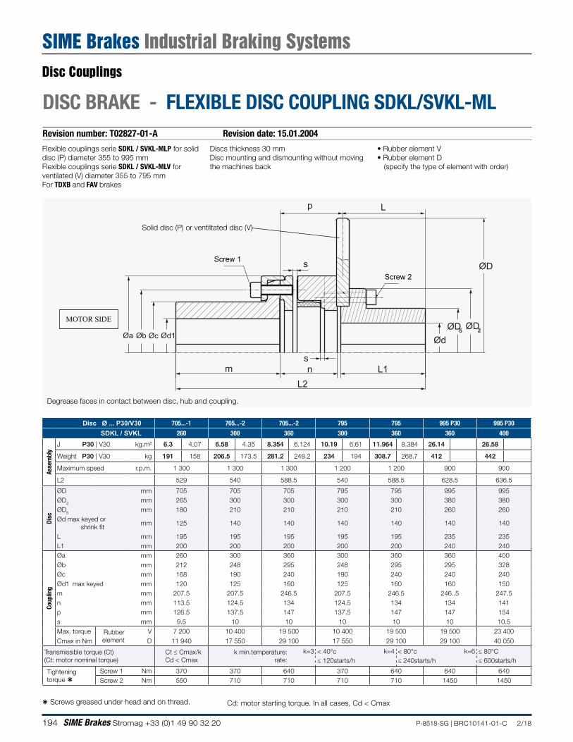
194 SIME Brakes Stromag +33 (0)1 49 90 32 20 P-8518-SG | BRC10141-01-C 2/18
DISC BRAKE - FLEXIBLE DISC COUPLING SDKL/SVKL-MLRevision number: T02827-01-A Revision date: 15.01.2004
Degrease faces in contact between disc, hub and coupling.
MOTOR SIDE
Flexible couplings serie SDKL / SVKL-MLP for solid disc (P) diameter 355 to 995 mmFlexible couplings serie SDKL / SVKL-MLV for ventilated (V) diameter 355 to 795 mmFor TDXB and FAV brakes
• Rubber element V• Rubber element D
(specify the type of element with order)
Screws greased under head and on thread. Cd: motor starting torque. In all cases, Cd < Cmax
Disc Ø ... P30/V30 705...-1 705...-2 705...-2 795 795 995 P30 995 P30
SDKL / SVKL 260 300 360 300 360 360 400
Asse
mbl
y
J P30 | V30 kg.m² 6.3 4.07 6.58 4.35 8.354 6.124 10.19 6.61 11.964 8.384 26.14 26.58
Weight P30 | V30 kg 191 158 206.5 173.5 281.2 248.2 234 194 308.7 268.7 412 442
Maximum speed r.p.m. 1 300 1 300 1 300 1 200 1 200 900 900
L2 529 540 588.5 540 588.5 628.5 636.5
Disc
ØD mm 705 705 705 795 795 995 995ØD2 mm 265 300 300 300 300 380 380ØD5 mm 180 210 210 210 210 260 260Ød max keyed or shrink fit
mm 125 140 140 140 140 140 140
L mm 195 195 195 195 195 235 235L1 mm 200 200 200 200 200 240 240
Coup
ling
Øa mm 260 300 360 300 360 360 400Øb mm 212 248 295 248 295 295 328Øc mm 168 190 240 190 240 240 240Ød1 max keyed mm 120 125 160 125 160 160 150m mm 207.5 207.5 246.5 207.5 246.5 246..5 247.5n mm 113.5 124.5 134 124.5 134 134 141p mm 126.5 137.5 147 137.5 147 147 154s mm 9.5 10 10 10 10 10 10.5Max. torque Rubber
element V 7 200 10 400 19 500 10 400 19 500 19 500 23 400
Cmax in Nm D 11 940 17 550 29 100 17 550 29 100 29 100 40 050
Transmissible torque (Ct)(Ct: motor nominal torque)
Ct ≤ Cmax/kCd < Cmax
k min.temperature:rate:
k=3 < 40°c≤ 120starts/h
k=4 < 80°c≤ 240starts/h
k=6 ≤ 80°C≤ 600starts/h
Tightening torque
Screw 1 Nm 370 370 640 370 640 640 640Screw 2 Nm 550 710 710 710 710 1450 1450
Øa Øb Øc Ød1 ØdØD2ØD5
ØDs
p L
sm n L1
L2
Screw 1
Screw 2
Solid disc (P) or ventiltated disc (V)
Discs thickness 30 mmDisc mounting and dismounting without moving the machines back
Disc Couplings
SIME Brakes Industrial Braking Systems

195P-8518-SG | BRC10141-01-C 2/18 SIME Brakes Stromag +33 (0)1 49 90 32 20
NOTES
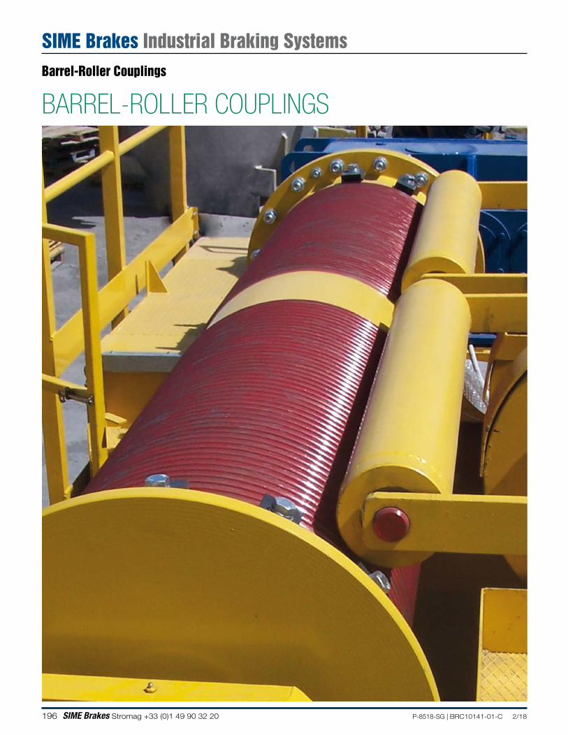
196 SIME Brakes Stromag +33 (0)1 49 90 32 20 P-8518-SG | BRC10141-01-C 2/18
BARREL-ROLLER COUPLINGSBarrel-Roller Couplings
SIME Brakes Industrial Braking Systems
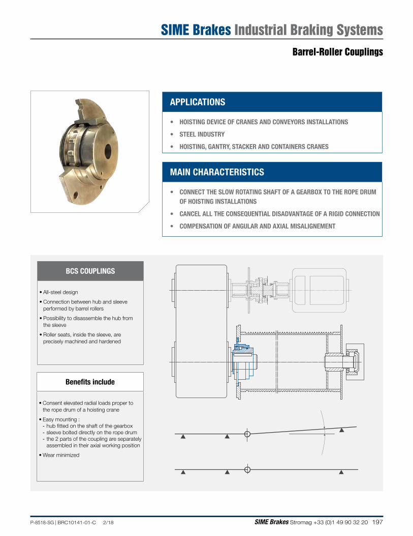
197P-8518-SG | BRC10141-01-C 2/18 SIME Brakes Stromag +33 (0)1 49 90 32 20
BCS COUPLINGS
• All-steel design
• Connection between hub and sleeve performed by barrel rollers
• Possibility to disassemble the hub from the sleeve
• Roller seats, inside the sleeve, are precisely machined and hardened
Benefits include
• Consent elevated radial loads proper to the rope drum of a hoisting crane
• Easy mounting : - hub fitted on the shaft of the gearbox - sleeve bolted directly on the rope drum - the 2 parts of the coupling are separately assembled in their axial working position
• Wear minimized
MAIN CHARACTERISTICS
• CONNECT THE SLOW ROTATING SHAFT OF A GEARBOX TO THE ROPE DRUM OF HOISTING INSTALLATIONS
• CANCEL ALL THE CONSEQUENTIAL DISADVANTAGE OF A RIGID CONNECTION
• COMPENSATION OF ANGULAR AND AXIAL MISALIGNEMENT
APPLICATIONS
• HOISTING DEVICE OF CRANES AND CONVEYORS INSTALLATIONS
• STEEL INDUSTRY
• HOISTING, GANTRY, STACKER AND CONTAINERS CRANES
Barrel-Roller Couplings
SIME Brakes Industrial Braking Systems
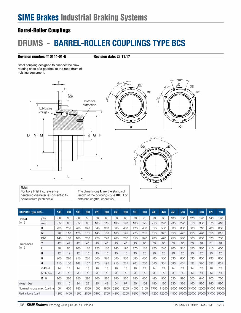
198 SIME Brakes Stromag +33 (0)1 49 90 32 20 P-8518-SG | BRC10141-01-C 2/18
DRUMS - BARREL-ROLLER COUPLINGS TYPE BCSRevision number: T10144-01-B Revision date: 23.11.17
Steel coupling designed to connect the slow rotating shaft of a gearbox to the rope drum of hoisting equipment.
COUPLING type BCS... 140 160 180 200 220 240 260 280 310 340 400 420 450 530 560 600 670 730
Bore d (mm)
pilot 30 30 30 50 50 60 60 60 70 70 90 90 100 100 120 120 140 140
max 65 80 85 95 105 115 130 140 160 175 210 220 235 290 310 330 375 410
Dimensions(mm)
D 230 250 280 320 340 360 380 400 420 450 510 550 580 650 680 710 780 850
M 90 110 120 135 145 163 183 195 225 255 310 325 350 425 455 490 555 615
F h6 140 160 180 200 220 240 260 280 310 340 400 420 450 530 560 600 670 730
T 42 42 42 45 45 45 45 45 45 60 60 60 60 65 65 81 81 81
L 90 95 100 110 125 130 145 170 175 185 220 240 260 315 350 380 410 450
H 12 12 12 15 15 15 15 15 15 20 20 20 20 25 25 25 25 25
N 200 220 250 280 300 320 340 360 380 400 460 500 530 600 630 660 730 800
G 110 130 142 157 175 195 215 231 261 286 346 361 386 461 491 526 591 651
Ø E H8 14 14 14 18 18 18 18 18 18 24 24 24 24 24 24 28 28 28
N° holes 6 6 6 6 6 6 6 6 6 6 6 6 8 8 24 24 24 24
K h9 200 220 250 280 300 320 340 360 380 400 460 500 530 580 600 640 700 760
Weight (kg) 13 16 24 29 35 42 54 67 90 108 150 190 230 395 460 520 740 890
Nominal torque max. (daNm) 50 400 780 1350 1600 1850 2200 3200 4000 5100 7700 11250 13000 19000 31000 42000 54000 75000
Radial force (daN) 1200 1400 1800 2500 3100 3700 4200 5200 6300 7950 11250 12300 14500 20200 25000 30000 34000 39000
T
D
L
d G FN M
H
ØEØE
ØD
K K
ØE
ØD
K
ØEØD
Lubricating charge
Holes for extraction
Nota : For bore finishing, reference centering diameter is concentric to barrel rollers pitch circle.
The dimensions L are the standard length of the couplings type BCS. For different lengths, conult us.
Barrel-Roller Couplings
SIME Brakes Industrial Braking Systems
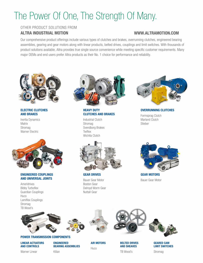
LINEAR ACTUATORS AND CONTROLS
Warner Linear
POWER TRANSMISSION COMPONENTS
ENGINEERED BEARING ASSEMBLIES
Kilian
AIR MOTORS
Huco
GEARED CAMLIMIT SWITCHES
Stromag
GEAR DRIVES
Bauer Gear MotorBoston GearDelroyd Worm GearNuttall Gear
BELTED DRIVESAND SHEAVES
TB Wood’s
OVERRUNNING CLUTCHES
Formsprag ClutchMarland ClutchStieber
ENGINEERED COUPLINGS AND UNIVERSAL JOINTS
AmeridrivesBibby Turbo exGuardian CouplingsHucoLami ex CouplingsStromagTB Wood’s
GEAR MOTORS
Bauer Gear Motor
OTHER PRODUCT SOLUTIONS FROMALTRA INDUSTRIAL MOTION
Our comprehensive product offerings include various types of clutches and brakes, overrunning clutches, engineered bearing assemblies, gearing and gear motors along with linear products, belted drives, couplings and limit switches. With thousands of product solutions available, Altra provides true single source convenience while meeting specific customer requirements. Many major OEMs and end users prefer Altra products as their No. 1 choice for performance and reliability.
HEAVY DUTY CLUTCHES AND BRAKES
Industrial ClutchStromagSvendborg BrakesTwi exWichita Clutch
ELECTRIC CLUTCHES AND BRAKES
Inertia DynamicsMatrixStromagWarner Electric
The Power Of One, The Strength Of Many.
WWW.ALTRAMOTION.COM
Altra Industrial Motion
P-8518-SG | BRC10141-01-C 2/18www.stromag.com
The Brands of Altra Industrial Motion
Couplings
Ameridriveswww.ameridrives.com
Bibby Turbofl ex www.bibbyturbofl ex.com
Guardian Couplingswww.guardiancouplings.com
Hucowww.huco.com
Lamifl ex Couplingswww.lamifl excouplings.com
Stromag www.stromag.com
TB Wood’swww.tbwoods.com
Geared Cam Limit Switches
Stromagwww.stromag.com
Electric Clutches & Brakes
Inertia Dynamicswww.idicb.com
Matrixwww.matrix-international.com
Stromagwww.stromag.com
Warner Electricwww.warnerelectric.com
Linear Products
Warner Linearwww.warnerlinear.com
Engineered Bearing Assemblies
Kilianwww.kilianbearings.com
Heavy Duty Clutches & Brakes
Industrial Clutchwww.indclutch.com
Twifl exwww.twifl ex.com
Stromagwww.stromag.com
Svendborg Brakeswww.svendborg-brakes.com
Wichita Clutchwww.wichitaclutch.com
Belted Drives
TB Wood’s www.tbwoods.com
Gearing
Bauer Gear Motorwww.bauergears.com
Boston Gearwww.bostongear.com
Delroyd Worm Gearwww.delroyd.com
Nuttall Gearwww.nuttallgear.com
Overrunning Clutches
Formsprag Clutchwww.formsprag.com
Marland Clutchwww.marland.com
Stieberwww.stieberclutch.com
Neither the accuracy nor completeness of the information contained in this publication is guaranteed by the company and may be subject to change in its sole discretion. The operating and performance characteristics of these products may vary depending on the application, installation, operating conditions and environmental factors. The company’s terms and conditions of sale can be viewed at http://www.altramotion.com/terms-and-conditions/sales-terms-and-conditions. These terms and conditions apply to any person who may buy, acquire or use a product referred to herein, including any person who buys from a licensed distributor of these branded products.
©2018 by Stromag LLC. All rights reserved. All trademarks in this publication are the sole and exclusive property of Stromag LLC or one of its affi liated companies.
Stromag Facilities
Europe
Germany
Hansastraße 12059425 Unna - Germany+49 (0) 23 03 102 0
Clutches & Brakes, Couplings, Geared Cam Limit Switches, Discs, Wind Brakes
Dessauer Str. 1006844 Dessau-Roßlau - Germany+49 (0) 340 2190 0
Electromagnetic Clutches & Brakes
France
Avenue de l’Europe18150 La Guerche sur L’Aubois - France+33 (0)2 48 80 72 72
Disc Brakes & Drum Brakes
Great Britain
Ampthill RoadBedford, MK42 9RD - UK+44 (0)1234 350311
Electromagnetic Clutches & Brakes, Industrial Caliper Brakes
North America
USA
31 Industrial Park RoadNew Hartford, CT 06057 - USA860-238-4783
Electromagnetic Clutches & Brakes
300 Indiana Highway 212Michigan City, IN 46360 – USA219-874-5248
Couplings
2800 Fisher Rd.Wichita Falls, TX940-723-3400
Geared Cam Limit Switches, Industrial Caliper & Drum Brakes
Asia Pacifi c
China
T40B -5, No. 1765 Chuan Qiao RoadPudong 201206, Shanghai - ChinaTel +86 21-60580600
Clutches & Brakes, Electromagnetic Clutches & Brakes, Couplings, Industrial Caliper & Drum Brakes, Discs, Geared Cam Limit Switches, Wind Brakes
India
Gat No.: 448/14, Shinde Vasti, NighojeTal Khed, Pune- 410 501+91 2135 622100
Clutches & Brakes, Electromagnetic Clutches & Brakes, Couplings, Industrial Caliper & Drum Brakes, Discs, Geared Cam Limit Switches, Wind Brakes
Related Documents