SIMATIC Windows Automation Center RTX Open Development Kit (WinAC ODK) _ _____________ _ _____________ _ _____________ _ _____________ Product overview and installation 1 CCX - Custom Code Extension 2 SMX - Shared Memory Extension 3 CMI - Controller Management Interface 4 SIMATIC Windows Automation Center RTX Open Development Kit (WinAC ODK) Programming Manual 04/2009 A5E00340326-02 This document is part of the WinAC ODK V4.2 package with order number: 6ES7806-1CC03-0BA0

Welcome message from author
This document is posted to help you gain knowledge. Please leave a comment to let me know what you think about it! Share it to your friends and learn new things together.
Transcript

SIMATIC Windows Automation Center RTX Open Development Kit (WinAC ODK)
____________________________
____________________________
Product overview and installation 1
CCX - Custom Code Extension
2
SMX - Shared Memory Extension
3
CMI - Controller Management Interface
4
SIMATIC
Windows Automation Center RTXOpen Development Kit (WinAC ODK)
Programming Manual
04/2009 A5E00340326-02
This document is part of the WinAC ODK V4.2 package with order number: 6ES7806-1CC03-0BA0

Legal information Legal information Warning notice system
This manual contains notices you have to observe in order to ensure your personal safety, as well as to prevent damage to property. The notices referring to your personal safety are highlighted in the manual by a safety alert symbol, notices referring only to property damage have no safety alert symbol. These notices shown below are graded according to the degree of danger.
DANGER indicates that death or severe personal injury will result if proper precautions are not taken.
WARNING indicates that death or severe personal injury may result if proper precautions are not taken.
CAUTION with a safety alert symbol, indicates that minor personal injury can result if proper precautions are not taken.
CAUTION without a safety alert symbol, indicates that property damage can result if proper precautions are not taken.
NOTICE indicates that an unintended result or situation can occur if the corresponding information is not taken into account.
If more than one degree of danger is present, the warning notice representing the highest degree of danger will be used. A notice warning of injury to persons with a safety alert symbol may also include a warning relating to property damage.
Qualified Personnel The device/system may only be set up and used in conjunction with this documentation. Commissioning and operation of a device/system may only be performed by qualified personnel. Within the context of the safety notes in this documentation qualified persons are defined as persons who are authorized to commission, ground and label devices, systems and circuits in accordance with established safety practices and standards.
Proper use of Siemens products Note the following:
WARNING Siemens products may only be used for the applications described in the catalog and in the relevant technical documentation. If products and components from other manufacturers are used, these must be recommended or approved by Siemens. Proper transport, storage, installation, assembly, commissioning, operation and maintenance are required to ensure that the products operate safely and without any problems. The permissible ambient conditions must be adhered to. The information in the relevant documentation must be observed.
Trademarks All names identified by ® are registered trademarks of the Siemens AG. The remaining trademarks in this publication may be trademarks whose use by third parties for their own purposes could violate the rights of the owner.
Disclaimer of Liability We have reviewed the contents of this publication to ensure consistency with the hardware and software described. Since variance cannot be precluded entirely, we cannot guarantee full consistency. However, the information in this publication is reviewed regularly and any necessary corrections are included in subsequent editions.
Siemens AG Industry Sector Postfach 48 48 90026 NÜRNBERG GERMANY
A5E00340326-02 Ⓟ 03/2009
Copyright © Siemens AG 2009. Technical data subject to change

Open Development Kit (WinAC ODK) Programming Manual, 04/2009, A5E00340326-02 3
Table of contents
1 Product overview and installation .............................................................................................................. 7
1.1 Overview ........................................................................................................................................7 1.2 What's new?...................................................................................................................................8 1.3 System requirements .....................................................................................................................9 1.4 Installing WinAC ODK..................................................................................................................10
2 CCX - Custom Code Extension ............................................................................................................... 11 2.1 Overview ......................................................................................................................................11 2.1.1 What is WinAC ODK CCX? .........................................................................................................11 2.1.2 Process solutions with STEP 7 and CCX ....................................................................................12 2.1.3 CCX program overview................................................................................................................13 2.1.4 STEP 7 program overview...........................................................................................................14 2.1.5 Synchronous or asynchronous execution?..................................................................................14 2.1.6 Documentation organization ........................................................................................................15 2.2 Development tasks ......................................................................................................................16 2.2.1 Creating a CCX object with the application wizard......................................................................16 2.2.1.1 Configuring project information....................................................................................................16 2.2.1.2 Entering CCX project subcommands...........................................................................................17 2.2.1.3 Enabling asynchronous processing .............................................................................................19 2.2.1.4 Enabling asynchronous monitoring..............................................................................................21 2.2.1.5 Specifying vendor information......................................................................................................23 2.2.1.6 Generating the application wizard project....................................................................................24 2.2.2 Programming the CCX application ..............................................................................................24 2.2.2.1 Programming task overview.........................................................................................................24 2.2.2.2 Programming the CCX extension object......................................................................................25 2.2.2.3 Programming asynchronous events ............................................................................................28 2.2.2.4 Programming monitor threads .....................................................................................................30 2.2.2.5 Building the extension object .......................................................................................................32 2.2.2.6 Developing C# or VB CCX applications.......................................................................................34 2.2.3 Programming the STEP 7 program to call the CCX extension object .........................................35 2.2.3.1 Loading the WinAC ODK library into STEP 7 ..............................................................................35 2.2.3.2 Creating and executing the CCX extension object from the STEP 7 program............................36 2.2.4 Debugging the CCX extension object..........................................................................................38 2.2.4.1 Debugging tasks ..........................................................................................................................38 2.2.4.2 Building a debug version..............................................................................................................38 2.2.4.3 Updating the STEP 7 project to use a new extension object.......................................................39 2.2.4.4 Testing your software...................................................................................................................40 2.2.4.5 Replacing an extension object .....................................................................................................41 2.2.4.6 Ending a debug session...............................................................................................................41 2.2.4.7 Updating the release version of the extension object ..................................................................42 2.3 CCX references ...........................................................................................................................42 2.3.1 CCX support software..................................................................................................................42 2.3.2 STEP 7 WinAC ODK SFB references .........................................................................................43 2.3.2.1 SFB65001 references ..................................................................................................................43 2.3.2.2 SFB65002 references ..................................................................................................................45 2.3.2.3 SFB65003 references ..................................................................................................................46

Table of contents
Open Development Kit (WinAC ODK) 4 Programming Manual, 04/2009, A5E00340326-02
2.3.3 CCX data access helper classes ................................................................................................ 48 2.3.4 Auxiliary STEP 7 interface functions........................................................................................... 49 2.3.4.1 ODK_ReadState.......................................................................................................................... 49 2.3.4.2 ODK_ScheduleOB ...................................................................................................................... 50 2.3.4.3 ODK_CreateThread .................................................................................................................... 52 2.3.4.4 Functions for reading and writing controller data........................................................................ 52 2.3.4.5 Functions for cyclic reads............................................................................................................ 53 2.3.4.6 Functions for getting STEP 7 block information.......................................................................... 55 2.3.4.7 Memory areas and data types for reading and writing................................................................ 56 2.3.4.8 ODK_DATA_STRUCT................................................................................................................. 56 2.3.5 CCX object web .......................................................................................................................... 58 2.4 Examples..................................................................................................................................... 58 2.4.1 CCX_SyncVsAsync example program........................................................................................ 58 2.4.1.1 Differences between synchronous and asynchronous use of the CCX extension object .......... 58 2.4.1.2 Introduction to the CCX _SyncVsAsync example program......................................................... 59 2.4.1.3 Overview of the CCX program .................................................................................................... 60 2.4.1.4 Overview of the STEP 7 user program ....................................................................................... 60 2.4.1.5 Building the CCX_SyncVsAsync extension object...................................................................... 61 2.4.1.6 Retrieving and running the STEP 7 CCX_SyncVsAsync program ............................................. 61 2.4.1.7 Using the STEP 7 program and calling the CCX extension object ............................................. 62 2.4.2 Examples of auxiliary STEP 7 function usage ............................................................................ 63 2.4.2.1 Example: scheduling an OB........................................................................................................ 63 2.4.2.2 Example: creating a separate thread of execution ..................................................................... 64 2.4.2.3 Example: reading and writing controller data.............................................................................. 65 2.4.2.4 Example: implementing cyclic reads........................................................................................... 66 2.4.2.5 Example: accessing STEP 7 block information .......................................................................... 68 2.4.3 Additional CCX example programs............................................................................................. 70 2.4.4 GNU C++ example program for CCX ......................................................................................... 72
3 SMX - Shared Memory Extension............................................................................................................ 73 3.1 Overview ..................................................................................................................................... 73 3.1.1 Documentation organization ....................................................................................................... 74 3.2 Development tasks...................................................................................................................... 74 3.2.1 Creating an SMX project with the application wizard.................................................................. 74 3.2.1.1 Configuring project information ................................................................................................... 75 3.2.1.2 Specifying vendor information..................................................................................................... 76 3.2.1.3 Generating the application wizard project................................................................................... 76 3.2.2 Programming the SMX application ............................................................................................. 77 3.2.3 Programming the STEP 7 program to use SMX......................................................................... 79 3.2.4 Debugging an SMX object .......................................................................................................... 80 3.2.5 Considering scan cycle impact ................................................................................................... 80 3.2.6 Ensuring data consistency .......................................................................................................... 80 3.3 SMX references .......................................................................................................................... 81 3.3.1 SMX support software................................................................................................................. 81 3.3.2 SMX object web .......................................................................................................................... 82 3.4 Examples..................................................................................................................................... 82 3.4.1 SMX_Start example program...................................................................................................... 82 3.4.1.1 Using the SMX_Start C++ program ............................................................................................ 82 3.4.1.2 Using the SMX_Start STEP 7 program....................................................................................... 84 3.4.2 Additional SMX example programs............................................................................................. 85 3.4.3 Example: using the block copy functions .................................................................................... 88 3.4.4 Example: using the array of boolean functions........................................................................... 89 3.4.5 GNU C++ example program for SMX ......................................................................................... 90
Table of contents
Open Development Kit (WinAC ODK) Programming Manual, 04/2009, A5E00340326-02 5
4 CMI - Controller Management Interface................................................................................................... 91 4.1 Overview ......................................................................................................................................91 4.1.1 Capabilities of the FeatureProvider .............................................................................................91 4.1.2 CMI Type Libraries (DLLs)...........................................................................................................92 4.1.3 Interfaces of the Feature Provider ...............................................................................................93 4.1.4 Methods of the IPLC Interface .....................................................................................................94 4.1.5 Methods of the IFeature Interface................................................................................................97 4.1.6 Methods of the IFeatureCallback Interface................................................................................104 4.2 Features and attributes of WinLC RTX......................................................................................106 4.2.1 About attributes..........................................................................................................................110 4.2.2 List of WinLC RTX features and attributes ................................................................................111 4.2.2.1 AutoStart ....................................................................................................................................111 4.2.2.2 ControllerHelp ............................................................................................................................112 4.2.2.3 CPULanguage ...........................................................................................................................112 4.2.2.4 CPU Usage Extended................................................................................................................113 4.2.2.5 Diagnostic ..................................................................................................................................113 4.2.2.6 DiagnosticLanguage ..................................................................................................................114 4.2.2.7 Error ...........................................................................................................................................114 4.2.2.8 Failsafe CPU..............................................................................................................................115 4.2.2.9 HW DataStorage........................................................................................................................115 4.2.2.10 HW LEDs ...................................................................................................................................116 4.2.2.11 KeySwitch ..................................................................................................................................117 4.2.2.12 LED ............................................................................................................................................118 4.2.2.13 MemoryCardFile (MCF) .............................................................................................................119 4.2.2.14 MinCycleTime ............................................................................................................................120 4.2.2.15 MinSleepTime ............................................................................................................................120 4.2.2.16 OBExecution ..............................................................................................................................121 4.2.2.17 Personality .................................................................................................................................122 4.2.2.18 PLC ............................................................................................................................................123 4.2.2.19 PLCInstance...............................................................................................................................123 4.2.2.20 PLC Memory Size ......................................................................................................................124 4.2.2.21 Priority ........................................................................................................................................124 4.2.2.22 Security ......................................................................................................................................125 4.2.2.23 SpeedStep .................................................................................................................................126 4.2.2.24 StartAtBoot.................................................................................................................................127 4.2.2.25 Timing ........................................................................................................................................127 4.3 Development tasks ....................................................................................................................128 4.3.1 Including the Controller Management Interface type libraries ...................................................128 4.3.2 Including the feature and attribute definitions ............................................................................129 4.3.3 Accessing the IPLC and IFeature interfaces .............................................................................130 4.3.4 Including the IFeatureCallback interface ...................................................................................132 4.3.5 Browsing for available PLCs......................................................................................................134 4.3.6 Connecting to a PLC..................................................................................................................135 4.3.7 Getting attributes of a PLC feature ............................................................................................137 4.3.8 Setting attribute values of a PLC feature ...................................................................................139 4.3.9 Responding to changed feature attribute values in the PLC .....................................................141 4.3.10 Responding to loss of PLC connection......................................................................................144 4.3.11 Disconnecting from a PLC .........................................................................................................147 4.3.12 Programming tips and error handling ........................................................................................148 4.4 CMI references...........................................................................................................................149 4.4.1 CMI object web ..........................................................................................................................149 4.4.2 Visual C++ ATL project use of IFeatureCallback interface........................................................150 4.5 Examples ...................................................................................................................................151

Table of contents
Open Development Kit (WinAC ODK) 6 Programming Manual, 04/2009, A5E00340326-02
4.5.1 Introduction to the CMI example programs............................................................................... 151 4.5.2 CMI_Connect_To_PLC example program ................................................................................ 152 4.5.3 CMI_Get_And_Set_Feature example program ......................................................................... 153 4.5.4 CMI_Register_For_Feature_Change example program ........................................................... 154 4.5.5 Additional CMI example programs............................................................................................ 155 4.5.6 GNU C++ example programs for CMI....................................................................................... 156
Index...................................................................................................................................................... 157

Open Development Kit (WinAC ODK) Programming Manual, 04/2009, A5E00340326-02 7
Product overview and installation 11.1 Overview
The Windows Automation Center Open Development Kit (WinAC ODK) is an open interface to WinLC RTX. It provides a set of tools that enables you to implement custom software in high-level programming languages that works with WinLC RTX. WinAC ODK supports three types of programming interfaces: ● CCX - Custom Code Extension ● SMX - Shared Memory Extension ● CMI - Controller Management Interface
CCX CCX provides tools for you to implement a DLL or RTDLL from a high-level programming language environment. Your STEP 7 user program can call this DLL or RTDLL (extension object) from an SFB. The CCX chapter (Page 11) describes the full set of CCX features, contains software references, and explains the use of CCX through an example program.
SMX SMX provides tools for you to create an application in a high-level programming language that executes separately from your STEP 7 user program. The SMX application and the STEP 7 user program can read and write controller data using a shared memory area. The SMX chapter (Page 73) describes the full set of SMX features, contains software references, and explains the use of SMX through an example program.
CMI CMI provides tools for you to create an application in a high-level programming language that can read and write specific WinLC RTX features and attributes. Your application can access controller data such as status indicators, mode selector switch position, diagnostic buffer data, and tuning panel data through a set of provided function calls. The CMI chapter (Page 91) describes the full set of CMI features, contains software references, and explains the use of CMI through an example program.

Product overview and installation 1.2 What's new?
Open Development Kit (WinAC ODK) 8 Programming Manual, 04/2009, A5E00340326-02
1.2 What's new?
New features The following features are new in WinAC ODK: ● Ability to call a CCX extension object asynchronously from SFB65003 in the STEP 7
program (Page 36) ● CCX data access functions for copying and replacing the WinAC RTX work memory
(Page 48) ● CCX auxiliary STEP 7 functions for obtaining time/date stamp, checksum, and length
information for STEP 7 blocks (Page 55) ● CCX interface functions to detect when a DB has been created, downloaded, or deleted
(Page 25) ● Improved error recovery such that CCX applications with improper RTX exception
handling do not jeopardize WinAC RTX execution, or the execution of other WinAC ODK applications
● Programming language support for C# and VB for CCX and SMX Windows applications in addition to support for C/C++ for both Windows and RTSS applications
● SMX functions for reading and writing arrays of booleans (Page 89) ● SMX functions for reading and writing blocks of the shared memory segment (Page 88) ● Support for debugging CCX RTDLLs in Visual Studio V6.0 (Page 38). ● Combination of CCX, SMX, and CMI documentation into a single help system with
corresponding PDF version for printing purposes ● Updated example programs for CCX (Page 58) , SMX (Page 82) , and CMI (Page 151) in
the supported programming languages
Obsolete features The following features are no longer supported by WinAC ODK: ● Support for the WinAC Slot controllers: CPU 412-2 PCI and CPU 416-2 PCI ● Support for WinLC Basis ● Support for Borland Delphi for CMI applications

Product overview and installation 1.3 System requirements
Open Development Kit (WinAC ODK) Programming Manual, 04/2009, A5E00340326-02 9
1.3 System requirements To install WinAC ODK and execute WinAC ODK applications your computer must satisfy the hardware and software requirements listed below.
Hardware requirements To use WinAC ODK, your personal computer (PC) must meet the following criteria: ● 512 Mbytes RAM ● Approximately 30 Mbytes on your hard disk ● At least 1 Mbyte free memory capacity on drive C for the Setup program (Setup files are
deleted when the installation is complete.)
Software requirements To use WinAC ODK, your personal computer (PC) must have the following software installed: ● Microsoft Windows XP Professional SP 2 or SP3 ● For WinAC ODK CCX and SMX: WinLC RTX V4.4 or WinLC RTX V4.5 ● For WinAC ODK CMI: WinLC RTX V4.2 or higher ● Internet Explorer 6.0 (or higher), for viewing product documentation ● An integrated development environment (IDE) from the following list:
– Microsoft Visual C++ 6.0 SP 5 or higher – Microsoft Visual C++ .NET 2003 – Microsoft Visual C++ 2005 or 2008 – Microsoft Visual Basic 2005 or 2008 – Microsoft Visual C# 2005 or 2008 WinAC ODK also supports the following IDEs for some CMI example programs from previous releases of WinAC ODK: – Microsoft Visual Basic 6.0 SP5 – Microsoft Visual Basic .NET 2003 – Microsoft Visual C# .NET 2003
Note For developing CCX real-time projects, you must have the IntervalZero Software Development Kit (SDK) version 8.1. The IntervalZero SDK is not required for non-realtime projects that run in Windows only. For running C# or VB CCX extension objects on a computer other than the computer where the extension object was built, the runtime computer must have Visual Studio 2005, Visual Studio 2008, or the .NET 2.0 Framework.

Product overview and installation 1.4 Installing WinAC ODK
Open Development Kit (WinAC ODK) 10 Programming Manual, 04/2009, A5E00340326-02
1.4 Installing WinAC ODK Before installing WinAC ODK, ensure that your computer meets the system requirements (Page 9).
Note Do not install WinAC ODK or any other component of WinAC on a computer while any other component of WinAC is executing (running) on that computer. Because SIMATIC Computing, WinAC controllers, and other elements of WinAC use common files, attempting to install any component of the WinAC software when any of the components of WinAC are executing can corrupt the software files. Close all programs that are running before you install WinAC ODK.
To install WinAC ODK, follow these steps: 1. Insert the WinAC ODK installation CD. 2. Follow the step-by-step instructions that the Setup program displays. You can switch to
the next step or to the previous step from any step of the installation.
Installing WinAC ODK when a version is already installed If the Setup program finds another version of WinAC ODK on your computer, it displays a dialog that allows you to modify, repair or remove the installation. Select Remove on this dialog to uninstall the previous version. Repeat the installation procedure to install. Your software is better organized if you uninstall any older versions before installing the new version. Overwriting an old version with a new version has the disadvantage that if you then uninstall, any remaining components of the old version are not removed.
Uninstalling (removing) To remove the WinAC ODK software, follow these steps: 1. Select the Start > Settings > Control Panel menu command to display the Windows
control panel. 2. Double-click the Add/Remove Programs icon to display the Add/Remove Programs
Properties dialog box. 3. Select the entry for the SIMATIC WinAC Open Development Kit and click the Remove
button. 4. Follow the dialog instructions to remove the software.
Note Commands in instruction steps may vary depending on your operating system.

Open Development Kit (WinAC ODK) Programming Manual, 04/2009, A5E00340326-02 11
CCX - Custom Code Extension 22.1 Overview
2.1.1 What is WinAC ODK CCX? WinAC ODK is an engineering package that enables you to program custom software in a high-level programming language and create a DLL or RTDLL that your STEP 7 program logic can call directly. The Custom Code Extension (CCX) interface of WinAC ODK provides this interface between a STEP 7 program and a DLL or RTDLL (CCX extension object) that you create with the WinAC ODK programming tools. For example, without using the Open Development Kit, consider a process that uses a motion control board and a vision board and requires a custom application to interact between the two boards. The STEP 7 user program in WinLC RTX can monitor and modify the motion and vision board I/O through STEP 7 asynchronous read/write functions or perform process control through an OPC interface, but the STEP 7 user program and the custom application are not integrated. By using the CCX interface of WinAC ODK, you can create a custom application that works directly with the STEP 7 user program. The STEP 7 user program can access the motion control board or vision board through a DLL or RTDLL that CCX helps you create. The interface between the custom application and the STEP 7 user program is provided by the CCX interface. You can program whatever custom software your application requires in the CCX extension object.
Using CCX to expand the capabilities of the STEP 7 user program Because CCX enables you to integrate custom software into your control program, you can expand the capabilities of a STEP 7 user program. The following situations are examples where CCX can provide benefits: ● Incorporating special control logic that was written in Visual Basic, Visual C++, or C# ● Using a complex or proprietary calculation (such as PID or gas flow), which has higher
performance requirements or is more easily written and maintained in a high-level programming language

CCX - Custom Code Extension 2.1 Overview
Open Development Kit (WinAC ODK) 12 Programming Manual, 04/2009, A5E00340326-02
● Connecting with other applications or hardware, such as motion control or vision systems ● Accessing features of the computer that are not accessible by standard S7 control
languages WinAC ODK CCX supports the Visual Basic, Visual C++ and Visual C# programming languages, and compilers Microsoft Visual C++ V6.0, Microsoft Visual C++ .NET, Microsoft Visual Studio 2005 and Microsoft Visual Studio 2008.
Note WinAC ODK supports only Windows DLLs for C#, VB, and Visual C++ 2008. WinAC ODK supports both RTSS RTDLLs and Windows DLLs for Visual C++ 6.0, Visual C++ .NET 2003, and Visual C++ 2005.
2.1.2 Process solutions with STEP 7 and CCX WinAC ODK CCX provides tools for you to implement a DLL or RTDLL from a high-level programming language environment. WinAC ODK includes an application wizard (Page 16) from which you create the initial project for your extension object. Using your programming environment, you then develop software specific to your application (Page 24) and generate a DLL or RTDLL (CCX extension object). You can program your STEP 7 user program (Page 35) to create the DLL or RTDLL and to execute this DLL or RTDLL according to the requirements of your application.
① You use the WinAC ODK Application Wizard and your programming environment to create and
program a DLL or RTDLL with your custom CCX software. ② You call predefined System Function Blocks from the STEP 7 program to create and execute
your extension object (RTDLL or DLL).

CCX - Custom Code Extension 2.1 Overview
Open Development Kit (WinAC ODK) Programming Manual, 04/2009, A5E00340326-02 13
Programming language support WinAC ODK CCX supports the following programming languages, environments, and types of extension objects: Programming Language
Compiler Environments Release extension object
C/C++ Microsoft Visual C++ V6.0 Microsoft Visual C++ .NET Microsoft Visual C++ 2005
RTSS RTDLL (requires use of IntervalZero SDK V8.1) or Windows DLL
C/C++ Microsoft Visual C++ 2008 Windows DLL Visual Basic Microsoft Visual Basic 2005
Microsoft Visual Basic 2008 Windows DLL
C# Microsoft Visual C# 2005 Microsoft Visual C# 2008
Windows DLL
2.1.3 CCX program overview The CCX program contains the custom C++, VB, or C# software for your application. Typically, you create a CCX project with the WinAC ODK Application Wizard, program the CCX interface functions that the wizard creates, program custom software according to the requirements of your application using the auxiliary STEP 7 interface functions, and build a DLL or RTDLL that the STEP 7 program can create and execute.
WinAC ODK Application Wizard You create the initial CCX program with the WinAC ODK Application Wizard (Page 16). Here you will select your programming language and compiler.
CCX interface functions The wizard creates a shell program with empty CCX interface functions (Page 25) that you program according to the requirements of your application. These functions execute under the following circumstances: ● When the STEP 7 user program creates the extension object ● When the STEP 7 user program executes the extension object, either synchronously or
asynchronously. ● When WinLC RTX transitions from STOP to STARTUP, from HALT to RUN, or when the
extension object is first created ● When WinLC RTX transitions to STOP or HALT mode

CCX - Custom Code Extension 2.1 Overview
Open Development Kit (WinAC ODK) 14 Programming Manual, 04/2009, A5E00340326-02
Auxiliary STEP 7 interface functions Auxiliary STEP 7 interface functions (Page 49) allow the CCX program to perform these tasks: ● Schedule an OB for execution ● Read the current operating state of the controller ● Read and write data to and from the controller ● Read information about STEP 7 blocks ● Create separate threads of execution
Restrictions Because you can configure WinLC RTX to start automatically when the computer restarts, you must be aware of some restrictions on what your CCX custom software can do. For example, if your software activates a graphical user interface (GUI), that interface would not be visible after a reboot. The interface (GUI) needs to be a separate process started in a user context with communication to your extension object, possibly through shared memory.
2.1.4 STEP 7 program overview The STEP 7 program is responsible for executing the CCX custom software. WinAC ODK provides a STEP 7 library that enables the STEP 7 program to perform the following tasks: ● Create a CCX extension object by calling SFB65001, for example from the OB100 startup
OB. ● Execute the CCX extension object synchronously within the scan cycle by calling
SFB65002. ● Execute the CCX extension object asynchronously outside of the scan cycle by calling
SFB65003. Whether you execute the CCX extension object synchronously or asynchronously (Page 14) depends upon the specific characteristics of your application. The chapter "Programming the STEP 7 program to call the CCX extension object (Page 35)" describes how to include the WinAC ODK library and use the WinAC ODK SFBs. The topic "STEP 7 WinAC ODK SFB references (Page 43)" defines the input parameters that the STEP 7 program must set to create or execute a CCX extenstion object, and the output parameters that the CCX extension object returns to the STEP 7 program.
2.1.5 Synchronous or asynchronous execution? The STEP 7 program can execute a CCX extension object either synchronously with SFB65002 or asynchronously with SFB65003. Synchronous execution occurs within the scan cycle. Asynchronous execution does not.

CCX - Custom Code Extension 2.1 Overview
Open Development Kit (WinAC ODK) Programming Manual, 04/2009, A5E00340326-02 15
Choosing SFB65002 or SFB65003 CCX extension objects created by SFB65002 run to completion within the scan cycle, and can therefore have a negative impact on the cycle time. Use these guidelines to help you to decide whether to call your extension object from SFB65002 (EXEC_COM) or SFB65003 (ASYN_COM): ● Use SFB65002 if the time required to execute the software in your extension object is
inconsequential to the total scan time. ● Use SFB65002 if subsequent processing in your STEP 7 user program is dependent on
the results of the CCX extension object execution. ● Use SFB65003 if your custom software can take a long time relative to your scan time
requirements. ● Use SFB65003 for all CCX extension objects that are Windows DLLs. ● Use SFB65003 or the asynchronous processor for software that calls Windows functions.
Windows functions such as Rtprintf and others are non-deterministic; thus you cannot predict the impact on the scan cycle.
2.1.6 Documentation organization The following chapters teach you how to develop a WinAC ODK Custom Code Extension (CCX) application: : The Development tasks (Page 16) chapter contains the following sections: ● Creating a CCX object with the application wizard (Page 16): This section explains how to
use the application wizard to specify configuration options and create a program shell for your custom CCX extension object.
● Programming the CCX application (Page 24): This section describes how to implement software in the CCX functions of the program shell created by the application wizard.
● Programming the STEP 7 program to call the CCX extension object (Page 35): This section explains how to load the WinAC ODK library that contains CCX-specific SFBs into your STEP 7 program. It describes the CCX SFBs and how to use them in your STEP 7 user program to call the CCX extension object.
● Debugging the CCX extension object (Page 38): This section describes how to debug extension object software using the Microsoft Visual C++ debugger.
The CCX references (Page 42) chapter describes the data access helper classes, the WinAC ODK STEP 7 library, and the CCX functions that interface with the STEP 7 program data. This chapter also displays the CCX object web that provides detailed information about the CCX software interfaces, including all function headers, parameter descriptions, and related type and constant definitions. Use the object web together with the information in this chapter when developing your CCX application. The Examples (Page 58) chapter describes the functionality and implementation of the CCX_SyncVsAsync example program. Read the documentation in this chapter, execute and experiment with the CCX_SyncVsAsync sample programs on your PC, and view the CCX interfaces for this program in the CCX object web to learn how to use CCX from an example application. In addition to CCX_SyncVsAsync example program, this chapter also includes small examples of the use of auxiliary STEP 7 functions (Page 63).
CCX - Custom Code Extension 2.2 Development tasks
Open Development Kit (WinAC ODK) 16 Programming Manual, 04/2009, A5E00340326-02
2.2 Development tasks
2.2.1 Creating a CCX object with the application wizard The application wizard helps you perform the following tasks: ● Define project information for the CCX extension object (Page 16) ● Configure subcommands for your extension object (optional) (Page 17) ● Create classes that you can use to execute functions asynchronously from the WinLC
RTX scan cycle (optional) (Page 19) ● Create classes that you can use to asynchronously monitor one or more attributes of your
system (optional) (Page 21) ● Specify vendor information to uniquely identify your project (optional) (Page 23) ● Generate the CCX project (Page 24)
Note The application wizard produces unmanaged code for C/C++, managed code for Visual Basic and C#.
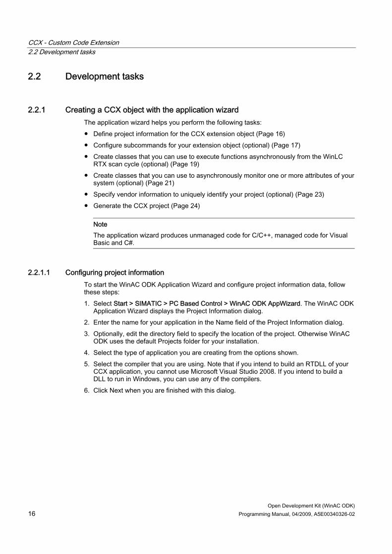
2.2.1.1 Configuring project information To start the WinAC ODK Application Wizard and configure project information data, follow these steps: 1. Select Start > SIMATIC > PC Based Control > WinAC ODK AppWizard. The WinAC ODK
Application Wizard displays the Project Information dialog. 2. Enter the name for your application in the Name field of the Project Information dialog. 3. Optionally, edit the directory field to specify the location of the project. Otherwise WinAC
ODK uses the default Projects folder for your installation. 4. Select the type of application you are creating from the options shown. 5. Select the compiler that you are using. Note that if you intend to build an RTDLL of your
CCX application, you cannot use Microsoft Visual Studio 2008. If you intend to build a DLL to run in Windows, you can use any of the compilers.
6. Click Next when you are finished with this dialog.

CCX - Custom Code Extension 2.2 Development tasks
Open Development Kit (WinAC ODK) Programming Manual, 04/2009, A5E00340326-02 17
A project information dialog for a CCX project is shown below:
2.2.1.2 Entering CCX project subcommands
What is a subcommand? You can organize your CCX custom logic to use subcommands. A subcommand is a unique function within your CCX program that the Execute function of your extension object can call when SFB65002 (EXEC_COM) or SFB65003 (ASYN_COM) starts the DLL or RTDLL execution. By using subcommands, you can create one RTDLL or DLL that performs a variety of tasks, rather than using several RTDLLs or DLLs that perform single tasks. From the STEP 7 program, you specify which subcommand to call in the Command parameter for SFB65002 or SFB65003. When your STEP 7 program calls SFB65002 or SFB65003, the SFB calls the Execute function of your DLL or RTDLL, which in turn calls the subcommand function specified by the Command parameter.

CCX - Custom Code Extension 2.2 Development tasks
Open Development Kit (WinAC ODK) 18 Programming Manual, 04/2009, A5E00340326-02
Configuring subcommands from the WinAC ODK application wizard When you click Next on the Project Information dialog, you see the CCX Subcommands dialog as shown below. You use this dialog to add or delete subcommands for your C/C++ program:
To configure the subcommands for your extension object, follow these steps as needed: 1. Click the Add button to add a new subcommand. 2. Enter the command name and number index in the CCX SubCommand dialog, and click
OK.
3. Click Next on the CCX Subcommands dialog when you have finished subcommand
configuration.
Note If you need to delete a subcommand, highlight the subcommand in the CCX Subcommands window and click the Delete button. If you need to rename a subcommand, first delete the subcommand, and then add it using the new name.

CCX - Custom Code Extension 2.2 Development tasks
Open Development Kit (WinAC ODK) Programming Manual, 04/2009, A5E00340326-02 19
Making changes to subcommand structure from the programming environment The application wizard requires that you specify at least one subcommand; however, your RTDLL or DLL does not have to make use of subcommands. If you do not have more than one type of task for your custom software to perform, you can implement the custom software directly in the Execute function and eliminate the subcommand functions produced by the application wizard. Similarly if you choose to add more subcommands than at the time you created the project using the application wizard, you can add them from your programming environment.
2.2.1.3 Enabling asynchronous processing If you configure asynchronous processing with the WinAC ODK Application Wizard, you are setting up separate events in your extension object that will allow functions to execute outside of the main thread of execution. Regardless of whether you configure asynchronous processing with the application wizard, you can, however, execute any CCX extension object asynchronously by calling it from your STEP 7 program with SFB65003. These are two separate means of accomplishing asynchronous exection.
Asynchronous execution from SFB65003 (ASYN_COM) WinAC ODK V4.2 introduces SFB65003, which enables your STEP 7 user program to call the CCX extension object asynchronously. The custom logic in your CCX extension object then executes on a separate thread asynchronously from the scan cycle. The time to execute the software in the CCX extension object does not affect the scan cycle. If you use SFB65003 to execute your DLL or RTDLL asynchronously, you do not need to configure asynchronous events in your project from the WinAC ODK Application Wizard.
Asynchronous processing with asynchronous events Prior to the introduction of SFB65003 in WinAC ODK, STEP 7 executed CCX extension objects only through SFB65002. The CCX extension object ran within the scan cycle, but could accomplish asynchronous execution through the use of asynchronous events. Although SFB65003 now provides asynchronous execution of the CCX extension object, WinAC ODK and the Application Wizard still support the use of asynchronous event processing within the CCX extension object and the use of monitor threads (Page 21) to monitor the progress of those events. Asynchronous processing allows specific functions to be executed outside of the main Execute function. These commands can then be executed without penalizing the controller scan cycle, even if the STEP 7 program used SFB65002 for synchronous execution of the extension object. The asynchronous processor uses objects derived from the CEventMsg class to carry out event-specific functions. Asynchronous processing is optional, and with the introduction of SFB65003 rarely needed.
Note You do not select SFB65002 or SFB65003 (Page 14) for your CCX extension object when you are creating the project from the WinAC ODK Application Wizard. Rather, you make this choice when you program the STEP 7 program (Page 35).
To use asynchronous processing in your WinAC ODK project to create a thread of execution separate from the CCX extension object thread, follow these steps:

CCX - Custom Code Extension 2.2 Development tasks
Open Development Kit (WinAC ODK) 20 Programming Manual, 04/2009, A5E00340326-02
1. From the Asynchronous Processing dialog of the application wizard, select the Include Asynchronous Processing check box.
2. Choose a thread priority. A background priority means that the thread executes at a lower
priority than the main execution thread. A foreground priority means that the thread executes at a higher priority than the main execution thread and is to be used only with extreme caution.
3. Click the Add button to add an asynchronous event. 4. Accept the default or enter the class name for the event in the Asynchronous Event
dialog box, and click OK. The application wizard names the header file and/or source file based on the class name that you entered.

CCX - Custom Code Extension 2.2 Development tasks
Open Development Kit (WinAC ODK) Programming Manual, 04/2009, A5E00340326-02 21
5. Select the type of Event Deletion that you prefer, based on the instructions on the dialog, and click OK.
6. Click Next when you have completed Asynchronous Processing configuration.
Note If you need to delete an asynchronous event, highlight the event on the Asynchronous Processing dialog and click Delete. If you need to rename an asynchronous event, first delete it, and then add it using the new name.
Run-time execution of asynchronous threads The following picture illustrates the execution of a CCX extension object from SFB65002 that uses an asynchronous process thread and a monitor thread. Although the STEP 7 user program executes the extension object synchronously, the extension object uses an asynchronous processor thread for logic that is to be executed on a separate thread outside of the scan cycle, as well as a monitor thread:
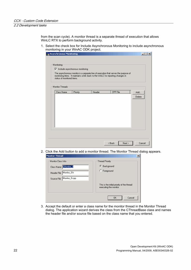
2.2.1.4 Enabling asynchronous monitoring The application wizard displays the Asynchronous Monitoring dialog after the Asynchronous Processing dialog. Like asynchronous processing, asynchronous monitoring is optional. Use asynchronous monitoring if your RTDLL or DLL needs to implement some functionality in the background (for example, to monitor data or wait for an event to occur that is asynchronous
CCX - Custom Code Extension 2.2 Development tasks
Open Development Kit (WinAC ODK) 22 Programming Manual, 04/2009, A5E00340326-02
from the scan cycle). A monitor thread is a separate thread of execution that allows WinLC RTX to perform background activity. 1. Select the check box for Include Asynchronous Monitoring to include asynchronous
monitoring in your WinAC ODK project.
2. Click the Add button to add a monitor thread. The Monitor Thread dialog appears.
3. Accept the default or enter a class name for the monitor thread in the Monitor Thread
dialog. The application wizard derives the class from the CThreadBase class and names the header file and/or source file based on the class name that you entered.

CCX - Custom Code Extension 2.2 Development tasks
Open Development Kit (WinAC ODK) Programming Manual, 04/2009, A5E00340326-02 23
4. Choose a thread priority from the drop-down list. A background priority means that the thread executes at a lower priority than the main execution thread. A foreground priority means that the thread executes at a higher priority than the main execution thread, and is to be used only with extreme caution. Click OK to close the Monitor Thread dialog.
5. Click Next when you have completed asynchronous monitoring configuration.
Note If you need to delete a monitor thread, highlight a monitor thread on the Asynchronous Monitoring dialog and click Delete. If you need to rename a monitor thread, first delete it, and then add it using the new name.
2.2.1.5 Specifying vendor information The Vendor Information dialog allows you to specify the manufacturer, product name, version of product, order information, and a description of the product. All fields on this dialog are optional. WinAC ODK uses your entries to add identification information to your custom application. To uniquely identify your project, enter vendor information on the following dialog:

CCX - Custom Code Extension 2.2 Development tasks
Open Development Kit (WinAC ODK) 24 Programming Manual, 04/2009, A5E00340326-02
2.2.1.6 Generating the application wizard project After you have finished the configuration, the application wizard displays a project summary window with your configured options. If you want to make changes to any of the options shown, click Back and correct the items that you need to change. Ensure that you have entered vendor information that uniquely identifies your project. To direct the application wizard to create the project framework, follow these steps: 1. Click Finish to confirm the project options and to generate the WinAC ODK project. The
application wizard creates the project for you and displays the Project Created dialog. 2. If you are using Microsoft Visual Studio and want to immediately open the project in
Visual Studio, check Open Visual Studio Project. 3. Click Close on the Project Created dialog to dismiss the dialog.
Note If you created a C/C++ project but are not using Microsoft Visual C++, you must use your C++ programming interface to compile the set of .h and .cpp files that the application wizard generates. These files are located in the folder configured on the Project Information dialog of the application wizard. By default, this pathname is: Program Files\Siemens\WinAC\ODK\Projects\<your project name>.
Note To make a new C# or VB CCX application, create it from the application wizard. Do not merely copy an existing project to a new project location. The application wizard creates DLLs that are unique to each project.
2.2.2 Programming the CCX application
2.2.2.1 Programming task overview The WinAC ODK Application Wizard (Page 16) creates a project shell that you use to generate your custom extension object. This project contains the CCX functions that are the interface to the STEP 7 program. If you specified asynchronous events and monitor threads, the project contains classes and functions for them as well. The application wizard creates these functions in the initial project as empty shells. To develop custom software for your specific application, you must perform the following tasks from your programming environment: ● Program the Execute function, subcommand functions (if selected) and any other custom
functions (Page 25) ● Program asynchronous events (Page 28) if your implementation uses asynchronous
events ● Program monitor threads (Page 30) if your implementation uses monitor threads ● Build and debug your extension object (Page 32) When finished, you can create and execute the CCX extension object from your STEP 7 user program (Page 36).

CCX - Custom Code Extension 2.2 Development tasks
Open Development Kit (WinAC ODK) Programming Manual, 04/2009, A5E00340326-02 25
Note To make a new C# or VB CCX application, create it from the application wizard. Do not merely copy an existing project to a new project location. The application wizard creates DLLs that are unique to each project.
2.2.2.2 Programming the CCX extension object
CCX interface functions The project that the Application Wizard creates contains functions, initially empty, that provide the interface to WinLC RTX and the STEP 7 user program: ● ODKCreate (can be left empty) ● Activate (can be left empty) ● Deactivate (can be left empty) ● ODKRelease (can be left empty) ● NotifyDBCreate (can be left empty) ● NotifyDBDelete (can be left empty) ● Execute Your program will also have one or more subcommand functions that the Execute function calls for each subcommand that you configured with the WinAC ODK Application Wizard. You must program the software in these functions for your specific application. CCX guarantees that WinLC RTX calls these functions from a single thread of execution.
ODKCreate function The ODKCreate function is responsible for initializing data or creating objects after the extension object is created. If you have any processing to perform when the extension object is initially created, put it in ODKCreate; otherwise, you can leave this function as is.
Activate function WinLC RTX calls the Activate function of the CCX extension object before it transitions from STOP or HALT mode to STARTUP or RUN mode. Activate is always called after the extension object is created and before the first call to the Execute function. If you have any processing to perform before the first call to Execute, you can put it in the Activate function; otherwise, you can leave this function as is.
Note The CPU is in HALT when it reaches a breakpoint in the STEP 7 editor.
CCX - Custom Code Extension 2.2 Development tasks
Open Development Kit (WinAC ODK) 26 Programming Manual, 04/2009, A5E00340326-02
DeActivate function WinLC RTX calls the DeActivate function after it transitions from STARTUP or RUN mode to STOP or HALT mode. If you have any processing to perform following the transition to STOP or HALT, you can put it in the DeActivate function; otherwise, you can leave this function as is.
Note WinLC RTX releases your extension objects on a memory reset (MRES) or on a controller shutdown. Because both the MRES and controller shutdown first change the controller to STOP mode, WinLC RTX always calls DeActivate before it calls ODKRelease, which releases the RTDLLs and/or DLLs.
ODKRelease function The ODKRelease function is responsible for releasing the extension object. If you have any processing to perform when the object is released, put it in ODKRelease; otherwise, you can leave this function as is.
NotifyDBCreate function WinLC RTX calls the NotifyDBCreate function of the CCX extension object whenever SFC22, SFC82, or SFC85 creates a DB or when STEP 7 downloads a new or changed DB to WinLC RTX. If you have any processing to perform when a DB is created or modified, put it in NotifyDBCreate; otherwise, you can leave this function as is.
NotifyDBDelete function WinLC RTX calls the NotifyDBCreate function of the CCX extension object whenever SFC23 deletes a DB or when someone deletes a DB from the STEP 7 user program and downloads the program to WinLC RTX. If you have any processing to perform when a DB is deleted, put it in NotifyDBDelete; otherwise, you can leave this function as is.
Execute function and subcommands The Execute function is executed when your STEP 7 program calls SFB65002 (EXEC_COM) or SFB65003 (ASYN_COM). From an SFB65002 call, the processing in the Execute function becomes part of the OB execution time. The STEP 7 program can pass parameters to the Execute function, which can, in turn, call subcommand functions based on the input parameters. You implement most of your custom software in the Execute function and the subcommand functions. Typically, your Execute function switches control to one of the subcommand functions based upon the input parameters to the Execute function.
CCX - Custom Code Extension 2.2 Development tasks
Open Development Kit (WinAC ODK) Programming Manual, 04/2009, A5E00340326-02 27
WARNING Scan cycle impact When called from SFB65002 (EXEC_COM), the custom software in the Execute function and the subcommand functions are part of the program scan cycle. The STEP 7 program executes the SFB that calls the CCX custom software as a single instruction. This instruction call is non-interruptible. During the execution of the CCX custom software, the watchdog timer, OBs, and process alarms are not available. They are handled after the SFB call to the CCX custom software completes. Custom software that significantly extends the cycle time delays the processing of critical activities in the controller, which can possibly result in personal injury. When called from SFB65003 (ASYN_COM), the custom software in the Execute function and the subcommand functions are executed on an asynchronous program thread and are not part of the main program scan cycle. To avoid delays in the scan cycle, call extension objects that contain custom logic of a lengthy duration from SFB65003 rather than SFB65002. Alternatively, you can call the extension object from SFB65002, but do not put any processing in the Execute or subcommand functions that would extend the scan cycle beyond an acceptable cycle time. This includes calls to non-deterministic functions such as Printf or RtPrintf. Program asynchronous events to handle custom logic of a lengthy duration. WinAC ODK supports both means of asynchronous processing: • Calling a CCX extension object from SFB65003 to execute the entire extension object
asynchronously • Calling a CCX extension object from SFB65002, which you have programmed to use
asynchronous events to perform specific time-consuming operations asynchronously Either method avoids unwanted delays in the scan cycle.
Programming multiple extension objects You can have more than one extension object, and each extension object can perform multiple tasks. When SFB65001 creates an extension object, it returns a unique program handle. An SFB65002 call uses the program handle of a specific extension object to execute the software in that specific extension object.
Additional classes and functions The C/C++ project produced by the application wizard includes the following classes that you can use in programming your custom application: ● Data access helper classes (Page 48): The application wizard always generates the data
access helper classes, CWinLCReadData and CWinLCReadWriteData. These classes are used to exchange data between the WinLC RTX buffer and the CCX extension object. You do not program custom software in any of the Data access helper class functions. You make calls to these functions to read and write controller memory.
● Asynchronous processor classes (Page 19): The application wizard generates the CThreadBase, CAsyncProc, CQueue, and CEventMsg classes only when you select the

CCX - Custom Code Extension 2.2 Development tasks
Open Development Kit (WinAC ODK) 28 Programming Manual, 04/2009, A5E00340326-02
Asynchronous Processing option. The wizard generates one class, derived from CEventMsg, for each asynchronous event that you request.
● Monitor classes (Page 21): The application wizard generates Monitor classes only when you select the Asynchronous Monitoring option. The wizard creates one class, derived from CThreadBase, for each monitor thread that you request.
The CCX interface also includes auxiliary STEP 7 interface functions (Page 49) that are available for interacting with WinLC RTX. These functions allow you to read the state of the controller, schedule an OB for execution, read and write data directly to WinLC RTX, get block information, and read data from the controller on a cyclic basis.
References The CCX interface functions, the CCX support classes, and the auxiliary STEP 7 interface functions are included in the CCX object web. The example programs provided with WinAC ODK demonstrate the use of many of these functions in actual applications.
Note To access any of the object webs for WinAC ODK, use the online help. Object webs are designed to be navigated from a web browser.
2.2.2.3 Programming asynchronous events You can define events to execute asynchronously on a thread of execution separate from WinLC RTX scan cycle. This allows the extension object to schedule and execute actions that can take a long time while allowing the controller to continue processing. You specify the number of asynchronous events when you set up your project with the application wizard. The asynchronous processor executes each of these events on a thread of execution separate from the scan cycle of the controller.
Note If you intend to execute the CCX extension object from SFB65003 in the STEP 7 program, the entire CCX extension object executes asynchronously. You achieve no advantage by creating and programming asynchronous events. If however, you intend to execute the CCX extension object from SFB65002 in the STEP 7 program, you can use asynchronous events to execute specific time-consuming functions in your program logic asynchronously.
Practical example Consider an example where WinLC RTX controls a stapler assembly line. One of the control program requirements is to send an E-mail notification when supplies are running low. You can program a WinAC ODK extension object to accomplish this task. However, putting all of the E-mail functionality in the Execute function could cause an unacceptable increase in the scan cycle. You could avoid this problem by using the asynchronous processor (AsyncProc) to schedule a "Send E-mail Notification" event. This allows WinLC RTX to maintain a fast scan cycle while sending E-mail at the same time.

CCX - Custom Code Extension 2.2 Development tasks
Open Development Kit (WinAC ODK) Programming Manual, 04/2009, A5E00340326-02 29
WARNING The custom software in the Execute function and the subcommand functions are part of the main program cycle. The STEP 7 program executes the SFB that calls the CCX custom software as a single instruction. This instruction call is non-interruptible. During the execution of the CCX custom software, the watchdog timer, OBs, and process alarms are not available. They are handled after the SFB call to the CCX custom software completes. Custom software that significantly extends the cycle time delays the processing of critical activities in the controller, which can possibly result in personal injury.
Asynchronous processor classes Asynchronous processing uses the following C++ classes: ● CAsyncProc: This class processes events posted to it on a thread of execution separate
from the main program. ● CEventMsg: This is the base class for asynchronous events. All asynchronous events
posted to the asynchronous processor must be derived from this class. The Execute function must be overloaded in the derived class to provide custom processing for the event.
● CQueue: This is a basic queue (first in, first out) class. The asynchronous processor uses it for scheduling events to process.
The application wizard adds an event class derived from the CEventMsg base class for each asynchronous event that you add, for example, CEvent_0. The Execute function of each event class is where you implement your asynchronous processing code and is indicated by the line below: // TODO: Add Code to customize this Event
Note If you add asynchronous event classes outside of the application wizard, you must also derive them from the CEventMsg class and implement the asynchronous event processing code in its Execute function.
Scheduling asynchronous event processing To schedule asynchronous event processing, you must implement code in the global Execute function that is called during the main control program scan cycle or in one of the Execute subcommands. The Execute function of the main program cycle must perform the following tasks: 1. Create an object of the derived event class using the "new" operator. 2. Call the ScheduleEvent function of the CAsyncProc class to post the event to the
asynchronous processor.

CCX - Custom Code Extension 2.2 Development tasks
Open Development Kit (WinAC ODK) 30 Programming Manual, 04/2009, A5E00340326-02
3. Call the GetStatus function of the event class to determine if the event has been processed.
4. Call the GetResult function of the event class to get the success/fail status returned from the event's Execute function.
Deallocating asynchronous events You are responsible for creating the event object on the heap (for example, using the "new" operator). You can specify deallocation either by the asynchronous processor or by your code, depending on whether or not your application requires post-processing status information. You can specify this choice through the application wizard, or you can use the SetDelTime function to set the deallocation method.
References The CCX object web includes all of the classes, functions, and data structures that support asynchronous event programming.
Note To access any of the object webs for WinAC ODK, use the online help. Object webs are designed to be navigated from a web browser.
2.2.2.4 Programming monitor threads You can use monitor classes to provide one or more separate lines of execution for WinAC ODK to monitor events external to its process. With the application wizard, you can configure whether or not your application uses asynchronous monitoring and the number of monitor threads that you need. The application wizard creates a monitor thread class for each thread, derived from the base class, CThreadBase. You can create monitor thread classes outside of the application wizard, but they must be derived from the CThreadBase class. The application wizard creates a function shell for the Execute function of each monitor class, in which you program the thread monitoring loop. Place all custom processing or monitoring immediately following the comment block containing this phrase: // TODO: Add Customized Monitoring Code here
The CCX object web includes one monitor thread, CMonitor_0 derived from CThreadBase. If your application uses a monitor thread, you would implement code in the Execute function of CMonitor_0.
Monitor thread considerations When WinLC RTX creates an extension object that has been configured or programmed to use monitor threads, it starts a separate thread of execution for each monitor thread. The software in a monitor thread runs asynchronously from your main program thread. If an event such as a controller shutdown or memory reset causes your extension object to be released, WinLC RTX calls the DeActivate function of the extension object main execution thread. The Deactivate function calls PauseThread for each monitor thread, which

CCX - Custom Code Extension 2.2 Development tasks
Open Development Kit (WinAC ODK) Programming Manual, 04/2009, A5E00340326-02 31
sets a variable named m_ThreadPaused to true. WinLC RTX then calls the ODKRelease function, which calls StopThread for each monitor thread. The StopThread function sets a variable named m_ExitThread to true, and then signals the monitor threads to resume execution so that they can terminate appropriately. The thread monitoring loop of the Execute function must check the variable m_ExitThread to determine whether to continue execution or to exit. It must also check the m_ThreadPaused variable to determine whether or not to suspend execution. The Execute function created by application wizard contains the necessary checks of m_ExitThread and m_ThreadPaused. The Execute function produced by the application wizard includes two ways of handling the thread monitoring loop. The first version uses a polling scheme. If the thread is not paused and is not to be stopped, it sleeps for an interval of 100 milliseconds and then continues with the thread monitoring loop. If the thread is paused, it waits for a signal to resume. If your monitor thread does not wait on events, use the polling version to control your thread monitoring loop. The second version is for use when you implement the monitor thread to wait for a signal from a monitored event. If your monitor thread uses external events, comment out Version 1 of the thread monitoring loop, and uncomment Version 2 of the thread monitoring loop. Add code to Version 2 as needed to wait for a signal that the monitored external event has completed. Implement a customized StopThread for your monitor thread that signals that the external event is finished as well as signalling the monitor thread itself. Your StopThread function must provide code to cause your main thread loop to terminate.
Note Before calling any function that is external to the extension object, check the m_ExitThread variable. This prevents the monitor thread from starting an external event when the extension object has already called StopThread. If (!m_ExitThread) { < external call > }
Examples The programs Latency and FileIO in the corresponding subfolders in \Program Files\Siemens\WinAC\ODK\Examples\CCX demonstrate how to use and program monitor threads.
References The CCX object web includes all of the classes, functions, and data structures that support asynchronous monitoring.
Note To access any of the object webs for WinAC ODK, use the online help. Object webs are designed to be navigated from a web browser.

CCX - Custom Code Extension 2.2 Development tasks
Open Development Kit (WinAC ODK) 32 Programming Manual, 04/2009, A5E00340326-02
2.2.2.5 Building the extension object After you have programmed your custom software, you must compile it into either an RTDLL or a DLL. Once it is built and loaded, your STEP 7 program can create and execute it.
Building an RTDLL or DLL You can build your extension object as either an RTDLL or a DLL. An RTDLL runs in the real-time subsystem (RTSS) and a DLL runs in the Windows operating system. WinAC ODK supports RTDLLs only for C/C++ projects, and only for the following compilers: ● Microsoft Visual C++ 6.0 ● Microsoft Visual C++ .NET 2003 ● Microsoft Visual C++ 2005 If your extension object makes calls to applications running in the Windows operating system, build your extension object as a DLL. Otherwise, build your extension object as an RTDLL. Because the RTDLL and WinLC RTX both run in the real-time subsystem, an RTDLL provides faster processing than a DLL. An RTDLL call from WinLC RTX is deterministic, whereas a call to a DLL from WinLC RTX stops the program execution for a non-deterministic amount of time.
Note If WinLC RTX calls a DLL, the scan cycle time can be adversely affected by other Windows applications running on the computer. The DLL competes with the other Windows applications for system resources, which can increase the time for the DLL to execute, possibly causing the controller to exceed the configured scan cycle monitoring time. You can raise the priority of any threads that your DLL creates so that their priorities are higher than that of other Windows applications. If you do raise the thread priorities, however, be aware that response time and processing time for the other Windows applications on your computer can be adversely affected.
The instructions that follow are for Microsoft Visual Studio V6.0 C/C++ projects. For C# and Visual Basic projects, and for any projects using any other type of compiler, use similar tasks as appropriate for your programming environment.
CCX - Custom Code Extension 2.2 Development tasks
Open Development Kit (WinAC ODK) Programming Manual, 04/2009, A5E00340326-02 33
Setting the project configuration and building To build your extension object from Microsoft Visual Studio V6.0, follow these steps: 1. Select Build > Set Active Configuration to set the project configuration. Select one of the
following choices for the project configuration: – Win32 Debug: debug version of standard Windows DLL – Win32 Release: standard Windows DLL – Win32 RTSS Debug: debug version of RTDLL (real-time DLL), which requires the
Ardence SDK – Win32 RTSS Release: RTDLL (real-time DLL), which requires the Ardence SDK
2. Select the project configuration that corresponds to your needs and click OK. 3. Select Build > Build <project name>.dll or Build > <project name>.rtdll to build the
extension object. The chapter Debugging the Extension Object (Page 38) includes information for using the debug versions.
Registering an RTDLL Building an RTDLL extension object from Microsoft Visual C++ registers your RTDLL. Your STEP 7 program will use this registered RTDLL regardless of the pathname specified in the data block that provides the extension object location. You do not need to explicitly register your RTDLL. In either of the following circumstances, however, you must register the RTDLL yourself from a DOS command prompt window: ● Your programming environment is not Microsoft Visual C++. ● You are using an RTDLL on one machine that was built on another computer. In either case, you must run a command to register your RTDLL. You do not need to register DLLs. To register the RTDLL from an environment other than Microsoft Visual C++, you must use the rtssrun command after you build the RTDLL: 1. Open a DOS command prompt window. 2. Change directory to ...\Program Files\Siemens\WinAC\ODK\Projects\<project
name>\RTSS_Release (or RTSS_Debug) to change to the folder containing the RTDLL that you just built. (If you are building one of the example projects, use the appropriate programming language subfolder within the Examples\CCX folder instead of the Projects folder.)
3. At the command prompt, type rtssrun /dll <project name>.rtdll to register the RTDLL.
Making a DLL easily accessible to the STEP 7 program Your STEP 7 program must provide the name of the DLL in the SFB65001 (CREA_COM) call. If this name is not a complete pathname (for example, '*dll:CCX_SyncVsAsync.dll'), copy the DLL that you built in Visual Studio to the C:\Windows\system32 folder. By so doing, your STEP 7 program can always find the DLL that you built without the need to specify a complete pathname.

CCX - Custom Code Extension 2.2 Development tasks
Open Development Kit (WinAC ODK) 34 Programming Manual, 04/2009, A5E00340326-02
If you do specify a complete pathname in STEP 7, you do not need to copy the DLL to the C:\Windows\system32 folder.
2.2.2.6 Developing C# or VB CCX applications
About C# and VB CCX applications When you build a C# or VB CCX application, the compiler produces two DLLs: DLL name Description <Project_name>.dll C++ DLL that the STEP 7 program creates and executes <Project_name>_CS.dll or <Project_name>_VB.dll
C# or VB DLL that <Project_name>.dll executes
The <Project_name>.dll that the build produces is a C++ DLL that the STEP 7 program will create from an SFB65001 call. The STEP 7 WinAC ODK SFBs always work with a C++ DLL, regardless of the programming language of the CCX application. For C# and VB applications, the C++ DLL acts as a proxy to call the C# or Visual Basic DLL (<Project_name>_CS.dll or <Project_name>_VB.dll ) that actually contains the custom code of your CCX application. When you edit your custom code in Visual Studio, only edit the C# or VB project files in your solution. The project framework, CCX interface functions, callback functions, and other CCX functions that you can use for your custom application are there, in the same way as for a C++ CCX application. Do not edit the C++ project files. They provide the interface between the C++ proxy DLL and your C# or VB DLL. When you build your solution, the compiler generates both DLLs and registers them on that computer.
Requirements for executing and building on different computers If you intend to run a C# or VB CCX application on one computer that you built on another computer, you must copy the C# or VB DLL to the computer on which it will run, and register it. If you run the DLL on the same computer on which you built it, the registration is automatic. To register a C# or VB DLL, the computer on which the DLL will run must have an installation of Visual Studio 2005, Visual Studio 2008, or .NET 2.0 Framework.
Procedure If the computer has Visual Studio, follow these steps to register a C# DLL: 1. Open a Visual Studio 2005 or 2008 command prompt. 2. From the command prompt, navigate to the folder that contains <Project_name>_CS.dll. 3. Enter "regasm <Project_name>_CS.dll /codebase. You can ignore warnings, but you
must see the "Types registered successfully" message. If the computer does not have Visual Studio but has the .NET 2.0 Framework, follow these steps to register a C# DLL:

CCX - Custom Code Extension 2.2 Development tasks
Open Development Kit (WinAC ODK) Programming Manual, 04/2009, A5E00340326-02 35
1. Open a Windows command prompt. 2. From the command prompt, navigate to the folder that contains <Project_name>_CS.dll. 3. Enter "C:\WINDOWS\Microsoft.NET\Framework\v2.0.50727\regasm.exe
<Project_name>_CS.dll /codebase. You can ignore warnings, but you must see the "Types registered successfully" message.
For a Visual Basic DLL, follow the same steps as above but use <Project_name>_VB.dll as the name of the DLL.
Location of and STEP 7 reference to the C++ proxy DLL As with other C++ DLLs, ensure that the STEP 7 user program either specifies a full pathname for <Project_name>.dll in the data block with the CCX parameters, or that <Project_name>.dll is in the C:\Windows\system32 folder if you do not specify a complete pathname. You must copy the <Project_name>.dll from the computer on which it was built to the specified or default folder on the computer on which it will run. For more information on how the STEP 7 user program specifies the name of the DLL, see the topics Updating the release version of the extension object (Page 42) or Updating the STEP 7 project to use a new extension object (Page 39).
Result After you have registered the C# or Visual Basic DLL, and the two DLLs are in the correct locations, your STEP 7 user program can successfully create the CCX extension object with a SFB65001 call.
Note Never copy the C++ proxy DLL <Project name>.dll from an existing project to a new project. The C++ proxy DLL and the C# or VB DLL are interrelated, and you must produce them together from the Application Wizard and a build of the solution workspace. Never copy an existing complete C# or VB project to begin a new project. The interdependencies between the project files and the two DLLs are fixed. Always use the Application Wizard to create a new C# or Visual Basic application. Copying files or projects independently will not produce usable CCX extension objects.
2.2.3 Programming the STEP 7 program to call the CCX extension object
2.2.3.1 Loading the WinAC ODK library into STEP 7 To implement a STEP 7 project that uses CCX, you must load the WinAC ODK library into your project and then develop STEP 7 program logic to call SFBs that create and execute the custom software in your extension objects. WinAC ODK includes a custom STEP 7 library that contains the SFBs that allow the STEP 7 program to create and execute your custom RTDLL or DLL. Before you can use these SFBs in your STEP 7 program, you must retrieve the library and load it into STEP 7. To retrieve and load the library, follow these steps:
CCX - Custom Code Extension 2.2 Development tasks
Open Development Kit (WinAC ODK) 36 Programming Manual, 04/2009, A5E00340326-02
1. Select Start > SIMATIC > SIMATIC Manager to start the SIMATIC Manager. 2. Select File > Retrieve from the SIMATIC Manager menu. 3. Browse to the folder \Program Files\Siemens\WinAC\ODK\Step7\S7libs and double-click
the file ODKLib.zip. 4. Select S7LIBS on the "Select destination directory" dialog and click OK. The SIMATIC
Manager extracts the WinAC ODK library into OdkLib in the Siemens\Step7\S7libs folder. If a dialog appears that informs you of the project location, click OK.
5. Click Yes on the final Retrieve dialog to open and load the WinAC ODK library.
2.2.3.2 Creating and executing the CCX extension object from the STEP 7 program The CCX interface of WinAC ODK provides three SFBs that allow you to use your custom RTDLL or DLL as part of the STEP 7 control program: ● SFB65001 (CREA_COM), which creates the instance of your CCX extension object ● SFB65002 (EXEC_COM), which sends an execution command to the CCX extension
object created by SFB65001 ● SFB65003 (ASYN_COM) which sends an asynchronous execution command to the CCX
extension object created by SFB65001
SFB65001 SFB65001 (CREA_COM) calls the ODKCreate function to create your extension object, and then the Activate function of the extension object.
SFB65002 SFB65002 (EXEC_COM) calls the Execute function of your CCX extension object, and does not return until the custom software in the Execute function finishes. The scan time is therefore extended by the time required to execute this function.
SFB65003 SFB65003 (ASYN_COM) with REQ=1 and unique job parameters also schedules a call to the Execute function of your CCX extension object, but it returns immediately after the call. The extension object software executes on a separate execution thread from the program scan cycle. SFB65003 (ASYN_COM) with REQ=0 does not call the Execute function of your CCX extension object, but returns the status of an existing asynchronous job. The job parameters ObjHandle, Command, InputData, and OutputData identify a specific asynchronous job for which to check status. The topic "Synchronous or asynchronous execution? (Page 14)" provides guidelines for choosing between synchronous execution of the extension object with SFB65002 and asynchronous execution with SFB65003.

CCX - Custom Code Extension 2.2 Development tasks
Open Development Kit (WinAC ODK) Programming Manual, 04/2009, A5E00340326-02 37
Limits on number of asynchronous CCX jobs The maximum number of asynchronous jobs that you can schedule with SFB65003 is 32. Of these, three can be actively executing at any time. WinAC ODK queues the remaining jobs for execution. Your STEP 7 program can check on the status of a job by calling SFB65003 with REQ=0 and the ObjHandle of an existing job.
Interfaces for the WinAC ODK SFBs See the chapter "STEP 7 WinAC ODK SFB references (Page 43)" for the parameters of SFB65001 (Page 43) , SFB65002 (Page 45), and SFB65003 (Page 46).
Accessing the WinAC ODK SFBs from the SIMATIC Manager In order to use these SFBs in your STEP 7 program, you must load the WinAC ODK library (Page 35). You can then insert the CCX SFBs into your program just like any other STEP 7 block. To open the WinAC ODK library and insert the CCX SFBs into your program, follow these steps: 1. Select Start > SIMATIC > SIMATIC Manager to open the SIMATIC Manager. 2. Select File > Open and select your project, or select File > New and enter a filename for a
new project. 3. Select File > Open and select the Libraries tab. Double-click WinAC ODK Library. 4. Select and drag the SFBs from the WinAC ODK library to the program blocks of the
STEP 7 program. The CCX SFBs are now available for you to use in your STEP 7 program.
5. Edit your program to call SFB65001 (CREA_COM).
Note Typically, the STEP 7 program calls SFB65001 (CREA_COM) from the startup OB (such as OB100) or a block called from the startup OB to create the instance of the RTDLL or DLL. The STEP 7 program saves the callback handle returned from the call to SFB65001 to a memory location for further reference.
6. Edit your program to call SFB65002 (EXEC_COM) or SFB65003 (ASYN_COM) as required. If you want your program to execute your custom software every scan cycle, then put the call to SFB65002/SFB65003 in OB1, or in an FB called from OB1. You can also call the extension object from a cyclic OB, or an error OB, depending on your application.
Your STEP 7 user program is now programmed to use the custom CCX extension object that you created. You can download the program to WinLC RTX.
Creating blocks to handle the CCX interface You can implement one or more standard FBs or FCs that call the CCX SFBs with parameters meaningful to your application. By so doing, you can create an easy-to-use block library that you can use throughout your STEP 7 program to create and execute the custom software in your CCX extension objects. For an example, examine the HistoDLL example program and see how it uses FC1002 to encapsulate the calls to SFB65001 and SFB65002.
CCX - Custom Code Extension 2.2 Development tasks
Open Development Kit (WinAC ODK) 38 Programming Manual, 04/2009, A5E00340326-02
2.2.4 Debugging the CCX extension object
2.2.4.1 Debugging tasks If your are using Microsoft Visual C++ for your programming environment, you can use its debugging capabilites to test the STEP 7 user program as it executes in WinLC RTX. This chapter describes how to debug a C/C++ extension object from Microsoft Visual C++. To debug a CCX extension object you must perform these tasks: ● Build a debug version of your extension object (Page 38) ● Update the STEP 7 project to use your new debug extension object (Page 39) ● Test your application (Page 40) , adding any debugging code to your application that you
need such as MessageBox calls or ODK watchdog macro calls. ● Replace the extension object that WinLC RTX is using (Page 41). ● End the debug session (Page 41)
Note When your control program reaches a breakpoint in a debug session, WinLC RTX stops execution immediately, including all communications. The controller can exceed the maximum scan cycle time when you use breakpoints in your extension object. To prevent overruns in the scan cycle time while debugging, you can use the ODK_DISABLE_WATCHDOG macro. The ODK_DISABLE_WATCHDOG macro has no effect in a release DLL or RTDLL.
When you finish debugging your extension object, rebuild it as a release version (Page 42) for STEP 7 and WinLC RTX to use. For other programming environments, use the debugging capabilities that the programming environment provides. This documentation only describes debugging Microsoft Visual C++ projects.
2.2.4.2 Building a debug version To debug an extension object, you must build it as a debug DLL or debug RTDLL. To build a debug version of an extension object, follow these steps: 1. Select Build > Set Active Configuration from the Microsoft Visual Studio menu. 2. From the list of project configurations, select the Win32 Debug or Win32 RTSS Debug
target that corresponds to your project. 3. Select Build > Rebuild All to recompile the project. This step produces a debug version
for use with the Visual C++ debugger.

CCX - Custom Code Extension 2.2 Development tasks
Open Development Kit (WinAC ODK) Programming Manual, 04/2009, A5E00340326-02 39
Result You now have a DLL or RTDLL in the debug folder of your project to use for debugging purposes.
Note To later build a release DLL or RTDLL, repeat the steps above with a release target for the active configuration.
2.2.4.3 Updating the STEP 7 project to use a new extension object Before you can debug your extension object, you must update the STEP 7 data block that specifies the name of your extension object and download the STEP 7 program to WinLC RTX. You must also ensure that the control panel does not start the controller. When debugging, you will start the controller from the Visual C++ debug session.
Configure the STEP 7 project to use a debug extension object To configure the STEP 7 project to use your extension object, you must update the STEP 7 data block that specifies the name of your extension object and download the program to the controller: 1. From the SIMATIC Manager, edit the Data Block of your ODK STEP 7 program that
contains the InstanceID name (or PROGID) of your DLL or RTDLL to be created and loaded. For example, for the HistoDLL program, this value is in address 0.0 of DB1001. In the Data View field of the DB, specify the name of the debug DLL for the actual value of the DLL name. An example of this string is shown below: '*dll:C:\Program Files\SIEMENS\WINAC\ODK\Projects\TestODK\Debug\MyApp.dll' Alternatively, if your STEP 7 does not specify a full pathname, and just specifies the DLL name such as '*dll:CCX_SyncVsAsync.dll', then you can just replace the DLL in the C:\Windows\System32 folder with the debug DLL that you built.
2. Start WinLC RTX. 3. From the SIMATIC Manager, download the STEP 7 program to WinLC RTX.
Result The STEP 7 user program in WinLC RTX uses your debug extension object.

CCX - Custom Code Extension 2.2 Development tasks
Open Development Kit (WinAC ODK) 40 Programming Manual, 04/2009, A5E00340326-02
2.2.4.4 Testing your software To test your custom application from Microsoft Visual C++, follow these steps: 1. Select Project > Settings from the Microsoft Visual C++ menu and then select the Debug
tab. 2. Click the arrow button next to the "Executable for debug session:" field, and then click
Browse. Browse to the folder where you installed WinLC RTX, for example Program Files\Siemens\WinAC\WinLCRTX, and double-click the WinLC RTX executable: s7wlcrtx.exe.
3. Click OK to confirm your settings. 4. Set any breakpoints that you need in your program and start the debugger. The debugger
starts WinLC RTX. 5. Click the WinLC RTX icon in the sytem tray to start the controller panel. 6. Set the controller to RUN mode. 7. Test your software by triggering events, watching variables, stopping at breakpoints and
checking the behavior of your program.
Using the ODK Watchdog macros
Note When your control program reaches a breakpoint in a debug session, WinLC RTX stops execution immediately, including all communications.
Using breakpoints while debugging can cause your control program to exceed the scan cycle. To avoid scan cycle overruns, you can call the macro ODK_DISABLE_WATCHDOG to disable the watchdog timer. When you disable the watchdog timer, your debugging activities will not cause the STEP 7 user program to exceed the scan cycle. To enable the watchdog timer, call ODK_ENABLE_WATCHDOG from your software. The ODK watchdog macros only affect the watchdog timer in a debug build. If you build a release version of your extension object, the ODK watchdog macro calls have no effect.
Note ODK_DISABLE_WATCHDOG and ODK_ENABLE_WATCHDOG are available for C++ applications only. For C# or Visual Basic applications, call the ODK_SetWatchDog function with the ODK object handle and 1 for enabled, or 0 for disabled. The ODK_SetWatchDog function as well as the ODK watchdog macros are represented in the CCX object web. To access any of the object webs for WinAC ODK, use the online help. Object webs are designed to be navigated from a web browser.

CCX - Custom Code Extension 2.2 Development tasks
Open Development Kit (WinAC ODK) Programming Manual, 04/2009, A5E00340326-02 41
2.2.4.5 Replacing an extension object If you make changes to your custom software, you must replace the existing extension object with the DLL or RTDLL containing your changes and then restart the controller: 1. Make changes to your software as needed. 2. Build your extension object. 3. From the control paneller, shut WinLC RTX down. 4. From the control panel, start WinLC RTX.
Note If your extension object has a new name, or is at a different location, you must edit the Data Block of your STEP 7 program that contains the InstanceID name (PROGID) of your DLL or RTDLL, and then download that block to the controller (Page 39), or you must replace the debug DLL in the C:\Windows\system32 folder with the changed DLL. For RTDLLs, a complete pathname is not necessary. The build command registers the RTDLL (Microsoft Visual C++). If your programming environment is not Microsoft Visual C++, you must register the RTDLL (Page 32).
2.2.4.6 Ending a debug session To finish debugging an extension object, follow these steps: 1. Start the WinLC RTX controller panel if it is not running. 2. Select the CPU > Shut Down Controller menu command.
Result WinLC RTX shuts down, which automatically terminates the debug session.
Note Do not stop a debug session for WinLC RTX from Microsoft Visual C++. If you do, WinLC RTX is left running and cannot be shut down normally from the controller panel. If you inadvertently stopped the debug session from Microsoft Visual C++, you must follow these steps to shut WinLC RTX down: 1. Open a DOS command prompt window. 2. Enter "rtsskill" followed by a carriage return. 3. Note the index of s7wlcvmx.rtss. 4. Enter "rtsskill <index>" followed by a carriage return, where <index> is the index of the
s7wlcvmx.rtss process. Result WinLC RTX is now shut down.

CCX - Custom Code Extension 2.3 CCX references
Open Development Kit (WinAC ODK) 42 Programming Manual, 04/2009, A5E00340326-02
2.2.4.7 Updating the release version of the extension object When you finish debugging and testing, rebuild your extension object as a release DLL or RTDLL, and replace it in the STEP 7 user program in WinLC RTX: 1. Build your extension object (Page 32) as you plan to use it: a Win32 Release DLL or a
Win32 RTSS release RTDLL. 2. If necessary, update the DLL name in the STEP 7 data block to the name of the release
version and download the STEP 7 user program to WinLC RTX, or alternatively, replace the Windows DLL in the C:\Windows\System32 folder with the release version. The process is simliar to that described in the topic "Updating the STEP 7 project to use a new extension object (Page 39)". Some example values for this string are shown below: – Release DLL:
'*dll:C:\Program Files\SIEMENS\WINAC\ODK\Examples\CCX\CCX_HistoDLL\Release\HistoDLL.dll'
– Unspecified DLL: '*dll:CCX_SyncVsAsync.dll'
– Release RTDLL: *rtss:HistoDLL.rtdll
2.3 CCX references
2.3.1 CCX support software WinAC ODK provides the following software that you use to program a CCX application: ● WinAC ODK library for STEP 7 (Page 43) that contains the SFBs you use to access your
CCX application ● CCX data access helper classes (Page 48) that allow you to read and write STEP 7
program data ● Auxiliary STEP 7 interface functions (Page 49) that allow you read the operating state of
WinLC RTX, schedule an OB for execution, access STEP 7 memory blocks, and perform other tasks.
The CCX object web is an interlinked web that displays all of the functions, data types and structures that you use to implement a CCX application.
Note To access any of the object webs for WinAC ODK, use the online help. Object webs are designed to be navigated from a web browser.

CCX - Custom Code Extension 2.3 CCX references
Open Development Kit (WinAC ODK) Programming Manual, 04/2009, A5E00340326-02 43
2.3.2 STEP 7 WinAC ODK SFB references WinAC ODK provides a STEP 7 library that includes SFBs to use with CCX applications: ● SFB65001 (CREA_COM) (Page 43) ● SFB65002 (EXEC_COM) (Page 45) ● SFB65003 (ASYN_COM) (Page 46) You include the WinAC ODK STEP 7 library (Page 35) and insert these SFBs into your STEP 7 program to create and execute your CCX extension object.
2.3.2.1 SFB65001 references
SFB65001 (CREA_COM) SFB65001 creates an instance of the CCX extension object specified by the PROGID parameter. Your STEP 7 program must supply the InstanceID parameter. The following table shows the interface for SFB65001 (CREA_COM): Address Declaration Name Data Type Comment 0.0 in PROGID STRING[254] ID of the extension object to be
created 256 out Status WORD SFB return code: Error code or object
instance handle
The InstanceID string contains a routing prefix that indicates whether the extension object is a DLL or an RTDLL, as well as the filename of the extension object. The forms of the InstanceID are as follows: Extension Object
Syntax of InstanceID
RTDLL '*RTSS:<RTDLL name>' example: '*rtss:MyApp.rtdll'
DLL '*DLL:<full pathname and filename of DLL>' or '*DLL:<DLL name>' where the DLL is in the C:\Windows\system32 folder. examples: '*dll:C:\Program Files\SIEMENS\WINAC\ODK\Projects\MyApp\Debug\MyApp.dll' '*dll:MyApp.dll'
Note WinAC ODK no longer generates COM objects, but if you have a COM object that you created with a previous version of WinAC ODK, you can call SFB65001 to create it.

CCX - Custom Code Extension 2.3 CCX references
Open Development Kit (WinAC ODK) 44 Programming Manual, 04/2009, A5E00340326-02
SFB65001 evaluates input conditions and performs the following actions: 1. If the extension object has not already been created, SFB65001 calls ODKCreate to
create the extension object, using the InstanceID parameter to create a ClassID. (SFB65001 creates only one instance of this object.) SFB65001 adds this object instance to the internal list of created WinAC ODK objects.
2. If the extension object has already been created, SFB65001 maintains the WinAC ODK handle for the previously created object (an index to locate the object pointer).
3. If this is the first call to SFB65001 after leaving STOP mode or if the extension object was just created, SFB65001 invokes the Activate function.
4. SFB65001 sets the Status parameter to the WinAC ODK handle (or error code) and sets the BR bit. To see software for handling the return value, examine OB1 or OB100 or CCX_SyncVsAsync example program.
Error Codes for SFB65001 Error Code Message Description 0x0001 - 0x7FFF
OBJ_HANDLE Returned WinAC ODK object handle
0x807F ERROR_INTERNAL An internal error occurred. 0x8001 E_EXCEPTION An exception occurred. 0x8102 E_CLSID_FAILED The call to CLSIDFromProgID failed. 0x8103 E_COINITIALIZE_FAILED The call to CoInitializeEd failed. 0x8104 E_CREATE_INSTANCE_FAILED The call to CoCreateInstance failed. 0x8105 E_LOAD_LIBRARY_FAILED The library failed to load. 0x8106 E_NT_RESPONSE_TIMEOUT A Windows response timeout occurred. 0x8107 E_INVALID_OB_STATE Controller is in an invalid state for
scheduling an OB. 0x8108 E_INVALID_OB_SCHEDULE Schedule information for OB is invalid. 0x8109 E_INVALID_INSTANCEID Instance ID for SFB65001 call is invalid. 0x810A E_START_ODKPROXY_FAILED Controller could not load proxy DLL. 0x810B E_CREATE_SHAREMEM_FAILED The WinAC controller could not create or
initialize shared memory area. 0x810C E_OPTION_NOT_AVAILABLE Attempt to access unavailable option
occurred.

CCX - Custom Code Extension 2.3 CCX references
Open Development Kit (WinAC ODK) Programming Manual, 04/2009, A5E00340326-02 45
2.3.2.2 SFB65002 references
SFB65002 (EXEC_COM) SFB65002 calls the Execute function of the extension object specified by the OBJHandle parameter. The following table shows the interface for SFB65002 (EXEC_COM): Address Declaration Name Data Type Description 0.0 in OBJHandle WORD Handle returned from SFB65001
(CREA_COM) 2.0 in Command DWORD Index of function or command to execute 6.0 in InputData ANY Pointer to function input area 16.0 in OutputData ANY Pointer to function output area 26.0 out Status WORD SFB error code or return code from
Execute
SFB65002 performs the following actions: 1. Verify that SFB65001 (CREA_COM) was called and that the object handle is valid. 2. Process the ANY pointers and returns error codes for invalid ANY pointer parameters. 3. Invoke the Execute function of the CCX extension object. 4. Assign the input and output ANY pointer areas to the WinLC data access helper classes. 5. Set the Status parameter to the Execute return code (unless there was a previous error)
and return to the STEP 7 program.
Status values for SFB65002 The following table lists the hexadecimal status codes for SFB65002: Error Code Message Description 0x0000 NO_ERRORS SFB65002: No errors.
SFB65003: Execution is finished. BUSY has the value 0
0x807F ERRORS_INTERNAL An internal error occurred. 0x8001 E_EXCEPTION An exception occurred. 0x8002 E_NO_VALID_INPUT Input: the ANY pointer is invalid. 0x8003 E_INPUT_RANGE_INVALID Input: the ANY pointer range is invalid. 0x8005 E_NO_VALID_INPUT Output: the ANY pointer is invalid. 0x8005 E_OUTPUT_RANGE_INVALID Output: the ANY pointer range is invalid. 0x8006 E_OUTPUT_OVERFLOW More bytes were written into the output buffer by
the extension object than were allocated. 0x8007 E_NOT_INITIALIZED ODK system has not been initialized: no previous
call to SFB65001 (CREA_COM).

CCX - Custom Code Extension 2.3 CCX references
Open Development Kit (WinAC ODK) 46 Programming Manual, 04/2009, A5E00340326-02
Error Code Message Description 0x8008 E_HANDLE_OUT_OF_RANGE The supplied handle value does not correspond to
a valid extension object. 0x8009 E_INPUT_OVERFLOW More bytes were written into the input buffer by
the extension object than were allocated.
2.3.2.3 SFB65003 references
SFB65003 (ASYN_COM) SFB65003 makes an asynchronous call to the Execute function of the specified extension object, or it checks the status of the specified extension object. The following table shows the interface for SFB65003 (ASYN_COM): Address Declaration Name Data Type Description 0.0 in REQ BOOL REQ=1: Activates an asynchronous call to
the CCX extension object REQ=0: Retrieves status from referenced CCX extension object
2.0 in OBJHandle WORD Handle returned from SFB65001 (CREA_COM)
4.0 in Command DWORD Index of function or command to execute 8.0 in InputData ANY Pointer to function input area 18.0 in OutputData ANY Pointer to function output area 28.0 out Busy BOOL BUSY=1: The asynchronous job is not yet
completed. BUSY=0: The asynchronous job is completed.
28.1 out Error BOOL 0: no error 1: an error occurred with corresponding status returned
30.0 out Status WORD SFB error code or return code from Execute
SFB65003 performs the following actions: 1. Verify that SFB65001 (CREA_COM) was called and that the object handle is valid. 2. Process the ANY pointers and returns error codes for invalid ANY pointer parameters. 3. Scans the list of active asynchronous CCX jobs. 4. Schedules an asynchronous job to call the Execute function of the CCX extension object
on a transition from REQ=0 to REQ=1, providing a job buffer is available for execution and the job parameters identify a new job (one that is not in the list of active jobs).
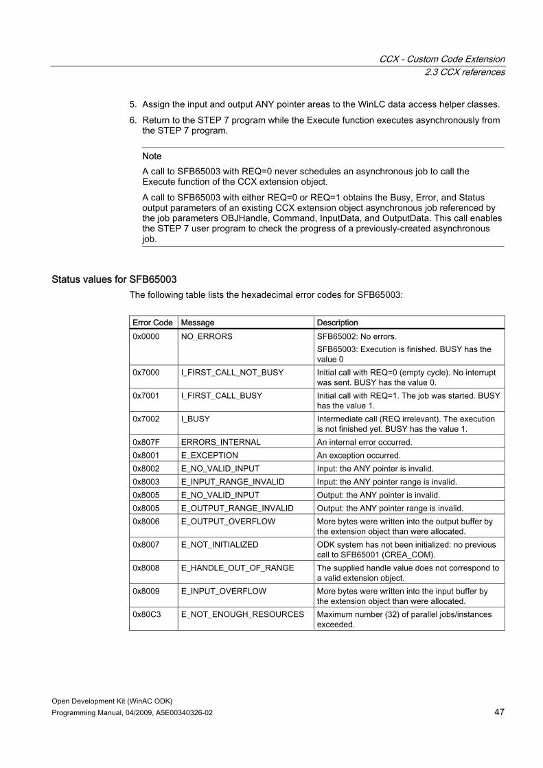
CCX - Custom Code Extension 2.3 CCX references
Open Development Kit (WinAC ODK) Programming Manual, 04/2009, A5E00340326-02 47
5. Assign the input and output ANY pointer areas to the WinLC data access helper classes. 6. Return to the STEP 7 program while the Execute function executes asynchronously from
the STEP 7 program.
Note A call to SFB65003 with REQ=0 never schedules an asynchronous job to call the Execute function of the CCX extension object. A call to SFB65003 with either REQ=0 or REQ=1 obtains the Busy, Error, and Status output parameters of an existing CCX extension object asynchronous job referenced by the job parameters OBJHandle, Command, InputData, and OutputData. This call enables the STEP 7 user program to check the progress of a previously-created asynchronous job.
Status values for SFB65003 The following table lists the hexadecimal error codes for SFB65003: Error Code Message Description 0x0000 NO_ERRORS SFB65002: No errors.
SFB65003: Execution is finished. BUSY has the value 0
0x7000 I_FIRST_CALL_NOT_BUSY Initial call with REQ=0 (empty cycle). No interrupt was sent. BUSY has the value 0.
0x7001 I_FIRST_CALL_BUSY Initial call with REQ=1. The job was started. BUSY has the value 1.
0x7002 I_BUSY Intermediate call (REQ irrelevant). The execution is not finished yet. BUSY has the value 1.
0x807F ERRORS_INTERNAL An internal error occurred. 0x8001 E_EXCEPTION An exception occurred. 0x8002 E_NO_VALID_INPUT Input: the ANY pointer is invalid. 0x8003 E_INPUT_RANGE_INVALID Input: the ANY pointer range is invalid. 0x8005 E_NO_VALID_INPUT Output: the ANY pointer is invalid. 0x8005 E_OUTPUT_RANGE_INVALID Output: the ANY pointer range is invalid. 0x8006 E_OUTPUT_OVERFLOW More bytes were written into the output buffer by
the extension object than were allocated. 0x8007 E_NOT_INITIALIZED ODK system has not been initialized: no previous
call to SFB65001 (CREA_COM). 0x8008 E_HANDLE_OUT_OF_RANGE The supplied handle value does not correspond to
a valid extension object. 0x8009 E_INPUT_OVERFLOW More bytes were written into the input buffer by
the extension object than were allocated. 0x80C3 E_NOT_ENOUGH_RESOURCES Maximum number (32) of parallel jobs/instances
exceeded.

CCX - Custom Code Extension 2.3 CCX references
Open Development Kit (WinAC ODK) 48 Programming Manual, 04/2009, A5E00340326-02
2.3.3 CCX data access helper classes The data access helper classes provide access to WinLC RTX data. The two data access helper classes are: ● CWinLCReadData ● CWinLCReadWriteData The functions in these classes allow you to read and write data of various S7 data types through the read functions (ODK_ReadS7<data type>) and write functions (ODK_WriteS7<data type>). The data access helper functions are separated into the two classes to provide very basic security on the input and output parameters of the Execute function. The ODK_ReadS7<data type> and ODK_WriteS7<data type> functions in the data access helper classes can help you avoid programming errors, such as out-of-range values or writing to invalid pointers. They also perform the necessary byte-swapping to convert data from the "big endian" format used in the S7 CPU architecture to the "little endian" format required for Microsoft Windows operating systems. The data access helper classes also include the functions ODK_GetBuffer and ODK_GetBufferSize for convenient access to the STEP 7 data buffer (work memory). With these functions you can get the entire buffer and copy to memory in your CCX application. In the Execute function, the data input and output buffers are declared to be of classes CWinLCReadData and CWinLCReadWriteData respectively. They are not accessible outside of the Execute function. To access controller data outside of the Execute function, you must use the global functions ODK_ReadData and ODK_WriteData of the auxiliary STEP 7 interface functions (Page 49).
WARNING Your in-process function (thread) can corrupt controller memory if it uses invalid addresses when writing data. Memory corruption can cause erratic and unpredictable controller operation, which can result in injury or property damage. When developing your application, always follow proper programming guidelines and industrial standards. Always test your application carefully before running the application.
References The CCX object web contains object definitions for the data access helper classes and their included functions.
Note To access any of the object webs for WinAC ODK, use the online help. Object webs are designed to be navigated from a web browser.

CCX - Custom Code Extension 2.3 CCX references
Open Development Kit (WinAC ODK) Programming Manual, 04/2009, A5E00340326-02 49
2.3.4 Auxiliary STEP 7 interface functions The CCX interface of WinAC ODK provides the following set of auxiliary functions that are available to your extension object for interacting with WinLC RTX: ● ODK_ReadState (Page 49) ● ODK_ScheduleOB (Page 50) ● ODK_CreateThread (Page 52) ● Functions for reading and writing controller data (Page 52):
– ODK_ReadData – ODK_WriteData
● Functions for configuring and implementing cyclic reads (Page 53): – ODK_CreateCyclicRead – ODK_DeleteCyclicRead – ODK_StartCyclicRead – ODK_StopCyclicRead
● Functions for accessing STEP 7 block information (Page 55). – ODK_GetBlockTimeStamp – ODK_GetBlockChecksum – ODK_GetBlockSize
The CCX object web describes all of the auxiliary STEP 7 interface functions.
Note To access any of the object webs for WinAC ODK, use the online help. Object webs are designed to be navigated from a web browser.
2.3.4.1 ODK_ReadState ODK_ReadState retrieves the current state (operating mode) of the controller, which is one of the following hexadecimal values: CPU State Description Value STOP_Update Not used in WinLC RTX 0x01 STOP_Reset STOP state during a memory reset 0x02 STOP_Init STOP state for transition to STOP_Internal 0x03 STOP_Internal STOP state: control program does not execute 0x04 START_OB102 STARTUP state for cold restart (OB102 executes on startup) 0x05 START_OB100 STARTUP state for warm restart (OB100 executes on startup) 0x06 START_OB101 Not used in WinLC RTX 0x07 RUN RUN state: control program is executing 0x08 HALT HALT or HOLD state: control program execution is suspended for
testing; see STEP 7 online help for specific details 0x0A

CCX - Custom Code Extension 2.3 CCX references
Open Development Kit (WinAC ODK) 50 Programming Manual, 04/2009, A5E00340326-02
CPU State Description Value DEFECTIVE A fault has occurred 0x0D POWER_Off WinAC controller is shut down or in process of shutting down 0x0F
References The CCX object web contains the function header and parameter descriptions for ODK_ReadState. The return value of ODK_ReadState indicates whether the call was successful or resulted in an error.
Note To access any of the object webs for WinAC ODK, use the online help. Object webs are designed to be navigated from a web browser.
2.3.4.2 ODK_ScheduleOB ODK_ScheduleOB schedules an OB to be run by the controller. When you schedule an OB, select one of the ODK-specific OBs, or one whose standard S7 behavior is closest to the way you plan to use the OB and is normally triggered by some asynchronous event, such as an error or a diagnostic event. When selecting an OB to schedule, consider the following OBs: ● OB52 - OB54 (CCX-specific interrupts)
Your CCX extension object can schedule OB52, OB53, or OB54 at any time. These OBs are not associated with other events and are available specifically for CCX custom software. The events for these OBs are only generated when the STEP 7 user program executes these OBs as scheduled by an ODK_ScheduleOB call in a CCX application. The CCX-specific OBs provide an additional set of OBs that you can program for application-specific needs.
● OB40 (Hardware interrupt) ● OB80 (Time error, such as a watchdog alarm) ● OB82 (Diagnostic Alarm interrupt) ● OB83 (Insert/Remove Module interrupt)
Setting the ODK_ScheduleOB parameters Set the service parameter to a callback handle for WinAC services. For the CCX-specific OBs (OB52 - OB54), use either 0x10 or 0x12 for the class_ID parameter . Use 0x10 if you require no entry in the diagnostic buffer when the OB executes and use 0x12 if you do require a diagnostic buffer entry.

CCX - Custom Code Extension 2.3 CCX references
Open Development Kit (WinAC ODK) Programming Manual, 04/2009, A5E00340326-02 51
When scheduling OB52 - OB54, use the eventNr that corresponds to the CCX-specific OB: OB Value of eventNr Parameter OB52 0x71 OB53 0x72 OB54 0x73
For OBs other than OB52 - OB54, the class_ID and eventNr parameters of ODK_ScheduleOB correspond directly to the OB parameters for the specific OB that you are calling. The Organization Blocks chapter of the STEP 7 manual System and Standard Functions for S7-300 and S7-400 documents these parameters for each OB. ODK_ScheduleOB does not use the seqLayer parameter. The priority class for OB52 - OB54 is always 15, and the priority class for all other OBs is defined in the STEP 7 Hardware Configuration. The priority of the scheduled OB is relative to other OBs as configured by the Hardware Configuration utility of STEP 7. (For example, when OB52 executes, it interrupts OB1, OB35, or any OB at a lower priority than 15.) The seqLayer parameter is reserved for future use. For this release, use a value of 0xFE for this parameter. The dataType2, dataType1, data1, and data2 parameters can vary in meaning and type depending on the OB. You can use these data words according to your own requirements. WinLC RTX does not interpret the data type or data parameters when scheduling the OB. The data words are copied to the local data (L memory) for the OB when the OB is scheduled to be executed. You can then access this information in your implementation of the OB that you scheduled. If you require that the entry in the Module Information/Diagnostic Buffer of STEP 7 be displayed with descriptive text, you must use the correct data types as specified for the OB. The parameter dataType2 specifies how data2 is to be interpreted, and dataType1 specifies how data1 is to be interpreted. In the ODK_ScheduleOB call, data2 is an unsigned long value. Depending on the OB, this might correspond to four BYTE parameters, two WORD parameters, one DWORD parameter, or other interpretations. The dataType1 parameter and data1 parameters are used in the same way. The following tables show some of the possible values for dataType2 and dataType1: dataType2: Value Description 0xC1 32-bit double word 0xC4 Two 16-bit binary values 0xC8 32-bit signed value 0xC9 Two 16-bit signed values 0xCA 32-bit floating point values 0xCD 32 Relative time in milliseconds
dataType1: Value Description 0x51 16-bit field: unspecified numeric value 0x58 16-bit field: time in milliseconds 0x59 16-bit integer value 0x5B Two 8-bit binary value

CCX - Custom Code Extension 2.3 CCX references
Open Development Kit (WinAC ODK) 52 Programming Manual, 04/2009, A5E00340326-02
The last eight bytes of the local data contain the time stamp when the event was created. The CCX interface enters this data when your application calls the ODK_ScheduleOB function.
Example program and software references The CCX object web contains the function header and parameter descriptions for ODK_ScheduleOB. The return value of ODK_ScheduleOB indicates whether the call was successful or resulted in an error.
Note To access any of the object webs for WinAC ODK, use the online help. Object webs are designed to be navigated from a web browser.
The example program CCX_HistoDLL demonstrates the use of the ODK_ScheduleOB function. See the example for scheduling an OB (Page 63) for details.
2.3.4.3 ODK_CreateThread ODKCreateThread creates a separate thread of execution from the calling thread. You can put any processing that you want performed outside of your main execution thread in the function that you specifiy in the ODK_CreateThread call. Software executed from a thread of execution separate from the main thread does not affect the scan cycle.
Example program and software references The CCX object web contains the function header and parameter descriptions for ODK_CreateThread. The return value of ODK_CreateThread indicates whether the call was successful or resulted in an error. The CCX_FileIO example program demonstrates the use of ODK_CreateThread. See the example for creating a separate thread of execution (Page 64) for more details.
Note To access any of the object webs for WinAC ODK, use the online help. Object webs are designed to be navigated from a web browser.
2.3.4.4 Functions for reading and writing controller data The CCX interface of WinAC ODK provides the following functions for reading data from or writing data to WinLC RTX: ● ODK_ReadData ● ODK_WriteData These functions are global; they can be executed anywhere in your code including monitor or asynchronous threads and are not restricted to the Execute function. They use an ODK_DATA_STRUCT (Page 56) buffer that is passed as an argument, but they perform no byte swapping or data conversion on the data in the buffer. The functions return an error if

CCX - Custom Code Extension 2.3 CCX references
Open Development Kit (WinAC ODK) Programming Manual, 04/2009, A5E00340326-02 53
called with an unsupported memory area or data type, or for other error conditions. Program your CCX application to check the return value from ODK_ReadData and ODK_WriteData calls. To handle the data conversion, implement your code to call one of the ODK_ReadS7<data type> functions after calling ODK_ReadData, using the buffer read by ODK_ReadData. Conversely, implement your code to call the appropriate ODK_WriteS7<data type> functions before calling ODK_WriteData to convert the data to the proper format before writing the data buffer to the controller. The ODK_ReadS7<data type> and ODK_WriteS7<data type> functions of the CWinLCReadData and CWinLCReadWriteData data access helper classes (Page 48) perform the necessary byte swapping and data conversion.
Example program and software references The sample project DirAccess in the Program Files\Siemens\WinAC\ODK\Examples\CCX\CCX_DirAccess folder demonstrates the use of ODK_ReadData and ODK_WriteData together with the data access helper class functions to perform byte swapping. See the example for reading and writing controller data (Page 65) for details. A .NET version of DirAccess, NET_DirAccess, is also provided. The CCX object web in the online help includes the function headers and parameter descriptions for ODK_ReadData and ODK_WriteData, as well as the structure of ODK_DATA_STRUCT. ODK_ReadData and ODK_WriteData support the STEP 7 memory areas and data types that are relevant for a software PLC.
Note To access any of the object webs for WinAC ODK, use the online help. Object webs are designed to be navigated from a web browser.
2.3.4.5 Functions for cyclic reads The CCX interface of WinAC ODK provides the following functions that enable you to read data from WinLC RTX on a cyclic basis: ● ODK_CreateCyclicRead ● ODK_DeleteCyclicRead ● ODK_StartCyclicRead ● ODK_StopCyclicRead You can define a frequency based on a fixed minimum read rate value that specifies how often to perform the cyclic read. For example, you can program your CCX application to read a block of WinLC RTX controller memory every 500 microseconds. The functions return an error if they do not succeed. Program your CCX application to check the return value from calls to the cyclic read functions. The CCX functions that provide the cyclic read functionality are described below.

CCX - Custom Code Extension 2.3 CCX references
Open Development Kit (WinAC ODK) 54 Programming Manual, 04/2009, A5E00340326-02
ODK_CreateCyclicRead The ODK_CreateCyclicRead function creates a cyclic read job and returns a unique job ID. The startNow parameter defines whether the cyclic read job is to start immediately or is to be started later by a call to ODK_StartCyclicRead. The phJobID parameter is a pointer to a unique job ID for each cyclic read. ODK_CreateCyclicRead returns the phJobID when it creates the cyclic read job and you use it for starting and deleting cyclic read jobs with the ODK_StartCyclicRead and ODK_DeleteCyclicRead functions. The fptrCbfn parameter for ODK_CreateCyclicRead specifies the callback function that is called when the cyclic job completes. The pList parameter is a pointer to an ODK_DATA_STRUCT data structure (Page 56) (or an array of data structures) that receives the data that is read on each cycle. Within this data structure, ODK_CreateCyclicRead supports the STEP 7 memory areas and data types that are relevant for WInLC RTX, and returns an error if called with an unsupported memory area or data type. The status member of the ODK_DATA_STRUCT indicates success or failure of the cyclic read job for that particular ODK_DATA_STRUCT. Other parameters for ODK_CreateCyclicRead specify how much data is to be read and at what frequency, as defined in the CCX object web.
WARNING The parameters phJobID and pList must point to static or global variables that persist outside of the function that calls ODK_CreateCyclicRead. An attempt to access memory that is out of scope can cause an abrupt termination of the control program, the controller, and/or the computer, which could cause unexpected process or machine operation resulting in death, serious injury and/or property damage. Always use pointers to a static or global phJobID variable and a static or global list data structure for ODK_CreateCyclicRead calls.
The phJobID and pList parameters must point to static or global variables that persist outside of the function that calls ODK_CreateCyclicRead.
ODK_DeleteCyclicRead The ODK_DeleteCyclicRead function deletes a cyclic read job, using the job ID returned by ODK_CreateCyclicRead.
Note You must call ODK_DeleteCyclicRead for every cyclic read job that you create.
ODK_StartCyclicRead The ODK_StartCyclicRead function starts execution of a cyclic read job, using the job ID that ODK_CreateCyclicRead returned when it created the job. At the completion of the read job, ODK_StartCyclicRead sends a callback to the program that called it.
CCX - Custom Code Extension 2.3 CCX references
Open Development Kit (WinAC ODK) Programming Manual, 04/2009, A5E00340326-02 55
ODK_StopCyclicRead The ODK_StopCyclicRead function stops a cyclic read job, using the job ID returned by ODK_CreateCyclicRead. It does not delete the job, but stops its execution. The job can be restarted with the ODK_StartCyclicRead function.
Note You must call ODK_StopCyclicRead for every cyclic read job that you start.
Example program and software references The sample project DirAccess in the Program Files\Siemens\WinAC\ODK\Examples\CCX\CCX_DirAccess folder demonstrates the use of the cyclic read functions. See the example for implementing cyclic reads (Page 66) for details. A .NET version of DirAccess, NET_DirAccess, is also provided. The CCX object web includes the function headers and parameter descriptions for the cyclic read functions.
Note To access any of the object webs for WinAC ODK, use the online help. Object webs are designed to be navigated from a web browser.
2.3.4.6 Functions for getting STEP 7 block information WinAC ODK provides the following set of functions for obtaining information about STEP 7 blocks: ● ODK_GetBlockTimeStamp: obtains the date/time stamp corresponding to the last
modified time for the specified block in the form of the ODK_MMSTIME data structure: ● ODK_GetBlockChecksum: obtains the checksum of the specified block ● ODK_GetBlockSize: obtains the total length in bytes of the load memory requirement of
the specified block Each of the block access functions accepts a blockType parameter for identifying the specific block. The following table lists possible values for the blockType parameter:
Data type Value Description ODK_BTYP_OB 0x08 Organization Block (OB) ODK_BTYP_DB 0x0A Data Block (DB) ODK_BTYP_SDB 0x0B System Data Block (SDB) ODK_BTYP_FC 0x0C Function Call Block (FC) ODK_BTYP_SFC 0x0D System Function Call Block (SFC) ODK_BTYP_FB 0x0E Function Call with Data Block (FB) ODK_BTYP_SFB 0x0F System Function Call with Data Block (SFB)

CCX - Custom Code Extension 2.3 CCX references
Open Development Kit (WinAC ODK) 56 Programming Manual, 04/2009, A5E00340326-02
Example program and software references The CCX object web in the online help includes the function headers and parameter descriptions for the block access functions, and the structure of ODK_MMSTIME. The example program CCX_BlockAccess demonstrates the use of the STEP 7 block access functions. See the example for accessing STEP 7 block information (Page 68) for details.
2.3.4.7 Memory areas and data types for reading and writing The auxiliary STEP 7 interface functions, ODK_ReadData, ODK_WriteData, and ODK_CreateCyclicRead accept a pointer to an ODK_DATA_STRUCT (Page 56) data structure. This data structure specifies details for the read or write operation, including the type of data to read or write, how much data to read or write, the memory area, an offset into the memory area, and other information specific to the particular read or write request. WinLC RTX does not support all of the STEP 7 memory areas and data types, just those that are relevant for a PC-based controller. In particular, the memory areas for the AS200 do not apply to WinLC RTX. The CCX object web lists the memory areas and data types that WinAC ODK supports.
Limitations on reading and writing boolean values The dataType member of the ODK_DATA_STRUCT specifies the type of data to read or write, and the quantity member of the ODK_DATA_STRUCT specifies how many values of that data type to read or write. WinAC ODK does not support using a quantity value greater than one with a dataType of ODK_DATA_TYPE_BOOL. Arrays of booleans can not be implemented in this way. In order to read or write arrays of booleans, you can use another data type such as ODK_DATA_TYPE_BYTE and treat each of the eight bits of the byte as a boolean value. You can apply the same concept with other data types such as ODK_DATA_TYPE_WORD (16 bits) or ODK_DATA_TYPE_DWORD (32 bits). You can read or write any quantity of data types other than ODK_DATA_TYPE_BOOL.
2.3.4.8 ODK_DATA_STRUCT The read and write auxiliary STEP 7 interface functions use an array of one or more ODK_DATA_STRUCTs for reading and writing controller data. The ODK_DATA_STRUCT is a general purpose data structure that can be used for any of the supported memory areas and data types. In your CCX application, you assign the members of each ODK_DATA_STRUCT based on the type of data that you are reading or writing, and the memory area of the data. Each read or write function sets the status member for each ODK_DATA_STRUCT in the array. Program your CCX application to initialize the status to 0 and to check the status for each ODK_DATA_STRUCT used in an ODK_ReadData, ODK_WriteData, or ODK_CreateCyclicRead function call. The data types supported by the CCX interface include elementary data types, complex data types, and parameter data types. The memory areas supported by the CCX interface include elementary memory areas and parameter type memory areas. The following table explains how to assign the members of an ODK_DATA_STRUCT according to the type of data you are reading or writing:
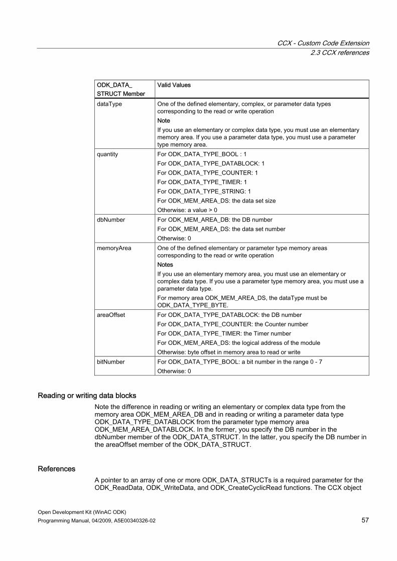
CCX - Custom Code Extension 2.3 CCX references
Open Development Kit (WinAC ODK) Programming Manual, 04/2009, A5E00340326-02 57
ODK_DATA_ STRUCT Member
Valid Values
dataType One of the defined elementary, complex, or parameter data types corresponding to the read or write operation Note If you use an elementary or complex data type, you must use an elementary memory area. If you use a parameter data type, you must use a parameter type memory area.
quantity For ODK_DATA_TYPE_BOOL : 1 For ODK_DATA_TYPE_DATABLOCK: 1 For ODK_DATA_TYPE_COUNTER: 1 For ODK_DATA_TYPE_TIMER: 1 For ODK_DATA_TYPE_STRING: 1 For ODK_MEM_AREA_DS: the data set size Otherwise: a value > 0
dbNumber For ODK_MEM_AREA_DB: the DB number For ODK_MEM_AREA_DS: the data set number Otherwise: 0
memoryArea One of the defined elementary or parameter type memory areas corresponding to the read or write operation Notes If you use an elementary memory area, you must use an elementary or complex data type. If you use a parameter type memory area, you must use a parameter data type. For memory area ODK_MEM_AREA_DS, the dataType must be ODK_DATA_TYPE_BYTE.
areaOffset For ODK_DATA_TYPE_DATABLOCK: the DB number For ODK_DATA_TYPE_COUNTER: the Counter number For ODK_DATA_TYPE_TIMER: the Timer number For ODK_MEM_AREA_DS: the logical address of the module Otherwise: byte offset in memory area to read or write
bitNumber For ODK_DATA_TYPE_BOOL: a bit number in the range 0 - 7 Otherwise: 0
Reading or writing data blocks Note the difference in reading or writing an elementary or complex data type from the memory area ODK_MEM_AREA_DB and in reading or writing a parameter data type ODK_DATA_TYPE_DATABLOCK from the parameter type memory area ODK_MEM_AREA_DATABLOCK. In the former, you specify the DB number in the dbNumber member of the ODK_DATA_STRUCT. In the latter, you specify the DB number in the areaOffset member of the ODK_DATA_STRUCT.
References A pointer to an array of one or more ODK_DATA_STRUCTs is a required parameter for the ODK_ReadData, ODK_WriteData, and ODK_CreateCyclicRead functions. The CCX object
CCX - Custom Code Extension 2.4 Examples
Open Development Kit (WinAC ODK) 58 Programming Manual, 04/2009, A5E00340326-02
web includes these functions, the ODK_DATA_STRUCT, and the defined memory areas and data types.
2.3.5 CCX object web The CCX object web shows the CCX interfaces for a C++ project as created using the WinAC ODK application wizard. This project contains one asynchronous processing event and one asynchronous monitor. The CCX object web shows the classes supporting these features, the CCX interface functions, data access help classes, and auxiliary STEP 7 interface functions. The object web shows these functions and classes as created by the WinAC ODK application wizard. They are empty shells, with no additional custom programming. In addition to the general CCX interface, the object web also shows a specific example project implementation for the CCX_SyncVsAsync example project. This project uses same CCX functions and classes, but in this case custom code has been added.
Note To access any of the object webs for WinAC ODK, use the online help. Object webs are designed to be navigated from a web browser.
2.4 Examples
2.4.1 CCX_SyncVsAsync example program
2.4.1.1 Differences between synchronous and asynchronous use of the CCX extension object You can call a CCX extension object from your STEP 7 user program either synchronously with SFB65002 (EXEC_COM) or asynchronously with SFB65003 (ASYN_COM).
Synchronous usage SFB65002 is a synchronous call. The STEP 7 user program calls the CCX extension object; the CCX extension object executes to completion; it returns control to the STEP 7 user program, and the scan cycle continues. The time that the CCX extension object requires to execute is part of the scan cycle.
Asynchronous usage SFB65003 is an asynchronous call. The STEP 7 user program calls the CCX extension object and the CCX extension object executes on a separate thread of execution to the STEP 7 user program. The time that the CCX extension object requires to execute is independent of the scan cycle.

CCX - Custom Code Extension 2.4 Examples
Open Development Kit (WinAC ODK) Programming Manual, 04/2009, A5E00340326-02 59
The following diagram shows the difference between asynchronous and synchronous CCX extension object execution:
Deciding which type of call to use Refer to the "Synchronous or asynchronous execution? (Page 14)" topic for reasons to select either synchronous or asynchronous execution.
2.4.1.2 Introduction to the CCX _SyncVsAsync example program The example program CCX_SyncVsAsync demonstrates and compares the use of CCX for both synchronous and asynchronous SFB calls.
CCX_SyncVsAsync extension object description CCX_SyncVsAsync is a CCX extension object that performs the following tasks: 1. Reads a value from the STEP 7 input buffer that contains a delay value in milliseconds. 2. Sleeps for the number of milliseconds that was read. 3. Increments an internal counter. 4. Writes the counter value to the STEP 7 output buffer.
Calling the CCX_SyncVsAsync extension object from a STEP 7 program A STEP 7 program can call the CCX_SyncVsAsync extension object using either SFB65002 or SFB65003.

CCX - Custom Code Extension 2.4 Examples
Open Development Kit (WinAC ODK) 60 Programming Manual, 04/2009, A5E00340326-02
When called from SFB65002, the call is synchronous and the STEP 7 program main program thread is suspended until the call to CCX_SyncVsASync complete. When called from SFB65003, the call is asynchronous and the STEP 7 program main program thread continues execution while CCX_SyncVsASync executes asynchronously. The CCX_SyncVsAsync STEP 7 program includes two variable tables that allow you to call the CCX_SyncVsAsync extension object either synchronously or asynchronously and observe the effect on control program execution with each method. You can exercise the variables repeatedly to compare the differences between synchronous and asynchronous extension object calls.
2.4.1.3 Overview of the CCX program
Program operation The CCX extension object receives a parameter that specifies a number of milliseconds to delay and performs these actions: 1. Reads the delay value from STEP 7 memory 2. Reads the current CCX counter value from STEP 7 memory. 3. Sleeps for the number of milliseconds specified in the delay parameter. 4. Increments the CCX counter value. 5. Stores the CCX counter value back to STEP 7 memory. 6. Return The CCX program uses ODK_ReadS7WORD and ODK_WriteS7WORD from the data access helper classes (Page 48) to read and write the data values.
2.4.1.4 Overview of the STEP 7 user program
Objective The CCX_SyncVsAsync example program demonstrates the difference in STEP 7 program execution when using an asynchronous call to a CCX extension object versus a synchronous call to the same CCX extension object.
Program operation OB1 of the STEP 7 program monitors two variables, START_SYNC_TEST and START_ASYNC_TEST. When START_SYNC_TEST is set, the STEP 7 program calls the CCX_SyncVsAsync extension object synchronously from SFB65002. When START_ASYNC_TEST is set, the STEP 7 program calls the CCX_SyncVsAsync extension object asynchronously from SFB65003. In both cases, the STEP 7 user program sends a parameter to the CCX extension object that specifies a number of milliseconds to delay. This parameter, CounterStruct.DelayinMsec has a default value of 1000ms. OB35 loads a counter variable, OB35Counter, increments it, and saves it. OB35 is a cyclic OB that runs every 100 ms.
CCX - Custom Code Extension 2.4 Examples
Open Development Kit (WinAC ODK) Programming Manual, 04/2009, A5E00340326-02 61
The SYNC_TEST and ASYNC_TEST variable tables that are included in the CCX_SyncVsAsync example program allow you to call the CCX extension object either synchronously or asynchronously, and observe the effects on the controller.
2.4.1.5 Building the CCX_SyncVsAsync extension object You can build your C++ extension object as either an RTDLL or a DLL. An RTDLL runs in the real-time subsystem (RTSS) and a DLL runs in the Windows operating system. (You can only build C# and VB extension objects as DLLs.)
Building the extension object To build the CCX_SyncVsAsync extension object, follow these steps: 1. Select Build > Set Active Configuration to set the project configuration. 2. Select one of the following choices for the project configuration:
– CCX_SyncVsAsync - Win32 Debug: Debug version of standard DLL to run in Windows
– CCX_SyncVsAsync - Win32 Release: Standard DLL to run in Windows – CCX_SyncVsAsync - Win32 RTSS Debug: Debug version of RTDLL to run in real-time
subsystem – CCX_SyncVsAsync - Win32 RTSS Release: RTDLL to run in real-time subsystem
3. Click OK to confirm your choice. 4. Press F7 or select Build > Build CCX_SyncVsAsync.dll or Build > Build
CCX_SyncVsAsync.rtdll to build the extension object.
2.4.1.6 Retrieving and running the STEP 7 CCX_SyncVsAsync program Before you can run the CCX_SyncVsAsync example STEP 7 program, you must retrieve it, configure the station name, and download it to WinLC RTX.
Retrieving and configuring the CCXSyncVsSync STEP 7 program To retrieve the CCXSyncVsSync STEP 7 program and configure it for use with your controller, follow these steps: 1. Select Start > Simatic > SIMATIC Manager to start the SIMATIC Manager. 2. Select File > Retrieve from the SIMATIC Manager. 3. Browse to the folder Program
Files\Siemens\WinAC\ODK\Examples\CCX\CCX_SyncVsAsync\Step7 and double-click the file CCX_Sync.zip.
4. Click OK on the "Select destination directory" dialog. The SIMATIC Manager extracts the CCX_SyncVsAsync STEP 7 project and puts it in the Siemens\Step7\S7proj folder. Click OK on the Retrieving dialog that informs you of the project location, if it appears.
5. Click Yes on the final Retrieve dialog to open the CCX_SyncVsAsync project. 6. In the CCX_SyncVsAsync project, change the station name corresponding to your WinAC
controller to match the Station Name configured in the Station Configuration Editor. (To

CCX - Custom Code Extension 2.4 Examples
Open Development Kit (WinAC ODK) 62 Programming Manual, 04/2009, A5E00340326-02
find the station name, click the Station Configuration Editor icon in the Windows Taskbar, select the WinLC RTX controller, and click the Station Name button.)
Downloading and running the CCX_SyncVsAsync STEP 7 program To download and run the CCX_SyncVsAsync STEP 7 program to your controller, follow these steps: 1. Start the WinLC RTX and the controller panel:
– If WinLC RTX is already operating but the controller panel is not open, double-click the WinLC controller icon in the Windows Taskbar to start the controller panel.
– If WinLC RTX is not operating, double-click the controller panel icon on your desktop to start the controller panel and WinLC RTX.
2. From the controller panel, set the operating mode of the controller to STOP, and perform a memory reset (MRES).
3. From the SIMATIC Manager, click the Blocks folder of the CCX_SyncVsAsync S7 Program and select PLC > Download to download the CCX_SyncVsAsync program to WinLC RTX.
4. Change the operating mode of the controller from STOP mode to RUN mode. The controller executes the CCX_SyncVsAsync program.
2.4.1.7 Using the STEP 7 program and calling the CCX extension object
Using the CCX_SyncVsAsync STEP 7 program The STEP 7 program CCX_SyncVsAsync has two variable tables from which you start execution of the CCX extension object from the STEP 7 user program: ● SYNC_TEST ● ASYNC_TEST The variable tables include variables that you use to call the CCX extension object, counters of the number of times that OB35 has executed, and of the number of times that the CCX extension object has executed, and a delay value to send to the CCX extension object. The ASYNC_TEST variable table also displays two flags to show you when the asynchronous request is executing.
Calling the CCX extension object synchronously With the CCX_SyncVsAsync program running (Page 61) in WinLC RTX, follow these steps: 1. Open VAR table START_SYNC from the Blocks folder. 2. Ensure that the START_SYNC_TEST is set to 1. 3. Ensure that the delay counter variable CounterStruct.DelayinMsec is set to 1000. 4. Select the Variable > Modify command or click the Modify icon to send these values to
WinLC RTX.

CCX - Custom Code Extension 2.4 Examples
Open Development Kit (WinAC ODK) Programming Manual, 04/2009, A5E00340326-02 63
Result The STEP 7 program calls the CCX_SyncVsAsync extension object from the asynchronous SFB , SFB65002. OB1 must wait for the CCX extension object software to complete before continuing. OB35 is a cyclic OB that executes every 100 ms. The 1000 ms delay, however, causes the scan cycle to be delayed such that OB35 cannot run when it is scheduled. WinLC RTX incurs an internal fault and goes to STOP mode.
Calling the CCX extension object asynchronously To call the CCX extension object asynchronously, follow these steps: 1. Open VAR table START_ASYNC from the Blocks folder. 2. Ensure that the START_ASYNC_TEST is set to 1. 3. Ensure that the delay counter variable CounterStruct.DelayinMsec is set to 1000. 4. Select the Variable > Modify command or click the Modify icon to send these values to
WinLC RTX.
Result The STEP 7 program calls the CCX_SyncVsAsync extension object from the asynchronous SFB , SFB65003. The CCX extension object delays for 1000 ms, but has no effect on the scan cycle, because the CCX extension object is running asynchronously to the STEP 7 user program. OB35 continues to execute every 100 ms as programmed. In the variable table, you can see the counter for OB35 continue to increment, and you can see the counter for CCX increment.
2.4.2 Examples of auxiliary STEP 7 function usage
2.4.2.1 Example: scheduling an OB The following example (taken from the HistoDLL sample project) shows a function that schedules an OB by calling ODK_ScheduleOB: void ScheduleOB52 (unsigned long mode, unsigned short deviation) { if (g_hServiceHandle) { ODK_ScheduleOB(g_hServiceHandle, 0x10, // class ID 0x71, // event nr 0xFE, // fill in configured sequence layer 52, // execute OB52 0xC4, // dataType2 (for long word): two 16 bit words 0x58, // dataType1 (for short word): time in milliseconds deviation, // data1 mode); // data2 } }

CCX - Custom Code Extension 2.4 Examples
Open Development Kit (WinAC ODK) 64 Programming Manual, 04/2009, A5E00340326-02
The ODK_ScheduleOB function header and parameter descriptions are included in the CCX object web.
Note To access any of the object webs for WinAC ODK, use the online help. Object webs are designed to be navigated from a web browser.
2.4.2.2 Example: creating a separate thread of execution The following example (from Counter.cpp in the FileIO sample project) shows a constructor for a class that calls ODK_CreateThread to configure and create a new thread. This constructor passes a function name to ODK_CreateThread that specifies which function to execute from the new thread, and at what thread priority. All software in this function, and functions called from this function, execute in a separate thread of execution and do not affect the processing time of the main execution thread. The main execution thread is executed as part of the controller scan cycle. In this example, the class CCounter creates a thread to be executed from the StartThread function of the CCounter class: /** * Initializes the WinLC Services callback handle * along with all other member variables and creates * a new thread of execution for the monitor. * @param hWinLCSvc: Callback handle WinLC Services */ CCounter::CCounter(ODK_CallBack_HANDLE hwinLCSvc) : CThreadBase(hWinLCSvc) { m_Count = 0; reset_m_CountHit(); m_ThreadHwnd = ODK_CreateThread(hWinLCSvc, PRIORITY_BACKGROUND, 0, CCounter::StartThread, reinterpret_cast<void*>(this)); if (m_hThreadHwnd) { m_ThreadEvent.WaitForSignal(); m_ThreadEvent.ResetSignal(); } }
The function headers and parameter descriptions for ODK_CreateThread are in the CCX object web. The sample project FileIO contains the code listed above.
Note To access any of the object webs for WinAC ODK, use the online help. Object webs are designed to be navigated from a web browser.
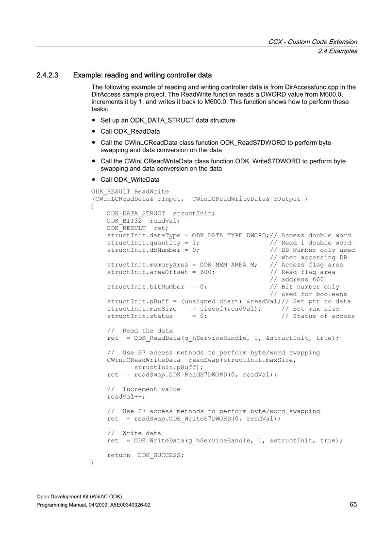
CCX - Custom Code Extension 2.4 Examples
Open Development Kit (WinAC ODK) Programming Manual, 04/2009, A5E00340326-02 65
2.4.2.3 Example: reading and writing controller data The following example of reading and writing controller data is from DirAccessfunc.cpp in the DirAccess sample project. The ReadWrite function reads a DWORD value from M600.0, increments it by 1, and writes it back to M600.0. This function shows how to perform these tasks: ● Set up an ODK_DATA_STRUCT data structure ● Call ODK_ReadData ● Call the CWinLCReadData class function ODK_ReadS7DWORD to perform byte
swapping and data conversion on the data ● Call the CWinLCReadWriteData class function ODK_WriteS7DWORD to perform byte
swapping and data conversion on the data ● Call ODK_WriteData
ODK_RESULT ReadWrite (CWinLCReadData& rInput, CWinLCReadWriteData& rOutput ) { ODK_DATA_STRUCT structInit; ODK_BIT32 readVal; ODK_RESULT ret; structInit.dataType = ODK_DATA_TYPE_DWORD;// Access double word structInit.quantity = 1; // Read 1 double word structInit.dbNumber = 0; // DB Number only used // when accessing DB structInit.memoryArea = ODK_MEM_AREA_M; // Access flag area structInit.areaOffset = 600; // Read flag area // address 600 structInit.bitNumber = 0; // Bit number only // used for booleans structInit.pBuff = (unsigned char*) &readVal;// Set ptr to data structInit.maxSize = sizeof(readVal); // Set max size structInit.status = 0; // Status of access // Read the data ret = ODK_ReadData(g_hServiceHandle, 1, &structInit, true); // Use S7 access methods to perform byte/word swapping CWinLCReadWriteData readSwap(structInit.maxSize, structInit.pBuff); ret = readSwap.ODK_ReadS7DWORD(0, readVal); // Increment value readVal++; // Use S7 access methods to perform byte/word swapping ret = readSwap.ODK_WriteS7DWORD(0, readVal); // Write data ret = ODK_WriteData(g_hServiceHandle, 1, &structInit, true); return ODK_SUCCESS; }

CCX - Custom Code Extension 2.4 Examples
Open Development Kit (WinAC ODK) 66 Programming Manual, 04/2009, A5E00340326-02
The CCX object web includes the descriptions for the functions and parameters of ODK_ReadData and ODK_WriteData, for the classes CWinLCReadData and CWinLCReadWriteData, and for the ODK_DATA_STRUCT.
Note To access any of the object webs for WinAC ODK, use the online help. Object webs are designed to be navigated from a web browser.
2.4.2.4 Example: implementing cyclic reads The following example (from the DirAccessfunc.cpp in the CCX_DirAccess example project) contains functions that configure a cyclic read job, start the job, stop the job, and delete the job. The cyclic read functions use an ODK_DATA_STRUCT data structure to set up a cyclic read job that reads five DWORDs beginning at M500.0 every 5000 milliseconds. The functions below perform these tasks: ● Configuring and creating a cyclic read job ● Starting the created cyclic read job ● Stopping the cyclic read job ● Deleting the cyclic read job
Declarations needed by the CCX_DirAccess cyclic functions /// Define WinAC Controller Callback ODK_CallBack_HANDLE g_hServiceHandle = 0; #define DWORD_COUNT 5 ODK_HANDLE hJobId = NULL; DWORD data[DWORD_COUNT]; ODK_DATA_STRUCT cyclicStruct;
Function to create a cyclic read job ODK_RESULT CreateCyclic (CWinLCReadData& rInput, CWinLCReadWriteData& rOutput) { ODK_RESULT ret; if (hJobId) return ODK_SUCCESS; unsigned long freq = 0; cyclicStruct.dataType = ODK_DATA_TYPE_DWORD; cyclicStruct.quantity = DWORD_COUNT; cyclicStruct.dbNumber = 0; cyclicStruct.memoryArea = ODK_MEM_AREA_M; cyclicStruct.areaOffset = 500; cyclicStruct.bitNumber = 0; cyclicStruct.pBuff = (unsigned char*) &data[0]; cyclicStruct.maxSize = sizeof(data); cyclicStruct.status = 0;

CCX - Custom Code Extension 2.4 Examples
Open Development Kit (WinAC ODK) Programming Manual, 04/2009, A5E00340326-02 67
ret = ODK_CreateCyclicRead(g_hServiceHandle, 1, &cyclicStruct, ODK_READWRITE_IMMEDIATE, 5000, ODK_FALSE, &CyclicReadCB, &freq, &hJobId); return ODK_SUCCESS; }
Function to start a cyclic read job ODK_RESULT StartCyclic (CWinLCReadData& rInput, CWinLCReadWriteData& rOutput ) { ODK_RESULT ret; if (!hJobId) return ODK_INV_JOBID_PTR; ret = ODK_StartCyclicRead(hJobId); return ODK_SUCCESS; }
Function to stop a cyclic read job ODK_RESULT StopCyclic (CWinLCReadData& rInput, CWinLCReadWriteData& rOutput ) { ODK_RESULT ret; if (!hJobId) return ODK_INV_JOBID_PTR; ret = ODK_StopCyclicRead(hJobId); return ODK_SUCCESS; }
Function to delete a cyclic read job ODK_RESULT DeleteCyclic (CWinLCReadData& rInput, CWinLCReadWriteData& rOutput ) { ODK_RESULT ret; if (!hJobId) return ODK_INV_JOBID_PTR; ret = ODK_DeleteCyclicRead(hJobId); if (ret == 0) hJobId = NULL; return ODK_SUCCESS; }

CCX - Custom Code Extension 2.4 Examples
Open Development Kit (WinAC ODK) 68 Programming Manual, 04/2009, A5E00340326-02
References The descriptions for the functions and parameters of ODK_CreateCyclicRead, ODK_StartCyclicRead, ODK_StopCyclicRead, and ODK_DeleteCyclicRead and for the ODK_DATA_STRUCT are in the CCX object web.
Note To access any of the object webs for WinAC ODK, use the online help. Object webs are designed to be navigated from a web browser.
2.4.2.5 Example: accessing STEP 7 block information The following example from the CCX_BlockAccess_Cpp example project illustrates the use of the WinAC ODK STEP 7 block access functions: ● ODK_GetBlockTimeStamp ● ODK_GetBlockSize ● ODK_GetBlockChecksum
Internal BlockDataAccess function in project CCX_BlockAccess ODK_RESULT BlockDataAccess(CWinLCReadData& rInput, CWinLCReadWriteData& rOutput) { ODK_RESULT res = ODK_SUCCESS; BlOCK_DATA BlkData; // Initialize the Block data structure to Zero memset(&BlkData,0,sizeof(BlOCK_DATA)); // read BlockType information in the STEP 7 program rInput.ODK_ReadS7WORD(0,BlkData.BlockType); // read BlockNumber information ein the STEP 7 program rInput.ODK_ReadS7WORD(2,BlkData.BlockNumber); // Get the Timestamp information for the // requested block type and number res = ODK_GetBlockTimeStamp(g_hServiceHandle, BlkData.BlockType, BlkData.BlockNumber, &BlkData.time); if (res == ODK_SUCCESS) { unsigned short date = MC7ToNative<unsigned short>(BlkData.time.mmDate); unsigned int time= MC7ToNative<unsigned int>(BlkData.time.mmTime); // subtract the difference in the dates between the // base year for STEP 7 Time and ODK_MMSTIME date -= BASE_YEAR_NORMALIZATION; // Write the returned value into the STEP 7 Output buffer rOutput.ODK_WriteS7DATE(8,date); rOutput.ODK_WriteS7TIME(10,time);

CCX - Custom Code Extension 2.4 Examples
Open Development Kit (WinAC ODK) Programming Manual, 04/2009, A5E00340326-02 69
} else { return res; } // Get the Blocksize information for the // requested block type and number res = ODK_GetBlockSize(g_hServiceHandle, BlkData.BlockType, BlkData.BlockNumber, &BlkData.blksize); if (res == ODK_SUCCESS) { // Write the returned value into the STEP 7 Output buffer rOutput.ODK_WriteS7WORD(4,BlkData.blksize); } else { return res; } // Get Block Checksum information for the // requested block type and number res = ODK_GetBlockChecksum(g_hServiceHandle, BlkData.BlockType, BlkData.BlockNumber, &BlkData.checksum); if (res == ODK_SUCCESS) { // Write the returned value into the STEP 7 Output buffer rOutput.ODK_WriteS7WORD(6,BlkData.checksum); } else { return res; } return ODK_SUCCESS; }
References The descriptions for the functions and parameters of ODK_GetBlockTimestamp, ODK_GetBlockSize, and ODK_GetBlockChecksum are in the CCX object web.
Note To access any of the object webs for WinAC ODK, use the online help. Object webs are designed to be navigated from a web browser.

CCX - Custom Code Extension 2.4 Examples
Open Development Kit (WinAC ODK) 70 Programming Manual, 04/2009, A5E00340326-02
2.4.3 Additional CCX example programs WinAC ODK installs the example applications that use the CCX interface in the ...\Program Files\Siemens\WinAC\ODK\Examples\CCX folder. In the CCX folder, subfolders exist for C++ (Cpp), C# (CS) and Visual Basic (VB). Within each programming language folder, folders exist for the source files, the project files for the supported compilers, and for the corresponding STEP 7 program.
Supported compilers For the following programming languages, WinAC ODK provides project files for the supported programming languages in the compiler folders listed below: Programming language Language folder Compiler project folders C++ Cpp VS6, VSNET, VS2005, VS2008 C# CS VS2005, VS2008 VB VB VS2005, VS2008
Example: The folder and file structure for the CCX_SyncVsAsync example program is: ● C:\Program Files\SIEMENS\WINAC\ODK\Examples\CCX\Cpp\CCX_SyncVsAsync:
CCXSyncVsAsync example program source and header files are here. ● C:\Program Files\SIEMENS\WINAC\ODK\Examples\CCX\Cpp\ CCX_SyncVsAsync\
Step7: The CCXSyncVsAsync STEP 7 program is here that you can retrieve from STEP 7.
● C:\Program Files\SIEMENS\WINAC\ODK\Examples\CCX\Cpp\CCX_SyncVsAsync\VS2005: CCXSyncVsAsync project files for Microsoft Visual Studio 2005 are here.
● C:\Program Files\SIEMENS\WINAC\ODK\Examples\CCX\Cpp\CCX_SyncVsAsync\VS2008: CCXSyncVsAsync project files for Microsoft Visual Studio 2008 are here.
● C:\Program Files\SIEMENS\WINAC\ODK\Examples\CCX\Cpp\CCX_SyncVsAsync\VS6: CCXSyncVsAsync project files for Microsoft Visual Studio C++ V6.0 are here.
● C:\Program Files\SIEMENS\WINAC\ODK\Examples\CCX\Cpp\CCX_SyncVsAsync\VSNET: CCXSyncVsAsync project files for Microsoft Visual Studio .NET are here.
The file folder structure for CS (C#) and VB (Visual Basic) is simliar. Other example programs follow the same structure, depending on programming language support as listed below. Note that WinAC ODK does not support all compilers for all programming languages for all example programs.

CCX - Custom Code Extension 2.4 Examples
Open Development Kit (WinAC ODK) Programming Manual, 04/2009, A5E00340326-02 71
Example programs The WinAC ODK CCX example programs are listed below, and for which programming environments they are available: Example program Description Available programming environments CCX_Async Performs file read and write
activities when called with command=0 and produces a beep every second when called with command=1; designed to demonstrate advantages and flexibility of SFB65003
C++: VS6 , VSNET, VS2005, VS2008 C#: VS2005 and VS2008 VB: VS2005 and VS2008
CCX_BlockAccess Uses the CCX block access functions to get the time stamp, block size, and checksum for the block specified in the input parameters.
C++: VS6 , VSNET, VS2005, VS2008 C#: VS2005 and VS2008 VB: VS2005 and VS2008
CCX_DirAccess Performs direct memory access using the auxiliary STEP 7 interface functions ODK_ReadData and ODK_WriteData, as well as configuring and executing cyclic read operations.
C++: VS6 and VSNET
CCX_DirDataAccess Uses the ODK_GetBufferSize and ODK_GetBuffer functions to read the STEP 7 input area into local memory, make changes to the contents, and write the modified content to the STEP 7 output area.
C++: VS6 , VSNET, VS2005, VS2008 C#: VS2005 and VS2008 VB: VS2005 and VS2008
CCX_FileIO Monitors a counter, creates events that schedule OBs, and performs file I/O
C++: VS6 and VSNET C#: VS2005 and VS2008 VB: VS2005 and VS2008
CCX_HistoDLL Collects data about the scan cycle, and maintains a history of scan cycle time statistical data.
C++: VS6 and VSNET
CCX_Latency Measures latency between OB scheduling and execution.
C++: VS6
CCX_NotifyDB Receives notification whenever a DB is created or deleted, and records creations and deletions in a log file.
C++: VS6 , VSNET, VS2005, VS2008 C#: VS2005 and VS2008 VB: VS2005 and VS2008
CCX_SyncVsAsync See "Introduction to the CCX _SyncVsAsync example program (Page 59)"
C++: VS6 , VSNET, VS2005, VS2008 C#: VS2005 and VS2008 VB: VS2005 and VS2008
CCX_TonePulse Interfaces with external hardware to generate a tone pulse
C++: VS6
CCX - Custom Code Extension 2.4 Examples
Open Development Kit (WinAC ODK) 72 Programming Manual, 04/2009, A5E00340326-02
Note Do not use the .NET conversion tool to convert a Microsoft Visual C++ V6.0 project to a Microsoft Visual Studio .NET solution. To use any of the example programs that are available in C++ only for Microsoft Visual Studio V6.0 and not Microsoft Visual Studio .NET, such as CCX_Latency, create a new solution and add source and header files from the corresponding Microsoft Visual Studio C++ V6.0 projecs.
2.4.4 GNU C++ example program for CCX WinAC ODK installs one C++ example program for CCX that you can compile with a GNU compiler. The installed project compiles and runs from a Cygwin environment running in Microsoft Windows XP Professional. You can modify and test this program yourself for any other usage. The GNU C++ CCX_BlockAccess example program provides the same functionality as the CCX_BlockAccess (Page 70) program that WinAC ODK provides for C++, C#, and Visual Basic. WinAC ODK installs the GNU C++ CCX_BlockAccess program at \Examples\_GNU_Compiler_Cpp_\CCX_BlockAccess. Refer to the Readme text file at this location for usage instructions and related information.

Open Development Kit (WinAC ODK) Programming Manual, 04/2009, A5E00340326-02 73
SMX - Shared Memory Extension 33.1 Overview
SMX provides tools for you to create an application in a high-level programming language that executes separately from your STEP 7 user program. The SMX application and the STEP 7 user program can read and write controller data using a shared memory area. The shared memory consists of two areas, a 4 Kbyte input area and a 4 Kbyte output area. The STEP 7 program uses Load and Transfer instructions to read and write from shared memory. The SMX application uses the SMX read and write S7 data type functions to access the shared memory.
L MW 14T PQW 5000
L PIW 4096T MW 16
S7SMX_ReadS7Word(4,value)
S7SMX_WriteS7Word(0,value)
WinAC ODK supports the following programming languages and compiler environments for SMX: Programming Language Compiler Environments Application Type C/C++ Microsoft Visual C++ V6.0
Microsoft Visual C++ .NET Microsoft Visual C++ 2005
RTSS or Windows
C/C++ Microsoft Visual C++ 2008 Windows Visual Basic Microsoft Visual Basic 2005
Microsoft Visual Basic 2008 Windows
C# Microsoft Visual C# 2005 Microsoft Visual C# 2008
Windows

SMX - Shared Memory Extension 3.2 Development tasks
Open Development Kit (WinAC ODK) 74 Programming Manual, 04/2009, A5E00340326-02
3.1.1 Documentation organization The following chapters teach you how to develop a WinAC ODK application using the SMX interface and contains the following sections: ● Creating an SMX project with the application wizard (Page 74): This section explains how
to use the application wizard to create a program shell for your custom SMX application. ● Programming the SMX application (Page 77): This topic describes how to use the SMX
interface functions in your application to exchange data with the STEP 7 program executing in the WinLC RTX controller.
● Programming the STEP 7 program to use SMX (Page 79): This topic describes how to use Load and Transfer instructions in your STEP 7 program to exchange data with an SMX application.
● Considering scan cycle impact (Page 80): This topic describes the interaction between the STEP 7 program and the SMX application as they run in parallel on your computer, and the effect on the scan cycle.
● Ensuring data consistency (Page 80): This topic describes the need for ensuring data consistency between the STEP 7 program and the SMX application.
The SMX object web provides detailed information about the SMX software interfaces, including all function headers, parameter descriptions, and related type and constant definitions. The SMX object web also includes software interfaces for an example application, SMX_Start (Page 82) , to show how to use the SMX interfaces in a typical application. Use the object web together with the information in this chapter when developing your SMX application.
3.2 Development tasks
3.2.1 Creating an SMX project with the application wizard The application wizard helps you perform the following tasks: ● Create a C/C++, VB, or C# project that uses the WinAC ODK SMX interface (Page 75) ● Specify vendor information to uniquely identify your project (Page 76) ● Generate the SMX project (Page 76) You can then edit the SMX project in your programming environment, add code that is specific to your application, and build an executable. This executable can share data with a STEP 7 user program that you implement to use the SMX shared memory area (Page 79).
Note The application wizard produces unmanaged code for C/C++, managed code for Visual Basic and C#.
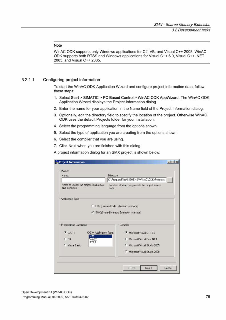
SMX - Shared Memory Extension 3.2 Development tasks
Open Development Kit (WinAC ODK) Programming Manual, 04/2009, A5E00340326-02 75
Note WinAC ODK supports only Windows applications for C#, VB, and Visual C++ 2008. WinAC ODK supports both RTSS and Windows applications for Visual C++ 6.0, Visual C++ .NET 2003, and Visual C++ 2005.
3.2.1.1 Configuring project information To start the WinAC ODK Application Wizard and configure project information data, follow these steps: 1. Select Start > SIMATIC > PC Based Control > WinAC ODK AppWizard. The WinAC ODK
Application Wizard displays the Project Information dialog. 2. Enter the name for your application in the Name field of the Project Information dialog. 3. Optionally, edit the directory field to specify the location of the project. Otherwise WinAC
ODK uses the default Projects folder for your installation. 4. Select the programming language from the options shown. 5. Select the type of application you are creating from the options shown. 6. Select the compiler that you are using. 7. Click Next when you are finished with this dialog. A project information dialog for an SMX project is shown below:
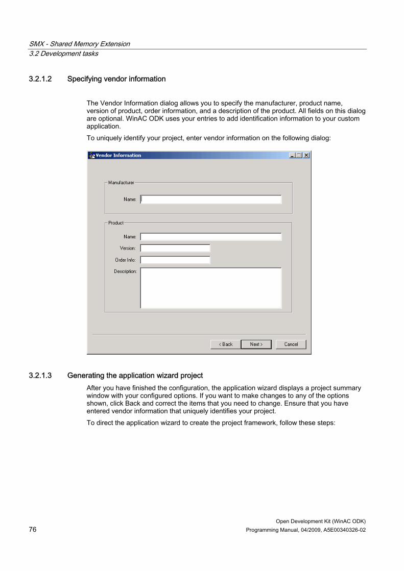
SMX - Shared Memory Extension 3.2 Development tasks
Open Development Kit (WinAC ODK) 76 Programming Manual, 04/2009, A5E00340326-02
3.2.1.2 Specifying vendor information The Vendor Information dialog allows you to specify the manufacturer, product name, version of product, order information, and a description of the product. All fields on this dialog are optional. WinAC ODK uses your entries to add identification information to your custom application. To uniquely identify your project, enter vendor information on the following dialog:
3.2.1.3 Generating the application wizard project After you have finished the configuration, the application wizard displays a project summary window with your configured options. If you want to make changes to any of the options shown, click Back and correct the items that you need to change. Ensure that you have entered vendor information that uniquely identifies your project. To direct the application wizard to create the project framework, follow these steps:

SMX - Shared Memory Extension 3.2 Development tasks
Open Development Kit (WinAC ODK) Programming Manual, 04/2009, A5E00340326-02 77
1. Click Finish to confirm the project options and to generate the WinAC ODK project. The application wizard creates the project for you and displays the Project Created dialog.
2. If you are using Microsoft Visual Studio and want to immediately open the project in Visual Studio, check Open Visual Studio Project.
3. Click Close on the Project Created dialog to dismiss the dialog.
Note If you created a C/C++ project but are not using Microsoft Visual C++, you must use your C++ programming interface to compile the set of .h and .cpp files that the application wizard generates. These files are located in the folder configured on the Project Information dialog of the application wizard. By default, this pathname is: Program Files\Siemens\WinAC\ODK\Projects\<your project name>.
Note To make a new C# or VB CCX application, create it from the application wizard. Do not merely copy an existing project to a new project location. The application wizard creates DLLs that are unique to each project.
3.2.2 Programming the SMX application The SMX interface enables you to develop a custom application that can share data with a STEP 7 program executing in WinLC RTX. The SMX interface provides a set of global function interfaces that you can use to read from or write to the memory that the STEP 7 program shares with the SMX application (Page 79). The SMX interface provides global read and write functions for each STEP 7 data type, for example, S7SMX_ReadS7BYTE and S7SMX_WriteS7BYTE (Windows) or S7SMX_ReadBYTE and S7SMX_WriteBYTE (RTX) and for arrays of booleans: S7SMX_ReadS7BOOL_ARRAY and S7SMX_WriteS7BOOL_ARRAY (Windows) and S7SMX_ReadBOOL_ARRAY and S7SMX_WriteBOOL_ARRAY (RTX). The SMX interface also includes functions to read and write blocks of memory in the shared memory area.
SMX block access functions The following SMX functions for reading and writing blocks are new for WinAC ODK V4.2: ● S7SMX_AllocExtMemBuffer: allocates an extended memory buffer to be used for
read/write block operations ● S7SMX_FreeExtMemBuffer: frees the extended memory buffer ● S7SMX_ReadBlock: reads a block of data from the shared memory segment to the
extended memory buffer ● S7SMX_WriteBlock: writes a block of data from the extended memory buffer to the
shared memory segment

SMX - Shared Memory Extension 3.2 Development tasks
Open Development Kit (WinAC ODK) 78 Programming Manual, 04/2009, A5E00340326-02
If you use the application wizard to create a program shell for your custom application, you implement your application-specific code within that shell. The project that the application wizard generates includes all of the SMX interfaces for the read and write functions and the memory block functions.
Note You must use an even address in the shared memory when reading or writing WORD or DWORD data.
If you are developing or modifying an SMX custom application that the application wizard did not generate, you must include SMX header and library files in your project. The necessary files for Windows are in your WinAC ODK Include and Lib folders. The necessary files for RTX can be found within the SMX_DataMemCopy_RTX example program files.
Windows applications: ● s7smxx.h: include in the main .cpp file of your project ● s7smxx.lib: include in the object/library modules of the Link tab of the Project Settings
RTX applications: ● RtxSmxFuncs.h: Add to your project header files ● RtxSmxFuncs.cpp: Add to your project source files and call its Initialize function from your
main .cpp file of your project. For Visual Basic and C# projects, SMXWrapper.vb and SMXWrapper.cs encapsulate the include files.
Note If your version of WinLC RTX is earlier than WinLC RTX V4.4.1 and you build an SMX RTX application on one computer that you intend to execute on another computer, you must register the file s7smxrtx.rtdll on the computer where the SMX RTX application will execute. To register this rtdll, enter the following commands from a cmd window: 1. cd C:\Program Files\Common Files\Siemens\WinSMX\SMX 2. rtssrun /dll s7smxrtx.rtdll These commands are not necessary if you build and execute the SMX RTX application on the same computer, if your application is a Windows application, or if your version of WinLC RTX is WinLC RTX V4.4.1.

SMX - Shared Memory Extension 3.2 Development tasks
Open Development Kit (WinAC ODK) Programming Manual, 04/2009, A5E00340326-02 79
SMX interface definitions The SMX object web in the online help includes the function headers, parameter descriptions, and data structures of the SMX interface for both Windows and RTX applications and for the SMX_Start example program.
Note To access any of the object webs for WinAC ODK, use the online help. Object webs are designed to be navigated from a web browser.
3.2.3 Programming the STEP 7 program to use SMX The SMX interface provides a shared memory area that serves as a communication interface between a STEP 7 program and an SMX application in C/C++, Visual Basic, or C#. The STEP 7 program and the SMX application can both read from this area or write to this area. The shared memory is divided into two areas, a 4 Kbyte input area and a 4 Kbyte output area. To program the STEP 7 user program to access the shared memory, you use STEP 7 Load and Transfer instructions as shown in the picture below:
L MW 14T PQW 5000
L PIW 4096T MW 16
S7SMX_ReadS7Word(4,value)
S7SMX_WriteS7Word(0,value)
Note: The SMX read and write S7 data type functions perform the conversion between S7 data
format and PC data format. The SMX ReadBlock and WriteBlock functions do not.
To write data from the STEP 7 program to the shared memory area, use a Transfer command in your STEP 7 program. To read data from the STEP 7 program to the shared memory area, use a Load command in your STEP 7 program.

SMX - Shared Memory Extension 3.2 Development tasks
Open Development Kit (WinAC ODK) 80 Programming Manual, 04/2009, A5E00340326-02
3.2.4 Debugging an SMX object To build a debug version of an SMX executable, follow these steps : 1. Select Build > Set Active Configuration from the Microsoft Visual Studio menu. 2. From the list of project configurations, select the Win32 Debug target that corresponds to
your project. 3. Select Build > Rebuild All to recompile the project. This step produces a debug version
for use with the Microsoft Visual Studio debugger. Perform your debugging within Microsoft Visual Studio. No extra settings are required in STEP 7 or in WinLC RTX. For C# and Visual Basic programming environments, use the debugging tools that are available with those environments.
3.2.5 Considering scan cycle impact When programming your SMX custom application, consider the impact of your program on the cycle time of the controller.
Cycle time overflow from continuous load If your software creates a continuous load by overuse of SMX Read or Write functions, WinLC RTX can go to STOP mode. For example, if your program executes a loop with 10,000 WriteS7Word calls, it is continuously demanding a data stream between the SMX custom application and the shared memory area. During this time, the STEP 7 program might not get enough time to access the shared memory, resulting in a cycle time overflow. WinLC RTX changes to STOP mode or invokes OB 122 when a cycle time overflow occurs. For this reason, program your SMX application to avoid continuous loads. Use sleep function calls or lower repetition rates for your loops, as shown in the following example Code that produces a continuous load Code that avoids a continuous load for (i=0; i<10000, i++) { bResult = S7SMX_WriteS7Word(0, Bit16Val); }
for (k=0; k<10, k++) { for (i=0; i<1000, i++) { bResult = S7SMX_WriteS7Word(0, Bit16Val); } sleep(100); }
3.2.6 Ensuring data consistency In SMX applications, the STEP 7 program and the SMX program can concurrently access the 4 Kbyte input area or the 4 Kbyte output area of the shared memory. The SMX interface does not provide any tools to ensure data consistency or to synchronize read and write operations. SMX applications must handle such considerations programmatically.

SMX - Shared Memory Extension 3.3 SMX references
Open Development Kit (WinAC ODK) Programming Manual, 04/2009, A5E00340326-02 81
Establishing data consistency in the SMX_ConsData example program The SMX_ConsData (Consistent Data) example program demonstrates one way of coordinating reads and writes in an SMX application as follows: ● The SMX_ConsData STEP 7 program and the SMX_ConsData SMX application are
using a word in the shared memory segment as a flag to indicate when a transfer is in progress and when it is clear to initiate a transfer.
● The SMX_ConsData STEP 7 program checks to see if a transfer is possible at the current time. – If a transfer is not yet possible, it calls a delay timer instruction. – If a transfer is possible, the STEP 7 program proceeds with the transfer. If not, it
delays again. ● The SMX_ConsData SMX application is concurrently setting and resetting the word in the
shared memory segment when it is processing transfers and when a transfer initiation is possible.
You can find the SMX_ConsData example program files in the ...Program Files\Siemens\WinAC\ODK\Examples\SMX\Cpp\SMX_ConsData folder. WinAC ODK provides this program in C++ only.
3.3 SMX references
3.3.1 SMX support software WinAC ODK provides the following files to support SMX application development : C/C++ (Windows) C/C++ (RTSS) VB C# s7smxx.h s7smxrtx.h SMXWrapper.vb SMXWrapper.cs s7smxx.lib RtxSmxFuncs.h RtxSmxFuncs.cpp
These files contain the read functions and write functions for the STEP 7 data types, and the block access functions that you use to access the memory that is shared between the SMX application and the STEP 7 program. A read and write function exists for each STEP 7 data type, and for memory blocks. The read and write functions for STEP 7 data types perform all necessary byte-swapping and conversion between the S7 data format and the PC data format. The read and write functions for memory blocks do not. Look at an example program that corresonds to your programming language and compiler environment to understand how to include the support files.

SMX - Shared Memory Extension 3.4 Examples
Open Development Kit (WinAC ODK) 82 Programming Manual, 04/2009, A5E00340326-02
3.3.2 SMX object web The SMX object web shows the data structures, classes, and functions you use to create a SMX application for Windows or RTX. It also shows object references for SMX_Start, an example program that illustrates the use of SMX.
Note To access any of the object webs for WinAC ODK, use the online help. Object webs are designed to be navigated from a web browser.
3.4 Examples
3.4.1 SMX_Start example program WinAC ODK installs several example programs that use the SMX interface. The SMX_Start example program consists of a STEP 7 program and a C++ program that exchange data through the shared memory interface. SMX_Start provides a user interface where a user can click a button to send a data value to WinLC RTX and can click a button to receive and display a data value from WinLC RTX. The SMX_Start STEP 7 program executes Load instructions from all of the data words in the 4 Kbyte input area followed by Transfer instructions to all of the corresponding data words in the 4 Kbyte output area. The controller is therefore continually updating the output area with the values in the input area. The SMX_Start C++ program manages a user interface that allows you to send a word value to an address in the shared memory area, and to read a word value from an address in the shared memory area.
Note The following topics use the C++ program as an example; however, SMX_Start is also available in C# and Visual Basic in the Examples folder.
3.4.1.1 Using the SMX_Start C++ program The SMXStart C++ program provides an interface for reading a value from the controller and writing a value to the controller. The SMX_Start C++ program works together with the SMXStart STEP 7 program (Page 84). To build and execute the SMX_Start C++ sample program on your computer, follow these steps: 1. Start Microsoft Visual C++ V6.0. 2. Select File > Open Workspace and navigate to SMXStart.dsw in the ..\Program
Files\Siemens\WinAC\ODK\Examples\SMX\Cpp\SMX_Start\VS6 folder. 3. Select Build > Build SMXStart.exe or click to build the SMXStart sample program.

SMX - Shared Memory Extension 3.4 Examples
Open Development Kit (WinAC ODK) Programming Manual, 04/2009, A5E00340326-02 83
4. From Visual Studio, select Build > Execute SMXStart.exe or click the Execute Program icon to execute the SMXStart program. You can also double-click the SMXStart.exe file from Windows Explorer to execute the SMXStart program.
5. From the SMX_Start dialog select the SMX > Open menu command. The SMX Open dialog appears:
The Device Name field on the SMX Open dialog contains the controller name as specified in the Station Configuration Editor. The default device name is WinLC RTX.
6. Enter the device name of your controller, and click OK. SMXStart connects to the controller that you specified.
7. Select the SMX > Transfer 16-Bit Values menu command from the SMXStart window. SMXStart displays the Transfer 16-Bit Value dialog that allows you to send data to the controller through the shared memory area, or to receive data from the controller through the shared memory area. – To send a data value to the controller, enter a value in the Send Data numeric field, an
address offset in the DP-RAM Offset field, and click the Send Data (PC -> S7) button. – To receive a data value from the controller, enter an address offset in the DP-RAM
Offset field and click the Receive Data (S7 -> PC) button. The SMXStart program displays the value read from the controller in the Receive Data numeric field:
Shared memory addressing The DP-Ram Offset field contains the offset address within the input or output area of the shared memory. Each area is 4 Kbytes, addressable in the SMX program from 0 to 4094. Enter the address for the word to read or write in the DP_Ram Offset field. In the STEP 7 program, the shared memory is addressed as shown in the following table: Controller type Address range in STEP 7 program Address range in C++ program WinLC RTX PIW / PQW 16384 - 20478 0 - 4094

SMX - Shared Memory Extension 3.4 Examples
Open Development Kit (WinAC ODK) 84 Programming Manual, 04/2009, A5E00340326-02
C++ code for the "Send Data (PC->S7)" button The following code fragment shows the code that corresponds to the button in the SMXStart program that sends data to the PC at the specified offset. The function writes a word value to the output area using the WriteS7WORD function. The variable m_offset contains the user-entered offset into the 4 KByte output area, and the variable m_sendData contains the user-entered numerical value to write: void DTransferValue::OnButtonSendPc() { long offset; S7SMX_ERROR err; UpdateData(TRUE); ODK_BIT16 bit16 = m_sendData; offset = m_offset; err = S7SMX_WriteS7WORD(hSMX, offset, bit16);}
Software references You can find source code for the SMXStart C++ program in the SMX object web. Your WinAC ODK installation also includes the SMXStart example program in Visual Basic and C#.
Note To access any of the object webs for WinAC ODK, use the online help. Object webs are designed to be navigated from a web browser.
3.4.1.2 Using the SMX_Start STEP 7 program The SMX_Start STEP 7 program uses OB1 together with FC1 – FC4 to load all of the word values from the input area of the shared memory and transfer those word values to the output area of the shared memory. The addressing is shown below in the STL code for OB1: OB1: Network 1: L PIW 16384 T PQW 16384 Network 2: UC FC 1 UC FC 2 UC FC 3 UC FC 4 Network 3: L PIW 20476 T PQW 20476 The instructions in FC1 – FC4 load and transfer all of the words between 16384 and 20476 to continually update the output area with the data from the input area. To download the STEP 7 SMXStart example program to WinLC RTX and run it, follow these steps: 1. From the SIMATIC Manager, select the File > Retrieve menu command. 2. From the Retrieving dialog, browse to the folder
Program Files\Siemens\WinAC\ODK\Examples\SMX\Cpp\SMX_Start\Step7 and double-click the file SMXStart.zip.

SMX - Shared Memory Extension 3.4 Examples
Open Development Kit (WinAC ODK) Programming Manual, 04/2009, A5E00340326-02 85
3. Click OK on the "Select destination directory" dialog. The SIMATIC Manager extracts the SMX_Start STEP 7 project and puts it in the Siemens\Step7\S7proj folder. Click OK on the Retrieving dialog that informs you of the project location, if it appears.
4. Click Yes on the final Retrieve dialog to open the SMX_Start project. 5. In the SMX_Start project, change the station name corresponding to WinLC RTX to
match the Station Name configured in the Station Configuration Editor. (To find the station name, click the Station Configuration Editor icon in the Windows Taskbar, select the WinLC RTX controller, and click the Station Name button.)
6. Select Options > Set PG/PC Interface and set the access point of the application to PC Internal.
7. Start WinLC RTX if it is not already running. 8. Select PLC > Download or click the download icon to download the program to your
controller. 9. From the WinLC RTX controller panel, select CPU > RUN to set the operating mode to
Run. WinLC RTX is now running the SMX_Start example program, continually loading the words from the input data area and transferring them to the output area.
3.4.2 Additional SMX example programs In addition to the SMX_Start sample program, WinAC ODK installs additional example applications that use the SMX interface. Each application has a C/C++ project and a STEP 7 project. WinAC ODK also provides C++ .NET, C#, and Visual Basic example programs for SMX_Start and SMX_DataMemCopy. The example applications are in subfolders in the ...\Program Files\Siemens\WinAC\ODK\Examples\SMX folder:
Supported compilers For the following programming languages, WinAC ODK provides project files for the supported programming languages in the compiler folders listed below: Programming language Language folder Compiler project folders C++ Cpp VS6, VSNET, VS2005 C# CS VS2005, VS2008 VB VB VS2005, VS2008
Example: The folder and file structure for the C++ version of the SMX_DataMemCopy example program is: ● C:\Program Files\SIEMENS\WINAC\ODK\Examples\SMX\Cpp\SMX_DataMemCopy:
SMX_DataMemCopy example program source and header files are here. ● C:\Program Files\SIEMENS\WINAC\ODK\Examples\SMX\Cpp\SMX_DataMemCopy\
Step7: The SMX_DataMemCopy STEP 7 program is here that you can retrieve from STEP 7.

SMX - Shared Memory Extension 3.4 Examples
Open Development Kit (WinAC ODK) 86 Programming Manual, 04/2009, A5E00340326-02
● C:\Program Files\SIEMENS\WINAC\ODK\Examples\SMX\Cpp\SMX_DataMemCopy\VS2005: SMX_DataMemCopy project files for Microsoft Visual Studio 2005 are here.
● C:\Program Files\SIEMENS\WINAC\ODK\Examples\SMX\Cpp\SMX_DataMemCopy\VS6: SMX_DataMemCopy project files for Microsoft Visual Studio C++ V6.0 are here.
● C:\Program Files\SIEMENS\WINAC\ODK\Examples\SMX\Cpp\SMX_DataMemCopy\VSNET: SMX_DataMemCopy project files for Microsoft Visual Studio .NET are here.
The file folder structure for CS (C#) and VB (Visual Basic) is similar. Other example programs follow the same structure, depending on programming language support as listed below. Note that WinAC ODK does not support all compilers for all programming languages for all example programs.
Example programs The WinAC ODK SMX example programs are listed below, and for which programming environments they are available: Example program Description Available programming
environments SMX_ArrayofBool The SMXapplication uses
S7SMX_ReadBOOL_ARRAY to read an array of 40 boolean values from the input area of the shared memory, toggles the values of these 40 bits and writes them back to the shared memory using S7SMX_WriteBOOL_ARRAY. The STEP 7 program displays the result in the VAT_1 variable table.
C++: VS6 , VSNET, VS2005 C#: VS2005 and VS2008 VB: VS2005 and VS2008
SMX_ArrayofBool_RTX RTX version of SMX_ArrayofBool C++: VS6 , VSNET, VS2005 C#: VS2005 and VS2008 VB: VS2005 and VS2008
SMX_ConsData (Consistent Data)
The SMX application uses a protocol to coordinate communication with the STEP 7 program to consistently read or write a block of 20 DWords.
C++: VS6
SMX_DataMemCopy The SMX application allocates an internal memory buffer, reads data from the SMX shared memory area into the buffer, changes the values and writes the changed values to the buffer, and then updates the shared memory segment from the buffer. When finished the program frees the internal memory buffer.
C++: VS6 , VSNET, VS2005 C#: VS2005 and VS2008 VB: VS2005 and VS2008
SMX_DataMemCopy_RTX RTX version of SMX_DataMemCopy C++: VS6 , VSNET, VS2005 C#: VS2005 and VS2008 VB: VS2005 and VS2008
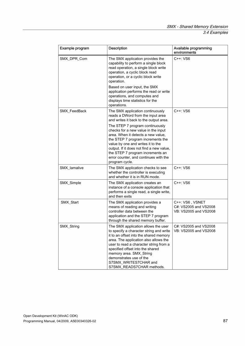
SMX - Shared Memory Extension 3.4 Examples
Open Development Kit (WinAC ODK) Programming Manual, 04/2009, A5E00340326-02 87
Example program Description Available programming environments
SMX_DPR_Com The SMX application provides the capability to perform a single block read operation, a single block write operation, a cyclic block read operation, or a cyclic block write operation. Based on user input, the SMX application performs the read or write operations, and computes and displays time statistics for the operations.
C++: VS6
SMX_FeedBack The SMX application continuously reads a DWord from the input area and writes it back to the output area. The STEP 7 program continuously checks for a new value in the input area. When it detects a new value, the STEP 7 program increments the value by one and writes it to the output. If it does not find a new value, the STEP 7 program increments an error counter, and continues with the program cycle.
C++: VS6
SMX_Iamalive The SMX application checks to see whether the controller is executing and whether it is in RUN mode.
C++: VS6
SMX_Simple The SMX application creates an instance of a console application that performs a single read, a single write, and then exits
C++: VS6
SMX_Start The SMX application provides a means of reading and writing controller data between the application and the STEP 7 program through the shared memory buffer.
C++: VS6 , VSNET C#: VS2005 and VS2008 VB: VS2005 and VS2008
SMX_String The SMX application allows the user to specify a character string and write it to an offset into the shared memory area. The application also allows the user to read a character string from a specified offset into the shared memory area. SMX_String demonstrates use of the S7SMX_WRITES7CHAR and S7SMX_READS7CHAR methods.
C#: VS2005 and VS2008 VB: VS2005 and VS2008

SMX - Shared Memory Extension 3.4 Examples
Open Development Kit (WinAC ODK) 88 Programming Manual, 04/2009, A5E00340326-02
Note Do not use the .NET conversion tool to convert a Microsoft Visual C++ V6.0 project to a Microsoft Visual Studio .NET solution. To use any of the example programs that are available in C++ only for Microsoft Visual Studio V6.0 and not Microsoft Visual Studio .NET, such as SMX_ConsData, create a new solution and add source and header files from the corresponding Microsoft Visual Studio C++ V6.0 projecs.
3.4.3 Example: using the block copy functions The following code fragment from the SMX_DataMemCopy_RTX C++ example program shows the use of the SMX block copy functions. In this fragment, the program allocates a private memory buffer and reads data from the SMX shared memory area into the buffer. The program then multiplies a number of the word values by 15 and writes the changed values back to the private memory buffer. Afterwards, the program updates the SMX shared memory segment from the private memory buffer. When finished the program frees the internal memory buffer.
Example code // alloc private memory (read and write areas) SMX_API.S7SMX_AllocExtMemBuffer(hSmx, &hExtSmx); // read a memory block from the shared memory and copy it // in the allocated private memory SMX_API.S7SMX_ReadBlock(hExtSmx, byteOffset, blockLen); for (int i = 0; i < DWORDS_TO_BE_HANDLED; i++) { // read the values from the private memory block SMX_API.S7SMX_ReadDWORD(hExtSmx, i*sizeof(ODK_UINT32), &Value); // multiply the values to effect a change Value *= 15; // write the new values in the private memory block SMX_API.S7SMX_WriteDWORD(hExtSmx, i*sizeof(ODK_UINT32), Value); } // write the memory block in the shared memory SMX_API.S7SMX_WriteBlock(hExtSmx, byteOffset, blockLen); // free the private memory SMX_API.S7SMX_FreeExtMemBuffer(hExtSmx);

SMX - Shared Memory Extension 3.4 Examples
Open Development Kit (WinAC ODK) Programming Manual, 04/2009, A5E00340326-02 89
3.4.4 Example: using the array of boolean functions The following cope fragment from the SMX_ArrayOfBool C++ example program shows the use of the read and write functions for an array of booleans. The SMX program reads an array of forty booleans, toggles the bit values, and writes the array back to the shared memory. The corresponding STEP 7 program provides a variable table for observing the changes.
Example code These code fragments are from SMX_ArrayOfBool.h and SMX_ArrayOfBool.cpp: #define MASK_BIT_1 0x01 #define MASK_BIT_2 0x02 #define MASK_BIT_3 0x04 #define MASK_BIT_4 0x08 #define MASK_BIT_5 0x10 #define MASK_BIT_6 0x20 #define MASK_BIT_7 0x40 #define MASK_BIT_8 0x80 ODK_UINT32 bitCount = 40; static ODK_BIT8 rdBitArray[5]; S7SMX_ERROR err = NULL; // initialize arrays memset(rdBitArray, 0, sizeof(rdBitArray)); // read the array of boolean values err = S7SMX_ReadS7BOOL_ARRAY(hSmx, 0, 0, bitCount, rdBitArray); // toggle each of the 40 bits for (int i = 0; i < 5; i++) { rdBitArray[i] ^= MASK_BIT_1; rdBitArray[i] ^= MASK_BIT_2; rdBitArray[i] ^= MASK_BIT_3; rdBitArray[i] ^= MASK_BIT_4; rdBitArray[i] ^= MASK_BIT_5; rdBitArray[i] ^= MASK_BIT_6; rdBitArray[i] ^= MASK_BIT_7; rdBitArray[i] ^= MASK_BIT_8; } // write the array of boolean values err = S7SMX_WriteS7BOOL_ARRAY(hSmx, 0, 0, bitCount, rdBitArray);

SMX - Shared Memory Extension 3.4 Examples
Open Development Kit (WinAC ODK) 90 Programming Manual, 04/2009, A5E00340326-02
3.4.5 GNU C++ example program for SMX WinAC ODK installs one C++ example program for SMX that you can compile with a GNU compiler. The installed project compiles and runs from a Cygwin environment running in Microsoft Windows XP Professional. You can modify and test this program yourself for any other usage. The GNU C++ SMX_DataMemCopy example program provides the same functionality as the SMX_DataMemCopy program (Page 85) that WinAC ODK provides for C++, C#, and Visual Basic. WinAC ODK installs the GNU C++ SMX_DataMemCopy program at \Examples\_GNU_Compiler_Cpp_\SMX_DataMemCopy. Refer to the Readme text file at this location for usage instructions and related information.

Open Development Kit (WinAC ODK) Programming Manual, 04/2009, A5E00340326-02 91
CMI - Controller Management Interface 44.1 Overview
The WinAC ODK Controller Management Interface (CMI) provides tools to create a custom client application that interacts directly with WinLC RTX. Your application runs as a client of WinLC RTX, which can get or set specific features of the PLC. The open nature of the WinAC ODK Controller Management Interface allows you to develop applications in the programming environment of your choice, for example, Visual Basic, C++, or C#. Your custom application can implement all of the functionality of the WinLC RTX controller panel using the CMI interface. It can display status indicators, change the operating mode, display and change tuning data, read the diagnostic buffer, and perform other functions using the published interfaces. The Controller Management Interface provides a set of methods for accessing controller information, and defines a set of features and feature attributes that your client application can get or set. For example, CMI defines the feature KeySwitch. The KeySwitch feature contains one attribute named Value that corresponds to the possible operating mode selector positions (RUN, STOP, or MRES) of the controller. A CMI application can use the GetFeature method to get the current value of the WinLC RTX operating mode selector, which it can then display on a dialog or in a console window. A CMI application can also use the SetFeature method to set the current position of the WinLC RTX operating mode selector as illustrated below:
4.1.1 Capabilities of the FeatureProvider
FeatureProvider COM object The WinAC ODK Controller Management Interface provides a FeatureProvider COM object. The Feature Provider enables your application to perform the following functions: ● Find and connect to WinLC RTX on your computer ● Determine the set of features that the connected controller supports.

CMI - Controller Management Interface 4.1 Overview
Open Development Kit (WinAC ODK) 92 Programming Manual, 04/2009, A5E00340326-02
● Read the values for attributes of the features that WinLC RTX and CMI support. Your software can use these attributes according to the requirements of your application, such as displaying the LED indicators of WinLC RTX.
● Change the values of the attributes for specific features supported by WinLC RTX and CMI. This allows your application to perform certain functions such as changing the operating mode of the controller.
● Register a feature for change notification so that your application can respond to specific events in the controller. For example, your application can detect a change to STOP mode and take specific action in that event.
The picture below shows the capabilities of the WinAC ODK Controller Management Interface:
The List of Features and Attributes section (Page 111) contains the complete set of features and attributes that WinLC RTX supports.
4.1.2 CMI Type Libraries (DLLs) Your client application connects to the FeatureProvider COM object of the WinAC ODK Controller Management Interface, which contains two DLLs that provide interfaces for accessing the functionality of the PLC: ● S7WCUIFX.DLL is the "S7 WinAC Unified Panel Interfaces 1.0 Type Library". It provides
the interface definitions. ● S7WCUFPX.DLL is the "FeatureProvider 1.0 Type Library". It provides the Feature
Provider that implements the interfaces.
The WinLC RTX installation supplies the two CMI DLLs in the default installation folder ...\Siemens\Common\OCX. The installation of WinAC ODK installs type library files that provide access to the CMI DLLs. How you incorporate the Feature Provider into your custom

CMI - Controller Management Interface 4.1 Overview
Open Development Kit (WinAC ODK) Programming Manual, 04/2009, A5E00340326-02 93
application depends on your programming environment, and is described in the topic "Including the Controller Management Interface type libraries (Page 128)".
4.1.3 Interfaces of the Feature Provider The DLLs of the Feature Provider supply interfaces that your client application uses to interact with WinLC RTX. These interfaces provide methods (functions) for getting or setting the values of the features supported by WinLC RTX. Error! Bookmark not defined. WinLC RTX supports a set of features for monitoring or modifying operation of the controller, such as the keyswitch position or status LEDs. Each feature has a set of attributes that contain a value. For example, the mode selector that sets the operating mode is controlled by the Value attribute of the KeySwitch feature. The CMI application can get this value, or it can set this value. The picture below illustrates the interfaces between the CMI application and the features and attributes of the PLC.
You use the methods of the following interfaces to interact with WinLC RTX by getting and setting values for the attributes of the features:

CMI - Controller Management Interface 4.1 Overview
Open Development Kit (WinAC ODK) 94 Programming Manual, 04/2009, A5E00340326-02
● The IPLC (Page 94) interface provides methods for finding and connecting to a controller on the local computer.
● The IFeature (Page 97) interface provides methods for getting or setting an individual feature and its attributes. It also provides methods that register (or unregister) a feature for notification of a change in the value of an attribute of that feature such that the CMI application receives a callback when a change occurs in a registered feature. In addition, the IFeature interface provides methods for the CMI application to be notified of a loss of connection to WinLC RTX.
● The IFeatureCallback (Page 104) interface provides a method that you can program in your CMI application to be executed whenever a value of an attribute of a registered feature changes. It also provides a method that you can program to be executed when the connection to WinLC RTX is broken.
Note The IFeatureCallback interface defines two methods: OnFeatureChanged and OnPLCDisconnect. You must write the code in your CMI application to implement these methods for handling the callbacks for changed feature attribute values (OnFeatureChanged) and for the notification of an abnormal loss-of-connection (OnPLCDisconnect).
4.1.4 Methods of the IPLC Interface The IPLC interface provides two methods that allow the client application to perform the following tasks: ● Find all PC-based PLC installed on the computer (Browse) ● Connect to a specific PLC (Connect)
Browse You use the Browse method to find the available PLCs that your client application can access. The Browse method returns arrays of connection strings and start information for any PC-based PLC on the computer.

CMI - Controller Management Interface 4.1 Overview
Open Development Kit (WinAC ODK) Programming Manual, 04/2009, A5E00340326-02 95
Browse (pConnectStrings, pStartInfos, pErrorID) Visual Basic Sub Browse( pConnectStrings, pStartInfos, pErrorID As Long)
C++ HRESULT Browse( [in,out] VARIANT* pConnectStrings, [in,out] VARIANT* pStartInfos, [in,out] long* pErrorID);
C# void Browse( ref object pConnectStrings, ref object pStartInfos, ref int pErrorID)
Parameter definitions ● pConnectStrings is a pointer to the connection information for the PLC that provides the
name of the computer (ComputerName), the name of the PLC (PLCName), and the type of PLC (PLCType). A slash ("/") or backslash ("\") separates each element of the connection information.
● pStartInfos is a pointer to start information for the PLC. – If the PLC has not started, the start information is empty. – If the PLC is running, the start information returns the following value: Running – If the PLC has been configured but is not running, the start information returns the
following value: Configured ● pErrorID is a pointer to the error number and is one of the following values: Error code Description EFP_SUCCESS Browse successful EFP_PARAM_INVALID pStartInfos or pConnectStrings is not valid EFP_BROWSE_FAILED Unable to perform the browse operation
Connect The Connect method connects to the specified PLC and returns the list of features that are supported by that PLC. Connect (ConnectString, pIFeature, pFeatureNames, pAttributeNamesArray, pErrorID) Visual Basic Sub Connect( ConnectString As String, pIFeature As IFeature, pFeatureNames, pAttributeNamesArray, pErrorID As Long)
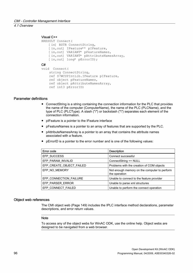
CMI - Controller Management Interface 4.1 Overview
Open Development Kit (WinAC ODK) 96 Programming Manual, 04/2009, A5E00340326-02
Visual C++ HRESULT Connect( [in] BSTR ConnectString, [in,out] IFeature** pIFeature, [in,out] VARIANT* pFeatureNames, [in,out] VARIANT* pAttributeNamesArray, [in,out] long* pErrorID);
C# void Connect( string ConnectString, ref S7WCUPIntLib.IFeature pIFeature, ref object pFeatureNames, ref object pAttributeNamesArray, ref int3 pErrorID)
Parameter definitions ● ConnectString is a string containing the connection information for the PLC that provides
the name of the computer (ComputerName), the name of the PLC (PLCName), and the type of PLC (PLCType). A slash ("/") or backslash ("\") separates each element of the connection information.
● pIFeature is a pointer to the IFeature interface ● pFeatureNames is a pointer to an array of features that are supported by the PLC. ● pAttributeNamesArray is a pointer to an array that contains the attribute names
associated with a feature. ● pErrorID is a pointer to the error number and is one of the following values: Error code Description EFP_SUCCESS Connect successful EFP_PARAM_INVALID ConnectString == NULL EFP_CREATE_OBJECT_FAILED Problems with the creation of COM objects EFP_NO_MEMORY Not enough memory on the computer to perform
the operation EFP_CONNECTION_FAILURE Unable to connect to the feature provider EFP_PARSER_ERROR Unable to parse xml structures EFP_CONNECT_FAILED Unable to perform the connect operation
Object web references The CMI object web (Page 149) includes the IPLC interface method declarations, parameter descriptions, and error return values.
Note To access any of the object webs for WinAC ODK, use the online help. Object webs are designed to be navigated from a web browser.

CMI - Controller Management Interface 4.1 Overview
Open Development Kit (WinAC ODK) Programming Manual, 04/2009, A5E00340326-02 97
4.1.5 Methods of the IFeature Interface The IFeature interface provides three sets of paired methods (six individual methods) for interacting with the PLC: ● GetFeature and SetFeature: These methods allow you to read (get) and write (set) values
for the attributes of specific features. ● RegisterFeatureForChange and UnregisterFeatureForChange: These methods allow you
to register (and to unregister) for callback notification whenever a readable value of a feature changes. (Not all features can be registered. Refer to the list of features to determine whether a feature can be registered for callback.)
● RegisterForConnectionCheck and UnregisterForConnectionCheck: These methods allow you to register (and to unregister) for a connection check by the Feature Provider.
The RegisterFeatureForChange and RegisterForConnectionCheck methods direct the Feature Provider to call the OnFeatureChanged and OnPLCDisconnect methods of the IFeatureCallback interface (Page 104) when registered features change or when CMI loses the connection to the PLC.
GetFeature and SetFeature methods You use the GetFeature and SetFeature methods to read (get) or write (set) values for the attributes associated with a feature:
GetFeature The GetFeature method reads a feature in the PLC and returns the values of the attributes. GetFeature (FeatureName, pAttributeNames, pAttributeValues, pErrorID) Visual Basic Sub GetFeature( FeatureName As String, pAttributeNames, pAttributeValues, pErrorID As Long)

CMI - Controller Management Interface 4.1 Overview
Open Development Kit (WinAC ODK) 98 Programming Manual, 04/2009, A5E00340326-02
C++ HRESULT GetFeature( [in] BSTR FeatureName, [in,out] VARIANT* pAttributeNames, [in,out] VARIANT* pAttributeValues, [in,out] long* pErrorID);
C# void GetFeature( string FeatureName, ref object pAttributeNames, ref object pAttributeValues, ref int pErrorID)
Parameter definitions ● FeatureName defines the feature to be read by this operation. ● pAttributeNames is a pointer to an array of names for the attributes associated with the
selected feature. ● pAttributeValues is a pointer to an array of values for the attributes of the selected
feature. ● pErrorID is a pointer to the error number and is one of the following values: Error code Description EFP_SUCCESS GetFeature successful EFP_PARAM_INVALID pAttributeValues, pAttributeNames or
FeatureName is not valid EFP_FEATURE_INVALID Feature specified in FeatureName is not
supported by the PLC EFP_NO_MEMORY Not enough memory on the computer to perform
the operation EFP_CONNECTION_FAILURE Unable to connect to the feature provider EFP_PARSER_ERROR Unable to parse xml structures EFP_GET_FEATURE_FAILED Unable to execute GetFeature
SetFeature The SetFeature method writes new values for the attributes of a specified feature in the PLC. A CMI application can only use SetFeature to write attributes of type Write or Read/Write.
Note Do not pass attributes of type Read to SetFeature. SetFeature ignores any attributes that are read-only. It returns no error code and does not generate a value change in the Error feature.
SetFeature (FeatureName, AttributeNames, AttributeValues, pErrorID)

CMI - Controller Management Interface 4.1 Overview
Open Development Kit (WinAC ODK) Programming Manual, 04/2009, A5E00340326-02 99
Visual Basic Sub SetFeature( FeatureName As String, AttributeNames, AttributeValues, pErrorID As Long
Visual C++ HRESULT SetFeature( [in] BSTR FeatureName, [in] VARIANT AttributeNames, [in] VARIANT AttributeValues, [in,out] long* pErrorID);
C# void SetFeature( string FeatureName, object AttributeNames, object AttributeValues, ref int pErrorID)
Parameter definitions ● FeatureName defines the feature to be modified by this operation. ● AttributeNames is an array of names for the attributes associated with the selected
feature. ● AttributeValues is an array of values for the attributes of the selected feature. ● pErrorID is a pointer to the error number and is one of the following values: Error code Description EFP_SUCCESS SetFeature successful EFP_PARAM_INVALID FeatureName is not valid EFP_FEATURE_INVALID Feature specified in FeatureName is not
supported by the PLC EFP_NO_MEMORY Not enough memory on the computer to perform
the operation EFP_CONNECTION_FAILURE Unable to connect to the feature provider EFP_PARSER_ERROR Unable to parse xml structures EFP_SET_FEATURE_FAILED Unable to execute SetFeature
RegisterFeatureForChange and UnregisterFeatureForChange methods You use the RegisterFeatureForChange method to register a specific feature for change notification (callback). The Feature Provider generates a call to the OnFeatureChanged method whenever a value for any of the Read or Read/Write attributes of the registered feature changes. You program the OnFeatureChanged method with custom software to respond to changes in the features that you registered. Changes to Write attributes do not generate a callback.

CMI - Controller Management Interface 4.1 Overview
Open Development Kit (WinAC ODK) 100 Programming Manual, 04/2009, A5E00340326-02
You use the UnregisterFeatureForChange method to remove the registration for a selected feature.
Note The Feature Provider maintains a notification table for tracking the registered client applications so that it can perform callback to those client applications. The Feature Provider creates a new entry in the notificiation table and stores the context, feature, and notification ID for the registered feature.
Not all features can be registered. Refer to the list of features to determine whether a feature can be registered for callback.
RegisterFeatureForChange The RegisterFeatureForChange method registers a specified feature with the Feature Provider to generate notification whenever the values of the attributes of that feature change. You pass the IFeatureCallback interface pointer to the Feature Provider, and the Feature Provider performs the callback on the OnFeatureChanged method that you implemented. The RegisterFeatureForChange method generates a pointer to a unique notification ID for the registered feature as an output parameter. RegisterFeatureForChange (pCallback, FeatureName, Context, pNotificationID, pErrorID) Visual Basic Sub RegisterFeatureForChange( pCallback As IFeatureCallback, FeatureName As String, Context, pNotificationID As Long, pErrorID As Long)
Visual C++ HRESULT RegisterFeatureForChange( [in] IFeatureCallback* pCallback, [in] BSTR FeatureName, [in] VARIANT Context, [in,out] long* pNotificationID, [in,out] long* pErrorID);

CMI - Controller Management Interface 4.1 Overview
Open Development Kit (WinAC ODK) Programming Manual, 04/2009, A5E00340326-02 101
C# void RegisterFeatureForChange( S7WCUPIntLib.IFeatureCallback pCallback, string FeatureName, object Context, ref int pNotificationID, ref int pErrorID)
Parameter definitions ● pCallback is a pointer to a callback interface IFeatureCallback. ● FeatureName is the name of the feature to be registered by this operation. ● Context is a pointer to a client context that is stored and returned by the
OnFeatureChanged method. This allows your application to identify elements within a specific feature.
● pNotificationID is a pointer to a unique identification number. You use this identification number when unregistering the feature.
● pErrorID is a pointer to the error number and is one of the following values: Error code Description EFP_SUCCESS RegisterFeatureForChange successful EFP_PARAM_INVALID pNotificationID == NULL or FeatureName ==
NULL or pCallback == NULL EFP_FEATURE_INVALID Feature is not supported by the PLC EFP_ALREADY_REGISTERED Feature is already registered EFP_NO_MEMORY Not enough memory on the computer to perform
the operation EFP_CONNECTION_FAILURE Unable to connect to the feature provider EFP_PARSER_ERROR Unable to parse xml structures EFP_REGISTER_FEATURE_FAILED Unable to perform registration EFP_INTERNAL_ERROR Operating system error
UnregisterFeatureForChange The UnregisterFeatureForChange method sends the notification ID to remove the callback registration for the specified feature.
Note Ensure that your client application unregisters all of the registered features and disconnects from the Feature Provider before exiting.
UnregisterFeatureForChange (NotificationID, pErrorID) Visual Basic Sub UnregisterFeatureForChange( NotificationID As Long, pErrorID As Long)

CMI - Controller Management Interface 4.1 Overview
Open Development Kit (WinAC ODK) 102 Programming Manual, 04/2009, A5E00340326-02
Visual C++ HRESULT UnregisterFeatureForChange( [in] long* NotificationID, [in,out] long* pErrorID);
C# void UnregisterFeatureForChange( int NotificationID, ref int pErrorID)
Parameter definitions ● NotificationID is the identification number that was returned by the
RegisterFeatureForChange method. In order to ensure that the same feature is registered or unregistered, the NotificationID used by the call to UnregisterFeatureForChange must be the same as the Notification ID that was obtained from the call to RegisterFeatureForChange.
● pErrorID is a pointer to the error number and is one of the following values: Error code Description EFP_SUCCESS UnregisterFeatureForChange successful EFP_NOTIFICATION_ID_INVALID Invalid identification number EFP_NO_MEMORY Not enough memory on the computer to perform
the operation EFP_CONNECTION_FAILURE Unable to connect to the feature provider EFP_UNREGISTER_FEATURE_FAILED Unable to perform unregistration EFP_INTERNAL_ERROR Operating system error
RegisterForConnectionCheck and UnregisterForConnectionCheck methods You use the RegisterForConnectionCheck to enable the Feature Provider to perform a connection check. If the connection is broken, the Feature Provider generates a call to the OnPLCDisconnect method of the IFeatureCallback interface. You program the OnPLCDisconnect method with custom software for responding to a loss of PLC connection. You use the UnregisterForConnectionCheck method to disable the connection check.

CMI - Controller Management Interface 4.1 Overview
Open Development Kit (WinAC ODK) Programming Manual, 04/2009, A5E00340326-02 103
RegisterForConnectionCheck The RegisterForConnectionCheck method sets up a callback to occur if the connection to the PLC is broken. The RegisterForConnectionCheck method generates a pointer to a unique notification ID for the registered connection check as an output parameter. RegisterForConnectionCheck (pCallback, pNotificationID, pErrorID) Visual Basic Sub RegisterForConnectionCheck( pCallback As IFeatureCallback, pNotificationID As Long,& pErrorID As Long)
Visual C++ HRESULT RegisterForConnectionCheck( [in] IFeatureCallback* pCallback, [in,out] long* pNotificationID, [in,out] long* pErrorID);
C# void RegisterForConnectionCheck( S7WCUPIntLib.IFeatureCallback pCallback, ref int pNotificationID, ref int pErrorID)
Parameter definitions ● pCallback is a pointer to a callback interface IFeatureCallback. ● pNotificationID is a pointer to a unique identification number. You use this identification
number when unregistering the connection check. ● pErrorID is a pointer to the error number and is one of the following values: Error code Description EFP_SUCCESS RegisterForConnectionCheck successful EFP_PARAM_INVALID pNotificationID or pCallback is not valid EFP_ALREADY_REGISTERED Already registered for the connection check EFP_INTERNAL_ERROR Operating system error
UnregisterForConnectionCheck The UnregisterForConnectionCheck ends the connection check. UnregisterForConnectionCheck (NotificationID, pErrorID ) Visual Basic Sub UnregisterForConnectionCheck( NotificationID As Long, pErrorID As Long)
Visual C++ HRESULT UnregisterForConnectionCheck( [in] long NotificationID, [in,out] long* pErrorID);

CMI - Controller Management Interface 4.1 Overview
Open Development Kit (WinAC ODK) 104 Programming Manual, 04/2009, A5E00340326-02
C# void RegisterForConnectionCheck( int NotificationID, ref int pErrorID)
Parameter definitions ● NotificationID is the identification number that was returned by the
RegisterForConnectionCheck method. ● pErrorID is a pointer to the error number and is following value: Error code Description EFP_SUCCESS UnregisterForConnectionCheck successful
Object web references The CMI object web (Page 149) includes the IFeature interface method declarations, parameter descriptions, and error return values.
Note To access any of the object webs for WinAC ODK, use the online help. Object webs are designed to be navigated from a web browser.
4.1.6 Methods of the IFeatureCallback Interface The IFeatureCallback interface provides two methods that allow the client CMI application to interact with the PLC. These methods respond to the registration methods RegisterFeatureForChange and RegisterForConnectionCheck of the IFeature interface and allow you to perform the following tasks: ● Read the changes to the attributes of a registered feature (OnFeatureChanged) ● Receive notification of connection loss from the Feature Provider (OnPLCDisconnect) If you use the IFeatureCallback interface, you must write the code for OnFeatureChanged and OnPLCDisconnect in your CMI application.

CMI - Controller Management Interface 4.1 Overview
Open Development Kit (WinAC ODK) Programming Manual, 04/2009, A5E00340326-02 105
OnFeatureChanged The Feature Provider calls the OnFeatureChanged method of your client application whenever a Read or Read/Write attribute value for a registered feature changes. This method provides the notification ID of the registered feature and the values for the attributes of that feature. You implement code in the OnFeatureChanged method to respond to the changes. Changes to attributes of type Write do not generate a callback. OnFeatureChanged (FeatureName, Context, NotificationID, AttributeNames, AttributeValues) Visual Basic Sub OnFeatureChanged( FeatureName As String, Context, NotificationID As Long, AttributeNames, AttributeValues)
C++ HRESULT OnFeatureChanged( [in] BSTR FeatureName, [in] VARIANT Context, [in] long NotificationID, [in] VARIANT AttributeNames, [in] VARIANT AttributeValues);
C# void OnFeatureChanged( string FeatureName, object Context, int NotificationID, object AttributeNames, object AttributeValues)
Parameter definitions ● FeatureName is the name of the registered feature that changed. ● Context contains the value of the Context that was passed by the
RegisterFeatureForChange method. ● NotificationID is the notification identifier that was returned by the
RegisterFeatureForChange method. ● AttributeNames contains the names of the attributes associated with the feature. ● AttributeValues contains the values for the attributes of the feature.
OnPLCDisconnect The Feature Provider calls the OnPLCDisconnect method of the client application when the connection to the PLC has been broken and the client application has registered for notification of connection loss. You use the RegisterForConnectionCheck method to register for PLC connection loss notification. You implement code in the OnPLCDisconnect method to respond to a broken PLC connection. OnPLCDisconnect (ErrorID)

CMI - Controller Management Interface 4.2 Features and attributes of WinLC RTX
Open Development Kit (WinAC ODK) 106 Programming Manual, 04/2009, A5E00340326-02
Visual Basic Sub OnPLCDisconnect(ErrorID As Long)
Visual C++ HRESULT OnPLCDisconnect([in] long ErrorID);
C# void OnPLCDisconnect(int ErrorID)
Parameter definition ErrorID denotes the error condition that resulted in the loss of PLC connection.
Object web references The CMI object web (Page 149) includes the IFeatureCallback interface method declarations, parameter descriptions, and error return values.
Note To access any of the object webs for WinAC ODK, use the online help. Object webs are designed to be navigated from a web browser.
4.2 Features and attributes of WinLC RTX WinLC RTX supports a set of specific features with specific attributes. Some attributes only allow you to read the value, while others allow you to change the value of that attribute. In addition, some attributes support callback, allowing your client application to be notified whenever the value of that attribute changes. The Feature Provider acts as an interface between your CMI application and WinLC RTX and provides the means to read and write values of the attributes for the defined features. Each feature represents an element or operation of the controller, such as a keyswitch position or status LEDs. Each feature has a set of attributes, and each attribute has a set of defined values that are valid for that attribute. For example, the operating mode selector switch is controlled by the Value attribute of the KeySwitch feature. The Value attribute can be set to the following values: ● STOP: Sets the operating mode selector to STOP and places the controller in STOP
mode ● RUN: Sets the operating mode selector to RUN and places the controller in RUN mode ● MRES: Initiates a memory reset of the controller

CMI - Controller Management Interface 4.2 Features and attributes of WinLC RTX
Open Development Kit (WinAC ODK) Programming Manual, 04/2009, A5E00340326-02 107
The features can be grouped according to functions. For a complete list of all of the WinLC RTX features and attributes, see the List of WinLC RTX features and attributes (Page 111).
Features that correspond to controller operations Feature Attribute Description KeySwitch Value, ForceColdStart Changes the keyswitch settings for
changing the operating mode of the PLC Also allows you to force WinLC RTX to perform a cold restart
LED Power, BatteryFault, InternalFault, ExternalFault, BusFaultCount, BusFault_, Force, Run, Stop
Provides the state of the status indicators of the PLC
Error ID Provides the error code from the PLC for an illegal operation, such as attempting to restore an archive file when the keyswitch is set to RUN.
ControllerHelp Help_Host, Help_System, Help_Dir, HelpLanguage_Count, HelpLanguage
Provides the name, type and other characterstics of the online help system for the controller

CMI - Controller Management Interface 4.2 Features and attributes of WinLC RTX
Open Development Kit (WinAC ODK) 108 Programming Manual, 04/2009, A5E00340326-02
Features that start or shut down the controller Feature Attribute Description PLCInstance Value Creates or shuts down an instance of
WinLC RTX PLC Value Reports the state of the PLC:
Started or powered on Shutdown or powered off Not available
Personality Name, Type, ProductCode, SWRelease, FWRelease, HWRelease
Provides the product-specific information about the PLC
StartAtBoot Value Configures the WinLC controller to automatically start whenever the computer is booted (turned on or restarted)
MemoryCardFile Buffer, Size Contains the PLC archive/restore file (memory card file
Features that configure WinLC RTX options Feature Attribute Description AutoStart Value Sets the Autostart option for starting
WinLC RTX CPULanguage CurrentLanguage, Count,
Language_ Provides the language selection for WinLC RTX
Security n/a Internal use only: This feature is not available for CMI applications.
HW_DataStorage Path_Prog, Path_File, Active_DataStorage, RetStg_Available,MemSize,PDState,Microbox
Specifies information about WinAC Data Storage as configurable from the Customizing Options of the controller panel.
HW_LEDs Available, Active Defines whether the hardware platform has physical LEDs, and if so whether WinLC RTX activates them or not.
SpeedStep Enabled Determines whether the Intel "SpeedStep" and AMD "Cool'n'Quiet" Technology is enabled or not
PLC Memory Size Max_Code_Size, Max_Data_Size
Specifies maximum memory allocated for the code and for the data blocks of the STEP 7 user program
Failsafe CPU FS Available Specifies whether WinLC RTX is failsafe or not (WinAC RTX F installation.)

CMI - Controller Management Interface 4.2 Features and attributes of WinLC RTX
Open Development Kit (WinAC ODK) Programming Manual, 04/2009, A5E00340326-02 109
Features that tune WinLC RTX performance Feature Attribute Description CPU Usage (Extended)
RTSSCfg, RTXUsage,CPU_Count,CPU_Kernel, CPU_Appl
Provides information about CPU Usage regarding WinLC RTX, the kernel, and applications.
Priority Value, LowerLimit, UpperLimit, Normal, Critical
Sets the parameters for adjusting the priority of WinLC RTX
MinCycleTime Value, LowerLimit, UpperLimit Sets the parameters for the minimum cycle time of WinLC RTX
MinSleepTime Value, LowerLimit, UpperLimit Sets the parameters for the minimum sleep time of WinLC RTX
OBExecution WakeInterval, SleepInterval, DefaultWakeInterval, DefaultSleepInterval, UpperLimit, LowerLimit
Provides information about the amount of sleep time for WinLC RTX
Timing UpperLimit, CycleTimeCount, CycleTimeBuffer, CycleTimeMax. CycleTimeAverage, CycleTimeLast, ExecTimeMin, ExecTimeMax, ExecTimeAverage, ExecTimeLast, SleepIntervalCounter, Clear
Provides information about the performance for WinLC RTX (showing the configured and actual execution times of the control program)
Features that provide diagnostic data Feature Attribute Description Diagnostic Language, Count, Time_, Date_,
EventShort_, EventLong_, EventID_, EventHex_
Provides the information in the diagnostic buffer
DiagnosticLanguage Count, Language_ Provides the language options for the diagnostic buffer

CMI - Controller Management Interface 4.2 Features and attributes of WinLC RTX
Open Development Kit (WinAC ODK) 110 Programming Manual, 04/2009, A5E00340326-02
4.2.1 About attributes CMI provides a header file for each of the programming environments that contains the feature names, attribute names, and constant values for specified attributes. Use the constants as defined in the header file for your programming environment when constructing your CMI function calls. The header files for the features are listed below: Programming language environment
Features header file
Location
Visual Basic V6.0 Feature.bas Program Files\Siemens\WINAC\ODK\ Examples\CMI\VB\CMI_Demo_Panel\VB6
Visual Basic (.NET, 2005, 2008)
Feature.vb Program Files\Siemens\WINAC\ODK\ Examples\CMI\VB\CMI_Get_And_Set_Feature
Visual C++ (V6.0, .NET, 2005, 2008)
featureStrDefine.h Program Files\Siemens\WINAC\ODK\Include
Visual C# (.NET, 2005, 2008)
Feature.cs Program Files\Siemens\WINAC\ODK\Examples\ CMI\CS\CMI_Get_And_Set_Feature
About attribute types Most feature attributes are of type Read, Write, or Read/Write. They represent data that is read from or written to the PLC. Some attributes, however, can be typed as Input or Output parameters. An attribute of type Input can be used as an input parameter to a GetFeature or SetFeature call and provides information about executing the call. An attribute of type Output is returned as an output parameter from either a GetFeature or SetFeature call, for example a return status. Input and Output parameters are not read from or written to the PLC. The following table describes each of the attribute types: Attribute Type Description Read Value to be read from the PLC using a GetFeature call, for example, Error feature,
ID attribute Write Value to be written to the PLC using a SetFeature call, for example, PLCInstance or
PLCPower feature, Value attribute Read/Write Value that can be either read from the PLC using a GetFeature call, or written to the
PLC using a SetFeature call, for example, Autostart feature, Value attribute Input Parameter required by either a GetFeature or SetFeature call to provide information
about how to perform the call, for example, Diagnostic feature, Language attribute The Language attribute when passed to a GetFeature call for the Diagnostic feature, specifies the language in which GetFeature is to return the diagnostic information. If Language is VAL_LANGUAGE_GERMAN, for example, the GetFeature returns the event descriptions in German. The input attribute Language is not read from or written to the PLC or to the diagnostic buffer language setting. It is only input information for the GetFeature call.
Output Parameter returned from either a GetFeature or SetFeature call that provides information about the call, for example, a status value. Currently, CMI does not define any attributes of type Output.

CMI - Controller Management Interface 4.2 Features and attributes of WinLC RTX
Open Development Kit (WinAC ODK) Programming Manual, 04/2009, A5E00340326-02 111
About attribute values The attribute values in the list of features and attributes are either string or integer data types. Use the data types of your programming environment for declaring variables for attribute values. In the list of features and attributes, the value column sometimes lists a fixed set of values that are valid for the specific attribute, especially when the attribute value is a string. In this case, the value column provides the string constants from the feature header file. The names of the string constants and their values are the same for each programming environment; for example, VAL_ON is "On" in the feature header file for each supported programming environment. In other cases, the value column provides a range of valid values for the attribute, for example, 0..100 for a percentage. In still other cases, the value column describes the requirements or limitations for the value for the specific attribute, for example, the relationship between the minimum sleep time for a PLC and the scan cycle monitoring time configured in STEP 7. When the value column is empty, the attribute value has no restrictions other than its data type.
About repeating attributes Several of the features contain attributes for which GetFeature returns multiple occurrences. In the attribute name array returned by the Connect method, these attribute names end in "_" and occur only once. When GetFeature returns a feature with multiply-occurring attributes, it appends the integers 0..n to the repeating attribute names that correspond to each of the multiple occurrences. For example, a call to GetFeature for the CPULanguage feature returns Language_0, Language_1, and Language_2 for the three languages supported by the connected PLC (English, German, and French).
4.2.2 List of WinLC RTX features and attributes
4.2.2.1 AutoStart This feature contains the Autostart option that defines the operating mode for the controller when it starts. If Autostart is On, the controller starts up in the operating mode that it was in when it was last shut down. If Autostart is Off, the controller starts up in STOP mode. The values listed below are string constants defined in the feature header file for your environment. Attribute Data
Type Type Value Description
Value String Read/Write VAL_ON VAL_OFF
Specifies whether the AutoStart option is configured or not
This feature can be registered for a feature change callback through the IFeatureCallback interface (Page 104).
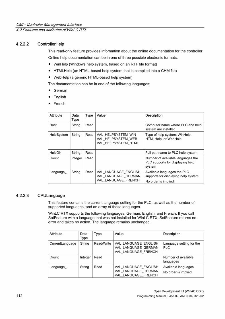
CMI - Controller Management Interface 4.2 Features and attributes of WinLC RTX
Open Development Kit (WinAC ODK) 112 Programming Manual, 04/2009, A5E00340326-02
4.2.2.2 ControllerHelp This read-only feature provides information about the online documentation for the controller. Online help documentation can be in one of three possible electronic formats: ● WinHelp (Windows help system, based on an RTF file format) ● HTMLHelp (an HTML-based help system that is compiled into a CHM file) ● WebHelp (a generic HTML-based help system) The documentation can be in one of the following languages: ● German ● English ● French Attribute Data
Type Type Value Description
Host String Read Computer name where PLC and help system are installed
HelpSystem String Read VAL_HELPSYSTEM_WIN VAL_HELPSYSTEM_WEB VAL_HELPSYSTEM_HTML
Type of help system: WinHelp, HTMLHelp, or WebHelp
HelpDir String Read Full pathname to PLC help system Count Integer Read Number of available languages the
PLC supports for displaying help system
Language_
String Read VAL_LANGUAGE_ENGLISH VAL_LANGUAGE_GERMAN VAL_LANGUAGE_FRENCH
Available languages the PLC supports for displaying help system No order is implied.
4.2.2.3 CPULanguage This feature contains the current language setting for the PLC, as well as the number of supported languages, and an array of those languages. WinLC RTX supports the following languages: German, English, and French. If you call SetFeature with a language that was not installed for WinLC RTX, SetFeature returns no error and takes no action. The language remains unchanged. Attribute Data
Type Type Value Description
CurrentLanguage String Read/Write VAL_LANGUAGE_ENGLISH VAL_LANGUAGE_GERMAN VAL_LANGUAGE_FRENCH
Language setting for the PLC
Count Integer Read Number of available languages
Language_
String Read VAL_LANGUAGE_ENGLISH VAL_LANGUAGE_GERMAN VAL_LANGUAGE_FRENCH
Available languages No order is implied.

CMI - Controller Management Interface 4.2 Features and attributes of WinLC RTX
Open Development Kit (WinAC ODK) Programming Manual, 04/2009, A5E00340326-02 113
This feature can be registered for a feature change callback through the IFeatureCallback interface (Page 104).
4.2.2.4 CPU Usage Extended This read-only feature contains information about extended information about CPU usage. Attribute Data
Type Type Value Description
RTSSCfg String Read VAL_CFG_UP_PIC VAL_CFG_UP_APIC VAL_CFG_MP_DEDICATED VAL_CFG_MP_SHARED
Type of processor(s) on local computer: Uni- or multi-processor; shared or dedicated.
RTX Usage
Integer Read 0 - 100% Percentage of CPU that WinLC RTX is using.
CPU Count Integer Read 0 - 100% Number of processors CPU Kernel
Integer Read 0 - 100% Percentage of CPU that the kernel is using.
CPU Appl Integer Read 0 - 100% Percentage of CPU that all other applications are using.
4.2.2.5 Diagnostic This read-only feature accesses the information in the diagnostic buffer of the PLC. WinLC RTX supports the following languages: German, English, and French. See also the DiagnosticLanguage feature. Attribute Data
Type Type Value Description
Language String Input VAL_LANGUAGE_ENGLISH VAL_LANGUAGE_GERMAN VAL_LANGUAGE_FRENCH
Input parameter to GetFeature that defines the language in which to return the diagnostic buffer
TimeDiff Integer Read Difference in half-hours between the controller time and local time; can be used as a time zone correction factor
Count Integer Read Number of diagnostic buffer event entries
Time_ String Read Time of event, for each event Date_ String Read Date of event, for each event EventShort_ String Read Short description of event, for
each event EventLong_ String Read Long description of event, for
each event EventID_ String Read ID of event, for each event EventHex_ String Read Hexadecimal ID of event, for each
event

CMI - Controller Management Interface 4.2 Features and attributes of WinLC RTX
Open Development Kit (WinAC ODK) 114 Programming Manual, 04/2009, A5E00340326-02
4.2.2.6 DiagnosticLanguage This read-only feature provides information about the language options for the diagnostic buffer. Attribute Data
Type Type Value Description
Count Integer Read Number of available languages for diagnostic buffer
Language_ String Read VAL_LANGUAGE_ENGLISH VAL_LANGUAGE_GERMAN VAL_LANGUAGE_FRENCH VAL_LANGUAGE_SPANISH VAL_LANGUAGE_ITALIAN VAL_LANGUAGE_JAPANESE
Available languages for diagnostic buffer No order is implied.
4.2.2.7 Error This read-only feature returns the error code from the controller for an illegal operation, such as attempting to restore an archive file when the keyswitch is set to RUN. Attribute Data Type Type Description ID Integer Read Error code returned from PLC
Note If you retrieve the Error feature with a GetFeature call, you will always get an ID value of 0. You must register this feature for change notification (Page 141) to get the actual error ID. The reason is that the Feature Provider immediately resets the error ID value to 0 after sending change notification callbacks to clients that registered the Error feature for change.
The following table lists the possible error ID values and descriptions. Error ID and Description _PSERR_OKAY (= 0) The operation was executed successfully. _PSERR_NO_MEMORY (= 1) The PLC does not have sufficient memory to perform this operation. _PSERR_ARCHIVE_NOT_VALID_IN_RUN (= 2) The PLC must be in STOP mode before you can create an archive file of the control program. _PSERR_ARCHIVE_CANNOT_GET_BLOCK_FROM_CPU (=3) The PLC was unable to create the archive file. _PSERR_RESTORE_CANNOT_LINKIN_BLOCK (= 4) The PLC is unable to restore the control program from the archive file. _PSERR_RESTORE_NOT_VALID_IN_RUN (= 5) The PLC must be in STOP mode before you can restore an archived control program.

CMI - Controller Management Interface 4.2 Features and attributes of WinLC RTX
Open Development Kit (WinAC ODK) Programming Manual, 04/2009, A5E00340326-02 115
Error ID and Description _PSERR_RESTORE_FILE_INVALID (= 6) The file specified is not an archive file or has become corrupted. _PSERR_INIT_EDBSERVER (= 7) The diagnostic buffer was not able to access the descriptions and event data list from the EDB server. You may need to reinstall the PLC. _PSERR_INIT_PDH (= 8) The system information of the computer (such as CPU usage and number of processors) in not available. This information is provided by the PDH.DLL of the Windows operating system. _PSERR_KEYSWITCH_NOT_ALLOWED_IN_ MCF_OP (= 9) There was an attempt to change the setting of the keyswitch during an archive or restore operation. _PSERR_ARCHIVE_CANNOT_GET_BLOCK_FROM_CPU_PASSWORD_PROTECTED (= 10) The security setting for the PLC requires a password before allowing the control program to be archived. _PSERR_F_RESTORE_COMPLETED (=16) Status only: Restoration of a .wld file for a Failsafe CPU was successful.
This feature can be registered for a feature change callback through the IFeatureCallback interface (Page 104).
4.2.2.8 Failsafe CPU This read-only feature provides information about whether the connected PLC is a FailSafe CPU or not. Attribute Data Type Type Value Description Available String Read VAL_YES
VAL_NO Yes indicates the PLC is FailSafe, for example WinLC RTX F; No indicates it is not.
See also Methods of the IFeatureCallback Interface (Page 104)
4.2.2.9 HW DataStorage This feature provides information about the data storage location for WinLC RTX. Attribute Data
Type Type Value Description
Path_Prog String Read/Write
Program and Configuration path in WinLC RTX Data Storage tab of the Customize dialog: specifies where WinLC RTX stores the STEP 7 user program and configuration
Path_File String Read/Write
File storage path in WinLC RTX Data Storage tab of the Customize dialog: specifies where WinLC RTX stores retentive data if stored to a file

CMI - Controller Management Interface 4.2 Features and attributes of WinLC RTX
Open Development Kit (WinAC ODK) 116 Programming Manual, 04/2009, A5E00340326-02
Attribute Data Type
Type Value Description
Active_DataStorage String Read/Write
VAL_NVRAM VAL_FILE
Specifies type of retentive data storage for WinLC RTX: NVRAM storage (if available) or File Storage
RetStg_Available String Read VAL_YES VAL_NO
Specifies whether NVRAM storage is available in the computer as a retentive data storage location
MemSize Integer Read Specifies the amount of memory available in NVRAM storage, if available
PDState String Read VAL_TOOLARGEVAL_OK
Specifies whether the power-down state data is too large or not for the available NVRAM if available, and if selected.
Microbox String Read VAL_YES VAL_NO
Specifies whether the computer is a Microbox or not.
Note You must restart WinLC RTX for a change to this feature to take effect.
4.2.2.10 HW LEDs This feature provides information about the hardware LEDs for the computer of the connected controller. Some computer platforms such as the Microbox PC 427B have physical LEDs that WinLC RTX can operate. To determine whether the connected controller has hardware LEDs that WinLC RTX can operate, execute a FetFeature call and check the "Available" attribute. If it is "VAL_YES" you can get and set the "Active" attribute for WinLC RTX. If it is "VAL_NO", calls to SetFeature will be ignored and SetFeature will not return an error. Attribute Data Type Type Value Description Available String Read VAL_YES
VAL_NO Specifies whether the hardware platform has physical LEDs
Active String Read/Write VAL_YES VAL_NO
Specifies whether WinLC RTX is operating the LEDs or not
Note You must restart WinLC RTX for a change to this feature to take effect.

CMI - Controller Management Interface 4.2 Features and attributes of WinLC RTX
Open Development Kit (WinAC ODK) Programming Manual, 04/2009, A5E00340326-02 117
4.2.2.11 KeySwitch This feature provides the keyswitch position (operating mode selector setting) for WinLC RTX.
Note For the embedded controller, S7-mEC, this feature is read-only. For WinLC RTX in other cases, this feature is read/write and you can use it to change the keyswitch position (operating mode selector) of WinLC RTX. The Personality feature (Page 122) provides information on whether the PLC is an embedded controller or not.
The value attribute of the keyswitch feature for non-embedded controllers allows you to change the operating mode as follows: ● MRES initiates a memory reset and places WinLC RTX in STOP mode. ● STOP places WinLC RTX in STOP mode. With the keyswitch set to STOP, the PLC does
not execute the control program, and the outputs are set to their safe states. STEP 7 can modify and download the control program and reset the memory (MRES), but cannot change the operating mode of the PLC.
● RUN places the WinLC RTX in RUN mode and allows STEP 7 to interact with the PLC. With the keyswitch set to RUN, STEP 7 can modify and download the control program , monitor the running control program, change the variables, reset the memory (MRES), and change the operating mode of WinLC RTX.
The optional ForceColdstart attribute allows you to force WinLC RTX to perform a cold restart instead of a warm restart. A restart deletes the peripheral I/O (PII and PIQ), deletes the non-retentive memory bits (M), timers (T) and counters (C), and changes the peripheral outputs to a pre-defined safe state (default is 0). A warm restart saves the retentive memory bits, timers, counters and data blocks (DBs). A cold restart does not save the retentive memory bits, timers, counters and data blocks (DBs), but sets these areas to their default (initial) values. Attribute Data
Type Type Value Description
Value String Read/Write
VAL_KEYSWITCH_MRES VAL_KEYSWITCH_STOP VAL_KEYSWITCH_RUN
Specifies keyswitch position (operating mode selector) of PLC or Memory Reset command
ForceColdstart (optional)
String Write VAL_ON VAL_OFF
Specifies whether or not to perform cold restart when PLC is restarted
This feature can be registered for a feature change callback through the IFeatureCallback interface (Page 104).
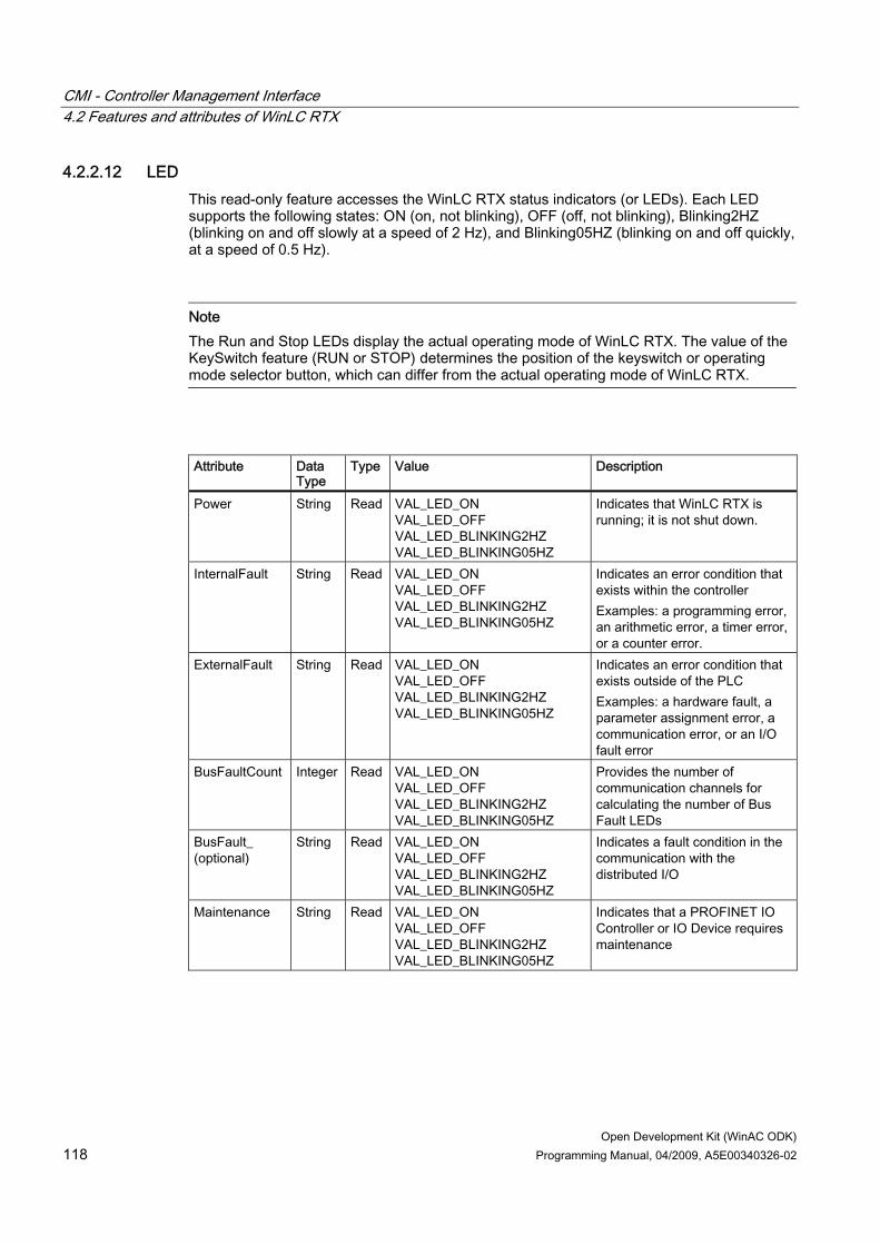
CMI - Controller Management Interface 4.2 Features and attributes of WinLC RTX
Open Development Kit (WinAC ODK) 118 Programming Manual, 04/2009, A5E00340326-02
4.2.2.12 LED This read-only feature accesses the WinLC RTX status indicators (or LEDs). Each LED supports the following states: ON (on, not blinking), OFF (off, not blinking), Blinking2HZ (blinking on and off slowly at a speed of 2 Hz), and Blinking05HZ (blinking on and off quickly, at a speed of 0.5 Hz).
Note The Run and Stop LEDs display the actual operating mode of WinLC RTX. The value of the KeySwitch feature (RUN or STOP) determines the position of the keyswitch or operating mode selector button, which can differ from the actual operating mode of WinLC RTX.
Attribute Data
Type Type Value Description
Power String Read VAL_LED_ON VAL_LED_OFF VAL_LED_BLINKING2HZ VAL_LED_BLINKING05HZ
Indicates that WinLC RTX is running; it is not shut down.
InternalFault String Read VAL_LED_ON VAL_LED_OFF VAL_LED_BLINKING2HZ VAL_LED_BLINKING05HZ
Indicates an error condition that exists within the controller Examples: a programming error, an arithmetic error, a timer error, or a counter error.
ExternalFault String Read VAL_LED_ON VAL_LED_OFF VAL_LED_BLINKING2HZ VAL_LED_BLINKING05HZ
Indicates an error condition that exists outside of the PLC Examples: a hardware fault, a parameter assignment error, a communication error, or an I/O fault error
BusFaultCount Integer Read VAL_LED_ON VAL_LED_OFF VAL_LED_BLINKING2HZ VAL_LED_BLINKING05HZ
Provides the number of communication channels for calculating the number of Bus Fault LEDs
BusFault_ (optional)
String Read VAL_LED_ON VAL_LED_OFF VAL_LED_BLINKING2HZ VAL_LED_BLINKING05HZ
Indicates a fault condition in the communication with the distributed I/O
Maintenance String Read VAL_LED_ON VAL_LED_OFF VAL_LED_BLINKING2HZ VAL_LED_BLINKING05HZ
Indicates that a PROFINET IO Controller or IO Device requires maintenance

CMI - Controller Management Interface 4.2 Features and attributes of WinLC RTX
Open Development Kit (WinAC ODK) Programming Manual, 04/2009, A5E00340326-02 119
Attribute Data Type
Type Value Description
Run String Read VAL_LED_ON VAL_LED_OFF VAL_LED_BLINKING2HZ VAL_LED_BLINKING05HZ
Indicates that the PLC is in RUN mode
Stop String Read VAL_LED_ON VAL_LED_OFF VAL_LED_BLINKING2HZ VAL_LED_BLINKING05HZ
Indicates that the PLC is in STOP mode
This feature can be registered for a feature change callback through the IFeatureCallback interface (Page 104).
4.2.2.13 MemoryCardFile (MCF) This feature enables archiving and restoring of the memory card file (archive file) for the STEP 7 user program of WinLC RTX. To restore a memory card file, the CMI application must read a memory card file from the hard disk or other media and convert it to a buffer in the format required by the MemoryCardFile feature. To do this, the CMI application must use the function hideSpecialChars() to convert the memory card file contents to a string to be used for the Buffer attribute. The CMI application must then call SetFeature for the MemoryCardFile feature with this converted buffer as the Buffer attribute, and the size of the converted buffer as the Size attribute. To archive the STEP 7 user program to a memory card file, the CMI application must call GetFeature to read the Buffer and the Size attributes from WinLC RTX. The application must then call unhideSpecialChars() to convert the string format of the buffer into the format required for the memory card file. The CMI application can then write the contents of the buffer returned by unhideSpecialChars() to a memory card file on the hard disk or other media.
NOTICE The use of the MemoryCardFile feature requires a significant amount of memory. The entire contents of a .wld file must be managed as a string buffer to perform archive and restore operations. CMI applications cannot archive and restore directly to or from the hard disk or other media. You must ensure that your system has enough available memory for the memory card file string buffer.
Attribute Data Type Type Value Description Buffer String Read/Write Binary information
as string Contents of memory card file (archive file)
Size Integer Read/Write size of memory card file in bytes
The WinAC ODK installation includes the functions hideSpecialChars() and unhideSpecialChars() as well as sample programs that use the MemoryCardFile feature to perform archive and restore operations.

CMI - Controller Management Interface 4.2 Features and attributes of WinLC RTX
Open Development Kit (WinAC ODK) 120 Programming Manual, 04/2009, A5E00340326-02
The CMI_ArchiveRestore example program demonstrates the use of the MemoryCardFile feature and the conversion functions. This program is available in C++, C#, and VB in the C:\Program Files\Siemens\WINAC\ODK\Examples\CMI folders for each programming language.
4.2.2.14 MinCycleTime This feature contains values for the minimum cycle time (in milliseconds) for the WinLC RTX scan cycle. The scan cycle time is the number of milliseconds from the start of one cycle to the start of the next cycle, and the execution time is the actual amount of time used by WinLC RTX to update the I/O and to execute the STEP 7 user program. The scan cycle time value must be greater than the execution time of the scan to provide execution time for any application that has a lower priority than WinLC RTX. Attribute Data
Type Type Value Description
Value Integer Read/Write Must be less than Scan Cycle Monitoring Time specified in STEP 7 in the Cycle/Clock Memory tab of the WinLC RTX properties.
Minimum scan cycle time
LowerLimit Integer Read 0 Lowest allowed cycle time
UpperLimit Integer Read Equal to the Scan Cycle Monitoring Time that is specified in STEP 7 in the Cycle/Clock Memory tab of the WinLC RTX properties.
Highest allowed cycle time
Note A SetFeature call with a Value attribute greater than 6000 will fail with an EFP_SET_FEATURE_FAILED error return value. A SetFeature call with a Value attribute that is less than or equal to 6000 but greater than or equal to the Scan Cycle Monitoring Time will be ignored, with no error indication. WinLC RTX will not change the value. To ensure that your Value attribute is valid for a SetFeature call, first perform a GetFeature call and verify that your intended Value attribute is less that the UpperLimit attribute. After the SetFeature call, you can again call GetFeature and verify that GetFeature returns the Value attribute that you passed to the SetFeature call.
This feature can be registered for a feature change callback through the IFeatureCallback interface (Page 104).
4.2.2.15 MinSleepTime This feature contains the values for the minimum time (in milliseconds) that WinLC RTX sleeps during the execution of OB1 to allow other Windows applications to be executed. The sleep time determines how much time is available during the free cycle (execution cycle for OB1) to allow higher priority OBs and other applications to use the resources of the computer.

CMI - Controller Management Interface 4.2 Features and attributes of WinLC RTX
Open Development Kit (WinAC ODK) Programming Manual, 04/2009, A5E00340326-02 121
Attribute Data
Type Type Value Description
Value Integer Read/Write Must be less than Scan Cycle Monitoring Time specified in STEP 7 in the Cycle/Clock Memory tab of the WinLC RTX properties.
Minimum sleep time
LowerLimit Integer Read 0 Lowest allowed sleep time
UpperLimit Integer Read Equal to the Scan Cycle Monitoring Time specified in STEP 7 in the Cycle/Clock Memory tab of the WinLC RTX properties.
Highest allowed sleep time
Note A SetFeature call with a Value attribute greater than 6000 will fail with an EFP_SET_FEATURE_FAILED error return value. A SetFeature call with a Value attribute that is less than or equal to 6000 but greater than or equal to the Scan Cycle Monitoring Time will be ignored, with no error indication. WinLC RTX will not change the value. To ensure that your Value attribute is valid for a SetFeature call, first perform a GetFeature call and verify that your intended Value attribute is less that the UpperLimit attribute. After the SetFeature call, you can again call GetFeature and verify that GetFeature returns the Value attribute that you passed to the SetFeature call.
This feature can be registered for a feature change callback through the IFeatureCallback interface (Page 104).
4.2.2.16 OBExecution This feature provides information about the amount of sleep time for WinLC RTX in microseconds. See the documentation for your controller before changing any of these attribute values. Attribute Data
Type Type Value Description
WakeInterval Integer Read/Write Execution time limit SleepInterval Integer Read/Write Forced execution sleep time DefaultWakeInterval Integer Read Default execution time limit DefaultSleepInterval Integer Read Default forced execution sleep time UpperLimit Integer Read 0..100% Maximum execution load as a percentage of
the scan cycle LowerLimit Integer Read 0..100% Minimum execution load as a percentage of
the scan cycle
This feature can be registered for a feature change callback through the IFeatureCallback interface (Page 104).

CMI - Controller Management Interface 4.2 Features and attributes of WinLC RTX
Open Development Kit (WinAC ODK) 122 Programming Manual, 04/2009, A5E00340326-02
4.2.2.17 Personality This read-only feature provides the product-specific information about the PLC. Attribute Data
Type Type Description
Name String Read PLC name (for example, "WinLC") Type String Read PLC type (for example, "RTX") ProductCode (order number)
String Read Product code (order number) o
SWRelease String Read Software version level of PLC: Format is <major release number>.<minor release number>.<service pack number>
FWRelease String Read Firmware version level of PLC: not used for WinLC RTX HWRelease String Read Hardware version level of PLC: not used for WinLC RTX Slot String Read Slot number in rack in Hardware Configuration in
STEP 7. Rack String Read Rack number in Hardware Configuration in STEP 7. Owner String Read Owner: not used for WinLC RTX Company String Read Company name: not used for WinLC RTX SerialNumber String Read Serial number of WinLC RTX ASName String Read Station name of computer on which WinLC RTX is
running. AKZ String Read Plant identification code OKZ String Read Location identification code IsEmbCtrl String Read "Yes": PLC is an embedded controller (S7-mEC)
"No": PLC is not an embedded controller
Relevance of Personality feature The Personality feature returns the PLC version to which CMI is connected. WinAC ODK V4.2 requires WinAC RTX 2009 to be installed on your computer, which includes the WinLC RTX controller with the following Personality attributes of interest: ● Name: WinLC ● Type: RTX ● SWRelease: V4.5.0 Former releases of WinAC ODK supported features for the WinAC Slot PLCs and WinLC Basis as well as WinLC RTX. Former releases of WinAC RTX included prior versions of WinLC RTX, for example: Windows Automation Center product Windows Logic Controller version WinAC RTX V4.0 WinLC RTX V4.0 WinAC RTX V4.1 WinLC RTX V4.1 WinAC RTX 2005 + SP1 WinLC RTX V4.2 WinAC RTX 2005 + SP2 WinLC RTX V4.3

CMI - Controller Management Interface 4.2 Features and attributes of WinLC RTX
Open Development Kit (WinAC ODK) Programming Manual, 04/2009, A5E00340326-02 123
Windows Automation Center product Windows Logic Controller version WinAC RTX 2008 WinLC RTX V4.4 WinAC RTX 2009 WinLC RTX V4.5
The set of features and attributes that are applicable for the connected PLC is determined by the Personality feature. The header file with the defined features and attributes is cumulative. It includes all features and attributes that have ever been supported by WinAC ODK. This document, however, describes only those features and attributes that are applicable for WinAC ODK V4.2 and the current WinLC RTX V4.5 PLC personality.
4.2.2.18 PLC This read-only feature provides the state of the PLC: ● Created: The PLC has been started or powered on. ● Shutdowned: The PLC has been shut down or powered off. ● NotAvailable: The PLC is no longer available. For example, you can use STEP 7 to
change the name of a running instance of the PLC. In this case, the CMI application can evaluate this feature and then disconnect in order to connect to the new (renamed) instance of the PLC. This feature can also be used to respond to a situation where the PLC has encountered a fatal error and is no longer responsive.
Attribute Data Type Type Value Description Value String Read VAL_PLC_CREATED
VAL_PLC_SHUTDOWNED VAL_PLC_NOTAVAILABLE
State of PLC
This feature can be registered for a feature change callback through the IFeatureCallback interface (Page 104).
4.2.2.19 PLCInstance This write-only feature creates or shuts down an instance of WinLC RTX. Attribute Data
Type Type Value Description
Value String Write VAL_PLCINSTANCE_CREATE VAL_PLCINSTANCE_SHUTDOWN
Command to create or shut down WinLC RTX
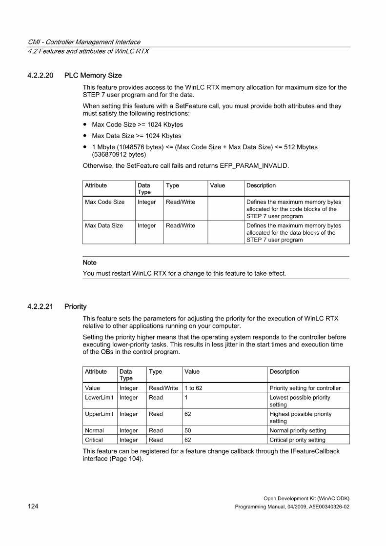
CMI - Controller Management Interface 4.2 Features and attributes of WinLC RTX
Open Development Kit (WinAC ODK) 124 Programming Manual, 04/2009, A5E00340326-02
4.2.2.20 PLC Memory Size This feature provides access to the WinLC RTX memory allocation for maximum size for the STEP 7 user program and for the data. When setting this feature with a SetFeature call, you must provide both attributes and they must satisfy the following restrictions: ● Max Code Size >= 1024 Kbytes ● Max Data Size >= 1024 Kbytes ● 1 Mbyte (1048576 bytes) <= (Max Code Size + Max Data Size) <= 512 Mbytes
(536870912 bytes) Otherwise, the SetFeature call fails and returns EFP_PARAM_INVALID. Attribute Data
Type Type Value Description
Max Code Size Integer Read/Write Defines the maximum memory bytes allocated for the code blocks of the STEP 7 user program
Max Data Size Integer Read/Write Defines the maximum memory bytes allocated for the data blocks of the STEP 7 user program
Note You must restart WinLC RTX for a change to this feature to take effect.
4.2.2.21 Priority This feature sets the parameters for adjusting the priority for the execution of WinLC RTX relative to other applications running on your computer. Setting the priority higher means that the operating system responds to the controller before executing lower-priority tasks. This results in less jitter in the start times and execution time of the OBs in the control program. Attribute Data
Type Type Value Description
Value Integer Read/Write 1 to 62 Priority setting for controller LowerLimit Integer Read 1 Lowest possible priority
setting UpperLimit Integer Read 62 Highest possible priority
setting Normal Integer Read 50 Normal priority setting Critical Integer Read 62 Critical priority setting
This feature can be registered for a feature change callback through the IFeatureCallback interface (Page 104).
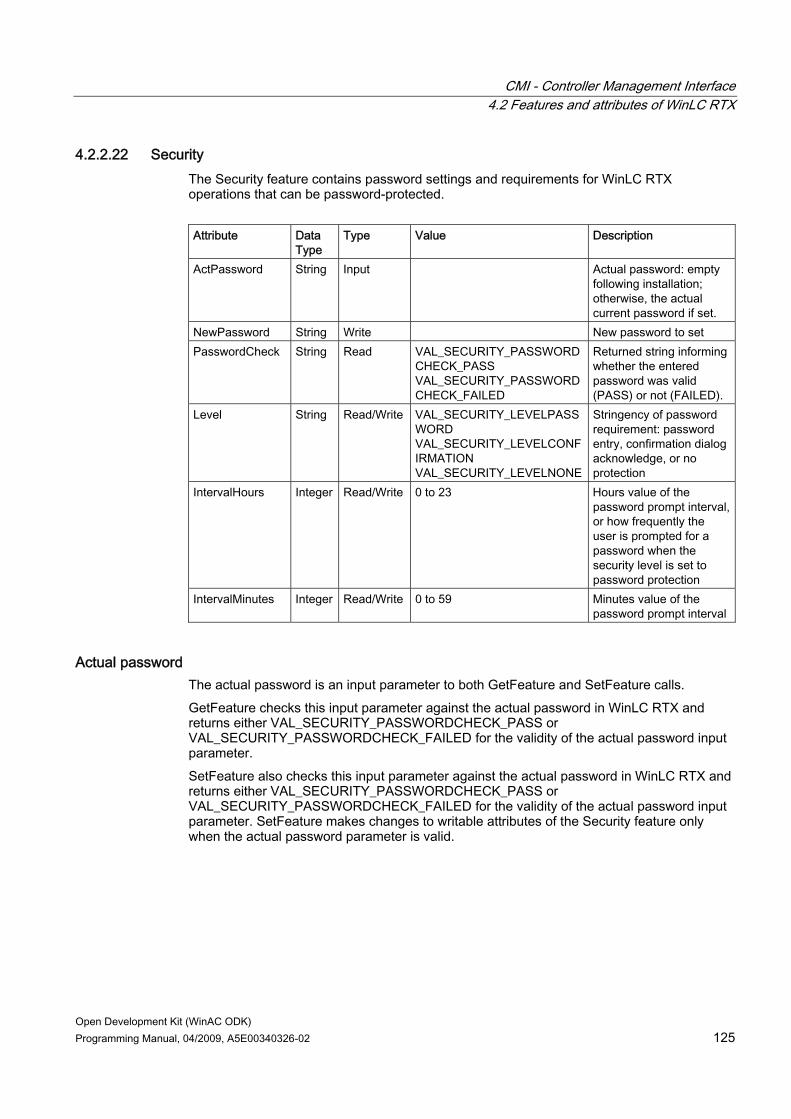
CMI - Controller Management Interface 4.2 Features and attributes of WinLC RTX
Open Development Kit (WinAC ODK) Programming Manual, 04/2009, A5E00340326-02 125
4.2.2.22 Security The Security feature contains password settings and requirements for WinLC RTX operations that can be password-protected. Attribute Data
Type Type Value Description
ActPassword String Input Actual password: empty following installation; otherwise, the actual current password if set.
NewPassword String Write New password to set PasswordCheck
String Read VAL_SECURITY_PASSWORDCHECK_PASS VAL_SECURITY_PASSWORDCHECK_FAILED
Returned string informing whether the entered password was valid (PASS) or not (FAILED).
Level String Read/Write VAL_SECURITY_LEVELPASSWORD VAL_SECURITY_LEVELCONFIRMATION VAL_SECURITY_LEVELNONE
Stringency of password requirement: password entry, confirmation dialog acknowledge, or no protection
IntervalHours Integer Read/Write 0 to 23 Hours value of the password prompt interval, or how frequently the user is prompted for a password when the security level is set to password protection
IntervalMinutes Integer Read/Write 0 to 59 Minutes value of the password prompt interval
Actual password The actual password is an input parameter to both GetFeature and SetFeature calls. GetFeature checks this input parameter against the actual password in WinLC RTX and returns either VAL_SECURITY_PASSWORDCHECK_PASS or VAL_SECURITY_PASSWORDCHECK_FAILED for the validity of the actual password input parameter. SetFeature also checks this input parameter against the actual password in WinLC RTX and returns either VAL_SECURITY_PASSWORDCHECK_PASS or VAL_SECURITY_PASSWORDCHECK_FAILED for the validity of the actual password input parameter. SetFeature makes changes to writable attributes of the Security feature only when the actual password parameter is valid.

CMI - Controller Management Interface 4.2 Features and attributes of WinLC RTX
Open Development Kit (WinAC ODK) 126 Programming Manual, 04/2009, A5E00340326-02
Security level The Security feature allows you to set levels of password security that limit access to the controller. WinLC RTX supports the following security levels: ● Password: When you select Password, certain controller panel operations such as
changing the operating mode and archiving and restoring a STEP 7 user program require that the user enter a password.
● Confirmation: When you select Confirmation, operating mode changes require that the user acknowledge a confirmation dialog.
● None: When you select None, no confirmation or password is required.
Password prompt interval You can set the password prompt interval to a time interval of your choice, from 0 to a maximum of 23 hours, 59 minutes. After entry of a valid password, WinLC RTX does not prompt the user for the password again until this time interval expires. The default setting of 0 means that the user must enter a password for each protected operation. Shutting down and starting the controller does not affect the expiration of the password prompt interval; however, it is reset whenever the user shuts down the controller panel. The next time the user starts the controller panel and accesses a password-protected function, WinLC RTX will prompt for password entry. This feature can be registered for a feature change callback through the IFeatureCallback interface (Page 104).
4.2.2.23 SpeedStep This feature contains the selection for the energy saving function of Intel or AMD processors. Intel processors offer a "SpeedStep" function and AMD processors offer "Cool'n'Quiet" Technology. Both of these are energy saving options, but they can interfere with WinLC RTX performance. WinLC RTX disables these functions by default, but this feature allows the CMI application to enable them. Attribute Data Type Type Value Description Enabled String Read/Write VAL_YES
VAL_NO Yes indicates that the Intel "SpeedStep" or AMD "Cool'n'Quiet" Technology is enabled; No indicates that the energy saving function for the processor is not enabled.
Note You must restart WinLC RTX for a change to this feature to take effect.

CMI - Controller Management Interface 4.2 Features and attributes of WinLC RTX
Open Development Kit (WinAC ODK) Programming Manual, 04/2009, A5E00340326-02 127
4.2.2.24 StartAtBoot This feature configures WinLC RTX to start automatically whenever the computer is rebooted (turned on or restarted). Attribute Data
Type Type Value Description
Value String Read/Write VAL_ON VAL_OFF
Specifies whether or not to start the PLC automatically after a reboot
This feature can be registered for a feature change callback through the IFeatureCallback interface (Page 104).
4.2.2.25 Timing This feature provides information about the performance for WinLC RTX and shows the configured and actual execution times of the STEP 7 user program). The execution time is the actual time the controller takes to complete one pass through the instructions of the user program. This includes executing OB1 and updating the I/O. The scan cycle time is the time required to execute the complete scan cycle, which also includes the minimum sleep time. The cycle time buffer is a space-separated list of values where the first value is the cycle time, and the second value is the number of scan cycles that executed at that cycle time. This buffer can be used as a histogram of scan cycle performance. Use the Clear attribute to reset all of the values in WinLC RTX. Attribute Data Type Type Description UpperLimit Integer Read Configured execution time limit, default is 9000 µs CycleTimeCount Integer Read Number of data pairs in the CycleTimeBuffer CycleTimeBuffer Integer Integer
... Read Buffer containing cycle time data as described
above CycleTimeMin Integer Read Minimum scan cycle time CycleTimeMax Integer Read Maximum scan cycle time CycleTimeAverage Integer Read Average scan cycle time CycleTimeLast Integer Read Last scan cycle time ExecTimeMin Integer Read Minimum execution time ExecTimeMax Integer Read Maximum execution time ExecTimeAverage Integer Read Average execution time ExecTimeLast Integer Read Last execution time SleepIntervalCounter Integer Read Number of times PLC has had a forced execution
sleep Clear <empty> Write Resets all of the collected timing values

CMI - Controller Management Interface 4.3 Development tasks
Open Development Kit (WinAC ODK) 128 Programming Manual, 04/2009, A5E00340326-02
4.3 Development tasks
4.3.1 Including the Controller Management Interface type libraries The CMI type libraries (Page 92) provide an interface between your application and the controller through the Feature Provider COM object. You must include these type libraries in your project to establish the IPLC interface (Page 94) and the IFeature interface (Page 97) between your application and WinLC RTX. To include the CMI type libraries, follow the instructions for your development environment.
Note The "FeatureProvider 1.0 Type Library" is S7WCUFPX.DLL and the "S7 WinAC Unified Panel Interfaces 1.0 Type Library" is S7WCUIFX.DLL. These DLLs implement the WinAC ODK Controller Management Interface.
Visual Basic 6.0 For Visual Basic 6.0, follow these steps: 1. Select Project -> References from the project menu. 2. Select the checkboxes for "FeatureProvider 1.0 Type Library" and "S7 WinAC Unified
Panel Interfaces 1.0 Type Library". 3. Click OK.
Visual Basic .NET, 2005, 2008 For Visual Basic .NET, follow these steps: 1. Select Project > Add Reference from the project menu. 2. From the COM tab of the Add Reference dialog, select the checkboxes for
"FeatureProvider 1.0 Type Library" and "S7 WinAC Unified Panel Interfaces 1.0 Type Library".
3. Click OK.
C++ 1. For C++ in all programming environments, insert the following two lines in one of your
header files, for example, StdAfx.h: #import "S7WCUFPX.dll" no_namespace #import "S7WCUIFX.dll" no_namespace If your CMI application does not include the IFeatureCallback interface, use this for the second line: #import "S7WCUIFX.dll" no_namespace exclude("IFeatureCallback")
2. Select Project > Settings from the project menu.

CMI - Controller Management Interface 4.3 Development tasks
Open Development Kit (WinAC ODK) Programming Manual, 04/2009, A5E00340326-02 129
3. Select the C/C++ tab and the category Preprocessor. 4. Enter the relative path to S7WCUFPX.DLL and S7SCUIFX.dll in the "Additional include
directories" field. By default, these files are in the .\Common Files\Siemens\ocx folder.
C# For Visual C#, follow these steps: 1. Select Project > Add Reference from the project menu. 2. From the COM tab of the Add Reference dialog, select the checkboxes for
"FeatureProvider 1.0 Type Library" and "S7 WinAC Unified Panel Interfaces 1.0 Type Library".
3. Click OK.
4.3.2 Including the feature and attribute definitions The Controller Management Interface supports a set of specific features and attributes. Some features and attributes apply to all types of PLCs; some are specific for a particular type of PLC. You must include definitions of these features in your application. The installation CD contains the feature and attribute definition files that you need. To include the feature and attribute definitions, follow the instructions for your development environment.
Visual Basic 6.0 To include the feature definitions in a Visual Basic application, add the file Feature.bas as a module of your project. To add it, follow these steps: 1. Right-click on the project name in the project explorer window. 2. Select the menu command Add > Module. 3. Select the Existing tab and navigate to the directory that contains Feature.bas. 4. Double-click Feature.bas to add it to your project.
Visual Basic .NET, 2005, 2008 To include the feature definitions in a Visual Basic application, add the file Feature.bas as a module of your project. To add it, follow these steps: 1. Right-click on the project name in the project explorer window. 2. Select the menu command Add > Existing Item. 3. Select the Existing tab and navigate to the directory that contains Feature.vb. 4. Select Feature.vb to add it to your project. Youl have a choice of "Add" or "Add as link".
"Add" makes a copy of the file and adds it to your project folder; "Add as link" links to the existing Feature.vb file. Tip: If you want a local copy of Feature.vb in your project to make changes, select "Add". If you want to merely include the installed Feature.vb without changes, select "Add as link".

CMI - Controller Management Interface 4.3 Development tasks
Open Development Kit (WinAC ODK) 130 Programming Manual, 04/2009, A5E00340326-02
Visual C++ 6.0 To include the feature definitions in a Visual C++ application, follow these steps: 1. Insert the following two lines in one of your header files, for example, StdAfx.h:
#include "strdef.h" #include "featureStrDefine.h" By default, these files are located in the ...\Program Files\Siemens\WinAC\ODK\Include directory.
2. Select the Project > Settings menu command. 3. Select the C/C++ tab and category Preprocessor. 4. Enter the relative path to featureStrDefine.h and strdef.h in the "Additional include
directories" field.
Visual C++ .NET, 2005, 2008 To include the feature definitions in a Visual C++ .NET application, follow these steps: 1. Insert the following two lines in one of your header files, for example, StdAfx.h:
#include "strdef.h" #include "featureStrDefine.h" By default, these files are located in the ...\Program Files\Siemens\WinAC\ODK\Include directory.
2. Select the Project > Properties menu command. 3. Select the C/C++ tab and category General. 4. Enter the relative path to featureStrDefine.h and strdef.h in the "Additional include
directories" field.
C# To include the feature definitions in a C# application, follow these steps: 1. Right-click on the project name in the project explorer window. 2. Select the menu command Add > Existing Item. 3. Navigate to the directory that contains Feature.cs. 4. Double-click Feature.cs to add it to your project.
4.3.3 Accessing the IPLC and IFeature interfaces The Feature Provider COM object is the channel for communications between your application and the PLC. You must create an instance of the Feature Provider in order to establish the communication interface between the CMI application and the PLC. You must establish a connection to the IPLC interface (Page 94) to browse for and connect to WinLC RTX. You must establish a connection to the IFeature interface (Page 97) to get and set feature attribute values in the PLC, and to register for callbacks that the IFeature interface supports.

CMI - Controller Management Interface 4.3 Development tasks
Open Development Kit (WinAC ODK) Programming Manual, 04/2009, A5E00340326-02 131
To create an instance of the Feature Provider, and have access to the IPLC interface and IFeature interface, follow the instructions for your development environment.
Visual Basic 6.0 To create the Feature Provider and initialize pointers to the IPLC and IFeature interfaces in a Visual Basic 6.0 application, follow these steps: 1. Declare a pointer to the IPLC interface, for example:
Private m_pIPlc As IPLC 2. Declare a pointer to the IFeature interface, for example:
Private m_pIFeature As IFeature 3. Create a new instance of the feature provider in one of the first statements that your
application executes: Set m_pIPlc = New PLC
Visual Basic .NET, 2005, 2008 To create the Feature Provider and initialize pointers to the IPLC and IFeature interfaces in a Visual Basic .NET application, follow these steps: 1. Declare a pointer to the IPLC interface from the S7 WinAC Unified Panel Interfaces 1.0
Type Library, for example: Private myPlc As S7WCUPIntLib.IPLC = Nothing
2. Declare a pointer to the IPLC interface from the S7 WinAC Unified Panel Interfaces 1.0 Type Library, for example: Private myPLCIFeatureInterface As S7WCUPIntLib.IFeature = Nothing
3. Create a new instance of the feature provider in one of the first statements that your application executes: myPLC = New FEATUREPROVIDERLib.PLCClass()
C++ To create the Feature Provider and initialize pointers to the IPLC and IFeature interfaces in a Visual C++ application, follow these steps: 1. Declare a pointer to the IPLC interface, for example:
private IPLCPtr pIPlc; 2. Declare a pointer to the IFeature interface, for example:
private IFeature pIFeature; 3. Create a new instance of the feature provider in one of the first statements that your
application executes: HRESULT hr = pIPlc.CreateInstance(__uuidof(PLC));

CMI - Controller Management Interface 4.3 Development tasks
Open Development Kit (WinAC ODK) 132 Programming Manual, 04/2009, A5E00340326-02
C# To create the Feature Provider and initialize pointers to the IPLC and IFeature interfaces in a C# application, follow these steps: 1. Declare a pointer to the IPLC interface, for example:
private IPLC myPLC = null; 2. Declare a pointer to the IFeature interface, for example:
private IFeature myPLCFeatureInterface = null; 3. Set this variable to a new instance of the feature provider:
myPLC = new PLCClass();
4.3.4 Including the IFeatureCallback interface The IFeatureCallback interface (Page 104) enables a CMI application to define one or more specific features that send a callback notification event back to the application when they change. When one of these registered features in the PLC changes, the Feature Provider calls the OnFeatureChanged method of the application. You must implement the OnFeatureChanged method in your application to respond to PLC events when registered features change. The IFeatureCallback interface also allows an application to receive callback notification in the event that the CMI Feature Provider loses the connection to the PLC. When the Feature Provider detects a loss of connection, it calls the OnPLCDisconnect method of the application if the application registered for connection check. You must implement the OnPLCDisconnect method in your application with logic to respond to a loss of PLC connection.
Procedure To include the IFeatureCallback interface in your application, follow the instructions for your development environment.
Visual Basic To include the IFeatureCallback interface in a Visual Basic application, include the following line at the beginning of the code for your form: Implements S7WCUPIntLib.IFeatureCallback
C++ The IFeatureCallback interface is a COM object, which you can include in your CMI application in a variety of ways. The following instructions are from the CMI_Register_For_Feature_Change example program and represent the way a simple application includes the IFeatureCallback interface. Projects created from Microsoft Visual Studio with the ATL COM Wizard typically establish the COM object interface using code provided by the wizard (Page 150). You can examine the CMI_Demo_Panel C++ example program to see the technique that a wizard-generated project uses to include the IFeatureCallback interface. To include the IFeatureCallback interface in a simple Visual C++ application, follow these steps:

CMI - Controller Management Interface 4.3 Development tasks
Open Development Kit (WinAC ODK) Programming Manual, 04/2009, A5E00340326-02 133
1. Include code similar to the following code in the StdAfx.h file for your project, using your program name instead of CMI_Register_For_Feature_Change: #import "S7WCUIFX.dll" no_namespace class CCMI_Register_For_Feature_Change : public CComObjectRoot, public IDispatchImpl<IFeatureCallback, &__uuidof(IFeatureCallback), &CComModule::m_libid, 1, 0 > { public: BEGIN_COM_MAP(CCMI_Register_For_Feature_Change) COM_INTERFACE_ENTRY(IFeatureCallback) COM_INTERFACE_ENTRY(IDispatch) END_COM_MAP() };
2. Include the following code in the .h file for your project if you are using both methods of the IFeatureCallback interface; otherwise just include in the public declarations whichever method you intend to use: class CMI_Register_For_Feature_Change : public CComObject<CCMI_Register_For_Feature_Change> public: STDMETHODIMP raw_OnFeatureChanged(BSTR FeatureName,VARIANT Context,long NotificationID,VARIANT AttributeNames,VARIANT AttributeValues); STDMETHODIMP raw_OnPLCDisconnect(long ErrorID);
3. Include local methods in the .cpp file of your application for the IFeatureCallback methods that you intend to use: STDMETHODIMP CMI_Register_For_Feature_Change::raw_OnFeatureChanged (BSTR FeatureName,VARIANT Context,long NotificationID,VARIANT AttributeNames,VARIANT AttributeValues) { . . . custom code here . . . } STDMETHODIMP CMI_Register_For_Feature_Change::raw_OnPLCDisconnect (long ErrorID) { . . . custom code here . . . }

CMI - Controller Management Interface 4.3 Development tasks
Open Development Kit (WinAC ODK) 134 Programming Manual, 04/2009, A5E00340326-02
C# To include the IFeatureCallback interface in a Visual C# .NET application, include the following lines of code in your application: using S7WCUPIntLib; using FEATUREPROVIDERLib; public class Form1 : System.Windows.Forms.Form, IFeatureCallback
Result Your CMI application is now equipped to use the IFeatureCallback interface. You can register for a callback when a feature changes and program custom software in the OnFeatureChanged method (Page 141) to respond. You can also register to check for a lost connection between CMI and the PLC and program custom software in the OnPLCDisconnect method (Page 144) in that event.
4.3.5 Browsing for available PLCs The IPLC interface (Page 94) of the WinAC ODK Controller Management Interface includes a Browse method that enables you to find the names of all PLCs accessible from your computer. You can use the Browse method, for example, to display a list of controllers available for connecting to your application. Another use of the Browse method is to verify that a controller name entered by the user is accessible from the computer running the application.
Example program and references The CMI_Connect_To_PLC example program uses the Browse method to find accessible PLCs on the local computer. The CMI_Connect_To_PLC example program is represented in the CMI C# object web and the CMI C++ object web. For all languages environments, reference the CMI_Connect_to_PLC program in the C:\Program Files\Siemens\WINAC\ODK\Examples folder corresponding to your programming language and environment. There you can see a typical usage of the Browse function, with subsequent error checking and handling of the connections strings that the Browse function finds.
Procedure To browse for PLCs on your computer program your CMI application to perform the following tasks: 1. Include the CMI type libraries in your project. (Page 128) 2. Create an instance of the Feature Provider to access the IPLC and IFeature interfaces.
(Page 130) 3. Declare variables for the Browse function to return. 4. Call the Browse function.

CMI - Controller Management Interface 4.3 Development tasks
Open Development Kit (WinAC ODK) Programming Manual, 04/2009, A5E00340326-02 135
Result Your CMI application has an array of available PLCs on the local computer to which the program can connect.
Programming examples The following code fragment from the CMI_Connect_To_PLC example program shows the variable declarations and the Browse function call:
Visual Basic Dim oConnectStrings As Object = New String(-1) {} Dim oStartInfos As Object = New String(-1) {} Dim errorID As Integer = 0 ' browse for reachable PLCs myPLC.Browse(oConnectStrings, oStartInfos, errorID)
C++ CSafeStringArray saConnectStrings; CSafeStringArray saStartInfos; long ErrorID = 0; // clear the variants saConnectStrings.Clear(); saStartInfos.Clear(); // browse for reachable PLCs hr = pIPlc->Browse(saConnectStrings, saStartInfos, &ErrorID);
C# object oConnectStrings = new string[0]; object oStartInfos = new string[0]; int errorID = 0; // browse for reachable PLCs myPLC.Browse(ref oConnectStrings, ref oStartInfos, ref errorID);
4.3.6 Connecting to a PLC The IPLC interface (Page 94) of the WinAC ODK Controller Management Interface provides the Connect method for connecting to any WinAC controller that is accessible on your local computer. When your application software successfully connects to a controller, the Feature Provider returns the complete set of features and attributes that the controller supports.
Example program and references The CMI_Connect_To_PLC example program demonstrates the use of the Connect method. The CMI_Connect_To_PLC example program is represented in the CMI C# object web and

CMI - Controller Management Interface 4.3 Development tasks
Open Development Kit (WinAC ODK) 136 Programming Manual, 04/2009, A5E00340326-02
the CMI C++ object web. For all languages environments, reference the CMI_Connect_to_PLC program in the C:\Program Files\Siemens\WINAC\ODK\Examples folder corresponding to your programming language and environment. There you can see a typical usage of the Connect function, with subsequent error checking and processing of the features and attributes that the Connect function returns for the PLC.
Procedure To connect to a PLCs on your computer, program your CMI application to perform the following tasks: 1. Include the CMI type libraries in your project. (Page 128) 2. Create an instance of the Feature Provider to access the IPLC and IFeature interfaces.
(Page 130) 3. Declare variables for the Connect function to return. 4. Call the Connect function (typically with a PLC connection string that the Browse function
(Page 134) found.)
Result After the CMI application successfully connects to a PLC, the program can access the features and attributes (Page 106) of the PLC as required by the application.
Programming examples The following code fragment from the CMI_Connect_To_PLC example program shows the variable declarations and the Connect function call:
Visual Basic Dim errorID As Integer = 0 ' establish connection Dim oFeatures As Object = Nothing Dim oFeatureAttributes As Object = Nothing myPLC.Connect(connectStrings(0), myPLCFeatureInterface, oFeatures, oFeatureAttributes, errorID)
C++ long ErrorID = 0; // establish connection CSafeStringArray saFeatureNames; CSafeVariantArray saAttributeNames; // clear the variants saFeatureNames.Clear(); saAttributeNames.Clear(); // Connect to first available WinAC PLC bsConnection = saConnectStrings(0); hr = pIPlc->Connect(bsConnection, &pIFeature, saFeatureNames, saAttributeNames, &ErrorID);

CMI - Controller Management Interface 4.3 Development tasks
Open Development Kit (WinAC ODK) Programming Manual, 04/2009, A5E00340326-02 137
C# int errorID = 0; // establish connection object oFeatures = null; object oFeatureAttributes = null; myPLC.Connect(connectStrings[0], ref myPLCFeatureInterface, ref oFeatures, ref oFeatureAttributes, ref errorID);
4.3.7 Getting attributes of a PLC feature The IFeature interface (Page 97) of the WinAC ODK Controller Management Interface provides methods for getting values from the controller and for setting values in the controller. Each controller defines a set of features that it supports, and each feature consists of a set of attributes. Some of these attribute values are available for reading and writing, others just for reading.
Getting attribute values of a feature The Controller Management Interface provides the method GetFeature to get all of the attributes of a specific feature and their values. Your code can call GetFeature according to the application requirements, for example, to retrieve the position of the keyswitch (operating mode selector) of the PLC.
Example program and references The CMI application program provides the name of a feature as a parameter to GetFeature. The GetFeature method returns the names and values of all of the attributes that belong to that feature as well as an error return value. The CMI application then can loop through the array of returned attribute values to find the particular attribute of interest. The example program CMI_Get_And_Set_Feature demonstrates the use of the GetFeature method. After browsing for available PLCs, and connecting to a PLC, the program gets the attributes and values of the FEATURE_KEYSWITCH feature. The program then loops through the FEATURE_KEYSWITCH feature to find the value of the ATT_KEYSWITCH attribute. The CMI program thus retrieves the current position of the keyswitch. The CMI_Get_and_Set_Feature example program is represented in the CMI C# object web and the CMI C++ object web. For all language environments, reference the CMI_Get_and_Set_Feature program in the C:\Program Files\Siemens\WINAC\ODK\Examples folder corresponding to your programming language and environment.
Procedure To get all of the attributes of a specific feature and their values, program your CMI application to perform the following tasks: 1. Include the CMI type libraries in your project. (Page 128) 2. Create an instance of the Feature Provider to access the IPLC and IFeature interfaces
(Page 130). 3. Include the feature header file (Page 129) for your programming language environment.
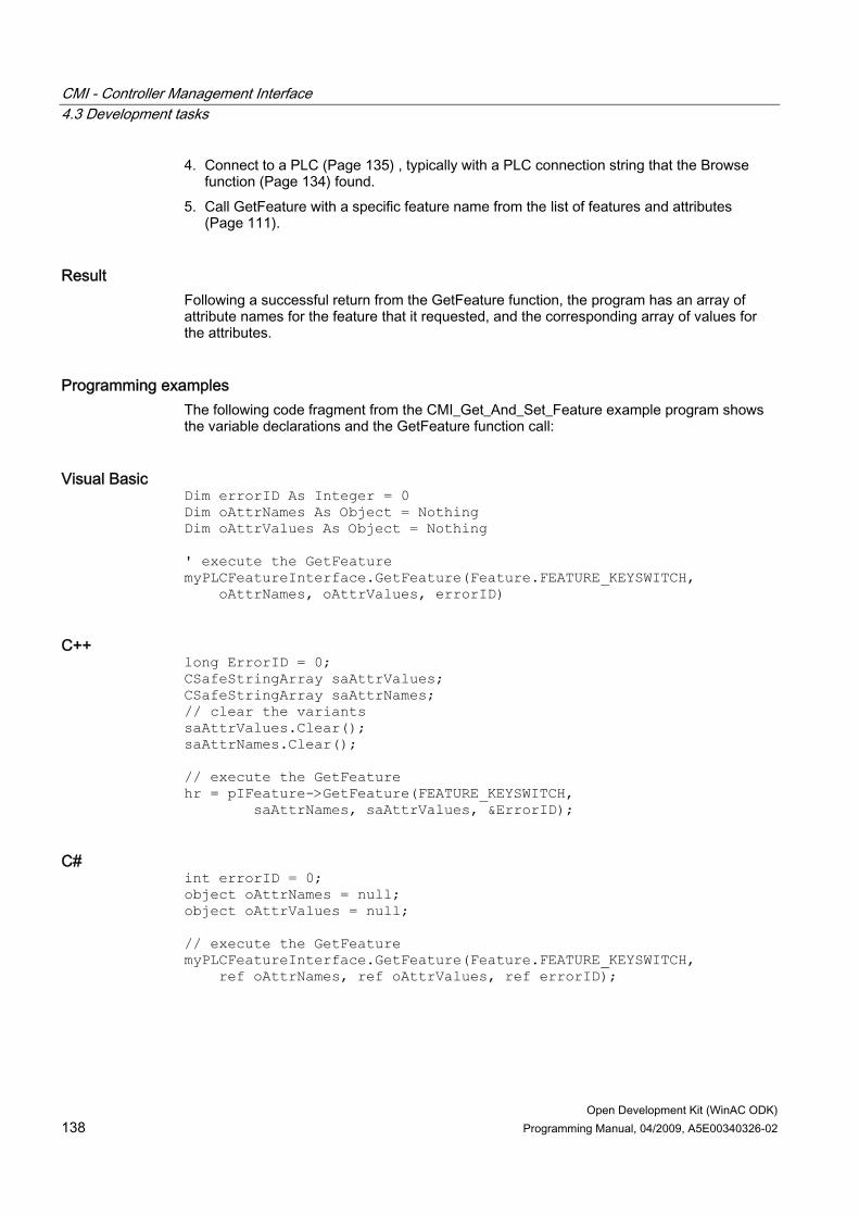
CMI - Controller Management Interface 4.3 Development tasks
Open Development Kit (WinAC ODK) 138 Programming Manual, 04/2009, A5E00340326-02
4. Connect to a PLC (Page 135) , typically with a PLC connection string that the Browse function (Page 134) found.
5. Call GetFeature with a specific feature name from the list of features and attributes (Page 111).
Result Following a successful return from the GetFeature function, the program has an array of attribute names for the feature that it requested, and the corresponding array of values for the attributes.
Programming examples The following code fragment from the CMI_Get_And_Set_Feature example program shows the variable declarations and the GetFeature function call:
Visual Basic Dim errorID As Integer = 0 Dim oAttrNames As Object = Nothing Dim oAttrValues As Object = Nothing ' execute the GetFeature myPLCFeatureInterface.GetFeature(Feature.FEATURE_KEYSWITCH, oAttrNames, oAttrValues, errorID)
C++ long ErrorID = 0; CSafeStringArray saAttrValues; CSafeStringArray saAttrNames; // clear the variants saAttrValues.Clear(); saAttrNames.Clear(); // execute the GetFeature hr = pIFeature->GetFeature(FEATURE_KEYSWITCH, saAttrNames, saAttrValues, &ErrorID);
C# int errorID = 0; object oAttrNames = null; object oAttrValues = null; // execute the GetFeature myPLCFeatureInterface.GetFeature(Feature.FEATURE_KEYSWITCH, ref oAttrNames, ref oAttrValues, ref errorID);

CMI - Controller Management Interface 4.3 Development tasks
Open Development Kit (WinAC ODK) Programming Manual, 04/2009, A5E00340326-02 139
4.3.8 Setting attribute values of a PLC feature The IFeature interface (Page 97) of the WinAC ODK Controller Management Interface provides methods for getting values from the controller and for setting values in the controller. Each controller defines a set of features that it supports, and each feature consists of a set of attributes. Some of these attribute values are available for reading and writing, others just for reading.
Setting attribute values of a feature The Controller Management Interface provides the method SetFeature to set specific values for specific attributes of a specific feature of the PLC. Your code can call SetFeature according to the application requirements, for example, to set the position of the keyswitch (operating mode selector) of the PLC to STOP mode. The CMI application program must provide the name of a specific feature as a parameter to SetFeature, along with an array of attributes of that feature for which to set values, and an array of the values to set. For each attribute in the input array of attribute names, the SetFeature method sets the value in the PLC to the corresponding value in the input parameter of array values. The CMI application can set any or all of the attributes of a specific feature. The example program CMI_Get_And_Set_Feature demonstrates the use of the SetFeature method. After browsing for available PLCs, connecting to a PLC, and getting a feature, the program calls SetFeature for the FEATURE_KEYSWITCH feature. The program provides an attribute array with one element: the ATT_KEYSWITCH attribute. The program provides a value array with one element. This value is VAL_KEYSWITCH_STOP if the previous GetFeature call returned a value of VAL_KEYSWITCH_RUN; otherwise the value for ATT_KEYSWITCH is unchanged. The result is that the CMI application sets the keyswitch position of the PLC to STOP if it was previously set to RUN.
Example program and references The CMI_Get_and_Set_Feature example program is represented in the CMI C# object web and the CMI C++ object web. For all language environments, reference the CMI_Get_and_Set_Feature program in the C:\Program Files\Siemens\WINAC\ODK\Examples folder corresponding to your programming language and environment.
Procedure To get all of the attributes of a specific feature and their values, program your CMI application to perform the following tasks: 1. Include the CMI type libraries in your project. (Page 128) 2. Create an instance of the Feature Provider to access the IPLC and IFeature interfaces
(Page 130). 3. Include the feature header file (Page 129) for your programming language environment. 4. Connect to a PLC (Page 135) , typically with a PLC connection string that the Browse
function (Page 134) found. 5. Call SetFeature with a specific feature name from the list of features and attributes
(Page 111) , an array of attributes to set, and the values to which those attributes are to be set.

CMI - Controller Management Interface 4.3 Development tasks
Open Development Kit (WinAC ODK) 140 Programming Manual, 04/2009, A5E00340326-02
Result Following a successful return from the SetFeature function, the CMI application has set the values of the feature attributes in the PLC.
Programming examples The following code fragment from the CMI_Get_And_Set_Feature example program shows the variable declarations and the SetFeature function call:
Visual Basic Dim errorID As Integer = 0 ' select the new value to set Dim newValue As String = Feature.VAL_KEYSWITCH_RUN If value = Feature.VAL_KEYSWITCH_RUN Then newValue = Feature.VAL_KEYSWITCH_STOP End If ' fill the objects and execute the SetFeature Dim set_values As String() = New String(0) {} Dim set_names As String() = New String(0) {} set_names.SetValue(Feature.ATT_KEYSWITCH, 0) set_values.SetValue(newValue, 0) oAttrNames = set_names oAttrValues = set_values myPLCFeatureInterface.SetFeature(Feature.FEATURE_KEYSWITCH, oAttrNames, oAttrValues, errorID)
C++ long ErrorID = 0; saAttrNames.SetSize(1); saAttrValues.SetSize(1); // select the new value to set bstr_t newValue = VAL_KEYSWITCH_RUN; bstr_t valRun = VAL_KEYSWITCH_RUN; if (value == valRun) newValue = VAL_KEYSWITCH_STOP; bstr_t attrName = ATT_KEYSWITCH; saAttrNames.PutElement(0, attrName); saAttrValues.PutElement(0, newValue); hr = pIFeature->SetFeature(FEATURE_KEYSWITCH, saAttrNames, saAttrValues, &ErrorID);

CMI - Controller Management Interface 4.3 Development tasks
Open Development Kit (WinAC ODK) Programming Manual, 04/2009, A5E00340326-02 141
C# int errorID = 0; // select the new value to set string newValue = Feature.VAL_KEYSWITCH_RUN; if (value == Feature.VAL_KEYSWITCH_RUN) newValue = Feature.VAL_KEYSWITCH_STOP; // fill the objects and execute the SetFeature string[] set_values = new string[1]; string[] set_names = new string[1]; set_names.SetValue(Feature.ATT_KEYSWITCH, 0); set_values.SetValue(newValue, 0); oAttrNames = set_names; oAttrValues = set_values; myPLCFeatureInterface.SetFeature(Feature.FEATURE_KEYSWITCH, oAttrNames, oAttrValues, ref errorID);
4.3.9 Responding to changed feature attribute values in the PLC The IFeatureCallback interface (Page 104) of the WinAC ODK Controller Management Interface enables you to program your application to be notified whenever specific features in the PLC change, and to take whatever action those changes require.
Registering for and responding to feature changes To get the values of controller features whenever they change, program your software to register one or more features for change notification. When your program registers a feature using the RegisterFeatureForChange method of the IFeature interface (Page 97) , it receives a callback event whenever the value of any attribute in that feature changes. The callback is a call to the OnFeatureChanged method in your application, which is a method of the IFeatureCallback interface that you must implement. The WinAC ODK Controller Management Interface returns all attributes of the registered feature to the OnFeatureChanged method.
Example and references The CMI_Register_For_Feature_Change example program (Page 154) demonstrates the use of the RegisterFeatureForChange method and the OnFeatureChanged method. The CMI_Register_For_Feature_Change example program is represented in the CMI C# object web and the CMI C++ object web. For all language environments, reference the CMI_Register_For_Feature_Change program in the C:\Program Files\Siemens\WINAC\ODK\Examples folder corresponding to your programming language and environment. There you can see a simple example of registering the FEATURE_KEYSWITCH feature for callback notification, and printing out a simple message from the OnFeatureChanged method when the registered feature changes. CMI_Register_For_Feature_Change also calls UnregisterFeatureForChange in the program termination code.

CMI - Controller Management Interface 4.3 Development tasks
Open Development Kit (WinAC ODK) 142 Programming Manual, 04/2009, A5E00340326-02
Procedure To register a feature for callback notification, and to execute application-specific code when that feature changes, program your CMI application to perform the following tasks: 1. Include the CMI type libraries in your project. (Page 128) 2. Create an instance of the Feature Provider to access the IPLC and IFeature interfaces.
(Page 130) 3. Install the IFeatureCallback interface (Page 132). 4. Connect to a PLC (Page 135) (typically with a PLC connection string that the Browse
function (Page 134) found.) 5. Declare variables for the RegisterFeatureForChange method. 6. Call RegisterFeatureForChange with a specific feature from the list of features and
attributes. 7. Program application-specific code in the OnFeatureChanged method to be executed
whenever the Controller Management Interface detects as change in the registered feature.
Result The Feature Provider notifies the CMI application whenever the value of any attribute in a registered feature changes. The CMI application then executes the custom logic in the OnFeatureChanged method.
Programming examples The following code fragment from the CMI_Register_Feature_For_Change example program shows the variable declarations for RegisterFeatureForChange, the RegisterFeatureForChange method call, and the shell of the OnFeatureChanged method. Examine the CMI_Register_Feature_For_Change example program for your programming environment to see the custom code in the OnFeatureChanged function. The custom OnFeatureChanged method is not displayed here.
Visual Basic ' register the feature to get notified of changes Dim errorID As Integer = 0 Dim Context As Object = Nothing Dim NotificationID As Integer = 0 ' the registration will automatically generate a call ' to the method OnFeatureChanged myPLCFeatureInterface.RegisterFeatureForChange(Me, Feature.FEATURE_KEYSWITCH, Context, NotificationID, errorID) Public Sub OnFeatureChanged(ByVal FeatureName As String, ByVal Context As Object, ByVal NotificationID As Integer, ByVal AttributeNames As Object, ByVal AttributeValues As Object) Implements S7WCUPIntLib.IFeatureCallback.OnFeatureChanged ... custom code here ... End Sub

CMI - Controller Management Interface 4.3 Development tasks
Open Development Kit (WinAC ODK) Programming Manual, 04/2009, A5E00340326-02 143
C++ long ErrorID = 0; // register the feature to get notified of changes VARIANT Context; VariantInit(&Context); long NotificationID = 0; // the registration will automatically generate a call // to the method OnFeatureChanged long errorID = 0; pIFeature -> RegisterFeatureForChange( this, FEATURE_KEYSWITCH, Context, &NotificationID, &errorID); STDMETHODIMP CMI_Register_For_Feature_Change::raw_OnFeatureChanged( BSTR FeatureName,VARIANT Context,long NotificationID, VARIANT AttributeNames,VARIANT AttributeValues) { .... custom code here ... }
C# // register the feature to get notified of changes object Context = null; int NotificationID = 0; // the registration will automatically generate a call // to the method OnFeatureChanged myPLCFeatureInterface.RegisterFeatureForChange(this, Feature.FEATURE_KEYSWITCH, Context, ref NotificationID, ref errorID); public void OnFeatureChanged(string FeatureName, object Context, int NotificationID, object AttributeNames, object AttributeValues) { .... custom code here ... }
Unregistering features If your application no longer needs a callback when a particular feature changes, you can unregister that feature from requiring change notification. You use the method UnregisterFeatureForChange to unregister a single feature. Also, in your program termination code unregister all features that your program registered for change notification. The UnregisterFeatureForChange call in the CMI_Restore_Feature_For_Change example program is shown below:
Visual Basic myPLCFeatureInterface.UnregisterFeatureForChange(NotificationID, errorID)
CMI - Controller Management Interface 4.3 Development tasks
Open Development Kit (WinAC ODK) 144 Programming Manual, 04/2009, A5E00340326-02
C++ pIFeature->UnregisterFeatureForChange(NotificationID, &errorID);
C# myPLCFeatureInterface.UnregisterFeatureForChange(NotificationID, ref errorID);
4.3.10 Responding to loss of PLC connection The IFeatureCallback interface (Page 104) of the WinAC ODK Controller Management Interface enables you to program your application to be notified whenever CMI loses the connection to the PLC, and to take whatever action is necessary in that case.
Registering for and responding to a connection loss To get a callback whenever CMI loses the connection to the PLC, program your software to use the RegisterForConnectionCheck method of the IFeature interface (Page 97). When registered, your CMI application receives a callback event if the connection between the CMI Feature Provider and the PLC is ever lost. The callback is a call to the OnPLCDisconnect method in your application, which is a method of the IFeatureCallback interface that you must implement. You program the OnPLCDisconnect method within your application with code to handle a loss of communication with the PLC. For example, your application could display a message to the user, deactivate controls on the dialog, close dialogs, or whatever is appropriate.
NOTICE Shutting down the PLC does not cause a call to OnPLCDisconnect. A PLC shutdown is a normal action for the PLC and is not a loss in connection. Your application can still communicate with a PLC that has been shut down and be notified, for example, when the PLC is started. The Controller Management Interface does not call OnPLCDisconnect when the user disconnects the application from the PLC. The communication connection is still available in this situation for the user to reconnect the application to the PLC. The Controller Management Interface only calls OnPLCDisconnect when the Controller Management Interface itself cannot communicate with the PLC, and thus cannot provide a connection interface between the PLC and the application.
Example and references The CMI_Register_For_Feature_Change example program (Page 154) demonstrates the use of the RegisterForConnectionCheck method and the OnPLCDisconnect method. The CMI_Register_For_Feature_Change example program is represented in the CMI C# object web and the CMI C++ object web. For all language environments, reference the CMI_Register_For_Feature_Change program in the C:\Program Files\Siemens\WINAC\ODK\Examples folder corresponding to your programming language and environment. There you can see a simple example of registering for a connection loss callback, and printing out a simple message from the OnPLCDisconnect method if the

CMI - Controller Management Interface 4.3 Development tasks
Open Development Kit (WinAC ODK) Programming Manual, 04/2009, A5E00340326-02 145
connection is ever lost. CMI_Register_For_Feature_Change also calls UnregisterForConnectionCheck in the program termination code.
Procedure To register for a connection lost callback, and to execute application-specific code when CMI loses the connection to the PLC, program your CMI application to perform the following tasks: 1. Include the CMI type libraries in your project. (Page 128) 2. Create an instance of the Feature Provider to access the IPLC and IFeature interfaces.
(Page 130) 3. Install the IFeatureCallback interface (Page 132). 4. Connect to a PLC (Page 135) (typically with a PLC connection string that the Browse
function (Page 134) found.) 5. Call RegisterForConnectionCheck. 6. Program application-specific code in the OnPLCDisconnect method to be executed
whenever the CMI Feature Provider loses the connection to the PLC.
Result The Feature Provider notifies the CMI application whenever a loss of connection to the PLC occurs. The CMI application then executes the custom logic in the OnPLCDisconnect method.
Programming examples The following code fragment from the CMI_Register_Feature_For_Change example program shows the RegisterForConnectionCheck method call, and the implementation of the OnPLCDisconnection method.
Visual Basic ' register for the feature to get notified of when connection ' to PLC is lost. myPLCFeatureInterface.RegisterForConnectionCheck(Me, NotificationIDConnectionCheck, errorID) ' Callback method for the IFeatureCallback interface, This is called ' when the connection to the PLC is lost. ' RegisterForConnectionCheck is called inside Run to register ' for this feature Public Sub OnPLCDisconnect(ByVal ErrorID As Integer) Implements S7WCUPIntLib.IFeatureCallback.OnPLCDisconnect Console.WriteLine("Lost connection." & vbNewLine) End Sub

CMI - Controller Management Interface 4.3 Development tasks
Open Development Kit (WinAC ODK) 146 Programming Manual, 04/2009, A5E00340326-02
C++ // register for the feature to get notified of when connection // to PLC is lost. long NotificationIDConnectionCheck = 0; pIFeature -> RegisterForConnectionCheck ( this, &NotificationIDConnectionCheck, &errorID); /** * Callback method for the IFeatureCallback interface, This * is called when the connection to the PLC is lost. * RegisterForConnectionCheck is called inside Run to register * for this feature */ STDMETHODIMP CMI_Register_For_Feature_Change::raw_OnPLCDisconnect(long ErrorID) { printf("Lost connection.\n"); return NOERROR; }
C# // register for the feature to get notified of when connection // to PLC is lost. int NotificationIDConnectionCheck = 0; myPLCFeatureInterface.RegisterForConnectionCheck(this, ref NotificationIDConnectionCheck, ref errorID); /** * Callback method for the IFeatureCallback interface This is called * when the connection to the PLC is lost * RegisterForConnectionCheck is called inside Run to register * for this feature */ public void OnPLCDisconnect(int ErrorID) { Console.WriteLine("Lost connection.\n"); }
Unregistering for connection check If your application no longer needs a callback when CMI loses the connection to the PLC, use the method UnregisterForConnectionCheck to unregister for a connection check. Also, in your program termination code unregister the connection loss callback, if you previously registered for it. The UnregisterForConnectionCheck call in the CMI_Restore_Feature_For_Change example program is shown below:
Visual Basic myPLCFeatureInterface.UnregisterForConnectionCheck( NotificationIDConnectionCheck, errorID)
CMI - Controller Management Interface 4.3 Development tasks
Open Development Kit (WinAC ODK) Programming Manual, 04/2009, A5E00340326-02 147
C++ pIFeature->UnregisterForConnectionCheck( NotificationIDConnectionCheck, &errorID);
C# myPLCFeatureInterface.UnregisterForConnectionCheck( NotificationIDConnectionCheck, ref errorID);
4.3.11 Disconnecting from a PLC To disconnect your application from a controller, your software must release the controller management interface.
Example and references All of the simple CMI example programs (Page 151) demonstrate disconnecting CMI from the PLC. They are represented in the CMI C# object web and the CMI C++ object web. For all language environments, reference these example programs in the C:\Program Files\Siemens\WINAC\ODK\Examples folder corresponding to your programming language and environment.
Procedure To disconnect from the PLC, program your software to follow these steps: 1. Unregister any features that were registered for change notification (Page 141) and the
connection check callback (Page 144) , if registered. 2. Release the pointer to the controller management interface. 3. Depending on your application, display a disconnected status (optional).
Result Your CMI application releases the controller management interface, which breaks the connection to the Feature Provider.
Programming examples The following code fragments illustrate the release of the controller management interface:
Visual Basic V6.0 ' release the controller management interface Set m_pIfeature = Nothing

CMI - Controller Management Interface 4.3 Development tasks
Open Development Kit (WinAC ODK) 148 Programming Manual, 04/2009, A5E00340326-02
Visual Basic .NET, 2005, 2008 ' release the controller management interface If myPLCFeatureInterface IsNot Nothing Then Marshal.Release(Marshal.GetIUnknownForObject (myPLCFeatureInterface)) myPLCFeatureInterface = Nothing End If
C++ // release the controller management interface if (pIFeature.GetInterfacePtr()) { pIFeature.Release(); }
C# // release the controller management interface if (myPLCFeatureInterface != null) { Marshal.Release(Marshal.GetIUnknownForObject (myPLCFeatureInterface)); myPLCFeatureInterface = null; }
4.3.12 Programming tips and error handling In your CMI application, verify the results of each CMI method call before using data from the call in subsequent program logic. Verify that parameters for the CMI methods are suitable for the particular task you intend it to perform.
Verifying a connection to a PLC When your CMI application calls the Connect method to connect to a PLC, the Feature Provider returns a complete set of features and attributes for that PLC when the Connect call succeeds. Program your CMI application to check that the array of feature names and the array of attribute names is not empty. An empty feature and attribute array means that the Connect call was unsuccessful, probably due to an invalild ConnectString parameter. You can also call the Browse method prior to calling the Connect method, and verify that the ConnectString parameter for the Connect method corresponds to an entry in the pConnectStrings array returned by the Browse method. The Connect method can only connect to PLCs that the Browse method identifies.
Ensuring that feature and attribute names are valid Before your CMI application calls GetFeature or SetFeature to read or write attribute values for a particular feature, verify that the feature name and the attribute names are valid for the PLC to which your application is connected.

CMI - Controller Management Interface 4.4 CMI references
Open Development Kit (WinAC ODK) Programming Manual, 04/2009, A5E00340326-02 149
Your application must successfully connect to a PLC before it can get features or set features. The Connect method returns arrays of features and attributes for the PLC when the connection attempt succeeds. Before calling GetFeature or SetFeature, verify that the parameters containing the feature name and the attribute names correspond to values in the arrays returned by the Connect method.
Handling a loss of PLC connection Your CMI application most likely needs to take some action if the connection to the PLC is lost. You can, for example, program buttons and fields on your user interface to be desensitized when there is no valid PLC connection. If your application is performing data collection, or some other task that does not involve a user interface, you can also program logic to handle a connection loss according to your specific requirements. To program an application to respond to a loss of PLC connection, register for connection check in your application and program an OnPLCDisconnect method to perform tasks that are appropriate in the event of a PLC connection loss.
Following SetFeature calls with GetFeature calls You can follow SetFeature calls in your application with calls to GetFeature to verify that the attribute values that you intended to set are actually set in the PLC. For example, if your application writes a new value for the Keyswitch feature, your application can then read the Keyswitch value that it just set. You can also program your application to read the Run and Stop attributes of the LED feature to verify that your keyswitch setting did in fact change the operating mode correctly.
4.4 CMI references
4.4.1 CMI object web The object webs for CMI show the data structures, classes, and functions you use to create a C/C++ or C# application using the CMI interface. ● CMI object web for C/C++ ● CMI object web for C# In addition to the general CMI interfaces, each object web shows object references for the following CMI example programs: ● CMI_Connect_To_PLC (Page 152) ● CMI_Get_and_Set_Feature (Page 153) ● CMI_Register_For_Feature_Change (Page 154)

CMI - Controller Management Interface 4.4 CMI references
Open Development Kit (WinAC ODK) 150 Programming Manual, 04/2009, A5E00340326-02
CMI also supports the use of Visual Basic in addition to C/C++ and C#.
Note To access any of the object webs for WinAC ODK, use the online help. Object webs are designed to be navigated from a web browser.
4.4.2 Visual C++ ATL project use of IFeatureCallback interface If you create an executable from Visual C++ using the ATL wizard, the wizard supplies code for specifying a COM interface. You need only to modify the COM interface that the wizard creates to make it specific to the IFeatureCallback interface and your project. The CMI_Demo_Panel example program for C++ uses this approach, and the code excerpts below are from CMI_Demo_Panel. These steps are an alternative to the procedure that the topic "Including the IFeatureCallback interface (Page 132)" describes.
Procedure To include the IFeatureCallback interface in a Visual C++ application created with the ATL COM AppWizard or the ATL Project Wizard, follow these steps using names applicable to your project instead of "DemoDlg" and "DEMO": 1. Include code similar to the following code in the .idl file for your project:
#include "FeatureCallback.idl" [ uuid(8FDA52F5-A330-409D-9040-B9F95DA3B4A1), helpstring("DemoDlg Class") ] coclass DemoDlg { [default] interface IFeatureCallback; };
2. Include the following code after your #include statements in the .h file for your project: _COM_SMARTPTR_TYPEDEF(IFeatureCallback, __uuidof(IFeatureCallback));
3. Also in the .h file of your project, derive the callback object from at least from the following classes: class CDemoDlg : public CComObjectRootEx<CComSingleThreadModel>, public CComCoClass<CDemoDlg, &CLSID_DemoDlg>, public IDispatchImpl<IFeatureCallback, &IID_IFeatureCallback, LIBID_DEMOLib>

CMI - Controller Management Interface 4.5 Examples
Open Development Kit (WinAC ODK) Programming Manual, 04/2009, A5E00340326-02 151
4. Define the following macros in the class declaration of your callback object: DECLARE_REGISTRY_RESOURCEID(IDR_DEMO) BEGIN_COM_MAP(CDemoDlg) COM_INTERFACE_ENTRY(IFeatureCallback) COM_INTERFACE_ENTRY(IDispatch) END_COM_MAP()
5. Include your callback object in the object map: BEGIN_OBJECT_MAP(ObjectMap) OBJECT_ENTRY(CLSID_DemoDlg, CDemoDlg) END_OBJECT_MAP()
6. Include the following declarations for the IFeatureCallback interface methods in the .h file for your project: // IFeatureCallback interface methods STDMETHOD(OnFeatureChanged)(BSTR FeatureName, VARIANT Context, long NotificationID, VARIANT AttributeNames, VARIANT AttributeValues); STDMETHOD(OnPLCDisconnect)(long ErrorID);
Result Your CMI application is now equipped to use the IFeatureCallback interface. You can register for a callback when a feature changes and program custom software in the OnFeatureChanged method (Page 141) to respond. You can also register to check for a lost connection between CMI and the PLC and program custom software in the OnPLCDisconnect method (Page 144) in that event.
4.5 Examples
4.5.1 Introduction to the CMI example programs WinAC ODK installs CMI example programs in the C:\Program Files\Siemens\WinAC\ODK\Examples\CMI folder in versions for C++ (Cpp subfolder), C# (CS subfolder), and Visual Basic (VB subfolder). Three simple example programs show the use of the three CMI interfaces (Page 93) , and all of the CMI functions: ● CMI_Connect_To_PLC (Page 152): This program browses for a WinAC controller on the
computer, and if found connects to it. This program demonstrates use of the IPLC interface (Page 94).
● CMI_Get_And_Set_Feature (Page 153) : This program gets the current value of the keyswitch position attribute, and then sets the keyswitch position to either RUN or STOP. This program demonstrates the use of the IFeature interface (Page 97).
● CMI_Register_For_Feature_Change (Page 154) : This program checks to see if the keyswitch position changes, and if so prints a message displaying the new value. It also
CMI - Controller Management Interface 4.5 Examples
Open Development Kit (WinAC ODK) 152 Programming Manual, 04/2009, A5E00340326-02
prints a message if CMI loses the connection to the PLC. This program demonstrates the use of the IFeatureCallback interface (Page 104).
For these three programs, WinAC ODK provides project files for C+, C# and Visual Basic for the following programming environments and compilers: ● Microsoft Visual Studio 2005 ● Microsoft Visual Studio 2008 In addition, WinAC ODK also provides project files for the C++ example programs in these programming environments and compilers. ● Microsoft Visual Studio V6.0 ● Microsoft Visual Studio .NET For a list of other example programs, see the topic "Additional CMI example programs (Page 155)".
4.5.2 CMI_Connect_To_PLC example program
Description CMI_Connect_To_PLC is a simple CMI application that demonstrates browsing for WinAC controllers on the local computer and connecting to a controller, using the Browse and Connect methods of the IPLC interface (Page 94). It is a console application that runs in a command window.
Operation CMI_Connect_To_PLC performs the following tasks, prompts the user step by step, and displays results of each operation in the command window: 1. Establish a connection to the IPLC interface (Page 130). 2. Browse (Page 134) for available WinAC controllers on the computer, and display the
results of the Browse operation. 3. Connect (Page 135) to the first WinAC controller that the Browse function returned. 4. Display the features and attributes (Page 106) for the connected controller. 5. Exit.
Note The Controller Management Interface is capable of finding WinLC Basis and WinAC Slot CPUs as well as WinLC RTX; however, WinLC ODK V4.2 requires an installation of WinAC RTX. This documentation assumes that the Controller Management Interface is connecting to WinLC RTX.

CMI - Controller Management Interface 4.5 Examples
Open Development Kit (WinAC ODK) Programming Manual, 04/2009, A5E00340326-02 153
References WinAC ODK installs CMI_Connect_To_PLC in the C:\Program Files\Siemens\WinAC\ODK\Examples\CMI folder in versions for C++ (Cpp subfolder), C# (CS subfolder), and Visual Basic (VB subfolder). The CMI C++ object web and the CMI C# object web contain program documentation and code listings for CMI_Connect_to_PLC. Follow the program logic step-by-step in an object web to understand how to program and use the Browse and Connect method calls.
4.5.3 CMI_Get_And_Set_Feature example program
Description CMI_Get_And_Set_Feature is a simple CMI application that demonstrates getting a specific feature of the PLC, and setting an attribute of that feature to a specific value. It uses the GetFeature and SetFeature methods of the IFeature interface (Page 97), and is a console application that runs in a command window.
Operation CMI_Get_And_Set_Feature performs the following tasks, prompts the user step by step, and displays the value of the keyswitch position after the GetFeature call and after the SetFeature call: 1. Establish a connection to the IPLC and IFeature interfaces (Page 130). 2. Browse (Page 134) for available WinAC controllers on the computer, and display the
results of the Browse operation. 3. Connect (Page 135) to the first WinAC controller that the Browse function returned. 4. Call GetFeature (Page 137) to get the FEATURE_KEYSWITCH feature of the connected
controller. The CMI interface returns all of the attributes and values for the FEATURE_KEYSWITCH feature.
5. Call SetFeature (Page 139) to set the ATT_KEYSWITCH value to RUN, or if the keyswitch position is already RUN, set it to STOP.
6. Exit at user's request.
References WinAC ODK installs CMI_Get_And_Set_Feature in the C:\Program Files\Siemens\WinAC\ODK\Examples\CMI folder in versions for C++ (Cpp subfolder), C# (CS subfolder), and Visual Basic (VB subfolder). The CMI C++ object web and the CMI C# object web contain program documentation and code listings for CMI_Get_And_Set_Feature. Follow the program logic step-by-step in an object web to understand how to program and use the GetFeature and SetFeature method calls.
CMI - Controller Management Interface 4.5 Examples
Open Development Kit (WinAC ODK) 154 Programming Manual, 04/2009, A5E00340326-02
4.5.4 CMI_Register_For_Feature_Change example program
Description CMI_Register_For_Feature_Change is a simple CMI application that demonstrates registering a feature for change notification, and executing custom code when that feature changes, in this case a simple print statement. It also demonstrates registering for a callback notification if the Controller Management Interface loses the connection to the PLC, and executing custom code in that event. CMI_Register_For_Feature_Change uses the RegisterFeatureForChange and RegisterForConnectionCheck methods of the IFeature interface (Page 97) to register for the callback notifications, and it uses the OnFeatureChanged and OnPLCDisconnect methods of the IFeatureCallback interface (Page 104) to respond to the callbacks. Like CMI_Connect_To_PLC and CMI_Get_And_Set_Feature, it is a console application that runs in a command window.
Operation CMI_Register_For_Feature_Change performs the following tasks: 1. Establish a connection to the IPLC interface. (Page 130). 2. Include the IFeatureCallback interface (Page 132). 3. Browse (Page 134) for available WinAC controllers on the computer, and display the
results of the Browse operation. 4. Connect (Page 135) to the first WinAC controller that the Browse function returned. 5. Call RegisterForFeatureChange (Page 141) to register the feature
FEATURE_KEYSWITCH for callback notification when that feature changes in the PLC. 6. Call RegisterForConnectionCheck (Page 144) to register for a connection check such
that the Controller Management Interface sends a callback if the connection to the PLC is lost.
7. When a callback occurs for a change to FEATURE_KEYSWITCH, print a message with the new position value from the OnFeatureChanged method (Page 141).
8. If the connection to the PLC is ever lost, print a message from the OnPLCDisconnect method (Page 144).
9. Continue waiting for and processing callbacks until the user exits the program.
References WinAC ODK installs CMI_Register_For_Feature_Change in the C:\Program Files\Siemens\WinAC\ODK\Examples\CMI folder in versions for C++ (Cpp subfolder), C# (CS subfolder), and Visual Basic (VB subfolder). The CMI C++ object web and the CMI C# object web contain program documentation and code listings for CMI_Register_For_Feature_Change. Follow the program logic step-by-step in an object web to understand using RegisterForFeatureChange and RegisterForConnectionCheck to register for change notification and PLC connection loss notification. Look at the OnFeatureChanged and OnPLCDisconnect method implementations to see how a CMI program can perform application-specific code when callbacks occur.

CMI - Controller Management Interface 4.5 Examples
Open Development Kit (WinAC ODK) Programming Manual, 04/2009, A5E00340326-02 155
4.5.5 Additional CMI example programs In addition to the simple example programs (Page 151) , WinAC ODK includes the following additional example programs: ● Demo Panel: implements a controller panel similar to the WinLC RTX controller panel.
The demo panel uses CMI to activate status LEDs, and to operate buttons for performing a memory reset and for changing the operating mode.
● Archive and Restore: uses the CMI MemoryCardFile feature to archive and restore the controller.
● Diagnostics: saves diagnostic information for the controller (C++ only). The example programs are in the ...\Program Files\Siemens\WinAC\ODK\Examples\CMI folder in subfolders Cpp, CS, and VB for C++, C#, and Visual Basic implementations, respectively. Within each programming language folder, a folder exists for each project that contains source files and the project files for the supported compilers. The supported programming languages and development environments are listed below. Complier-specific subfolder names for each programming language are shown in parentheses: Program C++ C# VB CMI_Demo_Panel Microsoft Visual C++
V6.0 (VS6) Microsoft Visual Studio .NET (VSNET)
Microsoft Visual Studio .NET (VSNET)
Microsoft Visual Basic V6.0 (VB6) Microsoft Visual Studio .NET (VSNET)
CMI_ArchiveRestore Microsoft Visual C++ V6.0 (VS6) Microsoft Visual Studio .NET (VSNET)
Microsoft Visual Studio .NET (VSNET)
Microsoft Visual Basic V6.0 (VB6) Microsoft Visual Studio .NET (VSNET)
CMI_Diagnostic Microsoft Visual C++ V6.0 (VS6) Microsoft Visual Studio .NET (VSNET)
Not available Not available
These programs are not represented in an object web. To study and learn from these programs, open them in your programming environment.
Note Source files for C++ do not differ between Microsoft Visual Studio V6.0 and Microsoft Visual Studio .NET. The example project folders for C++ have a project workspace for Visual C++ V6.0 (VS6), a solution workspace for Visual C++ .NET (VSNET) and a set of common source and header files for the project. Source files for Visual Basic do differ between Microsoft Visual Studio V6.0 and Microsoft Visual Studio .NET. You can find the Visual Basic V6.0 source files under the VB6 subfolder of the project.

CMI - Controller Management Interface 4.5 Examples
Open Development Kit (WinAC ODK) 156 Programming Manual, 04/2009, A5E00340326-02
4.5.6 GNU C++ example programs for CMI WinAC ODK installs three C++ example programs for CCX that you can compile with a GNU compiler: ● CMI_Connect_To_PLC ● CMI_Get_And_Set_Feature ● CMI_Register_For_Feature_Change These projects compile and run from a Cygwin environment running in Microsoft Windows XP Professional. You can modify and test these programs yourself for any other usage. The GNU C++ CMI example programs provide the same functionality as the CMI_Connect_To_PLC (Page 152) , CMI_Get_And_Set_Feature (Page 153) , and CMI_Register_For_Feature_Change (Page 154) programs that WinAC ODK provides for C++, C#, and Visual Basic. WinAC ODK installs the GNU C++ CMI example programs at \Examples\_GNU_Compiler_Cpp_ in folders for each program name. Refer to the Readme text file in each program folder for usage instructions and related information.

Open Development Kit (WinAC ODK) Programming Manual, 04/2009, A5E00340326-02 157
Index
A Accessing
shared data (SMX), 79 STEP 7 block information (CCX), 68
Activate function (CCX), 25, 36 Active configuration
CCX, 38 SMX, 80
Add/remove programs, 10 Adding feature definitions (CMI), 129 Application wizard
creating project (CCX), 16 creating project (SMX), 74 enabling asynchronous monitoring (CCX), 22 enabling asynchronous processing (CCX), 19 entering subcommands (CCX), 17 generating project, 24, 76 project information (CCX), 16 project information (SMX), 75 project summary, 24, 76 specifying vendor information, 23, 76
Archive and restore example program (CMI), 155 Archive file (CMI), 119 ASYN_COM status values, 47 Asynchronous event processing (CCX), 19, 25, 28 Asynchronous monitoring (CCX), 22, 25, 30 ATL projects (CMI), 150 Attributes (CMI)
arrays of names, values, 137, 139 checking names, 148 descriptions, 106 getting, 137 including definitions, 129 setting, 139
AutoStart feature (CMI), 111 Auxiliary STEP 7 interface functions, 49 Available PLCs, finding (CMI), 134
B Background priority (CCX), 19, 22 Block information functions (CCX), 55 Block memory access,SMX, 77 Blocks, creating for CCX interface, 37 Boolean value read and write restrictions (CCX), 56
Breakpoints, effect on scan cycle (CCX), 40 Broken controller connection (CMI), 144 Browsing for PLCs (CMI)
Browse method, 94, 134 example program, 152
Building CCX extension object (DLL, RTDLL), 32, 41 debug extension objects (CCX), 38 SMX debug version, 80
Byte swapping (CCX), 48, 53
C C#, (See Visual C#) Callback (CMI)
example program, 154 feature change, 104, 141 IFeatureCallback interface, 132 loss of PLC connection, 104, 144 registering and unregistering, 97, 141, 144
Calling non-deterministic functions (CCX), 28 ODK_ScheduleOB function, 63 software outside of extension object, 30 WinAC ODK SFBs (CCX), 36
Capabilities of the Controller Management Interface, 91 CAsyncProc, 25, 28 CCX
asynchronous monitoring, 22, 30 asynchronous processing, 19, 27, 28 block information functions, 55 CCX-specific interrupts, 50 cyclic read functions, 53 data access helper classes, 25, 48 interface functions, 25 monitor classes, 25 object web, 58 programming overview, 24 read and write functions, 48, 53 subcommands, 17 support software, 27, 42
CCX example programs, (Example programs (CCX)) CCX_BlockAccess example program, 68 CCX_SyncvsAsync example program
operation, 60 CCX_SyncVsAsync example program
introduction, 59 STEP 7 program, 60
Index
Open Development Kit (WinAC ODK) 158 Programming Manual, 04/2009, A5E00340326-02
CEventMsg, 25, 28 Changing extension objects (CCX), 41 Changing PLC attribute values (CMI), 97 Checking controller, 85
CCX, 49 SMX, 85
Checking PLC connection (CMI), 97, 144 Classes (CCX), 25
CAsyncProc, 28 CEvent_0, 19, 28 CEventMsg, 19, 28 CMonitor_0, 22, 30 CQueue, 28 CThreadBase, 22, 30 CWinLCReadData, 48 CWinLCReadWriteData, 48
Clearing PLC data (CMI), 147 CMI
example programs, 151, 155 feature header files, 129 features and attributes, overview, 106 overview, 91 software references, 149
CMI_Connect_To_PLC, 152 CMI_Get_And_Set_Feature, 153 CMI_Register_For_Feature_Change, 154 CMonitor_0, 22, 30 Communication error interrupt, 50 Communication loss to PLC (CMI), 97, 144 Compiler selection
CCX, 16 SMX, 75
Compiling extension object (CCX), 32
Complex data types (CCX), 56 Computer requirements, 9 Configuring
asynchronous monitoring (CCX), 22 asynchronous processing (CCX), 19 cyclic reads (CCX), 53 monitor threads (CCX), 22 project information (CCX), 16 SMX project information, 75 subcommands (CCX), 25
Connecting to a controller SMX_Start example program, 82
Connecting to a controller, SMXStart sample program, 82 Connecting to a PLC (CMI)
Connect method, 135 Connect method, 94 example program, 152 verifying, 148
Connection names, PLCs (CMI), 134 Consistent Data SMX program, 85 Console application, 85 Continuous reads (SMX), 85 Controller check, 85 Controller data
reading and writing (CCX), 48, 53 reading and writing (SMX), 82
Controller Management Interface (CMI) capabilities, 91 example programs, 151 IFeature interface methods, 97 implementing, 92 IPLC interface methods, 94 overview, 91 referencing type libraries, 128 releasing, 147 software references, 149
Controller Management Interface (CMI) Methods (CMI) IFeatureCallback interface, 104
ControllerHelp feature (CMI), 112 Controllers
connecting to (CMI), 135 disconnecting from (CMI), 147 finding available (CMI), 134
Copying projects (CCX), 24, 76 CPU state, reading (CCX), 49 CPU Usage Extended feature (CMI), 113 CPULanguage feature (CMI), 112 CQueue, 25, 28 CREA_COM, 35, 36, 43 Creating
asynchronous events (CCX), 19, 28 CCX project, 16 CCX STEP 7 program, 36 CCX subcommands, 17 execution threads, 52 monitor threads, 30 monitor threads (CCX), 22 SMX project, 74 SMX STEP 7 program, 79
Creating an instance of the feature provider (CMI), 130 CThreadBase, 22, 25, 30 Custom application
SMX, 74 Custom application, CCX, 15 CWinLCReadData, 25, 48, 53 CWinLCReadWriteData, 25, 48, 53 Cycle (CCX), 25
avoiding impact, asynchronous events, 28 effect of breakpoints, 40
Cycle (CCX), 36 Cyclic reads, 53

Index
Open Development Kit (WinAC ODK) Programming Manual, 04/2009, A5E00340326-02 159
D Data access helper classes (CCX), 25, 48, 53 Data blocks, reading and writing, 56 Data consistency, 85 Data consistency (SMX), 80 Data conversion
CCX, 53 Data conversion (CCX), 48 Data exchange (SMX), 79 Data Memory Copy SMX program, 85 Data types
reading and writing (CCX), 56 Data types (CCX)
cyclic reads, 53 Data types (CCX), 56 data1 and data2 parameters, 50 dataType1 and dataType2 parameters, 50 DeActivate function, 30 DeActivate function (CCX), 25 Deallocating asynchronous events (CCX), 28 Debugging (CCX), 38
building extension object, 38 controller preparation, 39
Debugging (SMX), 80 Declarations
Feature Provider (CMI), 130 including IFeatureCallback interface, 132
Defines (CMI) features and attributes, 129
Deleting asynchronous events (CCX), 19 cyclic read jobs (CCX), 53
Demo Panel example program, 155 Detecting data change (SMX), 85 Developing
CCX application, 15 CCX STEP 7 program, 36 SMX application, 74 SMX STEP 7 program, 79
Development environments supported, 9 Device name, SMX_Start example program, 82 Diagnostic alarm interrupt, 50 Diagnostic data (CMI), 106 Diagnostic feature (CMI), 113 DiagnosticLanguage feature (CMI), 114 Diagnostics example program (CMI), 155 DirAccess CCX example program, 53 DirAccess CCX sample program, 53 DirAccess example program, 65 Disabling watchdog timer (CCX), 38 Disconnecting from a PLC (CMI), 147 Disk space requirements, 9
DLLs (CCX) building, 32 built and run on different computers, 34 debugging, 38 name, 41 updating name in STEP 7, 42
DLLs (CMI), 92 DLLs (SMX), 77 DPR Com SMX program, 85 DP-Ram offset, 82
E Elementary data types (CCX), 56 Embedded controller keyswitch (CMI), 117 Enabling
asynchronous monitoring (CCX), 22 asynchronous processing (CCX), 19 watchdog timer (CCX), 40
Endian formats (CCX), 48 Ending a debug session (CCX), 41 Ensuring data consistency (SMX), 80 Entering subcommands (CCX), 17, 25 Error Codes
SFB65001, 44 SFB65002, 45 SFB65003, 47
Error feature (CMI), 114 Error handling, 148 Events, asynchronous (CCX), 19, 28, 30 Example programs
SMX, 85 Example programs (CCX), 70
accessing STEP 7 block information (CCX), 68 CCX_Async, 71 CCX_BlockAccess, 71 CCX_DirAccess, 71 CCX_DirDataAccess, 71 CCX_FileIO, 71 CCX_HistoDLL, 71 CCX_Latency, 71 CCX_NotifyDB, 71 CCX_SyncVsAsync, 59 CCX_TonePulse, 71 creating a separate thread of execution, 64 DirAccess, 53 FileIO, 30 GNU examples, 72 implementing cyclic reads (CCX), 66 Latency, 30 reading and writing controller data, 65 scheduling an OB (CCX), 63

Index
Open Development Kit (WinAC ODK) 160 Programming Manual, 04/2009, A5E00340326-02
Example programs (CMI), 151, 155 ArchiveRestore, 155 CMI_Connect_To_PLC, 152 CMI_Get_And_Set_Feature, 153 CMI_Register_For_Feature_Change, 154 Demo Panel, 155 Diagnostics, 155 GNU examples, 156
Example programs (SMX) ConsistantData, 85 Data Memory Copy, 85 DPR_Com, 85 FeedBack, 85 GNU examples, 90 I_am_alive, 85 Simple, 85 SMX_Start, 82
EXEC_COM, 17, 35, 36 EXEC_COM status values, 45 Executable for debug session, setting (CCX), 40 Execute function (CCX), 17, 25, 36, 48
event class, 28 monitor class, 30
Execution threads (CCX), 28, 30 creating, 52
Extension objects (CCX) building, 32 building debug version, 38 calling from STEP 7 program, 36 calls outside of, 30 changing, 41 debugging, 38 name in STEP 7, 41 releasing, 41 structure, 25 updating name in STEP 7, 42
F Failsafe CPU feature (CMI), 115 Feature and attribute definitions (CMI), 129 Feature Provider, 92
breaking connection, 147 capabilities, 91 creating instance, 130 interfaces, 93 referencing type libraries, 128
FeatureCallback.idl, 132 FeatureProvider 1.0 Type Library, 92, 128 FEATUREPROVIDERLib, 132 Features (CMI)
capabilities, 91
checking names, 148 configuration options, 108 controller operations, 107 diagnostics, 109 getting, 137 including definitions, 129 obtaining for connected PLC, 135 overview, 106 registering for changes, 141 setting, 139 starting or shutting down PLC, 108 tuning WinLC RTX, 109 unregistering, 101, 143
Features (CMI), WinLC RTX AutoStart, 111 ControllerHelp, 112 CPU Usage Extended, 113 CPULanguage, 112 Diagnostic, 113 DiagnosticLanguage, 114 Error, 114 Failsafe CPU, 115 HW_DataStorage, 115 HW_LEDs, 116 KeySwitch, 117 LED, 118 MemoryCardFile, 119 MinCycleTime, 120 MinSleepTime, 120 OBExecution, 121 Personality, 122 PLC, 123 PLC Memory Size, 124 PLCInstance, 123 Priority, 124 Security, 125 SpeedStep, 126 StartAtBoot, 127 Timing, 127
Feedback example program (SMX), 85 FileIO example program (CCX), 30 Finding PLCs (CMI), 94, 134 Foreground priority (CCX), 19, 22 Functions (CCX)
Activate, 25 auxiliary STEP 7 interface, 49 data access, 48 DeActivate, 25, 30 Execute, 25 Execute function, monitor class, 30 Execute, event class, 28 GetResult, 28 GetStatus, 28
Index
Open Development Kit (WinAC ODK) Programming Manual, 04/2009, A5E00340326-02 161
ODK_CreateCyclicRead, 53, 56 ODK_CreateThread, 52 ODK_DeleteCyclicRead, 53 ODK_ReadData, 53, 56 ODK_ReadState, 49 ODK_ScheduleOB, 50, 63 ODK_StartCyclicRead, 53 ODK_StopCyclicRead, 53 ODK_WriteData, 53, 56 ODKCreate, 25 ODKRelease, 25, 30 PauseThread, 30 ResumeThread, 30 ScheduleEvent, 28 SetDelTime, 28 StopThread, 30
Functions (CMI), (See Methods (CMI)) Functions (SMX), 77
G Generating project from application wizard, 24, 76 GetResult function (CCX), 28 GetStatus function (CCX), 28 Getting features (CMI)
example program, 153 GetFeature method, 97, 137
Getting PLC attribute values (CMI), 97, 137 Global read and write functions
CCX, 53 SMX, 77
GNU example programs CCX, 72 CMI, 156 SMX, 90
H Hardware
faults, 50 interrupts, 50 LEDs, 116 requirements, 9
Header files CMI, 129 SMX, 77
HW DataStorage feature (CMI), 115 HW_LEDs feature (CMI), 116
I I_am_alive SMX program, 85 IDEs supported, 9 IFeature interface (CMI), 93, 97, 128
example program, 153 IFeatureCallback interface, 132 IFeatureCallback interface (CMI), 93, 104
example program, 154 Implementing
CCX application, 15, 24 CCX extension objects (DLLs and RTDLLs), 25 CCX STEP 7 program, 36 Controller Management Interface, 92 cyclic reads (CCX), 53 SMX application, 74 SMX program, 77 SMX STEP 7 program, 79
Including asynchronous processing (CCX), 19 CMI type libraries, 128 feature and attribute definitions (CMI), 129 IFeatureCallback interface (CMI), 132
Input area (SMX), 79 Input parameters (CMI), 110 Insert/Remove module interrupts, 50 Installation requirements, 9 Installing WinAC ODK, 10 InstanceID string (CCX), 39, 41 Instantiating the feature provider (CMI), 130 Interface functions (CCX), 49 Interfaces (CMI), 93
IFeature, 97 IFeatureCallback, 104 IPLC, 94 Type libraries, 92, 128
Interrupts, 50 IntervalZero SDK requirement (CCX real-time), 9 Invalid addresses (CCX), 48 IPLC interface (CMI), 93, 94, 128
example program, 152 IPLC variable declaration, 130
K KeySwitch feature (CMI), 117
L Latency example program (CCX), 30 LED feature (CMI), 118 Libraries (CMI), required references, 128
Index
Open Development Kit (WinAC ODK) 162 Programming Manual, 04/2009, A5E00340326-02
Load instructions, SMX STEP 7 program, 79 Loading the WinAC ODK STEP 7 Library (CCX), 35 Loss of controller connection (CMI), 144
M m_ExitThread variable, 30 Managed code, 74 Managed code (CCX), 16 Memory areas (CCX)
ODK_DATA_STRUCT, 56 reading and writing, 56
Memory block access,SMX, 77 Memory corruption (CCX), 48 Memory requirements, 9 MemoryCardFile feature (CMI), 119
example program, 155 Methods (CCX), (See Functions (CCX)) Methods (CMI)
Browse, 94, 134 Connect, 94, 135 GetFeature, 97, 137 IFeature interface, 97 IFeatureCallback interface, 104 IPLC interface, 94 OnFeatureChanged, 104, 132 OnPLCDisconnect, 104, 132, 144 RegisterFeatureForChange, 97 RegisterForConnectionCheck, 97, 144 SetFeature, 97, 139 UnregisterFeatureForChange, 97 UnregisterForConnectionCheck, 97, 144 verifying calls, 148
Methods (SMX), (See Functions (SMX)) MinCycleTime feature (CMI), 120 MinSleepTime feature (CMI), 120 Module (CMI)
adding, Visual Basic 6.0, 129 Monitor class, 30 Monitor class (CCX), 22, 25 Monitor threads (CCX), 22, 25, 30 Multiple extension objects (CCX)
programming, 25
N Name changes, CCX extension objects, 41 NET conversion tool, avoiding, 82, 85 Non-deterministic functions (CCX), 25, 28, 32 Notification (CMI)
OnFeatureChanged, 104 OnPLCDisconnect, 104
O OBExecution feature (CMI), 121 Object webs
CCX, 58 OBs, 50
CCX-specific, OB52 - OB54, 50 scheduling from CCX application, 50 supported by CCX, 50
ODK_CreateCyclicRead function, 53, 56 example program, 66
ODK_CreateThread function, 52 example, FileIO example program, 64
ODK_DATA_STRUCT, 53, 56 ODK_DeleteCyclicRead function, 53
example program, 66 ODK_DISABLE_WATCHDOG macro (CCX), 38, 40 ODK_ENABLE_WATCHDOG macro (CCX), 40 ODK_GetBlockChecksum, 55, 68 ODK_GetBlockSize, 55, 68 ODK_GetBlockTimeStamp, 55, 68 ODK_ReadData example DirAccess sample program, 65 ODK_ReadData function, 53, 56, 65 ODK_ReadS7 functions (CCX), 48
example, 65 ODK_ReadState function, 49 ODK_ScheduleOB function, 50, 63
example, HistoDLL example program, 63 ODK_SetWatchdog (CCX), 40 ODK_StartCyclicRead function, 53, 66
example program, 66 ODK_StopCyclicRead function, 53
example program, 66 ODK_WriteData example
DirAccess sample program, 65 ODK_WriteData function, 53, 56 ODK_WriteS7 functions (CCX), 48
example, DirAccess sample program, 65 ODKCreate function (CCX), 25, 36 OdkLib (CCX), 35 ODKRelease function (CCX), 25, 30 OnFeatureChanged, 104, 132, 141
example program, 154 OnPLCDisconnect, 104, 132, 144
example program, 154 Operating mode transition (CCX)
reading, 49 Operating system requirements, 9 Operations, PLC (CMI), 106 Options, PLC (CMI), 106 Ouput parameters (CMI), 110 Output area (SMX), 79
Index
Open Development Kit (WinAC ODK) Programming Manual, 04/2009, A5E00340326-02 163
Overview CMI, 91 SMX, 73
P Panel interfaces (CMI), 128 Parameter data types (CCX), 56 Parameter memory areas (CCX), 56 Parameters
cyclic read functions (CCX), 53 SFB65002, 45 SFB65003, 46
Parameters for functions, 53 Password protection (CMI), 125
prompt interval, 125 PauseThread function (CCX), 30 Performance, PLC (CMI), 106 Personality feature (CMI), 122 phJobID parameter, cyclic read, 53 PLC feature (CMI), 123 PLC Memory Size feature (CMI), 124 PLCInstance feature (CMI), 123 PLCs
CMI interface to, 93, 94 connecting to (CMI), 135 disconnecting from (CMI), 147 features (CMI), 106 finding available (CMI), 134 performance features (CMI), 109
Preparing controller for debugging (CCX), 39 Printf, effect on scan cycle (CCX), 28 Priorities (CCX), 19, 22 Priority feature (CMI), 124 PROGID, 43 PROGID (CCX), 39 Program cycle (CCX), 25, 36
avoiding impact, asynchronous events, 28 effect of breakpoints, 40
Programming CCX application, 15 CCX monitor threads, 30 CCX subcommands, 17 SMX, 77 SMX application, 74 SMX STEP 7 program, 79
Programming (CCX) asynchronous events, 28 CCX interface functions, 25 multiple extension objects, 25 overview, 24 STEP 7 program, 36
subcommands, 25 Programming (CMI)
Feature Provider, creating instance, 130 IFeatureCallback interface, 132 including feature and attribute definitions, 129 referencing type libraries, 128 tips, 148
Programming environments, 9 Programming environments (CCX)
effect on RTDLL registration, 32 Programming examples, CCX
creating a separate thread of execution, 64 implementing Cyclic Reads, 66 reading and writing controller data (CCX), 65 scheduling an OB, 63
Project (CCX) configuration, 32 information, application wizard, 16 settings, 40
Project (CMI) properties, Visual C++ .NET, 128 references, Visual Basic, C#, 128 settings, Visual C++ 6.0, 128
Project (SMX) information, application wizard, 75
Protocol, SMX communication, 85 Proxy DLL (CCX), 34
Q Queue class (CCX), 25, 28
R RAM requirements, 9 Reading
controller data (CCX), 48, 53, 56, 65 controller data (SMX), 77, 79 controller state (CCX), 49 data cyclically (CCX), 53, 56, 66 data values, SMX_Start example program, 82 data values,SMX_Start STEP 7 program, 84
Reading PLC attribute values (CMI), 97, 137 Receiving data values
SMX_Start example program, 82 References
SFB65002, 45 SFB65003, 46
Referencing CMI type libraries, 128 RegisterFeatureForChange, 97, 141
example program, 154 RegisterForConnectionCheck, 97, 144

Index
Open Development Kit (WinAC ODK) 164 Programming Manual, 04/2009, A5E00340326-02
example program, 154 Registering callbacks (CMI)
features for change, 97 features for change (CMI), 141 loss of PLC connection, 97, 144
Registering RTDLL requirements (CCX), 32 Reinstalling WinAC ODK, 10 Release version of extension object (CCX)
updating, 42 Releasing extension objects (CCX), 41 Releasing the CMI interface, 147 Removing Installation, 10 Renaming asynchronous events (CCX), 19 Replacing extension objects (CCX), 41 Requirements, 9 Requirements, programming (CMI)
Feature Provider, creating instance, 130 IFeatureCallback interface, 132 including feature and attribute definitions, 129 referencing type libraries, 128
Responding to changes in PLC (CMI), 97, 104, 141 Responding to loss of PLC connection (CMI), 97, 104, 144 Restoring PLC data (CMI), 119 ResumeThread function (CCX(, 30 Retrieving PLC features and attributes (CMI), 135 Retrieving WinAC ODK library (CCX), 35 RTDLLs (CCX)
building, 32 debugging, 38 name, 41 registering, 32 updating name in STEP 7, 42
RtPrintf, effect on scan cycle (CCX), 28 rtsskill, 41 rtssrun, 33
S S7 WinAC Unified Panel Interfaces 1.0, 92, 128 S7LIBS (CCX), 35 S7-mEC keyswitch, 117 S7SMX_AllocExtMemBuffer, 77 S7SMX_FreeExtMemBuffer, 77 S7SMX_ReadBlock, 77 S7SMX_WriteBlock, 77 S7UnifiedPanelRCW.dll, 129 S7UP_Feature.pas, 129 S7UP_FeatureProvider.pas, 128 S7UP_Interfaces.pas, 128 S7WCUFPX.DLL, 92, 128 S7WCUIFX.DLL, 92, 128
S7WCUPIntLib, 132 S7wlcrtx.exe, 40 s7wlcvmx.exe, 39, 40 s7wlcvmx.rtss, 41 Sample programs, (See Example programs) Scan cycle (CCX), 25, 36
avoiding impact, asynchronous events, 28 effect of breakpoints, 40
ScheduleEvent function (CCX), 28 Scheduling OBs (CCX), 50, 63 SDK requirement (CCX real-time), 9 Searching for PLCs (CMI), 94, 134 Security feature (CMI), 125 Sending data values
SMX_Start example program, 82 Separate threads of execution (CCX), 30, 52 SetDelTime function (CCX), 28 SetFeature method (CMI), 97, 139
example program, 152 Setting active configuration
CCX, 38 SMX, 80
Setting active configuration (CCX), 32 Setting executable for debug session (CCX), 40 Setting features (CMI)
example program, 153 Setting PLC attribute values (CMI), 97, 137, 139 Setup program, 10 SFB65001, 25, 36, 43
parameters, 43 status values, 43
SFB65002, 25, 36, 45 parameters, 45 status values, 45 use of subcommands, 17
SFB65003 parameters, 46 status values, 47
SFBs (CCX), 43 loading, 35
Shared data, accessing (SMX), 79 Shared memory exchange, 74 Shutting down PLC (CMI), 106 SMX
application development, 74, 77 block access functions, 77 data consistency, 80 example programs, 85 interface definitions, 77 overview, 73 project information, 75 reading and writing controller data, 77, 79 shared memory, 73

Index
Open Development Kit (WinAC ODK) Programming Manual, 04/2009, A5E00340326-02 165
SMX_Start example program, 84 SMX example programs, (Example programs (SMX))
ConsistantData, 85 Data Memory Copy, 85 DPR_Com, 85 FeedBack, 85 I_am_alive, 85 Simple, 85 SMXStart, 82
SMX_Start example program, 82 STEP 7, 84
Software references (CMI), 149 Software requirements, 9 SpeedStep feature (CMI), 126 StartAtBoot feature (CMI), 127 Starting cyclic reads (CCX), 53, 66 Starting PLC (CMI), 106 State of controller, reading (CCX), 49 Status values
SFB65002, 45 SFB65003, 47
STEP 7 program accessing SMX shared memory, 79
STEP 7 program (CCX) debug DLL, 39 interface functions, 49 name of extension object, 39 program cycle, 25 programming, 36 scan cycle, 28 WinAC ODK library, 35
STEP 7 program (SMX) programming, 77 SMXstart example program, 79
STEP 7 programs SMX_Start, 84
Stop debugging (CCX), 41 Stopping cyclic reads (CCX), 53 StopThread function (CCX), 30 Subcommands (CCX), 17, 25 Summary of project options, 24, 76 Support classes, 27 Support classes (CCX), 48 Support software
CCX, 42 System Function Blocks (CCX), 43
loading, 35 System Requirements, 9
T Terminating CMI application, 147
Testing your custom application (CCX), 38, 40 Threads
creating, 52 Threads (CCX), 25
asynchronous monitoring, 22, 30 asynchronous processing, 19, 28 priorities, 22
Time error, 50 Timing feature (CMI), 127 Tips, programming, 148 Transfer instructions, SMX STEP 7 program, 79 Transferring data values
SMX_Start example program, 82 Type Libraries (CMI), 92, 128
U Uninstalling WinAC ODK, 10 Unmanaged code, 74 Unmanaged code (CCX), 16 UnregisterFeatureForChange, 97, 141 UnregisterForConnectionCheck, 97, 144 Unregistering callbacks (CMI)
features, 101 features for change, 143 loss of PLC connection, 103, 144
Using application wizard (CCX), 16 application wizard (SMX), 74 asynchronous processing (CCX), 19, 28 CCX, 15 monitor threads (CCX), 22, 30 SMX_Start example program, 84 SMXStart sample program, 82 subcommands (CCX), 25
Using the Features of the PLC (CMI), 106
V Values of attributes (CMI), 106
about, 111 getting, 137 reading and writing, 97 setting, 139
Variable declarations (CMI) Feature Provider, 130 including feature and attribute definitions, 129
Vendor information, 16, 23, 76 Verifying CMI method calls, 148 Version of extension object (CCX)
updating, 42 Version requirements, 9

Index
Open Development Kit (WinAC ODK) 166 Programming Manual, 04/2009, A5E00340326-02
Visual Basic (CCX) DLLs built and run on different computers, 34
Visual Basic (CMI) accessing IPLC and IFeature interfaces), 130 adding feature definitions, 129 browsing for PLCs, 134 connecting to a PLC, 135 disconnecting from PLC, 147 getting features, 137 including IFeatureCallback interface, 132 responding to changes in PLC, 141 responding to loss of PLC connection, 144 setting feature attribute values, 139
Visual C# (CCX) DLLs built and run on different computers, 34
Visual C# (CMI) accessing IPLC and IFeature interfaces, 130 adding feature definitions, 129 browsing for PLCs, 134 connecting to a PLC, 135 disconnecting from PLC), 147 getting features, 137 including IFeatureCallback interface, 132 Responding to changes in PLC, 141 responding to loss of PLC connection, 144 setting feature attribute values, 139
Visual C++ (CMI) accessing IPLC and IFeature interfaces, 130 adding feature definitions, 129 ATL projects, 150 browsing for PLCs, 134 connecting to a PLC, 135 disconnecting from PLC, 147 getting features, 137 including IFeatureCallback interface, 132 responding to changes in PLC), 141 responding to loss of PLC connection, 144 setting feature attribute values, 139
Visual C++ Debugger, 38, 40
W Watchdog alarm time error, 50 Watchdog macros for debugging (CCX), 40 WinAC ODK application wizard
enabling asynchronous monitoring (CCX), 22 enabling asynchronous processing (CCX), 19 project information (CCX), 16 project information (SMX), 75 specifying vendor information, 23, 76
WinAC ODK Controller Management Interface (CMI) capabilities, 91
example programs, 151 IFeature interface methods, 97 IFeatureCallback interface methods, 104 implementing, 92 IPLC interface methods, 94 overview, 91 referencing type libraries, 128 releasing, 147 software references, 149
WinLC RTX scan cycle (CCX), 25, 36 avoiding impact, asynchronous events, 28 effect of breakpoints, 40
WinLC RTX security feature (CMI), 125 Writing
controller data (CCX), 48, 53, 56 controller data (SMX), 77, 79 data values, SMXStart example program, 82
Writing PLC attribute values (CMI), 97, 139

SIMATIC Windows Automation Center RTX Open Development Kit (WinAC ODK) Programming Manual, 04/2009, A5E00340326-02 167

SIMATIC Windows Automation Center RTX Open Development Kit (WinAC ODK) Programming Manual, 04/2009, A5E00340326-02 168
Related Documents