Preface, Contents Product Overview 1 Installing Your TD Device 2 Using the Keypad Designer to Create a Custom Faceplate for Your TD 200C 3 Using the TD 200 Wizard to Configure the S7-200 CPU for Your TD Device 4 Operating Your TD Device 5 Appendices Technical Specifications and Reference Information A Connecting Multiple Devices on a Network B Troubleshooting C Index Text Display (TD) User Manual SIMATIC Edition: 06/2004 A5E00341992-01

Welcome message from author
This document is posted to help you gain knowledge. Please leave a comment to let me know what you think about it! Share it to your friends and learn new things together.
Transcript
Preface, Contents
Product Overview 1
Installing Your TD Device 2Using the Keypad Designer toCreate a Custom Faceplate forYour TD 200C
3
Using the TD 200 Wizard toConfigure the S7-200 CPU forYour TD Device
4
Operating Your TD Device 5
Appendices
Technical Specifications andReference Information AConnecting Multiple Devices on aNetwork B
Troubleshooting C
Index
Text Display (TD)User Manual
SIMATIC
Edition: 06/2004
A5E00341992-01
ii
Safety Guidelines
This manual contains notices which you should observe to ensure your own personal safety, aswell as to protect the product and connected equipment. These notices are highlighted in themanual by a warning triangle and are marked as follows according to the level of danger:
DangerDanger indicates an imminently hazardous situation which, if not avoided, will result in death orserious injury.
WarningWarning indicates a potentially hazardous situation which, if not avoided, could result in death orserious injury.
CautionCaution used with the safety alert symbol indicates a potentially hazardous situation which, if notavoided, may result in minor or moderate injury.
CautionCaution used without the safety alert symbol indicates a potentially hazardous situation which, ifnot avoided, may result in property damage.
NoticeNotice indicates a potential situation which, if not avoided, may result in an undesirable result orstate.
Qualified Personnel
Only qualified personnel should be allowed to install and work on this equipment. Qualified per-sons are defined as persons who are authorized to commission, to ground, and to tag circuits,equipment, and systems in accordance with established safety practices and standards.
Correct UsageNote the following:
WarningThis device and its components may only be used for the applications described in the catalogor the technical descriptions, and only in connection with devices or components from othermanufacturers which have been approved or recommended by Siemens.
This product can only function correctly and safely if it is transported, stored, set up, andinstalled correctly, and operated and maintained as recommended.
TrademarksSIMATICR, SIMATIC HMIR and SIMATIC NETR are registered trademarks of SIEMENS AG.
Some of other designations used in these documents are also registered trademarks; the owner’s rights may beviolated if they are used by third parties for their own purposes.
We have checked the contents of this manual for agreement with the hardware andsoftware described. Since deviations cannot be precluded entirely, we cannot gua-rantee full agreement. However, the data in thismanual are reviewed regularly andany necessary corrections included in subsequent editions. Suggestions for impro-vement are welcomed.
Disclaimer of LiabilityCopyright Siemens AG 2004 All rights reserved
The reproduction, transmission or use of this document or its contents is notpermitted without express written authority. Offenders will be liable for damages.All rights, including rights created by patent grant or registration of a utility modelor design, are reserved.
Siemens AGBereich Automation and DrivesGeschaeftsgebiet Industrial Automation SystemsPostfach 4848, D- 90327 Nuernberg
E Siemens AG 2004Technical data subject to change.
Siemens Aktiengesellschaft
iii
PrefacePurpose of the manual
The SIMATIC Text Display (TD) User Manual is a combination user and reference manual thatdescribes the operation of the TD devices (TD 200 and TD 200C) with an S7-200 CPU.
Required Basic KnowledgeThis manual is designed for engineers, programmers, and maintenance personnel who have ageneral knowledge of programmable logic controllers and operator interfaces.
Scope of This ManualThis manual describes the installation, configuration and operation of both the TD 200 version 3.0and the TD 200C version 1.0. This manual also describes the TD 200 wizard ofSTEP 7--Micro/WIN (used to configure the S7-200 CPU for either TD device) and the KeypadDesigner application (used to configure the keypad of the TD 200C).
To utilize the new features of these TD devices, you must use STEP 7--Micro/WIN version 4.0 orgreater.
Agency ApprovalsThese SIMATIC TD devices meet the standards and regulations of the following agencies.
- Underwriters Laboratories, Inc.(UL): UL 60950
- Canadian Standards Association: CSA C22.2 No. 60950 standard
Refer to Appendix A for additional compliance information.
CertificationThese SIMATIC TD devices have the following certification:
- Underwriters Laboratories (UL) Standards UL 60950 and CSA C22.2 No. 60950
- Factory Mutual Research: Standard Class Number 3611, Class I, Division 2, Group A, B, C,D, and Class I, Zone 2, Group IIC.
Temperature class T5 is adhered to when the ambient temperature during operation doesnot exceed 60°C.
CE LabelingThese SIMATIC TD devices fulfill the requirements and protection guidelines of the following EUdirectives:
- EC Directive 73/23/EEC “Low--voltage directive”
- EC Directive 89/336/EEC “EMC directive”
C--TickThese TD devices are compliant with requirements of the AS/NZS 3548 (Australian) standard.
Recycling and DisposalPlease contact a company certified in the disposal of electronic scrap for environmentally saferecycling and disposal of your device.
SIMATIC Text Display (TD) User Manual
iv
How to Use This ManualIf this is your first experience using an operator interface, read the entire manual. If you are anexperienced user, refer to the Table of Contents or Index to find specific information.
Location of this Document in the Information EnvironmentProductFamily Documentation Order Number
S7-200 SIMATIC Text Display (TD) User Manual Not applicable
S7-200 Programmable Controller System Manual 6ES7 298--8FA24--8BH0
Finding Your WayIf you are a first-time (novice) user of TD devices, you should read the entire SIMATIC TextDisplay (TD) User Manual. If you are an experienced user, refer to the table of contents or index tofind specific information.
The SIMATIC Text Display User Manual is organized according to the following topics:
- Chapter 1 (Product Overview) provides an overview of the TD devices: TD 200 andTD 200C.
- Chapter 2 (Installing Your TD Device) provides provides installation instructions andguidelines.
- Chapter 3 (Using the Keypad Designer to Create a Custom Faceplate for the TD 200C)provides information about the Keypad Designer and the steps required for configuring thekeypad and faceplate for the TD 200C.
- Chapter 4 (Using the TD 200 Wizard to Configure the S7-200 CPU for the TD Device)provides information about using the TD 200 wizard of STEP 7--Micro/WIN to configure theS7-200 CPU for either the TD 200 or the TD 200C.
- Chapter 5 (Operating Your TD Device) provides information about the basic operation of theTD devices and also describes new features and capabilities, such as user screens.
- Appendix A (Technical Specifications and Reference Information) provides the technicalinformation for the TD devices and also provides references for the character setssupported.
- Appendix B (Connecting Multiple Devices on a Network) provides information about using aTD device in a network with other TD devices and S7-200 CPUs.
- Appendix C (Troubleshooting) provides information to help you diagnose problems with theTD device.
Preface
v
Additional Support
Local Siemens Sales Office or DistributorFor assistance in answering any technical questions, for training on the S7-200 products, or forordering S7-200 products, contact your Siemens distributor or sales office. Because your salesrepresentatives are technically trained and have the most specific knowledge about youroperations, process and industry, as well as about the individual Siemens products that you areusing, they can provide the fastest and most efficient answers to any problems that you mightencounter.
Service & Support on the InternetIn addition to our documentation, we offer our Know-How online on the internet at:
http://www.siemens.com/automation/service&support
where you will find the following:
- Access the S7-200 Internet site to find additional S7-200 product information:
www.siemens.com/S7--200
This site includes frequently asked questions (FAQs), Programming Tips (applicationexamples and sample programs), information about newly released products, and productupdates or downloads
- Read the newsletter, which constantly provides you with up-to-date information on yourproducts
- Use the Search feature of the Service & Support area to find specific documentation
- Share information and exchange experiences with a forum of other users and experts fromall over the world
- Find your local Siemens representative for Automation & Drives
- Use the “Services” link to find information on field service, repairs, spare parts and more
Technical ServicesThe highly trained staff of the S7-200 Technical Services center is also available to help you solveany problems that you might encounter. You can call on them 24 hours a day, 7 days a week.
SIMATIC Text Display (TD) User Manual
vi
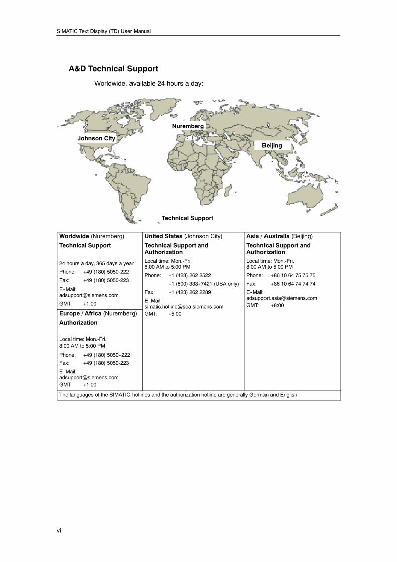
A&D Technical Support
Worldwide, available 24 hours a day:
Johnson City
Nuremberg
Beijing
Technical Support
Worldwide (Nuremberg)
Technical Support
24 hours a day, 365 days a year
Phone: +49 (180) 5050-222
Fax: +49 (180) 5050-223
E--Mail:[email protected]
GMT: +1:00
United States (Johnson City)
Technical Support andAuthorizationLocal time: Mon.-Fri.8:00 AM to 5:00 PM
Phone: +1 (423) 262 2522
+1 (800) 333--7421 (USA only)
Fax: +1 (423) 262 2289
E--Mail:[email protected]
Asia / Australia (Beijing)
Technical Support andAuthorizationLocal time: Mon.-Fri.8:00 AM to 5:00 PM
Phone: +86 10 64 75 75 75
Fax: +86 10 64 74 74 74
E--Mail:[email protected]: +8:00
Europe / Africa (Nuremberg)
Authorization
Local time: Mon.-Fri.8:00 AM to 5:00 PM
Phone: +49 (180) 5050--222
Fax: +49 (180) 5050-223
E--Mail:[email protected]: +1:00
[email protected]: --5:00
GMT: +8:00
The languages of the SIMATIC hotlines and the authorization hotline are generally German and English.
vii
Contents1 Product Overview 1. . . . . . . . . . . . . . . . . . . . . . . . . . . . . . . . . . . . . . . . . . . . . . . . . . . . . .
Introducing the S7-200 Text Display (TD) Devices 2. . . . . . . . . . . . . . . . . . . . . . . . . . . . . . . . . .
Features of the TD Devices 3. . . . . . . . . . . . . . . . . . . . . . . . . . . . . . . . . . . . . . . . . . . . . . . . . . . . .
Support for Multiple Language Sets 3. . . . . . . . . . . . . . . . . . . . . . . . . . . . . . . . . . . . . . . . . .
Comparing the TD 200 and the TD 200C 4. . . . . . . . . . . . . . . . . . . . . . . . . . . . . . . . . . . . . . . . . .
Using the TD Device to Access Screens and Alarms 5. . . . . . . . . . . . . . . . . . . . . . . . . . . . . . . .
Dividing Information into Screens and Bit-Enabled Alarms 5. . . . . . . . . . . . . . . . . . . . . . .
Installation and Configuration Tasks 7. . . . . . . . . . . . . . . . . . . . . . . . . . . . . . . . . . . . . . . . . . . . . .
Creating a Custom Faceplate for Your TD 200C 9. . . . . . . . . . . . . . . . . . . . . . . . . . . . . . . . . . . .
Printing the Custom Faceplate for the TD 200C 10. . . . . . . . . . . . . . . . . . . . . . . . . . . . . . . . . . . .
Printer Requirements 10. . . . . . . . . . . . . . . . . . . . . . . . . . . . . . . . . . . . . . . . . . . . . . . . . . . . . . .
Ordering Additional Faceplate Overlay Material 10. . . . . . . . . . . . . . . . . . . . . . . . . . . . . . . .
2 Installing Your TD Device 11. . . . . . . . . . . . . . . . . . . . . . . . . . . . . . . . . . . . . . . . . . . . . . .
Components Shipped with the TD Devices 12. . . . . . . . . . . . . . . . . . . . . . . . . . . . . . . . . . . . . . . .
Mounting the TD Device in a Panel or on a Surface 12. . . . . . . . . . . . . . . . . . . . . . . . . . . . . . . . .
Preparing the Mounting Surface 12. . . . . . . . . . . . . . . . . . . . . . . . . . . . . . . . . . . . . . . . . . . . .
Preparing the TD Device for Mounting 12. . . . . . . . . . . . . . . . . . . . . . . . . . . . . . . . . . . . . . . .
Positioning the Spacers for the TD Device 13. . . . . . . . . . . . . . . . . . . . . . . . . . . . . . . . . . . . .
Mounting the TD Device 13. . . . . . . . . . . . . . . . . . . . . . . . . . . . . . . . . . . . . . . . . . . . . . . . . . . .
Customizing the Labels for the Keys of Your TD 200 14. . . . . . . . . . . . . . . . . . . . . . . . . . . . . . . .
Modifying the Label Insert of the TD 200 14. . . . . . . . . . . . . . . . . . . . . . . . . . . . . . . . . . . . . .
Creating a Custom Label Insert for the TD 200 14. . . . . . . . . . . . . . . . . . . . . . . . . . . . . . . . .
Installing a Custom Faceplate for the TD 200C 15. . . . . . . . . . . . . . . . . . . . . . . . . . . . . . . . . . . . .
Connecting the TD/CPU Cable 16. . . . . . . . . . . . . . . . . . . . . . . . . . . . . . . . . . . . . . . . . . . . . . . . . .
Supplying Power for the TD Device 16. . . . . . . . . . . . . . . . . . . . . . . . . . . . . . . . . . . . . . . . . . . . . . .
Establishing a Connection for Your TD 200C 17. . . . . . . . . . . . . . . . . . . . . . . . . . . . . . . . . . . . . . .
3 Using the Keypad Designer to Create a Custom Faceplate for Your TD 200C 19
Using the Keypad Designer with Other Applications 20. . . . . . . . . . . . . . . . . . . . . . . . . . . . . . . . .
Starting the Keypad Designer 22. . . . . . . . . . . . . . . . . . . . . . . . . . . . . . . . . . . . . . . . . . . . . . . . . . .
Adding Buttons to the Keypad 23. . . . . . . . . . . . . . . . . . . . . . . . . . . . . . . . . . . . . . . . . . . . . . . . . . .
Inserting a Button 23. . . . . . . . . . . . . . . . . . . . . . . . . . . . . . . . . . . . . . . . . . . . . . . . . . . . . . . . . .
Modifying the Shape of a Button 23. . . . . . . . . . . . . . . . . . . . . . . . . . . . . . . . . . . . . . . . . . . . .
Defining the Properties of the Button 24. . . . . . . . . . . . . . . . . . . . . . . . . . . . . . . . . . . . . . . . . . . . . .
Exporting the Keypad Layout to a Graphics Application 26. . . . . . . . . . . . . . . . . . . . . . . . . . . . .
Adding a Panel Image to the Faceplate 27. . . . . . . . . . . . . . . . . . . . . . . . . . . . . . . . . . . . . . . . . . .
Importing a Panel Image 27. . . . . . . . . . . . . . . . . . . . . . . . . . . . . . . . . . . . . . . . . . . . . . . . . . . .
Saving the Keypad to a TD Configuration File 28. . . . . . . . . . . . . . . . . . . . . . . . . . . . . . . . . . . . . .
Reversing the Panel Image 28. . . . . . . . . . . . . . . . . . . . . . . . . . . . . . . . . . . . . . . . . . . . . . . . . . . . .
Printing the Faceplate 29. . . . . . . . . . . . . . . . . . . . . . . . . . . . . . . . . . . . . . . . . . . . . . . . . . . . . . . . . .
Printing a Single Faceplate from the Keypad Designer 30. . . . . . . . . . . . . . . . . . . . . . . . . .
Printing the Faceplate from a Word-Processing Application 30. . . . . . . . . . . . . . . . . . . . . .
SIMATIC Text Display (TD) User Manual
viii
Installing the Printed Faceplate onto the TD 200C 32. . . . . . . . . . . . . . . . . . . . . . . . . . . . . . . . . .
4 Using the TD 200 Wizard to Configure the S7-200 CPU for the TD Device 33. . .
Overview of the Configuration Tasks 34. . . . . . . . . . . . . . . . . . . . . . . . . . . . . . . . . . . . . . . . . . . . . .
Configuring the TD Device 36. . . . . . . . . . . . . . . . . . . . . . . . . . . . . . . . . . . . . . . . . . . . . . . . . . . . . .
Task Overview 36. . . . . . . . . . . . . . . . . . . . . . . . . . . . . . . . . . . . . . . . . . . . . . . . . . . . . . . . . . . .
Starting the TD 200 Wizard for Your TD Device 37. . . . . . . . . . . . . . . . . . . . . . . . . . . . . . . . .
Selecting the Type of TD Device to Configure 37. . . . . . . . . . . . . . . . . . . . . . . . . . . . . . . . . .
Enabling the TD Device to Modify Data in the S7-200 CPU 38. . . . . . . . . . . . . . . . . . . . . .
Selecting a Password for the TD Device 39. . . . . . . . . . . . . . . . . . . . . . . . . . . . . . . . . . . . . .
Selecting the Update Rate for the TD Device 39. . . . . . . . . . . . . . . . . . . . . . . . . . . . . . . . . .
Selecting the Language and the Character Set 39. . . . . . . . . . . . . . . . . . . . . . . . . . . . . . . . .
Loading a Custom Keypad (TD 200C Only) 40. . . . . . . . . . . . . . . . . . . . . . . . . . . . . . . . . . . .
Configuring the Buttons on the Keypad 40. . . . . . . . . . . . . . . . . . . . . . . . . . . . . . . . . . . . . . .
Configuring the Screens for the TD Device 41. . . . . . . . . . . . . . . . . . . . . . . . . . . . . . . . . . . . . . . .
Creating the User Menu 42. . . . . . . . . . . . . . . . . . . . . . . . . . . . . . . . . . . . . . . . . . . . . . . . . . . .
Creating the Text for a Screen 43. . . . . . . . . . . . . . . . . . . . . . . . . . . . . . . . . . . . . . . . . . . . . . .
Embedding a Variable into the Text of a Screen 43. . . . . . . . . . . . . . . . . . . . . . . . . . . . . . . .
Configuring the Alarms 45. . . . . . . . . . . . . . . . . . . . . . . . . . . . . . . . . . . . . . . . . . . . . . . . . . . . . . . . .
Determining the Type of Operator-Interaction for an Alarm 46. . . . . . . . . . . . . . . . . . . . . . .
Setting the Default Display Mode and Alarm Parameters 47. . . . . . . . . . . . . . . . . . . . . . . .
Entering the Text for an Alarm 47. . . . . . . . . . . . . . . . . . . . . . . . . . . . . . . . . . . . . . . . . . . . . . .
Embedding a Variable into the Text of an Alarm 48. . . . . . . . . . . . . . . . . . . . . . . . . . . . . . . .
Configuring the Language Sets for the TD Device 50. . . . . . . . . . . . . . . . . . . . . . . . . . . . . . . . . .
Notes for Using the Simplified Chinese Character Set 51. . . . . . . . . . . . . . . . . . . . . . . . . . .
Assigning the V Memory Address for the Parameter Block 52. . . . . . . . . . . . . . . . . . . . . . . . . . .
Finishing the Configuration for the TD Device 52. . . . . . . . . . . . . . . . . . . . . . . . . . . . . . . . . . . . . .
5 Operating Your TD Device 53. . . . . . . . . . . . . . . . . . . . . . . . . . . . . . . . . . . . . . . . . . . . . . .
Using the TD Device to Access Screens and Alarms 54. . . . . . . . . . . . . . . . . . . . . . . . . . . . . . . .
Displaying Information on the TD Device 55. . . . . . . . . . . . . . . . . . . . . . . . . . . . . . . . . . . . . .
Using the TD Device to Edit Variables in the S7-200 CPU 56. . . . . . . . . . . . . . . . . . . . . . . .
Accessing the Menus and Screens 57. . . . . . . . . . . . . . . . . . . . . . . . . . . . . . . . . . . . . . . . . . . . . . .
Entering and Releasing a Password 58. . . . . . . . . . . . . . . . . . . . . . . . . . . . . . . . . . . . . . . . . . . . . .
Entering the Password 58. . . . . . . . . . . . . . . . . . . . . . . . . . . . . . . . . . . . . . . . . . . . . . . . . . . . .
Releasing the Password 58. . . . . . . . . . . . . . . . . . . . . . . . . . . . . . . . . . . . . . . . . . . . . . . . . . . .
Viewing the Screens and the Alarms 59. . . . . . . . . . . . . . . . . . . . . . . . . . . . . . . . . . . . . . . . . . . . . .
Displaying the Alarms 60. . . . . . . . . . . . . . . . . . . . . . . . . . . . . . . . . . . . . . . . . . . . . . . . . . . . . .
Editing a Variable That Is Embedded in an Alarm or a Screen 62. . . . . . . . . . . . . . . . . . . .
Performing Typical or Routine Operator Tasks (Operator Menu) 63. . . . . . . . . . . . . . . . . . . . . .
Viewing the Status of an S7-200 CPU 63. . . . . . . . . . . . . . . . . . . . . . . . . . . . . . . . . . . . . . . . .
Setting Time and Date in the S7-200 CPU 64. . . . . . . . . . . . . . . . . . . . . . . . . . . . . . . . . . . . .
Changing the Language Set 65. . . . . . . . . . . . . . . . . . . . . . . . . . . . . . . . . . . . . . . . . . . . . . . . .
Contents
ix
Performing Specialized Operator Tasks (Diagnostic Menu) 65. . . . . . . . . . . . . . . . . . . . . . . . . . .
Setting up the TD Device 66. . . . . . . . . . . . . . . . . . . . . . . . . . . . . . . . . . . . . . . . . . . . . . . . . . .
Viewing the TD Messages Stored in the S7-200 CPU 67. . . . . . . . . . . . . . . . . . . . . . . . . . .
Forcing the Inputs and Outputs in the S7-200 CPU 67. . . . . . . . . . . . . . . . . . . . . . . . . . . . .
Changing the Operating Mode of the S7-200 CPU (TD 200C Only) 68. . . . . . . . . . . . . . . .
Copying the User Program to a Memory Cartridge (TD 200C Only) 68. . . . . . . . . . . . . . . .
Editing the CPU Memory (TD 200C Only) 69. . . . . . . . . . . . . . . . . . . . . . . . . . . . . . . . . . . . .
A Technical Specifications and Reference Information 71. . . . . . . . . . . . . . . . . . . . . .
General Technical Specifications 72. . . . . . . . . . . . . . . . . . . . . . . . . . . . . . . . . . . . . . . . . . . . . . . . .
Certificates, Directives and Declarations 74. . . . . . . . . . . . . . . . . . . . . . . . . . . . . . . . . . . . . . . . . .
Notes on the CE Symbol 74. . . . . . . . . . . . . . . . . . . . . . . . . . . . . . . . . . . . . . . . . . . . . . . . . . . .
EMC Directive 74. . . . . . . . . . . . . . . . . . . . . . . . . . . . . . . . . . . . . . . . . . . . . . . . . . . . . . . . . . . . .
ATEX Directive (Explosion Protection Guidelines) 74. . . . . . . . . . . . . . . . . . . . . . . . . . . . . .
Declaration of Conformity 74. . . . . . . . . . . . . . . . . . . . . . . . . . . . . . . . . . . . . . . . . . . . . . . . . . .
Observing the Setup Guidelines 74. . . . . . . . . . . . . . . . . . . . . . . . . . . . . . . . . . . . . . . . . . . . .
Approvals for USA, Canada and Australia 75. . . . . . . . . . . . . . . . . . . . . . . . . . . . . . . . . . . . . . . . .
FM Approval Notes 75. . . . . . . . . . . . . . . . . . . . . . . . . . . . . . . . . . . . . . . . . . . . . . . . . . . . . . . .
Standard TD Character Set 76. . . . . . . . . . . . . . . . . . . . . . . . . . . . . . . . . . . . . . . . . . . . . . . . . . . . .
ALT Key Combinations for International and Special Characters 77. . . . . . . . . . . . . . . . . .
Bar Graph Character Set 78. . . . . . . . . . . . . . . . . . . . . . . . . . . . . . . . . . . . . . . . . . . . . . . . . . . .
Arabic Character Set 79. . . . . . . . . . . . . . . . . . . . . . . . . . . . . . . . . . . . . . . . . . . . . . . . . . . . . . . . . . .
Baltic Character Set 80. . . . . . . . . . . . . . . . . . . . . . . . . . . . . . . . . . . . . . . . . . . . . . . . . . . . . . . . . . . .
Simplified Chinese Character Set 81. . . . . . . . . . . . . . . . . . . . . . . . . . . . . . . . . . . . . . . . . . . . . . . .
Notes for Using the Simplified Chinese Character Set 81. . . . . . . . . . . . . . . . . . . . . . . . . . .
Cyrillic Character Set 82. . . . . . . . . . . . . . . . . . . . . . . . . . . . . . . . . . . . . . . . . . . . . . . . . . . . . . . . . . .
Greek Character Set 83. . . . . . . . . . . . . . . . . . . . . . . . . . . . . . . . . . . . . . . . . . . . . . . . . . . . . . . . . . .
Hebrew Character Set 84. . . . . . . . . . . . . . . . . . . . . . . . . . . . . . . . . . . . . . . . . . . . . . . . . . . . . . . . . .
Latin 1 Character Set 85. . . . . . . . . . . . . . . . . . . . . . . . . . . . . . . . . . . . . . . . . . . . . . . . . . . . . . . . . . .
Latin 2 Character Set 86. . . . . . . . . . . . . . . . . . . . . . . . . . . . . . . . . . . . . . . . . . . . . . . . . . . . . . . . . . .
Turkish (Latin 5) Character Set 87. . . . . . . . . . . . . . . . . . . . . . . . . . . . . . . . . . . . . . . . . . . . . . . . . .
B Connecting Multiple Devices on a Network 89. . . . . . . . . . . . . . . . . . . . . . . . . . . . . . .
Communicating with Multiple CPUs 90. . . . . . . . . . . . . . . . . . . . . . . . . . . . . . . . . . . . . . . . . . . . . . .
Determining the Distances, Transmission Rate, and Cable 91. . . . . . . . . . . . . . . . . . . . . . . . . . .
Using Repeaters on the Network 91. . . . . . . . . . . . . . . . . . . . . . . . . . . . . . . . . . . . . . . . . . . . .
Selecting the Network Cable 92. . . . . . . . . . . . . . . . . . . . . . . . . . . . . . . . . . . . . . . . . . . . . . . .
Biasing and Terminating the Network Cable 92. . . . . . . . . . . . . . . . . . . . . . . . . . . . . . . . . . . .
Building a TD/CPU Cable 93. . . . . . . . . . . . . . . . . . . . . . . . . . . . . . . . . . . . . . . . . . . . . . . . . . . . . . .
Making a Cable That Supplies Power to the TD 200 93. . . . . . . . . . . . . . . . . . . . . . . . . . . .
Making a Cable That Does Not Supply Power to the TD 200 93. . . . . . . . . . . . . . . . . . . . .
CPU Grounding and Circuit Reference Point Guidelines for Using Isolated Circuits 94. . . . . .
C Troubleshooting 95. . . . . . . . . . . . . . . . . . . . . . . . . . . . . . . . . . . . . . . . . . . . . . . . . . . . . . .
Index 97. . . . . . . . . . . . . . . . . . . . . . . . . . . . . . . . . . . . . . . . . . . . . . . . . . . . . . . . . . . . . . . . . . . . . . . .

SIMATIC Text Display (TD) User Manual
x
1
Product Overview
The S7-200 TD devices (TD 200 and TD 200C) provide a low-cost human-machine interface(HMI), allowing an operator or user to interact with your application.
The TD devices allow you to configure a set of hierarchical user menus that allow you to provideadditional structure for the interaction with your application. You can also configure the TD deviceto display alarms or messages that are enabled by specific bits in the S7-200 CPU.
TipThe new TD devices provide additional functionality, such as the hierarchical user-definedmenus, yet remain fully compatible with projects that were created with earlier versions of theTD 200 (prior to TD 200 V3.0, which supported only the bit-enabled messages from theS7-200 CPU).
You can use a new TD 200 or TD 200C with an existing TD configuration without having tomodify the control program in the S7-200 CPU.
In This ChapterIntroducing the S7-200 Text Display (TD) Devices 2. . . . . . . . . . . . . . . . . . . . . . . . . . . . . . . . . .
Features of the TD Devices 3. . . . . . . . . . . . . . . . . . . . . . . . . . . . . . . . . . . . . . . . . . . . . . . . . . . . .
Support for Multiple Language Sets 3. . . . . . . . . . . . . . . . . . . . . . . . . . . . . . . . . . . . . . . . . .
Comparing the TD 200 and the TD 200C 4. . . . . . . . . . . . . . . . . . . . . . . . . . . . . . . . . . . . . . . . . .
Using the TD Device to Access Screens and Alarms 5. . . . . . . . . . . . . . . . . . . . . . . . . . . . . . . .
Dividing Information into Screens and Bit-Enabled Alarms 5. . . . . . . . . . . . . . . . . . . . . . .
Installation and Configuration Tasks 7. . . . . . . . . . . . . . . . . . . . . . . . . . . . . . . . . . . . . . . . . . . . . .
Creating a Custom Faceplate for Your TD 200C 9. . . . . . . . . . . . . . . . . . . . . . . . . . . . . . . . . . . .
Printing the Custom Faceplate for the TD 200C 10. . . . . . . . . . . . . . . . . . . . . . . . . . . . . . . . . . . .
Printer Requirements 10. . . . . . . . . . . . . . . . . . . . . . . . . . . . . . . . . . . . . . . . . . . . . . . . . . . . . . .
Ordering Additional Faceplate Overlay Material 10. . . . . . . . . . . . . . . . . . . . . . . . . . . . . . . .
SIMATIC Text Display (TD) User Manual
2
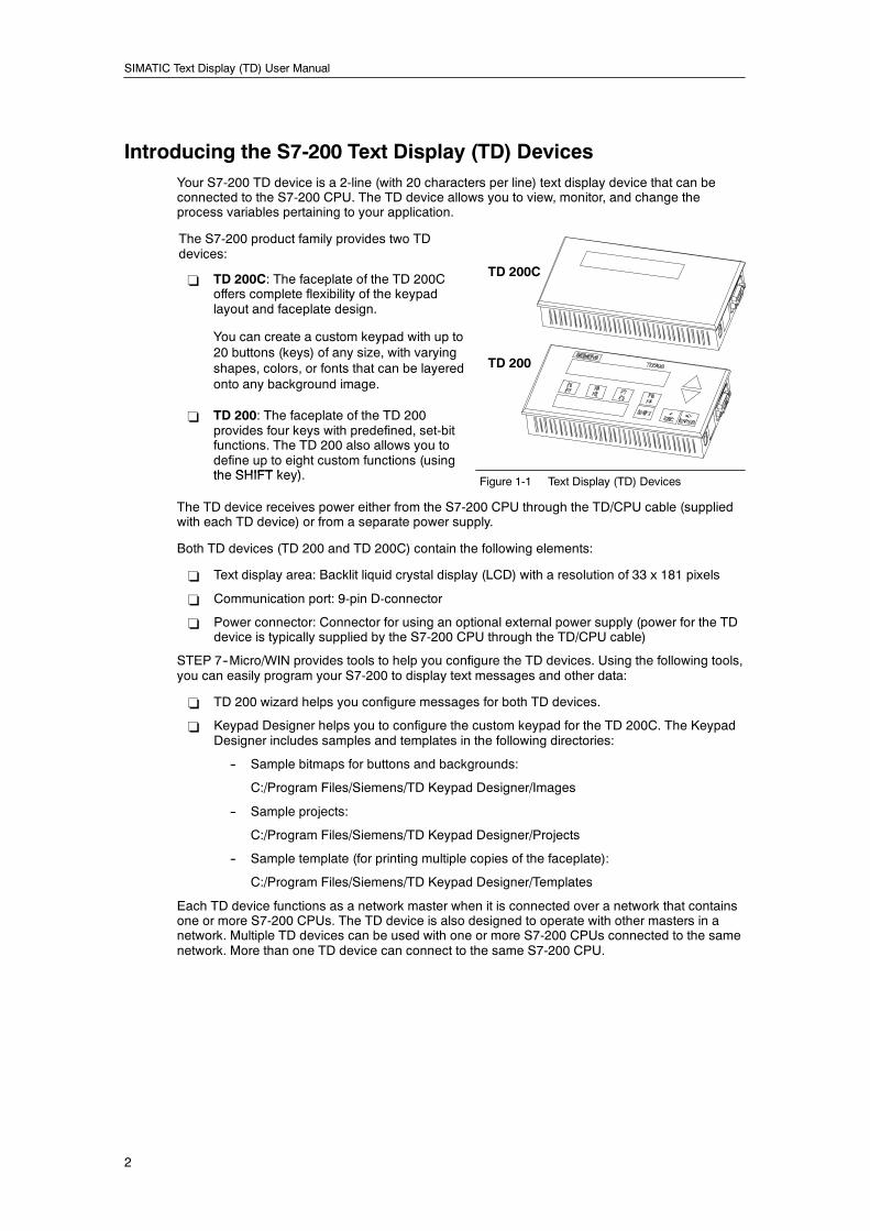
Introducing the S7-200 Text Display (TD) DevicesYour S7-200 TD device is a 2-line (with 20 characters per line) text display device that can beconnected to the S7-200 CPU. The TD device allows you to view, monitor, and change theprocess variables pertaining to your application.
The S7-200 product family provides two TDdevices:
- TD 200C: The faceplate of the TD 200Coffers complete flexibility of the keypadlayout and faceplate design.
You can create a custom keypad with up to20 buttons (keys) of any size, with varyingshapes, colors, or fonts that can be layeredonto any background image.
- TD 200: The faceplate of the TD 200provides four keys with predefined, set-bitfunctions. The TD 200 also allows you todefine up to eight custom functions (usingthe SHIFT key)
TD 200C
TD 200
the SHIFT key). Figure 1-1 Text Display (TD) Devices
The TD device receives power either from the S7-200 CPU through the TD/CPU cable (suppliedwith each TD device) or from a separate power supply.
Both TD devices (TD 200 and TD 200C) contain the following elements:
- Text display area: Backlit liquid crystal display (LCD) with a resolution of 33 x 181 pixels
- Communication port: 9-pin D-connector
- Power connector: Connector for using an optional external power supply (power for the TDdevice is typically supplied by the S7-200 CPU through the TD/CPU cable)
STEP 7--Micro/WIN provides tools to help you configure the TD devices. Using the following tools,you can easily program your S7-200 to display text messages and other data:
- TD 200 wizard helps you configure messages for both TD devices.
- Keypad Designer helps you to configure the custom keypad for the TD 200C. The KeypadDesigner includes samples and templates in the following directories:
-- Sample bitmaps for buttons and backgrounds:
C:/Program Files/Siemens/TD Keypad Designer/Images
-- Sample projects:
C:/Program Files/Siemens/TD Keypad Designer/Projects
-- Sample template (for printing multiple copies of the faceplate):
C:/Program Files/Siemens/TD Keypad Designer/Templates
Each TD device functions as a network master when it is connected over a network that containsone or more S7-200 CPUs. The TD device is also designed to operate with other masters in anetwork. Multiple TD devices can be used with one or more S7-200 CPUs connected to the samenetwork. More than one TD device can connect to the same S7-200 CPU.
Product Overview Chapter 1
3
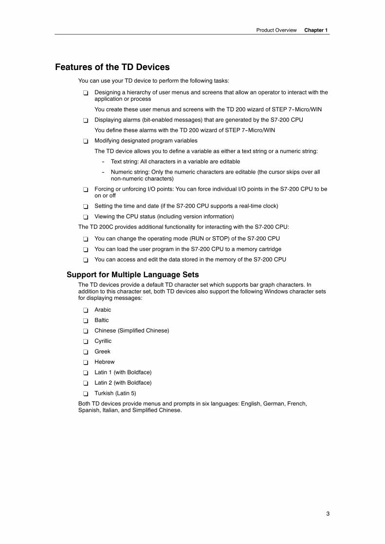
Features of the TD DevicesYou can use your TD device to perform the following tasks:
- Designing a hierarchy of user menus and screens that allow an operator to interact with theapplication or process
You create these user menus and screens with the TD 200 wizard of STEP 7--Micro/WIN
- Displaying alarms (bit-enabled messages) that are generated by the S7-200 CPU
You define these alarms with the TD 200 wizard of STEP 7--Micro/WIN
- Modifying designated program variables
The TD device allows you to define a variable as either a text string or a numeric string:
-- Text string: All characters in a variable are editable
-- Numeric string: Only the numeric characters are editable (the cursor skips over allnon-numeric characters)
- Forcing or unforcing I/O points: You can force individual I/O points in the S7-200 CPU to beon or off
- Setting the time and date (if the S7-200 CPU supports a real-time clock)
- Viewing the CPU status (including version information)
The TD 200C provides additional functionality for interacting with the S7-200 CPU:
- You can change the operating mode (RUN or STOP) of the S7-200 CPU
- You can load the user program in the S7-200 CPU to a memory cartridge
- You can access and edit the data stored in the memory of the S7-200 CPU
Support for Multiple Language SetsThe TD devices provide a default TD character set which supports bar graph characters. Inaddition to this character set, both TD devices also support the following Windows character setsfor displaying messages:
- Arabic
- Baltic
- Chinese (Simplified Chinese)
- Cyrillic
- Greek
- Hebrew
- Latin 1 (with Boldface)
- Latin 2 (with Boldface)
- Turkish (Latin 5)
Both TD devices provide menus and prompts in six languages: English, German, French,Spanish, Italian, and Simplified Chinese.
SIMATIC Text Display (TD) User Manual
4
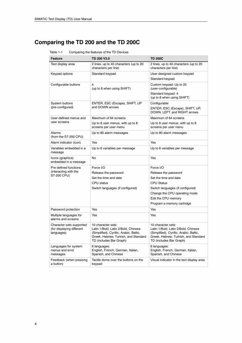
Comparing the TD 200 and the TD 200C
Table 1-1 Comparing the features of the TD Devices
Feature TD 200 V3.0 TD 200C
Text display area 2 lines, up to 40 characters (up to 20characters per line)
2 lines, up to 40 characters (up to 20characters per line)
Keypad options Standard keypad User-designed custom keypad
Standard keypad
Configurable buttons 4(up to 8 when using SHIFT)
Custom keypad: Up to 20(user-configurable)
Standard keypad: 4(up to 8 when using SHIFT)
System buttons(pre-configured)
ENTER, ESC (Escape), SHIFT, UPand DOWN arrows
Configurable
ENTER, ESC (Escape), SHIFT, UP,DOWN, LEFT, and RIGHT arrows
User-defined menus anduser screens
Maximum of 64 screens
Up to 8 user menus, with up to 8screens per user menu
Maximum of 64 screens
Up to 8 user menus, with up to 8screens per user menu
Alarms(from the S7-200 CPU)
Up to 80 alarm messages Up to 80 alarm messages
Alarm indicator (icon) Yes Yes
Variables embedded in amessage
Up to 6 variables per message Up to 6 variables per message
Icons (graphics)embedded in a message
No Yes
Pre-defined functions(interacting with theS7-200 CPU)
Force I/O
Release the password
Set the time and date
CPU status
Switch languages (if configured)
Force I/O
Release the password
Set the time and date
CPU Status
Switch languages (if configured)
Change the CPU operating mode
Edit the CPU memory
Program a memory cartridge
Password protection Yes Yes
Multiple languages foralarms and screens
Yes Yes
Character sets supported(for displaying differentlanguages)
10 character sets:Latin 1/Bold, Latin 2/Bold, Chinese(Simplified), Cyrillic, Arabic, Baltic,Greek, Hebrew, Turkish, and StandardTD (includes Bar Graph)
10 character sets:Latin 1/Bold, Latin 2/Bold, Chinese(Simplified), Cyrillic, Arabic, Baltic,Greek, Hebrew, Turkish, and StandardTD (includes Bar Graph)
Languages for systemmenus and errormessages
6 languages:English, French, German, Italian,Spanish, and Chinese
6 languages:English, French, German, Italian,Spanish, and Chinese
Feedback (when pressinga button)
Tactile dome over the buttons on thekeypad
Visual indicator in the text display area
Product Overview Chapter 1
5
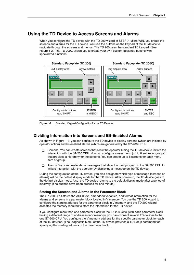
Using the TD Device to Access Screens and AlarmsWhen you configure the TD device with the TD 200 wizard of STEP 7--Micro/WIN, you create thescreens and alarms for the TD device. You use the buttons on the keypad of the TD device tonavigate through the screens and menus. The TD 200 uses the standard TD keypad. (SeeFigure 1-2.) The TD 200C allows you to create your own custom-designed buttons withspecialized functions.
F1F5
F2F6
F3F7
F4F8
SHIFT ESC ENTER
Text display area Arrow buttons
Configurable buttons(and SHIFT)
ENTERand ESC
F1F5
F2F6
F3F7
F4F8
SHIFT ESC ENTER
Text display area Arrow buttons
Configurable buttons(and SHIFT)
ENTERand ESC
Standard Faceplate (TD 200) Standard Faceplate (TD 200C)
Figure 1-2 Standard Keypad Configuration for the TD Devices
Dividing Information into Screens and Bit-Enabled AlarmsAs shown in Figure 1-3, you can configure the TD device to display screens (which are initiated byoperator action) and bit-enabled alarms (which are generated by the S7-200 CPU).
- Screens: You can create screens that allow the operator (using the TD device) to initiate theinteraction with the S7-200 CPU. You can configure a user menu (up to 8 entries or groups)that provides a hierarchy for the screens. You can create up to 8 screens for each menuitem or group.
- Alarms: You can create alarm messages that allow the user program in the S7-200 CPU toinitiate interaction with the operator by displaying a message on the TD device.
During the configuration of the TD device, you also designate which type of message (screens oralarms) will be the default display mode for the TD device. After power-up, the TD device goes tothe default display mode. Also, the TD device returns to the default display mode after a period ofinactivity (if no buttons have been pressed for one minute).
Storing the Screens and Alarms in the Parameter BlockThe S7-200 CPU stores the ASCII text, embedded variables, and format information for thealarms and screens in a parameter block located in V memory. You use the TD 200 wizard toconfigure the starting address for the parameter block in V memory, and the TD 200 wizardallocates the memory required to store the information for the TD device.
If you configure more than one parameter block for the S7-200 CPU (with each parameter blockhaving a different range of addresses in V memory), you can connect several TD devices to thatone S7-200 CPU. You configure the V memory address for the specific parameter block for eachof the TD devices. (The Diagnostic Menu of the TD device provides a TD Setup command forspecifying the starting address of the parameter block.)
SIMATIC Text Display (TD) User Manual
6
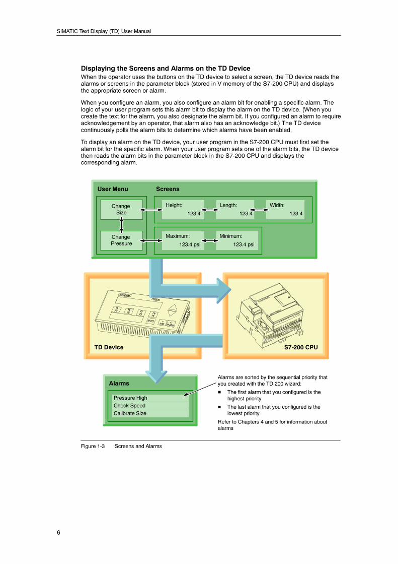
Displaying the Screens and Alarms on the TD DeviceWhen the operator uses the buttons on the TD device to select a screen, the TD device reads thealarms or screens in the parameter block (stored in V memory of the S7-200 CPU) and displaysthe appropriate screen or alarm.
When you configure an alarm, you also configure an alarm bit for enabling a specific alarm. Thelogic of your user program sets this alarm bit to display the alarm on the TD device. (When youcreate the text for the alarm, you also designate the alarm bit. If you configured an alarm to requireacknowledgement by an operator, that alarm also has an acknowledge bit.) The TD devicecontinuously polls the alarm bits to determine which alarms have been enabled.
To display an alarm on the TD device, your user program in the S7-200 CPU must first set thealarm bit for the specific alarm. When your user program sets one of the alarm bits, the TD devicethen reads the alarm bits in the parameter block in the S7-200 CPU and displays thecorresponding alarm.
TD Device
Pressure High
Check Speed
Calibrate Size
Alarms
S7-200 CPU
Width:
123.4
Minimum:
123.4 psi
Length:
123.4
Height:
123.4ChangeSize
Maximum:
123.4 psiChangePressure
User Menu Screens
Alarms are sorted by the sequential priority thatyou created with the TD 200 wizard:
H The first alarm that you configured is thehighest priority
H The last alarm that you configured is thelowest priority
Refer to Chapters 4 and 5 for information aboutalarms
Figure 1-3 Screens and Alarms
Product Overview Chapter 1
7
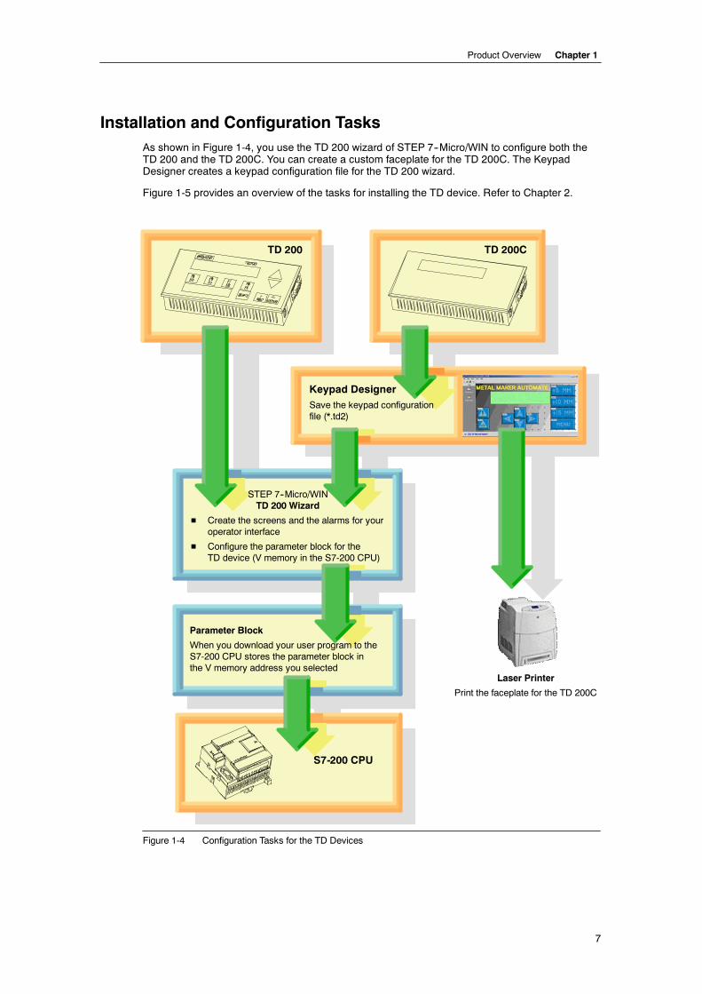
Installation and Configuration TasksAs shown in Figure 1-4, you use the TD 200 wizard of STEP 7--Micro/WIN to configure both theTD 200 and the TD 200C. You can create a custom faceplate for the TD 200C. The KeypadDesigner creates a keypad configuration file for the TD 200 wizard.
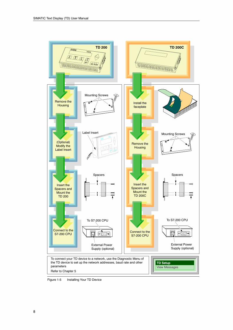
Figure 1-5 provides an overview of the tasks for installing the TD device. Refer to Chapter 2.
Keypad DesignerSave the keypad configurationfile (*.td2)
STEP 7--Micro/WINTD 200 Wizard
H Create the screens and the alarms for youroperator interface
H Configure the parameter block for theTD device (V memory in the S7-200 CPU)
TD 200
Parameter Block
When you download your user program to theS7-200 CPU stores the parameter block inthe V memory address you selected
Laser Printer
Print the faceplate for the TD 200C
S7-200 CPU
TD 200C
Figure 1-4 Configuration Tasks for the TD Devices
SIMATIC Text Display (TD) User Manual
8
Label Insert
TD 200 TD 200C
Install thefaceplate
Remove theHousing
Mounting Screws
(Optional)Modify theLabel Insert
Insert theSpacers andMount theTD 200
Spacers
To S7-200 CPU
Connect to theS7-200 CPU
External PowerSupply (optional)
Remove theHousing
Insert theSpacers andMount theTD 200C
Connect to theS7-200 CPU
Mounting Screws
Spacers
To S7-200 CPU
External PowerSupply (optional)
View MessagesTD Setup
To connect your TD device to a network, use the Diagnostic Menu ofthe TD device to set up the network addresses, baud rate and otherparameters
Refer to Chapter 5
Figure 1-5 Installing Your TD Device
Product Overview Chapter 1
9
Creating a Custom Faceplate for Your TD 200CWith the TD 200C, you can design a custom faceplate that incorporates up to 20 buttons (keys) ofany size, with varying shapes, colors, or fonts that can be layered onto any background image.You use the Keypad Designer to create the custom-designed layout for the keypad.
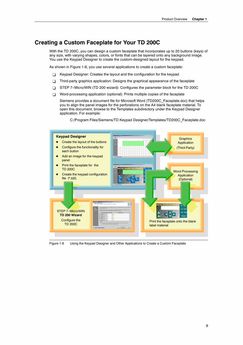
As shown in Figure 1-6, you use several applications to create a custom faceplate:
- Keypad Designer: Creates the layout and the configuration for the keypad
- Third-party graphics application: Designs the graphical appearance of the faceplate
- STEP 7--Micro/WIN (TD 200 wizard): Configures the parameter block for the TD 200C
- Word-processing application (optional): Prints multiple copies of the faceplate
Siemens provides a document file for Microsoft Word (TD200C_Faceplate.doc) that helpsyou to align the panel images for the perforations on the A4 blank faceplate material. Toopen this document, browse to the Templates subdirectory under the Keypad Designerapplication. For example:
C:/Program Files/Siemens/TD Keypad Designer/Templates/TD200C_Faceplate.doc
STEP 7--Micro/WINTD 200 Wizard
Configure theTD 200C
Keypad DesignerH Create the layout of the buttons
H Configure the functionality foreach button
H Add an image for the keypadpanel
H Print the faceplate for theTD 200C
H Create the keypad configurationfile (*.td2)
GraphicsApplication
(Third-Party)
Word-ProcessingApplication(Optional)
Print the faceplate onto the blanklabel material
Figure 1-6 Using the Keypad Designer and Other Applications to Create a Custom Faceplate
SIMATIC Text Display (TD) User Manual
10
Printing the Custom Faceplate for the TD 200CThe TD 200C ships with one blank overlay (envelope-size) for printing the faceplate. Thefaceplate overlay is constructed from durable, polyester material which has been designedespecially for use on HMI faceplates.
! You can print a single faceplate directly from the Keypad Designer on the envelope-sizedblank faceplate overlay.
! To print multiple faceplates, you can use the Microsoft Word template (provided online) thatensures your faceplate design is properly sized. You can print up to 3 faceplates onto theperforated A4-size blank overlay sheets.
Refer to Chapter 3 for specific information about printing the custom faceplate for the TD 200C.
TipThe faceplate material is specially treated on one side to accommodate printing with a laserprinter. The treated surface is up (or toward you) when you are holding the material with the cutcorner in the top right of the sheet.
Ensure that the material is correctly inserted into the laser printer so that the faceplate prints thereversed image onto the treated surface of the material. You must print a reversed-imageversion of the faceplate onto the overlay material.
Before printing your custom faceplate onto the blank overlay sheet, first test your design byprinting the faceplate onto regular paper. You can then temporarily use the paper overlay to testthe functionality of the design with your TD 200C.
Printer RequirementsTo print your custom-designed image onto the blank faceplate material, you must use a laserprinter that supports the following features:
! Paper size: The laser printer must be able to print on both the A4 (210 mm X 297 mm) andenvelope formats.
! Color: The laser printer must support color printing.
! Transparencies: The laser printer must support the printing of transparencies (or othernon-paper stock).
Ordering Additional Faceplate Overlay MaterialYou can order additional blank overlays in perforated A4-size sheets (10 sheets/package). Theoverlay material is especially designed for printing on a laser printer. The blank overlay sheetsalso allow you to utilize the services of professional printing vendors that specialize in laserprinting in order to create large quantities of high-quality faceplates.
Contact your local Siemens representative or distributor to purchase additional quantities of theoverlay material (order number: 6ES7 272--1AF00--7AA0).
11
Installing Your TD Device
You can install you TD device for easy access, whether on a panel, on a door of an enclosure, oron a wall. Installed properly, the TD device meets the following standards for protection:
- IP 65 (mounted on front of the panel)
- IP 20 (mounted on casing)
- NEMA 4
Refer to Appendix A for technical specification and for information about agency approvals andother certifications.
TipYou can use a new TD 200 or TD 200C with an existing TD 200 configuration without having tomodify the control program in the S7-200 CPU.
In This ChapterComponents Shipped with the TD Devices 12. . . . . . . . . . . . . . . . . . . . . . . . . . . . . . . . . . . . . . . .
Mounting the TD Device in a Panel or on a Surface 12. . . . . . . . . . . . . . . . . . . . . . . . . . . . . . . . .
Preparing the Mounting Surface 12. . . . . . . . . . . . . . . . . . . . . . . . . . . . . . . . . . . . . . . . . . . . .
Preparing the TD Device for Mounting 12. . . . . . . . . . . . . . . . . . . . . . . . . . . . . . . . . . . . . . . .
Positioning the Spacers for the TD Device 13. . . . . . . . . . . . . . . . . . . . . . . . . . . . . . . . . . . . .
Mounting the TD Device 13. . . . . . . . . . . . . . . . . . . . . . . . . . . . . . . . . . . . . . . . . . . . . . . . . . . .
Customizing the Labels for the Keys of Your TD 200 14. . . . . . . . . . . . . . . . . . . . . . . . . . . . . . . .
Modifying the Label Insert of the TD 200 14. . . . . . . . . . . . . . . . . . . . . . . . . . . . . . . . . . . . . .
Creating a Custom Label Insert for the TD 200 14. . . . . . . . . . . . . . . . . . . . . . . . . . . . . . . . .
Installing a Custom Faceplate for the TD 200C 15. . . . . . . . . . . . . . . . . . . . . . . . . . . . . . . . . . . . .
Connecting the TD/CPU Cable 16. . . . . . . . . . . . . . . . . . . . . . . . . . . . . . . . . . . . . . . . . . . . . . . . . .
Supplying Power for the TD Device 16. . . . . . . . . . . . . . . . . . . . . . . . . . . . . . . . . . . . . . . . . . . . . . .
Establishing a Connection for Your TD 200C 17. . . . . . . . . . . . . . . . . . . . . . . . . . . . . . . . . . . . . . .
2
SIMATIC Text Display (TD) User Manual
12
Components Shipped with the TD DevicesBoth TD devices (TD 200 and TD 200C) ship with the following components:
- Gasket: Protective cushion with gasket for installing the TD device in inclementenvironments
- TD/CPU cable: 9-pin, straight-through cable that provides both communication and powerto the TD device
- Spacers: Self-adhesive spacers for mounting the TD device in a panel
The TD 200 ships with a pull-out user label that allows you to label the function keys for yourapplication.
The TD 200C ships with a blank faceplate overlay that you can customize, and also includes aprinted overlay for the standard TD keypad. The faceplate overlay is constructed from durable,polyester material which has been designed specifically for use for HMI faceplates.
TipTo print your custom-designed image onto the blank faceplate material, you must use a laserprinter that supports the printing of transparencies on both A4 and envelope formats and alsosupports color printing.
Mounting the TD Device in a Panel or on a Surface
TipIf you are using a customized label insert for your TD 200, you must first install the new labelinsert before you mount the TD 200.
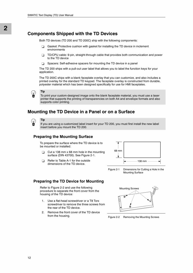
Preparing the Mounting Surface
To prepare the surface where the TD device is tobe mounted or installed:
- Cut a 138 mm x 68 mm hole in the mountingsurface (DIN 43700). See Figure 2-1.
- Refer to Table A-1 for the outsidedimensions of the TD device.
138 mm
68 mm
Figure 2-1 Dimensions for Cutting a Hole in theMounting Surface
Preparing the TD Device for Mounting
Refer to Figure 2-2 and use the followingprocedure to separate the front cover from thehousing of the TD device:
1. Use a flat-head screwdriver or a T8 Torxscrewdriver to remove the three screws fromthe rear of the TD device.
2. Remove the front cover of the TD devicef
Mounting Screws
from the housing. Figure 2-2 Removing the Mounting Screws
2
Installing Your TD Device Chapter 2
13
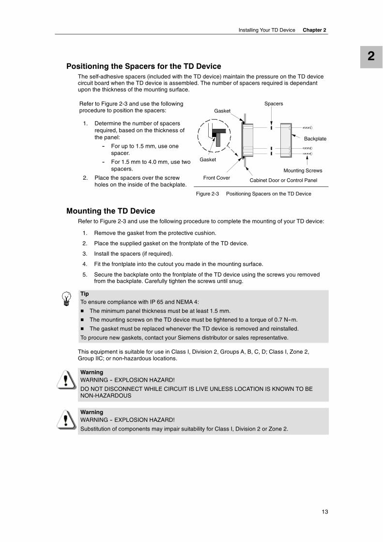
Positioning the Spacers for the TD DeviceThe self-adhesive spacers (included with the TD device) maintain the pressure on the TD devicecircuit board when the TD device is assembled. The number of spacers required is dependantupon the thickness of the mounting surface.
Refer to Figure 2-3 and use the followingprocedure to position the spacers:
1. Determine the number of spacersrequired, based on the thickness ofthe panel:
-- For up to 1.5 mm, use onespacer.
-- For 1.5 mm to 4.0 mm, use twospacers.
2. Place the spacers over the screwholes on the inside of the backplate.
Backplate
Front Cover Cabinet Door or Control Panel
GasketSpacers
Mounting Screws
Gasket
p
Figure 2-3 Positioning Spacers on the TD Device
Mounting the TD DeviceRefer to Figure 2-3 and use the following procedure to complete the mounting of your TD device:
1. Remove the gasket from the protective cushion.
2. Place the supplied gasket on the frontplate of the TD device.
3. Install the spacers (if required).
4. Fit the frontplate into the cutout you made in the mounting surface.
5. Secure the backplate onto the frontplate of the TD device using the screws you removedfrom the backplate. Carefully tighten the screws until snug.
TipTo ensure compliance with IP 65 and NEMA 4:
! The minimum panel thickness must be at least 1.5 mm.
! The mounting screws on the TD device must be tightened to a torque of 0.7 N--m.
! The gasket must be replaced whenever the TD device is removed and reinstalled.
To procure new gaskets, contact your Siemens distributor or sales representative.
This equipment is suitable for use in Class I, Division 2, Groups A, B, C, D; Class I, Zone 2,Group IIC; or non-hazardous locations.
WarningWARNING -- EXPLOSION HAZARD!
DO NOT DISCONNECT WHILE CIRCUIT IS LIVE UNLESS LOCATION IS KNOWN TO BENON-HAZARDOUS
WarningWARNING -- EXPLOSION HAZARD!
Substitution of components may impair suitability for Class I, Division 2 or Zone 2.
2
SIMATIC Text Display (TD) User Manual
14
Customizing the Labels for the Keys of Your TD 200The TD 200 allows you to define the functions for four of the nine keys (or buttons) on thestandard faceplate. You can remove the label insert of the TD 200 and designate the functionsassigned to those user-defined keys. You can also replace the standard TD 200 insert with yourown custom insert for the user-defined keys.
You must remove (at least partially) the TD housing in order to access the label insert fromunderneath the front cover of the TD device.
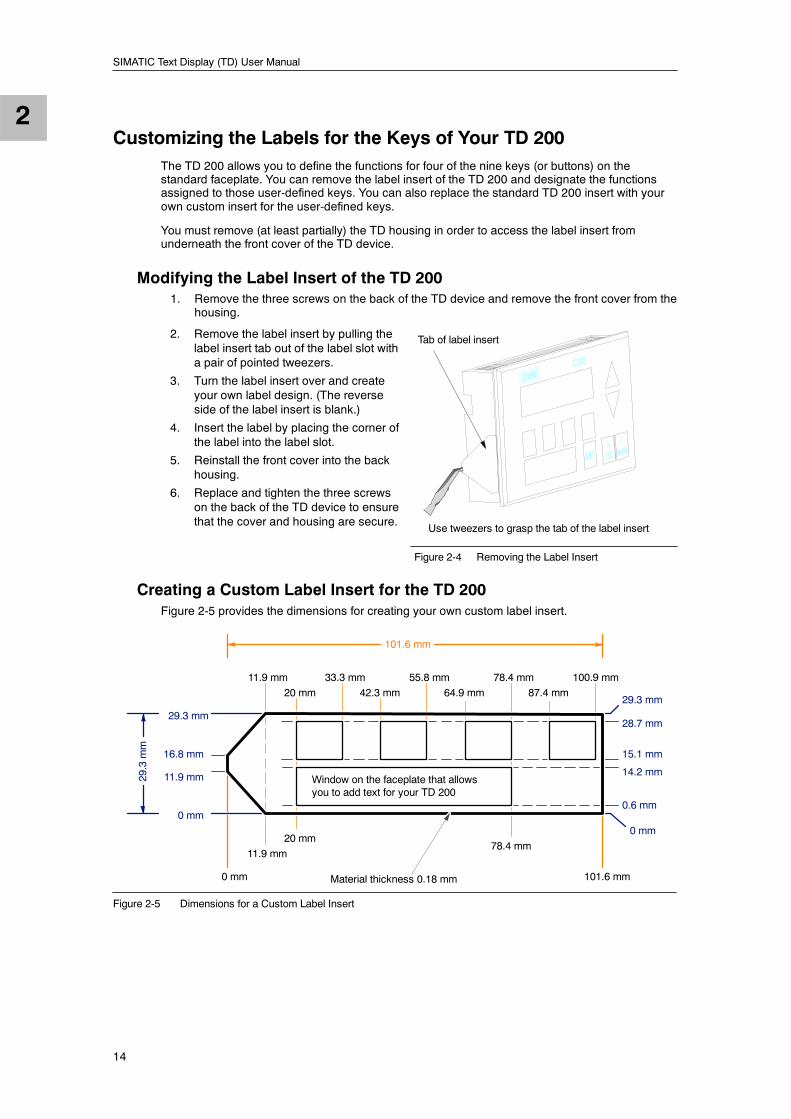
Modifying the Label Insert of the TD 2001. Remove the three screws on the back of the TD device and remove the front cover from the
housing.
2. Remove the label insert by pulling thelabel insert tab out of the label slot witha pair of pointed tweezers.
3. Turn the label insert over and createyour own label design. (The reverseside of the label insert is blank.)
4. Insert the label by placing the corner ofthe label into the label slot.
5. Reinstall the front cover into the backhousing.
6. Replace and tighten the three screwson the back of the TD device to ensurethat the cover and housing are secure.
Use tweezers to grasp the tab of the label insert
Tab of label insert
Figure 2-4 Removing the Label Insert
Creating a Custom Label Insert for the TD 200Figure 2-5 provides the dimensions for creating your own custom label insert.
29.3 mm
14.2 mm
15.1 mm
29.3 mm
Material thickness 0.18 mm
16.8 mm
11.9 mm
0 mm
11.9 mm
20 mm78.4 mm
0 mm
11.9 mm
20 mm
33.3 mm
42.3 mm
55.8 mm
64.9 mm
78.4 mm
87.4 mm
100.9 mm
Window on the faceplate that allowsyou to add text for your TD 200
101.6 mm
101.6 mm
0.6 mm
28.7 mm
0 mm
29.3mm
Figure 2-5 Dimensions for a Custom Label Insert

2
Installing Your TD Device Chapter 2
15
Installing a Custom Faceplate for the TD 200CThe TD 200C ships with a blank faceplate (envelopesize) for creating a custom-designed faceplate.
The TD 200C does not ship with a faceplate attached.The front of the TD 200C is an adhesive surface(shipped with a protective paper) that allows you toattach your custom faceplate.
Refer to Chapter 3 for information about designing andprinting a custom faceplate.
The upper diagram of Figure 2-6 shows the dimensionsfor the faceplate of the TD 200C. Blank faceplatematerial is available in two sizes:
- Envelope size for printing a single faceplate
- A4 size (210 mm x 297 mm) for printing up to 3copies of the faceplate
You must cut the faceplate from the envelope-sizedmaterial, but the A4 material is perforated to allow youto remove the faceplates without cutting.
Use the following procedure to install your customfaceplate on the TD 200C:
1. As shown in Figure 2-6, remove the strip ofprotective paper on the left side of the TD 200Cto expose a strip of the adhesive.
2. Carefully align your custom faceplate on theentire TD 200C, and then seal the faceplate tothe exposed adhesive by pressing down on theleft side of the faceplate.
3. Carefully lift back the unadhered faceplate andremove the rest of the protective paper from theTD 200C.
4. Carefully position the faceplate onto theTD 200C. Firmly press the faceplate onto theadhesive as shown in Figure 2-6, taking care toremove any air bubbles that may have beentrapped underneath.
The TD 200C comes configured as a standard TD 200(with LEFT and RIGHT arrows, see Figure 1-2). Aftercreating and installing the custom faceplate on yourTD 200C, you must also download the TD configurationthat you created with both the Keypad Designer andthe TD 200 wizard.
- Chapter 3 describes the Keypad Designer.
- Chapter 4 describes the TD 200 wizard.
3
1
2
4
Dimensions for the Custom Faceplate
65.7 mm
137.7 mm
Custom Faceplate
Figure 2-6 Installing a Custom Faceplate
2
SIMATIC Text Display (TD) User Manual
16
Connecting the TD/CPU Cable
CautionOperating the TD 200 with an ungrounded voltage source can damage the TD 200 device.
The TD 200 may only be connected to grounded voltage sources. Non-grounded operation cancause the TD 200 device to become damaged.
Always ensure that the voltage source for the TD 200 is properly grounded.
Both TD devices (TD 200 and TD 200C) can use the TD/CPU cable for communicating with theS7-200 CPU.
- You can connect the TD device directly to the S7-200 CPU, creating a one-to-one networkconfiguration. In this configuration, one TD device connects to one S7-200 CPU through theTD/CPU cable.
- You can connect multiple TD devices to multiple S7-200 CPUs over a network. TheTD device defaults to address 1 and attempts to communicate to a CPU at address 2.
For more information about connecting to multiple CPUs, see Appendix B. For informationabout changing the default addresses in the TD device, see Chapter 5.
If you require a longer cable (>2.5 m) to connect the TD device to the S7-200 CPU, usePROFIBUS components for the network connection. Refer to the SINEC IK10 Catalog.
Supplying Power for the TD DeviceThe S7-200 CPU uses the TD/CPU cable to provide power to the TD device. Use this type ofpower supply when the distance between the TD device and the S7-200 CPU is less than 2.5 m(the length of the TD/CPU cable).
TipIf the distance between the TD device and the S7-200 CPU is greater than 2.5 m, use anexternal 24 VDC power supply. The TD device ships with an power connector that allows you toconnect an optional external power supply to the TD device.
If you require a longer cable (greater than 2.5 m) to connect the TD device to the S7-200 CPU,use PROFIBUS components for the network connection. Refer to the SINEC IK10 Catalog.
Refer to Appendix B for information about using the TD device on a network.
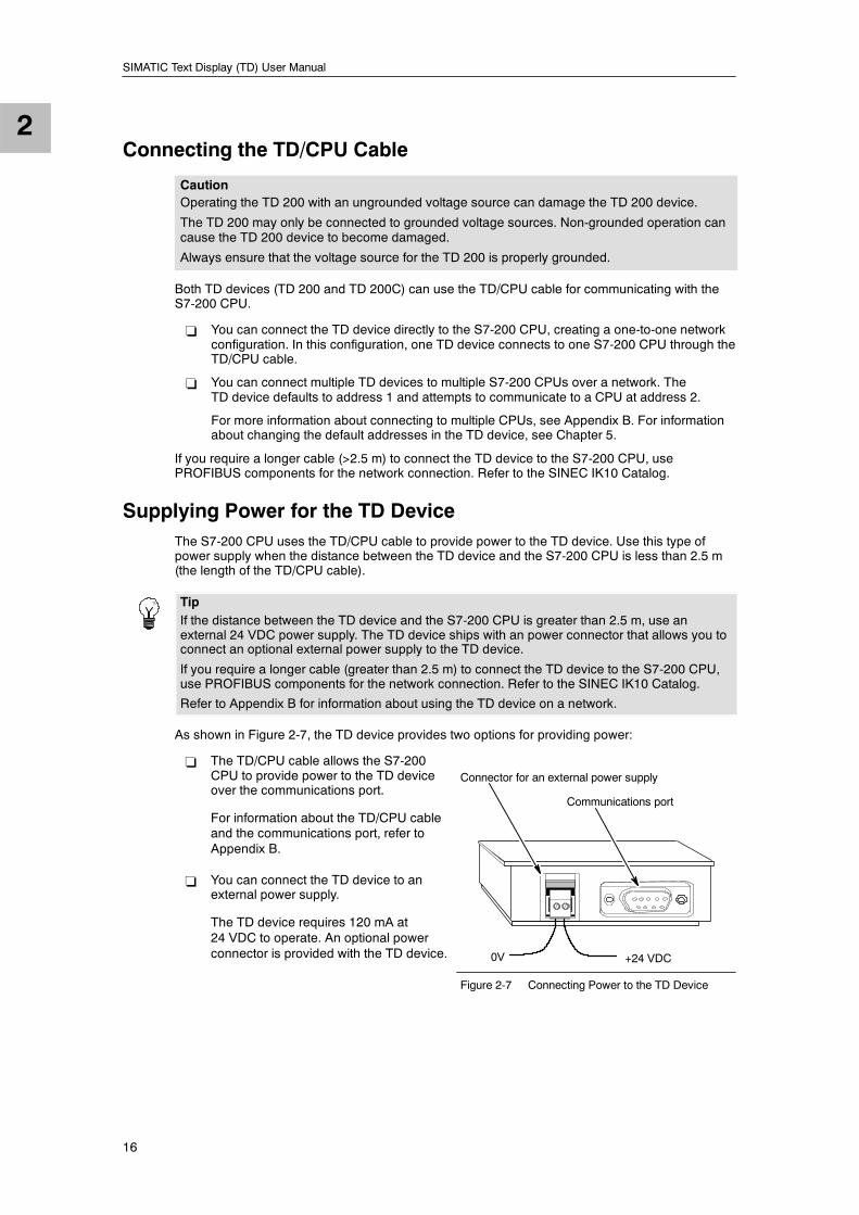
As shown in Figure 2-7, the TD device provides two options for providing power:
- The TD/CPU cable allows the S7-200CPU to provide power to the TD deviceover the communications port.
For information about the TD/CPU cableand the communications port, refer toAppendix B.
- You can connect the TD device to anexternal power supply.
The TD device requires 120 mA at24 VDC to operate. An optional powerconnector is provided with the TD device. +24 VDC0V
Connector for an external power supply
Communications port
Figure 2-7 Connecting Power to the TD Device
2
Installing Your TD Device Chapter 2
17
Establishing a Connection for Your TD 200CAs described in Chapter 4, you use the TD 200 wizard of STEP 7--Micro/WIN to configure thescreens, alarms, languages, and custom keypad layout for the TD 200C. The S7-200 CPU storesthis information in a parameter block (V memory).
The TD 200C ships with a default configurationand is set to communicate at a rate of 9600 baud.In order to read the parameter block, The TD 200Cmust communicate with the S7-200 CPU.
You must configure your TD 200C to communicateat the same baud rate as your S7-200 CPU.
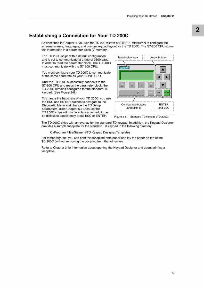
Until the TD 200C successfully connects to theS7-200 CPU and reads the parameter block, theTD 200C remains configured for the standard TDkeypad. (See Figure 2-8.)
To change the baud rate of your TD 200C, you usethe ESC and ENTER buttons to navigate to theDiagnostic Menu and change the TD Setupparameters. (See Chapter 5.) Because theTD 200C ships with no faceplate attached, it mayb diffi l i l ESC ENTER
F1F5
F2F6
F3F7
F4F8
SHIFT ESC ENTER
Text display area Arrow buttons
Configurable buttons(and SHIFT)
ENTERand ESC
p p , ybe difficult to consistently press ESC or ENTER. Figure 2-8 Standard TD Keypad (TD 200C)
The TD 200C ships with an overlay for the standard TD keypad. In addition, the Keypad Designerprovides a sample faceplate for the standard TD keypad in the following directory:
C:/Program Files/Siemens/TD Keypad Designer/Templates
For temporary use, you can print this faceplate onto paper and lay the paper on top of theTD 200C (without removing the covering from the adhesive).
Refer to Chapter 3 for information about opening the Keypad Designer and about printing afaceplate.

2
SIMATIC Text Display (TD) User Manual
18
19
Using the Keypad Designer to Createa Custom Faceplate for Your TD 200C
With the TD 200C, you can design a custom keypad that incorporates up to 20 buttons (keys) ofany size, with varying shapes, colors, or fonts that can be layered onto any background image.
The Keypad Designer application allows you to create a custom-designed layout for the keypad ofthe TD 200C and includes samples and templates in the following directories:
- Sample bitmaps for buttons and backgrounds:
C:/Program Files/Siemens/TD Keypad Designer/Images
- Sample projects:
C:/Program Files/Siemens/TD Keypad Designer/Projects
- Sample template (for printing multiple copies of the faceplate):
C:/Program Files/Siemens/TD Keypad Designer/Templates
This chapter guides you through the tasks required for creating the layout for the keypad, creatingthe configuration file for the keypad, and printing the faceplate for the TD 200C.
You use the configuration file when you are configuring the TD 200C with the TD 200 wizard ofSTEP 7--Micro/WIN. Refer to Chapter 4 for information about the TD 200 wizard.
In This ChapterUsing the Keypad Designer with Other Applications 20. . . . . . . . . . . . . . . . . . . . . . . . . . . . . . . . .
Starting the Keypad Designer 22. . . . . . . . . . . . . . . . . . . . . . . . . . . . . . . . . . . . . . . . . . . . . . . . . . .
Adding Buttons to the Keypad 23. . . . . . . . . . . . . . . . . . . . . . . . . . . . . . . . . . . . . . . . . . . . . . . . . . .
Inserting a Button 23. . . . . . . . . . . . . . . . . . . . . . . . . . . . . . . . . . . . . . . . . . . . . . . . . . . . . . . . . .
Modifying the Shape of a Button 23. . . . . . . . . . . . . . . . . . . . . . . . . . . . . . . . . . . . . . . . . . . . .
Defining the Properties of the Button 24. . . . . . . . . . . . . . . . . . . . . . . . . . . . . . . . . . . . . . . . . . . . . .
Exporting the Keypad Layout to a Graphics Application 26. . . . . . . . . . . . . . . . . . . . . . . . . . . . .
Adding a Panel Image to the Faceplate 27. . . . . . . . . . . . . . . . . . . . . . . . . . . . . . . . . . . . . . . . . . .
Importing a Panel Image 27. . . . . . . . . . . . . . . . . . . . . . . . . . . . . . . . . . . . . . . . . . . . . . . . . . . .
Saving the Keypad to a TD Configuration File 28. . . . . . . . . . . . . . . . . . . . . . . . . . . . . . . . . . . . . .
Reversing the Panel Image 28. . . . . . . . . . . . . . . . . . . . . . . . . . . . . . . . . . . . . . . . . . . . . . . . . . . . .
Printing the Faceplate 29. . . . . . . . . . . . . . . . . . . . . . . . . . . . . . . . . . . . . . . . . . . . . . . . . . . . . . . . . .
Printing a Single Faceplate from the Keypad Designer 30. . . . . . . . . . . . . . . . . . . . . . . . . .
Printing the Faceplate from a Word-Processing Application 30. . . . . . . . . . . . . . . . . . . . . .
Installing the Printed Faceplate onto the TD 200C 32. . . . . . . . . . . . . . . . . . . . . . . . . . . . . . . . . .
SIMATIC Text Display (TD) User Manual
20
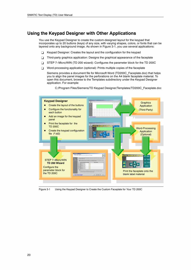
Using the Keypad Designer with Other ApplicationsYou use the Keypad Designer to create the custom-designed layout for the keypad thatincorporates up to 20 buttons (keys) of any size, with varying shapes, colors, or fonts that can belayered onto any background image. As shown in Figure 3-1, you use several applications:
- Keypad Designer: Creates the layout and the configuration for the keypad
- Third-party graphics application: Designs the graphical appearance of the faceplate
- STEP 7--Micro/WIN (TD 200 wizard): Configures the parameter block for the TD 200C
- Word-processing application (optional): Prints multiple copies of the faceplate
Siemens provides a document file for Microsoft Word (TD200C_Faceplate.doc) that helpsyou to align the panel images for the perforations on the A4 blank faceplate material. Toopen this document, browse to the Templates subdirectory under the Keypad Designerapplication. For example:
C:/Program Files/Siemens/TD Keypad Designer/Templates/TD200C_Faceplate.doc
STEP 7--Micro/WINTD 200 Wizard
Configure theparameter block forthe TD 200C
Keypad DesignerH Create the layout of the buttons
H Configure the functionality foreach button
H Add an image for the keypadpanel
H Print the faceplate for theTD 200C
H Create the keypad configurationfile (*.td2)
GraphicsApplication
(Third-Party)
Word-ProcessingApplication(Optional)
Print the faceplate onto theblank label material
Figure 3-1 Using the Keypad Designer to Create the Custom Faceplate for Your TD 200C
Using the Keypad Designer to Create a Custom Faceplate for Your TD 200C Chapter 3
21
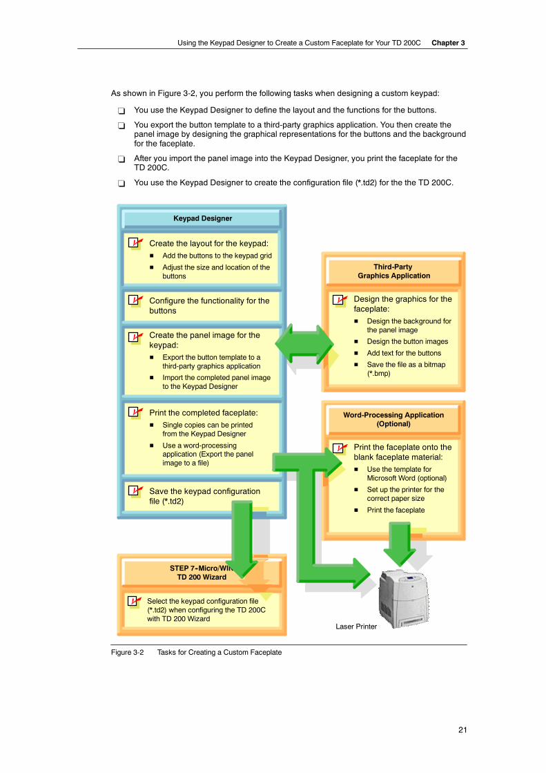
As shown in Figure 3-2, you perform the following tasks when designing a custom keypad:
- You use the Keypad Designer to define the layout and the functions for the buttons.
- You export the button template to a third-party graphics application. You then create thepanel image by designing the graphical representations for the buttons and the backgroundfor the faceplate.
- After you import the panel image into the Keypad Designer, you print the faceplate for theTD 200C.
- You use the Keypad Designer to create the configuration file (*.td2) for the the TD 200C.
Keypad Designer
n Create the layout for the keypad:
H Add the buttons to the keypad grid
H Adjust the size and location of thebuttons
n Configure the functionality for thebuttons
n Print the completed faceplate:
H Single copies can be printedfrom the Keypad Designer
H Use a word-processingapplication (Export the panelimage to a file)
n Save the keypad configurationfile (*.td2)
Word-Processing Application(Optional)
n Print the faceplate onto theblank faceplate material:
H Use the template forMicrosoft Word (optional)
H Set up the printer for thecorrect paper size
H Print the faceplate
n
Third-PartyGraphics Application
n Design the graphics for thefaceplate:
H Design the background forthe panel image
H Design the button images
H Add text for the buttons
H Save the file as a bitmap(*.bmp)
STEP 7--Micro/WINTD 200 Wizard
Select the keypad configuration file(*.td2) when configuring the TD 200Cwith TD 200 Wizard
n Create the panel image for thekeypad:
H Export the button template to athird-party graphics application
H Import the completed panel imageto the Keypad Designer
Laser Printer
Figure 3-2 Tasks for Creating a Custom Faceplate
SIMATIC Text Display (TD) User Manual
22
Starting the Keypad DesignerYou use the Keypad Designer application to create a custom-designed layout for the keypad ofthe TD 200C.
When you install STEP 7--Micro/WIN, you also install the Keypad Designer application. However,the Keypad Designer does not require STEP 7--Micro/WIN.
You can start the Keypad Designer either from within STEP 7--Micro/WIN or as a stand-aloneapplication:
- To start as a stand-alone application: Select the Start > SIMATIC > TD Keypad Designermenu command
- To start from STEP 7--Micro/WIN: Click the Keypad Designer icon in the Tools window
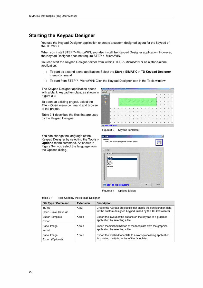
The Keypad Designer application openswith a blank keypad template, as shown inFigure 3-3.
To open an existing project, select theFile > Open menu command and browseto the project.
Table 3-1 describes the files that are usedby the Keypad Designer.
Figure 3-3 Keypad Template
You can change the language of theKeypad Designer by selecting the Tools >Options menu command. As shown inFigure 3-4, you select the language fromthe Options dialog.
Figure 3-4 Options Dialog
Table 3-1 Files Used by the Keypad Designer
File Type / Command Extension Description
TD file
Open, Save, Save As
*.td2 Create the Keypad project file that stores the configuration datafor the custom-designed keypad. (used by the TD 200 wizard)
Button Template
Export
*.bmp Export the layout of the buttons on the keypad to a graphicsapplication by selecting a file.
Panel Image
Import
*.bmp Import the finished bitmap of the faceplate from the graphicsapplication by selecting a file.
Panel Image
Export (Optional)
*.bmp Export the finished faceplate to a word-processing applicationfor printing multiple copies of the faceplate.
Using the Keypad Designer to Create a Custom Faceplate for Your TD 200C Chapter 3
23
Adding Buttons to the KeypadThe TD 200C allows you relative freedom when designing your keypad:
- You can configure up to 20 buttons on thekeypad.
- You can vary the size and the location ofthe buttons.
- You can define the functionality for eachbutton.
The Keypad Designer provides a grid that alignsthe location of the buttons with the physical
f C
Keypad Designer
n Create the layout for the keypad:
H Add the buttons to the keypad grid
H Adjust the size and location of thebuttons
p ykeypad of the TD 200C. Figure 3-5 Adding the Button to the Keypad
TipTypically, your keypad design should always include buttons with the following functions: Enter,Escape, Up Arrow, and Down Arrow. These functions allow you to access the pre-configuredmenus and functions of the TD 200C.
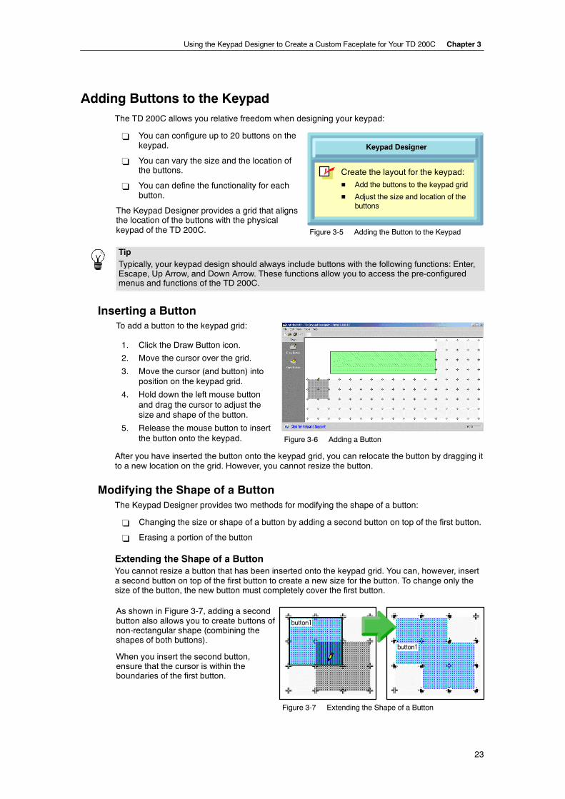
Inserting a ButtonTo add a button to the keypad grid:
1. Click the Draw Button icon.
2. Move the cursor over the grid.
3. Move the cursor (and button) intoposition on the keypad grid.
4. Hold down the left mouse buttonand drag the cursor to adjust thesize and shape of the button.
5. Release the mouse button to insertthe button onto the keypad. Figure 3-6 Adding a Button
After you have inserted the button onto the keypad grid, you can relocate the button by dragging itto a new location on the grid. However, you cannot resize the button.
Modifying the Shape of a ButtonThe Keypad Designer provides two methods for modifying the shape of a button:
- Changing the size or shape of a button by adding a second button on top of the first button.
- Erasing a portion of the button
Extending the Shape of a ButtonYou cannot resize a button that has been inserted onto the keypad grid. You can, however, inserta second button on top of the first button to create a new size for the button. To change only thesize of the button, the new button must completely cover the first button.
As shown in Figure 3-7, adding a secondbutton also allows you to create buttons ofnon-rectangular shape (combining theshapes of both buttons).
When you insert the second button,ensure that the cursor is within theboundaries of the first button.
Figure 3-7 Extending the Shape of a Button
SIMATIC Text Display (TD) User Manual
24
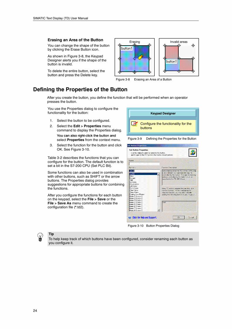
Erasing an Area of the ButtonYou can change the shape of the buttonby clicking the Erase Button icon.
As shown in Figure 3-8, the KeypadDesigner alerts you if the shape of thebutton is invalid.
To delete the entire button, select thebutton and press the Delete key.
Invalid areasErasing
button and press the Delete key.Figure 3-8 Erasing an Area of a Button
Defining the Properties of the ButtonAfter you create the button, you define the function that will be performed when an operatorpresses the button.
You use the Properties dialog to configure thefunctionality for the button:
1. Select the button to be configured.
2. Select the Edit > Properties menucommand to display the Properties dialog.
You can also right-click the button and
Keypad Designer
n Configure the functionality for thebuttons
You can also right-click the button andselect Properties from the context menu. Figure 3-9 Defining the Properties for the Button
3. Select the function for the button and clickOK. See Figure 3-10.
Table 3-2 describes the functions that you canconfigure for the button. The default function is toset a bit in the S7-200 CPU (Set PLC Bit).
Some functions can also be used in combinationwith other buttons, such as SHIFT or the arrowbuttons. The Properties dialog providessuggestions for appropriate buttons for combiningthe functions.
After you configure the functions for each buttonon the keypad, select the File > Save or theFile > Save As menu command to create theconfiguration file (*.td2).
Figure 3-10 Button Properties Dialog
TipTo help keep track of which buttons have been configured, consider renaming each button asyou configure it.
Using the Keypad Designer to Create a Custom Faceplate for Your TD 200C Chapter 3
25
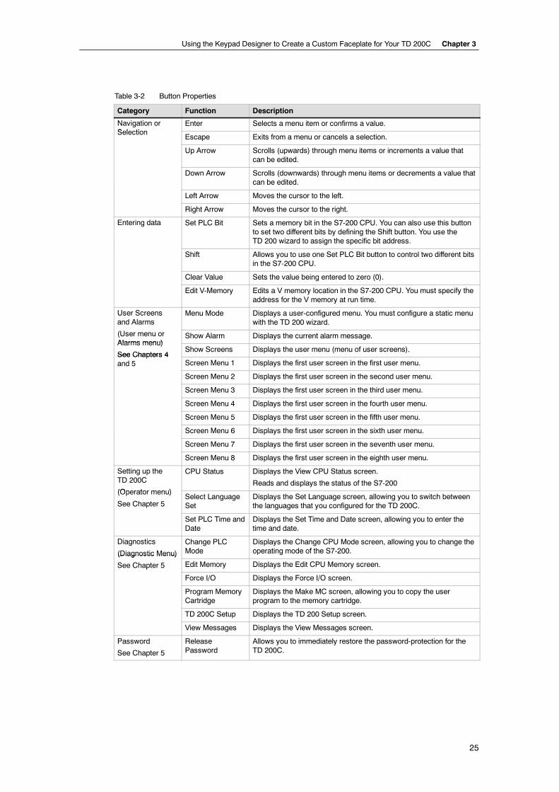
Table 3-2 Button Properties
Category Function Description
Navigation orS l ti
Enter Selects a menu item or confirms a value.Selection
Escape Exits from a menu or cancels a selection.
Up Arrow Scrolls (upwards) through menu items or increments a value thatcan be edited.
Down Arrow Scrolls (downwards) through menu items or decrements a value thatcan be edited.
Left Arrow Moves the cursor to the left.
Right Arrow Moves the cursor to the right.
Entering data Set PLC Bit Sets a memory bit in the S7-200 CPU. You can also use this buttonto set two different bits by defining the Shift button. You use theTD 200 wizard to assign the specific bit address.
Shift Allows you to use one Set PLC Bit button to control two different bitsin the S7-200 CPU.
Clear Value Sets the value being entered to zero (0).
Edit V-Memory Edits a V memory location in the S7-200 CPU. You must specify theaddress for the V memory at run time.
User Screensand Alarms
Menu Mode Displays a user-configured menu. You must configure a static menuwith the TD 200 wizard.
(User menu orAlarms menu)
Show Alarm Displays the current alarm message.Alarms menu)
See Chapters 4Show Screens Displays the user menu (menu of user screens).
See Chapters 4and 5 Screen Menu 1 Displays the first user screen in the first user menu.
Screen Menu 2 Displays the first user screen in the second user menu.
Screen Menu 3 Displays the first user screen in the third user menu.
Screen Menu 4 Displays the first user screen in the fourth user menu.
Screen Menu 5 Displays the first user screen in the fifth user menu.
Screen Menu 6 Displays the first user screen in the sixth user menu.
Screen Menu 7 Displays the first user screen in the seventh user menu.
Screen Menu 8 Displays the first user screen in the eighth user menu.
Setting up theTD 200C
(O t )
CPU Status Displays the View CPU Status screen.
Reads and displays the status of the S7-200(Operator menu)
See Chapter 5Select LanguageSet
Displays the Set Language screen, allowing you to switch betweenthe languages that you configured for the TD 200C.
Set PLC Time andDate
Displays the Set Time and Date screen, allowing you to enter thetime and date.
Diagnostics
(Diagnostic Menu)
Change PLCMode
Displays the Change CPU Mode screen, allowing you to change theoperating mode of the S7-200.(Diagnostic Menu)
See Chapter 5 Edit Memory Displays the Edit CPU Memory screen.p
Force I/O Displays the Force I/O screen.
Program MemoryCartridge
Displays the Make MC screen, allowing you to copy the userprogram to the memory cartridge.
TD 200C Setup Displays the TD 200 Setup screen.
View Messages Displays the View Messages screen.
Password
See Chapter 5
ReleasePassword
Allows you to immediately restore the password-protection for theTD 200C.
SIMATIC Text Display (TD) User Manual
26
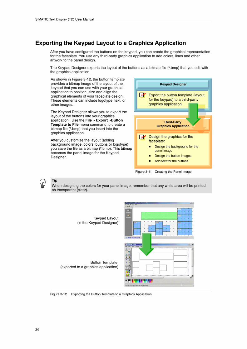
Exporting the Keypad Layout to a Graphics ApplicationAfter you have configured the buttons on the keypad, you can create the graphical representationfor the faceplate. You use any third-party graphics application to add colors, lines and otherartwork to the panel design.
The Keypad Designer exports the layout of the buttons as a bitmap file (*.bmp) that you edit withthe graphics application.
As shown in Figure 3-12, the button templateprovides a bitmap image of the layout of thekeypad that you can use with your graphicalapplication to position, size and align thegraphical elements of your faceplate design.These elements can include logotype, text, orother images.
The Keypad Designer allows you to export thelayout of the buttons into your graphicsapplication. Use the File > Export >ButtonTemplate to File menu command to create abitmap file (*.bmp) that you insert into thegraphics application.
After you customize the layout (addingbackground image, colors, buttons or logotype),you save the file as a bitmap (*.bmp). This bitmapbecomes the panel image for the KeypadDesigner.
Keypad Designer
n Design the graphics for thefaceplate:
H Design the background for thepanel image
H Design the button images
H Add text for the buttons
Third-PartyGraphics Application
n Export the button template (layoutfor the keypad) to a third-partygraphics application
Figure 3-11 Creating the Panel Image
TipWhen designing the colors for your panel image, remember that any white area will be printedas transparent (clear).
Keypad Layout(in the Keypad Designer)
Button Template(exported to a graphics application)
Figure 3-12 Exporting the Button Template to a Graphics Application
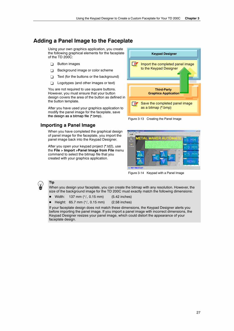
Using the Keypad Designer to Create a Custom Faceplate for Your TD 200C Chapter 3
27
Adding a Panel Image to the FaceplateUsing your own graphics application, you createthe following graphical elements for the faceplateof the TD 200C:
- Button images
- Background image or color scheme
- Text (for the buttons or the background)
- Logotypes (and other images or text)
You are not required to use square buttons.However, you must ensure that your buttondesign covers the area of the button as defined inthe button template.
After you have used your graphics application tomodify the panel image for the faceplate, savethe design as a bitmap file (* bmp)
Keypad Designer
n Save the completed panel imageas a bitmap (*.bmp)
Third-PartyGraphics Application
n Import the completed panel imageto the Keypad Designer
the design as a bitmap file (*.bmp).Figure 3-13 Creating the Panel Image
Importing a Panel ImageWhen you have completed the graphical designof panel image for the faceplate, you import thepanel image back into the Keypad Designer.
After you open your keypad project (*.td2), usethe File > Import >Panel Image from File menucommand to select the bitmap file that youcreated with your graphics application.
Figure 3-14 Keypad with a Panel Image
TipWhen you design your faceplate, you can create the bitmap with any resolution. However, thesize of the background image for the TD 200C must exactly match the following dimensions:
H Width: 137 mm (+/-- 0.15 mm) (5.42 inches)
H Height: 65.7 mm (+/-- 0.15 mm) (2.58 inches)
If your faceplate design does not match these dimensions, the Keypad Designer alerts youbefore importing the panel image. If you import a panel image with incorrect dimensions, theKeypad Designer resizes your panel image, which could distort the appearance of yourfaceplate design.
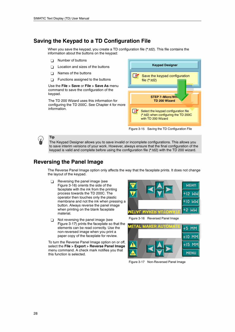
SIMATIC Text Display (TD) User Manual
28
Saving the Keypad to a TD Configuration FileWhen you save the keypad, you create a TD configuration file (*.td2). This file contains theinformation about the buttons on the keypad:
- Number of buttons
- Location and sizes of the buttons
- Names of the buttons
- Functions assigned to the buttons
Use the File > Save or File > Save As menucommand to save the configuration of thekeypad.
The TD 200 Wizard uses this information forconfiguring the TD 200C. See Chapter 4 for moreinformation.
Keypad Designer
n Save the keypad configurationfile (*.td2)
n
STEP 7--Micro/WINTD 200 Wizard
Select the keypad configuration file(*.td2) when configuring the TD 200Cwith TD 200 Wizard
Figure 3-15 Saving the TD Configuration File
TipThe Keypad Designer allows you to save invalid or incomplete configurations. This allows youto save interim versions of your work. However, always ensure that the final configuration of thekeypad is valid and complete before using the configuration file (*.td2) with the TD 200 wizard.
Reversing the Panel ImageThe Reverse Panel Image option only affects the way that the faceplate prints. It does not changethe layout of the keypad.
- Reversing the panel image (seeFigure 3-16) orients the side of thefaceplate with the ink from the printingprocess towards the TD 200C. Theoperator then touches only the plasticmembrane and not the ink when pressing abutton. Always reverse the panel imagewhen printing on the blank faceplatematerial.
- Not reversing the panel image (seeFigure 3 17) prints the faceplate so that the
Figure 3-16 Reversed Panel Image
Figure 3-17) prints the faceplate so that theelements can be read correctly. Use thenon-reversed image when you print apaper copy of the faceplate for review.
To turn the Reverse Panel Image option on or off,select the File > Export > Reverse Panel Imagemenu command. A check mark notifies you thatthis function is selected.
Figure 3-17 Non-Reversed Panel Image
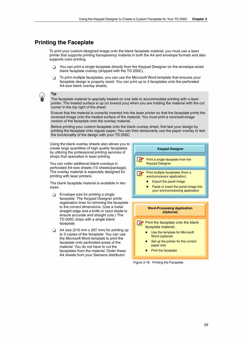
Using the Keypad Designer to Create a Custom Faceplate for Your TD 200C Chapter 3
29
Printing the FaceplateTo print your custom-designed image onto the blank faceplate material, you must use a laserprinter that supports printing transparency material in both the A4 and envelope formats and alsosupports color printing.
! You can print a single faceplate directly from the Keypad Designer on the envelope-sizedblank faceplate overlay (shipped with the TD 200C).
! To print multiple faceplates, you can use the Microsoft Word template that ensures yourfaceplate design is properly sized. You can print up to 3 faceplates onto the perforatedA4-size blank overlay sheets.
TipThe faceplate material is specially treated on one side to accommodate printing with a laserprinter. The treated surface is up (or toward you) when you are holding the material with the cutcorner in the top right of the sheet.
Ensure that the material is correctly inserted into the laser printer so that the faceplate prints thereversed image onto the treated surface of the material. You must print a reversed-imageversion of the faceplate onto the overlay material.
Before printing your custom faceplate onto the blank overlay sheet, first test your design byprinting the faceplate onto regular paper. You can then temporarily use the paper overlay to testthe functionality of the design with your TD 200C.
Using the blank overlay sheets also allows you tocreate large quantities of high-quality faceplatesby utilizing the professional printing services ofshops that specialize in laser printing.
You can order additional blank overlays inperforated A4-size sheets (10 sheets/package).The overlay material is especially designed forprinting with laser printers.
The blank faceplate material is available in twosizes:
! Envelope size for printing a singlefaceplate: The Keypad Designer printsregistration lines for trimming the faceplateto the correct dimensions. (Use a metalstraight edge and a knife or razor blade toensure accurate and straight cuts.) TheTD 200C ships with a single blankfaceplate.
! A4 size (210 mm x 297 mm) for printing upto 3 copies of the faceplate: You can usethe Microsoft Word template to print thefaceplate onto perforated areas of thematerial. You do not have to cut thefaceplates from the material. Order theseA4 sheets from your Siemens distributor.
Keypad Designer
"""" Print a single faceplate from theKeypad Designer
Word-Processing Application(Optional)
"""" Print the faceplate onto the blankfaceplate material:
# Use the template for MicrosoftWord (optional)
# Set up the printer for the correctpaper size
# Print the faceplate
"""" Print multiple faceplates (from aword-processor application):
# Export the panel image
# Paste or insert the panel image intoyour word-processing application
Figure 3-18 Printing the Faceplate
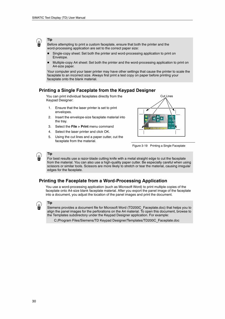
SIMATIC Text Display (TD) User Manual
30
TipBefore attempting to print a custom faceplate, ensure that both the printer and theword-processing application are set to the correct paper size:
H Single-copy sheet: Set both the printer and word-processing application to print onEnvelope.
H Multiple-copy A4 sheet: Set both the printer and the word-processing application to print onA4-size paper.
Your computer and your laser printer may have other settings that cause the printer to scale thefaceplate to an incorrect size. Always first print a test copy on paper before printing yourfaceplate onto the blank material.
Printing a Single Faceplate from the Keypad DesignerYou can print individual faceplates directly from theKeypad Designer:
1. Ensure that the laser printer is set to printenvelopes.
2. Insert the envelope-size faceplate material intothe tray.
3. Select the File > Print menu command
4. Select the laser printer and click OK.
5. Using the cut lines and a paper cutter, cut thefaceplate from the material.
Cut Lines
pFigure 3-19 Printing a Single Faceplate
TipFor best results use a razor-blade cutting knife with a metal straight edge to cut the faceplatefrom the material. You can also use a high-quality paper cutter. Be especially careful when usingscissors or similar tools. Scissors are more likely to stretch or tear the material, causing irregularedges for the faceplate.
Printing the Faceplate from a Word-Processing ApplicationYou use a word-processing application (such as Microsoft Word) to print multiple copies of thefaceplate onto A4-size blank faceplate material. After you export the panel image of the faceplateinto a document, you adjust the location of the panel images and print the document.
TipSiemens provides a document file for Microsoft Word (TD200C_Faceplate.doc) that helps you toalign the panel images for the perforations on the A4 material. To open this document, browse tothe Templates subdirectory under the Keypad Designer application. For example:
C:/Program Files/Siemens/TD Keypad Designer/Templates/TD200C_Faceplate.doc

Using the Keypad Designer to Create a Custom Faceplate for Your TD 200C Chapter 3
31
Before printing the faceplate onto the blank faceplatematerial, you must ensure that the document and theprinter settings are both set to print on A4 paper. Also,ensure that the laser printer itself is configured to printA4 paper.
After you print the faceplate document, you use theperforations to remove the faceplates from the sheet.
To export the panel image to your word-processingapplication:
1. Open your word-processing application (forexample, Microsoft Word) and open the template
A4 FaceplateMaterial
Perforated Areas
example, Microsoft Word) and open the templatefile: TD200C_Faceplate.doc Figure 3-20 Printing Multiple Faceplates
2. Open the Keypad Designer.
3. In the Keypad Designer, select the File > Export > Panel Image to File menu command tocreate a bitmap file that you insert into the word-processing application.
4. Insert the panel image into the document (TD200C_Faceplate.doc) by using theword-processing application to insert the bitmap file (*.bmp) that you created with theKeypad Designer.
5. After inserting the panel image into the document, save the document (using the File >Save As menu command of the word-processing application).
With the panel images saved in your document, you can print the document to your laser printer.
TipBefore printing the panel image onto the blank faceplate material, first test your design byprinting the faceplate onto regular A4 paper.
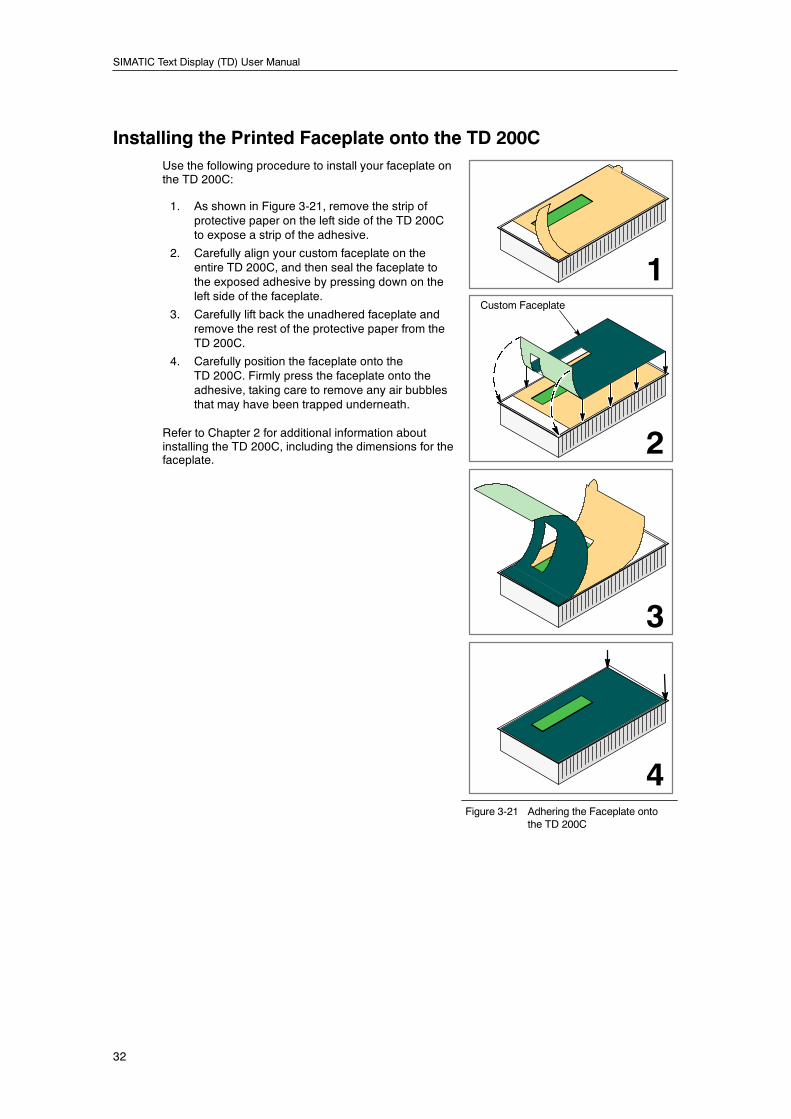
SIMATIC Text Display (TD) User Manual
32
Installing the Printed Faceplate onto the TD 200CUse the following procedure to install your faceplate onthe TD 200C:
1. As shown in Figure 3-21, remove the strip ofprotective paper on the left side of the TD 200Cto expose a strip of the adhesive.
2. Carefully align your custom faceplate on theentire TD 200C, and then seal the faceplate tothe exposed adhesive by pressing down on theleft side of the faceplate.
3. Carefully lift back the unadhered faceplate andremove the rest of the protective paper from theTD 200C.
4. Carefully position the faceplate onto theTD 200C. Firmly press the faceplate onto theadhesive, taking care to remove any air bubblesthat may have been trapped underneath.
Refer to Chapter 2 for additional information aboutinstalling the TD 200C, including the dimensions for thefaceplate.
3
1
2
4
Custom Faceplate
Figure 3-21 Adhering the Faceplate ontothe TD 200C
33
Using the TD 200 Wizard to Configurethe S7-200 CPU for the TD Device
You do not configure or program the TD device. The TD 200 wizard creates a parameter blockthat stores the configuration, screens and alarms for the TD device. The S7-200 CPU stores theparameter block in V memory. At power-up, the TD device reads the parameter block from theS7-200 CPU.
You use the TD 200 wizard of STEP 7--Micro/WIN to perform the following tasks:
- Configuring the parameters for the TD device
- Creating the screens and alarms to be displayed on the TD device
- Creating the language sets for the TD device
- Assigning the V memory address for the parameter block
TipTo connect your TD device to a network, you use the Diagnostic Menu of the TD device to setup the network addresses, baud rate and other parameters. Refer to Chapter 5.
In This ChapterOverview of the Configuration Tasks 34. . . . . . . . . . . . . . . . . . . . . . . . . . . . . . . . . . . . . . . . . . . . . .
Configuring the TD Device 36. . . . . . . . . . . . . . . . . . . . . . . . . . . . . . . . . . . . . . . . . . . . . . . . . . . . . .
Task Overview 36. . . . . . . . . . . . . . . . . . . . . . . . . . . . . . . . . . . . . . . . . . . . . . . . . . . . . . . . . . . .
Starting the TD 200 Wizard for Your TD Device 37. . . . . . . . . . . . . . . . . . . . . . . . . . . . . . . . .
Selecting the Type of TD Device to Configure 37. . . . . . . . . . . . . . . . . . . . . . . . . . . . . . . . . .
Enabling the TD Device to Modify Data in the S7-200 CPU 38. . . . . . . . . . . . . . . . . . . . . .
Selecting a Password for the TD Device 39. . . . . . . . . . . . . . . . . . . . . . . . . . . . . . . . . . . . . .
Selecting the Update Rate for the TD Device 39. . . . . . . . . . . . . . . . . . . . . . . . . . . . . . . . . .
Selecting the Language and the Character Set 39. . . . . . . . . . . . . . . . . . . . . . . . . . . . . . . . .
Loading a Custom Keypad (TD 200C Only) 40. . . . . . . . . . . . . . . . . . . . . . . . . . . . . . . . . . . .
Configuring the Buttons on the Keypad 40. . . . . . . . . . . . . . . . . . . . . . . . . . . . . . . . . . . . . . .
Configuring the Screens for the TD Device 41. . . . . . . . . . . . . . . . . . . . . . . . . . . . . . . . . . . . . . . .
Creating the User Menu 42. . . . . . . . . . . . . . . . . . . . . . . . . . . . . . . . . . . . . . . . . . . . . . . . . . . .
Creating the Text for a Screen 43. . . . . . . . . . . . . . . . . . . . . . . . . . . . . . . . . . . . . . . . . . . . . . .
Embedding a Variable into the Text of a Screen 43. . . . . . . . . . . . . . . . . . . . . . . . . . . . . . . .
Configuring the Alarms 45. . . . . . . . . . . . . . . . . . . . . . . . . . . . . . . . . . . . . . . . . . . . . . . . . . . . . . . . .
Determining the Type of Operator-Interaction for an Alarm 46. . . . . . . . . . . . . . . . . . . . . . .
Setting the Default Display Mode and Alarm Parameters 47. . . . . . . . . . . . . . . . . . . . . . . .
Entering the Text for an Alarm 47. . . . . . . . . . . . . . . . . . . . . . . . . . . . . . . . . . . . . . . . . . . . . . .
Embedding a Variable into the Text of an Alarm 48. . . . . . . . . . . . . . . . . . . . . . . . . . . . . . . .
Configuring the Language Sets for the TD Device 50. . . . . . . . . . . . . . . . . . . . . . . . . . . . . . . . . .
Notes for Using the Simplified Chinese Character Set 51. . . . . . . . . . . . . . . . . . . . . . . . . . .
Assigning the V Memory Address for the Parameter Block 52. . . . . . . . . . . . . . . . . . . . . . . . . . .
Finishing the Configuration for the TD Device 52. . . . . . . . . . . . . . . . . . . . . . . . . . . . . . . . . . . . . .
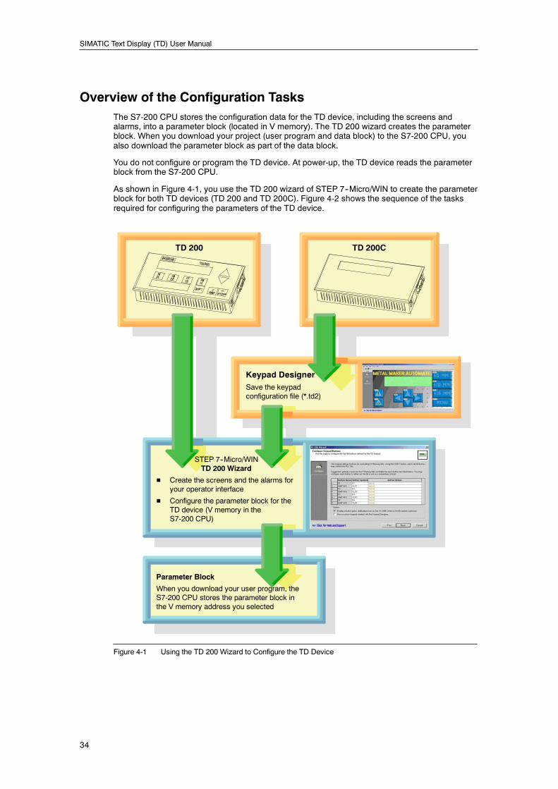
SIMATIC Text Display (TD) User Manual
34
Overview of the Configuration TasksThe S7-200 CPU stores the configuration data for the TD device, including the screens andalarms, into a parameter block (located in V memory). The TD 200 wizard creates the parameterblock. When you download your project (user program and data block) to the S7-200 CPU, youalso download the parameter block as part of the data block.
You do not configure or program the TD device. At power-up, the TD device reads the parameterblock from the S7-200 CPU.
As shown in Figure 4-1, you use the TD 200 wizard of STEP 7--Micro/WIN to create the parameterblock for both TD devices (TD 200 and TD 200C). Figure 4-2 shows the sequence of the tasksrequired for configuring the parameters of the TD device.
Keypad DesignerSave the keypadconfiguration file (*.td2)
STEP 7--Micro/WINTD 200 Wizard
H Create the screens and the alarms foryour operator interface
H Configure the parameter block for theTD device (V memory in theS7-200 CPU)
TD 200 TD 200C
Parameter Block
When you download your user program, theS7-200 CPU stores the parameter block inthe V memory address you selected
Figure 4-1 Using the TD 200 Wizard to Configure the TD Device
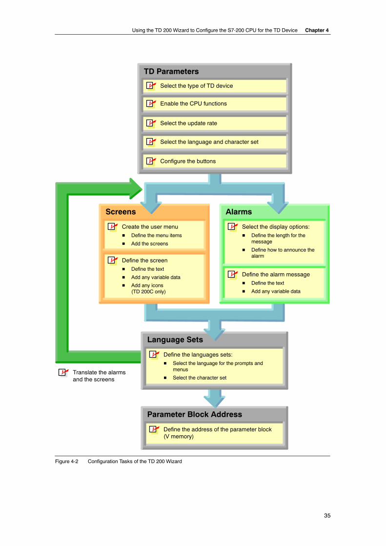
Using the TD 200 Wizard to Configure the S7-200 CPU for the TD Device Chapter 4
35
Parameter Block Address
Define the address of the parameter block(V memory)
Language Sets
Define the languages sets:
H Select the language for the prompts andmenus
H Select the character set
Define the screen
H Define the text
H Add any variable data
H Add any icons(TD 200C only)
Screens
Create the user menu
H Define the menu items
H Add the screens
Define the alarm message
H Define the text
H Add any variable data
Alarms
Select the display options:
H Define the length for themessage
H Define how to announce thealarm
Enable the CPU functions
Select the update rate
Select the language and character set
Configure the buttons
TD Parameters
n Select the type of TD device
n
n
n
n
n
n
n
n
n
n
Translate the alarmsand the screens
n
Figure 4-2 Configuration Tasks of the TD 200 Wizard
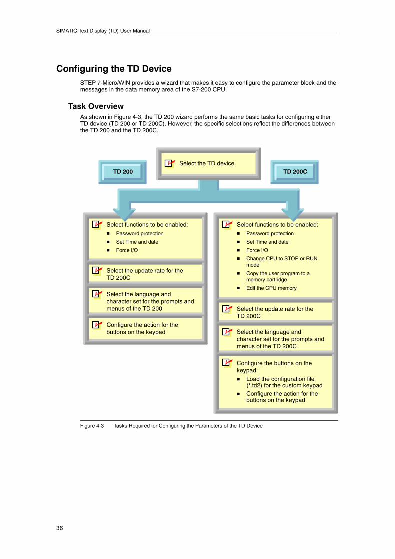
SIMATIC Text Display (TD) User Manual
36
Configuring the TD DeviceSTEP 7-Micro/WIN provides a wizard that makes it easy to configure the parameter block and themessages in the data memory area of the S7-200 CPU.
Task OverviewAs shown in Figure 4-3, the TD 200 wizard performs the same basic tasks for configuring eitherTD device (TD 200 or TD 200C). However, the specific selections reflect the differences betweenthe TD 200 and the TD 200C.
Select functions to be enabled:
H Password protection
H Set Time and date
H Force I/O
Select the update rate for theTD 200C
Select the language andcharacter set for the prompts andmenus of the TD 200
Configure the action for thebuttons on the keypad
Select functions to be enabled:
H Password protection
H Set Time and date
H Force I/O
H Change CPU to STOP or RUNmode
H Copy the user program to amemory cartridge
H Edit the CPU memory
Select the update rate for theTD 200C
Select the language andcharacter set for the prompts andmenus of the TD 200C
Configure the buttons on thekeypad:
H Load the configuration file(*.td2) for the custom keypad
H Configure the action for thebuttons on the keypad
Select the TD deviceTD 200CTD 200
n
n
n
n
n
n
n
n
n
Figure 4-3 Tasks Required for Configuring the Parameters of the TD Device

Using the TD 200 Wizard to Configure the S7-200 CPU for the TD Device Chapter 4
37
Starting the TD 200 Wizard for Your TD DeviceYou use the TD 200 wizard to configure the parameters for both the TD 200 and the TD 200C.You can also use the TD 200 wizard to modify an existing TD configuration.
To open the TD 200 wizard:
1. Start STEP 7--Micro/WIN.
2. Select the Tools > TD 200Wizard menu command.
The TD 200 wizard displays theIntroduction dialog, as shown inFigure 4-4.
If the TD 200 wizard finds an existingTD configuration, the Introductiondialog provides a list of existing TDconfigurations and allows you to selecta TD configuration to modify.
Use the Next button to proceedthrough the dialogs of the wizard.through the dialogs of the wizard.
Figure 4-4 TD 200 Wizard
Selecting the Type of TD Device to ConfigureAs shown in Figure 4-5, the TD 200wizard prompts you to select the typeof TD device to be configured.
The TD 200 wizard uses this selectionto display the dialogs for configuringthe parameters for your specificTD device.
Figure 4-5 Selecting the TD Device
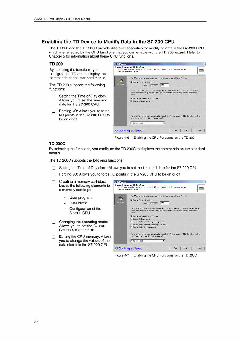
SIMATIC Text Display (TD) User Manual
38
Enabling the TD Device to Modify Data in the S7-200 CPUThe TD 200 and the TD 200C provide different capabilities for modifying data in the S7-200 CPU,which are reflected by the CPU functions that you can enable with the TD 200 wizard. Refer toChapter 5 for information about these CPU functions.
TD 200By selecting the functions, youconfigure the TD 200 to display thecommands on the standard menus.
The TD 200 supports the followingfunctions:
- Setting the Time-of-Day clock:Allows you to set the time anddate for the S7-200 CPU
- Forcing I/O: Allows you to forceI/O points in the S7-200 CPU tobe on or off
Figure 4-6 Enabling the CPU Functions for the TD 200
TD 200CBy selecting the functions, you configure the TD 200C to displays the commands on the standardmenus.
The TD 200C supports the following functions:
- Setting the Time-of-Day clock: Allows you to set the time and date for the S7-200 CPU
- Forcing I/O: Allows you to force I/O points in the S7-200 CPU to be on or off
- Creating a memory cartridge:Loads the following elements toa memory cartridge:
-- User program
-- Data block
-- Configuration of theS7-200 CPU
- Changing the operating mode:Allows you to set the S7-200CPU to STOP or RUN
- Editing the CPU memory: Allowsyou to change the values of thedata stored in the S7-200 CPU
Figure 4-7 Enabling the CPU Functions for the TD 200C
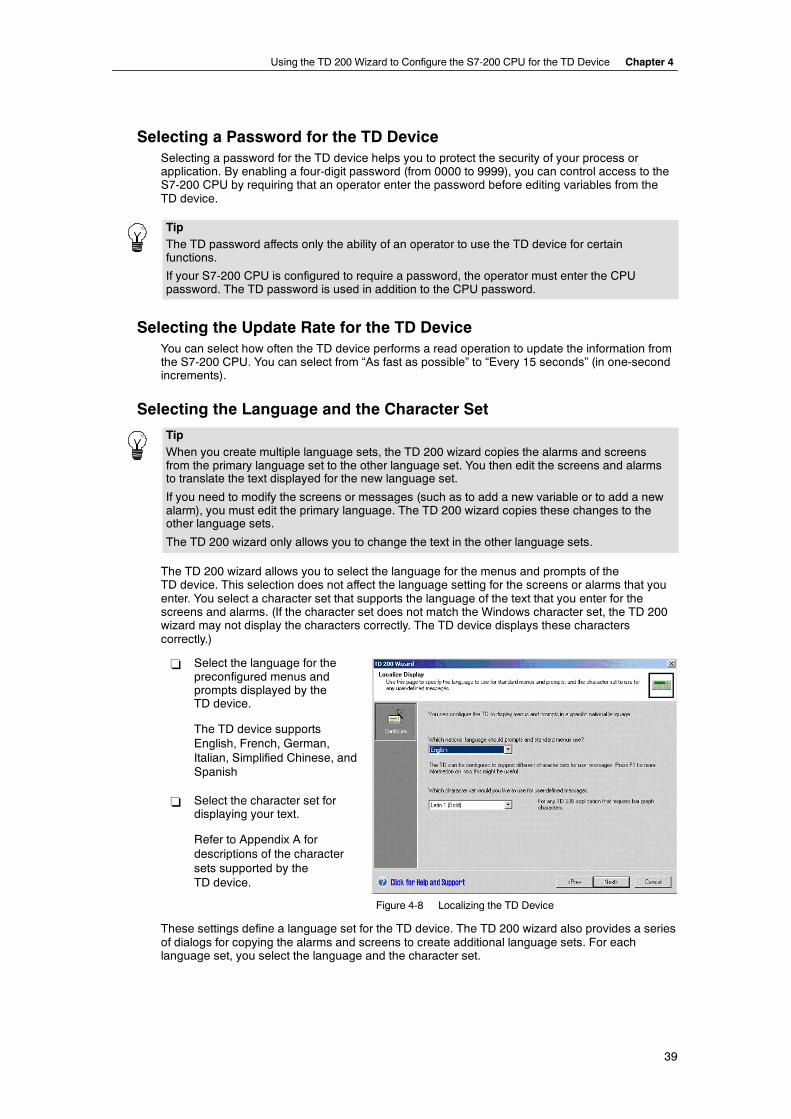
Using the TD 200 Wizard to Configure the S7-200 CPU for the TD Device Chapter 4
39
Selecting a Password for the TD DeviceSelecting a password for the TD device helps you to protect the security of your process orapplication. By enabling a four-digit password (from 0000 to 9999), you can control access to theS7-200 CPU by requiring that an operator enter the password before editing variables from theTD device.
TipThe TD password affects only the ability of an operator to use the TD device for certainfunctions.
If your S7-200 CPU is configured to require a password, the operator must enter the CPUpassword. The TD password is used in addition to the CPU password.
Selecting the Update Rate for the TD DeviceYou can select how often the TD device performs a read operation to update the information fromthe S7-200 CPU. You can select from “As fast as possible” to “Every 15 seconds” (in one-secondincrements).
Selecting the Language and the Character Set
TipWhen you create multiple language sets, the TD 200 wizard copies the alarms and screensfrom the primary language set to the other language set. You then edit the screens and alarmsto translate the text displayed for the new language set.
If you need to modify the screens or messages (such as to add a new variable or to add a newalarm), you must edit the primary language. The TD 200 wizard copies these changes to theother language sets.
The TD 200 wizard only allows you to change the text in the other language sets.
The TD 200 wizard allows you to select the language for the menus and prompts of theTD device. This selection does not affect the language setting for the screens or alarms that youenter. You select a character set that supports the language of the text that you enter for thescreens and alarms. (If the character set does not match the Windows character set, the TD 200wizard may not display the characters correctly. The TD device displays these characterscorrectly.)
- Select the language for thepreconfigured menus andprompts displayed by theTD device.
The TD device supportsEnglish, French, German,Italian, Simplified Chinese, andSpanish
- Select the character set fordisplaying your text.
Refer to Appendix A fordescriptions of the charactersets supported by theTD device.
Figure 4-8 Localizing the TD Device
These settings define a language set for the TD device. The TD 200 wizard also provides a seriesof dialogs for copying the alarms and screens to create additional language sets. For eachlanguage set, you select the language and the character set.
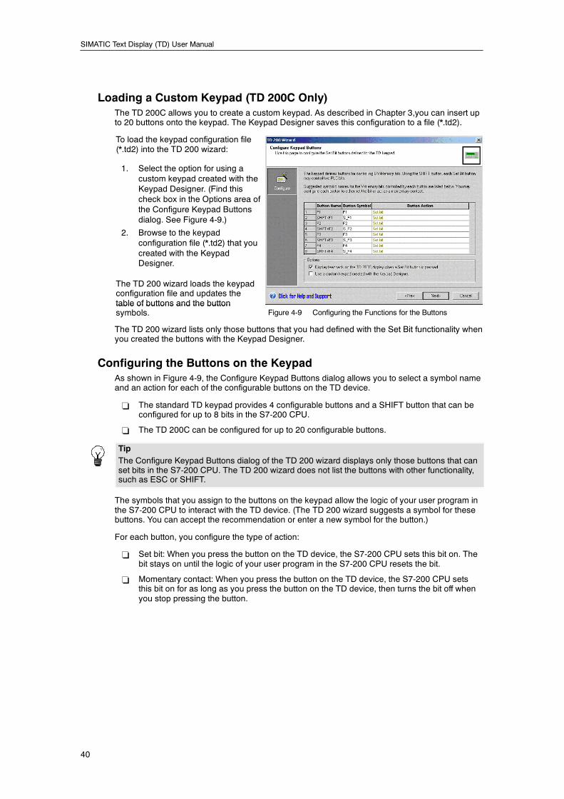
SIMATIC Text Display (TD) User Manual
40
Loading a Custom Keypad (TD 200C Only)The TD 200C allows you to create a custom keypad. As described in Chapter 3,you can insert upto 20 buttons onto the keypad. The Keypad Designer saves this configuration to a file (*.td2).
To load the keypad configuration file(*.td2) into the TD 200 wizard:
1. Select the option for using acustom keypad created with theKeypad Designer. (Find thischeck box in the Options area ofthe Configure Keypad Buttonsdialog. See Figure 4-9.)
2. Browse to the keypadconfiguration file (*.td2) that youcreated with the KeypadDesigner.
The TD 200 wizard loads the keypadconfiguration file and updates thetable of buttons and the buttontable of buttons and the buttonsymbols. Figure 4-9 Configuring the Functions for the Buttons
The TD 200 wizard lists only those buttons that you had defined with the Set Bit functionality whenyou created the buttons with the Keypad Designer.
Configuring the Buttons on the KeypadAs shown in Figure 4-9, the Configure Keypad Buttons dialog allows you to select a symbol nameand an action for each of the configurable buttons on the TD device.
- The standard TD keypad provides 4 configurable buttons and a SHIFT button that can beconfigured for up to 8 bits in the S7-200 CPU.
- The TD 200C can be configured for up to 20 configurable buttons.
TipThe Configure Keypad Buttons dialog of the TD 200 wizard displays only those buttons that canset bits in the S7-200 CPU. The TD 200 wizard does not list the buttons with other functionality,such as ESC or SHIFT.
The symbols that you assign to the buttons on the keypad allow the logic of your user program inthe S7-200 CPU to interact with the TD device. (The TD 200 wizard suggests a symbol for thesebuttons. You can accept the recommendation or enter a new symbol for the button.)
For each button, you configure the type of action:
- Set bit: When you press the button on the TD device, the S7-200 CPU sets this bit on. Thebit stays on until the logic of your user program in the S7-200 CPU resets the bit.
- Momentary contact: When you press the button on the TD device, the S7-200 CPU setsthis bit on for as long as you press the button on the TD device, then turns the bit off whenyou stop pressing the button.
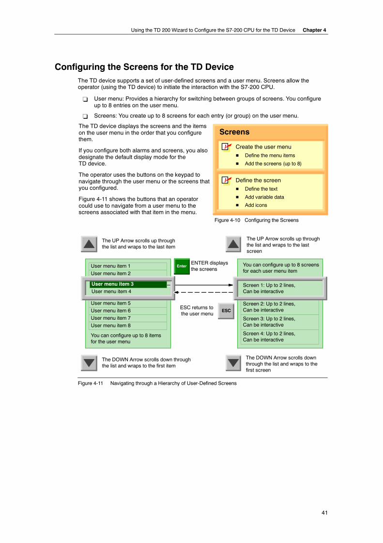
Using the TD 200 Wizard to Configure the S7-200 CPU for the TD Device Chapter 4
41
Configuring the Screens for the TD DeviceThe TD device supports a set of user-defined screens and a user menu. Screens allow theoperator (using the TD device) to initiate the interaction with the S7-200 CPU.
- User menu: Provides a hierarchy for switching between groups of screens. You configureup to 8 entries on the user menu.
- Screens: You create up to 8 screens for each entry (or group) on the user menu.
The TD device displays the screens and the itemson the user menu in the order that you configurethem.
If you configure both alarms and screens, you alsodesignate the default display mode for theTD device.
The operator uses the buttons on the keypad tonavigate through the user menu or the screens thatyou configured.
Figure 4-11 shows the buttons that an operatorcould use to navigate from a user menu to thescreens associated with that item in the menu.
Define the screen
H Define the text
H Add variable data
H Add icons
Screens
Create the user menu
H Define the menu items
H Add the screens (up to 8)
n
n
Figure 4-10 Configuring the Screens
You can configure up to 8 itemsfor the user menu
User menu item 1
User menu item 4
User menu item 5
User menu item 6
ENTER displaysthe screens
The UP Arrow scrolls up throughthe list and wraps to the last item
Enter
ESCESC returns tothe user menu
User menu item 2
The DOWN Arrow scrolls downthrough the list and wraps to thefirst screen
The DOWN Arrow scrolls down throughthe list and wraps to the first item
User menu item 7
User menu item 8
The UP Arrow scrolls up throughthe list and wraps to the lastscreen
User menu item 3 Screen 1: Up to 2 lines,Can be interactive
You can configure up to 8 screensfor each user menu item
Screen 2: Up to 2 lines,Can be interactive
Screen 3: Up to 2 lines,Can be interactive
Screen 4: Up to 2 lines,Can be interactive
Figure 4-11 Navigating through a Hierarchy of User-Defined Screens
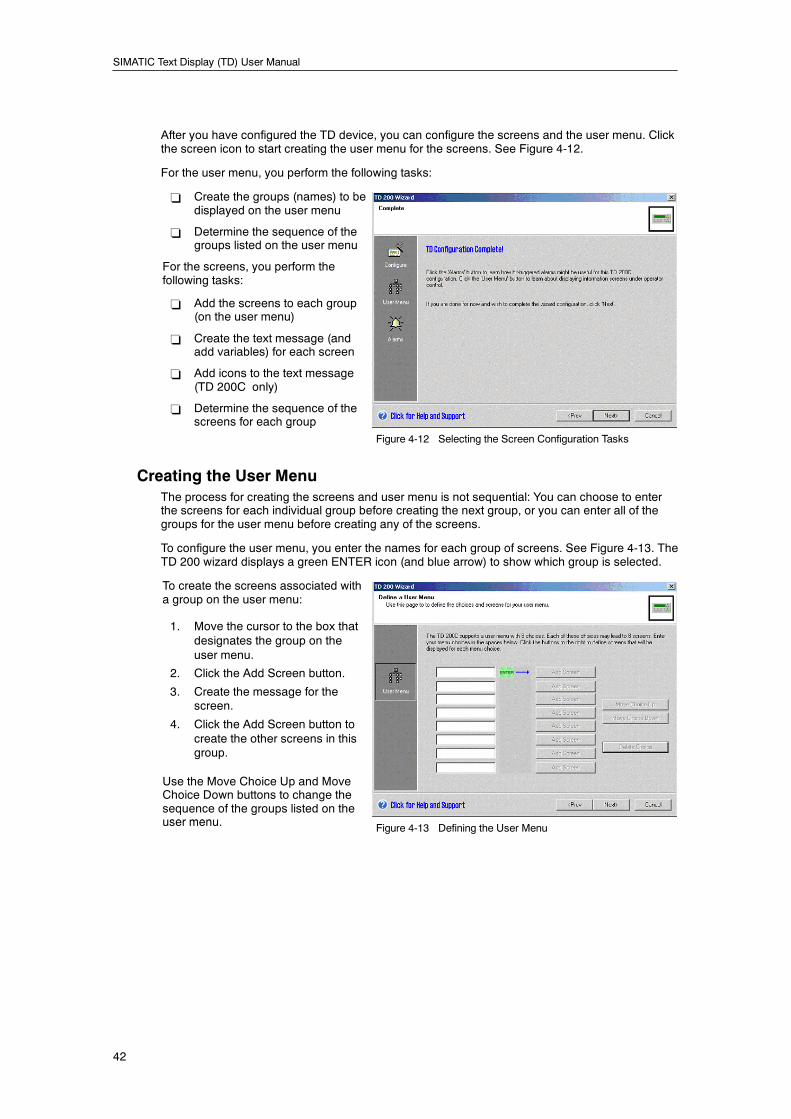
SIMATIC Text Display (TD) User Manual
42
After you have configured the TD device, you can configure the screens and the user menu. Clickthe screen icon to start creating the user menu for the screens. See Figure 4-12.
For the user menu, you perform the following tasks:
- Create the groups (names) to bedisplayed on the user menu
- Determine the sequence of thegroups listed on the user menu
For the screens, you perform thefollowing tasks:
- Add the screens to each group(on the user menu)
- Create the text message (andadd variables) for each screen
- Add icons to the text message(TD 200C only)
- Determine the sequence of thescreens for each groupg p
Figure 4-12 Selecting the Screen Configuration Tasks
Creating the User MenuThe process for creating the screens and user menu is not sequential: You can choose to enterthe screens for each individual group before creating the next group, or you can enter all of thegroups for the user menu before creating any of the screens.
To configure the user menu, you enter the names for each group of screens. See Figure 4-13. TheTD 200 wizard displays a green ENTER icon (and blue arrow) to show which group is selected.
To create the screens associated witha group on the user menu:
1. Move the cursor to the box thatdesignates the group on theuser menu.
2. Click the Add Screen button.
3. Create the message for thescreen.
4. Click the Add Screen button tocreate the other screens in thisgroup.
Use the Move Choice Up and MoveChoice Down buttons to change thesequence of the groups listed on theuser menuuser menu. Figure 4-13 Defining the User Menu
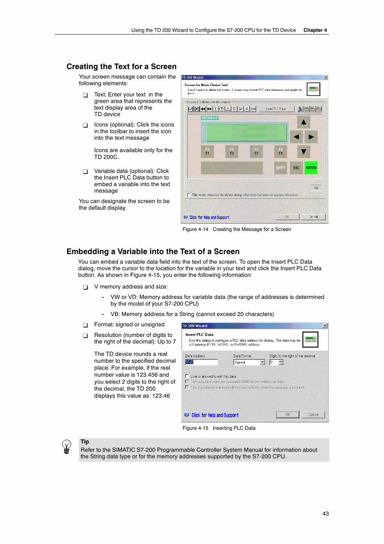
Using the TD 200 Wizard to Configure the S7-200 CPU for the TD Device Chapter 4
43
Creating the Text for a ScreenYour screen message can contain thefollowing elements:
- Text: Enter your text in thegreen area that represents thetext display area of theTD device
- Icons (optional): Click the iconsin the toolbar to insert the iconinto the text message
Icons are available only for theTD 200C.
- Variable data (optional): Clickthe Insert PLC Data button toembed a variable into the textmessage
You can designate the screen to bethe default display.
Figure 4-14 Creating the Message for a Screen
Embedding a Variable into the Text of a ScreenYou can embed a variable data field into the text of the screen. To open the Insert PLC Datadialog, move the cursor to the location for the variable in your text and click the Insert PLC Databutton. As shown in Figure 4-15, you enter the following information:
- V memory address and size:
-- VW or VD: Memory address for variable data (the range of addresses is determinedby the model of your S7-200 CPU)
-- VB: Memory address for a String (cannot exceed 20 characters)
- Format: signed or unsigned
- Resolution (number of digits tothe right of the decimal): Up to 7
The TD device rounds a realnumber to the specified decimalplace. For example, if the realnumber value is 123.456 andyou select 2 digits to the right ofthe decimal, the TD 200displays this value as: 123.46
Figure 4-15 Inserting PLC Data
TipRefer to the SIMATIC S7-200 Programmable Controller System Manual for information aboutthe String data type or for the memory addresses supported by the S7-200 CPU.
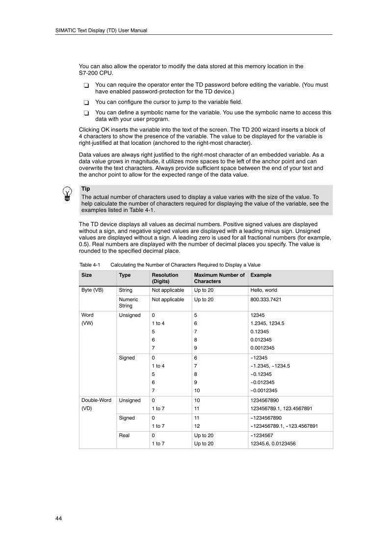
SIMATIC Text Display (TD) User Manual
44
You can also allow the operator to modify the data stored at this memory location in theS7-200 CPU.
- You can require the operator enter the TD password before editing the variable. (You musthave enabled password-protection for the TD device.)
- You can configure the cursor to jump to the variable field.
- You can define a symbolic name for the variable. You use the symbolic name to access thisdata with your user program.
Clicking OK inserts the variable into the text of the screen. The TD 200 wizard inserts a block of4 characters to show the presence of the variable. The value to be displayed for the variable isright-justified at that location (anchored to the right-most character).
Data values are always right justified to the right-most character of an embedded variable. As adata value grows in magnitude, it utilizes more spaces to the left of the anchor point and canoverwrite the text characters. Always provide sufficient space between the end of your text andthe anchor point to allow for the expected range of the data value.
TipThe actual number of characters used to display a value varies with the size of the value. Tohelp calculate the number of characters required for displaying the value of the variable, see theexamples listed in Table 4-1.
The TD device displays all values as decimal numbers. Positive signed values are displayedwithout a sign, and negative signed values are displayed with a leading minus sign. Unsignedvalues are displayed without a sign. A leading zero is used for all fractional numbers (for example,0.5). Real numbers are displayed with the number of decimal places you specify. The value isrounded to the specified decimal place.
Table 4-1 Calculating the Number of Characters Required to Display a Value
Size Type Resolution(Digits)
Maximum Number ofCharacters
Example
Byte (VB) String Not applicable Up to 20 Hello, world
NumericString
Not applicable Up to 20 800.333.7421
Word
(VW)
Unsigned 0
1 to 4
5
6
7
5
6
7
8
9
12345
1.2345, 1234.5
0.12345
0.012345
0.0012345
Signed 0
1 to 4
5
6
7
6
7
8
9
10
--12345
--1.2345, --1234.5
--0.12345
--0.012345
--0.0012345
Double-Word
(VD)
Unsigned 0
1 to 7
10
11
1234567890
123456789.1, 123.4567891
Signed 0
1 to 7
11
12
--1234567890
--123456789.1, --123.4567891
Real 0
1 to 7
Up to 20
Up to 20
--1234567
12345.6, 0.0123456
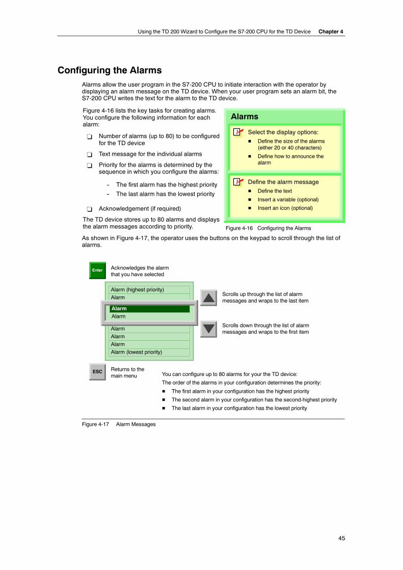
Using the TD 200 Wizard to Configure the S7-200 CPU for the TD Device Chapter 4
45
Configuring the AlarmsAlarms allow the user program in the S7-200 CPU to initiate interaction with the operator bydisplaying an alarm message on the TD device. When your user program sets an alarm bit, theS7-200 CPU writes the text for the alarm to the TD device.
Figure 4-16 lists the key tasks for creating alarms.You configure the following information for eachalarm:
- Number of alarms (up to 80) to be configuredfor the TD device
- Text message for the individual alarms
- Priority for the alarms is determined by thesequence in which you configure the alarms:
-- The first alarm has the highest priority
-- The last alarm has the lowest priority
- Acknowledgement (if required)
The TD device stores up to 80 alarms and displaysh l di i i
Define the alarm message
H Define the text
H Insert a variable (optional)
H Insert an icon (optional)
Alarms
Select the display options:
H Define the size of the alarms(either 20 or 40 characters)
H Define how to announce thealarm
n
n
p p ythe alarm messages according to priority. Figure 4-16 Configuring the Alarms
As shown in Figure 4-17, the operator uses the buttons on the keypad to scroll through the list ofalarms.
Alarm (highest priority)
Alarm
Alarm
Alarm
Acknowledges the alarmthat you have selected
Scrolls up through the list of alarmmessages and wraps to the last item
Enter
ESC Returns to themain menu
Alarm
Scrolls down through the list of alarmmessages and wraps to the first item
Alarm
Alarm
Alarm (lowest priority)
You can configure up to 80 alarms for your the TD device:
The order of the alarms in your configuration determines the priority:
H The first alarm in your configuration has the highest priority
H The second alarm in your configuration has the second-highest priority
H The last alarm in your configuration has the lowest priority
Figure 4-17 Alarm Messages
SIMATIC Text Display (TD) User Manual
46
Determining the Type of Operator-Interaction for an AlarmThe TD 200 wizard allows you to determine the type interaction required by the operator for analarm:
- Acknowledgement is not required, and editing of variables is not allowed:
The TD device displays the alarm. The alarm can contain variables that are updated at theupdate rate of the TD device, but ENTER has no function because the alarm does notcontain any editable variable. Pressing ESC returns to the main menu. An up or down arrowdisplayed with the alarm signals that higher or lower alarms have been enabled. Theoperator can use the UP or DOWN arrows to scroll through the other alarms.
The TD device does not reset the alarm bit for this type of alarm. To remove this alarm fromthe TD device, you must include logic in your user program to reset the alarm bit.
- Acknowledgement is not required, but Editing of variables is required:
The TD device displays the alarm and waits for the operator to edit the value of theembedded variable. If you configured the alarm for automatic editing, the TD device placesthe cursor to the right-most character of the variable. Pressing ESC returns to the mainmenu. An up or down arrow displayed with the alarm signals that higher or lower alarmshave been enabled. The operator can use the UP or DOWN arrows to scroll through theother alarms.
After modifing the value for the embedded variable, the operator presses ENTER. TheTD device then moves the cursor to the next editable variable. Pressing ENTER for the lasteditable variable of an alarm writes the new values for the variables to the S7-200 CPU.The TD device resets the alarm bit.
- Acknowledgement is required, but editing of variables is not allowed:
If you configured the alarm to require acknowledgement, the TD device alerts the operatorin the manner that you selected. If the alarm contains a variable, the TD device updates thisvalue at the rate of the TD device. An up or down arrow displayed with the alarm signalsthat higher or lower alarms have been enabled, but the operator must first acknowledge thisalarm before scrolling to another alarm.
When the operator acknowledges the alarm (by pressing ENTER), the TD device sets theacknowledge bit for the alarm and resets the alarm bit.
- Acknowledgement is required, and Editing of variables is also required:
If you configured the alarm to require acknowledgement, the TD device alerts the operatorin the manner that you selected. If the alarm contains a variable, the TD device updates thisvalue at the rate of the TD device. If you configured the alarm for automatic editing, theTD device places the cursor to the right-most character of the variable. An up or down arrowdisplayed with the alarm signals that higher or lower alarms have been enabled, but theoperator must first acknowledge this alarm before scrolling to another alarm.
After modifing the value for the embedded variable, the operator presses ENTER. TheTD device then moves the cursor to the next editable variable. Pressing ENTER for the lasteditable variable of an alarm writes the new values for the variables to the S7-200 CPU.The TD device sets the acknowledge bit for the alarm and resets the alarm bit.
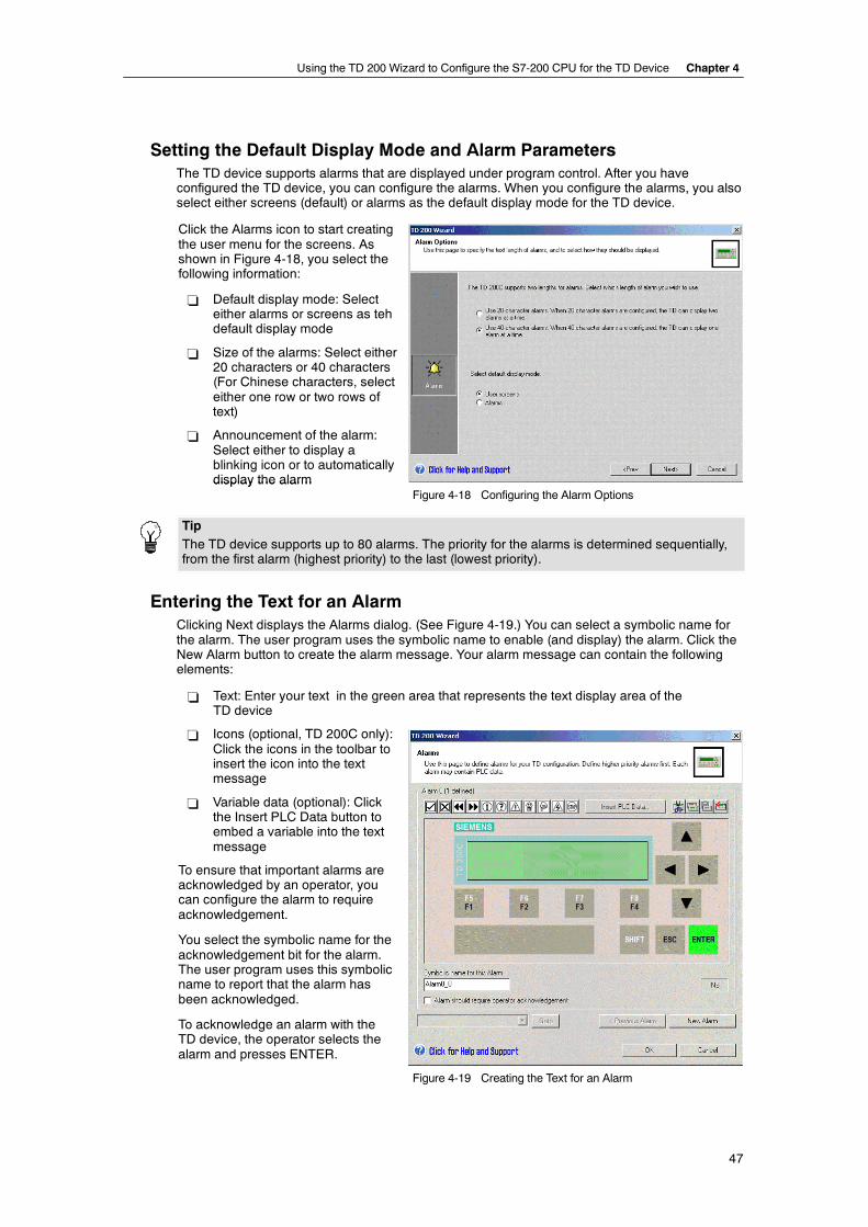
Using the TD 200 Wizard to Configure the S7-200 CPU for the TD Device Chapter 4
47
Setting the Default Display Mode and Alarm ParametersThe TD device supports alarms that are displayed under program control. After you haveconfigured the TD device, you can configure the alarms. When you configure the alarms, you alsoselect either screens (default) or alarms as the default display mode for the TD device.
Click the Alarms icon to start creatingthe user menu for the screens. Asshown in Figure 4-18, you select thefollowing information:
- Default display mode: Selecteither alarms or screens as tehdefault display mode
- Size of the alarms: Select either20 characters or 40 characters(For Chinese characters, selecteither one row or two rows oftext)
- Announcement of the alarm:Select either to display ablinking icon or to automaticallydisplay the alarmdisplay the alarm
Figure 4-18 Configuring the Alarm Options
TipThe TD device supports up to 80 alarms. The priority for the alarms is determined sequentially,from the first alarm (highest priority) to the last (lowest priority).
Entering the Text for an AlarmClicking Next displays the Alarms dialog. (See Figure 4-19.) You can select a symbolic name forthe alarm. The user program uses the symbolic name to enable (and display) the alarm. Click theNew Alarm button to create the alarm message. Your alarm message can contain the followingelements:
- Text: Enter your text in the green area that represents the text display area of theTD device
- Icons (optional, TD 200C only):Click the icons in the toolbar toinsert the icon into the textmessage
- Variable data (optional): Clickthe Insert PLC Data button toembed a variable into the textmessage
To ensure that important alarms areacknowledged by an operator, youcan configure the alarm to requireacknowledgement.
You select the symbolic name for theacknowledgement bit for the alarm.The user program uses this symbolicname to report that the alarm hasbeen acknowledged.
To acknowledge an alarm with theTD device, the operator selects thealarm and presses ENTER.
Figure 4-19 Creating the Text for an Alarm
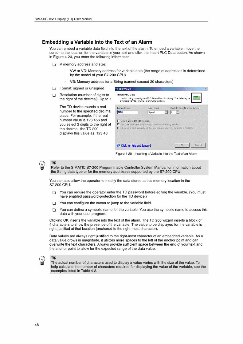
SIMATIC Text Display (TD) User Manual
48
Embedding a Variable into the Text of an AlarmYou can embed a variable data field into the text of the alarm. To embed a variable, move thecursor to the location for the variable in your text and click the Insert PLC Data button. As shownin Figure 4-20, you enter the following information:
- V memory address and size:
-- VW or VD: Memory address for variable data (the range of addresses is determinedby the model of your S7-200 CPU)
-- VB: Memory address for a String (cannot exceed 20 characters)
- Format: signed or unsigned
- Resolution (number of digits tothe right of the decimal): Up to 7
The TD device rounds a realnumber to the specified decimalplace. For example, if the realnumber value is 123.456 andyou select 2 digits to the right ofthe decimal, the TD 200displays this value as: 123.46
Figure 4-20 Inserting a Variable into the Text of an Alarm
TipRefer to the SIMATIC S7-200 Programmable Controller System Manual for information aboutthe String data type or for the memory addresses supported by the S7-200 CPU.
You can also allow the operator to modify the data stored at this memory location in theS7-200 CPU.
- You can require the operator enter the TD password before editing the variable. (You musthave enabled password-protection for the TD device.)
- You can configure the cursor to jump to the variable field.
- You can define a symbolic name for the variable. You use the symbolic name to access thisdata with your user program.
Clicking OK inserts the variable into the text of the alarm. The TD 200 wizard inserts a block of4 characters to show the presence of the variable. The value to be displayed for the variable isright-justified at that location (anchored to the right-most character).
Data values are always right justified to the right-most character of an embedded variable. As adata value grows in magnitude, it utilizes more spaces to the left of the anchor point and canoverwrite the text characters. Always provide sufficient space between the end of your text andthe anchor point to allow for the expected range of the data value.
TipThe actual number of characters used to display a value varies with the size of the value. Tohelp calculate the number of characters required for displaying the value of the variable, see theexamples listed in Table 4-2.
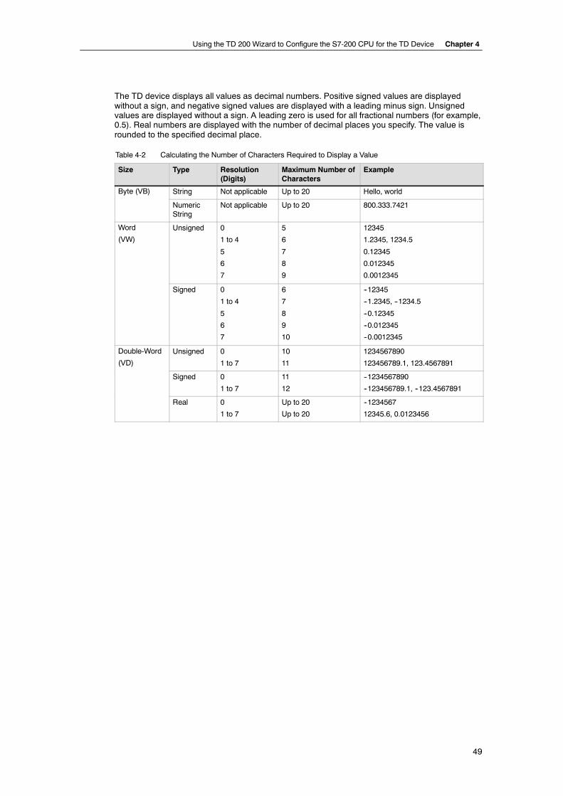
Using the TD 200 Wizard to Configure the S7-200 CPU for the TD Device Chapter 4
49
The TD device displays all values as decimal numbers. Positive signed values are displayedwithout a sign, and negative signed values are displayed with a leading minus sign. Unsignedvalues are displayed without a sign. A leading zero is used for all fractional numbers (for example,0.5). Real numbers are displayed with the number of decimal places you specify. The value isrounded to the specified decimal place.
Table 4-2 Calculating the Number of Characters Required to Display a Value
Size Type Resolution(Digits)
Maximum Number ofCharacters
Example
Byte (VB) String Not applicable Up to 20 Hello, world
NumericString
Not applicable Up to 20 800.333.7421
Word
(VW)
Unsigned 0
1 to 4
5
6
7
5
6
7
8
9
12345
1.2345, 1234.5
0.12345
0.012345
0.0012345
Signed 0
1 to 4
5
6
7
6
7
8
9
10
--12345
--1.2345, --1234.5
--0.12345
--0.012345
--0.0012345
Double-Word
(VD)
Unsigned 0
1 to 7
10
11
1234567890
123456789.1, 123.4567891
Signed 0
1 to 7
11
12
--1234567890
--123456789.1, --123.4567891
Real 0
1 to 7
Up to 20
Up to 20
--1234567
12345.6, 0.0123456
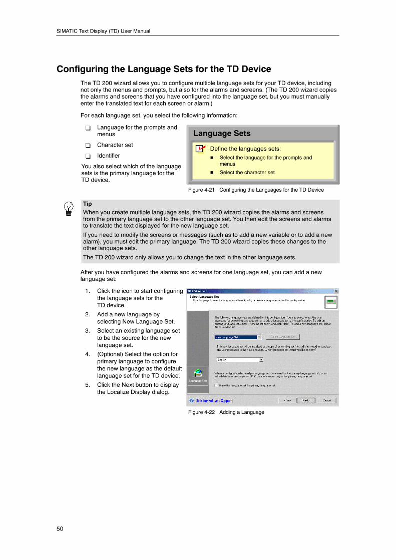
SIMATIC Text Display (TD) User Manual
50
Configuring the Language Sets for the TD DeviceThe TD 200 wizard allows you to configure multiple language sets for your TD device, includingnot only the menus and prompts, but also for the alarms and screens. (The TD 200 wizard copiesthe alarms and screens that you have configured into the language set, but you must manuallyenter the translated text for each screen or alarm.)
For each language set, you select the following information:
- Language for the prompts andmenus
- Character set
- Identifier
You also select which of the languagesets is the primary language for theTD device.
Language Sets
Define the languages sets:
H Select the language for the prompts andmenus
H Select the character set
n
Figure 4-21 Configuring the Languages for the TD Device
TipWhen you create multiple language sets, the TD 200 wizard copies the alarms and screensfrom the primary language set to the other language set. You then edit the screens and alarmsto translate the text displayed for the new language set.
If you need to modify the screens or messages (such as to add a new variable or to add a newalarm), you must edit the primary language. The TD 200 wizard copies these changes to theother language sets.
The TD 200 wizard only allows you to change the text in the other language sets.
After you have configured the alarms and screens for one language set, you can add a newlanguage set:
1. Click the icon to start configuringthe language sets for theTD device.
2. Add a new language byselecting New Language Set.
3. Select an existing language setto be the source for the newlanguage set.
4. (Optional) Select the option forprimary language to configurethe new language as the defaultlanguage set for the TD device.
5. Click the Next button to displaythe Localize Display dialog.
Figure 4-22 Adding a Language
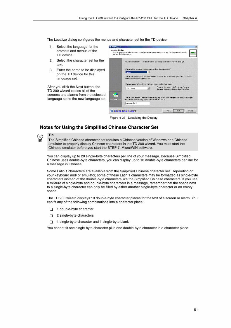
Using the TD 200 Wizard to Configure the S7-200 CPU for the TD Device Chapter 4
51
The Localize dialog configures the menus and character set for the TD device:
1. Select the language for theprompts and menus of theTD device.
2. Select the character set for thetext.
3. Enter the name to be displayedon the TD device for thislanguage set.
After you click the Next button, theTD 200 wizard copies all of thescreens and alarms from the selectedlanguage set to the new language set.
Figure 4-23 Localizing the Display
Notes for Using the Simplified Chinese Character Set
TipThe Simplified Chinese character set requires a Chinese version of Windows or a Chineseemulator to properly display Chinese characters in the TD 200 wizard. You must start theChinese emulator before you start the STEP 7--Micro/WIN software.
You can display up to 20 single-byte characters per line of your message. Because SimplifiedChinese uses double-byte characters, you can display up to 10 double-byte characters per line fora message in Chinese.
Some Latin 1 characters are available from the Simplified Chinese character set. Depending onyour keyboard and/ or emulator, some of these Latin 1 characters may be formatted as single-bytecharacters instead of the double-byte characters like the Simplified Chinese characters. If you usea mixture of single-byte and double-byte characters in a message, remember that the space nextto a single-byte character can only be filled by either another single-byte character or an emptyspace.
The TD 200 wizard displays 10 double-byte character places for the text of a screen or alarm. Youcan fit any of the following combinations into a character place:
- 1 double-byte character
- 2 single-byte characters
- 1 single-byte character and 1 single-byte blank
You cannot fit one single-byte character plus one double-byte character in a character place.
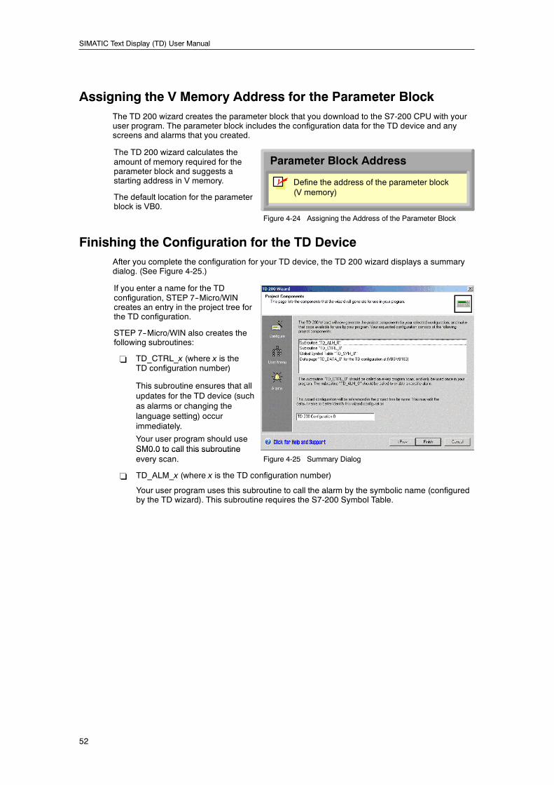
SIMATIC Text Display (TD) User Manual
52
Assigning the V Memory Address for the Parameter BlockThe TD 200 wizard creates the parameter block that you download to the S7-200 CPU with youruser program. The parameter block includes the configuration data for the TD device and anyscreens and alarms that you created.
The TD 200 wizard calculates theamount of memory required for theparameter block and suggests astarting address in V memory.
The default location for the parameterblock is VB0.
Parameter Block Address
Define the address of the parameter block(V memory)
n
Figure 4-24 Assigning the Address of the Parameter Block
Finishing the Configuration for the TD DeviceAfter you complete the configuration for your TD device, the TD 200 wizard displays a summarydialog. (See Figure 4-25.)
If you enter a name for the TDconfiguration, STEP 7--Micro/WINcreates an entry in the project tree forthe TD configuration.
STEP 7--Micro/WIN also creates thefollowing subroutines:
- TD_CTRL_x (where x is theTD configuration number)
This subroutine ensures that allupdates for the TD device (suchas alarms or changing thelanguage setting) occurimmediately.
Your user program should useSM0.0 to call this subroutineSM0.0 to call this subroutineevery scan. Figure 4-25 Summary Dialog
- TD_ALM_x (where x is the TD configuration number)
Your user program uses this subroutine to call the alarm by the symbolic name (configuredby the TD wizard). This subroutine requires the S7-200 Symbol Table.
53
Operating Your TD Device
This chapter describes the following information about the operation of the TD devices, such asusing the keypad to navigate to the screens and bit-enabled alarm messages.
Included in this chapter is information about routine operator tasks, such as entering and releasingthe password, editing variables embedded in a message or screen, and checking the statusinformation of the S7-200 CPU. This chapter also describes the less-routine diagnostic functionsprovided by the TD device for troubleshooting problems in the S7-200 CPU, such as forcing I/O orchanging the operating mode.
In This ChapterUsing the TD Device to Access Screens and Alarms 54. . . . . . . . . . . . . . . . . . . . . . . . . . . . . . . .
Displaying Information on the TD Device 55. . . . . . . . . . . . . . . . . . . . . . . . . . . . . . . . . . . . . .
Using the TD Device to Edit Variables in the S7-200 CPU 56. . . . . . . . . . . . . . . . . . . . . . . .
Accessing the Menus and Screens 57. . . . . . . . . . . . . . . . . . . . . . . . . . . . . . . . . . . . . . . . . . . . . . .
Entering and Releasing a Password 58. . . . . . . . . . . . . . . . . . . . . . . . . . . . . . . . . . . . . . . . . . . . . .
Entering the Password 58. . . . . . . . . . . . . . . . . . . . . . . . . . . . . . . . . . . . . . . . . . . . . . . . . . . . .
Releasing the Password 58. . . . . . . . . . . . . . . . . . . . . . . . . . . . . . . . . . . . . . . . . . . . . . . . . . . .
Viewing the Screens and the Alarms 59. . . . . . . . . . . . . . . . . . . . . . . . . . . . . . . . . . . . . . . . . . . . . .
Displaying the Alarms 60. . . . . . . . . . . . . . . . . . . . . . . . . . . . . . . . . . . . . . . . . . . . . . . . . . . . . .
Editing a Variable That Is Embedded in an Alarm or a Screen 62. . . . . . . . . . . . . . . . . . . .
Performing Typical or Routine Operator Tasks (Operator Menu) 63. . . . . . . . . . . . . . . . . . . . . .
Viewing the Status of an S7-200 CPU 63. . . . . . . . . . . . . . . . . . . . . . . . . . . . . . . . . . . . . . . . .
Setting Time and Date in the S7-200 CPU 64. . . . . . . . . . . . . . . . . . . . . . . . . . . . . . . . . . . . .
Changing the Language Set 65. . . . . . . . . . . . . . . . . . . . . . . . . . . . . . . . . . . . . . . . . . . . . . . . .
Performing Specialized Operator Tasks (Diagnostic Menu) 65. . . . . . . . . . . . . . . . . . . . . . . . . . .
Setting up the TD Device 66. . . . . . . . . . . . . . . . . . . . . . . . . . . . . . . . . . . . . . . . . . . . . . . . . . .
Viewing the TD Messages Stored in the S7-200 CPU 67. . . . . . . . . . . . . . . . . . . . . . . . . . .
Forcing the Inputs and Outputs in the S7-200 CPU 67. . . . . . . . . . . . . . . . . . . . . . . . . . . . .
Changing the Operating Mode of the S7-200 CPU (TD 200C Only) 68. . . . . . . . . . . . . . . .
Copying the User Program to a Memory Cartridge (TD 200C Only) 68. . . . . . . . . . . . . . . .
Editing the CPU Memory (TD 200C Only) 69. . . . . . . . . . . . . . . . . . . . . . . . . . . . . . . . . . . . .
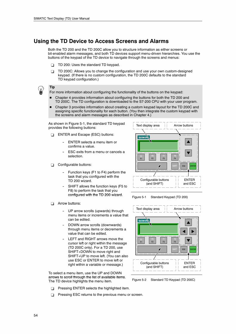
SIMATIC Text Display (TD) User Manual
54
Using the TD Device to Access Screens and AlarmsBoth the TD 200 and the TD 200C allow you to structure information as either screens orbit-enabled alarm messages, and both TD devices support menu-driven hierarchies. You use thebuttons of the keypad of the TD device to navigate through the screens and menus:
- TD 200: Uses the standard TD keypad.
- TD 200C: Allows you to change the configuration and use your own custom-designedkeypad. (If there is no custom configuration, the TD 200C defaults to the standardTD keypad configuration.)
TipFor more information about configuring the functionality of the buttons on the keypad:
H Chapter 4 provides information about configuring the buttons for both the TD 200 andTD 200C. The TD configuration is downloaded to the S7-200 CPU with your user program.
H Chapter 3 provides information about creating a custom keypad layout for the TD 200C andassigning specific functionality for each button. (You then integrate the custom keypad withthe screens and alarm messages as described in Chapter 4.)
As shown in Figure 5-1, the standard TD keypadprovides the following buttons:
- ENTER and Escape (ESC) buttons:
-- ENTER selects a menu item orconfirms a value.
-- ESC exits from a menu or cancels aselection.
- Configurable buttons:
-- Function keys (F1 to F4) perform thetask that you configured with theTD 200 wizard.
-- SHIFT allows the function keys (F5 toF8) to perform the task that youconfigured with the TD 200 wizard
F1F5
F2F6
F3F7
F4F8
SHIFT ESC ENTER
Text display area Arrow buttons
Configurable buttons(and SHIFT)
ENTERand ESC
configured with the TD 200 wizard.
- Arrow buttons:
Figure 5-1 Standard Keypad (TD 200)
- Arrow buttons:
-- UP arrow scrolls (upwards) throughmenu items or increments a value thatcan be edited.
-- DOWN arrow scrolls (downwards)through menu items or decrements avalue that can be edited.
-- LEFT and RIGHT arrows move thecursor left or right within the message(TD 200C only). For a TD 200, useSHIFT+DOWN to move right andSHIFT+UP to move left. (You can alsouse ESC or ENTER to move left orright within a variable or message.)
To select a menu item, use the UP and DOWNarrows to scroll through the list of available items
F1F5
F2F6
F3F7
F4F8
SHIFT ESC ENTER
Text display area Arrow buttons
Configurable buttons(and SHIFT)
ENTERand ESC
arrows to scroll through the list of available items.The TD device highlights the menu item. Figure 5-2 Standard TD Keypad (TD 200C)
- Pressing ENTER selects the highlighted item.
- Pressing ESC returns to the previous menu or screen.
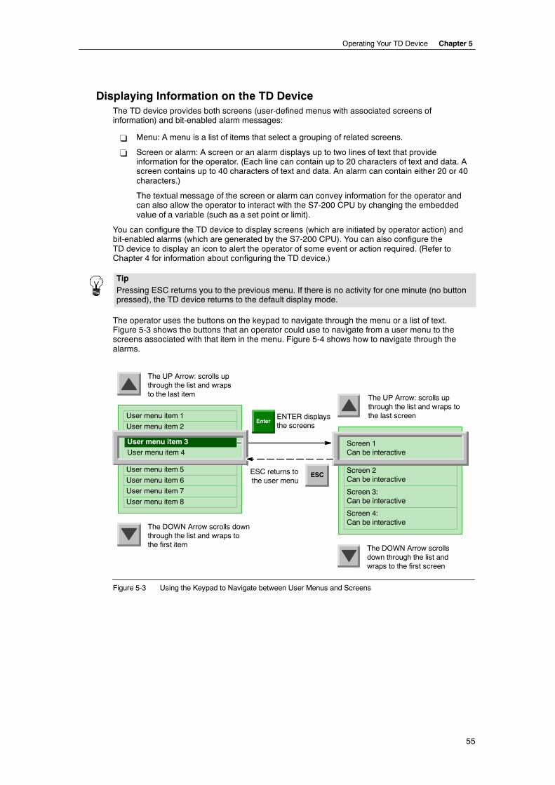
Operating Your TD Device Chapter 5
55
Displaying Information on the TD DeviceThe TD device provides both screens (user-defined menus with associated screens ofinformation) and bit-enabled alarm messages:
- Menu: A menu is a list of items that select a grouping of related screens.
- Screen or alarm: A screen or an alarm displays up to two lines of text that provideinformation for the operator. (Each line can contain up to 20 characters of text and data. Ascreen contains up to 40 characters of text and data. An alarm can contain either 20 or 40characters.)
The textual message of the screen or alarm can convey information for the operator andcan also allow the operator to interact with the S7-200 CPU by changing the embeddedvalue of a variable (such as a set point or limit).
You can configure the TD device to display screens (which are initiated by operator action) andbit-enabled alarms (which are generated by the S7-200 CPU). You can also configure theTD device to display an icon to alert the operator of some event or action required. (Refer toChapter 4 for information about configuring the TD device.)
TipPressing ESC returns you to the previous menu. If there is no activity for one minute (no buttonpressed), the TD device returns to the default display mode.
The operator uses the buttons on the keypad to navigate through the menu or a list of text.Figure 5-3 shows the buttons that an operator could use to navigate from a user menu to thescreens associated with that item in the menu. Figure 5-4 shows how to navigate through thealarms.
User menu item 1
User menu item 4
User menu item 5
User menu item 6
ENTER displaysthe screens
The UP Arrow: scrolls upthrough the list and wrapsto the last item
Enter
ESCESC returns tothe user menu
User menu item 2
The DOWN Arrow scrollsdown through the list andwraps to the first screen
The DOWN Arrow scrolls downthrough the list and wraps tothe first item
User menu item 7
User menu item 8
The UP Arrow: scrolls upthrough the list and wraps tothe last screen
User menu item 3 Screen 1Can be interactive
Screen 2Can be interactive
Screen 3:Can be interactive
Screen 4:Can be interactive
Figure 5-3 Using the Keypad to Navigate between User Menus and Screens
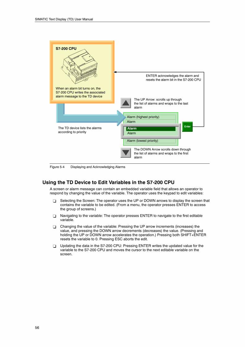
SIMATIC Text Display (TD) User Manual
56
Alarm (highest priority)
Alarm
Alarm (lowest priority)
The UP Arrow: scrolls up throughthe list of alarms and wraps to the lastalarm
Alarm
The DOWN Arrow scrolls down throughthe list of alarms and wraps to the firstalarm
Alarm
S7-200 CPU
ENTER acknowledges the alarm andresets the alarm bit in the S7-200 CPU
When an alarm bit turns on, theS7-200 CPU writes the associatedalarm message to the TD device
EnterThe TD device lists the alarmsaccording to priority
Figure 5-4 Displaying and Acknowledging Alarms
Using the TD Device to Edit Variables in the S7-200 CPUA screen or alarm message can contain an embedded variable field that allows an operator torespond by changing the value of the variable. The operator uses the keypad to edit variables:
- Selecting the Screen: The operator uses the UP or DOWN arrows to display the screen thatcontains the variable to be edited. (From a menu, the operator presses ENTER to accessthe group of screens.)
- Navigating to the variable: The operator presses ENTER to navigate to the first editablevariable.
- Changing the value of the variable: Pressing the UP arrow increments (increases) thevalue, and pressing the DOWN arrow decrements (decreases) the value. (Pressing andholding the UP or DOWN arrow accelerates the operation.) Pressing both SHIFT+ENTERresets the variable to 0. Pressing ESC aborts the edit.
- Updating the data in the S7-200 CPU: Pressing ENTER writes the updated value for thevariable to the S7-200 CPU and moves the cursor to the next editable variable on thescreen.
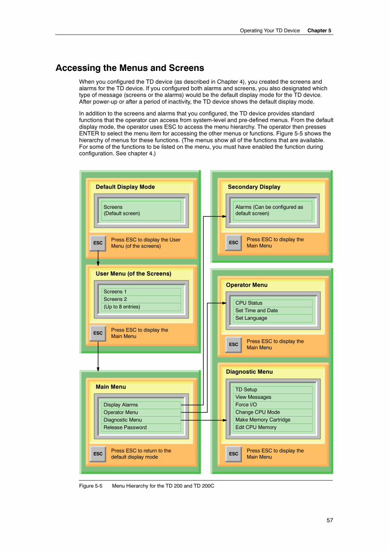
Operating Your TD Device Chapter 5
57
Accessing the Menus and ScreensWhen you configured the TD device (as described in Chapter 4), you created the screens andalarms for the TD device. If you configured both alarms and screens, you also designated whichtype of message (screens or the alarms) would be the default display mode for the TD device.After power-up or after a period of inactivity, the TD device shows the default display mode.
In addition to the screens and alarms that you configured, the TD device provides standardfunctions that the operator can access from system-level and pre-defined menus. From the defaultdisplay mode, the operator uses ESC to access the menu hierarchy. The operator then pressesENTER to select the menu item for accessing the other menus or functions. Figure 5-5 shows thehierarchy of menus for these functions. (The menus show all of the functions that are available.For some of the functions to be listed on the menu, you must have enabled the function duringconfiguration. See chapter 4.)
Diagnostic Menu
TD Setup
View Messages
Force I/O
Change CPU Mode
Make Memory Cartridge
Edit CPU Memory
Alarms (Can be configured asdefault screen)
ESCPress ESC to display theMain Menu
ESCPress ESC to display theMain Menu
Operator Menu
Secondary Display
Press ESC to display the UserMenu (of the screens)
Screens(Default screen)
Default Display Mode
Press ESC to display theMain Menu
User Menu (of the Screens)
Screens 1
Screens 2
(Up to 8 entries)
ESCPress ESC to return to thedefault display mode
Main Menu
CPU Status
Set Time and Date
Set Language
ESCPress ESC to display theMain Menu
ESC
Display Alarms
Operator Menu
Diagnostic Menu
Release Password
ESC
Figure 5-5 Menu Hierarchy for the TD 200 and TD 200C
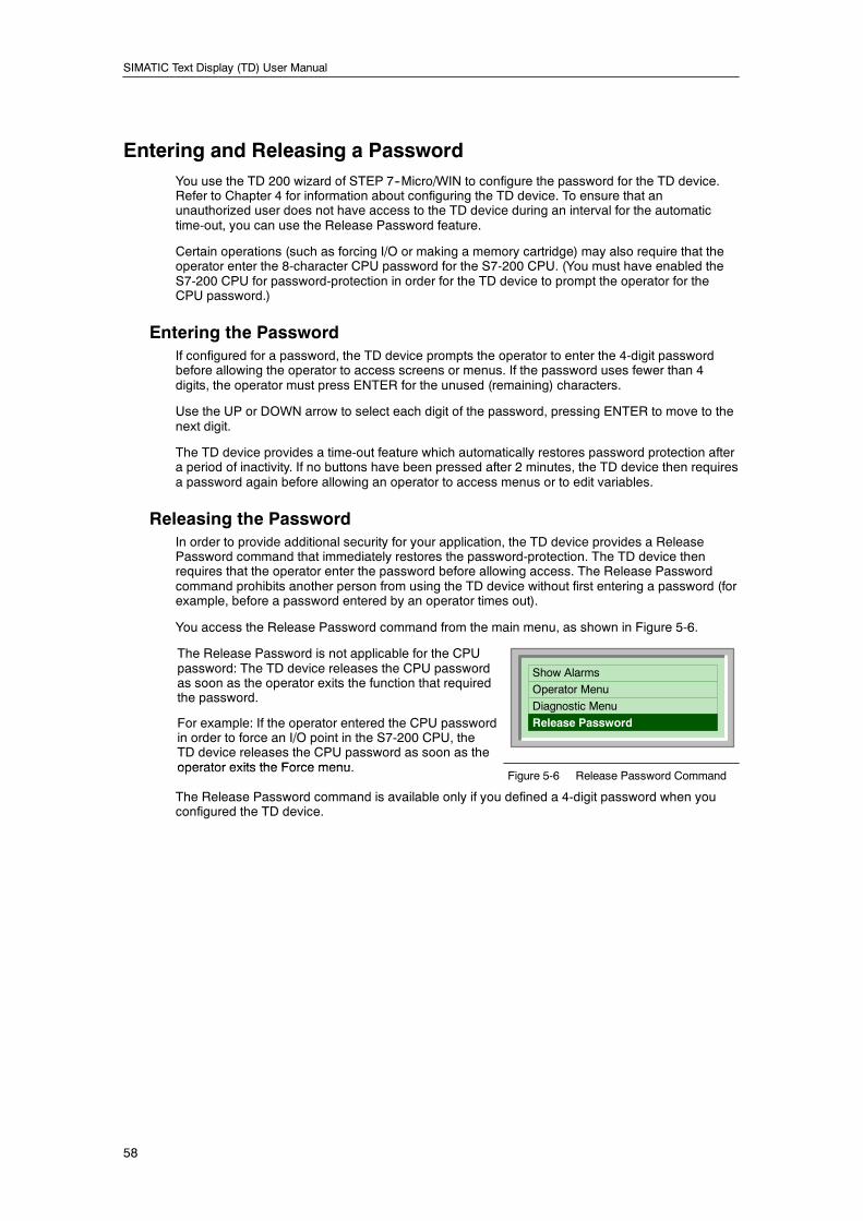
SIMATIC Text Display (TD) User Manual
58
Entering and Releasing a PasswordYou use the TD 200 wizard of STEP 7--Micro/WIN to configure the password for the TD device.Refer to Chapter 4 for information about configuring the TD device. To ensure that anunauthorized user does not have access to the TD device during an interval for the automatictime-out, you can use the Release Password feature.
Certain operations (such as forcing I/O or making a memory cartridge) may also require that theoperator enter the 8-character CPU password for the S7-200 CPU. (You must have enabled theS7-200 CPU for password-protection in order for the TD device to prompt the operator for theCPU password.)
Entering the PasswordIf configured for a password, the TD device prompts the operator to enter the 4-digit passwordbefore allowing the operator to access screens or menus. If the password uses fewer than 4digits, the operator must press ENTER for the unused (remaining) characters.
Use the UP or DOWN arrow to select each digit of the password, pressing ENTER to move to thenext digit.
The TD device provides a time-out feature which automatically restores password protection aftera period of inactivity. If no buttons have been pressed after 2 minutes, the TD device then requiresa password again before allowing an operator to access menus or to edit variables.
Releasing the PasswordIn order to provide additional security for your application, the TD device provides a ReleasePassword command that immediately restores the password-protection. The TD device thenrequires that the operator enter the password before allowing access. The Release Passwordcommand prohibits another person from using the TD device without first entering a password (forexample, before a password entered by an operator times out).
You access the Release Password command from the main menu, as shown in Figure 5-6.
The Release Password is not applicable for the CPUpassword: The TD device releases the CPU passwordas soon as the operator exits the function that requiredthe password.
For example: If the operator entered the CPU passwordin order to force an I/O point in the S7-200 CPU, theTD device releases the CPU password as soon as theoperator exits the Force menu
Show Alarms
Operator Menu
Diagnostic Menu
Release Password
operator exits the Force menu.Figure 5-6 Release Password Command
The Release Password command is available only if you defined a 4-digit password when youconfigured the TD device.
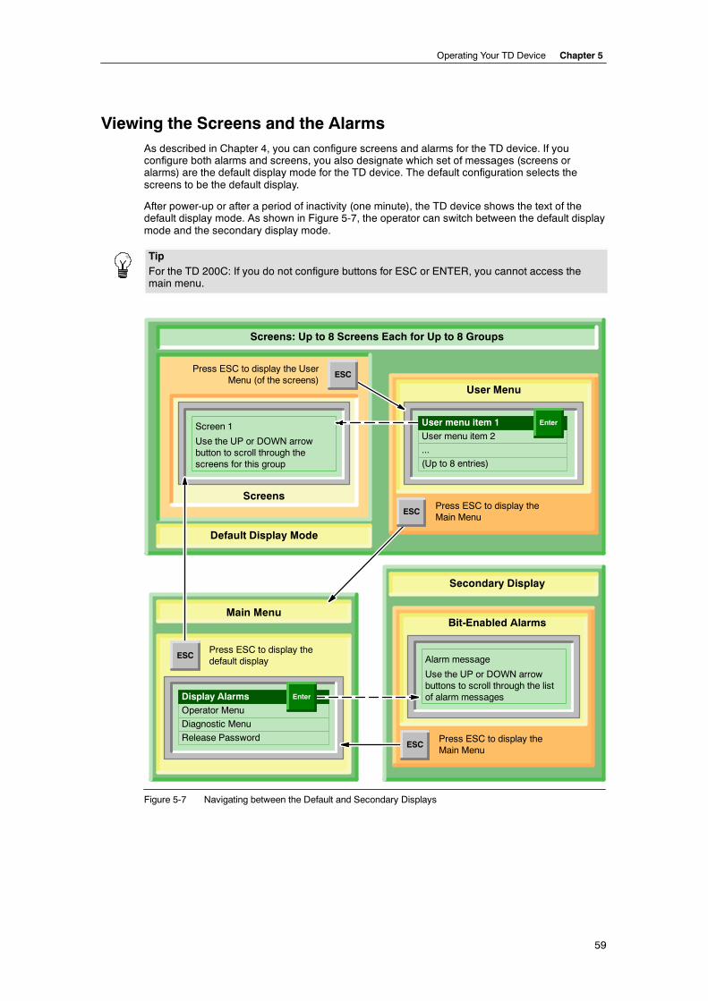
Operating Your TD Device Chapter 5
59
Viewing the Screens and the AlarmsAs described in Chapter 4, you can configure screens and alarms for the TD device. If youconfigure both alarms and screens, you also designate which set of messages (screens oralarms) are the default display mode for the TD device. The default configuration selects thescreens to be the default display.
After power-up or after a period of inactivity (one minute), the TD device shows the text of thedefault display mode. As shown in Figure 5-7, the operator can switch between the default displaymode and the secondary display mode.
TipFor the TD 200C: If you do not configure buttons for ESC or ENTER, you cannot access themain menu.
Alarm message
Use the UP or DOWN arrowbuttons to scroll through the listof alarm messages
Press ESC to display theMain Menu
Bit-Enabled Alarms
Press ESC to display the UserMenu (of the screens)
Screen 1
Use the UP or DOWN arrowbutton to scroll through thescreens for this group
ScreensPress ESC to display theMain Menu
User Menu
User menu item 2
...
Press ESC to display thedefault display
Operator Menu
Diagnostic Menu
Release Password
(Up to 8 entries)
Screens: Up to 8 Screens Each for Up to 8 Groups
Secondary Display
Display Alarms
User menu item 1 Enter
ESC
ESC
Default Display Mode
Main Menu
ESC
ESC
Enter
Figure 5-7 Navigating between the Default and Secondary Displays
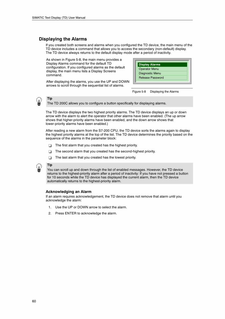
SIMATIC Text Display (TD) User Manual
60
Displaying the AlarmsIf you created both screens and alarms when you configured the TD device, the main menu of theTD device includes a command that allows you to access the secondary (non-default) display.The TD device always returns to the default display mode after a period of inactivity.
As shown in Figure 5-8, the main menu provides aDisplay Alarms command for the default TDconfiguration. If you configured alarms as the defaultdisplay, the main menu lists a Display Screenscommand.
After displaying the alarms, you use the UP and DOWNarrows to scroll through the sequential list of alarms.
Display AlarmsOperator Menu
Diagnostic Menu
Release Password
Figure 5-8 Displaying the Alarms
TipThe TD 200C allows you to configure a button specifically for displaying alarms.
The TD device displays the two highest priority alarms. The TD device displays an up or downarrow with the alarm to alert the operator that other alarms have been enabled. (The up arrowshows that higher-priority alarms have been enabled, and the down arrow shows thatlower-priority alarms have been enabled.)
After reading a new alarm from the S7-200 CPU, the TD device sorts the alarms again to displaythe highest priority alarms at the top of the list. The TD device determines the priority based on thesequence of the alarms in the parameter block:
- The first alarm that you created has the highest priority.
- The second alarm that you created has the second-highest priority.
- The last alarm that you created has the lowest priority.
TipYou can scroll up and down through the list of enabled messages. However, the TD devicereturns to the highest-priority alarm after a period of inactivity: If you have not pressed a buttonfor 10 seconds while the TD device has displayed the current alarm, then the TD deviceautomatically returns to the highest-priority alarm.
Acknowledging an AlarmIf an alarm requires acknowledgement, the TD device does not remove that alarm until youacknowledge the alarm:
1. Use the UP or DOWN arrow to select the alarm.
2. Press ENTER to acknowledge the alarm.
Operating Your TD Device Chapter 5
61
Types of AlarmsWhen you configured the alarms (see Chapter 4), you enabled the following interaction with theoperator:
- Acknowledgement is not required, and editing of variables is not allowed:
The TD device displays the alarm. The alarm can contain variables that are updated at theupdate rate of the TD device, but ENTER has no function because the alarm does notcontain any editable variable. Pressing ESC returns to the main menu. An up or down arrowdisplayed with the alarm signals that higher or lower alarms have been enabled. Theoperator can use the UP or DOWN arrows to scroll through the other alarms.
The TD device does not reset the alarm bit for this type of alarm. To remove this alarm fromthe TD device, you must include logic in your user program to reset the alarm bit.
- Acknowledgement is not required, but Editing of variables is required:
The TD device displays the alarm and waits for the operator to edit the value of theembedded variable. If you configured the alarm for automatic editing, the TD device placesthe cursor to the right-most character of the variable. Pressing ESC returns to the mainmenu. An up or down arrow displayed with the alarm signals that higher or lower alarmshave been enabled. The operator can use the UP or DOWN arrows to scroll through theother alarms.
After modifing the value for the embedded variable, the operator presses ENTER. TheTD device then moves the cursor to the next editable variable. Pressing ENTER for the lasteditable variable of an alarm writes the new values for the variables to the S7-200 CPU.The TD device resets the alarm bit.
- Acknowledgement is required, but editing of variables is not allowed:
If you configured the alarm to require acknowledgement, the TD device alerts the operatorin the manner that you selected. If the alarm contains a variable, the TD device updates thisvalue at the rate of the TD device. An up or down arrow displayed with the alarm signalsthat higher or lower alarms have been enabled, but the operator must first acknowledge thisalarm before scrolling to another alarm.
When the operator acknowledges the alarm (by pressing ENTER), the TD device sets theacknowledge bit for the alarm and resets the alarm bit.
- Acknowledgement is required, and Editing of variables is also required:
If you configured the alarm to require acknowledgement, the TD device alerts the operatorin the manner that you selected. If the alarm contains a variable, the TD device updates thisvalue at the rate of the TD device. If you configured the alarm for automatic editing, theTD device places the cursor to the right-most character of the variable. An up or down arrowdisplayed with the alarm signals that higher or lower alarms have been enabled, but theoperator must first acknowledge this alarm before scrolling to another alarm.
After modifing the value for the embedded variable, the operator presses ENTER. TheTD device then moves the cursor to the next editable variable. Pressing ENTER for the lasteditable variable of an alarm writes the new values for the variables to the S7-200 CPU.The TD device sets the acknowledge bit for the alarm and resets the alarm bit.
SIMATIC Text Display (TD) User Manual
62
Editing a Variable That Is Embedded in an Alarm or a ScreenIf you configured a screen or an alarm to include a variable, you can enter a new value for thevariable:
- Use ENTER to move the cursor to the the variable.
- Use the UP or DOWN arrows to change the value of the variable.
- Use the following buttons to move the cursor to different characters within the variable:
-- TD 200C: LEFT and RIGHT arrows
-- TD 200: SHIFT+UP arrow and SHIFT+DOWN arrow
- ESC reads the value of the variable from the S7-200 CPU and redisplays the value.
- ENTER writes the new value to the S7-200 CPU. (If the alarm contains other variables, thecursor moves to the next variable.)
If the alarm was configured as a numeric string, the cursor skips over any non-numeric charactersin the message. See Chapter 4. After you have edited all of the variables in an alarm, theTD device resets the alarm bit in the S7-200 CPU.
WarningDue to restrictions in the format used to store real (floating-point) numbers in both the S7-200CPU and the TD device, the accuracy of the number is limited to six significant digits. Editing areal number with more than six digits may not change the value of the variable, or may causeother digits within the number to change:
H Changing the least significant (right-most) digit of a real-number variable with more than sixdigits may have no effect. For example, if you try to change the “9” in “1234.56789”, thevalue of the variable does not change.
H Changing the most significant (left-most) digit of a real-number variable with more than sixdigits may cause other (less significant) digits in the variable to change.
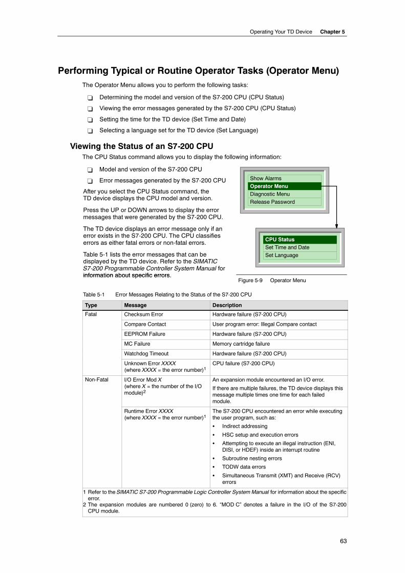
Operating Your TD Device Chapter 5
63
Performing Typical or Routine Operator Tasks (Operator Menu)The Operator Menu allows you to perform the following tasks:
- Determining the model and version of the S7-200 CPU (CPU Status)
- Viewing the error messages generated by the S7-200 CPU (CPU Status)
- Setting the time for the TD device (Set Time and Date)
- Selecting a language set for the TD device (Set Language)
Viewing the Status of an S7-200 CPUThe CPU Status command allows you to display the following information:
- Model and version of the S7-200 CPU
- Error messages generated by the S7-200 CPU
After you select the CPU Status command, theTD device displays the CPU model and version.
Press the UP or DOWN arrows to display the errormessages that were generated by the S7-200 CPU.
The TD device displays an error message only if anerror exists in the S7-200 CPU. The CPU classifieserrors as either fatal errors or non-fatal errors.
Table 5-1 lists the error messages that can bedisplayed by the TD device. Refer to the SIMATICS7-200 Programmable Controller System Manual forinformation about specific errors
CPU StatusSet Time and Date
Set Language
Show Alarms
Operator MenuDiagnostic Menu
Release Password
information about specific errors.Figure 5-9 Operator Menu
Table 5-1 Error Messages Relating to the Status of the S7-200 CPU
Type Message Description
Fatal Checksum Error Hardware failure (S7-200 CPU)
Compare Contact User program error: Illegal Compare contact
EEPROM Failure Hardware failure (S7-200 CPU)
MC Failure Memory cartridge failure
Watchdog Timeout Hardware failure (S7-200 CPU)
Unknown Error XXXX(where XXXX = the error number)1
CPU failure (S7-200 CPU)
Non-Fatal I/O Error Mod X(where X = the number of the I/Omodule)2
An expansion module encountered an I/O error.
If there are multiple failures, the TD device displays thismessage multiple times one time for each failedmodule.
Runtime Error XXXX(where XXXX = the error number)1
The S7-200 CPU encountered an error while executingthe user program, such as:
S Indirect addressing
S HSC setup and execution errors
S Attempting to execute an illegal instruction (ENI,DISI, or HDEF) inside an interrupt routine
S Subroutine nesting errors
S TODW data errors
S Simultaneous Transmit (XMT) and Receive (RCV)errors
1 Refer to the SIMATIC S7-200 Programmable Logic Controller System Manual for information about the specificerror.
2 The expansion modules are numbered 0 (zero) to 6. “MOD C” denotes a failure in the I/O of the S7-200CPU module.
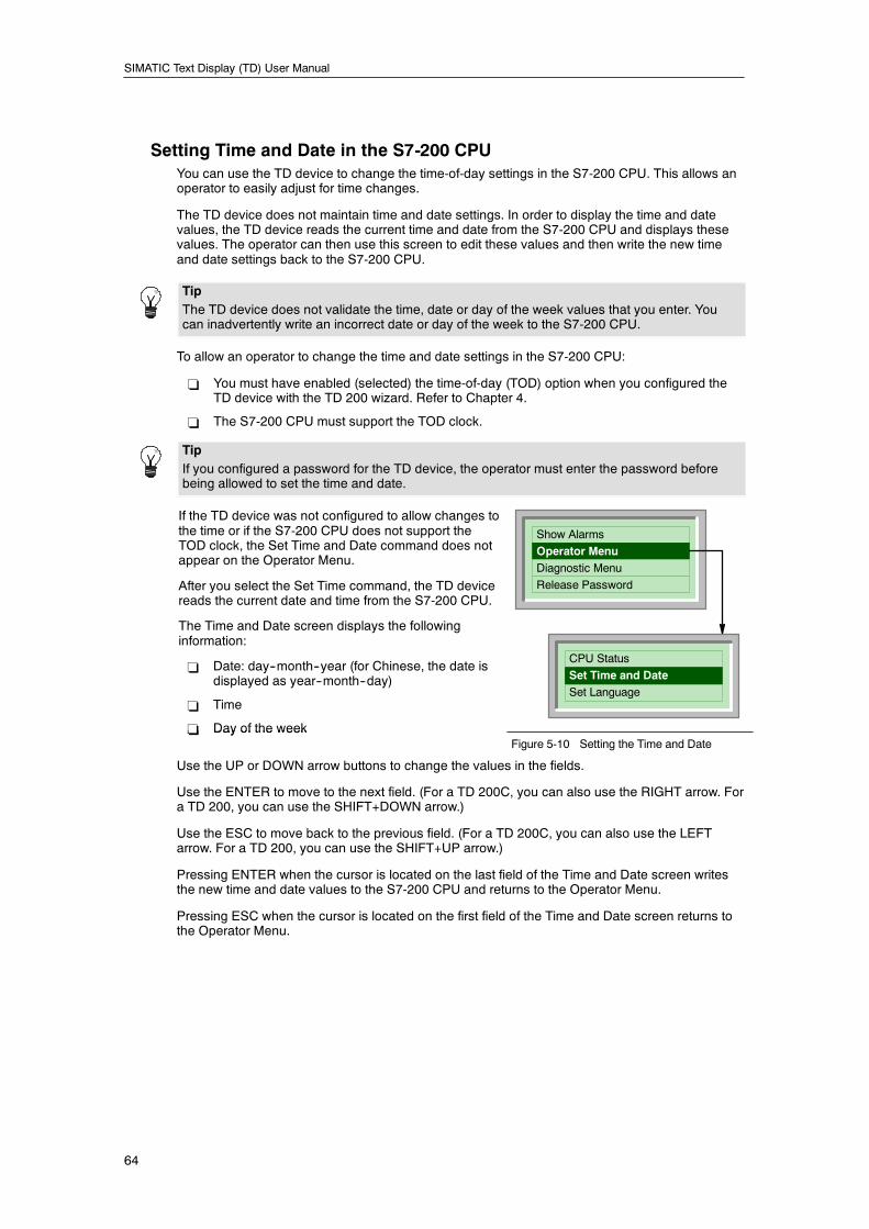
SIMATIC Text Display (TD) User Manual
64
Setting Time and Date in the S7-200 CPUYou can use the TD device to change the time-of-day settings in the S7-200 CPU. This allows anoperator to easily adjust for time changes.
The TD device does not maintain time and date settings. In order to display the time and datevalues, the TD device reads the current time and date from the S7-200 CPU and displays thesevalues. The operator can then use this screen to edit these values and then write the new timeand date settings back to the S7-200 CPU.
TipThe TD device does not validate the time, date or day of the week values that you enter. Youcan inadvertently write an incorrect date or day of the week to the S7-200 CPU.
To allow an operator to change the time and date settings in the S7-200 CPU:
- You must have enabled (selected) the time-of-day (TOD) option when you configured theTD device with the TD 200 wizard. Refer to Chapter 4.
- The S7-200 CPU must support the TOD clock.
TipIf you configured a password for the TD device, the operator must enter the password beforebeing allowed to set the time and date.
If the TD device was not configured to allow changes tothe time or if the S7-200 CPU does not support theTOD clock, the Set Time and Date command does notappear on the Operator Menu.
After you select the Set Time command, the TD devicereads the current date and time from the S7-200 CPU.
The Time and Date screen displays the followinginformation:
- Date: day--month--year (for Chinese, the date isdisplayed as year--month--day)
- Time
- Day of the week
CPU Status
Set Time and DateSet Language
Show Alarms
Operator MenuDiagnostic Menu
Release Password
- Day of the weekFigure 5-10 Setting the Time and Date
Use the UP or DOWN arrow buttons to change the values in the fields.
Use the ENTER to move to the next field. (For a TD 200C, you can also use the RIGHT arrow. Fora TD 200, you can use the SHIFT+DOWN arrow.)
Use the ESC to move back to the previous field. (For a TD 200C, you can also use the LEFTarrow. For a TD 200, you can use the SHIFT+UP arrow.)
Pressing ENTER when the cursor is located on the last field of the Time and Date screen writesthe new time and date values to the S7-200 CPU and returns to the Operator Menu.
Pressing ESC when the cursor is located on the first field of the Time and Date screen returns tothe Operator Menu.
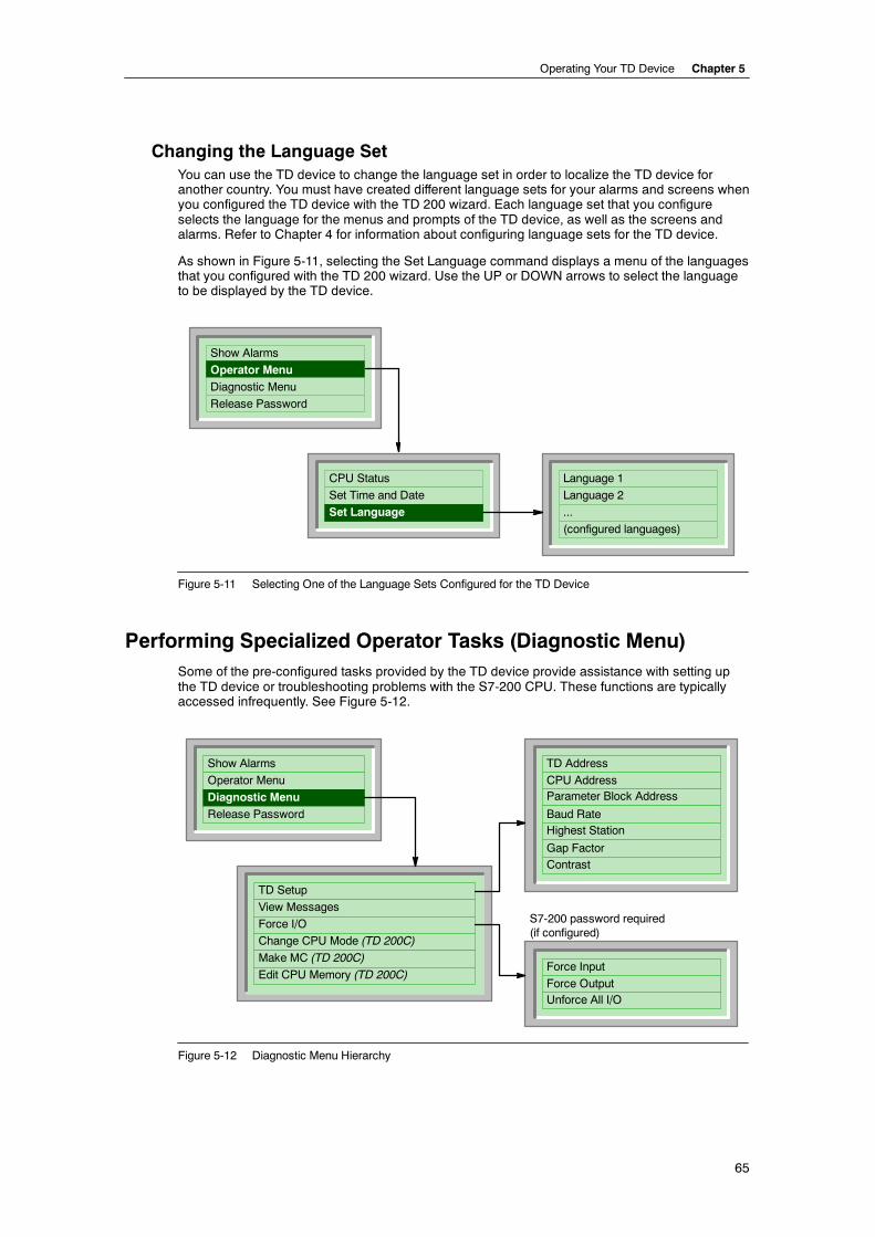
Operating Your TD Device Chapter 5
65
Changing the Language SetYou can use the TD device to change the language set in order to localize the TD device foranother country. You must have created different language sets for your alarms and screens whenyou configured the TD device with the TD 200 wizard. Each language set that you configureselects the language for the menus and prompts of the TD device, as well as the screens andalarms. Refer to Chapter 4 for information about configuring language sets for the TD device.
As shown in Figure 5-11, selecting the Set Language command displays a menu of the languagesthat you configured with the TD 200 wizard. Use the UP or DOWN arrows to select the languageto be displayed by the TD device.
CPU Status
Set Time and Date
Show Alarms
Operator MenuDiagnostic Menu
Release Password
Language 1
Language 2
...
(configured languages)
Set Language
Figure 5-11 Selecting One of the Language Sets Configured for the TD Device
Performing Specialized Operator Tasks (Diagnostic Menu)Some of the pre-configured tasks provided by the TD device provide assistance with setting upthe TD device or troubleshooting problems with the S7-200 CPU. These functions are typicallyaccessed infrequently. See Figure 5-12.
Show Alarms
Operator Menu
Diagnostic MenuRelease Password
TD Setup
View Messages
Force I/O
Change CPU Mode (TD 200C)
Make MC (TD 200C)
Edit CPU Memory (TD 200C)
TD Address
CPU AddressParameter Block Address
Baud RateHighest Station
Gap FactorContrast
S7-200 password required(if configured)
Force Input
Force OutputUnforce All I/O
Figure 5-12 Diagnostic Menu Hierarchy
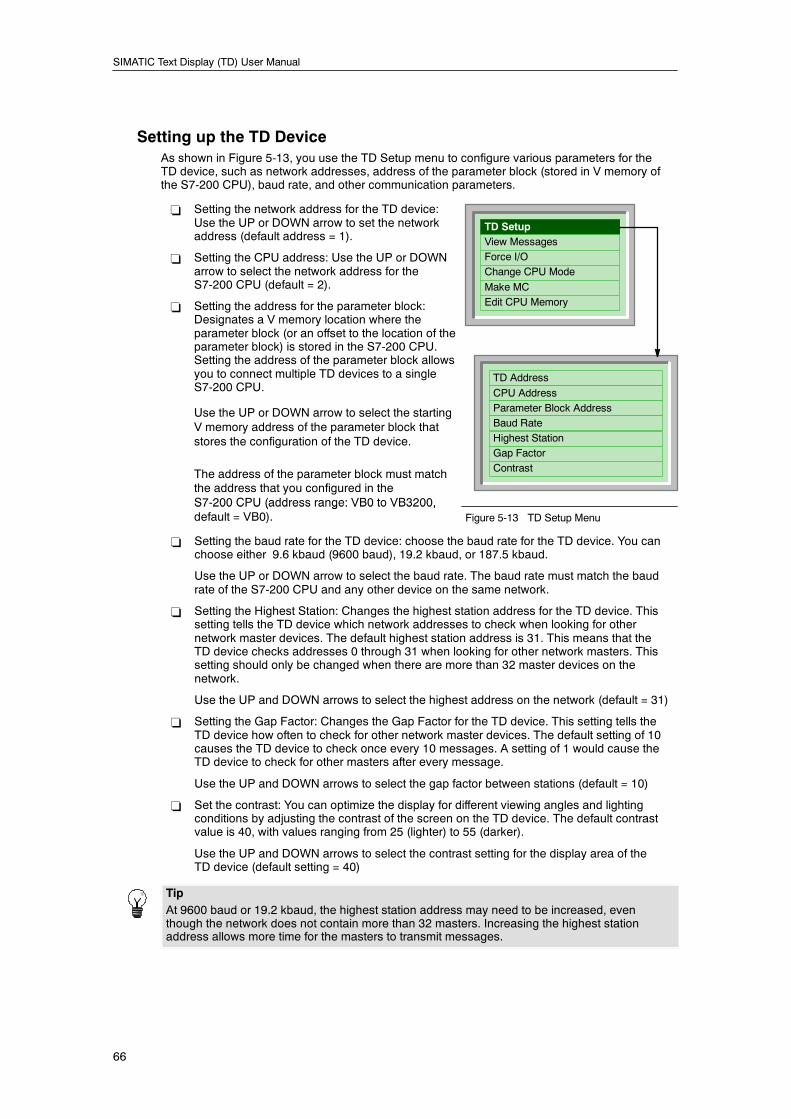
SIMATIC Text Display (TD) User Manual
66
Setting up the TD DeviceAs shown in Figure 5-13, you use the TD Setup menu to configure various parameters for theTD device, such as network addresses, address of the parameter block (stored in V memory ofthe S7-200 CPU), baud rate, and other communication parameters.
- Setting the network address for the TD device:Use the UP or DOWN arrow to set the networkaddress (default address = 1).
- Setting the CPU address: Use the UP or DOWNarrow to select the network address for theS7-200 CPU (default = 2).
- Setting the address for the parameter block:Designates a V memory location where theparameter block (or an offset to the location of theparameter block) is stored in the S7-200 CPU.Setting the address of the parameter block allowsyou to connect multiple TD devices to a singleS7-200 CPU.
Use the UP or DOWN arrow to select the startingV memory address of the parameter block thatstores the configuration of the TD device.
The address of the parameter block must matchthe address that you configured in theS7-200 CPU (address range: VB0 to VB3200,
TD SetupView MessagesForce I/OChange CPU Mode
Make MCEdit CPU Memory
TD Address
CPU AddressParameter Block AddressBaud RateHighest StationGap FactorContrast
S7 200 CPU (address range: VB0 to VB3200,default = VB0). Figure 5-13 TD Setup Menu
- Setting the baud rate for the TD device: choose the baud rate for the TD device. You canchoose either 9.6 kbaud (9600 baud), 19.2 kbaud, or 187.5 kbaud.
Use the UP or DOWN arrow to select the baud rate. The baud rate must match the baudrate of the S7-200 CPU and any other device on the same network.
- Setting the Highest Station: Changes the highest station address for the TD device. Thissetting tells the TD device which network addresses to check when looking for othernetwork master devices. The default highest station address is 31. This means that theTD device checks addresses 0 through 31 when looking for other network masters. Thissetting should only be changed when there are more than 32 master devices on thenetwork.
Use the UP and DOWN arrows to select the highest address on the network (default = 31)
- Setting the Gap Factor: Changes the Gap Factor for the TD device. This setting tells theTD device how often to check for other network master devices. The default setting of 10causes the TD device to check once every 10 messages. A setting of 1 would cause theTD device to check for other masters after every message.
Use the UP and DOWN arrows to select the gap factor between stations (default = 10)
- Set the contrast: You can optimize the display for different viewing angles and lightingconditions by adjusting the contrast of the screen on the TD device. The default contrastvalue is 40, with values ranging from 25 (lighter) to 55 (darker).
Use the UP and DOWN arrows to select the contrast setting for the display area of theTD device (default setting = 40)
TipAt 9600 baud or 19.2 kbaud, the highest station address may need to be increased, eventhough the network does not contain more than 32 masters. Increasing the highest stationaddress allows more time for the masters to transmit messages.
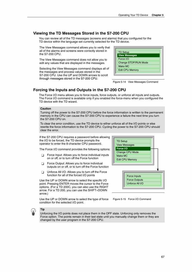
Operating Your TD Device Chapter 5
67
Viewing the TD Messages Stored in the S7-200 CPUYou can review all of the TD messages (screens and alarms) that you configured for theTD device within the language set currently selected for the TD device.
The View Messages command allows you to verify thatall of the alarms and screens were correctly stored inthe S7-200 CPU.
The View Messages command does not allow you toedit any values that are displayed in the messages.
Selecting the View Messages command displays all ofthe messages and process values stored in theS7-200 CPU. Use the UP and DOWN arrows to scrollthrough messages stored in the S7-200 CPU.
TD SetupView MessagesForce I/OChange STOP/RUN Mode
Make MCEdit CPU Memory
through messages stored in the S7 200 CPU.Figure 5-14 View Messages Command
Forcing the Inputs and Outputs in the S7-200 CPUThe Force I/O menu allows you to force inputs, force outputs, or unforce all inputs and outputs.The Force I/O command is available only if you enabled the force-menu when you configured theTD device with the TD wizard.
CautionTurning off the power to the S7-200 CPU before the force information is written to the permanentmemory in the CPU can cause the S7-200 CPU to experience a failure the next time you turnthe S7-200 CPU on.
To clear the error condition, use the TD device to either unforce all of the I/O points or elserewrite the force information to the S7-200 CPU. Cycling the power to the S7-200 CPU shouldclear the error.
If the S7-200 CPU requires a password before allowingthe I/O to be forced, the TD device prompts theoperator to enter the 8-character CPU password.
The Force I/O command provides the following options:
- Force Input: Allows you to force individual inputson or off, or to turn off the Force function
- Force Output: Allows you to force individualoutputs on or off, or to turn off the Force function
- Unforce All I/O: Allows you to turn off the Forcefunction for all of the forced I/O points
Use the UP or DOWN arrow to select the specific I/Opoint. Pressing ENTER moves the cursor to the Forceoptions. (For a TD 200C, you can also use the RIGHTarrow. For a TD 200, you can use the SHIFT+DOWNarrow.)
TD Setup
View MessagesForce I/OChange CPU ModeMake MC
Edit CPU Memory
Force Inputs
Force OutputsUnforce All I/O
Use the UP or DOWN arrow to select the type of forcecondition for the selected I/O point.
Figure 5-15 Force I/O Command
TipUnforcing the I/O points does not place them in the OFF state. Unforcing only removes theForce option. The points remain in their last state until you manually change them or they arechanged by the user program in the S7-200 CPU.
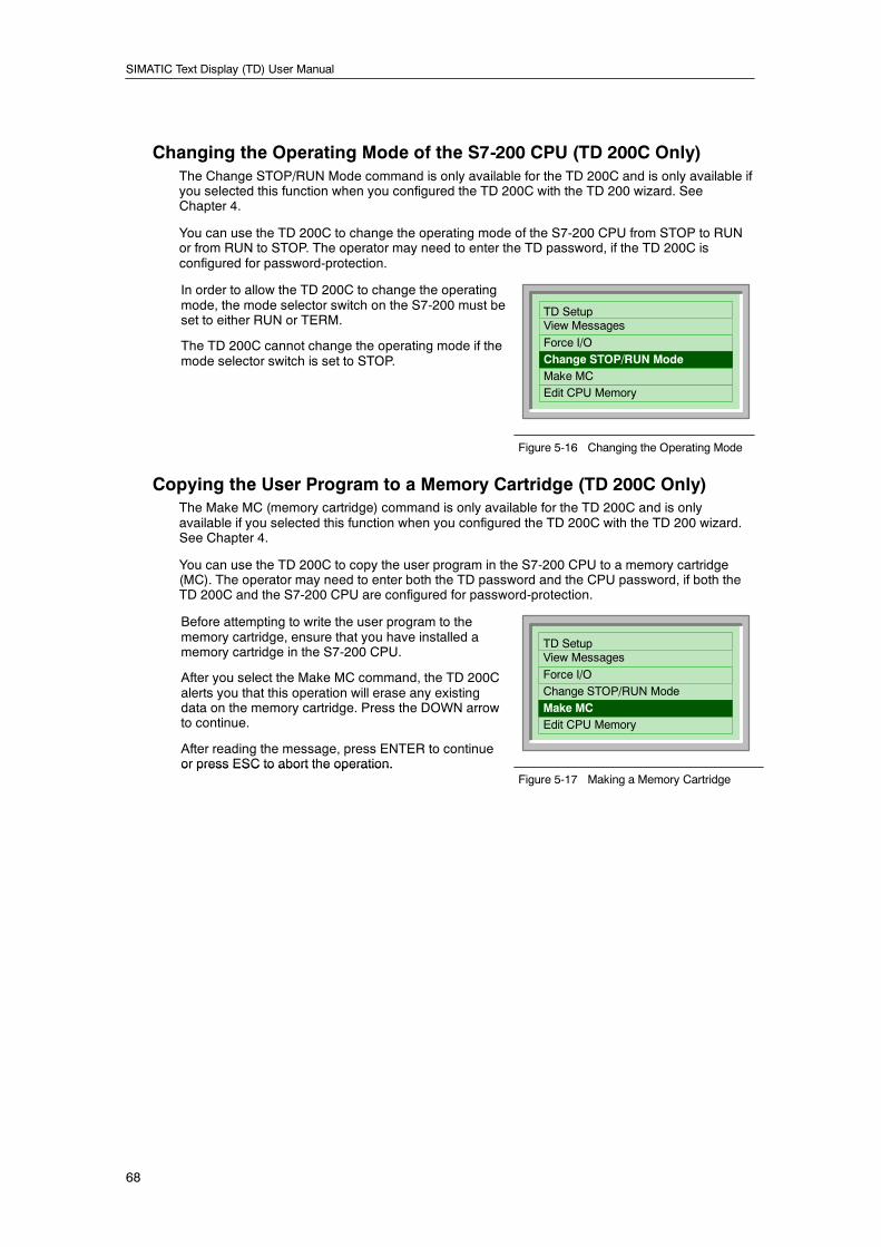
SIMATIC Text Display (TD) User Manual
68
Changing the Operating Mode of the S7-200 CPU (TD 200C Only)The Change STOP/RUN Mode command is only available for the TD 200C and is only available ifyou selected this function when you configured the TD 200C with the TD 200 wizard. SeeChapter 4.
You can use the TD 200C to change the operating mode of the S7-200 CPU from STOP to RUNor from RUN to STOP. The operator may need to enter the TD password, if the TD 200C isconfigured for password-protection.
In order to allow the TD 200C to change the operatingmode, the mode selector switch on the S7-200 must beset to either RUN or TERM.
The TD 200C cannot change the operating mode if themode selector switch is set to STOP.
TD SetupView Messages
Force I/OChange STOP/RUN ModeMake MCEdit CPU Memory
Figure 5-16 Changing the Operating Mode
Copying the User Program to a Memory Cartridge (TD 200C Only)The Make MC (memory cartridge) command is only available for the TD 200C and is onlyavailable if you selected this function when you configured the TD 200C with the TD 200 wizard.See Chapter 4.
You can use the TD 200C to copy the user program in the S7-200 CPU to a memory cartridge(MC). The operator may need to enter both the TD password and the CPU password, if both theTD 200C and the S7-200 CPU are configured for password-protection.
Before attempting to write the user program to thememory cartridge, ensure that you have installed amemory cartridge in the S7-200 CPU.
After you select the Make MC command, the TD 200Calerts you that this operation will erase any existingdata on the memory cartridge. Press the DOWN arrowto continue.
After reading the message, press ENTER to continueor press ESC to abort the operation.
TD SetupView Messages
Force I/OChange STOP/RUN ModeMake MCEdit CPU Memory
or press ESC to abort the operation.Figure 5-17 Making a Memory Cartridge
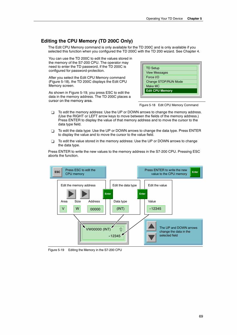
Operating Your TD Device Chapter 5
69
Editing the CPU Memory (TD 200C Only)The Edit CPU Memory command is only available for the TD 200C and is only available if youselected this function when you configured the TD 200C with the TD 200 wizard. See Chapter 4.
You can use the TD 200C to edit the values stored inthe memory of the S7-200 CPU. The operator mayneed to enter the TD password, if the TD 200C isconfigured for password-protection.
After you select the Edit CPU Memory command(Figure 5-18), the TD 200C displays the Edit CPUMemory screen.
As shown in Figure 5-19, you press ESC to edit thedata in the memory address. The TD 200C places acursor on the memory area.
TD SetupView Messages
Force I/OChange STOP/RUN ModeMake MCEdit CPU Memory
cursor on the memory area.Figure 5-18 Edit CPU Memory Command
- To edit the memory address: Use the UP or DOWN arrows to change the memory address.(Use the RIGHT or LEFT arrow keys to move between the fields of the memory address.)Press ENTER to display the value of that memory address and to move the cursor to thedata type field.
- To edit the data type: Use the UP or DOWN arrows to change the data type. Press ENTERto display the value and to move the cursor to the value field.
- To edit the value stored in the memory address: Use the UP or DOWN arrows to changethe data type.
Press ENTER to write the new values to the memory address in the S7-200 CPU. Pressing ESCaborts the function.
VW00000 (INT)
--12345
(INT) --12345V
ESC
Area
W
Size
00000
Address
Edit the memory address Edit the data type
Data type
Edit the value
Value
Enter
The UP and DOWN arrowschange the data in theselected field
Press ESC to edit theCPU memory
Press ENTER to write the newvalue to the CPU memory
Enter Enter
Figure 5-19 Editing the Memory in the S7-200 CPU
SIMATIC Text Display (TD) User Manual
70
Table 5-2 lists the memory address and data types possible. For information about the memoryareas, sizes of the data, and data types supported by your S7-200 CPU, refer to the data sheet foryour CPU model or to the S7-200 Programmable Controller System Manual.
Use the UP and DOWN arrows to scroll through the list of valid entries for each field.
To change the numeric value displayed in the address and value fields:
- Use the UP and DOWN arrows to adjust each digit in the value or address.
- Use the LEFT and RIGHT arrows to move between the digits of the value or address.
- Press ENTER to write the new value to the S7-200 CPU.
TipBinary values cannot be edited.
Table 5-2 Possible Values for the CPU Memory Address and Data Type
Field Description
Memory area V Variable memory area
M Bit Memory area
SM Special Memory area
T Timers Current value only1, INT only
C Counters Current value only1, INT only
I Inputs
Q Outputs
Memory size B (byte)
W (word)
D (double-word)
Address 0 to 32000 (limited by the memory for your S7-200 CPU)
Refer to the S7-200 Programmable Controller System Manual for the range of memorysupported by the different S7-200 CPU models)
Data type INT Integer (valid for Byte, Word or Double-word)
Byte values are displayed as unsigned integersWord and Double-word values are displayed as signed integers
REAL Real or floating-point (valid for Double-word only)
The value displayed for a Real number is rounded to 6 or 7 significant digits. TheTD 200C displays the Real number in fixed-point format only (no scientific notation)
The TD 200C cannot display Real numbers larger than 18 digits and allows up to 7decimal places. (For example: The TD 200C displays 0.00000005 as 0.0000001, anddisplays real numbers less than 0.00000005 as “0.0”.)
The TD 200C writes the number displayed to the S7-200 CPU without rounding.
HEX Hexadecimal (valid for Byte, Word, and Double-word)
BIN Binary (valid for Byte and Word only)
Binary values are displayed in the same pattern (7..0) as discussed in the S7-200Programmable Controller System Manual and displayed by the Status Chart ofSTEP 7--Micro/WIN
Binary values cannot be edited
1 The TD 200C displays only the current value for timers and counters. To display preset values for timers orcounters, you must store these values in V memory. The TD 200C does not display the value of the timer orcounter bit.
71
Technical Specifications andReference Information
In This ChapterGeneral Technical Specifications 72. . . . . . . . . . . . . . . . . . . . . . . . . . . . . . . . . . . . . . . . . . . . . . . . .
Certificates, Directives and Declarations 74. . . . . . . . . . . . . . . . . . . . . . . . . . . . . . . . . . . . . . . . . .
Notes on the CE Symbol 74. . . . . . . . . . . . . . . . . . . . . . . . . . . . . . . . . . . . . . . . . . . . . . . . . . . .
EMC Directive 74. . . . . . . . . . . . . . . . . . . . . . . . . . . . . . . . . . . . . . . . . . . . . . . . . . . . . . . . . . . . .
ATEX Directive (Explosion Protection Guidelines) 74. . . . . . . . . . . . . . . . . . . . . . . . . . . . . .
Declaration of Conformity 74. . . . . . . . . . . . . . . . . . . . . . . . . . . . . . . . . . . . . . . . . . . . . . . . . . .
Observing the Setup Guidelines 74. . . . . . . . . . . . . . . . . . . . . . . . . . . . . . . . . . . . . . . . . . . . .
Approvals for USA, Canada and Australia 75. . . . . . . . . . . . . . . . . . . . . . . . . . . . . . . . . . . . . . . . .
FM Approval Notes 75. . . . . . . . . . . . . . . . . . . . . . . . . . . . . . . . . . . . . . . . . . . . . . . . . . . . . . . .
Standard TD Character Set 76. . . . . . . . . . . . . . . . . . . . . . . . . . . . . . . . . . . . . . . . . . . . . . . . . . . . .
ALT Key Combinations for International and Special Characters 77. . . . . . . . . . . . . . . . . .
Bar Graph Character Set 78. . . . . . . . . . . . . . . . . . . . . . . . . . . . . . . . . . . . . . . . . . . . . . . . . . . .
Arabic Character Set 79. . . . . . . . . . . . . . . . . . . . . . . . . . . . . . . . . . . . . . . . . . . . . . . . . . . . . . . . . . .
Baltic Character Set 80. . . . . . . . . . . . . . . . . . . . . . . . . . . . . . . . . . . . . . . . . . . . . . . . . . . . . . . . . . . .
Simplified Chinese Character Set 81. . . . . . . . . . . . . . . . . . . . . . . . . . . . . . . . . . . . . . . . . . . . . . . .
Notes for Using the Simplified Chinese Character Set 81. . . . . . . . . . . . . . . . . . . . . . . . . . .
Cyrillic Character Set 82. . . . . . . . . . . . . . . . . . . . . . . . . . . . . . . . . . . . . . . . . . . . . . . . . . . . . . . . . . .
Greek Character Set 83. . . . . . . . . . . . . . . . . . . . . . . . . . . . . . . . . . . . . . . . . . . . . . . . . . . . . . . . . . .
Hebrew Character Set 84. . . . . . . . . . . . . . . . . . . . . . . . . . . . . . . . . . . . . . . . . . . . . . . . . . . . . . . . . .
Latin 1 Character Set 85. . . . . . . . . . . . . . . . . . . . . . . . . . . . . . . . . . . . . . . . . . . . . . . . . . . . . . . . . . .
Latin 2 Character Set 86. . . . . . . . . . . . . . . . . . . . . . . . . . . . . . . . . . . . . . . . . . . . . . . . . . . . . . . . . . .
Turkish (Latin 5) Character Set 87. . . . . . . . . . . . . . . . . . . . . . . . . . . . . . . . . . . . . . . . . . . . . . . . . .
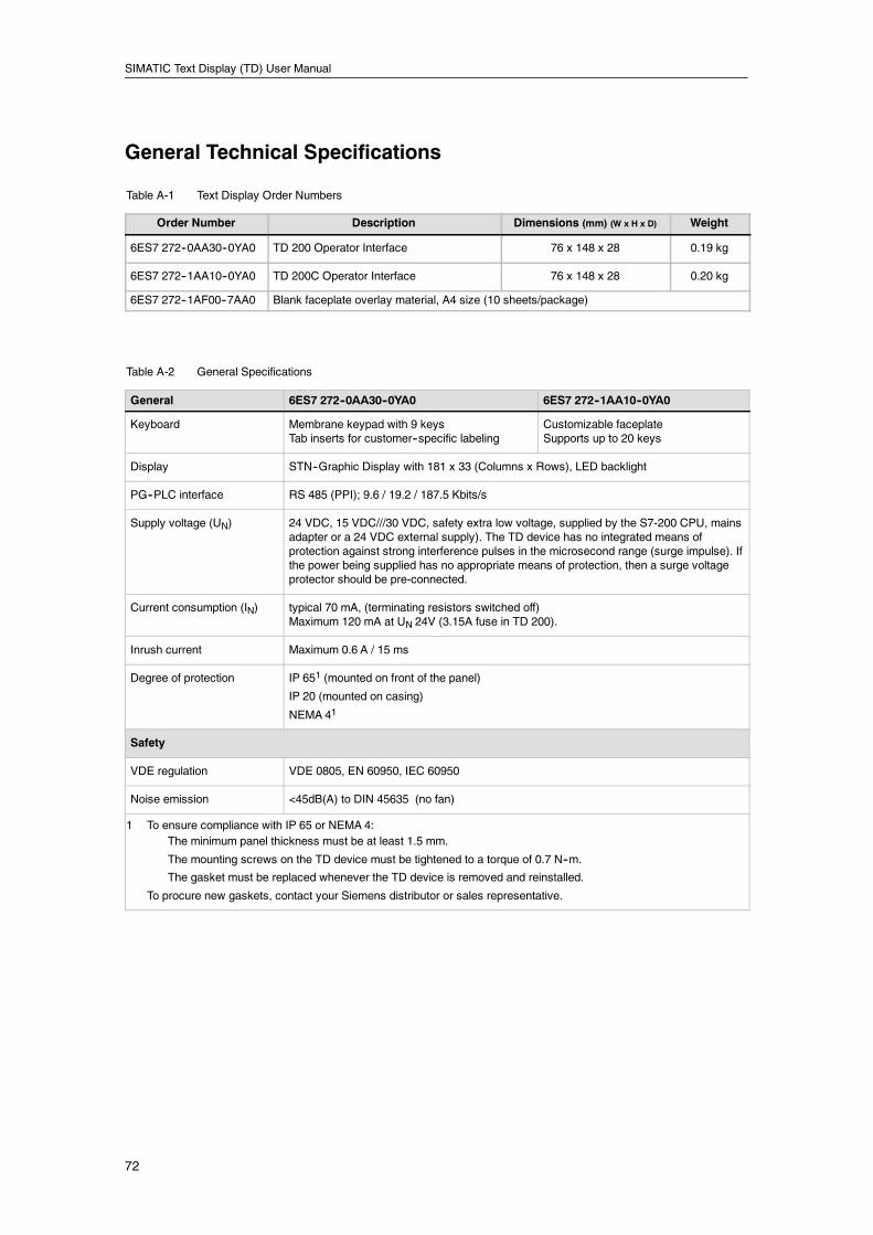
SIMATIC Text Display (TD) User Manual
72
General Technical Specifications
Table A-1 Text Display Order Numbers
Order Number Description Dimensions (mm) (W x H x D) Weight
6ES7 272--0AA30--0YA0 TD 200 Operator Interface 76 x 148 x 28 0.19 kg
6ES7 272--1AA10--0YA0 TD 200C Operator Interface 76 x 148 x 28 0.20 kg
6ES7 272--1AF00--7AA0 Blank faceplate overlay material, A4 size (10 sheets/package)
Table A-2 General Specifications
General 6ES7 272--0AA30--0YA0 6ES7 272--1AA10--0YA0
Keyboard Membrane keypad with 9 keysTab inserts for customer--specific labeling
Customizable faceplateSupports up to 20 keys
Display STN--Graphic Display with 181 x 33 (Columns x Rows), LED backlight
PG--PLC interface RS 485 (PPI); 9.6 / 19.2 / 187.5 Kbits/s
Supply voltage (UN) 24 VDC, 15 VDC///30 VDC, safety extra low voltage, supplied by the S7-200 CPU, mainsadapter or a 24 VDC external supply). The TD device has no integrated means ofprotection against strong interference pulses in the microsecond range (surge impulse). Ifthe power being supplied has no appropriate means of protection, then a surge voltageprotector should be pre-connected.
Current consumption (IN) typical 70 mA, (terminating resistors switched off)Maximum 120 mA at UN 24V (3.15A fuse in TD 200).
Inrush current Maximum 0.6 A / 15 ms
Degree of protection IP 651 (mounted on front of the panel)
IP 20 (mounted on casing)
NEMA 41
Safety
VDE regulation VDE 0805, EN 60950, IEC 60950
Noise emission <45dB(A) to DIN 45635 (no fan)
1 To ensure compliance with IP 65 or NEMA 4:The minimum panel thickness must be at least 1.5 mm.
The mounting screws on the TD device must be tightened to a torque of 0.7 N--m.
The gasket must be replaced whenever the TD device is removed and reinstalled.
To procure new gaskets, contact your Siemens distributor or sales representative.
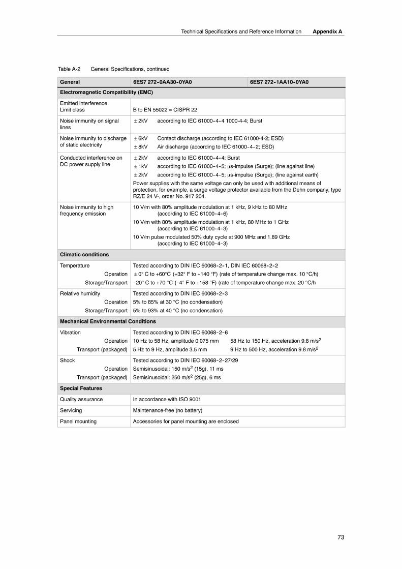
Technical Specifications and Reference Information Appendix A
73
Table A-2 General Specifications, continued
6ES7 272--1AA10--0YA06ES7 272--0AA30--0YA0General
Electromagnetic Compatibility (EMC)
Emitted interferenceLimit class B to EN 55022 = CISPR 22
Noise immunity on signallines
2kV according to IEC 61000--4--4 1000-4-4; Burst
Noise immunity to dischargeof static electricity
6kV Contact discharge (according to IEC 61000-4-2; ESD)
8kV Air discharge (according to IEC 61000--4--2; ESD)
Conducted interference onDC power supply line
2kV according to IEC 61000--4--4; Burst
1kV according to IEC 61000--4--5; µs-impulse (Surge); (line against line)
2kV according to IEC 61000--4--5; µs-impulse (Surge); (line against earth)
Power supplies with the same voltage can only be used with additional means ofprotection, for example, a surge voltage protector available from the Dehn company, typeRZ/E 24 V-, order No. 917 204.
Noise immunity to highfrequency emission
10 V/m with 80% amplitude modulation at 1 kHz, 9 kHz to 80 MHz(according to IEC 61000--4--6)
10 V/m with 80% amplitude modulation at 1 kHz, 80 MHz to 1 GHz(according to IEC 61000--4--3)
10 V/m pulse modulated 50% duty cycle at 900 MHz and 1.89 GHz(according to IEC 61000--4--3)
Climatic conditions
Temperature
Operation
Storage/Transport
Tested according to DIN IEC 60068--2--1, DIN IEC 60068--2--2
0° C to +60°C (+32° F to +140 °F) (rate of temperature change max. 10 °C/h)
--20° C to +70 °C (--4° F to +158 °F) (rate of temperature change max. 20 °C/h
Relative humidity
Operation
Storage/Transport
Tested according to DIN IEC 60068--2--3
5% to 85% at 30 °C (no condensation)
5% to 93% at 40 °C (no condensation)
Mechanical Environmental Conditions
Vibration
Operation
Transport (packaged)
Tested according to DIN IEC 60068--2--6
10 Hz to 58 Hz, amplitude 0.075 mm 58 Hz to 150 Hz, acceleration 9.8 m/s2
5 Hz to 9 Hz, amplitude 3.5 mm 9 Hz to 500 Hz, acceleration 9.8 m/s2
Shock
Operation
Transport (packaged)
Tested according to DIN IEC 60068--2--27/29
Semisinusoidal: 150 m/s2 (15g), 11 ms
Semisinusoidal: 250 m/s2 (25g), 6 ms
Special Features
Quality assurance In accordance with ISO 9001
Servicing Maintenance-free (no battery)
Panel mounting Accessories for panel mounting are enclosed
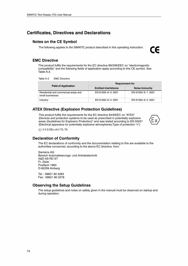
SIMATIC Text Display (TD) User Manual
74
Certificates, Directives and Declarations
Notes on the CE SymbolThe following applies to the SIMATIC product described in this operating instruction:
EMC DirectiveThis product fulfils the requirements for the EC directive 89/336/EEC on “electromagneticcompatibility” and the following fields of application apply according to this CE symbol. SeeTable A-3.
Table A-3 EMC Directive
Field of ApplicationRequirement for
Field of ApplicationEmitted Interfetence Noise Immunity
Residential and commercial areas andsmall businesses
EN 61000--6--3: 2001 EN 61000--6--1: 2001
Industry EN 61000--6--4: 2001 EN 61000--6--2: 2001
ATEX Directive (Explosion Protection Guidelines)This product fulfils the requirements for the EC directive 94/9/EEC on “ATEX”(Devices and protection systems to be used as prescribed in potentially explosiveareas (Guidelines for Explosion Protection)” and was tested according to EN 50021(Electrical apparatus tor potentially explosive atmospheres;Type of protection “n”).
II 3 G EEx nA II T3..T6
Declaration of ConformityThe EC declarations of conformity and the documentation relating to this are available to theauthorities concerned, according to the above EC directive, from:
Siemens AGBereich Automatisierungs- und AntriebstechnikA&D AS RD STFr. ZislerPostfach 1963D-92209 Amberg
Tel.: 09621 80 3283Fax: 09621 80 3278
Observing the Setup GuidelinesThe setup guidelines and notes on safety given in the manual must be observed on startup andduring operation.
Technical Specifications and Reference Information Appendix A
75
Approvals for USA, Canada and AustraliaThe characters stamped on a device are indicative of the requirements which that device meets:
Underwriters Laboratories: cULus Approval, Hazardous Location
CULUS Listed 21BP I.T.E. for Hazardous LocationUnderwrites Laboroatories Inc., according to:
- UL 60950 (Information Technology)
- CSA C22.2 No. 60950 (Information Technology)
- UL 1604 (Hazardous Location)
- CSA--213 (Hazardous Location)
APPROVED for Use in:
- CI. 1, Div.2, GP. A, S, C, D, T5
- CI. 1, Zone 2, GP.IIC, T5
Please see the note below:
Note:This plant has to be mounted according to the NEC (National Electric Code)stipulations.
When used in environments according to class I, division 2 (see above), theSIMATIC TD device must be mounted in a housing that corresponds to atleast IP54 according to EN 60529.
C US
HAZ. LOC.
UL recognition mark
FM approval to Factory Mutual Approval Standard Class Number 3611, Class I,Division 2, Group A, B, C, D, and Class I, Zone 2, Group IIC.Temperature class T5 is adhered to when the ambient temperature duringoperation does not exceed 60°C.
FM
APPROVED
Note for Australia: Our product fulfills the requirements for Norm AS/NZS 3548.
FM Approval NotesFM approval, if present, is to Factory Mutual Approval Standard Class Number 3611, Class I,Division 2, Group A, B, C, D, and Class I, Zone 2, Group IIC.
Temperature class T5 is adhered to when the ambient temperature during operation does notexceed 60°C.
WarningPersonal injury or property damage can result if you do not follow FM hazardous locationguidelines.
In hazardous areas, personal injury or property damage can result if you close or disconnect anelectrical circuit during operation (for example, plug-in connections, fuses, switches).
Do not close or disconnect any live circuits unless explosion hazards can be definitely excluded.Do not disconnect while the circuit is live unless the location is known to be non-hazardous.
WarningWARNING - DO NOT DISCONNECT WHILE CIRCUIT IS LIVE
UNLESS LOCATION IS KNOWN TO BE NON-HAZARDOUS
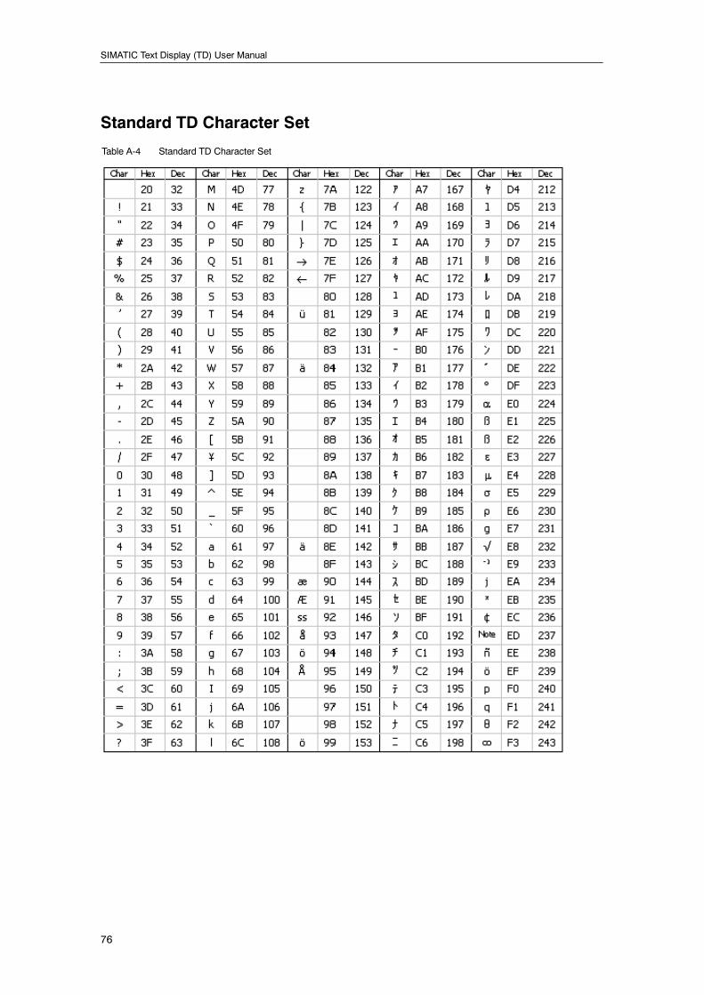
SIMATIC Text Display (TD) User Manual
76
Standard TD Character Set
Table A-4 Standard TD Character Set
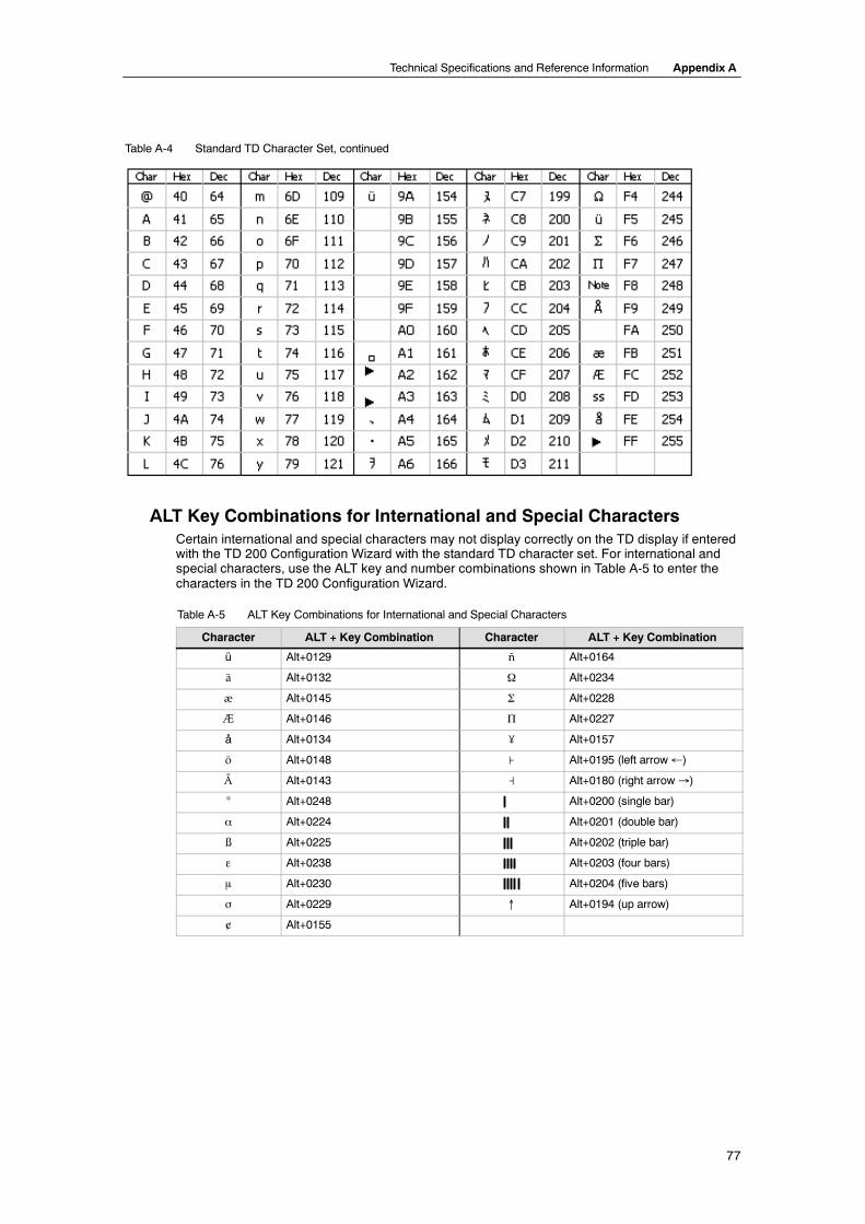
Technical Specifications and Reference Information Appendix A
77
Table A-4 Standard TD Character Set, continued
ALT Key Combinations for International and Special CharactersCertain international and special characters may not display correctly on the TD display if enteredwith the TD 200 Configuration Wizard with the standard TD character set. For international andspecial characters, use the ALT key and number combinations shown in Table A-5 to enter thecharacters in the TD 200 Configuration Wizard.
Table A-5 ALT Key Combinations for International and Special Characters
Character ALT + Key Combination Character ALT + Key Combination
ü Alt+0129 ñ Alt+0164
ä Alt+0132 Ω Alt+0234
æ Alt+0145 Σ Alt+0228
Æ Alt+0146 Π Alt+0227
å Alt+0134 O Alt+0157
ö Alt+0148 ⊦ Alt+0195 (left arrow ←)
Å Alt+0143 Alt+0180 (right arrow →)
° Alt+0248 Alt+0200 (single bar)
α Alt+0224 Alt+0201 (double bar)
ß Alt+0225 Alt+0202 (triple bar)
ε Alt+0238 Alt+0203 (four bars)
m Alt+0230 Alt+0204 (five bars)
σ Alt+0229 ↑ Alt+0194 (up arrow)
¢ Alt+0155
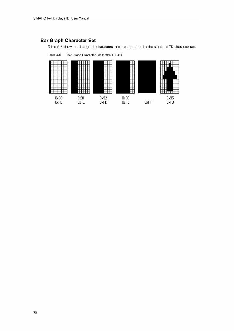
SIMATIC Text Display (TD) User Manual
78
Bar Graph Character SetTable A-6 shows the bar graph characters that are supported by the standard TD character set.
Table A-6 Bar Graph Character Set for the TD 200
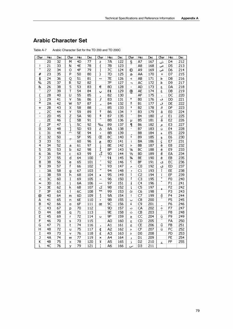
Technical Specifications and Reference Information Appendix A
79
Arabic Character Set
Table A-7 Arabic Character Set for the TD 200 and TD 200C
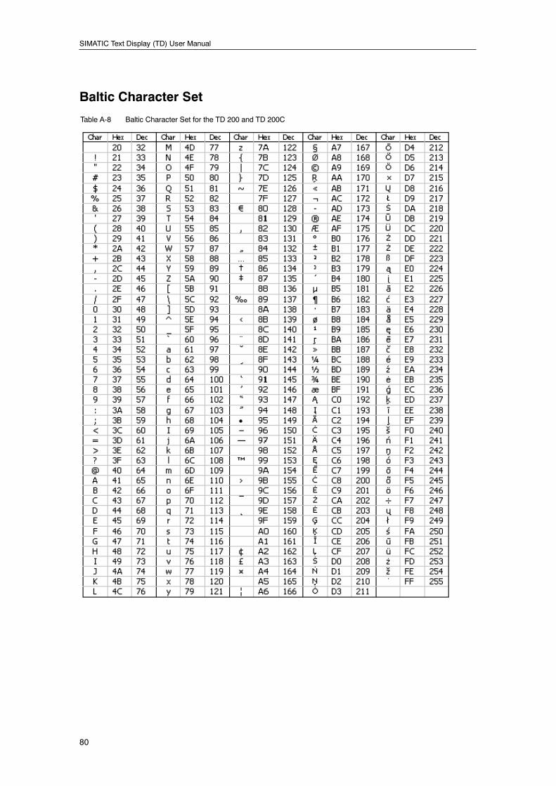
SIMATIC Text Display (TD) User Manual
80
Baltic Character Set
Table A-8 Baltic Character Set for the TD 200 and TD 200C
Technical Specifications and Reference Information Appendix A
81
Simplified Chinese Character SetThe TD 200 supports the Simplified Chinese character set (GB2312--80) for the People’s Republicof China. The TD 200 uses Microsoft Windows encoding for this character set. The Windowsencoding allows the TD 200 to display the same characters as shown in the STEP 7--Micro/WINTD 200 Wizard when you are using a Chinese emulator or a Chinese version of MicrosoftWindows.
Chinese characters are represented in STEP 7--Micro/WIN by a pair of numbers which representthe row and column positions of the character in the GB2312--80 specification. The TD 200 alsouses a pair of numbers to represent the Chinese character.
Notes for Using the Simplified Chinese Character Set
TipThe Simplified Chinese character set requires a Chinese version of Windows or a Chineseemulator to properly display Chinese characters in the TD 200 wizard. You must start theChinese emulator before you start the STEP 7--Micro/WIN software.
You can display up to 20 single-byte characters per line of your message. Because the characterset for Simplified Chinese are double-byte characters, you can display up to 10 double-bytecharacters per line for a message in Chinese.
Some Latin 1 characters are available from the Simplified Chinese character set. Depending onyour keyboard and/ or emulator, the Latin 1 characters may be available in single-byte format orthey may be double-byte characters like the Simplified Chinese characters. If you use a mixture ofsingle-byte and double-byte characters in a message, remember that the space next to asingle-byte character can only be filled by either another single-byte character or an empty space.
The message editor displays 10 double-byte character places. You can fit any of the followingcombinations into a character place:
- 1 double-byte character
- 2 single-byte characters
- 1 single-byte character and 1 single-byte blank
You cannot fit one single-byte character plus one double-byte character in a character place.
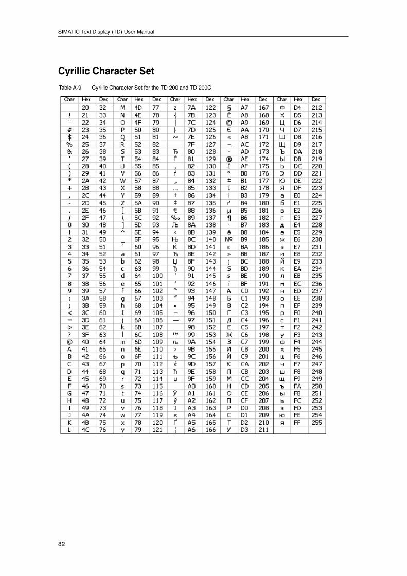
SIMATIC Text Display (TD) User Manual
82
Cyrillic Character Set
Table A-9 Cyrillic Character Set for the TD 200 and TD 200C
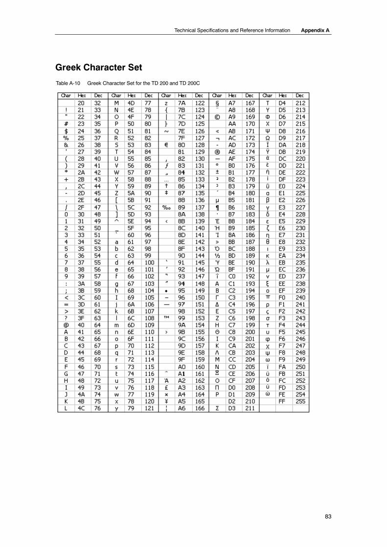
Technical Specifications and Reference Information Appendix A
83
Greek Character Set
Table A-10 Greek Character Set for the TD 200 and TD 200C
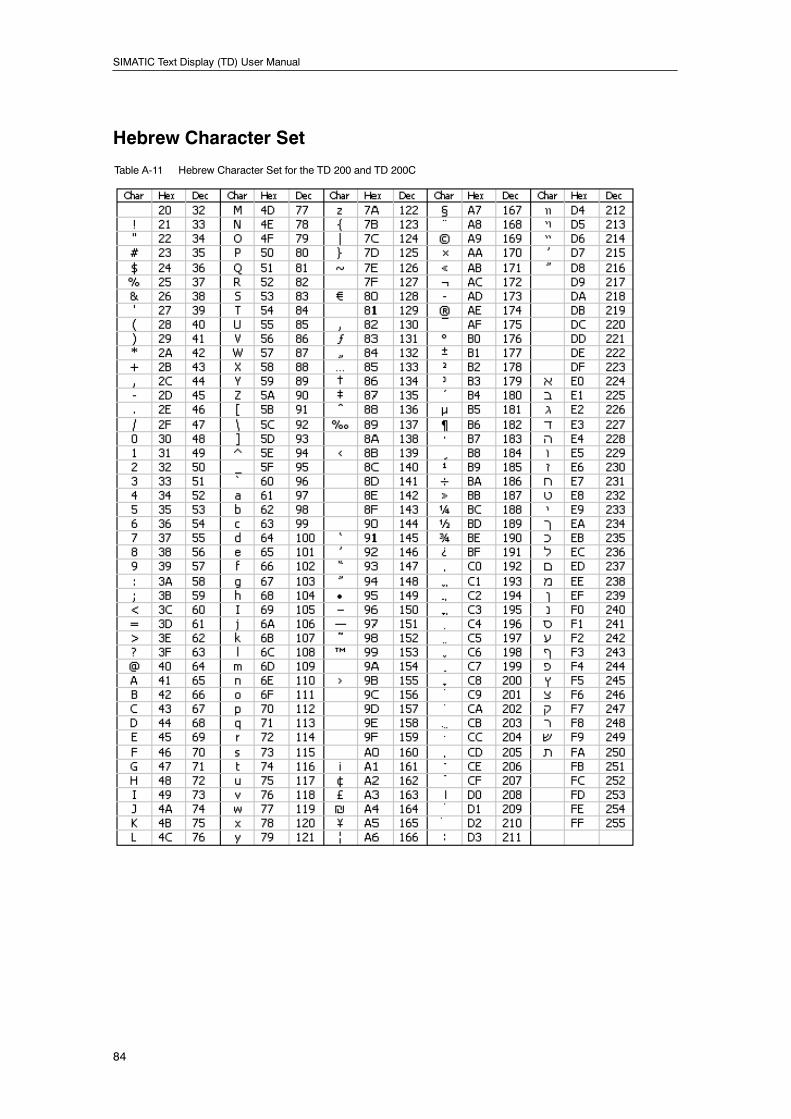
SIMATIC Text Display (TD) User Manual
84
Hebrew Character Set
Table A-11 Hebrew Character Set for the TD 200 and TD 200C
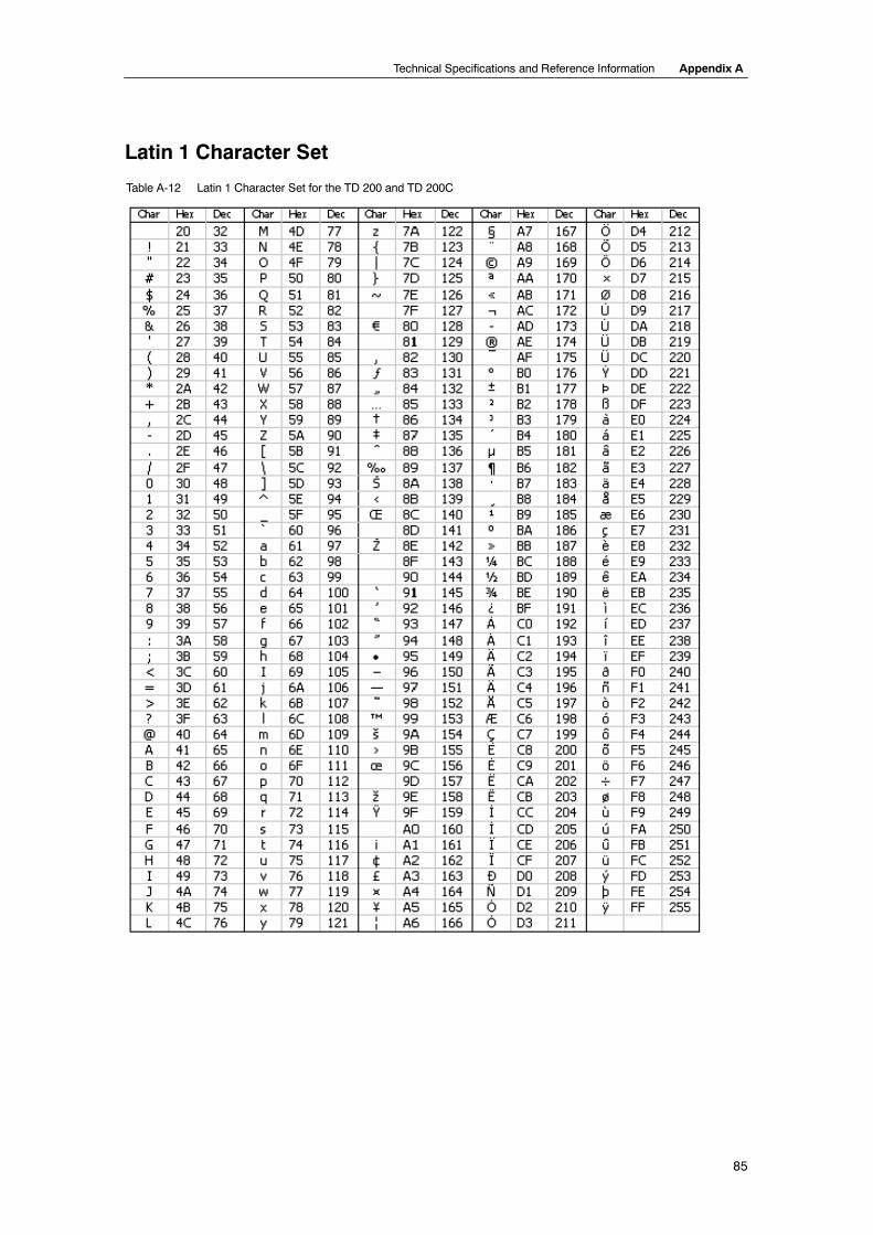
Technical Specifications and Reference Information Appendix A
85
Latin 1 Character Set
Table A-12 Latin 1 Character Set for the TD 200 and TD 200C
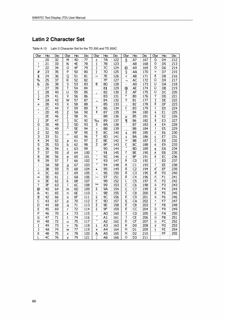
SIMATIC Text Display (TD) User Manual
86
Latin 2 Character Set
Table A-13 Latin 2 Character Set for the TD 200 and TD 200C
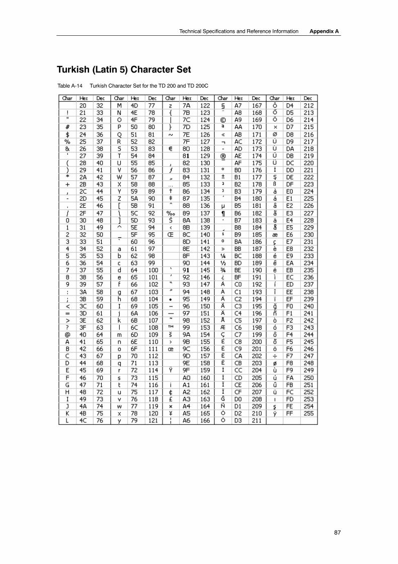
Technical Specifications and Reference Information Appendix A
87
Turkish (Latin 5) Character Set
Table A-14 Turkish Character Set for the TD 200 and TD 200C

SIMATIC Text Display (TD) User Manual
88
89
Connecting Multiple Devices on aNetwork
You can connect multiple TD 200s and S7-200 CPUs together on one communication network.The TD 200 devices act as network masters and do not interfere with each other. You candesignate the S7-200 CPUs to be either masters or slaves on the network.
In This ChapterCommunicating with Multiple CPUs 90. . . . . . . . . . . . . . . . . . . . . . . . . . . . . . . . . . . . . . . . . . . . . . .
Determining the Distances, Transmission Rate, and Cable 91. . . . . . . . . . . . . . . . . . . . . . . . . . .
Using Repeaters on the Network 91. . . . . . . . . . . . . . . . . . . . . . . . . . . . . . . . . . . . . . . . . . . . .
Selecting the Network Cable 92. . . . . . . . . . . . . . . . . . . . . . . . . . . . . . . . . . . . . . . . . . . . . . . .
Biasing and Terminating the Network Cable 92. . . . . . . . . . . . . . . . . . . . . . . . . . . . . . . . . . . .
Building a TD/CPU Cable 93. . . . . . . . . . . . . . . . . . . . . . . . . . . . . . . . . . . . . . . . . . . . . . . . . . . . . . .
Making a Cable That Supplies Power to the TD 200 93. . . . . . . . . . . . . . . . . . . . . . . . . . . .
Making a Cable That Does Not Supply Power to the TD 200 93. . . . . . . . . . . . . . . . . . . . .
CPU Grounding and Circuit Reference Point Guidelines for Using Isolated Circuits 94. . . . . .
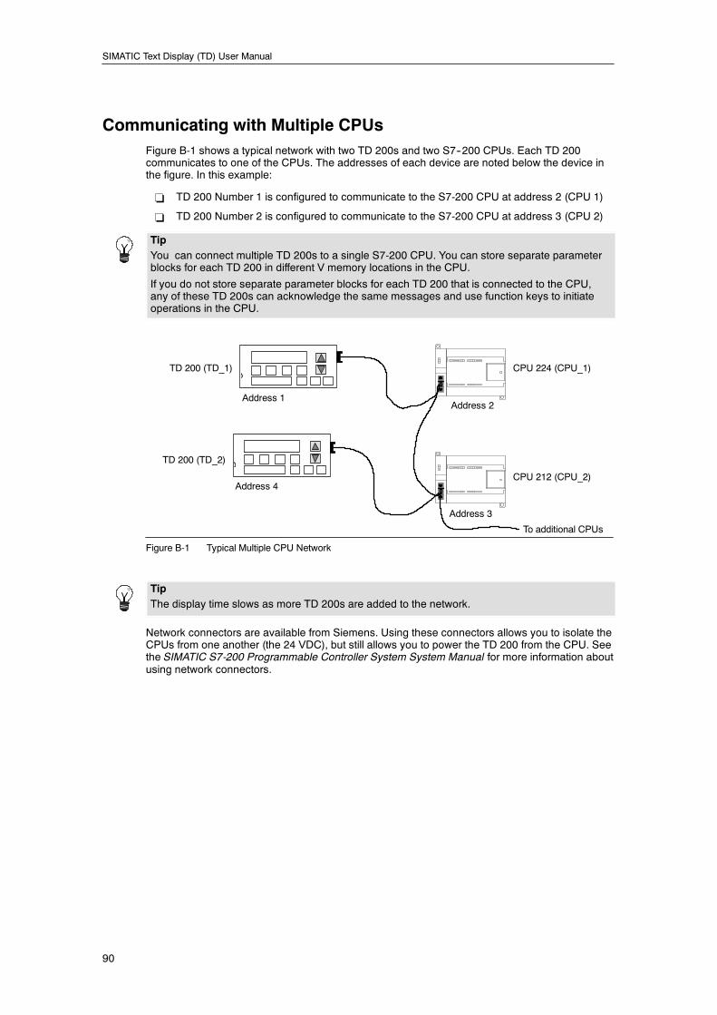
SIMATIC Text Display (TD) User Manual
90
Communicating with Multiple CPUsFigure B-1 shows a typical network with two TD 200s and two S7--200 CPUs. Each TD 200communicates to one of the CPUs. The addresses of each device are noted below the device inthe figure. In this example:
- TD 200 Number 1 is configured to communicate to the S7-200 CPU at address 2 (CPU 1)
- TD 200 Number 2 is configured to communicate to the S7-200 CPU at address 3 (CPU 2)
TipYou can connect multiple TD 200s to a single S7-200 CPU. You can store separate parameterblocks for each TD 200 in different V memory locations in the CPU.
If you do not store separate parameter blocks for each TD 200 that is connected to the CPU,any of these TD 200s can acknowledge the same messages and use function keys to initiateoperations in the CPU.
TD 200 (TD_1) CPU 224 (CPU_1)
TD 200 (TD_2)
CPU 212 (CPU_2)
Address 1
Address 4
Address 2
Address 3
To additional CPUs
Figure B-1 Typical Multiple CPU Network
TipThe display time slows as more TD 200s are added to the network.
Network connectors are available from Siemens. Using these connectors allows you to isolate theCPUs from one another (the 24 VDC), but still allows you to power the TD 200 from the CPU. Seethe SIMATIC S7-200 Programmable Controller System System Manual for more information aboutusing network connectors.
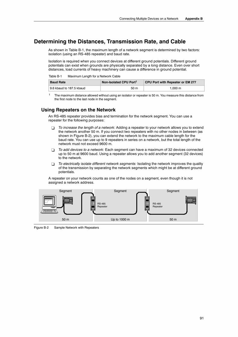
Connecting Multiple Devices on a Network Appendix B
91
Determining the Distances, Transmission Rate, and CableAs shown in Table B-1, the maximum length of a network segment is determined by two factors:isolation (using an RS-485 repeater) and baud rate.
Isolation is required when you connect devices at different ground potentials. Different groundpotentials can exist when grounds are physically separated by a long distance. Even over shortdistances, load currents of heavy machinery can cause a difference in ground potential.
Table B-1 Maximum Length for a Network Cable
Baud Rate Non-Isolated CPU Port1 CPU Port with Repeater or EM 277
9.6 kbaud to 187.5 kbaud 50 m 1,000 m
1 The maximum distance allowed without using an isolator or repeater is 50 m. You measure this distance fromthe first node to the last node in the segment.
Using Repeaters on the NetworkAn RS-485 repeater provides bias and termination for the network segment. You can use arepeater for the following purposes:
- To increase the length of a network: Adding a repeater to your network allows you to extendthe network another 50 m. If you connect two repeaters with no other nodes in between (asshown in Figure B-2), you can extend the network to the maximum cable length for thebaud rate. You can use up to 9 repeaters in series on a network, but the total length of thenetwork must not exceed 9600 m.
- To add devices to a network: Each segment can have a maximum of 32 devices connectedup to 50 m at 9600 baud. Using a repeater allows you to add another segment (32 devices)to the network.
- To electrically isolate different network segments: Isolating the network improves the qualityof the transmission by separating the network segments which might be at different groundpotentials.
A repeater on your network counts as one of the nodes on a segment, even though it is notassigned a network address.
RS-485Repeater
RS-485Repeater
50 m 50 mUp to 1000 m
Segment Segment Segment
Figure B-2 Sample Network with Repeaters
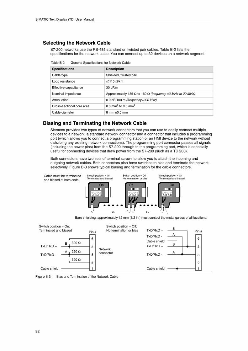
SIMATIC Text Display (TD) User Manual
92
Selecting the Network CableS7-200 networks use the RS-485 standard on twisted pair cables. Table B-2 lists thespecifications for the network cable. You can connect up to 32 devices on a network segment.
Table B-2 General Specifications for Network Cable
Specifications Description
Cable type Shielded, twisted pair
Loop resistance ±115 Ω/km
Effective capacitance 30 pF/m
Nominal impedance Approximately 135 Ω to 160 Ω (frequency =3 MHz to 20 MHz)
Attenuation 0.9 dB/100 m (frequency=200 kHz)
Cross-sectional core area 0.3 mm2 to 0.5 mm2
Cable diameter 8 mm ±0.5 mm
Biasing and Terminating the Network CableSiemens provides two types of network connectors that you can use to easily connect multipledevices to a network: a standard network connector and a connector that includes a programmingport (which allows you to connect a programming station or an HMI device to the network withoutdisturbing any existing network connections). The programming port connector passes all signals(including the power pins) from the S7-200 through to the programming port, which is especiallyuseful for connecting devices that draw power from the S7-200 (such as a TD 200).
Both connectors have two sets of terminal screws to allow you to attach the incoming andoutgoing network cables. Both connectors also have switches to bias and terminate the networkselectively. Figure B-3 shows typical biasing and termination for the cable connectors.
A B A B A B A B
On On
A B A B
Off
Switch position = OnTerminated and biased
Switch position = OffNo termination or bias
Switch position = OnTerminated and biased
Cable must be terminatedand biased at both ends.
390 Ω
220 Ω
390 Ω
B
A
TxD/RxD +
TxD/RxD -
Cable shield
6
3
8
5
1
Networkconnector
Pin #
B
A
TxD/RxD +
TxD/RxD -
Cable shield
A
BTxD/RxD +
TxD/RxD -
Cable shield
Bare shielding: approximately 12 mm (1/2 in.) must contact the metal guides of all locations.
6
3
8
5
1
Pin #
Switch position = Off:No termination or bias
Switch position = On:Terminated and biased
Figure B-3 Bias and Termination of the Network Cable
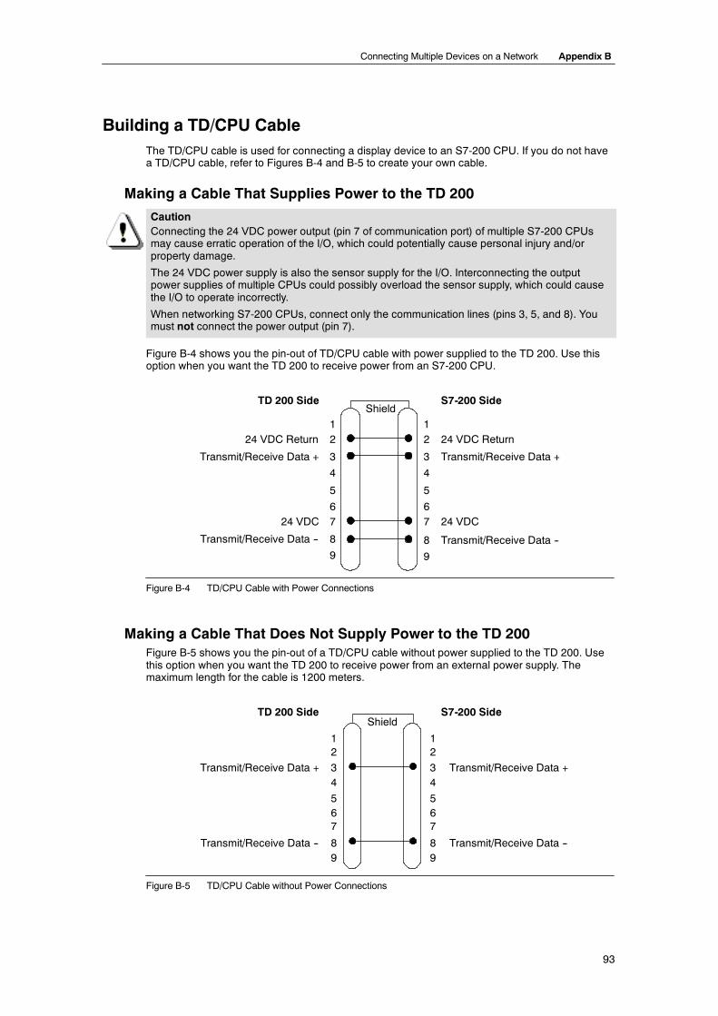
Connecting Multiple Devices on a Network Appendix B
93
Building a TD/CPU CableThe TD/CPU cable is used for connecting a display device to an S7-200 CPU. If you do not havea TD/CPU cable, refer to Figures B-4 and B-5 to create your own cable.
Making a Cable That Supplies Power to the TD 200
CautionConnecting the 24 VDC power output (pin 7 of communication port) of multiple S7-200 CPUsmay cause erratic operation of the I/O, which could potentially cause personal injury and/orproperty damage.
The 24 VDC power supply is also the sensor supply for the I/O. Interconnecting the outputpower supplies of multiple CPUs could possibly overload the sensor supply, which could causethe I/O to operate incorrectly.
When networking S7-200 CPUs, connect only the communication lines (pins 3, 5, and 8). Youmust not connect the power output (pin 7).
Figure B-4 shows you the pin-out of TD/CPU cable with power supplied to the TD 200. Use thisoption when you want the TD 200 to receive power from an S7-200 CPU.
24 VDC Return
Transmit/Receive Data +
24 VDC
Transmit/Receive Data --
24 VDC Return
Transmit/Receive Data +
24 VDC
Transmit/Receive Data --
Shield
12
3
4
5
67
8
9
12
3
4
5
67
8
9
TD 200 Side S7-200 Side
Figure B-4 TD/CPU Cable with Power Connections
Making a Cable That Does Not Supply Power to the TD 200Figure B-5 shows you the pin-out of a TD/CPU cable without power supplied to the TD 200. Usethis option when you want the TD 200 to receive power from an external power supply. Themaximum length for the cable is 1200 meters.
Transmit/Receive Data +
Transmit/Receive Data --
Transmit/Receive Data +
Transmit/Receive Data --
12
34
567
89
TD 200 Side S7-200 Side
12
34
567
89
Shield
Figure B-5 TD/CPU Cable without Power Connections
SIMATIC Text Display (TD) User Manual
94
CPU Grounding and Circuit Reference Point Guidelines forUsing Isolated Circuits
The following items are CPU grounding and circuit guidelines for using isolated circuits:
- You should identify the reference point (0 voltage reference) for each circuit in theinstallation, and the points at which circuits with possibly different references can connecttogether. Such connections can result in unwanted current flows that can cause logic errorsor can damage circuits. A common cause of different reference potentials is grounds thatare physically separated by long distances. When devices with widely separated groundsare connected with a communication or sensor cable, unexpected currents can flowthrough the circuit created by the cable and the ground. Even over short distances, loadcurrents of heavy machinery can cause differences in ground potential or can directlyinduce unwanted currents by electromagnetic induction. Power supplies that are improperlyreferenced with respect to each other can cause damaging currents to flow between theirassociated circuits.
- When you connect CPUs with different ground potentials to the same PPI network, youshould use an isolated RS-485 repeater.
- S7-200 products include isolation boundaries at certain points to help prevent unwantedcurrent flows in your installation. When you plan your installation, you should considerwhere these isolation boundaries are provided, and where they are not provided. Youshould also consider the isolation boundaries in associated power supplies and otherequipment, and where all associated power supplies have their reference points.
- You should choose your ground reference points and use the isolation boundaries providedto interrupt unneeded circuit loops that could allow unwanted currents to flow. Remember toconsider temporary connections which may introduce a new circuit reference, such as theconnection of a programming device to the CPU.
- When locating grounds, you must also consider safety grounding requirements and theproper operation of protective interrupting devices.
- In most installations, you will have the best noise immunity if you connect the CPU sensorsupply M terminal to ground.
The following descriptions are an introduction to general isolation characteristics of the S7-200family, but some features may be different on specific products. Consult your productspecifications in the appropriate manual for information about which circuits include isolationboundaries and the ratings of the boundaries. Isolation boundaries rated less than 1,500 VAC aredesigned as functional isolation only, and should not be depended on as safety boundaries.
- Logic circuit reference is the same as DC sensor supply M.
- Logic circuit reference is the same as the input power supply M on a CPU with DC powersupply.
- CPU communication ports have the same reference as logic circuit.
- Analog inputs and outputs are not isolated from logic circuit. Analog inputs are fulldifferential to provide low voltage common mode rejection.
- Logic circuit is isolated from ground to 500 VAC.
- DC digital inputs and outputs are isolated from logic circuit to 500 VAC.
- DC digital I/O groups are isolated from each other by 500 VAC.
- Relay outputs are isolated from logic circuit to 1,500 VAC.
- Relay output groups are isolated from each other by 1,500 VAC.
- AC power supply line and neutral are isolated from ground, the logic circuit, and all I/O to1,500 VAC.
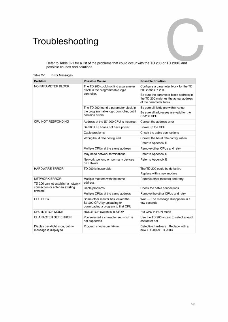
95
Troubleshooting
Refer to Table C-1 for a list of the problems that could occur with the TD 200 or TD 200C andpossible causes and solutions.
Table C-1 Error Messages
Problem Possible Cause Possible Solution
NO PARAMETER BLOCK The TD 200 could not find a parameterblock in the programmable logiccontroller.
Configure a parameter block for the TD200 in the S7-200.
Be sure the parameter block address inthe TD 200 matches the actual addressof the parameter block.
The TD 200 found a parameter block inthe programmable logic controller, but itcontains errors
Be sure all fields are within range
Be sure all addresses are valid for theS7-200 CPU
CPU NOT RESPONDING Address of the S7-200 CPU is incorrect Correct the address error
S7-200 CPU does not have power Power up the CPU
Cable problems Check the cable connections
Wrong baud rate configured Correct the baud rate configuration
Refer to Appendix B
Multiple CPUs at the same address Remove other CPUs and retry
May need network terminations Refer to Appendix B
Network too long or too many deviceson network
Refer to Appendix B
HARDWARE ERROR TD 200 is inoperable The TD 200 could be defective
Replace with a new module
NETWORK ERROR
TD 200 cannot establish a network
Multiple masters with the sameaddress.
Remove other masters and retry
TD 200 cannot establish a networkconnection or enter an existingnetwork
Cable problems Check the cable connectionsnetwork
Multiple CPUs at the same address Remove the other CPUs and retry
CPU BUSY Some other master has locked theS7-200 CPU by uploading ordownloading a program to that CPU
Wait — The message disappears in afew seconds
CPU IN STOP MODE RUN/STOP switch is in STOP Put CPU in RUN mode
CHARACTER SET ERROR You selected a character set which isnot supported
Use the TD 200 wizard to select a validcharacter set
Display backlight is on, but nomessage is displayed
Program checksum failure Defective hardware: Replace with anew TD 200 or TD 200C

SIMATIC Text Display (TD) User Manual
96
97
IndexAAccessing screens and alarms, Button descriptions,
54Acknowledging an alarm, 60
Types of alarms, 46, 61Adhering a custom faceplate, 15, 32Alarms
Accessing the menus, 57Acknowledging, 60Alarm variables, 47, 48Button descriptions, 54Configuring, 45–50Default display mode, 5, 47, 59Description, 5Displaying, 60Displaying alarms, 6Displaying information, 55Editing variables, 56, 62Entering a password, 58Parameter block, 5, 52Priority, 60Releasing a password, 58Types of alarms, 61
Approvals, USA and Canada, for, 75Arabic character set, 79ATEX guidelines, 74
BBaltic character set, 80Bar graph character set, 78Baud rate, 66Baud rates, network, 91Biasing, network cable, 92Button template, 26Buttons
Accessing screens, alarms, and menus, 57Default display mode, 59Descriptions, 54Displaying information, 55Editing variables, 56, 62Keypad Designer
Adding, 23Button template, 26Deleting, 24Erasing, 24Modifying, 23Panel image, 27Properties, 24–26Reversing the panel image, 28
CCable
no power to TD 200, 93to supply power to TD 200, 93
Cable, TD/CPU, creating a pin-out, 93Cables
biasing, 92
network, 91, 92terminating, 92
Cabling, 16CE Symbol, 74Certificates, Directives, Declarations, 74Changing the language set, 65Changing the operating mode of the S7--200 CPU,
68Changing the time and date, 64Character Set Error, troubleshooting, 95Character sets
ALT key combinations, 77Arabic, 79Baltic, 80Bar graph, 78Chinese, 81Cyrillic, 82Greek, 83Hebrew, 84Latin 1, 85Latin 2, 86Turkish (Latin 5), 87
Character sets supported, 3Chinese character set, 81Communication, multiple CPUs, 89Components
Faceplate overlay (TD 200C), 12Gasket, 12Label insert (TD 200), 12Spacers, 12TD/CPU cable, 12
ConfigurationAlarms, 45–50
Types of alarms, 46Default display mode, 47multiple CPUs, 89, 90Multiple language sets, 50–52Parameter block, 5, 52Screens, 41–45
Alarm variables, 47Screen text, 43Screen variables, 43, 48User menu, 42
subroutines, 52Task overview, 7–9, 34–36TD parameters, 36–41
Button functionality, 40Device, 37Enabling CPU functions, 38Keypad configuration file (*.td2), 40Language set (primary), 39Password, 39Update rate, 39
Configuring the properties for the buttons, TD 200Ckeypad, 24–26
Connecting the TD device, 16Contrast of the display area, 66CPU, multiple CPU communication, 90CPU address, 66
SIMATIC Text Display (TD) User Manual
98
CPU Busy, troubleshooting, 95CPU Grounding and Circuit Point Guidelines, 94CPU not responding, troubleshooting, 95Creating a TD/CPU cable, 93Custom cable, 16Custom faceplate
Dimensions, 15Installation procedures, 15, 32Keypad configuration file (*.td2), 21, 28, 40Panel image, 27Reversing the panel image, 28Tasks for creating a custom faceplate, 21Templates, 17
Customer support, v–viiCyrillic character set, 82
DDate and Time for the TD device, 64Declaration of Conformity, 74Default display mode, 5, 59Diagnostic Menu, 65–70
Change Operating Mode, 68Edit CPU memory, 69–71Force I/O, 67Make memory cartridge, 68Setting up the TD device, 66View messages, 67
DimensionsFaceplate (TD 200C), 15Label insert (TD 200), 14TD device, 12
Display backlight, troubleshooting, 95Displaying information, 55
EEditing the CPU memory, 69–71Editing variables, 56, 62EMC Directive, 74Entering a password, 58Error messages, Status of the S7--200 CPU, 63Explosion protection guidelines, 74Exporting
Button Template, 26Panel image, 27
External power supply, 16
FFaceplate
Dimensions (custom faceplate), 15Installing a custom faceplate, 15, 32Keypad configuration file (*.td2), 21, 28, 40Order number, 10Overlay material, 10, 29–32Panel image, 27Reversing the panel image, 28Standard TD keypad, 5, 54Tasks for creating a custom faceplate, 21Template file (A4), 9, 20Templates, 17
Features, 3
Comparing TD devices, 4Order number
Faceplate overlay material, 10, 72TD 200, 72TD 200C, 72
Floating--point numbers, 62FM Approval, 75Forcing I/O, 67
GGap factor, 66Gasket, 12, 13Graphics application
Button template, 26Panel image, 27
Greek character set, 83Guidelines
CPU grounding and circuit reference point, 94setup, 74
HHardware
Order numberFaceplate overlay material, 10, 72TD 200, 72TD 200C, 72
Setting up the TD device, 66Specification, 72Task overview, 7–9
Hardware Error, troubleshooting, 95Hebrew character set, 84Hierarchy of menus, 57Highest station, 66Hotline support, v
IImporting, Panel image, 27Installation
Components, 12Connecting a TD 200C, 17Custom cable, 16Dimensions
Custom faceplate, 15Label insert, 14TD device, 12
Installing a custom faceplate, 15, 32Mounting a TD device, 12–14Order number
Faceplate overlay material, 10, 72TD 200, 72TD 200C, 72
Power (TD/CPU cable), 16Power supply, 16Procedures and guidelines, 11–19Spacers, 13Task overview, 7–9TD/CPU cable, 16
International characters, 77Internet, vIsolated circuits, guidelines, 94
Index
99
Isolationcharacteristics of S7--200 , 94network, 91
KKeypad
Creating a custom keypad, 9, 20Order number for faceplate overlay material, 10Panel image, 27Reversing the panel image, 28Standard TD, 5, 54
Keypad configuration file (*.td2), 21, 22, 28, 40Keypad Designer
ButtonsAdding, 23Button template, 26Deleting, 24Erasing, 24Modifying, 23–25Moving, 23Panel image, 27Properties, 24–26Reversing the panel image, 28
Configuration file (TD 200 wizard), 40Dimensions (custom faceplate), 15Faceplate template file, 9, 20File types, 22Installing a custom faceplate, 15, 32Keypad configuration file (*.td2), 21, 28, 40Options, 22Order number for faceplate material, 10Overview, 9, 20Printer requirements, 10Saving, 28Starting the application, 22Tasks for creating a custom faceplate, 21TD 200 wizard, 34–36Templates, 17Tools (options), 22
KeysAccessing screens, alarms, and menus, 57Button descriptions, 54Button template, 26Displaying information, 55Editing variables, 56, 62Keypad Designer
Adding buttons, 23Deleting buttons, 24Erasing buttons, 24Modifying buttons, 23Properties, 24–26
Panel image, 27Reversing the panel image, 28
LLabel insert (TD 200)
Dimensions, 14Modifying, 14
Language setMultiple, 50–52Primary, 39
Switching langauges, 65Laser printer requirements, 10Latin 1 character set, 85Latin 2 character set, 86
MMaking, cable to supply power to TD 200, 93Making a cable, no power to TD 200, 93Memory cartridge, 68Menus
Accessing the menus, 57Default display mode, 59Diagnostic Menu, 65–70Display Alarms, 60Displaying information, 55Editing variables, 56, 62Hierarchy, 57Operator Menu, 63–66
MessagesAccessing screens, alarms, and menus, 57Displaying information, 55Editing variables, 56, 62
Mounting a TD device, 12–14Spacers, 13
Multiple language sets, 50–52
NNetwork
baud rate, 91biasing cable, 92cable, 91, 92calculating distances, 91isolation, 91repeaters, 91terminating cable, 92transmission rate, 91typical multiple CPU , 90
Network address, 66Network Connectors, 90Network Error, troubleshooting, 95No Parameter Block, troubleshooting, 95
OOperation
Accessing screens, alarms, and menus, 57Changing the language set, 65Changing the operating mode of the S7--200
CPU, 68Displaying information, 55Editing the CPU memory, 69–71Editing variables, 56, 62Forcing I/O, 67Making a memory cartridge, 68Reviewing the configured messages, 67Setting the time and date, 64Setting up the TD device, 66Types of alarms, 61Viewing the status of the S7--200 CPU, 63
OperationsButton descriptions, 54
SIMATIC Text Display (TD) User Manual
100
Overview (screens and alarms), 6Operator Menu, 63–66
Changing the language set, 65Setting the Time and Date, 64View Status of the S7--200 CPU
error messages, 63Firmware version, 63
Order numberFaceplate overlay material, 10, 72TD 200, 72TD 200C, 72
Overlay, Reversing the panel image, 28Overlay material, 10, 29–32
Order number, 10
PPanel image, 27
Reversing for print, 28Parameter block, 5, 7
Configuring the address in the TD device, 66V memory address, 52
PasswordEntering, 58Releasing, 58
Pin-out, TD/CPU cable, 93Power supply, 16Primary language set, 39Printer requirements, 10Printing a custom faceplate, Creating a custom
faceplate, 21Printing multiple faceplates, 10, 29–32
Template file, 9, 20Printing the faceplate, Reversing the panel image,
28Priority of alarms, 60Product overview, 1–10
Backwards compatible, 11Character sets, 3Comparison TD devices, 4Components, 12Creating a custom keypad, 9, 20Description, 2Features, 3Order number
Faceplate overlay material, 10, 72TD 200, 72TD 200C, 72
Printer requirements, 10Standard TD keypads, 5, 54Task overview, 7
PROFIBUS--DP networkcable specifications, 91repeaters, 91
Properties of buttons (TD 200C), 24–26
RReal numbers, 62Releasing a password, 58Repeaters, network, 91Reversing the panel image, 28Reviewing the configured messages, 67
RS--485 standard, 92
SS7--200, general isolation characteristics, 94S7--200 CPU
Changing the operating mode, 68Editing the CPU memory, 69–71Error messages, 63Firmware version, 63Making a memory cartridge, 68Model number, 63Parameter block, 5Supplying power to the TD device, 16
ScreensAccessing the menus, 57Button descriptions, 54Configuring, 41–45Default display mode, 5, 47, 59Displaying information, 55Displaying screens, 6Editing variables, 56, 62Entering a password, 58Overview, 5Parameter block, 5, 52Releasing a password, 58Screen variables, 43Text message, 43User menu, 42
Setting the time and date for the TD device, 64Setup Guidelines, 74Spacers, 13Special characters, 77Specifications, 72–74Standard TD keypad, 17Standard TD keypads, 5, 54STEP 7--Micro/WIN
Keypad configuration file (*.td2), 21, 28, 40Keypad Designer, 2Starting the Keypad Designer, 22Subroutines, 52Task overview, 7–9TD 200 wizard, 2
Alarm variables, 47, 48Alarms, 45–50Default display mode, 47Parameter block, 52Screen text, 43Screen variables, 43Screens, 41–45User menu, 42
Supplying power to the TD device, 16Support, v–viiSwitching the language set, 65
TTD 200
Accessing screens, alarms, and menus, 57Alarms, 5Backwards compatible, 11Changing the language set, 65Character sets, 3
Index
101
Comparing TD devices, 4Components, 12Configuration tasks, 34–36Contrast of the display, 66Default display mode, 59Description, 2Dimensions
Label insert, 14TD 200, 12
Displaying alarms, 6Displaying information, 55Displaying screens, 6Editing variables, 56, 62Entering a password, 58Features, 3, 4Forcing I/O, 67Installation procedures, 11–19Modifying the label insert, 14Mounting instructions, 12–14Multiple language sets, 50–52Order number, TD 200, 72Parameter block, 5Product overview, 1–10Releasing a password, 58Reviewing the configured messages, 67Screens, 5Set time and date, 64Setup, 66Spacers, 13Specification, 72–74Standard TD keypad, 5, 54Supplying power, 16Task overview, 7–9TD parameters, 36–41
Button functionality, 40Device, 37Enabling CPU functions, 38Keypad configuration file (*.td2), 40Language set (primary), 39Password, 39Update rate, 39
TD/CPU cable, 16Types of alarms, 46, 61
TD 200 wizardAlarm variables, 47, 48Alarms, 45–50Default display mode, 47Multiple language sets, 50–52Parameter block, 52Screen text, 43Screen variables, 43Screens, 41–45subroutines, 52Task overview, 34–36TD parameters, 36–41
Button functionality, 40Device, 37Enabling CPU functions, 38Keypad configuration file (*.td2), 40Language set (primary), 39Password, 39Update rate, 39
User menu, 42
TD 200CAccessing screens, alarms, and menus, 57Alarms, 5Backwards compatible, 11Changing the language set, 65Changing the operating mode of the S7--200
CPU, 68Character sets, 3Comparing TD devices, 4Components, 12Configuration tasks, 34–36Contrast of the display, 66Creating a custom keypad, 9, 20Default display mode, 59Description, 2Dimensions, TD 200C, 12Displaying alarms, 6Displaying information, 55Displaying screens, 6Editing the CPU memory, 69–71Editing variables, 56, 62Entering a password, 58Establishing a connection, 17Features, 3, 4Forcing I/O, 67Installation procedures, 11–19Installing a custom faceplate, 15, 32Keypad configuration file (*.td2), 21, 28, 40Making a memory cartridge, 68Mounting instructions, 12–14Multiple Language sets, 50–52Order number
Faceplate overlay material, 10, 72TD 200C, 72
Parameter block, 5Printer requirements, 10Product overview, 1–10Releasing a password, 58Reviewing the configured messages, 67Screens, 5Set time and date, 64Setup, 66Spacers, 13Specifications, 72Standard configuration, 17Standard TD faceplate, 17Standard TD keypad, 5, 54Supplying power, 16Task overview, 7–9Tasks for creating a custom faceplate, 21TD parameters, 36–41
Button functionality, 40Device, 37Enabling CPU functions, 38Keypad configuration file (*.td2), 40Language set (primary), 39Password, 39Update rate, 39
TD/CPU cable, 16Templates, 17Types of alarms, 46, 61
TD/CPU cable, 12, 16creating a pin-out, 93
SIMATIC Text Display (TD) User Manual
102
Technical support, v–viiTemplate for printing multiple faceplates, 9, 20
Printer requirements, 10Templates, Standard TD keypad, 17Terminating, network cable, 92Time and Date for the TD device, 64Transmission rate, network, 91Troubleshooting, TD 200, 95Turkish (Latin 5) character set, 87Types of alarms, 46, 61
UUnforcing I/O, 67
VV memory address for the parameter block, 52Variables, Editing values, 56, 62View status of the S7--200 CPU
Error messages, 63Firmware version, 63
Viewing the configured messages, 67
WWizard
Configuring the alarm variables, 47, 48Configuring the alarms, 45–50Configuring the screen text, 43Configuring the screen variables, 43Configuring the screens, 41–45Configuring the user menu, 42Default display mode, 47Parameter block, 52
Wizard (TD 200 configuration)Multiple language sets, 50–52Task overview, 34–36TD parameters, 36–41
Button functionality, 40Device, 37Enabling CPU functions, 38Keypad configuration file (*.td2), 40Language set (primary), 39Password, 39Update rate, 39
SIMATIC Text Display (TD) User Manual
To
SIEMENS ENERGY & AUTOMATION INC
ATTN: TECHNICAL COMMUNICATIONS
ONE INTERNET PLAZA
PO BOX 4991
JOHNSON CITY TN USA 37602--4991
From
Name: _ _ _ _ _ _ _ _ _ _ _ _ _ _ _ _ _ _ _ _ _ _ _ _ _ _ _ _ _ _ _
Job Title: _ _ _ _ _ _ _ _ _ _ _ _ _ _ _ _ _ _ _ _ _ _ _ _ _ _ _ _ _ _ _
Company Name: _ _ _ _ _ _ _ _ _ _ _ _ _ _ _ _ _ _ _ _ _ _ _ _ _ _ _ _ _ _ _
Street: _ _ _ _ _ _ _ _ _ _ _ _ _ _ _ _ _ _ _ _ _ _ _ _ _ _ _ _ _ _ _
City and State: _ _ _ _ _ _ _ _ _ _ _ _ _ _ _ _ _ _ _ _ _ _ _ _ _ _ _ _ _ _ _
Country: _ _ _ _ _ _ _ _ _ _ _ _ _ _ _ _ _ _ _ _ _ _ _ _ _ _ _ _ _ _ _
Telephone: _ _ _ _ _ _ _ _ _ _ _ _ _ _ _ _ _ _ _ _ _ _ _ _ _ _ _ _ _ _ _
Please check any industry that applies to you:
Automotive
Chemical
Electrical Machinery
Food
Instrument and Control
Non-electrical Machinery
Petrochemical
Pharmaceutical
Plastic
Pulp and Paper
Textiles
Transportation
Other ___________________________
SIMATIC Text Display (TD) User Manual
Additional comments:
_ _ _ _ _ _ _ _ _ _ _ _ _ _ _ _ _ _ _ _ _ _ _ _ _ _ _ _ _ _ _ _ _ _ _ _ _ _ _ _
_ _ _ _ _ _ _ _ _ _ _ _ _ _ _ _ _ _ _ _ _ _ _ _ _ _ _ _ _ _ _ _ _ _ _ _ _ _ _ _
_ _ _ _ _ _ _ _ _ _ _ _ _ _ _ _ _ _ _ _ _ _ _ _ _ _ _ _ _ _ _ _ _ _ _ _ _ _ _ _
_ _ _ _ _ _ _ _ _ _ _ _ _ _ _ _ _ _ _ _ _ _ _ _ _ _ _ _ _ _ _ _ _ _ _ _ _ _ _ _
_ _ _ _ _ _ _ _ _ _ _ _ _ _ _ _ _ _ _ _ _ _ _ _ _ _ _ _ _ _ _ _ _ _ _ _ _ _ _ _
_ _ _ _ _ _ _ _ _ _ _ _ _ _ _ _ _ _ _ _ _ _ _ _ _ _ _ _ _ _ _ _ _ _ _ _ _ _ _ _
_ _ _ _ _ _ _ _ _ _ _ _ _ _ _ _ _ _ _ _ _ _ _ _ _ _ _ _ _ _ _ _ _ _ _ _ _ _ _ _
_ _ _ _ _ _ _ _ _ _ _ _ _ _ _ _ _ _ _ _ _ _ _ _ _ _ _ _ _ _ _ _ _ _ _ _ _ _ _ _
_ _ _ _ _ _ _ _ _ _ _ _ _ _ _ _ _ _ _ _ _ _ _ _ _ _ _ _ _ _ _ _ _ _ _ _ _ _ _ _
_ _ _ _ _ _ _ _ _ _ _ _ _ _ _ _ _ _ _ _ _ _ _ _ _ _ _ _ _ _ _ _ _ _ _ _ _ _ _ _
_ _ _ _ _ _ _ _ _ _ _ _ _ _ _ _ _ _ _ _ _ _ _ _ _ _ _ _ _ _ _ _ _ _ _ _ _ _ _ _
_ _ _ _ _ _ _ _ _ _ _ _ _ _ _ _ _ _ _ _ _ _ _ _ _ _ _ _ _ _ _ _ _ _ _ _ _ _ _ _
_ _ _ _ _ _ _ _ _ _ _ _ _ _ _ _ _ _ _ _ _ _ _ _ _ _ _ _ _ _ _ _ _ _ _ _ _ _ _ _
_ _ _ _ _ _ _ _ _ _ _ _ _ _ _ _ _ _ _ _ _ _ _ _ _ _ _ _ _ _ _ _ _ _ _ _ _ _ _ _
_ _ _ _ _ _ _ _ _ _ _ _ _ _ _ _ _ _ _ _ _ _ _ _ _ _ _ _ _ _ _ _ _ _ _ _ _ _ _ _
_ _ _ _ _ _ _ _ _ _ _ _ _ _ _ _ _ _ _ _ _ _ _ _ _ _ _ _ _ _ _ _ _ _ _ _ _ _ _ _
_ _ _ _ _ _ _ _ _ _ _ _ _ _ _ _ _ _ _ _ _ _ _ _ _ _ _ _ _ _ _ _ _ _ _ _ _ _ _ _
_ _ _ _ _ _ _ _ _ _ _ _ _ _ _ _ _ _ _ _ _ _ _ _ _ _ _ _ _ _ _ _ _ _ _ _ _ _ _ _
_ _ _ _ _ _ _ _ _ _ _ _ _ _ _ _ _ _ _ _ _ _ _ _ _ _ _ _ _ _ _ _ _ _ _ _ _ _ _ _
_ _ _ _ _ _ _ _ _ _ _ _ _ _ _ _ _ _ _ _ _ _ _ _ _ _ _ _ _ _ _ _ _ _ _ _ _ _ _ _
Please give each of the following questions your own personal mark within a range from 1 (verygood) to 5 (very poor).
1. Do the contents meet your requirements?
2. Is the information you need easy to find?
3. Is the text easy to understand?
4. Does the level of technical detail meet your requirements?
5. Please rate the quality of the graphics and tables.
Remarks Form
Your comments and recommendations will help us to improve the quality and usefulness of ourpublications. Please take the first available opportunity to fill out this questionnaire and return itto Siemens.
Related Documents