SIMATIC Route Control (V8.0 SP1) _____________________________________ ___________________ _______________________________________________________ ___________________ ___________________ ___________________ _____________________________________ ___________________ ___________________ ___________________ ___________________ SIMATIC Process Control System PCS 7 SIMATIC Route Control (V8.0 SP1) Programming and Operating Manual 12/2012 A5E03709032-02 Welcome 1 Preface 2 What's new? 3 Product Introduction 4 Software update 5 General 6 Important notes 7 Block library 8 Guide to Configuration 9 Configuration in SIMATIC Manager 10 Exporting/Importing with the Route Control Wizard 11 CSV Export/Import 12 Configuring with Route Control Engineering 13 Operator Control and Monitoring 14 Appendix 15

Welcome message from author
This document is posted to help you gain knowledge. Please leave a comment to let me know what you think about it! Share it to your friends and learn new things together.
Transcript
� �SIMATIC Route Control (V8.0 SP1)
___________________
___________________
___________________
___________________
___________________
___________________
___________________
___________________
___________________
___________________
___________________
___________________
___________________
___________________
___________________
SIMATIC
Process Control System PCS 7SIMATIC Route Control (V8.0 SP1)
Programming and Operating Manual
12/2012 A5E03709032-02
Welcome 1
Preface 2
What's new? 3
Product Introduction 4
Software update 5
General 6
Important notes 7
Block library 8
Guide to Configuration 9
Configuration in SIMATIC Manager
10
Exporting/Importing with the Route Control Wizard
11
CSV Export/Import 12
Configuring with Route Control Engineering
13
Operator Control and Monitoring
14
Appendix 15
Siemens AG Industry Sector Postfach 48 48 90026 NÜRNBERG GERMANY
A5E03709032-02 Ⓟ 10/2012 Technical data subject to change
Copyright © Siemens AG 2012. All rights reserved
Legal information Warning notice system
This manual contains notices you have to observe in order to ensure your personal safety, as well as to prevent damage to property. The notices referring to your personal safety are highlighted in the manual by a safety alert symbol, notices referring only to property damage have no safety alert symbol. These notices shown below are graded according to the degree of danger.
DANGER indicates that death or severe personal injury will result if proper precautions are not taken.
WARNING indicates that death or severe personal injury may result if proper precautions are not taken.
CAUTION indicates that minor personal injury can result if proper precautions are not taken.
NOTICE indicates that property damage can result if proper precautions are not taken.
If more than one degree of danger is present, the warning notice representing the highest degree of danger will be used. A notice warning of injury to persons with a safety alert symbol may also include a warning relating to property damage.
Qualified Personnel The product/system described in this documentation may be operated only by personnel qualified for the specific task in accordance with the relevant documentation, in particular its warning notices and safety instructions. Qualified personnel are those who, based on their training and experience, are capable of identifying risks and avoiding potential hazards when working with these products/systems.
Proper use of Siemens products Note the following:
WARNING Siemens products may only be used for the applications described in the catalog and in the relevant technical documentation. If products and components from other manufacturers are used, these must be recommended or approved by Siemens. Proper transport, storage, installation, assembly, commissioning, operation and maintenance are required to ensure that the products operate safely and without any problems. The permissible ambient conditions must be complied with. The information in the relevant documentation must be observed.
Trademarks All names identified by ® are registered trademarks of Siemens AG. The remaining trademarks in this publication may be trademarks whose use by third parties for their own purposes could violate the rights of the owner.
Disclaimer of Liability We have reviewed the contents of this publication to ensure consistency with the hardware and software described. Since variance cannot be precluded entirely, we cannot guarantee full consistency. However, the information in this publication is reviewed regularly and any necessary corrections are included in subsequent editions.
SIMATIC Route Control (V8.0 SP1) Programming and Operating Manual, 12/2012, A5E03709032-02 3
Table of contents
1 Welcome.................................................................................................................................................. 19
2 Preface .................................................................................................................................................... 21
3 What's new? ............................................................................................................................................ 23
3.1 What's new in SIMATIC Route Control V8.0 SP1? .....................................................................23
3.2 What's new in earlier versions? ...................................................................................................25 3.2.1 What's new in SIMATIC Route Control V8.0? .............................................................................25 3.2.2 What's New in SIMATIC Route Control V7.1 SP2?.....................................................................27 3.2.3 What's new in SIMATIC Route Control V7.1 SP1? .....................................................................30 3.2.4 What's New in SIMATIC Route Control V7.1?.............................................................................31 3.2.5 What's new in SIMATIC Route Control V7.0 SP1? .....................................................................32 3.2.6 What's new in SIMATIC Route Control V7.0? .............................................................................36 3.2.7 What's new in SIMATIC Route Control V6.1 SP1 ? ....................................................................41 3.2.8 What's New in SIMATIC Route Control V6.1?.............................................................................44 3.2.9 What's new in SIMATIC Route Control V6.0 SP1 ? ....................................................................47 3.2.10 What's new in SIMATIC Route Control V6.0? .............................................................................48
4 Product Introduction................................................................................................................................. 53
4.1 What is SIMATIC Route Control? ................................................................................................53
4.2 SIMATIC Route Control overview................................................................................................55
4.3 Route Control Components .........................................................................................................56 4.3.1 Component Overview ..................................................................................................................56 4.3.2 Route Control library ....................................................................................................................57 4.3.3 Route Control Wizard...................................................................................................................57 4.3.4 Route Control Engineering...........................................................................................................58 4.3.5 Route Control server....................................................................................................................59 4.3.6 Route Control Center ...................................................................................................................59 4.3.7 Route Control Route Log .............................................................................................................60 4.3.8 Route Control Operator Dialog ....................................................................................................60 4.3.9 PCS 7 OS Web option .................................................................................................................61
4.4 Configuration options ...................................................................................................................62 4.4.1 Client/Server Architecture of Route Control.................................................................................62 4.4.2 Basic Configurations ....................................................................................................................62 4.4.3 Configurations, non-redundant ....................................................................................................64 4.4.4 Configurations, redundant............................................................................................................66
4.5 Installing Route Control................................................................................................................68 4.5.1 Delivery form of Route Control.....................................................................................................68 4.5.2 Readme file with current information ...........................................................................................68 4.5.3 Installing Route Control components...........................................................................................69 4.5.4 Installation requirements..............................................................................................................71 4.5.4.1 ES and server hardware and software ........................................................................................71 4.5.4.2 AS hardware and software...........................................................................................................73 4.5.4.3 Dependence on other components..............................................................................................74
Table of contents
SIMATIC Route Control (V8.0 SP1) 4 Programming and Operating Manual, 12/2012, A5E03709032-02
4.6 Licensing ..................................................................................................................................... 75 4.6.1 Overview of Licensing ................................................................................................................. 75
4.7 User rights................................................................................................................................... 77 4.7.1 Introduction to authorization management.................................................................................. 77 4.7.2 User roles and user rights ........................................................................................................... 78 4.7.3 Defining user rights ..................................................................................................................... 80
5 Software update....................................................................................................................................... 83
5.1 Updating from V8.0 to V8.0 SP1................................................................................................. 83
5.2 Updating from earlier versions .................................................................................................... 84 5.2.1 Updating from V7.1SP2 to V8.0.................................................................................................. 84 5.2.2 Update of V7.1SP1 to V7.1 SP2 ................................................................................................. 86 5.2.3 Updating from V7.1 to V7.1 SP1................................................................................................. 88 5.2.4 Updating from V7.0 to V7.0 SP1................................................................................................. 89 5.2.5 How to update projects from V6.1 SP1 to V7.0 .......................................................................... 91 5.2.6 How to import locations into the PH............................................................................................ 93 5.2.7 Updating in overview................................................................................................................... 94 5.2.8 Updating tasks ............................................................................................................................ 95 5.2.9 Block changes............................................................................................................................. 96 5.2.10 Updating from RCS-based-on-PCS 7 projects ........................................................................... 97 5.2.11 Updating from RCS-based-on-BRAUMAT projects .................................................................... 98 5.2.12 Updating from V6.0 to V6.1....................................................................................................... 100 5.2.13 Updating from V6.1 to V6.1 SP1............................................................................................... 101
6 General.................................................................................................................................................. 105
6.1 S88 terms.................................................................................................................................. 105
6.2 Abbreviations ............................................................................................................................ 106
6.3 Menu commands....................................................................................................................... 110
6.4 Dialog boxes ............................................................................................................................. 111
6.5 Keyboard commands ................................................................................................................ 113
6.6 User Interfaces.......................................................................................................................... 114
6.7 Control commands .................................................................................................................... 115
7 Important notes...................................................................................................................................... 117
7.1 Order of Tasks .......................................................................................................................... 117
7.2 General Information .................................................................................................................. 119 7.2.1 Logon Dialog Box...................................................................................................................... 119 7.2.2 Restriction of the quantity framework........................................................................................ 120 7.2.3 Invalid characters ...................................................................................................................... 121 7.2.4 Route Request via any Mode Table.......................................................................................... 122 7.2.5 Reinstallation of the Route Control Faceplate .......................................................................... 122 7.2.6 Route Control faceplate without Route Control server ............................................................. 123 7.2.7 PCS 7 OS memory reset........................................................................................................... 123 7.2.8 Enabling changes to configuration............................................................................................ 123 7.2.9 Downloading to the Server During an Active Route ................................................................. 124 7.2.10 Online help in the Route Control Center ................................................................................... 124 7.2.11 MES Interface ........................................................................................................................... 124 7.2.12 SIMATIC Route Control and PLCSim ....................................................................................... 125
Table of contents
SIMATIC Route Control (V8.0 SP1) Programming and Operating Manual, 12/2012, A5E03709032-02 5
7.3 Notes on Libraries and Blocks ...................................................................................................126 7.3.1 Installing a new Route Control library ........................................................................................126 7.3.2 Downloading instance data blocks to the AS.............................................................................126 7.3.3 Downloading user blocks to the AS ...........................................................................................127 7.3.4 LOCK input on element blocks ..................................................................................................128
7.4 Notes on Configuration ..............................................................................................................129 7.4.1 Creating a new S7 project for Route Control .............................................................................129 7.4.2 Adapting the block ranges .........................................................................................................129 7.4.3 Optimizing memory requirements in the AS ..............................................................................130 7.4.4 Optimizing the number of PCS 7 OS tags .................................................................................132 7.4.5 SCL compiler error message .....................................................................................................132 7.4.6 Calling RC_IF_SFC (FB 849) - Online Help...............................................................................133 7.4.7 Copying RC_IF_ROUTE route blocks........................................................................................134 7.4.8 BSEND/BRCV and PUT ............................................................................................................134 7.4.9 Run Sequence of Blocks............................................................................................................135 7.4.10 Location as a variant..................................................................................................................135 7.4.11 Chart-in-chart technology...........................................................................................................135 7.4.12 "RC_LOAD" directory on the Route Control Server...................................................................136 7.4.13 Drop-down list box for selecting locations in plant pictures .......................................................137 7.4.14 Compiling the script file for the Route Control Dynamic Wizard................................................139 7.4.15 SIMATIC BATCH and SIMATIC Route Control .........................................................................140
7.5 Notes about the Route Control Wizard ......................................................................................142 7.5.1 Transferring from an S7 project .................................................................................................142 7.5.2 Route Control Wizard Start Requirements ................................................................................143 7.5.3 Industrial Ethernet properties.....................................................................................................144 7.5.4 Computer name and IP address of the Route Control server ...................................................145
7.6 Notes on route configuration......................................................................................................146 7.6.1 Route search basics ..................................................................................................................146 7.6.2 Routes........................................................................................................................................146 7.6.3 Partial routes and VIAs ..............................................................................................................146 7.6.4 Assembly of routes ....................................................................................................................148 7.6.5 Variants in the route search .......................................................................................................151 7.6.6 Route search in theory...............................................................................................................154
8 Block library ........................................................................................................................................... 155
8.1 Classification of Route Control Blocks.......................................................................................155
8.2 General information about block descriptions............................................................................156
8.3 Interface Blocks .........................................................................................................................158 8.3.1 Interface Block Overview ...........................................................................................................158 8.3.2 Routes........................................................................................................................................159 8.3.2.1 RC_IF_ROUTE (FB 800) ...........................................................................................................159 8.3.2.2 RC_IF_ROUTE.QREC_STA ......................................................................................................177 8.3.2.3 RC_IF_ROUTE.QRET_VAL.......................................................................................................178 8.3.2.4 RC_IF_ROUTE.QMAT_DIAG ....................................................................................................182 8.3.2.5 Updating external parameter elements......................................................................................183 8.3.2.6 RC_IF_ROUTE.QDIAG..............................................................................................................184 8.3.2.7 Idle-state monitoring ..................................................................................................................185 8.3.2.8 Example using QRESTPOS and QRPOSERR..........................................................................187 8.3.2.9 Simulated Idle State in RC_IF_ROUTE .....................................................................................188 8.3.2.10 RC_ResPosV5 (FB 815) ............................................................................................................188
Table of contents
SIMATIC Route Control (V8.0 SP1) 6 Programming and Operating Manual, 12/2012, A5E03709032-02
8.3.2.11 RC_IF_ENCODER (FC 800) ..................................................................................................... 189 8.3.2.12 RC_IF_DECODER (FC 801) ..................................................................................................... 191 8.3.3 Control elements ....................................................................................................................... 193 8.3.3.1 RC_IF_VALVE (FB 826)............................................................................................................ 193 8.3.3.2 RC_IF_VAL_MOT (FB 825)....................................................................................................... 198 8.3.3.3 RC_IF_MOTOR (FB 822).......................................................................................................... 203 8.3.3.4 RC_IF_MOT_REV (FB 823) ...................................................................................................... 207 8.3.3.5 RC_IF_MOT_SPED (FB 824).................................................................................................... 212 8.3.3.6 RC_IF_USER_CE (FB 829) ...................................................................................................... 217 8.3.3.7 Activation Bit Assignment.......................................................................................................... 222 8.3.3.8 Feedback Bit Assignment ......................................................................................................... 222 8.3.4 Sensor elements ....................................................................................................................... 223 8.3.4.1 RC_IF_SENSOR (FB 845) ........................................................................................................ 223 8.3.4.2 RC_IF_CONDUCT (FB 846) ..................................................................................................... 226 8.3.4.3 RC_IF_USER_SE (FB 848)....................................................................................................... 230 8.3.5 Parameter elements.................................................................................................................. 233 8.3.5.1 General Information About Parameter Elements...................................................................... 233 8.3.5.2 RC_IF_VOLUME (FC 808)........................................................................................................ 236 8.3.5.3 RC_IF_TIMER (FC 809)............................................................................................................ 237 8.3.5.4 RC_IF_USER_PE (FC 807) ...................................................................................................... 238 8.3.6 Link element.............................................................................................................................. 240 8.3.6.1 RC_IF_LE (FB 828)................................................................................................................... 240 8.3.7 User-defined type...................................................................................................................... 242 8.3.8 Generic user-defined elements................................................................................................. 244 8.3.9 Configuration and Cross-Coupling............................................................................................ 247 8.3.9.1 Block Overview ......................................................................................................................... 247 8.3.9.2 RC_IF_CFG (FB 850)................................................................................................................ 247 8.3.9.3 RC_IF_XC_DIAG (FB 884)........................................................................................................ 254 8.3.9.4 RC_IF_XC_LIFE (FC 884)......................................................................................................... 260 8.3.10 REMOTE blocks........................................................................................................................ 261 8.3.10.1 Overview of REMOTE blocks.................................................................................................... 261 8.3.10.2 Diagnostics................................................................................................................................ 262 8.3.10.3 RC_IF_REMOTE_CE (FB 821)................................................................................................. 263 8.3.10.4 RC_IF_REMOTE_SE (FB 842) ................................................................................................. 266 8.3.10.5 RC_IF_REMOTE_PE (FB 843) ................................................................................................. 269 8.3.10.6 RC_IF_REMOTE_SEND (FB 831)............................................................................................ 273 8.3.10.7 RC_IF_REMOTE_RECV (FB 833)............................................................................................ 276
8.4 Kernel Blocks ............................................................................................................................ 279 8.4.1 Overview of kernel blocks ......................................................................................................... 279 8.4.2 Data Blocks ............................................................................................................................... 279 8.4.2.1 RC_CE_FIELD (DB 99)............................................................................................................. 279 8.4.2.2 RC_CFG (DB 100) .................................................................................................................... 279 8.4.2.3 RC_DATA_TG34_36 (DB 405) ................................................................................................. 279 8.4.2.4 RC_FIFO1 (DB 870).................................................................................................................. 280 8.4.2.5 RC_FIFO1_SE (DB 874) ........................................................................................................... 280 8.4.2.6 RC_FIFO4 (DB 890).................................................................................................................. 280 8.4.2.7 RC_FIFO4_SE (DB 894) ........................................................................................................... 280 8.4.2.8 RC_IDB_SEND_FIFO1 (DB 590).............................................................................................. 280 8.4.2.9 RC_IDB_SEND_FIFO4 (DB 593).............................................................................................. 280 8.4.2.10 RC_LE_FIELD (DB 96) ............................................................................................................. 280 8.4.2.11 RC_PE_FIELD (DB 97) ............................................................................................................. 281 8.4.2.12 RC_REMOTE1..5 (DB 91 to 95) ............................................................................................... 281
Table of contents
SIMATIC Route Control (V8.0 SP1) Programming and Operating Manual, 12/2012, A5E03709032-02 7
8.4.2.13 RC_ROUTE1 (DB 101 to 400) ...................................................................................................281 8.4.2.14 RC_SE_FIELD (DB 98)..............................................................................................................281 8.4.2.15 RC_SYS_DB (DB 10).................................................................................................................281 8.4.2.16 RC_TG34_TG36_DB (DB 404) ..................................................................................................281 8.4.2.17 RC_XC_1 (DB 751)....................................................................................................................282 8.4.2.18 RC_XC_JOB (DB 705)...............................................................................................................282 8.4.2.19 RC_XC_JOB_START (DB 450) .................................................................................................282 8.4.2.20 RC_XC_PCU (DB 704) ..............................................................................................................282 8.4.2.21 RC_XC_PUTX_1..31 (DB 451 to 481) .......................................................................................282 8.4.3 User-defined types.....................................................................................................................283 8.4.3.1 RC_ANY_UDT (UDT 506)..........................................................................................................283 8.4.3.2 RC_CE_FIELD_UDT (UDT 99) ..................................................................................................283 8.4.3.3 RC_EXT_PE_ACTV (UDT 103) .................................................................................................283 8.4.3.4 RC_FIFO__UDT (UDT 121) .......................................................................................................283 8.4.3.5 RC_LE_FIELD_UDT (UDT 96)...................................................................................................283 8.4.3.6 RC_PE_FIELD_UDT (UDT 97) ..................................................................................................283 8.4.3.7 RC_RE_INFO_UDT (UDT 109)..................................................................................................284 8.4.3.8 RC_RE_UDT (UDT 100) ............................................................................................................284 8.4.3.9 RC_REM_CESEPE (UDT 104)..................................................................................................284 8.4.3.10 RC_REQUEST_BUFFER_UDT (UDT 111) ...............................................................................284 8.4.3.11 RC_ROUTE_CFG (UDT 105) ....................................................................................................284 8.4.3.12 RC_ROUTE_CM_UDT (UDT 110) .............................................................................................284 8.4.3.13 RC_ROUTE_TB_UDT (UDT 102) ..............................................................................................284 8.4.3.14 RC_SE_FIELD_UDT (UDT 98) ..................................................................................................285 8.4.3.15 RC_SEPU__UDT (UDT 122) .....................................................................................................285 8.4.3.16 RC_SYS_UDT (UDT 120)..........................................................................................................285 8.4.3.17 RC_XC_JOB_UDT (UDT 705) ...................................................................................................285 8.4.3.18 RC_XC_PCU_UDT (UDT 704)...................................................................................................285 8.4.3.19 RC_XC_PUT_DB_UDT (UDT 452) ............................................................................................285 8.4.3.20 RC_XC_PUT_SD_UDT (UDT 684) ............................................................................................285 8.4.3.21 RC_XC_PUT_UDT (UDT 683) ...................................................................................................286 8.4.3.22 RC_XC_PUTX_UDT (UDT 451).................................................................................................286 8.4.3.23 RC_XC_UDT (UDT 101) ............................................................................................................286 8.4.3.24 RC_XC_AS (UDT 108)...............................................................................................................286 8.4.4 Function Blocks (FC) .................................................................................................................286 8.4.4.1 RC_ATTRIB_PTR (FC 860) .......................................................................................................286 8.4.4.2 RC_DB_AREA_COPY (FC 862) ................................................................................................286 8.4.4.3 RC_FC_COPY (FC 863) ............................................................................................................287 8.4.4.4 RC_FIFO_DEBUG_SEND (FC 891) ..........................................................................................287 8.4.4.5 RC_FIFO_INPUT_FC (FC 890) .................................................................................................287 8.4.4.6 RC_FIFO_SEND (FC 803).........................................................................................................287 8.4.4.7 RC_KERNEL_CALL (FC 804)....................................................................................................287 8.4.4.8 RC_PE_COMMON (FC 810) .....................................................................................................288 8.4.4.9 RC_CALL_KILLER (FC 814)......................................................................................................292 8.4.4.10 RC_LE_DGRAMM (FC 825) ......................................................................................................292 8.4.4.11 RC_LOAD_AR1 (FC 861) ..........................................................................................................292 8.4.4.12 RC_MASTER_CREATE_ERR (FC 851)....................................................................................292 8.4.4.13 RC_MAT (FC 836) .....................................................................................................................292 8.4.4.14 RC_ROUTE_CE_ERR (FC 812) ................................................................................................292 8.4.4.15 RC_ROUTE_PE_DGRAM (FC 822) ..........................................................................................293 8.4.4.16 RC_ROUTE_SE_ERR (FC 813) ................................................................................................293 8.4.4.17 RC_TG34_03 (FC 811) ..............................................................................................................293
Table of contents
SIMATIC Route Control (V8.0 SP1) 8 Programming and Operating Manual, 12/2012, A5E03709032-02
8.4.4.18 RC_UPD_CESEPE (FC 823) .................................................................................................... 293 8.4.4.19 RC_UPD_CESEPE_EX (FC 824) ............................................................................................. 293 8.4.4.20 RC_XC_CALL (FC 805) ............................................................................................................ 293 8.4.4.21 RC_XC_JOB_USER (FC 885) .................................................................................................. 294 8.4.4.22 RC_XC_PUTX_RECV (FC 882)................................................................................................ 294 8.4.4.23 RC_XC_PUTX_SEND (FC 881)................................................................................................ 294 8.4.4.24 RC_XFER_LE (FC 826) ............................................................................................................ 294 8.4.4.25 RC_XFER_MON_FLT (FC 829)................................................................................................ 294 8.4.5 Function Blocks (FB)................................................................................................................. 295 8.4.5.1 RC_CALL_DIAG (FB 851)......................................................................................................... 295 8.4.5.2 RC_CLOCK (FB 899)................................................................................................................ 295 8.4.5.3 RC_MASTER_BUFFER (FB 856)............................................................................................. 295 8.4.5.4 RC_MASTER_FUNC (FB 852) ................................................................................................. 295 8.4.5.5 RC_MASTER_MSG (FB 857) ................................................................................................... 295 8.4.5.6 RC_MASTER_TIMES (FB 859) ................................................................................................ 295 8.4.5.7 RC_MASTER_XC_SND (FB 858)............................................................................................. 296 8.4.5.8 RC_ROUTE (FB 801)................................................................................................................ 296 8.4.5.9 RC_TG_36 (FB 813) ................................................................................................................. 296 8.4.5.10 RC_ROUTE_GET_EXT_PE (FB 818)....................................................................................... 296 8.4.5.11 RC_ROUTE_MAT (FB 819) ...................................................................................................... 296 8.4.5.12 RC_ROUTE_RCE_OFF (FB 804) ............................................................................................. 296 8.4.5.13 RC_ROUTE_RCE_ON (FB 803)............................................................................................... 297 8.4.5.14 RC_ROUTE_STATE_OS (FB 807) ........................................................................................... 297 8.4.5.15 RC_ROUTE_STATES (FB 809)................................................................................................ 297 8.4.5.16 RC_ROUTE_TELEGR (FB 808) ............................................................................................... 297 8.4.5.17 RC_ROUTE_TIME (FB 805) ..................................................................................................... 297 8.4.5.18 RC_ROUTE_XC_PE_ACTV (FB 817)....................................................................................... 297 8.4.5.19 RC_ROUTE_XC_REC (FB 802) ............................................................................................... 298 8.4.5.20 RC_ROUTE_XC_SEND (FB 806)............................................................................................. 298 8.4.5.21 RC_ROUTE_XC_SND_ORDER (FB 816) ................................................................................ 298 8.4.5.22 RC_CE_COMMON (FB 827)..................................................................................................... 298 8.4.5.23 RC_SE_COMMON (FB 847)..................................................................................................... 303 8.4.5.24 RC_ROUTEMASTER (FB 854)................................................................................................. 305 8.4.5.25 RC_ROUTEMASTER_TELE99 (FB 855).................................................................................. 305 8.4.5.26 RC_ROUTEMASTER_TELEGR (FB 853) ................................................................................ 305 8.4.5.27 RC_MASTER_MATERIAL (FB 860) ......................................................................................... 305 8.4.5.28 RC_SEND_FIFO1 (FB 890) ...................................................................................................... 305 8.4.5.29 RC_SEND_FIFO4 (FB 891) ...................................................................................................... 305 8.4.5.30 RC_TG34_TG36 (FB 812) ........................................................................................................ 306 8.4.5.31 RC_TIME_DELTA (FB 879) ...................................................................................................... 306 8.4.5.32 RC_TIME_RCE (FB 810) .......................................................................................................... 306 8.4.5.33 RC_XC_DIAG (FB 897)............................................................................................................. 306 8.4.5.34 RC_XC_FB (FB 880)................................................................................................................. 306 8.4.5.35 RC_XC_INIT (FB 896)............................................................................................................... 306 8.4.5.36 RC_XC_JOB_FB (FB 882) ........................................................................................................ 306 8.4.5.37 RC_XC_JOB_TIME_FB (FB 885) ............................................................................................. 307 8.4.5.38 RC_XC_PCU_FB (FB 881) ....................................................................................................... 307 8.4.5.39 RC_XC_REMOTE_RECV (FB 834) .......................................................................................... 307 8.4.5.40 RC_XC_REMOTE_SEND (FB 832) .......................................................................................... 307 8.4.5.41 RC_XC_STAT_FB (FB 883)...................................................................................................... 307 8.4.5.42 RC_ZTG (FB 895) ..................................................................................................................... 307
Table of contents
SIMATIC Route Control (V8.0 SP1) Programming and Operating Manual, 12/2012, A5E03709032-02 9
9 Guide to Configuration........................................................................................................................... 309
9.1 General ......................................................................................................................................309 9.1.1 Structure of guide sections ........................................................................................................309 9.1.2 Guide to the SIMATIC Route Control Structure.........................................................................310 9.1.3 General information about configuration....................................................................................311 9.1.4 General information about servers and clients ..........................................................................313 9.1.5 General information about the automation system....................................................................315 9.1.6 General information about the user program.............................................................................317 9.1.7 Guide to Setting Up a New Project ............................................................................................318 9.1.8 Guide to Predefined Element Types..........................................................................................320 9.1.9 Guide to External Parameter Elements .....................................................................................321 9.1.10 Guide to material sequences during runtime .............................................................................323 9.1.11 Guidelines on concurrent routes................................................................................................324 9.1.12 Guide to the block icon and faceplate........................................................................................327
9.2 NetPro Examples .......................................................................................................................328 9.2.1 Overview of the configuration in NetPro ....................................................................................328 9.2.2 Configuring with an AS ..............................................................................................................329 9.2.3 Configuring the first of two ASs..................................................................................................330 9.2.4 Configuring the second of two ASs............................................................................................331 9.2.5 Configuring H machines.............................................................................................................332
9.3 SIMATIC Manager .....................................................................................................................333 9.3.1 S7 project ...................................................................................................................................333 9.3.1.1 Route Control applications in HW Config ..................................................................................333 9.3.1.2 Guide to configuring the AS-AS and AS-Server connections....................................................334 9.3.1.3 CFC overview.............................................................................................................................337 9.3.1.4 Guide to CFC charts ..................................................................................................................338 9.3.1.5 Overview of CFC examples .......................................................................................................339 9.3.1.6 Guide to the Route Control SFC type ........................................................................................340 9.3.2 CFC Configuration .....................................................................................................................341 9.3.2.1 Guide to configuration of the automation systems.....................................................................341 9.3.2.2 Guide to CFC configuration of one automation system.............................................................342 9.3.2.3 Guide to CFC configuration of one of multiple automation systems..........................................343 9.3.3 CFC Routes ...............................................................................................................................344 9.3.3.1 Guide to the CFC route..............................................................................................................344 9.3.3.2 Guide to CFC encoder ...............................................................................................................345 9.3.3.3 Guide to CFC decoder ...............................................................................................................346 9.3.4 CFC Control Elements ...............................................................................................................347 9.3.4.1 Guide to the CFC control element .............................................................................................347 9.3.4.2 Guide to CFC motor with two statuses ......................................................................................348 9.3.4.3 Guide to CFC motor with two statuses with no feedback ..........................................................349 9.3.4.4 Guide to CFC motor with interlocking block...............................................................................350 9.3.4.5 Guide to CFC dual-speed motor ................................................................................................351 9.3.4.6 Guide to CFC bidirectional motor...............................................................................................352 9.3.4.7 Guide to CFC valve with feedback.............................................................................................353 9.3.4.8 Guide to CFC valve with dual feedback signals ........................................................................354 9.3.4.9 Guide to CFC valve with interlocking block ...............................................................................355 9.3.4.10 Guide to CFC valve with no feedback signal .............................................................................356 9.3.4.11 Guide to CFC motor-actuated valve ..........................................................................................357 9.3.4.12 Route Control and the Advanced Process Library (APL) ..........................................................358
Table of contents
SIMATIC Route Control (V8.0 SP1) 10 Programming and Operating Manual, 12/2012, A5E03709032-02
9.3.5 CFC Sensor Elements .............................................................................................................. 359 9.3.5.1 Guide to CFC sensor element .................................................................................................. 359 9.3.5.2 Guide to CFC Sensor, Binary ................................................................................................... 360 9.3.5.3 Guide to CFC conductivity ........................................................................................................ 360 9.3.6 CFC Parameter Element........................................................................................................... 361 9.3.6.1 Guide to CFC parameter element............................................................................................. 361 9.3.7 CFC Link Element ..................................................................................................................... 361 9.3.7.1 Guide to the CFC link element.................................................................................................. 361 9.3.8 REMOTE Elements................................................................................................................... 362 9.3.8.1 CFC Charts with REMOTE Elements ....................................................................................... 362 9.3.8.2 S7 connection of a local AS in NetPro ...................................................................................... 365 9.3.8.3 S7 connection for a peer AS in NetPro ..................................................................................... 365 9.3.8.4 Configuring REMOTE Elements ............................................................................................... 366 9.3.8.5 REMOTE elements in the CFC chart of a local AS .................................................................. 370 9.3.8.6 REMOTE elements in the CFC chart of a peer AS................................................................... 371 9.3.9 Route Control SFC.................................................................................................................... 372 9.3.9.1 SFC overview............................................................................................................................ 372 9.3.9.2 Relationship of SFC and route with operator dialogs ............................................................... 373 9.3.9.3 SFC block schematic ................................................................................................................ 374 9.3.9.4 S88 status ................................................................................................................................. 375 9.3.9.5 Start conditions for HOLDING in SFC....................................................................................... 375 9.3.9.6 SFC mode levels....................................................................................................................... 376 9.3.9.7 SFC editor ................................................................................................................................. 377 9.3.9.8 Full Interconnection of the SFC block ....................................................................................... 377 9.3.10 Dynamic ID Assignment............................................................................................................ 378 9.3.10.1 Guide to Dynamic ID Assignment ............................................................................................. 378 9.3.10.2 Example for Dynamic ID Assignment ....................................................................................... 381
9.4 Route Control Wizard................................................................................................................ 382 9.4.1 Guide to the Route Control Wizard ........................................................................................... 382 9.4.2 Guide to exporting an S7 project .............................................................................................. 384 9.4.3 Guide to exporting linking configuration from NetPro ............................................................... 385
9.5 Route Control Engineering........................................................................................................ 387 9.5.1 Guide to Route Control Engineering ......................................................................................... 387 9.5.2 Guide to the offline route search............................................................................................... 389 9.5.3 Guide to the cross-reference list of elements ........................................................................... 394 9.5.4 Guide to the CSV interface ....................................................................................................... 394
9.6 Route Control server ................................................................................................................. 395 9.6.1 Guide to the Route Control Server............................................................................................ 395 9.6.2 Guide to Starting up the Route Control System........................................................................ 397 9.6.3 Settings for redundant Route Control servers........................................................................... 399
Table of contents
SIMATIC Route Control (V8.0 SP1) Programming and Operating Manual, 12/2012, A5E03709032-02 11
10 Configuration in SIMATIC Manager ....................................................................................................... 401
10.1 General ......................................................................................................................................401 10.1.1 Overview of configuration ..........................................................................................................401 10.1.2 Adding projects to a multiproject................................................................................................403 10.1.3 Communication with H-machines ..............................................................................................405 10.1.4 Run sequence of Route Control blocks .....................................................................................406 10.1.5 Configuring the Route Control Server........................................................................................406
10.2 Configuration in CFC .................................................................................................................409 10.2.1 How to Adapt the Block Ranges ................................................................................................409 10.2.2 Engineering the AS Configuration in CFC .................................................................................411 10.2.3 Configuring routes in CFC .........................................................................................................411 10.2.4 Configuring elements in CFC.....................................................................................................412 10.2.5 Configuring user-defined element types ....................................................................................412
10.3 PC stations.................................................................................................................................413 10.3.1 Hardware configuration HW Config ...........................................................................................413 10.3.2 Route Control application properties .........................................................................................415 10.3.3 Route Control application...........................................................................................................415 10.3.4 Route Control application (stby).................................................................................................415 10.3.5 Route Control application client .................................................................................................416 10.3.6 Station Configuration Editor .......................................................................................................417
10.4 Route Control Objects................................................................................................................418 10.4.1 Creating Route Control Objects .................................................................................................418 10.4.2 Route Control object properties .................................................................................................418 10.4.3 Route Control object in the project folder ..................................................................................419 10.4.4 Route Control object in the RC application client ......................................................................419
10.5 Options Menu in SIMATIC Manager..........................................................................................420 10.5.1 SIMATIC Route Control .............................................................................................................420 10.5.2 SIMATIC Route Control Wizard.................................................................................................420 10.5.3 SIMATIC Route Control Show Wizard Log................................................................................420 10.5.4 SIMATIC Route Control Engineering.........................................................................................421 10.5.5 Import/Export of SIMATIC Route Control Equipment Properties...............................................421
10.6 Locations....................................................................................................................................422 10.6.1 Locations....................................................................................................................................422 10.6.2 Number ranges ..........................................................................................................................429 10.6.3 Configuring the locations ...........................................................................................................431 10.6.4 How to configure location types.................................................................................................432 10.6.5 How to configure locations.........................................................................................................434 10.6.6 Mass configuration of locations via exporting and importing .....................................................436
10.7 Route Control Dynamic Wizard..................................................................................................439 10.7.1 Overview of Route Control Block Icon Interconnection .............................................................439 10.7.2 How to Copy the Route Control Block Icon ...............................................................................440 10.7.3 How to Start the Dynamic Wizard..............................................................................................441 10.7.4 How to Select a Route Instance.................................................................................................442 10.7.5 How to Select an SFC Block......................................................................................................444 10.7.6 Summary in Dynamic Wizard.....................................................................................................446
Table of contents
SIMATIC Route Control (V8.0 SP1) 12 Programming and Operating Manual, 12/2012, A5E03709032-02
11 Exporting/Importing with the Route Control Wizard ............................................................................... 447
11.1 Transferring Data from an S7 Project ....................................................................................... 447
11.2 Synchronizing Objects .............................................................................................................. 448
11.3 Deleting Used Elements............................................................................................................ 450
11.4 Actions in the Route Control Wizard ......................................................................................... 451
11.5 Selecting Actions in the Route Control Wizard ......................................................................... 453
11.6 Selection of the PCS 7 OS Message Server ............................................................................ 454
11.7 Selecting Objects to be Exported.............................................................................................. 455
11.8 Adapt IDs of Routes .................................................................................................................. 457
11.9 Summary of the Actions ............................................................................................................ 459
11.10 Result of the Actions ................................................................................................................. 461
11.11 Log ............................................................................................................................................ 463
12 CSV Export/Import................................................................................................................................. 465
12.1 CSV Interface Overview............................................................................................................ 465
12.2 Initial Step.................................................................................................................................. 468
12.3 Global Settings.......................................................................................................................... 470
12.4 Selecting Objects ...................................................................................................................... 472
12.5 Summary................................................................................................................................... 474
12.6 Result ........................................................................................................................................ 475
12.7 Log File...................................................................................................................................... 477
12.8 CSV Interface Export Log ......................................................................................................... 479
12.9 CSV Interface Import Log.......................................................................................................... 481
12.10 CSV File Structure .................................................................................................................... 483
12.11 Error Messages......................................................................................................................... 491
13 Configuring with Route Control Engineering .......................................................................................... 493
13.1 Process cells, units and locations ............................................................................................. 493
13.2 Getting Started .......................................................................................................................... 494 13.2.1 Starting Route Control Engineering .......................................................................................... 494 13.2.2 Route Control Engineering main view....................................................................................... 495 13.2.3 Route Control Engineering menu.............................................................................................. 499 13.2.4 Creating a new Route Control project....................................................................................... 502 13.2.5 Saving a Route Control Project................................................................................................. 503 13.2.6 Converting a Route Control Project .......................................................................................... 504 13.2.7 How to print out the configuration of elements and partial routes ............................................ 506
13.3 Global Project Settings.............................................................................................................. 507 13.3.1 Overview of project settings...................................................................................................... 507 13.3.2 Attribute properties.................................................................................................................... 508 13.3.3 Runtime Parameter Properties ................................................................................................. 509 13.3.4 Runtime parameters.................................................................................................................. 510
Table of contents
SIMATIC Route Control (V8.0 SP1) Programming and Operating Manual, 12/2012, A5E03709032-02 13
13.3.4.1 Overview of Runtime Parameters..............................................................................................510 13.3.4.2 "General" folder..........................................................................................................................510 13.3.4.3 "Material" folder..........................................................................................................................512 13.3.4.4 "Rules for the route algorithm functions" folder .........................................................................513 13.3.4.5 "Route log" folder .......................................................................................................................514 13.3.4.6 "Monitoring" folder......................................................................................................................515 13.3.4.7 Downloading settings to the server............................................................................................516
13.4 Notes..........................................................................................................................................517 13.4.1 Monitoring the server and AS ....................................................................................................517 13.4.2 Directory Sharing in the Route Log............................................................................................518 13.4.3 Notes on maintenance ...............................................................................................................519
13.5 General Information About Objects ...........................................................................................521 13.5.1 Locations....................................................................................................................................521 13.5.2 Location properties ....................................................................................................................521 13.5.3 Location type..............................................................................................................................522 13.5.4 Partial routes..............................................................................................................................522 13.5.5 Routes........................................................................................................................................522 13.5.6 Predefined routes.......................................................................................................................522 13.5.7 Mode tables................................................................................................................................523 13.5.8 Mode levels ................................................................................................................................523 13.5.9 Automatic generation of elements .............................................................................................524 13.5.10 Creating Elements .....................................................................................................................524 13.5.11 How to Delete Elements ............................................................................................................525 13.5.12 Element subtypes ......................................................................................................................525
13.6 Mode table .................................................................................................................................526 13.6.1 How to Configure Mode Tables .................................................................................................526 13.6.2 Mode Table Properties...............................................................................................................527
13.7 Mode levels ................................................................................................................................528 13.7.1 How to Configure Mode Levels..................................................................................................528 13.7.2 Mode Level Properties ...............................................................................................................530
13.8 Partial routes..............................................................................................................................531 13.8.1 How to Configure Partial Routes................................................................................................531 13.8.2 Partial Route Properties.............................................................................................................533
13.9 Static routes ...............................................................................................................................535 13.9.1 How to use static routes.............................................................................................................535 13.9.2 Save route..................................................................................................................................538 13.9.3 Start a saved route.....................................................................................................................540
13.10 Elements ....................................................................................................................................541 13.10.1 How to Insert an Element in a Partial Route..............................................................................541 13.10.2 How to Configure Activation of Elements ..................................................................................542 13.10.3 Meanings of Activation Key Symbols.........................................................................................544 13.10.4 How to Change the Activation Key Symbols .............................................................................545 13.10.5 How to Create User Keys ..........................................................................................................546 13.10.6 How to Delete User Keys...........................................................................................................548 13.10.7 Control elements........................................................................................................................549 13.10.7.1 Control Element Properties...................................................................................................549 13.10.7.2 Activation of control elements...............................................................................................551 13.10.7.3 Control Elements Cross-reference List.................................................................................553 13.10.7.4 Route Control Element Properties ........................................................................................555
Table of contents
SIMATIC Route Control (V8.0 SP1) 14 Programming and Operating Manual, 12/2012, A5E03709032-02
13.10.8 Sensor elements ....................................................................................................................... 557 13.10.8.1 Activation of Sensor Elements ............................................................................................. 557 13.10.8.2 Sensor Elements Cross-reference List ................................................................................ 558 13.10.8.3 Route Sensor Element Properties ....................................................................................... 559 13.10.9 Parameter Elements ................................................................................................................. 560 13.10.9.1 Parameter element subtypes ............................................................................................... 560 13.10.9.2 Parameter Element Properties............................................................................................. 560 13.10.9.3 Parameter element types..................................................................................................... 562 13.10.9.4 Parameter Elements Cross-reference List........................................................................... 563 13.10.9.5 Route parameter element properties ................................................................................... 563 13.10.10 Link elements ............................................................................................................................ 565 13.10.10.1 Properties of link elements and route connection elements ................................................ 565 13.10.10.2 Link Elements Cross-reference List ..................................................................................... 565 13.10.11 Wait elements ........................................................................................................................... 565 13.10.11.1 Wait element ........................................................................................................................ 565 13.10.11.2 Configure wait element ........................................................................................................ 567 13.10.11.3 Change the processing sequence with wait elements......................................................... 568 13.10.11.4 Activation sequence............................................................................................................. 571 13.10.11.5 Deactivation sequence......................................................................................................... 572 13.10.11.6 Configuring a deactivation sequence of a partial route........................................................ 575 13.10.11.7 Inserting or deleting wait elements ...................................................................................... 575 13.10.11.8 Copying or deleting deactivation sequences ....................................................................... 576 13.10.11.9 Invert activation or deactivation sequence........................................................................... 576 13.10.11.10 CSV export/import................................................................................................................ 577 13.10.11.11 Pulse mode .......................................................................................................................... 579
13.11 Entering and Changing Parameter Values ............................................................................... 583 13.11.1 Function ID Properties .............................................................................................................. 583
13.12 Materials.................................................................................................................................... 585 13.12.1 Overview of Materials................................................................................................................ 585 13.12.2 Material sequence diagram for RC_IF_ROUTE........................................................................ 586 13.12.3 Configuring Materials and Material Groups .............................................................................. 587 13.12.4 How to Assign Materials to a Material Group............................................................................ 588 13.12.5 Configuring Material Sequences............................................................................................... 588 13.12.6 How to Specify Successors for a Material ................................................................................ 591 13.12.7 How to Specify Successors for a Material Group ..................................................................... 591 13.12.8 How to Import Materials ............................................................................................................ 592
13.13 External Material Interface ........................................................................................................ 593 13.13.1 Material interface....................................................................................................................... 593 13.13.2 Process for Downloading the Material Configuration................................................................ 594 13.13.3 Material Interface Transfer Files ............................................................................................... 595 13.13.4 Material Master Data................................................................................................................. 595 13.13.5 Successor Relationships........................................................................................................... 596 13.13.6 Material Interface Example ....................................................................................................... 597 13.13.7 Material Data Test..................................................................................................................... 597
13.14 Consistency Check ................................................................................................................... 598 13.14.1 How to Start the Consistency Check ........................................................................................ 598 13.14.2 Consistency Check Result ........................................................................................................ 599 13.14.3 Consistency Check Log ............................................................................................................ 600
Table of contents
SIMATIC Route Control (V8.0 SP1) Programming and Operating Manual, 12/2012, A5E03709032-02 15
13.15 Transfer to the Server ................................................................................................................602 13.15.1 Downloading the Route Control Server .....................................................................................602 13.15.2 Dialog Box for Downloading to the Route Control Server .........................................................604 13.15.3 Downloading the Redundant Route Control Server...................................................................605 13.15.4 Server 1 Can Be Downloaded, But Not Server 2.......................................................................606 13.15.5 Server 2 Can Be Downloaded, But Not Server 1.......................................................................606 13.15.6 Both Servers Can Be Downloaded ............................................................................................607 13.15.7 Neither Server Can Be Downloaded..........................................................................................607
14 Operator Control and Monitoring ........................................................................................................... 609
14.1 Operator Control and Monitoring Overview ...............................................................................609
14.2 Route Status ..............................................................................................................................610
14.3 Route Control Block Icon ...........................................................................................................611 14.3.1 Block Icon Structure...................................................................................................................611 14.3.2 Block Icon Display Elements......................................................................................................612
14.4 Route Control faceplate .............................................................................................................613 14.4.1 Opening the Route Control Faceplate .......................................................................................613 14.4.2 Faceplate Display and Operator-Control Elements 1/4 .............................................................614 14.4.3 Faceplate Display and Operator-Control Elements 2/4 .............................................................615 14.4.4 Faceplate Display and Operator-Control Elements 3/4 .............................................................616 14.4.5 Faceplate Display and Operator-Control Elements 4/4 .............................................................617
14.5 Route Control Center .................................................................................................................619 14.5.1 General ......................................................................................................................................619 14.5.1.1 Route Control Center Overview.................................................................................................619 14.5.1.2 Using the PCS 7 OS Keyset to Call the Route Control Center..................................................620 14.5.1.3 Route Control Center, Logon.....................................................................................................620 14.5.1.4 Selecting a Route Control Server ..............................................................................................621 14.5.1.5 Finding a Server.........................................................................................................................622 14.5.1.6 Adding and Removing the Server..............................................................................................623 14.5.1.7 Server status..............................................................................................................................624 14.5.1.8 Updating the Route Control Server............................................................................................626 14.5.1.9 Errors During Route Request.....................................................................................................627 14.5.1.10 SIMATIC Route Control Support for Maintenance Work ......................................................628 14.5.1.11 AS in Maintenance................................................................................................................629 14.5.2 User interface.............................................................................................................................631 14.5.2.1 Route Control Center Menu .......................................................................................................631 14.5.2.2 Route Control Center Status Bar ...............................................................................................633 14.5.2.3 General operator control elements of the Route Control Center ...............................................634 14.5.2.4 Options > Settings Menu............................................................................................................635 14.5.2.5 Keys for the Type of Activation ..................................................................................................636 14.5.2.6 Route Control Center Route Overview ......................................................................................638 14.5.2.7 Route Control Center Maintenance View ..................................................................................641 14.5.2.8 "Functions" Tab in the Route Control Center.............................................................................644 14.5.2.9 "Elements" Tab in the Route Control Center .............................................................................645 14.5.2.10 "Partial Routes" tab in the Route Control Center..................................................................645 14.5.2.11 Route Control Center Sorting ...............................................................................................646 14.5.3 Configuring a Material Transport ...............................................................................................646 14.5.3.1 How to Configure Route Properties ...........................................................................................646 14.5.3.2 Working with Route Templates ..................................................................................................649
Table of contents
SIMATIC Route Control (V8.0 SP1) 16 Programming and Operating Manual, 12/2012, A5E03709032-02
14.6 Route Control Route Log .......................................................................................................... 651 14.6.1 Overview ................................................................................................................................... 651 14.6.1.1 Route Log.................................................................................................................................. 651 14.6.1.2 Structure and Function of Route Logs ...................................................................................... 652 14.6.1.3 Log File...................................................................................................................................... 654 14.6.2 Route Log Dialogs and User Interfaces .................................................................................... 654 14.6.2.1 Rights for Operating the User Interface .................................................................................... 654 14.6.2.2 Route Log User Interface.......................................................................................................... 655 14.6.2.3 Menu, Toolbar and Keyboard Controls ..................................................................................... 657 14.6.2.4 List of log files ........................................................................................................................... 660 14.6.2.5 Adding or Removing Log Files.................................................................................................. 661 14.6.2.6 Adding a Log File ...................................................................................................................... 662 14.6.2.7 Filter Functions.......................................................................................................................... 662 14.6.2.8 Display of Log Data................................................................................................................... 663 14.6.2.9 How to Select Visible Columns ................................................................................................. 664 14.6.2.10 Meanings of Columns .......................................................................................................... 665 14.6.2.11 Status bar............................................................................................................................. 666 14.6.2.12 Exporting Log Data .............................................................................................................. 666
14.7 Route Control server ................................................................................................................. 668 14.7.1 Calling the Route Control Server .............................................................................................. 668 14.7.2 Route Control Server User Interface......................................................................................... 669 14.7.3 Switching Languages in the Route Control Server ................................................................... 671 14.7.4 Route Control Server Startup Sequence .................................................................................. 672 14.7.5 Route Control Server Status ..................................................................................................... 673 14.7.6 Redundancy failover ................................................................................................................. 674 14.7.7 Expanded Diagnostic Information (AS List) .............................................................................. 675 14.7.8 Expanded Diagnostic Information (Route List) ......................................................................... 677 14.7.9 Expanded Diagnostic Information (AS Connections)................................................................ 679 14.7.10 Expanded Diagnostic Information (Client Connections) ........................................................... 680
14.8 Messages.................................................................................................................................. 681 14.8.1 Overview of Route Control Messages ...................................................................................... 681 14.8.2 AS Messages ............................................................................................................................ 682 14.8.2.1 Overview of AS Messages........................................................................................................ 682 14.8.2.2 AS Messages Relating to the System and FB 850................................................................... 682 14.8.2.3 AS Messages Relating to Route FB 800 .................................................................................. 685 14.8.2.4 AS Messages Relating to Control Elements FB 822, 823, 824, 825 ........................................ 691 14.8.2.5 AS Messages Relating to Sensor Elements FB 845, 846 ........................................................ 692 14.8.2.6 AS Messages Relating to Remote Elements FB 831, 833 ....................................................... 693 14.8.3 PCS 7 OS Messages ................................................................................................................ 694 14.8.3.1 Overview of OS Messages........................................................................................................ 694 14.8.3.2 OS Messages Relating to the System and Server ................................................................... 694 14.8.3.3 OS Messages Relating to the Route and Server...................................................................... 696 14.8.4 Route Control Operator Messages ........................................................................................... 699 14.8.4.1 Operator messages................................................................................................................... 699
Table of contents
SIMATIC Route Control (V8.0 SP1) Programming and Operating Manual, 12/2012, A5E03709032-02 17
15 Appendix................................................................................................................................................ 701
15.1 Range of values .........................................................................................................................701 15.1.1 Overview of Valid Ranges of Values .........................................................................................701 15.1.2 Valid route IDs............................................................................................................................702 15.1.3 Valid function ID.........................................................................................................................702 15.1.4 Valid Maximum Route Request Time ........................................................................................703 15.1.5 Valid maximum material acceptance time .................................................................................703 15.1.6 Valid material IDs.......................................................................................................................703 15.1.7 Valid ID Ranges for CEs, SEs, LEs, and PEs ...........................................................................704 15.1.8 Valid SNDRCVDB block numbers for remote elements ............................................................705 15.1.9 Valid AS numbers ......................................................................................................................705 15.1.10 Valid index, external parameter elements .................................................................................706
15.2 Quantity framework....................................................................................................................707 15.2.1 Quantity framework for Route Control .......................................................................................707
15.3 Diagnostics and Logs.................................................................................................................709 15.3.1 Trace Server ..............................................................................................................................709 15.3.2 Diagnostics Overview ................................................................................................................709 15.3.3 Diagnostics for engineering .......................................................................................................710 15.3.4 Diagnostics for Operator Control and Monitoring ......................................................................710 15.3.5 Diagnostics for Cross-Coupling .................................................................................................713 15.3.6 Diagnostics for the Route Control Server ..................................................................................714
15.4 FAQs ..........................................................................................................................................715 15.4.1 Subsequent Modification of AS ID .............................................................................................715 15.4.2 AS Load Due to Route Execution ..............................................................................................716 15.4.3 Network Security........................................................................................................................717 15.4.4 Download of changes or CPU Stop ...........................................................................................717 15.4.5 "online" route search..................................................................................................................718
Glossary ................................................................................................................................................ 719
Index...................................................................................................................................................... 725

Table of contents
SIMATIC Route Control (V8.0 SP1) 18 Programming and Operating Manual, 12/2012, A5E03709032-02
SIMATIC Route Control (V8.0 SP1) Programming and Operating Manual, 12/2012, A5E03709032-02 19
Welcome 1SIMATIC Route Control
Welcome to SIMATIC Route Control.

Welcome
SIMATIC Route Control (V8.0 SP1) 20 Programming and Operating Manual, 12/2012, A5E03709032-02
SIMATIC Route Control (V8.0 SP1) Programming and Operating Manual, 12/2012, A5E03709032-02 21
Preface 2Purpose of this Documentation
This documentation provides a comprehensive overview of programming with SIMATIC Route Control. The documentation will help you to install and commission the software. Procedures for program creation, user-program setup and the individual language elements are presented.
The SIMATIC Route Control documentation is intended for the following people:
● Programmers
● Persons involved in project engineering, commissioning and servicing automation systems
We recommend that you familiarize yourself with the examples in the "Guide to Configuration" section.
In this documentation the designations of elements of the user interface are specified in the language of this documentation. If you have installed a multi-language package for the operating system, some of the designations will be displayed in the base language of the operating system after a language switch and will, therefore, differ from the designations used in the documentation.
Required Basic Knowledge The following knowledge is required in order to understand this documentation:
● Basic knowledge of automation engineering
● Knowledge of how to use computers or PC-like equipment (such as programming devices) in the Windows 2003, Windows XP, Windows 7 or Windows Server 2008 operating systems.
● Experience with the STEP 7/PCS 7 basic software This topic is covered in the Programming with STEP 7/PCS 7 manual.
Validity of the Documentation The documentation is valid for the SIMATIC Route Control V8.0 SP1 software package.
Changes Compared with the Previous Version You can find additional information about this in the section: What's new in SIMATIC Route Control V8.0 SP1? (Page 23)

Preface
SIMATIC Route Control (V8.0 SP1) 22 Programming and Operating Manual, 12/2012, A5E03709032-02
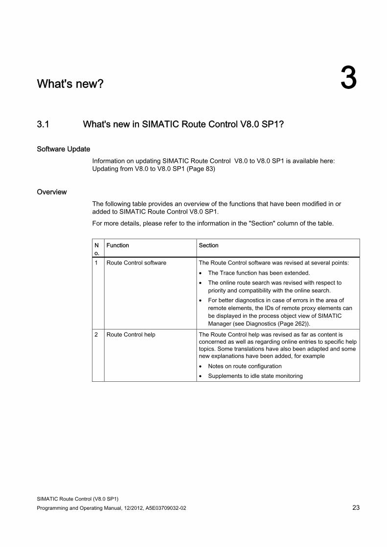
SIMATIC Route Control (V8.0 SP1) Programming and Operating Manual, 12/2012, A5E03709032-02 23
What's new? 33.1 What's new in SIMATIC Route Control V8.0 SP1?
Software Update Information on updating SIMATIC Route Control V8.0 to V8.0 SP1 is available here: Updating from V8.0 to V8.0 SP1 (Page 83)
Overview The following table provides an overview of the functions that have been modified in or added to SIMATIC Route Control V8.0 SP1.
For more details, please refer to the information in the "Section" column of the table.
No.
Function Section
1 Route Control software The Route Control software was revised at several points: • The Trace function has been extended. • The online route search was revised with respect to
priority and compatibility with the online search. • For better diagnostics in case of errors in the area of
remote elements, the IDs of remote proxy elements can be displayed in the process object view of SIMATIC Manager (see Diagnostics (Page 262)).
2 Route Control help The Route Control help was revised as far as content is concerned as well as regarding online entries to specific help topics. Some translations have also been adapted and some new explanations have been added, for example • Notes on route configuration • Supplements to idle state monitoring
What's new? 3.1 What's new in SIMATIC Route Control V8.0 SP1?
SIMATIC Route Control (V8.0 SP1) 24 Programming and Operating Manual, 12/2012, A5E03709032-02
The first USER_PE is "treated as a wait element" (from RC V8.0) In RC < V8.0, wait elements were routed as parameter elements (element type 3, sub type 3). This was changed to Engineering page starting at RC V8.0. An independent element type was introduced for "Special elements". For compatibility reasons (to prevent a CPU stop because of new S7 blocks), the old coding was maintained on the Runtime page (RC server, RC block, RC center). This results in the combination of type=3/subtype=3 being interpreted as a wait element. However, this combination is provided in RC V8.0 on the Engineering page for the first USER_PE type found by the RC assistants.
The consequence of this is that all instances of this first USER_PE are treated as a wait element in the AS as well as in the RC center.
Solution for RC V8.0
USER_PE created in:
● RC V7.1 SP2:
The database converter adapts the data automatically.
● RC V8.0:
They contain the affected USER_PE type (instances of which are displayed as a wait element in the RC Center) as unconnected dummies in CFC, but do not use other instances of it. Instead of this, you create a functionally identical USER_PE type with a different name. Place and interconnect instances of this type in place of the instances of the original USER_PE type. After the RC wizard is run, place the instances of the new USER_PE type in the corresponding partial routes. Through these measures, the dummy type has the combination type=3/subtype=3 (see above). However, because no more instances of this can be used, there are also no fault indications.
Solutions for RC V8.0 Update 1 and RC V8.0 SP1
USER_PE created in:
● RC V7.1 SP2:
The database converter adapts the data automatically.
● RC V8.0
– The aforementioned change was already carried out.
The problem is already resolved.
– The aforementioned change was not implemented.
The "solution for RC V8.0" also helps in this case.
● RC V8.0 Update 1
USER_PEs are detected correctly. No adaptation is necessary.
● RC V8.0 SP1
USER_PEs are detected correctly. No adaptation is necessary.
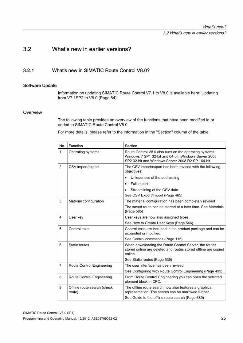
What's new? 3.2 What's new in earlier versions?
SIMATIC Route Control (V8.0 SP1) Programming and Operating Manual, 12/2012, A5E03709032-02 25
3.2 What's new in earlier versions?
3.2.1 What's new in SIMATIC Route Control V8.0?
Software Update Information on updating SIMATIC Route Control V7.1 to V8.0 is available here: Updating from V7.1SP2 to V8.0 (Page 84)
Overview The following table provides an overview of the functions that have been modified in or added to SIMATIC Route Control V8.0.
For more details, please refer to the information in the "Section" column of the table.
No. Function Section 1 Operating systems Route Control V8.0 also runs on the operating systems
Windows 7 SP1 32-bit and 64-bit, Windows Server 2008 SP2 32-bit and Windows Server 2008 R2 SP1 64-bit.
2 CSV import/export The CSV import/export has been revised with the following objectives: • Uniqueness of the addressing • Full import • Streamlining of the CSV data See CSV Export/Import (Page 465)
3 Material configuration The material configuration has been completely revised The saved route can be started at a later time. See Materials (Page 585)
4 User key User keys are now also assigned types. See How to Create User Keys (Page 546)
5 Control texts Control texts are included in the product package and can be expanded or modified. See Control commands (Page 115)
6 Static routes When downloading the Route Control Server, the routes stored online are deleted and routes stored offline are copied online. See Static routes (Page 535)
7 Route Control Engineering The user interface has been revised. See Configuring with Route Control Engineering (Page 493)
8 Route Control Engineering From Route Control Engineering you can open the selected element block in CFC.
9 Offline route search (check route)
The offline route search now also features a graphical representation. The search can be narrowed further. See Guide to the offline route search (Page 389)
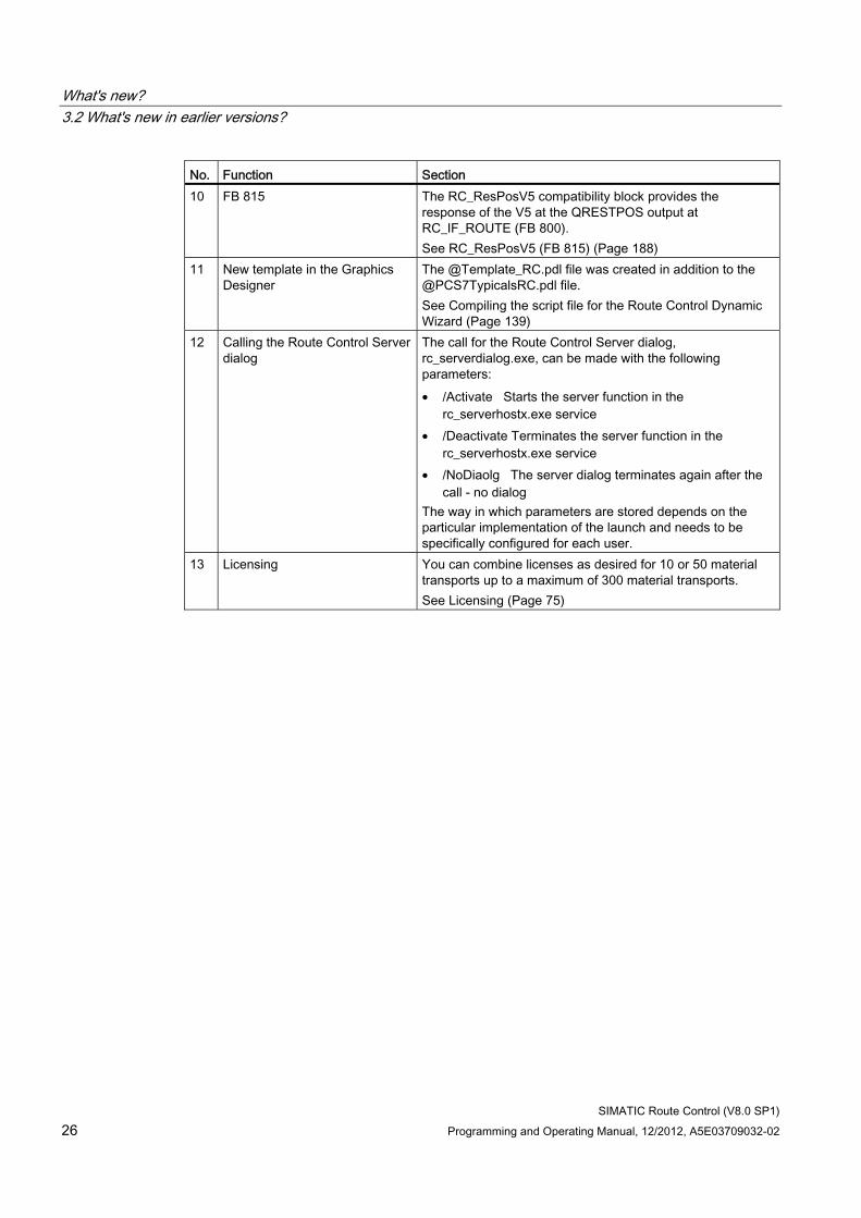
What's new? 3.2 What's new in earlier versions?
SIMATIC Route Control (V8.0 SP1) 26 Programming and Operating Manual, 12/2012, A5E03709032-02
No. Function Section 10 FB 815 The RC_ResPosV5 compatibility block provides the
response of the V5 at the QRESTPOS output at RC_IF_ROUTE (FB 800). See RC_ResPosV5 (FB 815) (Page 188)
11 New template in the Graphics Designer
The @Template_RC.pdl file was created in addition to the @PCS7TypicalsRC.pdl file. See Compiling the script file for the Route Control Dynamic Wizard (Page 139)
12 Calling the Route Control Server dialog
The call for the Route Control Server dialog, rc_serverdialog.exe, can be made with the following parameters: • /Activate Starts the server function in the
rc_serverhostx.exe service • /Deactivate Terminates the server function in the
rc_serverhostx.exe service • /NoDiaolg The server dialog terminates again after the
call - no dialog The way in which parameters are stored depends on the particular implementation of the launch and needs to be specifically configured for each user.
13 Licensing You can combine licenses as desired for 10 or 50 material transports up to a maximum of 300 material transports. See Licensing (Page 75)
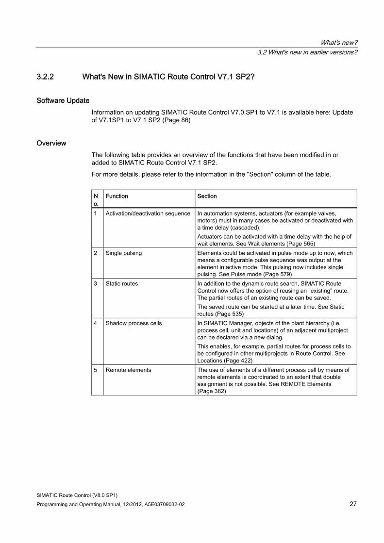
What's new? 3.2 What's new in earlier versions?
SIMATIC Route Control (V8.0 SP1) Programming and Operating Manual, 12/2012, A5E03709032-02 27
3.2.2 What's New in SIMATIC Route Control V7.1 SP2?
Software Update Information on updating SIMATIC Route Control V7.0 SP1 to V7.1 is available here: Update of V7.1SP1 to V7.1 SP2 (Page 86)
Overview The following table provides an overview of the functions that have been modified in or added to SIMATIC Route Control V7.1 SP2.
For more details, please refer to the information in the "Section" column of the table.
No.
Function Section
1 Activation/deactivation sequence In automation systems, actuators (for example valves, motors) must in many cases be activated or deactivated with a time delay (cascaded). Actuators can be activated with a time delay with the help of wait elements. See Wait elements (Page 565)
2 Single pulsing Elements could be activated in pulse mode up to now, which means a configurable pulse sequence was output at the element in active mode. This pulsing now includes single pulsing. See Pulse mode (Page 579)
3 Static routes In addition to the dynamic route search, SIMATIC Route Control now offers the option of reusing an "existing" route. The partial routes of an existing route can be saved. The saved route can be started at a later time. See Static routes (Page 535)
4 Shadow process cells In SIMATIC Manager, objects of the plant hierarchy (i.e. process cell, unit and locations) of an adjacent multiproject can be declared via a new dialog. This enables, for example, partial routes for process cells to be configured in other multiprojects in Route Control. See Locations (Page 422)
5 Remote elements The use of elements of a different process cell by means of remote elements is coordinated to an extent that double assignment is not possible. See REMOTE Elements (Page 362)
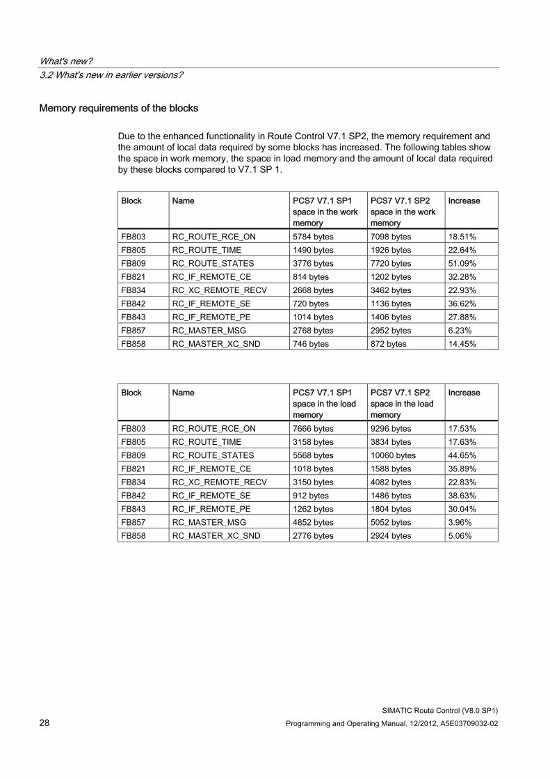
What's new? 3.2 What's new in earlier versions?
SIMATIC Route Control (V8.0 SP1) 28 Programming and Operating Manual, 12/2012, A5E03709032-02
Memory requirements of the blocks Due to the enhanced functionality in Route Control V7.1 SP2, the memory requirement and the amount of local data required by some blocks has increased. The following tables show the space in work memory, the space in load memory and the amount of local data required by these blocks compared to V7.1 SP 1.
Block Name PCS7 V7.1 SP1
space in the work memory
PCS7 V7.1 SP2 space in the work memory
Increase
FB803 RC_ROUTE_RCE_ON 5784 bytes 7098 bytes 18.51% FB805 RC_ROUTE_TIME 1490 bytes 1926 bytes 22.64% FB809 RC_ROUTE_STATES 3776 bytes 7720 bytes 51.09% FB821 RC_IF_REMOTE_CE 814 bytes 1202 bytes 32.28% FB834 RC_XC_REMOTE_RECV 2668 bytes 3462 bytes 22.93% FB842 RC_IF_REMOTE_SE 720 bytes 1136 bytes 36.62% FB843 RC_IF_REMOTE_PE 1014 bytes 1406 bytes 27.88% FB857 RC_MASTER_MSG 2768 bytes 2952 bytes 6.23% FB858 RC_MASTER_XC_SND 746 bytes 872 bytes 14.45%
Block Name PCS7 V7.1 SP1
space in the load memory
PCS7 V7.1 SP2 space in the load memory
Increase
FB803 RC_ROUTE_RCE_ON 7666 bytes 9296 bytes 17.53% FB805 RC_ROUTE_TIME 3158 bytes 3834 bytes 17.63% FB809 RC_ROUTE_STATES 5568 bytes 10060 bytes 44.65% FB821 RC_IF_REMOTE_CE 1018 bytes 1588 bytes 35.89% FB834 RC_XC_REMOTE_RECV 3150 bytes 4082 bytes 22.83% FB842 RC_IF_REMOTE_SE 912 bytes 1486 bytes 38.63% FB843 RC_IF_REMOTE_PE 1262 bytes 1804 bytes 30.04% FB857 RC_MASTER_MSG 4852 bytes 5052 bytes 3.96% FB858 RC_MASTER_XC_SND 2776 bytes 2924 bytes 5.06%
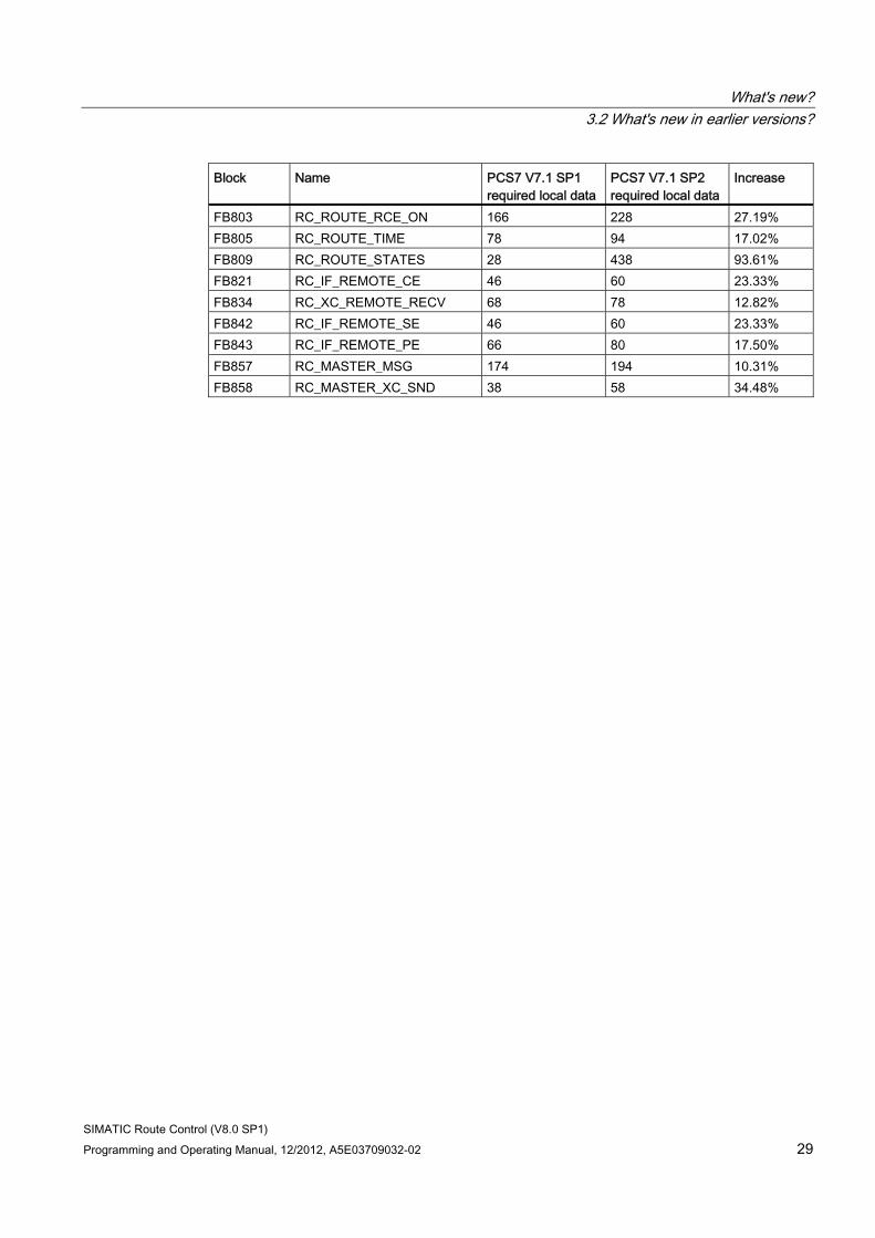
What's new? 3.2 What's new in earlier versions?
SIMATIC Route Control (V8.0 SP1) Programming and Operating Manual, 12/2012, A5E03709032-02 29
Block Name PCS7 V7.1 SP1 required local data
PCS7 V7.1 SP2 required local data
Increase
FB803 RC_ROUTE_RCE_ON 166 228 27.19% FB805 RC_ROUTE_TIME 78 94 17.02% FB809 RC_ROUTE_STATES 28 438 93.61% FB821 RC_IF_REMOTE_CE 46 60 23.33% FB834 RC_XC_REMOTE_RECV 68 78 12.82% FB842 RC_IF_REMOTE_SE 46 60 23.33% FB843 RC_IF_REMOTE_PE 66 80 17.50% FB857 RC_MASTER_MSG 174 194 10.31% FB858 RC_MASTER_XC_SND 38 58 34.48%
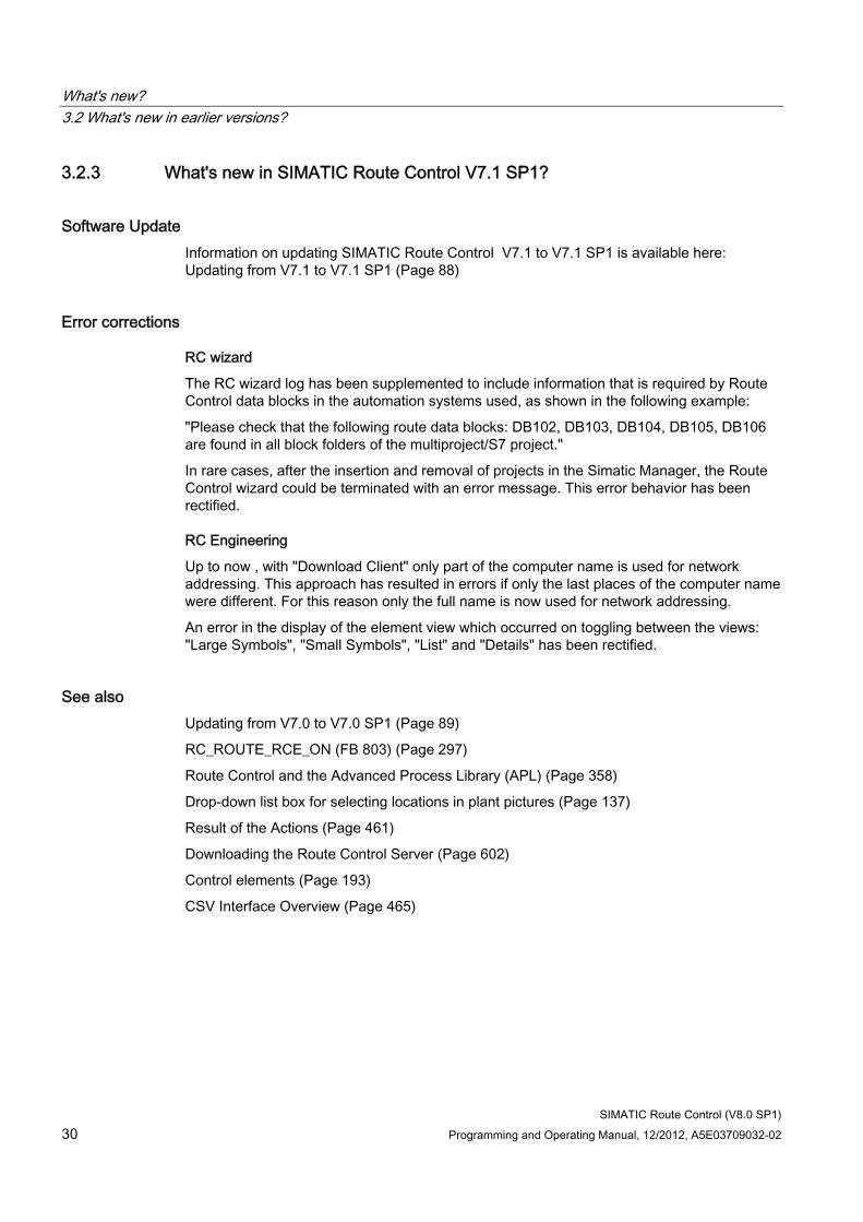
What's new? 3.2 What's new in earlier versions?
SIMATIC Route Control (V8.0 SP1) 30 Programming and Operating Manual, 12/2012, A5E03709032-02
3.2.3 What's new in SIMATIC Route Control V7.1 SP1?
Software Update Information on updating SIMATIC Route Control V7.1 to V7.1 SP1 is available here: Updating from V7.1 to V7.1 SP1 (Page 88)
Error corrections
RC wizard
The RC wizard log has been supplemented to include information that is required by Route Control data blocks in the automation systems used, as shown in the following example:
"Please check that the following route data blocks: DB102, DB103, DB104, DB105, DB106 are found in all block folders of the multiproject/S7 project."
In rare cases, after the insertion and removal of projects in the Simatic Manager, the Route Control wizard could be terminated with an error message. This error behavior has been rectified.
RC Engineering
Up to now , with "Download Client" only part of the computer name is used for network addressing. This approach has resulted in errors if only the last places of the computer name were different. For this reason only the full name is now used for network addressing.
An error in the display of the element view which occurred on toggling between the views: "Large Symbols", "Small Symbols", "List" and "Details" has been rectified.
See also Updating from V7.0 to V7.0 SP1 (Page 89)
RC_ROUTE_RCE_ON (FB 803) (Page 297)
Route Control and the Advanced Process Library (APL) (Page 358)
Drop-down list box for selecting locations in plant pictures (Page 137)
Result of the Actions (Page 461)
Downloading the Route Control Server (Page 602)
Control elements (Page 193)
CSV Interface Overview (Page 465)
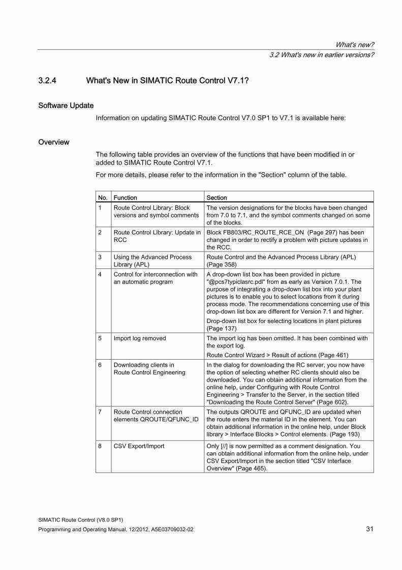
What's new? 3.2 What's new in earlier versions?
SIMATIC Route Control (V8.0 SP1) Programming and Operating Manual, 12/2012, A5E03709032-02 31
3.2.4 What's New in SIMATIC Route Control V7.1?
Software Update Information on updating SIMATIC Route Control V7.0 SP1 to V7.1 is available here:
Overview The following table provides an overview of the functions that have been modified in or added to SIMATIC Route Control V7.1.
For more details, please refer to the information in the "Section" column of the table.
No. Function Section 1 Route Control Library: Block
versions and symbol comments The version designations for the blocks have been changed from 7.0 to 7.1, and the symbol comments changed on some of the blocks.
2 Route Control Library: Update in RCC
Block FB803/RC_ROUTE_RCE_ON (Page 297) has been changed in order to rectify a problem with picture updates in the RCC.
3 Using the Advanced Process Library (APL)
Route Control and the Advanced Process Library (APL) (Page 358)
4 Control for interconnection with an automatic program
A drop-down list box has been provided in picture "@pcs7typiclasrc.pdl" from as early as Version 7.0.1. The purpose of integrating a drop-down list box into your plant pictures is to enable you to select locations from it during process mode. The recommendations concerning use of this drop-down list box are different for Version 7.1 and higher. Drop-down list box for selecting locations in plant pictures (Page 137)
5 Import log removed The import log has been omitted. It has been combined with the export log. Route Control Wizard > Result of actions (Page 461)
6 Downloading clients in Route Control Engineering
In the dialog for downloading the RC server, you now have the option of selecting whether RC clients should also be downloaded. You can obtain additional information from the online help, under Configuring with Route Control Engineering > Transfer to the Server, in the section titled "Downloading the Route Control Server" (Page 602).
7 Route Control connection elements QROUTE/QFUNC_ID
The outputs QROUTE and QFUNC_ID are updated when the route enters the material ID in the element. You can obtain additional information in the online help, under Block library > Interface Blocks > Control elements. (Page 193)
8 CSV Export/Import
Only [//] is now permitted as a comment designation. You can obtain additional information from the online help, under CSV Export/Import in the section titled "CSV Interface Overview" (Page 465).
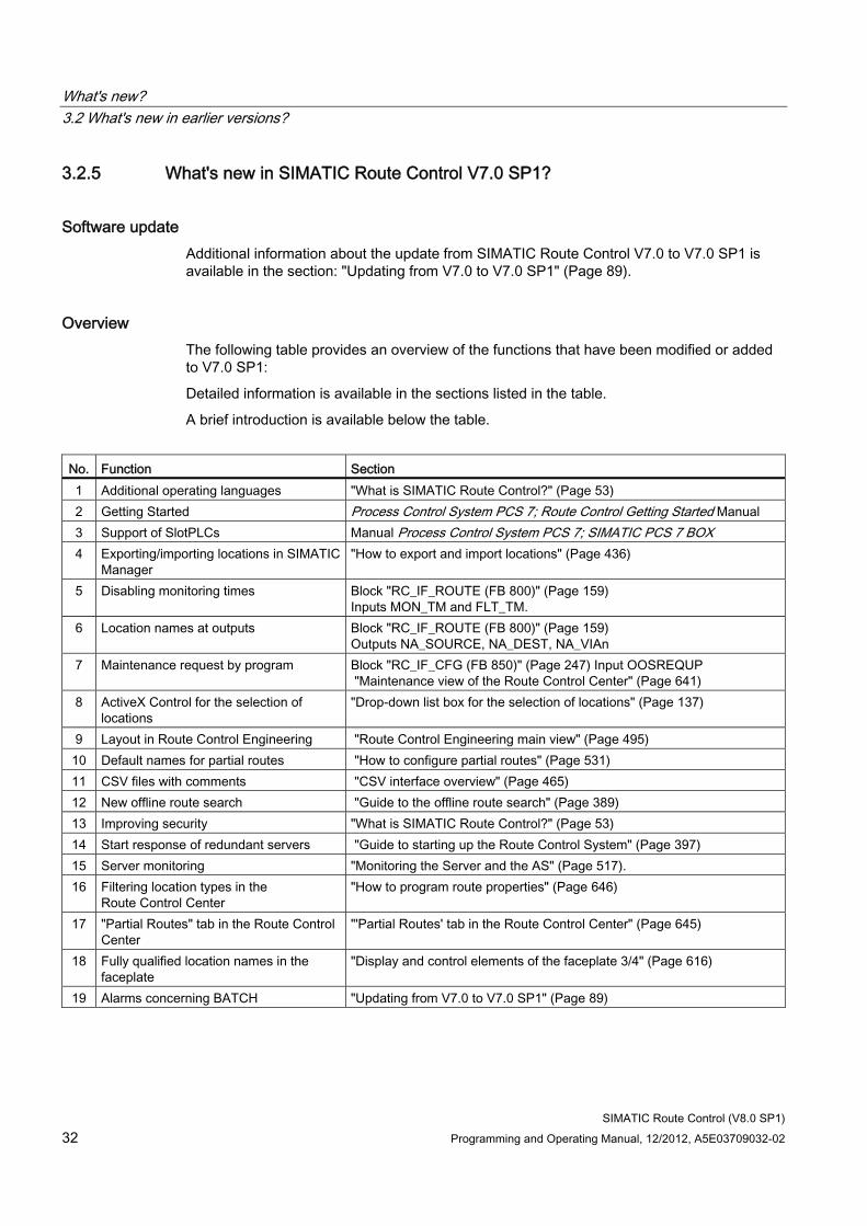
What's new? 3.2 What's new in earlier versions?
SIMATIC Route Control (V8.0 SP1) 32 Programming and Operating Manual, 12/2012, A5E03709032-02
3.2.5 What's new in SIMATIC Route Control V7.0 SP1?
Software update Additional information about the update from SIMATIC Route Control V7.0 to V7.0 SP1 is available in the section: "Updating from V7.0 to V7.0 SP1" (Page 89).
Overview The following table provides an overview of the functions that have been modified or added to V7.0 SP1:
Detailed information is available in the sections listed in the table.
A brief introduction is available below the table.
No. Function Section 1 Additional operating languages "What is SIMATIC Route Control?" (Page 53) 2 Getting Started Process Control System PCS 7; Route Control Getting Started Manual 3 Support of SlotPLCs Manual Process Control System PCS 7; SIMATIC PCS 7 BOX 4 Exporting/importing locations in SIMATIC
Manager "How to export and import locations" (Page 436)
5 Disabling monitoring times Block "RC_IF_ROUTE (FB 800)" (Page 159) Inputs MON_TM and FLT_TM.
6 Location names at outputs Block "RC_IF_ROUTE (FB 800)" (Page 159) Outputs NA_SOURCE, NA_DEST, NA_VIAn
7 Maintenance request by program Block "RC_IF_CFG (FB 850)" (Page 247) Input OOSREQUP "Maintenance view of the Route Control Center" (Page 641)
8 ActiveX Control for the selection of locations
"Drop-down list box for the selection of locations" (Page 137)
9 Layout in Route Control Engineering "Route Control Engineering main view" (Page 495) 10 Default names for partial routes "How to configure partial routes" (Page 531) 11 CSV files with comments "CSV interface overview" (Page 465) 12 New offline route search "Guide to the offline route search" (Page 389) 13 Improving security "What is SIMATIC Route Control?" (Page 53) 14 Start response of redundant servers "Guide to starting up the Route Control System" (Page 397) 15 Server monitoring "Monitoring the Server and the AS" (Page 517). 16 Filtering location types in the
Route Control Center "How to program route properties" (Page 646)
17 "Partial Routes" tab in the Route Control Center
"'Partial Routes' tab in the Route Control Center" (Page 645)
18 Fully qualified location names in the faceplate
"Display and control elements of the faceplate 3/4" (Page 616)
19 Alarms concerning BATCH "Updating from V7.0 to V7.0 SP1" (Page 89)
What's new? 3.2 What's new in earlier versions?
SIMATIC Route Control (V8.0 SP1) Programming and Operating Manual, 12/2012, A5E03709032-02 33
More operating languages Alongside German, English, French, Italian and Spanish, SIMATIC Route Control now also supports Chinese as operating language. The documentation is available in German, English, French and Chinese.
Route Control Getting Started To get to know how to configure Route Control using an example project, a "Getting Started" is now available in German and English.
Support of SlotPLCs The Route Control Wizard in STEP 7 V5.4 SP2 can now be used to create S7 connections between two applications of a PC station. This functionality enables the use of SlotPLCs, that is, automation systems operated in a PC station, for Route Control.
Exporting/importing locations in SIMATIC Manager The "Options" menu in SIMATIC Manager can be used to export all locations of a PCS 7 project, including the hierarchy folders and units, to a CSV file and to re-import these data to SIMATIC Manager after they have been edited and/or expanded using external tools.
The monitoring times can be disabled A status monitoring time MON_TMx and a fault tolerance time FLT_TMx are defined for each mode level at the RC_IF_ROUTE block. These inputs are set to the default -1 value. This setting activates the substitute values MON_TM and FLT_TM. If the maximum value 32767 is set at one of these inputs the corresponding monitoring time never expires.
Location names at outputs Previous versions output the location names at the NA_SOURCE, NA_DEST and NA_VIAn outputs of RC_IF_ROUTE as long as the route controlled by this block was active. The output now consists of the first five digits with the location ID and, separated by a space character, the location name.
Maintenance request by program A user program can now set input OOSREQUP at the RC_IF_CFG block to request the "AS in maintenance" (Out of Service) state. This "Maintenance request by program" can be disabled/enabled in the column header of an AS by selecting the corresponding shortcut menu in the Route Control Center maintenance view.
What's new? 3.2 What's new in earlier versions?
SIMATIC Route Control (V8.0 SP1) 34 Programming and Operating Manual, 12/2012, A5E03709032-02
ActiveX Control for the selection of locations Graphics Designer now provides a new control element that you can install in plant pictures for selecting a location from a drop-down list box in process runtime. The location types offered in this drop-down list box, that is, "Source", "Via", "Destination" or "All Types", are defined when you install the element. The control element returns the ID of the selected location to be set at the input of a route block, for example.
Layout in Route Control Engineering The automation systems are now visualized so that users can recognize their association with a multiproject and a project. The runtime parameters have been distributed to subfolders.
Default name of partial routes derived from the source and destination The system now proposes a name for new partial routes that consists of the source and destination name. The source and destination names are derived from the unit and location names.
CSV files with comments You can add comments to the CSV files that were generated during the export of configuration data from Route Control Engineering. A comment can be entered at the end of a line, or as the only text in a line. The comment text starts with the [//] or [;] characters. The Wizard ignores the comment during import.
New offline route search The user interface was redesigned. You now have the following options:
● Visualization of all route combinations between a source and a destination.
● Visualization of the shortest route between a source and a destination.
● Visualization of alternative parallel routes.
● Visualization of all destinations which can be reached from a specific source.
The new route search is based on a faster search algorithm.
Improving security Route Control now uses an integrated communication and copy service to move or copy files to other computers. These data are transferred using the SIMATIC Communication Service (SCS), which does not require any open ports.
What's new? 3.2 What's new in earlier versions?
SIMATIC Route Control (V8.0 SP1) Programming and Operating Manual, 12/2012, A5E03709032-02 35
Improving the start response of redundant servers The server now requests information about the availability and operating state of the partner station during its startup in order to determine whether to start in master or standby mode. The server compares the configuration data if the partner station is available. The server does not start up if the offline Route Control databases are inconsistent with project data downloaded to the redundant servers.
Improving redundancy monitoring The master server cyclically broadcasts monitoring message frames to all ASs used by the Route Control system. Each AS returns a response frame to both servers. If the standby server does not receive any further monitoring message frames it no longer immediately interprets this as a master server failure and initially responds by requesting the operating state of the partner station. If the master server returns a message frame indicating its faultless state, the standby server does not assume the master function.
Filtering location types in the Route Control Center The RCC drop-down list boxes that are used to select the source, destination or Via of a route now offer only the locations of the type to be selected.
New "Partial Routes" tab in the Route Control Center The new "Partial Routes" tab returns information about the partial routes of a route you selected in the Route Control Center.
Fully qualified location names in the faceplate The Route Control faceplate now visualizes the source, destination and Via names in the "plant\unit\location" format. These names are unique throughout the PCS 7 project.
Alarms concerning BATCH on the PCS 7 OS The auxiliary values of alarms of the route block FB 800, which affect the interplay with SIMATIC BATCH, now contain batch name, step number and batch number. If this information is to be correctly transferred to the PCS 7 OS then you will need to restart the respective AS.
What's new? 3.2 What's new in earlier versions?
SIMATIC Route Control (V8.0 SP1) 36 Programming and Operating Manual, 12/2012, A5E03709032-02
3.2.6 What's new in SIMATIC Route Control V7.0?
Software update You will find information about updating from SIMATIC Route Control V6.x to V7.0 in "Updating from V6.1 SP1 to V7.0" (Page 91).
Overview The following table provides an overview of the functions that have been modified or added to V7.0:
You can find detailed information in the sections specified in the table.
You can find brief, explanatory information below the table.
Mode Sections Licenses "Overview of Licensing" (Page 75) Configuring the locations "Configuring the locations" (Page 431) Location Import Wizard "How to import locations into the PH" (Page 93) Location as a variant "Location as a variant" (Page 135) Generic user-defined elements
"Generic User-Defined Elements" (Page 244)
Adding projects to a multiproject
"Adding Projects to a Multiproject" (Page 403)
Access protection Help on SIMATIC Manager ("Options" Menu) Change log Help on SIMATIC Manager ("Options" Menu) Route Control Wizard "Transferring Data From an S7 Project" (Page 447) Transferring Data From a Multiproject
"Transferring Data from an S7 Project" (Page 447)
Interaction with SIMATIC BATCH
"SIMATIC BATCH and SIMATIC Route Control" (Page 140)
Engineering user interface "Route Control Engineering Main View" (Page 495) Activation key icons "Meanings of Activation Key Icons" (Page 544)
"How to Change the Activation Key Icons" (Page 545) "How to Configure Activation of Elements" (Page 542)
User-defined Activation Keys
"How to Create User Keys" (Page 546) "How to Delete User Keys" (Page 548)
CSV interface "Overview of the CSV Interface" (Page 465) "Structure of CSV Files" (Page 483)
Route Control Center "Keys for the Type of Activation" (Page 636) Configuring route properties
"How to Configure Route Properties" (Page 646)
Route templates "Working with Route Templates" (Page 649) Operator languages "What is SIMATIC Route Control?" (Page 53)
What's new? 3.2 What's new in earlier versions?
SIMATIC Route Control (V8.0 SP1) Programming and Operating Manual, 12/2012, A5E03709032-02 37
Mode Sections Operator messages in the PCS 7 OS
"Operator messages" (Page 699)
PCS 7 OS Web option "Operator Control and Monitoring with PCS 7 Web Option" (Page 61)
Licenses The Route Control Applications Server, Engineering and Center require licenses for V7.0.
The following features are new to Version V7.0:
● The rental license for Route Control Engineering lasts 30 days (previously 150 hours).
● The PCS 7 Software Update Service SIMATIC Route Control
● The PCS 7 Upgrade Package SIMATIC Route Control
Configuring locations in SIMATIC Manager As of V7.0, you configure or change process cells, units and locations along with their properties, solely in the plant hierarchy in SIMATIC Manager.
You create location types as equipment properties in the shared declarations. You create locations (instances of location types) as equipment properties in units. The locations are thereby given unique location IDs across projects.
You must manually assign the first ID in an appropriate way. Additional IDs are then consecutively assigned by the system. Make sure you reserve a large enough number range for the IDs of each project of a multiproject when assigning the first ID.
SIMATIC BATCH takes the locations from the S7 project and uses them to control material transports with Route Control.
Location Import Wizard Once the Route Control configuration data have been converted to V7.0 format, you can read the locations that were configured in V6.1 SP1 from Route Control Engineering using the Location Import Wizard and copy them to the plant hierarchy of the S7 project.
Location as a variant The "Variant" property of a location cannot be configured in SIMATIC Manager.
To ensure compatibility with projects from earlier versions, you can continue to activate this property in Route Control Engineering.
Generic user-defined elements You can assemble technologically compatible elements which are always added together in a partial route in a generic user-defined element (GE block). You can include both standard elements such as RC_IF_VALVE and user-defined elements such as RC_IF_USER_CE in a GE block. The Route Control Wizard recognizes these GE blocks and imports the elements they contain to Route Control Engineering as individual elements.
What's new? 3.2 What's new in earlier versions?
SIMATIC Route Control (V8.0 SP1) 38 Programming and Operating Manual, 12/2012, A5E03709032-02
Adding projects to a multiproject If you want to add projects to a multiproject, the system checks whether the new data match the existing data. If the Route Control specifications are violated, a dialog box displaying notes on how to correct the errors appears automatically.
Access protection If you are using the components of SIMATC Logon, you can activate access protection in SIMATIC Manager from the "Options" menu. This provides protection with a project password when opening projects and starting the Route Control Wizard.
Change log If you activated access protection, you can activate and display the change log from the "Options" menu in SIMATIC Manager. This records specific online functions, such as delta download to the AS or the download to the Route Control Server, along with comments you may have entered.
Route Control Wizard There is only one Route Control Wizard, which performs all the tasks from exporting data from the S7 multiproject to importing it into Route Control Engineering in consecutive order. The Route Control Wizard can only be started in SIMATIC Manager.
Before performing the import, you can specify if the route ID should be dynamic or fixed.
Transferring Data From a Multiproject If you have removed single projects from a multiproject for external processing, the Route Control Wizard will detect this during export/import. The data of these projects remains in Route Control Engineering and can be further processed there.
Interaction with SIMATIC BATCH Supporting BATCH recipes, V7.0 makes managing material transport processes easier. The interface is provided by an SFC type, which activates a Route Control route block. The BATCH operator specifies, e.g., the source and target of a material transport process in the transfer parameters associated with a transfer phase. The Route Control library contains an executable example of such an SFC type.
What's new? 3.2 What's new in earlier versions?
SIMATIC Route Control (V8.0 SP1) Programming and Operating Manual, 12/2012, A5E03709032-02 39
Route Control Engineering User Interface As before, there are four Route Control Engineering panes. When a partial route is selected, the lower right-hand panel now only contains two tabs:
● "Elements" tab: Information from the previous columns "Value" and "Passive/Idle state" has been collated in a column entitled "Activation". The display is therefore similar to the one in the "Elements" tab in the Route Control Center.
● The "Functions" tab is new to Route Control Engineering: The elements are displayed as on the Route Control Center "Functions" tab. When adding an element to a partial route, you set the element activation parameters as previously in a mode level. You can now configure activation in additional mode levels on the "Functions" tab. You no longer have to configure the activation properties each and every time; you can now use default activation keys.
Changing the Icons for the Activation Keys You change the icons associated with the activation keys in Route Control Engineering (previously these changes were made in the Route Control Center).
User-defined Activation Keys You can assign a user-defined key of your choice to each activation mode. You configure these keys once and use them in the configuration in the same way as the supplied keys.
CSV interface As of V7.0, you can also export user-defined elements and activation masks for user-defined elements from Route Control Engineering via the CSV interface.
You configure user-defined elements in SIMATIC Manager. This means that you can only import user-defined elements into Route Control Engineering via the Route Control Wizard, and not via the CSV interface.
You configure activation masks in Route Control Engineering. This means that you can import activation masks for user-defined elements into Route Control Engineering via the CSV interface.
Route Control Center The display of keys for the activation type has been corrected.
Route Properties If you wish to run a material transport process in manual mode, you must configure the route properties in the Route Control Center. As of V7.0 you can enter all required parameters in a single dialog box.
What's new? 3.2 What's new in earlier versions?
SIMATIC Route Control (V8.0 SP1) 40 Programming and Operating Manual, 12/2012, A5E03709032-02
Route templates Once you have configured a set of route properties you can save them as a route template. Whenever you need to run a material transport process of this type again, simply select the corresponding route template.
Operator languages Route Control V7.0 supports the following operator languages: English, French, German, Italian, and Spanish.
Operator Messages in the PCS 7 OS As of V7.0, the system writes all Route Control operator messages to the operation list of the PCS 7 OS.
PCS 7 OS Web option The PCS 7 OS Web option enables you operate and monitor routes with the Route Control faceplate via Intranet/Internet.
What's new? 3.2 What's new in earlier versions?
SIMATIC Route Control (V8.0 SP1) Programming and Operating Manual, 12/2012, A5E03709032-02 41
3.2.7 What's new in SIMATIC Route Control V6.1 SP1 ?
Migration
Note
The process for migrating a V6.1 project to V6.1 SP1 is described in "Migration From V6.1 to V6.1 SP1". (Page 101)
Route Control applications in HW Config Prior to V6.1, you had to configure a standard application for the Route Control server in HW Config. The Route Control Wizard then asked for this application when exporting objects to the Route Control Engineering project. As of V6.1 SP1, you now configure special SIMATIC Route Control applications in HW Config. In this respect, the following applications are offered for SIMATIC Route Control:
● Route Control application A Route Control application is the preferred station (server master) for SIMATIC Route Control. A PCS 7 OS application and/or BATCH application can also run on this station. Following a switchover, this station becomes the standby station for all applications running on it. You can find additional information in "Route Control Redundancy".
● Route Control application (stby) A Route Control application (stby) is the substitute station (standby server) for SIMATIC Route Control. A PCS 7 OS application (stby) and/or BATCH application (stby) can also run on this station. Following a switchover, this station becomes the master station for all applications running on it (you can find additional information in "Route Control Redundancy").
● Route Control application client A Route Control application client represents a station on which a Route Control Center (client) is installed. The configuration related to Route Control (one or two computer names for the Route Control servers) is downloaded to the client station via the Route Control application.
Additional information ● Section "Route Control Applications" (Page 333)
Downloading the Configuration to a Route Control Client Once the Route Control server applications have been configured, this information can be downloaded to a Route Control client. This configuration with the names of the Route Control servers replaces the previous selection dialog box in the Route Control Center.
Select the Route Control application client to which the configuration is to be downloaded in the SIMATIC Manager S7 project. Open the shortcut menu and select the menu command CPU > Download.
You can find additional information in "Selecting a Route Control Server". (Page 621)
What's new? 3.2 What's new in earlier versions?
SIMATIC Route Control (V8.0 SP1) 42 Programming and Operating Manual, 12/2012, A5E03709032-02
Maintenance The Route Control server process and the Route Control Center application are linked to the maintenance component of PCS 7 (Station Observer). In this version, therefore, you can monitor the computer-based properties such as hard disk space and available RAM. Parameters specific to SIMATIC Route Control are not monitored.
PCS 7 Standard Redundancy for Route Control Server The Route Control server process is now linked to the PCS 7 standard redundancy monitoring at all times (redundancy control). SIMATIC Route Control thus runs in a network with the PCS 7 OS and/or SIMATIC BATCH server applications and can be switched together with these as a group. A connection is required for the two servers to monitor each other. The monitoring of the redundant processes and the switchover of the redundancy status between the computers must be guaranteed. We therefore recommend you set up a serial connection between the two computers (as for SIMATIC Batch).
You can find additional information in "Redundant Route Control Configurations". (Page 66)
Additional Operator Languages In addition to the existing languages of English, French and German, SIMATIC Route Control V6.1 SP1 now also supports Italian and Spanish as user interface and operator languages for the Route Control tools. Chinese (Simplified) is also supported for Asia. The required modules for Chinese (Simplified) are installed on the target system by a separate PCS 7 setup routine (DVD).
Additional Changes from V6.1 to V6.1 SP1 Blocks
● FB 800 (RC_IF_ROUTE) The MAN_AUT input now has a different logic for the values 0 and 1. It is, therefore, now like all other blocks of STEP 7 or SIMATIC Route Control. The input is now called MAN_AUT instead of AUT_MAN. The @PG_RC_IF_ROUTE_STANDARD.PDL picture has been correspondingly adapted.
● FB 825 (RC_IF_VAL_MOT) The QAUTO_OC signal has moved from Q_C_00 to Q_C_01.
● FB 808 (RC_IF_VOLUME) The texts for the "QSUMMED" output have been corrected.
● FB 800 and as such also FB 852, FB 853, FB 854, FB 855, FB 856, FB 857, FB 858, FB 859, FB 860 The blocks have taken on the data structure of FB 800 and must, therefore, be recompiled!
● FB 800, FB 852 und FB 857 These blocks now use the input and have been adapted to the reversed logic using an internal Temp variable.
What's new? 3.2 What's new in earlier versions?
SIMATIC Route Control (V8.0 SP1) Programming and Operating Manual, 12/2012, A5E03709032-02 43
● FB 800 and as such also FB 852, FB 853, FB 854, FB 855, FB 856, FB 857, FB 858, FB 859, FB 860 The maintenance inputs at blocks FB 850 and FB 800 have a new data structure. The blocks named above adopt this changed structure and, therefore, have to be recompiled.
● FB 850 The block has a new input.
PCS 7 OS Pictures
● The tooltip for the Route Control block icon now no longer cuts off the full text (@PCS7TypicalsRC.PDL). You need to reinsert the @PCS7TypicalsRC.PDL file in your PCS 7 OS project for existing PCS 7 OS pictures.
● No additional windows open when enlarging the Route Control faceplate in PCS 7 OS.
What's new? 3.2 What's new in earlier versions?
SIMATIC Route Control (V8.0 SP1) 44 Programming and Operating Manual, 12/2012, A5E03709032-02
3.2.8 What's New in SIMATIC Route Control V6.1?
Integration in the PCS 7 System Setup For the first time, SIMATIC Route Control V6.1 is available to you from within the PCS 7 system setup. As with other option packages, you select which product you wish to install at the beginning of the PCS 7 system setup. The PCS 7 system setup will then install the product automatically. You can find additional information in "Installing Route Control Components". (Page 69)
Automation License Manager
As of V6.1, SIMATIC Route Control supports the Automation License Manager. This means that it is now also able to support the SIMATIC Route Control license model. You can find additional information in "Overview of Authorization". (Page 75)
Route Control Maintenance Safety SIMATIC Route Control V6.1 provides support to maintenance personnel by enabling them to set the automation system to "Maintenance" status. New material transport processes are no longer permitted via this automation system. You can find additional information in "Route Control Support for Maintenance Work". (Page 628)
Operating Systems SIMATIC Route Control can run under Windows XP Professional (Route Control Center, Route Control Engineering) or Windows 2003 Server (Route Control server), as well as Windows 2000. You can find additional information in "Hardware and Software". (Page 71)
SIMATIC S7 417-H SIMATIC Route Control V6.1 supports SIMATIC S7 H-CPUs. In addition to the server level, you can now also design and implement the automation systems to be more fault-tolerant. The Route Control library now supports non-H and H-machines. A route can also be controlled by both non-H and H-machines in combined operation. You can find additional information in "Communication with H-Machines". (Page 405)
What's new? 3.2 What's new in earlier versions?
SIMATIC Route Control (V8.0 SP1) Programming and Operating Manual, 12/2012, A5E03709032-02 45
Hardware Configuration You can now use the HW Config application to configure the Route Control server and get support from the Route Control Wizard when generating the named communication links. These links are also downloaded to the PC station on the target computer, similar to other PCS 7 OS or BATCH servers. The Route Control Server then uses these configured link to establish the link. You can find additional information in "Hardware Configuration (HW Config)". (Page 413)
CPU Firmware SIMATIC Route Control now also supports CPUs with firmware versions earlier than V3.1.0. The Route Control Wizard no longer stops with an error message; it shows a warning instead. We still recommend that you use firmware V3.1.0 or later.
SIMATIC Logon SIMATIC Route Control V6.1 is based on the same version of SIMATIC Logon as all other PCS 7 V6.1 products. The authorization management system functions in the same way as in RC V6.0 and V6.0 SP1. You can find additional information in "User Roles for Route Control". (Page 78)
Multiprocessor Computers Recommended hardware configurations for PC stations appear in the Process Control System PCS 7; PC Configuration and Authorization Manual.
Security With SIMATIC Route Control, directories are no longer shared for "everyone", but only for Route Control groups (RC_ENGINEER, RC_MAINTENANCE, RC_OPERATOR_L1 to RC_OPERATOR_L3). This means that only members of one of these groups can access the shared directories from another computer.
Material in the Route Control Center In manual mode, material can now even be changed during an active route in the Route Control Center. Before RC V6.0 SP1, it was only possible to change the material when the route was not active. You can find additional information in "Route Properties" (Page 646).
What's new? 3.2 What's new in earlier versions?
SIMATIC Route Control (V8.0 SP1) 46 Programming and Operating Manual, 12/2012, A5E03709032-02
Route Control messages In the PCS 7 OS alarm server for Route Control messages, the Route Control Wizard generates messages with a tag.
Example:
Previous message New message Functionality "Fault on route 23" "Fault on route %d" The wildcard (%d) is assigned the number of the
corresponding route during runtime and a message is generated.
This means message definitions in a PCS 7 OS project can be created up to 300 times faster using the Route Control Wizard.
What's new? 3.2 What's new in earlier versions?
SIMATIC Route Control (V8.0 SP1) Programming and Operating Manual, 12/2012, A5E03709032-02 47
3.2.9 What's new in SIMATIC Route Control V6.0 SP1 ?
New Functions SIMATIC Route Control V6.0 Service Pack 1 has the following new functions:
● External Material Interface
You can now transfer material master data to the Route Control server from an external source. In addition to the actual materials, you can also define the successor relationships.
You can find additional information in "Material Interface" (Page 593).
● Route Log
The following information is recorded in the route log:
– Operator input by means of the Route Control Center
– Status of a route (e.g., Start, Stop, Pause, mode level activation/deactivation)
– Startup, operation and shutdown of the Route Control server
These route logs can be displayed and saved using an application that is provided with SIMOTION Route Control. This route log user interface offers you a wide range of functions for filtering, searching and evaluating logs.
You can find additional information about this in "Route Log" (Page 651).
● User-Defined Element Blocks
In addition to the preset element types (control, parameter, linking, and sensor elements), you can also create your own element types (CFC), transfer them to the Route Control configuration and interconnect them in partial routes.
You can find additional information about this in "Example of a User-Defined Type" (Page 242).
Note
You can find all changes relating to SIMATIC Route Control V6.0 SP1 in this online Help system by searching for "SP1".
What's new? 3.2 What's new in earlier versions?
SIMATIC Route Control (V8.0 SP1) 48 Programming and Operating Manual, 12/2012, A5E03709032-02
3.2.10 What's new in SIMATIC Route Control V6.0?
Overview In this section, you will find information about the new and expanded functions of SIMATIC Route Control V6.0 as compared to the following previous versions:
● Route Control V5 based on BRAUMAT V5
● Route Control V5 based on PCS 7 V5
General Windows 2000 Capability
Like PCS 7, SIMATIC Route Control V6.0 can run on the Windows 2000 operating system.
Integration in PCS 7
SIMATIC Route Control V6.0 is integrated in PCS 7.
● User Interfaces
An essential component of SIMATIC Route Control V6.0 is integration into the PCS 7 environment. In many areas, the user interfaces (for example, dialog boxes, icons) have been revised, simpler procedures for working with the tools have been introduced and a wizard and PCS 7 OS faceplate have been added.
The Route Control Wizard also includes a plausibility check of the configured element and route blocks. This enables errors to be detected early and data consistency between the S7 project and the Route Control project to be ensured.
● AS-Server Connection (Route Control AS and Server)
The automation systems are connected to the Route Control server by means of BSEND services (in V5, this was accomplished using alarm services).
● Messages
In version 6.0, blocks in the Route Control library use standard alarm services (ALARM blocks) and communication routes to signal to a PCS 7 OS message server.
To avoid dependence on BRAUMAT/SISTAR library blocks (V5), the required blocks are now integrated in the Route Control library.
● Elimination of Major Sources of Error
In SIMATIC Route Control V6.0, the problem of extended data blocks which arose in V5 has been eliminated. The data areas in the automation systems have now been separated and revised. As a result, route data in the instance data block of RC_IF_ROUTE are separated from the element list DB 101 to DB 400.
To reduce the burden on the OB 1 cycle, you can now also call route blocks in other organization blocks.
What's new? 3.2 What's new in earlier versions?
SIMATIC Route Control (V8.0 SP1) Programming and Operating Manual, 12/2012, A5E03709032-02 49
● Basic Package - Expanding the Number of Material Transports Incrementally
The SIMATIC Route Control V6.0 basic package supports material transports, from project engineering to the runtime system, to operator control and monitoring of routes and route elements, including process messages. The basic package is limited to 30 routes (no more than 30 material transports can take place simultaneously). An upgrade package provides an incremental expansion to 100 or 300 material transports.
At level 1 (V6.0) the functionality of SIMATIC Route Control V6.0 cannot currently be expanded by adding options: SIMATIC Route Control V6.1 does support these packages (H-Option, S7-317). You can find additional information in file readme.wri supplied with SIMATIC Route Control V6.0.
● Redundancy
With SIMATIC Route Control, you can configure the Route Control server that processes route requests redundantly. This ensures permanent availability.
● Integration in PCS 7 OS
SIMATIC Route Control V6.0 provides improved integration in the PCS 7 OS (client) via the following options:
– Block icon
– PCS 7 OS faceplate
– Cross-selection between PCS 7 OS pictures and the Route Control Center
Project Engineering in the Engineering System Several important additions have been made for project engineering route control, which make it easier to enter and import existing data from an S7 project to a Route Control project.
A portion of project engineering takes place in SIMATIC Manager and associated applications:
● CFC: Project engineering of routes
● CFC: Project engineering of elements
● CFC: Configuration of a Route Control automation system
● NetPro: Project engineering of AS-AS connections
● NetPro: Project engineering of AS-server connections
The Route Control Wizard assists you in carrying out all this project engineering work.
What's new? 3.2 What's new in earlier versions?
SIMATIC Route Control (V8.0 SP1) 50 Programming and Operating Manual, 12/2012, A5E03709032-02
● Route Control Servers and Route Control Clients
Phase one does not yet have its own Route Control object manager (OM) in SIMATIC Manager. Because of this, the Route Control server settings are made in the Route Control Wizard, transferred to Route Control Project Engineering and downloaded from there to the server computers.
● S7 Individual Projects and Multiprojects
SIMATIC Route Control V6.0 supports both individual S7 projects and S7 multiprojects of SIMATIC Manager. Each individual project or multiproject can have no more than one Route Control project. If you are implementing various process cells using multiple multiprojects, then you must also use several Route Control projects. The maximum scope of a Route Control project is the multiproject.
● Type-Based Engineering (Sample SFC for Route Control)
SIMATIC Route Control contains a sample SFC (SFC Typical) for controlling the route, which includes S88 status tabs with sample programming. Copy this SFC and adapt it to your requirements. The following steps are suitable for adaptation:
– Transferring relevant parameters (e.g. source and destination locations, function ID, material)
– Requesting a route
– Controlling a route (mode levels)
– Deactivating a route
● Interface to Processing Programs
The interface between SIMATIC Route Control V6.0 and the actual processing in the automation system is formed by the following blocks:
– SFC types created using SFC standard tools in PCS 7 V6.0 and higher
– Route Control interface blocks
The interfaces are required for the following tasks:
– Activation of elements and routes
– AS-AS cross-coupling within a Route Control project
– AS-AS cross-coupling spanning several Route Control projects
– Diagnosis
– Use of the preconfigured sample SFC
● Plant Hierarchy in the Plant View
The plant hierarchy in SIMATIC Manager allows you to display your project in a structured manner. The plant view of the Route Control Engineering system can include up to two levels of the plant hierarchy (process cell and unit) in accordance with S88.01. These two levels are recognized by the BATCH attributes in the hierarchy folder.
To improve the structure, you can also add (bi-level) neutral folders to the plant hierarchy in SIMATIC Route Control.
What's new? 3.2 What's new in earlier versions?
SIMATIC Route Control (V8.0 SP1) Programming and Operating Manual, 12/2012, A5E03709032-02 51
● Fault-Tolerant Route Control
You can configure the Route Control servers redundantly to increase availability (fault tolerance) and enable software updates during operation. The two Route Control servers (standby/master) are switched over if redundant operation is required.
Redundancy is achieved with two Route Control servers. These servers do not require local data management. Nevertheless, to enable the Route Control client applications (Route Control Center) to access the current Route Control server database, the two local project-engineering databases are synchronized. If one Route Control server fails, the other server reads in the project-engineering database again and initiates a general request. This general request provides the new master server with the current status of the elements and routes from the automation systems.
This strategy renders the continuous synchronization of server data and persistent data management on a hard disk superfluous. Data only has to be synchronized when a Route Control server is reloaded from the Route Control Project Engineering application.
You can find additional information in the section "Downloading to the Server".
● Route Control Interface Blocks
SIMATIC Route Control V6.0 takes advantage of the new functionality of SFC types in the engineering system. Alternatively, SIMATIC Route Control V6.0 still contains special interface blocks with a new technical design as communication interfaces to the processing programs in the automation system:
– Faceplates A Route Control block icon and faceplate for the RC_IF_ROUTE route block are available for operation on the PCS 7 OS.
– RC_IF_ROUTE This block is the central block for controlling a route (was: ROUTE_CM block).
– RC_IF_CFG This block is used centrally once for each automation system. The automation-system number and communication IDs for the cross-coupling configuration are configured in this block. You can assign these IDs using the Route Control Wizard. This makes it easier for you to configure the cross-coupling entries.
● Route Control Wizard
A wizard in the context of SIMATIC Manager helps you to configure cross-coupling communication (communication ID). You can also use the wizard to export the configured data relevant to Route Control and to import them to Route Control Project Engineering:
– Plant hierarchy
– Automation systems
– AS-AS and AS-server connection information
– Elements
– Route properties (route ID and fixed/dynamic specification)
The Route Control Wizard is also used to define the relevant message server (PCS 7 message OS) for Route Control and to check the element and route IDs for consistency and plausibility.
What's new? 3.2 What's new in earlier versions?
SIMATIC Route Control (V8.0 SP1) 52 Programming and Operating Manual, 12/2012, A5E03709032-02
Route Control Runtime System ● Working in the PCS 7 OS Faceplate
Click the block icon that displays the most important route status to open the faceplate. It is used to perform the following tasks:
– Displaying the route status in various views
– Operating the route
– Displaying pending messages for the route
The Route Control operator prompts are displayed in the group display of PCS 7 OS.
● Working in the Route Control Center (RCC)
The RCC provides the following highly-detailed displays going beyond the scope of the Route Control PCS 7 OS faceplate:
– Route
– Route status
– Elements and their status
It also enables you to operate the route more comprehensively.
● Authorization Management
SIMATIC Route Control V6.0 supports PCS 7 SIMATIC Logon centralized user management. At level 1 (V6.0), you must create five user groups with specific names in Windows.
Due to a redesign of the SIMATIC Logon Component itself, SIMATIC Route Control will be integrated in and administered from the SIMATIC Logon Admintool as of SIMATIC Route Control V6.1. From a current perspective, it will then be possible to configure the names of the user groups freely.
Other Changes ● Switch-On and Switch-Off Delays for Elements
In SIMATIC Route Control V6 and higher, the switch-on and switch-off delays for elements relate to the mode level and will be valid across automation systems. These delays are absolute and are no longer relative to the preceding element, as was the case in version 5.
When project-engineering data are migrated from V5 to V6, the conversion tool automatically converts the element times. The maximum time has been limited to 255 seconds.
● Element Sorting
The sorting number for elements in a partial route has been eliminated from the engineering tool, as it was irrelevant with respect to the order in which elements are switched on or off. Because SIMATIC Route Control V6.0 is currently designed for the transport of liquids only (and materials that can be transported according to this concept), the sorting number has been removed. This sorting number will become relevant when solid-material variants are introduced because the interlocking of elements is dependent on the element sequence for these materials.
SIMATIC Route Control (V8.0 SP1) Programming and Operating Manual, 12/2012, A5E03709032-02 53
Product Introduction 44.1 What is SIMATIC Route Control?
Definition SIMATIC Route Control is a SIMATIC PCS 7 programming package for automated transport of materials in process cells.
Basic mode of operation You request a material transport during runtime by specifying the source and destination locations. You can also define up to 10 intermediate locations for routing. Route Control searches for a route through the route network, which is made up of partial routes, and controls material transport by opening valves and activating pumps, for example.
Range of Functions SIMATIC Route Control encompasses both the configuration and the runtime system and provides many interfaces to the PCS 7 basic system and to user programs.
Route Control can provide everything from simple transport processes to a large number of complex route combinations, depending on the process cell design.
SIMATIC Route Control is primarily a tool for simplifying and standardizing the following tasks:
● Project configuration
● Processing during runtime
● Diagnosing material transports (routes)
Configuration Features The following features characterize SIMATIC Route Control configuration:
● Simple configuration and interconnection of process-related elements in CFC
● Wizard-assisted configuration of the cross-coupling among the automation systems relevant for SIMATIC Route Control
● Wizard-assisted configuration of parameters for the connection between Route Control automation systems and Route Control Servers
● Transfer of configuration data from the S7 project to Route Control Engineering
● Insertion of elements in partial routes per drag-and-drop operation
● Efficient configuration using external tools, such as Microsoft Excel, with a simple interface in the form of CSV files
Product Introduction 4.1 What is SIMATIC Route Control?
SIMATIC Route Control (V8.0 SP1) 54 Programming and Operating Manual, 12/2012, A5E03709032-02
Runtime System Features The following features characterize the SIMATIC Route Control runtime system:
● Activation of transports in up to 32 levels
● Automatic route search, combination of partial routes and the elements they contain
● Control and monitoring of routes and associated elements
● Diagnosis of routes and elements, including messages related to a route
● Redundant configuration of the Route Control Server possible for high availability
● Redundant configuration of Route Control automation systems possible
Note
SIMATIC Route Control is a system for use in controlling material transports. It is not designed for the automation of packaging sectors or package tracking (tracing packages / recording). Do not confuse this with material tracking. A material tracing and tracking system is not part of Route Control. However, Route Control returns information about the specific material assigned to a specific partial route or route.
Security Route Control V7.0 SP1 or higher now handles tasks such as moving or copying files to other computers by means of an integrated communication and copy service. All of these data are transferred by way of SIMATIC Communication Service (SCS). This process does not require any open ports.
Languages SIMATIC Route Control as of V7.0 SP1 supports the following operating languages:
● German
● English
● French
● Italian
● Spanish
● Chinese
● Japanese
The documentation is available in the following languages:
● German
● English
● French
● Chinese
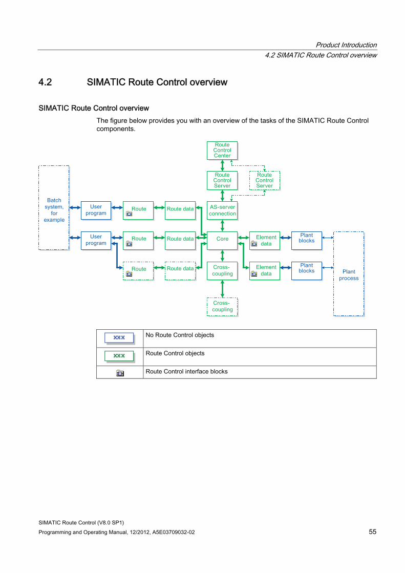
Product Introduction 4.2 SIMATIC Route Control overview
SIMATIC Route Control (V8.0 SP1) Programming and Operating Manual, 12/2012, A5E03709032-02 55
4.2 SIMATIC Route Control overview
SIMATIC Route Control overview The figure below provides you with an overview of the tasks of the SIMATIC Route Control components.
No Route Control objects
Route Control objects
Route Control interface blocks
Product Introduction 4.3 Route Control Components
SIMATIC Route Control (V8.0 SP1) 56 Programming and Operating Manual, 12/2012, A5E03709032-02
4.3 Route Control Components
4.3.1 Component Overview
Overview SIMATIC Route Control comprises the following components:
● "Route Control library" (Page 57) with interface blocks for interconnection with user blocks and process blocks
● "Route Control Wizard" (Page 57) for exporting configuration data from the S7 project and importing these data to Route Control Engineering
● "Route Control Engineering" (Page 58) for creating and managing any number of partial routes with elements
● "Route Control Server" (Page 59) for finding routes and which acts as an interface between the Route Control Center and/or PCS 7 OS and the automation systems
● "Route Control Center" (Page 59) for the control and detailed diagnosis of the route and its elements
● "Route Control Route Log" (Page 60) for saving and evaluating information relating to material transports
● "Route Control Operator Dialog" (Page 60) for the operator control and monitoring of a route
● "PCS 7 OS Web Option" (Page 61) for the operator control and monitoring of routes via Intranet/Internet
Product Introduction 4.3 Route Control Components
SIMATIC Route Control (V8.0 SP1) Programming and Operating Manual, 12/2012, A5E03709032-02 57
4.3.2 Route Control library
Route Control library The Route Control library contains a number of function blocks and data blocks for operating the route controller and linking external blocks:
● Route Control interface blocks for routes
● Route Control interface blocks for elements
● Route Control interface blocks for the configuration
● Route Control interface blocks for diagnosing the cross-coupling
● Route Control kernel blocks for route execution
● Route Control kernel blocks for processing elements
● Route Control kernel blocks for the AS-server connection
● Route Control kernel blocks for the AS-AS connection
Additional information A list and description of all blocks can be found in the following sections:
● "Interface Block Overview" (Page 158)
● "Overview of REMOTE Blocks" (Page 261)
● "Overview of Cross-Coupling Blocks" (Page 247)
● "Overview of Kernel Blocks" (Page 279)
4.3.3 Route Control Wizard
Route Control Wizard The Route Control Wizard assists you in performing the configuration steps below for Route Control and the associated S7 project:
● Assigning unique element and route IDs, with a plausibility check
● Creating and checking the consistency of S7 connections for Route Control automation systems
● Exporting configured elements, routes, locations, and the plant hierarchy to the Route Control project
● Selecting the PCS 7 OS message server for Route Control server messages
You can find additional information in "Actions in the Route Control Wizard". (Page 451)
Product Introduction 4.3 Route Control Components
SIMATIC Route Control (V8.0 SP1) 58 Programming and Operating Manual, 12/2012, A5E03709032-02
4.3.4 Route Control Engineering
Configuration tasks Route Control Engineering comprises the steps below:
Step Procedure 1 Transfer elements, routes, locations, and automation systems from an S7 project. 2 Configure mode tables and function IDs. 3 Configure the partial routes of the route network. 4 Interconnect elements with partial routes and mode level assignment. 5 Configure materials, material groups and permitted successor relationships between
materials and material groups. 6 Export and import via CSV files.
Test Application for Routes For early diagnostics, Route Control Engineering has a "test application for routes". with this tool, you can perform the following functions:
● Use configuration data to determine whether routes can be found between certain locations and the elements that they contain. Information that does not become available until runtime can not yet be taken into consideration here. This can include such information as whether an element is faulty or must be operated manually.
● Checking consistency of the configuration data and of partial routes and their elements. Items checked by the test application:
– The uniqueness of element IDs
– Sorting order of elements
– The variants (with partial routes)
– Consistent activation of the same elements in the same mode level
Download The Route Control Server is also downloaded from the configuration application. The new configuration must then be activated via the Route Control Center.
Product Introduction 4.3 Route Control Components
SIMATIC Route Control (V8.0 SP1) Programming and Operating Manual, 12/2012, A5E03709032-02 59
4.3.5 Route Control server
Route Control server The Route Control server performs the following tasks:
● It searches for a suitable path through the route network;
● It downloads the element lists to the automation system;
● It provides a display of routes and elements for the clients (Route Control Center).
The Route Control server can be used in a redundant configuration.
4.3.6 Route Control Center
Route Control Center The Route Control Center offers the most extensive options for controlling routes because it displays detailed information about a route or multiple routes.
You can start the Route Control Center in two ways:
● From a PCS 7 OS picture by means of the Route Control faceplate
● From the Windows start bar
Starting the Route Control Center from the Route Control faceplate will display information about one specific route. With concurrent routes that use the same function ID, all routes involved are displayed.
Starting the Route Control Center from the Windows start bar will display all the routes. You can then select a route from the list. The elements and their properties are displayed for the selected route.
Product Introduction 4.3 Route Control Components
SIMATIC Route Control (V8.0 SP1) 60 Programming and Operating Manual, 12/2012, A5E03709032-02
4.3.7 Route Control Route Log
Route Control Route Log The following information is recorded in a route log:
● Operator input by means of the Route Control faceplate
● Operator input by means of the Route Control Center
● Route status messages
● Route Control server status messages
Additional information ● Section "Route Log" (Page 651)
4.3.8 Route Control Operator Dialog
Route Control Operator Dialog The Route Control operator dialog comprises two parts:
● A block icon (Page 611) This is inserted in PCS 7 OS pictures and displays information about the status of a route.
● A faceplate (Page 613) Clicking the block icon opens the faceplate. This is used to operate and diagnose routes.
You can call other applications from the faceplate:
● Route Control Center*
● Batch Control Center*
● SFC dialog containing the user program for this route**
* If these applications are installed on the computer
** If the SFC path is configured in the block icon
Product Introduction 4.3 Route Control Components
SIMATIC Route Control (V8.0 SP1) Programming and Operating Manual, 12/2012, A5E03709032-02 61
4.3.9 PCS 7 OS Web option
Operator Control and Monitoring with PCS 7 OS Web Option The PCS 7 OS Web option enables you operate and monitor routes with the Route Control faceplate via Intranet/Internet. Only the buttons at the bottom of the Route Control faceplate are missing in the Web faceplate, because the applications they open are not on the Web client.
Note
While installing the Web client you need to download the "Web Components for SIMATIC Route Control Faceplate" plug-in.
You can find additional information in the Process Control System PCS 7; PCS 7 Web Option Manual.
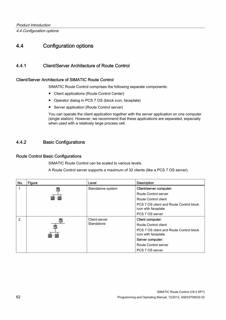
Product Introduction 4.4 Configuration options
SIMATIC Route Control (V8.0 SP1) 62 Programming and Operating Manual, 12/2012, A5E03709032-02
4.4 Configuration options
4.4.1 Client/Server Architecture of Route Control
Client/Server Architecture of SIMATIC Route Control SIMATIC Route Control comprises the following separate components:
● Client applications (Route Control Center)
● Operator dialog in PCS 7 OS (block icon, faceplate)
● Server application (Route Control server)
You can operate the client application together with the server application on one computer (single station). However, we recommend that these applications are separated, especially when used with a relatively large process cell.
4.4.2 Basic Configurations
Route Control Basic Configurations SIMATIC Route Control can be scaled to various levels.
A Route Control server supports a maximum of 32 clients (like a PCS 7 OS server).
No. Figure Level Description 1
Standalone system Client/server computer: Route Control server Route Control client PCS 7 OS client and Route Control block icon with faceplate PCS 7 OS server
2
Client-server Standalone
Client computer: Route Control client PCS 7 OS client and Route Control block icon with faceplate Server computer: Route Control server PCS 7 OS server
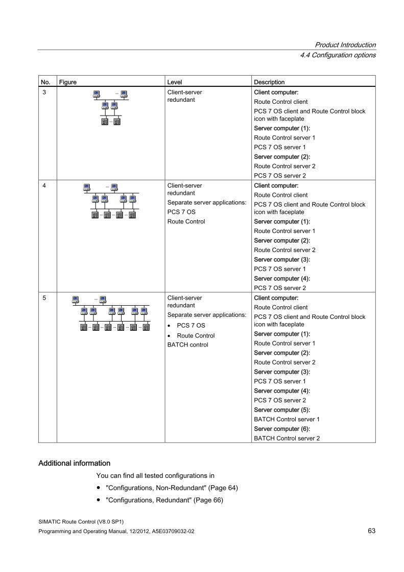
Product Introduction 4.4 Configuration options
SIMATIC Route Control (V8.0 SP1) Programming and Operating Manual, 12/2012, A5E03709032-02 63
No. Figure Level Description 3
Client-server redundant
Client computer: Route Control client PCS 7 OS client and Route Control block icon with faceplate Server computer (1): Route Control server 1 PCS 7 OS server 1 Server computer (2): Route Control server 2 PCS 7 OS server 2
4
Client-server redundant Separate server applications: PCS 7 OS Route Control
Client computer: Route Control client PCS 7 OS client and Route Control block icon with faceplate Server computer (1): Route Control server 1 Server computer (2): Route Control server 2 Server computer (3): PCS 7 OS server 1 Server computer (4): PCS 7 OS server 2
5
Client-server redundant Separate server applications: • PCS 7 OS • Route Control BATCH control
Client computer: Route Control client PCS 7 OS client and Route Control block icon with faceplate Server computer (1): Route Control server 1 Server computer (2): Route Control server 2 Server computer (3): PCS 7 OS server 1 Server computer (4): PCS 7 OS server 2 Server computer (5): BATCH Control server 1 Server computer (6): BATCH Control server 2
Additional information You can find all tested configurations in
● "Configurations, Non-Redundant" (Page 64)
● "Configurations, Redundant" (Page 66)
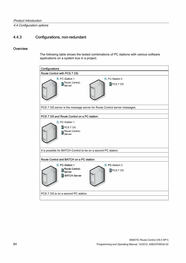
Product Introduction 4.4 Configuration options
SIMATIC Route Control (V8.0 SP1) 64 Programming and Operating Manual, 12/2012, A5E03709032-02
4.4.3 Configurations, non-redundant
Overview The following table shows the tested combinations of PC stations with various software applications on a system bus in a project.
Configurations Route Control with PCS 7 OS:
PCS 7 OS server is the message server for Route Control server messages. PCS 7 OS and Route Control on a PC station:
It is possible for BATCH Control to be on a second PC station. Route Control and BATCH on a PC station:
PCS 7 OS is on a second PC station.
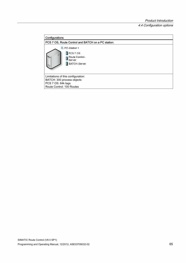
Product Introduction 4.4 Configuration options
SIMATIC Route Control (V8.0 SP1) Programming and Operating Manual, 12/2012, A5E03709032-02 65
Configurations PCS 7 OS, Route Control and BATCH on a PC station:
Limitations of this configuration: BATCH: 300 process objects PCS 7 OS: 64k tags Route Control: 100 Routes
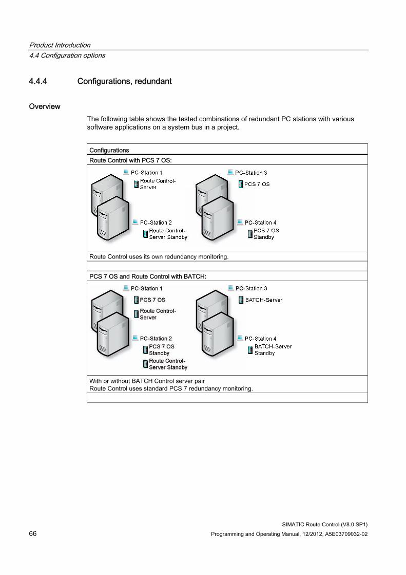
Product Introduction 4.4 Configuration options
SIMATIC Route Control (V8.0 SP1) 66 Programming and Operating Manual, 12/2012, A5E03709032-02
4.4.4 Configurations, redundant
Overview The following table shows the tested combinations of redundant PC stations with various software applications on a system bus in a project.
Configurations Route Control with PCS 7 OS:
Route Control uses its own redundancy monitoring. PCS 7 OS and Route Control with BATCH:
With or without BATCH Control server pair Route Control uses standard PCS 7 redundancy monitoring.
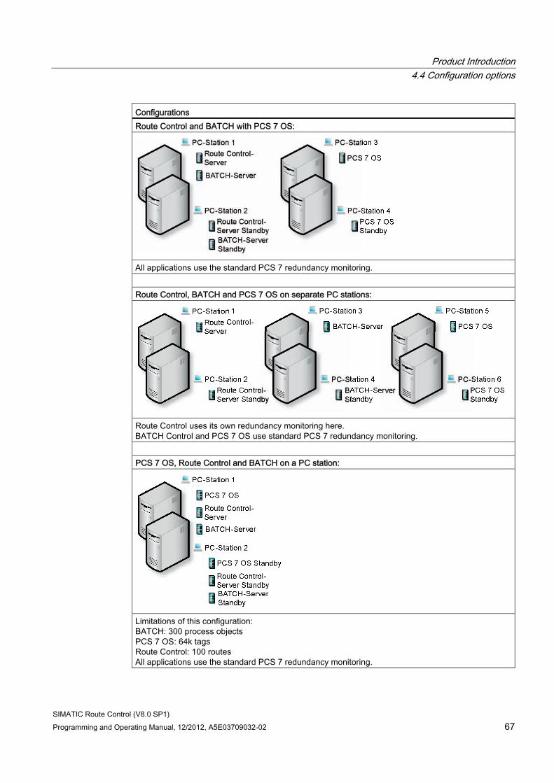
Product Introduction 4.4 Configuration options
SIMATIC Route Control (V8.0 SP1) Programming and Operating Manual, 12/2012, A5E03709032-02 67
Configurations Route Control and BATCH with PCS 7 OS:
All applications use the standard PCS 7 redundancy monitoring. Route Control, BATCH and PCS 7 OS on separate PC stations:
Route Control uses its own redundancy monitoring here. BATCH Control and PCS 7 OS use standard PCS 7 redundancy monitoring. PCS 7 OS, Route Control and BATCH on a PC station:
Limitations of this configuration: BATCH: 300 process objects PCS 7 OS: 64k tags Route Control: 100 routes All applications use the standard PCS 7 redundancy monitoring.
Product Introduction 4.5 Installing Route Control
SIMATIC Route Control (V8.0 SP1) 68 Programming and Operating Manual, 12/2012, A5E03709032-02
4.5 Installing Route Control
4.5.1 Delivery form of Route Control
Introduction SIMATIC Route Control is supplied with PCS 7 on DVD. During installation you indicate which applications you need to run on your station.
You can find additional information in the manuals regarding PCS 7 installation.
The licenses for these applications are not included on the PCS 7 DVD and must be ordered separately. You can find additional information in "Overview of Authorization" (Page 75)
Delivery form of Route Control SIMATIC Route Control offers the following packages:
● Route Control Engineering
● Route Control Center
● Route Control Server
● Route Control Routes (10 routes)
● Route Control Routes (50 routes (PowerPack))
4.5.2 Readme file with current information
Readme File
Note
Refer also to the current SIMATIC Route Control notes in the PCS 7 Route Control Basis readme.wri file provided on the software DVD.
Opening the Readme File There are three methods available for opening the file:
● Double-click PCS 7 Route Control Basis readme.wri on the DVD-ROM.
● In the Windows Start menu, select the menu command Start > SIMATIC > Information > German.
● Double-click SIMATIC Route Control - Readme.
Product Introduction 4.5 Installing Route Control
SIMATIC Route Control (V8.0 SP1) Programming and Operating Manual, 12/2012, A5E03709032-02 69
4.5.3 Installing Route Control components
Installing As of V6.1, the installation program for SIMATIC Route Control is started from within PCS 7 system setup. It is called using the standard procedure for software installation in Windows.
Note
Refer also to the notes on installing SIMATIC Route Control in the SIMATIC Route Control readme.wri file. You can also find the readme file in the Setup directory for SIMATIC Route Control.
Component Installation Options As of SIMATIC Route Control V6.1, the Route Control installation program is called "silently" via PCS 7 system setup. Thus, no further action is required during installation.
with the basic package, the following applications are offered at the start of installation:
● Route Control Engineering
● Route Control single station
● Route Control server
● Route Control client
● User-defined installation
Select the applications, which you wish to install.
The SIMATIC Route Control basic software is installed automatically and, therefore, does not need to be selected.
Creating an Image To ensure you have a backup of partitions and hard disk data (after a new installation, for example), we recommend that you create an image of the installation.
Note
Please note that authorizations and license keys cannot and may not be backed up.
Move the authorizations and license keys to another medium (diskette, partition, etc.) before creating the image.
When choosing the image software, please note that it must be suitable for the operating system used.
To create an image, follow the instructions provided by the manufacturer of the image software.
Product Introduction 4.5 Installing Route Control
SIMATIC Route Control (V8.0 SP1) 70 Programming and Operating Manual, 12/2012, A5E03709032-02
Removal Route Control is removed via the Windows Control Panel (Add or Remove Programs), as are other PCS 7 components.
Installation in a Redundant System
Note
You must take a number of special features into account in a redundant PCS 7 system.
You can find additional information in "Monitoring Functions" (Page 515)
Product Introduction 4.5 Installing Route Control
SIMATIC Route Control (V8.0 SP1) Programming and Operating Manual, 12/2012, A5E03709032-02 71
4.5.4 Installation requirements
4.5.4.1 ES and server hardware and software
Recommended Hardware for PCS 7 Recommended hardware configurations for PC stations appear in the Process Control System PCS 7; PC Configuration and Authorization Manual.
Setting Operating System Partition C Configure partition C to at least 50 GB for the operating system and PCS 7.
● For projects and the project database: Additional memory
● For the output of configured data (e.g., partial routes, elements): A graphics-compatible printer supported by Windows (the software was tested with HP Laser Jet)
Software requirements
Note
Information about the current status is available in the description of PCS 7. A copy is provided in this document. • SIMATIC Route Control V6.0 based on PCS 7 V6.0 SP2 • SIMATIC Route Control V6.0 SP1 based on PCS 7 V6.0 SP3 • SIMATIC Route Control V6.1 based on PCS 7 V6.1 • SIMATIC Route Control V6.1 SP1 based on PCS 7 V6.1 SP1 • SIMATIC Route Control V7.0 based on PCS 7 V7.0 • SIMATIC Route Control V7.0 SP1 based on PCS 7 V7.0 SP1 • SIMATIC Route Control V7.1 based on PCS 7 V7.1 • SIMATIC Route Control V7.1 SP1 based on PCS 7 V7.1 SP1 • SIMATIC Route Control V7.1 SP2 based on PCS 7 V7.1 SP2 • SIMATIC Route Control V8.0 based on PCS 7 V8.0
Route Control requires the PCS 7 operating system for client and server.
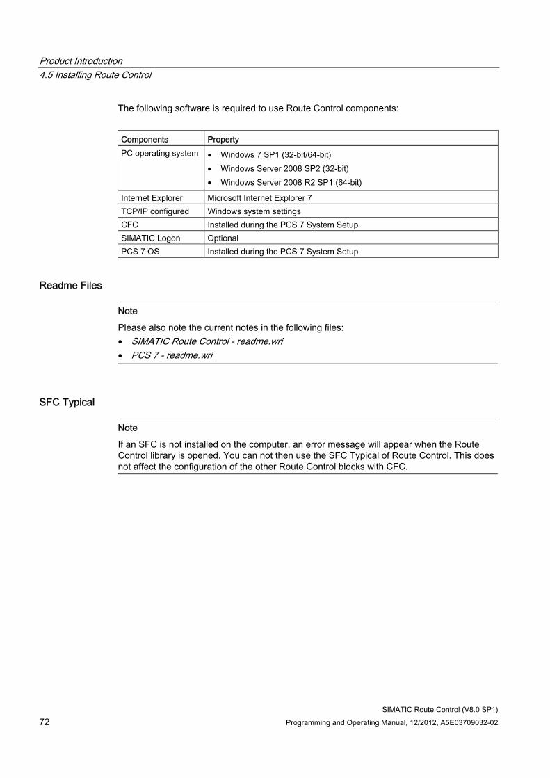
Product Introduction 4.5 Installing Route Control
SIMATIC Route Control (V8.0 SP1) 72 Programming and Operating Manual, 12/2012, A5E03709032-02
The following software is required to use Route Control components:
Components Property PC operating system • Windows 7 SP1 (32-bit/64-bit)
• Windows Server 2008 SP2 (32-bit) • Windows Server 2008 R2 SP1 (64-bit)
Internet Explorer Microsoft Internet Explorer 7 TCP/IP configured Windows system settings CFC Installed during the PCS 7 System Setup SIMATIC Logon Optional PCS 7 OS Installed during the PCS 7 System Setup
Readme Files
Note
Please also note the current notes in the following files: • SIMATIC Route Control - readme.wri • PCS 7 - readme.wri
SFC Typical
Note
If an SFC is not installed on the computer, an error message will appear when the Route Control library is opened. You can not then use the SFC Typical of Route Control. This does not affect the configuration of the other Route Control blocks with CFC.

Product Introduction 4.5 Installing Route Control
SIMATIC Route Control (V8.0 SP1) Programming and Operating Manual, 12/2012, A5E03709032-02 73
4.5.4.2 AS hardware and software
Automation System Requirements Route Control supports the CPU types below:
● CPU 416-3 (Notice! Smaller quantity framework with approx. 30 routes)
● CPU 417-4
● CPU 417-4H
Route Control requires CPU firmware version 3.1.0 and higher for these CPU types.
You can find additional information in the SIMATIC PCS 7 - Enabled PCS 7 Modules Manual.
Resources required in the CPU Set at least the following values for the local data of the OBs in HWConfig -> CPU Properties -> Save as listed below:
OB Local data 1 1450 9 1200 11 1200 12 1400 25 1400 26 1400 27 1400 28 1400 29 20
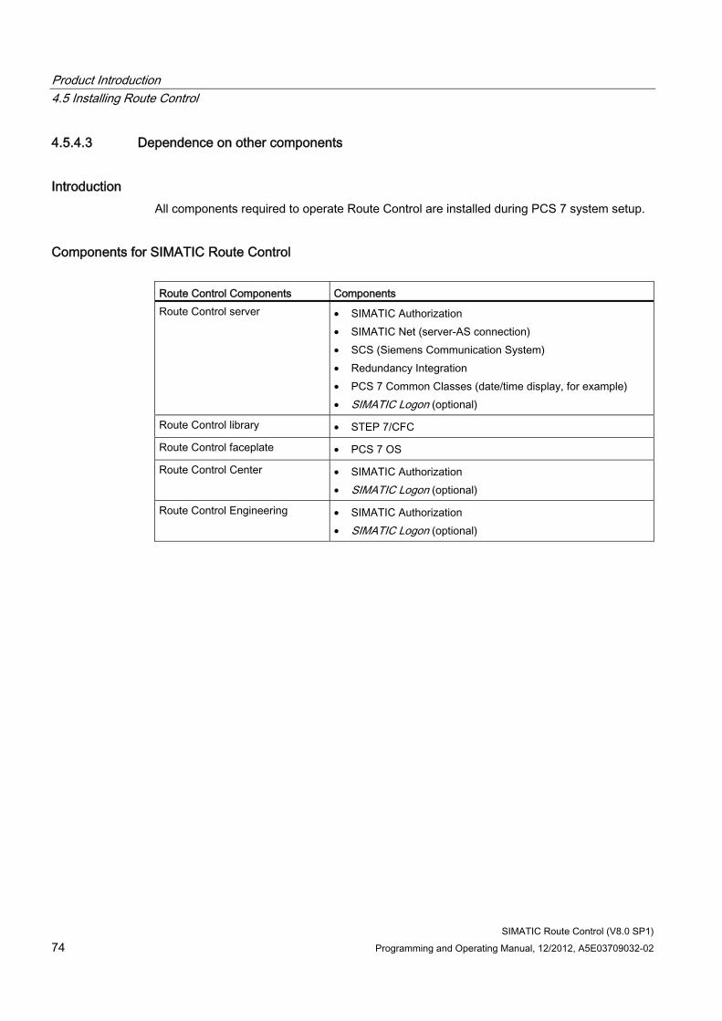
Product Introduction 4.5 Installing Route Control
SIMATIC Route Control (V8.0 SP1) 74 Programming and Operating Manual, 12/2012, A5E03709032-02
4.5.4.3 Dependence on other components
Introduction All components required to operate Route Control are installed during PCS 7 system setup.
Components for SIMATIC Route Control Route Control Components Components Route Control server • SIMATIC Authorization
• SIMATIC Net (server-AS connection) • SCS (Siemens Communication System) • Redundancy Integration • PCS 7 Common Classes (date/time display, for example) • SIMATIC Logon (optional)
Route Control library • STEP 7/CFC
Route Control faceplate • PCS 7 OS
Route Control Center • SIMATIC Authorization • SIMATIC Logon (optional)
Route Control Engineering • SIMATIC Authorization • SIMATIC Logon (optional)
Product Introduction 4.6 Licensing
SIMATIC Route Control (V8.0 SP1) Programming and Operating Manual, 12/2012, A5E03709032-02 75
4.6 Licensing
4.6.1 Overview of Licensing
Introduction The software of SIMATIC Route Control can only be used if the applications find the appropriate licenses.
A single license is always located on the hard disk of the computer on which the application runs.
Floating licenses can be managed on a central license server. This allows you to install an application on any number of computers and start it as often as permitted by the number of licenses you have obtained.
You can find detailed information about installing and managing licenses in online help of the Automation License Manager.
Server License The license for the server restricts the maximum number of simultaneously operating material transports to the number of installed route licenses up to a maximum of 300. If the number of route requests to the Route Control server exceeds these limits, a message is transmitted to the message system. The Route Control server continues to run and responds to the route request that caused the limit violation with a route request error.
Note
Always install only one server license on a Route Control server.
Client license The Route Control Center is enabled via floating licenses.
Engineering license Route Control Engineering is enabled via floating licenses.
Overview of route licenses as of V 8.0 As of version 8.0, you can combine licenses as desired for 10 or 50 material transports up to a maximum of 300 material transports. This replaces the previous licensing concept for routes.
Product Introduction 4.6 Licensing
SIMATIC Route Control (V8.0 SP1) 76 Programming and Operating Manual, 12/2012, A5E03709032-02
Upgrade You can upgrade Route Control from PCS 7 V7.0.x and V7.1.x to V8.0. The upgrade package comprises the following licenses:
● Route Control Center
● Route Control Engineering
● Route Control Server
● Route Control Routes 10 routes
● Route Control Routes 50 routes
Product Introduction 4.7 User rights
SIMATIC Route Control (V8.0 SP1) Programming and Operating Manual, 12/2012, A5E03709032-02 77
4.7 User rights
4.7.1 Introduction to authorization management
Integration of SIMATIC Logon in SIMATIC Route Control SIMATIC Route Control supports the central user management SIMATIC Logon of PCS 7, which in turn is based on the mechanisms of the user management in Windows.
Principles of Authorization Management ● Users, user groups and passwords are centrally defined in Windows.
● For SIMATIC Route Control V6.0 and higher, the five relevant user groups are created in Windows during setup.
● You must create the SIMATIC Route Control user groups on all computers, on which SIMATIC Route Control is to operate with the user concept.
● You will require Windows administrator rights and expertise in order to set up users and assign them to groups.
● A user logs on and off by means of the following applications: Route Control Engineering tool, Route Control Center and Route Control server. Route Control is also notified when a user logs on or off outside of SIMATIC Route Control. After such a change occurs, corresponding functions are enabled or disabled.
Access protection If you are using the components of SIMATC Logon, you can activate access protection in SIMATIC Manager from the "Options" menu. This provides password protection when opening projects and starting the Route Control Wizard.
You can find additional information in the online help for SIMATIC Manager.
Reaction without SIMATIC Logon If SIMATIC Logon is not installed, all operator actions are allowed. Access protection and change log are then not possible.
Product Introduction 4.7 User rights
SIMATIC Route Control (V8.0 SP1) 78 Programming and Operating Manual, 12/2012, A5E03709032-02
4.7.2 User roles and user rights
User Roles for SIMATIC Route Control SIMATIC Route Control works with five user groups that are also valid in the user concept SIMATIC Logon.
The dependencies of these user groups are described in the following tables:
User group includes RC_ENGINEER - RC_OPERATOR_L1 - RC_OPERATOR_L2 RC_OPERATOR_L1 RC_OPERATOR_L3 RC_OPERATOR_L2 RC_MAINTENANCE RC_OPERATOR_L3 + RC_ENGINEER
Fixed operating authorizations are assigned to these user groups. Thus, each group contains a user role.
These user groups must be set up for the components below:
● Route Control Engineering
● Route Control server
● Route Control Center
User rights The user groups have different authorizations within SIMATIC Route Control:
User group Authorization (Overview) RC_ENGINEER To engineer and download to the Route Control server;
To restart and shut down the server directly when the Route Control server is running on a computer without PCS 7 OS. Note: When the Route Control server is running on a PCS 7 OS server, it is started and shut down with the OS project.
RC_OPERATOR_L1 To perform simple operations in the Route Control Center, including holding a route RC_OPERATOR_L2 Middle authorization level; includes access operations such as re-requesting the same route RC_OPERATOR_L3 Highest authorization level for the operating personnel;
Request a route with a different source / different destination; Enable a new loaded Route Control project to the Route Control Center
RC_MAINTENANCE Full access, all rights, emergency personnel Restart and end the server
Product Introduction 4.7 User rights
SIMATIC Route Control (V8.0 SP1) Programming and Operating Manual, 12/2012, A5E03709032-02 79
The following table illustrates the individual user rights in detail:
User group Rights Unprotected Update route Unprotected Update elements
To open and modify the configuration RC_ENGINEER Load Route Control server with new configuration Manual and automatic switchover RC_OPERATOR_L1 Pause route Request route Start route Stop route (corresponds to reset request and reset start) Restart route (after stop)
RC_OPERATOR_L2
To acknowledge (positive edge) Specifying locations for a path (source, via1...10 and destination) Specifying the mode table of a route Specifying the function ID of a route Specifying the material of a route To activate/deactivate ignoring of errors To adjust the option dialog
RC_OPERATOR_L3
in case of redundancy: switch to a different Route Control server RC_MAINTENANCE Complete access to all actions/operations
If you wish to apply these user rights within the scope of SIMATIC Logon also for the Route Control faceplate in the PCS 7 OS, then, with the "User Administrator" of the PCS 7 OS, set up the user groups RC_OPERATOR_L1 and / or RC_OPERATOR_L2.
Assign these user groups the following permission levels:
User group Rights Permission levels of the PCS 7 OS RC_OPERATOR_L1 see table above 2, 4 and 5 RC_OPERATOR_L2 see table above 2, 4, 5 and 6
If you also want to enable the members of other Route Control user groups to operate with the Route Control faceplate, then via the "User Administration" set up these user groups too and assign them the necessary permission levels of the PCS 7 OS.
Note
The rights of the user group RC_OPERATOR_L3 cannot be used with the Route Control faceplate.
Product Introduction 4.7 User rights
SIMATIC Route Control (V8.0 SP1) 80 Programming and Operating Manual, 12/2012, A5E03709032-02
4.7.3 Defining user rights
Requirements SIMATIC Logon comprises two components and is installed on every computer with a Route Control application:
● SIMATIC Logon administration tool
● SIMATIC Logon service (runtime component)
The following requirement applies when working with SIMATIC Logon:
● The "Logon_Administrator“ Windows group must be created. This group is used in all SIMATIC components such as BATCH or Route Control. Only the members of one of these two user groups may open the SIMATIC Access Control application and define user roles.
Note
As Route Control works with five fixed user groups, no other groups have to be set up using SIMATIC Access Control for Route Control.
Basic Procedure Step Action 1 Create all users with passwords. 2 Assign users to to the specific groups.
Note
You will need Administrator rights and expertise in order to work in Windows user administration.
The Route Control setup creates the required groups during installation.
If a domain controller is available, you can manage the users and groups there centrally.
If you use a SIMATIC Logon logon server or a domain controller, you must create the user groups manually.
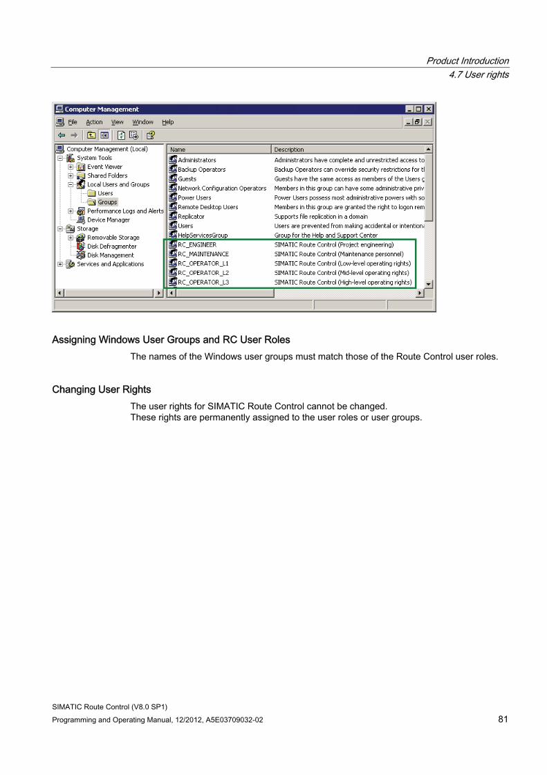
Product Introduction 4.7 User rights
SIMATIC Route Control (V8.0 SP1) Programming and Operating Manual, 12/2012, A5E03709032-02 81
Assigning Windows User Groups and RC User Roles The names of the Windows user groups must match those of the Route Control user roles.
Changing User Rights The user rights for SIMATIC Route Control cannot be changed. These rights are permanently assigned to the user roles or user groups.

Product Introduction 4.7 User rights
SIMATIC Route Control (V8.0 SP1) 82 Programming and Operating Manual, 12/2012, A5E03709032-02
SIMATIC Route Control (V8.0 SP1) Programming and Operating Manual, 12/2012, A5E03709032-02 83
Software update 55.1 Updating from V8.0 to V8.0 SP1
Overview Select "Update" in Setup to update the SIMATIC Route Control software from V8.0 / V8.0 Update 1 to V8.0 SP1.
You can find information about the new functions in the section: What's new in SIMATIC Route Control V8.0 SP1? (Page 23).
Note the following when updating a Route Control project from V8.0 / V8.0 Up 1 to V 8.0 SP 1:
● Conversion of the Route Control database is not required.
● Copy the new RC blocks from the installed RC library to the S7 projects in which you use RC functionality, update the CFC charts with block type import and compile / load the charts to the respective automation systems.
Continue working with the blocks of V8.0 or V8.0 Update 1 No stop of the CPU is required after installation of the blocks of the V8.0 SP1.
If you nevertheless want to further process version V8.0 / V8.0 Update 1, note the following limitations:
The blocks provided for the use of elements of other PCells (RC_IF_Remote_CE/SE/PE) do not have the corresponding parameter attributes for indicating the parameters in a process object view.
Information on the blocks is located in the section REMOTE blocks (Page 261).
Software update 5.2 Updating from earlier versions
SIMATIC Route Control (V8.0 SP1) 84 Programming and Operating Manual, 12/2012, A5E03709032-02
5.2 Updating from earlier versions
5.2.1 Updating from V7.1SP2 to V8.0
Overview When you install the SIMATIC Route Control V8.0 software, note the following:
New RC library A new RC library is installed during setup. Make sure, therefore, that you save the original RC Library 7.1 beforehand.
If possible, close any running RC applications on the computer where the installation will be performed and run the provided update setup. It will install the required or selected components onto the system.
AS blocks The following AS blocks have been changed in this version of RC Lib to provide the new functionality:
● FB 803 / RC_ROUTE_CE_ON
● DB100 / RC_CFG
The following block has been newly created:
● FB 815 / RC_ResPosV5
Due to the dependencies of DB100, the following blocks needed to be recompiled, although they have not changed. They therefore obtained a new time stamp:
● FB852 / RC_MASTER_FUNC
● FB850 / RC_IF_CFG
● FB818 / RC_ROUTE_GET_EXT_PE
● FB817 / RC_ROUTE_XC_PE_ACTV
● FB812 / RC_TG34_TG36
● FB806 / RC_ROUTE_XC_SEND
● FB801 / RC_ROUTE
● FB858 / RC_MASTER_XC_SEND
Software update 5.2 Updating from earlier versions
SIMATIC Route Control (V8.0 SP1) Programming and Operating Manual, 12/2012, A5E03709032-02 85
To bring your S7 user projects up to date, proceed as follows:
1. Close all routes before downloading the automation systems.
2. Copy the RC blocks listed above from the installed library into the block folders of the user projects.
3. If you want to set the behavior of V5, enter the value W#16#ABAB for the ID "wLikeV5" (offset 80.0) in all automation systems in DB100/RC_CFG.
4. Open a CFC in every user project.
5. Import the new block types (see above).
6. Compile and download the automation systems (with user data blocks).
7. Run the RC Wizard and follow the instructions it provides.
You can find information about the new functions in the section: What's new in SIMATIC Route Control V8.0? (Page 25)
Software update 5.2 Updating from earlier versions
SIMATIC Route Control (V8.0 SP1) 86 Programming and Operating Manual, 12/2012, A5E03709032-02
5.2.2 Update of V7.1SP1 to V7.1 SP2
Overview Select "Update" in Setup to upgrade the SIMATIC Route Control software from V7.1 to V7.1 SP2.
You can find information about the new functions in the section: What's New in SIMATIC Route Control V7.1 SP2? (Page 27)
AS blocks: new structure of instance DBs (e.g. route DBs (DB101 to DB400)) The newly implemented functions (wait elements, remote elements) call for structural changes to various function blocks and their instance data. In addition, the interface of the FB800/RC_IF_Route has been extended and the structure of the instance DB has also been changed.
These changes call for the replacement of all RC blocks.
Note CPU in STOP
The RC blocks can only be replaced if the CPU is in STOP mode.
Carry out the following steps:
1. Copy all RC blocks (FB 8xx, FC 8xx, DB, UDT) from the installed library to the block folders of your projects.
2. Open a CFC chart in every user project.
3. Import the new block types
4. Compile and download your automation systems and restart them
Note Larger local data ranges
The local data ranges have been made larger for various blocks of the RC Lib. This can result in warnings or errors when you load the CFC. Make the local data ranges of the displayed priority levels larger as well (properties of CPU) and repeat the download.
Software update 5.2 Updating from earlier versions
SIMATIC Route Control (V8.0 SP1) Programming and Operating Manual, 12/2012, A5E03709032-02 87
Continuing to work with V7.1.1 blocks Following the installation of V7.1.2 blocks, you have to set the CPU to STOP. If this is not possible, you can also continue to work with V7.1.1 blocks.
The following new functions can then not be used:
● Save route/Start saved route
During startup, the Route Control server checks whether one of the automation systems involved does not contain any current blocks. If this is the case, the buttons for the two functions are disabled in the Route Control Center.
● Wait elements
Routes with wait elements can be configured, but are terminated with an error message pointing out the incompatibility with the old blocks. Additional error messages are entered in WinCC and in the diagnostic buffer of the CPU. You can avoid these by not using wait elements when working with V7.1.1 blocks.
Updating the blocks You cannot operate V7.1 SP1 blocks together with V7.1 SP2 blocks in the same project.
For a project with several automation systems, you either have to update all the automation systems to version 7.1 SP2 or leave version 7.1 SP1 blocks on all automation systems.
Combined operation, for example, 2 automation systems with new blocks and 3 automation systems with old blocks, is not possible.
See also What's new in SIMATIC Route Control V8.0? (Page 25)
Software update 5.2 Updating from earlier versions
SIMATIC Route Control (V8.0 SP1) 88 Programming and Operating Manual, 12/2012, A5E03709032-02
5.2.3 Updating from V7.1 to V7.1 SP1
Procedure Perform the following steps to update a Route Control project from V7.1 to V7.1 SP1:
● Conversion of the Route Control database to V7.1 SP1 format by opening Route Control Engineering or when the Route Control wizard is initially run.
Then download and update your RC server.
● Optional: Update the Route Control block FB803 in your S7 user projects if you would like to use the correction named in point 2.
You can find information about the new functions in: What's new in SIMATIC Route Control V7.1 SP1? (Page 30)
Blocks The version V7.1 blocks also function with Route Control V7.1 SP1.
To correct the reaction of the QRPOSERR output at the FB800/RC_IF_ROUTE , the FB803/ RC_ROUTE_RCE_ON has been changed. Idle-state errors of a function are now correctly displayed with a 1. If you want to use this correction in your user projects, you have to copy the FB803 from the installed RC Lib ("RC Library V71SP1") to your user projects. Please note that you may have to adapt the evaluation of this output in your CFC interconnection. Update the block types in CFC, then compile and download the CFC charts. (only changes) It is not necessary to set the CPU to STOP for this step.
Software update 5.2 Updating from earlier versions
SIMATIC Route Control (V8.0 SP1) Programming and Operating Manual, 12/2012, A5E03709032-02 89
5.2.4 Updating from V7.0 to V7.0 SP1
Overview It is not necessary to re-install the SIMATIC Route Control software when updating from V7.0 to V7.0 SP1. Select "Update" in the Setup.
Additional information on the new functions is available in the section: "What's new in SIMATIC Route Control V7.0 SP1?" (Page 32).
Updating the blocks The version V7.0 blocks also function with Route Control V7.0 SP1. Update all Route Control block types if you want to use one of the following new functions:
● Disabling monitoring times
● Maintenance request by program
● Display the complete name of the locations in the Route Control faceplate
● Alarms concerning BATCH on the PCS 7 OS
Note
The central updating of block types does not include DBs and UDTs. Therefore you must first of all manually copy the required DBs and all the UDTs into the block folder of the respective CPU.
To update the block types, proceed as follows:
1. In the SIMATIC Manager, open the RC Library V70 SP1.
2. Select all the Route Control blocks in the "RC Library V70 SP1\Blocks+Templates\Blocks" folder.
3. Select the Tools > Charts > Update block types ....
4. Follow the instructions in the following dialogs.
Then compile the entire program and load just the changes to the affected automation system. A CPU stop is not required for these changes.
Alarms concerning BATCH on the PCS 7 OS The auxiliary values of alarms of the route block FB 800, which affect the interplay with SIMATIC BATCH, are now changed. They now include the batch name, step number and batch number. If this information is to be correctly transferred to the PCS 7 OS then after updating the block and compiling the OS with you will need to restart the respective AS with a memory reset.
Software update 5.2 Updating from earlier versions
SIMATIC Route Control (V8.0 SP1) 90 Programming and Operating Manual, 12/2012, A5E03709032-02
Other necessary actions Ensure you run the Route Control wizard so that the Route Control database is updated. Then load and update the Route Control server(s).
Adding the new control element in Graphics Designer Update the PCS 7 OS software in order to integrate the new drop-down list box for selecting locations in your plant pictures.
Add the control element "rcCBox Class" to the object palette in Graphics Designer.
Procedure:
1. Open Graphics Designer.
2. Open the shortcut menu in the "Controls" tab of the object palette and select the Add/Remove command. The "Select OCXs" dialog box opens.
3. Select the check box for the "rcCBox Class" control.
4. Click "OK". The control element is added to the object palette.
Software update 5.2 Updating from earlier versions
SIMATIC Route Control (V8.0 SP1) Programming and Operating Manual, 12/2012, A5E03709032-02 91
5.2.5 How to update projects from V6.1 SP1 to V7.0
Introduction As of V7.0, you configure process cells, units and locations, along with their properties, solely in SIMATIC Manager. You can no longer add, change or delete process cells, units or locations in Route Control Engineering.
Locations that were previously configured in Route Control Engineering must be imported into the plant hierarchy in SIMATIC Manager.
Overview of Procedure Step Action 1 Update the S7 project in SIMATIC Manager from V6.1 SP1 to V7.0 2 Implementation of licenses for V7.0
You require the Server, Engineering and Center licenses for Route Control. 3 Converting CFC charts into the V7.0 format
(can be done by moving a block in a CFC chart) 4 Implementing equipment properties in the global declarations
(can be done when you create the "Equipment Properties" folder) 5 Conversion of the Route Control database to V7.0 format
(executed when Route Control Engineering is initially opened) 6 Import the locations from Route Control engineering in the PH in SIMATIC Manager.
You can find additional information in: "How to import locations into the PH" (Page 93).
7 Import the locations from SIMATIC Manager into Route Control engineering using the Route Control wizard
8 Compile the CFC charts (entire program) 9 Download the automation systems (with changes) 10 Download the Route Control server and update it in the Route Control Center.
Note
Steps 1, 3, and 4 may be performed automatically during steps 6 and 7 if required.
Software update 5.2 Updating from earlier versions
SIMATIC Route Control (V8.0 SP1) 92 Programming and Operating Manual, 12/2012, A5E03709032-02
Blocks The blocks from version V6.1 SP1 also work with Route Control V7.0.
If you want to use blocks from V7.0, update the Route Control block types.
Centralized updating of the block types does not affect DBs and UDTs. For this reason, you must copy the required DBs and all UDTs to the block folders associated with the CPUs concerned manually before performing the update.
Proceed as follows to update the block types:
1. Open the RC Library V70 in SIMATIC Manager.
2. Select the required Route Control blocks in folder "RC Library V70\Blocks+Templates\Blocks".
3. Select the menu command Options > Charts > Update block types....
Note
Once you have updated the Route Control blocks, you will need to perform a complete CPU download. To do this, you will need to stop all CPUs.
Software update 5.2 Updating from earlier versions
SIMATIC Route Control (V8.0 SP1) Programming and Operating Manual, 12/2012, A5E03709032-02 93
5.2.6 How to import locations into the PH
Introduction If you converted the Route Control configuration data to V7.0 format during the software update from V6.1 SP1 to V7.0, you need to import the locations from Route Control Engineering into the plant hierarchy of the S7 project. The Route Control Location Import Wizard will assist you.
Requirements The procedure described below applies to all situations in which the structure of the process cells and units in Route Control Engineering matches the structure of the PH in SIMATIC Manager.
The following rules apply in situations in which this requirement is not fulfilled:
● A project in the SIMATIC Manager may contain only one plant. The import wizard cannot generate any additional plants in the S7 project. Locations which are in additional plants in Route Control-Engineering are therefore not imported into the plant hierarchy.
● If the process cell in Route Control Engineering contains more units than the process cell in the PH, then the import wizard generates all additional units in the PH and imports the locations of these units.
Procedure for importing locations 1. Start the program rclocimpax.exe from the directory C:\Program Files\Siemens\RCS\bin.
The step "Introduction" for the wizard opens.
2. Click "Project". The dialog box for selecting a project appears.
3. Select the project whose locations you wish to import into the PH.
4. Click "Next" and check the displayed data.
5. Click "Next". The import is executed and a summary is displayed.
6. Click "Finish".
Result The "Equipment Properties" folder in the "Shared Declarations" of the S7 project contains all location types. The units contain "Equipment Properties" folders with locations. These folders have the same names as the units. Locations from the previous "General Locations" folder in Route Control Engineering are saved in the PH in the "General Locations" units in the "General Locations" folder.
Software update 5.2 Updating from earlier versions
SIMATIC Route Control (V8.0 SP1) 94 Programming and Operating Manual, 12/2012, A5E03709032-02
5.2.7 Updating in overview
Overview This description applies to Route Control projects that were implemented with one of the following variants of SIMATIC Route Control V5:
● Updating from "RCS-based-on-PCS 7" Projects (Page 97) (V5.0, V5.2)
● Updating from "RCS-based-on-BRAUMAT" Projects (Page 98) (V5.2, V5.3)
Earlier versions of Route Control, such as the routing system of SISTAR/BRAUMAT V4.x, are not considered here.
You can find additional information in section
● "Updating tasks" (Page 95)
Note
You can find a brief overview of the blocks that have changed in V6.0 in "Block Changes". (Page 96)
Additional information ● Section: "Updating From V6.0 to V6.1" (Page 100)
● Section: "Updating From V6.1 to V6.1 SP1" (Page 101)
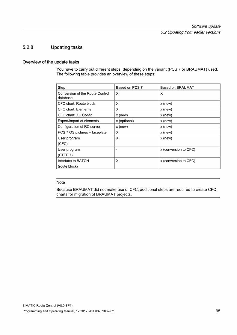
Software update 5.2 Updating from earlier versions
SIMATIC Route Control (V8.0 SP1) Programming and Operating Manual, 12/2012, A5E03709032-02 95
5.2.8 Updating tasks
Overview of the update tasks You have to carry out different steps, depending on the variant (PCS 7 or BRAUMAT) used. The following table provides an overview of these steps:
Step Based on PCS 7 Based on BRAUMAT Conversion of the Route Control database
X X
CFC chart: Route block X x (new) CFC chart: Elements X x (new) CFC chart: XC Config x (new) x (new) Export/import of elements x (optional) x (new) Configuration of RC server x (new) x (new) PCS 7 OS pictures + faceplate X x (new) User program (CFC)
X x (new)
User program (STEP 7)
- x (conversion to CFC)
Interface to BATCH (route block)
X x (conversion to CFC)
Note
Because BRAUMAT did not make use of CFC, additional steps are required to create CFC charts for migration of BRAUMAT projects.
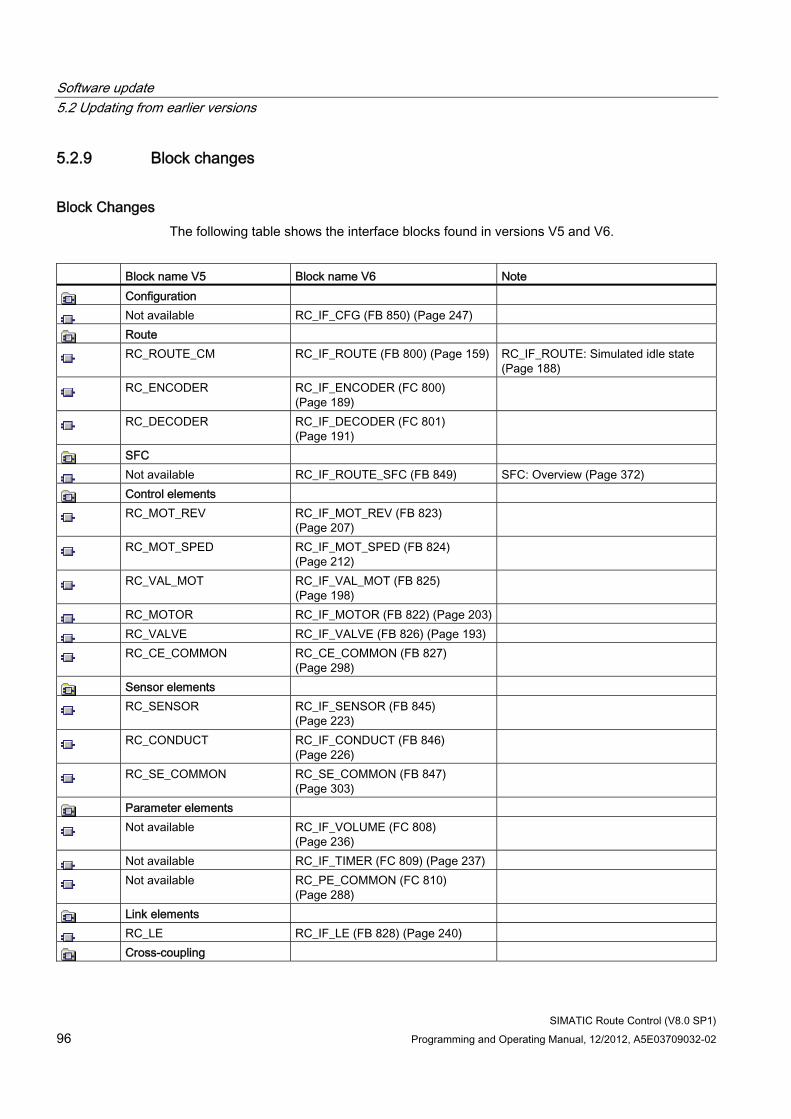
Software update 5.2 Updating from earlier versions
SIMATIC Route Control (V8.0 SP1) 96 Programming and Operating Manual, 12/2012, A5E03709032-02
5.2.9 Block changes
Block Changes The following table shows the interface blocks found in versions V5 and V6.
Block name V5 Block name V6 Note
Configuration
Not available RC_IF_CFG (FB 850) (Page 247)
Route
RC_ROUTE_CM RC_IF_ROUTE (FB 800) (Page 159) RC_IF_ROUTE: Simulated idle state (Page 188)
RC_ENCODER RC_IF_ENCODER (FC 800) (Page 189)
RC_DECODER RC_IF_DECODER (FC 801) (Page 191)
SFC
Not available RC_IF_ROUTE_SFC (FB 849) SFC: Overview (Page 372)
Control elements
RC_MOT_REV RC_IF_MOT_REV (FB 823) (Page 207)
RC_MOT_SPED RC_IF_MOT_SPED (FB 824) (Page 212)
RC_VAL_MOT RC_IF_VAL_MOT (FB 825) (Page 198)
RC_MOTOR RC_IF_MOTOR (FB 822) (Page 203)
RC_VALVE RC_IF_VALVE (FB 826) (Page 193)
RC_CE_COMMON RC_CE_COMMON (FB 827) (Page 298)
Sensor elements
RC_SENSOR RC_IF_SENSOR (FB 845) (Page 223)
RC_CONDUCT RC_IF_CONDUCT (FB 846) (Page 226)
RC_SE_COMMON RC_SE_COMMON (FB 847) (Page 303)
Parameter elements
Not available RC_IF_VOLUME (FC 808) (Page 236)
Not available RC_IF_TIMER (FC 809) (Page 237)
Not available RC_PE_COMMON (FC 810) (Page 288)
Link elements
RC_LE RC_IF_LE (FB 828) (Page 240)
Cross-coupling
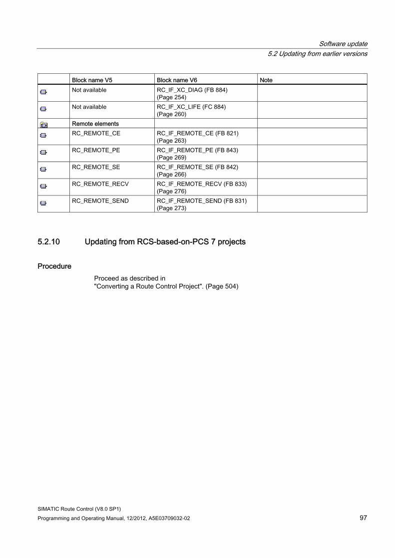
Software update 5.2 Updating from earlier versions
SIMATIC Route Control (V8.0 SP1) Programming and Operating Manual, 12/2012, A5E03709032-02 97
Block name V5 Block name V6 Note
Not available RC_IF_XC_DIAG (FB 884) (Page 254)
Not available RC_IF_XC_LIFE (FC 884) (Page 260)
Remote elements
RC_REMOTE_CE RC_IF_REMOTE_CE (FB 821) (Page 263)
RC_REMOTE_PE RC_IF_REMOTE_PE (FB 843) (Page 269)
RC_REMOTE_SE RC_IF_REMOTE_SE (FB 842) (Page 266)
RC_REMOTE_RECV RC_IF_REMOTE_RECV (FB 833) (Page 276)
RC_REMOTE_SEND RC_IF_REMOTE_SEND (FB 831) (Page 273)
5.2.10 Updating from RCS-based-on-PCS 7 projects
Procedure Proceed as described in "Converting a Route Control Project". (Page 504)
Software update 5.2 Updating from earlier versions
SIMATIC Route Control (V8.0 SP1) 98 Programming and Operating Manual, 12/2012, A5E03709032-02
5.2.11 Updating from RCS-based-on-BRAUMAT projects
Introduction BRAUMAT systems based on PCS 7, which interconnect blocks in CFC charts, are better suited for updating to SIMATIC Route Control than systems in which CFC charts are not used.
Note
SIMATIC Route Control does not support SIMATIC S5 modules.
Updating the Route Control Library (CFC Charts) 1. RC_CALL is replaced by RC_IF_CFG.
2. Element blocks are replaced by blocks from the SIMATIC Route Control V6 library. Note the following:
– The correct element types must be used.
– Element blocks are placed in CFC for all elements that were previously interconnected in partial routes. This prevents any elements that have already been interconnected having to be deleted during import into Route Control Configuration.
The AS-AS connections are generated by the Route Control Wizard.
Updating the Route Control Configuration 1. Route Control Configuration version 5 is opened using the Route Control configuration
tool.
2. Convert the database into the V6 format The conversion tool is automatically called. The elements are transferred from the CFC charts to the Route Control configuration using the wizard. Elements that are not in the S7 project can be deleted. The activation masks and return values for the standard types can be retained. The partial routes and their interconnected elements are retained
3. The global settings are adapted according to the earlier parameter files (INI files).
Updating the Route Control Server 1. The PCU server with Route Control miniport is completely replaced by a Route Control
server V6. In principle, BRAUMAT can be uninstalled on the server and the Route Control server installed, as there are no persistent data that must be transferred from V5 to V6.
2. A new configuration is then downloaded to the Route Control server V6 by the Route Control Engineering tool. This configuration contains the settings for server-server communication and server-AS communication, as well as the settings contained in the previous parameter files (INI files).
Software update 5.2 Updating from earlier versions
SIMATIC Route Control (V8.0 SP1) Programming and Operating Manual, 12/2012, A5E03709032-02 99
Updating the Route Control Block Icons and Faceplate Because version 5 does not include a block icon or faceplate, you must now configure them in your PCS 7 OS pictures.
Updating the Route Control Center 1. BRAUMAT is uninstalled from the client computers.
2. SIMATIC Route Control V6 is installed.
The Route Control Center does not need to be configured. The Route Control server will be determined or requested during the initial call.
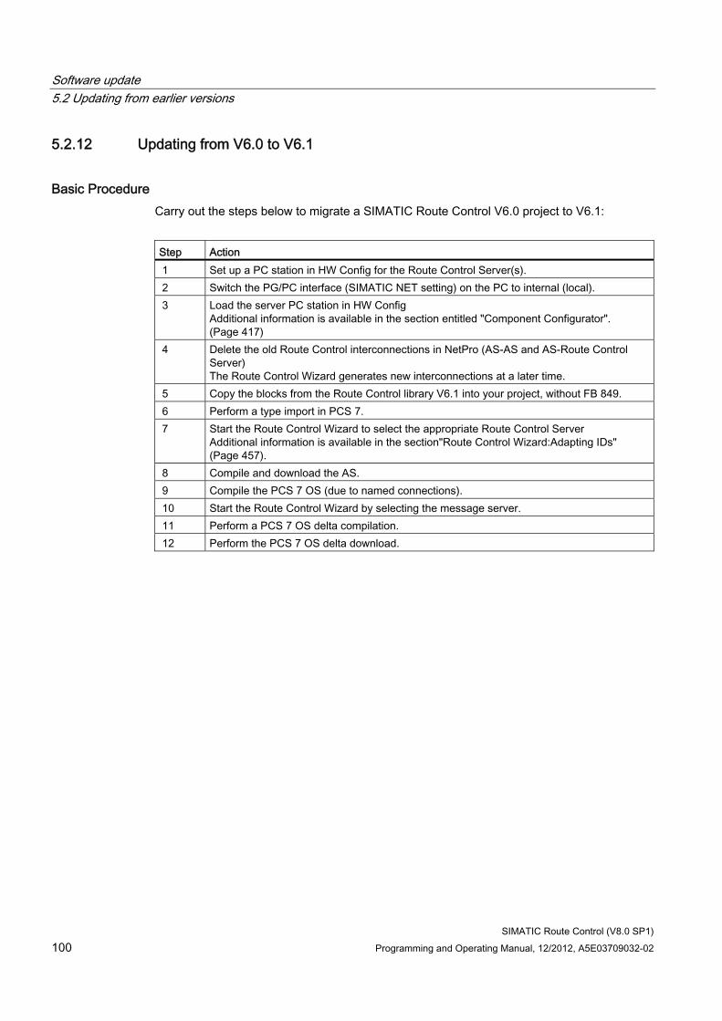
Software update 5.2 Updating from earlier versions
SIMATIC Route Control (V8.0 SP1) 100 Programming and Operating Manual, 12/2012, A5E03709032-02
5.2.12 Updating from V6.0 to V6.1
Basic Procedure Carry out the steps below to migrate a SIMATIC Route Control V6.0 project to V6.1:
Step Action 1 Set up a PC station in HW Config for the Route Control Server(s). 2 Switch the PG/PC interface (SIMATIC NET setting) on the PC to internal (local). 3 Load the server PC station in HW Config
Additional information is available in the section entitled "Component Configurator". (Page 417)
4 Delete the old Route Control interconnections in NetPro (AS-AS and AS-Route Control Server) The Route Control Wizard generates new interconnections at a later time.
5 Copy the blocks from the Route Control library V6.1 into your project, without FB 849. 6 Perform a type import in PCS 7. 7 Start the Route Control Wizard to select the appropriate Route Control Server
Additional information is available in the section"Route Control Wizard:Adapting IDs" (Page 457).
8 Compile and download the AS. 9 Compile the PCS 7 OS (due to named connections). 10 Start the Route Control Wizard by selecting the message server. 11 Perform a PCS 7 OS delta compilation. 12 Perform the PCS 7 OS delta download.
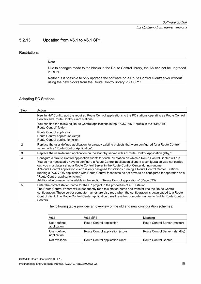
Software update 5.2 Updating from earlier versions
SIMATIC Route Control (V8.0 SP1) Programming and Operating Manual, 12/2012, A5E03709032-02 101
5.2.13 Updating from V6.1 to V6.1 SP1
Restrictions
Note
Due to changes made to the blocks in the Route Control library, the AS can not be upgraded in RUN.
Neither is it possible to only upgrade the software on a Route Control client/server without using the new blocks from the Route Control library V6.1 SP1!
Adapting PC Stations Step Action 1 New In HW Config, add the required Route Control applications to the PC stations operating as Route Control
Servers and Route Control client stations. You can find the following Route Control applications in the "PCS7_V61" profile in the "SIMATIC Route Control" folder: Route Control application Route Control application (stby) Route Control application client
2 Replace the user-defined application for already existing projects that were configured for a Route Control server with a "Route Control Application".
3 Replace the user-defined application on the standby server with a "Route Control Application (stby)". 4 Configure a "Route Control application client" for each PC station on which a Route Control Center will run.
You do not necessarily have to configure a Route Control application client. If a configuration was not carried out, you must later set up a Route Control Server in the Route Control Center during runtime. A "Route Control application client" is only designed for stations running a Route Control Center. Stations running a PCS 7 OS application with Route Control faceplates do not have to be configured for operation as a "Route Control application client". Additional information is available in the section "Route Control applications" (Page 333).
5 Enter the correct station name for the S7 project in the properties of a PC station. The Route Control Wizard will subsequently read this station name and transfer it to the Route Control configuration. These server computer names are also read when the configuration is downloaded to a Route Control client. The Route Control Center application uses these two computer names to find its Route Control Servers.
The following table provides an overview of the old and new configuration schemes:
V6.1 V6.1 SP1 Meaning User-defined application
Route Control application Route Control Server (master)
User-defined application
Route Control application (stby) Route Control Server (standby)
Not available Route Control application client Route Control Center
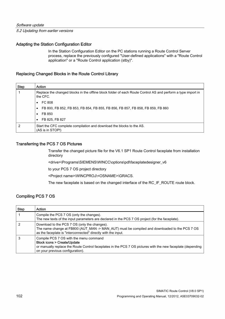
Software update 5.2 Updating from earlier versions
SIMATIC Route Control (V8.0 SP1) 102 Programming and Operating Manual, 12/2012, A5E03709032-02
Adapting the Station Configuration Editor In the Station Configuration Editor on the PC stations running a Route Control Server process, replace the previously configured "User-defined applications" with a "Route Control application" or a "Route Control application (stby)".
Replacing Changed Blocks in the Route Control Library Step Action 1 Replace the changed blocks in the offline block folder of each Route Control AS and perform a type import in
the CFC. • FC 808 • FB 800, FB 852, FB 853, FB 854, FB 855, FB 856, FB 857, FB 858, FB 859, FB 860 • FB 850 • FB 825, FB 827
2 Start the CFC complete compilation and download the blocks to the AS. (AS is in STOP!)
Transferring the PCS 7 OS Pictures Transfer the changed picture file for the V6.1 SP1 Route Control faceplate from installation directory
<drive>\Programs\SIEMENS\WINCC\options\pdl\faceplatedesigner_v6
to your PCS 7 OS project directory
<Project name>\WINCPROJ\<OSNAME>\GRACS.
The new faceplate is based on the changed interface of the RC_IF_ROUTE route block.
Compiling PCS 7 OS Step Action 1 Compile the PCS 7 OS (only the changes).
The new texts of the input parameters are declared in the PCS 7 OS project (for the faceplate). 2 Download to the PCS 7 OS (only the changes).
The name change at FB800 (AUT_MAN -> MAN_AUT) must be compiled and downloaded to the PCS 7 OS as the faceplate is "interconnected" directly with the input.
3 Compile PCS 7 OS with the menu command Block icons > Create/Update or manually replace the Route Control faceplates in the PCS 7 OS pictures with the new faceplate (depending on your previous configuration).
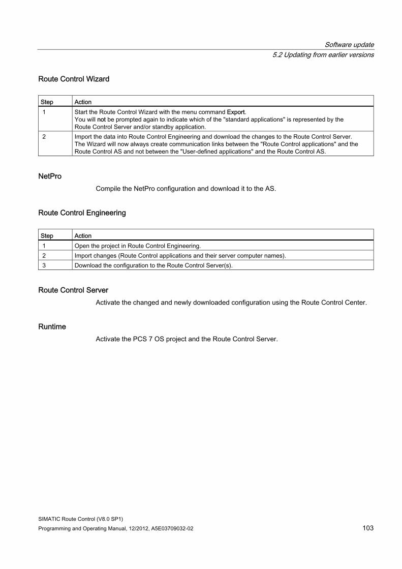
Software update 5.2 Updating from earlier versions
SIMATIC Route Control (V8.0 SP1) Programming and Operating Manual, 12/2012, A5E03709032-02 103
Route Control Wizard Step Action 1 Start the Route Control Wizard with the menu command Export.
You will not be prompted again to indicate which of the "standard applications" is represented by the Route Control Server and/or standby application.
2 Import the data into Route Control Engineering and download the changes to the Route Control Server. The Wizard will now always create communication links between the "Route Control applications" and the Route Control AS and not between the "User-defined applications" and the Route Control AS.
NetPro Compile the NetPro configuration and download it to the AS.
Route Control Engineering Step Action 1 Open the project in Route Control Engineering. 2 Import changes (Route Control applications and their server computer names). 3 Download the configuration to the Route Control Server(s).
Route Control Server Activate the changed and newly downloaded configuration using the Route Control Center.
Runtime Activate the PCS 7 OS project and the Route Control Server.

Software update 5.2 Updating from earlier versions
SIMATIC Route Control (V8.0 SP1) 104 Programming and Operating Manual, 12/2012, A5E03709032-02
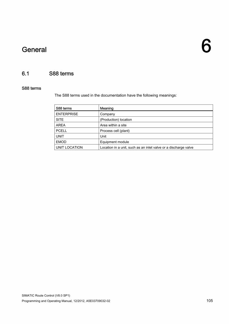
SIMATIC Route Control (V8.0 SP1) Programming and Operating Manual, 12/2012, A5E03709032-02 105
General 66.1 S88 terms
S88 terms The S88 terms used in the documentation have the following meanings:
S88 terms Meaning ENTERPRISE Company SITE (Production) location AREA Area within a site PCELL Process cell (plant) UNIT Unit EMOD Equipment module UNIT LOCATION Location in a unit, such as an inlet valve or a discharge valve
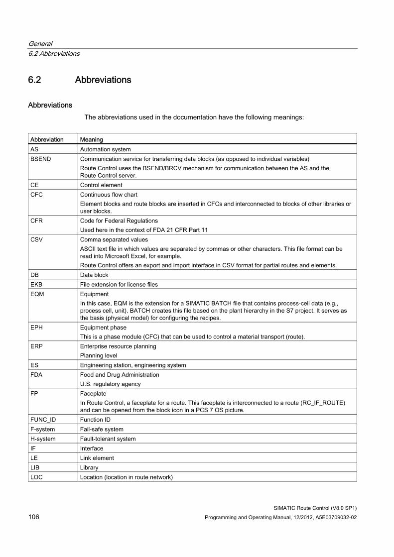
General 6.2 Abbreviations
SIMATIC Route Control (V8.0 SP1) 106 Programming and Operating Manual, 12/2012, A5E03709032-02
6.2 Abbreviations
Abbreviations The abbreviations used in the documentation have the following meanings:
Abbreviation Meaning AS Automation system BSEND Communication service for transferring data blocks (as opposed to individual variables)
Route Control uses the BSEND/BRCV mechanism for communication between the AS and the Route Control server.
CE Control element CFC Continuous flow chart
Element blocks and route blocks are inserted in CFCs and interconnected to blocks of other libraries or user blocks.
CFR Code for Federal Regulations Used here in the context of FDA 21 CFR Part 11
CSV Comma separated values ASCII text file in which values are separated by commas or other characters. This file format can be read into Microsoft Excel, for example. Route Control offers an export and import interface in CSV format for partial routes and elements.
DB Data block EKB File extension for license files EQM Equipment
In this case, EQM is the extension for a SIMATIC BATCH file that contains process-cell data (e.g., process cell, unit). BATCH creates this file based on the plant hierarchy in the S7 project. It serves as the basis (physical model) for configuring the recipes.
EPH Equipment phase This is a phase module (CFC) that can be used to control a material transport (route).
ERP Enterprise resource planning Planning level
ES Engineering station, engineering system FDA Food and Drug Administration
U.S. regulatory agency FP Faceplate
In Route Control, a faceplate for a route. This faceplate is interconnected to a route (RC_IF_ROUTE) and can be opened from the block icon in a PCS 7 OS picture.
FUNC_ID Function ID F-system Fail-safe system H-system Fault-tolerant system IF Interface LE Link element LIB Library LOC Location (location in route network)
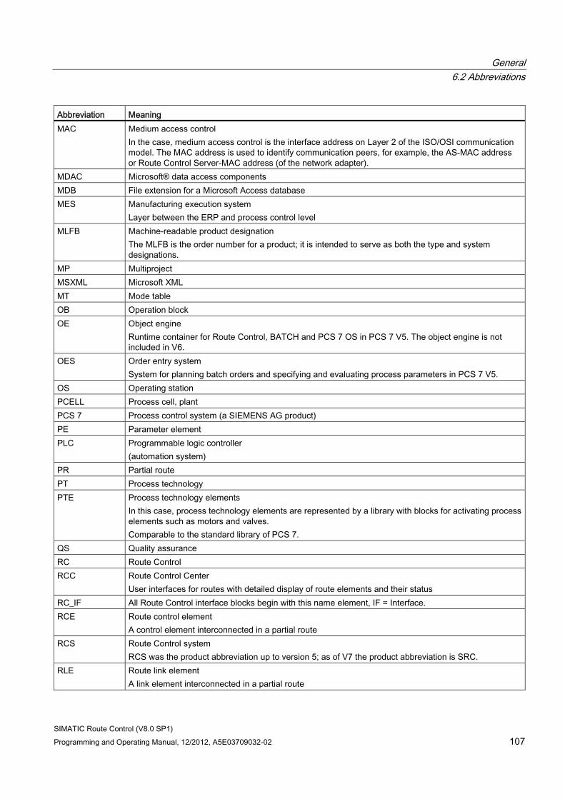
General 6.2 Abbreviations
SIMATIC Route Control (V8.0 SP1) Programming and Operating Manual, 12/2012, A5E03709032-02 107
Abbreviation Meaning MAC Medium access control
In the case, medium access control is the interface address on Layer 2 of the ISO/OSI communication model. The MAC address is used to identify communication peers, for example, the AS-MAC address or Route Control Server-MAC address (of the network adapter).
MDAC Microsoft® data access components MDB File extension for a Microsoft Access database MES Manufacturing execution system
Layer between the ERP and process control level MLFB Machine-readable product designation
The MLFB is the order number for a product; it is intended to serve as both the type and system designations.
MP Multiproject MSXML Microsoft XML MT Mode table OB Operation block OE Object engine
Runtime container for Route Control, BATCH and PCS 7 OS in PCS 7 V5. The object engine is not included in V6.
OES Order entry system System for planning batch orders and specifying and evaluating process parameters in PCS 7 V5.
OS Operating station PCELL Process cell, plant PCS 7 Process control system (a SIEMENS AG product) PE Parameter element PLC Programmable logic controller
(automation system) PR Partial route PT Process technology PTE Process technology elements
In this case, process technology elements are represented by a library with blocks for activating process elements such as motors and valves. Comparable to the standard library of PCS 7.
QS Quality assurance RC Route Control RCC Route Control Center
User interfaces for routes with detailed display of route elements and their status RC_IF All Route Control interface blocks begin with this name element, IF = Interface. RCE Route control element
A control element interconnected in a partial route RCS Route Control system
RCS was the product abbreviation up to version 5; as of V7 the product abbreviation is SRC. RLE Route link element
A link element interconnected in a partial route
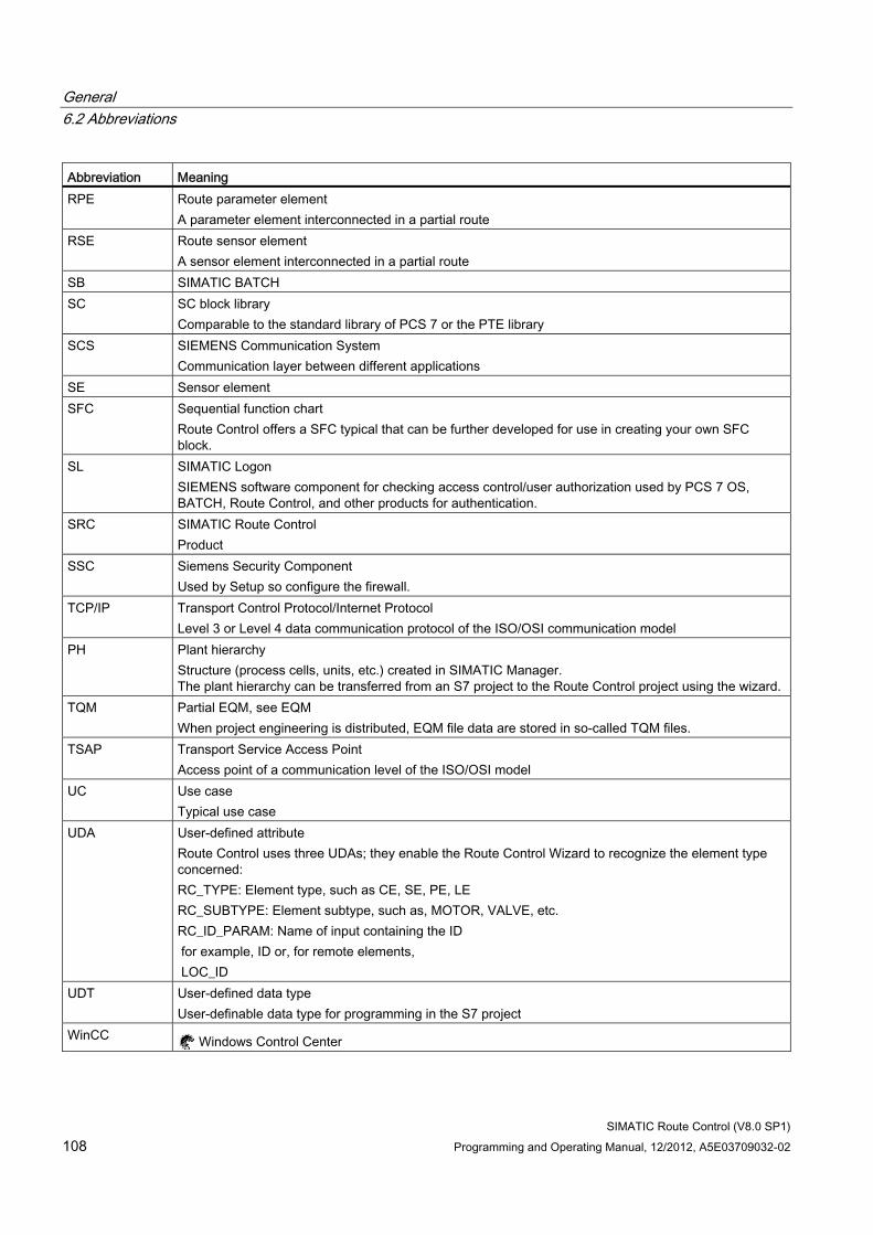
General 6.2 Abbreviations
SIMATIC Route Control (V8.0 SP1) 108 Programming and Operating Manual, 12/2012, A5E03709032-02
Abbreviation Meaning RPE Route parameter element
A parameter element interconnected in a partial route RSE Route sensor element
A sensor element interconnected in a partial route SB SIMATIC BATCH SC SC block library
Comparable to the standard library of PCS 7 or the PTE library SCS SIEMENS Communication System
Communication layer between different applications SE Sensor element SFC Sequential function chart
Route Control offers a SFC typical that can be further developed for use in creating your own SFC block.
SL SIMATIC Logon SIEMENS software component for checking access control/user authorization used by PCS 7 OS, BATCH, Route Control, and other products for authentication.
SRC SIMATIC Route Control Product
SSC Siemens Security Component Used by Setup so configure the firewall.
TCP/IP Transport Control Protocol/Internet Protocol Level 3 or Level 4 data communication protocol of the ISO/OSI communication model
PH Plant hierarchy Structure (process cells, units, etc.) created in SIMATIC Manager. The plant hierarchy can be transferred from an S7 project to the Route Control project using the wizard.
TQM Partial EQM, see EQM When project engineering is distributed, EQM file data are stored in so-called TQM files.
TSAP Transport Service Access Point Access point of a communication level of the ISO/OSI model
UC Use case Typical use case
UDA User-defined attribute Route Control uses three UDAs; they enable the Route Control Wizard to recognize the element type concerned: RC_TYPE: Element type, such as CE, SE, PE, LE RC_SUBTYPE: Element subtype, such as, MOTOR, VALVE, etc. RC_ID_PARAM: Name of input containing the ID for example, ID or, for remote elements, LOC_ID
UDT User-defined data type User-definable data type for programming in the S7 project
WinCC Windows Control Center
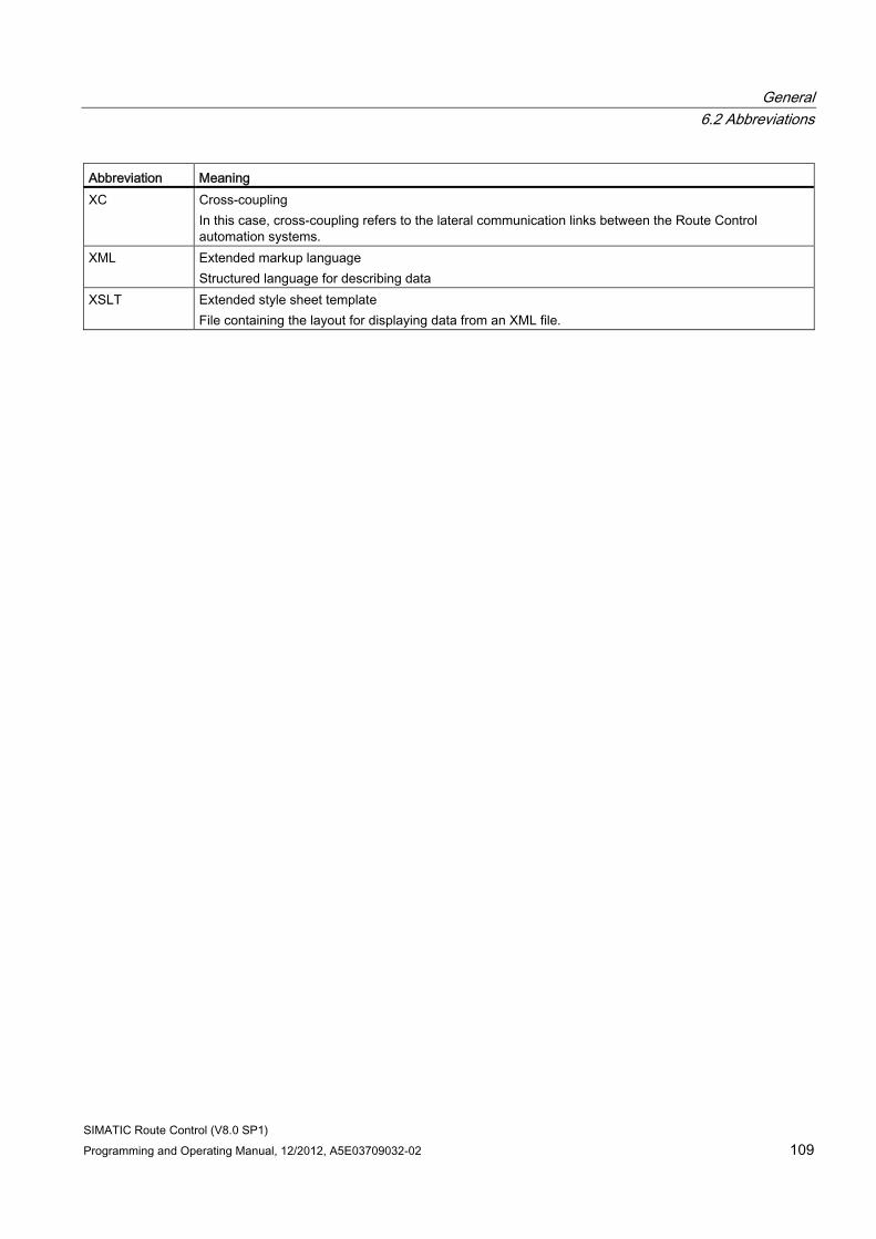
General 6.2 Abbreviations
SIMATIC Route Control (V8.0 SP1) Programming and Operating Manual, 12/2012, A5E03709032-02 109
Abbreviation Meaning XC Cross-coupling
In this case, cross-coupling refers to the lateral communication links between the Route Control automation systems.
XML Extended markup language Structured language for describing data
XSLT Extended style sheet template File containing the layout for displaying data from an XML file.
General 6.3 Menu commands
SIMATIC Route Control (V8.0 SP1) 110 Programming and Operating Manual, 12/2012, A5E03709032-02
6.3 Menu commands
Route Control Engineering ● Section "Engineering Menu" (Page 499)
Route Control Center ● Section "Route Control Center Menu" (Page 631)
Note
If you want to open the shortcut menu of an object then right-click on the object.
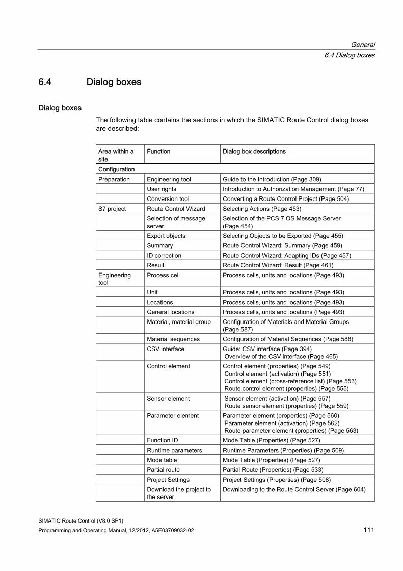
General 6.4 Dialog boxes
SIMATIC Route Control (V8.0 SP1) Programming and Operating Manual, 12/2012, A5E03709032-02 111
6.4 Dialog boxes
Dialog boxes The following table contains the sections in which the SIMATIC Route Control dialog boxes are described:
Area within a site
Function Dialog box descriptions
Configuration Preparation Engineering tool Guide to the Introduction (Page 309) User rights Introduction to Authorization Management (Page 77) Conversion tool Converting a Route Control Project (Page 504) S7 project Route Control Wizard Selecting Actions (Page 453) Selection of message
server Selection of the PCS 7 OS Message Server (Page 454)
Export objects Selecting Objects to be Exported (Page 455) Summary Route Control Wizard: Summary (Page 459) ID correction Route Control Wizard: Adapting IDs (Page 457) Result Route Control Wizard: Result (Page 461) Engineering tool
Process cell Process cells, units and locations (Page 493)
Unit Process cells, units and locations (Page 493) Locations Process cells, units and locations (Page 493) General locations Process cells, units and locations (Page 493) Material, material group Configuration of Materials and Material Groups
(Page 587) Material sequences Configuration of Material Sequences (Page 588) CSV interface Guide: CSV interface (Page 394)
Overview of the CSV interface (Page 465) Control element Control element (properties) (Page 549)
Control element (activation) (Page 551) Control element (cross-reference list) (Page 553) Route control element (properties) (Page 555)
Sensor element Sensor element (activation) (Page 557) Route sensor element (properties) (Page 559)
Parameter element Parameter element (properties) (Page 560) Parameter element (activation) (Page 562) Route parameter element (properties) (Page 563)
Function ID Mode Table (Properties) (Page 527) Runtime parameters Runtime Parameters (Properties) (Page 509) Mode table Mode Table (Properties) (Page 527) Partial route Partial Route (Properties) (Page 533) Project Settings Project Settings (Properties) (Page 508) Download the project to
the server Downloading to the Route Control Server (Page 604)
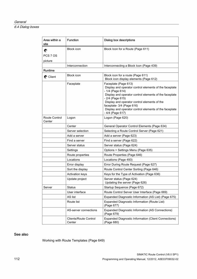
General 6.4 Dialog boxes
SIMATIC Route Control (V8.0 SP1) 112 Programming and Operating Manual, 12/2012, A5E03709032-02
Area within a site
Function Dialog box descriptions
PCS 7 OS picture
Block icon Block Icon for a Route (Page 611)
Interconnection Interconnecting a Block Icon (Page 439) Runtime
Client Block icon Block icon for a route (Page 611) Block icon display elements (Page 612)
Faceplate Faceplate (Page 613) Display and operator control elements of the faceplate - 1/4 (Page 614) Display and operator control elements of the faceplate - 2/4 (Page 615) Display and operator control elements of the faceplate- 3/4 (Page 616) Display and operator control elements of the faceplate - 4/4 (Page 617)
Route Control Center
Logon Logon (Page 620)
Center General Operator Control Elements (Page 634) Server selection Selecting a Route Control Server (Page 621) Add a server Add a server (Page 623) Find a server Find a server (Page 622) Server status Server status (Page 624) Settings Options > Settings Menu (Page 635) Route properties Route Properties (Page 646) Locations Locations (Page 493) Error display Error During Route Request (Page 627) Sort the display Route Control Center Sorting (Page 646) Activation keys Keys for the Type of Activation (Page 636) Update project Server status (Page 624)
Updating the server (Page 626) Server Status Startup Sequence (Page 672) User interface Route Control Server User Interface (Page 669) AS list Expanded Diagnostic Information (AS List) (Page 675) Route list Expanded Diagnostic Information (Route List)
(Page 677) AS-server connections Expanded Diagnostic Information (AS Connections)
(Page 679) Clients/Route Control
Center Expanded Diagnostic Information (Client Connections) (Page 680)
See also Working with Route Templates (Page 649)
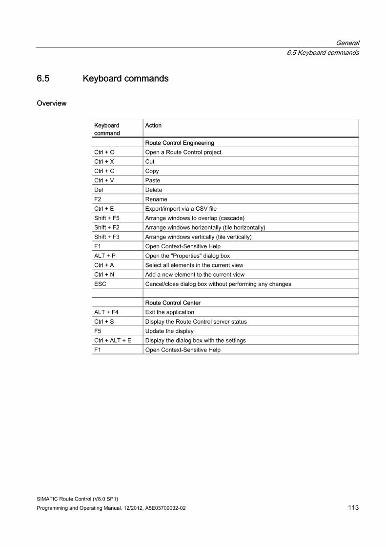
General 6.5 Keyboard commands
SIMATIC Route Control (V8.0 SP1) Programming and Operating Manual, 12/2012, A5E03709032-02 113
6.5 Keyboard commands
Overview Keyboard command
Action
Route Control Engineering Ctrl + O Open a Route Control project Ctrl + X Cut Ctrl + C Copy Ctrl + V Paste Del Delete F2 Rename Ctrl + E Export/import via a CSV file Shift + F5 Arrange windows to overlap (cascade) Shift + F2 Arrange windows horizontally (tile horizontally) Shift + F3 Arrange windows vertically (tile vertically) F1 Open Context-Sensitive Help ALT + P Open the "Properties" dialog box Ctrl + A Select all elements in the current view Ctrl + N Add a new element to the current view ESC Cancel/close dialog box without performing any changes Route Control Center ALT + F4 Exit the application Ctrl + S Display the Route Control server status F5 Update the display Ctrl + ALT + E Display the dialog box with the settings F1 Open Context-Sensitive Help
General 6.6 User Interfaces
SIMATIC Route Control (V8.0 SP1) 114 Programming and Operating Manual, 12/2012, A5E03709032-02
6.6 User Interfaces
Introduction Route Control offers three user interfaces for the operator control and monitoring of a route and its elements:
Route Control block icon The block icon is interconnected to a route block using the Route Control Dynamic Wizard for PCS 7 OS faceplates. The block icon displays the main properties of a route during runtime.
You can find additional information in the section "Route Control Block Icon for a Route" (Page 611).
Route Control faceplate For a more detailed route diagnosis, click the block icon to open the faceplate. It displays, for example, the source and destination of a route.
You can find additional information in the section "Route Control Faceplate" (Page 613).
Route Control Center You can open the Route Control Center from the faceplate to display the elements of the route and their statuses.
You can find additional information in the section "Route Control Center" (Page 619).
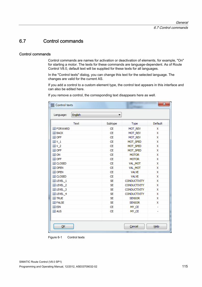
General 6.7 Control commands
SIMATIC Route Control (V8.0 SP1) Programming and Operating Manual, 12/2012, A5E03709032-02 115
6.7 Control commands
Control commands Control commands are names for activation or deactivation of elements, for example, "On" for starting a motor. The texts for these commands are language-dependent. As of Route Control V8.0, default text will be supplied for these texts for all languages.
In the "Control texts" dialog, you can change this text for the selected language. The changes are valid for the current AS.
If you add a control to a custom element type, the control text appears in this interface and can also be edited here.
If you remove a control, the corresponding text disappears here as well.
Figure 6-1 Control texts

General 6.7 Control commands
SIMATIC Route Control (V8.0 SP1) 116 Programming and Operating Manual, 12/2012, A5E03709032-02
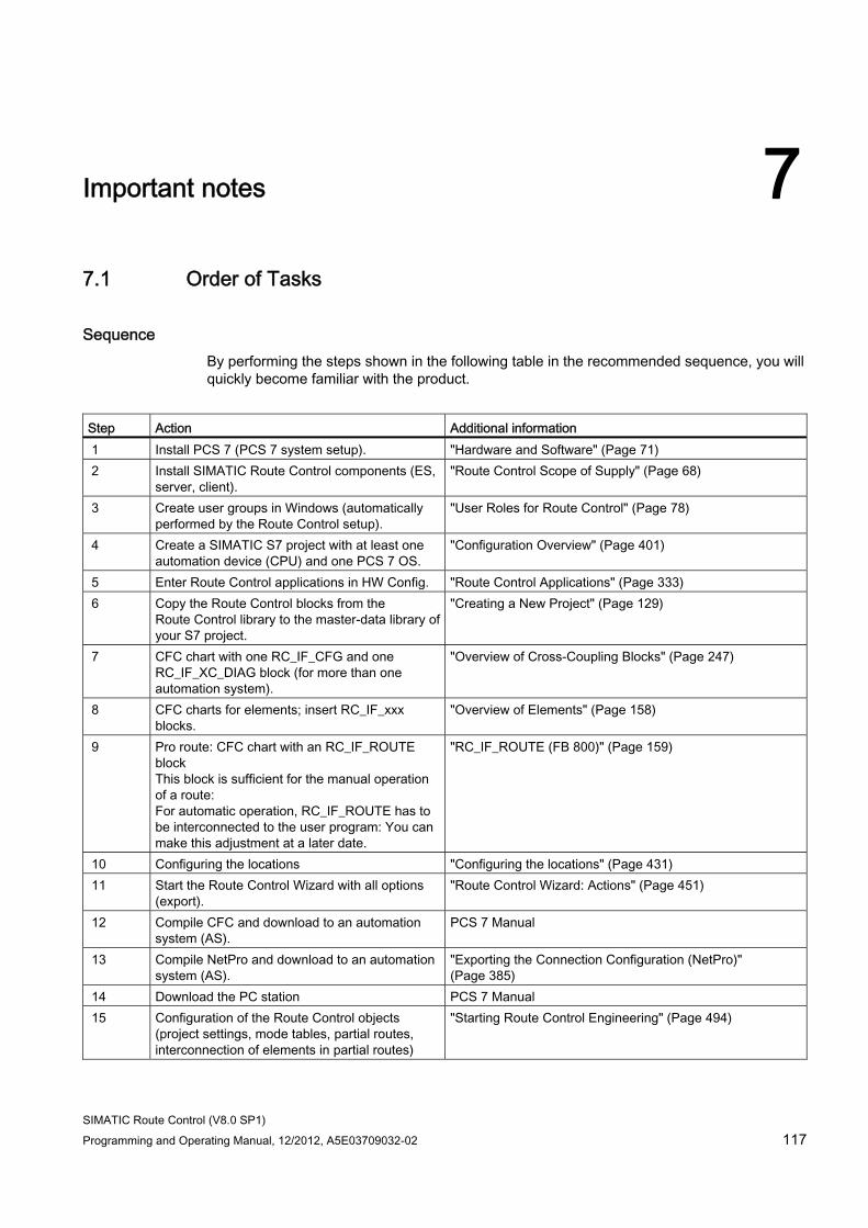
SIMATIC Route Control (V8.0 SP1) Programming and Operating Manual, 12/2012, A5E03709032-02 117
Important notes 77.1 Order of Tasks
Sequence By performing the steps shown in the following table in the recommended sequence, you will quickly become familiar with the product.
Step Action Additional information 1 Install PCS 7 (PCS 7 system setup). "Hardware and Software" (Page 71) 2 Install SIMATIC Route Control components (ES,
server, client). "Route Control Scope of Supply" (Page 68)
3 Create user groups in Windows (automatically performed by the Route Control setup).
"User Roles for Route Control" (Page 78)
4 Create a SIMATIC S7 project with at least one automation device (CPU) and one PCS 7 OS.
"Configuration Overview" (Page 401)
5 Enter Route Control applications in HW Config. "Route Control Applications" (Page 333) 6 Copy the Route Control blocks from the
Route Control library to the master-data library of your S7 project.
"Creating a New Project" (Page 129)
7 CFC chart with one RC_IF_CFG and one RC_IF_XC_DIAG block (for more than one automation system).
"Overview of Cross-Coupling Blocks" (Page 247)
8 CFC charts for elements; insert RC_IF_xxx blocks.
"Overview of Elements" (Page 158)
9 Pro route: CFC chart with an RC_IF_ROUTE block This block is sufficient for the manual operation of a route: For automatic operation, RC_IF_ROUTE has to be interconnected to the user program: You can make this adjustment at a later date.
"RC_IF_ROUTE (FB 800)" (Page 159)
10 Configuring the locations "Configuring the locations" (Page 431) 11 Start the Route Control Wizard with all options
(export). "Route Control Wizard: Actions" (Page 451)
12 Compile CFC and download to an automation system (AS).
PCS 7 Manual
13 Compile NetPro and download to an automation system (AS).
"Exporting the Connection Configuration (NetPro)" (Page 385)
14 Download the PC station PCS 7 Manual 15 Configuration of the Route Control objects
(project settings, mode tables, partial routes, interconnection of elements in partial routes)
"Starting Route Control Engineering" (Page 494)
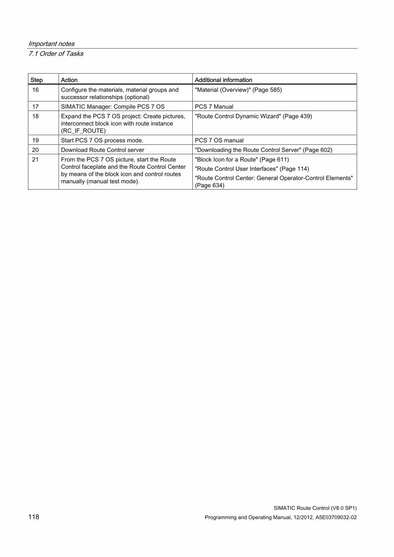
Important notes 7.1 Order of Tasks
SIMATIC Route Control (V8.0 SP1) 118 Programming and Operating Manual, 12/2012, A5E03709032-02
Step Action Additional information 16 Configure the materials, material groups and
successor relationships (optional) "Material (Overview)" (Page 585)
17 SIMATIC Manager: Compile PCS 7 OS PCS 7 Manual 18 Expand the PCS 7 OS project: Create pictures,
interconnect block icon with route instance (RC_IF_ROUTE)
"Route Control Dynamic Wizard" (Page 439)
19 Start PCS 7 OS process mode. PCS 7 OS manual 20 Download Route Control server "Downloading the Route Control Server" (Page 602) 21 From the PCS 7 OS picture, start the Route
Control faceplate and the Route Control Center by means of the block icon and control routes manually (manual test mode).
"Block Icon for a Route" (Page 611) "Route Control User Interfaces" (Page 114) "Route Control Center: General Operator-Control Elements" (Page 634)
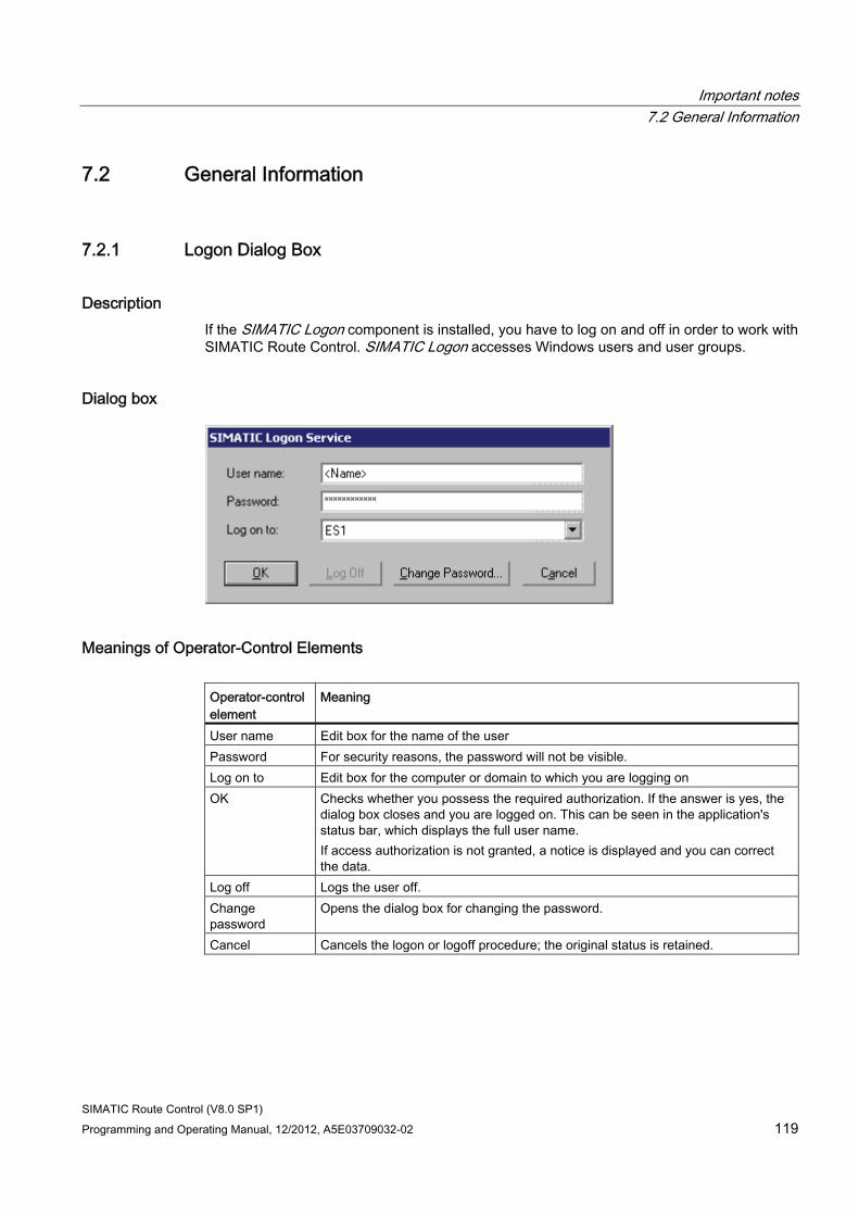
Important notes 7.2 General Information
SIMATIC Route Control (V8.0 SP1) Programming and Operating Manual, 12/2012, A5E03709032-02 119
7.2 General Information
7.2.1 Logon Dialog Box
Description If the SIMATIC Logon component is installed, you have to log on and off in order to work with SIMATIC Route Control. SIMATIC Logon accesses Windows users and user groups.
Dialog box
Meanings of Operator-Control Elements Operator-control element
Meaning
User name Edit box for the name of the user Password For security reasons, the password will not be visible. Log on to Edit box for the computer or domain to which you are logging on OK Checks whether you possess the required authorization. If the answer is yes, the
dialog box closes and you are logged on. This can be seen in the application's status bar, which displays the full user name. If access authorization is not granted, a notice is displayed and you can correct the data.
Log off Logs the user off. Change password
Opens the dialog box for changing the password.
Cancel Cancels the logon or logoff procedure; the original status is retained.
Important notes 7.2 General Information
SIMATIC Route Control (V8.0 SP1) 120 Programming and Operating Manual, 12/2012, A5E03709032-02
7.2.2 Restriction of the quantity framework
Description There are restrictions on the quantity framework for Route Control sensor and control elements.
Cause of Messages Route Control element blocks issue messages:
● If a fault occurs
● If an error occurs
● If the element transitions to manual mode
The element blocks call the AlarmS block (SFC18) for this purpose.
Number of Calls The number of calls is limited to 4,096 in PCS 7 if the new message concept is used.
The total number of elements multiplied by the number of messages issued by these elements must not exceed 4,096. The different elements generate a different number of messages:
● Control elements of SIMATIC Route Control call the block for three different messages.
● Sensor elements call the block for two different messages.
● Parameter elements and link elements do not generate any messages.
Note
Please note that all program sections in an automation system share these resources. Therefore, the total number of all program sections must not exceed the limit of 4,096 calls.
Calculation Formula The number of SIMATIC Route Control calls is calculated as follows:
Number of calls for Route Control = Number of control elements * 3 + Number of sensor elements * 2
Important notes 7.2 General Information
SIMATIC Route Control (V8.0 SP1) Programming and Operating Manual, 12/2012, A5E03709032-02 121
Examples Number of control elements Number of sensor elements Total number 1024 512 4096 512 1024 2560 680 1024 4088
From our experience, this number of control elements has never been reached in one automation system. Because other programs besides SIMATIC Route Control are also being executed, as a rule such quantities are already distributed among more than one automation system for performance reasons.
Additional information You can find an overview of the Route Control quantity framework in "Quantity Framework for Route Control" (Page 707).
7.2.3 Invalid characters
PCS 7 For the names of hierarchy folders, blocks and CFC charts, the special characters [ \ ] [ / ] [ . ] [ " ] [ % ] are not permitted.
Route Control In Route Control, the [ ' ] (apostrophe) special character is not permitted either. Neither can it be used in comments.
If the Route Control Wizard finds this character when exporting from PCS 7, it will write an error message to the log.
For CSV exports/imports to Route Control Engineering, one of the following characters can be selected as a separator: [ ; ] [ , ] [ * ]. These characters must not be used in configuration.
Note
Please also note the comprehensive information provided in the PCS 7 OS online help. Search the help for "invalid characters".
We recommend that you completely avoid special characters during configuration. Sole exception: [ _ ] (underscore).
Important notes 7.2 General Information
SIMATIC Route Control (V8.0 SP1) 122 Programming and Operating Manual, 12/2012, A5E03709032-02
7.2.4 Route Request via any Mode Table
Special consideration for mode table = 0 If you request a route with mode table = 0, the route found may contain partial routes to which different mode tables have been assigned. In such cases, the Route Control Center will not be able to display the mode level unequivocally.
If you must work with mode table = 0, we recommend that you give the mode levels in the mode table concerned the same names.
7.2.5 Reinstallation of the Route Control Faceplate
Initial Situation ● You have a PCS 7 OS project containing Route Control faceplates.
● You want to install a new version of the Route Control faceplate.
Procedure Step Procedure 1 Opening the C editor in your PCS 7 OS project 2 Executing the menu command Regenerate Header
Result The standard functions, including the Route Control scripts, are recompiled and communicated to the PCS 7 OS project. This procedure is necessary to ensure that the newly installed Route Control faceplate can be operated with the old scripts.
Important notes 7.2 General Information
SIMATIC Route Control (V8.0 SP1) Programming and Operating Manual, 12/2012, A5E03709032-02 123
7.2.6 Route Control faceplate without Route Control server
Route Control faceplate without Route Control server Your computer has the following constellation:
● PCS 7 OS is installed.
● Route Control server is not installed.
If you want the Route Control faceplate to be available, you must execute the Route Control faceplate setup, including Route Control Base.
The Route Control faceplate setup installs script files and global functions in the PCS 7 OS directory, which are required for the Route Control faceplate to function properly.
7.2.7 PCS 7 OS memory reset
PCS 7 OS memory reset
Note
Of a PCS 7 OS with a memory reset is recompile, the Route Control Wizard must be run again with the menu command Select the Message Server and the "Generated messages" check box must be activated.
Additional information ● Section "Actions" (Page 451)
● Section "Selecting the PCS 7 OS Message Server" (Page 454)
7.2.8 Enabling changes to configuration
Enabling Changes
Note
If you make changes to the Route Control configuration and download the changes to the Route Control server, the changes do not become active until the next route request.
Example: You have incorporated additional elements in partial routes or modified properties.
Important notes 7.2 General Information
SIMATIC Route Control (V8.0 SP1) 124 Programming and Operating Manual, 12/2012, A5E03709032-02
7.2.9 Downloading to the Server During an Active Route
Problem The Route Control Center displays the elements of an active material transport. If the configuration is changed, downloaded to the Route Control server and activated while a transport is active, discrepancies can arise between the configuration and the route.
Example: A new element is assigned to a partial route. This new configuration is downloaded to the Route Control server and activated. The Route Control Center now displays the new element in the list, although it has not been activated in the automation system. The automation system is still working with an element list that is based on the previous configuration.
Solution The new element is included as soon as the route is completed and started again. At this point, a new element list is downloaded to the automation system.
7.2.10 Online help in the Route Control Center
Online help in the Route Control Center The user can open the Windows Explorer from the online help, thus giving access to the file system. This is not possible on operator stations.
Due to reasons of security, the online help cannot be accessed in the Route Control Center if this application has been opened through a PCS 7 OS picture. The online help in the Route Control faceplate has also been deactivated.
If you call up the Route Control Center from the start bar, on the other hand, the online help is available since the Windows Explorer can also be called up from the start bar.
7.2.11 MES Interface
MES Interface Although SIMATIC Route Control does not feature a direct interface to SIMATIC IT, certain data can be exchanged nonetheless by means of standard interfaces (Runtime and OPC coupling) via PCS 7 OS-Server / OpenPCS 7 including, for example, data of the "RC_IF_ROUTE" route block such as the input parameters of the Source, Via and Destination locations of a route, material data, or output parameters such as the route status, and the values of parameter elements.
Important notes 7.2 General Information
SIMATIC Route Control (V8.0 SP1) Programming and Operating Manual, 12/2012, A5E03709032-02 125
7.2.12 SIMATIC Route Control and PLCSim
SIMATIC Route Control and PLCSim SIMATIC Route Control does not support PLCSim, as PLCSim is unable to process BSEND/BRCV orders, which are required for communication between the Route Control automation systems and the Route Control servers. Communication between the Route Control server and the automation systems is carried out over "named connections" and BSEND/BRCV.
We do not recommend connection via MPI.
Important notes 7.3 Notes on Libraries and Blocks
SIMATIC Route Control (V8.0 SP1) 126 Programming and Operating Manual, 12/2012, A5E03709032-02
7.3 Notes on Libraries and Blocks
7.3.1 Installing a new Route Control library
Requirement You want to install a more recent version of the Route Control library and update your project with the latest blocks.
Requirement The configuration environment for an S7 project and the Route Control project are installed on your computer.
Basic Procedure Step Procedure 1 Open the new Route Control library. 2 Copy the changed blocks (FB, FC, DB and UDT) from the block folder of the Route Control
library into the block folders of each individual project to be changed. 3 Perform a block type import for Route Control blocks in CFC. 4 Compile and download the charts.
7.3.2 Downloading instance data blocks to the AS
Problem Blocks from a later version of SIMATIC Route Control will be compiled and downloaded to the AS, to remedy an error, for example. The block interface has changed. A new number can result from the interface change and the automatic assignment of instance-data-block numbers.
If the new function block and data block are imported into one automation system (AS), the peer automation systems of a route can still run. These peer automation systems have received the instance-data-block number of their master route or master FB at the beginning of the route. Once a route is started, they constantly send up-to-date data (PUT jobs) to this instance DB.
If another instance data block is now downloaded to the master AS, the previous data block simultaneously becomes invalid or is even reassigned to an entirely different function block. There is a risk that data will be overwritten.
Important notes 7.3 Notes on Libraries and Blocks
SIMATIC Route Control (V8.0 SP1) Programming and Operating Manual, 12/2012, A5E03709032-02 127
Remedy You must first close all routes involved in the AS to be reloaded. This applies both to master routes in this AS as well as to routes for which the AS is involved as a slave.
How to Identify the Routes Involved in this AS 1. Start the Route Control Center from the Windows start menu.
All routes are displayed.
2. At the top of the list, sort the routes according to the "AS" column. As well as the AS involved, all route IDs will appear in the first column.
3. Terminate all the routes in this AS manually.
4. Once the blocks are downloaded to the AS, reset these routes to automatic mode.
Note
As an AS can also be involved as a slave to another AS in a material transport, the routes in any other AS also have to be terminated manually.
In the Route Control Center, you can select "View Maintenance Tasks", which lists all automation systems and their statuses.
7.3.3 Downloading user blocks to the AS
Downloading user blocks to the AS Important notes for importing blocks into the AS:
CAUTION If you want to import a new version of Route Control blocks into the AS, you must follow the steps below: • Deactivate the routes in which the target AS is involved.
Do this by setting the routes to manual and deactivating them. This pertains to all routes for which this AS is the master or a slave.
• Compile the blocks If the block interface has changed (also pertains to parameter properties such as "S7_m_c=true"), the instance-data-block number can also change during compilation.
• Import the blocks. • Restart the Route Control server
This ensures that all of the AS data are reestablished in the server by means of a general request. This affects the instance DB number in particular.
Important notes 7.3 Notes on Libraries and Blocks
SIMATIC Route Control (V8.0 SP1) 128 Programming and Operating Manual, 12/2012, A5E03709032-02
CAUTION The SIMATIC Route Control data blocks must not be read back from the automation system to the project's offline container on the engineering station (ES). The offline container must contain the original blocks from the Route Control library!
This affects the following blocks: • Route blocks DB 101 to DB 400 • The blocks for cross coupling DB 450 to DB 481
and DB 751 to DB 781
Reason: If data blocks are read back from the automation system to the engineering station, the current image (status of a portion of the elements of this route) is uploaded. If these data blocks are subsequently downloaded to the automation system again and the route has already been deactivated on this AS, elements are activated according to the latest image.
7.3.4 LOCK input on element blocks
LOCK Input The LOCK input at the element blocks designed for interlocking elements currently has no function and is reserved for use in future versions.
Important notes 7.4 Notes on Configuration
SIMATIC Route Control (V8.0 SP1) Programming and Operating Manual, 12/2012, A5E03709032-02 129
7.4 Notes on Configuration
7.4.1 Creating a new S7 project for Route Control
Basic Procedure Step Procedure 1 Create a new S7 project in a multiproject. 2 Copy the Route Control blocks from the Route Control library to the master data library of
your S7 project (including the DBs and UDTs). 3 Copy the Route Control blocks from the master data library into the block containers of the
individual projects (including the DBs and UDTs) of your S7 project. 4 Perform a block type import in the CFCs of individual projects.
Note
A master data library can only exist in one multiproject. You should therefore also create a single project in a multiproject.
For a single project, you need to manually copy the required DBs and all UDTs manually to the block folders of the automation systems.
7.4.2 Adapting the block ranges
Adapting the block ranges The blocks in SIMATIC Route Control are considered user blocks in terms of an S7 project. The block range settings therefore have to be adapted in the CFC Editor.
This also applies if you want to use the STEP 7 Import/Export Wizard to create models in the project library, which does not yet contain any CFC charts.
Set the upper limits as follows:
● DB to 899
● FC to 899
Additional information ● Section: "Adapting the Block Ranges in CFC" (Page 409)
Important notes 7.4 Notes on Configuration
SIMATIC Route Control (V8.0 SP1) 130 Programming and Operating Manual, 12/2012, A5E03709032-02
7.4.3 Optimizing memory requirements in the AS
Deleting Blocks Not Required Better use can be made of the memory in an automation system if you delete unneeded blocks.
Route blocks The blocks for the element list of a route have fixed block numbers which are assigned to route IDs according to the following rule:
Block number = route ID + 100
Route ID DB no. 1 101 2 102 ... ... 300 400
You can delete data blocks for route IDs that are not used in any of the automation systems.
One of the following conditions must be true:
● All route blocks use a fixed route ID;
● Only certain areas are permitted for dynamic IDs.
Example Route ID DB no. Note AS1 AS2 AS... AS n 1 101 Fixed ID X X X X 2 102 Fixed ID X X X X 3 103 Fixed ID X X X X 4 104 Fixed ID X X X X 5 105 Fixed ID X X X X 6 106 Fixed ID X X X X 7 107 Dynamic ID X X X X 8 108 Dynamic ID X X X X 9 109 Dynamic ID X X X X 10 110 Dynamic ID X X X X 11 111 Not used - - - - ... ... Not used - - - - 300 400 Not used - - - -
In this example, DB 101 to DB 110 must be available in all automation systems. You may delete DB 111 to DB 400.
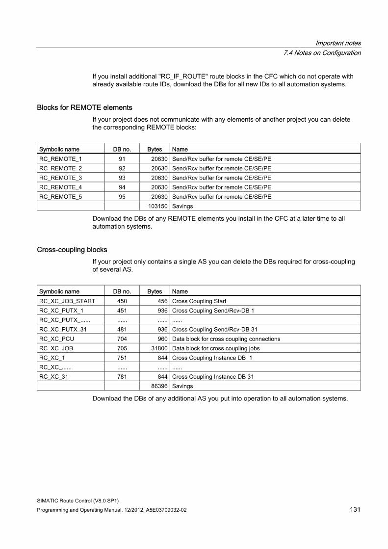
Important notes 7.4 Notes on Configuration
SIMATIC Route Control (V8.0 SP1) Programming and Operating Manual, 12/2012, A5E03709032-02 131
If you install additional "RC_IF_ROUTE" route blocks in the CFC which do not operate with already available route IDs, download the DBs for all new IDs to all automation systems.
Blocks for REMOTE elements If your project does not communicate with any elements of another project you can delete the corresponding REMOTE blocks:
Symbolic name DB no. Bytes Name RC_REMOTE_1 91 20630 Send/Rcv buffer for remote CE/SE/PE RC_REMOTE_2 92 20630 Send/Rcv buffer for remote CE/SE/PE RC_REMOTE_3 93 20630 Send/Rcv buffer for remote CE/SE/PE RC_REMOTE_4 94 20630 Send/Rcv buffer for remote CE/SE/PE RC_REMOTE_5 95 20630 Send/Rcv buffer for remote CE/SE/PE 103150 Savings
Download the DBs of any REMOTE elements you install in the CFC at a later time to all automation systems.
Cross-coupling blocks If your project only contains a single AS you can delete the DBs required for cross-coupling of several AS.
Symbolic name DB no. Bytes Name RC_XC_JOB_START 450 456 Cross Coupling Start RC_XC_PUTX_1 451 936 Cross Coupling Send/Rcv-DB 1 RC_XC_PUTX_...... ...... ...... ...... RC_XC_PUTX_31 481 936 Cross Coupling Send/Rcv-DB 31 RC_XC_PCU 704 960 Data block for cross coupling connections RC_XC_JOB 705 31800 Data block for cross coupling jobs RC_XC_1 751 844 Cross Coupling Instance DB 1 RC_XC_...... ...... ...... ...... RC_XC_31 781 844 Cross Coupling Instance DB 31 86396 Savings
Download the DBs of any additional AS you put into operation to all automation systems.
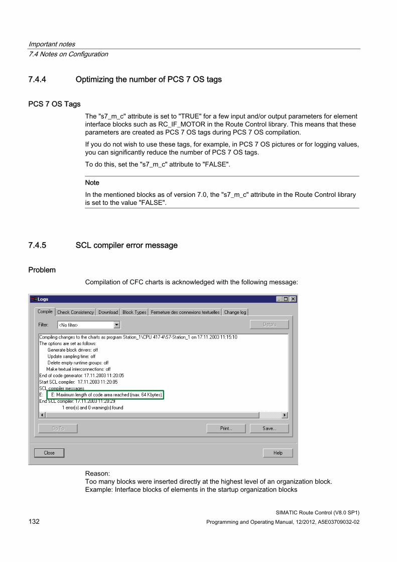
Important notes 7.4 Notes on Configuration
SIMATIC Route Control (V8.0 SP1) 132 Programming and Operating Manual, 12/2012, A5E03709032-02
7.4.4 Optimizing the number of PCS 7 OS tags
PCS 7 OS Tags The "s7_m_c" attribute is set to "TRUE" for a few input and/or output parameters for element interface blocks such as RC_IF_MOTOR in the Route Control library. This means that these parameters are created as PCS 7 OS tags during PCS 7 OS compilation.
If you do not wish to use these tags, for example, in PCS 7 OS pictures or for logging values, you can significantly reduce the number of PCS 7 OS tags.
To do this, set the "s7_m_c" attribute to "FALSE".
Note
In the mentioned blocks as of version 7.0, the "s7_m_c" attribute in the Route Control library is set to the value "FALSE".
7.4.5 SCL compiler error message
Problem Compilation of CFC charts is acknowledged with the following message:
Reason: Too many blocks were inserted directly at the highest level of an organization block. Example: Interface blocks of elements in the startup organization blocks
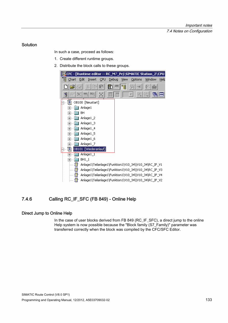
Important notes 7.4 Notes on Configuration
SIMATIC Route Control (V8.0 SP1) Programming and Operating Manual, 12/2012, A5E03709032-02 133
Solution In such a case, proceed as follows:
1. Create different runtime groups.
2. Distribute the block calls to these groups.
7.4.6 Calling RC_IF_SFC (FB 849) - Online Help
Direct Jump to Online Help In the case of user blocks derived from FB 849 (RC_IF_SFC), a direct jump to the online Help system is now possible because the "Block family (S7_Family)" parameter was transferred correctly when the block was compiled by the CFC/SFC Editor.
Important notes 7.4 Notes on Configuration
SIMATIC Route Control (V8.0 SP1) 134 Programming and Operating Manual, 12/2012, A5E03709032-02
7.4.7 Copying RC_IF_ROUTE route blocks
Copying RC_IF_ROUTE route blocks If you copy charts in CFC containing RC_IF_ROUTE (FB800) type blocks to which a route ID has already been assigned, you must set the block input ID to 0 manually in the copied chart. The Route Control Wizard will otherwise detect several identical route IDs and automatically correct the ID in the original block. Thus, it would end up changing a correctly assigned route ID.
7.4.8 BSEND/BRCV and PUT
PUT/BRCV Calls As regards communication between automation systems, there are two different types of data exchange:
● If communication between the automation systems takes place within the same Route Control project, Route Control uses PUT calls. with this type, the connections are specified, because the peer AS is known.
● If data are being exchanged with automation systems from another Route Control project, Route Control uses BSEND/BRCV calls. The connections are unspecified, because the peer AS is not known.
Note
In the second case, elements of the other Route Control project are mapped in the first Route Control project using "proxy blocks," such as RC_IF_REMOTE_CE.
This function has been designed to support the parallel control of individual elements from another area. It has not been designed to enable a route to run on multiple automation systems in different Route Control projects.
Additional information ● Section "AS-AS and AS-Server Connection Configuration" (Page 334)
● Section "CFC Charts with REMOTE Elements" (Page 362)
● Section "Configuring REMOTE Elements" (Page 366)
Important notes 7.4 Notes on Configuration
SIMATIC Route Control (V8.0 SP1) Programming and Operating Manual, 12/2012, A5E03709032-02 135
7.4.9 Run Sequence of Blocks
Run Sequence of Blocks When configuring Route Control, ensure that the blocks run in the sequence specified.
Additional information ● Section "Run Sequence of Route Control Blocks" (Page 406)
7.4.10 Location as a variant
Location as a variant As of V7.0, do not configure locations in Route Control Engineering any more, configure them directly in SIMATIC Manager instead. The "Source", "Via" and "Destination" properties can be configured there.
The "Variant" property cannot be configured in SIMATIC Manager. However, this property can still be activated in Route Control Engineering.
7.4.11 Chart-in-chart technology
Object name If you are using chart-in-chart technology with CFC and you insert element (RC_IF_MOTOR, etc.) or route (RC_IF_ROUTE) blocks, you must take the maximum length of the object name into consideration.
The Route Control Wizard will transfer up to 250 characters to the Route Control configuration. If this maximum length is exceeded, the Route Control Wizard issues a warning message and also generates an entry in the log file.
If character strings are too long, the Wizard only uses the characters at the end of the text and truncates the characters at the beginning of the name.
Important notes 7.4 Notes on Configuration
SIMATIC Route Control (V8.0 SP1) 136 Programming and Operating Manual, 12/2012, A5E03709032-02
7.4.12 "RC_LOAD" directory on the Route Control Server
Rights for the "RC_LOAD" directory The "RC_LOAD" directory is used to load the Route Control configuration on a Route Control server.
Both Route Control Server and Route Control Engineering components read and write to this RC_LOAD directory.
Route Control Engineering must be performed by a user in the RC_ENGINEER or RC_MAINTENANCE user group.
The Route Control Server must be started by one of the five user IDs.
Memory Expansion The drive on which the Route Control configuration is located does not have enough available memory. Check the available memory on the relevant partition; at least 100 MB must be available.
Important notes 7.4 Notes on Configuration
SIMATIC Route Control (V8.0 SP1) Programming and Operating Manual, 12/2012, A5E03709032-02 137
7.4.13 Drop-down list box for selecting locations in plant pictures
Introduction Refer to the "@pcs7typiclasrc.pdl" picture for three examples of the "rcCBox Class" control in Graphics Designer. You can insert these examples in your plant pictures so that locations can be selected from a drop-down list box there during process mode. The locations available in the project are offered for selection in this drop-down list box according to their type, with their PH names displayed. The location types offered in this drop-down list box, that is, "Source", "Via", "Destination", or "All Types", are defined when you program the control properties. The control determines the ID of the selected location and supplies it to the block input interconnected to "Loc ID".
Project Engineering Program the following control properties:
Parameter Data type Meaning RCServer IP DWORD Expects the IP address of the current Route Control server.
You must interconnect this parameter to the "QSERV_IP" output of a route block (FB 800/RC_IF_ROUTE), as this output supplies the IP address in the required format. (Example: 142.120.30.10 as 0A 1E 78 8Eh)
Loc Typ BYTE Selects the types of locations which are to be offered in the drop-down list box. You can select the following values: "eLoc_Type_Src - 1" for locations of the type "Source" "eLoc_Type_Via - 2" for locations of the type "Via" "eLoc_Type_Dst - 4" for locations of the type "Destination" "eLoc_Type_All - 7" for locations of all types Only the values listed in the table below can be used when programming the Loc Typ parameter manually. However, certain combinations are possible using scripts or variable interconnections, for example, the value "5" for selecting "Source" and "Destination" locations.
Loc ID DWORD Supplies the ID of the location selected from the drop-down list box. Interconnect this output to the appropriate location input of an RC_IF_SFC or a different automatic program, for example.
Enable BOOL Enables the control element for operation. Set this input to TRUE or interconnect it to a corresponding variable.
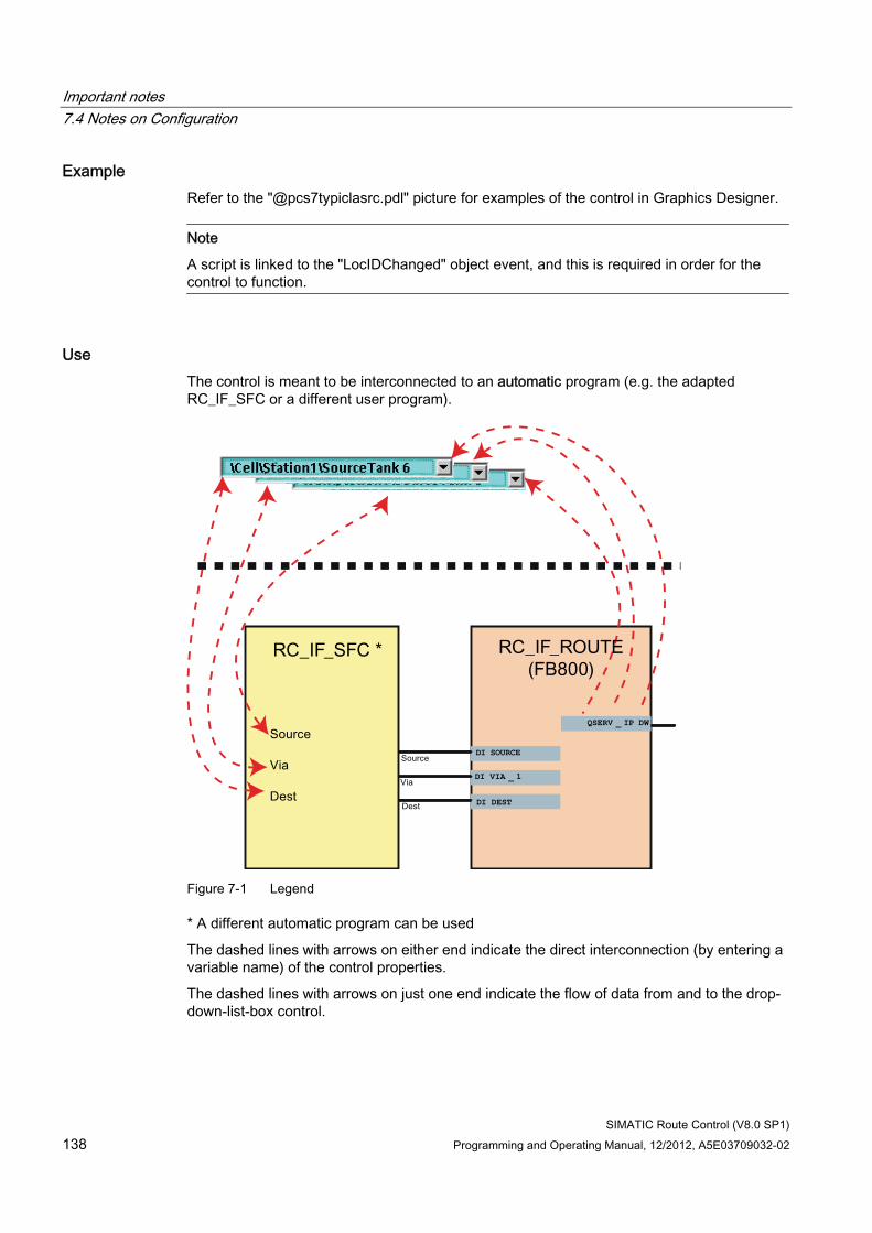
Important notes 7.4 Notes on Configuration
SIMATIC Route Control (V8.0 SP1) 138 Programming and Operating Manual, 12/2012, A5E03709032-02
Example Refer to the "@pcs7typiclasrc.pdl" picture for examples of the control in Graphics Designer.
Note
A script is linked to the "LocIDChanged" object event, and this is required in order for the control to function.
Use The control is meant to be interconnected to an automatic program (e.g. the adapted RC_IF_SFC or a different user program).
DI SOURCE
QSERV _ IP DW
DI VIA _ 1
DI DEST
Source
Via
Dest
Source
Via
Dest
Figure 7-1 Legend
* A different automatic program can be used
The dashed lines with arrows on either end indicate the direct interconnection (by entering a variable name) of the control properties.
The dashed lines with arrows on just one end indicate the flow of data from and to the drop-down-list-box control.
Important notes 7.4 Notes on Configuration
SIMATIC Route Control (V8.0 SP1) Programming and Operating Manual, 12/2012, A5E03709032-02 139
Inadvisable Use It is not advisable to interconnect to an FB 800/RC_IF_ROUTE; see the information below:
● In route manual mode, the FB 800/RC_IF_ROUTE does not evaluate its location inputs. Therefore, it is not possible to use the control in this operating mode.
● The control could technically be used in route automatic mode, as the FB 800/RC_IF_ROUTE does evaluate location inputs in this operating mode. However, there is a serious disadvantage to doing so: The control must be interconnected to the location inputs of the block via the Properties dialog, but in standard operation these inputs are already interconnected to an automatic program via CFC. This gives rise to a conflict, which will always be dominated by the CFC interconnection, as the interconnected values are always used when processing the block. This also means that the IDs selected in the control are not taken into account.
7.4.14 Compiling the script file for the Route Control Dynamic Wizard
Introduction A Route Control faceplate is available for the operator control and monitoring of material transports in PCS 7 OS process pictures in the "@PCS7TypicalsRC.pdl" and "@Template_RC.pdl" templates. The Route Control Dynamic Wizard assists you in interconnecting this faceplate to the associated route block.
Note
The block icons are available in the "@PCS7TypicalsRC.pdl" and "@Template_RC.pdl" files.
The "@Template_RC.pdl" file basically includes the same block icons as the "@PCS7TypicalsRC.pdl" file with one important difference:
The block icons of the "@ PCS7TypicalsRC.pdl" file are used for automatic placement of the block icons in process pictures in the "Create/update block icons" function (in SIMATIC Manager).
The block icons of the "@Template_RC.pdl" file are used to manually add block icons.
Procedure If the Route Control Dynamic Wizard is not yet available, compile it as follows:
1. In Windows, select the menu command Start > SIMATIC > WinCC > Tools > Dynamic Wizard Editor The Dynamic Wizard Editor appears.
2. Select the language as "English", "French" or "German" from the drop-down list in the toolbar.
3. Activate the language in the PCS 7 OS Explorer using the menu command Options > Language.
Important notes 7.4 Notes on Configuration
SIMATIC Route Control (V8.0 SP1) 140 Programming and Operating Manual, 12/2012, A5E03709032-02
4. In the Dynamic Wizard Editor, open the script in directory <Drive>\Program Files\SIEMENS\WINCC\wScripts\wscripts.<Language>\\ The following languages are available: deu = German enu = English fra = French. The script file is called rc_if_route_<L>.wnf. <L> stands for the language: a = German b = English c = French.
5. Compile the script in the Dynamic Wizard Editor by selecting the menu command Dynamic Wizard > Create CWD. The script will be compiled.
6. Change to the Graphics Designer. If you now select a Route Control object, a new tab called "RC Faceplates" appears in the "Dynamic Wizard" window.
You can now work with the Route Control Dynamic Wizard.
7.4.15 SIMATIC BATCH and SIMATIC Route Control
Blocks for Linking to SIMATIC BATCH As of V6.1, you can link SIMATIC Route Control to SIMATIC BATCH using the following interfaces:
● RC_IF_ROUTE blocks
● SFC Typical
These interfaces are included in the Route Control library.
Interaction of SIMATIC BATCH and SIMATIC Route Control The interaction of SIMATIC BATCH and SIMATIC Route Control has been simplified beginning with version 7.0.
You no longer configure locations in Route Control Engineering, you do this in SIMATIC Manager. The locations are assigned unambiguous IDs within the entire project. For further information, refer to the section "Configuring locations" (Page 431)
The locations are imported by both BATCH and Route Control.
An instance of an SFC type that controls a Route Control route block is used as an interface between BATCH and Route Control. The instance can be configured as a recipe function (EPH category) or as a recipe operation (EOP category) and used in a recipe in BATCH.
In the Route Control library located in the "Templates" folder, you will find the example SFC type "RC_IF_SFC_SB", which is defined as an EPH and prepared for use by SIMATIC BATCH and SIMATIC Route Control.
Important notes 7.4 Notes on Configuration
SIMATIC Route Control (V8.0 SP1) Programming and Operating Manual, 12/2012, A5E03709032-02 141
If you use an instance of this type in BATCH, you will see the new "Transfer Parameters" tab in the properties dialog of the block for the recipe. There, you configure the locations for the source and destination and the vias, as required. These transfer parameters are configured in the SFC type in the characteristics editor as setpoints. These setpoints are outputs of the SFC instance that must be interconnected to the route block of Route Control.
As an example for the interconnection of this type of instance to a Route Control route block, you will find the CFC chart "ROUTE_SFC_SB" in the "Templates" folder of the Route Control library.
Reaction of BATCH to failure of the Route Control Server The Route Control block "RC_IF_CFG" (FB 850) generates a message in order to report any failure of the Route Control Server.
BATCH does not detect this failure. A Batch with active transfer phase remains in wait state.
You can change this reaction by interconnecting the inverted output "Comserv1" of the "RC_IF_CFG" block with input "BA_EN" of the EPH block.
If the Route Control Server now fails within a transfer phase the phase and the unit enter the fault state on expiration of a waiting time of 10 seconds.
You can resume the Batch operation after recovery of the Route Control Server.
BATCH View in the Route Control Faceplate In order for the BATCH data to be displayed in the Route Control faceplate, the following inputs of the RC_IF_ROUTE must be interconnected with the appropriate outputs of the SFC type:
Input Meaning BA_EN Released by BATCH OCCUPIED Allocated by BATCH BA_NA Name of batch STEP_NO Step number BA_ID Batch ID
Important notes 7.5 Notes about the Route Control Wizard
SIMATIC Route Control (V8.0 SP1) 142 Programming and Operating Manual, 12/2012, A5E03709032-02
7.5 Notes about the Route Control Wizard
7.5.1 Transferring from an S7 project
Data to be Transferred The Route Control Wizard can be used to transfer data configured in SIMATIC Manager to Route Control Engineering. You can transfer the following data from an S7 project or the projects associated with an S7 multiproject:
● Plant hierarchy
● Elements
● Routes
● Locations
● Automation systems
Note
You do not have to assign route IDs at the RC_IF_ROUTE blocks manually. If your project has a maximum of 300 route blocks, you can leave the FIXED_ID input with a value of 1 and the ROUTE_ID input with a value of 0 at all route blocks. The Wizard then assigns unique fixed route IDs. If there are more than 300 route blocks, use the dynamic ID assignment procedure. You can find information about this in "Guide to Dynamic ID Assignment" (Page 378).
Leave the assignment of the RC_IF_xxx interface block IDs to the wizard too.
The Route Control Wizard recognizes the automation systems that are relevant for Route Control at the inserted block RC_IF_CFG and creates all NetPro connections for the cross-couplings.
The Route Control Wizard recognizes the PC stations that are relevant for Route Control at the inserted RC applications and creates the AS-server connections too.
Additional information ● Section "Transferring Data From an S7 Project" (Page 447)
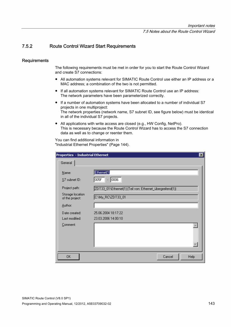
Important notes 7.5 Notes about the Route Control Wizard
SIMATIC Route Control (V8.0 SP1) Programming and Operating Manual, 12/2012, A5E03709032-02 143
7.5.2 Route Control Wizard Start Requirements
Requirements The following requirements must be met in order for you to start the Route Control Wizard and create S7 connections:
● All automation systems relevant for SIMATIC Route Control use either an IP address or a MAC address; a combination of the two is not permitted.
● If all automation systems relevant for SIMATIC Route Control use an IP address: The network parameters have been parameterized correctly.
● If a number of automation systems have been allocated to a number of individual S7 projects in one multiproject: The network properties (network name, S7 subnet ID, see figure below) must be identical in all of the individual S7 projects.
● All applications with write access are closed (e.g., HW Config, NetPro). This is necessary because the Route Control Wizard has to access the S7 connection data as well as to change or reenter them.
You can find additional information in "Industrial Ethernet Properties" (Page 144).
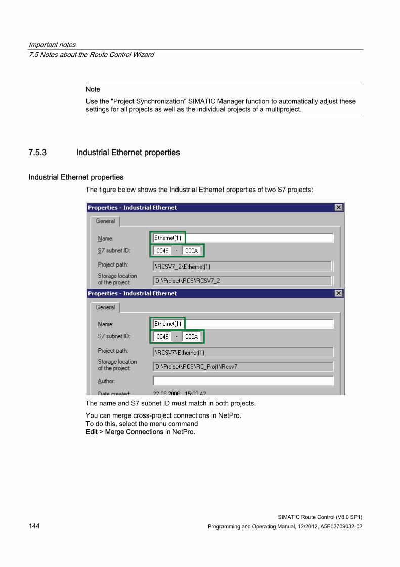
Important notes 7.5 Notes about the Route Control Wizard
SIMATIC Route Control (V8.0 SP1) 144 Programming and Operating Manual, 12/2012, A5E03709032-02
Note
Use the "Project Synchronization" SIMATIC Manager function to automatically adjust these settings for all projects as well as the individual projects of a multiproject.
7.5.3 Industrial Ethernet properties
Industrial Ethernet properties The figure below shows the Industrial Ethernet properties of two S7 projects:
The name and S7 subnet ID must match in both projects.
You can merge cross-project connections in NetPro. To do this, select the menu command Edit > Merge Connections in NetPro.
Important notes 7.5 Notes about the Route Control Wizard
SIMATIC Route Control (V8.0 SP1) Programming and Operating Manual, 12/2012, A5E03709032-02 145
7.5.4 Computer name and IP address of the Route Control server
SIMATIC Route Control Version 6.1 Up until version 6.1, you needed to enter an IP address for the Route Control server(s) in the Route Control Wizard or configure a computer name. The computer name was required in order to download the RC server from the RC Engineering tool (shared drive). The computer name of the server was also used by the wizard to correctly set the "PCS 7 OS-dependent startup" and "PCS 7 redundancy logon" switches. You can find additional information in "Overview of Project Settings" (Page 507).
SIMATIC Route Control Version 6.1 SP1 and Higher As of V6.1 SP1, "Route Control applications" are configured in HW Config. The Route Control Wizard uses these to automatically detect the stations where Route Control applications are running and the other applications, which are also running on the same stations. As of version 6.1 SP1, you do not have to specify the computer name of the Route Control server or enter its IP address. The two global settings referred to above are also ascertained automatically.
You can find additional information in "Hardware Configuration (HW Config)" (Page 413).
Important notes 7.6 Notes on route configuration
SIMATIC Route Control (V8.0 SP1) 146 Programming and Operating Manual, 12/2012, A5E03709032-02
7.6 Notes on route configuration
7.6.1 Route search basics
What is the route search? The route search is used to establish a connection between a starting and destination location by stringing together configured partial routes. This search can be affected by specification of certain parameters, such as VIA points or priorities of partial routes.
7.6.2 Routes
What is a route? Although routes or material transports are indeed visible in RC Engineering, they are no longer configured. Routes "come into being" at the moment of the route search via the assembly of partial routes.
You define a route by indicating the following parameters:
● Mode table
● Function ID
● Material
● Source and destination location
● Up to 10 VIAs
7.6.3 Partial routes and VIAs
Relationship between partial routes and VIAs A partial route is the connection between two locations. A route consists of at least one, but generally several partial routes.
VIAs are intermediate destinations that can be used for configuring partial routes.
Note
If VIAs are predefined in the route search, they must be used for the route to be searched. This means that the course of the route can be affected with the use of VIAs.
Important notes 7.6 Notes on route configuration
SIMATIC Route Control (V8.0 SP1) Programming and Operating Manual, 12/2012, A5E03709032-02 147
Create partial route You create and program partial routes in Route Control Engineering.
A partial route is always an object within a mode table. Partial routes generally contain elements (e.g., control elements such as valves), that are "incorporated" into different mode levels with a different activation. The sum of the partial routes forms the route network of the process cell.
Types of partial routes Specify how partial routes are used during the route search:
● As unidirectional partial routes
● As bidirectional partial routes
The difference lies in the fact that unidirectional partial routes in the route search are used only in the direction that is established by start and final point.
Bidirectional partial routes, on the other hand, can also be used from the final point to the start point, whereupon the number of combinations for routes is normally greater.
However, there is a danger that circular or undesired routes are found.
Priority of a partial route You can weight partial routes in the configuration by specifying various values (1 – 32000) for the "priority" parameter. The smaller the numerical value, the higher the priority. In the route search, the priorities of the individual partial routes are added up. The path with the smallest priority sum is selected.
Establish the priority in the configuration and enter the value you have selected as a parameter of the partial route. For example, you can take the following criteria into account to set the priority of a partial route:
● Length of pipeline
● Number of elements in the route
● Particular elements, such as pumps, that have not been used as heavily
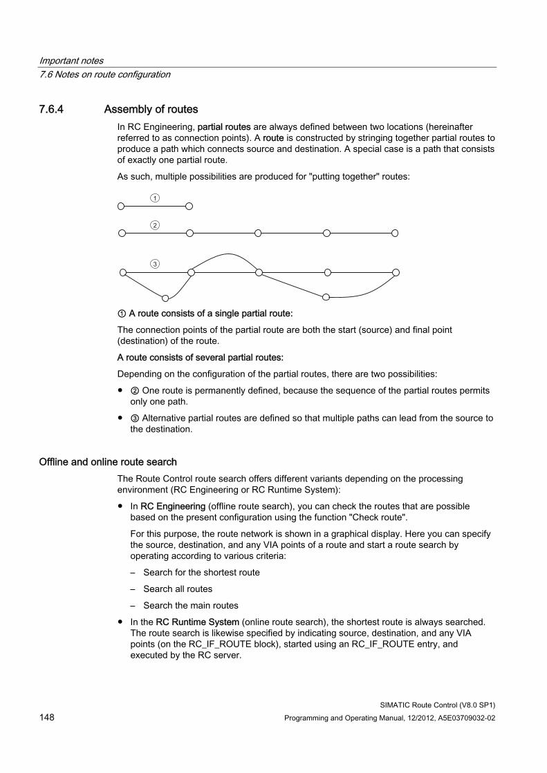
Important notes 7.6 Notes on route configuration
SIMATIC Route Control (V8.0 SP1) 148 Programming and Operating Manual, 12/2012, A5E03709032-02
7.6.4 Assembly of routes In RC Engineering, partial routes are always defined between two locations (hereinafter referred to as connection points). A route is constructed by stringing together partial routes to produce a path which connects source and destination. A special case is a path that consists of exactly one partial route.
As such, multiple possibilities are produced for "putting together" routes:
1
2
3
① A route consists of a single partial route:
The connection points of the partial route are both the start (source) and final point (destination) of the route.
A route consists of several partial routes:
Depending on the configuration of the partial routes, there are two possibilities:
● ② One route is permanently defined, because the sequence of the partial routes permits only one path.
● ③ Alternative partial routes are defined so that multiple paths can lead from the source to the destination.
Offline and online route search The Route Control route search offers different variants depending on the processing environment (RC Engineering or RC Runtime System):
● In RC Engineering (offline route search), you can check the routes that are possible based on the present configuration using the function "Check route".
For this purpose, the route network is shown in a graphical display. Here you can specify the source, destination, and any VIA points of a route and start a route search by operating according to various criteria:
– Search for the shortest route
– Search all routes
– Search the main routes
● In the RC Runtime System (online route search), the shortest route is always searched. The route search is likewise specified by indicating source, destination, and any VIA points (on the RC_IF_ROUTE block), started using an RC_IF_ROUTE entry, and executed by the RC server.
Important notes 7.6 Notes on route configuration
SIMATIC Route Control (V8.0 SP1) Programming and Operating Manual, 12/2012, A5E03709032-02 149
Shortest route The search for the shortest route is conducted in Route Control according to the Dijkstra algorithm:
By setting priorities for the partial routes (from 1 to 32000) a length is assigned to a partial route; the sum of the partial route priorities from the starting point yields the length of the route.
In the route search, a search is made from the starting point to the connection point over the partial route having the lowest priority. The starting point is assigned to this connection point as the preceding point, and the sum of the priorities of the partial routes (lengths) is noted up to this connection point. Since this connection point has now been reached, all steps in the search sequence that reach this connection point in a later search step are classified as unsuitable and rejected. The next search step always starts from the connection point that has the smallest sum of the priorities of all partial routes. These search steps are performed until the goal is achieved.
Online as well as offline route searches can be affected by additional parameters:
● Specifying additional route points (VIAs) that must be included in the route.
● Weighting of the partial routes by assignment of various priorities ("length") to partial routes.
Differences between offline and online search There are two essential differences:
● In the offline search, locations can certainly be excluded when running the route search. Otherwise, all configured elements and partial routes are available for the search because only one route search or one route is ever active when offline. Routes which are active simultaneously, such as those in the Runtime System, do not exist and, therefore, cannot affect the offline search.
● The online search, by contrast, takes the current system state into account. As such, elements of a partial route may not be available and could cause this partial route to not be available for the route search. Moreover, in the Runtime System up to 300 routes may also run simultaneously, by which partial routes are already assigned that would also be needed for the route search just started. In this case, a search is made for alternative partial routes.
See also on this Guidelines on concurrent routes (Page 324).
Important notes 7.6 Notes on route configuration
SIMATIC Route Control (V8.0 SP1) 150 Programming and Operating Manual, 12/2012, A5E03709032-02
Particularities
Priority
There is a possibility that several paths with the same sum of priorities from the partial routes (length) lead to the final point in different ways. Which path is then actually used as the shortest path is a random selection.
VIA points
Dynamically, the course of a route can also be determined by assignment of intermediate locations (VIAs). The route is then determined in several stages by searching for the shortest route between the pre-determined route points. Depending on the configuration, it may be possible that a route cannot be found. This could be due to the first section of the route a partial route is already being used used that urgently requires a different, subsequent route section. However, a solution may possibly be found by assigning various partial route priorities.
Saved routes
If a specific route is always to be used for a combination of source, destination, and VIAs, a route can be determined in the offline search and then saved.
In the Runtime System, it is possible to save an active path.
These routes can be used via the "Start saved route" function.
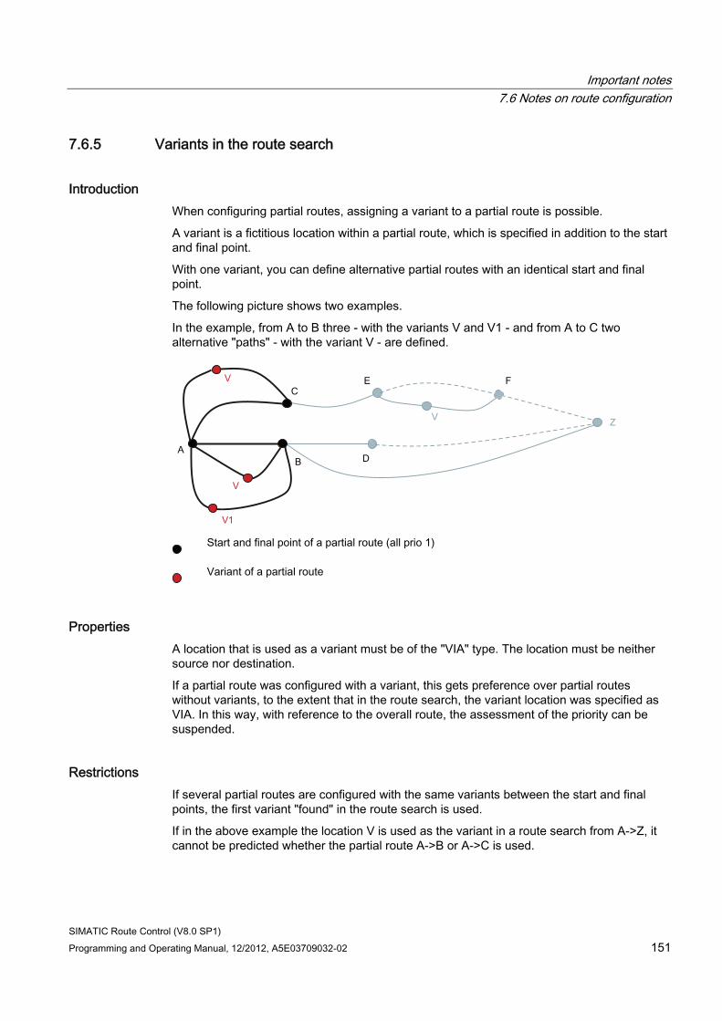
Important notes 7.6 Notes on route configuration
SIMATIC Route Control (V8.0 SP1) Programming and Operating Manual, 12/2012, A5E03709032-02 151
7.6.5 Variants in the route search
Introduction When configuring partial routes, assigning a variant to a partial route is possible.
A variant is a fictitious location within a partial route, which is specified in addition to the start and final point.
With one variant, you can define alternative partial routes with an identical start and final point.
The following picture shows two examples.
In the example, from A to B three - with the variants V and V1 - and from A to C two alternative "paths" - with the variant V - are defined.
Start and final point of a partial route (all prio 1)
Variant of a partial route
Properties A location that is used as a variant must be of the "VIA" type. The location must be neither source nor destination.
If a partial route was configured with a variant, this gets preference over partial routes without variants, to the extent that in the route search, the variant location was specified as VIA. In this way, with reference to the overall route, the assessment of the priority can be suspended.
Restrictions If several partial routes are configured with the same variants between the start and final points, the first variant "found" in the route search is used.
If in the above example the location V is used as the variant in a route search from A->Z, it cannot be predicted whether the partial route A->B or A->C is used.
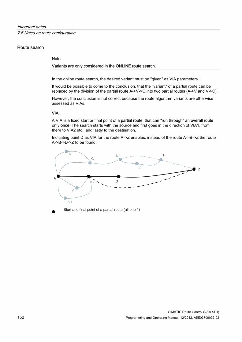
Important notes 7.6 Notes on route configuration
SIMATIC Route Control (V8.0 SP1) 152 Programming and Operating Manual, 12/2012, A5E03709032-02
Route search
Note
Variants are only considered in the ONLINE route search.
In the online route search, the desired variant must be "given" as VIA parameters.
It would be possible to come to the conclusion, that the "variant" of a partial route can be replaced by the division of the partial route A->V->C into two partial routes (A->V and V->C).
However, the conclusion is not correct because the route algorithm variants are otherwise assessed as VIAs.
VIA:
A VIA is a fixed start or final point of a partial route, that can "run through" an overall route only once. The search starts with the source and first goes in the direction of VIA1, from there to VIA2 etc., and lastly to the destination.
Indicating point D as VIA for the route A->Z enables, instead of the route A->B->Z the route A->B->D->Z to be found.
Start and final point of a partial route (all prio 1)
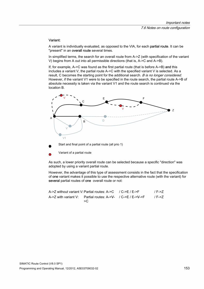
Important notes 7.6 Notes on route configuration
SIMATIC Route Control (V8.0 SP1) Programming and Operating Manual, 12/2012, A5E03709032-02 153
Variant:
A variant is individually evaluated, as opposed to the VIA, for each partial route. It can be "present" in an overall route several times.
In simplified terms, the search for an overall route from A->Z (with specification of the variant V) begins from A out into all permissible directions (that is, A->C and A->B).
If, for example, A->C was found as the first partial route (that is before A->B) and this includes a variant V, the partial route A->C with the specified variant V is selected. As a result, C becomes the starting point for the additional search. B is no longer considered. However, if the variant V1 were to be specified in the route search, the partial route A->B of absolute necessity is taken via the variant V1 and the route search is continued via the location B.
Start and final point of a partial route (all prio 1)
Variant of a partial route
As such, a lower priority overall route can be selected because a specific "direction" was adopted by using a variant partial route.
However, the advantage of this type of assessment consists in the fact that the specification of one variant makes it possible to use the respective alternative route (with the variant) for several partial routes of one overall route or not:
A->Z without variant V: Partial routes: A->C / C->E / E->F / F->Z A->Z with variant V: Partial routes: A->V-
>C / C->E / E->V->F / F->Z
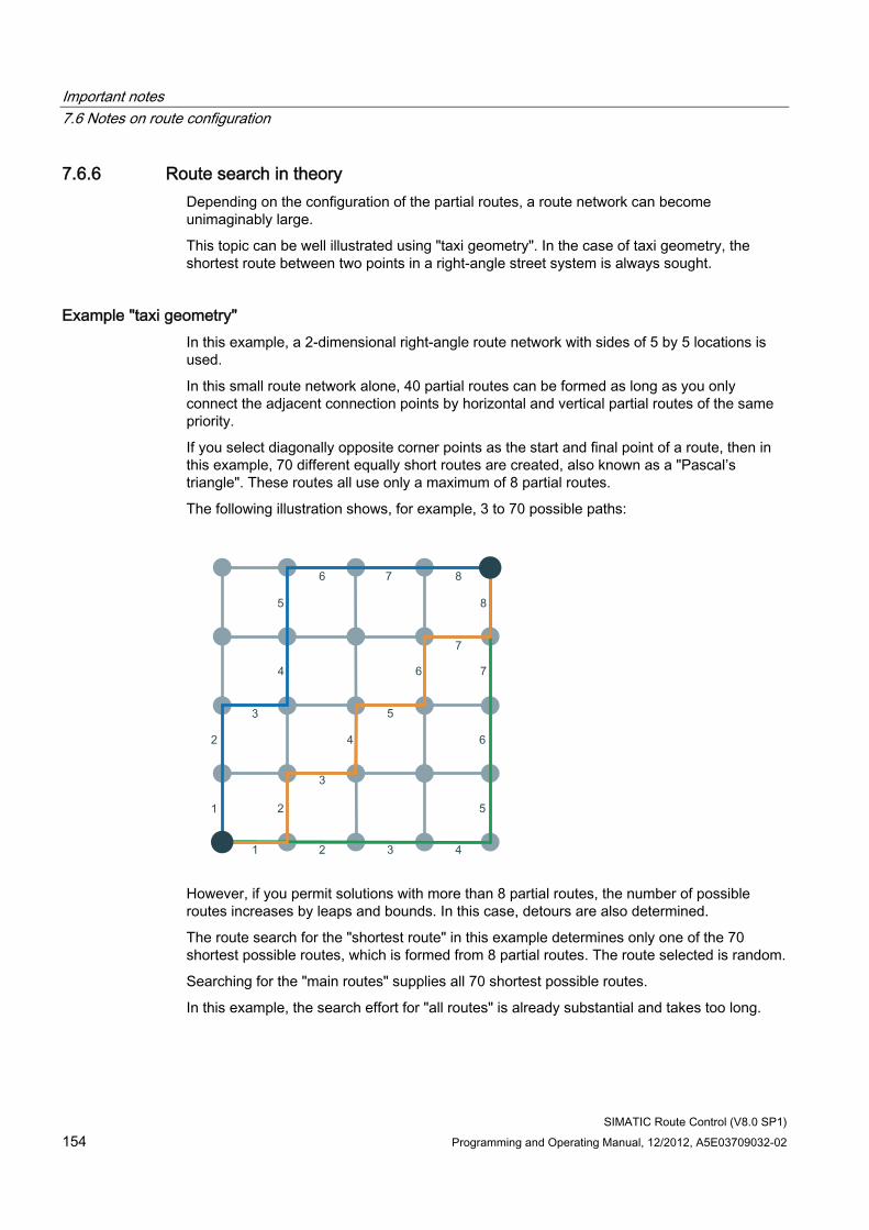
Important notes 7.6 Notes on route configuration
SIMATIC Route Control (V8.0 SP1) 154 Programming and Operating Manual, 12/2012, A5E03709032-02
7.6.6 Route search in theory Depending on the configuration of the partial routes, a route network can become unimaginably large.
This topic can be well illustrated using "taxi geometry". In the case of taxi geometry, the shortest route between two points in a right-angle street system is always sought.
Example "taxi geometry" In this example, a 2-dimensional right-angle route network with sides of 5 by 5 locations is used.
In this small route network alone, 40 partial routes can be formed as long as you only connect the adjacent connection points by horizontal and vertical partial routes of the same priority.
If you select diagonally opposite corner points as the start and final point of a route, then in this example, 70 different equally short routes are created, also known as a "Pascal’s triangle". These routes all use only a maximum of 8 partial routes.
The following illustration shows, for example, 3 to 70 possible paths:
However, if you permit solutions with more than 8 partial routes, the number of possible routes increases by leaps and bounds. In this case, detours are also determined.
The route search for the "shortest route" in this example determines only one of the 70 shortest possible routes, which is formed from 8 partial routes. The route selected is random.
Searching for the "main routes" supplies all 70 shortest possible routes.
In this example, the search effort for "all routes" is already substantial and takes too long.
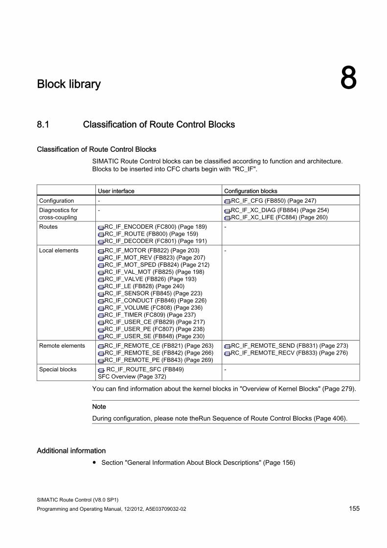
SIMATIC Route Control (V8.0 SP1) Programming and Operating Manual, 12/2012, A5E03709032-02 155
Block library 88.1 Classification of Route Control Blocks
Classification of Route Control Blocks SIMATIC Route Control blocks can be classified according to function and architecture. Blocks to be inserted into CFC charts begin with "RC_IF".
User interface Configuration blocks Configuration - RC_IF_CFG (FB850) (Page 247) Diagnostics for cross-coupling
- RC_IF_XC_DIAG (FB884) (Page 254) RC_IF_XC_LIFE (FC884) (Page 260)
Routes RC_IF_ENCODER (FC800) (Page 189) RC_IF_ROUTE (FB800) (Page 159) RC_IF_DECODER (FC801) (Page 191)
-
Local elements RC_IF_MOTOR (FB822) (Page 203) RC_IF_MOT_REV (FB823) (Page 207) RC_IF_MOT_SPED (FB824) (Page 212) RC_IF_VAL_MOT (FB825) (Page 198) RC_IF_VALVE (FB826) (Page 193) RC_IF_LE (FB828) (Page 240) RC_IF_SENSOR (FB845) (Page 223) RC_IF_CONDUCT (FB846) (Page 226) RC_IF_VOLUME (FC808) (Page 236) RC_IF_TIMER (FC809) (Page 237) RC_IF_USER_CE (FB829) (Page 217) RC_IF_USER_PE (FC807) (Page 238) RC_IF_USER_SE (FB848) (Page 230)
-
Remote elements RC_IF_REMOTE_CE (FB821) (Page 263) RC_IF_REMOTE_SE (FB842) (Page 266) RC_IF_REMOTE_PE (FB843) (Page 269)
RC_IF_REMOTE_SEND (FB831) (Page 273) RC_IF_REMOTE_RECV (FB833) (Page 276)
Special blocks RC_IF_ROUTE_SFC (FB849) SFC Overview (Page 372)
-
You can find information about the kernel blocks in "Overview of Kernel Blocks" (Page 279).
Note
During configuration, please note theRun Sequence of Route Control Blocks (Page 406).
Additional information ● Section "General Information About Block Descriptions" (Page 156)
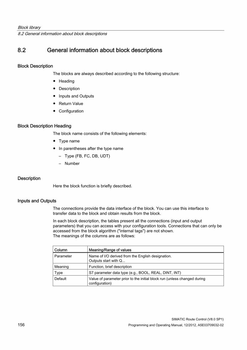
Block library 8.2 General information about block descriptions
SIMATIC Route Control (V8.0 SP1) 156 Programming and Operating Manual, 12/2012, A5E03709032-02
8.2 General information about block descriptions
Block Description The blocks are always described according to the following structure:
● Heading
● Description
● Inputs and Outputs
● Return Value
● Configuration
Block Description Heading The block name consists of the following elements:
● Type name
● In parentheses after the type name
– Type (FB, FC, DB, UDT)
– Number
Description Here the block function is briefly described.
Inputs and Outputs The connections provide the data interface of the block. You can use this interface to transfer data to the block and obtain results from the block.
In each block description, the tables present all the connections (input and output parameters) that you can access with your configuration tools. Connections that can only be accessed from the block algorithm ("internal tags") are not shown. The meanings of the columns are as follows:
Column Meaning/Range of values Parameter Name of I/O derived from the English designation.
Outputs start with Q... Meaning Function, brief description Type S7 parameter data type (e.g., BOOL, REAL, DINT, INT) Default Value of parameter prior to the initial block run (unless changed during
configuration)
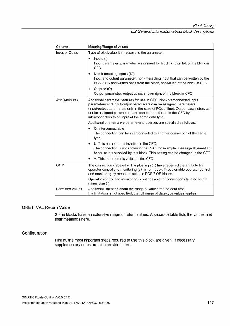
Block library 8.2 General information about block descriptions
SIMATIC Route Control (V8.0 SP1) Programming and Operating Manual, 12/2012, A5E03709032-02 157
Column Meaning/Range of values lnput or Output Type of block-algorithm access to the parameter:
• Inputs (I) Input parameter, parameter assignment for block, shown left of the block in CFC
• Non-interacting inputs (IO) Input and output parameter, non-interacting input that can be written by the PCS 7 OS and written back from the block, shown left of the block in CFC
• Outputs (O) Output parameter, output value, shown right of the block in CFC
Attr.(Attribute) Additional parameter features for use in CFC. Non-interconnected input parameters and input/output parameters can be assigned parameters (input/output parameters only in the case of FCs online). Output parameters can not be assigned parameters and can be transferred in the CFC by interconnection to an input of the same data type. Additional or alternative parameter properties are specified as follows: • Q: Interconnectable
The connection can be interconnected to another connection of the same type.
• U: This parameter is invisible in the CFC. The connection is not shown in the CFC (for example, message ID/event ID) because it is supplied by this block. This setting can be changed in the CFC.
• V: This parameter is visible in the CFC.
OCM The connections labeled with a plus sign (+) have received the attribute for operator control and monitoring (s7_m_c = true). These enable operator control and monitoring by means of suitable PCS 7 OS blocks. Operator control and monitoring is not possible for connections labeled with a minus sign (-).
Permitted values Additional limitation about the range of values for the data type. If a limitation is not specified, the full range of data-type values applies.
QRET_VAL Return Value Some blocks have an extensive range of return values. A separate table lists the values and their meanings here.
Configuration Finally, the most important steps required to use this block are given. If necessary, supplementary notes are also provided here.
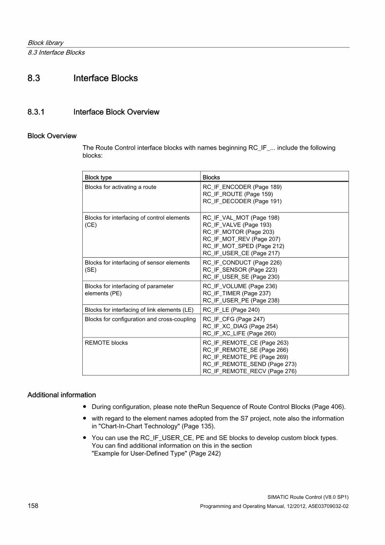
Block library 8.3 Interface Blocks
SIMATIC Route Control (V8.0 SP1) 158 Programming and Operating Manual, 12/2012, A5E03709032-02
8.3 Interface Blocks
8.3.1 Interface Block Overview
Block Overview The Route Control interface blocks with names beginning RC_IF_... include the following blocks:
Block type Blocks Blocks for activating a route RC_IF_ENCODER (Page 189)
RC_IF_ROUTE (Page 159) RC_IF_DECODER (Page 191)
Blocks for interfacing of control elements (CE)
RC_IF_VAL_MOT (Page 198) RC_IF_VALVE (Page 193) RC_IF_MOTOR (Page 203) RC_IF_MOT_REV (Page 207) RC_IF_MOT_SPED (Page 212) RC_IF_USER_CE (Page 217)
Blocks for interfacing of sensor elements (SE)
RC_IF_CONDUCT (Page 226) RC_IF_SENSOR (Page 223) RC_IF_USER_SE (Page 230)
Blocks for interfacing of parameter elements (PE)
RC_IF_VOLUME (Page 236) RC_IF_TIMER (Page 237) RC_IF_USER_PE (Page 238)
Blocks for interfacing of link elements (LE) RC_IF_LE (Page 240) Blocks for configuration and cross-coupling RC_IF_CFG (Page 247)
RC_IF_XC_DIAG (Page 254) RC_IF_XC_LIFE (Page 260)
REMOTE blocks RC_IF_REMOTE_CE (Page 263) RC_IF_REMOTE_SE (Page 266) RC_IF_REMOTE_PE (Page 269) RC_IF_REMOTE_SEND (Page 273) RC_IF_REMOTE_RECV (Page 276)
Additional information ● During configuration, please note theRun Sequence of Route Control Blocks (Page 406).
● with regard to the element names adopted from the S7 project, note also the information in "Chart-In-Chart Technology" (Page 135).
● You can use the RC_IF_USER_CE, PE and SE blocks to develop custom block types. You can find additional information on this in the section "Example for User-Defined Type" (Page 242)
Block library 8.3 Interface Blocks
SIMATIC Route Control (V8.0 SP1) Programming and Operating Manual, 12/2012, A5E03709032-02 159
8.3.2 Routes
8.3.2.1 RC_IF_ROUTE (FB 800)
Description This block is the central interface of a route to the user program and the counterpart to the Route Control faceplate in the PCS 7 OS picture. The following tasks are performed on this block:
● Specifying route parameters (e.g. source, destination, via, mode, material)
● Starting, holding, and ending material transports
● Defining setpoints for monitoring times (status-monitoring time, error tolerance time)
● Specifying dynamic setpoints for external parameter elements
● Transferring batch ID, batch name, and step number from a BATCH system
The block controls exactly one route, i.e. one material transport. It provides additional information about the status of the route and its elements to the user program by means of output parameters.
Typically, one user-defined SFC derived from RC_IF_ROUTE_SFC and one RC_IF_ENCODER (FC 800) (Page 189) is connected upstream of RC_IF_ROUTE and one RC_IF_DECODER (FC 801) (Page 191) is connected downstream of RC_IF_ROUTE.
An overview of the relationship between SFC, route and operator dialogs is provided in the section "Relationship of SFC and Route with Operator Dialogs". (Page 373)
Dynamic or Fixed Route ID A route can be operated with a fixed route ID. For additional information see the section "Valid Route IDs" (Page 702).
Dynamic route IDs are primarily used when a project contains more than 300 routes. This procedure ensures that no more than 300 material transports take place simultaneously.
Even if a project contains fewer than 300 route blocks, dynamic ID assignment can still make project engineering easier and prevent duplicate assignment of IDs.
For additional information on this see section "Guide to Dynamic ID Assignment (Page 378)".
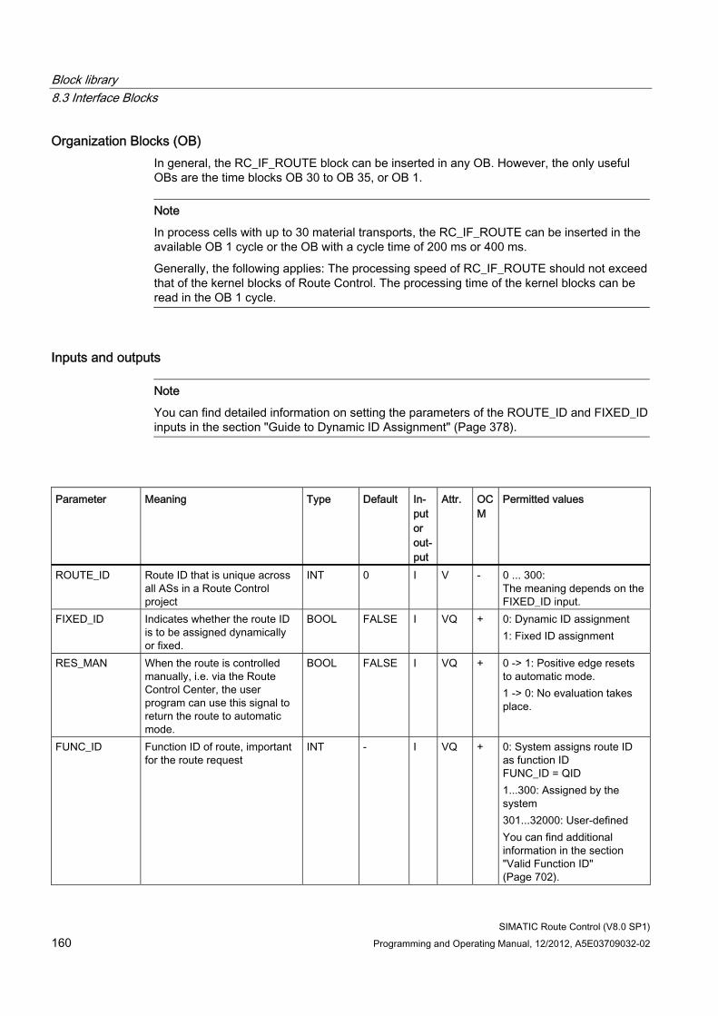
Block library 8.3 Interface Blocks
SIMATIC Route Control (V8.0 SP1) 160 Programming and Operating Manual, 12/2012, A5E03709032-02
Organization Blocks (OB) In general, the RC_IF_ROUTE block can be inserted in any OB. However, the only useful OBs are the time blocks OB 30 to OB 35, or OB 1.
Note
In process cells with up to 30 material transports, the RC_IF_ROUTE can be inserted in the available OB 1 cycle or the OB with a cycle time of 200 ms or 400 ms.
Generally, the following applies: The processing speed of RC_IF_ROUTE should not exceed that of the kernel blocks of Route Control. The processing time of the kernel blocks can be read in the OB 1 cycle.
Inputs and outputs
Note
You can find detailed information on setting the parameters of the ROUTE_ID and FIXED_ID inputs in the section "Guide to Dynamic ID Assignment" (Page 378).
Parameter Meaning Type Default In-
put or out-put
Attr. OCM
Permitted values
ROUTE_ID Route ID that is unique across all ASs in a Route Control project
INT 0 I V - 0 ... 300: The meaning depends on the FIXED_ID input.
FIXED_ID Indicates whether the route ID is to be assigned dynamically or fixed.
BOOL FALSE I VQ + 0: Dynamic ID assignment 1: Fixed ID assignment
RES_MAN When the route is controlled manually, i.e. via the Route Control Center, the user program can use this signal to return the route to automatic mode.
BOOL FALSE I VQ + 0 -> 1: Positive edge resets to automatic mode. 1 -> 0: No evaluation takes place.
FUNC_ID Function ID of route, important for the route request
INT - I VQ + 0: System assigns route ID as function ID FUNC_ID = QID 1...300: Assigned by the system 301...32000: User-defined You can find additional information in the section "Valid Function ID" (Page 702).
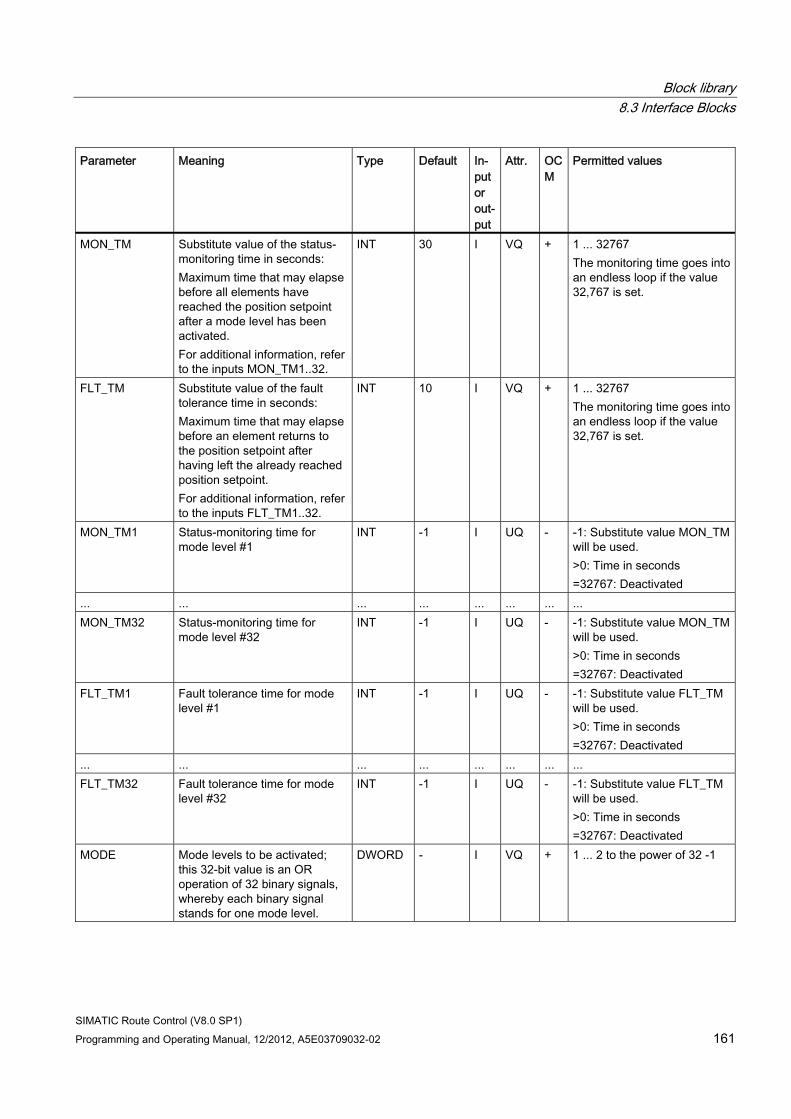
Block library 8.3 Interface Blocks
SIMATIC Route Control (V8.0 SP1) Programming and Operating Manual, 12/2012, A5E03709032-02 161
Parameter Meaning Type Default In-put or out-put
Attr. OCM
Permitted values
MON_TM Substitute value of the status-monitoring time in seconds: Maximum time that may elapse before all elements have reached the position setpoint after a mode level has been activated. For additional information, refer to the inputs MON_TM1..32.
INT 30 I VQ + 1 ... 32767 The monitoring time goes into an endless loop if the value 32,767 is set.
FLT_TM Substitute value of the fault tolerance time in seconds: Maximum time that may elapse before an element returns to the position setpoint after having left the already reached position setpoint. For additional information, refer to the inputs FLT_TM1..32.
INT 10 I VQ + 1 ... 32767 The monitoring time goes into an endless loop if the value 32,767 is set.
MON_TM1 Status-monitoring time for mode level #1
INT -1 I UQ - -1: Substitute value MON_TM will be used. >0: Time in seconds =32767: Deactivated
... ... ... ... ... ... ... ... MON_TM32 Status-monitoring time for
mode level #32 INT -1 I UQ - -1: Substitute value MON_TM
will be used. >0: Time in seconds =32767: Deactivated
FLT_TM1 Fault tolerance time for mode level #1
INT -1 I UQ - -1: Substitute value FLT_TM will be used. >0: Time in seconds =32767: Deactivated
... ... ... ... ... ... ... ... FLT_TM32 Fault tolerance time for mode
level #32 INT -1 I UQ - -1: Substitute value FLT_TM
will be used. >0: Time in seconds =32767: Deactivated
MODE Mode levels to be activated; this 32-bit value is an OR operation of 32 binary signals, whereby each binary signal stands for one mode level.
DWORD - I VQ + 1 ... 2 to the power of 32 -1
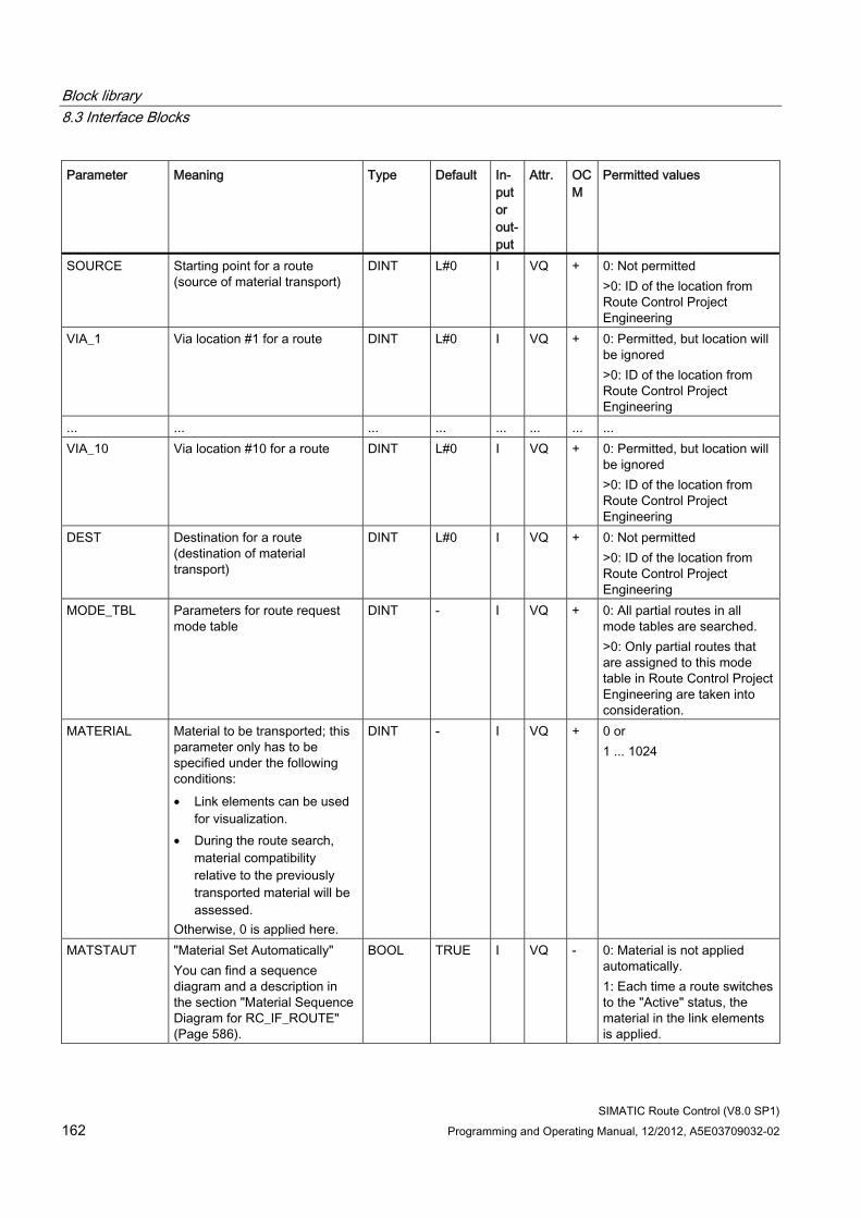
Block library 8.3 Interface Blocks
SIMATIC Route Control (V8.0 SP1) 162 Programming and Operating Manual, 12/2012, A5E03709032-02
Parameter Meaning Type Default In-put or out-put
Attr. OCM
Permitted values
SOURCE Starting point for a route (source of material transport)
DINT L#0 I VQ + 0: Not permitted >0: ID of the location from Route Control Project Engineering
VIA_1 Via location #1 for a route DINT L#0 I VQ + 0: Permitted, but location will be ignored >0: ID of the location from Route Control Project Engineering
... ... ... ... ... ... ... ... VIA_10 Via location #10 for a route DINT L#0 I VQ + 0: Permitted, but location will
be ignored >0: ID of the location from Route Control Project Engineering
DEST Destination for a route (destination of material transport)
DINT L#0 I VQ + 0: Not permitted >0: ID of the location from Route Control Project Engineering
MODE_TBL Parameters for route request mode table
DINT - I VQ + 0: All partial routes in all mode tables are searched. >0: Only partial routes that are assigned to this mode table in Route Control Project Engineering are taken into consideration.
MATERIAL Material to be transported; this parameter only has to be specified under the following conditions: • Link elements can be used
for visualization. • During the route search,
material compatibility relative to the previously transported material will be assessed.
Otherwise, 0 is applied here.
DINT - I VQ + 0 or 1 ... 1024
MATSTAUT "Material Set Automatically" You can find a sequence diagram and a description in the section "Material Sequence Diagram for RC_IF_ROUTE" (Page 586).
BOOL TRUE I VQ - 0: Material is not applied automatically. 1: Each time a route switches to the "Active" status, the material in the link elements is applied.
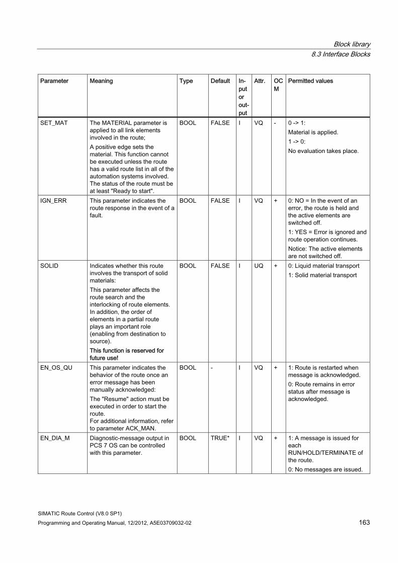
Block library 8.3 Interface Blocks
SIMATIC Route Control (V8.0 SP1) Programming and Operating Manual, 12/2012, A5E03709032-02 163
Parameter Meaning Type Default In-put or out-put
Attr. OCM
Permitted values
SET_MAT The MATERIAL parameter is applied to all link elements involved in the route; A positive edge sets the material. This function cannot be executed unless the route has a valid route list in all of the automation systems involved. The status of the route must be at least "Ready to start".
BOOL FALSE I VQ - 0 -> 1: Material is applied. 1 -> 0: No evaluation takes place.
IGN_ERR This parameter indicates the route response in the event of a fault.
BOOL FALSE I VQ + 0: NO = In the event of an error, the route is held and the active elements are switched off. 1: YES = Error is ignored and route operation continues. Notice: The active elements are not switched off.
SOLID Indicates whether this route involves the transport of solid materials: This parameter affects the route search and the interlocking of route elements. In addition, the order of elements in a partial route plays an important role (enabling from destination to source). This function is reserved for future use!
BOOL FALSE I UQ + 0: Liquid material transport 1: Solid material transport
EN_OS_QU This parameter indicates the behavior of the route once an error message has been manually acknowledged: The "Resume" action must be executed in order to start the route. For additional information, refer to parameter ACK_MAN.
BOOL - I VQ + 1: Route is restarted when message is acknowledged. 0: Route remains in error status after message is acknowledged.
EN_DIA_M Diagnostic-message output in PCS 7 OS can be controlled with this parameter.
BOOL TRUE* I VQ + 1: A message is issued for each RUN/HOLD/TERMINATE of the route. 0: No messages are issued.
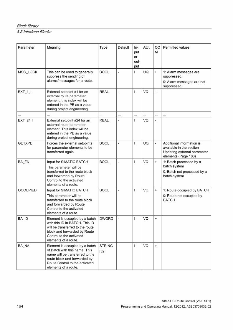
Block library 8.3 Interface Blocks
SIMATIC Route Control (V8.0 SP1) 164 Programming and Operating Manual, 12/2012, A5E03709032-02
Parameter Meaning Type Default In-put or out-put
Attr. OCM
Permitted values
MSG_LOCK This can be used to generally suppress the sending of alarms/messages for a route.
BOOL - I UQ + 1: Alarm messages are suppressed. 0: Alarm messages are not suppressed.
EXT_1_I External setpoint #1 for an external route parameter element; this index will be entered in the PE as a value during project engineering.
REAL - I VQ -
... ... ... ... ... ... ... ... EXT_24_I External setpoint #24 for an
external route parameter element. This index will be entered in the PE as a value during project engineering.
REAL - I VQ -
GETXPE Forces the external setpoints for parameter elements to be transferred again.
BOOL - I UQ - Additional information is available in the section Updating external parameter elements (Page 183)
BA_EN Input for SIMATIC BATCH This parameter will be transferred to the route block and forwarded by Route Control to the activated elements of a route.
BOOL - I VQ + 1: Batch processed by a batch system 0: Batch not processed by a batch system
OCCUPIED Input for SIMATIC BATCH This parameter will be transferred to the route block and forwarded by Route Control to the activated elements of a route.
BOOL - I VQ + 1: Route occupied by BATCH0: Route not occupied by BATCH
BA_ID Element is occupied by a batch with this ID in BATCH. This ID will be transferred to the route block and forwarded by Route Control to the activated elements of a route.
DWORD - I VQ +
BA_NA Element is occupied by a batch of Batch with this name. This name will be transferred to the route block and forwarded by Route Control to the activated elements of a route.
STRING [32]
- I VQ +
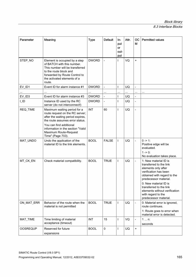
Block library 8.3 Interface Blocks
SIMATIC Route Control (V8.0 SP1) Programming and Operating Manual, 12/2012, A5E03709032-02 165
Parameter Meaning Type Default In-put or out-put
Attr. OCM
Permitted values
STEP_NO Element is occupied by a step of BATCH with this number. This number will be transferred to the route block and forwarded by Route Control to the activated elements of a route.
DWORD - I VQ +
EV_ID1 Event ID for alarm instance #1 DWORD - I UQ - ... ... ... ... ... ... ... ... EV_ID3 Event ID for alarm instance #3 DWORD - I UQ - I_ID Instance ID used by the RC
server (do not interconnect!) DWORD - I UQ -
REQ_TIME Maximum waiting period for a route request on the RC server; after the waiting period expires, the route assumes error status. You can find additional information in the section "Valid Maximum Route-Request Time" (Page 703).
INT 60 I UQ -
MAT_UNDO Undo the application of the material ID to the link elements.
BOOL FALSE I UQ - 0 -> 1: Positive edge will be evaluated. 1 -> 0: No evaluation takes place.
MT_CK_EN Check material compatibility. BOOL TRUE I UQ - 1: New material ID is transferred to the link elements only after verification has been obtained with regard to the predecessor material. 0: New material ID is transferred to the link elements without verification with regard to the predecessor material.
ON_MAT_ERR Behavior of the route when the material is not permitted
BOOL TRUE I UQ - 0: Material error is ignored, route continues. 1: Route goes to error when material error is detected.
MAT_TIME Time limiting of material acceptance (timeout)
INT 15 I VQ - 1 ... n: seconds
OOSREQUP Reserved for future expansions
BOOL 0 I UQ +
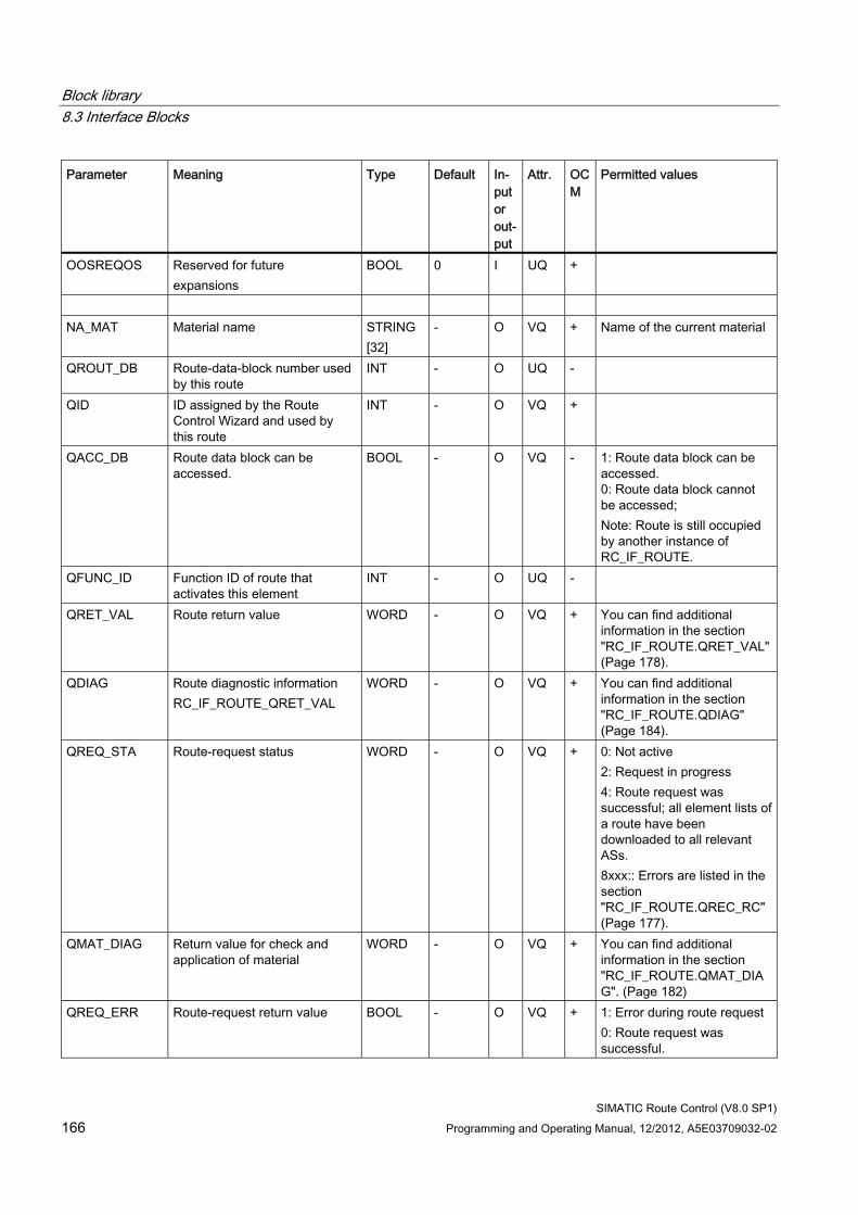
Block library 8.3 Interface Blocks
SIMATIC Route Control (V8.0 SP1) 166 Programming and Operating Manual, 12/2012, A5E03709032-02
Parameter Meaning Type Default In-put or out-put
Attr. OCM
Permitted values
OOSREQOS Reserved for future expansions
BOOL 0 I UQ +
NA_MAT Material name STRING
[32] - O VQ + Name of the current material
QROUT_DB Route-data-block number used by this route
INT - O UQ -
QID ID assigned by the Route Control Wizard and used by this route
INT - O VQ +
QACC_DB Route data block can be accessed.
BOOL - O VQ - 1: Route data block can be accessed. 0: Route data block cannot be accessed; Note: Route is still occupied by another instance of RC_IF_ROUTE.
QFUNC_ID Function ID of route that activates this element
INT - O UQ -
QRET_VAL Route return value WORD - O VQ + You can find additional information in the section "RC_IF_ROUTE.QRET_VAL" (Page 178).
QDIAG Route diagnostic information RC_IF_ROUTE_QRET_VAL
WORD - O VQ + You can find additional information in the section "RC_IF_ROUTE.QDIAG" (Page 184).
QREQ_STA Route-request status WORD - O VQ + 0: Not active 2: Request in progress 4: Route request was successful; all element lists of a route have been downloaded to all relevant ASs. 8xxx:: Errors are listed in the section "RC_IF_ROUTE.QREC_RC" (Page 177).
QMAT_DIAG Return value for check and application of material
WORD - O VQ + You can find additional information in the section "RC_IF_ROUTE.QMAT_DIAG". (Page 182)
QREQ_ERR Route-request return value BOOL - O VQ + 1: Error during route request 0: Route request was successful.
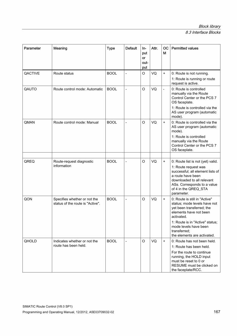
Block library 8.3 Interface Blocks
SIMATIC Route Control (V8.0 SP1) Programming and Operating Manual, 12/2012, A5E03709032-02 167
Parameter Meaning Type Default In-put or out-put
Attr. OCM
Permitted values
QACTIVE Route status BOOL - O VQ + 0: Route is not running. 1: Route is running or route request is active.
QAUTO Route control mode: Automatic BOOL - O VQ - 0: Route is controlled manually via the Route Control Center or the PCS 7 OS faceplate. 1: Route is controlled via the AS user program (automatic mode).
QMAN Route control mode: Manual BOOL - O VQ + 0: Route is controlled via the AS user program (automatic mode). 1: Route is controlled manually via the Route Control Center or the PCS 7 OS faceplate.
QREQ Route-request diagnostic
information BOOL - O VQ + 0: Route list is not (yet) valid.
1: Route request was successful; all element lists of a route have been downloaded to all relevant ASs. Corresponds to a value of 4 in the QREQ_STA parameter.
QON Specifies whether or not the status of the route is "Active".
BOOL - O VQ + 0: Route is still in "Active" status; mode levels have not yet been transferred; the elements have not been activated. 1: Route is in "Active" status; mode levels have been transferred; the elements are activated.
QHOLD Indicates whether or not the route has been held.
BOOL - O VQ + 0: Route has not been held. 1: Route has been held. For the route to continue running, the HOLD input must be reset to 0 or RESUME must be clicked on the faceplate/RCC.
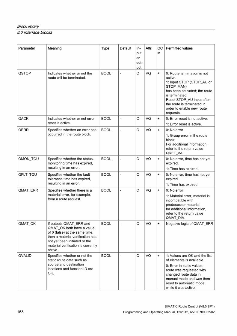
Block library 8.3 Interface Blocks
SIMATIC Route Control (V8.0 SP1) 168 Programming and Operating Manual, 12/2012, A5E03709032-02
Parameter Meaning Type Default In-put or out-put
Attr. OCM
Permitted values
QSTOP Indicates whether or not the route will be terminated.
BOOL - O VQ + 0: Route termination is not active. 1: Input STOP (STOP_AU or STOP_MAN) has been activated; the route is terminated. Reset STOP_AU input after the route is terminated in order to enable new route requests.
QACK Indicates whether or not error reset is active.
BOOL - O VQ + 0: Error reset is not active. 1: Error reset is active.
QERR Specifies whether an error has occurred in the route block.
BOOL - O VQ + 0: No error 1: Group error in the route block; For additional information, refer to the return value QRET_VAL.
QMON_TOU Specifies whether the status-monitoring time has expired, resulting in an error.
BOOL - O VQ + 0: No error, time has not yet expired. 1: Time has expired.
QFLT_TOU Specifies whether the fault tolerance time has expired, resulting in an error.
BOOL - O VQ + 0: No error, time has not yet expired. 1: Time has expired.
QMAT_ERR Specifies whether there is a material error, for example, from a route request.
BOOL - O VQ + 0: No error 1: Material error, material is incompatible with predecessor material; for additional information, refer to the return value QMAT_DIA.
QMAT_OK If outputs QMAT_ERR and QMAT_OK both have a value of 0 (false) at the same time, then a material verification has not yet been initiated or the material verification is currently active.
BOOL - O VQ + Negative logic of QMAT_ERR
QVALID Specifies whether or not the static route data such as source and destination locations and function ID are OK.
BOOL - O VQ + 1: Values are OK and the list of elements is available. 0: Error in static values; route was requested with changed route data in manual mode and was then reset to automatic mode while it was active.
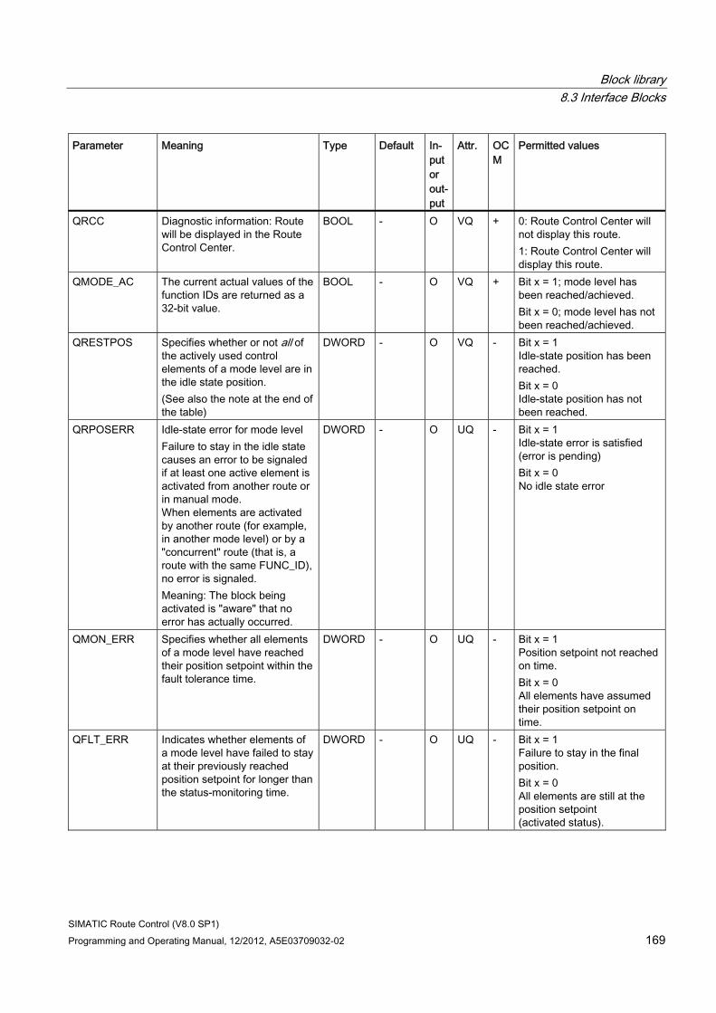
Block library 8.3 Interface Blocks
SIMATIC Route Control (V8.0 SP1) Programming and Operating Manual, 12/2012, A5E03709032-02 169
Parameter Meaning Type Default In-put or out-put
Attr. OCM
Permitted values
QRCC Diagnostic information: Route will be displayed in the Route Control Center.
BOOL - O VQ + 0: Route Control Center will not display this route. 1: Route Control Center will display this route.
QMODE_AC The current actual values of the function IDs are returned as a 32-bit value.
BOOL - O VQ + Bit x = 1; mode level has been reached/achieved. Bit x = 0; mode level has not been reached/achieved.
QRESTPOS Specifies whether or not all of the actively used control elements of a mode level are in the idle state position. (See also the note at the end of the table)
DWORD - O VQ - Bit x = 1 Idle-state position has been reached. Bit x = 0 Idle-state position has not been reached.
QRPOSERR Idle-state error for mode level Failure to stay in the idle state causes an error to be signaled if at least one active element is activated from another route or in manual mode. When elements are activated by another route (for example, in another mode level) or by a "concurrent" route (that is, a route with the same FUNC_ID), no error is signaled. Meaning: The block being activated is "aware" that no error has actually occurred.
DWORD - O UQ - Bit x = 1 Idle-state error is satisfied (error is pending) Bit x = 0 No idle state error
QMON_ERR Specifies whether all elements of a mode level have reached their position setpoint within the fault tolerance time.
DWORD - O UQ - Bit x = 1 Position setpoint not reached on time. Bit x = 0 All elements have assumed their position setpoint on time.
QFLT_ERR Indicates whether elements of a mode level have failed to stay at their previously reached position setpoint for longer than the status-monitoring time.
DWORD - O UQ - Bit x = 1 Failure to stay in the final position. Bit x = 0 All elements are still at the position setpoint (activated status).
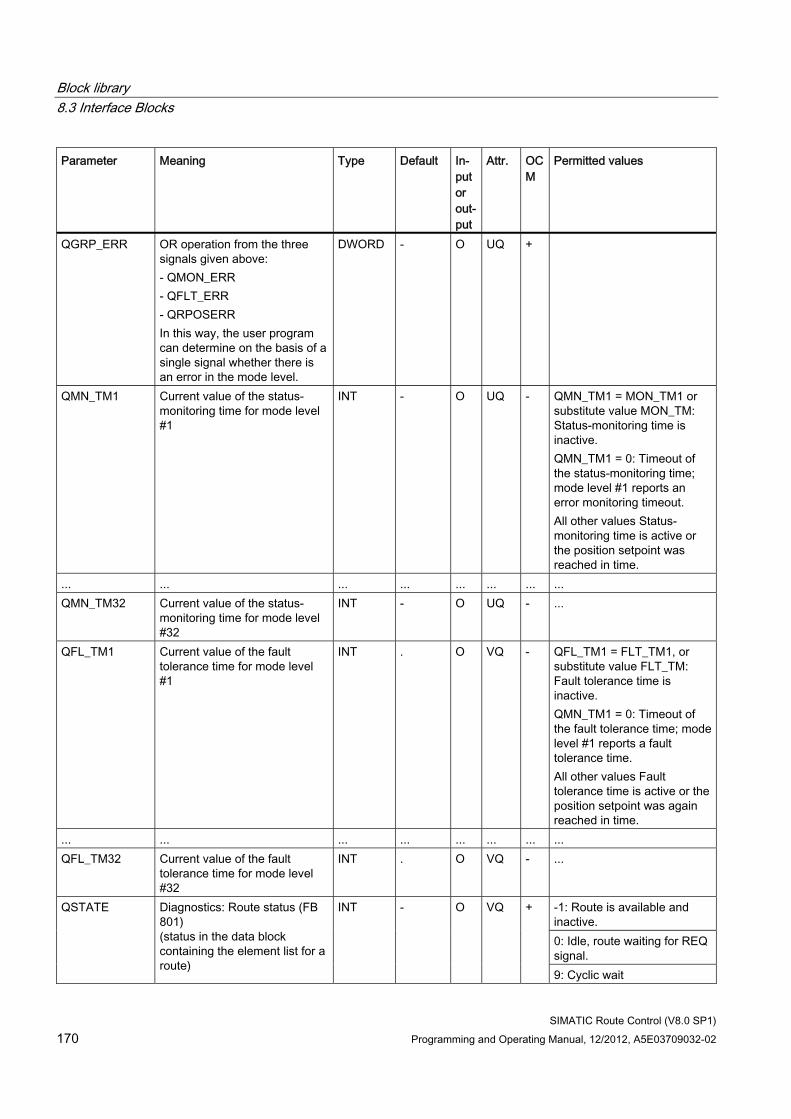
Block library 8.3 Interface Blocks
SIMATIC Route Control (V8.0 SP1) 170 Programming and Operating Manual, 12/2012, A5E03709032-02
Parameter Meaning Type Default In-put or out-put
Attr. OCM
Permitted values
QGRP_ERR OR operation from the three signals given above: - QMON_ERR - QFLT_ERR - QRPOSERR In this way, the user program can determine on the basis of a single signal whether there is an error in the mode level.
DWORD - O UQ +
QMN_TM1 Current value of the status-monitoring time for mode level #1
INT - O UQ - QMN_TM1 = MON_TM1 or substitute value MON_TM: Status-monitoring time is inactive. QMN_TM1 = 0: Timeout of the status-monitoring time; mode level #1 reports an error monitoring timeout. All other values Status-monitoring time is active or the position setpoint was reached in time.
... ... ... ... ... ... ... ... QMN_TM32 Current value of the status-
monitoring time for mode level #32
INT - O UQ - ...
QFL_TM1 Current value of the fault tolerance time for mode level #1
INT . O VQ - QFL_TM1 = FLT_TM1, or substitute value FLT_TM: Fault tolerance time is inactive. QMN_TM1 = 0: Timeout of the fault tolerance time; mode level #1 reports a fault tolerance time. All other values Fault tolerance time is active or the position setpoint was again reached in time.
... ... ... ... ... ... ... ... QFL_TM32 Current value of the fault
tolerance time for mode level #32
INT . O VQ - ...
-1: Route is available and inactive. 0: Idle, route waiting for REQ signal.
QSTATE Diagnostics: Route status (FB 801) (status in the data block containing the element list for a route)
INT - O VQ +
9: Cyclic wait
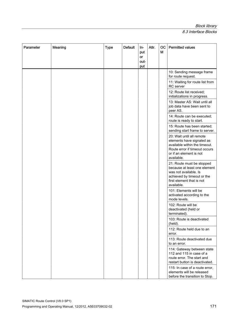
Block library 8.3 Interface Blocks
SIMATIC Route Control (V8.0 SP1) Programming and Operating Manual, 12/2012, A5E03709032-02 171
Parameter Meaning Type Default In-put or out-put
Attr. OCM
Permitted values
10: Sending message frame for route request. 11: Waiting for route list from RC server 12: Route list received; initializations in progress. 13: Master AS: Wait until all job data have been sent to peer AS. 14: Route can be executed; route is ready to start. 15: Route has been started; sending start frame to server.20: Wait until all remote elements have signaled as available within the timeout. Route error if timeout occurs or if an element is not available. 21: Route must be stopped because at least one element was not available. Is achieved by timeout or the first element that is not available. 101: Elements will be activated according to the mode levels. 102: Route will be deactivated (held or terminated). 103: Route is deactivated (held). 112: Route held due to an error. 113: Route deactivated due to an error. 114: Gateway between state 112 and 115 in case of a route error. The start and restart button is deactivated. 115: In case of a route error, elements will be released before the transition to Stop.
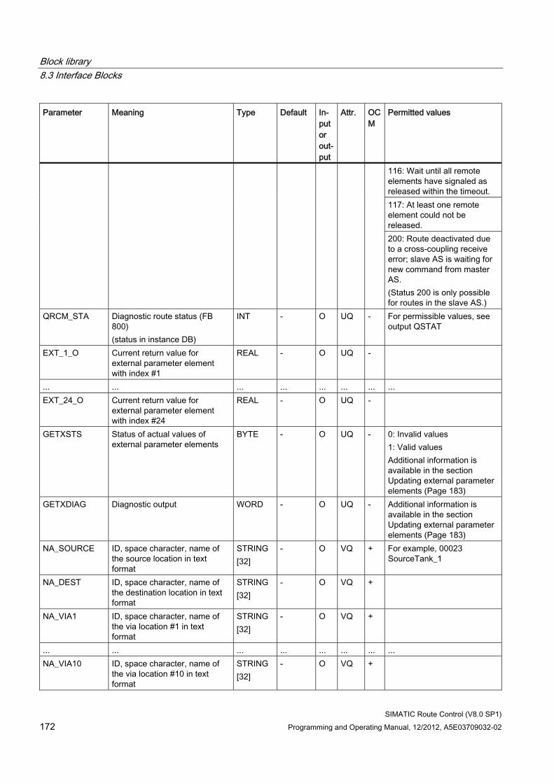
Block library 8.3 Interface Blocks
SIMATIC Route Control (V8.0 SP1) 172 Programming and Operating Manual, 12/2012, A5E03709032-02
Parameter Meaning Type Default In-put or out-put
Attr. OCM
Permitted values
116: Wait until all remote elements have signaled as released within the timeout. 117: At least one remote element could not be released. 200: Route deactivated due to a cross-coupling receive error; slave AS is waiting for new command from master AS. (Status 200 is only possible for routes in the slave AS.)
QRCM_STA Diagnostic route status (FB 800) (status in instance DB)
INT - O UQ - For permissible values, see output QSTAT
EXT_1_O Current return value for external parameter element with index #1
REAL - O UQ -
... ... ... ... ... ... ... ... EXT_24_O Current return value for
external parameter element with index #24
REAL - O UQ -
GETXSTS Status of actual values of external parameter elements
BYTE - O UQ - 0: Invalid values 1: Valid values Additional information is available in the section Updating external parameter elements (Page 183)
GETXDIAG Diagnostic output WORD - O UQ - Additional information is available in the section Updating external parameter elements (Page 183)
NA_SOURCE ID, space character, name of the source location in text format
STRING [32]
- O VQ + For example, 00023 SourceTank_1
NA_DEST ID, space character, name of the destination location in text format
STRING [32]
- O VQ +
NA_VIA1 ID, space character, name of the via location #1 in text format
STRING [32]
- O VQ +
... ... ... ... ... ... ... ... NA_VIA10 ID, space character, name of
the via location #10 in text format
STRING [32]
- O VQ +
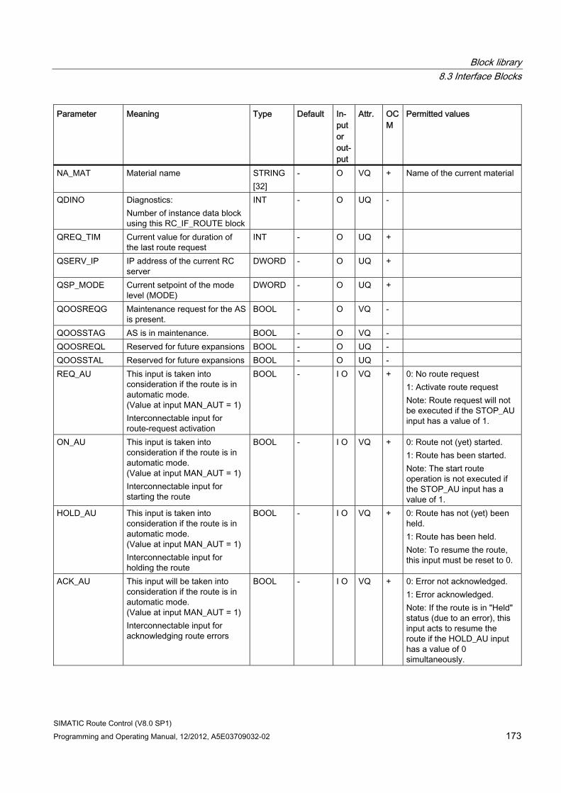
Block library 8.3 Interface Blocks
SIMATIC Route Control (V8.0 SP1) Programming and Operating Manual, 12/2012, A5E03709032-02 173
Parameter Meaning Type Default In-put or out-put
Attr. OCM
Permitted values
NA_MAT Material name STRING [32]
- O VQ + Name of the current material
QDINO Diagnostics: Number of instance data block using this RC_IF_ROUTE block
INT - O UQ -
QREQ_TIM Current value for duration of the last route request
INT - O UQ +
QSERV_IP IP address of the current RC server
DWORD - O UQ +
QSP_MODE Current setpoint of the mode level (MODE)
DWORD - O UQ +
QOOSREQG Maintenance request for the AS is present.
BOOL - O VQ -
QOOSSTAG AS is in maintenance. BOOL - O VQ - QOOSREQL Reserved for future expansions BOOL - O UQ - QOOSSTAL Reserved for future expansions BOOL - O UQ - REQ_AU This input is taken into
consideration if the route is in automatic mode. (Value at input MAN_AUT = 1) Interconnectable input for route-request activation
BOOL - I O VQ + 0: No route request 1: Activate route request Note: Route request will not be executed if the STOP_AU input has a value of 1.
ON_AU This input is taken into consideration if the route is in automatic mode. (Value at input MAN_AUT = 1) Interconnectable input for starting the route
BOOL - I O VQ + 0: Route not (yet) started. 1: Route has been started. Note: The start route operation is not executed if the STOP_AU input has a value of 1.
HOLD_AU This input is taken into consideration if the route is in automatic mode. (Value at input MAN_AUT = 1) Interconnectable input for holding the route
BOOL - I O VQ + 0: Route has not (yet) been held. 1: Route has been held. Note: To resume the route, this input must be reset to 0.
ACK_AU This input will be taken into consideration if the route is in automatic mode. (Value at input MAN_AUT = 1) Interconnectable input for acknowledging route errors
BOOL - I O VQ + 0: Error not acknowledged. 1: Error acknowledged. Note: If the route is in "Held" status (due to an error), this input acts to resume the route if the HOLD_AU input has a value of 0 simultaneously.
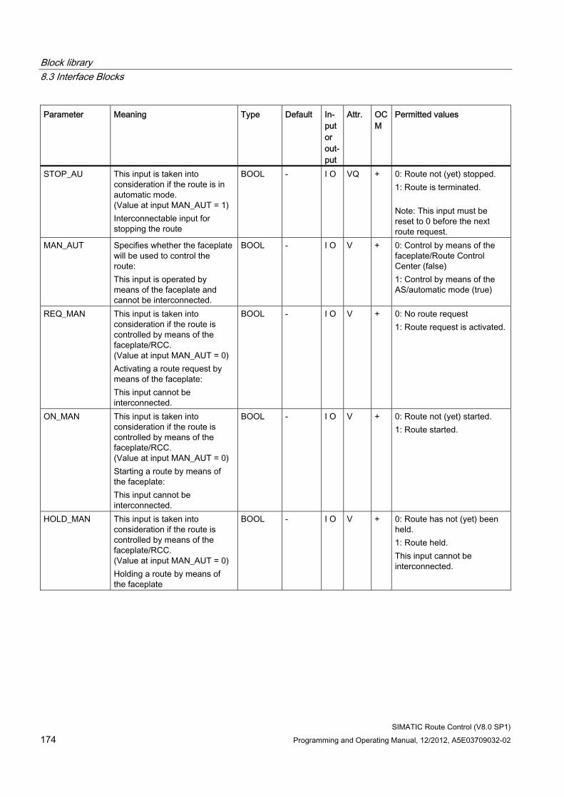
Block library 8.3 Interface Blocks
SIMATIC Route Control (V8.0 SP1) 174 Programming and Operating Manual, 12/2012, A5E03709032-02
Parameter Meaning Type Default In-put or out-put
Attr. OCM
Permitted values
STOP_AU This input is taken into consideration if the route is in automatic mode. (Value at input MAN_AUT = 1) Interconnectable input for stopping the route
BOOL - I O VQ + 0: Route not (yet) stopped. 1: Route is terminated. Note: This input must be reset to 0 before the next route request.
MAN_AUT Specifies whether the faceplate will be used to control the route: This input is operated by means of the faceplate and cannot be interconnected.
BOOL - I O V + 0: Control by means of the faceplate/Route Control Center (false) 1: Control by means of the AS/automatic mode (true)
REQ_MAN This input is taken into consideration if the route is controlled by means of the faceplate/RCC. (Value at input MAN_AUT = 0) Activating a route request by means of the faceplate: This input cannot be interconnected.
BOOL - I O V + 0: No route request 1: Route request is activated.
ON_MAN This input is taken into consideration if the route is controlled by means of the faceplate/RCC. (Value at input MAN_AUT = 0) Starting a route by means of the faceplate: This input cannot be interconnected.
BOOL - I O V + 0: Route not (yet) started. 1: Route started.
HOLD_MAN This input is taken into consideration if the route is controlled by means of the faceplate/RCC. (Value at input MAN_AUT = 0) Holding a route by means of the faceplate
BOOL - I O V + 0: Route has not (yet) been held. 1: Route held. This input cannot be interconnected.
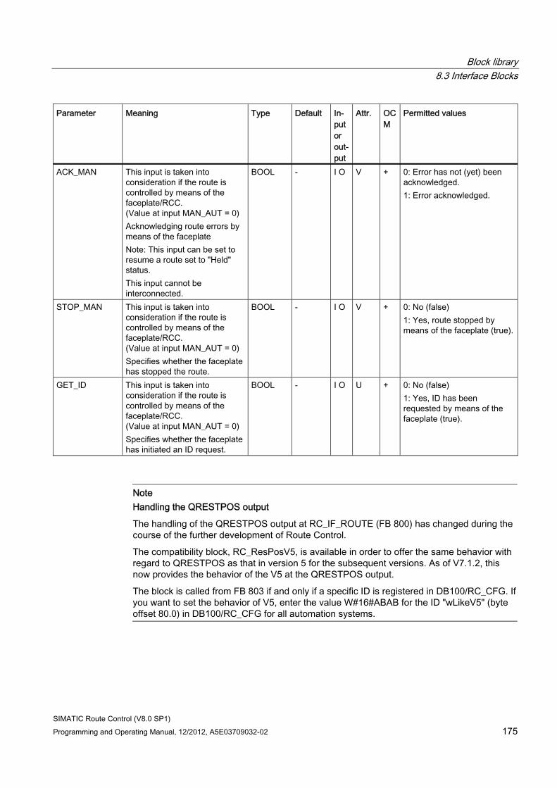
Block library 8.3 Interface Blocks
SIMATIC Route Control (V8.0 SP1) Programming and Operating Manual, 12/2012, A5E03709032-02 175
Parameter Meaning Type Default In-put or out-put
Attr. OCM
Permitted values
ACK_MAN This input is taken into consideration if the route is controlled by means of the faceplate/RCC. (Value at input MAN_AUT = 0) Acknowledging route errors by means of the faceplate Note: This input can be set to resume a route set to "Held" status. This input cannot be interconnected.
BOOL - I O V + 0: Error has not (yet) been acknowledged. 1: Error acknowledged.
STOP_MAN This input is taken into consideration if the route is controlled by means of the faceplate/RCC. (Value at input MAN_AUT = 0) Specifies whether the faceplate has stopped the route.
BOOL - I O V + 0: No (false) 1: Yes, route stopped by means of the faceplate (true).
GET_ID This input is taken into consideration if the route is controlled by means of the faceplate/RCC. (Value at input MAN_AUT = 0) Specifies whether the faceplate has initiated an ID request.
BOOL - I O U + 0: No (false) 1: Yes, ID has been requested by means of the faceplate (true).
Note Handling the QRESTPOS output
The handling of the QRESTPOS output at RC_IF_ROUTE (FB 800) has changed during the course of the further development of Route Control.
The compatibility block, RC_ResPosV5, is available in order to offer the same behavior with regard to QRESTPOS as that in version 5 for the subsequent versions. As of V7.1.2, this now provides the behavior of the V5 at the QRESTPOS output.
The block is called from FB 803 if and only if a specific ID is registered in DB100/RC_CFG. If you want to set the behavior of V5, enter the value W#16#ABAB for the ID "wLikeV5" (byte offset 80.0) in DB100/RC_CFG for all automation systems.
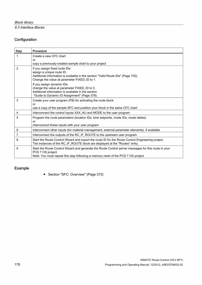
Block library 8.3 Interface Blocks
SIMATIC Route Control (V8.0 SP1) 176 Programming and Operating Manual, 12/2012, A5E03709032-02
Configuration Step Procedure 1 Create a new CFC chart
or copy a previously-created sample chart to your project
2 If you assign fixed route IDs: assign a unique route ID. Additional information is available in the section "Valid Route IDs" (Page 702). Change the value at parameter FIXED_ID to 1. If you assign dynamic IDs: change the value at parameter FIXED_ID to 0. Additional information is available in the section "Guide to Dynamic ID Assignment" (Page 378).
3 Create your user program (FB) for activating the route block or use a copy of the sample SFC and position your block in the same CFC chart
4 Interconnect the control inputs XXX_AU and MODE to the user program 5 Program the route parameters (location IDs, time setpoints, mode IDs, mode tables)
or interconnect these inputs with your user program
6 Interconnect other inputs (for material management, external parameter elements), if available 7 Interconnect the outputs of the RC_IF_ROUTE to the upstream user program 8 Start the Route Control Wizard and export the route ID for the Route Control Engineering project.
The instances of the RC_IF_ROUTE block are displayed at the "Routes" entry. 9 Start the Route Control Wizard and generate the Route Control server messages for this route in your
PCS 7 OS project. Note: You must repeat this step following a memory reset of the PCS 7 OS project.
Example ● Section "SFC: Overview" (Page 372)
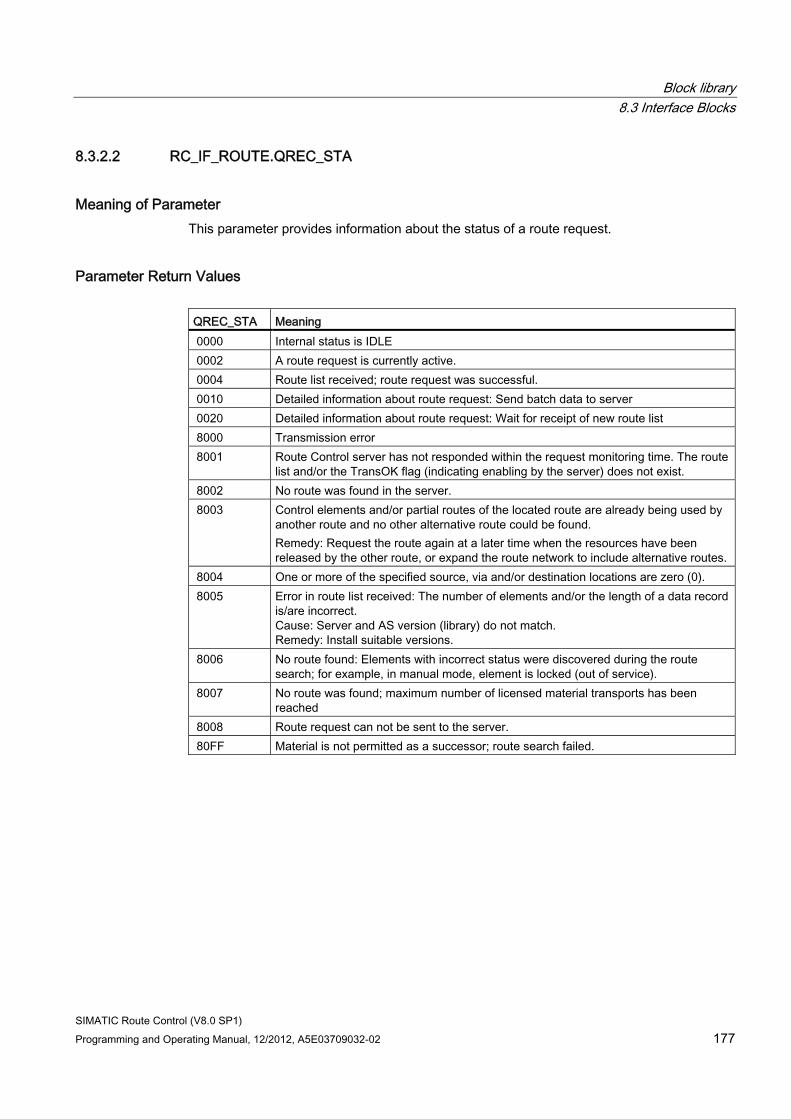
Block library 8.3 Interface Blocks
SIMATIC Route Control (V8.0 SP1) Programming and Operating Manual, 12/2012, A5E03709032-02 177
8.3.2.2 RC_IF_ROUTE.QREC_STA
Meaning of Parameter This parameter provides information about the status of a route request.
Parameter Return Values QREC_STA Meaning 0000 Internal status is IDLE 0002 A route request is currently active. 0004 Route list received; route request was successful. 0010 Detailed information about route request: Send batch data to server 0020 Detailed information about route request: Wait for receipt of new route list 8000 Transmission error 8001 Route Control server has not responded within the request monitoring time. The route
list and/or the TransOK flag (indicating enabling by the server) does not exist. 8002 No route was found in the server. 8003 Control elements and/or partial routes of the located route are already being used by
another route and no other alternative route could be found. Remedy: Request the route again at a later time when the resources have been released by the other route, or expand the route network to include alternative routes.
8004 One or more of the specified source, via and/or destination locations are zero (0). 8005 Error in route list received: The number of elements and/or the length of a data record
is/are incorrect. Cause: Server and AS version (library) do not match. Remedy: Install suitable versions.
8006 No route found: Elements with incorrect status were discovered during the route search; for example, in manual mode, element is locked (out of service).
8007 No route was found; maximum number of licensed material transports has been reached
8008 Route request can not be sent to the server. 80FF Material is not permitted as a successor; route search failed.
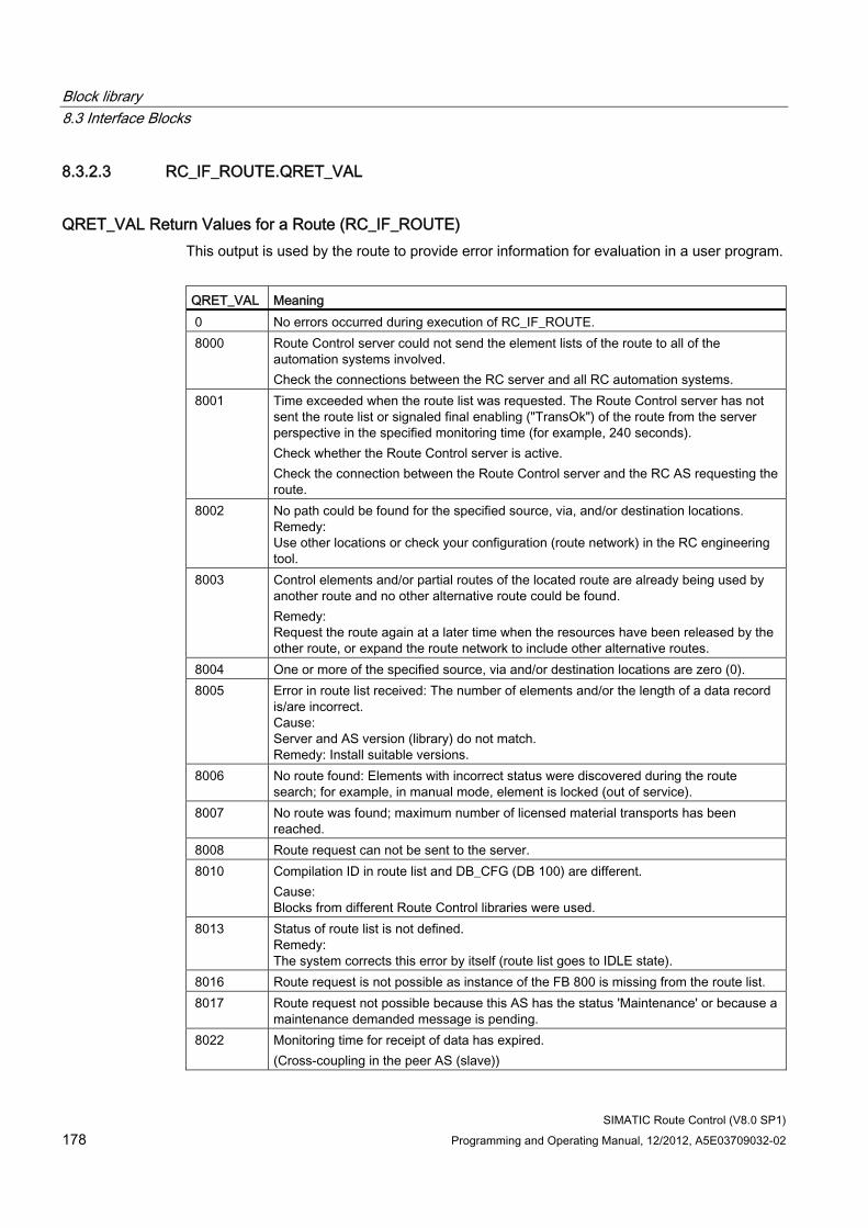
Block library 8.3 Interface Blocks
SIMATIC Route Control (V8.0 SP1) 178 Programming and Operating Manual, 12/2012, A5E03709032-02
8.3.2.3 RC_IF_ROUTE.QRET_VAL
QRET_VAL Return Values for a Route (RC_IF_ROUTE) This output is used by the route to provide error information for evaluation in a user program.
QRET_VAL Meaning 0 No errors occurred during execution of RC_IF_ROUTE. 8000 Route Control server could not send the element lists of the route to all of the
automation systems involved. Check the connections between the RC server and all RC automation systems.
8001 Time exceeded when the route list was requested. The Route Control server has not sent the route list or signaled final enabling ("TransOk") of the route from the server perspective in the specified monitoring time (for example, 240 seconds). Check whether the Route Control server is active. Check the connection between the Route Control server and the RC AS requesting the route.
8002 No path could be found for the specified source, via, and/or destination locations. Remedy: Use other locations or check your configuration (route network) in the RC engineering tool.
8003 Control elements and/or partial routes of the located route are already being used by another route and no other alternative route could be found. Remedy: Request the route again at a later time when the resources have been released by the other route, or expand the route network to include other alternative routes.
8004 One or more of the specified source, via and/or destination locations are zero (0). 8005 Error in route list received: The number of elements and/or the length of a data record
is/are incorrect. Cause: Server and AS version (library) do not match. Remedy: Install suitable versions.
8006 No route found: Elements with incorrect status were discovered during the route search; for example, in manual mode, element is locked (out of service).
8007 No route was found; maximum number of licensed material transports has been reached.
8008 Route request can not be sent to the server. 8010 Compilation ID in route list and DB_CFG (DB 100) are different.
Cause: Blocks from different Route Control libraries were used.
8013 Status of route list is not defined. Remedy: The system corrects this error by itself (route list goes to IDLE state).
8016 Route request is not possible as instance of the FB 800 is missing from the route list. 8017 Route request not possible because this AS has the status 'Maintenance' or because a
maintenance demanded message is pending. 8022 Monitoring time for receipt of data has expired.
(Cross-coupling in the peer AS (slave))
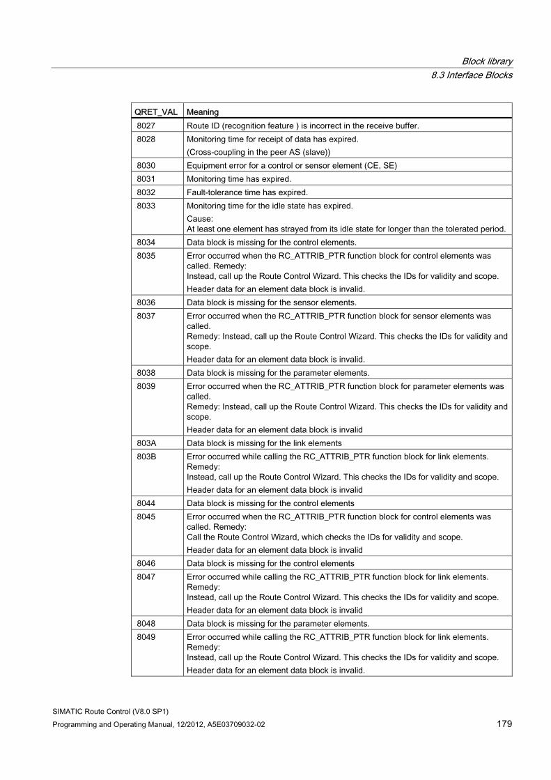
Block library 8.3 Interface Blocks
SIMATIC Route Control (V8.0 SP1) Programming and Operating Manual, 12/2012, A5E03709032-02 179
QRET_VAL Meaning 8027 Route ID (recognition feature ) is incorrect in the receive buffer. 8028 Monitoring time for receipt of data has expired.
(Cross-coupling in the peer AS (slave)) 8030 Equipment error for a control or sensor element (CE, SE) 8031 Monitoring time has expired. 8032 Fault-tolerance time has expired. 8033 Monitoring time for the idle state has expired.
Cause: At least one element has strayed from its idle state for longer than the tolerated period.
8034 Data block is missing for the control elements. 8035 Error occurred when the RC_ATTRIB_PTR function block for control elements was
called. Remedy: Instead, call up the Route Control Wizard. This checks the IDs for validity and scope. Header data for an element data block is invalid.
8036 Data block is missing for the sensor elements. 8037 Error occurred when the RC_ATTRIB_PTR function block for sensor elements was
called. Remedy: Instead, call up the Route Control Wizard. This checks the IDs for validity and scope. Header data for an element data block is invalid.
8038 Data block is missing for the parameter elements. 8039 Error occurred when the RC_ATTRIB_PTR function block for parameter elements was
called. Remedy: Instead, call up the Route Control Wizard. This checks the IDs for validity and scope. Header data for an element data block is invalid
803A Data block is missing for the link elements 803B Error occurred while calling the RC_ATTRIB_PTR function block for link elements.
Remedy: Instead, call up the Route Control Wizard. This checks the IDs for validity and scope. Header data for an element data block is invalid
8044 Data block is missing for the control elements 8045 Error occurred when the RC_ATTRIB_PTR function block for control elements was
called. Remedy: Call the Route Control Wizard, which checks the IDs for validity and scope. Header data for an element data block is invalid
8046 Data block is missing for the control elements 8047 Error occurred while calling the RC_ATTRIB_PTR function block for link elements.
Remedy: Instead, call up the Route Control Wizard. This checks the IDs for validity and scope. Header data for an element data block is invalid
8048 Data block is missing for the parameter elements. 8049 Error occurred while calling the RC_ATTRIB_PTR function block for link elements.
Remedy: Instead, call up the Route Control Wizard. This checks the IDs for validity and scope. Header data for an element data block is invalid.
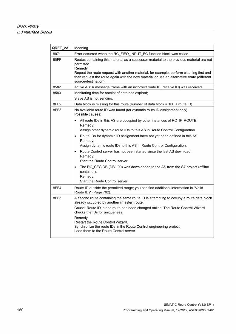
Block library 8.3 Interface Blocks
SIMATIC Route Control (V8.0 SP1) 180 Programming and Operating Manual, 12/2012, A5E03709032-02
QRET_VAL Meaning 8071 Error occurred when the RC_FIFO_INPUT_FC function block was called 80FF Routes containing this material as a successor material to the previous material are not
permitted. Remedy: Repeat the route request with another material, for example, perform cleaning first and then request the route again with the new material or use an alternative route (different source/destination).
8582 Active AS: A message frame with an incorrect route ID (receive ID) was received. 8583 Monitoring time for receipt of data has expired;
Slave AS is not sending. 8FF2 Data block is missing for this route (number of data block = 100 + route ID). 8FF3 No available route ID was found (for dynamic route ID assignment only).
Possible causes: • All route IDs in this AS are occupied by other instances of RC_IF_ROUTE.
Remedy: Assign other dynamic route IDs to this AS in Route Control Configuration.
• Route IDs for dynamic ID assignment have not yet been defined in this AS. Remedy: Assign dynamic route IDs to this AS in Route Control Configuration.
• Route Control server has not been started since the last AS download. Remedy: Start the Route Control server.
• The RC_CFG DB (DB 100) was downloaded to the AS from the S7 project (offline container). Remedy: Start the Route Control server.
8FF4 Route ID outside the permitted range; you can find additional information in "Valid Route IDs" (Page 702).
8FF5 A second route containing the same route ID is attempting to occupy a route data block already occupied by another (master) route. Cause: Route ID in one route has been changed online. The Route Control Wizard checks the IDs for uniqueness. Remedy: Restart the Route Control Wizard. Synchronize the route IDs in the Route Control engineering project. Load them to the Route Control server.
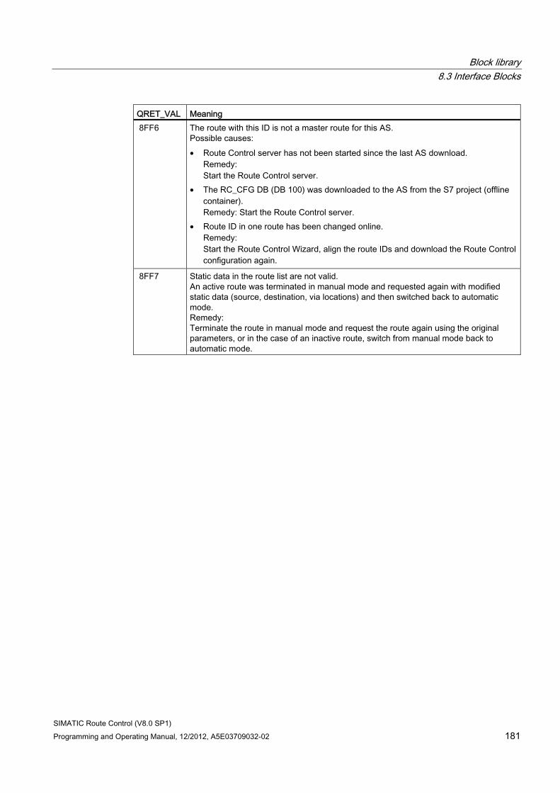
Block library 8.3 Interface Blocks
SIMATIC Route Control (V8.0 SP1) Programming and Operating Manual, 12/2012, A5E03709032-02 181
QRET_VAL Meaning 8FF6 The route with this ID is not a master route for this AS.
Possible causes: • Route Control server has not been started since the last AS download.
Remedy: Start the Route Control server.
• The RC_CFG DB (DB 100) was downloaded to the AS from the S7 project (offline container). Remedy: Start the Route Control server.
• Route ID in one route has been changed online. Remedy: Start the Route Control Wizard, align the route IDs and download the Route Control configuration again.
8FF7 Static data in the route list are not valid. An active route was terminated in manual mode and requested again with modified static data (source, destination, via locations) and then switched back to automatic mode. Remedy: Terminate the route in manual mode and request the route again using the original parameters, or in the case of an inactive route, switch from manual mode back to automatic mode.
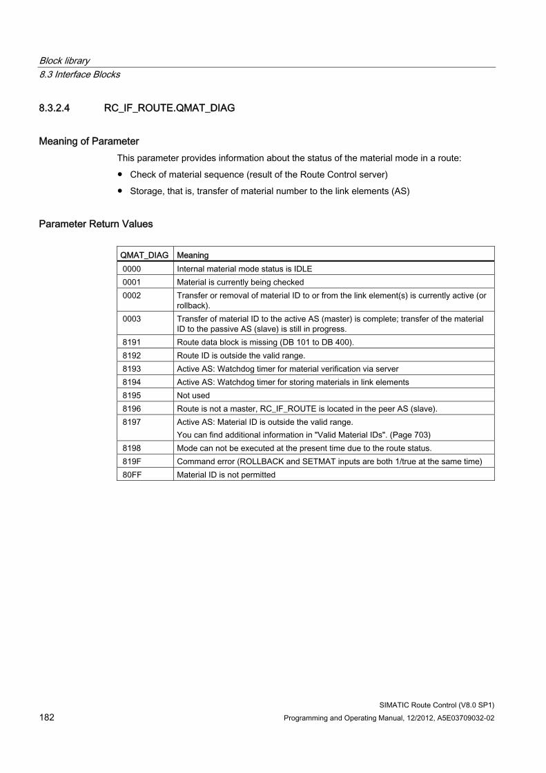
Block library 8.3 Interface Blocks
SIMATIC Route Control (V8.0 SP1) 182 Programming and Operating Manual, 12/2012, A5E03709032-02
8.3.2.4 RC_IF_ROUTE.QMAT_DIAG
Meaning of Parameter This parameter provides information about the status of the material mode in a route:
● Check of material sequence (result of the Route Control server)
● Storage, that is, transfer of material number to the link elements (AS)
Parameter Return Values QMAT_DIAG Meaning 0000 Internal material mode status is IDLE 0001 Material is currently being checked 0002 Transfer or removal of material ID to or from the link element(s) is currently active (or
rollback). 0003 Transfer of material ID to the active AS (master) is complete; transfer of the material
ID to the passive AS (slave) is still in progress. 8191 Route data block is missing (DB 101 to DB 400). 8192 Route ID is outside the valid range. 8193 Active AS: Watchdog timer for material verification via server 8194 Active AS: Watchdog timer for storing materials in link elements 8195 Not used 8196 Route is not a master, RC_IF_ROUTE is located in the peer AS (slave). 8197 Active AS: Material ID is outside the valid range.
You can find additional information in "Valid Material IDs". (Page 703) 8198 Mode can not be executed at the present time due to the route status. 819F Command error (ROLLBACK and SETMAT inputs are both 1/true at the same time) 80FF Material ID is not permitted
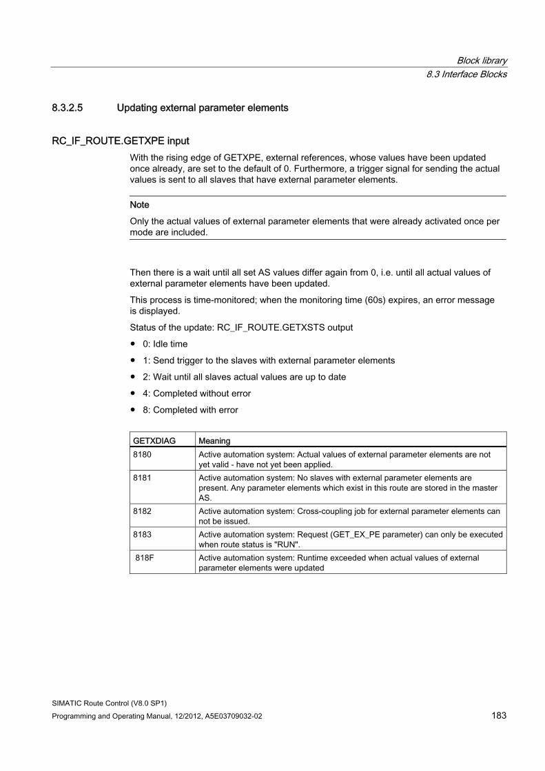
Block library 8.3 Interface Blocks
SIMATIC Route Control (V8.0 SP1) Programming and Operating Manual, 12/2012, A5E03709032-02 183
8.3.2.5 Updating external parameter elements
RC_IF_ROUTE.GETXPE input With the rising edge of GETXPE, external references, whose values have been updated once already, are set to the default of 0. Furthermore, a trigger signal for sending the actual values is sent to all slaves that have external parameter elements.
Note
Only the actual values of external parameter elements that were already activated once per mode are included.
Then there is a wait until all set AS values differ again from 0, i.e. until all actual values of external parameter elements have been updated.
This process is time-monitored; when the monitoring time (60s) expires, an error message is displayed.
Status of the update: RC_IF_ROUTE.GETXSTS output
● 0: Idle time
● 1: Send trigger to the slaves with external parameter elements
● 2: Wait until all slaves actual values are up to date
● 4: Completed without error
● 8: Completed with error
GETXDIAG Meaning 8180 Active automation system: Actual values of external parameter elements are not
yet valid - have not yet been applied. 8181 Active automation system: No slaves with external parameter elements are
present. Any parameter elements which exist in this route are stored in the master AS.
8182 Active automation system: Cross-coupling job for external parameter elements can not be issued.
8183 Active automation system: Request (GET_EX_PE parameter) can only be executed when route status is "RUN".
818F Active automation system: Runtime exceeded when actual values of external parameter elements were updated
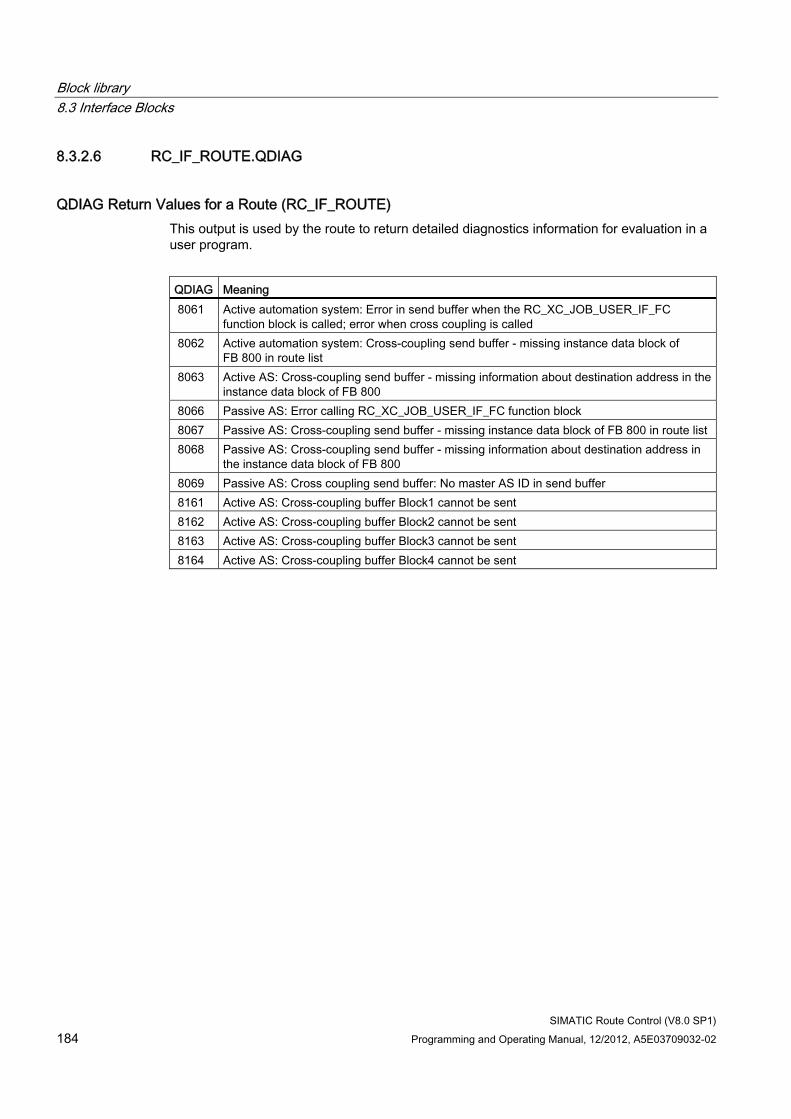
Block library 8.3 Interface Blocks
SIMATIC Route Control (V8.0 SP1) 184 Programming and Operating Manual, 12/2012, A5E03709032-02
8.3.2.6 RC_IF_ROUTE.QDIAG
QDIAG Return Values for a Route (RC_IF_ROUTE) This output is used by the route to return detailed diagnostics information for evaluation in a user program.
QDIAG Meaning 8061 Active automation system: Error in send buffer when the RC_XC_JOB_USER_IF_FC
function block is called; error when cross coupling is called 8062 Active automation system: Cross-coupling send buffer - missing instance data block of
FB 800 in route list 8063 Active AS: Cross-coupling send buffer - missing information about destination address in the
instance data block of FB 800 8066 Passive AS: Error calling RC_XC_JOB_USER_IF_FC function block 8067 Passive AS: Cross-coupling send buffer - missing instance data block of FB 800 in route list 8068 Passive AS: Cross-coupling send buffer - missing information about destination address in
the instance data block of FB 800 8069 Passive AS: Cross coupling send buffer: No master AS ID in send buffer 8161 Active AS: Cross-coupling buffer Block1 cannot be sent 8162 Active AS: Cross-coupling buffer Block2 cannot be sent 8163 Active AS: Cross-coupling buffer Block3 cannot be sent 8164 Active AS: Cross-coupling buffer Block4 cannot be sent
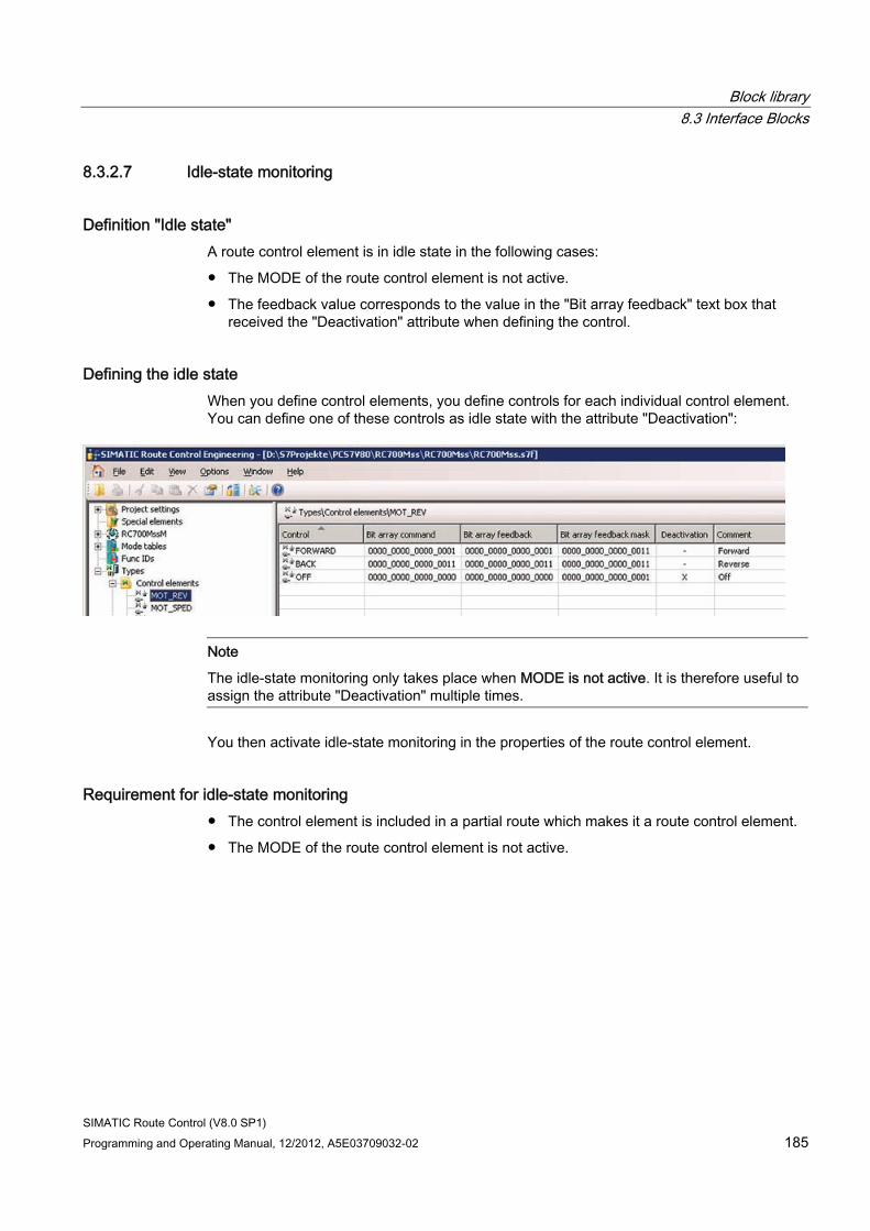
Block library 8.3 Interface Blocks
SIMATIC Route Control (V8.0 SP1) Programming and Operating Manual, 12/2012, A5E03709032-02 185
8.3.2.7 Idle-state monitoring
Definition "Idle state" A route control element is in idle state in the following cases:
● The MODE of the route control element is not active.
● The feedback value corresponds to the value in the "Bit array feedback" text box that received the "Deactivation" attribute when defining the control.
Defining the idle state When you define control elements, you define controls for each individual control element. You can define one of these controls as idle state with the attribute "Deactivation":
Note
The idle-state monitoring only takes place when MODE is not active. It is therefore useful to assign the attribute "Deactivation" multiple times.
You then activate idle-state monitoring in the properties of the route control element.
Requirement for idle-state monitoring ● The control element is included in a partial route which makes it a route control element.
● The MODE of the route control element is not active.
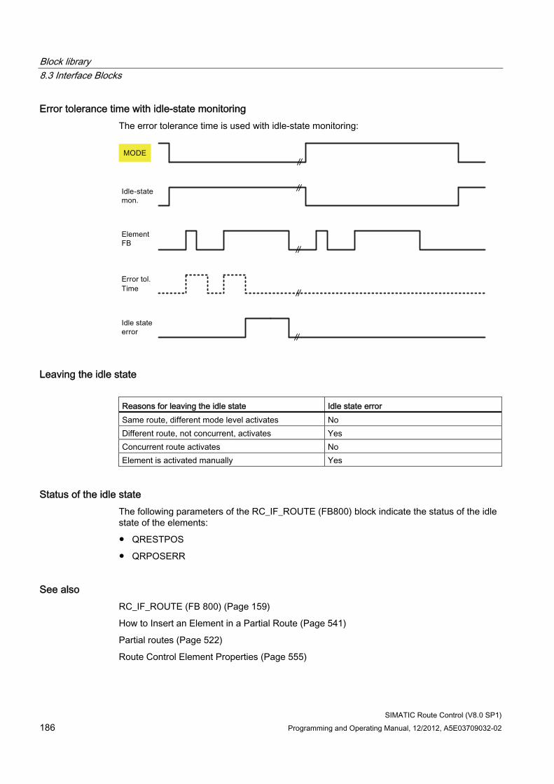
Block library 8.3 Interface Blocks
SIMATIC Route Control (V8.0 SP1) 186 Programming and Operating Manual, 12/2012, A5E03709032-02
Error tolerance time with idle-state monitoring The error tolerance time is used with idle-state monitoring:
Leaving the idle state Reasons for leaving the idle state Idle state error Same route, different mode level activates No Different route, not concurrent, activates Yes Concurrent route activates No Element is activated manually Yes
Status of the idle state The following parameters of the RC_IF_ROUTE (FB800) block indicate the status of the idle state of the elements:
● QRESTPOS
● QRPOSERR
See also RC_IF_ROUTE (FB 800) (Page 159)
How to Insert an Element in a Partial Route (Page 541)
Partial routes (Page 522)
Route Control Element Properties (Page 555)
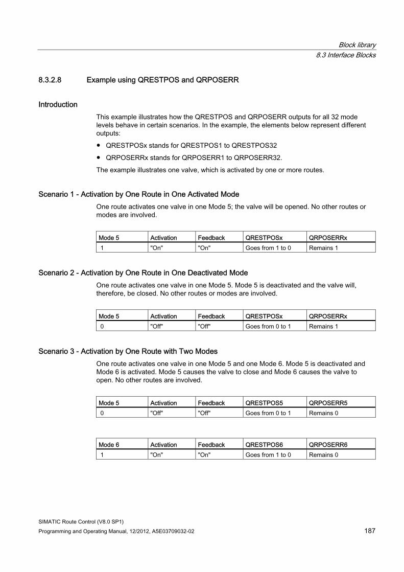
Block library 8.3 Interface Blocks
SIMATIC Route Control (V8.0 SP1) Programming and Operating Manual, 12/2012, A5E03709032-02 187
8.3.2.8 Example using QRESTPOS and QRPOSERR
Introduction This example illustrates how the QRESTPOS and QRPOSERR outputs for all 32 mode levels behave in certain scenarios. In the example, the elements below represent different outputs:
● QRESTPOSx stands for QRESTPOS1 to QRESTPOS32
● QRPOSERRx stands for QRPOSERR1 to QRPOSERR32.
The example illustrates one valve, which is activated by one or more routes.
Scenario 1 - Activation by One Route in One Activated Mode One route activates one valve in one Mode 5; the valve will be opened. No other routes or modes are involved.
Mode 5 Activation Feedback QRESTPOSx QRPOSERRx 1 "On" "On" Goes from 1 to 0 Remains 1
Scenario 2 - Activation by One Route in One Deactivated Mode One route activates one valve in one Mode 5. Mode 5 is deactivated and the valve will, therefore, be closed. No other routes or modes are involved.
Mode 5 Activation Feedback QRESTPOSx QRPOSERRx 0 "Off" "Off" Goes from 0 to 1 Remains 1
Scenario 3 - Activation by One Route with Two Modes One route activates one valve in one Mode 5 and one Mode 6. Mode 5 is deactivated and Mode 6 is activated. Mode 5 causes the valve to close and Mode 6 causes the valve to open. No other routes are involved.
Mode 5 Activation Feedback QRESTPOS5 QRPOSERR5 0 "Off" "Off" Goes from 0 to 1 Remains 0
Mode 6 Activation Feedback QRESTPOS6 QRPOSERR6 1 "On" "On" Goes from 1 to 0 Remains 0
Block library 8.3 Interface Blocks
SIMATIC Route Control (V8.0 SP1) 188 Programming and Operating Manual, 12/2012, A5E03709032-02
Scenario 4 - Activation by Two "Concurrent Routes" One route activates a valve in deactivated Mode 5, while another route with the same FUNC_ID activates the same valve in Mode 6.
Result is the same as in Scenario 3.
Scenario 5 - Activation by Route in Automatic and Manual Mode Two different routes activate the same valve. Here, it is irrelevant whether the same mode is used. However, the first route activates the valve in manual mode, while the second route activates the valve in automatic mode.
8.3.2.9 Simulated Idle State in RC_IF_ROUTE
Simulated Idle State in RC_IF_ROUTE The RC_IF_ROUTE block has an output QRPOSERR. This is a 32-bit value that provides feedback about the idle state of the elements of mode levels 1 to 32. It is, therefore, QRPOSERR1 to QRPOSERR32.
The bit QRPOSERRx is set (1) when all active control elements in the respective mode level are in idle state and are providing the correct feedback (OFF, CLOSED).
The bit QRPOSERRx is also set (1) when the element is activated in another mode level of the same route or by a concurrent route (with the same function ID/FUNC_ID).
The simulated idle state is signaled as long as the control element is not activated by its own route and mode level.
8.3.2.10 RC_ResPosV5 (FB 815)
Description The handling of the QRESTPOS output at RC_IF_ROUTE (FB 800) has changed during the course of the further development of Route Control.
The compatibility block, RC_ResPosV5, is available in order to offer the same behavior with regard to QRESTPOS as that in version 5 for the subsequent versions. As of V7.1.2, this now provides the behavior of the V5 at the QRESTPOS output.
The block is called from FB 803 if and only if a specific ID is registered in DB100/RC_CFG. If you want to set the behavior of V5, enter the value W#16#ABAB for the ID "wLikeV5" (byte offset 80.0) in DB100/RC_CFG for all automation systems.
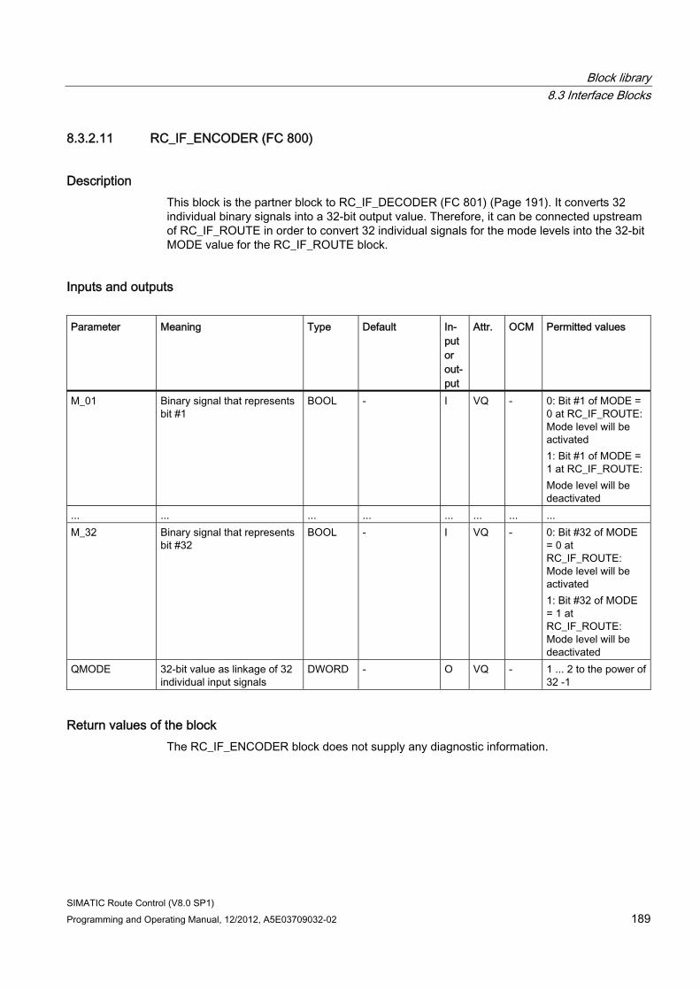
Block library 8.3 Interface Blocks
SIMATIC Route Control (V8.0 SP1) Programming and Operating Manual, 12/2012, A5E03709032-02 189
8.3.2.11 RC_IF_ENCODER (FC 800)
Description This block is the partner block to RC_IF_DECODER (FC 801) (Page 191). It converts 32 individual binary signals into a 32-bit output value. Therefore, it can be connected upstream of RC_IF_ROUTE in order to convert 32 individual signals for the mode levels into the 32-bit MODE value for the RC_IF_ROUTE block.
Inputs and outputs Parameter Meaning Type Default In-
put or out-put
Attr. OCM Permitted values
M_01 Binary signal that represents bit #1
BOOL - I VQ - 0: Bit #1 of MODE = 0 at RC_IF_ROUTE: Mode level will be activated 1: Bit #1 of MODE = 1 at RC_IF_ROUTE: Mode level will be deactivated
... ... ... ... ... ... ... ... M_32 Binary signal that represents
bit #32 BOOL - I VQ - 0: Bit #32 of MODE
= 0 at RC_IF_ROUTE: Mode level will be activated 1: Bit #32 of MODE = 1 at RC_IF_ROUTE: Mode level will be deactivated
QMODE 32-bit value as linkage of 32 individual input signals
DWORD - O VQ - 1 ... 2 to the power of 32 -1
Return values of the block The RC_IF_ENCODER block does not supply any diagnostic information.
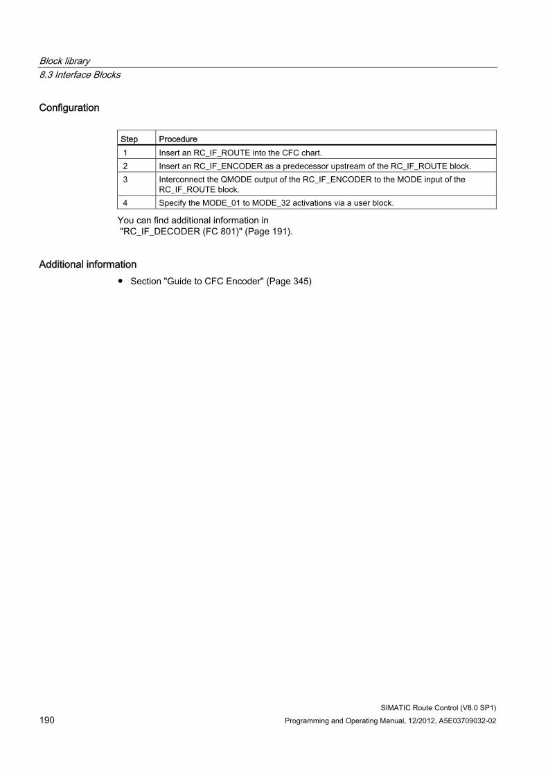
Block library 8.3 Interface Blocks
SIMATIC Route Control (V8.0 SP1) 190 Programming and Operating Manual, 12/2012, A5E03709032-02
Configuration Step Procedure 1 Insert an RC_IF_ROUTE into the CFC chart. 2 Insert an RC_IF_ENCODER as a predecessor upstream of the RC_IF_ROUTE block. 3 Interconnect the QMODE output of the RC_IF_ENCODER to the MODE input of the
RC_IF_ROUTE block. 4 Specify the MODE_01 to MODE_32 activations via a user block.
You can find additional information in "RC_IF_DECODER (FC 801)" (Page 191).
Additional information ● Section "Guide to CFC Encoder" (Page 345)
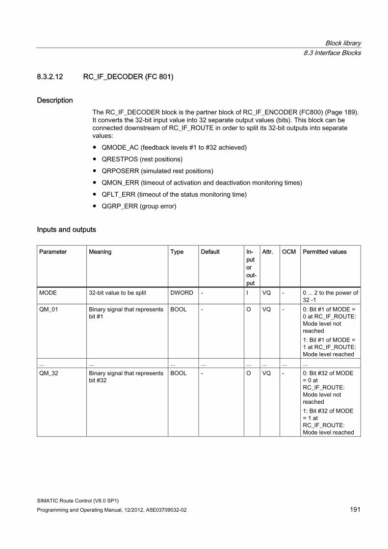
Block library 8.3 Interface Blocks
SIMATIC Route Control (V8.0 SP1) Programming and Operating Manual, 12/2012, A5E03709032-02 191
8.3.2.12 RC_IF_DECODER (FC 801)
Description The RC_IF_DECODER block is the partner block of RC_IF_ENCODER (FC800) (Page 189). It converts the 32-bit input value into 32 separate output values (bits). This block can be connected downstream of RC_IF_ROUTE in order to split its 32-bit outputs into separate values:
● QMODE_AC (feedback levels #1 to #32 achieved)
● QRESTPOS (rest positions)
● QRPOSERR (simulated rest positions)
● QMON_ERR (timeout of activation and deactivation monitoring times)
● QFLT_ERR (timeout of the status monitoring time)
● QGRP_ERR (group error)
Inputs and outputs Parameter Meaning Type Default In-
put or out-put
Attr. OCM Permitted values
MODE 32-bit value to be split DWORD - I VQ - 0 ... 2 to the power of 32 -1
QM_01 Binary signal that represents bit #1
BOOL - O VQ - 0: Bit #1 of MODE = 0 at RC_IF_ROUTE: Mode level not reached 1: Bit #1 of MODE = 1 at RC_IF_ROUTE: Mode level reached
... ... ... ... ... ... ... ... QM_32 Binary signal that represents
bit #32 BOOL - O VQ - 0: Bit #32 of MODE
= 0 at RC_IF_ROUTE: Mode level not reached 1: Bit #32 of MODE = 1 at RC_IF_ROUTE: Mode level reached
Block library 8.3 Interface Blocks
SIMATIC Route Control (V8.0 SP1) 192 Programming and Operating Manual, 12/2012, A5E03709032-02
Return values of the block The RC_IF_DECODER block does not return any diagnostics information.
Configuration Step Action 1 Insert an RC_IF_ROUTE into the CFC chart. 2 Insert an RC_IF_DECODER as the successor of the RC_IF_ROUTE block. 3 Interconnect the required output of the RC_IF_ROUTE block with the MODE input of
RC_IF_DECODER. 4 Evaluate the return signals of RC_IF_DECODER through a user block.
Additional information ● Section "Guide to CFC DECODER" (Page 346)
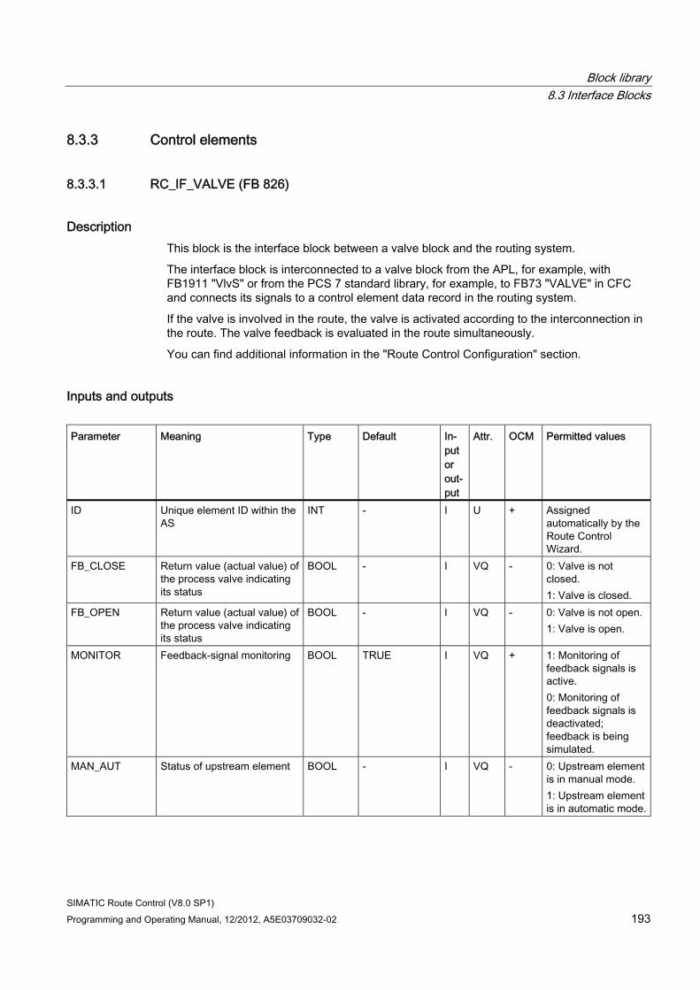
Block library 8.3 Interface Blocks
SIMATIC Route Control (V8.0 SP1) Programming and Operating Manual, 12/2012, A5E03709032-02 193
8.3.3 Control elements
8.3.3.1 RC_IF_VALVE (FB 826)
Description This block is the interface block between a valve block and the routing system.
The interface block is interconnected to a valve block from the APL, for example, with FB1911 "VlvS" or from the PCS 7 standard library, for example, to FB73 "VALVE" in CFC and connects its signals to a control element data record in the routing system.
If the valve is involved in the route, the valve is activated according to the interconnection in the route. The valve feedback is evaluated in the route simultaneously.
You can find additional information in the "Route Control Configuration" section.
Inputs and outputs Parameter Meaning Type Default In-
put or out-put
Attr. OCM Permitted values
ID Unique element ID within the AS
INT - I U + Assigned automatically by the Route Control Wizard.
FB_CLOSE Return value (actual value) of the process valve indicating its status
BOOL - I VQ - 0: Valve is not closed. 1: Valve is closed.
FB_OPEN Return value (actual value) of the process valve indicating its status
BOOL - I VQ - 0: Valve is not open. 1: Valve is open.
MONITOR Feedback-signal monitoring BOOL TRUE I VQ + 1: Monitoring of feedback signals is active. 0: Monitoring of feedback signals is deactivated; feedback is being simulated.
MAN_AUT Status of upstream element BOOL - I VQ - 0: Upstream element is in manual mode. 1: Upstream element is in automatic mode.
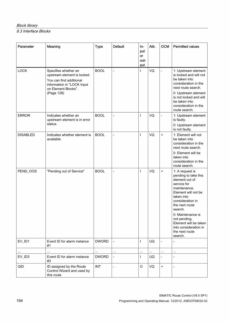
Block library 8.3 Interface Blocks
SIMATIC Route Control (V8.0 SP1) 194 Programming and Operating Manual, 12/2012, A5E03709032-02
Parameter Meaning Type Default In-put or out-put
Attr. OCM Permitted values
LOCK Specifies whether an upstream element is locked. You can find additional information in "LOCK Input on Element Blocks". (Page 128)
BOOL - I VQ - 1: Upstream element is locked and will not be taken into consideration in the next route search. 0: Upstream element is not locked and will be taken into consideration in the route search.
ERROR Indicates whether an upstream element is in error status.
BOOL - I VQ - 1: Upstream element is faulty. 0: Upstream element is not faulty.
DISABLED Indicates whether element is available
BOOL - I VQ + 1: Element will not be taken into consideration in the next route search. 0: Element will be taken into consideration in the route search.
PEND_OOS "Pending out of Service" BOOL - I VQ + 1: A request is pending to take this element out of service for maintenance. Element will not be taken into consideration in the next route search. 0: Maintenance is not pending. Element will be taken into consideration in the next route search.
EV_ID1 Event ID for alarm instance #1
DWORD - I UQ - -
... ... ... ... ... ... ... ... EV_ID3 Event ID for alarm instance
#3 DWORD - I UQ - -
QID ID assigned by the Route Control Wizard and used by this route
INT - O VQ + -
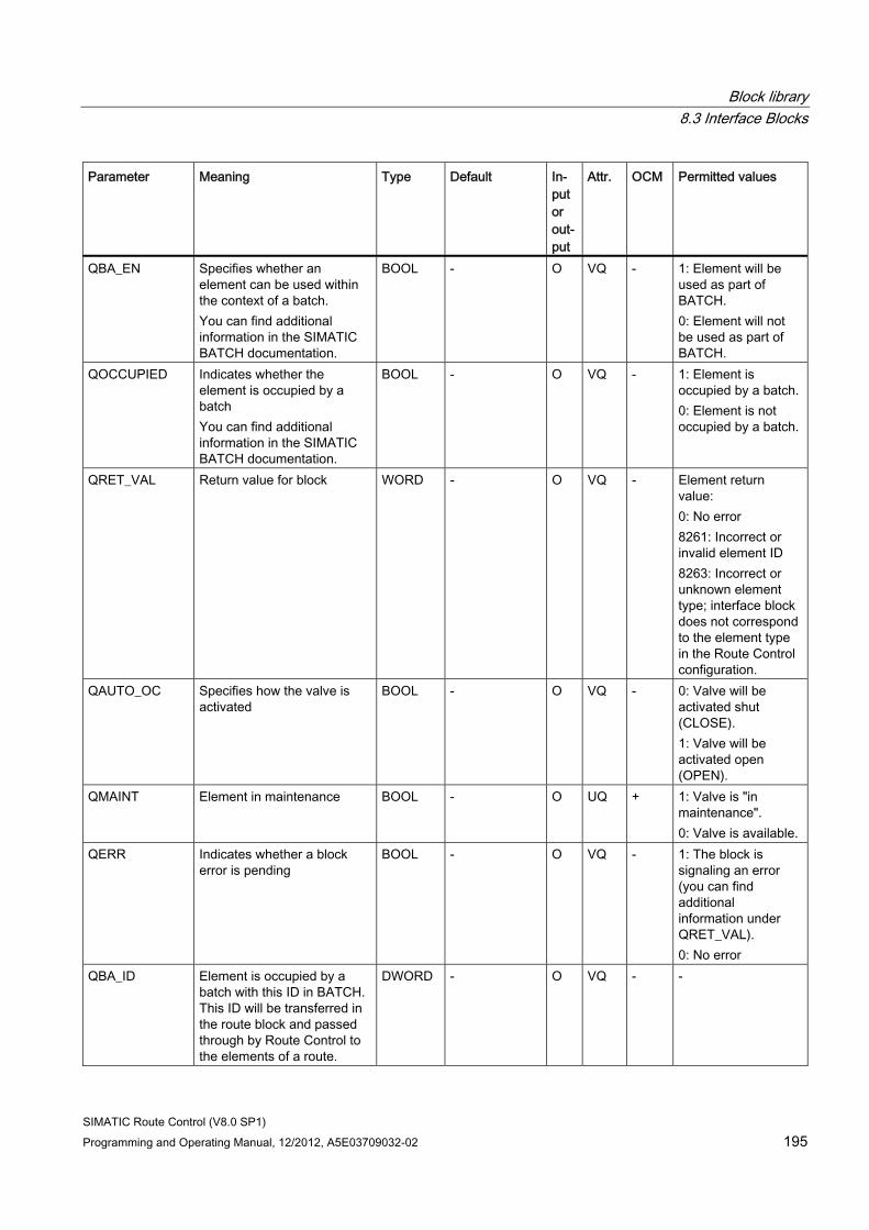
Block library 8.3 Interface Blocks
SIMATIC Route Control (V8.0 SP1) Programming and Operating Manual, 12/2012, A5E03709032-02 195
Parameter Meaning Type Default In-put or out-put
Attr. OCM Permitted values
QBA_EN Specifies whether an element can be used within the context of a batch. You can find additional information in the SIMATIC BATCH documentation.
BOOL - O VQ - 1: Element will be used as part of BATCH. 0: Element will not be used as part of BATCH.
QOCCUPIED Indicates whether the element is occupied by a batch You can find additional information in the SIMATIC BATCH documentation.
BOOL - O VQ - 1: Element is occupied by a batch. 0: Element is not occupied by a batch.
QRET_VAL Return value for block WORD - O VQ - Element return value: 0: No error 8261: Incorrect or invalid element ID 8263: Incorrect or unknown element type; interface block does not correspond to the element type in the Route Control configuration.
QAUTO_OC Specifies how the valve is activated
BOOL - O VQ - 0: Valve will be activated shut (CLOSE). 1: Valve will be activated open (OPEN).
QMAINT Element in maintenance BOOL - O UQ + 1: Valve is "in maintenance". 0: Valve is available.
QERR Indicates whether a block error is pending
BOOL - O VQ - 1: The block is signaling an error (you can find additional information under QRET_VAL). 0: No error
QBA_ID Element is occupied by a batch with this ID in BATCH. This ID will be transferred in the route block and passed through by Route Control to the elements of a route.
DWORD - O VQ - -
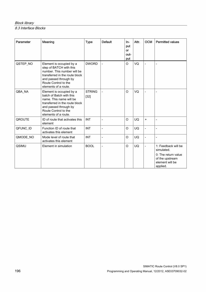
Block library 8.3 Interface Blocks
SIMATIC Route Control (V8.0 SP1) 196 Programming and Operating Manual, 12/2012, A5E03709032-02
Parameter Meaning Type Default In-put or out-put
Attr. OCM Permitted values
QSTEP_NO Element is occupied by a step of BATCH with this number. This number will be transferred in the route block and passed through by Route Control to the elements of a route.
DWORD - O VQ - -
QBA_NA Element is occupied by a batch of Batch with this name. This name will be transferred in the route block and passed through by Route Control to the elements of a route.
STRING [32]
- O VQ - -
QROUTE ID of route that activates this element
INT - O UQ + -
QFUNC_ID Function ID of route that activates this element
INT - O UQ - -
QMODE_NO Mode level of route that activates this element
INT - O UQ - -
QSIMU Element in simulation BOOL - O UQ - 1: Feedback will be simulated. 0: The return value of the upstream element will be applied.
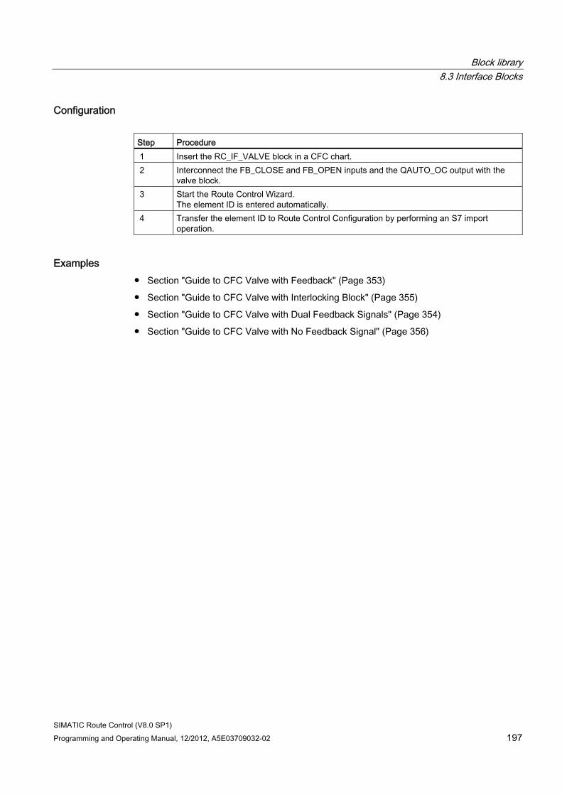
Block library 8.3 Interface Blocks
SIMATIC Route Control (V8.0 SP1) Programming and Operating Manual, 12/2012, A5E03709032-02 197
Configuration Step Procedure 1 Insert the RC_IF_VALVE block in a CFC chart. 2 Interconnect the FB_CLOSE and FB_OPEN inputs and the QAUTO_OC output with the
valve block. 3 Start the Route Control Wizard.
The element ID is entered automatically. 4 Transfer the element ID to Route Control Configuration by performing an S7 import
operation.
Examples ● Section "Guide to CFC Valve with Feedback" (Page 353)
● Section "Guide to CFC Valve with Interlocking Block" (Page 355)
● Section "Guide to CFC Valve with Dual Feedback Signals" (Page 354)
● Section "Guide to CFC Valve with No Feedback Signal" (Page 356)
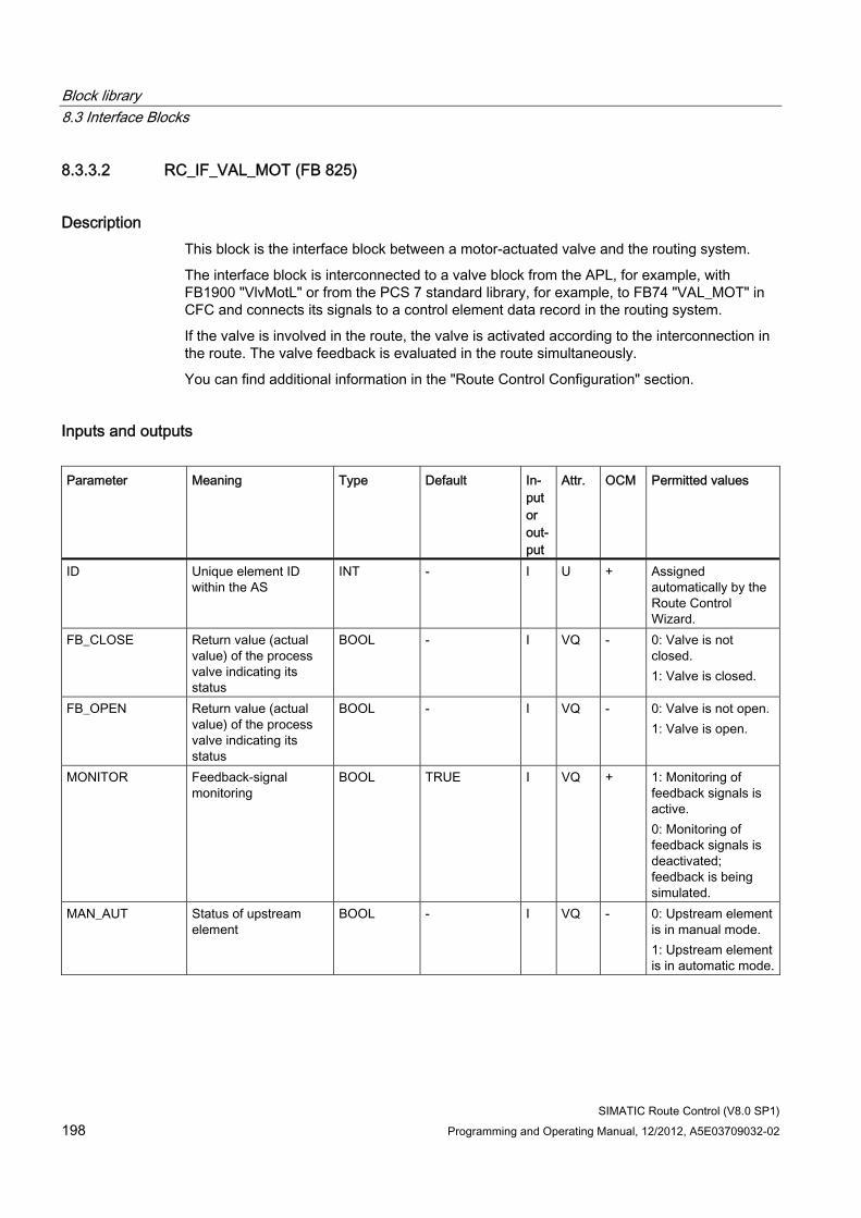
Block library 8.3 Interface Blocks
SIMATIC Route Control (V8.0 SP1) 198 Programming and Operating Manual, 12/2012, A5E03709032-02
8.3.3.2 RC_IF_VAL_MOT (FB 825)
Description This block is the interface block between a motor-actuated valve and the routing system.
The interface block is interconnected to a valve block from the APL, for example, with FB1900 "VlvMotL" or from the PCS 7 standard library, for example, to FB74 "VAL_MOT" in CFC and connects its signals to a control element data record in the routing system.
If the valve is involved in the route, the valve is activated according to the interconnection in the route. The valve feedback is evaluated in the route simultaneously.
You can find additional information in the "Route Control Configuration" section.
Inputs and outputs Parameter Meaning Type Default In-
put or out-put
Attr. OCM Permitted values
ID Unique element ID within the AS
INT - I U + Assigned automatically by the Route Control Wizard.
FB_CLOSE Return value (actual value) of the process valve indicating its status
BOOL - I VQ - 0: Valve is not closed. 1: Valve is closed.
FB_OPEN Return value (actual value) of the process valve indicating its status
BOOL - I VQ - 0: Valve is not open. 1: Valve is open.
MONITOR Feedback-signal monitoring
BOOL TRUE I VQ + 1: Monitoring of feedback signals is active. 0: Monitoring of feedback signals is deactivated; feedback is being simulated.
MAN_AUT Status of upstream element
BOOL - I VQ - 0: Upstream element is in manual mode. 1: Upstream element is in automatic mode.
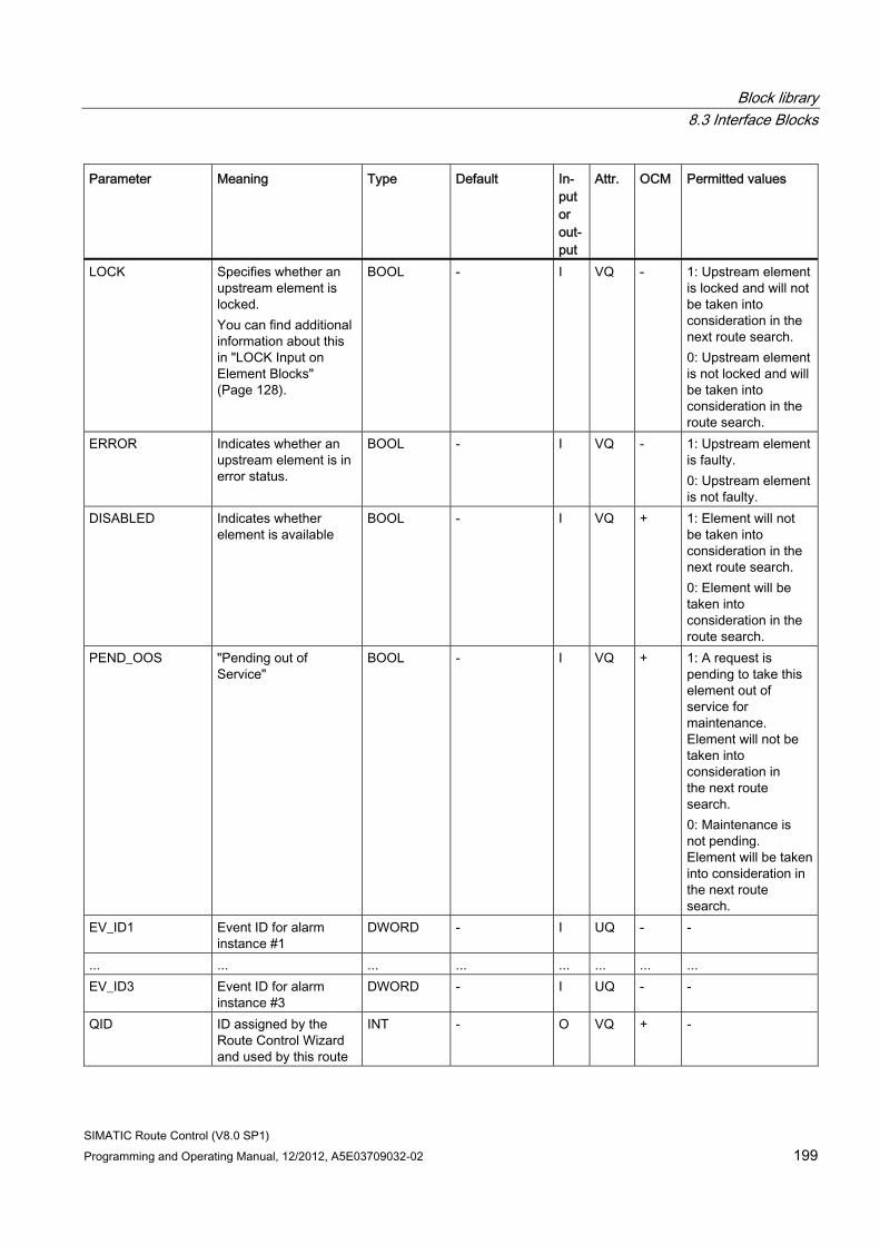
Block library 8.3 Interface Blocks
SIMATIC Route Control (V8.0 SP1) Programming and Operating Manual, 12/2012, A5E03709032-02 199
Parameter Meaning Type Default In-put or out-put
Attr. OCM Permitted values
LOCK Specifies whether an upstream element is locked. You can find additional information about this in "LOCK Input on Element Blocks" (Page 128).
BOOL - I VQ - 1: Upstream element is locked and will not be taken into consideration in the next route search. 0: Upstream element is not locked and will be taken into consideration in the route search.
ERROR Indicates whether an upstream element is in error status.
BOOL - I VQ - 1: Upstream element is faulty. 0: Upstream element is not faulty.
DISABLED Indicates whether element is available
BOOL - I VQ + 1: Element will not be taken into consideration in the next route search. 0: Element will be taken into consideration in the route search.
PEND_OOS "Pending out of Service"
BOOL - I VQ + 1: A request is pending to take this element out of service for maintenance. Element will not be taken into consideration in the next route search. 0: Maintenance is not pending. Element will be taken into consideration in the next route search.
EV_ID1 Event ID for alarm instance #1
DWORD - I UQ - -
... ... ... ... ... ... ... ... EV_ID3 Event ID for alarm
instance #3 DWORD - I UQ - -
QID ID assigned by the Route Control Wizard and used by this route
INT - O VQ + -
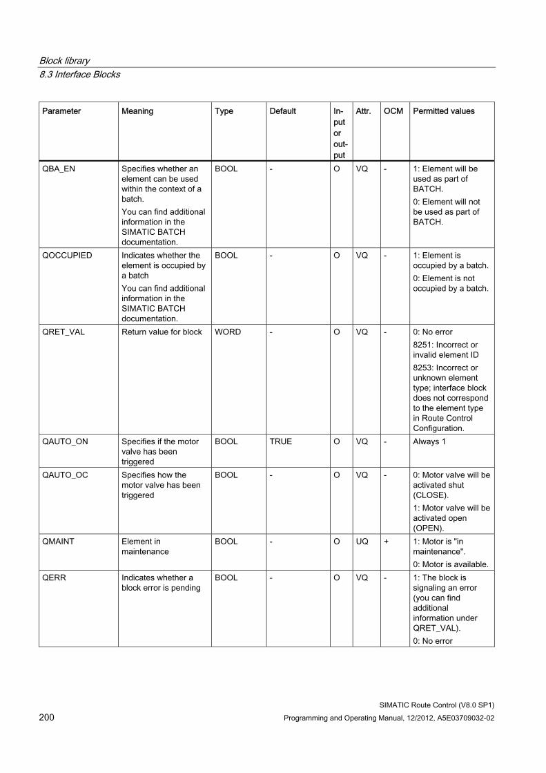
Block library 8.3 Interface Blocks
SIMATIC Route Control (V8.0 SP1) 200 Programming and Operating Manual, 12/2012, A5E03709032-02
Parameter Meaning Type Default In-put or out-put
Attr. OCM Permitted values
QBA_EN Specifies whether an element can be used within the context of a batch. You can find additional information in the SIMATIC BATCH documentation.
BOOL - O VQ - 1: Element will be used as part of BATCH. 0: Element will not be used as part of BATCH.
QOCCUPIED Indicates whether the element is occupied by a batch You can find additional information in the SIMATIC BATCH documentation.
BOOL - O VQ - 1: Element is occupied by a batch. 0: Element is not occupied by a batch.
QRET_VAL Return value for block WORD - O VQ - 0: No error 8251: Incorrect or invalid element ID 8253: Incorrect or unknown element type; interface block does not correspond to the element type in Route Control Configuration.
QAUTO_ON Specifies if the motor valve has been triggered
BOOL TRUE O VQ - Always 1
QAUTO_OC Specifies how the motor valve has been triggered
BOOL - O VQ - 0: Motor valve will be activated shut (CLOSE). 1: Motor valve will be activated open (OPEN).
QMAINT Element in maintenance
BOOL - O UQ + 1: Motor is "in maintenance". 0: Motor is available.
QERR Indicates whether a block error is pending
BOOL - O VQ - 1: The block is signaling an error (you can find additional information under QRET_VAL). 0: No error
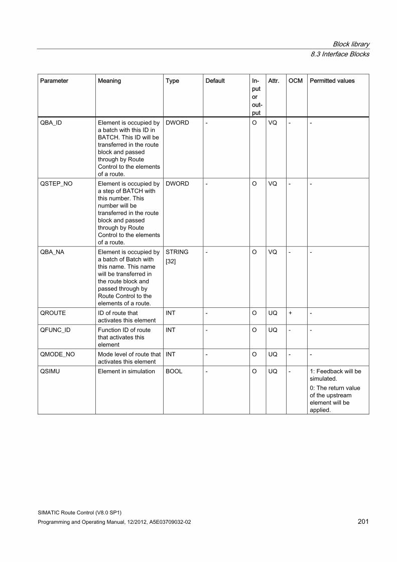
Block library 8.3 Interface Blocks
SIMATIC Route Control (V8.0 SP1) Programming and Operating Manual, 12/2012, A5E03709032-02 201
Parameter Meaning Type Default In-put or out-put
Attr. OCM Permitted values
QBA_ID Element is occupied by a batch with this ID in BATCH. This ID will be transferred in the route block and passed through by Route Control to the elements of a route.
DWORD - O VQ - -
QSTEP_NO Element is occupied by a step of BATCH with this number. This number will be transferred in the route block and passed through by Route Control to the elements of a route.
DWORD - O VQ - -
QBA_NA Element is occupied by a batch of Batch with this name. This name will be transferred in the route block and passed through by Route Control to the elements of a route.
STRING [32]
- O VQ - -
QROUTE ID of route that activates this element
INT - O UQ + -
QFUNC_ID Function ID of route that activates this element
INT - O UQ - -
QMODE_NO Mode level of route that activates this element
INT - O UQ - -
QSIMU Element in simulation BOOL - O UQ - 1: Feedback will be simulated. 0: The return value of the upstream element will be applied.
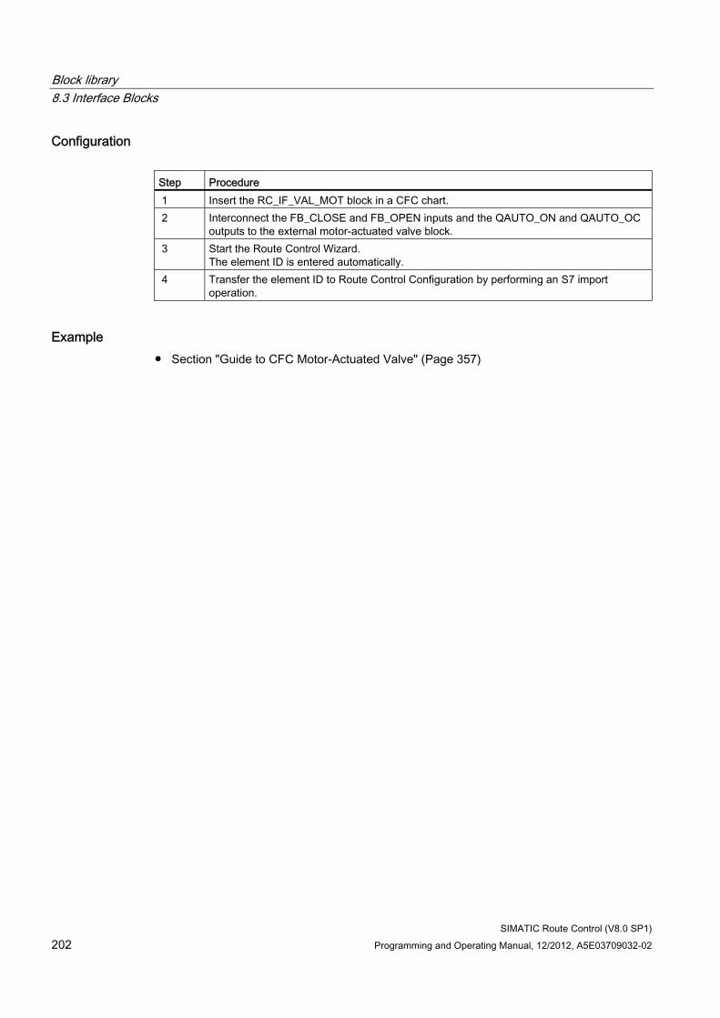
Block library 8.3 Interface Blocks
SIMATIC Route Control (V8.0 SP1) 202 Programming and Operating Manual, 12/2012, A5E03709032-02
Configuration Step Procedure 1 Insert the RC_IF_VAL_MOT block in a CFC chart. 2 Interconnect the FB_CLOSE and FB_OPEN inputs and the QAUTO_ON and QAUTO_OC
outputs to the external motor-actuated valve block. 3 Start the Route Control Wizard.
The element ID is entered automatically. 4 Transfer the element ID to Route Control Configuration by performing an S7 import
operation.
Example ● Section "Guide to CFC Motor-Actuated Valve" (Page 357)
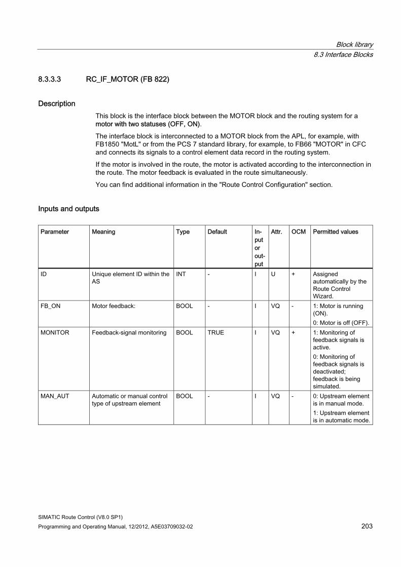
Block library 8.3 Interface Blocks
SIMATIC Route Control (V8.0 SP1) Programming and Operating Manual, 12/2012, A5E03709032-02 203
8.3.3.3 RC_IF_MOTOR (FB 822)
Description This block is the interface block between the MOTOR block and the routing system for a motor with two statuses (OFF, ON).
The interface block is interconnected to a MOTOR block from the APL, for example, with FB1850 "MotL" or from the PCS 7 standard library, for example, to FB66 "MOTOR" in CFC and connects its signals to a control element data record in the routing system.
If the motor is involved in the route, the motor is activated according to the interconnection in the route. The motor feedback is evaluated in the route simultaneously.
You can find additional information in the "Route Control Configuration" section.
Inputs and outputs Parameter Meaning Type Default In-
put or out-put
Attr. OCM Permitted values
ID Unique element ID within the AS
INT - I U + Assigned automatically by the Route Control Wizard.
FB_ON Motor feedback: BOOL - I VQ - 1: Motor is running (ON). 0: Motor is off (OFF).
MONITOR Feedback-signal monitoring BOOL TRUE I VQ + 1: Monitoring of feedback signals is active. 0: Monitoring of feedback signals is deactivated; feedback is being simulated.
MAN_AUT Automatic or manual control type of upstream element
BOOL - I VQ - 0: Upstream element is in manual mode. 1: Upstream element is in automatic mode.

Block library 8.3 Interface Blocks
SIMATIC Route Control (V8.0 SP1) 204 Programming and Operating Manual, 12/2012, A5E03709032-02
Parameter Meaning Type Default In-put or out-put
Attr. OCM Permitted values
LOCK Specifies whether an upstream element is locked. You can find additional information in "LOCK Input on Element Blocks" (Page 128).
BOOL - I VQ - 1: Upstream element is locked and will not be taken into consideration in the next route search. 0: Upstream element is not locked and will be taken into consideration in the route search.
ERROR Indicates whether an upstream element is in error status.
BOOL - I VQ - 1: Upstream element is faulty. 0: Upstream element is not faulty.
DISABLED Indicates whether element is available
BOOL - I VQ + 1: Element will not be taken into consideration in the next route search. 0: Element will be taken into consideration in the route search.
PEND_OOS "Pending out of Service" BOOL - I VQ + 1: A request is pending to take this element out of service for maintenance. Element will not be taken into consideration in the next route search. 0: Maintenance is not pending. Element will be taken into consideration in the next route search.
EV_ID1 Event ID for alarm instance #1
DWORD - I UQ - -
... ... ... ... ... ... ... ... EV_ID3 Event ID for alarm instance
#3 DWORD - I UQ - -
QID ID assigned by the Route Control Wizard and used by this route
INT - O VQ + -
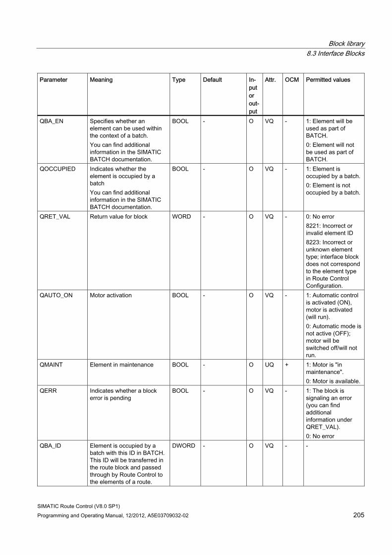
Block library 8.3 Interface Blocks
SIMATIC Route Control (V8.0 SP1) Programming and Operating Manual, 12/2012, A5E03709032-02 205
Parameter Meaning Type Default In-put or out-put
Attr. OCM Permitted values
QBA_EN Specifies whether an element can be used within the context of a batch. You can find additional information in the SIMATIC BATCH documentation.
BOOL - O VQ - 1: Element will be used as part of BATCH. 0: Element will not be used as part of BATCH.
QOCCUPIED Indicates whether the element is occupied by a batch You can find additional information in the SIMATIC BATCH documentation.
BOOL - O VQ - 1: Element is occupied by a batch. 0: Element is not occupied by a batch.
QRET_VAL Return value for block WORD - O VQ - 0: No error 8221: Incorrect or invalid element ID 8223: Incorrect or unknown element type; interface block does not correspond to the element type in Route Control Configuration.
QAUTO_ON Motor activation BOOL - O VQ - 1: Automatic control is activated (ON), motor is activated (will run). 0: Automatic mode is not active (OFF); motor will be switched off/will not run.
QMAINT Element in maintenance BOOL - O UQ + 1: Motor is "in maintenance". 0: Motor is available.
QERR Indicates whether a block error is pending
BOOL - O VQ - 1: The block is signaling an error (you can find additional information under QRET_VAL). 0: No error
QBA_ID Element is occupied by a batch with this ID in BATCH. This ID will be transferred in the route block and passed through by Route Control to the elements of a route.
DWORD - O VQ - -
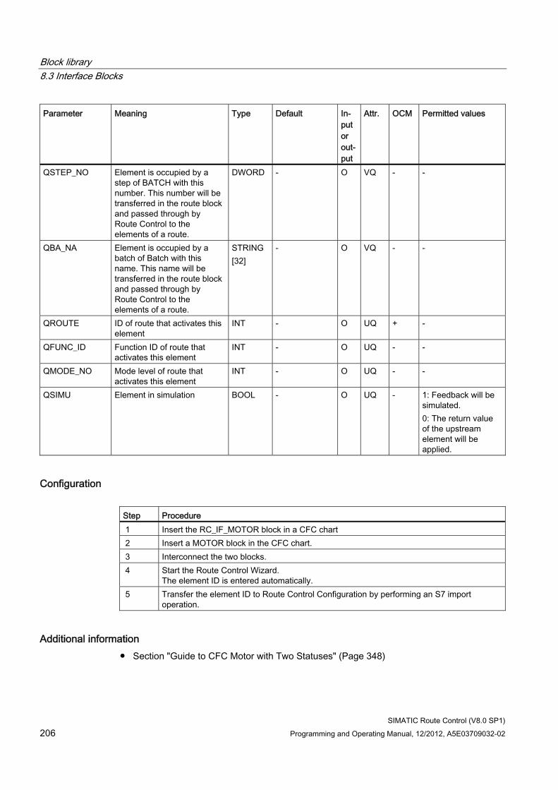
Block library 8.3 Interface Blocks
SIMATIC Route Control (V8.0 SP1) 206 Programming and Operating Manual, 12/2012, A5E03709032-02
Parameter Meaning Type Default In-put or out-put
Attr. OCM Permitted values
QSTEP_NO Element is occupied by a step of BATCH with this number. This number will be transferred in the route block and passed through by Route Control to the elements of a route.
DWORD - O VQ - -
QBA_NA Element is occupied by a batch of Batch with this name. This name will be transferred in the route block and passed through by Route Control to the elements of a route.
STRING [32]
- O VQ - -
QROUTE ID of route that activates this element
INT - O UQ + -
QFUNC_ID Function ID of route that activates this element
INT - O UQ - -
QMODE_NO Mode level of route that activates this element
INT - O UQ - -
QSIMU Element in simulation BOOL - O UQ - 1: Feedback will be simulated. 0: The return value of the upstream element will be applied.
Configuration Step Procedure 1 Insert the RC_IF_MOTOR block in a CFC chart 2 Insert a MOTOR block in the CFC chart. 3 Interconnect the two blocks. 4 Start the Route Control Wizard.
The element ID is entered automatically. 5 Transfer the element ID to Route Control Configuration by performing an S7 import
operation.
Additional information ● Section "Guide to CFC Motor with Two Statuses" (Page 348)
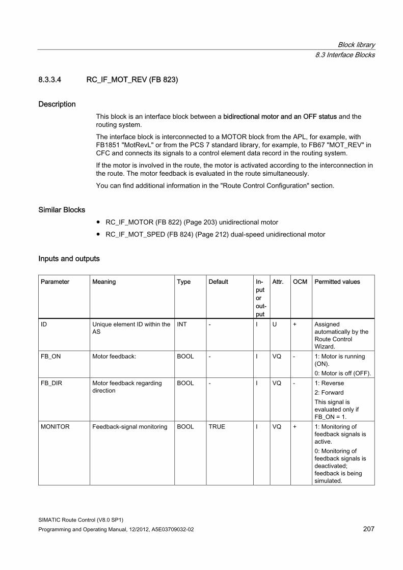
Block library 8.3 Interface Blocks
SIMATIC Route Control (V8.0 SP1) Programming and Operating Manual, 12/2012, A5E03709032-02 207
8.3.3.4 RC_IF_MOT_REV (FB 823)
Description This block is an interface block between a bidirectional motor and an OFF status and the routing system.
The interface block is interconnected to a MOTOR block from the APL, for example, with FB1851 "MotRevL" or from the PCS 7 standard library, for example, to FB67 "MOT_REV" in CFC and connects its signals to a control element data record in the routing system.
If the motor is involved in the route, the motor is activated according to the interconnection in the route. The motor feedback is evaluated in the route simultaneously.
You can find additional information in the "Route Control Configuration" section.
Similar Blocks ● RC_IF_MOTOR (FB 822) (Page 203) unidirectional motor
● RC_IF_MOT_SPED (FB 824) (Page 212) dual-speed unidirectional motor
Inputs and outputs Parameter Meaning Type Default In-
put or out-put
Attr. OCM Permitted values
ID Unique element ID within the AS
INT - I U + Assigned automatically by the Route Control Wizard.
FB_ON Motor feedback: BOOL - I VQ - 1: Motor is running (ON). 0: Motor is off (OFF).
FB_DIR Motor feedback regarding direction
BOOL - I VQ - 1: Reverse 2: Forward This signal is evaluated only if FB_ON = 1.
MONITOR Feedback-signal monitoring BOOL TRUE I VQ + 1: Monitoring of feedback signals is active. 0: Monitoring of feedback signals is deactivated; feedback is being simulated.
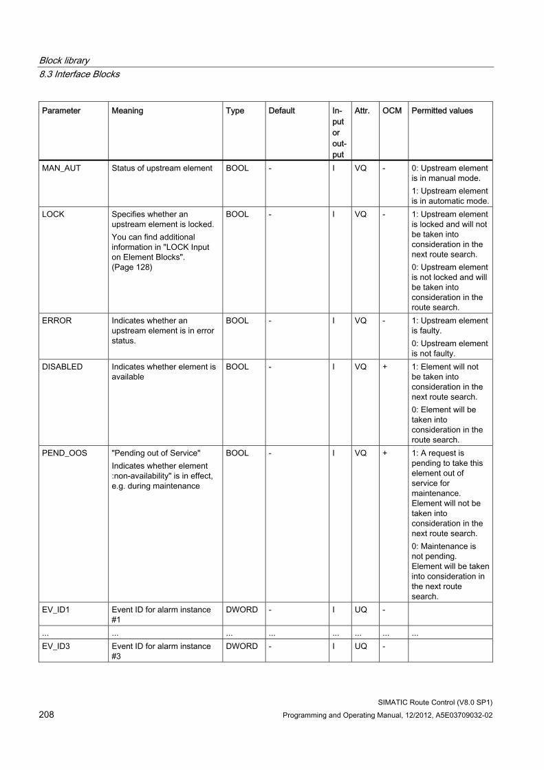
Block library 8.3 Interface Blocks
SIMATIC Route Control (V8.0 SP1) 208 Programming and Operating Manual, 12/2012, A5E03709032-02
Parameter Meaning Type Default In-put or out-put
Attr. OCM Permitted values
MAN_AUT Status of upstream element BOOL - I VQ - 0: Upstream element is in manual mode. 1: Upstream element is in automatic mode.
LOCK Specifies whether an upstream element is locked. You can find additional information in "LOCK Input on Element Blocks". (Page 128)
BOOL - I VQ - 1: Upstream element is locked and will not be taken into consideration in the next route search. 0: Upstream element is not locked and will be taken into consideration in the route search.
ERROR Indicates whether an upstream element is in error status.
BOOL - I VQ - 1: Upstream element is faulty. 0: Upstream element is not faulty.
DISABLED Indicates whether element is available
BOOL - I VQ + 1: Element will not be taken into consideration in the next route search. 0: Element will be taken into consideration in the route search.
PEND_OOS "Pending out of Service" Indicates whether element :non-availability" is in effect, e.g. during maintenance
BOOL - I VQ + 1: A request is pending to take this element out of service for maintenance. Element will not be taken into consideration in the next route search. 0: Maintenance is not pending. Element will be taken into consideration in the next route search.
EV_ID1 Event ID for alarm instance #1
DWORD - I UQ -
... ... ... ... ... ... ... ... EV_ID3 Event ID for alarm instance
#3 DWORD - I UQ -
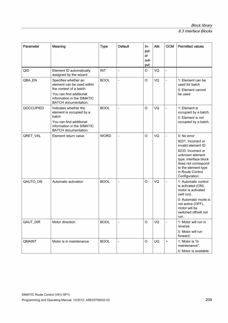
Block library 8.3 Interface Blocks
SIMATIC Route Control (V8.0 SP1) Programming and Operating Manual, 12/2012, A5E03709032-02 209
Parameter Meaning Type Default In-put or out-put
Attr. OCM Permitted values
QID Element ID automatically assigned by the wizard
INT - O VQ -
QBA_EN Specifies whether an element can be used within the context of a batch. You can find additional information in the SIMATIC BATCH documentation.
BOOL - O VQ - 1: Element can be used for batch 0: Element cannot be used
QOCCUPIED Indicates whether the element is occupied by a batch You can find additional information in the SIMATIC BATCH documentation.
BOOL - O VQ - 1: Element is occupied by a batch. 0: Element is not occupied by a batch.
QRET_VAL Element return value WORD - O VQ - 0: No error 8231: Incorrect or invalid element ID 8233: Incorrect or unknown element type; interface block does not correspond to the element type in Route Control Configuration.
QAUTO_ON Automatic activation BOOL - O VQ - 1: Automatic control is activated (ON), motor is activated (will run). 0: Automatic mode is not active (OFF), motor will be switched off/will not run.
QAUT_DIR Motor direction: BOOL - O VQ - 1: Motor will run in reverse. 0: Motor will run forward.
QMAINT Motor is in maintenance BOOL - O UQ + 1: Motor is "in maintenance". 0: Motor is available.
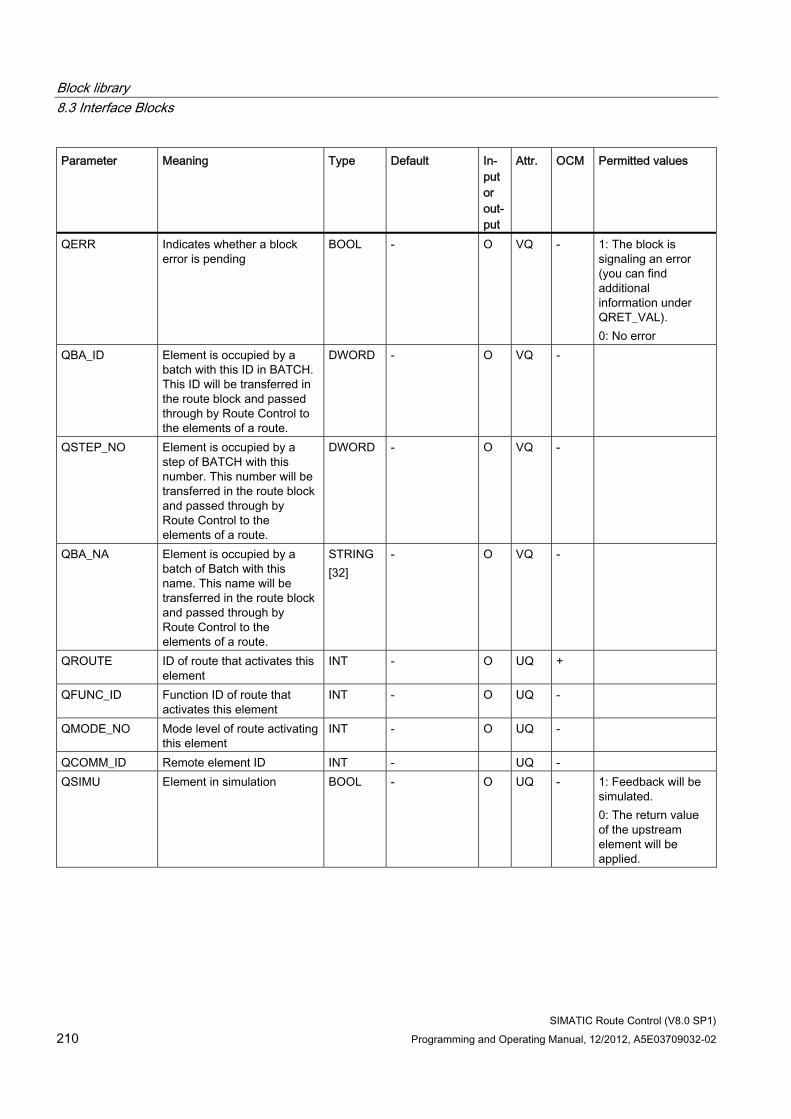
Block library 8.3 Interface Blocks
SIMATIC Route Control (V8.0 SP1) 210 Programming and Operating Manual, 12/2012, A5E03709032-02
Parameter Meaning Type Default In-put or out-put
Attr. OCM Permitted values
QERR Indicates whether a block error is pending
BOOL - O VQ - 1: The block is signaling an error (you can find additional information under QRET_VAL). 0: No error
QBA_ID Element is occupied by a batch with this ID in BATCH. This ID will be transferred in the route block and passed through by Route Control to the elements of a route.
DWORD - O VQ -
QSTEP_NO Element is occupied by a step of BATCH with this number. This number will be transferred in the route block and passed through by Route Control to the elements of a route.
DWORD - O VQ -
QBA_NA Element is occupied by a batch of Batch with this name. This name will be transferred in the route block and passed through by Route Control to the elements of a route.
STRING [32]
- O VQ -
QROUTE ID of route that activates this element
INT - O UQ +
QFUNC_ID Function ID of route that activates this element
INT - O UQ -
QMODE_NO Mode level of route activating this element
INT - O UQ -
QCOMM_ID Remote element ID INT - UQ - QSIMU Element in simulation BOOL - O UQ - 1: Feedback will be
simulated. 0: The return value of the upstream element will be applied.
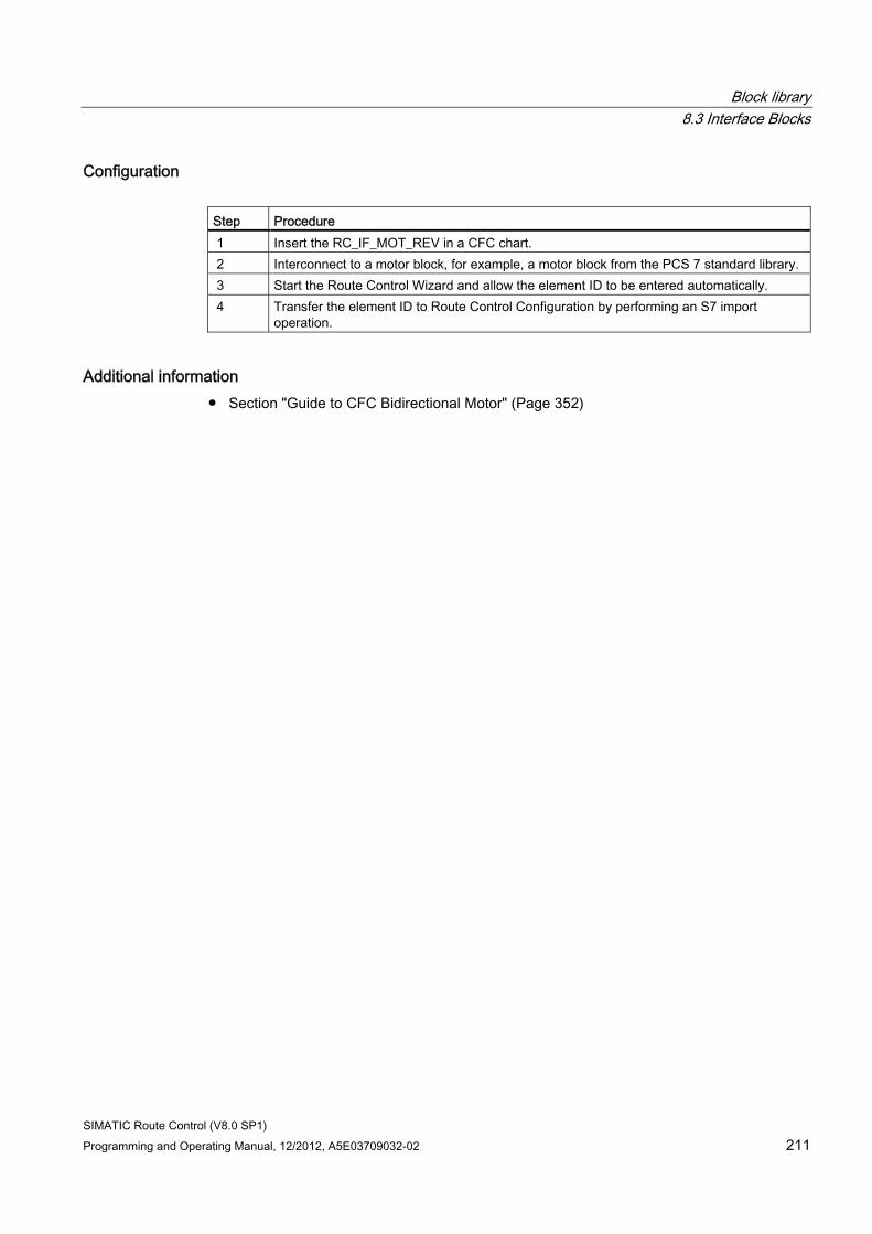
Block library 8.3 Interface Blocks
SIMATIC Route Control (V8.0 SP1) Programming and Operating Manual, 12/2012, A5E03709032-02 211
Configuration Step Procedure 1 Insert the RC_IF_MOT_REV in a CFC chart. 2 Interconnect to a motor block, for example, a motor block from the PCS 7 standard library. 3 Start the Route Control Wizard and allow the element ID to be entered automatically. 4 Transfer the element ID to Route Control Configuration by performing an S7 import
operation.
Additional information ● Section "Guide to CFC Bidirectional Motor" (Page 352)
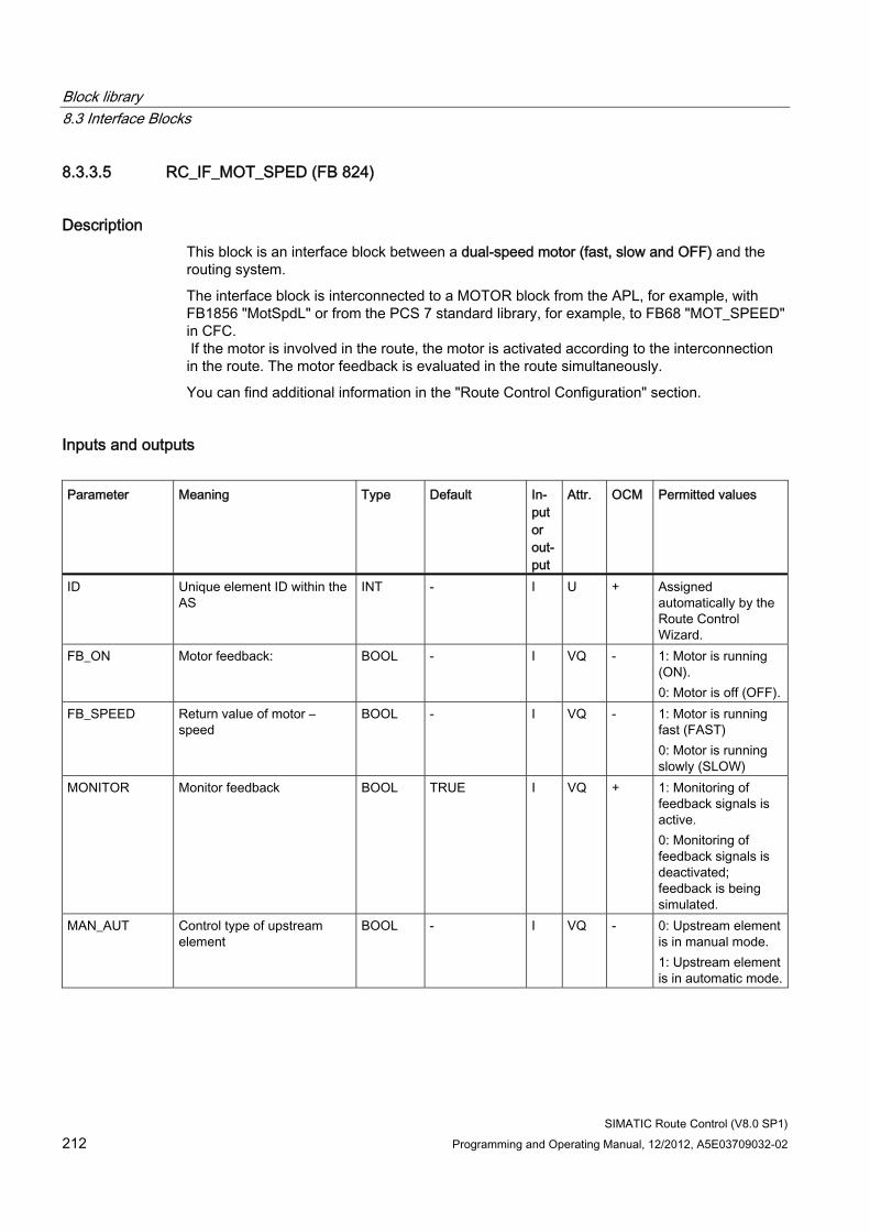
Block library 8.3 Interface Blocks
SIMATIC Route Control (V8.0 SP1) 212 Programming and Operating Manual, 12/2012, A5E03709032-02
8.3.3.5 RC_IF_MOT_SPED (FB 824)
Description This block is an interface block between a dual-speed motor (fast, slow and OFF) and the routing system.
The interface block is interconnected to a MOTOR block from the APL, for example, with FB1856 "MotSpdL" or from the PCS 7 standard library, for example, to FB68 "MOT_SPEED" in CFC. If the motor is involved in the route, the motor is activated according to the interconnection in the route. The motor feedback is evaluated in the route simultaneously.
You can find additional information in the "Route Control Configuration" section.
Inputs and outputs Parameter Meaning Type Default In-
put or out-put
Attr. OCM Permitted values
ID Unique element ID within the AS
INT - I U + Assigned automatically by the Route Control Wizard.
FB_ON Motor feedback: BOOL - I VQ - 1: Motor is running (ON). 0: Motor is off (OFF).
FB_SPEED Return value of motor – speed
BOOL - I VQ - 1: Motor is running fast (FAST) 0: Motor is running slowly (SLOW)
MONITOR Monitor feedback BOOL TRUE I VQ + 1: Monitoring of feedback signals is active. 0: Monitoring of feedback signals is deactivated; feedback is being simulated.
MAN_AUT Control type of upstream element
BOOL - I VQ - 0: Upstream element is in manual mode. 1: Upstream element is in automatic mode.
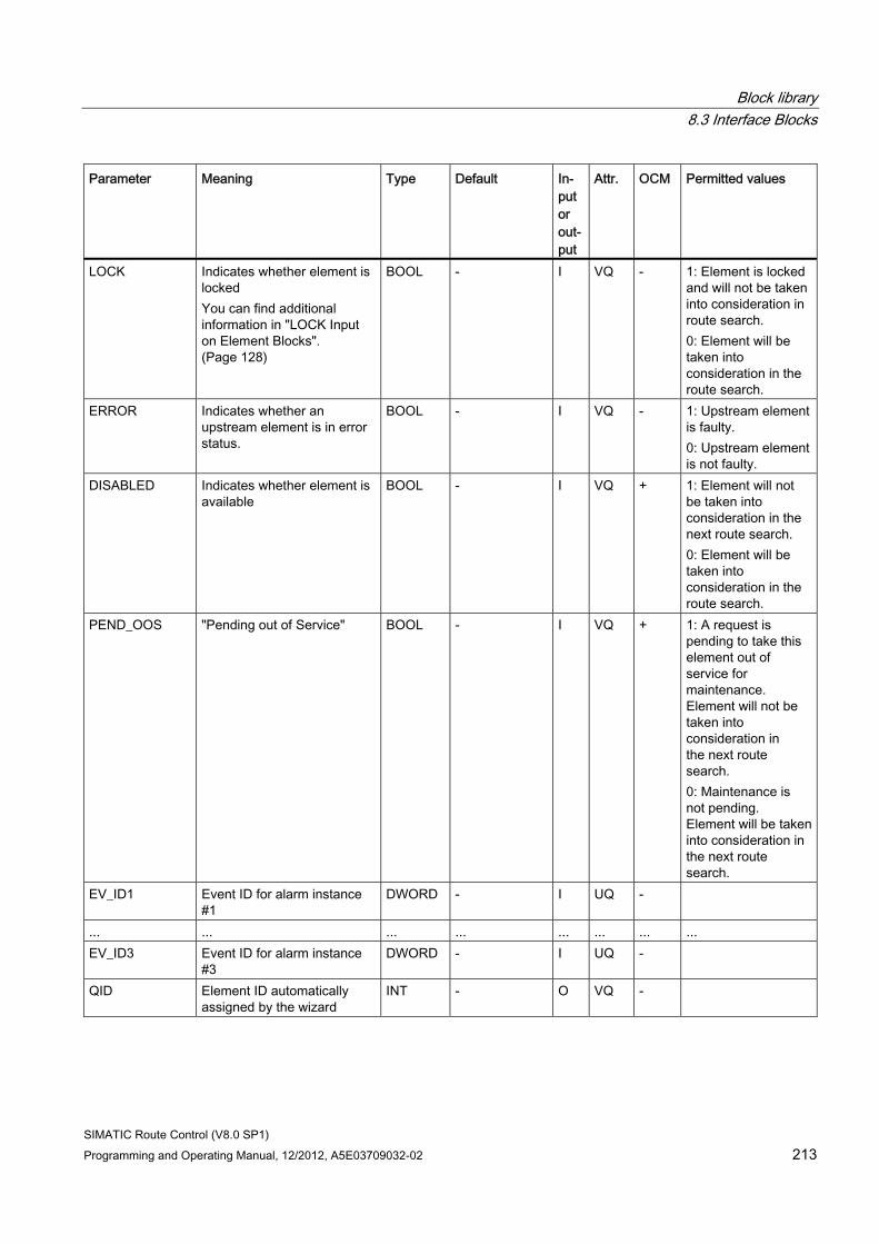
Block library 8.3 Interface Blocks
SIMATIC Route Control (V8.0 SP1) Programming and Operating Manual, 12/2012, A5E03709032-02 213
Parameter Meaning Type Default In-put or out-put
Attr. OCM Permitted values
LOCK Indicates whether element is locked You can find additional information in "LOCK Input on Element Blocks". (Page 128)
BOOL - I VQ - 1: Element is locked and will not be taken into consideration in route search. 0: Element will be taken into consideration in the route search.
ERROR Indicates whether an upstream element is in error status.
BOOL - I VQ - 1: Upstream element is faulty. 0: Upstream element is not faulty.
DISABLED Indicates whether element is available
BOOL - I VQ + 1: Element will not be taken into consideration in the next route search. 0: Element will be taken into consideration in the route search.
PEND_OOS "Pending out of Service" BOOL - I VQ + 1: A request is pending to take this element out of service for maintenance. Element will not be taken into consideration in the next route search. 0: Maintenance is not pending. Element will be taken into consideration in the next route search.
EV_ID1 Event ID for alarm instance #1
DWORD - I UQ -
... ... ... ... ... ... ... ... EV_ID3 Event ID for alarm instance
#3 DWORD - I UQ -
QID Element ID automatically assigned by the wizard
INT - O VQ -
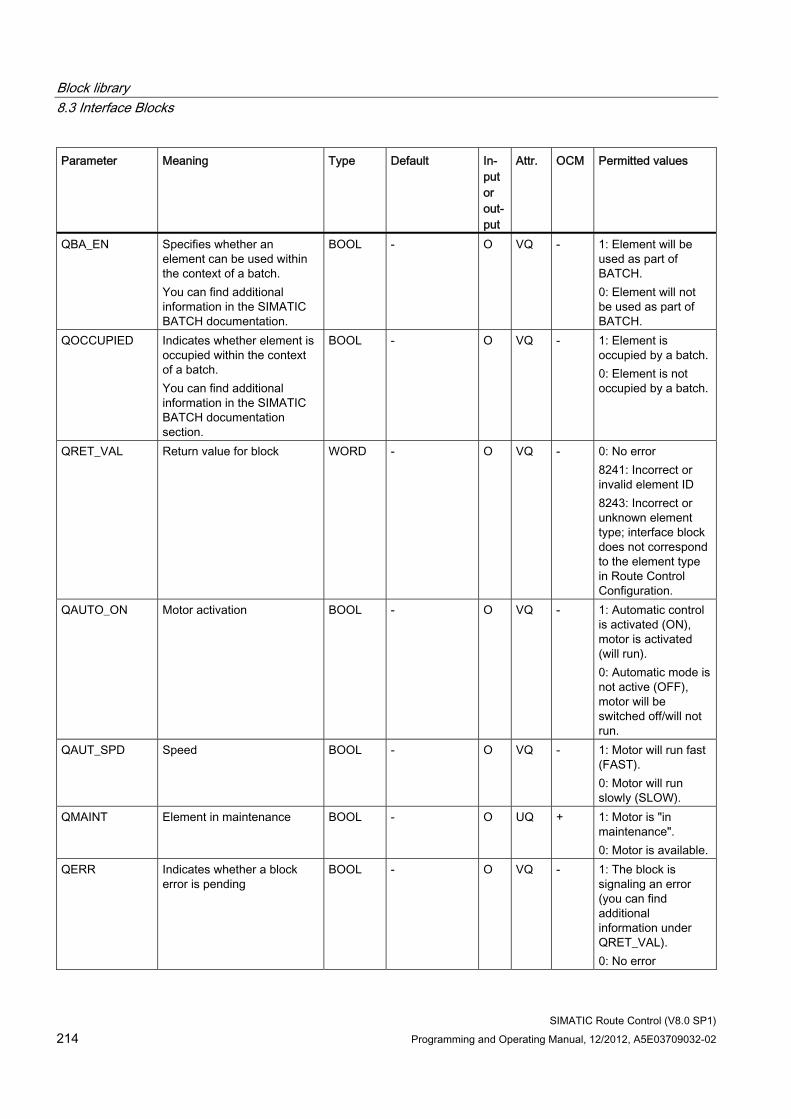
Block library 8.3 Interface Blocks
SIMATIC Route Control (V8.0 SP1) 214 Programming and Operating Manual, 12/2012, A5E03709032-02
Parameter Meaning Type Default In-put or out-put
Attr. OCM Permitted values
QBA_EN Specifies whether an element can be used within the context of a batch. You can find additional information in the SIMATIC BATCH documentation.
BOOL - O VQ - 1: Element will be used as part of BATCH. 0: Element will not be used as part of BATCH.
QOCCUPIED Indicates whether element is occupied within the context of a batch. You can find additional information in the SIMATIC BATCH documentation section.
BOOL - O VQ - 1: Element is occupied by a batch. 0: Element is not occupied by a batch.
QRET_VAL Return value for block WORD - O VQ - 0: No error 8241: Incorrect or invalid element ID 8243: Incorrect or unknown element type; interface block does not correspond to the element type in Route Control Configuration.
QAUTO_ON Motor activation BOOL - O VQ - 1: Automatic control is activated (ON), motor is activated (will run). 0: Automatic mode is not active (OFF), motor will be switched off/will not run.
QAUT_SPD Speed BOOL - O VQ - 1: Motor will run fast (FAST). 0: Motor will run slowly (SLOW).
QMAINT Element in maintenance BOOL - O UQ + 1: Motor is "in maintenance". 0: Motor is available.
QERR Indicates whether a block error is pending
BOOL - O VQ - 1: The block is signaling an error (you can find additional information under QRET_VAL). 0: No error
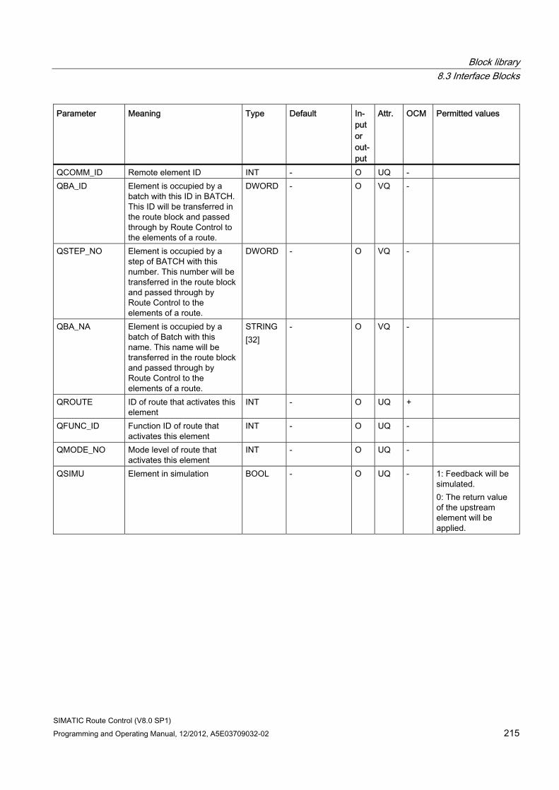
Block library 8.3 Interface Blocks
SIMATIC Route Control (V8.0 SP1) Programming and Operating Manual, 12/2012, A5E03709032-02 215
Parameter Meaning Type Default In-put or out-put
Attr. OCM Permitted values
QCOMM_ID Remote element ID INT - O UQ - QBA_ID Element is occupied by a
batch with this ID in BATCH. This ID will be transferred in the route block and passed through by Route Control to the elements of a route.
DWORD - O VQ -
QSTEP_NO Element is occupied by a step of BATCH with this number. This number will be transferred in the route block and passed through by Route Control to the elements of a route.
DWORD - O VQ -
QBA_NA Element is occupied by a batch of Batch with this name. This name will be transferred in the route block and passed through by Route Control to the elements of a route.
STRING [32]
- O VQ -
QROUTE ID of route that activates this element
INT - O UQ +
QFUNC_ID Function ID of route that activates this element
INT - O UQ -
QMODE_NO Mode level of route that activates this element
INT - O UQ -
QSIMU Element in simulation BOOL - O UQ - 1: Feedback will be simulated. 0: The return value of the upstream element will be applied.
Block library 8.3 Interface Blocks
SIMATIC Route Control (V8.0 SP1) 216 Programming and Operating Manual, 12/2012, A5E03709032-02
Configuration Step Procedure 1 Insert the RC_IF_MOT_SPED in a CFC chart. 2 Insert the MOTOR block in the CFC chart. 3 Interconnect the two blocks. 4 Start the Route Control Wizard.
The element ID is entered automatically. 5 Transfer the element ID to Route Control Configuration by performing an S7 import
operation.
Additional information ● Section "Guide to CFC Dual-Speed Motor" (Page 351)
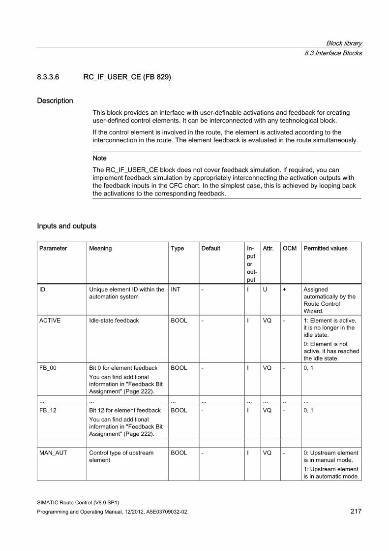
Block library 8.3 Interface Blocks
SIMATIC Route Control (V8.0 SP1) Programming and Operating Manual, 12/2012, A5E03709032-02 217
8.3.3.6 RC_IF_USER_CE (FB 829)
Description This block provides an interface with user-definable activations and feedback for creating user-defined control elements. It can be interconnected with any technological block.
If the control element is involved in the route, the element is activated according to the interconnection in the route. The element feedback is evaluated in the route simultaneously.
Note
The RC_IF_USER_CE block does not cover feedback simulation. If required, you can implement feedback simulation by appropriately interconnecting the activation outputs with the feedback inputs in the CFC chart. In the simplest case, this is achieved by looping back the activations to the corresponding feedback.
Inputs and outputs Parameter Meaning Type Default In-
put or out-put
Attr. OCM Permitted values
ID Unique element ID within the automation system
INT - I U + Assigned automatically by the Route Control Wizard.
ACTIVE Idle-state feedback BOOL - I VQ - 1: Element is active, it is no longer in the idle state. 0: Element is not active, it has reached the idle state.
FB_00 Bit 0 for element feedback You can find additional information in "Feedback Bit Assignment" (Page 222).
BOOL - I VQ - 0, 1
... ... ... ... ... ... ... ... FB_12 Bit 12 for element feedback
You can find additional information in "Feedback Bit Assignment" (Page 222).
BOOL - I VQ - 0, 1
MAN_AUT Control type of upstream
element BOOL - I VQ - 0: Upstream element
is in manual mode. 1: Upstream element is in automatic mode.
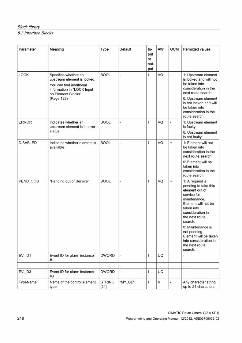
Block library 8.3 Interface Blocks
SIMATIC Route Control (V8.0 SP1) 218 Programming and Operating Manual, 12/2012, A5E03709032-02
Parameter Meaning Type Default In-put or out-put
Attr. OCM Permitted values
LOCK Specifies whether an upstream element is locked. You can find additional information in "LOCK Input on Element Blocks". (Page 128)
BOOL - I VQ - 1: Upstream element is locked and will not be taken into consideration in the next route search. 0: Upstream element is not locked and will be taken into consideration in the route search.
ERROR Indicates whether an upstream element is in error status.
BOOL - I VQ - 1: Upstream element is faulty. 0: Upstream element is not faulty.
DISABLED Indicates whether element is available
BOOL - I VQ + 1: Element will not be taken into consideration in the next route search. 0: Element will be taken into consideration in the route search.
PEND_OOS "Pending out of Service" BOOL - I VQ + 1: A request is pending to take this element out of service for maintenance. Element will not be taken into consideration in the next route search. 0: Maintenance is not pending. Element will be taken into consideration in the next route search.
EV_ID1 Event ID for alarm instance #1
DWORD - I UQ - -
... ... ... ... ... ... ... ... EV_ID3 Event ID for alarm instance
#3 DWORD - I UQ - -
TypeName Name of the control element type
STRING [24]
"MY_CE" I V - Any character string up to 24 characters
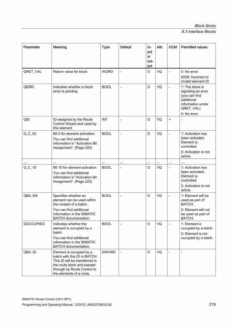
Block library 8.3 Interface Blocks
SIMATIC Route Control (V8.0 SP1) Programming and Operating Manual, 12/2012, A5E03709032-02 219
Parameter Meaning Type Default In-put or out-put
Attr. OCM Permitted values
QRET_VAL Return value for block WORD - O VQ - 0: No error 8229: Incorrect or invalid element ID
QERR Indicates whether a block error is pending
BOOL - O VQ - 1: The block is signaling an error (you can find additional information under QRET_VAL). 0: No error
QID ID assigned by the Route Control Wizard and used by this element
INT - O VQ + -
Q_C_00 Bit 0 for element activation You can find additional information in "Activation Bit Assignment". (Page 222)
BOOL - O VQ - 1: Activation has been activated. Element is controlled. 0: Activation is not active.
... ... ... ... ... ... ... ... Q_C_15 Bit 15 for element activation
You can find additional information in "Activation Bit Assignment". (Page 222)
BOOL - O VQ - 1: Activation has been activated. Element is controlled. 0: Activation is not active.
QBA_EN Specifies whether an element can be used within the context of a batch. You can find additional information in the SIMATIC BATCH documentation.
BOOL - O VQ - 1: Element will be used as part of BATCH. 0: Element will not be used as part of BATCH.
QOCCUPIED Indicates whether the element is occupied by a batch You can find additional information in the SIMATIC BATCH documentation.
BOOL - O VQ - 1: Element is occupied by a batch. 0: Element is not occupied by a batch.
QBA_ID Element is occupied by a batch with this ID in BATCH. This ID will be transferred in the route block and passed through by Route Control to the elements of a route.
DWORD - O VQ - -
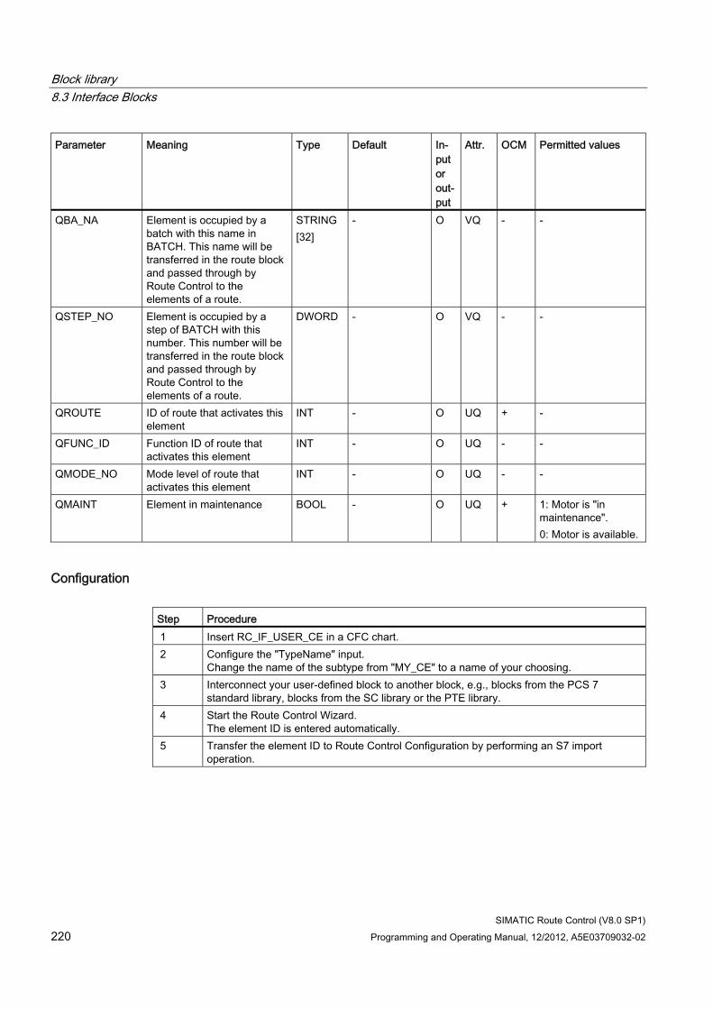
Block library 8.3 Interface Blocks
SIMATIC Route Control (V8.0 SP1) 220 Programming and Operating Manual, 12/2012, A5E03709032-02
Parameter Meaning Type Default In-put or out-put
Attr. OCM Permitted values
QBA_NA Element is occupied by a batch with this name in BATCH. This name will be transferred in the route block and passed through by Route Control to the elements of a route.
STRING [32]
- O VQ - -
QSTEP_NO Element is occupied by a step of BATCH with this number. This number will be transferred in the route block and passed through by Route Control to the elements of a route.
DWORD - O VQ - -
QROUTE ID of route that activates this element
INT - O UQ + -
QFUNC_ID Function ID of route that activates this element
INT - O UQ - -
QMODE_NO Mode level of route that activates this element
INT - O UQ - -
QMAINT Element in maintenance BOOL - O UQ + 1: Motor is "in maintenance". 0: Motor is available.
Configuration Step Procedure 1 Insert RC_IF_USER_CE in a CFC chart. 2 Configure the "TypeName" input.
Change the name of the subtype from "MY_CE" to a name of your choosing. 3 Interconnect your user-defined block to another block, e.g., blocks from the PCS 7
standard library, blocks from the SC library or the PTE library. 4 Start the Route Control Wizard.
The element ID is entered automatically. 5 Transfer the element ID to Route Control Configuration by performing an S7 import
operation.
Block library 8.3 Interface Blocks
SIMATIC Route Control (V8.0 SP1) Programming and Operating Manual, 12/2012, A5E03709032-02 221
Note
To activate this control element in routes, perform the following steps: 1. Create relevant commands on the subtype in Route Control Configuration. 2. Edit the activation and feedback masks in accordance with the assignment of activation
and feedback inputs on the block.
Example ● Section "Example of a User-Defined Type" (Page 242)
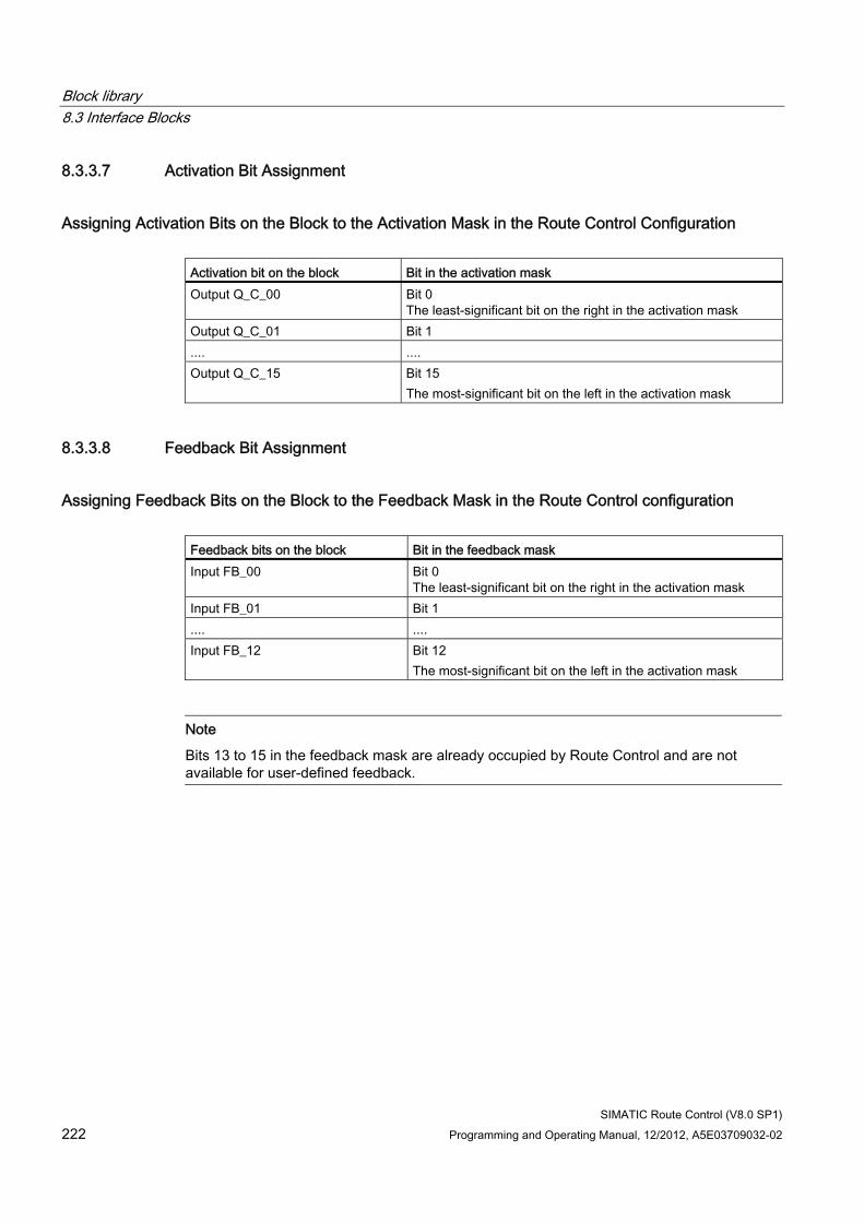
Block library 8.3 Interface Blocks
SIMATIC Route Control (V8.0 SP1) 222 Programming and Operating Manual, 12/2012, A5E03709032-02
8.3.3.7 Activation Bit Assignment
Assigning Activation Bits on the Block to the Activation Mask in the Route Control Configuration Activation bit on the block Bit in the activation mask Output Q_C_00 Bit 0
The least-significant bit on the right in the activation mask Output Q_C_01 Bit 1 .... .... Output Q_C_15 Bit 15
The most-significant bit on the left in the activation mask
8.3.3.8 Feedback Bit Assignment
Assigning Feedback Bits on the Block to the Feedback Mask in the Route Control configuration Feedback bits on the block Bit in the feedback mask Input FB_00 Bit 0
The least-significant bit on the right in the activation mask Input FB_01 Bit 1 .... .... Input FB_12 Bit 12
The most-significant bit on the left in the activation mask
Note
Bits 13 to 15 in the feedback mask are already occupied by Route Control and are not available for user-defined feedback.
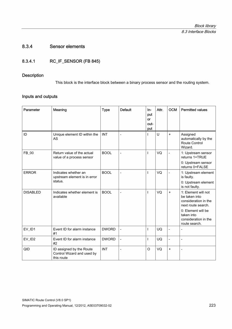
Block library 8.3 Interface Blocks
SIMATIC Route Control (V8.0 SP1) Programming and Operating Manual, 12/2012, A5E03709032-02 223
8.3.4 Sensor elements
8.3.4.1 RC_IF_SENSOR (FB 845)
Description This block is the interface block between a binary process sensor and the routing system.
Inputs and outputs Parameter Meaning Type Default In-
put or out-put
Attr. OCM Permitted values
ID Unique element ID within the AS
INT - I U + Assigned automatically by the Route Control Wizard.
FB_00 Return value of the actual value of a process sensor
BOOL - I VQ - 1: Upstream sensor returns 1=TRUE 0: Upstream sensor returns 0=FALSE
ERROR Indicates whether an upstream element is in error status.
BOOL - I VQ - 1: Upstream element is faulty. 0: Upstream element is not faulty.
DISABLED Indicates whether element is available
BOOL - I VQ + 1: Element will not be taken into consideration in the next route search. 0: Element will be taken into consideration in the route search.
EV_ID1 Event ID for alarm instance #1
DWORD - I UQ - -
EV_ID2 Event ID for alarm instance #2
DWORD - I UQ - -
QID ID assigned by the Route Control Wizard and used by this route
INT - O VQ + -
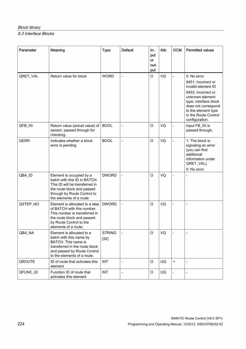
Block library 8.3 Interface Blocks
SIMATIC Route Control (V8.0 SP1) 224 Programming and Operating Manual, 12/2012, A5E03709032-02
Parameter Meaning Type Default In-put or out-put
Attr. OCM Permitted values
QRET_VAL Return value for block WORD - O VQ - 0: No error 8451: Incorrect or invalid element ID 8453: Incorrect or unknown element type; interface block does not correspond to the element type in the Route Control configuration.
QFB_00 Return value (actual value) of sensor; passed through for checking.
BOOL - O VQ - Input FB_00 is passed through.
QERR Indicates whether a block error is pending
BOOL - O VQ - 1: The block is signaling an error (you can find additional information under QRET_VAL). 0: No error
QBA_ID Element is occupied by a batch with this ID in BATCH. This ID will be transferred in the route block and passed through by Route Control to the elements of a route.
DWORD - O VQ - -
QSTEP_NO Element is allocated to a step of BATCH with this number. This number is transferred in the route block and passed by Route Control to the elements of a route.
DWORD - O VQ - -
QBA_NA Element is allocated to a batch with this name by BATCH. This name is transferred in the route block and passed by Route Control to the elements of a route.
STRING [32]
- O VQ - -
QROUTE ID of route that activates this element
INT - O UQ + -
QFUNC_ID Function ID of route that activates this element
INT - O UQ - -
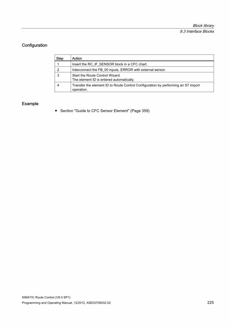
Block library 8.3 Interface Blocks
SIMATIC Route Control (V8.0 SP1) Programming and Operating Manual, 12/2012, A5E03709032-02 225
Configuration Step Action 1 Insert the RC_IF_SENSOR block in a CFC chart. 2 Interconnect the FB_00 inputs, ERROR with external sensor. 3 Start the Route Control Wizard.
The element ID is entered automatically. 4 Transfer the element ID to Route Control Configuration by performing an S7 import
operation.
Example ● Section "Guide to CFC Sensor Element" (Page 359)
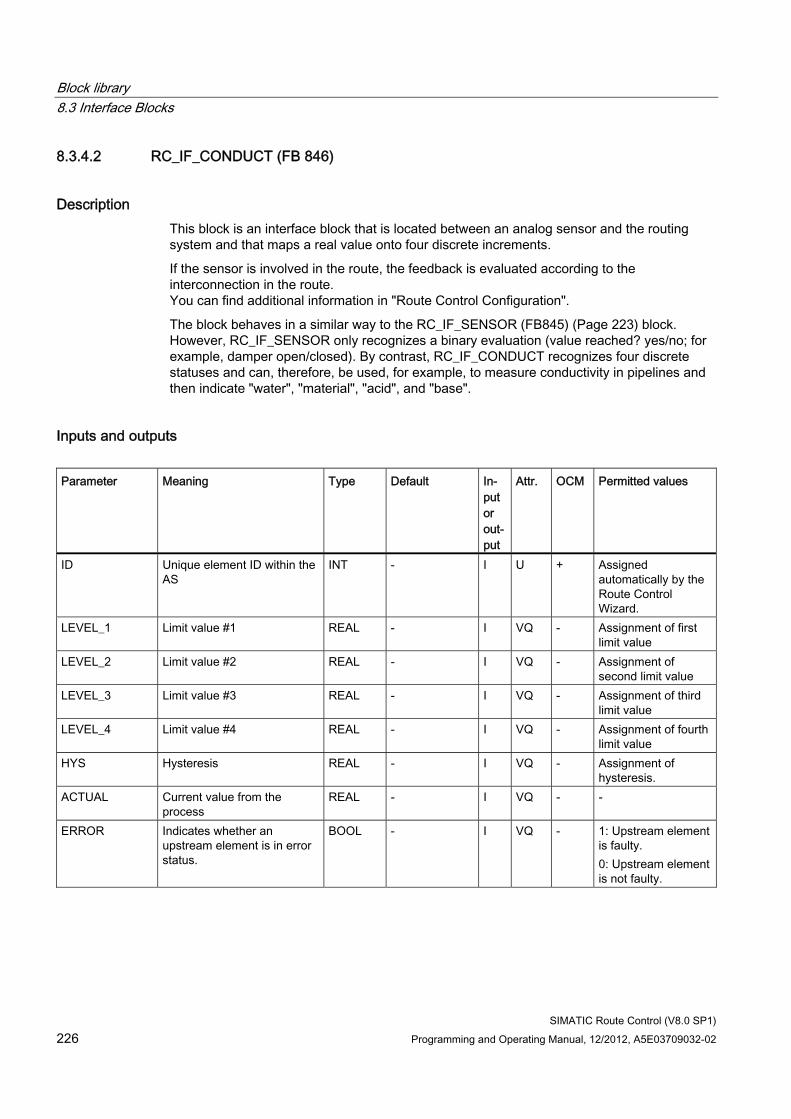
Block library 8.3 Interface Blocks
SIMATIC Route Control (V8.0 SP1) 226 Programming and Operating Manual, 12/2012, A5E03709032-02
8.3.4.2 RC_IF_CONDUCT (FB 846)
Description This block is an interface block that is located between an analog sensor and the routing system and that maps a real value onto four discrete increments.
If the sensor is involved in the route, the feedback is evaluated according to the interconnection in the route. You can find additional information in "Route Control Configuration".
The block behaves in a similar way to the RC_IF_SENSOR (FB845) (Page 223) block. However, RC_IF_SENSOR only recognizes a binary evaluation (value reached? yes/no; for example, damper open/closed). By contrast, RC_IF_CONDUCT recognizes four discrete statuses and can, therefore, be used, for example, to measure conductivity in pipelines and then indicate "water", "material", "acid", and "base".
Inputs and outputs Parameter Meaning Type Default In-
put or out-put
Attr. OCM Permitted values
ID Unique element ID within the AS
INT - I U + Assigned automatically by the Route Control Wizard.
LEVEL_1 Limit value #1 REAL - I VQ - Assignment of first limit value
LEVEL_2 Limit value #2 REAL - I VQ - Assignment of second limit value
LEVEL_3 Limit value #3 REAL - I VQ - Assignment of third limit value
LEVEL_4 Limit value #4 REAL - I VQ - Assignment of fourth limit value
HYS Hysteresis REAL - I VQ - Assignment of hysteresis.
ACTUAL Current value from the process
REAL - I VQ - -
ERROR Indicates whether an upstream element is in error status.
BOOL - I VQ - 1: Upstream element is faulty. 0: Upstream element is not faulty.
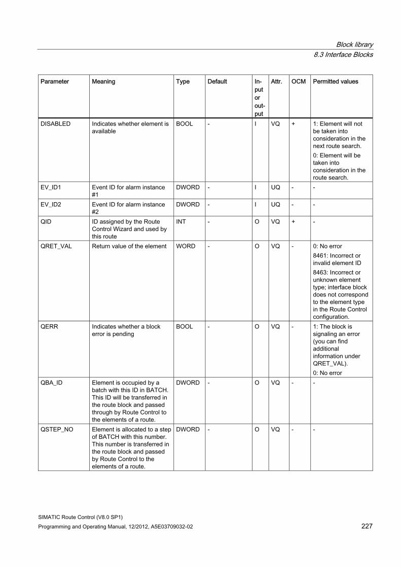
Block library 8.3 Interface Blocks
SIMATIC Route Control (V8.0 SP1) Programming and Operating Manual, 12/2012, A5E03709032-02 227
Parameter Meaning Type Default In-put or out-put
Attr. OCM Permitted values
DISABLED Indicates whether element is available
BOOL - I VQ + 1: Element will not be taken into consideration in the next route search. 0: Element will be taken into consideration in the route search.
EV_ID1 Event ID for alarm instance #1
DWORD - I UQ - -
EV_ID2 Event ID for alarm instance #2
DWORD - I UQ - -
QID ID assigned by the Route Control Wizard and used by this route
INT - O VQ + -
QRET_VAL Return value of the element WORD - O VQ - 0: No error 8461: Incorrect or invalid element ID 8463: Incorrect or unknown element type; interface block does not correspond to the element type in the Route Control configuration.
QERR Indicates whether a block error is pending
BOOL - O VQ - 1: The block is signaling an error (you can find additional information under QRET_VAL). 0: No error
QBA_ID Element is occupied by a batch with this ID in BATCH. This ID will be transferred in the route block and passed through by Route Control to the elements of a route.
DWORD - O VQ - -
QSTEP_NO Element is allocated to a step of BATCH with this number. This number is transferred in the route block and passed by Route Control to the elements of a route.
DWORD - O VQ - -
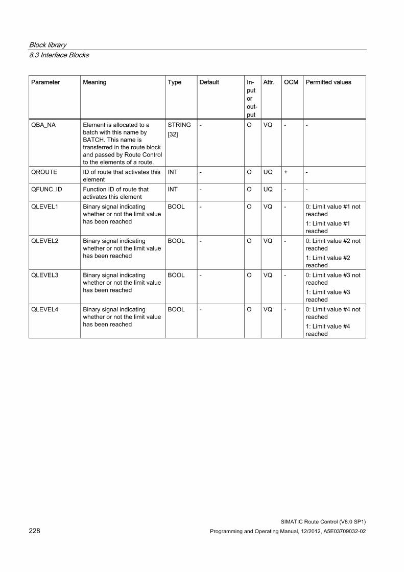
Block library 8.3 Interface Blocks
SIMATIC Route Control (V8.0 SP1) 228 Programming and Operating Manual, 12/2012, A5E03709032-02
Parameter Meaning Type Default In-put or out-put
Attr. OCM Permitted values
QBA_NA Element is allocated to a batch with this name by BATCH. This name is transferred in the route block and passed by Route Control to the elements of a route.
STRING [32]
- O VQ - -
QROUTE ID of route that activates this element
INT - O UQ + -
QFUNC_ID Function ID of route that activates this element
INT - O UQ - -
QLEVEL1 Binary signal indicating whether or not the limit value has been reached
BOOL - O VQ - 0: Limit value #1 not reached 1: Limit value #1 reached
QLEVEL2 Binary signal indicating whether or not the limit value has been reached
BOOL - O VQ - 0: Limit value #2 not reached 1: Limit value #2 reached
QLEVEL3 Binary signal indicating whether or not the limit value has been reached
BOOL - O VQ - 0: Limit value #3 not reached 1: Limit value #3 reached
QLEVEL4 Binary signal indicating whether or not the limit value has been reached
BOOL - O VQ - 0: Limit value #4 not reached 1: Limit value #4 reached
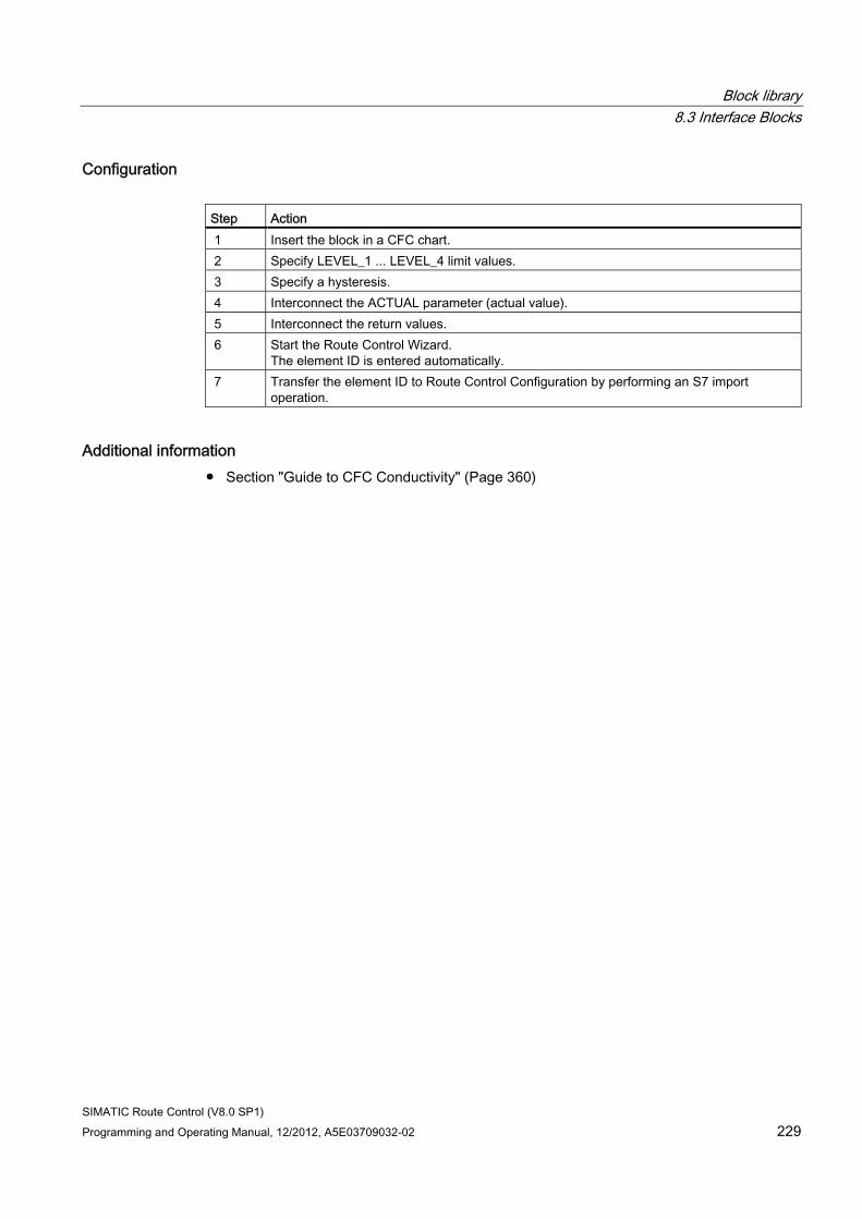
Block library 8.3 Interface Blocks
SIMATIC Route Control (V8.0 SP1) Programming and Operating Manual, 12/2012, A5E03709032-02 229
Configuration Step Action 1 Insert the block in a CFC chart. 2 Specify LEVEL_1 ... LEVEL_4 limit values. 3 Specify a hysteresis. 4 Interconnect the ACTUAL parameter (actual value). 5 Interconnect the return values. 6 Start the Route Control Wizard.
The element ID is entered automatically. 7 Transfer the element ID to Route Control Configuration by performing an S7 import
operation.
Additional information ● Section "Guide to CFC Conductivity" (Page 360)
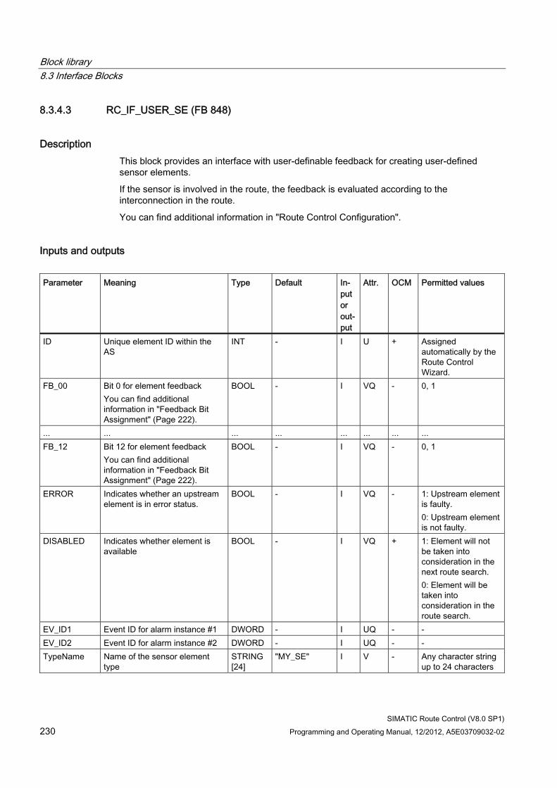
Block library 8.3 Interface Blocks
SIMATIC Route Control (V8.0 SP1) 230 Programming and Operating Manual, 12/2012, A5E03709032-02
8.3.4.3 RC_IF_USER_SE (FB 848)
Description This block provides an interface with user-definable feedback for creating user-defined sensor elements.
If the sensor is involved in the route, the feedback is evaluated according to the interconnection in the route.
You can find additional information in "Route Control Configuration".
Inputs and outputs Parameter Meaning Type Default In-
put or out-put
Attr. OCM Permitted values
ID Unique element ID within the AS
INT - I U + Assigned automatically by the Route Control Wizard.
FB_00 Bit 0 for element feedback You can find additional information in "Feedback Bit Assignment" (Page 222).
BOOL - I VQ - 0, 1
... ... ... ... ... ... ... ... FB_12 Bit 12 for element feedback
You can find additional information in "Feedback Bit Assignment" (Page 222).
BOOL - I VQ - 0, 1
ERROR Indicates whether an upstream element is in error status.
BOOL - I VQ - 1: Upstream element is faulty. 0: Upstream element is not faulty.
DISABLED Indicates whether element is available
BOOL - I VQ + 1: Element will not be taken into consideration in the next route search. 0: Element will be taken into consideration in the route search.
EV_ID1 Event ID for alarm instance #1 DWORD - I UQ - - EV_ID2 Event ID for alarm instance #2 DWORD - I UQ - - TypeName Name of the sensor element
type STRING [24]
"MY_SE" I V - Any character string up to 24 characters
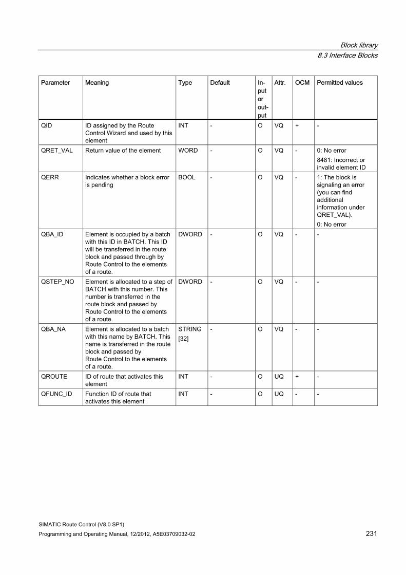
Block library 8.3 Interface Blocks
SIMATIC Route Control (V8.0 SP1) Programming and Operating Manual, 12/2012, A5E03709032-02 231
Parameter Meaning Type Default In-put or out-put
Attr. OCM Permitted values
QID ID assigned by the Route Control Wizard and used by this element
INT - O VQ + -
QRET_VAL Return value of the element WORD - O VQ - 0: No error 8481: Incorrect or invalid element ID
QERR Indicates whether a block error is pending
BOOL - O VQ - 1: The block is signaling an error (you can find additional information under QRET_VAL). 0: No error
QBA_ID Element is occupied by a batch with this ID in BATCH. This ID will be transferred in the route block and passed through by Route Control to the elements of a route.
DWORD - O VQ - -
QSTEP_NO Element is allocated to a step of BATCH with this number. This number is transferred in the route block and passed by Route Control to the elements of a route.
DWORD - O VQ - -
QBA_NA Element is allocated to a batch with this name by BATCH. This name is transferred in the route block and passed by Route Control to the elements of a route.
STRING [32]
- O VQ - -
QROUTE ID of route that activates this element
INT - O UQ + -
QFUNC_ID Function ID of route that activates this element
INT - O UQ - -
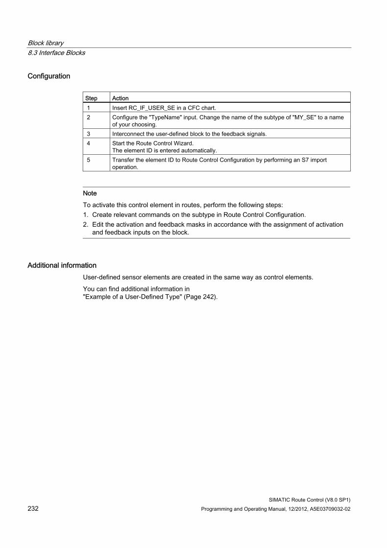
Block library 8.3 Interface Blocks
SIMATIC Route Control (V8.0 SP1) 232 Programming and Operating Manual, 12/2012, A5E03709032-02
Configuration Step Action 1 Insert RC_IF_USER_SE in a CFC chart. 2 Configure the "TypeName" input. Change the name of the subtype of "MY_SE" to a name
of your choosing. 3 Interconnect the user-defined block to the feedback signals. 4 Start the Route Control Wizard.
The element ID is entered automatically. 5 Transfer the element ID to Route Control Configuration by performing an S7 import
operation.
Note
To activate this control element in routes, perform the following steps: 1. Create relevant commands on the subtype in Route Control Configuration. 2. Edit the activation and feedback masks in accordance with the assignment of activation
and feedback inputs on the block.
Additional information User-defined sensor elements are created in the same way as control elements.
You can find additional information in "Example of a User-Defined Type" (Page 242).
Block library 8.3 Interface Blocks
SIMATIC Route Control (V8.0 SP1) Programming and Operating Manual, 12/2012, A5E03709032-02 233
8.3.5 Parameter elements
8.3.5.1 General Information About Parameter Elements
General Information About Parameter Elements Parameter elements represent a setpoint (QVALUE_I, _D, _R) which can be further processed by user programs and take an actual value (ACT_VAL) from the process. Parameter elements are used to specify setpoints, whereby the setpoint specification can depend on a given route. For example, the calculation of the discharge quantity may depend on the volume of a pipe.
PE Types SIMATIC Route Control provides two predefined PE types:
● RC_IF_VOLUME (FC 808) (Page 236)
● RC_IF_TIMER (FC 809) (Page 237)
An interface block is available for user-defined parameter elements. You call this block in the user programs in order to access the SIMATIC Route Control internal PA data structures:
● RC_IF_USER_PE (FC 807) (Page 238)
Parameter Element Types SIMATIC Route Control distinguishes between two types of parameter elements:
● Internal parameter elements
● External parameter elements
You can mix internal and external parameter elements when a parameter element is inserted in a partial route.
Internal Parameter Elements The setpoints of internal parameter elements are known at the time of the configuration (Route Control).
Examples: Volumes/quantity of a material in the pipes, fixed times.
Block library 8.3 Interface Blocks
SIMATIC Route Control (V8.0 SP1) 234 Programming and Operating Manual, 12/2012, A5E03709032-02
External Parameter Elements The setpoints of external parameter elements are not known at the time of the configuration (Route Control).
Examples: Weighed quantities, which are usually specified by recipes.
Whereas the setpoint is specified directly at the RPE (Route Parameter Element) as a property for an internal parameter element, it is configured as an index for an external parameter element. This index references one of the inputs (EXT_..._I, ... = 1 to 24) at the route (RC_IF_ROUTE) during runtime. The setpoint located there is passed by the route block to the EXT_..._O outputs and also output to the parameter element interface blocks (e.g., RC_IF_VOLUME, RC_IF_TIMER).
Summation and non summation parameter elements You obtain a summation parameter element when you activate the option "Type sum" in the Route parameter element properties" dialog for an internal parameter element. External parameter elements cannot also be summation parameter elements.
You can mix summation and non summation parameter elements when a parameter element is inserted in a partial route.
When a route is requested or started, the Route Control server forms a sum from the setpoints of all summing parameter elements involved in the route. When a mode containing one or more summing PEs is activated, this sum is passed to all PEs configured in this mode, specifically at the QVALUE_x output of the PE interface block.
The sum of the individual values of PEs placed in this mode are shown in the respective Mode column for each configured PE in the Route Control Center.
The feedback values displayed in the Route Control Center indicate the value interconnected to the ACT_VAL input of the PE interface block.
Non summation parameter elements of this route are not taken into account when the sum is formed and are supplied with the value defined for it.
Block library 8.3 Interface Blocks
SIMATIC Route Control (V8.0 SP1) Programming and Operating Manual, 12/2012, A5E03709032-02 235
RC_IF_VOLUME A volume parameter element is used when an action is to be performed for a specific volume, depending on the selected route.
Example: Material should only exit a pipe until the output valve closes and the destination container valve opens.
RC_IF_TIMER A timer parameter element is used when an action is to be performed at a specific time, depending on the selected route.
Example: Material should only exit a pipe until the output valve closes and the destination container valve opens.
Additional information ● Section "RC_IF_ROUTE (FB 800)" (Page 159)
Block library 8.3 Interface Blocks
SIMATIC Route Control (V8.0 SP1) 236 Programming and Operating Manual, 12/2012, A5E03709032-02
8.3.5.2 RC_IF_VOLUME (FC 808)
Description This block is a parameter element for a volumetric value. The RC_IF_VOLUME and RC_IF_TIMER blocks use the RC_PE_COMMON block internally.
A parameter element specifies a setpoint. The actual value of the parameter element is only used for visualization on the Route Control Center.
If the parameter element is involved in the route, the setpoint is output according to the interconnection in the route. The parameter-element feedback is not evaluated in the route.
Inputs and Outputs You can find additional information about inputs and outputs in "RC_PE_COMMON (FC 810)". (Page 288)
Block Return Values QRET_VAL Meaning 0 No error 8102 Incorrect or invalid element ID 8103 External parameter elements only: The index is outside the permissible range (1 to 24). 8104 External parameter elements only: The route ID is outside the permissible range (1 to
the maximum number of routes). The maximum number of routes is specified using the NoRoutes input on FB 850 RC_IF_CFG.
Configuration Step Procedure 1 Insert a user-defined block in a CFC. 2 Interconnect the user-defined block to technological blocks, such as PCS 7 standard
library blocks. 3 Start the Route Control Wizard.
The element ID is entered automatically. 4 Transfer the element ID to Route Control Configuration by performing an S7 import
operation.
Example ● Section "Guide to CFC Parameter Element" (Page 361)
Block library 8.3 Interface Blocks
SIMATIC Route Control (V8.0 SP1) Programming and Operating Manual, 12/2012, A5E03709032-02 237
8.3.5.3 RC_IF_TIMER (FC 809)
Description This block is a parameter element for a time value. The RC_IF_VOLUME and RC_IF_TIMER blocks use the RC_PE_COMMON block internally.
A parameter element specifies a setpoint. The actual value of the parameter element is only used for visualization on the Route Control Center.
If the parameter element is involved in the route, the setpoint is output according to the interconnection in the route. The parameter-element feedback is not evaluated in the route.
Inputs and Outputs You can find additional information about inputs and outputs in "RC_PE_COMMON (FC 810)". (Page 288)
Block Return Values (QRET_VAL) QRET_VAL Meaning 0 No error 8102 Incorrect or invalid element ID 8103 External parameter elements only: The index is outside the permissible range (1 to
24). 8104 External parameter elements only: The route ID is outside the permissible range (1 to
the maximum number of routes). The maximum number of routes is specified using the NoRoutes input on the FB850 RC_IF_CFG.
Configuration Step Procedure 1 Insert a user-defined block in a CFC chart. 2 Interconnect the user-defined block to technological blocks, such as PCS 7 standard
library blocks. 3 Start the Route Control Wizard.
The element ID is entered automatically. 4 Transfer the element ID to Route Control Configuration by performing an S7 import
operation.
Block library 8.3 Interface Blocks
SIMATIC Route Control (V8.0 SP1) 238 Programming and Operating Manual, 12/2012, A5E03709032-02
8.3.5.4 RC_IF_USER_PE (FC 807)
Description This block is a parameter element for a volumetric value. Internally, it uses the RC_PE_COMMON block.
A parameter element specifies a setpoint. The actual value of the parameter element is used for visualization in the Route Control Center.
If the parameter element is involved in the route, the setpoint is output according to the interconnection in the route. The parameter-element feedback is not evaluated in the route.
Inputs and Outputs You can find additional information about inputs and outputs in "RC_PE_COMMON (FC 810)". (Page 288)
Additional input on RC_IF_USER_PE:
Parameter Meaning Type Default In-
put or Out-put
Attr. OCM
Permitted values
TypeName Name of the sensor element type
STRING [24]
-- I V - Any character string up to 24 characters
Block Return Values QRET_VAL Meaning 0 No error 8102 Incorrect or invalid element ID 8103 External parameter elements only: The index is outside the permissible range (1 to
24). 8104 External parameter elements only: The route ID is outside the permissible range (1 to
the maximum number of routes). The maximum number of routes is specified using the NoRoutes (number of routes) input on RC_IF_CFG (FB 850) (Page 247).
Block library 8.3 Interface Blocks
SIMATIC Route Control (V8.0 SP1) Programming and Operating Manual, 12/2012, A5E03709032-02 239
Configuration Step Procedure 1 Insert the RC_IF_USER_PE block in a CFC chart. 2 Configure the "TypeName" input.
Change the name of the subtype to a name of your choosing. 3 Interconnect the user-defined block to technological blocks, such as PCS 7 standard
library blocks. 4 Start the Route Control Wizard.
The element ID is entered automatically. 5 Transfer the element ID and the new subtype to Route Control Configuration by performing
an S7 Import operation.
Note
To activate this parameter element in routes, you still have to edit the unit for visualization on the Route Control Center on the subtype in the Route Control configuration tool.
Additional information User-defined parameter elements are created in the same way as control elements.
You can find additional information in "Example of a User-Defined Type" (Page 242).
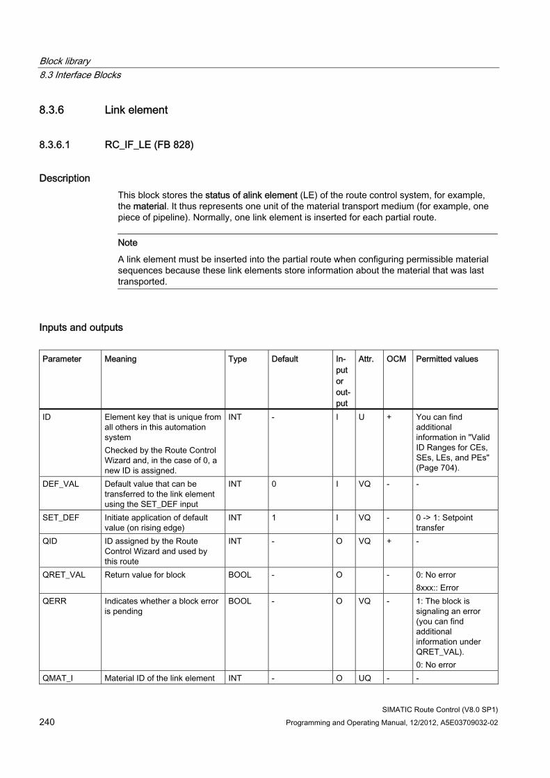
Block library 8.3 Interface Blocks
SIMATIC Route Control (V8.0 SP1) 240 Programming and Operating Manual, 12/2012, A5E03709032-02
8.3.6 Link element
8.3.6.1 RC_IF_LE (FB 828)
Description This block stores the status of alink element (LE) of the route control system, for example, the material. It thus represents one unit of the material transport medium (for example, one piece of pipeline). Normally, one link element is inserted for each partial route.
Note
A link element must be inserted into the partial route when configuring permissible material sequences because these link elements store information about the material that was last transported.
Inputs and outputs Parameter Meaning Type Default In-
put or out-put
Attr. OCM Permitted values
ID Element key that is unique from all others in this automation system Checked by the Route Control Wizard and, in the case of 0, a new ID is assigned.
INT - I U + You can find additional information in "Valid ID Ranges for CEs, SEs, LEs, and PEs" (Page 704).
DEF_VAL Default value that can be transferred to the link element using the SET_DEF input
INT 0 I VQ - -
SET_DEF Initiate application of default value (on rising edge)
INT 1 I VQ - 0 -> 1: Setpoint transfer
QID ID assigned by the Route Control Wizard and used by this route
INT - O VQ + -
QRET_VAL Return value for block BOOL - O - 0: No error 8xxx:: Error
QERR Indicates whether a block error is pending
BOOL - O VQ - 1: The block is signaling an error (you can find additional information under QRET_VAL). 0: No error
QMAT_I Material ID of the link element INT - O UQ - -
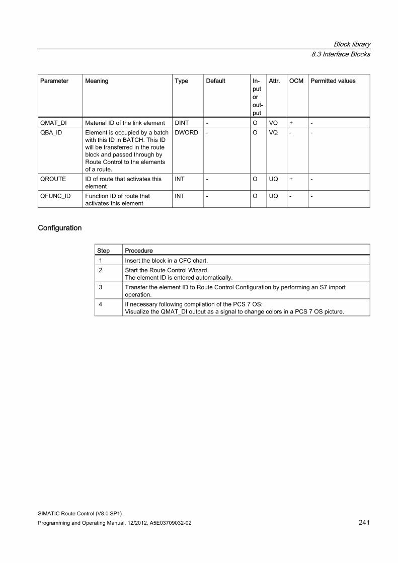
Block library 8.3 Interface Blocks
SIMATIC Route Control (V8.0 SP1) Programming and Operating Manual, 12/2012, A5E03709032-02 241
Parameter Meaning Type Default In-put or out-put
Attr. OCM Permitted values
QMAT_DI Material ID of the link element DINT - O VQ + - QBA_ID Element is occupied by a batch
with this ID in BATCH. This ID will be transferred in the route block and passed through by Route Control to the elements of a route.
DWORD - O VQ - -
QROUTE ID of route that activates this element
INT - O UQ + -
QFUNC_ID Function ID of route that activates this element
INT - O UQ - -
Configuration Step Procedure 1 Insert the block in a CFC chart. 2 Start the Route Control Wizard.
The element ID is entered automatically. 3 Transfer the element ID to Route Control Configuration by performing an S7 import
operation. 4 If necessary following compilation of the PCS 7 OS:
Visualize the QMAT_DI output as a signal to change colors in a PCS 7 OS picture.
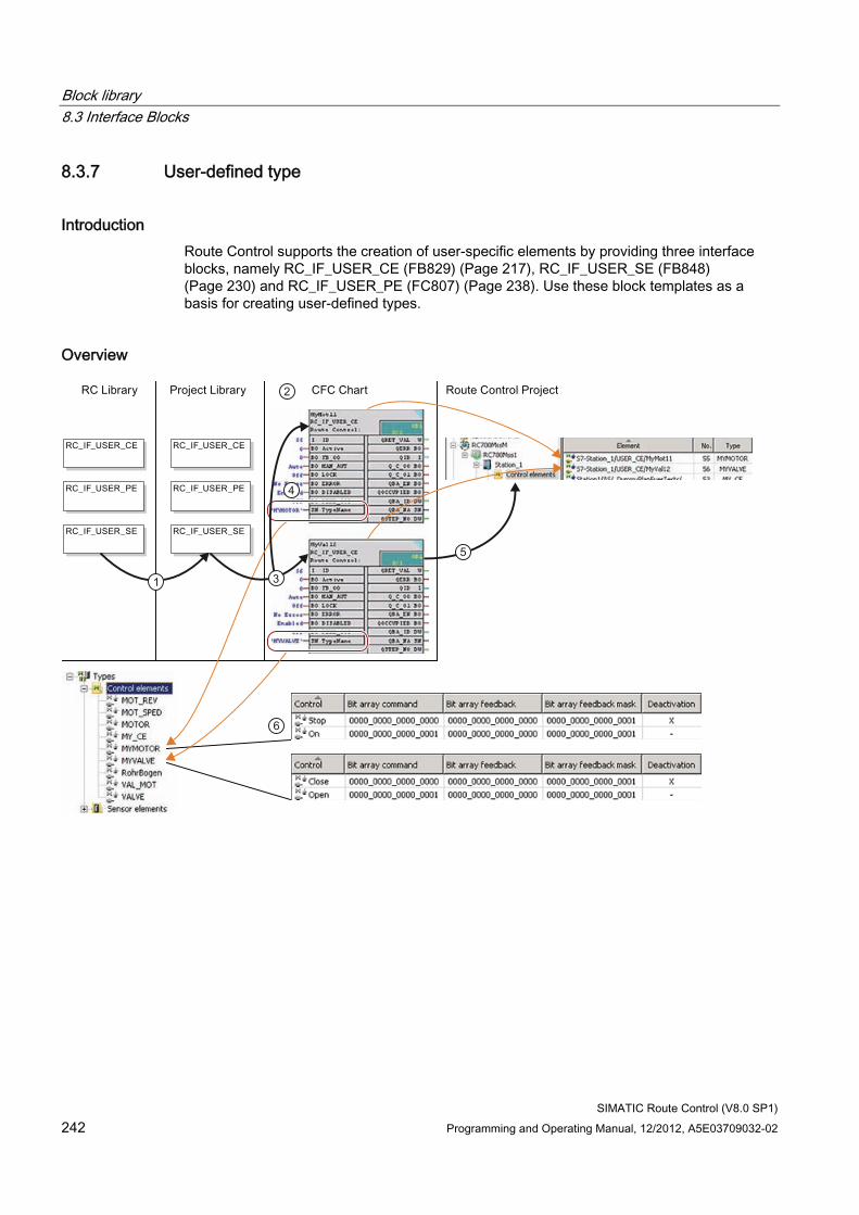
Block library 8.3 Interface Blocks
SIMATIC Route Control (V8.0 SP1) 242 Programming and Operating Manual, 12/2012, A5E03709032-02
8.3.7 User-defined type
Introduction Route Control supports the creation of user-specific elements by providing three interface blocks, namely RC_IF_USER_CE (FB829) (Page 217), RC_IF_USER_SE (FB848) (Page 230) and RC_IF_USER_PE (FC807) (Page 238). Use these block templates as a basis for creating user-defined types.
Overview
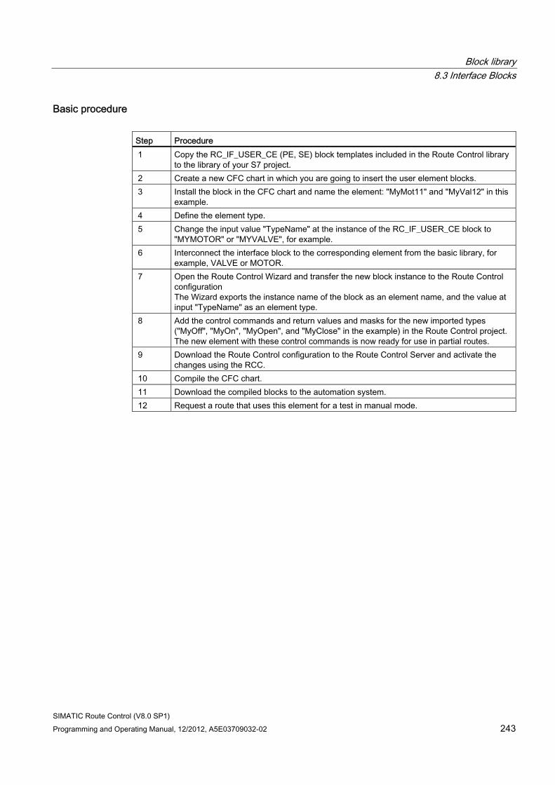
Block library 8.3 Interface Blocks
SIMATIC Route Control (V8.0 SP1) Programming and Operating Manual, 12/2012, A5E03709032-02 243
Basic procedure Step Procedure 1 Copy the RC_IF_USER_CE (PE, SE) block templates included in the Route Control library
to the library of your S7 project. 2 Create a new CFC chart in which you are going to insert the user element blocks. 3 Install the block in the CFC chart and name the element: "MyMot11" and "MyVal12" in this
example. 4 Define the element type. 5 Change the input value "TypeName" at the instance of the RC_IF_USER_CE block to
"MYMOTOR" or "MYVALVE", for example. 6 Interconnect the interface block to the corresponding element from the basic library, for
example, VALVE or MOTOR. 7 Open the Route Control Wizard and transfer the new block instance to the Route Control
configuration The Wizard exports the instance name of the block as an element name, and the value at input "TypeName" as an element type.
8 Add the control commands and return values and masks for the new imported types ("MyOff", "MyOn", "MyOpen", and "MyClose" in the example) in the Route Control project. The new element with these control commands is now ready for use in partial routes.
9 Download the Route Control configuration to the Route Control Server and activate the changes using the RCC.
10 Compile the CFC chart. 11 Download the compiled blocks to the automation system. 12 Request a route that uses this element for a test in manual mode.
Block library 8.3 Interface Blocks
SIMATIC Route Control (V8.0 SP1) 244 Programming and Operating Manual, 12/2012, A5E03709032-02
8.3.8 Generic user-defined elements
Introduction You can group elements that are technologically associated and always installed in the same partial route by means of a generic user-defined element (GE block). You can include standard elements such as RC_IF_VALVE and user-defined elements such as RC_IF_USER_CE in a GE block.
Nesting of GE blocks (GE block in GE block) is not supported.
The Route Control Wizard identifies these GE blocks and the elements they contain based on special user-defined attributes (UDA) and imports the elements as separate elements to Route Control Engineering.
As these elements reside in the same block, you must always install all elements of a GE block in a partial route.
Note
You run the risk of malfunctions if you ignore this rule.
Note No link elements
Link elements are not supported in GE blocks.
Description The I/O of the installed blocks you are going to interconnect with other blocks must be placed on the sheet bar of the GE block.
The "ID" inputs of all interface blocks you installed and the "TypeName" inputs of the inserted user-defined elements must be available for external programming at the GE block. You need the names of these GE block inputs to program the UDA.
A GE block header must contain the following UDAs:
UDA Value RC_type 'GE' RC_id_param Names of all GE block inputs at which you program the IDs of the elements
contained therein. Example with three elements: 'CE_ID, VV_ID, PE_ID'
The so-called ID input variables of the GE block must contain both the "RC_type" and "RC_subtype" UDAs.
Block library 8.3 Interface Blocks
SIMATIC Route Control (V8.0 SP1) Programming and Operating Manual, 12/2012, A5E03709032-02 245
The following table shows the values of these UDAs for each possible element:
Element RC_type RC_subtype RC_IF_MOT_REV 'CE' 'MOT_REV' RC_IF_MOT_SPED 'CE' 'MOT_SPED' RC_IF_VAL_MOT 'CE' 'VAL_MOT' RC_IF_MOTOR 'CE' 'MOTOR' RC_IF_VALVE 'CE' 'VALVE' RC_IF_SENSOR 'SE' 'SENSOR' RC_IF_CONDUCT 'SE' 'CONDUCTIVITY' RC_IF_VOLUME 'PE' 'VOLUME' RC_IF_TIMER 'PE' 'TIMER' RC_IF_USER_CE 'CE' 'IS_USER_ELEMENT' RC_IF_USER_SE 'SE' 'IS_USER_ELEMENT' RC_IF_USER_PE 'PE' 'IS_USER_ELEMENT'
The ID input variable for a user-defined element must contain a third UDA: "RC_Typ_Param".
In this UDA, enter the name of the input at the GE block at which you configure the "TypeName" input of the corresponding user-defined element, for example, 'CE_Name'.
Sample blocks and charts The RC Library V8.0 provides three block sources with identical functionality to serve as patterns or templates:
● "GE_AWLDE": STL with mnemonics and comments in German
● "GE_AWLEN": STL with mnemonics and comments in English
● "GE_SCL": SCL with comments in English
You generate the block FB "GE_AWLorSCL" by compiling one of these sources in the corresponding environment.
The CFC chart "GE_AWLorSCL" contains a textually interconnected instance of this FB.
The CFC chart "GE_CFC" shows how you can create a GE block as multiinstance block in CFC.
Block library 8.3 Interface Blocks
SIMATIC Route Control (V8.0 SP1) 246 Programming and Operating Manual, 12/2012, A5E03709032-02
Basic procedure for creating a GE Block in CFC Step Procedure 1 Create a new CFC chart. 2 Install the required RC_IF_xxx interface blocks. 3 Create the required chart connections. 4 Enter the UDAs in the ID input variables of the GE block in the "Attributes" tab of the
Object Properties dialog of the chart connections. 5 Interconnect the inputs and outputs with the chart connections. 6 Compile the CFC chart as a block type.
Enter the UDAs for the block header in the "Attributes" tab.
Configuration Step Procedure 1 Insert the GE block in a CFC chart. 2 Configure the inputs at which you define the names of the subtypes for the inserted user-
defined elements. 3 Interconnect the GE block with other blocks such as blocks from the PCS 7 standard
library, SC library or PTE library. 4 Start the Route Control Wizard.
The RC Wizard assigns unique IDs if the value "0" is set at the element IDs.
Generic elements in Route Control In Route Control, the elements of a GE block are assigned the name of the the GE block. In order to identify a specific element, the name of the input variables for the element ID is appended in parentheses to the block name, for example, (CE_ID).
Block library 8.3 Interface Blocks
SIMATIC Route Control (V8.0 SP1) Programming and Operating Manual, 12/2012, A5E03709032-02 247
8.3.9 Configuration and Cross-Coupling
8.3.9.1 Block Overview
Overview of Cross-Coupling Blocks The following blocks are available for cross-coupling:
Blocks Purpose RC_IF_CFG (FB850) (Page 247) Configuration of the AS-server coupling
Configuration of the AS-AS coupling (cross-coupling) RC_IF_XC_DIAG (FB 884) (Page 254) RC_IF_XC_LIFE (FC 884) (Page 260)
Diagnostics for cross-coupling
8.3.9.2 RC_IF_CFG (FB 850)
Description Insert this function block into an (RC configuration) CFC chart and program it once for each AS. The block receives the parameters of this AS and of the Route Control servers via its inputs. It also enables system blocks of the Route Control Library to be called in the AS. The sublevel blocks of the Route Control system which are needed to execute route control are then called from these blocks in the AS.
FB 850/RC_IF_CFG must be executed in a valid watchdog interrupt OB (OB 30 to OB 35). Position the block, therefore, on an appropriate sequence level. Due to its internal programming it is also called in OB 1, in the restart OBs OB 100/OB 101/OB 102, and in the error OBs OB 121/OB 122 of the corresponding AS.
To ensure communication with the RC server is fast enough, we recommend that FB 850/RC_IF_CFG is inserted in OB 35 (with 100 ms). This value must then also be available at the OB_KOMM input. All other Route Control system tasks can be executed in OB 1 cyclic operation. Therefore, you must select a value of 1 for both inputs OB_SYS and OB_XC.
Note
If you want to execute FB 850/RC_IF_CFG in a different watchdog interrupt OB (OB 30 to OB 34), you must insert it in the corresponding sequence group. However, please note that in such cases you will need to adapt the values at the OB_KOMM, OB_SYS, and OB_XC inputs to this new setting. These inputs can then only be programmed using the number of the watchdog interrupt OB in which you have placed FB 850/RC_IF_CFG, as well as OB 1.
In block RC_IF_CFG, the Route Control Wizard also automatically enters and configures the local communication IDs for the cross-coupling connections to the peer automation system.
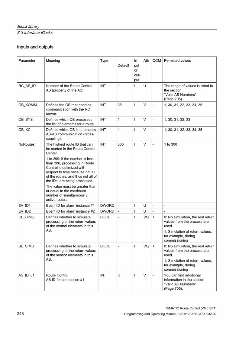
Block library 8.3 Interface Blocks
SIMATIC Route Control (V8.0 SP1) 248 Programming and Operating Manual, 12/2012, A5E03709032-02
Inputs and outputs Parameter Meaning Type
Default In-put or out-put
Attr OCM Permitted values
RC_AS_ID Number of the Route Control AS (property of the AS)
INT 1 I U - The range of values is listed in the section "Valid AS Numbers" (Page 705).
OB_KOMM Defines the OB that handles communication with the RC server.
INT 35 I V - 1, 30, 31, 32, 33, 34, 35
OB_SYS Defines which OB processes the list of elements for a route.
INT 1 I V - 1, 30, 31, 32, 33
OB_XC Defines which OB is to process AS-AS communication (cross-coupling).
INT 1 I V - 1, 30, 31, 32, 33, 34, 35
NoRoutes The highest route ID that can be started in the Route Control Center. 1 to 299: If the number is less than 300, processing in Route Control is optimized with respect to time because not all of the routes, and thus not all of the IDs, are being processed. The value must be greater than or equal to the maximum number of simultaneously active routes.
INT 300 I V - 1 to 300
EV_ID1 Event ID for alarm instance #1 DWORD - I U - - EV_ID2 Event ID for alarm instance #2 DWORD - I U - - CE_SIMU Defines whether to simulate
processing or the return values of the control elements in this AS.
BOOL - I VQ + 0: No simulation, the real return values from the process are used. 1: Simulation of return values, for example, during commissioning
SE_SIMU Defines whether to simulate processing or the return values of the sensor elements in this AS.
BOOL - I VQ + 0: No simulation, the real return values from the process are used. 1: Simulation of return values, for example, during commissioning
AS_ID_01 Route Control AS ID for connection #1
INT 0 I V - You can find additional information in the section "Valid AS Numbers" (Page 705).
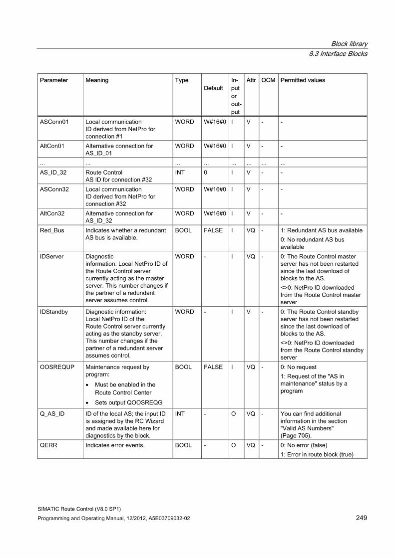
Block library 8.3 Interface Blocks
SIMATIC Route Control (V8.0 SP1) Programming and Operating Manual, 12/2012, A5E03709032-02 249
Parameter Meaning Type Default
In-put or out-put
Attr OCM Permitted values
ASConn01 Local communication ID derived from NetPro for connection #1
WORD W#16#0 I V - -
AltCon01 Alternative connection for AS_ID_01
WORD W#16#0 I V - -
... ... ... ... ... ... ... ... AS_ID_32 Route Control
AS ID for connection #32 INT 0 I V - -
ASConn32 Local communication ID derived from NetPro for connection #32
WORD W#16#0 I V - -
AltCon32 Alternative connection for AS_ID_32
WORD W#16#0 I V - -
Red_Bus Indicates whether a redundant AS bus is available.
BOOL FALSE I VQ - 1: Redundant AS bus available 0: No redundant AS bus available
IDServer Diagnostic information: Local NetPro ID of the Route Control server currently acting as the master server. This number changes if the partner of a redundant server assumes control.
WORD - I VQ - 0: The Route Control master server has not been restarted since the last download of blocks to the AS. <>0: NetPro ID downloaded from the Route Control master server
IDStandby Diagnostic information: Local NetPro ID of the Route Control server currently acting as the standby server. This number changes if the partner of a redundant server assumes control.
WORD - I V - 0: The Route Control standby server has not been restarted since the last download of blocks to the AS. <>0: NetPro ID downloaded from the Route Control standby server
OOSREQUP Maintenance request by program: • Must be enabled in the
Route Control Center • Sets output QOOSREQG
BOOL FALSE I VQ - 0: No request 1: Request of the "AS in maintenance" status by a program
Q_AS_ID ID of the local AS; the input ID is assigned by the RC Wizard and made available here for diagnostics by the block.
INT - O VQ - You can find additional information in the section "Valid AS Numbers" (Page 705).
QERR Indicates error events. BOOL - O VQ - 0: No error (false) 1: Error in route block (true)
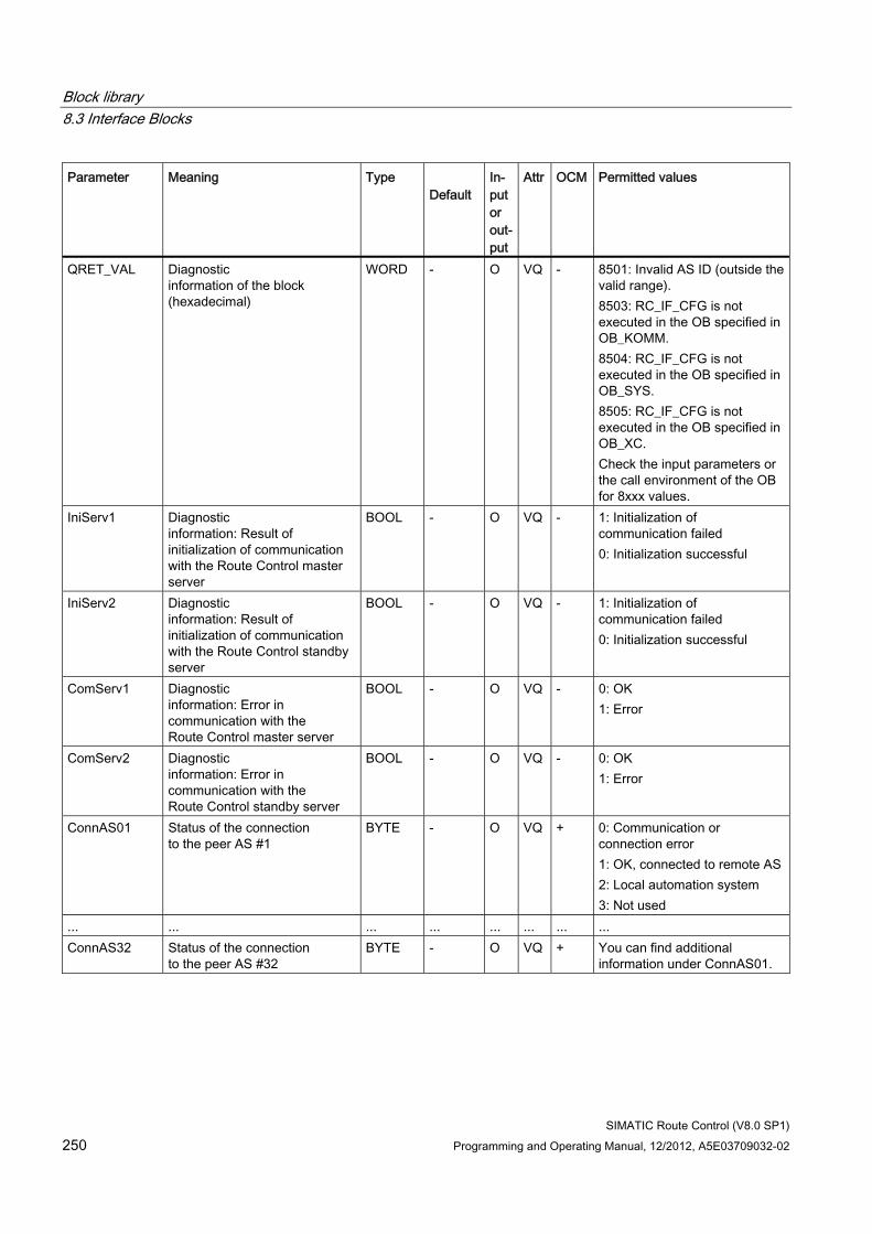
Block library 8.3 Interface Blocks
SIMATIC Route Control (V8.0 SP1) 250 Programming and Operating Manual, 12/2012, A5E03709032-02
Parameter Meaning Type Default
In-put or out-put
Attr OCM Permitted values
QRET_VAL Diagnostic information of the block (hexadecimal)
WORD - O VQ - 8501: Invalid AS ID (outside the valid range). 8503: RC_IF_CFG is not executed in the OB specified in OB_KOMM. 8504: RC_IF_CFG is not executed in the OB specified in OB_SYS. 8505: RC_IF_CFG is not executed in the OB specified in OB_XC. Check the input parameters or the call environment of the OB for 8xxx values.
IniServ1 Diagnostic information: Result of initialization of communication with the Route Control master server
BOOL - O VQ - 1: Initialization of communication failed 0: Initialization successful
IniServ2 Diagnostic information: Result of initialization of communication with the Route Control standby server
BOOL - O VQ - 1: Initialization of communication failed 0: Initialization successful
ComServ1 Diagnostic information: Error in communication with the Route Control master server
BOOL - O VQ - 0: OK 1: Error
ComServ2 Diagnostic information: Error in communication with the Route Control standby server
BOOL - O VQ - 0: OK 1: Error
ConnAS01 Status of the connection to the peer AS #1
BYTE - O VQ + 0: Communication or connection error 1: OK, connected to remote AS 2: Local automation system 3: Not used
... ... ... ... ... ... ... ... ConnAS32 Status of the connection
to the peer AS #32 BYTE - O VQ + You can find additional
information under ConnAS01.
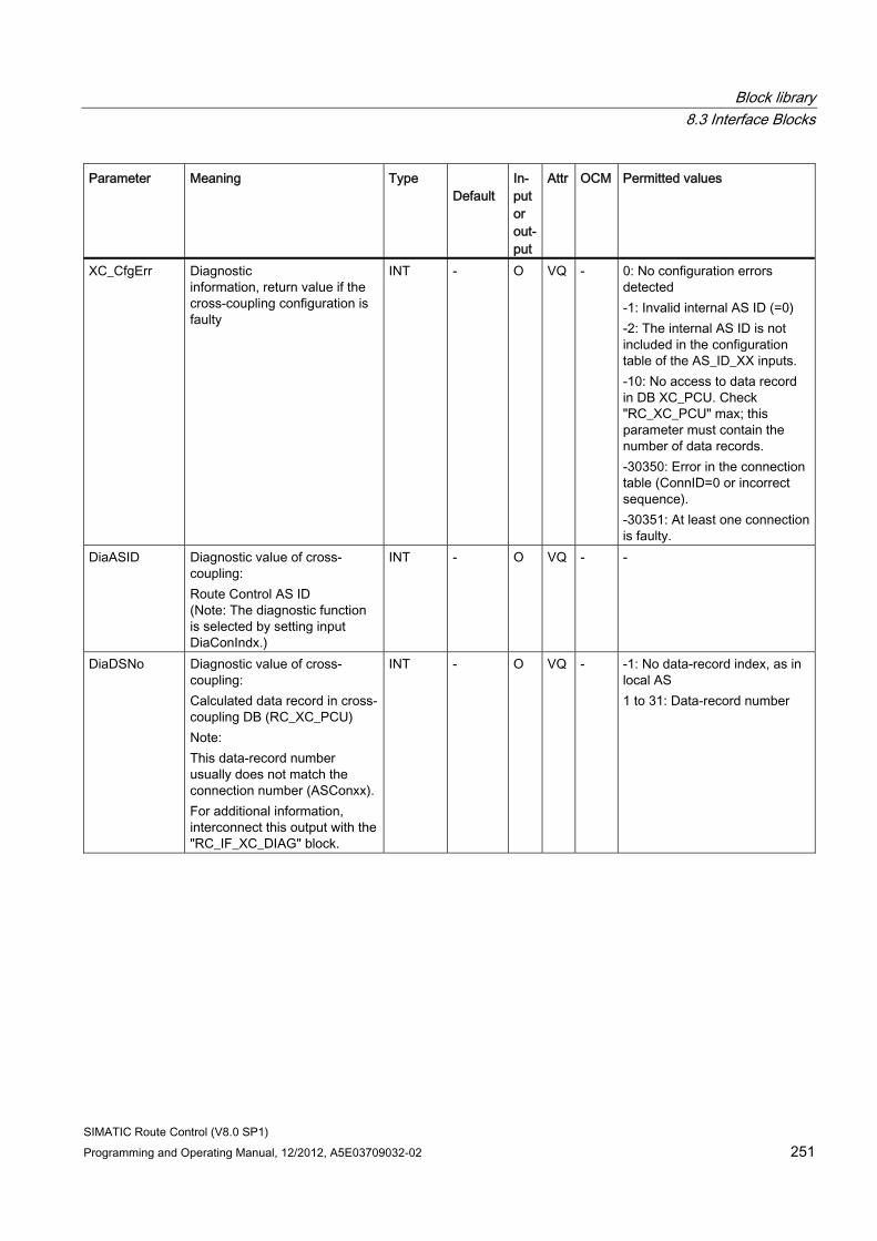
Block library 8.3 Interface Blocks
SIMATIC Route Control (V8.0 SP1) Programming and Operating Manual, 12/2012, A5E03709032-02 251
Parameter Meaning Type Default
In-put or out-put
Attr OCM Permitted values
XC_CfgErr Diagnostic information, return value if the cross-coupling configuration is faulty
INT - O VQ - 0: No configuration errors detected -1: Invalid internal AS ID (=0) -2: The internal AS ID is not included in the configuration table of the AS_ID_XX inputs. -10: No access to data record in DB XC_PCU. Check "RC_XC_PCU" max; this parameter must contain the number of data records. -30350: Error in the connection table (ConnID=0 or incorrect sequence). -30351: At least one connection is faulty.
DiaASID Diagnostic value of cross-coupling: Route Control AS ID (Note: The diagnostic function is selected by setting input DiaConIndx.)
INT - O VQ - -
DiaDSNo Diagnostic value of cross-coupling: Calculated data record in cross-coupling DB (RC_XC_PCU) Note: This data-record number usually does not match the connection number (ASConxx). For additional information, interconnect this output with the "RC_IF_XC_DIAG" block.
INT - O VQ - -1: No data-record index, as in local AS 1 to 31: Data-record number
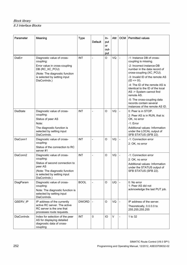
Block library 8.3 Interface Blocks
SIMATIC Route Control (V8.0 SP1) 252 Programming and Operating Manual, 12/2012, A5E03709032-02
Parameter Meaning Type Default
In-put or out-put
Attr OCM Permitted values
DiaErr Diagnostic value of cross-coupling: Error value in cross-coupling DB (RC_XC_PCU) (Note: The diagnostic function is selected by setting input DiaConIndx.)
INT - O VQ - -1: Instance DB of cross-coupling is missing. -2: Incorrect instance-DB number in the data record of cross-coupling (XC_PCU). -3: Invalid ID of the remote AS (ID <= 0!). -4: The ID of the remote AS is identical to the ID of the local AS -> System cannot find remote AS. -5: The cross-coupling data records contain several instances of the remote AS ID.
DiaState Diagnostic value of cross-coupling: Status of peer AS Note: The diagnostic function is selected by setting input DiaConIndx.
INT - O VQ - 0: Peer is in STOP. 2: Peer AS is in RUN, that is: OK, no error -1: Error Additional values: Information under the LOCAL output of SFB STATUS (SFB 22).
DiaConn1 Diagnostic value of cross-coupling: Status of the connection to RC server #1
INT - O VQ - -1: Connection error 2: OK, no error
DiaConn2 Diagnostic value of cross-coupling: Status of second connection to peer AS (Note: The diagnostic function is selected by setting input DiaConIndx.)
INT - O VQ - -1: Connection error 2: OK, no error Additional values: Information under the STATUS output of SFB STATUS (SFB 22).
DiagParam Diagnostic value of cross-coupling: Note: The diagnostic function is selected by setting input DiaConIndx.
BOOL - O UQ - 0: No error 1: Peer AS did not acknowledge the last PUT job.
QSERV_IP IP address of the currently active RC server. The active RC server is the one that processes route requests.
DWORD - O VQ - IP address of the server. Theoretically, 0.0.0.0 to 255.255.255.255
DiaConIndx Index for selection of the peer AS for displaying detailed diagnostic data of cross-coupling
INT 0 IO V - 1 to 32
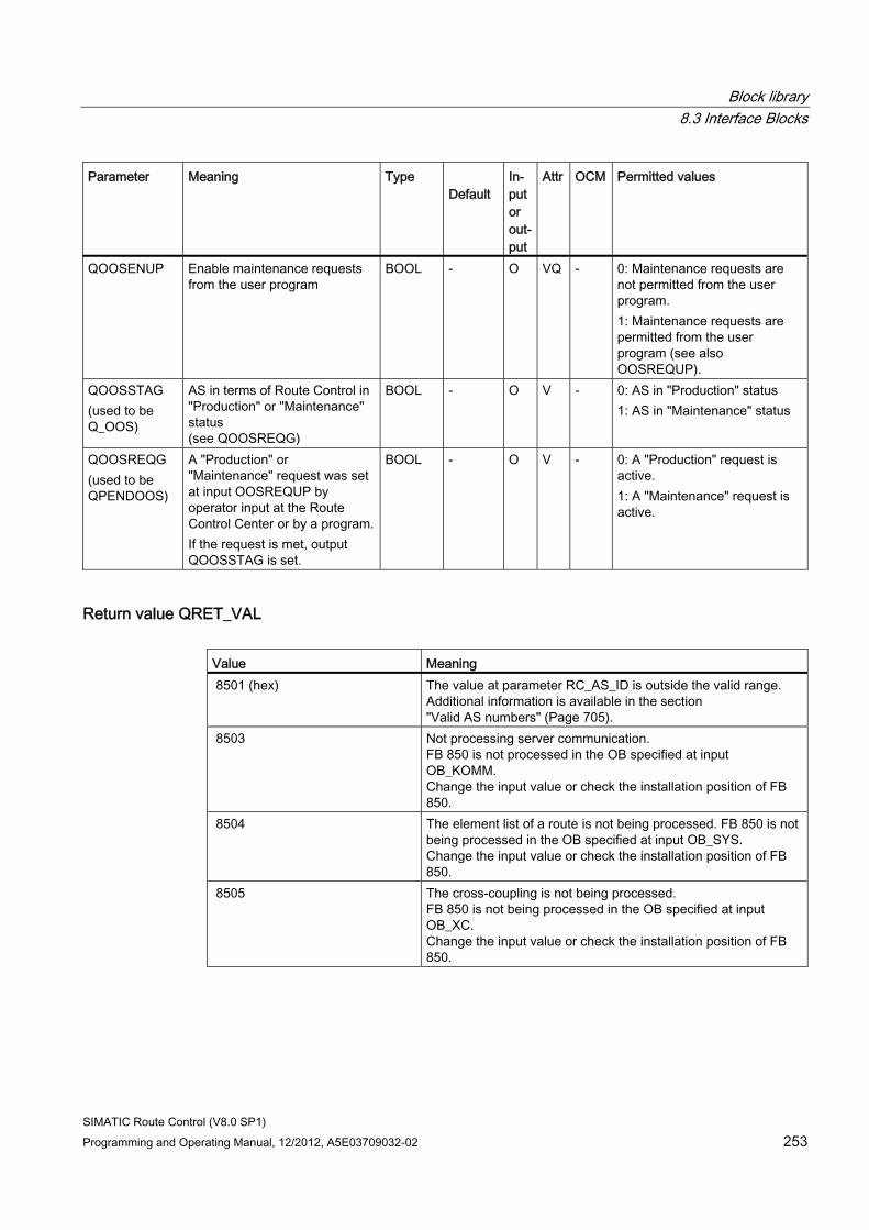
Block library 8.3 Interface Blocks
SIMATIC Route Control (V8.0 SP1) Programming and Operating Manual, 12/2012, A5E03709032-02 253
Parameter Meaning Type Default
In-put or out-put
Attr OCM Permitted values
QOOSENUP Enable maintenance requests from the user program
BOOL - O VQ - 0: Maintenance requests are not permitted from the user program. 1: Maintenance requests are permitted from the user program (see also OOSREQUP).
QOOSSTAG (used to be Q_OOS)
AS in terms of Route Control in "Production" or "Maintenance" status (see QOOSREQG)
BOOL - O V - 0: AS in "Production" status 1: AS in "Maintenance" status
QOOSREQG (used to be QPENDOOS)
A "Production" or "Maintenance" request was set at input OOSREQUP by operator input at the Route Control Center or by a program.If the request is met, output QOOSSTAG is set.
BOOL - O V - 0: A "Production" request is active. 1: A "Maintenance" request is active.
Return value QRET_VAL Value Meaning 8501 (hex) The value at parameter RC_AS_ID is outside the valid range.
Additional information is available in the section "Valid AS numbers" (Page 705).
8503 Not processing server communication. FB 850 is not processed in the OB specified at input OB_KOMM. Change the input value or check the installation position of FB 850.
8504 The element list of a route is not being processed. FB 850 is not being processed in the OB specified at input OB_SYS. Change the input value or check the installation position of FB 850.
8505 The cross-coupling is not being processed. FB 850 is not being processed in the OB specified at input OB_XC. Change the input value or check the installation position of FB 850.
Block library 8.3 Interface Blocks
SIMATIC Route Control (V8.0 SP1) 254 Programming and Operating Manual, 12/2012, A5E03709032-02
Configuration Step Procedure 1 Create a new CFC chart in an AS 2 Copy the sample chart from the Route Control library to your project 3 Program input RC_AS_ID.
The valid range of values is defined in the section "Valid AS Numbers" (Page 705).
4 Start the Route Control Wizard. The local communication IDs for AS-AS connections (cross-coupling) to the peer ASs are entered automatically. To activate this step, see the Route Control Wizard dialog box in the section "Actions of the Route Control Wizard" (Page 451).
CAUTION As the SFB PUT saves the connection ID passed during the initial call, an AS restart is required each time the connection ID is changed (inputs ASConn01 to ASConn32 or AltCon01 to AltCon32). SFB PUT continues transmission with the old connection ID and to the wrong peer AS if you do not restart the AS.
8.3.9.3 RC_IF_XC_DIAG (FB 884)
Description This block is a diagnostic block for Route Control that provides detailed information about the status of the AS-AS connections to another partner automation system (cross-coupling). This function block is inserted centrally once for each AS and interconnected with RC_IF_CFG.
You only need to insert this block if you want to obtain diagnostic information about AS-AS communication. The function block should be inserted following RC_IF_CFG in the runtime group (OB) in which AS-AS communication (cross-coupling) is being processed.
You can find additional information under OB_XC of RC_IF_CFG.
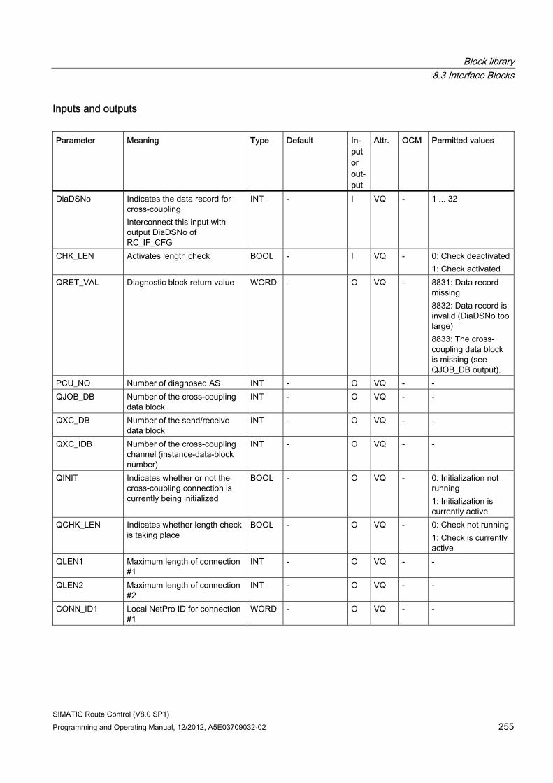
Block library 8.3 Interface Blocks
SIMATIC Route Control (V8.0 SP1) Programming and Operating Manual, 12/2012, A5E03709032-02 255
Inputs and outputs Parameter Meaning Type Default In-
put or out-put
Attr. OCM Permitted values
DiaDSNo Indicates the data record for cross-coupling Interconnect this input with output DiaDSNo of RC_IF_CFG
INT - I VQ - 1 ... 32
CHK_LEN Activates length check BOOL - I VQ - 0: Check deactivated1: Check activated
QRET_VAL Diagnostic block return value WORD - O VQ - 8831: Data record missing 8832: Data record is invalid (DiaDSNo too large) 8833: The cross-coupling data block is missing (see QJOB_DB output).
PCU_NO Number of diagnosed AS INT - O VQ - - QJOB_DB Number of the cross-coupling
data block INT - O VQ - -
QXC_DB Number of the send/receive data block
INT - O VQ - -
QXC_IDB Number of the cross-coupling channel (instance-data-block number)
INT - O VQ - -
QINIT Indicates whether or not the cross-coupling connection is currently being initialized
BOOL - O VQ - 0: Initialization not running 1: Initialization is currently active
QCHK_LEN Indicates whether length check is taking place
BOOL - O VQ - 0: Check not running 1: Check is currently active
QLEN1 Maximum length of connection #1
INT - O VQ - -
QLEN2 Maximum length of connection #2
INT - O VQ - -
CONN_ID1 Local NetPro ID for connection #1
WORD - O VQ - -
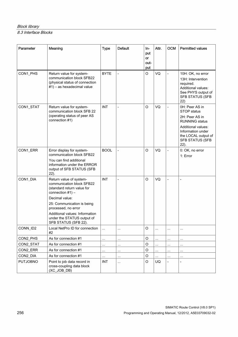
Block library 8.3 Interface Blocks
SIMATIC Route Control (V8.0 SP1) 256 Programming and Operating Manual, 12/2012, A5E03709032-02
Parameter Meaning Type Default In-put or out-put
Attr. OCM Permitted values
CON1_PHS Return value for system-communication block SFB22 (physical status of connection #1) – as hexadecimal value
BYTE - O VQ - 10H: OK, no error 13H: Intervention required. Additional values: See PHYS output of SFB STATUS (SFB 22)
CON1_STAT Return value for system-communication block SFB 22 (operating status of peer AS connection #1)
INT - O VQ - 0H: Peer AS in STOP status 2H: Peer AS in RUNNING status Additional values: Information under the LOCAL output of SFB STATUS (SFB 22).
CON1_ERR Error display for system-communication block SFB22 You can find additional information under the ERROR output of SFB STATUS (SFB 22).
BOOL - O VQ - 0: OK, no error 1: Error
CON1_DIA Return value of system-communication block SFB22 (standard return value for connection #1) – Decimal value: 25: Communication is being processed, no error Additional values: Information under the STATUS output of SFB STATUS (SFB 22).
INT - O VQ - -
CONN_ID2 Local NetPro ID for connection #2
... ... O ... ... ...
CON2_PHS As for connection #1 ... ... O ... ... ... CON2_STAT As for connection #1 ... ... O ... ... ... CON2_ERR As for connection #1 ... ... O ... ... ... CON2_DIA As for connection #1 ... ... O ... ... ... PUTJOBNO Point to job data record in
cross-coupling data block (XC_JOB_DB)
INT ... O UQ - -
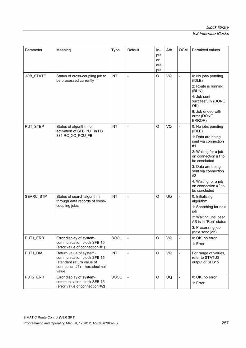
Block library 8.3 Interface Blocks
SIMATIC Route Control (V8.0 SP1) Programming and Operating Manual, 12/2012, A5E03709032-02 257
Parameter Meaning Type Default In-put or out-put
Attr. OCM Permitted values
JOB_STATE Status of cross-coupling job to be processed currently
INT - O VQ - 0: No jobs pending (IDLE) 2: Route is running (RUN) 4: Job sent successfully (DONE OK) 8: Job ended with error (DONE ERROR)
PUT_STEP Status of algorithm for activation of SFB PUT in FB 881 RC_XC_PCU_FB
INT - O VQ - 0: No jobs pending (IDLE) 1: Data are being sent via connection #1 2: Waiting for a job on connection #1 to be concluded 3: Data are being sent via connection #2 4: Waiting for a job on connection #2 to be concluded
SEARC_STP Status of search algorithm through data records of cross-coupling jobs:
INT - O UQ - 0: Initializing algorithm 1: Searching for next job 2: Waiting until peer AS is in "Run" status 3: Processing job (next send job)
PUT1_ERR Error display of system-communication block SFB 15 (error value of connection #1)
BOOL - O VQ - 0: OK, no error 1: Error
PUT1_DIA Return value of system-communication block SFB 15 (standard return value of connection #1) – hexadecimal value
INT - O VQ - For range of values, refer to STATUS output of SFB15
PUT2_ERR Error display of system-communication block SFB 15 (error value of connection #2)
BOOL - O UQ - 0: OK, no error 1: Error
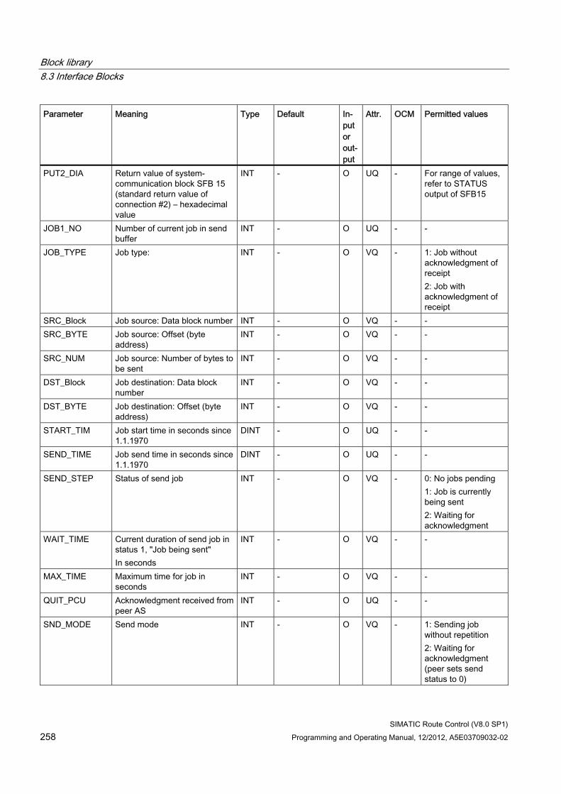
Block library 8.3 Interface Blocks
SIMATIC Route Control (V8.0 SP1) 258 Programming and Operating Manual, 12/2012, A5E03709032-02
Parameter Meaning Type Default In-put or out-put
Attr. OCM Permitted values
PUT2_DIA Return value of system-communication block SFB 15 (standard return value of connection #2) – hexadecimal value
INT - O UQ - For range of values, refer to STATUS output of SFB15
JOB1_NO Number of current job in send buffer
INT - O UQ - -
JOB_TYPE Job type: INT - O VQ - 1: Job without acknowledgment of receipt 2: Job with acknowledgment of receipt
SRC_Block Job source: Data block number INT - O VQ - - SRC_BYTE Job source: Offset (byte
address) INT - O VQ - -
SRC_NUM Job source: Number of bytes to be sent
INT - O VQ - -
DST_Block Job destination: Data block number
INT - O VQ - -
DST_BYTE Job destination: Offset (byte address)
INT - O VQ - -
START_TIM Job start time in seconds since 1.1.1970
DINT - O UQ - -
SEND_TIME Job send time in seconds since 1.1.1970
DINT - O UQ - -
SEND_STEP Status of send job INT - O VQ - 0: No jobs pending 1: Job is currently being sent 2: Waiting for acknowledgment
WAIT_TIME Current duration of send job in status 1, "Job being sent" In seconds
INT - O VQ - -
MAX_TIME Maximum time for job in seconds
INT - O VQ - -
QUIT_PCU Acknowledgment received from peer AS
INT - O UQ - -
SND_MODE Send mode INT - O VQ - 1: Sending job without repetition 2: Waiting for acknowledgment (peer sets send status to 0)
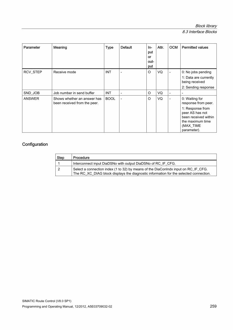
Block library 8.3 Interface Blocks
SIMATIC Route Control (V8.0 SP1) Programming and Operating Manual, 12/2012, A5E03709032-02 259
Parameter Meaning Type Default In-put or out-put
Attr. OCM Permitted values
RCV_STEP Receive mode INT - O VQ - 0: No jobs pending 1: Data are currently being received 2: Sending response
SND_JOB Job number in send buffer INT - O VQ - - ANSWER Shows whether an answer has
been received from the peer. BOOL - O VQ - 0: Waiting for
response from peer. 1: Response from peer AS has not been received within the maximum time (MAX_TIME parameter).
Configuration Step Procedure 1 Interconnect input DiaDSNo with output DiaDSNo of RC_IF_CFG. 2 Select a connection index (1 to 32) by means of the DiaConIndx input on RC_IF_CFG.
The RC_XC_DIAG block displays the diagnostic information for the selected connection.
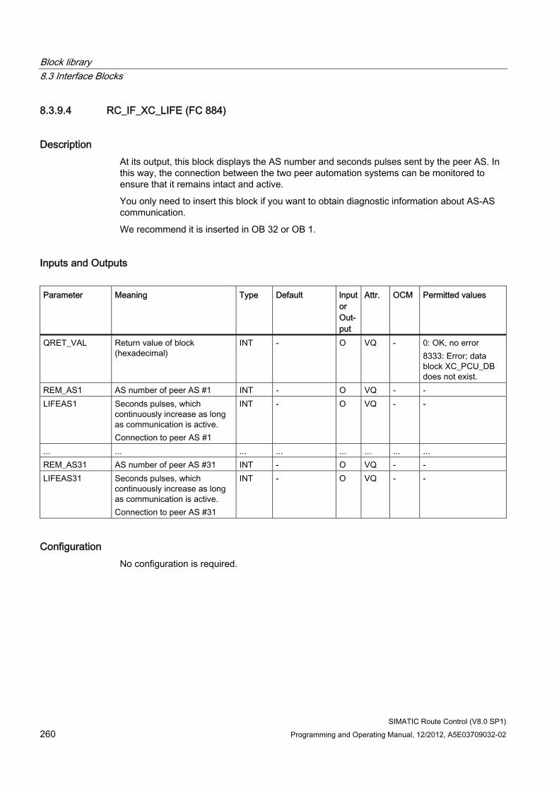
Block library 8.3 Interface Blocks
SIMATIC Route Control (V8.0 SP1) 260 Programming and Operating Manual, 12/2012, A5E03709032-02
8.3.9.4 RC_IF_XC_LIFE (FC 884)
Description At its output, this block displays the AS number and seconds pulses sent by the peer AS. In this way, the connection between the two peer automation systems can be monitored to ensure that it remains intact and active.
You only need to insert this block if you want to obtain diagnostic information about AS-AS communication.
We recommend it is inserted in OB 32 or OB 1.
Inputs and Outputs Parameter Meaning Type Default lnput
or Out-put
Attr. OCM Permitted values
QRET_VAL Return value of block (hexadecimal)
INT - O VQ - 0: OK, no error 8333: Error; data block XC_PCU_DB does not exist.
REM_AS1 AS number of peer AS #1 INT - O VQ - - LIFEAS1 Seconds pulses, which
continuously increase as long as communication is active. Connection to peer AS #1
INT - O VQ - -
... ... ... ... ... ... ... ... REM_AS31 AS number of peer AS #31 INT - O VQ - - LIFEAS31 Seconds pulses, which
continuously increase as long as communication is active. Connection to peer AS #31
INT - O VQ - -
Configuration No configuration is required.
Block library 8.3 Interface Blocks
SIMATIC Route Control (V8.0 SP1) Programming and Operating Manual, 12/2012, A5E03709032-02 261
8.3.10 REMOTE blocks
8.3.10.1 Overview of REMOTE blocks
Note
These REMOTE blocks are only required for communication between automation systems from different projects.
REMOTE blocks Blocks for REMOTE elements are used when route elements from another project are to be used.
The following REMOTE blocks are available for elements:
● RC_IF_REMOTE_CE (FB821) (Page 263) for control elements
● RC_IF_REMOTE_SE (FB842) (Page 266) for sensor elements
● RC_IF_REMOTE_PE (FB 843) (Page 269) for parameter elements
Two additional communication blocks are required for data exchange with the remote automation system that contains the remote elements:
● RC_IF_REMOTE_SEND (FB 831) (Page 273)
● RC_IF_REMOTE_RECV (FB833) (Page 276)
For remote operation of controls, parameter and sensor elements, only the most important element data is transmitted between the controlling and connected remote element. Consequently, in contrast to local mode, not all outputs can be controlled on the connected remote element.
On the connected remote element, the number of the DB used for data transmission is multiplied by -1 and output at the QFUNC_ID output as an identifier for the remote control.
Example Section "CFC Charts with REMOTE Elements" (Page 362)
Block library 8.3 Interface Blocks
SIMATIC Route Control (V8.0 SP1) 262 Programming and Operating Manual, 12/2012, A5E03709032-02
8.3.10.2 Diagnostics If a remote element is not available for a route, the route signals an error. Only the local ID of the respective element is displayed in the Route Control Center.
To search for the associated remote ID of a remote element, use the attribute "s7_edit = para" of the input parameters LOC_xE and REM_xE of the following blocks:
● RC_IF_REMOTE_CE
● RC_IF_REMOTE_SE
● RC_IF_REMOTE_PE
The attribute "s7_edit = para" is available as of RC version 8.0 SP1. Use the attribute "s7_edit = para" to display input parameters LOC_xE and REM_xE in the "Parameters" tab of the process object view of SIMATIC Manager.
If you set the filter to "Block type" / "RC_IF_REMOTE", all instances of the blocks RC_IF_REMOTE_CE, RC_IF_REMOTE_SE and RC_IF_REMOTE_PE with the input parameters LOC_xE and REM_xE are displayed. This way you assign the remote ID to the local ID.
Note
The new attribute will only become active with new CFC instances of the blocks RC_IF_REMOTE_CE, RC_IF_REMOTE_SE and RC_IF_REMOTE_PE. Existing instances are not changed by the CFC block type import.
You can also set the "Parameter" attribute manually. To do so, open the properties of a corresponding input parameter of a CFC instance, for example, REM_CE, and activate the option "Parameter" in the "Process object view" area.
See also RC_IF_REMOTE_CE (FB 821) (Page 263)
RC_IF_REMOTE_SE (FB 842) (Page 266)
RC_IF_REMOTE_PE (FB 843) (Page 269)
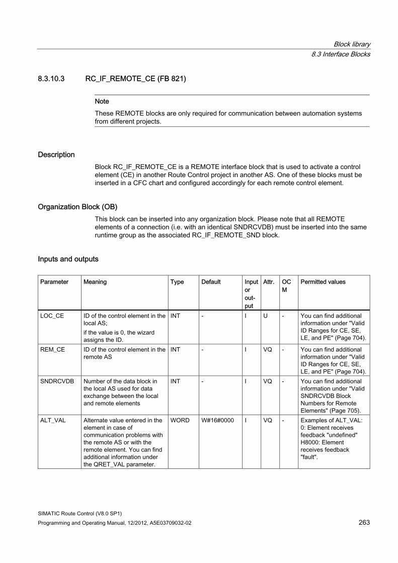
Block library 8.3 Interface Blocks
SIMATIC Route Control (V8.0 SP1) Programming and Operating Manual, 12/2012, A5E03709032-02 263
8.3.10.3 RC_IF_REMOTE_CE (FB 821)
Note
These REMOTE blocks are only required for communication between automation systems from different projects.
Description Block RC_IF_REMOTE_CE is a REMOTE interface block that is used to activate a control element (CE) in another Route Control project in another AS. One of these blocks must be inserted in a CFC chart and configured accordingly for each remote control element.
Organization Block (OB) This block can be inserted into any organization block. Please note that all REMOTE elements of a connection (i.e. with an identical SNDRCVDB) must be inserted into the same runtime group as the associated RC_IF_REMOTE_SND block.
Inputs and outputs Parameter Meaning Type Default Input
or out-put
Attr. OCM
Permitted values
LOC_CE ID of the control element in the local AS; if the value is 0, the wizard assigns the ID.
INT - I U - You can find additional information under "Valid ID Ranges for CE, SE, LE, and PE" (Page 704).
REM_CE ID of the control element in the remote AS
INT - I VQ - You can find additional information under "Valid ID Ranges for CE, SE, LE, and PE" (Page 704).
SNDRCVDB Number of the data block in the local AS used for data exchange between the local and remote elements
INT - I VQ - You can find additional information under "Valid SNDRCVDB Block Numbers for Remote Elements" (Page 705).
ALT_VAL Alternate value entered in the element in case of communication problems with the remote AS or with the remote element. You can find additional information under the QRET_VAL parameter.
WORD W#16#0000 I VQ - Examples of ALT_VAL: 0: Element receives feedback "undefined" H8000: Element receives feedback "fault".
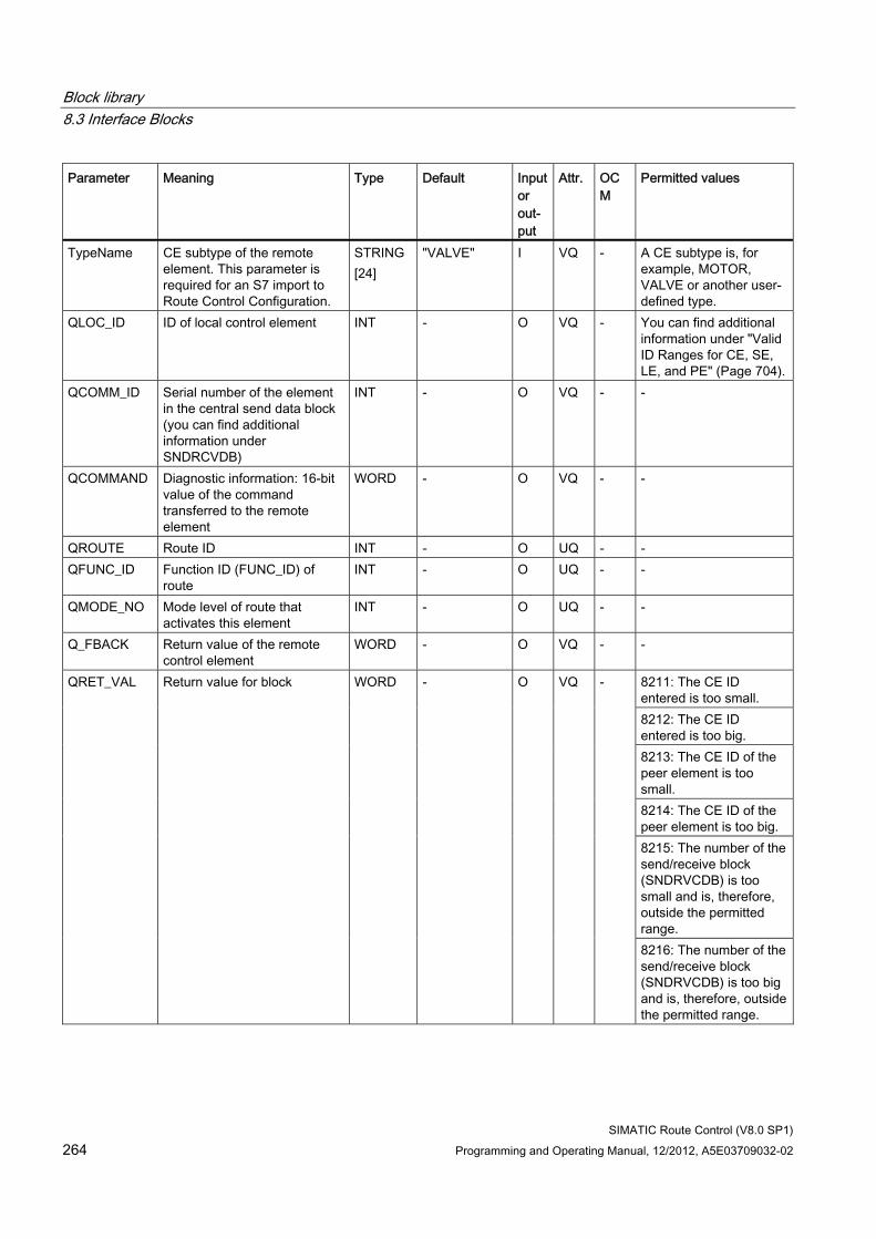
Block library 8.3 Interface Blocks
SIMATIC Route Control (V8.0 SP1) 264 Programming and Operating Manual, 12/2012, A5E03709032-02
Parameter Meaning Type Default Input or out-put
Attr. OCM
Permitted values
TypeName CE subtype of the remote element. This parameter is required for an S7 import to Route Control Configuration.
STRING [24]
"VALVE" I VQ - A CE subtype is, for example, MOTOR, VALVE or another user-defined type.
QLOC_ID ID of local control element INT - O VQ - You can find additional information under "Valid ID Ranges for CE, SE, LE, and PE" (Page 704).
QCOMM_ID Serial number of the element in the central send data block (you can find additional information under SNDRCVDB)
INT - O VQ - -
QCOMMAND Diagnostic information: 16-bit value of the command transferred to the remote element
WORD - O VQ - -
QROUTE Route ID INT - O UQ - - QFUNC_ID Function ID (FUNC_ID) of
route INT - O UQ - -
QMODE_NO Mode level of route that activates this element
INT - O UQ - -
Q_FBACK Return value of the remote control element
WORD - O VQ - -
8211: The CE ID entered is too small. 8212: The CE ID entered is too big. 8213: The CE ID of the peer element is too small. 8214: The CE ID of the peer element is too big. 8215: The number of the send/receive block (SNDRVCDB) is too small and is, therefore, outside the permitted range.
QRET_VAL Return value for block WORD - O VQ -
8216: The number of the send/receive block (SNDRVCDB) is too big and is, therefore, outside the permitted range.
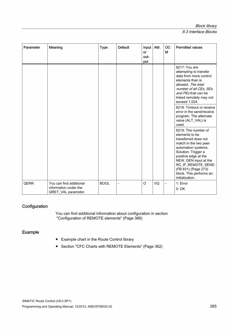
Block library 8.3 Interface Blocks
SIMATIC Route Control (V8.0 SP1) Programming and Operating Manual, 12/2012, A5E03709032-02 265
Parameter Meaning Type Default Input or out-put
Attr. OCM
Permitted values
8217: You are attempting to transfer data from more control elements than is allowed. The total number of all CEs, SEs and PEs that can be linked remotely may not exceed 1,024. 8218: Timeout or receive error in the send/receive program. The alternate value (ALT_VAL) is used. 8219: The number of elements to be transferred does not match in the two peer automation systems. Solution: Trigger a positive edge at the NEW_GEN input at the RC_IF_REMOTE_SEND (FB 831) (Page 273) block. This performs an initialization.
QERR You can find additional information under the QRET_VAL parameter.
BOOL - O VQ - 1: Error 0: OK
Configuration You can find additional information about configuration in section "Configuration of REMOTE elements" (Page 366)
Example ● Example chart in the Route Control library
● Section "CFC Charts with REMOTE Elements" (Page 362)
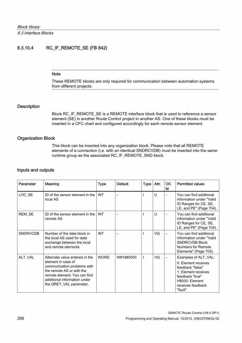
Block library 8.3 Interface Blocks
SIMATIC Route Control (V8.0 SP1) 266 Programming and Operating Manual, 12/2012, A5E03709032-02
8.3.10.4 RC_IF_REMOTE_SE (FB 842)
Note
These REMOTE blocks are only required for communication between automation systems from different projects.
Description Block RC_IF_REMOTE_SE is a REMOTE interface block that is used to reference a sensor element (SE) in another Route Control project in another AS. One of these blocks must be inserted in a CFC chart and configured accordingly for each remote sensor element.
Organization Block This block can be inserted into any organization block. Please note that all REMOTE elements of a connection (i.e. with an identical SNDRCVDB) must be inserted into the same runtime group as the associated RC_IF_REMOTE_SND block.
Inputs and outputs Parameter Meaning Type Default Type Attr. OC
M Permitted values
LOC_SE ID of the sensor element in the local AS
INT - I U - You can find additional information under "Valid ID Ranges for CE, SE, LE, and PE" (Page 704).
REM_SE ID of the sensor element in the remote AS
INT - I U - You can find additional information under "Valid ID Ranges for CE, SE, LE, and PE" (Page 704).
SNDRVCDB Number of the data block in the local AS used for data exchange between the local and remote elements
INT - I VQ - You can find additional information under "Valid SNDRCVDB Block Numbers for Remote Elements" (Page 705).
ALT_VAL Alternate value entered in the element in case of communication problems with the remote AS or with the remote element. You can find additional information under the QRET_VAL parameter.
WORD W#16#0000 I VQ - Examples of ALT_VAL: 0: Element receives feedback "false" 1: Element receives feedback "true" H8000: Element receives feedback "fault".
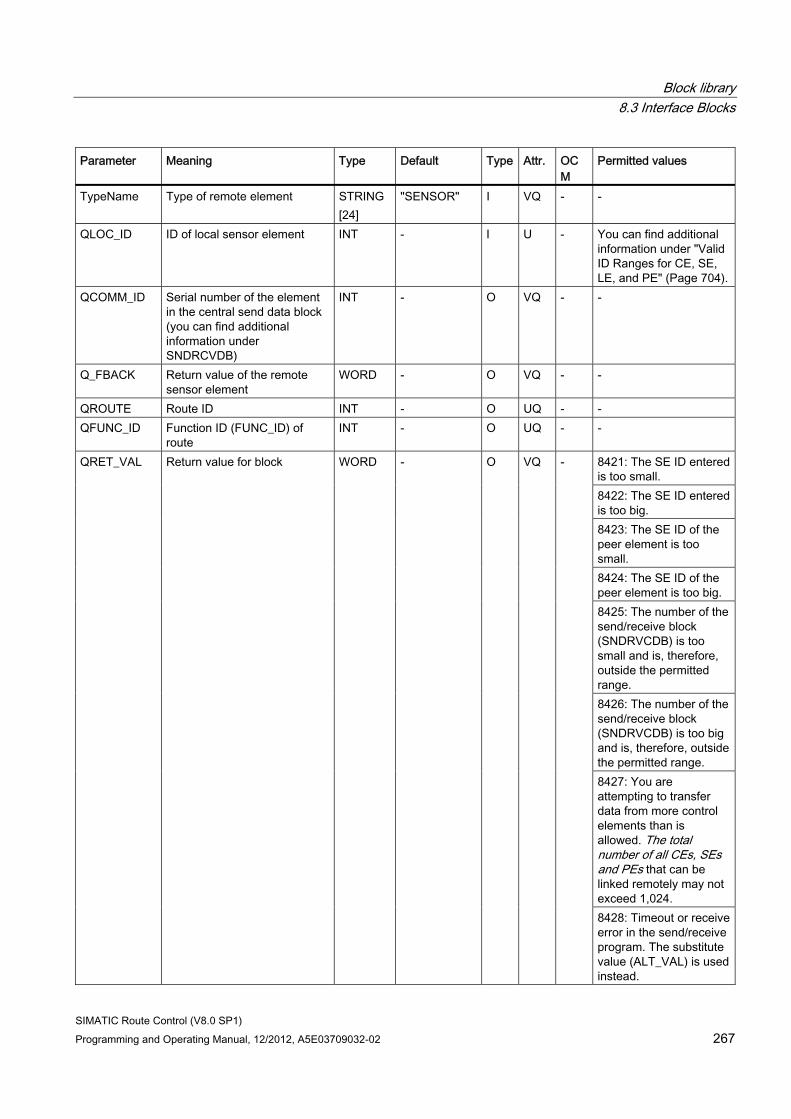
Block library 8.3 Interface Blocks
SIMATIC Route Control (V8.0 SP1) Programming and Operating Manual, 12/2012, A5E03709032-02 267
Parameter Meaning Type Default Type Attr. OCM
Permitted values
TypeName Type of remote element STRING [24]
"SENSOR" I VQ - -
QLOC_ID ID of local sensor element INT - I U - You can find additional information under "Valid ID Ranges for CE, SE, LE, and PE" (Page 704).
QCOMM_ID Serial number of the element in the central send data block (you can find additional information under SNDRCVDB)
INT - O VQ - -
Q_FBACK Return value of the remote sensor element
WORD - O VQ - -
QROUTE Route ID INT - O UQ - - QFUNC_ID Function ID (FUNC_ID) of
route INT - O UQ - -
8421: The SE ID entered is too small. 8422: The SE ID entered is too big. 8423: The SE ID of the peer element is too small. 8424: The SE ID of the peer element is too big. 8425: The number of the send/receive block (SNDRVCDB) is too small and is, therefore, outside the permitted range. 8426: The number of the send/receive block (SNDRVCDB) is too big and is, therefore, outside the permitted range. 8427: You are attempting to transfer data from more control elements than is allowed. The total number of all CEs, SEs and PEs that can be linked remotely may not exceed 1,024.
QRET_VAL Return value for block WORD - O VQ -
8428: Timeout or receive error in the send/receive program. The substitute value (ALT_VAL) is used instead.
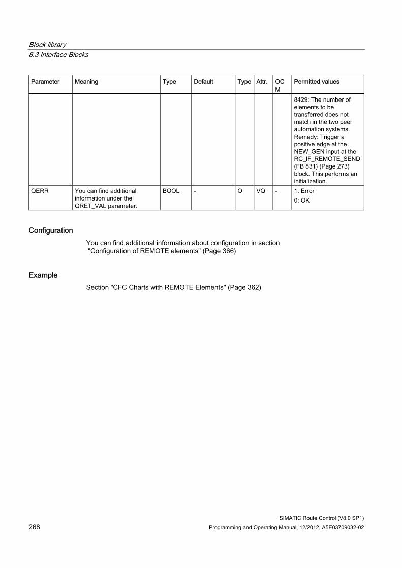
Block library 8.3 Interface Blocks
SIMATIC Route Control (V8.0 SP1) 268 Programming and Operating Manual, 12/2012, A5E03709032-02
Parameter Meaning Type Default Type Attr. OCM
Permitted values
8429: The number of elements to be transferred does not match in the two peer automation systems. Remedy: Trigger a positive edge at the NEW_GEN input at the RC_IF_REMOTE_SEND (FB 831) (Page 273) block. This performs an initialization.
QERR You can find additional information under the QRET_VAL parameter.
BOOL - O VQ - 1: Error 0: OK
Configuration You can find additional information about configuration in section "Configuration of REMOTE elements" (Page 366)
Example Section "CFC Charts with REMOTE Elements" (Page 362)
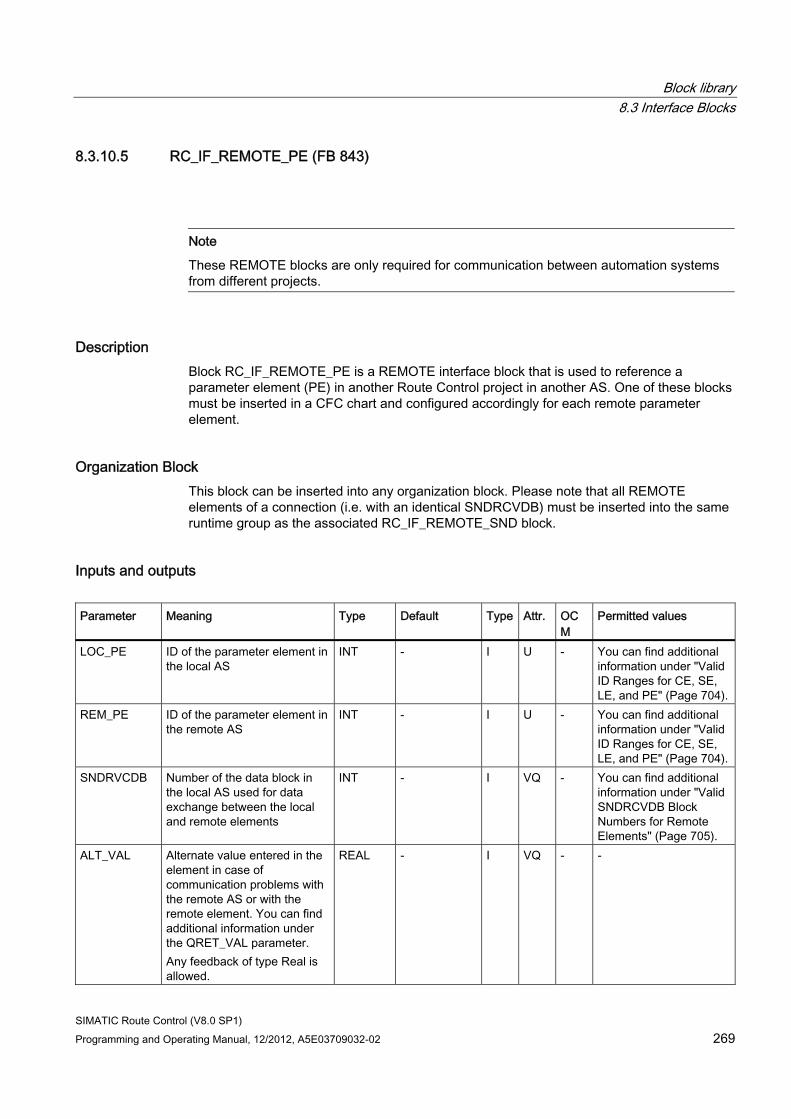
Block library 8.3 Interface Blocks
SIMATIC Route Control (V8.0 SP1) Programming and Operating Manual, 12/2012, A5E03709032-02 269
8.3.10.5 RC_IF_REMOTE_PE (FB 843)
Note
These REMOTE blocks are only required for communication between automation systems from different projects.
Description Block RC_IF_REMOTE_PE is a REMOTE interface block that is used to reference a parameter element (PE) in another Route Control project in another AS. One of these blocks must be inserted in a CFC chart and configured accordingly for each remote parameter element.
Organization Block This block can be inserted into any organization block. Please note that all REMOTE elements of a connection (i.e. with an identical SNDRCVDB) must be inserted into the same runtime group as the associated RC_IF_REMOTE_SND block.
Inputs and outputs Parameter Meaning Type Default Type Attr. OC
M Permitted values
LOC_PE ID of the parameter element in the local AS
INT - I U - You can find additional information under "Valid ID Ranges for CE, SE, LE, and PE" (Page 704).
REM_PE ID of the parameter element in the remote AS
INT - I U - You can find additional information under "Valid ID Ranges for CE, SE, LE, and PE" (Page 704).
SNDRVCDB Number of the data block in the local AS used for data exchange between the local and remote elements
INT - I VQ - You can find additional information under "Valid SNDRCVDB Block Numbers for Remote Elements" (Page 705).
ALT_VAL Alternate value entered in the element in case of communication problems with the remote AS or with the remote element. You can find additional information under the QRET_VAL parameter. Any feedback of type Real is allowed.
REAL - I VQ - -
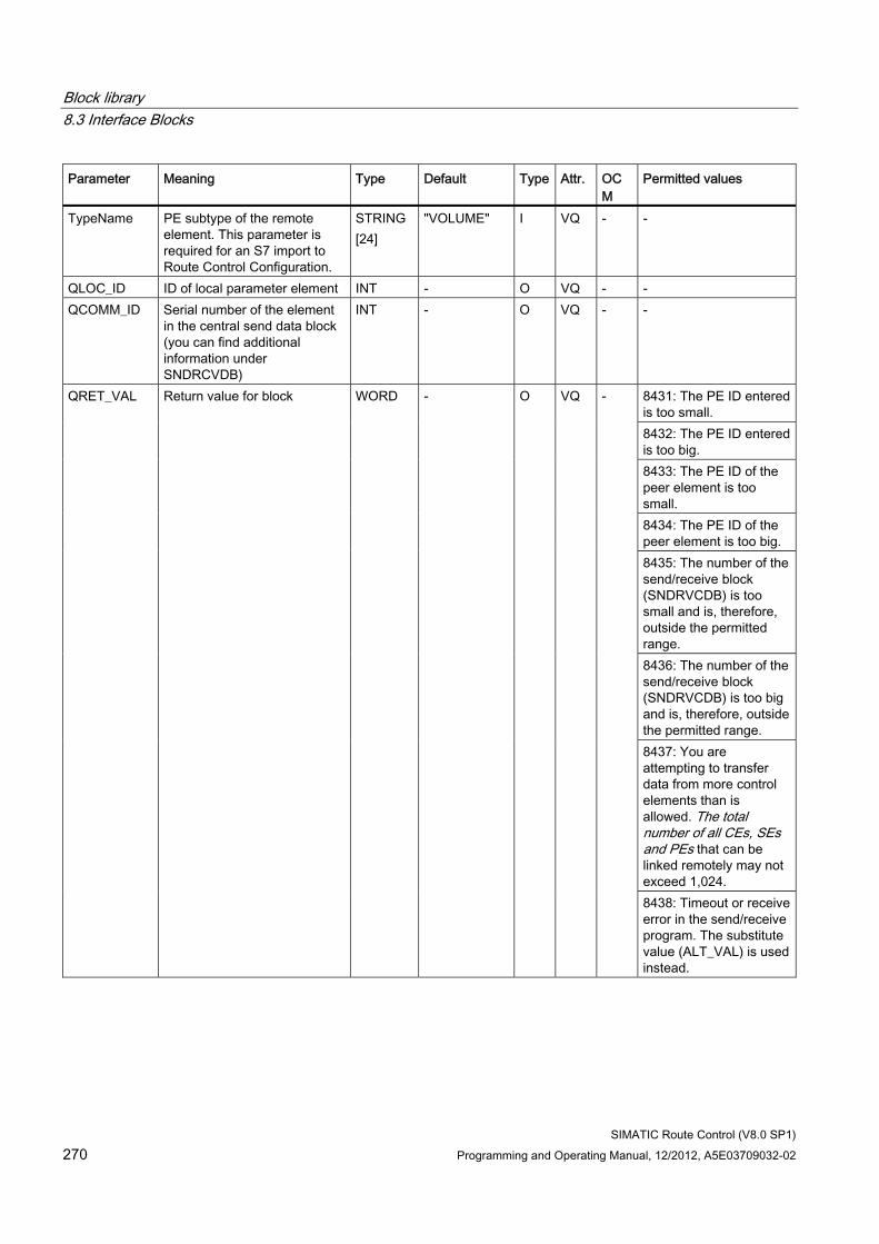
Block library 8.3 Interface Blocks
SIMATIC Route Control (V8.0 SP1) 270 Programming and Operating Manual, 12/2012, A5E03709032-02
Parameter Meaning Type Default Type Attr. OCM
Permitted values
TypeName PE subtype of the remote element. This parameter is required for an S7 import to Route Control Configuration.
STRING [24]
"VOLUME" I VQ - -
QLOC_ID ID of local parameter element INT - O VQ - - QCOMM_ID Serial number of the element
in the central send data block (you can find additional information under SNDRCVDB)
INT - O VQ - -
8431: The PE ID entered is too small. 8432: The PE ID entered is too big. 8433: The PE ID of the peer element is too small. 8434: The PE ID of the peer element is too big. 8435: The number of the send/receive block (SNDRVCDB) is too small and is, therefore, outside the permitted range. 8436: The number of the send/receive block (SNDRVCDB) is too big and is, therefore, outside the permitted range. 8437: You are attempting to transfer data from more control elements than is allowed. The total number of all CEs, SEs and PEs that can be linked remotely may not exceed 1,024.
QRET_VAL Return value for block WORD - O VQ -
8438: Timeout or receive error in the send/receive program. The substitute value (ALT_VAL) is used instead.
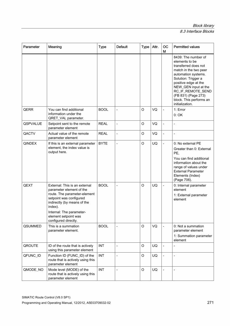
Block library 8.3 Interface Blocks
SIMATIC Route Control (V8.0 SP1) Programming and Operating Manual, 12/2012, A5E03709032-02 271
Parameter Meaning Type Default Type Attr. OCM
Permitted values
8439: The number of elements to be transferred does not match in the two peer automation systems. Solution: Trigger a positive edge at the NEW_GEN input at the RC_IF_REMOTE_SEND (FB 831) (Page 273) block. This performs an initialization.
QERR You can find additional information under the QRET_VAL parameter.
BOOL - O VQ - 1: Error 0: OK
QSPVALUE Setpoint sent to the remote parameter element
REAL - O VQ - -
QACTV Actual value of the remote parameter element
REAL - O VQ - -
QINDEX If this is an external parameter element, the index value is output here.
BYTE - O UQ - 0: No external PE Greater than 0: External PE, You can find additional information about the range of values under External Parameter Elements (Index) (Page 706).
QEXT External: This is an external parameter element of the route. The parameter-element setpoint was configured indirectly (by means of the index). Internal: The parameter-element setpoint was configured directly.
BOOL - O UQ - 0: Internal parameter element 1: External parameter element
QSUMMED This is a summation parameter element.
BOOL - O VQ - 0: Not a summation parameter element 1: Summation parameter element
QROUTE ID of the route that is actively using this parameter element
INT - O UQ - -
QFUNC_ID Function ID (FUNC_ID) of the route that is actively using this parameter element
INT - O UQ - -
QMODE_NO Mode level (MODE) of the route that is actively using this parameter element
INT - O UQ - -
Block library 8.3 Interface Blocks
SIMATIC Route Control (V8.0 SP1) 272 Programming and Operating Manual, 12/2012, A5E03709032-02
Configuration You can find additional information about configuration in section "Configuration of REMOTE elements" (Page 366)
Example Section "CFC Charts with REMOTE Elements" (Page 362)
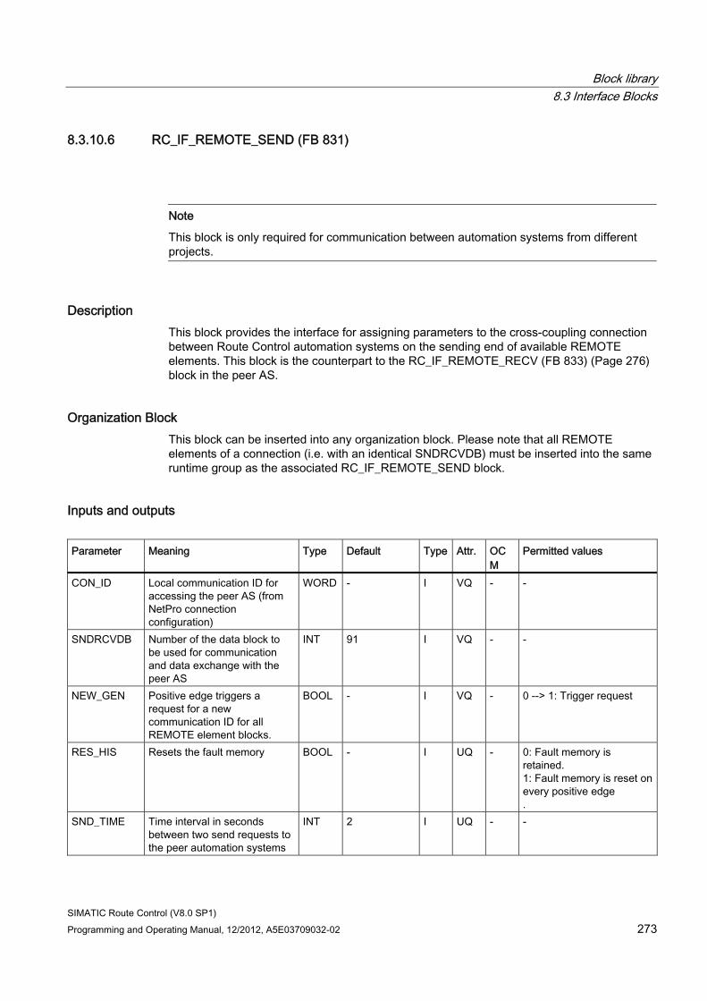
Block library 8.3 Interface Blocks
SIMATIC Route Control (V8.0 SP1) Programming and Operating Manual, 12/2012, A5E03709032-02 273
8.3.10.6 RC_IF_REMOTE_SEND (FB 831)
Note
This block is only required for communication between automation systems from different projects.
Description This block provides the interface for assigning parameters to the cross-coupling connection between Route Control automation systems on the sending end of available REMOTE elements. This block is the counterpart to the RC_IF_REMOTE_RECV (FB 833) (Page 276) block in the peer AS.
Organization Block This block can be inserted into any organization block. Please note that all REMOTE elements of a connection (i.e. with an identical SNDRCVDB) must be inserted into the same runtime group as the associated RC_IF_REMOTE_SEND block.
Inputs and outputs Parameter Meaning Type Default Type Attr. OC
M Permitted values
CON_ID Local communication ID for accessing the peer AS (from NetPro connection configuration)
WORD - I VQ - -
SNDRCVDB Number of the data block to be used for communication and data exchange with the peer AS
INT 91 I VQ - -
NEW_GEN Positive edge triggers a request for a new communication ID for all REMOTE element blocks.
BOOL - I VQ - 0 --> 1: Trigger request
RES_HIS Resets the fault memory BOOL - I UQ - 0: Fault memory is retained. 1: Fault memory is reset on every positive edge .
SND_TIME Time interval in seconds between two send requests to the peer automation systems
INT 2 I UQ - -
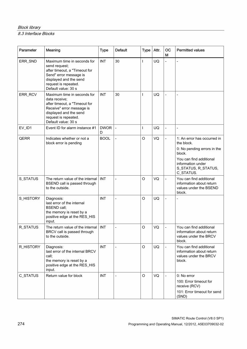
Block library 8.3 Interface Blocks
SIMATIC Route Control (V8.0 SP1) 274 Programming and Operating Manual, 12/2012, A5E03709032-02
Parameter Meaning Type Default Type Attr. OCM
Permitted values
ERR_SND Maximum time in seconds for send request; after timeout, a "Timeout for Send" error message is displayed and the send request is repeated. Default value: 30 s
INT 30 I UQ - -
ERR_RCV Maximum time in seconds for data receive; after timeout, a "Timeout for Receive" error message is displayed and the send request is repeated. Default value: 30 s
INT 30 I UQ - -
EV_ID1 Event ID for alarm instance #1 DWORD
- I UQ - -
QERR Indicates whether or not a block error is pending
BOOL - O VQ - 1: An error has occurred in the block. 0: No pending errors in the block. You can find additional information under S_STATUS, R_STATUS, C_STATUS.
S_STATUS The return value of the internal BSEND call is passed through to the outside.
INT - O VQ - You can find additional information about return values under the BSEND block.
S_HISTORY Diagnosis: last error of the internal BSEND call; the memory is reset by a positive edge at the RES_HIS input.
INT - O UQ - -
R_STATUS The return value of the internal BRCV call is passed through to the outside.
INT - O VQ - You can find additional information about return values under the BRCV block.
R_HISTORY Diagnosis: last error of the internal BRCV call; the memory is reset by a positive edge at the RES_HIS input.
INT - O UQ - You can find additional information about return values under the BRCV block.
C_STATUS Return value for block INT - O VQ - 0: No error 100: Error timeout for receive (RCV) 101: Error timeout for send (SND)
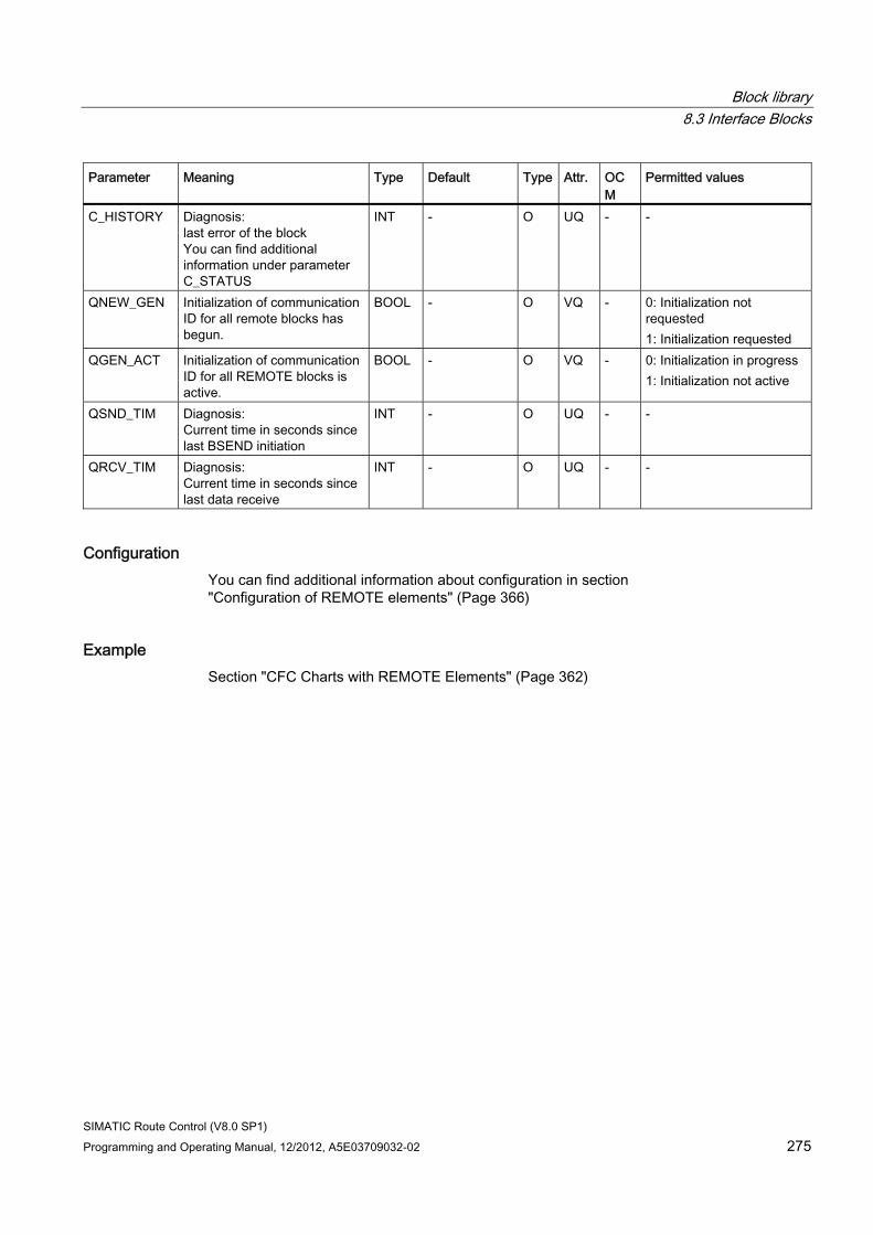
Block library 8.3 Interface Blocks
SIMATIC Route Control (V8.0 SP1) Programming and Operating Manual, 12/2012, A5E03709032-02 275
Parameter Meaning Type Default Type Attr. OCM
Permitted values
C_HISTORY Diagnosis: last error of the block You can find additional information under parameter C_STATUS
INT - O UQ - -
QNEW_GEN Initialization of communication ID for all remote blocks has begun.
BOOL - O VQ - 0: Initialization not requested 1: Initialization requested
QGEN_ACT Initialization of communication ID for all REMOTE blocks is active.
BOOL - O VQ - 0: Initialization in progress 1: Initialization not active
QSND_TIM Diagnosis: Current time in seconds since last BSEND initiation
INT - O UQ - -
QRCV_TIM Diagnosis: Current time in seconds since last data receive
INT - O UQ - -
Configuration You can find additional information about configuration in section "Configuration of REMOTE elements" (Page 366)
Example Section "CFC Charts with REMOTE Elements" (Page 362)
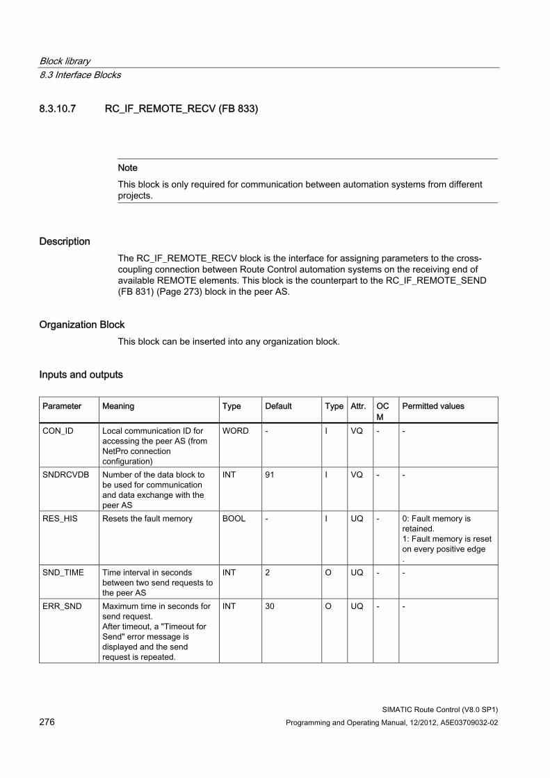
Block library 8.3 Interface Blocks
SIMATIC Route Control (V8.0 SP1) 276 Programming and Operating Manual, 12/2012, A5E03709032-02
8.3.10.7 RC_IF_REMOTE_RECV (FB 833)
Note
This block is only required for communication between automation systems from different projects.
Description The RC_IF_REMOTE_RECV block is the interface for assigning parameters to the cross-coupling connection between Route Control automation systems on the receiving end of available REMOTE elements. This block is the counterpart to the RC_IF_REMOTE_SEND (FB 831) (Page 273) block in the peer AS.
Organization Block This block can be inserted into any organization block.
Inputs and outputs Parameter Meaning Type Default Type Attr. OC
M Permitted values
CON_ID Local communication ID for accessing the peer AS (from NetPro connection configuration)
WORD - I VQ - -
SNDRCVDB Number of the data block to be used for communication and data exchange with the peer AS
INT 91 I VQ - -
RES_HIS Resets the fault memory BOOL - I UQ - 0: Fault memory is retained. 1: Fault memory is reset on every positive edge .
SND_TIME Time interval in seconds between two send requests to the peer AS
INT 2 O UQ - -
ERR_SND Maximum time in seconds for send request. After timeout, a "Timeout for Send" error message is displayed and the send request is repeated.
INT 30 O UQ - -
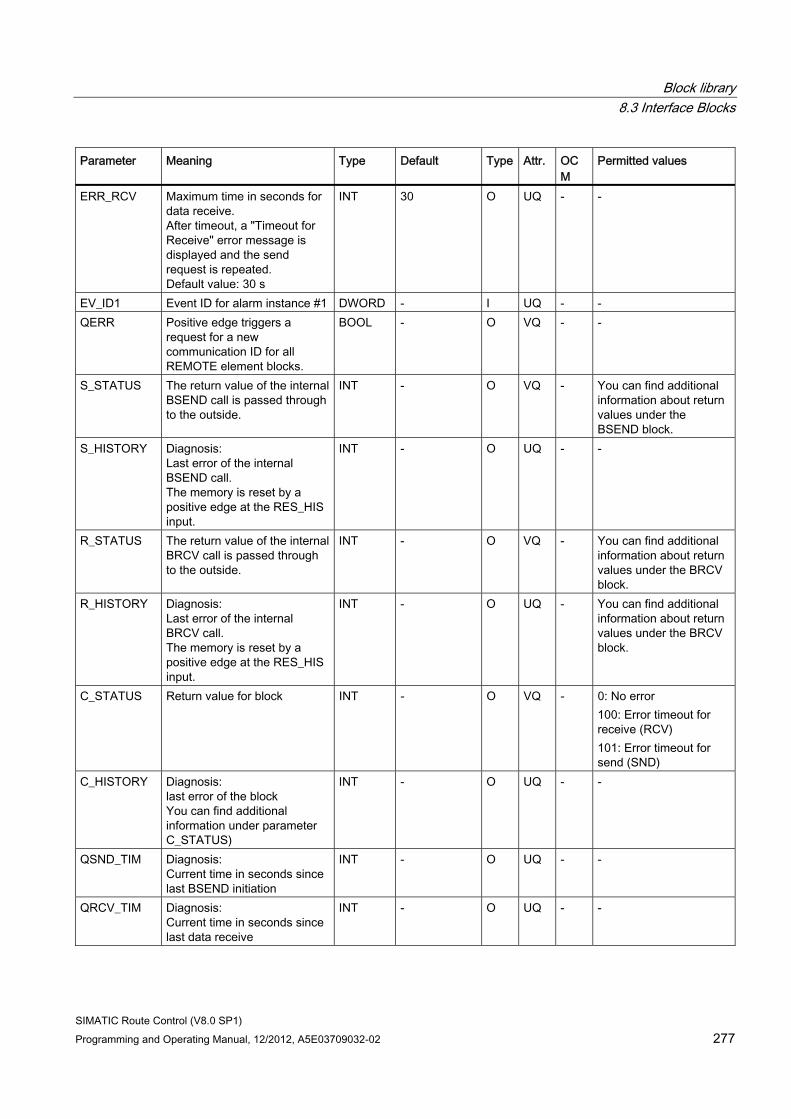
Block library 8.3 Interface Blocks
SIMATIC Route Control (V8.0 SP1) Programming and Operating Manual, 12/2012, A5E03709032-02 277
Parameter Meaning Type Default Type Attr. OCM
Permitted values
ERR_RCV Maximum time in seconds for data receive. After timeout, a "Timeout for Receive" error message is displayed and the send request is repeated. Default value: 30 s
INT 30 O UQ - -
EV_ID1 Event ID for alarm instance #1 DWORD - I UQ - - QERR Positive edge triggers a
request for a new communication ID for all REMOTE element blocks.
BOOL - O VQ - -
S_STATUS The return value of the internal BSEND call is passed through to the outside.
INT - O VQ - You can find additional information about return values under the BSEND block.
S_HISTORY Diagnosis: Last error of the internal BSEND call. The memory is reset by a positive edge at the RES_HIS input.
INT - O UQ - -
R_STATUS The return value of the internal BRCV call is passed through to the outside.
INT - O VQ - You can find additional information about return values under the BRCV block.
R_HISTORY Diagnosis: Last error of the internal BRCV call. The memory is reset by a positive edge at the RES_HIS input.
INT - O UQ - You can find additional information about return values under the BRCV block.
C_STATUS Return value for block INT - O VQ - 0: No error 100: Error timeout for receive (RCV) 101: Error timeout for send (SND)
C_HISTORY Diagnosis: last error of the block You can find additional information under parameter C_STATUS)
INT - O UQ - -
QSND_TIM Diagnosis: Current time in seconds since last BSEND initiation
INT - O UQ - -
QRCV_TIM Diagnosis: Current time in seconds since last data receive
INT - O UQ - -
Block library 8.3 Interface Blocks
SIMATIC Route Control (V8.0 SP1) 278 Programming and Operating Manual, 12/2012, A5E03709032-02
Configuration You can find additional information about configuration in section "Configuration of REMOTE elements" (Page 366)
Example Section "CFC Charts with REMOTE Elements" (Page 362)
Block library 8.4 Kernel Blocks
SIMATIC Route Control (V8.0 SP1) Programming and Operating Manual, 12/2012, A5E03709032-02 279
8.4 Kernel Blocks
8.4.1 Overview of kernel blocks
Kernel Blocks The following are kernel blocks for Route Control:
● Blocks for processing routes
● Blocks for processing elements
● Blocks for connecting to the Route Control server
● Blocks for connecting to other Route Control automation systems (cross-coupling)
For each kernel block description, you will find a brief explanation of what the block is used for. Because the kernel blocks are not interface blocks for interconnecting library blocks, a description of inputs and outputs is not provided here.
8.4.2 Data Blocks
8.4.2.1 RC_CE_FIELD (DB 99)
Description This block contains the data records for control elements.
8.4.2.2 RC_CFG (DB 100)
Description This block is an internal, AS-centralized routing-system configuration block. Direct access, as was possible in Route Control V5, is no longer required or permitted! In V6, block FB 850 RC_IF_CFG acts as an interface.
8.4.2.3 RC_DATA_TG34_36 (DB 405)
Description This block is required for the general request that occurs when the Route Control server is restarted.
Block library 8.4 Kernel Blocks
SIMATIC Route Control (V8.0 SP1) 280 Programming and Operating Manual, 12/2012, A5E03709032-02
8.4.2.4 RC_FIFO1 (DB 870)
Description This block acts as a circular buffer in the AS for Route Control server telegrams.
8.4.2.5 RC_FIFO1_SE (DB 874)
Description This block acts as a send buffer in the AS for Route Control server telegrams.
8.4.2.6 RC_FIFO4 (DB 890)
Description This block acts as a circular buffer in the AS for Route Control server telegrams.
8.4.2.7 RC_FIFO4_SE (DB 894)
Description This block acts as a send buffer in the AS for Route Control server telegrams.
8.4.2.8 RC_IDB_SEND_FIFO1 (DB 590)
Description This block is the instance data block for FB 890, RC_SEND_FIFO1.
8.4.2.9 RC_IDB_SEND_FIFO4 (DB 593)
Description This block is the instance data block for FB 891, RC_SEND_FIFO4.
8.4.2.10 RC_LE_FIELD (DB 96)
Description This block contains the data records for link elements.
Block library 8.4 Kernel Blocks
SIMATIC Route Control (V8.0 SP1) Programming and Operating Manual, 12/2012, A5E03709032-02 281
8.4.2.11 RC_PE_FIELD (DB 97)
Description This block contains the data records for parameter elements.
8.4.2.12 RC_REMOTE1..5 (DB 91 to 95)
Description This block is an internal block with a send/receive area for elements in another AS (remote elements).
8.4.2.13 RC_ROUTE1 (DB 101 to 400)
Description Internal data structures: Each one of these blocks contains data for a route. DB 101 corresponds to the route with ID 1, DB 102 corresponds to route ID 2, etc.
If it is known which IDs are not being used in the entire routing system, then the corresponding data blocks can be deleted to free up memory in the AS.
8.4.2.14 RC_SE_FIELD (DB 98)
Description This block contains the data records for sensor elements.
8.4.2.15 RC_SYS_DB (DB 10)
Description Internal data structure
8.4.2.16 RC_TG34_TG36_DB (DB 404)
Description This block is required in the context of connecting the AS and the Route Control server.
Block library 8.4 Kernel Blocks
SIMATIC Route Control (V8.0 SP1) 282 Programming and Operating Manual, 12/2012, A5E03709032-02
8.4.2.17 RC_XC_1 (DB 751)
Description These are instance blocks for FB 880, RC_XC_FB.
8.4.2.18 RC_XC_JOB (DB 705)
Description Internal data structure used in the context of AS-AS communication (cross-coupling).
8.4.2.19 RC_XC_JOB_START (DB 450)
Description This block is used in the context of AS-AS communication (cross-coupling).
8.4.2.20 RC_XC_PCU (DB 704)
Description This block is used in the context of AS-AS communication (cross-coupling).
8.4.2.21 RC_XC_PUTX_1..31 (DB 451 to 481)
Description Internal data area used in the context of AS-AS communication (cross-coupling).
Block library 8.4 Kernel Blocks
SIMATIC Route Control (V8.0 SP1) Programming and Operating Manual, 12/2012, A5E03709032-02 283
8.4.3 User-defined types
8.4.3.1 RC_ANY_UDT (UDT 506)
Description This is an internal routing-system block.
8.4.3.2 RC_CE_FIELD_UDT (UDT 99)
Description Internal data structure
8.4.3.3 RC_EXT_PE_ACTV (UDT 103)
Description Internal data structure for processing external parameter elements.
8.4.3.4 RC_FIFO__UDT (UDT 121)
Description Internal data structure
8.4.3.5 RC_LE_FIELD_UDT (UDT 96)
Description Internal data structure
8.4.3.6 RC_PE_FIELD_UDT (UDT 97)
Description Internal data structure
Block library 8.4 Kernel Blocks
SIMATIC Route Control (V8.0 SP1) 284 Programming and Operating Manual, 12/2012, A5E03709032-02
8.4.3.7 RC_RE_INFO_UDT (UDT 109)
Description Internal data structure
8.4.3.8 RC_RE_UDT (UDT 100)
Description Internal data structure
8.4.3.9 RC_REM_CESEPE (UDT 104)
Description Internal data structure for elements in another AS (remote elements)
8.4.3.10 RC_REQUEST_BUFFER_UDT (UDT 111)
Description Internal data structure
8.4.3.11 RC_ROUTE_CFG (UDT 105)
Description Internal data structure
8.4.3.12 RC_ROUTE_CM_UDT (UDT 110)
Description Internal data structure
8.4.3.13 RC_ROUTE_TB_UDT (UDT 102)
Description Internal data structure
Block library 8.4 Kernel Blocks
SIMATIC Route Control (V8.0 SP1) Programming and Operating Manual, 12/2012, A5E03709032-02 285
8.4.3.14 RC_SE_FIELD_UDT (UDT 98)
Description Internal data structure
8.4.3.15 RC_SEPU__UDT (UDT 122)
Description Internal data structure
8.4.3.16 RC_SYS_UDT (UDT 120)
Description Internal data structure
8.4.3.17 RC_XC_JOB_UDT (UDT 705)
Description This internal data structure is used in the context of AS-AS communication (cross-coupling).
8.4.3.18 RC_XC_PCU_UDT (UDT 704)
Description This internal data structure is used in the context of AS-AS communication (cross-coupling).
8.4.3.19 RC_XC_PUT_DB_UDT (UDT 452)
Description This internal data structure is used in the context of AS-AS communication (cross-coupling).
8.4.3.20 RC_XC_PUT_SD_UDT (UDT 684)
Description This internal data structure is used in the context of AS-AS communication (cross-coupling).
Block library 8.4 Kernel Blocks
SIMATIC Route Control (V8.0 SP1) 286 Programming and Operating Manual, 12/2012, A5E03709032-02
8.4.3.21 RC_XC_PUT_UDT (UDT 683)
Description This internal data structure is used in the context of AS-AS communication (cross-coupling).
8.4.3.22 RC_XC_PUTX_UDT (UDT 451)
Description This internal data structure is used in the context of AS-AS communication (cross-coupling).
8.4.3.23 RC_XC_UDT (UDT 101)
Description Internal data structure used in the context of AS-AS communication (cross-coupling).
8.4.3.24 RC_XC_AS (UDT 108)
Description This internal data structure is used in the context of AS-AS communication (cross-coupling) and includes the IDs of the ASs involved in cross-coupling.
8.4.4 Function Blocks (FC)
8.4.4.1 RC_ATTRIB_PTR (FC 860)
Description This is an internal routing-system block.
8.4.4.2 RC_DB_AREA_COPY (FC 862)
Description This is an internal block for copying a block from one data block to another.
Block library 8.4 Kernel Blocks
SIMATIC Route Control (V8.0 SP1) Programming and Operating Manual, 12/2012, A5E03709032-02 287
8.4.4.3 RC_FC_COPY (FC 863)
Description This block is an internal auxiliary block.
8.4.4.4 RC_FIFO_DEBUG_SEND (FC 891)
Description This block is an internal system block, which stores the SFB SEND diagnostic messages in the routing system.
8.4.4.5 RC_FIFO_INPUT_FC (FC 890)
Description This block is required for communication between the AS and the Route Control server. It transfers all telegrams from the AS to the Route Control server to a circular buffer (FIFO).
8.4.4.6 RC_FIFO_SEND (FC 803)
Description This block sends telegrams to the Route Control server by means of BSEND.
8.4.4.7 RC_KERNEL_CALL (FC 804)
Description This internal block contains all Route Control kernel block calls required to process the route lists (DB 101 and higher).
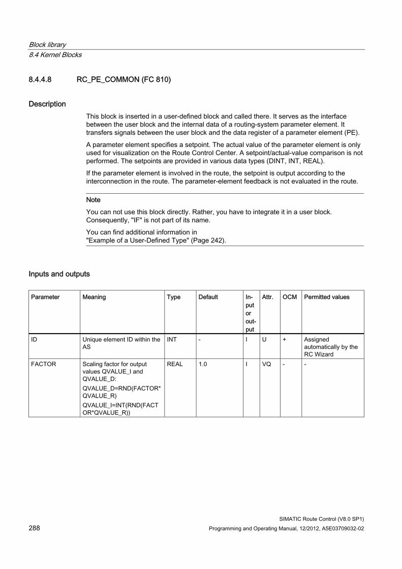
Block library 8.4 Kernel Blocks
SIMATIC Route Control (V8.0 SP1) 288 Programming and Operating Manual, 12/2012, A5E03709032-02
8.4.4.8 RC_PE_COMMON (FC 810)
Description This block is inserted in a user-defined block and called there. It serves as the interface between the user block and the internal data of a routing-system parameter element. It transfers signals between the user block and the data register of a parameter element (PE).
A parameter element specifies a setpoint. The actual value of the parameter element is only used for visualization on the Route Control Center. A setpoint/actual-value comparison is not performed. The setpoints are provided in various data types (DINT, INT, REAL).
If the parameter element is involved in the route, the setpoint is output according to the interconnection in the route. The parameter-element feedback is not evaluated in the route.
Note
You can not use this block directly. Rather, you have to integrate it in a user block. Consequently, "IF" is not part of its name.
You can find additional information in "Example of a User-Defined Type" (Page 242).
Inputs and outputs Parameter Meaning Type Default In-
put or out-put
Attr. OCM Permitted values
ID Unique element ID within the AS
INT - I U + Assigned automatically by the RC Wizard
FACTOR Scaling factor for output values QVALUE_I and QVALUE_D: QVALUE_D=RND(FACTOR*QVALUE_R) QVALUE_I=INT(RND(FACTOR*QVALUE_R))
REAL 1.0 I VQ - -
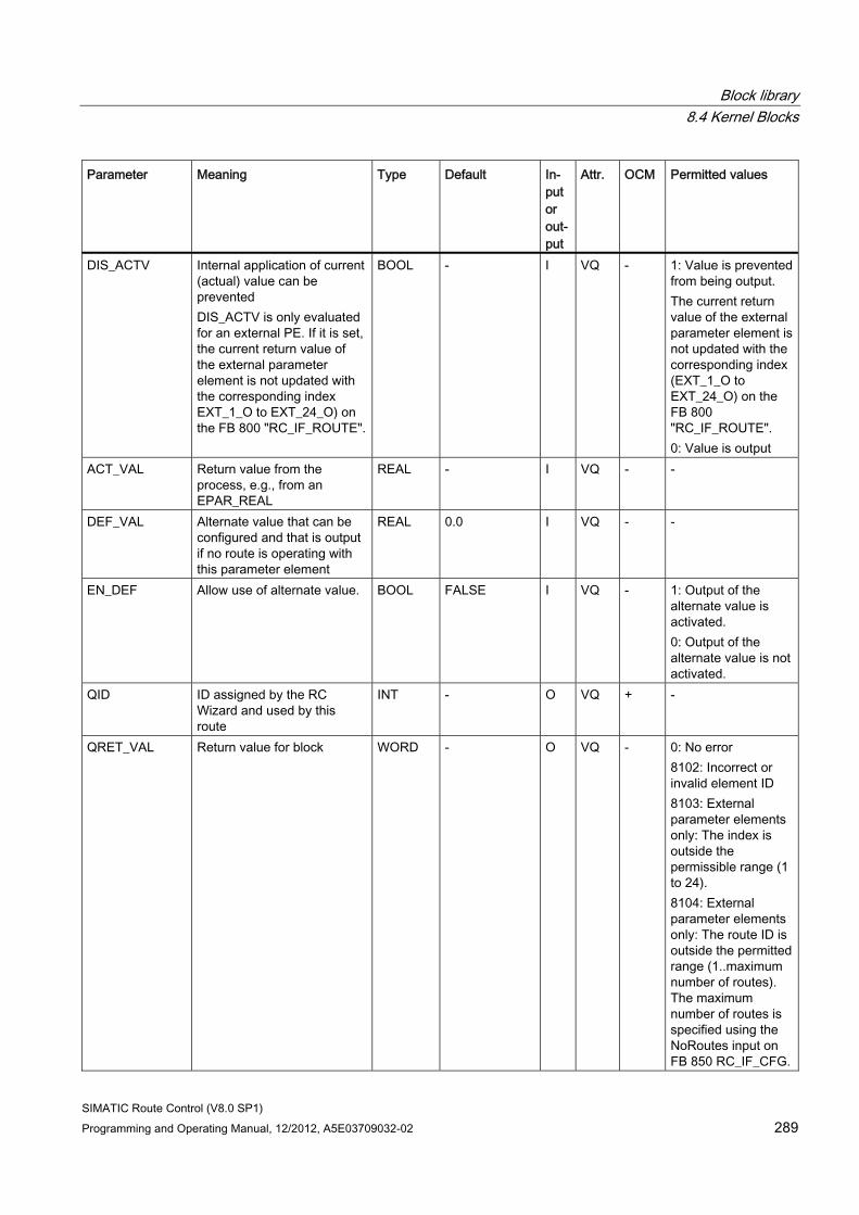
Block library 8.4 Kernel Blocks
SIMATIC Route Control (V8.0 SP1) Programming and Operating Manual, 12/2012, A5E03709032-02 289
Parameter Meaning Type Default In-put or out-put
Attr. OCM Permitted values
DIS_ACTV Internal application of current (actual) value can be prevented DIS_ACTV is only evaluated for an external PE. If it is set, the current return value of the external parameter element is not updated with the corresponding index EXT_1_O to EXT_24_O) on the FB 800 "RC_IF_ROUTE".
BOOL - I VQ - 1: Value is prevented from being output. The current return value of the external parameter element is not updated with the corresponding index (EXT_1_O to EXT_24_O) on the FB 800 "RC_IF_ROUTE". 0: Value is output
ACT_VAL Return value from the process, e.g., from an EPAR_REAL
REAL - I VQ - -
DEF_VAL Alternate value that can be configured and that is output if no route is operating with this parameter element
REAL 0.0 I VQ - -
EN_DEF Allow use of alternate value. BOOL FALSE I VQ - 1: Output of the alternate value is activated. 0: Output of the alternate value is not activated.
QID ID assigned by the RC Wizard and used by this route
INT - O VQ + -
QRET_VAL Return value for block WORD - O VQ - 0: No error 8102: Incorrect or invalid element ID 8103: External parameter elements only: The index is outside the permissible range (1 to 24). 8104: External parameter elements only: The route ID is outside the permitted range (1..maximum number of routes). The maximum number of routes is specified using the NoRoutes input on FB 850 RC_IF_CFG.
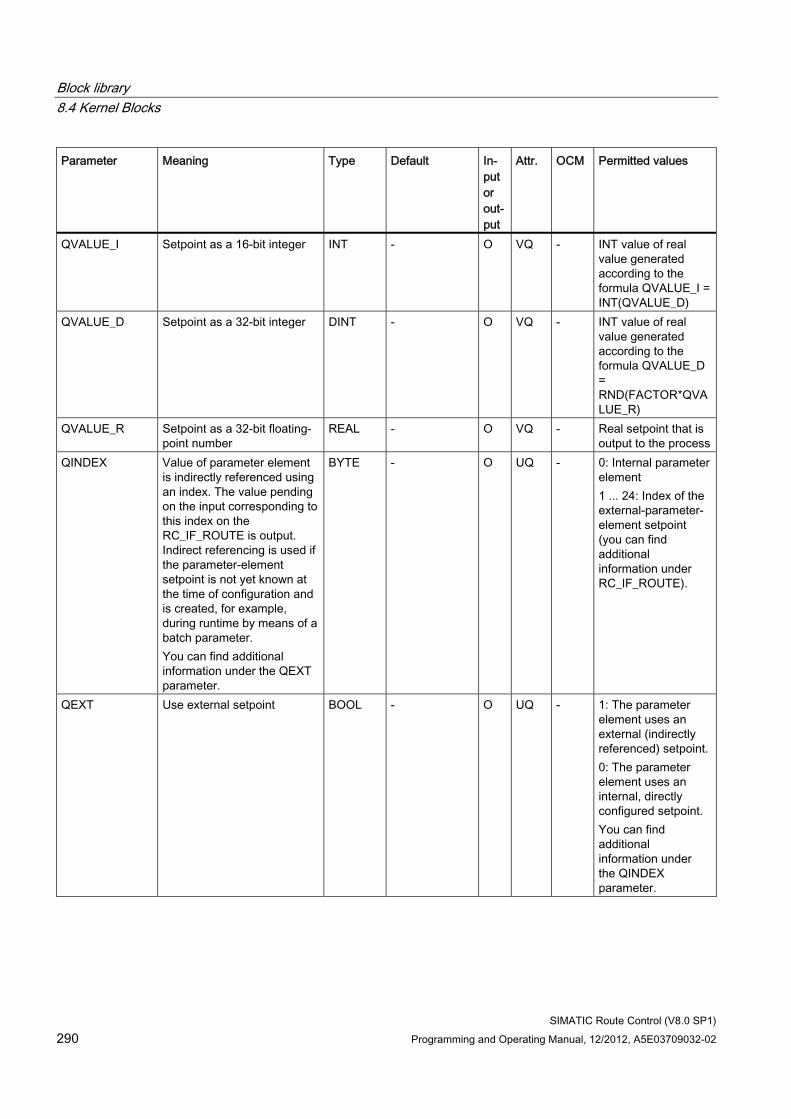
Block library 8.4 Kernel Blocks
SIMATIC Route Control (V8.0 SP1) 290 Programming and Operating Manual, 12/2012, A5E03709032-02
Parameter Meaning Type Default In-put or out-put
Attr. OCM Permitted values
QVALUE_I Setpoint as a 16-bit integer INT - O VQ - INT value of real value generated according to the formula QVALUE_I = INT(QVALUE_D)
QVALUE_D Setpoint as a 32-bit integer DINT - O VQ - INT value of real value generated according to the formula QVALUE_D = RND(FACTOR*QVALUE_R)
QVALUE_R Setpoint as a 32-bit floating-point number
REAL - O VQ - Real setpoint that is output to the process
QINDEX Value of parameter element is indirectly referenced using an index. The value pending on the input corresponding to this index on the RC_IF_ROUTE is output. Indirect referencing is used if the parameter-element setpoint is not yet known at the time of configuration and is created, for example, during runtime by means of a batch parameter. You can find additional information under the QEXT parameter.
BYTE - O UQ - 0: Internal parameter element 1 ... 24: Index of the external-parameter-element setpoint (you can find additional information under RC_IF_ROUTE).
QEXT Use external setpoint BOOL - O UQ - 1: The parameter element uses an external (indirectly referenced) setpoint. 0: The parameter element uses an internal, directly configured setpoint. You can find additional information under the QINDEX parameter.
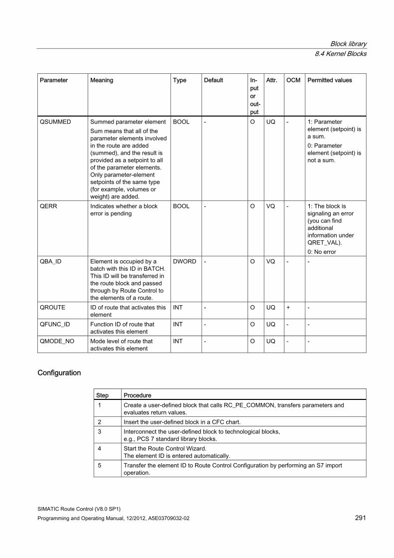
Block library 8.4 Kernel Blocks
SIMATIC Route Control (V8.0 SP1) Programming and Operating Manual, 12/2012, A5E03709032-02 291
Parameter Meaning Type Default In-put or out-put
Attr. OCM Permitted values
QSUMMED Summed parameter element Sum means that all of the parameter elements involved in the route are added (summed), and the result is provided as a setpoint to all of the parameter elements. Only parameter-element setpoints of the same type (for example, volumes or weight) are added.
BOOL - O UQ - 1: Parameter element (setpoint) is a sum. 0: Parameter element (setpoint) is not a sum.
QERR Indicates whether a block error is pending
BOOL - O VQ - 1: The block is signaling an error (you can find additional information under QRET_VAL). 0: No error
QBA_ID Element is occupied by a batch with this ID in BATCH. This ID will be transferred in the route block and passed through by Route Control to the elements of a route.
DWORD - O VQ - -
QROUTE ID of route that activates this element
INT - O UQ + -
QFUNC_ID Function ID of route that activates this element
INT - O UQ - -
QMODE_NO Mode level of route that activates this element
INT - O UQ - -
Configuration Step Procedure 1 Create a user-defined block that calls RC_PE_COMMON, transfers parameters and
evaluates return values. 2 Insert the user-defined block in a CFC chart. 3 Interconnect the user-defined block to technological blocks,
e.g., PCS 7 standard library blocks. 4 Start the Route Control Wizard.
The element ID is entered automatically. 5 Transfer the element ID to Route Control Configuration by performing an S7 import
operation.
Block library 8.4 Kernel Blocks
SIMATIC Route Control (V8.0 SP1) 292 Programming and Operating Manual, 12/2012, A5E03709032-02
Note
To activate this parameter element in routes, you still have to create a user-defined subtype in Route Control Engineering with appropriate commands.
8.4.4.9 RC_CALL_KILLER (FC 814)
Description This is an internal routing-system block.
8.4.4.10 RC_LE_DGRAMM (FC 825)
Description This internal block generates update message frames for the link elements.
8.4.4.11 RC_LOAD_AR1 (FC 861)
Description Internal auxiliary block
8.4.4.12 RC_MASTER_CREATE_ERR (FC 851)
Description This block is required to generate alarm messages for a route.
8.4.4.13 RC_MAT (FC 836)
Description This block is an internal auxiliary block for executing material functions.
8.4.4.14 RC_ROUTE_CE_ERR (FC 812)
Description This block is required to send update telegrams for the control elements to the Route Control server.
Block library 8.4 Kernel Blocks
SIMATIC Route Control (V8.0 SP1) Programming and Operating Manual, 12/2012, A5E03709032-02 293
8.4.4.15 RC_ROUTE_PE_DGRAM (FC 822)
Description This block is required to send update telegrams for the parameter elements to the Route Control server.
8.4.4.16 RC_ROUTE_SE_ERR (FC 813)
Description This block is used to send update telegrams for the sensor elements to the Route Control server.
8.4.4.17 RC_TG34_03 (FC 811)
Description This block combines particular telegrams and sends them to the Route Control server.
8.4.4.18 RC_UPD_CESEPE (FC 823)
Description Internal block for processing element data
8.4.4.19 RC_UPD_CESEPE_EX (FC 824)
Description Internal block for processing element data
8.4.4.20 RC_XC_CALL (FC 805)
Description This block is an internal block used in the context of cross-coupling among automation systems.
Block library 8.4 Kernel Blocks
SIMATIC Route Control (V8.0 SP1) 294 Programming and Operating Manual, 12/2012, A5E03709032-02
8.4.4.21 RC_XC_JOB_USER (FC 885)
Description This block is used in the context of AS-AS communication (cross-coupling).
8.4.4.22 RC_XC_PUTX_RECV (FC 882)
Description This block is used in the context of AS-AS communication (cross-coupling).
8.4.4.23 RC_XC_PUTX_SEND (FC 881)
Description This block is used in the context of AS-AS communication (cross-coupling).
8.4.4.24 RC_XFER_LE (FC 826)
Description This block is used in the context of cross-coupling for link element data.
8.4.4.25 RC_XFER_MON_FLT (FC 829)
Description This block is an internal block for transferring status monitoring and fault-tolerance times from FB 800 RC_IF_ROUTE to route lists RC_ROUTE1 to RC_ROUTE300 (DB 101 to DB 400).
Block library 8.4 Kernel Blocks
SIMATIC Route Control (V8.0 SP1) Programming and Operating Manual, 12/2012, A5E03709032-02 295
8.4.5 Function Blocks (FB)
8.4.5.1 RC_CALL_DIAG (FB 851)
Description This is an internal block for diagnostic processing.
8.4.5.2 RC_CLOCK (FB 899)
Description This block is the interface between the realtime clock of the AS and the routing system.
8.4.5.3 RC_MASTER_BUFFER (FB 856)
Description This block is an internal block for managing a data buffer during a route request.
8.4.5.4 RC_MASTER_FUNC (FB 852)
Description This block is an internal auxiliary block for a master route.
8.4.5.5 RC_MASTER_MSG (FB 857)
Description This block is required to issue alarm messages for a route.
8.4.5.6 RC_MASTER_TIMES (FB 859)
Description This block is an internal auxiliary block for generating time functions for a master route.
Block library 8.4 Kernel Blocks
SIMATIC Route Control (V8.0 SP1) 296 Programming and Operating Manual, 12/2012, A5E03709032-02
8.4.5.7 RC_MASTER_XC_SND (FB 858)
Description This block is an internal auxiliary block for communication between a master route and the associated slave routes in another AS.
8.4.5.8 RC_ROUTE (FB 801)
Description This RC_ROUTE block is the internal counterpart to RC_IF_ROUTE and performs route processing.
8.4.5.9 RC_TG_36 (FB 813)
Description This block is an internal block in the context of telegram processing (sending to the Route Control server) of the routing system.
8.4.5.10 RC_ROUTE_GET_EXT_PE (FB 818)
Description This block is used in connection with external parameter elements of a route.
8.4.5.11 RC_ROUTE_MAT (FB 819)
Description This block is used in the context of material processing for a route.
8.4.5.12 RC_ROUTE_RCE_OFF (FB 804)
Description This block deactivates the elements of a route in accordance with its properties, e.g., switch-off delays.
Block library 8.4 Kernel Blocks
SIMATIC Route Control (V8.0 SP1) Programming and Operating Manual, 12/2012, A5E03709032-02 297
8.4.5.13 RC_ROUTE_RCE_ON (FB 803)
Description This block activates the elements of a route in accordance with its properties, e.g., switch-on delays.
8.4.5.14 RC_ROUTE_STATE_OS (FB 807)
Description This block checks to see if there are any update telegrams for a route to be sent to the Route Control server.
8.4.5.15 RC_ROUTE_STATES (FB 809)
Description This block is an internal block, which controls a route list status chart.
8.4.5.16 RC_ROUTE_TELEGR (FB 808)
Description This block sends the update telegrams of a route to the Route Control server.
8.4.5.17 RC_ROUTE_TIME (FB 805)
Description This block is responsible for managing all times used within the routing system.
8.4.5.18 RC_ROUTE_XC_PE_ACTV (FB 817)
Description This block is used in the context of cross-coupling of parameter element data.
Block library 8.4 Kernel Blocks
SIMATIC Route Control (V8.0 SP1) 298 Programming and Operating Manual, 12/2012, A5E03709032-02
8.4.5.19 RC_ROUTE_XC_REC (FB 802)
Description This block works together with the RC_ROUTE block and receives cross-coupling data from peer automation systems.
8.4.5.20 RC_ROUTE_XC_SEND (FB 806)
Description The block sends data to peer automation systems involved in the route.
8.4.5.21 RC_ROUTE_XC_SND_ORDER (FB 816)
Description This block is used to transfer the request data of a route to the peer AS involved in the route.
8.4.5.22 RC_CE_COMMON (FB 827)
Description This block is inserted in a user-defined block and is called there. It serves as the interface between the user block and the internal data of a routing-system control element. It transfers signals between the user block and the data register of a control element (CE).
If the control element is involved in the route, the element is then activated according to the interconnection in the route. The element feedback is evaluated in the route simultaneously.
Note
You can not use this block directly. Rather, you have to integrate it in a user block. Consequently, "IF" is not part of its name.
You can find additional information in "Example of a User-Defined Type" (Page 242).
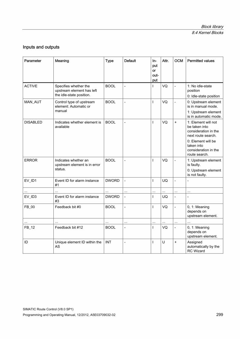
Block library 8.4 Kernel Blocks
SIMATIC Route Control (V8.0 SP1) Programming and Operating Manual, 12/2012, A5E03709032-02 299
Inputs and outputs Parameter Meaning Type Default In-
put or out-put
Attr. OCM Permitted values
ACTIVE Specifies whether the upstream element has left the idle-state position.
BOOL - I VQ - 1: No idle-state position 0: Idle-state position
MAN_AUT Control type of upstream element: Automatic or manual
BOOL - I VQ - 0: Upstream element is in manual mode. 1: Upstream element is in automatic mode.
DISABLED Indicates whether element is available
BOOL - I VQ + 1: Element will not be taken into consideration in the next route search. 0: Element will be taken into consideration in the route search.
ERROR Indicates whether an upstream element is in error status.
BOOL - I VQ - 1: Upstream element is faulty. 0: Upstream element is not faulty.
EV_ID1 Event ID for alarm instance #1
DWORD - I UQ - -
... ... ... ... ... ... ... ... EV_ID3 Event ID for alarm instance
#3 DWORD - I UQ - -
FB_00 Feedback bit #0 BOOL - I VQ - 0, 1: Meaning depends on upstream element.
... ... ... ... ... ... ... ... FB_12 Feedback bit #12 BOOL - I VQ - 0, 1: Meaning
depends on upstream element.
ID Unique element ID within the AS
INT - I U + Assigned automatically by the RC Wizard
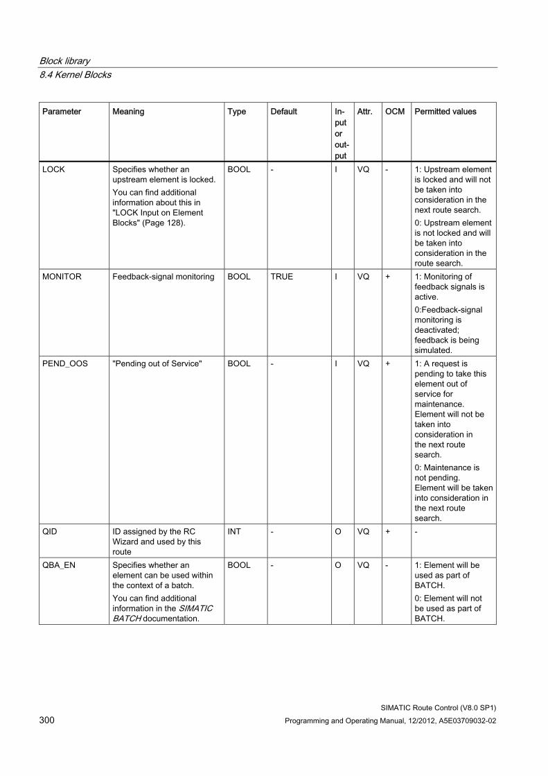
Block library 8.4 Kernel Blocks
SIMATIC Route Control (V8.0 SP1) 300 Programming and Operating Manual, 12/2012, A5E03709032-02
Parameter Meaning Type Default In-put or out-put
Attr. OCM Permitted values
LOCK Specifies whether an upstream element is locked. You can find additional information about this in "LOCK Input on Element Blocks" (Page 128).
BOOL - I VQ - 1: Upstream element is locked and will not be taken into consideration in the next route search. 0: Upstream element is not locked and will be taken into consideration in the route search.
MONITOR Feedback-signal monitoring BOOL TRUE I VQ + 1: Monitoring of feedback signals is active. 0:Feedback-signal monitoring is deactivated; feedback is being simulated.
PEND_OOS "Pending out of Service" BOOL - I VQ + 1: A request is pending to take this element out of service for maintenance. Element will not be taken into consideration in the next route search. 0: Maintenance is not pending. Element will be taken into consideration in the next route search.
QID ID assigned by the RC Wizard and used by this route
INT - O VQ + -
QBA_EN Specifies whether an element can be used within the context of a batch. You can find additional information in the SIMATIC BATCH documentation.
BOOL - O VQ - 1: Element will be used as part of BATCH. 0: Element will not be used as part of BATCH.
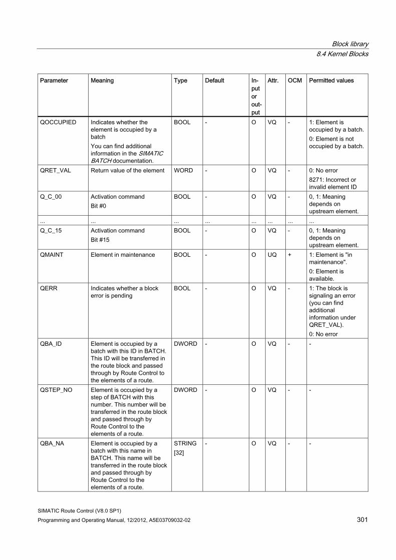
Block library 8.4 Kernel Blocks
SIMATIC Route Control (V8.0 SP1) Programming and Operating Manual, 12/2012, A5E03709032-02 301
Parameter Meaning Type Default In-put or out-put
Attr. OCM Permitted values
QOCCUPIED Indicates whether the element is occupied by a batch You can find additional information in the SIMATIC BATCH documentation.
BOOL - O VQ - 1: Element is occupied by a batch. 0: Element is not occupied by a batch.
QRET_VAL Return value of the element WORD - O VQ - 0: No error 8271: Incorrect or invalid element ID
Q_C_00 Activation command Bit #0
BOOL - O VQ - 0, 1: Meaning depends on upstream element.
... ... ... ... ... ... ... ... Q_C_15 Activation command
Bit #15 BOOL - O VQ - 0, 1: Meaning
depends on upstream element.
QMAINT Element in maintenance BOOL - O UQ + 1: Element is "in maintenance". 0: Element is available.
QERR Indicates whether a block error is pending
BOOL - O VQ - 1: The block is signaling an error (you can find additional information under QRET_VAL). 0: No error
QBA_ID Element is occupied by a batch with this ID in BATCH. This ID will be transferred in the route block and passed through by Route Control to the elements of a route.
DWORD - O VQ - -
QSTEP_NO Element is occupied by a step of BATCH with this number. This number will be transferred in the route block and passed through by Route Control to the elements of a route.
DWORD - O VQ - -
QBA_NA Element is occupied by a batch with this name in BATCH. This name will be transferred in the route block and passed through by Route Control to the elements of a route.
STRING [32]
- O VQ - -
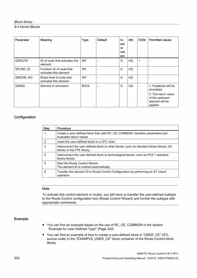
Block library 8.4 Kernel Blocks
SIMATIC Route Control (V8.0 SP1) 302 Programming and Operating Manual, 12/2012, A5E03709032-02
Parameter Meaning Type Default In-put or out-put
Attr. OCM Permitted values
QROUTE ID of route that activates this element
INT - O UQ + -
QFUNC_ID Function ID of route that activates this element
INT - O UQ - -
QMODE_NO Mode level of route that activates this element
INT - O UQ - -
QSIMU Element in simulation BOOL - O UQ - 1: Feedback will be simulated. 0: The return value of the upstream element will be applied.
Configuration Step Procedure 1 Create a user-defined block that calls RC_CE_COMMON, transfers parameters and
evaluates return values 2 Insert the user-defined block in a CFC chart. 3 Interconnect the user-defined block to other blocks, such as standard library blocks, SC
blocks or the PTE library. 4 Interconnect the user-defined block to technological blocks, such as PCS 7 standard
library blocks. 5 Start the Route Control Wizard.
The element ID is entered automatically. 6 Transfer the element ID to Route Control Configuration by performing an S7 import
operation.
Note
To activate this control element in routes, you still have to transfer the user-defined subtype to the Route Control configuration tool (Route Control Wizard) and furnish the subtype with appropriate commands.
Example ● You can find an example based on the use of RC_CE_COMMON in the section
"Example for User-Defined Type" (Page 242)
● You can find an example of how to create a user-defined block in "USER_CE" (STL source code) in the "EXAMPLE_USER_CE" block container of the Route Control block library.
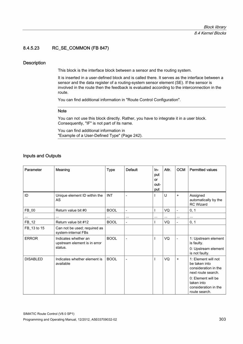
Block library 8.4 Kernel Blocks
SIMATIC Route Control (V8.0 SP1) Programming and Operating Manual, 12/2012, A5E03709032-02 303
8.4.5.23 RC_SE_COMMON (FB 847)
Description This block is the interface block between a sensor and the routing system.
It is inserted in a user-defined block and is called there. It serves as the interface between a sensor and the data register of a routing-system sensor element (SE). If the sensor is involved in the route then the feedback is evaluated according to the interconnection in the route.
You can find additional information in "Route Control Configuration".
Note
You can not use this block directly. Rather, you have to integrate it in a user block. Consequently, "IF" is not part of its name.
You can find additional information in "Example of a User-Defined Type" (Page 242).
Inputs and Outputs Parameter Meaning Type Default In-
put or out-put
Attr. OCM Permitted values
ID Unique element ID within the AS
INT - I U + Assigned automatically by the RC Wizard
FB_00 Return value bit #0 BOOL - I VQ - 0, 1 ... ... ... ... ... ... ... ... FB_12 Return value bit #12 BOOL - I VQ - 0, 1 FB_13 to 15 Can not be used; required as
system-internal FBs
ERROR Indicates whether an upstream element is in error status.
BOOL - I VQ - 1: Upstream element is faulty. 0: Upstream element is not faulty.
DISABLED Indicates whether element is available
BOOL - I VQ + 1: Element will not be taken into consideration in the next route search. 0: Element will be taken into consideration in the route search.
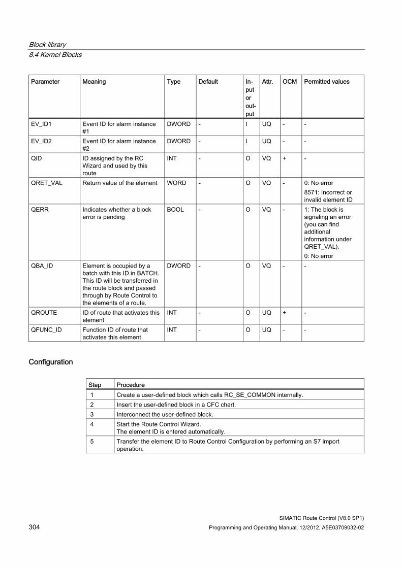
Block library 8.4 Kernel Blocks
SIMATIC Route Control (V8.0 SP1) 304 Programming and Operating Manual, 12/2012, A5E03709032-02
Parameter Meaning Type Default In-put or out-put
Attr. OCM Permitted values
EV_ID1 Event ID for alarm instance #1
DWORD - I UQ - -
EV_ID2 Event ID for alarm instance #2
DWORD - I UQ - -
QID ID assigned by the RC Wizard and used by this route
INT - O VQ + -
QRET_VAL Return value of the element WORD - O VQ - 0: No error 8571: Incorrect or invalid element ID
QERR Indicates whether a block error is pending
BOOL - O VQ - 1: The block is signaling an error (you can find additional information under QRET_VAL). 0: No error
QBA_ID Element is occupied by a batch with this ID in BATCH. This ID will be transferred in the route block and passed through by Route Control to the elements of a route.
DWORD - O VQ - -
QROUTE ID of route that activates this element
INT - O UQ + -
QFUNC_ID Function ID of route that activates this element
INT - O UQ - -
Configuration Step Procedure 1 Create a user-defined block which calls RC_SE_COMMON internally. 2 Insert the user-defined block in a CFC chart. 3 Interconnect the user-defined block. 4 Start the Route Control Wizard.
The element ID is entered automatically. 5 Transfer the element ID to Route Control Configuration by performing an S7 import
operation.
Block library 8.4 Kernel Blocks
SIMATIC Route Control (V8.0 SP1) Programming and Operating Manual, 12/2012, A5E03709032-02 305
8.4.5.24 RC_ROUTEMASTER (FB 854)
Description This block is an internal block, which controls a master route status chart.
8.4.5.25 RC_ROUTEMASTER_TELE99 (FB 855)
Description This block sends telegrams with the name of the batch and the unit to the Route Control server.
8.4.5.26 RC_ROUTEMASTER_TELEGR (FB 853)
Description This block sends request frames to the Route Control server.
8.4.5.27 RC_MASTER_MATERIAL (FB 860)
Description This block is an internal routing-system block for material management of a route in manual or automatic mode.
8.4.5.28 RC_SEND_FIFO1 (FB 890)
Description This block is an internal block for sending telegrams to the Route Control server (master).
8.4.5.29 RC_SEND_FIFO4 (FB 891)
Description This block is an internal block for sending telegrams to the Route Control server (standby).
Block library 8.4 Kernel Blocks
SIMATIC Route Control (V8.0 SP1) 306 Programming and Operating Manual, 12/2012, A5E03709032-02
8.4.5.30 RC_TG34_TG36 (FB 812)
Description This block is required to transfer telegrams to the Route Control server.
8.4.5.31 RC_TIME_DELTA (FB 879)
Description This block is an internal auxiliary block for determining time intervals.
8.4.5.32 RC_TIME_RCE (FB 810)
Description This block is a clock pulse generator for activating elements that are switched on with a time delay or that pulsate on and off.
8.4.5.33 RC_XC_DIAG (FB 897)
Description This internal block is required for AS-AS communication (cross-coupling) diagnostics.
8.4.5.34 RC_XC_FB (FB 880)
Description This block is used in the context of AS-AS communication (cross-coupling).
8.4.5.35 RC_XC_INIT (FB 896)
Description This block is used in the context of AS-AS communication (cross-coupling).
8.4.5.36 RC_XC_JOB_FB (FB 882)
Description This block is used in the context of AS-AS communication (cross-coupling).
Block library 8.4 Kernel Blocks
SIMATIC Route Control (V8.0 SP1) Programming and Operating Manual, 12/2012, A5E03709032-02 307
8.4.5.37 RC_XC_JOB_TIME_FB (FB 885)
Description This block is used in the context of AS-AS communication (cross-coupling).
8.4.5.38 RC_XC_PCU_FB (FB 881)
Description This block is used in the context of AS-AS communication (cross-coupling).
8.4.5.39 RC_XC_REMOTE_RECV (FB 834)
Description This block is used in the context of AS-AS communication (cross-coupling with a remote process cell).
8.4.5.40 RC_XC_REMOTE_SEND (FB 832)
Description This block is used in the context of AS-AS communication (cross-coupling with a remote process cell).
8.4.5.41 RC_XC_STAT_FB (FB 883)
Description This block is used in the context of AS-AS communication (cross-coupling).
8.4.5.42 RC_ZTG (FB 895)
Description This block is an internal block in the context of time processing of the routing system.

Block library 8.4 Kernel Blocks
SIMATIC Route Control (V8.0 SP1) 308 Programming and Operating Manual, 12/2012, A5E03709032-02
SIMATIC Route Control (V8.0 SP1) Programming and Operating Manual, 12/2012, A5E03709032-02 309
Guide to Configuration 99.1 General
9.1.1 Structure of guide sections
Purpose This guide supplements online help and manuals and facilitates your work with SIMATIC Route Control by providing appropriate examples.
It is intended to be a "common thread" that provides a coherent correlation between various sections of the online help and the manuals.
Areas The guide is divided into the following chapters:
● The Overview chapter presents the tools and functions of SIMATIC Route Control with respect to particular topics.
● This chapter presents the most important areas to be configured in SIMATIC Route Control.
● A number of typical use cases complete this guide. This chapter provides concrete solution approaches and suggestions, some of which include images of CFC charts and interconnected blocks.
Structure of Sections The individual sections have the following basic structure:
Section Description Requirement Typical areas of application or user tasks from practical applications,
followed by examples of proposed solutions. Overview of the procedure
General configuration procedure and the tools used
Example Proposed solution for an actual configuration case. The proposed solution is illustrated by a number of figures showing, for example, an interconnection in CFC.
Check List The most important points to be taken into account during the configuration and the learning objectives of this section
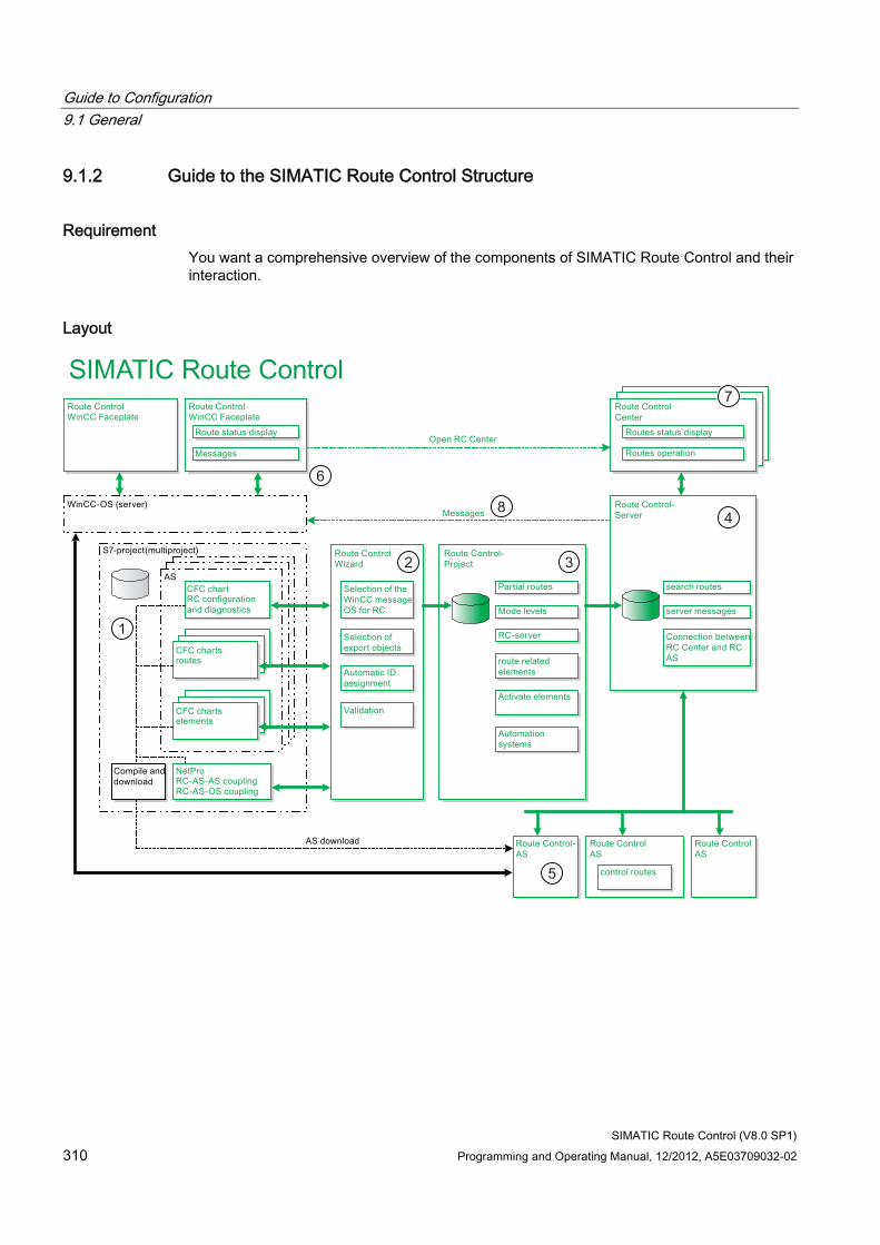
Guide to Configuration 9.1 General
SIMATIC Route Control (V8.0 SP1) 310 Programming and Operating Manual, 12/2012, A5E03709032-02
9.1.2 Guide to the SIMATIC Route Control Structure
Requirement You want a comprehensive overview of the components of SIMATIC Route Control and their interaction.
Layout
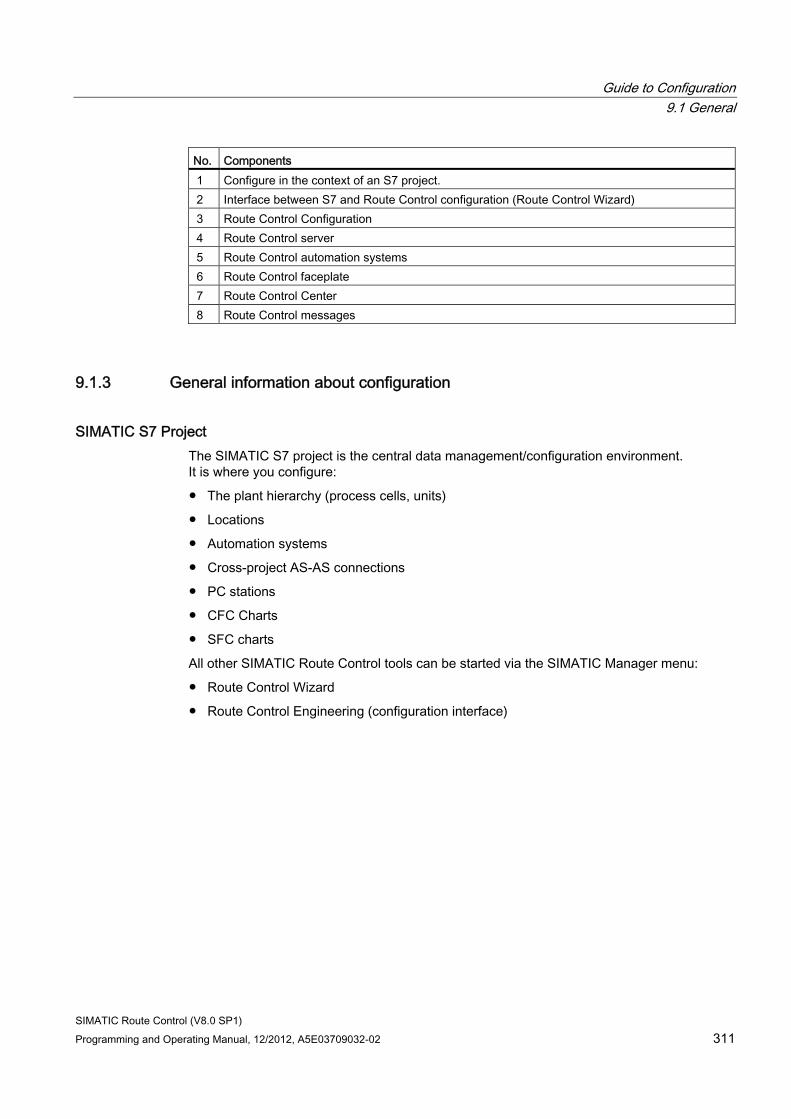
Guide to Configuration 9.1 General
SIMATIC Route Control (V8.0 SP1) Programming and Operating Manual, 12/2012, A5E03709032-02 311
No. Components 1 Configure in the context of an S7 project. 2 Interface between S7 and Route Control configuration (Route Control Wizard) 3 Route Control Configuration 4 Route Control server 5 Route Control automation systems 6 Route Control faceplate 7 Route Control Center 8 Route Control messages
9.1.3 General information about configuration
SIMATIC S7 Project The SIMATIC S7 project is the central data management/configuration environment. It is where you configure:
● The plant hierarchy (process cells, units)
● Locations
● Automation systems
● Cross-project AS-AS connections
● PC stations
● CFC Charts
● SFC charts
All other SIMATIC Route Control tools can be started via the SIMATIC Manager menu:
● Route Control Wizard
● Route Control Engineering (configuration interface)
Guide to Configuration 9.1 General
SIMATIC Route Control (V8.0 SP1) 312 Programming and Operating Manual, 12/2012, A5E03709032-02
Route Control Wizard In order to prevent duplicate configurations, the Route Control Wizard supports you in exporting configuration data from the S7 project.
The Route Control Wizard also supports you in importing configuration data (exported from the S7 project) to Route Control Engineering.
Note
You do not have to assign route IDs at the RC_IF_ROUTE blocks manually. If your project has a maximum of 300 route blocks, you can leave the FIXED_ID input with a value of 1 and the ROUTE_ID input with a value of 0 at all route blocks. The Wizard then assigns unique fixed route IDs. If there are more than 300 route blocks, use the dynamic ID assignment procedure. You can find information about this in "Guide to Dynamic ID Assignment" (Page 378).
Leave the assignment of the RC_IF_xxx interface block IDs to the wizard too.
The wizard recognizes the automation systems that are relevant for Route Control at the inserted block RC_IF_CFG and creates all NetPro connections for the cross-couplings automatically.
The wizard recognizes the PC stations that are relevant for Route Control at the inserted RC applications and creates the AS-server connections automatically too.
Route Control Engineering In Route Control Engineering, you add special routing-system objects to your configuration:
● Partial routes
● Materials and material sequences
● Mode tables
● Mode levels
You also insert the elements in partial routes.
In so doing, you also configure the following:
● Element activation
● The mode level
● Special features, such as switch-on delays and fault-tolerance times
Guide to Configuration 9.1 General
SIMATIC Route Control (V8.0 SP1) Programming and Operating Manual, 12/2012, A5E03709032-02 313
9.1.4 General information about servers and clients
Route Control server The Route Control server's main task is to find possible routes in the configured route network at the request of the AS. It can also be part of a redundant configuration. The search itself can be influenced by the following parameters, for example:
● Locked elements or elements that are already occupied by another material transport
● Elements in manual mode
● Checking of the material sequence
● Locked partial routes
In addition, the Route Control server acts as a connection between the automation systems and the user interfaces (Route Control Center) by displaying objects that are relevant for SIMATIC Route Control.
Route Control Center The Route Control Center is an application that displays detailed information about a route. In addition to the status of a route, the Route Control Center also displays all elements and their status (setpoint, actual value and mode level). You can perform the following tasks here:
● Actively intervene
● Request the route
● Start the route
● Pause the route
● Stop the route
Depending on the level of authorization, you can also specify other route parameters:
● Source and destination of the material transport
● Material
● Mode table
Guide to Configuration 9.1 General
SIMATIC Route Control (V8.0 SP1) 314 Programming and Operating Manual, 12/2012, A5E03709032-02
Route Control Faceplate in PCS 7 OS The Route Control faceplate is a user interface used for displaying and manipulating the main statuses and functions of a route. A block icon is added to a PCS 7 OS picture and interconnected with an instance of the RC_IF_ROUTE block type using the Route Control Dynamic Wizard. During runtime, the block icon can be used to open the Route Control faceplate. In addition to the route status, the faceplate also displays messages pertaining to a route. Operators can perform the following tasks here:
● Actively intervene
● Request the route
● Start the route
● Pause the route
● Stop the route
You can not select new source or destination locations here.
From this faceplate, you can switch to the BATCH Control Center (if installed), the Route Control Center or the SFC dialog box (if configured).
Guide to Configuration 9.1 General
SIMATIC Route Control (V8.0 SP1) Programming and Operating Manual, 12/2012, A5E03709032-02 315
9.1.5 General information about the automation system
Route Control Automation System The Route Control automation systems assume the most important part of material transport. Except for the route search, the entire material transport control (that is, control of elements involved in the route) is carried out here in the AS.
Because the elements for a material transport can be spread out over several automation systems, the exchange of setpoint and actual values of these elements, the mode levels, is integrated in SIMATIC Route Control.
You can configure the AS-AS connections with the help of the Route Control Wizard. The user program does not need to ensure cross-AS data transfer. The individual interfaces are as follows:
● RC_IF_ROUTE for a route
● RC_IF_... blocks for the elements for interfacing technological elements from the standard library (each AS has several of these)
● Configuration and diagnostic blocks (RC_IF_CFG, RC_IF_XC_DIAG, RC_IF_XC_LIFE, one per AS)
Interaction of Areas SIMATIC Manager and the Route Control project represent the basic environment for the Route Control configuration. All relevant information for SIMATIC Route Control is stored together in both project environments (automation systems, servers, elements, and partial routes, for example).
The configuration is partially downloaded to the AS (CFC blocks and Route Control kernel) and partially transferred to PCS 7 OS (messages and tags for picture creation).
The Route Control project is copied to the Route Control server and read in there during startup. During runtime, the Route Control blocks request a route, that is, element lists, in the AS.
The server searches for the route, assigns elements and writes these lists to the automation systems involved. At this point, the AS takes over control of the elements.
Monitoring and operator control of routes can be performed from the Route Control faceplate (via PCS 7 OS channels) and the Route Control Center (via a connection to the Route Control server).
Guide to Configuration 9.1 General
SIMATIC Route Control (V8.0 SP1) 316 Programming and Operating Manual, 12/2012, A5E03709032-02
AS Tasks The AS performs the following tasks:
● It serves as the interface to the process-related elements;
● It controls routes and elements, including cross-coupling, among automation systems;
● It evaluates feedback from the elements.
The following tasks are transparent to the user program when performed:
● Communication between the Route Control automation systems and the Route Control servers
● Route searches
● Compilation of element lists
● Distribution of these lists by the server to all participating Route Control automation systems
● Activation of elements involved in the route
Route Control contains interface blocks for interfacing technological elements, i.e., blocks, from the standard library. Adapt technological blocks from other libraries accordingly before interconnecting them to Route Control interface blocks.
If in a material transport you use elements, which are distributed across several automation systems, Route Control carries out data exchange (which is transparent to the user program) via cross-coupling connections. Route Control can also incorporate elements from another Route Control project in a route.
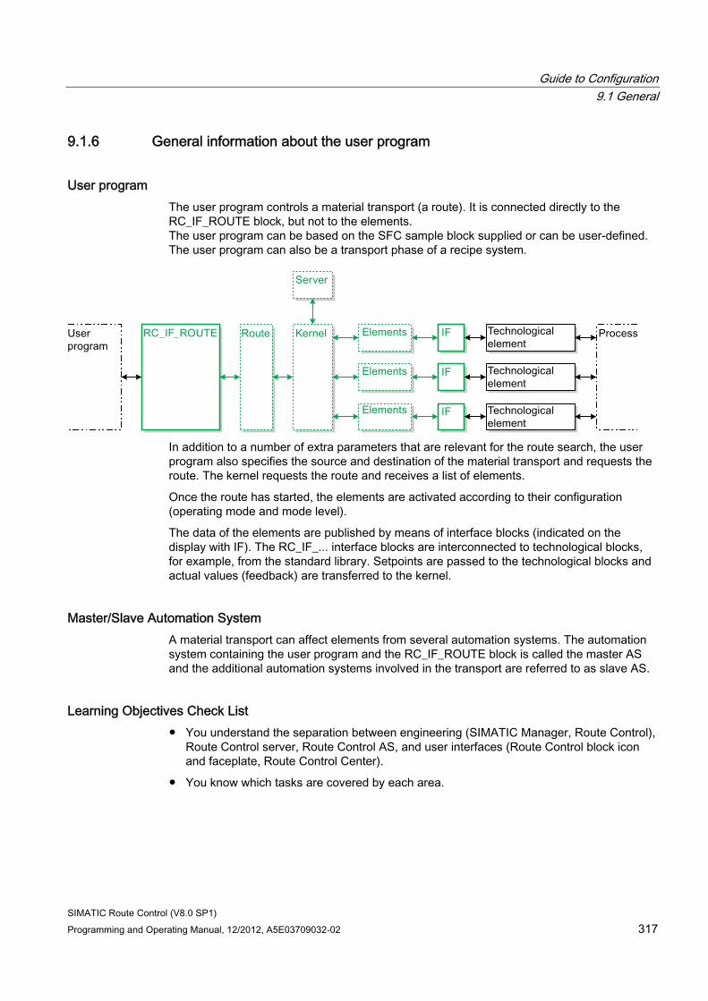
Guide to Configuration 9.1 General
SIMATIC Route Control (V8.0 SP1) Programming and Operating Manual, 12/2012, A5E03709032-02 317
9.1.6 General information about the user program
User program The user program controls a material transport (a route). It is connected directly to the RC_IF_ROUTE block, but not to the elements. The user program can be based on the SFC sample block supplied or can be user-defined. The user program can also be a transport phase of a recipe system.
In addition to a number of extra parameters that are relevant for the route search, the user program also specifies the source and destination of the material transport and requests the route. The kernel requests the route and receives a list of elements.
Once the route has started, the elements are activated according to their configuration (operating mode and mode level).
The data of the elements are published by means of interface blocks (indicated on the display with IF). The RC_IF_... interface blocks are interconnected to technological blocks, for example, from the standard library. Setpoints are passed to the technological blocks and actual values (feedback) are transferred to the kernel.
Master/Slave Automation System A material transport can affect elements from several automation systems. The automation system containing the user program and the RC_IF_ROUTE block is called the master AS and the additional automation systems involved in the transport are referred to as slave AS.
Learning Objectives Check List ● You understand the separation between engineering (SIMATIC Manager, Route Control),
Route Control server, Route Control AS, and user interfaces (Route Control block icon and faceplate, Route Control Center).
● You know which tasks are covered by each area.
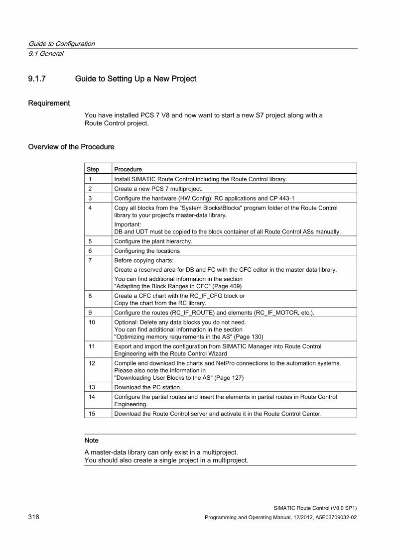
Guide to Configuration 9.1 General
SIMATIC Route Control (V8.0 SP1) 318 Programming and Operating Manual, 12/2012, A5E03709032-02
9.1.7 Guide to Setting Up a New Project
Requirement You have installed PCS 7 V8 and now want to start a new S7 project along with a Route Control project.
Overview of the Procedure Step Procedure 1 Install SIMATIC Route Control including the Route Control library. 2 Create a new PCS 7 multiproject. 3 Configure the hardware (HW Config): RC applications and CP 443-1 4 Copy all blocks from the "System Blocks\Blocks" program folder of the Route Control
library to your project's master-data library. Important: DB and UDT must be copied to the block container of all Route Control ASs manually.
5 Configure the plant hierarchy. 6 Configuring the locations 7 Before copying charts:
Create a reserved area for DB and FC with the CFC editor in the master data library. You can find additional information in the section "Adapting the Block Ranges in CFC" (Page 409)
8 Create a CFC chart with the RC_IF_CFG block or Copy the chart from the RC library.
9 Configure the routes (RC_IF_ROUTE) and elements (RC_IF_MOTOR, etc.). 10 Optional: Delete any data blocks you do not need.
You can find additional information in the section "Optimizing memory requirements in the AS" (Page 130)
11 Export and import the configuration from SIMATIC Manager into Route Control Engineering with the Route Control Wizard
12 Compile and download the charts and NetPro connections to the automation systems. Please also note the information in "Downloading User Blocks to the AS" (Page 127)
13 Download the PC station. 14 Configure the partial routes and insert the elements in partial routes in Route Control
Engineering. 15 Download the Route Control server and activate it in the Route Control Center.
Note
A master-data library can only exist in a multiproject. You should also create a single project in a multiproject.
Guide to Configuration 9.1 General
SIMATIC Route Control (V8.0 SP1) Programming and Operating Manual, 12/2012, A5E03709032-02 319
Project Engineering Checklist ● The S7 project is available.
● The global settings have been made (block ranges).
● CFC charts are available, for example, for the blocks below:
– RC_IF_CFG
– RC_IF_XC_DIAG
– RC_IF_XC_LIFE
– RC_IF_ROUTE
– RC_IF_MOTOR
● The Route Control project is available.
● The blocks have been compiled and downloaded.
Guide to Configuration 9.1 General
SIMATIC Route Control (V8.0 SP1) 320 Programming and Operating Manual, 12/2012, A5E03709032-02
9.1.8 Guide to Predefined Element Types
Requirement You want to know which element types are already predefined and how you can add your own element types.
Predefined Element Types Both the Route Control library and the configuration environment contain predefined element types for the following four groups:
● Control elements (and subtypes)
● Parameter elements (and subtypes)
● Sensor elements
● Link elements
Additional information ● You can find the list of interface blocks for elements in the section
"Route Control Blocks" (Page 155)
● You will find a description of how to create and transfer user-defined block types in the section "User-defined type (Page 242)
Learning Objectives Check List ● You are familiar with the four main groups of element types.
● You are familiar with the subtypes.
● You can create your own type, use it in a CFC chart and add it to the Route Control configuration.
See also General information about block descriptions (Page 156)
Guide to Configuration 9.1 General
SIMATIC Route Control (V8.0 SP1) Programming and Operating Manual, 12/2012, A5E03709032-02 321
9.1.9 Guide to External Parameter Elements
User Task Some setpoints will not have been declared when the parameter elements are configured. For example, material quantities that must be weighed are typically supplied as batch parameters from a recipe system and are dependent on the size of the batch. Another example of such parameters are the level sensors, where the actual value detected by these sensors is compared with a setpoint. The fill process is terminated when a set volume, which can only be determined during runtime, has been reached.
Overview of Procedure In such cases, so-called external parameter elements are included in a partial route. External parameter elements (ext. PEs for short) are different from internal PEs in that configured setpoints do not represent the direct setpoint for the process, but act as an index for the inputs EXT_ .. _I, whereby ... stands for the index 1 to 24. This value can be specified in the Properties dialog of an interconnected parameter element in a partial route.
Upon runtime activation of the mode level at which this parameter element is inserted in the partial route, the route transfers the value of the corresponding EXT_..._I input as a setpoint to the data record of a parameter element. (This can be seen in the RC_IF_VOLUME or RC_IF_TIMER interface block.) In return, the actual value of the parameter element is transferred to the outputs of RC_IF_ROUTE EXT_..._O, where it can be accepted by the user program. ... corresponds to the index.
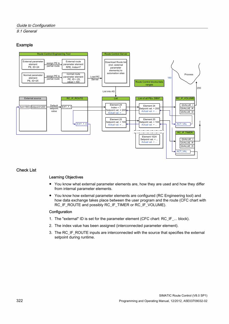
Guide to Configuration 9.1 General
SIMATIC Route Control (V8.0 SP1) 322 Programming and Operating Manual, 12/2012, A5E03709032-02
Example
Check List Learning Objectives
● You know what external parameter elements are, how they are used and how they differ from internal parameter elements.
● You know how external parameter elements are configured (RC Engineering tool) and how data exchange takes place between the user program and the route (CFC chart with RC_IF_ROUTE and possibly RC_IF_TIMER or RC_IF_VOLUME).
Configuration
1. The "external" ID is set for the parameter element (CFC chart: RC_IF_... block).
2. The index value has been assigned (interconnected parameter element).
3. The RC_IF_ROUTE inputs are interconnected with the source that specifies the external setpoint during runtime.
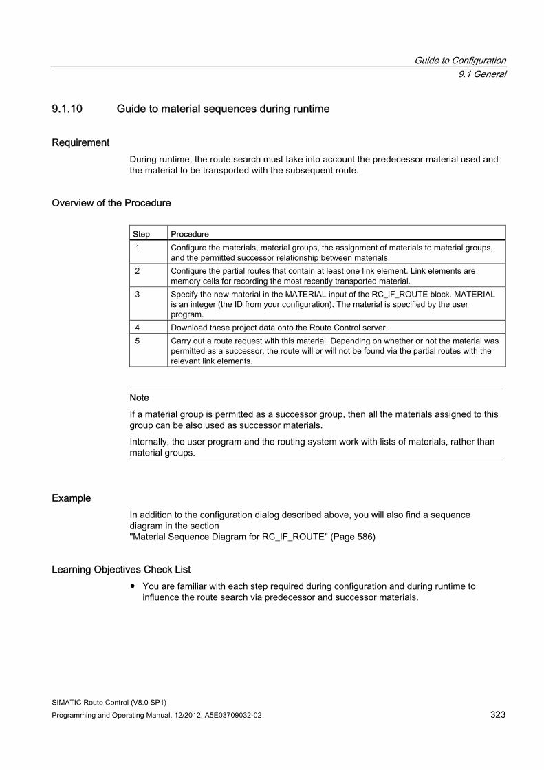
Guide to Configuration 9.1 General
SIMATIC Route Control (V8.0 SP1) Programming and Operating Manual, 12/2012, A5E03709032-02 323
9.1.10 Guide to material sequences during runtime
Requirement During runtime, the route search must take into account the predecessor material used and the material to be transported with the subsequent route.
Overview of the Procedure Step Procedure 1 Configure the materials, material groups, the assignment of materials to material groups,
and the permitted successor relationship between materials. 2 Configure the partial routes that contain at least one link element. Link elements are
memory cells for recording the most recently transported material. 3 Specify the new material in the MATERIAL input of the RC_IF_ROUTE block. MATERIAL
is an integer (the ID from your configuration). The material is specified by the user program.
4 Download these project data onto the Route Control server. 5 Carry out a route request with this material. Depending on whether or not the material was
permitted as a successor, the route will or will not be found via the partial routes with the relevant link elements.
Note
If a material group is permitted as a successor group, then all the materials assigned to this group can be also used as successor materials.
Internally, the user program and the routing system work with lists of materials, rather than material groups.
Example In addition to the configuration dialog described above, you will also find a sequence diagram in the section "Material Sequence Diagram for RC_IF_ROUTE" (Page 586)
Learning Objectives Check List ● You are familiar with each step required during configuration and during runtime to
influence the route search via predecessor and successor materials.
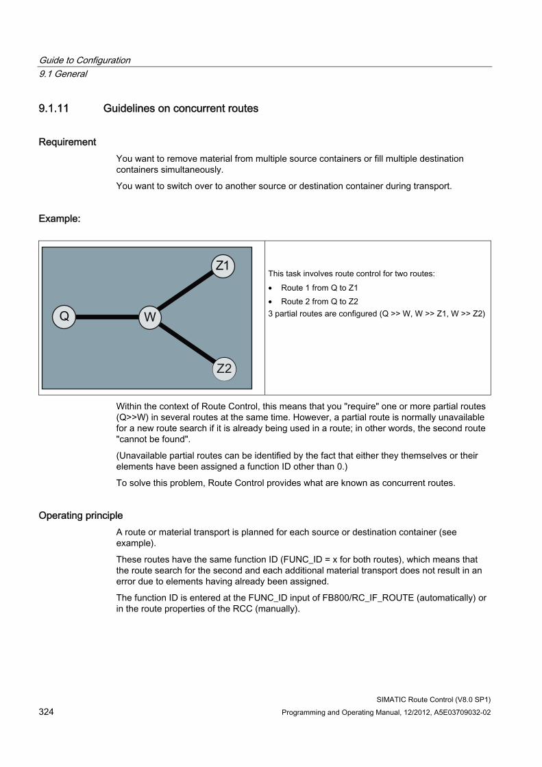
Guide to Configuration 9.1 General
SIMATIC Route Control (V8.0 SP1) 324 Programming and Operating Manual, 12/2012, A5E03709032-02
9.1.11 Guidelines on concurrent routes
Requirement You want to remove material from multiple source containers or fill multiple destination containers simultaneously.
You want to switch over to another source or destination container during transport.
Example:
This task involves route control for two routes: • Route 1 from Q to Z1 • Route 2 from Q to Z2 3 partial routes are configured (Q >> W, W >> Z1, W >> Z2)
Within the context of Route Control, this means that you "require" one or more partial routes (Q>>W) in several routes at the same time. However, a partial route is normally unavailable for a new route search if it is already being used in a route; in other words, the second route "cannot be found".
(Unavailable partial routes can be identified by the fact that either they themselves or their elements have been assigned a function ID other than 0.)
To solve this problem, Route Control provides what are known as concurrent routes.
Operating principle A route or material transport is planned for each source or destination container (see example).
These routes have the same function ID (FUNC_ID = x for both routes), which means that the route search for the second and each additional material transport does not result in an error due to elements having already been assigned.
The function ID is entered at the FUNC_ID input of FB800/RC_IF_ROUTE (automatically) or in the route properties of the RCC (manually).
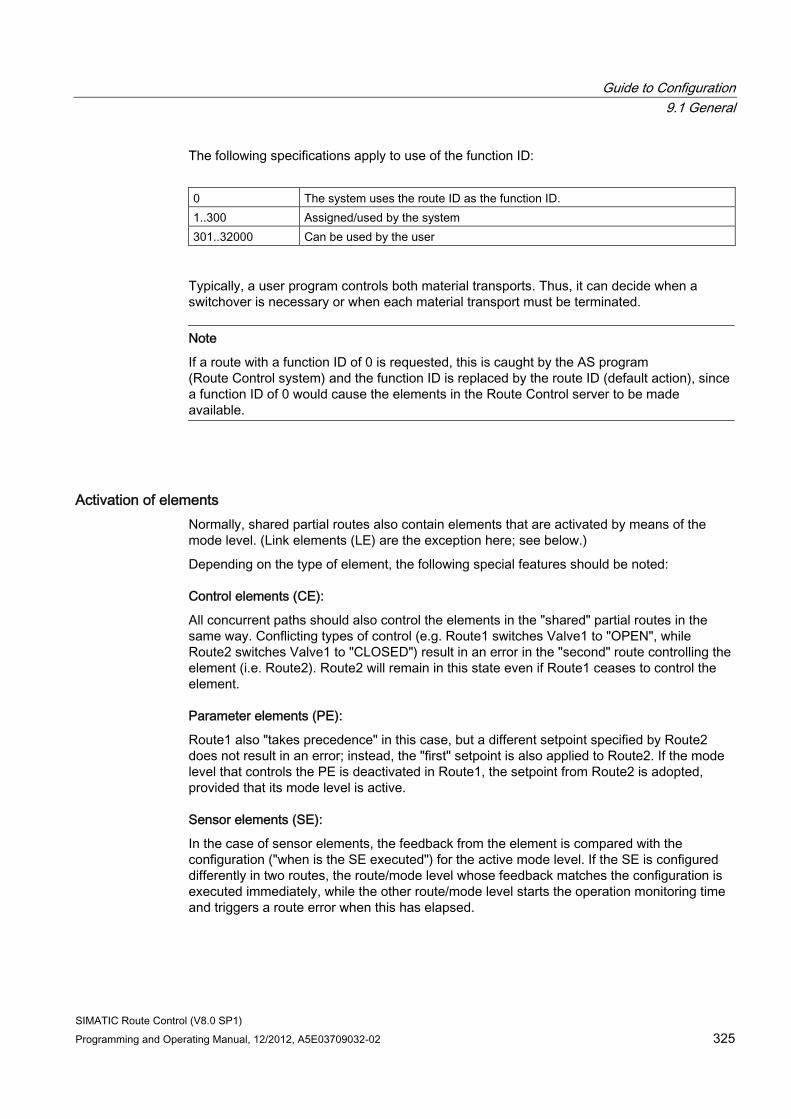
Guide to Configuration 9.1 General
SIMATIC Route Control (V8.0 SP1) Programming and Operating Manual, 12/2012, A5E03709032-02 325
The following specifications apply to use of the function ID:
0 The system uses the route ID as the function ID. 1..300 Assigned/used by the system 301..32000 Can be used by the user
Typically, a user program controls both material transports. Thus, it can decide when a switchover is necessary or when each material transport must be terminated.
Note
If a route with a function ID of 0 is requested, this is caught by the AS program (Route Control system) and the function ID is replaced by the route ID (default action), since a function ID of 0 would cause the elements in the Route Control server to be made available.
Activation of elements Normally, shared partial routes also contain elements that are activated by means of the mode level. (Link elements (LE) are the exception here; see below.)
Depending on the type of element, the following special features should be noted:
Control elements (CE):
All concurrent paths should also control the elements in the "shared" partial routes in the same way. Conflicting types of control (e.g. Route1 switches Valve1 to "OPEN", while Route2 switches Valve1 to "CLOSED") result in an error in the "second" route controlling the element (i.e. Route2). Route2 will remain in this state even if Route1 ceases to control the element.
Parameter elements (PE):
Route1 also "takes precedence" in this case, but a different setpoint specified by Route2 does not result in an error; instead, the "first" setpoint is also applied to Route2. If the mode level that controls the PE is deactivated in Route1, the setpoint from Route2 is adopted, provided that its mode level is active.
Sensor elements (SE):
In the case of sensor elements, the feedback from the element is compared with the configuration ("when is the SE executed") for the active mode level. If the SE is configured differently in two routes, the route/mode level whose feedback matches the configuration is executed immediately, while the other route/mode level starts the operation monitoring time and triggers a route error when this has elapsed.
Guide to Configuration 9.1 General
SIMATIC Route Control (V8.0 SP1) 326 Programming and Operating Manual, 12/2012, A5E03709032-02
Link elements (LE):
These are not related to the mode level, but instead are updated when one of the possible activation functions for the material is initiated. The link elements configured in the concurrent routes contain the material that was up to date when the most recent "Set material" function was executed.
Learning Objectives Check List ● You are familiar with the concept of concurrent routes.
● You know how certain parameters should be assigned during runtime (FUNC_ID = x for both routes).
Guide to Configuration 9.1 General
SIMATIC Route Control (V8.0 SP1) Programming and Operating Manual, 12/2012, A5E03709032-02 327
9.1.12 Guide to the block icon and faceplate
User Task
You want to interconnect the block icon and the faceplate to a route block to display information about the route in a PCS 7 OS picture during runtime.
Requirements ● You have created a CFC chart with an RC_IF_ROUTE block.
● You have performed PCS 7 OS compilation so that tags are available.
Overview of Procedure Installation of the Route Control Engineering component has provided you with a Route Control Dynamic Wizard and a block icon.
Step Procedure 1 Copy the block icon to a PCS 7 OS picture. 2 Start the Route Control Dynamic Wizard
This wizard guides you through a number of steps in order to interconnect the block icon to an instance of block type RC_IF_ROUTE. Optional: Preassign the name of an SFC chart to parameter SFC_PATH. Enter the name of the SFC chart which controls this route. During runtime you will be able to open an SFC dialog box from the Route Control faceplate indicating the current status of the SFC. This is particularly useful for diagnostic purposes.
Note
The elements or their interface blocks do not have their own faceplates for PCS 7 OS because the process-related elements, for example, from the standard library, already contain such faceplates. For diagnostic purposes, you have the Route Control Center and the CFC Editor online view.
Example ● Section "Starting the Dynamic Wizard" (Page 441)
Configuration Check List 1. You have placed a block icon and interconnected it to a route (RC_IF_ROUTE).
2. You have supplied the SFC_PATH parameter correctly.
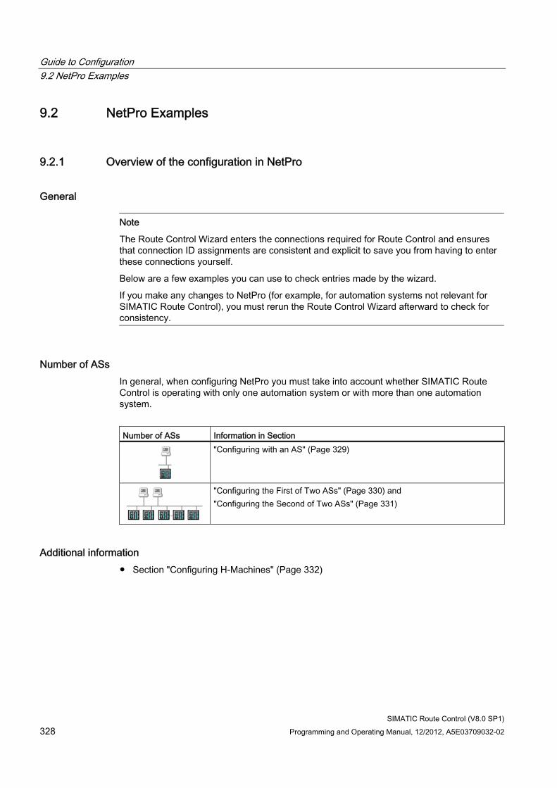
Guide to Configuration 9.2 NetPro Examples
SIMATIC Route Control (V8.0 SP1) 328 Programming and Operating Manual, 12/2012, A5E03709032-02
9.2 NetPro Examples
9.2.1 Overview of the configuration in NetPro
General
Note
The Route Control Wizard enters the connections required for Route Control and ensures that connection ID assignments are consistent and explicit to save you from having to enter these connections yourself.
Below are a few examples you can use to check entries made by the wizard.
If you make any changes to NetPro (for example, for automation systems not relevant for SIMATIC Route Control), you must rerun the Route Control Wizard afterward to check for consistency.
Number of ASs In general, when configuring NetPro you must take into account whether SIMATIC Route Control is operating with only one automation system or with more than one automation system.
Number of ASs Information in Section
"Configuring with an AS" (Page 329)
"Configuring the First of Two ASs" (Page 330) and "Configuring the Second of Two ASs" (Page 331)
Additional information ● Section "Configuring H-Machines" (Page 332)
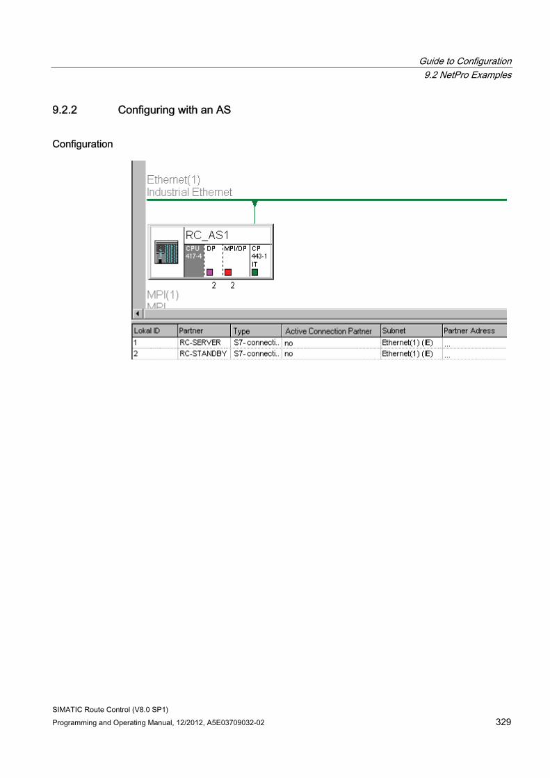
Guide to Configuration 9.2 NetPro Examples
SIMATIC Route Control (V8.0 SP1) Programming and Operating Manual, 12/2012, A5E03709032-02 329
9.2.2 Configuring with an AS
Configuration
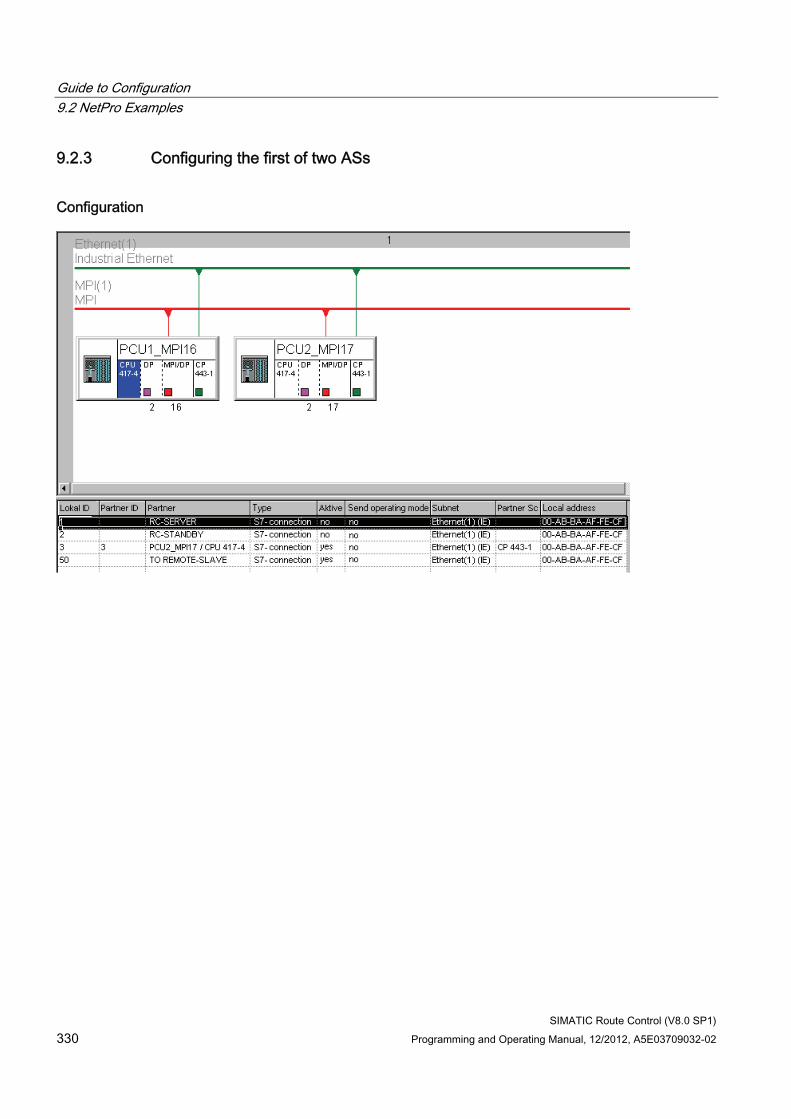
Guide to Configuration 9.2 NetPro Examples
SIMATIC Route Control (V8.0 SP1) 330 Programming and Operating Manual, 12/2012, A5E03709032-02
9.2.3 Configuring the first of two ASs
Configuration
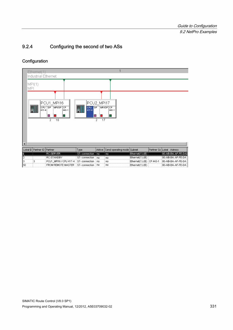
Guide to Configuration 9.2 NetPro Examples
SIMATIC Route Control (V8.0 SP1) Programming and Operating Manual, 12/2012, A5E03709032-02 331
9.2.4 Configuring the second of two ASs
Configuration
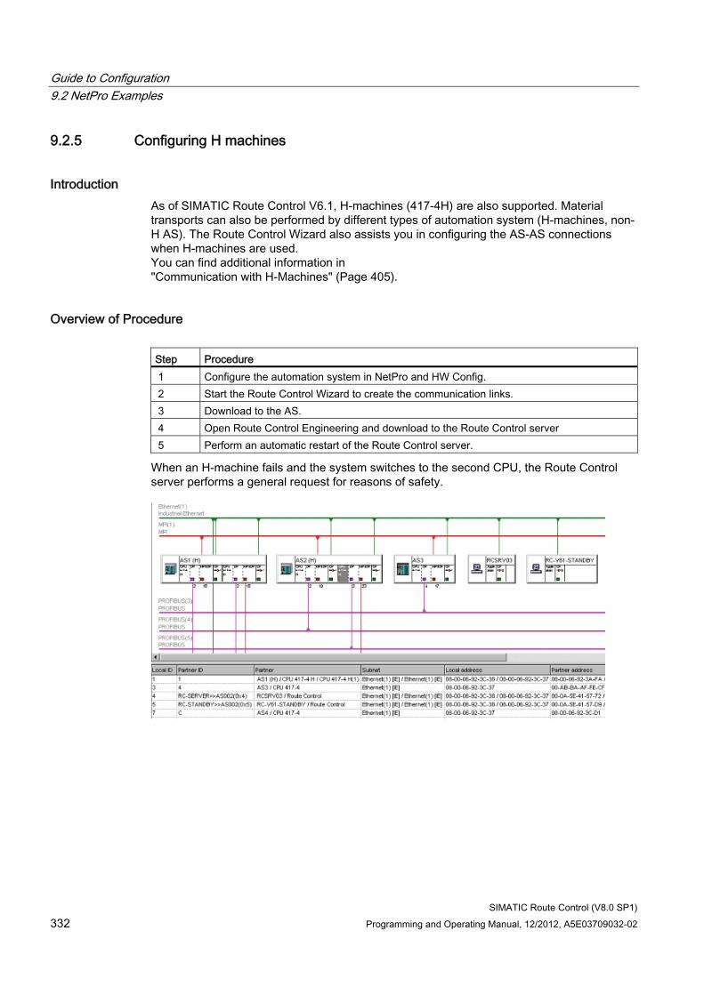
Guide to Configuration 9.2 NetPro Examples
SIMATIC Route Control (V8.0 SP1) 332 Programming and Operating Manual, 12/2012, A5E03709032-02
9.2.5 Configuring H machines
Introduction As of SIMATIC Route Control V6.1, H-machines (417-4H) are also supported. Material transports can also be performed by different types of automation system (H-machines, non-H AS). The Route Control Wizard also assists you in configuring the AS-AS connections when H-machines are used. You can find additional information in "Communication with H-Machines" (Page 405).
Overview of Procedure Step Procedure 1 Configure the automation system in NetPro and HW Config. 2 Start the Route Control Wizard to create the communication links. 3 Download to the AS. 4 Open Route Control Engineering and download to the Route Control server 5 Perform an automatic restart of the Route Control server.
When an H-machine fails and the system switches to the second CPU, the Route Control server performs a general request for reasons of safety.
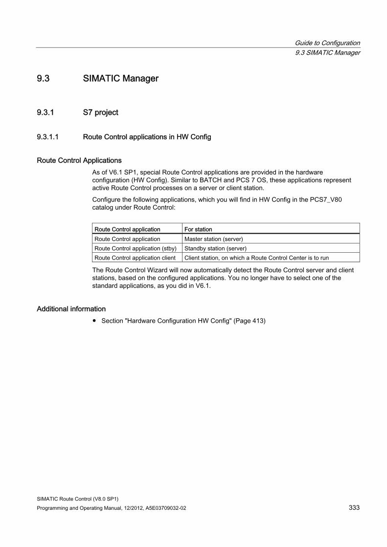
Guide to Configuration 9.3 SIMATIC Manager
SIMATIC Route Control (V8.0 SP1) Programming and Operating Manual, 12/2012, A5E03709032-02 333
9.3 SIMATIC Manager
9.3.1 S7 project
9.3.1.1 Route Control applications in HW Config
Route Control Applications As of V6.1 SP1, special Route Control applications are provided in the hardware configuration (HW Config). Similar to BATCH and PCS 7 OS, these applications represent active Route Control processes on a server or client station.
Configure the following applications, which you will find in HW Config in the PCS7_V80 catalog under Route Control:
Route Control application For station Route Control application Master station (server) Route Control application (stby) Standby station (server) Route Control application client Client station, on which a Route Control Center is to run
The Route Control Wizard will now automatically detect the Route Control server and client stations, based on the configured applications. You no longer have to select one of the standard applications, as you did in V6.1.
Additional information ● Section "Hardware Configuration HW Config" (Page 413)
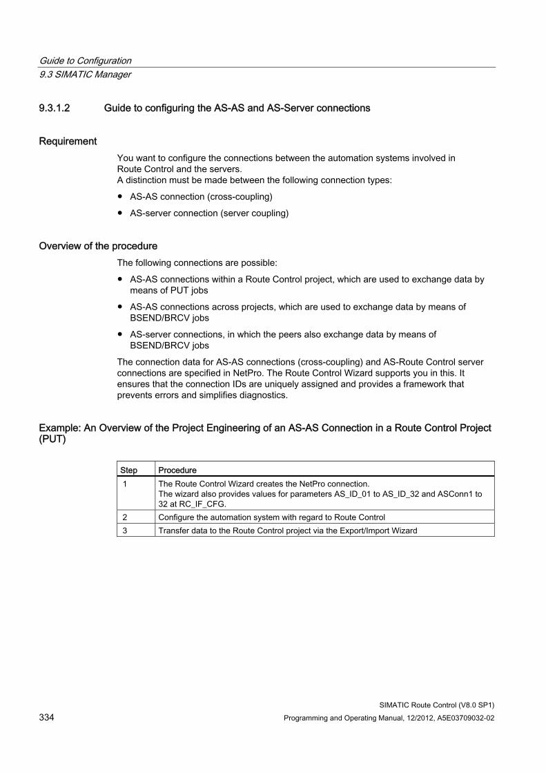
Guide to Configuration 9.3 SIMATIC Manager
SIMATIC Route Control (V8.0 SP1) 334 Programming and Operating Manual, 12/2012, A5E03709032-02
9.3.1.2 Guide to configuring the AS-AS and AS-Server connections
Requirement You want to configure the connections between the automation systems involved in Route Control and the servers. A distinction must be made between the following connection types:
● AS-AS connection (cross-coupling)
● AS-server connection (server coupling)
Overview of the procedure The following connections are possible:
● AS-AS connections within a Route Control project, which are used to exchange data by means of PUT jobs
● AS-AS connections across projects, which are used to exchange data by means of BSEND/BRCV jobs
● AS-server connections, in which the peers also exchange data by means of BSEND/BRCV jobs
The connection data for AS-AS connections (cross-coupling) and AS-Route Control server connections are specified in NetPro. The Route Control Wizard supports you in this. It ensures that the connection IDs are uniquely assigned and provides a framework that prevents errors and simplifies diagnostics.
Example: An Overview of the Project Engineering of an AS-AS Connection in a Route Control Project (PUT)
Step Procedure 1 The Route Control Wizard creates the NetPro connection.
The wizard also provides values for parameters AS_ID_01 to AS_ID_32 and ASConn1 to 32 at RC_IF_CFG.
2 Configure the automation system with regard to Route Control 3 Transfer data to the Route Control project via the Export/Import Wizard
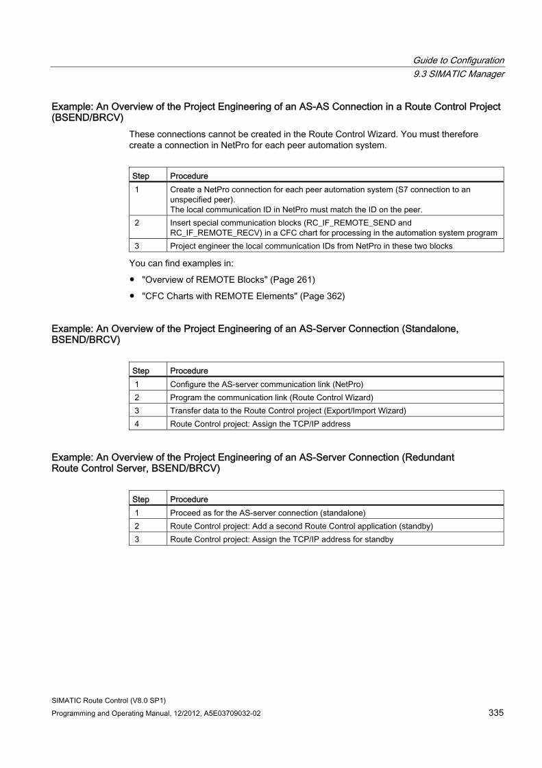
Guide to Configuration 9.3 SIMATIC Manager
SIMATIC Route Control (V8.0 SP1) Programming and Operating Manual, 12/2012, A5E03709032-02 335
Example: An Overview of the Project Engineering of an AS-AS Connection in a Route Control Project (BSEND/BRCV)
These connections cannot be created in the Route Control Wizard. You must therefore create a connection in NetPro for each peer automation system.
Step Procedure 1 Create a NetPro connection for each peer automation system (S7 connection to an
unspecified peer). The local communication ID in NetPro must match the ID on the peer.
2 Insert special communication blocks (RC_IF_REMOTE_SEND and RC_IF_REMOTE_RECV) in a CFC chart for processing in the automation system program
3 Project engineer the local communication IDs from NetPro in these two blocks
You can find examples in:
● "Overview of REMOTE Blocks" (Page 261)
● "CFC Charts with REMOTE Elements" (Page 362)
Example: An Overview of the Project Engineering of an AS-Server Connection (Standalone, BSEND/BRCV)
Step Procedure 1 Configure the AS-server communication link (NetPro) 2 Program the communication link (Route Control Wizard) 3 Transfer data to the Route Control project (Export/Import Wizard) 4 Route Control project: Assign the TCP/IP address
Example: An Overview of the Project Engineering of an AS-Server Connection (Redundant Route Control Server, BSEND/BRCV)
Step Procedure 1 Proceed as for the AS-server connection (standalone) 2 Route Control project: Add a second Route Control application (standby) 3 Route Control project: Assign the TCP/IP address for standby
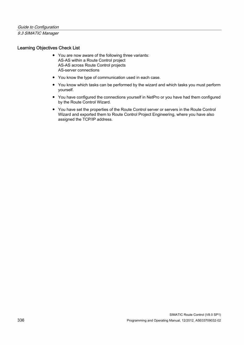
Guide to Configuration 9.3 SIMATIC Manager
SIMATIC Route Control (V8.0 SP1) 336 Programming and Operating Manual, 12/2012, A5E03709032-02
Learning Objectives Check List ● You are now aware of the following three variants:
AS-AS within a Route Control project AS-AS across Route Control projects AS-server connections
● You know the type of communication used in each case.
● You know which tasks can be performed by the wizard and which tasks you must perform yourself.
● You have configured the connections yourself in NetPro or you have had them configured by the Route Control Wizard.
● You have set the properties of the Route Control server or servers in the Route Control Wizard and exported them to Route Control Project Engineering, where you have also assigned the TCP/IP address.
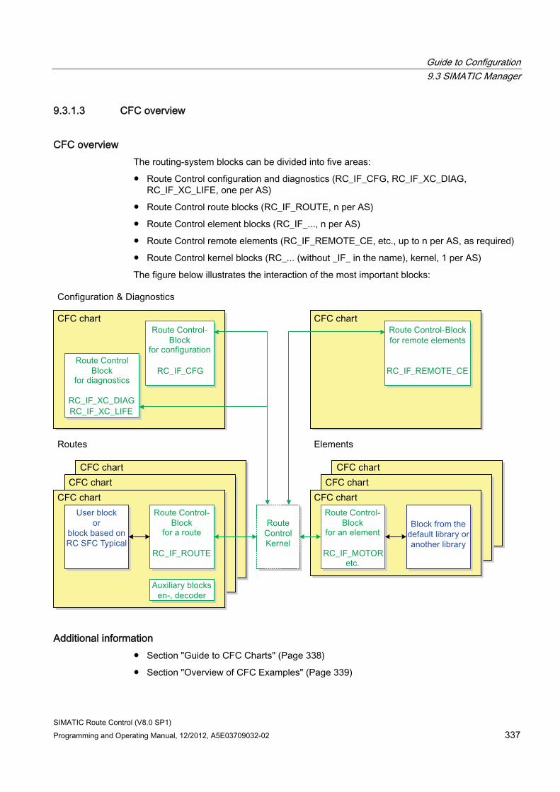
Guide to Configuration 9.3 SIMATIC Manager
SIMATIC Route Control (V8.0 SP1) Programming and Operating Manual, 12/2012, A5E03709032-02 337
9.3.1.3 CFC overview
CFC overview The routing-system blocks can be divided into five areas:
● Route Control configuration and diagnostics (RC_IF_CFG, RC_IF_XC_DIAG, RC_IF_XC_LIFE, one per AS)
● Route Control route blocks (RC_IF_ROUTE, n per AS)
● Route Control element blocks (RC_IF_..., n per AS)
● Route Control remote elements (RC_IF_REMOTE_CE, etc., up to n per AS, as required)
● Route Control kernel blocks (RC_... (without _IF_ in the name), kernel, 1 per AS)
The figure below illustrates the interaction of the most important blocks:
Additional information ● Section "Guide to CFC Charts" (Page 338)
● Section "Overview of CFC Examples" (Page 339)
Guide to Configuration 9.3 SIMATIC Manager
SIMATIC Route Control (V8.0 SP1) 338 Programming and Operating Manual, 12/2012, A5E03709032-02
9.3.1.4 Guide to CFC charts
User Task In addition to the relevant centralized configurations for a Route Control AS, you want to create the CFC charts for a route and the elements.
Overview of Procedure Step Procedure 1 Configure a CFC chart with one RC_IF_CFG type block per AS.
You also have the option of positioning two additional blocks for diagnostic purposes: RC_IF_XC_DIAG RC_IF_XC_LIFE These two blocks are then required for diagnostics if cross-coupling is used in Route Control, i.e., if the Route Control project contains more than one AS.
2 One instance of block type RC_IF_ROUTE is required per material transport (or route). We recommend that you create a separate CFC chart for each route to include the user program and an optional RC_IF_DECODER and RC_IF_ENCODER, as well as the RC_IF_ROUTE.
3 Creating separate CFC charts for the elements; this is because, in addition to the Route Control interface block (such as an RC_IF_MOTOR), the process-related block from the standard library (e.g., the MOTOR block) and other auxiliary blocks are also inserted in the CFC charts.
Examples ● Section "Overview of CFC Examples" (Page 339)
Learning Objectives Check List ● For each automation system, you have inserted one centralized CFC chart in which a
block of type RC_IF_CFG has been placed and configured.
● You have created one (or more) CFC chart(s) and placed blocks of type RC_IF_ROUTE for route activation by the user program.
● You have created one (or more) CFC charts and placed blocks of type RC_IF_VALVE, RC_IF_MOTOR, or a similar type to activate process-related elements.
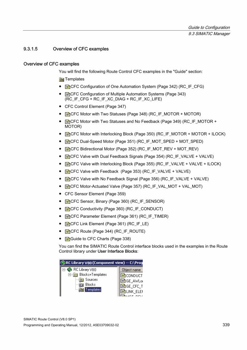
Guide to Configuration 9.3 SIMATIC Manager
SIMATIC Route Control (V8.0 SP1) Programming and Operating Manual, 12/2012, A5E03709032-02 339
9.3.1.5 Overview of CFC examples
Overview of CFC examples You will find the following Route Control CFC examples in the "Guide" section:
Templates
● CFC Configuration of One Automation System (Page 342) (RC_IF_CFG)
● CFC Configuration of Multiple Automation Systems (Page 343) (RC_IF_CFG + RC_IF_XC_DIAG + RC_IF_XC_LIFE)
● CFC Control Element (Page 347)
● CFC Motor with Two Statuses (Page 348) (RC_IF_MOTOR + MOTOR)
● CFC Motor with Two Statuses and No Feedback (Page 349) (RC_IF_MOTOR + MOTOR)
● CFC Motor with Interlocking Block (Page 350) (RC_IF_MOTOR + MOTOR + ILOCK)
● CFC Dual-Speed Motor (Page 351) (RC_IF_MOT_SPED + MOT_SPED)
● CFC Bidirectional Motor (Page 352) (RC_IF_MOT_REV + MOT_REV)
● CFC Valve with Dual Feedback Signals (Page 354) (RC_IF_VALVE + VALVE)
● CFC Valve with Interlocking Block (Page 355) (RC_IF_VALVE + VALVE + ILOCK)
● CFC Valve with Feedback (Page 353) (RC_IF_VALVE + VALVE)
● CFC Valve with No Feedback Signal (Page 356) (RC_IF_VALVE + VALVE)
● CFC Motor-Actuated Valve (Page 357) (RC_IF_VAL_MOT + VAL_MOT)
● CFC Sensor Element (Page 359)
● CFC Sensor, Binary (Page 360) (RC_IF_SENSOR)
● CFC Conductivity (Page 360) (RC_IF_CONDUCT)
● CFC Parameter Element (Page 361) (RC_IF_TIMER)
● CFC Link Element (Page 361) (RC_IF_LE)
● CFC Route (Page 344) (RC_IF_ROUTE)
● Guide to CFC Charts (Page 338)
You can find the SIMATIC Route Control interface blocks used in the examples in the Route Control library under User Interface Blocks:
Guide to Configuration 9.3 SIMATIC Manager
SIMATIC Route Control (V8.0 SP1) 340 Programming and Operating Manual, 12/2012, A5E03709032-02
9.3.1.6 Guide to the Route Control SFC type
User Task You want to use a standardized basic framework as the basis for your user program for controlling a route.
Overview of Procedure Step Procedure 1 Copy the Route Control SFC type from the Route Control library to your own project. 2 Adapt the type to meet your requirements.
The Route Control SFC type already includes a number of steps that are identical for all route-control processes: • Assigning "static" parameters * (source, destination, mode table, material, route ID,
times) • Requesting the route • Starting the route • Controlling the material transport (specification of mode-level feedback evaluation) • Specifying another material and external setpoints • Holding the route • Ending the route
* with respect to the duration of a material transport
Additional information ● Section "SFC Overview" (Page 372)
Check List ● You are familiar with the Route Control SFC type and know how to use it as a basis for
your own SFC user programs.
● You are familiar with each status or branch of the SFC type and the actions that can be typically carried out in each one.
● You know the data that are exchanged between the user program (SFC) and the route.
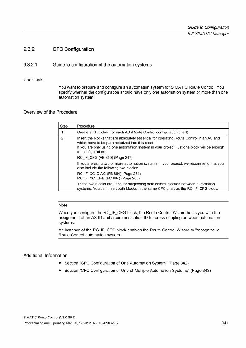
Guide to Configuration 9.3 SIMATIC Manager
SIMATIC Route Control (V8.0 SP1) Programming and Operating Manual, 12/2012, A5E03709032-02 341
9.3.2 CFC Configuration
9.3.2.1 Guide to configuration of the automation systems
User task You want to prepare and configure an automation system for SIMATIC Route Control. You specify whether the configuration should have only one automation system or more than one automation system.
Overview of the Procedure Step Procedure 1 Create a CFC chart for each AS (Route Control configuration chart) 2 Insert the blocks that are absolutely essential for operating Route Control in an AS and
which have to be parameterized into this chart. If you are only using one automation system in your project, just one block will be enough for configuration: RC_IF_CFG (FB 850) (Page 247) If you are using two or more automation systems in your project, we recommend that you also include the following two blocks: RC_IF_XC_DIAG (FB 884) (Page 254) RC_IF_XC_LIFE (FC 884) (Page 260) These two blocks are used for diagnosing data communication between automation systems. You can insert both blocks in the same CFC chart as the RC_IF_CFG block.
Note
When you configure the RC_IF_CFG block, the Route Control Wizard helps you with the assignment of an AS ID and a communication ID for cross-coupling between automation systems.
An instance of the RC_IF_CFG block enables the Route Control Wizard to "recognize" a Route Control automation system.
Additional Information ● Section "CFC Configuration of One Automation System" (Page 342)
● Section "CFC Configuration of One of Multiple Automation Systems" (Page 343)
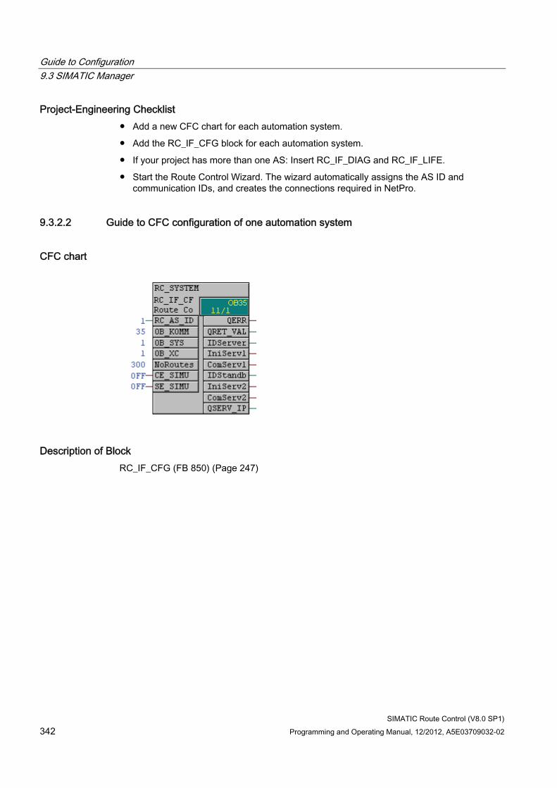
Guide to Configuration 9.3 SIMATIC Manager
SIMATIC Route Control (V8.0 SP1) 342 Programming and Operating Manual, 12/2012, A5E03709032-02
Project-Engineering Checklist ● Add a new CFC chart for each automation system.
● Add the RC_IF_CFG block for each automation system.
● If your project has more than one AS: Insert RC_IF_DIAG and RC_IF_LIFE.
● Start the Route Control Wizard. The wizard automatically assigns the AS ID and communication IDs, and creates the connections required in NetPro.
9.3.2.2 Guide to CFC configuration of one automation system
CFC chart
Description of Block RC_IF_CFG (FB 850) (Page 247)
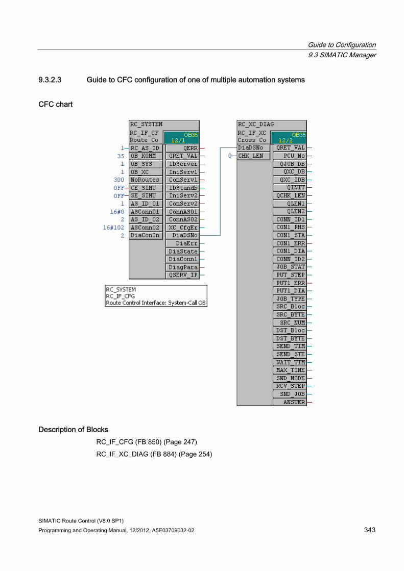
Guide to Configuration 9.3 SIMATIC Manager
SIMATIC Route Control (V8.0 SP1) Programming and Operating Manual, 12/2012, A5E03709032-02 343
9.3.2.3 Guide to CFC configuration of one of multiple automation systems
CFC chart
Description of Blocks RC_IF_CFG (FB 850) (Page 247)
RC_IF_XC_DIAG (FB 884) (Page 254)
Guide to Configuration 9.3 SIMATIC Manager
SIMATIC Route Control (V8.0 SP1) 344 Programming and Operating Manual, 12/2012, A5E03709032-02
9.3.3 CFC Routes
9.3.3.1 Guide to the CFC route
User Task You want to insert and configure a route in an S7 project.
Overview of Procedure Step Procedure 1 Insert a block of type RC_IF_ROUTE for each route (material transport). 2 Configure the parameters. 3 Adjust the parameters of RC_IF_CFG if required. 4 Insert the user block in the CFC
The user block can be developed based on a sample SFC supplied by Route Control. You can find additional information in "SFC Overview" (Page 372).
Additional information ● Section "Dynamic ID Assignment" (Page 378)
Example ● Section "SFC Schematic" (Page 374)
Configuration Check List 1. CFC chart has been created.
2. The RC_IF_ROUTE block has been inserted.
3. An ID has been configured (or assigned by the Route Control Wizard).
4. Parameters have been configured for fixed or dynamic ID assignment.
5. The NoRoutes parameter in RC_IF_CFG has been adjusted (to equal the highest assigned ID in the RC_IF_ROUTE blocks).
6. RC_IF_ROUTE has been interconnected to the user program.
7. Routes have been incorporated in the Route Control configuration using Route Control Wizard's export procedure.
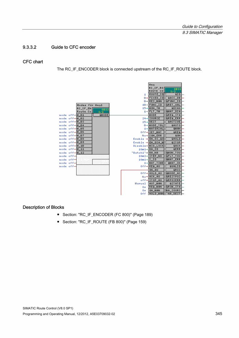
Guide to Configuration 9.3 SIMATIC Manager
SIMATIC Route Control (V8.0 SP1) Programming and Operating Manual, 12/2012, A5E03709032-02 345
9.3.3.2 Guide to CFC encoder
CFC chart The RC_IF_ENCODER block is connected upstream of the RC_IF_ROUTE block.
Description of Blocks ● Section: "RC_IF_ENCODER (FC 800)" (Page 189)
● Section: "RC_IF_ROUTE (FB 800)" (Page 159)
Guide to Configuration 9.3 SIMATIC Manager
SIMATIC Route Control (V8.0 SP1) 346 Programming and Operating Manual, 12/2012, A5E03709032-02
9.3.3.3 Guide to CFC decoder
CFC chart The CFC chart is structured in the same way as for the CFC encoder (Page 345), but the decoder is connected downstream (and to the right) of RC_IF_ROUTE and connected to its QMODE_AS output.
Description of Blocks ● Section: "RC_IF_ROUTE (FB 800)" (Page 159)
● Section: "RC_IF_DECODER (FC 801)" (Page 191)
Guide to Configuration 9.3 SIMATIC Manager
SIMATIC Route Control (V8.0 SP1) Programming and Operating Manual, 12/2012, A5E03709032-02 347
9.3.4 CFC Control Elements
9.3.4.1 Guide to the CFC control element
User Task You want to control a process-related element such as a MOTOR, a VALVE or another object from the standard library, sensor and parameter elements from SIMATIC Route Control.
Overview of Procedure Step Procedure 1 Placing the standard library block in a CFC chart 2 Placing the corresponding Route Control interface block in the CFC chart 3 Connecting the corresponding inputs and outputs 4 Exporting the elements to the Route Control configuration 5 Configuring partial routes with these elements 6 Using these elements to control routes
Examples ● Section "CFC Motor with Two Statuses" (Page 348)
● Section "CFC Motor with Two Statuses with No Feedback" (Page 349)
● Section "CFC Motor with Interlocking Block" (Page 350)
● Section "CFC Dual-Speed Motor" (Page 351)
● Section "CFC Bidirectional Motor" (Page 352)
● Section "CFC Valve with Feedback" (Page 353)
● Section "CFC Valve with Dual Feedback Signals" (Page 354)
● Section "CFC Valve with Interlocking Block" (Page 355)
● Section "CFC Valve with No Feedback Signal" (Page 356)
● Section "CFC Motor-Actuated Valve" (Page 357)
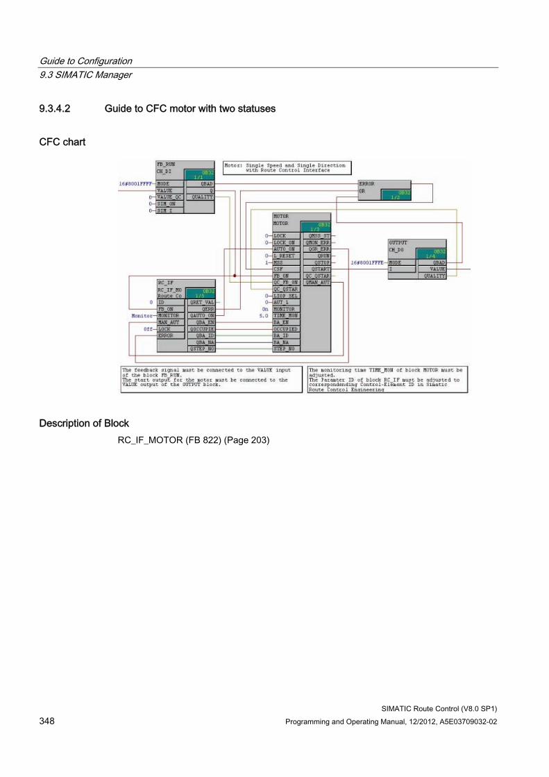
Guide to Configuration 9.3 SIMATIC Manager
SIMATIC Route Control (V8.0 SP1) 348 Programming and Operating Manual, 12/2012, A5E03709032-02
9.3.4.2 Guide to CFC motor with two statuses
CFC chart
Description of Block RC_IF_MOTOR (FB 822) (Page 203)
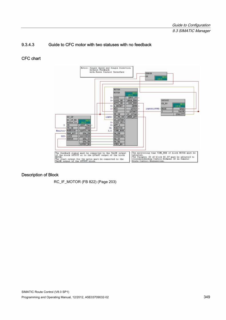
Guide to Configuration 9.3 SIMATIC Manager
SIMATIC Route Control (V8.0 SP1) Programming and Operating Manual, 12/2012, A5E03709032-02 349
9.3.4.3 Guide to CFC motor with two statuses with no feedback
CFC chart
Description of Block RC_IF_MOTOR (FB 822) (Page 203)
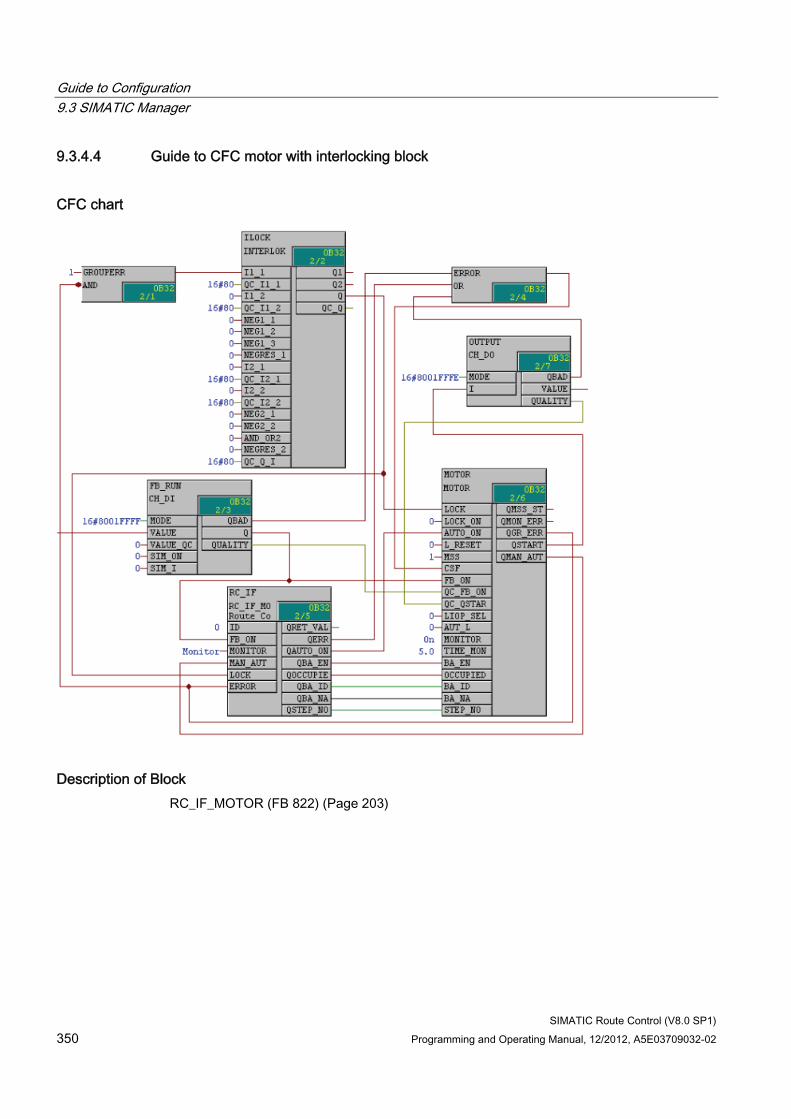
Guide to Configuration 9.3 SIMATIC Manager
SIMATIC Route Control (V8.0 SP1) 350 Programming and Operating Manual, 12/2012, A5E03709032-02
9.3.4.4 Guide to CFC motor with interlocking block
CFC chart
Description of Block RC_IF_MOTOR (FB 822) (Page 203)
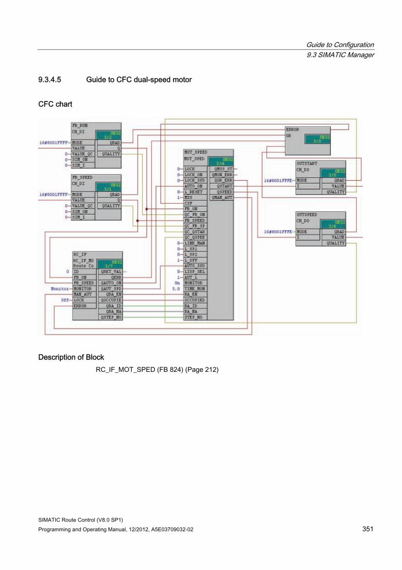
Guide to Configuration 9.3 SIMATIC Manager
SIMATIC Route Control (V8.0 SP1) Programming and Operating Manual, 12/2012, A5E03709032-02 351
9.3.4.5 Guide to CFC dual-speed motor
CFC chart
Description of Block RC_IF_MOT_SPED (FB 824) (Page 212)
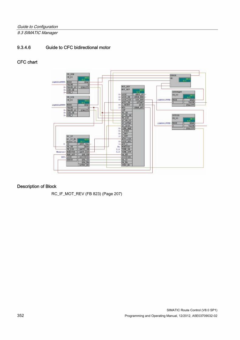
Guide to Configuration 9.3 SIMATIC Manager
SIMATIC Route Control (V8.0 SP1) 352 Programming and Operating Manual, 12/2012, A5E03709032-02
9.3.4.6 Guide to CFC bidirectional motor
CFC chart
Description of Block RC_IF_MOT_REV (FB 823) (Page 207)
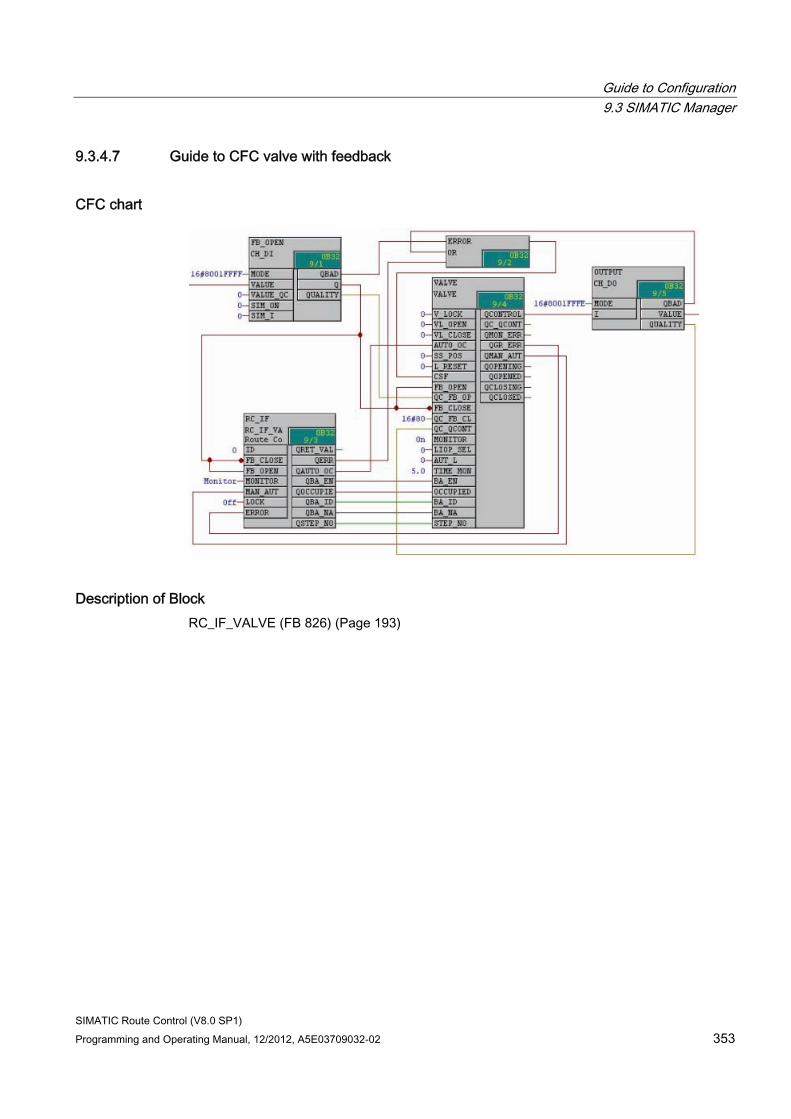
Guide to Configuration 9.3 SIMATIC Manager
SIMATIC Route Control (V8.0 SP1) Programming and Operating Manual, 12/2012, A5E03709032-02 353
9.3.4.7 Guide to CFC valve with feedback
CFC chart
Description of Block RC_IF_VALVE (FB 826) (Page 193)
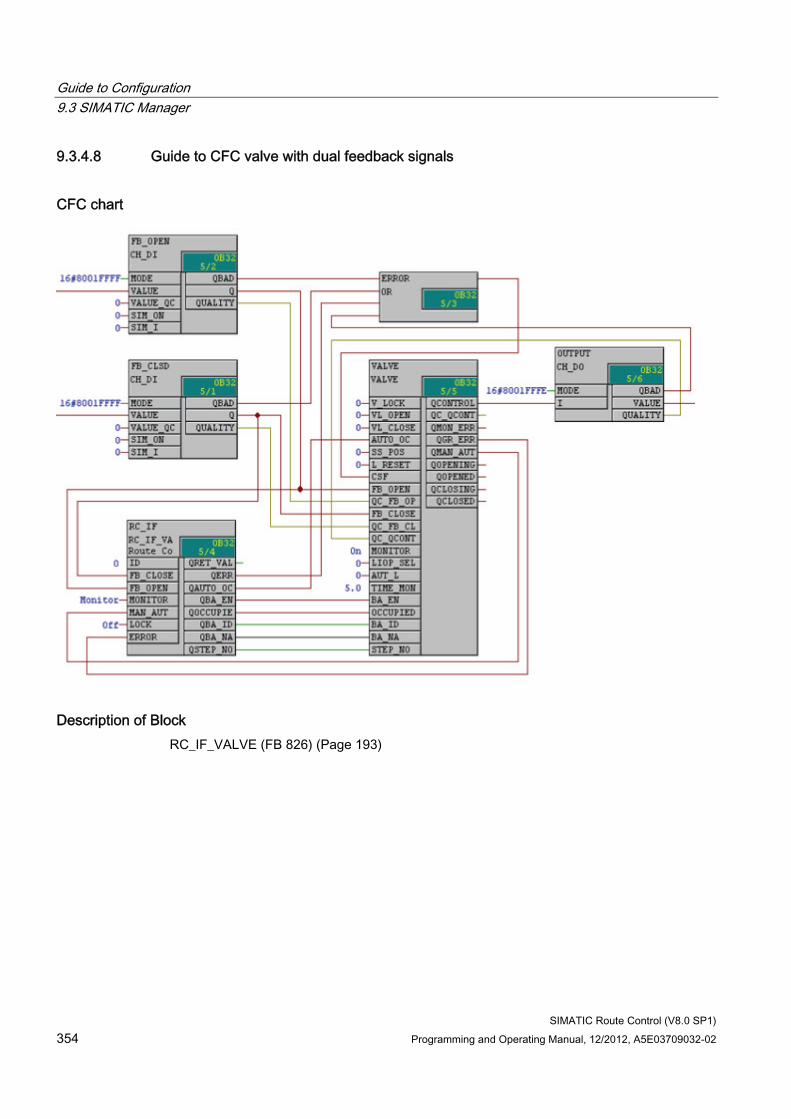
Guide to Configuration 9.3 SIMATIC Manager
SIMATIC Route Control (V8.0 SP1) 354 Programming and Operating Manual, 12/2012, A5E03709032-02
9.3.4.8 Guide to CFC valve with dual feedback signals
CFC chart
Description of Block RC_IF_VALVE (FB 826) (Page 193)
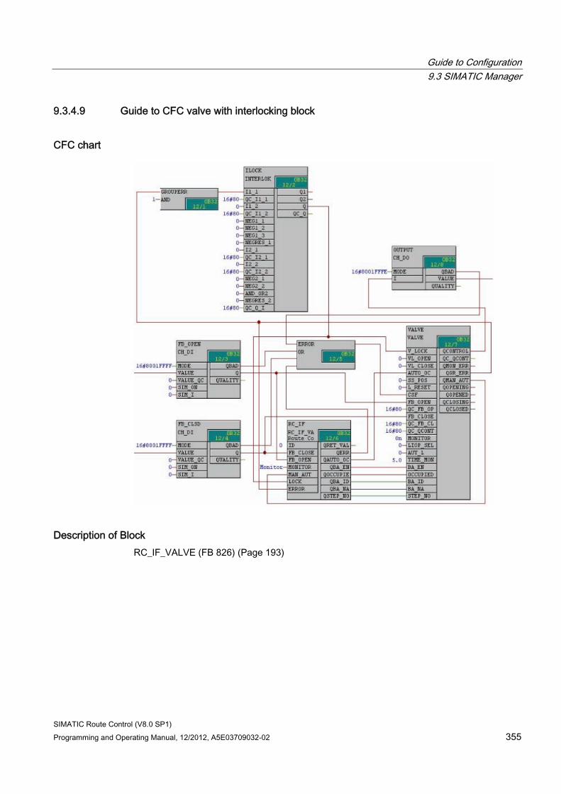
Guide to Configuration 9.3 SIMATIC Manager
SIMATIC Route Control (V8.0 SP1) Programming and Operating Manual, 12/2012, A5E03709032-02 355
9.3.4.9 Guide to CFC valve with interlocking block
CFC chart
Description of Block RC_IF_VALVE (FB 826) (Page 193)
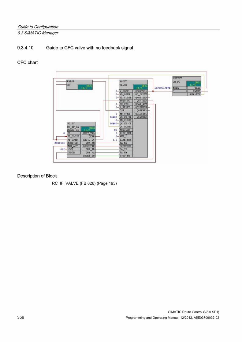
Guide to Configuration 9.3 SIMATIC Manager
SIMATIC Route Control (V8.0 SP1) 356 Programming and Operating Manual, 12/2012, A5E03709032-02
9.3.4.10 Guide to CFC valve with no feedback signal
CFC chart
Description of Block RC_IF_VALVE (FB 826) (Page 193)
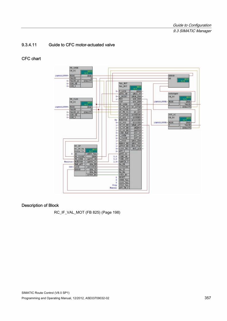
Guide to Configuration 9.3 SIMATIC Manager
SIMATIC Route Control (V8.0 SP1) Programming and Operating Manual, 12/2012, A5E03709032-02 357
9.3.4.11 Guide to CFC motor-actuated valve
CFC chart
Description of Block RC_IF_VAL_MOT (FB 825) (Page 198)
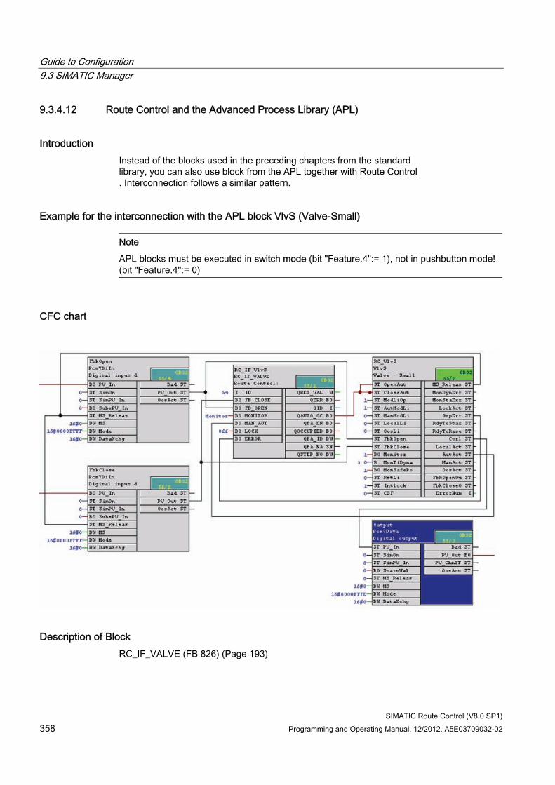
Guide to Configuration 9.3 SIMATIC Manager
SIMATIC Route Control (V8.0 SP1) 358 Programming and Operating Manual, 12/2012, A5E03709032-02
9.3.4.12 Route Control and the Advanced Process Library (APL)
Introduction Instead of the blocks used in the preceding chapters from the standard library, you can also use block from the APL together with Route Control . Interconnection follows a similar pattern.
Example for the interconnection with the APL block VlvS (Valve-Small)
Note
APL blocks must be executed in switch mode (bit "Feature.4":= 1), not in pushbutton mode! (bit "Feature.4":= 0)
CFC chart
Description of Block RC_IF_VALVE (FB 826) (Page 193)
Guide to Configuration 9.3 SIMATIC Manager
SIMATIC Route Control (V8.0 SP1) Programming and Operating Manual, 12/2012, A5E03709032-02 359
9.3.5 CFC Sensor Elements
9.3.5.1 Guide to CFC sensor element
User Task You want to evaluate process-related feedback for a level sensor or conductivity sensor in SIMATIC Route Control.
Overview of Procedure Step Procedure 1 Placing the corresponding SIMATIC Route Control interface block in the CFC chart 2 Connecting the corresponding inputs and outputs 3 Exporting the elements to the Route Control configuration 4 Configuring partial routes with these elements 5 Evaluating these elements indirectly via a mode level
Examples ● Section "CFC Sensor, Binary" (Page 360)
● Section "CFC Conductivity" (Page 360)
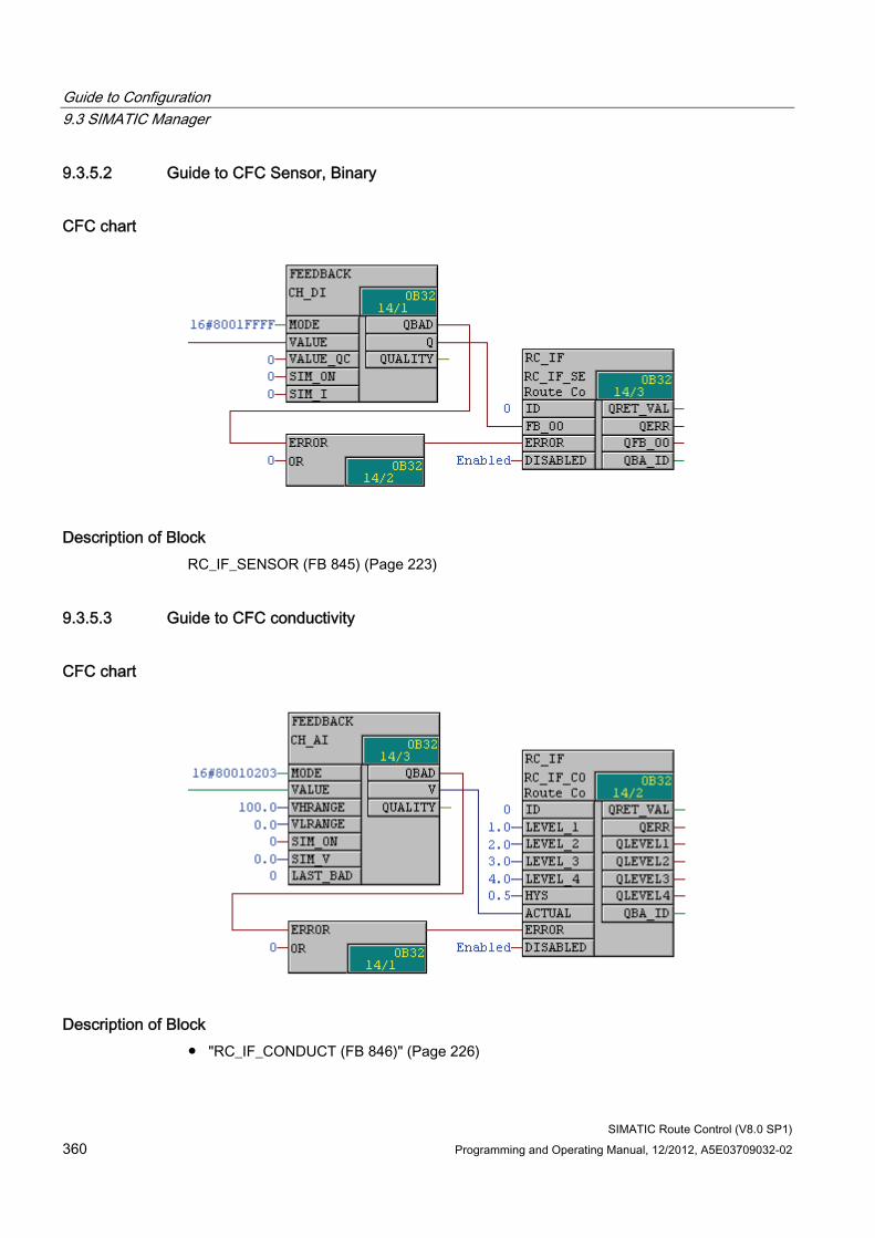
Guide to Configuration 9.3 SIMATIC Manager
SIMATIC Route Control (V8.0 SP1) 360 Programming and Operating Manual, 12/2012, A5E03709032-02
9.3.5.2 Guide to CFC Sensor, Binary
CFC chart
Description of Block RC_IF_SENSOR (FB 845) (Page 223)
9.3.5.3 Guide to CFC conductivity
CFC chart
Description of Block ● "RC_IF_CONDUCT (FB 846)" (Page 226)
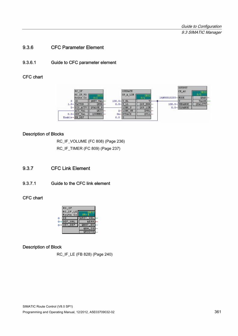
Guide to Configuration 9.3 SIMATIC Manager
SIMATIC Route Control (V8.0 SP1) Programming and Operating Manual, 12/2012, A5E03709032-02 361
9.3.6 CFC Parameter Element
9.3.6.1 Guide to CFC parameter element
CFC chart
Description of Blocks RC_IF_VOLUME (FC 808) (Page 236)
RC_IF_TIMER (FC 809) (Page 237)
9.3.7 CFC Link Element
9.3.7.1 Guide to the CFC link element
CFC chart
Description of Block RC_IF_LE (FB 828) (Page 240)
Guide to Configuration 9.3 SIMATIC Manager
SIMATIC Route Control (V8.0 SP1) 362 Programming and Operating Manual, 12/2012, A5E03709032-02
9.3.8 REMOTE Elements
9.3.8.1 CFC Charts with REMOTE Elements
Application REMOTE elements are used where two production areas "come into contact". Each production area belongs to a different S7 project/multiproject and, therefore, to a different Route Control project. From the perspective of a control system, certain elements, such as a valve, are associated with both areas because they act as a link between them.
Note
The remote use of an element V of PCell B is possible only from ONE PCell A.
Additional use from another PCell C could lead to double allocation of the element!
Synchronization between the two Route Control projects is performed for cross-process cell routes. Multiple usage of an element in two or more process cells (local and remote) is therefore not possible.
For synchronization, when a route is requested or started, a check is made as to whether one of the elements (CE, PE, SE) used in this route is already used in a different process cell in a route. In this case, the route is terminated with errors.
Note
The final test of whether remote elements included in the route are available can only occur at the start of the route. This can result in the the route request being achieved, but the route then being ended because of unavailable elements.
To register the use, occupied identifiers must be stored in the individual element data records. In the case of "concurrent routes" (same FuncID), the occupied identifier is stored as a counter. The maximum values of the counters are limited, which means the number of routes that can be concurrently used by an element is reduced. ("local elements: max. 63 uses, "remote" elements: max. 15 uses)
Note
REMOTE elements are only required for cross-project communication between automation systems.
Please also note the information in "Configuring Locations" (Page 431).
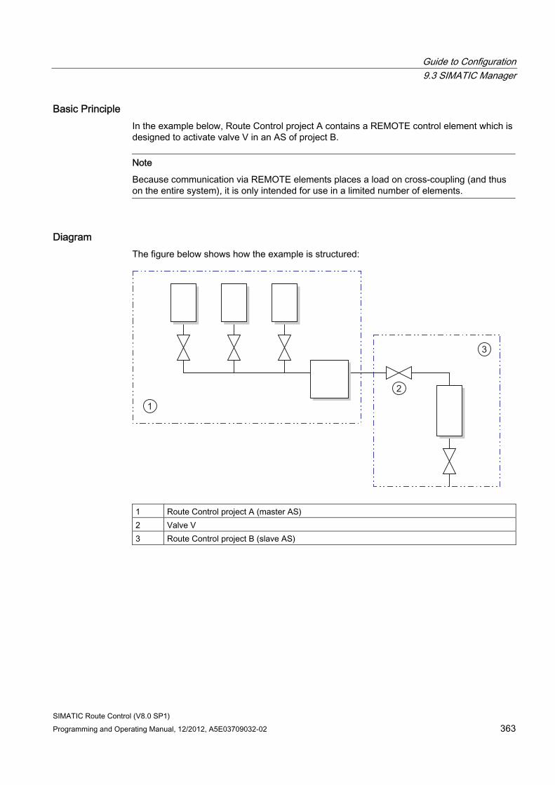
Guide to Configuration 9.3 SIMATIC Manager
SIMATIC Route Control (V8.0 SP1) Programming and Operating Manual, 12/2012, A5E03709032-02 363
Basic Principle In the example below, Route Control project A contains a REMOTE control element which is designed to activate valve V in an AS of project B.
Note
Because communication via REMOTE elements places a load on cross-coupling (and thus on the entire system), it is only intended for use in a limited number of elements.
Diagram The figure below shows how the example is structured:
1 Route Control project A (master AS) 2 Valve V 3 Route Control project B (slave AS)
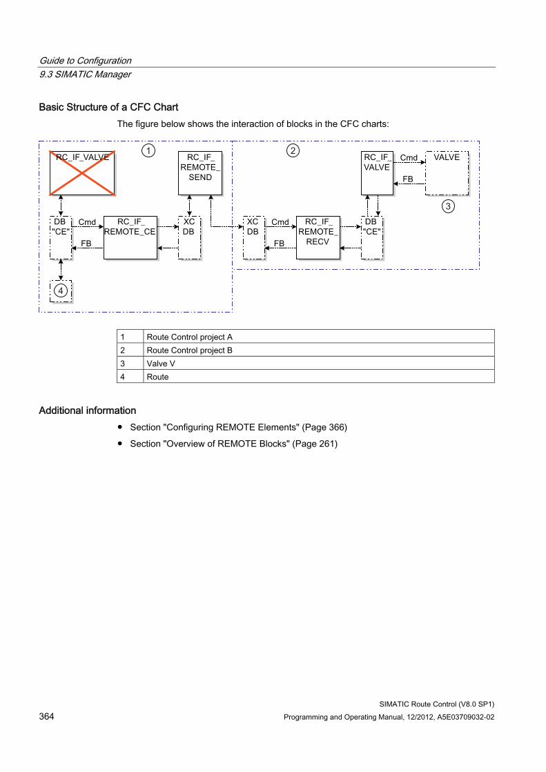
Guide to Configuration 9.3 SIMATIC Manager
SIMATIC Route Control (V8.0 SP1) 364 Programming and Operating Manual, 12/2012, A5E03709032-02
Basic Structure of a CFC Chart The figure below shows the interaction of blocks in the CFC charts:
1 Route Control project A 2 Route Control project B 3 Valve V 4 Route
Additional information ● Section "Configuring REMOTE Elements" (Page 366)
● Section "Overview of REMOTE Blocks" (Page 261)
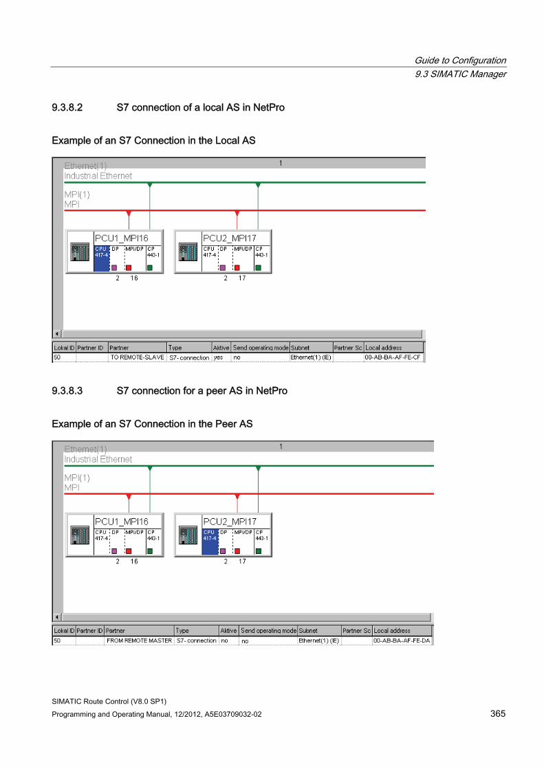
Guide to Configuration 9.3 SIMATIC Manager
SIMATIC Route Control (V8.0 SP1) Programming and Operating Manual, 12/2012, A5E03709032-02 365
9.3.8.2 S7 connection of a local AS in NetPro
Example of an S7 Connection in the Local AS
9.3.8.3 S7 connection for a peer AS in NetPro
Example of an S7 Connection in the Peer AS
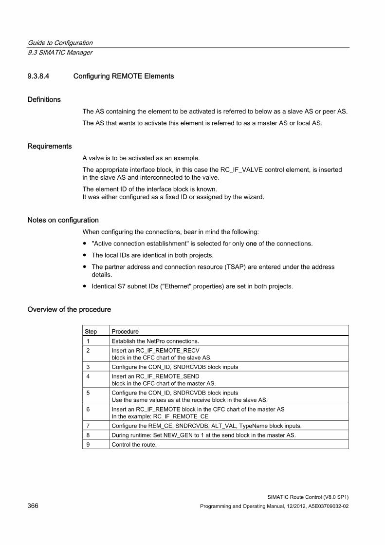
Guide to Configuration 9.3 SIMATIC Manager
SIMATIC Route Control (V8.0 SP1) 366 Programming and Operating Manual, 12/2012, A5E03709032-02
9.3.8.4 Configuring REMOTE Elements
Definitions The AS containing the element to be activated is referred to below as a slave AS or peer AS.
The AS that wants to activate this element is referred to as a master AS or local AS.
Requirements A valve is to be activated as an example.
The appropriate interface block, in this case the RC_IF_VALVE control element, is inserted in the slave AS and interconnected to the valve.
The element ID of the interface block is known. It was either configured as a fixed ID or assigned by the wizard.
Notes on configuration When configuring the connections, bear in mind the following:
● "Active connection establishment" is selected for only one of the connections.
● The local IDs are identical in both projects.
● The partner address and connection resource (TSAP) are entered under the address details.
● Identical S7 subnet IDs ("Ethernet" properties) are set in both projects.
Overview of the procedure Step Procedure 1 Establish the NetPro connections. 2 Insert an RC_IF_REMOTE_RECV
block in the CFC chart of the slave AS. 3 Configure the CON_ID, SNDRCVDB block inputs 4 Insert an RC_IF_REMOTE_SEND
block in the CFC chart of the master AS. 5 Configure the CON_ID, SNDRCVDB block inputs
Use the same values as at the receive block in the slave AS. 6 Insert an RC_IF_REMOTE block in the CFC chart of the master AS
In the example: RC_IF_REMOTE_CE 7 Configure the REM_CE, SNDRCVDB, ALT_VAL, TypeName block inputs. 8 During runtime: Set NEW_GEN to 1 at the send block in the master AS. 9 Control the route.
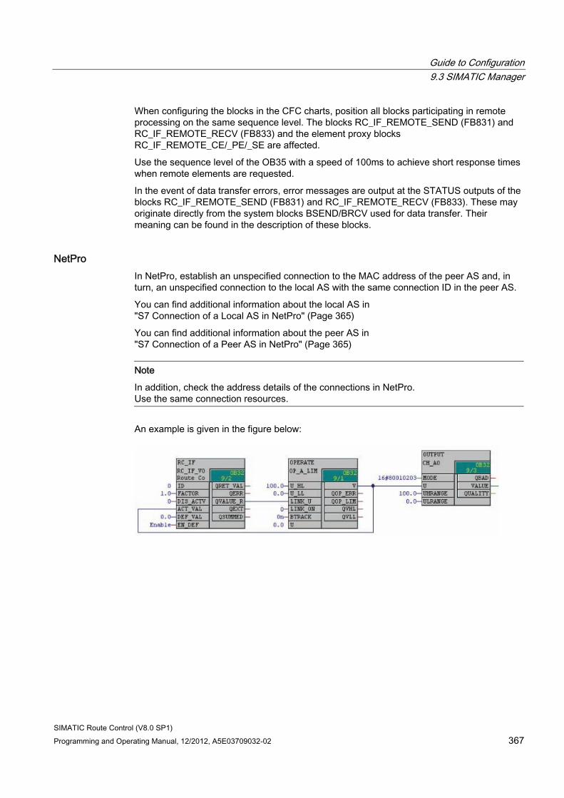
Guide to Configuration 9.3 SIMATIC Manager
SIMATIC Route Control (V8.0 SP1) Programming and Operating Manual, 12/2012, A5E03709032-02 367
When configuring the blocks in the CFC charts, position all blocks participating in remote processing on the same sequence level. The blocks RC_IF_REMOTE_SEND (FB831) and RC_IF_REMOTE_RECV (FB833) and the element proxy blocks RC_IF_REMOTE_CE/_PE/_SE are affected.
Use the sequence level of the OB35 with a speed of 100ms to achieve short response times when remote elements are requested.
In the event of data transfer errors, error messages are output at the STATUS outputs of the blocks RC_IF_REMOTE_SEND (FB831) and RC_IF_REMOTE_RECV (FB833). These may originate directly from the system blocks BSEND/BRCV used for data transfer. Their meaning can be found in the description of these blocks.
NetPro In NetPro, establish an unspecified connection to the MAC address of the peer AS and, in turn, an unspecified connection to the local AS with the same connection ID in the peer AS.
You can find additional information about the local AS in "S7 Connection of a Local AS in NetPro" (Page 365)
You can find additional information about the peer AS in "S7 Connection of a Peer AS in NetPro" (Page 365)
Note
In addition, check the address details of the connections in NetPro. Use the same connection resources.
An example is given in the figure below:
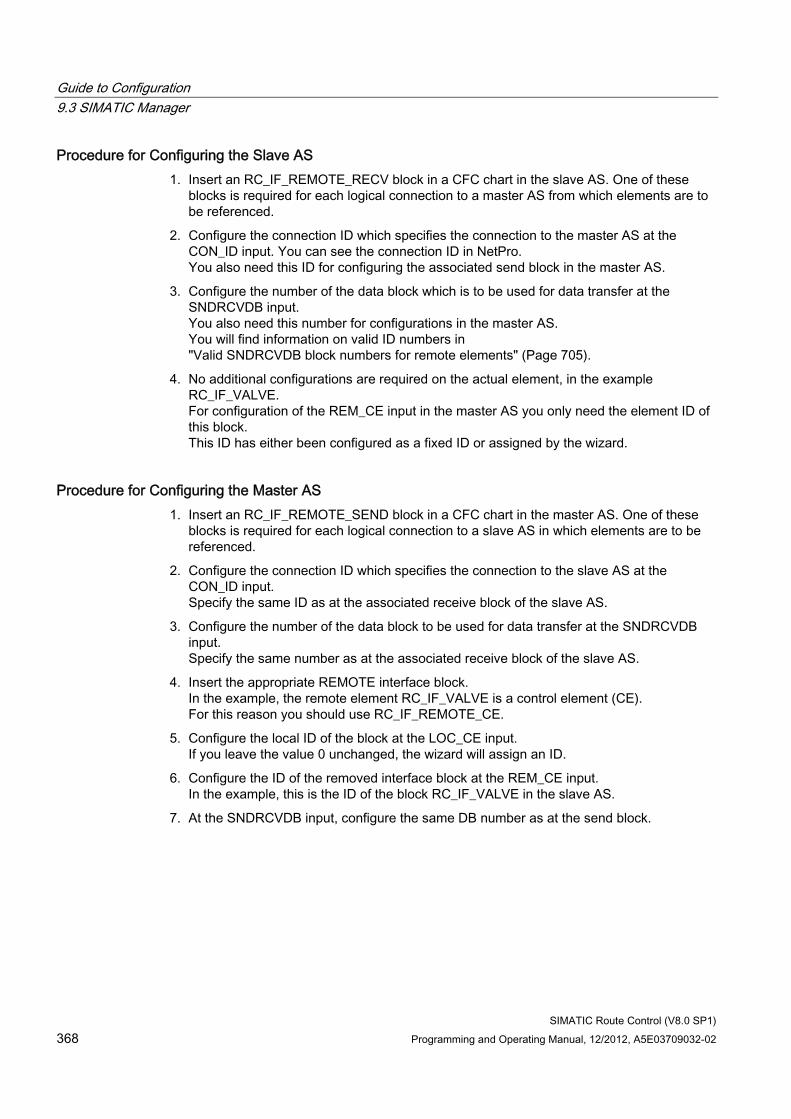
Guide to Configuration 9.3 SIMATIC Manager
SIMATIC Route Control (V8.0 SP1) 368 Programming and Operating Manual, 12/2012, A5E03709032-02
Procedure for Configuring the Slave AS 1. Insert an RC_IF_REMOTE_RECV block in a CFC chart in the slave AS. One of these
blocks is required for each logical connection to a master AS from which elements are to be referenced.
2. Configure the connection ID which specifies the connection to the master AS at the CON_ID input. You can see the connection ID in NetPro. You also need this ID for configuring the associated send block in the master AS.
3. Configure the number of the data block which is to be used for data transfer at the SNDRCVDB input. You also need this number for configurations in the master AS. You will find information on valid ID numbers in "Valid SNDRCVDB block numbers for remote elements" (Page 705).
4. No additional configurations are required on the actual element, in the example RC_IF_VALVE. For configuration of the REM_CE input in the master AS you only need the element ID of this block. This ID has either been configured as a fixed ID or assigned by the wizard.
Procedure for Configuring the Master AS 1. Insert an RC_IF_REMOTE_SEND block in a CFC chart in the master AS. One of these
blocks is required for each logical connection to a slave AS in which elements are to be referenced.
2. Configure the connection ID which specifies the connection to the slave AS at the CON_ID input. Specify the same ID as at the associated receive block of the slave AS.
3. Configure the number of the data block to be used for data transfer at the SNDRCVDB input. Specify the same number as at the associated receive block of the slave AS.
4. Insert the appropriate REMOTE interface block. In the example, the remote element RC_IF_VALVE is a control element (CE). For this reason you should use RC_IF_REMOTE_CE.
5. Configure the local ID of the block at the LOC_CE input. If you leave the value 0 unchanged, the wizard will assign an ID.
6. Configure the ID of the removed interface block at the REM_CE input. In the example, this is the ID of the block RC_IF_VALVE in the slave AS.
7. At the SNDRCVDB input, configure the same DB number as at the send block.
Guide to Configuration 9.3 SIMATIC Manager
SIMATIC Route Control (V8.0 SP1) Programming and Operating Manual, 12/2012, A5E03709032-02 369
8. Configure the alternate value that is to be used if communication is interrupted at the ALT_VAL input.
9. Configure the subtype of the removed element at the TypeName input, in the example: 'VALVE'
Note
Use the RC_IF_REMOTE_SE block to activate a sensor element and the RC_IF_REMOTE_PE block to activate a parameter element.
The inputs for the local and remote element IDs are LOC_SE and REM_SE for the sensor element and LOC_PE and REM_PE for the parameter element.
Special points to consider when configuring remote connections With cross-process cell routes, a route may occasionally be rejected with the message "Element(s) or partial route(s) already being used", although none of the elements to be used are being used in a different route.
With remote elements, the information whether an element is assigned or not must be requested and received from the remote process cell via a coupling. If the requesting partner does not receive a response within a certain amount of time, this also results in the above-mentioned message as, due to the missing information, no statement can be made about the assignment of the element(s). This behavior can occur more or less frequently on account of the different loading of the coupling path.
This behavior can be improved by increasing the input parameter SND_TIME at the send block RC_IF_REMOTE_SEND of the respective coupling path. This approach also increases the time for the response. The disadvantage of this solution is that the data throughput between the remote partners is reduced due to the longer send interval.
Additional information ● You can find information about the REMOTE blocks in the section
"Overview of REMOTE blocks" (Page 261).
● You can find information about the CFC charts in the slave AS in "REMOTE elements in the CFC chart of a peer AS" (Page 371).
● You can find information about the CFC charts in the master AS in "REMOTE elements in the CFC chart of a local AS" (Page 370).
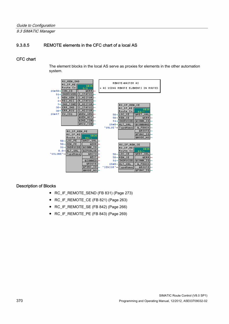
Guide to Configuration 9.3 SIMATIC Manager
SIMATIC Route Control (V8.0 SP1) 370 Programming and Operating Manual, 12/2012, A5E03709032-02
9.3.8.5 REMOTE elements in the CFC chart of a local AS
CFC chart The element blocks in the local AS serve as proxies for elements in the other automation system.
Description of Blocks ● RC_IF_REMOTE_SEND (FB 831) (Page 273)
● RC_IF_REMOTE_CE (FB 821) (Page 263)
● RC_IF_REMOTE_SE (FB 842) (Page 266)
● RC_IF_REMOTE_PE (FB 843) (Page 269)
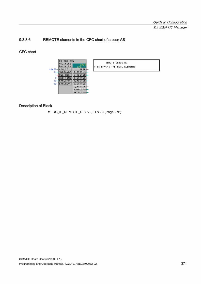
Guide to Configuration 9.3 SIMATIC Manager
SIMATIC Route Control (V8.0 SP1) Programming and Operating Manual, 12/2012, A5E03709032-02 371
9.3.8.6 REMOTE elements in the CFC chart of a peer AS
CFC chart
Description of Block ● RC_IF_REMOTE_RECV (FB 833) (Page 276)
Guide to Configuration 9.3 SIMATIC Manager
SIMATIC Route Control (V8.0 SP1) 372 Programming and Operating Manual, 12/2012, A5E03709032-02
9.3.9 Route Control SFC
9.3.9.1 SFC overview
Overview The Route Control library contains the RC_IF_SFC SFC block as a sample for activating the RC_IF_ROUTE route block.
You can find a brief overview of how to insert the SFC block in:
● "SFC Block Schematic" (Page 374)
Overview of Procedure Follow the steps below to adapt the sample SFC to your requirements and use it in your own project:
Step Procedure 1 Copy the sample SFC from the Route Control library to your own S7 project. 2 Modify this copy in accordance with your requirements,
thereby creating a user-specific sample SFC. 3 Create as many copies of the user-specific sample SFC as you need (in general, one SFC
per RC_IF_ROUTE). 4 Interconnect this SFC instance to the RC_IF_ROUTE blocks in the individual CFC charts.
Note
If an SFC package is not installed on the computer and you open the Route Control library, an error message will appear.
Reason: This is because the Route Control library contains an SFC block (SFC Typical).
An overview of the relationship between SFC, route and faceplates in "Relationship of SFC and Route with Operator Dialogs" (Page 373).
The SFC block provided with the Route Control library is a sample that you have to copy and adapt according to your requirements. If these mode levels are not used for the material transport, steps to activate mode levels (or stepping conditions that request values) should be removed from the chains.
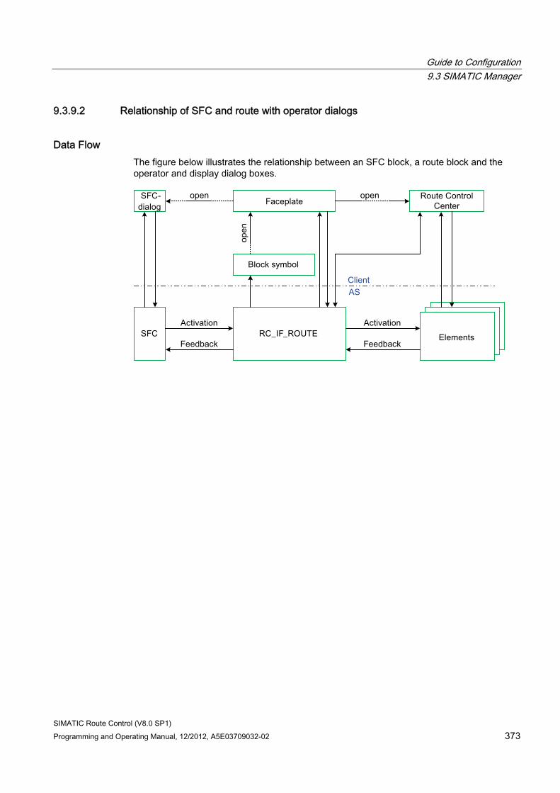
Guide to Configuration 9.3 SIMATIC Manager
SIMATIC Route Control (V8.0 SP1) Programming and Operating Manual, 12/2012, A5E03709032-02 373
9.3.9.2 Relationship of SFC and route with operator dialogs
Data Flow The figure below illustrates the relationship between an SFC block, a route block and the operator and display dialog boxes.
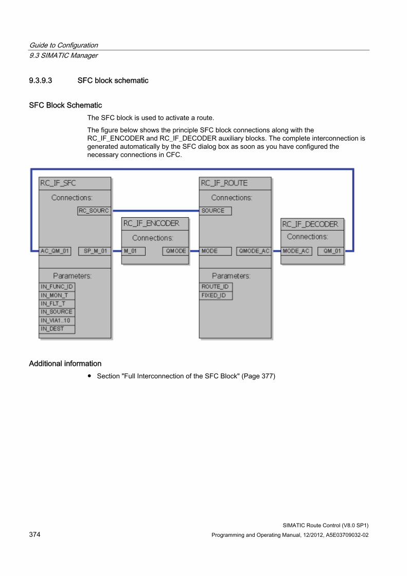
Guide to Configuration 9.3 SIMATIC Manager
SIMATIC Route Control (V8.0 SP1) 374 Programming and Operating Manual, 12/2012, A5E03709032-02
9.3.9.3 SFC block schematic
SFC Block Schematic The SFC block is used to activate a route.
The figure below shows the principle SFC block connections along with the RC_IF_ENCODER and RC_IF_DECODER auxiliary blocks. The complete interconnection is generated automatically by the SFC dialog box as soon as you have configured the necessary connections in CFC.
Additional information ● Section "Full Interconnection of the SFC Block" (Page 377)
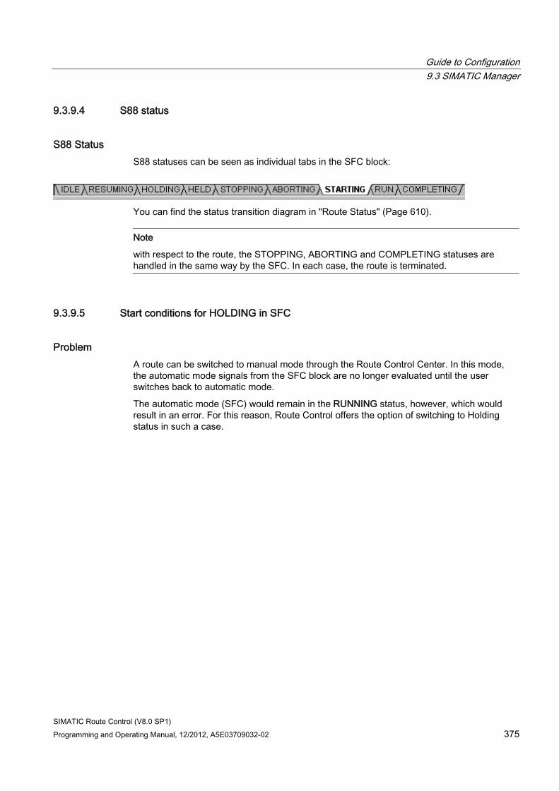
Guide to Configuration 9.3 SIMATIC Manager
SIMATIC Route Control (V8.0 SP1) Programming and Operating Manual, 12/2012, A5E03709032-02 375
9.3.9.4 S88 status
S88 Status S88 statuses can be seen as individual tabs in the SFC block:
You can find the status transition diagram in "Route Status" (Page 610).
Note
with respect to the route, the STOPPING, ABORTING and COMPLETING statuses are handled in the same way by the SFC. In each case, the route is terminated.
9.3.9.5 Start conditions for HOLDING in SFC
Problem A route can be switched to manual mode through the Route Control Center. In this mode, the automatic mode signals from the SFC block are no longer evaluated until the user switches back to automatic mode.
The automatic mode (SFC) would remain in the RUNNING status, however, which would result in an error. For this reason, Route Control offers the option of switching to Holding status in such a case.
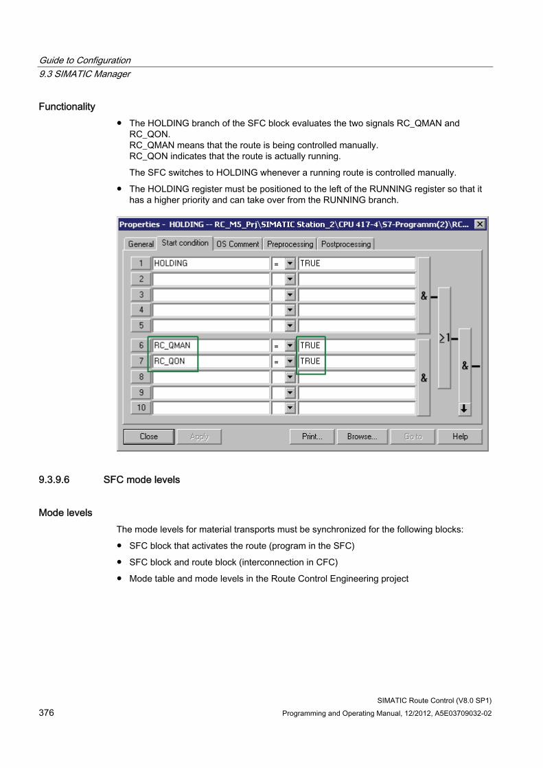
Guide to Configuration 9.3 SIMATIC Manager
SIMATIC Route Control (V8.0 SP1) 376 Programming and Operating Manual, 12/2012, A5E03709032-02
Functionality ● The HOLDING branch of the SFC block evaluates the two signals RC_QMAN and
RC_QON. RC_QMAN means that the route is being controlled manually. RC_QON indicates that the route is actually running.
The SFC switches to HOLDING whenever a running route is controlled manually.
● The HOLDING register must be positioned to the left of the RUNNING register so that it has a higher priority and can take over from the RUNNING branch.
9.3.9.6 SFC mode levels
Mode levels The mode levels for material transports must be synchronized for the following blocks:
● SFC block that activates the route (program in the SFC)
● SFC block and route block (interconnection in CFC)
● Mode table and mode levels in the Route Control Engineering project
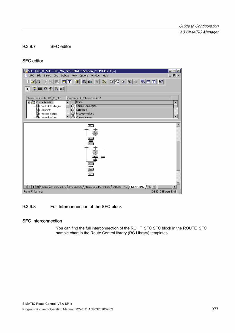
Guide to Configuration 9.3 SIMATIC Manager
SIMATIC Route Control (V8.0 SP1) Programming and Operating Manual, 12/2012, A5E03709032-02 377
9.3.9.7 SFC editor
SFC editor
9.3.9.8 Full Interconnection of the SFC block
SFC Interconnection You can find the full interconnection of the RC_IF_SFC SFC block in the ROUTE_SFC sample chart in the Route Control library (RC Library) templates.
Guide to Configuration 9.3 SIMATIC Manager
SIMATIC Route Control (V8.0 SP1) 378 Programming and Operating Manual, 12/2012, A5E03709032-02
9.3.10 Dynamic ID Assignment
9.3.10.1 Guide to Dynamic ID Assignment
Introduction In Route Control, a maximum of 300 routes can be started simultaneously. If you want to insert more than 300 RC_IF_ROUTE route blocks in your project, the number of available route IDs will not suffice. You do not have to permanently assign the route IDs. The dynamic ID assignment procedure was developed to deal with this situation.
You can always start a route with a fixed route ID. A route with a dynamic route ID can only be started if a dynamic ID is available in the pool of the AS in which this route is inserted.
User Task You want to configure the route blocks and specify the fixed and dynamic route IDs for each AS and transfer them to the Route Control project.
Overview of Procedure Step Procedure 1 Specify the number and values of route IDs that are to form the pool of dynamic route IDs
in each AS. 2 Specify the number of route blocks in each AS that are also to be provided with dynamic
route IDs from the pool. 3 Specify the route blocks with fixed route IDs in each AS. 4 Insert and configure the route blocks. 5 Transfer the routes and route IDs to the Route Control configuration using the
Route Control Wizard. 6 Download the automation systems. 7 Download and activate the Route Control servers. 8 Start a route with a dynamic route ID.
The AS in question finds an available ID from its pool and writes it to the ROUTE_ID input of the route block. The route is controlled like a fixed ID.
9 Ending the route The reserved ID is enabled again.
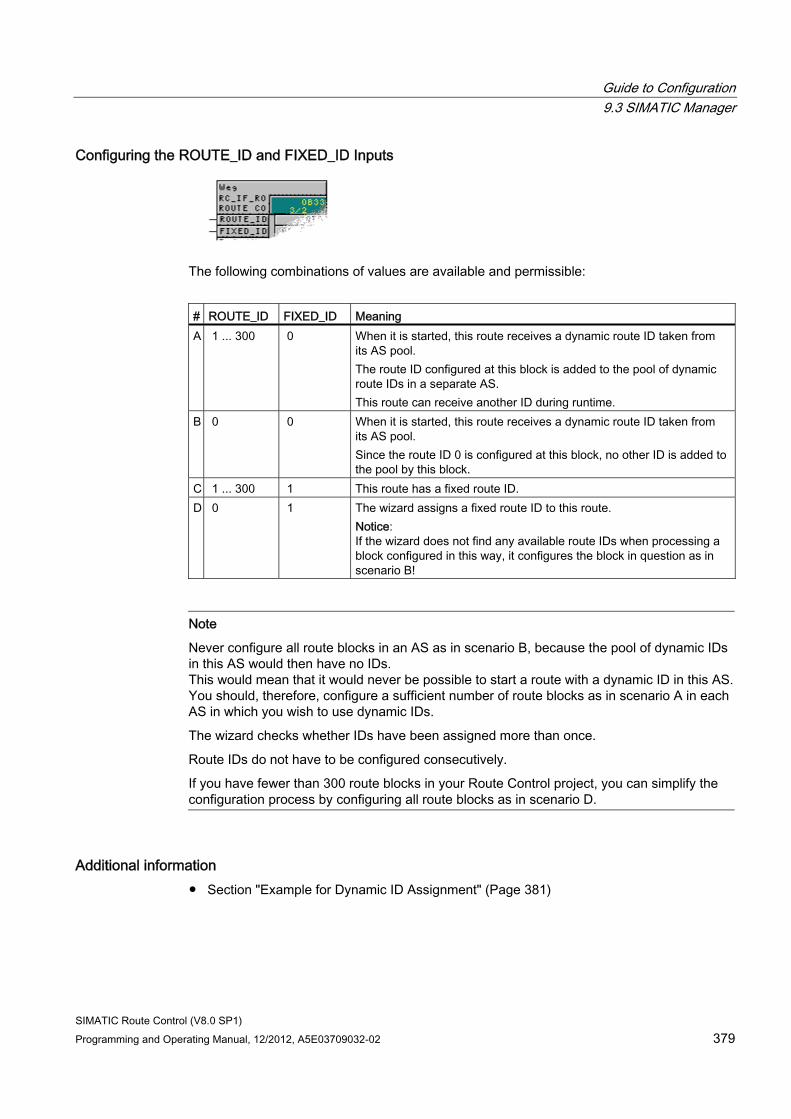
Guide to Configuration 9.3 SIMATIC Manager
SIMATIC Route Control (V8.0 SP1) Programming and Operating Manual, 12/2012, A5E03709032-02 379
Configuring the ROUTE_ID and FIXED_ID Inputs
The following combinations of values are available and permissible:
# ROUTE_ID FIXED_ID Meaning A 1 ... 300 0 When it is started, this route receives a dynamic route ID taken from
its AS pool. The route ID configured at this block is added to the pool of dynamic route IDs in a separate AS. This route can receive another ID during runtime.
B 0 0 When it is started, this route receives a dynamic route ID taken from its AS pool. Since the route ID 0 is configured at this block, no other ID is added to the pool by this block.
C 1 ... 300 1 This route has a fixed route ID. D 0 1 The wizard assigns a fixed route ID to this route.
Notice: If the wizard does not find any available route IDs when processing a block configured in this way, it configures the block in question as in scenario B!
Note
Never configure all route blocks in an AS as in scenario B, because the pool of dynamic IDs in this AS would then have no IDs. This would mean that it would never be possible to start a route with a dynamic ID in this AS.You should, therefore, configure a sufficient number of route blocks as in scenario A in each AS in which you wish to use dynamic IDs.
The wizard checks whether IDs have been assigned more than once.
Route IDs do not have to be configured consecutively.
If you have fewer than 300 route blocks in your Route Control project, you can simplify the configuration process by configuring all route blocks as in scenario D.
Additional information ● Section "Example for Dynamic ID Assignment" (Page 381)
Guide to Configuration 9.3 SIMATIC Manager
SIMATIC Route Control (V8.0 SP1) 380 Programming and Operating Manual, 12/2012, A5E03709032-02
Learning Objectives Check List ● You are familiar with the concept of dynamic ID assignment and how it differs from fixed
ID assignment.
● You know the necessary steps for configuration.
● You know how the ID is determined during runtime.
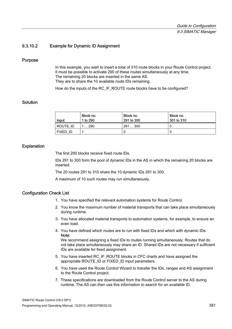
Guide to Configuration 9.3 SIMATIC Manager
SIMATIC Route Control (V8.0 SP1) Programming and Operating Manual, 12/2012, A5E03709032-02 381
9.3.10.2 Example for Dynamic ID Assignment
Purpose In this example, you wish to insert a total of 310 route blocks in your Route Control project. It must be possible to activate 290 of these routes simultaneously at any time. The remaining 20 blocks are inserted in the same AS. They are to share the 10 available route IDs remaining.
How do the inputs of the RC_IF_ROUTE route blocks have to be configured?
Solution Input
Block no. 1 to 290
Block no. 291 to 300
Block no. 301 to 310
ROUTE_ID 1 ... 290 291 ... 300 0 FIXED_ID 1 0 0
Explanation The first 290 blocks receive fixed route IDs.
IDs 291 to 300 form the pool of dynamic IDs in the AS in which the remaining 20 blocks are inserted.
The 20 routes 291 to 310 share the 10 dynamic IDs 291 to 300.
A maximum of 10 such routes may run simultaneously.
Configuration Check List 1. You have specified the relevant automation systems for Route Control.
2. You know the maximum number of material transports that can take place simultaneously during runtime.
3. You have allocated material transports to automation systems, for example, to ensure an even load.
4. You have defined which routes are to run with fixed IDs and which with dynamic IDs. Note: We recommend assigning a fixed IDs to routes running simultaneously. Routes that do not take place simultaneously may share an ID. Shared IDs are not necessary if sufficient IDs are available for fixed assignment.
5. You have inserted RC_IF_ROUTE blocks in CFC charts and have assigned the appropriate ROUTE_ID or FIXED_ID input parameters.
6. You have used the Route Control Wizard to transfer the IDs, ranges and AS assignment to the Route Control project.
7. These specifications are downloaded from the Route Control server to the AS during runtime. The AS can then use this information to search for an available ID.
Guide to Configuration 9.4 Route Control Wizard
SIMATIC Route Control (V8.0 SP1) 382 Programming and Operating Manual, 12/2012, A5E03709032-02
9.4 Route Control Wizard
9.4.1 Guide to the Route Control Wizard
Requirement ● You want to configure the AS-AS and AS-server connection data relevant for Route
Control.
● You want to simplify project engineering in the following ways:
– Element IDs that have not yet been configured (=0) are to be assigned automatically
– Element IDs that have already been configured (<>0) are to be checked for validity and corrected, if necessary
– Elements that have already been configured in the CFC charts are to be transferred to Route Control Engineering
● The plant hierarchy from the S7 project must also be available in the Route Control project.
● The locations configured in SIMATIC Manager should be transferred to Route Control Engineering.
● The routes (ID + dynamic/fixed property) must also be checked and transferred to the Route Control project.
● The message server (PCS 7 OS) that is to receive messages during runtime from the Route Control server(s) must be specified.
Guide to Configuration 9.4 Route Control Wizard
SIMATIC Route Control (V8.0 SP1) Programming and Operating Manual, 12/2012, A5E03709032-02 383
Overview of the Procedure The Route Control Wizard helps you specifically with these tasks by providing appropriate user interfaces and selection dialog boxes. It guides you through a number of dialog boxes, in which you can make the relevant settings, corrections, and selections.
Start the Route Control Wizard in SIMATIC Manager by selecting the menu command Options > SIMATIC > Route Control > Wizard. You can perform the following tasks here:
# Task 1 Check and automatically correct element IDs.
If this is not possible, you can/must correct the ID manually. 2 Select the connection data and provide parameter inputs to the instances of block type
RC_IF_CFG (central configuration of a Route Control AS). 3 Select and transfer the Route Control server properties to the Route Control project. 4 Select and transfer elements from the CFC charts of the S7 project to the Route Control project. 5 Transfer route instances (RC_IF_ROUTE block) and, if available, route IDs to the Route Control
project. 6 Transfer the plant hierarchy. .7 Transfer the locations.
Example Route Control Wizard Dialogs You can find the individual steps with the corresponding Route Control Wizard dialog boxes in the section "Selecting Actions". (Page 453)
Project-Engineering Checklist 1. You have followed the Route Control Wizard instructions and dialog boxes and have
selected the objects to be checked and exported.
2. The wizard has suggested different IDs for elements or routes. If you have not made any changes, these IDs will be applied.
3. You have selected a message server. Route Control messages will be created in this PCS 7 OS.
4. Elements that are selected will be exported automatically.
5. You have received a log providing information about the actions previously selected by you and performed by the wizard, and information about their results.
Additional Information ● Section "Transferring from an S7 Project" (Page 142)
Guide to Configuration 9.4 Route Control Wizard
SIMATIC Route Control (V8.0 SP1) 384 Programming and Operating Manual, 12/2012, A5E03709032-02
9.4.2 Guide to exporting an S7 project
User Task Data and objects already contained in an S7 project are to be transferred to the Route Control project. Duplicate configuration and inconsistent data are to be prevented.
Overview of Procedure You can find the dialog boxes relating to the individual Route Control Wizard steps in "Actions in the Route Control Wizard" (Page 451)
Configuration Check List 1. Prepare the hardware (automation system in HW Config and PCS 7 OS).
2. Prepare (plant hierarchy, insertion, block configuration) the CFC charts: routes and elements.
3. Configuring the locations
4. Call and run the Route Control Wizard and select the options.
5. Perform the selected actions.
6. Check the results (in the log files).
Guide to Configuration 9.4 Route Control Wizard
SIMATIC Route Control (V8.0 SP1) Programming and Operating Manual, 12/2012, A5E03709032-02 385
9.4.3 Guide to exporting linking configuration from NetPro
Requirement You want to have the communication links between automation systems, in which Route Control blocks are operating, configured automatically (assignment of communication IDs).
Overview of the procedure If an AS relevant to Route Control has been added to or removed from the S7 project, proceed as follows:
Step Procedure 1 Start the Route Control Wizard in SIMATIC Manager by selecting the menu command
Options > SIMATIC > Route Control > Wizard. 2 Assign or correct the communication IDs (modified NetPro settings). 3 Export from the S7 project and import to the Route Control Engineering project. 4 Download the database to the Route Control server and restart the server
The new IDs are made known to the instances that use these IDs. 5 Download the connections from NetPro to the automation system. 6 Restart the AS
A restart always has to be performed when changes are made to the NetPro settings.
Example 1. Start the Route Control Wizard.
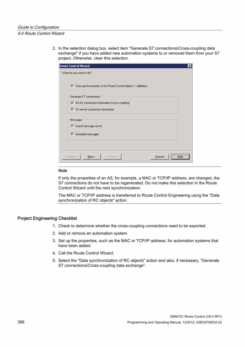
Guide to Configuration 9.4 Route Control Wizard
SIMATIC Route Control (V8.0 SP1) 386 Programming and Operating Manual, 12/2012, A5E03709032-02
2. In the selection dialog box, select item "Generate S7 connections\Cross-coupling data exchange" if you have added new automation systems to or removed them from your S7 project. Otherwise, clear this selection.
Note
If only the properties of an AS, for example, a MAC or TCP/IP address, are changed, the S7 connections do not have to be regenerated. Do not make this selection in the Route Control Wizard until the next synchronization.
The MAC or TCP/IP address is transferred to Route Control Engineering using the "Data synchronization of RC objects" action.
Project Engineering Checklist 1. Check to determine whether the cross-coupling connections need to be exported.
2. Add or remove an automation system.
3. Set up the properties, such as the MAC or TCP/IP address, for automation systems that have been added.
4. Call the Route Control Wizard.
5. Select the "Data synchronization of RC objects" action and also, if necessary, "Generate S7 connections\Cross-coupling data exchange".
Guide to Configuration 9.5 Route Control Engineering
SIMATIC Route Control (V8.0 SP1) Programming and Operating Manual, 12/2012, A5E03709032-02 387
9.5 Route Control Engineering
9.5.1 Guide to Route Control Engineering
User Task You wish to obtain an overview of the Route Control configuration environment.
Overview of Procedure Step Procedure 1 Start Route Control Engineering using one of the options below:
• In SIMATIC Manager, select the menu command Options > SIMATIC Route Control > Engineering.
• In SIMATIC Manager, double-click the Route Control object in the project folder. • Select the menu command
Start > SIMATIC > ROUTE CONTROL > Engineering from the Windows start menu. Use the menu command File > Open to select an S7 project.
2 Configure the following objects: • Mode tables
A mode table is a group of mode levels, to which elements interconnected to partial routes can be assigned.
• Partial routes with an indication of their beginning and end (locations) and assignment of elements
• Materials, material groups, and permitted material sequences
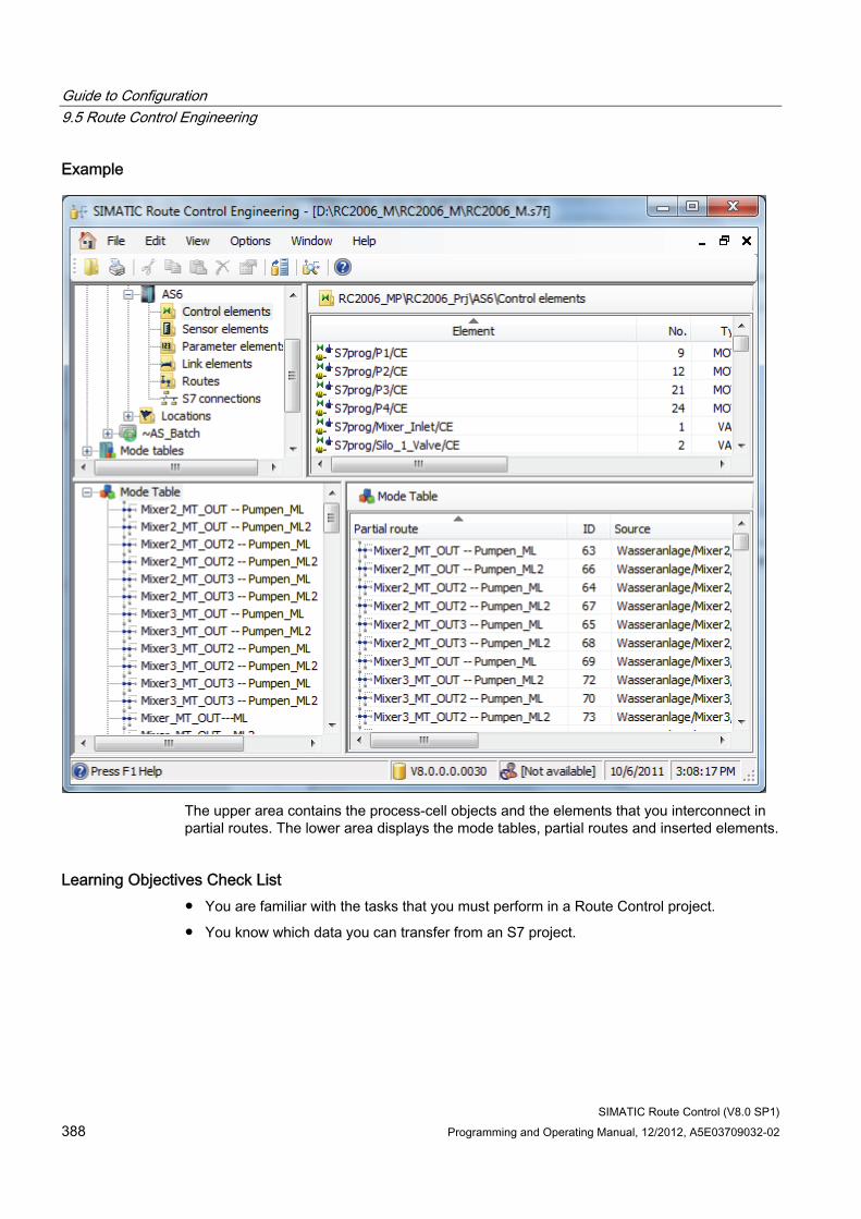
Guide to Configuration 9.5 Route Control Engineering
SIMATIC Route Control (V8.0 SP1) 388 Programming and Operating Manual, 12/2012, A5E03709032-02
Example
The upper area contains the process-cell objects and the elements that you interconnect in partial routes. The lower area displays the mode tables, partial routes and inserted elements.
Learning Objectives Check List ● You are familiar with the tasks that you must perform in a Route Control project.
● You know which data you can transfer from an S7 project.
Guide to Configuration 9.5 Route Control Engineering
SIMATIC Route Control (V8.0 SP1) Programming and Operating Manual, 12/2012, A5E03709032-02 389
9.5.2 Guide to the offline route search
Requirement You have configured your network into partial routes and want to check the route network for correctness before downloading it onto the Route Control server (and thus enabling it).
Basic Procedure 1. In Route Control Engineering, select the menu command Options > Verify Route
or click:
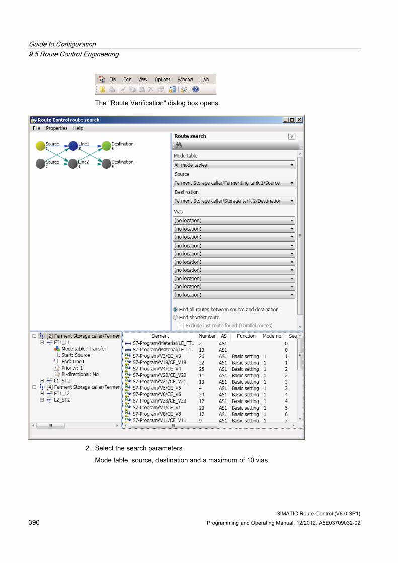
Guide to Configuration 9.5 Route Control Engineering
SIMATIC Route Control (V8.0 SP1) 390 Programming and Operating Manual, 12/2012, A5E03709032-02
The "Route Verification" dialog box opens.
2. Select the search parameters
Mode table, source, destination and a maximum of 10 vias.
Guide to Configuration 9.5 Route Control Engineering
SIMATIC Route Control (V8.0 SP1) Programming and Operating Manual, 12/2012, A5E03709032-02 391
3. Select the type of search.
– Search shortest route.
Vias are searched in the order in which they are specified. The priorities of the partial routes are considered in the search
With this type of search, the last route found can be excluded. In this case, all locations apart from source, destination, vias and the partial routes involved are blocked. The next route found is therefore a parallel route.
– Shortest route between source, vias and any destination.
Starting with the specified source, an attempt is made to reach all locations with the destination property with the shortest possible route.
– Find all routes between source and destination.
The runtime for this search depends very much on the structure of the graph, that is, the Route Control project structure, and may take hours in difficult cases. Moreover, the number of routes found, for example, with checkerboard patterns or complete graphs, may run into the millions and the search may be terminated before all routes are found. Therefore, specify the number of found routes after which the search should be terminated in the Properties dialog.
– Find main routes between source and destination.
This also searches for additional routes with the shortest possible route.
4. Click the button. The search is executed. A progress bar appears during the search. Once a route is found, it is shown in the results window.
5. Click on the route in the results window. The program displays details of the partial routes involved in the selected route.
Mode tables You can restrict both the search and the graphic representation to allow only selected partial routes with a selected mode table.
● Then, the only locations displayed in the graphic representation are those which are connected to partial routes that correspond to the selected mode table.
Since locations are not assigned to mode tables, it is possible that individual locations without connection to a partial route may appear in the graphs, even though a mode table has been selected.
● Only partial routes with the selected mode table are taken into consideration for the route search.
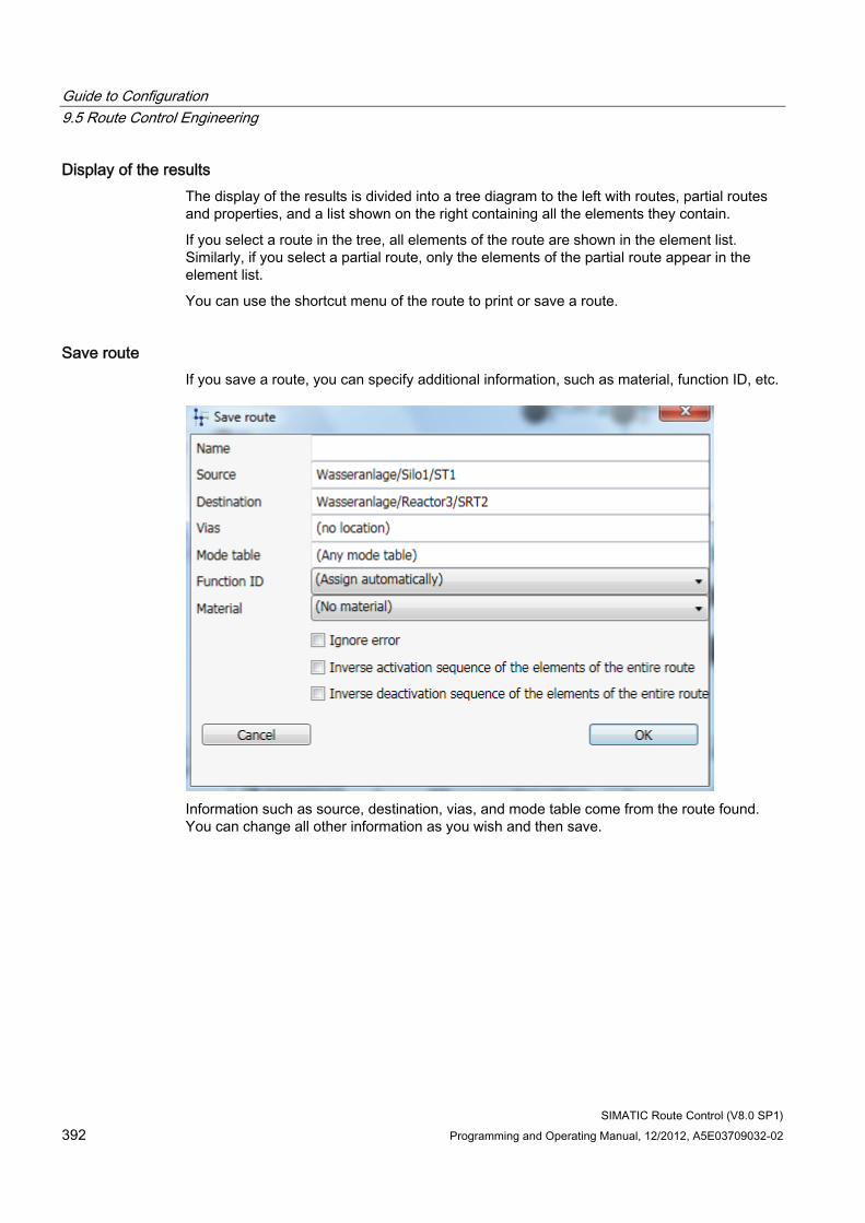
Guide to Configuration 9.5 Route Control Engineering
SIMATIC Route Control (V8.0 SP1) 392 Programming and Operating Manual, 12/2012, A5E03709032-02
Display of the results The display of the results is divided into a tree diagram to the left with routes, partial routes and properties, and a list shown on the right containing all the elements they contain.
If you select a route in the tree, all elements of the route are shown in the element list. Similarly, if you select a partial route, only the elements of the partial route appear in the element list.
You can use the shortcut menu of the route to print or save a route.
Save route If you save a route, you can specify additional information, such as material, function ID, etc.
Information such as source, destination, vias, and mode table come from the route found. You can change all other information as you wish and then save.
Guide to Configuration 9.5 Route Control Engineering
SIMATIC Route Control (V8.0 SP1) Programming and Operating Manual, 12/2012, A5E03709032-02 393
Memory and distinguishing criteria The location IDs of source, destination and via (not symbolic names) are used as memory and distinguishing criteria. All the currently used partial routes and the mode table will be saved.
Note Loading routes found offline
When downloading the Route Control Server, the routes stored online are deleted and routes stored offline are copied online.
Displaying saved routes The command File -> Saved routes or CTRL+R opens a dialog with the following lists in the offline route search:
● The first list shows the saved routes and some of their properties.
● When you select a route, the second list displays any available vias.
● The third list shows the used partial routes.
You can use the shortcut menu command "Delete" or press the "Del" key to delete individual routes or all routes.
Note Why Are Available Via Locations Not Displayed in the Route Control Route Verification Dialog Box Under Via?
Locations can have one or all of the three properties "Source", "Via", and "Destination". If the "Any location" function is used, all locations with the "Destination" property are considered solely as possible destinations. For this reason, locations with both the "Via" and "Destination" properties will not appear in the list of "Via" locations.
Project Engineering Checklist 1. You have configured partial routes.
2. You started the route-search tool and are now checking various source and destination combinations. The tool displays all routes/partial routes found.
3. You check whether the correct partial routes have been found and correct your configuration, if necessary.
Guide to Configuration 9.5 Route Control Engineering
SIMATIC Route Control (V8.0 SP1) 394 Programming and Operating Manual, 12/2012, A5E03709032-02
9.5.3 Guide to the cross-reference list of elements
User Task You want to find out which partial routes contain a particular element, that is, where the element is being used.
Procedure 1. In the top or bottom window of Route Control Engineering, select the menu command
Cross-reference List in an element shortcut menu. The "Cross-reference List" dialog box opens.
2. Select a partial route and click the "Elements" tab. A list of all elements associated with this partial route appears.
Learning Objectives Check List ● You know how to display a list of partial routes that contain a particular element.
● You can also determine the other elements that are interconnected in this partial route.
9.5.4 Guide to the CSV interface
User Task You want to configure mode tables or partial routes efficiently, with the aid of Microsoft Excel, for example.
Overview of Procedure Step Procedure 1 Exporting the objects from the Route Control configuration to a CSV file 2 Modifying and adding to the list 3 Importing the new list from a CSV file to the Route Control configuration
Check List Follow the individual steps as described in "CSV Interface Overview" (Page 465).
Guide to Configuration 9.6 Route Control server
SIMATIC Route Control (V8.0 SP1) Programming and Operating Manual, 12/2012, A5E03709032-02 395
9.6 Route Control server
9.6.1 Guide to the Route Control Server
Requirement You want to obtain an overview of the Route Control Server and user interfaces.
Component overview The Route Control runtime environment comprises three components:
● Route Control Server
● Route Control Center
● Route Control faceplate for PCS 7 OS
Additional information is available in the section "User interface of the servers" (Page 669)
"Overview of servers"
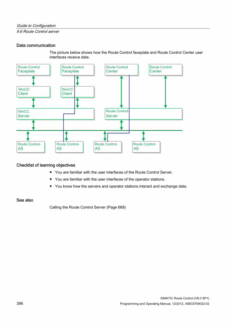
Guide to Configuration 9.6 Route Control server
SIMATIC Route Control (V8.0 SP1) 396 Programming and Operating Manual, 12/2012, A5E03709032-02
Data communication The picture below shows how the Route Control faceplate and Route Control Center user interfaces receive data.
Checklist of learning objectives ● You are familiar with the user interfaces of the Route Control Server.
● You are familiar with the user interfaces of the operator stations.
● You know how the servers and operator stations interact and exchange data.
See also Calling the Route Control Server (Page 668)
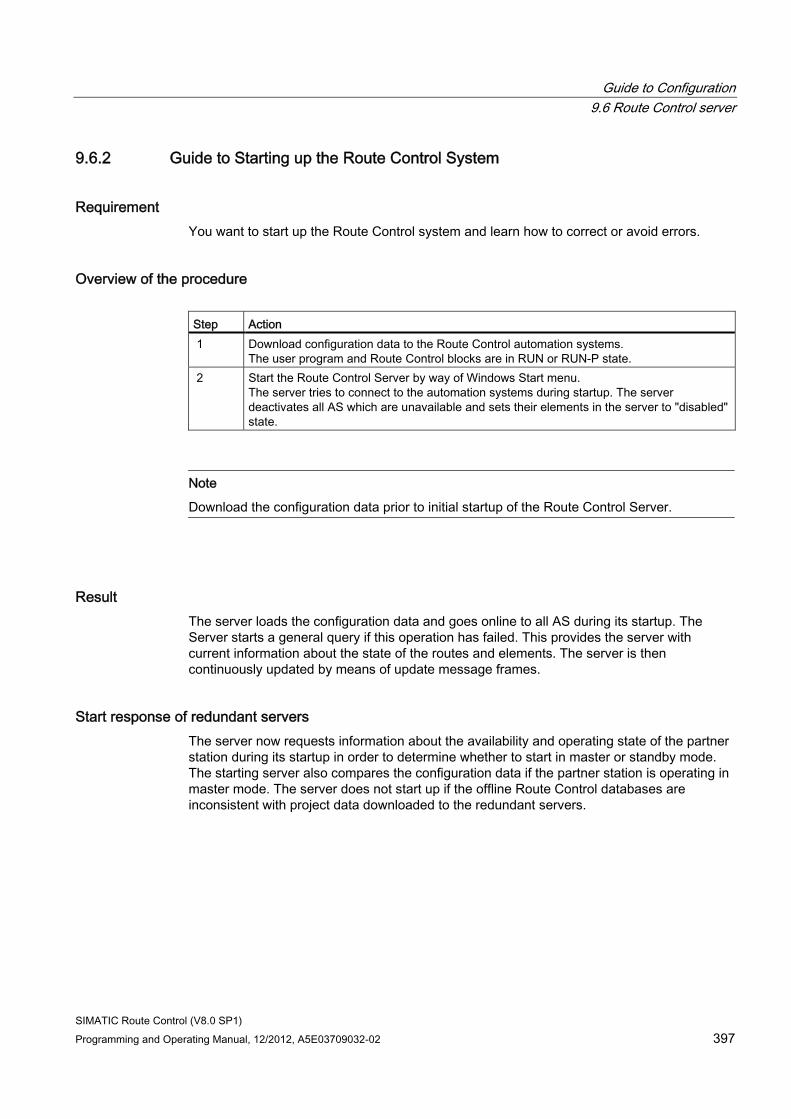
Guide to Configuration 9.6 Route Control server
SIMATIC Route Control (V8.0 SP1) Programming and Operating Manual, 12/2012, A5E03709032-02 397
9.6.2 Guide to Starting up the Route Control System
Requirement You want to start up the Route Control system and learn how to correct or avoid errors.
Overview of the procedure Step Action 1 Download configuration data to the Route Control automation systems.
The user program and Route Control blocks are in RUN or RUN-P state. 2 Start the Route Control Server by way of Windows Start menu.
The server tries to connect to the automation systems during startup. The server deactivates all AS which are unavailable and sets their elements in the server to "disabled" state.
Note
Download the configuration data prior to initial startup of the Route Control Server.
Result The server loads the configuration data and goes online to all AS during its startup. The Server starts a general query if this operation has failed. This provides the server with current information about the state of the routes and elements. The server is then continuously updated by means of update message frames.
Start response of redundant servers The server now requests information about the availability and operating state of the partner station during its startup in order to determine whether to start in master or standby mode. The starting server also compares the configuration data if the partner station is operating in master mode. The server does not start up if the offline Route Control databases are inconsistent with project data downloaded to the redundant servers.
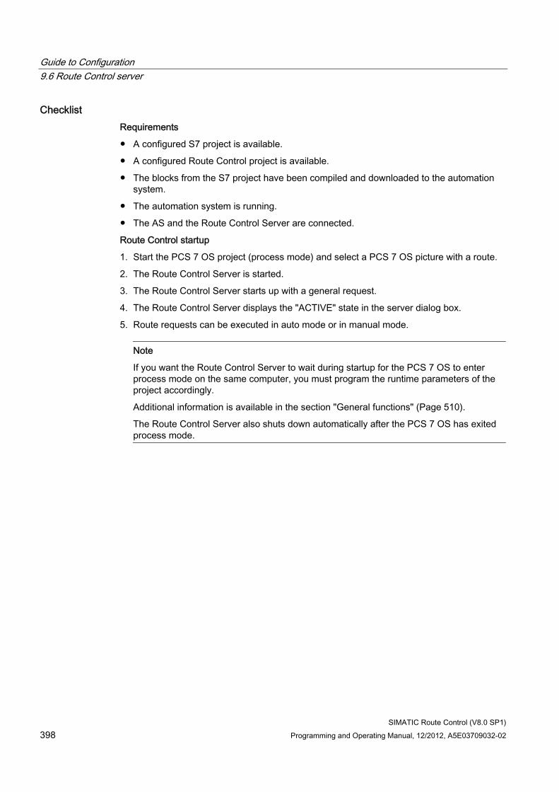
Guide to Configuration 9.6 Route Control server
SIMATIC Route Control (V8.0 SP1) 398 Programming and Operating Manual, 12/2012, A5E03709032-02
Checklist Requirements
● A configured S7 project is available.
● A configured Route Control project is available.
● The blocks from the S7 project have been compiled and downloaded to the automation system.
● The automation system is running.
● The AS and the Route Control Server are connected.
Route Control startup
1. Start the PCS 7 OS project (process mode) and select a PCS 7 OS picture with a route.
2. The Route Control Server is started.
3. The Route Control Server starts up with a general request.
4. The Route Control Server displays the "ACTIVE" state in the server dialog box.
5. Route requests can be executed in auto mode or in manual mode.
Note
If you want the Route Control Server to wait during startup for the PCS 7 OS to enter process mode on the same computer, you must program the runtime parameters of the project accordingly.
Additional information is available in the section "General functions" (Page 510).
The Route Control Server also shuts down automatically after the PCS 7 OS has exited process mode.
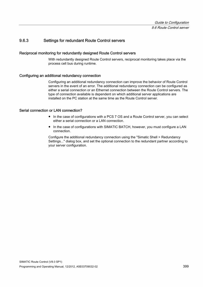
Guide to Configuration 9.6 Route Control server
SIMATIC Route Control (V8.0 SP1) Programming and Operating Manual, 12/2012, A5E03709032-02 399
9.6.3 Settings for redundant Route Control servers
Reciprocal monitoring for redundantly designed Route Control servers With redundantly designed Route Control servers, reciprocal monitoring takes place via the process cell bus during runtime.
Configuring an additional redundancy connection Configuring an additional redundancy connection can improve the behavior of Route Control servers in the event of an error. The additional redundancy connection can be configured as either a serial connection or an Ethernet connection between the Route Control servers. The type of connection available is dependent on which additional server applications are installed on the PC station at the same time as the Route Control server.
Serial connection or LAN connection? ● In the case of configurations with a PCS 7 OS and a Route Control server, you can select
either a serial connection or a LAN connection.
● In the case of configurations with SIMATIC BATCH, however, you must configure a LAN connection.
Configure the additional redundancy connection using the "Simatic Shell > Redundancy Settings..." dialog box, and set the optional connection to the redundant partner according to your server configuration.

Guide to Configuration 9.6 Route Control server
SIMATIC Route Control (V8.0 SP1) 400 Programming and Operating Manual, 12/2012, A5E03709032-02
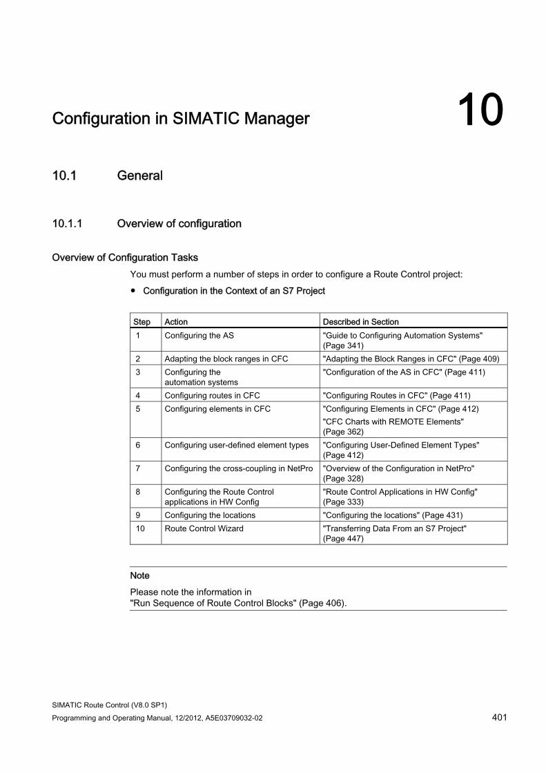
SIMATIC Route Control (V8.0 SP1) Programming and Operating Manual, 12/2012, A5E03709032-02 401
Configuration in SIMATIC Manager 1010.1 General
10.1.1 Overview of configuration
Overview of Configuration Tasks You must perform a number of steps in order to configure a Route Control project:
● Configuration in the Context of an S7 Project
Step Action Described in Section 1 Configuring the AS "Guide to Configuring Automation Systems"
(Page 341) 2 Adapting the block ranges in CFC "Adapting the Block Ranges in CFC" (Page 409) 3 Configuring the
automation systems "Configuration of the AS in CFC" (Page 411)
4 Configuring routes in CFC "Configuring Routes in CFC" (Page 411) 5 Configuring elements in CFC "Configuring Elements in CFC" (Page 412)
"CFC Charts with REMOTE Elements" (Page 362)
6 Configuring user-defined element types "Configuring User-Defined Element Types" (Page 412)
7 Configuring the cross-coupling in NetPro "Overview of the Configuration in NetPro" (Page 328)
8 Configuring the Route Control applications in HW Config
"Route Control Applications in HW Config" (Page 333)
9 Configuring the locations "Configuring the locations" (Page 431) 10 Route Control Wizard "Transferring Data From an S7 Project"
(Page 447)
Note
Please note the information in "Run Sequence of Route Control Blocks" (Page 406).
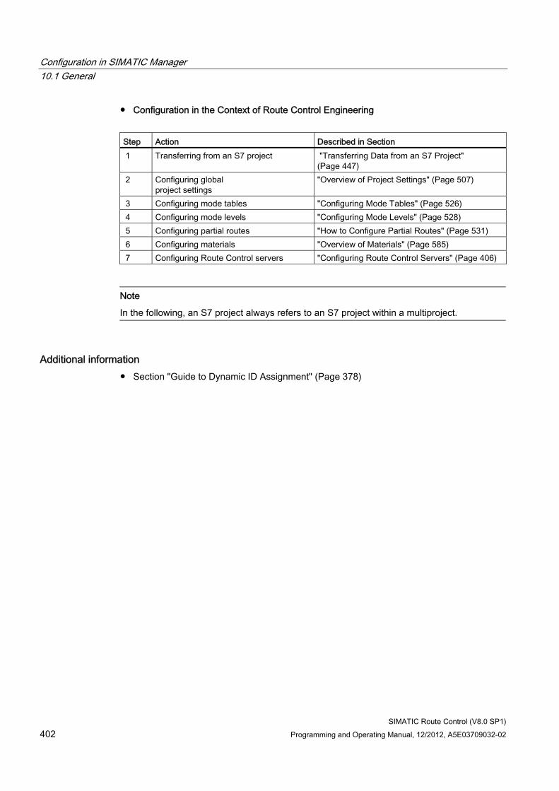
Configuration in SIMATIC Manager 10.1 General
SIMATIC Route Control (V8.0 SP1) 402 Programming and Operating Manual, 12/2012, A5E03709032-02
● Configuration in the Context of Route Control Engineering
Step Action Described in Section 1 Transferring from an S7 project "Transferring Data from an S7 Project"
(Page 447) 2 Configuring global
project settings "Overview of Project Settings" (Page 507)
3 Configuring mode tables "Configuring Mode Tables" (Page 526) 4 Configuring mode levels "Configuring Mode Levels" (Page 528) 5 Configuring partial routes "How to Configure Partial Routes" (Page 531) 6 Configuring materials "Overview of Materials" (Page 585) 7 Configuring Route Control servers "Configuring Route Control Servers" (Page 406)
Note
In the following, an S7 project always refers to an S7 project within a multiproject.
Additional information ● Section "Guide to Dynamic ID Assignment" (Page 378)
Configuration in SIMATIC Manager 10.1 General
SIMATIC Route Control (V8.0 SP1) Programming and Operating Manual, 12/2012, A5E03709032-02 403
10.1.2 Adding projects to a multiproject
Introduction If you want to add projects to a multiproject, Route Control checks whether the new data match the existing data. If the Route Control specifications are violated, a dialog box displaying notes on how to correct the errors appears automatically.
Dialog Box Tabs Depending on the type of error, the dialog box may contain the following tabs:
● RCS Data
● RC Application
● RC Application (stby)
● RC Application Client
Complete all tabs before clicking "OK". You must rectify all errors before adding all projects to the multiproject.
If you click "Cancel", no projects will be added.
Note
If you have already added a project to another multiproject, this is indicated in the "From multiproject" column.
You cannot add a project to more than one multiproject.
If you click "OK", a prompt appears asking whether or not the project should be removed from the other multiproject.
"RCS Data" Tab This tab is displayed if Route Control configuration data already exist in the multiproject and in the projects to be added.
You have two options:
● Option 1:
– Check the "Delete" box. The project will be added without Route Control configuration data.
● Option 2:
– Click "Cancel".
– Synchronize the project data with the multiproject.
– Add the project again, checking the "Delete" box on the "RCS Data" tab.
Configuration in SIMATIC Manager 10.1 General
SIMATIC Route Control (V8.0 SP1) 404 Programming and Operating Manual, 12/2012, A5E03709032-02
"RC Application" Tab This tab is displayed if addition would result in there being more than one RC application in the multiproject.
In the "Projects" list, select as many "Delete" check boxes as required to ensure that only one RC application will exist in the multiproject after addition.
"RC Application (stby)" Tab This tab is displayed if addition would result in there being more than one RC application (stby) in the multiproject.
In the "Projects" list, check as many "Delete" boxes as required to ensure that there will only be one RC application (stby) in the multiproject after addition.
"RC Application Client" Tab This tab is displayed if addition would result in the maximum number of RC applications clients for a multiproject being exceeded.
In the "Projects" list, select as many "Delete" check boxes as required to ensure that the displayed maximum number of clients in the multiproject will not be exceeded after addition.
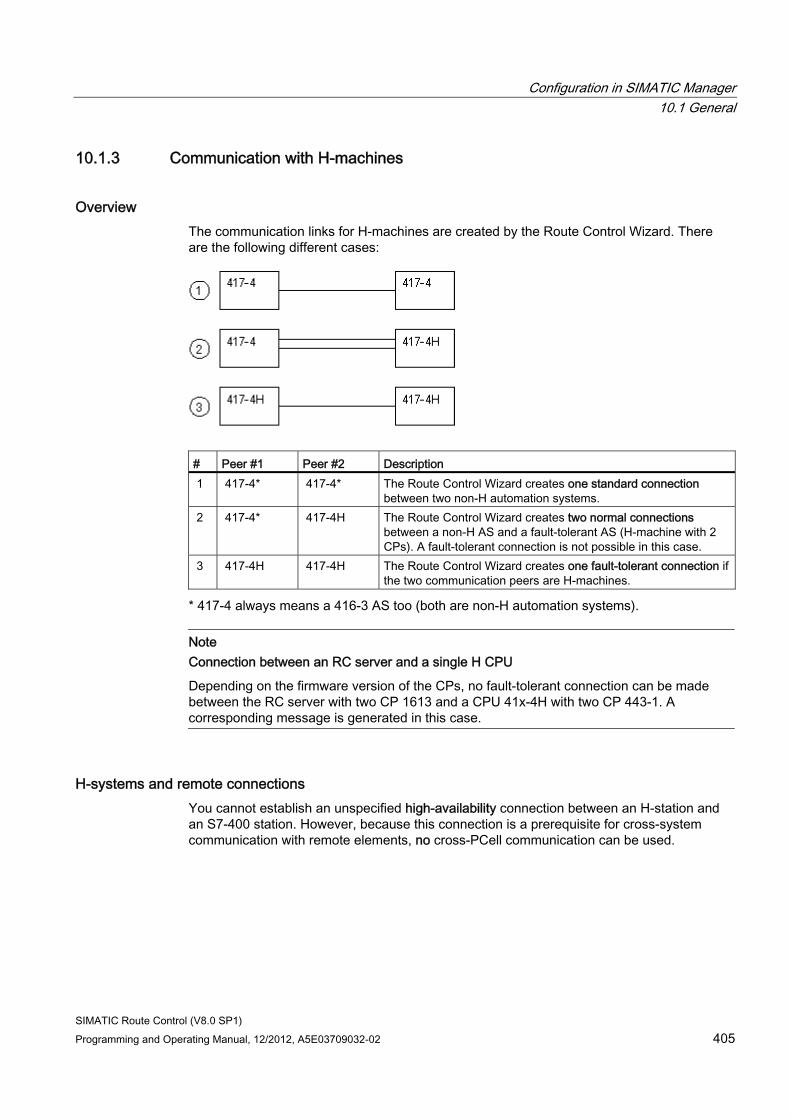
Configuration in SIMATIC Manager 10.1 General
SIMATIC Route Control (V8.0 SP1) Programming and Operating Manual, 12/2012, A5E03709032-02 405
10.1.3 Communication with H-machines
Overview The communication links for H-machines are created by the Route Control Wizard. There are the following different cases:
# Peer #1 Peer #2 Description 1 417-4* 417-4* The Route Control Wizard creates one standard connection
between two non-H automation systems. 2 417-4* 417-4H The Route Control Wizard creates two normal connections
between a non-H AS and a fault-tolerant AS (H-machine with 2 CPs). A fault-tolerant connection is not possible in this case.
3 417-4H 417-4H The Route Control Wizard creates one fault-tolerant connection if the two communication peers are H-machines.
* 417-4 always means a 416-3 AS too (both are non-H automation systems).
Note Connection between an RC server and a single H CPU
Depending on the firmware version of the CPs, no fault-tolerant connection can be made between the RC server with two CP 1613 and a CPU 41x-4H with two CP 443-1. A corresponding message is generated in this case.
H-systems and remote connections You cannot establish an unspecified high-availability connection between an H-station and an S7-400 station. However, because this connection is a prerequisite for cross-system communication with remote elements, no cross-PCell communication can be used.
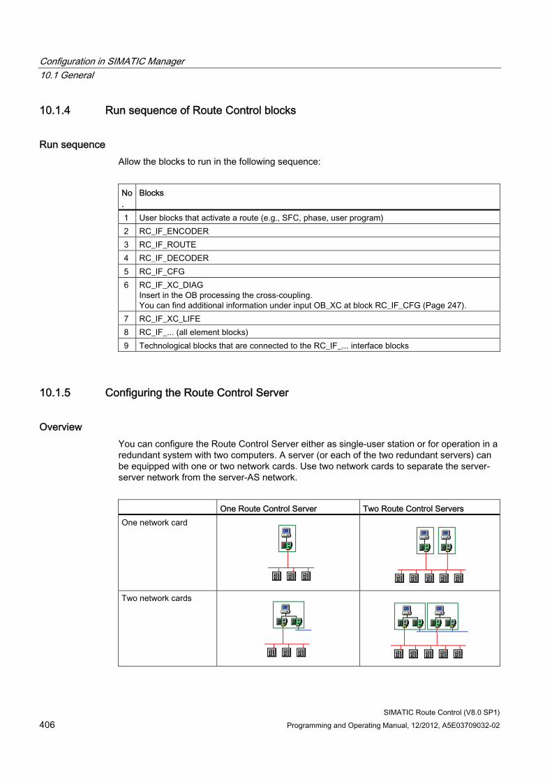
Configuration in SIMATIC Manager 10.1 General
SIMATIC Route Control (V8.0 SP1) 406 Programming and Operating Manual, 12/2012, A5E03709032-02
10.1.4 Run sequence of Route Control blocks
Run sequence Allow the blocks to run in the following sequence:
No.
Blocks
1 User blocks that activate a route (e.g., SFC, phase, user program) 2 RC_IF_ENCODER 3 RC_IF_ROUTE 4 RC_IF_DECODER 5 RC_IF_CFG 6 RC_IF_XC_DIAG
Insert in the OB processing the cross-coupling. You can find additional information under input OB_XC at block RC_IF_CFG (Page 247).
7 RC_IF_XC_LIFE 8 RC_IF_... (all element blocks) 9 Technological blocks that are connected to the RC_IF_... interface blocks
10.1.5 Configuring the Route Control Server
Overview You can configure the Route Control Server either as single-user station or for operation in a redundant system with two computers. A server (or each of the two redundant servers) can be equipped with one or two network cards. Use two network cards to separate the server-server network from the server-AS network.
One Route Control Server Two Route Control Servers One network card
Two network cards
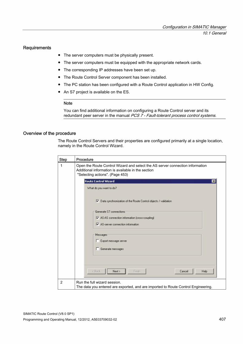
Configuration in SIMATIC Manager 10.1 General
SIMATIC Route Control (V8.0 SP1) Programming and Operating Manual, 12/2012, A5E03709032-02 407
Requirements ● The server computers must be physically present.
● The server computers must be equipped with the appropriate network cards.
● The corresponding IP addresses have been set up.
● The Route Control Server component has been installed.
● The PC station has been configured with a Route Control application in HW Config.
● An S7 project is available on the ES.
Note
You can find additional information on configuring a Route Control server and its redundant peer server in the manual PCS 7 - Fault-tolerant process control systems.
Overview of the procedure The Route Control Servers and their properties are configured primarily at a single location, namely in the Route Control Wizard.
Step Procedure 1 Open the Route Control Wizard and select the AS server connection information
Additional information is available in the section "Selecting actions". (Page 453)
2 Run the full wizard session.
The data you entered are exported, and are imported to Route Control Engineering.
Configuration in SIMATIC Manager 10.1 General
SIMATIC Route Control (V8.0 SP1) 408 Programming and Operating Manual, 12/2012, A5E03709032-02
Step Procedure 3 Check the transferred data
Additional information is available in the section "Import log" (Page 463)
4 Download the Route Control configuration to the Route Control Server. 5 Start the server (or cold restart)
Additional information is available in the section "Overview of servers" (Page 668)
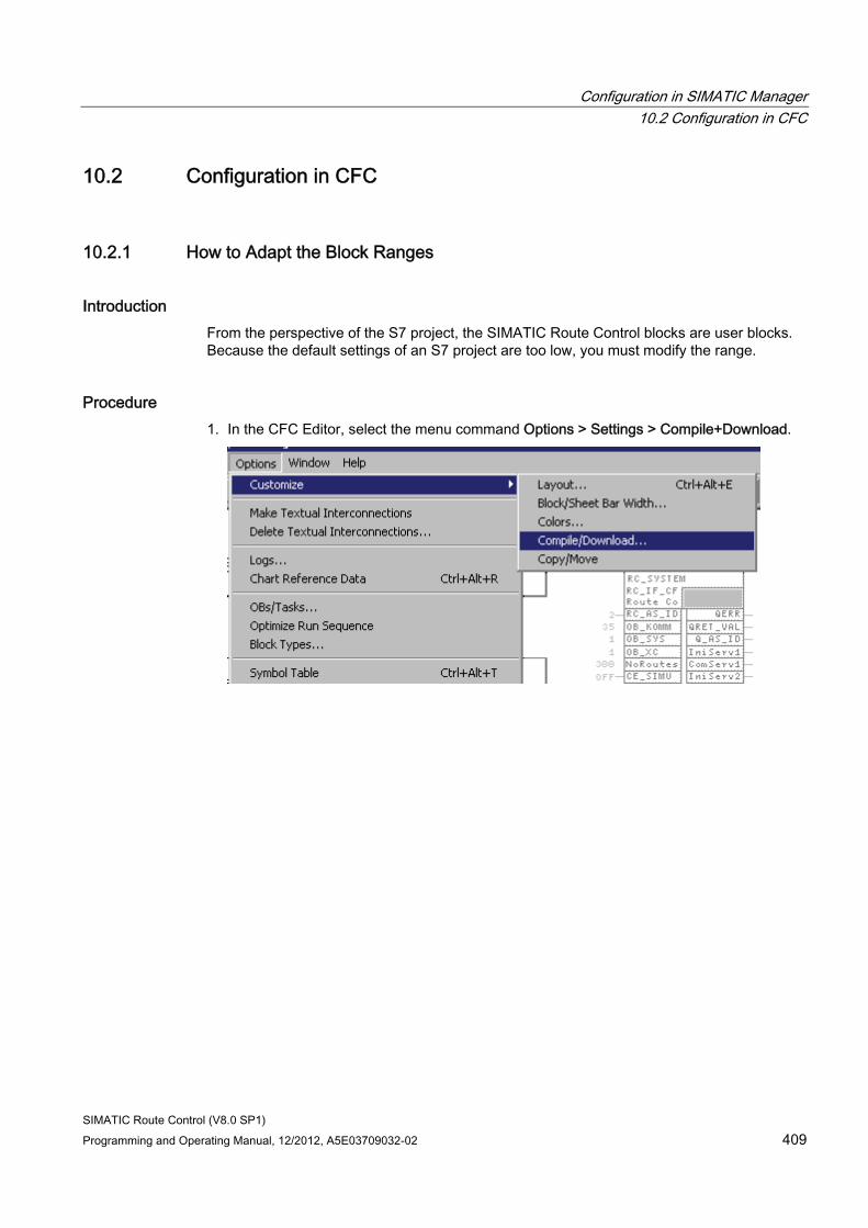
Configuration in SIMATIC Manager 10.2 Configuration in CFC
SIMATIC Route Control (V8.0 SP1) Programming and Operating Manual, 12/2012, A5E03709032-02 409
10.2 Configuration in CFC
10.2.1 How to Adapt the Block Ranges
Introduction From the perspective of the S7 project, the SIMATIC Route Control blocks are user blocks. Because the default settings of an S7 project are too low, you must modify the range.
Procedure 1. In the CFC Editor, select the menu command Options > Settings > Compile+Download.
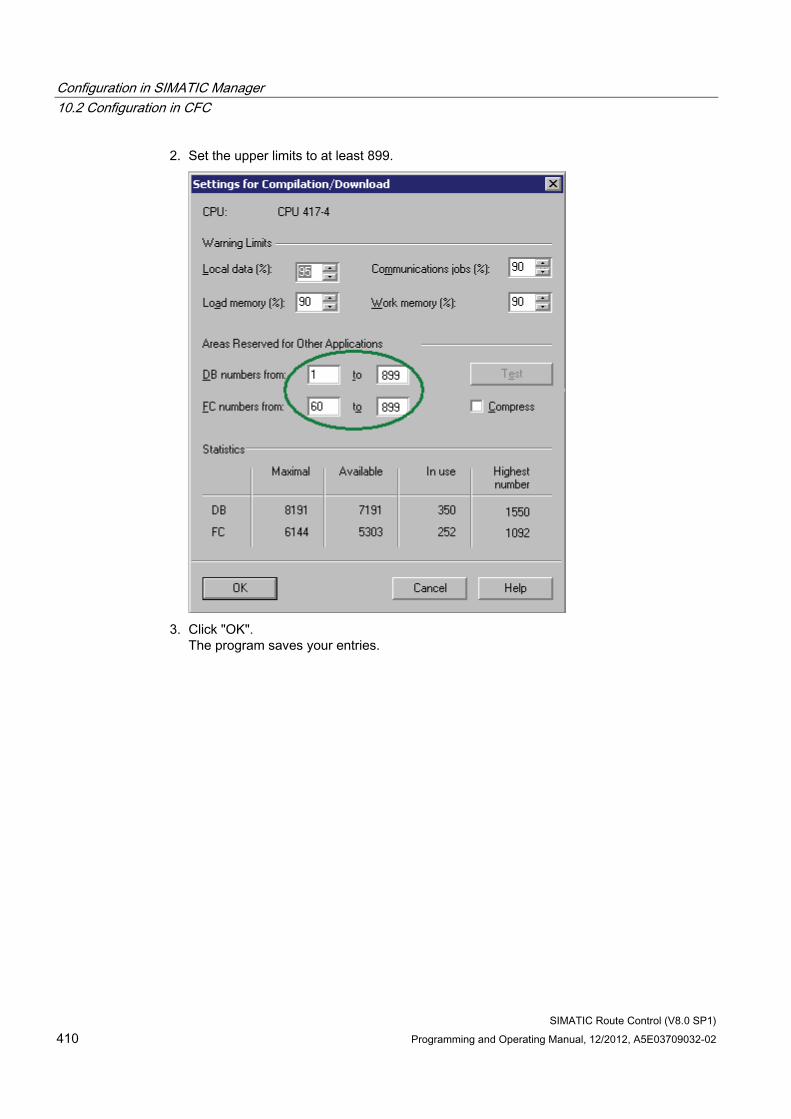
Configuration in SIMATIC Manager 10.2 Configuration in CFC
SIMATIC Route Control (V8.0 SP1) 410 Programming and Operating Manual, 12/2012, A5E03709032-02
2. Set the upper limits to at least 899.
3. Click "OK".
The program saves your entries.
Configuration in SIMATIC Manager 10.2 Configuration in CFC
SIMATIC Route Control (V8.0 SP1) Programming and Operating Manual, 12/2012, A5E03709032-02 411
10.2.2 Engineering the AS Configuration in CFC
CFC Engineering of the Configuration Insert a separate instance of the RC_IF_CFG block type in a separate CFC chart in each AS.
If you are using two or more automation systems in your project, we recommend that you also include the following two blocks in each AS:
● RC_IF_XC_DIAG (FB 884) (Page 254)
● RC_IF_XC_LIFE (FC 884) (Page 260)
These two blocks are used for diagnostics of data communication between automation systems. You can insert both blocks in the same CFC chart as the RC_IF_CFG block.
Additional information ● Section "Block RC_IF_CFG" (Page 247)
10.2.3 Configuring routes in CFC
CFC Configuration of Routes Insert a separate instance of the RC_IF_ROUTE block type in a CFC chart for each route (later, material transport).
Note
Use a separate CFC chart for each instance, as it will also contain the user block, such as a phase block, in addition to the route block.
Additional information ● Section "Block RC_IF_ROUTE" (Page 159)
● Section "Guide to Dynamic ID Assignment" (Page 378)
Configuration in SIMATIC Manager 10.2 Configuration in CFC
SIMATIC Route Control (V8.0 SP1) 412 Programming and Operating Manual, 12/2012, A5E03709032-02
10.2.4 Configuring elements in CFC
CFC Configuration of Elements You have to insert a block from the standard library in a CFC chart for every element to be controlled in the system. Alternatively, you can use other block libraries. In this case, it must be ensured that these blocks are compatible with the routing-system interface blocks.
Insert a routing-system interface block for each element block, preferably in the CFC chart. This interface block links the external block to the data administration of the routing system in the automation systems.
Examples ● RC_IF_MOTOR and MOTOR
● RC_IF_VALVE and VALVE
10.2.5 Configuring user-defined element types
Introduction If you want, for example, to use a motor with a special activation control and different feedback signals, you create a user-defined element type, insert it in CFC and export it to the Route Control project.
Overview of Procedure Insert a default block, in this case RC_IF_MOTOR, in the appropriate user block, in this case RC_IF_USER_CE.
The following are supplied as templates for user elements:
● RC_IF_USER_CE (Page 217) control element)
● RC_IF_USER_SE (Page 230) (sensor element)
● RC_IF_USER_PE (Page 238) (parameter element)
User-defined attributes (UDAs) tell the Route Control Wizard that this block is relevant for data export.
Additional information ● Section "Example of a User-Defined Type" (Page 242)
● Section "Generic User Elements" (Page 244)
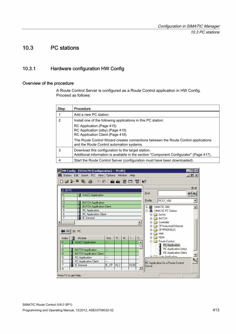
Configuration in SIMATIC Manager 10.3 PC stations
SIMATIC Route Control (V8.0 SP1) Programming and Operating Manual, 12/2012, A5E03709032-02 413
10.3 PC stations
10.3.1 Hardware configuration HW Config
Overview of the procedure A Route Control Server is configured as a Route Control application in HW Config. Proceed as follows:
Step Procedure 1 Add a new PC station. 2 Install one of the following applications in this PC station:
RC Application (Page 415) RC Application (stby) (Page 415) RC Application Client (Page 416) The Route Control Wizard creates connections between the Route Control applications and the Route Control automation systems.
3 Download this configuration to the target station. Additional information is available in the section "Component Configurator" (Page 417).
4 Start the Route Control Server (configuration must have been downloaded).
Configuration in SIMATIC Manager 10.3 PC stations
SIMATIC Route Control (V8.0 SP1) 414 Programming and Operating Manual, 12/2012, A5E03709032-02
Result The Route Control Server now activates the named connections to the automation systems.
Configuration in SIMATIC Manager 10.3 PC stations
SIMATIC Route Control (V8.0 SP1) Programming and Operating Manual, 12/2012, A5E03709032-02 415
10.3.2 Route Control application properties
"General" Tab This dialog box displays the general properties of the selected Route Control application. You can change the "Name" and "Comments" field in HW Config. You can also change the name directly by editing the object in SIMATIC Manager.
Field Meaning Short designation Here you can view the application abbreviation from HW Config. Order no.: --- Name If you need to, change the name to suit your requirements.
The new name will then appear in SIMATIC Manager. Comments You can enter additional information relating to the application here.
10.3.3 Route Control application
RC Application The Route Control application object represents the Route Control server component.
The Route Control server, Route Control standby server and Route Control clients (Route Control Center) usually run on different computers. In order to be able to download the process-cell data for a project to these computers separately, you have to create a SIMATIC PC station in the SIMATIC Manager component view for every Route Control server and every Route Control client. You must also configure these stations in HW Config, using the corresponding Route Control application.
10.3.4 Route Control application (stby)
RC Application (stby) The Route Control application (stby) object represents the Route Control standby server component.
The Route Control server, Route Control standby server and Route Control clients (Route Control Center) usually run on different computers. In order to be able to download the process-cell data for a project to these computers separately, you have to create a SIMATIC PC station in the SIMATIC Manager component view for every Route Control server and every Route Control client. You must also configure these stations in HW Config, using the corresponding Route Control application.
Configuration in SIMATIC Manager 10.3 PC stations
SIMATIC Route Control (V8.0 SP1) 416 Programming and Operating Manual, 12/2012, A5E03709032-02
10.3.5 Route Control application client
RC Application Client The Route Control application client object represents the Route Control client (Route Control Center) component.
The Route Control server, Route Control standby server and Route Control clients usually run on different computers. In order to be able to download the process-cell data for a project to these computers separately, you have to create a SIMATIC PC station in the SIMATIC Manager component view for every Route Control server and every Route Control client. You must also configure these stations in HW Config, using the corresponding Route Control application.
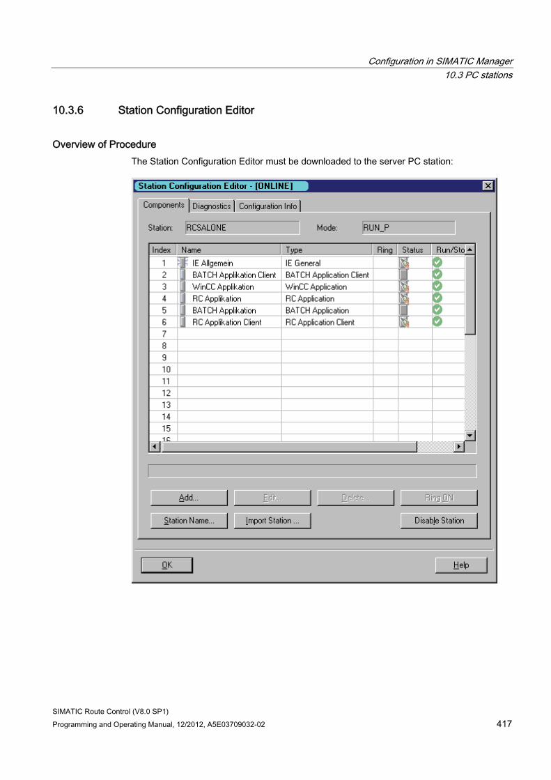
Configuration in SIMATIC Manager 10.3 PC stations
SIMATIC Route Control (V8.0 SP1) Programming and Operating Manual, 12/2012, A5E03709032-02 417
10.3.6 Station Configuration Editor
Overview of Procedure The Station Configuration Editor must be downloaded to the server PC station:
Configuration in SIMATIC Manager 10.4 Route Control Objects
SIMATIC Route Control (V8.0 SP1) 418 Programming and Operating Manual, 12/2012, A5E03709032-02
10.4 Route Control Objects
10.4.1 Creating Route Control Objects
"Route Control" Objects When Route Control is installed, a "Route Control" object is also created automatically in the project folder in SIMATIC Manager.
A "Route Control" object is also created automatically when the Route Control application client is inserted in a PC station.
If one of these objects has been deleted, you can recreate it manually.
To do this, open the shortcut menu in the project folder or RC application client and select the menu command Add New Object > Route Control.
Additional information ● Section "Route Control Object Properties" (Page 418)
● Section "Route Control Object in the Project Folder" (Page 419)
● Section "Route Control Object in the RC Application Client" (Page 419)
10.4.2 Route Control object properties
"General" Tab This dialog box displays the general properties of the "Route Control" object.
Field Meaning Name You can change the name of the object here. Project path Here you can view the path from the project to the current object (via
the components) from the component view. Storage location of project The path for the project directory appears here. Author The name of the creator is displayed here. Date created The date on which the object was created is displayed here. Last modified The date on which the object was last changed is displayed here. Comments You can enter additional information relating to the object here.
Configuration in SIMATIC Manager 10.4 Route Control Objects
SIMATIC Route Control (V8.0 SP1) Programming and Operating Manual, 12/2012, A5E03709032-02 419
10.4.3 Route Control object in the project folder
Route Control object
This object contains information about the location of the Route Control database.
To start Route Control Engineering, double-click the object or open the shortcut menu and select the menu command Object > Open.
To download the server and, if available, the standby server, open the shortcut menu and select the menu command PLC > Download.
To start the wizard, display the wizard log or start the Engineering, open the shortcut menu and select the menu command SIMATIC Route Control.
To display the object properties, open the shortcut menu and select the menu command Object Properties.
10.4.4 Route Control object in the RC application client
Route Control Object
The names and addresses of the Route Control server(s) are stored in this object.
To download the configuration to the client, open the shortcut menu and select the menu command PLC > Download. Perform this action just once after the first download to the server.
To start the wizard, display the wizard log or start Engineering, open the shortcut menu and select the menu command SIMATIC Route Control.
To display the object properties, open the shortcut menu and select the menu command Object Properties.
Note
In SIMATIC Route Control V7.1 and higher this step can be omitted, as the RC clients can receive their downloads in RC Engineering directly (Download to server function).
Configuration in SIMATIC Manager 10.5 Options Menu in SIMATIC Manager
SIMATIC Route Control (V8.0 SP1) 420 Programming and Operating Manual, 12/2012, A5E03709032-02
10.5 Options Menu in SIMATIC Manager
10.5.1 SIMATIC Route Control
Options > SIMATIC Route Control Menu You can perform the following actions using the submenu functions:
● Start the Route Control Wizard (Page 420)
● Display the Route Control Wizard log (Page 420)
● Start Route Control Engineering (Page 421)
● Open the wizard for importing/exporting equipment properties (Page 421)
10.5.2 SIMATIC Route Control Wizard
Options > SIMATIC Route Control > Wizard Menu This menu command starts the Route Control Wizard in order to export the configuration from the S7 project. The exported data are saved and can be imported into Route Control Engineering at a later time.
Additional Information Section "Actions in the Route Control Wizard" (Page 451)
10.5.3 SIMATIC Route Control Show Wizard Log
Options > SIMATIC Route Control > Show Wizard Log Menu This menu command opens an editor that displays the log of the last export carried out using the Route Control Wizard.
Additional Information Section "Export Log" (Page 463)
Configuration in SIMATIC Manager 10.5 Options Menu in SIMATIC Manager
SIMATIC Route Control (V8.0 SP1) Programming and Operating Manual, 12/2012, A5E03709032-02 421
10.5.4 SIMATIC Route Control Engineering
Options > SIMATIC Route Control > Engineering Menu This menu command opens the Route Control Engineering window.
Additional Information Section "Route Control Engineering Main View" (Page 495)
10.5.5 Import/Export of SIMATIC Route Control Equipment Properties
Options > SIMATIC Route Control > Import/Export Equipment Properties Menu This menu command opens the wizard for importing/exporting equipment properties.
Additional Information Section: ""How to export and import locations" (Page 436)
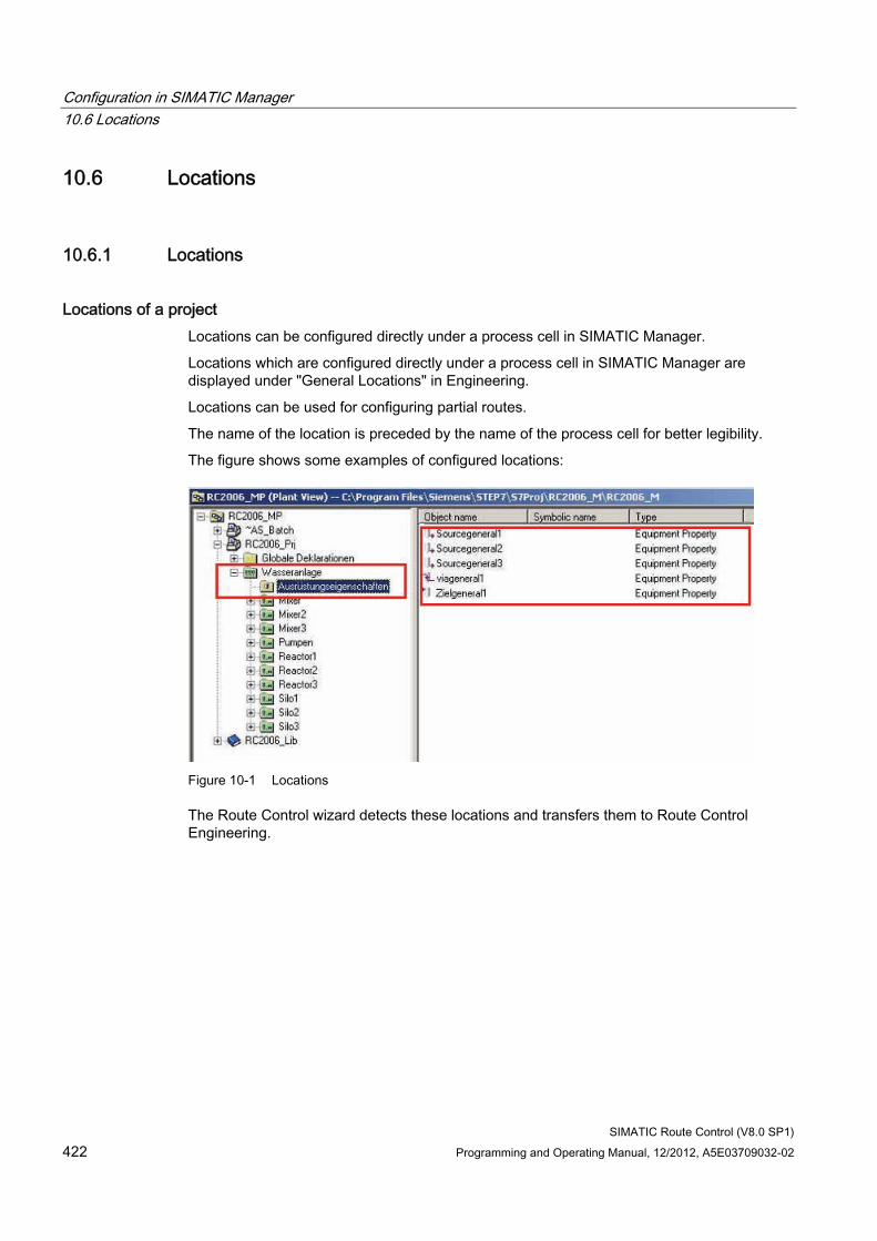
Configuration in SIMATIC Manager 10.6 Locations
SIMATIC Route Control (V8.0 SP1) 422 Programming and Operating Manual, 12/2012, A5E03709032-02
10.6 Locations
10.6.1 Locations
Locations of a project Locations can be configured directly under a process cell in SIMATIC Manager.
Locations which are configured directly under a process cell in SIMATIC Manager are displayed under "General Locations" in Engineering.
Locations can be used for configuring partial routes.
The name of the location is preceded by the name of the process cell for better legibility.
The figure shows some examples of configured locations:
Figure 10-1 Locations
The Route Control wizard detects these locations and transfers them to Route Control Engineering.
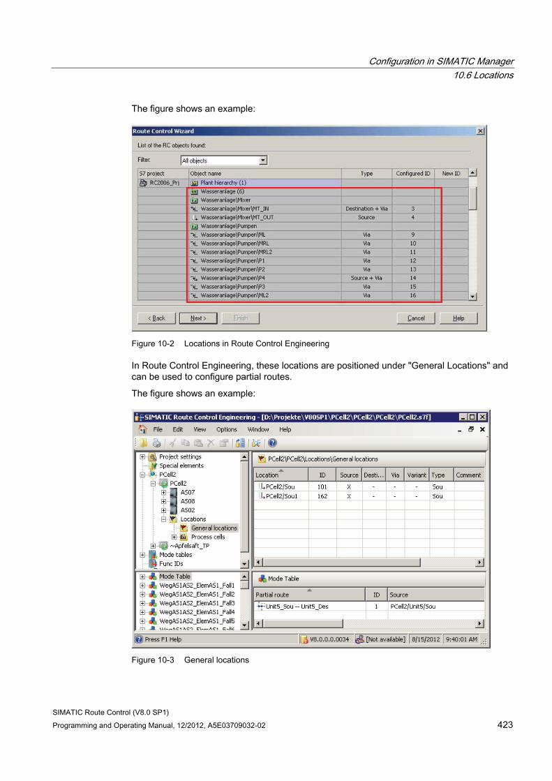
Configuration in SIMATIC Manager 10.6 Locations
SIMATIC Route Control (V8.0 SP1) Programming and Operating Manual, 12/2012, A5E03709032-02 423
The figure shows an example:
Figure 10-2 Locations in Route Control Engineering
In Route Control Engineering, these locations are positioned under "General Locations" and can be used to configure partial routes.
The figure shows an example:
Figure 10-3 General locations
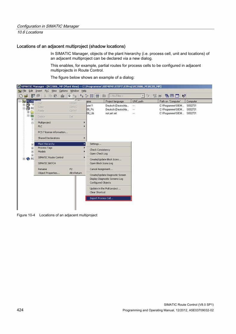
Configuration in SIMATIC Manager 10.6 Locations
SIMATIC Route Control (V8.0 SP1) 424 Programming and Operating Manual, 12/2012, A5E03709032-02
Locations of an adjacent multiproject (shadow locations) In SIMATIC Manager, objects of the plant hierarchy (i.e. process cell, unit and locations) of an adjacent multiproject can be declared via a new dialog.
This enables, for example, partial routes for process cells to be configured in adjacent multiprojects in Route Control.
The figure below shows an example of a dialog:
Figure 10-4 Locations of an adjacent multiproject
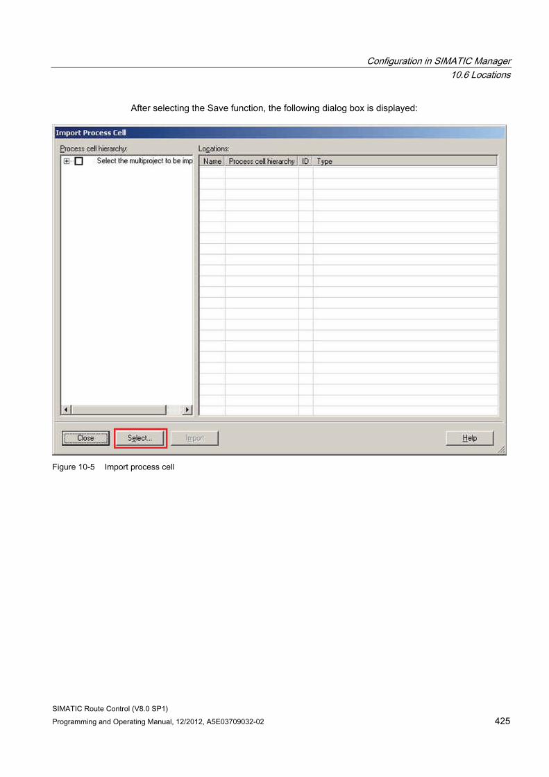
Configuration in SIMATIC Manager 10.6 Locations
SIMATIC Route Control (V8.0 SP1) Programming and Operating Manual, 12/2012, A5E03709032-02 425
After selecting the Save function, the following dialog box is displayed:
Figure 10-5 Import process cell
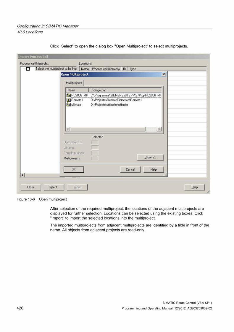
Configuration in SIMATIC Manager 10.6 Locations
SIMATIC Route Control (V8.0 SP1) 426 Programming and Operating Manual, 12/2012, A5E03709032-02
Click "Select" to open the dialog box "Open Multiproject" to select multiprojects.
Figure 10-6 Open multiproject
After selection of the required multiproject, the locations of the adjacent multiprojects are displayed for further selection. Locations can be selected using the existing boxes. Click "Import" to import the selected locations into the multiproject.
The imported multiprojects from adjacent multiprojects are identified by a tilde in front of the name. All objects from adjacent projects are read-only.
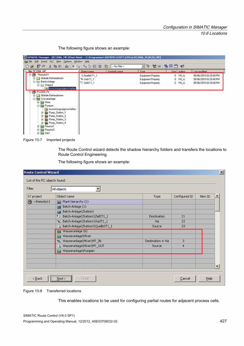
Configuration in SIMATIC Manager 10.6 Locations
SIMATIC Route Control (V8.0 SP1) Programming and Operating Manual, 12/2012, A5E03709032-02 427
The following figure shows an example:
Figure 10-7 Imported projects
The Route Control wizard detects the shadow hierarchy folders and transfers the locations to Route Control Engineering.
The following figure shows an example:
Figure 10-8 Transferred locations
This enables locations to be used for configuring partial routes for adjacent process cells.
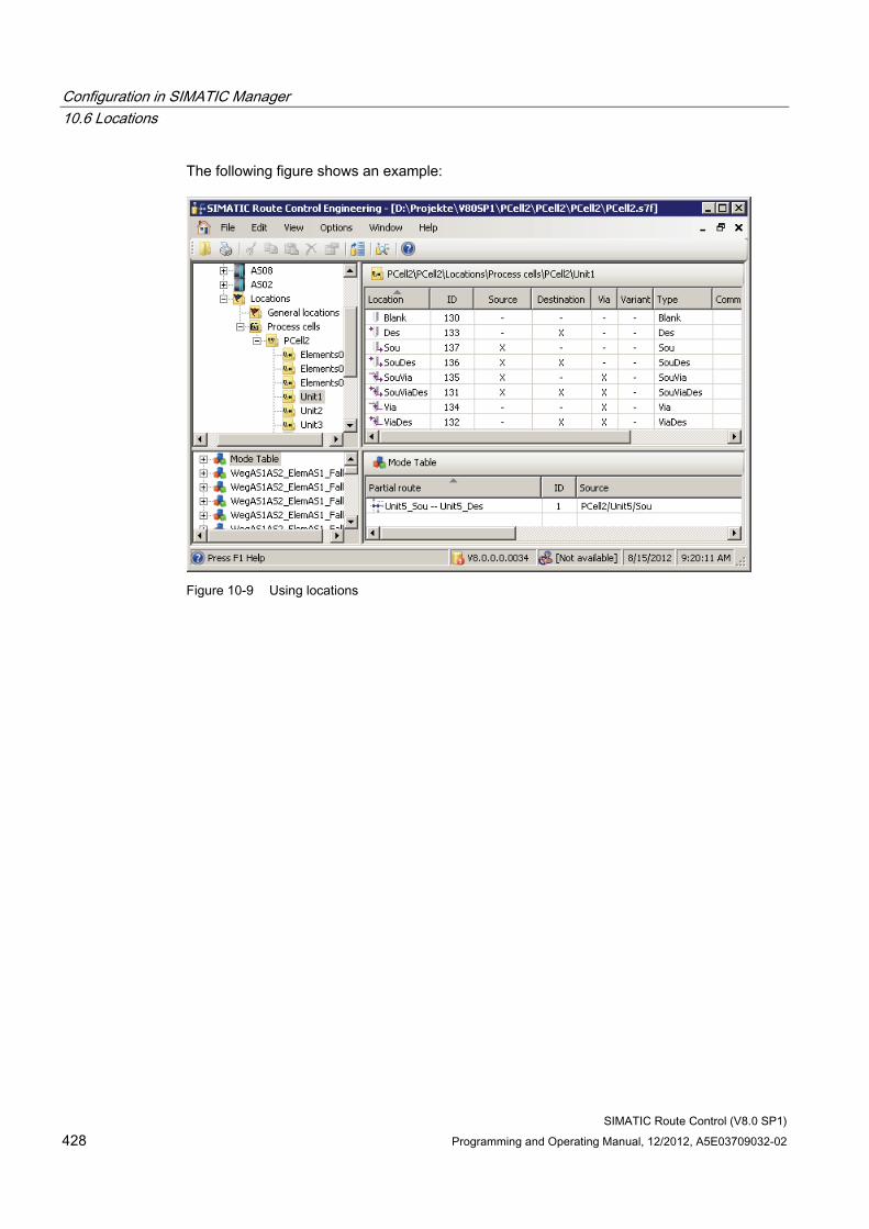
Configuration in SIMATIC Manager 10.6 Locations
SIMATIC Route Control (V8.0 SP1) 428 Programming and Operating Manual, 12/2012, A5E03709032-02
The following figure shows an example:
Figure 10-9 Using locations
Configuration in SIMATIC Manager 10.6 Locations
SIMATIC Route Control (V8.0 SP1) Programming and Operating Manual, 12/2012, A5E03709032-02 429
10.6.2 Number ranges
Number ranges of locations From the Route Control perspective, the ID of a location must be globally unique within a multiproject. The number range in a project is defined in SIMATIC Manager via a dialog.
You must ensure that the number ranges in the SIMATIC projects of a multiproject are unique.
This uniqueness must also be ensured when importing shadow hierarchy folders.
When changing the number range, please ensure that the IDs are automatically numbered within the number range.
For this reason, check any possible fixed ID assignments within your configuration, for example, in your user programs or direct configurations at route blocks. These ID assignments are not known to SIMATIC Manager and are therefore not automatically updated You must manually update the ID changes at these positions in your project.
Defining number ranges of locations You define the number range in SIMATIC Manager using the dialog box "Properties Equipment Properties" in the "Locations" tab.
The high and low limits of the number range is displayed here.
Number ranges may not overlap in the sub-projects and in a multiproject. This fact is checked when they are entered and an error message may be generated identifying the relevant sub-project.
The number range must contain positive integers from 1 to 65,535; a message appears if an entry is invalid.
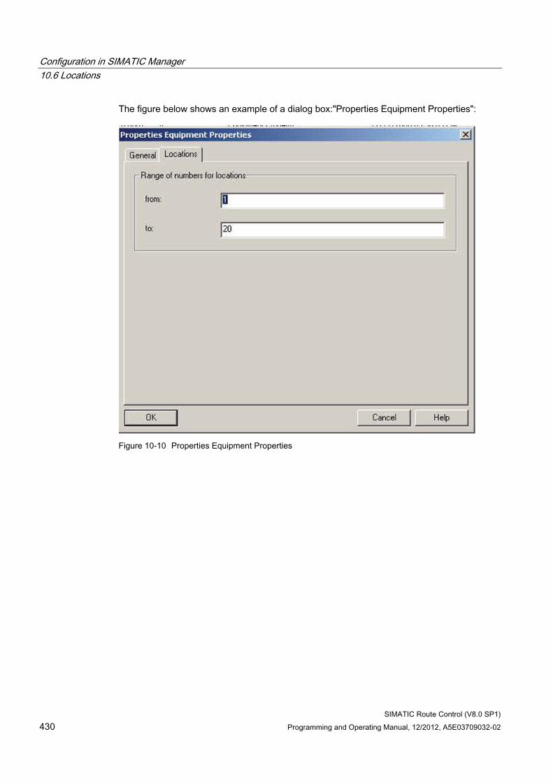
Configuration in SIMATIC Manager 10.6 Locations
SIMATIC Route Control (V8.0 SP1) 430 Programming and Operating Manual, 12/2012, A5E03709032-02
The figure below shows an example of a dialog box:"Properties Equipment Properties":
Figure 10-10 Properties Equipment Properties
Configuration in SIMATIC Manager 10.6 Locations
SIMATIC Route Control (V8.0 SP1) Programming and Operating Manual, 12/2012, A5E03709032-02 431
10.6.3 Configuring the locations
Introduction Locations refer to the start, paths (vias) and final points of routes.
As of V7.0, do not configure locations in Route Control Engineering any more, configure them directly in SIMATIC Manager instead.
The locations are imported by both SIMATIC BATCH and SIMATIC Route Control and thus only have to be configured once.
Overview of Procedure You configure the locations in two steps:
Step Procedure 1 Create location types in the "Shared Declarations". 2 Create locations in units.
To inform the system about the types of location used, create all the required location types once as equipment properties in the project's "Shared Declarations" folder. Additional information is available in the section "How to configure location types" (Page 432)
Now create the locations (instances of the location types) as equipment properties in technological units. Each location is assigned an unambiguous ID within the entire project. You can find additional information in "How to configure locations" (Page 434).
Configuring general locations As of V7.0, you must assign all locations to a unit in SIMATIC Manager. Therefore, distribute all locations to the technological units appropriately.
You can also formally create one or more units in the plant hierarchy, which are not available for BATCH batches. Equip these formal units with the locations which you do not wish to assign to a technological unit.
Note
The "General Locations" folder in Route Control Engineering is no longer used.
Configuration in SIMATIC Manager 10.6 Locations
SIMATIC Route Control (V8.0 SP1) 432 Programming and Operating Manual, 12/2012, A5E03709032-02
10.6.4 How to configure location types
Introduction Before you can create locations, you must first create the required location types in SIMATIC Manager. To do this, create a "Shared Declarations" folder and an "Equipment Properties" subfolder in your project. Configure an "Equipment property" object of the "LOCATION" data type there for each location type. In this object, specify if a location of this type should be used as a source, destination or via of a material transport in runtime. You can also assign several or all these properties to a location type.
You can use locations for which you have assigned none of these properties to create partial routes in Route Control Engineering. These locations are not offered for selection when configuring a material transport in runtime.
When creating location types, keep in mind that you can insert instances of a certain location type in any number of units. However, you can only insert one instance of a certain location type in each unit.
Therefore, the number of identical location types that you have to create is dictated by the maximum number required in a unit.
Example Each unit in your project contains a maximum of three inlet valves of the same type, which should only be used as the destination of a route or partial route.
You then configure three location types, for example, inlet1, inlet2 and inlet3, all with the "Destination" property. You can assign "inlet1", for example, to units that have only one inlet valve.
Procedure for Configuring Location Types 1. If a project-specific "Shared Declarations" folder does not exist in the component view of
SIMATIC Manager, open the project-folder shortcut menu and select the menu command Add New Object >Shared Declarations The "Shared Declarations" folder is created.
2. Select the "Shared Declarations" folder.
3. If an "Equipment Properties" folder does not yet exist there, open the unit shortcut menu and select Add New Object > Equipment Properties. The "Equipment Properties" folder is created.
4. Select the "Equipment Properties" folder.
5. Open the shortcut menu and select Add New Object > Equipment Property.A new object is created.
6. Open the shortcut menu and select the Object Properties command. The "Properties equipment properties" dialog box opens.
Configuration in SIMATIC Manager 10.6 Locations
SIMATIC Route Control (V8.0 SP1) Programming and Operating Manual, 12/2012, A5E03709032-02 433
7. Enter the name of the location type in the "Name" edit box. The "Display name" field is updated automatically. The name and the display name must be the same.
8. Select the "LOCATION" entry from the "Data type" drop-down list.
9. Check none, one or several of the "Source", "Destination" and "Via" boxes.
10. If necessary, enter information in the "Author" and "Comment" fields.
11. Click "OK". The program saves your entries.
Note
If the name entered in the "Name" edit box is already in use, your entries are not accepted.
Result You have created an object in the "Equipment Properties" folder of the "Shared Declarations" for each location type and have given each location type a unique name.
Additional information You can find information about equipping units with locations in
● "How to configure locations" (Page 434)
Configuration in SIMATIC Manager 10.6 Locations
SIMATIC Route Control (V8.0 SP1) 434 Programming and Operating Manual, 12/2012, A5E03709032-02
10.6.5 How to configure locations
Introduction Once you have created the location types, you then configure the locations as instances of the location types in the units. To do this, create an "Equipment Properties" subfolder in each affected unit. In this subfolder, create an "equipment property" object for each location. Give each object (location) the name and properties of a suitable location type. Each location is assigned an unambiguous ID within the entire project.
Note
Only create locations in units. The Route Control Wizard will not export locations in subfolders.
Unique Location IDs Numerical values from 1 to 65535 are allowed for the IDs.
When configuring locations as equipment properties in the plant hierarchy, the system suggests an ID (this can be changed by the user). A plausibility check ensures that the ID is unique within the individual project, while the Route Control wizard checks the uniqueness of the locations in the multiproject.
Procedure for Configuring Locations 1. In the Plant view in SIMATIC Manager, select a unit.
2. If an "Equipment Properties" folder does not yet exist in this unit, open the unit shortcut menu and select Add New Object > Equipment Properties. The "Equipment Properties" folder is created.
3. Select the "Equipment Properties" folder.
4. Open the folder's shortcut menu and select Add New Object > Equipment Property. A new object is created.
5. Open the shortcut menu and select the Object Properties command. The "Properties equipment properties" dialog box opens.
6. Select the applicable type of location from the "Names" drop-down list box. The location receives the name of its location type.
7. The system will have determined an ID for the location which is unique within the project and displays it in the "Value" box. You can change this number if necessary.
Configuration in SIMATIC Manager 10.6 Locations
SIMATIC Route Control (V8.0 SP1) Programming and Operating Manual, 12/2012, A5E03709032-02 435
8. If necessary, enter information in the "Author" and "Comment" fields.
9. Click "OK". The program saves your entries.
Note
If the ID entered in the "Value" box is not allowed, your entry will not be accepted.
Result You have distributed all locations to units appropriately. In the course of this, each location was assigned a unique ID. Following import into Route Control Engineering, you can use these locations when creating partial routes.
Configuration in SIMATIC Manager 10.6 Locations
SIMATIC Route Control (V8.0 SP1) 436 Programming and Operating Manual, 12/2012, A5E03709032-02
10.6.6 Mass configuration of locations via exporting and importing
Introduction The "Equipment Properties Import/Export" wizard is available for mass configuration of locations. During the export process, locations that have already been configured are exported to a CSV file, which can then be expanded to include additional locations. When importing data that has changed, the new equipment properties are created in the plant hierarchy. For consistency reasons, the wizard only permits delta configuration; i.e. only new locations can be added to the configuration.
If there are no locations in SIMATIC Manager, the "Equipment Properties Import/Export" wizard imports all locations along with the IDs configured in the CSV file.
Note
When the Save As... > With Reorganization function is used for a multiproject, in some cases the system assigns new IDs to the configured node points.
Export procedure 1. Open SIMATIC Manager and select
Options > SIMATIC Route Control > Equipment Properties Import/Export. The wizard starts and opens the "Introduction" step.
2. Select the export check box.
3. Click "Project". The "Open" dialog box opens.
4. Select the S7F file of the corresponding PCS 7 multiproject.
5. Click "Open". The "Open" dialog box closes.
6. Accept or change the proposed path for saving the export file. Click .
7. Click "Next". The wizard scans the multiproject and displays all data found.
8. Click "Next". The "Summary" dialog box opens.
9. Click "Finish". The program runs the export and opens the "Result" dialog box.
10. Click "Show log". The log file opens.
11. Check the log and then close the editor.
12. Click "Close". The wizard is closed.
Configuration in SIMATIC Manager 10.6 Locations
SIMATIC Route Control (V8.0 SP1) Programming and Operating Manual, 12/2012, A5E03709032-02 437
Import procedure 1. Select the
Options > Equipment Properties Import/Export command in SIMATIC Manager.
2. The Wizard is started and the "Introduction" step opens.
3. Select the import check box.
4. Click . The "Open" dialog box opens.
5. Select the required CSV file and then click "Open". The wizard checks the data in the CSV file and displays the result:
– existing data are displayed in gray color
– new data are displayed on a green background
6. Click "Next". The "Summary" dialog box opens.
7. Click "Finish". The data are imported. Any further hierarchy folders you enter in the CSV file between a plant and a unit are created as new folders in the PH. The "Result" step is displayed after the import is successfully completed.
8. Click "Show log". The log file opens.
9. Check the log and then close the editor.
10. Click "Close". The wizard is closed.
Mass configuration in Route Control as of V7.1 SP2 The name and display name of locations can now also be edited in SIMATIC Manager.
The old CSV structure for exporting and importing locations only contains columns for the location type name as up to now the location type name was identical to the location name.
The old CSV structure contained the columns
● Location type
● Display name
Instead of this, the new CSV structure contains the columns
● Location type
● Location type (display name)
● Location name
● Location name (display name)
Configuration in SIMATIC Manager 10.6 Locations
SIMATIC Route Control (V8.0 SP1) 438 Programming and Operating Manual, 12/2012, A5E03709032-02
This setup now also enables handling of the names and display names of the individual locations via import/export.
Note Transfer of former CSV structure
The CSV structure used up to now can no longer process the import/export of locations.
You therefore have to adapt your existing CSV file to the new columns.
Export the existing locations from the plant hierarchy of Simatic Manager and adapt the content, if necessary.
For consistency reasons, the wizard only permits a delta configuration; this means that apart from the update of comments and the display names of existing locations, only new locations are imported from the CSV file to the plant hierarchy.
Inconsistent properties of locations result in an error message with subsequent termination of the program and must be rectified.
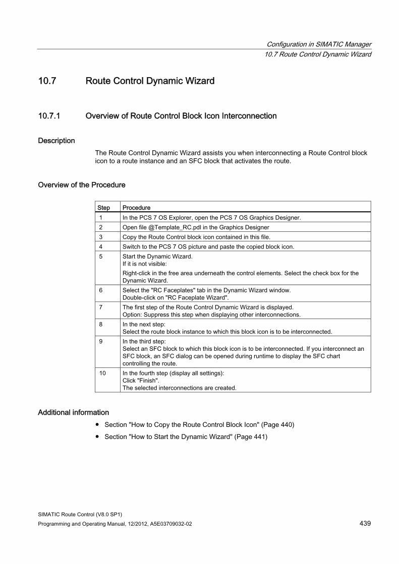
Configuration in SIMATIC Manager 10.7 Route Control Dynamic Wizard
SIMATIC Route Control (V8.0 SP1) Programming and Operating Manual, 12/2012, A5E03709032-02 439
10.7 Route Control Dynamic Wizard
10.7.1 Overview of Route Control Block Icon Interconnection
Description The Route Control Dynamic Wizard assists you when interconnecting a Route Control block icon to a route instance and an SFC block that activates the route.
Overview of the Procedure Step Procedure 1 In the PCS 7 OS Explorer, open the PCS 7 OS Graphics Designer. 2 Open file @Template_RC.pdl in the Graphics Designer 3 Copy the Route Control block icon contained in this file. 4 Switch to the PCS 7 OS picture and paste the copied block icon. 5 Start the Dynamic Wizard.
If it is not visible: Right-click in the free area underneath the control elements. Select the check box for the Dynamic Wizard.
6 Select the "RC Faceplates" tab in the Dynamic Wizard window. Double-click on "RC Faceplate Wizard".
7 The first step of the Route Control Dynamic Wizard is displayed. Option: Suppress this step when displaying other interconnections.
8 In the next step: Select the route block instance to which this block icon is to be interconnected.
9 In the third step: Select an SFC block to which this block icon is to be interconnected. If you interconnect an SFC block, an SFC dialog can be opened during runtime to display the SFC chart controlling the route.
10 In the fourth step (display all settings): Click "Finish". The selected interconnections are created.
Additional information ● Section "How to Copy the Route Control Block Icon" (Page 440)
● Section "How to Start the Dynamic Wizard" (Page 441)
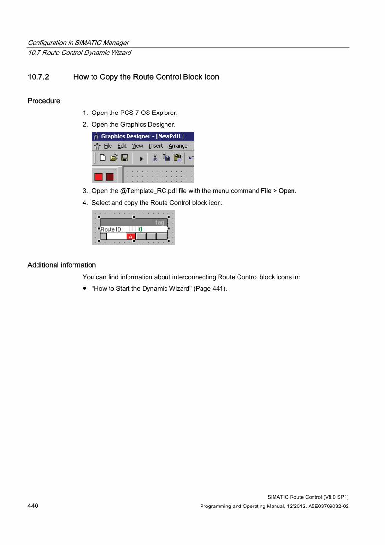
Configuration in SIMATIC Manager 10.7 Route Control Dynamic Wizard
SIMATIC Route Control (V8.0 SP1) 440 Programming and Operating Manual, 12/2012, A5E03709032-02
10.7.2 How to Copy the Route Control Block Icon
Procedure 1. Open the PCS 7 OS Explorer.
2. Open the Graphics Designer.
3. Open the @Template_RC.pdl file with the menu command File > Open.
4. Select and copy the Route Control block icon.
Additional information You can find information about interconnecting Route Control block icons in:
● "How to Start the Dynamic Wizard" (Page 441).
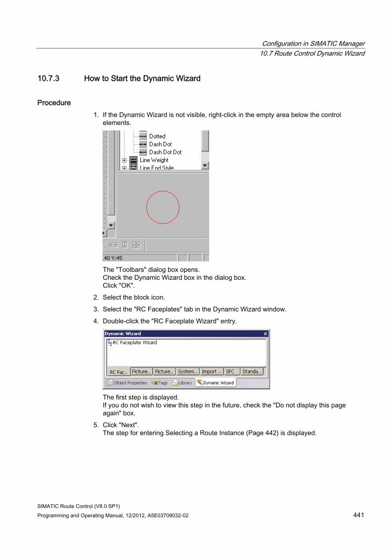
Configuration in SIMATIC Manager 10.7 Route Control Dynamic Wizard
SIMATIC Route Control (V8.0 SP1) Programming and Operating Manual, 12/2012, A5E03709032-02 441
10.7.3 How to Start the Dynamic Wizard
Procedure 1. If the Dynamic Wizard is not visible, right-click in the empty area below the control
elements.
The "Toolbars" dialog box opens. Check the Dynamic Wizard box in the dialog box. Click "OK".
2. Select the block icon.
3. Select the "RC Faceplates" tab in the Dynamic Wizard window.
4. Double-click the "RC Faceplate Wizard" entry.
The first step is displayed. If you do not wish to view this step in the future, check the "Do not display this page again" box.
5. Click "Next". The step for entering Selecting a Route Instance (Page 442) is displayed.
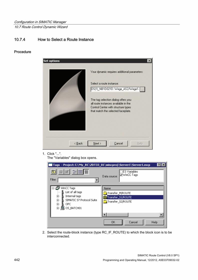
Configuration in SIMATIC Manager 10.7 Route Control Dynamic Wizard
SIMATIC Route Control (V8.0 SP1) 442 Programming and Operating Manual, 12/2012, A5E03709032-02
10.7.4 How to Select a Route Instance
Procedure
1. Click "...".
The "Variables" dialog box opens.
2. Select the route-block instance (type RC_IF_ROUTE) to which the block icon is to be
interconnected.
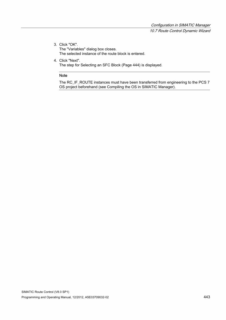
Configuration in SIMATIC Manager 10.7 Route Control Dynamic Wizard
SIMATIC Route Control (V8.0 SP1) Programming and Operating Manual, 12/2012, A5E03709032-02 443
3. Click "OK". The "Variables" dialog box closes. The selected instance of the route block is entered.
4. Click "Next". The step for Selecting an SFC Block (Page 444) is displayed.
Note
The RC_IF_ROUTE instances must have been transferred from engineering to the PCS 7 OS project beforehand (see Compiling the OS in SIMATIC Manager).
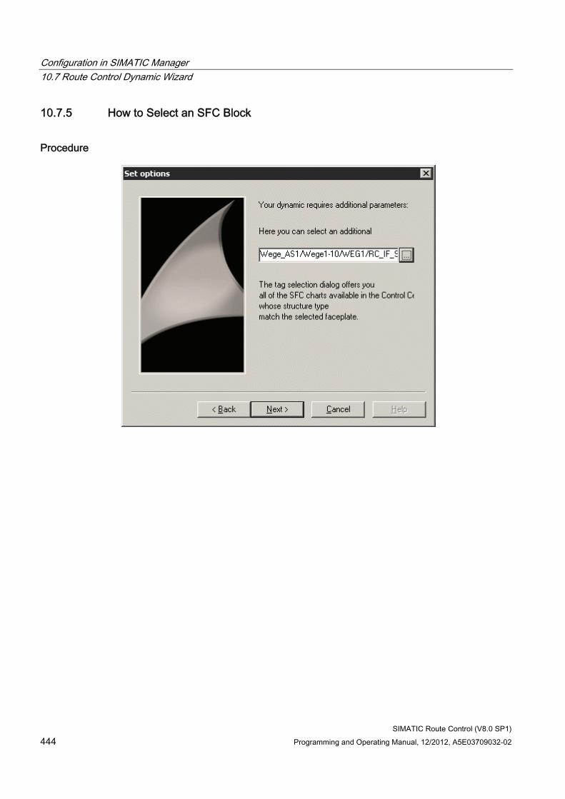
Configuration in SIMATIC Manager 10.7 Route Control Dynamic Wizard
SIMATIC Route Control (V8.0 SP1) 444 Programming and Operating Manual, 12/2012, A5E03709032-02
10.7.5 How to Select an SFC Block
Procedure
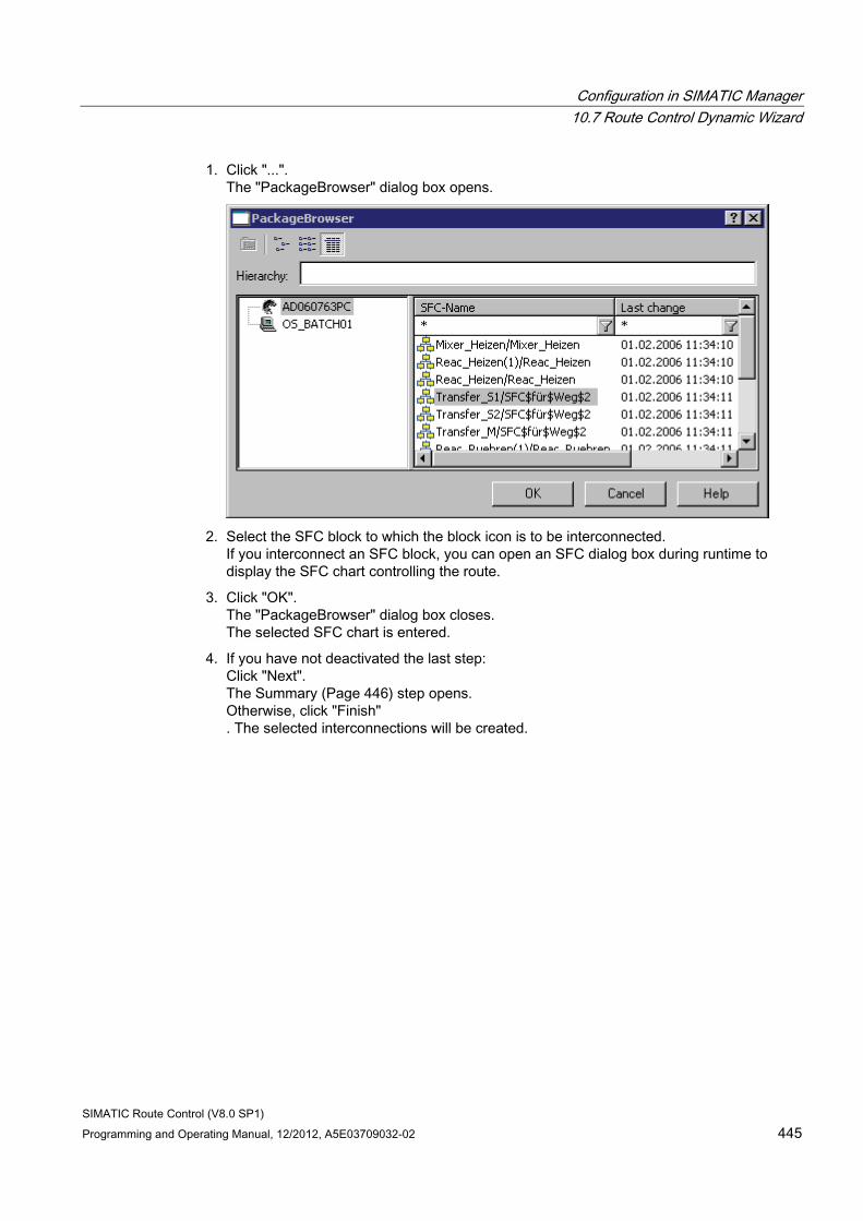
Configuration in SIMATIC Manager 10.7 Route Control Dynamic Wizard
SIMATIC Route Control (V8.0 SP1) Programming and Operating Manual, 12/2012, A5E03709032-02 445
1. Click "...". The "PackageBrowser" dialog box opens.
2. Select the SFC block to which the block icon is to be interconnected.
If you interconnect an SFC block, you can open an SFC dialog box during runtime to display the SFC chart controlling the route.
3. Click "OK". The "PackageBrowser" dialog box closes. The selected SFC chart is entered.
4. If you have not deactivated the last step: Click "Next". The Summary (Page 446) step opens. Otherwise, click "Finish" . The selected interconnections will be created.
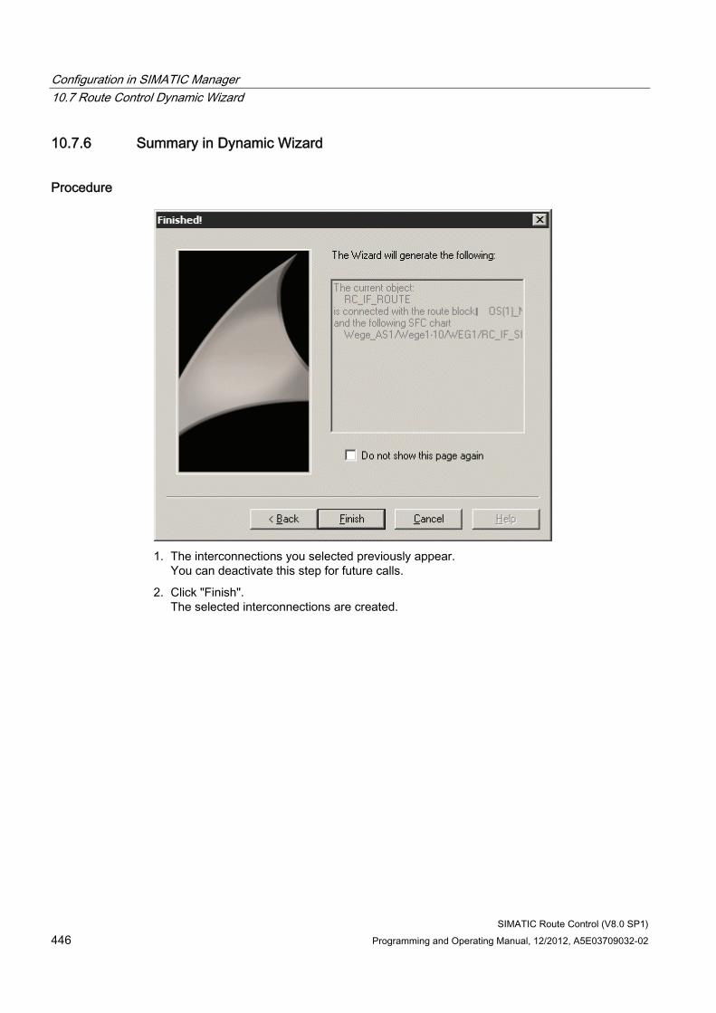
Configuration in SIMATIC Manager 10.7 Route Control Dynamic Wizard
SIMATIC Route Control (V8.0 SP1) 446 Programming and Operating Manual, 12/2012, A5E03709032-02
10.7.6 Summary in Dynamic Wizard
Procedure
1. The interconnections you selected previously appear.
You can deactivate this step for future calls.
2. Click "Finish". The selected interconnections are created.
SIMATIC Route Control (V8.0 SP1) Programming and Operating Manual, 12/2012, A5E03709032-02 447
Exporting/Importing with the Route Control Wizard 1111.1 Transferring Data from an S7 Project
Interaction of the Components You configure central data in SIMATIC Manager. Using the Route Control Wizard, you can export the data relevant for Route Control from the S7 project and import it into the Route Control project.
As of V7.0, there is only one Route Control Wizard, which performs both the export and import of data in immediate sequence.
You start the Route Control Wizard in SIMATIC Manager.
The Route Control Wizard generates a log file while it is running.
You can find additional information in the section "Actions in the Route Control Wizard". (Page 451)
Reaction after Removing Projects from a Multiproject If you have removed individual projects from a multiproject for a time for the purposes of external editing and you then start the Route Control Wizard, you will be prompted that not all data from the multiproject are currently available.
When the Route Control Wizard imports data into Route Control Engineering, it informs you that the data removed from the multiproject must be handled in a particular way. The wizard does not delete these data from the Route Control project; instead, it shows the affected objects in gray and in brackets. You can nevertheless continue to work with these objects in Route Control Engineering.
When downloading to the server you are informed that these objects cannot be downloaded. The affected automation systems are locked for Route Control.
Exporting/Importing with the Route Control Wizard 11.2 Synchronizing Objects
SIMATIC Route Control (V8.0 SP1) 448 Programming and Operating Manual, 12/2012, A5E03709032-02
11.2 Synchronizing Objects
Introduction When the Route Control Wizard imports the data exported from the S7 project into the Route Control project, the wizard synchronizes the data to be imported with the data in the Route Control project.
Synchronizing Objects The following rules apply when objects are synchronized:
Type of object Result of synchronization Objects with the following properties: • Created in the Route Control project during an earlier import
performed by the wizard • Now contained in the import file again • Whose properties may have changed
Objects are updated..
Objects with the following properties: • Created in the Route Control project during an earlier import
performed by the wizard • Not contained in the import file • Groups (e.g., CE, SE, etc., routes, TH) were selected during
export
Objects are deleted.
Objects with the following properties: • Created manually in the Route Control project
Object are neither deleted nor modified.
Objects with the following properties: • Not previously available in the Route Control project • Available in the import file
Objects are newly created.
"Process cell" and "unit" objects with the following properties: • Containing an internal key, which the wizard can use for
identification purposes
Interconnections are not lost.
Objects with the following properties: • Belongs to a project that has been removed from the
multiproject for external editing.
Object are neither deleted nor modified.
Exporting/Importing with the Route Control Wizard 11.2 Synchronizing Objects
SIMATIC Route Control (V8.0 SP1) Programming and Operating Manual, 12/2012, A5E03709032-02 449
CAUTION Do not assign the Route Control object IDs in the CFC charts manually. Leave this to the Route Control Wizard. This ensures consistent data.
The ID is the key for these objects. For example, if you assign another ID to an AS, this AS is then recognized as a "new" AS and the old AS as a "deleted" AS. As a result, the interconnections of elements from this AS are then lost in Route Control Engineering.
Additional information ● Section "Deleting Used Elements" (Page 450)
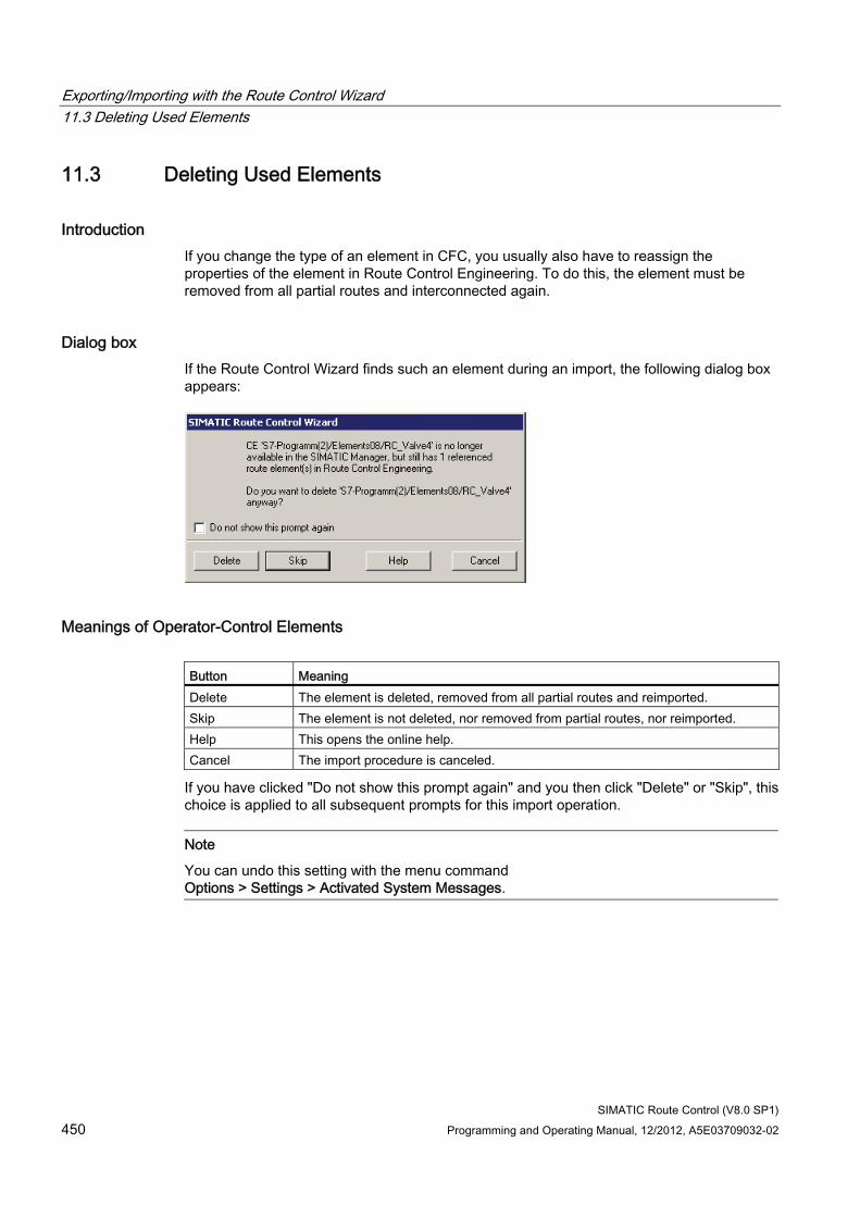
Exporting/Importing with the Route Control Wizard 11.3 Deleting Used Elements
SIMATIC Route Control (V8.0 SP1) 450 Programming and Operating Manual, 12/2012, A5E03709032-02
11.3 Deleting Used Elements
Introduction If you change the type of an element in CFC, you usually also have to reassign the properties of the element in Route Control Engineering. To do this, the element must be removed from all partial routes and interconnected again.
Dialog box If the Route Control Wizard finds such an element during an import, the following dialog box appears:
Meanings of Operator-Control Elements Button Meaning Delete The element is deleted, removed from all partial routes and reimported. Skip The element is not deleted, nor removed from partial routes, nor reimported. Help This opens the online help. Cancel The import procedure is canceled.
If you have clicked "Do not show this prompt again" and you then click "Delete" or "Skip", this choice is applied to all subsequent prompts for this import operation.
Note
You can undo this setting with the menu command Options > Settings > Activated System Messages.
Exporting/Importing with the Route Control Wizard 11.4 Actions in the Route Control Wizard
SIMATIC Route Control (V8.0 SP1) Programming and Operating Manual, 12/2012, A5E03709032-02 451
11.4 Actions in the Route Control Wizard
Overview The Route Control Wizard ensures that exported data are consistent. Please also refer to the information in the section titled "Route Control Wizard Start Requirements" (Page 143).
You can perform the following actions in various steps in the Route Control Wizard:
Action Meaning Data synchronization of Route Control objects/ plausibility check
Transfer the plant hierarchy, including process cells, units, and locations, from the S7 project to the Route Control project. Check and, if necessary, correct the element IDs in an AS. If an invalid ID has been configured for an element, the wizard will suggest a new ID. Transfer new element types, such as MYMOTOR. Check and, if necessary, correct the IDs of the automation systems relevant to Route Control. Transfer the AS names and IDs to Route Control Project Engineering.
Generation of AS-AS connections
Establish and modify the communication links between the automation systems relevant to Route Control (cross-couplings).
Generation of AS-server connections
Establish and modify the communication links between the automation systems relevant to Route Control and Route Control servers.
Export of message servers If Route Control is to generate messages, you have to export the PCS 7 OS servers available in the project so that you can select the PCS 7 OS server in the next step.
Generation of messages If this check box is selected, the messages for the Route Control server are generated in the PCS 7 OS project. These two settings have been separated because messages do not always have to be generated anew, for example, when only the name of the PCS 7 OS computer has changed.
Selection of the PCS 7 OS message server(s)
Specify the PCS 7 OS that is to act as the message server for Route Control (only one PCS 7 OS is ever selected here, including for a redundant configuration).
Note
AS-AS and AS-server connections: In order for the Route Control Wizard to create the connections, the automation systems and their network cards must have already been configured in NetPro (HW Config).
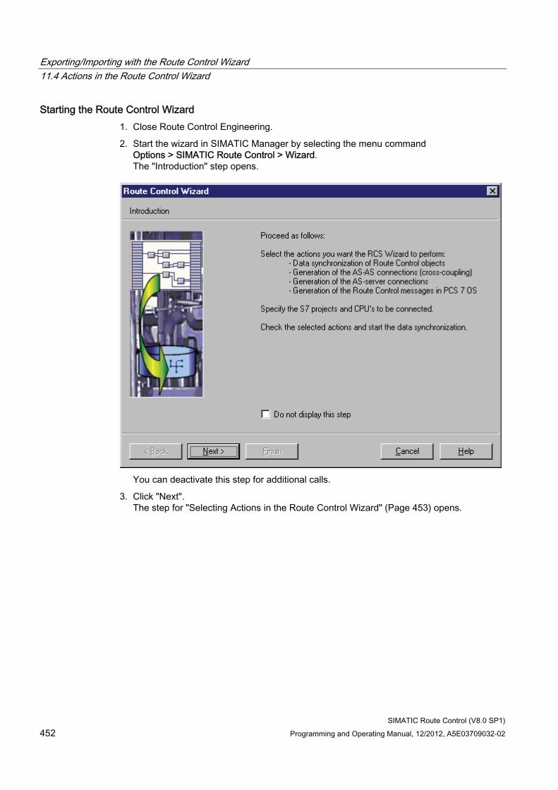
Exporting/Importing with the Route Control Wizard 11.4 Actions in the Route Control Wizard
SIMATIC Route Control (V8.0 SP1) 452 Programming and Operating Manual, 12/2012, A5E03709032-02
Starting the Route Control Wizard 1. Close Route Control Engineering.
2. Start the wizard in SIMATIC Manager by selecting the menu command Options > SIMATIC Route Control > Wizard. The "Introduction" step opens.
You can deactivate this step for additional calls.
3. Click "Next". The step for "Selecting Actions in the Route Control Wizard" (Page 453) opens.
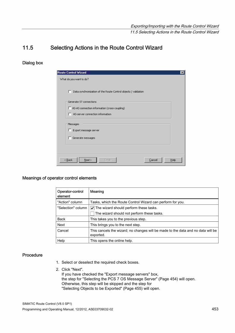
Exporting/Importing with the Route Control Wizard 11.5 Selecting Actions in the Route Control Wizard
SIMATIC Route Control (V8.0 SP1) Programming and Operating Manual, 12/2012, A5E03709032-02 453
11.5 Selecting Actions in the Route Control Wizard
Dialog box
Meanings of operator control elements Operator-control element
Meaning
"Action" column Tasks, which the Route Control Wizard can perform for you. "Selection" column The wizard should perform these tasks.
The wizard should not perform these tasks. Back This takes you to the previous step. Next This brings you to the next step. Cancel This cancels the wizard; no changes will be made to the data and no data will be
exported. Help This opens the online help.
Procedure 1. Select or deselect the required check boxes.
2. Click "Next". If you have checked the "Export message servers" box, the step for "Selecting the PCS 7 OS Message Server" (Page 454) will open. Otherwise, this step will be skipped and the step for "Selecting Objects to be Exported" (Page 455) will open.
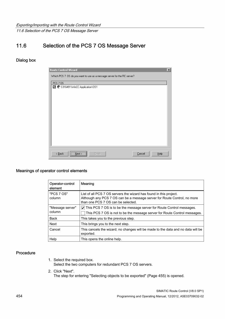
Exporting/Importing with the Route Control Wizard 11.6 Selection of the PCS 7 OS Message Server
SIMATIC Route Control (V8.0 SP1) 454 Programming and Operating Manual, 12/2012, A5E03709032-02
11.6 Selection of the PCS 7 OS Message Server
Dialog box
Meanings of operator control elements Operator-control element
Meaning
"PCS 7 OS" column
List of all PCS 7 OS servers the wizard has found in this project. Although any PCS 7 OS can be a message server for Route Control, no more than one PCS 7 OS can be selected.
"Message server" column
This PCS 7 OS is to be the message server for Route Control messages. This PCS 7 OS is not to be the message server for Route Control messages.
Back This takes you to the previous step. Next This brings you to the next step. Cancel This cancels the wizard; no changes will be made to the data and no data will be
exported. Help This opens the online help.
Procedure 1. Select the required box.
Select the two computers for redundant PCS 7 OS servers.
2. Click "Next". The step for entering "Selecting objects to be exported" (Page 455) is opened.
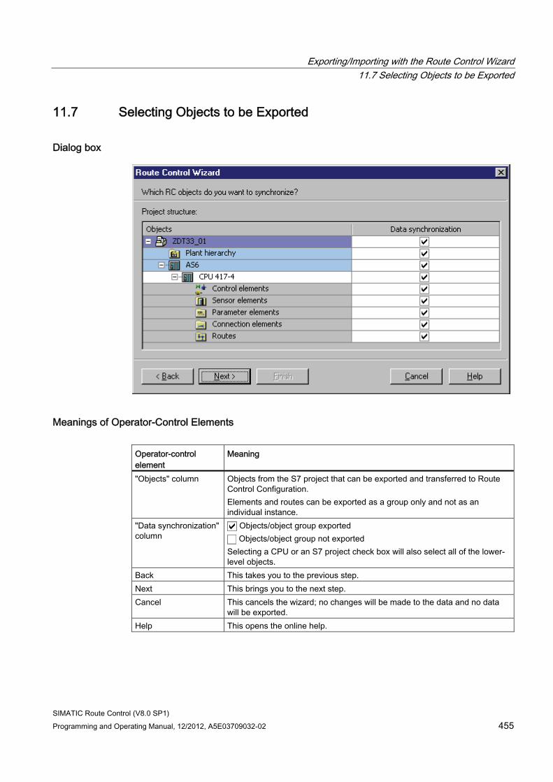
Exporting/Importing with the Route Control Wizard 11.7 Selecting Objects to be Exported
SIMATIC Route Control (V8.0 SP1) Programming and Operating Manual, 12/2012, A5E03709032-02 455
11.7 Selecting Objects to be Exported
Dialog box
Meanings of Operator-Control Elements Operator-control element
Meaning
"Objects" column Objects from the S7 project that can be exported and transferred to Route Control Configuration. Elements and routes can be exported as a group only and not as an individual instance.
"Data synchronization" column
Objects/object group exported Objects/object group not exported
Selecting a CPU or an S7 project check box will also select all of the lower-level objects.
Back This takes you to the previous step. Next This brings you to the next step. Cancel This cancels the wizard; no changes will be made to the data and no data
will be exported. Help This opens the online help.
Exporting/Importing with the Route Control Wizard 11.7 Selecting Objects to be Exported
SIMATIC Route Control (V8.0 SP1) 456 Programming and Operating Manual, 12/2012, A5E03709032-02
Procedure 1. Select or deselect the required check boxes.
2. Click "Next". The step for "Adapting Route IDs" (Page 457) opens.
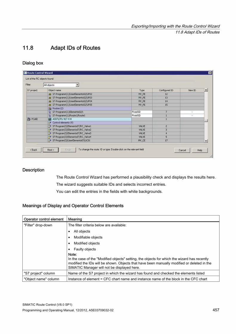
Exporting/Importing with the Route Control Wizard 11.8 Adapt IDs of Routes
SIMATIC Route Control (V8.0 SP1) Programming and Operating Manual, 12/2012, A5E03709032-02 457
11.8 Adapt IDs of Routes
Dialog box
Description The Route Control Wizard has performed a plausibility check and displays the results here.
The wizard suggests suitable IDs and selects incorrect entries.
You can edit the entries in the fields with white backgrounds.
Meanings of Display and Operator Control Elements Operator control element Meaning "Filter" drop-down The filter criteria below are available:
• All objects • Modifiable objects • Modified objects • Faulty objects Note: In the case of the "Modified objects" setting, the objects for which the wizard has recently modified the IDs will be shown. Objects that have been manually modified or deleted in the SIMATIC Manager will not be displayed here.
"S7 project" column Name of the S7 project in which the wizard has found and checked the elements listed "Object name" column Instance of element = CFC chart name and instance name of the block in the CFC chart
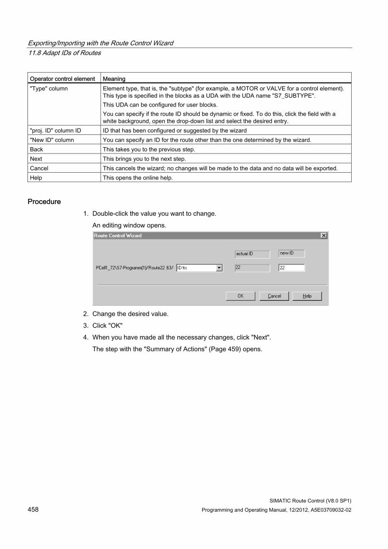
Exporting/Importing with the Route Control Wizard 11.8 Adapt IDs of Routes
SIMATIC Route Control (V8.0 SP1) 458 Programming and Operating Manual, 12/2012, A5E03709032-02
Operator control element Meaning "Type" column Element type, that is, the "subtype" (for example, a MOTOR or VALVE for a control element).
This type is specified in the blocks as a UDA with the UDA name "S7_SUBTYPE". This UDA can be configured for user blocks. You can specify if the route ID should be dynamic or fixed. To do this, click the field with a white background, open the drop-down list and select the desired entry.
"proj. ID" column ID ID that has been configured or suggested by the wizard "New ID" column You can specify an ID for the route other than the one determined by the wizard. Back This takes you to the previous step. Next This brings you to the next step. Cancel This cancels the wizard; no changes will be made to the data and no data will be exported. Help This opens the online help.
Procedure 1. Double-click the value you want to change.
An editing window opens.
2. Change the desired value.
3. Click "OK"
4. When you have made all the necessary changes, click "Next".
The step with the "Summary of Actions" (Page 459) opens.
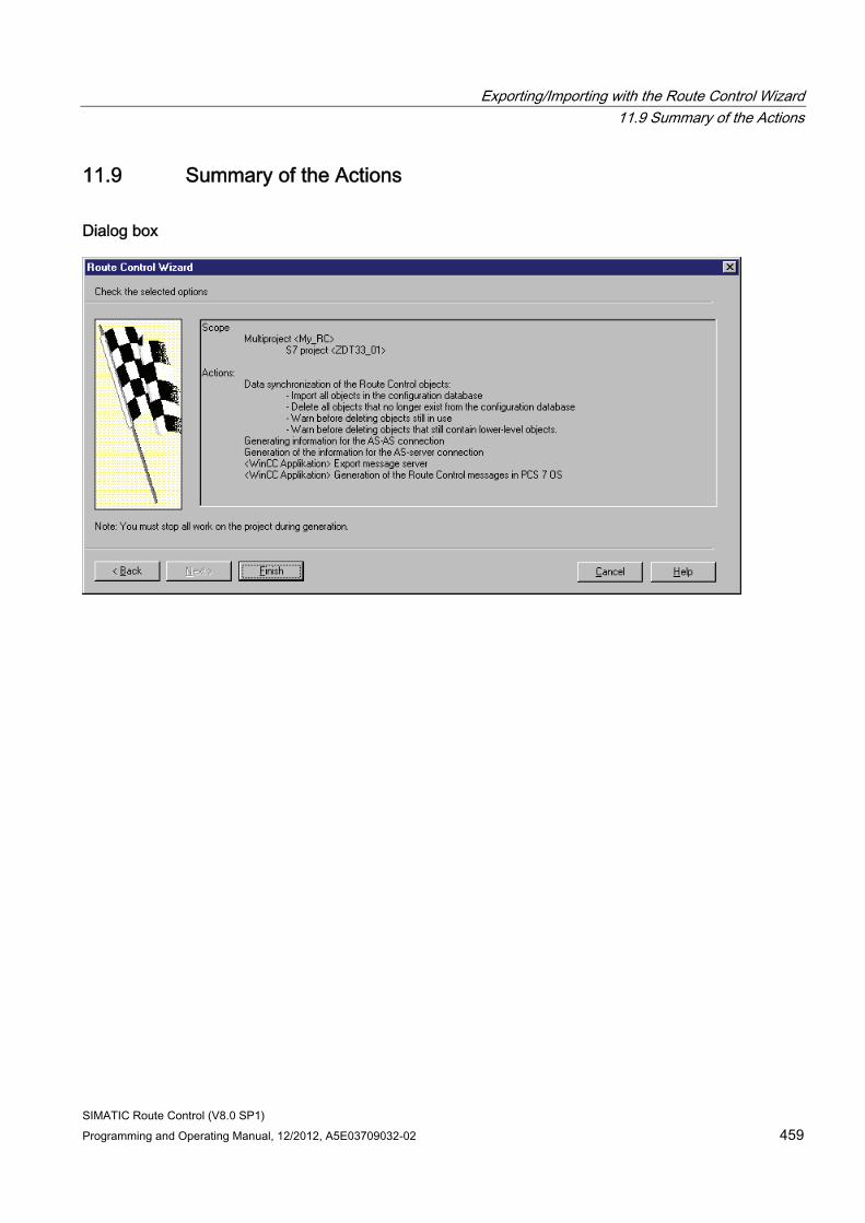
Exporting/Importing with the Route Control Wizard 11.9 Summary of the Actions
SIMATIC Route Control (V8.0 SP1) Programming and Operating Manual, 12/2012, A5E03709032-02 459
11.9 Summary of the Actions
Dialog box
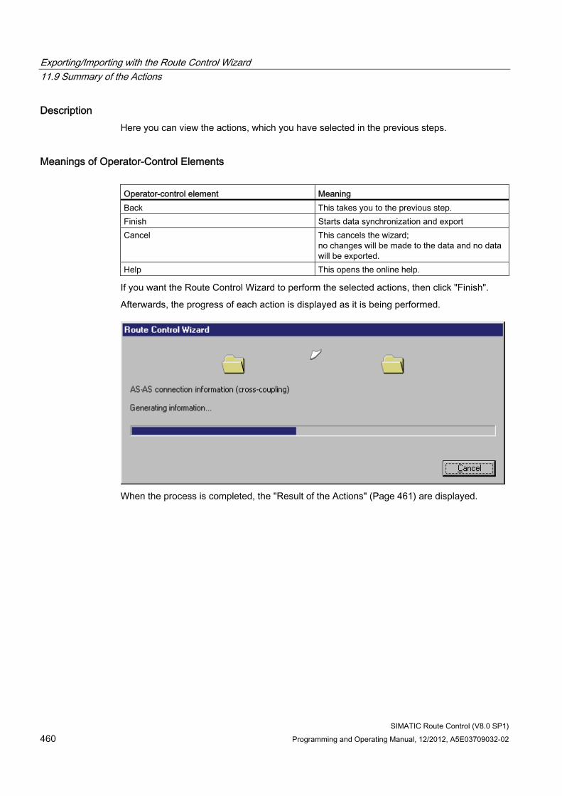
Exporting/Importing with the Route Control Wizard 11.9 Summary of the Actions
SIMATIC Route Control (V8.0 SP1) 460 Programming and Operating Manual, 12/2012, A5E03709032-02
Description Here you can view the actions, which you have selected in the previous steps.
Meanings of Operator-Control Elements Operator-control element Meaning Back This takes you to the previous step. Finish Starts data synchronization and export Cancel This cancels the wizard;
no changes will be made to the data and no data will be exported.
Help This opens the online help.
If you want the Route Control Wizard to perform the selected actions, then click "Finish".
Afterwards, the progress of each action is displayed as it is being performed.
When the process is completed, the "Result of the Actions" (Page 461) are displayed.
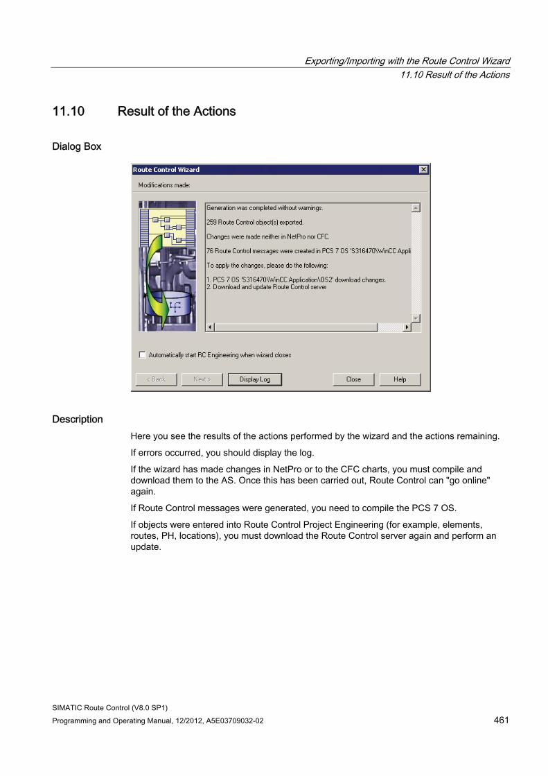
Exporting/Importing with the Route Control Wizard 11.10 Result of the Actions
SIMATIC Route Control (V8.0 SP1) Programming and Operating Manual, 12/2012, A5E03709032-02 461
11.10 Result of the Actions
Dialog Box
Description Here you see the results of the actions performed by the wizard and the actions remaining.
If errors occurred, you should display the log.
If the wizard has made changes in NetPro or to the CFC charts, you must compile and download them to the AS. Once this has been carried out, Route Control can "go online" again.
If Route Control messages were generated, you need to compile the PCS 7 OS.
If objects were entered into Route Control Project Engineering (for example, elements, routes, PH, locations), you must download the Route Control server again and perform an update.
Exporting/Importing with the Route Control Wizard 11.10 Result of the Actions
SIMATIC Route Control (V8.0 SP1) 462 Programming and Operating Manual, 12/2012, A5E03709032-02
Meanings of Operator-Control Elements If required, check the box for starting Route Control Engineering automatically.
Operator-control element
Meaning
Display Log Opens the log file. Close Closes the Route Control Wizard. Help This opens the online help.
Additional Information ● Section "Export Log" (Page 463)
Exporting/Importing with the Route Control Wizard 11.11 Log
SIMATIC Route Control (V8.0 SP1) Programming and Operating Manual, 12/2012, A5E03709032-02 463
11.11 Log
File Name RC_EXPORT_ASSISTANT.LOG
File Location The log file is saved to the same location as the Route Control project database, e.g., Program Files\SIEMENS\STEP7\S7Proj\Multiproject\Project\Global\RCS.
File Sections The meanings of the file sections are listed in the following table:
Section Meaning Log of the Route Control Wizard (V x.y)
S7 project path in whose context the Route Control Wizard was called
Reading of project structure General information relating to the project Selecting Actions Actions to be performed by the wizard Selection of message server PCS 7 OS (WinCC application) Selection of Route Control objects The objects/object groups (such as CE, PE, SE, LE, and routes)
to be exported from an AS are specified here (filter). Reading of instances A list of the elements (instances of elements, routes, and plant
hierarchy) that were found in this project (restricted by the filter indicated above)
Prepare transaction List of objects that have been exported Information as to whether an element ID has to be modified and, if so, which new ID is suggested
Generation of AS-server connections
List of S7 connections
Generation of AS-AS connections List of S7 connections Update of the cross-coupling variables at the <RC_IF_CFG> block
List of variables Indication if update is required
Close transaction Information about closing actions Database synchronization Information about the synchronization of the Route Control
database Summary Information about the results of the export TODO Actions you need to perform to put the changes into effect.

Exporting/Importing with the Route Control Wizard 11.11 Log
SIMATIC Route Control (V8.0 SP1) 464 Programming and Operating Manual, 12/2012, A5E03709032-02
SIMATIC Route Control (V8.0 SP1) Programming and Operating Manual, 12/2012, A5E03709032-02 465
CSV Export/Import 1212.1 CSV Interface Overview
Description This interface allows you to simplify and accelerate the configuration process in Route Control. You can export the most important objects from Route Control Engineering to a CSV file, edit these using external tools, and then re-import them. A wizard supports you in exporting and importing the data.
Benefits can mainly be seen during configuration if you are able to make good use of the copy function, for example in Microsoft Excel.
Note Editing the CSV file
You should adhere in particular to the rules for the editing sequence when editing the CSV file used for the configuration in Route Control. If you insert routes into the CSV file, you need to adapt the sequence according to modes. First, enter the elements of mode 1, then the elements of mode 2, etc. Then adapt the sequence or renumber the elements.
The following data can be exported: ● CE - control elements
● SE - sensor elements
● PE - parameter elements
● LE - link elements
● All locations
● User types
● Activation masks for user types
● All mode tables
● All partial routes
● All partial routes with interconnected elements
● One partial route with interconnected elements
CSV Export/Import 12.1 CSV Interface Overview
SIMATIC Route Control (V8.0 SP1) 466 Programming and Operating Manual, 12/2012, A5E03709032-02
The following data can be imported: ● Activation masks for user types from screenshot
● All mode tables
● All partial routes
● All partial routes with interconnected elements
● One partial route with interconnected elements
You can import some of the following data: ● CE - control elements
"Ignore error" only
● PE - parameter elements
"External" only
● All locations
"Variants" only
● User types
"Unit" only for PE
Note You cannot import the following data or can import it only partially: • Locations • User types • Elements
This data is now configured in SIMATIC Manager and not in Route Control Engineering. The Route Control Wizard scans the PCS7 project for this data and imports it into Route Control Engineering. To prevent inconsistencies between the SIMATIC PCS 7 project and Route Control Engineering, importing this data via the CSV interface is not allowed. The elements, locations and user types must be configured in SIMATIC Manager. You cannot import these data using the CSV interface.
Note Note on editing in Excel
Instead of double-clicking the CSV files to open these for editing in Microsoft Excel, use the menu command File > Open so that you can set the separator correctly.
Save the files after editing in Microsoft Excel as "Unicode Text". The separators are replaced with tabs.
CSV Export/Import 12.1 CSV Interface Overview
SIMATIC Route Control (V8.0 SP1) Programming and Operating Manual, 12/2012, A5E03709032-02 467
Comments You can add comments at the end of a line when editing exported CSV files. A comment may also appear on its own in a line. A comment must always begin with the character [//].
The Wizard ignores the comments during import.
Note
A new export to the same file deletes all comments from this file!
Starting the wizard Select the Options > Export/Import > CSV command in Route Control Engineering. The Start step (Page 468) is displayed.
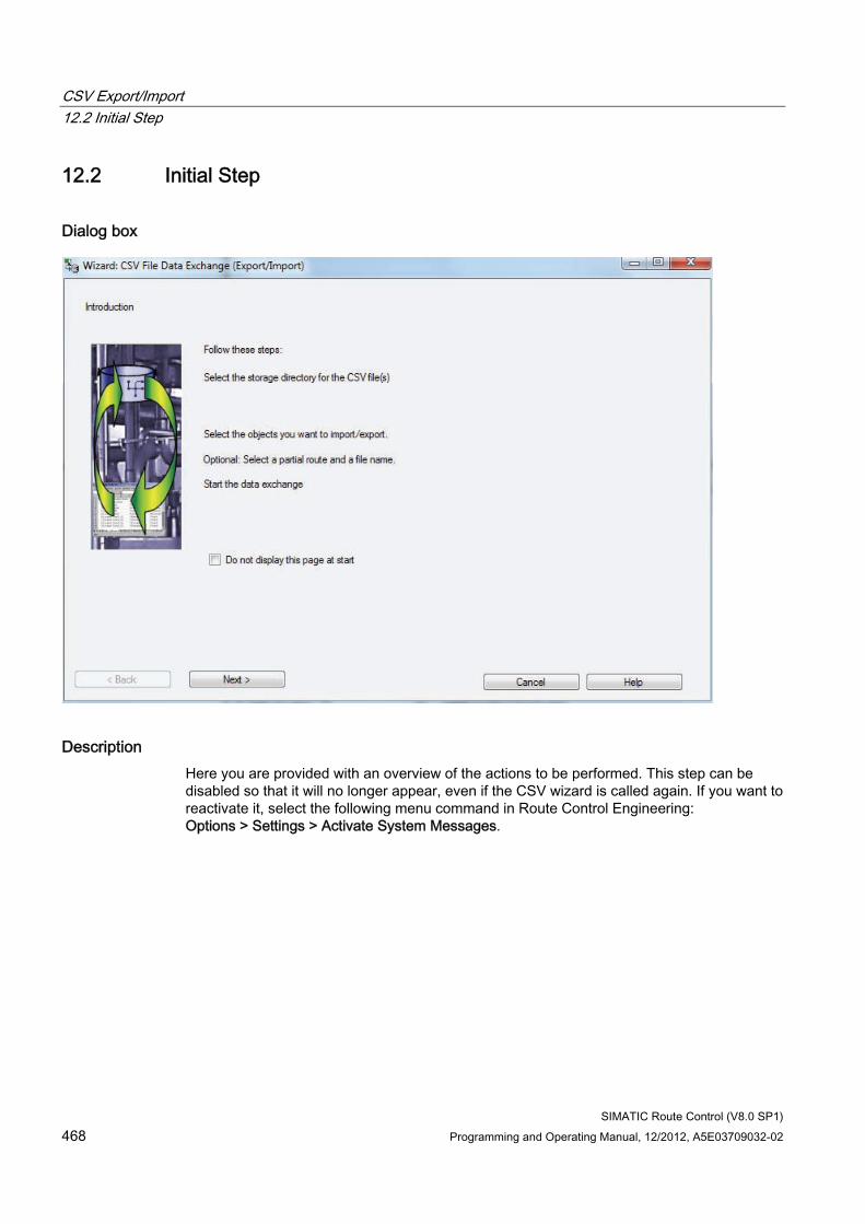
CSV Export/Import 12.2 Initial Step
SIMATIC Route Control (V8.0 SP1) 468 Programming and Operating Manual, 12/2012, A5E03709032-02
12.2 Initial Step
Dialog box
Description Here you are provided with an overview of the actions to be performed. This step can be disabled so that it will no longer appear, even if the CSV wizard is called again. If you want to reactivate it, select the following menu command in Route Control Engineering: Options > Settings > Activate System Messages.
CSV Export/Import 12.2 Initial Step
SIMATIC Route Control (V8.0 SP1) Programming and Operating Manual, 12/2012, A5E03709032-02 469
Meanings of Operator-Control Elements Operator-control element Meaning
Do not display this page again
This step will always be displayed upon subsequent calls.
Do not display this page again
This step will no longer be displayed upon subsequent calls.
Next This brings you to the next step. Cancel This cancels the wizard; no changes will be made to the data and no
data will be imported or exported. Help This opens the online help.
Click "Next". The step for entering global settings (Page 470) is displayed.
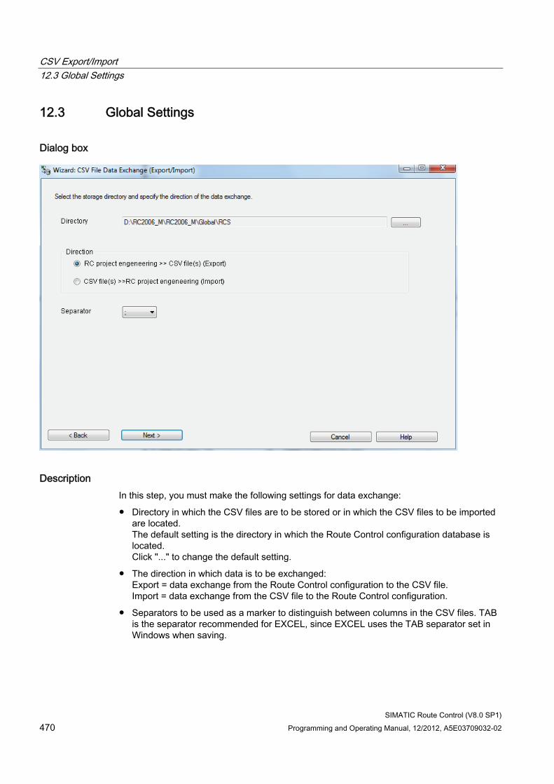
CSV Export/Import 12.3 Global Settings
SIMATIC Route Control (V8.0 SP1) 470 Programming and Operating Manual, 12/2012, A5E03709032-02
12.3 Global Settings
Dialog box
Description In this step, you must make the following settings for data exchange:
● Directory in which the CSV files are to be stored or in which the CSV files to be imported are located. The default setting is the directory in which the Route Control configuration database is located. Click "..." to change the default setting.
● The direction in which data is to be exchanged: Export = data exchange from the Route Control configuration to the CSV file. Import = data exchange from the CSV file to the Route Control configuration.
● Separators to be used as a marker to distinguish between columns in the CSV files. TAB is the separator recommended for EXCEL, since EXCEL uses the TAB separator set in Windows when saving.
CSV Export/Import 12.3 Global Settings
SIMATIC Route Control (V8.0 SP1) Programming and Operating Manual, 12/2012, A5E03709032-02 471
Meanings of operator control elements Operator control element
Meaning
Back This takes you to the previous step. Next This brings you to the next step. Cancel This cancels the wizard; no changes will be made to the data and no data will
be imported or exported. Help Opens the online help.
Click "Next". The step for selecting the objects (Page 472) is displayed.
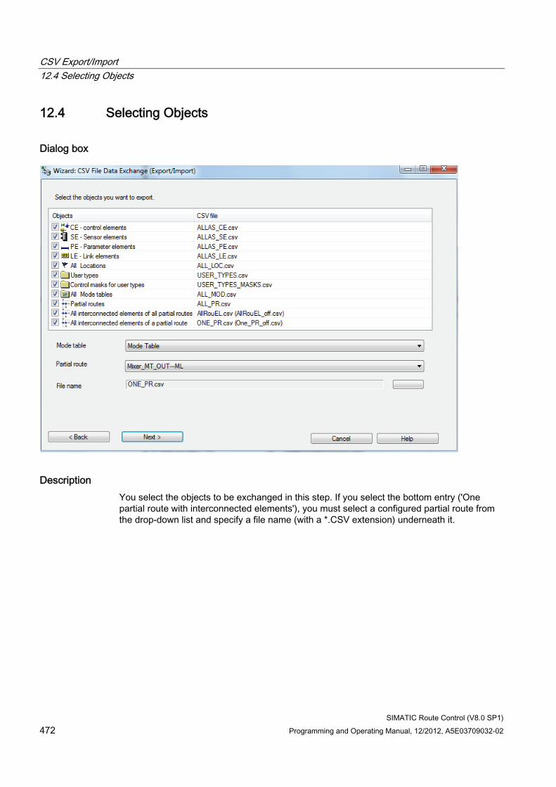
CSV Export/Import 12.4 Selecting Objects
SIMATIC Route Control (V8.0 SP1) 472 Programming and Operating Manual, 12/2012, A5E03709032-02
12.4 Selecting Objects
Dialog box
Description You select the objects to be exchanged in this step. If you select the bottom entry ('One partial route with interconnected elements'), you must select a configured partial route from the drop-down list and specify a file name (with a *.CSV extension) underneath it.
CSV Export/Import 12.4 Selecting Objects
SIMATIC Route Control (V8.0 SP1) Programming and Operating Manual, 12/2012, A5E03709032-02 473
Meanings of Operator-Control Elements Operator-control element
Meaning
Here you can select an existing CSV file.
Back This takes you to the previous step. Next This brings you to the next step. Cancel This cancels the wizard; no changes will be made to the data and no data will
be imported or exported. Help This opens the online help.
Click "Next". The Summary (Page 474) is displayed.
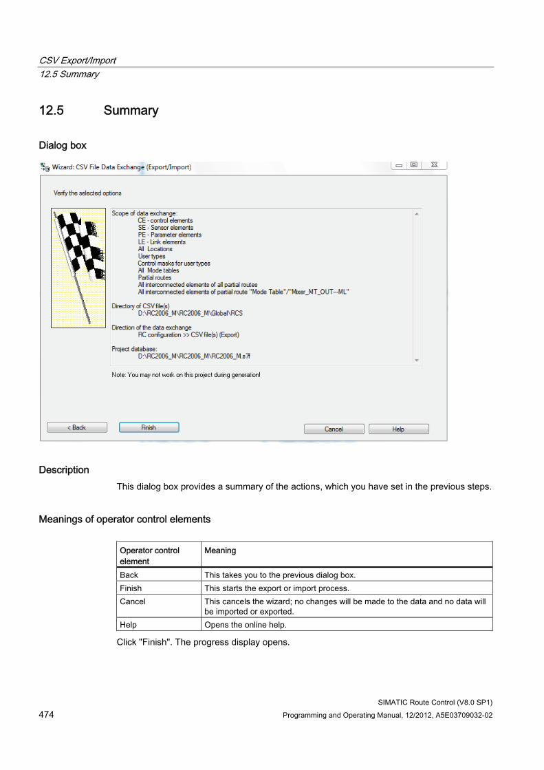
CSV Export/Import 12.5 Summary
SIMATIC Route Control (V8.0 SP1) 474 Programming and Operating Manual, 12/2012, A5E03709032-02
12.5 Summary
Dialog box
Description This dialog box provides a summary of the actions, which you have set in the previous steps.
Meanings of operator control elements Operator control element
Meaning
Back This takes you to the previous dialog box. Finish This starts the export or import process. Cancel This cancels the wizard; no changes will be made to the data and no data will
be imported or exported. Help Opens the online help.
Click "Finish". The progress display opens.
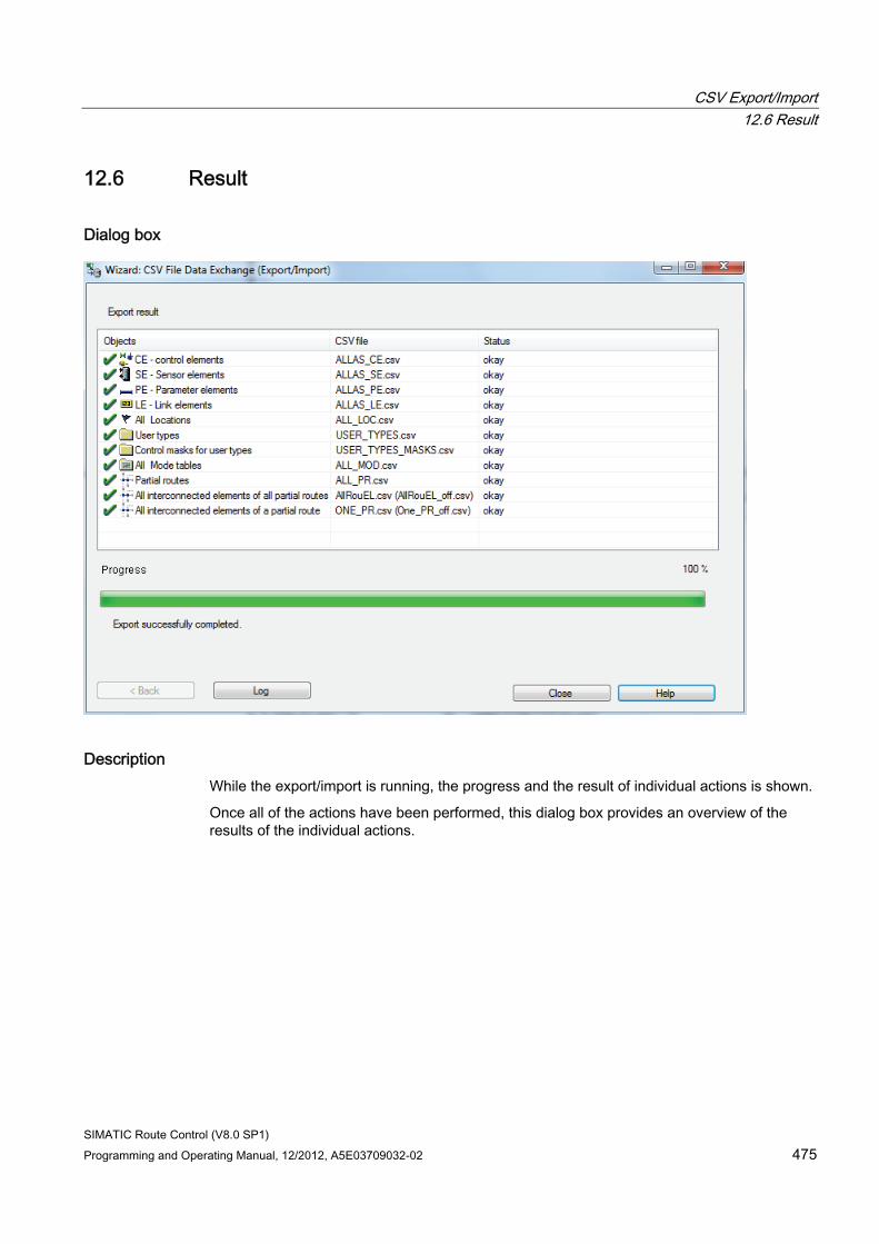
CSV Export/Import 12.6 Result
SIMATIC Route Control (V8.0 SP1) Programming and Operating Manual, 12/2012, A5E03709032-02 475
12.6 Result
Dialog box
Description While the export/import is running, the progress and the result of individual actions is shown.
Once all of the actions have been performed, this dialog box provides an overview of the results of the individual actions.
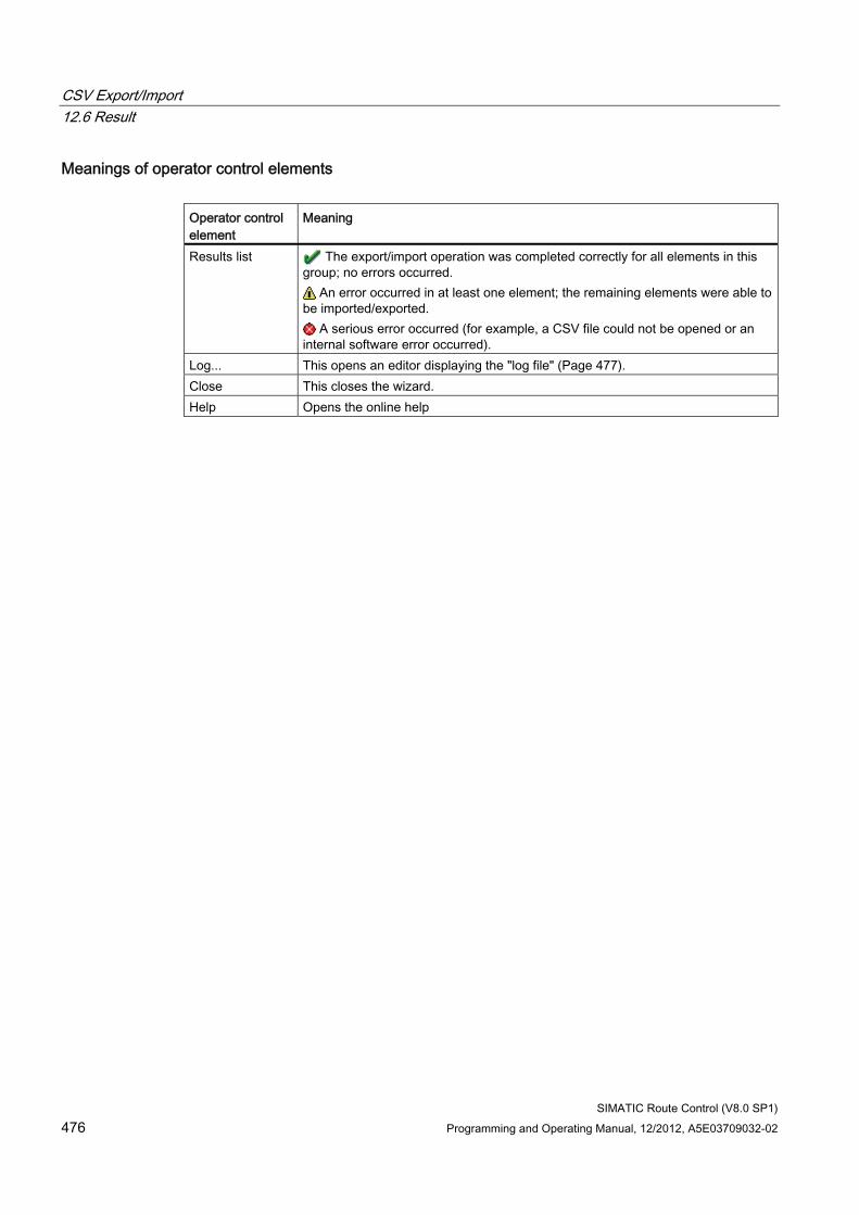
CSV Export/Import 12.6 Result
SIMATIC Route Control (V8.0 SP1) 476 Programming and Operating Manual, 12/2012, A5E03709032-02
Meanings of operator control elements Operator control element
Meaning
Results list The export/import operation was completed correctly for all elements in this group; no errors occurred.
An error occurred in at least one element; the remaining elements were able to be imported/exported.
A serious error occurred (for example, a CSV file could not be opened or an internal software error occurred).
Log... This opens an editor displaying the "log file" (Page 477). Close This closes the wizard. Help Opens the online help
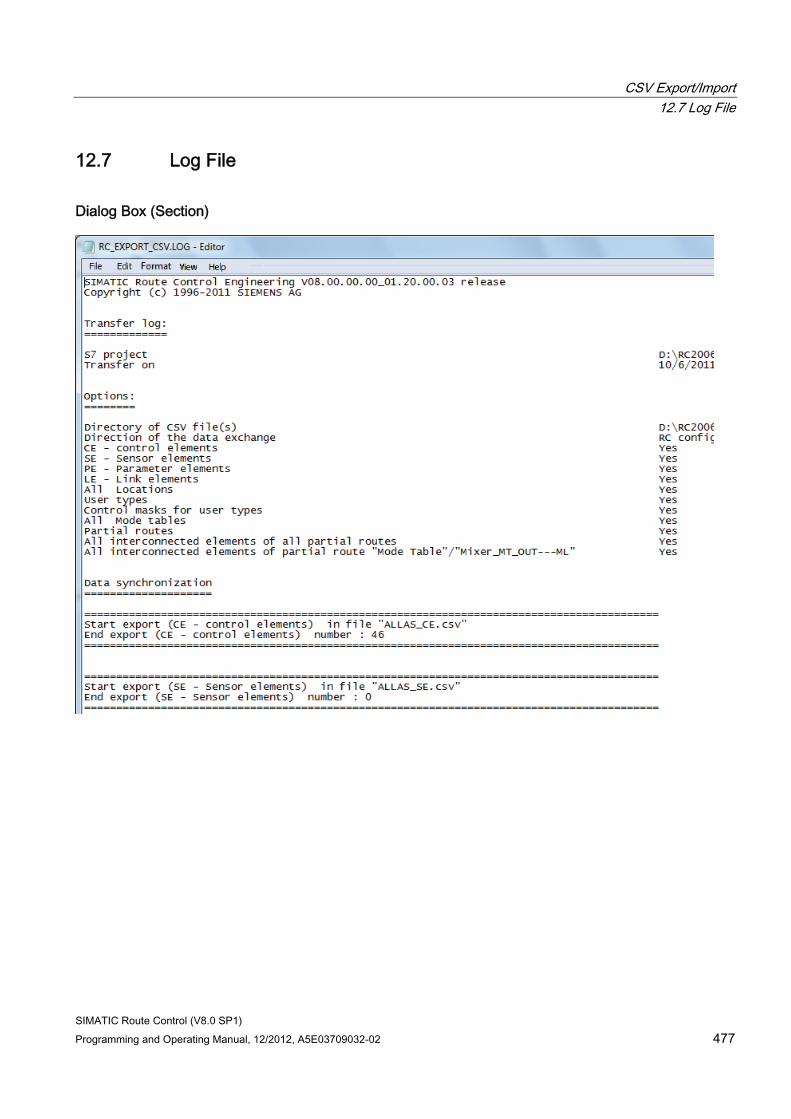
CSV Export/Import 12.7 Log File
SIMATIC Route Control (V8.0 SP1) Programming and Operating Manual, 12/2012, A5E03709032-02 477
12.7 Log File
Dialog Box (Section)
CSV Export/Import 12.7 Log File
SIMATIC Route Control (V8.0 SP1) 478 Programming and Operating Manual, 12/2012, A5E03709032-02
Description This log summarizes all of the settings and results of the individual steps. If an error occurs, you can consult this log to identify the cause of the error. The RC_EXPORT_LOG.TXT or RC_IMPORT_LOG.TXT file is always located in the same directory where the CSV files are stored.
You can find details in:
● "CSV Interface Export Log" (Page 479)
● "CSV Interface Import Log" (Page 481)
Additional information ● Section "CSV File Structure" (Page 483)
● Section "Error Messages" (Page 491)
CSV Export/Import 12.8 CSV Interface Export Log
SIMATIC Route Control (V8.0 SP1) Programming and Operating Manual, 12/2012, A5E03709032-02 479
12.8 CSV Interface Export Log
File Name RC_EXPORT_CSV.LOG
File Location The log file is saved in the same path as the CSV files.
File Sections The transfer log contains the following information:
● Global information
● S7 project name: Name of S7 project containing the Route Control project
● S7 project path: Path to the S7 project
● User: User who initiated the export operation.
● Transfer date: Time stamp indicating the date of the export
Options:
● Settings you have made
● CSV storage directory: Path where the export CSV files are stored
● Direction of data exchange: Whether data are to be exported (written to CSV file) or imported (read from CSV file) is indicated here: Exporting
Data synchronization: (CE-control elements):
● Number of exported objects
For the objects below, the number of exported elements is also indicated in the same way as for control elements:
● SE
● PE
● LE
● Mode tables
● Locations
● Partial routes
● All partial routes with interconnected elements
● A partial route with interconnected elements
CSV Export/Import 12.8 CSV Interface Export Log
SIMATIC Route Control (V8.0 SP1) 480 Programming and Operating Manual, 12/2012, A5E03709032-02
Additional information ● Section "CSV File Structure" (Page 483)
● Section "Error Messages" (Page 491)
● Section "CSV Interface Import Log" (Page 481)
CSV Export/Import 12.9 CSV Interface Import Log
SIMATIC Route Control (V8.0 SP1) Programming and Operating Manual, 12/2012, A5E03709032-02 481
12.9 CSV Interface Import Log
File Name RC_IMPORT_CSV.LOG
File Location The log file is saved in the same path as the CSV files.
File Sections The transfer log contains the following information:
● Global information
● S7 project name: Name of S7 project containing the Route Control project
● S7 project path: Path to the S7 project
● User: User who initiated the export operation.
● Transfer date: Time stamp indicating the date of the export
Options:
● Settings you have made
● CSV storage directory: Path where the export CSV files are stored
● Direction of data exchange: Whether data are to be exported (written to CSV file) or imported (read from CSV file) is indicated here: Import
Data synchronization: (CE-control elements):
● Name of imported objects and information indicating whether they were updated only or recreated
For the objects below, the number of imported elements is also indicated in the same way as for control elements:
● SE
● PE
● LE
● Mode tables
● Locations
● Partial routes
● All partial routes with interconnected elements
CSV Export/Import 12.9 CSV Interface Import Log
SIMATIC Route Control (V8.0 SP1) 482 Programming and Operating Manual, 12/2012, A5E03709032-02
Number of objects transferred:
● Final information about the total number of imported elements
Compressed database:
● Information about the file size before and after compression, which is always initiated automatically
Additional information ● Section "CSV File Structure" (Page 483)
● Section "Error Messages" (Page 491)
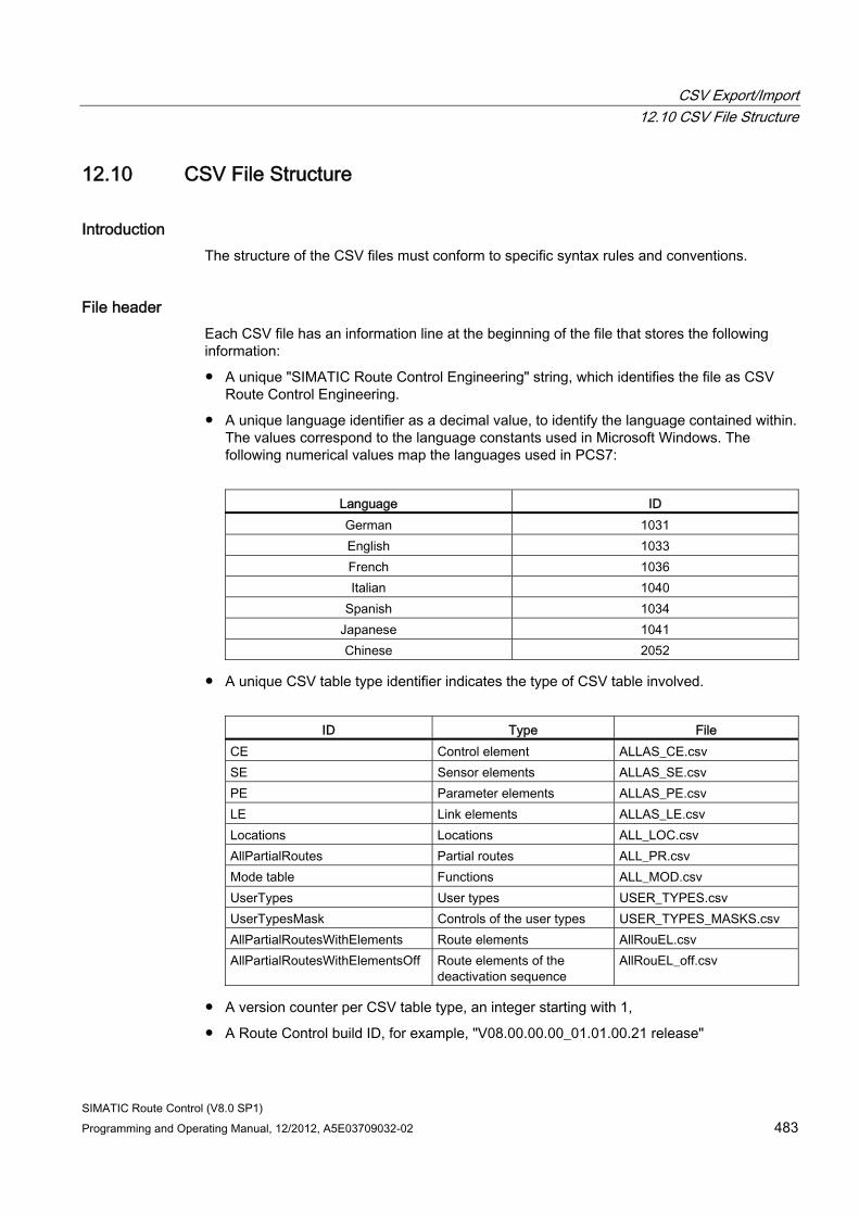
CSV Export/Import 12.10 CSV File Structure
SIMATIC Route Control (V8.0 SP1) Programming and Operating Manual, 12/2012, A5E03709032-02 483
12.10 CSV File Structure
Introduction The structure of the CSV files must conform to specific syntax rules and conventions.
File header Each CSV file has an information line at the beginning of the file that stores the following information:
● A unique "SIMATIC Route Control Engineering" string, which identifies the file as CSV Route Control Engineering.
● A unique language identifier as a decimal value, to identify the language contained within. The values correspond to the language constants used in Microsoft Windows. The following numerical values map the languages used in PCS7:
Language ID German 1031 English 1033 French 1036 Italian 1040
Spanish 1034 Japanese 1041 Chinese 2052
● A unique CSV table type identifier indicates the type of CSV table involved.
ID Type File CE Control element ALLAS_CE.csv SE Sensor elements ALLAS_SE.csv PE Parameter elements ALLAS_PE.csv LE Link elements ALLAS_LE.csv Locations Locations ALL_LOC.csv AllPartialRoutes Partial routes ALL_PR.csv Mode table Functions ALL_MOD.csv UserTypes User types USER_TYPES.csv UserTypesMask Controls of the user types USER_TYPES_MASKS.csv AllPartialRoutesWithElements Route elements AllRouEL.csv AllPartialRoutesWithElementsOff Route elements of the
deactivation sequence AllRouEL_off.csv
● A version counter per CSV table type, an integer starting with 1,
● A Route Control build ID, for example, "V08.00.00.00_01.01.00.21 release"
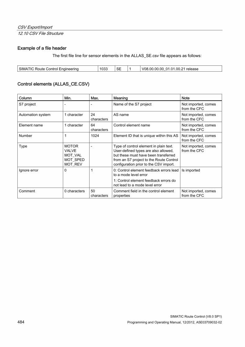
CSV Export/Import 12.10 CSV File Structure
SIMATIC Route Control (V8.0 SP1) 484 Programming and Operating Manual, 12/2012, A5E03709032-02
Example of a file header The first file line for sensor elements in the ALLAS_SE.csv file appears as follows:
SIMATIC Route Control Engineering 1033 SE 1 V08.00.00.00_01.01.00.21 release
Control elements (ALLAS_CE.CSV) Column Min. Max. Meaning Note S7 project - - Name of the S7 project Not imported, comes
from the CFC Automation system 1 character 24
characters AS name Not imported, comes
from the CFC Element name 1 character 64
characters Control element name Not imported, comes
from the CFC Number 1 1024 Element ID that is unique within this AS Not imported, comes
from the CFC Type MOTOR
VALVE MOT_VAL MOT_SPED MOT_REV
- Type of control element in plain text. User-defined types are also allowed, but these must have been transferred from an S7 project to the Route Control configuration prior to the CSV import.
Not imported, comes from the CFC
Ignore error 0 1 0: Control element feedback errors lead to a mode level error 1: Control element feedback errors do not lead to a mode level error
Is imported
Comment 0 characters 50 characters
Comment field in the control element properties
Not imported, comes from the CFC
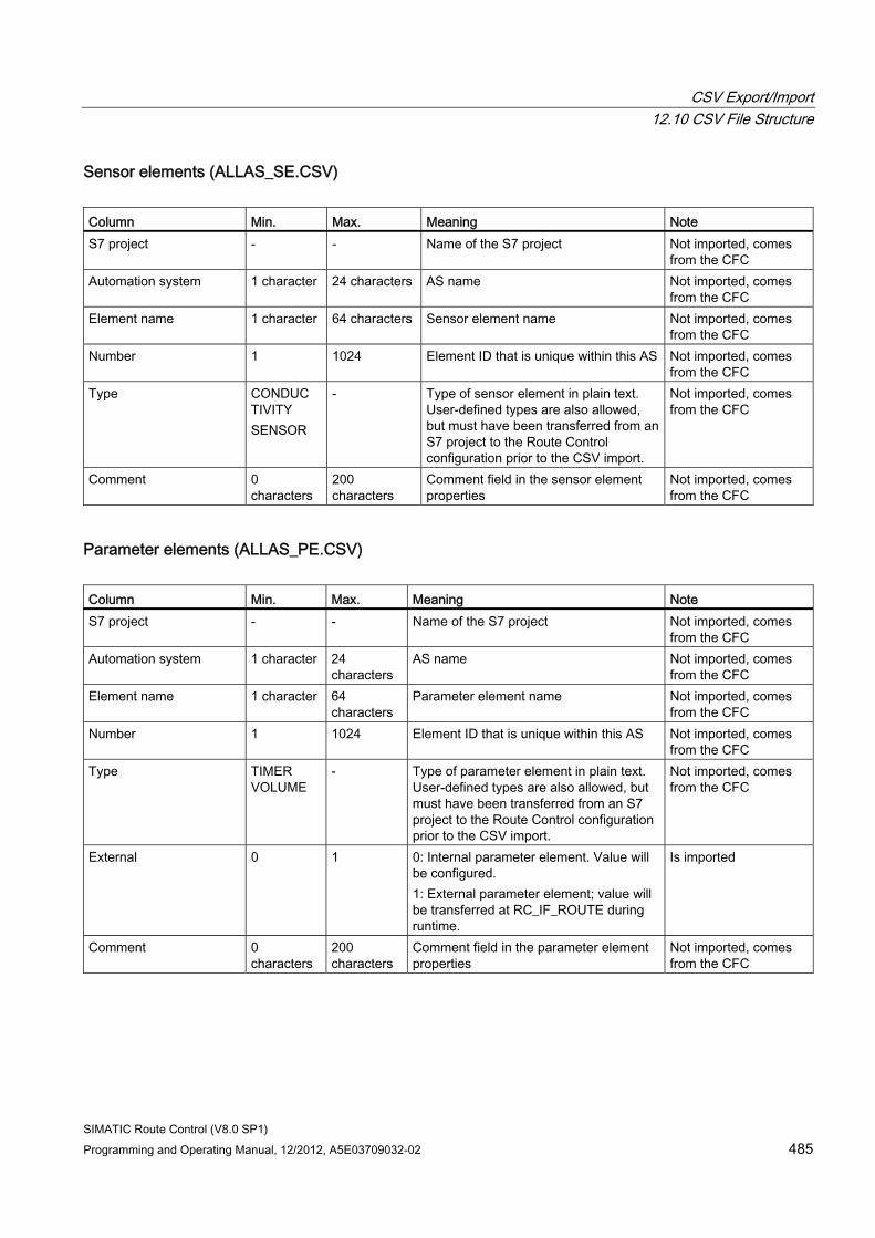
CSV Export/Import 12.10 CSV File Structure
SIMATIC Route Control (V8.0 SP1) Programming and Operating Manual, 12/2012, A5E03709032-02 485
Sensor elements (ALLAS_SE.CSV) Column Min. Max. Meaning Note S7 project - - Name of the S7 project Not imported, comes
from the CFC Automation system 1 character 24 characters AS name Not imported, comes
from the CFC Element name 1 character 64 characters Sensor element name Not imported, comes
from the CFC Number 1 1024 Element ID that is unique within this AS Not imported, comes
from the CFC Type CONDUC
TIVITY SENSOR
- Type of sensor element in plain text. User-defined types are also allowed, but must have been transferred from an S7 project to the Route Control configuration prior to the CSV import.
Not imported, comes from the CFC
Comment 0 characters
200 characters
Comment field in the sensor element properties
Not imported, comes from the CFC
Parameter elements (ALLAS_PE.CSV) Column Min. Max. Meaning Note S7 project - - Name of the S7 project Not imported, comes
from the CFC Automation system 1 character 24
characters AS name Not imported, comes
from the CFC Element name 1 character 64
characters Parameter element name Not imported, comes
from the CFC Number 1 1024 Element ID that is unique within this AS Not imported, comes
from the CFC Type TIMER
VOLUME - Type of parameter element in plain text.
User-defined types are also allowed, but must have been transferred from an S7 project to the Route Control configuration prior to the CSV import.
Not imported, comes from the CFC
External 0 1 0: Internal parameter element. Value will be configured. 1: External parameter element; value will be transferred at RC_IF_ROUTE during runtime.
Is imported
Comment 0 characters
200 characters
Comment field in the parameter element properties
Not imported, comes from the CFC
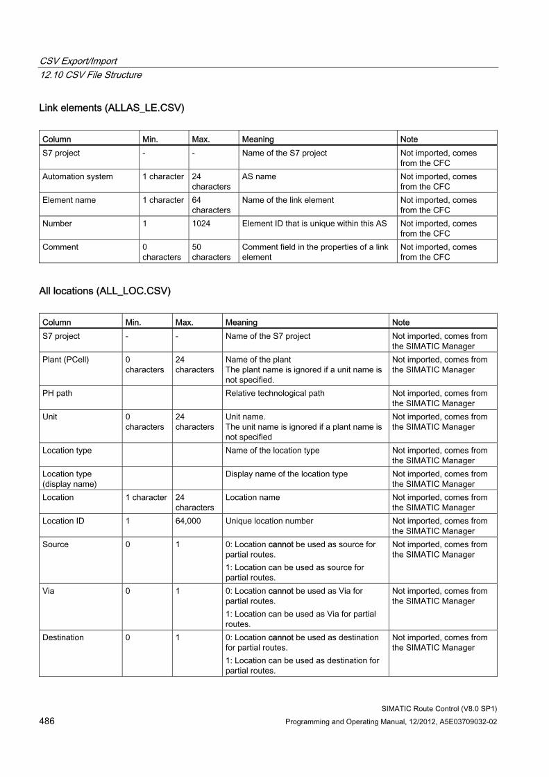
CSV Export/Import 12.10 CSV File Structure
SIMATIC Route Control (V8.0 SP1) 486 Programming and Operating Manual, 12/2012, A5E03709032-02
Link elements (ALLAS_LE.CSV) Column Min. Max. Meaning Note S7 project - - Name of the S7 project Not imported, comes
from the CFC Automation system 1 character 24
characters AS name Not imported, comes
from the CFC Element name 1 character 64
characters Name of the link element Not imported, comes
from the CFC Number 1 1024 Element ID that is unique within this AS Not imported, comes
from the CFC Comment 0
characters 50 characters
Comment field in the properties of a link element
Not imported, comes from the CFC
All locations (ALL_LOC.CSV) Column Min. Max. Meaning Note S7 project - - Name of the S7 project Not imported, comes from
the SIMATIC Manager Plant (PCell) 0
characters 24 characters
Name of the plant The plant name is ignored if a unit name is not specified.
Not imported, comes from the SIMATIC Manager
PH path Relative technological path Not imported, comes from the SIMATIC Manager
Unit 0 characters
24 characters
Unit name. The unit name is ignored if a plant name is not specified
Not imported, comes from the SIMATIC Manager
Location type Name of the location type Not imported, comes from the SIMATIC Manager
Location type (display name)
Display name of the location type Not imported, comes from the SIMATIC Manager
Location 1 character 24 characters
Location name Not imported, comes from the SIMATIC Manager
Location ID 1 64,000 Unique location number Not imported, comes from the SIMATIC Manager
Source 0 1 0: Location cannot be used as source for partial routes. 1: Location can be used as source for partial routes.
Not imported, comes from the SIMATIC Manager
Via 0 1 0: Location cannot be used as Via for partial routes. 1: Location can be used as Via for partial routes.
Not imported, comes from the SIMATIC Manager
Destination 0 1 0: Location cannot be used as destination for partial routes. 1: Location can be used as destination for partial routes.
Not imported, comes from the SIMATIC Manager
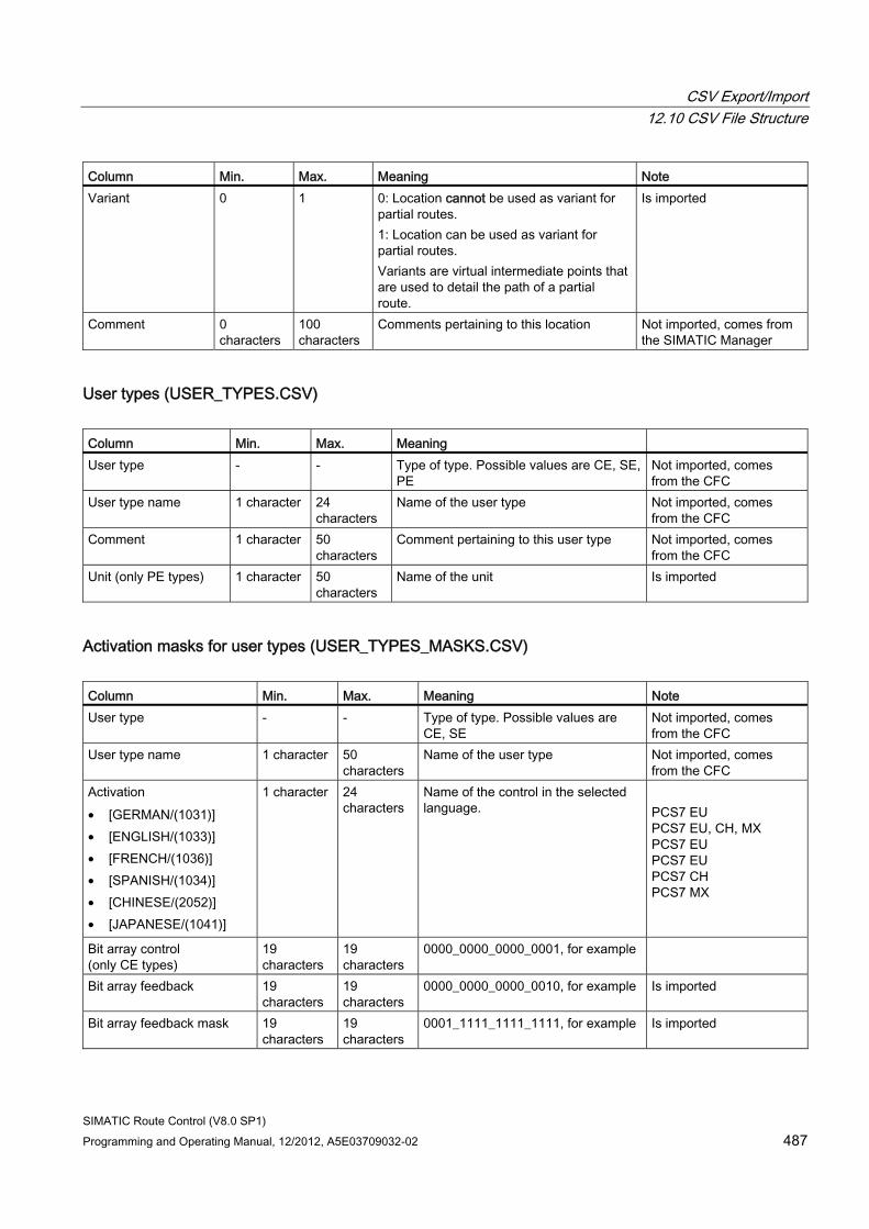
CSV Export/Import 12.10 CSV File Structure
SIMATIC Route Control (V8.0 SP1) Programming and Operating Manual, 12/2012, A5E03709032-02 487
Column Min. Max. Meaning Note Variant 0 1 0: Location cannot be used as variant for
partial routes. 1: Location can be used as variant for partial routes. Variants are virtual intermediate points that are used to detail the path of a partial route.
Is imported
Comment 0 characters
100 characters
Comments pertaining to this location Not imported, comes from the SIMATIC Manager
User types (USER_TYPES.CSV) Column Min. Max. Meaning User type - - Type of type. Possible values are CE, SE,
PE Not imported, comes from the CFC
User type name 1 character 24 characters
Name of the user type Not imported, comes from the CFC
Comment 1 character 50 characters
Comment pertaining to this user type Not imported, comes from the CFC
Unit (only PE types) 1 character 50 characters
Name of the unit Is imported
Activation masks for user types (USER_TYPES_MASKS.CSV) Column Min. Max. Meaning Note User type - - Type of type. Possible values are
CE, SE Not imported, comes from the CFC
User type name 1 character 50 characters
Name of the user type Not imported, comes from the CFC
Activation • [GERMAN/(1031)] • [ENGLISH/(1033)] • [FRENCH/(1036)] • [SPANISH/(1034)] • [CHINESE/(2052)] • [JAPANESE/(1041)]
1 character 24 characters
Name of the control in the selected language.
PCS7 EU PCS7 EU, CH, MX PCS7 EU PCS7 EU PCS7 CH PCS7 MX
Bit array control (only CE types)
19 characters
19 characters
0000_0000_0000_0001, for example
Bit array feedback 19 characters
19 characters
0000_0000_0000_0010, for example Is imported
Bit array feedback mask 19 characters
19 characters
0001_1111_1111_1111, for example Is imported
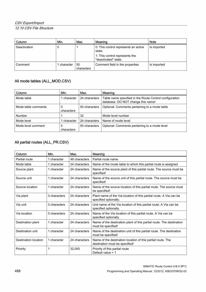
CSV Export/Import 12.10 CSV File Structure
SIMATIC Route Control (V8.0 SP1) 488 Programming and Operating Manual, 12/2012, A5E03709032-02
Column Min. Max. Meaning Note Deactivation 0 1 0: This control represents an active
state. 1: This control represents the "deactivated" state.
Is imported
Comment 1 character 50 characters
Comment field in the properties Is imported
All mode tables (ALL_MOD.CSV) Column Min. Max. Meaning Mode table 1 character 24 characters Table name specified in the Route Control configuration
database. DO NOT change this name! Mode table comments 0
characters 50 characters Optional: Comments pertaining to a mode table
Number 1 32 Mode level number Mode level 1 character 24 characters Name of mode level Mode level comment 0
characters 50 characters Optional: Comments pertaining to a mode level
All partial routes (ALL_PR.CSV) Column Min. Max. Meaning Partial route 1 character 48 characters Partial route name Mode table 1 character 24 characters Name of the mode table to which this partial route is assigned Source plant 1 character 24 characters Name of the source plant of this partial route. The source must be
specified! Source unit 1 character 24 characters Name of the source unit of this partial route. The source must be
specified! Source location 1 character 24 characters Name of the source location of this partial route. The source must
be specified! Via plant 0 characters 24 characters Plant name of the Via location of this partial route. A Via can be
specified optionally. Via unit 0 characters 24 characters Unit name of the Via location of this partial route. A Via can be
specified optionally. Via location 0 characters 24 characters Name of the Via location of this partial route. A Via can be
specified optionally. Destination plant 1 character 24 characters Name of the destination plant of this partial route. The destination
must be specified! Destination unit 1 character 24 characters Name of the destination unit of this partial route. The destination
must be specified! Destination location 1 character 24 characters Name of the destination location of this partial route. The
destination must be specified! Priority 1 32,000 Priority of this partial route
Default value = 1
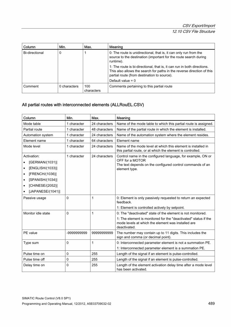
CSV Export/Import 12.10 CSV File Structure
SIMATIC Route Control (V8.0 SP1) Programming and Operating Manual, 12/2012, A5E03709032-02 489
Column Min. Max. Meaning Bi-directional 0 1 0: The route is unidirectional, that is, it can only run from the
source to the destination (important for the route search during runtime). 1: The route is bi-directional, that is, it can run in both directions. This also allows the search for paths in the reverse direction of this partial route (from destination to source). Default value = 0
Comment 0 characters 100 characters
Comments pertaining to this partial route
All partial routes with interconnected elements (ALLRouEL.CSV) Column Min. Max. Meaning Mode table 1 character 24 characters Name of the mode table to which this partial route is assigned.Partial route 1 character 48 characters Name of the partial route in which the element is installed. Automation system 1 character 24 characters Name of the automation system where the element resides. Element name 1 character 64 characters Element name Mode level 1 character 24 characters Name of the mode level at which this element is installed in
this partial route, or at which the element is controlled. Activation: • [GERMAN/(1031)] • [ENGLISH/(1033)] • [FRENCH/(1036)] • [SPANISH/(1034)] • [CHINESE/(2052)] • [JAPANESE/(1041)]
1 character 24 characters Control name in the configured language, for example, ON or OFF for a MOTOR The text depends on the configured control commands of an element type.
Passive usage 0 1 0: Element is only passively requested to return an expected feedback. 1: Element is controlled actively by setpoint.
Monitor idle state 0 1 0: The "deactivated" state of the element is not monitored. 1: The element is monitored for the "deactivated" status if the mode levels at which the element was installed are deactivated.
PE value -9999999999 99999999999 The number may contain up to 11 digits. This includes the sign and comma (or decimal point).
Type sum 0 1 0: Interconnected parameter element is not a summation PE. 1: Interconnected parameter element is a summation PE.
Pulse time on 0 255 Length of the signal if an element is pulse-controlled. Pulse time off 0 255 Length of the signal if an element is pulse-controlled. Delay time on 0 255 Length of the element activation delay time after a mode level
has been activated.
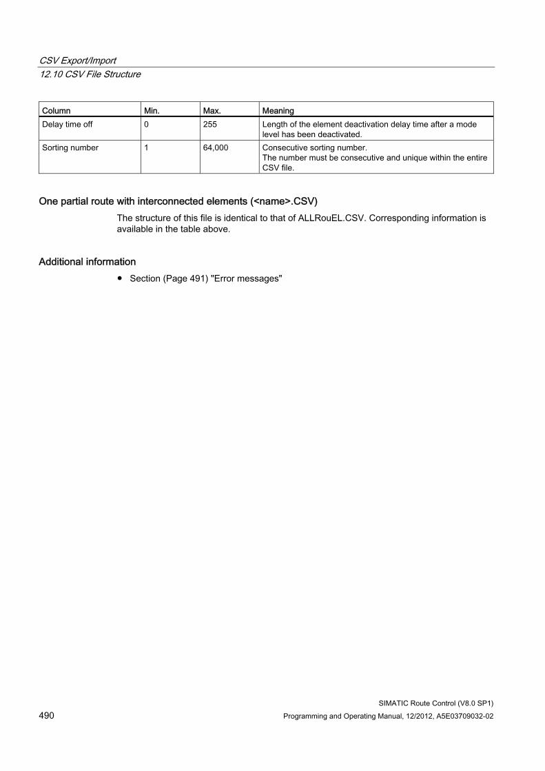
CSV Export/Import 12.10 CSV File Structure
SIMATIC Route Control (V8.0 SP1) 490 Programming and Operating Manual, 12/2012, A5E03709032-02
Column Min. Max. Meaning Delay time off 0 255 Length of the element deactivation delay time after a mode
level has been deactivated. Sorting number 1 64,000 Consecutive sorting number.
The number must be consecutive and unique within the entire CSV file.
One partial route with interconnected elements (<name>.CSV) The structure of this file is identical to that of ALLRouEL.CSV. Corresponding information is available in the table above.
Additional information ● Section (Page 491) "Error messages"
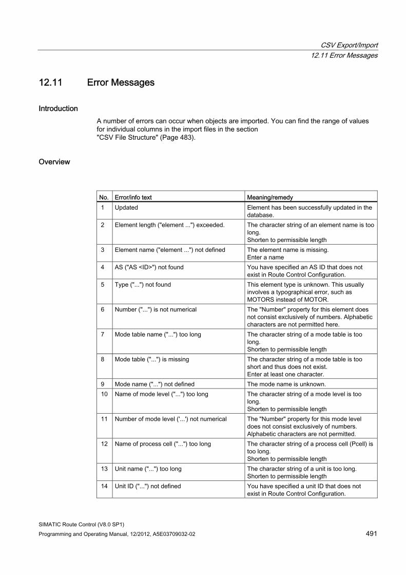
CSV Export/Import 12.11 Error Messages
SIMATIC Route Control (V8.0 SP1) Programming and Operating Manual, 12/2012, A5E03709032-02 491
12.11 Error Messages
Introduction A number of errors can occur when objects are imported. You can find the range of values for individual columns in the import files in the section "CSV File Structure" (Page 483).
Overview
No. Error/info text Meaning/remedy 1 Updated Element has been successfully updated in the
database. 2 Element length ("element ...") exceeded. The character string of an element name is too
long. Shorten to permissible length
3 Element name ("element ...") not defined The element name is missing. Enter a name
4 AS ("AS <ID>") not found You have specified an AS ID that does not exist in Route Control Configuration.
5 Type ("...") not found This element type is unknown. This usually involves a typographical error, such as MOTORS instead of MOTOR.
6 Number ("...") is not numerical The "Number" property for this element does not consist exclusively of numbers. Alphabetic characters are not permitted here.
7 Mode table name ("...") too long The character string of a mode table is too long. Shorten to permissible length
8 Mode table ("...") is missing The character string of a mode table is too short and thus does not exist. Enter at least one character.
9 Mode name ("...") not defined The mode name is unknown. 10 Name of mode level ("...") too long The character string of a mode level is too
long. Shorten to permissible length
11 Number of mode level ('...') not numerical The "Number" property for this mode level does not consist exclusively of numbers. Alphabetic characters are not permitted.
12 Name of process cell ("...") too long The character string of a process cell (Pcell) is too long. Shorten to permissible length
13 Unit name ("...") too long The character string of a unit is too long. Shorten to permissible length
14 Unit ID ("...") not defined You have specified a unit ID that does not exist in Route Control Configuration.
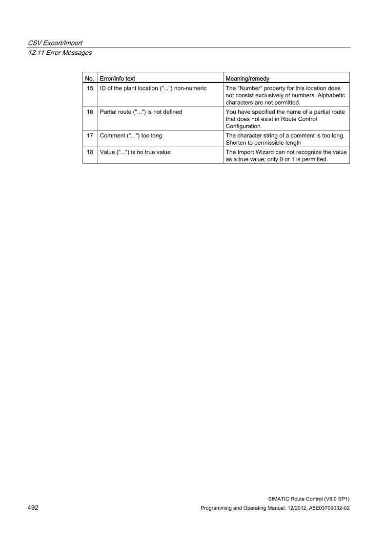
CSV Export/Import 12.11 Error Messages
SIMATIC Route Control (V8.0 SP1) 492 Programming and Operating Manual, 12/2012, A5E03709032-02
No. Error/info text Meaning/remedy 15 ID of the plant location ("...") non-numeric The "Number" property for this location does
not consist exclusively of numbers. Alphabetic characters are not permitted.
16 Partial route ("...") is not defined You have specified the name of a partial route that does not exist in Route Control Configuration.
17 Comment ("...") too long The character string of a comment is too long.Shorten to permissible length
18 Value ("...") is no true value The Import Wizard can not recognize the value as a true value; only 0 or 1 is permitted.
SIMATIC Route Control (V8.0 SP1) Programming and Operating Manual, 12/2012, A5E03709032-02 493
Configuring with Route Control Engineering 1313.1 Process cells, units and locations
Transfer of Configuration Data As of V7.0, you configure process cells, units and locations solely in SIMATIC Manager. Use the Route Control Wizard to run an export/import and transfer the configuration data to Route Control Engineering.
SIMATIC BATCH also imports configuration data from the S7 project. Some of these data are needed in order for BATCH and Route Control to interact.
Due to the central configuration in SIMATIC Manager, you only have to enter these data once.
Additional information ● Section "Transferring Data From an S7 Project" (Page 447)
● Section "Configuring Locations" (Page 431)
Configuring with Route Control Engineering 13.2 Getting Started
SIMATIC Route Control (V8.0 SP1) 494 Programming and Operating Manual, 12/2012, A5E03709032-02
13.2 Getting Started
13.2.1 Starting Route Control Engineering
Procedure Start Route Control Engineering using one of the three options below:
● From the Windows start bar
● From the "Options" menu in SIMATIC Manager
● From one of the "Route Control" objects in SIMATIC Manager
Starting via the Windows Start Bar 1. Select the menu command Start > SIMATIC > ROUTE CONTROL > Engineering. The
Route Control Engineering window opens.
2. Select the menu command File > Open, then select the path to an S7 project (*.s7p) or S7 multiproject (*.s7f). This creates the project context manually.
Note
The next time Route Control Engineering is started from the Windows start bar, the most recently opened project database is opened once again.
Starting via SIMATIC Manager Select the menu command Options > SIMATIC Route Control > Engineering. The S7 project context is set automatically and the associated Route Control project database is opened.
Starting via one of the "Route Control" Objects in SIMATIC Manager You will find two "Route Control" objects in SIMATIC Manager:
● In the project folder
● In the PC station in the RC application client
Open the object's shortcut menu and select the menu command SIMATIC Route Control > Engineering. The S7 project context is set automatically and the associated Route Control project database is opened.
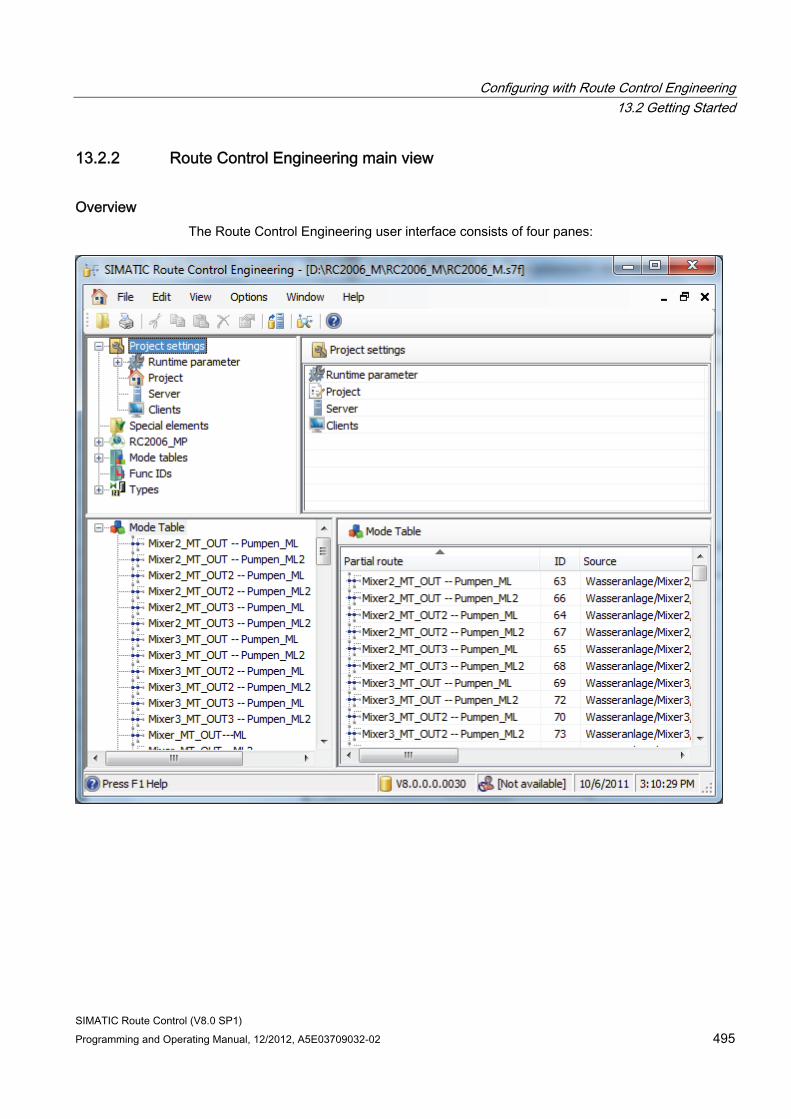
Configuring with Route Control Engineering 13.2 Getting Started
SIMATIC Route Control (V8.0 SP1) Programming and Operating Manual, 12/2012, A5E03709032-02 495
13.2.2 Route Control Engineering main view
Overview The Route Control Engineering user interface consists of four panes:
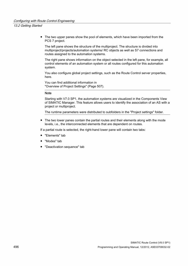
Configuring with Route Control Engineering 13.2 Getting Started
SIMATIC Route Control (V8.0 SP1) 496 Programming and Operating Manual, 12/2012, A5E03709032-02
● The two upper panes show the pool of elements, which have been imported from the PCS 7 project.
The left pane shows the structure of the multiproject. The structure is divided into multiproject/projects/automation systems/ RC objects as well as S7 connections and routes assigned to the automation systems.
The right pane shows information on the object selected in the left pane, for example, all control elements of an automation system or all routes configured for this automation system.
You also configure global project settings, such as the Route Control server properties, here.
You can find additional information in "Overview of Project Settings" (Page 507).
Note
Starting with V7.0 SP1, the automation systems are visualized in the Components View of SIMATIC Manager. This feature allows users to identify the association of an AS with a project or multiproject.
The runtime parameters were distributed to subfolders in the "Project settings" folder.
● The two lower panes contain the partial routes and their elements along with the mode levels, i.e., the interconnected elements that are dependent on routes.
If a partial route is selected, the right-hand lower pane will contain two tabs:
● "Elements" tab
● "Modes" tab
● "Deactivation sequence" tab
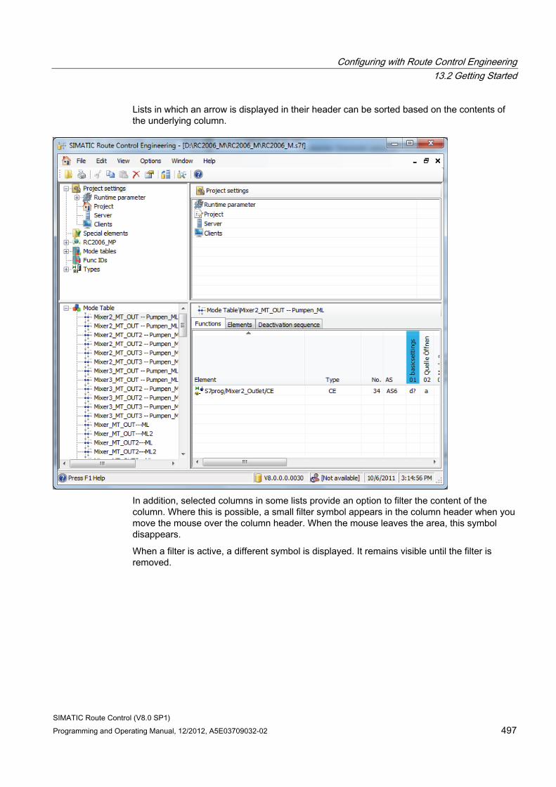
Configuring with Route Control Engineering 13.2 Getting Started
SIMATIC Route Control (V8.0 SP1) Programming and Operating Manual, 12/2012, A5E03709032-02 497
Lists in which an arrow is displayed in their header can be sorted based on the contents of the underlying column.
In addition, selected columns in some lists provide an option to filter the content of the column. Where this is possible, a small filter symbol appears in the column header when you move the mouse over the column header. When the mouse leaves the area, this symbol disappears.
When a filter is active, a different symbol is displayed. It remains visible until the filter is removed.
Configuring with Route Control Engineering 13.2 Getting Started
SIMATIC Route Control (V8.0 SP1) 498 Programming and Operating Manual, 12/2012, A5E03709032-02
"Elements" tab The "Elements" tab displays all the elements that are inserted in a partial route. If an element is activated in several mode levels, a corresponding number of rows is displayed for this element.
The information in the previous "Values" and "Passive/Idle state" columns were accumulated in V8.0 in a new "Command/Value" column. This aligns the representation of control commands with the layout of the "Elements" tab in Route Control Center. For further information, refer to the section "Elements tab in the Route Control Center" (Page 645)
Note
As of V7.0, you can change the order of the elements in a partial route on the Route Control Engineering "Elements" tab.
This option will be provided for future expansions (solid material transports).
"Modes" tab The "Modes" tab is new as of V7.0. Each element is displayed in a separate line. You will find configured activation keys for each of the 32 mode levels for every element.
You have already configured the mode levels when the element was inserted in the partial route. Configure the activations in other mode levels from this view.
"Deactivation sequence" tab In the "Deactivation sequence" tab, WAIT elements can be inserted and deleted, or the sequence of the elements can be changed.
A deactivation sequence can be defined for each partial route and mode. The presence of a deactivation sequence is indicated by color coding in the column header of the mode in the function view.
A deactivation sequence basically contains all the CE, SE and PE elements of the partial route. If an element is deleted, therefore, it disappears from the deactivation sequence. When an element is inserted into a partial route and there is a deactivation sequence, it is also integrated into it.
In some circumstances, a deactivation sequence without Wait elements can be useful. If, for example, a route is composed of partial routes 1,2,3 and contains 3 Wait elements in the deactivation sequence, all elements from the partial routes that are before the first Wait element of PR1 in the sequence and all elements of an involved partial route that does not have a deactivation sequence are immediately deactivated. If PR2, therefore, had no deactivation sequence, its elements would be deactivated immediately.
If PR2 has a deactivation sequence without Wait elements, then all its elements are deactivated when PR1 is completely deactivated with its Wait elements.
The actual deactivation sequence of the elements in a route is derived from the order of partial routes in the route and from the sorting order of elements within the partial routes.

Configuring with Route Control Engineering 13.2 Getting Started
SIMATIC Route Control (V8.0 SP1) Programming and Operating Manual, 12/2012, A5E03709032-02 499
Since the route first comes into existence in runtime and is composed of the assembled partial routes found, it is difficult to make a statement about the exact sequence of elements at the point in time when configuration is performed. This does not apply to saved routes.
You can find additional information on this in the sections: "How to program the activation of elements" (Page 542) "Meaning of the activation key symbols" (Page 544).
13.2.3 Route Control Engineering menu
Overview Menu item Submenu Meaning File Open Opens an already existing database file.
As a rule, this function is no longer necessary if the Route Control engineering environment is started via SIMATIC Manager. The correct database file is opened automatically from the path under the S7 project.
Close Closes the database file. The database is closed automatically when the Route Control engineering tool is closed.
Print Report Creates prepared reports (lists) for printout. Change logon Opens a submenu for logging on or off of the Logon service. 1 ... Opens the most recently opened database. ... 4 ... Close Closes the Route Control Engineering tool. Availability of the following functions depends on the object
selected. Edit Cut Cuts an element and copies it to the clipboard Copy Copies an element to the clipboard Paste Pastes an element from the clipboard to a selected location Delete Deletes an element Rename Renames an element Properties Opens the Properties dialog for the selected element.
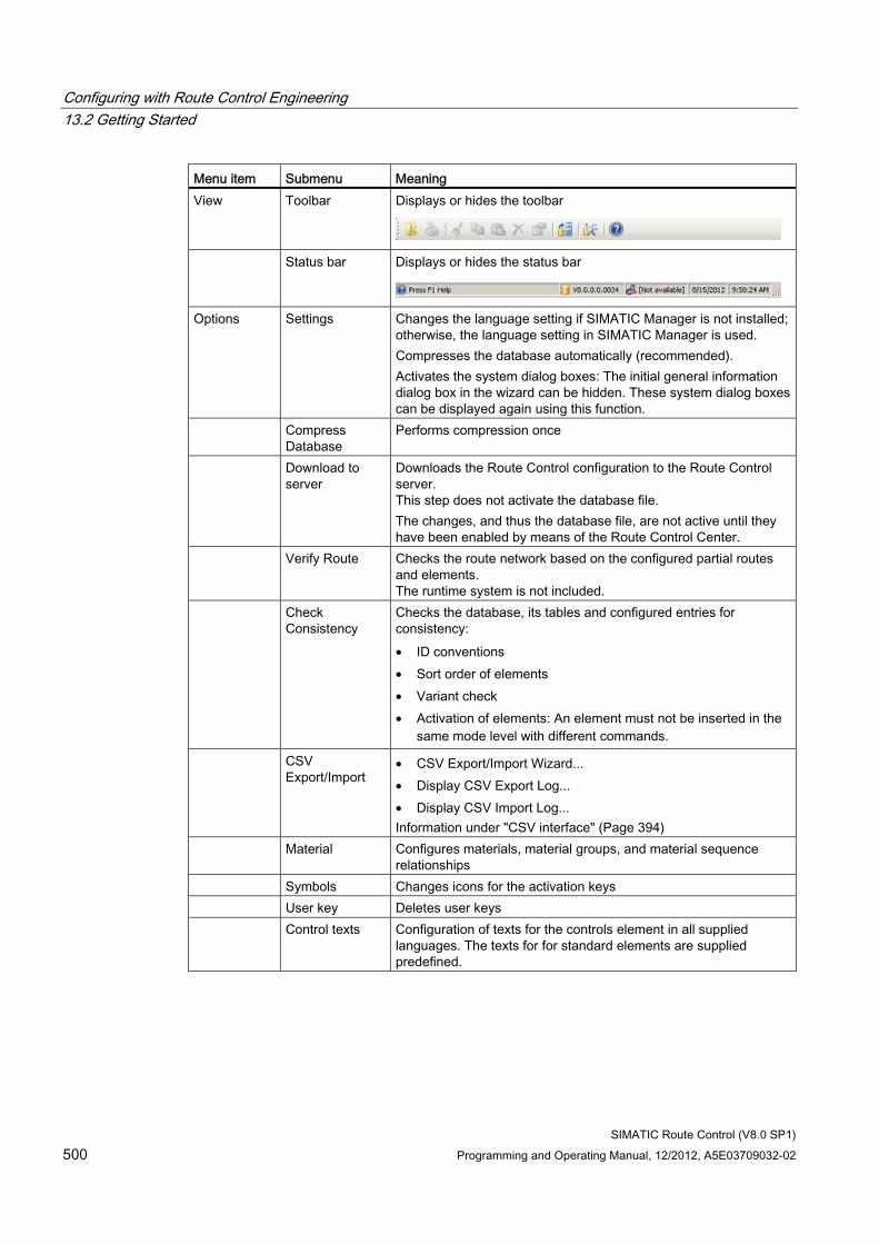
Configuring with Route Control Engineering 13.2 Getting Started
SIMATIC Route Control (V8.0 SP1) 500 Programming and Operating Manual, 12/2012, A5E03709032-02
Menu item Submenu Meaning View Toolbar Displays or hides the toolbar
Status bar Displays or hides the status bar
Options Settings Changes the language setting if SIMATIC Manager is not installed; otherwise, the language setting in SIMATIC Manager is used. Compresses the database automatically (recommended). Activates the system dialog boxes: The initial general information dialog box in the wizard can be hidden. These system dialog boxes can be displayed again using this function.
Compress Database
Performs compression once
Download to server
Downloads the Route Control configuration to the Route Control server. This step does not activate the database file. The changes, and thus the database file, are not active until they have been enabled by means of the Route Control Center.
Verify Route Checks the route network based on the configured partial routes and elements. The runtime system is not included.
Check Consistency
Checks the database, its tables and configured entries for consistency: • ID conventions • Sort order of elements • Variant check • Activation of elements: An element must not be inserted in the
same mode level with different commands.
CSV Export/Import
• CSV Export/Import Wizard... • Display CSV Export Log... • Display CSV Import Log... Information under "CSV interface" (Page 394)
Material Configures materials, material groups, and material sequence relationships
Symbols Changes icons for the activation keys User key Deletes user keys Control texts Configuration of texts for the controls element in all supplied
languages. The texts for for standard elements are supplied predefined.
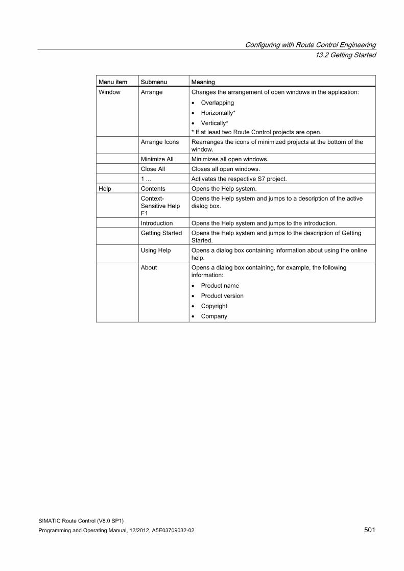
Configuring with Route Control Engineering 13.2 Getting Started
SIMATIC Route Control (V8.0 SP1) Programming and Operating Manual, 12/2012, A5E03709032-02 501
Menu item Submenu Meaning Window Arrange Changes the arrangement of open windows in the application:
• Overlapping • Horizontally* • Vertically* * If at least two Route Control projects are open.
Arrange Icons Rearranges the icons of minimized projects at the bottom of the window.
Minimize All Minimizes all open windows. Close All Closes all open windows. 1 ... Activates the respective S7 project. Help Contents Opens the Help system. Context-
Sensitive Help F1
Opens the Help system and jumps to a description of the active dialog box.
Introduction Opens the Help system and jumps to the introduction. Getting Started Opens the Help system and jumps to the description of Getting
Started. Using Help Opens a dialog box containing information about using the online
help. About Opens a dialog box containing, for example, the following
information: • Product name • Product version • Copyright • Company
Configuring with Route Control Engineering 13.2 Getting Started
SIMATIC Route Control (V8.0 SP1) 502 Programming and Operating Manual, 12/2012, A5E03709032-02
13.2.4 Creating a new Route Control project
Introduction You can use Route Control Engineering to create a new Route Control project.
Procedure 1. In Route Control Engineering, select the menu command File > Open.
2. In the dialog box, select the path to an S7 project (*.s7p) or S7 multiproject (*.s7f).
The Route Control Engineering tool opens the configuration database and you can begin your configuration.
Result SIMATIC Route Control creates a Route Control subdirectory and a configuration database (\global\rcs\) associated with the given path. In doing so, SIMATIC Route Control assumes that the "\global" subdirectory already exists, as SIMATIC Route Control is always stored in an S7 project or S7 multiproject.
Note
If you start Route Control Engineering from SIMATIC Manager with an S7 project open, the associated Route Control database is automatically created in the S7 project path and opened.
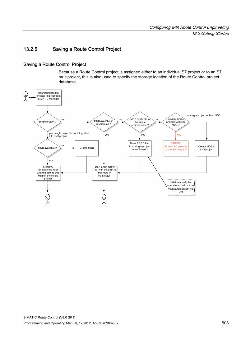
Configuring with Route Control Engineering 13.2 Getting Started
SIMATIC Route Control (V8.0 SP1) Programming and Operating Manual, 12/2012, A5E03709032-02 503
13.2.5 Saving a Route Control Project
Saving a Route Control Project Because a Route Control project is assigned either to an individual S7 project or to an S7 multiproject, this is also used to specify the storage location of the Route Control project database.
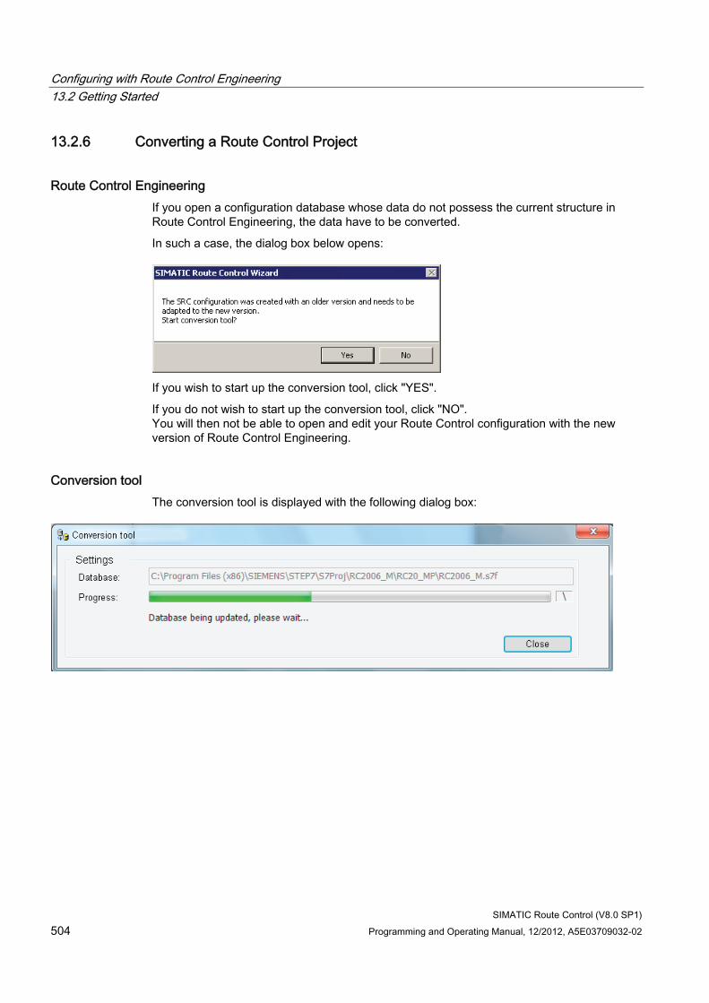
Configuring with Route Control Engineering 13.2 Getting Started
SIMATIC Route Control (V8.0 SP1) 504 Programming and Operating Manual, 12/2012, A5E03709032-02
13.2.6 Converting a Route Control Project
Route Control Engineering If you open a configuration database whose data do not possess the current structure in Route Control Engineering, the data have to be converted.
In such a case, the dialog box below opens:
If you wish to start up the conversion tool, click "YES".
If you do not wish to start up the conversion tool, click "NO". You will then not be able to open and edit your Route Control configuration with the new version of Route Control Engineering.
Conversion tool The conversion tool is displayed with the following dialog box:
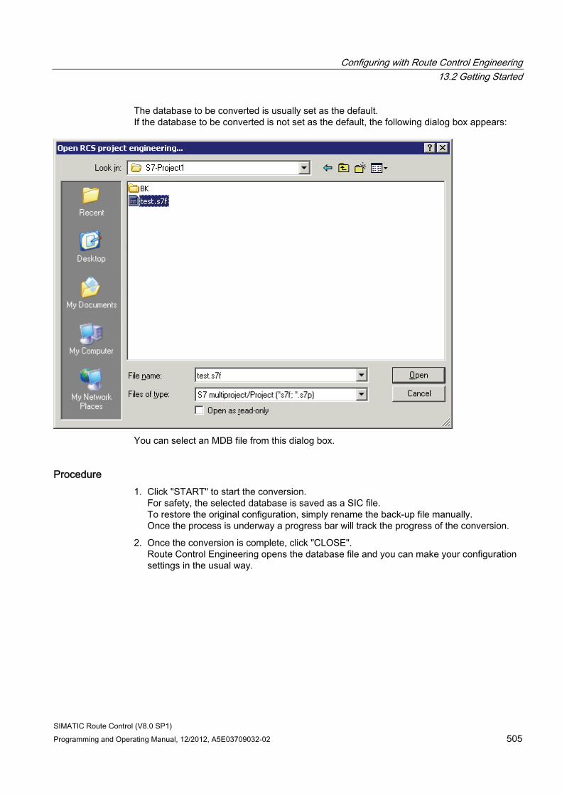
Configuring with Route Control Engineering 13.2 Getting Started
SIMATIC Route Control (V8.0 SP1) Programming and Operating Manual, 12/2012, A5E03709032-02 505
The database to be converted is usually set as the default. If the database to be converted is not set as the default, the following dialog box appears:
You can select an MDB file from this dialog box.
Procedure 1. Click "START" to start the conversion.
For safety, the selected database is saved as a SIC file. To restore the original configuration, simply rename the back-up file manually. Once the process is underway a progress bar will track the progress of the conversion.
2. Once the conversion is complete, click "CLOSE". Route Control Engineering opens the database file and you can make your configuration settings in the usual way.
Configuring with Route Control Engineering 13.2 Getting Started
SIMATIC Route Control (V8.0 SP1) 506 Programming and Operating Manual, 12/2012, A5E03709032-02
13.2.7 How to print out the configuration of elements and partial routes
Procedure 1. Select one of the following objects in Route Control Engineering:
– A partial route from a mode group with all of its interconnected elements
– An automation system from the "Automation Systems" folder
– One of the following element groups of an automation system: "Control elements" "Sensor elements" "Link elements" "Parameter elements"
– Process cell
– A unit of a process cell
2. Select the menu command File > Print Report > Preview. The print preview opens.
3. Select the menu command File > Print Report > Print. Printing begins.
Configuring with Route Control Engineering 13.3 Global Project Settings
SIMATIC Route Control (V8.0 SP1) Programming and Operating Manual, 12/2012, A5E03709032-02 507
13.3 Global Project Settings
13.3.1 Overview of project settings
"Properties" Dialog Boxes Configure all global settings for a Route Control project in the upper pane of Route Control Engineering in the "Project settings" folder.
Here you will find the subfolders
● Attributes
● Runtime parameters
● Server
Open the "Properties" dialog boxes by double-clicking the entries in the list. You can find additional information about these dialog boxes in:
● "Attribute Properties" (Page 508)
● "Runtime Parameter Properties" (Page 509)
● "Server Properties"
Runtime parameters You can find additional information in: "Overview of Runtime Parameters" (Page 510).
Additional information ● Section "Monitoring the Server and AS" (Page 517)
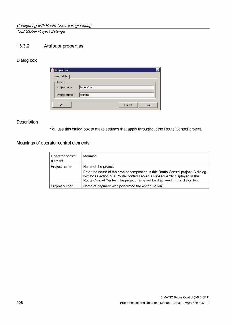
Configuring with Route Control Engineering 13.3 Global Project Settings
SIMATIC Route Control (V8.0 SP1) 508 Programming and Operating Manual, 12/2012, A5E03709032-02
13.3.2 Attribute properties
Dialog box
Description You use this dialog box to make settings that apply throughout the Route Control project.
Meanings of operator control elements Operator control element
Meaning
Project name Name of the project Enter the name of the area encompassed in this Route Control project. A dialog box for selection of a Route Control server is subsequently displayed in the Route Control Center. The project name will be displayed in this dialog box.
Project author Name of engineer who performed the configuration
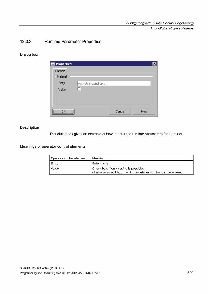
Configuring with Route Control Engineering 13.3 Global Project Settings
SIMATIC Route Control (V8.0 SP1) Programming and Operating Manual, 12/2012, A5E03709032-02 509
13.3.3 Runtime Parameter Properties
Dialog box
Description This dialog box gives an example of how to enter the runtime parameters for a project.
Meanings of operator control elements Operator control element Meaning Entry Entry name Value Check box, if only yes/no is possible,
otherwise an edit box in which an integer number can be entered
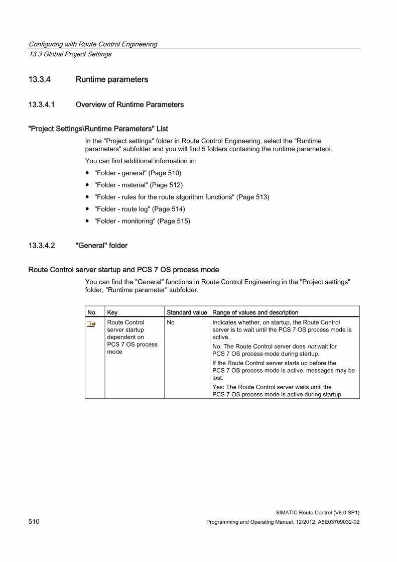
Configuring with Route Control Engineering 13.3 Global Project Settings
SIMATIC Route Control (V8.0 SP1) 510 Programming and Operating Manual, 12/2012, A5E03709032-02
13.3.4 Runtime parameters
13.3.4.1 Overview of Runtime Parameters
"Project Settings\Runtime Parameters" List In the "Project settings" folder in Route Control Engineering, select the "Runtime parameters" subfolder and you will find 5 folders containing the runtime parameters.
You can find additional information in:
● "Folder - general" (Page 510)
● "Folder - material" (Page 512)
● "Folder - rules for the route algorithm functions" (Page 513)
● "Folder - route log" (Page 514)
● "Folder - monitoring" (Page 515)
13.3.4.2 "General" folder
Route Control server startup and PCS 7 OS process mode You can find the "General" functions in Route Control Engineering in the "Project settings" folder, "Runtime parameter" subfolder.
No. Key Standard value Range of values and description
Route Control server startup dependent on PCS 7 OS process mode
No Indicates whether, on startup, the Route Control server is to wait until the PCS 7 OS process mode is active. No: The Route Control server does not wait for PCS 7 OS process mode during startup. If the Route Control server starts up before the PCS 7 OS process mode is active, messages may be lost. Yes: The Route Control server waits until the PCS 7 OS process mode is active during startup.
Configuring with Route Control Engineering 13.3 Global Project Settings
SIMATIC Route Control (V8.0 SP1) Programming and Operating Manual, 12/2012, A5E03709032-02 511
Load Route Control server If WinCC is operated in Service mode, that is, without a logged on user, the flag "Route Control server depends on WinCC startup" must not be set.
Only then is it ensured that the Route Control server continues to run if WinCC is loaded.
For this reason, the RC wizard no longer sets the flag "RC server depends on WinCC startup" as of V8.0.
This means that the setting selected in RC Engineering is kept.
Additional Information About Runtime Parameters ● Section "Overview of Runtime Parameters" (Page 510)
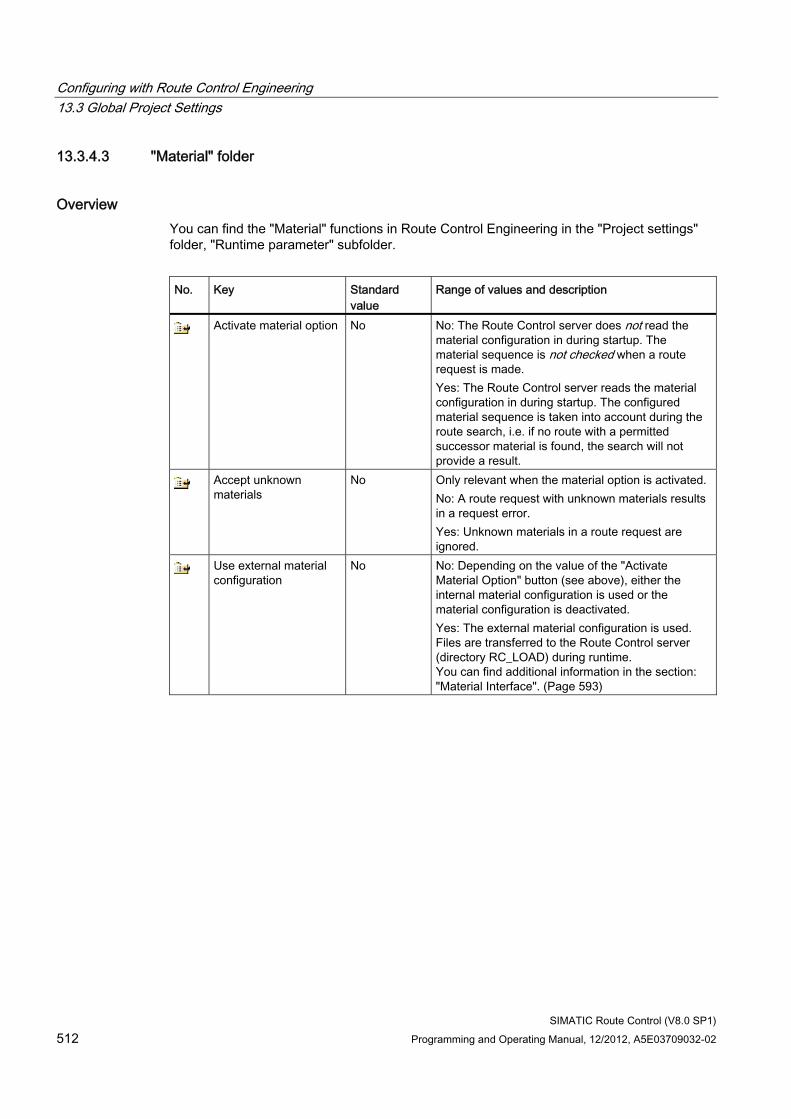
Configuring with Route Control Engineering 13.3 Global Project Settings
SIMATIC Route Control (V8.0 SP1) 512 Programming and Operating Manual, 12/2012, A5E03709032-02
13.3.4.3 "Material" folder
Overview You can find the "Material" functions in Route Control Engineering in the "Project settings" folder, "Runtime parameter" subfolder.
No. Key Standard
value Range of values and description
Activate material option No No: The Route Control server does not read the material configuration in during startup. The material sequence is not checked when a route request is made. Yes: The Route Control server reads the material configuration in during startup. The configured material sequence is taken into account during the route search, i.e. if no route with a permitted successor material is found, the search will not provide a result.
Accept unknown materials
No Only relevant when the material option is activated. No: A route request with unknown materials results in a request error. Yes: Unknown materials in a route request are ignored.
Use external material configuration
No No: Depending on the value of the "Activate Material Option" button (see above), either the internal material configuration is used or the material configuration is deactivated. Yes: The external material configuration is used. Files are transferred to the Route Control server (directory RC_LOAD) during runtime. You can find additional information in the section: "Material Interface". (Page 593)
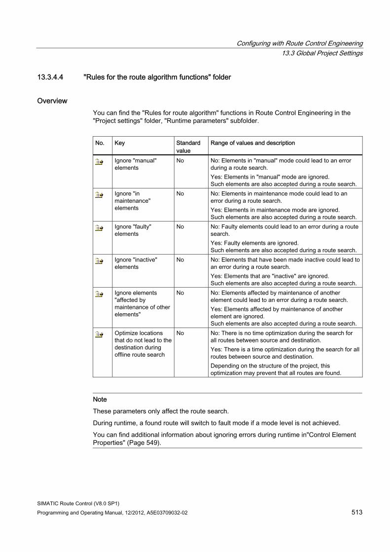
Configuring with Route Control Engineering 13.3 Global Project Settings
SIMATIC Route Control (V8.0 SP1) Programming and Operating Manual, 12/2012, A5E03709032-02 513
13.3.4.4 "Rules for the route algorithm functions" folder
Overview You can find the "Rules for route algorithm" functions in Route Control Engineering in the "Project settings" folder, "Runtime parameters" subfolder.
No. Key Standard
value Range of values and description
Ignore "manual" elements
No No: Elements in "manual" mode could lead to an error during a route search. Yes: Elements in "manual" mode are ignored. Such elements are also accepted during a route search.
Ignore "in maintenance" elements
No No: Elements in maintenance mode could lead to an error during a route search. Yes: Elements in maintenance mode are ignored. Such elements are also accepted during a route search.
Ignore "faulty" elements
No No: Faulty elements could lead to an error during a route search. Yes: Faulty elements are ignored. Such elements are also accepted during a route search.
Ignore "inactive" elements
No No: Elements that have been made inactive could lead to an error during a route search. Yes: Elements that are "inactive" are ignored. Such elements are also accepted during a route search.
Ignore elements "affected by maintenance of other elements"
No No: Elements affected by maintenance of another element could lead to an error during a route search. Yes: Elements affected by maintenance of another element are ignored. Such elements are also accepted during a route search.
Optimize locations that do not lead to the destination during offline route search
No No: There is no time optimization during the search for all routes between source and destination. Yes: There is a time optimization during the search for all routes between source and destination. Depending on the structure of the project, this optimization may prevent that all routes are found.
Note
These parameters only affect the route search.
During runtime, a found route will switch to fault mode if a mode level is not achieved.
You can find additional information about ignoring errors during runtime in"Control Element Properties" (Page 549).
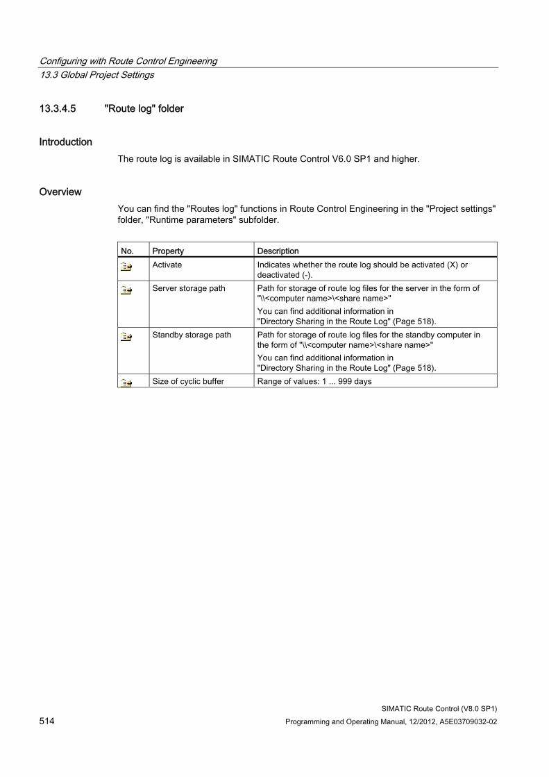
Configuring with Route Control Engineering 13.3 Global Project Settings
SIMATIC Route Control (V8.0 SP1) 514 Programming and Operating Manual, 12/2012, A5E03709032-02
13.3.4.5 "Route log" folder
Introduction The route log is available in SIMATIC Route Control V6.0 SP1 and higher.
Overview You can find the "Routes log" functions in Route Control Engineering in the "Project settings" folder, "Runtime parameters" subfolder.
No. Property Description
Activate Indicates whether the route log should be activated (X) or deactivated (-).
Server storage path Path for storage of route log files for the server in the form of "\\<computer name>\<share name>" You can find additional information in "Directory Sharing in the Route Log" (Page 518).
Standby storage path Path for storage of route log files for the standby computer in the form of "\\<computer name>\<share name>" You can find additional information in "Directory Sharing in the Route Log" (Page 518).
Size of cyclic buffer Range of values: 1 ... 999 days
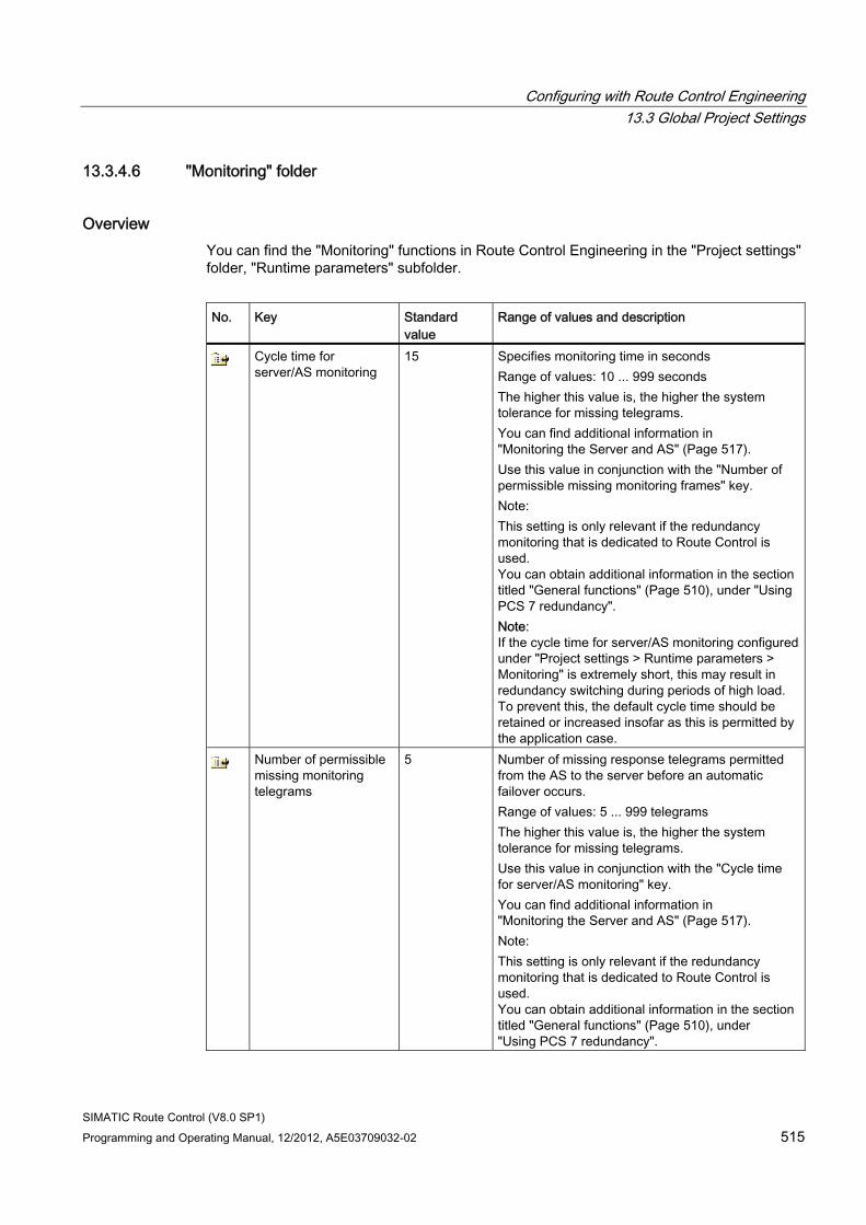
Configuring with Route Control Engineering 13.3 Global Project Settings
SIMATIC Route Control (V8.0 SP1) Programming and Operating Manual, 12/2012, A5E03709032-02 515
13.3.4.6 "Monitoring" folder
Overview You can find the "Monitoring" functions in Route Control Engineering in the "Project settings" folder, "Runtime parameters" subfolder.
No. Key Standard
value Range of values and description
Cycle time for server/AS monitoring
15 Specifies monitoring time in seconds Range of values: 10 ... 999 seconds The higher this value is, the higher the system tolerance for missing telegrams. You can find additional information in "Monitoring the Server and AS" (Page 517). Use this value in conjunction with the "Number of permissible missing monitoring frames" key. Note: This setting is only relevant if the redundancy monitoring that is dedicated to Route Control is used. You can obtain additional information in the section titled "General functions" (Page 510), under "Using PCS 7 redundancy". Note: If the cycle time for server/AS monitoring configured under "Project settings > Runtime parameters > Monitoring" is extremely short, this may result in redundancy switching during periods of high load. To prevent this, the default cycle time should be retained or increased insofar as this is permitted by the application case.
Number of permissible missing monitoring telegrams
5 Number of missing response telegrams permitted from the AS to the server before an automatic failover occurs. Range of values: 5 ... 999 telegrams The higher this value is, the higher the system tolerance for missing telegrams. Use this value in conjunction with the "Cycle time for server/AS monitoring" key. You can find additional information in "Monitoring the Server and AS" (Page 517). Note: This setting is only relevant if the redundancy monitoring that is dedicated to Route Control is used. You can obtain additional information in the section titled "General functions" (Page 510), under "Using PCS 7 redundancy".
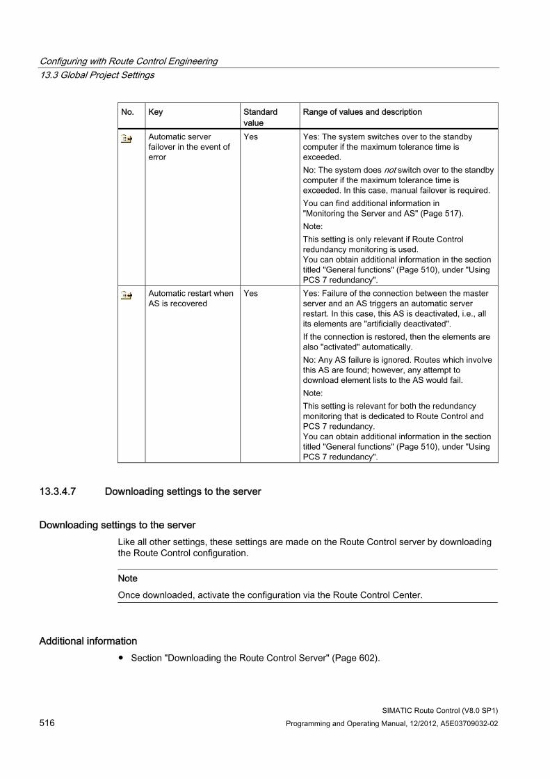
Configuring with Route Control Engineering 13.3 Global Project Settings
SIMATIC Route Control (V8.0 SP1) 516 Programming and Operating Manual, 12/2012, A5E03709032-02
No. Key Standard value
Range of values and description
Automatic server failover in the event of error
Yes Yes: The system switches over to the standby computer if the maximum tolerance time is exceeded. No: The system does not switch over to the standby computer if the maximum tolerance time is exceeded. In this case, manual failover is required. You can find additional information in "Monitoring the Server and AS" (Page 517). Note: This setting is only relevant if Route Control redundancy monitoring is used. You can obtain additional information in the section titled "General functions" (Page 510), under "Using PCS 7 redundancy".
Automatic restart when AS is recovered
Yes Yes: Failure of the connection between the master server and an AS triggers an automatic server restart. In this case, this AS is deactivated, i.e., all its elements are "artificially deactivated". If the connection is restored, then the elements are also "activated" automatically. No: Any AS failure is ignored. Routes which involve this AS are found; however, any attempt to download element lists to the AS would fail. Note: This setting is relevant for both the redundancy monitoring that is dedicated to Route Control and PCS 7 redundancy. You can obtain additional information in the section titled "General functions" (Page 510), under "Using PCS 7 redundancy".
13.3.4.7 Downloading settings to the server
Downloading settings to the server Like all other settings, these settings are made on the Route Control server by downloading the Route Control configuration.
Note
Once downloaded, activate the configuration via the Route Control Center.
Additional information ● Section "Downloading the Route Control Server" (Page 602).
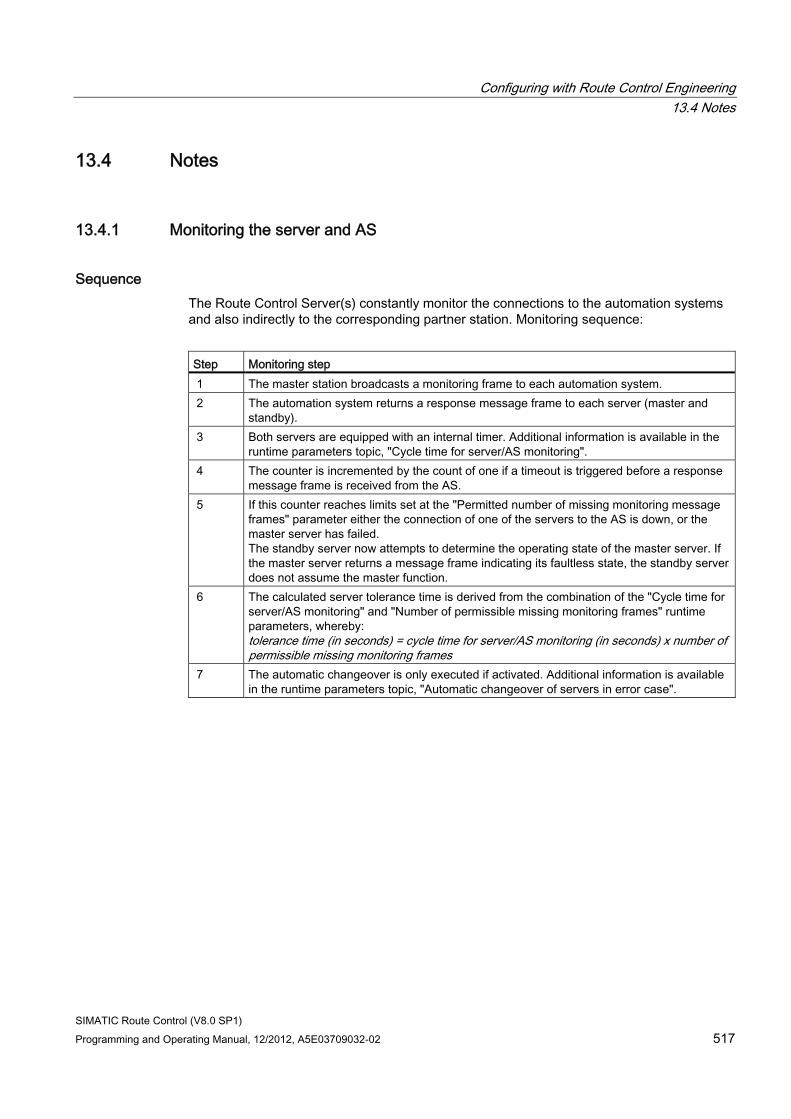
Configuring with Route Control Engineering 13.4 Notes
SIMATIC Route Control (V8.0 SP1) Programming and Operating Manual, 12/2012, A5E03709032-02 517
13.4 Notes
13.4.1 Monitoring the server and AS
Sequence The Route Control Server(s) constantly monitor the connections to the automation systems and also indirectly to the corresponding partner station. Monitoring sequence:
Step Monitoring step 1 The master station broadcasts a monitoring frame to each automation system. 2 The automation system returns a response message frame to each server (master and
standby). 3 Both servers are equipped with an internal timer. Additional information is available in the
runtime parameters topic, "Cycle time for server/AS monitoring". 4 The counter is incremented by the count of one if a timeout is triggered before a response
message frame is received from the AS. 5 If this counter reaches limits set at the "Permitted number of missing monitoring message
frames" parameter either the connection of one of the servers to the AS is down, or the master server has failed. The standby server now attempts to determine the operating state of the master server. If the master server returns a message frame indicating its faultless state, the standby server does not assume the master function.
6 The calculated server tolerance time is derived from the combination of the "Cycle time for server/AS monitoring" and "Number of permissible missing monitoring frames" runtime parameters, whereby: tolerance time (in seconds) = cycle time for server/AS monitoring (in seconds) x number of permissible missing monitoring frames
7 The automatic changeover is only executed if activated. Additional information is available in the runtime parameters topic, "Automatic changeover of servers in error case".
Configuring with Route Control Engineering 13.4 Notes
SIMATIC Route Control (V8.0 SP1) 518 Programming and Operating Manual, 12/2012, A5E03709032-02
13.4.2 Directory Sharing in the Route Log
Storage of the Route Log Files You can configure the directory in which the Route Control server stores the route log files as you wish.
Storage in the standard directory on the Route Control server If you do not configure a path, the Route Control server saves the log files locally.
Note
If you have a distributed system in which several computers access the route logs, the path to the route log must be configured; see below.
Storage in a Separate Directory on the Route Control Server If you want route log files to be stored on the Route Control server, you must specify the path as follows:
\\<computer name>\<share name>
The <computer name> is the name of the computer on which the Route Control server process is running.
The directory must be accessible for the Route Control server - read and write access - as well as the Route Control route log application - read access only (Windows user rights).
Storage in a Directory on Another Computer If you want route log files to be stored on a server other than the Route Control server, you must specify the path as follows:
\\<computer name>\<share name>
The <computer name> is the name of the other computer.
Note
If you want to access the log files using the route log application from another computer, you must ensure that the relevant directory is shared out on the computer on which the files are stored (Windows directory sharing). This applies to all three cases mentioned above.
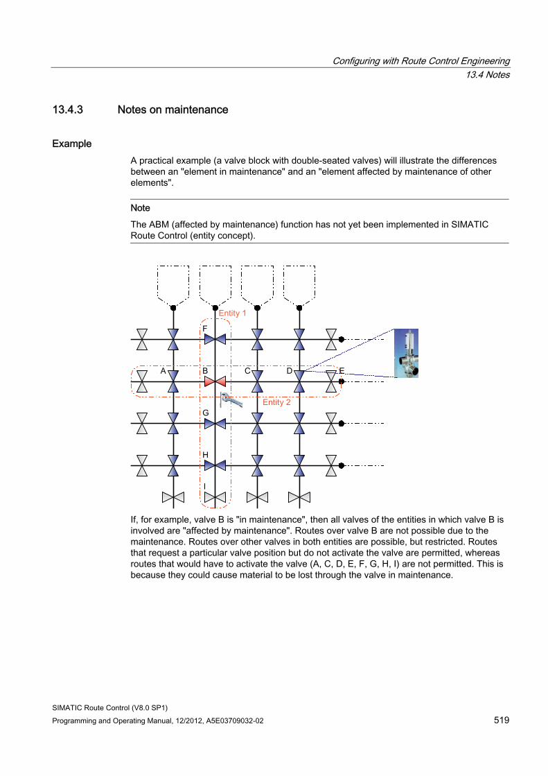
Configuring with Route Control Engineering 13.4 Notes
SIMATIC Route Control (V8.0 SP1) Programming and Operating Manual, 12/2012, A5E03709032-02 519
13.4.3 Notes on maintenance
Example A practical example (a valve block with double-seated valves) will illustrate the differences between an "element in maintenance" and an "element affected by maintenance of other elements".
Note
The ABM (affected by maintenance) function has not yet been implemented in SIMATIC Route Control (entity concept).
If, for example, valve B is "in maintenance", then all valves of the entities in which valve B is involved are "affected by maintenance". Routes over valve B are not possible due to the maintenance. Routes over other valves in both entities are possible, but restricted. Routes that request a particular valve position but do not activate the valve are permitted, whereas routes that would have to activate the valve (A, C, D, E, F, G, H, I) are not permitted. This is because they could cause material to be lost through the valve in maintenance.
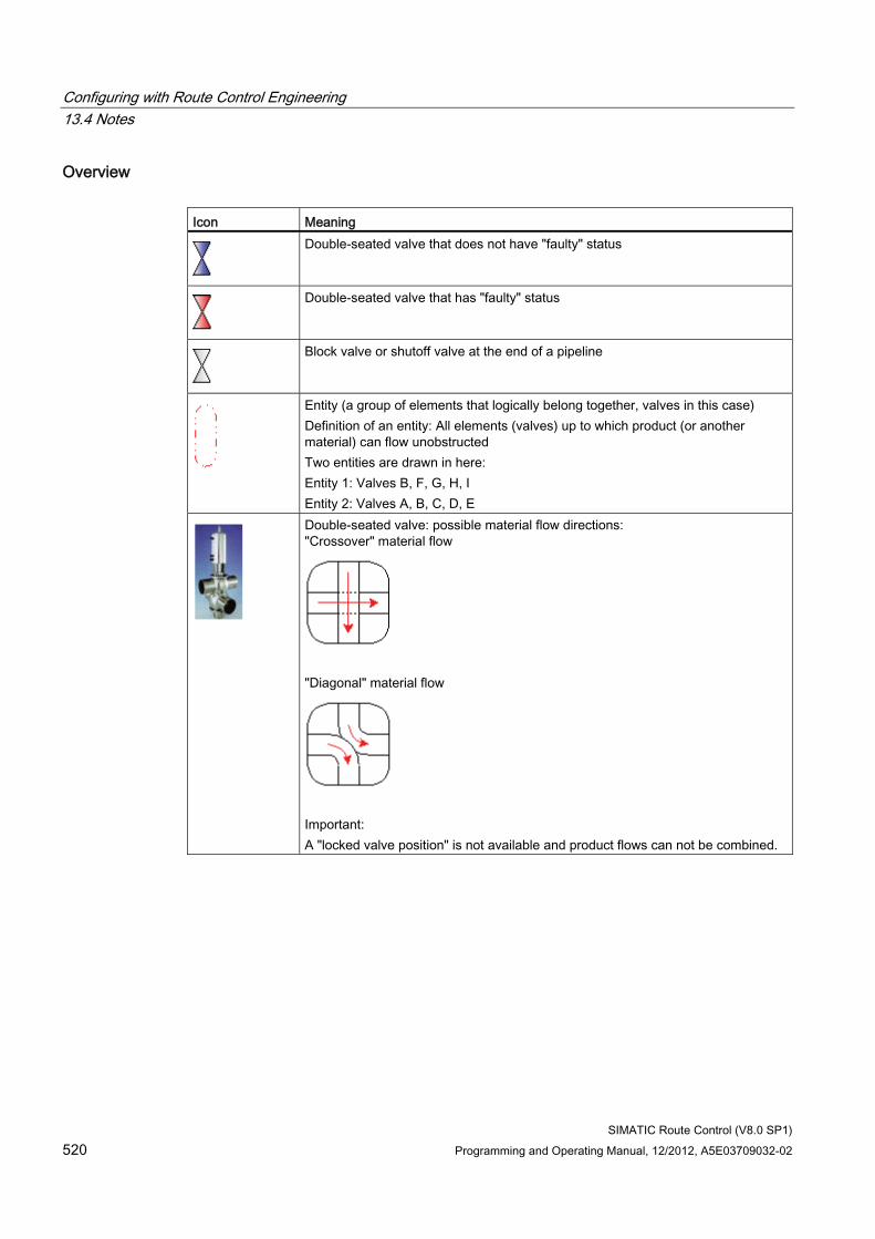
Configuring with Route Control Engineering 13.4 Notes
SIMATIC Route Control (V8.0 SP1) 520 Programming and Operating Manual, 12/2012, A5E03709032-02
Overview Icon Meaning
Double-seated valve that does not have "faulty" status
Double-seated valve that has "faulty" status
Block valve or shutoff valve at the end of a pipeline
Entity (a group of elements that logically belong together, valves in this case) Definition of an entity: All elements (valves) up to which product (or another material) can flow unobstructed Two entities are drawn in here: Entity 1: Valves B, F, G, H, I Entity 2: Valves A, B, C, D, E
Double-seated valve: possible material flow directions: "Crossover" material flow
"Diagonal" material flow
Important: A "locked valve position" is not available and product flows can not be combined.
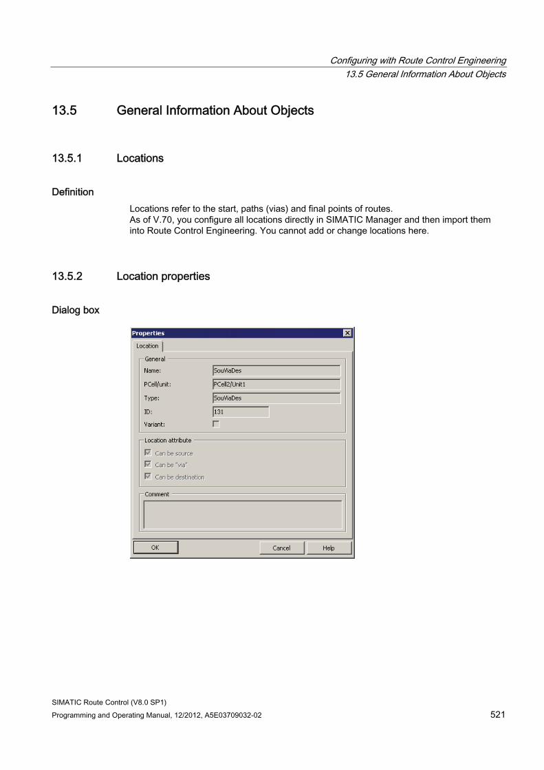
Configuring with Route Control Engineering 13.5 General Information About Objects
SIMATIC Route Control (V8.0 SP1) Programming and Operating Manual, 12/2012, A5E03709032-02 521
13.5 General Information About Objects
13.5.1 Locations
Definition Locations refer to the start, paths (vias) and final points of routes. As of V.70, you configure all locations directly in SIMATIC Manager and then import them into Route Control Engineering. You cannot add or change locations here.
13.5.2 Location properties
Dialog box
Configuring with Route Control Engineering 13.5 General Information About Objects
SIMATIC Route Control (V8.0 SP1) 522 Programming and Operating Manual, 12/2012, A5E03709032-02
Properties The "Properties" dialog box of a location in Route Control Engineering displays the following:
● Location name
● Process cell/unit to which this location is assigned
● Type of location
● Location ID that is unique throughout the project
The central area of the dialog box shows whether this location can be used as the source and/or destination location of a partial route or route or as the via location of a route.
13.5.3 Location type
Location type As of Version V7.0 you configure location types in SIMATIC Manager. You can neither enter nor change types in Route Control Engineering.
13.5.4 Partial routes You can find explanations of the partial route in the section "Partial routes and VIAs (Page 146)".
13.5.5 Routes You can find explanations of the routes in the section "Routes (Page 146)".
13.5.6 Predefined routes
Predefined routes This functionality is no longer a feature in SIMATIC Route Control V6 and higher.
Configuring with Route Control Engineering 13.5 General Information About Objects
SIMATIC Route Control (V8.0 SP1) Programming and Operating Manual, 12/2012, A5E03709032-02 523
13.5.7 Mode tables
Definition A mode table contains 32 mode levels. You can set up multiple mode tables with mode levels with varying names. Each partial route is assigned to a mode table.
During runtime, a route can only consist of partial routes from the same mode table.
13.5.8 Mode levels
Definition The mode levels are activated or deactivated by the user program that is connected upstream of the route. You can also activate or deactivate mode levels manually in the Route Control Center. The individual mode levels are independent of one another but can be activated and requested in parallel. Route Control controls the individual elements in partial routes in accordance with which mode levels are activated or deactivated. An element can be inserted in multiple mode levels with different modes of activation in a single partial route.
Example Thus, in the following example, the "Pump on" and "Destination container full?" mode levels can be activated at the same time.
● The "initial state" mode level checks that:
– All valves are closed
– The pump is disabled
– The source tank contains sufficient material
– The destination container has sufficient space available
● Mode level: "Open transport valves": The transport valves on the route are opened. The mode level is "achieved" once all elements have adopted their set position.
● Mode level "Pump on": The material transport pump is turned on.
● Mode level "Open source valve": The valve on the source tank is opened.
● Mode level "Destination container full?": The sensor on the destination container outputs a signal when the container is full. Its feedback is continuously evaluated by the routing system.
Configuring with Route Control Engineering 13.5 General Information About Objects
SIMATIC Route Control (V8.0 SP1) 524 Programming and Operating Manual, 12/2012, A5E03709032-02
13.5.9 Automatic generation of elements
Generating Elements
Note
The option to generate an entire range of elements has been removed from SIMATIC Route Control.
Up until version V5 (PCS 7 and BRAUMAT), the Route Control Wizard did not exist and there was thus no efficient way to transfer elements that had already been configured from CFC charts.
V6 now features the Route Control Wizard and is no longer based on BRAUMAT. This eliminated the need to generate elements on the Route Control project side. However, it did give rise to the risk of inconsistent data between the Route Control project and the S7 project.
The CSV interface for exporting and importing elements has been limited to ensure that inconsistent data can not be configured here either. You can find additional information in "CSV Interface Overview" (Page 465).
13.5.10 Creating Elements
Creating Elements As of V6, Route Control no longer supports the creation of control, sensor, parameter, link elements, or routes . For reasons of consistency, the elements are first inserted into CFC interface blocks (RC_IF_...) in the S7 project and then transferred to Route Control Engineering using the Route Control Wizard.
Configuring with Route Control Engineering 13.5 General Information About Objects
SIMATIC Route Control (V8.0 SP1) Programming and Operating Manual, 12/2012, A5E03709032-02 525
13.5.11 How to Delete Elements
Introduction You cannot delete imported elements from the upper area of Route Control Engineering. However, you can remove an element inserted in a partial route in the lower area from that partial route.
Procedure 1. In the tree structure on the bottom left, open the mode table that contains the partial route
from which you want to remove an element.
2. Select the partial route.
3. Select the "Elements" tab.
4. Select the element.
5. Press <DEL>. A prompt for confirmation appears.
6. Click "Yes". The element is removed from the list.
13.5.12 Element subtypes
Creating Element Types As of V6, Route Control no longer supports the creation of control, sensor, parameter, or link elements types. For reasons of consistency, subtypes are created in the S7 project as blocks with a specific ID and added to CFCs as instances. They are then transferred to Route Control Engineering using the Route Control Wizard.
You can find additional information in "Example of a User-Defined Type" (Page 242).
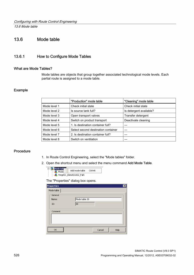
Configuring with Route Control Engineering 13.6 Mode table
SIMATIC Route Control (V8.0 SP1) 526 Programming and Operating Manual, 12/2012, A5E03709032-02
13.6 Mode table
13.6.1 How to Configure Mode Tables
What are Mode Tables? Mode tables are objects that group together associated technological mode levels. Each partial route is assigned to a mode table.
Example "Production" mode table "Cleaning" mode table Mode level 1 Check initial state Check initial state Mode level 2 Is source tank full? Is detergent available? Mode level 3 Open transport valves Transfer detergent Mode level 4 Switch on product transport Deactivate cleaning Mode level 5 1. Is destination container full? --- Mode level 6 Select second destination container --- Mode level 7 2. Is destination container full? --- Mode level 8 Switch on ventilation ---
Procedure 1. In Route Control Engineering, select the "Mode tables" folder.
2. Open the shortcut menu and select the menu command Add Mode Table.
The "Properties" dialog box opens.
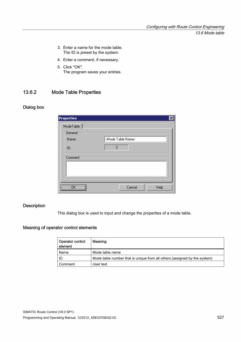
Configuring with Route Control Engineering 13.6 Mode table
SIMATIC Route Control (V8.0 SP1) Programming and Operating Manual, 12/2012, A5E03709032-02 527
3. Enter a name for the mode table. The ID is preset by the system.
4. Enter a comment, if necessary.
5. Click "OK". The program saves your entries.
13.6.2 Mode Table Properties
Dialog box
Description This dialog box is used to input and change the properties of a mode table.
Meaning of operator control elements Operator control element
Meaning
Name Mode table name ID Mode table number that is unique from all others (assigned by the system) Comment User text
Configuring with Route Control Engineering 13.7 Mode levels
SIMATIC Route Control (V8.0 SP1) 528 Programming and Operating Manual, 12/2012, A5E03709032-02
13.7 Mode levels
13.7.1 How to Configure Mode Levels
Introduction Mode levels are fine gradations used to control a route, that is, the elements of a route. In a technological process, it is not enough to merely enable a material transport and then terminate it after a certain period of time has elapsed or a particular quantity of products has been transported. Rather, the following conditions must be taken into account:
● Certain valves not directly located on the transport route must be closed to prevent the product from following an incorrect route.
● Elements such as manual valves, ventilators or similar are activated separately in response to conditions such as a temperature increase.
● During transport, the transport valves are opened first while the discharge valve on the source tank remains shut. This discharge valve is then opened and the pumped switched on only after the transport valves have attained their set position.
● Fill levels are scanned in the source and destination containers and, if necessary, the transport must be switched to other source and destination containers.
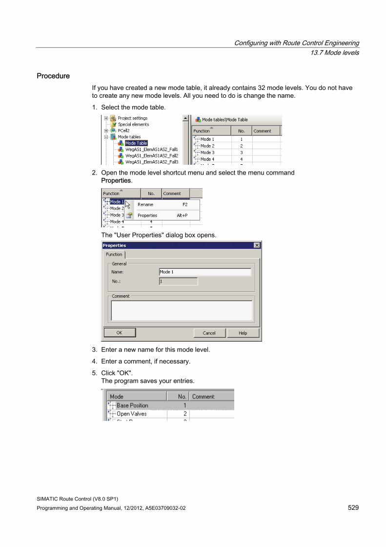
Configuring with Route Control Engineering 13.7 Mode levels
SIMATIC Route Control (V8.0 SP1) Programming and Operating Manual, 12/2012, A5E03709032-02 529
Procedure If you have created a new mode table, it already contains 32 mode levels. You do not have to create any new mode levels. All you need to do is change the name.
1. Select the mode table.
2. Open the mode level shortcut menu and select the menu command
Properties.
The "User Properties" dialog box opens.
3. Enter a new name for this mode level.
4. Enter a comment, if necessary.
5. Click "OK". The program saves your entries.
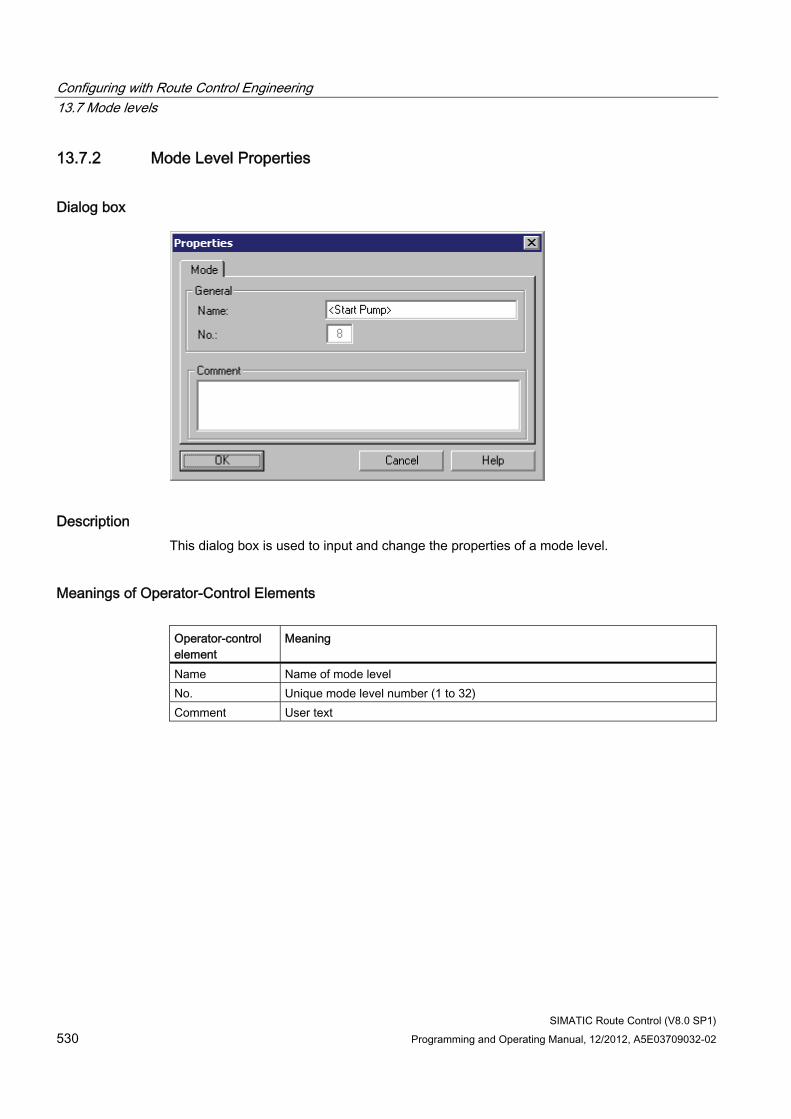
Configuring with Route Control Engineering 13.7 Mode levels
SIMATIC Route Control (V8.0 SP1) 530 Programming and Operating Manual, 12/2012, A5E03709032-02
13.7.2 Mode Level Properties
Dialog box
Description This dialog box is used to input and change the properties of a mode level.
Meanings of Operator-Control Elements Operator-control element
Meaning
Name Name of mode level No. Unique mode level number (1 to 32) Comment User text
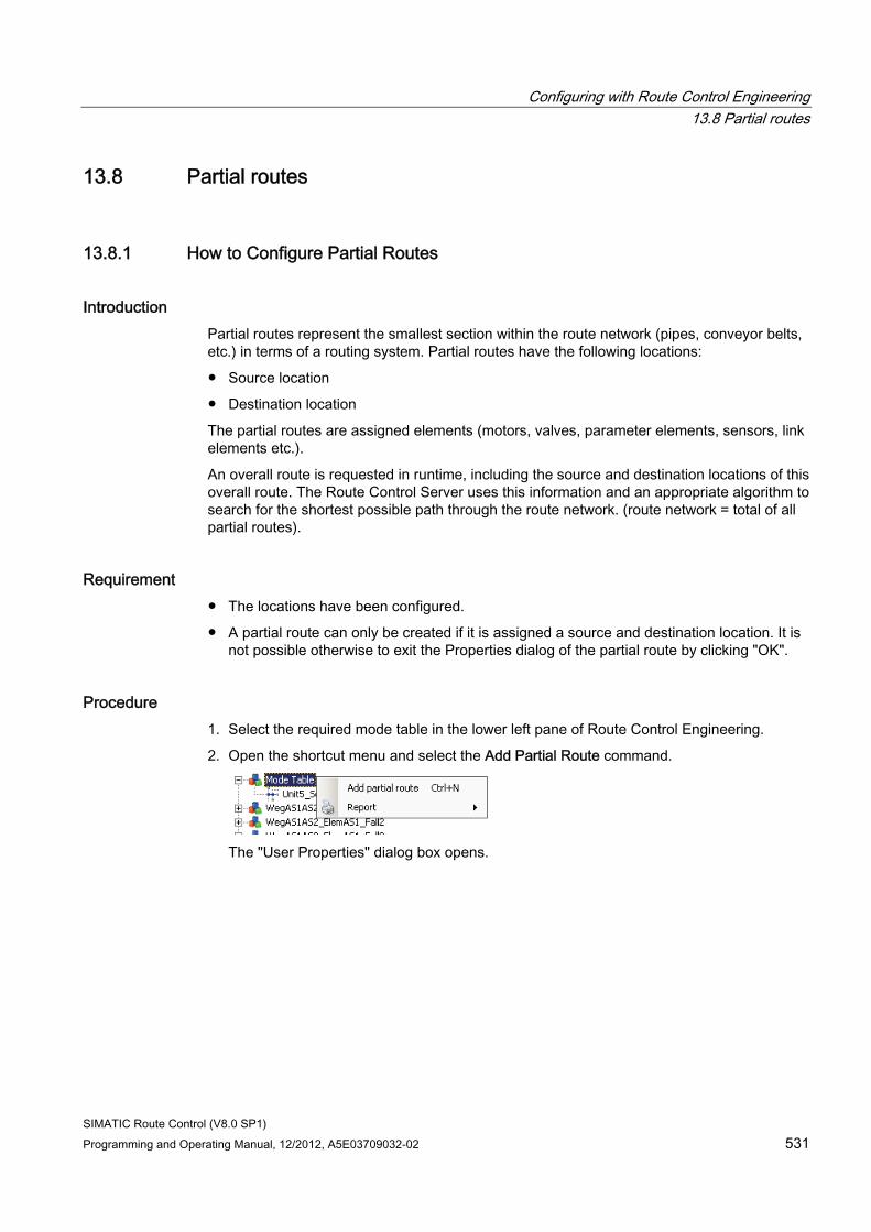
Configuring with Route Control Engineering 13.8 Partial routes
SIMATIC Route Control (V8.0 SP1) Programming and Operating Manual, 12/2012, A5E03709032-02 531
13.8 Partial routes
13.8.1 How to Configure Partial Routes
Introduction Partial routes represent the smallest section within the route network (pipes, conveyor belts, etc.) in terms of a routing system. Partial routes have the following locations:
● Source location
● Destination location
The partial routes are assigned elements (motors, valves, parameter elements, sensors, link elements etc.).
An overall route is requested in runtime, including the source and destination locations of this overall route. The Route Control Server uses this information and an appropriate algorithm to search for the shortest possible path through the route network. (route network = total of all partial routes).
Requirement ● The locations have been configured.
● A partial route can only be created if it is assigned a source and destination location. It is not possible otherwise to exit the Properties dialog of the partial route by clicking "OK".
Procedure 1. Select the required mode table in the lower left pane of Route Control Engineering.
2. Open the shortcut menu and select the Add Partial Route command.
The "User Properties" dialog box opens.
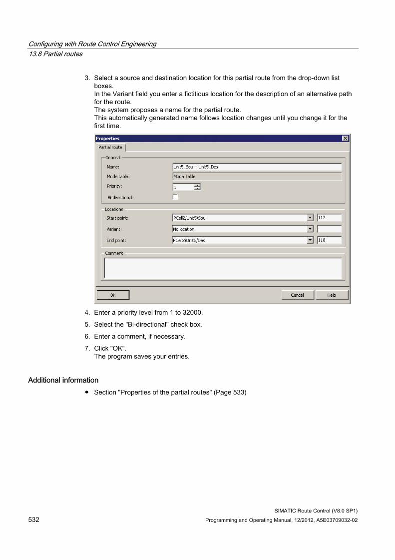
Configuring with Route Control Engineering 13.8 Partial routes
SIMATIC Route Control (V8.0 SP1) 532 Programming and Operating Manual, 12/2012, A5E03709032-02
3. Select a source and destination location for this partial route from the drop-down list boxes. In the Variant field you enter a fictitious location for the description of an alternative path for the route. The system proposes a name for the partial route. This automatically generated name follows location changes until you change it for the first time.
4. Enter a priority level from 1 to 32000.
5. Select the "Bi-directional" check box.
6. Enter a comment, if necessary.
7. Click "OK". The program saves your entries.
Additional information ● Section "Properties of the partial routes" (Page 533)
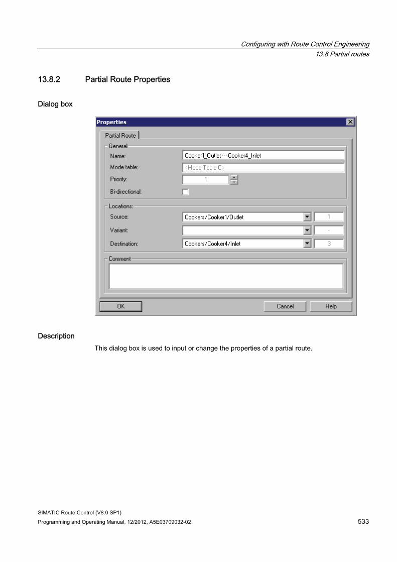
Configuring with Route Control Engineering 13.8 Partial routes
SIMATIC Route Control (V8.0 SP1) Programming and Operating Manual, 12/2012, A5E03709032-02 533
13.8.2 Partial Route Properties
Dialog box
Description This dialog box is used to input or change the properties of a partial route.
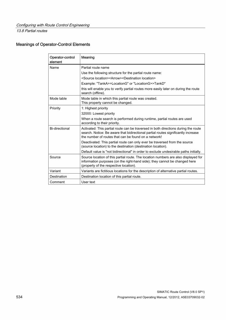
Configuring with Route Control Engineering 13.8 Partial routes
SIMATIC Route Control (V8.0 SP1) 534 Programming and Operating Manual, 12/2012, A5E03709032-02
Meanings of Operator-Control Elements Operator-control element
Meaning
Name Partial route name Use the following structure for the partial route name: <Source location><Arrow><Destination location> Example: "TankA>>LocationG" or "LocationG>>TankD" this will enable you to verify partial routes more easily later on during the route search (offline).
Mode table Mode table in which this partial route was created. This property cannot be changed.
Priority 1: Highest priority 32000: Lowest priority When a route search is performed during runtime, partial routes are used according to their priority.
Bi-directional Activated: This partial route can be traversed in both directions during the route search. Notice: Be aware that bidirectional partial routes significantly increase the number of routes that can be found on a network! Deactivated: This partial route can only ever be traversed from the source (source location) to the destination (destination location). Default value is "not bidirectional" in order to exclude undesirable paths initially.
Source Source location of this partial route. The location numbers are also displayed for information purposes (on the right-hand side); they cannot be changed here (property of the respective location).
Variant Variants are fictitious locations for the description of alternative partial routes. Destination Destination location of this partial route. Comment User text
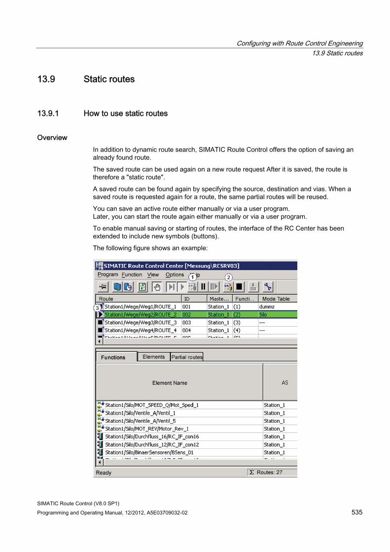
Configuring with Route Control Engineering 13.9 Static routes
SIMATIC Route Control (V8.0 SP1) Programming and Operating Manual, 12/2012, A5E03709032-02 535
13.9 Static routes
13.9.1 How to use static routes
Overview In addition to dynamic route search, SIMATIC Route Control offers the option of saving an already found route.
The saved route can be used again on a new route request After it is saved, the route is therefore a "static route".
A saved route can be found again by specifying the source, destination and vias. When a saved route is requested again for a route, the same partial routes will be reused.
You can save an active route either manually or via a user program. Later, you can start the route again either manually or via a user program.
To enable manual saving or starting of routes, the interface of the RC Center has been extended to include new symbols (buttons).
The following figure shows an example:
Configuring with Route Control Engineering 13.9 Static routes
SIMATIC Route Control (V8.0 SP1) 536 Programming and Operating Manual, 12/2012, A5E03709032-02
1
Start a saved route
2
Save the current route
3 Indicator showing that a saved route exists
Note Start a saved route
Note the following when starting saved routes:
The "Start Saved Route" button that can be used in manual mode in the Route Control Center is disabled if no route is stored for the selected source-via-destination combination. Therefore, you cannot start the route manually.
However, if the start of the saved route is performed automatically (0 -> 1 edge at IN_OUT parameter ONSR_AU) and there is no saved route, the RC server performs a normal search for a route. If a route is found in this way, this is also started, although it is actually not a "saved" route.
A small yellow triangle in the icon indicates whether a saved route exists for the currently stored combination of source, destination and via.
A saved route is requested and started via the route block FB800/RC_IF_ROUTE in the AS. The server takes the specified combination of source, destination and via from the route block as well as the other parameters at the start of the route (mode table, function ID…). It is determined whether a saved route exists for the combination of source, destination and via. If a route with this data is available, the server takes the partial routes saved for this route.
In the next step, a search is performed to determine whether the same partial routes exist for the mode table specified in the route request. This check is performed on the basis of the partial route name assigned by the user.
Note Partial routes
Partial routes are configured as components of mode tables. Partial routes with the same name are allowed to exist in different mode tables. In this case, it is assumed that a physical partial route with identical elements in different mode tables has been configured.
The route request of saved routes permits use of a saved route with different mode tables.
Configuring with Route Control Engineering 13.9 Static routes
SIMATIC Route Control (V8.0 SP1) Programming and Operating Manual, 12/2012, A5E03709032-02 537
The following errors can occur when saved routes are requested:
Cause of error Response Cannot find requested and allegedly saved route The usual route search is performed Partial routes of the requested saved route are not available for the specified mode table
Route request failed Error output
Elements of the partial routes of the requested saved route are disabled
Route request failed Error output
Static routes from the offline route search Routes that were found during the offline route search can be saved as static routes. The online saved static routes are deleted when the Route Control server is downloaded. The static routes stored offline are copied for online use when the Route Control server is downloaded and may be used again there.
Error/message outputs via WinCC ● Stat. route request start: "source" -> "destination"
● Route cannot be saved
● Cannot be saved: Route has incorrect status
● Route was saved
Configuring with Route Control Engineering 13.9 Static routes
SIMATIC Route Control (V8.0 SP1) 538 Programming and Operating Manual, 12/2012, A5E03709032-02
13.9.2 Save route
Preliminary remark You can save routes manually or automatically.
Saving a route manually If a route is in the status "running", you can save it by clicking "Save Current Route". If a route cannot be saved due to its status, the button will be disabled.
Saving a route again manually A route can only be saved once while it is running. A repetition of the operation is ignored as no new information can be saved. After stopping and restarting the route, clicking the button again results in the existing saved settings being overwritten.
Saving a route in automatic mode In automatic mode, an active route can be saved for later reuse by a 0->1 edge at the IN_OUT parameter SVRT_AU of the FB800/RC_IF_ROUTE. The route is identified on the basis of the combination of the parameters source, destination, via.
The route block sends a save request to the server. The route is only saved if the route has been started and is in the status "running". A route in error status cannot be saved.
Memory and distinguishing criteria The location IDs of source, destination and via (not symbolic names) are used as memory and distinguishing criteria. All the currently used partial routes and the mode table will be saved.
Saving a route with redundant servers The route to be saved is saved in the RouteControl database. If the process cell is part of a redundant configuration, which means both a Route Control master server and a standby server exist, the routes to be saved are transferred to the standby server by the master server. If the standby server is switched off or not available, the saved routes will not be found on the standby server. The routes have to be saved again as soon as the standby server is switched on and activated as the master.
Configuring with Route Control Engineering 13.9 Static routes
SIMATIC Route Control (V8.0 SP1) Programming and Operating Manual, 12/2012, A5E03709032-02 539
Server update The RC server stores this information in a database, which is deleted when the RC server is updated, which means there are no saved routes following a server update.
Exception:
A route is running and has been saved. If a server update is performed in this status, the route will still be saved in spite of the update.
Configuring with Route Control Engineering 13.9 Static routes
SIMATIC Route Control (V8.0 SP1) 540 Programming and Operating Manual, 12/2012, A5E03709032-02
13.9.3 Start a saved route
Preliminary remark You can start routes manually or automatically.
If there is no saved route available for the current combination of source, destination and via, a standard route search is performed as for "Set route start".
Start a saved route manually In manual mode you can start a saved route, evident by its icon (yellow triangle), via the "Start Saved Route" icon.
Start a saved route automatically In automatic mode, a saved route can be saved by a 0->1 edge at the IN_OUT parameter ONSR_AU.
The route is identified on the basis of the combination of the parameters source, destination, via. A started saved route is displayed at the QONSR output.
Configuring with Route Control Engineering 13.10 Elements
SIMATIC Route Control (V8.0 SP1) Programming and Operating Manual, 12/2012, A5E03709032-02 541
13.10 Elements
13.10.1 How to Insert an Element in a Partial Route
Procedure To insert an element in a partial route, proceed as follows:
1. Select the element from the list in the upper area of Route Control Engineering and drag-and-drop it to the partial route in the lower area. A dialog box opens.
2. Set the element properties:
– Mode level in which the element is to be inserted/activated/requested
– Activation value, for example, Switch on motor, Close valve, etc.
– Passive usage: The element is only polled but not activated in this mode level.
– Monitor idle state: The element is still monitored to ensure it retains the required position if the mode level is deactivated.
– Pulse time on/off: Duration of the on and off signals, in seconds
– Delay time on/off: Duration of the on and off signals, in seconds Elements can be switched on or off with a delay relative to activation or deactivation of their mode level (for example, motor coasting; valves with delayed closing).
3. Click "OK". The element is assigned to the partial route along with the programmed properties. If you click "Cancel", no element is inserted.
Additional information You can then program the other instances of element activation in other mode levels on the "Modes" tab in Route Control Engineering. You can find information on this in the section "How to Program the Activation of Elements". (Page 542)
Configuring with Route Control Engineering 13.10 Elements
SIMATIC Route Control (V8.0 SP1) 542 Programming and Operating Manual, 12/2012, A5E03709032-02
13.10.2 How to Configure Activation of Elements
Introduction You configure the activation of an element in a mode level when the element is inserted in a partial route. You can then configure the activation of elements in other mode levels on the Route Control Engineering "Modes" tab, without having to open the "User Properties" dialog box each time.
Procedure 1. In Route Control Engineering, select the partial route whose elements you want to
configure.
2. Select the "Modes" tab.
3. Use the left mouse button to click an element row, in the column for the required mode level. The drop-down list containing the icons for the activation keys opens.
4. Select the desired entry from the drop-down list. The selected icon is added to the list.
Note
If the type of activation selected requires further configuration, the "Properties" dialog box opens automatically. Change the configuration here.
Configuring with Route Control Engineering 13.10 Elements
SIMATIC Route Control (V8.0 SP1) Programming and Operating Manual, 12/2012, A5E03709032-02 543
How to Change an Activation To change the activation of an element in a mode level, proceed as follows:
1. Open the shortcut menu in the column of the element mode level that has already been configured and select the menu command "Properties". The "Properties" dialog box opens.
2. Change the configuration here.
3. Click "OK". The program saves your entries. The icon for the activation type is adapted automatically.
Note
If you no longer want to activate an element in a certain mode level, use the left mouse button to open the drop-down list and select the blank icon here.
Note
You must download the server again whenever you make a change to the configuration!You can find information about this in "Downloading the Route Control Server" (Page 602).
Additional information ● Section "Meanings of Activation Key Icons" (Page 544)
● Section "How to Change the Activation Key Icons" (Page 545)
● Section "How to Create User Keys" (Page 546)
● Section "How to Delete User Keys" (Page 548)

Configuring with Route Control Engineering 13.10 Elements
SIMATIC Route Control (V8.0 SP1) 544 Programming and Operating Manual, 12/2012, A5E03709032-02
13.10.3 Meanings of Activation Key Symbols
Introduction If a partial route is selected, the "Modes" tab in the lower section of the Route Control Engineering window shows how an element is used in the different mode levels, for example, whether it is actively controlled or passively requested.
Activation Keys and Symbols The way in which an element is activated in the different mode levels is shown with activation keys.
An activation key consists of a symbol or a combination of symbols.
Meanings of Symbols The following table shows the symbols with their default factory settings.
Symbol Meaning a The element will be activated. d The element will be deactivated. ? The actual position of the element will be requested (checked). p The element is activated in pulse mode.
A pulse time is configured in the element properties. 1 The element is activated with a switch-on delay.
A switch-on delay time is configured in the element properties. 2 The element is activated with a switch-off delay.
A switch-off delay time is configured in the element properties. 3 The element is activated with a switch-on and a switch-off delay.
A switch-on delay and a switch-off delay are configured in the element properties. - The idle state position is monitored.
When the mode level is deactivated, monitoring will be performed to determine whether the element is also switched off (motor) or closed (valve).
You can change these symbols. You can also create your own user keys.
Additional information ● Section "How to Change the Activation Key Symbols" (Page 545)
● Section "How to Create User Keys" (Page 546)
● Section "How to Delete User Keys" (Page 548)
Configuring with Route Control Engineering 13.10 Elements
SIMATIC Route Control (V8.0 SP1) Programming and Operating Manual, 12/2012, A5E03709032-02 545
13.10.4 How to Change the Activation Key Symbols
Procedure 1. In Route Control Engineering, select the menu command Options > Symbols.
The "Key symbols" dialog box opens.
2. Change the symbols in the entry fields.
3. Click "OK". The program saves your entries.
Note
You must download the server again whenever you make a change to the configuration!You can find information about this in "Downloading the Route Control Server" (Page 602).
Additional information ● Section "Meanings of Activation Key Symbols" (Page 544)
● Section "How to Create User Keys" (Page 546)
● Section "How to Delete User Keys" (Page 548)
Configuring with Route Control Engineering 13.10 Elements
SIMATIC Route Control (V8.0 SP1) 546 Programming and Operating Manual, 12/2012, A5E03709032-02
13.10.5 How to Create User Keys
Introduction To simplify configuration, you can replace activation keys, which consist of more than one icon, with simple user keys.
Definition A user key is a complicated activation key to which you have assigned a specific name.
The key is configured once and is then used like a symbol for each additional configuration.
A user key is assigned to a type and can only be assigned to elements which correspond to this type. In other words, a key defined for a MOTOR cannot be assigned to a VALVE. The function view only shows keys to the assignment that correspond to the current element type.
Only one key may exist for a given combination of properties. When a key is deleted, the system search for this key throughout all installation locations (partial routes) and replaces it with the default key. When a key is redefined for a combination of properties, the new key is transferred to all installation locations that comply with this combination.
Procedure There are two ways to create a user key:
● By interconnecting elements in partial routes
● By using the menu command "Options" -> "User Keys" -> "New"
1. In Route Control Engineering, with a partial route selected, select the "Modes" tab.
2. Use the left mouse button to click an element row in the column for a mode level. The dropdown list opens with the symbols of the control key.
3. Select "p..." in the drop-down list. The "Properties" dialog box opens.
4. Configure the activation of the element.
Note
If there is already a user key for selected parameter combination, its name is displayed. This cannot be changed at this location. However, if you choose a new combination, you can also define a new name and thus a new user key.
5. Enter the name of the new user key.
6. Click "OK". The program saves your entries.
Configuring with Route Control Engineering 13.10 Elements
SIMATIC Route Control (V8.0 SP1) Programming and Operating Manual, 12/2012, A5E03709032-02 547
"Options" menu command
1. In Route Control Engineering, select the menu command Options > User Keys.
The "User keys" dialog box opens. All available user keys are displayed.
2. Click "New".
The dialog box for configuring a user key opens. Select the desired CE type, the control, etc., and specify a new name. If the chosen name already exists, you must correct your entry. It is also not possible to assign different names to the same parameter combination.
3. Click "OK".
The new user key is displayed as a new row in the table.
4. Click "Close" to exit the dialog.
Note
Download the server again after each change to the configuration. You can find information about this in the section "Downloading the Route Control Server" (Page 602)
Result The new key is available in the drop-down list as an additional icon, with the specified properties.
Additional information ● Section "How to Delete User Keys" (Page 548)
Configuring with Route Control Engineering 13.10 Elements
SIMATIC Route Control (V8.0 SP1) 548 Programming and Operating Manual, 12/2012, A5E03709032-02
13.10.6 How to Delete User Keys
Procedure 1. In Route Control Engineering, select the menu command Options > User Keys.
The "User Keys" dialog box opens. All existing user keys are displayed.
2. Select a row in the list and click the "OK". If you want to delete all user keys, click the "Delete All" button. The confirmation dialog box opens.
3. Click "Yes". The selected keys are deleted.
Note
Although a key may still be in use, it can nevertheless be deleted. A dialog box shows you the partial routes in which the key is still used. If you delete the key anyway, the default key combinations are entered at all locations of this key.
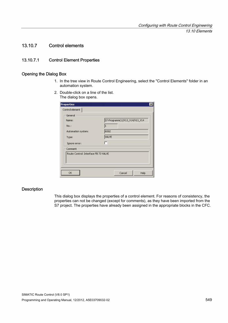
Configuring with Route Control Engineering 13.10 Elements
SIMATIC Route Control (V8.0 SP1) Programming and Operating Manual, 12/2012, A5E03709032-02 549
13.10.7 Control elements
13.10.7.1 Control Element Properties
Opening the Dialog Box 1. In the tree view in Route Control Engineering, select the "Control Elements" folder in an
automation system.
2. Double-click on a line of the list. The dialog box opens.
Description This dialog box displays the properties of a control element. For reasons of consistency, the properties can not be changed (except for comments), as they have been imported from the S7 project. The properties have already been assigned in the appropriate blocks in the CFC.
Configuring with Route Control Engineering 13.10 Elements
SIMATIC Route Control (V8.0 SP1) 550 Programming and Operating Manual, 12/2012, A5E03709032-02
Meanings of Fields Field Meaning Name Control element name No. Control element number that is unique from all others Automation system Name of automation system to which the control element is assigned
through configuration Type Type of element Ignore error Deactivated: Control element feedback error results in a mode-level error.
Activated: Control element feedback error does not result in a mode-level error.
Comment User text
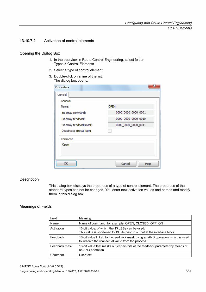
Configuring with Route Control Engineering 13.10 Elements
SIMATIC Route Control (V8.0 SP1) Programming and Operating Manual, 12/2012, A5E03709032-02 551
13.10.7.2 Activation of control elements
Opening the Dialog Box 1. In the tree view in Route Control Engineering, select folder
Types > Control Elements.
2. Select a type of control element.
3. Double-click on a line of the list. The dialog box opens.
Description This dialog box displays the properties of a type of control element. The properties of the standard types can not be changed. You enter new activation values and names and modify them in this dialog box.
Meanings of Fields Field Meaning Name Name of command, for example, OPEN, CLOSED, OFF, ON Activation 16-bit value, of which the 13 LSBs can be used.
This value is shortened to 13 bits prior to output at the interface block. Feedback 16-bit value linked to the feedback mask using an AND operation, which is used
to indicate the real actual value from the process Feedback mask 16-bit value that masks out certain bits of the feedback parameter by means of
an AND operation Comment User text
Configuring with Route Control Engineering 13.10 Elements
SIMATIC Route Control (V8.0 SP1) 552 Programming and Operating Manual, 12/2012, A5E03709032-02
Display language of the control commands and feedback texts If the control commands for control elements or the feedback texts for sensor elements are not displayed in the language you set, proceed as follows:
1. Close Route Control Engineering.
2. Switch to a different language in SIMATIC Manager.
3. Start and close Route Control Engineering.
4. Set the required language again in SIMATIC Manager.
5. Immediately after, start Route Control Engineering.
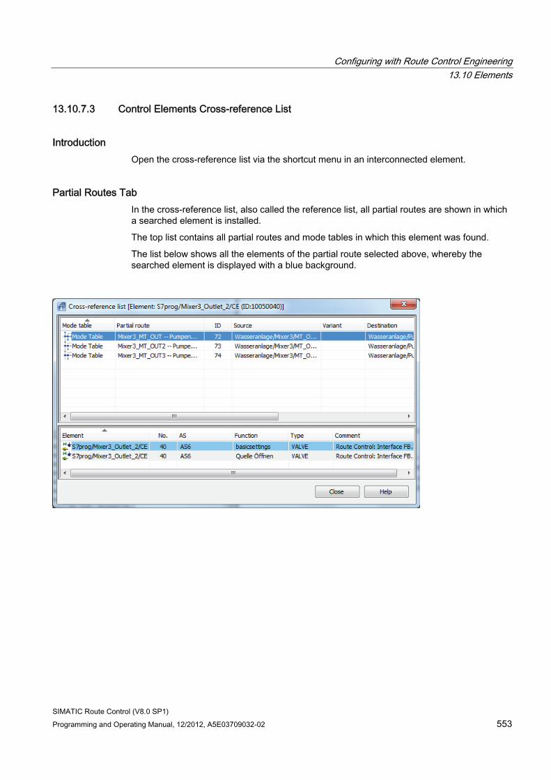
Configuring with Route Control Engineering 13.10 Elements
SIMATIC Route Control (V8.0 SP1) Programming and Operating Manual, 12/2012, A5E03709032-02 553
13.10.7.3 Control Elements Cross-reference List
Introduction Open the cross-reference list via the shortcut menu in an interconnected element.
Partial Routes Tab In the cross-reference list, also called the reference list, all partial routes are shown in which a searched element is installed.
The top list contains all partial routes and mode tables in which this element was found.
The list below shows all the elements of the partial route selected above, whereby the searched element is displayed with a blue background.
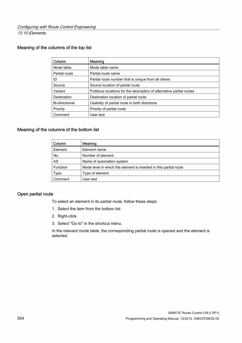
Configuring with Route Control Engineering 13.10 Elements
SIMATIC Route Control (V8.0 SP1) 554 Programming and Operating Manual, 12/2012, A5E03709032-02
Meaning of the columns of the top list Column Meaning Mode table Mode table name Partial route Partial route name ID Partial route number that is unique from all others Source Source location of partial route Variant Fictitious locations for the description of alternative partial routes Destination Destination location of partial route Bi-directional Usability of partial route in both directions Priority Priority of partial route Comment User text
Meaning of the columns of the bottom list Column Meaning Element Element name No. Number of element AS Name of automation system Function Mode level in which the element is inserted in this partial route Type Type of element Comment User text
Open partial route To select an element in its partial route, follow these steps:
1. Select the item from the bottom list.
2. Right-click.
3. Select "Go to" in the shortcut menu.
In the relevant mode table, the corresponding partial route is opened and the element is selected.
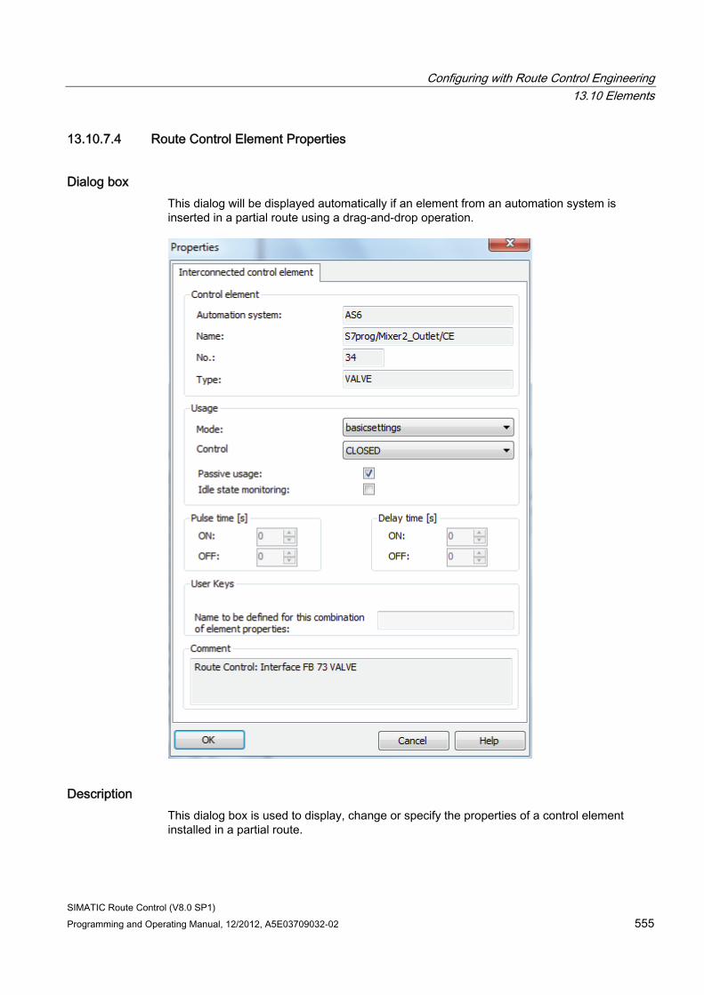
Configuring with Route Control Engineering 13.10 Elements
SIMATIC Route Control (V8.0 SP1) Programming and Operating Manual, 12/2012, A5E03709032-02 555
13.10.7.4 Route Control Element Properties
Dialog box This dialog will be displayed automatically if an element from an automation system is inserted in a partial route using a drag-and-drop operation.
Description This dialog box is used to display, change or specify the properties of a control element installed in a partial route.
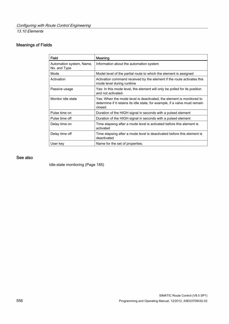
Configuring with Route Control Engineering 13.10 Elements
SIMATIC Route Control (V8.0 SP1) 556 Programming and Operating Manual, 12/2012, A5E03709032-02
Meanings of Fields Field Meaning Automation system, Name, No. and Type
Information about the automation system
Mode Model level of the partial route to which the element is assigned Activation Activation command received by the element if the route activates this
mode level during runtime Passive usage Yes: In this mode level, the element will only be polled for its position
and not activated. Monitor idle state Yes: When the mode level is deactivated, the element is monitored to
determine if it retains its idle state; for example, if a valve must remain closed.
Pulse time on Duration of the HIGH signal in seconds with a pulsed element Pulse time off Duration of the HIGH signal in seconds with a pulsed element Delay time on Time elapsing after a mode level is activated before this element is
activated Delay time off Time elapsing after a mode level is deactivated before this element is
deactivated User key Name for the set of properties.
See also Idle-state monitoring (Page 185)
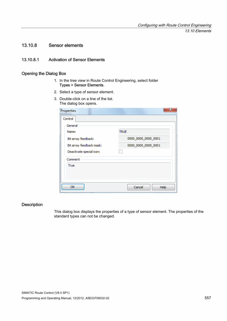
Configuring with Route Control Engineering 13.10 Elements
SIMATIC Route Control (V8.0 SP1) Programming and Operating Manual, 12/2012, A5E03709032-02 557
13.10.8 Sensor elements
13.10.8.1 Activation of Sensor Elements
Opening the Dialog Box 1. In the tree view in Route Control Engineering, select folder
Types > Sensor Elements.
2. Select a type of sensor element.
3. Double-click on a line of the list. The dialog box opens.
Description This dialog box displays the properties of a type of sensor element. The properties of the standard types can not be changed.
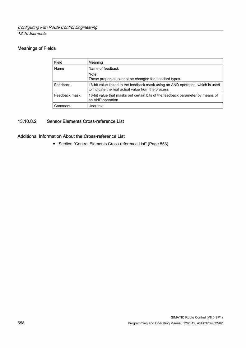
Configuring with Route Control Engineering 13.10 Elements
SIMATIC Route Control (V8.0 SP1) 558 Programming and Operating Manual, 12/2012, A5E03709032-02
Meanings of Fields Field Meaning Name Name of feedback
Note: These properties cannot be changed for standard types.
Feedback 16-bit value linked to the feedback mask using an AND operation, which is used to indicate the real actual value from the process
Feedback mask 16-bit value that masks out certain bits of the feedback parameter by means of an AND operation
Comment User text
13.10.8.2 Sensor Elements Cross-reference List
Additional Information About the Cross-reference List ● Section "Control Elements Cross-reference List" (Page 553)
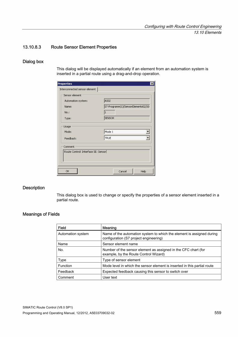
Configuring with Route Control Engineering 13.10 Elements
SIMATIC Route Control (V8.0 SP1) Programming and Operating Manual, 12/2012, A5E03709032-02 559
13.10.8.3 Route Sensor Element Properties
Dialog box This dialog will be displayed automatically if an element from an automation system is inserted in a partial route using a drag-and-drop operation.
Description This dialog box is used to change or specify the properties of a sensor element inserted in a partial route.
Meanings of Fields Field Meaning Automation system Name of the automation system to which the element is assigned during
configuration (S7 project engineering) Name Sensor element name No. Number of the sensor element as assigned in the CFC chart (for
example, by the Route Control Wizard) Type Type of sensor element Function Mode level in which the sensor element is inserted in this partial route Feedback Expected feedback causing this sensor to switch over Comment User text
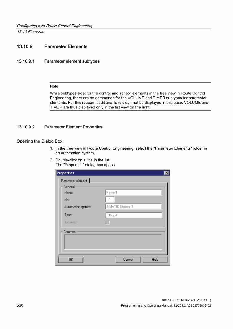
Configuring with Route Control Engineering 13.10 Elements
SIMATIC Route Control (V8.0 SP1) 560 Programming and Operating Manual, 12/2012, A5E03709032-02
13.10.9 Parameter Elements
13.10.9.1 Parameter element subtypes
Note
While subtypes exist for the control and sensor elements in the tree view in Route Control Engineering, there are no commands for the VOLUME and TIMER subtypes for parameter elements. For this reason, additional levels can not be displayed in this case. VOLUME and TIMER are thus displayed only in the list view on the right.
13.10.9.2 Parameter Element Properties
Opening the Dialog Box 1. In the tree view in Route Control Engineering, select the "Parameter Elements" folder in
an automation system.
2. Double-click on a line in the list. The "Properties" dialog box opens.
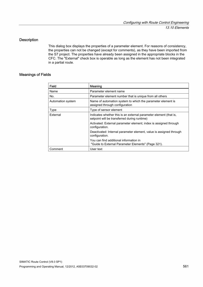
Configuring with Route Control Engineering 13.10 Elements
SIMATIC Route Control (V8.0 SP1) Programming and Operating Manual, 12/2012, A5E03709032-02 561
Description This dialog box displays the properties of a parameter element. For reasons of consistency, the properties can not be changed (except for comments), as they have been imported from the S7 project. The properties have already been assigned in the appropriate blocks in the CFC. The "External" check box is operable as long as the element has not been integrated in a partial route.
Meanings of Fields Field Meaning Name Parameter element name No. Parameter element number that is unique from all others Automation system Name of automation system to which the parameter element is
assigned through configuration Type Type of sensor element External Indicates whether this is an external parameter element (that is,
setpoint will be transferred during runtime) Activated: External parameter element; index is assigned through configuration. Deactivated: Internal parameter element, value is assigned through configuration. You can find additional information in "Guide to External Parameter Elements" (Page 321).
Comment User text
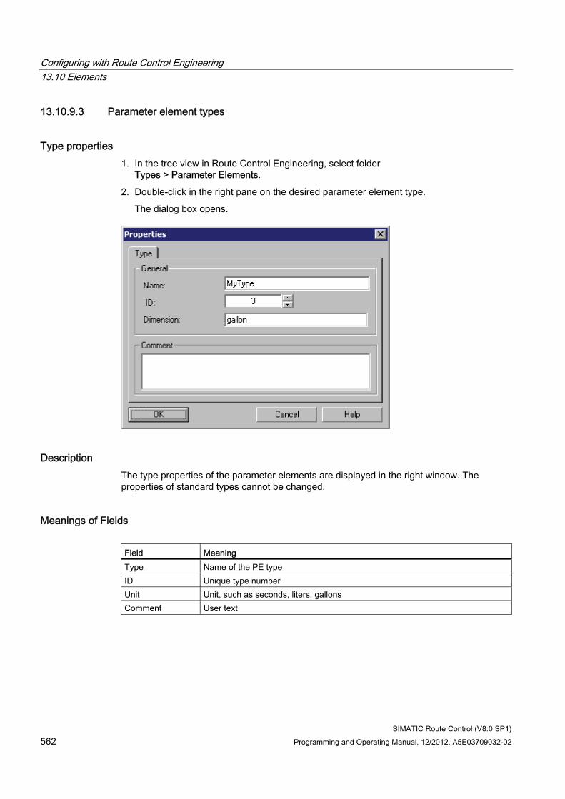
Configuring with Route Control Engineering 13.10 Elements
SIMATIC Route Control (V8.0 SP1) 562 Programming and Operating Manual, 12/2012, A5E03709032-02
13.10.9.3 Parameter element types
Type properties 1. In the tree view in Route Control Engineering, select folder
Types > Parameter Elements.
2. Double-click in the right pane on the desired parameter element type.
The dialog box opens.
Description The type properties of the parameter elements are displayed in the right window. The properties of standard types cannot be changed.
Meanings of Fields Field Meaning Type Name of the PE type ID Unique type number Unit Unit, such as seconds, liters, gallons Comment User text
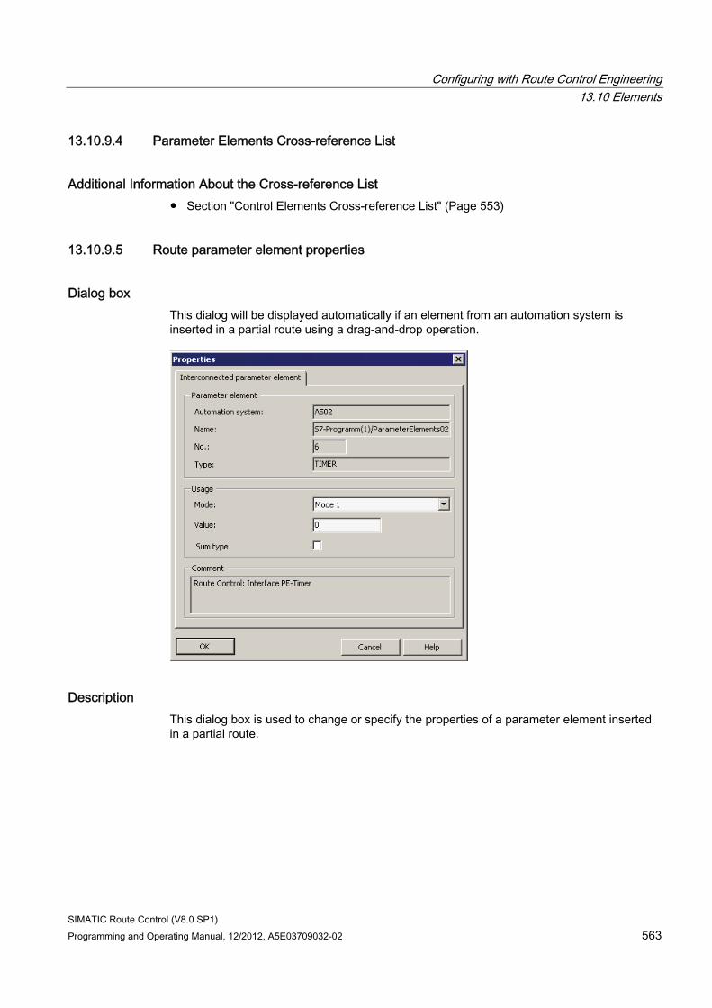
Configuring with Route Control Engineering 13.10 Elements
SIMATIC Route Control (V8.0 SP1) Programming and Operating Manual, 12/2012, A5E03709032-02 563
13.10.9.4 Parameter Elements Cross-reference List
Additional Information About the Cross-reference List ● Section "Control Elements Cross-reference List" (Page 553)
13.10.9.5 Route parameter element properties
Dialog box This dialog will be displayed automatically if an element from an automation system is inserted in a partial route using a drag-and-drop operation.
Description This dialog box is used to change or specify the properties of a parameter element inserted in a partial route.
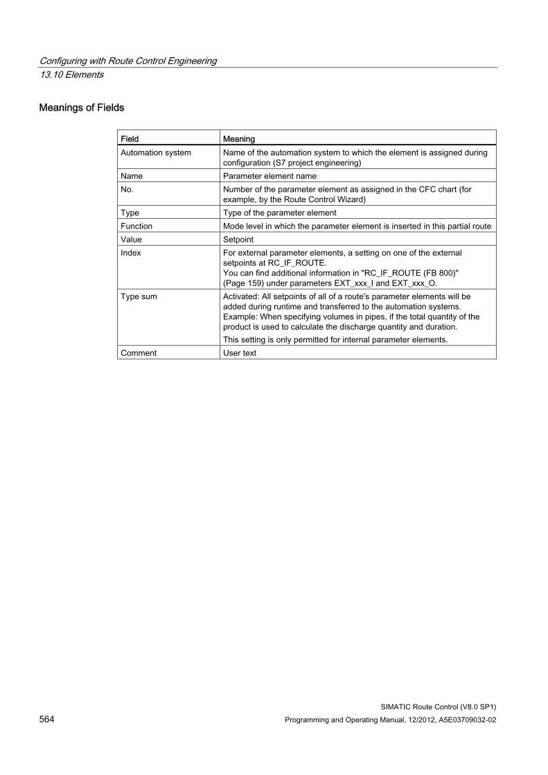
Configuring with Route Control Engineering 13.10 Elements
SIMATIC Route Control (V8.0 SP1) 564 Programming and Operating Manual, 12/2012, A5E03709032-02
Meanings of Fields Field Meaning Automation system Name of the automation system to which the element is assigned during
configuration (S7 project engineering) Name Parameter element name No. Number of the parameter element as assigned in the CFC chart (for
example, by the Route Control Wizard) Type Type of the parameter element Function Mode level in which the parameter element is inserted in this partial route Value Setpoint Index For external parameter elements, a setting on one of the external
setpoints at RC_IF_ROUTE. You can find additional information in "RC_IF_ROUTE (FB 800)" (Page 159) under parameters EXT_xxx_I and EXT_xxx_O.
Type sum Activated: All setpoints of all of a route's parameter elements will be added during runtime and transferred to the automation systems. Example: When specifying volumes in pipes, if the total quantity of the product is used to calculate the discharge quantity and duration. This setting is only permitted for internal parameter elements.
Comment User text
Configuring with Route Control Engineering 13.10 Elements
SIMATIC Route Control (V8.0 SP1) Programming and Operating Manual, 12/2012, A5E03709032-02 565
13.10.10 Link elements
13.10.10.1 Properties of link elements and route connection elements
Link element A link element includes information on which material is used for a partial route.
If a connection element is installed in a partial route, we refer to it as a route connection element.
Route control checks if a specific material is permitted to follow a preceding material based on the material configuration and the information stored in the route connection element.
13.10.10.2 Link Elements Cross-reference List
Additional Information About the Cross-reference List ● Section "Control Elements Cross-reference List" (Page 553)
13.10.11 Wait elements
13.10.11.1 Wait element
Overview The following functions can be performed by inserting wait elements in partial routes/routes.
● Activation sequence
An activation sequence regulates the activation of the actuators of a mode.
● Deactivation sequence
A deactivation sequence regulates the deactivation of elements.
● Single pulsing
With a single pulsing, the element is activated once in active mode for the duration of the pulse time.
Wait elements form a separate element type and are not assigned to a plant or automation system. You have no interface block that must be installed in CFC charts.
The wait element is always available and you can insert it in any partial routes for functions.
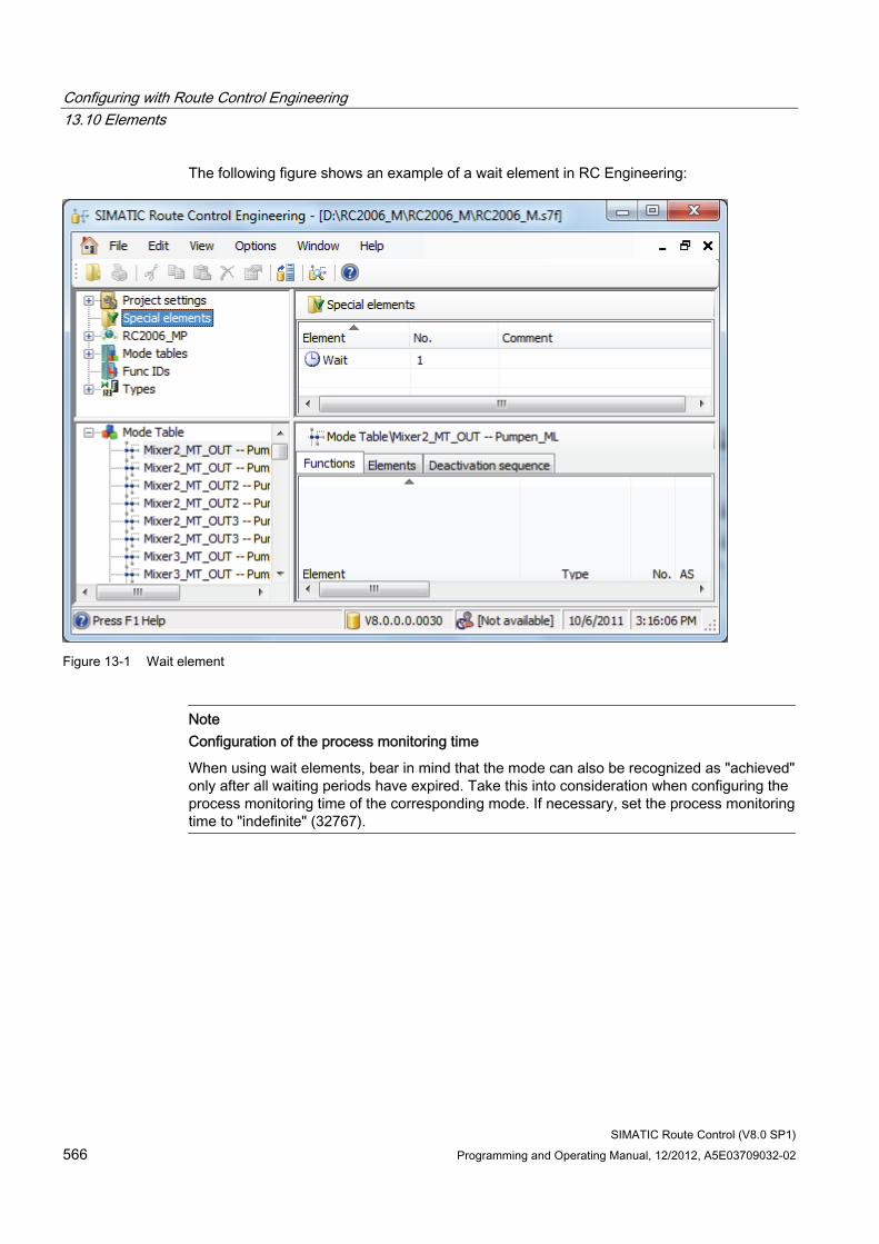
Configuring with Route Control Engineering 13.10 Elements
SIMATIC Route Control (V8.0 SP1) 566 Programming and Operating Manual, 12/2012, A5E03709032-02
The following figure shows an example of a wait element in RC Engineering:
Figure 13-1 Wait element
Note Configuration of the process monitoring time
When using wait elements, bear in mind that the mode can also be recognized as "achieved" only after all waiting periods have expired. Take this into consideration when configuring the process monitoring time of the corresponding mode. If necessary, set the process monitoring time to "indefinite" (32767).
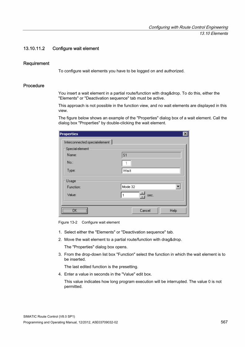
Configuring with Route Control Engineering 13.10 Elements
SIMATIC Route Control (V8.0 SP1) Programming and Operating Manual, 12/2012, A5E03709032-02 567
13.10.11.2 Configure wait element
Requirement To configure wait elements you have to be logged on and authorized.
Procedure You insert a wait element in a partial route/function with drag&drop. To do this, either the "Elements" or "Deactivation sequence" tab must be active.
This approach is not possible in the function view, and no wait elements are displayed in this view.
The figure below shows an example of the "Properties" dialog box of a wait element. Call the dialog box "Properties" by double-clicking the wait element.
Figure 13-2 Configure wait element
1. Select either the "Elements" or "Deactivation sequence" tab.
2. Move the wait element to a partial route/function with drag&drop.
The "Properties" dialog box opens.
3. From the drop-down list box "Function" select the function in which the wait element is to be inserted.
The last edited function is the presetting.
4. Enter a value in seconds in the "Value" edit box.
This value indicates how long program execution will be interrupted. The value 0 is not permitted.
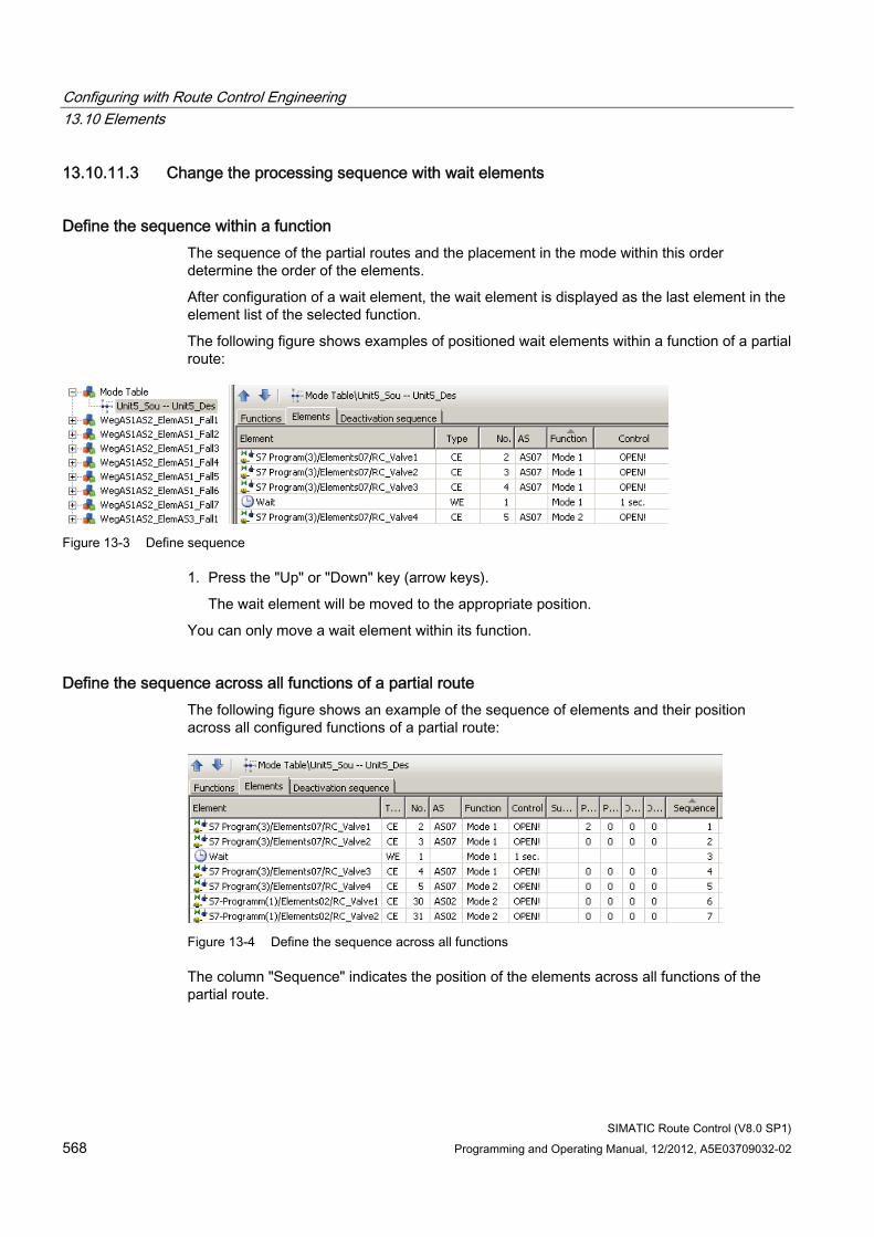
Configuring with Route Control Engineering 13.10 Elements
SIMATIC Route Control (V8.0 SP1) 568 Programming and Operating Manual, 12/2012, A5E03709032-02
13.10.11.3 Change the processing sequence with wait elements
Define the sequence within a function The sequence of the partial routes and the placement in the mode within this order determine the order of the elements.
After configuration of a wait element, the wait element is displayed as the last element in the element list of the selected function.
The following figure shows examples of positioned wait elements within a function of a partial route:
Figure 13-3 Define sequence
1. Press the "Up" or "Down" key (arrow keys).
The wait element will be moved to the appropriate position.
You can only move a wait element within its function.
Define the sequence across all functions of a partial route The following figure shows an example of the sequence of elements and their position across all configured functions of a partial route:
Figure 13-4 Define the sequence across all functions
The column "Sequence" indicates the position of the elements across all functions of the partial route.
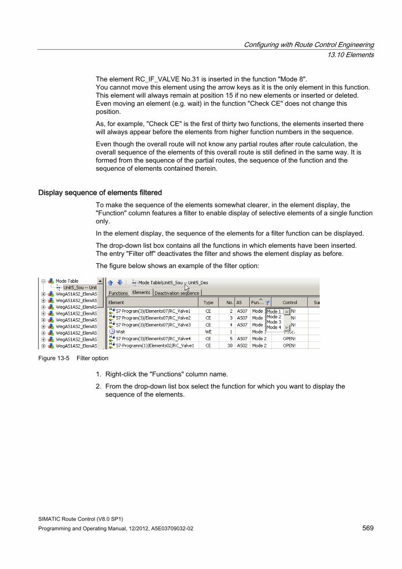
Configuring with Route Control Engineering 13.10 Elements
SIMATIC Route Control (V8.0 SP1) Programming and Operating Manual, 12/2012, A5E03709032-02 569
The element RC_IF_VALVE No.31 is inserted in the function "Mode 8". You cannot move this element using the arrow keys as it is the only element in this function. This element will always remain at position 15 if no new elements or inserted or deleted. Even moving an element (e.g. wait) in the function "Check CE" does not change this position.
As, for example, "Check CE" is the first of thirty two functions, the elements inserted there will always appear before the elements from higher function numbers in the sequence.
Even though the overall route will not know any partial routes after route calculation, the overall sequence of the elements of this overall route is still defined in the same way. It is formed from the sequence of the partial routes, the sequence of the function and the sequence of elements contained therein.
Display sequence of elements filtered To make the sequence of the elements somewhat clearer, in the element display, the "Function" column features a filter to enable display of selective elements of a single function only.
In the element display, the sequence of the elements for a filter function can be displayed.
The drop-down list box contains all the functions in which elements have been inserted. The entry "Filter off" deactivates the filter and shows the element display as before.
The figure below shows an example of the filter option:
Figure 13-5 Filter option
1. Right-click the "Functions" column name.
2. From the drop-down list box select the function for which you want to display the sequence of the elements.
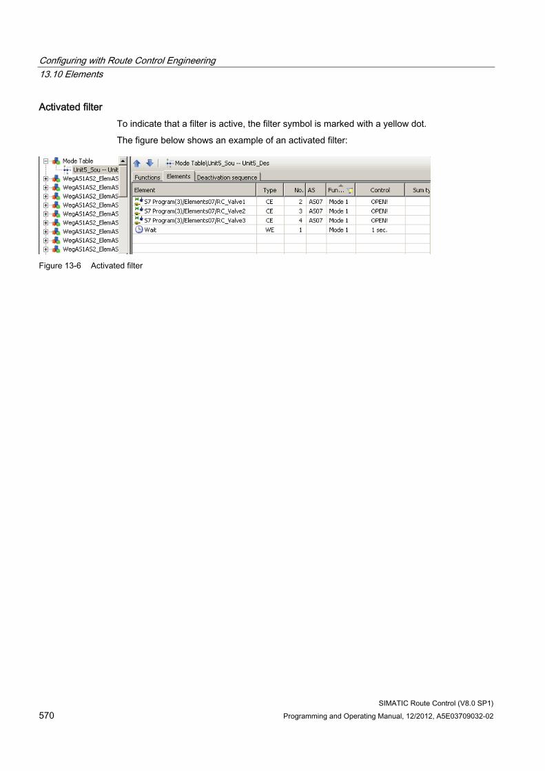
Configuring with Route Control Engineering 13.10 Elements
SIMATIC Route Control (V8.0 SP1) 570 Programming and Operating Manual, 12/2012, A5E03709032-02
Activated filter To indicate that a filter is active, the filter symbol is marked with a yellow dot.
The figure below shows an example of an activated filter:
Figure 13-6 Activated filter
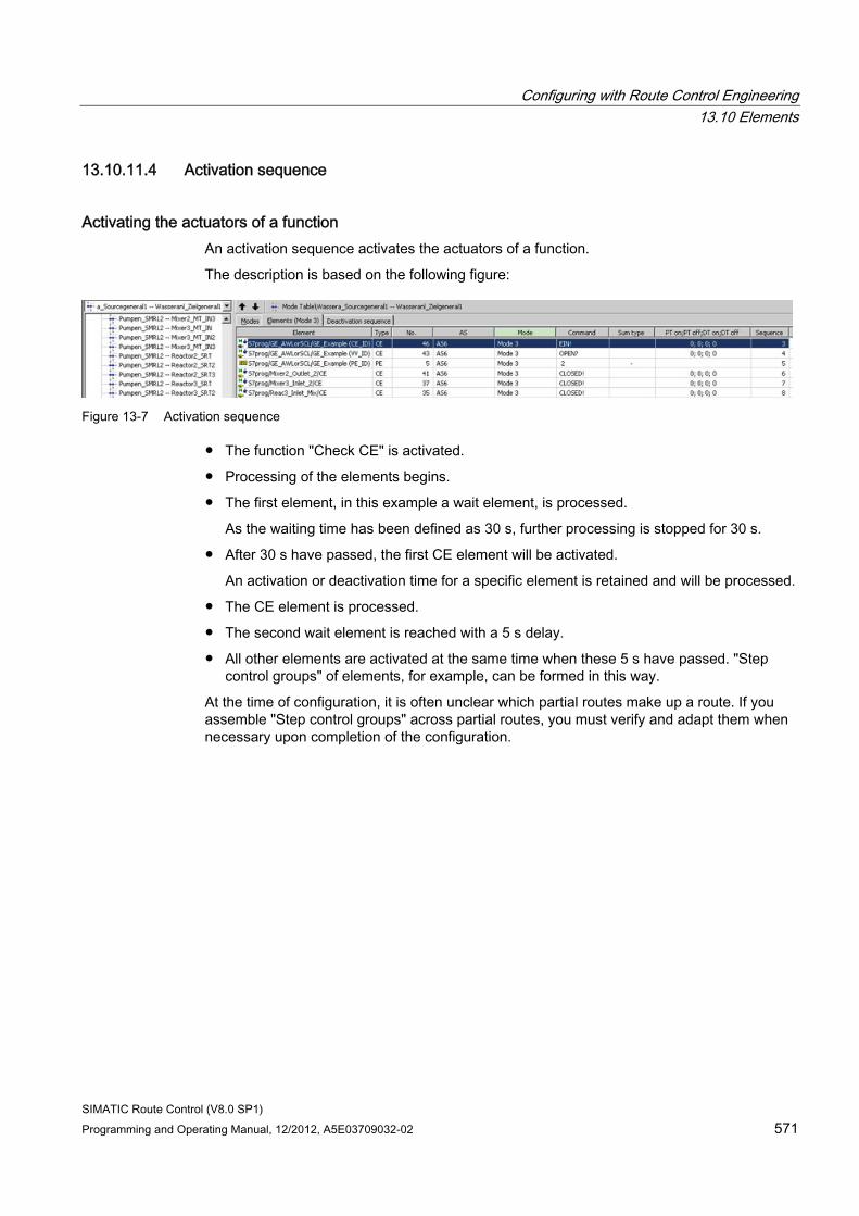
Configuring with Route Control Engineering 13.10 Elements
SIMATIC Route Control (V8.0 SP1) Programming and Operating Manual, 12/2012, A5E03709032-02 571
13.10.11.4 Activation sequence
Activating the actuators of a function An activation sequence activates the actuators of a function.
The description is based on the following figure:
Figure 13-7 Activation sequence
● The function "Check CE" is activated.
● Processing of the elements begins.
● The first element, in this example a wait element, is processed.
As the waiting time has been defined as 30 s, further processing is stopped for 30 s.
● After 30 s have passed, the first CE element will be activated.
An activation or deactivation time for a specific element is retained and will be processed.
● The CE element is processed.
● The second wait element is reached with a 5 s delay.
● All other elements are activated at the same time when these 5 s have passed. "Step control groups" of elements, for example, can be formed in this way.
At the time of configuration, it is often unclear which partial routes make up a route. If you assemble "Step control groups" across partial routes, you must verify and adapt them when necessary upon completion of the configuration.
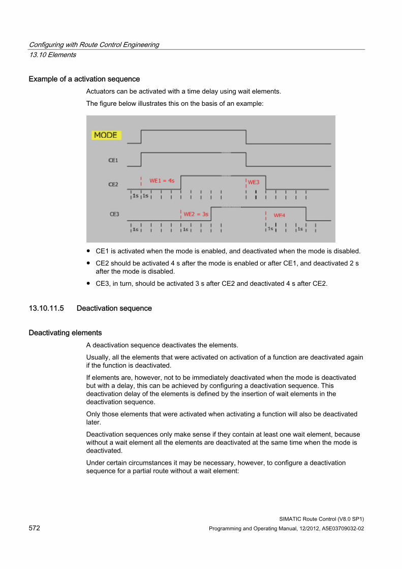
Configuring with Route Control Engineering 13.10 Elements
SIMATIC Route Control (V8.0 SP1) 572 Programming and Operating Manual, 12/2012, A5E03709032-02
Example of a activation sequence Actuators can be activated with a time delay using wait elements.
The figure below illustrates this on the basis of an example:
● CE1 is activated when the mode is enabled, and deactivated when the mode is disabled.
● CE2 should be activated 4 s after the mode is enabled or after CE1, and deactivated 2 s after the mode is disabled.
● CE3, in turn, should be activated 3 s after CE2 and deactivated 4 s after CE2.
13.10.11.5 Deactivation sequence
Deactivating elements A deactivation sequence deactivates the elements.
Usually, all the elements that were activated on activation of a function are deactivated again if the function is deactivated.
If elements are, however, not to be immediately deactivated when the mode is deactivated but with a delay, this can be achieved by configuring a deactivation sequence. This deactivation delay of the elements is defined by the insertion of wait elements in the deactivation sequence.
Only those elements that were activated when activating a function will also be deactivated later.
Deactivation sequences only make sense if they contain at least one wait element, because without a wait element all the elements are deactivated at the same time when the mode is deactivated.
Under certain circumstances it may be necessary, however, to configure a deactivation sequence for a partial route without a wait element:
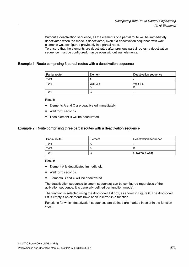
Configuring with Route Control Engineering 13.10 Elements
SIMATIC Route Control (V8.0 SP1) Programming and Operating Manual, 12/2012, A5E03709032-02 573
Without a deactivation sequence, all the elements of a partial route will be immediately deactivated when the mode is deactivated, even if a deactivation sequence with wait elements was configured previously in a partial route. To ensure that the elements are deactivated after previous partial routes, a deactivation sequence must be configured, maybe even without wait elements.
Example 1: Route comprising 3 partial routes with a deactivation sequence Partial route Element Deactivation sequence TW1 A - TW4 Wait 3 s
B Wait 3 s B
TW3 C -
Result:
● Elements A and C are deactivated immediately.
● Wait for 3 seconds.
● Then element B will be deactivated.
Example 2: Route comprising three partial routes with a deactivation sequence Partial route Element Deactivation sequence TW1 A - TW4 B B TW3 C C (without wait)
Result:
● Element A is deactivated immediately.
● Wait for 3 seconds.
● Elements B and C will be deactivated.
The deactivation sequence (element sequence) can be configured regardless of the activation sequence. It is generally defined per function (mode).
The function is selected using the drop-down list box, as shown in Figure 6. The drop-down list is empty if no elements have been inserted in a function.
Functions for which deactivation sequences are defined are marked in color in the function view.
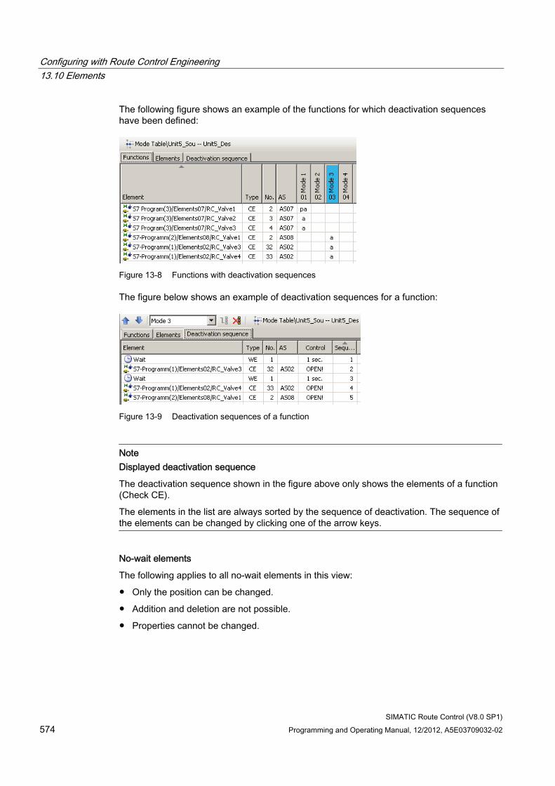
Configuring with Route Control Engineering 13.10 Elements
SIMATIC Route Control (V8.0 SP1) 574 Programming and Operating Manual, 12/2012, A5E03709032-02
The following figure shows an example of the functions for which deactivation sequences have been defined:
Figure 13-8 Functions with deactivation sequences
The figure below shows an example of deactivation sequences for a function:
Figure 13-9 Deactivation sequences of a function
Note Displayed deactivation sequence
The deactivation sequence shown in the figure above only shows the elements of a function (Check CE).
The elements in the list are always sorted by the sequence of deactivation. The sequence of the elements can be changed by clicking one of the arrow keys.
No-wait elements
The following applies to all no-wait elements in this view:
● Only the position can be changed.
● Addition and deletion are not possible.
● Properties cannot be changed.
Configuring with Route Control Engineering 13.10 Elements
SIMATIC Route Control (V8.0 SP1) Programming and Operating Manual, 12/2012, A5E03709032-02 575
13.10.11.6 Configuring a deactivation sequence of a partial route
Procedure Add a deactivation sequence to a partial route using the following icon:
1. Select the "Deactivation sequence" tab.
2. From the drop-down list box select the function for which you want to create a deactivation sequence.
3. Add a new deactivation sequence using the "Deactivation sequence" icon.
If the element list is not empty and the "Deactivation sequence" icon is activated, you can add a new deactivation sequence.
During an add operation, all elements except link and wait elements, that were configured for this project will be copied to and inserted in the deactivation list together with a new wait element.
4. You insert additional wait elements with drag&drop.
5. Set the required sequence using the arrow keys.
13.10.11.7 Inserting or deleting wait elements
Insertion with drag&drop You insert additional wait elements in the deactivation list with drag&drop.
If you add a wait element to the deactivation list, then this element will automatically be inserted at the last position.
See also Deactivation sequence (Page 572)
Configuring with Route Control Engineering 13.10 Elements
SIMATIC Route Control (V8.0 SP1) 576 Programming and Operating Manual, 12/2012, A5E03709032-02
13.10.11.8 Copying or deleting deactivation sequences
Copying the deactivation sequence of a partial route When you copy a partial route, a box will open to prompt you if you want to copy all existing interconnections.
If your answer is yes, then all existing deactivation sequences will also be copied.
Deleting the deactivation sequence of a function in a partial route You delete a deactivation sequence with the following icon:
13.10.11.9 Invert activation or deactivation sequence The direction of processing when elements are switched on and off usually runs from the source to the destination. This direction can be inverted for both switching on and off.
During a route search the partial routes are then lined up together in the direction from the destination to the source instead of from the source to the destination.
This inversion only influences the sequence of the partial routes; the sequence of the elements within the partial routes will be the sequence you selected during configuration.
In manual mode select the direction of processing in the route properties.
In automatic mode this is done via the SWONINV and SWOFINV inputs at the FB800/RC_IF_ROUTE.
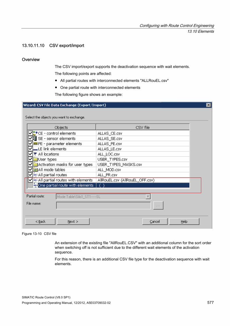
Configuring with Route Control Engineering 13.10 Elements
SIMATIC Route Control (V8.0 SP1) Programming and Operating Manual, 12/2012, A5E03709032-02 577
13.10.11.10 CSV export/import
Overview The CSV import/export supports the deactivation sequence with wait elements.
The following points are affected:
● All partial routes with interconnected elements "ALLRouEL.csv"
● One partial route with interconnected elements
The following figure shows an example:
Figure 13-10 CSV file
An extension of the existing file "AllRouEL.CSV" with an additional column for the sort order when switching off is not sufficient due to the different wait elements of the activation sequence.
For this reason, there is an additional CSV file type for the deactivation sequence with wait elements.
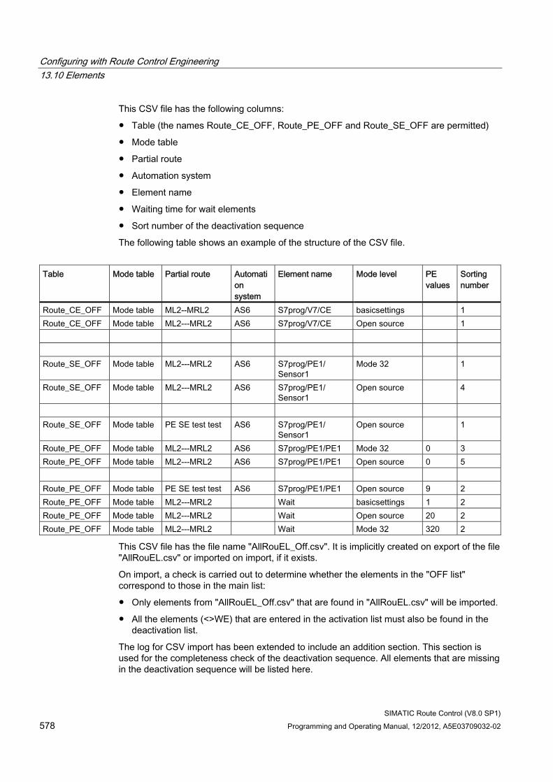
Configuring with Route Control Engineering 13.10 Elements
SIMATIC Route Control (V8.0 SP1) 578 Programming and Operating Manual, 12/2012, A5E03709032-02
This CSV file has the following columns:
● Table (the names Route_CE_OFF, Route_PE_OFF and Route_SE_OFF are permitted)
● Mode table
● Partial route
● Automation system
● Element name
● Waiting time for wait elements
● Sort number of the deactivation sequence
The following table shows an example of the structure of the CSV file.
Table Mode table Partial route Automati
on system
Element name Mode level PE values
Sorting number
Route_CE_OFF Mode table ML2--MRL2 AS6 S7prog/V7/CE basicsettings 1 Route_CE_OFF Mode table ML2---MRL2 AS6 S7prog/V7/CE Open source 1 Route_SE_OFF Mode table ML2---MRL2 AS6 S7prog/PE1/
Sensor1 Mode 32 1
Route_SE_OFF Mode table ML2---MRL2 AS6 S7prog/PE1/ Sensor1
Open source 4
Route_SE_OFF Mode table PE SE test test AS6 S7prog/PE1/
Sensor1 Open source 1
Route_PE_OFF Mode table ML2---MRL2 AS6 S7prog/PE1/PE1 Mode 32 0 3 Route_PE_OFF Mode table ML2---MRL2 AS6 S7prog/PE1/PE1 Open source 0 5 Route_PE_OFF Mode table PE SE test test AS6 S7prog/PE1/PE1 Open source 9 2 Route_PE_OFF Mode table ML2---MRL2 Wait basicsettings 1 2 Route_PE_OFF Mode table ML2---MRL2 Wait Open source 20 2 Route_PE_OFF Mode table ML2---MRL2 Wait Mode 32 320 2
This CSV file has the file name "AllRouEL_Off.csv". It is implicitly created on export of the file "AllRouEL.csv" or imported on import, if it exists.
On import, a check is carried out to determine whether the elements in the "OFF list" correspond to those in the main list:
● Only elements from "AllRouEL_Off.csv" that are found in "AllRouEL.csv" will be imported.
● All the elements (<>WE) that are entered in the activation list must also be found in the deactivation list.
The log for CSV import has been extended to include an addition section. This section is used for the completeness check of the deactivation sequence. All elements that are missing in the deactivation sequence will be listed here.
Configuring with Route Control Engineering 13.10 Elements
SIMATIC Route Control (V8.0 SP1) Programming and Operating Manual, 12/2012, A5E03709032-02 579
The following section shows an example of a completeness verification for the deactivation sequence:
Error: CE: 'S7prog/V8/CE' missing in partial route 'ML2---MRL2' in the mode 'basicsettings'
Error: SE: 'S7prog/PE1/Sensor1' missing in partial route 'ML2---MRL2' in the mode 'basicsettings'
Error: PE: 'S7prog/PE1/PE1' missing in partial route 'ML2---MRL2' in the mode 'basicsettings'
For the "One partial route with elements" function, there is a file for the deactivation sequence with a wait element with the extension "_off.csv".
If the file name "Brauhaus.csv" was selected, export and import of the deactivation sequence with a wait element is carried out implicitly with the file "Brauhaus_off.csv".
13.10.11.11 Pulse mode
Single pulsing In pulse mode, a configurable pulse sequence is output at the appropriately configured elements in active mode.
With single pulsing, the pulse time of the element is set to the required duration (e.g. 1s) and the pulse pause is set to zero (i.e. 0 s).
Result: In active mode the element is activated once for the duration of the pulse time.
If you now also configure a deactivation sequence, all the elements of the activation list, including the elements for which you have selected "single pulsing", will be entered in the deactivation list.
This does not mean that a single pulse is also output on deactivation (of the mode).
If several elements are to be pulsed in a particular order and at particular intervals, you can do this by inserting wait elements between the elements. The wait element parameters are used to define the time "interval" from the previous element in this mode.
If there are several elements between two wait elements, these will be activated together and form a group. A group comprises all the elements between two contiguous wait elements. If required, it is also possible to form "cross-partial route" groups, depending on the later composition of the route from partial routes.
The sequence of the elements and wait elements within the partial route is configured.
The sequence in the path is formed from the sequence of the partial routes and the sequence of the elements in the partial routes. By default the direction from source to destination is used for the sequence of the partial routes in the route. The direction can be inverted, however, when a route is requested.
The wait element (WE) is a "special" parameter element. There is no RC_IF block. The wait element is not configured in the CFC. It only occurs in Route Control Engineering and can be used in partial routes.
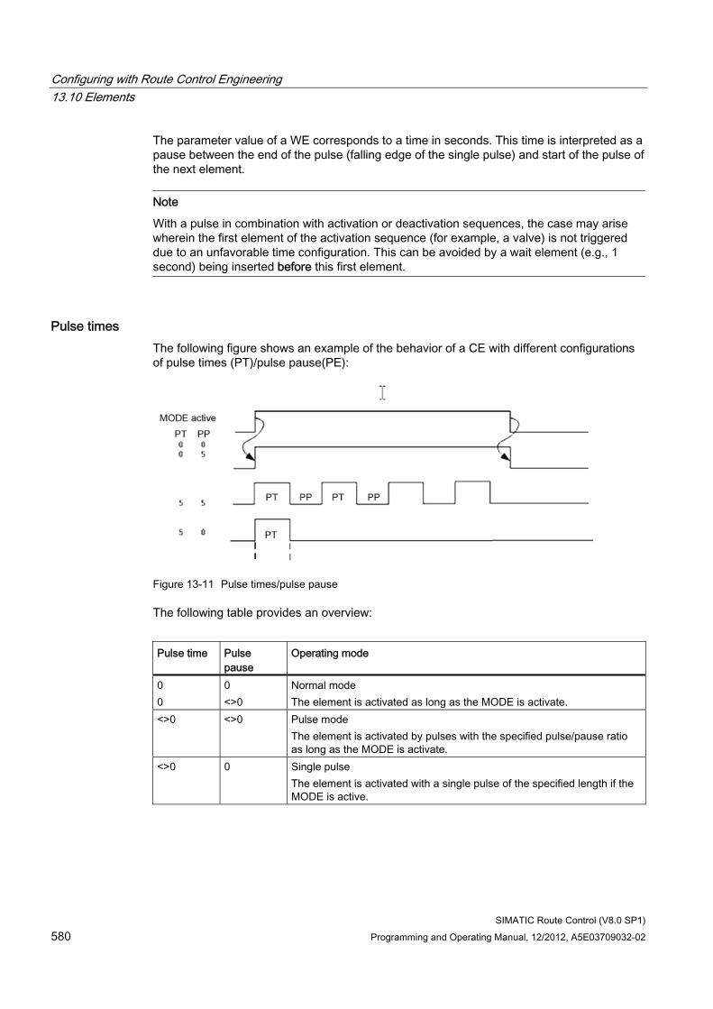
Configuring with Route Control Engineering 13.10 Elements
SIMATIC Route Control (V8.0 SP1) 580 Programming and Operating Manual, 12/2012, A5E03709032-02
The parameter value of a WE corresponds to a time in seconds. This time is interpreted as a pause between the end of the pulse (falling edge of the single pulse) and start of the pulse of the next element.
Note
With a pulse in combination with activation or deactivation sequences, the case may arise wherein the first element of the activation sequence (for example, a valve) is not triggered due to an unfavorable time configuration. This can be avoided by a wait element (e.g., 1 second) being inserted before this first element.
Pulse times The following figure shows an example of the behavior of a CE with different configurations of pulse times (PT)/pulse pause(PE):
Figure 13-11 Pulse times/pulse pause
The following table provides an overview:
Pulse time Pulse
pause Operating mode
0 0
0 <>0
Normal mode The element is activated as long as the MODE is activate.
<>0 <>0 Pulse mode The element is activated by pulses with the specified pulse/pause ratio as long as the MODE is activate.
<>0 0 Single pulse The element is activated with a single pulse of the specified length if the MODE is active.
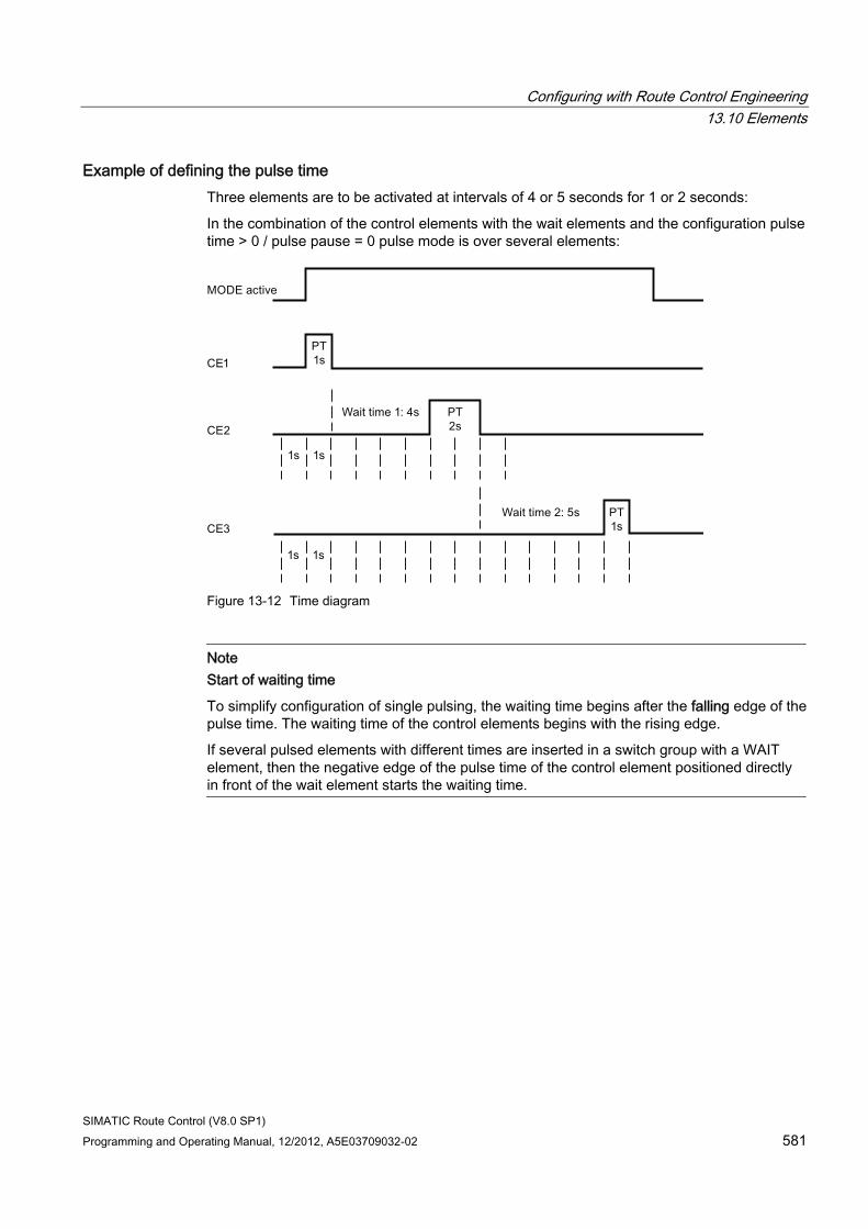
Configuring with Route Control Engineering 13.10 Elements
SIMATIC Route Control (V8.0 SP1) Programming and Operating Manual, 12/2012, A5E03709032-02 581
Example of defining the pulse time Three elements are to be activated at intervals of 4 or 5 seconds for 1 or 2 seconds:
In the combination of the control elements with the wait elements and the configuration pulse time > 0 / pulse pause = 0 pulse mode is over several elements:
Figure 13-12 Time diagram
Note Start of waiting time
To simplify configuration of single pulsing, the waiting time begins after the falling edge of the pulse time. The waiting time of the control elements begins with the rising edge.
If several pulsed elements with different times are inserted in a switch group with a WAIT element, then the negative edge of the pulse time of the control element positioned directly in front of the wait element starts the waiting time.
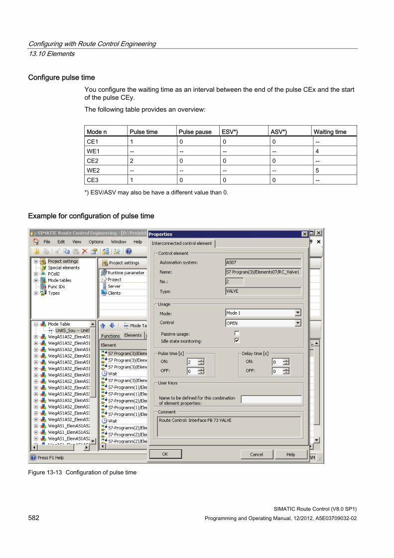
Configuring with Route Control Engineering 13.10 Elements
SIMATIC Route Control (V8.0 SP1) 582 Programming and Operating Manual, 12/2012, A5E03709032-02
Configure pulse time You configure the waiting time as an interval between the end of the pulse CEx and the start of the pulse CEy.
The following table provides an overview:
Mode n Pulse time Pulse pause ESV*) ASV*) Waiting time CE1 1 0 0 0 -- WE1 -- -- -- -- 4 CE2 2 0 0 0 -- WE2 -- -- -- -- 5 CE3 1 0 0 0 --
*) ESV/ASV may also be have a different value than 0.
Example for configuration of pulse time
Figure 13-13 Configuration of pulse time
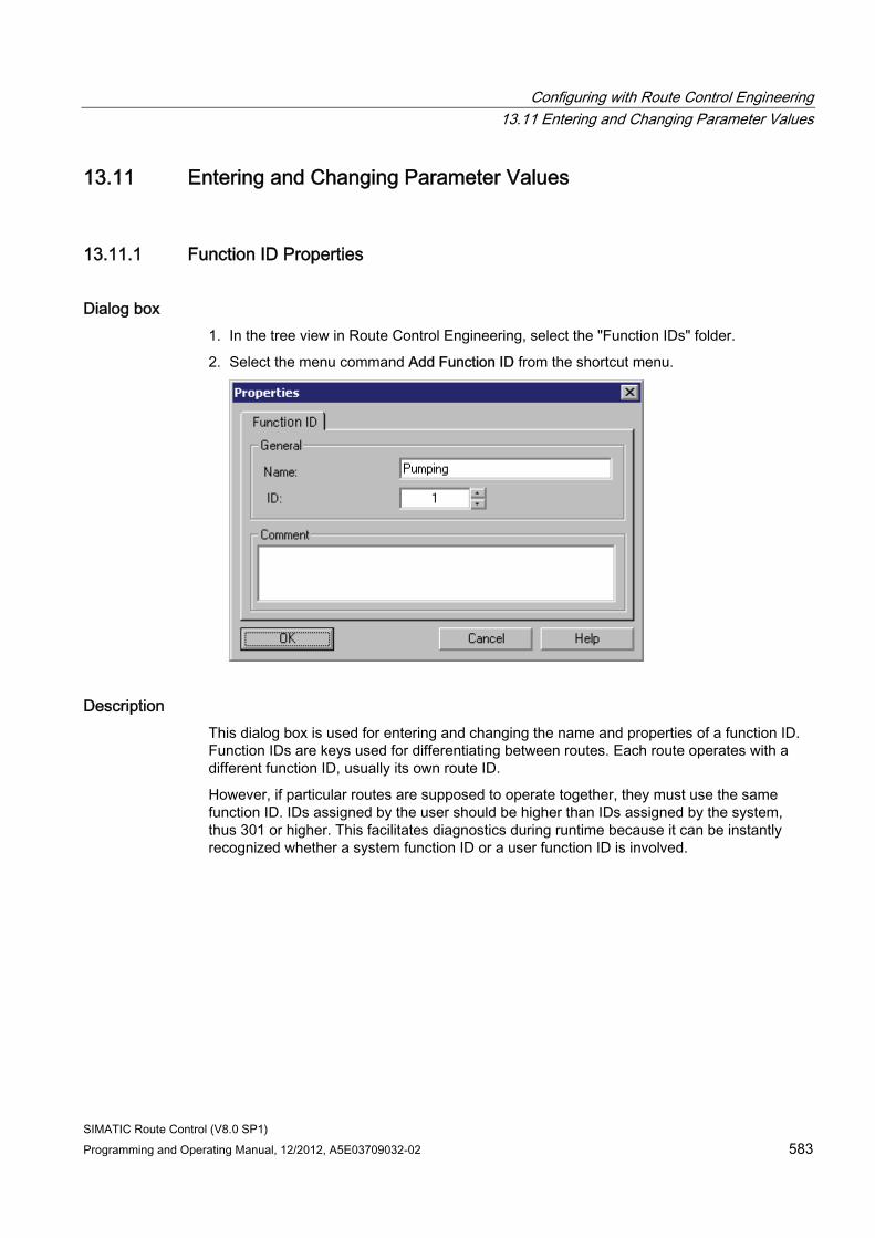
Configuring with Route Control Engineering 13.11 Entering and Changing Parameter Values
SIMATIC Route Control (V8.0 SP1) Programming and Operating Manual, 12/2012, A5E03709032-02 583
13.11 Entering and Changing Parameter Values
13.11.1 Function ID Properties
Dialog box 1. In the tree view in Route Control Engineering, select the "Function IDs" folder.
2. Select the menu command Add Function ID from the shortcut menu.
Description This dialog box is used for entering and changing the name and properties of a function ID. Function IDs are keys used for differentiating between routes. Each route operates with a different function ID, usually its own route ID.
However, if particular routes are supposed to operate together, they must use the same function ID. IDs assigned by the user should be higher than IDs assigned by the system, thus 301 or higher. This facilitates diagnostics during runtime because it can be instantly recognized whether a system function ID or a user function ID is involved.
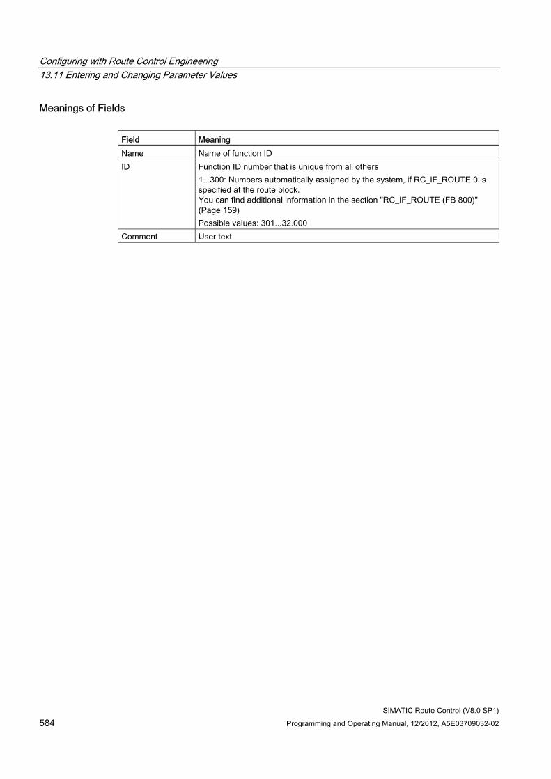
Configuring with Route Control Engineering 13.11 Entering and Changing Parameter Values
SIMATIC Route Control (V8.0 SP1) 584 Programming and Operating Manual, 12/2012, A5E03709032-02
Meanings of Fields Field Meaning Name Name of function ID ID Function ID number that is unique from all others
1...300: Numbers automatically assigned by the system, if RC_IF_ROUTE 0 is specified at the route block. You can find additional information in the section "RC_IF_ROUTE (FB 800)" (Page 159) Possible values: 301...32.000
Comment User text
Configuring with Route Control Engineering 13.12 Materials
SIMATIC Route Control (V8.0 SP1) Programming and Operating Manual, 12/2012, A5E03709032-02 585
13.12 Materials
13.12.1 Overview of Materials
Introduction In many industrial sectors, certain materials may not succeed each other or use the same transport route. For example, in the brewing industry, beer product must never follow an acid cleaning step directly, but must always be preceded by a water flush. For this reason, the routing system provides a parameter assignment option for material compatibility or material sequencing. Information about the material currently being used in a particular partial route is stored temporarily in an interconnected link element. The routing system uses this information to determine whether the successor material is permitted.
Significance of Materials Materials are involved in SIMATIC Route Control in the following areas:
● Materials and material groups are configured in Route Control Engineering.
● Relationships to the permitted successor materials are entered in Route Control Engineering.
● During runtime, the user program can transfer a desired new material prior to a route request. This will be taken into consideration in the next route search. It is checked to determine whether or not it is a permitted successor material.
● The Route Control server checks whether the new material is permitted as a successor to the material that was transported previously. If the new material is not permitted, a route is not found when no alternative path is available. You can find additional information on this in the section "Material sequence diagram RC_IF_ROUTE" (Page 586)
The configuration of materials is presented in the following sections.
Note
Material data can also be specified on the Route Control server during runtime. You can find additional information in the section "Material Interface" (Page 593)
Additional information ● Section "Configuring Materials and Material Groups" (Page 587)
● Section "Configuring Material Sequences" (Page 588)
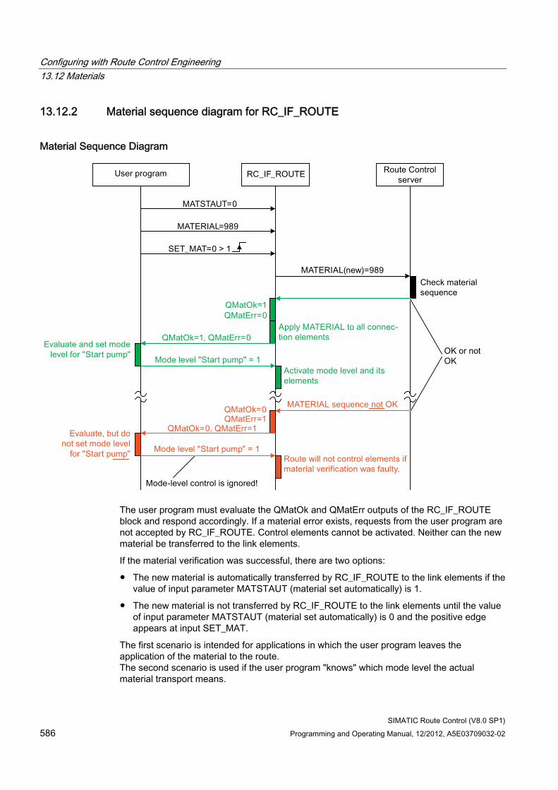
Configuring with Route Control Engineering 13.12 Materials
SIMATIC Route Control (V8.0 SP1) 586 Programming and Operating Manual, 12/2012, A5E03709032-02
13.12.2 Material sequence diagram for RC_IF_ROUTE
Material Sequence Diagram
The user program must evaluate the QMatOk and QMatErr outputs of the RC_IF_ROUTE block and respond accordingly. If a material error exists, requests from the user program are not accepted by RC_IF_ROUTE. Control elements cannot be activated. Neither can the new material be transferred to the link elements.
If the material verification was successful, there are two options:
● The new material is automatically transferred by RC_IF_ROUTE to the link elements if the value of input parameter MATSTAUT (material set automatically) is 1.
● The new material is not transferred by RC_IF_ROUTE to the link elements until the value of input parameter MATSTAUT (material set automatically) is 0 and the positive edge appears at input SET_MAT.
The first scenario is intended for applications in which the user program leaves the application of the material to the route. The second scenario is used if the user program "knows" which mode level the actual material transport means.
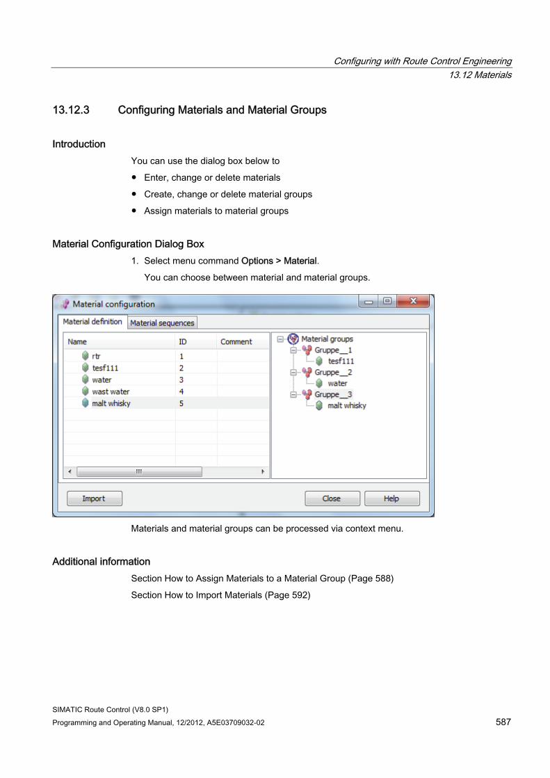
Configuring with Route Control Engineering 13.12 Materials
SIMATIC Route Control (V8.0 SP1) Programming and Operating Manual, 12/2012, A5E03709032-02 587
13.12.3 Configuring Materials and Material Groups
Introduction You can use the dialog box below to
● Enter, change or delete materials
● Create, change or delete material groups
● Assign materials to material groups
Material Configuration Dialog Box 1. Select menu command Options > Material.
You can choose between material and material groups.
Materials and material groups can be processed via context menu.
Additional information Section How to Assign Materials to a Material Group (Page 588)
Section How to Import Materials (Page 592)
Configuring with Route Control Engineering 13.12 Materials
SIMATIC Route Control (V8.0 SP1) 588 Programming and Operating Manual, 12/2012, A5E03709032-02
13.12.4 How to Assign Materials to a Material Group
Procedure 1. Select menu command Options > Material.
2. Drag-and-drop materials from the "Material definition" list into a material group of the "Material groups" list.
The materials are assigned to the material group.
13.12.5 Configuring Material Sequences
Introduction In configuring material sequences, you specify which materials or material groups may follow a specific material or material group.
Material Sequence Dialog 1. Select menu command Options > Material.
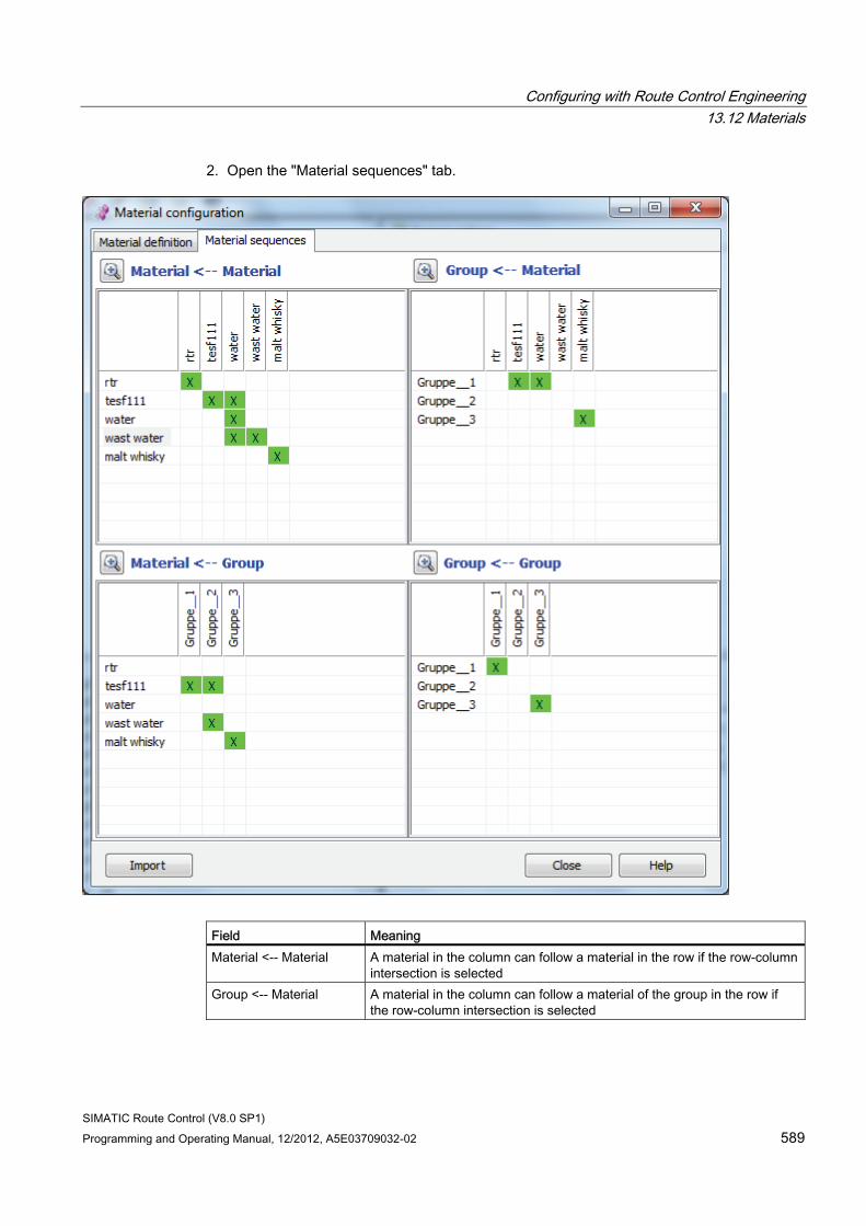
Configuring with Route Control Engineering 13.12 Materials
SIMATIC Route Control (V8.0 SP1) Programming and Operating Manual, 12/2012, A5E03709032-02 589
2. Open the "Material sequences" tab.
Field Meaning Material <-- Material A material in the column can follow a material in the row if the row-column
intersection is selected Group <-- Material A material in the column can follow a material of the group in the row if
the row-column intersection is selected
Configuring with Route Control Engineering 13.12 Materials
SIMATIC Route Control (V8.0 SP1) 590 Programming and Operating Manual, 12/2012, A5E03709032-02
Field Meaning Material <-- Group Any material of the group in the column can follow a material in the row if
the row-column intersection is selected Group <-- Group Any material of the group in the column can follow any material of the
group in the row if the row-column intersection is selected
Example The selection of the intersection of row 1 and column 1 in the "Material ß group" determines that water can be followed by all materials contained in Group_1.
Magnifying glass When you click the magnifying glass button above a field, the field is enlarged and occupies the entire space of the window. The other fields are then no longer visible. Clicking once again on the magnifying glass button restores the original state.
Import You can use the "IMPORT" button to import an external material and material sequence definition.
This consists of 2 ASCII files.
● MAT_EXT.TXT Definition of the materials as a list.
Empty lines in this list correspond to undefined material IDs.
● MAT_EXT.CSV Sequence definition in matrix format.
The "-" character represents unknown materials (equivalent to an empty line in MAT_EXT.TXT)
You can freely choose the names of these files. The extension TXT, CSV and the structure of the contents are fixed.
Importing irretrievably deletes all existing material, group and sequence definitions. Then, the materials and sequences from the ASCII files are imported.
Note Material import via txt file only
If you only select the txt file in the material import dialog, the materials are imported. A default is entered for the material sequence. This means that every material has itself as its successor.
Additional information ● Section How to Specify Successors for a Material (Page 591)
● Section How to Specify Successors for a Material Group (Page 591)
Configuring with Route Control Engineering 13.12 Materials
SIMATIC Route Control (V8.0 SP1) Programming and Operating Manual, 12/2012, A5E03709032-02 591
13.12.6 How to Specify Successors for a Material
Procedure 1. Select menu command Options > Material.
2. Open the "Material sequences" tab.
3. If a material is specified as a successor: In the "Material <-- Material" field, select the intersection of the column of the material that can follow the material in the row, and the corresponding row.
4. If all materials of a group are specified as a successor: In the "Material <-- Group" field, select the intersection of the column of the group, whose materials can follow the material in the row, and the corresponding row.
Additional information ● Section "How to Specify Successors for a Material Group" (Page 591)
13.12.7 How to Specify Successors for a Material Group
Procedure 1. Select menu command Options > Material.
2. Open the "Material sequences" tab.
3. If a material is specified as a successor: In the "Group <-- Material" field, select the intersection of the column of the material that can follow all the materials of the group in the row, and the corresponding row.
4. If all materials of a group are specified as a successor: In the "Material <-- Group" field, select the intersection of the column of the group, whose materials can follow the all the materials of the group in the row, and the corresponding row.
Additional information ● Section "How to Specify Successors for a Material" (Page 591)
Configuring with Route Control Engineering 13.12 Materials
SIMATIC Route Control (V8.0 SP1) 592 Programming and Operating Manual, 12/2012, A5E03709032-02
13.12.8 How to Import Materials
Importing materials You can use the "IMPORT" button in the "Material Configuration" dialog box to import a material.
This consists of 2 ASCII files.
● MAT_EXT.TXT Definition of the materials as a list.
Empty lines in this list correspond to undefined material IDs.
● MAT_EXT.CSV Sequence definition in matrix format.
The "-" character represents unknown materials (equivalent to an empty line in MAT_EXT.TXT)
You can freely choose the names of these files. The extension TXT, CSV and the structure of the contents are fixed.
Importing irretrievably deletes all existing materials. The materials are then inserted from the ASCII files.
Note Material import via txt file only
If you only select the txt file in the material import dialog, the materials are imported. A default is entered for the material sequence. This means that every material has itself as its successor.
Additional information ● Section Material Master Data (Page 595)
● Section Successor Relationships (Page 596)
Configuring with Route Control Engineering 13.13 External Material Interface
SIMATIC Route Control (V8.0 SP1) Programming and Operating Manual, 12/2012, A5E03709032-02 593
13.13 External Material Interface
13.13.1 Material interface
Overview You have the following options:
● SIMATIC Route Control without material configuration or material verification
● SIMATIC Route Control with internal material configuration and material verification
● SIMATIC Route Control with external material configuration and material verification
Configure these settings in the global project settings \ runtime parameters in the material functions. You can find more information on the global project settings in the section "Overview of the project settings" (Page 507)
No Material Configuration The default setting is a new Route Control configuration without material configuration or a runtime check.
External Material Interface on the Route Control Server The material interface on the Route Control server was created to enable application of external master data in Route Control.
The external material interface is also supported, from Route Control version V8.0. However, with a redundantly set Route Control server no automatic synchronization of the data occurs. The data must be loaded on both computers (master and standby).
The interface was kept simple so that it can be supplied with existing applications. Two files (MAT_EXT.TXT and MAT_EXT.CSV) are sent to the interface. You can find additional information in the section "Process for Downloading the Material Configuration" (Page 594)
See also Overview of Materials (Page 585)
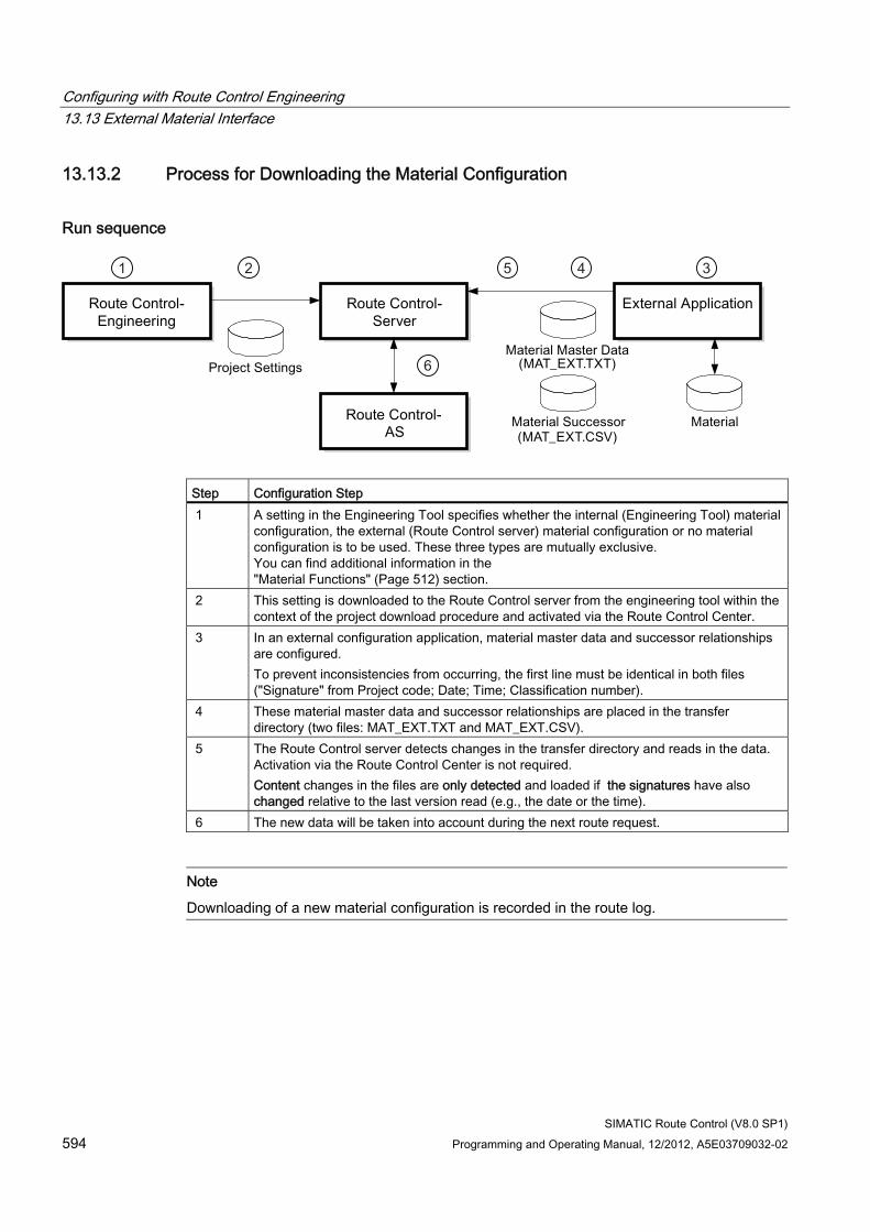
Configuring with Route Control Engineering 13.13 External Material Interface
SIMATIC Route Control (V8.0 SP1) 594 Programming and Operating Manual, 12/2012, A5E03709032-02
13.13.2 Process for Downloading the Material Configuration
Run sequence
Step Configuration Step 1 A setting in the Engineering Tool specifies whether the internal (Engineering Tool) material
configuration, the external (Route Control server) material configuration or no material configuration is to be used. These three types are mutually exclusive. You can find additional information in the "Material Functions" (Page 512) section.
2 This setting is downloaded to the Route Control server from the engineering tool within the context of the project download procedure and activated via the Route Control Center.
3 In an external configuration application, material master data and successor relationships are configured. To prevent inconsistencies from occurring, the first line must be identical in both files ("Signature" from Project code; Date; Time; Classification number).
4 These material master data and successor relationships are placed in the transfer directory (two files: MAT_EXT.TXT and MAT_EXT.CSV).
5 The Route Control server detects changes in the transfer directory and reads in the data. Activation via the Route Control Center is not required. Content changes in the files are only detected and loaded if the signatures have also changed relative to the last version read (e.g., the date or the time).
6 The new data will be taken into account during the next route request.
Note
Downloading of a new material configuration is recorded in the route log.
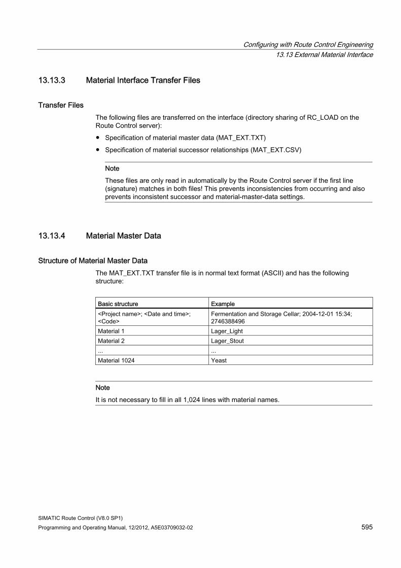
Configuring with Route Control Engineering 13.13 External Material Interface
SIMATIC Route Control (V8.0 SP1) Programming and Operating Manual, 12/2012, A5E03709032-02 595
13.13.3 Material Interface Transfer Files
Transfer Files The following files are transferred on the interface (directory sharing of RC_LOAD on the Route Control server):
● Specification of material master data (MAT_EXT.TXT)
● Specification of material successor relationships (MAT_EXT.CSV)
Note
These files are only read in automatically by the Route Control server if the first line (signature) matches in both files! This prevents inconsistencies from occurring and also prevents inconsistent successor and material-master-data settings.
13.13.4 Material Master Data
Structure of Material Master Data The MAT_EXT.TXT transfer file is in normal text format (ASCII) and has the following structure:
Basic structure Example <Project name>; <Date and time>; <Code>
Fermentation and Storage Cellar; 2004-12-01 15:34; 2746388496
Material 1 Lager_Light Material 2 Lager_Stout ... ... Material 1024 Yeast
Note
It is not necessary to fill in all 1,024 lines with material names.
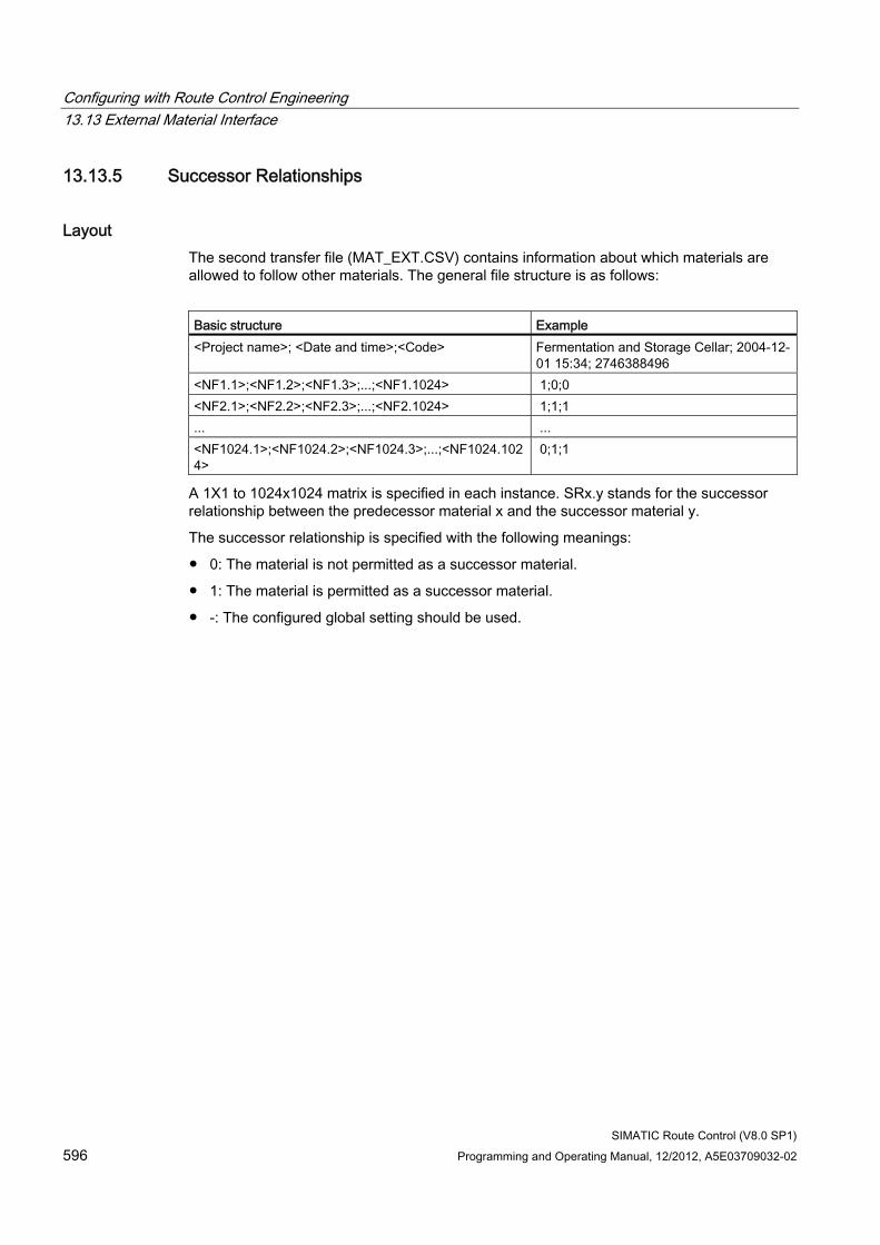
Configuring with Route Control Engineering 13.13 External Material Interface
SIMATIC Route Control (V8.0 SP1) 596 Programming and Operating Manual, 12/2012, A5E03709032-02
13.13.5 Successor Relationships
Layout The second transfer file (MAT_EXT.CSV) contains information about which materials are allowed to follow other materials. The general file structure is as follows:
Basic structure Example <Project name>; <Date and time>;<Code> Fermentation and Storage Cellar; 2004-12-
01 15:34; 2746388496 <NF1.1>;<NF1.2>;<NF1.3>;...;<NF1.1024> 1;0;0 <NF2.1>;<NF2.2>;<NF2.3>;...;<NF2.1024> 1;1;1 ... ... <NF1024.1>;<NF1024.2>;<NF1024.3>;...;<NF1024.1024>
0;1;1
A 1X1 to 1024x1024 matrix is specified in each instance. SRx.y stands for the successor relationship between the predecessor material x and the successor material y.
The successor relationship is specified with the following meanings:
● 0: The material is not permitted as a successor material.
● 1: The material is permitted as a successor material.
● -: The configured global setting should be used.
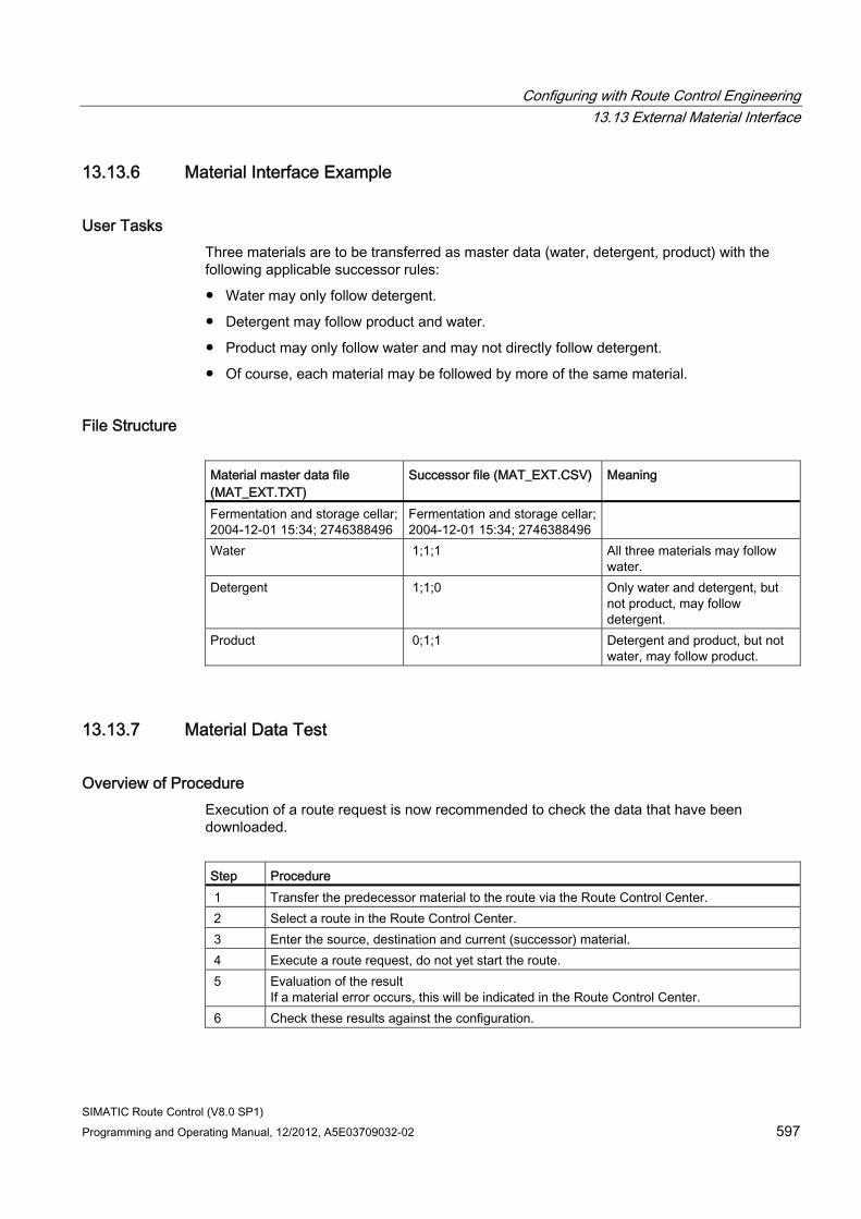
Configuring with Route Control Engineering 13.13 External Material Interface
SIMATIC Route Control (V8.0 SP1) Programming and Operating Manual, 12/2012, A5E03709032-02 597
13.13.6 Material Interface Example
User Tasks Three materials are to be transferred as master data (water, detergent, product) with the following applicable successor rules:
● Water may only follow detergent.
● Detergent may follow product and water.
● Product may only follow water and may not directly follow detergent.
● Of course, each material may be followed by more of the same material.
File Structure Material master data file (MAT_EXT.TXT)
Successor file (MAT_EXT.CSV) Meaning
Fermentation and storage cellar;2004-12-01 15:34; 2746388496
Fermentation and storage cellar;2004-12-01 15:34; 2746388496
Water 1;1;1 All three materials may follow water.
Detergent 1;1;0 Only water and detergent, but not product, may follow detergent.
Product 0;1;1 Detergent and product, but not water, may follow product.
13.13.7 Material Data Test
Overview of Procedure Execution of a route request is now recommended to check the data that have been downloaded.
Step Procedure 1 Transfer the predecessor material to the route via the Route Control Center. 2 Select a route in the Route Control Center. 3 Enter the source, destination and current (successor) material. 4 Execute a route request, do not yet start the route. 5 Evaluation of the result
If a material error occurs, this will be indicated in the Route Control Center. 6 Check these results against the configuration.
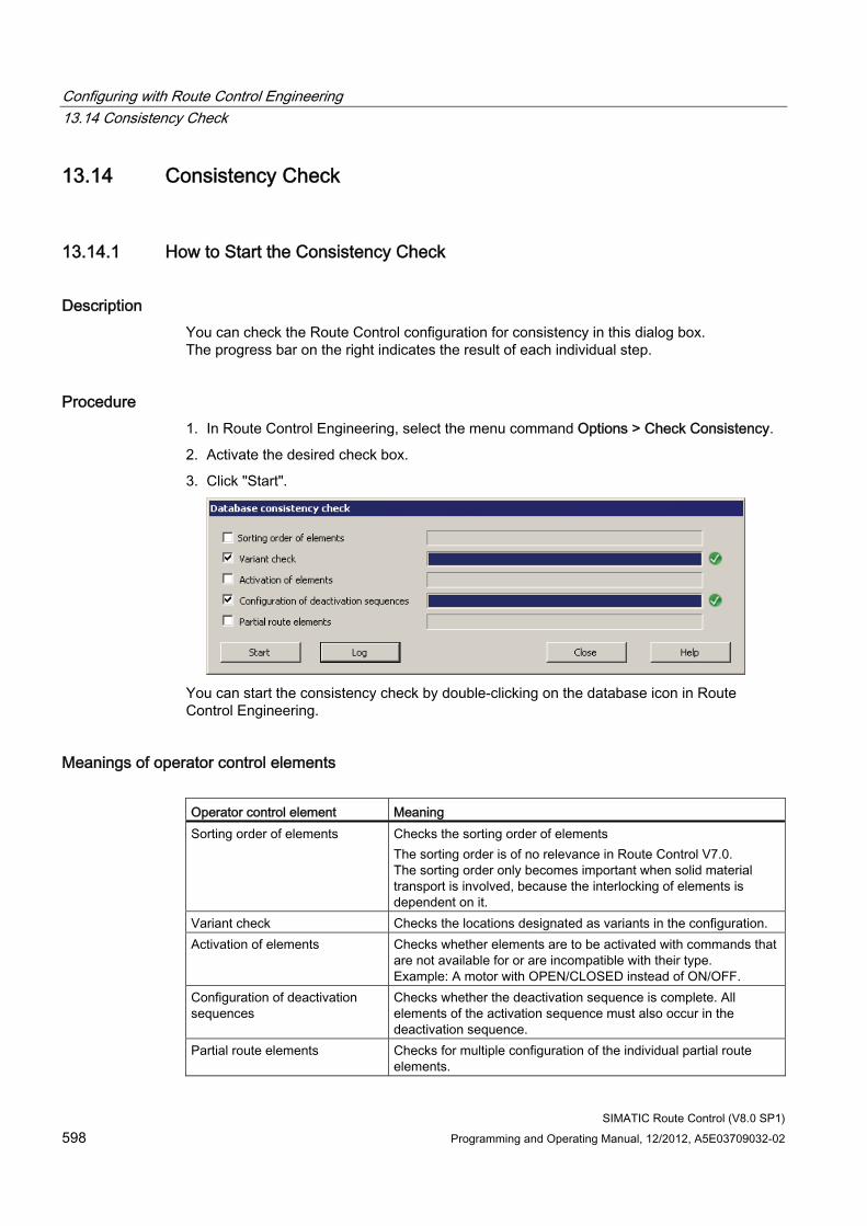
Configuring with Route Control Engineering 13.14 Consistency Check
SIMATIC Route Control (V8.0 SP1) 598 Programming and Operating Manual, 12/2012, A5E03709032-02
13.14 Consistency Check
13.14.1 How to Start the Consistency Check
Description You can check the Route Control configuration for consistency in this dialog box. The progress bar on the right indicates the result of each individual step.
Procedure 1. In Route Control Engineering, select the menu command Options > Check Consistency.
2. Activate the desired check box.
3. Click "Start".
You can start the consistency check by double-clicking on the database icon in Route Control Engineering.
Meanings of operator control elements Operator control element Meaning Sorting order of elements Checks the sorting order of elements
The sorting order is of no relevance in Route Control V7.0. The sorting order only becomes important when solid material transport is involved, because the interlocking of elements is dependent on it.
Variant check Checks the locations designated as variants in the configuration. Activation of elements Checks whether elements are to be activated with commands that
are not available for or are incompatible with their type. Example: A motor with OPEN/CLOSED instead of ON/OFF.
Configuration of deactivation sequences
Checks whether the deactivation sequence is complete. All elements of the activation sequence must also occur in the deactivation sequence.
Partial route elements Checks for multiple configuration of the individual partial route elements.
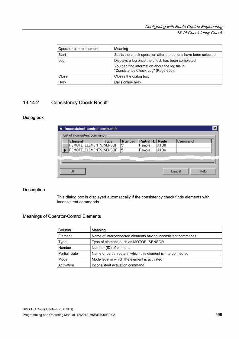
Configuring with Route Control Engineering 13.14 Consistency Check
SIMATIC Route Control (V8.0 SP1) Programming and Operating Manual, 12/2012, A5E03709032-02 599
Operator control element Meaning Start Starts the check operation after the options have been selected Log... Displays a log once the check has been completed
You can find information about the log file in "Consistency Check Log" (Page 600).
Close Closes the dialog box Help Calls online help
13.14.2 Consistency Check Result
Dialog box
Description This dialog box is displayed automatically if the consistency check finds elements with inconsistent commands.
Meanings of Operator-Control Elements Column Meaning Element Name of interconnected elements having inconsistent commands. Type Type of element, such as MOTOR, SENSOR Number Number (ID) of element Partial route Name of partial route in which this element is interconnected Mode Mode level in which the element is activated Activation Inconsistent activation command
Configuring with Route Control Engineering 13.14 Consistency Check
SIMATIC Route Control (V8.0 SP1) 600 Programming and Operating Manual, 12/2012, A5E03709032-02
13.14.3 Consistency Check Log
File Name RC_CONSISTENCY.LOG
File Location The log file is stored in the same path where the Route Control project database is located. You can find additional information about this in the section "Saving a Route Control Project" (Page 503)
File Sections ● Verification log
– S7 project name: Name of S7 project containing the Route Control project
– S7 project path: Path to the S7 project
– Route Control project name: Name of Route Control project (database file name)
– Route Control project path: Path to the Route Control project
– User: User who initiated the export operation.
– Verification date: Time stamp indicating date of consistency check
● Options
– Settings you have made
– ID conventions: Yes/No
– Sorting order of elements: Yes/No
– Variant check: Yes/No
– Activation of elements: Yes/No
– Configuration of deactivation sequences: Yes/No
– Partial route elements: Yes/No
● Verify sorting order of elements
– Checks that the element numbers are in ascending order within the partial route mode levels.
● Check variants
– Checks whether locations that are used as variants are only of the VIA type.
● Verify activation of elements:
– Checks to determine whether an element command exists at all in the element type in a partial route.
Configuring with Route Control Engineering 13.14 Consistency Check
SIMATIC Route Control (V8.0 SP1) Programming and Operating Manual, 12/2012, A5E03709032-02 601
● Check configuration of deactivation sequences
– Checks whether the deactivation sequence is complete. All elements of the activation sequence must also occur in the deactivation sequence.
● Check partial route elements
– Checks for multiple configuration of the individual partial route elements.
Configuring with Route Control Engineering 13.15 Transfer to the Server
SIMATIC Route Control (V8.0 SP1) 602 Programming and Operating Manual, 12/2012, A5E03709032-02
13.15 Transfer to the Server
13.15.1 Downloading the Route Control Server
Initial Download to the Route Control Server Proceed as follows the first time you download the Route Control configuration:
Step Action 1 Start the Route Control server via the Windows Start menu by selecting the menu
command Start > SIMATIC > Route Control > Server. The Route Control server attempts to read a configuration in. As no configuration is available yet, it assumes error status.
2 Download the Route Control configuration to the server via Route Control Engineering by selecting the menu command Options > Download to Server. Specify whether it should also be downloaded to the clients (this selection only needs to be made once).
3 Open the Route Control Center. 4 Select the menu command View > Server Status. 5 Update the Route Control server.
The server retains its error status. 6 Restart the Route Control server.
The Route Control server finds the configuration and starts up without errors.
Now download the configuration to the clients just once. Proceed as follows:
Step Action 1 In the Component view of SIMATIC Manager, select the "RC Application Client" object in
the PC station. 2 Open the shortcut menu of the "Route Control" object and select the menu command PLC
> Download. The configuration is downloaded to the client.
Configuring with Route Control Engineering 13.15 Transfer to the Server
SIMATIC Route Control (V8.0 SP1) Programming and Operating Manual, 12/2012, A5E03709032-02 603
Updating (Subsequent Download to) the Route Control Server To transfer the Route Control configuration to the Route Control server and make it active after changes have been made, proceed as follows:
Step Action 1 Download the Route Control configuration to the server via Route Control Engineering
using the menu command Options > Download to Server. This is only a preparatory step; the changes have not yet been made effective.
2 Open the Route Control Center. 3 Select the menu command View > Server Status. 4 Update the Route Control server.
The previous configuration is replaced with the new one.
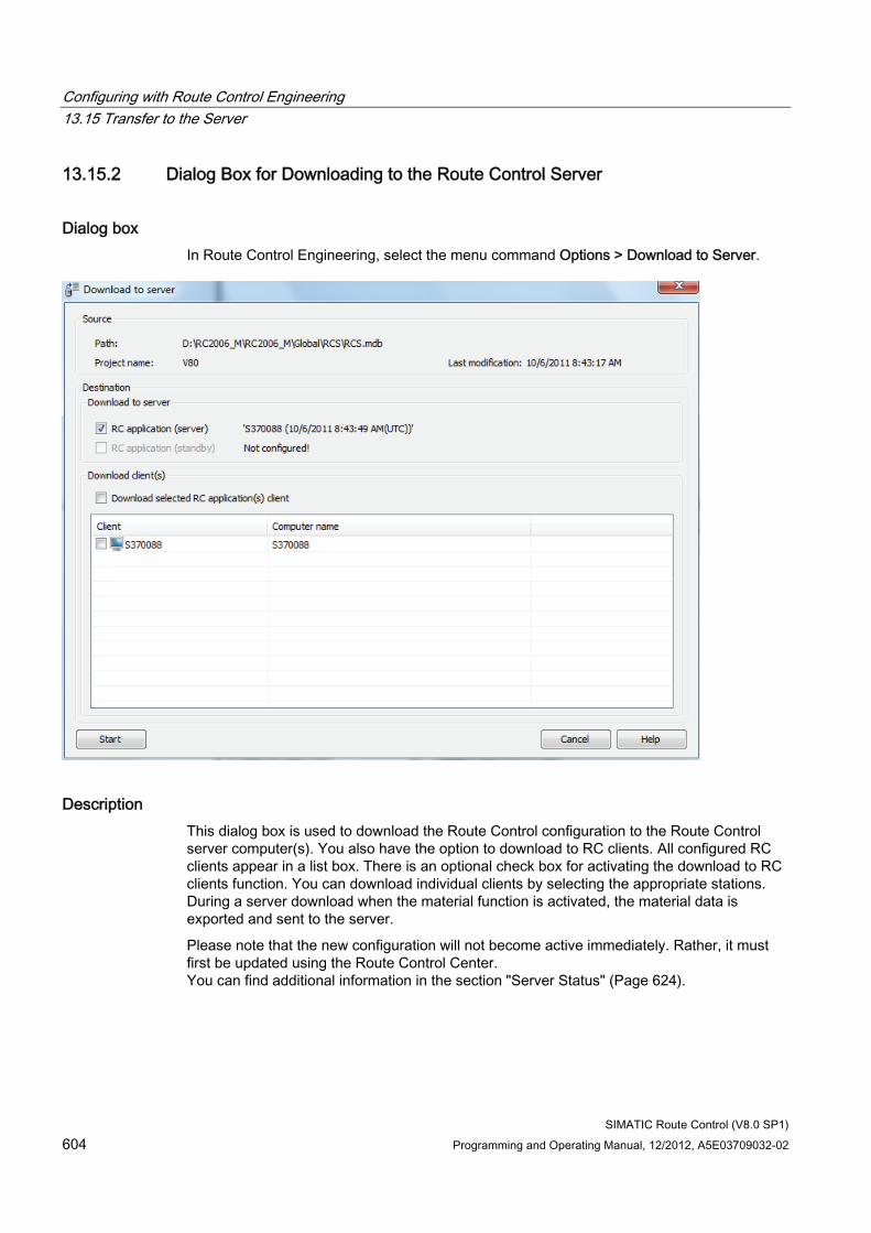
Configuring with Route Control Engineering 13.15 Transfer to the Server
SIMATIC Route Control (V8.0 SP1) 604 Programming and Operating Manual, 12/2012, A5E03709032-02
13.15.2 Dialog Box for Downloading to the Route Control Server
Dialog box In Route Control Engineering, select the menu command Options > Download to Server.
Description This dialog box is used to download the Route Control configuration to the Route Control server computer(s). You also have the option to download to RC clients. All configured RC clients appear in a list box. There is an optional check box for activating the download to RC clients function. You can download individual clients by selecting the appropriate stations. During a server download when the material function is activated, the material data is exported and sent to the server.
Please note that the new configuration will not become active immediately. Rather, it must first be updated using the Route Control Center. You can find additional information in the section "Server Status" (Page 624).
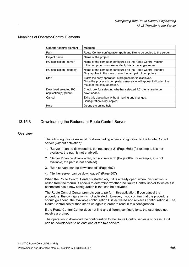
Configuring with Route Control Engineering 13.15 Transfer to the Server
SIMATIC Route Control (V8.0 SP1) Programming and Operating Manual, 12/2012, A5E03709032-02 605
Meanings of Operator-Control Elements Operator-control element Meaning Path Route Control configuration (path and file) to be copied to the server Project name Name of the project RC application (server) Name of the computer configured as the Route Control master
If the computer is non-redundant, this is the single server. RC application (standby) Name of the computer configured as the Route Control standby
Only applies in the case of a redundant pair of computers Start Starts the copy operation; a progress bar is displayed.
Once the process is complete, a message will appear indicating the result of the copy operation.
Download selected RC application(s) (client)
Check box for selecting whether selected RC clients are to be downloaded.
Cancel Exits this dialog box without making any changes. Configuration is not copied.
Help Opens the online help
13.15.3 Downloading the Redundant Route Control Server
Overview The following four cases exist for downloading a new configuration to the Route Control server (without activation):
1. "Server 1 can be downloaded, but not server 2" (Page 606) (for example, it is not available, the path is not enabled).
2. "Server 2 can be downloaded, but not server 1" (Page 606) (for example, it is not available, the path is not enabled).
3. "Both servers can be downloaded" (Page 607)
4. "Neither server can be downloaded" (Page 607)
When the Route Control Center is started (or, if it is already open, when this function is called from the menu), it checks to determine whether the Route Control server to which it is connected has a new configuration B that can be activated.
The Route Control Center prompts you to perform this activation. If you cancel the procedure, the configuration is not activated. However, if you confirm that the procedure should go ahead, the available configuration B is activated and replaces configuration A. The Route Control server then starts up again in order to read in this configuration.
If the Route Control Center does not find any different configurations, the user does not receive a prompt.
The operation to download the configuration to the Route Control server is successful if it can be downloaded to at least one of the two servers.
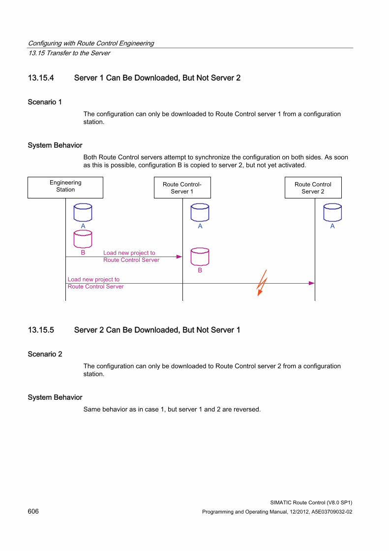
Configuring with Route Control Engineering 13.15 Transfer to the Server
SIMATIC Route Control (V8.0 SP1) 606 Programming and Operating Manual, 12/2012, A5E03709032-02
13.15.4 Server 1 Can Be Downloaded, But Not Server 2
Scenario 1 The configuration can only be downloaded to Route Control server 1 from a configuration station.
System Behavior Both Route Control servers attempt to synchronize the configuration on both sides. As soon as this is possible, configuration B is copied to server 2, but not yet activated.
13.15.5 Server 2 Can Be Downloaded, But Not Server 1
Scenario 2 The configuration can only be downloaded to Route Control server 2 from a configuration station.
System Behavior Same behavior as in case 1, but server 1 and 2 are reversed.
Configuring with Route Control Engineering 13.15 Transfer to the Server
SIMATIC Route Control (V8.0 SP1) Programming and Operating Manual, 12/2012, A5E03709032-02 607
13.15.6 Both Servers Can Be Downloaded
Scenario 3 The configuration can be downloaded to Route Control servers 1 and 2 from a configuration station.
System Behavior Same status as following synchronization of scenarios 1 and 2.
Additional information ● Section "Server 1 Can Be Downloaded, But Not Server 2" (Page 606)
● Section "Server 2 Can Be Downloaded, But Not Server 1" (Page 606)
13.15.7 Neither Server Can Be Downloaded
Scenario 4 The configuration cannot be downloaded to Route Control servers 1 or 2 from a configuration station.
System Behavior The system can not synchronize any of the databases; you must correct the error (missing share attribute for the directory on the server computer, for example) and reload.

Configuring with Route Control Engineering 13.15 Transfer to the Server
SIMATIC Route Control (V8.0 SP1) 608 Programming and Operating Manual, 12/2012, A5E03709032-02

SIMATIC Route Control (V8.0 SP1) Programming and Operating Manual, 12/2012, A5E03709032-02 609
Operator Control and Monitoring 1414.1 Operator Control and Monitoring Overview
Overview Operator control and monitoring of the objects relevant to Route Control can be performed using:
● Route Control block icon for a route Additional information:
– Section "Block Icon Structure" (Page 611)
– Section "Block Icon Display Elements" (Page 612)
● Route Control faceplate for a route Additional information:
– Section "Opening the Route Control Faceplate" (Page 613)
– Section "Faceplate Display and Operator-Control Elements - 1/4" (Page 614)
– Section "Faceplate Display and Operator-Control Elements - 2/4" (Page 615)
– Section "Faceplate Display and Operator-Control Elements - 3/4" (Page 616)
– Section "Faceplate Display and Operator-Control Elements - 4/4" (Page 617)
● Route Control Center for a route or routes Additional information:
– Section "Route Control Center" (Page 619)
● Route Control server Additional information:
– Section "Calling the Route Control Server" (Page 668)
– Section "Route Control Server Startup Sequence" (Page 672)
– Section "Route Control Server Status" (Page 673)
– Section "Redundancy Failover" (Page 674)
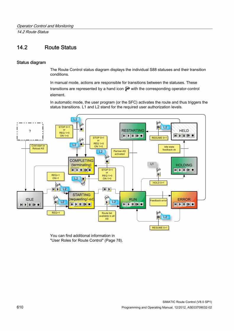
Operator Control and Monitoring 14.2 Route Status
SIMATIC Route Control (V8.0 SP1) 610 Programming and Operating Manual, 12/2012, A5E03709032-02
14.2 Route Status
Status diagram The Route Control status diagram displays the individual S88 statuses and their transition conditions.
In manual mode, actions are responsible for transitions between the statuses. These transitions are represented by a hand icon with the corresponding operator-control element.
In automatic mode, the user program (or the SFC) activates the route and thus triggers the status transitions. L1 and L2 stand for the required user authorization levels.
You can find additional information in "User Roles for Route Control" (Page 78).
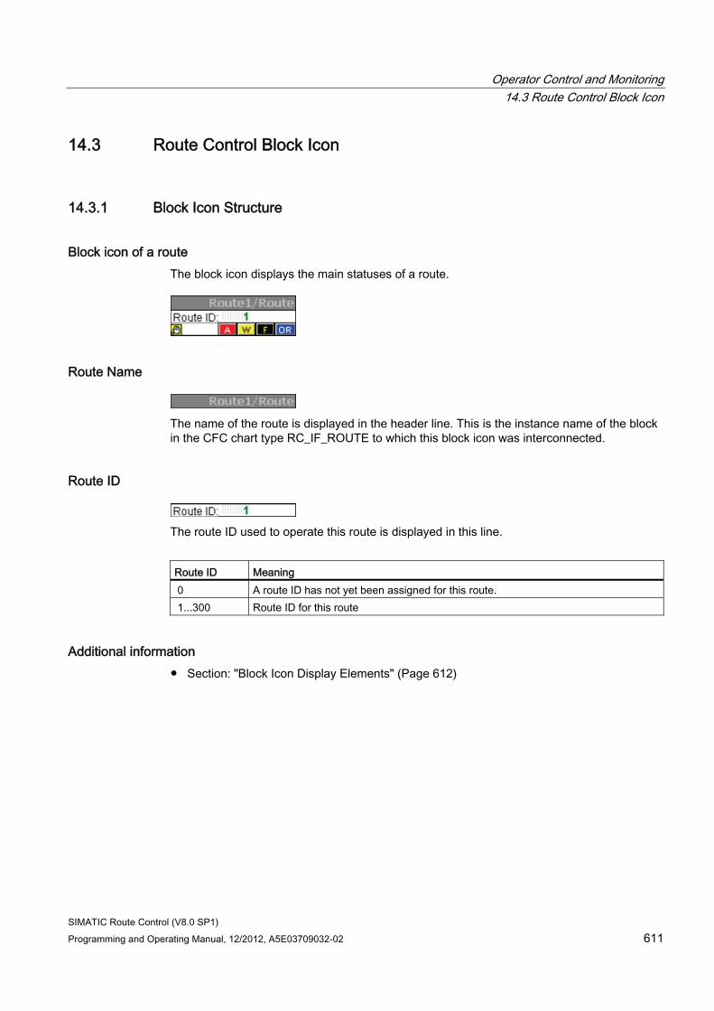
Operator Control and Monitoring 14.3 Route Control Block Icon
SIMATIC Route Control (V8.0 SP1) Programming and Operating Manual, 12/2012, A5E03709032-02 611
14.3 Route Control Block Icon
14.3.1 Block Icon Structure
Block icon of a route The block icon displays the main statuses of a route.
Route Name
The name of the route is displayed in the header line. This is the instance name of the block in the CFC chart type RC_IF_ROUTE to which this block icon was interconnected.
Route ID
The route ID used to operate this route is displayed in this line.
Route ID Meaning 0 A route ID has not yet been assigned for this route. 1...300 Route ID for this route
Additional information ● Section: "Block Icon Display Elements" (Page 612)
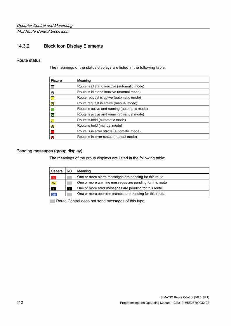
Operator Control and Monitoring 14.3 Route Control Block Icon
SIMATIC Route Control (V8.0 SP1) 612 Programming and Operating Manual, 12/2012, A5E03709032-02
14.3.2 Block Icon Display Elements
Route status The meanings of the status displays are listed in the following table:
Picture Meaning
Route is idle and inactive (automatic mode)
Route is idle and inactive (manual mode)
Route request is active (automatic mode)
Route request is active (manual mode)
Route is active and running (automatic mode)
Route is active and running (manual mode)
Route is held (automatic mode)
Route is held (manual mode)
Route is in error status (automatic mode)
Route is in error status (manual mode)
Pending messages (group display) The meanings of the group displays are listed in the following table:
General RC Meaning
One or more alarm messages are pending for this route
One or more warning messages are pending for this route
One or more error messages are pending for this route
One or more operator prompts are pending for this route
Route Control does not send messages of this type.
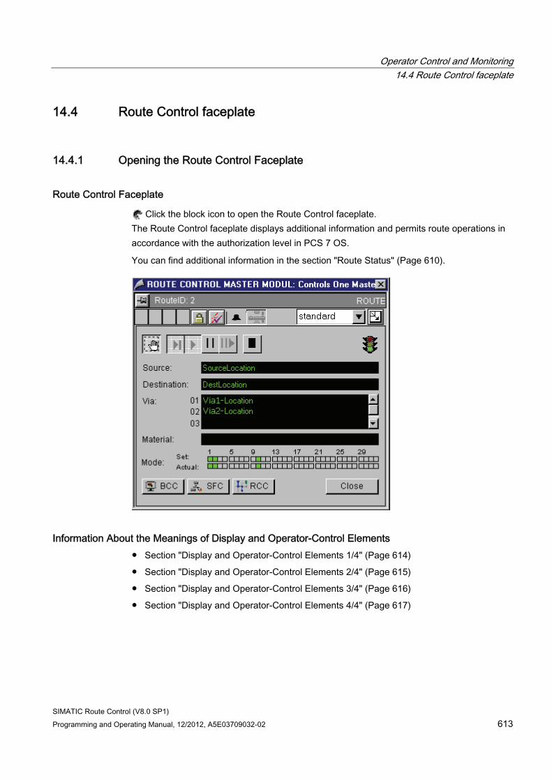
Operator Control and Monitoring 14.4 Route Control faceplate
SIMATIC Route Control (V8.0 SP1) Programming and Operating Manual, 12/2012, A5E03709032-02 613
14.4 Route Control faceplate
14.4.1 Opening the Route Control Faceplate
Route Control Faceplate
Click the block icon to open the Route Control faceplate. The Route Control faceplate displays additional information and permits route operations in accordance with the authorization level in PCS 7 OS.
You can find additional information in the section "Route Status" (Page 610).
Information About the Meanings of Display and Operator-Control Elements ● Section "Display and Operator-Control Elements 1/4" (Page 614)
● Section "Display and Operator-Control Elements 2/4" (Page 615)
● Section "Display and Operator-Control Elements 3/4" (Page 616)
● Section "Display and Operator-Control Elements 4/4" (Page 617)
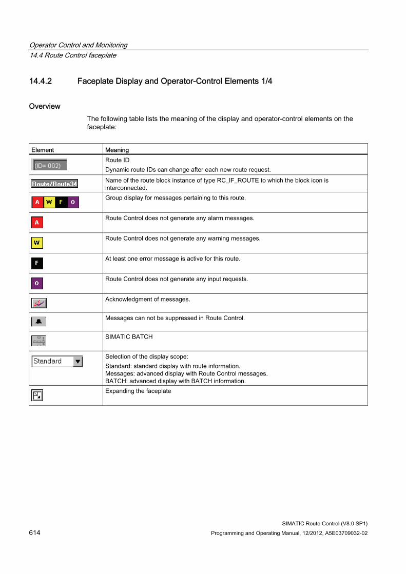
Operator Control and Monitoring 14.4 Route Control faceplate
SIMATIC Route Control (V8.0 SP1) 614 Programming and Operating Manual, 12/2012, A5E03709032-02
14.4.2 Faceplate Display and Operator-Control Elements 1/4
Overview The following table lists the meaning of the display and operator-control elements on the faceplate:
Element Meaning
Route ID Dynamic route IDs can change after each new route request.
Name of the route block instance of type RC_IF_ROUTE to which the block icon is interconnected.
Group display for messages pertaining to this route.
Route Control does not generate any alarm messages.
Route Control does not generate any warning messages.
At least one error message is active for this route.
Route Control does not generate any input requests.
Acknowledgment of messages.
Messages can not be suppressed in Route Control.
SIMATIC BATCH
Selection of the display scope: Standard: standard display with route information. Messages: advanced display with Route Control messages. BATCH: advanced display with BATCH information.
Expanding the faceplate
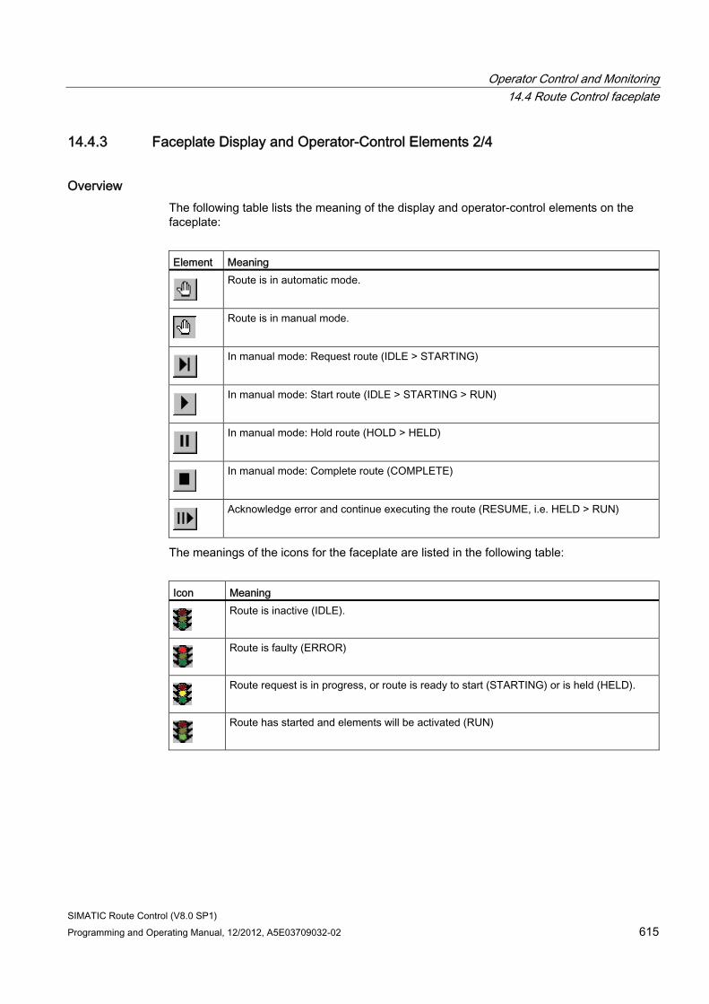
Operator Control and Monitoring 14.4 Route Control faceplate
SIMATIC Route Control (V8.0 SP1) Programming and Operating Manual, 12/2012, A5E03709032-02 615
14.4.3 Faceplate Display and Operator-Control Elements 2/4
Overview The following table lists the meaning of the display and operator-control elements on the faceplate:
Element Meaning
Route is in automatic mode.
Route is in manual mode.
In manual mode: Request route (IDLE > STARTING)
In manual mode: Start route (IDLE > STARTING > RUN)
In manual mode: Hold route (HOLD > HELD)
In manual mode: Complete route (COMPLETE)
Acknowledge error and continue executing the route (RESUME, i.e. HELD > RUN)
The meanings of the icons for the faceplate are listed in the following table:
Icon Meaning
Route is inactive (IDLE).
Route is faulty (ERROR)
Route request is in progress, or route is ready to start (STARTING) or is held (HELD).
Route has started and elements will be activated (RUN)
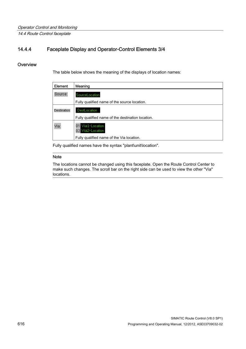
Operator Control and Monitoring 14.4 Route Control faceplate
SIMATIC Route Control (V8.0 SP1) 616 Programming and Operating Manual, 12/2012, A5E03709032-02
14.4.4 Faceplate Display and Operator-Control Elements 3/4
Overview The table below shows the meaning of the displays of location names:
Element Meaning
Fully qualified name of the source location.
Fully qualified name of the destination location.
Fully qualified name of the Via location.
Fully qualified names have the syntax "plant\unit\location".
Note
The locations cannot be changed using this faceplate. Open the Route Control Center to make such changes. The scroll bar on the right side can be used to view the other "Via" locations.
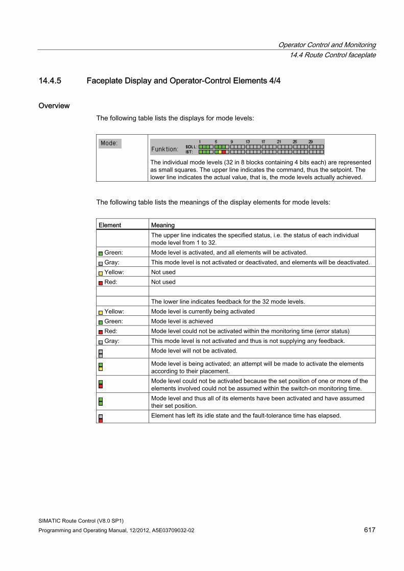
Operator Control and Monitoring 14.4 Route Control faceplate
SIMATIC Route Control (V8.0 SP1) Programming and Operating Manual, 12/2012, A5E03709032-02 617
14.4.5 Faceplate Display and Operator-Control Elements 4/4
Overview The following table lists the displays for mode levels:
The individual mode levels (32 in 8 blocks containing 4 bits each) are represented as small squares. The upper line indicates the command, thus the setpoint. The lower line indicates the actual value, that is, the mode levels actually achieved.
The following table lists the meanings of the display elements for mode levels:
Element Meaning The upper line indicates the specified status, i.e. the status of each individual
mode level from 1 to 32. Green: Mode level is activated, and all elements will be activated. Gray: This mode level is not activated or deactivated, and elements will be deactivated. Yellow: Not used Red: Not used
The lower line indicates feedback for the 32 mode levels.
Yellow: Mode level is currently being activated Green: Mode level is achieved Red: Mode level could not be activated within the monitoring time (error status) Gray: This mode level is not activated and thus is not supplying any feedback.
Mode level will not be activated.
Mode level is being activated; an attempt will be made to activate the elements according to their placement.
Mode level could not be activated because the set position of one or more of the elements involved could not be assumed within the switch-on monitoring time.
Mode level and thus all of its elements have been activated and have assumed their set position.
Element has left its idle state and the fault-tolerance time has elapsed.
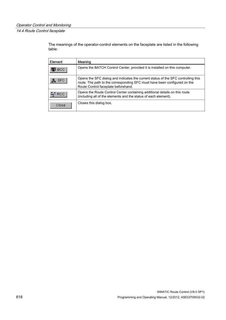
Operator Control and Monitoring 14.4 Route Control faceplate
SIMATIC Route Control (V8.0 SP1) 618 Programming and Operating Manual, 12/2012, A5E03709032-02
The meanings of the operator-control elements on the faceplate are listed in the following table:
Element Meaning
Opens the BATCH Control Center, provided it is installed on this computer.
Opens the SFC dialog and indicates the current status of the SFC controlling this route. The path to the corresponding SFC must have been configured on the Route Control faceplate beforehand.
Opens the Route Control Center containing additional details on this route (including all of the elements and the status of each element).
Closes this dialog box.
Operator Control and Monitoring 14.5 Route Control Center
SIMATIC Route Control (V8.0 SP1) Programming and Operating Manual, 12/2012, A5E03709032-02 619
14.5 Route Control Center
14.5.1 General
14.5.1.1 Route Control Center Overview
Open the Route Control Center. The following options of opening the Route Control Center are available:
● Using the Windows Start menu
● Using the PCS 7 OS keyset
● Using the Route Control faceplate from a PCS 7 OS picture
Route information The Route Control Center provides information about a route and its elements. The user interface of the Route Control Center is divided into two areas. The upper area displays the route data.
If the Route Control Center is started from a PCS 7 OS picture by means of the Route Control faceplate, only the route associated with this faceplate is displayed. If several routes use the same function ID, all of these routes are displayed.
If the Route Control Center is not started using the Route Control faceplate, all routes are displayed.
Three views The lower area of the window displays the elements of the route selected in the upper area.
You can choose among three views:
● "Modes" tab: Each element and its type of control at the different mode levels are displayed in a row. Unused mode levels are hidden.
● "Elements" tab: Displays all route elements, including the actual position and the position setpoint. An element controlled at several mode levels is displayed in an appropriate number of rows.
● "Partial routes" tab: Displays all partial routes of the selected active route.
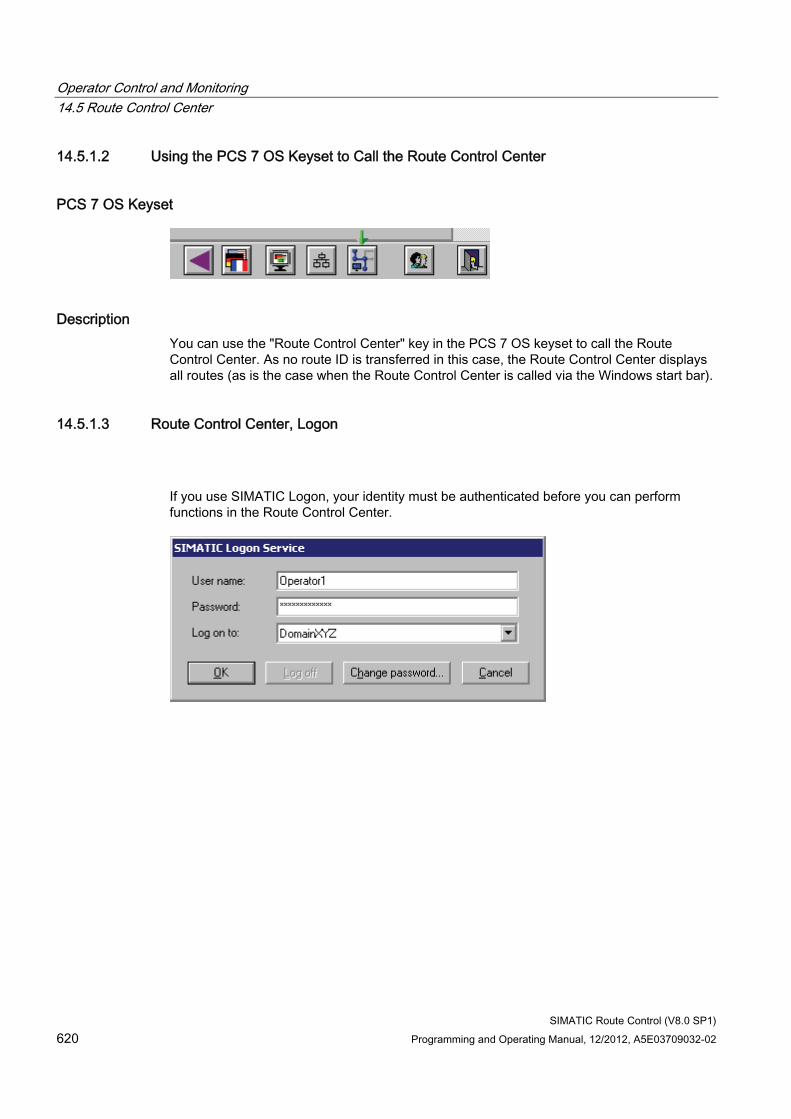
Operator Control and Monitoring 14.5 Route Control Center
SIMATIC Route Control (V8.0 SP1) 620 Programming and Operating Manual, 12/2012, A5E03709032-02
14.5.1.2 Using the PCS 7 OS Keyset to Call the Route Control Center
PCS 7 OS Keyset
Description You can use the "Route Control Center" key in the PCS 7 OS keyset to call the Route Control Center. As no route ID is transferred in this case, the Route Control Center displays all routes (as is the case when the Route Control Center is called via the Windows start bar).
14.5.1.3 Route Control Center, Logon
If you use SIMATIC Logon, your identity must be authenticated before you can perform functions in the Route Control Center.
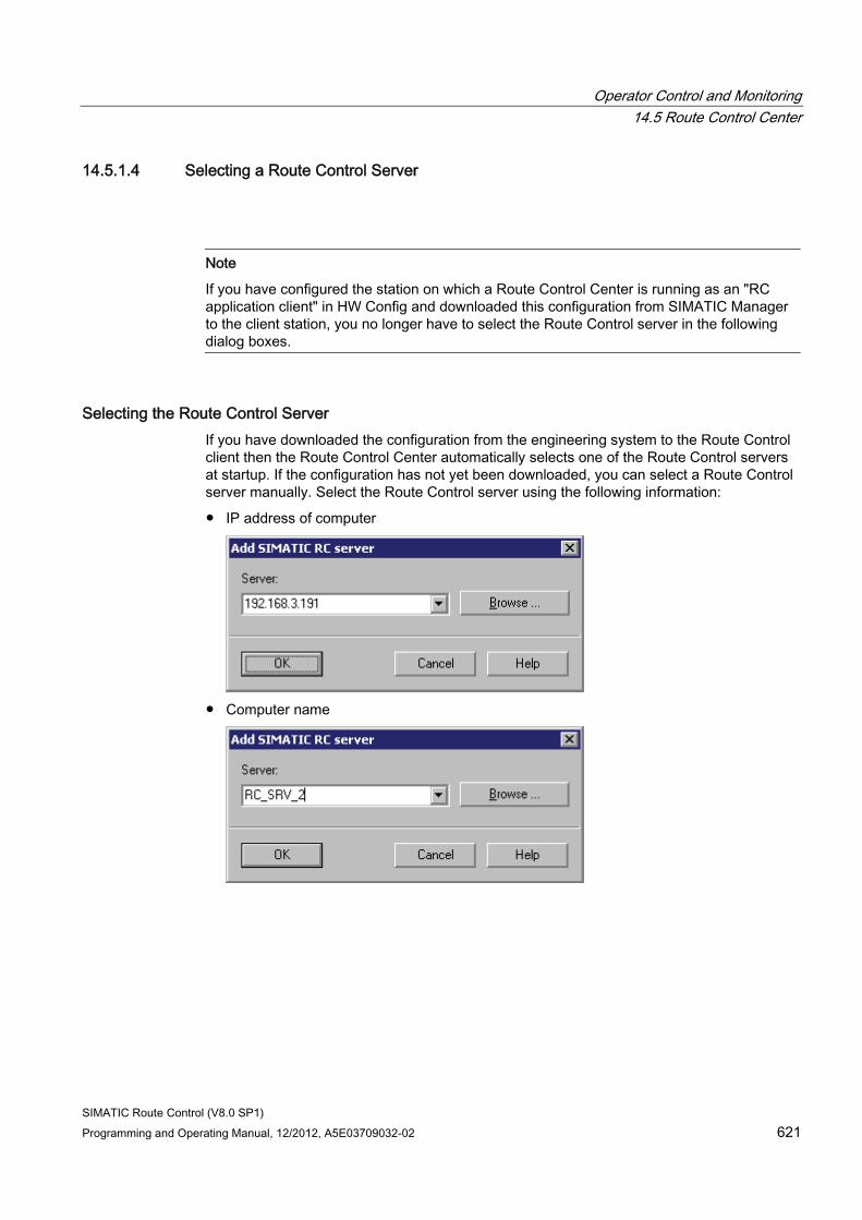
Operator Control and Monitoring 14.5 Route Control Center
SIMATIC Route Control (V8.0 SP1) Programming and Operating Manual, 12/2012, A5E03709032-02 621
14.5.1.4 Selecting a Route Control Server
Note
If you have configured the station on which a Route Control Center is running as an "RC application client" in HW Config and downloaded this configuration from SIMATIC Manager to the client station, you no longer have to select the Route Control server in the following dialog boxes.
Selecting the Route Control Server If you have downloaded the configuration from the engineering system to the Route Control client then the Route Control Center automatically selects one of the Route Control servers at startup. If the configuration has not yet been downloaded, you can select a Route Control server manually. Select the Route Control server using the following information:
● IP address of computer
● Computer name
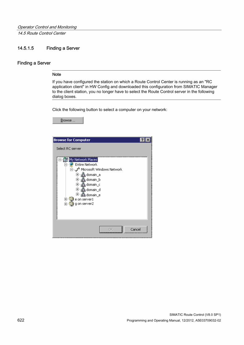
Operator Control and Monitoring 14.5 Route Control Center
SIMATIC Route Control (V8.0 SP1) 622 Programming and Operating Manual, 12/2012, A5E03709032-02
14.5.1.5 Finding a Server
Finding a Server
Note
If you have configured the station on which a Route Control Center is running as an "RC application client" in HW Config and downloaded this configuration from SIMATIC Manager to the client station, you no longer have to select the Route Control server in the following dialog boxes.
Click the following button to select a computer on your network:
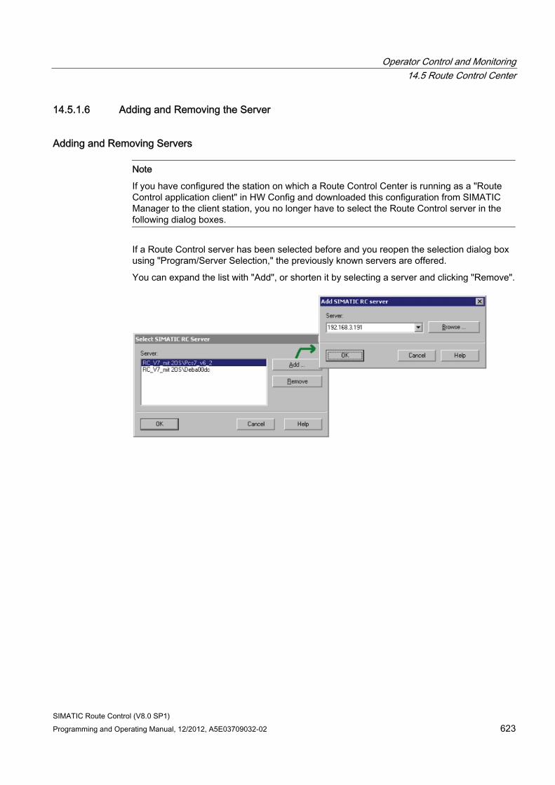
Operator Control and Monitoring 14.5 Route Control Center
SIMATIC Route Control (V8.0 SP1) Programming and Operating Manual, 12/2012, A5E03709032-02 623
14.5.1.6 Adding and Removing the Server
Adding and Removing Servers
Note
If you have configured the station on which a Route Control Center is running as a "Route Control application client" in HW Config and downloaded this configuration from SIMATIC Manager to the client station, you no longer have to select the Route Control server in the following dialog boxes.
If a Route Control server has been selected before and you reopen the selection dialog box using "Program/Server Selection," the previously known servers are offered.
You can expand the list with "Add", or shorten it by selecting a server and clicking "Remove".
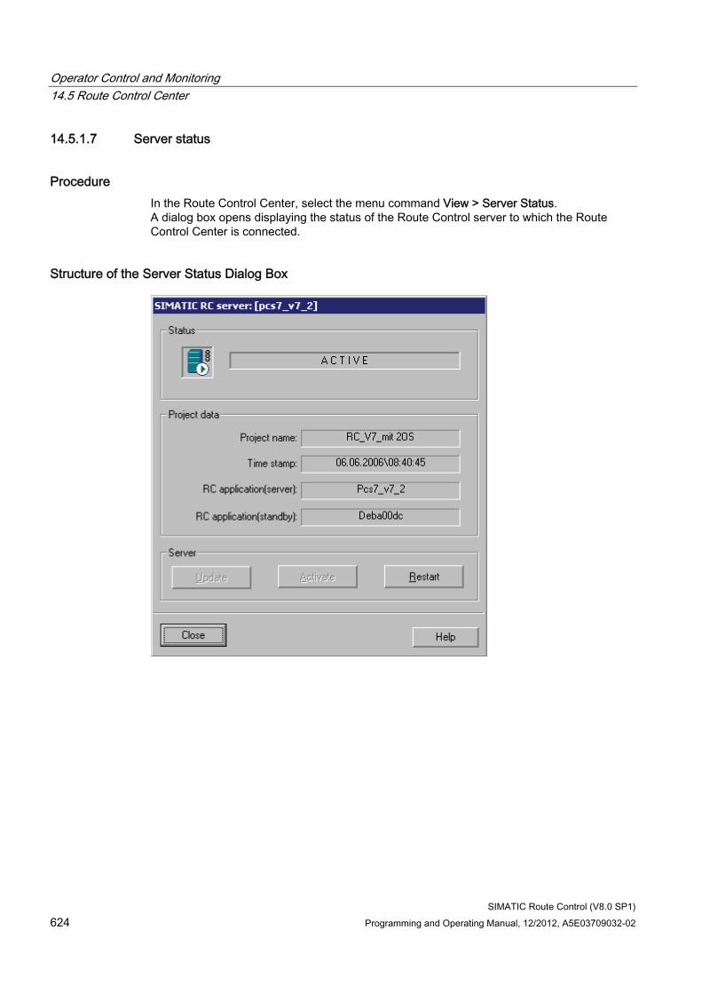
Operator Control and Monitoring 14.5 Route Control Center
SIMATIC Route Control (V8.0 SP1) 624 Programming and Operating Manual, 12/2012, A5E03709032-02
14.5.1.7 Server status
Procedure In the Route Control Center, select the menu command View > Server Status. A dialog box opens displaying the status of the Route Control server to which the Route Control Center is connected.
Structure of the Server Status Dialog Box
Operator Control and Monitoring 14.5 Route Control Center
SIMATIC Route Control (V8.0 SP1) Programming and Operating Manual, 12/2012, A5E03709032-02 625
Meanings of Operator-Control Elements The meanings of the operator-control elements in the "Server status" dialog box are listed in the following table:
Operator-control element
Meaning
Update Copies a modified Route Control Configuration that was previously copied to the server to the active area of the server and activates a restart once confirmation is received. You can find additional information in "Updating the Route Control Server" (Page 626)
Activate Activates the standby computer as the master computer. This operator input is only available if the server is currently running in standby mode.
Restart Shuts the Route Control server down, then rereads the configuration and executes a general request. Telegram processing is then enabled again.
Additional information ● Section: "Route Control Server User Interface Dialog" (Page 669)
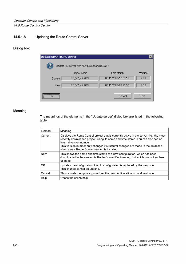
Operator Control and Monitoring 14.5 Route Control Center
SIMATIC Route Control (V8.0 SP1) 626 Programming and Operating Manual, 12/2012, A5E03709032-02
14.5.1.8 Updating the Route Control Server
Dialog box
Meaning The meanings of the elements in the "Update server" dialog box are listed in the following table:
Element Meaning Current Displays the Route Control project that is currently active in the server, i.e., the most
recently downloaded project, using its name and time stamp. You can also see an internal version number. This version number only changes if structural changes are made to the database when a new Route Control version is installed.
New This shows the name and time stamp of a new configuration, which has been downloaded to the server via Route Control Engineering, but which has not yet been updated.
OK Updates the configuration; the old configuration is replaced by the new one. This change cannot be undone.
Cancel This cancels the update procedure, the new configuration is not downloaded. Help Opens the online help
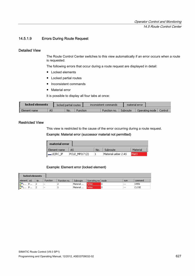
Operator Control and Monitoring 14.5 Route Control Center
SIMATIC Route Control (V8.0 SP1) Programming and Operating Manual, 12/2012, A5E03709032-02 627
14.5.1.9 Errors During Route Request
Detailed View The Route Control Center switches to this view automatically if an error occurs when a route is requested.
The following errors that occur during a route request are displayed in detail:
● Locked elements
● Locked partial routes
● Inconsistent commands
● Material error
It is possible to display all four tabs at once:
Restricted View This view is restricted to the cause of the error occurring during a route request.
Example: Material error (successor material not permitted)
Example: Element error (locked element)
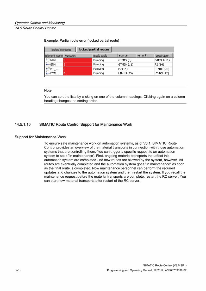
Operator Control and Monitoring 14.5 Route Control Center
SIMATIC Route Control (V8.0 SP1) 628 Programming and Operating Manual, 12/2012, A5E03709032-02
Example: Partial route error (locked partial route)
Note
You can sort the lists by clicking on one of the column headings. Clicking again on a column heading changes the sorting order.
14.5.1.10 SIMATIC Route Control Support for Maintenance Work
Support for Maintenance Work To ensure safe maintenance work on automation systems, as of V6.1, SIMATIC Route Control provides an overview of the material transports in connection with those automation systems that are controlling them. You can trigger a specific request to an automation system to set it "in maintenance". First, ongoing material transports that affect this automation system are completed - no new routes are allowed by the system, however. All routes are eventually completed and the automation system goes "in maintenance" as soon as the final route is completed. Now maintenance personnel can perform the required updates and changes to the automation system and then restart the system. If you recall the maintenance request before the material transports are complete, restart the RC server. You can start new material transports after restart of the RC server.
Operator Control and Monitoring 14.5 Route Control Center
SIMATIC Route Control (V8.0 SP1) Programming and Operating Manual, 12/2012, A5E03709032-02 629
14.5.1.11 AS in Maintenance
Introduction Route Control supports your AS maintenance. An AS must be set to "Maintenance" state for
● Updating single blocks
● Updating all AS blocks (initial download after hardware has been replaced)
Sequence of Steps Since an AS can control routes actively as well as participate passively in the route (as a slave), an AS can not simply be stopped. This could lead to the product being lost in the process cell. Therefore, you must perform the steps below:
Step Action 1 Requesting the "Maintenance" state
For further information, refer to the section "Route Control Center: Maintenance View" (Page 641).
2 The system stops after all active routes are completed and does not permit any new routes. You can intervene here and complete the routes or stop them manually.
3 Once all routes have been completed on this AS, the Route Control AS switches to "Maintenance" status.
4 Now make the required changes on this AS (e.g., replace hardware and/or software).
5 The maintenance work is completed. 6 The maintenance request is canceled in the Route Control Center
For further information, refer to the section "Route Control Center: Maintenance View". (Page 641).
7 As soon as the AS is back in "Production" status... 8 ... routes (material transports) can be started again.
A message (PCS 7 OS status message of the Route Control Server) is output to the alarm system at each transition between the "Production" and "Maintenance" states. For further information, refer to the section "OS messages (system, server)". (Page 694).
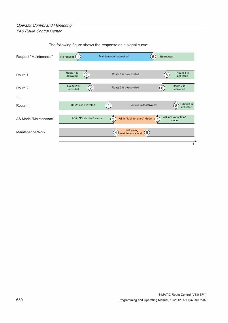
Operator Control and Monitoring 14.5 Route Control Center
SIMATIC Route Control (V8.0 SP1) 630 Programming and Operating Manual, 12/2012, A5E03709032-02
The following figure shows the response as a signal curve:
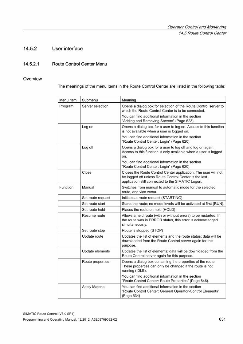
Operator Control and Monitoring 14.5 Route Control Center
SIMATIC Route Control (V8.0 SP1) Programming and Operating Manual, 12/2012, A5E03709032-02 631
14.5.2 User interface
14.5.2.1 Route Control Center Menu
Overview The meanings of the menu items in the Route Control Center are listed in the following table:
Menu item Submenu Meaning Program Server selection Opens a dialog box for selection of the Route Control server to
which the Route Control Center is to be connected. You can find additional information in the section "Adding and Removing Servers" (Page 623).
Log on Opens a dialog box for a user to log on. Access to this function is not available when a user is logged on. You can find additional information in the section "Route Control Center: Login" (Page 620).
Log off Opens a dialog box for a user to log off and log on again. Access to this function is only available when a user is logged on. You can find additional information in the section "Route Control Center: Login" (Page 620).
Close Closes the Route Control Center application. The user will not be logged off unless Route Control Center is the last application still connected to the SIMATIC Logon.
Function Manual Switches from manual to automatic mode for the selected route, and vice versa.
Set route request Initiates a route request (STARTING). Set route start Starts the route; no mode levels will be activated at first (RUN). Set route hold Places the route on hold (HOLD) Resume route Allows a held route (with or without errors) to be restarted. If
the route was in ERROR status, this error is acknowledged simultaneously.
Set route stop Route is stopped (STOP) Update route Updates the list of elements and the route status; data will be
downloaded from the Route Control server again for this purpose.
Update elements Updates the list of elements; data will be downloaded from the Route Control server again for this purpose.
Route properties Opens a dialog box containing the properties of the route. These properties can only be changed if the route is not running (IDLE). You can find additional information in the section "Route Control Center: Route Properties" (Page 646).
Apply Material You can find additional information in the section "Route Control Center: General Operator-Control Elements" (Page 634)
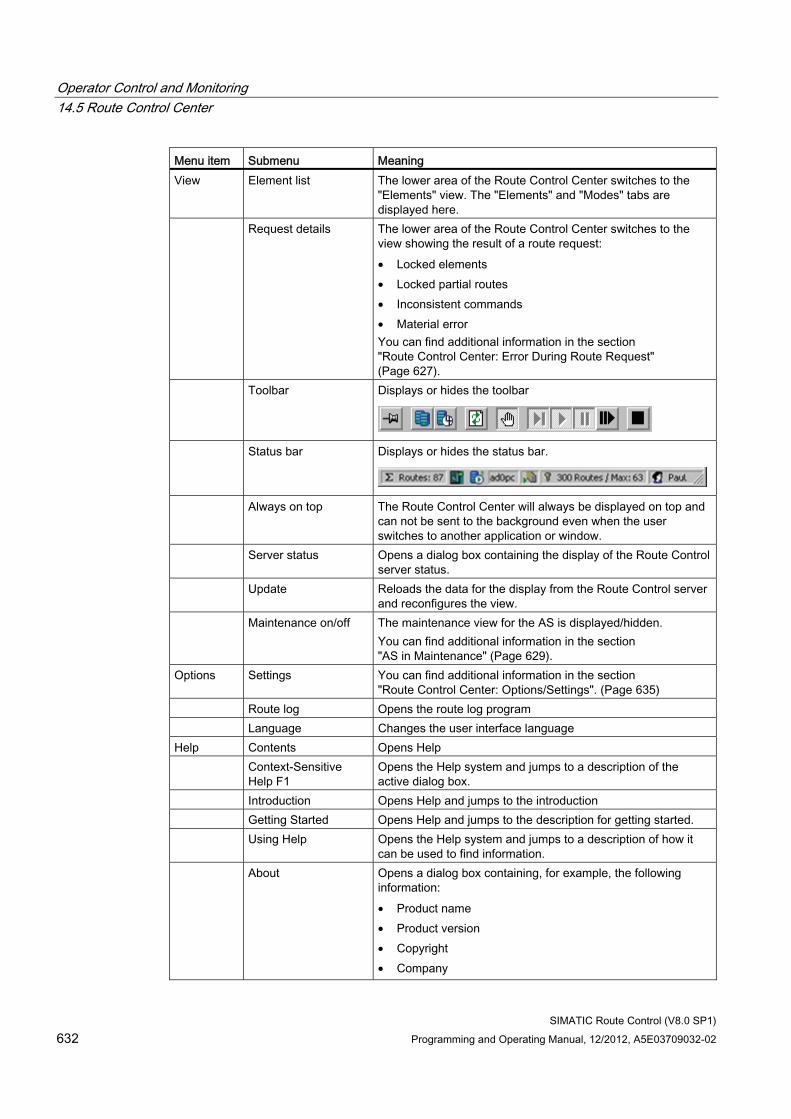
Operator Control and Monitoring 14.5 Route Control Center
SIMATIC Route Control (V8.0 SP1) 632 Programming and Operating Manual, 12/2012, A5E03709032-02
Menu item Submenu Meaning View Element list The lower area of the Route Control Center switches to the
"Elements" view. The "Elements" and "Modes" tabs are displayed here.
Request details The lower area of the Route Control Center switches to the view showing the result of a route request: • Locked elements • Locked partial routes • Inconsistent commands • Material error You can find additional information in the section "Route Control Center: Error During Route Request" (Page 627).
Toolbar Displays or hides the toolbar
Status bar Displays or hides the status bar.
Always on top The Route Control Center will always be displayed on top and can not be sent to the background even when the user switches to another application or window.
Server status Opens a dialog box containing the display of the Route Control server status.
Update Reloads the data for the display from the Route Control server and reconfigures the view.
Maintenance on/off The maintenance view for the AS is displayed/hidden. You can find additional information in the section "AS in Maintenance" (Page 629).
Options Settings You can find additional information in the section "Route Control Center: Options/Settings". (Page 635)
Route log Opens the route log program Language Changes the user interface language Help Contents Opens Help Context-Sensitive
Help F1 Opens the Help system and jumps to a description of the active dialog box.
Introduction Opens Help and jumps to the introduction Getting Started Opens Help and jumps to the description for getting started. Using Help Opens the Help system and jumps to a description of how it
can be used to find information. About Opens a dialog box containing, for example, the following
information: • Product name • Product version • Copyright • Company
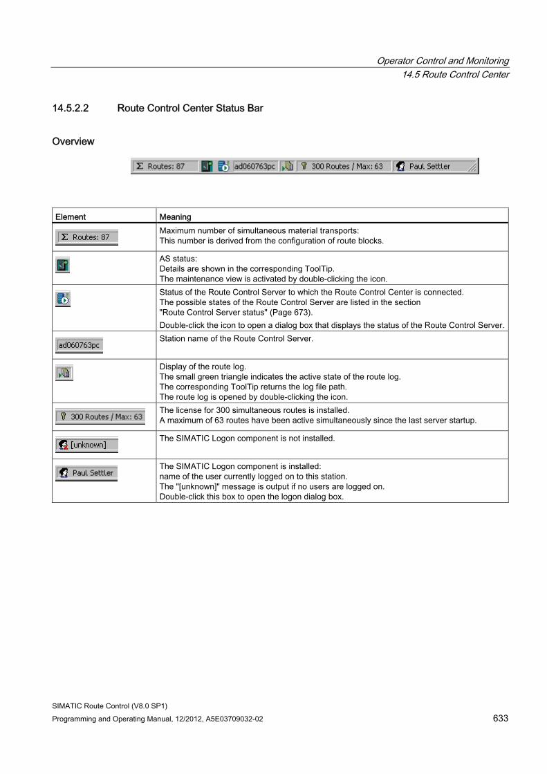
Operator Control and Monitoring 14.5 Route Control Center
SIMATIC Route Control (V8.0 SP1) Programming and Operating Manual, 12/2012, A5E03709032-02 633
14.5.2.2 Route Control Center Status Bar
Overview
Element Meaning
Maximum number of simultaneous material transports: This number is derived from the configuration of route blocks.
AS status: Details are shown in the corresponding ToolTip. The maintenance view is activated by double-clicking the icon.
Status of the Route Control Server to which the Route Control Center is connected. The possible states of the Route Control Server are listed in the section "Route Control Server status" (Page 673). Double-click the icon to open a dialog box that displays the status of the Route Control Server.
Station name of the Route Control Server.
Display of the route log. The small green triangle indicates the active state of the route log. The corresponding ToolTip returns the log file path. The route log is opened by double-clicking the icon.
The license for 300 simultaneous routes is installed. A maximum of 63 routes have been active simultaneously since the last server startup.
The SIMATIC Logon component is not installed.
The SIMATIC Logon component is installed: name of the user currently logged on to this station. The "[unknown]" message is output if no users are logged on. Double-click this box to open the logon dialog box.
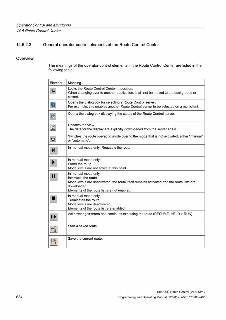
Operator Control and Monitoring 14.5 Route Control Center
SIMATIC Route Control (V8.0 SP1) 634 Programming and Operating Manual, 12/2012, A5E03709032-02
14.5.2.3 General operator control elements of the Route Control Center
Overview The meanings of the operator-control elements in the Route Control Center are listed in the following table:
Element Meaning
Locks the Route Control Center in position. When changing over to another application, it will not be moved to the background or closed.
Opens the dialog box for selecting a Route Control server. For example, this enables another Route Control server to be selected on a multiclient.
Opens the dialog box displaying the status of the Route Control server.
Updates the view. The data for the display are explicitly downloaded from the server again.
Switches the route operating mode over to the mode that is not activated, either "manual" or "automatic".
In manual mode only: Requests the route.
In manual mode only: Starts the route. Mode levels are not active at this point.
In manual mode only: Interrupts the route. Mode levels are deactivated, the route itself remains activated and the route lists are downloaded. Elements of the route list are not enabled.
In manual mode only: Terminates the route. Mode levels are deactivated. Elements of the route list are enabled.
Acknowledges errors and continues executing the route (RESUME, HELD > RUN).
Start a saved route.
Save the current route.
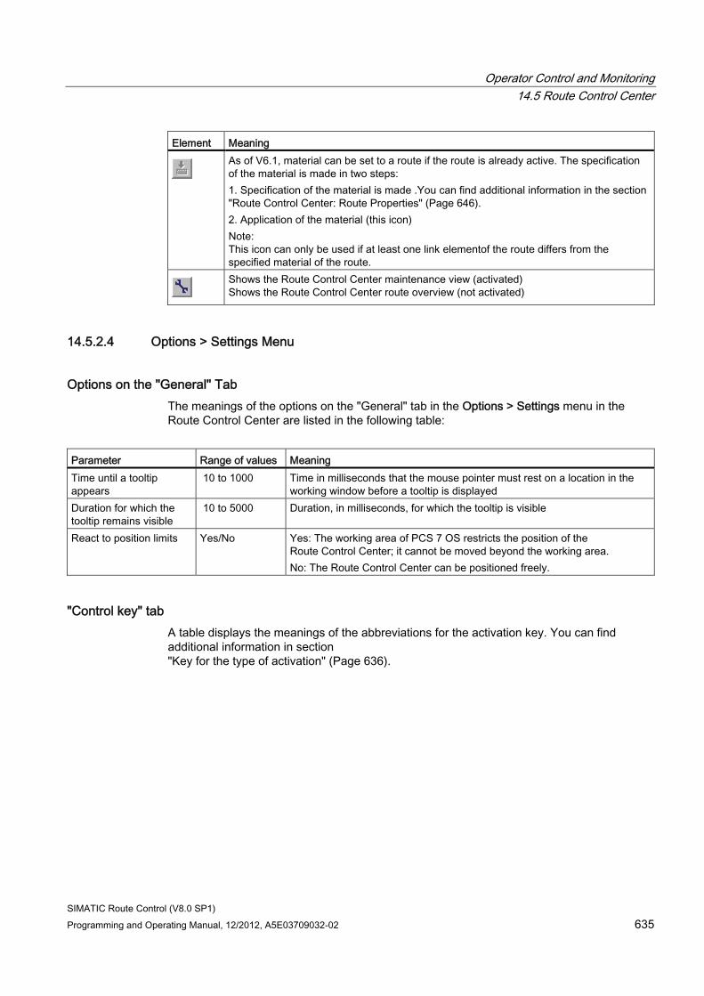
Operator Control and Monitoring 14.5 Route Control Center
SIMATIC Route Control (V8.0 SP1) Programming and Operating Manual, 12/2012, A5E03709032-02 635
Element Meaning
As of V6.1, material can be set to a route if the route is already active. The specification of the material is made in two steps: 1. Specification of the material is made .You can find additional information in the section "Route Control Center: Route Properties" (Page 646). 2. Application of the material (this icon) Note: This icon can only be used if at least one link elementof the route differs from the specified material of the route.
Shows the Route Control Center maintenance view (activated) Shows the Route Control Center route overview (not activated)
14.5.2.4 Options > Settings Menu
Options on the "General" Tab The meanings of the options on the "General" tab in the Options > Settings menu in the Route Control Center are listed in the following table:
Parameter Range of values Meaning Time until a tooltip appears
10 to 1000 Time in milliseconds that the mouse pointer must rest on a location in the working window before a tooltip is displayed
Duration for which the tooltip remains visible
10 to 5000 Duration, in milliseconds, for which the tooltip is visible
React to position limits Yes/No Yes: The working area of PCS 7 OS restricts the position of the Route Control Center; it cannot be moved beyond the working area. No: The Route Control Center can be positioned freely.
"Control key" tab A table displays the meanings of the abbreviations for the activation key. You can find additional information in section "Key for the type of activation" (Page 636).
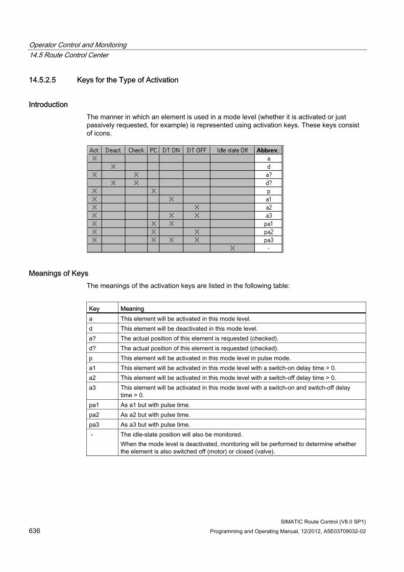
Operator Control and Monitoring 14.5 Route Control Center
SIMATIC Route Control (V8.0 SP1) 636 Programming and Operating Manual, 12/2012, A5E03709032-02
14.5.2.5 Keys for the Type of Activation
Introduction The manner in which an element is used in a mode level (whether it is activated or just passively requested, for example) is represented using activation keys. These keys consist of icons.
Meanings of Keys The meanings of the activation keys are listed in the following table:
Key Meaning a This element will be activated in this mode level. d This element will be deactivated in this mode level. a? The actual position of this element is requested (checked). d? The actual position of this element is requested (checked). p This element will be activated in this mode level in pulse mode. a1 This element will be activated in this mode level with a switch-on delay time > 0. a2 This element will be activated in this mode level with a switch-off delay time > 0. a3 This element will be activated in this mode level with a switch-on and switch-off delay
time > 0. pa1 As a1 but with pulse time. pa2 As a2 but with pulse time. pa3 As a3 but with pulse time. - The idle-state position will also be monitored.
When the mode level is deactivated, monitoring will be performed to determine whether the element is also switched off (motor) or closed (valve).
Operator Control and Monitoring 14.5 Route Control Center
SIMATIC Route Control (V8.0 SP1) Programming and Operating Manual, 12/2012, A5E03709032-02 637
Note
From V7.0 and higher you can no longer change the activation key in the Route Control Center. Change the icons in Route Control Engineering. You can also create your own user keys there.
Additional information ● "How to Change the Activation Key Icons" (Page 545)
● "How to Create User Keys" (Page 546)
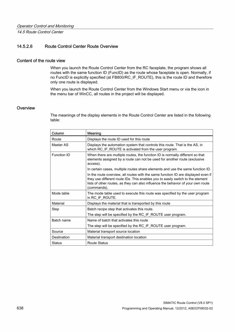
Operator Control and Monitoring 14.5 Route Control Center
SIMATIC Route Control (V8.0 SP1) 638 Programming and Operating Manual, 12/2012, A5E03709032-02
14.5.2.6 Route Control Center Route Overview
Content of the route view When you launch the Route Control Center from the RC faceplate, the program shows all routes with the same function ID (FuncID) as the route whose faceplate is open. Normally, if no FuncID is explicitly specified (at FB800/RC_IF_ROUTE), this is the route ID and therefore only one route is displayed.
When you launch the Route Control Center from the Windows Start menu or via the icon in the menu bar of WinCC, all routes in the project will be displayed.
Overview The meanings of the display elements in the Route Control Center are listed in the following table:
Column Meaning Route Displays the route ID used for this route Master AS Displays the automation system that controls this route. That is the AS, in
which RC_IF_ROUTE is activated from the user program. Function ID When there are multiple routes, the function ID is normally different so that
elements assigned by a route can not be used for another route (exclusive access). In certain cases, multiple routes share elements and use the same function ID. In the route overview, all routes with the same function ID are displayed even if they use different route IDs. This enables you to easily switch to the element lists of other routes, as they can also influence the behavior of your own route (commands).
Mode table The mode table used to execute this route was specified by the user program in RC_IF_ROUTE.
Material Displays the material that is transported by this route Step Batch recipe step that activates this route.
The step will be specified by the RC_IF_ROUTE user program. Batch name Name of batch that activates this route
The step will be specified by the RC_IF_ROUTE user program. Source Material transport source location Destination Material transport destination location Status Route Status
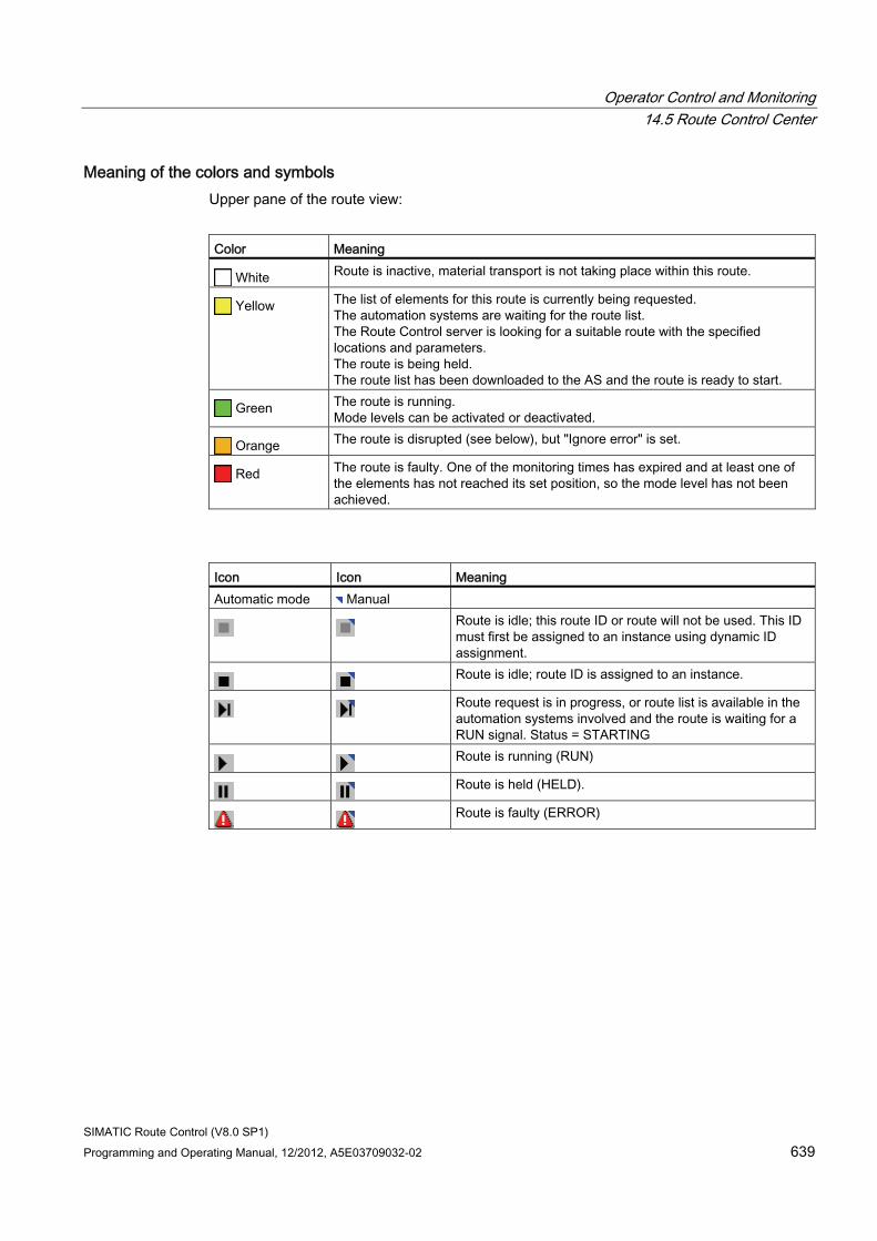
Operator Control and Monitoring 14.5 Route Control Center
SIMATIC Route Control (V8.0 SP1) Programming and Operating Manual, 12/2012, A5E03709032-02 639
Meaning of the colors and symbols Upper pane of the route view:
Color Meaning
White Route is inactive, material transport is not taking place within this route.
Yellow The list of elements for this route is currently being requested. The automation systems are waiting for the route list. The Route Control server is looking for a suitable route with the specified locations and parameters. The route is being held. The route list has been downloaded to the AS and the route is ready to start.
Green The route is running. Mode levels can be activated or deactivated.
Orange The route is disrupted (see below), but "Ignore error" is set.
Red The route is faulty. One of the monitoring times has expired and at least one of the elements has not reached its set position, so the mode level has not been achieved.
Icon Icon Meaning Automatic mode Manual
Route is idle; this route ID or route will not be used. This ID must first be assigned to an instance using dynamic ID assignment.
Route is idle; route ID is assigned to an instance.
Route request is in progress, or route list is available in the automation systems involved and the route is waiting for a RUN signal. Status = STARTING
Route is running (RUN)
Route is held (HELD).
Route is faulty (ERROR)
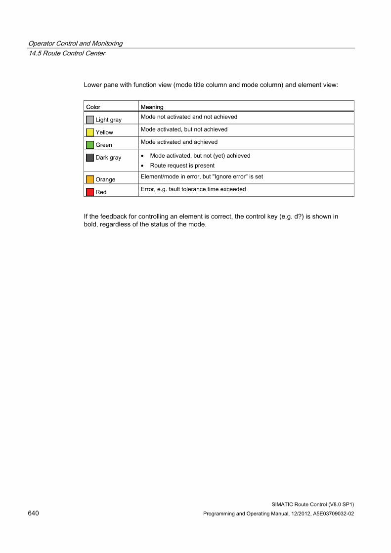
Operator Control and Monitoring 14.5 Route Control Center
SIMATIC Route Control (V8.0 SP1) 640 Programming and Operating Manual, 12/2012, A5E03709032-02
Lower pane with function view (mode title column and mode column) and element view:
Color Meaning
Light gray Mode not activated and not achieved
Yellow Mode activated, but not achieved
Green Mode activated and achieved
Dark gray • Mode activated, but not (yet) achieved • Route request is present
Orange Element/mode in error, but "Ignore error" is set
Red Error, e.g. fault tolerance time exceeded
If the feedback for controlling an element is correct, the control key (e.g. d?) is shown in bold, regardless of the status of the mode.
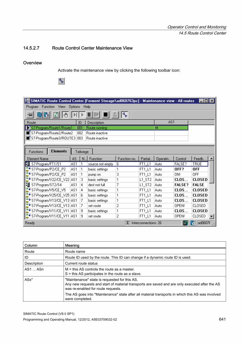
Operator Control and Monitoring 14.5 Route Control Center
SIMATIC Route Control (V8.0 SP1) Programming and Operating Manual, 12/2012, A5E03709032-02 641
14.5.2.7 Route Control Center Maintenance View
Overview Activate the maintenance view by clicking the following toolbar icon:
Column Meaning Route Route name ID Route ID used by the route. This ID can change if a dynamic route ID is used. Description Current route status AS1 ... ASn M = this AS controls the route as a master.
S = this AS participates in the route as a slave. ASx* "Maintenance" state is requested for this AS.
Any new requests and start of material transports are saved and are only executed after the AS was re-enabled for route requests. The AS goes into "Maintenance" state after all material transports in which this AS was involved were completed.
Operator Control and Monitoring 14.5 Route Control Center
SIMATIC Route Control (V8.0 SP1) 642 Programming and Operating Manual, 12/2012, A5E03709032-02
Column Meaning ASx** This AS is in "Maintenance" state. All material transports involving this AS are completed. New
material-transport requests and starts are saved and are not executed until route requests are re-enabled at the AS.
AS...? This AS has been enabled for route requests and will be initialized. AS ... (H) This is a fault-tolerant AS, for example, CPU 417-4H.
Operator input You can execute the following actions in the upper window partition by calling the shortcut menu in the column header of an AS:
● Set the AS to maintenance state (request of the "Maintenance" state in manual mode)
● Enable the AS for route requests (reset of the manual request)
● Enable maintenance requests by program
● Disable maintenance by program
Only two of these menu commands are available at a time, depending on the AS state.
Note
An AS is re-enabled for route requests after both maintenance requests were reset.
Colors Meaning of the background color of the Route, ID and Description columns:
Color Meaning White Route is inactive. Yellow Route is requested or in hold state. Green Route is in active state. Orange Route in error, but "Ignore error" is set Red Route is in error state.
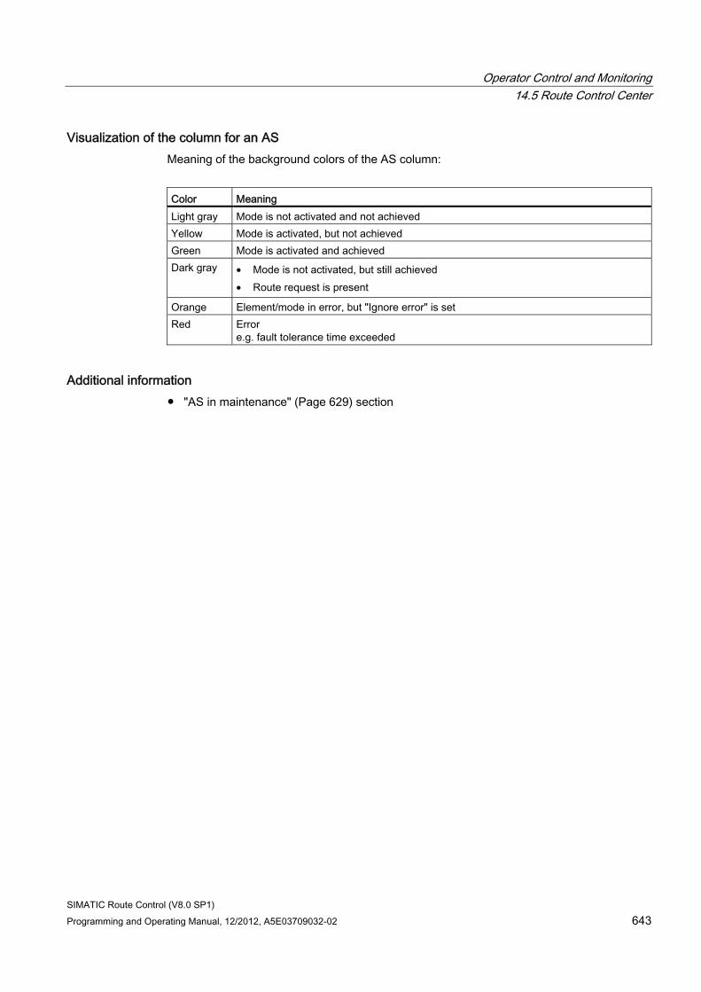
Operator Control and Monitoring 14.5 Route Control Center
SIMATIC Route Control (V8.0 SP1) Programming and Operating Manual, 12/2012, A5E03709032-02 643
Visualization of the column for an AS Meaning of the background colors of the AS column:
Color Meaning Light gray Mode is not activated and not achieved Yellow Mode is activated, but not achieved Green Mode is activated and achieved Dark gray • Mode is not activated, but still achieved
• Route request is present
Orange Element/mode in error, but "Ignore error" is set Red Error
e.g. fault tolerance time exceeded
Additional information ● "AS in maintenance" (Page 629) section
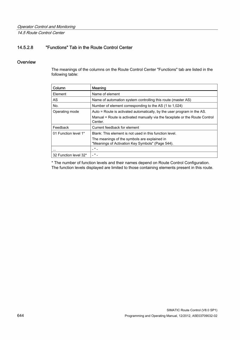
Operator Control and Monitoring 14.5 Route Control Center
SIMATIC Route Control (V8.0 SP1) 644 Programming and Operating Manual, 12/2012, A5E03709032-02
14.5.2.8 "Functions" Tab in the Route Control Center
Overview The meanings of the columns on the Route Control Center "Functions" tab are listed in the following table:
Column Meaning Element Name of element AS Name of automation system controlling this route (master AS) No. Number of element corresponding to the AS (1 to 1,024) Operating mode Auto = Route is activated automatically, by the user program in the AS.
Manual = Route is activated manually via the faceplate or the Route Control Center.
Feedback Current feedback for element 01 Function level 1* Blank: This element is not used in this function level.
The meanings of the symbols are explained in "Meanings of Activation Key Symbols" (Page 544).
... - " - 32 Function level 32* - " -
* The number of function levels and their names depend on Route Control Configuration. The function levels displayed are limited to those containing elements present in this route.
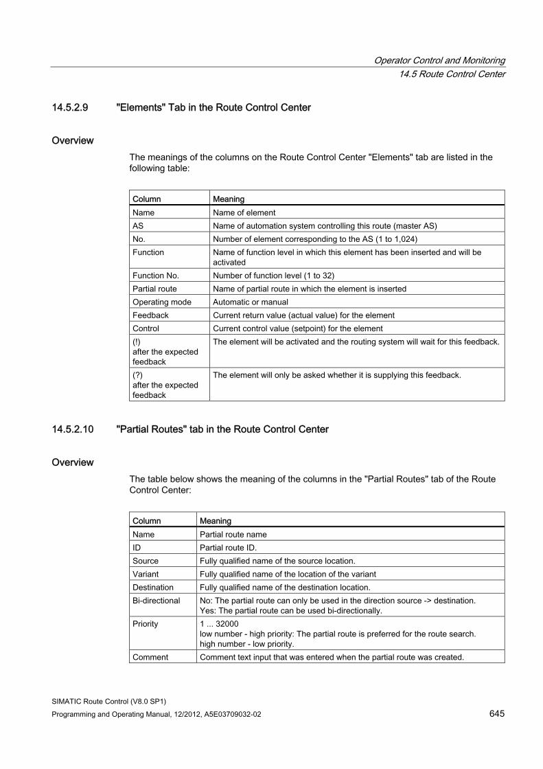
Operator Control and Monitoring 14.5 Route Control Center
SIMATIC Route Control (V8.0 SP1) Programming and Operating Manual, 12/2012, A5E03709032-02 645
14.5.2.9 "Elements" Tab in the Route Control Center
Overview The meanings of the columns on the Route Control Center "Elements" tab are listed in the following table:
Column Meaning Name Name of element AS Name of automation system controlling this route (master AS) No. Number of element corresponding to the AS (1 to 1,024) Function Name of function level in which this element has been inserted and will be
activated Function No. Number of function level (1 to 32) Partial route Name of partial route in which the element is inserted Operating mode Automatic or manual Feedback Current return value (actual value) for the element Control Current control value (setpoint) for the element (!) after the expected feedback
The element will be activated and the routing system will wait for this feedback.
(?) after the expected feedback
The element will only be asked whether it is supplying this feedback.
14.5.2.10 "Partial Routes" tab in the Route Control Center
Overview The table below shows the meaning of the columns in the "Partial Routes" tab of the Route Control Center:
Column Meaning Name Partial route name ID Partial route ID. Source Fully qualified name of the source location. Variant Fully qualified name of the location of the variant Destination Fully qualified name of the destination location. Bi-directional No: The partial route can only be used in the direction source -> destination.
Yes: The partial route can be used bi-directionally. Priority 1 ... 32000
low number - high priority: The partial route is preferred for the route search. high number - low priority.
Comment Comment text input that was entered when the partial route was created.
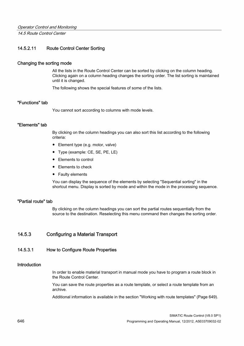
Operator Control and Monitoring 14.5 Route Control Center
SIMATIC Route Control (V8.0 SP1) 646 Programming and Operating Manual, 12/2012, A5E03709032-02
14.5.2.11 Route Control Center Sorting
Changing the sorting mode All the lists in the Route Control Center can be sorted by clicking on the column heading. Clicking again on a column heading changes the sorting order. The list sorting is maintained until it is changed.
The following shows the special features of some of the lists.
"Functions" tab You cannot sort according to columns with mode levels.
"Elements" tab By clicking on the column headings you can also sort this list according to the following criteria:
● Element type (e.g. motor, valve)
● Type (example: CE, SE, PE, LE)
● Elements to control
● Elements to check
● Faulty elements
You can display the sequence of the elements by selecting "Sequential sorting" in the shortcut menu. Display is sorted by mode and within the mode in the processing sequence.
"Partial route" tab By clicking on the column headings you can sort the partial routes sequentially from the source to the destination. Reselecting this menu command then changes the sorting order.
14.5.3 Configuring a Material Transport
14.5.3.1 How to Configure Route Properties
Introduction In order to enable material transport in manual mode you have to program a route block in the Route Control Center.
You can save the route properties as a route template, or select a route template from an archive.
Additional information is available in the section "Working with route templates" (Page 649).
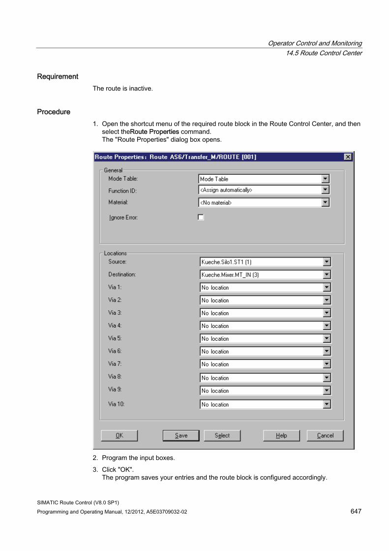
Operator Control and Monitoring 14.5 Route Control Center
SIMATIC Route Control (V8.0 SP1) Programming and Operating Manual, 12/2012, A5E03709032-02 647
Requirement The route is inactive.
Procedure 1. Open the shortcut menu of the required route block in the Route Control Center, and then
select theRoute Properties command. The "Route Properties" dialog box opens.
2. Program the input boxes.
3. Click "OK". The program saves your entries and the route block is configured accordingly.
Operator Control and Monitoring 14.5 Route Control Center
SIMATIC Route Control (V8.0 SP1) 648 Programming and Operating Manual, 12/2012, A5E03709032-02
Input boxes The table below describes the input boxes (drop-down list boxes, check boxes):
Input box Meaning Mode table Mode table to which the partial routes of the route must belong Function ID For individual routes: assign automatically,
for concurrent routes: select ID. Material Material to be transported
(can also be set if the route is active). Ignore error Deactivated: If an error occurs, the route is stopped and all elements are
deactivated. Activated: The error is ignored and no elements are deactivated.
Source Location of the source of material transport. Destination Location of the destination of material transport. Via 1 ... Via 10 Via locations (optional).
Note
The drop-down list boxes used to select the source, destination and Via only offer the locations of the type to be selected.
Buttons The table below describes the buttons:
Button Meaning OK Activates the properties that have been set. Save Opens the dialog box for saving the properties as a route template. Select Opens the dialog box for selecting a route template. Help Opens the online help. Cancel Cancels the entry.
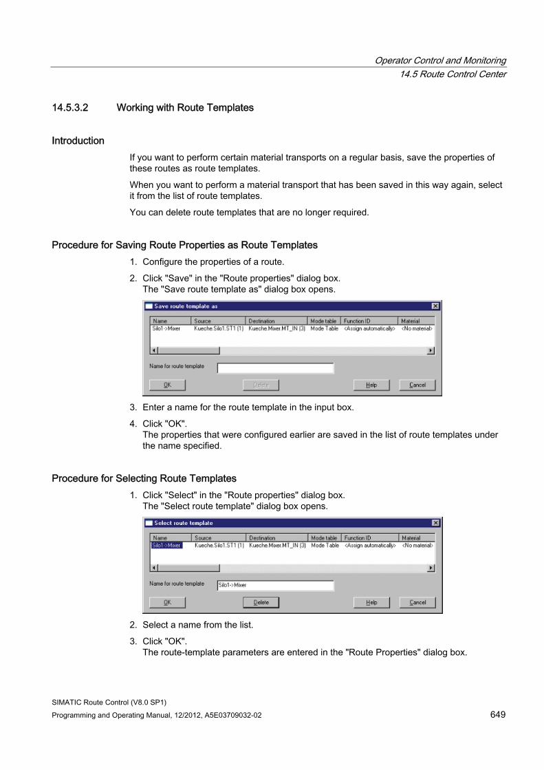
Operator Control and Monitoring 14.5 Route Control Center
SIMATIC Route Control (V8.0 SP1) Programming and Operating Manual, 12/2012, A5E03709032-02 649
14.5.3.2 Working with Route Templates
Introduction If you want to perform certain material transports on a regular basis, save the properties of these routes as route templates.
When you want to perform a material transport that has been saved in this way again, select it from the list of route templates.
You can delete route templates that are no longer required.
Procedure for Saving Route Properties as Route Templates 1. Configure the properties of a route.
2. Click "Save" in the "Route properties" dialog box. The "Save route template as" dialog box opens.
3. Enter a name for the route template in the input box.
4. Click "OK". The properties that were configured earlier are saved in the list of route templates under the name specified.
Procedure for Selecting Route Templates 1. Click "Select" in the "Route properties" dialog box.
The "Select route template" dialog box opens.
2. Select a name from the list.
3. Click "OK". The route-template parameters are entered in the "Route Properties" dialog box.
Operator Control and Monitoring 14.5 Route Control Center
SIMATIC Route Control (V8.0 SP1) 650 Programming and Operating Manual, 12/2012, A5E03709032-02
Procedure for Deleting Route Templates 1. Select the name of the template to be deleted from the list of route templates.
The "Delete" button is no longer grayed out.
2. You can select other templates by holding down the <Ctrl> key.
3. Click "Delete". A prompt dialog box opens.
4. Click "Yes". The selected route templates are deleted.
Operator Control and Monitoring 14.6 Route Control Route Log
SIMATIC Route Control (V8.0 SP1) Programming and Operating Manual, 12/2012, A5E03709032-02 651
14.6 Route Control Route Log
14.6.1 Overview
14.6.1.1 Route Log
Route Log The route log is available in SIMATIC Route Control V6.0 SP1 and higher.
The route log contains all of the information concerning material-transport processes:
● Route status: Start, Stop, Hold, Restart, Error
● Activation and deactivation of mode levels
● Information about starting up and shutting down the Route Control server
Every day, the Route Control server creates a log file that can be opened with a separate "Route Log User Interface" application.
This application provides the following options:
● Filtering according to specific columns, e. g., the batch name or the source or destination of the material transport
● Searching for specific texts in columns
● Exporting the filtered result to a CSV file, which can then be edited and evaluated using other media, such as Microsoft Excel
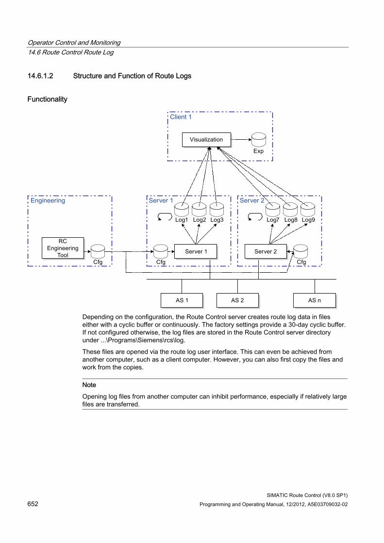
Operator Control and Monitoring 14.6 Route Control Route Log
SIMATIC Route Control (V8.0 SP1) 652 Programming and Operating Manual, 12/2012, A5E03709032-02
14.6.1.2 Structure and Function of Route Logs
Functionality
Depending on the configuration, the Route Control server creates route log data in files either with a cyclic buffer or continuously. The factory settings provide a 30-day cyclic buffer. If not configured otherwise, the log files are stored in the Route Control server directory under ...\Programs\Siemens\rcs\log.
These files are opened via the route log user interface. This can even be achieved from another computer, such as a client computer. However, you can also first copy the files and work from the copies.
Note
Opening log files from another computer can inhibit performance, especially if relatively large files are transferred.
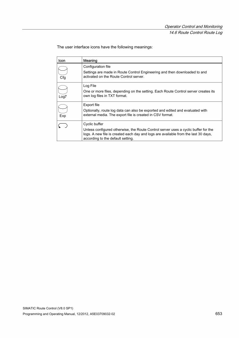
Operator Control and Monitoring 14.6 Route Control Route Log
SIMATIC Route Control (V8.0 SP1) Programming and Operating Manual, 12/2012, A5E03709032-02 653
The user interface icons have the following meanings:
Icon Meaning
Configuration file Settings are made in Route Control Engineering and then downloaded to and activated on the Route Control server.
Log File One or more files, depending on the setting. Each Route Control server creates its own log files in TXT format.
Export file Optionally, route log data can also be exported and edited and evaluated with external media. The export file is created in CSV format.
Cyclic buffer Unless configured otherwise, the Route Control server uses a cyclic buffer for the logs. A new file is created each day and logs are available from the last 30 days, according to the default setting.
Operator Control and Monitoring 14.6 Route Control Route Log
SIMATIC Route Control (V8.0 SP1) 654 Programming and Operating Manual, 12/2012, A5E03709032-02
14.6.1.3 Log File
Log File Once the Route Control server has restarted, e.g., because the configuration has been activated via the Route Control Center, it has already applied the new settings and stored a new log file during startup.
Format The names of log files take the following format: RC_LOG_<Server_computer_name>_YYYY-MM-DD.TXT
The <server computer name> is the name of the computer.
YYYY-MM-DD is the year, month and day on which this file was created. Because a new file is created each day, the file name indicates the day associated with this log.
14.6.2 Route Log Dialogs and User Interfaces
14.6.2.1 Rights for Operating the User Interface
User Rights Special user rights are not required to start and operate the Route Control routes log user interface.
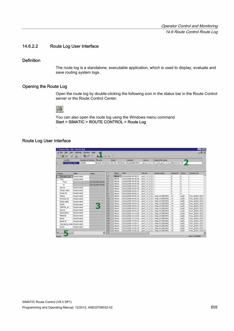
Operator Control and Monitoring 14.6 Route Control Route Log
SIMATIC Route Control (V8.0 SP1) Programming and Operating Manual, 12/2012, A5E03709032-02 655
14.6.2.2 Route Log User Interface
Definition The route log is a standalone, executable application, which is used to display, evaluate and save routing system logs.
Opening the Route Log Open the route log by double-clicking the following icon in the status bar in the Route Control server or the Route Control Center.
You can also open the route log using the Windows menu command Start > SIMATIC > ROUTE CONTROL > Route Log .
Route Log User Interface
Operator Control and Monitoring 14.6 Route Control Route Log
SIMATIC Route Control (V8.0 SP1) 656 Programming and Operating Manual, 12/2012, A5E03709032-02
The user interface is divided into five areas:
Area within a site
Meaning
1 Menu and toolbar 2 List of log files 3 Filter Functions 4 Table of log data 5 Status bar
Note
This is a view-oriented application. You first create a frame and the view, then open the log files inside this view. View properties include whether columns are to be shown or hidden and whether or not the current log data should be read in again when a view is opened. These views are saved in the configuration files (CFG files).
You can open one or several log files simultaneously. Area 2 displays the names of the opened log files. Area 4 displays the contents of all opened log files at the same time.
Operator Control and Monitoring 14.6 Route Control Route Log
SIMATIC Route Control (V8.0 SP1) Programming and Operating Manual, 12/2012, A5E03709032-02 657
14.6.2.3 Menu, Toolbar and Keyboard Controls
Route Log Menu Menu item Submenu Meaning File New Log View Creates a new log view Open Opens an existing log view Close Empties the window Save Saves the current log view Save As... Saves the log view under a name of your choice Add/Remove Log Adds or removes log files to/from the current view Export... Export a route log in CSV format 1 ... Opens the last view selected Close Terminate the application Edit Cut Cuts the selected text Copy Copies the selected text Paste Pastes cut or copied text Delete Deletes selected text Find Find a specific character string:
Up/down, with/without case matching Note: Looking for complete character strings in the "Time" column can be very time-consuming where large files are concerned. If you are looking for a specific time of day, enter just an hour and minute, e.g., "14:57".
Filter • Activates the filters • Resets the filters.
All filter settings are deactivated.
Bookmark • Sets/resets a bookmark • Next: Jumps to next bookmark • Previous: Jumps to previous bookmark • Delete All: Deletes all bookmarks
View Update Updates, after changes have been made to the log file, for example
Log Files Shows/hides the "Log Files" window Filter Shows/hides the "Filter" window Select Columns Opens the dialog box for selecting visible columns. Settings Language Sets the language Auto Save Saves the current view when closing or ending Load Last Log View Opens the last view loaded the next time the program
starts up
Operator Control and Monitoring 14.6 Route Control Route Log
SIMATIC Route Control (V8.0 SP1) 658 Programming and Operating Manual, 12/2012, A5E03709032-02
Menu item Submenu Meaning Window Arrange Changes the arrangement of several views:
• Overlapping • Horizontally • Vertically
Arrange Icons Rearranges the icons of several minimized views at the bottom of the window
1 ... Activates the window for one of the loaded views Help Contents Opens the help. Context-Sensitive Help
F1 Opens the help and displays a description of the active dialog box.
Introduction Opens the help and displays the introduction. Getting Started Opens the help and displays the description the initial
steps. Using Help Opens the help and displays the description about how
additional information can be found using the help system. About Opens the dialog box with information about Route Control
Icons on the Toolbar and Keyboard Controls You can also perform the following actions via the icons on the toolbar or using keyboard controls:
Icon Keyboard control Description
Ctrl + N Creates a new log view
Ctrl + O Opens an existing log view
Ctrl + S Saves the current log view
Ctrl + P Adds or removes log files from the view
Ctrl + E Exports data from the view to a CSV file for editing in external tools
Ctrl + F2 Sets or deletes a bookmark
F2 Jumps to next bookmark
Shift + F2 Jumps to previous bookmark
Ctrl + Shift + F2 Deletes all bookmarks
F7 Activates the filters
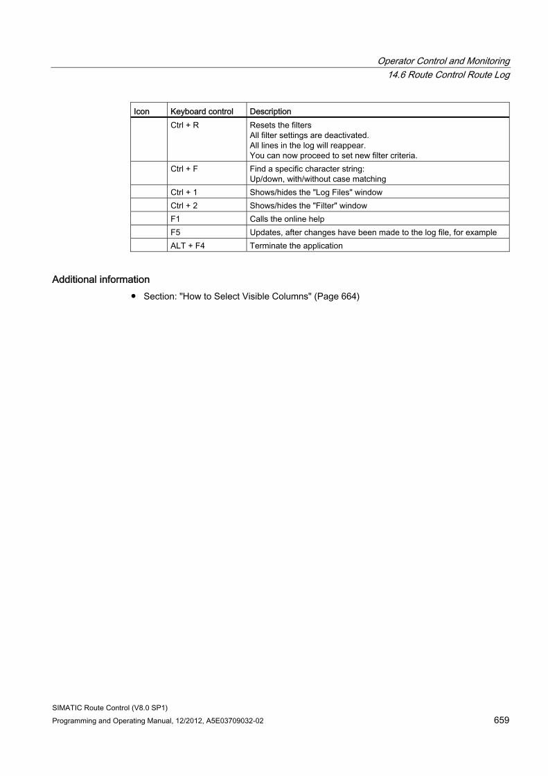
Operator Control and Monitoring 14.6 Route Control Route Log
SIMATIC Route Control (V8.0 SP1) Programming and Operating Manual, 12/2012, A5E03709032-02 659
Icon Keyboard control Description Ctrl + R Resets the filters
All filter settings are deactivated. All lines in the log will reappear. You can now proceed to set new filter criteria.
Ctrl + F Find a specific character string: Up/down, with/without case matching
Ctrl + 1 Shows/hides the "Log Files" window Ctrl + 2 Shows/hides the "Filter" window F1 Calls the online help F5 Updates, after changes have been made to the log file, for example ALT + F4 Terminate the application
Additional information ● Section: "How to Select Visible Columns" (Page 664)
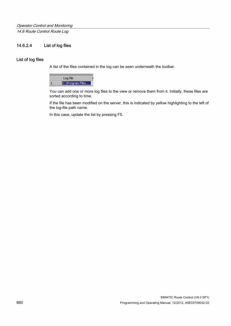
Operator Control and Monitoring 14.6 Route Control Route Log
SIMATIC Route Control (V8.0 SP1) 660 Programming and Operating Manual, 12/2012, A5E03709032-02
14.6.2.4 List of log files
List of log files A list of the files contained in the log can be seen underneath the toolbar.
You can add one or more log files to the view or remove them from it. Initially, these files are sorted according to time.
If the file has been modified on the server, this is indicated by yellow highlighting to the left of the log-file path name.
In this case, update the list by pressing F5.
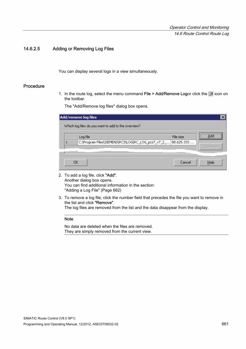
Operator Control and Monitoring 14.6 Route Control Route Log
SIMATIC Route Control (V8.0 SP1) Programming and Operating Manual, 12/2012, A5E03709032-02 661
14.6.2.5 Adding or Removing Log Files
You can display several logs in a view simultaneously.
Procedure 1. In the route log, select the menu command File > Add/Remove Logor click the icon on
the toolbar.
The "Add/Remove log files" dialog box opens.
2. To add a log file, click "Add".
Another dialog box opens. You can find additional information in the section: "Adding a Log File" (Page 662)
3. To remove a log file, click the number field that precedes the file you want to remove in the list and click "Remove". The log files are removed from the list and the data disappear from the display.
Note
No data are deleted when the files are removed. They are simply removed from the current view.
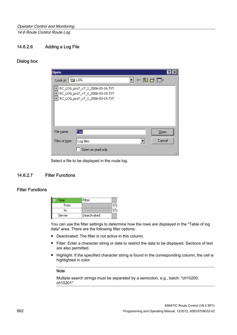
Operator Control and Monitoring 14.6 Route Control Route Log
SIMATIC Route Control (V8.0 SP1) 662 Programming and Operating Manual, 12/2012, A5E03709032-02
14.6.2.6 Adding a Log File
Dialog box
Select a file to be displayed in the route log.
14.6.2.7 Filter Functions
Filter Functions
You can use the filter settings to determine how the rows are displayed in the "Table of log data" area. There are the following filter options:
● Deactivated: The filter is not active in this column.
● Filter: Enter a character string or date to restrict the data to be displayed. Sections of text are also permitted.
● Highlight: If the specified character string is found in the corresponding column, the cell is highlighted in color.
Note
Multiple search strings must be separated by a semicolon, e.g., batch: "ch10200; ch10201".
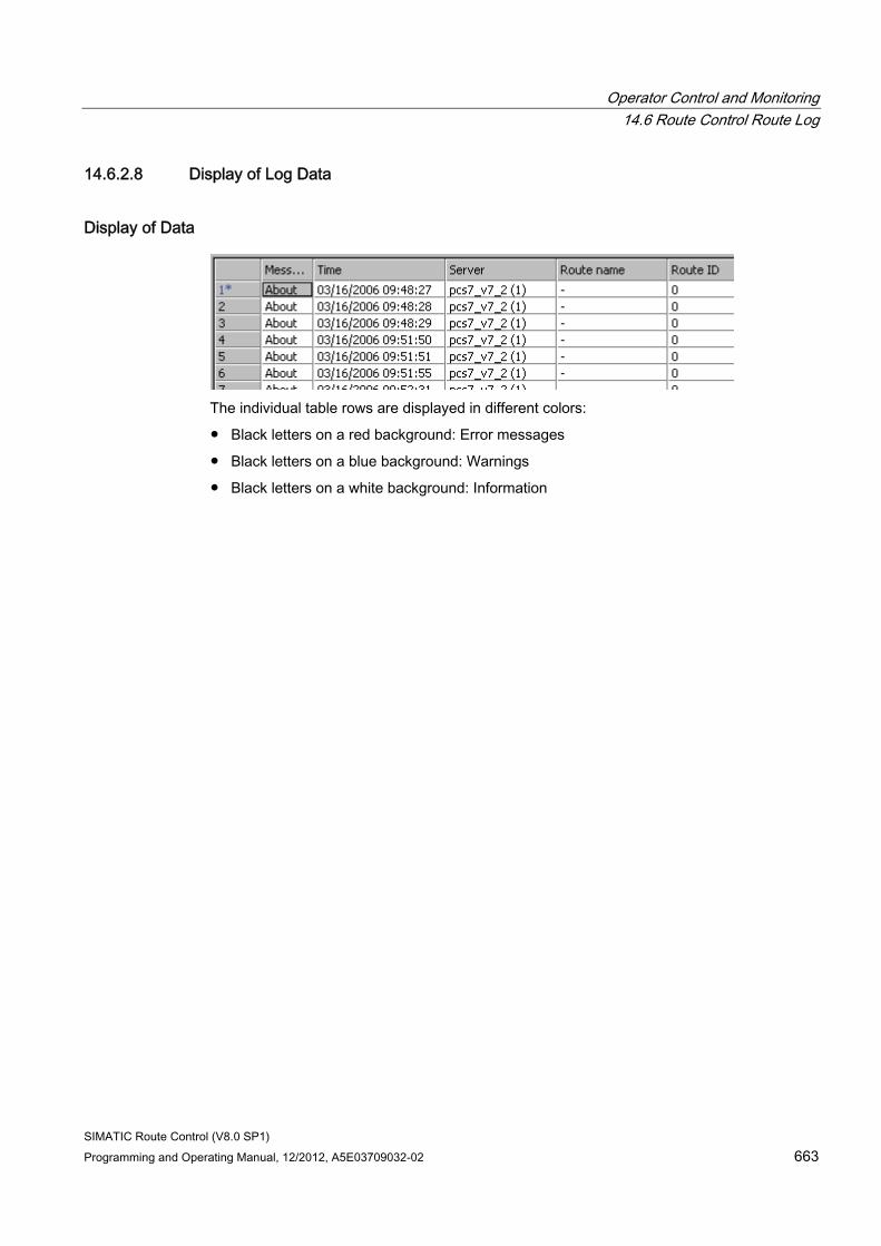
Operator Control and Monitoring 14.6 Route Control Route Log
SIMATIC Route Control (V8.0 SP1) Programming and Operating Manual, 12/2012, A5E03709032-02 663
14.6.2.8 Display of Log Data
Display of Data
The individual table rows are displayed in different colors:
● Black letters on a red background: Error messages
● Black letters on a blue background: Warnings
● Black letters on a white background: Information
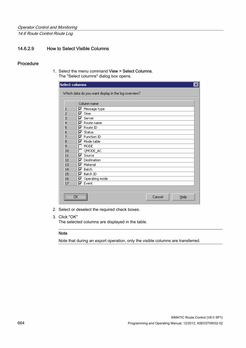
Operator Control and Monitoring 14.6 Route Control Route Log
SIMATIC Route Control (V8.0 SP1) 664 Programming and Operating Manual, 12/2012, A5E03709032-02
14.6.2.9 How to Select Visible Columns
Procedure 1. Select the menu command View > Select Columns.
The "Select columns" dialog box opens.
2. Select or deselect the required check boxes.
3. Click "OK" The selected columns are displayed in the table.
Note
Note that during an export operation, only the visible columns are transferred.
Operator Control and Monitoring 14.6 Route Control Route Log
SIMATIC Route Control (V8.0 SP1) Programming and Operating Manual, 12/2012, A5E03709032-02 665
14.6.2.10 Meanings of Columns
Columns The meaning of each column in the log view is explained in the following table:
Column Description Message Type Information, warning or error
You can find additional information about this in " Display of Log Data" (Page 663).
Time Date and time the message was generated. The time stamp is generated on the Route Control server.
Server Name of computer on which the Route Control server process has created this route log.
Route Name RC_IF_ROUTE instance name Route ID Number that is unique throughout the project and with which this route works.
If IDs are assigned dynamically, this number may differ for each material transport.
Status Current route status: e.g., not active, running, held Function ID Usually, the function ID is the same as the route ID.
If several routes are executing overlapping material transports, they use the same function ID.
Mode table Group containing all mode levels of a route, e.g., "Production" or "Cleaning" Mode Mode level (user program setpoint) for the route,
information under Note 1 QMODE_AC Mode level (actual value of route),
information under Note 1 Source Source of material transport Destination Destination of material transport Material Material being transported
You can find information under the MATERIAL input at RC_IF_ROUTE. Batch name Name of batch that activates this route.
This is only displayed if the BATCHNAME input parameter at RC_IF_ROUTE has been interconnected.
Batch ID Batch ID You can find information under "Batch name".
Operating mode If an event has been triggered by the automation system, "Automatic" or "Manual" will appear here. If an operation has been executed via the Route Control Center, the "Computer name\User" will be displayed.
Event Plain text message
Note 1: These values are only displayed as binary numbers and are used for diagnostics for configuration and process-cell maintenance. You must refer to the configuration to obtain the mode level names.
Activation and deactivation of a mode level is displayed along with the mode level name in the "Event" column and is thus easier to read.
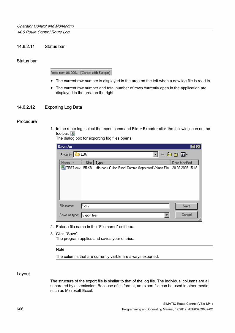
Operator Control and Monitoring 14.6 Route Control Route Log
SIMATIC Route Control (V8.0 SP1) 666 Programming and Operating Manual, 12/2012, A5E03709032-02
14.6.2.11 Status bar
Status bar
● The current row number is displayed in the area on the left when a new log file is read in.
● The current row number and total number of rows currently open in the application are displayed in the area on the right.
14.6.2.12 Exporting Log Data
Procedure 1. In the route log, select the menu command File > Exportor click the following icon on the
toolbar: The dialog box for exporting log files opens.
2. Enter a file name in the "File name" edit box.
3. Click "Save". The program applies and saves your entries.
Note
The columns that are currently visible are always exported.
Layout The structure of the export file is similar to that of the log file. The individual columns are all separated by a semicolon. Because of its format, an export file can be used in other media, such as Microsoft Excel.
Operator Control and Monitoring 14.6 Route Control Route Log
SIMATIC Route Control (V8.0 SP1) Programming and Operating Manual, 12/2012, A5E03709032-02 667
Opening with Microsoft Excel When working with Microsoft Excel, the CSV file must not be opened by double-clicking, but rather by selecting:
● File -> Open
● A converter opens.
● Select semicolons to act as separators.
● The import takes place for display and evaluation purposes.
Currently, each Excel sheet can only open or import files with a maximum of 65,535 lines. This number may well be exceeded if you are dealing with large route logs. In such cases, you can reduce the number of lines in the exported file using the appropriate filtering methods referred to previously.
Operator Control and Monitoring 14.7 Route Control server
SIMATIC Route Control (V8.0 SP1) 668 Programming and Operating Manual, 12/2012, A5E03709032-02
14.7 Route Control server
14.7.1 Calling the Route Control Server
Procedure If the Route Control server is not running, select the Windows Start menu command Start > SIMATIC > Route Control > Server.
If the Route Control server is already running, but has been minimized, click the icon on the task bar:
The "SIMATIC RC server" (Page 669) dialog box opens.
Parameter You can call the Route Control Server dialog, rc_serverdialog.exe, with the following parameters:
● /Activate
Starts the server function in the rc_serverhostx.exe service.
● /Deactivate
Terminates the server function in the rc_serverhostx.exe service.
● /NoDialog
The server dialog terminates again after the call - no dialog.
The way in which parameters are stored depends on the particular implementation of the launch and needs to be specifically configured for each user.
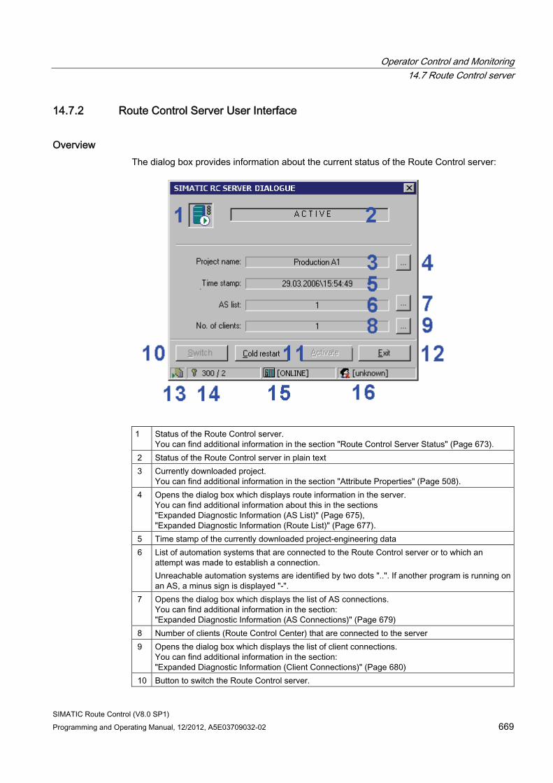
Operator Control and Monitoring 14.7 Route Control server
SIMATIC Route Control (V8.0 SP1) Programming and Operating Manual, 12/2012, A5E03709032-02 669
14.7.2 Route Control Server User Interface
Overview The dialog box provides information about the current status of the Route Control server:
1 Status of the Route Control server.
You can find additional information in the section "Route Control Server Status" (Page 673). 2 Status of the Route Control server in plain text 3 Currently downloaded project.
You can find additional information in the section "Attribute Properties" (Page 508). 4 Opens the dialog box which displays route information in the server.
You can find additional information about this in the sections "Expanded Diagnostic Information (AS List)" (Page 675), "Expanded Diagnostic Information (Route List)" (Page 677).
5 Time stamp of the currently downloaded project-engineering data 6 List of automation systems that are connected to the Route Control server or to which an
attempt was made to establish a connection. Unreachable automation systems are identified by two dots "..". If another program is running on an AS, a minus sign is displayed "-".
7 Opens the dialog box which displays the list of AS connections. You can find additional information in the section: "Expanded Diagnostic Information (AS Connections)" (Page 679)
8 Number of clients (Route Control Center) that are connected to the server 9 Opens the dialog box which displays the list of client connections.
You can find additional information in the section: "Expanded Diagnostic Information (Client Connections)" (Page 680)
10 Button to switch the Route Control server.
Operator Control and Monitoring 14.7 Route Control server
SIMATIC Route Control (V8.0 SP1) 670 Programming and Operating Manual, 12/2012, A5E03709032-02
11 Left: Button for restarting the server: Reads the configuration in again and performs a general request for the automation systems. Right: Button for activating the Route Control server when it is running in standby mode: The computer then becomes the master. Note: Update the project-engineering data that have previously been downloaded to the server via Route Control Engineering in the Route Control Center server status. You can find additional information in the section "Server Status".
12 Button for terminating the Route Control server. Notice: This will terminate the Route Control server. Route control operation can no longer be guaranteed as a result (unless a redundant server takes over control). An application restart via menu command Start > SIMATIC > Route Control > Server is required.
13 Displays the route log. A small green triangle indicates that the route log is active (file is being written). The tooltip shows the path for the log file. Double-click the icon to open the route log.
14 Displays the Route Control server license: 30, 100, or 300 simultaneous material transports. The first number shows the installed license, the right-hand number shows the number of active routes.
15 Indicates whether or not the automation systems are connected 16 Indicates whether or not a user is logged on.
You can find additional information in the section "Route Control Center Status Bar" (Page 633).
Additional information You can find the individual Route Control server startup and shutdown levels in the section "Route Control Server Startup Sequence" (Page 672).
See also Server status (Page 624)
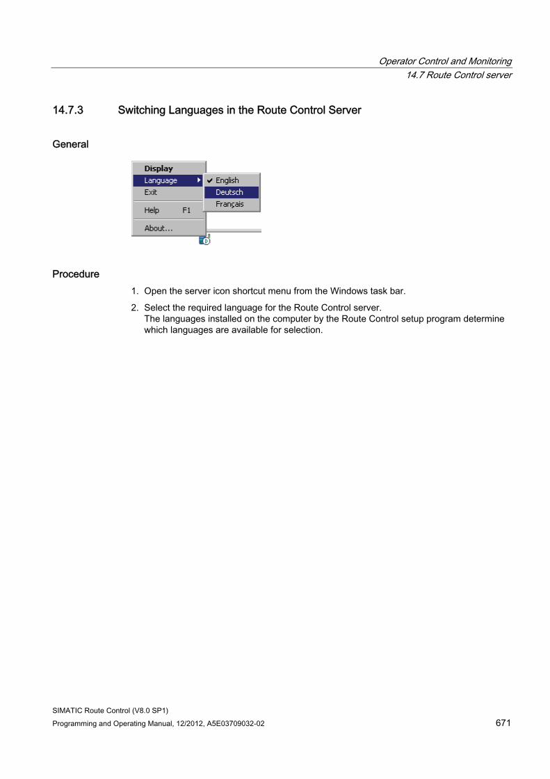
Operator Control and Monitoring 14.7 Route Control server
SIMATIC Route Control (V8.0 SP1) Programming and Operating Manual, 12/2012, A5E03709032-02 671
14.7.3 Switching Languages in the Route Control Server
General
Procedure 1. Open the server icon shortcut menu from the Windows task bar.
2. Select the required language for the Route Control server. The languages installed on the computer by the Route Control setup program determine which languages are available for selection.
Operator Control and Monitoring 14.7 Route Control server
SIMATIC Route Control (V8.0 SP1) 672 Programming and Operating Manual, 12/2012, A5E03709032-02
14.7.4 Route Control Server Startup Sequence
Dependencies A Route Control server has dependencies on the other components below:
● PCS 7 OS message server
● Redundancy control
Sequence Therefore, you must follow the startup sequence below:
Step Procedure 1 Start PCS 7 OS process mode so that the message server is available. 2 Start the redundancy control (if used, it is activated automatically when PCS 7 OS starts). 3 Start the Route Control server.
Note
You can start the Route Control server by executing the following file: <Installation_path>\Siemens\rcs\bin\RC_SERVX.EXE.
Example: c:\Program Files\Siemens\rcs\bin\RC_SERVX.EXE
When you exit PCS 7 OS process mode, the Route Control server shuts down automatically.
Additional information You can find additional information about the statuses of the Route Control server during startup and shutdown in
● "Route Control Server Status" (Page 673)
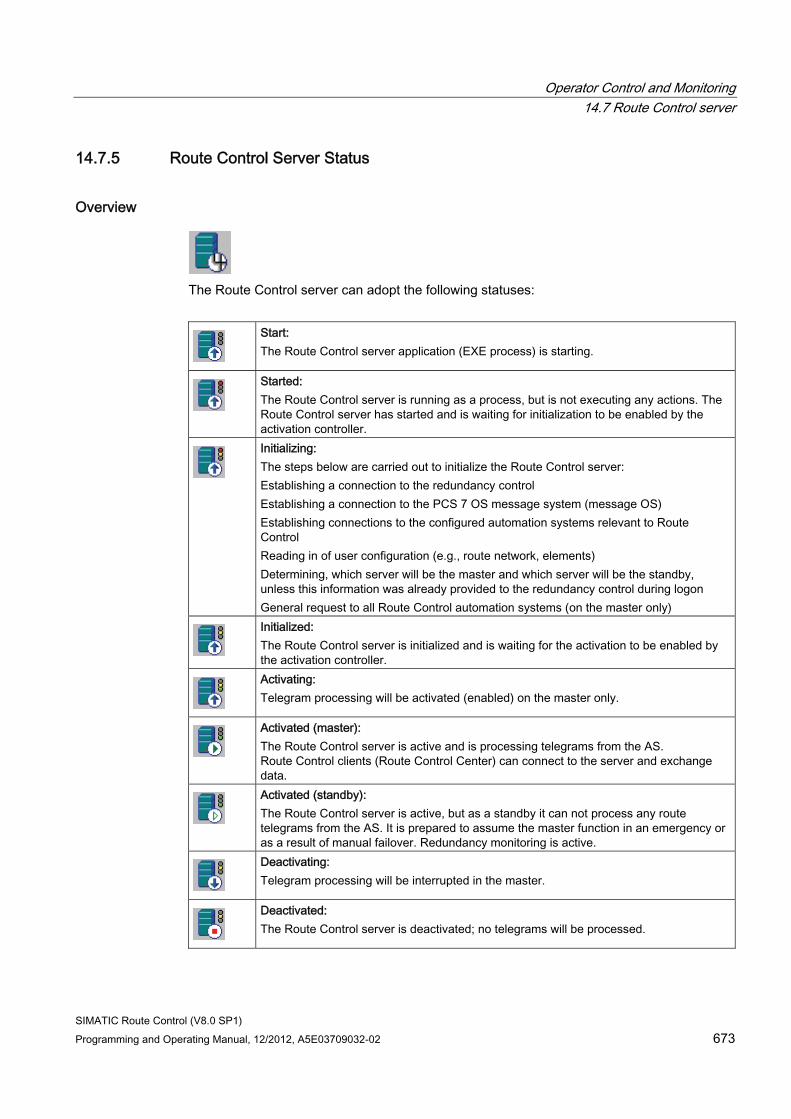
Operator Control and Monitoring 14.7 Route Control server
SIMATIC Route Control (V8.0 SP1) Programming and Operating Manual, 12/2012, A5E03709032-02 673
14.7.5 Route Control Server Status
Overview
The Route Control server can adopt the following statuses:
Start: The Route Control server application (EXE process) is starting.
Started: The Route Control server is running as a process, but is not executing any actions. The Route Control server has started and is waiting for initialization to be enabled by the activation controller.
Initializing: The steps below are carried out to initialize the Route Control server: Establishing a connection to the redundancy control Establishing a connection to the PCS 7 OS message system (message OS) Establishing connections to the configured automation systems relevant to Route Control Reading in of user configuration (e.g., route network, elements) Determining, which server will be the master and which server will be the standby, unless this information was already provided to the redundancy control during logon General request to all Route Control automation systems (on the master only)
Initialized: The Route Control server is initialized and is waiting for the activation to be enabled by the activation controller.
Activating: Telegram processing will be activated (enabled) on the master only.
Activated (master): The Route Control server is active and is processing telegrams from the AS. Route Control clients (Route Control Center) can connect to the server and exchange data.
Activated (standby): The Route Control server is active, but as a standby it can not process any route telegrams from the AS. It is prepared to assume the master function in an emergency or as a result of manual failover. Redundancy monitoring is active.
Deactivating: Telegram processing will be interrupted in the master.
Deactivated: The Route Control server is deactivated; no telegrams will be processed.
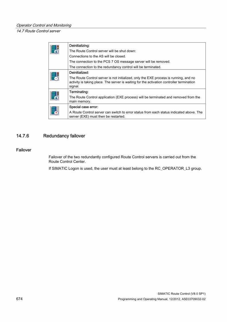
Operator Control and Monitoring 14.7 Route Control server
SIMATIC Route Control (V8.0 SP1) 674 Programming and Operating Manual, 12/2012, A5E03709032-02
Deinitializing: The Route Control server will be shut down: Connections to the AS will be closed. The connection to the PCS 7 OS message server will be removed. The connection to the redundancy control will be terminated.
Deinitialized: The Route Control server is not initialized, only the EXE process is running, and no activity is taking place. The server is waiting for the activation controller termination signal.
Terminating: The Route Control application (EXE process) will be terminated and removed from the main memory.
Special case error: A Route Control server can switch to error status from each status indicated above. The server (EXE) must then be restarted.
14.7.6 Redundancy failover
Failover Failover of the two redundantly configured Route Control servers is carried out from the Route Control Center.
If SIMATIC Logon is used, the user must at least belong to the RC_OPERATOR_L3 group.
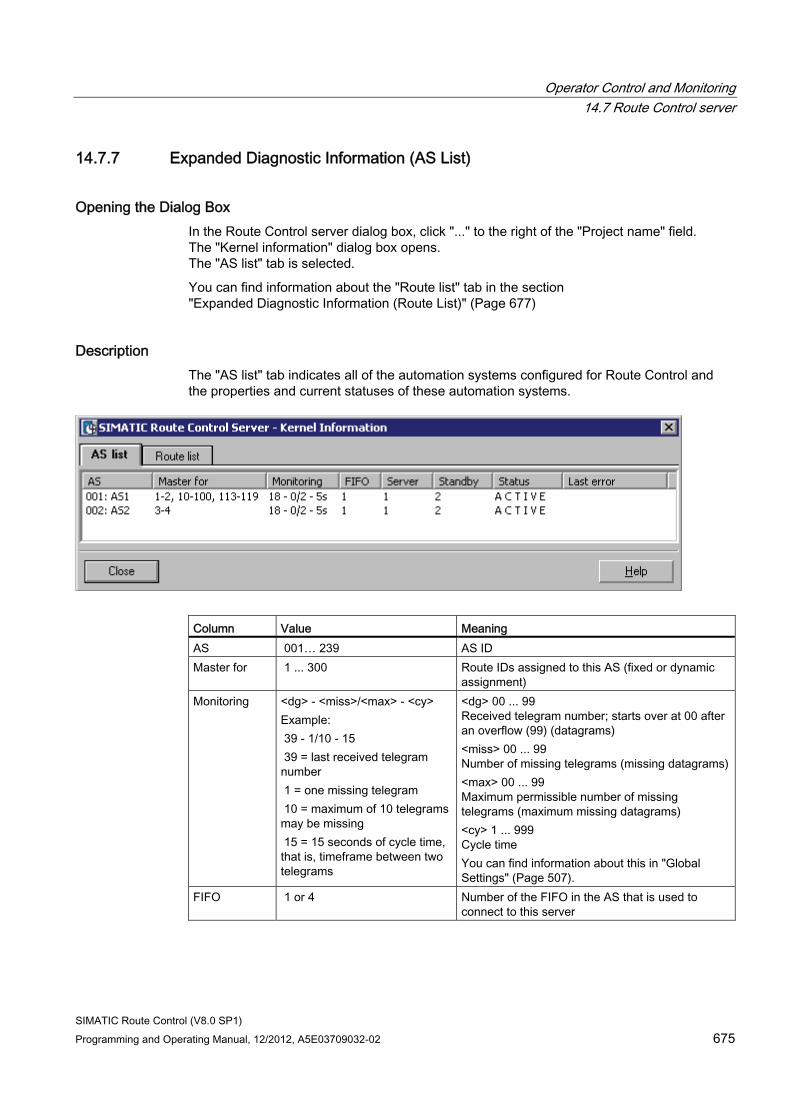
Operator Control and Monitoring 14.7 Route Control server
SIMATIC Route Control (V8.0 SP1) Programming and Operating Manual, 12/2012, A5E03709032-02 675
14.7.7 Expanded Diagnostic Information (AS List)
Opening the Dialog Box In the Route Control server dialog box, click "..." to the right of the "Project name" field. The "Kernel information" dialog box opens. The "AS list" tab is selected.
You can find information about the "Route list" tab in the section "Expanded Diagnostic Information (Route List)" (Page 677)
Description The "AS list" tab indicates all of the automation systems configured for Route Control and the properties and current statuses of these automation systems.
Column Value Meaning AS 001… 239 AS ID Master for 1 ... 300 Route IDs assigned to this AS (fixed or dynamic
assignment) Monitoring <dg> - <miss>/<max> - <cy>
Example: 39 - 1/10 - 15 39 = last received telegram number 1 = one missing telegram 10 = maximum of 10 telegrams may be missing 15 = 15 seconds of cycle time, that is, timeframe between two telegrams
<dg> 00 ... 99 Received telegram number; starts over at 00 after an overflow (99) (datagrams) <miss> 00 ... 99 Number of missing telegrams (missing datagrams)<max> 00 ... 99 Maximum permissible number of missing telegrams (maximum missing datagrams) <cy> 1 ... 999 Cycle time You can find information about this in "Global Settings" (Page 507).
FIFO 1 or 4 Number of the FIFO in the AS that is used to connect to this server
Operator Control and Monitoring 14.7 Route Control server
SIMATIC Route Control (V8.0 SP1) 676 Programming and Operating Manual, 12/2012, A5E03709032-02
Column Value Meaning Server 1 or 2 1: First configured computer is the master
(Route Control application (master)). 2: Second configured computer is the master (Route Control application (standby)).
Standby 0, 1, or 2 0: Second computer is not available; this is a non-redundant Route Control server. 1: First configured computer is the standby (Route Control application (master)). 2: Second configured computer is the standby (Route Control application (standby)).
Status ACTIVE STANDBY STARTUP In Maintenance
Computer is the master relative to the connected AS. Computer is the standby relative to the connected AS. Computer is starting up Computer is in maintenance. This status is only displayed on the master RC server. In case of STANDBY the status remains STANDBY when the automation system is in maintenance.
Last error <Text> Last error that occurred
Additional information You can find information about the "Route list" tab in:
● "Expanded Diagnostic Information (Route List)" (Page 677)
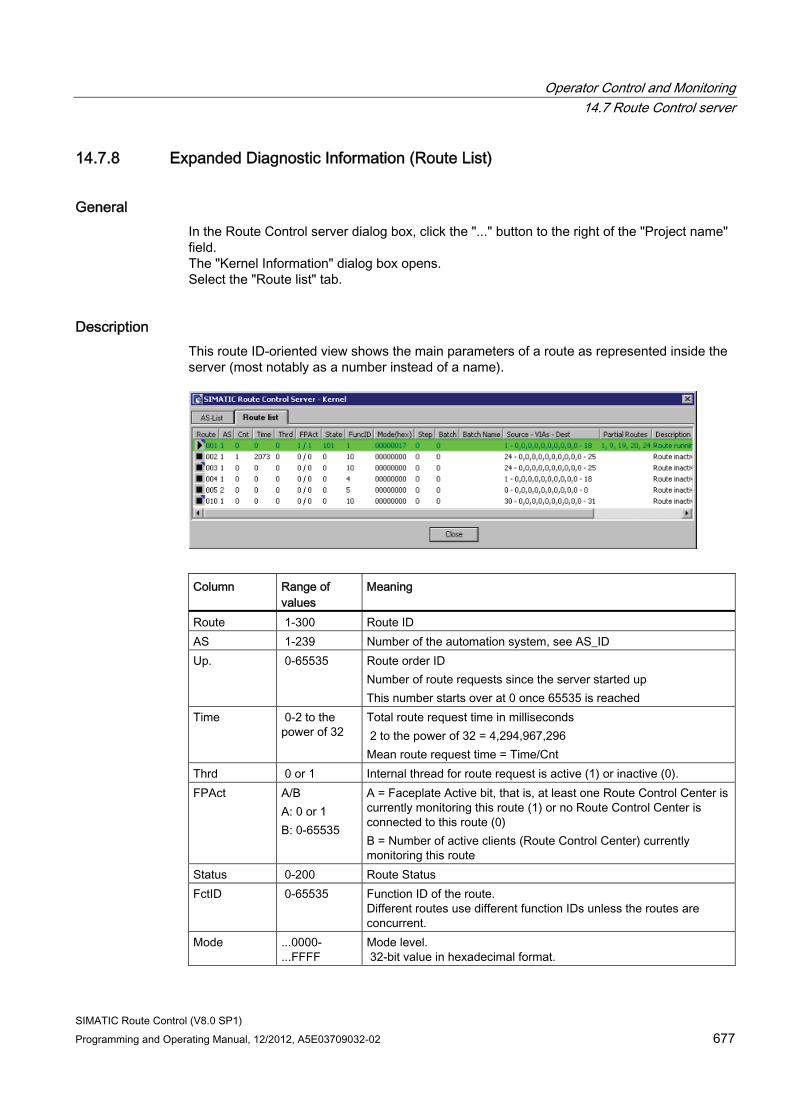
Operator Control and Monitoring 14.7 Route Control server
SIMATIC Route Control (V8.0 SP1) Programming and Operating Manual, 12/2012, A5E03709032-02 677
14.7.8 Expanded Diagnostic Information (Route List)
General In the Route Control server dialog box, click the "..." button to the right of the "Project name" field. The "Kernel Information" dialog box opens. Select the "Route list" tab.
Description This route ID-oriented view shows the main parameters of a route as represented inside the server (most notably as a number instead of a name).
Column Range of
values Meaning
Route 1-300 Route ID AS 1-239 Number of the automation system, see AS_ID Up. 0-65535 Route order ID
Number of route requests since the server started up This number starts over at 0 once 65535 is reached
Time 0-2 to the power of 32
Total route request time in milliseconds 2 to the power of 32 = 4,294,967,296 Mean route request time = Time/Cnt
Thrd 0 or 1 Internal thread for route request is active (1) or inactive (0). FPAct A/B
A: 0 or 1 B: 0-65535
A = Faceplate Active bit, that is, at least one Route Control Center is currently monitoring this route (1) or no Route Control Center is connected to this route (0) B = Number of active clients (Route Control Center) currently monitoring this route
Status 0-200 Route Status FctID 0-65535 Function ID of the route.
Different routes use different function IDs unless the routes are concurrent.
Mode ...0000-...FFFF
Mode level. 32-bit value in hexadecimal format.
Operator Control and Monitoring 14.7 Route Control server
SIMATIC Route Control (V8.0 SP1) 678 Programming and Operating Manual, 12/2012, A5E03709032-02
Column Range of values
Meaning
Step 0-2 to the power of 32
Step number (from BATCH phase)
BatchID 0-2 to the power of 32
Batch number
Batch name <Text> Batch name. 0 to 32 characters.
Source - VIAs - Destination
0 ... 65,535 Locations for source, vias and destination of route, expressed as location numbers
Partial routes 0 ... 65,535 Number of partial routes involved in this route Description <Text> Status of route from the perspective of the Route Control server:
• Route started • Route inactive • Route request • Route in error status
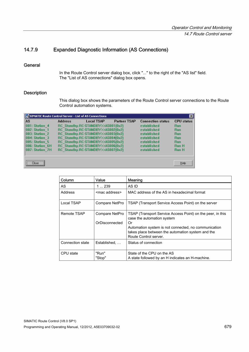
Operator Control and Monitoring 14.7 Route Control server
SIMATIC Route Control (V8.0 SP1) Programming and Operating Manual, 12/2012, A5E03709032-02 679
14.7.9 Expanded Diagnostic Information (AS Connections)
General In the Route Control server dialog box, click "..." to the right of the "AS list" field. The "List of AS connections" dialog box opens.
Description This dialog box shows the parameters of the Route Control server connections to the Route Control automation systems.
Column Value Meaning AS 1 ... 239 AS ID Address
<mac address> MAC address of the AS in hexadecimal format
Local TSAP
Compare NetPro TSAP (Transport Service Access Point) on the server
Remote TSAP
Compare NetPro OrDisconnected
TSAP (Transport Service Access Point) on the peer, in this case the automation system Or Automation system is not connected, no communication takes place between the automation system and the Route Control server.
Connection state
Established, … Status of connection
CPU state
"Run" "Stop"
State of the CPU on the AS A state followed by an H indicates an H-machine.
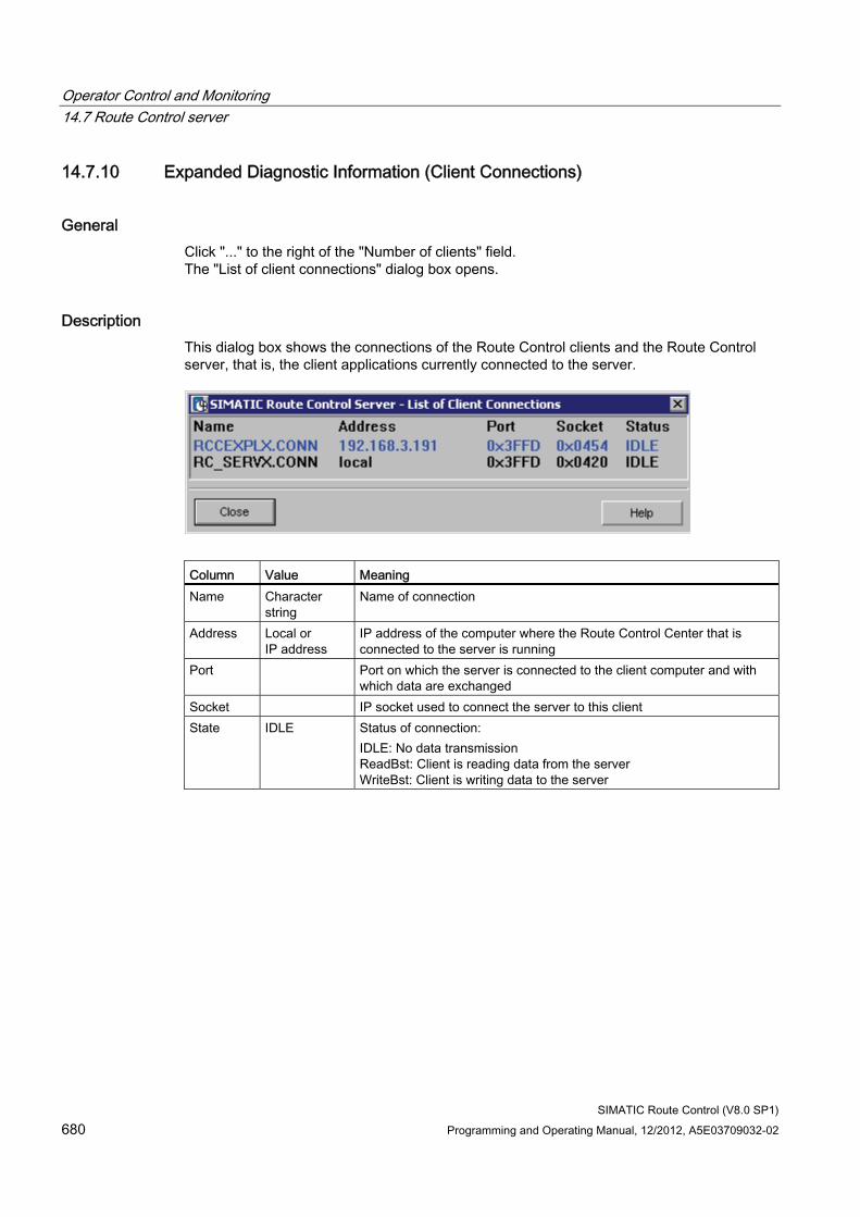
Operator Control and Monitoring 14.7 Route Control server
SIMATIC Route Control (V8.0 SP1) 680 Programming and Operating Manual, 12/2012, A5E03709032-02
14.7.10 Expanded Diagnostic Information (Client Connections)
General Click "..." to the right of the "Number of clients" field. The "List of client connections" dialog box opens.
Description This dialog box shows the connections of the Route Control clients and the Route Control server, that is, the client applications currently connected to the server.
Column Value Meaning Name Character
string Name of connection
Address Local or IP address
IP address of the computer where the Route Control Center that is connected to the server is running
Port Port on which the server is connected to the client computer and with which data are exchanged
Socket IP socket used to connect the server to this client State IDLE Status of connection:
IDLE: No data transmission ReadBst: Client is reading data from the server WriteBst: Client is writing data to the server
Operator Control and Monitoring 14.8 Messages
SIMATIC Route Control (V8.0 SP1) Programming and Operating Manual, 12/2012, A5E03709032-02 681
14.8 Messages
14.8.1 Overview of Route Control Messages
Introduction SIMATIC Route Control produces messages in PCS 7 OS via blocks in the AS and through the Route Control server.
Note
You can recognize the messages originating from the Route Control server by the fact that the message text starts with the abbreviation RCS:.
Messages, AS Type of message Described in Section
System messages "AS Messages (System, FB 850)" (Page 682)
Route "AS Messages (Route, FB 800)" (Page 685)
Control elements "AS Messages (Control Elements, FB 822, 823, 824, 825)" (Page 691)
Sensor elements "AS Messages (Sensor Elements, FB 845, 846)" (Page 692)
REMOTE blocks "AS Messages (Remote Elements, FB 831, 833)" (Page 693)
You can find additional information about AS messages in "Route Control AS Messages" (Page 682).
OS Messages Type of message Described in Section
System messages "OS Messages (System, Server)" (Page 694)
Route messages "OS Messages (Route, Server)" (Page 696)
Operator messages Type of message Described in Section
Operator messages "Route Control Operator Messages" (Page 699)
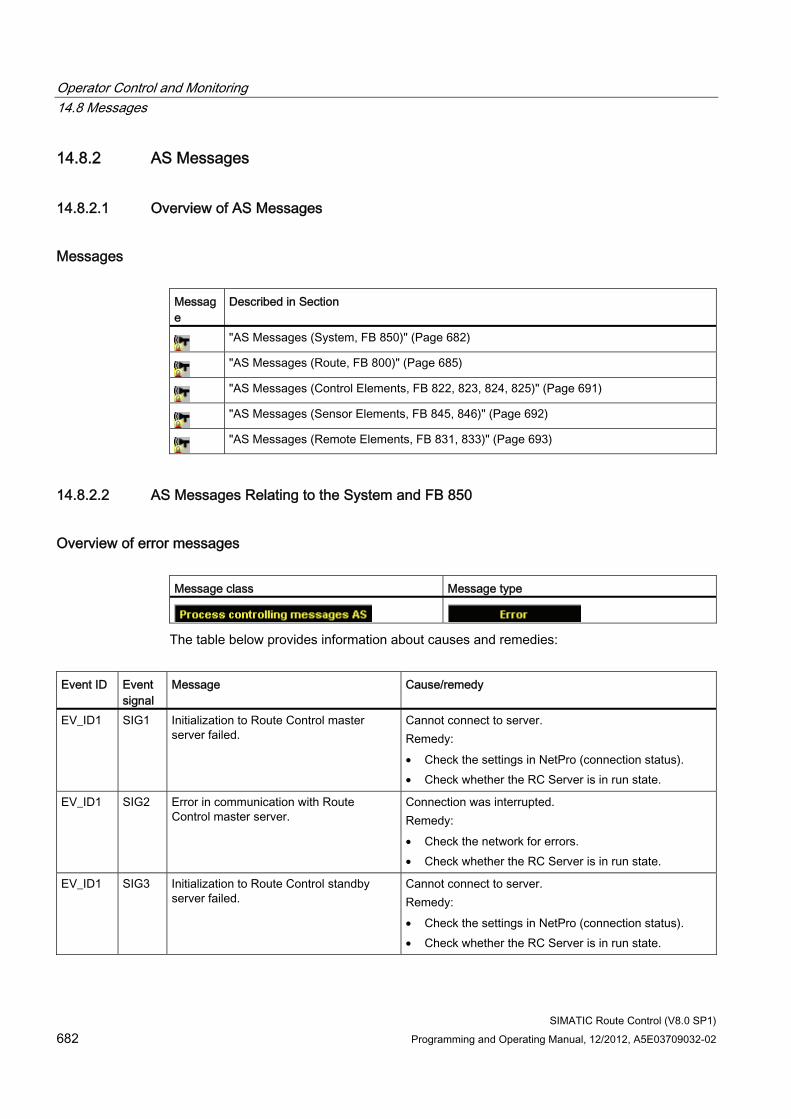
Operator Control and Monitoring 14.8 Messages
SIMATIC Route Control (V8.0 SP1) 682 Programming and Operating Manual, 12/2012, A5E03709032-02
14.8.2 AS Messages
14.8.2.1 Overview of AS Messages
Messages Message
Described in Section
"AS Messages (System, FB 850)" (Page 682)
"AS Messages (Route, FB 800)" (Page 685)
"AS Messages (Control Elements, FB 822, 823, 824, 825)" (Page 691)
"AS Messages (Sensor Elements, FB 845, 846)" (Page 692)
"AS Messages (Remote Elements, FB 831, 833)" (Page 693)
14.8.2.2 AS Messages Relating to the System and FB 850
Overview of error messages Message class Message type
The table below provides information about causes and remedies:
Event ID Event
signal Message Cause/remedy
EV_ID1 SIG1 Initialization to Route Control master server failed.
Cannot connect to server. Remedy: • Check the settings in NetPro (connection status). • Check whether the RC Server is in run state.
EV_ID1 SIG2 Error in communication with Route Control master server.
Connection was interrupted. Remedy: • Check the network for errors. • Check whether the RC Server is in run state.
EV_ID1 SIG3 Initialization to Route Control standby server failed.
Cannot connect to server. Remedy: • Check the settings in NetPro (connection status). • Check whether the RC Server is in run state.
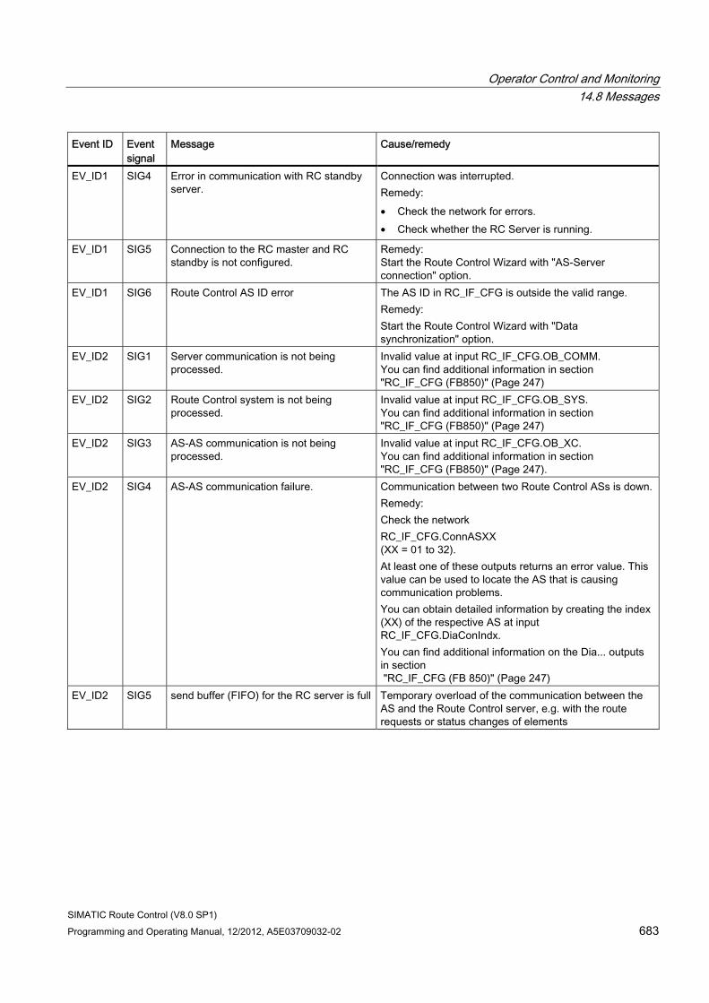
Operator Control and Monitoring 14.8 Messages
SIMATIC Route Control (V8.0 SP1) Programming and Operating Manual, 12/2012, A5E03709032-02 683
Event ID Event signal
Message Cause/remedy
EV_ID1 SIG4 Error in communication with RC standby server.
Connection was interrupted. Remedy: • Check the network for errors. • Check whether the RC Server is running.
EV_ID1 SIG5 Connection to the RC master and RC standby is not configured.
Remedy: Start the Route Control Wizard with "AS-Server connection" option.
EV_ID1 SIG6 Route Control AS ID error The AS ID in RC_IF_CFG is outside the valid range. Remedy: Start the Route Control Wizard with "Data synchronization" option.
EV_ID2 SIG1 Server communication is not being processed.
Invalid value at input RC_IF_CFG.OB_COMM. You can find additional information in section "RC_IF_CFG (FB850)" (Page 247)
EV_ID2 SIG2 Route Control system is not being processed.
Invalid value at input RC_IF_CFG.OB_SYS. You can find additional information in section "RC_IF_CFG (FB850)" (Page 247)
EV_ID2 SIG3 AS-AS communication is not being processed.
Invalid value at input RC_IF_CFG.OB_XC. You can find additional information in section "RC_IF_CFG (FB850)" (Page 247).
EV_ID2 SIG4 AS-AS communication failure. Communication between two Route Control ASs is down. Remedy: Check the network RC_IF_CFG.ConnASXX (XX = 01 to 32). At least one of these outputs returns an error value. This value can be used to locate the AS that is causing communication problems. You can obtain detailed information by creating the index (XX) of the respective AS at input RC_IF_CFG.DiaConIndx. You can find additional information on the Dia... outputs in section "RC_IF_CFG (FB 850)" (Page 247)
EV_ID2 SIG5 send buffer (FIFO) for the RC server is full Temporary overload of the communication between the AS and the Route Control server, e.g. with the route requests or status changes of elements
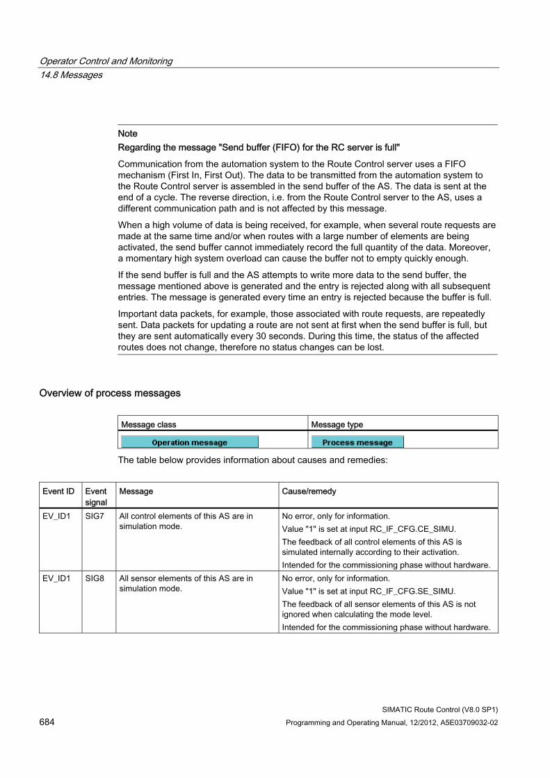
Operator Control and Monitoring 14.8 Messages
SIMATIC Route Control (V8.0 SP1) 684 Programming and Operating Manual, 12/2012, A5E03709032-02
Note Regarding the message "Send buffer (FIFO) for the RC server is full"
Communication from the automation system to the Route Control server uses a FIFO mechanism (First In, First Out). The data to be transmitted from the automation system to the Route Control server is assembled in the send buffer of the AS. The data is sent at the end of a cycle. The reverse direction, i.e. from the Route Control server to the AS, uses a different communication path and is not affected by this message.
When a high volume of data is being received, for example, when several route requests are made at the same time and/or when routes with a large number of elements are being activated, the send buffer cannot immediately record the full quantity of the data. Moreover, a momentary high system overload can cause the buffer not to empty quickly enough.
If the send buffer is full and the AS attempts to write more data to the send buffer, the message mentioned above is generated and the entry is rejected along with all subsequent entries. The message is generated every time an entry is rejected because the buffer is full.
Important data packets, for example, those associated with route requests, are repeatedly sent. Data packets for updating a route are not sent at first when the send buffer is full, but they are sent automatically every 30 seconds. During this time, the status of the affected routes does not change, therefore no status changes can be lost.
Overview of process messages Message class Message type
The table below provides information about causes and remedies:
Event ID Event
signal Message Cause/remedy
EV_ID1 SIG7 All control elements of this AS are in simulation mode.
No error, only for information. Value "1" is set at input RC_IF_CFG.CE_SIMU. The feedback of all control elements of this AS is simulated internally according to their activation. Intended for the commissioning phase without hardware.
EV_ID1 SIG8 All sensor elements of this AS are in simulation mode.
No error, only for information. Value "1" is set at input RC_IF_CFG.SE_SIMU. The feedback of all sensor elements of this AS is not ignored when calculating the mode level. Intended for the commissioning phase without hardware.
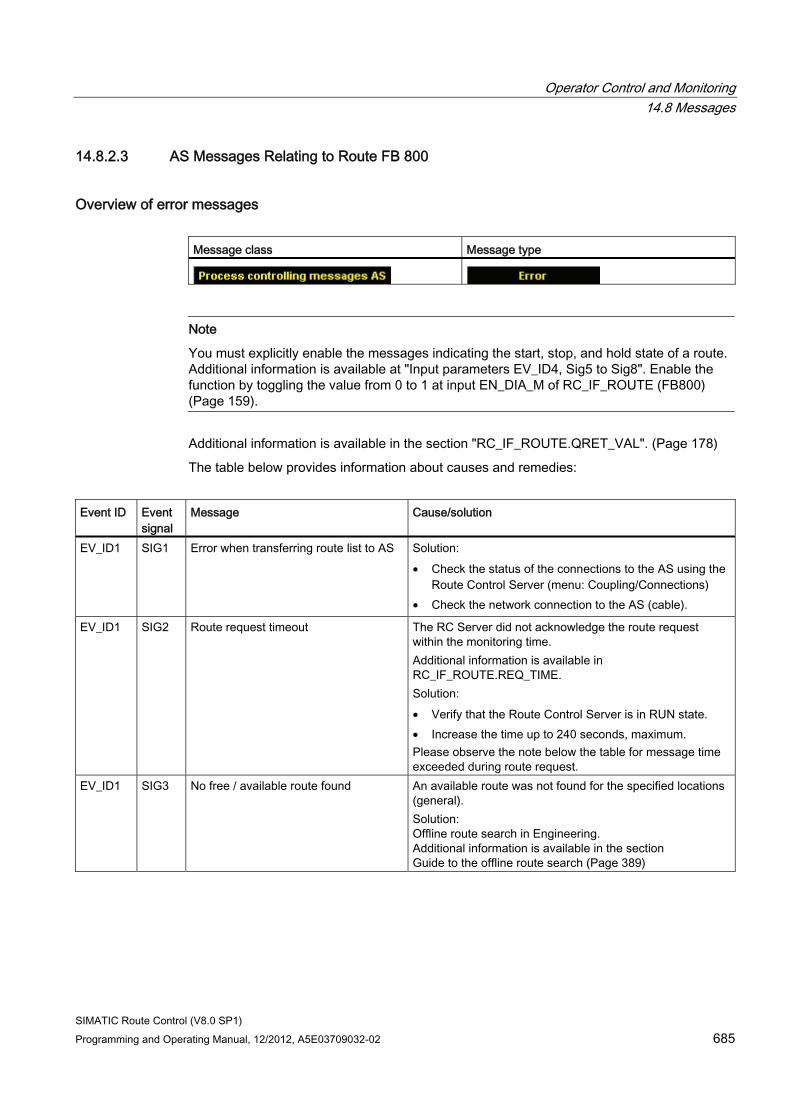
Operator Control and Monitoring 14.8 Messages
SIMATIC Route Control (V8.0 SP1) Programming and Operating Manual, 12/2012, A5E03709032-02 685
14.8.2.3 AS Messages Relating to Route FB 800
Overview of error messages Message class Message type
Note
You must explicitly enable the messages indicating the start, stop, and hold state of a route. Additional information is available at "Input parameters EV_ID4, Sig5 to Sig8". Enable the function by toggling the value from 0 to 1 at input EN_DIA_M of RC_IF_ROUTE (FB800) (Page 159).
Additional information is available in the section "RC_IF_ROUTE.QRET_VAL". (Page 178)
The table below provides information about causes and remedies:
Event ID Event
signal Message Cause/solution
EV_ID1 SIG1 Error when transferring route list to AS Solution: • Check the status of the connections to the AS using the
Route Control Server (menu: Coupling/Connections) • Check the network connection to the AS (cable).
EV_ID1 SIG2 Route request timeout The RC Server did not acknowledge the route request within the monitoring time. Additional information is available in RC_IF_ROUTE.REQ_TIME. Solution: • Verify that the Route Control Server is in RUN state. • Increase the time up to 240 seconds, maximum. Please observe the note below the table for message time exceeded during route request.
EV_ID1 SIG3 No free / available route found An available route was not found for the specified locations (general). Solution: Offline route search in Engineering. Additional information is available in the section Guide to the offline route search (Page 389)
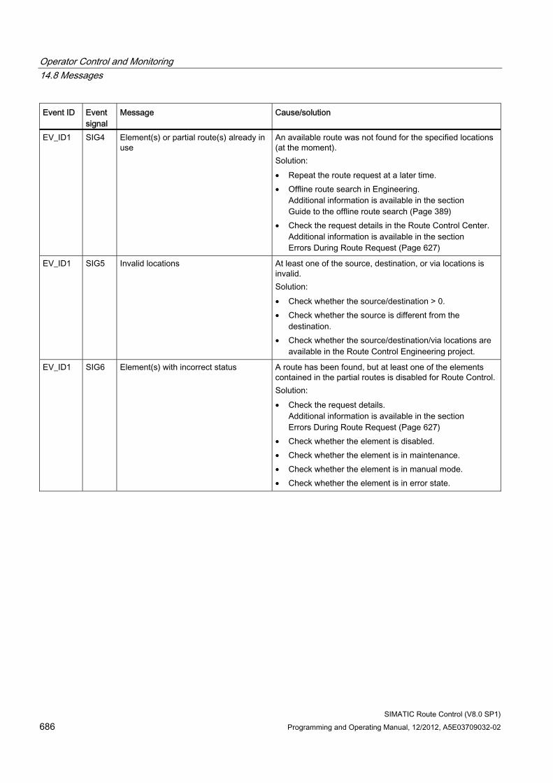
Operator Control and Monitoring 14.8 Messages
SIMATIC Route Control (V8.0 SP1) 686 Programming and Operating Manual, 12/2012, A5E03709032-02
Event ID Event signal
Message Cause/solution
EV_ID1 SIG4 Element(s) or partial route(s) already in use
An available route was not found for the specified locations (at the moment). Solution: • Repeat the route request at a later time. • Offline route search in Engineering.
Additional information is available in the section Guide to the offline route search (Page 389)
• Check the request details in the Route Control Center. Additional information is available in the section Errors During Route Request (Page 627)
EV_ID1 SIG5 Invalid locations At least one of the source, destination, or via locations is invalid. Solution: • Check whether the source/destination > 0. • Check whether the source is different from the
destination. • Check whether the source/destination/via locations are
available in the Route Control Engineering project.
EV_ID1 SIG6 Element(s) with incorrect status A route has been found, but at least one of the elements contained in the partial routes is disabled for Route Control. Solution: • Check the request details.
Additional information is available in the section Errors During Route Request (Page 627)
• Check whether the element is disabled. • Check whether the element is in maintenance. • Check whether the element is in manual mode. • Check whether the element is in error state.
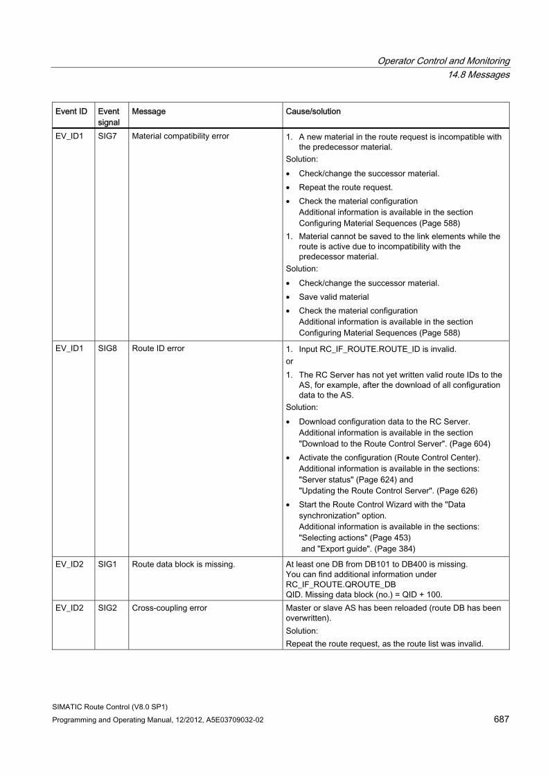
Operator Control and Monitoring 14.8 Messages
SIMATIC Route Control (V8.0 SP1) Programming and Operating Manual, 12/2012, A5E03709032-02 687
Event ID Event signal
Message Cause/solution
EV_ID1 SIG7 Material compatibility error 1. A new material in the route request is incompatible with the predecessor material.
Solution: • Check/change the successor material. • Repeat the route request. • Check the material configuration
Additional information is available in the section Configuring Material Sequences (Page 588)
1. Material cannot be saved to the link elements while the route is active due to incompatibility with the predecessor material.
Solution: • Check/change the successor material. • Save valid material • Check the material configuration
Additional information is available in the section Configuring Material Sequences (Page 588)
EV_ID1 SIG8 Route ID error 1. Input RC_IF_ROUTE.ROUTE_ID is invalid. or 1. The RC Server has not yet written valid route IDs to the
AS, for example, after the download of all configuration data to the AS.
Solution: • Download configuration data to the RC Server.
Additional information is available in the section "Download to the Route Control Server". (Page 604)
• Activate the configuration (Route Control Center). Additional information is available in the sections: "Server status" (Page 624) and "Updating the Route Control Server". (Page 626)
• Start the Route Control Wizard with the "Data synchronization" option. Additional information is available in the sections: "Selecting actions" (Page 453) and "Export guide". (Page 384)
EV_ID2 SIG1 Route data block is missing. At least one DB from DB101 to DB400 is missing. You can find additional information under RC_IF_ROUTE.QROUTE_DB QID. Missing data block (no.) = QID + 100.
EV_ID2 SIG2 Cross-coupling error Master or slave AS has been reloaded (route DB has been overwritten). Solution: Repeat the route request, as the route list was invalid.
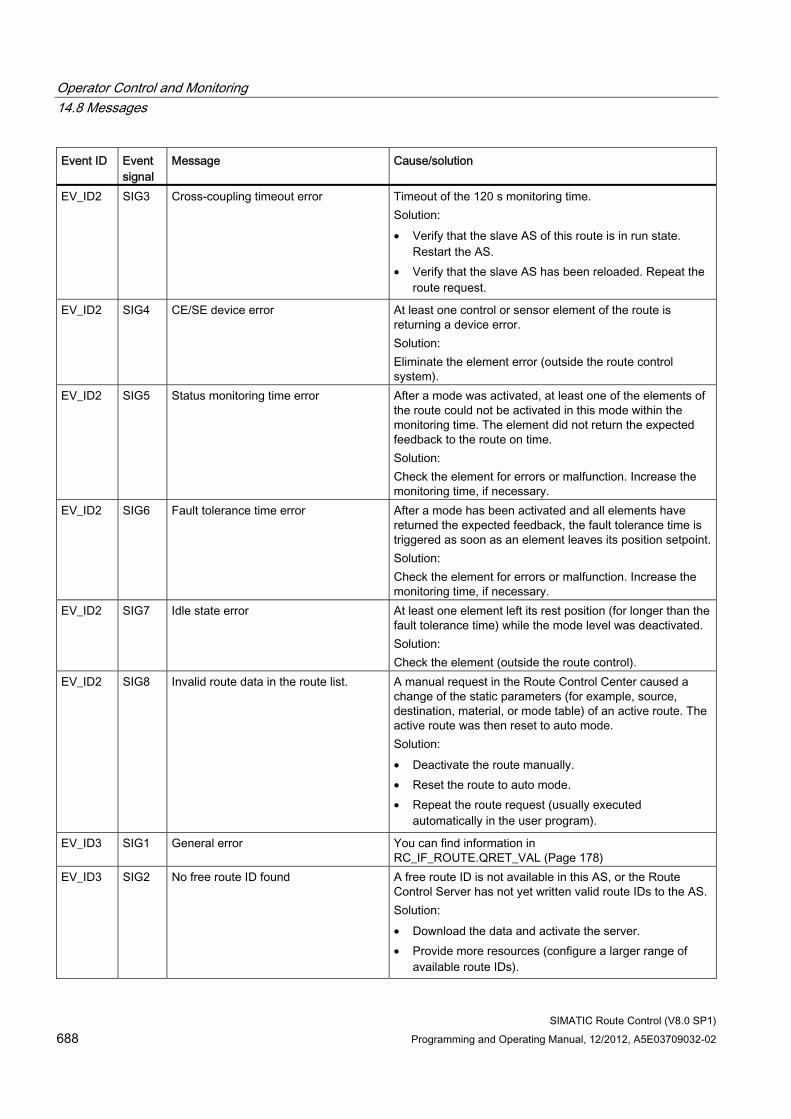
Operator Control and Monitoring 14.8 Messages
SIMATIC Route Control (V8.0 SP1) 688 Programming and Operating Manual, 12/2012, A5E03709032-02
Event ID Event signal
Message Cause/solution
EV_ID2 SIG3 Cross-coupling timeout error Timeout of the 120 s monitoring time. Solution: • Verify that the slave AS of this route is in run state.
Restart the AS. • Verify that the slave AS has been reloaded. Repeat the
route request.
EV_ID2 SIG4 CE/SE device error At least one control or sensor element of the route is returning a device error. Solution: Eliminate the element error (outside the route control system).
EV_ID2 SIG5 Status monitoring time error After a mode was activated, at least one of the elements of the route could not be activated in this mode within the monitoring time. The element did not return the expected feedback to the route on time. Solution: Check the element for errors or malfunction. Increase the monitoring time, if necessary.
EV_ID2 SIG6 Fault tolerance time error After a mode has been activated and all elements have returned the expected feedback, the fault tolerance time is triggered as soon as an element leaves its position setpoint.Solution: Check the element for errors or malfunction. Increase the monitoring time, if necessary.
EV_ID2 SIG7 Idle state error At least one element left its rest position (for longer than the fault tolerance time) while the mode level was deactivated. Solution: Check the element (outside the route control).
EV_ID2 SIG8 Invalid route data in the route list. A manual request in the Route Control Center caused a change of the static parameters (for example, source, destination, material, or mode table) of an active route. The active route was then reset to auto mode. Solution: • Deactivate the route manually. • Reset the route to auto mode. • Repeat the route request (usually executed
automatically in the user program).
EV_ID3 SIG1 General error You can find information in RC_IF_ROUTE.QRET_VAL (Page 178)
EV_ID3 SIG2 No free route ID found A free route ID is not available in this AS, or the Route Control Server has not yet written valid route IDs to the AS. Solution: • Download the data and activate the server. • Provide more resources (configure a larger range of
available route IDs).
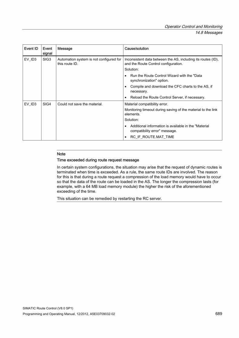
Operator Control and Monitoring 14.8 Messages
SIMATIC Route Control (V8.0 SP1) Programming and Operating Manual, 12/2012, A5E03709032-02 689
Event ID Event signal
Message Cause/solution
EV_ID3 SIG3 Automation system is not configured for this route ID.
Inconsistent data between the AS, including its routes (ID), and the Route Control configuration. Solution: • Run the Route Control Wizard with the "Data
synchronization" option. • Compile and download the CFC charts to the AS, if
necessary. • Reload the Route Control Server, if necessary.
EV_ID3 SIG4 Could not save the material. Material compatibility error. Monitoring timeout during saving of the material to the link elements. Solution: • Additional information is available in the "Material
compatibility error" message. • RC_IF_ROUTE.MAT_TIME
Note Time exceeded during route request message
In certain system configurations, the situation may arise that the request of dynamic routes is terminated when time is exceeded. As a rule, the same route IDs are involved. The reason for this is that during a route request a compression of the load memory would have to occur so that the data of the route can be loaded in the AS. The longer the compression lasts (for example, with a 64 MB load memory module) the higher the risk of the aforementioned exceeding of the time.
This situation can be remedied by restarting the RC server.
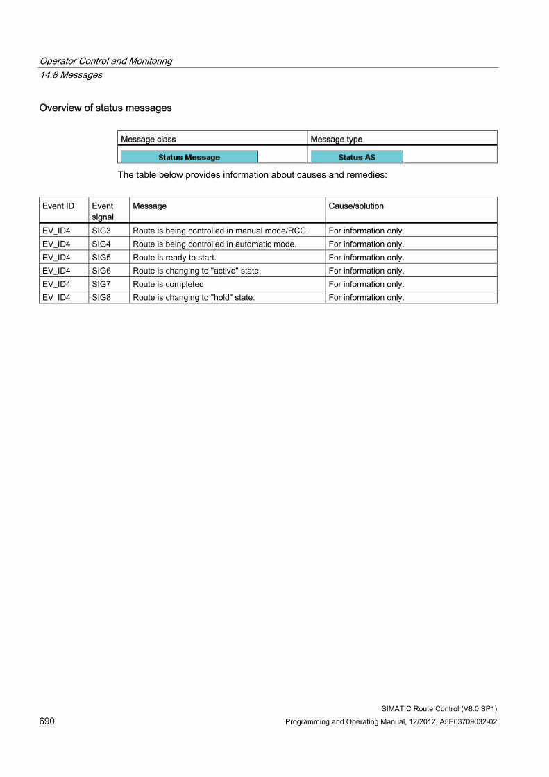
Operator Control and Monitoring 14.8 Messages
SIMATIC Route Control (V8.0 SP1) 690 Programming and Operating Manual, 12/2012, A5E03709032-02
Overview of status messages Message class Message type
The table below provides information about causes and remedies:
Event ID Event
signal Message Cause/solution
EV_ID4 SIG3 Route is being controlled in manual mode/RCC. For information only. EV_ID4 SIG4 Route is being controlled in automatic mode. For information only. EV_ID4 SIG5 Route is ready to start. For information only. EV_ID4 SIG6 Route is changing to "active" state. For information only. EV_ID4 SIG7 Route is completed For information only. EV_ID4 SIG8 Route is changing to "hold" state. For information only.
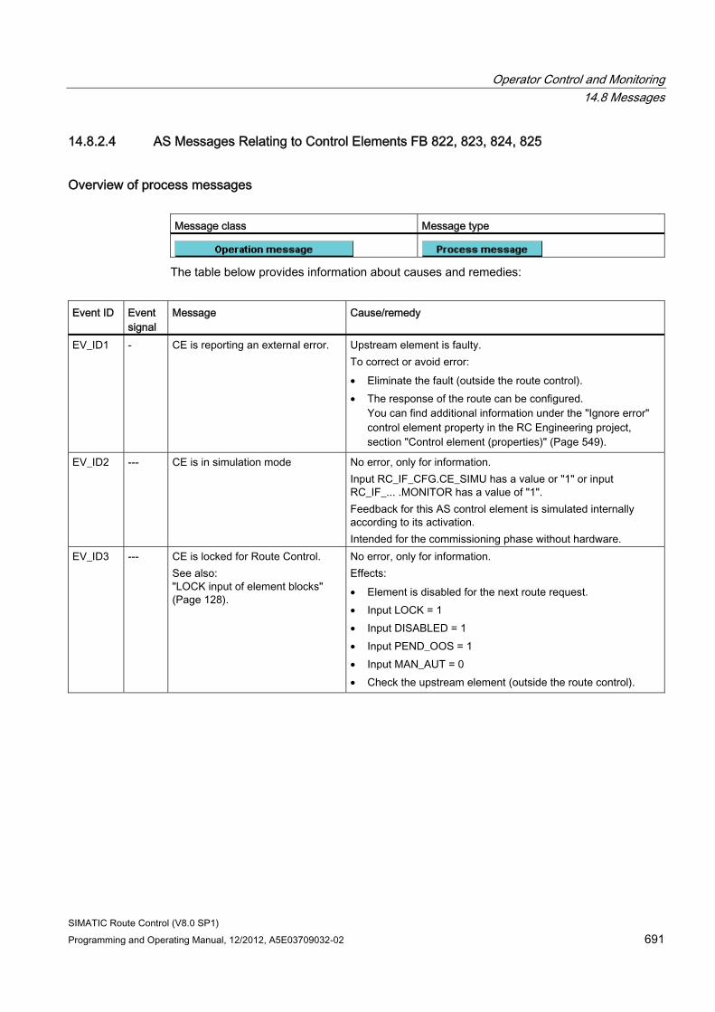
Operator Control and Monitoring 14.8 Messages
SIMATIC Route Control (V8.0 SP1) Programming and Operating Manual, 12/2012, A5E03709032-02 691
14.8.2.4 AS Messages Relating to Control Elements FB 822, 823, 824, 825
Overview of process messages Message class Message type
The table below provides information about causes and remedies:
Event ID Event
signal Message Cause/remedy
EV_ID1 - CE is reporting an external error. Upstream element is faulty. To correct or avoid error: • Eliminate the fault (outside the route control). • The response of the route can be configured.
You can find additional information under the "Ignore error" control element property in the RC Engineering project, section "Control element (properties)" (Page 549).
EV_ID2 --- CE is in simulation mode No error, only for information. Input RC_IF_CFG.CE_SIMU has a value or "1" or input RC_IF_... .MONITOR has a value of "1". Feedback for this AS control element is simulated internally according to its activation. Intended for the commissioning phase without hardware.
EV_ID3 --- CE is locked for Route Control. See also: "LOCK input of element blocks" (Page 128).
No error, only for information. Effects: • Element is disabled for the next route request. • Input LOCK = 1 • Input DISABLED = 1 • Input PEND_OOS = 1 • Input MAN_AUT = 0 • Check the upstream element (outside the route control).
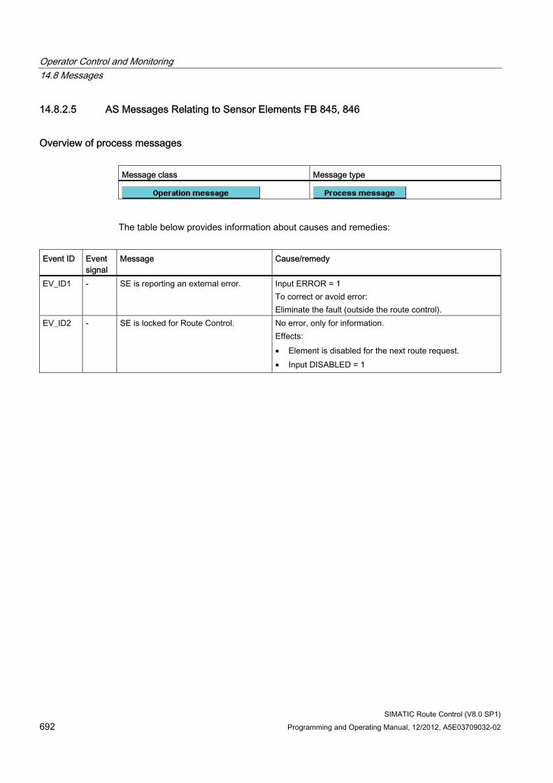
Operator Control and Monitoring 14.8 Messages
SIMATIC Route Control (V8.0 SP1) 692 Programming and Operating Manual, 12/2012, A5E03709032-02
14.8.2.5 AS Messages Relating to Sensor Elements FB 845, 846
Overview of process messages Message class Message type
The table below provides information about causes and remedies:
Event ID Event
signal Message Cause/remedy
EV_ID1 - SE is reporting an external error. Input ERROR = 1 To correct or avoid error: Eliminate the fault (outside the route control).
EV_ID2 - SE is locked for Route Control. No error, only for information. Effects: • Element is disabled for the next route request. • Input DISABLED = 1
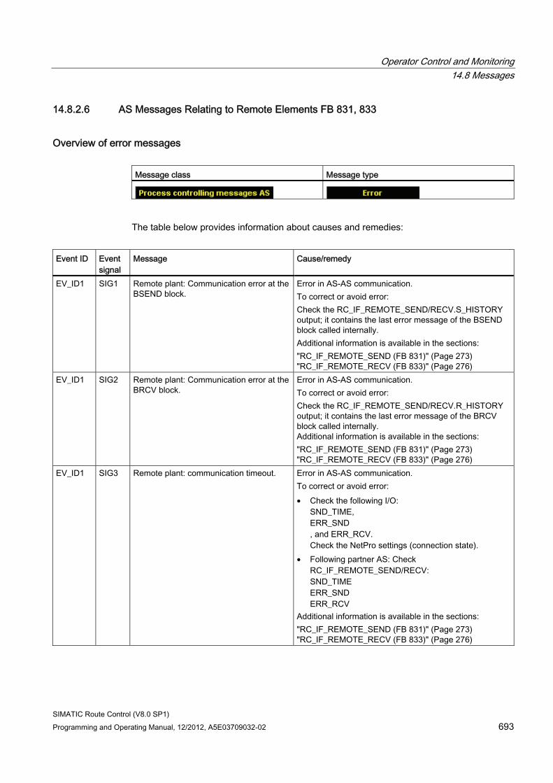
Operator Control and Monitoring 14.8 Messages
SIMATIC Route Control (V8.0 SP1) Programming and Operating Manual, 12/2012, A5E03709032-02 693
14.8.2.6 AS Messages Relating to Remote Elements FB 831, 833
Overview of error messages Message class Message type
The table below provides information about causes and remedies:
Event ID Event
signal Message Cause/remedy
EV_ID1 SIG1 Remote plant: Communication error at the BSEND block.
Error in AS-AS communication. To correct or avoid error: Check the RC_IF_REMOTE_SEND/RECV.S_HISTORY output; it contains the last error message of the BSEND block called internally. Additional information is available in the sections: "RC_IF_REMOTE_SEND (FB 831)" (Page 273) "RC_IF_REMOTE_RECV (FB 833)" (Page 276)
EV_ID1 SIG2 Remote plant: Communication error at the BRCV block.
Error in AS-AS communication. To correct or avoid error: Check the RC_IF_REMOTE_SEND/RECV.R_HISTORY output; it contains the last error message of the BRCV block called internally. Additional information is available in the sections: "RC_IF_REMOTE_SEND (FB 831)" (Page 273) "RC_IF_REMOTE_RECV (FB 833)" (Page 276)
EV_ID1 SIG3 Remote plant: communication timeout. Error in AS-AS communication. To correct or avoid error: • Check the following I/O:
SND_TIME, ERR_SND , and ERR_RCV. Check the NetPro settings (connection state).
• Following partner AS: Check RC_IF_REMOTE_SEND/RECV: SND_TIME ERR_SND ERR_RCV
Additional information is available in the sections: "RC_IF_REMOTE_SEND (FB 831)" (Page 273) "RC_IF_REMOTE_RECV (FB 833)" (Page 276)
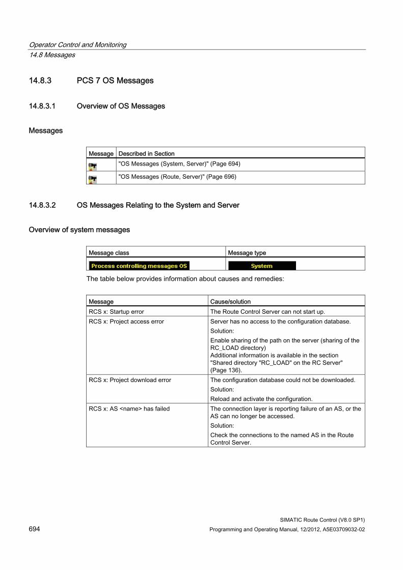
Operator Control and Monitoring 14.8 Messages
SIMATIC Route Control (V8.0 SP1) 694 Programming and Operating Manual, 12/2012, A5E03709032-02
14.8.3 PCS 7 OS Messages
14.8.3.1 Overview of OS Messages
Messages Message Described in Section
"OS Messages (System, Server)" (Page 694)
"OS Messages (Route, Server)" (Page 696)
14.8.3.2 OS Messages Relating to the System and Server
Overview of system messages Message class Message type
The table below provides information about causes and remedies:
Message Cause/solution RCS x: Startup error The Route Control Server can not start up. RCS x: Project access error Server has no access to the configuration database.
Solution: Enable sharing of the path on the server (sharing of the RC_LOAD directory) Additional information is available in the section "Shared directory "RC_LOAD" on the RC Server" (Page 136).
RCS x: Project download error The configuration database could not be downloaded. Solution: Reload and activate the configuration.
RCS x: AS <name> has failed The connection layer is reporting failure of an AS, or the AS can no longer be accessed. Solution: Check the connections to the named AS in the Route Control Server.
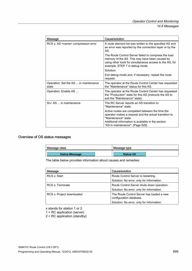
Operator Control and Monitoring 14.8 Messages
SIMATIC Route Control (V8.0 SP1) Programming and Operating Manual, 12/2012, A5E03709032-02 695
Message Cause/solution RCS x: AS <name> compression error A route element list was written to the specified AS and
an error was reported by the connection layer or by the AS. The Route Control Server failed to compress the load memory of the AS. This may have been caused by using other tools for simultaneous access to the AS, for example, STEP 7 in debug mode. Solution: Exit debug mode and, if necessary, repeat the route request.
Operation: Set the AS ... in maintenance state
The operator at the Route Control Center has requested the "Maintenance" status for this AS.
Operation: Enable AS ... The operator at the Route Control Center has requested the "Production" state for this AS (instructs the AS to exit the "Maintenance" state).
Srv: AS ... in maintenance The RC Server reports an AS transition to "Maintenance" state. Active routes are completed between the time the operator makes a request and the actual transition to "Maintenance" state. Additional information is available in the section "AS in maintenance". (Page 629)
Overview of OS status messages Message class Message type
The table below provides information about causes and remedies:
Message Cause/solution RCS x: Start Route Control Server is restarting.
Solution: No error, only for information. RCS x: Terminate Route Control Server shuts down operation.
Solution: No error, only for information. RCS x: Project downloaded The Route Control Server has loaded a new
configuration database. Solution: No error, only for information.
x stands for station 1 or 2. 1 = RC application (server) 2 = RC application (standby)
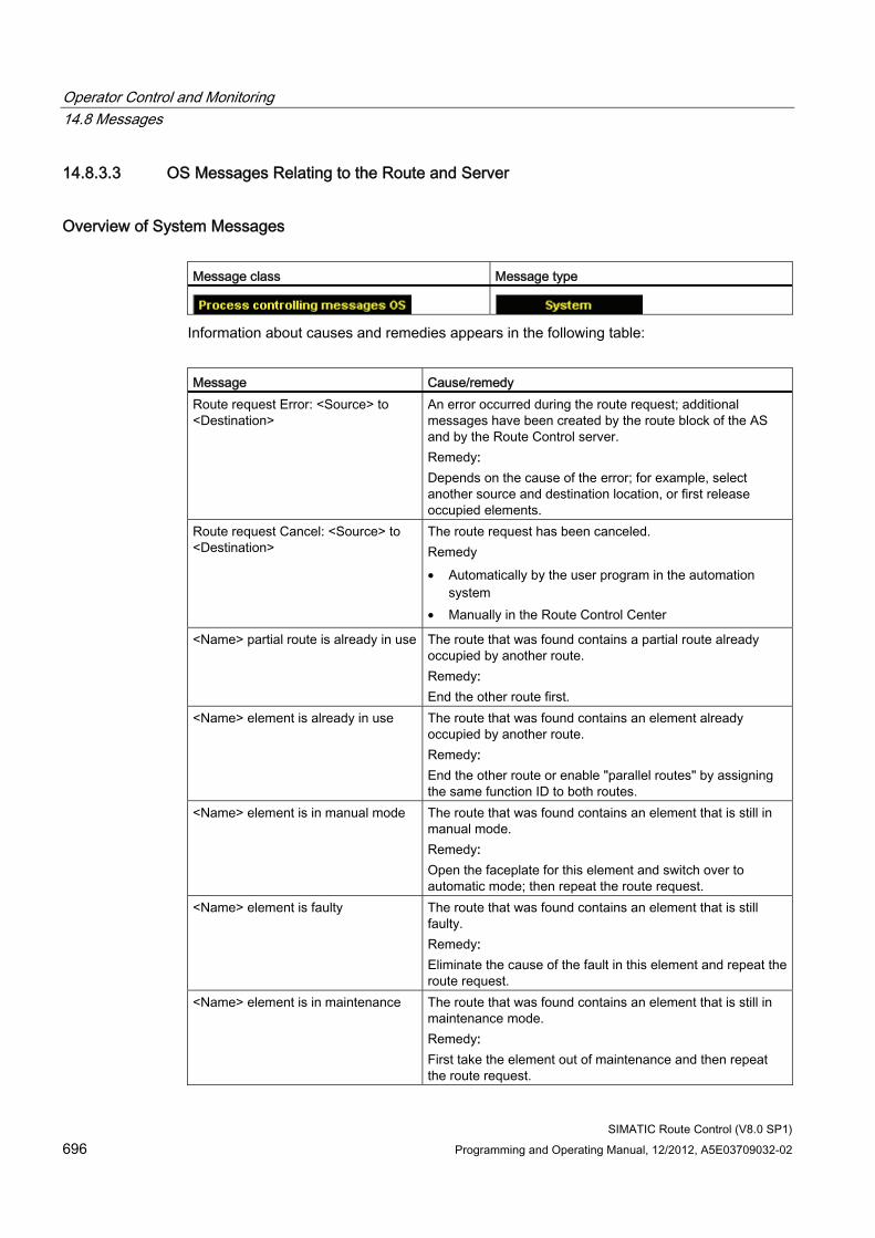
Operator Control and Monitoring 14.8 Messages
SIMATIC Route Control (V8.0 SP1) 696 Programming and Operating Manual, 12/2012, A5E03709032-02
14.8.3.3 OS Messages Relating to the Route and Server
Overview of System Messages Message class Message type
Information about causes and remedies appears in the following table:
Message Cause/remedy Route request Error: <Source> to <Destination>
An error occurred during the route request; additional messages have been created by the route block of the AS and by the Route Control server. Remedy: Depends on the cause of the error; for example, select another source and destination location, or first release occupied elements.
Route request Cancel: <Source> to <Destination>
The route request has been canceled. Remedy • Automatically by the user program in the automation
system • Manually in the Route Control Center
<Name> partial route is already in use The route that was found contains a partial route already occupied by another route. Remedy: End the other route first.
<Name> element is already in use The route that was found contains an element already occupied by another route. Remedy: End the other route or enable "parallel routes" by assigning the same function ID to both routes.
<Name> element is in manual mode The route that was found contains an element that is still in manual mode. Remedy: Open the faceplate for this element and switch over to automatic mode; then repeat the route request.
<Name> element is faulty The route that was found contains an element that is still faulty. Remedy: Eliminate the cause of the fault in this element and repeat the route request.
<Name> element is in maintenance The route that was found contains an element that is still in maintenance mode. Remedy: First take the element out of maintenance and then repeat the route request.
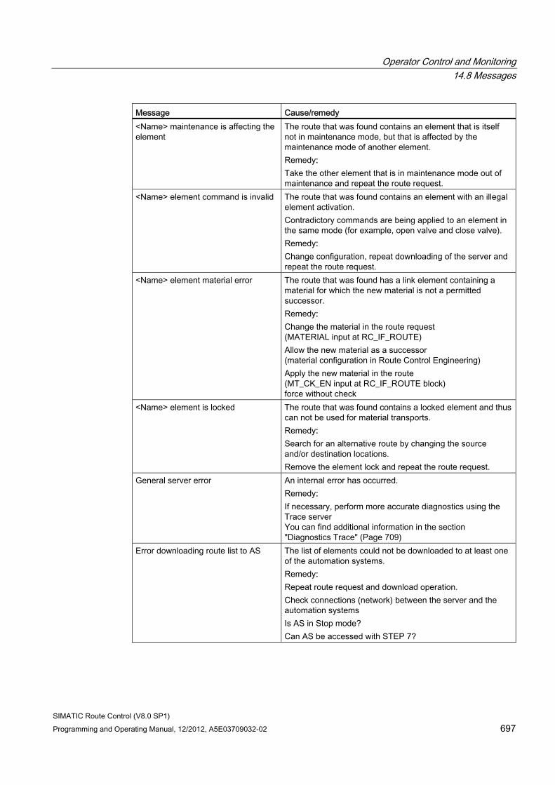
Operator Control and Monitoring 14.8 Messages
SIMATIC Route Control (V8.0 SP1) Programming and Operating Manual, 12/2012, A5E03709032-02 697
Message Cause/remedy <Name> maintenance is affecting the element
The route that was found contains an element that is itself not in maintenance mode, but that is affected by the maintenance mode of another element. Remedy: Take the other element that is in maintenance mode out of maintenance and repeat the route request.
<Name> element command is invalid The route that was found contains an element with an illegal element activation. Contradictory commands are being applied to an element in the same mode (for example, open valve and close valve). Remedy: Change configuration, repeat downloading of the server and repeat the route request.
<Name> element material error The route that was found has a link element containing a material for which the new material is not a permitted successor. Remedy: Change the material in the route request (MATERIAL input at RC_IF_ROUTE) Allow the new material as a successor (material configuration in Route Control Engineering) Apply the new material in the route (MT_CK_EN input at RC_IF_ROUTE block) force without check
<Name> element is locked The route that was found contains a locked element and thus can not be used for material transports. Remedy: Search for an alternative route by changing the source and/or destination locations. Remove the element lock and repeat the route request.
General server error An internal error has occurred. Remedy: If necessary, perform more accurate diagnostics using the Trace server You can find additional information in the section "Diagnostics Trace" (Page 709)
Error downloading route list to AS The list of elements could not be downloaded to at least one of the automation systems. Remedy: Repeat route request and download operation. Check connections (network) between the server and the automation systems Is AS in Stop mode? Can AS be accessed with STEP 7?
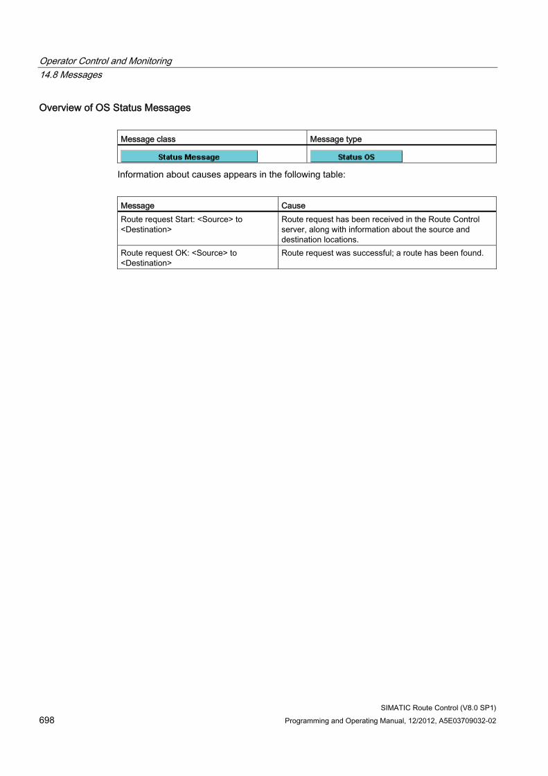
Operator Control and Monitoring 14.8 Messages
SIMATIC Route Control (V8.0 SP1) 698 Programming and Operating Manual, 12/2012, A5E03709032-02
Overview of OS Status Messages Message class Message type
Information about causes appears in the following table:
Message Cause Route request Start: <Source> to <Destination>
Route request has been received in the Route Control server, along with information about the source and destination locations.
Route request OK: <Source> to <Destination>
Route request was successful; a route has been found.
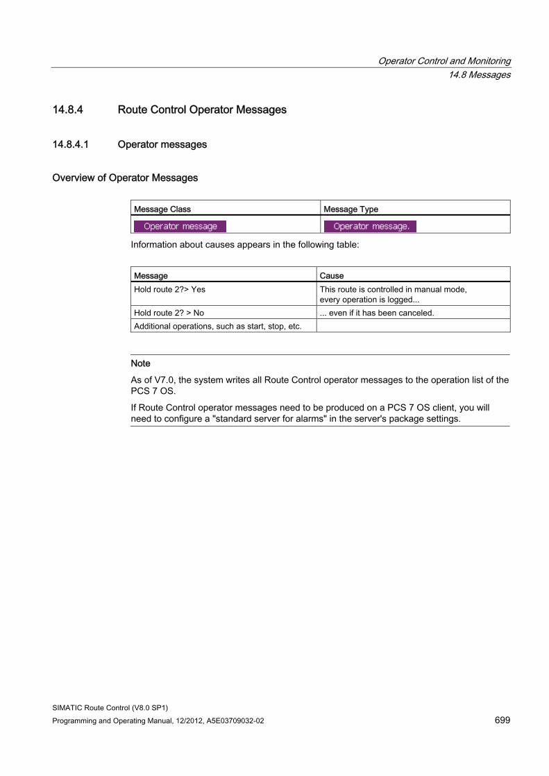
Operator Control and Monitoring 14.8 Messages
SIMATIC Route Control (V8.0 SP1) Programming and Operating Manual, 12/2012, A5E03709032-02 699
14.8.4 Route Control Operator Messages
14.8.4.1 Operator messages
Overview of Operator Messages Message Class Message Type
Information about causes appears in the following table:
Message Cause Hold route 2?> Yes This route is controlled in manual mode,
every operation is logged... Hold route 2? > No ... even if it has been canceled. Additional operations, such as start, stop, etc.
Note
As of V7.0, the system writes all Route Control operator messages to the operation list of the PCS 7 OS.
If Route Control operator messages need to be produced on a PCS 7 OS client, you will need to configure a "standard server for alarms" in the server's package settings.
Operator Control and Monitoring 14.8 Messages
SIMATIC Route Control (V8.0 SP1) 700 Programming and Operating Manual, 12/2012, A5E03709032-02
SIMATIC Route Control (V8.0 SP1) Programming and Operating Manual, 12/2012, A5E03709032-02 701
Appendix 1515.1 Range of values
15.1.1 Overview of Valid Ranges of Values
Introduction Here is an overview of all ranges of values. These ranges of values are valid for inputs and outputs (parameters) of blocks in the Route Control library as well as in the Route Control configuration or your Route Control project.
Available Ranges ● "Valid Route IDs" (Page 702)
● "Valid Function ID" (Page 702)
● "Valid Maximum Route Request Time" (Page 703)
● "Valid Maximum Material Acceptance Time" (Page 703)
● "Valid Material IDs" (Page 703)
● "Valid ID Ranges for CEs, SEs, LEs, and PEs" (Page 704)
● "Valid SNDRCVDB Block Numbers for Remote Elements" (Page 705)
● "Valid AS Numbers" (Page 705)
● "Valid Index of External Parameter Elements" (Page 706)
● "Chart-in-Chart Technology" (Page 135)
Additional information Not all objects in the quantity framework are input and output parameters in the sense described above. You can find an overview of the Route Control quantity framework in "Quantity Framework for Route Control" (Page 707).
Appendix 15.1 Range of values
SIMATIC Route Control (V8.0 SP1) 702 Programming and Operating Manual, 12/2012, A5E03709032-02
15.1.2 Valid route IDs
Blocks RC_IF_ROUTE (FB800) (Page 159)
Parameters and Ranges of Values Parameter Min. Max. Notes ROUTE_ID 1 300 Up to 300 material transports can be performed simultaneously.
If more than 300 blocks of the RC_IF_ROUTE type are inserted in CFC charts, you must use dynamic ID assignment. You can find information about this in "Guide to Dynamic ID Assignment" (Page 378).
Note
The FIXED_ID parameter must be set to 1 for fixed route IDs.
Assign the route IDs once and do not change them afterward.
For every route ID used in an automation system, the corresponding data block must be downloaded to and available in this AS and all (slave) automation systems involved in the route.
Data-block number = 100 + route ID, i.e., DB number = 101 ... 400
15.1.3 Valid function ID
Blocks RC_IF_ROUTE (FB800) (Page 159)
Parameters and Ranges of Values Parameter Min. Max. Note FUNC_ID 0 32,000 0: System uses the route ID as the function ID
1...300: Used by the system 301 to 32,000 User-defined
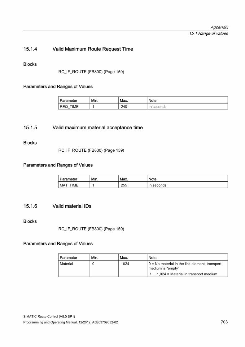
Appendix 15.1 Range of values
SIMATIC Route Control (V8.0 SP1) Programming and Operating Manual, 12/2012, A5E03709032-02 703
15.1.4 Valid Maximum Route Request Time
Blocks RC_IF_ROUTE (FB800) (Page 159)
Parameters and Ranges of Values Parameter Min. Max. Note REQ_TIME 1 240 In seconds
15.1.5 Valid maximum material acceptance time
Blocks RC_IF_ROUTE (FB800) (Page 159)
Parameters and Ranges of Values Parameter Min. Max. Note MAT_TIME 1 255 In seconds
15.1.6 Valid material IDs
Blocks RC_IF_ROUTE (FB800) (Page 159)
Parameters and Ranges of Values Parameter Min. Max. Note Material 0 1024 0 = No material in the link element, transport
medium is "empty" 1 ... 1,024 = Material in transport medium
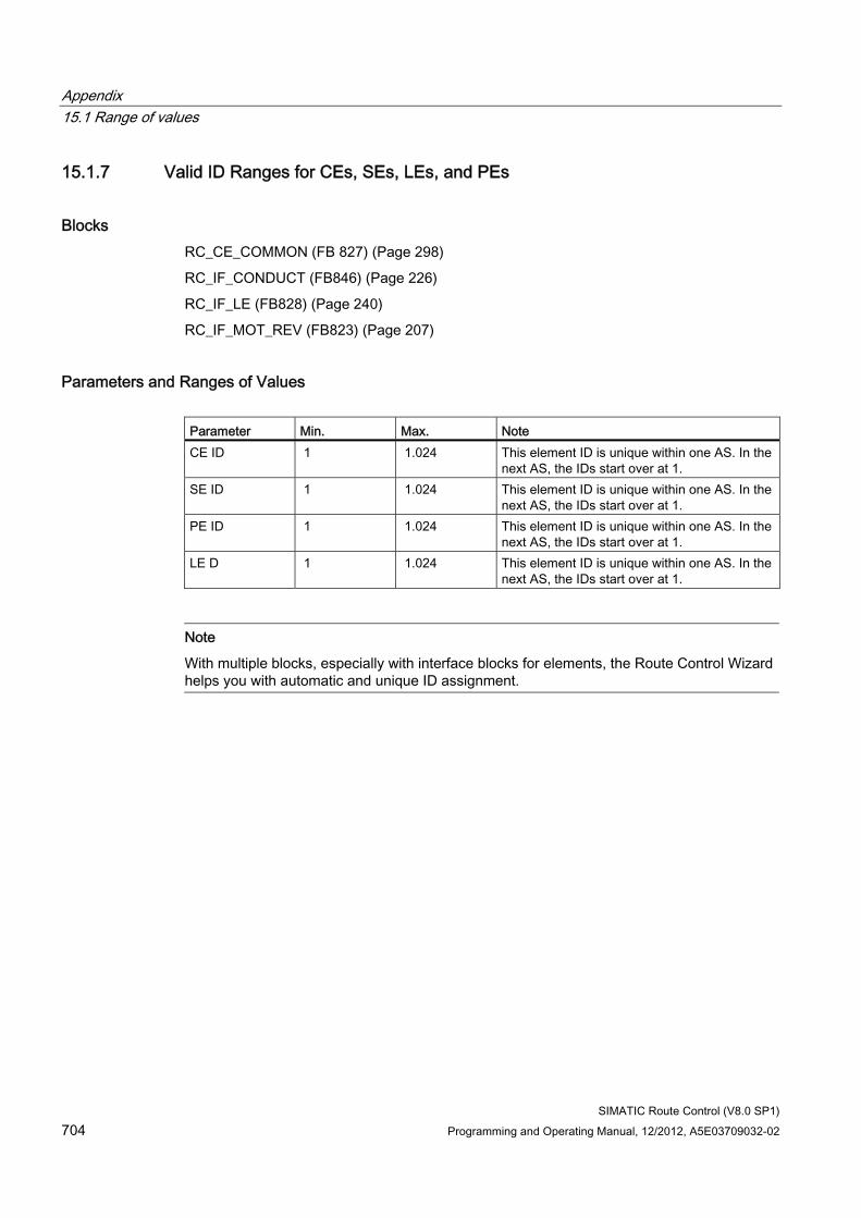
Appendix 15.1 Range of values
SIMATIC Route Control (V8.0 SP1) 704 Programming and Operating Manual, 12/2012, A5E03709032-02
15.1.7 Valid ID Ranges for CEs, SEs, LEs, and PEs
Blocks RC_CE_COMMON (FB 827) (Page 298)
RC_IF_CONDUCT (FB846) (Page 226)
RC_IF_LE (FB828) (Page 240)
RC_IF_MOT_REV (FB823) (Page 207)
Parameters and Ranges of Values Parameter Min. Max. Note CE ID 1 1.024 This element ID is unique within one AS. In the
next AS, the IDs start over at 1. SE ID 1 1.024 This element ID is unique within one AS. In the
next AS, the IDs start over at 1. PE ID 1 1.024 This element ID is unique within one AS. In the
next AS, the IDs start over at 1. LE D 1 1.024 This element ID is unique within one AS. In the
next AS, the IDs start over at 1.
Note
With multiple blocks, especially with interface blocks for elements, the Route Control Wizard helps you with automatic and unique ID assignment.
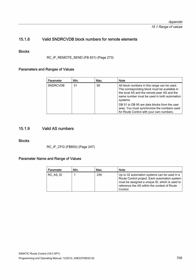
Appendix 15.1 Range of values
SIMATIC Route Control (V8.0 SP1) Programming and Operating Manual, 12/2012, A5E03709032-02 705
15.1.8 Valid SNDRCVDB block numbers for remote elements
Blocks RC_IF_REMOTE_SEND (FB 831) (Page 273)
Parameters and Ranges of Values Parameter Min. Max. Note SNDRCVDB 51 95 All block numbers in this range can be used.
The corresponding block must be available in the local AS and the remote peer AS and the same number must be used in both automation systems. DB 51 to DB 90 are data blocks from the user area. You must synchronize the numbers used for Route Control with your own numbers.
15.1.9 Valid AS numbers
Blocks RC_IF_CFG (FB850) (Page 247)
Parameter Name and Range of Values Parameter Min. Max. Note RC_AS_ID 1 239 Up to 32 automation systems can be used in a
Route Control project. Each automation system must be assigned a unique ID, which is used to reference the AS within the context of Route Control.
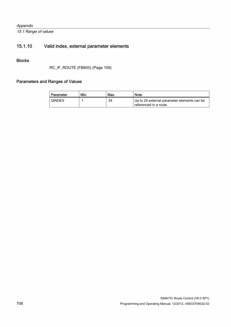
Appendix 15.1 Range of values
SIMATIC Route Control (V8.0 SP1) 706 Programming and Operating Manual, 12/2012, A5E03709032-02
15.1.10 Valid index, external parameter elements
Blocks RC_IF_ROUTE (FB800) (Page 159)
Parameters and Ranges of Values Parameter Min. Max. Note QINDEX 1 24 Up to 24 external parameter elements can be
referenced in a route.
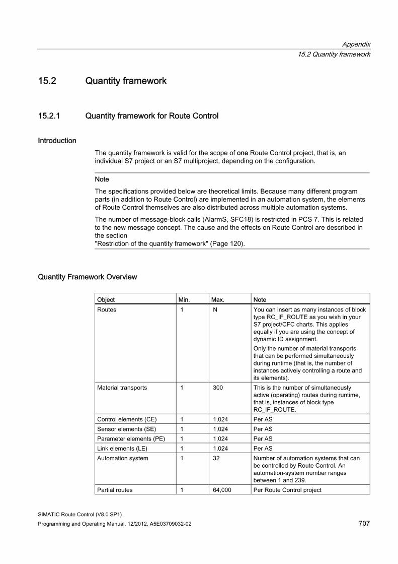
Appendix 15.2 Quantity framework
SIMATIC Route Control (V8.0 SP1) Programming and Operating Manual, 12/2012, A5E03709032-02 707
15.2 Quantity framework
15.2.1 Quantity framework for Route Control
Introduction The quantity framework is valid for the scope of one Route Control project, that is, an individual S7 project or an S7 multiproject, depending on the configuration.
Note
The specifications provided below are theoretical limits. Because many different program parts (in addition to Route Control) are implemented in an automation system, the elements of Route Control themselves are also distributed across multiple automation systems.
The number of message-block calls (AlarmS, SFC18) is restricted in PCS 7. This is related to the new message concept. The cause and the effects on Route Control are described in the section "Restriction of the quantity framework" (Page 120).
Quantity Framework Overview Object Min. Max. Note Routes 1 N You can insert as many instances of block
type RC_IF_ROUTE as you wish in your S7 project/CFC charts. This applies equally if you are using the concept of dynamic ID assignment. Only the number of material transports that can be performed simultaneously during runtime (that is, the number of instances actively controlling a route and its elements).
Material transports 1 300 This is the number of simultaneously active (operating) routes during runtime, that is, instances of block type RC_IF_ROUTE.
Control elements (CE) 1 1,024 Per AS Sensor elements (SE) 1 1,024 Per AS Parameter elements (PE) 1 1,024 Per AS Link elements (LE) 1 1,024 Per AS Automation system 1 32 Number of automation systems that can
be controlled by Route Control. An automation-system number ranges between 1 and 239.
Partial routes 1 64,000 Per Route Control project
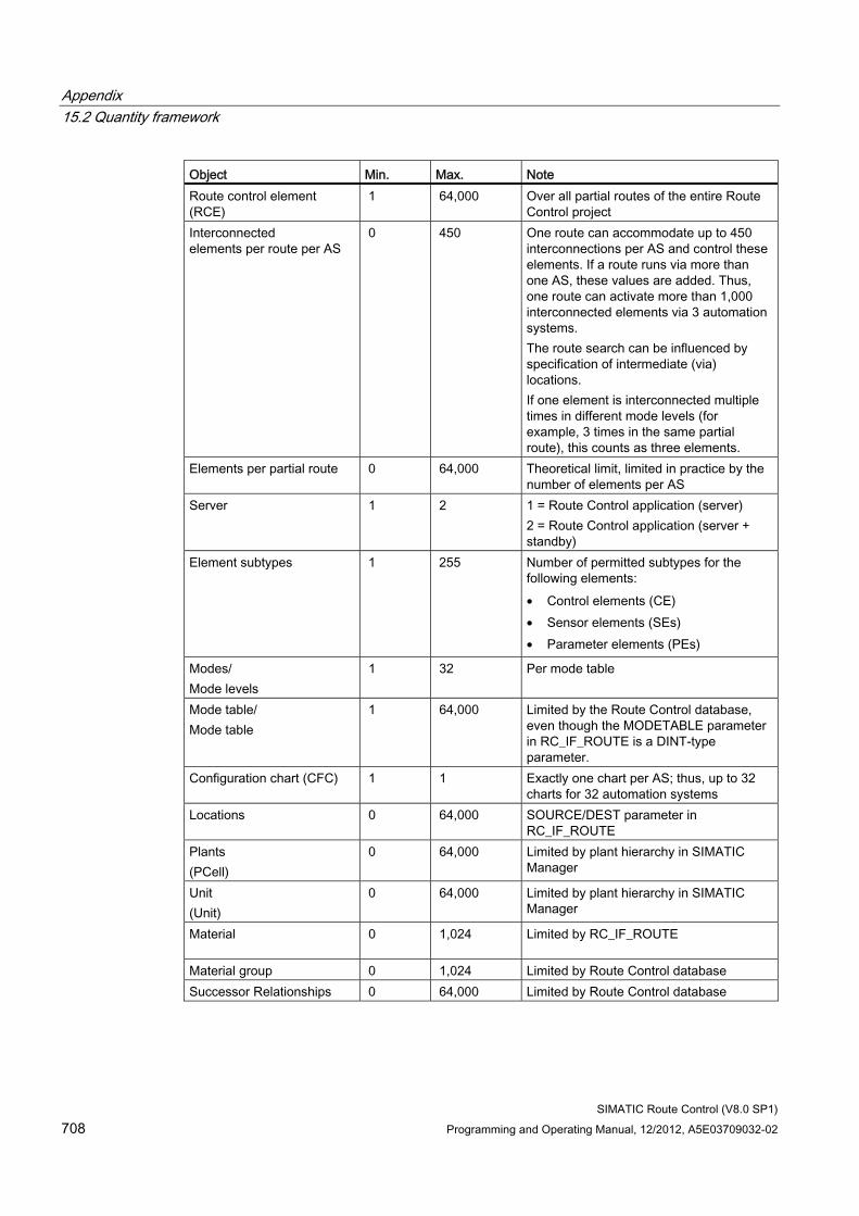
Appendix 15.2 Quantity framework
SIMATIC Route Control (V8.0 SP1) 708 Programming and Operating Manual, 12/2012, A5E03709032-02
Object Min. Max. Note Route control element (RCE)
1 64,000 Over all partial routes of the entire Route Control project
Interconnected elements per route per AS
0 450 One route can accommodate up to 450 interconnections per AS and control these elements. If a route runs via more than one AS, these values are added. Thus, one route can activate more than 1,000 interconnected elements via 3 automation systems. The route search can be influenced by specification of intermediate (via) locations. If one element is interconnected multiple times in different mode levels (for example, 3 times in the same partial route), this counts as three elements.
Elements per partial route 0 64,000 Theoretical limit, limited in practice by the number of elements per AS
Server 1 2 1 = Route Control application (server) 2 = Route Control application (server + standby)
Element subtypes 1 255 Number of permitted subtypes for the following elements: • Control elements (CE) • Sensor elements (SEs) • Parameter elements (PEs)
Modes/ Mode levels
1 32 Per mode table
Mode table/ Mode table
1 64,000 Limited by the Route Control database, even though the MODETABLE parameter in RC_IF_ROUTE is a DINT-type parameter.
Configuration chart (CFC) 1 1 Exactly one chart per AS; thus, up to 32 charts for 32 automation systems
Locations 0 64,000 SOURCE/DEST parameter in RC_IF_ROUTE
Plants (PCell)
0 64,000 Limited by plant hierarchy in SIMATIC Manager
Unit (Unit)
0 64,000 Limited by plant hierarchy in SIMATIC Manager
Material 0 1,024 Limited by RC_IF_ROUTE
Material group 0 1,024 Limited by Route Control database Successor Relationships 0 64,000 Limited by Route Control database
Appendix 15.3 Diagnostics and Logs
SIMATIC Route Control (V8.0 SP1) Programming and Operating Manual, 12/2012, A5E03709032-02 709
15.3 Diagnostics and Logs
15.3.1 Trace Server
Description The Trace Server installed with Route Control is not intended for operating personal. It is a special tool to be used by experts, such as commissioning personnel, for detailed diagnostics.
While the information displayed is complex, it can also be used by the hotline to diagnose and quickly locate the causes of faults. with some practice, valuable information can be obtained even during the commissioning phase.
For more information, refer to the section: "Diagnostics Overview" (Page 709)
15.3.2 Diagnostics Overview
Diagnostics Overview Route Control offers experienced users a series of expanded diagnostic options for the following levels:
● "Diagnostics for Engineering" (Page 710)
● "Diagnostics for Operator Control and Monitoring" (Page 710) (operating personnel)
● "Diagnostics for Cross-Coupling" (Page 713) (automation system)
● "Diagnostics for the Route Control Server" (Page 714)
These diagnostic options are not intended for operating personnel, but rather for configuring engineers and commissioning personnel.
Appendix 15.3 Diagnostics and Logs
SIMATIC Route Control (V8.0 SP1) 710 Programming and Operating Manual, 12/2012, A5E03709032-02
15.3.3 Diagnostics for engineering
Diagnostics for Engineering Route Control creates log files at various times. Once an operation is complete, you can open these log files using an editor.
● "CSV Interface (Export Log)" (Page 479) (exporting from the Route Control project)
● "CSV Interface (Import Log)" (Page 481) (importing to the Route Control project)
● "Route Control Wizard (Export Log)" (Page 463) (exporting from the S7 project)
● "Route Control Engineering: Checking Data Consistency" (Page 600) (Route Control project)
Note
For all log files, time stamps are indicated in the individual sections so that the duration of an operation can be calculated.
15.3.4 Diagnostics for Operator Control and Monitoring
General The Trace Server application always operates locally instead of over the network. Always start Trace Server on the computer where the application to be diagnosed, such as the Route Control Center or the Route Control server, is running.
Setting Diagnostics 1. Start Trace Server via ..\SIEMENS\RCS\bin\rctrcsrv.exe.
2. In the dialog box, select one of the applications to be diagnosed. The Trace Server displays only those applications that are currently running, are in the main memory and are logged on in the Trace Server.
3. Set the scope of messages to be displayed (diagnostic, information, warning, error).
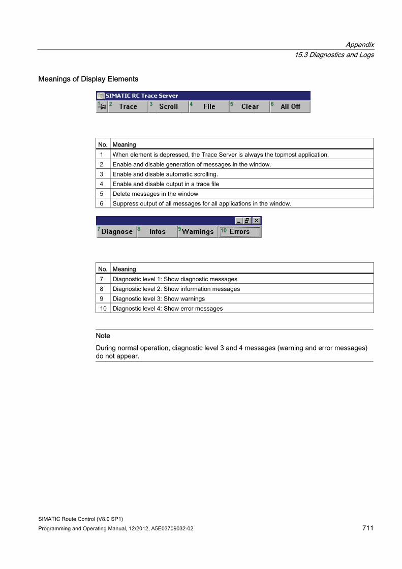
Appendix 15.3 Diagnostics and Logs
SIMATIC Route Control (V8.0 SP1) Programming and Operating Manual, 12/2012, A5E03709032-02 711
Meanings of Display Elements
No. Meaning 1 When element is depressed, the Trace Server is always the topmost application. 2 Enable and disable generation of messages in the window. 3 Enable and disable automatic scrolling. 4 Enable and disable output in a trace file 5 Delete messages in the window 6 Suppress output of all messages for all applications in the window.
No. Meaning 7 Diagnostic level 1: Show diagnostic messages 8 Diagnostic level 2: Show information messages 9 Diagnostic level 3: Show warnings 10 Diagnostic level 4: Show error messages
Note
During normal operation, diagnostic level 3 and 4 messages (warning and error messages) do not appear.
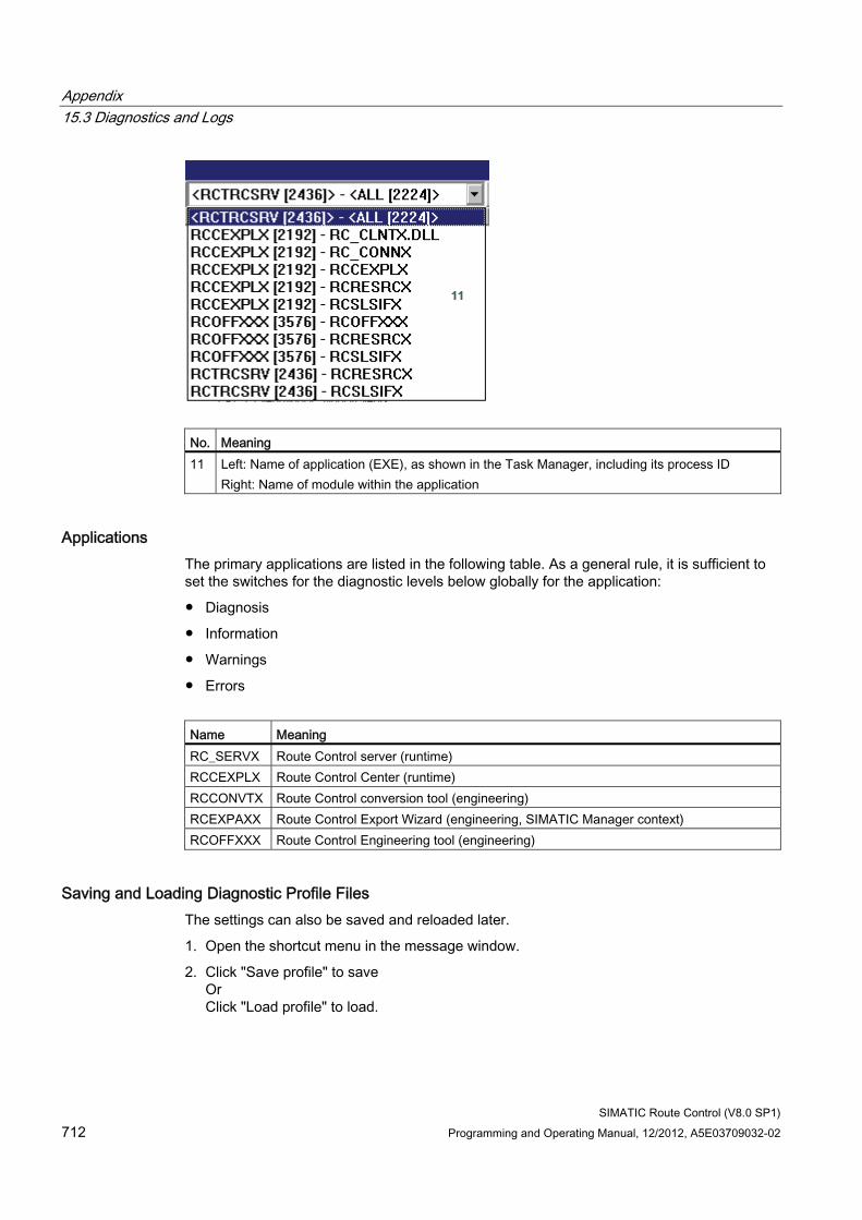
Appendix 15.3 Diagnostics and Logs
SIMATIC Route Control (V8.0 SP1) 712 Programming and Operating Manual, 12/2012, A5E03709032-02
No. Meaning 11 Left: Name of application (EXE), as shown in the Task Manager, including its process ID
Right: Name of module within the application
Applications The primary applications are listed in the following table. As a general rule, it is sufficient to set the switches for the diagnostic levels below globally for the application:
● Diagnosis
● Information
● Warnings
● Errors
Name Meaning RC_SERVX Route Control server (runtime) RCCEXPLX Route Control Center (runtime) RCCONVTX Route Control conversion tool (engineering) RCEXPAXX Route Control Export Wizard (engineering, SIMATIC Manager context) RCOFFXXX Route Control Engineering tool (engineering)
Saving and Loading Diagnostic Profile Files The settings can also be saved and reloaded later.
1. Open the shortcut menu in the message window.
2. Click "Save profile" to save Or Click "Load profile" to load.
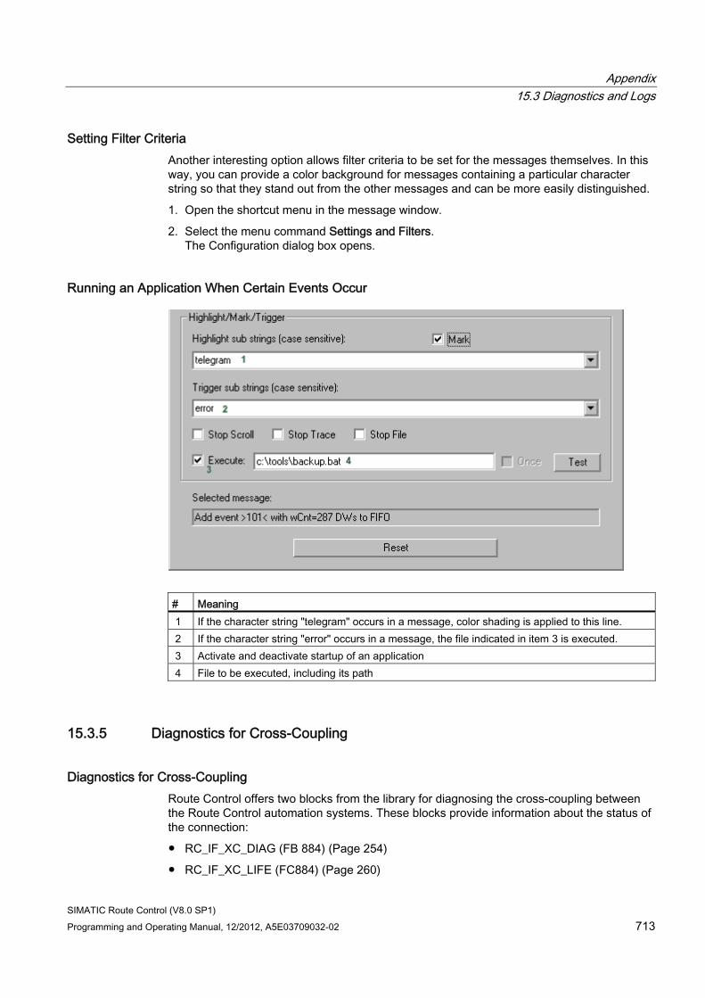
Appendix 15.3 Diagnostics and Logs
SIMATIC Route Control (V8.0 SP1) Programming and Operating Manual, 12/2012, A5E03709032-02 713
Setting Filter Criteria Another interesting option allows filter criteria to be set for the messages themselves. In this way, you can provide a color background for messages containing a particular character string so that they stand out from the other messages and can be more easily distinguished.
1. Open the shortcut menu in the message window.
2. Select the menu command Settings and Filters. The Configuration dialog box opens.
Running an Application When Certain Events Occur
# Meaning 1 If the character string "telegram" occurs in a message, color shading is applied to this line. 2 If the character string "error" occurs in a message, the file indicated in item 3 is executed. 3 Activate and deactivate startup of an application 4 File to be executed, including its path
15.3.5 Diagnostics for Cross-Coupling
Diagnostics for Cross-Coupling Route Control offers two blocks from the library for diagnosing the cross-coupling between the Route Control automation systems. These blocks provide information about the status of the connection:
● RC_IF_XC_DIAG (FB 884) (Page 254)
● RC_IF_XC_LIFE (FC884) (Page 260)
Appendix 15.3 Diagnostics and Logs
SIMATIC Route Control (V8.0 SP1) 714 Programming and Operating Manual, 12/2012, A5E03709032-02
15.3.6 Diagnostics for the Route Control Server
Diagnostics for the Route Control Server You can use the application Trace Server to create a log file. You can find additional information in"Trace Server" (Page 709).
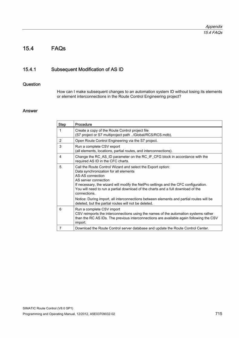
Appendix 15.4 FAQs
SIMATIC Route Control (V8.0 SP1) Programming and Operating Manual, 12/2012, A5E03709032-02 715
15.4 FAQs
15.4.1 Subsequent Modification of AS ID
Question How can I make subsequent changes to an automation system ID without losing its elements or element interconnections in the Route Control Engineering project?
Answer Step Procedure 1 Create a copy of the Route Control project file
(S7 project or S7 multiproject path ../Global/RCS/RCS.mdb). 2 Open Route Control Engineering via the S7 project. 3 Run a complete CSV export
(all elements, locations, partial routes, and interconnections). 4 Change the RC_AS_ID parameter on the RC_IF_CFG block in accordance with the
required AS ID in the CFC charts. 5 Call the Route Control Wizard and select the Export option:
Data synchronization for all elements AS-AS connection AS server connection If necessary, the wizard will modify the NetPro settings and the CFC configuration. You will need to run a partial download of the charts and a full download of the connections. Notice: During import, all interconnections between elements and partial routes will be deleted, but the partial routes will not be deleted.
6 Run a complete CSV import CSV reimports the interconnections using the names of the automation systems rather than the RC AS IDs. The previous interconnections are available again following the CSV import.
7 Download the Route Control server database and update the Route Control Center.
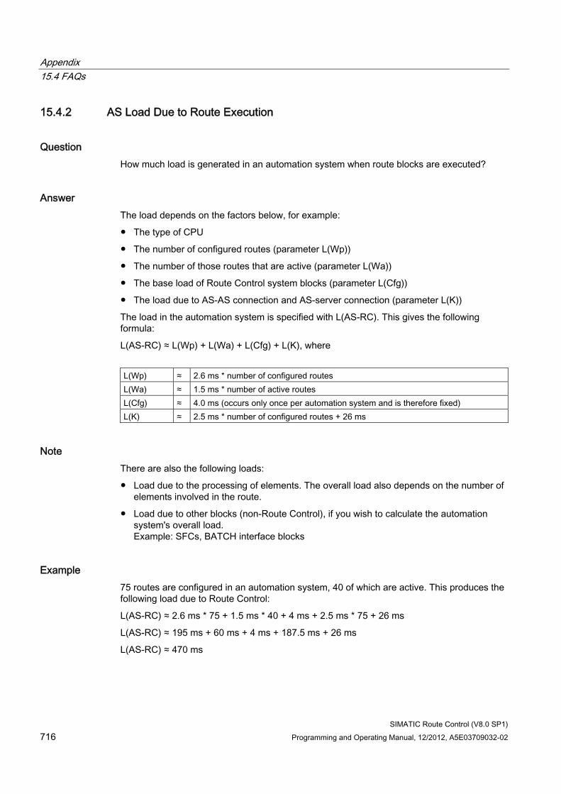
Appendix 15.4 FAQs
SIMATIC Route Control (V8.0 SP1) 716 Programming and Operating Manual, 12/2012, A5E03709032-02
15.4.2 AS Load Due to Route Execution
Question How much load is generated in an automation system when route blocks are executed?
Answer The load depends on the factors below, for example:
● The type of CPU
● The number of configured routes (parameter L(Wp))
● The number of those routes that are active (parameter L(Wa))
● The base load of Route Control system blocks (parameter L(Cfg))
● The load due to AS-AS connection and AS-server connection (parameter L(K))
The load in the automation system is specified with L(AS-RC). This gives the following formula:
L(AS-RC) ≈ L(Wp) + L(Wa) + L(Cfg) + L(K), where
L(Wp) ≈ 2.6 ms * number of configured routes L(Wa) ≈ 1.5 ms * number of active routes L(Cfg) ≈ 4.0 ms (occurs only once per automation system and is therefore fixed) L(K) ≈ 2.5 ms * number of configured routes + 26 ms
Note There are also the following loads:
● Load due to the processing of elements. The overall load also depends on the number of elements involved in the route.
● Load due to other blocks (non-Route Control), if you wish to calculate the automation system's overall load. Example: SFCs, BATCH interface blocks
Example 75 routes are configured in an automation system, 40 of which are active. This produces the following load due to Route Control:
L(AS-RC) ≈ 2.6 ms * 75 + 1.5 ms * 40 + 4 ms + 2.5 ms * 75 + 26 ms
L(AS-RC) ≈ 195 ms + 60 ms + 4 ms + 187.5 ms + 26 ms
L(AS-RC) ≈ 470 ms
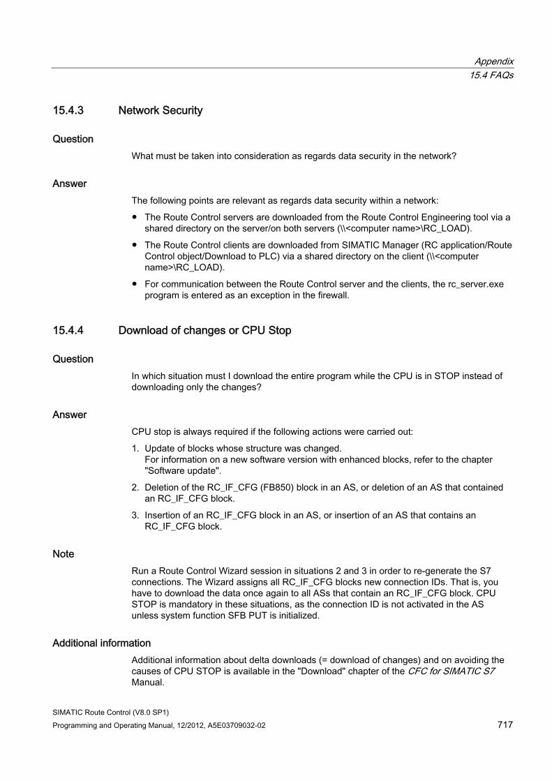
Appendix 15.4 FAQs
SIMATIC Route Control (V8.0 SP1) Programming and Operating Manual, 12/2012, A5E03709032-02 717
15.4.3 Network Security
Question What must be taken into consideration as regards data security in the network?
Answer The following points are relevant as regards data security within a network:
● The Route Control servers are downloaded from the Route Control Engineering tool via a shared directory on the server/on both servers (\\<computer name>\RC_LOAD).
● The Route Control clients are downloaded from SIMATIC Manager (RC application/Route Control object/Download to PLC) via a shared directory on the client (\\<computer name>\RC_LOAD).
● For communication between the Route Control server and the clients, the rc_server.exe program is entered as an exception in the firewall.
15.4.4 Download of changes or CPU Stop
Question In which situation must I download the entire program while the CPU is in STOP instead of downloading only the changes?
Answer CPU stop is always required if the following actions were carried out:
1. Update of blocks whose structure was changed. For information on a new software version with enhanced blocks, refer to the chapter "Software update".
2. Deletion of the RC_IF_CFG (FB850) block in an AS, or deletion of an AS that contained an RC_IF_CFG block.
3. Insertion of an RC_IF_CFG block in an AS, or insertion of an AS that contains an RC_IF_CFG block.
Note Run a Route Control Wizard session in situations 2 and 3 in order to re-generate the S7 connections. The Wizard assigns all RC_IF_CFG blocks new connection IDs. That is, you have to download the data once again to all ASs that contain an RC_IF_CFG block. CPU STOP is mandatory in these situations, as the connection ID is not activated in the AS unless system function SFB PUT is initialized.
Additional information Additional information about delta downloads (= download of changes) and on avoiding the causes of CPU STOP is available in the "Download" chapter of the CFC for SIMATIC S7 Manual.
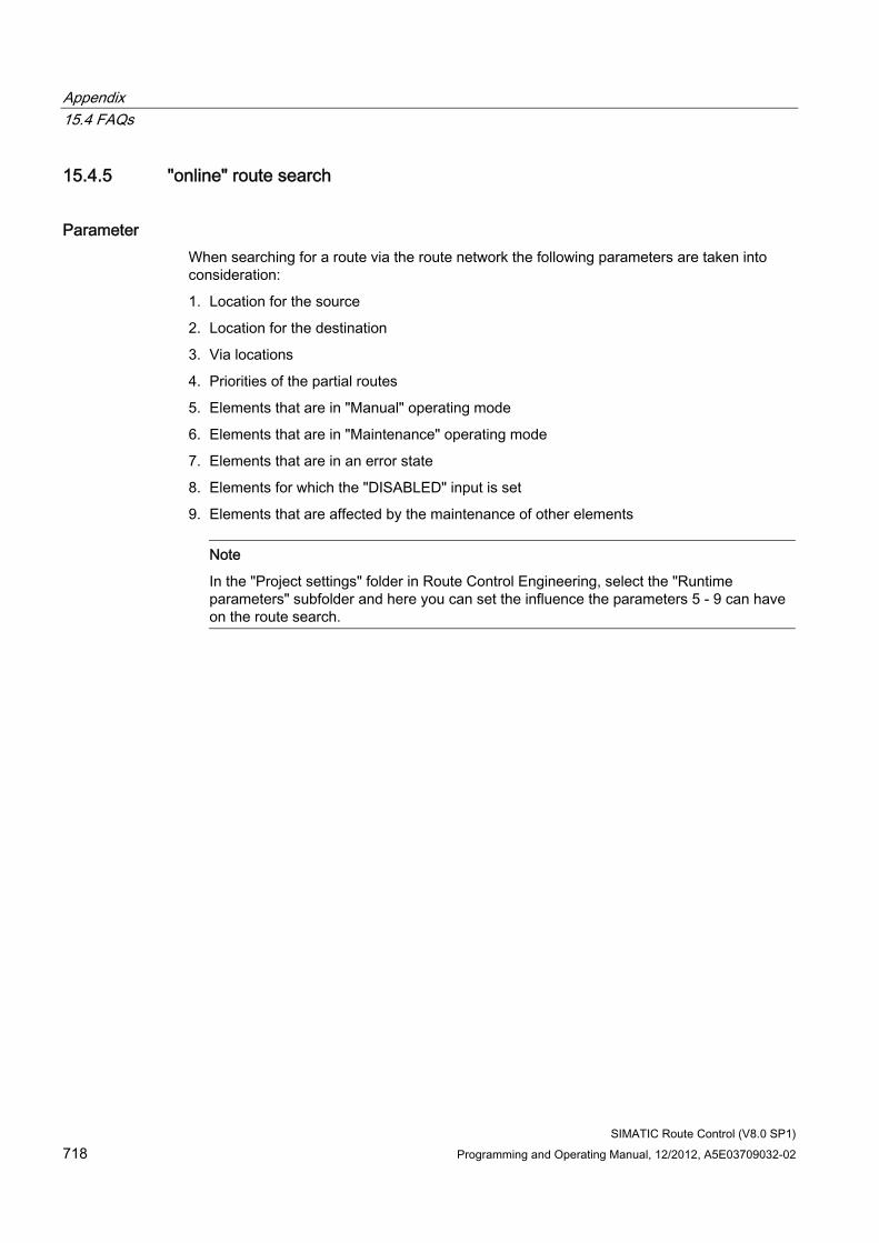
Appendix 15.4 FAQs
SIMATIC Route Control (V8.0 SP1) 718 Programming and Operating Manual, 12/2012, A5E03709032-02
15.4.5 "online" route search
Parameter When searching for a route via the route network the following parameters are taken into consideration:
1. Location for the source
2. Location for the destination
3. Via locations
4. Priorities of the partial routes
5. Elements that are in "Manual" operating mode
6. Elements that are in "Maintenance" operating mode
7. Elements that are in an error state
8. Elements for which the "DISABLED" input is set
9. Elements that are affected by the maintenance of other elements
Note
In the "Project settings" folder in Route Control Engineering, select the "Runtime parameters" subfolder and here you can set the influence the parameters 5 - 9 can have on the route search.
SIMATIC Route Control (V8.0 SP1) Programming and Operating Manual, 12/2012, A5E03709032-02 719
Glossary
Activation delay time When installing a control element in a mode level, program the activation delay time for the control element to be triggered after this mode level has been activated (0 to 255 seconds).
Activation key Icons show the activation type of an element at different mode levels. They are used on the "Modes" tab in Route Control Engineering and in the Route Control Center.
AS-AS connection AS-AS communication link, also known as cross-coupling.
A (logical) AS-AS connection is always a point-to-point connection and is created for Route Control by the Route Control Wizard.
As the system supports operation with up to 32 AS, the Wizard generates up to 32 * 31 connections are generated, that is, up to 31 connections per Route Control AS.
AS-Server connection Communication link between an AS and a computer, in this case, the Route Control Server.
A (logical) AS-server connection is always a point-to-point connection and is created for Route Control by the Route Control Wizard.
A standalone server for Route Control provides one connection for each Route Control AS, that is, up to 32 connections.
A redundant server system for Route Control provides one connection for each Route Control AS to each redundant server, that is, up to 2 * 32 connections.
Control element The CE (control element) is an active object that can also return a value. Examples: motors, valves, pumps, controlled flaps
Cross-coupling This term always denotes a communication link between two Route Control automation systems.
Glossary
SIMATIC Route Control (V8.0 SP1) 720 Programming and Operating Manual, 12/2012, A5E03709032-02
Deactivation delay time When installing a control element in a mode level, program the deactivation delay time for the control element to be triggered after this mode level has been deactivated (0 to 255 seconds).
Element Interface block of the Route Control library for integrating process blocks. The name of these interface blocks starts with RC_IF_. Elements are installed in partial routes in Route Control Engineering. This configuration includes the definition of the element activation mode at the different mode levels.
Element subtype Subtypes of a main type include items such as a motor or a valve in the group of control elements. Element subtypes also differ in terms of their activation commands and feedback.
Element type Route Control distinguishes between four main types of the elements:
● Control elements (CE)
● Sensor elements (SE)
● Parameter elements (PE)
● Verbindungselemente / link elements (LE)
Control, sensor, and parameter elements are further split into "element subtypes".
Fault tolerance time A mode level is successfully activated after all elements have returned the expected feedback. The route enters the error state if an element changes its position setpoint for a duration longer than the fault tolerance time after this mode level was activated.
Function ID Material transports operate with different values for the function ID parameter.
Partial routes and elements are assigned a function ID by the route network when a search is made for a suitable path. This ID specifies whether a partial route or an element is locked for a further search. Material transports or routes cannot share an element or a partial route. This safely prevents any mixing of products.
Mixed products are, however, desirable in certain situations. In other situations the material is transported from two sources to the same destination. The same function ID is then entered for both routes (FUNC_ID parameter at RC_IF_ROUTE). This expressly allows joint operation of the routes.
Glossary
SIMATIC Route Control (V8.0 SP1) Programming and Operating Manual, 12/2012, A5E03709032-02 721
General request Request of all automation systems by the server to update the process image.
If the general request is interrupted when the server starts up, then end the server, load NetPro and restart the server.
Generic user-defined element Also known as GE block.
User-specific block that is compatible with RC_IF_ and characterized by special User Defined Attributes (UDA). The block contains several standard and/or user-defined elements. The elements are imported separately to Route Control Engineering.
An example is available in the Route Control library.
H-CPU CPU of an H-machine
H-machine An H-machine consists of two CPUs, two PSs (power supplies) and 2 CPs (communication processors). The CPUs are interconnected and represent a pair of redundant ASs. One CPU assumes control (master), while the other CPU remains in standby mode in order to assume control if necessary (fault-tolerant system).
Link element The LE (link element) object represents a material in a transport medium such as a pipe or a conveyor belt. The LE is also used to check material compatibility for route requests.
Location Locations refer to the start, paths (vias) and final points of partial routes or routes. Each location is an instance of a location type. Locations are configured as equipment properties of units in SIMATIC Manager and are then imported to Route Control Engineering for creating partial routes.
Location
Glossary
SIMATIC Route Control (V8.0 SP1) 722 Programming and Operating Manual, 12/2012, A5E03709032-02
Location ID Location identifier that is unique throughout the project.
Location type Equipment property of data type "LOCATION" in the "Shared Declarations" folder of an S7 project A location type can have none, one, or several properties of the "Source", "Via" or "Destination" type.
Master AS A master AS is an automation system that controls the route and its elements. It is the automation system in which the user program activates an RC_IF_ROUTE block and from which a route request is transferred to the Route Control Server. Each route requires precisely one master AS.
See also "Slave AS".
Mode level It is not necessary to simultaneously activate/deactivate all of the elements of a route or partial route. Instead, these can be implemented in up to 32 groups, namely the mode levels, with different activation type or times. Additional information is available under the keyword "Mode table".
The user program is responsible for generating suitable logical links of the mode levels. Examples:
If "initial position reached", then "open transport valves"
If "Transport valves open", then "Switch on pump"
"Basic position reached" means that the parameter value QMODE at RC_IF_ROUTE must return the value 1 when logically linked to the mode level bit by an OR operation.
"Open transport valves" means that the mode level bit must be set to 1 at the MODE input parameter of RC_IF_ROUTE.
Mode table A mode table comprises up to 32 modes or mode levels, and groups them into process-related levels. Example:
Brewery/fermenting cellar (mode table)
● Initial state (mode level)
● Open transport valves (mode level)
● Switch on pump (mode level)
● Open source valve (mode level)
Glossary
SIMATIC Route Control (V8.0 SP1) Programming and Operating Manual, 12/2012, A5E03709032-02 723
Parameter element A PE (parameter element) is an object that defines a setpoint and displays an actual value (from the process).
An external PE is an expansion of the general PE. The setpoint of an external parameter element is unknown at the time of configuration and is not transferred until runtime. A "wildcard" is configured by referencing a specific PE based on its index for this reason. The actual setpoint is transferred as a parameter to the RC_IF_ROUTE block in runtime. The block transfers this value to an output, from which it can be read by the user program.
Partial route Partial routes form the sections of a route. They are defined by their source and destination locations. Elements are inserted into partial routes during configuration. The combination of all partial routes forms the route network from which the search algorithm selects specific partial routes in order to assemble the routes.
Route A route always comprises 1 to n partial routes. The partial routes are selected in runtime. A route comprises all transport media and elements of its partial routes, and covers the distance between the source and the destination of material transport.
The Route Control configuration only covers partial routes. A route from the source to the destination of material transport is only generated on request in runtime.
Route element Element that has been installed in a partial route.
S7 connection Logical communication link either between a Route Control AS and a Route Control Server, or between two Route Control ASs.
Sensor element The SE (sensor element) is an object that returns a value from the process and specifies whether an expected actual value is equivalent to the real actual value. Sensor elements are not activated. Examples: conductivity measurements, flow volume measuring sensors, limit switches
Server Refers to the Route Control Server in this context.
Standalone or redundant computers that process route requests from the Route Control automation systems, and act as a link between the RC AS and clients (Route Control Centers).
Glossary
SIMATIC Route Control (V8.0 SP1) 724 Programming and Operating Manual, 12/2012, A5E03709032-02
Slave AS A route can include slave automation systems (0 to 31). These partner ASs are controlled by way of cross-coupling by the master AS and return their feedback to the master AS.
Each AS can be the master of one route, and a slave for one or several other routes. A slave AS also receives its element list from the Route Control Server (as does the master AS), however, without requesting any routes.
Additional information is available at the "Master AS" entry.
Status monitoring time The route enters an error state (mode level error or mode error) if at least one element fails to return the expected feedback within this monitoring time after a mode level was activated. Additional information: Inputs MON_TM at RC_IF_ROUTE and MONITOR at the control elements.
Symbol One or several characters used to display the type of activation of an element in activation keys.
User element See "User-Defined Type".
User key User-defined activation key The key is configured once and an icon is used for each additional configuration.
User-defined type Also known as user element.
RC_IF-compatible block that you can edit and install as an element.
The SW package includes the block templates RC_IF_USER_CE, RC_IF_USER_SE, and RC_IF_USER_PE
Variant A variant is a fictitious location within a partial route, which is specified in addition to the start and final point. With one variant, you can define alternative partial routes with an identical start and final point.
SIMATIC Route Control (V8.0 SP1) Programming and Operating Manual, 12/2012, A5E03709032-02 725
Index
@ @PCS7TypicalsRC.pdl, 139 @Typicals_RC.pdl, 139
A Abbreviations, 106 Activation bit assignment, 222 Activation key symbols, changing, 545 Activation key symbols, meanings, 544 Activation of control elements, 551 Activation of elements, configuration, 542 Adapting the block ranges, 129 Adapting the Block Ranges in CFC, 409 Adding projects to a multiproject, 403 Any mode table for route request, 122 AS hardware and software, 73 AS in Maintenance, 629 AS Load Due to Route Execution, 716 AS messages for control elements FB822, FB823, FB824, FB825, 691 AS messages for remote elements FB831 and FB833, 693 AS messages for sensor elements FB845 and FB846, 692 Assigning materials to a material group, 588 Attribute properties, 508 Authorization management, introduction, 77 Automatic generation of elements, 524 Automatic restart when AS is recovered, 516 Automatic server failover in the event of error, 516
B Basic configurations, 62 Block changes, 96 Block Icon, Display Elements, 612 Block Icon, Structure, 611 BSEND/BRCV and PUT, 134
C CFC overview, 337 Chart-in-chart technology, 135 Classification of Route Control blocks, 155 Client/server architecture of Route Control, 62 Communication with H-machines, 405 Compiling the script file for the Route Control Dynamic Wizard, 139 Computer name and IP address of the Route Control server, 145 Concurrent routes, 324 Configurations, non-redundant, 64 Configurations, redundant, 66 Configuring elements in CFC, 412 Configuring H machines, 332 Configuring locations, 431 Configuring material sequences, 588 Configuring materials and material groups, 587 Configuring REMOTE elements, 366 Configuring routes in CFC, 411 Configuring the first of two ASs, 330 Configuring the Route Control Server, 406 Configuring the second of two ASs, 331 Configuring user-defined element types, 412 Configuring with an AS, 329 Consistency Check, 598 Consistency Check Result, 599 Consistency Check, Log, 600 Control element (cross-reference list), 553 Control elements, 325 Control elements properties, 549 Converting a Route Control project, 504 Copying RC_IF_ROUTE route blocks, 134 Copying the block icon, 440 Creating a new Route Control project, 502 Creating a new S7 project for Route Control, 129 Creating Route Control objects, 418 Cross-coupling blocks, overview, 247 Cross-coupling connections, 247 CSV File Wizard overview, 465 CSV File Wizard, error messages, 491 CSV File Wizard, file structure, 483 CSV File Wizard, global settings, 470 CSV File Wizard, Initial step, 468 CSV File Wizard, log file, 477 CSV File Wizard, Result, 475
Index
SIMATIC Route Control (V8.0 SP1) 726 Programming and Operating Manual, 12/2012, A5E03709032-02
CSV File Wizard, selecting objects, 472 CSV File Wizard, Summary, 474 CSV Interface Export Log, 479 CSV Interface Import Log, 481 Cycle time
Default setting, 515 Cycle time for server/AS monitoring, 515
D Deleting elements, 525 Delivery form of Route Control, 68 Dependence on other components, 74 Diagnostics for Cross-Coupling, 713 Diagnostics for engineering, 710 Diagnostics for Operator Control and Monitoring, 710 Diagnostics for the Route Control Server, 714 Diagnostics for the Trace Server, 709 Diagnostics overview, 709 Dialog boxes, 111 Download to client, 604 Download to server, 604 Downloading instance data blocks to the AS, 126 Downloading settings to the server, 516 Downloading the Route Control server, redundant, 605 Downloading to the Route Control Server, 602 Downloading to the Route Control server, dialog box, 604 Downloading to the Server During an Active Route, 124 Downloading user blocks to the AS, 127 Drop-down list box, 137 Drop-down-list-box control, 138 Dynamic ID assignment, example, 381 Dynamic Wizard, Overview, 439 Dynamic Wizard, selecting route instance, 442 Dynamic Wizard, selecting SFC block, 444 Dynamic Wizard, Summary, 446
E Element subtypes, 525 Elements, creating, 524 Enabling changes to configuration, 123 Engineering the AS Configuration in CFC, 411 Equipment properties, 434 ES and server hardware and software, 71 Example of a user-defined type, 242 Example using QRESTPOS and QRPOSERR, 187 Export Log, 463
F Faceplate, display and operating elements - 1/4, 614 Faceplate, display and operating elements - 3/4, 616 Faceplate, Display and Operator-Control Elements - 2/4, 615 Faceplate, Display and Operator-Control Elements - 4/4, 617 Feedback Bit Assignment, 222 Full Interconnection of the SFC block, 377 Function ID, 324 Function IDs properties, 583
G General information about block descriptions, 156 General information about configuration, 311 General Information About Parameter Elements, 233 General information about servers and clients, 313 General information about the automation system, 315 General information about the user program, 317 General operator control elements of the Route Control Center, 634 Generic user-defined elements, 244 Guide to CFC bidirectional motor, 352 Guide to CFC charts, 338 Guide to CFC conductivity, 360 Guide to CFC configuration of one automation system, 342 Guide to CFC configuration of one of multiple automation systems, 343 Guide to CFC decoder, 346 Guide to CFC dual-speed motor, 351 Guide to CFC encoder, 345 Guide to CFC motor with interlocking block, 350 Guide to CFC motor with two statuses, 348 Guide to CFC motor with two statuses with no feedback, 349 Guide to CFC motor-actuated valve, 357 Guide to CFC parameter element, 361 Guide to CFC sensor element, 359 Guide to CFC sensor, binary, 360 Guide to CFC valve with dual feedback signals, 354 Guide to CFC valve with feedback, 353 Guide to CFC valve with interlocking block, 355 Guide to CFC valve with no feedback signal, 356 Guide to Configuration of the Automation Systems, 341 Guide to dynamic ID assignment, 378 Guide to exporting an S7 project, 384 Guide to exporting linking configuration from NetPro, 385 Guide to External Parameter Elements, 321
Index
SIMATIC Route Control (V8.0 SP1) Programming and Operating Manual, 12/2012, A5E03709032-02 727
Guide to material sequences during runtime, 323 Guide to predefined element types, 320 Guide to Project Engineering the AS-AS and AS-Server Connections, 334 Guide to Route Control Engineering, 387 Guide to Setpoints in Runtime (External PEs), 321 Guide to setting up a new project, 318 Guide to starting up the Route Control system, 397 Guide to the block icon and faceplate, 327 Guide to the CFC control element, 347 Guide to the CFC link element, 361 Guide to the CFC route, 344 Guide to the cross-reference list of elements, 394 Guide to the CSV interface, 394 Guide to the Offline Route Search, 389 Guide to the Route Control Server, 395 Guide to the Route Control SFC type, 340 Guide to the Route Control Wizard, 382 Guidelines on concurrent routes, 324
H Hardware configuration HW Config, 413 How to Adapt the Block Ranges, 409 How to configure location types, 432 How to configure locations, 434 How to export and import locations, 436 How to import locations into the PH, 93 How to print out the configuration of elements and partial routes, 506
I ID
Multiproject, 434 Idle state, 185 Idle-state monitoring, 185 Industrial Ethernet properties, 144 Inserting an element in a partial route, 541 Installing a new Route Control library, 126 Installing Route Control components, 69 Interface Block Overview, 158 Invalid characters, 121
K Keyboard Commands, 113
L Licensing, 75 Link element (cross-reference list), 565 Link elements, 326 Location as a variant, 135 Location properties, 521 Location type, 522 Locations, 521 Locations from a drop-down list box, 137 LOCK input on element blocks, 128 Log file, 447 Logon Dialog, 119
M Maintenance Work, 628 Material functions, 512 Material interface, 593 Material interface, download, 594 Material interface, example, 597 Material interface, material master data, 595 Material interface, successor relationships, 596 Material interface, test, 597 Material Interface, transfer files, 595 Material overview, 585 Material sequence diagram for RC_IF_ROUTE, 586 Menu commands, 110 MES interface, 124 Messages for AS route FB800, 685 Messages, AS, 682 Messages, AS system and FB850, 682 Messages, operator messages, 699 Messages, OS, Overview, 694 Messages, OS, route/server, 696 Messages, Overview, 681 Mode level, 325 Mode level properties, 530 Mode levels, 523 Mode levels, configuration, 528 Mode table properties, 527 Mode tables, 523 Mode tables, configuration, 526 Monitoring functions, 515 Monitoring the run sequence of blocks, 135
N Network security, 717 Notes on maintenance, 519 Number of permissible missing monitoring telegrams, 515
Index
SIMATIC Route Control (V8.0 SP1) 728 Programming and Operating Manual, 12/2012, A5E03709032-02
O Offline/online route search, 148 Online help in the Route Control Center, 124 Operator Control and Monitoring Overview, 609 Optimizing memory requirements in the AS, 130 Optimizing the number of PCS 7 OS tags, 132 Order of tasks, 117 OS messages for system and server, 694 Overview of CFC examples, 339 Overview of configuration, 401 Overview of kernel blocks, 279 Overview of project settings, 507 Overview of REMOTE blocks, 261 Overview of the configuration in NetPro, 328
P Parameter element (activation), 562 Parameter element (cross-reference list), 563 Parameter element (properties), 560 Parameter element subtypes, 560 Parameter elements, 325 Partial route, 146
Priority, 147, 150 Variant, 151
Partial routes, 522 Partial routes configuration, 531 Partial routes properties, 533 PCS 7 OS memory reset, 123 PCS 7 OS Web option, 61 PLCSim and SIMATIC Route Control, 125 Predefined routes, 522 Preface, 21 Process cells, units and locations, 493
Q Quantity framework for Route Control, 707
R RC_ANY_UDT (UDT 506), 283 RC_ATTRIB_PTR (FC 860), 286 RC_CALL_DIAG (FB 851), 295 RC_CALL_KILLER FC 814, 292 RC_CE_COMMON (FB 827), 298 RC_CE_FIELD (DB 99), 279 RC_CE_FIELD_UDT (UDT 99), 283 RC_CFG (DB 100), 279 RC_CLOCK (FB 899), 295
RC_DATA_TG34_36 (DB 405), 279 RC_DB_AREA_COPY (FC 862), 286 RC_EXT_PE_ACTV (UDT 103), 283 RC_FC_COPY (FC 863), 287 RC_FIFO__UDT (UDT121), 283 RC_FIFO_DEBUG_SEND (FC 891), 287 RC_FIFO_INPUT_FC (FC 890), 287 RC_FIFO_SEND (FC 803), 287 RC_FIFO1 (DB 870), 280 RC_FIFO1_SE (DB 874), 280 RC_FIFO4 (DB 890), 280 RC_FIFO4_SE (DB 894), 280 RC_IDB_SEND_FIFO1 (DB 590), 280 RC_IDB_SEND_FIFO4 (DB 593), 280 RC_IF_CFG FB 850, 247 RC_IF_CONDUCT (FB846), 226 RC_IF_DECODER FC801, 191 RC_IF_ENCODER FC 800, 189 RC_IF_LE (FB828), 240 RC_IF_MOT_REV FB 823, 207 RC_IF_MOT_SPED FB 824, 212 RC_IF_MOTOR FB 822, 203 RC_IF_REMOTE_CE (FB821), 263 RC_IF_REMOTE_PE (FB843), 269 RC_IF_REMOTE_RECV_FB833, 276 RC_IF_REMOTE_SE (FB 842), 266 RC_IF_REMOTE_SEND (FB 831), 273 RC_IF_ROUTE FB 800, 159 RC_IF_ROUTE, simulated idle state, 188 RC_IF_ROUTE.QDIAG, 184 RC_IF_ROUTE.QMAT_DIAG, 182 RC_IF_ROUTE.QREC_STA, 177 RC_IF_ROUTE.QRET_VAL, 178 RC_IF_SENSOR (FB845), 223 RC_IF_SFC FB 849 calling online help, 133 RC_IF_TIMER (FC809), 237 RC_IF_USER_CE FB 829, 217 RC_IF_USER_PE (FC807), 238 RC_IF_USER_SE (FB848), 230 RC_IF_VAL_MOT FB 825, 198 RC_IF_VALVE FB 826, 193 RC_IF_VOLUME (FC808), 236 RC_IF_XC_DIAG (FB 884), 254 RC_IF_XC_LIFE (FC884), 260 RC_KERNEL_CALL (FC 804), 287 RC_LE_DGRAMM (FC 825), 292 RC_LE_FIELD (DB 96), 280 RC_LE_FIELD_UDT (UDT 96), 283 RC_LOAD directory on the Route Control Server, 136 RC_LOAD_AR1 (FC 861), 292 RC_MASTER_BUFFER (FB 856), 295 RC_MASTER_CREATE_ERR (FC 851), 292
Index
SIMATIC Route Control (V8.0 SP1) Programming and Operating Manual, 12/2012, A5E03709032-02 729
RC_MASTER_FUNC (FB 852), 295 RC_MASTER_MATERIAL FB 860, 305 RC_MASTER_MSG (FB 857), 295 RC_MASTER_TIMES (FB 859), 295 RC_MASTER_XC_SND (FB 858), 296 RC_MAT (FC 836), 292 RC_PE_COMMON (FC810), 288 RC_PE_FIELD (DB 97), 281 RC_PE_FIELD_UDT (UDT 97), 283 RC_RE_INFO_UDT (UDT 109), 284 RC_RE_UDT (UDT 100), 284 RC_REM_CESEPE (UDT 104), 284 RC_REMOTE1..5 (DB91 to DB 95), 281 RC_REQUEST_BUFFER_UDT (UDT 111), 284 RC_ROUTE (FB 801), 296 RC_ROUTE_CE_ERR (FC 812), 292 RC_ROUTE_CFG (UDT 105), 284 RC_ROUTE_CM_UDT (UDT 110), 284 RC_ROUTE_GET_EXT_PE (FB 818), 296 RC_ROUTE_MAT (FB 819), 296 RC_ROUTE_PE_DGRAM (FC 822), 293 RC_ROUTE_RCE_OFF (FB 804), 296 RC_ROUTE_RCE_ON (FB 803), 297 RC_ROUTE_SE_ERR (FC 813), 293 RC_ROUTE_STATE_OS (FB 807), 297 RC_ROUTE_STATES (FB 809), 297 RC_ROUTE_TB_UDT (UDT 102), 284 RC_ROUTE_TELEGR (FB 808), 297 RC_ROUTE_TIME (FB 805), 297 RC_ROUTE_XC_PE_ACTV (FB 817), 297 RC_ROUTE_XC_REC (FB 802), 298 RC_ROUTE_XC_SEND (FB 806), 298 RC_ROUTE_XC_SND_ORDER (FB 816), 298 RC_ROUTE1 (DB 101), 281 RC_ROUTEMASTER (FB 854), 305 RC_ROUTEMASTER_TELE99 (FB 855), 305 RC_ROUTEMASTER_TELEGR (FB 853), 305 RC_SE_COMMON (FB 847), 303 RC_SE_FIELD (DB 98), 281 RC_SE_FIELD_UDT (UDT 98), 285 RC_SEND_FIFO1 (FB 890), 305 RC_SEND_FIFO4 (FB 891), 305 RC_SEPU__UDT (UDT122), 285 RC_SYS_DB (DB 410), 281 RC_SYS_UDT (UDT 120), 285 RC_TG_36 FB 813, 296 RC_TG34_03 (FC 811), 293 RC_TG34_TG36 (FB 812), 306 RC_TG34_TG36_DB (DB 404), 281 RC_TIME_DELTA (FB 879), 306 RC_TIME_RCE (FB 810), 306 RC_UPD_CESEPE (FC 823), 293
RC_UPD_CESEPE_EX (FC 824), 293 RC_XC_1 (DB 751), 282 RC_XC_AS (UDT108), 286 RC_XC_CALL (FC 805), 293 RC_XC_DIAG (FB 897), 306 RC_XC_FB (FB 880), 306 RC_XC_INIT (FB 896), 306 RC_XC_JOB (DB 705), 282 RC_XC_JOB_FB (FB 882), 306 RC_XC_JOB_START (DB 450), 282 RC_XC_JOB_TIME_FB (FB 885), 307 RC_XC_JOB_UDT (UDT 705), 285 RC_XC_JOB_USER (FC 885), 294 RC_XC_PCU (DB 704), 282 RC_XC_PCU_FB (FB 881), 307 RC_XC_PCU_UDT (UDT 704), 285 RC_XC_PUT_DB_UDT (UDT 452), 285 RC_XC_PUT_SD_UDT (UDT 684), 285 RC_XC_PUT_UDT (UDT 683), 286 RC_XC_PUTX_1 (DB 451), 282 RC_XC_PUTX_RECV (FC 882), 294 RC_XC_PUTX_SEND (FC 881), 294 RC_XC_PUTX_UDT (UDT 451), 286 RC_XC_REMOTE_RECV (FB 834), 307 RC_XC_REMOTE_SEND (FB 832), 307 RC_XC_STAT_FB (FB 883), 307 RC_XC_UDT (UDT 101), 286 RC_XFER_LE (FC 826), 294 RC_XFER_MON_FLT (FC 829), 294 RC_ZTG (FB 895), 307 Readme file with current information, 68 Redundancy failover, 674 Relationship of SFC and route with operator dialogs, 373 REMOTE elements CFC example, 362 REMOTE elements in the CFC chart of a local AS, 370 REMOTE elements in the CFC chart of a peer AS, 371 Restriction of the quantity framework, 120 Route, 146 Route Control application, 415 Route Control application client, 416 Route Control application properties, 415 Route Control application stby, 415 Route Control applications in HW Config, 333 Route Control Center, 59 Route Control Center route overview, 638 Route Control Center, Activation Keys, 636 Route Control Center, Adding a Server, 623 Route Control Center, Elements Tab, 645 Route Control Center, Errors During Route Request, 627 Route Control Center, Finding a Server, 622
Index
SIMATIC Route Control (V8.0 SP1) 730 Programming and Operating Manual, 12/2012, A5E03709032-02
Route Control Center, functions, 644 Route Control Center, Logon, 620 Route Control Center, maintenance view, 641 Route Control Center, Menu, 631 Route Control Center, Options/Settings, 635 Route Control Center, overview, 619 Route Control Center, Partial Routes tab, 645 Route Control Center, route properties, 646 Route Control Center, Route Templates, 649 Route Control Center, Selecting a Route Control Server, 621 Route Control Center, Server Status, 624 Route Control Center, sorting, 646 Route Control Center, status bar, 633 Route Control Components - Overview, 56 Route Control element (properties), 555 Route Control Engineering, 58 Route Control Engineering main view, 495 Route Control Engineering menu, 499 Route Control faceplate, 613 Route Control faceplate reinstallation, 122 Route Control faceplate without Route Control server, 123 Route Control library, 57 Route Control object in the project folder, 419 Route Control Object in the RC Application Client, 419 Route Control object properties, 418 Route Control Operator Dialog, 60 Route Control Route Log, 60 Route Control server, 59 Route Control Server Startup Sequence, 672 Route Control Server Status, 673 Route Control Server, Call, 668 Route Control server, expanded diagnostic information (AS connections), 679 Route Control server, expanded diagnostic information (AS list), 675 Route Control server, expanded diagnostic information (client connections), 680 Route Control server, expanded diagnostic information (route list), 677 Route Control Server, Switching Languages, 671 Route Control server, user-interface dialog, 669 Route Control Wizard, 57 Route Control Wizard selection of the PCS 7 OS message server, 454 Route Control Wizard results, 461 Route Control Wizard start requirements, 143 Route Control Wizard summary of the actions, 459 Route Control Wizard, actions, 451 Route Control Wizard, adapting IDs, 457 Route Control Wizard, deleting used elements, 450
Route Control Wizard, selecting actions, 453 Route Control Wizard, selecting objects to be exported, 455 Route log functions, 514 Route log menu, toolbar and keyboard control, 657 Route log user interface, 655 Route log user interface - filter functions, 662 Route log user interface - list of log files, 660 Route log user interface - rights, 654 Route log user interface - status bar, 666 Route log, adding a log file, 662 Route log, adding/removing log files, 661 Route log, directory sharing, 518 Route log, display of log data, 663 Route log, export, 666 Route log, log file, 654 Route log, meanings of columns, 665 Route log, overview, 651 Route log, selecting visible columns, 664 Route log, structure and function, 652 Route parameter element properties, 563 Route request, 325 Route search
Assembly of routes, 148 Basics, 146 Example "taxi geometry", Offline/online route search, 148 Partial routes, 146 Routes, 146 Save routes, 150 Shortest route, 149 VIAs, 146
Route sensor element (properties), 559 Route Status, 610 Routes, 522 Rules for route algorithm functions, 513 Run sequence of Route Control blocks, 406 Runtime parameter properties, 509 Runtime parameters, overview, 510
S S7 connection for a peer AS in NetPro, 365 S7 connection of a local AS in NetPro, 365 S88 status, 375 S88 terms, 105 Saving a Route Control project, 503 Scenario 1:Server 1 can be downloaded but not server 2, 606 Scenario 2:Server 2 can be downloaded but not server 1, 606 Scenario 3:Both servers can be downloaded, 607
Index
SIMATIC Route Control (V8.0 SP1) Programming and Operating Manual, 12/2012, A5E03709032-02 731
Scenario 4:Neither server can be downloaded, 607 SCL compiler error message, 132 Sensor element (activation), 557 Sensor element (cross-reference list), 558 Sensor elements, 325 Server and AS monitoring, 517 SFC block schematic, 374 SFC editor, 377 SFC mode levels, 376 SFC overview, 372 SIMATIC BATCH and SIMATIC Route Control, 140 SIMATIC Route Control, 420 SIMATIC Route Control > Engineering, 421 SIMATIC Route Control > Show Wizard Log, 420 SIMATIC Route Control > Wizard, 420 SIMATIC Route Control overview, 55 SIMATIC Route Control structure, 310 Specifying successors for a material, 591 Specifying the successors for a material group, 591 Start conditions for HOLDING in SFC, 375 Starting Route Control Engineering, 494 Starting the Dynamic Wizard, 441 Station Configuration Editor, 417 Structure of guide sections, 309 Subsequent Modification of AS ID, 715 Switch mode, 358 Synchronizing objects during import, 448
T Template
@PCS7TypicalsRC, 139 @Template_RC, 139
Transferring from an S7 project, 142, 447
U Updating from RCS-based-on-BRAUMAT projects, 98 Updating from RCS-based-on-PCS 7 projects, 97 Updating from V6.0 to V6.1, 100 Updating from V6.1 SP1 to V7.0, 91 Updating from V6.1 to V6.1 SP1, 101 Updating in overview, 94 Updating tasks, 95 Updating the Route Control Server, 626 User Interfaces, 114 User keys, creating, 546 User keys, deleting, 548 User program, 325 User rights, defining, 80 User roles and user rights, 78
Using APL, 358 Using the PCS 7 OS Keyset to Call the Route Control Center, 620
V Valid AS numbers, 705 Valid function ID, 702 Valid ID ranges for CEs, SEs, LEs, and PEs, 704 Valid index, external parameter elements, 706 Valid material IDs, 703 Valid maximum material acceptance time, 703 Valid maximum route request time, 703 Valid ranges of values, overview, 701 Valid route IDs, 702 Valid SNDRCVDB block numbers for remote elements, 705 Variant, 151 Via locations not displayed, 393 VIAs, 146
W Welcome, 19 What is SIMATIC Route Control?, 53 What's new in SIMATIC Route Control V6.0 SP1 ?, 47 What's New in SIMATIC Route Control V6.0?, 48 What's new in SIMATIC Route Control V6.1 SP1 ?, 41 What's New in SIMATIC Route Control V6.1?, 44 What's new in SIMATIC Route Control V7.0 SP1?, 32 What's new in SIMATIC Route Control V7.0?, 36 What's new in SIMATIC Route Control V7.1?, 27, 31 What's new in SIMATIC Route Control V8.0, 25 What's new in SIMATIC Route Control V8.0 SP1?, 23

Index
SIMATIC Route Control (V8.0 SP1) 732 Programming and Operating Manual, 12/2012, A5E03709032-02
Related Documents