Important Information - List of Safety Notes Contents Product Overview 1 Getting Started 2 Safety Mechanisms 3 Configuration 4 Programming 5 Operation and Maintenance 6 Safety 7 Fail-Safe Function Blocks 8 Appendices Check Lists A References B Glossary, Index SIMATIC Programmable Controllers S7 F/FH Systems Manual This manual is part of the documentation package with the order number: 6ES7988-8FA10-8BA0 Edition 02/2003 A5E00085588-03

Welcome message from author
This document is posted to help you gain knowledge. Please leave a comment to let me know what you think about it! Share it to your friends and learn new things together.
Transcript

Important Information -List of Safety Notes
Contents
Product Overview 1
Getting Started 2
Safety Mechanisms 3
Configuration 4
Programming 5
Operation and Maintenance 6
Safety 7
Fail-Safe Function Blocks 8
Appendices
Check Lists A
References B
Glossary, Index
SIMATIC
Programmable ControllersS7 F/FH Systems
Manual
This manual is part of the documentationpackage with the order number:6ES7988-8FA10-8BA0
Edition 02/2003A5E00085588-03

Copyright © Siemens AG 2003 All rights reserved
The reproduction, transmission or use of this document or itscontents is not permitted without express written authority.Offenders will be liable for damages. All rights, including rightscreated by patent grant or registration of a utility model or design,are reserved.
Siemens AGAutomation and DrivesIndustrial Automation SystemsPostfach 4848, D- 90327 Nuernberg
Disclaimer of Liability
We have checked the contents of this manual for agreement withthe hardware and software described. Since deviations cannot beprecluded entirely, we cannot guarantee full agreement. However,the data in this manual are reviewed regularly and any necessarycorrections included in subsequent editions. Suggestions forimprovement are welcomed.
©Siemens AG 2003Technical data subject to change.
Siemens Aktiengesellschaft A5E00085588-03
Safety Guidelines
This manual contains notices intended to ensure personal safety, as well as to protect the products and
connected equipment against damage. These notices are highlighted by the symbols shown below and
graded according to severity by the following texts:
! Safety NoteContains important information on the acceptance and safety-related use of the product.
! Warningindicates that death, severe personal injury or substantial property damage can result if properprecautions are not taken.
! Cautionindicates that minor personal injury can result if proper precautions are not taken.
Notedraws your attention to particularly important information on the product, handling the product, or to aparticular part of the documentation.
Qualified Personnel
Only qualified personnel should be allowed to install and work on this equipment. Qualified persons are
defined as persons who are authorized to commission, to ground and to tag circuits, equipment, and
systems in accordance with established safety practices and standards.
Correct Usage
Note the following:
! WarningThis device and its components may only be used for the applications described in the catalog or the
technical description, and only in connection with devices or components from other manufacturers
which have been approved or recommended by Siemens.
This product can only function correctly and safely if it is transported, stored, set up, and installedcorrectly, and operated and maintained as recommended.
Trademarks
SIMATIC®, SIMATIC HMI® and SIMATIC NET® are registered trademarks of SIEMENS AG.
Some of the other designations used in these documents are also registered trademarks; the owner’s rights
may be violated if they are used by third parties for their own purposes.

Fail-Safe SystemsA5E00085588-03 iii
Important Information
Purpose of the Manual
The information contained in this manual enables you to configure and program S7F/FH Systems using S7 F Systems V5.2.
Target Group
This manual is intended for system planners, configuration engineers andprogrammers. Knowledge of STEP 7 and CFC is assumed in most areas.
Contents
This manual describes how to work with the S7 F/FH Systems using S7 F-SystemsV5.2 software. It consists of instructive chapters and reference chapters(descriptions of the fail-safe function blocks and check lists for acceptance). Themanual covers the following topics:
• Safety Mechanisms
• Configuration
• Programming
• Maintenance
• Safety
• Fail-Safe Blocks
Scope of the Manual
Module Order Number As of Version
The S7 F Systems V5.2Options Package includingAuthorization License V5.0
6ES7 833 1CC00 0YX0 V5.2
F-Copy License 6ES7 833 1CC00 6YX0 V5.0

Important Information
Fail-Safe Systemsiv A5E00085588-03
What’s New?
The following changes are new in the S7 F Systems V5.2:
Topic Chapter
New Fail-Safe Blocks Fail-Safe Blocks
Introduction to the F_Shutdown Logic Getting Started
Support of the new ET 200S failsafe modules to the S7 F/FHSystems
Throughout thedocument
Enhanced usability Programming
Standards, Certificates and Approvals
The S7 FH System and the fail-safe F-I/O’s are certified for use in safety mode upto the following levels:
• Requirement classes AK1 to AK6 in accordance with DIN V 19250/DIN V VDE 0801
• SIL1 to SIL3 (Safety Integrity Level) in accordance with IEC 61508
• Categories 1 to 4 in accordance with EN 954-1
Place in the Information Landscape
This manual is part of the documentation package for the S7 F/FH System.
System Documentation Package Order Number
S7 F Systems • Safety Engineering in SIMATIC S7
• Programmable Controllers, S7 F/FH Systems
• ET200 S Distributed I/O System Fail-Safe Modules
• Automation Systems S7-300 Fail-SafeSignal Modules
6ES7988-8FB10-8BA0
CD-ROM
You can also obtain all the SIMATIC S7 documentation as a dedicated SIMATICS7 collection on CD-ROM.

Important Information
Fail-Safe SystemsA5E00085588-03 v
How to Use this Manual
To help you find specific information quickly, the manual contains the followingaids:
• There is a complete table of contents at the beginning of the manual.
• A heading indicating the contents of each section is provided in the left-handcolumn on each page of each chapter.
• Following the appendices, you will find a glossary in which important technicalterms used in the manual are defined.
• At the end of the manual you will find a detailed index, which makes it easy foryou to find the information you are looking for.
Additional Support
For any unanswered questions about the use of products presented in this manual,contact your local Siemens representative:
http://www.siemens.com/automation/partner
Training CenterWe offer courses to help you get started with the S7 automation system. Contactyour regional training center or the central training center in Nuremberg (90327),Federal Republic of Germany.
Telephone: +49 (911) 895–3200
http://www.sitrain.com
H/F Competence Center
The H/F Competence Center in Nuremberg offers special workshops on SIMATICS7 fail-safe and fault-tolerant automation systems. The H/F Competence Centercan also provide assistance with onsite configuration, commissioning, andtroubleshooting.
Telephone: +49 (911) 895-4759Fax: +49 (911) 895-5193
For questions about workshops, etc., contact: [email protected]
For Safety Integrated questions (system, wiring, etc.), contact:[email protected]

Important Information
Fail-Safe Systemsvi A5E00085588-03
A&D Technical SupportAvailable worldwide, 24 hours a day:
Beijing
Nuernberg
Johnson City
Worldwide (Nuremberg)
Technical Support
Local time: 24 hours per day/365 daysper year
Telephone: +49 (0) 180 5050–222
Fax: +49 (0) 180 5050-223
E-mail: [email protected]
GMT: +1:00
Europe/Africa (Nuremberg)
Authorization
Local time: M - F 8:00 a.m. to5:00 p.m.
Telephone: +49 (0) 180 5050–-222
Fax: +49 (0) 180 5050-223
E-mail: [email protected]
GMT: +1:00
United States (Johnson City)
Technical Support andAuthorization
Local time: M - F 8:00 a.m. to 5:00 p.m.
Telephone: +1 (0) 770 740–3505
Fax: +1 (0) 770 740–3699
E-mail: isd-callcenter@
sea.siemens.com
GMT: -5:00
Asia/Australia (Beijing)
Technical Support andAuthorization
Local time: M - F 8:00 a.m. to5:00 p.m.
Telephone: +86 10 64 75 75 75
Fax: +86 10 64 74 74 74
E-mail: adsupport.asia@
siemens.com
GMT: +8:00
In general, English and German are spoken by Technical Support and Authorization staff.

Important Information
Fail-Safe SystemsA5E00085588-03 vii
Service & Support on the InternetIn addition to our paper documentation, we also provide all of our technicalinformation on the Internet at:
http://www.siemens.com/automation/service&support
Here, you will find the following information:
• Newsletter providing the latest information on your products
• Exact documents for your requirements, which you can access by performingan online search in Service & Support
• Forum in which users and experts worldwide exchange ideas
• Your local Automation & Drives contact, who can be accessed in our Contactsdatabase
• Information about local service, repair, and replacement parts. Much moreinformation can be found under "Services“.

Important Information
Fail-Safe Systemsviii A5E00085588-03

Fail-Safe SystemsA5E00085588-03 ix
Safety Notes
Keep Safety and Standard Functions Separate .............................................................1-19Public Network Safety F-CPU Communication Not Allowed..........................................3-12Safety Rules for Safety Operation ....................................................................................4-2CPU containing safety program must have a password ..................................................4-3I/O Group Diagnosis .........................................................................................................4-5Modify Variables can cause Shutdown ............................................................................4-7Limiting Access through ES..............................................................................................4-8Password Protection.........................................................................................................4-8Safety Program and CPU Passwords should be different ...............................................4-9Authorized use of Password...........................................................................................4-10Compiler Generated Values off-limits...............................................................................5-5Comparison Changes Signature ......................................................................................5-6Symbol Table Entries for F-Blocks cannot be changed .................................................5-10Do not change automatically inserted F-Control Blocks. ...............................................5-11Incorrect changes to fail-safe blocks input parameters may result in the
Safety Program and its outputs being disabled. .............................................5-12During simulation of Input Channels the Simulation value is always available
on the block’s output. ......................................................................................5-22Automatic Reintegration may not always be possible....................................................5-25Startup Protection to handle short power failures in the F-I/O. ......................................5-26Automatic Reintegration through F_QUITES .................................................................5-27Default MAX_CYC..........................................................................................................5-30Safety Program must be re-compiled if S7 connections used for CPU-CPU
Communication have changed........................................................................5-32Use F_LIM_R for plausibility check of standard to F-data conversion ...........................5-37When Deactivating Safety Mode ....................................................................................5-40F-Blocks outputs’ always use the preset initial values. ..................................................5-44Safety Program on Memory Card...................................................................................5-48Downloading ...................................................................................................................5-49OB Cycle Times Changes Restricted.............................................................................5-50Password Protection Level .............................................................................................5-54Download Operation Aborted .........................................................................................5-55Safety Program disable if change to failsafe outputs .....................................................5-56ES changes can change signature.................................................................................5-56Simulation Warning (V5.0 and below) ............................................................................5-59Simulation Warning (V5.1 and above)............................................................................5-61Allowable F Control Block comparison changes ............................................................5-75Checking online comparison output ...............................................................................5-76Simulation of PROFIsafe devices not permitted...............................................................6-1Duplicate Masters must be avoided .................................................................................6-2Safety measures must be followed...................................................................................6-2Pulse Detection.................................................................................................................7-9Archive STEP 7 Projects ................................................................................................7-14Do Not Change PAR_ID and COMPLEM parameters .....................................................8-2Do not change automatically supplied FB inputs .............................................................8-4Fail-safe FB numbers .......................................................................................................8-7

Safety Notes
Fail-Safe Systemsx A5E00085588-03
Safety Program can be installed in OB 3x ONLY.............................................................8-8Do NOT change CRC_IMP input....................................................................................8-26Use F_LIM_R for plausibility check of standards to F-data conversion .........................8-35Reintegration through User Acknowledgement with F_QUITES....................................8-45PD_FLAG not to be interconnected................................................................................8-56F_SHUTDN in slowest configured OB............................................................................8-74

Fail-Safe SystemsA5E00085588-03 xi
Contents
1 Product Overview 1-1
1.1 Overview ...........................................................................................................1-11.2 Basic Configuration Variants.............................................................................1-41.3 Components of an S7 F System .......................................................................1-71.4 Hardware Components .....................................................................................1-81.5 Software Components.....................................................................................1-101.6 Installing the S7 F Systems Optional Package...............................................1-111.6.1 Getting Started Information Applicable to All Use-Case-Scenarios................1-111.6.2 Use-case-scenarios ........................................................................................1-121.7 Working with F-Systems .................................................................................1-19
2 Getting Started 2-1
2.1 Introduction........................................................................................................2-12.2 S7 F System - Getting Started ..........................................................................2-42.2.1 S7 F System, Setting up the Hardware.............................................................2-42.2.2 Configuring the S7 F System ............................................................................2-62.2.3 S7 F System, Creating a Fail-Safe User Program............................................2-82.2.4 Starting Up the S7 F System ..........................................................................2-112.2.5 S7 F System, Monitoring Errors ......................................................................2-122.3 Fault-Tolerant S7 FH System - Getting Started ..............................................2-132.3.1 Fault-Tolerant S7 FH System, Setting Up the Hardware................................2-132.3.2 Configuring the Fault-Tolerant S7 FH System................................................2-152.3.3 Fault-Tolerant S7 FH System, Creating a Fail-Safe User Program................2-162.3.4 Starting Up a Fault-Tolerant S7 FH System ...................................................2-162.3.5 Fault-Tolerant S7 FH System, Monitoring Errors............................................2-17
3 Safety Mechanisms 3-1
3.1 Introduction to the Safety Mechanisms.............................................................3-13.2 Safety Mode ......................................................................................................3-23.3 Fault Reactions .................................................................................................3-33.4 Startup of an F-System .....................................................................................3-43.5 Self-Tests and Command Tests .......................................................................3-53.6 Logical and Timed-Based Program Execution Monitoring................................3-53.7 Fail-Safe User Times ........................................................................................3-73.8 Password Protection for F-Systems..................................................................3-83.9 Safety-Related Communication ........................................................................3-93.9.1 Communication Between the Safety Program and the
Standard User Program ..................................................................................3-103.9.2 Communication Between F-Run-Time Groups...............................................3-113.9.3 Communication Between the F-CPU and F-I/Os............................................3-113.9.4 Safety-Related Communication Between F-CPUs .........................................3-12

Contents
Fail-Safe Systemsxii A5E00085588-03
4 Configuration 4-1
4.1 Overview ...........................................................................................................4-14.2 Hardware Configuration and Parameter Assignment .......................................4-14.3 CPU Parameter Assignment .............................................................................4-34.4 Parameter Assignment of F-I/Os.......................................................................4-44.5 Configuring Redundant F-I/Os ..........................................................................4-64.6 Configuring the Networks and Connections......................................................4-64.7 Programming Device Functions in STEP 7......................................................4-74.8 Setting up, Modifying and Cancelling Access Rights........................................4-84.8.1 Setting up Access Rights for the CPU ..............................................................4-84.8.2 Entering/Changing the Password for the Safety Program ................................4-94.8.3 Cancelling Access Rights for the Safety Program ..........................................4-104.9 Configuration in Run .......................................................................................4-11
5 Programming 5-1
5.1 Overview ...........................................................................................................5-15.1.1 Structure of the Safety Program .......................................................................5-15.1.2 Blocks of the Safety Program............................................................................5-25.2 Creating Safety Programs.................................................................................5-45.2.1 Creating a Safety Program - Basic Procedure.................................................5-45.2.2 Safety Notes for Programming..........................................................................5-55.2.3 Defining the Program Structure.........................................................................5-75.2.4 Inserting CFC Charts ........................................................................................5-85.2.5 Inserting Run-Time Groups...............................................................................5-95.3 Inserting and Interconnecting Fail-Safe Blocks...............................................5-105.3.1 Inserting Fail-Safe Blocks ...............................................................................5-105.3.2 Automatically Inserted F-Blocks......................................................................5-115.3.3 Interconnecting and Assigning Parameters to F-Blocks .................................5-125.3.4 Defining the Run Sequence ............................................................................5-145.3.5 Interconnecting F-Driver Blocks......................................................................5-165.3.6 Passivation and Reintegration of the Input and Output Channels ..................5-245.3.7 Programming Startup Protection.....................................................................5-285.3.8 Example: Reintegration after Startup of the Safety Program..........................5-295.3.9 Assigning Parameters to the F Cycle Time Monitoring...................................5-305.3.10 Interconnecting F Communication Blocks.......................................................5-315.4 Processing of the Safety Program ..................................................................5-395.4.1 Managing Safety Programs.............................................................................5-395.4.2 Deactivating Safety Mode ...............................................................................5-405.4.3 Activating Safety Mode ...................................................................................5-425.4.4 Compiling a Safety Program ...........................................................................5-435.4.5 Creating Fail-Safe Block Types.......................................................................5-445.4.6 Downloading a Safety Program ......................................................................5-475.4.7 Downloading the Entire Safety Program.........................................................5-485.4.8 Changes to the Safety Program in RUN Mode ..............................................5-495.4.9 Downloading Changes ....................................................................................5-545.4.10 Testing the Safety Program ............................................................................5-565.4.11 Testing a Safety Program Offline with S7-PLCSim.........................................5-575.4.12 Changing Fail-Safe Constants in CFC Test Mode..........................................5-625.4.13 Displaying Information.....................................................................................5-655.4.14 Saving reference data .....................................................................................5-665.4.15 Comparing Safety Programs...........................................................................5-675.4.16 Logging the Safety Program ...........................................................................5-765.4.17 Printing the Safety Program ............................................................................5-77

Contents
Fail-Safe SystemsA5E00085588-03 xiii
6 Operation and Maintenance 6-1
6.1 Operation and Maintenance of the F-Systems .................................................6-16.2 Rules for Operation ...........................................................................................6-16.3 Working with the Safety Program .....................................................................6-26.4 Changing the Safety Program...........................................................................6-36.5 Replacing Software and Hardware Components..............................................6-46.6 Uninstalling the S7 F/FH System ......................................................................6-5
7 Safety 7-1
7.1 Standards, Certificates and Approvals..............................................................7-17.2 Safety Requirements.........................................................................................7-47.3 System Configuration........................................................................................7-77.4 Monitoring Times...............................................................................................7-87.4.1 Configuring the Monitoring Times for F/FH Systems........................................7-87.4.2 Calculation of the Minimum Monitoring Times................................................7-107.5 Acceptance of an F-System............................................................................7-147.5.1 Initial Acceptance of a Safety Program...........................................................7-157.5.2 Acceptance of Changes to the Safety Program..............................................7-207.5.3 Acceptance of F-Block Types .........................................................................7-227.5.4 Responsibilities and Qualifications .................................................................7-22
8 Fail-Safe Blocks 8-1
8.1 Overview ...........................................................................................................8-18.1.1 Fail-Safe Blocks ................................................................................................8-18.1.2 F-Data Types.....................................................................................................8-28.1.3 Block I/Os..........................................................................................................8-48.1.4 Block Numbers..................................................................................................8-68.1.5 Installation in Cyclic Interrupt OBs ....................................................................8-88.2 Driver Blocks for F-I/Os.....................................................................................8-98.2.1 F_CH_DI .........................................................................................................8-108.2.2 F_CH_DO........................................................................................................8-138.2.3 F_CH_AI..........................................................................................................8-168.2.4 Common Features of the Driver Blocks ..........................................................8-228.3 Blocks for F Communication Between CPUs..................................................8-258.3.1 F_SENDBO.....................................................................................................8-278.3.2 F_RCVBO .......................................................................................................8-298.3.3 F_SENDR........................................................................................................8-318.3.4 F_RCVR..........................................................................................................8-338.4 Blocks for Converting Data .............................................................................8-358.4.1 F_BO_FBO......................................................................................................8-368.4.2 F_I_FI ..............................................................................................................8-378.4.3 F_R_FR...........................................................................................................8-388.4.4 F_TI_FTI..........................................................................................................8-398.4.5 F_FBO_BO......................................................................................................8-408.4.6 F_FI_I ..............................................................................................................8-418.4.7 F_FR_R...........................................................................................................8-428.4.8 F_FR_FI ..........................................................................................................8-438.4.9 F_FTI_TI..........................................................................................................8-448.4.10 F_QUITES.......................................................................................................8-458.5 F-System Blocks .............................................................................................8-478.5.1 F_S_BO...........................................................................................................8-488.5.2 F_R_BO ..........................................................................................................8-498.5.3 F_S_R .............................................................................................................8-518.5.4 F_R_R.............................................................................................................8-52

Contents
Fail-Safe Systemsxiv A5E00085588-03
8.5.5 F_START ........................................................................................................8-548.6 F Control Blocks..............................................................................................8-558.6.1 F_CYC_CO .....................................................................................................8-568.6.2 F_M_DI8..........................................................................................................8-588.6.3 F_M_DI24........................................................................................................8-618.6.4 F_M_DO8........................................................................................................8-648.6.5 F_M_DO10......................................................................................................8-668.6.6 F_M_AI6..........................................................................................................8-688.6.7 F_PLK .............................................................................................................8-708.6.8 F_PLK_O.........................................................................................................8-718.6.9 F_SHUTDN .....................................................................................................8-728.6.10 F_TEST...........................................................................................................8-778.6.11 F_TESTC ........................................................................................................8-788.6.12 F_TESTM........................................................................................................8-798.6.13 DB_RES ..........................................................................................................8-808.6.14 DB_INIT...........................................................................................................8-818.6.15 FAIL_MSG.......................................................................................................8-828.6.16 RTG_LOGIC....................................................................................................8-838.6.17 SFC F_CTRL...................................................................................................8-848.7 Logic Blocks with the BOOL Data Type..........................................................8-858.7.1 F_AND4...........................................................................................................8-858.7.2 F_OR4.............................................................................................................8-878.7.3 F_XOR2 ..........................................................................................................8-888.7.4 F_NOT.............................................................................................................8-898.7.5 F_2OUT3.........................................................................................................8-898.7.6 F_XOUTY........................................................................................................8-918.8 Comparison Blocks for Two Input Values of the Same Type .........................8-928.8.1 F_LIM_HL........................................................................................................8-928.8.2 F_LIM_LL ........................................................................................................8-948.8.3 F_2oo3_R........................................................................................................8-968.8.4 F_1oo2_R........................................................................................................8-988.9 Flip-Flop Blocks.............................................................................................8-1008.9.1 F_RS_FF.......................................................................................................8-1008.9.2 F_SR_FF.......................................................................................................8-1028.10 IEC Pulse and Counter Blocks......................................................................8-1038.10.1 F_CTUD ........................................................................................................8-1038.10.2 F_TP..............................................................................................................8-1058.10.3 F_TON...........................................................................................................8-1078.10.4 F_TOF...........................................................................................................8-1098.11 Pulse Blocks..................................................................................................8-1118.11.1 F_F_TRIG .....................................................................................................8-1118.11.2 F_R_TRIG.....................................................................................................8-1128.11.3 F_LIM_TI .......................................................................................................8-1138.12 Arithmetic Blocks with the INT Data Type.....................................................8-1148.12.1 F_LIM_I .........................................................................................................8-1148.13 Arithmetic Blocks with the REAL Data Type .................................................8-1158.13.1 F_ADD_R......................................................................................................8-1158.13.2 F_SUB_R ......................................................................................................8-1168.13.3 F_MUL_R......................................................................................................8-1178.13.4 F_DIV_R........................................................................................................8-1188.13.5 F_ABS_R ......................................................................................................8-1198.13.6 F_MAX3_R....................................................................................................8-1208.13.7 F_MID3_R.....................................................................................................8-1218.13.8 F_MIN3_R.....................................................................................................8-122

Contents
Fail-Safe SystemsA5E00085588-03 xv
8.13.9 F_LIM_R........................................................................................................8-1238.13.10 F_SQRT ........................................................................................................8-1248.13.11 F_AVEX_R....................................................................................................8-1258.13.12 F_SMP_AV....................................................................................................8-1278.14 Multiplex Blocks ............................................................................................8-1288.14.1 F_MUX2_R....................................................................................................8-1288.15 Error Handling ...............................................................................................8-1298.15.1 Error Handling of Driver Blocks.....................................................................8-1308.15.2 Error Information at the Outputs of the Driver Blocks ...................................8-1328.15.3 Errror Information in the Diagnostic Buffer....................................................8-1348.15.4 Error Information at the Output RETVAL ......................................................8-1408.16 Run Times.....................................................................................................8-1418.16.1 Run Times of the Fail-Safe Blocks................................................................8-141
A Check Lists A-1
A.1 Life Cycle of the Fail-Safe Programmable Controllers..................................... A-1A.2 Check List of the Certified Modules ................................................................. A-5A.3 Check List of the Certified F-Blocks................................................................. A-7A.4 Check List of the Safety Parameters of the F-Drivers ................................... A-10
B References B-1
Glossary Glossary-1
Index Index-1

Contents
Fail-Safe Systemsxvi A5E00085588-03

Fail-Safe SystemsA5E00085588-03 1-1
1 Product Overview
1.1 Overview
SIMATIC S7 F/FH Systems
The S7 F/FH Programmable Controllers (F-Systems) are used in systems withincreased safety requirements. The aim of the S7 F/FH System is to controlprocesses that can immediately be returned to a safe state. In other words, whenthese processes are suddenly shut down, it represents no danger to either man orthe environment.
Safety Requirements
The S7 F/FH System fulfills the following safety requirements:
• Requirement classes AK1 to AK6 in accordance with DIN V 19250/DIN V VDE0801
• SIL1 to SIL3 (Safety Integrity Level) in accordance with IEC 61508
• Categories 1 to 4 in accordance with EN 954-1
Principle Behind the Safety Functions
Fail-safe behavior is achieved by means of safety functions primarily in thesoftware. Safety functions are executed by the S7 F/FH programmable controller inorder to return the system to a safe state, or keep it in a safe state when ahazardous event occurs.
The safety function for the process can be executed by means of a user safetyfunction or a fault reaction function. If the F-System can no longer execute itsactual user safety function in the event of a fault, it executes the fault reactionfunction. For example, the associated outputs are switched off and the SafetyProgram or parts of the Safety Program are disabled, if necessary.
For example: The F-System has to open a valve when there is excess pressure(user safety function). In the event of a dangerous fault occurring in the CPU, allthe outputs are switched off (fault reaction function), thus opening the valve andreturning the other actuators to a safe state. If the F-System were intact, only thevalve would be opened.

Product Overview
Fail-Safe Systems1-2 A5E00085588-03
The safety functions are primarily incorporated in the following components:
• In the safety-related user program on the central processing unit
• In the fail-safe input/output modules
Safety and Availability
To increase the availability of the automation system and consequently avoidprocess downtimes as a result of failures in the F-System, fail-safe systems can beoptionally configured for high availability (fault tolerance). This increasedavailability can be achieved by means of redundant components (power supply,central processing unit and communication and I/O systems).
The fail-safe and fault-tolerant S7 F/FH Systems allow production to continuewithout causing any harm to people or the environment.
Use in Process Engineering
The figure below shows integration options for the S7 F/FH Systems in processautomation systems with PCS 7.

Product Overview
Fail-Safe SystemsA5E00085588-03 1-3
PC
PC PC PC
Standard Ethernet
Industrial Ethernet or PROFIBUS
S7 F Sys S7-400H S7 FH Sys S7-400 Standard
F-SMs
Standard SMs Standard SMs
F-SMs
Boiler prot. Emerg. stop
F-SMs
ET 200M ET 200M
Burner, coal mill
Central engineering system (ES)
Operator Stations (OS)
ET 200M ET 200M
...
Standard SMs
ET 200S

Product Overview
Fail-Safe Systems1-4 A5E00085588-03
1.2 Basic Configuration Variants
This section describes the two basic configuration variants of F-Systems:
• Fail-safe S7 F System
• Fail-safe, fault-tolerant S7 FH System
S7 F System
The S7 F System is a fail-safe automation system consisting of at least thefollowing components:
• An F-capable CPU module such as CPU 417-4 H that can run a fail-safe (F)user program
• One or more fail-safe inputs/outputs (F-I/Os) in a distributed I/O device(redundancy optional)
The following figure shows the hardware and software components of an FSystem. You can expand the configuration with standard S7-400 and S7-300modules.
Programmable controller S7 F System
ET 200M distributed I/O device Fail-safe signal modules (optionally redundant)
ET 200M distributed I/O device Standard modules (optionally redundant)
Operator Station (system visualization)
Programming device
ET 200S distributed I/O device Standard modules

Product Overview
Fail-Safe SystemsA5E00085588-03 1-5
S7 FH System
The S7 FH System is a fail-safe, fault-tolerant automation system consisting of atleast the following components:
• A fault-tolerant S7 400H system (master and standby) running a fail-safe (F)user program
• One or more fail-safe inputs/outputs (F-I/Os) in a distributed I/O device(redundancy optional)
The following figure shows an example of an S7 FH configuration with a redundantCPU, shared, switched distributed I/O modules connected via a redundant systembus.
Redundant PROFIBUS - DP
Programmable controller S7 FH System
ET 200M distributed I/O device Fail - safe signal modules (optionally redundant)
ET 200M distributed I/O device Standard modules (optionally redun dant)
Operator station (System visualization)
Redundant system bus (PROFIBUS or Ethernet)

Product Overview
Fail-Safe Systems1-6 A5E00085588-03
Combination of Standard, Fault-Tolerant and Fail-Safe Components
Standard, fault-tolerant (H) and fail-safe (F) components and systems can be usedtogether as follows:
• Standard systems, H systems, F Systems and FH Systems can be usedtogether in a single system.
• Standard modules and F-I/Os can be used together in a single automationsystem.
• A safety-related F user program can be run together with a non-safety-relatedstandard user program in a fail-safe (F) or fail-safe, fault-tolerant (FH) system.
The fact that fail-safe (F), fault-tolerant (H) and standard components can becombined has the following advantages:
• You can set up a fully integrated automation system in which you can makeuse of the innovation of the standard CPUs and, at the same time, use fail-safecomponents independently of standard components such as FMs or CPs. Youcan configure and program the whole system using standard tools such asHWCONFIG and CFC.
• The fact that you can combine standard and fail-safe program parts in a singleCPU reduces acceptance costs because only fail-safe program parts aresubject to acceptance procedures. Maintenance costs can also be reduced bylocating as many functions as possible in the standard section, which can bemodified during operation.

Product Overview
Fail-Safe SystemsA5E00085588-03 1-7
1.3 Components of an S7 F System
The figure below shows the hardware and software components required for theconfiguration and operation of the S7 F.
S7 F programmable controller
distributed I/O device (optionally redundant)
Programming device
F user program F run - time license
F - I /Os Optional package S7 F Systems with • Configuration tool • F library • Safety program
editing
Interaction of the Components
The S7 F System consists of hardware and software components that have to becombined with one another in order to configure an S7 F System.
Wiring the F-I/Os
The F-I/Os must be wired with the sensors and actuators in such a way as toensure that the desired safety level can be achieved.
Configuring the Hardware
The configuration set using HWCONFIG must correspond to the hardwareconfiguration; in other words, the circuit diagram of the I/O system must bereflected in the parameter settings. The F-capable CPU must be configured.
Creating the F User Program
You create the fail-safe user program in CFC using fail-safe blocks from the"Failsafe Blocks" library. For the connection to the F-I/Os you use F Channel andModule driver blocks, to which you have to assign parameters. Some of theparameters are assigned automatically as a result of the hardware configuration ofthe F-I/Os.
When the executable F user program is generated, safety tests are carried outautomatically and additional fault detection functions incorporated.

Product Overview
Fail-Safe Systems1-8 A5E00085588-03
Compatibility of standard and fail-safe components in a programmable logiccontroller
If you use a safety protector in the ET 200M, then you can operate fail-safe signalmodules with the S7-300 standard signal modules in an ET 200M even in safetymode in SIL 3.
The safety protector protects the fail-safe signal modules from possible overvoltagein the event of a fault. To do this, the fail-safe signal modules must be inserted inthe ET 200M configuration to the right of the safety protector, and all the standardsignal modules must be inserted to the left of the safety protector.
1.4 Hardware Components
An F System consists of hardware components that fulfill certain safetyrequirements, such as:
• A CPU such as the CPU 417-4H with an F-Copy License
• F-I/Os
You can also expand the F System with standard components.
F-Capable CPUs
For S7 F/FH Systems, the CPU (e.g. the CPU 417-4 H as of V2.0) with an F-CopyLicense is used either individually or as a fault-tolerant master/standby system.The F-Copy License permits you to use the CPU as an F-CPU (i.e. to run a fail-safe user program on it).
An F-capable CPU is a CPU that is approved for use in the S7 F/FH. It onlybecomes an F-CPU if there is an F user program running on it. Otherwise, astandard S7 program runs on the CPU. A combination of standard and F userprograms is possible because the safety-related data of the F user program isprotected from the influence of non-safety-related data. The CPU must beconfigured as an F-CPU in this case as well.
Safety-relevant sections of the user program must be password-protected on theCPU and in the ES/programming device against unauthorized access. In addition,comprehensive self-tests run on the CPU. These ensure a high rate of faultdetection.
F-I/Os
The following F-I/Os are available:
For ET 200M:
• SM 326; DI 24 x 24 V DC; with Diagnostic Interrupt
• SM 326; DI 8 x NAMUR; with Diagnostic Interrupt
• SM 326; DO 10 x 24 V DC/2A, with Diagnostic Interrupt
• SM 336; AI 6 x 13Bit, with Diagnostic Interrupt

Product Overview
Fail-Safe SystemsA5E00085588-03 1-9
ET 200M F-I/Os can be used in a single-channel or redundant configuration:
Please refer to the manual: Automation System S7-300 Fail-Safe Signal Modules’
For ET 200S:
• PM-E F 24 VDC PROFIsafe Power Module
• 4/8 F-DI 24 VDC PROFIsafe Digital Electronic Module
• 4 F-DO 24 VDC/2 A PROFIsafe Digital Electronic Module
• PM-D F PROFIsafe Power Module
Please refer to the manual: ET 200S Distributed I/O System, Fail-Safe Modules
Standard Components
The restrictions for fault-tolerant systems apply to the use of standard components.
You will find the restrictions for standard components in safety mode of fail-safesignal modules in the safety information in Chapter 3 of the "S7-300 ProgrammableController, Fail-Safe Signal Modules".
Additional Information
You can find detailed descriptions of the hardware components for the S7 F/FHSystems in the following manuals:
• S7-400, M7-400 Programmable Controllers, Installation and Module Data
• S7-400H Programmable Controller, Fault-Tolerant Systems
• S7-300 Programmable Controller, Fail-Safe Signal Modules
• ET 200S Distributed I/O System, Fail-Safe Modules

Product Overview
Fail-Safe Systems1-10 A5E00085588-03
1.5 Software Components
The S7 F Systems have the following software components:
• S7 F Systems (Programming)
• S7 F Configuration Pack (Configuration of the F-I/O’s)
• The fail-safe user program (F user program) on the CPU
The S7 F Systems Optional Package
The S7 F Systems optional package is available for the configuration andprogramming of the S7 F System. This gives you:
• Support for the configuration of the F-I/Os with HWCONFIG.
• The "Failsafe Blocks" library for the programming of fail-safe user programs.
• Support for the processing of the F user program and for the integration of faultdetection functions in the F user program.
Fail-Safe User Program
A fail-safe user program is referred to below simply as a Safety Program.
You create Safety Programs with CFC using the fail-safe blocks contained in alibrary shipped with the S7 F Systems optional package. The fail-safe blockscontain fault detection and fault reaction functions, as well as functions forprogramming safety functions. In other words, they ensure that failures and faultsare detected and that an appropriate reaction is initiated that will keep the F-system in a safe state or return it to a safe state.
The user program on the CPU can be made up of safety-related sections (SafetyProgram) and not safety-related sections (Standard Program). The Safety Programis written in separate CFC charts. A combination of F and standard blocks in onechart is not permissible and is detected during compilation. Data transfers betweenthe standard and the Safety Program are carried out via conversion blocks.
During compilation, certain fault detection and fault reaction functions areautomatically added to the Safety Program. The S7 F Systems optional packagealso provides functions for comparing Safety Programs and supporting theacceptance of Safety Programs.
Additional Information
You can find detailed information in the following sections.
• Configuration
• Programming
• Fail-Safe Blocks
and in the context-sensitive help information.

Product Overview
Fail-Safe SystemsA5E00085588-03 1-11
1.6 Installing the S7 F Systems Optional Package
Before using an existing project with S7 F Systems V5.2, please read this entiresection which provides you with:
• getting started information applicable to the three use-case-scenariosdescribed below.
• the three use-case-scenarios are as follows, please select the one that bestsuits your needs:
1. Compiling/editing current projects based on Failsafe Blocks (V1_1)
a. Upgrading a PC/Programming Device/Workstation containing S7 FSystems V5.1 Optional Package
b. Installing S7 F Systems V5.2 Optional Package on a newPC/Programming Device/Workstation
2. Upgrading current projects based on Failsafe Blocks (V1_1) to Failsafe Blocks(V1_2)
3. Modifying or creating projects based on Failsafe Blocks (V1_2)
1.6.1 Getting Started Information Applicable to All Use-Case-Scenarios
Installing the Optional Package
1. Start the PC/Programming Device/Workstation that has the STEP 7 basicsoftware package installed. Make sure that there are no open STEP 7applications.
2. Insert the optional package product CD.
3. Run the SETUP.EXE program on the CD.
4. Follow the setup program instructions.
Reading the Readme File
The readme file (S7 F Systems – Readme) contains important, up-to-dateinformation about the software. You can display this file on completion of the setupprogram, or open it later using the Start > Simatic > Product Notes > Englishmenu command. It is located in the S7ftl directory of STEP 7.
Starting the Optional Package
The optional package does not contain any applications that have to be startedexplicitly. Support for configuration and programming of the F-Systems isintegrated in SIMATIC Manager, HWCONFIG and CFC.

Product Overview
Fail-Safe Systems1-12 A5E00085588-03
Displaying the Integrated Help System
Context-sensitive help information is available for the optional package dialogboxes. Help can be displayed at any time during configuration or programming bypressing F1, or clicking the Help button. You can obtain more help information bychoosing the Help > Contents > Calling Help on Optional Packages > S7-400F/FH – Working with F Systems.
Authorization
Authorization is required for the S7 F Systems optional package. Authorization canbe installed in the same way as STEP 7 and the optional packages. You can findinformation on how to install and work with the authorization component in thereadme file and in STEP 7’s main help system.
Note
SIMATIC S7 F Systems V5.0 license also supports V5.2
F-Copy License
An F-Copy License permits you to use the CPU as an F-CPU (e.g. to run a SafetyProgram on it).
1.6.2 Use-case-scenarios
Scenario 1: Compiling/Editing Current Projects based on Failsafe Blocks (V1_1)
1. a. Upgrading From S7 F-Systems V5.1 to S7 F-Systems V5.2 to SupportFailsafe Blocks (V1_1) Projects
Use this scenario if you have:
An existing PC/Programming Device/Workstation with S7 F Systems V5.1 OptionalPackage installed, and you wish to use existing projects based on Failsafe Blocks(V1_1).

Product Overview
Fail-Safe SystemsA5E00085588-03 1-13
Software Requirements
The following software packages must be installed on the PC/programming devicein order to use, modify, or create projects based on Failsafe Blocks (V1_1) librarywith S7 F Systems V5.2:
• S7 F Systems V5.2
• STEP 7 V5.1.3 or higher
• CFC V5.2.4
• S7 H Systems Optional Package V5.1or higher (required for S7 FH Systems)
Procedure
If S7 F Systems V5.1 is already installed, the projects based on Failsafe Blocks(V1_1) library are supported without any additional procedures.
1.b. Installing S7 F Systems V5.2 on a New PC to Support Failsafe Blocks (V1_1)Projects
Use this scenario if you have:
Purchased a new PC/Programming Device/Workstation, and you wish to useprojects based on Failsafe Blocks (V1_1) library.
Software Requirements
The following software packages must be installed on the PC/programming devicein order to use, modify, or create projects based on Failsafe Blocks (V1_1) librarywith S7 F Systems V5.2:
• S7 F Systems V5.2
• STEP 7 V5.1.3 or higher
• CFC V5.2.4
• S7 H Systems Optional Package V5.1or higher (required for S7 FH Systems)
Procedure
1. If S7 F Systems V5.2 is installed, uninstall it.
2. Install S7 F Systems V5.1
3. Install S7 F Systems V5.2
4. If you had PCS7 Driver Blocks or PCS7 Library installed, you must also installthese.

Product Overview
Fail-Safe Systems1-14 A5E00085588-03
Scenario 2: Upgrading Failsafe Blocks (V1_1) Projects to Failsafe Blocks (V1_2)
Use this scenario if you wish to:
Upgrade current projects based on Failsafe Blocks (V1_1) to the new FailsafeBlocks (V1_2) library contained in S7 F Systems V5.2. You must have theminimum software requirements to allow this.
Software/Firmware Requirements
The following software packages must be installed on the PC/ProgrammingDevice/Workstation in order to upgrade projects based on Failsafe Blocks (V1_1)library to Failsafe Blocks (V1_2):
• S7 F Systems V5.2
• STEP7 V5.2 or higher
• S7 H Systems Optional Package V5.1 or higher (required for S7 FH Systems)
• CFC V5.2.4
• CPU S7-417F/FH V3.1 or higher
ET 200S fail-safe module drivers are available, but this requires CFC V6.0.

Product Overview
Fail-Safe SystemsA5E00085588-03 1-15
Procedure: Updating Failsafe Blocks (V1_1) Project to Failsafe Blocks (V1_2)
1. Ensure the above software requirements are met.
2. Ensure Failsafe Blocks (V1_2) is available within the Manage dialog box inSIMATIC Manager.
a. Within SIMATIC Manager open the Manage dialog box by choosing File>Manage…
b. Verify Failsafe Blocks (V1_2) is in the list. If it is, then go to step 3.
c. Open the library within SIMATIC Manager by choosing File > Open… andpress the Browse button.
d. Open the folder \SIEMENS\STEP7\S7LIBS and select Failsafe Blocks(V1_2) and press OK. This will open the Failsafe Blocks (V1_2) library.

Product Overview
Fail-Safe Systems1-16 A5E00085588-03
e. Close the library.
f. Go back to step 2.a.
3. Choose the Options > Edit Safety Program menu command.
4. Press the Library Version... Button.
5. Select the Library to which you wish to upgrade to, and press the OK button.
6. Open a CFC Chart from the Program.
7. Choose the Options > Block Types menu command.
8. Select all blocks in the Charts Folder pane.

Product Overview
Fail-Safe SystemsA5E00085588-03 1-17
9. Press the New Version... Button to import.
10. Recompile the program.
Important Note
You must Import the new Block Type after upgrading the library to insure all blocksare up to date. Failure to Import new block types may result in a failed compile.
Important Note
Unplaced F-Blocks from the block container are automatically deleted when thesafety program is compiled.
Important Note
Run-time groups containing F-Blocks in task OB1 must be moved to OB3xbecause OB1 is no longer supported.

Product Overview
Fail-Safe Systems1-18 A5E00085588-03
Scenario 3: Modifying or Creating Projects Based on Failsafe Blocks (V1_2)
Use this scenario if you wish to:
Modify or create projects based on Failsafe Blocks (V1_2) library contained in S7 FSystems V5.2. You must have the minimum software requirements to allow this.
Software/Firmware Requirements
The following software packages must be installed on the PC/ProgrammingDevice/Workstation in order to modify or create projects based on Failsafe Blocks(V1_2) library:
• S7 F Systems V5.2
• STEP7 V5.2 or higher
• S7 H Systems Optional Package V5.1 or higher (required for S7 FH Systems)
• CFC V5.2.4
• CPU S7-417F/FH V3.1 or higher
ET 200S fail-safe module drivers are available, but this requires CFC V6.0.
Procedure
There are no additional procedures beyond this.

Product Overview
Fail-Safe SystemsA5E00085588-03 1-19
1.7 Working with F-Systems
This section describes the basic procedure for working with fail-safe systems. Onlythose steps that are relevant to F-Systems and differ from the standard procedureare included.
Planning the System
Process-dependent planning tasks such as defining a piping and instrumentationdiagram, creating a flowchart, creating a measuring point list, defining a structure,etc. are not described here. When you plan the system, specify the required safetyfunctions with the corresponding Safety Integrity Levels (SILs). From these, derivethe demands on the components in order to implement the safety functions (PLCs,sensors, actuators). These decisions affect other tasks such as hardwareinstallation, configuration, and programming.
! Safety Note – Keep Safety and Standard Functions Separate
It is important to separate standard (e.g. not safety-related) and safety (e.g. safety-related) functions rigorously during planning.

Product Overview
Fail-Safe Systems1-20 A5E00085588-03
Basic Procedure
Configure S7 F/FH hardware
Set addresses on the F-I/Os via DIP switches
Wire modules according to required circuit program
Configure system
Parameterize CPU for safety program
Parameterize F-I/Os according to safety class and circuit diagram
Create Safety Program
Place, interconnect, and parameterize F function blocks
Generate executable code and load to the CPU of the S7 F/FH
Commission the system
Have safety-related sections accepted by expert before safety mode is operational
Maintain system
Replace hardware components
Change Safety Program
Update operating system

Product Overview
Fail-Safe SystemsA5E00085588-03 1-21
Compiling as a Program
To compile the Safety Program, proceed as follows:
1. Carry out a consistency check by choosing the Chart > Check Consistency>Charts as Program menu command. (This step is optional.)
2. Choose the Chart > Compile > Charts as Program menu command.
3. Select one of the following options in the "Compile Charts as Program" dialogbox:
• Entire Program, if the whole program is to be compiled.
• Changes, if only the changes are to be compiled.
4. If the F module drivers are not yet placed, select the "Generate ModuleDrivers" check box in the "Compile Charts as Program" dialog box. Thisautomatically inserts and interconnects the required F module drivers inseparate charts @Fx.
Result: The Safety Program is compiled and can be downloaded to the CPU.Safety functions are added to the charts of the Safety Program automatically. Theautomatically added elements, such as additional blocks and interconnections, arepartially visible in the CFC charts, but must on no account be changed or deleted.Graphical moving of blocks within the same chart is permissible

Product Overview
Fail-Safe Systems1-22 A5E00085588-03

Fail-Safe SystemsA5E00085588-03 2-1
2 Getting Started
2.1 Introduction
This introduction uses concrete examples to walk you through the steps required tocreate a working application, which will enable you to discover how a fail-safeautomation system works, and how it behaves in the event of a fault/error.
The following two systems will be used as examples to lead you through the initialcommissioning phase to an actual working application.
• A fail-safe, S7 F system, and
• A fail-safe, fault-tolerant S7 FH system
Terminology
The following table describes terminology used in the example projects.
F_SHUTDN A standard function block used to manage the shutdown andrestart of the Safety Program. Please see chapter 8 for moreinformation on the F_SHUTDN function block.
F-run-timegroup
This is a run-time group that has F-Blocks within it. The Step 7definition of run-time groups: (Run-time groups are used tostructure tasks. The blocks are installed sequentially in the run-time groups. Run-time groups can be activated and deactivatedseparately. If a run-time group is deactivated, the blocks itcontains will no longer be activated.)
SafetyProgram
This is the collection of all F-run-time groups within the project.
Force FullShutdown
The user may force the manual shutdown of the entire SafetyProgram through the RQ_FULL input of the F_SHUTDN functionblock.
FullShutdown
The Shutdown logic responds to an internal diagnostic that hasdetected a failure by disabling the entire Safety Program (Pleasenote that CPU will remaining running). This is configured on theF_SHUTDN SHUTDOWN input.
PartialShutdown
The Shutdown logic responds to an internal diagnostic that hasdetected a failure by disabling only that F-run-time group thatencountered the failure (Please note that CPU will remainrunning). This is configured on the F_SHUTDN SHUTDOWNinput.

Getting Started
Fail-Safe Systems2-2 A5E00085588-03
Restart The shutdown logic’s F_SHUTDN RESTART input allows you torestart the Safety Program that has been shutdown.Reintegration of I/O may be necessary after this action.
Shutdown The Shutdown logic responds to an internal diagnostic that hasdetected a failure by disabling either the entire Safety Program(Full Shutdown) or the isolated F-run-time group (PartialShutdown). The shutdown logic response depends on how youconfigured the shutdown logic, either Partial Shutdown or FullShutdown.
S7 F Systems V5.2 Shutdown Logic
S7 F Systems V5.2 is packaged with an enhancement that allows you to manageshutdown and restart of the Safety Program. When an F-run-time group is createdby the user, and the project is compiled, the shutdown logic is automatically placedby the CFC Editor. The CFC Editor creates charts to contain this logic:@F_ShutDn and @F_DbInit1. Please note that the @ is used by the CFC editor todenote automatically created and is a reserved name. There are other charts thatare automatically placed that are used to provide information to the shutdown logicand these include: @F_Init1, @F_CycCo-OB35, and @F_TestMode.
At the center of the shutdown logic is the F_SHUTDN function block in the@F_ShutDn chart. The F_SHUTDN block provides you with the following action:
• You can force a manual shutdown of the entire Safety Program or you canrestart the shutdown Safety Program.
• You can use the SHUTDOWN input to set either Full Shutdown or PartialShutdown.
• You can use the FAILURE input of the F_SHUTDN function block to identifythat a failure occurs and observe the FULL_SD output if a failure is detectedwhile SHUTDOWN = Full Shutdown.
The F_SHUTDN block also has an input F_PRG_SI to provide you with the overallSafety Program Signature, and an output SAFE_M to provide you with the currentsafety mode status of the Safety Program.
The F_SHUTDN function block also reports error events to the Diagnostic Buffer.The events reported are Restart, Full Shutdown, and Partial Shutdown. Similarly,alarm messages are also reported to WinCC under these three conditions.
Basic Procedure
Carry out the following tasks step by step:
• Set up the hardware (F-I/O and CPU).
• Configure the F-system.
• Create a fail-safe program using CFC charts.
• Commission the F-system, and check if the fail-safe program is operational.

Getting Started
Fail-Safe SystemsA5E00085588-03 2-3
You will then be able to configure a fault-tolerant F-system.
Sample Projects Provided
Note
The sample projects require Step 7 V5.2 and the S7 H Systems Optional PackageVersion 5.1.
You can find two sample projects in step7\Examples:
• ZEN32 01_FSystem_Fproj – For an F System
• ZEN32 02_FHSystem_FHProj – For a fault-tolerant FH System
You can use the examples to check the results of similar project sessionsdescribed below.
Passwords
The passwords for the projects provided are:
• CPU password: anna
• Safety Program password: otto

Getting Started
Fail-Safe Systems2-4 A5E00085588-03
2.2 S7 F System - Getting Started
2.2.1 S7 F System, Setting up the Hardware
The following figure shows you an example of a hardware configuration.
Single-channel, one-sided ET 200M Distributed I/O
S7 F programmable controller
Fail-safe signal modules
Profibus DP Cable Safety Protector Module
For this example, you need the following hardware components:
• A programmable logic controller consisting of:
- 1 mounting rack (UR2-H)
- 1 power supply (PS 407 10A)
- 1 CPU 417-4H
• An ET 200M distributed I/O device with an active backplane bus consisting of:
- 1 power supply (PS307 5A)
- 1 IM 153-2 Bus Interface Module
- 1 Safety Protector Module
- 1 fail-safe digital input module (SM 326F DI 24xDC24V)
- 1 fail-safe digital output module (SM 326F DO10xDC24V/2A)
• Other accessories
- PROFIBUS cables and connectors
Set the DIL switches for the individual components as follows:
• IM153-2 PROFIBUS address 3
• SM 326F DI 24 Module address 8(Only found on the reverse side; only in steps of 8)
• SM 326F DO10 Module address 24(Only found on the reverse side; only in steps of 8)

Getting Started
Fail-Safe SystemsA5E00085588-03 2-5
Connect actuators, or alternatively terminating resistors, to the output module (e.g.between 12 Ω and 3.4 kΩ with 1 watt), or disable group diagnosis for unusedchannels in the hardware configuration.
Interface restrictions between S7-400 CPU and ET 200M I/O
The ET 200M components which can be used in safety mode depend on the safetyclass and the use of a safety protector in the ET 200M configuration:
• If you comply with the requirements of safety class SIL 2 or use a safetyprotector in SIL 3 in ET 200M, you can use all the available IM 153-2 interfacemodules and you can set up the PROFIBUS-DP with the copper cable (as instandard mode).
• If you don’t use a safety protector in SIL 3 in ET 200M, you must connect thePROFIBUS-DP lines - the S7 F System and the S7 400H programmablecontrollers with fiber optic cables as described in the S7 F/FH ProgrammableControllers.
Additional Information
You can find detailed descriptions of the hardware components in the followingmanuals:
• S7-400, M7-400 Programmable Controllers, Installation and ModuleSpecifications
• S7-400H Programmable Controller, Fault-Tolerant Systems
• S7-300 Programmable Controller, Fail-Safe Signal Modules
• ET 200S Distributed I/O System, Fail-Safe Modules

Getting Started
Fail-Safe Systems2-6 A5E00085588-03
2.2.2 Configuring the S7 F System
The following steps show you how to create a new project and configure thehardware setup described above.
Procedure
1. Open SIMATIC Manager, and create a new project called "FProject" using theFile > New menu command.
2. Insert a new S7-400 station: Insert > Station > SIMATIC 400 Station.
3. Open the hardware configuration (HWCONFIG) of the SIMATIC 400(1) stationcreated (you can change the name) by double-clicking the hardware object (orright-click the Open Object pop-up menu command).
4. Insert the individual hardware components of the SIMATIC 400 from the"Hardware Catalog" window (you can open the catalog with View > Catalog)by dragging and dropping them to the station window.
5. First place the UR2 mounting rack from the RACK 400 catalog.
6. Insert the standard power supply (PS 407 10 A) in slot 1 of the mounting rack.
7. Place the CPU 417-4H V3.1 in slot 3: Create a subnet (which will subsequentlybe connected to the ET 200M) in the "Properties - PROFIBUS Interface DPMaster" dialog box by clicking New.

Getting Started
Fail-Safe SystemsA5E00085588-03 2-7
8. Select the CPU, and choose the Edit > Object Properties menu command (ordouble-click the CPU): The "Properties - CPU 417-4H" dialog box appears:Enter a password for the CPU on the "Protection" tab, and select the"CPU Contains Safety Program" check box.
9. From the PROFIBUS-DP catalog, insert the IM 153-2 directly in the"PROFIBUS(1): DP Master System (1)" in the station window: Enter theaddress 3 on the "Parameters" tab in the "Properties - Profibus Interface ET200M IM153-2" dialog box.
10. Insert the input module SM 326F DI24xDC24V from the DI-300 catalog of theIM 153-2 in slot 4 of the ET 200M (you can see a detailed view in the lowerpart of the station window).
11. Select the module. Right-click to choose Edit Symbols from the pop-up menuand enter symbolic names for all the channels: You will need the symbolicnames for the channels to create the user program.
12. Double-click to open the properties dialog box, and select "Enable DiagnosticInterrupt" and "Safety Mode" with "1oo1 Evaluation" on the "Inputs" tab.
13. Insert the output module SM 326F DO10xDC24V/2A from the DO-300 catalogof the IM 153-2 in slot 5 of the ET 200M.
14. Assign symbolic names to all the channels (e.g. by using "Add to Symbol").
15. Open the properties dialog box, select "Safety Mode in Accordance with SIL2 /AK4" on the "Outputs" tab.This completes hardware configuration.
16. Save the current configuration by choosing the Station > Save and Compilemenu command: The system blocks are generated and stored in the programcontainer.
17. Download the hardware configuration to the CPU by means of the PLC >Download to Module menu command.

Getting Started
Fail-Safe Systems2-8 A5E00085588-03
2.2.3 S7 F System, Creating a Fail-Safe User Program
In the following steps you create a fail-safe CFC user program that interconnectsthe fail-safe inputs with the fail-safe outputs.
The Safety Program consists of several charts:
• At least one chart for user logic program interconnection (F-Blocks)
• System charts automatically created for diagnostics:
• Charts for the Safety Critical Diagnostic blocks
• Charts for the Safety Program Shutdown and Restart Logic
Creating CFC Charts
1. Open SIMATIC Manager, and open the 400 Station in your project.
2. Expand the selections S7 Program to display Source, Blocks and Charts. If theCharts folder does not exist, create one by right clicking on S7 Program andselect "Insert New Object, Chart Folder“.
3. Right click on the Charts folder.
4. Choose a new Chart, and call it "F Blocks".
Creating the Run Sequence
The F function blocks must be inserted in run-time groups. Function Blocks havenot been placed yet. However, you can setup a run-time group to be the defaultdestination for new F-Blocks.
1. Within your project in SIMATIC Manager, click on the Charts folder.
2. Open the F-Blocks chart by double-clicking on it.
3. Open the Run Sequence either by pressing Control-F11 or selecting Edit>RunSequence within the CFC Editor.
4. Select the OB3x that you wish to contain the F-Blocks (OB35 is the mostcommon) by clicking on the OB3x, in this example, OB35.
5. If the run-time group has not already been added, insert a run-time group byright clicking on the OB35 and selecting "Insert Run-Time Group…". TheInsert Run-Time Group dialog box will appear.
6. Enter the name of the Run-Time group, in this case call it "F Blocks". Enter acomment if you desire. Do not change the Scan rate or Phase Offset. PressOK.
7. Select the run-time group and right-click.
8. Select Predecessor for Installation from the pop-up menu or press F11. Byselecting this option, all newly created F-Blocks will automatically be placedinto this F-run-time group.

Getting Started
Fail-Safe SystemsA5E00085588-03 2-9
Inserting F-Blocks
1. Close the Run Sequences either by closing the window within CFC editor, orpressing Control-F11.
2. Insert user logic such as F_ADD_R, F_LIM_R etc… Refer to section Insertingand Interconnecting Fail-Safe Blocks for details.
Note 1
The fail-safe blocks of the Failsafe Blocks library are yellow to differentiate themfrom standard blocks.
Note 2
Previously a chart needed to be added manually by the user with the F_CYC_CO.This is no longer necessary or allowed. The Placement of the F_CYC_CO blocksis now a system function.
3. Insert two F_CH_DI F channel drivers to read in the fail-safe input module,channels 0 and 1 (input value is at the Q output of the F_CH_DI FB).
4. Interconnect the VALUE input with the symbolic names for channel 0 (e.g.E24.0) and channel 1 (e.g. E24.1) using the right mouse button andInterconnection to Address.
5. Assign a value of 1 to the ACK_NEC input: in the event of an error, useracknowledgment (at ACK_REI) is required for reintegration.
6. Place two F_CH_DO F channel drivers (values are at the I input) to write to thefail-safe output module.
7. Interconnect the VALUE output with the symbolic name for channel 0 (e.g.A.8.0) and channel 1 (e.g. A.8.1).
8. Assign the value 1 to the ACK_NEC input.
9. Connect the Q outputs of the two F_CH_DI with the I inputs of thecorresponding F_CH_DOs.
10. Insert the F_QUITES block (fail-safe acknowledgment) from the library andconnect the OUT output to the ACK_REI inputs of the two F_CH_DI and thetwo F_CH_DOs.

Getting Started
Fail-Safe Systems2-10 A5E00085588-03
11. Check again in the run-time group overview whether all the F-blocks are in theF-blocks run-time groups as required.
Compilation of the Blocks
Choose the Chart > Compile > Charts as Program menu command to compileyour program. Activate the Generate Module Drivers option.
You will be prompted to enter a password for the safety program (see above underPasswords). This password will be requested on future compiles.
You will be prompted for MAX_CYC time for every OB3x with a failsafe program.
After the charts have been compiled, the following control blocks are integratedautomatically by the "S7 F Systems" option package:
• In the F-CycCo-Obxx chart F_CYC_CO, F_TEST, and F_TESTC (for tests)
• In chart @F_TestMode the F_TESTM for Test Mode management
• In chart @F_RtgDiagxx the F_PLK and F_PLK_O (for program executionmonitoring)
• In a separate chart @F1 F_M_DI24 and F_M_DO10 (F module driver)
• In a separate chart @F_ShutDn, the shutdown logic is created containing theF_SHUTDN, RTG LOGIC, and standard logic blocks.

Getting Started
Fail-Safe SystemsA5E00085588-03 2-11
• In a separate chart @F_DbInit contains the DB_INIT function blocks requiredfor performing an F-run-time group coldstart.
• All the required error OBs have also been inserted in the block container inSIMATIC Manager.
Note
The CFC charts with fail-safe blocks are yellow and marked with an "F" todistinguish them from standard charts.
Downloading the Program to the CPU
Download the CFC charts to the CPU by means of the PLC > Download toModule menu command.
2.2.4 Starting Up the S7 F System
Start the programmable controller by switching the mode selector to RUN-P andcarrying out a warm restart on the CPU (PLC > Operating Mode).
If you apply voltage to inputs 1 or 2, the corresponding output is set. Get thevoltage from the Vs terminal (Sensor Supply).

Getting Started
Fail-Safe Systems2-12 A5E00085588-03
2.2.5 S7 F System, Monitoring Errors
Removing the Front Connector
1. Remove the front connector of the SM 326F DI24xDC24V.You have triggered an error at the SM 326F DI24xDC24V. The SF LED comeson and the SAFE LED goes out. The EXTF LED of the CPU comes on, but theCPU remains in RUN.
2. Go into the diagnostic buffer of the CPU (PLC > Module Information >Diagnostic Buffer). The signal module with the address 8 is reported asdefective, but because OB82 is present, the diagnostic interrupt does not resultin CPU stop.
3. You can read out detailed information on defective modules by choosing PLC> Hardware Diagnostics. Double-click DI 24 in the open ONLINE hardwareconfiguration, and look at the diagnostic buffer in the module state.
4. Go to the "F blocks" CFC chart, and switch to test mode. The QBAD output ofthe F_CH_DI F channel driver blocks are set to TRUE: There is an error.QUALITY=16#48 indicates that there are substitute values at Q output.
5. Now insert the front connector in the SM 326F DI24xDC24V again. After areintegration time of approx. 1 minute, the SAFE LED comes on again and theSF LED goes out. The EXTF LED on the CPU goes out.The module is reported as OK in the diagnostic buffer of the CPU.In test mode you can still see that the driver block is reporting an error: If, forexample, you apply voltage at terminal 5 for input 8.0, the Q output of thedriver block remains at 0. The SM 326F DI24xDC24V must therefore bereintegrated first: The ACK_REQ=1 output requests an acknowledgment at thefail-safe ACK_REI input.
6. In our case, you can output a signal of 1 for one cycle via the F_QUITES F FB,whose input can be connected to a non-fail-safe engineering system (ES).Double-click the IN input, and enter the value 6; then double-click (within aminute) IN again, and enter 9 - you can also use the Apply button - (seeChapter 8, Fail-Safe Function Blocks F_QUITES). The driver block now nolonger reports an error, and the Q output changes from 0 to 1.
Additional Errors
Trigger the following two errors, and display the diagnostic buffer of the CPU:
• Interruption in the PROFIBUS connection
• Remove and insert the SM 326F DI24xDC24V
Then reintegrate the signal module again.

Getting Started
Fail-Safe SystemsA5E00085588-03 2-13
2.3 Fault-Tolerant S7 FH System - Getting Started
2.3.1 Fault-Tolerant S7 FH System, Setting Up the Hardware
The following figure shows you an example of a hardware configuration.
S7 FH programmable controller
Redundant DP master systems
Single-channel, switched ET 200M Distributed I/O
Fail-safe signal modules
Profibus DP Cable Safety Protector Module
For this example, you need the following hardware components:
• A programmable logic controller consisting of:
- 1 mounting rack (UR2-H)
- 2 power supplies (PS 407 10A)
- 2 CPU 417-4H
- 4 synchronization modules
- 2 fiber-optic cables
• An ET 200M distributed I/O device with an active backplane bus consisting of:
- 1 power supply (PS307 5A)
- 2 IM 153-2 Bus Interface Modules
- 1 Safety Protector Module
- 1 fail-safe digital input module (SM 326F DI 24xDC24V)
- 1 fail-safe digital output module (SM 326F DO10xDC24V/2A)
• Other accessories
- PROFIBUS cables and connectors

Getting Started
Fail-Safe Systems2-14 A5E00085588-03
Set the DIL switches for the individual components as follows:
• IM153-2 FO PROFIBUS address 3
• SM 326F DI 24 Module address 8(Only found on the reverse side; only in steps of 8)
• SM 326F DO 10 Module address 24(Only found on the reverse side; only in steps of 8)
Set the mounting rack numbers 0 and 1 for the synchronization modules.
Connect actuators, or alternatively terminating resistors, to the output module (e.g.between 12 Ω and 3.4 kΩ with 1 watt), or disable group diagnosis for unusedchannels in the hardware configuration.
Interface restrictions between S7-400 CPU and ET 200M IO
The ET 200M components which can be used in safety mode depends on thesafety class and the use of a safety protector in the ET 200M configuration:
• If you comply with the requirements of safety class SIL 2 or use a safetyprotector in SIL 3 in ET 200 M, you can use the IM 153-2 for S7 F/FHSystems or the IM 153-3 only for the S7 FH Systems and you can set up thePROFIBUS-DP with the copper cable (as in standard mode).
• If you don’t use a safety protector in SIL 3 in ET 200M, you must connect thePROFIBUS-DP lines of the S7 F/FH Systems with fiber optic cables. You canonly use the IM 153-2FO.
Additional Information
You can find detailed descriptions of the hardware components in the followingmanuals:
• S7-400, M7-400 Programmable Controllers, Installation and ModuleSpecifications
• S7-400H Programmable Controller, Fault-Tolerant Systems
• S7-300 Programmable Controller, Fail-Safe Signal Modules
• ET 200S Distributed I/O System, Fail-Safe Modules

Getting Started
Fail-Safe SystemsA5E00085588-03 2-15
2.3.2 Configuring the Fault-Tolerant S7 FH System
Proceed in the same way as when you configure the S7 F Systems. You create anew project in SIMATIC Manager for the hardware setup described above.
Procedure
1. Create a new project called "FHProject".
2. Insert a new SIMATIC H Station.
3. Open the hardware configuration of the SIMATIC H station(1).
4. Begin by placing the UR2-H mounting rack.
5. Insert the standard power supply (PS 407 10 A) in slot 1.
6. Place the CPU 417-4H V3.1 in slot 3 and create a subnet.Insert two synchronization modules (H Sync module) at IF1 and IF2.
7. Open the properties dialog box of the CPU, enter a password for the CPU onthe "Protection" tab, and select the "CPU Contains Safety Program" check box.
8. Duplicate the entire mounting rack, and connect the CPU to a secondPROFIBUS subnet.
9. Add the IM 153-2 directly onto one of the two PROFIBUS subnets, and enterthe address 3: The ET 200M is connected to both subnets automatically.(There is a "Redundancy" tab in the properties dialog box of the ET 200M.)

Getting Started
Fail-Safe Systems2-16 A5E00085588-03
10. Insert the input module SM 326FDI24xDC24V in slot 4 of the ET 200M.
11. Assign symbolic names for all the channels.
12. On the "Inputs" tab of the properties dialog box, select "Enable DiagnosticInterrupt" and "Safety Mode" with "1oo1 Evaluation".
13. Now insert the output module SM 326F DO10xDC24V/2A.
14. Assign symbolic names for all the channels.
15. On the "Outputs" tab of the properties dialog box, select "Enable DiagnosticInterrupt" and "Safety Mode in Accordance with SIL2 / AK4". This completeshardware configuration.
16. Save the current configuration by choosing the Station > Save and Compilemenu command: The system blocks are generated and stored in the programcontainer.
17. Download the hardware configuration to the CPU of rack 0 (or CPU0 for short).
Note that in SIMATIC Manager all the blocks are stored only in CPU0 (the upperone of the two).
2.3.3 Fault-Tolerant S7 FH System, Creating a Fail-Safe User Program
Procedure
1. Create the same fail-safe CFC user program as described for the S7 FSystems.
2. After the charts have been compiled, download them to CPU0.
2.3.4 Starting Up a Fault-Tolerant S7 FH System
Start the programmable controller by first switching the mode selector to RUN-P forCPU0 and carrying out a warm restart (PLC > Operating Mode). Then switch themode selector to RUN-P for CPU1.
CPU0 starts up as the master CPU. CPU1 then starts up and becomes the standbyCPU after it has been linked up and updated.
The first IM 153-2 connected to CPU0 is active: The ACT LED lights up.

Getting Started
Fail-Safe SystemsA5E00085588-03 2-17
2.3.5 Fault-Tolerant S7 FH System, Monitoring Errors
Interruption in the PROFIBUS Connection
1. Remove the PROFIBUS cable from CPU0. The BUS2F LED flashes and theREDF LED lights up on CPU0.The second IM 153-2 is now active, and the first one indicates a bus fault.
2. Read out the diagnostic buffer of CPU0. Although there is a loss of redundancyon the DP slave, your I/O system still continues to operate without error.
3. Now insert the PROFIBUS cable into CPU0 again. All the error LEDs go outagain. However, the second IM 153-2 remains active.
Wire Break on the SM 326F DO10xDC24V/2A with User Acknowledgment
1. Break the connection to your actuator or load resistor, for example on channel0.
2. Apply voltage to channel 0 of the input module (e.g. from the terminal Vs). Youroutput should be set now, but if the output module reports a fault, the SF LEDcomes on and the channel LED is off.
3. Display the diagnostic buffer of the CPU and of the output module by means ofDiagnose Hardware: A wire break on channel 0 is reported.
4. Go to the "F blocks" CFC chart, and switch to test mode. The QBAD output ofthe F_CH_DO F channel driver blocks are set: The entire module has a fault.
5. Eliminate the wire break.
6. As soon as the output ACK_REQ=1 is set, reintegrate the output module viaF_QUITES (as described for the F-system): The error I/Os no longer report anerror and the SF LED of the module goes out.

Getting Started
Fail-Safe Systems2-18 A5E00085588-03

Fail-Safe SystemsA5E00085588-03 3-1
3 Safety Mechanisms
3.1 Introduction to the Safety Mechanisms
This chapter describes the safety-related mechanisms of the S7 F/FH Systems.This information serves as background knowledge when you configure the F-System and create and test the Safety Program. Only the functions in which thebehavior of an S7 F System differs from that of a standard S7 system aredescribed. The standard behavior is described in the STEP 7 and hardwaremanuals.
Which Safety Mechanisms Are Relevant to You?
The safety-related mechanisms in the CPU (hardware and operating system) are:
• Access protection for F-Systems – which helps to avoid faults
• Self-tests – which help to detect and identify faults
The safety-related functions for fault detection and fault reaction are mainly locatedin the Safety Program and in the F-I/Os. These functions are implemented bymeans of appropriate fail-safe blocks and supported by the hardware and the CPUoperating system.
The safety-related functions of the F-I/Os are described in manual /1/. (Pleaserefer to the references in Appendix B.)

Safety Mechanisms
Fail-Safe Systems3-2 A5E00085588-03
3.2 Safety Mode
The safety-related functions for fault detection and fault reaction are activated insafety mode.
• In the F-I/Os
• In the Safety Program of the CPU
Safety Mode of the F-I/Os
When configuring the F-I/Os in HWCONFIG, you can use the "Safety Mode"parameter to set standard mode or safety mode for them, if this feature issupported:
• To set standard mode, do not select the "Safety Mode" parameter.
• To set safety mode, select the "Safety Mode" parameter.
You can find additional information on standard mode and safety mode in manual/1/. (Please refer to the references in Appendix B.) You can find information on theparameter assignment of the F-I/Os in the online help system and in the section"Configuring, Parameter Assignment of F-I/Os".
Safety Mode of the Safety Program
The Safety Program usually runs on the CPU in safety mode. In other words, allthe safety mechanisms for fault detection and fault reaction are activated. It is notpossible to change the Safety Program during operation when it is in safety mode.
Safety mode of the Safety Program in the CPU can be switched off and on again toallow changes to the Safety Program during RUN mode. You can switch safetymode on and off for the Safety Program in the CPU in SIMATIC Manager bychoosing the Options > Edit Safety Program menu command. You can findfurther information on changing the Safety Program in RUN mode in the chaptersentitled "Programming, Deactivating Safety Mode" and "Changing the SafetyProgram in RUN Mode".

Safety Mechanisms
Fail-Safe SystemsA5E00085588-03 3-3
3.3 Fault Reactions
Safe State
The basis of the safety concept is that there must be a safe, neutral position for allprocess variables. In the case of binary signal modules, this is always the value"0".
Fault Reactions in the CPU and Operating System
If the CPU detects a fault by means of the hardware (time monitoring) or operatingsystem (self-tests etc.), the Safety Program may become disabled or a switchovermay occur if the fault occurs on the master side in a redundant system.
Fault Reactions in the Safety Program
All the fault reactions of the Safety Program lead to a safe state:
Note
When a failure is detected, Full Shutdown occurs and all F-run-time groups in theSafety Program are disabled.
When a failure is detected, Partial Shutdown occurs and an F-run-time group(where the failure occurs) is disabled, leaving other run-time groups activated.
• Full and Partial Safety Program Shutdown (F_SHUTDN inputSHUTDOWN=Full and all F-run-time groups disabled). This state can bereversed by two methods: restarting the shutdown logic through the RESTARTinput on the F_SHUTDN block or by stopping the F-CPU and forcing acoldstart. You can find information on restart behavior, startup protection andrestartup protection in section, "Startup of an F-System".
• Power failure-proof disabling of the safety-related outputs. I/O orcommunication faults lead to the affected outputs being disabled. The outputscan be enabled after user acknowledgment via an ACK_REI input on the Fchannel driver.
Typically, in reaction to the detection of faults, non-safety-related diagnostic andreport functions can be executed.
A master/standby switchover is initiated in the S7 FH system if the master isswitched to STOP mode.
You will find a list of causes of F-run-time group shutdown in the section "ErrorInformation After F-Run-time group shutdown".

Safety Mechanisms
Fail-Safe Systems3-4 A5E00085588-03
3.4 Startup of an F-System
Operating Modes of an S7 F/FH Systems
The operating modes of an S7 F System differ from the normal ones only in theirstartup characteristics and behavior in HOLD mode. Otherwise, the system statesof the fault-tolerant system and the operating modes of the master CPU andstandby CPU occur in an S7 FH System as described in Chapter 4.
Startup Characteristics
The startup characteristics are determined by the Safety Program as follows. Aftereach interruption of the user program, by means of power off CPU STOP, or SafetyProgram disable, startup of the Safety Program is only possible with the initialvalues of the fail-safe blocks.
If a warm restart is requested during startup, a warm restart is only carried out forthe standard section of the user program. A warm restart for the fail-safe section ofthe user program is not possible; the Safety Program starts up with the initialvalues of the fail-safe blocks in the same way as after a cold restart.
To handle Warm or Cold Start of the Safety Program, additional blocks (DB_RES)and calls that must not be changed are automatically inserted in the OB 100 andblocks DB_INIT are automatically placed into @F_DbInit at compile time.
Startup Protection
A startup of the Safety Program using the initial values can also be triggered by ahandling error or an internal error. If the process does not permit this, a reaction tothis must be programmed in the Safety Program. The F_START block is availableto signal a startup of the Safety Program with the initial values (see the sectionentitled "Programming the Startup Characteristics).
Hot Restart Protection
If a hot restart (Power Off > Power On) of the process is not permissible after thereaction of the S7 F System to an internal fault, manual enabling of the outputsafter the startup of the Safety Program with the initial values (see above) must beprogrammed.
HOLD Mode
HOLD mode is not supported for the S7 F/FH systems. If the execution of the userprogram is stopped by a HOLD request, the F-I/Os go to failsafe (Outputsdisabled). Once the CPU is back in RUN mode, the Safety Program performs aFull Shutdown. The Shutdown logic must be Restarted and the F-I/Osreintegrated.
See Also
Programming the Startup Characteristics

Safety Mechanisms
Fail-Safe SystemsA5E00085588-03 3-5
3.5 Self-Tests and Command Tests
Self-Tests
Self-tests are carried out in the S7 F/FH system to detect faults. The duration of thecyclic self-tests can be set during configuration (the default is 90 mins).
Note
Only settings of up to 12 hours are permitted for the S7 F/FH Systems.
You cannot modify safety-relevant self-tests for the S7 F/FH Systems with theSFC 90 "H_CTRL". If you do, the Safety Program will become disabled at thelatest after 24 hours. It is not permitted to switch test components off or on(submode 0 .. 5 from mode 20, 21 and 22).
For the same reason, you must not disable updating with SFC 90 "H_CTRL" fortoo long.
Execution (program run, entire safety-related hardware) and the test result arechecked in the Safety Program by an F test block (F_TESTC) that is insertedautomatically when the Safety Program is compiled.
Command Tests
Some commands are tested in the quickest cycle of the Safety Program. Thesecommand tests are implemented in the F_TEST block, which is includedautomatically when the Safety Program is compiled.
3.6 Logical and Timed-Based Program Execution Monitoring
Program Execution Monitoring
CPU or RAM Faults can corrupt the correct execution of the program. Logical andtimed program execution monitoring and data flow monitoring can detect this.
Logical Program Execution and Data Flow Monitoring
During compilation, fail-safe blocks are automatically inserted in the CFC chart forlogical program execution monitoring and data flow monitoring: In each run-timegroup with fail-safe blocks, one F_PLK block and one F_PLK_O block is inserted.The F_PLK is called before the outputs, and the F_PLK_O after them.

Safety Mechanisms
Fail-Safe Systems3-6 A5E00085588-03
When a hazardous fault is detected, the logical program execution check performsthe following:
• In a non-redundant system or in a situation that is a common cause (e.g. bothCPUs encounter fault). The Safety Program will be disabled.*
• In a redundant system, if the failure is detected on the master CPU, a switch tothe Standby will occur. If the failure is on a reserve CPU or if the failure is onboth CPUs, a switch will not be performed and a portion or all of the SafetyProgram will be disabled.*
*This is configurable by the shutdown logic. If a fault is detected in an F-run-timegroup, depending on the configured response in the shutdown logic, the F-run-timegroup will be disabled or the entire Safety Program will be disabled and allassociated outputs revert to the safe state.
Time-Based Program Execution Monitoring
Time-based program execution monitoring takes place through monitoring of the Fcycle time by the F_CYC_CO within each OB3x.
• Monitoring of the F Cycle Time
The maximum F cycle time (cyclic interrupt time for OBs with F-run-time groups) isassigned in CFC as an input parameter of the F-Block F_CYC_CO. An F_CYC_COF-Block must be present in each F cycle (i.e. in each cyclic interrupt OB with F-Blocks). This Block is placed automatically during compilation.
In the event of an F cycle time overrun, the associated F-run-time groups willbecome disabled causing all associated outputs to revert to the safe state.
Live Monitoring During Safety-Related Communication
The Safety Program communicates cyclically with the F-I/Os and with SafetyPrograms on other CPUs using special safety protocols. The receivers implementthe fault reaction function in the event of a problem:
• F output modules switch the outputs off.
• The fail-safe blocks F_RCVBO and F_RCVR in Safety Programs on otherCPUs output parameterizable substitute values.
• The fail-safe blocks F_R_BO and F_R_R used for RTG to RTGcommunications, output parameterizable substitue values.
After the problem has been eliminated, user acknowledgment on the F channeldriver block or the F-Block F_RCVBO or F_RCVR or a Restart of the ShutdownLogic is required. The fail-safe blocks F_R_BO and F_R_R, used for RTG to RTGcommunications, are automatically reintegrated.
See Also
Interconnecting F Cycle Time Monitoring
F_PLK_O, F_PLK, F_CYC_CO

Safety Mechanisms
Fail-Safe SystemsA5E00085588-03 3-7
3.7 Fail-Safe User Times
Time values generated in the Safety Program with the F_TP, F_TON and F_TOFFblocks are monitored by means of safety mechanisms of the CPU. To do this, twomutually independent time counters are compared. As long as the discrepancybetween the two counters is less than 10 ms within a time period of 50 s, the timeis considered correct. If the discrepancy is larger, a hardware fault is assumed andthe Safety Program is disabled.
The maximum inaccuracy of user times can be calculated on the basis of thefollowing table:
User Times From To Max. Inaccuracy
10 ms 50 s ± 5 ms
> 50 s 100 s ± 10 ms
... ... ...
> n* 50 s (n+1)*50 s ± (n+1)*5 ms
The actual inaccuracy is considerably less than this. Also note the time inaccuracythat occurs due to processing in the cyclic interrupt scan cycle.

Safety Mechanisms
Fail-Safe Systems3-8 A5E00085588-03
3.8 Password Protection for F-Systems
Password protection protects the S7 F/FH Systems from unauthorized access, e.g.from unwanted downloads to the CPU from the engineering system (ES) or theprogramming device (PG). In addition to the standard password for the CPU, anadditional password is also required for S7 F/FH Systems for the Safety Program(F password).
The following tables describe the CPU password and the password for the SafetyProgram.
CPU Password
User Input In HWCONFIG, during configuration of the CPU, "Protection" tab in the"Properties" dialog box
User Requested • Downloading of the whole program from CFC or SIMATIC Manager
• Downloading of Safety Program changes from CFC
• Downloading and deletion of F-Blocks from SIMATIC Manager
• Downloading to the EPROM memory card on the CPU from SIMATICManager
• Memory reset from CFC or SIMATIC Manager
• Modification of F constants in CFC test mode
PasswordValidity
Legitimization is valid without restrictions, until explicitly withdrawn via thecorresponding SIMATIC Manager function or until all Step 7 applicationshave been terminated.
Password for Safety Program
User Input In SIMATIC Manager, Options > Edit Safety Program
User Requested • Compilation of changes to the Safety Program
• Switching safety mode on and off
• Downloading of changes to the data of the Safety Program when safetymode is inactive
• Modification of F constants in CFC test mode
PasswordValidity
An hour after the password has been entered or until the access rights areexplicitly canceled
You can find additional information on password protection in the section on settingup, changing and canceling access rights.

Safety Mechanisms
Fail-Safe SystemsA5E00085588-03 3-9
3.9 Safety-Related Communication
Communication Overview
The following figure shows the communication options available to an F-system:
Standard
F-Programm
F-Ablaufgruppe
F-Ablaufgruppe
F-CPU
F-SM
F-Treiber
1
5 3
4
Standard program
Standard or F-CPU
F-Programm
F-CPU
6
2
Safety Program
F-run-time group
F-run-time group
F-CPU
F-I/O
F driver
1
5 3
4
Safety Program
F-CPU
6
2
Standard program
Legend: Safety-related Non-safety-related
Number Communication Between And Safety-Related
1 Safety Program in F-CPU Standard program No
2 Standard program Safety Program No
3 F-run-time group (RTG) F-run-time group (RTG) Yes
4 Safety Program in F-CPU F-I/O Yes
5 Safety Program in F-CPU Safety Program in F-CPU
Yes
6 Standard program in standardor F-CPU
Standard program instandard or F-CPU
No

Safety Mechanisms
Fail-Safe Systems3-10 A5E00085588-03
3.9.1 Communication Between the Safety Program and the StandardUser Program
The standard and Safety Programs use different data formats. Special conversionblocks must therefore be used for the data exchange.
F-CPU
Standard program
Safety Program
Non-safety-related
From To Block Safety-Related
Safety Program Standard program F_Fdata type_data type No
Standard program Safety Program F_data type_Fdata type No
The following data types are supported: BOOL, REAL, INT and TIME.
Parameters are passed as safety-related F-data types in the Safety Program. If thestandard user program has to process data from the Safety Program, formonitoring purposes, for example, then a block for the conversion of data (F_Fdatatype_data type) must be inserted in CFC to convert the F-data types to standarddata types.These blocks can be found in the Failsafe Blocks, User Blocks library.
The F_Fdata type_data type blocks must be called in the standard user program(CFC chart, standard run-time group).
If data from the standard user program has to be processed in the Safety Program,safety-related F-data types must be created from the standard data types usingF_data type_Fdata type blocks for data conversion and, if necessary, thensubjected to a plausibility check programmed using fail-safe blocks. The F_datatype_Fdata type data conversion blocks must only be used in the Safety Program(CFC chart, F-run-time group).
See Also
Programming Communication Between F User Programs and Standard UserPrograms

Safety Mechanisms
Fail-Safe SystemsA5E00085588-03 3-11
3.9.2 Communication Between F-Run-Time Groups
Run-time groups that contain fail-safe blocks are referred to as F-run-time groups.Data transmission between the F-run-time groups of a user program must besafety-related. The fail-safe blocks F_S_BO, F_S_R and F_R_BO, F_R_R areavailable for safety-related communication between F-run-time groups. Thisenables you to transfer a fixed number of parameters of the same F-data type.
The following data types are supported: BOOL, REAL.
To permit communication between F-run-time groups in different cyclic interruptOBs, the cyclic interrupt with the shorter cycle must be configured with a higherpriority.
The F_S_BO (BOOL), F_S_R (REAL) blocks are integrated in the sending F-run-time group, and its F input parameters are interconnected to the sendingparameters of other fail-safe blocks. The F_R_BO (BOOL), F_R_R (REAL) blocksare inserted in the receiving F-run-time group, and its F output parameters areinterconnected to the inputs of other fail-safe blocks. The connection betweenF_S_BO and F_R_BO or F_S_R and F_R_R is established by means ofinterconnection in CFC.
The F_R_BO and F_R_R blocks have inputs to supply substitute values for theouptuts when a fault is detected (e.g. Timeout).
See Also
Programming Communication Between F Run-Time Groups Within a CPU
3.9.3 Communication Between the F-CPU and F-I/Os
Safety-Related Communication Between the F-CPU and F-I/Os Via PROFIsafe
The Safety Program communicates with the F-I/Os via PROFIsafe, the safety-related bus profile of PROFIBUS DP/PA. This safety protocol is implemented in theSafety Program in the F module driver blocks, as well as in the firmware of the F-I/Os.
Safety-related communication between the Safety Program and the F-I/Os takesplace via cyclic user data transfer. An important parameter for this is the monitoringtime specified during configuration of the F-I/Os and automatically passed to the Fmodule driver blocks as an input parameter.
Non Safety-Related Communication Between the F-CPU and F-I/Os
For non safety-related communication between the F-CPU and the F-I/Os, theusual mechanisms - direct access, access to process image or records - can beused. For example, non-safety-relevant diagnostic information is transferredacyclically from the F-I/Os by means of record transfers.

Safety Mechanisms
Fail-Safe Systems3-12 A5E00085588-03
See Also
Interconnecting F-Driver Blocks and Driver Blocks for F-Signal Modules
3.9.4 Safety-Related Communication Between F-CPUs
Communication Options
S7-400FH S7 FH Systems
S7 F Systems
S7-400FH S7 FH Systems
S7 F Systems
2
1
3
2
Safety-related communication between CPUs takes place via configured standard orfault-tolerant S7 connections.
Number CommunicationFrom...
To Connection Type Safety-Related
1 S7 FH Systems S7 FH Systems S7 connection, fault-tolerant Yes
2 S7 F/FH Systems S7 F Systems S7 connection, fault-tolerant Yes
3 S7 F Systems S7 F Systems S7 connection Yes
The fail-safe blocks F_SENDBO <-> and F_RCVBO or F_SENDR <-> F_RCVR areavailable for safety-related communication between safety programs on different F-CPUs. This means a fixed number of parameters of BOOLs or REALs can be safelytransferred.
! Safety Note – Public Network Safety F-CPU Communication Not Allowed
Safety-related communication between F-CPUs is not permissible via publicnetworks.

Safety Mechanisms
Fail-Safe SystemsA5E00085588-03 3-13
Note
Multiproject is a new feature of STEP7 V5.2, with this feature, you do not need tomaintain all CPUs in the same project; and you may have several projects in whichCPU to CPU communication is shared between them.
Communication with Standard CPUs
Direct communication between a Safety Program and a standard CPU is notpossible. Communication can only take place in a standard program on the F-CPUafter the F-data types have been converted into standard data types by means of aconversion block. Communication in the standard program uses the standardcommunication functions.
See Also
Programming Communication Between Safety Programs on Different CPUs

Safety Mechanisms
Fail-Safe Systems3-14 A5E00085588-03

Fail-Safe SystemsA5E00085588-03 4-1
4 Configuration
4.1 Overview
This section describes the main differences between the configuration of a fail-safesystem and that of a standard S7 system. It also deals with the special features ofthe programming device functions that you must watch out for when working with afail-safe system.
4.2 Hardware Configuration and Parameter Assignment
The basic procedure for configuring a fail-safe system doesn’t differ from that of astandard S7 system, e.g. it comprises the following steps:
• Creating projects and stations
• Configuring hardware and the network
• Downloading the system data to the PLC
The individual steps required for configuration are also largely identical with thoseof the S7-400. Authorization is always required to change the parameterassignment of an F-System.
Rules for F-Systems
In addition to the rules that generally apply to the arrangement of modules in anS7-400, the following conditions must be complied with in the case of an F-System:
Note: An ET 200S can contain Fail-Safe Modules and Standard Modules.
• In safety mode, fail-safe signal modules can only be used in an ET 200M withthe IM 153-2 FO or a Safety Protector Module. Exception: The S7-300standard module SM 331; AI 2 x 12Bit (order no. 6ES7 331-7TB00-0AB0) canbe used together with fail-safe signal modules in safety mode in an ET 200M.
• Fail-safe operation of the F-SMs is only possible in the address area 8 to 8191.The address used must be set on the F-SM by means of switches and mustmatch the configured address.
• To run a CPU with a Safety Program, the appropriate option must be activatedfor the CPU and a password configured.
• If the configuration of an F-I/O or the CPU (cycle times of the cyclic interruptOBs) is changed, the Safety Program must be compiled again and downloadedto the CPU.

Configuration
Fail-Safe Systems4-2 A5E00085588-03
• Before downloading the Safety Program, you must download the configurationto the CPU.
• If you use a safety protector in the ET 200M, then you can operate fail-safesignal modules with the S7-300 standard signal modules in an ET 200M evenin safety mode in SIL 3.
• The safety protector protects the fail-safe signal modules from possibleovervoltage in the event of a fault. To do this, the fail-safe signal modulesmust be inserted in the ET 200M configuration to the right of the safetyprotector, and all the standard signal modules must be inserted to the left ofthe safety protector.
The ET 200M components which can be used in safety mode depends on thesafety class and the use of a safety protector in the ET 200M configuration:
• If you comply with the requirements of safety class SIL 2 or use a safetyprotector in SIL 3 in ET 200M, you can use the IM 153-2 for S7 F/FH Systemsor the IM 153-3 only for the S7 FH Systems and you can set up thePROFIBUS-DP with the copper cable (as in standard mode).
• If you don’t use a safety protector in SIL 3 in ET 200M, you must connect thePROFIBUS-DP lines of the S7 F/FH Systems with fiber optic cables, you canonly use the IM 153-2FO.
Additional Information
You can find a full description of the safety protector in the S7-300 ProgrammableController, Fail-Safe Signal Modules; A5E00048969-03; edition 02/2001.
! Safety Note – Safety Rules for Safety Operation
A safe operation is not possible if these rules are not complied with.

Configuration
Fail-Safe SystemsA5E00085588-03 4-3
4.3 CPU Parameter Assignment
Rules for Configuration as an F-CPU
! Safety Note – CPU containing safety program must have a password
The user must comply with the following rules:
• The "CPU Contains Safety Program" option must be selected.
• A password must always be assigned.
You must make these settings via the CPU’s object properties in HWCONFIG.
Procedure
1. Select the desired CPU in HWCONFIG, and then choose the Edit > ObjectProperties menu command.
2. Select the protection level you want for the CPU, and then enter a password inthe text boxes provided.
3. Select the "CPU Contains Safety Program" option on the "Protection" tab.
Important Parameters for the CPU in the S7 FH System
To prevent time monitoring during a master/standby switchover, you mustconfigure the OB3x provided for Safety Programs with a priority > 15 on the "CyclicInterrupts" tab.
The cyclic interrupt OB of the Safety Program must be configured as a "CyclicInterrupt OB with Special Handling". Only then will this cyclic interrupt be calledduring updating of the standby for priority classes > 15 directly before the start ofthe blocking time. To do this, go to the "H Parameters" tab in the CPU properties,and then enter in the "Cyclic Interrupt OB with Special Handling" text box thenumber of the highest priority cyclic interrupt OB to which blocks of the SafetyProgram section are assigned in CFC.

Configuration
Fail-Safe Systems4-4 A5E00085588-03
4.4 Parameter Assignment of F-I/Os
Additional options are available for parameter assignment of F-I/Os that are notavailable for parameter assignment of comparable standard SMs:
• You can select between safety mode (different levels to a certain extent) andstandard mode.
• You can operate F-I/Os redundantly in safety mode to increase availability(fault tolerance). Redundant modules can be inserted either in the samemounting rack or in different ones for increased availability. Note: redundancyis only available in modules which support it.
An F-I/O cannot be addressed directly in safety mode. It can only be addressed viathe fail-safe driver blocks.
Only in the F-I/O can you choose between Safety and Standard-Mode, but not inthe ET 200S F modules.
Dynamic parameter assignment by means of SFC calls is only possible in standardmode for the F-SM. It is not possible to change to safety mode in this way.
You can find more information on the parameter assignment of F-I/Os in manual /1/(refer to the references in Appendix B) and in the context-sensitive help informationin HWCONFIG.
Symbolic Names
Note
Enter a symbolic name for each input or output channel of the configured F-I/Os.
In the case of F-I/Os in safety mode, in CFC you must assign the symbolic name ofthe associated channel to the VALUE input of each F channel driver block.
This enables automatic assignment between the module parameters configured inHWCONFIG (addresses, monitoring times, etc.) and the I/Os of the associated Fchannel driver blocks in CFC.
If you configure 1oo2 sensor evaluation for the digital input modules, werecommend that you mark the channels that are unavailable (4 to 7 in the SM 326;DI 8 x NAMUR and 12 to 23 in the SM 326; DI 24 x DC 24 V and thecorresponding channel in the 4/8 F-DI 24 VDC PROFIsafe) as reserved in thesymbol table.

Configuration
Fail-Safe SystemsA5E00085588-03 4-5
Entering Module Names
You can enter a module name for an F-I/O In HWCONFIG. This name is copied forthe instance of the associated F module driver (F_Name_x) if the associated Fmodule driver is placed automatically. This enables the link between the F moduledriver and the F-I/O to be seen and checked more easily.
The name entered can have a maximum of 12 characters if the associatedinstance names of the F module driver are to be unique.
To do this, proceed as follows:
1. Select the desired F-I/O in HWCONFIG, and then choose the Edit > ObjectProperties menu command.
2. Under Name, enter a name for the F-I/O using a maximum of 12 characters.
If the instance name of the F module driver is not unique, you will subsequentlyonly be able to check the link between the F module driver and the F-I/O via thelogical address.
Group Diagnosis for F-SM
This section is only valid for F-SM. Group Diagnosis in the ET 200S F-Modulescannot be switched off.
The "Group Diagnosis" parameter switches on and off the transmission of channel-specific diagnostic messages (e.g. wire break, short circuit) of the F-signal modulesto the CPU. The group diagnosis can be switched off on unused input or outputchannels in the interests of availability. This results in the following behavior:
Fail-Safe Input Modules:
If the group diagnoses of the input channels are switched off, safe 0 values arealso sent to the CPU in the event of a fault, but no error messages are sent to theCPU.
Fail-Safe Output Modules:
The following occurs if there are channel faults at outputs with group diagnosisswitched off:
• In the case of faults with channel-specific switch-off, the affected channels ofthe module are not switched off.
• In the case of faults at which the affected module half (DO0...DO4 orDO5...DO9) is switched off, the affected module half is switched off.
• The CPU does not receive a diagnostic message, and the outputs are notpassivated, depending on the setting on the F-driver block.
! Safety Note – I/O Group Diagnosis
In the case of fail-safe input and output modules in safety mode, group diagnosismust be set for all the connected channels.
Please check that the switching off of the group diagnosis has really only been setfor unused input and output channels.

Configuration
Fail-Safe Systems4-6 A5E00085588-03
4.5 Configuring Redundant F-I/Os
(only in supported modules)
Note
In the case of redundantly configured modules, you must make sure of thefollowing:
• That the two modules are of the same type and have the same parameterassignment.
• That the same monitoring time is parameterized for both modules.
• That the "Safety Mode" option is selected on the "Inputs" tab.
For example, to configure two ET 200M fail-safe input modules redundantly,proceed as follows:
1. In HWCONFIG, insert the two F-SMs in the ET 200M(s).
2. Assign parameters to the first module: Select the "Safety Mode" option on the"Inputs" tab and set any additional parameters.
3. Assign parameters to the second module: Select the "Safety Mode" option onthe "Inputs" tab and set the same parameters as for the first module.
4. For the second module, set the "Redundancy 2x" option on the "Redundancy"tab.
5. In the "Find Redundant Module" dialog box, select the module you want.
6. You can set the discrepancy time for redundant digital input modules, ifrequired.
4.6 Configuring the Networks and Connections
The configuration of networks and connections in a fail-safe system only differsfrom that in a standard S7 system in one respect:
The fail-safe function blocks are required for safety-related communicationbetween CPUs. It is therefore only possible between the Safety Programs on F-CPUs.

Configuration
Fail-Safe SystemsA5E00085588-03 4-7
4.7 Programming Device Functions in STEP 7
The same functions are available for working with a fail-safe system in STEP 7 asfor a standard S7 system.
Safety-Relevant Programming Device Functions
Safety-relevant programming device functions are only executed if you have set upaccess rights for yourself. The following programming device functions are safety-relevant and can only be executed once authorization has been obtained with aCPU password, irrespective of the protection level set:
• Downloading of the whole program from CFC or SIMATIC Manager
• Downloading of Safety Program changes from CFC
• Downloading and deletion of F-Blocks from SIMATIC Manager
• Downloading to the EPROM memory card on the programming device
• Memory reset from CFC or SIMATIC Manager
! Safety Note – Modify Variables can cause Shutdown
You cannot change variables and values on F-Block I/Os online using the PLC >Monitor/Modify Variables menu command, for example. If such a modification toan F function block is detected, the Safety Program may be shutdown which willresult in your outputs being disabled.
Setting Breakpoints
Note
After the HOLD mode has been requested, a Restart of the Shutdown Logic isrequired.

Configuration
Fail-Safe Systems4-8 A5E00085588-03
4.8 Setting up, Modifying and Cancelling Access Rights
4.8.1 Setting up Access Rights for the CPU
To set up access rights for the CPU, proceed as follows:
1. Select the CPU or its S7 program in SIMATIC Manager.
2. Choose the PLC > Access Rights > Setup menu command. In the dialogtab box that appears, locate the protection tab and enter the passwordassigned during parameter assignment of the CPU.
Access rights are valid until they are canceled (PLC > Access Rights > Cancel)or until the last S7 application has been terminated.
! Safety Note – Limiting Access through ES
If access to the ES or programming device is not limited by means of accessprotection to those individuals authorized to modify Safety Programs, the efficacyof the password protection must be ensured by means of the followingorganizational measures on the ES/programming device:
• The password must only be accessible to people with authorization.
• People with authorization must explicitly cancel the authorization when theyexit the ES/programming device. If this is not rigorously adhered to, a screensaver with a password accessible only to authorized people must also be used.
When the standard program is changed in safety mode, access rights should notbe obtained using the CPU password because otherwise the Safety Program canalso be changed. The protection level must instead be set accordingly.
After access rights have been canceled, check, if safety mode is active, whetherthe overall signature of the Safety Program online and the overall signature of theaccepted Safety Program are identical. If not, download the correct SafetyProgram to the CPU again (see sections "Downloading Changes" and "ComparingSafety Programs".
! Safety Note – Password Protection
After an unbuffered cold restart, the current password is deleted from the RAMload memory and the old password from the flash EPROM memory card is validagain. To prevent this old password on the flash EPROM memory card beingknown to too many people, you should take organizational measures.

Configuration
Fail-Safe SystemsA5E00085588-03 4-9
Changing the Password
A password can only be changed by changing the configuration.
To do this for the S7 F System, you must switch the CPU to STOP.
It is possible to change the password (configuration change) for the S7 FH Systemwithout interrupting the process (in RUN mode).
4.8.2 Entering/Changing the Password for the Safety Program
To enter or change the password for the safety program, proceed as follows:
1. Select the CPU or its S7 program in SIMATIC Manager.
2. Choose the Options > Edit Safety Program menu command.
3. Select the "Password..." button in the Safety Program dialog box that appears,and perform the appropriate action as listed below:
• Enter the password for the Safety Program for the first time. In this case,ignore the "Old Password" field.
• Change the existing password for the Safety Program. You must enter theexisting password in the "Old Password" field.
Use the Cancel Access Rights button to immediately stop the one-hour persistenceof Access Rights since the last time the password was entered. Following this, anyuser must provide the Safety Program Password explicitly for any operation thatnormally requires it, regardless of how much time has passed since the last entryof the password.
! Safety Note – Safety Program and CPU Passwords should be different
We recommend you use different passwords for the CPU and for the safetyprogram for improved access protection.
If you haven’t already entered a password, you will be requested to enter one whenyou compile the Safety Program for the first time (see below, "Request for thePassword for the Safety Program".)
You can change the password in the same way as usual under Windows 95/98/NTby entering the old password once and the new password twice.
The password for the Safety Program is stored offline in the ES/programmingdevice together with the safety program.

Configuration
Fail-Safe Systems4-10 A5E00085588-03
Request for the Password for the Safety Program
A dialog box to request the password for the safety program is displayed in thefollowing cases:
• Compilation of changes to the Safety Program
• Switching safety mode on and off
• Downloading of changes to the data of the Safety Program when safety modeis switched off
• Modification of F constants in CFC test mode
4.8.3 Cancelling Access Rights for the Safety Program
Validity of the Password for the Safety Program
After the password for the safety program has been entered (following a request ora change), it is valid for an hour. In a session to edit the safety program(modification, compilation, deactivation of safety mode, downloading of changes),you only have to enter it once. After an hour you have to enter it again.
You also have to enter the password again if the last of the specified actions duringa session is more than an hour ago.
! Safety Note – Authorized use of Password
If access to the ES or programming device is not limited by means of accessprotection to those individuals authorized to modify Safety Programs, the efficacyof the password protection must be ensured by means of the followingorganizational measures on the ES/programming device:
• The password must only be accessible to people with authorization.
• People with authorization must explicitly cancel the authorization when theyexit the ES/programming device. If this is not rigorously adhered to, a screensaver with a password accessible only to authorized people must also be used.
Cancelling Access Rights
You can cancel access rights at any time using the password for the SafetyProgram. To do this, proceed as follows:
1. Select the CPU or its S7 program in SIMATIC Manager.
2. Choose the Options > Edit Safety Program menu command
3. Click the "Password..." button in the dialog box that appears.
4. In the "Password" dialog box that appears, click the "Cancel Access Rights"button.

Configuration
Fail-Safe SystemsA5E00085588-03 4-11
4.9 Configuration in Run
There are process control systems that may not be switched off during operation,e.g. due to the complexity of the automated process, or expensive restart costs.Nevertheless, a change or expansion of the process control system may berequired. Configuration in Run (CiR) makes this possible. The program executionwill be stopped for a certain time up to 2500 ms. During this time, the processoutputs keep their current value. In particular, in process control systems, this hasno effect on the process.
Before using the information below, please review the CiR procedures in themanual „How to Modify the System during Operation with CiR“.
Calculate the Monitoring Times
When loading a safety program, it is necessary to calculate all safety monitoringtimes within the F-System including the CiR Synchronization time in order todetermine which monitoring time settings are necessary to use with CIR. If thesevalues are unacceptable for the process, you can recalculate the monitoring timeby reducing the CiR Synchronization Time. To reduce the CiR SynchronizationTime, you have the following possibilities:
• reduce the amount of input and output bytes of the master system
• reduce the amount of guaranteed slaves of the master systems to be changed
• reduce the amount of changing master systems within one CiR event
To calculate the safety monitoring times use the spreadsheet:\\Step7\S7BIN\S7FTIMEB.XLS
Limitation of the CiR Synchronization Time
The F-CPU compares the actual calculated CiR Synchronization Time with thecurrent upper limit of the CiR Synchronization Time. If the calculated value is lessthan the upper limit, the CiR is carried out. The default value of the upper limit ofthe CiR Synchronization Time within the CPU is 1 second. This value can bechanged by using the SFC104 to reduce or to enlarge the upper limit in the rangeof 200ms to 2500ms. You can find the detailed description of the SFC 104 in themanual "SIMATIC System Software for S7300/400 System and StandardFunctions“.
Configuration of F-I/O’s via CiR
With CiR you can add a new F-I/O to your System or you can delete an existing F-I/O from your System. The following procedures show you how to do this:

Configuration
Fail-Safe Systems4-12 A5E00085588-03
Adding F-I/O’s via CIR
To add a new F-I/O to your System follow these steps:
• Configure the new F-I/O within HWCONFIG according to the manual, “How toModify the System during Operation wth CiR (handle it like a standard module)
• Calculate the Monitoring Time for this F-Module (see “Calculate the MonitoringTime for Communication between the F-CPU and the F-I/O“) and use it toupdate the Monitoring Time for this F-Module in HWCONFIG.
• Modify your safety program (add safety logic, channel driver and module driverfor this module)
• Deactivate safety mode (see “Deactivating Safety Mode“)
• Download your safety program
• Download your configuration via CiR
• Activate safety mode (see “Activating Safety Mode“)
Deleting F-I/O‘s via CiR
To delete an already existing F-I/O from your System follow these steps:
• Delete the F-I/O within HWCONFIG according to the manual, “How to Modifythe System during Operation with CiR“ (handle it like a standard module)
• Modify your safety program (delete safety logic, channel driver and moduledriver for this module)
• Deactivate safety mode (see “Deactivating Safety Mode“)
• Download your safety program
• Download your configuration via CiR
• Activate safety mode (see “Activating Safety Mode“)
Note
You can only delete an existing F-I/O via CiR if the module was added to thesystem via CiR.
Changing of an exisiting configuration of an F-I/O is not possible.

Fail-Safe SystemsA5E00085588-03 5-1
5 Programming
5.1 Overview
5.1.1 Structure of the Safety Program
The following figure illustrates the structure of a Safety Program in theprogramming device/ES and CPU schematically:
S7 F System
F-SMs
Standard SMs
User STEP 7 project
CFC Standard F-System
F User’s
Charts Libraries
Programming device / ES
Hardware
Failsafe Blocks V1_2 Control Blocks Simulation Blocks User Blocks
Standard Program
Safety Program
The user program in the CPU is usually made up of a standard and a fail-safesection. The safety functions are programmed in CFC using fail-safe blocks.

Programming
Fail-Safe Systems5-2 A5E00085588-03
5.1.2 Blocks of the Safety Program
Fail-Safe Blocks
A Safety Program can contain the following fail-safe blocks:
• Fail-safe blocks that can be inserted by the user (F user blocks)
F User Blocks Function
F-Driver
F_CH_DIF_CH_AIF_CH_DO
Channel driver for the input and output signals of the F-I/Os
Conversion
F_BO_FBOF_I_FIF_R_FRF_TI_FTI
Conversion from standard to F-data types
F_FBO_BOF_FI_IF_FR_RF_FTI_TI
Conversion from F to standard data types
F_QUITES Fail-safe acknowledgment via the ES/OS
F_FR_FI Conversion from F_REAL to F_INT.
RTG – RTGCommunication
F_S_BO, F_S_RF_R_BO, F_R_R
Communication between F-run-time groups
CPU – CPUCommunication
F_SENDBO,F_SENDRF_RCVBO, F_RCVR
Communication with Safety Programs on other CPUs
F_START Signals a cold restart or warm restart.

Programming
Fail-Safe SystemsA5E00085588-03 5-3
In addition, fail-safe blocks are also available for standard functions such asarithmetic, logic, multiplexing, etc. You can find a complete list of the fail-safeblocks in Appendix.
• F Control blocks are automatically inserted during compilation and are neverto be inserted by user.
F Control Blocks Function
F_CYC_CO F cycle time monitoring
F_M_DI4F_M_DI8F_M_AI6F_M_DO10
F_M_DO8
Fmodule driver for PROFIsafe communication with F-I/Os
F_PLKF_PLK_O
Logical program execution monitoring and data flow monitoring
F_TESTC Monitoring of the self-tests of the operating system
F_TEST Self-tests executed in each cyclic interrupt cycle
F_TESTM Switching of safety mode on and off
F_SHUTDN, DB_INIT,RTG_LOGIC,FAIL_MSG
Safety Program shutdown and restart logic blocks
• Simulation blocks (F-simulation blocks) that are used in the offline simulationof the Safety Program with PLCSim 5.0. PLCSim 5.1 does not use thesimulation blocks.
Libraries with Different Versions
Several versions of the "Failsafe Blocks" library can exist on a programmingdevice/engineering system at the same time. However, a Safety Program can onlycontain blocks of the same version. Programs that contain blocks from librarieswith different versions cannot be compiled.

Programming
Fail-Safe Systems5-4 A5E00085588-03
5.2 Creating Safety Programs
5.2.1 Creating a Safety Program - Basic Procedure
Prerequisites
• The project structure must be created in SIMATIC Manager. The SafetyProgram must be assigned to an F-capable CPU (e.g. a CPU 417- 4H).
• A chart folder must be created for CFC under the S7 program.
• The hardware components of the project and, in particular, the CPU and the F-signal modules must be configured and assigned parameters.
Basic Procedure
The following basic procedure applies when creating a Safety Program:
Insert F-function blocks Parameterize and interconnect F-function blocks
Insert CFC charts
Compile Safety Program Load Safety Program Test Safety Program
Change Safety Program
On-site acceptance of the Safety Program e.g. by an expert
OK? No Yes
Insert run-time groups (applies to CFC V5.2)
Define program structure

Programming
Fail-Safe SystemsA5E00085588-03 5-5
5.2.2 Safety Notes for Programming
• A Safety Program can only be compiled to be executable under an F-capableCPU (e.g. CPU 417-4H).
• The Safety Program must be created in CFC using special F-Blocks from theFailsafe Blocks library. The name of the library must not be changed.
• During compilation the Safety Program is changed automatically, and F-specific sections are added. These are modified parameter values andadditional blocks. These modifications are visible in the CFC chart.
! Safety Note – Compiler Generated Values off-limits
Placements, interconnections and parameter assignments of F-Blocksautomatically executed during compilation must not be changed!
• The COMPLEM and PARID structural components of F-data types must not bemanipulated.
• Control blocks inserted automatically must not be changed.
• Parameters not visible in F blocks and parameters marked as non-interconnectable (UDA s7_visible, s7_link) must not be interconnected orparameterized.
Fail-safe blocks must not be manipulated (deleted, inserted) offline or online in theblock container.
Online modifications of the fail-safe I/Os in SIMATIC Manager made, for example,by controlling variables or forcing are not permissible and will result in a SafetyProgam disable if fail-safe blocks (V1.2) or greater is used.
You must not operate Safety Programs directly when safety mode is activated! Youcan enter safety parameters for unconnected inputs:
• from the standard program, using fail-safe conversion blocks with anadditional plausibility check
• in CFC test mode and with safety mode deactivated.
If you don’t comply with these safety guidelines, you also risk the Safety Programbecoming disabled.

Programming
Fail-Safe Systems5-6 A5E00085588-03
Notes on Working With CFC
! Safety Note – Compression Changes Signature
Compressing CFC programs changes the overall signature of the program!
If the program has to be compressed, carry out the compression before it isaccepted.
The fail-safe blocks in the Fail-safe Blocks library are highlighted in color in theCFC chart. They are colored yellow to indicate that it is a safety program.
The CFC charts and run-time groups with F-Blocks are yellow and marked with an"F" to differentiate them from the charts and run-time groups of the standardprogram.

Programming
Fail-Safe SystemsA5E00085588-03 5-7
5.2.3 Defining the Program Structure
Rules for the Program Structure
You must comply with the following rules when you design a user program for theS7 F/FH Systems:
• You can combine standard and Safety Program sections within a CPU.
• Multiple charts with fail-safe blocks are permissible for each priority class (taskor OB).
• Run-time groups with fail-safe blocks can only be assigned to OB3x cyclicinterrupts (OB 30 to OB 38).
• It is recommended to place all the blocks in a chart, with the exception of themodule driver, in the same run-time group whenever possible. A run-timegroup can, however, contain blocks from several charts.
• A chart may contain both F-blocks and standard blocks, as long as the F-blocks are in separate run-time groups from the standard blocks, and as longas the charts are not compiled as block types.
• You can only access the F-I/Os in the Safety Program via the F channeldrivers, which make the process signals available in the safe data format.
• As of about 1000 blocks, you have to distribute the Safety Program to severalF-run-time groups; otherwise, it can’t be compiled.
• 110 Run-time groups maximum.
Specifications for the Safety Program
When you design a user program for the S7 F/FH Systems, you must also makethe following decisions in addition to what is required for a standard system:
• Which sections of the user program have to be fail-safe?You must create separate CFC charts and run-time groups for these sectionsof the user program.
• Which OB3x cyclic interrupts do the fail-safe sections of the user program haveto be assigned to? With which priorities and cycle times?You must configure these OBs for the CPU.
Note
You can improve the performance by removing the non-safety-related functionsfrom the Safety Program section and leaving them in the standard programsection. This particularly includes functions such as reporting, monitoring etc.
When distributing functions between the standard and fail-safe section of theprogram, note that it is easier to change the standard section of the program anddownload it to the CPU. Changes to the standard section do not normally requireacceptance.

Programming
Fail-Safe Systems5-8 A5E00085588-03
For Fault-Tolerant Systems
In fail-safe and fault-tolerant S7 FH Systems, one or more separate cyclicinterrupts with a high priority should be reserved for the Safety Program. This isnecessary to prevent time monitoring being initiated in the case of amaster/standby switchover. To do this, you must configure the OB3x cyclicinterrupts provided for the Safety Program on the "Cyclic Interrupts" tab in the CPUproperties with a priority > 15. No standard blocks should then be placed in theseOBs.
5.2.4 Inserting CFC Charts
Rules for the CFC Charts of the Safety Program
Please note that separate charts must be created for the fail-safe section of theuser program.
Procedure
You can create individual CFC charts in the chart folder in the usual way:
• By choosing the Insert > S7 Software > CFC menu command in SIMATICManager
• By choosing the Chart > New menu command in the CFC editor
Chart in Chart
In order to structure a program according, for example, to process-related aspects,you can use a CFC chart within a CFC chart (Chart in Chart). This enables you touse solutions already in existence as often as you want. You can find out how tocreate Chart in Chart charts, assign them I/Os and insert them in other CFC chartsin the CFC online help system.
Note
If you nest a chart in another chart, you must make sure that the blocks of thelower-level chart are in the same run-time group as those of the higher-level chart(of the basic chart). If necessary, move them. Otherwise, you will receive an errormessage when the Safety Program is compiled.
Chart outputs of a lower-level chart that are not interconnected internally cannot beinterconnected further in the higher-level chart.

Programming
Fail-Safe SystemsA5E00085588-03 5-9
5.2.5 Inserting Run-Time Groups
(applies to CFC V5.2 only)
Rules for the Run-Time Groups of the Safety Program
• The F-blocks must not be inserted directly in tasks/OBs; instead, they must beinserted in run-time groups.
• A separate CFC chart containing the F_CYC_CO block is required for F cycletime monitoring. In every cyclic interrupt OB to which F-run-time groups areassigned, this chart must be in a separate run-time group. In the run sequenceof an OB, this run-time group must be called before all the other run-timegroups with F-Blocks of this OB. This is created automatically duringcompilation.
• We recommend the following to achieve F cycles of an equal length: If F andstandard run-time groups are combined in a cyclic interrupt OB, the F-run-timegroups should be executed before the standard run-time groups.
Note
A Failsafe Run-time group must keep the default values for the Scan and OffsetRun-Time Properties as follows:
Scan = 1
Offset = 0
It is unsafe to change these values, therefore attempting to do this will cause anerror to be posted.
Procedure
Insert the run-time groups in the CFC run sequence editor in the usual way:
• by choosing the Insert > Run-Time Group menu command, or
• by choosing the pop-up menu command Insert Run-Time Group (right mousebutton)
Specify the run sequence by selecting a run-time group, a chart or a block as"Predecessor for Installation", using the right mouse button or shift+F11.

Programming
Fail-Safe Systems5-10 A5E00085588-03
5.3 Inserting and Interconnecting Fail-Safe Blocks
5.3.1 Inserting Fail-Safe Blocks
Blocks are inserted in the chart by dragging and dropping them from the F UserBlocks folder of the Failsafe Blocks library. Each block can be inserted as oftenas you want.
Note
If a block type has already been inserted from the library, it can be inserted morequickly the next time from the "CFC Catalog". Note that although fail-safe blocksand conversion blocks that convert F-data types to standard data types aredistributed to the usual block groups, they are easy to recognize because they arecolored yellow and their names always begin with F_.
Rules for Fail-Safe Blocks• Fail-safe blocks must be inserted in separate charts in which there must not be
any standard blocks.
• The F blocks in the F Control Blocks folder are automatically inserted whenthe chart is compiled; you must not insert these blocks. Exception: Manualinsertion of the F module drivers.
• Fail-safe block’s instances must not be placed in multiple F-run-time groups.This may occur due to an F-run-time group being copied to or inserted inanother task.
• You must not use the names of the fail-safe blocks for other blocks or renamethe fail-safe blocks.
!Safety Note – Symbol Table Entries for F-Blocks cannot be changedThe names of the fail-safe blocks in the "Symbol" column of the symbol table ofyour user program must not be changed or deleted.
If a change to the block names in the symbol table is detected, the compilation ofthe Safety Program is rejected with the following error message:
"Block type ’xxx’ does not correspond to the standard in the "Fail-safe Blockslibrary [Import the block again from the "Fail-safe Blocks" library into the blockcatalog and the chart folder of the program]
This also applies to changes in the symbol table assigned to the "Fail-safe Blocks"block library.
If changes to F-Block names are detected, you can correct the names of the fail-safe blocks in the symbol table. You can find the correct names in the "Name(Header)" text box on the "General" tab in the "Object Properties" dialog box for theblock.
See Also
Fail-Safe Blocks

Programming
Fail-Safe SystemsA5E00085588-03 5-11
5.3.2 Automatically Inserted F-Blocks
When a CFC chart with fail-safe blocks is compiled, the following F-Control blocksare inserted automatically in the Safety Program:
• F_SHUTDN
• DB_INIT
• RTG_LOGIC
• FAIL_MSG (part of RTG_LOGIC block type)
• DB_RES
• F_CYC_CO
• F_PLK
• F_PLK_O
• F_TEST
• F_TESTC
• F_TESTM
The following F module drivers can be inserted automatically (through generatemodule drivers) or manually:
• F_M_DI24
• F_M_DI8
• F_M_AI6
• F_M_DO8
• F_M_DO10
! Safety Note – Do not change automatically inserted F-Control Blocks.
The automatically inserted F-Control Blocks are visible after compilation. You mustnot delete or change these blocks in any way. This may result in errors at the nextcompilation.

Programming
Fail-Safe Systems5-12 A5E00085588-03
5.3.3 Interconnecting and Assigning Parameters to F-Blocks
You can assign parameters to the inputs and outputs of the F-Blocks orinterconnect them with other blocks.
Rules for Interconnecting F-Blocks
! Safety Note – Incorrect changes to fail-safe blocks input parameters mayresult in the Safety Program and its outputs being disabled.
Changes to fail-safe block input parameters with F-data types can be made in thefollowing ways:
• Using CFC offline.
• Using CFC test mode with safety mode deactivated.
Online changes made to F-data types when safety mode is activated or by meansother than CFC test mode, will result in a Safety Program and it’s outputs beingdisabled.
• Certain inputs and outputs of the fail-safe blocks are automatically suppliedwhen the charts are compiled. By default, these I/Os are not visible, but theycan be made visible.
• You must not change the I/Os that are supplied automatically. You can find outwhether an I/O is automatically supplied in the block description under Fail-Safe Blocks or in the online help system.
• EN/ENO I/Os of the F-blocks and run-time group enables must not beinterconnected. EN must not be assigned the value 0 (FALSE).
• We recommend that you do not configure a phase offset or a scan rate for run-time groups. If you do, you must take this into consideration when configuringthe monitoring times.
• Only I/Os with standard data types can be interconnected using globaloperands.
• The F-data types are implemented in the program as structures in which onlythe first component, Data, has the relevant value.
Note
When you assign parameters to an I/O to which an F-data type is assigned, youcan only assign a value to the first component, DATA. The other components ofthe structure are automatically supplied with values during compilation of theprogram.

Programming
Fail-Safe SystemsA5E00085588-03 5-13
Recommendation: meaningful names for placed blocks
Give each block placed a meaningful name. You can choose any name.
Assigning a Value to a Fail-Safe I/O
To assign a value to a fail-safe I/O of an F-Block, proceed as follows:
1. Open the sheet view of the F-Block.
2. Select the I/O and open Object Properties by double-clicking it, for example.Result: The "Select Structure Element" dialog box appears.
3. Double-click the first structure element in the "Select Structure Element" dialogbox.Result: The "Properties – Inputs/Outputs" dialog box appears.
4. Enter the desired value in the "Value" text box and confirm with "OK".

Programming
Fail-Safe Systems5-14 A5E00085588-03
5. Close the "Select Structure Element" dialog box.
Result: The new value is displayed on the I/O.
See Also
F-Data Types
5.3.4 Defining the Run Sequence
Run-Time Properties
The run-time properties of a block define the position of this block in thechronological processing sequence within the overall structure of the PLC. Theseproperties are decisive in the behavior of the PLC with regard to response times,dead times or the stability of time-dependent structures such as control loops.Each block receives default run-time properties when it is inserted. To do this, youput it into a task at a position you can set. You can change this installation positionand other attributes to suit your requirements at a later date.
Run Sequence Within a Run-time Group
Note
The run sequence is checked at the beginning of compilation of the SafetyProgram. The following F-Blocks are placed in the correct run sequenceautomatically when the Safety Program is compiled:
• F Control Blocks including F Module Driver Blocks
• Blocks for F Communication Between CPUs
• F-System Blocks
• Blocks for Converting Data Between Standard and SafetySections
You must arrange your blocks in following sequence:
• F Input Channel Drivers (F_CH_DI, F_CH_AI)
• All other F-Blocks not listed in the Note above
• F Output Channel Drivers (F_CH_DO)
After the program is compiled for the first time (or modified), the CFC editor willautomatically place (or adjust) system level run-time groups necessary for theSafety Program operation. These run-time groups have the ‘@’ symbol precedingthe name of the run-time groups. These run-time groups contain the followingfunction blocks that are placed automatically:

Programming
Fail-Safe SystemsA5E00085588-03 5-15
F_TESTM: Automatic placement of the F_TESTM block and associated chart inthe slowest OB that contains a piece of the failsafe program.
F_CYC_CO: Automatic placement of a F_CYC_CO block and associated chart ineach OB that contains a piece of the failsafe program. The user will be requestedto enter the maximum cycle time (MAX_CYC) at the first compile.
F_TEST/F_TESTC: Automatic placement of the F_TEST and F_TESTC blocks andassociated chart in each OB that contains a piece of the failsafe program.
Shutdown Logic: Automatic placement of the Shutdown Logic for the failsafeprogram. This would include all necessary blocks and charts and any connectionsto the failsafe RTG’s.
Note
Please note that although the CFC Editor automatically creates the necessarylogic for the user’s Safety Program, it may not delete it once the user deletes theSafety Program. If the user wishes to delete the Safety Program, the user mayhave to manually delete the Safety Program’s system level run-time groups.
You may arrange your fail-safe user logic in any run-time order (following theabove guidelines). You may mix standard and fail-safe run-time groups, as shownin the graphic below. In the example below, there are three user standard run-timegroups, which are S1, S2, and S3. There are two fails-afe user run-time groupsthat are placed and the CFC Editor automatically places the ‘@’ run-time groups.You should place the fail-safe run-time groups before the standard run-time groupsin the run sequence if possible. This will avoid any variable amounts of delayencountered when executing the standard run-time groups before the execution ofthe fail-safe diagnostics.

Programming
Fail-Safe Systems5-16 A5E00085588-03
Note
Please be aware that by mixing standard and fail-safe run-time groups, youcould possibly jeopardize your ‘MAX_CYC’ maximum cycle time. The morelogic you add to the other run-time groups in the fail-safe OB3x’s, the greaterthe chance of encountering a scan overrun if care isn’t taken.
Defining the Run Sequence
Define the run sequence in CFC in the usual way:
1. Choose the Edit > Run Sequence menu command to open the run sequenceview.
2. Drag and drop the blocks in the run-time groups in the required sequence.
5.3.5 Interconnecting F-Driver Blocks
Available F-Driver Blocks
The Fail-safe Blocks (V1_2) library has two types of driver blocks to access the F-I/Os:
• F channel drivers to access the input/output channels of the F-I/Os. One Fchannel driver block is required for each input or output channel of an F-signalmodule used. Exception: Only one F channel driver is required for tworedundant channels. You must insert the required F channel drivers in the CFCchart.
• F module drivers for PROFIsafe communication between the safety programand the F-I/Os. One F module driver is required for each module. You caninsert and interconnect the required F module drivers manually orautomatically.
The following F module driver blocks are available:
F-Signal Module F Module Drivers F Channel Drivers
SM 326 DI 8xNAMUR F_M_DI8 F_CH_DI
SM 326 DI 24xDC24V F_M_DI24 F_CH_DI
SM 336 AI 6x13Bit F_M_AI6 F_CH_AI
SM 326 DO 10xDC24V/2A F_M_DO10 F_CH_DO
ET 200S F-DI F_M_DI8 F_CH_DI
ET 200S F-DO F_M_DO8 F_CH_DO
ET 200S PM-E F F_M_DO8 F_CH_DO
ET 200S PM-DF F_M_DO8 F_CH_DO
The F channel drivers must be interconnected with the associated F module drivervia the CHADDRxx I/O. One MOD_D1/D2 module diagnostic block can also beinserted for each F module driver (see the figures below).

Programming
Fail-Safe SystemsA5E00085588-03 5-17
Example: F-Driver for Digital Input Module SM 326 DI 8xNAMUR
MOD_D1
...
Channel 00 F_CH_DI
CHADDR
VALUE
Q
QN
F channel driver
Symb. addr. Chan. 00
F module driver
Channel 07 F_CH_DI
CHADDR
VALUE
Q
QN Symb. addr. Chan. 07
Module diagnostic
F_M_DI8
TIMEOUT
LADDR LADDR_R
CHADDR00
CHADDR07
DIAG_2 DIAG_1
...
Logical address of the module
The F-drivers for the digital input module SM 326 DI 24xDC24V and for the analoginput module SM 336 AI 6x13Bit normally have the same configuration with thecorresponding number of channels.
Example: F-Driver for Digital Output Module SM 326 DO 10xDC24V/2A
F channel driver F module driver
...
Channel 00 F_CH_DO
CHADDR
VALUE
I Symb. addr. Chan. 00
Module diagnostic
F_M_DO10
TIMEOUT
LADDR LADDR_R
CHADDR00
CHADDR09
DIAG_2 DIAG_1
...
Channel 09 F_CH_DO
CHADDR
VALUE
I Symb. addr. Chan. 09
Logical addr. of modules
You can find descriptions of the blocks under "Driver Blocks for F-I/Os" or in theonline help system.

Programming
Fail-Safe Systems5-18 A5E00085588-03
Drivers for the F-I/Os in Standard Mode
If you use the F-I/Os in standard mode, you can use the standard channel driversfrom the PCS 7 Driver Blocks library.
Rules for F-Driver Blocks
• The VALUE I/O of the F channel driver must be interconnected with thesymbolic address of the channel. In the case of redundant channels, theVALUE I/O must be interconnected with the symbolic address of the channelwith the lower address .
• A fail-safe signal on the ACK_REI input of each channel driver is required toreintegrate an input or output channel. The signal must come from a fail-safedigital input module or – via the F_QUITES F block – from an ES or OS.
• Sequence: See Defining the Run Sequence.
Prerequisite
Symbolic names: Enter a symbolic name for each channel used. You mustallocate this name to the VALUE I/O of the associated F channel driver. Werecommend, for the sake of clarity, that you also enter the unused channels in thesymbol table as reserved or not used.
Procedure
When working with F-driver blocks, proceed as follows:
1. Insert the correct F channel driver for each configured input/output channel.You only have to insert one F channel driver for each pair of redundantchannels.
2. Interconnect the VALUE I/O in each F channel driver with the symbolic nameof the associated channel. This step is required for all F channel driversplaced. In the case of redundant modules, interconnect the VALUE I/O with thelower channel address.
3. Interconnect the following with the required signals:
- the I inputs of the F channel drivers F_CH_DO
- the Q outputs of the F channel drivers F_CH_DI
- the V outputs of the F channel drivers F_CH_AI
These I/Os are F_BOOL or F_REAL types and should only be interconnected with I/Os ofthe same type belonging to other fail-safe blocks.
4. Set the relevant ACK_NEC input to "1" if user acknowledgment is required withautomatic reintegration of the channel. The ACK_NEC input is preset with "0"(optional, see "Passivation and Reintegration").
5. Optional: Evaluate the ACK_REQ output in the standard program or on the OSto find out if user acknowledgment is required.

Programming
Fail-Safe SystemsA5E00085588-03 5-19
6. Optional: Interconnect the QBAD output to find out if a substitute value or validprocess value is output. Value status (quality code) of the process value
7. Optional: Evaluate the QUALITY output in the standard program or on the OSto obtain or find out the quality code of the process value.
8. Interconnect the relevant ACK_REI input with the signal for theacknowledgment of reintegration (see "Passivation and Reintegration").
9. Interconnect the simulation I/Os (optional, see "Simulation Mode").
10. Interconnect the diagnostic outputs DIAG_1/DIAG_2 of the F module driversF_M_DI8 or F_M_DI24 if you want to evaluate in the standard programwhether discrepancy errors have occurred (optional, see Descriptions of the FDriver Blocks). You can use this information to program messages aboutdiscrepancy errors to the OS.
11. Place and interconnect the F module drivers manually or automatically.
Note
You can read out byte 0 of DIAG_1/DIAG_2 for service purposes in the event of anerror in CFC test mode.
Placing and Interconnecting the F Module Drivers Automatically
You have two options:
• At any time before you compile the Safety Program :In Simatic Manager, choose the Options > Charts > Generate ModuleDrivers menu command. Open the Properties dialog box and make sure thatthe PCS 7 Drivers\PCS 7 Drivers\Blocks library is set. Confirm by clicking OKtwice.

Programming
Fail-Safe Systems5-20 A5E00085588-03
• At compilation of the Safety Program:In CFC, choose the Chart > Compile > Charts as Program menu command.Select the "Generate Module Drivers" check box in the dialog box. Confirmwith OK.

Programming
Fail-Safe SystemsA5E00085588-03 5-21
In both cases, the necessary F module drivers and module diagnostic blocks areautomatically inserted into separate CFC charts called @F1, @F2, ... andinterconnected. The instances of the F module drivers automatically receive thename you have entered in HWCONFIG for the associated F-I/O (F_Name_x). Seethe chapter entitled "Parameterization of the F-I/Os".
Placing and Interconnecting the F Module Drivers Manually
Proceed as follows:
1. Insert the appropriate F module driver in any F chart for each configured Fail-safe signal module. Only one F module driver is required for the two moduleswhen Fail-safe signal modules are in a redundant configuration.
2. For each F channel driver, interconnect the CHADDR I/O with thecorresponding CHADDRxx I/O of the F module driver, as shown in theexamples above. Make sure that the channel number xx of the CHADDRxx I/Ocorresponds to the channel number of the F channel driver.
3. Allocate the logical start address of the Fail-safe signal module to the LADDRI/O for each F module driver. In the case of redundant modules, allocate thelogical start address of the second module to the LADDR_R I/O in addition.
We recommend that you use the same instance name for the F-module as youused in HWCONFIG for the associated F-I/O (F_Name_x). See the chapterentitled "Parameterization of the F-I/Os".
Simulation Mode
For each input channel, you can specify a simulation value instead of the currentone received from the F-I/O. At an output, a simulation value can also be outputinstead of the value at input I (e.g. for hardware tests). To output simulation valueson a channel, proceed as follows:
1. Activate the output of simulation values by interconnecting the SIM_ON inputwith a constant 1 or a signal.
2. Interconnect the SIM_I input for F_CH_DI or F_CH_DO and SIM_V forF_CH_AI with the desired signal, or parameterize it with the desired value.
Substitute Values
If the F-I/O or an F-driver block detects an error, substitute values are output fromthe F-driver or from the F-I/O. In the case of digital input and digital output drivers,the substitute value 0 is output, and the output QBAD=1 is set. In the case ofanalog input drivers, depending on the parameter assignment, the substitute valueSUBS_V or the last valid value is output, and the output QBAD=1 is set (see thedescription of F_CH_AI).

Programming
Fail-Safe Systems5-22 A5E00085588-03
! Safety Note – During simulation of Input Channels the Simulation value isalways available on the block's output.
In the event of an error with digital or analog input channels, if SIM ON=TRUE thensimulation values are placed on the block’s output instead of the substitute values.
Error Handling and Diagnostics
You can find information on the diagnostic outputs of the F driver blocks under:
• Error Handling of Driver Blocks
• Error Information at the Outputs of the Driver Blocks

Programming
Fail-Safe SystemsA5E00085588-03 5-23
Configuring Messages
The same module diagnostic blocks are used for the F-I/Os as for the standardmodules. The following MOD, SUBNET and RACK blocks are insertedautomatically when you choose the Options > Charts > Generate ModuleDrivers menu command:
Block No.
Per Fail-safe signal module
SM 326F DI 8xNAMUR MOD_D1 FB 93
SM 326F DI 24xDC24V MOD_D2 FB 93
SM 336F AI 6x13Bit MOD_D1 FB 93
SM 326F DO 10xDC24V/2A MOD_D1 FB 93
Per DP master system
SUBNET FB 106
Per rack
RACK FB 107
In contrast to the standard drivers, the F-driver blocks are not interconnected withthe PCS 7 blocks.
Note
Messages about the following are issued from the MOD, SUBNET and RACKblocks: parameter assignment errors, module removed, module errors, channelerrors, rack failures and DP master system failures. I/O access errors cannot bedetected and reported by the diagnostic blocks.

Programming
Fail-Safe Systems5-24 A5E00085588-03
5.3.6 Passivation and Reintegration of the Input and Output Channels
Passivation
Passivation means that, in the event of a fault/error, one or more channels of an F-I/O are switched to the safe state.
When a channel fault occurs (e.g. sensor defective), only the affected channel ispassivated. In the event of a module fault/error (e.g. communication error), all thechannels of the F-I/O are passivated. The messages on the ES/OS indicatewhether all channels or only specific channels of a fail-safe module are passivated.
Passivation can be triggered by the F-I/O, the F module driver or F channel driveror by the user in the safety program.
If an F-I/O detects a fault/error, it switches the affected channel or all its channelsto the safe state. In other words, channels of this module are passivated. The F-I/Oreports detected error to the F driver block.
• Passivation of output channels means that the outputs are de-energized.The F channel driver of a passivated digital output channel outputs a substitutevalue with the quality code (QUALITY) 16#48 and the output QBAD = 1 is set.
• Passivation of input channels means that substitute values are forwarded tothe safety program regardless of the current process signal. The F channeldriver of a passivated digital input channel outputs the substitute value 0 withthe quality code (QUALITY) 16#48 and the output QBAD = 1 is set. Dependingon the parameterization at the input SUBS_ON, the F channel driver of ananalog input channel outputs a substitute value with the quality code(QUALITY) 16#48 or the last valid value with the quality code (QUALITY)16#44 . In addition, the output QBAD = 1 is set and, if a substitute value isoutput, the output QSUBS = 1 is set as well.
Via the input PASS_ON, you can also switch the passivation of a channel on andoff in the safety program (e.g. depending on certain conditions in the execution ofthe program). If PASS_ON = 1 is set, the channel is passivated as describedabove. If PASS_ON = 0, passivation is canceled.
Group Passivation
In the event of a fault or error, other channels (of the same or different modules)can be passivated by interconnecting the input PASS_ON with the outputPASS_OUT of another channel. For a group shutdown of several channels, all thePASS_OUT outputs of the channels in this group are ORed, and the result is sentto the PASS_ON inputs of all the channels in this group.
A group shutdown by means of PASS_OUT/PASS_ON can also be used to force asimultaneous switchover to process values after a startup (cold or warm restart).

Programming
Fail-Safe SystemsA5E00085588-03 5-25
Reintegration After Error Correction
Reintegration means:
• Valid process values are output again on the output channels of the fail-safeoutput modules.
• The F channel drivers of the fail-safe input modules forward valid processvalues to the safety program again.
After an error/fault is corrected, a channel of a fail-safe module can be reintegratedautomatically or after a user acknowledgment. At the input ACK_NEC of an Fchannel driver, you can specify whether a user acknowledgment is required:
• Value 0: automatic reintegration without user acknowledgment
• Value 1: request of user acknowledgment for reintegration after fault/errorcorrection
If passivation is caused by setting PASS_ON = 1, no user acknowledgment isrequired for reintegration.
Automatic Reintegration
If the input ACK_NEC is not set, after the correction of the fault/error (with theexception of communication errors) reintegration (depassivation) of the affectedchannel is carried out automatically:
• In the case of input modules - immediately
• In the case of output modules - within minutes, due to the need for test signalapplication
Note
After PROFIsafe communication errors, a user acknowledgement is alwaysrequired for reintegration (output ACK REQ set), even when ACK NEC is not set.
! Safety Note – Automatic Reintegration may not always be possible
The parameterization of the input ACK_NEC=0 is only permitted if automaticreintegration is permissible for the process from a safety point of view.
The permissibility of automatic reintegration depends on the process and must beagreed with the acceptance authority.

Programming
Fail-Safe Systems5-26 A5E00085588-03
! Safety Note – Startup Protection to handle short power failures in the F-I/O.
Following a power failure in the F-I/O that is shorter than the watchdog time set forthe F-I/O in HW Config (See Safety Engineering in SIMATIC S7 systemdescription), automatic reintegration can occur, as is the case when ACK NEC = 0,regardless of your setting for ACK NEC. If automatic reintegration for the affectedprocess is not permitted for this case, you must program startup protection byevaluating the variables QBAD or PASS_OUT (see Programming StartupProtection).When a power failure occurs in the F-I/O and lasts longer than the watchdog timeset for the F-I/O in HW Config, the F-system detects a communication error (seePassivation and Reintegration of the F-I/O after Communication Errors).
Reintegration After User Acknowledgment
If the input ACK_NEC is set, the reintegration of the input or output channel doesnot take place until after a user acknowledgment with a positive edge at the inputACK_REI of the F channel drivers. At the output ACK_REQ of the F channel driver,a value of 1 indicates that the error has gone and that a user acknowledgment ofthe reintegration is possible.
You can implement the user acknowledgment of reintegration in the SafetyProgram as follows:
• A manual input using OS/ES (see below) or
• A hardware switch connected to a fail-safe input module.
Note
In the event of a PROFIsafe communication error on the fail-safe input module withthe hardware switch, manual acknowledgment of the input ACK_REI is no longerpossible. This can lead to blocking, which can only be corrected by means of astartup (cold or warm restart).
We therefore recommend that the acknowledgment is also always possible viaES/OS.

Programming
Fail-Safe SystemsA5E00085588-03 5-27
User Acknowledgment by Means of OS/ES
You can use the F_QUITES block in the following way for fail-safeacknowledgment using a non-fail-safe Engineering System or Operator Station:
1. Insert the F_QUITES block in the run-time group of the F channel driver.
2. Interconnect the ACK_REI input of the F channel driver with the OUT output ofF_QUITES.
! Safety Note – Automatic Reintegration through F_QUITES
The non-safety-related input IN of F_QUITES must not be interconnected with asignal or defined by a signal that automatically produces the above mentionedcondition (change from 6 to 9 within a minute) for a fail-safe acknowledgment. Thefail-safe acknowledgment can only be produced by means of conscious, manualinput on the ES/OS, not automatically in the program.
Behavior in the Case of Module Redundancy
In the case of module redundancy, user acknowledgment after reintegration is onlyrequired if both redundant modules have a fault at the same time.
See Also
Error_Handling_of_Driver Blocks

Programming
Fail-Safe Systems5-28 A5E00085588-03
5.3.7 Programming Startup Protection
After startup (cold restart or complete restart (warm restart)), the Safety Programautomatically starts up with the initial values .
Note
When the Safety Program is compiled, additional blocks and calls that must not bechanged are inserted automatically at the beginning of the run sequence in OB100.
If the process doesn’t permit the Safety Program to start up with the initial valuesafter an error automatically, a response to startup must be programmed. TheF_START fail-safe block is available to signal a startup of the Safety Program withthe initial values.
The COLDSTRT output parameter signals the occurrence of a startup (cold restartor warm restart).
Examples
Possible measures for responding to a startup of the Safety Program with the initialvalues are as follows:
• Programming an interlock of the outputs after startup via the passivationinputs PASS_ON at F_CH_DO. This entails the COLDSTRT output of the F FBF_START being interconnected with the S input of an SR flipflop (F_SR_FF)and the Q output of F_SR_FF being interconnected with PASS_ON ofF_CH_DO. This interlock can then be enabled manually:
Using a switch that is requested via a fail-safe digital input module or
Via input at ES/OS via the F_QUITES F FB.
The Q output of the F_CH_DI of the switch or the OUT output of F_QUITESmust be interconnected with the R input of F_SR_FF.
• Programming of a wait loop so that the internal states of the Safety Programcorrespond to the process state again (see the example of reintegration afterstartup of the Safety Program).
• Programming using multiplexers: The output of an F_MUX2_R multiplexer iscontrolled by the COLDSTRT output of the F_START F FB fail-safe block. As aresult, a different program branch to that in the F cycle can be executed afterstartup.

Programming
Fail-Safe SystemsA5E00085588-03 5-29
5.3.8 Example: Reintegration after Startup of the Safety Program
After startup (cold restart or warm restart) the following occurs for a short time:
• The substitute value 0 is output from the F channel driver for digital input.
• The parameterized substitute value is output from the F channel driver foranalog input
• The substitute value 0 is transferred from the F channel driver for digital outputto the F-I/O.
The output of substitute values is signaled at the output QBAD=1 and can last upto 3 cyclic interrupt cycles.
The following example shows you how, using group passivation and/or a wait loop,you can ensure that all the F channel drivers in a group output substitute values foran identical length of time after startup of the Safety Program with the initial values(see also group passivation).
If you don’t want group passivation, don’t interconnect PASS_OUT outputs withF_OR4, and only use the wait loop via F_START and F_TP. If you use grouppassivation, you only need the wait loop via F_START and F_TP if the substitutevalues are to be output after the last channel has switched over to process values.
F_TP F_CH_DOF_START
F_OR4
F_OR4
IN1
IN1
IN
PT Q
IN2
IN2
IN3
IN3
IN4
IN4
OUT
OUT
PASS_ON
PASS_OUT
COLDSTRT
F_CH_DO
F_CH_DO
PASS_ON
PASS_ON
PASS_OUT
PASS_OUT
Set the minimum time at the PT input for which substitute values are to be outputafter a cold restart. F_START, F_TP and F_OR4 must be called before the Fchannel drivers.

Programming
Fail-Safe Systems5-30 A5E00085588-03
5.3.9 Assigning Parameters to the F Cycle Time Monitoring
The F_CYC_CO Block is automatically placed and configured during compilation.If a Task is found to be missing, the F_CYC_CO a Chart and Run-time group willbe placed with the F_CYC_CO block. During this compilation and any furthercompilations where the MAX_CYC parameter is invalid, a dialog box will bepresented to request a valid value. The default value of the dialog box will be asuggested value.
! Safety Note – Default MAX_CYC
The default setting for the maximum cycle monitoring time is 3s. Please checkwhether this setting is suitable for your process and, if required, change it.
Changing the F Cycle Time
After the OB3x cycle times have been changed, the Safety Program must berecompiled. This is necessary at least if, as a result, an F_TESTM block mighthave to be moved to another OB. (At compilation the F_TESTM block is alwaysautomatically placed in the OB with the longest cycle time.)
Note
It is not possible to download changes in RUN mode after changes have beenmade to the F cycle time.

Programming
Fail-Safe SystemsA5E00085588-03 5-31
5.3.10 Interconnecting F Communication Blocks
You can insert and interconnect the following types of communication blocks in theSafety Program:
• Blocks for communication between Safety Programs on different CPUs
• Blocks for communication between F-run-time groups
• Blocks for communication between the F user program and the standard userprogram
5.3.10.1 Programming Communication Between Safety Programs on Different CPUs
Available Fail-Safe Blocks
The following fail-safe blocks are available for communication between SafetyPrograms on different CPUs:
Block Description
F_SENDBO/F_RCVBO Safe transfer of 20 parameters of the F data type F_BOOL
F_SENDR/F_RCVR: Safe transfer of 20 parameters of the F data type F_REAL
This means a fixed number of up to 20 F parameters of the F-data type F_BOOL orF_REAL can be safely transferred.
Prerequisites
The following prerequisites must be fulfilled for communication between F-capableCPUs:
• The two CPUs must be configured as F-CPUs: The "CPU Contains SafetyProgram" option must be selected and the password set.
• An S7 connection must be configured between the CPUs.
• Sequence: See Defining the Run Sequence.

Programming
Fail-Safe Systems5-32 A5E00085588-03
Procedure
Proceed as follows:
1. Insert the send block (F_SENDBO/F_SENDR) in the Safety Program fromwhich data is to be transferred.
2. Insert the receive block (F_RCVBO/F_RCVR) in the Safety Program to whichdata is to be transferred.
3. Assign parameters to the ID inputs with the relevant identifiers of theconfigured S7 connections.
4. Assign parameters to the R_ID inputs. This establishes that the send andreceive blocks belong together: The associated fail-safe blocks contain thesame (freely selectable, odd) value for R_ID. Note that the value R_ID+1 isfilled automatically when this happens.
5. Interconnect the SD_BO_xx and SD_R_xx inputs of the F_SENDBO andF_SENDR F blocks with the send signals.
6. Interconnect the RD_BO_xx and RD_R_xx outputs of the F_RCVBO andF_RCVR F blocks with the F-Blocks for further processing the receive signals.
7. Assign parameters to the TIMEOUT inputs of the send and receive blocks withthe desired monitoring time.You can find information on how to calculate this in the section entitled"Configuring the Monitoring Times for S7 F/FH Systems".
Note
It can only be guaranteed (with fail safety) that a signal level to be transferred willbe detected on the sender side and transferred to the recipient if it is present for atleast as long as the specified monitoring time (TIMEOUT).
8. Interconnect the ACK_NEC outputs of the F-blocks F_RCVBO and F_RCVRto find out whether it is necessary to acknowledge reintegration after an errorhas been eliminated.
9. Interconnect the relevant ACK_REI inputs of the F-blocks F_RCVBO F_RCVRwith the signal for the reintegration acknowledgment.
! Safety Note – Safety Program must be re-compiled if S7 connections usedfor CPU-CPU Communication have changed.
If the Safety Program contains blocks for safe CPU-CPU communication:
After a CPU has been copied or a program or chart has been copied to anotherCPU, or after a communication partner of an S7 connection has been changed, theprogram must be compiled again to update the connection data.

Programming
Fail-Safe SystemsA5E00085588-03 5-33
Examples:
Receive Block:
Send Block:

Programming
Fail-Safe Systems5-34 A5E00085588-03
5.3.10.2 Programming Communication Between F-Run-Time GroupsWithin a CPU
Rules for Communication Between F-Run-Time Groups
• If data has to be exchanged between two F-run-time groups, you cannotinterconnect the inputs and outputs directly. Instead, you must use separatefail-safe blocks for these functions.
• Sequence: See Defining the Run Sequence.
Available Fail-Safe Blocks
You must use the following fail-safe blocks for data exchange between F-run-timegroups:
Block Description
F_S_R / F_R_R Safe transfer of 5 parameters of the F-data type F_REAL
F_S_BO / F_R_BO Safe transfer of 10 parameters of the F-data type F_BOOL
Procedure
1. Insert an F-Block of the type F_S_x (F_S_R or F_S_BO) in the F-run-timegroup from which data is to be transferred.
2. Insert an F-Block of the type F_R_x (F_R_R or F_R_BO) in the F-run-timegroup to which data is to be transferred.
3. Interconnect the SD_R_xx input of the F_S_R or the SD_BO_xx input of theF_S_BO with the send data.
4. Interconnect the RD_R_xx outputs of the F_R_R or the RD_BO_xx outputs ofthe F_R_BO with the inputs of the F-Blocks for further processing of thereceived data.
5. Interconnect the S_DB output of the send block with the S_DB input of thecorresponding receive block.
6. Assign parameter to the TIMEOUT inputs of the F_R_R and F_R_BO receiveblocks with the desired monitoring time.You can find information on how to calculate this in the section entitled"Configuring the Monitoring Times for S7 F/FH Systems".

Programming
Fail-Safe SystemsA5E00085588-03 5-35
Example: Extract from the Chart of the Sender Run-Time Group
Example: Extract from the Chart of the Receiving Run-Time Group

Programming
Fail-Safe Systems5-36 A5E00085588-03
5.3.10.3 Programming Communication Between the F User Program andthe Standard User Program
Available F Conversion Blocks
The following F conversion blocks are available:
Block Description
F_BO_FBO Converts from standard BOOL to F_BOOL
F_I_FI Converts from standard INT to F_INT
F_R_FR Converts from standard REAL to F_REAL
F_TI_FTI Converts from standard TIME to F_TIME
F_FBO_BO Converts from F_BOOL to standard BOOL
F_FR_R Converts from F_REAL to standard REAL
F_FI_I Converts from F_INT to standard INT
F_FTI_TI Converts from F_TIME to standard TIME
Rules for F Conversion Blocks
If data is to be exchanged between the F and the standard user programs, youmust not interconnect the inputs and outputs directly. Instead, you must useseparate F conversion blocks from the F library for these functions that can convertto and from the safety data type.
Please comply with the following rules when you insert and interconnect Fconversion blocks:
• The F-Blocks used to convert F-data types into standard data types(F_FBO_BO, F_FR_R, F_FI_I or F_FTI_TI) must be placed in the standardprogram.
• The blocks used to convert standard data types to F-data types (F_BO_FBO,F_I_FI, F_R_FR, F_TI_FTI) must be placed in the Safety Program.
• You can only operate the Safety Program by means of F conversion blocks,which you must insert explicitly.

Programming
Fail-Safe SystemsA5E00085588-03 5-37
Procedure
Proceed as follows:
1. Insert the F-Blocks of the type F_FBO_BO, F_FR_R, F_FI_I or F_FTI_TI in thecharts of the standard user program.
2. Insert the blocks of the type F_BO_FBO, F_I_FI, F_TI_FTI or F_R_FR in thecharts of the Safety Program. These blocks can also be found in the Fail-safeBlocks library.
3. Interconnect the inputs and outputs of the type F_data type with the sametypes of signals from the Safety Program in each case.
4. Interconnect the inputs and outputs of the standard data type with the sametype of signals from the standard user program in each case.
! Safety Note – Use F_LIM_R for plausibility check of standard to F-dataconversion
The F_BO_FBO, F_I_FI, F_TI_FTI and F_R_FR blocks only carry out dataconversion. This means you must program additional measures for plausibilitychecks in the Safety Program, for example using F_LIM_R, to ensure that onlysafe operation is possible.
Plausibility Checking
The simplest form of plausibility check is a specified range with fixed upper andlower limits. Not all input parameters can be checked for plausibility simplyenough. These input parameters cannot be changed during operation.

Programming
Fail-Safe Systems5-38 A5E00085588-03
Example: Converting Standard Data Types to F-Data Types
Section from an F chart, showing conversion from REAL to F_REAL
Example: Converting F-Data Types to Standard Data Types
Section from a standard chart, showing conversion from F_BOOL to BOOL

Programming
Fail-Safe SystemsA5E00085588-03 5-39
5.4 Processing of the Safety Program
5.4.1 Managing Safety Programs
The following sections tell you how to do the following:
• Deactivating Safety Mode
• Activating Safety Mode
• Compiling a Safety Program
• Creating Fail-Safe Block Types
• Downloading a Safety Program
• Downloading the Entire Safety Program
• Changes to the Safety Program in RUN Mode
• Downloading Changes
• Testing the Safety Program
• Displaying Information
• Saving reference data
• Comparing Safety Programs
• Logging the Safety Program
• Printing the Safety Program

Programming
Fail-Safe Systems5-40 A5E00085588-03
5.4.2 Deactivating Safety Mode
The Safety Program usually runs on the CPU in safety mode. In other words, allthe safety mechanisms for fault detection and fault reactions are activated. It is notpossible to change the Safety Program during operation (RUN) when it is in safetymode. To download changes to the Safety Program in RUN or to change Fconstants in CFC test mode, you must deactivate safety mode for the SafetyProgram .
! Safety Note – When Deactivating Safety Mode
Since modifications to the Safety Program can be made in RUN mode when safetymode is deactivated by downloading the changes, you must observe the following:
• You should deactivate safety mode for test purposes, commissioning, etc.When safety mode is deactivated, the safety of the system must be ensured bymeans of other organizational measures (e.g. monitored operation and manualsafety shutdown).
• When you make changes to the Safety Program in RUN mode with safety modedeactivated, switchover effects can occur. The information on the downloadingsequence for download changes in the section entitled "Changing the SafetyProgram in RUN Mode" will give you an overview of this.
• Wherever possible, the standard program and the Safety Program should onlybe changed separately, and the changes downloaded, because otherwise an errorcould be downloaded at the same time into the standard program, and the requiredprotection function in the Safety Program could be destroyed, or switchover effectscould occur in both programs.
• Deactivation of safety mode must be detectable. Logging is necessary, ifpossible by recording messages to the OS, or if necessary by means oforganizational measures. It is also recommended that deactivation of safety modeshould be indicated on the OS.
• Safety mode can only be deactivated CPU-wide. In the case of safety-relatedCPU-CPU communication, note that the data sent by an F_SENDBO or F_SENDRwith safety mode deactivated and the outputs obtained from must be included inmonitored operation.
Note
If simulation mode is activated, you cannot deactivate safety mode or downloadchanges.
Prerequisites
• The CPU is in RUN mode (the mode selector is on RUN or RUN-P).
• Safety mode is activated.

Programming
Fail-Safe SystemsA5E00085588-03 5-41
Procedure
1. Select the CPU or its S7 program in SIMATIC Manager.
2. Choose the Options > Edit Safety Program menu command.
3. Select the online view in the dialog box that appears.
4. Enter the CPU password, if it is requested.
5. Check whether "Active" is displayed in the "Safety Mode" text box. If yes,continue to the next step; if not, terminate the procedure because safety modeis already inactive.
6. Click the "Safety Mode" button, and enter the password for the safety program,if necessary.
Note
If the validity time of one hour has elapsed, the password for the safety program isrequested again the next time safety mode is deactivated and is then valid afterentry for another hour or until access rights are explicitly canceled.

Programming
Fail-Safe Systems5-42 A5E00085588-03
7. If the password is entered correctly, a further request is made (next step); if thepassword is invalid, safety mode is not switched off and remains active.
8. Confirm that safety mode is to be deactivated with OK.Result: Safety mode is deactivated.
You can then download changes to the Safety Program to the CPU duringoperation (RUN).
5.4.3 Activating Safety Mode
After you have downloaded the changes, you must activate safety mode again toguarantee the safe execution of the Safety Program.
Procedure
1. Select the CPU or its S7 program in SIMATIC Manager.
2. Choose the Options > Edit Safety Program menu command.
3. Select the online view in the dialog box that appears.
4. Enter the CPU password, if it is requested.
5. Check whether "Inactive" is displayed in the "Safety Mode" text box. If yes,continue to the next step; if not, terminate the procedure because safety modeis already active.
6. Click the "Safety Mode" button.
7. Confirm that safety mode is to be activated again with OK.Result: Safety mode is activated again and "Active" is displayed in the "SafetyMode" box.
Note
If you are unable to reactivate safety mode using the procedure described, eitherswitch the line voltage off and then on or switch the CPU to STOP and then toRUN.
Note on Activation or Deactivation of Safety Mode
The F_TESTM block sets the TEST output when safety mode is deactivated. Inaddition, it is recommended that the safety mode status is indicated on the OS bymeans of the TEST output parameter of the F_TESTM.

Programming
Fail-Safe SystemsA5E00085588-03 5-43
5.4.4 Compiling a Safety Program
There are two compilation options:
• Compile all the CFC charts as a program. The charts are converted intomachine code that you can download to the CPU and run there.
• Compile a chart as a block type in order to use it again.
Note
Use hierarchical CFC charts or create new block types to use existing chartsrepeatedly.
At compilation of the Safety Program, the password for the safety program isrequested when changes are detected in fail-safe blocks.
Unplaced F-Blocks from the block container are automatically deleted when thesafety program is compiled.
Password Protection During Compilation of the Safety Program
If changes to fail-safe blocks are detected at compilation, the password for thesafety program is requested.
• If the password entered is correct, the entire Safety Program is compiled or,alternatively, only the changes. Authorization is valid for an hour after thepassword has been entered.
• If authorization is not granted, the entire compilation is terminated with an errormessage.
If no changes have to be made to the Safety Program section, compilation isexecuted without a password request.

Programming
Fail-Safe Systems5-44 A5E00085588-03
5.4.5 Creating Fail-Safe Block Types
You can create a fail-safe block type that can be reused in other safety programsfrom the CFC chart of a safety program.
Rules for Fail-Safe Block Types
To create a new block type with fail-safe blocks, proceed as you would normally.The same rules apply as in the standard case, with the following additional points:
• The new block type must be a function block (FB).
• The new block type can only contain fail-safe blocks. Standard blocks are notpermissible.
• The fail-safe blocks that are to be called in the new block type and the F-Blocks of the entire Safety Program in which the block type is to be used mustcome from one and the same library version. Blocks from different versions ofthe "Fail-safe Blocks" library are not permitted.
• The fail-safe blocks must not be used in new block types:
- The system blocks F_S_BO, F_S_R, F_R_BO, F_R_R
- All control blocks
• Nesting of newly created fail-safe block types is not permitted.
• An output of an F-Block must not be connected to two chart I/Os.
• The run sequence is not corrected automatically at compilation. The sequencedefined during creation is retained.
Note
If the run sequence is different to the data flow due to feedback, for example, anerror is reported when the F-Block type is compiled.
• The chart I/Os of the new block type can be F-data types and standard datatypes.
• You can use the following names for F-Blocks that are called in a block type:
- Numerals only, as specified by CFC
- Alphanumeric names that must always begin with F_.
! Safety Note – F-Blocks outputs’ always use the preset initial values.
When F-block types are created, none of the initial values at outputs of fail-safeblocks may be changed. CFC will permit them to be changed and will display thechange, but the preset initial values, as specified in the library, are always used.

Programming
Fail-Safe SystemsA5E00085588-03 5-45
Procedure
1. Create the CFC chart in a separate S7 program assigned to an F-capableCPU.
2. Open the chart you want.
3. Choose the Chart > Compile > Chart as Block menu command. A dialog boxfor entering the block properties appears.
4. Enter the properties of the new block type. Select the options "Compile for PLC- S7 400" and "Optimize Code for - Downloading Changes in RUN Mode" andconfirm with OK.Result: A new block type is created that can be used in safety programs.
5. Insert the new block type in a Safety Program and test it there.
6. Accept the Safety Program of the new F-Block type.
Using a New Block Type in the Safety Program
If you use a fail-safe block of a newly created type, you must recompile the SafetyProgram and download the whole program or the changes to the CPU.

Programming
Fail-Safe Systems5-46 A5E00085588-03
Changing a Fail-Safe Block Type
Changes to a block type require acceptance.
Modified block types must be entered using the Options > Block Types menucommand. After using a modified block type, you must recompile the safetyprogram and download it to the CPU. It is not always possible to download thechanges in RUN. In the case of changes to chart I/Os or modified block calls, forexample, it is not possible to download the changes.
Both the rules for the standard case and the rules for Safety Programs apply to thedownloading of changes.
When you use a new version of the Fail-safe Blocks library, you must alsorecompile the F-Block type after you have imported the new blocks. In this way,you ensure that the F-Blocks in the Safety Program all have the same libraryversion.
F Channel Drivers in F-Block Types
If F channel drivers are used in a block type, the VALUE, ADDR_CODE, CHADDRI/Os at least must be defined as chart I/Os, because these I/Os have to beinterconnected outside of the F-Block type with the symbolic name of theassociated channel or with the F module driver, or they have to be suppliedautomatically.

Programming
Fail-Safe SystemsA5E00085588-03 5-47
5.4.6 Downloading a Safety Program
After compilation you can download the CFC program to the PLC. Depending onwhether or not safety mode is activated, you can download the entire SafetyProgram or just changes to the Safety Program as follows:
Downloading CPU inSTOP
CPU in RUN, SafetyMode Active
CPU in RUN, SafetyMode Inactive
Of the entire SafetyProgram
Possible Not possible Not possible
Of changes to thestandard program
Notpossible
Possible Possible
Of changes to theSafety Program
Notpossible
Not possible Possible
Prerequisites
• Before the entire Safety Program is downloaded, there should be a memoryreset of the CPU if it contains an old Safety Program.
• The hardware configuration data of the station is downloaded to the CPU.
• The user program is compiled without error.
• You have access rights to the PLC.
• There is an online connection between the CPU and your programmingdevice/ES.
Rules for Downloading
• The Safety Program can only be downloaded from CFC, not from SIMATICManager.
• In the S7 FH Systems, the two CPUs must have the same (F) user program.Both CPUs have either a RAM or a flash EPROM memory card.
• When an accepted Safety Program is downloaded, you must check the overallsignature after downloading in the same way as you must after acceptance(see "Checking the Overall Signatures" in the section entitled "InitialAcceptance of a Safety Program").

Programming
Fail-Safe Systems5-48 A5E00085588-03
5.4.7 Downloading the Entire Safety Program
Procedure
To download the Safety Program to the PLC, proceed as follows:
1. Switch the CPU to STOP mode.
2. Choose the PLC > Download > Entire Program menu command in CFC.
Note
Before the Safety Program is downloaded, the CPU password is requested ifchanges are detected in the fail-safe program section.
Result: If you enter the correct password, the Safety Program is downloaded to theCPU to which the program container is assigned. If the password is enteredincorrectly, the download operation is not executed.
After the program has been downloaded to the CPU, you have to compare theoverall signature of the program in the CPU with the overall signature in theaccepted printout (see "Checking the Overall Signatures" in the section entitled"Initial Acceptance of a Safety Program"). In the case of S7 FH systems, you haveto make this comparison for both CPUs.
Working With Programs on a Memory Card
If you use the Safety Program on a memory card, remember the following:
! Safety Note – Safety Program on Memory Card
• Before you switch the S7 F System to RUN mode, compare theoverall signature of the program on the flash EPROM memorycard with the overall signature of the reference data. If necessary,identify the memory card with the overall signature.
• In the case of a fault-tolerant S7 FH System, make sure that thememory cards of the redundant CPUs are of the same type - RAMor flash EPROM – and that the same Safety Program is on theredundant flash EPROM memory cards.
• Ensure there is access protection regulating the removal andinsertion of memory cards.

Programming
Fail-Safe SystemsA5E00085588-03 5-49
5.4.8 Changes to the Safety Program in RUN Mode
You can only make changes to the Safety Program during operation (RUN) ifsafety mode is deactivated. You have the following options for changing the SafetyProgram during operation:
• Change the CFC charts, and compile and download the changes to the CPU.
• Change fail-safe constants (I/Os that are interconnected ) in CFC test mode.
Notes on the Run Sequence During the Downloading of Changes
Time stamps are not taken into account when changes are downloaded. Instead,all changes detected (i.e. caused by editing operations) are downloaded.
! Safety Note - Downloading
Downloading the changes is executed in two stages:
• All complete blocks are downloaded first. These are newly placed blocks, newinstance DBs or newly generated FCs (for modified run-time groups or tasks).These blocks are downloaded in sequence in such a way that called blocks areavailable for every phase (i.e. the CPU continues to run). (For example, newrun-time group FCs are only downloaded when newly called blocks in themhave already been downloaded.)All blocks that are no longer required are deleted during this downloadingphase.
• All changed input or output parameters of blocks are then downloaded. Thesechanges are downloaded by only writing the parameters that have beenchanged (not the whole block) to the CPU. This can take several cyclicinterrupt cycles. The order in which the parameters are written cannot bepredicted. Make sure that parameters are not changed in such a way thatdownloading across several cyclic interrupt cycles and/or in a particular ordercan result in temporary dangerous states. You can avoid this by separatingcontrol functions (in the standard program) from protection functions (in theSafety Program) and by making changes to standard and Safety Programsseparately.

Programming
Fail-Safe Systems5-50 A5E00085588-03
Permissible Changes
Below you can find a list of the permissible program changes. These changes canbe downloaded when safety mode is deactivated, without the Safety Programgoing into shutdown mode. The restrictions listed below, however, continue toapply:
• Any local changes to run-time groups.Local changes are changes that do not involve changes to the communicationbetween run-time groups or CPUs. Within the run-time group anyinterconnections and constants can be changed and blocks can be deleted,reinserted or moved in the run sequence within the run-time group.
• Deletion of complete run-time groups: Run-time groups must only be deleted individually. After a run-time group hasbeen deleted, you must recompile the program and download the changes.
• Insertion of new run-time groups
• Changes to the priority classes.The monitoring times must be taken into consideration (see below).
- Changes to the OB cycle time (parameter assignment of the CPU issupported for the S7-400FH with the CPU 417-4H, V2.0 and above).
- Movement of run-time groups (deletion and insertion) to new tasks/OBs.
! Safety Note – OB Cycle Times Changes Restricted
You must not change OB cycle times or move run-time groups unless the time andspeed relationships change as well. This means that the tasks that used to be theslowest and fastest must continue to be so after the changes have beendownloaded.
If they are not, it may not be possible to deactivate safety mode, or the SafetyProgram might shutdown when changes are downloaded. In this case, anychanges cannot be reversed, and you have to revert to a previously saved SafetyProgram ).
• It is possible to move run-time groups to another task. The monitoring timesmust be taken into consideration (see below).
Some operations require several steps because the new Safety Program cannotbe activated all at once. Instead, it has to be activated in several steps (see below).

Programming
Fail-Safe SystemsA5E00085588-03 5-51
Changing the Time Conditions or Monitoring Times
This is possible, but you must ensure that such changes don’t initiate any cyclicmeasures. For example:
• Changing the OB cycle time: All monitoring times (F_CYC_CO, F moduledriver, F communication) must be greater than the new OB cycle time. If thisisn’t the case, you must increase these times beforehand and download thembefore the new OB cycle time is brought in. Only in the second step can theparameter assignment of the execution time of the cyclic interrupt OBs beadapted in the S7 FH System. The monitoring times of F-I/Os cannot bechanged during operation (see "Impermissible Changes").
Note: If the MAX_CYC parameter of the F_CYC_CO is invalid, a new value will be requested at compile time.
• Moving run-time groups: This corresponds to changing the OB cycle time forthe run-time group to be moved (see above).
• Direct changing of monitoring times for F-Blocks: The monitoring times must fitthe OB cycle time. In the case of F-driver blocks, it is not possible to makechanges during operation (see "Impermissible Changes").
First Call and Restart Characteristics
Newly inserted F-Blocks behave for a first call or a warm restart as for a coldrestart. For example:
• Module drivers or communication blocks output substitute values.
• The F_START block indicates a cold restart in the first cycle.
It may be necessary in such cases to place these blocks initially withoutinterconnecting them and to download them to the CPU by means of changedownloading. These blocks can only be interconnected and then downloaded tothe CPU as changes in the second step.

Programming
Fail-Safe Systems5-52 A5E00085588-03
Communication Between Run-Time Groups or CPUs
You must proceed in several steps if the communication is to continue in allphases. In one step, only the change for one communication partner can beintroduced. Changes must not be downloaded for both partners simultaneously.
• Inserting new F-Blocks for communication between run-time groups: Substitutevalues are output until the newly created connections are synchronized.The sending side must always be programmed and downloaded first.The receiving block can be placed and immediately interconnected with thesend block only as of the second step.
• The data sources and sinks can be changed (i.e. the interconnections from/tothe output/input parameters of the blocks). Such a change should, however,never be made for a data value at the same time for the sender and thereceiver because simultaneous activation of the new interconnections cannotbe guaranteed. If it is absolutely necessary, proceed as follows:
- On the sending side, attach the desired interconnection to a new,previously unused input parameter of the end block and download thischange. The new value at the receiver is now correctly available.
- In the next step, the new interconnection on the receiver side can be madeusing the new output parameter of the receiving block rather than the oldone as the source. This change can be downloaded and results in aconsistent switch to the new data paths.
- Finally, the now superfluous interconnection to the old input parameter ofthe send block can be deleted on the sending side.
• The situation is particularly crucial if a communication partner is replaced, i.e. ifcommunication is supposed to go to another run-time group or to another CPU.This is only possible if a second channel is set up for the new communicationpartner and a switchover is then made to it. This applies when data is to bereceived from a different CPU than before. However, the principle is just asvalid for communication between run-time groups.
- Configure the new connection in NetPro and download the connection datain RUN mode (this step is required only for CPU-CPU communication)
- Place new communication blocks on the sending side and assign the dataof the new connection (ID, R_ID). Interconnect, compile and download thedata to be sent to the send block.
- Place new communication blocks on the receiving side, assign the data ofthe new connection (ID, R_ID), and then compile and download them. Thedata of the old and new sender is now available in the receiver.
- The interconnections can now be switched over from the old to the newreceive block and the old receive block can be deleted. When the changedprogram is downloaded, a switchover immediately takes place to the newsender.
- Finally, the now superfluous send block of the old sender can be deletedand perhaps also the corresponding connection from NetPro.

Programming
Fail-Safe SystemsA5E00085588-03 5-53
• Deletion of run-time groups: If a run-time group is moved to another task, youmust not delete the run-time group of the F_CYC_CO in the old task at thesame time. If you want to do that in order to delete the old task completely, forexample, proceed as follows in two steps:
- Move, compile and download the run-time group to the new task.
- Then delete, compile and download the run-time group of the F_CYC_COfrom the old task.
Impermissible Changes
Some changes must not be carried out even when safety mode is deactivated,because continuous (bumpless) execution of the user program cannot beguaranteed. The following changes can cause the execution of the user program tobe interrupted or the Safety Program to shutdown, or even prevent the changes tothe Safety Program from being downloaded:
• Changes to the parameter assignment of F-I/Os are not possible duringoperation in the current product version. The modules can only receive themodified parameter assignment in the S7 FH System as well after removal andinsertion. The F-I/Os detect a CRC error after the first change has beendownloaded and output substitute values.
• Like parameter changes in HWCONFIG, changes to the properties of existingCPU-CPU connections are not bumpless if properties are modified that go tothe network addresses. In this case, as well, substitute values are output untilthe state of the F communication blocks is consistent. It is, possible to achievethis in several steps by means of an additional connection (see"Communication Between Run-Time Groups or CPUs"). Changing the ID andR_ID I/Os of the F-SENDR/BO and F-RCVR/BO is not permitted.
• Deletion and reinsertion of the automatically inserted F control blocks and theF_CYC_CO F-system block will result in Safety Program disable.
• The same thing applies to F_S_BO and F_S_R: If such an F-Block is deleted,reinserted and interconnected, the associated F_R_BO or F_R_R F-Blockoutputs substitute values.
• Moving an F-run-time group to another priority class is not permitted.
• Interface changes to fail-safe blocks cause the Safety Program to disable.

Programming
Fail-Safe Systems5-54 A5E00085588-03
5.4.9 Downloading Changes
Changes to the Standard Program
You can download changes when the CPU is in RUN mode irrespective of whethersafety mode is active or not.
Note
If you make changes to the fail-safe section of the user program, you can’tdownload changes for the standard section in safety mode either. A change to thefail-safe program that is reversed is also considered to be a change.
! Safety Note – Password Protection Level
When the standard program is changed in safety mode, access rights should notbe obtained using the CPU password because otherwise the Safety Program canalso be changed. The protection level must instead be set accordingly.
Changes to the Safety Program
You can only download changes to the CPU in RUN mode if safety mode isinactive.
Note
If simulation mode is activated, you cannot switch off safety mode or downloadchanges.
Before downloading, a check is carried out to find out if there are any simulationblocks in the Safety Program. If there are, downloading is terminated.

Programming
Fail-Safe SystemsA5E00085588-03 5-55
Procedure
1. Change the Safety Program and compile it (see "Compiling a SafetyProgram").
2. If simulation mode is activated, deactivate it (see "Testing a Safety ProgramOffline with S7-PLCSim").
3. Deactivate safety mode (see Deactivating Safety Mode).
4. Choose the PLC > Download > Changes Only menu command in CFC.Always respond with "Yes" when you are asked to confirm that you want toregister the CPU for a test.
5. If necessary, repeat steps 1 to 4 to download changes step by step, forexample.
6. Activate safety mode (see "Activating Safety Mode").
7. Choose the Options > Edit Safety Program menu command in SIMATICManager.
In the "Safety Program – S7 Program" dialog box, activate the "Online" and"Offline" options one after another and check whether the overall signatures (onlineand offline) match (see "Checking the Overall Signatures" in the section entitled"Initial Acceptance of a Safety Program"). If they match, downloading has beensuccessfully completed. If not, repeat step 4 of the download operation. In the caseof S7 FH systems you must carry out this comparison for the two CPUs.
! Safety Note – Download Operation Aborted
If the download operation is terminated, you must repeat downloading the changes(step 4) and check the overall signatures online and offline (step 7) to ensure theconsistency of the data in the load memory and the working memory.

Programming
Fail-Safe Systems5-56 A5E00085588-03
5.4.10 Testing the Safety Program
After compilation and downloading, you can test the program. You can test SafetyPrograms by switching to test mode in CFC using the Test > Test Mode menucommand. In test mode you are connected to the automation system (CPU) online.
Rules for Testing
! Safety Note – Safety Program disable if change to failsafe outputs
You can observe the Safety Programs in CFC test mode and change non-interconnected inputs of fail-safe blocks. Online changes to fail-safe outputs andautomatically assigned I/Os are not permitted and result in a Safety Programdisable.
! Safety Note – ES changes can change signature
When you use the ES, changes to non-safety-related parameters can result in achange to the overall signature of the offline Safety Program. This means that theSafety Program might have to be accepted again after the test. To ensure that theoverall signature of the Safety Program remains unchanged, you must undo anyparameter changes by reassigning the original values to the parameters.

Programming
Fail-Safe SystemsA5E00085588-03 5-57
5.4.11 Testing a Safety Program Offline with S7-PLCSim
It is not always possible to test Safety Programs in a real system. The PLCSimsoftware package is intended to help you test Safety Programs by simulating aCPU on the PC/programming device.
5.4.11.1 Using PLCSim V5.0 (and below)
Prerequisite: Copying the Project
It is not possible to carry out the offline test with the original project. The projectmust be copied, and the simulation can only be carried out using this copiedproject.
The changes can then be transferred to the original project and with the safetymode deactivated, transferred to the CPU using "Download Changes".
To make sure that all the changes made in the test project have been madecorrectly in the original project as well, you can use the chart comparison functionin the F add-on package to compare the original project with the simulation project(in SIMATIC Manager via Options - Edit Safety Program, see Comparing SafetyPrograms). Depending on the editing sequence, it may be that differences aredisplayed in parameters that are automatically assigned (e.g. F_PLK/SIG_I etc.).These differences can be ignored.
If PLCSim is used with the original project, it is no longer possible todownload in RUN.
Starting Simulation
Proceed as follows:
1. Select the program folder (e.g. S7 Program) in SIMATIC Manager.
2. Choose the Options > Edit Safety Program menu command.

Programming
Fail-Safe Systems5-58 A5E00085588-03
Result: The "Safety Program – S7 Program" dialog box appears.
3. Select the "Password..." button and cancel the access rights for the safetyprogram. This means the password for the safety program will be requestedagain in the case of operations such as the compilation or downloading ofchanges to the Safety Program.
4. If safety mode is inactive, activate it (see "Activating Safety Mode").
5. Click the "Simulation..." button and, in response to the query that appears,confirm that you want the F-Blocks to be replaced by the simulation blocks.
6. In the "Copy" dialog box that appears, confirm that individual objects are to beoverwritten with "Yes" or that all objects are to be overwritten with "All".Result: The F-Blocks of the Safety Program are overwritten by simulationblocks of the same name from the Failsafe Blocks: F-Simulation Blockslibrary. "Inactive" is displayed in the text box under the button.
7. Activate the simulation by clicking the button for the simulation on thetoolbar of SIMATIC Manager or by choosing the Options > Simulate Modulesmenu command. All the programming device functions, such as downloading,module status, etc., are then processed by PLCSim instead of the realmodules.

Programming
Fail-Safe SystemsA5E00085588-03 5-59
You can find information on working with S7-PLCSim in manual /12/. (Pleaserefer to the references in Appendix B.)
To carry out a test, download the Safety Program to the virtual CPU of PLCSim.Changes to the Safety Program can only be downloaded with the whole programwhen the virtual CPU is in STOP mode. In test mode, the Safety Program can bemonitored as with a real CPU.
Note
If the virtual CPU of PLCSim goes into STOP mode or the Safety Programbecomes disabled, you must do the following:
• Reset the memory of the virtual CPU of PLCSim.
• Download the configuration data and the S7 program again.
What to Remember When You Simulate Safety Programs
! Safety Note – Simulation Warning
This is not a substitute for a function test!
If the simulation takes place on a programming device or ES with a physical onlineconnection to the CPU, you must not deactivate safety mode and you must nothave access rights by means of the CPU password.
When the simulation is switched on, all the F-Blocks in the offline block container ofthe program are replaced with a simulation-capable version from the Fail-safeBlocks: F-Simulation Blocks library. The blocks in this library are only suitable forsimulation purposes and must not be downloaded to the CPU.
These blocks have the same interface as the normal F-Blocks, but they havelimited functionality determined by the functional scope of PLCSim.
When you carry out program changes in simulation mode, you can only place newblocks from the "F-Simulation Blocks" library. A combination of F and simulationblocks is not permissible and is reported at the next compilation of the SafetyProgram.
The driver blocks do not access the I/O.
Input signals of F input modules can be modified in the process input image (PII) ofPLCSim.
Communication between CPUs cannot be simulated.
In the "Edit Safety Program" dialog box, a CRC is not displayed for the simulationblocks. An overall signature is not calculated for the Safety Program if the SafetyProgram contains simulation blocks.

Programming
Fail-Safe Systems5-60 A5E00085588-03
Downloading the Safety Program After Simulation
Before you download the tested Safety Program to the CPU you must do thefollowing:
1. Switch off the simulation by clicking the "Simulation Off" button in the "SafetyProgram – S7 Program" dialog box.Result: The blocks from the Fail-safe Blocks: F User Blocks library arecopied to the block container.
2. Recompile CFC charts if there have been any changes.
5.4.11.2 Using PLCSim V5.1 (and above)
Starting with PLCSim V5.1, the F User Blocks library is supported directly; there isno need to replace the blocks in the program’s offline blocks container with blocksfrom the F Simulation library.
In the "Edit Safety Program" dialog box, the Simulation button is not displayed ifPLCSim V5.1 or above is detected on the ES.
Starting Simulation
Proceed as follows:
1. Activate the simulation by clicking the button for simulation on thetoolbar of SIMATIC Manager or by choosing the Options > Simulate Modulesmenu command. PLCSim then processes all the programming devicefunctions, such as downloading, module status, etc., instead of the realmodules. You can find information on working with S7-PLCSim in manual /12/.
2. The system data must be downloaded to PLCSIM via HWCONFIG.
3. When downloading the Safety Program into PLCSim, a “Setup Access Rightsdialog box will appear requesting a password for the CPU. You MUST enterplcsim (all lower case) regardless of the password you assigned the CPU inHWCONFIG.
Changes to the Safety Program can only be downloaded with the whole programwhen the virtual CPU is in STOP mode. In test mode, the Safety Program can bemonitored as with a real CPU.
Note
If the virtual CPU of PLCSim goes into STOP mode or the Safety Programbecomes disabled, you must do the following:
• Reset the memory of the virtual CPU of PLCSim.
• Download the configuration data and the S7 program again.
This also applies to either a “Partial (isolated F Run-time groups shutdown) or “Full(entire Safety Program shutdown).

Programming
Fail-Safe SystemsA5E00085588-03 5-61
What to Remember When You Simulate Safety Programs
! Safety Note – Simulation Warning
This is not a substitute for a function test!
If the simulation takes place on a programming device or ES with a physical onlineconnection to the CPU, you must not deactivate safety mode and you must nothave access rights by means of the CPU password.
The driver blocks do not access the I/O.
Input signals of F input modules can be modified in the process input image (PII) ofPLCSim.
Communication between CPUs cannot be simulated.

Programming
Fail-Safe Systems5-62 A5E00085588-03
5.4.12 Changing Fail-Safe Constants in CFC Test Mode
It is possible in CFC test mode (V5.2 and above) to change fail-safe constants(non-interconnected I/Os of fail-safe blocks) during operation (RUN). In the case ofsafety programs, this is only permitted when safety mode is deactivated. There areno restrictions on changing standard parameters.
Rules for Changing Fail-Safe Constants
• In the case of parameters in the safety data format, you can only change theDATA components, not COMPLEM or PARID.
• You must not change output parameters and automatically supplied I/Os.
Prerequisites
Before you switch on CFC test mode, make sure that the following prerequisitesare met:
• The CPU must be in RUN.
• Safety mode of the Safety Program must be deactivated. If it is not, you will berequested to deactivate safety mode when you try to change the firstparameter.
Note
Changing fail-safe constants in safety mode will always result in a safe state(Safety Program disabled).
To change fail-safe constants, you must enter the F password. The password isthe same one used for the compilation and downloading of changes. Irrespective ofthe protection level set for the CPU, it might be necessary to provide legitimationfor the online connection to the CPU.

Programming
Fail-Safe SystemsA5E00085588-03 5-63
Changing a Fail-Safe Block I/O
1. Activate test mode for the chart in CFC using the Test > Test Mode menucommand.
2. Open the sheet view of the F-Block.
3. Select the block I/O that you want to change, and open Object Properties witha double-click, for example.Result: The "Select Structure Element" dialog box appears.
4. Double-click the DATA structure element in the "Select Structure Element"dialog box.Result: The "Properties – Inputs/Outputs" dialog box appears.
5. Enter the desired value in the "Value" text box and confirm with "OK".

Programming
Fail-Safe Systems5-64 A5E00085588-03
6. Close the "Select Structure Element" dialog box. If the change is possible, acheck box appears with the changed value, which you have to confirm withOK.
7. If the change is not possible, you will receive a message requesting you toeliminate the cause of the error. You then have to repeat steps 3 to 6.
Result: The new value is downloaded to the CPU and displayed at the I/O.
It is not possible to compile and download changes after CFC test mode has beendeactivated until safety mode has been activated, because all the necessarychanges were made when each individual parameter was changed.

Programming
Fail-Safe SystemsA5E00085588-03 5-65
5.4.13 Displaying Information
To display information on the Safety Program
1. Select the program folder (e.g. "S7 Program") in SIMATIC Manager.
2. Choose the Options > Edit Safety Program menu command.
Result: The "Safety Program – S7 Program" dialog box appears. The followinginformation on the online (on the CPU) or offline (in the programming device/ES)Safety Program is displayed:
• A list of all the blocks with signatures and signatures of the initial values
• Date and signature of the last compilation and the most recently savedreference data
• An indication of whether the source code, load memory and working memorymatch

Programming
Fail-Safe Systems5-66 A5E00085588-03
5.4.14 Saving reference data
You can save all the data of a program (charts, parameters, etc.) as reference datain order to use it for comparisons, as required.
Procedure
To save the reference data of a Safety Program, proceed as follows:
1. Select the program folder (e.g. "S7 Program") in SIMATIC Manager.
2. Choose the Options > Edit Safety Program menu command. The "SafetyProgram – S7 Program" dialog box appears.
3. Click the "Save Reference" button. You will then be asked again if you want tosave the reference data. You have two options:
- Confirm with "Yes" if you want all the information on the blocks of thecurrent project to be saved as reference information. Any existingreference data will be overwritten.
- Cancel with "No" if you do not want to save reference data.

Programming
Fail-Safe SystemsA5E00085588-03 5-67
5.4.15 Comparing Safety Programs
This dialog assists you in comparing two Safety Programs, displaying and printingthe differences between them. (See the procedure below entitled ComparingSafety Programs.) Programs available for comparison include the online programin the F-CPU, the current offline program, the previous compilation of the currentprogram, and the saved reference program. This dialog may be used as a tool toindicate that a program has not changed, for example, when compared to a savedreference program.
Program/Reference
Choose one of these option buttons to specify whether the current program or thereference program is to be compared.

Programming
Fail-Safe Systems5-68 A5E00085588-03
Compare with:
Use this drop-down selection box to choose the second program to compare.
If you selected the Program option button above, choose one from the following:
• Reference (the last saved reference of this program)
• Before Last Generation (the previous compilation of this program)
• Online (this program as currently loaded in the F-CPU)
• Other Project (any offline program, use Browse button to select)
If you selected the Reference option button, choose one from the following:
• Current Project (the current offline program)
• Before Last Generation (the previous compilation of this program)
• Online (this program as currently loaded in the F-CPU)
• Other Project (any offline program, use Browse button to select)
Browse Button
Use this button and the “Open dialog box to select the offline program of anyproject that you want to compare.
Start Button
Click this button to start the comparison.
View Options
If both of the compared programs are offline, you can toggle between these twooptions by selecting the appropriate option button:
• Block view: a list of the blocks that differ.
• Chart view: a hierarchical view showing Task, Runtime Group, Block andparameter for all differences. With this view option, the Go To button isenabled.

Programming
Fail-Safe SystemsA5E00085588-03 5-69
Result of the Comparison of the Safety Blocks (both programs offline)
An indication is given of whether the overall signatures across all blocks areidentical or different.
Difference Display, Block View:
Any blocks whose signatures have changed are displayed, along with the signatureof each. No task or run-time group information is available.
Difference Display, Chart View:
The differences between the two charts are displayed in a hierarchical structure, asin Explorer. All the blocks in this structure are displayed under the assigned taskand run-time group. Information on possible differences is displayed for each block.These differences refer to the task/run-time group in which the block is used, theparameterization and interconnection of the block and the run sequence.
Only tasks, run-time groups, blocks and parameters in which differences werefound are displayed.

Programming
Fail-Safe Systems5-70 A5E00085588-03
The differences are described as follows:
Text Meaning
Deleted Block only exists in the source
Added Block only exists in the comparison object
Task changed from ’Task1’ to ’Task2’ Block in another task/priority class
Run-time group changed from ’Group1’ to’Group2’
Block in another run-time group
Instance DB changed from ’I-DB1’ to ’I-DB2’
Block has another instance DB
Run position changed Block in different run position within the run-timegroup
Interface changed Number of parameters changed
Interconnection changed from ’Connect1’to ’Connect2’
Interconnection of a parameter changed
Result of the Comparison of the Safety Blocks (online program)
If the “Compare with: field selects the online program, only the Block Viewdifference output is shown. There are two additional viewing options available byuse of the check boxes:
• Show unconnected F-FB input parameter differences
• Filter F-System checksums

Programming
Fail-Safe SystemsA5E00085588-03 5-71
As with the offline Block View, a window shows any blocks whose signatures differ.
View option “Show unconnected F-FB input parameter differences:
This option forces a complete comparison of values of constants connected to theinputs of F-Blocks between the online and an offline program, and displaysdifferences in an upper pane in the dialog.
Note that normally this option is only used when the overall signatures alreadymatch, indicating that the offline program has not changed since the last downloadto the F-CPU. Checking this option allows the more thorough check for anyparameters that may have been changed online by a method other than compileand download.
View option “Filter F-System checksums
This option suppresses the display of expected differences that will occur when theF-CPU writes to input parameters of certain F-Blocks (e.g. checksum values atinputs of F_PLK, F_PLK_O). This option is only valid when you have checked theoption for “Show unconnected F-FB input parameter differences.
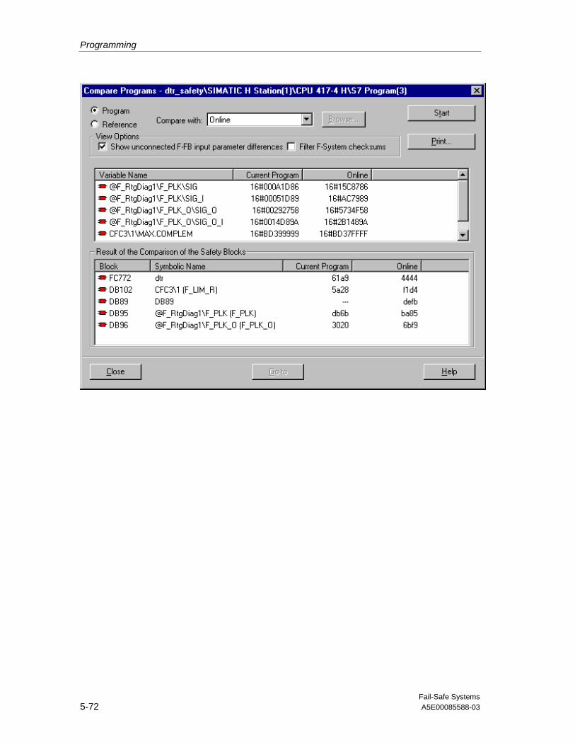
Programming
Fail-Safe Systems5-72 A5E00085588-03

Programming
Fail-Safe SystemsA5E00085588-03 5-73
Comparison of Overall Signatures:
This group displays attributes for each of the two programs selected forcomparison:
• Program type (Current program, reference program, Before Last Program,Online Program, Other Project program).
• Overall Signature: The identifying overall signature, generated at the mostrecent compilation.
• Program name: A string combining the project name, the CPU type, and theprogram name.
The words, IDENTICAL or NOT IDENTICAL, are appended to the caption of thisgroup of windows, to indicate clearly whether the overall signatures of the twoprograms match or differ.
Print Button
Click this button to print the result of the comparison.
Go to Button
When Chart View is selected, you may select any block or parameter in thedisplayed differences window, and click this button to go to the block in question inthe CFC editor.
Comparing Safety Programs
You can compare two statuses of the Safety Program in the programmingdevice/ES or online on the basis of the following criteria:
• Overall signature
• Individual signatures
• Parameter values
• Modified or deleted blocks and interconnections, etc.

Programming
Fail-Safe Systems5-74 A5E00085588-03
What Can You Compare?
You can compare the following, irrespective of whether you have selected"Program" or "Reference":
Program Compare with
Reference (Reference of this program)
Before Last Generation (Status before the last generation of thisprogram)
Online (Online status of this program)
Program (Any offline program)
Reference Compare with
Current project (Offline program)
Before Last Generation (Status before the last generation of thisprogram)
Online (Online status of this program)
Program (Any offline program)

Programming
Fail-Safe SystemsA5E00085588-03 5-75
Procedure
To compare two Safety Programs, proceed as follows:
1. Select the program folder (e.g. "S7 Program") in SIMATIC Manager.
2. Choose the Options > Edit Safety Program menu command. The "SafetyProgram – S7 Program" dialog box appears.
3. Select the "Compare..." button. The "Compare Programs" dialog box appears.
4. Select the programs you want to compare. If necessary, use the "Browse..."button to enter the path.
5. Select the "Start" button.
The result is displayed in a dialog box at block or chart level and can be printed outusing the "Print" button. The signatures of the individual blocks are displayed in theblock view. The changes to charts, blocks and run-time groups are displayed in thechart view. You can also see here if the signatures of the F-Blocks have changed.
! Safety Note – Allowable F Control Block comparison changes
At the F_CNT_W input of the F_TESTC block, the number of F code blocks (FBand run-time group FC) in working memory is displayed. If changes are made tothe Safety Program, changes to this parameter can be expected in the section ofthe program that has already been accepted.
The differences in the chart comparison of the following block I/Os can be ignoredbecause they are due to internal changes in the Safety Program. These changescan be caused, for example, by compressing the data blocks in CFC.
Block I/O
F_TESTC TESTM_DB, CYC_DB
F_PLK SIG, SIG_I, CYC_DB, TEST_DB, TESTC_DB, TESTM_DB
F_PLK_O SIG_O, SIG_O_I
The overall signature still changes, of course, and differences must be taken intoconsideration at acceptance.
The overall signature is visible at the F_SHUTDN function block’s F_PRG_SIGinput.

Programming
Fail-Safe Systems5-76 A5E00085588-03
Comparison with the Online Safety Program
! Safety Note – Checking online comparison output
When a comparison with the online program is made, it is indicated whether thesource, load memory and working memory match up (this enables the detection ofimpermissible data manipulation to non-interconnected fail-safe input parametersin the working memory). See "Checking the Overall Signatures" in the sectionentitled "Initial Acceptance of a Safety Program".
5.4.16 Logging the Safety Program
To request logs on the Safety Program, proceed as follows:
1. Select the program folder (e.g. "S7 Program") in SIMATIC Manager.
2. Choose the Options > Edit Safety Program menu command. The "SafetyProgram – S7 Program" dialog box appears.
3. Select the "Log..." button. The "Logs" dialog box appears. The following logsare displayed on the individual tabs:
- Consistency check – Log of the last consistency check
- Compilation – Log of the last compilation
- Download – Log of the last download
4. Select the one of the following options for the display:
- Only errors
- Only errors and warnings
- All
5. Click the "Page Setup" button to specify the print format (optional).
6. If necessary, print out the desired log using the "Print" button.

Programming
Fail-Safe SystemsA5E00085588-03 5-77
5.4.17 Printing the Safety Program
To print all the important project data, proceed as follows:
1. Select the program folder (e.g. "S7 Program") in SIMATIC Manager.
2. Choose the Options > Edit Safety Program menu command. The "SafetyProgram – S7 Program" dialog box appears.
3. Press the "Print" button. You can then select the parts of the project that youwant to print:
- The CFC charts
- The fail-safe program (all F-blocks and all data blocks from the F-run-timegroups).
- The hardware configuration with the module parameters
• Chart data: all the charts of the program are printed graphically
• Safety Program data, printed report contains:
- Offline/Online report status
- Safety Program name
- Current Safety Program datestamp and overall signature (of SafetyProgram blocks in the Safety Program block folder)
- Reference program datestamp and overall signature
- Blocks in the Safety Program (as shown in the dialog list box)
- Safety-related parameter values
- The document footer on each page shows:
- The current release version of the F-System software
- The overall signature (of Safety Program blocks in the CFC).
• Hardware Configuration: all or part of the hardware configuration. The Printdialog will appear to allow you to specify what module information to print.

Programming
Fail-Safe Systems5-78 A5E00085588-03
The overall signature and the date of the last compilation appear in the printout ofthe fail-safe program, which is important for the on-site acceptance of the SafetyProgram (e.g. by an outside expert). The overall signature of the compiled SafetyProgram appears twice in the printout: once in the program information section asa value of the block container and once in the footer as a value from the source(see "Checking the Overall Signatures" in the section entitled "Initial Acceptance ofa Safety Program").

Fail-Safe SystemsA5E00085588-03 6-1
6 Operation and Maintenance
6.1 Operation and Maintenance of the F-Systems
The following sections describe:
• Rules for the operation of the fail-safe S7 F/FH Systems
• How to work with the Safety Program
• How to change the Safety Program
• How to replace software and hardware components
• How to uninstall the S7 F/FH Systems
6.2 Rules for Operation
Below you can find the rules and safety notes for the operation of the S7 F/FHSystems.
PROFIsafe Nodes
! Safety Note – Simulation of PROFIsafe devices not permitted
No devices that simulate PROFIsafe nodes can be used on PROFIsafe in safetymode. A log analyzer must not, for example, execute a function to play backrecorded frame sequences with the correct dynamic response.

Operation and Maintenance
Fail-Safe Systems6-2 A5E00085588-03
Fiber-Optic Cables Between the Synchronization Modules in the S7-400 FH
! Safety Note – Duplicate Masters must be avoided
In a fail-safe and fault-tolerant S7 FH System, you must prevent both CPUs frombeing master at the same time, since this may result in hazardous faults.
Such a state (the two CPUs are both masters at the same time) can occur if thetwo fiber-optic cables used to connect the CPUs are removed or interruptedsimultaneously when the S7-400 FH is in a redundant configuration. This must beprevented by laying separate fiber-optic cables.
This state (two CPUs both masters at the same time) can also occur after a CPU isrepaired if the CPUs have not been connected via both fiber-optic cables beforethe power supply is switched back on.
Take organizational steps to ensure that, after a CPU has been replaced, bothfiber-optic cable connections are established before the power supply is switchedon.
You can find information on replacing components in fault-tolerant systems inmanual /4/. Please refer to the references in Appendix B.)
6.3 Working with the Safety Program
You must take into account the following when working with the Safety Program:
• You must not operate Safety Programs directly when safety mode is activated!You can enter safety parameters:
- by means of fail-safe conversion blocks.
- in CFC test mode.
• Access to the CPU must be protected with a password.
• The offline project in the programming device/ES must always be keptconsistent with the CPU. In other words, no old programs, charts or blocksshould be copied to a project.
! Safety Note – Safety measures must be followed
If you don’t follow the above safety measures, this may result in errors in theexecution of the safety program and in the Safety Program Shutdown.

Operation and Maintenance
Fail-Safe SystemsA5E00085588-03 6-3
6.4 Changing the Safety Program
Rules for Changes to the Safety Program
• Changes to fail-safe input parameters are only possible in safety mode byusing or downloading changes in the standard user program with the help ofconversion blocks F_BO_FBO, F_R_FR, etc. and a plausibility checkprogrammed with fail-safe blocks.
The simplest form of plausibility check is when a range is specified with fixedupper and lower limits. The on-site technical expert must always be consultedabout a plausibility check.
Not all the input parameters can be checked for plausibility in a sufficientlysimple way. You can’t change these input parameters during operation.
• The following changes to the Safety Program can be made during operation(RUN) only if safety mode is deactivated:
- Changing the CFC charts, compiling and downloading the changes to theCPU.
- Changing fail-safe constants in CFC test mode.
Changing the Safety Program
After making changes to the Safety Program, proceed as follows:
1. Compile the modified Safety Program.
2. Test the Safety Program.
3. Check whether the signatures of the blocks in the block container and the CFCcharts are the same.
4. Check the safety parameters.
5. Carry out acceptance of the changes.
6. Download the entire program or the changes only to the CPU.
7. Archive the entire modified project. The accepted Safety Program must besaved.
Batch Programming
Parameters that are not safety-related can be changed in the standard program ina batch process. Safety-related checks of these parameters (e.g. permissiblerange, consistency of parameter sets, etc.) must be carried out in the SafetyProgram.

Operation and Maintenance
Fail-Safe Systems6-4 A5E00085588-03
See Also
You can find additional information on modifying the Safety Program in thefollowing sections:
• Deactivating Safety Mode
• Changes to the Safety Program in RUN
• Downloading Changes
• Changing Fail-Safe Constants in CFC Test Mode
6.5 Replacing Software and Hardware Components
Replacing Software Components
When you replace software components on your programming device/ES, forexample in new PCS 7 or STEP 7 versions, you must comply with the guidelineson upward and downward compatibility contained in the documentation and in thereadme files of these products.
Installing New Versions of the Software Packages
After you have installed a new version of STEP 7 or add-on packages such asCFC or SCL, proceed as follows:
1. Compile the Safety Program in the new environment (new compiler or newlibraries).
Compare the overall signature of the newly compiled Safety Program with theoverall signature of the accepted Safety Program (see "Checking the OverallSignatures" in the section entitled "Initial Acceptance of a Safety Program").
2. If the overall signatures are identical, the programs are the same.
3. If the overall signatures are not identical, the program has been changed.Proceed in the same way as when there is a change to the Safety Program.
Replacing Hardware Components
The replacement of hardware components for the S7-400 FH (modules, cards,batteries, etc.) is carried out in the usual way. You can find descriptions in manuals/1/, /2/, /5/ and /7/. (Please refer to the references in Appendix B.)
Duration of the Repair with the S7 FH Systems
For redundant components in S7 FH Systems, repairs should be organized insuch a way that, in the event of a failure, repairs do not take longer than 24 hours,if possible. On weekends, repairs can last up to 72 hours for unattended systems.As a general principle, availability increases as the duration of the repair isreduced.

Operation and Maintenance
Fail-Safe SystemsA5E00085588-03 6-5
Fiber-Optic Cables in S7 FH Systems
After a CPU of the S7-400 FH has been repaired, the fiber-optic cables must notbe disconnected from the CPUs at the same time. This must be prevented bylaying separate fiber-optic cables.
Preventative Maintenance (Proof Test)
The probability values specified in the section entitled "Safety" for the certifiedcomponents of the F-Systems ensure a proof test interval of 10 years for theusual configurations. The proof test for complex electronic components usuallymeans they are replaced with unused ones. If there are special reasons why yourequire an even longer proof test interval than 10 years, please contact yourSiemens advice center.
A shorter proof test interval is normally required for sensors and actuators.
Passivating Fail-Safe Output Modules Passive over the Long Term
If a fail-safe output module is passivated for an extended period (> 72h) and thefault is not eliminated, it is possible for the module to be activated by a secondfault, thus putting the system in a dangerous state. Although the probability of suchhardware faults occurring is very slight, such unwanted activation of passivated Foutput modules due to switching or organizational measures must be prevented.One possibility is to switch off the power supply to the passivated module(s) for aperiod of time (e.g. 72 hours).
In the case of systems for which there are product standards, the requiredmeasures are standardized. In the case of all other systems, the expert accepting itmust approve the concept for the required measures put forward by the systemoperator.
6.6 Uninstalling the S7 F/FH System
Uninstalling the software and disassembling and disposing of the hardware of anF-System are carried out as normal.

Operation and Maintenance
Fail-Safe Systems6-6 A5E00085588-03

Fail-Safe SystemsA5E00085588-03 7-1
7 Safety
7.1 Standards, Certificates and Approvals
Safety Certification
When you order an F-Copy License, a copy of the TÜV certificate for the fail-safecomponents of the S7 F/FH System will be included with the product.
You can obtain additional copies of the certificate, the accompanying report andAnnex 1 of the certificate report entitled"Safety-Related Programmable Systems SIMATIC S7-400F and S7-400FH"on request from:
Ms. Petra BleicherA&D AS RD 423Fax no.: ++49 9621 80 3146
Note
Annex 1 of the certificate report contains permissible version numbers andsignatures of fail-safe components of the S7 F/FH System that have to be checkedwhen the program is accepted.
The certificate report contains conditions that currently have to be complied withwhen using the S7 F/FH System.

Safety
Fail-Safe Systems7-2 A5E00085588-03
Standards Relating to Functional Safety
The following tables list the standards taken into account when developing the S7F/FH System.
The current statuses and versions of the standards and the currently applicableconditions can be found in the safety certification report.
Standard Title/Description
DIN V 19250 Fundamental Aspects to be Considered for Measurement andControl Equipment
DIN V VDE 0801
Including modification A1
Principles for Computers in Safety-Related Systems
IEC 61508 - 1 to 7 Functional Safety; Safety-Related Systems
prEN 50159-1 Railway Applications; Requirements for Safety-RelatedCommunication in Closed Transmission Systems
prEN 50159-2 Railway Applications; Requirements for Safety-RelatedCommunication in Open Transmission Systems
Process Engineering Standard Title/Description
DIN V 19251 Process and Control Technology - MC Protection Equipment -Requirements and Measures for Safeguarded Function
VDI / VDE 2180 - 1, 2and 5
Safeguarding of Industrial Processing Plants by Means of ProcessInstrumentation and Control Technology
NE 31 NAMUR recommendationEquipment Safety Using Process Instrumentation and ControlTechnology
ISA S 84.01 Application of Safety Instrumented Systems for Process Industries
Furnace Engineering Standard Title/Description
EN 230 no. 7.3 Monobloc Oil Burners
EN 298 no. 7.3, 8,9, 10
Automatic Gas Burner Control Systems for Gas Burners and GasBurning Appliances with or without Fans
DIN V ENV 1954 Internal and External Fault Behavior of Safety-Related Electronic Partsof Gas Appliances
DIN VDE 0116 no.8 , 9
Electrical Equipment of Furnaces
pr EN 50156-1 Electrical Equipment of FurnacesPart 1: Regulations for Application Planning and Construction

Safety
Fail-Safe SystemsA5E00085588-03 7-3
Safety of Machinery Standard Title/Description
EN 60204-1 Safety of Machinery - Electrical Equipment of Machines; Part 1:General Requirements
EN 954-1 cat. 2 to4
Safety of Machinery - Safety-Related Parts of Control Systems - Part 1:General Principles for Design
Standards and Directives Relating to Other Aspects Standard Title/Description
DIN EN 61131-2 Programmable Controllers - Equipment Requirements and Tests
EN 50178 Electronic Equipment for Use in Power Installations
DIN VDE 0110 Insulation Coordination for Equipment within Low-Voltage Systems
EN 60068 Environmental Testing
EN 55011 Limits and Methods of Measurement of Radio DisturbanceCharacteristics of Industrial, Scientific and Medical (ISM) Radio-Frequency Equipment
EN 50081-2 Electromagnetic Compatibility (EMC); Generic Emission Standard; Part2: Industrial environment
EN 50082-2 Electromagnetic Compatibility (EMC); Generic Immunity Standard; Part2: Industrial environment

Safety
Fail-Safe Systems7-4 A5E00085588-03
7.2 Safety Requirements
Standardized Safety Requirements
The S7 F/FH System fulfills the following safety requirements:
• Requirement classes AK1 to AK6 in accordance with DIN V 19250/VDE 0801
• SIL1 to SIL3 (Safety Integrity Level) in accordance with IEC 61508
• Categories 1 to 4 in accordance with EN 954-1
Risk Graph and Requirement Classes (AK) to DIN V 19250
Requirement classes (AK) assigned to particular risks are defined in DIN V 19250.The requirements of the process can be worked out using the risk parameters. Therequirement class (AK) to be complied with by the controller can be establishedusing the risk chart.
This procedure results in an AK requirement class for applications without aproduct standard. Using DIN V VDE 0801, the basic safety requirements can thenbe established. If there is a product standard for an application, the safetyrequirements are noted in it.
4 3 2
2 1 -
3 2 1
1
W3
S1
A1
A1
G1
G1A2
A2
G2
G2
S2
S3
S4
S1-4
A1-2
G1-2
W1-3
Requirement classes
W2 W1
- -
5 4 3
6 5 4
8 7 6
7 6 5
Extent of damageLength of stayAvoidance of dangerProbability of undesiredevent occurring

Safety
Fail-Safe SystemsA5E00085588-03 7-5
Risk Parameters
The risk parameters have the following meaning in accordance with DIN V 19250:
Parameters Meaning
Extent of injury ordamage
S1 Minor injuries; minor harmful effects on the environment
S2 Serious irreversible injuries of one or more persons or fatality ofa person;
Temporary, seriously harmful effects on the environment
S3 Several fatalities;
Lasting, seriously harmful effects on the environment
S4 Catastrophic repercussions, large number of fatalities
Frequency and exposure time
A1 Rare to more often
A2 Frequent to continuous
Possibility of avoiding hazard
G1 Possible in certain circumstances
G2 Rarely possible
Probability of the unwanted occurrence
W1 Very low
W2 Low
W3 Relatively high
Safety Integrity Level in Accordance with IEC 61508
For each Safety Integrity Level (SIL), IEC 61508 defines the probability of failure ofa safety function allocated to a safety-related system as a target measure.
Safety integritylevel
Low Demand Mode of Operation
(Average probability of failure toperform its design function ondemand)
High Demand or ContinuousMode of Operation
(Probability of a hazardousfailure per hour)
4 ≥ 10-5 to < 10-4 ≥ 10-9 to < 10-8
3 ≥ 10-4 to < 10-3 ≥ 10-8 to < 10-7
2 ≥ 10-3 to < 10-2 ≥ 10-7 to < 10-6
1 ≥ 10-2 to < 10-1 ≥ 10-6 to < 10-5
The actuators and sensors generally contribute most to these failure probabilities.
Each safety function always comprises the entire chain, from the collection andprocessing of information to the intended action.
The equipment involved, such as the S7 F/FH programmable controller, sensorsand actuators, must in its entirety fulfill the AK and SIL determined as a result ofrisk assessment.
If control functions and associated protection functions are implemented together inthe same S7 F/FH, this is said to be high-demand or continuous mode.

Safety
Fail-Safe Systems7-6 A5E00085588-03
The following table lists the probability values of individual components of the S7F/FH Systems:
Low Demand Mode ofOperation
(Average probability offailure to perform itsdesign function ondemand)
High Demand orContinuous Modeof Operation
(Probability of adangerous failureper hour)
Proof testinterval
F-capable CPU 1,24E-04 1,42E-09 10 years
SM 326; DO 10 x DC24V/2A; with diagnosticinterrupt
6ES7 326-2BF00-0AB0
6,97E-06 7,96E-11 10 years
ET 200S PM-E F 24 VDCPROFIsafe Power Module
<< 1.00 E-05 << 1.00 E-10 10 years
ET 200S EM 4/8 F-DI 24VDC PROFIsafe DigitalElectronic Module
<<1.00 E-03 at SIL 2
<<1.00 E-05 at SIL 3
<<1.00 E-08 at SIL 2
<<1.00 E-10 at SIL 3
10 years
ET 200S EM 4 F-DO 24VDC/2 A PROFIsafe DigitalElectronic Module
<<1.00 E-05 <<1.00 E-10 10 years
ET 200S PM-D F 24VDCPROFIsafe Power Module
<<1.00 E-05 <<1.00 E-10 10 years
SM 326; DI 24 x DC 24V;with diagnostic interrupt
6ES7 326-1BK00-0AB0
1,55E-06 at SIL 2
4,99E-08 at SIL 3
1,77E-11 at SIL 2
5,70E-13 at SIL 3
10 years
SM 326; DI 8 x NAMUR;with diagnostic interrupt
6ES7 326-1RF00-0AB0
2,74E-06 at SIL 2
4,83E-08 at SIL 3
3,13E-11 at SIL 2
5,51E-13 at SIL 3
10 years
SM 336; AI 6 x 13Bit;with diagnostic interrupt
6ES7 336-1HE00-0AB0
4,96E-08 at SIL 3 5,66E-13 at SIL 3 10 years
Safety-relatedcommunication
1,00E-05 1,00E-09
You can obtain the contribution of the S7 F/FH System to the failure probability of asafety function by adding up the failure probabilities of all the CPUs and F-SMs ofthe S7 F/FH System that are involved. Redundant CPUs are counted singly –redundant F-SMs are counted double. The contribution of safety-relatedcommunication must then be added. Several S7 F/FH Systems can be involved ina safety function.

Safety
Fail-Safe SystemsA5E00085588-03 7-7
Example:
A safety function is implemented with an S7 FH System. The CPUs and F-SMsinvolved in the safety function are listed in the table below. These CPUs and F-SMs are used in a redundant configuration. Their proof test interval is 10 years.The F-SMs are in safety mode for SIL 3. Operation is in high demand mode:
CPUs, F SMs and Safety-Related CommunicationEquipment Involved in theSafety Function.
Number Redundancy Probability of aHazardous Failure
per Hour
F-capable CPU 1 Yes 1,42E-09
SM 326; DO 10 x DC 24V/2A;with diagnostic interrupt
6ES7 326-2BF00-0AB0
1 Yes 1,59E-10
SM 326; DI 24 x DC 24V; withdiagnostic interrupt
6ES7 326-1BK00-0AB0
2 Yes 2,28E-12
Safety-related communication 1,00E-09
Total 2,58E-09
7.3 System Configuration
The limits for the system configuration of the S7 F/FH System are set mainly by theCPU used. You can find the relevant values in the technical specifications of theCPU in /3/, Chapter 5.
You will find any restrictions that apply to the S7 FH System in the readme file inthe "S7 H Systems" optional package.
In Appendix A you will find the certified hardware and software components of anF-system in the form of check lists.

Safety
Fail-Safe Systems7-8 A5E00085588-03
7.4 Monitoring Times
7.4.1 Configuring the Monitoring Times for F/FH Systems
Rules for Monitoring Times
When you configure the monitoring times, you must take into consideration boththe availability and the safety of the F/FH system:
• Availability: To ensure that the temporal monitoring is not triggered when thereis no error, the monitoring times selected must be sufficiently long.
• Safety: To ensure that the process safety time is not exceeded, the monitoringtimes selected must be sufficiently short.
Monitoring Times of an F System
You must configure the following monitoring times for the F-system:
• Parameters of the fail-safe blocks:
Monitoring Block Parameter
Monitoring of the F cycle time of the cyclic interrupt OBthat contains the safety program
F_CYC_CO MAX_CYC
Monitoring of safety-related communication between Frun-time groups
F_R_R
F_R_BO
TIMEOUT
Monitoring Safety-Related Communication BetweenCPUs
F_RCVR,F_RCVBO
F_SENDR,F_SENDBO
TIMEOUT
• Parameters of the F-I/Os
Monitoring Parameter
Monitoring Safety-Related CommunicationBetween F-CPU and F-I/Os via PROFIsafe
Monitoring time (properties dialog inHWCONFIG)

Safety
Fail-Safe SystemsA5E00085588-03 7-9
Basic Procedure
To configure the monitoring times, proceed as follows:
1. Configure the standard or fault-tolerant system. You can find the necessaryinformation in the relevant hardware manuals and online help systems.
2. Configure the specific monitoring times of the F-system with regard toavailability: The times should be considerably longer than the minimummonitoring times. You can find approximation formulas in the information oncalculating the minimum monitoring times or in the Excel tableSTEP7\S7BIN\S7ftimeb.xls.
3. Use the Excel table STEP7\S7BIN\S7ftimeb.xls to calculate the maximumresponse time, and check whether the maximum fault tolerance time for theprocess has been exceeded.
! Safety Note – Pulse Detection
To enable pulses to be detected reliably, the time between two signal changes(pulse duration) must be longer than the corresponding monitoring time.

Safety
Fail-Safe Systems7-10 A5E00085588-03
7.4.2 Calculation of the Minimum Monitoring Times
7.4.2.1 Monitoring the F Cycle Time
The monitoring time is assigned parameters at the MAX_CYC input parameter ofthe F_CYC_CO fail-safe blocks.
To ensure monitoring is not triggered when there is no fault, MAX_CYC must begreater than the maximum cycle time TCImax of the relevant cyclic interrupt OB:
MAX_CYC > TCImax
TCImax is at least as large as the configured cycle time TCI of the cyclic interruptOB. In the FH system, the maximum disabling time for priority classes > 15 (TP15)at updating must also be taken into consideration. Thus the followingapproximation formulae apply:
TCImax ≈ TCI + MIN(TCiR, 2500) In the F system
TCImax ≈ MAX (TCI; TP15) + MIN(TCiR,2500)
In the FH system with cyclic interrupt OB withspecial handling
TCImax ≈ TCI + TP15 + MIN(TCiR, 2500) In the FH system with cyclic interrupt OBwithout special handling
Note the following:
Time Description Where to Find it?
TCI Configured cycle time of thecyclic interrupt OB
HWCONFIG
CPU properties, "Cyclic Interrupt, Execution"
TP15 Maximum disabling time forpriority classes > 15
HWCONFIG
CPU Properties, "H Parameters"
TCiR CiR Synchronization Time:-From the CiR-Objectparameters in STEP7-Summarize all CiR-Objectsynchronization times of thesimultaneously changing DPbuses and place total here.If CiR is not used, enter 0.
Properties of the CiR_Object in HWCONFIG.For additional information, refer to section 4.8.4"Configuration in Run (CiR)".
"Cyclic Interrupt OB with Special Handling" is an H parameter of the CPU in the S7FH system. The parameter contains the number of the cyclic interrupt OB that iscalled separately by the operating system when the standby is updated, after allthe interrupts have been locked. Usually the number of the cyclic interrupt OB withthe highest priority is entered, to which F-blocks of the Safety Program areassigned in CFC.
Note
To activate the monitoring of the maximum disabling time for priority classes > 15,you must assign this parameter a value in HWCONFIG (CPU properties, "HParameters" tab).

Safety
Fail-Safe SystemsA5E00085588-03 7-11
7.4.2.2 Monitoring Safety-Related Communication Between the F-CPUand F-I/Os
PROFIsafe time monitoring is executed in the F-I/Oand F driver with the samePROFIsafe monitoring time. The value is entered in HWCONFIG as the monitoringtime of the F-I/O and assigned (monitoring time) and automatically assigned to theF drivers at compilation (TIMEOUT).
To ensure that monitoring is not triggered in either the F driver or the F-I/O whenthere are no faults, the PROFIsafe monitoring time TPSTO selected must besufficiently long:
TPSTO > 2* TTR + TF-I/O, ACK + MAX(TCImax ; TCI + TDP_FD) + TDP_SO +TSLAVE_SO + 2* TDP_DLY
Note the following:
Time Description Where to Find it?
TCI Configured cycle time ofthe cyclic interrupt OB
HWCONFIG
CPU properties, "Cyclic Interrupt,Execution"
TCImax Maximum cycle time of therelevant cyclic interrupt OB
Monitoring the F Cycle Time section
TTR Max. target rotation timefor the DP master system
Properties of the DP master system,bus parameters in HWCONFIG
TDP_FD Max. DP fault detectiontime
Properties of the DP master system,bus parameters, "H Parameters" tabin HWCONFIG
TDP_SO Max. DP switchover time Properties of the DP master system,bus parameters, "H Parameters" tabin HWCONFIG
TSLAVE_SO Maximum switchover timefor the activecommunication channel ina switched I/O system
In the technical specifications of theswitched DP slave (ET 200M)
TF-I/O, ACK Maximum acknowledgmenttime of the F-I/Oin safetymode
You can find this time in the technicalspecifications of the fail-safe I/Omanuals.
TDP_DLY Additional DP Delay Time,External DP Interface (DP)
Properties of the External DPInterface (CP), “Operating Mode tab inHWCONFIG.

Safety
Fail-Safe Systems7-12 A5E00085588-03
Note
To check during operation whether the configured PROFIsafe monitoring times aretoo short, you can insert in an ET 200M with fail-safe signal modules in safetymode additional fail-safe signal modules in safety mode in which the configuredPROFIsafe monitoring time is lower. This is particularly advisable if the configuredPROFIsafe monitoring time that has to be checked is not much longer than theminimum possible PROFIsafe monitoring time.
See Also
Configuring the Monitoring Times for F/FH Systems
7.4.2.3 Monitoring of Safety-related Communication between CPUs
Time monitoring takes place in the F_SENDR and F_RCVR and F_SENDBO andF_RCVBO blocks respectively with the same monitoring time, which has to beassigned parameters on both blocks (TIMEOUT).
To ensure that monitoring is not triggered in F_SENDR and F_SENDBO or inF_RCVR and F_RCVBO when there are no errors, the TIMEOUT monitoring timeselected must be sufficiently long:
TIMEOUT > T CI,F_SEND + T CI,F_RCV + MAX(TDelay,F_SEND;TDelay,F_RCV) + 2*TUSEND + MAX(MIN(TCiR, F_SEND;2500), MIN(TCiR,F_RCV;2500))
Note the following:
Time Description Where to Find it?
TCI,F_SEND Configured cycle time of the cyclic interrupt OB with thecall of F_SENDBO or F_SENDR
HWCONFIG
CPU properties, "CyclicInterrupt, Execution"
TCI,F_RCV Configured cycle time of the cyclic interrupt OB with thecall of F_RCVBO or F_RCVR
HWCONFIG
CPU properties, "CyclicInterrupt, Execution"
TDelay,F_SEND Maximum communication delay when the standby inthe FH system is updated with the call of F_SENDBOor F_SENDR
Properties of the senderCPU, "H Parameters" tab
TDelay,F_RCV Maximum communication delay when the standby inthe FH system is updated with the call of F_RCVBO orF_RCVR
Properties of the receivingCPU, "H Parameters" tab
TUSEND Maximum response time of USEND
• With 48 bytes of user data for F_SENDBO
• With 88 bytes of user data for F_SENDR
You can find information onthe Internet (see below)

Safety
Fail-Safe SystemsA5E00085588-03 7-13
Time Description Where to Find it?
TCiR,F_SEND CiR Synchronization Time of the CPU with the call ofF_SENDBO or F_SENDR:
- From the CiR-Object parameters in STEP7- Summarize all CiR-Object synchronization times ofthe simultaneously changing DP buses and place totalhere. If CiR is not used, enter 0.
Properties of the CiR_Objectin HWCONFIG.
For additional information,refer to section 4.8.4"Configuration in Run (CiR)".
TCiR,F_RCV CiR Synchronization Time of the CPU with the call ofF_RCVBO or F_RCVR:
-From the CiR-Object parameters in STEP7
-Summarize all CiR-Object synchronization times of thesimultaneously changing DP buses and place totalhere. If CiR is not used, enter 0.
Properties of the CiR_Objectin HWCONFIG.
For additional information,refer to section 4.8.4"Configuration in Run (CiR)".
Finding TUSEND
You can download a tool for calculating the TUSEND value from the Internet at:
http://www4.ad.siemens.de/view/cs/de/1651770
Contribution ID 1651770
Note
To activate the monitoring of the maximum communication delaywhen the standby in the FH system is updated, you must assign thisparameter a value in HWCONFIG (CPU properties, "H Parameters"tab).
Simultaneous updating in both CPUs is not assumed.
7.4.2.4 Monitoring of Safety-Related Communication Between F-run-timeGroups
Time monitoring takes place in the FBs F_R_BO and F_R_R and is assigned thereat the TIMEOUT input parameter.
To ensure that time monitoring is not triggered when there are no faults, theTIMEOUT monitoring time must be at least as large as the larger of the twomaximum cyclic interrupt cycle times of F_S_R and F_S_BO or F_R_R andF_R_BO:
TIMEOUT > MAX(TCimax, F_S; TCImax, F_R)
Note the following:
Time Description Where to Find it?
TCImax, F_S Maximum cycle time of the cyclic interrupt OB with thecall of F_R_BO or F_R_R
Monitoring the F Cycle Timesection
TCImax, F_R Maximum cycle time of the cyclic interrupt OB with thecall of F_S_BO or F_S_R
Monitoring the F Cycle Timesection

Safety
Fail-Safe Systems7-14 A5E00085588-03
7.5 Acceptance of an F-System
An F system is usually accepted by an independent expert.
During acceptance of an F-System you are supported by special functions inSIMATIC Manager. This enables you to:
• Compare Safety Programs
• Log Safety Programs
• Print Safety Programs
You can find information on these topics in Section 5.4.
! Safety Note – Archive STEP 7 Projects
Version management must be available for the purpose of archiving the S7 F/FHSystems project. Apart from that, we recommend you archive each acceptedproject in STEP 7 and create a new project for changes.
When the system is accepted, all requirements contained in the report on thecertificate that require approval must be taken into account.
You can archive all data relevant to the acceptance of the F-System in SIMATICManager (File > Archive) and print it out, as required.
Check Lists for Acceptance
You can find the following check lists in the appendix. These can be used whenyou accept S7 F/FH Systems:
• Check list for the life cycle of the fail-safe programmable controllers – containsa summary of the activities in the life cycle of S7 F/FH Systems, as well asreferences to the requirements and rules that must be complied with.
• Check list of the certified modules
• Check list of the certified blocks

Safety
Fail-Safe SystemsA5E00085588-03 7-15
7.5.1 Initial Acceptance of a Safety Program
Basic Procedure for the Initial Acceptance of a Safety Program
1. Optional: advance acceptance of the configuration of the F-I/Os
2. Saving the program
3. Checking the printout
4. Downloading the program to the CPU
5. Carrying out a complete function test
Optional Advance Acceptance of the Configuration of the F-I/Os
After hardware configuration and parameter assignment of the F-I/Os, you cancarry out initial acceptance of the configuration of the F-I/Os.
The hardware configuration data must be printed out, saved and archived alongwith the whole STEP 7 project.
Print the Safety Program from SIMATIC Manager using the File > Print menucommand. Select the print range and options as illustrated below to receive acomplete printout:
After a check of the safety-relevant module parameters of an F-I/O, the parameterCRCs in the printout of the module parameters of the F-I/Os are sufficient as areference for subsequent acceptance. These are as follows:
• Parameter CRC (incl. address): 12345
• Parameter CRC (without address): 54321

Safety
Fail-Safe Systems7-16 A5E00085588-03
F-I/Os that are supposed to have the same safety-relevant module parameters canbe copied during configuration. Their safety-relevant module parameters no longerhave to be checked individually: It is enough to compare the ’Parameter CRC(without address)’ of the copied F-I/Os with the ’Parameter CRC (without address)’of the already checked F-I/Os and to check the logical start addresses.
Saving the Program
The Safety Program to be accepted must be saved and archived with the wholeSTEP 7 project. All the project data (program information, CFC charts, hardwareconfiguration data and logs) must be printed out and archived together with theSTEP 7 project. You can find out how to save and archive S7 projects in the basicSTEP 7 help system.
Checking the Printout
Print out the whole project as described in the section entitled Printing the SafetyProgram.
The printout contains the overall signature as a reference. The overall signatureappears twice in the printout, once in the program information section as the valueof the block container and once in the footer as a value from the source. Thevalues must match up.
The version number of the S7 F Systems optional package appears in the footer ofthe printout and must be checked.
If the overall signature is not printed in the footer, this means that the SafetyProgram or the configuration (HWCONFIG or NetPro) has changed. In this casethe Safety Program has to be recompiled.

Safety
Fail-Safe SystemsA5E00085588-03 7-17
Configuration
• F-I/Os that are supposed to have the same safety-relevant module parameterscan be copied during configuration. Their safety-relevant module parametersno longer have to be checked individually: It is enough to compare the’Parameter CRC (without address)’ of the copied F-I/Os with the ’ParameterCRC (without address)’ of the already checked F-I/Os and to check the logicalstart addresses.
• After advance acceptance of the configuration of an F-I/O, it is sufficient tocompare the ’Parameter CRC (incl. address)’ in the new printout and the one inthe accepted printout of the configuration.
Programming
The following parameters of fail-safe blocks must be checked in the printout:
• Any safety-related input parameters that are not automatically assigned mustbe checked in the printout – either in the CFC charts or in the section onsafety-related parameters. Input parameters that are not visible in the CFCcharts are printed out in the section on safety-related parameters. If it is easierto check the parameters in the chart than in the section on safety-relatedparameters, the parameters should not be hidden.
• At each F module driver, the assignment to the F channel drivers at theCHADDRxx I/Os must be checked using function tests or by looking at theprintout.
• The initial values of safety-related output parameters must be checked if therun sequence does not correspond to the flow of data, i.e. if the block is onlycalled after the output parameter has been transferred to another block. Thishappens, for example, in the case of feedback. These output parameters areprinted out in the safety-related parameters section and marked with an (*).

Safety
Fail-Safe Systems7-18 A5E00085588-03
• The specified I/Os must be checked in the case of the following fail-safeblocks:
Fail-Safe Block I/O Description
F_CYC_CO MAX_CYC Maximum permissibleF cycle time
F_SENDBO, F_RCVBO
F_SENDR, F_RCVR
TIMEOUT Monitoring time duringcommunication between F-CPUs
F_R_R, F_R_BO TIMEOUT Monitoring time duringcommunication between F-run-time groups
F_M_DI8
F_M_DI24
F_M_DO10
F_M_DO8
F_M_AI6
TIMEOUT Monitoring time forPROFIsafe communicationwith F-I/O
F_M_DI8
F_M_DI24
F_M_DO10
F_M_DO8
F_M_AI6
LADDR
LADDR_R
Logical address of themodule (SM1)
Logical address of theredundant module (SM2)
F_M_AI6 MODE_00 to MODE_05 Measurement range codingin the case of an analoginput module
F_CH_DI,
F_CH_DO, F_CH_AI
ACK_NEC Acknowledgment requiredfor reintegration
F_LIM_HL QH 1: Upper limit violated
F_LIM_LL QL 1: Lower limit violated
F_RS_FF Q Output
F_SR_FF Q Output
F_CTUD CV Current count value
Switched output parameters are marked with an asterisk (*) on the printout.
Checking the Signatures
Overall signature: After the program has been downloaded to the CPU (see thesections entitled "Downloading the Whole Safety Program" and "DownloadingChanges"), you have to compare the overall signature of the program in the CPUwith the overall signature in the accepted printout. In the case of S7 FH systems,you have to make this comparison for both CPUs.
Signatures and initial-value signatures of the F-Blocks: The signatures andinitial-value signatures of all the fail-safe blocks must be identical with those inAnnex 1 of the certificate report. When you use newly created F-Block types, youmust carry out this comparison for all the F-Blocks called in the F-Block type.

Safety
Fail-Safe SystemsA5E00085588-03 7-19
You can obtain the overall signature of the program and the signatures of theblocks in the CPU by choosing the Options > Edit Safety Program menucommand. When a comparison with the online program is made, it is indicatedwhether the source, load memory and working memory match up (this enablesimpermissible data manipulation to non-interconnected fail-safe input parametersin the working memory to be detected).
You can check whether a Safety Program in the CPU is really the one youexpected by carrying out the following steps:
1. Choose the Options > Edit Safety Program menu command in SIMATICManager and activate "Online" in the dialog box. The signature displayed in thedialog box must match the signatures in the accepted printout (in the text andin the footer).
2. To detect impermissible manipulation (e.g. via test mode in CFC) in theworking memory of the CPU, choose "Compare..." and compare the acceptedprogram with the online program in the dialog box. Any manipulatedparameters are displayed there. This step is imperative for acceptance.
3. In the case of fault-tolerant S7 FH systems, the above steps must be carriedout for both CPUs in the online view of SIMATIC Manager.
When you repeat downloading or repeat checks of the Safety Program, carryout this overall signature check again.
Please note that the overall signature is also available from “F_PRG_SI input theF_SHUTDN function block within the @F_ShutDn CFC.

Safety
Fail-Safe Systems7-20 A5E00085588-03
7.5.2 Acceptance of Changes to the Safety Program
To accept changes to the Safety Program, proceed as follows:
1. Save the program
2. Compare the new program with the accepted one (see the section entitled"Comparing Safety Programs").
3. Check the changes in the printout
4. Download the new program to the CPU
5. Carry out a functional test of the changes
When you check the printout and carry out the functional test, only the newsections and sections with changes have to be checked.
To identify these, the new program is compared with the accepted program.
The accepted program must be saved in another project. Click "Browse", and enterthe path of the accepted program.
Changes to the safety-relevant configuration of F-I/Os can be recognized by thechange to the CRC_IMP1 and CRC_IMP2 parameters of the relevant F moduledriver (F_M_xx).

Safety
Fail-Safe SystemsA5E00085588-03 7-21
Changes to the addresses or symbolic names of signals can be recognized by thechange to the ADDR_CODE parameter of the relevant F channel driver(F_CH_xx).
Changes to the network configuration in NetPro can be recognized by the changeto the CRC_IMP parameter of the relevant F communication blocks (F_RCVxx andF_SENDxx).
You can find rules and information on how to proceed in the case of changes to theSafety Program in the section entitled "Operation and Maintenance, Modifying theSafety Program".

Safety
Fail-Safe Systems7-22 A5E00085588-03
7.5.3 Acceptance of F-Block Types
Initial Acceptance
A newly created F-Block type is accepted for the first time in the same way as aSafety Program. The function test of the F-Block type must take place in a differentSafety Program to the test environment.
At the acceptance of new F-Block types, the signature and initial-value signature ofthe new F-Block are relevant. These signatures must be compared with theacceptance printout. The signatures and initial-value signatures of the called F-Blocks must also be checked.
The overall signatures in the footers of the printouts of the safety program and theCFC chart of the F-Block type must match up or the block type will have to berecompiled.
Acceptance of Changes
Acceptance of changes to an F-Block type is carried out in the same way as for aSafety Program. All the points in the F test program at which the new F-Block typeis called must also be checked by means of a function test. Changed signatures ofF-Blocks are displayed in the chart view when the Safety Program s are compared.
7.5.4 Responsibilities and Qualifications
Safety requirements relating to the system-specific use of the S7 F/FH Systemscan be met by allocating responsibilities as follows:
• The process experts and the operators for the safety concept of the system,including the definition of safety-relevant and non-safety-relevant functions.
• The (independent) expert for the safety-related acceptance testing of thesystem.
• The planners of the S7 F/FH Systems for the implementation of the safetyconcept of the system in function, configuration and wiring charts/diagrams, forthe planning of the interfaces of the F-System, the compliance with andimplementation of regulations from the report on the certificate, and the entry ofpasswords in STEP 7.
• The installation and commissioning technicians of the S7 F/FH Systems for theimplementation of and compliance with the requirements placed on theenvironment at the installation location, the error-free implementation of thewiring charts/diagrams, the downloading of the enabled Safety Program to theCPU, and the assignment of a password to the CPU.
• The commissioning technician of the S7 F/FH Systems for the functional testsof the acceptance with simulation of the switch-off criteria in accordance withthe safety concept of the system and measurement of the required safetytimes.

Fail-Safe SystemsA5E00085588-03 8-1
8 Fail-Safe Blocks
8.1 Overview
8.1.1 Fail-Safe Blocks
All the fail-safe blocks are contained in the Failsafe Blocks library in the catalog of
libraries .
If possible, the F-Blocks are assigned to the existing families of standard blocks in
the catalog of the blocks used . Since the names of the F-Blocks alwaysbegin with "F_", they appear together as a group.
Fail-safe blocks are available in the following block families:
DRIVER Driver Blocks for F-I/Os
COM_FUNC Blocks for F Communication Between CPUs
F_SYSTEM F system blocks
CONVERT Blocks for converting data between standard andsafety sections
F_CTRL F Control Blocks
BIT_LGC Logic blocks with the BOOL data type
COMPARE Comparison blocks for two input values of the sametype
FLIPFLOP Flipflop blocks
IEC_TC IEC pulse and counter blocks
IMPULS Pulse blocks
MATH_INT Arithmetic blocks with the INT data type
MATH_FP Arithmetic blocks with the REAL data type
MULTIPLX Multiplex blocks

Fail-Safe Blocks
Fail-Safe Systems8-2 A5E00085588-03
8.1.2 F-Data Types
Special F-data types in a safety data format are used for fail-safe block I/Os. Thesafety data format is used to expose data and address corruptions.
The F-data types are programmed as structures and appear in the CFC chart withthe prefix "ST". The structures always consist of three components, of which thefirst component, DATA, determines the data type. The PAR_ID and COMPLEMcomponents are included for safety reasons and are automatically assigned valuesat compilation of the CFC chart.
For example, in the structure of the F_BOOL data type, DATA is of the type BOOL:
F_BOOL:
STRUCT
DATA BOOL
PAR_ID WORD
COMPLEM WORD
END_STRUCT
Note
Only I/Os with the same F-data type can be interconnected.
! Safety Note – Do Not Change PAR_ID and COMPLEM parameters
You must not change the PAR_ID and COMPLEM components after the SafetyProgram has been compiled since this might result in serious errors remainingundetected. If errors are detected in the safety data format during execution of theSafety Program, the Safety Program will be disabled and may require the SafetyProgram to be recompiled and downloaded to the CPU.
Possible Data Types
The data types F_REAL and F_BOOL are possible for calculations.
If the F blocks have parameters with the data types F_INT, F_DINT, F_BYTE,F_WORD, F_DWORD and F_TIME, these parameters can only be assignedconstants. You can use F_FR_FI to convert to F_INT.
Note
Output parameters of the types F_TIME and F_INT can be converted byconversion blocks into the associated elementary data types for further processingin the standard program. Conversely, elementary data types of the types TIME andINT can be converted into F data types and processed further in the SafetyProgram with the appropriate plausibility check.

Fail-Safe Blocks
Fail-Safe SystemsA5E00085588-03 8-3
Default
The default only specifies the first structural component, DATA. The other twostructure elements required for safety are automatically added when CFC chartsare compiled.
The same applies to the assignment of constants.
See Also
Blocks for Converting Data Between Standard and Safety Sections

Fail-Safe Blocks
Fail-Safe Systems8-4 A5E00085588-03
8.1.3 Block I/Os
In the case of fail-safe blocks, there are some points to note concerning the blockI/Os:
• Although the I/Os EN and ENO appear in the CFC chart, they are neitherevaluated nor assigned by the program code of the F-Block and you must notinterconnect them.
• Each F-Block has three inputs (DB_ID, DB_INIT and PLK_DB) that arerequired to ensure safety. These inputs are automatically supplied withconstants at compilation. You must not change these settings either.
• The F-Blocks have additional inputs or outputs, which are switched to invisiblein the CFC chart. There are some that you must not change. Some of theothers must be switched to visible for input, for modification or monitoring (e.g.for diagnostic purposes).
• The CRC_IMP, CRC_IMP1 and CRC_IMP2 I/Os are automatically supplied.You must not change them.
Note
You must not change any I/Os that have the entry "Supplied Automatically" in the"Default" column. You can rectify any changes made to I/Os that are suppliedautomatically by recompiling the Safety Program.
! Safety Note – Do not change automatically supplied FB inputs
Online changes to inputs that are supplied automatically can result in a disabling ofthe Safety Program or in undetected errors in CPU-CPU communication!
Description of the EN, ENO, DB_ID, DB_INIT and PLK_DB Block I/Os
The following description explains the block I/Os of the individual fail-safe blocks.The block I/Os that cannot be changed (EN, ENO, DB_ID, DB_INIT and PLK_DB)are not listed or mentioned again.
Note
Although the I/Os EN and ENO appear in the CFC chart, they are neitherevaluated nor assigned by the program code of the F block and you must notinterconnect them.
EN must not be assigned the value 0 or FALSE!

Fail-Safe Blocks
Fail-Safe SystemsA5E00085588-03 8-5
Signal State 1 or 0
Signal state 1 at the block I/O of the data type BOOL always means that the eventdescribed (e.g. error on channel x) is active.
Making Block I/Os Visible
Proceed as follows:
1. Double-click the block’s header.
2. Select the "Inputs/Outputs" tab in the "Properties" dialog box.
3. Scroll to the right until the "Invisible" column appears.
4. Right-click the "Invisible" selection cross of the block I/O.
Result: The invisible block I/O becomes visible in CFC.

Fail-Safe Blocks
Fail-Safe Systems8-6 A5E00085588-03
8.1.4 Block Numbers
Block Number Block Name
FC 180 DB_INIT
FC 181 FAIL_MSG
FC 301 DB_RES
FC 303 F_FBO_BO
FC 304 F_FR_R
FC 305 F_FI_I
FC 306 F_FTI_TI
FB 301 F_AND4
FB 302 F_OR4
FB 303 F_XOR2
FB 304 F_NOT
FB 305 F_2OUT3
FB 306 F_XOUTY
FB 307 F_RS_FF
FB 308 F_SR_FF
FB 314 F_LIM_HL
FB 315 F_LIM_LL
FB 321 F_ADD_R
FB 322 F_SUB_R
FB 323 F_MUL_R
FB 324 F_DIV_R
FB 325 F_ABS_R
FB 326 F_MAX3_R
FB 327 F_MID3_R
FB 328 F_MIN3_R
FB 329 F_LIM_R
FB 330 F_SQRT
FB 331 F_AVEX_R
FB 332 F_MUX2_R
FB 333 F_SMP_AV
FB 341 F_CTUD
FB 342 F_TP
FB 343 F_TON
FB 344 F_TOF
FB 345 F_LIM_TI
FB 346 F_R_TRIG
FB 347 F_F_TRIG
FB 350 F_LIM_I
FB 361 F_BO_FBO
FB 362 F_R_FR
FB 367 F_QUITES

Fail-Safe Blocks
Fail-Safe SystemsA5E00085588-03 8-7
Block Number Block Name
FB 368 F_TI_FTI
FB 369 F_I_FI
FB 370 F_SENDBO
FB 371 F_RCVBO
FB 372 F_SENDR
FB 373 F_RCVR
FB 377 F_CH_DI
FB 378 F_CH_DO
FB 379 F_CH_AI
FB 384 F_M_DI8
FB 385 F_M_DI24
FB 386 F_M_DO10
FB 387 F_M_AI6
FB 388 F_M_DO8
FB 390 F_S_BO
FB 391 F_R_BO
FB 392 F_S_R
FB 393 F_R_R
FB 394 F_START
FB 395 F_CYC_CO
FB 396 F_PLK
FB 397 F_PLK_O
FB 398 F_TEST
FB 399 F_TESTC
FB 400 F_TESTM
FB 456 F_2oo3_R
FB 457 F_1oo2_R
FB 458 F_SHUTDN
FB 459 RTG_LOGIC
FB 461 F_FR_FI
! Safety Note – Fail-safe FB numbers
Numbers FB396 to FB400 must be kept free.
The numbers of the fail-safe blocks must not be changed.

Fail-Safe Blocks
Fail-Safe Systems8-8 A5E00085588-03
8.1.5 Installation in Cyclic Interrupt OBs
! Safety Note – Safety Program can be installed in OB 3x ONLY
Fail-safe blocks can only be installed in a cyclic interrupt OB 3x. Installation in theOB 1 is not permissible.
The cycle time of the cyclic interrupt OB is assigned parameters in HWCONFIG(CPU parameters "Cyclic Interrupts, Execution". See "Monitoring the F CycleTime").

Fail-Safe Blocks
Fail-Safe SystemsA5E00085588-03 8-9
8.2 Driver Blocks for F-I/Os
To ensure fail-safe data exchange between the Safety Program and F-I/Os,additional safety-related information is also transmitted in addition to the actualuser data (process values).
The following driver blocks are available for the transfer of user data with a safetyprotocol:
F Channel Drivers Block Description
F_CH_DI F channel driver for digital input
F_CH_DO F channel driver for digital output
F_CH_AI F channel driver for analog input
F Module Drivers Block Description
F_M_DI8 F module driver for 8-channel digital input
F_M_DI24 F module driver for 24-channel digital input
F_M_DO10 F module driver for 10-channel digital output
F_M_DO8 F module driver for 8-channel digital output
F_M_AI6 F module driver for 6-channel analog input
The F module drivers belong to the group of F control blocks.
See Also
Common Features of the Driver Blocks

Fail-Safe Blocks
Fail-Safe Systems8-10 A5E00085588-03
8.2.1 F_CH_DI
Function
The block reads the digital value of the input channel whose symbolic name islinked to the input VALUE from the associated F module driver (F_M_DIx). The Fmodule driver has read the digital value via a safety frame from the digital inputmodule (or possibly a module that is redundant to this one). The connection to theassociated F module driver (F_M_DIx) is automatically established by means of theinterconnection at the input CHADDR.
If the digital value is valid, it is made available at the output Q.
If the digital value is invalid, the substitute value 0 is output at the output Q. For thereintegration of a process value after an error is corrected, a user acknowledgmentis required depending on the parameterization and error type.
Alternatively, a simulation value can be output at the output Q.
For the process value at the output Q, a value status (quality code) is generated atthe output QUALITY that can take on the following states:
State Quality Code
Valid value 16#80
Simulation value 16#60
Substitute value 16#48
I/Os Name Data Type Explanation Default
Inputs: ADDR_CODE DWORD Address code for VALUEinterconnection
Suppliedautomatically
CHADDR F_WORD Address of the channel in the Fmodule driver
Interconnectedautomatically
VALUE BOOL Must be interconnected with thesymbolic address of the channelfrom HWCONFIG across themargin of the chart
0
SIM_I F_BOOL Simulation value 0
SIM_ON F_BOOL 1= activate simulation value
0= deactivate simulation value
0
PASS_ON F_BOOL 1= activate passivation
0= deactivate passivation
0
ACK_NEC F_BOOL User acknowledgment forreintegration after error
1 = required
0 = not required
0
ACK_REI F_BOOL Reintegration acknowledgment 0

Fail-Safe Blocks
Fail-Safe SystemsA5E00085588-03 8-11
Name Data Type Explanation Default
Outputs: PASS_OUT F_BOOL Passivation output 0
QBAD F_BOOL 1=process value invalid, valuesubstitution active
0
QSIM F_BOOL 1=simulation active 0
Q F_BOOL Process value 0
QN F_BOOL Negating process value 1
Q_DATA BOOL DATA component of the processvalue (for visualization)
0
QUALITY BYTE Value status (quality code) ofthe process value
0
ACK_REQ BOOL Acknowledgment required forreintegration
0
Addressing
You must assign the symbol of the corresponding digital input channel to the inputVALUE of the F channel driver.
Normal Value
The digital value is output at the output Q with the quality code (QUALITY) 16#80.
Simulation Value
A simulation value can be output at the output Q instead of the normal value readfrom the module.
When the input parameter SIM_ON = 1, the value of the input parameter SIM_I isoutput with the quality code (QUALITY) 16#60 and the output QSIM = 1 is set.
In the event of an error, the output of the simulation value takes precedence overthe output of the substitute value.
Substitute Value
In the case of an invalid digital value as a result of a communication error(PROFIsafe) or channel fault (e.g. wire break), in the case of passivation andduring a startup (cold or warm restart), the substitute value 0 is output with thequality code (QUALITY) 16#48 and the output QBAD = 1 is set. If the substitutevalue is not caused by passivation, the output PASS_OUT = 1 is set as well topassivate other channels.

Fail-Safe Blocks
Fail-Safe Systems8-12 A5E00085588-03
Startup Characteristics
After a startup (cold restart or warm restart), communication must first beestablished between the F module driver and the digital input module. In this time,the substitute value 0 is output with the quality code (QUALITY) 16#48, and theoutputs QBAD = 1 and PASS_OUT = 1 are set as well.
Error Handling
In the event of an error that is critical to safety, the system function SFC F_CTRLis called. This records the event in the Diagnostic Buffer and requests a switch tothe reserve CPU if the error occurred only on the master CPU. For non-redundantsystems or a common-cause error occurring in both CPUs, the shutdown logic canbe configured to either disable the erred F-run-time group or the entire SafetyProgram.
Error Information in Diagnostic Buffer Error Code (W#16#...) Description
75DAH Error in the safety data format (error due to online modificationof the Safety Program or internal CPU fault)
Report Characteristics
The block has no reporting behavior.
See Also
Common Features of the Driver Blocks
Passivation and Reintegration

Fail-Safe Blocks
Fail-Safe SystemsA5E00085588-03 8-13
8.2.2 F_CH_DO
Function
The F channel driver makes the process value at the input I available to theassociated F module driver (F_M_DOx). The F module driver reads the value fromthe F channel driver F_CH_DO and writes it via a safety frame to the channel ofthe digital output module addressed via the output VALUE (and possibly of amodule that is redundant to this). The connection to the associated F module driver(F_M_DOx) is automatically established by means of the interconnection at theoutput CHADDR.
If the F channel driver detects at the next call that errors have occurred, thesubstitute value 0 is made available for the associated F module driver at the nextcall instead of the process value at the input I. For the reintegration of the processvalue after an error is corrected, a user acknowledgment is required depending onthe parameterization and error type.
Alternatively, a simulation value can be output at the module output if there is noerror.
For the digital value I output to the module, a value status (quality code) isgenerated at the QUALITY output that can take on the following states:
State Quality Code
Valid value 16#80
Simulation value 16#60
Substitute Value 16#48
I/Os Name Data Type Explanation Default
Inputs: ADDR_CODE DWORD Address code for VALUEinterconnection
Suppliedautomatically
I F_BOOL Process value 0
SIM_I F_BOOL Simulation value 0
SIM_MOD F_BOOL 1=Simulate I/O Module 0
SIM_ON F_BOOL 1= activate simulation value
0= deactivate simulationvalue
0
PASS_ON F_BOOL 1= activate passivation
0= deactivate passivation
0
ACK_NEC F_BOOL User acknowledgment forreintegration after error
1 = required
0 = not required
0
ACK_REI F_BOOL Reintegrationacknowledgment
0

Fail-Safe Blocks
Fail-Safe Systems8-14 A5E00085588-03
Name Data Type Explanation Default
Outputs: PASS_OUT F_BOOL Passivation output 0
QBAD F_BOOL 1=process value invalid,value substitution active
0
QSIM F_BOOL 1=simulation active 0
CHADDR F_WORD Address of the channel inthe F module driver
Interconnectedautomatically
VALUE BOOL Must be interconnected withthe symbolic address of thechannel from HWCONFIGacross the margin of thechart
0
QUALITY BYTE Value status (quality code) ofthe output value
0
ACK_REQ BOOL Acknowledgment requiredfor reintegration
0
Addressing
You must assign the symbol of the corresponding digital output channel to theoutput VALUE of the F channel driver.
Normal Value
The process value at the input I is made available for the associated F moduledriver (F_M_DOx). 16#80 is output as the quality code (QUALITY).
Simulation Value
At the output, a simulation value can be output instead of the value at the input I(e.g. for hardware tests).
When the input parameter SIM_ON = 1, the value of the input parameter SIM_I ismade available to the associated F module driver (F_M_DOx). 16#80 is output asthe quality code (QUALITY), and the output QSIM = 1 is set.
When SIM_MOD=0, the output of the simulation value takes precedence over theoutput of the normal value and passivation, but not over the substitution value 0 inthe event of an error.
When SIM_MOD=1, the output of the simulation values always takes precedenceover the output of the normal value and passivation, regardless of any moduleerror. (QBAD=0) This mode would be useful to simulate “error-free operation evenwithout the hardware DO modules.

Fail-Safe Blocks
Fail-Safe SystemsA5E00085588-03 8-15
Substitute Value
In the event of communication errors (PROFIsafe) or channel faults (e.g. wirebreak), in the case of passivation and during a startup (cold or warm restart), thesubstitute value 0 is made available for the associated F module driver(F_M_DOx). 16#48 is output as the quality code (QUALITY), and the output QBAD= 1 is set.
If the substitute value is not caused by passivation, the output PASS_OUT = 1 isset as well to passivate other channels. In the event of an error, the output of thesubstitute value has the highest priority.
Startup Characteristics
After a startup (cold restart or warm restart), communication must first beestablished between the F module driver and the digital output module. In this time,the substitute value 0 is output with the quality code (QUALITY) 16#48, and theoutputs QBAD = 1 and PASS_OUT = 1 are set as well. At ACK_REQ = 1 theACK_REI acknowledgement must follow, even if ACK_NEC = 0.
Error Handling
In the event of an error that is critical to safety, the system function SFC F_CTRLis called. This records the event in the Diagnostic Buffer and requests a switch tothe reserve CPU if the error occurred only on the master CPU. For non-redundantsystems or a common-cause error occurring in both CPUs, the shutdown logic canbe configured to either disable the erred F-run-time group or the entire SafetyProgram.
Error Information in Diagnostic Buffer
Error Code (W#16#...) Description
75DAH Error in the safety data format (error due to online modificationof the Safety Program or internal CPU fault)
Report Characteristics
The block has no reporting behavior.
See Also
Common Features of the Driver Blocks
Passivation and Reintegration

Fail-Safe Blocks
Fail-Safe Systems8-16 A5E00085588-03
8.2.3 F_CH_AI
Function
The block reads the analog non-linearized value of the input channel whosesymbolic name is linked to the input VALUE from the associated F module driver(F_M_AIx). The F module driver has read the non-linearized value via a safetyframe from the analog input module (or possibly a module that is redundant to thisone). The connection to the associated F module driver (F_M_AIx) is automaticallyestablished by means of the interconnection at the input CHADDR.
If the non-linearized value is valid, it is adapted to its physical size and madeavailable at the output V as a process value.
If the non-linearized value is invalid, a substitute value or the last valid value isoutput at the output V, depending on the parameterization. For the reintegration ofa process value after an error is corrected, a user acknowledgment is requireddepending on the parameterization and error type.
Alternatively, a simulation value can be output at the output V.
For the process value at the output V, a value status (quality code) is generated atthe output QUALITY that can take on the following states:
State Quality Code
Valid value 16#80
Simulation value 16#60
Substitute value 16#48
Last valid value 16#44
I/Os Name Data Type Explanation Default
Inputs: ADDR_CODE DWORD Address code for VALUEinterconnection
Suppliedautomatically
CHADDR F_WORD Address of the channel in the Fmodule driver
Interconnectedautomatically
VALUE WORD Must be interconnected with thesymbolic address of the channelfrom HWCONFIG across themargin of the chart
0
VHRANGE F_REAL Upper limit of the process value 0.0
VLRANGE F_REAL Lower limit of the process value 0.0
CH_F_ON F_BOOL 1=activate limit-value monitoring 0
CH_F_HL F_REAL Overrange limit of the input value(mA)
0.0
CH_F_LL F_REAL Underrange limit of the input value(mA)
0.0
SIM_V F_REAL Simulation value 0.0

Fail-Safe Blocks
Fail-Safe SystemsA5E00085588-03 8-17
Name Data Type Explanation Default
SIM_ON F_BOOL 1= activate simulation value
0= deactivate simulation value
0
SUBS_ON F_BOOL 1=enable value substitution 0
SUBS_V F_REAL Substitute value 0.0
PASS_ON F_BOOL 1= activate passivation
0= deactivate passivation
0
ACK_NEC F_BOOL User acknowledgment forreintegration after error
1 = required
0 = not required
0
ACK_REI F_BOOL Reintegration acknowledgment 0
Outputs: PASS_OUT F_BOOL Passivation output 0
QCHF_HL F_BOOL 1=input value in overrange 0
QCHF_LL F_BOOL 1=input value in underrange 0
QBAD F_BOOL 1=process value invalid 0
QSIM F_BOOL 1=simulation active 0
QSUBS F_BOOL 1=value substitution active 0
OVHRANGE F_REAL Upper limit of the process value(copy)
0.0
OVLRANGE F_REAL Lower limit of the process value(copy)
0.0
V F_REAL Process value 0.0
V_DATA REAL DATA process value 0.0
QUALITY BYTE Value status (quality code) of theprocess value
0
ACK_REQ BOOL Acknowledgment required forreintegration
0
Addressing
You must assign the symbol of the corresponding analog input channel to the inputVALUE of the F channel driver.

Fail-Safe Blocks
Fail-Safe Systems8-18 A5E00085588-03
Non-Linearized Value Checking
Depending on the measurement type and measurement range, there is a ratedrange of the analog input module, in which the analog signal is converted to adigitized non-linearized value. To this end, there is an overrange and anunderrange in which the analog signal can still be converted. Overflow andunderflow apply beyond these limits. The F channel driver indicates whether thenon-linearized value lies within the rated range of the module. If the value liesunder the rated range, the output parameter QCHF_LL = 1 is set. If the value liesabove the rated range, the output parameter QCHF_HL = 1 is set. In the case ofoverflow or underflow, the output QBAD = 1 is also set, and, depending on theparameter assignment, a substitute value or the last valid value is output.
In the event of channel faults (e.g. wire break), the module outputs 16#7FFF(overflow) as a non-linearized value. Accordingly, the F channel driver F_CH_AIdetects an overflow and sets the output QCHF_HL = 1 and QBAD = 1.
NAMUR Limit Value Checking
In the NAMUR guidelines for analog signal processing, limit values are defined forlife zero (4 to 20 mA) analog signals where there is a channel fault:
3.6 mA < analog signal < 21 mA.
By default, the above NAMUR limits are set for limit value checking. If other limitvalues are to be set, the input parameter CH_F_ON = 1 must be set and the inputparameters CH_F_HL and CH_F_LL must be set in mA with corresponding newlimit values. In the event of overflow or underflow of the active limit values, theoutput QBAD = 1 is set, and, in the case of a life zero analog signal, a substitutevalue or the last valid value is output, depending on the parameter assignment(input SUBS_ON).
Note
The selectable limit values must be under the upper limit of the overrange andabove the lower limit of the underrange of the module. Values outside the NAMURrange are thus also possible, unless the module automatically limits the measuredvalues.

Fail-Safe Blocks
Fail-Safe SystemsA5E00085588-03 8-19
Normal Value
The non-linearized value is adapted to its physical size using the input parametersVLRANGE and VHRANGE and the measurement range and measurement type(MODE) set in HWCONFIG. To enable the settings for VLRANGE and VHRANGEto be switched to other block parameters, these are written to the outputsOVLRANGE and OVHRANGE.
The conversion algorithm assumes a linear input signal.
When VLRANGE = 0.0 and VHRANGE = 100.0, you receive a percentage value.
When VHRANGE = VLRANGE is set, you receive the input signal of the analoginput module (e.g. mA) in accordance with the MODE setting.
16#80 is output as the quality code (QUALITY).
Measurement Range Coding of the Analog Input Module
The block is only released for the analog input module SM 336; AI 6 13Bit; withdiagnostic interrupt. Only a measurement range of 4 to 20 mA is supported with ameasurement type of 2- or 4-wire measuring transducer. The coding of themeasurement range of the analog input module is carried out in HWCONFIG andis applied at compilation automatically to the parameter MODE_xx of theassociated F module driver (F_M_AIx). F_CH_AI reads the value from theassociated F module driver. MODE can take on the following values:
Measurement Type MeasurementRange
MODE (Decimal/Hex.)
4-wire measuringtransducer
4 to 20 mA 515 / 16#0203
2-wire measuringtransducer
4 to 20 mA 771 / 16#0303
Simulation Value
A simulation value can be output at the output V instead of the normal value.
When the input parameter SIM_ON = 1, the value of the input parameter SIM_V isoutput with the quality code (QUALITY) 16#60 and the output QSIM = 1 is set.
The output of the simulation value has the highest priority.
If a simulation value is selected that would result from a non-linearized value belowthe rated range of the module, the output parameter QCHF_LL = 1 is set. If acorresponding non-linearized value would exceed the rated range, the outputparameter QCHF_HL = 1 is set. In the event of overflow or underflow or violation ofthe active limits, the output QBAD = 1 is also set, and then, depending on theparameter assignment for the input SUBS_ON, a substitute value or the last validvalue is output.

Fail-Safe Blocks
Fail-Safe Systems8-20 A5E00085588-03
Substitute Value/Keep Last Value
In the case of an invalid non-linearized value as a result of a communication error(PROFIsafe), channel fault, overflow/underflow or violation of channel fault limitsand in the case of passivation, depending on the parameter assignment (inputparameter SUBS_ON), a substitute value or the last valid value is output, and theoutput QBAD = 1 is set. During a startup (cold or warm restart), there is no lastvalid value yet available, and, regardless of the parameter assignment, thesubstitute value configured at the input SUBS_V is output.
If the output of the substitute value or the last valid value is not caused bypassivation, the output PASS_OUT = 1 is set additionally to passivate otherchannels.
When the input parameter SUBS_ON = 0, the last valid value of V is output withthe quality code (QUALITY) 16#44.
When the input parameter SUBS_ON = 1, the substitute value SUBS_V is outputwith the quality code (QUALITY) 16#48, and the output QSUBS = 1 is set.
Startup Characteristics
After a startup (cold restart or warm restart), communication must first beestablished between the F module driver and the analog input module. In this time,regardless of the parameter assignment at the input SUBS_ON, the substitutevalue SUBS_V is output with the quality code (QUALITY) 16#48, and the outputsQBAD = 1, QSUBS = 1 and PASS_OUT = 1 are set.
Error Handling
If the value for measurement range and measurement type (MODE) is invalid, aninvalid non-linearized value is assumed.
In the event of an error that is critical to safety, the system function SFC F_CTRLis called. This records the event in the Diagnostic Buffer and requests a switch tothe reserve CPU if the error occurred only on the master CPU. For non-redundantsystems or a common-cause error occurring in both CPUs, the shutdown logic canbe configured to either disable the erred F-run-time group or the entire SafetyProgram.
Error Information in Diagnostic Buffer Error Code (W#16#...) Description
75DAH Error in the safety data format (error due to online modificationof the Safety Program or internal CPU fault)
75D9H Invalid REAL number (DATA component)

Fail-Safe Blocks
Fail-Safe SystemsA5E00085588-03 8-21
Error in the Case of Module Redundancy
In the event of an error, a switch is made to the analog value of the redundantmodule. After the error is corrected, there is no switch back; instead, workcontinues with the last valid analog value. If an error only occurs on one of theredundant modules, automatic reintegration takes place in the F channel driverF_CH_AI after the error is corrected.
Report Characteristics
The block has no reporting behavior.
See Also
Common Features of the Driver Blocks
Passivation and Reintegration

Fail-Safe Blocks
Fail-Safe Systems8-22 A5E00085588-03
8.2.4 Common Features of the Driver Blocks
F Module Drivers
Safety frame
Fail-safe data exchange between a Safety Program and an F-I/O occurs via safetyframes. In addition to user data (i.e. process values), information on safety is alsotransferred.
Monitoring Time TIMEOUT
See "Configuring the Monitoring Times for F/FH Systems".
Redundancy
The driver blocks support the following types of redundancy:
• Signal redundancy in the case of digital input modules as a result of 1oo2sensor evaluation: If a digital input module is run with 1oo2 sensor evaluation,only F channel drivers can be placed for channels 0 to 3 of the digital inputmodule SM 326; DI 8 x NAMUR and channels 0 to 11 of the SM 326; DI 24 xDC 24 V.
• Module redundancy: The F module drivers are able to address two redundantsignal modules.
The settings necessary for this are made when parameters are assigned to themodules in HWCONFIG.
Module redundancy
The processing of redundant modules comprises the following functions:
• In the case of problem-free operation:
- In the case of digital input modules, the input signals are ORed perchannel.
- In the case of digital output modules, the digital value at I/O I of thechannel driver is forwarded to both modules in parallel.
- In the case of analog input modules, the input signals of the module that isavailable first after startup are forwarded to the F channel drivers.
• If a fault occurs on one of the redundant channels:
- In the case of digital input modules and analog input modules, aswitchover takes place to the channel of the other module.
- In the case of digital output modules, the substitute value 0 is sent to thechannel with the fault.

Fail-Safe Blocks
Fail-Safe SystemsA5E00085588-03 8-23
• If a fault occurs on both of the redundant channels:
- In the case of digital input modules, the substitute value 0 is output on theF channel driver.
- In the case of digital output modules, the substitute value 0 is sent to bothchannels.
- In the case of analog input modules, the substitute value or the last validvalue is output on the F channel driver, depending what is configured.
As long as both redundant channels don’t fail, an acknowledgment is notnecessary for reintegration after the problem has been dealt with.
Note
In the case of analog input modules, after a problem is corrected there is no switchback to the channel of the original module. This can lead to the presence of activechannels on both modules.
When an analog input modules is replaced, a switchover to the second moduletakes place automatically.
Discrepancy Analysis In the Case of Module Redundancy
In the case of redundant, fail-safe digital input modules with single-channel or two-channel non-equivalent sensor interconnection, the F module driver carries out adiscrepancy analysis to increase availability. For this purpose, the input DISC_ONis assigned automatically and the assigned discrepancy time is stored at the inputDISCTIME when CFC charts are compiled.
In the discrepancy analysis, the F module driver compares two corresponding inputsignals in each case. If a discrepancy between the signals lasts longer than theconfigured discrepancy time, it detects a discrepancy error for the channel thatsupplies the 0 signal and sets the corresponding bit in the diagnostic information atthe DIAG_1/2 output.
As long as it is only discrepancy errors that occur for a channel, the output QBADis not set on the F channel driver and the process value remains valid.Reintegration after an error has been eliminated occurs automatically withoutacknowledgment at the F channel driver.
In the case of redundant analog input modules, a discrepancy analysis is notcarried out.
A distinction should be drawn between this and discrepancy analysis in the caseof 1oo2 sensor evaluation, which is carried out by the module rather than thedriver block. A discrepancy error in the case of 1oo2 evaluation is handled in thesame way as a channel fault. You can find additional information on discrepancyanalysis and sensor interconnection in the Fail-Safe Signal Modules manual,sections 3.2, 9.1 and 9.2.

Fail-Safe Blocks
Fail-Safe Systems8-24 A5E00085588-03
Error Handling
The F module drivers can detect errors as well as respond to errors reported by themodule. Each block has several options for signaling and handling errors.
F Channel Drivers
Installation in Cyclic Interrupt OBs
Every F channel driver block must be installed in a cyclic interrupt OB3x. Multipleinstallation of an instance in different cyclic interrupts is not permissible. The cyclicinterrupt interval must be coordinated with the monitoring time configured for themodule in HWCONFIG.
When the Safety Program is compiled, a check is carried out to establish whetheran F channel driver has been installed in more than one cyclic interrupt OB. Ifappropriate, a corresponding error message is output.
All the F channel drivers that belong to a module must be integrated into the sameF-run-time group.
Startup Characteristics
After a startup (cold restart or warm restart), communication must first beestablished between the F module driver and the F-I/O. Until this happens,substitute values are output with the quality code (QUALITY) 16#48 and theoutputs QBAD and PASS_OUT of the F channel drivers are set.
As soon as PROFIsafe communication has been established without any errorsand no more module or communication faults/errors occur, valid process valuesare output.
If PROFIsafe communication cannot be established within the configuredmonitoring time, a TIMEOUT error is detected.
See Also
"Error Handling of Driver Blocks"
Passivation and Reintegration

Fail-Safe Blocks
Fail-Safe SystemsA5E00085588-03 8-25
8.3 Blocks for F Communication Between CPUs
To ensure additional safety-related data exchange between Safety Programs ondifferent CPUs, additional fail-safety-related information is also transferred as wellas the actual user data. This information and the associated mechanisms remainhidden to the user.
The following blocks are available for F communication:
Block Description
F_SENDBO Send F_BOOL data to another CPU
F_RCVBO Receive F_BOOL data from another CPU
F_SENDR Send F_REAL data to another CPU
F_RCVR Receive F_REAL data from another CPU
ID and R_ID Addressing Parameters for F Communication Blocks
• ID is the reference to the local connection description. ID is assigned duringconnection configuration (NetPro). The I/O ID must be assigned parameters onthe sending side (F_SENDBO, F_SENDR) and on the receiving side(F_RCVBO, F_RCVR).
• Via R_ID you can define that a sending and a receiving fail-safe block belongtogether: The associated fail-safe blocks receive the same value for R_ID. Thevalue R_ID is a freely selectable odd number, but it must be unique for asending/receiving F block pair.
Note
The value R_ID + 1 is also assigned and must not be used.
TIMEOUT Parameter
All four blocks for F communication have the TIMEOUT parameter for vital-signmonitoring of the communication between the CPUs. You can find out how tocalculate TIMEOUT in the section entitled "Configuring the Monitoring Times forF/FH Systems".
Note
Data transfer takes place cyclically. It can only be guaranteed that a signal level tobe transferred will be detected on the sender side and transferred to the recipient ifit is present for at least as long as the configured monitoring time (TIMEOUT).

Fail-Safe Blocks
Fail-Safe Systems8-26 A5E00085588-03
RETVAL Parameter
Return values (RET_VAL) of the system functions are indicated at the RETVALparameter of the blocks for F communication. The return values are error codesthat give you additional assistance in finding the error (see the section entitled"Error Information at the Output RETVAL").
CRC_IMP Parameter
! Safety Note – Do NOT change CRC_IMP input
Do not make any changes to the CRC_IMP I/O because this I/O is suppliedautomatically. As a result of online changes to this I/O, errors can occur duringtransmission of fail-safe data when the Safety Program is executed. For example,data may be sent to the wrong recipient or may not be recognized as coming froman incorrect sender.

Fail-Safe Blocks
Fail-Safe SystemsA5E00085588-03 8-27
8.3.1 F_SENDBO
Function
This block safely sends 20 data items of the F_BOOL data type to another CPU.The data can be received there by the F_RCVBO block.
The data to be sent (e.g. outputs from other blocks) is stored at the inputsSD_BO_xx.
The data is transferred via safety frames.
If you want to temporarily switch off a data interchange that has been establishedbetween two CPUs in order to reduce the load on the bus, you can assign thevalue FALSE to the input EN_SEND. In this case, no more data is sent to therecipient, and the recipient outputs the configured substitute values. Ifcommunication between the connection partners was already established, whendata interchange restarted with EN_SEND = TRUE, an acknowledgment isrequired on the recipient’s side before the values sent are output again.
Startup Characteristics
After a startup (cold restart or warm restart), communication must first beestablished between the communication partners. F_SENDBO indicates this at theSUBS_ON parameter with "1". The recipient (F_RCVBO) outputs substitute valuesduring this time until communication between F_SENDBO and F_RCVBO hasstarted up via the safety frame and any acknowledgment required for reintegrationat F_RCVBO has been made.
I/Os Name Data Type Explanation Default
Inputs: EN_SEND BOOL 1 = switch transmission on
0 = switch transmission off
1
ID WORD ID addressing parameter 0000
R_ID DWORD R_ID addressing parameter 00000000
SD_BO_00 F_BOOL Send date 00 0
... ...
SD_BO_19 F_BOOL Send date 19 0
CRC_IMP DWORD Address reference CRC Suppliedautomatically
TIMEOUT F_TIME Monitoring time in ms for vital-sign monitoring
T#0 ms
Outputs: ERROR F_BOOL Transmission error 0
SUBS_ON F_BOOL Recipient outputs substitutevalues
0
RETVAL WORD Error code 0000

Fail-Safe Blocks
Fail-Safe Systems8-28 A5E00085588-03
TIMEOUT Parameter
The input TIMEOUT cannot be interconnected and must be assigned a constantvalue. See "Monitoring Safety-Related Communication Between CPUs".
Error Handling
If a connection partner (recipient) acknowledges receipt via an invalid safety frame(e. g. due to a check value error (CRC) or watchdog error) or does notacknowledge it within the TIMEOUT monitoring time, the outputs ERROR andSUBS_ON are set. The recipient (F_RCVBO) then outputs substitute values. Anerror code is displayed at the output RETVAL. Communication between theconnection partners is reestablished.
Note
Once communication has been set up without errors, compliance with the assignedmonitoring time (TIMEOUT parameter) is checked.
In the event of an error that is critical to safety, the system function SFC F_CTRLis called. This records the event in the Diagnostic Buffer and requests a switch tothe reserve CPU if the error occurred only on the master CPU. For non-redundantsystems or a common-cause error occurring in both CPUs, the shutdown logic canbe configured to either disable the erred F-run-time group or the entire SafetyProgram.
Error Information in Diagnostic Buffer
Error Code (W#16#...) Description
75DAH Error in the safety data format (error due to online modificationof the Safety Program or internal CPU fault)

Fail-Safe Blocks
Fail-Safe SystemsA5E00085588-03 8-29
8.3.2 F_RCVBO
Function
This block safely receives 20 data items of the F_BOOL data type sent by theF_SENDBO block from another CPU.
The received data is stored at the outputs RD_BO_xx for further processing byother blocks.
The data is transferred via safety frames.
Startup Characteristics
After a startup (cold restart or warm restart), communication must first beestablished between the communication partners. As long as the recipient does notreceive a safety frame from the sender, it sets the output SUBS_ON and outputsthe substitute values at the outputs RD_BO_xx.
The substitute values can be stored at the inputs SUBBO_xx.
I/Os Name Data Type Explanation Default
Inputs: ID WORD ID addressing parameter 0000
R_ID DWORD R_ID addressing parameter 00000000
CRC_IMP DWORD Address reference CRC Suppliedautomatically
TIMEOUT F_TIME Monitoring time in ms for vital-sign monitoring
T#0 ms
ACK_REI F_BOOL Acknowledgment forreintegration of process valuesafter transmission errors
0
SUBBO_00 F_BOOL Substitute value for receiptdata 00
0
... ...
SUBBO_19 F_BOOL Substitute value for receiptdata 19
0
Outputs: ACK_REQ BOOL Acknowledgment forreintegration of process valuesrequired
0
ERROR F_BOOL Transmission error 0
SUBS_ON F_BOOL Substitution values are output 1
RD_BO_00 F_BOOL Receipt data 00 0
... ...
RD_BO_19 F_BOOL Receipt data 19 0
RETVAL WORD Error code 0000

Fail-Safe Blocks
Fail-Safe Systems8-30 A5E00085588-03
TIMEOUT Parameter
It can only safely be guaranteed that a signal level to be transferred will bedetected on the sender side and transferred to the recipient if it is present for atleast as long as the specified monitoring time (TIMEOUT).
The input TIMEOUT cannot be interconnected and must be assigned a constantvalue. See "Monitoring Safety-Related Communication Between CPUs".
Error Handling
If a connection partner receives an invalid safety frame (e.g.: due to a check valueerror (CRC) or watchdog error) or doesn’t receive a valid safety frame within theTIMEOUT monitoring time, the outputs ERROR and SUBS_ON are set and thesubstitute values are output. An error code is displayed at the output RETVAL.
Note
Once communication has been set up without errors, compliance with the assignedmonitoring time (TIMEOUT parameter) is checked.
Communication between the connection partners is reestablished. The datareceived with valid safety frames is not applied to the outputs (= reintegrated) untilthe input ACK_REI had a rising edge (e.g. via F_QUITES).
The block sets the output ACK_REQ to indicate that acknowledgment is required.
In the event of an error that is critical to safety, the system function SFC F_CTRLis called. This records the event in the Diagnostic Buffer and requests a switch tothe reserve CPU if the error occurred only on the master CPU. For non-redundantsystems or a common-cause error occurring in both CPUs, the shutdown logic canbe configured to either disable the erred F-run-time group or the entire SafetyProgram.
Error Information in Diagnostic Buffer
Error Code (W#16#...) Description
75DAH Error in the safety data format (error due to online modificationof the Safety Program or internal CPU fault)

Fail-Safe Blocks
Fail-Safe SystemsA5E00085588-03 8-31
8.3.3 F_SENDR
Function
This block safely sends 20 data items of the F_REAL data type to another CPU. Itcan be received there by the F_RCVR block.
The data to be sent (e.g. outputs from other blocks) is stored at the inputsSD_R_xx.
The data is transferred via safety frames.
If you want to temporarily switch off a data interchange that has been establishedbetween two CPUs in order to reduce the load on the bus, you can assign thevalue 0 to the input EN_SEND. In this case, no more data is sent to the recipient,and the recipient outputs the configured substitute values. If communicationbetween the connection partners was already established, when data interchangerestarted with EN_SEND = 1, an acknowledgment is required on the recipient’sside before the values sent are output again.
Startup Characteristics
After a startup (cold restart or warm restart), communication must first beestablished between the communication partners. The F_SENDR signals this atthe SUBS_ON parameter with "1". The recipient (F_RCVR) outputs substitutevalues during this time until communication between F_SENDR and F_RCVR viathe safety frame has started up and any acknowledgment required for reintegrationat F_RCVR has been made.
I/Os Name Data Type Explanation Default
Inputs: EN_SEND BOOL 1 = switch transmission on
0 = switch transmission off
1
ID WORD ID addressing parameter 0000
R_ID DWORD R_ID addressing parameter 00000000
SD_R_00 F_REAL Send date 00 0
... ...
SD_R_19 F_REAL Send date 19 0
TIMEOUT F_TIME Monitoring time in ms for vital-sign monitoring
T#0 ms
CRC_IMP DWORD Address reference CRC Suppliedautomatically
Outputs: ERROR F_BOOL Transmission error 0
SUBS_ON F_BOOL Recipient outputs substitutevalues
0
RETVAL WORD Error code 0000

Fail-Safe Blocks
Fail-Safe Systems8-32 A5E00085588-03
TIMEOUT Parameter
It can only safely be guaranteed that a signal level to be transferred will bedetected on the sender side and transferred to the recipient if it is present for atleast as long as the specified monitoring time (TIMEOUT).
The input TIMEOUT cannot be interconnected and must be assigned a constantvalue. See "Monitoring Safety-Related Communication Between CPUs".
Error Handling
If a connection partner (recipient) acknowledges receipt via an invalid safety frame(e. g. due to a check value error (CRC) or watchdog error) or does notacknowledge it within the TIMEOUT monitoring time, the outputs ERROR andSUBS_ON are set. The recipient (F_RCVR) then outputs substitute values. Anerror code is displayed at the output RETVAL. Communication between theconnection partners is reestablished.
Note
Once communication has been set up without errors, compliance with the assignedmonitoring time (TIMEOUT parameter) is checked.
In the event of an error that is critical to safety, the system function SFC F_CTRLis called. This records the event in the Diagnostic Buffer and requests a switch tothe reserve CPU if the error occurred only on the master CPU. For non-redundantsystems or a common-cause error occurring in both CPUs, the shutdown logic canbe configured to either disable the erred F-run-time group or the entire SafetyProgram.
Error Information in Diagnostic Buffer
Error Code (W#16#...) Description
75DAH Error in the safety data format (error due to online modificationof the Safety Program or internal CPU fault)

Fail-Safe Blocks
Fail-Safe SystemsA5E00085588-03 8-33
8.3.4 F_RCVR
Function
This block safely receives 20 data items of the F_REAL data type sent by theF_SENDR block from another CPU.
The received data comes to the outputs RD_R_xx for further processing by otherblocks.
The data is transferred via safety frames.
Startup Characteristics
After a startup (cold restart or warm restart), communication must first beestablished between the communication partners. As long as the recipient does notreceive a safety frame from the sender, it sets the output SUBS_ON and outputsthe substitute values at the outputs RD_R_xx.
The substitute values can be applied at the inputs SUBR_xx.
I/Os Name Data Type Explanation Default
Inputs: ID WORD ID addressing parameter 0000
R_ID DWORD R_ID addressing parameter 00000000
CRC_IMP DWORD Address reference CRC Suppliedautomatically
TIMEOUT F_TIME Monitoring time in ms for vital-sign monitoring
T#0 ms
ACK_REI F_BOOL Acknowledgment forreintegration of process valuesafter transmission errors
0
SUBR_00 F_REAL Substitute value for receiptdata 00
0
... ...
SUBR_19 F_REAL Substitute value for receiptdata 19
0
Outputs: ACK_REQ BOOL Acknowledgment forreintegration of process valuesrequired
0
ERROR F_BOOL Transmission error 0
SUBS_ON F_BOOL Substitution values are output 1
RD_R_00 F_REAL Receipt data 00 0
... ...
RD_R_19 F_REAL Receipt data 19 0
RETVAL WORD Error code 0000

Fail-Safe Blocks
Fail-Safe Systems8-34 A5E00085588-03
TIMEOUT Parameter
The input TIMEOUT cannot be interconnected and must be assigned a constantvalue. See "Monitoring Safety-Related Communication Between CPUs".
Error Handling
If a connection partner receives an invalid safety frame (e.g.: due to a check valueerror (CRC) or watchdog error) or doesn’t receive a valid safety frame within theTIMEOUT monitoring time, the outputs ERROR and SUBS_ON are set and thesubstitute values are output. An error code is displayed at the output RETVAL.
Note
Once communication has been set up without errors, compliance with the assignedmonitoring time (TIMEOUT parameter) is checked.
Communication between the connection partners is reestablished. The datareceived with valid safety frames is not applied to the outputs (= reintegrated) untilthe input ACK_REI had a rising edge (e.g. via F_QUITES).
The block sets the output ACK_REQ to indicate that acknowledgment is required.
In the event of an error that is critical to safety, the system function SFC F_CTRLis called. This records the event in the Diagnostic Buffer and requests a switch tothe reserve CPU if the error occurred only on the master CPU. For non-redundantsystems or a common-cause error occurring in both CPUs, the shutdown logic canbe configured to either disable the erred F-run-time group or the entire SafetyProgram.
Error Information in Diagnostic Buffer
Error Code (W#16#...) Description
75DAH Error in the safety data format (error due to online modificationof the Safety Program or internal CPU fault)

Fail-Safe Blocks
Fail-Safe SystemsA5E00085588-03 8-35
8.4 Blocks for Converting Data
Block Description
F_BO_FBO Convert from BOOL to F_BOOL
F_I_FI Convert from INT to F_INT
F_R_FR Convert from REAL to F_REAL
F_TI_FTI Convert from TIME to F_TIME
F_FBO_BO Convert from F_BOOL to BOOL
F_FI_I Convert from F_INT to INT
F_FR_R Convert from F_REAL to REAL
F_FR_FI Convert from F_REAL to F_INT
F_FTI_TI Convert from F_TIME to TIME
F_QUITES Fail-safe acknowledgment via the ES/OS
! Safety Note – Use F_LIM_R for plausibility check of standards to F-dataconversion
The F_BO_FBO, F_I_FI, F_TI_FTI and F_R_FR blocks only carry out dataconversion. This means you must program additional measures for plausibilitychecks in the Safety Program, for example using F_LIM_R, to ensure that onlysafe operation is possible.
Plausibility Checking
The simplest form of plausibility check is to specify a range with fixed upper andlower limits, e.g. with the F_LIM_R block. Not all the input parameters can bechecked for plausibility simply enough. These input parameters cannot bemodified during operation.

Fail-Safe Blocks
Fail-Safe Systems8-36 A5E00085588-03
8.4.1 F_BO_FBO
Function
This block converts the BOOL data type into the corresponding F_BOOL F datatype. This enables signals formed in the standard program section to be furtherprocessed in the safety program section following a plausibility check.
I/Os Name Data Type Explanation Default
Input: IN BOOL Input variable 0
Output: OUT F_BOOL Output variable 0
Error Handling
None

Fail-Safe Blocks
Fail-Safe SystemsA5E00085588-03 8-37
8.4.2 F_I_FI
Function
This block converts the INT data type into the corresponding F_INT F data type.This enables signals formed in the standard program section to be processedfurther in the safety program section following a plausibility check (to be added bythe user with F-block F_LIM_I, for example).
I/Os
Name Data Type Explanation Default
Input: IN INT Input variable 0
Output: OUT F_INT Output variable 0
Error Handling
None

Fail-Safe Blocks
Fail-Safe Systems8-38 A5E00085588-03
8.4.3 F_R_FR
Function
This block converts the REAL data type into the corresponding F_REAL F datatype. This enables signals formed in the standard program section to be furtherprocessed in the safety program section following a plausibility check (to be addedin the Safety Program with F-block F_LIM_R, for example).
I/Os
Name Data Type Explanation Default
Input: IN REAL Input variable 0.0
Output: OUT F_REAL Output variable 0.0
Error Handling
None.

Fail-Safe Blocks
Fail-Safe SystemsA5E00085588-03 8-39
8.4.4 F_TI_FTI
Function
This block converts the TIME data type into the corresponding F_TIME F datatype. This enables signals formed in the standard program section to be furtherprocessed in the safety program section following a plausibility check (to be addedby the user with F-block F_LIM_TI, for example).
I/Os
Name Data Type Explanation Default
Input: IN TIME Input variable T#0 ms
Output: OUT F_TIME Output variable T#0 ms
Error Handling
None

Fail-Safe Blocks
Fail-Safe Systems8-40 A5E00085588-03
8.4.5 F_FBO_BO
Function
This block converts the F-data type F_BOOL into the standard data type BOOL,since individual structure elements of the F-data type cannot be accessedseparately in the CFC chart. This enables signals formed in the Safety Programsection to be further processed in the standard program section.
This block must be placed in the standard program section.
I/Os
Name Data Type Explanation Default
Input: IN F_BOOL Input variable 0
Output: OUT BOOL Output variable 0
Error Handling
None

Fail-Safe Blocks
Fail-Safe SystemsA5E00085588-03 8-41
8.4.6 F_FI_I
Function
This block converts the F-data type F_INT into the standard data type INT, sinceindividual structure elements of the F-data type cannot be accessed separately inthe CFC chart. This enables signals formed in the Safety Program section to befurther processed in the standard program section.
This block must be placed in the standard program section.
I/Os
Name Data Type Explanation Default
Input: IN F_INT Input variable 0
Output: OUT INT Output variable 0
Error Handling
None

Fail-Safe Blocks
Fail-Safe Systems8-42 A5E00085588-03
8.4.7 F_FR_R
Function
This block converts the F-data type F_REAL into the standard data type REAL,since individual structure elements of the F-data type cannot be accessedseparately in the CFC chart. This enables signals formed in the Safety Programsection to be further processed in the standard program section.
This block must be placed in the standard program section.
I/Os
Name Data Type Explanation Default
Input: IN F_REAL Input variable 0.0
Output: OUT REAL Output variable 0.0
Error Handling
None

Fail-Safe Blocks
Fail-Safe SystemsA5E00085588-03 8-43
8.4.8 F_FR_FI
Function
The block converts the F data type F_REAL data type into the F_INT F data type.This enables signals formed within the safety program section to be converted andmaintain the safety data format.
I/Os
Name Data Type Explanation Default
Input: IN F_REAL Input variable 0.0
...
Output: OUT F_INT Output variable 0
Error Handling
None

Fail-Safe Blocks
Fail-Safe Systems8-44 A5E00085588-03
8.4.9 F_FTI_TI
Function
This block converts the F-data type F_TIME into the standard data type TIME,since individual structure elements of the F-data type cannot be accessedseparately in the CFC chart. This enables signals formed in the Safety Programsection to be further processed in the standard program section.
This block must be placed in the standard program section.
I/Os
Name Data Type Explanation Default
Input: IN F_TIME Input variable T#0 ms
Output: OUT TIME Output variable T#0 ms
Error Handling
None

Fail-Safe Blocks
Fail-Safe SystemsA5E00085588-03 8-45
8.4.10 F_QUITES
Function
This block enables fail-safe acknowledgment from a non-fail-safe ES/OS. Thisallows reintegration of F-I/Os to be controlled via the ES/OS, for example. Anacknowledgment comprises two steps:
1. Changing the input IN to the value 6
2. Changing the input IN from the value 6 to the value 9 within a minute
The block evaluates whether, after the input IN has changed to the value 6 after asecond at the earliest or a minute at the latest, a change to the value 9 hastaken place. The signal 1 is then output at the output OUT (output foracknowledgment) for the duration of a single cycle.
If an invalid value is entered or if the change to 9 does not take place within aminute or before a second has elapsed, the input IN is reset to 0 and the two stepsspecified above have to be carried out again.
During the time in which the change from 6 to 9 must occur, the non-fail-safeoutput Q is set to 1. As soon as the input IN has accepted the value 9, or if therehas not been a change within a minute, Q is reset to 0.
Note
Because the fail-safe output OUT is only set for one cycle, a separate F_QUITESis required for each cyclic interrupt.
If there is only one block for different run-time groups in a cyclic interrupt, theblocks F_S_BO and F_R_BO must be used for the exchange of data between therun-time groups.
! Safety Note – Reintegration through User Acknowledgement with F_QUITES
The non-safety-related input IN must not be interconnected with a signal or definedby a signal that automatically produces the above mentioned condition (changefrom 6 to 9 within a minute) for a fail-safe acknowledgment. The fail-safeacknowledgment can only be produced by means of conscious, manual input onthe ES/OS, not automatically in the program.
Changing the Overall Signature of the Offline Safety Program
If the above two acknowledgment steps are entered directly via the ES in CFC testmode rather than via the OS, the overall signature of the offline Safety Programchanges as a result of the acknowledgment. To avoid this, you must ensure that azero is entered after a 9 or an invalid value.

Fail-Safe Blocks
Fail-Safe Systems8-46 A5E00085588-03
Timing Diagram
6 9
Min. 1s
: Possible time for a signal change
IN
OUT
Q
t
Max. 1min
Max. 1min
One cycle
I/Os Name Data Type Explanation Default
Input: IN INT Input variable from the ES 0
Outputs: OUT F_BOOL Output for acknowledgment 0
Q BOOL Status of the time evaluation 0
Error Handling
In the event of an error that is critical to safety, the system function SFC F_CTRLis called. This records the event in the Diagnostic Buffer and requests a switch tothe reserve CPU if the error occurred only on the master CPU. For non-redundantsystems or a common-cause error occurring in both CPUs, the shutdown logic canbe configured to either disable the erred F-run-time group or the entire SafetyProgram.
Error Information in Diagnostic Buffer
Error Code (W#16#...) Description
75DAH Error in the safety data format (error due to online modificationof the Safety Program or internal CPU fault)
Operation and Monitoring
Parameters IN and Q have the system attribute S7_m_c. They can therefore bedirectly operated and monitored from an operator interface system (OS).

Fail-Safe Blocks
Fail-Safe SystemsA5E00085588-03 8-47
8.5 F-System Blocks
Block Description
F_S_BO Fail-safe transmission of 10 data items of the data type F_BOOLto another F-run-time group.
F_R_BO Fail-safe receipt of 10 data items of the data type F_BOOL fromanother F-run-time group
F_S_R Fail-safe transmission of 5 data items of the data type F_ toanother F-run-time group
F_R_R Fail-safe receipt of 5 data items of the data type F_REAL fromanother F-run-time group
F_START Startup detection (cold restart or warm restart)
Integration in Block Types
With the exception of F_START, the system blocks must not be integrated in blocktypes.

Fail-Safe Blocks
Fail-Safe Systems8-48 A5E00085588-03
8.5.1 F_S_BO
Function
This block safely transfers 10 data items of the data type F_BOOL to another F-run-time group. It can be received there by the F_R_BO block.
The data to be sent (e.g. outputs from other blocks) is stored at the inputsSD_BO_xx.
The output S_DB must be connected with the input of the same name in thereceived block.
I/Os
Name Data Type Explanation Default
Inputs: SD_BO_00 F_BOOL Send date 00 0
... ...
SD_BO_09 F_BOOL Send data 09 0
Output: S_DB F_WORD Separate instance DB no. 0
Error Handling
None

Fail-Safe Blocks
Fail-Safe SystemsA5E00085588-03 8-49
8.5.2 F_R_BO
Function
This block safely receives 10 data items of the data type F_BOOL sent fromanother F-run-time group from the F_S_BO block.
The received data is stored at the outputs RD_BO_xx for further processing byother blocks.
The input S_DB must be connected with the output of the same name of thesending block.
The input TIMEOUT must be assigned a value for monitoring the safety-relatedcommunication. If an updated frame is not received during this time, the systemfunction SFC F_CTRL is called. See "Monitoring Safety-Related CommunicationBetween F Run-Time Groups".
Startup Characteristics
In the first cycle after a cold or warm restart, the block outputs the substitute valuesconfigured at the SUBBO_xx inputs. The output of the substitute values dependson the configured execution times of the cyclic interrupts and occurs as long as thevalue F_TRUE is at the output SUBS_ON, but only until the monitoring timeTIMEOUT elapses.
I/Os
Name Data Type Explanation Default
Inputs: TIMEOUT F_TIME Monitoring time in ms for vital-sign monitoring
T#0 ms
S_DB F_WORD Instance DB no. of theassociated F_S_BO
0
SUBBO_00 F_BOOL Substitute value for receiptdata 00
0
... ...
SUBBO_09 F_BOOL Substitute value for receiptdata 09
0
Outputs: SUBS_ON F_BOOL Substitution values are output 0
RD_BO_00 F_BOOL Receipt data 00 0
... ...
RD_BO_09 F_BOOL Receipt data 09 0

Fail-Safe Blocks
Fail-Safe Systems8-50 A5E00085588-03
Error Handling
In the event of an error that is critical to safety, the system function SFC F_CTRLis called. This records the event in the Diagnostic Buffer and requests a switch tothe reserve CPU if the error occurred only on the master CPU. For non-redundantsystems or a common-cause error occurring in both CPUs, the shutdown logic canbe configured to either disable the erred F-run-time group or the entire SafetyProgram.
Error Information in Diagnostic Buffer
Error Code (W#16#...) Description
75DAH Error in the safety data format of the input TIMEOUT (errordue to online modification of the Safety Program or internalCPU fault)
75DCH Internal CPU fault

Fail-Safe Blocks
Fail-Safe SystemsA5E00085588-03 8-51
8.5.3 F_S_R
Function
This block safely transfers 5 data items of the data type F_REAL to another F-run-time group. It can be received there by the F_R_R block.
The data to be sent (e.g. outputs from other blocks) is stored at the inputsSD_R_xx.
The output S_DB must be connected with the input of the same name in thereceived block.
I/Os
Name Data Type Explanation Default
Inputs: SD_R_00 F_REAL Send date 00 0
... ...
SD_R_04 F_REAL Send data 04 0
Output: S_DB F_WORD Separate instance DB no. 0
Error Handling
None

Fail-Safe Blocks
Fail-Safe Systems8-52 A5E00085588-03
8.5.4 F_R_R
Function
This block safely receives 5 data items of the data type F_REAL sent from anotherF-run-time group from the F_S_R block.
The received data comes to the outputs RD_R_xx for further processing by otherblocks.
The input S_DB must be connected with the output of the same name of thesending block.
The input TIMEOUT must be assigned a value for monitoring the safety-relatedcommunication. If an updated frame is not received during this time, the systemfunction SFC F_CTRL is called. See "Monitoring Safety-Related CommunicationBetween F Run-Time Groups".
Startup Characteristics
In the first cycle after a cold or warm restart, the block outputs the substitute valuesconfigured at the SUBR_xx inputs. The output of the substitute values depends onthe configured execution times of the cyclic interrupts and occurs as long as thevalue F_TRUE is at the output SUBS_ON, but only until the monitoring timeTIMEOUT elapses.
I/Os
Name Data Type Explanation Default
Inputs: TIMEOUT F_TIME Monitoring time in ms for vital-sign monitoring
T#0 ms
S_DB F_WORD Instance DB no. of theassociated F_S_R
0
SUBR_00 F_REAL Substitute value for receiptdata 00
0
... ...
SUBR_04 F_REAL Substitute value for receiptdata 04
0
Outputs: SUBS_ON F_BOOL Substitution values are output 0
RD_R_00 F_REAL Receipt data 00 0
... ...
RD_R_04 F_REAL Receipt data 04 0

Fail-Safe Blocks
Fail-Safe SystemsA5E00085588-03 8-53
Error Handling
In the event of an error that is critical to safety, the system function SFC F_CTRLis called. This records the event in the Diagnostic Buffer and requests a switch tothe reserve CPU if the error occurred only on the master CPU. For non-redundantsystems or a common-cause error occurring in both CPUs, the shutdown logic canbe configured to either disable the erred F-run-time group or the entire SafetyProgram.
Error Information in Diagnostic Buffer
Error Code (W#16#...) Description
75DAH Error in the safety data format of the input TIMEOUT (errordue to online modification of the Safety Program or internalCPU fault)
75DCH Internal CPU fault

Fail-Safe Blocks
Fail-Safe Systems8-54 A5E00085588-03
8.5.5 F_START
Function
In the first cycle of the cyclic interrupt cycle after a cold or warm restart, the blockindicates by means of a value of 1 at the output COLDSTRT that a startup (cold orwarm restart) has been carried out. COLDSTRT remains present until the next callof F_START.
The F_START must be called before the evaluating blocks.
I/Os
Name Data Type Explanation Default
Output: COLDSTRT F_BOOL Startup identifier (cold restartor warm restart)
1
Error Handling
None

Fail-Safe Blocks
Fail-Safe SystemsA5E00085588-03 8-55
8.6 F Control Blocks
To ensure that a Safety Program is executable, the F control blocks are necessaryto check the program execution time. These F control blocks are automaticallyinserted and interconnected at compilation of CFC charts.
Block Description
F_CYC_CO F cycle time monitoring
F_M_DI8 F module driver for 8-channel digital input
F_M_DI24 F module driver for 24-channel digital input
F_M_DO8 F module driver for 8-channel digital output
F_M_DO10 F module driver for 10-channel digital output
F_M_AI6 F module driver for 6-channel analog input
F_PLK Program execution monitoring before output blocks
F_PLK_O Program execution monitoring after output blocks
F_SHUTDN Manage F-run-time group shutdown and restart in theevent shutdown errors occur.
F_TEST Self-test for commands not backed up by diversity
F_TESTC Control block for the background self-test of the CPU
F_TESTM Activate/deactivate safety mode
DB_RES Support of the startup characteristics for coldrestart/warm restart
DB_INIT FC used to restart (cold start) shutdown one or moreF-run-time groups
FAIL_MSG FC used to report a shutdown F-run-time group.
RTG_LOGIC Logic used to interface between F_SHUTDN,DB_INIT, and the F-run-time groups.
Integration in Block Types
The control blocks must not be integrated in block types.

Fail-Safe Blocks
Fail-Safe Systems8-56 A5E00085588-03
8.6.1 F_CYC_CO
Function
This block monitors the cycle time of its priority class (cyclic interrupt OB 3x) andprovides a fail-safe time base for other F blocks.
At compilation, the block is inserted automatically into a F-run-time group named@F_CycCo-OB3x, where x is 0 through 8 that correspond to the OB3x containingF-Blocks, that contain the blocks F_TESTC and F_TEST.
If the value of MAX_CYC is invalid, a new value will be requested at compile time.See "Configuring the Monitoring Times for F/FH Systems".
! Safety Note – PD_FLAG not to be interconnected
The invisible output PD_FLAG must not be interconnected.
I/Os
Name Data Type Explanation Default
Inputs: MAX_CYC F_TIME Maximum permissibleF cycle time
T# 0s
PD OFF F_BOOL Power Down Monitoring 0
Outputs: PD FLAG F_BOOL Power-off code 0
DIFF F_DINT Time difference since the lastcycle in ms
0
CYC_SQ F_INT Sequence number 0
FAILED BOOL Failure of the OB Indicator 0
Error Handling
In the event of an error that is critical to safety, the system function SFC F_CTRLis called. This records the event in the Diagnostic Buffer and requests a switch tothe reserve CPU if the error occurred only on the master CPU. For non-redundantsystems or a common-cause error occurring in both CPUs, the shutdown logic canbe configured to either disable the erred F-run-time group or the entire SafetyProgram.

Fail-Safe Blocks
Fail-Safe SystemsA5E00085588-03 8-57
Error Information in Diagnostic Buffer
Error Code (W#16#...) Description
75DAH Error in the safety data format of the input MAX_CYC orthe output DIFF (error due to online modification of theSafety Program or internal CPU fault)
75E1H Power failure
75E1H
...
75E1H
Internal CPU fault
75E1H Maximum permissible F cycle time exceeded or internalCPU fault
75E1H Internal CPU fault

Fail-Safe Blocks
Fail-Safe Systems8-58 A5E00085588-03
8.6.2 F_M_DI8
Function
The F module driver reads the digital values and error information of an 8-channel,fail-safe digital input module and makes the data available to the associated Fchannel driver (F_CH_DI).
If there is a redundant module, the digital values of both modules are evaluated.
The F module driver is automatically inserted at the beginning of the run-timegroup which also contains the associated F channel driver F_CH_DI. The I/Os ofthe F module driver are automatically interconnected and supplied with values.
The outputs DIAG_1 and DIAG_2, at which error information is output, areimportant.
I/Os
Name Data Type Explanation Default
Inputs: CRC_IMP1 WORD CRC via implicit data SM1 Suppliedautomatically
CRC_IMP2 WORD CRC via implicit data SM2(only when RED = 1)
Suppliedautomatically
DISC_ON BOOL Carry out discrepancy analysis Suppliedautomatically
DISCTIME DINT Discrepancy time in ms Suppliedautomatically
TIMEOUT F_DINT Monitoring time in ms for vital-sign monitoring
Suppliedautomatically
SENS_RED F_BOOL 1=1oo2 evaluation of thesensors
Suppliedautomatically
RED F_BOOL Module Redundancy
0: SM configured as non-redundant
1: SM configured as redundant
Suppliedautomatically
LADDR INT Logical address of the module(SM1)
Suppliedautomatically
LADDR_R INT Address of the configuredredundant SM2 module (onlywhen RED = 1)
Suppliedautomatically

Fail-Safe Blocks
Fail-Safe SystemsA5E00085588-03 8-59
Name Data Type Explanation Default
Outputs: CHADDR00 F_WORD Interconnection with the Fchannel driver of channel 0
Interconnectedautomatically
...
CHADDR07 F_WORD Interconnection with the Fchannel driver of channel 7
Interconnectedautomatically
DIAG_1 DWORD Diagnostic information forSM1, see table below
0
DIAG_2 DWORD Diagnostic information forSM2, see table below
0
PROFIsafe1 F_BOOL Identify failure on a specificPROFIsafe bus
0
PROFIsafe2 F_BOOL Identify failure on a specficPROFIsafe bus
0
SM1, SM2 – redundant modules
Error Information at the Output DIAG_1/2
DIAG_1 DIAG_2
Byte 0 Byte 0
Bit 0: TIMEOUT error on SM1 Bit 0: TIMEOUT error on SM2
Bit 1: Common error on SM1 Bit 1: Common error on SM2
Bit 2: CRC value/watchdog error on SM1 Bit 2: CRC value/watchdog error on SM2
Bit 3: Reserved Bit 3: Reserved
Bit 4: TIMEOUT error on CPU Bit 4: TIMEOUT error on CPU
Bit 5: Watchdog error on CPU Bit 5: Watchdog error on CPU
Bit 6: Check value error (CRC) on CPU Bit 6: Check value error (CRC) on CPU
Bit 7: Reserved Bit 7: Reserved
Byte 1 Byte 1
Bit 0: Discrepancy error on channel 0 of SM1 Bit 0: Discrepancy error on channel 0 of SM2
... ...
Bit 7: Discrepancy error on channel 7 of SM1 Bit 7: Discrepancy error on channel 7 of SM2
Byte 2 Byte 2
Reserved Reserved
Byte 3 Byte 3
Reserved Reserved
Note
In byte 0 of DIAG_1/2, the most recent error information remains stored until a newerror occurs, even if the error has already been eliminated.

Fail-Safe Blocks
Fail-Safe Systems8-60 A5E00085588-03
Error Handling
In the event of an error that is critical to safety, the system function SFC_F_CTRLis called. This records the event in the Diagnostic Buffer and requests a switch tothe reserve CPU if the error occurred only on the master CPU. For non-redundantsystems or a common-cause error occurring in both CPUs, the shutdown logic canbe configured to either disable the erred F-run-time group or the entire SafetyProgram.
Error Information in Diagnostic Buffer
Error Code (W#16#...) Description
75DAH Error in the safety data format (error due to online modificationof the Safety Program or internal CPU fault)

Fail-Safe Blocks
Fail-Safe SystemsA5E00085588-03 8-61
8.6.3 F_M_DI24
Function
The F module driver reads the digital values and error information of a 24-channel,fail-safe digital input module and makes the data available to the associated Fchannel driver (F_CH_DI).
If there is a redundant module, the digital values of both modules are evaluated.
The F module driver is automatically inserted at the beginning of the run-timegroup which also contains the associated F channel driver F_CH_DI. The I/Os ofthe F module driver are automatically interconnected and supplied with values.
The outputs DIAG_1 and DIAG_2, at which error information is output, areimportant.
I/Os
Name Data Type Explanation Default
Inputs: CRC_IMP1 WORD CRC via implicit data SM1 Suppliedautomatically
CRC_IMP2 WORD CRC via implicit data SM2(only when RED = 1)
Suppliedautomatically
DISC_ON BOOL Carry out discrepancy analysis Suppliedautomatically
DISCTIME DINT Discrepancy time in ms Suppliedautomatically
TIMEOUT F_DINT Monitoring time in ms for vital-sign monitoring
Suppliedautomatically
SENS_RED F_BOOL 1=1oo2 evaluation of thesensors
Suppliedautomatically
RED F_BOOL Module Redundancy
0: SM configured as non-redundant
1: SM configured as redundant
Suppliedautomatically
LADDR INT Logical address of the module(SM1)
Suppliedautomatically
LADDR_R INT Address of the configuredredundant SM2 module (onlywhen RED = 1)
Suppliedautomatically

Fail-Safe Blocks
Fail-Safe Systems8-62 A5E00085588-03
Name Data Type Explanation Default
Outputs: CHADDR00 F_WORD Interconnection with the Fchannel driver of channel 0
Interconnectedautomatically
...
CHADDR23 F_WORD Interconnection with the Fchannel driver of channel 23
Interconnectedautomatically
DIAG_1 DWORD Diagnostic information forSM1, see table below
0
DIAG_2 DWORD Diagnostic information forSM2, see table below
0
PROFIsafe1 F_BOOL Identify failure on a specificPROFIsafe bus
0
PROFIsafe2 F_BOOL Identify failure on a specficPROFIsafe bus
0
SM1, SM2 – redundant modules
Error Information at the Output DIAG_1/2
DIAG_1 DIAG_2
Byte 0 Byte 0
Bit 0: TIMEOUT error on SM1 Bit 0: TIMEOUT error on SM2
Bit 1: Common error on SM1 Bit 1: Common error on SM2
Bit 2: CRC value/watchdog error on SM1 Bit 2: CRC value/watchdog error on SM2
Bit 3: Reserved Bit 3: Reserved
Bit 4: TIMEOUT error on CPU Bit 4: TIMEOUT error on CPU
Bit 5: Watchdog error on CPU Bit 5: Watchdog error on CPU
Bit 6: Check value error (CRC) on CPU Bit 6: Check value error (CRC) on CPU
Bit 7: Reserved Bit 7: Reserved
Byte 1 Byte 1
Bit 0: Discrepancy error on channel 0 of SM1 Bit 0: Discrepancy error on channel 0 of SM2
... ...
Bit 7: Discrepancy error on channel 7 of SM1 Bit 7: Discrepancy error on channel 7 of SM2
Byte 2 Byte 2
Bit 0: Discrepancy error on channel 8 of SM1 Bit 0: Discrepancy error on channel 8 of SM2
... ...
Bit 7: Discrepancy error on channel 15 of SM1 Bit 7: Discrepancy error on channel 15 of SM2
Byte 3 Byte 3
Bit 0: Discrepancy error on channel 16 of SM1 Bit 0: Discrepancy error on channel 16 of SM2
... ...
Bit 7: Discrepancy error on channel 23 of SM1 Bit 7: Discrepancy error on channel 23 of SM2

Fail-Safe Blocks
Fail-Safe SystemsA5E00085588-03 8-63
Note
In byte 0 of DIAG_1/2, the most recent error information remains stored until a newerror occurs, even if the error has already gone.
Error Handling
In the event of an error that is critical to safety, the system function SFC_F_CTRLis called. This records the event in the Diagnostic Buffer and requests a switch tothe reserve CPU if the error occurred only on the master CPU. For non-redundantsystems or a common-cause error occurring in both CPUs, the shutdown logic canbe configured to either disable the erred F-run-time group or the entire SafetyProgram.
Error Information in Diagnostic Buffer
Error Code (W#16#...) Description
75DAH Error in the safety data format (error due to online modification of the SafetyProgram or internal CPU fault)

Fail-Safe Blocks
Fail-Safe Systems8-64 A5E00085588-03
8.6.4 F_M_DO8
Function
The F module driver reads the digital output values from the associated F channeldrivers (F_CH_DO) and writes them to an 8-channel, fail-safe digital outputmodule. In addition, it reads the error information of the module and makes thedata available to the associated F channel driver (F_CH_DO).
If there is a redundant module, the digital values are written to both modules.
The F module driver is automatically inserted at the end of the run-time groupwhich also contains the associated F channel driver F_CH_DO. The I/Os of the Fmodule driver are automatically interconnected and supplied with values.
The outputs DIAG_1 and DIAG_2, at which error information is output, areimportant.
I/Os
Name Data Type Explanation Default
Inputs: CHADDR00 F_WORD Interconnection with the Fchannel driver of channel 0
Interconnectedautomatically
...
CHADDR07 F_WORD Interconnection with the Fchannel driver of channel 7
Interconnectedautomatically
CRC_IMP1 WORD CRC via implicit data SM1 Suppliedautomatically
CRC_IMP2 WORD CRC via implicit data SM2(only when RED = 1)
Suppliedautomatically
TIMEOUT F_DINT Monitoring time in ms for vital-sign monitoring
Suppliedautomatically
RED F_BOOL Module Redundancy
0: SM configured as non-redundant
1: SM configured as redundant
Suppliedautomatically
LADDR INT Logical address of the module(SM1)
Suppliedautomatically
LADDR_R INT Address of the configuredredundant SM2 module (onlywhen RED = 1)
Suppliedautomatically

Fail-Safe Blocks
Fail-Safe SystemsA5E00085588-03 8-65
Name Data Type Explanation Default
Outputs: DIAG_1 DWORD Diagnostic information forSM1, see table below
0
DIAG_2 DWORD Diagnostic information forSM2, see table below
0
PROFIsafe1 F_BOOL Identify failure on a specificPROFIsafe bus
0
PROFIsafe2 F_BOOL Identify failure on a specficPROFIsafe bus
0
SM1, SM2 – redundant modules
Error Information at the Output DIAG_1/2
DIAG_1 DIAG_2
Byte 0 Byte 0
Bit 0: TIMEOUT error on SM1 Bit 0: TIMEOUT error on SM2
Bit 1: Common error on SM1 Bit 1: Common error on SM2
Bit 2: CRC value/watchdog error on SM1 Bit 2: CRC value/watchdog error on SM2
Bit 3: Reserved Bit 3: Reserved
Bit 4: TIMEOUT error on CPU Bit 4: TIMEOUT error on CPU
Bit 5: Watchdog error on CPU Bit 5: Watchdog error on CPU
Bit 6: Check value error (CRC) on CPU Bit 6: Check value error (CRC) on CPU
Bit 7: Reserved Bit 7: Reserved
Byte 1 Byte 1
Reserved Reserved
Byte 2 Byte 2
Reserved Reserved
Byte 3 Byte 3
Reserved Reserved
Note
In byte 0 of DIAG_1/2, the most recent error information remains stored until a newerror occurs, even if the error has already gone.
Error Handling
In the event of an error that is critical to safety, the system function SFC F_CTRLis called. This records the event in the Diagnostic Buffer and requests a switch tothe reserve CPU if the error occurred only on the master CPU. For non-redundantsystems or a common-cause error occurring in both CPUs, the shutdown logic canbe configured to either disable the erred F-run-time group or the entire SafetyProgram.

Fail-Safe Blocks
Fail-Safe Systems8-66 A5E00085588-03
Error Information in Diagnostic Buffer
Error Code (W#16#...) Description
75DAH Error in the safety data format (error due to online modification of the SafetyProgram or internal CPU fault)
8.6.5 F_M_DO10
Function
The F module driver reads the digital output values from the associated F channeldrivers (F_CH_DO) and writes them to a 10-channel, fail-safe digital outputmodule. In addition, it reads the error information of the module and makes thedata available to the associated F channel driver (F_CH_DO).
If there is a redundant module, the digital values are written to both modules.
The F module driver is automatically inserted at the end of the run-time groupwhich also contains the associated F channel driver F_CH_DO. The I/Os of the Fmodule driver are automatically interconnected and supplied with values.
The outputs DIAG_1 and DIAG_2, at which error information is output, areimportant.
I/Os
Name Data Type Explanation Default
Inputs: CHADDR00 F_WORD Interconnection with the Fchannel driver of channel 0
Interconnectedautomatically
...
CHADDR09 F_WORD Interconnection with the Fchannel driver of channel 9
Interconnectedautomatically
CRC_IMP1 WORD CRC via implicit data SM1 Suppliedautomatically
CRC_IMP2 WORD CRC via implicit data SM2(only when RED = 1)
Suppliedautomatically
TIMEOUT F_DINT Monitoring time in ms for vital-sign monitoring
Suppliedautomatically
RED F_BOOL Module Redundancy
0: SM configured as non-redundant
1: SM configured as redundant
Suppliedautomatically
LADDR INT Logical address of the module(SM1)
Suppliedautomatically
LADDR_R INT Address of the configuredredundant SM2 module (onlywhen RED = 1)
Suppliedautomatically

Fail-Safe Blocks
Fail-Safe SystemsA5E00085588-03 8-67
Name Data Type Explanation Default
Outputs: DIAG_1 DWORD Diagnostic information forSM1, see table below
0
DIAG_2 DWORD Diagnostic information forSM2, see table below
0
PROFIsafe1 F_BOOL Identify failure on a specificPROFIsafe bus
0
PROFIsafe2 F_BOOL Identify failure on a specficPROFIsafe bus
0
SM1, SM2 – redundant modules
Error Information at the Output DIAG_1/2
DIAG_1 DIAG_2
Byte 0 Byte 0
Bit 0: TIMEOUT error on SM1 Bit 0: TIMEOUT error on SM2
Bit 1: Common error on SM1 Bit 1: Common error on SM2
Bit 2: CRC value/watchdog error on SM1 Bit 2: CRC value/watchdog error on SM2
Bit 3: Reserved Bit 3: Reserved
Bit 4: TIMEOUT error on CPU Bit 4: TIMEOUT error on CPU
Bit 5: Watchdog error on CPU Bit 5: Watchdog error on CPU
Bit 6: Check value error (CRC) on CPU Bit 6: Check value error (CRC) on CPU
Bit 7: Reserved Bit 7: Reserved
Byte 1 Byte 1
Reserved Reserved
Byte 2 Byte 2
Reserved Reserved
Byte 3 Byte 3
Reserved Reserved
Note
In byte 0 of DIAG_1/2, the most recent error information remains stored until a newerror occurs, even if the error has already gone.
Error Handling
In the event of an error that is critical to safety, the system function SFC F_CTRLis called. This records the event in the Diagnostic Buffer and requests a switch tothe reserve CPU if the error occurred only on the master CPU. For non-redundantsystems or a common-cause error occurring in both CPUs, the shutdown logic canbe configured to either disable the erred F-run-time group or the entire SafetyProgram.

Fail-Safe Blocks
Fail-Safe Systems8-68 A5E00085588-03
Error Information in Diagnostic Buffer
Error Code (W#16#...) Description
75DAH Error in the safety data format (error due to online modificationof the Safety Program or internal CPU fault)
8.6.6 F_M_AI6
Function
The F module driver reads the analog values (non-linearized values) and errorinformation of a 6-channel, fail-safe analog input module and makes the dataavailable to the associated F channel driver (F_CH_AI).
If there is a redundant module, the analog values of both modules are evaluated.
The F module driver is automatically inserted at the beginning of the run-timegroup which also contains the associated F channel driver F_CH_AI. The I/Os ofthe F block driver are automatically interconnected and supplied with values.
The outputs DIAG_1 and DIAG_2, at which error information is output, areimportant.
I/Os
Name Data Type Explanation Default
Inputs: CRC_IMP1 WORD CRC via implicit data SM1 Suppliedautomatically
CRC_IMP2 WORD CRC via implicit data SM2(only when RED = 1)
Suppliedautomatically
TIMEOUT F_DINT Monitoring time in ms for vital-sign monitoring
Suppliedautomatically
MODE_00 F_WORD Measurement range coding,channel 0
Suppliedautomatically
...
MODE_05 F_WORD Measurement range coding,channel 5
Suppliedautomatically
RED F_BOOL Module Redundancy
0: SM configured as non-redundant
1: SM configured as redundant
Suppliedautomatically
LADDR INT Logical address of the module(SM1)
Suppliedautomatically
LADDR_R INT Address of the configuredredundant SM2 module (onlywhen RED = 1)
Suppliedautomatically

Fail-Safe Blocks
Fail-Safe SystemsA5E00085588-03 8-69
Name Data Type Explanation Default
Outputs: CHADDR00 F_WORD Interconnection with the Fchannel driver of channel 0
Interconnectedautomatically
...
CHADDR05 F_WORD Interconnection with the Fchannel driver of channel 5
Interconnectedautomatically
DIAG_1 DWORD Diagnostic information forSM1, see table below
0
DIAG_2 DWORD Diagnostic information forSM2, see table below
0
PROFIsafe1 F_BOOL Identify failure on a specificPROFIsafe bus
0
PROFIsafe2 F_BOOL Identify failure on a specficPROFIsafe bus
0
SM1, SM2 – redundant modules
Error Information at the Output DIAG_1/2
DIAG_1 DIAG_2
Byte 0 Byte 0
Bit 0: TIMEOUT error on SM1 Bit 0: TIMEOUT error on SM2
Bit 1: Common error on SM1 Bit 1: Common error on SM2
Bit 2: CRC value/watchdog error on SM1 Bit 2: CRC value/watchdog error on SM2
Bit 3: Reserved Bit 3: Reserved
Bit 4: TIMEOUT error on CPU Bit 4: TIMEOUT error on CPU
Bit 5: Watchdog error on CPU Bit 5: Watchdog error on CPU
Bit 6: Check value error (CRC) on CPU Bit 6: Check value error (CRC) on CPU
Bit 7: Reserved Bit 7: Reserved
Byte 1 Byte 1
Reserved Reserved
Byte 2 Byte 2
Reserved Reserved
Byte 3 Byte 3
Reserved Reserved
Note
In byte 0 of DIAG_1/2, the most recent error information remains stored until a newerror occurs, even if the error has already gone.
Error Handling
In the event of an error, the system function SFC F_CTRL is called.

Fail-Safe Blocks
Fail-Safe Systems8-70 A5E00085588-03
Error Information in Diagnostic Buffer
Error Code (W#16#...) Description
75DAH Error in the safety data format (error due to online modification of the SafetyProgram or internal CPU fault)
8.6.7 F_PLK
Function
This block executes, among other things, logical program and data flow controlbefore the output blocks and provides a corresponding enable signal for this.
The block is inserted automatically into each F-run-time group before the outputblocks at compilation.
The block output FAILED is for internal use only.
I/Os
Name Data Type Explanation Default
Outputs: FAILED BOOL F-run-time group failureindication
0
Error Handling
In the event of an error that is critical to safety, the system function SFC F_CTRLis called. This records the event in the Diagnostic Buffer and requests a switch tothe reserve CPU if the error occurred only on the master CPU. For non-redundantsystems or a common-cause error occurring in both CPUs, the shutdown logic canbe configured to either disable the erred F-run-time group or the entire SafetyProgram.
Error Information in Diagnostic Buffer
Error Code (W#16#...) Description
75DAH Internal CPU fault
75E1H Error during processing of F_CYC_CO
75E1H Error during processing of F_TEST
75E1H Error during processing of F_TESTC
75E1H Internal CPU fault
75E1H Error during program execution monitoring: error due to online modification ofthe Safety Program or internal CPU fault

Fail-Safe Blocks
Fail-Safe SystemsA5E00085588-03 8-71
8.6.8 F_PLK_O
Function
This block executes, among other things, logical program and data flow controlafter the output blocks and provides a corresponding enable signal for this.
The block is inserted automatically into each F-run-time group after the outputblocks at compilation.
I/Os
The block has no visible I/Os.
Error Handling
In the event of an error that is critical to safety, the system function SFC F_CTRLis called. This records the event in the Diagnostic Buffer and requests a switch tothe reserve CPU if the error occurred only on the master CPU. For non-redundantsystems or a common-cause error occurring in both CPUs, the shutdown logic canbe configured to either disable the erred F-run-time group or the entire SafetyProgram.
Error Information in Diagnostic Buffer
Error Code (W#16#...) Description
75E1H Internal CPU fault
75E1H Error during program execution monitoring: error due to online modification ofthe Safety Program or internal CPU fault

Fail-Safe Blocks
Fail-Safe Systems8-72 A5E00085588-03
8.6.9 F_SHUTDN
Function
The F_SHUTDN function block, which is a standard function block packaged in theFailsafe Blocks library, provides new functionality to control and manage F-run-timegroup shutdown and reinitialization.
The F_SHUTDN function block:
• is automatically placed by the compiler in a CFC named @F_ShutDn.
• interfaces to other blocks within the Safety Program.
• has two separate interfaces: shutdown logic interface and restart logicinterface.
• is connected to the shutdown logic through the RTG_LOGIC blocks to theF_PLK, F_PLK_O, F_TEST, F_TESTC, and F_CYC_CO.
• is connected to the restart logic through the RTG_LOGIC connected to theDB_INIT functionsstored in the @F_DbInit1.
• is placed in the slowest Organizational Block (OB3x) in a run-time groupnamed @F_ShutDn.
Note
No other logic shall be permitted to be placed within the @F_ShutDn CFC.Connections may only be made to specified inputs and outputs of the F_SHUTDNfunction block (see the table of I/Os below). Any logic placed within the@F_ShutDn CFC will automatically be deleted during the compile.
I/Os
Name Data Type Explanation Default
Inputs: RESTART BOOL Used to restart any F Run-timegroup that is shutdown. Arising edge will trigger thereinitialization process thatmay take several seconds tocomplete. This input may beconnected to external logic.
0
FAILURE BOOL Combination of logical OR ofall F Run-time groupShutdown requests (FAILEDoutput of F_PLK, F_TEST,F_TESTC, and F_CYC_CO).This input cannot beconnected to external logic.
0

Fail-Safe Blocks
Fail-Safe SystemsA5E00085588-03 8-73
Name Data Type Explanation Default
SHUTDOWN BOOL Defines the response to adetected FAILURE (risingedge). Either a “Partial(isolated F Run-time groupsshutdown) or “Full (entireSafety Program shutdown).
Full (1)
RQ_FULL BOOL Manual request for entireSafety Program shutdown. Arising edge will force a fullshutdown. User may connectexternal logic to this input.
0
F_PRG_SIG DWORD Safety Program OverallSignature (created duringcompile only – not updatedonline)
0
ALARM_EN BOOL Alarm messaging enabledallows messages to bereported to the HMI (WINCC).The messages (incoming andoutgoing) reported are FullShutdown, Partial Shutdown,Restart of Shutdown Logic,and Safety Mode (enabled ordisabled).
1
Outputs: FULL_SD BOOL Entire Safety Programshutdown when TRUE.Latched output resettablethrough RESTART input.
0
EN_INIT BOOL Required for Safety Programinitialization logic.Immediately following theRESTART request, EN_INITwill remain TRUE while thefunction block initializationlogic executes.
0
SAFE_M BOOL Indication of the currentsystem mode of operation.1=Safety Mode, 0=Test Mode.This output may be connectedto external logic.
0
MSG_ERR BOOL Return of SFB 34 ALARM_8ERROR output.
0
MSG_STAT WORD Return of SFB 34 ALARM_8STATUS output.
W#16#0000
MSG_ACK WORD Return of SFB 34 ALARM_8ACK output.
W#16#0000
NFY_DONE BOOL Return of SFB 31 NOTIFY_8PDONE output.
0
NFY_ERR BOOL Return of SFB 31 NOTIFY_8PERROR output.
0

Fail-Safe Blocks
Fail-Safe Systems8-74 A5E00085588-03
Name Data Type Explanation Default
NFY_STAT WORD Return of SFB 31 NOTIFY_8PSTAT output.
W#16#0000
Partial Shutdown Configuration
When SHUTDOWN =Partial, the F-run-time groups that have a detected failure willautomatically become disabled, not affecting other fault free F-run-time groups.For each F-run-time group with a detected failure, a diagnostic buffer event will bereported indicating that a failure was detected.
Full Shutdown Configuration
When SHUTDOWN =Full, the shutdown logic will respond to the first detected F-run-time group failure. All F-run-time groups will become disabled under thiscondition. A diagnostic buffer event will be reported indicating that the entireSafety Program was disabled.
! Safety Note – F_SHUTDN in slowest configured OB
This note pertains to users who utilize the “Full shutdown. Please note that theF_SHUTDN will be configured in the slowest running OB3x that contains an F Run-time group. If OB35 and OB34 were configured with F Blocks, the F_SHUTDNwould be placed in OB34 since it is the slowest out of the two (by default OB34 is200ms and OB35 is 100ms). The consequence of this is that a shutdown for thefaster F Run-time group may not occur until the next scan of the slowestconfigured OB, in this example OB34.
The F Run-time group that encounters the detected fault, regardless of theSHUTDOWN value will be shutdown.
Request Safety Program Shutdown
Under certain circumstances, the user may wish to manually request a completeshutdown. This can be accomplished by providing a rising edge to the RQ_FULLinput. It will force FULL_SD output to be TRUE, which will disable the entire SafetyProgram. When this request is detected and the Safety Program is forced toshutdown, a diagnostic buffer event will be reported. The FULL_SD output islatched and is only resettable through an entire system cold/warm start or throughthe RESTART input.
Restart Safety Program
The restart is triggered when a rising edge is detected on the RESTART input.Restart may only be triggered if there exists disabled F-run-time groups.Otherwise, the restart is ignored. When the restart is initiated, the EN_INIT outputtriggers a series of DB_INIT functions that coldstart initialize only those F FunctionBlocks within disabled F-run-time groups. During Safety Program coldstartinitialization, the disabled F-run-time groups will remain disabled. The DB_INIT

Fail-Safe Blocks
Fail-Safe SystemsA5E00085588-03 8-75
functions may take several seconds to complete. Upon completion, the disabled F-run-time groups will become reenabled and if the FULL_SD was TRUE indicating aSafety Program shutdown, this output will be set to FALSE.
Note
After restarting the Safety Program, reintegration of your I/O may be necessarythrough the use of the F_QUITES function block.
Note
If all Safety Programs are deleted except for the shutdown logic @F_ShutDn, the@F_ShutDn will not be removed. This must be removed manually.
Alarm and Notify Messages
The F_SHUTDN function block generates Alarm Messages and Notify Messagescaptured by an HMI (using WinCC) when a state transition occurs within theshutdown logic. However, these messages are only reported if the F_SHUTDNfunction block’s ALARM_EN input is TRUE. The state transitions are as follows:
• Full Shutdown Incoming (Alarm Message) – F_SHUTDN block entered the FullShutdown state either through manual request of a full shutdown or an F-Blocktripped diagnostic.
• Full Shutdown Outgoing (Alarm Message) – F_SHUTDN block exited the FullShutdown state because of a user requested restart.
• Partial Shutdown Incoming (Alarm Message) – If the F_SHUTDN functionblock is configured with RQ_FULL set to FALSE, the first detected shutdown F-run-time group will be alarmed as a FAILURE. While there remain shutdown F-run-time groups, subsequent failures of this F-run-time group will not bealarmed.
• Partial Shutdown Outgoing (Alarm Message) – F_SHUTDN block restarted theshutdown F-run-time groups.
• Restart Incoming (Notify Message) – The user requested a restart of theF_SHUTDN function block while it was in a full or partial shutdown state.
• Restart Outgoing (Notify Message) – The shutdown logic completed the restartsequence.
• Safety Mode Incoming (Notify Message) – Safety Mode has been enabled(Test Mode exited).
• Safety Mode Outgoing (Notify Message) – Safety Mode has been disabled(Test Mode entered).
The F_SHUTDN function block calls the SFB 34 “ALARM_8 to report the AlarmMessages and SFB 31 “NOTIFY_8P to report the Notify Messages. When anAlarm Message is reported, the MSG_XXX outputs return the status of theALARM_8 SFB call. To obtain help on the ALARM_8 error outputs, obtain help for

Fail-Safe Blocks
Fail-Safe Systems8-76 A5E00085588-03
the block by opening the Blocks folder of your F-Project and select the ALARM_8block and press F1 for help.
Similarly, when a Notify Message is reported, the NFY_XXX outputs will return thestatus of the NOTIFY_8P SFB call. To obtain help on the NOTIFY_8P erroroutputs, obtain help for the block by opening the Blocks folder of your F-Projectand select the NOTIFY_8P block and press F1 for help.
Error Handling
Diagnostic events will be posted to the CPU Diagnostic Buffer when the transitionto a different shutdown logic state occurs: Partial shutdown, Full shutdown,Restart, or Safety Mode Activated or Deactivated.
If the F_SHUTDN function block is configured with RQ_FULL set to FALSE (PartialShutdown), each detected shutdown F-run-time group will be reported as aFAILURE. Those F-run-time groups that are shutdown may be restarted byproviding a rising edge to the RESTART input, which will also trigger an event tobe reported in the Diagnostic Buffer indicating a restart has been requested. If theRQ_FULL is TRUE and a FAILURE is detected, the Safety Program will bedisabled through the FULL_SD output and this will also trigger an event indicatinga full system shutdown.
Startup Characteristics
The F_SHUTDN function block is intended to be available upon startup with theentire Safety Program enabled.
Error Information in Diagnostic Buffer
Error Code (W#16#...) Description
72DDH & 73DDH Safety Mode Activated/Deactivated.
75DDH & 74DDH Partial Safety Program shutdown state entered (one or more F-run-timegroups are shutdown but SHUTDOWN is configured as “Partial“). TheFAIL_MSG block (contained within the RTG_LOGIC block) reports thisevent. The DB# of the RTG_LOGIC block is included as extra information inthis diagnostic event. This will allow you to quickly identify the shutdown F-run-time group (once you identify the RTG_LOGIC block that reported theevent, you can follow the connection from the FAILED input of theRTG_LOGIC block to the F_PLK, F_CYC_CO, F_TEST, or F_TESTCFAILED outputs.).
75DEH & 74DEH Full Safety Program shutdown state entered (one or more F-run-time groupsshutdown and the configured response of SHUTDOWN was “Full“
75DFH & 74DFH RESTART rising edge detected while in a Partial or Full shutdown.

Fail-Safe Blocks
Fail-Safe SystemsA5E00085588-03 8-77
8.6.10 F_TEST
Function
This block executes a command test.
At compilation, the block is inserted automatically into a F-run-time group named@F_CycCo-OB3x, where x is 0 through 8 that correspond to the OB3x containingF-Blocks, that contain the blocks F_CYC_CO and F_TESTC.
Note
A project based on Fail-safe Blocks (V1_1) the user must follow the manualprocedure for creating a CFC chart with the F_CYC_CO function block. A Run-time group must also be created and the user must place the F_CYC_CO functionblock within this new Run-time group.
Again, for a project based on Fail-safe Blocks (V1_2) or higher the manualprocedure has been eliminated. The user is no longer allowed to manually placethe F_CYC_CO function blocks – it is now a system function.
I/Os
The inputs and outputs will not be explained here since this is logic that the systemautomatically generates.
Error Handling
In the event of an error that is critical to safety, the system function SFC F_CTRLis called. This records the event in the Diagnostic Buffer and requests a switch tothe reserve CPU if the error occurred only on the master CPU. For non-redundantsystems or a common-cause error occurring in both CPUs, the shutdown logic canbe configured to either disable the F-run-time group with the error or the entireSafety Program.
Error Information in Diagnostic Buffer
Error Code (W#16#...) Description
75E1H Internal CPU fault

Fail-Safe Blocks
Fail-Safe Systems8-78 A5E00085588-03
8.6.11 F_TESTC
Function
This block checks whether the background self-tests of the CPU have been carriedout fully and without errors and that this did not take place more than 24 hours ago.The tests must not be switched off by the SFC 90.
At compilation, the block is inserted automatically into a F-run-time group named@F_CycCo-OB3x, where x is 0 through 8 that correspond to the OB3x containingF-Blocks, that contain the blocks F_CYC_CO and F_TEST.
I/Os
The inputs and outputs will not be explained here since this is logic that the systemautomatically generates.
Error Handling
In the event of an error that is critical to safety, the system function SFC F_CTRLis called. This records the event in the Diagnostic Buffer and requests a switch tothe reserve CPU if the error occurred only on the master CPU. For non-redundantsystems or a common-cause error occurring in both CPUs, the shutdown logic canbe configured to either disable the F-run-time group with the error or the entireSafety Program.
Error Information in Diagnostic Buffer
Error Code (W#16#...) Description
75DAH Error in the safety data format of the input F_CNT_W (error due to onlinemodification of the Safety Program or internal CPU fault)
75E1H
...
75E1H
Errors at CPU self-tests or error due to online modification of the SafetyProgram or internal CPU fault

Fail-Safe Blocks
Fail-Safe SystemsA5E00085588-03 8-79
8.6.12 F_TESTM
Function
This block is for activating/deactivating safety mode.
At compilation, the block is inserted automatically into a F-run-time group named@F_TestMode.
I/Os
The block has no visible I/Os.
Error Handling
None
Operation and Monitoring
The invisible TEST parameter has the system attribute S7_m_c. It can therefore bemonitored directly from an operator interface system (OS). You can thus see onyour display whether safety mode is active or inactive.
• 0: Safety mode active
• 1: Safety mode inactive
Report Characteristics
When safety mode is activated/deactivated, the block issues the message "PLCnot in safety mode" to the OS using SFB 33 (ALARM).
The messages can be switched off via the (invisible) input EN_MSG = 0(MSG_STAT output parameter remains unchanged) if a suitable report system isnot available.
The ALARM block is called if message suppression is not activated. ALARM errorinformation (messages cannot be issued) is displayed in the (invisible) MSG_STAToutput parameter.
Error information of the MSG_STAT output parameter is described in detail in theonline help system for SFB 33 (ALARM).
General message text: Safety program is not in safety mode
Message class: process message with acknowledgment

Fail-Safe Blocks
Fail-Safe Systems8-80 A5E00085588-03
8.6.13 DB_RES
Function
This block supports the startup characteristics in the event of a cold restart/warmrestart of the CPU.
The block is inserted automatically at compilation.
I/Os
The block has no visible I/Os.

Fail-Safe Blocks
Fail-Safe SystemsA5E00085588-03 8-81
8.6.14 DB_INIT
Function
The DB_INIT function, which is a standard function packaged in the FailsafeBlocks library, provides new functionality to initialize F-run-time groups at thedirection of the F_SHUTDN function block.
The DB_INIT function block is automatically placed by the compiler in a CFC chartnamed @F_DbInit. Connections between the DB_INIT function and the shutdownlogic are also created automatically.
Note
No other logic shall be permitted to be placed within the @F_DbInit CFC.Connections may not be made to any inputs or outputs of these blocks. Any logicplaced within the @F_DbInit CFC will automatically be deleted during thecompile.
I/Os
The inputs and outputs will not be explained here since this is logic that the systemautomatically generates.

Fail-Safe Blocks
Fail-Safe Systems8-82 A5E00085588-03
8.6.15 FAIL_MSG
Function
This block is used by the RTG_LOGIC block type.
The block is inserted automatically at compilation.
I/Os
The inputs and outputs will not be explained here since this is logic that the systemautomatically generates.

Fail-Safe Blocks
Fail-Safe SystemsA5E00085588-03 8-83
8.6.16 RTG_LOGIC
Function
The RTG_LOGIC function block, which is a standard function packaged in theFailsafe Blocks library, provides new functionality to interface the F-run-time groupsand the shutdown logic.
The RTG_LOGIC function block is automatically placed by the compiler in a CFCchart named @F_ShutDn.
Note
No other logic shall be permitted to be placed within the @F_ShutDn CFC.Connections may not be made to any inputs or outputs of these blocks. Any logicplaced within the @F_ShutDn CFC will automatically be deleted during thecompile.
I/Os
The inputs and outputs will not be explained here since this is logic that the systemautomatically generates.

Fail-Safe Blocks
Fail-Safe Systems8-84 A5E00085588-03
8.6.17 SFC F_CTRL
SFC F_CTRL is a System Function Call in the CPU that is called in the event aninternal diagnostic determines there is a failure of the hardware or a diagnosticused to determine timeouts is tripped. SFC F_CTRL is called from function blocksthat have diagnostics for such conditions. These include, but are not limited to, thefunction blocks F_M_DO10, F_M_DO8, F_M_DI8, F_M_DI24, F_M_AI6, F_PLK,F_PLK_O, etc. SFC F_CTRL has two purposes.
1. To report a diagnostic failure to the diagnostic buffer for users to observe asthe cause of failure
2. In an S7 F/H system, to force a switchover if the fault is detected in the masteronly
As you can see from the two purposes above, SFC F_CTRL is used for diagnosticpurposes and for availability by forcing the CPU with the detected failure tobecome the reserve CPU.
SFC F_CTRL is not responsible for any switchover actions in an S7 F (singleCPU), in a redundant S7 F/H in which the fault occurs on both CPUs (commoncause), or in the case of the detected failure in the reserve CPU in a redundant S7F/H system.
The shutdown logic located in the @F_Shutdn chart is responsible for disabling theF-run-time group with the detected failure.

Fail-Safe Blocks
Fail-Safe SystemsA5E00085588-03 8-85
8.7 Logic Blocks with the BOOL Data Type
Block Description
F_AND4 AND logic operation on four inputs
F_OR4 OR logic operation on four inputs
F_XOR2 XOR logic operation on two inputs
F_NOT NOT logic operation
F_2OUT3 Binary selection 2 out of 3
F_XOUTY Binary selection X out of Y
8.7.1 F_AND4
Function
This block links the inputs by means of AND. The output OUT is 1 if all the inputsare 1. Otherwise, the output is 0. The output OUTN corresponds to the negatingoutput OUT.
Truth Table
IN1 IN2 IN3 IN4 OUT OUTN
0 0 0 0 0 1
0 0 0 1 0 1
0 0 1 0 0 1
0 0 1 1 0 1
0 1 0 0 0 1
0 1 0 1 0 1
0 1 1 0 0 1
0 1 1 1 0 1
1 0 0 0 0 1
1 0 0 1 0 1
1 0 1 0 0 1
1 0 1 1 0 1
1 1 0 0 0 1
1 1 0 1 0 1
1 1 1 0 0 1
1 1 1 1 1 0

Fail-Safe Blocks
Fail-Safe Systems8-86 A5E00085588-03
I/Os
Name Data Type Explanation Default
Inputs: IN1 F_BOOL Input 1 1
IN2 F_BOOL Input 2 1
IN3 F_BOOL Input 3 1
IN4 F_BOOL Input 4 1
Output: OUT F_BOOL Output 1
OUTN F_BOOL Negating output 0
Error Handling
None

Fail-Safe Blocks
Fail-Safe SystemsA5E00085588-03 8-87
8.7.2 F_OR4
Function
This block links the inputs by means of OR. The output OUT is 1 if at least oneinput is 1. If all outputs are 0, the output is 0. The output OUTN corresponds to thenegating output OUT.
Truth Table IN1 IN2 IN3 IN4 OUT OUTN
0 0 0 0 0 1
0 0 0 1 1 0
0 0 1 0 1 0
0 0 1 1 1 0
0 1 0 0 1 0
0 1 0 1 1 0
0 1 1 0 1 0
0 1 1 1 1 0
1 0 0 0 1 0
1 0 0 1 1 0
1 0 1 0 1 0
1 0 1 1 1 0
1 1 0 0 1 0
1 1 0 1 1 0
1 1 1 0 1 0
1 1 1 1 1 0
I/Os Name Data Type Explanation Default
Inputs: IN1 F_BOOL Input 1 0
IN2 F_BOOL Input 2 0
IN3 F_BOOL Input 3 0
IN4 F_BOOL Input 4 0
Output: OUT F_BOOL Output 0
OUTN F_BOOL Negating output 1
Error Handling
None

Fail-Safe Blocks
Fail-Safe Systems8-88 A5E00085588-03
8.7.3 F_XOR2
Function
This block links the inputs by means of XOR (exclusive OR). The output OUT is 1 ifexactly one input is 1. The output OUTN corresponds to the negating output OUT.
Truth Table IN1 IN2 OUT OUTN
0 0 0 1
0 1 1 0
1 0 1 0
1 1 0 1
I/Os Name Data Type Explanation Default
Inputs: IN1 F_BOOL Input 1 0
IN2 F_BOOL Input 2 0
Output: OUT F_BOOL Output 0
OUTN F_BOOL Negating output 1
Error Handling
None

Fail-Safe Blocks
Fail-Safe SystemsA5E00085588-03 8-89
8.7.4 F_NOT
Function
The block inverts the input.
Truth Table IN OUT
0 1
1 0
I/Os Name Data Type Explanation Default
Input: IN F_BOOL Input 0
Output: OUT F_BOOL Output 1
Error Handling
None
8.7.5 F_2OUT3
Function
This block monitors three binary inputs for signal state 1. The output OUT is 1 if atleast two inputs are 1. Otherwise, the output is 0. The output OUTN corresponds tothe negating output OUT.
Truth Table IN1 IN2 IN3 OUT OUTN
0 0 0 0 1
0 0 1 0 1
0 1 0 0 1
0 1 1 1 0
1 0 0 0 1
1 0 1 1 0
1 1 0 1 0
1 1 1 1 0

Fail-Safe Blocks
Fail-Safe Systems8-90 A5E00085588-03
I/Os Name Data Type Explanation Default
Inputs: IN1 F_BOOL Input 1 0
IN2 F_BOOL Input 2 0
IN3 F_BOOL Input 3 0
Output: OUT F_BOOL Output 0
OUTN F_BOOL Negating output 1
Error Handling
None

Fail-Safe Blocks
Fail-Safe SystemsA5E00085588-03 8-91
8.7.6 F_XOUTY
Function
The block monitors up to 16 binary inputs for signal state 1. The input signals aremonitored starting with the input IN1 up to and including the input INY for signalstate 1. The number of binary inputs to be monitored can be set with the Yparameter. The output OUT is 1 if at least X inputs are 1. Otherwise, the output is0. The output OUTN corresponds to the negating output OUT.
The binary inputs must be occupied continuously starting with IN1. When X>Y,X<=0, X>16, Y<=0, the output OUT is 0. When Y>16, the output OUT behaves inthe same way as when Y=16.
I/Os Name Data Type Explanation Default
Inputs: IN1 F_BOOL Input 1 0
IN2 F_BOOL Input 2 0
IN3 F_BOOL Input 3 0
... ...
IN16 F_BOOL Input 16 0
X F_INT Minimum number of inputs with1: 0 < X <= 16
0
Y F_INT Number of inputs to bemonitored: 0 < Y <= 16
0
Output: OUT F_BOOL Output 0
OUTN F_BOOL Negating output 1
Error Handling
In the event of an error that is critical to safety, the system function SFC F_CTRLis called. This records the event in the Diagnostic Buffer and requests a switch tothe reserve CPU if the error occurred only on the master CPU. For non-redundantsystems or a common-cause error occurring in both CPUs, the shutdown logic canbe configured to either disable the erred F-run-time group or the entire SafetyProgram.
Error Information in Diagnostic Buffer
Error Code (W#16#...) Description
75DAH Error in the safety data format of the inputs IN1 to IN6, X or Y
(Error due to online modification of the Safety Program orinternal CPU fault)

Fail-Safe Blocks
Fail-Safe Systems8-92 A5E00085588-03
8.8 Comparison Blocks for Two Input Values of the SameType
Block Description
F_LIM_HL Monitoring for upper limit violation of a REAL value
F_LIM_LL Monitoring for lower limit violation of a REAL value
F_2oo3_R Selects median of 3 REAL values
F_1oo2_R Selects between 2 REAL values based on diagnostics
8.8.1 F_LIM_HL
Function
This block monitors the input variable U for limit violation (U_HL). A hysteresis canalso be specified to avoid fluttering of the output QH in the event of fluctuations ofthe input value.
• U ≥ U_HL: In the event of violation of the upper limit, the output QH = 1.
• (U_HL – HYS) ≤ U < U_HL: QH remains unchanged in this range.
• U < (U_HL – HYS): In the event of violation of the lower limit (hysteresis), theoutput QH = 0.
The limit and hysteresis are also available as non-fail-safe data at the outputsU_HL_O and HYS_O for further processing in the standard program. Thehysteresis can be used to avoid fluttering of QH if the input value U fluctuates bythe limit value U_HL.
If either input variable U, U-HL or HYS contains an invalid REAL number, theSubstitute Input (SUBS_IN) will be passed directly to the output (QH).
If an invalid REAL number is generated during the calculations involving U, U-HLand HYS, the output QH=1.
The output QHN corresponds to the negating output QH.
Note
The non-fail-safe outputs can be made available to the standard program without aconversion block.

Fail-Safe Blocks
Fail-Safe SystemsA5E00085588-03 8-93
I/Os
Name Data Type Explanation Default
Inputs: U F_REAL Input variable 0.0
U_HL F_REAL Upper limit 100.0
HYS F_REAL Hysteresis 0.0
SUBS_IN F_BOOL Substitute Input 0
Outputs: QH F_BOOL 1: Upper limit violation 0
QHN F_BOOL Negating output QH 1
U_HL_O REAL Upper limit 100.0
HYS_O REAL Hysteresis 0
Note
If, when you create the program, you preset the QH output in CFC the initial value1, it will remain set after startup (cold restart or warm restart) if (U_HL - HYS) <= U< U_HL.
It is only reset if U < (U_HL - HYS).
Note that the initial values of the output parameters do not appear in the printout ofthe CFC chart. They must be checked in the printout of the safety program.
Error Handling
In the event of an error that is critical to safety, the system function SFC F_CTRLis called. This records the event in the Diagnostic Buffer and requests a switch tothe reserve CPU if the error occurred only on the master CPU. For non-redundantsystems or a common-cause error occurring in both CPUs, the shutdown logic canbe configured to either disable the erred F-run-time group or the entire SafetyProgram.
Error Information in Diagnostic Buffer
Error Code (W#16#...) Description
75D9H Invalid REAL number generated during the calculations involving U, U_HL,HYS and SUBS_IN
75DAH Error in the safety data format of the inputs U, U_HL, HYS
(Error due to online modification of the Safety Program or internal CPUfault)

Fail-Safe Blocks
Fail-Safe Systems8-94 A5E00085588-03
8.8.2 F_LIM_LL
Function
This block monitors the input variable U for violation of the lower limit (U_LL). Ahysteresis can also be specified to avoid fluttering of the output QL in the event offluctuations in the input value.
• U ≥ U_LL: In the event of violation of the lower limit, the output QL = 1.
• U_LL < U ≤ (U_LL + HYS): QL remains unchanged in this range.
• U > (U_LL + HYS): In the event of upper limit violation + hysteresis, the outputQL = 0.
The limit and hysteresis are also available as non-fail-safe data at the outputsU_LL_O and HYS_O for further processing in the standard program. Thehysteresis can be used to avoid fluttering of QL if the input value U fluctuates bythe limit value U_LL.
If either input variable U, U_LL or HYS contains an invalid REAL number, theSubstitute Input (SUBS_IN) will be passed directly to the output (QL).
If an invalid REAL number is generated during the calculations involving U, U-LLand HYS, the output QL=1.
The output QLN corresponds to the negating output QL.
Note
The non-fail-safe outputs can be made available to the standard program without aconversion block.
I/Os
Name Data Type Explanation Default
Inputs: U F_REAL Input variable 0.0
U_LL F_REAL Lower limit 100.0
HYS F_REAL Hysteresis 0.0
SUBS_IN F_BOOL Substitute Input 0
Outputs: QL F_BOOL 1: Lower limit violated 0
QLN F_BOOL Negating output QL 1
U_LL_O REAL Upper limit 100.0
HYS_O REAL Hysteresis 0

Fail-Safe Blocks
Fail-Safe SystemsA5E00085588-03 8-95
Note
If, when you create the program, you preset the QL output in CFC with the initialvalue 1, it will remain set after startup (cold restart or warm restart) if U_LL < U<= (U_LL + HYS).
It is only reset if U > (U_LL + HYS).
Note that the initial values of output parameters do not appear in the printout of theCFC chart. They must be checked in the printout of the safety program.
Error Handling
In the event of an error that is critical to safety, the system function SFC F_CTRLis called. This records the event in the Diagnostic Buffer and requests a switch tothe reserve CPU if the error occurred only on the master CPU. For non-redundantsystems or a common-cause error occurring in both CPUs, the shutdown logic canbe configured to either disable the erred F-run-time group or the entire SafetyProgram.
Error Information in Diagnostic Buffer
Error Code (W#16#...) Description
75D9H Invalid REAL number at the inputs U, U_LL, HYS (DATA component) or,generated during the calculations involving U, U_LL, HYS and SUBS_IN
75DAH Error in the safety data format of the inputs U, U_LL, HYS
(Error due to online modification of the Safety Program or internal CPUfault)

Fail-Safe Blocks
Fail-Safe Systems8-96 A5E00085588-03
8.8.3 F_2oo3_R
Function
This block selects the median value from three inputs and places the result at theoutput. The QBAD output will be set if two or more of the three inputs present aQBAD input.
Note
This function block is supplied as a block type. This adds one restriction to theusage of this block: It may not be placed within another block type.
Note
The OUT output is always the median value of the inputs. Inputs with bad quality(QBADx=TRUE) are not masked from the selection calculation. The OUTcalculation is NOT directly affected by QBAD.
I/Os
Name Data Type Explanation Default
Inputs: IN1 F_REAL Input variable 1 0.0
IN2 F_REAL Input variable 2 0.0
IN3 F_REAL Input variable 3 0.0
QBAD1 F_BOOL IN1 invalid 0
QBAD2 F_BOOL IN2 invalid 0
QBAD3 F_BOOL IN3 invalid 0
DELTA REAL Allowable difference 0.0
Outputs: OUT F_REAL Median value 0.0
QBAD BOOL Invalid median value 0
DIS1 BOOL IN1 DELTA Discrepancy 0
DIS2 BOOL IN2 DELTA Discrepancy 0
DIS3 BOOL IN3 DELTA Discrepancy 0
The block employs a two-out-of-three selection scheme and is often used to detectthe failure of sensors and input processing subsystems. Typical use of this blockwould have the V and QBAD outputs of three F_CH_AI blocks connected to theF_2oo3_R’s respective IN and QBAD inputs.
At least two of the three inputs must have their QBAD input clear for QBAD outputto be clear.
The DIS outputs indicate a discrepancy between the respective input, the DELTAinput and the selected median (the difference between IN and OUT is greater thanDELTA).

Fail-Safe Blocks
Fail-Safe SystemsA5E00085588-03 8-97
Interaction with Channel Drivers
For proper operation of the F_2oo3_R block when the three analog inputs areprovided by F_CH_AI channel drivers, it is important to coordinate theconfiguration parameters of the channel drivers and the F_2oo3_R block. The keyis to determine a typical, expected operating value for the values feeding theF_2oo3_R block and set all three channel drivers’ SUBS_V inputs to a value that isgreater than the expected value by more than the F_2oo3_R block’s DELTA input.The channel drivers’ SUBS_ON input must be set to 1 to enable outputting theSUBS_V value when a channel fault is detected.
If one channel driver detects a failure, that F_CH_AI block will provide theF_2oo3_R block with both the process value bad indicator (QBAD) and thesubstitute value (SUBS_V). The F_2oo3_R block would set the corresponding DISoutput (since the substitute value differs from the F_2oo3_R block’s current analogoutput by more than DELTA) and select one of the other two analog inputs as theF_2oo3_R block’s analog output.
If two or more channel drivers detect a failure (output their SUBS_V value and settheir QBAD to 1), the F_2oo3_R block’s QBAD output will be 1 indicating that theselected analog output V is no longer valid.
Therefore, a configuration using the F_CH_AI and F_2oo3_R blocks would havethe following connections:
• The V outputs of the three F_CH_AI connected to the three IN inputs of theF_2oo3_R
• The QBAD outputs of the three F_CH_AI connected to the three QBAD inputsof the F_2oo3_R
• The SUBS_ON inputs of the three F_CH_AI blocks set to 1
• The F_2oo3_R block’s DELTA input set to the largest acceptable differencefrom the expected value
• The SUBS_V inputs of the three F_CH_AI blocks set larger than the F_2oo3_Rblock’s DELTA input
• The F_2oo3_R block’s QBAD output connected to program logic to annunciate2oo3 failure
• The F_2oo3_R block’s three DIS outputs connected to program logic toannunciate a sensor failure
Error Handling
In the event of an error that is critical to safety, the system function SFC F_CTRLis called. This records the event in the Diagnostic Buffer and requests a switch tothe reserve CPU if the error occurred only on the master CPU. For non-redundantsystems or a common-cause error occurring in both CPUs, the shutdown logic canbe configured to either disable the erred F-run-time group or the entire SafetyProgram.

Fail-Safe Blocks
Fail-Safe Systems8-98 A5E00085588-03
Error Information in Diagnostic Buffer
Error Code (W#16#...) Description
0x75D9 Invalid REAL number
0x75DA Error in the safety data format (error due to online modification of theSafety Program or internal CPU fault)
8.8.4 F_1oo2_R
Function
This block selects its output from one of two inputs based on the QBAD inputs.IN1 will be output unless QBAD1 is set, which selects IN2 as the output. TheQBAD output will be set if both QBAD inputs are set.
Note
This function block is supplied as a block type. This adds one restriction to theusage of this block: It may not be placed within another block type.
I/Os
Name Data Type Explanation Default
Inputs: IN1 F_REAL Input variable 1 0.0
IN2 F_REAL Input variable 2 0.0
QBAD1 F_BOOL IN1 invalid 0
QBAD2 F_BOOL IN2 invalid 0
DELTA REAL Allowable difference 0.0
Outputs: OUT F_REAL Selected value 0.0
QBAD BOOL Invalid selected value 0
DIS1 BOOL IN1 DELTA Discrepancy 0
DIS2 BOOL IN2 DELTA Discrepancy 0
The block employs a one-out-of-two selection scheme and is often used to detectthe failure of sensors and input processing subsystems. Typical use of this blockwould have the V and QBAD outputs of two F_CH_AI blocks connected to theF_1oo2_R’s respective IN and QBAD inputs.
At least one of the two inputs must have their QBAD input clear for QBAD output tobe clear.
The DIS outputs indicate a discrepancy between the respective input, the DELTAinput and the selected output (the difference between IN and OUT is greater thanDELTA).

Fail-Safe Blocks
Fail-Safe SystemsA5E00085588-03 8-99
Interaction with Channel Drivers
For proper operation of the F_1oo2_R block when the two analog inputs areprovided by F_CH_AI channel drivers, it is important to coordinate theconfiguration parameters of the channel drivers and the F_1oo2_R block. The keyis to determine a typical, expected operating value for the values feeding theF_1oo2_R block and set all two channel drivers’ SUBS_V inputs to a value that isgreater than the expected value by more than the F_1oo2_R block’s DELTA input.The channel drivers’ SUBS_ON input must be set to 1 to enable outputting theSUBS_V value when a channel fault is detected.
If one channel driver detects a failure, that F_CH_AI block will provide theF_1oo2_R block with both the process value bad indicator (QBAD) and thesubstitute value (SUBS_V). The F_1oo2_R block would set the corresponding DISoutput (since the substitute value differs from the F_1oo2_R block’s current analogoutput by more than DELTA). If the failed channel driver is connected to the firstF_1oo2_R input (IN1, QBAD1), the F_1oo2_R block will select the other analoginput (IN2) as its analog output.
If both channel drivers detect a failure (output their SUBS_V value and set theirQBAD to 1), the F_1oo2_R block’s QBAD output will be 1 indicating that theselected analog output V is no longer valid.
Therefore, a configuration using the F_CH_AI and F_1oo2_R blocks would havethe following connections:
• The V outputs of the two F_CH_AI connected to the two IN inputs of theF_1oo2_R
• The QBAD outputs of the two F_CH_AI connected to the two QBAD inputs ofthe F_1oo2_R
• The SUBS_ON inputs of the two F_CH_AI blocks set to 1
• The F_1oo2_R block’s DELTA input set to the largest acceptable differencefrom the expected value
• The SUBS_V inputs of the two F_CH_AI blocks set larger than the F_1oo2_Rblock’s DELTA input
• The F_1oo2_R block’s QBAD output connected to program logic to annunciate1oo2 failure
• The F_1oo2_R block’s two DIS outputs connected to program logic toannunciate a sensor failure
Error Handling
In the event of an error that is critical to safety, the system function SFC F_CTRLis called. This records the event in the Diagnostic Buffer and requests a switch tothe reserve CPU if the error occurred only on the master CPU. For non-redundantsystems or a common-cause error occurring in both CPUs, the shutdown logic canbe configured to either disable the erred F-run-time group or the entire SafetyProgram.

Fail-Safe Blocks
Fail-Safe Systems8-100 A5E00085588-03
Error Information in Diagnostic Buffer
Error Code (W#16#...) Description
0x75D9 Invalid REAL number
0x75DA Error in the safety data format (error due to online modification of theSafety Program or internal CPU fault)
8.9 Flip-Flop Blocks
Block Description
F_RS_FF RS flipflop, resetting dominant
F_SR_FF SR flipflop, setting dominant
8.9.1 F_RS_FF
Function
The block executes the function of an RS flipflop (resetting dominant).
The RS flipflop is reset if the signal state at the input R = 1 and at the input S = 0. The flipflop is set if the input R = 0 and the input S = 1. If the result of the logicoperation is 1 at both inputs, the flipflop is reset.
Truth Table R S QN QNn
0 0 Qn-1 QNn-1
0 1 1 0
1 0 0 1
1 1 0 1
I/Os
Name Data Type Explanation Default
Inputs: R F_BOOL Reset 0
S F_BOOL Set 0
Outputs: Q F_BOOL Output 0
QN F_BOOL Negating output 1

Fail-Safe Blocks
Fail-Safe SystemsA5E00085588-03 8-101
Note
If, when you create the program, you preset the Q output in CFC with the initialvalue 1, it will remain set after startup (cold restart or warm restart) until the signalstate at the R input changes to 1.
Note that the initial values of output parameters do not appear in the printout of theCFC chart. They must be checked in the printout of the safety program.
Error Handling
In the event of an error that is critical to safety, the system function SFC F_CTRLis called. This records the event in the Diagnostic Buffer and requests a switch tothe reserve CPU if the error occurred only on the master CPU. For non-redundantsystems or a common-cause error occurring in both CPUs, the shutdown logic canbe configured to either disable the erred F-run-time group or the entire SafetyProgram.
Error Information in Diagnostic Buffer
Error Code (W#16#...) Description
75DAH Error in the safety data format of inputs S and R (error due toonline modification of the Safety Program or internal CPUfault)

Fail-Safe Blocks
Fail-Safe Systems8-102 A5E00085588-03
8.9.2 F_SR_FF
Function
The block executes the function of an SR flipflop (setting dominant).
The SR flipflop is set if the signal state at the input R = 0 and at the input S = 1.The flipflop is reset if the input R = 1 and the input S = 0. If the result of the logicoperation is 1 at both inputs, the flipflop is set.
Truth Table R S QN QNn
0 0 Qn-1 QNn-1
0 1 1 0
1 0 0 1
1 1 1 0
I/Os
Name Data Type Explanation Default
Inputs: R F_BOOL Reset 0
S F_BOOL Set 0
Outputs: Q F_BOOL Output 0
QN F_BOOL Negating output 1
Note
If, when you create the program, you preset the Q output in CFC with the initialvalue 1, it will remain set after startup (cold restart or warm restart) until the signalstate at the R input changes to 1 (at input S = 0).
Note that the initial values of output parameters do not appear in the printout of theCFC chart. They must be checked in the printout of the safety program.
Error Handling
In the event of an error that is critical to safety, the system function SFC F_CTRLis called. This records the event in the Diagnostic Buffer and requests a switch tothe reserve CPU if the error occurred only on the master CPU. For non-redundantsystems or a common-cause error occurring in both CPUs, the shutdown logic canbe configured to either disable the erred F-run-time group or the entire SafetyProgram .

Fail-Safe Blocks
Fail-Safe SystemsA5E00085588-03 8-103
Error Information in Diagnostic Buffer
Error Code (W#16#...) Description
75DAH Error in the safety data format of inputs S and R (error due toonline modification of the Safety Program or internal CPUfault)
8.10 IEC Pulse and Counter Blocks
Block Description
F_CTUD Up and down counter
F_TP Timer pulse
F_TON Timer on-delay
F_TOF Timer off-delay
8.10.1 F_CTUD
Function
This block is an edge-controlled up/down counter.
The CV count value responds to rising edges of the inputs CU and CD as well asto the level of the inputs LOAD and R:
• CU↑: CV is increased by 1.If the count value reaches the upper limit (32,767), it is not increased anyfurther.
• CD↑: CV is decreased by 1.If the count value reaches the lower limit (–32,768), it is not decreased anyfurther.
• LOAD = 1: CV is preset with the value of the input PV.The values at the inputs CU and CD are ignored.
• R = 1: CV is reset to 0.The values at the inputs CU, CD and LOAD are ignored.
If in a cycle there is a rising edge at the input CU and the input CD, the counterkeeps its current value.
The QU output is set if the count value is greater than or equal to the preset valuePV. The output QD is set if the count value is less than or equal to zero.
Startup Characteristics
In the first cycle after a cold or warm restart or in the case of a first call, the counteris reset.

Fail-Safe Blocks
Fail-Safe Systems8-104 A5E00085588-03
I/Os
Name Data Type Explanation Default
Inputs: CU F_BOOL Up-counting input 0
CD F_BOOL Down-counting input 0
R F_BOOL Reset input (R dominates overLOAD)
0
LOAD F_BOOL Load input (LOAD dominatesover CU and CD)
0
PV F_INT Preset value 0
Name Data Type Explanation Default
Outputs: QU F_BOOL Status of the up counter
QU has the value– 1 if CV >= PV– 0, otherwise
0
QD F_BOOL Status of the down counter
QD has the value– 1 if CV <= 0– 0, otherwise
0
CV F_INT Current count value 0
Note
If, when you create the program, you preset the CV output in CFC with an initialvalue of < 0 or > 0, the counter is incremented or decremented as of this value.
Note that the initial values of output parameters do not appear in the printout of theCFC chart. They must be checked in the printout of the safety program.
Error Handling
In the event of an error that is critical to safety, the system function SFC F_CTRLis called. This records the event in the Diagnostic Buffer and requests a switch tothe reserve CPU if the error occurred only on the master CPU. For non-redundantsystems or a common-cause error occurring in both CPUs, the shutdown logic canbe configured to either disable the erred F-run-time group or the entire SafetyProgram.
Error Information in Diagnostic Buffer
Error Code (W#16#...) Description
75DAH Error in the safety data format of the input CU, CD, R, LOADor PV (error due to online modification of the Safety Programor internal CPU fault)

Fail-Safe Blocks
Fail-Safe SystemsA5E00085588-03 8-105
8.10.2 F_TP
Function
The block generates a pulse with the duration PT at the output Q.
The pulse is started by a rising edge at the input IN. The output Q remains set forthe duration PT, irrespective of the subsequent pattern of the input signal.
The output ET indicates how long the output Q has already been set. Themaximum value it can adopt is that of the input PT. It is reset if the input INchanges to 0, but not before the time PT has elapsed.
If PT < 0, the outputs Q and ET are reset.
Timing Diagramscasc
Q
IN
PT
ET
PT PT PT
Startup Characteristics
In the first cycle after a cold or warm restart or in the case of a first call, the timer isreset.
I/Os
Name Data Type Explanation Default
Inputs: IN F_BOOL Start input 0
PT F_TIME Duration of the pulse T#0 ms
Outputs: Q F_BOOL Pulse output 0
ET F_TIME Elapsed time T#0 ms

Fail-Safe Blocks
Fail-Safe Systems8-106 A5E00085588-03
Error Handling
In the event of an error that is critical to safety, the system function SFC F_CTRLis called. This records the event in the Diagnostic Buffer and requests a switch tothe reserve CPU if the error occurred only on the master CPU. For non-redundantsystems or a common-cause error occurring in both CPUs, the shutdown logic canbe configured to either disable the erred F-run-time group or the entire SafetyProgram.
Error Information in Diagnostic Buffer
Error Code (W#16#...) Description
75DAH Error in the safety data format of the inputs PT and IN and theoutput ET (error due to online modification of the Safety Programor internal CPU fault)
See Also
Fail-Safe User Times

Fail-Safe Blocks
Fail-Safe SystemsA5E00085588-03 8-107
8.10.3 F_TON
Function
The block delays a rising edge by the time PT.
A rising edge at the input IN results in a rising edge at the output Q after the timePT has elapsed. Q remains set until the input IN changes to 0.
If the input IN changes to 0 before PT has elapsed, Q remains at 0.
The output ET indicates the time that has elapsed since the last rising edge at theinput IN, but only up to the value of the input PT. ET is reset if the input IN changesto 0.
If PT < 0, the outputs Q and ET are reset.
Timing Diagramscasc
Q
IN
PT
ET
PT PT
Startup Characteristics
In the first cycle after a cold or warm restart or in the case of a first call, the timer isreset.
I/Os
Name Data Type Explanation Default
Inputs: IN F_BOOL Start input 0
PT F_TIME Length of the delay T#0 ms
Outputs: Q F_BOOL Pulse output 0
ET F_TIME Elapsed time T#0 ms

Fail-Safe Blocks
Fail-Safe Systems8-108 A5E00085588-03
Error Handling
In the event of an error that is critical to safety, the system function SFC F_CTRLis called. This records the event in the Diagnostic Buffer and requests a switch tothe reserve CPU if the error occurred only on the master CPU. For non-redundantsystems or a common-cause error occurring in both CPUs, the shutdown logic canbe configured to either disable the erred F-run-time group or the entire SafetyProgram.
Error Information in Diagnostic Buffer
Error Code (W#16#...) Description
75DAH Error in the safety data format of the inputs PT and IN and theoutput ET (error due to online modification of the SafetyProgram or internal CPU fault)
See Also
Fail-Safe User Times

Fail-Safe Blocks
Fail-Safe SystemsA5E00085588-03 8-109
8.10.4 F_TOF
Function
The block delays a falling edge by the time PT.
A rising edge at the input IN results in a rising edge at the output Q. A falling edgeat IN results in a falling edge at Q after PT has elapsed.
If the input IN changes to 1 before PT has elapsed, Q remains on 1.
The output ET indicates the time that has elapsed since the last falling edge at theinput IN, but only up to the value at the input PT. ET is reset if the input IN changesto 1.
If PT < 0, the outputs Q and ET are reset.
Timing Diagram
Q
IN
PT
ET
PTPT
Startup Characteristics
In the first cycle after a cold or warm restart or in the case of a first call, the timer isreset.
I/Os
Name Data Type Explanation Default
Inputs: IN F_BOOL Start input 0
PT F_TIME Length of the delay T#0 ms
Outputs: Q F_BOOL Pulse output 0
ET F_TIME Elapsed time T#0 ms

Fail-Safe Blocks
Fail-Safe Systems8-110 A5E00085588-03
Error Handling
In the event of an error that is critical to safety, the system function SFC F_CTRLis called. This records the event in the Diagnostic Buffer and requests a switch tothe reserve CPU if the error occurred only on the master CPU. For non-redundantsystems or a common-cause error occurring in both CPUs, the shutdown logic canbe configured to either disable the erred F-run-time group or the entire SafetyProgram.
Error Information in Diagnostic Buffer
Error Code (W#16#...) Description
75DAH Error in the safety data format of the inputs PT and IN and theoutput ET (error due to online modification of the Safety Programor internal CPU fault)
See Also
Fail-Safe User Times

Fail-Safe Blocks
Fail-Safe SystemsA5E00085588-03 8-111
8.11 Pulse Blocks
Block Description
F_F_TRIG Detection of the falling edge
F_R_TRIG Detection of the rising edge
F_LIM_TI Asymmetrical limiter of TIME values
8.11.1 F_F_TRIG
FunctionThe block checks the input variable for the occurrence of a falling edge and indicates atthe output whether an edge has been detected. At a falling edge of the input pulse CLK,the output Q is set to 1 until the next call of the block.
Timing Diagram
CLK
Q
Startup Characteristics
In the first cycle after a cold or warm restart or in the case of a first call, no edge isdetected.
I/Os
Name Data Type Explanation Default
Input: CLK F_BOOL Input pulse 0
Output: Q F_BOOL Output pulse 0

Fail-Safe Blocks
Fail-Safe Systems8-112 A5E00085588-03
Error Handling
None
8.11.2 F_R_TRIG
Function
The block checks the input variable for the occurrence of a rising edge andindicates at the output whether an edge has been detected. At a rising edge of theinput pulse CLK, the output Q is set to 1 until the next call of the block.
Timing Diagram
CLK
Q
Startup Characteristics
If the input CLK has a value of 1 in the first cycle after a cold or warm restart, arising edge is detected and the output Q is set to 1 until the next call of the block.
I/Os
Name Data Type Explanation Default
Input: CLK F_BOOL Input pulse 0
Output: Q F_BOOL Output pulse 0
Error Handling
None

Fail-Safe Blocks
Fail-Safe SystemsA5E00085588-03 8-113
8.11.3 F_LIM_TI
Function
This block compares the input variables IN, MAX and MIN. It checks whether IN iswithin or outside the interval between MIN and MAX. If the lower limit (MIN) of theinterval is greater than or equal to the upper limit (MAX), the output OUT = MAXand the outputs OUTU and OUTL are set to 1. If IN is > MAX, the upper limit hasbeen violated, OUT = MAX, OUTU = 1 and OUTL = 0. If IN is < MIN, the lower limithas been violated, OUT = MIN, OUTU = 0 and OUTL = 1. If IN is between MIN andMAX, OUT = IN, OUTU = 0 and OUTL = 0 are set.
I/Os
Name Data Type Explanation Default
Inputs: IN F_TIME Input variable T#0 ms
MIN F_TIME Lower limit T#0 ms
MAX F_TIME Upper limit T# 24d 20h 31m 23s 647ms
Outputs: OUT F_TIME Output variable T#0 ms
OUTU F_BOOL Upper limit violation 0
OUTL F_BOOL Lower limit violation 0
Error Handling
None

Fail-Safe Blocks
Fail-Safe Systems8-114 A5E00085588-03
8.12 Arithmetic Blocks with the INT Data Type
Block Description
F_LIM_I Asymmetrical limiter of INT values
8.12.1 F_LIM_I
Function
This block compares the input variables IN, MAX and MIN. It checks whether IN iswithin or outside the interval between MIN and MAX. If the lower limit (MIN) of theinterval is greater than or equal to the upper limit (MAX), the output OUT = MAXand the outputs OUTU and OUTL are set to 1. If IN is > MAX, the upper limit hasbeen violated, OUT = MAX, OUTU = 1 and OUTL = 0. If IN is < MIN, the lower limithas been violated, OUT = MIN, OUTU = 0 and OUTL = 1. If IN is between MIN andMAX, OUT = IN, OUTU = 0 and OUTL = 0 are set.
I/Os
Name Data Type Explanation Default
Inputs: IN F_INT Input variable 0
MIN F_INT Lower limit -32768
MAX F_INT Upper limit 32767
Outputs: OUT F_INT Output variable 0
OUTU F_BOOL Upper limit violation 0
OUTL F_BOOL Lower limit violation 0
Error Handling
None

Fail-Safe Blocks
Fail-Safe SystemsA5E00085588-03 8-115
8.13 Arithmetic Blocks with the REAL Data Type
Block Description
F_ADD_R Addition of two REAL values
F_SUB_R Subtraction of two REAL values
F_MUL_R Multiplication of two REAL values
F_DIV_R Division of two REAL values
F_ABS_R Calculation of the absolute value
F_MAX3_R Maximum of three REAL values
F_MID3_R Medium of three REAL values
F_MIN3_R Minimum of three REAL values
F_LIM_R Asymmetrical limiter of REAL values
F_SQRT Calculation of the square root
F_AVEX_R Mean value of a maximum of nine REAL values
F_SMP_AV Sliding mean value
8.13.1 F_ADD_R
Function
This block adds the inputs and outputs the sum at the output.
OUT = IN1 + IN2
I/Os
Name Data Type Explanation Default
Inputs: IN1 F_REAL Addend 1 0.0
IN2 F_REAL Addend 2 0.0
Output: OUT F_REAL Sum 0.0
Error Handling
If the operation generates an invalid REAL number the event will be recorded inthe Diagnostic Buffer.

Fail-Safe Blocks
Fail-Safe Systems8-116 A5E00085588-03
Error Information in Diagnostic Buffer
Error Code (W#16#...) Description
75D9H Invalid REAL number generated by the operation.
8.13.2 F_SUB_R
Function
This block subtracts the input IN2 from the input IN1 and outputs the difference atthe output.
OUT = IN1 – IN2
I/Os
Name Data Type Explanation Default
Inputs: IN1 F_REAL Minuend 0.0
IN2 F_REAL Subtrahend 0.0
Output: OUT F_REAL Difference 0.0
Error Handling
If the operation generates an invalid REAL number the event will be recorded inthe Diagnostic Buffer.
Error Information in Diagnostic Buffer
Error Code (W#16#...) Description
75D9H Invalid REAL number generated by the operation.

Fail-Safe Blocks
Fail-Safe SystemsA5E00085588-03 8-117
8.13.3 F_MUL_R
Function
This block multiplies the inputs and outputs the product at the output.
OUT = IN1 * IN2
I/Os
Name Data Type Explanation Default
Inputs: IN1 F_REAL Multiplicand 0.0
IN2 F_REAL Multiplier 0.0
Output: OUT F_REAL Product 0.0
Error Handling
If the operation generates an invalid REAL number the event will be recorded inthe Diagnostic Buffer.
Error Information in Diagnostic Buffer
Error Code (W#16#...) Description
75D9H Invalid REAL number generated by the operation.

Fail-Safe Blocks
Fail-Safe Systems8-118 A5E00085588-03
8.13.4 F_DIV_R
Function
This block divides the input IN1 by the input IN2 and outputs the quotient at theoutput.
OUT = IN1 / IN2
I/Os
Name Data Type Explanation Default
Inputs: IN1 F_REAL Dividend 0.0
IN2 F_REAL Divisor 1.0
Output: OUT F_REAL Quotient 0.0
Error Handling
If the operation generates an invalid REAL number the event will be recorded inthe Diagnostic Buffer.
Error Information in Diagnostic Buffer
Error Code (W#16#...) Description
75D9H Invalid REAL number generated by the operation.
Note
Use the F block F_LIM_R to prevent errors as a result of division by 0.

Fail-Safe Blocks
Fail-Safe SystemsA5E00085588-03 8-119
8.13.5 F_ABS_R
Function
This block outputs the absolute value (amount) of the input at the output.
OUT = | IN |
I/Os
Name Data Type Explanation Default
Input: IN F_REAL Input value 0.0
Output: OUT F_REAL Absolute value 0.0
Error Handling
None

Fail-Safe Blocks
Fail-Safe Systems8-120 A5E00085588-03
8.13.6 F_MAX3_R
Function
This block compares three inputs and then outputs the maximum value at theoutput. All the inputs are preset with a value of -3,402823e+38 (largest negativeREAL number), so that even a maximum value can be formed from only twoinputs.
OUT = MAX IN1, IN2 , IN3
I/Os
Name Data Type Explanation Default
Inputs: IN1 F_REAL Input variable 1 -3.402823e+38
IN2 F_REAL Input variable 2 -3.402823e+38
IN3 F_REAL Input variable 3 -3.402823e+38
Output: OUT F_REAL Maximum value -3.402823e+38
Error Handling
If the operation generates an invalid REAL number the event will be recorded inthe Diagnostic Buffer.
Error Information in Diagnostic Buffer
Error Code (W#16#...) Description
75D9H Invalid REAL number generated by the operation.

Fail-Safe Blocks
Fail-Safe SystemsA5E00085588-03 8-121
8.13.7 F_MID3_R
Function
This block compares three inputs and then outputs the median value at the output.
OUT = mean value IN1, IN2, IN3
I/Os
Name Data Type Explanation Default
Inputs: IN1 F_REAL Input variable 1 0.0
IN2 F_REAL Input variable 2 0.0
IN3 F_REAL Input variable 3 0.0
Output: OUT F_REAL Mean value 0.0
Error Handling
If the operation generates an invalid REAL number the event will be recorded inthe Diagnostic Buffer.
Error Information in Diagnostic Buffer
Error Code (W#16#...) Description
75D9H Invalid REAL number generated by the operation.

Fail-Safe Blocks
Fail-Safe Systems8-122 A5E00085588-03
8.13.8 F_MIN3_R
Function
This block compares three inputs and then outputs the minimum value at theoutput. All the inputs are preset with a value of 3,402823e+38 (largest positiveREAL number), so that even a minimum value can be formed from only two inputs.
OUT = MIN IN1, IN2, IN3
I/Os
Name Data Type Explanation Default
Inputs: IN1 F_REAL Input variable 1 3.402823e+38
IN2 F_REAL Input variable 2 3.402823e+38
IN3 F_REAL Input variable 3 3.402823e+38
Output: OUT F_REAL Minimum value 3.402823e+38
Error Handling
If the operation generates an invalid REAL number the event will be recorded inthe Diagnostic Buffer.
Error Information in Diagnostic Buffer
Error Code (W#16#...) Description
75D9H Invalid REAL number generated by the operation.

Fail-Safe Blocks
Fail-Safe SystemsA5E00085588-03 8-123
8.13.9 F_LIM_R
Function
This block compares the input variables IN, MAX and MIN. It checks whether IN iswithin or outside the interval between MIN and MAX. If the lower limit (MIN) of theinterval is greater than or equal to the upper limit (MAX), the output OUT = MAXand the outputs OUTU and OUTL are set to 1. If IN is > MAX or IN represents apositive overflow, the upper limit has been violated, OUT = MAX, OUTU = 1 andOUTL = 0. If IN is < MIN or IN represents a negative overflow, the lower limit hasbeen violated, OUT = MIN, OUTU = 0 and OUTL = 1. If IN is between MIN andMAX, OUT = IN, OUTU = 0 and OUTL = 0 are set.
If the input variable (IN) contains an invalid REAL number, the Substitute Input(SUBS_IN) will be passed directly to the output (OUT) and both OUTH=1 andOUTL=1.
I/Os
Name Data Type Explanation Default
Inputs: IN F_REAL Input variable 0.0
MIN F_REAL Lower limit -100.0
MAX F_REAL Upper limit 100.0
SUBS_IN F_REAL Substitute Input 0.0
Outputs: OUT F_REAL Output variable 0.0
OUTU F_BOOL Upper limit violation 0
OUTL F_BOOL Lower limit violation 0
Error Handling
In the event of an error that is critical to safety, the system function SFC F_CTRL iscalled. This records the event in the Diagnostic Buffer and requests a switch to thereserve CPU if the error occurred only on the master CPU. For non-redundantsystems or a common-cause error occurring in both CPUs, the shutdown logic canbe configured to either disable the erred F-run-time group or the entire SafetyProgram.
Error Information in Diagnostic Buffer
Error Code (W#16#...) Description
75D9H Invalid REAL number generated during the calculationsinvolving IN, MIN, MAX.
75DAH Error in the safety data format of the inputs IN, MIN, MAX,SUBS_IN.

Fail-Safe Blocks
Fail-Safe Systems8-124 A5E00085588-03
8.13.10 F_SQRT
Function
This block calculates the square root of the input and then outputs it at the output.
OUT = IN
The input IN must be positive.
I/Os
Name Data Type Explanation Default
Input: IN F_REAL Radicand 0.0
Output: OUT F_REAL Root 0.0
Error Handling
If the operation generates an invalid REAL number the event will be recorded inthe Diagnostic Buffer.
Error Information in Diagnostic Buffer
Error Code (W#16#...) Description
75D9H Invalid REAL number generated by the operation.

Fail-Safe Blocks
Fail-Safe SystemsA5E00085588-03 8-125
8.13.11 F_AVEX_R
Function
This block calculates the mean value from a maximum of nine inputs and thenoutputs the result at the output. Inputs without a set validity bit are not included inthe mean value calculation. At least MIN inputs must be valid, otherwise the outputVALIDOUT will be reset.
I/Os
Name Data Type Explanation Default
Inputs: IN1 F_REAL Input variable 1 0.0
IN2 F_REAL Input variable 2 0.0
IN3 F_REAL Input variable 3 0.0
IN4 F_REAL Input variable 4 0.0
IN5 F_REAL Input variable 5 0.0
IN6 F_REAL Input variable 6 0.0
IN7 F_REAL Input variable 7 0.0
IN8 F_REAL Input variable 8 0.0
IN9 F_REAL Input variable 9 0.0
VALIDIN1 F_BOOL IN1 valid 1
VALIDIN2 F_BOOL IN2 valid 1
VALIDIN3 F_BOOL IN3 valid 1
VALIDIN4 F_BOOL IN4 valid 1
VALIDIN5 F_BOOL IN5 valid 1
VALIDIN6 F_BOOL IN6 valid 1
VALIDIN7 F_BOOL IN7 valid 1
VALIDIN8 F_BOOL IN8 valid 1
VALIDIN9 F_BOOL IN9 valid 1
MIN F_INT Minimum number of validchannels
9
Outputs: OUT F_REAL Mean value 0.0
VALIDOUT F_BOOL Valid mean value 1

Fail-Safe Blocks
Fail-Safe Systems8-126 A5E00085588-03
Error Handling
If the operation generates an invalid REAL number the event will be recorded inthe Diagnostic Buffer.
In the event of an error that is critical to safety, the system function SFC F_CTRLis called. This records the event in the Diagnostic Buffer and requests a switch tothe reserve CPU if the error occurred only on the master CPU. For non-redundantsystems or a common-cause error occurring in both CPUs, the shutdown logic canbe configured to either disable the erred F-run-time group or the entire SafetyProgram.
Error Information in Diagnostic Buffer
Error Code (W#16#...) Description
75D9H Invalid REAL number generated by the operation.
75DAH Error in the safety data format of the input MIN or fromVALIDIN1 to VALIDIN 9 (error due to online modification of theSafety Program or internal CPU fault)

Fail-Safe Blocks
Fail-Safe SystemsA5E00085588-03 8-127
8.13.12 F_SMP_AV
Function
This block outputs the mean value of the last N input values at the output.
OUT = (INk+INk-1+ ... +INk-N+1) / N
INk is the current input value.
The number N of input values must fulfill the condition 0 < N < 33.
I/Os
Name Data Type Explanation Default
Inputs: IN F_REAL Input variable 0.0
N F_INT Number of input variablesmonitored
1
Outputs: OUT F_REAL Mean value 0.0
Startup Characteristics
As long as N input values have not been read in after a cold or warm restart or inthe case of a first call, only the available input values (< N) are taken into accountfor mean value formation. Input values saved before the startup are not taken intoaccount.
Error Handling
If the condition 0 < N < 33 is not fulfilled, OUT = INk is set.
If the operation generates an invalid REAL number the event will be recorded inthe Diagnostic Buffer.
In the event of an error that is critical to safety, the system function SFC F_CTRLis called. This records the event in the Diagnostic Buffer and requests a switch tothe reserve CPU if the error occurred only on the master CPU. For non-redundantsystems or a common-cause error occurring in both CPUs, the shutdown logic canbe configured to either disable the erred F-run-time group or the entire SafetyProgram.
Error Information in Diagnostic Buffer
Error Code (W#16#...) Description
75DAH Error in the safety data format of the IN input (error due toonline modification of the Safety Program or internal CPUfault)
75D9H Invalid REAL number generated by the operation.

Fail-Safe Blocks
Fail-Safe Systems8-128 A5E00085588-03
8.14 Multiplex Blocks
Block Description
F_MUX2_R Multiplexer 1 out of 2 for REAL values
8.14.1 F_MUX2_R
Function
This block outputs one of the inputs IN0 or IN1, depending on the selection input K,at the output OUT:
• K = 0: OUT = IN0
• K = 1: OUT = IN1
I/Os
Name Data Type Explanation Default
Inputs: K F_BOOL Selection input 0
IN0 F_REAL Value 1 0.0
IN1 F_REAL Value 2 0.0
Output: OUT F_REAL Output 0.0
Error Handling
In the event of an error that is critical to safety, the system function SFC F_CTRLis called. This records the event in the Diagnostic Buffer and requests a switch tothe reserve CPU if the error occurred only on the master CPU. For non-redundantsystems or a common-cause error occurring in both CPUs, the shutdown logic canbe configured to either disable the erred F-run-time group or the entire SafetyProgram.
Error Information in Diagnostic Buffer
Error Code (W#16#...) Description
75DAH Error in the safety data format of the input K (error due to onlinemodification of the Safety Program or internal CPU fault)

Fail-Safe Blocks
Fail-Safe SystemsA5E00085588-03 8-129
8.15 Error Handling
Safety-Relevant Errors
If safety-relevant errors are detected in fail-safe blocks, the system function SFCF_CTRL is called. SFC F_CTRL records the event in the Diagnostic Buffer andrequests a switch to the reserve CPU if the error only occurred on the master CPU.The shutdown logic should be configuration for partial or full shutdown to handlefeatures in non-redundant systems or common cause faults on redundant systems(both CPUs encounter a fault at the same time).
Errors in the Event of Value Range Violations
REAL data type values of Underflow (very small real numbers) and Overflow arenot considered a range violation for REAL data values. They are simplyconsidered very small and very large values and will be accepted, used andgenerated by the fail-safe blocks without incident. If a fail-safe block generates aninvalid REAL number, the system function SFC 65097 (WRSYMSG) is called torecord the event in the Diagnostic Buffer. Once generated, invalid REAL numberswill be accepted and used by subsequent fail-safe blocks without incident.Remedy: check the values using, for example, F_LIM_R.
Error Information in Diagnostic Buffer
In the event of an error, error information is written into the Diagnostic Buffer. Byreading the Diagnostic Buffer you can find out:
• The data block number of the fail-safe block that triggered the error.
• An error code and thus the cause of the error.
The error codes and their causes are described for each of the fail-safe blocks.
Error Information at the Output RETVAL
Return values of the system functions (RET_VAL) are indicated at the outputRETVAL for the blocks for F communication between CPUs. The return values areerror codes that give you additional assistance in finding the error.
See Also
Error Information at the Outputs of the Driver Blocks
Error Information at the Output RETVAL

Fail-Safe Blocks
Fail-Safe Systems8-130 A5E00085588-03
8.15.1 Error Handling of Driver Blocks
The driver blocks can respond to the following errors:
• Communication errors, such as
- TIMEOUT errorsThe module has not received a new frame from the CPU or has notresponded to it within the configured monitoring time (TIMEOUT).
- Check value error (CRC):The check sum of the transferred data doesn’t match the check sumsupplied.
- Watchdog error (incorrect consecutive number)The module has not received the frame with the expected consecutivenumber from the CPU or sent the expected response to the CPU with thenew consecutive number.
• Discrepancy errors in the case of redundant digital input modules
• Module faults reported by the F-I/Os.
• Channel faults reported by the F-I/Os (ET 200M: only if the "Group Diagnosis"parameter is set).
Error Reaction
• F channel drivers for digital input modules output the substitute value 0 at theoutputs.
• F channel drivers for analog input modules output at the outputs the substitutevalue or the last valid value, depending on the parameterization.
• F channel drivers for digital output modules output the substitute value 0 to themodule instead of the process values.
Note
The output of simulation values has priority over the output of substitute values inthe case of input modules.

Fail-Safe Blocks
Fail-Safe SystemsA5E00085588-03 8-131
Error Signaling
The following block outputs are activated:
• DIAG_1, DIAG_2 at the F_M_xx F module drivers: diagnostic information forthe whole SM 1 or SM 2 module
• QUALITY at the F_CH_xx F channel drivers: quality code of the process valueper channel
• QBAD at the F_CH_xx F channel drivers: The output is set if substitute valuesare output.
• ACK_REQ at the F_CH_xx F channel drivers: The output is set if a useracknowledgment is required.
You can find an overview of diagnostic messages and possible remedies in thesection entitled "Error Information at the Outputs of the Driver Blocks".
Error in the Safety Data Format
If an error is detected in the safety data format, the system function SFC F_CTRLis called automatically. The system function SFC F_CTRL records the event in theDiagnostic Buffer and requests a switch to the reserve CPU if the error occurredonly on the master CPU. By reading the Diagnostic Buffer you can find out:
• The number of the fail-safe block that triggered the error.
• An error code and thus the cause of the error.
The error codes and their causes are described for each of the fail-safe blocks.
See Also
Error Information at the Outputs of the Driver Blocks

Fail-Safe Blocks
Fail-Safe Systems8-132 A5E00085588-03
8.15.2 Error Information at the Outputs of the Driver Blocks
The following errors are detected at the outputs of the F module drivers (F_M_DI8,F_M_DI24, F_M_DO10, F_M_DO8 and F_M_AI6):
Output Cause Remedies
DIAG_n Diagnostic information for SM n:
Byte 0
• Bit 0: TIMEOUT error on SMn Check the set monitoring time inHWCONFIG
Check the PROFIBUS connection betweenthe CPU and F-I/O
Read out the module diagnosis
• Bit 1: Common error on SMn Check the wiring
Read out the module diagnosis
• Bit 2: CRC value/watchdog error on SMn Compare the CRC_IMPx parameter withthe corresponding CRC check sumparameters from HWCONFIG
Download the configuration fromHWCONFIG, compile the changes to theSafety Program , download them again,and carry out a cold restart.
Switch the voltage off and on at the F-I/O
Check the PROFIBUS connection betweenthe CPU and F-I/O
Read out the module diagnosis
• Bit 3: Reserved
• Bit 4: TIMEOUT error on CPUor internal CPU fault
Check the PROFIBUS connection betweenthe CPU and F-I/O
Download the configuration fromHWCONFIG, compile the changes to theSafety Program , download them again,and carry out a cold restart.
Read out the module diagnosis
or replace the CPU
• Bit 5: Watchdog error on CPUor internal CPU fault
Check the PROFIBUS connection betweenthe CPU and F-I/O
or replace the CPU
• Bit 6: Check value error (CRC) on CPUor internal CPU fault
Compare the CRC_IMPx parameter withthe corresponding CRC check sumparameters from HWCONFIG
Download the configuration fromHWCONFIG, compile the changes to theSafety Program, download them again,and carry out a cold restart.
Switch the voltage off and on at the F-I/O
or replace the CPU
• Bit 7: Reserved

Fail-Safe Blocks
Fail-Safe SystemsA5E00085588-03 8-133
Output Cause Remedies
n = 1: Diagnostic information for module SM1n = 2: Diagnostic information for redundant module SM2
Output Cause Remedies
Byte 1 (in the case of F_M_DI8 and F_M_DI24 only)
• Bit 0: Discrepancy error on channel 0 ofSMn
Check sensor
• ...
• Bit 7: Discrepancy error on channel 7 ofSMn
Byte 2 (in the case of F_M_DI24 only)
• Bit 0: Discrepancy error on channel 8 ofSMn
• ...
• Bit 7: Discrepancy error on channel 15 ofSM1
Byte 3 (in the case of F_M_DI24 only)
• Bit 0: Discrepancy error on channel 16 ofSM1
• ...
• Bit 7: Discrepancy error on channel 23 ofSMn
n = 1: Diagnostic information for module SM1n = 2: Diagnostic information for redundant module SM2
Note
In byte 0 of DIAG_1/2, the most recent error information remains stored until a newerror occurs, even if the error has already gone.

Fail-Safe Blocks
Fail-Safe Systems8-134 A5E00085588-03
8.15.3 Errror Information in the Diagnostic Buffer
The table below contains all the causes for an error entry in the Diagnostic Buffer.Which errors are detected in which block is described for each fail-safe block.
The error code and thus the cause of the error can also be obtained.
Error Codes in Diagnostic Buffer
Invalid Number
Error Code (W#16#...) Cause Remedies
75D9H This event is posted to notify the userthat a floating point math calculationwithin a function block resulted in aninvalid floating point value. This value istypically represented as 1.#QNAN or –1.#IND. Typically the result ofunexpected results of previous functionblocks’ calculations, such as +/- infinity
This event contains the Instance DBnumber of the function block thatencountered this invalid calculation. Usethe DB number to identify the functionblock within the project that has thisfailure.
1. Open the CFC Editor and click onthe cross reference button.
2. Choose “Edit “Find… and enter “DBxxx“, where “xxx is the DB numberbeing reported in the error event.Once you identify the line in thecross reference list, double click onit. It will automatically open up thechart containing the function blockthat reported the error.
Please check the input values for thevalid number range.
F-specific error
Error Code (W#16#...) Cause Remedies
75DAH An incorrect online modification of theSafety Program.
The fault due to an internal failure of theRAM or F-CPU.
• Restart the Shutdown logic.
-or-
• Stop and ColdStart F-CPU.
-or-
• Full Download of the completeprogram to F-CPU.
-or-
• Replace the F-CPU.

Fail-Safe Blocks
Fail-Safe SystemsA5E00085588-03 8-135
Safety Mode Activated/Deactivated Events Reported From Shutdown Logic
Error Code (W#16#...) Cause Remedies
73DBH That Safety Mode was activated. Thatmeans all the safety mechanisms forfault detection and fault reactions areactivated.
72DBH The Safety Mode is deactivated. Thesafety of the system must be ensured bymeans of other organizational measures(e.g. monitored operation andmanualsafety shutdown).
Shutdown of Failsafe Runtime Group Activated – Reported from Shutdown Logic F_SHUTDN
Error Code (W#16#...) Cause Remedies
75DDH A Fail-safe run-time Group has detecteda critical fault and will be disabled. TheRTG_LOGIC identified by DBxx is theData Block number of the F-FB whichdetected the fault. The RTG_LOGIC FBsare in the CFC chart @F_ShutDn. Thenumber at the end of the RTG_LOGICFB’s Name is the instance DB number,finding the F-FB with the DB xx reportedin event will lead to discovering the Run-time Group Name and chart location.
Identify the cause of the shutdown andresolve the issue. You may restart all ofthe shutdown F-run-time Groups throughthe RESTART input of the FBF_SHUTDN located in the CFC chart@F_ShutDn.
• Identify the failure in the F-run-time Group.
-and-
• Restart the Shutdown logic.
-or-
• Stop and ColdStart F-CPU.
-or-
• Full Download of the completeprogram to F-CPU.
Shutdown of Failsafe Runtime Group Deactivated – Reported from Shutdown Logic F_SHUTDN
74DDH The RTG_LOGIC identified by DBxx hasre-enabled it’s Fail-safe run-time Group.A Fault was cleared following ainitialization of the F-run-time Group. Thiswould happen after the User causes a 0 -> 1 transition on the RESTART input ofthe FB F_SHUTDN located in the CFCchart @F_ShutDn

Fail-Safe Blocks
Fail-Safe Systems8-136 A5E00085588-03
Safety Mode Activated/Deactivated Events Reported From Shutdown Logic
Full Shutdown of Entire Safety Program Activated– Reported from Shutdown Logic F_SHUTDNBlock
Error Code (W#16#...) Cause Remedies
75DEH One or more F-run-time groups have detected acritical fault and all F-run-time groups in theSafety Program will be disabled.
Identify the cause of the shutdown and resolvethe issue. You may restart all of the shutdown F-run-time groups through the RESTART input ofthe F-FB F_SHUTDN located in the CFC chart@F_ShutDn.
• Identify the failure in theRun-time group.
-and-
• Restart the Shutdownlogic.
-or-
• Stop and ColdStart F-CPU.
-or-
• Full Download to F-CPU.
Full Shutdown of Entire Safety Program Deactivated– Reported from Shutdown Logic F_SHUTDN
Error Code (W#16#...) Cause Remedies
74DEH The FB F_SHUTDN has completed a re-initialization of the whole Safety Program, all F-run-time groups are enabled.
This would happen after the User causes a 0 ->1 transition on the RESTART input of the FBF_SHUTDN located in the CFC chart@F_ShutDn.
Safety Program Initialization Start/End– Reported from Shutdown Logic F_SHUTDN
Error Code (W#16#...) Cause Remedies
75DFH This would happen after the User causes a 0 ->1 transition on the RESTART input of the FBF_SHUTDN located in the CFC chart@F_ShutDn. The FB F_SHUTDN begins a re-initialization of all F-FBs in disabled F-run-timegroups.
Reinitialization may take several secondsdepending on the size of your Safety Programand your slowest configured OB3x containing anF-run-time Group.
74DFH The FB F_SHUTDN has completed a re-initialization of the Safety Program, all F-run-time groups are enabled.
You may have to Reintegrate your I/O throughthe F_QUITES function block – this is onlynecessary if the F-run-time Group that wasshutdown contains F Module Driver blocks...

Fail-Safe Blocks
Fail-Safe SystemsA5E00085588-03 8-137
Errors in Runtime Communications – Protocol Fault
Error Code (W#16#...) Cause Remedies
75DCH This fault results in disabling of the F-run-timegroup that contains the faulted F-FB andpossibly disabling of the entire Safety Program(depending upon the configuration of FULL_SDinput of the FB F_SHUTDN , either FullShutdown or Partial Shutdown). The fault dueto an internal failure of the RAM or F-CPU.
• Restart the Shutdown logic.
-or-
• Stop and ColdStart F-CPU.
-or-
• Full Download of thecomplete program to F-CPU.
-or-
• Replace the F-CPU.
Error Detected in F_PLK – Program/Data Flow Control Error Before Output Blocks
Error Code (W#16#...) Cause Remedies
75E1H Error processing F_CYC_CO, internal CPU fault
Error processing F_TEST, internal CPU fault
Error processing F_TESTC, internal CPU fault
Error due to online modification of the SafetyProgram or internal CPU fault
• Restart the Shutdown logic.
-or-
• Stop and ColdStart F-CPU.
-or-
• Full Download of thecomplete program to F-CPU.
-or-
• Replace the F-CPU.
Error Detected in F_PLK_O – Program/Data Flow Control Error After Output Blocks
Error Code (W#16#...) Cause Remedies
75E1 H Error due to online modification of the SafetyProgram or internal CPU fault
• Restart the Shutdown logic.
-or-
• Stop and ColdStart F-CPU.
-or-
• Full Download of thecomplete program to F-CPU.
-or-
• Replace the F-CPU.
Error Detected in F_CYC_CO – Exceeding of the F Cycle Time by...
Error Code (W#16#...) Cause Remedies
75E1H Power failure,
Internal CPU fault
• Restart the Shutdown logic.
-or-
• Stop and ColdStart F-CPU.
-or-
• Full Download of thecomplete program to F-CPU.
-or-
• Replace the F-CPU.

Fail-Safe Blocks
Fail-Safe Systems8-138 A5E00085588-03
Error Code (W#16#...) Cause Remedies
75E1H Maximum permissible F cycle time exceeded orinternal CPU fault
• Restart the Shutdownlogic.
-or-
• Stop and ColdStart F-CPU.
-or-
• Full Download of thecomplete program to F-CPU.
-or-
• Replace the F-CPU.
-or-
• Increase the cycle time ofthe OB3x containing yourF-run-time Groupexperiencing themaximum cycle timeexceeded
-or-
• Move functionality out ofthe OB3x to anotherOB3x. This includesstandard and F-Blocksthat are running withinsaid F- run-time the OB3x.
Error Detected in F_TEST – Command Test
Error Code (W#16#...) Cause Remedies
75E1H Internal CPU fault • Restart the Shutdownlogic.
-or-
• Stop and ColdStart F-CPU.
-or-
• Full Download of thecomplete program to F-CPU.
-or-
• Replace the F-CPU.

Fail-Safe Blocks
Fail-Safe SystemsA5E00085588-03 8-139
Error Code (W#16#...) Cause Remedies
Error Detected in F_TESTC – Background Self-Tests of the CPU
Error Code (W#16#...) Cause Remedies
75E1H Error during self-test of the CPU, or Error due toonline modification of the Safety Program, orinternal CPU fault
Check whether tests of the F-CPU have been switched offby SFC90 H_CTRL. The testsmust not be switched off.Insure that the F-CPU’s TestCycle Time has been set <12h in CPU’s “H Parametersproperties.
-or-
• Restart the Shutdownlogic.
-or-
• Stop and ColdStart F-CPU.
-or-
• Full Download of thecomplete program to F-CPU.
-or-
• Replace the F-CPU.

Fail-Safe Blocks
Fail-Safe Systems8-140 A5E00085588-03
8.15.4 Error Information at the Output RETVAL
The blocks for F communication between CPUs (F_SENDBO, F_RCVBO,F_SENDR and F_RCVR) call the SFBs 8 (USEND) and 9 (URCV) internally. In theevent of communication problems, these SFBs indicate the possible causes in theirSTATUS. This STATUS is entered in the high byte of RETVAL if ERROR=1(USEND or URCV).
The STATUS of the SFBs and thus the configuration of the high byte of RETVAL isdescribed in the System Software for S7-300/400, System and Standard Functionsreference manual.
The low byte of RETVAL has the following configuration:
Bit Cause Remedies
0 Reserved
1 Recipient outputs substitute values Read out the cause in RETVAL on the receiving side
2 ERROR bit of USEND set Communication problems: see high byte
Check the connection configuration, and download itagain
Check the connecting cable
3 ERROR bit of USEND set Communication problems: see high byte
Check the connection configuration, and download itagain
Check the connecting cable
4 ERROR bit of URCV set Communication problems: see high byte
Check the connection configuration, and download itagain
Check the connecting cable
5 Check value error (CRC) or internal error inthe sender or recipient CPU or in the CP
Check whether CRC_IMP is identical on the send andreceive sides; if not, recompile the Safety Program ,download it to the CPU, and execute a cold restart, or
Check the connection configuration, and download itagain
Check the connecting cable
or replace the CPU or CP
6 Watchdog error or
internal error in the sender or recipientCPU or in the CP
Check the connection configuration, and download itagain
Check the connecting cable
or replace the CPU or CP
7 TIMEOUT error or
internal error in the sender or recipientCPU or in the CP
Increase the TIMEOUT monitoring time, if necessary
Check the connection configuration, and download itagain
Check the connecting cable
or replace the CPU or CP

Fail-Safe Blocks
Fail-Safe SystemsA5E00085588-03 8-141
8.16 Run Times
8.16.1 Run Times of the Fail-Safe Blocks
The Principle of Run-Time Measurement
In order to obtain practical run times, all the fail-safe blocks were measured with adynamic circuit. In other words, the stored input variables of the blocks werechanged (dynamically) during measurement.
The run times in the table below are maximum values.
Block Name
Block Number
Function Maximum RunTime withDynamicallyConnected Inputsin
Driver Blocks
F_M_AI6 FB 383 F module driver for 6-channel analog input
• One CPU/one F-I/O
• Redundant CPU/one F-I/O
• One CPU/redundant F-I/O
• Redundant CPU/redundant F-I/O
465
520
740
814
F_M_DI8 FB 384 F module driver for 8-channel digital input
• One CPU/one F-I/O
• Redundant CPU/redundant F-I/O
• One CPU/redundant F-I/O
• Redundant CPU/redundant F-I/O
518
570
1046
1155
F_M_DI24 FB 385 F module driver for 24-channel digital input
• One CPU/one F-I/O
• Redundant CPU/one F-I/O
• One CPU/redundant F-I/O
• Redundant CPU/redundant F-I/O
789
847
1727
1830
F_M_DO8 FB 388 F module driver for 8-channel digital output
• One CPU/one F-I/O
• Redundant CPU/redundant F-I/O
488
542
F_M_DO10 FB 386 F module driver for 10-channel digital output
• One CPU/one F-I/O
• Redundant CPU/one F-I/O
• One CPU/redundant F-I/O
• Redundant CPU/redundant F-I/O
519
570
1210
1598
F_CH_DI FB 377 • F channel driver for digital input 51

Fail-Safe Blocks
Fail-Safe Systems8-142 A5E00085588-03
Block Name
Block Number
Function Maximum RunTime withDynamicallyConnected Inputsin
F_CH_DO FB 378 • F channel driver for digital output 44
F_CH_AI FB 379 • F channel driver for analog input 130
Further Blocks (in Alphabetical Order)
F_1oo2_R FB 457 1 out of 2 analog voter block (block type) 5900
F_2OUT3 FB 305 Binary selection 2 out of 3 16
F_2oo3_R FB 456 2 out of 3 analog voter block (block type) 7650
F_ABS_R FB 325 Calculation of the absolute value 12
F_ADD_R FB 321 Addition of two REAL values 16
F_AND4 FB 301 AND logic operation on four inputs 13
F_AVEX_R FB 331 Mean value of a maximum of nine REAL values 98
F_BO_FBO FC 303 Convert from BOOL to F_BOOL 10
F_CTUD FB 341 Up and down counter 28
F_CYC_CO FB 395 F cycle time monitoring 280
F_DIV_R FB 324 Division of two REAL values 18
F_F_TRIG FB 347 Detection of the falling edge 13
F_FBO_BO FC 363 Convert from F_BOOL to BOOL 9
F_FI_I FC 305 Convert from F_INT to INT 9
F_FR_FI FB 461 Convert from F_REAL to F_INT 13
F_FR_R FC 304 Convert from F_REAL to REAL 10
F_FTI_TI FC 306 Convert from F_TIME to TIME 10
F_I_FI FB 369 Converts from INT to F_INT 11
F_LIM_HL FB 314 Monitoring of upper limit value violation of a REAL value 24
F_LIM_I FB 350 Asymmetrical limiter of INT values 21
F_LIM_LL FB 315 Monitoring of lower limit violation of a REAL value 24
F_LIM_R FB 329 Asymmetrical limiter of REAL values 40
F_LIM_TI FB 345 Asymmetrical limiter of TIME values 26
F_MAX3_R FB 326 Maximum of three REAL values 18
F_MID3_R FB 327 Medium of three REAL values 21
F_MIN3_R FB 328 Minimum of three REAL values 18
F_MUL_R FB 323 Multiplication of two REAL values 18
F_MUX2_R FB 332 Multiplexer 1 out of 2 for REAL values 17
F_NOT FB 304 NOT logic operation 11
F_OR4 FB 302 OR logic operation on four inputs 15
F_PLK FB 396 Program execution monitoring before output blocks To be supplied
F_PLK_O FB 397 Program execution monitoring after output blocks To be supplied
F_QUITES FB 367 Fail-safe acknowledgment via the ES/OS 24
F_R_BO FB 391 Fail-safe receipt of 10 data items of the data typeF_BOOL from another F run-time group
44
F_R_FR FB 362 Convert from REAL to F_REAL 11

Fail-Safe Blocks
Fail-Safe SystemsA5E00085588-03 8-143
Block Name
Block Number
Function Maximum RunTime withDynamicallyConnected Inputsin
F_R_R FB 393 Fail-safe receipt of 5 data items of the data type F_REALfrom another F-run-time group
40
F_R_TRIG FB 346 Detection of the rising edge 13
F_RCVBO FB 371 Receives F_BOOL data from another CPU 1250
F_RCVR FB 373 Receives F_REAL data from another CPU 770
F_RS_FF FB 307 RS flipflop, resetting dominant 16
F_S_BO FB 390 Fail-safe transmission of 10 data items of the data typeF_BOOL to another F run-time group.
12
F_S_R FB 392 Fail-safe transmission of 5 data items of the data type F_to another F run-time group
12
F_SENDBO FB 370 Sends F_BOOL data to another CPU 1320
F_SENDR FB 372 Sends F_REAL data to another CPU 1420
F_SHUTDN FB 458 F Run-time group shutdown and restart management 21
F_SMP_AV FB 333 Sliding mean value 391
F_SQRT FB 330 Calculation of the square root 58
F_SR_FF FB 308 SR flipflop, setting dominant 16
F_START FB 394 Startup detection (cold restart or warm restart) 11
F_SUB_R FB 322 Subtraction of two REAL values 16
F_TEST FB 398 Self-test for commands not backed up by diversity 362
F_TESTC FB 399 Control block for the background self-test of the CPU 445
F_TESTM FB 400 Switching of Safety Mode on and off 178
F_TI_FTI FB 368 Converts from TIME to F_TIME 12
F_TOF FB 344 Timer off-delay 24
F_TON FB 343 Timer on-delay 24
F_TP FB 342 Timer pulse 24
F_XOR2 FB 303 XOR logic operation on two inputs 13
F_XOUTY FB 306 Binary selection X out of Y 74
DB_INIT FC 180 F-run-time group coldstart initialization logic 11
DB_RES FC 301 Supports the startup characteristics in the event of a coldrestart/warm restart of the CPU
To be supplied
FAIL_MSG FC 181 F-run-time group shutdown diagnostic error reporting Included inRTG_LOGIC
RTG_LOGIC FB 459 F-run-time group shutdown and restart logic interface 12
Run times of F block types
For a first estimate, add the run times of the called blocks. An exact run time canonly be obtained by measurement.

Fail-Safe Blocks
Fail-Safe Systems8-144 A5E00085588-03

Fail-Safe SystemsA5E00085588-03 A-1
A Check Lists
A.1 Life Cycle of the Fail-Safe Programmable Controllers
The following table gives you a summary in the form of a check list of the activitiesin the life cycle of S7 F/FH Systems as well as the requirements and rules thatmust be complied with. You can find detailed safety guidelines in the sectionsreferred to in the Refer to column, e.g.:
F-SYS: Sect. 5.2.3 means section 5.3.2. of the "Fail-Safe Systems" manual.
F-SM: Chap. 3 means Chapter 3 of the "Fail-Safe Signal Modules" manual.
F ET 200S: Chap. 5 means Chapter 5 of the „ET 200S Distributed I/O System,Fail-Safe Modules
Check List
Phase Note Refer to Check
Planning
Prerequisite: A "Safetyrequirements specification"must be available for theplanned application
Depends on theprocess
-
Specification of the systemarchitecture
Depends on theprocess
-
Allocation of functions andsubfunctions to the systemcomponents
Depends on theprocess
F-SYS: Sect. 1.7
F-SYS: Sect. 7.3
Selection of the sensors andactuators
Requirements placedon the actuators
F SM: Sect. 3.5,
F-SYS: Sect. 7.2
F ET200 S Sect. 6.5
Definition of the necessarysafety properties of theindividual components
DIN V 19 250
IEC 61508
F-SYS: Sect. 7.1, 7.2
Configuration
Installation of the add-onpackage
Prerequisites forinstallation
F-SYS: Sect. 1.6
Selection of S7 components Rules for physicalconfiguration
F-SYS: Sect. 1.3, 7.3
F SM: Sect. 3.1
F ET200 S Sect. 3.2

Check Lists
Fail-Safe SystemsA-2 A5E00085588-03
Phase Note Refer to Check
Configuration of the hardware Rules for F-Systems
Verification of thehardware componentsused on the basis of thecheck list of the certifiedmodules
F-SYS: Sect. 4.2
F-SYS: App. A.2
Parameter assignment of theCPU
• CPU contains thesafety program
• Password
F-SYS: Sect. 4.3
Parameter assignment of theF-I/Os
• Settings for safetymode
• Configuration of themonitoring times
• Module redundancy(optional)
F-SYS: Sect. 4.4, 4.5,7.4
F SM: Chap. 3 and 9
F ET 200S Chap. 4 and9
Programming
Program design Safety notes forprogramming
Verification of thehardware componentsused on the basis of thecheck list of the certifiedF function blocks
F-SYS: Sect. 5.2.1
F-SYS: App. A.3
Creation of the CFC charts. Rules for the CFCcharts of the SafetyProgram
F-SYS: Sect. 5.2.4
Creation of the run-timegroups
Rules for the run-timegroups of the SafetyProgram
F-SYS: Sect. 5.2.5
Placement andinterconnection of the Ffunction blocks
Rules for F functionblocks
Rules for F driver blocks
Rules for theinterconnection of theF_CYC_CO fail-safeblock
Rules for thecommunication of fail-safe blocks
Configuration of themonitoring times
Startup Characteristics
Passivation andreintegration
F-SYS: Sect. 5.3.1-5.3.4, Chap. 8
F-SYS: Sect. 5.3.5
F-SYS: Sect. 5.3.9, 7.4
F-SYS: Sect. 5.3.10
F-SYS: Sect. 7.4
F-SYS: Sect. 5.3.7,5.3.8
F-SYS: Sect. 5.3.6

Check Lists
Fail-Safe SystemsA5E00085588-03 A-3
Phase Note Refer to Check
Processing of the SafetyProgram
Rules for compilation
Rules for downloading
Rules for testing
Creating Block Types
F-SYS: Sect. 5.4.4
F-SYS: Sect. 5.4.7
F-SYS: Sect. 5.4.11,5.4.12
F-SYS: Sect. 5.4.6
Installation
Hardware setup Rules for installation
Rules for wiring
F SM: Chap. 4
F ET 200S Chap. 5 and6
F SM: Chap. 4
F ET 200S Chap. 5 and6
Downloading of the fail-safeprogram
Rules for downloading F-SYS: Sect. 5.4.7 to5.4.10

Check Lists
Fail-Safe SystemsA-4 A5E00085588-03
Commissioning
Switching on Rules for commissioning –as in the standard case
Standard S7-300 andS7-400(H)
Checking of the safety-related parameters
Rules for parameterassignment
F-SYS: Sect. 7.5
F SM: Chap. 6 and 9
F ET 200S Chap. 4and 9
Acceptance Rules and notes onacceptance
F-SYS: Sect. 7.5
Operation, maintenance
Operation, general Rules for operation F-SYS: Sect. 6.2
Access protection F-SYS: Sect. 4.8
Diagnostics Responses to faults/errorsand events
F-SYS: Sect. 8.15
Replacement of hardwarecomponents
Rules for the replacement ofmodules
F SM: Sect. 3.6
F ET 200S Sect. 6.4
Modifications to the SafetyProgram
Rules for deactivating safetymode
Rules for modifying theSafety Program
F SYS: Sect. 5.4.2
F-SYS: Sect. 6.3
Updating of the operatingsystem
Rules for the updating of theoperating system – as in thestandard case
Standard S7-400(H)
Modifications of softwarecomponents
Rules for updating softwarecomponents
F SYS: Sect. 6.5
Deinstallation, disassembly Notes on the deinstallation ofthe SW components
Notes on disassembly of themodules
F SYS: Sect. 6.6
F SM: Sect. 3.6
F ET 200S Sect. 6.4

Check Lists
Fail-Safe SystemsA5E00085588-03 A-5
A.2 Check List of the Certified Modules
The fail-safe modules listed in the table below are certified.
Please compare the order number and firmware version with those in Annex 1 ofthe report for the "Safety-Related Programmable Systems SIMATIC S7-400F andS7-400FH" certificate.
Module Description Order Number Check
SM 326; DI 8xNAMUR Digital input module 6ES7 326-1RF00-0AB0
SM 326; DI24x DC24V Digital input module 6ES7 326-1BK00-0AB0
SM 326; DO10xDC24V/2A Digital output module 6ES7 326-2BF00-0AB0
SM 336; AI 6x13Bit Analog input module 6ES7 336-1HE00-0AB0
PM-E F 24 VDC PROFIsafe Power Module 6ES7 138–4CF00-0AB0
4/8 F-DI 24 VDC PROFIsafe DigitalElectronic Module
6ES7 138-4FA00-0AB0
4 F-DO 24 VDC/2 A PROFIsafe DigitalElectronic Module
6ES7 138–4FB00-0AB0
PM-D F 24 VDC PROFIsafe Power Module 3RK 1903-3BA00
F-Copy License
Downloading F blocks to an F or FH destination system is only permitted if youhave an official F-Copy License (order number: 6ES7 833 1CC00 6YX0) for this For FH destination system.
The F-Copy License consists of:
• The F-Copy License contract
• A copy of the TÜV certificate
• Two stickers to identify the CPU (or CPUs in the case of S7 FH systems) forwhich the F copy license has been obtained.
S7-400F
Place the stickers next to the key-operated switch.

Check Lists
Fail-Safe SystemsA-6 A5E00085588-03
Sensors and Actuators
The sensors and actuators used in F-systems are not described in thisdocumentation. All the usual sensors and actuators are supported by S7 F/FHSystems and the usual operating modes (single-channel, two-channel, non-equivalent, etc.) can be selected during configuration.
Since sensors and actuators are decisive factors to be included in safetyconsiderations, the following check list ought to be of assistance when youconfigure the F-system with sensors and actuators.
Demands on Sensors and Actuators Check
Are your sensors and actuators of adequate quality and suitable forenvironments with polluted air and corrosive fumes?
Do you make use of the possibilities of double redundancy for sensors,where appropriate?
Do you make use, where appropriate, of the possibilities for actuators ofreading back auxiliary contacts or process-linked sensors?
Have you set sufficiently short proof test intervals, if necessaryindividually?

Check Lists
Fail-Safe SystemsA5E00085588-03 A-7
A.3 Check List of the Certified F-Blocks
Only the F-Blocks listed below can be used to program the F user program. Theseblocks are fail-safe and certified.
Please compare the signature and initial value signature of these F-Blocks withthose in the current Annex 1 of the report for the "Safety-Related ProgrammableSystems SIMATIC S7-400F and S7-400FH" certificate.
If the initial value signature is not in the printout of the safety program, thesignature must be compared with the CRC in Revision 1.0 of Annex 1 and checkedin SIMATIC Manager to see if the F FB is Version 1.0.
Block
Name
Block
Number
Function Check
Driver Blocks
F_M_AI6 FB 383 F module driver for 6-channel analog input
F_M_DI8 FB 384 F module driver for 8-channel digital input
F_M_DI24 FB 385 F module driver for 24-channel digital input
F_M_DO8 FB 388 F module driver for 8-channel digital output
F_M_DO10 FB 386 F module driver for 10-channel digital output
F_CH_DI FB 377 F channel driver for digital input
F_CH_DO FB 378 F channel driver for digital output
F_CH_AI FB 379 F channel driver for analog input
Further Blocks (in Alphabetical Order)
F_1oo2_R FB 457 1 out of 2 analog voter block (Block Type)
F_2OUT3 FB 305 Binary selection 2 out of 3
F_2oo3_R FB 456 2 out of 3 analog voter block (Bock Type)
F_ABS_R FB 325 Calculation of the absolute value
F_ADD_R FB 321 Addition of two REAL values
F_AND4 FB 301 AND logic operation on four inputs
F_AVEX_R FB 331 Mean value of a maximum of nine REALvalues
F_BO_FBO FC 303 Convert from BOOL to F_BOOL
F_CTUD FB 341 Up and down counter
F_CYC_CO FB 395 F cycle time monitoring
F_DIV_R FB 324 Division of two REAL values
F_F_TRIG FB 347 Detection of the falling edge
F_FBO_BO FC 363 Convert from F_BOOL to BOOL
F_FI_I FC 305 Convert from F_INT to INT
F_FR_FI FB 461 Convert from F_REAL to F_INT
F_FR_R FC 304 Convert from F_REAL to REAL
F_FTI_TI FC 306 Convert from F_TIME to TIME
F_I_FI FB 369 Converts from INT to F_INT
F_LIM_HL FB 314 Monitoring of upper limit value violation of aREAL value

Check Lists
Fail-Safe SystemsA-8 A5E00085588-03
Block
Name
Block
Number
Function Check
F_LIM_I FB 350 Asymmetrical limiter of INT values
F_LIM_LL FB 315 Monitoring of lower limit violation of a REALvalue
F_LIM_R FB 329 Asymmetrical limiter of REAL values
F_LIM_TI FB 345 Asymmetrical limiter of TIME values
F_MAX3_R FB 326 Maximum of three REAL values
F_MID3_R FB 327 Medium of three REAL values
F_MIN3_R FB 328 Minimum of three REAL values
F_MUL_R FB 323 Multiplication of two REAL values
F_MUX2_R FB 332 Multiplexer 1 out of 2 for REAL values
F_NOT FB 304 NOT logic operation
F_OR4 FB 302 OR logic operation on four inputs
F_PLK FB 396 Program execution monitoring before outputblocks
F_PLK_O FB 397 Program execution monitoring after outputblocks
F_QUITES FB 367 Fail-safe acknowledgment via the ES/OS
F_R_BO FB 391 Fail-safe receipt of 10 data items of the datatype F_BOOL from another F-run-time group
F_R_FR FB 362 Convert from REAL to F_REAL
F_R_R FB 393 Fail-safe receipt of 5 data items of the datatype F_REAL from another F-run-time group
F_R_TRIG FB 346 Detection of the rising edge
F_RCVBO FB 371 Receives F_BOOL data from another CPU
F_RCVR FB 373 Receives F_REAL data from another CPU
F_RS_FF FB 307 RS flipflop, resetting dominant
F_S_BO FB 390 Fail-safe transmission of 10 data items of thedata type F_BOOL to another F-run-timegroup.
F_S_R FB 392 Fail-safe transmission of 5 data items of thedata type F_ to another F-run-time group
F_SENDBO FB 370 Sends F_BOOL data to another CPU
F_SENDR FB 372 Sends F_REAL data to another CPU
F_SHUTDN* FB 458 F-run-time group shutdown and restartmanagement
F_SMP_AV FB 333 Sliding mean value
F_SQRT FB 330 Calculation of the square root
F_SR_FF FB 308 SR flipflop, setting dominant
F_START FB 394 Startup detection (cold restart or warm restart)
F_SUB_R FB 322 Subtraction of two REAL values
F_TEST FB 398 Self-test for commands not backed up bydiversity
F_TESTC FB 399 Control block for the background self-test ofthe CPU

Check Lists
Fail-Safe SystemsA5E00085588-03 A-9
Block
Name
Block
Number
Function Check
F_TESTM FB 400 Switching of Safety Mode on and off
F_TI_FTI FB 368 Converts from TIME to F_TIME
F_TOF FB 344 Timer off-delay
F_TON FB 343 Timer on-delay
F_TP FB 342 Timer pulse
F_XOR2 FB 303 XOR logic operation on two inputs
F_XOUTY FB 306 Binary selection X out of Y
DB_INIT* FC 180 F-run-time group coldstart initialization logic
DB_RES* FC 301 Supports the startup characteristics in theevent of a cold restart/warm restart of theCPU
FAIL_MSG* FC 181 F-run-time group shutdown diagnostic errorreporting
RTG_LOGIC* FB 459 F-run-time group shutdown and restart logicinterface
* Even though these blocks aren’t yellow, they are safety critical and are placedautomatically by the CFC editor. The user may not place or remove these blocks.Changes are not permitted except for connections to the F_SHUTDN block (seethe F_SHUTDN block description in the Fail-Safe Block section for furtherdescription).
Newly created accepted F block types can be added to the list of certified F-Blocks.

Check Lists
Fail-Safe SystemsA-10 A5E00085588-03
A.4 Check List of the Safety Parameters of the F-Drivers
You must complete the following table at acceptance. The listed safety parametersof the F driver blocks must be compared with the parameters of the F-I/Os from thehardware configuration.
F Driver Type Safety Parameter Value Check
<Call of the Fdriver block>
F_M_DI8,
F_M_DI24,F_M_AI6,
F_M_DO10, or
F_M_D08
LADDR
LADDR_R
TIMEOUT, etc.
<Value from theprintout of theSafety Programinformation>
Example
F Driver Type Safety Parameter Value Check
F/1 F_M_DI8 TIMEOUT 1000 √
LADDR 24 √LADDR_R 0 √
F/4 F_M_DI24 TIMEOUT 2000 √
LADDR 16 √LADDR_R 0 √

Fail-Safe SystemsA5E00085558-03 B-1
B References
1. S7-300 Programmable Controller, Fail-Safe Signal Modules
2. S7-400, M7-400 Programmable Controllers, Installation Manual
3. S7-400, M7-400 Programmable Controllers, Reference Manual
4. S7-400H Programmable Controller, Fault-Tolerant Systems
5. S7-300 Programmable Controllers, Hardware and Installation
6. S7-300 Programmable Controllers, Reference Manual
7. ET 200M Distributed I/O Device
8. ET 200S Distributed I/O System Fail-Safe Modules
9. STEP 7 manuals
10. PCS 7 manuals
11. CFC manuals
12. Testing S7 Programs with S7-PLCSIM
You can find manuals 2 to 8 in the "SIMATIC Electronic Manuals" collection on CDROM. Manuals 9 to 12 are included with the products in electronic form. Some ofthem can be obtained by choosing the Start > Simatic > Documentation >English menu command.
You can download all the manuals from the Internet at:
http://www.ad.siemens.de/simatic-cs

References
Fail-Safe SystemsB-2 A5E00085558-03

Fail-Safe SystemsA5E00085588-03 Glossary-1
Glossary
1oo1 evaluation Type of sensor evaluation: In 1oo1 evaluation, there is one sensor and itis connected to the module via a single channel.
1oo2 evaluation Type of sensor evaluation - In 1oo2 evaluation, the signal states of theinputs are compared internally (equivalence or non-equivalence).
AAcceptable risk The acceptable risk is the highest acceptable risk of a certain technical
procedure or state.
AK requirement classes Requirement classes (AK) in accordance with DIN V 19250 (DIN V VDE0801)
Categories or levels describing safety requirements in order to avoid anddeal with faults. The fail-safe signal modules can be used in safety modeup to requirement class AK6.
CChannel fault Channel-related fault (e.g. wire break or short circuit). In channel-specific
passivation, the relevant channel is automatically depassivated after theproblem is eliminated.
Cyclic redundancy check(CRC)
A test procedure to check the integrity of data. By means of a generatorpolynominal, a check sum is formed that is characteristic for the relevantdata volume in the sense of being a signature. A CRC check sum isformed, for example, for the process values contained in the safety frameor for the safety-related parameters of the fail-safe signal modules.
DDark period Dark periods occur during switch-off tests and complete bit pattern tests.
This involves test-related 0 signals being switched to the output by thefail-safe output module while the output is active. The output is thenswitched off briefly (dark period). A sufficiently slow actuator does notrespond to this and remains switched on.
Diagnostic coverage level Percentage of hardware faults that are detected by automatic diagnostictests.
Diagnostic test interval (DTI) Interval between online tests that detect faults in a fail-safe system with aspecific diagnostic coverage level.

Glossary
Fail-Safe SystemsGlossary-2 A5E00085588-03
1oo1 evaluation Type of sensor evaluation: In 1oo1 evaluation, there is one sensor and itis connected to the module via a single channel.
Discrepancy analysis The discrepancy analysis is used to determine errors in the timesequence of two signals with the same functionality. The discrepancyanalysis is started if different levels are detected in two associated inputsignals. After a configurable interval (discrepancy time) has elapsed, acheck is carried out to establish whether the discrepancy hasdisappeared. If not, there is a discrepancy error.
There are two different types of discrepancy analysis for fail-safe inputmodules:
• In the case of 1oo2 evaluation:The discrepancy analysis is carried out between the two inputsignals of the 1oo2 evaluation in the fail-safe input module.
• In the case of redundant I/O modules:The discrepancy analysis is carried out between the two inputsignals of the redundant input modules by means of the fail-safedriver blocks.
Discrepancy Time Configurable time for the discrepancy analysis
EES Engineering system
FF Abbreviation for fail-safe
F-Copy License Formal permission to use the CPU as an F-compatible CPU forS7 F/FH systems.
F CPU F-capable CPU containing a safety program
F cycle time Cyclic interrupt time for OBs with F-run-time groups
F-Data Types Fail-safe data types
F-FBs Fail-safe function blocks
F-I/Os Fail-safe Input/Output modules
F program Fail-safe user program or Safety Program consisting of the fail-safeblocks of the "Fail-safe Blocks" library.
F-run-time groups Run-time groups in which fail-safe function blocks are called
F-SMs Fail-safe signal modules
F-Systems Fail-safe systems
Fail-safe Capability of a technical system to remain in or revert to a safe stateimmediately after certain failures occur.
Fail-safe signal modules Signal modules that can be used for safety-related operation (safetymode) in the fail-safe S7 F/FH systems. These modules have integratedfunctions for fault/error detection and responses.
Fail-safe systems Fail-safe systems are characterized by the fact that they remain in orrevert to a safe state immediately after certain failures occur.
Fault reaction time The time between detection of an error and arrival at a safe state.

Glossary
Fail-Safe SystemsA5E00085588-03 Glossary-3
1oo1 evaluation Type of sensor evaluation: In 1oo1 evaluation, there is one sensor and itis connected to the module via a single channel.
Fault tolerance time (i. e.process safety time)
The time in which the effectiveness of the safety equipment can beimpaired without producing a hazard.
The fault tolerance times are determined by the relevant processfunctions.
F-capable CPU CPU permitted for use in the S7 F/FH
II&C Instrumentation and control
Internal fault -> Module error
LLight period Light periods occur during complete bit pattern tests. This involves test-
related 1 signals being switched to the output by the fail-safe outputmodule while the output is inactive (output signal "0"). The output is thenswitched on briefly (light period). A sufficiently slow actuator will notrespond to this and remains switched off.
MModule fault Module-wide fault – Module faults can be external faults (e. g. no load
voltage) or internal faults (e.g. processor failure). An internal error alwaysrequires module replacement.
Module redundancy An additional, identical module is operated redundantly to increaseavailability.
OOS Operator station
PPassivation Passivation of digital output channels means that the outputs are
deenergized.
Passivation of digital input channels occurs when the inputs transfer thevalue "0" to the CPU (via the fail-safe drivers), irrespective of the currentprocess signal.
Passivation of analog input channels occurs when the inputs transfer asubstitute value or the last valid value to the CPU (via the fail-safedrivers), irrespective of the current process signal.
PROFIsafe Safety-related bus profile of PROFIBUS DP/PA for communicationbetween the fail-safe user program and the fail-safe signal modules in S7F/FH Systems.
Proof test interval The period of time after which a component must be put into an error-freestate (i.e. replaced by an unused component or demonstrated to becompletely error-free).

Glossary
Fail-Safe SystemsGlossary-4 A5E00085588-03
1oo1 evaluation Type of sensor evaluation: In 1oo1 evaluation, there is one sensor and itis connected to the module via a single channel.
R
Redundancy, Availability-Enhancing
Multiple availability of components with the aim of ensuring thecomponents continue to function even in the event of hardware faults.
Redundancy, Safety-Enhancing
Multiple availability of components with the aim of compensating forrevealing hardware faults through comparison (e.g. 1oo2 evaluation in S7F/FH Systems).
SSafety Program Fail-safe user program or F Program consisting of the fail-safe blocks of
the "Failsafe Blocks" library.
Safe state State of a unit in which safety is assured. In other words, the risk isacceptably low because it has been established that safety-relatedmalfunctions do not occur or because of the safety measures taken toprevent possible safety-related malfunctions.
Safety Safety is a state in which the risk is not higher than the acceptable risk.
Safety frame In safety mode, data is transferred in a safety frame between the CPUsor between the CPU and the fail-safe signal modules.
Safety function In accordance with IEC 61508: A function implemented by a safetysystem to ensure that the system is kept in a safe state or brought into asafe state in the event of a problem.
All of the hardware and software components that are involved inimplementing a certain process subfunction.
Safety integrity level Safety level between 4 and 1 in accordance with IEC 61508 and prEN50129. The higher the safety integrity level, the more comprehensive arethe measures to avoid systematic errors and control systematic errorsand hardware failures.
Safety mode Safety mode of the fail-safe signal modules
Operating mode of the fail-safe signal modules used in S7 F/FHSystems. In safety mode, access to the inputs and outputs of the fail-safesignal modules is only permitted via the fail-safe driver blocks of the"Failsafe Blocks" library.
Safety mode of the safety program
Operating mode of the safety program in S7 F/FH Systems. All the safetymechanisms for fault detection and fault responses are activated insafety mode of the safety program. It is not possible to change the safetyprogram during operation when it is in safety mode.
Safety note Important information relating to the acceptance and safety-related use ofthe product.

Glossary
Fail-Safe SystemsA5E00085588-03 Glossary-5
1oo1 evaluation Type of sensor evaluation: In 1oo1 evaluation, there is one sensor and itis connected to the module via a single channel.
Safety system A system (including all devices, units and safety circuits) that protectspeople and the system. This particularly includes systems for flamecontrol, the interruption of fuel infeed and the ventilation of combustionchambers.
If this is achieved with multi-channel systems, the safety system consistsof all the channels and monitoring equipment that contribute to safety.
Safety-related -> Fail-safe
Sensor Evaluation There are two types of sensor evaluation:
• 1oo1 evaluation: The sensor signal is read once
• 1oo2 evaluation: To increase availability, the sensor signal is read intwice from the same module and compared internally.
SIL -> Safety integrity level
Standard mode Operating mode of the fail-safe signal modules
In standard mode, the fail-safe signal modules behave in the same wayas the SIMATIC S7-300 standard signal modules.

Glossary
Fail-Safe SystemsGlossary-6 A5E00085588-03

Fail-Safe SystemsA5E00085588-03 Index-1
Index
AAcceptance of an F system ..........................7-14Acceptance of Changes to the
Safety Program ........................................7-20Acceptance of F block types ........................7-22Access protection...........................................3-8Access rights
setting up....................................................4-7Access rights for the CPU ..............................4-7ACK_NEC ...........................................5-25, 5-26Address area..................................................4-1Allocating addresses ....................................5-16Arithmetic Blocks with the INT Data Type ..8-114Arithmetic Blocks with the REAL Data
Type .......................................................8-115Assigning parameters to F blocks ................5-12Assigning parameters to the CPU ..................4-3Authorization ................................................1-12Automatically Inserted F Blocks ...................5-11
BBinary selection...................................8-89, 8-91Block I/Os................................................8-4, 8-5Block Numbers...............................................8-6Blocks for converting data between
the standard and safety sections..............8-35Blocks for F Communication Between
CPUs........................................................8-25Blocks of the Safety Program.........................5-2
CCertification ....................................................7-2CFC charts
inserting......................................................5-8Changing a Safety Program .........................5-39Changing fail-safe constants in CFC test mode5-
62Changing the Safety Program ........................6-3Changing the Safety Program in
RUN Mode................................................5-49Check list of F blocks .................................... A-7Check list of the hardware components ........ A-5Check List of the Safety Parameters
of the F Drivers........................................ A-10Cold restart............................................3-4, 5-28Command tests ..............................................3-5Common features of the driver blocks..........8-22
Communication between F run-time groups 3-11Communication between standard
and Safety Program s .............................. 5-31Communication between the CPU
and F-I/Os................................................ 3-11Compare Safety Programs .......................... 5-67Comparison Blocks for Two Input Values
of the Same Type .................................... 8-92Compiling a Safety Program........................ 5-43COMPLEM component.................................. 8-2Components of an S7 F System.................... 1-7Configuration and parameter assignment
of hardware................................................ 4-1Configuring CIR ........................................... 4-11Configuring redundant F signal modules ....... 4-6Configuring the F System .............................. 2-6Configuring the Fault-Tolerant F System ..... 2-15Configuring the Networks and Connections... 4-6Control blocks ................................................ 5-3Converting
BOOL to F_BOOL.................................... 8-36F_BOOL to BOOL.................................... 8-40F_REAL to REAL..................................... 8-42REAL to F_REAL..................................... 8-38
CPU ............................................................... 1-8CPU-CPU communication ........................... 3-12Creating a fail-safe user program .................. 2-8Creating Fail-Safe Block Types ................... 5-44Cyclic interrupt OB3x ..................................... 5-7Cyclic interrupt OBs installation ..................... 8-8
DDATA component .......................................... 8-2Data exchange between the Safety
Program and the standard user program. 3-10DB_INIT....................................................... 8-81DB_RES ...................................................... 8-80Defining the program structure ...................... 5-7Disassembly .................................................. 6-5Discrepancy analysis in the case
of module redundancy ............................. 8-22Displaying Information ................................. 5-65Disposal......................................................... 6-5Downloading an Safety Program ................. 5-47Downloading changes ................................. 5-47Downloading Changes................................. 5-54Downloading in RUN mode ......................... 5-47Downloading the Entire Safety Program...... 5-48Downloading the Safety Program after
simulation................................................. 5-57Downloading the user program.................... 5-47

Index
Fail-Safe SystemsIndex-2 A5E00085588-03
Driver Blocks for F-I/Os.................................. 8-9Duration of the repair ..................................... 6-4
EError Handling............................................ 8-129Error Handling of Driver Blocks.................. 8-130Error information at the output RETVAL .... 8-140Error information in ACCU 1 after
CPU STOP............................................. 8-134Error messages and remedies................... 8-132Example of reintegration after startup
of the Safety Program .............................. 5-29Exclusive OR logic operation ....................... 8-88
FF block names ............................................. 5-10F block types
acceptance .............................................. 7-22F control blocks.............................................. 5-2F Control Blocks........................................... 8-55F conversion blocks ..................................... 5-36F cycle time........................................... 3-6, 5-30F cycle time monitoring .................................. 5-9F data types .......................................... 5-12, 8-2F run-time groups........................................... 5-9F run-time license ..........................................A-5F simulation blocks ............................... 5-2, 5-57F System
monitoring errors...................................... 2-12F System Blocks .......................................... 8-47F user blocks ................................................. 5-2F_1oo2_R .................................................... 8-99F_2oo3_R .................................................... 8-97F_2OUT3 ..................................................... 8-89F_ABS_R................................................... 8-119F_ADD_R .................................................. 8-115F_AND4AND logic operation ....................... 8-85F_AVEX_R................................................. 8-125F_BO_FBO ................................5-36, 5-37, 8-36F_CH_AI ..................5-18, 5-21, 8-18, 8-19, 8-21F_CH_DI....................................5-18, 5-21, 8-10F_CH_DO .........................5-16, 5-18, 5-21, 8-13F_CTUD..................................................... 8-103F_CYC_CO......................................... 5-30, 8-56F_DIV_R .................................................... 8-118F_F_TRIG.................................................. 8-111F_FBO_BO ................................5-36, 5-37, 8-40F_FI_I ........................................5-36, 5-37, 8-41F_FR_FI....................................................... 8-43F_FR_R .....................................5-36, 5-37, 8-42F_FTI_TI ....................................5-36, 5-37, 8-44F_I_FI .......................................................... 8-37F_LIM_HL .................................................... 8-92F_LIM_I...................................................... 8-114F_LIM_LL..................................................... 8-94F_LIM_R .................................................... 8-123F_LIM_TI.................................................... 8-113F_M_AI6 ...................................................... 8-68
F_M_DI24.....................................................8-61F_M_DI8.......................................................8-58F_M_DO10...................................................8-66F_M_DO8.....................................................8-64F_MAX3_R.................................................8-120F_MID3_R ..................................................8-121F_MIN3_R ..................................................8-122F_MUL_R ...................................................8-117F_MUX2_R.................................................8-128F_NOT..........................................................8-89F_OR4..........................................................8-87F_PLK ..........................................................8-70F_PLK_O......................................................8-71F_QUITES....................................................8-45F_R_BO ............................................. 5-34, 8-49F_R_FR..................................... 5-36, 5-37, 8-38F_R_R................................................ 5-34, 8-52F_R_TRIG ..................................................8-112F_RCVBO .......................................... 5-32, 8-29F_RCVR............................................. 5-32, 8-33F_RS_FF....................................................8-100F_S_BO.............................................. 5-34, 8-48F_S_R ................................................ 5-34, 8-51F_SENDBO ........................................ 5-32, 8-27F_SENDR........................................... 5-32, 8-31F_SHUTDN ...................... 8-72, 8-74, 8-75, 8-76F_SMP_AV.................................................8-127F_SQRT .....................................................8-124F_SR_FF....................................................8-102F_START ........................................... 5-28, 8-54F_SUB_R ...................................................8-116F_TEST........................................................8-77F_TESTC .....................................................8-78F_TESTM .....................................................8-79F_TI_FTI.......................................................8-39F_TOF........................................................8-109F_TON........................................................8-107F_TP...........................................................8-105F_XOR2 .......................................................8-88F_XOUTY.....................................................8-91FAIL_MSG....................................................8-82Fail-Safe Blocks .............................................8-1Fail-safe systems ................................... 1-2, 3-8
access protection .......................................3-8Fail-safe user program .................................1-10Fail-safe user times ........................................3-7Fault-tolerant F system
creating a fail-safe user program..............2-16monitoring errors ......................................2-17setting up the hardware ............................2-13
Fault-tolerant systems ....................................5-7F-capable CPU...............................................1-8F-I/Os ..................................................... 1-8, 1-9Flipflop Blocks ............................................8-100Functioning of the fail-safe systems ...............3-1
GGetting Started ...............................................2-1Group diagnosis .............................................4-5

Index
Fail-Safe SystemsA5E00085588-03 Index-3
HHardware components ............................1-8, 1-9Hierarchical charts..........................................5-8HOLD
operating mode ..........................................3-4How to work with the Safety Program ............6-2
IIEC pulse and counter blocks.....................8-103Inclusion in cyclic interrupt OB .....................8-22Initial acceptance of a Safety Program.........7-15Inserting F blocks .........................................5-10Inserting run-time groups ...............................5-9Installing the optional package .....................1-11Interconnecting F blocks ..............................5-12Interconnecting F cycle time monitoring .......5-30Interconnecting F driver blocks ....................5-16
LLife Cycle of the Fail-Safe Programmable
Controllers................................................. A-1Limit violation ......................................8-92, 8-93Live monitoring...............................................3-6Logging the Safety Program.........................5-76Logic Blocks with the BOOL Data Type .......8-85Logical program execution and data flow
monitoring ..................................................3-5Lower limit violation ......................................8-94
MMaintenance of the F systems .......................6-1Memory card ................................................5-47Messages
configuring................................................5-23Module redundancy......................................8-22Monitoring of safety-related communication
between CPUs .........................................7-12Monitoring of Safety-Related Communication
Between F Run-Time Groups...................7-13Monitoring Safety-Related Communication
Between F CPU and F-I/Os viaPROFIsafe ...............................................7-11
Monitoring the F Cycle Time ........................7-10Monitoring times......................................7-8, 7-9Multiplex Blocks .........................................8-128
OOperating modes............................................3-4Operation in frequent requirement or
continuous mode........................................7-4Operation in low requirement mode ...............7-4Optional package
installing ..........................................1-11, 1-13OR logic operation........................................8-87
Overview........................................................ 4-1Overview of fault control measures................ 3-3
PParameter assignment of F-I/Os.................... 4-4Passivating fail-safe output modules ............. 6-5Passivation ................................ 5-24, 5-25, 5-26Password....................................... 3-8, 4-3, 5-47Performance enhancement ........................... 5-7Placing and interconnecting F blocks ..... 5-4, 5-5Plausibility check .................................. 6-3, 8-35Plausibility checking..................................... 5-36PLCSim ...................5-57, 5-58, 5-59, 5-60, 5-61Preventative maintenance (proof test) ........... 6-4Printing the Safety Program......................... 5-77Product overview ........................................... 1-4PROFIsafe nodes .......................................... 6-1Programming communication between
F and standard user programs................. 5-36Programming communication between
F run-time groups .................................... 5-34Programming communication between
Safety Program s on different CPUs........ 5-31Programming device functions in STEP 7 ..... 4-7Proof test ....................................................... 6-5Pulse Blocks .............................................. 8-111
QQualifications ............................................... 7-22
RReceiving
F_BOOL data........................................... 8-29F_REAL data ........................................... 8-33
Redundant F signal modulesconfiguring ................................................. 4-6
References ....................................................B-1Reintegration ............................. 5-25, 5-26, 5-27Repair ............................................................ 6-4Replacing hardware components .................. 6-4Replacing software components.................... 6-4Requirements
installation................................................ 1-11Response time............................................... 7-8Response to cold restart .............................. 5-28Responsibilities............................................ 7-22Responsibilities and qualifications ............... 7-22Restart protection ................................. 3-4, 5-28Risk chart....................................................... 7-4Risk parameters...................................... 7-4, 7-5RTG_LOGIC ................................................ 8-83Rules for CFC charts ..................................... 5-8Rules for changing the Safety Program ......... 6-3Rules for communication between
F run-time groups .................................... 5-34Rules for compilation ................................... 5-43Rules for downloading ................................. 5-47

Index
Fail-Safe SystemsIndex-4 A5E00085588-03
Rules for F blocks ........................................ 5-10Rules for F conversion blocks...................... 5-36Rules for F driver blocks .............................. 5-16Rules for interconnecting F blocks............... 5-12Rules for operation......................................... 6-1Rules for testing........................................... 5-56Rules for the program structure ..................... 5-7Rules for the run-time groups ........................ 5-9Run sequence within a run-time group ........ 5-14Run Times of the Fail-Safe Blocks............. 8-141Run-time groups
scan rate .................................................. 5-12Run-time properties of the Safety Program.. 5-14
SS7 F Systems optional package .................. 1-10S7-400FH
both CPUs master at the same time .......... 6-1fiber-optic cables between
synchronization modules ....................... 6-1Safe state....................................................... 3-3Safety certification.......................................... 7-1Safety data format.......................................... 8-2Safety function ............................................... 1-1Safety Integrity Level .............................. 1-1, 7-5Safety level ............................................. 1-1, 7-4Safety mechanisms........................................ 3-1Safety mode................................................... 3-2Safety mode of the F-I/Os.............................. 3-2Safety mode of the Safety Program............... 3-2Safety program ............................................ 1-10Safety Program............................................ 1-10
testing ...................................................... 5-56Safety Program
compiling.................................................. 5-43Safety Program on the memory card ........... 5-47Safety Program s
managing ................................................. 5-39Safety requirements....................................... 7-4Safety-Related Communication ..................... 3-9Safety-related communication between
CPUs ....................................................... 3-12Safety-related parameters ........................... 7-17Save reference data..................................... 5-66Self-tests........................................................ 3-5Sending
F_BOOL data........................................... 8-27F_REAL data ........................................... 8-31
Setting up Access Rights for the CPU ........... 4-8Setting up the hardware................................. 2-4SFC F_CTRL ............................................... 8-84
Simulating an Safety Program withS7-PLCSIM...............................................5-57
Simulating PROFIsafe nodes .........................6-1Simulating Safety Programs.........................5-57Simulation................ 5-57, 5-58, 5-59, 5-60, 5-61Simulation blocks ...........................................5-3Simulation mode...........................................5-16Software architecture .....................................5-1Software components...................................1-10Standard run-time groups...............................5-9Standards
certificates and approvals...........................7-1Starting Up a Fault-Tolerant F System .........2-16Starting Up the F System .............................2-11Startup (cold restart or warm restart)............5-29Startup characteristics ..................................8-22Startup protection ................................. 3-4, 5-28Step-by-step acceptance of the
configuration.............................................7-14Structure element
selecting ...................................................5-12Structure of the Safety Program .....................5-1Substitute values ................................ 5-21, 5-22Switching safety mode on.............................5-42Switching safety mode on and off.................5-40Symbolic names .............................................4-4System Configuration .....................................7-7
TTesting offline ...............................................5-57Testing the Safety Program..........................5-56Time-based program execution monitoring ....3-6
UUninstallation of the S7-400F/FH ...................6-5User acknowledgment ............... 5-25, 5-26, 5-27User times
inaccuracy ..................................................3-7
VVersion management system .......................7-14
WWarm restart...................................................3-4Working with F-Systems...............................1-19
Related Documents