Siemens FS10 · 2009 4/14 Program overview 4/18 Blanking function package transistor output 4/25 Blanking function package relay output 4/26 Muting function package transistor output 4/28 Muting function package relay output 4/32 Sequence control system function package transistor output 4/32 Sequence control system function package relay output 4/36 Standard function package transistor output 4/52 Blanking function package ASIsafe 4/53 Muting function package ASIsafe 4/55 Sequence control system function package ASIsafe 4/59 Blanking function package PROFIsafe 4/60 Muting function package PROFIsafe 4/61 Sequence control system function package PROFIsafe 4/64 ASIsafe 4/72 Standard function package transistor output 4/76 Standard function package transistor output according to IEC/EN 61508 (SIL 2) 4/80 Transistor output 4/104 Standard laser scanners 4/108 ASIsafe laser scanner 4/112 PROFIsafe laser scanner © Siemens AG 2008

Welcome message from author
This document is posted to help you gain knowledge. Please leave a comment to let me know what you think about it! Share it to your friends and learn new things together.
Transcript
Siemens FS10 · 2009
4/2 Introduction4/4 SIMATIC FS100 switching strips4/6 SIMATIC FS200 light barriers4/9 SIMATIC FS400 light curtains
and light grids4/14 Program overview
4/16 3RG78 44 series, type 4Integrated evaluation
4/18 Blanking function packagetransistor output
4/25 Blanking function packagerelay output
4/26 Muting function packagetransistor output
4/28 Muting function package relay output
4/32 Sequence control system function package transistor output
4/32 Sequence control system function package relay output
4/34 3RG78 45 series, type 4Integrated evaluation
4/36 Standard function packagetransistor output
4/49 3SF78 44 series, type 4Integrated evaluation
4/52 Blanking function package ASIsafe
4/53 Muting function package ASIsafe
4/55 Sequence control systemfunction package ASIsafe
4/59 Blanking function package PROFIsafe
4/60 Muting function package PROFIsafe
4/61 Sequence control systemfunction package PROFIsafe
4/63 3SF78 42 series, type 4External evaluation
4/64 ASIsafe
4/69 3RG78 46 series, type 4Integrated evaluation
4/72 Standard function package transistor output
4/74 3RG78 43 series, type 2Integrated evaluation
4/76 Standard function package transistor output according to IEC/EN 61508 (SIL 2)
4/78 3RG78 41 series, type 2External evaluation
4/80 Transistor output
4/82 Evaluation units4/91 Accessories for
light curtains and grids4/101 SIMATIC FS600 laser scanners4/104 Standard laser scanners4/108 ASIsafe laser scanner4/112 PROFIsafe laser scanner
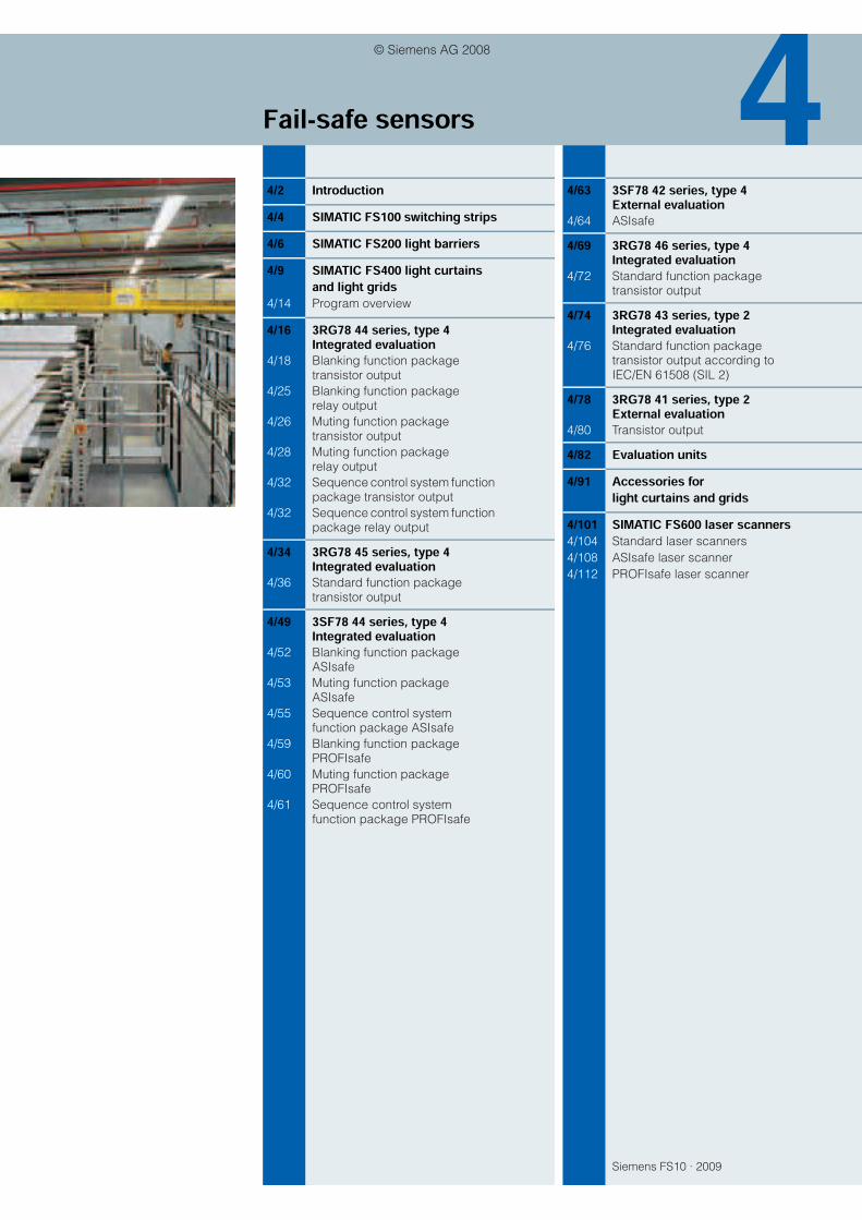
Fail-safe sensors
© Siemens AG 2008

Fail-safe sensorsIntroduction
4/2 Siemens FS 10 · 2009
4
Fail-safe sensors – For all-round protection of persons and machinesFor the protection of persons and machines in the industrial en-vironment, maximum process reliability is paramount. Not simply to prevent adverse events but also to achieve the greatest pos-sible plant availability for maximum efficiency. A clear case for our optical safety sensors. They ensure safe and reliable protec-tion for persons, machines and systems. They are, of course, in-tegrated into our uniform safety concept Safety Integrated.
Requirements for categories according to EN 954-1
Highlights• Laser scanners, light barriers, light curtains and light
grids for contact-free guarding of danger areas
• Safe all-round protection for persons and systems in stationary and mobile applications
• Wear-free and maintenance-free technology for maximum availability
• Freedom in machine design, without the need for mechanical safety gates
• Component of the complete Siemens Safety Integrated product range
Category1) Summary of requirements System response2) Principles for achieving safetyB The safety-relevant components of controls
and/or their protective equipment and com-ponents must be designed, constructed, selected, assembled and combined in com-pliance with all applicable standards such as to be capable of withstanding all potentially hazardous influences.
The occurrence of a fault can result in loss of the safety function.
Mainly characterized by the selection of components
1 The requirements of Category B must be met. Well-proven components and well-proven safety principles must be implemented.
The occurrence of a fault can result in loss of the safety function but the probability of it occurring is less than for Category B.
2 The requirements of Category B must be met and well-proven safety principles must be implemented. The safety functions must be tested at regular intervals by the machine control.
The occurrence of a fault can result in loss of the safety function between tests.
The loss of safety functionality is detected in the course of testing.
Mainly characterized by the structure
3 The requirements of Category B must be met and well-proven safety principles must be implemented. Parts with relevance for safety must be implemented such that:
• A single fault in any of these components does not result in loss of the safety function.
• If it can be implemented in an appropriate way, individual faults/errors can be detected.
If the single fault/error occurs, the safety func-tion always remains operational.
• Some but not all faults are detected.
• An accumulation of undetected faults may lead to loss of the safety function.
4 The requirements of Category B must be met and well-proven safety principles must be implemented. Parts with relevance for safety must be implemented such that:
• A single fault in any of these components does not result in loss of the safety function.
• The individual fault is detected during or be-fore the next activation of the safety function or, if this is not possible, an accumulation of faults will not result in loss of the safety func-tion.
When faults occur, the safety function is always maintained.
• Faults are detected early to prevent loss of the safety function.
1) The categories are not intended to be applied in a specific sequence or hierarchy with reference to the safety requirements.
2) The risk assessment will establish whether complete or partial loss of the safety function(s) due to faults is acceptable.
© Siemens AG 2008

Fail-safe sensorsIntroduction
4/3Siemens FS 10 · 2009
4
SIMATIC FS100 switching stripsFinger-traps are a danger on many machines and other tech-nical installations. In these situations, the simplest protection is implemented with rubber switching strips that on the one hand halt the dangerous motion in a fail-safe state and on the other hand act as a buffer to prevent injury.
The edge of the rubber strip (signal encoder) is monitored optically by means of a fail-safe send/receive sensor that is inserted into the strip from the outside. This means that any length can be used, cut to length as required by the customer.
SIMATIC FS200 light barriersWhen space is at a premium, contact-free light barriers are the ideal solution for access protection to danger zones, danger points or entry points. Designed to the degree of protection IP65, they have a range of up to 150 m in Category 2. The light barriers of Category 4 with a range of up to 60 m feature frequency modulated infrared light and integral pollu-tion monitoring. Additional evaluation units support start/restart inhibiting, contactor control and muting functions.
SIMATIC FS400 light curtains and light gridsThe contact-free, active optoelectronic light curtains and light grids for Category 2 and 4 according to EN 954-1 protect operating personnel at running machines or plants or in their vicinity. Thanks to specially developed integrated circuits (ASICs) and a patented, intelligent evaluation technique, they are extremely fault-tolerant and highly available. A wide range of different functions including start/restart inhibiting, contactor control, muting, cycle control and blanking support a wide range of different applications such as finger and hand protec-tion, horizontal danger zone protection or access protection to large areas. Versions for connection to ASIsafe and PROFIsafe are available.
A light curtain or light grid comprises an emitter and a receiver, which must be mounted opposite each other. Depending on the resolution and the length, a certain number of transmit and receive diodes are arranged on top of each other. The infrared LEDs of the emitter emit short light pulses that are detected by the receive diodes.
SIMATIC FS600 laser scannerThe laser scanner is an optical distance sensor for flexible guarding of danger zones. By emitting harmless laser pulses and subsequently evaluating the reflections, the scanner de-tects persons and objects and responds in accordance to the programmed protected fields.
© Siemens AG 2008
SIMATIC FS100 switching strips
Switching strips Category 4
4/4 Siemens FS 10 · 2009
4
n Overview
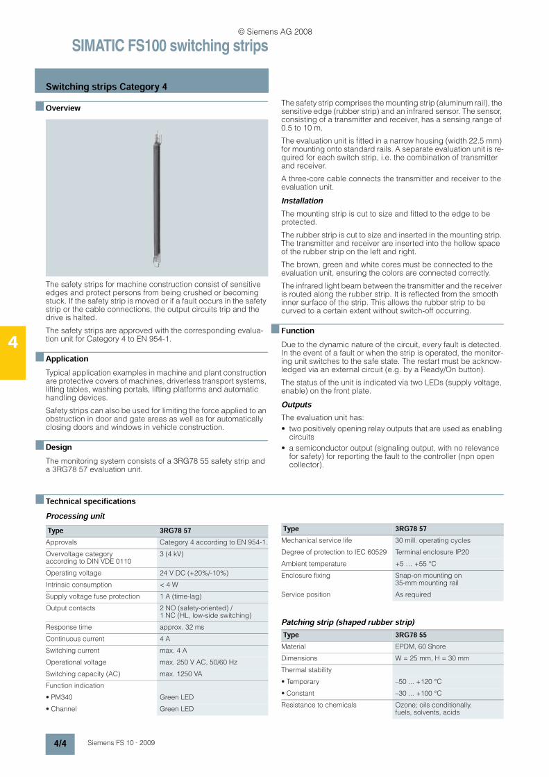
The safety strips for machine construction consist of sensitive edges and protect persons from being crushed or becoming stuck. If the safety strip is moved or if a fault occurs in the safety strip or the cable connections, the output circuits trip and the drive is halted.
The safety strips are approved with the corresponding evalua-tion unit for Category 4 to EN 954-1.
n ApplicationTypical application examples in machine and plant construction are protective covers of machines, driverless transport systems, lifting tables, washing portals, lifting platforms and automatic handling devices.
Safety strips can also be used for limiting the force applied to an obstruction in door and gate areas as well as for automatically closing doors and windows in vehicle construction.
n DesignThe monitoring system consists of a 3RG78 55 safety strip and a 3RG78 57 evaluation unit.
The safety strip comprises the mounting strip (aluminum rail), the sensitive edge (rubber strip) and an infrared sensor. The sensor, consisting of a transmitter and receiver, has a sensing range of 0.5 to 10 m.
The evaluation unit is fitted in a narrow housing (width 22.5 mm) for mounting onto standard rails. A separate evaluation unit is re-quired for each switch strip, i.e. the combination of transmitter and receiver.
A three-core cable connects the transmitter and receiver to the evaluation unit.
InstallationThe mounting strip is cut to size and fitted to the edge to be protected.
The rubber strip is cut to size and inserted in the mounting strip. The transmitter and receiver are inserted into the hollow space of the rubber strip on the left and right.
The brown, green and white cores must be connected to the evaluation unit, ensuring the colors are connected correctly.
The infrared light beam between the transmitter and the receiver is routed along the rubber strip. It is reflected from the smooth inner surface of the strip. This allows the rubber strip to be curved to a certain extent without switch-off occurring.
n FunctionDue to the dynamic nature of the circuit, every fault is detected. In the event of a fault or when the strip is operated, the monitor-ing unit switches to the safe state. The restart must be acknow-ledged via an external circuit (e.g. by a Ready/On button).
The status of the unit is indicated via two LEDs (supply voltage, enable) on the front plate.
OutputsThe evaluation unit has:
• two positively opening relay outputs that are used as enabling circuits
• a semiconductor output (signaling output, with no relevance for safety) for reporting the fault to the controller (npn open collector).
n Technical specificationsProcessing unit
Patching strip (shaped rubber strip)
Type 3RG78 57Approvals Category 4 according to EN 954-1.
Overvoltage category according to DIN VDE 0110
3 (4 kV)
Operating voltage 24 V DC (+20%/-10%)
Intrinsic consumption < 4 W
Supply voltage fuse protection 1 A (time-lag)
Output contacts 2 NO (safety-oriented) / 1 NC (HL, low-side switching)
Response time approx. 32 ms
Continuous current 4 A
Switching current max. 4 A
Operational voltage max. 250 V AC, 50/60 Hz
Switching capacity (AC) max. 1250 VA
Function indication
• PM340 Green LED
• Channel Green LED
Mechanical service life 30 mill. operating cycles
Degree of protection to IEC 60529 Terminal enclosure IP20
Ambient temperature +5 … +55 °C
Enclosure fixing Snap-on mounting on 35-mm mounting rail
Service position As required
Type 3RG78 55Material EPDM, 60 Shore
Dimensions W = 25 mm, H = 30 mm
Thermal stability
• Temporary –50 ... +120 °C
• Constant –30 ... +100 °C
Resistance to chemicals Ozone; oils conditionally, fuels, solvents, acids
Type 3RG78 57
© Siemens AG 2008
SIMATIC FS100 switching strips
Switching strips Category 4
4/5Siemens FS 10 · 2009
4
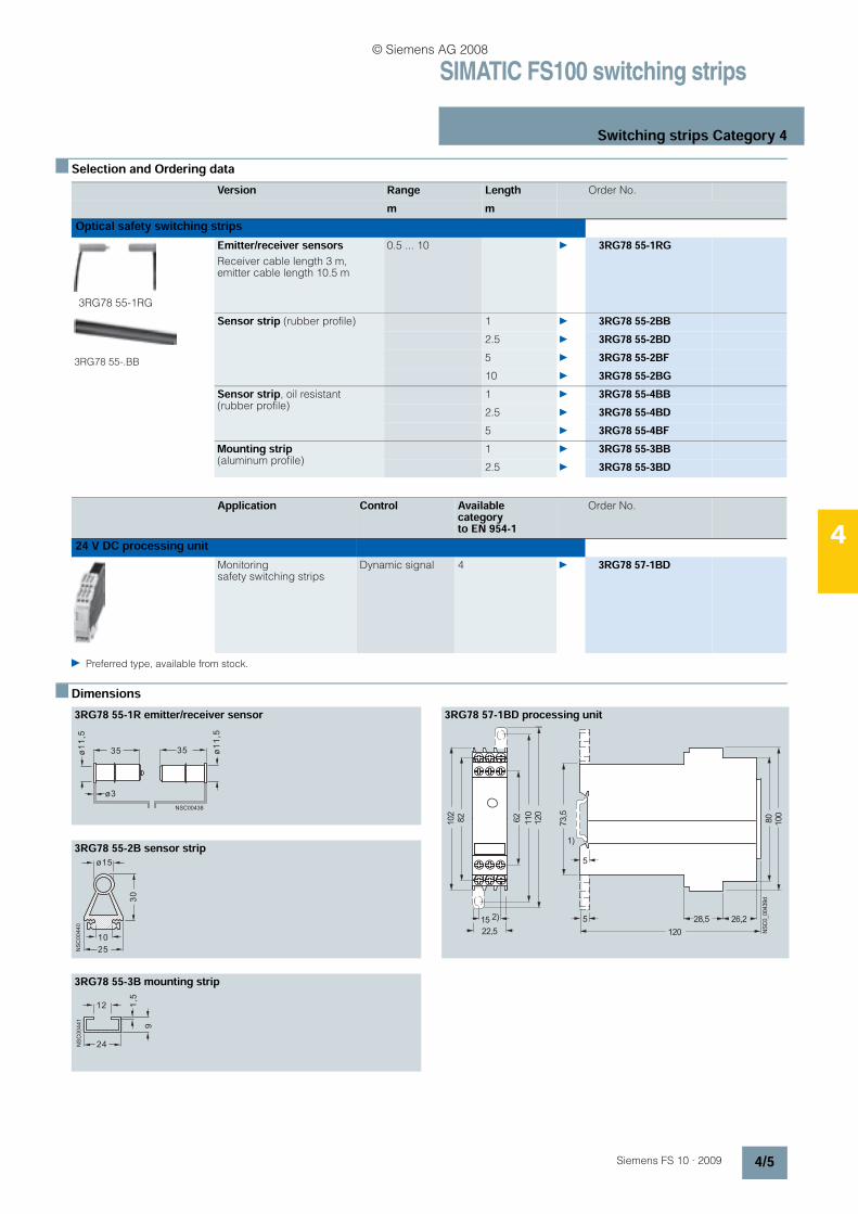
n Selection and Ordering data
Preferred type, available from stock.
n Dimensions
Version Range Length Order No.
m m
3RG78 55-1RG
Emitter/receiver sensors Receiver cable length 3 m, emitter cable length 10.5 m
0.5 ... 10 3RG78 55-1RG
3RG78 55-.BB
Sensor strip (rubber profile) 1 3RG78 55-2BB2.5 3RG78 55-2BD5 3RG78 55-2BF10 3RG78 55-2BG
Sensor strip, oil resistant (rubber profile)
1 3RG78 55-4BB2.5 3RG78 55-4BD5 3RG78 55-4BF
Mounting strip (aluminum profile)
1 3RG78 55-3BB2.5 3RG78 55-3BD
Application Control Available category to EN 954-1
Order No.
Monitoring safety switching strips
Dynamic signal 4 3RG78 57-1BD
3RG78 55-1R emitter/receiver sensor 3RG78 57-1BD processing unit
3RG78 55-2B sensor strip
3RG78 55-3B mounting strip
NSC00438
ø3
ø1
1,5
35 35 ø1
1,5
80
73,5
NS
C0_00439d
100
62
110
15
22,5
26,228,5
120
120
82
102
1)
5
52)
NS
C0
04
40
ø15
30
10
25
1,5
24
12
NS
C0
04
41
9
Optical safety switching strips
24 V DC processing unit
© Siemens AG 2008
SIMATIC FS200 light barriers
Light barriers Category 2 with evaluation unit,Light barriers Category 4
4/6 Siemens FS 10 · 2009
4
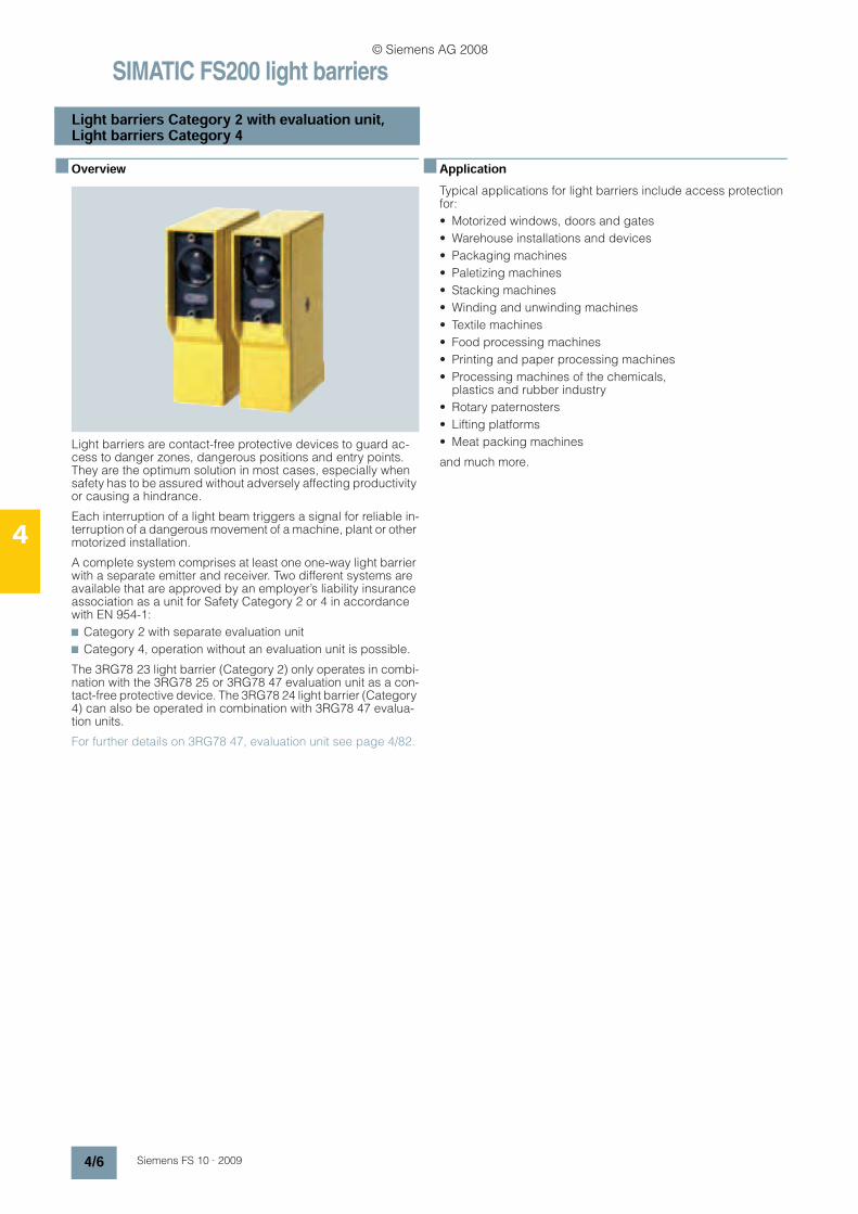
n Overview
Light barriers are contact-free protective devices to guard ac-cess to danger zones, dangerous positions and entry points. They are the optimum solution in most cases, especially when safety has to be assured without adversely affecting productivity or causing a hindrance.
Each interruption of a light beam triggers a signal for reliable in-terruption of a dangerous movement of a machine, plant or other motorized installation.
A complete system comprises at least one one-way light barrier with a separate emitter and receiver. Two different systems are available that are approved by an employer’s liability insurance association as a unit for Safety Category 2 or 4 in accordance with EN 954-1:
7 Category 2 with separate evaluation unit
7 Category 4, operation without an evaluation unit is possible.
The 3RG78 23 light barrier (Category 2) only operates in combi-nation with the 3RG78 25 or 3RG78 47 evaluation unit as a con-tact-free protective device. The 3RG78 24 light barrier (Category 4) can also be operated in combination with 3RG78 47 evalua-tion units.
For further details on 3RG78 47, evaluation unit see page 4/82.
n ApplicationTypical applications for light barriers include access protection for:
• Motorized windows, doors and gates
• Warehouse installations and devices
• Packaging machines
• Paletizing machines
• Stacking machines
• Winding and unwinding machines
• Textile machines
• Food processing machines
• Printing and paper processing machines
• Processing machines of the chemicals, plastics and rubber industry
• Rotary paternosters
• Lifting platforms
• Meat packing machines
and much more.
© Siemens AG 2008
SIMATIC FS200 light barriers
Light barriers Category 2 with evaluation unit,Light barriers Category 4
4/7Siemens FS 10 · 2009
4
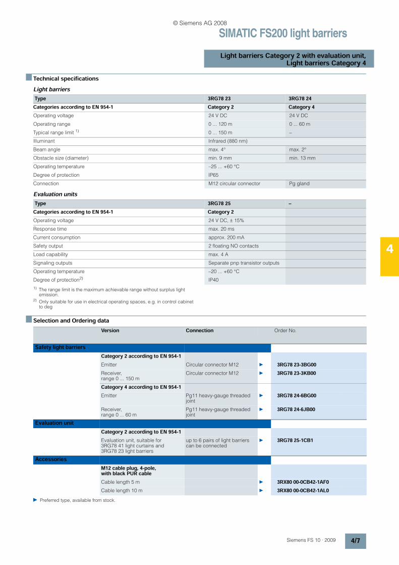
n Technical specificationsLight barriers
Evaluation units
1) The range limit is the maximum achievable range without surplus light emission.
2) Only suitable for use in electrical operating spaces, e.g. in control cabinet to deg
n Selection and Ordering data
Preferred type, available from stock.
Type 3RG78 23 3RG78 24Categories according to EN 954-1 Category 2 Category 4Operating voltage 24 V DC 24 V DC
Operating range 0 ... 120 m 0 ... 60 m
Typical range limit 1) 0 ... 150 m –
Illuminant Infrared (880 nm)
Beam angle max. 4° max. 2°
Obstacle size (diameter) min. 9 mm min. 13 mm
Operating temperature –25 ... +60 °C
Degree of protection IP65
Connection M12 circular connector Pg gland
Type 3RG78 25 –Categories according to EN 954-1 Category 2Operating voltage 24 V DC, ± 15%
Response time max. 20 ms
Current consumption approx. 200 mA
Safety output 2 floating NO contacts
Load capability max. 4 A
Signaling outputs Separate pnp transistor outputs
Operating temperature –20 ... +60 °C
Degree of protection2) IP40
Version Connection Order No.
Category 2 according to EN 954-1Emitter Circular connector M12 3RG78 23-3BG00Receiver, range 0 ... 150 m
Circular connector M12 3RG78 23-3KB00
Category 4 according to EN 954-1Emitter Pg11 heavy-gauge threaded
joint 3RG78 24-6BG00
Receiver, range 0 ... 60 m
Pg11 heavy-gauge threaded joint
3RG78 24-6JB00
Category 2 according to EN 954-1Evaluation unit, suitable for 3RG78 41 light curtains and 3RG78 23 light barriers
up to 6 pairs of light barriers can be connected
3RG78 25-1CB1
M12 cable plug, 4-pole, with black PUR cableCable length 5 m 3RX80 00-0CB42-1AF0Cable length 10 m 3RX80 00-0CB42-1AL0
Safety light barriers
Evaluation unit
Accessories
© Siemens AG 2008

SIMATIC FS200 light barriers
Light barriers Category 2 with evaluation unit,Light barriers Category 4
4/8 Siemens FS 10 · 2009
4
n Dimensions3RG78 23 light barrier 3RG78 24 light barrier
3RG78 25 evaluation unit
127
100
3899
b
8468 9
30.5
113
NS
C0_00641
7
a
c d
M 12 × 1
a
b
c
d
= Device mounting M 6 × 12
= Device mounting M 6 × 9
= Device mounting M 6 × 9
= LED
127
100
3899
ca. 153
8468 925 30.5
11
3
PG 11
NS
C0_00642
7
a
b c d
a
b
c
d
= Device mounting M 6 × 12
= Device mounting M 6 × 9
= Device mounting M 6 × 12
= LED
99,2
4 5 , 4 1 1 1NSC0_00643
© Siemens AG 2008
SIMATIC FS400 light curtains and light grids
Introduction
4/9Siemens FS 10 · 2009
4
n Overview
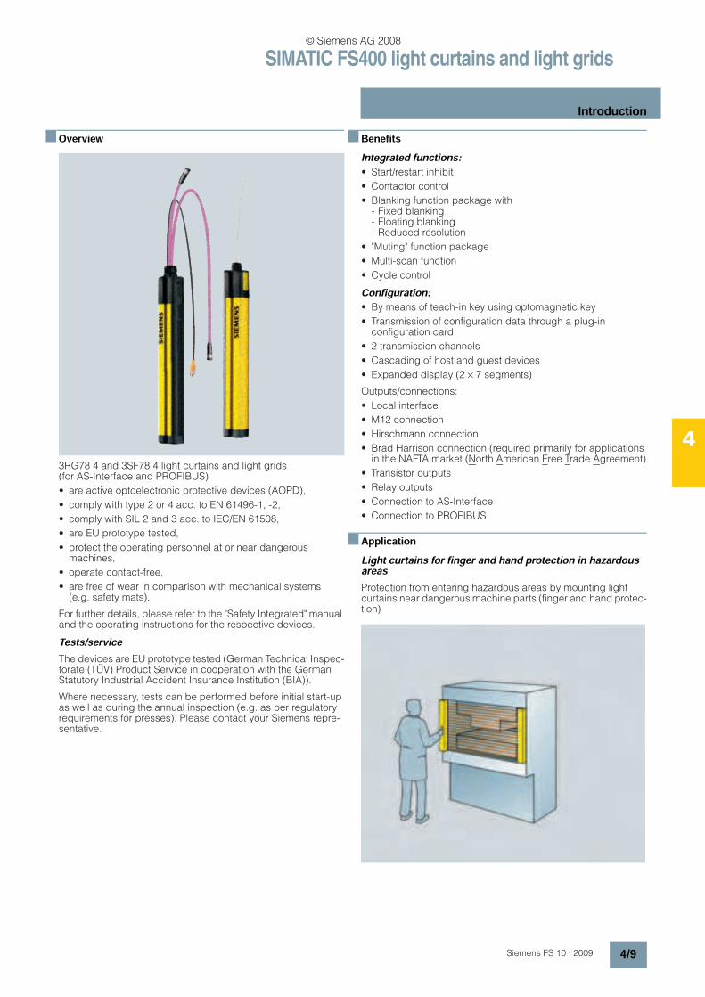
3RG78 4 and 3SF78 4 light curtains and light grids (for AS-Interface and PROFIBUS)
• are active optoelectronic protective devices (AOPD),
• comply with type 2 or 4 acc. to EN 61496-1, -2,
• comply with SIL 2 and 3 acc. to IEC/EN 61508,
• are EU prototype tested,
• protect the operating personnel at or near dangerous machines,
• operate contact-free,
• are free of wear in comparison with mechanical systems (e.g. safety mats).
For further details, please refer to the "Safety Integrated" manual and the operating instructions for the respective devices.
Tests/serviceThe devices are EU prototype tested (German Technical Inspec-torate (TÜV) Product Service in cooperation with the German Statutory Industrial Accident Insurance Institution (BIA)).
Where necessary, tests can be performed before initial start-up as well as during the annual inspection (e.g. as per regulatory requirements for presses). Please contact your Siemens repre-sentative.
n BenefitsIntegrated functions:• Start/restart inhibit
• Contactor control
• Blanking function package with - Fixed blanking- Floating blanking- Reduced resolution
• "Muting" function package
• Multi-scan function
• Cycle control
Configuration:• By means of teach-in key using optomagnetic key
• Transmission of configuration data through a plug-in configuration card
• 2 transmission channels
• Cascading of host and guest devices
• Expanded display (2 × 7 segments)
Outputs/connections:
• Local interface
• M12 connection
• Hirschmann connection
• Brad Harrison connection (required primarily for applications in the NAFTA market (North American Free Trade Agreement)
• Transistor outputs
• Relay outputs
• Connection to AS-Interface
• Connection to PROFIBUS
n ApplicationLight curtains for finger and hand protection in hazardous areasProtection from entering hazardous areas by mounting light curtains near dangerous machine parts (finger and hand protec-tion)
© Siemens AG 2008

SIMATIC FS400 light curtains and light grids
Introduction
4/10 Siemens FS 10 · 2009
4
Device selection
Light curtains for category 2 or 4, with 14, 20, 30 and 40 mm resolution
Application areas
E.g. presses, punches, filter presses, cutting machines
Light curtains to secure horizontal hazardous areas near the floorReliable detection of persons in hazardous areas by mounting the light curtain near the floor (not possible to crawl under)
Device selection
Light curtains for category 2 or 4, with 50 and 55 mm resolution
Application areas
E.g. welding and assembly lines and robots in the automotive industry
Light curtains to secure horizontal hazardous areasReliable detection of persons in hazardous areas by mounting the light curtain at heights of 0.6 to 1 m
Device selection
Light curtains for category 2 or 4, with 80 and 90 mm resolution
Application areas
E.g. welding and assembly lines and robots in the automotive industry
Light grids for securing access pointsReliable detection of persons when they enter hazardous areas
Device selection
2-beam, 3-beam or 4-beam light grids for category 4, with 18 m range
Application areas
Securing access points, e.g. to robots or handling machines.
Light grids to protect access to large areasReliable detection of persons when they enter hazardous areas
Securing larger hazardous areas with high ranges of 60 m and 70 m.
Device selection
2-beam, 3-beam or 4-beam light grids for category 4, with 60 m and 70 m ranges.
Application areas
Securing access points, e.g. to automatic processing centers or palleting machines.
Safety categoriesDepending on the safety category requirement to EN 954-1 that results from the C standard and/or the machine or system risk analysis, light curtains or grids up to type 2 or 4 can be used (definition of safety categories: see page 4/2).
n DesignA light curtain or light grid comprises an emitter and a receiver, which must be mounted opposite each other. Depending on the resolution and the length, a certain number of transmit and re-ceive diodes are arranged on top of each other. The infrared LEDs of the emitter emit short light pulses that are detected by the receive diodes.
Cascading of host and guest devices for greater protection field heights or lengths or for an angular arrangement (as an option).
• 3RG78 44 and 3SF78 44 light curtains and grids with inte-grated evaluation for Type 4 according to IEC/EN 61496 or SIL 3 to IEC 61508 - Resolution 14, 30, 50 and 90 mm- Protection field height: 150 mm to 3000 mm- 2-beam, 3-beam or 4-beam light grids- Transceiver, 2-beam with deflection mirror- Cascading of host and guest devices for greater protection
field heights or lengths or for an angular arrangement (as an option).
• 3RG78 45 light curtains and grids with integrated evaluation for Type 4 to IEC/EN 61496 - Resolution 14, 30, 50 and 90 mm- Protection field height: 150 mm to 3000 mm- Transceiver, 2-beam with reflective mirror- 2, 3, or 4-beam light grids- Cascading of host and guest devices for greater protection
field heights or lengths or for an angular arrangement (as an option).
• 3RG78 41 light curtains for external evaluation for Type 2 to IEC/EN 61496 - Resolution: 30, 55, and 80 mm- Protection field height: 150 mm to 1800 mm- Cascading of host and guest devices for greater protection
field heights or lengths or for an angular arrangement (as an option).
© Siemens AG 2008
SIMATIC FS400 light curtains and light grids
Introduction
4/11Siemens FS 10 · 2009
4
• 3RG78 43 light curtains with integrated evaluation for Type 2 according to IEC/EN 61496, developed according to EN 61508 (SIL 2), suited for risk assessment according to pr EN ISO 13849-1 - Resolution 20, 30, 40 and 90 mm- Protection field heights from 150 mm to 1800 mm
• 3RG78 46 light curtains with integrated evaluation for Type 4 to IEC/EN 61496 - Resolution 14, 20, 30, 40 and 90 mm- Protection field heights from 150 mm to 1800 mm
• 3RG78 42 light curtains and grids with external evaluation for Type 4 to IEC/EN 61496 - Resolution 14, 30, 50 and 90 mm- Protection field heights from 150 mm to 3000 mm- Transceiver, 2-beam with reflective mirror- 2-beam, 3-beam or 4-beam light grids- Connection to actuator sensor interface- Cascading of host and guest devices for greater protection
field heights or lengths or for an angular arrangement (as an option).
Standards• IEC/EN 61496-1, -2 (requirements for non-contact protection
systems)
• EN 999 (including calculation of safety clearances)
• EN 954-1 (machine safety, safety-related parts of control systems)
• EN 61508 (functional safety of electrical/electronic/program-mable electronic safety-related systems)
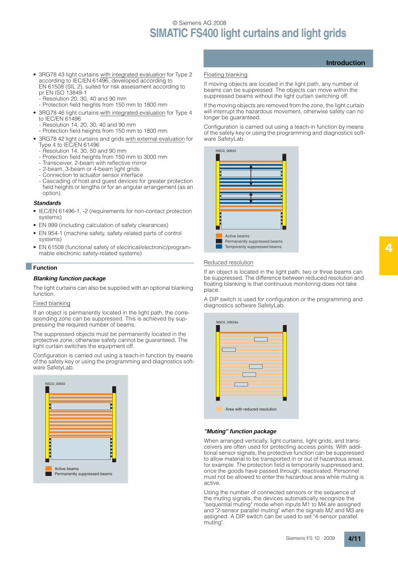
n FunctionBlanking function packageThe light curtains can also be supplied with an optional blanking function.
Fixed blanking
If an object is permanently located in the light path, the corre-sponding zone can be suppressed. This is achieved by sup-pressing the required number of beams.
The suppressed objects must be permanently located in the protective zone, otherwise safety cannot be guaranteed. The light curtain switches the equipment off.
Configuration is carried out using a teach-in function by means of the safety key or using the programming and diagnostics soft-ware SafetyLab.
Floating blanking
If moving objects are located in the light path, any number of beams can be suppressed. The objects can move within the suppressed beams without the light curtain switching off.
If the moving objects are removed from the zone, the light curtain will interrupt the hazardous movement, otherwise safety can no longer be guaranteed.
Configuration is carried out using a teach-in function by means of the safety key or using the programming and diagnostics soft-ware SafetyLab.
Reduced resolution
If an object is located in the light path, two or three beams can be suppressed. The difference between reduced resolution and floating blanking is that continuous monitoring does not take place.
A DIP switch is used for configuration or the programming and diagnostics software SafetyLab.
"Muting" function packageWhen arranged vertically, light curtains, light grids, and trans-ceivers are often used for protecting access points. With addi-tional sensor signals, the protective function can be suppressed to allow material to be transported in or out of hazardous areas, for example. The protection field is temporarily suppressed and, once the goods have passed through, reactivated. Personnel must not be allowed to enter the hazardous area while muting is active.
Using the number of connected sensors or the sequence of the muting signals, the devices automatically recognize the "sequential muting" mode when inputs M1 to M4 are assigned and "2-sensor parallel muting" when the signals M2 and M3 are assigned. A DIP switch can be used to set "4-sensor parallel muting".
NSC0_00632
Active beams
Permanently suppressed beams
NSC0_00633
Active beams
Permanently suppressed beams
Temporarily suppressed beams
NSC0_00634a
Area with reduced resolution
© Siemens AG 2008

SIMATIC FS400 light curtains and light grids
Introduction
4/12 Siemens FS 10 · 2009
4
Muting restart
If the power fails while goods are passing the muting sensors, for example, the valid muting sequence is interrupted. When the power supply has been restored, muting is not automatically resumed because the muting sequence is not as expected.
To remove the goods from the area covered by the muting sen-sors, an integrated retraction mode can be activated using the start key. The light curtain attempts to find a valid muting sequence from the muting sensors. If successful, the muting indicator lamp stops flashing and is lit continuously. If unsuc-cessful, the start key must be kept depressed until the muting path is completely free.
4-sensor sequential muting
If the material that is to be transported in the danger zone always has the same dimensions and there is no lack of space, the use of sequential muting is preferred. With sequential muting, four muting sensors are connected. These must be activated in a predefined sequence to trigger muting. They can be activated in either of the following sequences: M1, M2, M3, M4 or M4, M3, M2, M1. The transported goods must be of sufficient length to briefly activate all 4 sensors simultaneously. Sequential muting is successfully completed when the third muting sensor to be activated is not activated any longer.
The SafetyLab software can be used to select a muting variant in which the second muting sequence is triggered before the first has finished (sequential muting with two objects). This variant saves time and, in turn, production costs for the user.
2-sensor parallel muting
Parallel muting is ideal in plants in which the dimensions of the goods are not constant or space requirements must be kept to a minimum. Two muting sensors can be used, whose beams inter-sect behind the protection field in the danger zone.
Parallel muting is used when signals M2 and M3 are switched simultaneously without M1 and M4 having been activated or connected beforehand or simultaneously. Two-sensor parallel muting is straightforward because only two muting sensors are required. Goods can also be moved forward and backward within the muting area.
3-sensor direction muting
Three-sensor direction muting is configured in a similar way to 2-sensor parallel muting. Material can only be transported through the light curtain in one direction. To trigger the muting function, muting sensor M1 must first be activated, followed by muting sensors M2 and M3. If the paths for muting sensors M2 and M3 are interrupted, sensor M1 does not need to be activated.
Parallel muting with 4 sensors
4-sensor parallel muting can be used advantageously wherever
• the transported material is too small to be acquired simulta-neously by 4 sensors arranged sequentially,
• the available space is too small even for the crossover light beams of 2-sensor parallel muting.
The function of 4-sensor parallel muting corresponds to that of 2-sensor parallel muting with the additional characteristic of the muting activation signal being obtained from two sensor pairs. Muting is triggered when within a 2.5 s interval, M2 is activated with M3 or M1 is activated with M4.
Start
M1 M2 M3 M4
Danger ZoneEEEE
S S S S
E
S
Start
M2
M3
Danger zone
E
S
Start
M2
M3
E
S
M1
E
S
Danger zone
© Siemens AG 2008
SIMATIC FS400 light curtains and light grids
Introduction
4/13Siemens FS 10 · 2009
4
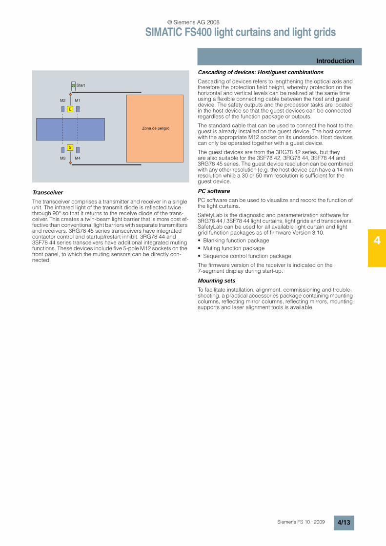
TransceiverThe transceiver comprises a transmitter and receiver in a single unit. The infrared light of the transmit diode is reflected twice through 90° so that it returns to the receive diode of the trans-ceiver. This creates a twin-beam light barrier that is more cost ef-fective than conventional light barriers with separate transmitters and receivers. 3RG78 45 series transceivers have integrated contactor control and startup/restart inhibit. 3RG78 44 and 3SF78 44 series transceivers have additional integrated muting functions. These devices include five 5-pole M12 sockets on the front panel, to which the muting sensors can be directly con-nected.
Cascading of devices: Host/guest combinationsCascading of devices refers to lengthening the optical axis and therefore the protection field height, whereby protection on the horizontal and vertical levels can be realized at the same time using a flexible connecting cable between the host and guest device. The safety outputs and the processor tasks are located in the host device so that the guest devices can be connected regardless of the function package or outputs.
The standard cable that can be used to connect the host to the guest is already installed on the guest device. The host comes with the appropriate M12 socket on its underside. Host devices can only be operated together with a guest device.
The guest devices are from the 3RG78 42 series, but they are also suitable for the 3SF78 42, 3RG78 44, 3SF78 44 and 3RG78 45 series. The guest device resolution can be combined with any other resolution (e.g. the host device can have a 14 mm resolution while a 30 or 50 mm resolution is sufficient for the guest device.
PC softwarePC software can be used to visualize and record the function of the light curtains.
SafetyLab is the diagnostic and parameterization software for 3RG78 44 / 3SF78 44 light curtains, light grids and transceivers. SafetyLab can be used for all available light curtain and light grid function packages as of firmware Version 3.10:
• Blanking function package
• Muting function package
• Sequence control function package
The firmware version of the receiver is indicated on the 7-segment display during start-up.
Mounting setsTo facilitate installation, alignment, commissioning and trouble-shooting, a practical accessories package containing mounting columns, reflecting mirror columns, reflecting mirrors, mounting supports and laser alignment tools is available.
Start
M1
M3
E
S
M4
M2
Zona de peligro
© Siemens AG 2008
SIMATIC FS400 light curtains and light grids
Program overview
4/14 Siemens FS 10 · 2009
4
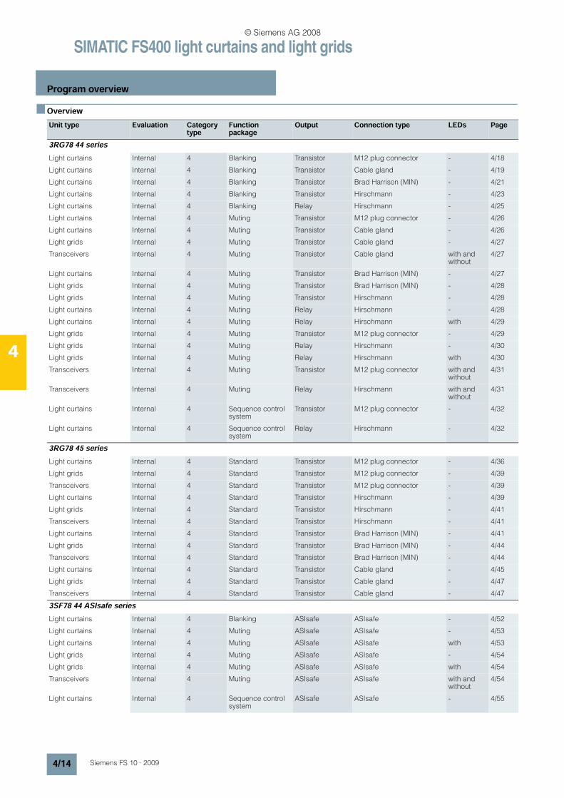
n OverviewUnit type Evaluation Category
typeFunctionpackage
Output Connection type LEDs Page
3RG78 44 seriesLight curtains Internal 4 Blanking Transistor M12 plug connector - 4/18
Light curtains Internal 4 Blanking Transistor Cable gland - 4/19
Light curtains Internal 4 Blanking Transistor Brad Harrison (MIN) - 4/21
Light curtains Internal 4 Blanking Transistor Hirschmann - 4/23
Light curtains Internal 4 Blanking Relay Hirschmann - 4/25
Light curtains Internal 4 Muting Transistor M12 plug connector - 4/26
Light curtains Internal 4 Muting Transistor Cable gland - 4/26
Light grids Internal 4 Muting Transistor Cable gland - 4/27
Transceivers Internal 4 Muting Transistor Cable gland with and without
4/27
Light curtains Internal 4 Muting Transistor Brad Harrison (MIN) - 4/27
Light grids Internal 4 Muting Transistor Brad Harrison (MIN) - 4/28
Light grids Internal 4 Muting Transistor Hirschmann - 4/28
Light curtains Internal 4 Muting Relay Hirschmann - 4/28
Light curtains Internal 4 Muting Relay Hirschmann with 4/29
Light grids Internal 4 Muting Transistor M12 plug connector - 4/29
Light grids Internal 4 Muting Relay Hirschmann - 4/30
Light grids Internal 4 Muting Relay Hirschmann with 4/30
Transceivers Internal 4 Muting Transistor M12 plug connector with and without
4/31
Transceivers Internal 4 Muting Relay Hirschmann with and without
4/31
Light curtains Internal 4 Sequence control system
Transistor M12 plug connector - 4/32
Light curtains Internal 4 Sequence control system
Relay Hirschmann - 4/32
3RG78 45 seriesLight curtains Internal 4 Standard Transistor M12 plug connector - 4/36
Light grids Internal 4 Standard Transistor M12 plug connector - 4/39
Transceivers Internal 4 Standard Transistor M12 plug connector - 4/39
Light curtains Internal 4 Standard Transistor Hirschmann - 4/39
Light grids Internal 4 Standard Transistor Hirschmann - 4/41
Transceivers Internal 4 Standard Transistor Hirschmann - 4/41
Light curtains Internal 4 Standard Transistor Brad Harrison (MIN) - 4/41
Light grids Internal 4 Standard Transistor Brad Harrison (MIN) - 4/44
Transceivers Internal 4 Standard Transistor Brad Harrison (MIN) - 4/44
Light curtains Internal 4 Standard Transistor Cable gland - 4/45
Light grids Internal 4 Standard Transistor Cable gland - 4/47
Transceivers Internal 4 Standard Transistor Cable gland - 4/47
3SF78 44 ASIsafe seriesLight curtains Internal 4 Blanking ASIsafe ASIsafe - 4/52
Light curtains Internal 4 Muting ASIsafe ASIsafe - 4/53
Light curtains Internal 4 Muting ASIsafe ASIsafe with 4/53
Light grids Internal 4 Muting ASIsafe ASIsafe - 4/54
Light grids Internal 4 Muting ASIsafe ASIsafe with 4/54
Transceivers Internal 4 Muting ASIsafe ASIsafe with and without
4/54
Light curtains Internal 4 Sequence control system
ASIsafe ASIsafe - 4/55
© Siemens AG 2008
SIMATIC FS400 light curtains and light grids
Program overview
4/15Siemens FS 10 · 2009
4
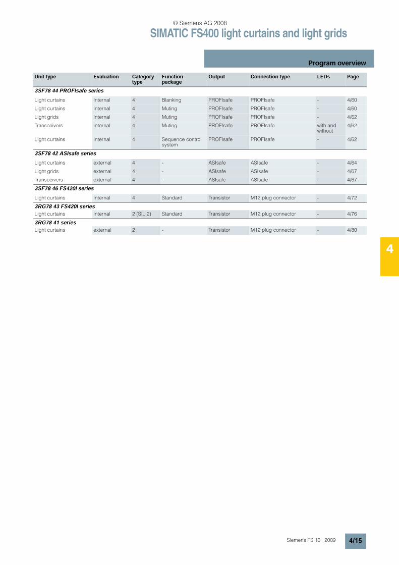
3SF78 44 PROFIsafe seriesLight curtains Internal 4 Blanking PROFIsafe PROFIsafe - 4/60
Light curtains Internal 4 Muting PROFIsafe PROFIsafe - 4/60
Light grids Internal 4 Muting PROFIsafe PROFIsafe - 4/62
Transceivers Internal 4 Muting PROFIsafe PROFIsafe with and without
4/62
Light curtains Internal 4 Sequence control system
PROFIsafe PROFIsafe - 4/62
3SF78 42 ASIsafe seriesLight curtains external 4 - ASIsafe ASIsafe - 4/64
Light grids external 4 - ASIsafe ASIsafe - 4/67
Transceivers external 4 - ASIsafe ASIsafe - 4/67
3SF78 46 FS420I seriesLight curtains Internal 4 Standard Transistor M12 plug connector - 4/72
3RG78 43 FS420I seriesLight curtains Internal 2 (SIL 2) Standard Transistor M12 plug connector - 4/76
3RG78 41 seriesLight curtains external 2 - Transistor M12 plug connector - 4/80
Unit type Evaluation Category type
Functionpackage
Output Connection type LEDs Page
© Siemens AG 2008
SIMATIC FS400 light curtains and light grids3RG78 44 series, type 4
Integrated evaluation
4/16 Siemens FS 10 · 2009
4
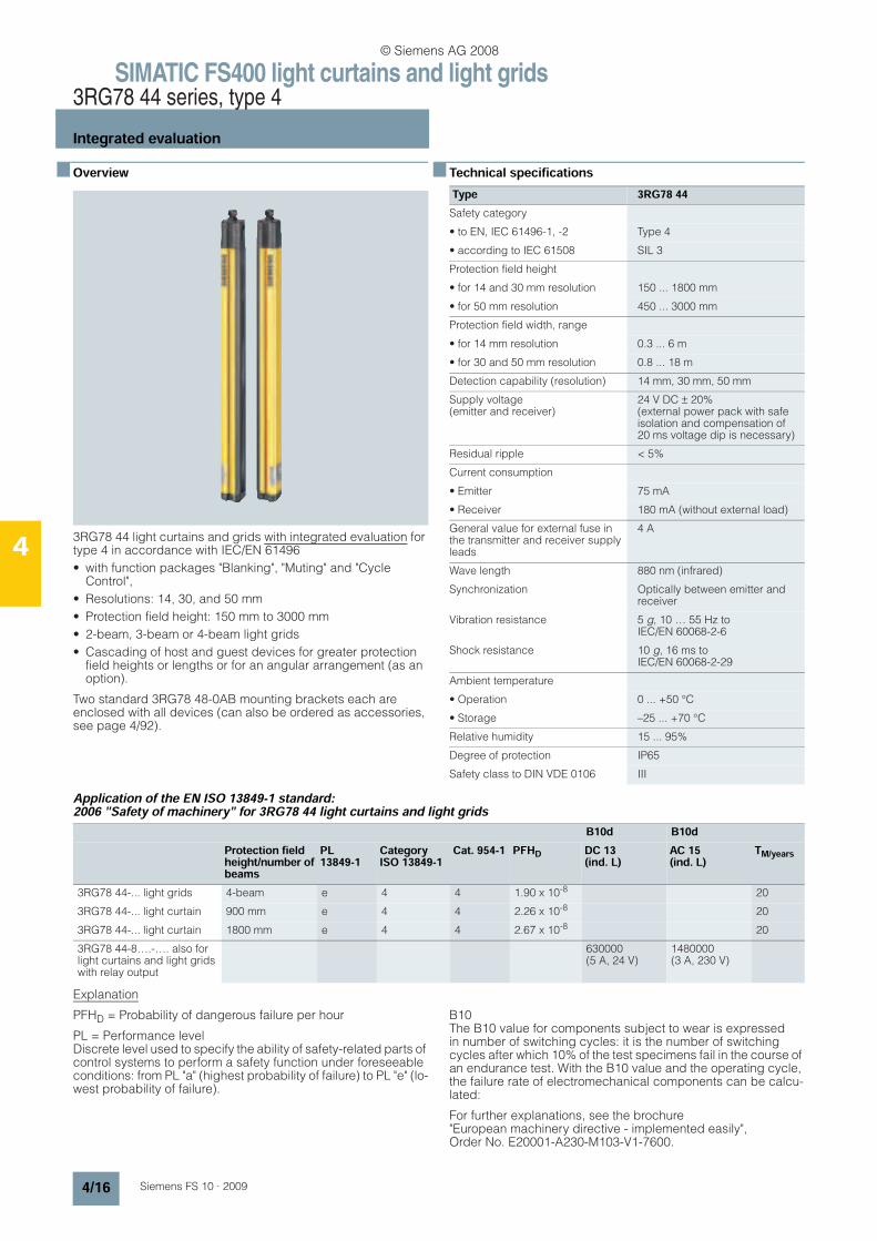
n Overview
3RG78 44 light curtains and grids with integrated evaluation for type 4 in accordance with IEC/EN 61496
• with function packages "Blanking", "Muting" and "Cycle Control",
• Resolutions: 14, 30, and 50 mm
• Protection field height: 150 mm to 3000 mm
• 2-beam, 3-beam or 4-beam light grids
• Cascading of host and guest devices for greater protection field heights or lengths or for an angular arrangement (as an option).
Two standard 3RG78 48-0AB mounting brackets each are enclosed with all devices (can also be ordered as accessories, see page 4/92).
n Technical specifications
Application of the EN ISO 13849-1 standard: 2006 "Safety of machinery" for 3RG78 44 light curtains and light grids
Explanation
PFHD = Probability of dangerous failure per hour
PL = Performance level Discrete level used to specify the ability of safety-related parts of control systems to perform a safety function under foreseeable conditions: from PL "a" (highest probability of failure) to PL "e" (lo-west probability of failure).
B10The B10 value for components subject to wear is expressed in number of switching cycles: it is the number of switching cycles after which 10% of the test specimens fail in the course of an endurance test. With the B10 value and the operating cycle, the failure rate of electromechanical components can be calcu-lated:
For further explanations, see the brochure "European machinery directive - implemented easily", Order No. E20001-A230-M103-V1-7600.
Type 3RG78 44Safety category
• to EN, IEC 61496-1, -2 Type 4
• according to IEC 61508 SIL 3
Protection field height
• for 14 and 30 mm resolution 150 ... 1800 mm
• for 50 mm resolution 450 ... 3000 mm
Protection field width, range
• for 14 mm resolution 0.3 ... 6 m
• for 30 and 50 mm resolution 0.8 ... 18 m
Detection capability (resolution) 14 mm, 30 mm, 50 mm
Supply voltage (emitter and receiver)
24 V DC ± 20% (external power pack with safe isolation and compensation of 20 ms voltage dip is necessary)
Residual ripple < 5%
Current consumption
• Emitter 75 mA
• Receiver 180 mA (without external load)
General value for external fuse in the transmitter and receiver supply leads
4 A
Wave length 880 nm (infrared)
Synchronization Optically between emitter and receiver
Vibration resistance 5 g, 10 … 55 Hz to IEC/EN 60068-2-6
Shock resistance 10 g, 16 ms to IEC/EN 60068-2-29
Ambient temperature
• Operation 0 ... +50 °C
• Storage –25 ... +70 °C
Relative humidity 15 ... 95%
Degree of protection IP65
Safety class to DIN VDE 0106 III
B10d B10dProtection field height/number of beams
PL13849-1
Category ISO 13849-1
Cat. 954-1 PFHD DC 13 (ind. L)
AC 15 (ind. L)
TM/years
3RG78 44-... light grids 4-beam e 4 4 1.90 x 10⁻⁸ 20
3RG78 44-... light curtain 900 mm e 4 4 2.26 x 10⁻⁸ 20
3RG78 44-... light curtain 1800 mm e 4 4 2.67 x 10⁻⁸ 20
3RG78 44-8….-…. also for light curtains and light grids with relay output
630000 (5 A, 24 V)
1480000 (3 A, 230 V)
© Siemens AG 2008
SIMATIC FS400 light curtains and light grids3RG78 44 series, type 4
Integrated evaluation
4/17Siemens FS 10 · 2009
4
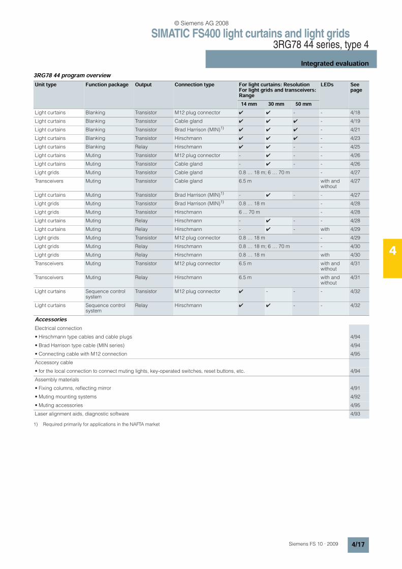
3RG78 44 program overview
Unit type Function package Output Connection type For light curtains: ResolutionFor light grids and transceivers: Range
LEDs Seepage
14 mm 30 mm 50 mmLight curtains Blanking Transistor M12 plug connector 4 4 - - 4/18
Light curtains Blanking Transistor Cable gland 4 4 4 - 4/19
Light curtains Blanking Transistor Brad Harrison (MIN)1)4 4 4 - 4/21
Light curtains Blanking Transistor Hirschmann 4 4 4 - 4/23
Light curtains Blanking Relay Hirschmann 4 4 - - 4/25
Light curtains Muting Transistor M12 plug connector - 4 - - 4/26
Light curtains Muting Transistor Cable gland - 4 - - 4/26
Light grids Muting Transistor Cable gland 0.8 … 18 m; 6 … 70 m - 4/27
Transceivers Muting Transistor Cable gland 6.5 m with and without
4/27
Light curtains Muting Transistor Brad Harrison (MIN)1) - 4 - - 4/27
Light grids Muting Transistor Brad Harrison (MIN)1) 0.8 … 18 m - 4/28
Light grids Muting Transistor Hirschmann 6 ... 70 m - 4/28
Light curtains Muting Relay Hirschmann - 4 - - 4/28
Light curtains Muting Relay Hirschmann - 4 - with 4/29
Light grids Muting Transistor M12 plug connector 0.8 … 18 m - 4/29
Light grids Muting Relay Hirschmann 0.8 … 18 m; 6 … 70 m - 4/30
Light grids Muting Relay Hirschmann 0.8 … 18 m with 4/30
Transceivers Muting Transistor M12 plug connector 6.5 m with and without
4/31
Transceivers Muting Relay Hirschmann 6.5 m with and without
4/31
Light curtains Sequence control system
Transistor M12 plug connector 4 - - - 4/32
Light curtains Sequence control system
Relay Hirschmann 4 4 - - 4/32
AccessoriesElectrical connection
• Hirschmann type cables and cable plugs 4/94
• Brad Harrison type cable (MIN series) 4/94
• Connecting cable with M12 connection 4/95
Accessory cable
• for the local connection to connect muting lights, key-operated switches, reset buttons, etc. 4/94
Assembly materials
• Fixing columns, reflecting mirror 4/91
• Muting mounting systems 4/92
• Muting accessories 4/95
Laser alignment aids, diagnostic software 4/93
1) Required primarily for applications in the NAFTA market
© Siemens AG 2008
SIMATIC FS400 light curtains and light grids3RG78 44 series, type 4
Integrated evaluation
4/18 Siemens FS 10 · 2009
4
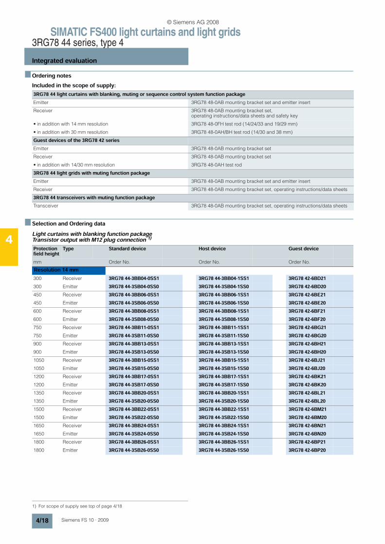
n Ordering notesIncluded in the scope of supply:
n Selection and Ordering dataLight curtains with blanking function packageTransistor output with M12 plug connection 1)
3RG78 44 light curtains with blanking, muting or sequence control system function packageEmitter 3RG78 48-0AB mounting bracket set and emitter insert
Receiver 3RG78 48-0AB mounting bracket set, operating instructions/data sheets and safety key
• in addition with 14 mm resolution 3RG78 48-0FH test rod (14/24/33 and 19/29 mm)
• in addition with 30 mm resolution 3RG78 48-0AH/BH test rod (14/30 and 38 mm)
Guest devices of the 3RG78 42 seriesEmitter 3RG78 48-0AB mounting bracket set
Receiver 3RG78 48-0AB mounting bracket set
• in addition with 14/30 mm resolution 3RG78 48-0AH test rod
3RG78 44 light grids with muting function packageEmitter 3RG78 48-0AB mounting bracket set and emitter insert
Receiver 3RG78 48-0AB mounting bracket set, operating instructions/data sheets
3RG78 44 transceivers with muting function packageTransceiver 3RG78 48-0AB mounting bracket set, operating instructions/data sheets
1) For scope of supply see top of page 4/18
Protection field height
Type Standard device Host device Guest device
mm Order No. Order No. Order No.
Resolution 14 mm300 Receiver 3RG78 44-3BB04-0SS1 3RG78 44-3BB04-1SS1 3RG78 42-6BD21300 Emitter 3RG78 44-3SB04-0SS0 3RG78 44-3SB04-1SS0 3RG78 42-6BD20450 Receiver 3RG78 44-3BB06-0SS1 3RG78 44-3BB06-1SS1 3RG78 42-6BE21450 Emitter 3RG78 44-3SB06-0SS0 3RG78 44-3SB06-1SS0 3RG78 42-6BE20600 Receiver 3RG78 44-3BB08-0SS1 3RG78 44-3BB08-1SS1 3RG78 42-6BF21600 Emitter 3RG78 44-3SB08-0SS0 3RG78 44-3SB08-1SS0 3RG78 42-6BF20750 Receiver 3RG78 44-3BB11-0SS1 3RG78 44-3BB11-1SS1 3RG78 42-6BG21750 Emitter 3RG78 44-3SB11-0SS0 3RG78 44-3SB11-1SS0 3RG78 42-6BG20900 Receiver 3RG78 44-3BB13-0SS1 3RG78 44-3BB13-1SS1 3RG78 42-6BH21900 Emitter 3RG78 44-3SB13-0SS0 3RG78 44-3SB13-1SS0 3RG78 42-6BH201050 Receiver 3RG78 44-3BB15-0SS1 3RG78 44-3BB15-1SS1 3RG78 42-6BJ211050 Emitter 3RG78 44-3SB15-0SS0 3RG78 44-3SB15-1SS0 3RG78 42-6BJ201200 Receiver 3RG78 44-3BB17-0SS1 3RG78 44-3BB17-1SS1 3RG78 42-6BK211200 Emitter 3RG78 44-3SB17-0SS0 3RG78 44-3SB17-1SS0 3RG78 42-6BK201350 Receiver 3RG78 44-3BB20-0SS1 3RG78 44-3BB20-1SS1 3RG78 42-6BL211350 Emitter 3RG78 44-3SB20-0SS0 3RG78 44-3SB20-1SS0 3RG78 42-6BL201500 Receiver 3RG78 44-3BB22-0SS1 3RG78 44-3BB22-1SS1 3RG78 42-6BM211500 Emitter 3RG78 44-3SB22-0SS0 3RG78 44-3SB22-1SS0 3RG78 42-6BM201650 Receiver 3RG78 44-3BB24-0SS1 3RG78 44-3BB24-1SS1 3RG78 42-6BN211650 Emitter 3RG78 44-3SB24-0SS0 3RG78 44-3SB24-1SS0 3RG78 42-6BN201800 Receiver 3RG78 44-3BB26-0SS1 3RG78 44-3BB26-1SS1 3RG78 42-6BP211800 Emitter 3RG78 44-3SB26-0SS0 3RG78 44-3SB26-1SS0 3RG78 42-6BP20
© Siemens AG 2008
SIMATIC FS400 light curtains and light grids3RG78 44 series, type 4
Integrated evaluation
4/19Siemens FS 10 · 2009
4
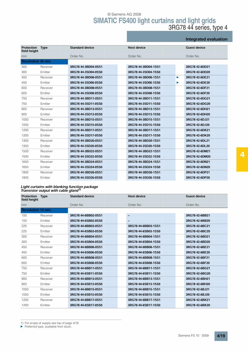
Light curtains with blanking function packageTransistor output with cable gland1)
Protection field height
Type Standard device Host device Guest device
mm Order No. Order No. Order No.
Resolution 30 mm300 Receiver 3RG78 44-3BD04-0SS1 3RG78 44-3BD04-1SS1 3RG78 42-6DD21300 Emitter 3RG78 44-3SD04-0SS0 3RG78 44-3SD04-1SS0 3RG78 42-6DD20450 Receiver 3RG78 44-3BD06-0SS1 3RG78 44-3BD06-1SS1 3RG78 42-6DE21450 Emitter 3RG78 44-3SD06-0SS0 3RG78 44-3SD06-1SS0 3RG78 42-6DE20600 Receiver 3RG78 44-3BD08-0SS1 3RG78 44-3BD08-1SS1 3RG78 42-6DF21600 Emitter 3RG78 44-3SD08-0SS0 3RG78 44-3SD08-1SS0 3RG78 42-6DF20750 Receiver 3RG78 44-3BD11-0SS1 3RG78 44-3BD11-1SS1 3RG78 42-6DG21750 Emitter 3RG78 44-3SD11-0SS0 3RG78 44-3SD11-1SS0 3RG78 42-6DG20900 Receiver 3RG78 44-3BD13-0SS1 3RG78 44-3BD13-1SS1 3RG78 42-6DH21900 Emitter 3RG78 44-3SD13-0SS0 3RG78 44-3SD13-1SS0 3RG78 42-6DH201050 Receiver 3RG78 44-3BD15-0SS1 3RG78 44-3BD15-1SS1 3RG78 42-6DJ211050 Emitter 3RG78 44-3SD15-0SS0 3RG78 44-3SD15-1SS0 3RG78 42-6DJ201200 Receiver 3RG78 44-3BD17-0SS1 3RG78 44-3BD17-1SS1 3RG78 42-6DK211200 Emitter 3RG78 44-3SD17-0SS0 3RG78 44-3SD17-1SS0 3RG78 42-6DK201350 Receiver 3RG78 44-3BD20-0SS1 3RG78 44-3BD20-1SS1 3RG78 42-6DL211350 Emitter 3RG78 44-3SD20-0SS0 3RG78 44-3SD20-1SS0 3RG78 42-6DL201500 Receiver 3RG78 44-3BD22-0SS1 3RG78 44-3BD22-1SS1 3RG78 42-6DM211500 Emitter 3RG78 44-3SD22-0SS0 3RG78 44-3SD22-1SS0 3RG78 42-6DM201650 Receiver 3RG78 44-3BD24-0SS1 3RG78 44-3BD24-1SS1 3RG78 42-6DN211650 Emitter 3RG78 44-3SD24-0SS0 3RG78 44-3SD24-1SS0 3RG78 42-6DN201800 Receiver 3RG78 44-3BD26-0SS1 3RG78 44-3BD26-1SS1 3RG78 42-6DP211800 Emitter 3RG78 44-3SD26-0SS0 3RG78 44-3SD26-1SS0 3RG78 42-6DP20
1) For scope of supply see top of page 4/18 Preferred type, available from stock.
Protection field height
Type Standard device Host device Guest device
mm Order No. Order No. Order No.
Resolution 14 mm150 Receiver 3RG78 44-6BB02-0SS1 – 3RG78 42-6BB21150 Emitter 3RG78 44-6SB02-0SS0 – 3RG78 42-6BB20225 Receiver 3RG78 44-6BB03-0SS1 3RG78 44-6BB03-1SS1 3RG78 42-6BC21225 Emitter 3RG78 44-6SB03-0SS0 3RG78 44-6SB03-1SS0 3RG78 42-6BC20300 Receiver 3RG78 44-6BB04-0SS1 3RG78 44-6BB04-1SS1 3RG78 42-6BD21300 Emitter 3RG78 44-6SB04-0SS0 3RG78 44-6SB04-1SS0 3RG78 42-6BD20450 Receiver 3RG78 44-6BB06-0SS1 3RG78 44-6BB06-1SS1 3RG78 42-6BE21450 Emitter 3RG78 44-6SB06-0SS0 3RG78 44-6SB06-1SS0 3RG78 42-6BE20600 Receiver 3RG78 44-6BB08-0SS1 3RG78 44-6BB08-1SS1 3RG78 42-6BF21600 Emitter 3RG78 44-6SB08-0SS0 3RG78 44-6SB08-1SS0 3RG78 42-6BF20750 Receiver 3RG78 44-6BB11-0SS1 3RG78 44-6BB11-1SS1 3RG78 42-6BG21750 Emitter 3RG78 44-6SB11-0SS0 3RG78 44-6SB11-1SS0 3RG78 42-6BG20900 Receiver 3RG78 44-6BB13-0SS1 3RG78 44-6BB13-1SS1 3RG78 42-6BH21900 Emitter 3RG78 44-6SB13-0SS0 3RG78 44-6SB13-1SS0 3RG78 42-6BH201050 Receiver 3RG78 44-6BB15-0SS1 3RG78 44-6BB15-1SS1 3RG78 42-6BJ211050 Emitter 3RG78 44-6SB15-0SS0 3RG78 44-6SB15-1SS0 3RG78 42-6BJ201200 Receiver 3RG78 44-6BB17-0SS1 3RG78 44-6BB17-1SS1 3RG78 42-6BK211200 Emitter 3RG78 44-6SB17-0SS0 3RG78 44-6SB17-1SS0 3RG78 42-6BK20
© Siemens AG 2008

SIMATIC FS400 light curtains and light grids3RG78 44 series, type 4
Integrated evaluation
4/20 Siemens FS 10 · 2009
4
Protection field height
Type Standard device Host device Guest device
mm Order No. Order No. Order No.
1350 Receiver 3RG78 44-6BB20-0SS1 3RG78 44-6BB20-1SS1 3RG78 42-6BL211350 Emitter 3RG78 44-6SB20-0SS0 3RG78 44-6SB20-1SS0 3RG78 42-6BL201500 Receiver 3RG78 44-6BB22-0SS1 3RG78 44-6BB22-1SS1 3RG78 42-6BM211500 Emitter 3RG78 44-6SB22-0SS0 3RG78 44-6SB22-1SS0 3RG78 42-6BM201650 Receiver 3RG78 44-6BB24-0SS1 3RG78 44-6BB24-1SS1 3RG78 42-6BN211650 Emitter 3RG78 44-6SB24-0SS0 3RG78 44-6SB24-1SS0 3RG78 42-6BN201800 Receiver 3RG78 44-6BB26-0SS1 3RG78 44-6BB26-1SS1 3RG78 42-6BP211800 Emitter 3RG78 44-6SB26-0SS0 3RG78 44-6SB26-1SS0 3RG78 42-6BP20Resolution 30 mm150 Receiver 3RG78 44-6BD02-0SS1 – 3RG78 42-6DB21150 Emitter 3RG78 44-6SD02-0SS0 – 3RG78 42-6DB20225 Receiver 3RG78 44-6BD03-0SS1 3RG78 44-6BD03-1SS1 3RG78 42-6DC21225 Emitter 3RG78 44-6SD03-0SS0 3RG78 44-6SD03-1SS0 3RG78 42-6DC20300 Receiver 3RG78 44-6BD04-0SS1 3RG78 44-6BD04-1SS1 3RG78 42-6DD21300 Emitter 3RG78 44-6SD04-0SS0 3RG78 44-6SD04-1SS0 3RG78 42-6DD20450 Receiver 3RG78 44-6BD06-0SS1 3RG78 44-6BD06-1SS1 3RG78 42-6DE21450 Emitter 3RG78 44-6SD06-0SS0 3RG78 44-6SD06-1SS0 3RG78 42-6DE20600 Receiver 3RG78 44-6BD08-0SS1 3RG78 44-6BD08-1SS1 3RG78 42-6DF21600 Emitter 3RG78 44-6SD08-0SS0 3RG78 44-6SD08-1SS0 3RG78 42-6DF20750 Receiver 3RG78 44-6BD11-0SS1 3RG78 44-6BD11-1SS1 3RG78 42-6DG21750 Emitter 3RG78 44-6SD11-0SS0 3RG78 44-6SD11-1SS0 3RG78 42-6DG20900 Receiver 3RG78 44-6BD13-0SS1 3RG78 44-6BD13-1SS1 3RG78 42-6DH21900 Emitter 3RG78 44-6SD13-0SS0 3RG78 44-6SD13-1SS0 3RG78 42-6DH201050 Receiver 3RG78 44-6BD15-0SS1 3RG78 44-6BD15-1SS1 3RG78 42-6DJ211050 Emitter 3RG78 44-6SD15-0SS0 3RG78 44-6SD15-1SS0 3RG78 42-6DJ201200 Receiver 3RG78 44-6BD17-0SS1 3RG78 44-6BD17-1SS1 3RG78 42-6DK211200 Emitter 3RG78 44-6SD17-0SS0 3RG78 44-6SD17-1SS0 3RG78 42-6DK201350 Receiver 3RG78 44-6BD20-0SS1 3RG78 44-6BD20-1SS1 3RG78 42-6DL211350 Emitter 3RG78 44-6SD20-0SS0 3RG78 44-6SD20-1SS0 3RG78 42-6DL201500 Receiver 3RG78 44-6BD22-0SS1 3RG78 44-6BD22-1SS1 3RG78 42-6DM211500 Emitter 3RG78 44-6SD22-0SS0 3RG78 44-6SD22-1SS0 3RG78 42-6DM201650 Receiver 3RG78 44-6BD24-0SS1 3RG78 44-6BD24-1SS1 3RG78 42-6DN211650 Emitter 3RG78 44-6SD24-0SS0 3RG78 44-6SD24-1SS0 3RG78 42-6DN201800 Receiver 3RG78 44-6BD26-0SS1 3RG78 44-6BD26-1SS1 3RG78 42-6DP211800 Emitter 3RG78 44-6SD26-0SS0 3RG78 44-6SD26-1SS0 3RG78 42-6DP20Resolution 50 mm450 Receiver 3RG78 44-6BE06-0SS1 3RG78 44-6BE06-1SS1 3RG78 42-6EE21450 Emitter 3RG78 44-6SE06-0SS0 3RG78 44-6SE06-1SS0 3RG78 42-6EE20600 Receiver 3RG78 44-6BE08-0SS1 3RG78 44-6BE08-1SS1 3RG78 42-6EF21600 Emitter 3RG78 44-6SE08-0SS0 3RG78 44-6SE08-1SS0 3RG78 42-6EF20750 Receiver 3RG78 44-6BE11-0SS1 3RG78 44-6BE11-1SS1 3RG78 42-6EG21750 Emitter 3RG78 44-6SE11-0SS0 3RG78 44-6SE11-1SS0 3RG78 42-6EG20900 Receiver 3RG78 44-6BE13-0SS1 3RG78 44-6BE13-1SS1 3RG78 42-6EH21900 Emitter 3RG78 44-6SE13-0SS0 3RG78 44-6SE13-1SS0 3RG78 42-6EH201050 Receiver 3RG78 44-6BE15-0SS1 3RG78 44-6BE15-1SS1 3RG78 42-6EJ211050 Emitter 3RG78 44-6SE15-0SS0 3RG78 44-6SE15-1SS0 3RG78 42-6EJ201200 Receiver 3RG78 44-6BE17-0SS1 3RG78 44-6BE17-1SS1 3RG78 42-6EK211200 Emitter 3RG78 44-6SE17-0SS0 3RG78 44-6SE17-1SS0 3RG78 42-6EK20 Preferred type, available from stock.
© Siemens AG 2008
SIMATIC FS400 light curtains and light grids3RG78 44 series, type 4
Integrated evaluation
4/21Siemens FS 10 · 2009
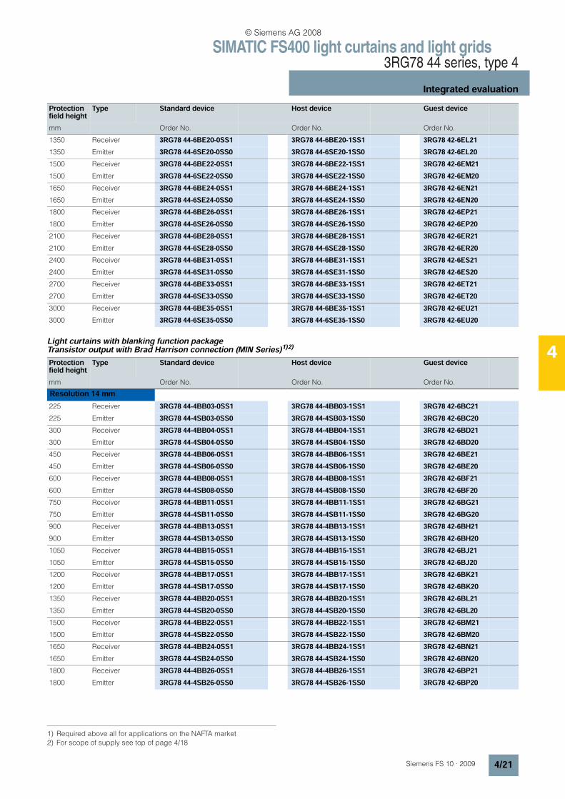
4Light curtains with blanking function packageTransistor output with Brad Harrison connection (MIN Series)1)2)
Protection field height
Type Standard device Host device Guest device
mm Order No. Order No. Order No.
1350 Receiver 3RG78 44-6BE20-0SS1 3RG78 44-6BE20-1SS1 3RG78 42-6EL211350 Emitter 3RG78 44-6SE20-0SS0 3RG78 44-6SE20-1SS0 3RG78 42-6EL201500 Receiver 3RG78 44-6BE22-0SS1 3RG78 44-6BE22-1SS1 3RG78 42-6EM211500 Emitter 3RG78 44-6SE22-0SS0 3RG78 44-6SE22-1SS0 3RG78 42-6EM201650 Receiver 3RG78 44-6BE24-0SS1 3RG78 44-6BE24-1SS1 3RG78 42-6EN211650 Emitter 3RG78 44-6SE24-0SS0 3RG78 44-6SE24-1SS0 3RG78 42-6EN201800 Receiver 3RG78 44-6BE26-0SS1 3RG78 44-6BE26-1SS1 3RG78 42-6EP211800 Emitter 3RG78 44-6SE26-0SS0 3RG78 44-6SE26-1SS0 3RG78 42-6EP202100 Receiver 3RG78 44-6BE28-0SS1 3RG78 44-6BE28-1SS1 3RG78 42-6ER212100 Emitter 3RG78 44-6SE28-0SS0 3RG78 44-6SE28-1SS0 3RG78 42-6ER202400 Receiver 3RG78 44-6BE31-0SS1 3RG78 44-6BE31-1SS1 3RG78 42-6ES212400 Emitter 3RG78 44-6SE31-0SS0 3RG78 44-6SE31-1SS0 3RG78 42-6ES202700 Receiver 3RG78 44-6BE33-0SS1 3RG78 44-6BE33-1SS1 3RG78 42-6ET212700 Emitter 3RG78 44-6SE33-0SS0 3RG78 44-6SE33-1SS0 3RG78 42-6ET203000 Receiver 3RG78 44-6BE35-0SS1 3RG78 44-6BE35-1SS1 3RG78 42-6EU213000 Emitter 3RG78 44-6SE35-0SS0 3RG78 44-6SE35-1SS0 3RG78 42-6EU20
1) Required above all for applications on the NAFTA market2) For scope of supply see top of page 4/18
Protection field height
Type Standard device Host device Guest device
mm Order No. Order No. Order No.
Resolution 14 mm225 Receiver 3RG78 44-4BB03-0SS1 3RG78 44-4BB03-1SS1 3RG78 42-6BC21225 Emitter 3RG78 44-4SB03-0SS0 3RG78 44-4SB03-1SS0 3RG78 42-6BC20300 Receiver 3RG78 44-4BB04-0SS1 3RG78 44-4BB04-1SS1 3RG78 42-6BD21300 Emitter 3RG78 44-4SB04-0SS0 3RG78 44-4SB04-1SS0 3RG78 42-6BD20450 Receiver 3RG78 44-4BB06-0SS1 3RG78 44-4BB06-1SS1 3RG78 42-6BE21450 Emitter 3RG78 44-4SB06-0SS0 3RG78 44-4SB06-1SS0 3RG78 42-6BE20600 Receiver 3RG78 44-4BB08-0SS1 3RG78 44-4BB08-1SS1 3RG78 42-6BF21600 Emitter 3RG78 44-4SB08-0SS0 3RG78 44-4SB08-1SS0 3RG78 42-6BF20750 Receiver 3RG78 44-4BB11-0SS1 3RG78 44-4BB11-1SS1 3RG78 42-6BG21750 Emitter 3RG78 44-4SB11-0SS0 3RG78 44-4SB11-1SS0 3RG78 42-6BG20900 Receiver 3RG78 44-4BB13-0SS1 3RG78 44-4BB13-1SS1 3RG78 42-6BH21900 Emitter 3RG78 44-4SB13-0SS0 3RG78 44-4SB13-1SS0 3RG78 42-6BH201050 Receiver 3RG78 44-4BB15-0SS1 3RG78 44-4BB15-1SS1 3RG78 42-6BJ211050 Emitter 3RG78 44-4SB15-0SS0 3RG78 44-4SB15-1SS0 3RG78 42-6BJ201200 Receiver 3RG78 44-4BB17-0SS1 3RG78 44-4BB17-1SS1 3RG78 42-6BK211200 Emitter 3RG78 44-4SB17-0SS0 3RG78 44-4SB17-1SS0 3RG78 42-6BK201350 Receiver 3RG78 44-4BB20-0SS1 3RG78 44-4BB20-1SS1 3RG78 42-6BL211350 Emitter 3RG78 44-4SB20-0SS0 3RG78 44-4SB20-1SS0 3RG78 42-6BL201500 Receiver 3RG78 44-4BB22-0SS1 3RG78 44-4BB22-1SS1 3RG78 42-6BM211500 Emitter 3RG78 44-4SB22-0SS0 3RG78 44-4SB22-1SS0 3RG78 42-6BM201650 Receiver 3RG78 44-4BB24-0SS1 3RG78 44-4BB24-1SS1 3RG78 42-6BN211650 Emitter 3RG78 44-4SB24-0SS0 3RG78 44-4SB24-1SS0 3RG78 42-6BN201800 Receiver 3RG78 44-4BB26-0SS1 3RG78 44-4BB26-1SS1 3RG78 42-6BP211800 Emitter 3RG78 44-4SB26-0SS0 3RG78 44-4SB26-1SS0 3RG78 42-6BP20
© Siemens AG 2008

SIMATIC FS400 light curtains and light grids3RG78 44 series, type 4
Integrated evaluation
4/22 Siemens FS 10 · 2009
4
Protection field height
Type Standard device Host device Guest device
mm Order No. Order No. Order No.
Resolution 30 mm150 Receiver 3RG78 44-4BD02-0SS1 – 3RG78 42-6DB21150 Emitter 3RG78 44-4SD02-0SS0 – 3RG78 42-6DB20225 Receiver 3RG78 44-4BD03-0SS1 3RG78 44-4BD03-1SS1 3RG78 42-6DC21225 Emitter 3RG78 44-4SD03-0SS0 3RG78 44-4SD03-1SS0 3RG78 42-6DC20300 Receiver 3RG78 44-4BD04-0SS1 3RG78 44-4BD04-1SS1 3RG78 42-6DD21300 Emitter 3RG78 44-4SD04-0SS0 3RG78 44-4SD04-1SS0 3RG78 42-6DD20450 Receiver 3RG78 44-4BD06-0SS1 3RG78 44-4BD06-1SS1 3RG78 42-6DE21450 Emitter 3RG78 44-4SD06-0SS0 3RG78 44-4SD06-1SS0 3RG78 42-6DE20600 Receiver 3RG78 44-4BD08-0SS1 3RG78 44-4BD08-1SS1 3RG78 42-6DF21600 Emitter 3RG78 44-4SD08-0SS0 3RG78 44-4SD08-1SS0 3RG78 42-6DF20750 Receiver 3RG78 44-4BD11-0SS1 3RG78 44-4BD11-1SS1 3RG78 42-6DG21750 Emitter 3RG78 44-4SD11-0SS0 3RG78 44-4SD11-1SS0 3RG78 42-6DG20900 Receiver 3RG78 44-4BD13-0SS1 3RG78 44-4BD13-1SS1 3RG78 42-6DH21900 Emitter 3RG78 44-4SD13-0SS0 3RG78 44-4SD13-1SS0 3RG78 42-6DH201050 Receiver 3RG78 44-4BD15-0SS1 3RG78 44-4BD15-1SS1 3RG78 42-6DJ211050 Emitter 3RG78 44-4SD15-0SS0 3RG78 44-4SD15-1SS0 3RG78 42-6DJ201200 Receiver 3RG78 44-4BD17-0SS1 3RG78 44-4BD17-1SS1 3RG78 42-6DK211200 Emitter 3RG78 44-4SD17-0SS0 3RG78 44-4SD17-1SS0 3RG78 42-6DK201350 Receiver 3RG78 44-4BD20-0SS1 3RG78 44-4BD20-1SS1 3RG78 42-6DL211350 Emitter 3RG78 44-4SD20-0SS0 3RG78 44-4SD20-1SS0 3RG78 42-6DL201500 Receiver 3RG78 44-4BD22-0SS1 3RG78 44-4BD22-1SS1 3RG78 42-6DM211500 Emitter 3RG78 44-4SD22-0SS0 3RG78 44-4SD22-1SS0 3RG78 42-6DM201650 Receiver 3RG78 44-4BD24-0SS1 3RG78 44-4BD24-1SS1 3RG78 42-6DN211650 Emitter 3RG78 44-4SD24-0SS0 3RG78 44-4SD24-1SS0 3RG78 42-6DN201800 Receiver 3RG78 44-4BD26-0SS1 3RG78 44-4BD26-1SS1 3RG78 42-6DP211800 Emitter 3RG78 44-4SD26-0SS0 3RG78 44-4SD26-1SS0 3RG78 42-6DP20Resolution 50 mm450 Receiver 3RG78 44-4BE06-0SS1 3RG78 44-4BE06-1SS1 3RG78 42-6EE21450 Emitter 3RG78 44-4SE06-0SS0 3RG78 44-4SE06-1SS0 3RG78 42-6EE20600 Receiver 3RG78 44-4BE08-0SS1 3RG78 44-4BE08-1SS1 3RG78 42-6EF21600 Emitter 3RG78 44-4SE08-0SS0 3RG78 44-4SE08-1SS0 3RG78 42-6EF20750 Receiver 3RG78 44-4BE11-0SS1 3RG78 44-4BE11-1SS1 3RG78 42-6EG21750 Emitter 3RG78 44-4SE11-0SS0 3RG78 44-4SE11-1SS0 3RG78 42-6EG20900 Receiver 3RG78 44-4BE13-0SS1 3RG78 44-4BE13-1SS1 3RG78 42-6EH21900 Emitter 3RG78 44-4SE13-0SS0 3RG78 44-4SE13-1SS0 3RG78 42-6EH201050 Receiver 3RG78 44-4BE15-0SS1 3RG78 44-4BE15-1SS1 3RG78 42-6EJ211050 Emitter 3RG78 44-4SE15-0SS0 3RG78 44-4SE15-1SS0 3RG78 42-6EJ201200 Receiver 3RG78 44-4BE17-0SS1 3RG78 44-4BE17-1SS1 3RG78 42-6EK211200 Emitter 3RG78 44-4SE17-0SS0 3RG78 44-4SE17-1SS0 3RG78 42-6EK201350 Receiver 3RG78 44-4BE20-0SS1 3RG78 44-4BE20-1SS1 3RG78 42-6EL211350 Emitter 3RG78 44-4SE20-0SS0 3RG78 44-4SE20-1SS0 3RG78 42-6EL201500 Receiver 3RG78 44-4BE22-0SS1 3RG78 44-4BE22-1SS1 3RG78 42-6EM211500 Emitter 3RG78 44-4SE22-0SS0 3RG78 44-4SE22-1SS0 3RG78 42-6EM201650 Receiver 3RG78 44-4BE24-0SS1 3RG78 44-4BE24-1SS1 3RG78 42-6EN211650 Emitter 3RG78 44-4SE24-0SS0 3RG78 44-4SE24-1SS0 3RG78 42-6EN201800 Receiver 3RG78 44-4BE26-0SS1 3RG78 44-4BE26-1SS1 3RG78 42-6EP211800 Emitter 3RG78 44-4SE26-0SS0 3RG78 44-4SB26-1SS0 3RG78 42-6EP20 Preferred type, available from stock.
© Siemens AG 2008
SIMATIC FS400 light curtains and light grids3RG78 44 series, type 4
Integrated evaluation
4/23Siemens FS 10 · 2009
4
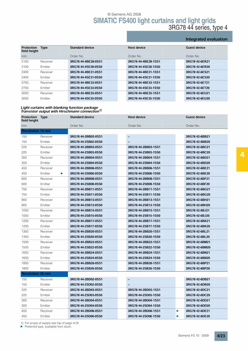
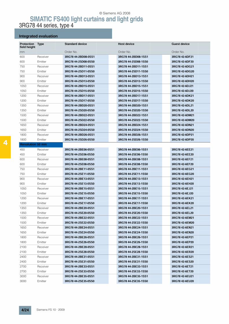
Light curtains with blanking function packageTransistor output with Hirschmann connection1)
Protection field height
Type Standard device Host device Guest device
mm Order No. Order No. Order No.
2100 Receiver 3RG78 44-4BE28-0SS1 3RG78 44-4BE28-1SS1 3RG78 42-6ER212100 Emitter 3RG78 44-4SE28-0SS0 3RG78 44-4SE28-1SS0 3RG78 42-6ER202400 Receiver 3RG78 44-4BE31-0SS1 3RG78 44-4BE31-1SS1 3RG78 42-6ES212400 Emitter 3RG78 44-4SE31-0SS0 3RG78 44-4SE31-1SS0 3RG78 42-6ES202700 Receiver 3RG78 44-4BE33-0SS1 3RG78 44-4BE33-1SS1 3RG78 42-6ET212700 Emitter 3RG78 44-4SE33-0SS0 3RG78 44-4SE33-1SS0 3RG78 42-6ET203000 Receiver 3RG78 44-4BE35-0SS1 3RG78 44-4BE35-1SS1 3RG78 42-6EU213000 Emitter 3RG78 44-4SE35-0SS0 3RG78 44-4SE35-1SS0 3RG78 42-6EU20
1) For scope of supply see top of page 4/18 Preferred type, available from stock.
Protection field height
Type Standard device Host device Guest device
mm Order No. Order No. Order No.
Resolution 14 mm150 Receiver 3RG78 44-2BB02-0SS1 – 3RG78 42-6BB21150 Emitter 3RG78 44-2SB02-0SS0 – 3RG78 42-6BB20225 Receiver 3RG78 44-2BB03-0SS1 3RG78 44-2BB03-1SS1 3RG78 42-6BC21225 Emitter 3RG78 44-2SB03-0SS0 3RG78 44-2SB03-1SS0 3RG78 42-6BC20300 Receiver 3RG78 44-2BB04-0SS1 3RG78 44-2BB04-1SS1 3RG78 42-6BD21300 Emitter 3RG78 44-2SB04-0SS0 3RG78 44-2SB04-1SS0 3RG78 42-6BD20450 Receiver 3RG78 44-2BB06-0SS1 3RG78 44-2BB06-1SS1 3RG78 42-6BE21450 Emitter 3RG78 44-2SB06-0SS0 3RG78 44-2SB06-1SS0 3RG78 42-6BE20600 Receiver 3RG78 44-2BB08-0SS1 3RG78 44-2BB08-1SS1 3RG78 42-6BF21600 Emitter 3RG78 44-2SB08-0SS0 3RG78 44-2SB08-1SS0 3RG78 42-6BF20750 Receiver 3RG78 44-2BB11-0SS1 3RG78 44-2BB11-1SS1 3RG78 42-6BG21750 Emitter 3RG78 44-2SB11-0SS0 3RG78 44-2SB11-1SS0 3RG78 42-6BG20900 Receiver 3RG78 44-2BB13-0SS1 3RG78 44-2BB13-1SS1 3RG78 42-6BH21900 Emitter 3RG78 44-2SB13-0SS0 3RG78 44-2SB13-1SS0 3RG78 42-6BH201050 Receiver 3RG78 44-2BB15-0SS1 3RG78 44-2BB15-1SS1 3RG78 42-6BJ211050 Emitter 3RG78 44-2SB15-0SS0 3RG78 44-2SB15-1SS0 3RG78 42-6BJ201200 Receiver 3RG78 44-2BB17-0SS1 3RG78 44-2BB17-1SS1 3RG78 42-6BK211200 Emitter 3RG78 44-2SB17-0SS0 3RG78 44-2SB17-1SS0 3RG78 42-6BK201350 Receiver 3RG78 44-2BB20-0SS1 3RG78 44-2BB20-1SS1 3RG78 42-6BL211350 Emitter 3RG78 44-2SB20-0SS0 3RG78 44-2SB20-1SS0 3RG78 42-6BL201500 Receiver 3RG78 44-2BB22-0SS1 3RG78 44-2BB22-1SS1 3RG78 42-6BM211500 Emitter 3RG78 44-2SB22-0SS0 3RG78 44-2SB22-1SS0 3RG78 42-6BM201650 Receiver 3RG78 44-2BB24-0SS1 3RG78 44-2BB24-1SS1 3RG78 42-6BN211650 Emitter 3RG78 44-2SB24-0SS0 3RG78 44-2SB24-1SS0 3RG78 42-6BN201800 Receiver 3RG78 44-2BB26-0SS1 3RG78 44-2BB26-1SS1 3RG78 42-6BP211800 Emitter 3RG78 44-2SB26-0SS0 3RG78 44-2SB26-1SS0 3RG78 42-6BP20Resolution 30 mm150 Receiver 3RG78 44-2BD02-0SS1 – 3RG78 42-6DB21150 Emitter 3RG78 44-2SD02-0SS0 – 3RG78 42-6DB20225 Receiver 3RG78 44-2BD03-0SS1 3RG78 44-2BD03-1SS1 3RG78 42-6DC21225 Emitter 3RG78 44-2SD03-0SS0 3RG78 44-2SD03-1SS0 3RG78 42-6DC20300 Receiver 3RG78 44-2BD04-0SS1 3RG78 44-2BD04-1SS1 3RG78 42-6DD21300 Emitter 3RG78 44-2SD04-0SS0 3RG78 44-2SD04-1SS0 3RG78 42-6DD20450 Receiver 3RG78 44-2BD06-0SS1 3RG78 44-2BD06-1SS1 3RG78 42-6DE21450 Emitter 3RG78 44-2SD06-0SS0 3RG78 44-2SD06-1SS0 3RG78 42-6DE20
© Siemens AG 2008
SIMATIC FS400 light curtains and light grids3RG78 44 series, type 4
Integrated evaluation
4/24 Siemens FS 10 · 2009
4
600 Receiver 3RG78 44-2BD08-0SS1 3RG78 44-2BD08-1SS1 3RG78 42-6DF21600 Emitter 3RG78 44-2SD08-0SS0 3RG78 44-2SD08-1SS0 3RG78 42-6DF20750 Receiver 3RG78 44-2BD11-0SS1 3RG78 44-2BD11-1SS1 3RG78 42-6DG21750 Emitter 3RG78 44-2SD11-0SS0 3RG78 44-2SD11-1SS0 3RG78 42-6DG20900 Receiver 3RG78 44-2BD13-0SS1 3RG78 44-2BD13-1SS1 3RG78 42-6DH21900 Emitter 3RG78 44-2SD13-0SS0 3RG78 44-2SD13-1SS0 3RG78 42-6DH201050 Receiver 3RG78 44-2BD15-0SS1 3RG78 44-2BD15-1SS1 3RG78 42-6DJ211050 Emitter 3RG78 44-2SD15-0SS0 3RG78 44-2SD15-1SS0 3RG78 42-6DJ201200 Receiver 3RG78 44-2BD17-0SS1 3RG78 44-2BD17-1SS1 3RG78 42-6DK211200 Emitter 3RG78 44-2SD17-0SS0 3RG78 44-2SD17-1SS0 3RG78 42-6DK201350 Receiver 3RG78 44-2BD20-0SS1 3RG78 44-2BD20-1SS1 3RG78 42-6DL211350 Emitter 3RG78 44-2SD20-0SS0 3RG78 44-2SD20-1SS0 3RG78 42-6DL201500 Receiver 3RG78 44-2BD22-0SS1 3RG78 44-2BD22-1SS1 3RG78 42-6DM211500 Emitter 3RG78 44-2SD22-0SS0 3RG78 44-2SD22-1SS0 3RG78 42-6DM201650 Receiver 3RG78 44-2BD24-0SS1 3RG78 44-2BD24-1SS1 3RG78 42-6DN211650 Emitter 3RG78 44-2SD24-0SS0 3RG78 44-2SD24-1SS0 3RG78 42-6DN201800 Receiver 3RG78 44-2BD26-0SS1 3RG78 44-2BD26-1SS1 3RG78 42-6DP211800 Emitter 3RG78 44-2SD26-0SS0 3RG78 44-2SD26-1SS0 3RG78 42-6DP20Resolution 50 mm450 Receiver 3RG78 44-2BE06-0SS1 3RG78 44-2BE06-1SS1 3RG78 42-6EE21450 Emitter 3RG78 44-2SE06-0SS0 3RG78 44-2SE06-1SS0 3RG78 42-6EE20600 Receiver 3RG78 44-2BE08-0SS1 3RG78 44-2BE08-1SS1 3RG78 42-6EF21600 Emitter 3RG78 44-2SE08-0SS0 3RG78 44-2SE08-1SS0 3RG78 42-6EF20750 Receiver 3RG78 44-2BE11-0SS1 3RG78 44-2BE11-1SS1 3RG78 42-6EG21750 Emitter 3RG78 44-2SE11-0SS0 3RG78 44-2SE11-1SS0 3RG78 42-6EG20900 Receiver 3RG78 44-2BE13-0SS1 3RG78 44-2BE13-1SS1 3RG78 42-6EH21900 Emitter 3RG78 44-2SE13-0SS0 3RG78 44-2SE13-1SS0 3RG78 42-6EH201050 Receiver 3RG78 44-2BE15-0SS1 3RG78 44-2BE15-1SS1 3RG78 42-6EJ211050 Emitter 3RG78 44-2SE15-0SS0 3RG78 44-2SE15-1SS0 3RG78 42-6EJ201200 Receiver 3RG78 44-2BE17-0SS1 3RG78 44-2BE17-1SS1 3RG78 42-6EK211200 Emitter 3RG78 44-2SE17-0SS0 3RG78 44-2SE17-1SS0 3RG78 42-6EK201350 Receiver 3RG78 44-2BE20-0SS1 3RG78 44-2BE20-1SS1 3RG78 42-6EL211350 Emitter 3RG78 44-2SE20-0SS0 3RG78 44-2SE20-1SS0 3RG78 42-6EL201500 Receiver 3RG78 44-2BE22-0SS1 3RG78 44-2BE22-1SS1 3RG78 42-6EM211500 Emitter 3RG78 44-2SE22-0SS0 3RG78 44-2SE22-1SS0 3RG78 42-6EM201650 Receiver 3RG78 44-2BE24-0SS1 3RG78 44-2BE24-1SS1 3RG78 42-6EN211650 Emitter 3RG78 44-2SE24-0SS0 3RG78 44-2SE24-1SS0 3RG78 42-6EN201800 Receiver 3RG78 44-2BE26-0SS1 3RG78 44-2BE26-1SS1 3RG78 42-6EP211800 Emitter 3RG78 44-2SE26-0SS0 3RG78 44-2SE26-1SS0 3RG78 42-6EP202100 Receiver 3RG78 44-2BE28-0SS1 3RG78 44-2BE28-1SS1 3RG78 42-6ER212100 Emitter 3RG78 44-2SE28-0SS0 3RG78 44-2SE28-1SS0 3RG78 42-6ER202400 Receiver 3RG78 44-2BE31-0SS1 3RG78 44-2BE31-1SS1 3RG78 42-6ES212400 Emitter 3RG78 44-2SE31-0SS0 3RG78 44-2SE31-1SS0 3RG78 42-6ES202700 Receiver 3RG78 44-2BE33-0SS1 3RG78 44-2BE33-1SS1 3RG78 42-6ET212700 Emitter 3RG78 44-2SE33-0SS0 3RG78 44-2SE33-1SS0 3RG78 42-6ET203000 Receiver 3RG78 44-2BE35-0SS1 3RG78 44-2BE35-1SS1 3RG78 42-6EU213000 Emitter 3RG78 44-2SE35-0SS0 3RG78 44-2SE35-1SS0 3RG78 42-6EU20
Protection field height
Type Standard device Host device Guest device
mm Order No. Order No. Order No.
© Siemens AG 2008
SIMATIC FS400 light curtains and light grids3RG78 44 series, type 4
Integrated evaluation
4/25Siemens FS 10 · 2009
4
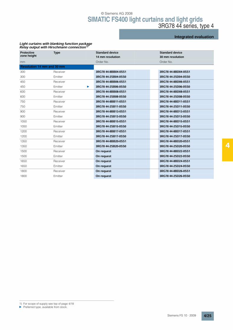
Light curtains with blanking function packageRelay output with Hirschmann connection1)
1) For scope of supply see top of page 4/18 Preferred type, available from stock.
Protective zone height
Type Standard device14 mm resolution
Standard device30 mm resolution
mm Order No. Order No.
Resolution 14 mm and 30 mm300 Receiver 3RG78 44-8BB04-0SS1 3RG78 44-8BD04-0SS1300 Emitter 3RG78 44-2SB04-0SS0 3RG78 44-2SD04-0SS0450 Receiver 3RG78 44-8BB06-0SS1 3RG78 44-8BD06-0SS1450 Emitter 3RG78 44-2SB06-0SS0 3RG78 44-2SD06-0SS0600 Receiver 3RG78 44-8BB08-0SS1 3RG78 44-8BD08-0SS1600 Emitter 3RG78 44-2SB08-0SS0 3RG78 44-2SD08-0SS0750 Receiver 3RG78 44-8BB11-0SS1 3RG78 44-8BD11-0SS1750 Emitter 3RG78 44-2SB11-0SS0 3RG78 44-2SD11-0SS0900 Receiver 3RG78 44-8BB13-0SS1 3RG78 44-8BD13-0SS1900 Emitter 3RG78 44-2SB13-0SS0 3RG78 44-2SD13-0SS01050 Receiver 3RG78 44-8BB15-0SS1 3RG78 44-8BD15-0SS11050 Emitter 3RG78 44-2SB15-0SS0 3RG78 44-2SD15-0SS01200 Receiver 3RG78 44-8BB17-0SS1 3RG78 44-8BD17-0SS11200 Emitter 3RG78 44-2SB17-0SS0 3RG78 44-2SD17-0SS01350 Receiver 3RG78 44-8BB20-0SS1 3RG78 44-8BD20-0SS11350 Emitter 3RG78 44-2SB20-0SS0 3RG78 44-2SD20-0SS01500 Receiver On request 3RG78 44-8BD22-0SS11500 Emitter On request 3RG78 44-2SD22-0SS01650 Receiver On request 3RG78 44-8BD24-0SS11650 Emitter On request 3RG78 44-2SD24-0SS01800 Receiver On request 3RG78 44-8BD26-0SS11800 Emitter On request 3RG78 44-2SD26-0SS0
© Siemens AG 2008

SIMATIC FS400 light curtains and light grids3RG78 44 series, type 4
Integrated evaluation
4/26 Siemens FS 10 · 2009
4
Light curtains with muting function package Transistor output with M12 plug connection1)
Light curtains with muting function packageTransistor output with cable gland1)
1) For scope of supply see top of page 4/18 Preferred type, available from stock.
Protective zone height
Type Standard device Host device Guest device
mm Order No. Order No. Order No.
Resolution 30 mm300 Receiver 3RG78 44-3MD04-0SS1 On request 3RG78 42-6DD21300 Emitter 3RG78 44-3SD04-0SS0 On request 3RG78 42-6DD20450 Receiver 3RG78 44-3MD06-0SS1 On request 3RG78 42-6DE21450 Emitter 3RG78 44-3SD06-0SS0 On request 3RG78 42-6DE20600 Receiver 3RG78 44-3MD08-0SS1 On request 3RG78 42-6DF21600 Emitter 3RG78 44-3SD08-0SS0 On request 3RG78 42-6DF20750 Receiver 3RG78 44-3MD11-0SS1 On request 3RG78 42-6DG21750 Emitter 3RG78 44-3SD11-0SS0 On request 3RG78 42-6DG20900 Receiver 3RG78 44-3MD13-0SS1 On request 3RG78 42-6DH21900 Emitter 3RG78 44-3SD13-0SS0 On request 3RG78 42-6DH201050 Receiver 3RG78 44-3MD15-0SS1 On request 3RG78 42-6DJ211050 Emitter 3RG78 44-3SD15-0SS0 On request 3RG78 42-6DJ201200 Receiver 3RG78 44-3MD17-0SS1 On request 3RG78 42-6DK211200 Emitter 3RG78 44-3SD17-0SS0 On request 3RG78 42-6DK201350 Receiver 3RG78 44-3MD20-0SS1 On request 3RG78 42-6DL211350 Emitter 3RG78 44-3SD20-0SS0 On request 3RG78 42-6DL201500 Receiver 3RG78 44-3MD22-0SS1 On request 3RG78 42-6DM211500 Emitter 3RG78 44-3SD22-0SS0 On request 3RG78 42-6DM201650 Receiver 3RG78 44-3MD24-0SS1 On request 3RG78 42-6DN211650 Emitter 3RG78 44-3SD24-0SS0 On request 3RG78 42-6DN201800 Receiver 3RG78 44-3MD26-0SS1 On request 3RG78 42-6DP211800 Emitter 3RG78 44-3SD26-0SS0 On request 3RG78 42-6DP20
Protective zone height
Type Standard device Host device Guest device
mm Order No. Order No. Order No.
Resolution 30 mm300 Receiver 3RG78 44-6MD04-0SS1 On request 3RG78 42-6DD21300 Emitter 3RG78 44-6SD04-0SS0 On request 3RG78 42-6DD20450 Receiver 3RG78 44-6MD06-0SS1 On request 3RG78 42-6DE21450 Emitter 3RG78 44-6SD06-0SS0 On request 3RG78 42-6DE20600 Receiver 3RG78 44-6MD08-0SS1 On request 3RG78 42-6DF21600 Emitter 3RG78 44-6SD08-0SS0 On request 3RG78 42-6DF20750 Receiver 3RG78 44-6MD11-0SS1 On request 3RG78 42-6DG21750 Emitter 3RG78 44-6SD11-0SS0 On request 3RG78 42-6DG20900 Receiver 3RG78 44-6MD13-0SS1 On request 3RG78 42-6DH21900 Emitter 3RG78 44-6SD13-0SS0 On request 3RG78 42-6DH201050 Receiver 3RG78 44-6MD15-0SS1 On request 3RG78 42-6DJ211050 Emitter 3RG78 44-6SD15-0SS0 On request 3RG78 42-6DJ201200 Receiver 3RG78 44-6MD17-0SS1 On request 3RG78 42-6DK211200 Emitter 3RG78 44-6SD17-0SS0 On request 3RG78 42-6DK201350 Receiver 3RG78 44-6MD20-0SS1 On request 3RG78 42-6DL211350 Emitter 3RG78 44-6SD20-0SS0 On request 3RG78 42-6DL201500 Receiver 3RG78 44-6MD22-0SS1 On request 3RG78 42-6DM211500 Emitter 3RG78 44-6SD22-0SS0 On request 3RG78 42-6DM20
© Siemens AG 2008

SIMATIC FS400 light curtains and light grids3RG78 44 series, type 4
Integrated evaluation
4/27Siemens FS 10 · 2009
4
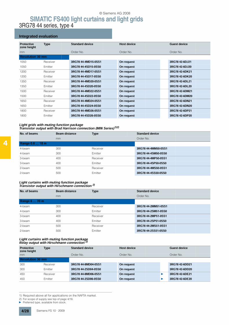
Light grids with muting function packageTransistor output with cable gland1)
Transceiver with muting function packageTransistor output with cable gland1)
Light curtains with muting function packageTransistor output with Brad Harrison connection (MIN Series)1)2)
1650 Receiver 3RG78 44-6MD24-0SS1 On request 3RG78 42-6DN211650 Emitter 3RG78 44-6SD24-0SS0 On request 3RG78 42-6DN201800 Receiver 3RG78 44-6MD26-0SS1 On request 3RG78 42-6DP211800 Emitter 3RG78 44-6SD26-0SS0 On request 3RG78 42-6DP20
1) For scope of supply see top of page 4/18.
Protective zone height
Type Standard device Host device Guest device
mm Order No. Order No. Order No.
Resolution 30 mm
No. of beams Beam distance Type Standard devicemm Order No.
Range 0.8 … 18 m4-beam 300 Receiver 3RG78 44-6MM50-0SS14-beam 300 Emitter 3RG78 44-6SM50-0SS03-beam 400 Receiver 3RG78 44-6MP50-0SS13-beam 400 Emitter 3RG78 44-6SP50-0SS02-beam 500 Receiver 3RG78 44-6MS50-0SS12-beam 500 Emitter 3RG78 44-6SS50-0SS0Range 6 … 70 m4-beam 300 Receiver 3RG78 44-6MM51-0SS14-beam 300 Emitter 3RG78 44-6SM51-0SS03-beam 400 Receiver 3RG78 44-6MP51-0SS13-beam 400 Emitter 3RG78 44-6SP51-0SS02-beam 500 Receiver 3RG78 44-6MS51-0SS12-beam 500 Emitter 3RG78 44-6SS51-0SS0
No. of beams Beam distance Type Standard devicemm Order No.
Range 6.5 m2-beam 500 Transceiver 3RG78 44-6MS50-0ST02-beam 500 Transceiver with integrated LED 3RG78 44-6MS50-0MT0Reflecting mirrors for transceivers 3RG78 48-1TL
2) Required above all for applications on the NAFTA market. Preferred type, available from stock.
Protective zone height
Type Standard device Host device Guest device
mm Order No. Order No. Order No.
Resolution 30 mm300 Receiver 3RG78 44-4MD04-0SS1 On request 3RG78 42-6DD21300 Emitter 3RG78 44-4SD04-0SS0 On request 3RG78 42-6DD20450 Receiver 3RG78 44-4MD06-0SS1 On request 3RG78 42-6DE21450 Emitter 3RG78 44-4SD06-0SS0 On request 3RG78 42-6DE20600 Receiver 3RG78 44-4MD08-0SS1 On request 3RG78 42-6DF21600 Emitter 3RG78 44-4SD08-0SS0 On request 3RG78 42-6DF20750 Receiver 3RG78 44-4MD11-0SS1 On request 3RG78 42-6DG21750 Emitter 3RG78 44-4SD11-0SS0 On request 3RG78 42-6DG20900 Receiver 3RG78 44-4MD13-0SS1 On request 3RG78 42-6DH21900 Emitter 3RG78 44-4SD13-0SS0 On request 3RG78 42-6DH20
© Siemens AG 2008
SIMATIC FS400 light curtains and light grids3RG78 44 series, type 4
Integrated evaluation
4/28 Siemens FS 10 · 2009
4
Light grids with muting function packageTransistor output with Brad Harrison connection (MIN Series)1)2)
Light curtains with muting function packageTransistor output with Hirschmann connection 2)
Light curtains with muting function packageRelay output with Hirschmann connection 2)
1050 Receiver 3RG78 44-4MD15-0SS1 On request 3RG78 42-6DJ211050 Emitter 3RG78 44-4SD15-0SS0 On request 3RG78 42-6DJ201200 Receiver 3RG78 44-4MD17-0SS1 On request 3RG78 42-6DK211200 Emitter 3RG78 44-4SD17-0SS0 On request 3RG78 42-6DK201350 Receiver 3RG78 44-4MD20-0SS1 On request 3RG78 42-6DL211350 Emitter 3RG78 44-4SD20-0SS0 On request 3RG78 42-6DL201500 Receiver 3RG78 44-4MD22-0SS1 On request 3RG78 42-6DM211500 Emitter 3RG78 44-4SD22-0SS0 On request 3RG78 42-6DM201650 Receiver 3RG78 44-4MD24-0SS1 On request 3RG78 42-6DN211650 Emitter 3RG78 44-4SD24-0SS0 On request 3RG78 42-6DN201800 Receiver 3RG78 44-4MD26-0SS1 On request 3RG78 42-6DP211800 Emitter 3RG78 44-4SD26-0SS0 On request 3RG78 42-6DP20
1) Required above all for applications on the NAFTA market.
Protective zone height
Type Standard device Host device Guest device
mm Order No. Order No. Order No.
Resolution 30 mm
No. of beams Beam distance Type Standard devicemm Order No.
Range 0.8 … 18 m4-beam 300 Receiver 3RG78 44-4MM50-0SS14-beam 300 Emitter 3RG78 44-4SM50-0SS03-beam 400 Receiver 3RG78 44-4MP50-0SS13-beam 400 Emitter 3RG78 44-4SP50-0SS02-beam 500 Receiver 3RG78 44-4MS50-0SS12-beam 500 Emitter 3RG78 44-4SS50-0SS0
No. of beams Beam distance Type Standard devicemm Order No.
Range 6 … 70 m4-beam 300 Receiver 3RG78 44-2MM51-0SS14-beam 300 Emitter 3RG78 44-2SM51-0SS03-beam 400 Receiver 3RG78 44-2MP51-0SS13-beam 400 Emitter 3RG78 44-2SP51-0SS02-beam 500 Receiver 3RG78 44-2MS51-0SS12-beam 500 Emitter 3RG78 44-2SS51-0SS0
2) For scope of supply see top of page 4/18. Preferred type, available from stock.
Protective zone height
Type Standard device Host device Guest devicemm Order No. Order No. Order No.
Resolution 30 mm300 Receiver 3RG78 44-8MD04-0SS1 On request 3RG78 42-6DD21300 Emitter 3RG78 44-2SD04-0SS0 On request 3RG78 42-6DD20450 Receiver 3RG78 44-8MD06-0SS1 On request 3RG78 42-6DE21450 Emitter 3RG78 44-2SD06-0SS0 On request 3RG78 42-6DE20
© Siemens AG 2008

SIMATIC FS400 light curtains and light grids3RG78 44 series, type 4
Integrated evaluation
4/29Siemens FS 10 · 2009
4Light curtains with Muting function packageRelay output with Hirschmann connection and integrated LED 1)
Light grids with Muting function packageTransistor output with M12 plug connection1)
600 Receiver 3RG78 44-8MD08-0SS1 On request 3RG78 42-6DF21600 Emitter 3RG78 44-2SD08-0SS0 On request 3RG78 42-6DF20750 Receiver 3RG78 44-8MD11-0SS1 On request 3RG78 42-6DG21750 Emitter 3RG78 44-2SD11-0SS0 On request 3RG78 42-6DG20900 Receiver 3RG78 44-8MD13-0SS1 On request 3RG78 42-6DH21900 Emitter 3RG78 44-2SD13-0SS0 On request 3RG78 42-6DH201050 Receiver 3RG78 44-8MD15-0SS1 On request 3RG78 42-6DJ211050 Emitter 3RG78 44-2SD15-0SS0 On request 3RG78 42-6DJ201200 Receiver 3RG78 44-8MD17-0SS1 On request 3RG78 42-6DK211200 Emitter 3RG78 44-2SD17-0SS0 On request 3RG78 42-6DK201350 Receiver 3RG78 44-8MD20-0SS1 On request 3RG78 42-6DL211350 Emitter 3RG78 44-2SD20-0SS0 On request 3RG78 42-6DL201500 Receiver 3RG78 44-8MD22-0SS1 On request 3RG78 42-6DM211500 Emitter 3RG78 44-2SD22-0SS0 On request 3RG78 42-6DM201650 Receiver 3RG78 44-8MD24-0SS1 On request 3RG78 42-6DN211650 Emitter 3RG78 44-2SD24-0SS0 On request 3RG78 42-6DN201800 Receiver 3RG78 44-8MD26-0SS1 On request 3RG78 42-6DP211800 Emitter 3RG78 44-2SD26-0SS0 On request 3RG78 42-6DP20
Protective zone height
Type Standard device Host device Guest devicemm Order No. Order No. Order No.
Resolution 30 mm
Protective zone height
Type Standard device Host device Guest devicemm Order No. Order No. Order No.
Resolution 30 mm300 Receiver 3RG78 44-8MD04-0KS1 On request 3RG78 42-6DD21300 Emitter 3RG78 44-2SD04-0SS0 On request 3RG78 42-6DD20450 Receiver 3RG78 44-8MD06-0KS1 On request 3RG78 42-6DE21450 Emitter 3RG78 44-2SD06-0SS0 On request 3RG78 42-6DE20600 Receiver 3RG78 44-8MD08-0KS1 On request 3RG78 42-6DF21600 Emitter 3RG78 44-2SD08-0SS0 On request 3RG78 42-6DF20750 Receiver 3RG78 44-8MD11-0KS1 On request 3RG78 42-6DG21750 Emitter 3RG78 44-2SD11-0SS0 On request 3RG78 42-6DG20900 Receiver 3RG78 44-8MD13-0KS1 On request 3RG78 42-6DH21900 Emitter 3RG78 44-2SD13-0SS0 On request 3RG78 42-6DH201050 Receiver 3RG78 44-8MD15-0KS1 On request 3RG78 42-6DJ211050 Emitter 3RG78 44-2SD15-0SS0 On request 3RG78 42-6DJ201200 Receiver 3RG78 44-8MD17-0KS1 On request 3RG78 42-6DK211200 Emitter 3RG78 44-2SD17-0SS0 On request 3RG78 42-6DK20
1) For scope of supply see top of page 4/18. Preferred type, available from stock.
No. of beams Beam distance Type Standard devicemm Order No.
Range 0.8 … 18 m4-beam 300 Receiver 3RG78 44-3MM50-0SS14-beam 300 Emitter 3RG78 44-3SM50-0SS03-beam 400 Receiver 3RG78 44-3MP50-0SS13-beam 400 Emitter 3RG78 44-3SP50-0SS02-beam 500 Receiver 3RG78 44-3MS50-0SS12-beam 500 Emitter 3RG78 44-3SS50-0SS0
© Siemens AG 2008
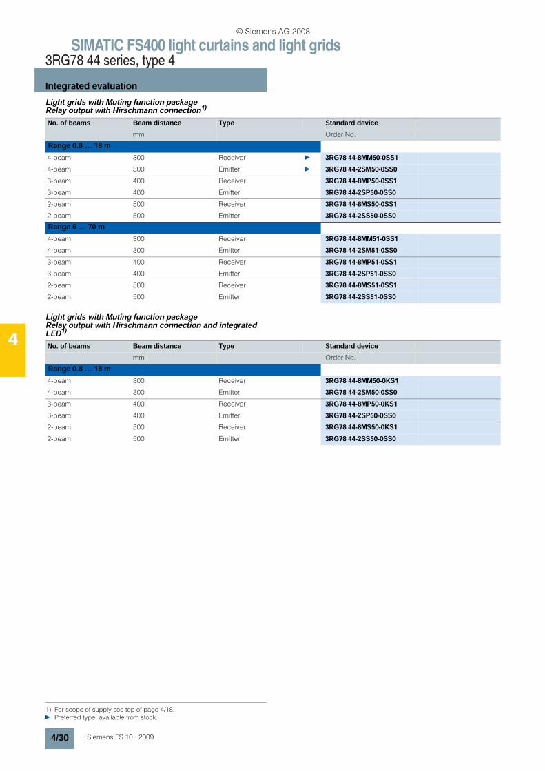
SIMATIC FS400 light curtains and light grids3RG78 44 series, type 4
Integrated evaluation
4/30 Siemens FS 10 · 2009
4
Light grids with Muting function packageRelay output with Hirschmann connection1)
Light grids with Muting function packageRelay output with Hirschmann connection and integrated LED1)
1) For scope of supply see top of page 4/18. Preferred type, available from stock.
No. of beams Beam distance Type Standard devicemm Order No.
Range 0.8 … 18 m4-beam 300 Receiver 3RG78 44-8MM50-0SS14-beam 300 Emitter 3RG78 44-2SM50-0SS03-beam 400 Receiver 3RG78 44-8MP50-0SS13-beam 400 Emitter 3RG78 44-2SP50-0SS02-beam 500 Receiver 3RG78 44-8MS50-0SS12-beam 500 Emitter 3RG78 44-2SS50-0SS0Range 6 … 70 m4-beam 300 Receiver 3RG78 44-8MM51-0SS14-beam 300 Emitter 3RG78 44-2SM51-0SS03-beam 400 Receiver 3RG78 44-8MP51-0SS13-beam 400 Emitter 3RG78 44-2SP51-0SS02-beam 500 Receiver 3RG78 44-8MS51-0SS12-beam 500 Emitter 3RG78 44-2SS51-0SS0
No. of beams Beam distance Type Standard devicemm Order No.
Range 0.8 … 18 m4-beam 300 Receiver 3RG78 44-8MM50-0KS14-beam 300 Emitter 3RG78 44-2SM50-0SS03-beam 400 Receiver 3RG78 44-8MP50-0KS13-beam 400 Emitter 3RG78 44-2SP50-0SS02-beam 500 Receiver 3RG78 44-8MS50-0KS12-beam 500 Emitter 3RG78 44-2SS50-0SS0
© Siemens AG 2008
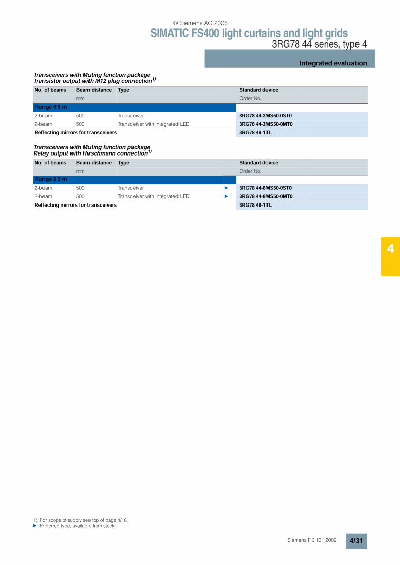
Range 6.5 m
SIMATIC FS400 light curtains and light grids3RG78 44 series, type 4
Integrated evaluation
4/31Siemens FS 10 · 2009
4
Transceivers with Muting function packageTransistor output with M12 plug connection1)
Transceivers with Muting function packageRelay output with Hirschmann connection1)
1) For scope of supply see top of page 4/18. Preferred type, available from stock.
No. of beams Beam distance Type Standard devicemm Order No.
Range 6.5 m2-beam 500 Transceiver 3RG78 44-3MS50-0ST02-beam 500 Transceiver with integrated LED 3RG78 44-3MS50-0MT0Reflecting mirrors for transceivers 3RG78 48-1TL
No. of beams Beam distance Type Standard devicemm Order No.
2-beam 500 Transceiver 3RG78 44-8MS50-0ST02-beam 500 Transceiver with integrated LED 3RG78 44-8MS50-0MT0Reflecting mirrors for transceivers 3RG78 48-1TL
© Siemens AG 2008
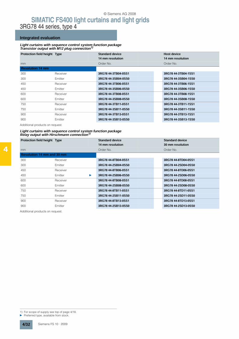
SIMATIC FS400 light curtains and light grids3RG78 44 series, type 4
Integrated evaluation
4/32 Siemens FS 10 · 2009
4
Light curtains with sequence control system function packageTransistor output with M12 plug connection1)
Additional products on request.
Light curtains with sequence control system function packageRelay output with Hirschmann connection1)
Additional products on request.
1) For scope of supply see top of page 4/18. Preferred type, available from stock.
Protection field height Type Standard device14 mm resolution
Host device14 mm resolution
mm Order No. Order No.
Resolution 14 mm300 Receiver 3RG78 44-3TB04-0SS1 3RG78 44-3TB04-1SS1300 Emitter 3RG78 44-3SB04-0SS0 3RG78 44-3SB04-1SS0450 Receiver 3RG78 44-3TB06-0SS1 3RG78 44-3TB06-1SS1450 Emitter 3RG78 44-3SB06-0SS0 3RG78 44-3SB06-1SS0600 Receiver 3RG78 44-3TB08-0SS1 3RG78 44-3TB08-1SS1600 Emitter 3RG78 44-3SB08-0SS0 3RG78 44-3SB08-1SS0750 Receiver 3RG78 44-3TB11-0SS1 3RG78 44-3TB11-1SS1750 Emitter 3RG78 44-3SB11-0SS0 3RG78 44-3SB11-1SS0900 Receiver 3RG78 44-3TB13-0SS1 3RG78 44-3TB13-1SS1900 Emitter 3RG78 44-3SB13-0SS0 3RG78 44-3SB13-1SS0
Protection field height Type Standard device14 mm resolution
Standard device30 mm resolution
mm Order No. Order No.
Resolution 14 mm and 30 mm300 Receiver 3RG78 44-8TB04-0SS1 3RG78 44-8TD04-0SS1300 Emitter 3RG78 44-2SB04-0SS0 3RG78 44-2SD04-0SS0450 Receiver 3RG78 44-8TB06-0SS1 3RG78 44-8TD06-0SS1450 Emitter 3RG78 44-2SB06-0SS0 3RG78 44-2SD06-0SS0600 Receiver 3RG78 44-8TB08-0SS1 3RG78 44-8TD08-0SS1600 Emitter 3RG78 44-2SB08-0SS0 3RG78 44-2SD08-0SS0750 Receiver 3RG78 44-8TB11-0SS1 3RG78 44-8TD11-0SS1750 Emitter 3RG78 44-2SB11-0SS0 3RG78 44-2SD11-0SS0900 Receiver 3RG78 44-8TB13-0SS1 3RG78 44-8TD13-0SS1900 Emitter 3RG78 44-2SB13-0SS0 3RG78 44-2SD13-0SS0
© Siemens AG 2008
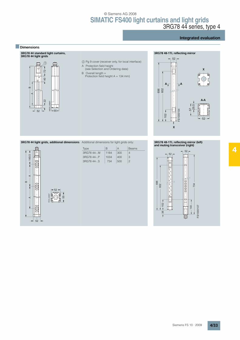
SIMATIC FS400 light curtains and light grids3RG78 44 series, type 4
Integrated evaluation
4/33Siemens FS 10 · 2009
4
n Dimensions3RG78 44 standard light curtains,3RG78 44 light grids
$ Pg 9 cover (receiver only, for local interface)
A Protection field height(see Selection and Ordering data)
B Overall length = Protection field height A + 134 mm)
3RG78 48-1TL reflecting mirror
3RG78 44 light grids, additional dimensions Additional dimensions for light grids only: 3RG78 48-1TL reflecting mirror (left) and muting transceiver (right)
NSC0_00647
A
5 2
B
5 5
22
1
72
40
52
102
602
696
X
52
29,5
57
A A
X
A-A
FS
10
00
10
4
52
52
55
149.5
A
FS
10
_0
03
07
B
A
Type B A Beams
3RG78 44-..M
3RG78 44-..P
3RG78 44-..S
1184
1034
734
300
400
500
4
3
2
52
102
602
52
734
140
38
696
FS
10
00
10
7
© Siemens AG 2008
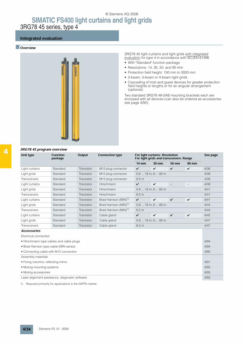
SIMATIC FS400 light curtains and light grids3RG78 45 series, type 4
Initegrated evaluation
4/34 Siemens FS 10 · 2009
4
n Overview
3RG78 45 light curtains and light grids with integratedevaluation for type 4 in accordance with IEC/EN 61496
• With "Standard" function package
• Resolutions: 14, 30, 50, and 90 mm
• Protection field height: 150 mm to 3000 mm
• 2-beam, 3-beam or 4-beam light grids
• Cascading of host and guest devices for greater protection field heights or lengths or for an angular arrangement (optional).
Two standard 3RG78 48-0AB mounting brackets each are enclosed with all devices (can also be ordered as accessories see page 4/92).
3RG78 45 program overviewUnit type Function
packageOutput Connection type For light curtains: Resolution
For light grids and transceivers: RangeSee page
14 mm 30 mm 50 mm 90 mmLight curtains Standard Transistor M12 plug connector 4 4 4 4 4/36
Light grids Standard Transistor M12 plug connector 0.8 ... 18 m; 6 ... 60 m 4/39
Transceivers Standard Transistor M12 plug connector 6.5 m 4/39
Light curtains Standard Transistor Hirschmann 4 4 − − 4/39
Light grids Standard Transistor Hirschmann 0.8 ... 18 m; 6 ... 60 m 4/41
Transceivers Standard Transistor Hirschmann 6.5 m 4/41
Light curtains Standard Transistor Brad Harrison (MIN)1)4 4 4 4 4/41
Light grids Standard Transistor Brad Harrison (MIN)1) 0.8 ... 18 m; 6 ... 60 m 4/44
Transceivers Standard Transistor Brad Harrison (MIN)1) 6.5 m 4/44
Light curtains Standard Transistor Cable gland 4 4 4 4 4/45
Light grids Standard Transistor Cable gland 0.8 ... 18 m; 6 ... 60 m 4/47
Transceivers Standard Transistor Cable gland 6.5 m 4/47
AccessoriesElectrical connection
• Hirschmann type cables and cable plugs 4/94
• Brad Harrison type cable (MIN series) 4/94
• Connecting cable with M12 connection 4/95
Assembly materials
• Fixing columns, reflecting mirror 4/91
• Muting mounting systems 4/92
• Muting accessories 4/95
Laser alignment assistance, diagnostic software 4/93
1) Required primarily for applications in the NAFTA market
© Siemens AG 2008
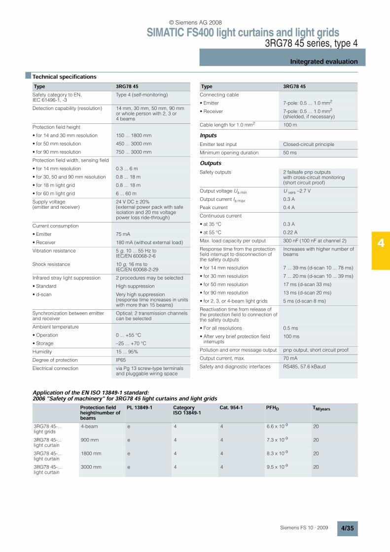
SIMATIC FS400 light curtains and light grids3RG78 45 series, type 4
Initegrated evaluation
4/35Siemens FS 10 · 2009
4
n Technical specifications
Inputs
Outputs
Application of the EN ISO 13849-1 standard: 2006 "Safety of machinery" for 3RG78 45 light curtains and light grids
Type 3RG78 45Safety category to EN, IEC 61496-1, -3
Type 4 (self-monitoring)
Detection capability (resolution) 14 mm, 30 mm, 50 mm, 90 mm or whole person with 2, 3 or 4 beams
Protection field height
• for 14 and 30 mm resolution 150 ... 1800 mm
• for 50 mm resolution 450 ... 3000 mm
• for 90 mm resolution 750 ... 3000 mm
Protection field width, sensing field
• for 14 mm resolution 0.3 ... 6 m
• for 30, 50 and 90 mm resolution 0.8 ... 18 m
• for 18 m light grid 0.8 ... 18 m
• for 60 m light grid 6 ... 60 m
Supply voltage (emitter and receiver)
24 V DC ± 20% (external power pack with safe isolation and 20 ms voltage power loss ride-through)
Current consumption
• Emitter 75 mA
• Receiver 180 mA (without external load)
Vibration resistance 5 g, 10 ... 55 Hz to IEC/EN 60068-2-6
Shock resistance 10 g, 16 ms to IEC/EN 60068-2-29
Infrared stray light suppression 2 procedures may be selected
• Standard High suppression
• d-scan Very high suppression (response time increases in units with more than 15 beams)
Synchronization between emitter and receiver
Optical; 2 transmission channels can be selected
Ambient temperature
• Operation 0 ... +55 °C
• Storage –25 ... +70 °C
Humidity 15 ... 95%
Degree of protection IP65
Electrical connection via Pg 13 screw-type terminals and pluggable wiring space
Connecting cable
• Emitter 7-pole: 0.5 ... 1.0 mm2
• Receiver 7-pole: 0.5 ... 1.0 mm2 (shielded, if necessary)
Cable length for 1.0 mm2 100 m
Emitter test input Closed-circuit principle
Minimum opening duration 50 ms
Safety outputs 2 failsafe pnp outputs with cross-circuit monitoring (short circuit proof)
Output voltage Ua min U vers –2.7 V
Output current Ia max 0.3 A
Peak current 0.4 A
Continuous current
• at 35 °C 0.3 A
• at 55 °C 0.22 A
Max. load capacity per output 300 nF (100 nF at channel 2)
Response time from the protection field interrupt to disconnection of the safety outputs
Increases with higher number of beams
• for 14 mm resolution 7 ... 39 ms (d-scan 10 ... 78 ms)
• for 30 mm resolution 7 ... 20 ms (d-scan 10 ... 39 ms)
• for 50 mm resolution 17 ms (d-scan 33 ms)
• for 90 mm resolution 13 ms (d-scan 20 ms)
• for 2, 3, or 4-beam light grids 5 ms (d-scan 8 ms)
Reactivation time from release of the protection field to connection of the safety outputs
• For all resolutions 0.5 ms
• After very brief protection field interrupts
100 ms
Pollution and error message output pnp output, short circuit proof
Output current, max. 70 mA
Safety and diagnostic interfaces RS485, 57.6 kBaud
Type 3RG78 45
Protection field height/number of beams
PL 13849-1 Category ISO 13849-1
Cat. 954-1 PFHD TM/years
3RG78 45-...light grids
4-beam e 4 4 6.6 x 10⁻⁹ 20
3RG78 45-...light curtain
900 mm e 4 4 7.3 x 10⁻⁹ 20
3RG78 45-...light curtain
1800 mm e 4 4 8.3 x 10⁻⁹ 20
3RG78 45-...light curtain
3000 mm e 4 4 9.5 x 10⁻⁹ 20
© Siemens AG 2008
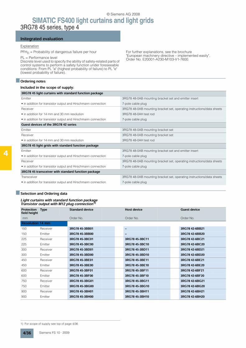
SIMATIC FS400 light curtains and light grids3RG78 45 series, type 4
Initegrated evaluation
4/36 Siemens FS 10 · 2009
4
Explanation
PFHD = Probability of dangerous failure per hour
PL = Performance level Discrete level used to specify the ability of safety-related parts of control systems to perform a safety function under foreseeable conditions: From PL "a" (highest probability of failure) to PL "e" (lowest probability of failure).
For further explanations, see the brochure "European machinery directive – implemented easily", Order No. E20001-A230-M103-V1-7600.
n Ordering notesIncluded in the scope of supply:
n Selection and Ordering dataLight curtains with standard function packageTransistor output with M12 plug connection1)
3RG78 45 light curtains with standard function packageEmitter 3RG78 48-0AB mounting bracket set and emitter insert
• in addition for transistor output and Hirschmann connection 7-pole cable plug
Receiver 3RG78 48-0AB mounting bracket set, operating instructions/data sheets
• in addition for 14 mm and 30 mm resolution 3RG78 48-0AH test rod
• in addition for transistor output and Hirschmann connection 7-pole cable plug
Guest devices of the 3RG78 42 seriesEmitter 3RG78 48-0AB mounting bracket set
Receiver 3RG78 48-0AB mounting bracket set
• in addition for 14 mm and 30 mm resolution 3RG78 48-0AH test rod
3RG78 45 light grids with standard function packageEmitter 3RG78 48-0AB mounting bracket set and emitter insert
• in addition for transistor output and Hirschmann connection 7-pole cable plug
Receiver 3RG78 48-0AB mounting bracket set, operating instructions/data sheets
• in addition for transistor output and Hirschmann connection 7-pole cable plug
3RG78 45 transceiver with standard function packageTransceiver 3RG78 48-0AB mounting bracket set, operating instructions/data sheets
• in addition for transistor output and Hirschmann connection 7-pole cable plug
1) For scope of supply see top of page 4/36
Protection field height
Type Standard device Host device Guest device
mm Order No. Order No. Order No.
Resolution 14 mm150 Receiver 3RG78 45-3BB01 – 3RG78 42-6BB21150 Emitter 3RG78 45-3BB00 – 3RG78 42-6BB20225 Receiver 3RG78 45-3BC01 3RG78 45-3BC11 3RG78 42-6BC21225 Emitter 3RG78 45-3BC00 3RG78 45-3BC10 3RG78 42-6BC20300 Receiver 3RG78 45-3BD01 3RG78 45-3BD11 3RG78 42-6BD21300 Emitter 3RG78 45-3BD00 3RG78 45-3BD10 3RG78 42-6BD20450 Receiver 3RG78 45-3BE01 3RG78 45-3BE11 3RG78 42-6BE21450 Emitter 3RG78 45-3BE00 3RG78 45-3BE10 3RG78 42-6BE20600 Receiver 3RG78 45-3BF01 3RG78 45-3BF11 3RG78 42-6BF21600 Emitter 3RG78 45-3BF00 3RG78 45-3BF10 3RG78 42-6BF20750 Receiver 3RG78 45-3BG01 3RG78 45-3BG11 3RG78 42-6BG21750 Emitter 3RG78 45-3BG00 3RG78 45-3BG10 3RG78 42-6BG20900 Receiver 3RG78 45-3BH01 3RG78 45-3BH11 3RG78 42-6BH21900 Emitter 3RG78 45-3BH00 3RG78 45-3BH10 3RG78 42-6BH20
© Siemens AG 2008
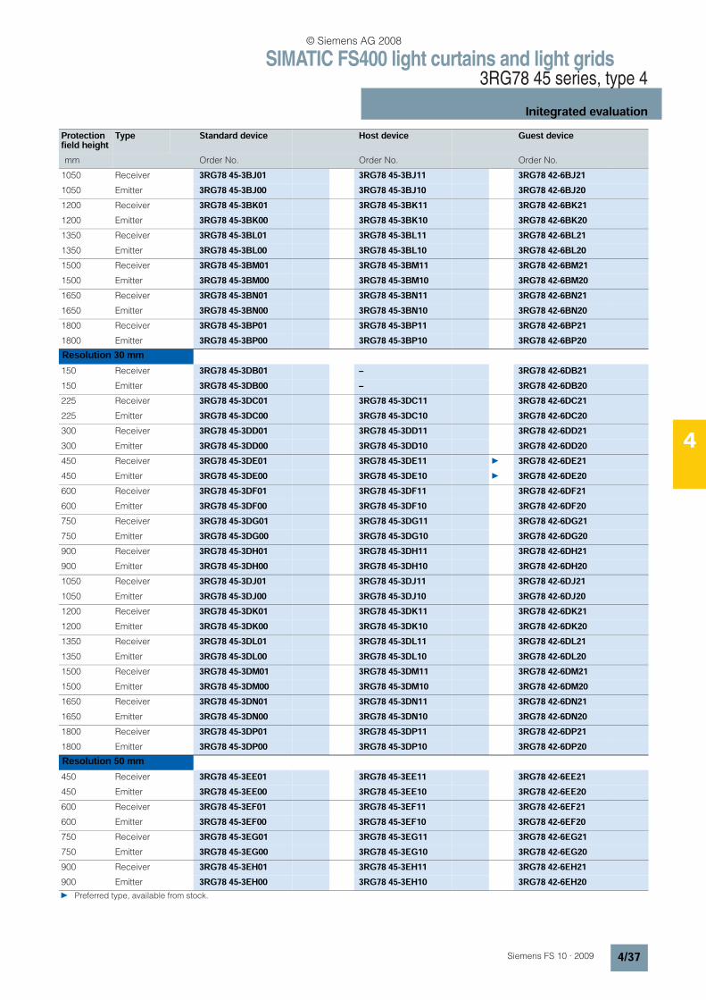
SIMATIC FS400 light curtains and light grids3RG78 45 series, type 4
Initegrated evaluation
4/37Siemens FS 10 · 2009
4
Protection field height
Type Standard device Host device Guest device
mm Order No. Order No. Order No.
1050 Receiver 3RG78 45-3BJ01 3RG78 45-3BJ11 3RG78 42-6BJ211050 Emitter 3RG78 45-3BJ00 3RG78 45-3BJ10 3RG78 42-6BJ201200 Receiver 3RG78 45-3BK01 3RG78 45-3BK11 3RG78 42-6BK211200 Emitter 3RG78 45-3BK00 3RG78 45-3BK10 3RG78 42-6BK201350 Receiver 3RG78 45-3BL01 3RG78 45-3BL11 3RG78 42-6BL211350 Emitter 3RG78 45-3BL00 3RG78 45-3BL10 3RG78 42-6BL201500 Receiver 3RG78 45-3BM01 3RG78 45-3BM11 3RG78 42-6BM211500 Emitter 3RG78 45-3BM00 3RG78 45-3BM10 3RG78 42-6BM201650 Receiver 3RG78 45-3BN01 3RG78 45-3BN11 3RG78 42-6BN211650 Emitter 3RG78 45-3BN00 3RG78 45-3BN10 3RG78 42-6BN201800 Receiver 3RG78 45-3BP01 3RG78 45-3BP11 3RG78 42-6BP211800 Emitter 3RG78 45-3BP00 3RG78 45-3BP10 3RG78 42-6BP20Resolution 30 mm150 Receiver 3RG78 45-3DB01 – 3RG78 42-6DB21150 Emitter 3RG78 45-3DB00 – 3RG78 42-6DB20225 Receiver 3RG78 45-3DC01 3RG78 45-3DC11 3RG78 42-6DC21225 Emitter 3RG78 45-3DC00 3RG78 45-3DC10 3RG78 42-6DC20300 Receiver 3RG78 45-3DD01 3RG78 45-3DD11 3RG78 42-6DD21300 Emitter 3RG78 45-3DD00 3RG78 45-3DD10 3RG78 42-6DD20450 Receiver 3RG78 45-3DE01 3RG78 45-3DE11 3RG78 42-6DE21450 Emitter 3RG78 45-3DE00 3RG78 45-3DE10 3RG78 42-6DE20600 Receiver 3RG78 45-3DF01 3RG78 45-3DF11 3RG78 42-6DF21600 Emitter 3RG78 45-3DF00 3RG78 45-3DF10 3RG78 42-6DF20750 Receiver 3RG78 45-3DG01 3RG78 45-3DG11 3RG78 42-6DG21750 Emitter 3RG78 45-3DG00 3RG78 45-3DG10 3RG78 42-6DG20900 Receiver 3RG78 45-3DH01 3RG78 45-3DH11 3RG78 42-6DH21900 Emitter 3RG78 45-3DH00 3RG78 45-3DH10 3RG78 42-6DH201050 Receiver 3RG78 45-3DJ01 3RG78 45-3DJ11 3RG78 42-6DJ211050 Emitter 3RG78 45-3DJ00 3RG78 45-3DJ10 3RG78 42-6DJ201200 Receiver 3RG78 45-3DK01 3RG78 45-3DK11 3RG78 42-6DK211200 Emitter 3RG78 45-3DK00 3RG78 45-3DK10 3RG78 42-6DK201350 Receiver 3RG78 45-3DL01 3RG78 45-3DL11 3RG78 42-6DL211350 Emitter 3RG78 45-3DL00 3RG78 45-3DL10 3RG78 42-6DL201500 Receiver 3RG78 45-3DM01 3RG78 45-3DM11 3RG78 42-6DM211500 Emitter 3RG78 45-3DM00 3RG78 45-3DM10 3RG78 42-6DM201650 Receiver 3RG78 45-3DN01 3RG78 45-3DN11 3RG78 42-6DN211650 Emitter 3RG78 45-3DN00 3RG78 45-3DN10 3RG78 42-6DN201800 Receiver 3RG78 45-3DP01 3RG78 45-3DP11 3RG78 42-6DP211800 Emitter 3RG78 45-3DP00 3RG78 45-3DP10 3RG78 42-6DP20Resolution 50 mm450 Receiver 3RG78 45-3EE01 3RG78 45-3EE11 3RG78 42-6EE21450 Emitter 3RG78 45-3EE00 3RG78 45-3EE10 3RG78 42-6EE20600 Receiver 3RG78 45-3EF01 3RG78 45-3EF11 3RG78 42-6EF21600 Emitter 3RG78 45-3EF00 3RG78 45-3EF10 3RG78 42-6EF20750 Receiver 3RG78 45-3EG01 3RG78 45-3EG11 3RG78 42-6EG21750 Emitter 3RG78 45-3EG00 3RG78 45-3EG10 3RG78 42-6EG20900 Receiver 3RG78 45-3EH01 3RG78 45-3EH11 3RG78 42-6EH21900 Emitter 3RG78 45-3EH00 3RG78 45-3EH10 3RG78 42-6EH20 Preferred type, available from stock.
© Siemens AG 2008

SIMATIC FS400 light curtains and light grids3RG78 45 series, type 4
Initegrated evaluation
4/38 Siemens FS 10 · 2009
4
Protection field height
Type Standard device Host device Guest device
mm Order No. Order No. Order No.
1050 Receiver 3RG78 45-3EJ01 3RG78 45-3EJ11 3RG78 42-6EJ211050 Emitter 3RG78 45-3EJ00 3RG78 45-3EJ10 3RG78 42-6EJ201200 Receiver 3RG78 45-3EK01 3RG78 45-3EK11 3RG78 42-6EK211200 Emitter 3RG78 45-3EK00 3RG78 45-3EK10 3RG78 42-6EK201350 Receiver 3RG78 45-3EL01 3RG78 45-3EL11 3RG78 42-6EL211350 Emitter 3RG78 45-3EL00 3RG78 45-3EL10 3RG78 42-6EL201500 Receiver 3RG78 45-3EM01 3RG78 45-3EM11 3RG78 42-6EM211500 Emitter 3RG78 45-3EM00 3RG78 45-3EM10 3RG78 42-6EM201650 Receiver 3RG78 45-3EN01 3RG78 45-3EN11 3RG78 42-6EN211650 Emitter 3RG78 45-3EN00 3RG78 45-3EN10 3RG78 42-6EN201800 Receiver 3RG78 45-3EP01 3RG78 45-3EP11 3RG78 42-6EP211800 Emitter 3RG78 45-3EP00 3RG78 45-3EP10 3RG78 42-6EP202100 Receiver 3RG78 45-3ER01 3RG78 45-3ER11 3RG78 42-6ER212100 Emitter 3RG78 45-3ER00 3RG78 45-3ER10 3RG78 42-6ER202400 Receiver 3RG78 45-3ES01 3RG78 45-3ES11 3RG78 42-6ES212400 Emitter 3RG78 45-3ES00 3RG78 45-3ES10 3RG78 42-6ES202700 Receiver 3RG78 45-3ET01 3RG78 45-3ET11 3RG78 42-6ET212700 Emitter 3RG78 45-3ET00 3RG78 45-3ET10 3RG78 42-6ET203000 Receiver 3RG78 45-3EU01 3RG78 45-3EU11 3RG78 42-6EU213000 Emitter 3RG78 45-3EU00 3RG78 45-3EU10 3RG78 42-6EU20Resolution 90 mm750 Receiver 3RG78 45-3JG01 3RG78 45-3JG11 3RG78 42-6JG21750 Emitter 3RG78 45-3JG00 3RG78 45-3JG10 3RG78 42-6JG20900 Receiver 3RG78 45-3JH01 3RG78 45-3JH11 3RG78 42-6JH21900 Emitter 3RG78 45-3JH00 3RG78 45-3JH10 3RG78 42-6JH201050 Receiver 3RG78 45-3JJ01 3RG78 45-3JJ11 3RG78 42-6JJ211050 Emitter 3RG78 45-3JJ00 3RG78 45-3JJ10 3RG78 42-6JJ201200 Receiver 3RG78 45-3JK01 3RG78 45-3JK11 3RG78 42-6JK211200 Emitter 3RG78 45-3JK00 3RG78 45-3JK10 3RG78 42-6JK201350 Receiver 3RG78 45-3JL01 3RG78 45-3JL11 3RG78 42-6JL211350 Emitter 3RG78 45-3JL00 3RG78 45-3JL10 3RG78 42-6JL201500 Receiver 3RG78 45-3JM01 3RG78 45-3JM11 3RG78 42-6JM211500 Emitter 3RG78 45-3JM00 3RG78 45-3JM10 3RG78 42-6JM201650 Receiver 3RG78 45-3JN01 3RG78 45-3JN11 3RG78 42-6JN211650 Emitter 3RG78 45-3JN00 3RG78 45-3JN10 3RG78 42-6JN201800 Receiver 3RG78 45-3JP01 3RG78 45-3JP11 3RG78 42-6JP211800 Emitter 3RG78 45-3JP00 3RG78 45-3JP10 3RG78 42-6JP202100 Receiver 3RG78 45-3JR01 3RG78 45-3JR11 3RG78 42-6JR212100 Emitter 3RG78 45-3JR00 3RG78 45-3JR10 3RG78 42-6JR202400 Receiver 3RG78 45-3JS01 3RG78 45-3JS11 3RG78 42-6JS212400 Emitter 3RG78 45-3JS00 3RG78 45-3JS10 3RG78 42-6JS202700 Receiver 3RG78 45-3JT01 3RG78 45-3JT11 3RG78 42-6JT212700 Emitter 3RG78 45-3JT00 3RG78 45-3JT10 3RG78 42-6JT203000 Receiver 3RG78 45-3JU01 3RG78 45-3JU11 3RG78 42-6JU213000 Emitter 3RG78 45-3JU00 3RG78 45-3JU10 3RG78 42-6JU20
© Siemens AG 2008
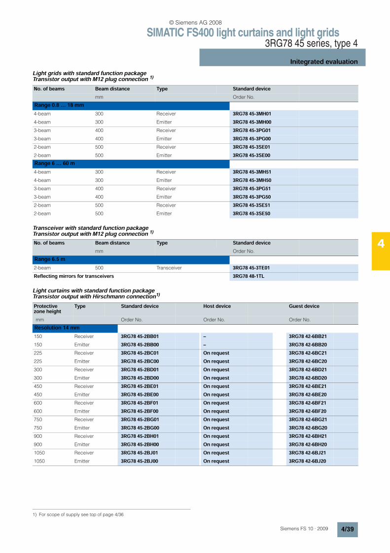
SIMATIC FS400 light curtains and light grids3RG78 45 series, type 4
Initegrated evaluation
4/39Siemens FS 10 · 2009
4
Light grids with standard function package Transistor output with M12 plug connection 1)
Transceiver with standard function package Transistor output with M12 plug connection 1)
Light curtains with standard function package Transistor output with Hirschmann connection1)
1) For scope of supply see top of page 4/36
No. of beams Beam distance Type Standard devicemm Order No.
Range 0.8 … 18 mm4-beam 300 Receiver 3RG78 45-3MH014-beam 300 Emitter 3RG78 45-3MH003-beam 400 Receiver 3RG78 45-3PG013-beam 400 Emitter 3RG78 45-3PG002-beam 500 Receiver 3RG78 45-3SE012-beam 500 Emitter 3RG78 45-3SE00Range 6 … 60 m4-beam 300 Receiver 3RG78 45-3MH514-beam 300 Emitter 3RG78 45-3MH503-beam 400 Receiver 3RG78 45-3PG513-beam 400 Emitter 3RG78 45-3PG502-beam 500 Receiver 3RG78 45-3SE512-beam 500 Emitter 3RG78 45-3SE50
No. of beams Beam distance Type Standard devicemm Order No.
Range 6.5 m2-beam 500 Transceiver 3RG78 45-3TE01Reflecting mirrors for transceivers 3RG78 48-1TL
Protective zone height
Type Standard device Host device Guest device
mm Order No. Order No. Order No.
Resolution 14 mm150 Receiver 3RG78 45-2BB01 – 3RG78 42-6BB21150 Emitter 3RG78 45-2BB00 – 3RG78 42-6BB20225 Receiver 3RG78 45-2BC01 On request 3RG78 42-6BC21225 Emitter 3RG78 45-2BC00 On request 3RG78 42-6BC20300 Receiver 3RG78 45-2BD01 On request 3RG78 42-6BD21300 Emitter 3RG78 45-2BD00 On request 3RG78 42-6BD20450 Receiver 3RG78 45-2BE01 On request 3RG78 42-6BE21450 Emitter 3RG78 45-2BE00 On request 3RG78 42-6BE20600 Receiver 3RG78 45-2BF01 On request 3RG78 42-6BF21600 Emitter 3RG78 45-2BF00 On request 3RG78 42-6BF20750 Receiver 3RG78 45-2BG01 On request 3RG78 42-6BG21750 Emitter 3RG78 45-2BG00 On request 3RG78 42-6BG20900 Receiver 3RG78 45-2BH01 On request 3RG78 42-6BH21900 Emitter 3RG78 45-2BH00 On request 3RG78 42-6BH201050 Receiver 3RG78 45-2BJ01 On request 3RG78 42-6BJ211050 Emitter 3RG78 45-2BJ00 On request 3RG78 42-6BJ20
© Siemens AG 2008
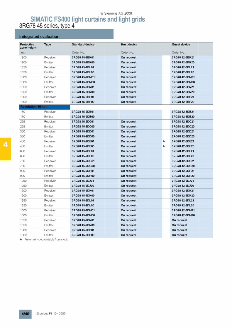
SIMATIC FS400 light curtains and light grids3RG78 45 series, type 4
Initegrated evaluation
4/40 Siemens FS 10 · 2009
4
Protective zone height
Type Standard device Host device Guest device
mm Order No. Order No. Order No.
1200 Receiver 3RG78 45-2BK01 On request 3RG78 42-6BK211200 Emitter 3RG78 45-2BK00 On request 3RG78 42-6BK201350 Receiver 3RG78 45-2BL01 On request 3RG78 42-6BL211350 Emitter 3RG78 45-2BL00 On request 3RG78 42-6BL201500 Receiver 3RG78 45-2BM01 On request 3RG78 42-6BM211500 Emitter 3RG78 45-2BM00 On request 3RG78 42-6BM201650 Receiver 3RG78 45-2BN01 On request 3RG78 42-6BN211650 Emitter 3RG78 45-2BN00 On request 3RG78 42-6BN201800 Receiver 3RG78 45-2BP01 On request 3RG78 42-6BP211800 Emitter 3RG78 45-2BP00 On request 3RG78 42-6BP20Resolution 30 mm150 Receiver 3RG78 45-2DB01 – 3RG78 42-6DB21150 Emitter 3RG78 45-2DB00 – 3RG78 42-6DB20225 Receiver 3RG78 45-2DC01 On request 3RG78 42-6DC21225 Emitter 3RG78 45-2DC00 On request 3RG78 42-6DC20300 Receiver 3RG78 45-2DD01 On request 3RG78 42-6DD21300 Emitter 3RG78 45-2DD00 On request 3RG78 42-6DD20450 Receiver 3RG78 45-2DE01 On request 3RG78 42-6DE21450 Emitter 3RG78 45-2DE00 On request 3RG78 42-6DE20600 Receiver 3RG78 45-2DF01 On request 3RG78 42-6DF21600 Emitter 3RG78 45-2DF00 On request 3RG78 42-6DF20750 Receiver 3RG78 45-2DG01 On request 3RG78 42-6DG21750 Emitter 3RG78 45-2DG00 On request 3RG78 42-6DG20900 Receiver 3RG78 45-2DH01 On request 3RG78 42-6DH21900 Emitter 3RG78 45-2DH00 On request 3RG78 42-6DH201050 Receiver 3RG78 45-2DJ01 On request 3RG78 42-6DJ211050 Emitter 3RG78 45-2DJ00 On request 3RG78 42-6DJ201200 Receiver 3RG78 45-2DK01 On request 3RG78 42-6DK211200 Emitter 3RG78 45-2DK00 On request 3RG78 42-6DK201350 Receiver 3RG78 45-2DL01 On request 3RG78 42-6DL211350 Emitter 3RG78 45-2DL00 On request 3RG78 42-6DL201500 Receiver 3RG78 45-2DM01 On request 3RG78 42-6DM211500 Emitter 3RG78 45-2DM00 On request 3RG78 42-6DM201650 Receiver 3RG78 45-2DN01 On request On request1650 Emitter 3RG78 45-2DN00 On request On request1800 Receiver 3RG78 45-2DP01 On request On request1800 Emitter 3RG78 45-2DP00 On request On request Preferred type, available from stock.
© Siemens AG 2008
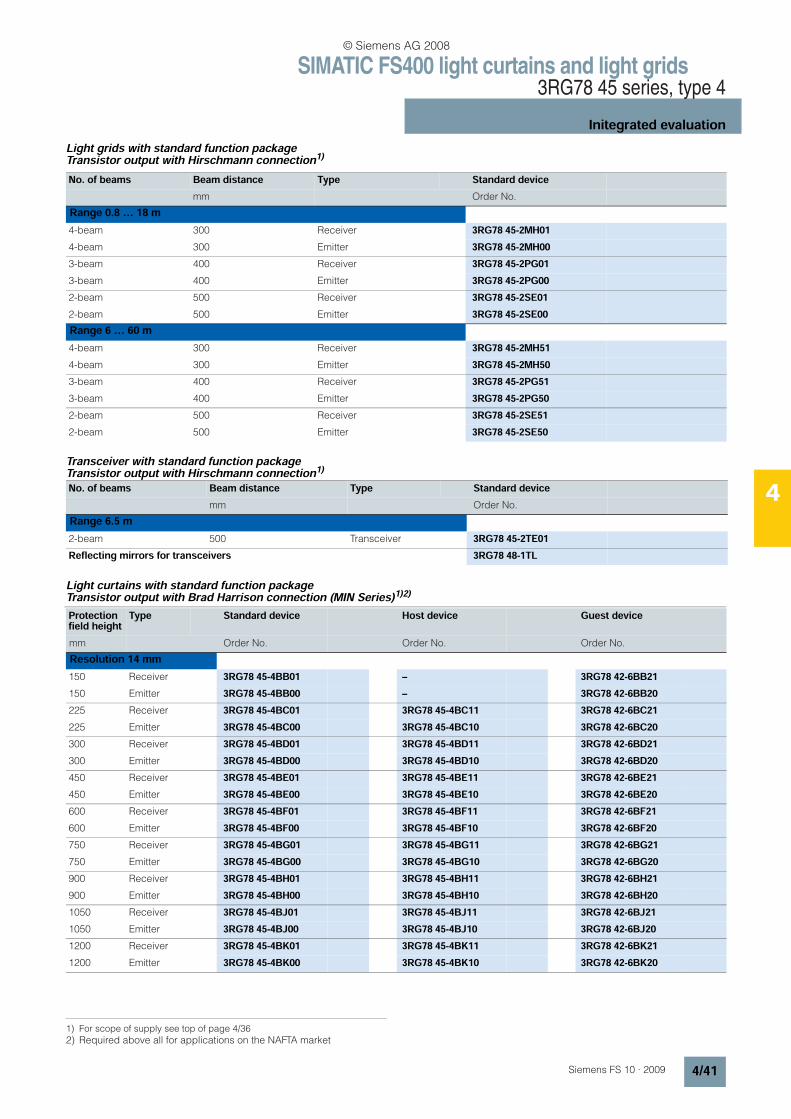
SIMATIC FS400 light curtains and light grids3RG78 45 series, type 4
Initegrated evaluation
4/41Siemens FS 10 · 2009
4
Light grids with standard function package Transistor output with Hirschmann connection1)
Transceiver with standard function package Transistor output with Hirschmann connection1)
Light curtains with standard function package Transistor output with Brad Harrison connection (MIN Series)1)2)
1) For scope of supply see top of page 4/36
No. of beams Beam distance Type Standard devicemm Order No.
Range 0.8 … 18 m4-beam 300 Receiver 3RG78 45-2MH014-beam 300 Emitter 3RG78 45-2MH003-beam 400 Receiver 3RG78 45-2PG013-beam 400 Emitter 3RG78 45-2PG002-beam 500 Receiver 3RG78 45-2SE012-beam 500 Emitter 3RG78 45-2SE00Range 6 … 60 m4-beam 300 Receiver 3RG78 45-2MH514-beam 300 Emitter 3RG78 45-2MH503-beam 400 Receiver 3RG78 45-2PG513-beam 400 Emitter 3RG78 45-2PG502-beam 500 Receiver 3RG78 45-2SE512-beam 500 Emitter 3RG78 45-2SE50
No. of beams Beam distance Type Standard devicemm Order No.
Range 6.5 m2-beam 500 Transceiver 3RG78 45-2TE01Reflecting mirrors for transceivers 3RG78 48-1TL
2) Required above all for applications on the NAFTA market
Protection field height
Type Standard device Host device Guest device
mm Order No. Order No. Order No.
Resolution 14 mm150 Receiver 3RG78 45-4BB01 – 3RG78 42-6BB21150 Emitter 3RG78 45-4BB00 – 3RG78 42-6BB20225 Receiver 3RG78 45-4BC01 3RG78 45-4BC11 3RG78 42-6BC21225 Emitter 3RG78 45-4BC00 3RG78 45-4BC10 3RG78 42-6BC20300 Receiver 3RG78 45-4BD01 3RG78 45-4BD11 3RG78 42-6BD21300 Emitter 3RG78 45-4BD00 3RG78 45-4BD10 3RG78 42-6BD20450 Receiver 3RG78 45-4BE01 3RG78 45-4BE11 3RG78 42-6BE21450 Emitter 3RG78 45-4BE00 3RG78 45-4BE10 3RG78 42-6BE20600 Receiver 3RG78 45-4BF01 3RG78 45-4BF11 3RG78 42-6BF21600 Emitter 3RG78 45-4BF00 3RG78 45-4BF10 3RG78 42-6BF20750 Receiver 3RG78 45-4BG01 3RG78 45-4BG11 3RG78 42-6BG21750 Emitter 3RG78 45-4BG00 3RG78 45-4BG10 3RG78 42-6BG20900 Receiver 3RG78 45-4BH01 3RG78 45-4BH11 3RG78 42-6BH21900 Emitter 3RG78 45-4BH00 3RG78 45-4BH10 3RG78 42-6BH201050 Receiver 3RG78 45-4BJ01 3RG78 45-4BJ11 3RG78 42-6BJ211050 Emitter 3RG78 45-4BJ00 3RG78 45-4BJ10 3RG78 42-6BJ201200 Receiver 3RG78 45-4BK01 3RG78 45-4BK11 3RG78 42-6BK211200 Emitter 3RG78 45-4BK00 3RG78 45-4BK10 3RG78 42-6BK20
© Siemens AG 2008
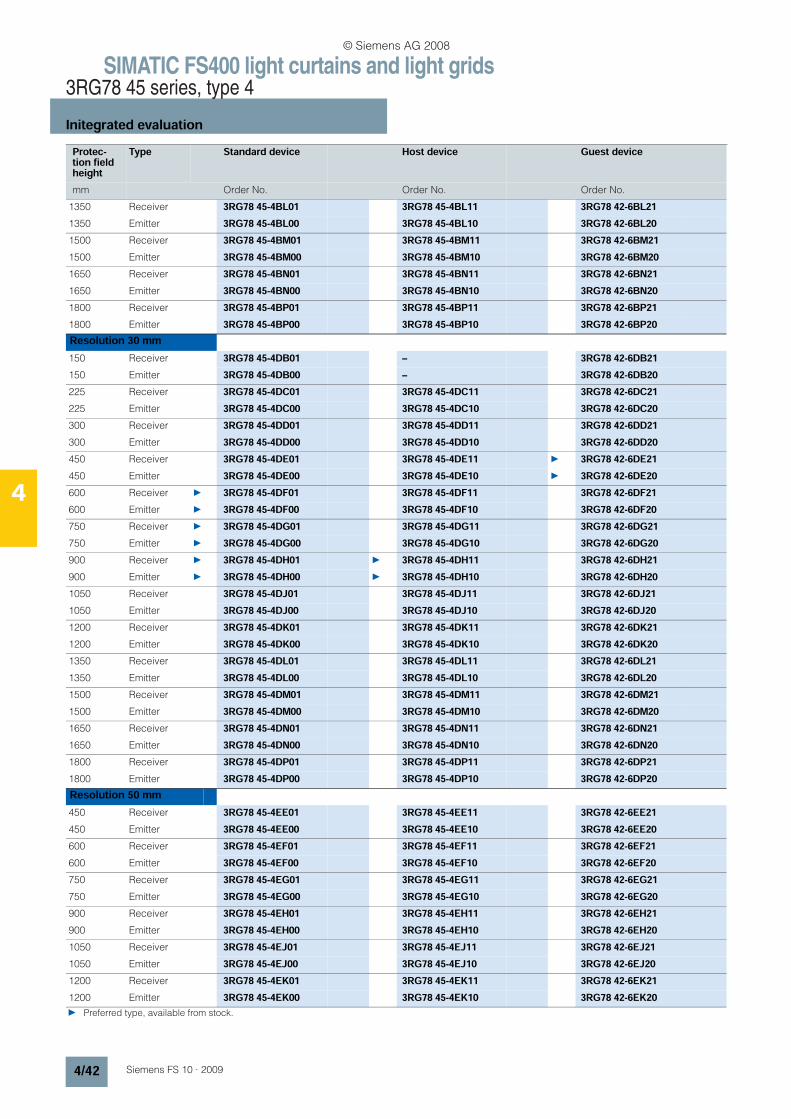
SIMATIC FS400 light curtains and light grids3RG78 45 series, type 4
Initegrated evaluation
4/42 Siemens FS 10 · 2009
4
Protec-tion field height
Type Standard device Host device Guest device
mm Order No. Order No. Order No.
1350 Receiver 3RG78 45-4BL01 3RG78 45-4BL11 3RG78 42-6BL211350 Emitter 3RG78 45-4BL00 3RG78 45-4BL10 3RG78 42-6BL201500 Receiver 3RG78 45-4BM01 3RG78 45-4BM11 3RG78 42-6BM211500 Emitter 3RG78 45-4BM00 3RG78 45-4BM10 3RG78 42-6BM201650 Receiver 3RG78 45-4BN01 3RG78 45-4BN11 3RG78 42-6BN211650 Emitter 3RG78 45-4BN00 3RG78 45-4BN10 3RG78 42-6BN201800 Receiver 3RG78 45-4BP01 3RG78 45-4BP11 3RG78 42-6BP211800 Emitter 3RG78 45-4BP00 3RG78 45-4BP10 3RG78 42-6BP20Resolution 30 mm150 Receiver 3RG78 45-4DB01 – 3RG78 42-6DB21150 Emitter 3RG78 45-4DB00 – 3RG78 42-6DB20225 Receiver 3RG78 45-4DC01 3RG78 45-4DC11 3RG78 42-6DC21225 Emitter 3RG78 45-4DC00 3RG78 45-4DC10 3RG78 42-6DC20300 Receiver 3RG78 45-4DD01 3RG78 45-4DD11 3RG78 42-6DD21300 Emitter 3RG78 45-4DD00 3RG78 45-4DD10 3RG78 42-6DD20450 Receiver 3RG78 45-4DE01 3RG78 45-4DE11 3RG78 42-6DE21450 Emitter 3RG78 45-4DE00 3RG78 45-4DE10 3RG78 42-6DE20600 Receiver 3RG78 45-4DF01 3RG78 45-4DF11 3RG78 42-6DF21600 Emitter 3RG78 45-4DF00 3RG78 45-4DF10 3RG78 42-6DF20750 Receiver 3RG78 45-4DG01 3RG78 45-4DG11 3RG78 42-6DG21750 Emitter 3RG78 45-4DG00 3RG78 45-4DG10 3RG78 42-6DG20900 Receiver 3RG78 45-4DH01 3RG78 45-4DH11 3RG78 42-6DH21900 Emitter 3RG78 45-4DH00 3RG78 45-4DH10 3RG78 42-6DH201050 Receiver 3RG78 45-4DJ01 3RG78 45-4DJ11 3RG78 42-6DJ211050 Emitter 3RG78 45-4DJ00 3RG78 45-4DJ10 3RG78 42-6DJ201200 Receiver 3RG78 45-4DK01 3RG78 45-4DK11 3RG78 42-6DK211200 Emitter 3RG78 45-4DK00 3RG78 45-4DK10 3RG78 42-6DK201350 Receiver 3RG78 45-4DL01 3RG78 45-4DL11 3RG78 42-6DL211350 Emitter 3RG78 45-4DL00 3RG78 45-4DL10 3RG78 42-6DL201500 Receiver 3RG78 45-4DM01 3RG78 45-4DM11 3RG78 42-6DM211500 Emitter 3RG78 45-4DM00 3RG78 45-4DM10 3RG78 42-6DM201650 Receiver 3RG78 45-4DN01 3RG78 45-4DN11 3RG78 42-6DN211650 Emitter 3RG78 45-4DN00 3RG78 45-4DN10 3RG78 42-6DN201800 Receiver 3RG78 45-4DP01 3RG78 45-4DP11 3RG78 42-6DP211800 Emitter 3RG78 45-4DP00 3RG78 45-4DP10 3RG78 42-6DP20Resolution 50 mm450 Receiver 3RG78 45-4EE01 3RG78 45-4EE11 3RG78 42-6EE21450 Emitter 3RG78 45-4EE00 3RG78 45-4EE10 3RG78 42-6EE20600 Receiver 3RG78 45-4EF01 3RG78 45-4EF11 3RG78 42-6EF21600 Emitter 3RG78 45-4EF00 3RG78 45-4EF10 3RG78 42-6EF20750 Receiver 3RG78 45-4EG01 3RG78 45-4EG11 3RG78 42-6EG21750 Emitter 3RG78 45-4EG00 3RG78 45-4EG10 3RG78 42-6EG20900 Receiver 3RG78 45-4EH01 3RG78 45-4EH11 3RG78 42-6EH21900 Emitter 3RG78 45-4EH00 3RG78 45-4EH10 3RG78 42-6EH201050 Receiver 3RG78 45-4EJ01 3RG78 45-4EJ11 3RG78 42-6EJ211050 Emitter 3RG78 45-4EJ00 3RG78 45-4EJ10 3RG78 42-6EJ201200 Receiver 3RG78 45-4EK01 3RG78 45-4EK11 3RG78 42-6EK211200 Emitter 3RG78 45-4EK00 3RG78 45-4EK10 3RG78 42-6EK20 Preferred type, available from stock.
© Siemens AG 2008
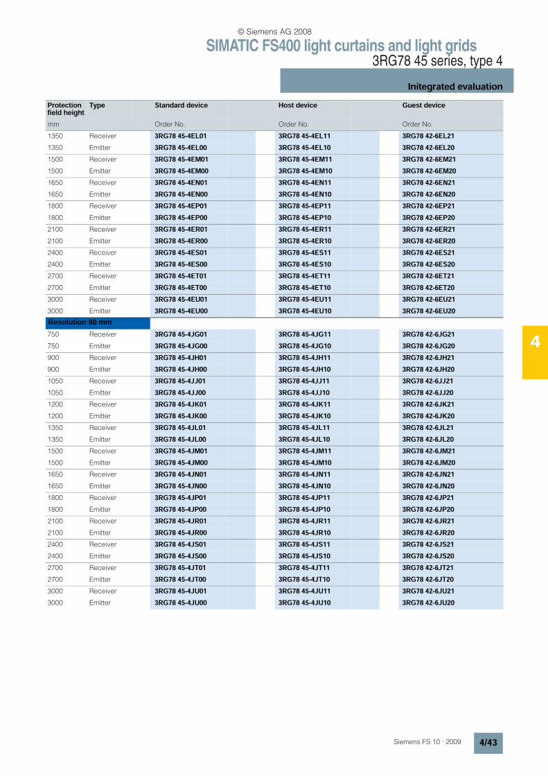
SIMATIC FS400 light curtains and light grids3RG78 45 series, type 4
Initegrated evaluation
4/43Siemens FS 10 · 2009
4
Protection field height
Type Standard device Host device Guest device
mm Order No. Order No. Order No.
1350 Receiver 3RG78 45-4EL01 3RG78 45-4EL11 3RG78 42-6EL211350 Emitter 3RG78 45-4EL00 3RG78 45-4EL10 3RG78 42-6EL201500 Receiver 3RG78 45-4EM01 3RG78 45-4EM11 3RG78 42-6EM211500 Emitter 3RG78 45-4EM00 3RG78 45-4EM10 3RG78 42-6EM201650 Receiver 3RG78 45-4EN01 3RG78 45-4EN11 3RG78 42-6EN211650 Emitter 3RG78 45-4EN00 3RG78 45-4EN10 3RG78 42-6EN201800 Receiver 3RG78 45-4EP01 3RG78 45-4EP11 3RG78 42-6EP211800 Emitter 3RG78 45-4EP00 3RG78 45-4EP10 3RG78 42-6EP202100 Receiver 3RG78 45-4ER01 3RG78 45-4ER11 3RG78 42-6ER212100 Emitter 3RG78 45-4ER00 3RG78 45-4ER10 3RG78 42-6ER202400 Receiver 3RG78 45-4ES01 3RG78 45-4ES11 3RG78 42-6ES212400 Emitter 3RG78 45-4ES00 3RG78 45-4ES10 3RG78 42-6ES202700 Receiver 3RG78 45-4ET01 3RG78 45-4ET11 3RG78 42-6ET212700 Emitter 3RG78 45-4ET00 3RG78 45-4ET10 3RG78 42-6ET203000 Receiver 3RG78 45-4EU01 3RG78 45-4EU11 3RG78 42-6EU213000 Emitter 3RG78 45-4EU00 3RG78 45-4EU10 3RG78 42-6EU20Resolution 90 mm750 Receiver 3RG78 45-4JG01 3RG78 45-4JG11 3RG78 42-6JG21750 Emitter 3RG78 45-4JG00 3RG78 45-4JG10 3RG78 42-6JG20900 Receiver 3RG78 45-4JH01 3RG78 45-4JH11 3RG78 42-6JH21900 Emitter 3RG78 45-4JH00 3RG78 45-4JH10 3RG78 42-6JH201050 Receiver 3RG78 45-4JJ01 3RG78 45-4JJ11 3RG78 42-6JJ211050 Emitter 3RG78 45-4JJ00 3RG78 45-4JJ10 3RG78 42-6JJ201200 Receiver 3RG78 45-4JK01 3RG78 45-4JK11 3RG78 42-6JK211200 Emitter 3RG78 45-4JK00 3RG78 45-4JK10 3RG78 42-6JK201350 Receiver 3RG78 45-4JL01 3RG78 45-4JL11 3RG78 42-6JL211350 Emitter 3RG78 45-4JL00 3RG78 45-4JL10 3RG78 42-6JL201500 Receiver 3RG78 45-4JM01 3RG78 45-4JM11 3RG78 42-6JM211500 Emitter 3RG78 45-4JM00 3RG78 45-4JM10 3RG78 42-6JM201650 Receiver 3RG78 45-4JN01 3RG78 45-4JN11 3RG78 42-6JN211650 Emitter 3RG78 45-4JN00 3RG78 45-4JN10 3RG78 42-6JN201800 Receiver 3RG78 45-4JP01 3RG78 45-4JP11 3RG78 42-6JP211800 Emitter 3RG78 45-4JP00 3RG78 45-4JP10 3RG78 42-6JP202100 Receiver 3RG78 45-4JR01 3RG78 45-4JR11 3RG78 42-6JR212100 Emitter 3RG78 45-4JR00 3RG78 45-4JR10 3RG78 42-6JR202400 Receiver 3RG78 45-4JS01 3RG78 45-4JS11 3RG78 42-6JS212400 Emitter 3RG78 45-4JS00 3RG78 45-4JS10 3RG78 42-6JS202700 Receiver 3RG78 45-4JT01 3RG78 45-4JT11 3RG78 42-6JT212700 Emitter 3RG78 45-4JT00 3RG78 45-4JT10 3RG78 42-6JT203000 Receiver 3RG78 45-4JU01 3RG78 45-4JU11 3RG78 42-6JU213000 Emitter 3RG78 45-4JU00 3RG78 45-4JU10 3RG78 42-6JU20
© Siemens AG 2008
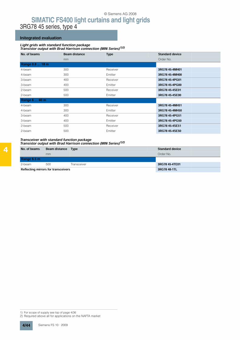
SIMATIC FS400 light curtains and light grids3RG78 45 series, type 4
Initegrated evaluation
4/44 Siemens FS 10 · 2009
4
Light grids with standard function package Transistor output with Brad Harrison connection (MIN Series)1)2)
Transceiver with standard function package Transistor output with Brad Harrison connection (MIN Series)1)2)
1) For scope of supply see top of page 4/362) Required above all for applications on the NAFTA market
No. of beams Beam distance Type Standard devicemm Order No.
Range 0.8 … 18 m4-beam 300 Receiver 3RG78 45-4MH014-beam 300 Emitter 3RG78 45-4MH003-beam 400 Receiver 3RG78 45-4PG013-beam 400 Emitter 3RG78 45-4PG002-beam 500 Receiver 3RG78 45-4SE012-beam 500 Emitter 3RG78 45-4SE00Range 6 … 60 m4-beam 300 Receiver 3RG78 45-4MH514-beam 300 Emitter 3RG78 45-4MH503-beam 400 Receiver 3RG78 45-4PG513-beam 400 Emitter 3RG78 45-4PG502-beam 500 Receiver 3RG78 45-4SE512-beam 500 Emitter 3RG78 45-4SE50
No. of beams Beam distance Type Standard devicemm Order No.
Range 6.5 m2-beam 500 Transceiver 3RG78 45-4TE01Reflecting mirrors for transceivers 3RG78 48-1TL
© Siemens AG 2008
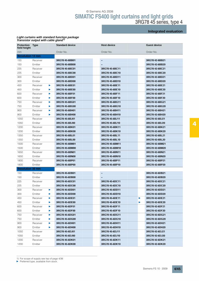
SIMATIC FS400 light curtains and light grids3RG78 45 series, type 4
Initegrated evaluation
4/45Siemens FS 10 · 2009
4
Light curtains with standard function package Transistor output with cable gland1)
1) For scope of supply see top of page 4/36 Preferred type, available from stock.
Protection field height
Type Standard device Host device Guest device
mm Order No. Order No. Order No.
Resolution 14 mm150 Receiver 3RG78 45-6BB01 – 3RG78 42-6BB21150 Emitter 3RG78 45-6BB00 – 3RG78 42-6BB20225 Receiver 3RG78 45-6BC01 3RG78 45-6BC11 3RG78 42-6BC21225 Emitter 3RG78 45-6BC00 3RG78 45-6BC10 3RG78 42-6BC20300 Receiver 3RG78 45-6BD01 3RG78 45-6BD11 3RG78 42-6BD21300 Emitter 3RG78 45-6BD00 3RG78 45-6BD10 3RG78 42-6BD20450 Receiver 3RG78 45-6BE01 3RG78 45-6BE11 3RG78 42-6BE21450 Emitter 3RG78 45-6BE00 3RG78 45-6BE10 3RG78 42-6BE20600 Receiver 3RG78 45-6BF01 3RG78 45-6BF11 3RG78 42-6BF21600 Emitter 3RG78 45-6BF00 3RG78 45-6BF10 3RG78 42-6BF20750 Receiver 3RG78 45-6BG01 3RG78 45-6BG11 3RG78 42-6BG21750 Emitter 3RG78 45-6BG00 3RG78 45-6BG10 3RG78 42-6BG20900 Receiver 3RG78 45-6BH01 3RG78 45-6BH11 3RG78 42-6BH21900 Emitter 3RG78 45-6BH00 3RG78 45-6BH10 3RG78 42-6BH201050 Receiver 3RG78 45-6BJ01 3RG78 45-6BJ11 3RG78 42-6BJ211050 Emitter 3RG78 45-6BJ00 3RG78 45-6BJ10 3RG78 42-6BJ201200 Receiver 3RG78 45-6BK01 3RG78 45-6BK11 3RG78 42-6BK211200 Emitter 3RG78 45-6BK00 3RG78 45-6BK10 3RG78 42-6BK201350 Receiver 3RG78 45-6BL01 3RG78 45-6BL11 3RG78 42-6BL211350 Emitter 3RG78 45-6BL00 3RG78 45-6BL10 3RG78 42-6BL201500 Receiver 3RG78 45-6BM01 3RG78 45-6BM11 3RG78 42-6BM211500 Emitter 3RG78 45-6BM00 3RG78 45-6BM10 3RG78 42-6BM201650 Receiver 3RG78 45-6BN01 3RG78 45-6BN11 3RG78 42-6BN211650 Emitter 3RG78 45-6BN00 3RG78 45-6BN10 3RG78 42-6BN201800 Receiver 3RG78 45-6BP01 3RG78 45-6BP11 3RG78 42-6BP211800 Emitter 3RG78 45-6BP00 3RG78 45-6BP10 3RG78 42-6BP20Resolution 30 mm150 Receiver 3RG78 45-6DB01 – 3RG78 42-6DB21150 Emitter 3RG78 45-6DB00 – 3RG78 42-6DB20225 Receiver 3RG78 45-6DC01 3RG78 45-6DC11 3RG78 42-6DC21225 Emitter 3RG78 45-6DC00 3RG78 45-6DC10 3RG78 42-6DC20300 Receiver 3RG78 45-6DD01 3RG78 45-6DD11 3RG78 42-6DD21300 Emitter 3RG78 45-6DD00 3RG78 45-6DD10 3RG78 42-6DD20450 Receiver 3RG78 45-6DE01 3RG78 45-6DE11 3RG78 42-6DE21450 Emitter 3RG78 45-6DE00 3RG78 45-6DE10 3RG78 42-6DE20600 Receiver 3RG78 45-6DF01 3RG78 45-6DF11 3RG78 42-6DF21600 Emitter 3RG78 45-6DF00 3RG78 45-6DF10 3RG78 42-6DF20750 Receiver 3RG78 45-6DG01 3RG78 45-6DG11 3RG78 42-6DG21750 Emitter 3RG78 45-6DG00 3RG78 45-6DG10 3RG78 42-6DG20900 Receiver 3RG78 45-6DH01 3RG78 45-6DH11 3RG78 42-6DH21900 Emitter 3RG78 45-6DH00 3RG78 45-6DH10 3RG78 42-6DH201050 Receiver 3RG78 45-6DJ01 3RG78 45-6DJ11 3RG78 42-6DJ211050 Emitter 3RG78 45-6DJ00 3RG78 45-6DJ10 3RG78 42-6DJ201200 Receiver 3RG78 45-6DK01 3RG78 45-6DK11 3RG78 42-6DK211200 Emitter 3RG78 45-6DK00 3RG78 45-6DK10 3RG78 42-6DK20
© Siemens AG 2008
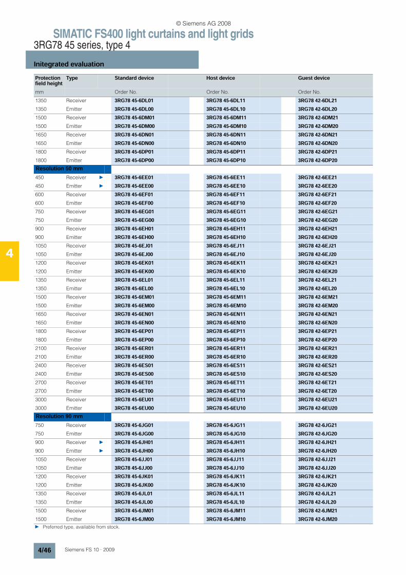
SIMATIC FS400 light curtains and light grids3RG78 45 series, type 4
Initegrated evaluation
4/46 Siemens FS 10 · 2009
4
Protection field height
Type Standard device Host device Guest device
mm Order No. Order No. Order No.
1350 Receiver 3RG78 45-6DL01 3RG78 45-6DL11 3RG78 42-6DL211350 Emitter 3RG78 45-6DL00 3RG78 45-6DL10 3RG78 42-6DL201500 Receiver 3RG78 45-6DM01 3RG78 45-6DM11 3RG78 42-6DM211500 Emitter 3RG78 45-6DM00 3RG78 45-6DM10 3RG78 42-6DM201650 Receiver 3RG78 45-6DN01 3RG78 45-6DN11 3RG78 42-6DN211650 Emitter 3RG78 45-6DN00 3RG78 45-6DN10 3RG78 42-6DN201800 Receiver 3RG78 45-6DP01 3RG78 45-6DP11 3RG78 42-6DP211800 Emitter 3RG78 45-6DP00 3RG78 45-6DP10 3RG78 42-6DP20Resolution 50 mm450 Receiver 3RG78 45-6EE01 3RG78 45-6EE11 3RG78 42-6EE21450 Emitter 3RG78 45-6EE00 3RG78 45-6EE10 3RG78 42-6EE20600 Receiver 3RG78 45-6EF01 3RG78 45-6EF11 3RG78 42-6EF21600 Emitter 3RG78 45-6EF00 3RG78 45-6EF10 3RG78 42-6EF20750 Receiver 3RG78 45-6EG01 3RG78 45-6EG11 3RG78 42-6EG21750 Emitter 3RG78 45-6EG00 3RG78 45-6EG10 3RG78 42-6EG20900 Receiver 3RG78 45-6EH01 3RG78 45-6EH11 3RG78 42-6EH21900 Emitter 3RG78 45-6EH00 3RG78 45-6EH10 3RG78 42-6EH201050 Receiver 3RG78 45-6EJ01 3RG78 45-6EJ11 3RG78 42-6EJ211050 Emitter 3RG78 45-6EJ00 3RG78 45-6EJ10 3RG78 42-6EJ201200 Receiver 3RG78 45-6EK01 3RG78 45-6EK11 3RG78 42-6EK211200 Emitter 3RG78 45-6EK00 3RG78 45-6EK10 3RG78 42-6EK201350 Receiver 3RG78 45-6EL01 3RG78 45-6EL11 3RG78 42-6EL211350 Emitter 3RG78 45-6EL00 3RG78 45-6EL10 3RG78 42-6EL201500 Receiver 3RG78 45-6EM01 3RG78 45-6EM11 3RG78 42-6EM211500 Emitter 3RG78 45-6EM00 3RG78 45-6EM10 3RG78 42-6EM201650 Receiver 3RG78 45-6EN01 3RG78 45-6EN11 3RG78 42-6EN211650 Emitter 3RG78 45-6EN00 3RG78 45-6EN10 3RG78 42-6EN201800 Receiver 3RG78 45-6EP01 3RG78 45-6EP11 3RG78 42-6EP211800 Emitter 3RG78 45-6EP00 3RG78 45-6EP10 3RG78 42-6EP202100 Receiver 3RG78 45-6ER01 3RG78 45-6ER11 3RG78 42-6ER212100 Emitter 3RG78 45-6ER00 3RG78 45-6ER10 3RG78 42-6ER202400 Receiver 3RG78 45-6ES01 3RG78 45-6ES11 3RG78 42-6ES212400 Emitter 3RG78 45-6ES00 3RG78 45-6ES10 3RG78 42-6ES202700 Receiver 3RG78 45-6ET01 3RG78 45-6ET11 3RG78 42-6ET212700 Emitter 3RG78 45-6ET00 3RG78 45-6ET10 3RG78 42-6ET203000 Receiver 3RG78 45-6EU01 3RG78 45-6EU11 3RG78 42-6EU213000 Emitter 3RG78 45-6EU00 3RG78 45-6EU10 3RG78 42-6EU20Resolution 90 mm750 Receiver 3RG78 45-6JG01 3RG78 45-6JG11 3RG78 42-6JG21750 Emitter 3RG78 45-6JG00 3RG78 45-6JG10 3RG78 42-6JG20900 Receiver 3RG78 45-6JH01 3RG78 45-6JH11 3RG78 42-6JH21900 Emitter 3RG78 45-6JH00 3RG78 45-6JH10 3RG78 42-6JH201050 Receiver 3RG78 45-6JJ01 3RG78 45-6JJ11 3RG78 42-6JJ211050 Emitter 3RG78 45-6JJ00 3RG78 45-6JJ10 3RG78 42-6JJ201200 Receiver 3RG78 45-6JK01 3RG78 45-6JK11 3RG78 42-6JK211200 Emitter 3RG78 45-6JK00 3RG78 45-6JK10 3RG78 42-6JK201350 Receiver 3RG78 45-6JL01 3RG78 45-6JL11 3RG78 42-6JL211350 Emitter 3RG78 45-6JL00 3RG78 45-6JL10 3RG78 42-6JL201500 Receiver 3RG78 45-6JM01 3RG78 45-6JM11 3RG78 42-6JM211500 Emitter 3RG78 45-6JM00 3RG78 45-6JM10 3RG78 42-6JM20 Preferred type, available from stock.
© Siemens AG 2008
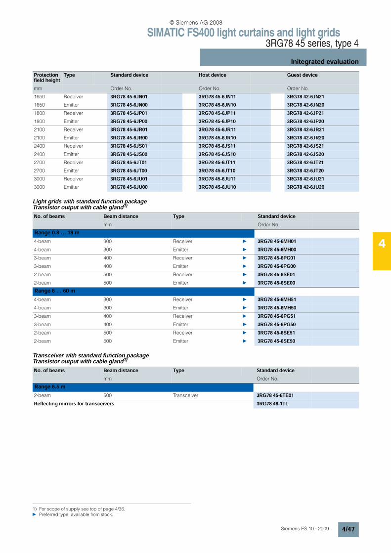
SIMATIC FS400 light curtains and light grids3RG78 45 series, type 4
Initegrated evaluation
4/47Siemens FS 10 · 2009
4
Light grids with standard function package Transistor output with cable gland1)
Transceiver with standard function package Transistor output with cable gland1)
Protection field height
Type Standard device Host device Guest device
mm Order No. Order No. Order No.
1650 Receiver 3RG78 45-6JN01 3RG78 45-6JN11 3RG78 42-6JN211650 Emitter 3RG78 45-6JN00 3RG78 45-6JN10 3RG78 42-6JN201800 Receiver 3RG78 45-6JP01 3RG78 45-6JP11 3RG78 42-6JP211800 Emitter 3RG78 45-6JP00 3RG78 45-6JP10 3RG78 42-6JP202100 Receiver 3RG78 45-6JR01 3RG78 45-6JR11 3RG78 42-6JR212100 Emitter 3RG78 45-6JR00 3RG78 45-6JR10 3RG78 42-6JR202400 Receiver 3RG78 45-6JS01 3RG78 45-6JS11 3RG78 42-6JS212400 Emitter 3RG78 45-6JS00 3RG78 45-6JS10 3RG78 42-6JS202700 Receiver 3RG78 45-6JT01 3RG78 45-6JT11 3RG78 42-6JT212700 Emitter 3RG78 45-6JT00 3RG78 45-6JT10 3RG78 42-6JT203000 Receiver 3RG78 45-6JU01 3RG78 45-6JU11 3RG78 42-6JU213000 Emitter 3RG78 45-6JU00 3RG78 45-6JU10 3RG78 42-6JU20
1) For scope of supply see top of page 4/36. Preferred type, available from stock.
No. of beams Beam distance Type Standard devicemm Order No.
Range 0.8 … 18 m4-beam 300 Receiver 3RG78 45-6MH014-beam 300 Emitter 3RG78 45-6MH003-beam 400 Receiver 3RG78 45-6PG013-beam 400 Emitter 3RG78 45-6PG002-beam 500 Receiver 3RG78 45-6SE012-beam 500 Emitter 3RG78 45-6SE00Range 6 … 60 m4-beam 300 Receiver 3RG78 45-6MH514-beam 300 Emitter 3RG78 45-6MH503-beam 400 Receiver 3RG78 45-6PG513-beam 400 Emitter 3RG78 45-6PG502-beam 500 Receiver 3RG78 45-6SE512-beam 500 Emitter 3RG78 45-6SE50
No. of beams Beam distance Type Standard devicemm Order No.
Range 6.5 m2-beam 500 Transceiver 3RG78 45-6TE01Reflecting mirrors for transceivers 3RG78 48-1TL
© Siemens AG 2008

SIMATIC FS400 light curtains and light grids3RG78 45 series, type 4
Initegrated evaluation
4/48 Siemens FS 10 · 2009
4
n Dimensions3RG78 45 standard light curtains, 3RG78 45 light grids
$ Pg 9 cover (receiver only, for local interface)
A Protection field height (see Selection and Ordering data)
B Overall length = Protection field height A + 134 mm
3RG78 45 light grids, additional dimensions Additional dimensions (mm) for light grids only:
52
52
55
22
B =
A +
84
mm
A
22
52
FS
10
_0
03
08
300
52
52
55
22
1134
300
99,5
300
22
5252
22
984
400
400
22
52
FS
10
_0
03
09
52
22
684
500
99,5
99,5
22
52
Type Overalllength
Beam distance
Beams
3RG78 45-..M
3RG78 45-..P
3RG78 45-..S
1134
984
684
300
400
500
4
3
2
© Siemens AG 2008
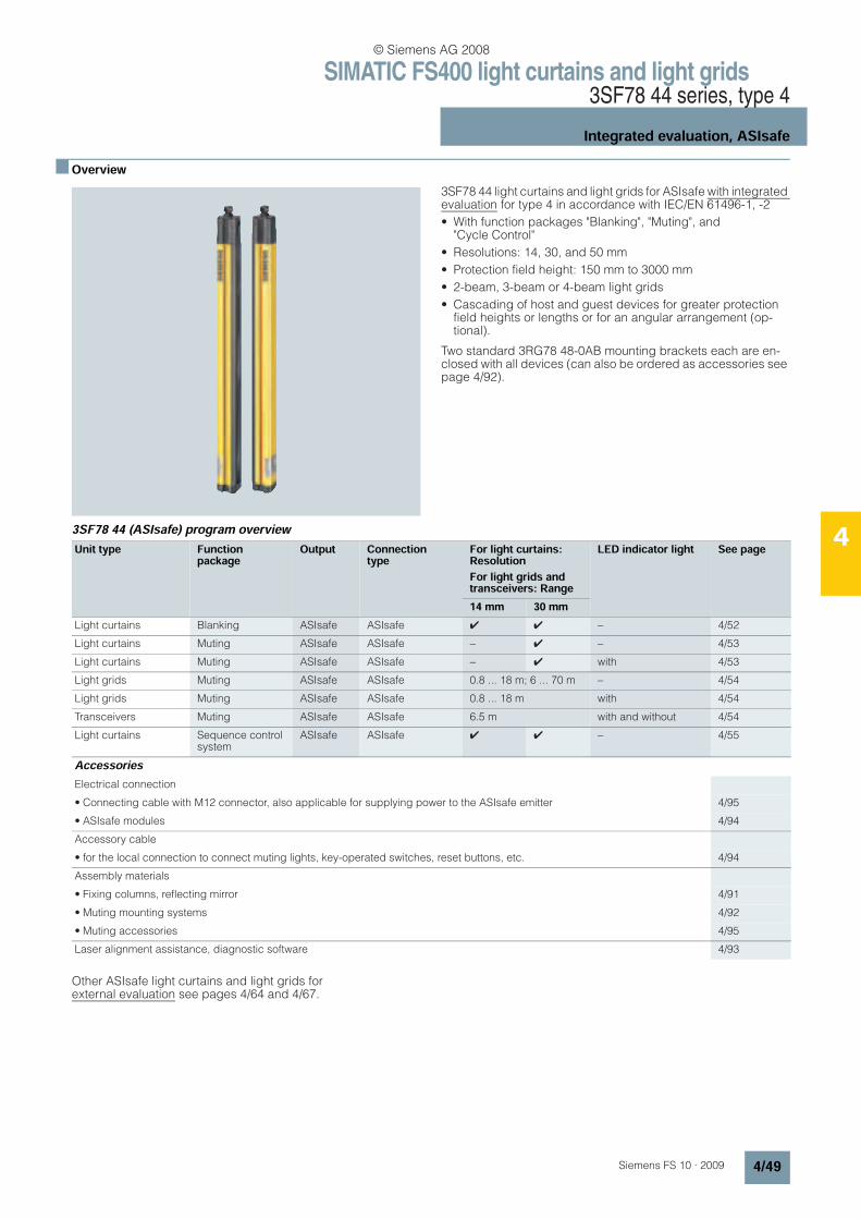
SIMATIC FS400 light curtains and light grids3SF78 44 series, type 4
Integrated evaluation, ASIsafe
4/49Siemens FS 10 · 2009
4
n Overview
3SF78 44 light curtains and light grids for ASIsafe with integrated evaluation for type 4 in accordance with IEC/EN 61496-1, -2
• With function packages "Blanking", "Muting", and "Cycle Control"
• Resolutions: 14, 30, and 50 mm
• Protection field height: 150 mm to 3000 mm
• 2-beam, 3-beam or 4-beam light grids
• Cascading of host and guest devices for greater protection field heights or lengths or for an angular arrangement (op-tional).
Two standard 3RG78 48-0AB mounting brackets each are en-closed with all devices (can also be ordered as accessories see page 4/92).
3SF78 44 (ASIsafe) program overview
Other ASIsafe light curtains and light grids for external evaluation see pages 4/64 and 4/67.
Unit type Functionpackage
Output Connectiontype
For light curtains: ResolutionFor light grids and transceivers: Range
LED indicator light See page
14 mm 30 mmLight curtains Blanking ASIsafe ASIsafe 4 4 − 4/52
Light curtains Muting ASIsafe ASIsafe − 4 − 4/53
Light curtains Muting ASIsafe ASIsafe − 4 with 4/53
Light grids Muting ASIsafe ASIsafe 0.8 ... 18 m; 6 ... 70 m − 4/54
Light grids Muting ASIsafe ASIsafe 0.8 ... 18 m with 4/54
Transceivers Muting ASIsafe ASIsafe 6.5 m with and without 4/54
Light curtains Sequence control system
ASIsafe ASIsafe 4 4 − 4/55
AccessoriesElectrical connection
• Connecting cable with M12 connector, also applicable for supplying power to the ASIsafe emitter 4/95
• ASIsafe modules 4/94
Accessory cable
• for the local connection to connect muting lights, key-operated switches, reset buttons, etc. 4/94
Assembly materials
• Fixing columns, reflecting mirror 4/91
• Muting mounting systems 4/92
• Muting accessories 4/95
Laser alignment assistance, diagnostic software 4/93
© Siemens AG 2008

SIMATIC FS400 light curtains and light grids3SF78 44 series, type 4
Integrated evaluation, ASIsafe
4/50 Siemens FS 10 · 2009
4
n Technical specificationsSignal inputs and outputs (local socket, optional)
Receiver/transceiver machine interface, ASIsafe
Type 3SF78 44Safety category
• to EN, IEC 61496-1, -2 Type 4
• according to IEC 61508 SIL 3
Protection field height
• for 14 and 30 mm resolution 150 ... 1800 mm
• for 50 mm resolution 450 ... 3000 mm
Protection field width, range
• for 14 mm resolution 0 ... 6 m
• for 30 and 50 mm resolution 0 ... 18 m
Detection capability (resolution) 14 mm, 30 mm, 50 mm
Supply voltage (emitter and receiver)
24 V DC ± 20% (external power pack with safe isolation and compensation of 20 ms voltage dip is necessary)
Residual ripple < 5%
Current consumption
• Emitter 75 mA
• Receiver 160 mA (without external load)
General value for external fuse in the transmitter and receiver supply leads
4 A
Wave length 880 nm (infrared)
Synchronization Optically between emitter and receiver
Ambient temperature
• Operation 0 ... +50 °C
• Storage –25 ... +70 °C
Relative humidity 15 ... 95%
Degree of protection IP65
Safety class to DIN VDE 0106 III
Vibration resistance 5 g, 10 ... 55 Hz acc. to IEC/EN 60068-2-6
Shock resistance 10 g, 16 ms to IEC/EN 60068-2-29
Signal inputs
• Restart inhibit unlocking 1 button with 1 NO contact (floating)
- Min. switching time 300 ms
- Max. switching time 4 sec
• Teach-in 2-pole key-operated switch (selector switch) (floating)
- Simultaneity < 500 ms
Voltage output (for command devices or safety sensors only)
24 V DC ± 20%, max 0.5 A
OSSDs safety switching outputs 4 bit AS-i dataMinimum Typical Maximum
Permissible cable length - - 100 m
Restart time after beam interruption - 140 ms -
Slave address area 1 - 31
Slave address area (WE) 0 (ex works)
ID code/IO code emitter -
ID code receiver B
IO code receiver 0
AS-i profile Secure slave
Cycle time according to AS-i specification 5 ms
OSSD response time Beam number dependent, see operating instructions
Additional AS-i system response time 40 ms
© Siemens AG 2008
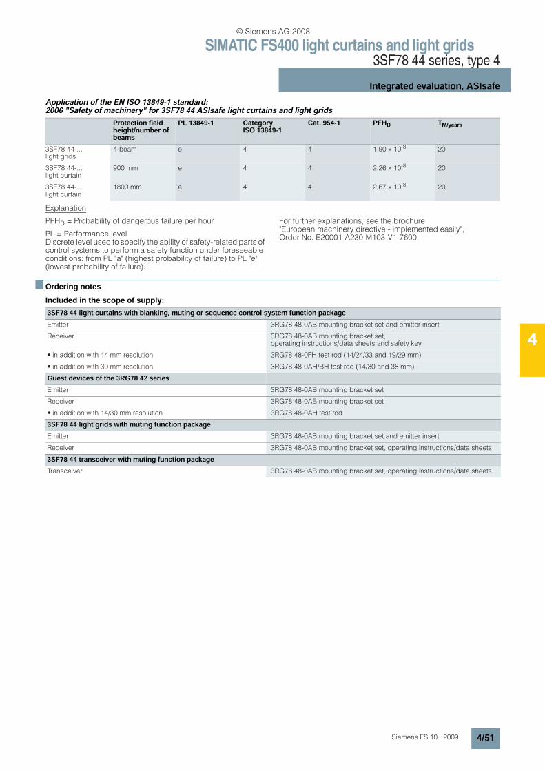
SIMATIC FS400 light curtains and light grids3SF78 44 series, type 4
Integrated evaluation, ASIsafe
4/51Siemens FS 10 · 2009
4
Application of the EN ISO 13849-1 standard: 2006 "Safety of machinery" for 3SF78 44 ASIsafe light curtains and light grids
Explanation
PFHD = Probability of dangerous failure per hour
PL = Performance level Discrete level used to specify the ability of safety-related parts of control systems to perform a safety function under foreseeable conditions: from PL "a" (highest probability of failure) to PL "e" (lowest probability of failure).
For further explanations, see the brochure "European machinery directive - implemented easily", Order No. E20001-A230-M103-V1-7600.
n Ordering notesIncluded in the scope of supply:
Protection field height/number of beams
PL 13849-1 Category ISO 13849-1
Cat. 954-1 PFHD TM/years
3SF78 44-...light grids
4-beam e 4 4 1.90 x 10⁻⁸ 20
3SF78 44-...light curtain
900 mm e 4 4 2.26 x 10⁻⁸ 20
3SF78 44-...light curtain
1800 mm e 4 4 2.67 x 10⁻⁸ 20
3SF78 44 light curtains with blanking, muting or sequence control system function packageEmitter 3RG78 48-0AB mounting bracket set and emitter insert
Receiver 3RG78 48-0AB mounting bracket set, operating instructions/data sheets and safety key
• in addition with 14 mm resolution 3RG78 48-0FH test rod (14/24/33 and 19/29 mm)
• in addition with 30 mm resolution 3RG78 48-0AH/BH test rod (14/30 and 38 mm)
Guest devices of the 3RG78 42 seriesEmitter 3RG78 48-0AB mounting bracket set
Receiver 3RG78 48-0AB mounting bracket set
• in addition with 14/30 mm resolution 3RG78 48-0AH test rod
3SF78 44 light grids with muting function packageEmitter 3RG78 48-0AB mounting bracket set and emitter insert
Receiver 3RG78 48-0AB mounting bracket set, operating instructions/data sheets
3SF78 44 transceiver with muting function packageTransceiver 3RG78 48-0AB mounting bracket set, operating instructions/data sheets
© Siemens AG 2008
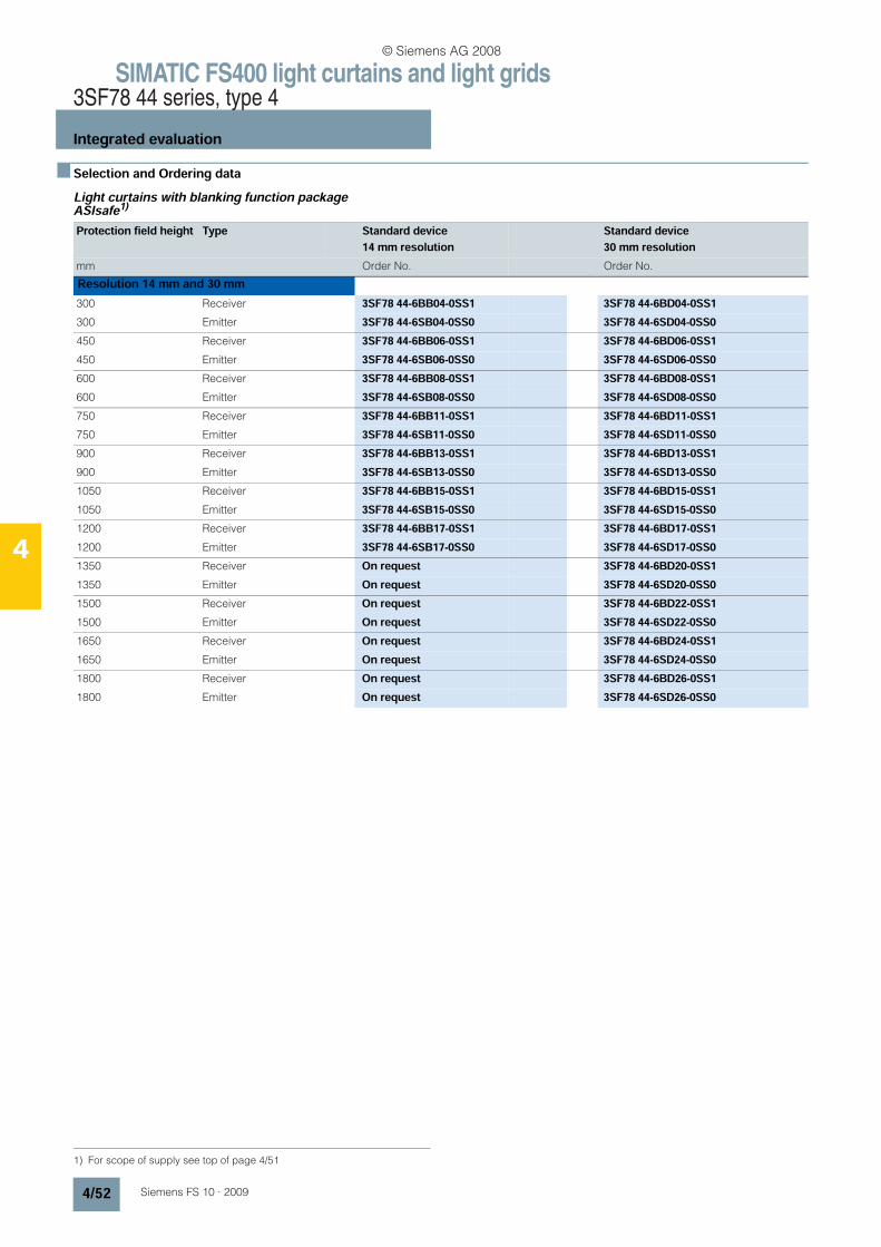
SIMATIC FS400 light curtains and light grids3SF78 44 series, type 4
Integrated evaluation
4/52 Siemens FS 10 · 2009
4
n Selection and Ordering dataLight curtains with blanking function package ASIsafe1)
1) For scope of supply see top of page 4/51
Protection field height Type Standard device14 mm resolution
Standard device30 mm resolution
mm Order No. Order No.
Resolution 14 mm and 30 mm300 Receiver 3SF78 44-6BB04-0SS1 3SF78 44-6BD04-0SS1300 Emitter 3SF78 44-6SB04-0SS0 3SF78 44-6SD04-0SS0450 Receiver 3SF78 44-6BB06-0SS1 3SF78 44-6BD06-0SS1450 Emitter 3SF78 44-6SB06-0SS0 3SF78 44-6SD06-0SS0600 Receiver 3SF78 44-6BB08-0SS1 3SF78 44-6BD08-0SS1600 Emitter 3SF78 44-6SB08-0SS0 3SF78 44-6SD08-0SS0750 Receiver 3SF78 44-6BB11-0SS1 3SF78 44-6BD11-0SS1750 Emitter 3SF78 44-6SB11-0SS0 3SF78 44-6SD11-0SS0900 Receiver 3SF78 44-6BB13-0SS1 3SF78 44-6BD13-0SS1900 Emitter 3SF78 44-6SB13-0SS0 3SF78 44-6SD13-0SS01050 Receiver 3SF78 44-6BB15-0SS1 3SF78 44-6BD15-0SS11050 Emitter 3SF78 44-6SB15-0SS0 3SF78 44-6SD15-0SS01200 Receiver 3SF78 44-6BB17-0SS1 3SF78 44-6BD17-0SS11200 Emitter 3SF78 44-6SB17-0SS0 3SF78 44-6SD17-0SS01350 Receiver On request 3SF78 44-6BD20-0SS11350 Emitter On request 3SF78 44-6SD20-0SS01500 Receiver On request 3SF78 44-6BD22-0SS11500 Emitter On request 3SF78 44-6SD22-0SS01650 Receiver On request 3SF78 44-6BD24-0SS11650 Emitter On request 3SF78 44-6SD24-0SS01800 Receiver On request 3SF78 44-6BD26-0SS11800 Emitter On request 3SF78 44-6SD26-0SS0
© Siemens AG 2008
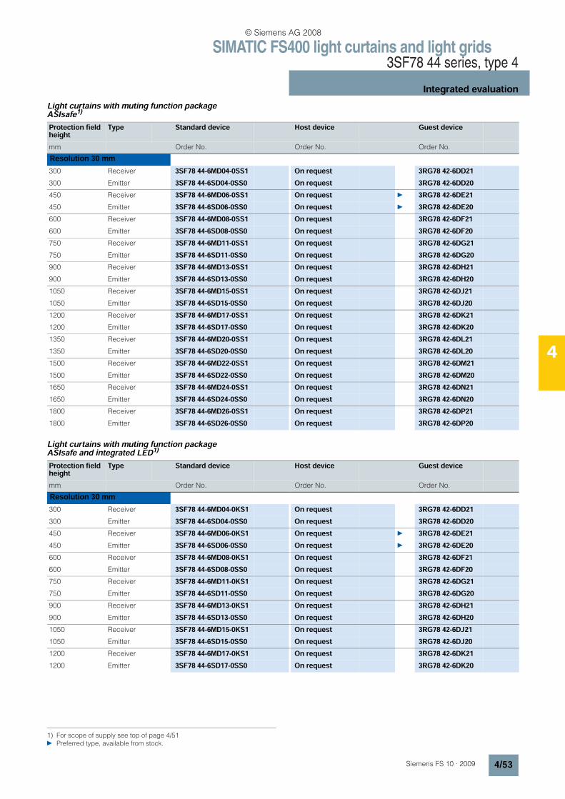
SIMATIC FS400 light curtains and light grids3SF78 44 series, type 4
Integrated evaluation
4/53Siemens FS 10 · 2009
4
Light curtains with muting function package ASIsafe1)
Light curtains with muting function package ASIsafe and integrated LED1)
1) For scope of supply see top of page 4/51 Preferred type, available from stock.
Protection field height
Type Standard device Host device Guest device
mm Order No. Order No. Order No.
Resolution 30 mm300 Receiver 3SF78 44-6MD04-0SS1 On request 3RG78 42-6DD21300 Emitter 3SF78 44-6SD04-0SS0 On request 3RG78 42-6DD20450 Receiver 3SF78 44-6MD06-0SS1 On request 3RG78 42-6DE21450 Emitter 3SF78 44-6SD06-0SS0 On request 3RG78 42-6DE20600 Receiver 3SF78 44-6MD08-0SS1 On request 3RG78 42-6DF21600 Emitter 3SF78 44-6SD08-0SS0 On request 3RG78 42-6DF20750 Receiver 3SF78 44-6MD11-0SS1 On request 3RG78 42-6DG21750 Emitter 3SF78 44-6SD11-0SS0 On request 3RG78 42-6DG20900 Receiver 3SF78 44-6MD13-0SS1 On request 3RG78 42-6DH21900 Emitter 3SF78 44-6SD13-0SS0 On request 3RG78 42-6DH201050 Receiver 3SF78 44-6MD15-0SS1 On request 3RG78 42-6DJ211050 Emitter 3SF78 44-6SD15-0SS0 On request 3RG78 42-6DJ201200 Receiver 3SF78 44-6MD17-0SS1 On request 3RG78 42-6DK211200 Emitter 3SF78 44-6SD17-0SS0 On request 3RG78 42-6DK201350 Receiver 3SF78 44-6MD20-0SS1 On request 3RG78 42-6DL211350 Emitter 3SF78 44-6SD20-0SS0 On request 3RG78 42-6DL201500 Receiver 3SF78 44-6MD22-0SS1 On request 3RG78 42-6DM211500 Emitter 3SF78 44-6SD22-0SS0 On request 3RG78 42-6DM201650 Receiver 3SF78 44-6MD24-0SS1 On request 3RG78 42-6DN211650 Emitter 3SF78 44-6SD24-0SS0 On request 3RG78 42-6DN201800 Receiver 3SF78 44-6MD26-0SS1 On request 3RG78 42-6DP211800 Emitter 3SF78 44-6SD26-0SS0 On request 3RG78 42-6DP20
Protection field height
Type Standard device Host device Guest device
mm Order No. Order No. Order No.
Resolution 30 mm300 Receiver 3SF78 44-6MD04-0KS1 On request 3RG78 42-6DD21300 Emitter 3SF78 44-6SD04-0SS0 On request 3RG78 42-6DD20450 Receiver 3SF78 44-6MD06-0KS1 On request 3RG78 42-6DE21450 Emitter 3SF78 44-6SD06-0SS0 On request 3RG78 42-6DE20600 Receiver 3SF78 44-6MD08-0KS1 On request 3RG78 42-6DF21600 Emitter 3SF78 44-6SD08-0SS0 On request 3RG78 42-6DF20750 Receiver 3SF78 44-6MD11-0KS1 On request 3RG78 42-6DG21750 Emitter 3SF78 44-6SD11-0SS0 On request 3RG78 42-6DG20900 Receiver 3SF78 44-6MD13-0KS1 On request 3RG78 42-6DH21900 Emitter 3SF78 44-6SD13-0SS0 On request 3RG78 42-6DH201050 Receiver 3SF78 44-6MD15-0KS1 On request 3RG78 42-6DJ211050 Emitter 3SF78 44-6SD15-0SS0 On request 3RG78 42-6DJ201200 Receiver 3SF78 44-6MD17-0KS1 On request 3RG78 42-6DK211200 Emitter 3SF78 44-6SD17-0SS0 On request 3RG78 42-6DK20
© Siemens AG 2008
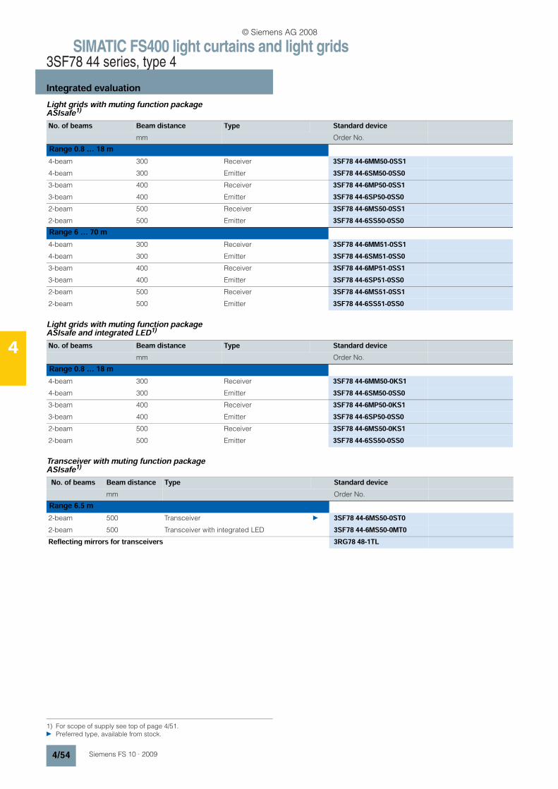
SIMATIC FS400 light curtains and light grids3SF78 44 series, type 4
Integrated evaluation
4/54 Siemens FS 10 · 2009
4
Light grids with muting function package ASIsafe1)
Light grids with muting function package ASIsafe and integrated LED1)
Transceiver with muting function packageASIsafe1)
No. of beams Beam distance Type Standard devicemm Order No.
Range 0.8 … 18 m4-beam 300 Receiver 3SF78 44-6MM50-0SS14-beam 300 Emitter 3SF78 44-6SM50-0SS03-beam 400 Receiver 3SF78 44-6MP50-0SS13-beam 400 Emitter 3SF78 44-6SP50-0SS02-beam 500 Receiver 3SF78 44-6MS50-0SS12-beam 500 Emitter 3SF78 44-6SS50-0SS0Range 6 … 70 m4-beam 300 Receiver 3SF78 44-6MM51-0SS14-beam 300 Emitter 3SF78 44-6SM51-0SS03-beam 400 Receiver 3SF78 44-6MP51-0SS13-beam 400 Emitter 3SF78 44-6SP51-0SS02-beam 500 Receiver 3SF78 44-6MS51-0SS12-beam 500 Emitter 3SF78 44-6SS51-0SS0
No. of beams Beam distance Type Standard devicemm Order No.
Range 0.8 … 18 m4-beam 300 Receiver 3SF78 44-6MM50-0KS14-beam 300 Emitter 3SF78 44-6SM50-0SS03-beam 400 Receiver 3SF78 44-6MP50-0KS13-beam 400 Emitter 3SF78 44-6SP50-0SS02-beam 500 Receiver 3SF78 44-6MS50-0KS12-beam 500 Emitter 3SF78 44-6SS50-0SS0
1) For scope of supply see top of page 4/51. Preferred type, available from stock.
No. of beams Beam distance Type Standard devicemm Order No.
Range 6.5 m2-beam 500 Transceiver 3SF78 44-6MS50-0ST02-beam 500 Transceiver with integrated LED 3SF78 44-6MS50-0MT0Reflecting mirrors for transceivers 3RG78 48-1TL
© Siemens AG 2008
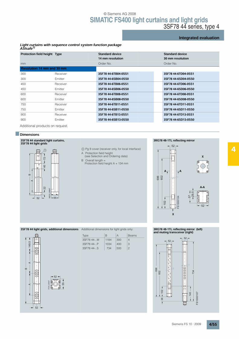
SIMATIC FS400 light curtains and light grids3SF78 44 series, type 4
Integrated evaluation
4/55Siemens FS 10 · 2009
4
Light curtains with sequence control system function package ASIsafe1)
Additional products on request.
n Dimensions
Protection field height Type Standard device14 mm resolution
Standard device30 mm resolution
mm Order No. Order No.
Resolution 14 mm and 30 mm300 Receiver 3SF78 44-6TB04-0SS1 3SF78 44-6TD04-0SS1300 Emitter 3SF78 44-6SB04-0SS0 3SF78 44-6SD04-0SS0450 Receiver 3SF78 44-6TB06-0SS1 3SF78 44-6TD06-0SS1450 Emitter 3SF78 44-6SB06-0SS0 3SF78 44-6SD06-0SS0600 Receiver 3SF78 44-6TB08-0SS1 3SF78 44-6TD08-0SS1600 Emitter 3SF78 44-6SB08-0SS0 3SF78 44-6SD08-0SS0750 Receiver 3SF78 44-6TB11-0SS1 3SF78 44-6TD11-0SS1750 Emitter 3SF78 44-6SB11-0SS0 3SF78 44-6SD11-0SS0900 Receiver 3SF78 44-6TB13-0SS1 3SF78 44-6TD13-0SS1900 Emitter 3SF78 44-6SB13-0SS0 3SF78 44-6SD13-0SS0
3SF78 44 standard light curtains, 3SF78 44 light grids
$ Pg 9 cover (receiver only, for local interface)
A Protection field height (see Selection and Ordering data)
B Overall length = Protection field height A + 134 mm
3RG78 48-1TL reflecting mirror
3SF78 44 light grids, additional dimensions Additional dimensions for light grids only: 3RG78 48-1TL reflecting mirror (left) and muting transceiver (right)
NSC0_00647
A
5 2
B
5 5
22
1
72
40
52
102
602
696
X
52
29,5
57
A A
X
A-A
FS
10
00
10
4
52
52
55
149.5
A
FS
10
_0
03
07
B
A
Type B A Beams
3SF78 44-..M
3SF78 44-..P
3SF78 44-..S
1184
1034
734
300
400
500
4
3
2
52
102
602
52
734
140
38
696
FS
10
00
10
7
© Siemens AG 2008

SIMATIC FS400 light curtains and light grids3SF78 44 series, type 4
Integrated evaluation, PROFIsafe
4/56 Siemens FS 10 · 2009
4
n Overview
3SF78 44 light curtains and grids for PROFIsafe with integrated evaluation for type 4 in accordance with IEC/EN 61496-1, -2
• with function packages "Blanking", "Muting", and "Cycle Control"
• Resolutions of 14 mm and 30 mm
• Protection field height: 150 mm to 3000 mm
• 2-beam, 3-beam or 4-beam light grids
• Cascading of host and guest devices for greater protection field heights or lengths or for an angular arrangement (as an option).
PROFIBUS connectivity only affects the receiver, as it also switches off the safety switch outputs on the PROFIBUS.
In the following selection and ordering data, a suitable emitter with AS-i M12 connection for power supply is always selected as emitter. However, the emitter can also be selected with other connection options such as M12, Hirschmann, cable gland, or Brad Harrison connector from the 3RG78 44 series. It is impor-tant that the selected 3RG78 44/3SF78 44 emitter has the same protection field height and resolution as the 3SF78 44 receiver!
Two standard 3RG78 48-0AB mounting brackets each are enclosed with all devices (can also be ordered as accessories see page 4/92).
Other versions not listed in the ordering data are available upon request.
3SF78 44 (PROFIsafe) program overview
Unit type Functionpackage
Output Connection type For light curtains: ResolutionFor light grids and transceivers: Range
LEDindicator light
See page
14 mm 30 mmLight curtains Blanking PROFIsafe PROFIsafe 4 4 − 4/60
Light curtains Muting PROFIsafe PROFIsafe 4 4 − 4/60
Light grids Muting PROFIsafe PROFIsafe 0.8 ... 18 m − 4/62
Transceivers Muting PROFIsafe PROFIsafe 6.5 m with and without 4/62
Light curtains Sequence control system
PROFIsafe PROFIsafe 4 − − 4/62
AccessoriesElectrical connection
• Connecting cable with M12 connector, also applicable for supplying power to the PROFIsafe emitter 4/95
Accessory cable
• for the local connection to connect muting lights, key-operated switches, reset buttons, etc. 4/94
Assembly materials
• Fixing columns, reflecting mirror 4/91
• Muting mounting systems 4/92
• Muting accessories 4/95
Laser alignment aids, diagnostic software 4/93
© Siemens AG 2008
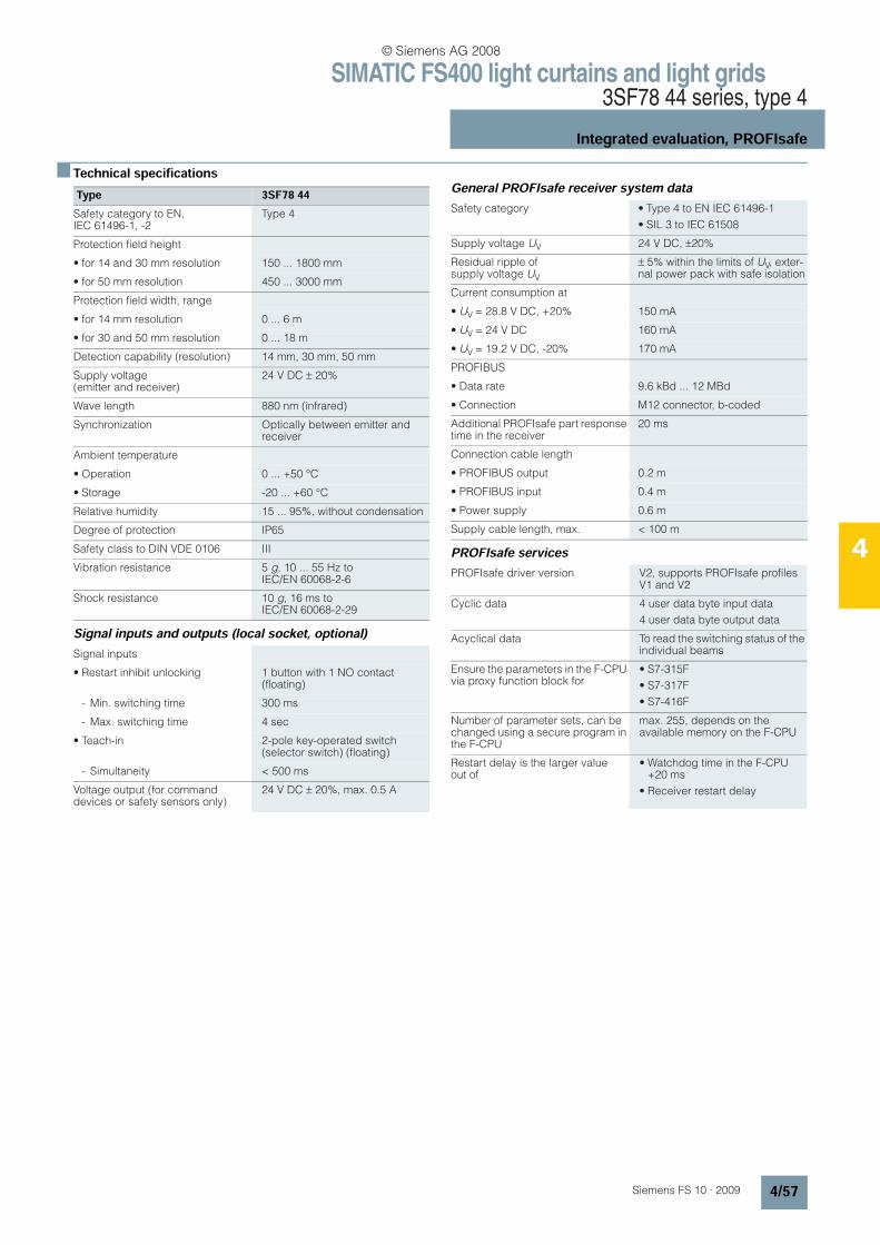
SIMATIC FS400 light curtains and light grids3SF78 44 series, type 4
Integrated evaluation, PROFIsafe
4/57Siemens FS 10 · 2009
4
n Technical specifications
Signal inputs and outputs (local socket, optional)
General PROFIsafe receiver system data
PROFIsafe services
Type 3SF78 44Safety category to EN, IEC 61496-1, -2
Type 4
Protection field height
• for 14 and 30 mm resolution 150 ... 1800 mm
• for 50 mm resolution 450 ... 3000 mm
Protection field width, range
• for 14 mm resolution 0 ... 6 m
• for 30 and 50 mm resolution 0 ... 18 m
Detection capability (resolution) 14 mm, 30 mm, 50 mm
Supply voltage (emitter and receiver)
24 V DC ± 20%
Wave length 880 nm (infrared)
Synchronization Optically between emitter and receiver
Ambient temperature
• Operation 0 ... +50 °C
• Storage -20 ... +60 °C
Relative humidity 15 ... 95%, without condensation
Degree of protection IP65
Safety class to DIN VDE 0106 III
Vibration resistance 5 g, 10 ... 55 Hz to IEC/EN 60068-2-6
Shock resistance 10 g, 16 ms to IEC/EN 60068-2-29
Signal inputs
• Restart inhibit unlocking 1 button with 1 NO contact (floating)
- Min. switching time 300 ms
- Max. switching time 4 sec
• Teach-in 2-pole key-operated switch (selector switch) (floating)
- Simultaneity < 500 ms
Voltage output (for command devices or safety sensors only)
24 V DC ± 20%, max. 0.5 A
Safety category • Type 4 to EN IEC 61496-1
• SIL 3 to IEC 61508
Supply voltage UV 24 V DC, ±20%
Residual ripple of supply voltage UV
± 5% within the limits of UV, exter-nal power pack with safe isolation
Current consumption at
• UV = 28.8 V DC, +20% 150 mA
• UV = 24 V DC 160 mA
• UV = 19.2 V DC, -20% 170 mA
PROFIBUS
• Data rate 9.6 kBd ... 12 MBd
• Connection M12 connector, b-coded
Additional PROFIsafe part response time in the receiver
20 ms
Connection cable length
• PROFIBUS output 0.2 m
• PROFIBUS input 0.4 m
• Power supply 0.6 m
Supply cable length, max. < 100 m
PROFIsafe driver version V2, supports PROFIsafe profiles V1 and V2
Cyclic data 4 user data byte input data
4 user data byte output data
Acyclical data To read the switching status of the individual beams
Ensure the parameters in the F-CPU via proxy function block for
• S7-315F
• S7-317F
• S7-416F
Number of parameter sets, can be changed using a secure program in the F-CPU
max. 255, depends on the available memory on the F-CPU
Restart delay is the larger value out of
• Watchdog time in the F-CPU +20 ms
• Receiver restart delay
© Siemens AG 2008
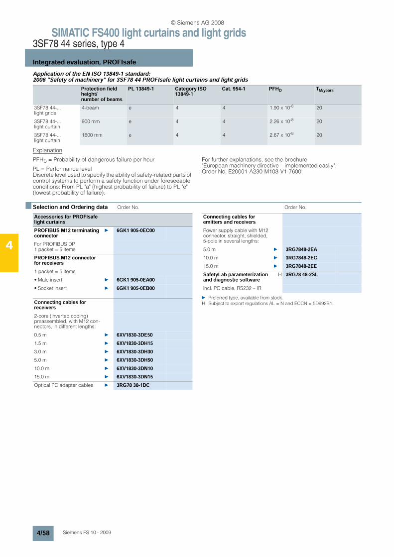
SIMATIC FS400 light curtains and light grids3SF78 44 series, type 4
Integrated evaluation, PROFIsafe
4/58 Siemens FS 10 · 2009
4
Application of the EN ISO 13849-1 standard: 2006 "Safety of machinery" for 3SF78 44 PROFIsafe light curtains and light grids
Explanation
PFHD = Probability of dangerous failure per hour
PL = Performance level Discrete level used to specify the ability of safety-related parts of control systems to perform a safety function under foreseeable conditions: From PL "a" (highest probability of failure) to PL "e" (lowest probability of failure).
For further explanations, see the brochure "European machinery directive – implemented easily", Order No. E20001-A230-M103-V1-7600.
n Selection and Ordering data Order No. Order No.
Preferred type, available from stock.
H: Subject to export regulations AL = N and ECCN = 5D992B1.
Protection field height/number of beams
PL 13849-1 Category ISO 13849-1
Cat. 954-1 PFHD TM/years
3SF78 44-...light grids
4-beam e 4 4 1.90 x 10⁻⁸ 20
3SF78 44-...light curtain
900 mm e 4 4 2.26 x 10⁻⁸ 20
3SF78 44-...light curtain
1800 mm e 4 4 2.67 x 10⁻⁸ 20
Accessories for PROFIsafe light curtainsPROFIBUS M12 terminating connector
6GK1 905-0EC00
For PROFIBUS DP 1 packet = 5 items
PROFIBUS M12 connector for receivers1 packet = 5 items
• Male insert 6GK1 905-0EA00• Socket insert 6GK1 905-0EB00
Connecting cables for receivers2-core (inverted coding) preassembled, with M12 con-nectors, in different lengths:
0.5 m 6XV1830-3DE501.5 m 6XV1830-3DH153.0 m 6XV1830-3DH305.0 m 6XV1830-3DH5010.0 m 6XV1830-3DN1015.0 m 6XV1830-3DN15Optical PC adapter cables 3RG78 38-1DC
Connecting cables for emitters and receiversPower supply cable with M12 connector, straight, shielded, 5-pole in several lengths:
5.0 m 3RG7848-2EA10.0 m 3RG7848-2EC15.0 m 3RG7848-2EESafetyLab parameterization and diagnostic software
H 3RG78 48-2SL
incl. PC cable, RS232 – IR
© Siemens AG 2008

SIMATIC FS400 light curtains and light grids3SF78 44 series, type 4
Integrated evaluation
4/59Siemens FS 10 · 2009
4
n Selection and Ordering dataLight curtains with blanking function package PROFIsafe1)Protection field height
Type Standard device Host device Guest device
mm Order No. Order No. Order No.
Resolution 14 mm300 Receiver 3SF78 44-8BB04-0SS1 3SF78 44-8BB04-1SS1 3RG78 42-6BD21300 Emitter 3SF78 44-6SB04-0SS0 3SF78 44-6SB04-1SS0 3RG78 42-6BD20450 Receiver 3SF78 44-8BB06-0SS1 3SF78 44-8BB06-1SS1 3RG78 42-6BE21450 Emitter 3SF78 44-6SB06-0SS0 3SF78 44-6SB06-1SS0 3RG78 42-6BE20600 Receiver 3SF78 44-8BB08-0SS1 3SF78 44-8BB08-1SS1 3RG78 42-6BF21600 Emitter 3SF78 44-6SB08-0SS0 3SF78 44-6SB08-1SS0 3RG78 42-6BF20750 Receiver 3SF78 44-8BB11-0SS1 3SF78 44-8BB11-1SS1 3RG78 42-6BG21750 Emitter 3SF78 44-6SB11-0SS0 3SF78 44-6SB11-1SS0 3RG78 42-6BG20900 Receiver 3SF78 44-8BB13-0SS1 3SF78 44-8BB13-1SS1 3RG78 42-6BH21900 Emitter 3SF78 44-6SB13-0SS0 3SF78 44-6SB13-1SS0 3RG78 42-6BH201050 Receiver 3SF78 44-8BB15-0SS1 3SF78 44-8BB15-1SS1 3RG78 42-6BJ211050 Emitter 3SF78 44-6SB15-0SS0 3SF78 44-6SB15-1SS0 3RG78 42-6BJ201200 Receiver 3SF78 44-8BB17-0SS1 3SF78 44-8BB17-1SS1 3RG78 42-6BK211200 Emitter 3SF78 44-6SB17-0SS0 3SF78 44-6SB17-1SS0 3RG78 42-6BK201350 Receiver 3SF78 44-8BB20-0SS1 3SF78 44-8BB20-1SS1 3RG78 42-6BL211350 Emitter 3SF78 44-6SB20-0SS0 3SF78 44-6SB20-1SS0 3RG78 42-6BL201500 Receiver 3SF78 44-8BB22-0SS1 3SF78 44-8BB22-1SS1 3RG78 42-6BM211500 Emitter 3SF78 44-6SB22-0SS0 3SF78 44-6SB22-1SS0 3RG78 42-6BM201650 Receiver 3SF78 44-8BB24-0SS1 3SF78 44-8BB24-1SS1 3RG78 42-6BN211650 Emitter 3SF78 44-6SB24-0SS0 3SF78 44-6SB24-1SS0 3RG78 42-6BN201800 Receiver 3SF78 44-8BB26-0SS1 3SF78 44-8BB26-1SS1 3RG78 42-6BP211800 Emitter 3SF78 44-6SB26-0SS0 3SF78 44-6SB26-1SS0 3RG78 42-6BP20Resolution 30 mm300 Receiver 3SF78 44-8BD04-0SS1 3SF78 44-8BD04-1SS1 3RG78 42-6DD21300 Emitter 3SF78 44-6SD04-0SS0 3SF78 44-6SD04-1SS0 3RG78 42-6DD20450 Receiver 3SF78 44-8BD06-0SS1 3SF78 44-8BD06-1SS1 3RG78 42-6DE21450 Emitter 3SF78 44-6SD06-0SS0 3SF78 44-6SD06-1SS0 3RG78 42-6DE20600 Receiver 3SF78 44-8BD08-0SS1 3SF78 44-8BD08-1SS1 3RG78 42-6DF21600 Emitter 3SF78 44-6SD08-0SS0 3SF78 44-6SD08-1SS0 3RG78 42-6DF20750 Receiver 3SF78 44-8BD11-0SS1 3SF78 44-8BD11-1SS1 3RG78 42-6DG21750 Emitter 3SF78 44-6SD11-0SS0 3SF78 44-6SD11-1SS0 3RG78 42-6DG20900 Receiver 3SF78 44-8BD13-0SS1 3SF78 44-8BD13-1SS1 3RG78 42-6DH21900 Emitter 3SF78 44-6SD13-0SS0 3SF78 44-6SD13-1SS0 3RG78 42-6DH201050 Receiver 3SF78 44-8BD15-0SS1 3SF78 44-8BD15-1SS1 3RG78 42-6DJ211050 Emitter 3SF78 44-6SD15-0SS0 3SF78 44-6SD15-1SS0 3RG78 42-6DJ201200 Receiver 3SF78 44-8BD17-0SS1 3SF78 44-8BD17-1SS1 3RG78 42-6DK211200 Emitter 3SF78 44-6SD17-0SS0 3SF78 44-6SD17-1SS0 3RG78 42-6DK201350 Receiver 3SF78 44-8BD20-0SS1 3SF78 44-8BD20-1SS1 3RG78 42-6DL211350 Emitter 3SF78 44-6SD20-0SS0 3SF78 44-6SD20-1SS0 3RG78 42-6DL201500 Receiver 3SF78 44-8BD22-0SS1 3SF78 44-8BD22-1SS1 3RG78 42-6DM211500 Emitter 3SF78 44-6SD22-0SS0 3SF78 44-6SD22-1SS0 3RG78 42-6DM201650 Receiver 3SF78 44-8BD24-0SS1 3SF78 44-8BD24-1SS1 3RG78 42-6DN211650 Emitter 3SF78 44-6SD24-0SS0 3SF78 44-6SD24-1SS0 3RG78 42-6DN20
1) For scope of supply see top of page 4/51.
Preferred type, available from stock.
© Siemens AG 2008

SIMATIC FS400 light curtains and light grids3SF78 44 series, type 4
Integrated evaluation
4/60 Siemens FS 10 · 2009
4
Light curtains with muting function package PROFIsafe1)
Protection field height
Type Standard device Host device Guest device
mm Order No. Order No. Order No.
1800 Receiver 3SF78 44-8BD26-0SS1 3SF78 44-8BD26-1SS1 3RG78 42-6DP211800 Emitter 3SF78 44-6SD26-0SS0 3SF78 44-6SD26-1SS0 3RG78 42-6DP20
1) For scope of supply see top of page 4/51.
Preferred type, available from stock.
Protection field height
Type Standard device Host device Guest device
mm Order No. Order No. Order No.
Resolution 14 mm300 Receiver 3SF78 44-8MB04-0SS1 On request 3RG78 42-6BD21300 Emitter 3SF78 44-6SB04-0SS0 On request 3RG78 42-6BD20450 Receiver 3SF78 44-8MB06-0SS1 On request 3RG78 42-6BE21450 Emitter 3SF78 44-6SB06-0SS0 On request 3RG78 42-6BE20600 Receiver 3SF78 44-8MB08-0SS1 On request 3RG78 42-6BF21600 Emitter 3SF78 44-6SB08-0SS0 On request 3RG78 42-6BF20750 Receiver 3SF78 44-8MB11-0SS1 On request 3RG78 42-6BG21750 Emitter 3SF78 44-6SB11-0SS0 On request 3RG78 42-6BG20900 Receiver 3SF78 44-8MB13-0SS1 On request 3RG78 42-6BH21900 Emitter 3SF78 44-6SB13-0SS0 On request 3RG78 42-6BH201050 Receiver 3SF78 44-8MB15-0SS1 On request 3RG78 42-6BJ211050 Emitter 3SF78 44-6SB15-0SS0 On request 3RG78 42-6BJ201200 Receiver 3SF78 44-8MB17-0SS1 On request 3RG78 42-6BK211200 Emitter 3SF78 44-6SB17-0SS0 On request 3RG78 42-6BK201350 Receiver 3SF78 44-8MB20-0SS1 On request 3RG78 42-6BL211350 Emitter 3SF78 44-6SB20-0SS0 On request 3RG78 42-6BL201500 Receiver 3SF78 44-8MB22-0SS1 On request 3RG78 42-6BM211500 Emitter 3SF78 44-6SB22-0SS0 On request 3RG78 42-6BM201650 Receiver 3SF78 44-8MB24-0SS1 On request 3RG78 42-6BN211650 Emitter 3SF78 44-6SB24-0SS0 On request 3RG78 42-6BN201800 Receiver 3SF78 44-8MB26-0SS1 On request 3RG78 42-6BP211800 Emitter 3SF78 44-6SB26-0SS0 On request 3RG78 42-6BP20Resolution 30 mm300 Receiver 3SF78 44-8MD04-0SS1 On request 3RG78 42-6DD21300 Emitter 3SF78 44-6SD04-0SS0 On request 3RG78 42-6DD20450 Receiver 3SF78 44-8MD06-0SS1 On request 3RG78 42-6DE21450 Emitter 3SF78 44-6SD06-0SS0 On request 3RG78 42-6DE20600 Receiver 3SF78 44-8MD08-0SS1 On request 3RG78 42-6DF21600 Emitter 3SF78 44-6SD08-0SS0 On request 3RG78 42-6DF20750 Receiver 3SF78 44-8MD11-0SS1 On request 3RG78 42-6DG21750 Emitter 3SF78 44-6SD11-0SS0 On request 3RG78 42-6DG20900 Receiver 3SF78 44-8MD13-0SS1 On request 3RG78 42-6DH21900 Emitter 3SF78 44-6SD13-0SS0 On request 3RG78 42-6DH201050 Receiver 3SF78 44-8MD15-0SS1 On request 3RG78 42-6DJ211050 Emitter 3SF78 44-6SD15-0SS0 On request 3RG78 42-6DJ201200 Receiver 3SF78 44-8MD17-0SS1 On request 3RG78 42-6DK211200 Emitter 3SF78 44-6SD17-0SS0 On request 3RG78 42-6DK201350 Receiver 3SF78 44-8MD20-0SS1 On request 3RG78 42-6DL211350 Emitter 3SF78 44-6SD20-0SS0 On request 3RG78 42-6DL20
© Siemens AG 2008
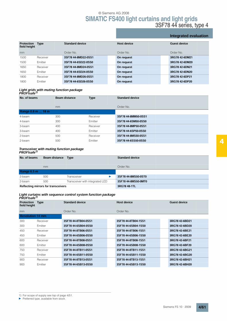
SIMATIC FS400 light curtains and light grids3SF78 44 series, type 4
Integrated evaluation
4/61Siemens FS 10 · 2009
4
Light grids with muting function package PROFIsafe1)
Transceiver with muting function packagePROFIsafe1)
Light curtains with sequence control system function package PROFIsafe1)
Protection field height
Type Standard device Host device Guest device
mm Order No. Order No. Order No.
1500 Receiver 3SF78 44-8MD22-0SS1 On request 3RG78 42-6DM211500 Emitter 3SF78 44-6SD22-0SS0 On request 3RG78 42-6DM201650 Receiver 3SF78 44-8MD24-0SS1 On request 3RG78 42-6DN211650 Emitter 3SF78 44-6SD24-0SS0 On request 3RG78 42-6DN201800 Receiver 3SF78 44-8MD26-0SS1 On request 3RG78 42-6DP211800 Emitter 3SF78 44-6SD26-0SS0 On request 3RG78 42-6DP20
No. of beams Beam distance Type Standard device
mm Order No.
Range 0.8 m … 18 m4-beam 300 Receiver 3SF78 44-8MM50-0SS14-beam 300 Emitter 3SF78 44-6SM50-0SS03-beam 400 Receiver 3SF78 44-8MP50-0SS13-beam 400 Emitter 3SF78 44-6SP50-0SS02-beam 500 Receiver 3SF78 44-8MS50-0SS12-beam 500 Emitter 3SF78 44-6SS50-0SS0
1) For scope of supply see top of page 4/51.
Preferred type, available from stock.
No. of beams Beam distance Type Standard device
mm Order No.
Range 6.5 m2-beam 500 Transceiver 3SF78 44-8MS50-0ST02-beam 500 Transceiver with integrated LED 3SF78 44-8MS50-0MT0Reflecting mirrors for transceivers 3RG78 48-1TL
Protection field height
Type Standard device Host device Guest device
mm Order No. Order No.
Resolution 14 mm300 Receiver 3SF78 44-8TB04-0SS1 3SF78 44-8TB04-1SS1 3RG78 42-6BD21300 Emitter 3SF78 44-6SB04-0SS0 3SF78 44-6SB04-1SS0 3RG78 42-6BD20450 Receiver 3SF78 44-8TB06-0SS1 3SF78 44-8TB06-1SS1 3RG78 42-6BE21450 Emitter 3SF78 44-6SB06-0SS0 3SF78 44-6SB06-1SS0 3RG78 42-6BE20600 Receiver 3SF78 44-8TB08-0SS1 3SF78 44-8TB08-1SS1 3RG78 42-6BF21600 Emitter 3SF78 44-6SB08-0SS0 3SF78 44-6SB08-1SS0 3RG78 42-6BF20750 Receiver 3SF78 44-8TB11-0SS1 3SF78 44-8TB11-1SS1 3RG78 42-6BG21750 Emitter 3SF78 44-6SB11-0SS0 3SF78 44-6SB11-1SS0 3RG78 42-6BG20900 Receiver 3SF78 44-8TB13-0SS1 3SF78 44-8TB13-1SS1 3RG78 42-6BH21900 Emitter 3SF78 44-6SB13-0SS0 3SF78 44-6SB13-1SS0 3RG78 42-6BH20
© Siemens AG 2008
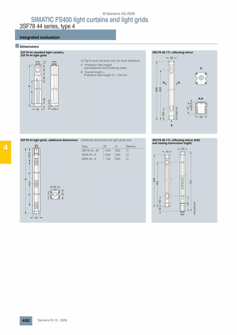
SIMATIC FS400 light curtains and light grids3SF78 44 series, type 4
Integrated evaluation
4/62 Siemens FS 10 · 2009
4
n Dimensions3SF78 44 standard light curtains, 3SF78 44 light grids
$ Pg 9 cover (receiver only, for local interface)
A Protection field height (see Selection and Ordering data)
B Overall length = Protection field height A + 134 mm
3RG78 48-1TL reflecting mirror
3SF78 44 light grids, additional dimensions Additional dimensions for light grids only: 3RG78 48-1TL reflecting mirror (left) and muting transceiver (right)
NSC0_00647
A
5 2
B
5 5
22
1
72
40
52
102
602
696
X
52
29,5
57
A A
X
A-A
FS
10
00
10
4
52
52
55
149.5
A
FS
10
_0
03
07
B
A
Type B A Beams
3SF78 44-..M
3SF8 44-..P
3SF8 44-..S
1184
1034
734
300
400
500
4
3
2
52
102
602
52
734
140
38
696
FS
10
00
10
7
© Siemens AG 2008
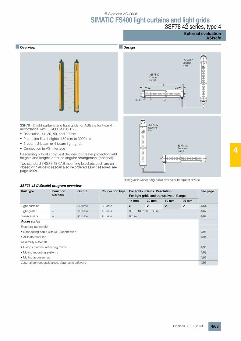
SIMATIC FS400 light curtains and light grids3SF78 42 series, type 4
External evaluationASIsafe
4/63Siemens FS 10 · 2009
4
n Overview
3SF78 42 light curtains and light grids for ASIsafe for type 4 in accordance with IEC/EN 61496-1, -2
• Resolution: 14, 30, 50, and 90 mm
• Protection field heights: 150 mm to 3000 mm
• 2-beam, 3-beam or 4-beam light grids
• Connection to AS-Interface
Cascading of host and guest devices for greater protection field heights and lengths or for an angular arrangement (optional).
Two standard 3RG78 48-0AB mounting brackets each are en-closed with all devices (can also be ordered as accessories see page 4/92).
n Design
Host/guest: Cascading basic device-subsequent device
3SF78 42 (ASIsafe) program overview
A
2222
B
Emitter
Host
3SF7842
Emitter
Guest
3SF7842
c
b=40
ReceiverHost
3SF7842
ReceiverGuest
3SF7842
c
Unit type Functionpackage
Output Connection type For light curtains: ResolutionFor light grids and transceivers: Range
See page
14 mm 30 mm 50 mm 90 mmLight curtains − ASIsafe ASIsafe 4 4 4 4 4/64
Light grids − ASIsafe ASIsafe 0.8 ... 18 m; 6 ... 60 m 4/67
Transceivers − ASIsafe ASIsafe 6.5 m 4/64
AccessoriesElectrical connection
• Connecting cable with M12 connection 4/95
• ASIsafe modules 4/94
Assembly materials
• Fixing columns, reflecting mirror 4/91
• Muting mounting systems 4/92
• Muting accessories 4/95
Laser alignment assistance, diagnostic software 4/93
© Siemens AG 2008
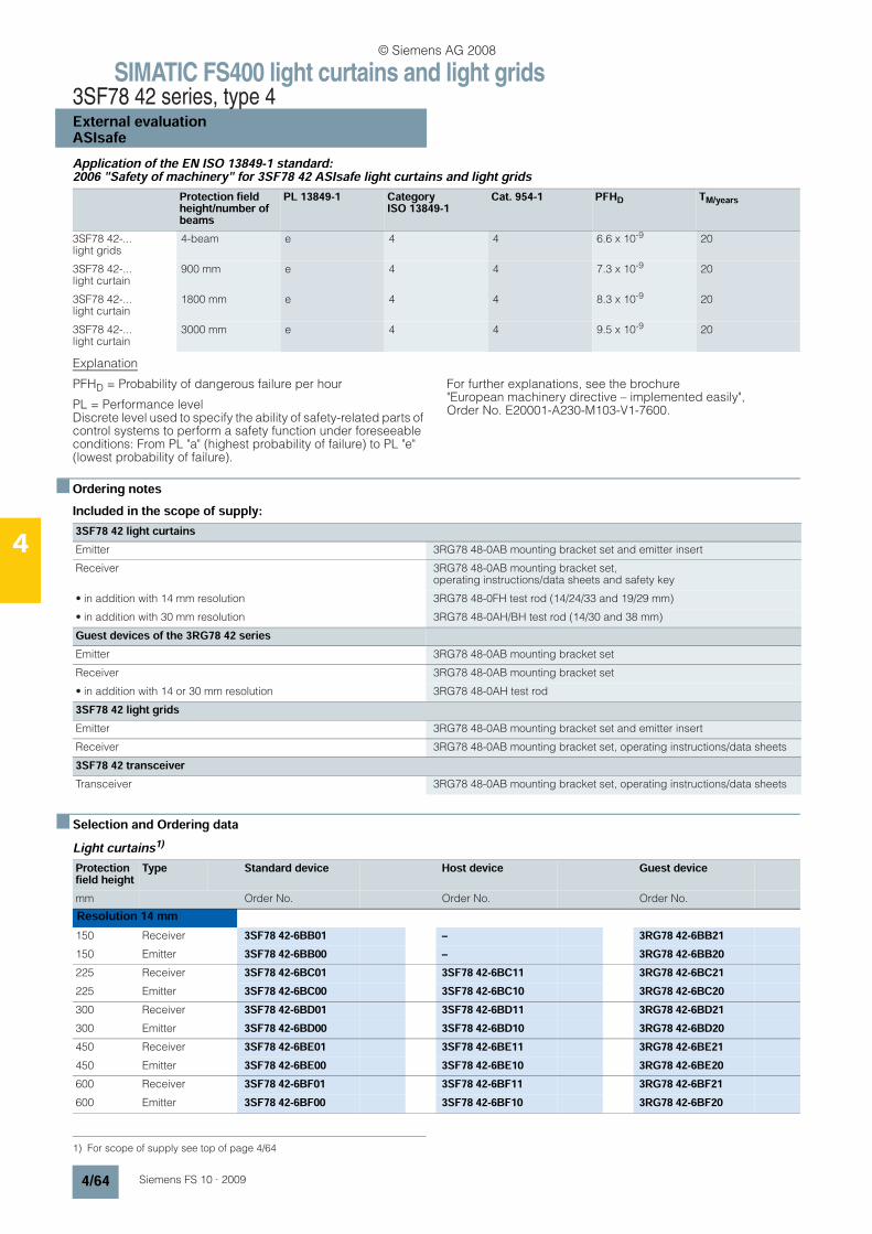
SIMATIC FS400 light curtains and light grids3SF78 42 series, type 4External evaluationASIsafe
4/64 Siemens FS 10 · 2009
4
Application of the EN ISO 13849-1 standard: 2006 "Safety of machinery" for 3SF78 42 ASIsafe light curtains and light grids
Explanation
PFHD = Probability of dangerous failure per hour
PL = Performance level Discrete level used to specify the ability of safety-related parts of control systems to perform a safety function under foreseeable conditions: From PL "a" (highest probability of failure) to PL "e" (lowest probability of failure).
For further explanations, see the brochure"European machinery directive – implemented easily", Order No. E20001-A230-M103-V1-7600.
n Ordering notesIncluded in the scope of supply:
n Selection and Ordering dataLight curtains1)
Protection field height/number of beams
PL 13849-1 Category ISO 13849-1
Cat. 954-1 PFHD TM/years
3SF78 42-...light grids
4-beam e 4 4 6.6 x 10⁻⁹ 20
3SF78 42-...light curtain
900 mm e 4 4 7.3 x 10⁻⁹ 20
3SF78 42-...light curtain
1800 mm e 4 4 8.3 x 10⁻⁹ 20
3SF78 42-...light curtain
3000 mm e 4 4 9.5 x 10⁻⁹ 20
3SF78 42 light curtains Emitter 3RG78 48-0AB mounting bracket set and emitter insert
Receiver 3RG78 48-0AB mounting bracket set, operating instructions/data sheets and safety key
• in addition with 14 mm resolution 3RG78 48-0FH test rod (14/24/33 and 19/29 mm)
• in addition with 30 mm resolution 3RG78 48-0AH/BH test rod (14/30 and 38 mm)
Guest devices of the 3RG78 42 seriesEmitter 3RG78 48-0AB mounting bracket set
Receiver 3RG78 48-0AB mounting bracket set
• in addition with 14 or 30 mm resolution 3RG78 48-0AH test rod
3SF78 42 light gridsEmitter 3RG78 48-0AB mounting bracket set and emitter insert
Receiver 3RG78 48-0AB mounting bracket set, operating instructions/data sheets
3SF78 42 transceiverTransceiver 3RG78 48-0AB mounting bracket set, operating instructions/data sheets
1) For scope of supply see top of page 4/64
Protection field height
Type Standard device Host device Guest device
mm Order No. Order No. Order No.
Resolution 14 mm150 Receiver 3SF78 42-6BB01 – 3RG78 42-6BB21150 Emitter 3SF78 42-6BB00 – 3RG78 42-6BB20225 Receiver 3SF78 42-6BC01 3SF78 42-6BC11 3RG78 42-6BC21225 Emitter 3SF78 42-6BC00 3SF78 42-6BC10 3RG78 42-6BC20300 Receiver 3SF78 42-6BD01 3SF78 42-6BD11 3RG78 42-6BD21300 Emitter 3SF78 42-6BD00 3SF78 42-6BD10 3RG78 42-6BD20450 Receiver 3SF78 42-6BE01 3SF78 42-6BE11 3RG78 42-6BE21450 Emitter 3SF78 42-6BE00 3SF78 42-6BE10 3RG78 42-6BE20600 Receiver 3SF78 42-6BF01 3SF78 42-6BF11 3RG78 42-6BF21600 Emitter 3SF78 42-6BF00 3SF78 42-6BF10 3RG78 42-6BF20
© Siemens AG 2008
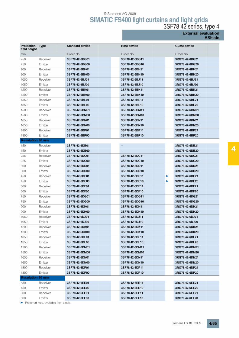
SIMATIC FS400 light curtains and light grids3SF78 42 series, type 4
External evaluationASIsafe
4/65Siemens FS 10 · 2009
4
750 Receiver 3SF78 42-6BG01 3SF78 42-6BG11 3RG78 42-6BG21750 Emitter 3SF78 42-6BG00 3SF78 42-6BG10 3RG78 42-6BG20900 Receiver 3SF78 42-6BH01 3SF78 42-6BH11 3RG78 42-6BH21900 Emitter 3SF78 42-6BH00 3SF78 42-6BH10 3RG78 42-6BH201050 Receiver 3SF78 42-6BJ01 3SF78 42-6BJ11 3RG78 42-6BJ211050 Emitter 3SF78 42-6BJ00 3SF78 42-6BJ10 3RG78 42-6BJ201200 Receiver 3SF78 42-6BK01 3SF78 42-6BK11 3RG78 42-6BK211200 Emitter 3SF78 42-6BK00 3SF78 42-6BK10 3RG78 42-6BK201350 Receiver 3SF78 42-6BL01 3SF78 42-6BL11 3RG78 42-6BL211350 Emitter 3SF78 42-6BL00 3SF78 42-6BL10 3RG78 42-6BL201500 Receiver 3SF78 42-6BM01 3SF78 42-6BM11 3RG78 42-6BM211500 Emitter 3SF78 42-6BM00 3SF78 42-6BM10 3RG78 42-6BM201650 Receiver 3SF78 42-6BN01 3SF78 42-6BN11 3RG78 42-6BN211650 Emitter 3SF78 42-6BN00 3SF78 42-6BN10 3RG78 42-6BN201800 Receiver 3SF78 42-6BP01 3SF78 42-6BP11 3RG78 42-6BP211800 Emitter 3SF78 42-6BP00 3SF78 42-6BP10 3RG78 42-6BP20Resolution 30 mm150 Receiver 3SF78 42-6DB01 – 3RG78 42-6DB21150 Emitter 3SF78 42-6DB00 – 3RG78 42-6DB20225 Receiver 3SF78 42-6DC01 3SF78 42-6DC11 3RG78 42-6DC21225 Emitter 3SF78 42-6DC00 3SF78 42-6DC10 3RG78 42-6DC20300 Receiver 3SF78 42-6DD01 3SF78 42-6DD11 3RG78 42-6DD21300 Emitter 3SF78 42-6DD00 3SF78 42-6DD10 3RG78 42-6DD20450 Receiver 3SF78 42-6DE01 3SF78 42-6DE11 3RG78 42-6DE21450 Emitter 3SF78 42-6DE00 3SF78 42-6DE10 3RG78 42-6DE20600 Receiver 3SF78 42-6DF01 3SF78 42-6DF11 3RG78 42-6DF21600 Emitter 3SF78 42-6DF00 3SF78 42-6DF10 3RG78 42-6DF20750 Receiver 3SF78 42-6DG01 3SF78 42-6DG11 3RG78 42-6DG21750 Emitter 3SF78 42-6DG00 3SF78 42-6DG10 3RG78 42-6DG20900 Receiver 3SF78 42-6DH01 3SF78 42-6DH11 3RG78 42-6DH21900 Emitter 3SF78 42-6DH00 3SF78 42-6DH10 3RG78 42-6DH201050 Receiver 3SF78 42-6DJ01 3SF78 42-6DJ11 3RG78 42-6DJ211050 Emitter 3SF78 42-6DJ00 3SF78 42-6DJ10 3RG78 42-6DJ201200 Receiver 3SF78 42-6DK01 3SF78 42-6DK11 3RG78 42-6DK211200 Emitter 3SF78 42-6DK00 3SF78 42-6DK10 3RG78 42-6DK201350 Receiver 3SF78 42-6DL01 3SF78 42-6DL11 3RG78 42-6DL211350 Emitter 3SF78 42-6DL00 3SF78 42-6DL10 3RG78 42-6DL201500 Receiver 3SF78 42-6DM01 3SF78 42-6DM11 3RG78 42-6DM211500 Emitter 3SF78 42-6DM00 3SF78 42-6DM10 3RG78 42-6DM201650 Receiver 3SF78 42-6DN01 3SF78 42-6DN11 3RG78 42-6DN211650 Emitter 3SF78 42-6DN00 3SF78 42-6DN10 3RG78 42-6DN201800 Receiver 3SF78 42-6DP01 3SF78 42-6DP11 3RG78 42-6DP211800 Emitter 3SF78 42-6DP00 3SF78 42-6DP10 3RG78 42-6DP20Resolution 50 mm450 Receiver 3SF78 42-6EE01 3SF78 42-6EE11 3RG78 42-6EE21450 Emitter 3SF78 42-6EE00 3SF78 42-6EE10 3RG78 42-6EE20600 Receiver 3SF78 42-6EF01 3SF78 42-6EF11 3RG78 42-6EF21600 Emitter 3SF78 42-6EF00 3SF78 42-6EF10 3RG78 42-6EF20 Preferred type, available from stock.
Protection field height
Type Standard device Host device Guest device
mm Order No. Order No. Order No.
© Siemens AG 2008
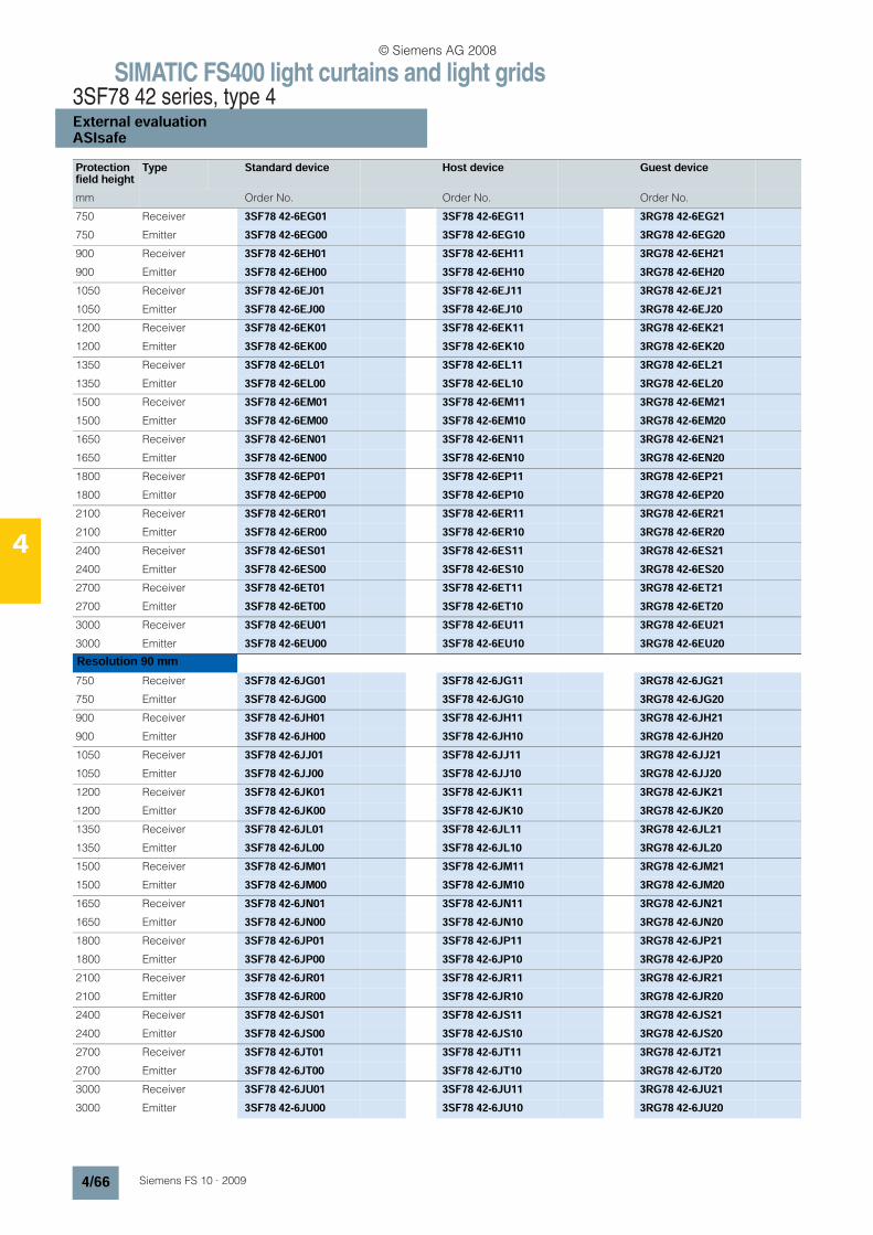
SIMATIC FS400 light curtains and light grids3SF78 42 series, type 4External evaluationASIsafe
4/66 Siemens FS 10 · 2009
4
750 Receiver 3SF78 42-6EG01 3SF78 42-6EG11 3RG78 42-6EG21750 Emitter 3SF78 42-6EG00 3SF78 42-6EG10 3RG78 42-6EG20900 Receiver 3SF78 42-6EH01 3SF78 42-6EH11 3RG78 42-6EH21900 Emitter 3SF78 42-6EH00 3SF78 42-6EH10 3RG78 42-6EH201050 Receiver 3SF78 42-6EJ01 3SF78 42-6EJ11 3RG78 42-6EJ211050 Emitter 3SF78 42-6EJ00 3SF78 42-6EJ10 3RG78 42-6EJ201200 Receiver 3SF78 42-6EK01 3SF78 42-6EK11 3RG78 42-6EK211200 Emitter 3SF78 42-6EK00 3SF78 42-6EK10 3RG78 42-6EK201350 Receiver 3SF78 42-6EL01 3SF78 42-6EL11 3RG78 42-6EL211350 Emitter 3SF78 42-6EL00 3SF78 42-6EL10 3RG78 42-6EL201500 Receiver 3SF78 42-6EM01 3SF78 42-6EM11 3RG78 42-6EM211500 Emitter 3SF78 42-6EM00 3SF78 42-6EM10 3RG78 42-6EM201650 Receiver 3SF78 42-6EN01 3SF78 42-6EN11 3RG78 42-6EN211650 Emitter 3SF78 42-6EN00 3SF78 42-6EN10 3RG78 42-6EN201800 Receiver 3SF78 42-6EP01 3SF78 42-6EP11 3RG78 42-6EP211800 Emitter 3SF78 42-6EP00 3SF78 42-6EP10 3RG78 42-6EP202100 Receiver 3SF78 42-6ER01 3SF78 42-6ER11 3RG78 42-6ER212100 Emitter 3SF78 42-6ER00 3SF78 42-6ER10 3RG78 42-6ER202400 Receiver 3SF78 42-6ES01 3SF78 42-6ES11 3RG78 42-6ES212400 Emitter 3SF78 42-6ES00 3SF78 42-6ES10 3RG78 42-6ES202700 Receiver 3SF78 42-6ET01 3SF78 42-6ET11 3RG78 42-6ET212700 Emitter 3SF78 42-6ET00 3SF78 42-6ET10 3RG78 42-6ET203000 Receiver 3SF78 42-6EU01 3SF78 42-6EU11 3RG78 42-6EU213000 Emitter 3SF78 42-6EU00 3SF78 42-6EU10 3RG78 42-6EU20Resolution 90 mm750 Receiver 3SF78 42-6JG01 3SF78 42-6JG11 3RG78 42-6JG21750 Emitter 3SF78 42-6JG00 3SF78 42-6JG10 3RG78 42-6JG20900 Receiver 3SF78 42-6JH01 3SF78 42-6JH11 3RG78 42-6JH21900 Emitter 3SF78 42-6JH00 3SF78 42-6JH10 3RG78 42-6JH201050 Receiver 3SF78 42-6JJ01 3SF78 42-6JJ11 3RG78 42-6JJ211050 Emitter 3SF78 42-6JJ00 3SF78 42-6JJ10 3RG78 42-6JJ201200 Receiver 3SF78 42-6JK01 3SF78 42-6JK11 3RG78 42-6JK211200 Emitter 3SF78 42-6JK00 3SF78 42-6JK10 3RG78 42-6JK201350 Receiver 3SF78 42-6JL01 3SF78 42-6JL11 3RG78 42-6JL211350 Emitter 3SF78 42-6JL00 3SF78 42-6JL10 3RG78 42-6JL201500 Receiver 3SF78 42-6JM01 3SF78 42-6JM11 3RG78 42-6JM211500 Emitter 3SF78 42-6JM00 3SF78 42-6JM10 3RG78 42-6JM201650 Receiver 3SF78 42-6JN01 3SF78 42-6JN11 3RG78 42-6JN211650 Emitter 3SF78 42-6JN00 3SF78 42-6JN10 3RG78 42-6JN201800 Receiver 3SF78 42-6JP01 3SF78 42-6JP11 3RG78 42-6JP211800 Emitter 3SF78 42-6JP00 3SF78 42-6JP10 3RG78 42-6JP202100 Receiver 3SF78 42-6JR01 3SF78 42-6JR11 3RG78 42-6JR212100 Emitter 3SF78 42-6JR00 3SF78 42-6JR10 3RG78 42-6JR202400 Receiver 3SF78 42-6JS01 3SF78 42-6JS11 3RG78 42-6JS212400 Emitter 3SF78 42-6JS00 3SF78 42-6JS10 3RG78 42-6JS202700 Receiver 3SF78 42-6JT01 3SF78 42-6JT11 3RG78 42-6JT212700 Emitter 3SF78 42-6JT00 3SF78 42-6JT10 3RG78 42-6JT203000 Receiver 3SF78 42-6JU01 3SF78 42-6JU11 3RG78 42-6JU213000 Emitter 3SF78 42-6JU00 3SF78 42-6JU10 3RG78 42-6JU20
Protection field height
Type Standard device Host device Guest device
mm Order No. Order No. Order No.
© Siemens AG 2008
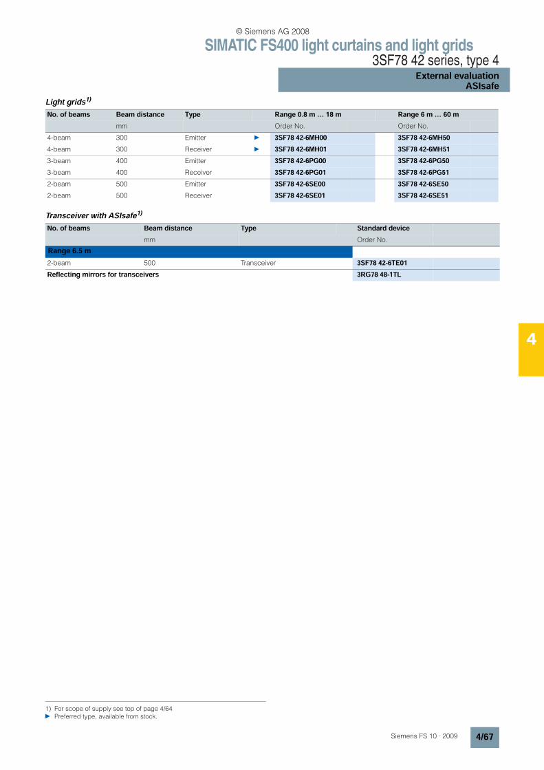
SIMATIC FS400 light curtains and light grids3SF78 42 series, type 4
External evaluationASIsafe
4/67Siemens FS 10 · 2009
4
Light grids1)
Transceiver with ASIsafe1)
1) For scope of supply see top of page 4/64 Preferred type, available from stock.
No. of beams Beam distance Type Range 0.8 m … 18 m Range 6 m … 60 m mm Order No. Order No.
4-beam 300 Emitter 3SF78 42-6MH00 3SF78 42-6MH504-beam 300 Receiver 3SF78 42-6MH01 3SF78 42-6MH513-beam 400 Emitter 3SF78 42-6PG00 3SF78 42-6PG503-beam 400 Receiver 3SF78 42-6PG01 3SF78 42-6PG512-beam 500 Emitter 3SF78 42-6SE00 3SF78 42-6SE502-beam 500 Receiver 3SF78 42-6SE01 3SF78 42-6SE51
No. of beams Beam distance Type Standard devicemm Order No.
Range 6.5 m2-beam 500 Transceiver 3SF78 42-6TE01Reflecting mirrors for transceivers 3RG78 48-1TL
© Siemens AG 2008
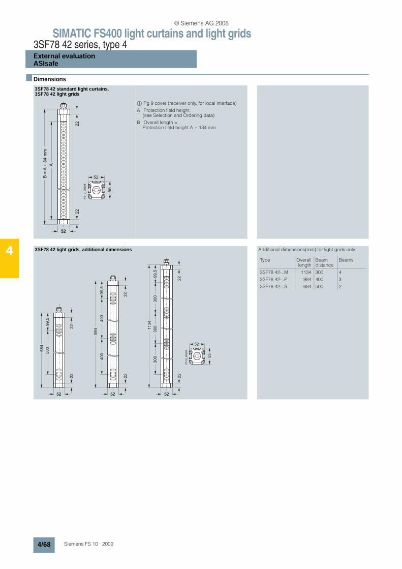
SIMATIC FS400 light curtains and light grids3SF78 42 series, type 4External evaluationASIsafe
4/68 Siemens FS 10 · 2009
4
n Dimensions3SF78 42 standard light curtains, 3SF78 42 light grids
$ Pg 9 cover (receiver only, for local interface)
A Protection field height (see Selection and Ordering data)
B Overall length = Protection field height A + 134 mm
3SF78 42 light grids, additional dimensions Additional dimensions(mm) for light grids only:
52
52
55
22
B =
A +
84
mm
A
22
52
FS
10
_0
03
08
300
52
52
55
22
1134
300
99,5
300
22
5252
22
984
400
400
22
52
FS
10
_0
03
09
52
22
684
500
99,5
99,5
22
52
Type Overalllength
Beam distance
Beams
3SF78 42-..M
3SF78 42-..P
3SF78 42-..S
1134
984
684
300
400
500
4
3
2
© Siemens AG 2008
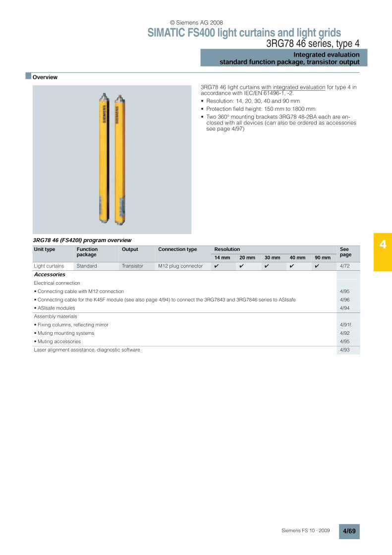
SIMATIC FS400 light curtains and light grids3RG78 46 series, type 4
Integrated evaluationstandard function package, transistor output
4/69Siemens FS 10 · 2009
4
n Overview
3RG78 46 light curtains with integrated evaluation for type 4 in accordance with IEC/EN 61496-1, -2.
• Resolution: 14, 20, 30, 40 and 90 mm
• Protection field height: 150 mm to 1800 mm
• Two 360° mounting brackets 3RG78 48-2BA each are en-closed with all devices (can also be ordered as accessories see page 4/97)
3RG78 46 (FS420I) program overview
Unit type Functionpackage
Output Connection type Resolution Seepage14 mm 20 mm 30 mm 40 mm 90 mm
Light curtains Standard Transistor M12 plug connector 4 4 4 4 4 4/72
AccessoriesElectrical connection
• Connecting cable with M12 connection 4/95
• Connecting cable for the K45F module (see also page 4/94) to connect the 3RG7843 and 3RG7846 series to ASIsafe 4/96
• ASIsafe modules 4/94
Assembly materials
• Fixing columns, reflecting mirror 4/91f.
• Muting mounting systems 4/92
• Muting accessories 4/95
Laser alignment assistance, diagnostic software 4/93
© Siemens AG 2008

SIMATIC FS400 light curtains and light grids3RG78 46 series, type 4Integrated evaluationstandard function package, transistor output
4/70 Siemens FS 10 · 2009
4
n Technical specifications
1) The circuits connected to the inputs and outputs must comply with the air gaps and creepage distances specified in the applicable stan-dards for safe isolation.
1) Fast recovery voltage for contactors, otherwise 0 V2) Please note further constraints due to cable length and load current.
Type 3RG78 46Safety category IEC/EN 61496 Type 4
Detection capability (resolution) 14 mm, 20 mm, 30 mm, 40 mm, 90 mm
Protection field width, range
• 14 mm resolution 0.5 ... 5 m
• 20 mm resolution 0.7 ... 14 m
• 30 mm resolution 0.5 ... 9 m
• 40 mm resolution 0.9 ... 20 m
• 90 mm resolution 0.9 ... 20 m
Supply voltage Uv(emitter and receiver)
24 V DC ± 20% (external power pack with safe isolation and compensation of 20 ms voltage dip is necessary, minimum 1 A current reserve)
Residual ripple of supply voltage ± 5% within the limits of Uv
Current consumption
• Emitter 75 mA
• Receiver 110 mA (without external load)
General value for external fuse in the transmitter and receiver supply leads
1 A medium time-lag
Permissible conductor cross-section
• Emitter 0.25 mm2
• Receiver 0.14 mm2
Emitter Light-emitting diodes according to EN 60825-1:1994+ A1:2002+A:2001
• Class 1
• Wave length 950 nm
• Power < 50 µW
Synchronization Optically between emitter and receiver
Safety class (VDE 106) 1) III
Ambient temperature
• Operation 0 ... +55 °C
• Storage –25 ... +70 °C
Relative humidity 15 ... 95%
Degree of protection IP65
Signal inputs
• Emitter pin 4
- Test input • Input: Contact or transistor connected to +24 V DC
• 0 V or spare = Test
• Current load: 20 mA max.
• Receiver pin 1
- Start/restart key Input: Contact (NO) connected to 24 V DC, current load: 15 mA max.
- Error/pollution group alarm Output: pnp: Connected to 24 V DC, 80 mA max.
• Receiver pin 3
- EDM (contactor control) • Input: Contact (NC) connected to 0 V
• Current load: 15 mA max.
- without EDM 24 V DC connection
• Receiver pin 4
- with RES Input: 24 V DC
- without RES Jumper to pin 1
Type 3RG78 46
OSSD transistor outputs 2 pnp safety-related transistor outputs, cross-connection monitored, short-circuit-proofMinimum Typical Maximum
Operational voltage active high (Uv – 1.6 V)
For resistive load Irated = 250 mA
– 22 V –
Operational voltage, low -80 V1) 0 V + 2.8 V
Operational current – 250 mA –
Leakage current – < 5 µA < 20 µA
Load capacitance – – < 220 nF
Load inductance – – < 2.0 H
Permissible line resistance to load – – < 300 Ω2)
Permissible line length between receiver and load (with 0.25 mm2) – – 100 m
Test pulse width 30 µs – 100 µs
Test pulse space – – 22 µs
OSSD reactivation time after beam interruption (without RES) 40 ms 100 ms –
OSSD response time Depending on number of beams, see operating instructions
© Siemens AG 2008
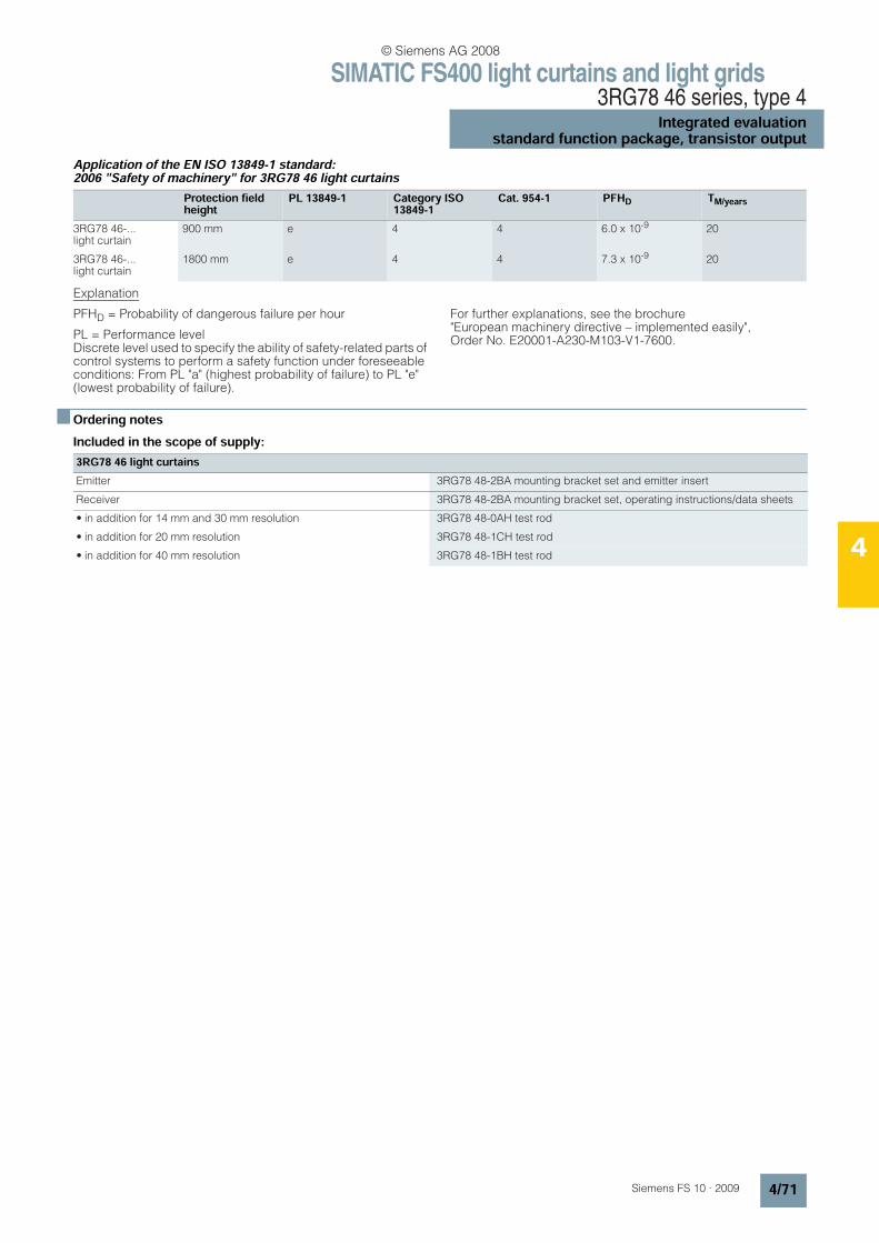
SIMATIC FS400 light curtains and light grids3RG78 46 series, type 4
Integrated evaluationstandard function package, transistor output
4/71Siemens FS 10 · 2009
4
Application of the EN ISO 13849-1 standard: 2006 "Safety of machinery" for 3RG78 46 light curtains
Explanation
PFHD = Probability of dangerous failure per hour
PL = Performance level Discrete level used to specify the ability of safety-related parts of control systems to perform a safety function under foreseeable conditions: From PL "a" (highest probability of failure) to PL "e" (lowest probability of failure).
For further explanations, see the brochure "European machinery directive – implemented easily", Order No. E20001-A230-M103-V1-7600.
n Ordering notesIncluded in the scope of supply:
Protection field height
PL 13849-1 Category ISO 13849-1
Cat. 954-1 PFHD TM/years
3RG78 46-...light curtain
900 mm e 4 4 6.0 x 10⁻⁹ 20
3RG78 46-...light curtain
1800 mm e 4 4 7.3 x 10⁻⁹ 20
3RG78 46 light curtainsEmitter 3RG78 48-2BA mounting bracket set and emitter insert
Receiver 3RG78 48-2BA mounting bracket set, operating instructions/data sheets
• in addition for 14 mm and 30 mm resolution 3RG78 48-0AH test rod
• in addition for 20 mm resolution 3RG78 48-1CH test rod
• in addition for 40 mm resolution 3RG78 48-1BH test rod
© Siemens AG 2008
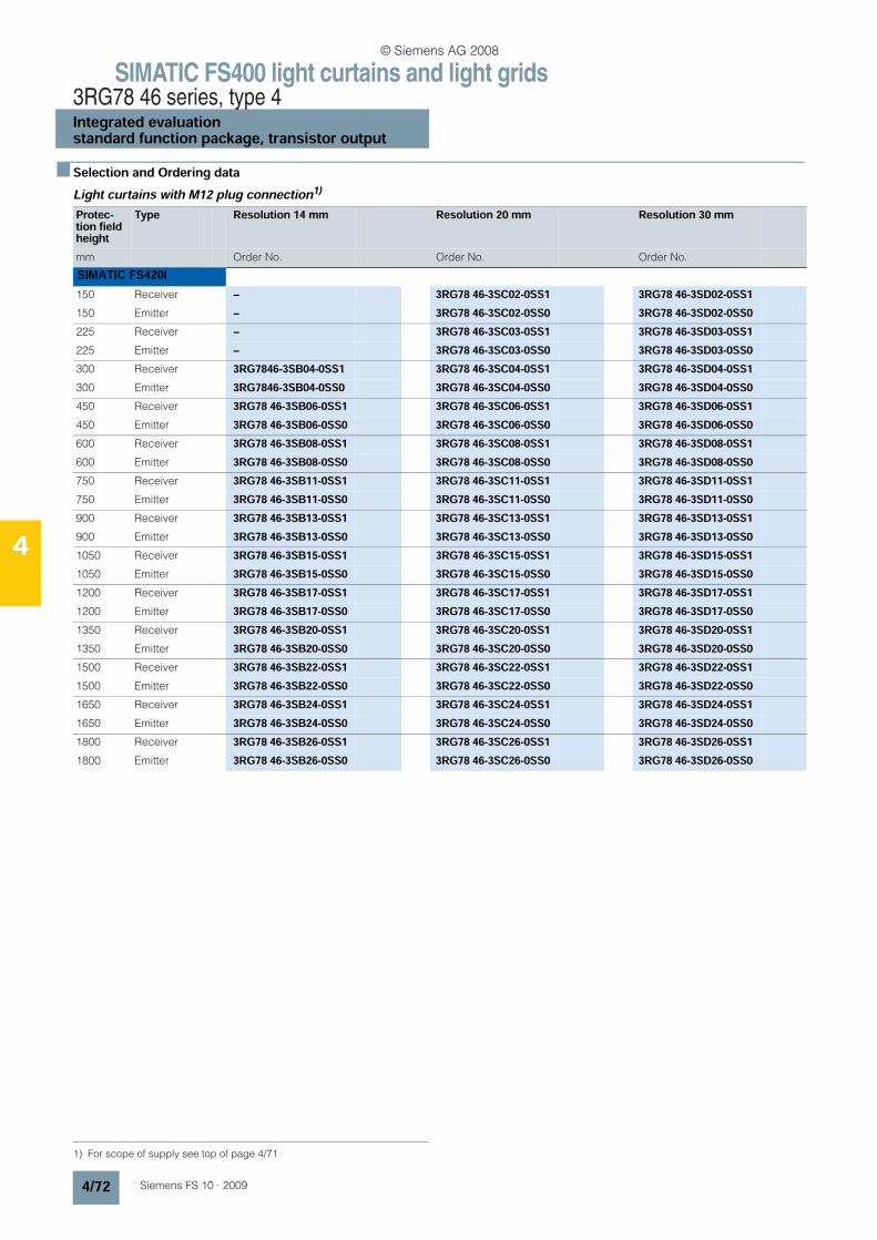
SIMATIC FS400 light curtains and light grids3RG78 46 series, type 4Integrated evaluationstandard function package, transistor output
4/72 Siemens FS 10 · 2009
4
n Selection and Ordering dataLight curtains with M12 plug connection1)
1) For scope of supply see top of page 4/71
Protec-tion field height
Type Resolution 14 mm Resolution 20 mm Resolution 30 mm
mm Order No. Order No. Order No.
SIMATIC FS420I150 Receiver – 3RG78 46-3SC02-0SS1 3RG78 46-3SD02-0SS1150 Emitter – 3RG78 46-3SC02-0SS0 3RG78 46-3SD02-0SS0225 Receiver – 3RG78 46-3SC03-0SS1 3RG78 46-3SD03-0SS1225 Emitter – 3RG78 46-3SC03-0SS0 3RG78 46-3SD03-0SS0300 Receiver 3RG7846-3SB04-0SS1 3RG78 46-3SC04-0SS1 3RG78 46-3SD04-0SS1300 Emitter 3RG7846-3SB04-0SS0 3RG78 46-3SC04-0SS0 3RG78 46-3SD04-0SS0450 Receiver 3RG78 46-3SB06-0SS1 3RG78 46-3SC06-0SS1 3RG78 46-3SD06-0SS1450 Emitter 3RG78 46-3SB06-0SS0 3RG78 46-3SC06-0SS0 3RG78 46-3SD06-0SS0600 Receiver 3RG78 46-3SB08-0SS1 3RG78 46-3SC08-0SS1 3RG78 46-3SD08-0SS1600 Emitter 3RG78 46-3SB08-0SS0 3RG78 46-3SC08-0SS0 3RG78 46-3SD08-0SS0750 Receiver 3RG78 46-3SB11-0SS1 3RG78 46-3SC11-0SS1 3RG78 46-3SD11-0SS1750 Emitter 3RG78 46-3SB11-0SS0 3RG78 46-3SC11-0SS0 3RG78 46-3SD11-0SS0900 Receiver 3RG78 46-3SB13-0SS1 3RG78 46-3SC13-0SS1 3RG78 46-3SD13-0SS1900 Emitter 3RG78 46-3SB13-0SS0 3RG78 46-3SC13-0SS0 3RG78 46-3SD13-0SS01050 Receiver 3RG78 46-3SB15-0SS1 3RG78 46-3SC15-0SS1 3RG78 46-3SD15-0SS11050 Emitter 3RG78 46-3SB15-0SS0 3RG78 46-3SC15-0SS0 3RG78 46-3SD15-0SS01200 Receiver 3RG78 46-3SB17-0SS1 3RG78 46-3SC17-0SS1 3RG78 46-3SD17-0SS11200 Emitter 3RG78 46-3SB17-0SS0 3RG78 46-3SC17-0SS0 3RG78 46-3SD17-0SS01350 Receiver 3RG78 46-3SB20-0SS1 3RG78 46-3SC20-0SS1 3RG78 46-3SD20-0SS11350 Emitter 3RG78 46-3SB20-0SS0 3RG78 46-3SC20-0SS0 3RG78 46-3SD20-0SS01500 Receiver 3RG78 46-3SB22-0SS1 3RG78 46-3SC22-0SS1 3RG78 46-3SD22-0SS11500 Emitter 3RG78 46-3SB22-0SS0 3RG78 46-3SC22-0SS0 3RG78 46-3SD22-0SS01650 Receiver 3RG78 46-3SB24-0SS1 3RG78 46-3SC24-0SS1 3RG78 46-3SD24-0SS11650 Emitter 3RG78 46-3SB24-0SS0 3RG78 46-3SC24-0SS0 3RG78 46-3SD24-0SS01800 Receiver 3RG78 46-3SB26-0SS1 3RG78 46-3SC26-0SS1 3RG78 46-3SD26-0SS11800 Emitter 3RG78 46-3SB26-0SS0 3RG78 46-3SC26-0SS0 3RG78 46-3SD26-0SS0
© Siemens AG 2008
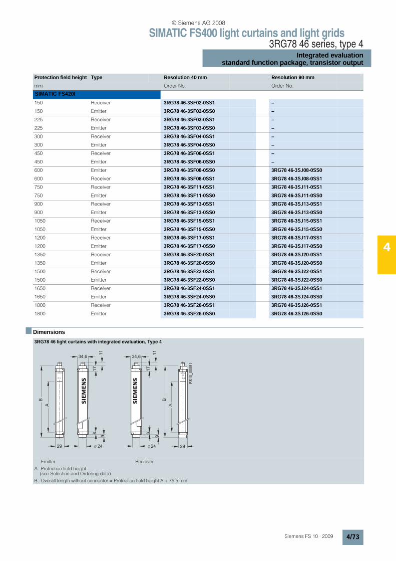
SIMATIC FS400 light curtains and light grids3RG78 46 series, type 4
Integrated evaluationstandard function package, transistor output
4/73Siemens FS 10 · 2009
4
n Dimensions
Protection field height Type Resolution 40 mm Resolution 90 mmmm Order No. Order No.
SIMATIC FS420I150 Receiver 3RG78 46-3SF02-0SS1 –150 Emitter 3RG78 46-3SF02-0SS0 –225 Receiver 3RG78 46-3SF03-0SS1 –225 Emitter 3RG78 46-3SF03-0SS0 –300 Receiver 3RG78 46-3SF04-0SS1 –300 Emitter 3RG78 46-3SF04-0SS0 –450 Receiver 3RG78 46-3SF06-0SS1 –450 Emitter 3RG78 46-3SF06-0SS0 –600 Emitter 3RG78 46-3SF08-0SS0 3RG78 46-3SJ08-0SS0600 Receiver 3RG78 46-3SF08-0SS1 3RG78 46-3SJ08-0SS1750 Receiver 3RG78 46-3SF11-0SS1 3RG78 46-3SJ11-0SS1750 Emitter 3RG78 46-3SF11-0SS0 3RG78 46-3SJ11-0SS0900 Receiver 3RG78 46-3SF13-0SS1 3RG78 46-3SJ13-0SS1900 Emitter 3RG78 46-3SF13-0SS0 3RG78 46-3SJ13-0SS01050 Receiver 3RG78 46-3SF15-0SS1 3RG78 46-3SJ15-0SS11050 Emitter 3RG78 46-3SF15-0SS0 3RG78 46-3SJ15-0SS01200 Receiver 3RG78 46-3SF17-0SS1 3RG78 46-3SJ17-0SS11200 Emitter 3RG78 46-3SF17-0SS0 3RG78 46-3SJ17-0SS01350 Receiver 3RG78 46-3SF20-0SS1 3RG78 46-3SJ20-0SS11350 Emitter 3RG78 46-3SF20-0SS0 3RG78 46-3SJ20-0SS01500 Receiver 3RG78 46-3SF22-0SS1 3RG78 46-3SJ22-0SS11500 Emitter 3RG78 46-3SF22-0SS0 3RG78 46-3SJ22-0SS01650 Receiver 3RG78 46-3SF24-0SS1 3RG78 46-3SJ24-0SS11650 Emitter 3RG78 46-3SF24-0SS0 3RG78 46-3SJ24-0SS01800 Receiver 3RG78 46-3SF26-0SS1 3RG78 46-3SJ26-0SS11800 Emitter 3RG78 46-3SF26-0SS0 3RG78 46-3SJ26-0SS0
3RG78 46 light curtains with integrated evaluation, Type 4
Emitter Receiver
A Protection field height (see Selection and Ordering data)
B Overall length without connector = Protection field height A + 75.5 mm
A
3RG7813
s s
3RG7813
FS
10
_0
00
81
B
34,6
17
11
24
8
9
29 29
8
9
24
34,6
17
11
A
B
© Siemens AG 2008
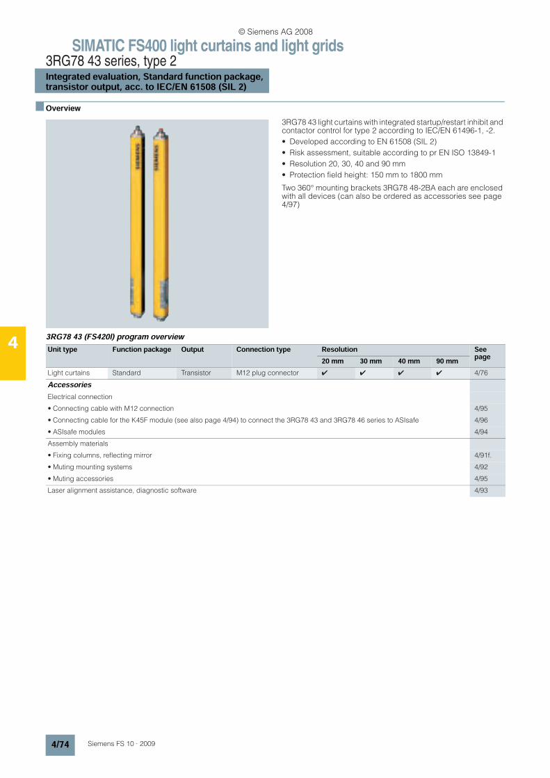
SIMATIC FS400 light curtains and light grids3RG78 43 series, type 2Integrated evaluation, Standard function package,transistor output, acc. to IEC/EN 61508 (SIL 2)
4/74 Siemens FS 10 · 2009
4
n Overview
3RG78 43 light curtains with integrated startup/restart inhibit and contactor control for type 2 according to IEC/EN 61496-1, -2.
• Developed according to EN 61508 (SIL 2)
• Risk assessment, suitable according to pr EN ISO 13849-1
• Resolution 20, 30, 40 and 90 mm
• Protection field height: 150 mm to 1800 mm
Two 360° mounting brackets 3RG78 48-2BA each are enclosed with all devices (can also be ordered as accessories see page 4/97)
3RG78 43 (FS420l) program overview
Unit type Function package Output Connection type Resolution Seepage20 mm 30 mm 40 mm 90 mm
Light curtains Standard Transistor M12 plug connector 4 4 4 4 4/76
AccessoriesElectrical connection
• Connecting cable with M12 connection 4/95
• Connecting cable for the K45F module (see also page 4/94) to connect the 3RG78 43 and 3RG78 46 series to ASIsafe 4/96
• ASIsafe modules 4/94
Assembly materials
• Fixing columns, reflecting mirror 4/91f.
• Muting mounting systems 4/92
• Muting accessories 4/95
Laser alignment assistance, diagnostic software 4/93
© Siemens AG 2008
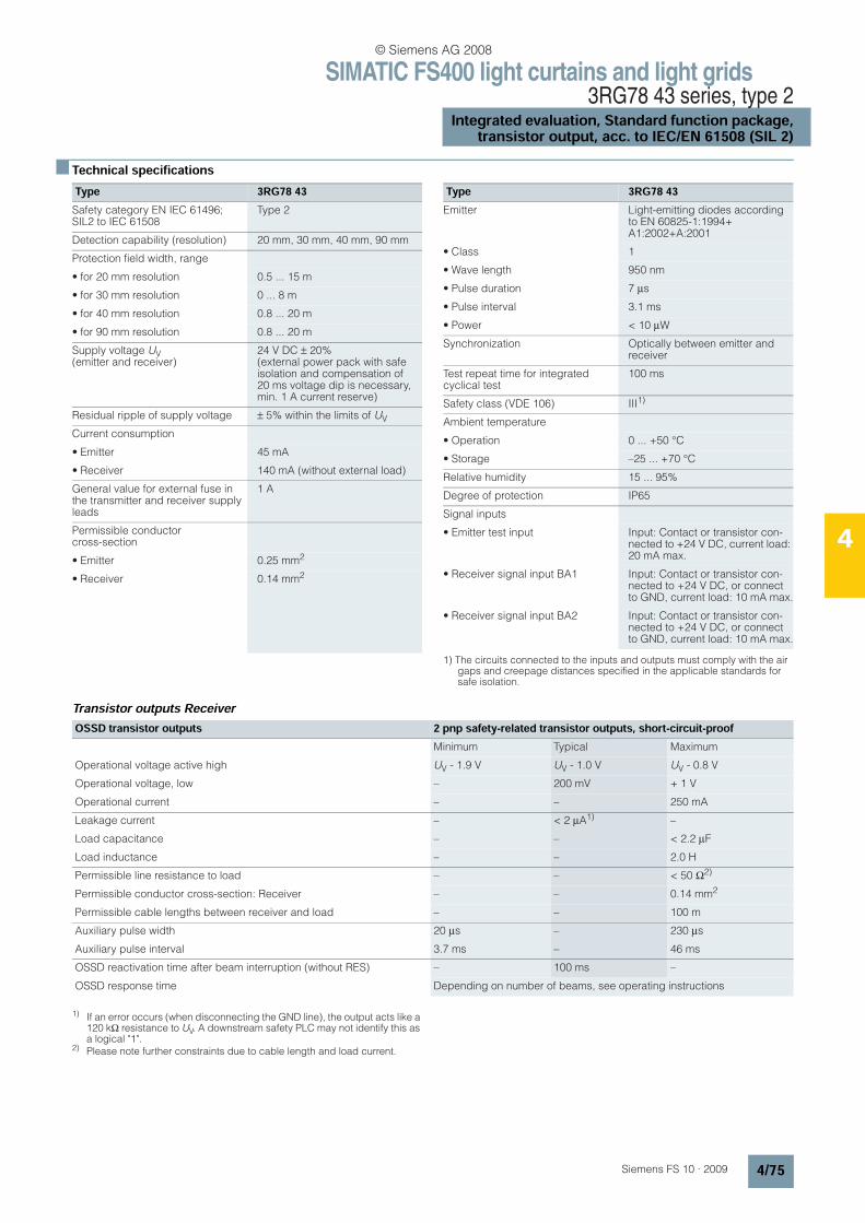
SIMATIC FS400 light curtains and light grids3RG78 43 series, type 2
Integrated evaluation, Standard function package,transistor output, acc. to IEC/EN 61508 (SIL 2)
4/75Siemens FS 10 · 2009
4
n Technical specifications
1) The circuits connected to the inputs and outputs must comply with the air gaps and creepage distances specified in the applicable standards for safe isolation.
Transistor outputs Receiver
1) If an error occurs (when disconnecting the GND line), the output acts like a 120 kΩ resistance to UV. A downstream safety PLC may not identify this as a logical "1".
2) Please note further constraints due to cable length and load current.
Type 3RG78 43Safety category EN IEC 61496; SIL2 to IEC 61508
Type 2
Detection capability (resolution) 20 mm, 30 mm, 40 mm, 90 mm
Protection field width, range
• for 20 mm resolution 0.5 ... 15 m
• for 30 mm resolution 0 ... 8 m
• for 40 mm resolution 0.8 ... 20 m
• for 90 mm resolution 0.8 ... 20 m
Supply voltage UV(emitter and receiver)
24 V DC ± 20% (external power pack with safe isolation and compensation of 20 ms voltage dip is necessary, min. 1 A current reserve)
Residual ripple of supply voltage ± 5% within the limits of UV
Current consumption
• Emitter 45 mA
• Receiver 140 mA (without external load)
General value for external fuse in the transmitter and receiver supply leads
1 A
Permissible conductor cross-section
• Emitter 0.25 mm2
• Receiver 0.14 mm2
Emitter Light-emitting diodes according to EN 60825-1:1994+ A1:2002+A:2001
• Class 1
• Wave length 950 nm
• Pulse duration 7 µs
• Pulse interval 3.1 ms
• Power < 10 µW
Synchronization Optically between emitter and receiver
Test repeat time for integrated cyclical test
100 ms
Safety class (VDE 106) III1)
Ambient temperature
• Operation 0 ... +50 °C
• Storage –25 ... +70 °C
Relative humidity 15 ... 95%
Degree of protection IP65
Signal inputs
• Emitter test input Input: Contact or transistor con-nected to +24 V DC, current load: 20 mA max.
• Receiver signal input BA1 Input: Contact or transistor con-nected to +24 V DC, or connect to GND, current load: 10 mA max.
• Receiver signal input BA2 Input: Contact or transistor con-nected to +24 V DC, or connect to GND, current load: 10 mA max.
Type 3RG78 43
OSSD transistor outputs 2 pnp safety-related transistor outputs, short-circuit-proofMinimum Typical Maximum
Operational voltage active high UV - 1.9 V UV - 1.0 V UV - 0.8 V
Operational voltage, low – 200 mV + 1 V
Operational current – – 250 mA
Leakage current – < 2 µA1) –
Load capacitance – – < 2.2 µF
Load inductance – – 2.0 H
Permissible line resistance to load – – < 50 Ω2)
Permissible conductor cross-section: Receiver – – 0.14 mm2
Permissible cable lengths between receiver and load – – 100 m
Auxiliary pulse width 20 µs – 230 µs
Auxiliary pulse interval 3.7 ms – 46 ms
OSSD reactivation time after beam interruption (without RES) – 100 ms –
OSSD response time Depending on number of beams, see operating instructions
© Siemens AG 2008
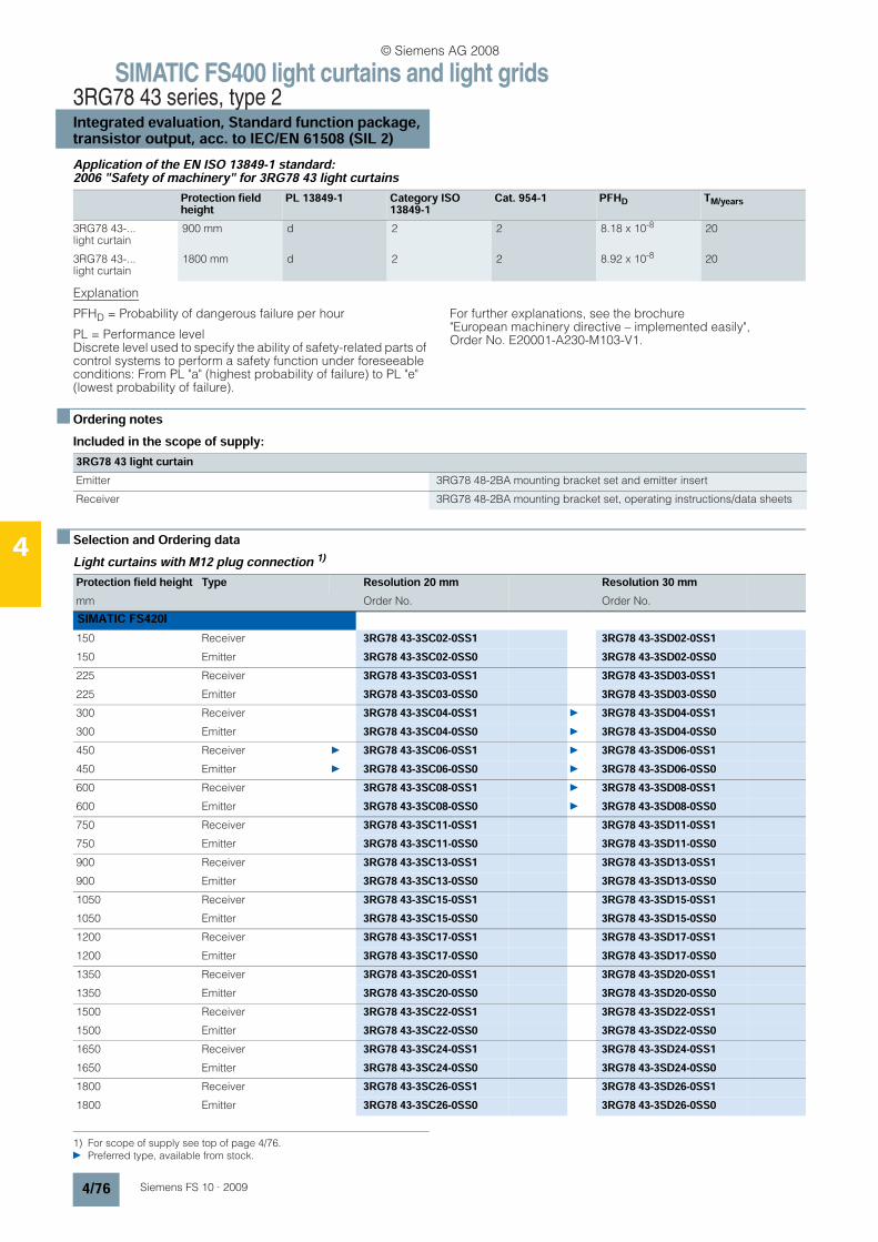
SIMATIC FS400 light curtains and light grids3RG78 43 series, type 2Integrated evaluation, Standard function package,transistor output, acc. to IEC/EN 61508 (SIL 2)
4/76 Siemens FS 10 · 2009
4
Application of the EN ISO 13849-1 standard: 2006 "Safety of machinery" for 3RG78 43 light curtains
Explanation
PFHD = Probability of dangerous failure per hour
PL = Performance level Discrete level used to specify the ability of safety-related parts of control systems to perform a safety function under foreseeable conditions: From PL "a" (highest probability of failure) to PL "e" (lowest probability of failure).
For further explanations, see the brochure "European machinery directive – implemented easily", Order No. E20001-A230-M103-V1.
n Ordering notesIncluded in the scope of supply:
n Selection and Ordering dataLight curtains with M12 plug connection 1)
Protection field height
PL 13849-1 Category ISO 13849-1
Cat. 954-1 PFHD TM/years
3RG78 43-...light curtain
900 mm d 2 2 8.18 x 10⁻⁸ 20
3RG78 43-...light curtain
1800 mm d 2 2 8.92 x 10⁻⁸ 20
3RG78 43 light curtainEmitter 3RG78 48-2BA mounting bracket set and emitter insert
Receiver 3RG78 48-2BA mounting bracket set, operating instructions/data sheets
1) For scope of supply see top of page 4/76. Preferred type, available from stock.
Protection field height Type Resolution 20 mm Resolution 30 mmmm Order No. Order No.
SIMATIC FS420I150 Receiver 3RG78 43-3SC02-0SS1 3RG78 43-3SD02-0SS1150 Emitter 3RG78 43-3SC02-0SS0 3RG78 43-3SD02-0SS0225 Receiver 3RG78 43-3SC03-0SS1 3RG78 43-3SD03-0SS1225 Emitter 3RG78 43-3SC03-0SS0 3RG78 43-3SD03-0SS0300 Receiver 3RG78 43-3SC04-0SS1 3RG78 43-3SD04-0SS1300 Emitter 3RG78 43-3SC04-0SS0 3RG78 43-3SD04-0SS0450 Receiver 3RG78 43-3SC06-0SS1 3RG78 43-3SD06-0SS1450 Emitter 3RG78 43-3SC06-0SS0 3RG78 43-3SD06-0SS0600 Receiver 3RG78 43-3SC08-0SS1 3RG78 43-3SD08-0SS1600 Emitter 3RG78 43-3SC08-0SS0 3RG78 43-3SD08-0SS0750 Receiver 3RG78 43-3SC11-0SS1 3RG78 43-3SD11-0SS1750 Emitter 3RG78 43-3SC11-0SS0 3RG78 43-3SD11-0SS0900 Receiver 3RG78 43-3SC13-0SS1 3RG78 43-3SD13-0SS1900 Emitter 3RG78 43-3SC13-0SS0 3RG78 43-3SD13-0SS01050 Receiver 3RG78 43-3SC15-0SS1 3RG78 43-3SD15-0SS11050 Emitter 3RG78 43-3SC15-0SS0 3RG78 43-3SD15-0SS01200 Receiver 3RG78 43-3SC17-0SS1 3RG78 43-3SD17-0SS11200 Emitter 3RG78 43-3SC17-0SS0 3RG78 43-3SD17-0SS01350 Receiver 3RG78 43-3SC20-0SS1 3RG78 43-3SD20-0SS11350 Emitter 3RG78 43-3SC20-0SS0 3RG78 43-3SD20-0SS01500 Receiver 3RG78 43-3SC22-0SS1 3RG78 43-3SD22-0SS11500 Emitter 3RG78 43-3SC22-0SS0 3RG78 43-3SD22-0SS01650 Receiver 3RG78 43-3SC24-0SS1 3RG78 43-3SD24-0SS11650 Emitter 3RG78 43-3SC24-0SS0 3RG78 43-3SD24-0SS01800 Receiver 3RG78 43-3SC26-0SS1 3RG78 43-3SD26-0SS11800 Emitter 3RG78 43-3SC26-0SS0 3RG78 43-3SD26-0SS0
© Siemens AG 2008

SIMATIC FS400 light curtains and light grids3RG78 43 series, type 2
Integrated evaluation, Standard function package,transistor output, acc. to IEC/EN 61508 (SIL 2)
4/77Siemens FS 10 · 2009
4
n Dimensions
Preferred type, available from stock.
Protection field height Type Resolution 40 mm Resolution 90 mmmm Order No. Order No.
SIMATIC FS420I150 Receiver 3RG78 43-3SF02-0SS1 –150 Emitter 3RG78 43-3SF02-0SS0 –225 Receiver 3RG78 43-3SF03-0SS1 –225 Emitter 3RG78 43-3SF03-0SS0 –300 Receiver 3RG78 43-3SF04-0SS1 –300 Emitter 3RG78 43-3SF04-0SS0 –450 Receiver 3RG78 43-3SF06-0SS1 3RG78 43-3SJ06-0SS1450 Emitter 3RG78 43-3SF06-0SS0 3RG78 43-3SJ06-0SS0600 Receiver 3RG78 43-3SF08-0SS1 3RG78 43-3SJ08-0SS1600 Emitter 3RG78 43-3SF08-0SS0 3RG78 43-3SJ08-0SS0750 Receiver 3RG78 43-3SF11-0SS1 3RG78 43-3SJ11-0SS1750 Emitter 3RG78 43-3SF11-0SS0 3RG78 43-3SJ11-0SS0900 Receiver 3RG78 43-3SF13-0SS1 3RG78 43-3SJ13-0SS1900 Emitter 3RG78 43-3SF13-0SS0 3RG78 43-3SJ13-0SS01050 Receiver 3RG78 43-3SF15-0SS1 3RG78 43-3SJ15-0SS11050 Emitter 3RG78 43-3SF15-0SS0 3RG78 43-3SJ15-0SS01200 Receiver 3RG78 43-3SF17-0SS1 3RG78 43-3SJ17-0SS11200 Emitter 3RG78 43-3SF17-0SS0 3RG78 43-3SJ17-0SS01350 Receiver 3RG78 43-3SF20-0SS1 3RG78 43-3SJ20-0SS11350 Emitter 3RG78 43-3SF20-0SS0 3RG78 43-3SJ20-0SS01500 Receiver 3RG78 43-3SF22-0SS1 3RG78 43-3SJ22-0SS11500 Emitter 3RG78 43-3SF22-0SS0 3RG78 43-3SJ22-0SS01650 Receiver 3RG78 43-3SF24-0SS1 3RG78 43-3SJ24-0SS11650 Emitter 3RG78 43-3SF24-0SS0 3RG78 43-3SJ24-0SS01800 Receiver 3RG78 43-3SF26-0SS1 3RG78 43-3SJ26-0SS11800 Emitter 3RG78 43-3SF26-0SS0 3RG78 43-3SJ26-0SS0
3RG78 43-3S...-0SS. light curtains
Emitter Receiver
A Protection field height (see Selection and Ordering data)
B Overall length without connector = Protection field height A + 75,5 mm
A
3RG7813
s s
3RG7813
FS
10
_0
00
81
B
34,6
17
11
24
8
9
29 29
8
9
24
34,6
17
11
A
B
© Siemens AG 2008
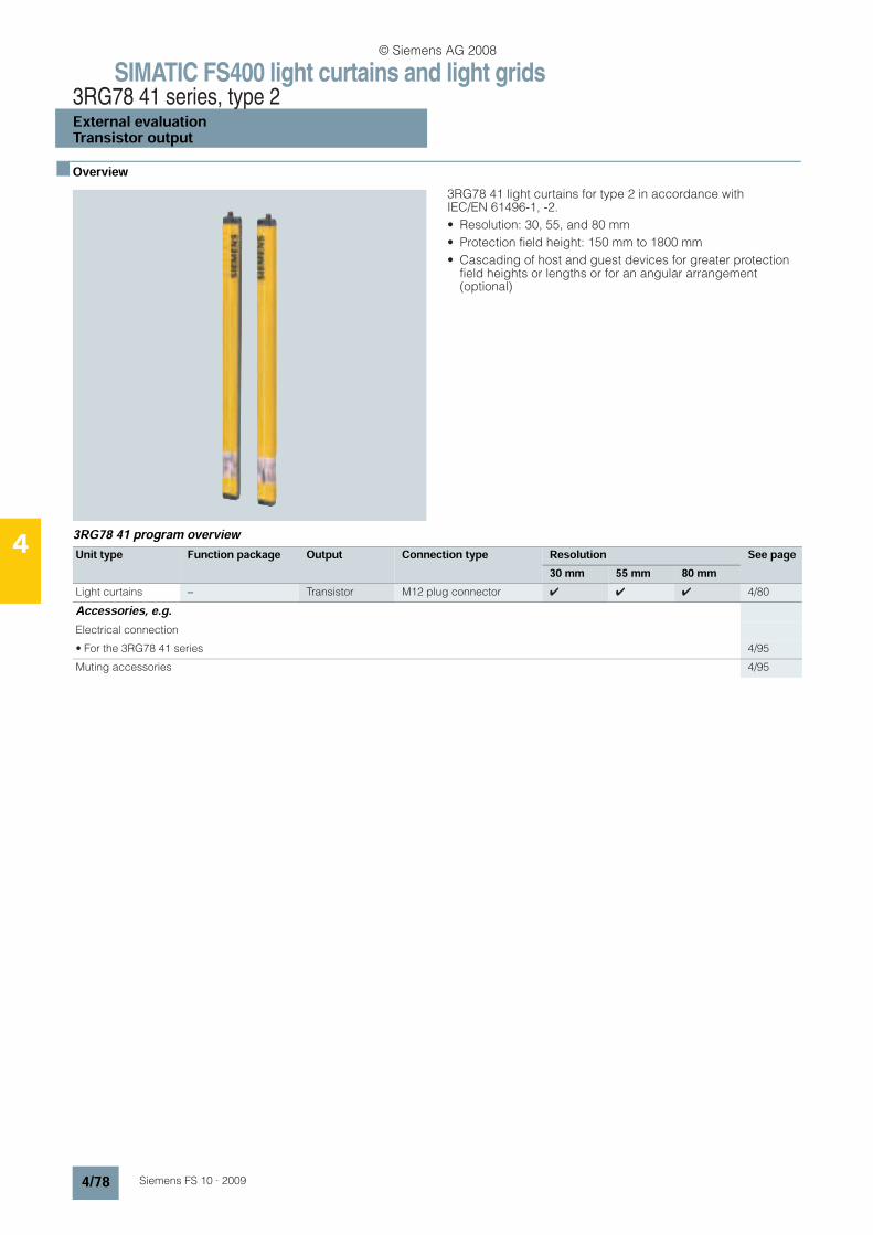
SIMATIC FS400 light curtains and light grids3RG78 41 series, type 2External evaluationTransistor output
4/78 Siemens FS 10 · 2009
4
n Overview
3RG78 41 light curtains for type 2 in accordance with IEC/EN 61496-1, -2.
• Resolution: 30, 55, and 80 mm
• Protection field height: 150 mm to 1800 mm
• Cascading of host and guest devices for greater protection field heights or lengths or for an angular arrangement (optional)
3RG78 41 program overview
Unit type Function package Output Connection type Resolution See page30 mm 55 mm 80 mm
Light curtains − Transistor M12 plug connector 4 4 4 4/80
Accessories, e.g.Electrical connection
• For the 3RG78 41 series 4/95
Muting accessories 4/95
© Siemens AG 2008
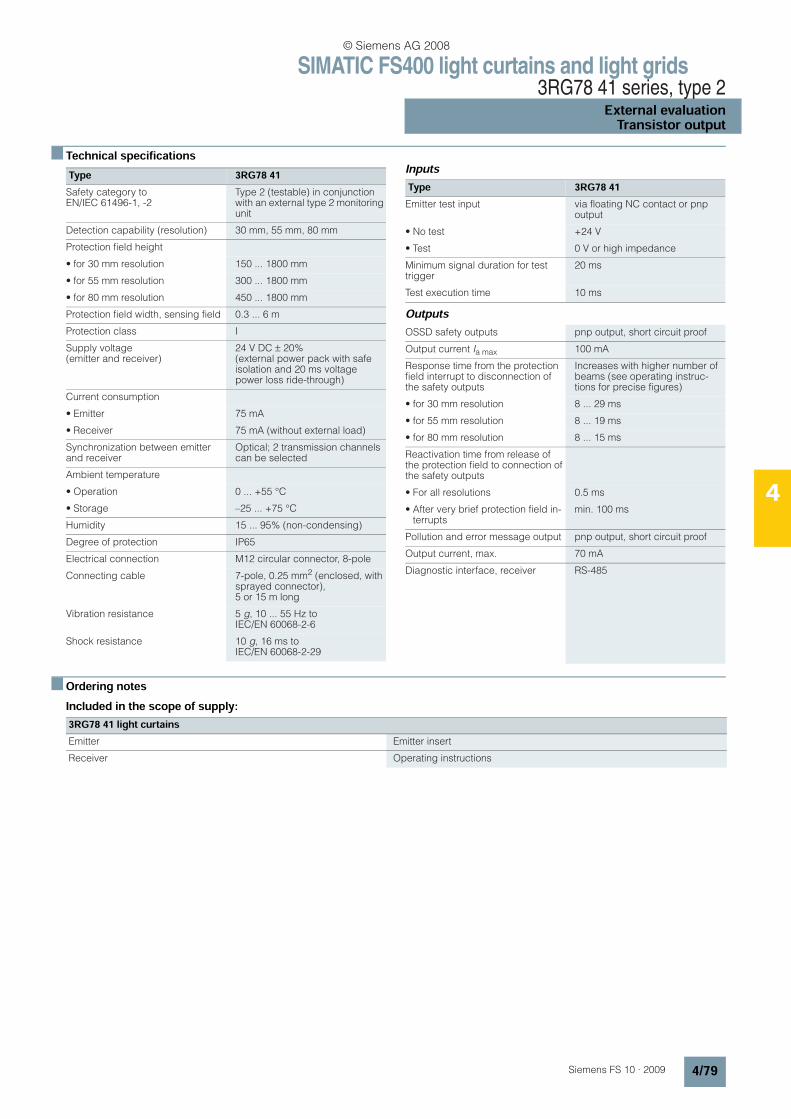
SIMATIC FS400 light curtains and light grids3RG78 41 series, type 2
External evaluationTransistor output
4/79Siemens FS 10 · 2009
4
n Technical specifications Inputs
Outputs
n Ordering notesIncluded in the scope of supply:
Type 3RG78 41Safety category to EN/IEC 61496-1, -2
Type 2 (testable) in conjunction with an external type 2 monitoring unit
Detection capability (resolution) 30 mm, 55 mm, 80 mm
Protection field height
• for 30 mm resolution 150 ... 1800 mm
• for 55 mm resolution 300 ... 1800 mm
• for 80 mm resolution 450 ... 1800 mm
Protection field width, sensing field 0.3 ... 6 m
Protection class I
Supply voltage (emitter and receiver)
24 V DC ± 20% (external power pack with safe isolation and 20 ms voltage power loss ride-through)
Current consumption
• Emitter 75 mA
• Receiver 75 mA (without external load)
Synchronization between emitter and receiver
Optical; 2 transmission channels can be selected
Ambient temperature
• Operation 0 ... +55 °C
• Storage –25 ... +75 °C
Humidity 15 ... 95% (non-condensing)
Degree of protection IP65
Electrical connection M12 circular connector, 8-pole
Connecting cable 7-pole, 0.25 mm2 (enclosed, with sprayed connector), 5 or 15 m long
Vibration resistance 5 g, 10 ... 55 Hz to IEC/EN 60068-2-6
Shock resistance 10 g, 16 ms to IEC/EN 60068-2-29
Type 3RG78 41Emitter test input via floating NC contact or pnp
output
• No test +24 V
• Test 0 V or high impedance
Minimum signal duration for test trigger
20 ms
Test execution time 10 ms
OSSD safety outputs pnp output, short circuit proof
Output current Ia max 100 mA
Response time from the protection field interrupt to disconnection of the safety outputs
Increases with higher number of beams (see operating instruc-tions for precise figures)
• for 30 mm resolution 8 ... 29 ms
• for 55 mm resolution 8 ... 19 ms
• for 80 mm resolution 8 ... 15 ms
Reactivation time from release of the protection field to connection of the safety outputs
• For all resolutions 0.5 ms
• After very brief protection field in-terrupts
min. 100 ms
Pollution and error message output pnp output, short circuit proof
Output current, max. 70 mA
Diagnostic interface, receiver RS-485
3RG78 41 light curtainsEmitter Emitter insert
Receiver Operating instructions
© Siemens AG 2008
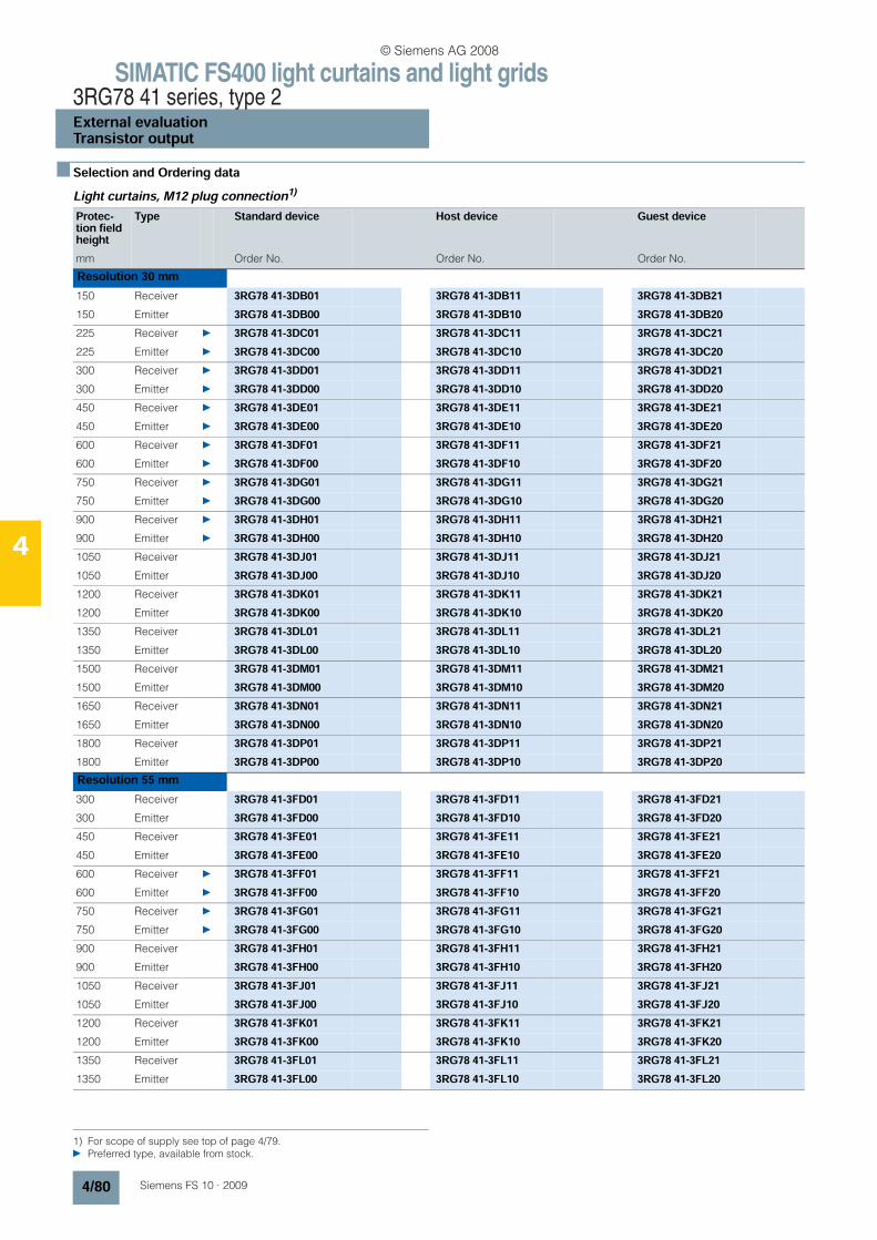
SIMATIC FS400 light curtains and light grids3RG78 41 series, type 2External evaluationTransistor output
4/80 Siemens FS 10 · 2009
4
n Selection and Ordering dataLight curtains, M12 plug connection1)
1) For scope of supply see top of page 4/79. Preferred type, available from stock.
Protec-tion field height
Type Standard device Host device Guest device
mm Order No. Order No. Order No.
Resolution 30 mm150 Receiver 3RG78 41-3DB01 3RG78 41-3DB11 3RG78 41-3DB21150 Emitter 3RG78 41-3DB00 3RG78 41-3DB10 3RG78 41-3DB20225 Receiver 3RG78 41-3DC01 3RG78 41-3DC11 3RG78 41-3DC21225 Emitter 3RG78 41-3DC00 3RG78 41-3DC10 3RG78 41-3DC20300 Receiver 3RG78 41-3DD01 3RG78 41-3DD11 3RG78 41-3DD21300 Emitter 3RG78 41-3DD00 3RG78 41-3DD10 3RG78 41-3DD20450 Receiver 3RG78 41-3DE01 3RG78 41-3DE11 3RG78 41-3DE21450 Emitter 3RG78 41-3DE00 3RG78 41-3DE10 3RG78 41-3DE20600 Receiver 3RG78 41-3DF01 3RG78 41-3DF11 3RG78 41-3DF21600 Emitter 3RG78 41-3DF00 3RG78 41-3DF10 3RG78 41-3DF20750 Receiver 3RG78 41-3DG01 3RG78 41-3DG11 3RG78 41-3DG21750 Emitter 3RG78 41-3DG00 3RG78 41-3DG10 3RG78 41-3DG20900 Receiver 3RG78 41-3DH01 3RG78 41-3DH11 3RG78 41-3DH21900 Emitter 3RG78 41-3DH00 3RG78 41-3DH10 3RG78 41-3DH201050 Receiver 3RG78 41-3DJ01 3RG78 41-3DJ11 3RG78 41-3DJ211050 Emitter 3RG78 41-3DJ00 3RG78 41-3DJ10 3RG78 41-3DJ201200 Receiver 3RG78 41-3DK01 3RG78 41-3DK11 3RG78 41-3DK211200 Emitter 3RG78 41-3DK00 3RG78 41-3DK10 3RG78 41-3DK201350 Receiver 3RG78 41-3DL01 3RG78 41-3DL11 3RG78 41-3DL211350 Emitter 3RG78 41-3DL00 3RG78 41-3DL10 3RG78 41-3DL201500 Receiver 3RG78 41-3DM01 3RG78 41-3DM11 3RG78 41-3DM211500 Emitter 3RG78 41-3DM00 3RG78 41-3DM10 3RG78 41-3DM201650 Receiver 3RG78 41-3DN01 3RG78 41-3DN11 3RG78 41-3DN211650 Emitter 3RG78 41-3DN00 3RG78 41-3DN10 3RG78 41-3DN201800 Receiver 3RG78 41-3DP01 3RG78 41-3DP11 3RG78 41-3DP211800 Emitter 3RG78 41-3DP00 3RG78 41-3DP10 3RG78 41-3DP20Resolution 55 mm300 Receiver 3RG78 41-3FD01 3RG78 41-3FD11 3RG78 41-3FD21300 Emitter 3RG78 41-3FD00 3RG78 41-3FD10 3RG78 41-3FD20450 Receiver 3RG78 41-3FE01 3RG78 41-3FE11 3RG78 41-3FE21450 Emitter 3RG78 41-3FE00 3RG78 41-3FE10 3RG78 41-3FE20600 Receiver 3RG78 41-3FF01 3RG78 41-3FF11 3RG78 41-3FF21600 Emitter 3RG78 41-3FF00 3RG78 41-3FF10 3RG78 41-3FF20750 Receiver 3RG78 41-3FG01 3RG78 41-3FG11 3RG78 41-3FG21750 Emitter 3RG78 41-3FG00 3RG78 41-3FG10 3RG78 41-3FG20900 Receiver 3RG78 41-3FH01 3RG78 41-3FH11 3RG78 41-3FH21900 Emitter 3RG78 41-3FH00 3RG78 41-3FH10 3RG78 41-3FH201050 Receiver 3RG78 41-3FJ01 3RG78 41-3FJ11 3RG78 41-3FJ211050 Emitter 3RG78 41-3FJ00 3RG78 41-3FJ10 3RG78 41-3FJ201200 Receiver 3RG78 41-3FK01 3RG78 41-3FK11 3RG78 41-3FK211200 Emitter 3RG78 41-3FK00 3RG78 41-3FK10 3RG78 41-3FK201350 Receiver 3RG78 41-3FL01 3RG78 41-3FL11 3RG78 41-3FL211350 Emitter 3RG78 41-3FL00 3RG78 41-3FL10 3RG78 41-3FL20
© Siemens AG 2008
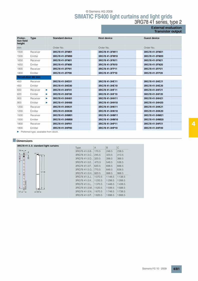
SIMATIC FS400 light curtains and light grids3RG78 41 series, type 2
External evaluationTransistor output
4/81Siemens FS 10 · 2009
4
n Dimensions
Protec-tion field height
Type Standard device Host device Guest device
mm Order No. Order No. Order No.
1500 Receiver 3RG78 41-3FM01 3RG78 41-3FM11 3RG78 41-3FM211500 Emitter 3RG78 41-3FM00 3RG78 41-3FM10 3RG78 41-3FM201650 Receiver 3RG78 41-3FN01 3RG78 41-3FN11 3RG78 41-3FN211650 Emitter 3RG78 41-3FN00 3RG78 41-3FN10 3RG78 41-3FN201800 Receiver 3RG78 41-3FP01 3RG78 41-3FP11 3RG78 41-3FP211800 Emitter 3RG78 41-3FP00 3RG78 41-3FP10 3RG78 41-3FP20Resolution 80 mm450 Receiver 3RG78 41-3HE01 3RG78 41-3HE11 3RG78 41-3HE21450 Emitter 3RG78 41-3HE00 3RG78 41-3HE10 3RG78 41-3HE20600 Receiver 3RG78 41-3HF01 3RG78 41-3HF11 3RG78 41-3HF21600 Emitter 3RG78 41-3HF00 3RG78 41-3HF10 3RG78 41-3HF20900 Receiver 3RG78 41-3HH01 3RG78 41-3HH11 3RG78 41-3HH21900 Emitter 3RG78 41-3HH00 3RG78 41-3HH10 3RG78 41-3HH201200 Receiver 3RG78 41-3HK01 3RG78 41-3HK11 3RG78 41-3HK211200 Emitter 3RG78 41-3HK00 3RG78 41-3HK10 3RG78 41-3HK201500 Receiver 3RG78 41-3HM01 3RG78 41-3HM11 3RG78 41-3HM211500 Emitter 3RG78 41-3HM00 3RG78 41-3HM10 3RG78 41-3HM201800 Receiver 3RG78 41-3HP01 3RG78 41-3HP11 3RG78 41-3HP211800 Emitter 3RG78 41-3HP00 3RG78 41-3HP10 3RG78 41-3HP20 Preferred type, available from stock.
3RG78 41-3..0. standard light curtains
66,5
A
28
14
C B
17 33
NS
C0
_0
04
85
c
Type A B C
3RG78 41-3.B..
3RG78 41-3.C..
3RG78 41-3.D..
3RG78 41-3.E..
3RG78 41-3.F..
3RG78 41-3.G..
3RG78 41-3.H..
170.5
245.5
320.5
470.5
620.5
770.5
920.5
248.5
323.5
398.5
548.5
698.5
848.5
998.5
238.5
313.5
388.5
538.5
688.5
838.5
988.5
3RG78 41-3.J..
3RG78 41-3.K..
3RG78 41-3.L..
3RG78 41-3.M..
3RG78 41-3.N..
3RG78 41-3.P..
1 070.5
1 220.5
1 370.5
1 520.5
1 670.5
1 820.5
1 148.5
1 298.5
1 448.5
1 598.5
1 748.5
1 898.5
1 138.5
1 288.5
1 438.5
1 588.5
1 738.5
1 888.5
© Siemens AG 2008
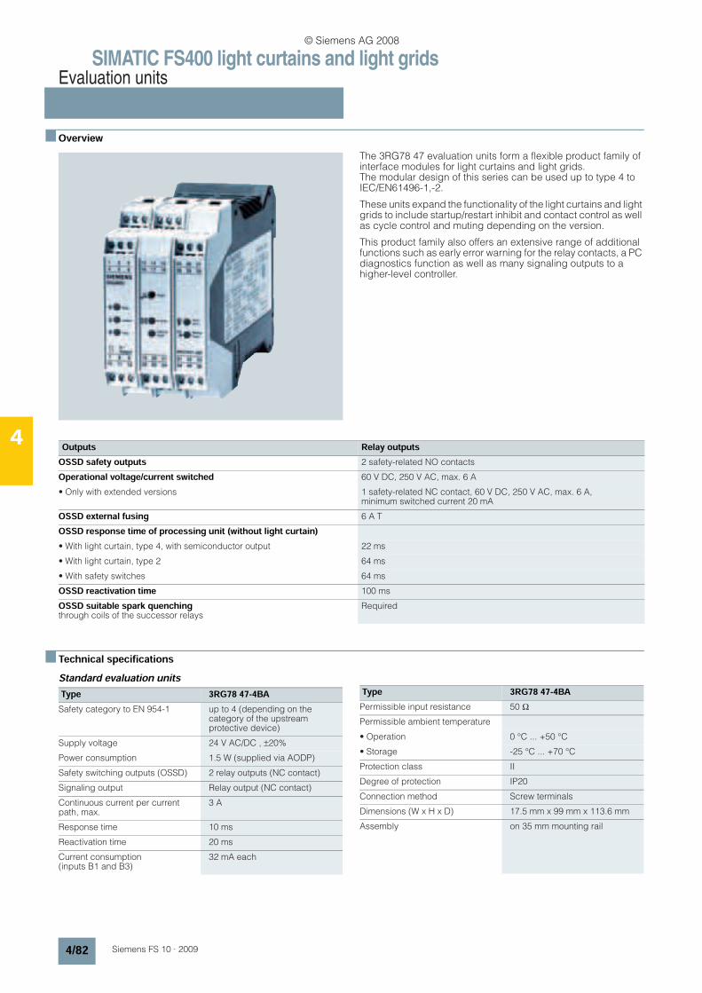
SIMATIC FS400 light curtains and light gridsEvaluation units
4/82 Siemens FS 10 · 2009
4
n Overview
The 3RG78 47 evaluation units form a flexible product family of interface modules for light curtains and light grids. The modular design of this series can be used up to type 4 to IEC/EN61496-1,-2.
These units expand the functionality of the light curtains and light grids to include startup/restart inhibit and contact control as well as cycle control and muting depending on the version.
This product family also offers an extensive range of additional functions such as early error warning for the relay contacts, a PC diagnostics function as well as many signaling outputs to a higher-level controller.
n Technical specificationsStandard evaluation units
Outputs Relay outputsOSSD safety outputs 2 safety-related NO contacts
Operational voltage/current switched 60 V DC, 250 V AC, max. 6 A
• Only with extended versions 1 safety-related NC contact, 60 V DC, 250 V AC, max. 6 A, minimum switched current 20 mA
OSSD external fusing 6 A T
OSSD response time of processing unit (without light curtain)• With light curtain, type 4, with semiconductor output 22 ms
• With light curtain, type 2 64 ms
• With safety switches 64 ms
OSSD reactivation time 100 ms
OSSD suitable spark quenching through coils of the successor relays
Required
Type 3RG78 47-4BASafety category to EN 954-1 up to 4 (depending on the
category of the upstream protective device)
Supply voltage 24 V AC/DC , ±20%
Power consumption 1.5 W (supplied via AODP)
Safety switching outputs (OSSD) 2 relay outputs (NC contact)
Signaling output Relay output (NC contact)
Continuous current per current path, max.
3 A
Response time 10 ms
Reactivation time 20 ms
Current consumption (inputs B1 and B3)
32 mA each
Permissible input resistance 50 Ω
Permissible ambient temperature
• Operation 0 °C ... +50 °C
• Storage -25 °C ... +70 °C
Protection class II
Degree of protection IP20
Connection method Screw terminals
Dimensions (W x H x D) 17.5 mm x 99 mm x 113.6 mm
Assembly on 35 mm mounting rail
Type 3RG78 47-4BA
© Siemens AG 2008
SIMATIC FS400 light curtains and light gridsEvaluation units
4/83Siemens FS 10 · 2009
4
Intelligent evaluation units Type 3RG78 47-4BB
Safety category to EN 954-1 Category 4
STOP category according to EN 60204-1 (11/ 98)
STOP category 0
Supply voltage 24 V AC/DC, –15 ... +10%
Residual ripple (with DC) 2.4 Vss
Frequency (AC) 50 ... 60 Hz
Power consumption 2.1 W (AC)/1.7 W (DC)
External fusing of supply circuit 1 A slow-action
Output contacts 2 NO,
1 NC AgSnO2, gold-flashed
Switching capacity according to EN 60947-5-1
• AC-15, 230 V 6 A
• DC-13, 24 V (360 switching cycles/h)
6 A
• DC-13: 24 V (3600 switching cycles/h)
3 A
Max. continuous current per current path
6 A
Contact fusing per current path 6.3 A quick-action or 4 A slow-action
Max. summation current of all current paths
12 A
Mechanical service life 10 x 106 switching cycles
Switching frequency 3600 switching cycles/h
ON delay
• Manual start 70 ms
• Automatic start 230 ms
Returning time, response time 20 ms
Minimum ON period S34, S35 80 ms
Electronic fuse protection
• Response time 2 sec
• Recovery time 2 sec
Control voltage/current at S11, S22, S31
24 V DC/20 mA
Permissible power input resistance < 70 Ω
Emitted interference EN 50081-1, -2
Noise immunity EN 50082-2
Air gaps and creepage distances according to DIN VDE 0110 (04.97)
4 kV
Operating temperature –25 ... +55 °C
Degree of protection
• Enclosure IP40
• Terminals IP20
Connection cross-sections
• Finely-stranded 2 x 0.14 ... 0.75 mm2
• Finely stranded with end sleeve 2 x 0.25 ... 0.5 mm2
• Finely stranded with twin end sleeve
2 x 1.5 mm2
• Solid 1 x 0.14 … 2.5 mm2
• Finely stranded with end sleeve 2 x 0.25 … 2.5 mm2
Type 3RG78 47Protection according to EN, IEC 61496-1
Type 4
Safety category to EN 954-1 Category 4
STOP category according to EN 60204-1 (11/ 98)
STOP category 0
Supply voltage 24 V DC ± 20%, external power pack with safe isolation and com-pensation of 20 ms voltage dip is required
Current consumption Approximately 200 mA without external load
External fusing (power supply) 2.5 A mT
Connectable safety sensors (extended versions)
1 light curtain, type 4, or up to 2 light curtains, type 2 (all according to IEC 61496)
Up to 2 light curtains, type 4, or up to 4 light curtains, type 2 (all according to IEC 61496)
Test outputs T1 and T2, test interval
200 ms
Available functions
• All versions Startup/restart inhibit, contractor control, diagnostics
• Versions with cycle control Protective, single-cycle and two-cycle operation
• Versions with muting function Sequential muting, parallel muting, parallel double muting (only 3RG78 47-4.G)
Control inputs
• Contactor control (EDM) Reset of positive-action contacts of downstream contactors
• Start/restart inhibit (reset) Floating NO (switch or key switch)
Connection
• Non-testable muting sensors Signal level in damped state: active high, +24 V
• Testable muting sensors Active high, +24 V, plus test pulses T1 or T2
Outputs
• Muting displays for lamps 24 V, max. 5 W
pnp switching outputs, muting function on, active high, +24 V, max. 200 mA
• Signaling outputs (depending on version)
Light curtain free/interrupted; switching status relay/transistor output; restart inhibit locked/unlocked; muting function status; muting error; warning defective muting lamp, internal error, etc.
Operating temperature 0 ... +55 °C
Degree of protection IP20; must be built into control cabinet or housing with degree of protection of at least IP54
Installation Mounting on 35-mm mounting rail
Connection method Pluggable, coded screw terminals up to 2.5 mm2
© Siemens AG 2008
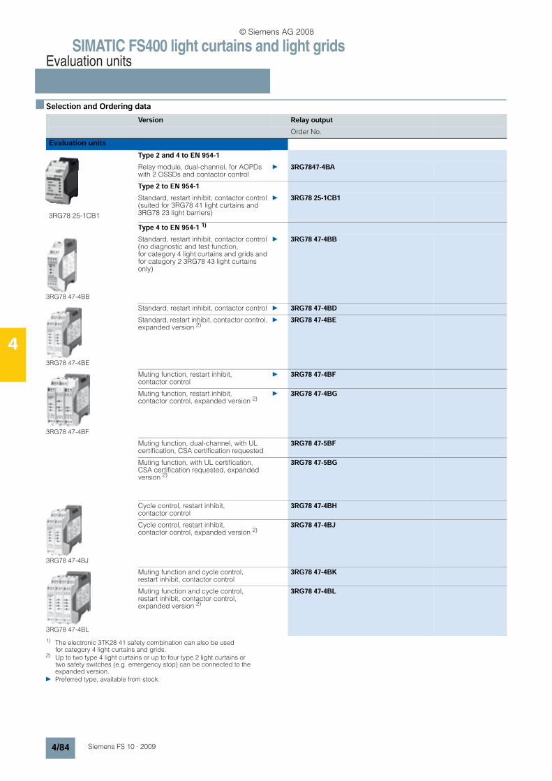
SIMATIC FS400 light curtains and light gridsEvaluation units
4/84 Siemens FS 10 · 2009
4
n Selection and Ordering data
1) The electronic 3TK28 41 safety combination can also be used for category 4 light curtains and grids.
2) Up to two type 4 light curtains or up to four type 2 light curtains or two safety switches (e.g. emergency stop) can be connected to the expanded version.
Preferred type, available from stock.
Version Relay outputOrder No.
Evaluation units
3RG78 25-1CB1
Type 2 and 4 to EN 954-1Relay module, dual-channel, for AOPDs with 2 OSSDs and contactor control
3RG7847-4BA
Type 2 to EN 954-1Standard, restart inhibit, contactor control (suited for 3RG78 41 light curtains and 3RG78 23 light barriers)
3RG78 25-1CB1
Type 4 to EN 954-1 1)
3RG78 47-4BB
Standard, restart inhibit, contactor control (no diagnostic and test function, for category 4 light curtains and grids and for category 2 3RG78 43 light curtains only)
3RG78 47-4BB
3RG78 47-4BE
Standard, restart inhibit, contactor control 3RG78 47-4BDStandard, restart inhibit, contactor control, expanded version 2)
3RG78 47-4BE
3RG78 47-4BF
Muting function, restart inhibit, contactor control
3RG78 47-4BF
Muting function, restart inhibit, contactor control, expanded version 2)
3RG78 47-4BG
Muting function, dual-channel, with UL certification, CSA certification requested
3RG78 47-5BF
Muting function, with UL certification, CSA certification requested, expanded version 2)
3RG78 47-5BG
3RG78 47-4BJ
Cycle control, restart inhibit, contactor control
3RG78 47-4BH
Cycle control, restart inhibit, contactor control, expanded version 2)
3RG78 47-4BJ
3RG78 47-4BL
Muting function and cycle control, restart inhibit, contactor control
3RG78 47-4BK
Muting function and cycle control, restart inhibit, contactor control, expanded version 2)
3RG78 47-4BL
© Siemens AG 2008
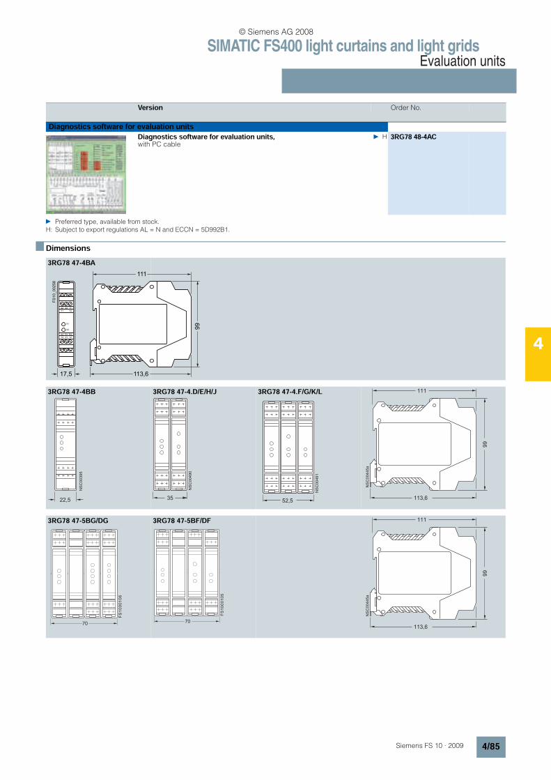
SIMATIC FS400 light curtains and light gridsEvaluation units
4/85Siemens FS 10 · 2009
4
Preferred type, available from stock.H: Subject to export regulations AL = N and ECCN = 5D992B1.
n Dimensions
Version Order No.
Diagnostics software for evaluation units
Diagnostics software for evaluation units, with PC cable
H 3RG78 48-4AC
3RG78 47-4BA
3RG78 47-4BB 3RG78 47-4.D/E/H/J 3RG78 47-4.F/G/K/L
3RG78 47-5BG/DG 3RG78 47-5BF/DF
FS
10_00258
111
99
113,617,5
22
Y1
24 11
Y2
A2
14
R1
21
R3
12
X1
X2
NS
C0
03
95
22,5
A A
35
NS
C0
04
90
A A A
52,5
NS
C0
04
91
111
113,6
99
NS
C0
04
45
a
FS
10
00
10
6
70
FS
10
00
10
5
70
111
113,6
99
NS
C0
04
45
a
© Siemens AG 2008
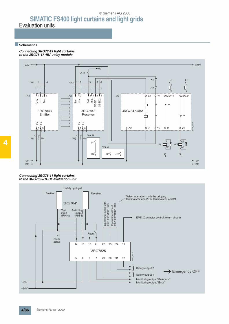
SIMATIC FS400 light curtains and light gridsEvaluation units
4/86 Siemens FS 10 · 2009
4
n SchematicsConnecting 3RG78 43 light curtains to the 3RG78 47-4BA relay module
Connecting 3RG78 41 light curtains to the 3RG7825-1CB1 evaluation unit
Receiver
Var. B
Var. A
FS
10_00305
+24V
3RG7843
8H7
7 8
0V
FE
5H3
3 5
0V
FE
0V
PE
0V
PE
41
-W1
-W1
-W2
-W2
41 2
+2
4V
-A1 -A2
+2
4V
BA
2
BA
1
OS
SD
1
OS
SD
2
31 2
-S1
5 6
31 42 5 6 -A3 B3 Y1
A2 B1 Y2 11
-K1
-K1-K2 -K2
-K1
-K2
12
L+
1
2
14
-K1
L-
A1
A2
21
22
L+
1
2
24
-K2
L-
A1
A2
+24V
3RG7843
0V
3RG7847-4BA
Te
st
Emitter
n.c
.
n.c
.
Monitoring output "Error"
Monitoring output "Safety on"
Safety output 1
Safety output 2
Emitter Receiver
Safety light grid
Test input(PIN 4)
Switchingoutput
(PIN 4)EMD (Contactor control, return circuit)
Select operation mode by bridging terminals 22 and 23 or terminals 23 and 24
Start/active
Opera
tion m
ode w
ith
sta
rt-u
p/r
esta
rt lock
Opera
tion w
ithout
sta
rt-u
p/r
esta
rt lock
Reset
Emergency OFF
FS
10
_0
03
12
+24V
GND
5 6 8 7 29 30 31
3RG7825
3RG7841
32
14 15 16 21 22 23 24 13
© Siemens AG 2008
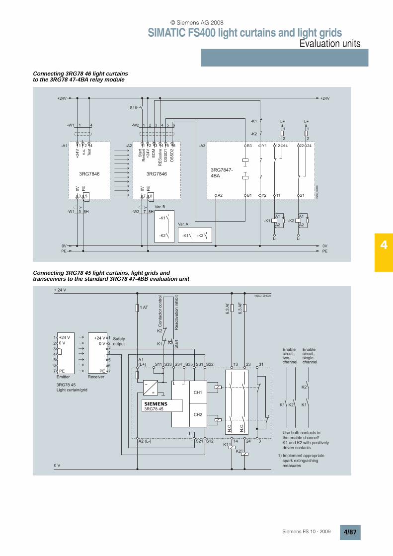
SIMATIC FS400 light curtains and light gridsEvaluation units
4/87Siemens FS 10 · 2009
4
Connecting 3RG78 46 light curtains to the 3RG78 47-4BA relay module
Connecting 3RG78 45 light curtains, light grids and transceivers to the standard 3RG78 47-4BB evaluation unit
+24V
3RG7846 3RG78463RG7847-
4BA
8H7
7 8
0V
FE
8H3
3 5
0V
FE
0V
41
41 2
+2
4V
n.c
.
-A1 -A2+
24
V
OS
SD
1
OS
SD
2
31 42 5 6
31 42 5 6 -A3 B3 Y1
A2 B1 Y2 11
-K1
-K1-K2 -K2
-K1
-K2
12
L+
1
2
14
-K1
L-
A1
A2
21
22
L+
1
2
24
-K2
L-
A1
A2
+24V
0V
FS
10_00259
Var. B
Var. A
Te
st
Sta
rtR
esta
rt
ED
M
RE
Ssolv
e
-W2-W1
-W1 -W2
-S1
PE PE
NSC0_00492e
0 V
+ 24 V
S11 13 23
14 24
1 AT
+24 V
0 V
1
2
3
4
5
6
7
1
23
4
5
6
7
N.O
.
N.O
.
K1 K2 K1
K2
A1(L+) S33 S34 S35 S31 S22
A2 (L-)
PE PE
6.3
Af
6.3
AF
CH1
CH2
3S21 S12
=
–
31
K2
K1
3RG78 45
K21)
K11)
+24 V
0 V
Co
nta
cto
r co
ntr
ol
Re
activa
tio
n in
hib
it
Safety
output
ReceiverEmitter
3RG78 45
Light curtain/grid
Sta
rt
Enablecircuit,two-channel
Enablecircuit,single-channel
Use both contacts in
the enable channel!
K1 and K2 with positively
driven contacts
1) Implement appropriate
spark extinguishing
measures
© Siemens AG 2008

SIMATIC FS400 light curtains and light gridsEvaluation units
4/88 Siemens FS 10 · 2009
4
Connecting 3RG78 34 laser scanners to the 3RG78 47-4BB evaluation unit
Connecting 3RG78 41 light curtains to the standard 3RG78 47-4BD evaluation unit
S11
FS
10
_0
03
11
+24V
n.c
.
n.c
.
rese
rve
d
Sh
ield
RS
23
2/4
22
RxD
+
RxD
-
TxD
-
TxD
+
SH1
0V
0V
0V
PE
0V
PE
-W1
-W1
42 3 75 6
Re
sta
rt
-A1 -X1
X1
X2
-A3 A1
A2
S31S33
+24V
3RG7834 3RG7847-4BB
FP
1
+2
4V
+2
4V
Ala
rm 1
FP
3
FP
2
FP
4
n.c
.
n.c
.
OS
SD
1
n.c
.
OS
SD
2
10 11 12 13 148 9 15
1 1-X1 -X2 4 5 6 7 82 3 9
42 3 11 12
5
1
1
8
9
6
9
15n.c
.
Ala
rm 2
1
2
Var. B
Var. A
-K1
-K1-K2 -K2
-K1
-K2
L+
1
2
L+
1
2
1
2
S34 S35 S22 13 23 31
24 32S21 S12 14
-K1
L-
A1
A2-K2
L-
A1
A2
NSC0_00483d
0 V
1)
3RG7847-4BD
+ 24 V
4 15 24 22 23 13 14 11
k2
k1
2
9 7 6 10 1
T1 T2 S1 S2
+ 2
4 V
0 V
2,5 AT
Test AOPDs
RE
SE
T
ED
M
RS
23
2
K2
1)
K1
+ 24 V
0 V
1
2
34
5
6
7
+ 24 V
0 V
1
2
34
5
6
7
OS
SD
1 N
.O.
OS
SD
2 N
.O.
L+
Ph
L-
N
L+
Fase
L-
N
k1 k2 k1
k2
8 8
0 V
h I
Receiver
Test input
Safety output
Conta
cto
r contr
ol
Reactivation inhib
it
R-output
Enablecircuit,single-channel
Enablecircuit,two-channel
Implement appropriatespark extinguishingmeasures
Use both contacts in theenable channel!K1 and K2 with positivelydriven contacts
1)
Diagn. State
6 A
T
ma
x.
6 A
T m
ax.
Sta
rt
3RG7841
Light curtain
Emitter
© Siemens AG 2008
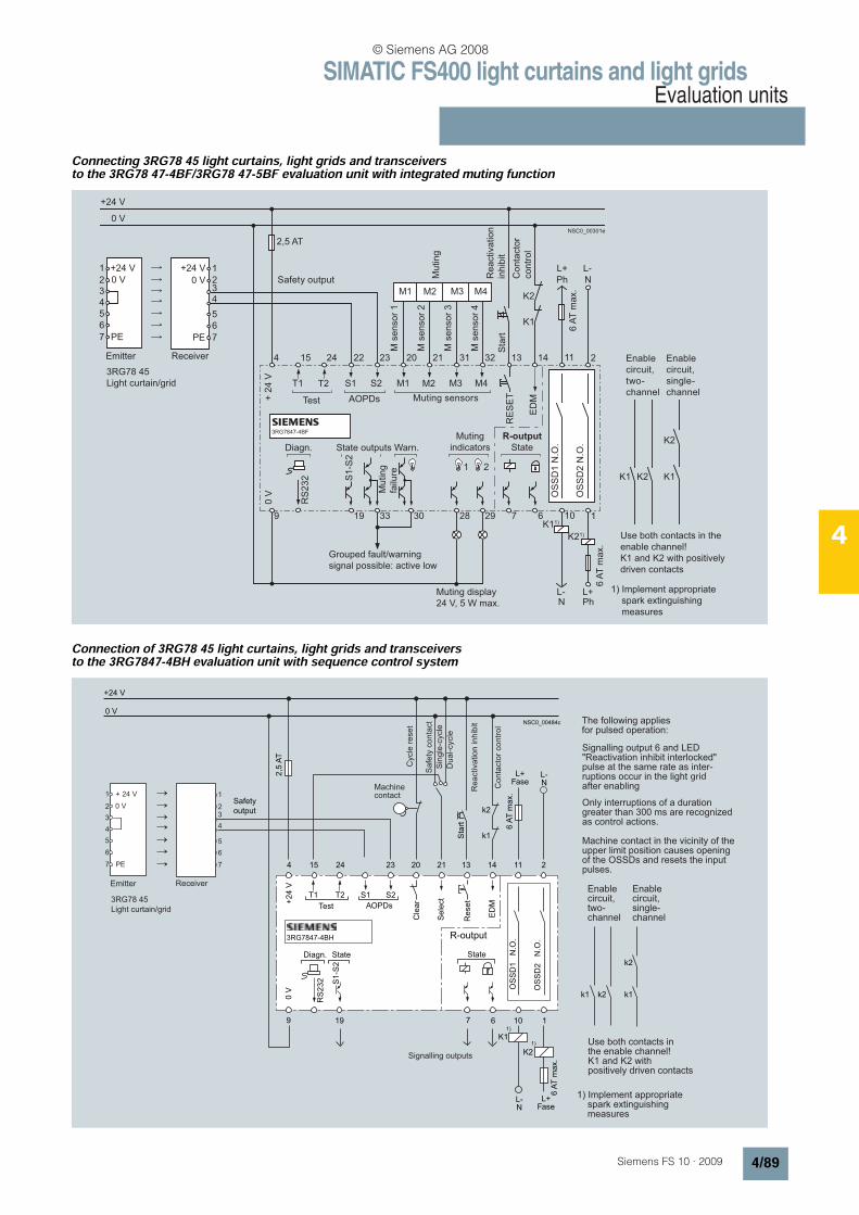
SIMATIC FS400 light curtains and light gridsEvaluation units
4/89Siemens FS 10 · 2009
4
Connecting 3RG78 45 light curtains, light grids and transceivers to the 3RG78 47-4BF/3RG78 47-5BF evaluation unit with integrated muting function
Connection of 3RG78 45 light curtains, light grids and transceivers to the 3RG7847-4BH evaluation unit with sequence control system
NSC0_00301e
0 V
+24 V
4 15 24 22 23 20 21 31 32 13 14 11
K2
K1
2
9 19 33 30 28 29 7 6 10 1
M1 M2 M3 M4T1 T2 S1 S2
+ 2
4 V
0 V
2,5 AT
AOPDs
RE
SE
T
ED
M
1
RS
23
2 S1
-S2
K21)
K11)
+24 V
PE
0 V
1
23
4
5
6
7 PE
0 V
1
234
5
6
7
OS
SD
1 N
.O.
OS
SD
2 N
.O.
M1 M2 M3 M4
L+
Ph
L-
N
L+Ph
L-N
K1 K2 K1
K23RG7847-4BF
+24 V
2
Enable
circuit,
two-
channel
Grouped fault/warning
signal possible: active low
3RG78 45
Light curtain/grid
Muting display
24 V, 5 W max.
Muting
indicators
R-output
State
Muting sensors
State outputs Warn.Diagn.
Safety output
Emitter Receiver
6 A
T m
ax.
6 A
T m
ax.
Co
nta
cto
r
co
ntr
ol
Mu
tin
g
failu
re
Re
activa
tio
n
inhib
itS
tart
M s
en
so
r 4
M s
en
so
r 3
M s
en
so
r 2
M s
en
so
r 1
Mu
tin
g
Test
Enable
circuit,
single-
channel
Use both contacts in the
enable channel!
K1 and K2 with positively
driven contacts
1) Implement appropriate
spark extinguishing
measures
grid
3RG78 45
Light curtain/grid
Emitter
© Siemens AG 2008

SIMATIC FS400 light curtains and light gridsEvaluation units
4/90 Siemens FS 10 · 2009
4
Connecting 3RG7834 laser scanners to a SafetyPLC
FS
10_00310
+24V
n.c
.
n.c
.
rese
rve
d
Sh
ield
RS
23
2/4
22
RxD
+
RxD
-
TxD
-
TxD
+
SH1
0V
0V
0V
PE
0V
PE
-W1
-W1
42 3 75 6
Re
sta
rt
-A1 -X1
X1
Safety PLC
X2
-A2
+24V
3RG7834
FP
1
+2
4V
+2
4V
Sta
nd
ard I/O
Ala
rm 1
FP
3
FP
2
FP
4
n.c
.
n.c
.
OS
SD
1
n.c
.
OS
SD
2
10 11 12 13 148 9 15
1 1-X1 -X2 4 5 6 7 82 3 9
42 3 75 6 11 128 15
5
1
1
8
9
6
9
15n.c
.
Ala
rm 2
Sa
fety
ou
tpu
ts
Sa
fety
inp
uts
1
2
© Siemens AG 2008
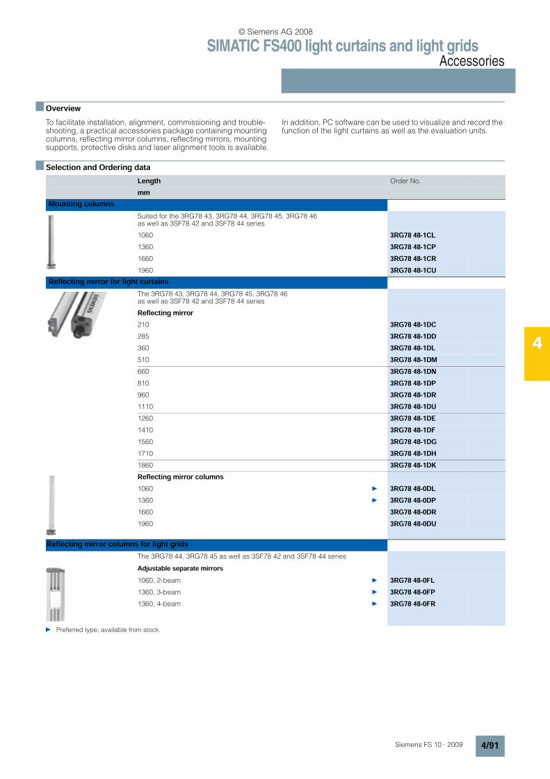
SIMATIC FS400 light curtains and light gridsAccessories
4/91Siemens FS 10 · 2009
4
n OverviewTo facilitate installation, alignment, commissioning and trouble-shooting, a practical accessories package containing mounting columns, reflecting mirror columns, reflecting mirrors, mounting supports, protective disks and laser alignment tools is available.
In addition, PC software can be used to visualize and record the function of the light curtains as well as the evaluation units.
n Selection and Ordering data
Length Order No.
mmMounting columns
Suited for the 3RG78 43, 3RG78 44, 3RG78 45, 3RG78 46 as well as 3SF78 42 and 3SF78 44 series
1060 3RG78 48-1CL1360 3RG78 48-1CP1660 3RG78 48-1CR1960 3RG78 48-1CU
Reflecting mirror for light curtains
The 3RG78 43, 3RG78 44, 3RG78 45, 3RG78 46 as well as 3SF78 42 and 3SF78 44 series
Reflecting mirror210 3RG78 48-1DC285 3RG78 48-1DD360 3RG78 48-1DL510 3RG78 48-1DM660 3RG78 48-1DN810 3RG78 48-1DP960 3RG78 48-1DR1110 3RG78 48-1DU1260 3RG78 48-1DE1410 3RG78 48-1DF1560 3RG78 48-1DG1710 3RG78 48-1DH1860 3RG78 48-1DKReflecting mirror columns1060 3RG78 48-0DL1360 3RG78 48-0DP1660 3RG78 48-0DR1960 3RG78 48-0DU
Reflecting mirror columns for light gridsThe 3RG78 44, 3RG78 45 as well as 3SF78 42 and 3SF78 44 series
Adjustable separate mirrors1060, 2-beam 3RG78 48-0FL1360, 3-beam 3RG78 48-0FP1360, 4-beam 3RG78 48-0FR
Preferred type, available from stock.
© Siemens AG 2008
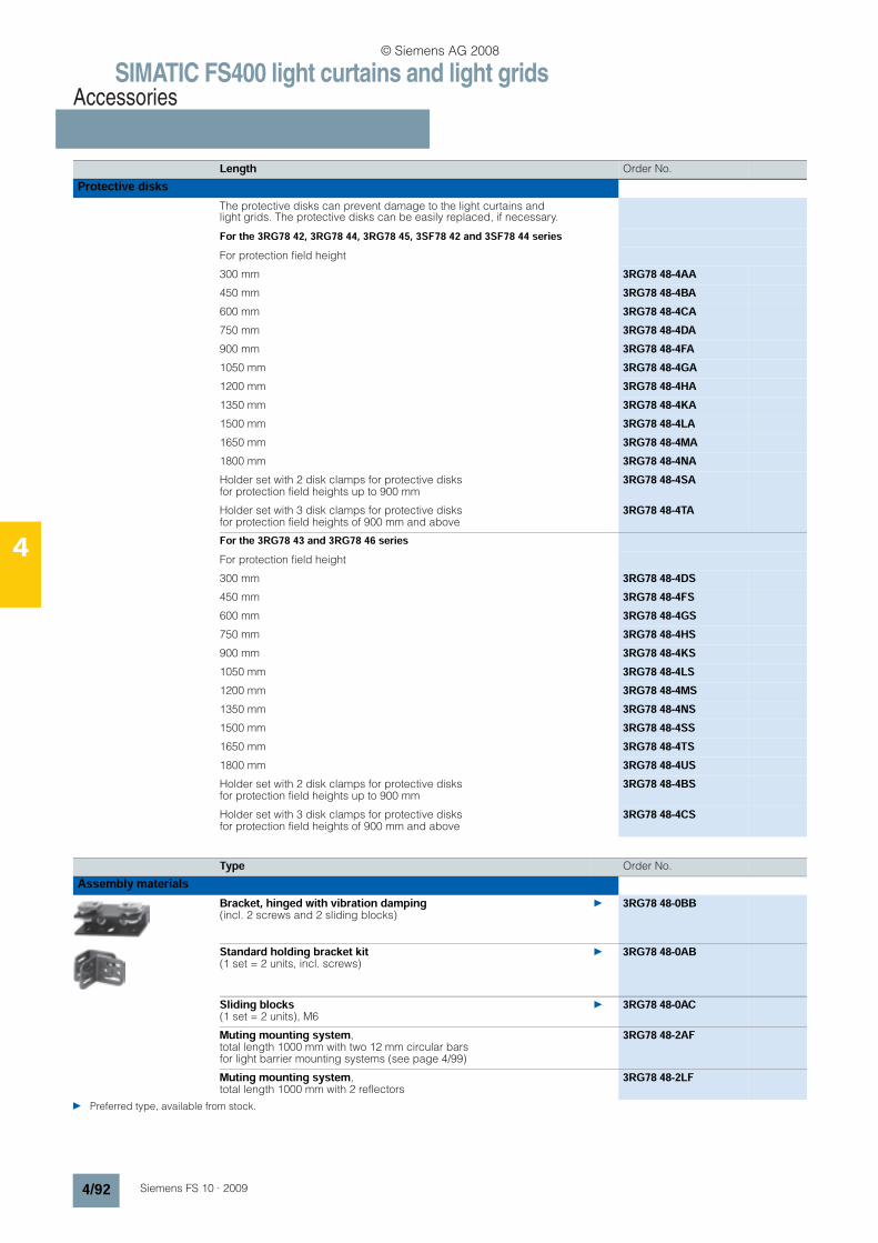
SIMATIC FS400 light curtains and light gridsAccessories
4/92 Siemens FS 10 · 2009
4
Length Order No.
Protective disksThe protective disks can prevent damage to the light curtains and light grids. The protective disks can be easily replaced, if necessary.
For the 3RG78 42, 3RG78 44, 3RG78 45, 3SF78 42 and 3SF78 44 seriesFor protection field height
300 mm 3RG78 48-4AA450 mm 3RG78 48-4BA600 mm 3RG78 48-4CA750 mm 3RG78 48-4DA900 mm 3RG78 48-4FA1050 mm 3RG78 48-4GA1200 mm 3RG78 48-4HA1350 mm 3RG78 48-4KA1500 mm 3RG78 48-4LA1650 mm 3RG78 48-4MA1800 mm 3RG78 48-4NAHolder set with 2 disk clamps for protective disks for protection field heights up to 900 mm
3RG78 48-4SA
Holder set with 3 disk clamps for protective disks for protection field heights of 900 mm and above
3RG78 48-4TA
For the 3RG78 43 and 3RG78 46 seriesFor protection field height
300 mm 3RG78 48-4DS450 mm 3RG78 48-4FS600 mm 3RG78 48-4GS750 mm 3RG78 48-4HS900 mm 3RG78 48-4KS1050 mm 3RG78 48-4LS1200 mm 3RG78 48-4MS1350 mm 3RG78 48-4NS1500 mm 3RG78 48-4SS1650 mm 3RG78 48-4TS1800 mm 3RG78 48-4USHolder set with 2 disk clamps for protective disks for protection field heights up to 900 mm
3RG78 48-4BS
Holder set with 3 disk clamps for protective disks for protection field heights of 900 mm and above
3RG78 48-4CS
Type Order No.
Assembly materials
Bracket, hinged with vibration damping (incl. 2 screws and 2 sliding blocks)
3RG78 48-0BB
Standard holding bracket kit (1 set = 2 units, incl. screws)
3RG78 48-0AB
Sliding blocks (1 set = 2 units), M6
3RG78 48-0AC
Muting mounting system, total length 1000 mm with two 12 mm circular bars for light barrier mounting systems (see page 4/99)
3RG78 48-2AF
Muting mounting system, total length 1000 mm with 2 reflectors
3RG78 48-2LF
Preferred type, available from stock.
© Siemens AG 2008
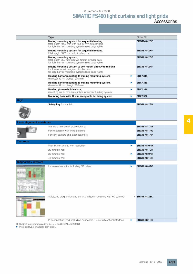
SIMATIC FS400 light curtains and light gridsAccessories
4/93Siemens FS 10 · 2009
4
Type Order No.
Muting mounting system for sequential muting, total length 1000 mm with four 12 mm circular bars for light barrier mounting systems (see page 4/99)
3RG784 8-2DF
Muting mounting system for sequential muting, total length 1000 mm with 4 reflectors
3RG78 48-2KF
Muting mounting system, total length 350 mm with two 12 mm circular bars for light barrier mounting systems (see page 4/99)
3RG78 48-2GF
Muting mounting system to bolt mount directly to the unit for 2 sensors with angular circular bars for light barrier mounting systems (see page 4/99)
3RG78 48-2HF
Holding bar for mounting to muting mounting system, diameter 12 mm, length 200 mm
3RX7 315
Holding bar for mounting to muting mounting system, diameter 12 mm, length 300 mm
3RX7 316
Holding plate to hold sensor, mounting on 12 mm circular bar for sensor holding system
3RX7 326
Mounting base with 12 mm receptacle for fixing system 3RX7 322Keys
Safety key for teach-in 3RG78 48-2AH
Laser alignment assistance
Standard version for slot mounting 3RG78 48-1ABFor installation with fixing columns 3RG78 48-1AGFor light barriers and laser scanners 3RG78 48-1AP
Test rodsWith 14 mm and 30 mm resolution 3RG78 48-0AH20 mm test rod 3RG78 48-1CH30 mm test rod 3RG78 48-0AH40 mm test rod 3RG78 48-1BH
Diagnostics software
for evaluation units, including PC cable H 3RG78 48-4AC
SafetyLab diagnostics and parameterization software with PC cable C H 3RG78 48-2SL
PC connecting lead, including connector, 9-pole with optical interface 3RG78 38-1DCH: Subject to export regulations AL = N and ECCN = 5D992B1
Preferred type, available from stock.
© Siemens AG 2008

SIMATIC FS400 light curtains and light gridsAccessories
4/94 Siemens FS 10 · 2009
4
Type Length Poles Order No.
mASIsafe
ASIsafe module for 3RG78 43 type 2 light curtains
B 3RK1205-0BQ21-0AA3
ASIsafe module for 3RG78 46 type 4 light curtains
3RK1205-0BQ24-0AA3
ASIsafe adapter for 3SF78 44 series receiver for use with 3RG78 38-1EA or 3RG78 38-1EB 5-pole connecting cables, for bus connection and 24 V power supply
3RG78 38-1DG
ASIsafe adapter for 3SF78 4 emitter and M12 bus terminal receiver for ASIsafe flat cable
3RX98 01-0AA00
Connecting cable for 3RG78 38-1DG ASIsafe adapter M12 ASIsafe adapter for 3SF78 44 M12 receiver
1 5-pole 3RG78 38-1EA
Connecting cable for 3RG78 38-1DG ASIsafe adapter M12 ASIsafe adapter for 3SF78 44 M12 receiver
2 5-pole 3RG78 38-1EB
Cables and cable plugs of the Hirschmann type for the 3RG78 44 seriesCable plug 12-pole 3RG78 48-2DAAngular cable socket 12-pole 3RG78 48-2DBCable for machine interface, straight plug
10 3RG78 48-2CK
Cable for machine interface, straight plug
25 3RG78 48-2DK
Cable for machine interface, straight plug
50 3RG78 48-2EK
Brad Harrison (MIN series) cable for 3RG78 45 and 3RG78 44 light curtains and light gridsNotice:
Primarily for the NAFTA market.
• Connecting cable for 3RG78 44 and 3RG78 45 receivers
4 7-pole 3RG78 48-0DB01
• Connecting cable for 3RG78 45 emitter 4 5-pole 3RG78 48-0DB00• Connecting cable for 3RG7844
and 3RG7845 receivers12 7-pole 3RG78 48-0KB01
• Connecting cable for 3RG78 45 emitter 12 5-pole 3RG78 48-0KB00• Connecting cable for 3RG78 44
and 3RG78 45 receivers20 7-pole 3RG78 48-0LB01
• Connecting cable for 3RG78 45 emitter 20 5-pole 3RG78 48-0LB00Cable and cable boxes for the 3RG78 44 and 3SF78 44 series
Cable for local connection, with M12 angular connector, 8-pole
3 3RG78 48-2AK
Cable for local connection, with M12 angular connector, 8-pole
10 3RG78 48-2BK
External local connection box, with 6 M12 sockets and cable; for connecting the muting sensors and the muting lamp
0.5 3RG78 48-2AB
Connecting cable, twisted (connecting pin 2 to plug pin 4), M12 angle plug – M12 connector
1.5 8-pole 3RG78 48-2FK
Connecting cable, twisted (connecting pin 2 to plug pin 4), M12 plug – M12 connector
1.5 8-pole 3RG78 48-2GK
Connecting cable, twisted (connecting pin 2 to plug pin 4), M12 angle plug – M12 angular connector
1.5 8-pole 3RG78 48-2HK
B: Subject to export regulations AL = N and ECCN = EAR99. Preferred type, available from stock.
© Siemens AG 2008
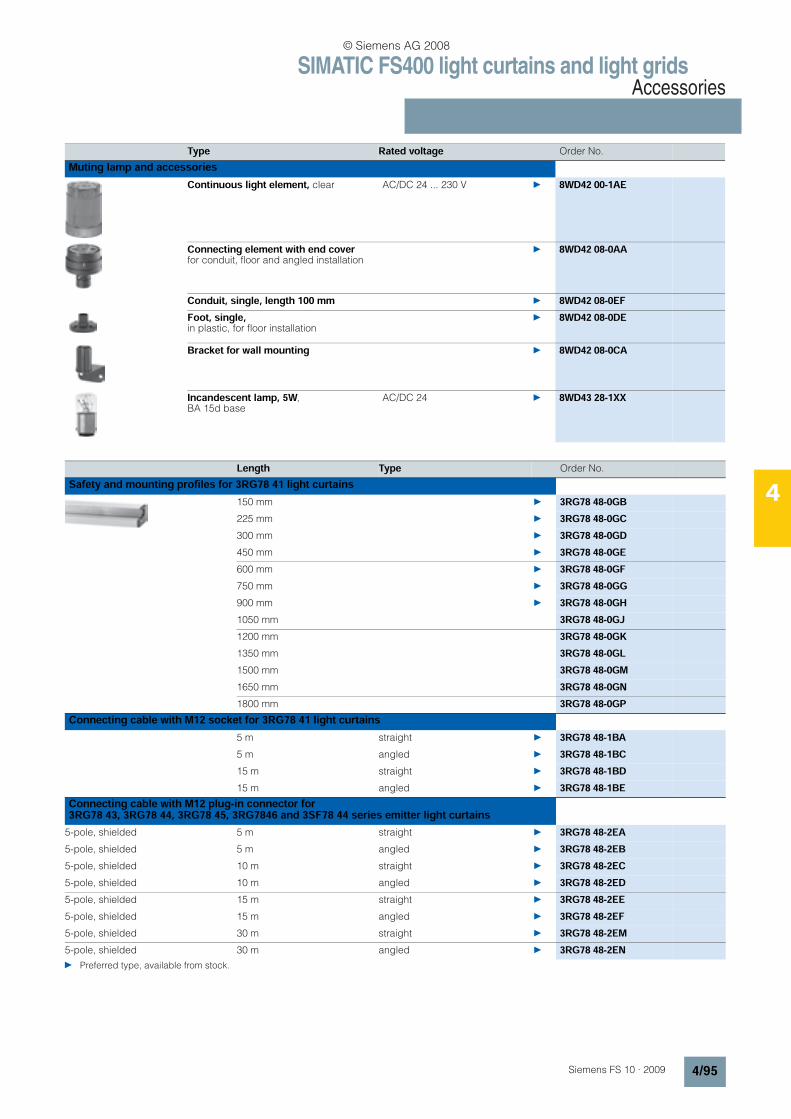
SIMATIC FS400 light curtains and light gridsAccessories
4/95Siemens FS 10 · 2009
4
Type Rated voltage Order No.
Muting lamp and accessoriesContinuous light element, clear AC/DC 24 ... 230 V 8WD42 00-1AE
Connecting element with end cover for conduit, floor and angled installation
8WD42 08-0AA
Conduit, single, length 100 mm 8WD42 08-0EFFoot, single, in plastic, for floor installation
8WD42 08-0DE
Bracket for wall mounting 8WD42 08-0CA
Incandescent lamp, 5W, BA 15d base
AC/DC 24 8WD43 28-1XX
Length Type Order No.
Safety and mounting profiles for 3RG78 41 light curtains150 mm 3RG78 48-0GB225 mm 3RG78 48-0GC300 mm 3RG78 48-0GD450 mm 3RG78 48-0GE600 mm 3RG78 48-0GF750 mm 3RG78 48-0GG900 mm 3RG78 48-0GH1050 mm 3RG78 48-0GJ1200 mm 3RG78 48-0GK1350 mm 3RG78 48-0GL1500 mm 3RG78 48-0GM1650 mm 3RG78 48-0GN1800 mm 3RG78 48-0GP
Connecting cable with M12 socket for 3RG78 41 light curtains5 m straight 3RG78 48-1BA5 m angled 3RG78 48-1BC15 m straight 3RG78 48-1BD15 m angled 3RG78 48-1BE
Connecting cable with M12 plug-in connector for 3RG78 43, 3RG78 44, 3RG78 45, 3RG7846 and 3SF78 44 series emitter light curtains
5-pole, shielded 5 m straight 3RG78 48-2EA5-pole, shielded 5 m angled 3RG78 48-2EB5-pole, shielded 10 m straight 3RG78 48-2EC5-pole, shielded 10 m angled 3RG78 48-2ED5-pole, shielded 15 m straight 3RG78 48-2EE5-pole, shielded 15 m angled 3RG78 48-2EF5-pole, shielded 30 m straight 3RG78 48-2EM5-pole, shielded 30 m angled 3RG78 48-2EN Preferred type, available from stock.
© Siemens AG 2008
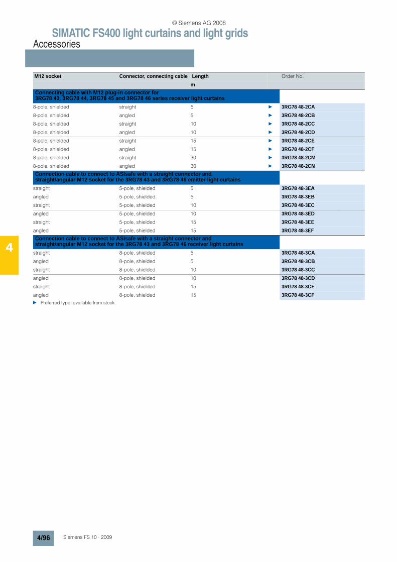
SIMATIC FS400 light curtains and light gridsAccessories
4/96 Siemens FS 10 · 2009
4
M12 socket Connector, connecting cable Length Order No.
mConnecting cable with M12 plug-in connector for 3RG78 43, 3RG78 44, 3RG78 45 and 3RG78 46 series receiver light curtains
8-pole, shielded straight 5 3RG78 48-2CA8-pole, shielded angled 5 3RG78 48-2CB8-pole, shielded straight 10 3RG78 48-2CC8-pole, shielded angled 10 3RG78 48-2CD8-pole, shielded straight 15 3RG78 48-2CE8-pole, shielded angled 15 3RG78 48-2CF8-pole, shielded straight 30 3RG78 48-2CM8-pole, shielded angled 30 3RG78 48-2CNConnection cable to connect to ASIsafe with a straight connector and straight/angular M12 socket for the 3RG78 43 and 3RG78 46 emitter light curtains
straight 5-pole, shielded 5 3RG78 48-3EAangled 5-pole, shielded 5 3RG78 48-3EBstraight 5-pole, shielded 10 3RG78 48-3ECangled 5-pole, shielded 10 3RG78 48-3EDstraight 5-pole, shielded 15 3RG78 48-3EEangled 5-pole, shielded 15 3RG78 48-3EFConnection cable to connect to ASIsafe with a straight connector and straight/angular M12 socket for the 3RG78 43 and 3RG78 46 receiver light curtains
straight 8-pole, shielded 5 3RG78 48-3CAangled 8-pole, shielded 5 3RG78 48-3CBstraight 8-pole, shielded 10 3RG78 48-3CCangled 8-pole, shielded 10 3RG78 48-3CDstraight 8-pole, shielded 15 3RG78 48-3CEangled 8-pole, shielded 15 3RG78 48-3CF Preferred type, available from stock.
© Siemens AG 2008
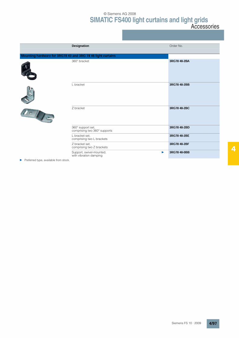
SIMATIC FS400 light curtains and light gridsAccessories
4/97Siemens FS 10 · 2009
4
Designation Order No.
Mounting hardware for 3RG78 43 and 3RG 78 46 light curtains360° bracket 3RG78 48-2BA
L bracket 3RG78 48-2BB
Z bracket 3RG78 48-2BC
360° support set, comprising two 360° supports
3RG78 48-2BD
L bracket set, comprising two L brackets
3RG78 48-2BE
Z bracket set, comprising two Z brackets
3RG78 48-2BF
Support, swivel-mounted, with vibration damping
3RG78 48-0BB
Preferred type, available from stock.
© Siemens AG 2008
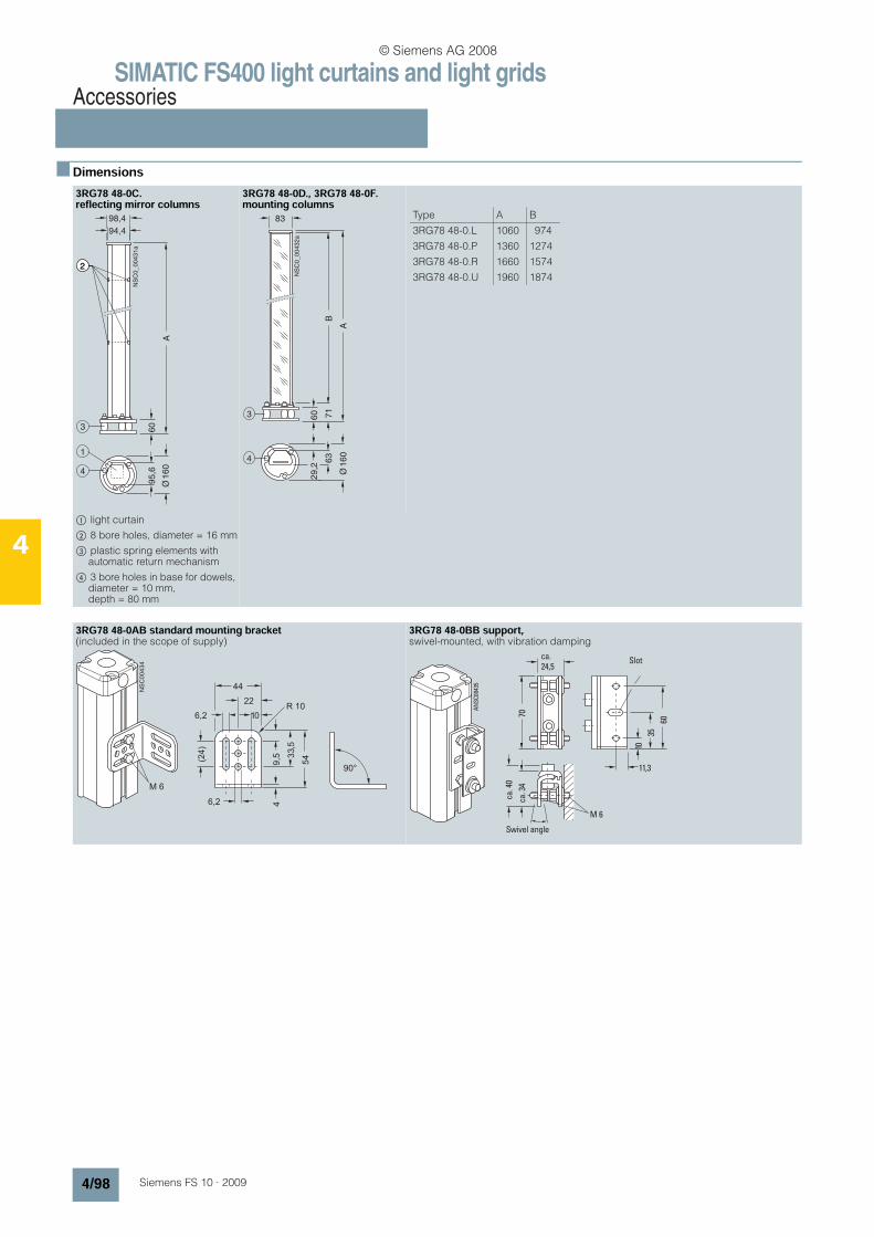
SIMATIC FS400 light curtains and light gridsAccessories
4/98 Siemens FS 10 · 2009
4
n Dimensions3RG78 48-0C. reflecting mirror columns
3RG78 48-0D., 3RG78 48-0F.mounting columns
$ light curtain
% 8 bore holes, diameter = 16 mm
& plastic spring elements with automatic return mechanism
( 3 bore holes in base for dowels, diameter = 10 mm, depth = 80 mm
3RG78 48-0AB standard mounting bracket (included in the scope of supply)
3RG78 48-0BB support,swivel-mounted, with vibration damping
NSC0_00431a
94,4
98,4
60
A
95,6
3
2
1
4
2
Ø160
NSC0_00432a
83
60
A
29,2
Ø
71
B
4 63
3
160
Type A B
3RG78 48-0.L 1060 974
3RG78 48-0.P 1360 1274
3RG78 48-0.R 1660 1574
3RG78 48-0.U 1960 1874
NS
C0
04
34
90°
6,2
R 1010
22
6,2
44
(24
)
9,5
4
33,5
54
M 6
ca. 3
4
ca. 4
0
M 6
70
10
35
60
11,3
ca.
24,5
Swivel angle
Slot
AN
SC
004
35
© Siemens AG 2008

SIMATIC FS400 light curtains and light gridsAccessories
4/99Siemens FS 10 · 2009
4
Muting mounting system
A V2A circular bar 12 x 100 mmB Fixing plateC Aluminum profileD Cover
3RG78 48-2GF muting mounting system, length 350 mm with 2 circular bars
3RG78 48-2DF muting mounting system for sequential muting,total length 1000 mm with four 12 mm circular bars
3RG78 48-2KF muting mounting system for sequential muting, length 1000 mm with four reflectors
=
40
FS1000108
100
1000
=
A
B
C D
FS10_00260
L
40
100
200
150
Ø12
FS10_00261
1000
40
100
200
150
Ø12
FS
10
_0
02
621000
3RG78 48-2BB L-bracket 3RG78 48-2BC Z-bracket
3RG78 48-2BA support 360° 3RG78 48-0BB pivoting support
FS10_0007912
4
16
293
9
R3,1
R10
30
R3,1
R6
18,4
31,7
12R10
R3,1
25
R3,1FS10_00080
6,2
617
3
R3,1
6,2
22
10
10,8
R10 R10
4
12,1
FS10_00082
8,2
24
20
34
29,1
6,2
24,5
9,1
41,2
8
9
32
(34-3
7)
(50-5
3)
-26,5
FS10_00084
-34-4
0
b
10
35
60
11,3
70
a
© Siemens AG 2008
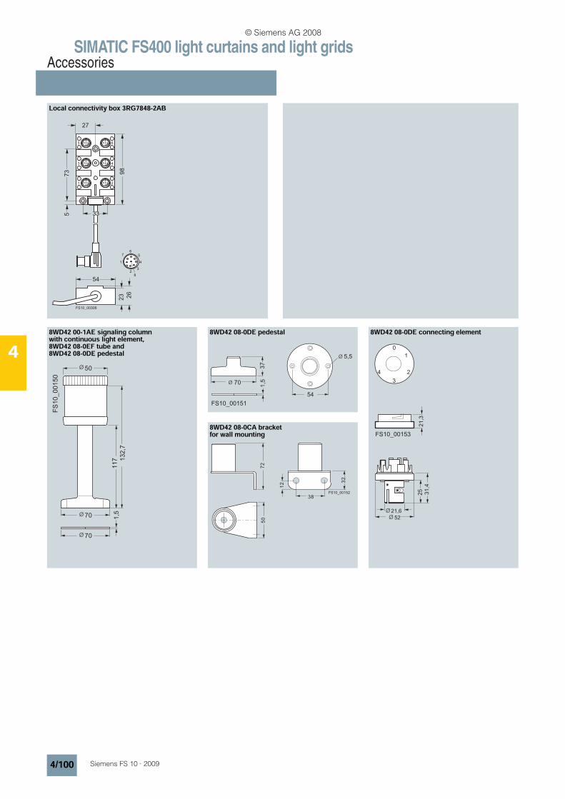
SIMATIC FS400 light curtains and light gridsAccessories
4/100 Siemens FS 10 · 2009
4
Local connectivity box 3RG7848-2AB
8WD42 00-1AE signaling column with continuous light element, 8WD42 08-0EF tube and 8WD42 08-0DE pedestal
8WD42 08-0DE pedestal 8WD42 08-0DE connecting element
8WD42 08-0CA bracket for wall mounting
33
27
548
2
1 4
98
73
5
23 26
7 56
3
1
3
5
2
4
6
FS10_00306
FS
10_00150
117 1
32,7
70
70
1,5
50Ø
Ø
Ø
FS10_00151
5,5Ø
37
1,570Ø
54
FS10_00153
Ø
1
0
3
24
21,3
25 31,4
52
21,6Ø
72
FS10_00152
38
32
12
50
© Siemens AG 2008
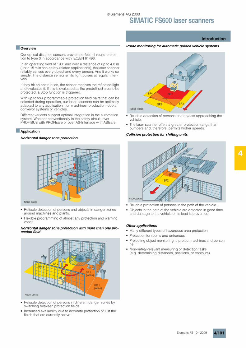
SIMATIC FS600 laser scanners
Introduction
4/101Siemens FS 10 · 2009
4
n OverviewOur optical distance sensors provide perfect all-round protec-tion to type 3 in accordance with IEC/EN 61496.
In an operating field of 190° and over a distance of up to 4.0 m (up to 15 m in non-safety-related applications), the laser scanner reliably senses every object and every person. And it works so simply: The distance sensor emits light pulses at regular inter-vals.
If they hit an obstruction, the sensor receives the reflected light and evaluates it. If this is evaluated as the predefined area to be protected, a Stop function is triggered.
With up to four programmable protection field pairs that can be selected during operation, our laser scanners can be optimally adapted to any application – on machines, production robots, conveyor systems or vehicles.
Different variants support optimal integration in the automation system: Whether conventionally in the safety circuit, over PROFIBUS with PROFIsafe or over AS-Interface with ASIsafe.
n ApplicationHorizontal danger zone protection
• Reliable detection of persons and objects in danger zones around machines and plants.
• Flexible programming of almost any protection and warning zones.
Horizontal danger zone protection with more than one pro-tection field
• Reliable detection of persons in different danger zones by switching between protection fields.
• Increased availability due to accurate protection of just the fields that are currently active.
Route monitoring for automatic guided vehicle systems
• Reliable detection of persons and objects approaching the vehicle.
• The laser scanner offers a greater protection range than bumpers and, therefore, permits higher speeds.
Collision protection for shifting units
• Reliable protection of persons in the path of the vehicle.
• Objects in the path of the vehicle are detected in good time and damage to the vehicle or its load is prevented.
Other applications• Many different types of hazardous area protection
• Protection for rooms and entrances
• Projecting object monitoring to protect machines and person-nel
• Non-safety-relevant measuring or detection tasks (e.g. determining distances, positions, or contours).
NSC0_00619
WF 1(active)
SF 1(active)
SF 2
WF 2
NSC0_00646
SF4
SF2 SF3
SF1
NSC0_00620
SF1
SF2
b
c
c
NSC0_00622
© Siemens AG 2008
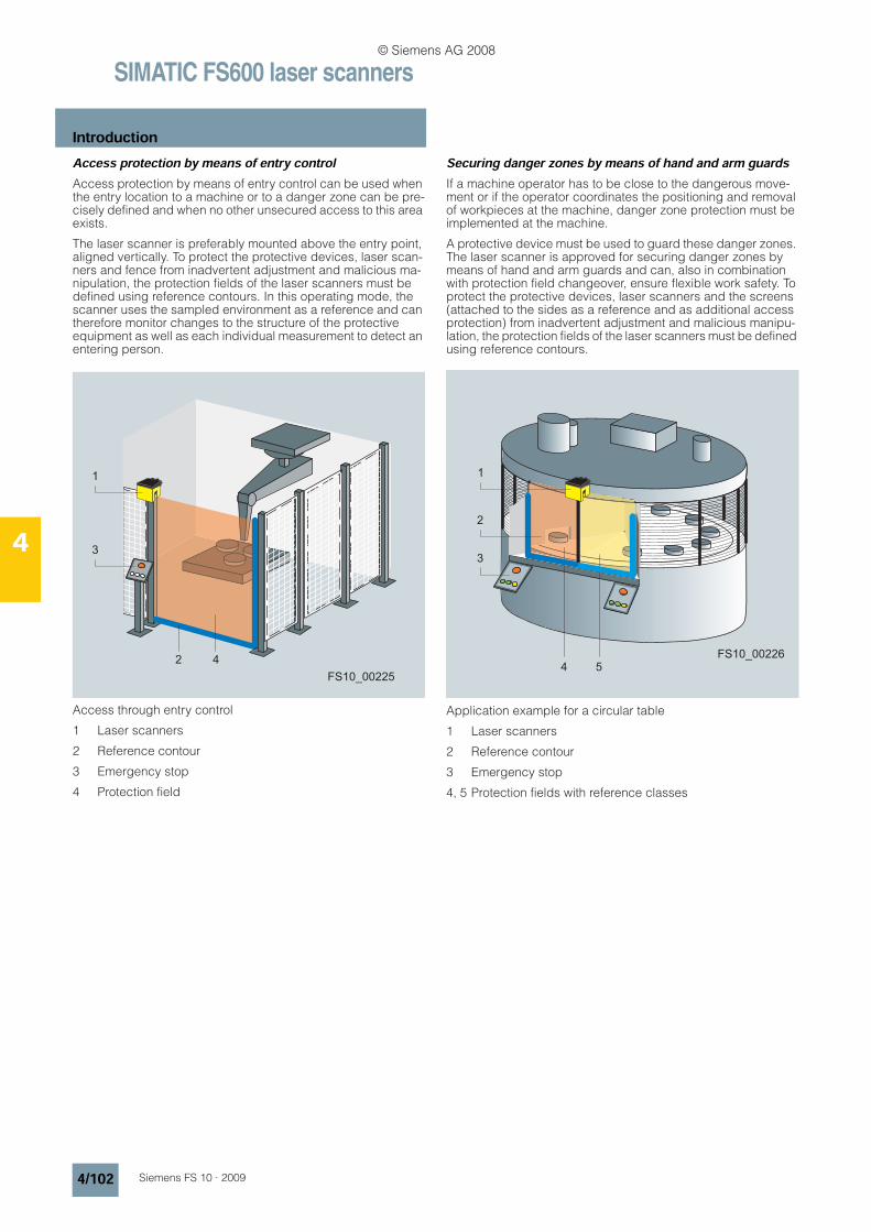
SIMATIC FS600 laser scanners
Introduction
4/102 Siemens FS 10 · 2009
4
Access protection by means of entry controlAccess protection by means of entry control can be used when the entry location to a machine or to a danger zone can be pre-cisely defined and when no other unsecured access to this area exists.
The laser scanner is preferably mounted above the entry point, aligned vertically. To protect the protective devices, laser scan-ners and fence from inadvertent adjustment and malicious ma-nipulation, the protection fields of the laser scanners must be defined using reference contours. In this operating mode, the scanner uses the sampled environment as a reference and can therefore monitor changes to the structure of the protective equipment as well as each individual measurement to detect an entering person.
Access through entry control
1 Laser scanners
2 Reference contour
3 Emergency stop
4 Protection field
Securing danger zones by means of hand and arm guardsIf a machine operator has to be close to the dangerous move-ment or if the operator coordinates the positioning and removal of workpieces at the machine, danger zone protection must be implemented at the machine.
A protective device must be used to guard these danger zones. The laser scanner is approved for securing danger zones by means of hand and arm guards and can, also in combination with protection field changeover, ensure flexible work safety. To protect the protective devices, laser scanners and the screens (attached to the sides as a reference and as additional access protection) from inadvertent adjustment and malicious manipu-lation, the protection fields of the laser scanners must be defined using reference contours.
Application example for a circular table
1 Laser scanners
2 Reference contour
3 Emergency stop
4, 5 Protection fields with reference classes
FS10_00225
1
3
2 4FS10_00226
4
1
2
3
5
© Siemens AG 2008

SIMATIC FS600 laser scanners
Introduction
4/103Siemens FS 10 · 2009
4
n FunctionThe laser scanner is an optical, contact-free surface scanner – designed primarily for operator protection.
Using a laser diode with transmission optics, the laser scanner continuously generates bundled light pulses that are scattered throughout the operating range by an integrated rotating mirror. If objects or persons enter the field, it evaluates the reflected light pulses and continuously calculates the exact position coor-dinates on the basis of the light propagation time. If the defined personnel protection field is penetrated, the laser scanner stops the machine immediately (within the system response time). The Stop function is reset when the protection field is free again, ei-ther automatically or following acknowledgement (depending on the operating mode).
The operating range of the laser scanner spans 190° and is sub-divided into angle segments of 0.36°.
The scan rate is 25 scans/second, i.e. one light pulse every 40 ms in each segment. A special algorithm ensures that objects larger than 70 mm (this corresponds to the scanner resolution) can be reliably detected and that contamination (e.g. dust) does not reduce system availability. The laser scanner detects people (even if they are wearing dark clothing) at a distance of up to 4 m (failsafe). People or objects can, however, be detected at a dis-tance of up to 15 m so that a warning can be output, for example (not safety relevant).
Four protection field/warning field pairsFour variable protection field pairs for the personnel protection field and warning field, which can be easily set on the PC, ensure that the laser scanner can be adapted to suit any requirement.
It can be implemented in stationary applications (machines and installations) or mobile applications (vehicles, automatic guided vehicle systems, or shifting units). In the case of a robot, for ex-ample, different operating ranges can be protected, whereby the laser scanner operates in succession with regard to time and space. In the case of automatic guided vehicle systems, four programmable protection fields can be protected (e.g. rapid travel, slow travel, turning left, turning right).
LS4soft operator softwareThanks to the PC operator software LS4soft, it could not be eas-ier to optimize the laser scanner settings. The following functions have been integrated:
• User-friendly configuration of the protection field using a PC or laptop
• Configuration of additional functions, such as protection field selection, restart inhibit, etc. by means of a software wizard
• Comprehensive range of displays, e.g. defined protection fields, current scan contours, system settings, etc. reliable, password-protected access with different authorization levels
• Executable under Microsoft Windows 95/98/NT/2000/XP
The operator software is supplied with the laser scanner.
E Sc
NSC0_00623
Reflection
185° 5°
0.36°
NSC0_00624
SF 1
SF 2
SF 3 SF 4
NSC0_00625
Only personal protection fields are shown
© Siemens AG 2008
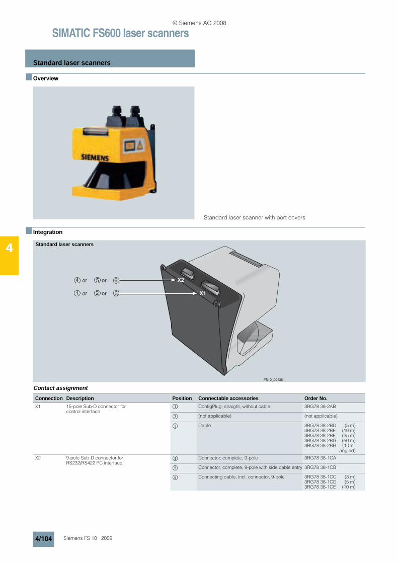
SIMATIC FS600 laser scanners
Standard laser scanners
4/104 Siemens FS 10 · 2009
4
n Overview
Standard laser scanner with port covers
n Integration
Contact assignment
X1
X2
or or
or or
FS10_00138
Standard laser scanners
Connection Description Position Connectable accessories Order No.X1 15-pole Sub-D connector for
control interface$ ConfigPlug, straight, without cable 3RG78 38-2AB
% (not applicable) (not applicable)
& Cable 3RG78 38-2BD (5 m)3RG78 38-2BE (10 m)3RG78 38-2BF (25 m)3RG78 38-2BG (50 m)3RG78 38-2BH (10 m,
angled)
X2 9-pole Sub-D connector for RS232/RS422 PC interface
( Connector, complete, 9-pole 3RG78 38-1CA
) Connector, complete, 9-pole with side cable entry 3RG78 38-1CB
* Connecting cable, incl. connector, 9-pole 3RG78 38-1CC (3 m)3RG78 38-1CD (5 m)3RG78 38-1CE (10 m)
© Siemens AG 2008
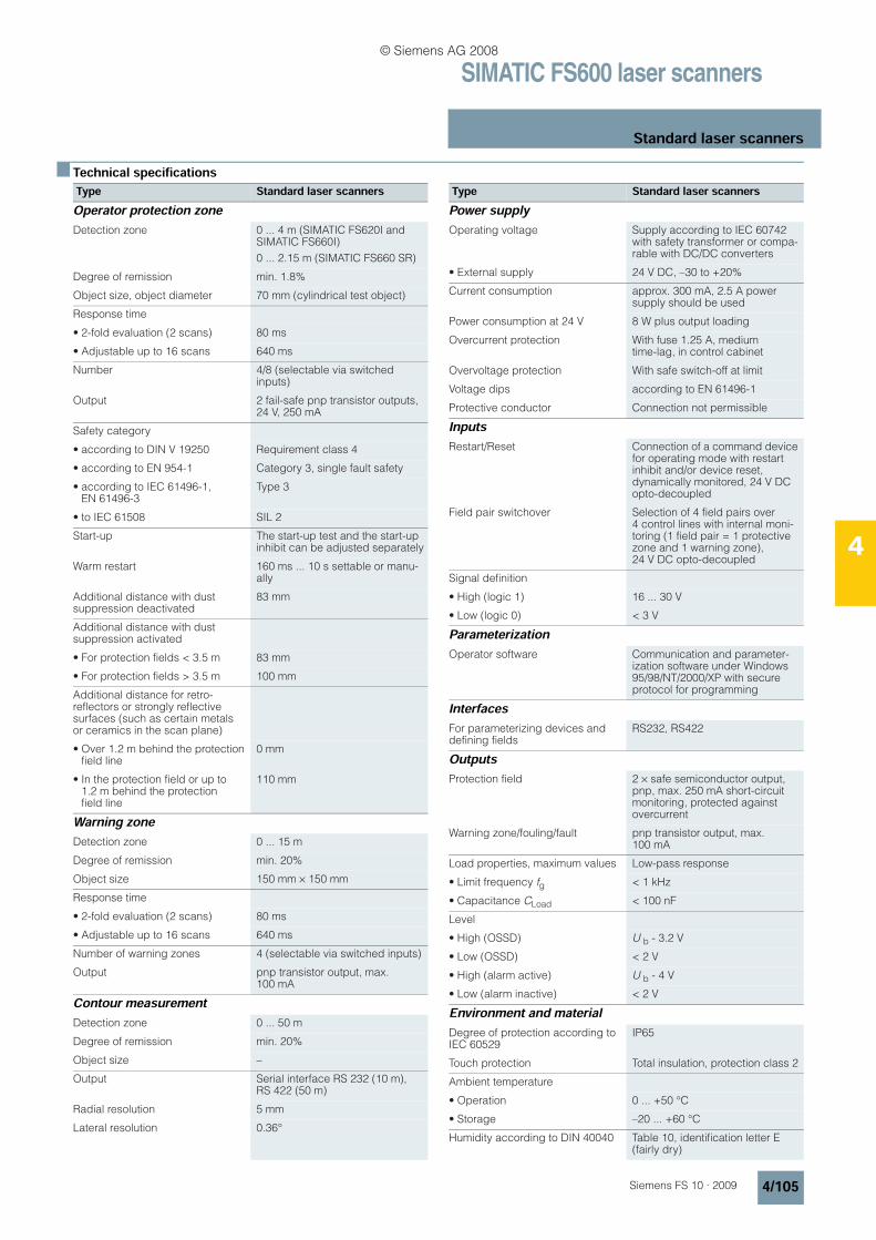
SIMATIC FS600 laser scanners
Standard laser scanners
4/105Siemens FS 10 · 2009
4
n Technical specifications Type Standard laser scannersOperator protection zone Detection zone 0 ... 4 m (SIMATIC FS620I and
SIMATIC FS660I)
0 ... 2.15 m (SIMATIC FS660 SR)
Degree of remission min. 1.8%
Object size, object diameter 70 mm (cylindrical test object)
Response time
• 2-fold evaluation (2 scans) 80 ms
• Adjustable up to 16 scans 640 ms
Number 4/8 (selectable via switched inputs)
Output 2 fail-safe pnp transistor outputs, 24 V, 250 mA
Safety category
• according to DIN V 19250 Requirement class 4
• according to EN 954-1 Category 3, single fault safety
• according to IEC 61496-1, EN 61496-3
Type 3
• to IEC 61508 SIL 2
Start-up The start-up test and the start-up inhibit can be adjusted separately
Warm restart 160 ms ... 10 s settable or manu-ally
Additional distance with dust suppression deactivated
83 mm
Additional distance with dust suppression activated
• For protection fields < 3.5 m 83 mm
• For protection fields > 3.5 m 100 mm
Additional distance for retro-reflectors or strongly reflective surfaces (such as certain metals or ceramics in the scan plane)
• Over 1.2 m behind the protection field line
0 mm
• In the protection field or up to 1.2 m behind the protection field line
110 mm
Warning zone Detection zone 0 ... 15 m
Degree of remission min. 20%
Object size 150 mm × 150 mm
Response time
• 2-fold evaluation (2 scans) 80 ms
• Adjustable up to 16 scans 640 ms
Number of warning zones 4 (selectable via switched inputs)
Output pnp transistor output, max. 100 mA
Contour measurement Detection zone 0 ... 50 m
Degree of remission min. 20%
Object size –
Output Serial interface RS 232 (10 m), RS 422 (50 m)
Radial resolution 5 mm
Lateral resolution 0.36°
Power supply Operating voltage Supply according to IEC 60742
with safety transformer or compa-rable with DC/DC converters
• External supply 24 V DC, –30 to +20%
Current consumption approx. 300 mA, 2.5 A power supply should be used
Power consumption at 24 V 8 W plus output loading
Overcurrent protection With fuse 1.25 A, medium time-lag, in control cabinet
Overvoltage protection With safe switch-off at limit
Voltage dips according to EN 61496-1
Protective conductor Connection not permissible
InputsRestart/Reset Connection of a command device
for operating mode with restart inhibit and/or device reset, dynamically monitored, 24 V DC opto-decoupled
Field pair switchover Selection of 4 field pairs over 4 control lines with internal moni-toring (1 field pair = 1 protective zone and 1 warning zone), 24 V DC opto-decoupled
Signal definition
• High (logic 1) 16 ... 30 V
• Low (logic 0) < 3 V
Parameterization Operator software Communication and parameter-
ization software under Windows 95/98/NT/2000/XP with secure protocol for programming
InterfacesFor parameterizing devices and defining fields
RS232, RS422
OutputsProtection field 2 × safe semiconductor output,
pnp, max. 250 mA short-circuit monitoring, protected against overcurrent
Warning zone/fouling/fault pnp transistor output, max. 100 mA
Load properties, maximum values Low-pass response
• Limit frequency fg < 1 kHz
• Capacitance CLoad < 100 nF
Level
• High (OSSD) U b - 3.2 V
• Low (OSSD) < 2 V
• High (alarm active) U b - 4 V
• Low (alarm inactive) < 2 V
Environment and material Degree of protection according to IEC 60529
IP65
Touch protection Total insulation, protection class 2
Ambient temperature
• Operation 0 ... +50 °C
• Storage –20 ... +60 °C
Humidity according to DIN 40040 Table 10, identification letter E (fairly dry)
Type Standard laser scanners
© Siemens AG 2008
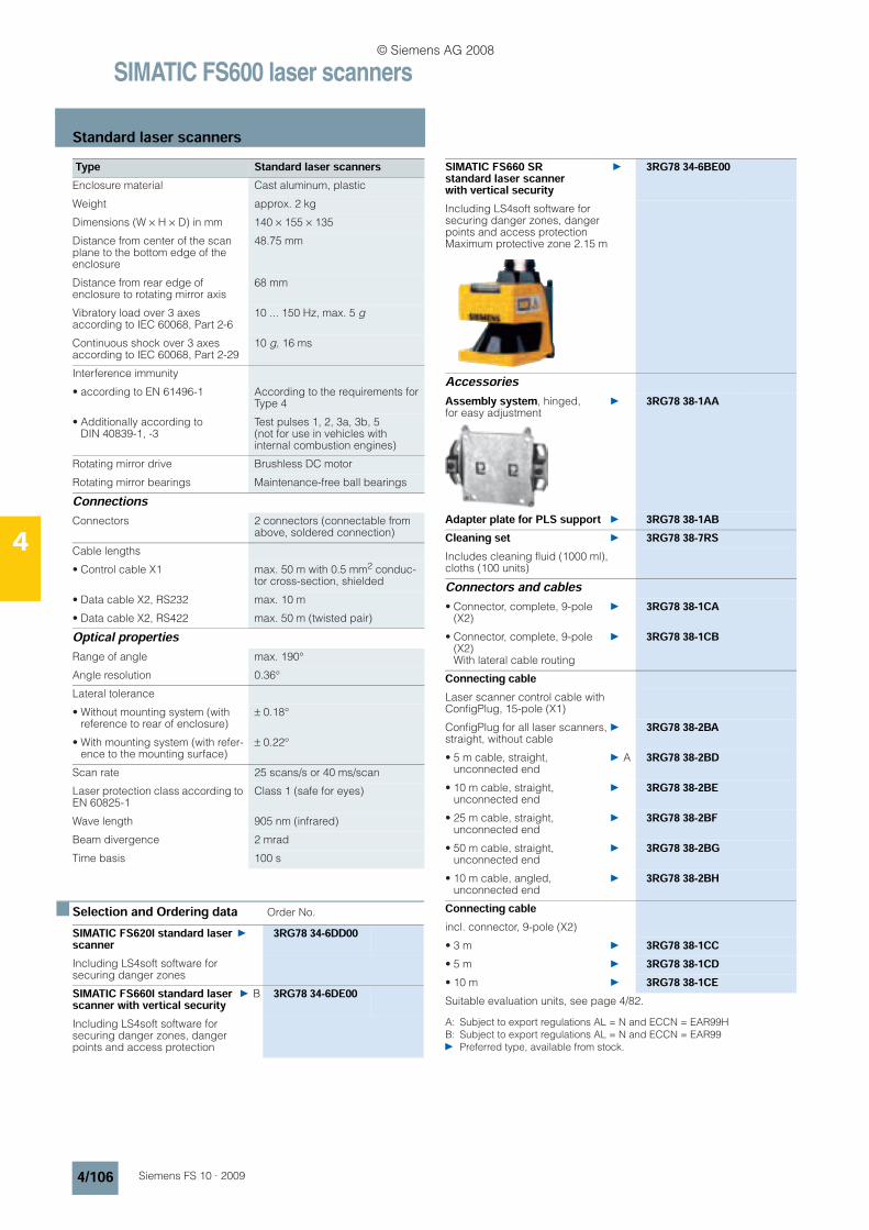
SIMATIC FS600 laser scanners
Standard laser scanners
4/106 Siemens FS 10 · 2009
4
n Selection and Ordering data Order No.
A: Subject to export regulations AL = N and ECCN = EAR99HB: Subject to export regulations AL = N and ECCN = EAR99 Preferred type, available from stock.
Enclosure material Cast aluminum, plastic
Weight approx. 2 kg
Dimensions (W × H × D) in mm 140 × 155 × 135
Distance from center of the scan plane to the bottom edge of the enclosure
48.75 mm
Distance from rear edge of enclosure to rotating mirror axis
68 mm
Vibratory load over 3 axes according to IEC 60068, Part 2-6
10 ... 150 Hz, max. 5 g
Continuous shock over 3 axes according to IEC 60068, Part 2-29
10 g, 16 ms
Interference immunity
• according to EN 61496-1 According to the requirements for Type 4
• Additionally according to DIN 40839-1, -3
Test pulses 1, 2, 3a, 3b, 5 (not for use in vehicles with internal combustion engines)
Rotating mirror drive Brushless DC motor
Rotating mirror bearings Maintenance-free ball bearings
ConnectionsConnectors 2 connectors (connectable from
above, soldered connection)
Cable lengths
• Control cable X1 max. 50 m with 0.5 mm2 conduc-tor cross-section, shielded
• Data cable X2, RS232 max. 10 m
• Data cable X2, RS422 max. 50 m (twisted pair)
Optical properties Range of angle max. 190°
Angle resolution 0.36°
Lateral tolerance
• Without mounting system (with reference to rear of enclosure)
± 0.18°
• With mounting system (with refer-ence to the mounting surface)
± 0.22°
Scan rate 25 scans/s or 40 ms/scan
Laser protection class according to EN 60825-1
Class 1 (safe for eyes)
Wave length 905 nm (infrared)
Beam divergence 2 mrad
Time basis 100 s
SIMATIC FS620I standard laser scanner
3RG78 34-6DD00
Including LS4soft software for securing danger zones
SIMATIC FS660I standard laser scanner with vertical security
B 3RG78 34-6DE00
Including LS4soft software for securing danger zones, danger points and access protection
Type Standard laser scanners SIMATIC FS660 SR standard laser scanner with vertical security
3RG78 34-6BE00
Including LS4soft software for securing danger zones, danger points and access protectionMaximum protective zone 2.15 m
AccessoriesAssembly system, hinged, for easy adjustment
3RG78 38-1AA
Adapter plate for PLS support 3RG78 38-1ABCleaning set 3RG78 38-7RSIncludes cleaning fluid (1000 ml), cloths (100 units)
Connectors and cables • Connector, complete, 9-pole
(X2) 3RG78 38-1CA
• Connector, complete, 9-pole (X2)With lateral cable routing
3RG78 38-1CB
Connecting cableLaser scanner control cable with ConfigPlug, 15-pole (X1)
ConfigPlug for all laser scanners, straight, without cable
3RG78 38-2BA
• 5 m cable, straight, unconnected end
A 3RG78 38-2BD
• 10 m cable, straight, unconnected end
3RG78 38-2BE
• 25 m cable, straight, unconnected end
3RG78 38-2BF
• 50 m cable, straight, unconnected end
3RG78 38-2BG
• 10 m cable, angled, unconnected end
3RG78 38-2BH
Connecting cableincl. connector, 9-pole (X2)
• 3 m 3RG78 38-1CC• 5 m 3RG78 38-1CD• 10 m 3RG78 38-1CESuitable evaluation units, see page 4/82.
© Siemens AG 2008
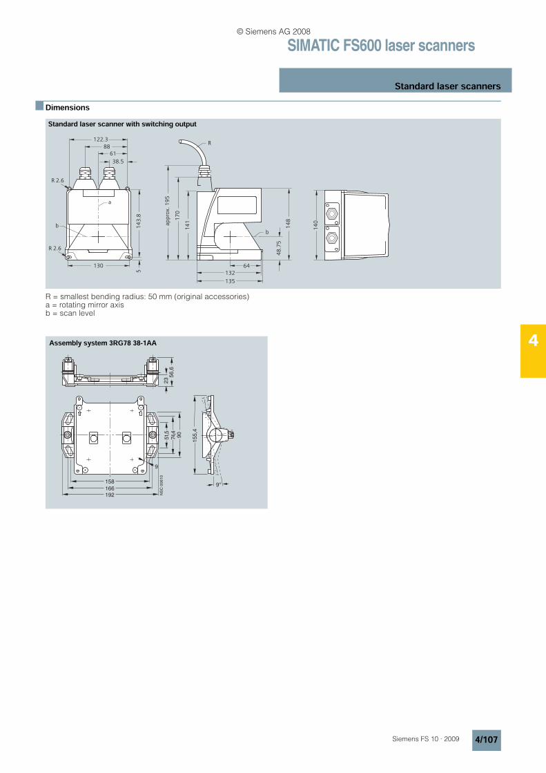
SIMATIC FS600 laser scanners
Standard laser scanners
4/107Siemens FS 10 · 2009
4
n Dimensions
R = smallest bending radius: 50 mm (original accessories)a = rotating mirror axisb = scan level
61
130
38.5
88
122.3
a
b
R 2.6
R 2.6
14
3.8
5
64
132
135
14
1
17
0
ap
pro
x. 1
95
R
b
48
.75
14
8
14
0
Standard laser scanner with switching output
2356,6
51,5
74,4
90
158
166
192
155,4
9°
NSC
00610
9
Assembly system 3RG78 38-1AA
© Siemens AG 2008
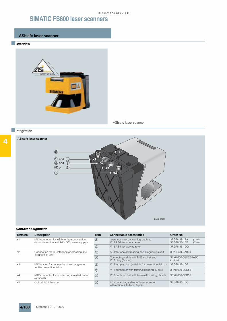
SIMATIC FS600 laser scanners
ASIsafe laser scanner
4/108 Siemens FS 10 · 2009
4
n Overview
ASIsafe laser scanner
n Integration
Contact assignment
X4
X3
X2
X1
X5
and
and
or
FS10_00136
ASIsafe laser scanner
Terminal Description Item Connectable accessories Order No.X1 M12 connector for AS-Interface connection
(bus connection and 24 V DC power supply)$ Laser scanner connecting cable to
M12 AS-Interface adapter3RG78 38-1EA (1 m)3RG78 38-1EB (2 m)
% M12 AS-Interface adapter 3RG78 38-1DG
X2 Connection for AS-Interface addressing and diagnostics unit
& AS-Interface addressing and diagnostics unit 3RK1 904-2AB01
( Connecting cable with M12 socket and M12 plug (3-core)
3RX8 000-0GF32-1AB5(1.5 m)
X3 M12 socket for connecting the changeover for the protection fields
) M12 jumper plug (suitable for protection field 1) 3RG78 38-1DF
* M12 connector with terminal housing, 5-pole 3RX8 000-0CD55
X4 M12 connector for connecting a restart button (optional)
+ M12 cable socket with terminal housing, 5-pole 3RX8 000-0CB55
X5 Optical PC interface , PC connecting cable for laser scanner with optical interface, 9-pole
3RG78 38-1DC
© Siemens AG 2008
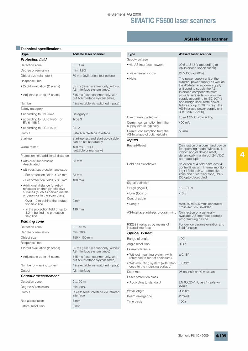
SIMATIC FS600 laser scanners
ASIsafe laser scanner
4/109Siemens FS 10 · 2009
4
n Technical specificationsType ASIsafe laser scannerProtection fieldDetection zone 0 ... 4 m
Degree of remission min. 1.8%
Object size (diameter) 70 mm (cylindrical test object)
Response time
• 2-fold evaluation (2 scans) 85 ms (laser scanner only, without AS-Interface system times)
• Adjustable up to 16 scans 645 ms (laser scanner only, with-out AS-Interface system times)
Number 4 (selectable via switched inputs)
Safety category
• according to EN 954-1 Category 3
• according to IEC 61496-1 or EN 61496-3
Type 3
• according to IEC 61506 SIL 2
Output Safe AS-Interface interface
Start-up Start-up test and start-up disable can be set separately
Warm restart 160 ms ... 10 s (settable or manually)
Protection field additional distance
• with dust suppression deactivated
83 mm
• with dust suppression activated
- For protection fields < 3.5 mm 83 mm
- For protection fields > 3.5 mm 100 mm
• Additional distance for retro-reflectors or strongly reflective surfaces (such as certain metals or ceramics in the scan plane)
- Over 1.2 m behind the protec-tion field line
0 mm
- In the protection field or up to 1.2 m behind the protection field line
110 mm
Warning zoneDetection zone 0 ... 15 m
Degree of remission min. 20%
Object size 150 × 150 mm
Response time
• 2-fold evaluation (2 scans) 85 ms (laser scanner only, without AS-Interface system times)
• Adjustable up to 16 scans 645 ms (laser scanner only, with-out AS-Interface system times)
Number of warning zones 4 (selectable via switched inputs)
Output AS-Interface
Contour measurementDetection zone 0 ... 50 m
Degree of remission min. 20%
Output RS232 serial interface via infrared interface
Radial resolution 5 mm
Lateral resolution 0.36°
Supply voltage
• via AS-Interface network 29.5 ... 31.6 V (according to AS-Interface specification)
• via external supply 24 V DC (+/-20%)
• Note The power supply unit of the external power supply as well as the AS-Interface power supply unit used to supply the AS-Interface components must provide safe isolation from the supply according to IEC 60742 and bridge short-term power failures of up to 20 ms (e.g. the AS-Interface power supply unit 3RX9 307-0AA00)
Overcurrent protection Fuse 1.25 A, slow acting
Current consumption from the supply circuit, typically
400 mA
Current consumption from the AS-Interface circuit, typically
50 mA
InputsRestart/Reset Connection of a command device
for operating mode "With restart inhibit" and/or device reset, dynamically monitored, 24 V DC opto-decoupled
Field pair switchover Selection of 4 field pairs over 4 control lines with internal monitor-ing (1 field pair = 1 protective zone and 1 warning zone), 24 V DC opto-decoupled
Signal definition
• High (logic 1) 16 ... 30 V
• Low (logic 0) < 3 V
Control cable
• Length max. 50 m (0.5 mm2 conductor cross-section, shielded)
AS-Interface address programming Connection of a generally available AS-Interface address programming device
RS232 interfaces by means of infrared interface
For device parameterization and field function
Optical systemRange of angle 190°
Angle resolution 0.36°
Lateral tolerance
• Without mounting system (with reference to rear of enclosure)
± 0.18°
• With mounting system (with refer-ence to the mounting surface)
± 0.22°
Scan rate 25 scans/s or 40 ms/scan
Laser protection class
• According to standard EN 60825-1, Class 1 (safe for eyes)
Wave length 905 nm
Beam divergence 2 mrad
Time basis 100 s
Type ASIsafe laser scanner
© Siemens AG 2008
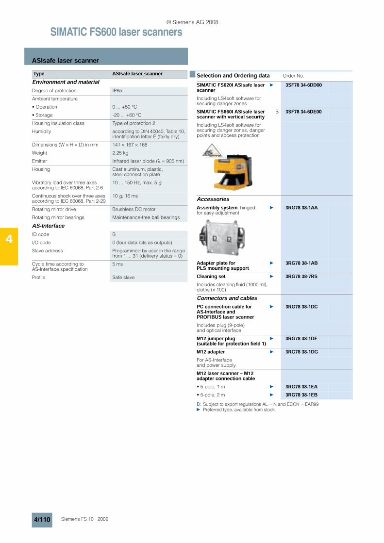
SIMATIC FS600 laser scanners
ASIsafe laser scanner
4/110 Siemens FS 10 · 2009
4
n Selection and Ordering data Order No.
B: Subject to export regulations AL = N and ECCN = EAR99 Preferred type, available from stock.
Environment and materialDegree of protection IP65
Ambient temperature
• Operation 0 ... +50 °C
• Storage -20 ... +60 °C
Housing insulation class Type of protection 2
Humidity according to DIN 40040, Table 10, identification letter E (fairly dry)
Dimensions (W × H × D) in mm 141 × 167 × 168
Weight 2.25 kg
Emitter Infrared laser diode (λ = 905 nm)
Housing Cast aluminum, plastic, steel connection plate
Vibratory load over three axes according to IEC 60068, Part 2-6
10 ... 150 Hz, max. 5 g
Continuous shock over three axes according to IEC 60068, Part 2-29
10 g, 16 ms
Rotating mirror drive Brushless DC motor
Rotating mirror bearings Maintenance-free ball bearings
AS-InterfaceID code B
I/O code 0 (four data bits as outputs)
Slave address Programmed by user in the range from 1 ... 31 (delivery status = 0)
Cycle time according to AS-Interface specification
5 ms
Profile Safe slave
Type ASIsafe laser scannerSIMATIC FS620I ASIsafe laser scanner
3SF78 34-6DD00
Including LS4soft software for securing danger zones
SIMATIC FS660I ASIsafe laser scanner with vertical security
B 3SF78 34-6DE00
Including LS4soft software for securing danger zones, danger points and access protection
AccessoriesAssembly system, hinged, for easy adjustment
3RG78 38-1AA
Adapter plate for PLS mounting support
3RG78 38-1AB
Cleaning set 3RG78 38-7RSIncludes cleaning fluid (1000 ml), cloths (x 100)
Connectors and cables PC connection cable for AS-Interface and PROFIBUS laser scanner
3RG78 38-1DC
Includes plug (9-pole) and optical interface
M12 jumper plug(suitable for protection field 1)
3RG78 38-1DF
M12 adapter 3RG78 38-1DGFor AS-Interface and power supply
M12 laser scanner – M12 adapter connection cable• 5-pole, 1 m 3RG78 38-1EA• 5-pole, 2 m 3RG78 38-1EB
© Siemens AG 2008

SIMATIC FS600 laser scanners
ASIsafe laser scanner
4/111Siemens FS 10 · 2009
4
n Dimensions
a = rotating mirror axisb = scan level
n Schematics
ap
pro
x. 2
20
approx. 168
48
.75
61
approx. 140
130
R 2.6
5
s
R 2.6
122.31
43
.8
64
132
14
8 16
7
a bb
a
ASIsafe laser scanner
2356,6
51,5
74,4
90
158
166
192
155,4
9°
NSC
00610
9
Assembly system 3RG7 838-1AA
X5
X1 X2 X3 X4
X1 AS-Interface connection (Bus connction and 24 Volt power supply)X2 AS-Interface connection for address programming deviceX3 Connection protective fields switchoverX4 Connection restart buttonX5 Optical PC Interface
© Siemens AG 2008
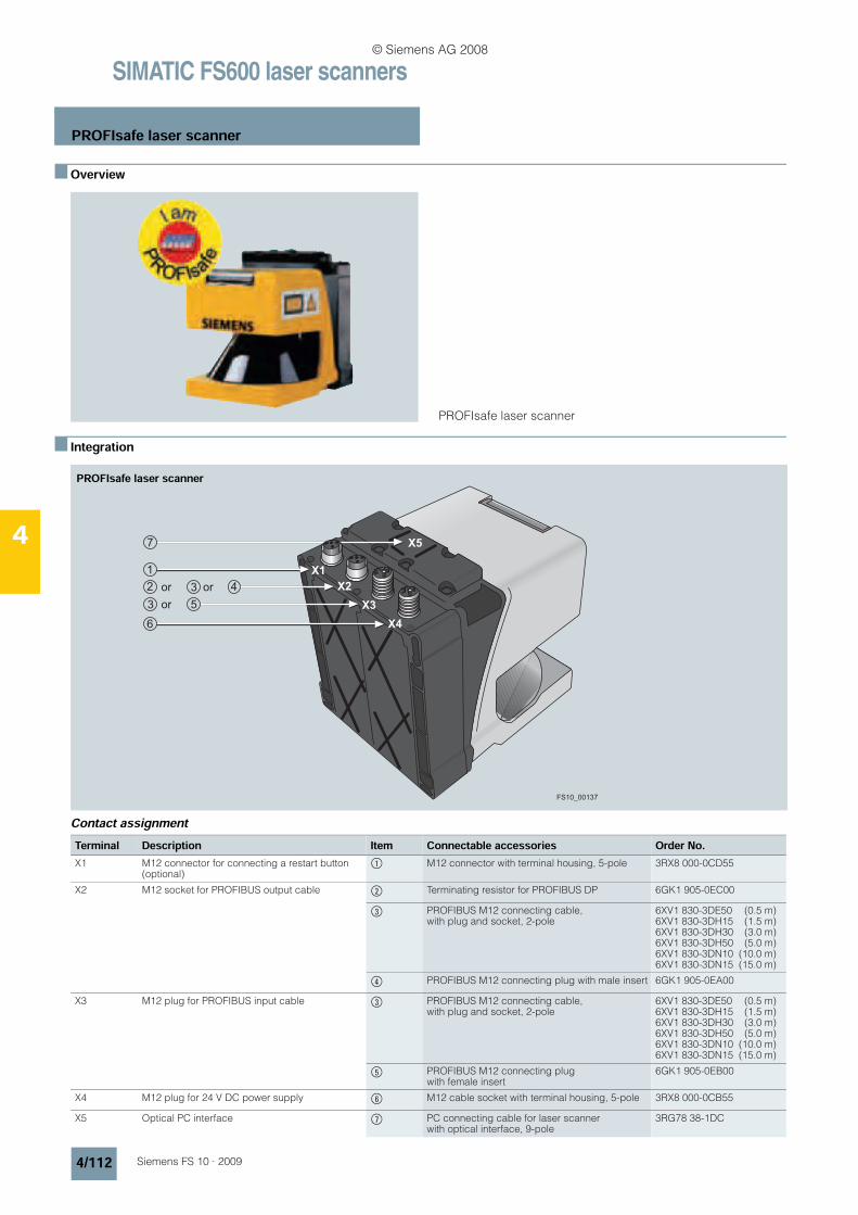
SIMATIC FS600 laser scanners
PROFIsafe laser scanner
4/112 Siemens FS 10 · 2009
4
n Overview
PROFIsafe laser scanner
n Integration
Contact assignment
X4
X3
X2
X1
X5
or
or or
FS10_00137
PROFIsafe laser scanner
Terminal Description Item Connectable accessories Order No.X1 M12 connector for connecting a restart button
(optional)$ M12 connector with terminal housing, 5-pole 3RX8 000-0CD55
X2 M12 socket for PROFIBUS output cable % Terminating resistor for PROFIBUS DP 6GK1 905-0EC00
& PROFIBUS M12 connecting cable, with plug and socket, 2-pole
6XV1 830-3DE50 (0.5 m)6XV1 830-3DH15 (1.5 m)6XV1 830-3DH30 (3.0 m)6XV1 830-3DH50 (5.0 m)6XV1 830-3DN10 (10.0 m)6XV1 830-3DN15 (15.0 m)
( PROFIBUS M12 connecting plug with male insert 6GK1 905-0EA00
X3 M12 plug for PROFIBUS input cable & PROFIBUS M12 connecting cable, with plug and socket, 2-pole
6XV1 830-3DE50 (0.5 m)6XV1 830-3DH15 (1.5 m)6XV1 830-3DH30 (3.0 m)6XV1 830-3DH50 (5.0 m)6XV1 830-3DN10 (10.0 m)6XV1 830-3DN15 (15.0 m)
) PROFIBUS M12 connecting plug with female insert
6GK1 905-0EB00
X4 M12 plug for 24 V DC power supply * M12 cable socket with terminal housing, 5-pole 3RX8 000-0CB55
X5 Optical PC interface + PC connecting cable for laser scanner with optical interface, 9-pole
3RG78 38-1DC
© Siemens AG 2008
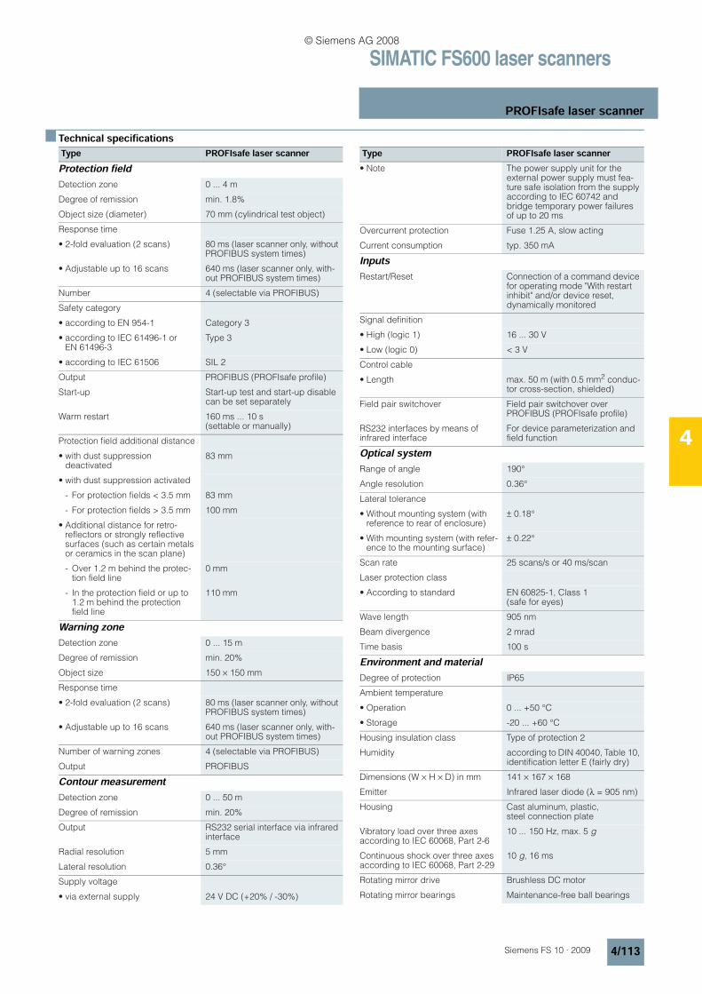
SIMATIC FS600 laser scanners
PROFIsafe laser scanner
4/113Siemens FS 10 · 2009
4
n Technical specifications Type PROFIsafe laser scannerProtection fieldDetection zone 0 ... 4 m
Degree of remission min. 1.8%
Object size (diameter) 70 mm (cylindrical test object)
Response time
• 2-fold evaluation (2 scans) 80 ms (laser scanner only, without PROFIBUS system times)
• Adjustable up to 16 scans 640 ms (laser scanner only, with-out PROFIBUS system times)
Number 4 (selectable via PROFIBUS)
Safety category
• according to EN 954-1 Category 3
• according to IEC 61496-1 or EN 61496-3
Type 3
• according to IEC 61506 SIL 2
Output PROFIBUS (PROFIsafe profile)
Start-up Start-up test and start-up disable can be set separately
Warm restart 160 ms ... 10 s (settable or manually)
Protection field additional distance
• with dust suppression deactivated
83 mm
• with dust suppression activated
- For protection fields < 3.5 mm 83 mm
- For protection fields > 3.5 mm 100 mm
• Additional distance for retro-reflectors or strongly reflective surfaces (such as certain metals or ceramics in the scan plane)
- Over 1.2 m behind the protec-tion field line
0 mm
- In the protection field or up to 1.2 m behind the protection field line
110 mm
Warning zoneDetection zone 0 ... 15 m
Degree of remission min. 20%
Object size 150 × 150 mm
Response time
• 2-fold evaluation (2 scans) 80 ms (laser scanner only, without PROFIBUS system times)
• Adjustable up to 16 scans 640 ms (laser scanner only, with-out PROFIBUS system times)
Number of warning zones 4 (selectable via PROFIBUS)
Output PROFIBUS
Contour measurementDetection zone 0 ... 50 m
Degree of remission min. 20%
Output RS232 serial interface via infrared interface
Radial resolution 5 mm
Lateral resolution 0.36°
Supply voltage
• via external supply 24 V DC (+20% / -30%)
• Note The power supply unit for the external power supply must fea-ture safe isolation from the supply according to IEC 60742 and bridge temporary power failures of up to 20 ms.
Overcurrent protection Fuse 1.25 A, slow acting
Current consumption typ. 350 mA
InputsRestart/Reset Connection of a command device
for operating mode "With restart inhibit" and/or device reset, dynamically monitored
Signal definition
• High (logic 1) 16 ... 30 V
• Low (logic 0) < 3 V
Control cable
• Length max. 50 m (with 0.5 mm2 conduc-tor cross-section, shielded)
Field pair switchover Field pair switchover over PROFIBUS (PROFIsafe profile)
RS232 interfaces by means of infrared interface
For device parameterization and field function
Optical systemRange of angle 190°
Angle resolution 0.36°
Lateral tolerance
• Without mounting system (with reference to rear of enclosure)
± 0.18°
• With mounting system (with refer-ence to the mounting surface)
± 0.22°
Scan rate 25 scans/s or 40 ms/scan
Laser protection class
• According to standard EN 60825-1, Class 1 (safe for eyes)
Wave length 905 nm
Beam divergence 2 mrad
Time basis 100 s
Environment and materialDegree of protection IP65
Ambient temperature
• Operation 0 ... +50 °C
• Storage -20 ... +60 °C
Housing insulation class Type of protection 2
Humidity according to DIN 40040, Table 10, identification letter E (fairly dry)
Dimensions (W × H × D) in mm 141 × 167 × 168
Emitter Infrared laser diode (λ = 905 nm)
Housing Cast aluminum, plastic, steel connection plate
Vibratory load over three axes according to IEC 60068, Part 2-6
10 ... 150 Hz, max. 5 g
Continuous shock over three axes according to IEC 60068, Part 2-29
10 g, 16 ms
Rotating mirror drive Brushless DC motor
Rotating mirror bearings Maintenance-free ball bearings
Type PROFIsafe laser scanner
© Siemens AG 2008

SIMATIC FS600 laser scanners
PROFIsafe laser scanner
4/114 Siemens FS 10 · 2009
4
n Selection and Ordering data Order No.
B: Subject to export regulations AL = N and ECCN = EAR99 Preferred type, available from stock.
SIMATIC FS620I PROFIsafe laser scanner
3SF78 34-6PB00
Including LS4soft software for securing danger zones
SIMATIC FS660I PROFIsafe laser scanner with vertical security
B 3SF78 34-6PE00
Including LS4soft software for securing danger zones, danger points and access protection
AccessoriesAssembly system, hinged, for easy adjustment
3RG78 38-1AA
Adapter plate for PLS mounting support
3RG78 38-1AB
Cleaning set 3RG78 38-7RSIncludes cleaning fluid (1000 ml), cloths (x 100)
Connectors and cables PC connection cable for AS-Interface and PROFIBUS laser scanners
3RG78 38-1DC
including plug (9-pole), and optical interface
PROFIBUS M12 terminating connector
6GK1 905-0EC00
For PROFIBUS DP 1 packet = 5 items
PROFIBUS M12 connectors1 packet = 5 items
• Male insert 6GK1 905-0EA00• Socket insert 6GK1 905-0EB00PROFIBUS M12 plug-in cables2-core (inverted coding) preassembled, with M12 connectors, in different lengths:
• 0.5 m 6XV1 830-3DE50• 1.5 m 6XV1 830-3DH15• 3.0 m 6XV1 830-3DH30• 5.0 m 6XV1 830-3DH50• 10.0 m 6XV1 830-3DN10• 15.0 m 6XV1 830-3DN15
© Siemens AG 2008
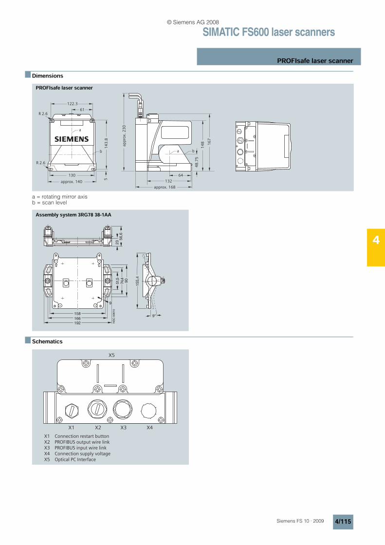
SIMATIC FS600 laser scanners
PROFIsafe laser scanner
4/115Siemens FS 10 · 2009
4
n Dimensions
a = rotating mirror axisb = scan level
n Schematics
61
approx. 140
130
R 2.6
5
s
R 2.6
122.31
43
.8
b
a
ap
pro
x. 2
30
approx. 168
48
.75
64
132
14
8 16
7
a b
PROFIsafe laser scanner
2356,6
51,5
74,4
90
158
166
192
155,4
9°
NSC
00610
9
Assembly system 3RG78 38-1AA
X5
X1 X2 X3 X4
X1 Connection restart buttonX2 PROFIBUS output wire linkX3 PROFIBUS input wire linkX4 Connection supply voltageX5 Optical PC Interface
© Siemens AG 2008

SIMATIC FS600 laser scanners
Notes
4/116 Siemens FS 10 · 2009
4
n
© Siemens AG 2008
Related Documents