SIMATIC Field Engineering Package SIEMENS Foreword, Contents Part 1: Field Engineering Package Introduction 1 Components of the field engineering package 2 SIMATIC Description of the optional components 3 FIELD ENGINEERING Catalog data 4 PACKAGE System Overview Part 2: Configuring and startup Installation guidelines 5 Hardware configuring (example) 6 Software configuring (example) 7 Appendices References A Index B Glossary C

Welcome message from author
This document is posted to help you gain knowledge. Please leave a comment to let me know what you think about it! Share it to your friends and learn new things together.
Transcript

SIMATIC Field Engineering Package
SIEMENS
Foreword, Contents
Part 1: Field Engineering Package
Introduction 1
Components of the field engineering
package 2
SIMATIC Description of the optional components 3
FIELD ENGINEERING Catalog data 4
PACKAGE
System OverviewPart 2: Configuring andstartup
Installation guidelines 5
Hardware configuring (example) 6
Software configuring (example) 7
Appendices
References A
Index B
Glossary C
SIMATIC Field Engineering Package
20.07.98 20Handbuch_pa.doc
Safety This manual contains instructions to be observed for your personalinstructions safety and to avoid damage. The instructions are emphasized with a warning
triangle and take the following form, according to the degree of danger:
Danger
This means that failure to observe the appropriate precautions will result in death,serious injury or considerable damage.
Warning
This means that failure to observe the appropriate precautions can result in death,serious injury or considerable damage.
Caution
This means that failure to observe the appropriate precautions can result in slight injuryor damage.
Note
This is important information relating to the product, handling of the product or the partof the documentation to which particular attention must be paid.
Qualified Startup and operation of equipment may only be carried out by qualifiedpersonnel personnel. In the context of the safety instructions of the manual, qualified
personnel are persons authorized to place the equipment, systems and circuits inoperation according to the safety standards, to ground them and mark them.
Normal use Observe the following:
Warning
These products may only be used for the applications intended in the catalog and in thetechnical description, and only in association with non-Siemens devices andcomponents recommended or approved by Siemens.Perfect and reliable operation of the product requires proper transportation and storage,setting up and installation as well as careful operation and maintenance.
Trademarks SIMATIC ,SITRANS, PDM and SINEC are registered trademarks ofSIEMENS AG.
Other designations in this publication may be trademarks whose utilization by thirdparties for their own purposes may infringe the holders’ rights.

01.98 0 Introduction
SIMATIC Field Engineering Package

Introduction 01.98
SIMATIC Field Engineering Package1–2
ContentsPart 1 The field engineering package
1 INTRODUCTION 1—1
1.1 Positioning of the field engineering package in the SIMATIC systems 1—2
1.2 PROFIBUS as the universal field bus 1—7
1.2.1 PROFIBUS-DP 1—7
1.2.2 PROFIBUS-PA 1—8
1.3 PROFIBUS components 1—9
1.3.1 Transition from PROFIBUS-DP to PROFIBUS-PA 1—9
1.3.2 PROFIBUS-PA configuration with SIMATIC S5 1—11
1.3.3 PROFIBUS-PA configuration with SIMATIC S7 1—11
1.4 HART functions 1—12
2 OVERVIEW OF THE COMPONENTS OF THE FIELD ENGINEERING PACKAGE 2–1
2.1 Introduction 2–2
2.2 Hardware components 2–2
2.2.1 PROFIBUS-PA 2–2
2.2.2 HART 2–3
2.3 Configuring the field engineering 2–5
3 COMPONENTS OF THE FIELD ENGINEERING PACKAGE IN DETAIL 3–1
3.1 Hardware 3–2
3.1.1 DP/PA coupler 3–2
3.1.2 DP/PA link 3–3
3.1.3 HART modules 3–4
3.1.3.1Two-channel analog input module 3–4
3.2 Software/configuration 3–6
3.2.1 Configuration/project scope 3–6
3.2.2 Addressing of PROFIBUS-PA field devices 3–7
3.2.3 Parameter assignment / device profiles 3–9
3.2.4 Device database (GSD) and device descriptions (DD) 3–12
3.2.5 Driver function blocks for the field engineering package 3–13
4 CATALOG DATA 4–2
4.1 Ordering data for the field engineering package 4–3
4.2 Cross-references to detailed catalogs 4–3
4.3 Positioning in the information environment 4–4
01.98 0 Introduction
SIMATIC Field Engineering Package i
Part 2 Configuring and startup
5 INSTALLATION GUIDELINES 5–1
5.1 Introduction 5–2
5.2 Mechanical and electrical installation 5–6
5.2.1 Installing the cables 5–6
5.2.2 Cable routes within and outside buildings 5–6
5.2.3 Cable specifications and cable recommendation for PROFIBUS-DP 5–8
5.2.4 Cable specifications and cable recommendation for PROFIBUS-PA 5–9
5.2.5 Shielding concept 5–11
5.2.6 Grounding and equipotential bonding 5–13
5.2.7 Lightning protection 5–13
5.2.8 Connectors 5–14
5.2.9 Installation materials and tools 5–15
5.3 Guidelines of the PNO (PROFIBUS Users' Organization) 5–16
6 HARDWARE CONFIGURING (PROJECT EXAMPLE) 6–1
6.1 Configuring a station 6–3
6.1.1 Creating a station and starting the hardware configuration 6–4
6.1.2 Configuring the station 6–5
6.1.3 Loading the hardware configuration into a CPU 6–7
6.2 PROFIBUS-DP distributed I/O 6–8
6.2.1 Inserting a DP slave in a station 6–8
6.2.1.1 Device database (GSD files) 6–8
6.2.1.2 Using a SITRANS P via a DP/PA coupler 6–9
6.2.1.3 Using an ET 200M with a HART module 6–10
6.3 Station diagnostics 6–11
6.4 SITRANS P parameter assignment with SIMATIC PDM 6–12
7 SOFTWARE CONFIGURING (PROJECT EXAMPLE) 7–2
7.1 Project example: Control loop (CFC) 7–3
7.2 Project example: Sequential control system with two-step control (SFC) 7–6

01.98 1 Introduction
SIMATIC Field Engineering Package 1—1
Introduction
This chapter contains:
1.1 Positioning of the field engineering package in the SIMATIC systems 1-2
1.2 PROFIBUS as the universal field bus 1-7
1.2.1 PROFIBUS-DP 1-7
1.2.2 PROFIBUS-PA 1-8
1.3 PROFIBUS components 1-9
1.3.1 Transition from PROFIBUS-DP to PROFIBUS-PA 1-9
1.3.2 PROFIBUS-PA configuration with SIMATIC S5 1-11
1.3.3 PROFIBUS-PA configuration with SIMATIC S7 1-11
1.4 HART functions 1-12
1
1 Introduction 01.98
SIMATIC Field Engineering Package1—2
1.1 Positioning of the field engineering package in theSIMATIC systems
General The new field engineering is designed for use in the SIMATIC S5,SIMATIC S7 and SIMATIC PCS 7 systems. The PCS 7 system is givenpriority in this overview because the entire performance range of the field buscomponents can be used conveniently in PCS 7.SIMATIC PCS 7 is the new Siemens process control system for the automationof industrial and production processes.Shown in Table 1-2 are the possible applications of the individual components.
Components The SIMATIC family comprises the following SIMATIC main components:
• SIMATIC S5, S7 and PCS 7 automation systems
• SIMATIC HMI - the human-machine interface systems: (such as operatorstations and operator terminals based on WinCC)
• SIMATIC NET - the communications basis consisting of PROFIBUS andIndustrial Ethernet
• SIMATIC NET DP - the PROFIBUS-DP field bus system for distributedI/O and PROFIBUS-DP compatible field devices
• SIMATIC PA - the PROFIBUS-PA field bus system as an extension of thePROFIBUS-DP field bus system to include the optimized transmissionsystem for applications in the intrinsically safe and non-intrinsically safeareas
• SIMATIC Industrial Software (e.g. engineering system with STEP 7 andSIMATIC Manager for SIMATIC S7 and PCS 7)
Hardware and At least the following releases must be available in order to use thesoftware field engineering package:requirements
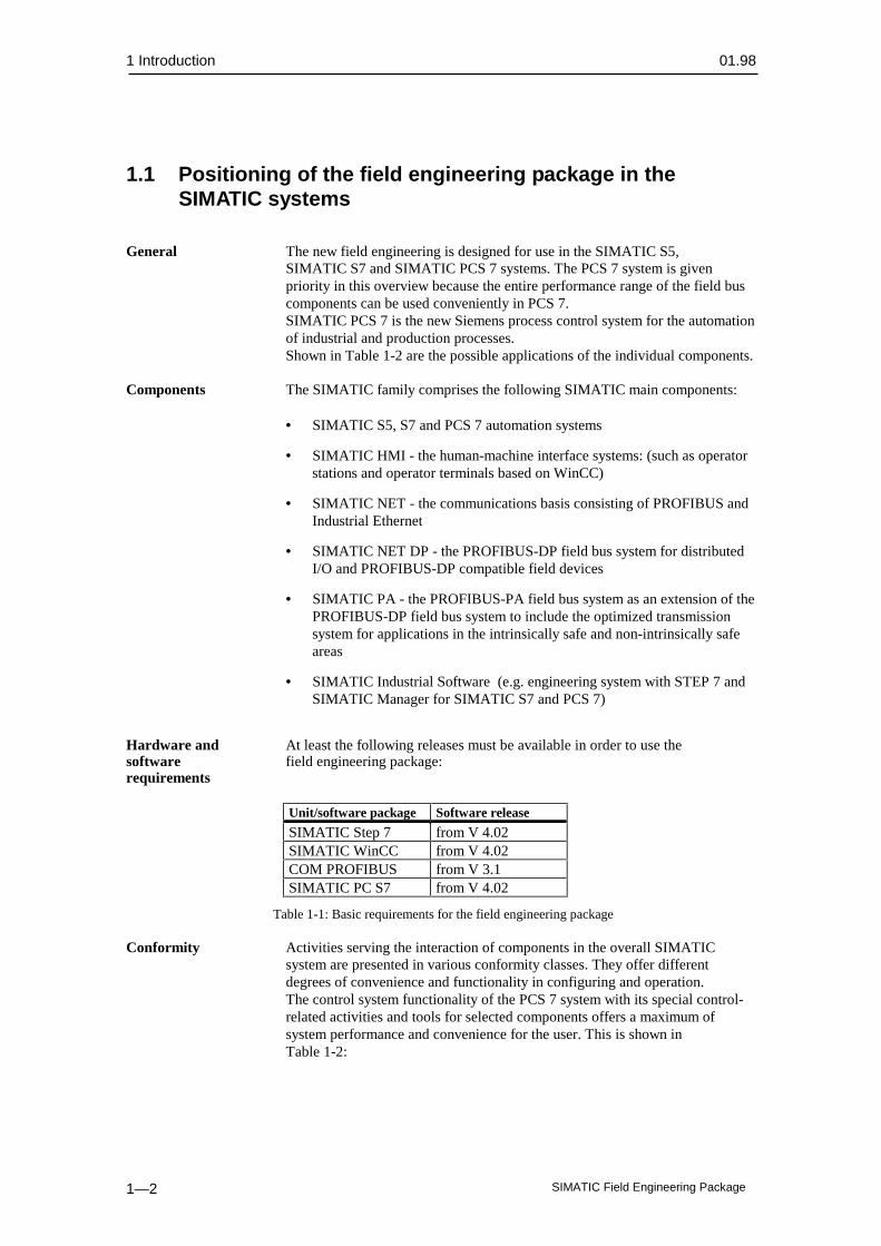
Unit/software package Software release
SIMATIC Step 7 from V 4.02SIMATIC WinCC from V 4.02COM PROFIBUS from V 3.1SIMATIC PC S7 from V 4.02
Table 1-1: Basic requirements for the field engineering package
Conformity Activities serving the interaction of components in the overall SIMATICsystem are presented in various conformity classes. They offer differentdegrees of convenience and functionality in configuring and operation.The control system functionality of the PCS 7 system with its special control-related activities and tools for selected components offers a maximum ofsystem performance and convenience for the user. This is shown inTable 1-2:

01.98 1 Introduction
SIMATIC Field Engineering Package 1—3
SIMATICBase
SIMATICS 5
SIMATICS 7
SIMATICPCS 7
Components ofoption package
COM PROFIBUS X - -Drivers - (X) X
HW-Config - X XSIMATIC PDM - X X
HART - (X) XDP/PA LINK - X X
DP/PA COUPLER X X XContinuousprocesses
- X X
Discontinuousprocesses
- X X
(X) Restricted performance level (no standard software components)
Table 1-2: Possible applications of the individual field bus components
Positioning in The field engineering package is positioned at the lowest level of thethe system automation systems.
• PROFIBUS-PA forms the communications channel between control level,automation system and field device over great distances with minimumoverhead.
• HART modules provide the information channel for the HART protocolbetween control level and field devices with HART protocol.
• SIMATIC PDM is a convenient configuring and parameter assignmentsystem for field devices with PROFIBUS-PA connection or the HARTprotocol.
Shown in Figs 1-1 to 1-4 is the positioning in an automation system as anexample.
I/O area
Part 1Manual
Part 2Manual

1 Introduction 01.98
SIMATIC Field Engineering Package1—4
PROFIBUS-DP, up to 12 Mbit/s
DP/PA coupler,DP/PA link
PROFIBUS-PA
4-20 mA+ HART
4-20 mA
SIMATIC S7-400CPU 414-2, 416-2
ET 200 M ET 200 M
DP/AS-ilink
Actuator/sensor interface
24 V
Fig. 1-1 Positioning of the new field device systems in the I/Os of theSIMATIC automation system
PROFIBUS-DPup to 12 MBit/s
ESOS
System Bus
SIMATIC S7-400
ET 200 M
0/4 ... 20 mA+ HART
SIPROM
DP/PA LINK
PROFIBUS-PA31.25 kbit/s
Fig. 1-2 Positioning of the PROFIBUS-PA field bus system and HART I/Omodules in the SIMATIC S7/PCS 7 automation system

01.98 1 Introduction
SIMATIC Field Engineering Package 1—5
COROS
System Bus
SIMATIC S5 - 155U
Programmer withCOM Profibus
PROFIBUS-PA
DP/PA COUPLER
PROFIBUS-DP45,45 kbit/s
SIPROMPC/PG
SIPROM
ET 200 M
Fig. 1-3 Positioning of the PROFIBUS-PA field bus system in theSIMATIC S5 system
PROFIBUS PROFIBUS is a multi-master bus system. PROFIBUS is the system busintended for SIMATIC PCS 7 in medium-sized to large installations with highperformance requirements.Up to 126 stations can be connected to a PROFIBUS. It can operate attransmission rates of 9.6 kbit/s to 12 Mbit/s and can have a network size of upto 21,730 m at 1.5 Mbit/s.
PROFIBUS-DP The exchange of data between automation system and distributed I/O aswell as intelligent field devices is nowadays carried out via field bus systemswith low installation overhead. The standardized PROFIBUS-DP is used forSIMATIC S5, S7, PCS 7. PROFIBUS-DP is a MASTER/SLAVE bus system.The master function is performed by an automation system (master class 1) orby one or more personal computers (master class 2). The automation system(master class 1) has full access via cyclic messages to all stations assigned to it.By means of the personal computer (master class 2), data can be exchanged asrequired with all connected stations via acyclic messages. For example theET 200 M distributed I/O and individual field devices are connected viaPROFIBUS-DP. Depending on the standard, up to 126 stations can also beconnected to a PROFIBUS-DP. PROFIBUS can operate at transmission ratesof 9.6 kbit/s to 12 Mbit/s and can have a network size of up to 21,730 m (at1.5 Mbit/s).
PROFIBUS-PA PROFIBUS-PA is the extension of PROFIBUS-DP to include the optimizedtransmission system for field devices whilst retaining the communicationsfunction of PROFIBUS-DP. With the selected transmission system, fielddevices, even in hazardous areas, can be connected to the automation systemover great distances and powered via PROFIBUS-PA. PROFIBUS-PA is thecommunications-compatible extension of PROFIBUS-DP.

1 Introduction 01.98
SIMATIC Field Engineering Package1—6
PROFIBUS-PA
=
PROFIBUS-DP communications
+
optimized transmission system for field devices(IEC 1188-2)
The HART HART (highway addressable remote transducer) is a serial transmissioninput module method with which additional data such as measuring range, attenuation, etc.
can be transmitted to connected sensors or actuators via a 4 to 20 mA currentloop. In the course of time, HART has developed into a vendor-independent(quasi-) standard.Utilization of the HART protocol becomes possible with the two HART analogmodules available from SIEMENS. This extends considerably beyond thefacility for incorporating a handheld terminal in the current loop.
01.98 1 Introduction
SIMATIC Field Engineering Package 1—7
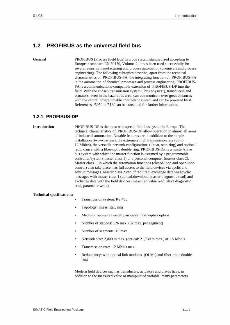
1.2 PROFIBUS as the universal field bus
General PROFIBUS (Process Field Bus) is a bus system standardized according to
European standard EN 50170, Volume 2; it has been used successfully forseveral years in manufacturing and process automation (chemicals and processengineering). The following subtopics describe, apart from the technicalcharacteristics of PROFIBUS-PA, the integrating function of PROFIBUS-PAin the automation of chemical processes and process engineering. PROFIBUS-PA is a communications-compatible extension of PROFIBUS-DP into thefield. With the chosen transmission system ("bus physics"), transducers andactuators, even in the hazardous area, can communicate over great distanceswith the central programmable controller / system and can be powered by it.References /505/ to /518/ can be consulted for further information.
1.2.1 PROFIBUS-DP
Introduction PROFIBUS-DP is the most widespread field bus system in Europe. Thetechnical characteristics of PROFIBUS-DP allow operation in almost all areasof industrial automation. Notable features are, in addition to the simpleinstallation (two-wire line), the extremely high transmission rate (up to12 Mbit/s), the versatile network configurations (linear, star, ring) and optionalredundancy with a fiber-optic double ring. PROFIBUS-DP is a master/slavebus system with which the master function is assumed by a programmablecontroller/system (master class 1) or a personal computer (master class 2).Master class 1, in which the automation functions (closed-loop and open-loopcontrol) also take place, has full access to the field devices via cyclic andacyclic messages. Master class 2 can, if required, exchange data via acyclicmessages with master class 1 (upload/download, master diagnostic read) andexchange data with the field devices (measured value read, slave diagnosticread, parameter write).
Technical specifications:• Transmission system: RS 485
• Topology: linear, star, ring
• Medium: two-wire twisted pair cable, fiber-optics option
• Number of stations: 126 max. (32 max. per segment)
• Number of segments: 10 max.
• Network size: 2,000 m max. (optical: 21,730 m max.) at 1.5 Mbit/s
• Transmission rate: 12 Mbit/s max.
• Redundancy: with optical link modules (OLMs) and fiber-optic doublering
Modern field devices such as transducers, actuators and drives have, inaddition to the measured value or manipulated variable, many parameters

1 Introduction 01.98
SIMATIC Field Engineering Package1—8
which must be changed during startup and, to some extent also duringoperation in order to utilize the "intelligence" of these field devices such aspreventive maintenance or optimization of the interface to the sensor. Onaccount of the different time-related demands for data access of the master,PROFIBUS-DP offers cyclic and acyclic services.All output values (control commands) are written to the field devices and allinput values (measured values) are read out of the field devices in one cycle.Subsequently, an acyclic data interchange can take place with a particular fielddevice. Settings of the field devices can be read or parameters can be modified.With the facility for supplementing each transmission cycle with precisely onesingle acyclic message, short, deterministic cycle times are ensured as the basisfor software control in the programmable controller/system.
1.2.2 PROFIBUS-PA
Introduction PROFIBUS-PA is the extension of PROFIBUS-DP to include the optimizedtransmission system for field devices (for example, for powering the fielddevices via the data cable and utilization in a hazardous environment) whilstretaining the communications functions of PROFIBUS-DP. This means thatwith PROFIBUS-PA a variant of PROFIBUS-DP has been defined whichallows the operation of PROFIBUS in the intrinsically safe area also, whilstsystem integration with PROFIBUS-DP is ensured. This has been achieved byadopting the PROFIBUS-DP protocol for PROFIBUS-PA.The choice of the internationally standardized transmission system to IEC1158-2 (International Electrotechnical Commission) ensures the future-orientedfield installation with PROFIBUS-PA.The advantages of the field bus system can now also be used in processengineering with the PROFIBUS-PA bus system. PROFIBUS-PA is more thana two-wire line connecting the field devices (transducers and actuators).Highlighted in the following subtopics, apart from the technical characteristicsof PROFIBUS-PA, is the integrating function of PROFIBUS–PA in theautomation of chemical processes and process engineering.PROFIBUS-PA meets the requirements of the process-engineering industry:
• Networking of transducers, valves, actuators via a serial bus system (two-wire line),
• for use in process engineering,
• with field device powering via the data cable, as well as
• for applications in the hazardous area ("intrinsically safe" type ofprotection EEx[i] )
Signal conversion Conversion of the PROFIBUS-DP transmission system from RS 485 (bitcoding with asynchronous NRZ code) to IEC 1158-2 (bit coding withsynchronous Manchester code) for PROFIBUS-PA takes place via the "DP/PAcoupler" or "DP/PA link" described in Chapter 3 ff..
Area of application PROFIBUS-PA is designed for operation in the intrinsically safe and non-intrinsically safe areas.
01.98 1 Introduction
SIMATIC Field Engineering Package 1—9
1.3 PROFIBUS components
1.3.1 Transition from PROFIBUS-DP to PROFIBUS-PA
Two network components, DP/PA coupler and DP/PA link, are available forthe transition of the transmission system from PROFIBUS-DP (RS 485) toPROFIBUS-PA (IEC 1158-2). Their use is governed by the automationrequirements.
DP/PA coupler The DP/PA coupler has the following tasks:
• Conversion of the data format from asynchronous (11 bits/character) tosynchronous (8 bits/character) and, associated with this, conversion of thetransmission rate from 45.45 kbit/s to 31.25 kbit/s. The DP/PA coupler"acts as a wire"; it is not configured and cannot be detected by the stations.
• Powering of the field devices
• Limiting of the supply current by barriers (for flameproof applications)
Two variants of the DP/PA coupler are available: A non-flameproof variantwith supply for up to 31 field devices, and a certified flameproof variant withsupply for up to 10 field devices for operation in zones 1 and 2.
Note:
The maximum usable number of field devices is governed by the currentconsumption of the individual field devices.
DP/PA link The DP/PA link comprises up to 5 DP/PA couplers (flameproof variant)or 5 DP/PA couplers (non-flameproof variant) connected via a headend moduleas a station to PROFIBUS-DP. The headend module is a slave on the higher-level PROFIBUS-DP (12 Mbit/s max.) and a master for the subordinate PAlines. Together, these PA lines form a logical bus. The total of all field deviceson a DP/PA link is limited to 31 on account of the message length. Thisrestriction applies irrespective of the DP/PA coupler variant in use.The DP/PA link is employed in the case of high demands for cycle time andlarge project scopes.
1 Introduction 01.98
SIMATIC Field Engineering Package1—10
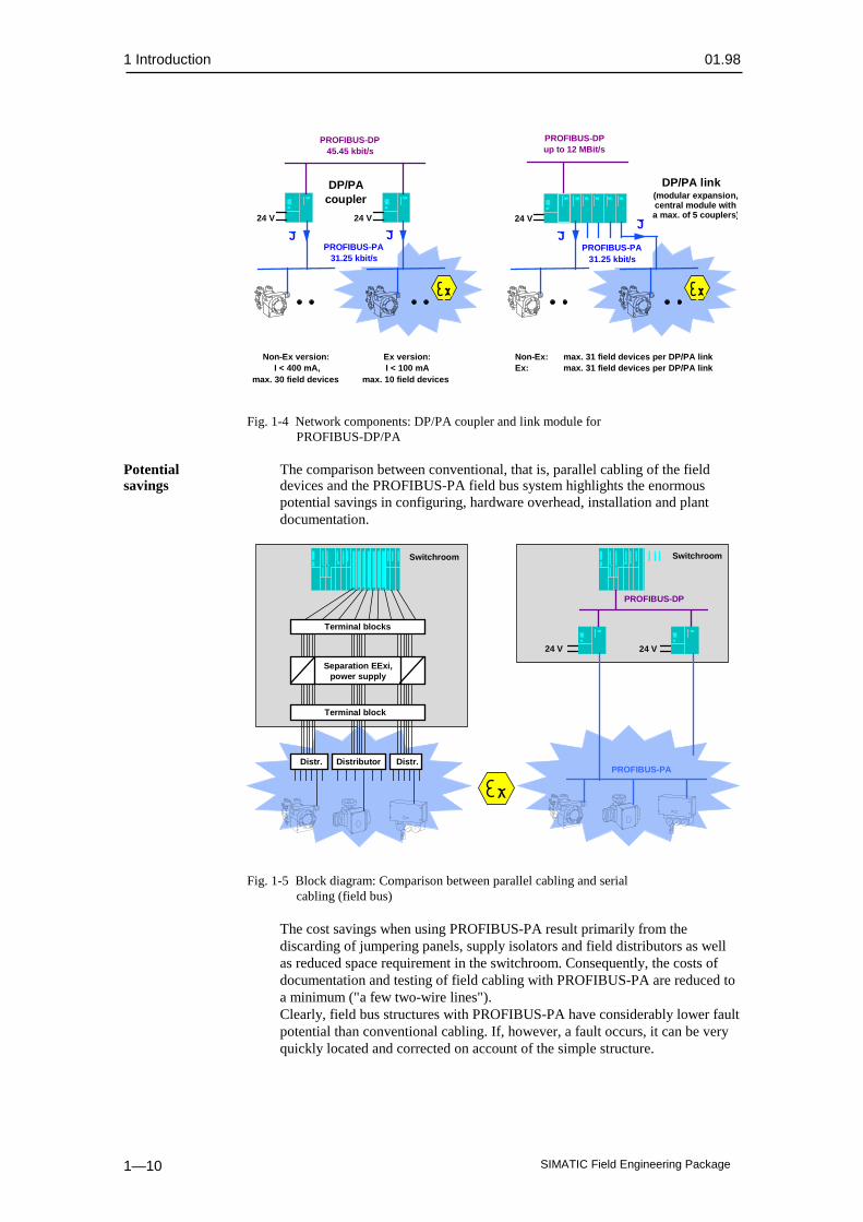
PROFIBUS-DPup to 12 MBit/s
DP/PA link(modular expansion,central module witha max. of 5 couplers)
PROFIBUS-DP45.45 kbit/s
DP/PAcoupler
PROFIBUS-PA31.25 kbit/s
24 V
Non-Ex version:I < 400 mA,
max. 30 field devices
24 V
Non-Ex: max. 31 field devices per DP/PA linkEx: max. 31 field devices per DP/PA link
J
24 V
J
Ex version:I < 100 mA
max. 10 field devices
PROFIBUS-PA31.25 kbit/s
JJ
Fig. 1-4 Network components: DP/PA coupler and link module forPROFIBUS-DP/PA
Potential The comparison between conventional, that is, parallel cabling of the fieldsavings devices and the PROFIBUS-PA field bus system highlights the enormous
potential savings in configuring, hardware overhead, installation and plantdocumentation.
Terminal blocks
PROFIBUS-PA
Switchroom
24 V
Distributor
Separation EExi,power supply
Terminal block
Distr. Distr.
PROFIBUS-DP
24 V
Switchroom
Fig. 1-5 Block diagram: Comparison between parallel cabling and serialcabling (field bus)
The cost savings when using PROFIBUS-PA result primarily from thediscarding of jumpering panels, supply isolators and field distributors as wellas reduced space requirement in the switchroom. Consequently, the costs ofdocumentation and testing of field cabling with PROFIBUS-PA are reduced toa minimum ("a few two-wire lines").Clearly, field bus structures with PROFIBUS-PA have considerably lower faultpotential than conventional cabling. If, however, a fault occurs, it can be veryquickly located and corrected on account of the simple structure.

01.98 1 Introduction
SIMATIC Field Engineering Package 1—11
1.3.2 PROFIBUS-PA configuration with SIMATIC S5
Components In the SIMATIC S5 control system, the DP/PA coupler is exclusivelyused in conjunction with the IM 308 - C DP master card (from release 7).Owing to the relatively low data rate on PROFIBUS-DP (45.45 kbit/s) theproject scope is governed either by the maximum number of addressable slaves(field devices) or the maximum cycle time.The following should be observed for operation in SIMATIC S5 (for example,SIMATIC S5-155U PLC with CPU 948):
• The exchange of data with each field device lasts approximately 10 ms(outgoing and return message).
• Thus the cycle time on a DP line with 10 field devices is about10 x 10 ms = 100 ms, i.e. the measured values can be read into the CPU orthe manipulated variables can be read out 10 times per second.
• The cycle time with 30 field devices per DP line is about 300 ms.
• Up to 7 DP lines for field bus applications can be plugged into oneSIMATIC S5-155U PLC.
1.3.3 PROFIBUS-PA configuration with SIMATIC S7
In conjunction with SIMATIC S7 and the SIMATIC PCS 7 control system, theDP/PA coupler is used for smaller project scopes or low time-related demands,and the DP/PA link for large project scopes and high time-related demands.The DP/PA link allows a configuration with a subordinate PA lines with shortcycle times (approximately 100 ms for 10 field devices). These data aretransferred to the SIMATIC PCS 7 control system via PROFIBUS-DP at up to12 Mbit/s without significant loss of time (approximately 1 ms).
Quantity framework
Control system
SIMATIC S5
SIMATIC PCS 7
45.45 kbit/s
DP/PAcoupler
45.45 kbit/s
DP/PAcoupler
up to 12 Mbit/s
DP/PA link
Fig. 1-6 Applications of the DP/PA coupler and link module forPROFIBUS-DP/PA

1 Introduction 01.98
SIMATIC Field Engineering Package1—12
1.4 HART functions
Introduction HART (highway addressable remote transducer) is a serial transmissionmethod with which additional data can be transferred via a 4 to 20 mA currentloop. The HART protocol describes the physical form of the transmission,transaction procedures, message structure, data formats and many commands.Furthermore, HART users can define their own commands.
HART signal The HART signal is a digital communication modulated onto the normalanalog signal. Sine waves of 1200 Hz and 2200 Hz represent the HART signaland are modulated onto the analog signal (4-20 mA). Since the signal has amean value of 0, the analog signal is not affected. The HART signal can beeasily filtered out with a filter, and the original analog signal is then availableagain. The HART signal can be additionally evaluated:
• HART signal with a frequency of 2200 Hz signifies a logic "0".
• HART signal with a frequency of 1200 Hz signifies a logic "1".
• The signal sequences are transferred alternately as the command (C) andresponse (R).
Application criteria/ HART modules are characterized by the following application criteria andcharacteristics characteristics:
• HART has developed into a quasi-standard since the 1980s.
• Several million HART devices are in operation worldwide.
• They are pin-compatible with conventional analog modules.
• Additional communication facilities via the current loop.
• The low power requirement with HART favors its application in thehazardous area.
The utilization of HART in the ET200 M distributed I/O system is possiblewith HART analog modules.
01.98 2 Overview of the components of the field engineering package
SIMATIC Field Engineering Package 2–1
Overview of the components of the fieldengineering package
This chapter contains:
2.1 Introduction 2–2
2.2 Hardware components 2–2
2.2.1 PROFIBUS-PA 2–2
2.2.2 HART 2–3
2.3 Configuring the field engineering 2–5
2

2 Overview of the components of the field engineering package 01.98
SIMATIC Field Engineering Package2–2
2.1 IntroductionThis chapter provides you with an overview of the components of the fieldengineering package. Detailed descriptions of the individual components canbe found in the corresponding manuals which are referred to at the appropriatepoints. These are as follows:
Hardware:
• PROFIBUS-DP/PA coupler
• PROFIBUS-DP/PA link
• Analog input module SM 331; AI 2 x HART
Software:
• Step 7 (HW-Config)
• PCS 7 driver/CFC
• SIMATIC PDM field device parameter assignment tool
• COM PROFIBUS
2.2 Hardware components
2.2.1 PROFIBUS-PA
Applications DP/PA bus communication can be used in SIMATIC S5 , S7 and PCS 7.You can connect all field devices certified for PROFIBUS-PA.
DP/PA coupler DP/PA coupler is available in the following variants:
• DP/PA coupler EEx [i]: 6ES7 157-0AD00-0XA0
• DP/PA coupler: 6ES7 157-0AC00-0XA0
The DP/PA coupler has the following features:
• Type of protection [EEx ia] II C (only 6ES7 157-0AD00-0XA0)
• Intrinsic safety (only 6ES7 157-0AD00-0XA0)
• Isolation between PROFIBUS-DP and PROFIBUS-PA
• Diagnostics via LEDs
• Baud rate on PROFIBUS-DP 45.45 kbit/s
• Baud rate on PROFIBUS-PA 31.25 kbit/s
01.98 2 Overview of the components of the field engineering package
SIMATIC Field Engineering Package 2–3
Detailed information can be found in /502/.
DP/PA link The DP/PA link is available in the following variants:
• DP/PA link interface module IM 157 (6ES7 157-0AA00-0XA0) with:
− DP/PA coupler EEx [i]: 6ES7 157-0AD00-0XA0
− DP/PA coupler: 6ES7 157-0AC00-0XA0
The DP/PA link is formed from the IM 157 interface module and one ormore DP/PA couplers (flameproof or non-flameproof variants). Allcomponents of the DP/PA link are interconnected via S7-300 standard busconnectors.The DP/PA link has the following features:
• Type of protection [EEx ia] II C (only with 6ES7 157-0AD00-0XA0)
• Intrinsic safety (only with 6ES7 157-0AD00-0XA0)
• Isolation between PROFIBUS-DP and PROFIBUS-PA
• Baud rate on PROFIBUS-DP 12 Mbit/s max.
• Baud rate on PROFIBUS-PA 31.25 kbit/s
• Diagnostics via LEDs
• Max. number of DP/PA couplers per DP/PA link: 5
Detailed information can be found in /502/.
2.2.2 HART
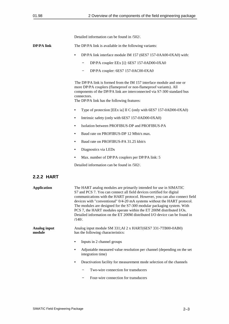
Application The HART analog modules are primarily intended for use in SIMATICS7 and PCS 7. You can connect all field devices certified for digitalcommunications with the HART protocol. However, you can also connect fielddevices with "conventional" 0/4-20 mA systems without the HART protocol.The modules are designed for the S7-300 modular packaging system. WithPCS 7, the HART modules operate within the ET 200M distributed I/Os.Detailed information on the ET 200M distributed I/O device can be found in/140/.
Analog input Analog input module SM 331;AI 2 x HART(6ES7 331-7TB00-0AB0)module has the following characteristics:
• Inputs in 2 channel groups
• Adjustable measured value resolution per channel (depending on the setintegration time)
• Deactivation facility for measurement mode selection of the channels
− Two-wire connection for transducers
− Four-wire connection for transducers

2 Overview of the components of the field engineering package 01.98
SIMATIC Field Engineering Package2–4
− Channels can be deactivated
• Current signal selectable per channel
− 0 to 20 mA (without HART function)
− 4 to 20 mA (with/without HART function)
• Parameterizable diagnostics
• Parameterizable diagnostic alarm
• Two channels with limit monitoring
• Parameterizable limit alarm
• Channels isolated from each other
• Open-circuit monitoring
• Channels isolated from CPU and L+ load voltage
Detailed information can be found in /503/.

01.98 2 Overview of the components of the field engineering package
SIMATIC Field Engineering Package 2–5
2.3 Configuring the field engineering
Introduction Extensive and convenient software tools are available for incorporatingthe components of the field engineering package into the automation system.Incorporation takes place according to standard rules, irrespectively of whetherit is a standard I/O module or an analog module +HART or a DP slave or PAslave. The principle of incorporation is uniform. The capabilities of the newcomponents are described in more detail in the following sections.
COM PROFIBUS The COM PROFIBUS program package is testing, diagnostic and parameter-assignment software for PROFIBUS-DP (for example, the IM 308-C masterinterface). With COM PROFIBUS, the ET200 system can be very easilyconfigured, documented and put into operation. You need COM PROFIBUS inthe SIMATIC S5 system for configuring the bus arrangement. Further detailsand instructions can be found in /501/.
Field device blocks Field device blocks are needed to transfer process data between the I/Os forprocess data processing. These field device blocks provide the interface to thehardware, including verification functionality.Detailed information on parameter assignment for blocks can be found in/258/, Chapter 5.A detailed description of all field device blocks can be found in /260/.The field device blocks currently available for process linking of the fieldengineering package in the PCS 7 automation system can be found inSection 3.2.5, Table 3-1.
Hardware Hardware configuring within the STEP 7 program package of the S7/PCS 7configuring automation system is a convenient configuring tool for creating the hardware
structures within your projects. You can use it for configuring and assigningparameters to modules of a centralized arrangement as well as of DP/PAdevices in a distributed arrangement.
"Configuring" is understood to mean:
• The arrangement of racks, modules, interface modules and devices.
During configuring, the addresses in the I/O area of the S7-400 areautomatically assigned to the individual modules.
"Parameterization" is understood to mean:
• The setting of parameters for parameterizable modules for the centralizedarrangement and for a network.
• The setting of bus parameters, DP master and DP/PA slave parameters fora PROFIBUS-DP or DP/PA network.
Detailed information can be found in /231/
SIMATIC PDM A universally applicable configuring tool for service and parameterassignment of field devices for the PROFIBUS-PA and HART analog modulepackages. A prerequisite is a device description (DD) which can be read and

2 Overview of the components of the field engineering package 01.98
SIMATIC Field Engineering Package2–6
interpreted by SIMATIC PDM (process device manager). SIMATIC PDM canbe operated in a centralized (for example via the ES station) or decentralizedarrangement (laptop at the IM 153-2 for HART modules or on PROFIBUS-DP).Direct operation via PROFIBUS-DP is available in the first stage of supply(see Fig. 2-1).
GSD
DD for generatingmanufacturer-neutralparameterizing masks
in PDM for(library in PDM)
PROFIBUS-DPup to 12 Mbit/s
DP/PA-Link
ESSIPROM
OS
System bus
PROFIBUS-PA
SIMATIC S7-400
ES
SIPROM
DD
GSD fornetwork configuring
the DP master(S7-400 and
DP/PA link) with theEngineering System
(for library inHW config)
One-timetransfer toSiemens
Fig. 2-1 Integration of any field devices in PROFIBUS-PA

01.98 3 Components of the field engineering package in detail
SIMATIC Field Engineering Package 3–1
Components of the field engineering packagein detail
This chapter contains:
3.1 Hardware 3–2
3.1.1 DP/PA coupler 3–2
3.1.2 DP/PA link 3–3
3.1.3 HART modules 3–4
3.1.3.1Two-channel analog input module 3–4
3.2 Software/configuration 3–6
3.2.1 Configuration/project scope 3–6
3.2.2 Addressing of PROFIBUS-PA field devices 3–7
3.2.3 Parameter assignment / device profiles 3–9
3.2.4 Device database (GSD) and device descriptions (DD) 3–12
3.2.5 Driver function blocks for the field engineering package 3–13
3

3 Components of the field engineering package in detail 01.98
SIMATIC Field Engineering Package3–2
3.1 Hardware
3.1.1 DP/PA coupler
Variants Two variants of the DP/PA coupler are available: A non-flameproofvariant with up to 400 mA output current for the PA cable, and a flameproofvariant with up to 100 mA output current. The PA cable of the flameproofvariant can be used in the hazardous area. The DP/PA coupler itself must beinstalled outside the hazardous area.
Mechanical design The mechanical design is characterized by the following points:
• Modular design in the S7-300 packaging system on a shallow S7 300 railwith swivel-mounting and screw fixing.
• Arrangement of all indicators and connectors at the front of the module.
• Recessed arrangement of all plug-in connectors, covered by means of thefront doors.
• Housing in degree of protection IP 20.
• Cooling by convection.
• Horizontal installation.
• For shielding purposes, the S7 300 rail serves as the functional groundreference point. Each module has an upper and lower shield contact springat the rear to provide the electrical connection to the S7 300 rail when themodule has been secured. Furthermore, the modules are equipped withadditional shielding plates.
• Adequate EMC is ensured through the use of plastic housings and lightguide elements for the status indications.
• The maximum overall mounting depth is 130 mm, height 125 mm. Thewidth of the DP/PA coupler is 80 mm.
• The S7 300 rail is supplied in various widths for cabinet installation, andin 2m lengths (standard S7-300 S7 300 rail).
• Installation clearance of 40 mm above and below the module is necessaryfor module handling, on account of the swivel-mounting system andsecuring by means of a screwdriver. Cable ducts must be fitted outsidethese clearances.
Connection system The connection system is characterized by the following points:
• The 24 V DC supply voltage is connected with 4-pole screw terminals.
• The PROFIBUS-DP interface is connected with a 9-pin sub D connector.Strain relief and shielding are provided by this sub D male connector.

01.98 3 Components of the field engineering package in detail
SIMATIC Field Engineering Package 3–3
• With the non-intrinsically safe variant, the PROFIBUS-PA interface isconnected via four screw terminals. The user can terminate the PA cable orloop it through, as required. The terminating resistor is selectable andintegrated in the housing.
• With the intrinsically safe variant, the PROFIBUS-PA interface isconnected via two screw terminals. The intrinsically safe DP/PA coupler isalways situated at the end of the PA cable. The terminating resistorintegrated in the housing is always active. With the intrinsically safevariant, this means that the PROFIBUS-PA must not be looped through.
• In both versions, the shield contact of the PA cable also serves for strainrelief.
A more detailed description of the module can be found in the DP/PA couplerManual /502/.
3.1.2 DP/PA link
Variants The DP/PA link is formed from the IM 157 interface module and one ormore DP/PA couplers (flameproof or non-flameproof variants). Allcomponents of the DP/PA link are interconnected via S7-300 standard busconnectors.By combining the IM 157 with flameproof or non-flameproof variants of theDP/PA coupler, flameproof or non-flameproof variants of the DP/PA link arealso possible. This modular system can be expanded to up to 5 PA lines.
IM 157 DP/PA-Coupler
DP/PA-Link (one PA line)
40 80
Fig. 3-1 The DP/PA link with IM 157 interface module and a DP/PAcoupler
Mechanical design The mechanical design is characterized by the following points:
• Modular design in the S7-300 design system on a shallow S7 300 rail withswivel-mounting and screw fixing.

3 Components of the field engineering package in detail 01.98
SIMATIC Field Engineering Package3–4
• The maximum overall mounting depth is 130 mm, and height 125 mm.The width of the IM 157 is 40 mm. The overall width of the DP/PA linkdepends on the number of DP/PA couplers used.
• The remaining mechanical design data are same as for the DP/PA coupler.
Connection system The connection system is characterized by the following points:
• The 24 V DC supply voltage is connected with 4-pole screw terminals.
• The PROFIBUS-DP interface is connected only at the IM 157 with a9-pin sub D connector. The PROFIBUS-DP interfaces of the DP/PAcouplers used in the DP/PA link have no function. Strain relief and shieldcontact are provided by the sub D male connector.
• With the non-intrinsically safe variant, the PROFIBUS-PA interface isconnected via four screw terminals. The user can terminate the PA cable orloop it through, as required. The terminating resistor is selectable andintegrated in the housing.
• With the intrinsically safe variant, the PROFIBUS-PA interface isconnected via two screw terminals. The intrinsically safe DP/PA coupler isalways situated at the end of the PA cable. The terminating resistorintegrated in the housing is always active.
• In both versions, the shield contact of the PA cable also serves for strainrelief.
A more detailed description of the module can be found in the DP/PA couplerManual /502/.
3.1.3 HART modules
3.1.3.1 Two-channel analog input module
Mechanical design The mechanical design is characterized by the following points:
• Modular design in the ET 200M design system on a shallow S7 300 railwith swivel-mounting and screw fixing.
• For operation in a distributed arrangement in the ET 200M with the IM 153-2 interface module. Detailed information on the ET 200Mdistributed I/O unit and interface module can be found in /140/.
• Arrangement of all indicators and connectors at the front of the module.
• Recessed arrangement of all connectors, covered by the front doors.
• Housing in degree of protection IP 20.
• Cooling by convection.
• Horizontal mounting.

01.98 3 Components of the field engineering package in detail
SIMATIC Field Engineering Package 3–5
• For shielding purposes, the S7 300 rail serves as the functional groundreference point. Each module has an upper and lower shield contact springat the rear to provide the electrical connection to the S7 300 rail when themodule has been secured. Furthermore, the modules are equipped withadditional shielding plates.
• Adequate EMC is ensured by using plastic housings and light guideelements for the status indications.
• The maximum overall mounting depth is 130 mm and height 125 mm. Thewidth of the module is 40 mm.
• The S7 300 rail is supplied in various widths for cabinet installation, andin 2m lengths (standard S7-300 S7 300 rail).
• Installation clearance of 40 mm above and below the module is necessaryfor module handling, on account of the swivel-mounting system andsecuring by means of a screwdriver. Cable ducts must be fitted outsidethese clearances.
Connection system The connection system is characterized by the following points:
• The 24 V DC supply voltage is connected at the 20-pin front connector bymeans of screw terminals.
• The 0/4 to 20 mA process signals are connected at the 20-pin frontconnector by means of screw terminals.
• Strain relief at the front connector.
• Shielding depends on the conductor cross-section, by means of shieldcontact elements to be ordered separately.
• The module can be pulled out and inserted online with an active backplanebus.
A more detailed description of the module can be found in the manual /503/.

3 Components of the field engineering package in detail 01.98
SIMATIC Field Engineering Package3–6
3.2 Software/configuration
3.2.1 Configuration/project scope
DP/PA coupler
PROFIBUS-DP45.45 kBit/s
DP/PA coupler
24 V
PROFIBUS-PA 31.25 kbit/s
10 ms10 ms 10 ms
10 ms
10 ms
Cycle time =4 x 10 ms + 10 ms = 50 ms
cyclic frame(4 bytes measured value + 1 byte status)
acyclic frame(Read alarm limit: 4 bytes)
Fig. 3-2 Block diagram for the determining of cycle times on thePROFIBUS-PA using a transceiver module
Within the bus cycle time, each field device exchanges the most importantinput and output data with the master. Additionally, the master accesses aparticular field device, for example, to write parameter assignment data or toread diagnostic parameters. The number of field devices on the PROFIBUS-PA segment governs the bus cycle time, i.e. the timebase in which the processvalues are exchanged with the field devices. The bus cycle time is obtained byadding the cyclic messages to all field devices, and the acyclic message to aparticular field device. In the example:4 x 10 ms + 10 ms = 50 ms.
Note:
The value of 10 ms within the bus cycle time applies to field devices whichexchange a measured value or manipulated value with its corresponding status,i.e. 5 bytes of useful data per cycle, with the programmable controller/system.Examples of these field devices are pressure, temperature, level transducers,valves and actuators. Complex field devices, for example those providingseveral measured variables simultaneously (such as flow transducers), requireadditional transfer time. With average field instrumentation, the number ofthese complex field devices is relatively low and their influence on the overallbus cycle time is negligible.
01.98 3 Components of the field engineering package in detail
SIMATIC Field Engineering Package 3–7
DP/PA link
PROFIBUS-DP, 12 Mbit/s
DP/PA link
24 V
PROFIBUS-PA 31.25 kbit/s
10 ms10 ms 10 ms
10 ms
max. 1 ms at 12 Mbit/s
10 ms
Cycle time = approx. 1 ms
Cycle time = 4 x 10 ms + 10 ms = 50 ms
cyclic frame(4 bytes measured value + 1 byte status)
acyclic frame(Read alarm limit: 4 bytes)
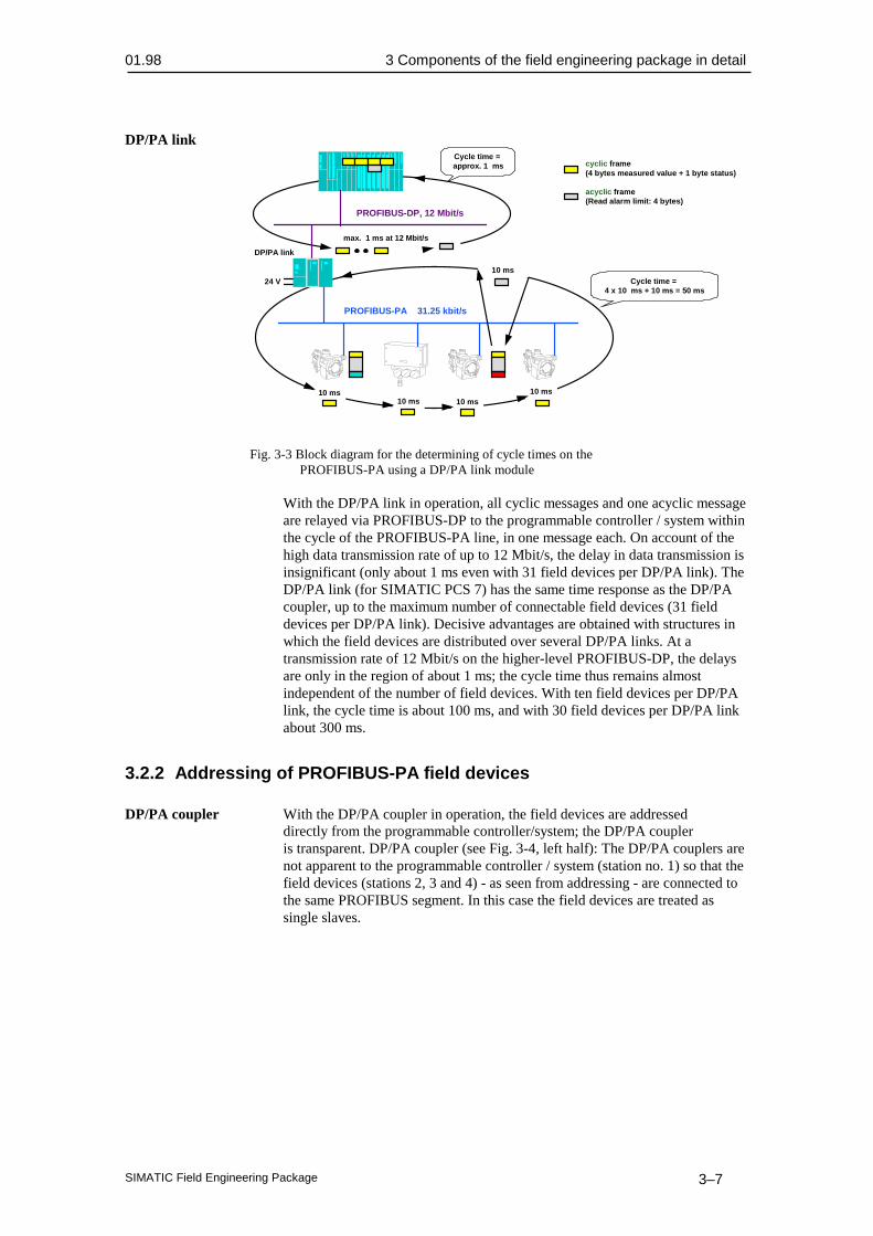
Fig. 3-3 Block diagram for the determining of cycle times on thePROFIBUS-PA using a DP/PA link module
With the DP/PA link in operation, all cyclic messages and one acyclic messageare relayed via PROFIBUS-DP to the programmable controller / system withinthe cycle of the PROFIBUS-PA line, in one message each. On account of thehigh data transmission rate of up to 12 Mbit/s, the delay in data transmission isinsignificant (only about 1 ms even with 31 field devices per DP/PA link). TheDP/PA link (for SIMATIC PCS 7) has the same time response as the DP/PAcoupler, up to the maximum number of connectable field devices (31 fielddevices per DP/PA link). Decisive advantages are obtained with structures inwhich the field devices are distributed over several DP/PA links. At atransmission rate of 12 Mbit/s on the higher-level PROFIBUS-DP, the delaysare only in the region of about 1 ms; the cycle time thus remains almostindependent of the number of field devices. With ten field devices per DP/PAlink, the cycle time is about 100 ms, and with 30 field devices per DP/PA linkabout 300 ms.
3.2.2 Addressing of PROFIBUS-PA field devices
DP/PA coupler With the DP/PA coupler in operation, the field devices are addresseddirectly from the programmable controller/system; the DP/PA coupleris transparent. DP/PA coupler (see Fig. 3-4, left half): The DP/PA couplers arenot apparent to the programmable controller / system (station no. 1) so that thefield devices (stations 2, 3 and 4) - as seen from addressing - are connected tothe same PROFIBUS segment. In this case the field devices are treated assingle slaves.

3 Components of the field engineering package in detail 01.98
SIMATIC Field Engineering Package3–8
PROFIBUS-DP45.45 kbit/s
DP/PAcoupler
PROFIBUS-PA31.25 kbit/s
24 V
PROFIBUS-DPup to 12 Mbit/s
DP/PA link
24 V
1
32
1
1
2 3
24 V
4
24 V
1
2
Slave
Master
PROFIBUS-PA31.25 kbit/s
2 3
Fig. 3-4 Addressing of field devices within an automation system onPROFIBUS-PA
DP/PA link The DP/PA link is a slave on PROFIBUS-DP and a master onPROFIBUS-PA. The programmable controller/system addresses the fielddevices via the DP/PA link, that is, indirectly.DP/PA link (see Fig. 3-4, right half): Each DP/PA link (stations 2 and 3 onPROFIBUS-DP) is a station (slave) on the higher-level PROFIBUS-DP andtherefore appears to the programmable controller/system with only one stationaddress each. Furthermore, each DP/PA link (station no. 1 on PROFIBUS-PA)is the master for the field devices connected to it (stations 2 and 3 or 2 onPROFIBUS-PA).Thus the DP/PA link acts as a "decoupler" for the transmission rate, allowingthe SIMATIC PCS 7 control system an extremely large addressing volume(theoretically 5 x 96 DP/PA links of 31 field devices, i.e. theoretically 14,880field devices per SIMATIC S7-400). In practice, this is limited by themaximum number of measured values to be processed in the user program ofthe S7-400 CPU.
Summary Shown in Fig. 3-5 is the relationship between project scope and time response using a DP/PA coupler and link modules with different configurations.
It can be seen that where two or more link modules are used with the samenumber of field devices, the loading on the DP line corresponds approximatelyto the loading of only one link module.

01.98 3 Components of the field engineering package in detail
SIMATIC Field Engineering Package 3–9
10 20 30 50
500 ms
100 ms
300 ms
Cycle time perDP line
Field devices perDP line
DP/PA coupler
30 field devices per DP/PA link
10 field devices per DP/PA link
90
Fig. 3-5 Overview of project scope: PROFIBUS-PA
HART HART analog modules are used within the ET 200 M distributed I/Osystem. Support of communication with HART devices via HART analogmodule, inserted centrally in an S7-300, is not provided. Addressing takesplace accordingly. Further information can be found in /140/.
3.2.3 Parameter assignment / device profiles
Introduction In order to allow uniform device responses, device profile definitions exist /518/. The basic arrangement is explained in more detail in the following.
PROFIBUS-PA
Measuring range
Filter time
Alarm/warning limits
Alarm summary
TAG
Vendor-specificparameters
DP servicescyclic and
acyclic
DP servicesacyclic
DP servicesacyclic
PA profile
(e.g. forpressure
transmitters)
Status
Measured value
Fig. 3-6 Schematic representation of a device profile for the PA profile onPROFIBUS-PA
Parameter groups The parameters in a field device can be classified in three groups:
1. Process parameters: Measured or manipulated value and correspondingstatus
3 Components of the field engineering package in detail 01.98
SIMATIC Field Engineering Package3–10
2. Operational parameters: Measuring range, filter time, alarm parameters(message, alarm and warning limits), standard parameters (measuring pointidentifiers, TAG)
3. Manufacturer-specific parameters such as special diagnostic information
1st group The parameters of the first group are read or written cyclically or acyclicallyby the programmable controller/system. The measured value and statusparameters are present in all measuring field devices, and the manipulatedvariable and status parameters are in all actuating field devices and are codeduniformly (for example, measured/manipulated value in 4 bytes, IEEE format).
2nd group The parameters of the second group can be read and written acyclically bythe programmable controller as required. Some of these parameters areexchanged with the field devices via the function blocks in the programmablecontroller/system, to allow access of the HMI system (for example,visualization of alarm violation).The parameters, that is the associated field device functions of the first andsecond groups, are defined in the PA profile of the PNO guidelines(PROFIBUS user organization) for PROFIBUS-PA. Some of these field devicefunctions are mandatory and some optional. Where optional functions areimplemented in the field device, they must comply with the descriptionaccording to the PA profile.
3rd group The parameters of the third group are manufacturer-specific. Acyclicaccess usually takes place with a personal computer for diagnostic andmaintenance purposes. In exceptional cases, certain parameters are also read orwritten from this group by the programmable controller/system.
Interoperability Programmable controllers/systems and PCs of different manufacturers canread/write the parameters defined in the PA profile from all field devices viaPROFIBUS-PA, thus affecting the field device functions defined in the PAprofile.The term "interoperability" is understood to mean the interaction betweencomponents (control systems and field devices in this case) of differentmanufacturers on an open bus system, on the basis of a vendor-independentdefinition of the device and communications functions.

01.98 3 Components of the field engineering package in detail
SIMATIC Field Engineering Package 3–11
PROFIBUS-DP
DP/PA coupler,DP/PA link
24 V
PROFIBUS-PA
Vendor X
Vendor Z Vendor Y
Vendor Y
PA profilevendor-specific
Fig. 3-7 Block diagram showing interchangeability of field devices on thebasis of the device profile on PROFIBUS-PA
On the basis of the parameters defined in profile PA, the programmablecontroller of manufacturer X and the PC of manufacturer Y can access bothfield devices of manufacturer Z and Y. The devices of manufacturers X,Y andZ are interoperable.Furthermore, data interchange of the manufacturer-specific parameters ispossible between PC and field device of manufacturer Y (homogeneouscommunications network). Manufacturer-specific parameters are not used as arule in the programmable controller/system, but can be read, for example, tocreate the plant image by the PC/PG.The field devices are interchangeable whilst retaining functionality, providedthe functions of profile PA are used.More detailed information on the individual, special device profile definitionscan be found in /518/.

3 Components of the field engineering package in detail 01.98
SIMATIC Field Engineering Package3–12
HART module
fast cyclic readingby S7-400,0/4 - 20 mA
slow acyclic read/ wr
by SIPROM orHART-handheld,
digital
commonpractice
universal
devicespecific
Measured value
Vendor
TAG
Measuring range
Filter time
Alarm/warning limits
Vendor-specificparameters
Fig. 3-8 Schematic representation of a device profile for HARTcommunications
Parameter groups The parameters in a HART field device can be classified in three groups:
1. Universal: Measured value or manipulated value, manufacturer name andmeasuring point identifier (TAG)
2. Common practice: Measuring range, filter time, alarm parameters(message, alarm and warning limits)
3. Device specific: For example, special diagnostic information
All three parameter groups are acquired via slow, acyclic reading bySIMATIC PDM or a HART handheld terminal.The measured value is represented by a 4 to 20 mA signal. The A/D or D/Aconversion takes place on the HART analog module, and this process value ishandled via fast cyclic reading/writing by the automation station. Inexceptional cases, certain parameter groups are also read and writtenacyclically by the programmable controller system.
3.2.4 Device database (GSD) and device descriptions (DD)
Device database The device database is a file containing the device’s master data enablingthe configuration of PROFIBUS-PA capable field devices in the SIMATICS5/S7/PCS 7 automation system. Each manufacturer of PROFIBUS-PAcapable field devices supplies a device database (GSD) with their devices.These must be read into the engineering station and updated in the COMPROFIBUS or STEP 7 program package in the HW-Config program section.Further information on this topic can be found in /231/.
Device description The device description (DD) is a universal, standardized device andparameter description for PROFIBUS-PA and HART-capable field devices.SIMATIC PDM is supplied with device data by the contents in the devicedescription.These describe:
01.98 3 Components of the field engineering package in detail
SIMATIC Field Engineering Package 3–13
• The user interface of SIMATIC PDM (text representation);
• the interdependences of device parameters;
• the online functions;
• the methods (special routines or functions) and
• the communications interfaces of the field devices.
3.2.5 Driver function blocks for the field engineering package
Introduction In order to transfer process data between the I/Os and the user program,field device blocks are needed. These field device blocks provide the interfaceto the hardware, including functionality verification.Detailed information on assigning parameters to blocks can be found in/258/, Chapter 5.The block types you use in PCS 7 can be purchased in the form of blocklibraries or you can create them yourself. The following reference books areavailable for the purpose:
• Basic blocks library /258/
• Technological blocks library /259/
• Field device blocks library /260/
The existing set of block types can be extended if necessary. We recommendthe use of the basic blocks and reference manual /258/ in which the blockconcept is described in detail (Chapter 2).
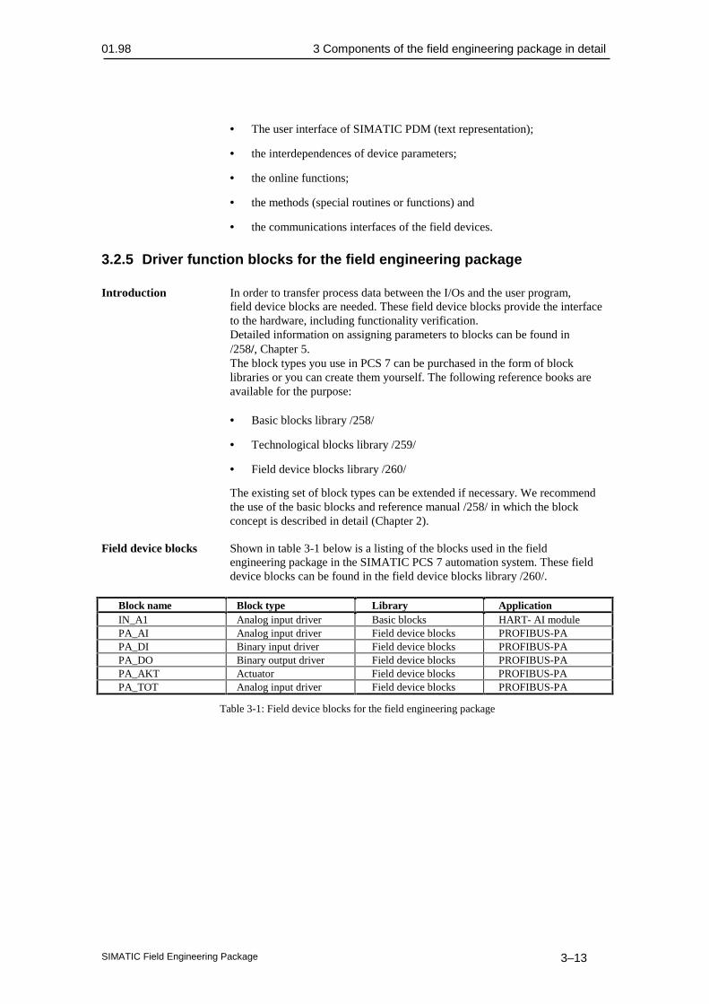
Field device blocks Shown in table 3-1 below is a listing of the blocks used in the fieldengineering package in the SIMATIC PCS 7 automation system. These fielddevice blocks can be found in the field device blocks library /260/.
Block name Block type Library ApplicationIN_A1 Analog input driver Basic blocks HART- AI modulePA_AI Analog input driver Field device blocks PROFIBUS-PAPA_DI Binary input driver Field device blocks PROFIBUS-PAPA_DO Binary output driver Field device blocks PROFIBUS-PAPA_AKT Actuator Field device blocks PROFIBUS-PAPA_TOT Analog input driver Field device blocks PROFIBUS-PA
Table 3-1: Field device blocks for the field engineering package


SIMATIC Field Engineering Package 3–1

4 Catalog data 01.98
SIMATIC Field Engineering Package4–2
Catalog data
This chapter contains:
4.1 Ordering data for the field engineering package 4–3
4.2 Cross-references to detailed catalogs 4–3
4.3 Positioning in the information environment 4–4
4

01.98 4 Catalog data
SIMATIC Field Engineering Package 4–3
4.1 Ordering data for the field engineering packageOrdering data Order No.
System overview, field engineering packageDrivers (basic blocks library) 6ES7 863 - 2DA00 - 0XX0PA drivers (field device blocks library) 6ES7 863 - 5DA00 - 0XX0Engineering toolset (STEP 7, SCL, CFC ) 6ES7 818 - 8AC00 - 0YE0SIMATIC PDM 7MP 9900 - 0AA00DP/PA coupler, intrinsically safe version 6ES7 157 - 0AD00 - 0XA0DP/PA coupler, non-intrinsically safe version 6ES7 157 - 0AC00 - 0XA0DP/PA link (IM 157) 6ES7 157 - 0AA00 - 0XA0Analog input module SM 331 AI 2 x HART 6ES7 331 - 7TB00 - 0AB0
4.2 Cross-references to detailed catalogs
Catalog Catalog contents Order No.ST 50 SIMATIC S5
Programmable controllersE86060-K4650-A101-A7
ST 70 SIMATICAutomation systemsSIMATIC S7/M7/C7
E86060-K4670-A101-A2
ST 80 SIMATIC HMIHuman-machine interface products / systems
E86060-K4680-A101-A2
IK 10 SIMATIC NETIndustrial communication networks
E86060-K6710-A101-A6
ST PI PROFIBUS & AS-InterfaceComponents on the field bus
E86060-K4660-A101-A1
PM 10.1 Printers and monitors for automationTechnical Catalog
E86060-K3310-A101-A1
KT 10 Combination systemSITOP power suppliesSITOP connection, system cabling
E86060-K2410-A101-A1
ST PCS 7 SIMATICProcess control system SIMATIC PCS 7
E86060-K4678-A111-A1
CA 01 Components for automation E86060-D4001-A100-A4
4 Catalog data 01.98
SIMATIC Field Engineering Package4–4
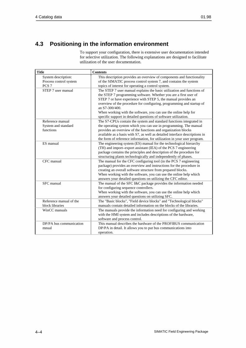
4.3 Positioning in the information environmentTo support your configuration, there is extensive user documentation intendedfor selective utilization. The following explanations are designed to facilitateutilization of the user documentation.
Title ContentsSystem description:Process control systemPCS 7
This description provides an overview of components and functionalityof the SIMATIC process control system 7, and contains the systemtopics of interest for operating a control system.
STEP 7 user manual The STEP 7 user manual explains the basic utilization and functions ofthe STEP 7 programming software. Whether you are a first user ofSTEP 7 or have experience with STEP 5, the manual provides anoverview of the procedure for configuring, programming and startup ofan S7-300/400.When working with the software, you can use the online help forspecific support in detailed questions of software utilization.
Reference manualSystem and standardfunctions
The S7-CPUs contain the system and standard functions integrated inthe operating system which you can use in programming. The manualprovides an overview of the functions and organization blocksavailable as a basis with S7, as well as detailed interface descriptions inthe form of reference information, for utilization in your user program.
ES manual The engineering system (ES) manual for the technological hierarchy(TH) and import–export assistant (IEA) of the PCS 7 engineeringpackage contains the principles and description of the procedure forstructuring plants technologically and independently of phases.
CFC manual The manual for the CFC configuring tool (in the PCS 7 engineeringpackage) provides an overview and instructions for the procedure increating an overall software structure from prepared blocks.When working with the software, you can use the online help whichanswers your detailed questions on utilizing the CFC editor.
SFC manual The manual of the SFC I&C package provides the information neededfor configuring sequence controllers.When working with the software, you can use the online help whichanswers your detailed questions on utilizing SFC.
Reference manual of theblock libraries
The "Basic blocks", "Field device blocks" and "Technological blocks"manuals contain detailed information on the blocks of the libraries.
WinCC manuals The manuals provide the information need for configuring and workingwith the HMI system and includes descriptions of the hardware,software and process control.
DP/PA bus communicationmnual
This manual describes the hardware of the PROFIBUS communicationDP/PA in detail. It allows you to put bus communications intooperation.

01.98 4 Catalog data
SIMATIC Field Engineering Package 4–5
Reference manualAutomation systemsS7-300, M7-300, ET200MFlameproof I/O modulesChapter 4HART analog modules
This chapter of the reference manual describes the HART analogmodule. It enables you to put the modules into operation.
ET 200M distributed I/Ounit manual
This manual describes the design of the ET 200M distributed I/O unitand includes a description of the IM 153-2 module needed foroperation of the HART modules.

01.98 5 Installation guidelines
SIMATIC Field Engineering Package 5–1
Installation guidelines
This chapter contains:
5.1 Introduction 5–2
5.2 Mechanical and electrical installation 5–6
5.2.1 Installing the cables 5–6
5.2.2 Cable routes within and outside buildings 5–6
5.2.3 Cable specifications and cable recommendation for PROFIBUS-DP 5–8
5.2.4 Cable specifications and cable recommendation for PROFIBUS-PA 5–9
5.2.5 Shielding concept 5–11
5.2.6 Grounding and equipotential bonding 5–13
5.2.7 Lightning protection 5–13
5.2.8 Connectors 5–14
5.2.9 Installation materials and tools 5–15
5.3 Guidelines of the PNO (PROFIBUS Users' Organization) 5–16
5

5 Installation guidelines 01.98
SIMATIC Field Engineering Package5–2
5.1 Introduction
General A bus system is characterized in that many stations can communicate witheach other using a low amount of cabling. Another important criterion is thecapability of the expansion of existing system sections without having tomodify the existing structures. This criterion is met with PROFIBUS-PA.The versatile system configuration of PROFIBUS-PA allows optimumadaptation of field cabling to the local circumstances of the industrial plant.
PROFIBUS-DP
T splitter
SIMATIC S7-400
Bus line
Hub
PROFIBUS-PA
DP/PA-Link
24 V
Spur cable
Terminatingresistor
Fig. 5-1 Topology of PROFIBUS-PA
Connection system The field devices are connected to the bus line by means of T splittersand hubs (connection box).
A distinction is made between the following arrangements:
• Bus line from the DP/PA coupler or DP/PA link to the field devices andstar-configuration cabling on site.
• Field devices connected with T splitters and hubs along the bus line.

01.98 5 Installation guidelines
SIMATIC Field Engineering Package 5–3
Star / field distributor(e.g. for 3 field devices)
T branch
Fig. 5-2 Connection diagram for field devices on PROFIBUS-PA
Number of By means of the DP/PA coupler or DP/PA link, up to ten field devicesfield devices can be powered on a PROFIBUS-PA segment (shielded two-wire cable) in
the hazardous area, and up to 31 field devices in the non-hazardous area.
Cable lengths The following cable lengths can be achieved independently of distributionand number of PROFIBUS-PA devices:
• Flameproof version 730m
• Non-flameproof version 560m
Depending on the distribution and number of PROFIBUS-PA devices, greaterlengths can be achieved:
• Non-flameproof and flameproof [ib] version 1900m max.
• Flameproof [ia] version 1000m max.
Power consumption Each field device on PROFIBUS-PA draws a static quiescent current of atleast 10 mA from the DP/PA coupler or DP/PA link via the data cable. Fielddevices with lower power consumption, such as pressure, temperature or leveltransducers, utilize this quiescent current for their own supply of power. Thetotal quiescent current of all stations is limited to 100 mA in the hazardous areaand 400 mA in the non-hazardous area. In the ideal case, each field devicedraws precisely 10 mA quiescent current; in practice, however, it is between 10and 30 mA according to field device.
5 Installation guidelines 01.98
SIMATIC Field Engineering Package5–4
PROFIBUS-DP
SIMATIC S7-400
PROFIBUS-PA31.25 kbit/s Ω100
µF1
Two-core, shieldedcable, total
length max. 1,900 m
< 100 mA
(Type of protection: [EEx ib],explosion group: IIC)
≥ 10 mA ≥ 10 mA
≥ 10 mA
≥ 10 mA
≥ 10 mA
24 V
Supply of field devices:Ex area: max. 10Non-Ex area: max. 30
Spur linemax. 30 m
DP/PA link
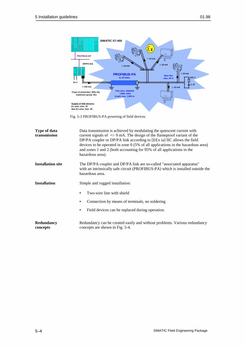
Fig. 5-3 PROFIBUS-PA powering of field devices
Type of data Data transmission is achieved by modulating the quiescent current withtransmission current signals of +/- 9 mA. The design of the flameproof variant of the
DP/PA coupler or DP/PA link according to [EEx ia] IIC allows the fielddevices to be operated in zone 0 (5% of all applications in the hazardous area)and zones 1 and 2 (both accounting for 95% of all applications in thehazardous area).
Installation site The DP/PA coupler and DP/PA link are so-called "associated apparatus"with an intrinsically safe circuit (PROFIBUS-PA) which is installed outside thehazardous area.
Installation Simple and rugged installation:
• Two-wire line with shield
• Connection by means of terminals, no soldering
• Field devices can be replaced during operation.
Redundancy Redundancy can be created easily and without problems. Various redundancyconcepts concepts are shown in Fig. 5-4.

01.98 5 Installation guidelines
SIMATIC Field Engineering Package 5–5
Star-configurationstructures with two
or moreinterfaces
Subordinatemini-PLCs
PROFIBUS-DPwith redundant
FO ring
S7-400 S7-400 S7-400
OLM
OLMOLM
OLMPROFIBUS-DP
PROFIBUS-DP
PROFIBUS-DP
Fig. 5-4 Redundancy concepts for PROFIBUS-DP

5 Installation guidelines 01.98
SIMATIC Field Engineering Package5–6
5.2 Mechanical and electrical installation
5.2.1 Installing the cables
Installation When installing the cables, ensure that they are not twisted, kinked,stretched or crushed.
Connecting the shields Shielded cables (braided shield) are recommended for the bus cable. Thisrecommendation also applies to any supply cables from external powersupplies to PROFIBUS devices (such as repeaters).Doubled-shielded cables are particularly suitable for environments subject toelectromagnetic interference. To ensure optimum protection, the outer shield(braided shield) and the inner shield (foil shield) at both cable ends must makelarge-area contact to ground with a grounding clamp.Where bus cables are inserted into electronics cabinets, the outer shield isadditionally given large-area contact to a shield bus to improve the diverting ofradio-frequency interference. The cable insulation should be stripped over thewidth of the clamp by means of a cable knife, without damaging the braidedshield. The shield bus must have a good electrical connection with the cabinetground (screw-fitting with a toothed lockwasher).For industrial areas subject to extreme electromagnetic interference(converters), laying of the cable within a steel pipe or sheet-steel duct ismandatory. The pipe or duct must have multiple grounding at various points.Alternatively, a fiber-optic bus may be used.
Securing the cables Bus cables must be mechanically secured at a distance of ≤ 1 meter fromthe terminal of the connected device (by means of a cable tie or clamp, forexample). The device terminals generally serve only to divert the interferencecurrents (shield contact) and cannot counteract vertical or horizontal tensileforces.
Equipotential bonding Where circulating currents via the shield are expected to be higher thanpermitted by the cable manufacturer, an additional equipotential bondingconductor (≥ 10 mm2 copper) should be laid to the bus cable, parallel ifpossible.
Note:
Particular attention must be paid to VDE 0165 Section 5.3.3. for operation inhazardous zones. It specifies that in hazardous zones and with more than oneground point, equipotential bonding is mandatory.
5.2.2 Cable routes within and outside buildings
Installing the cables Shielded bus cables must be laid at a distance of at least 200 mm fromsupply and high-voltage cables of more than 60 volts. With severe interferencesources (welding transformer, switched motors, etc.) the distance must beincreased to at least 500 mm.

01.98 5 Installation guidelines
SIMATIC Field Engineering Package 5–7
Installation next to telecommunications cables should be avoided becausemutual interference cannot be ruled out. Installation next to signal cables formeasurement and control with signal voltages of ≤ 60 volts is possible withoutproblems.Laying on cable racks and channels is permissible. Adequate grounding shouldbe ensured. Even short spur cable racks or steel conduits should be grounded.
Protection Where there is risk of mechanical damage (friction, walkways) specialagainst damage protection must be provided (closed sheet metal duct or conduit).
If no cable racks, channels or ducts are available, the cable must be installed ina conduit. This must be marked accordingly to prevent other cables from beingdrawn in later. At expansion joints of the building, the conduit may beinterrupted for a maximum of 500 mm provided the cables cannot be damagedby falling parts. At specially protected locations (electronics rooms) the cablesmay be installed without conduit. The subsequent pulling-in of bus cables intoan occupied conduit is not permissible on account of the risk of mechanicaldamage.
Storage and During storage, transportation and laying, ensure that both ends of the bustransportation cable are sealed with caps or insulating tape. This prevents the ingress of
moisture and dirt.
Laying of cables In the ground, a cable must be laid in conduits or duct blocks. With directin the ground laying, the cable must be covered with an additional protective layer of sand
to prevent damage to the cable. The manufacturer’s specifications relating tosuitability of the particular cable to burying in ground must be observed. Somemanufacturers assign a particular color to the cable to facilitate identification(for example, gray cable within buildings and black cable outside buildings andin the ground).For protection against the effects of lightning strikes, a 70 mm2 copper cableor 40 x 5 mm steel strip must be laid about 0.5 m above a cable buried in theground (covered with sand or in a PVC conduit).
Permissible bending Particularly with fiber-optic cables, the bending radius must not be lowerradius than the minimum value specified by the manufacturer. For example, the
bending radius applying to the SIMATIC NET PROFIBUS plastic fiber cableis ≥ 35 mm, and ≥ 150 mm for the corresponding glass fiber cable. Thecorresponding tensile strengths must not be exceeded (10 N and 500 Nrespectively for the above cables).The following guide value applies to copper cable with a plastic sheath:Laying radius = 12 x cable diameterThe maximum tensile stress (guide value) is 100 N.

5 Installation guidelines 01.98
SIMATIC Field Engineering Package5–8
5.2.3 Cable specifications and cable recommendation for PROFIBUS-DP
Cable specification
Cable type Twisted pairs 1 * 2 or 2 * 2 or 1 * 4 (starquad), shielded
Impedance 120 Ω nom., 100 Ω min., 130 Ω max.,f > 100 kHz
Cable capacitance < 60 pF/m typ.Core cross-section 0.22 mm
2 min., approx. AWG 24Signal attenuation 9 dB
1 max. over entire length of cable
section corresponding to 1200 m100 kbit/s [RS 422A] or approx.0.75 dB/100m f = 100 kHz
Shielding Apart from good RF characteristics, ensurethat the shield can be connected correctly.Wrapped shield foil is not suitable. Ifpossible, use aluminum foil and copperbraid or at least copper braid.
Table 5-1: Cable specification
Cable The search for suitable cables with the above specifications was unexpectedlyrecommendation difficult. Signal standard RS 485 was originally created for transmission on
telephone cables with 120 Ω impedance. These are frequently used withoutshielding. Where they are shielded, it is usually static which explains the typeswith aluminum foil and contact wire. However, the advent of ISDN networksresulted in a general need for telephone cables with shielding at RF.Two-wire data transmission at up to the highest frequency regions hasdeveloped greatly in recent years as local area networks (LANs). In newerbuildings, LAN-capable universal cables are pre-installed in the infrastructure.Unfortunately, the excellent cables developed for the purpose can hardly beused for PROFIBUS because the impedance of this network cable is a standard100 Ω. Although this value is precisely at the limit of the PROFIBUSspecification, the negative tolerance range of -10 % to -15 % can causeunacceptable reflections with a terminating resistance of 120 Ω. Only cableswith an impedance complying with the specifications are shown in thefollowing table.
1The PROFIBUS standard specifies 6 dB here, adopted from the quoted standards including CCITT V.11. The max.cable length of 1000 m mentioned therein is assumed to have a max. signal attenuation of 6 dB between transmitterand receiver. The specified test set-up with a twisted telephone cable of 0.51 mm diameter copper and 100 Ωterminating resistance already results in a resistive attenuation of 8.6 dB.
01.98 5 Installation guidelines
SIMATIC Field Engineering Package 5–9
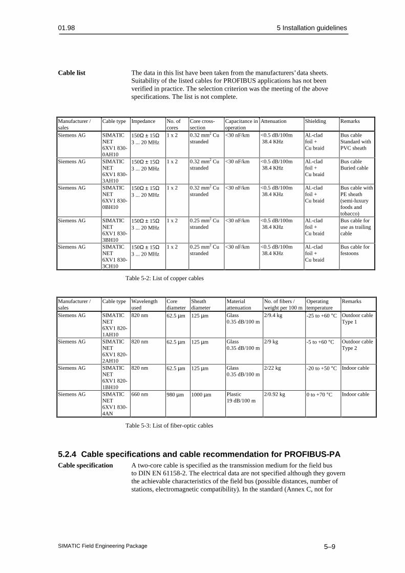
Cable list The data in this list have been taken from the manufacturers’ data sheets.Suitability of the listed cables for PROFIBUS applications has not beenverified in practice. The selection criterion was the meeting of the abovespecifications. The list is not complete.
Manufacturer /sales
Cable type Impedance No. ofcores
Core cross-section
Capacitance inoperation
Attenuation Shielding Remarks
Siemens AG SIMATICNET6XV1 830-0AH10
150Ω ± 15Ω3 ... 20 MHz
1 x 2 0.32 mm2 Custranded
<30 nF/km <0.5 dB/100m 38.4 KHz
Al.-cladfoil +Cu braid
Bus cableStandard withPVC sheath
Siemens AG SIMATICNET6XV1 830-3AH10
150Ω ± 15Ω3 ... 20 MHz
1 x 2 0.32 mm2 Custranded
<30 nF/km <0.5 dB/100m 38.4 KHz
Al.-cladfoil +Cu braid
Bus cableBuried cable
Siemens AG SIMATICNET6XV1 830-0BH10
150Ω ± 15Ω3 ... 20 MHz
1 x 2 0.32 mm2 Custranded
<30 nF/km <0.5 dB/100m 38.4 KHz
Al.-cladfoil +Cu braid
Bus cable withPE sheath(semi-luxuryfoods andtobacco)
Siemens AG SIMATICNET6XV1 830-3BH10
150Ω ± 15Ω3 ... 20 MHz
1 x 2 0.25 mm2 Custranded
<30 nF/km <0.5 dB/100m 38.4 KHz
Al.-cladfoil +Cu braid
Bus cable foruse as trailingcable
Siemens AG SIMATICNET6XV1 830-3CH10
150Ω ± 15Ω3 ... 20 MHz
1 x 2 0.25 mm2 Custranded
<30 nF/km <0.5 dB/100m 38.4 KHz
Al.-cladfoil +Cu braid
Bus cable forfestoons
Table 5-2: List of copper cables
Manufacturer /sales
Cable type Wavelengthused
Corediameter
Sheathdiameter
Materialattenuation
No. of fibers /weight per 100 m
Operatingtemperature
Remarks
Siemens AG SIMATICNET6XV1 820-1AH10
820 nm 62.5 µm 125 µm Glass0.35 dB/100 m
2/9.4 kg -25 to +60 °C Outdoor cableType 1
Siemens AG SIMATICNET6XV1 820-2AH10
820 nm 62.5 µm 125 µm Glass0.35 dB/100 m
2/9 kg -5 to +60 °C Outdoor cableType 2
Siemens AG SIMATICNET6XV1 820-1BH10
820 nm 62.5 µm 125 µm Glass0.35 dB/100 m
2/22 kg -20 to +50 °C Indoor cable
Siemens AG SIMATICNET6XV1 830-4AN
660 nm 980 µm 1000 µm Plastic19 dB/100 m
2/0.92 kg 0 to +70 °C Indoor cable
Table 5-3: List of fiber-optic cables
5.2.4 Cable specifications and cable recommendation for PROFIBUS-PACable specification A two-core cable is specified as the transmission medium for the field bus
to DIN EN 61158-2. The electrical data are not specified although they governthe achievable characteristics of the field bus (possible distances, number ofstations, electromagnetic compatibility). In the standard (Annex C, not for

5 Installation guidelines 01.98
SIMATIC Field Engineering Package5–10
standardization, for information only) a distinction is made between four cabletypes with the data presented in Table 5-4 (at 25° C).Installations according to the FISCO model are not subject to safety restrictionsif the limits given in Table 5-5 are met. Operation beyond these limits is notgenerally ruled out but must be considered in each case.
Type A(reference)
Type B Type C Type D
Cable type Twisted pair,shielded
One or moretwisted pairs,overall shield
Two or moretwisted pairs, notshielded
Two or morepairs,not twisted,not shielded
Core cross-section (nominal) 0.8 mm2
(AWG 18)0.32 mm
2
(AWG 22)0.13 mm
2
(AWG 26)1.25 mm
2
(AWG 16)Loop resistance (DC) 44 Ω/km 112 Ω/km 264 Ω/km 40 Ω/kmImpedance at 31.25 kHz 100 Ω ± 20 % 100 Ω ± 30 % ** **
Wave attenuation at 39 kHz 3 dB/km 5 dB/km 8 dB/km 8 dB/kmCapacitive asymmetry 2 nF/km 2nF/km ** **Group delay distortion (7.9 to 39 kHz) 1.7 µs/km ** ** **Shield coverage 90 % ** - -Recommended network size (inc. spur cables) 1900 m 1200 m 400 m 200 m
(** Not specified)
Table 5-4: Cable types to DIN EN 61158-2, Section 11.7.2 and Annex C
EEx ia EEx ib IIC / IIB
Loop resistance (DC) 15...150 Ω/km 15...150 Ω/kmInductance per unit length 0.4 ... 1 mH/km 0.4 ... 1 mH/kmCapacitance per unit length 80...200 nF/km 1) 80...200 nF/km 1)
Spur cable length ≤ 30 m 2) ≤ 30 m 2)
Cable length ≤ 1 km ≤ 5 km1) Definition cf. PNO guide PROFIBUS-PA /505/2) Tentative values according to the FISCO model
Table 5-5: Safety limits for the bus cable
The cores of all field bus cables must be clearly selectable (for example, withcolor coding or ring marking). Cables with intrinsically safe circuits must bemarked according to DIN 57 165/VDE 0165, Section 6.1.3.14 (for example,with a light-blue sheath).Where multi-pair cables are used in the hazardous area, the special installationconditions of DIN 57 165 / VDE 0165 (Chapter 6) /8/ must be observed.
Cable recommendation The reference cable (Type A) must be used for conformance tests. For thenew installations of plants, the cables used must meet the minimumrequirements of Types A or B. With multi-pair cables (Type B), two or morefield buses (31.25 kbit/s) may be operated in one cable. Other circuits in thesame cable should be avoided.Cables of Types C and D should only be used in retrofit applications (theutilization of already installed cables) with a greatly reduced network size. Inthese cases, allowance should be made for the fact that the interferenceimmunity of transmission often does not meet the requirements described in thestandard.The overall cable length is defined as the total length of the main cable and ofall spur cables.

01.98 5 Installation guidelines
SIMATIC Field Engineering Package 5–11
No. of spur cables Length of one spur cable,intrinsically safe
Length of one spur cable,not intrinsically safe
25-32 - -19-24 30 m 30 m15-18 30 m *) 60 m13-14 30 m *) 90 m1-12 30 m *) 120 m
*) Tentative values according to the FISCO model (spur cable ≤ 1 m may be considered as a splice)
Table 5-6: Recommended lengths of spur cables
Overall cable length Total length of splices> 400 m 8 m< 400 m 2 %
Table 5-7: Maximum lengths of splices
Cable list The data in this list have been taken from the manufacturers’ data sheets.Suitability of the listed cables for PROFIBUS applications has not beenverified in practice. The selection criterion was the meeting of the abovespecifications. The list is not complete.
Manufacturer/sales
Cable type Impedance No. ofcores
Core cross-section
Capacitancein operation
Attenuation Shielding Remarks
Siemens AG SIMATICNET6XV1 830-5AH10
100Ω ± 20Ω 1 x 2 0.75 mm2 Custranded
<90 nF/km <3 dB/km 39 KHz
Cu braid Bus cablePVC sheath,blue
Siemens AG SIMATICNET6XV1 830-35H10
100Ω ± 20Ω 1 x 2 0.75 mm2 Custranded
<90 nF/km <3 dB/km 39 KHz
Cu braid Bus cablePVC sheath,black
Table 5-8: Cable list for copper cables
5.2.5 Shielding concept
To shield or not to EN 50170 Vol. 2 allows the user to decide whether to employ shieldedshield cable. Unshielded cable is permissible in an interference-free environment.
On the other hand, there is the following argument for always using shieldedcable:
• An "interference-free" area exists, if at all, only in the interior of shieldingcabinets. However, as soon as relays and switching contactors are installedin them, the protection is lost.
Shielding rules For the optimum electromagnetic compatibility of systems, it is veryimportant that the system components and, in particular, the cables are shieldedand that these shields form a sheath which is as electrically seamless aspossible.To quote the "Grounding, shielding" Section of the DIN standard: "When ashielded bus cable is used, it is recommended that the shield be connected toprotective grounds with low inductance at both ends, to achieve the bestpossible EMC. Separate potentials (for example in a refinery) are an exception;as a rule, only single-ended grounding is permitted in these cases.

5 Installation guidelines 01.98
SIMATIC Field Engineering Package5–12
Note:
In systems without equipotential bonding, circulating currents at line frequencycan damage the bus cable in unfavorable cases (by exceeding the permissibleshield current). In these systems, therefore, the cable shield should be directlyconnected to the building ground at one end only.
The connection between shield and protective ground (for example, unithousing) should preferably be made via the metal housing and the screw-typeconnection of the sub D connectors. Where this type of shielding is notpossible, grounding can be achieved via pin 1 of the connector."It should be noted, however, that the connection via pin 1 does not meet the"low-inductance" condition. With a view to EMC, it is better to expose thecable shield at a suitable point and ground it to the (metal) structure of thecabinet with the shortest possible cable connection (for example, with a shieldclamp in front of the connector).
Shield connection By far the most important location of the shield ground connection is at theentry of the bus cable into the cabinet. Long external cables are often routedvia terminals here. For the shield connection to meet the "low-inductance"requirement, the following must be observed:
Note:
The cable shield must make contact over its circumference and have a large-area connection to the grounded structure (for example, ground bus, terminalrail).
Here are the most common mistakes resulting in non low-inductancegrounding:
• Connection via a sheath wire or contact wire.
• Connection via a short length of stranded conductor (a few cm), solderedon or crimped on ("pigtail method").
• Opening up or unsplicing the cable shield and clamping it directly in aground clamp. If the resultant ground wire is not longer than about 2 cm,this method is conditionally permissible.
• Routing of shield grounds via lengths of stranded copper conductor, evenwith large cross-sections (1.5 mm2 Cu).
With proper clamping of the cable shield by means of a cable clamp or otherclamping device, adequate contact pressure must be ensured. The clampingpressure is often exerted against the cable’s insulation which creeps in thecourse of time. Such arrangements require very great spring excursion. Theshield connection terminal of the KLBÜ series from Weidmüller is aconstructive response to the problem.

01.98 5 Installation guidelines
SIMATIC Field Engineering Package 5–13
5.2.6 Grounding and equipotential bonding
Protective grounding The protection concept of the station supply governs the need for protectivegrounding of a bus station. Consult the manufacturer’s data and localspecifications.
Equipotential bonding The RS 485 bus segment with 2 to 32 transceivers (transmitter/receivermodules) is electrically through-connected. Light equipotential bonding istherefore always provided by the bus cable. The question is whether additional,low-resistance equipotential bonding is necessary, as specified in the RS 485standard.
Two-wire line With a two-wire line, there is only light equipotential bonding. Isolation ofthe transceiver from the station with its other potential connections isunavoidable for fault-free data transmission.
Four-wire line With a four-wire line, equipotential bonding is provided by the DGNDconductor. This arrangement does not depend on isolation of the transceiver. Ifthe DGND is grounded with two or more stations, excessive circulatingcurrents can flow on the bus cable. For this case, RS 485 specifies a seriesresistance of about 100 ohms per station. Although this resistance providesprotection from excessive circulating currents, it reduces the equipotentialeffect. Isolation of the transceiver is advantageous, even with equipotentialbonding.
Conclusion Equipotential bonding according to RS 485 is only necessary when thereis no isolation of transceivers from other potential connections (such asgrounded supply, great capacitive coupling of an ungrounded supply).
Hazardous area This is an area in which the risk of explosion or a hazardous explosiveatmosphere can develop as a result of local operational conditions. According to the classification of this area, there are special requirements for the use of electrical apparatus. Further explanations and instructions can be found in VDE 0165 and /519/.
5.2.7 Lightning protection
Lightning protection is subdivided into external and internal protection. Wherebus cables are routed only within a building, only the internal lightningprotection need be taken into account.
External lightning External lightning protection always relates to the (bus) cables routed to theprotection plant sections located outside the building.
Where cables are laid in PVC or PE tubes, a grounding cable must be laidabout 0.5 m above the cables (at least 70 mm2 copper cable or 40 x 5 mm steelstrip). The copper cable or steel strip must be grounded at each entrance to thebuilding.Bus cables laid above ground must be routed in a closed steel conduit or sheetsteel duct. Both the conduit and the duct must be grounded at least at thebeginning, at the end and at each entrance to the building.
Internal lightning All electrical and metal parts (cables, pipes, etc.) leading into a buildingprotection must be incorporated in the equipotential bonding for lightning protection.

5 Installation guidelines 01.98
SIMATIC Field Engineering Package5–14
This means that all pipes (gas pipes, water pipes, cable conduits, etc.) must bedirectly connected to the equipotential bonding rail at the entrance to thebuilding. The cores of power cables are connected to the equipotential bondingrail via lightning arresters. This relates to EDP and bus cables as well as low-voltage cables.
5.2.8 Connectors
PROFIBUS-DP 9-pin sub D connectors are used as the connection medium for the bus cable(and for connecting PROFIBUS-PA to the DP/PA coupler). The connectionbetween core and socket or pin should be a screw terminal or soldered joint.The cases of the sub D connectors should preferably be metal or metalized toensure EMC, also at the connector. Connectors should be secured to theinterface or station by an electrically conductive screwed connection.DIN 41652, Part 1, applies to mechanical and electrical properties of 9-pin subD connectors.
PROFIBUS-PA PA terminals are used as the connection medium for the bus cable betweenthe individual field devices. The connection between core and socket or pinshould be a screw terminal or soldered joint. The cases of the PA terminalsshould preferably be metal or metalized to ensure EMC, also at the PAterminal.
Note:
It is not recommended that PROFIBUS-PA be looped-through via theindividual field devices. Subsequent replacement of only one field device canresult in a breakdown of bus communications.
Sub D connectors with Soldering work must be done cleanly and carefully. Additionally, a localsolder terminals 220/230 V outlet is needed for the soldering iron. Sub D connectors with
solder terminals are very common and are available from variousmanufacturers.
Sub D connectors with The crimping operation is relatively critical and can only be carried outcrimp terminals with a special tool. If improperly created, crimp contacts can slip out of
their seat and impair the reliability of a connection. However, the work can becarried out by one person. For production in a workshop, an automaticcrimping machine can considerably facilitate and accelerate the work (strippingand crimping in one operation).
Sub D connectors with Apart from the screwdriver and stripping tool, no other aids are needed. Asscrew terminals with modular terminals, screw connections are less subject to faults and
considerably easier to make than a soldered joint. No power is needed for asoldering iron, nor is there any need for assistance by a second person. Atpresent, however, there are few providers of this simple connection system(such as Phoenix Contact, Siemens, etc.).
Connectors for higher 9-pin sub D connectors are not suitable for use in a harsh environment anddegrees of protection in environments with higher degrees of protection. For these applications,(IP65) there are round connectors made of metal which meet the higher

01.98 5 Installation guidelines
SIMATIC Field Engineering Package 5–15
requirements. Another possibility is to provide the plug-in connection in asuitable housing and ensure the degree of protection at the cable bushings bymeans of suitable heavy-gauge threaded joints. (Interfaces or stations in IP65housings)
5.2.9 Installation materials and tools
Tool for In general, no special tools are required for fitting the copper bus cables.copper cable
Tools for No particular tools are required for fitting the fiber-optic cables. However,fiber-optics the following points must be noted:
• Prefabricated cables are usually available from individual companies forconnecting the FO components. These cables require no further treatment.
• Where connectors must be fitted to the glass FO cables on site, there arespecial splicing methods (mechanical or thermal) with which theconnectors can be properly clamped on. Splicing is normally undertakenby trained specialists because maximum accuracy and cleanliness areessential. Connectors can be fitted to FO cables or direct connections canbe made between FO cables.
• Some companies offer special installation cases containing the necessarytools and materials. Sometimes a microscope is needed in addition to theinstallation case.
• For simple connections, there are so-called finger splices. FO cables canbe easily interconnected (without special tools) by means of mechanicalself-alignment in the splice.
• Plastic FO cables can be preassembled without problems at the plant.
Installation materials Ground cables are normally connected directly to the supporting metalstructure with bolts (M6/M8/M10). To ensure a good contact, toothedlockwashers are inserted between the painted metal and the nut or cable lug.Bolts, nuts and lockwashers are therefore required as well as cable lugs.
The flexible cores of the signal cables are inserted into the terminals of thePROFIBUS components with ferrules.The shields are connected to the metal structure by means of large-area cableclamps. Suitable cable clamps are therefore needed for the cables. It should benoted that the shield creeps under the cable clamps. This means that a tightenedcable clamp becomes slack after a certain time and may no longer providelarge-area contact with the shield. Either the clamps must all be retightenedafter about six months, or spring-loaded clamps are used to compensate forcable creep.The sizes of the bolts, nuts, toothed lockwashers, cable lugs, ferrules and cableclamps to be procured are governed by the cross-sections of the cables andlines used.
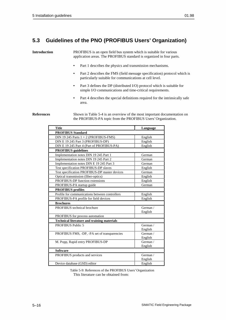
5 Installation guidelines 01.98
SIMATIC Field Engineering Package5–16
5.3 Guidelines of the PNO (PROFIBUS Users’ Organization)
Introduction PROFIBUS is an open field bus system which is suitable for variousapplication areas. The PROFIBUS standard is organized in four parts.
• Part 1 describes the physics and transmission mechanisms.
• Part 2 describes the FMS (field message specification) protocol which isparticularly suitable for communications at cell level.
• Part 3 defines the DP (distributed I/O) protocol which is suitable forsimple I/O communications and time-critical requirements.
• Part 4 describes the special definitions required for the intrinsically safearea.
References Shown in Table 5-4 is an overview of the most important documentation onthe PROFIBUS-PA topic from the PROFIBUS Users’ Organization.
Title LanguagePROFIBUS StandardDIN 19 245 Parts 1 + 2 (PROFIBUS-FMS) EnglishDIN E 19 245 Part 3 (PROFIBUS-DP) EnglishDIN E 19 245 Part 4 (Part of PROFIBUS-PA) EnglishPROFIBUS guidelinesImplementation notes DIN 19 245 Part 1 GermanImplementation notes DIN 19 245 Part 2 GermanImplementation notes DIN E 19 245 Part 3 GermanTest specification PROFIBUS-DP slaves EnglishTest specification PROFIBUS-DP master devices GermanOptical transmission (fiber-optics) EnglishPROFIBUS-DP function extensions EnglishPROFIBUS-PA startup guide GermanPROFIBUS profilesProfile for communications between controllers EnglishPROFIBUS-PA profile for field devices EnglishBrochuresPROFIBUS technical brochure German /
EnglishPROFIBUS for process automationTechnical literature and training materialsPROFIBUS Public 5 German /
EnglishPROFIBUS FMS, -DP, -PA set of transparencies German /
EnglishM. Popp, Rapid entry PROFIBUS-DP German /
EnglishSoftwarePROFIBUS products and services German /
EnglishDevice database (GSD) editor English
Table 5-9: References of the PROFIBUS Users’ OrganizationThis literature can be obtained from:

01.98 5 Installation guidelines
SIMATIC Field Engineering Package 5–17
UK: The PROFIBUS Group USA: PROFIBUS Trade Organization1, West Street 5010 East Shea Blvd., Suite C-226GB-P014-4DH Titchfield, Hants USA Scottsdale, AZ 85254-4683


01.98 6 Hardware configuring (project example)
SIMATIC Field Engineering Package 6–1
Hardware configuring (project example)
This chapter contains:
6.1 Configuring a station 6–3
6.1.1 Creating a station and starting the hardware configuration 6–4
6.1.2 Configuring the station 6–5
6.1.3 Loading the hardware configuration into a CPU 6–7
6.2 PROFIBUS-DP distributed I/O 6–8
6.2.1 Inserting a DP slave in a station 6–8
6.2.1.1 Device database (GSD files) 6–8
6.2.1.2 Using a SITRANS P via a DP/PA coupler 6–9
6.2.1.3 Using an ET 200M with a HART module 6–10
6.3 Station diagnostics 6–11
6.4 SITRANS P parameter assignment with SIMATIC PDM 6–12
6

6 Hardware configuring (project example) 01.98
SIMATIC Field Engineering Package6–2
Introduction• Where the new field engineering is not directly affected, this chapter does
not cover the configuration and installation of AS and OS. Further detailsare described in the references from /100/.
• A knowledge of the systems and devices used is a prerequisite forunderstanding the following explanations.
• The communications paths within SIMATIC S7/PCS 7 are representedschematically in Fig. 6-1 to facilitate understanding.
Engineering System ES(CFC-Bibliothek: Stellvertreter-Bausteine,SIPROM: Feldgeräte-Diagnose, - IBS,
Netz-Projekt.: DP/PA-Link, Feldgeräte)
PROFIBUS-DP, up to 12 MBit/s
DP/PA-Link
4-20 mA+ HART
ET 200 M
SIMATIC S7-400
Operating and MonitoringSystem OS (WinCC)
PROFIBUS / Ind. Ethernet
PROFIBUS-PA
Configuring
Field devicesdata read/ write
Operatingand monitoringof field devices
DiagnosticsIBS
SIMATIC PCS 7
Fig. 6-1 Communications paths for the intelligent field devices within anautomation system
The taskThe procedure is explained in more detail on the basis of a specific task toshow how PROFIBUS-PA field devices and HART modules are utilized in aproject. The following points are to be implemented in the project:
• Simple level control is to be created.
• The process signal will be acquired by a field device with PROFIBUS-PAconnection.
• The disturbance variable will be acquired via an analog input module withHART function, incorporated in the ET 200M I/O system.
• The actuating signal will be emitted via an analog output module withoutHART function via the ET 200M I/O system.
• Two separate PROFIBUS systems will be used:
− PROFIBUS-PA (DP line 1)
− ET 200M (DP line 2)
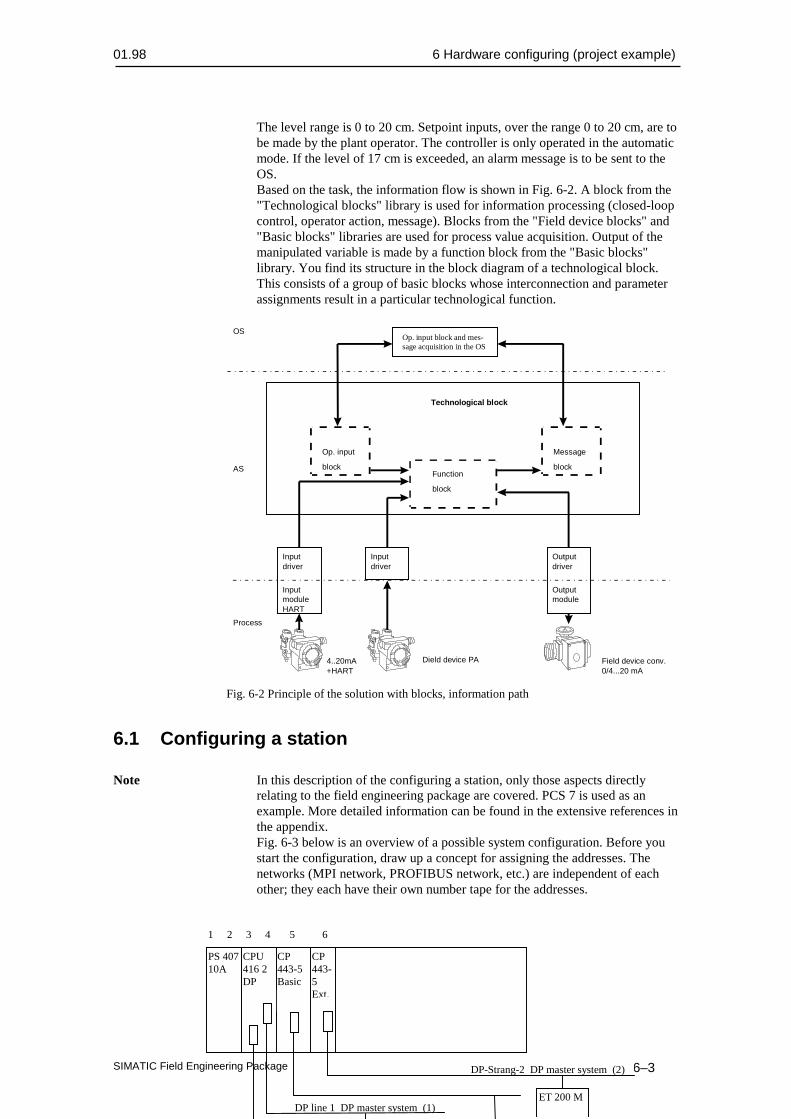
01.98 6 Hardware configuring (project example)
SIMATIC Field Engineering Package 6–3
The level range is 0 to 20 cm. Setpoint inputs, over the range 0 to 20 cm, are tobe made by the plant operator. The controller is only operated in the automaticmode. If the level of 17 cm is exceeded, an alarm message is to be sent to theOS.Based on the task, the information flow is shown in Fig. 6-2. A block from the"Technological blocks" library is used for information processing (closed-loopcontrol, operator action, message). Blocks from the "Field device blocks" and"Basic blocks" libraries are used for process value acquisition. Output of themanipulated variable is made by a function block from the "Basic blocks"library. You find its structure in the block diagram of a technological block.This consists of a group of basic blocks whose interconnection and parameterassignments result in a particular technological function.
Op. input
blockFunction
block
Message
block
Technological block
Inputdriver
InputmoduleHART
Outputdriver
Outputmodule
Inputdriver
4..20mA+HART
Dield device PA Field device conv.0/4...20 mA
Process
AS
OSOp. input block and mes-sage acquisition in the OS
Fig. 6-2 Principle of the solution with blocks, information path
6.1 Configuring a station
Note In this description of the configuring a station, only those aspects directlyrelating to the field engineering package are covered. PCS 7 is used as anexample. More detailed information can be found in the extensive references inthe appendix.Fig. 6-3 below is an overview of a possible system configuration. Before youstart the configuration, draw up a concept for assigning the addresses. Thenetworks (MPI network, PROFIBUS network, etc.) are independent of eachother; they each have their own number tape for the addresses.
CP443-5Ext.
CP443-5Basic
CPU416 2DP
PS 40710A
DP-Strang-2 DP master system (2)
DP line 1 DP master system (1)ET 200 M
1 2 3 4 5 6

6 Hardware configuring (project example) 01.98
SIMATIC Field Engineering Package6–4
Fig. 6-3 Example of hardware configuration
Note:
Further information on configuring the hardware can be found in the manual/100/.
6.1.1 Creating a station and starting the hardware configuration
To enter into configuring and parameter assignment, you need a station in yourproject which you can only insert directly under a project:
• Open the SIMATIC manager.
• Open a new project with a new name (e.g. Controller).
• Mark the project in the left part of the project window.
• Using menu command Insert > Station > SIMATIC 400 station, insert anew object. The station will be inserted with a preset designation (e.g.SIMATIC 400 station(1), SIMATIC 400 station(2), etc.). You can replacethe station designations with system-related names (such as AS1).
• When you double click on the SIMATIC station (right window) the"Hardware" icon will appear on the right window.
• Double click on the "Hardware" icon to open the configuring dialog.
• Either the hardware catalog is displayed automatically or you open thecatalog with View > Catalog.
DP slave
SITRANS P

01.98 6 Hardware configuring (project example)
SIMATIC Field Engineering Package 6–5
6.1.2 Configuring the station
Once you have created the station, assemble the hardware components asdescribed in the task description:
• Open catalog "SIMATIC 400" in the hardware catalog
Rack Open catalog "Rack 400" and insert basic board UR2 by double clicking(single clicking on the components will show the order number). The first slotof the rack will be automatically preselected as the current location.
Power supply Open catalog "PS-400" and select power supply "PS 407-10A" by doubleclicking. HW-Config automatically places the module at the current slot in therack and marks the next free location as the current location.
CPU Open "CPU 400" and select CPU 416-2DP. A PROFIBUS-DP connectionis integrated in this CPU, so you must configure the DP network as the nextstep.
Note:
Ensure that a check symbol is entered in front of "Station is connected toselected network". Only then will you have a connection to the DP networkwith your station.
DP line 1 The following steps must be taken for parameter assignment of the DP(CPU) interface integrated in the CPU for DP line 1:
• Enter the address (address 2) with which the integrated DP interface canbe addressed on the bus (see also Fig. 6-X).
• Enter a new subnetwork for the DP line (NEW button) and change thename to "DP line 1".
• Enter the parameters for "Network settings" according to your system (e.g.for "DP line 1" the highest PROFIBUS number: 126; baud rate: 45.45kbit/s using a DP/PA coupler; profile: DP) and complete the menus for theDP network with "OK". "DP master system (1)" will be displayed.
• If entries are made under menu item "Lines", the bus parameters will becomputed automatically.
Note:When configuring the input/output drivers, you must convert subnetworknumber "n" of the master system to hexadecimal and enter it at the parameter"Subn1_ID" or "Subn2_ID" in the CFC chart.In our example, this is a 1 corresponding to the DP master system (1).
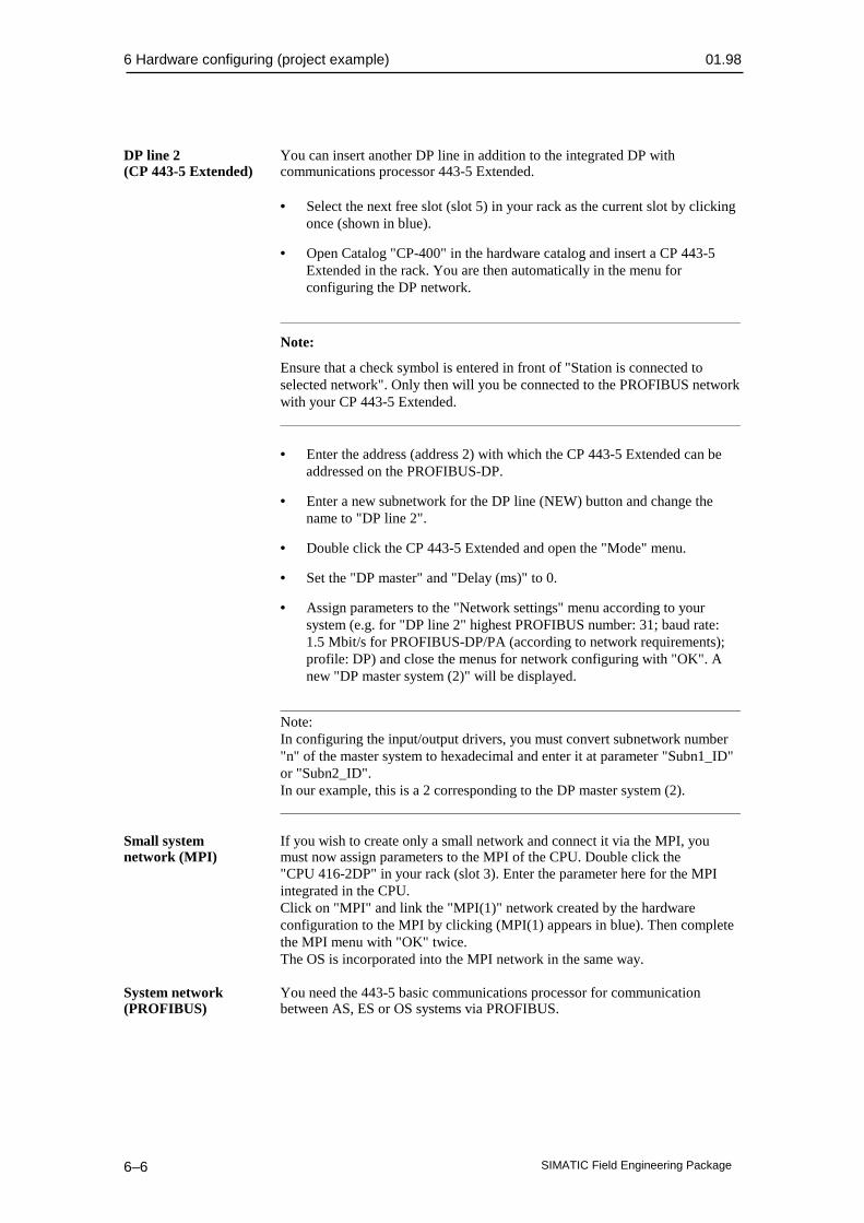
6 Hardware configuring (project example) 01.98
SIMATIC Field Engineering Package6–6
DP line 2 You can insert another DP line in addition to the integrated DP with(CP 443-5 Extended) communications processor 443-5 Extended.
• Select the next free slot (slot 5) in your rack as the current slot by clickingonce (shown in blue).
• Open Catalog "CP-400" in the hardware catalog and insert a CP 443-5Extended in the rack. You are then automatically in the menu forconfiguring the DP network.
Note:
Ensure that a check symbol is entered in front of "Station is connected toselected network". Only then will you be connected to the PROFIBUS networkwith your CP 443-5 Extended.
• Enter the address (address 2) with which the CP 443-5 Extended can beaddressed on the PROFIBUS-DP.
• Enter a new subnetwork for the DP line (NEW) button and change thename to "DP line 2".
• Double click the CP 443-5 Extended and open the "Mode" menu.
• Set the "DP master" and "Delay (ms)" to 0.
• Assign parameters to the "Network settings" menu according to yoursystem (e.g. for "DP line 2" highest PROFIBUS number: 31; baud rate:1.5 Mbit/s for PROFIBUS-DP/PA (according to network requirements);profile: DP) and close the menus for network configuring with "OK". Anew "DP master system (2)" will be displayed.
Note:In configuring the input/output drivers, you must convert subnetwork number"n" of the master system to hexadecimal and enter it at parameter "Subn1_ID"or "Subn2_ID".In our example, this is a 2 corresponding to the DP master system (2).
Small system If you wish to create only a small network and connect it via the MPI, younetwork (MPI) must now assign parameters to the MPI of the CPU. Double click the
"CPU 416-2DP" in your rack (slot 3). Enter the parameter here for the MPIintegrated in the CPU.Click on "MPI" and link the "MPI(1)" network created by the hardwareconfiguration to the MPI by clicking (MPI(1) appears in blue). Then completethe MPI menu with "OK" twice.The OS is incorporated into the MPI network in the same way.
System network You need the 443-5 basic communications processor for communication(PROFIBUS) between AS, ES or OS systems via PROFIBUS.

01.98 6 Hardware configuring (project example)
SIMATIC Field Engineering Package 6–7
• Select the next free slot in your rack (slot 6) as the current slot by clickingonce (shown in blue).
• Open "CP-400" in the hardware catalog and insert a CP 443-5 Basic intothe rack. You are automatically in the menu for configuring thePROFIBUS network.
Note:
Ensure that a check symbol is entered in front of "Station is connected to theselected network". Only then will you later be connected to the PROFIBUSnetwork with your CP 443-5.
• Enter the address with which the CP 443-5 can be addressed on the bus(e.g. address 4).
• Enter a new subnetwork for the PROFIBUS line (NEW button) andchange the name to "WinCC network".
• Assign parameters to the "Network settings" menu according to yoursystem (e.g. for the "WinCC network" highest PROFIBUS number: 126;baud rate: 1.5 Mbit/s; profile: standard) and close the menus for networkconfiguring with "OK".
6.1.3 Loading the hardware configuration into a CPUConfiguring of the SIMATIC station is terminated and you can pass on theinformation to the CPU with "Target system > Load into module". To loadthe module data, the CPU must be in the "STOP" state. A menu is displayed inwhich you can select the target module for loading the hardware configuration.In the example, there is a choice of the "CPU 416-2 DP(1)" and "CP 443-5Basic(1)". If you leave both modules selected, you must load both modules.The "CP 443-5 Extended" is not offered for loading because this module isloaded as the DP master via the CPU.
6 Hardware configuring (project example) 01.98
SIMATIC Field Engineering Package6–8
Note:
The first load operation of a CPU can only take place via the MPI of the CPU.The CP 443-5 for the PROFIBUS is supplied with the communicationsparameters. Each subsequent load operation can then take place viaPROFIBUS. Ensure that the correct module is assigned in the PG/PC interface.
During loading of the "CP 443-5 Basic", two additional queries appear. Youfirst specify that the configuration parameters are to be loaded into the RAM ofthe module (the parameters will be retained in the event of a power failure);additionally, you can decide whether or not the module is to be immediatelyrestarted after loading.
6.2 PROFIBUS-DP distributed I/ONote The following distinctions are made in the configuring of DP slaves:
• Compact DP slaves are directly connected, individual devices(for example, SITRANS P via a DP/PA coupler).
• Modular DP slaves (for example, link modules with up to fivePROFIBUS-PA lines).
• Intelligent slaves (I slaves) (DR 21 compact controllers).
Only aspects relating to PROFIBUS-DP/PA are covered. When a DP/PAcoupler is used in the DP network, the connected PROFIBUS- PA field devicesact as compact DP slaves. If the DP/PA couplers are grouped in a link module,the link module acts as a modular slave.
6.2.1 Inserting a DP slave in a station
6.2.1.1 Device database (GSD files)
To incorporate various PROFIBUS-PA capable field devices, the devicedatabase files supplied for the field devices must be inserted in the hardwareconfiguration.Copy the device database files into STEP 7 catalog "GSD" with the Explorer(standard path: SIEMENS\STEP7\S7Data\GSD).So that the device database files will be known to the hardware configuration,the files must be updated. You carry out this operation in Step7/hardwareconfiguration:Tools > update device database files.After updating, the slaves are available in hardware catalog.

01.98 6 Hardware configuring (project example)
SIMATIC Field Engineering Package 6–9
________________________________________________________Note:If a device database file is not correctly entered during updating (error message"Device database file ..... not found" during positioning of the DP slave) thename of the device database file must be changed so that there is an "X" as thelast character of the name (e.g. old name "abc01023.GSD" new name"abc01023X.GSD").________________________________________________________
6.2.1.2 Using a SITRANS P via a DP/PA coupler
The steps for inserting a slave in a DP/PA line are shown using the example ofa SITRANS P. In this case, the PROFIBUS-PA is linked via a DP/PA couplerto the PROFIBUS-DP.
Note:Please ensure that the hardware requirements for the PROFIBUS-PA aremet and that the baud rate is set to 45.45 kbit/s.
• Open catalog "PROFIBUS-D" from the hardware catalog.
• Open catalog "SITRANS" and use the left mouse key to drag the"SITRANS P" to DP line "DP master system(1)".
• You will see a menu for entering "Select specified configuration" bypreselecting the address identifiers (e.g. PV). For the SITRANS P, selectthe setting "4 bytes/1 byte". You will then have a 4 byte-wide measuredvalue and a 1 byte-wide diagnostic byte in the corresponding driver (CFCchart). The selection affects the addressing of inputs and outputs and,therefore, the configuration. Information on the different specifiedconfigurations can be found in the documentation of the relevant devices.Exit the menu after setting the PROFIBUS address with "OK".
• You will see a menu for making entries for "PROFIBUS stationSITRANS". Please enter the slave address, name and DP line name.However, changes to the bus characteristics affect all the slaves situated onthe line and also change the bus characteristics already set for the master.
• Store the current configuration and load it into your CPU as described in/234/.

6 Hardware configuring (project example) 01.98
SIMATIC Field Engineering Package6–10
6.2.1.3 Using an ET 200M with a HART module
ET200M The steps for inserting a modular slave into a DP line are shown using theexample of an ET 200M with an HART module. DP line 2 was configured asdescribed in Section 6.1.2.:
• Open catalog "PROFIBUS-DP" from the hardware catalog.
• Open "ET 200M" and use the left mouse key to drag "IM153-2" to DPline "DP master system(2)".
Note:
Remember that you can use a passive backplane bus or an active backplane bus(removal and insertion of I/O modules during operation).
• Enter the address of the ET 200M. A menu will appear for entering the"PROFIBUS station characteristics". The subnetwork will beautomatically set by allocating the IM 153-2 to a line. Additionally, youcan change the characteristics of the DP line (highest number of stations,baud rate, profile). However, changes will affect all the slaves situated onthe line and will change the bus characteristics already set at the master.Exit the menu with "OK" after setting the bus number.
• Select the first slot in the ET 200M (slot 4) as the current slot (bluesurrounding) and open the hardware catalog of the IM 153-2, which youhave dragged to the line.
• Open a module type "AI-300" (analog inputs) and select moduleSM 331 AI2xHART by double clicking. This module will automaticallybe assigned to the current slot in the ET 200M, and the next free slot willbecome the current slot.
• Then open module type "AO-300" (analog outputs) and select module SM332 AO 4x0/4..20mA by double clicking. This module will automaticallybe assigned to the current slot in the ET 200M, and the next free slot willbecome the current slot.
Note:
Please ensure that you do not use 8 analog modules with 8 channels each in anET 200M. Eight analog modules with 8 channels each (2 bytes per channel =16 bytes) occupy 128 bytes in an ET 200M. However, the IM 153 only allows124 bytes of useful data; the remaining 4 bytes are diagnostic data. /140/
• After assigning the modules to the slots, you can double click a module inthe ET 200M to set the characteristics of the module (current or voltage,live or dead zero, etc.). For assigning parameters to the individualmodules, please consult the module descriptions.
01.98 6 Hardware configuring (project example)
SIMATIC Field Engineering Package 6–11
Note:
When you select an ET 200M, a detailed view of the configured modules in theselected ET 200M will appear, displayed line by line in a table.
HART module The HART module is represented on three lines in the detailed view of theET 200M:
1. HART module itself
2. HART channel 1
3. HART channel 2
• By double clicking the first line of the displayed HART module, you canset the characteristics of the module (current signal, live or dead zero,diagnostic alarm, etc.). For the assignment of parameters, please consultthe module description /503/.
Note:
For operation without HART functions, you can use the current range0/4 to 20 mA; for operation with HART function the current range of4 to 20 mA defined in the HART device will apply.
• Store the current configuration and load it into your CPU.
SIMATIC PDM By double clicking the first or second channel of the displayed HARTmodules, you start the SIMATIC PDM parameter assignment software tool.A device selection window will open first. All the HART protocol-capablefield devices available in SIMATIC PDM will appear in the device selectionwindow.The remaining procedure is the same as that described in Section 6.4 as anexample for a PROFIBUS-PA device.
6.3 Station diagnosticsYou have the facility for reading out the current status of modules for aconfigured station. A prerequisite is that there is a connection betweenautomation system and PC/PG.
• In the SIMATIC Manager, select the menu command "View > Online".You will see an online view of you station.
• Open the AS from which you wish to read the diagnostic data (click on the"+" in front of the AS).
• Open the CPU.
• Select the program in the CPU with a click.
• Execute menu command "Target system > Module state".

6 Hardware configuring (project example) 01.98
SIMATIC Field Engineering Package6–12
• Select "Diagnostic buffer" in the menu.
In the "Events" window, you will see messages of events in brief form. If youclick onto an event in this window, a detailed description of the event willappear in the lower window. By clicking on "Event help" you can obtainfurther instructions as to the assessment of events or clearing of an existingfault.
6.4 SITRANS P parameter assignment with SIMATIC PDM
Note Section 6.1.1.2 describes how you incorporate a field device with PA profilein the hardware configuration. This section shows how you can assignparameters to this field device with parameter assignment tool SIMATICPDM. However, only a few aspects are mentioned here. The online help isexpressly referred to. The parameter assignment interface represented bySIMATIC PDM largely results from the DD description supplied with the fielddevices. A description of individual parameters and parameter assignmentoperations can be found in the device manuals. The online help is available forfurther support.
Start You start SIMATIC PDM by double clicking on the field device symbolin the hardware configuration.
Device selection In the device selection window, you will find all the field devices availablein SIMATIC PDM which may pertain to a device database (GSD).
• Double click onto the SITRANS P symbol on the DP line to obtain the"Device selection" menu.
• Open catalog "PROFIBUS-PA".
• Open catalog "Siemens".
• Select the device type (SITRANS P).
• Select the type of measurement (absolute pressure).
• Select the measuring range (250 mBar).
Access authorization The access authorization (password) for the parameter groups in SIMATICPDM is defined in the "user" window. A distinction is made between twoaccess authorizations:
• The specialist has access to all writable parameters.
• The maintenance operator has only restricted read/write access to theparameters.
Start menu The display which opens consists of three parts:
• Menu bar for data management / data transfer

01.98 6 Hardware configuring (project example)
SIMATIC Field Engineering Package 6–13
• Parameter tree for fast access to individual parameter groups
• Parameter list
The contents of the parameter tree and parameter list are governed by the DDdescription.
Parameter lists You can change all parameter fields with a white background in parameterlists. Changed parameters and the corresponding parameter tree branch aremarked. The marking is only removed:
• Upon archiving in the database;
• upon transfer of the parameters to the field device.
Data management The data record of each field device can be
• edited offline;
• archived in a database;
• read out of the field device;
• transferred to the field device
• or printed.
Online functions The following online functions can be used with SIMATIC PDM:
• Measured value indication with status
• Alarm status
• Device status
• Address change


01.98 6 Hardware configuring (project example)
SIMATIC Field Engineering Package 6–1

7 Software configuring (project example) 01.98
SIMATIC Field Engineering Package7–2
Software configuring (project example)
This chapter contains:
7.1 Project example: Control loop (CFC) 7–3
7.2 Project example: Sequential control system with two-step control (SFC) 7–6•
7

01.98 7 Software configuring (project example)
SIMATIC Field Engineering Package 7–3
The task On the basis of the task described in Chapter 6, the first example in thischapter describes the implementation of the control loop as a continuouscontrol loop using the CFC configuring tool. In the second example, thecontrol loop is described as a two-step control loop using the SFC configuringtool.
7.1 Project example: Control loop (CFC)
CFC The continuous function chart (CFC) is a graphics editor. It serves to createan overall software structure for a CPU from prepared blocks (blocks writtenby the user or adopted from libraries). The blocks are positioned on functioncharts, assigned parameters and interconnected. This results in an automationstructure which is loaded into the AS after generation of the executablemachine code.
Note:
A detailed description of the CFC can be found in the manual /254/.
Basic mode You work with graphics in the CFC editor: You select prepared blocks fromof operation the available set of blocks, position them with drag&drop on the chart, a kind
of "drawing sheet", and interconnect them with mouse clicks. You need not beconcerned with such details as algorithms or the allocation of machineresources, but can concentrate on the technological aspects of configuring.
The run characteristics of the blocks are defaults but can be adapted separatelyfor each block. A considerable aid to working is that you can copy individualblocks or entire groups of blocks from chart to chart or shift them. The blockinterconnections are retained.When you have created all the functions, you generate the executable machinecode by clicking the mouse, load it into the target system and test it with theCFC test functions provided for the purpose.
Selecting the Implementation of the solution principle shown in Fig. 6-2 is executed inblocks steps. The AS hardware was configured with STEP 7 resources in Chapter 6,
i.e. it is already known which analog input/output modules will be used, in which rack and at which slot they are installed and to which module channel the relevant level sensor (PROFIBUS-PA), flow sensor (HART) or actuator (control valve) is connected. The software can be structured under CFC with this assumption. For use of the blocks under simple STEP 7 methods (STL) however, you must program the interconnections, parameter assignments, allocation of various flags and block calls in the corresponding OBs. In neither case do you need to program and test the various functions used. In this example, we use the extensive block libraries made available to you in PCS 7.

7 Software configuring (project example) 01.98
SIMATIC Field Engineering Package7–4
Drivers
• Block IN_A1 is selected from the "Driver blocks" section of the "Basicblocks" library for reading in the temperature (analog input moduleSM 331 AI2xHART is supported by it).
• The PA_AI block is selected from the "Driver blocks" section of the"Field device blocks" library for reading in the level (the SITRANS Ppressure transducer is supported by it).
• The OUT_A1 block is selected from the "Driver blocks" section of the"Basic blocks" library to output the manipulated variable of the controller(the accepted analog output module is supported by it).
• Make a note of the subnetwork, rack and slot numbers of the modules used(you defined these with STEP 7 during hardware configuring), the channelnumbers and measuring ranges of the connected process signals formodules with the ET 200M. You must use these specifications whenstructuring the individual driver blocks.
• Make a note of the subnetwork and slave numbers of the connectedPROFIBUS-PA devices (you defined these with STEP 7 during hardwareconfiguring). You must use these specifications when structuring theindividual driver blocks.
Function blocks
The tasks of operating, controlling and signaling can be handled with a singleblock, the CTRL_PID block. It has all the necessary characteristics for the taskpresented:
• PID controller
• Operable with limits
• Signaling capability
This block can be found in the "Technological blocks" library.
Note:
Compared to the solution from the "Basic blocks" library, this solution for thesubtasks (control, limit monitoring, operating and monitoring as well assignaling) with a CTRL_PID block results in a shorter runtime, smallermemory requirement and lower structuring overhead.
Structuring the Described in the following is the procedure using the CFC for the taskblocks (as the standard tool for configuring process-engineering plants). For
details of the CFC handling or project management, please consult the CFCmanual.
• Place a chart with a designation corresponding to the task (e.g. LICA_123)in the chart container of your project.

01.98 7 Software configuring (project example)
SIMATIC Field Engineering Package 7–5
• Open the chart.
• Position one entity of each of the previously selected block types (in theexample, one IN_A1, PA_AI, OUT_A1, CTRL_PID in each case) on yourchart by transferring it from the block library.
• Name the blocks according to your wishes.
• For editing (CFC keyword "Run characteristics") register all entities in acommon time-interrupt OB (e.g. OB32). In the sequence for block callsfrom the OB, the general rule "Read in–>Edit–>Output" must be followed.To specify the sequence, you must establish where each block obtains itsparameters. As a rule, it must be reported to all other blocks from which itobtains interconnected values. In this example:IN_A1, PA_AI, CTRL_PID, OUT_A1.
• Interconnect the outputs of the blocks supplying values to thecorresponding inputs of the blocks which process these values.
• With each entity, assign parameters to the inputs whose default valuesmust be adapted to specific process specifications. In this example, thoseare at least the following parameters:
− – IN_A1: SUBNET1_ID, RACK1_NO, SLOT1_NO, CHANNEL,VHRANGE, CUR_VOL.
− – CTRL_PID:
− – Adapt GAIN, TN, TV and TM_LAG to the plant behavior.
− – SP_HLM, SP_LLM for setpoint limiting.
− – PVH_ALM and message text (if desired) for OS.
− – OUT_A1: SUBNET1_ID, RACK_NO, SLOT_NO, CHANNEL,UHRANGE, CUR_VOL
• Interconnect the outputs to the inputs according to the diagram inFig. 6-2.
• Generate the AS code and load it into the AS. Test the structure with theonline testing aids.
• Configure the OS image block of the CTRL_PID (see its description,section entitled "Operator control and process monitoring via OS" /254/).
Note:
This simple example contains no reaction to error indications of the individualblocks. The example can be extended by inserting MUX2_R blocks at variouspoints in the structure. These can be interconnected to the error outputs of theblocks (ENO or QERR) to provide a safety/substitute value for furtherprocessing in the event of an error.

7 Software configuring (project example) 01.98
SIMATIC Field Engineering Package7–6
7.2 Project example: Sequential control system with two-stepcontrol (SFC)
SFC A sequential function chart (SFC) is a sequential control system. The SFCeditor is a tool for creating sequential control.In the following text, SFC is understood to mean either the sequential controlsystem or chart or the editor, according to the context.An SFC is uniquely allocated to a CPU where it is fully processed. However, itmay also relate to automation functions of other CPUs.
Basic method In the SFC editor, you create the chart with graphics. The structural elementsof operation of the chart are positioned according to specific rules. You need not be
concerned with details such as algorithms or the allocation of machineresources, but can concentrate on the technological aspects of configuring.
When the chart topology has been created, you change to the detailedrepresentation (zoom configuring) and assign parameters to the individualelements; this means you configure the actions and conditions.After configuring, you let the SFC generate the executable machine code; youthen load it into the target system and test it with the SFC test functions.After transfer of the charts, WinCC offers you a convenient graphicvisualization of your charts without additional configuring overhead (SFCvisualization).
• Insert an SFC in your chart container. You can change the chart nameunder Characteristics.
• Open the chart with a double click and create your sequential controlsystem.
• For editing (Characteristics >Run) register the chart in a time-interruptOB (e.g. OB34).
• In all representations (SIMATIC manager, dialog fields for selecting thecharts, reference data, documentation, etc.) the chart name is extended toinclude the technological hierarchy if it is assigned to a hierarchycontainer.

01.98 7 Software configuring (project example)
SIMATIC Field Engineering Package 7–7
Additional run By clicking "Characteristics", you open a second dialog field for checkingcharacteristics and for entering additional run characteristics..
• Leave the default "1" for reduction unchanged. This means that the SFCwill be processed with each run.
• A phase shift to achieve a different load distribution within the CPU is notrequired in this project. Therefore, leave the default "0" unchanged.
• Click the Autostart field so that the sequential control system will bestarted immediately after loading into the AS.
• The default mode "Step control with transition (SSMT)" also remainsunchanged because the SFC is to run automatically without other operatoractions.
• For run options, click the field for cyclic operation and for commandoutput; leave the time monitoring switched off.
• Close both dialog fields successively with "OK". You can now turn toconfiguring the chart topology.
Chart topology You now create the structure of the sequential control system. You havedecided which actions and conditions are necessary for the two-step control,and insert the basic and structural elements accordingly.
• Insert the transitions, steps and loops into the chart.
Detailed configuring For the next configuring step, go over to the detailed representation of thesteps and transitions. The assigning of parameters to these elements is thereforealso known as "Zoom configuring".The steps and transitions are linked to the "Block world" with zoomconfiguring.
• Open the "Object characteristics" dialog field for the first step and edit it.Then work step by step, followed by all transitions in succession.
Compiling You must then compile the graphically created chart in the machine code ofthe target system.
• Click on "Compile... " in the "Chart" menu.
• The "Compile" dialog field is displayed. It contains the name of the targetsystem (CPU414-2 DP1) and the chart container name whose contents willbe compiled. The scope of compilation can be selected with the optionbuttons "All" or "Delta".
Loading the AS After compilation, the dialog field appears with the result protocol. Thereare no errors and no warnings; you can now close the dialog field.The compilation is completed and the blocks have been generated. The nextstage is to load the generated program into the target system.
Target system > Load
7 Software configuring (project example) 01.98
SIMATIC Field Engineering Package7–8
Note:
A detailed description of SFC charts can be obtained from the manual \255\.
Visualization in You transfer your created SFC charts to the WinCC data store. WithoutWinCC additional configuring overhead, you can then display the current status
of the sequential controllers in the WinCC runtime, and operate the controlsystem according to the preset authorization stage.
• In key set 2 (Runtime), click on the button for SFC visualization.
• From the displayed overview, select your desired chart; you will see theselected chart in the overview.
• Double-click the overview and you will see a detailed view of your chart.
• In the detailed view, you can control the chart (switch on, switch off, stepcontrol with transitions, step control with condition, etc.) and use a doubleclick to display the transitions or steps with the current statuses andremarks from the engineering system.
Furthermore, you have a facility for incorporating an SFC standard display in aprocess display. The chart will then be allocated to a process display and theoperator need not filter out the required chart from a large number of them.
Displaying the SFC imageInsert the "SFC control" image block in your display.
Connecting the SFC display• In the dynamic wizard, select "SFC" from the upper window.
Note:
When you display an SFC image in a process image for the first time, the scriptfor the "SFC display" is not yet available. In this case, click onto the "Readin..." button in the displayed dialog field and insert the script"Script.wnf" (path: WinCC\wscripts\wscripts.deu)._______________________________________________________________
• Select your desired chart and specify the window with which the SFC is tobe displayed after clicking the corresponding button in the SFC display(overview or extract). Exit the wizard.
• Store your process display and exit the graphics designer.

01.98 References
SIMATIC Field Engineering Package 1
References
/100/ Installationshandbuch: Automatisierungssysteme S7-400,M7-400,
Aufbauen
/101/ Referenzhandbuch: Automatisierungssysteme S7-400, M7-400,
Baugruppendaten
/102/ Operationsliste: Automatisierungssystem S7-400,CPU 414/416
/140/ Dezentrales Peripheriegerät ET 200MHandbuch
/141/ Dezentrales Peripheriegerät ET 200LHandbuch
/231/ Benutzerhandbuch: Basissoftware für S7 und M7,STEP 7
/232/ Handbuch: AWL für S7-300/400,Bausteine programmieren
/233/ Handbuch: KOP für S7-300/400,Bausteine programmieren
/234/ Programmierhandbuch: Systemsoftware für S7-300/400,Programmentwurf
/235/ Referenzhandbuch: Systemsoftware für S7-300/400 System-und Standardfunktionen
/236/ Handbuch: FUP für S7-300/400Bausteine programmieren
/237/ Gesamtindex, STEP 7
/250/ Handbuch: SCL für S7-300/400,Bausteine programmieren
/251/ Handbuch: GRAPH für S7-300/400,Ablaufsteuerungen programmieren
/252/ Handbuch: HiGraph für S7-300/400,Zustandsgraphen programmieren
/253/ Handbuch: C für S7-300/400,C-Programme erstellen
/254/ Handbuch: CFC,Basis–Teil und Systemspezifischer Teil: S7 / M7 TechnologischeFunktionen grafisch verschalten
/255/ Handbuch: Process Control System PCS 7,SFC Technologische Ablaufsteuerungen projektieren
/256/ Handbuch: Process Control System PCS 7,ES Anlagen technologisch und phasenübergreifend strukturieren
A

References 01.98
SIMATIC Field Engineering Package2
/257/ Handbuch: Process Control System PCS 7,BATCH flexible–System Chargenprozesse automatisieren
/258/ Referenzhandbuch: Process Control System PCS 7,Bibliothek Basisbausteine
/259/ Referenzhandbuch: Process Control System PCS 7,Bibliothek Technologische Bausteine
/260/ Referenzhandbuch: Process Control System PCS 7,Bibliothek Feldgerätebausteine
/261/ Systembeschreibung: Process Control System PCS 7
/280/ Programmierhandbuch: Systemsoftware für M7-300/400,Programmentwurf
/281/ Referenzhandbuch: Systemsoftware für M7-300/400,System- und Standardfunktionen
282/ Benutzerhandbuch: Systemsoftware für M7-300/400,Installieren und Bedienen
/290/ Benutzerhandbuch: ProC/C++ für M7-300/400,C-Programme erstellen
/291/ Benutzerhandbuch: ProC/C++ für M7-300/400,Debugger für C-Programme
/300/ Broschüre: SIMATIC WinCC,Windows Control Center
/301/ Handbuch: SIMATIC WinCC,Control Center + Global Script + User Administrator
/302/ Handbuch: SIMATIC WinCC,Graphics Designer
/303/ Handbuch: SIMATIC WinCC,Tag Logging + Alarm Logging + Report Designer
/304/ Handbuch: SIMATIC WinCC Options,Basic Process Control + Advanced Process Control + ChipCard +Video
/500/ Handbuch: SIMATIC Communications,NCM S7-H1 (Ethernet)
/501/ Handbuch: SIMATIC Communications,NCM S7-L2 (PROFIBUS)
/502/ Handbuch: SIMATIC,Buskopplung DP/PA
/503/ Automatisierungssystem: SIMATIC ,S7-300,M7-300,ET200MEx-PheripheribaugruppenReferenzhandbuch
/504/ Geting up: SIMATIC PCS 7,Leitfaden

01.98 References
SIMATIC Field Engineering Package 3
/505/ PROFIBUS-PA ,PNO - Leitfaden
/506/ PROFIBUS Standard,DIN 19 245 Teil 1 + 2 (PROFIBUS-FMS)
/507/ PROFIBUS Standard,, DIN E 19 245 Teil 3 (PROFIBUS-DP)
/508/ PROFIBUS Standard,PNO - Leitfaden DIN E 19 245 Teil 4 (Teil von PROFIBUS-PA)
/509/ PROFIBUS Richtlinie ,Implementierungshinweise DIN 19 245 Teil 1
/510/ PROFIBUS Richtlinie ,Implementierungshinweise DIN 19 245 Teil 2
/511/ PROFIBUS Richtlinie ,Implementierungshinweise DIN E 19 245 Teil 3
/512/ PROFIBUS Richtlinie ,Prüfvorschrift PROFIBUS-DP Slaves
/513/ PROFIBUS Richtlinie ,Prüfvorschrift PROFIBUS-DP Master Geräte
/514/ PROFIBUS Richtlinie ,Optische Übertragungstechnik (LWL)
/515/ PROFIBUS Richtlinie ,PROFIBUS-DP Funktionserweiterungen
/516/ PROFIBUS Richtlinie ,PROFIBUS-PA Inbetriebnahmeleitfaden
/517/ PROFIBUS Profile ,Profil für die Kommunikation zwischen Controllern englisch
/518/ PROFIBUS Profile,PROFIBUS-PA Profil für Feldgeräte
/519/ Automatisierungssystem: SIMATIC ,S7-300,M7-300,ET200MEx-PheripheribaugruppenGrundlagen Explosionschutz


01.98 References
SIMATIC Field Engineering Package 1

Index 01.98
SIMATIC Field Engineering Package2
Index
A
Addressing 3–7
B
Bending radius 5–7Block libraries 3–13Bus cycle time 3–6Bus system 5–2
C
Cable capacitance 5–8Cable laying 5–6Cable specification 5–8, 5–9Cable type 5–8Cables 5–6CFC 7–2COM PROFIBUS 2–5Communications paths 6–2Configuring 2–5, 6–3Conformity 1—2Connection system 5–2Connectors 5–14
D
Data transmission 5–4DD 3–12Device database 6–8Device database file 3–12Device description 3–12Device profiles 3–9Driver function blocks 3–13
E
Equipotential bonding 5–6, 5–13
F
Field device blocks 2–5, 3–13
G
Grounding 5–13GSD 3–12
H
Hardware 3–2
B

01.98 Index
SIMATIC Field Engineering Package 3
Hardware components 2–2Hardware configuring 2–5HART 1—6, 1—12, 2–3, 3–9HART modules 3–4
I
Impedance 5–8Installation 5–4Installation guidelines 5–1Installation site 5–4Installing 5–6Interface module IM 157 3–3Interoperability 3–10
L
Lightning protection 5–13Link 1—9, 2–3, 3–7, 3–8
M
Machine code 7–2
P
PA profile 3–9, 3–11Parameter assignment 2–5Potential savings 1-10Power consumption 5–3PROFIBUS 1—5PROFIBUS DP 1—5, 1—7PROFIBUS PA 1—5, 1—8Project scope 3–6
R
Redundancies 5–4RS 485 5–9Run characteristics 7–6
S
Sequential control system 7–5SFC 7–5Shield 5–6Shielding 5–8Shielding concept 5–11Signal attenuation 5–8PDM 2–5, 6–12Small system network 6–6Station diagnostics 6–12System network 6–7
T
Tools 5–15

Index 01.98
SIMATIC Field Engineering Package4
Transceiver 1-9, 2–2, 3–6, 3–7

01.98 Index
SIMATIC Field Engineering Package 1

Index 01.98
SIMATIC Field Engineering Package2
Glossary
AAddress An address is the identification for a particular operand or operand range.
Examples: input I 12.1, flag word FW 25, data block DB 3.
Analog module Analog modules convert analog process values, such as temperature, todigital values which can be further processed by the CPU, or convert digitalvalues to analog manipulated variables.
Arrangement, There is a centralized arrangement when the process I/Os and CPU arecentralized accommodated in the same rack or in expansion units in the same or adjacent
cabinet.
Arrangement, There is a distributed arrangement when the process I/Os are not arrangeddistributed with the CPU in the same rack or in the same or adjacent cabinet, but
are separated and interconnected by a communications bus (e.g. field bus).
Automation system An automation system is a → programmable controller with control system functionality, comprising at least one → CPU, various input and output
modules as well as HMI devices.
BBackplane bus The backplane bus is a serial data bus via which the modules communicate
with each other and via which they are supplied with the required power. Theconnection between the modules is provided by bus connectors.
Baud rate The baud rate is the speed of data transmission; it indicates the number ofbits transmitted per second (baud rate → bit rate).Baud rates of 9.6 kbaud to 12 Mbaud are possible with the ET 200.
Blocks Blocks are parts of a user program, demarcated by their function, structureor purpose.
Bus segment → Segment
CCentral section The central section of an AS comprises the following components: CPU,
rack, power supply, main memory and load memory. The basis is theSIMATIC S7–400 automation system.
CFC A continuous function chart makes function charts in which blocks can be interconnected and assigned parameters.
Chart A chart is the highest hierarchical level of a hierarchical block entity system.It has an implicit type but no interface and therefore cannot be connected.Charts cannot contain charts.
Cold restart During the startup of the AS CPU (e.g. when the mode switch is changed from
C

01.98 Index
SIMATIC Field Engineering Package 3
STOP to RUN or upon POWER ON), either organization block OB 101 (warmrestart only with the S7-400) or organization block OB 100 (cold restart) isfirst processed before the cyclic program processing (OB 1). With a coldrestart, the process image of the inputs is read in and the S7 user program isprocessed, starting with the first command in OB 1.
Configuration The assignment of modules to racks/slots and addresses. A distinction is madebetween the actual configuration (modules plugged in) and the specifiedconfiguration. You preset the latter with STEP 7, COM PROFIBUS (or COMET 200 Windows). The operating system can thus detect modules insertedincorrectly during the → start.
CPU Central processing unit of the S7 automation system with its control andarithmetic unit, memory, operating system and interface for programmingdevice.
DDevice description This is a universal, standardized device and parameter description for(DD) PROFIBUS-PA and HART protocol-capable field devices.
Distributed I/O The distributed I/O are devices situated at a distance from the centralsection and serve for input/output (e.g. field devices or analog and digitalmodules).
DP address Each station must be given a DP address for unique identification on thePROFIBUS-DP. The PC/PG or ET 200 handheld have the DP address "0".The DP master and DP slaves have a DP address in the range 1 to 125.
DP master A → master which behaves according to standard EN 50170, Volume 2,PROFIBUS, is known as a DP master.
DP slave A → slave which is operated on PROFIBUS with the PROFIBUS-DPprotocol and which behaves according to standard EN 50170, Volume 2,PROFIBUS, is known as a DP slave.
DP standard DP standard is the bus protocol according to standard EN 50170, Volume 2,PROFIBUS.
EEngineering system A PC-based configuring system with which the process control system can
be configured or adapted to the required tasks, in a convenient and visualmanner.
ES → Engineering system
ET 200 The ET 200 distributed I/O system with the PROFIBUS-DP protocol is a busfor connecting distributed I/Os to a CPU or adequate DP master. ET 200 ischaracterized by fast reaction times because only a few data (bytes) aretransferred. ET 200 is based on standard EN 50170, Volume 2, PROFIBUS.ET 200 operates according to the master-slave principle. DP masters can be,for example, the IM 308-C master interface or the CPU 315-2 DP. DP slaves

Index 01.98
SIMATIC Field Engineering Package4
can be the distributed I/Os ET 200B, ET 200C, ET 200M, ET 200U or DPslaves from SIEMENS or other manufacturers.
FField devices Intelligent field devices can be connected via their field bus interface over
PROFIBUS-DP or PROFIBUS-PA, and thus linked to the control system.Substitute blocks are available for the SIEMENS field devices.
FO The abbreviation for fiber optic (cable) the transmission medium forPROFIBUS.
Function block According to IEC 1131-3 , a function block (FB) is code block with staticdata which has a "memory". A function block offers the facility for transferringparameters in the user program. Function blocks are thus suitable forprogramming frequently recurring complex functions such as closed-loopcontrols and mode selection.
G
H
II/O bus Part of the S7 300 → backplane bus in the automation system, optimized
for the fast exchange of signals between the IM 153 and the signal modules.Useful data (e.g. digital input signals of a signal module) and system data (e.g._default parameter data records of a signal module) are transferred via the I/Obus.
IP 20 Degree of protection to DIN 40050: Protection against touching with thefingers and against the ingress of solid foreign bodies with a diameter of morethan 12 mm.
J
K
L
MMaster When a master is in possession of the token, it can send data to other
stations and request data from other stations: → DP masters are, for example,the CPU 416-2 DP or IM 308-C.
Master-slave A bus access process with which only one station is the → DP master andprocedure all other stations are the → DP slaves.

01.98 Index
SIMATIC Field Engineering Package 5
Message class The message class governs the nature of the message. With SIMATIC PCS 7the message classes are alarm, warning, tolerance, AS and OS control systemmessage, process message, operator input request and operator input message.
Message type There is a further subdivision for each message type (e.g. alarm, warning,tolerance). Together with the message class, this governs the type of message.Examples of messages types are alarm_high, alarm_low, warning_high,warning_low.
Messages, The creating of messages with their texts and attributes. Messages areconfiguring of configured from the CFC/SFC.
Module Module parameters are values with which the behavior of the module can beparameters set. A distinction is made between static and dynamic module parameters.
MPI The multipoint interface is the programming device interface of SIMATICS7. It forms the entry level of a system bus with SIMATIC PCS 7.
NNetwork A network comprises one or more linked subnetworks with any number of
stations. Two or more networks may exist side by side.
OODBC The abbreviation for open database connectivity. This is a Microsoft
technology enabling database access.
OLE The abbreviation for object linking and embedding. This is a Microsofttechnology enabling the linking of and data interchange between programs.
OLM The abbreviation for optical link module. This is an element for connectingthe redundant FO cable of PROFIBUS to the components of PCS 7.
OM The abbreviation for object manager. OMs manage objects persistentlystored there. Applications operate with these objects and execute operations onthem exclusively by invoking object methods.
Organization Organization blocks (OB) form the interface between the operating systemblock of the AS CPU and the user program. The sequence for processing the user
program is specified in the organization blocks.
OS Operator control and process monitoring system.
PParameter A parameter is: 1. a variable of an S7 code block (current parameter,
formal parameter); 2. a variable for setting the behavior of a module. Eachparameterizable module has, when supplied, a meaningful basic setting whichcan be changed by STEP 7.
PCS Process control system.
Index 01.98
SIMATIC Field Engineering Package6
PLC Programmable (logic) controller
PMC Process monitoring and control. Communications mechanisms withSIMATIC S5 and S7.
Process variable The process variable is a resource-neutral (project-global) object. It servesfor linking the AS configuring world (STEP 7, CFC...) to the OS configuringworld (WinCC). It possesses information about the location at which theprocess variable exists at runtime (e.g. network address in the AS) andinformation on specific OS-relevant characteristics.
PROFIBUS PROcess FIeld BUS, the European process and field bus standard defined inthe PROFIBUS standard (EN 50170). It specifies the functional, electrical andmechanical characteristics for a bit-serial field bus. PROFIBUS is a bus systemfor networking PROFIBUS-compatible automation systems and field devices atthe cell and field levels. PROFIBUS is available with the protocols DP (→distributed I/O), FMS (→ fieldbus message specification) or TF (→technological functions).
PROFIBUS-DP The PROFIBUS bus system with the DP protocol. DP stands for distributed I/O (periphery). The ET 200 distributed I/O system is based on standard EN 50 170, Volume 2, PROFIBUS.
Programmable (logic) A controller whose function is stored in the control unit in the form of aprogram. Thus the configuration and wiring of the unit do not depend on the function of the controller. The PLC has the structure of a computer; it consists of a CPU with memory, input/output modules and internal bus system. The I/Os and programming language are oriented to the requirements of the control system.
Project A project is a container for all objects of an automation solution, irrespectiveof the number of stations, modules and their networking.
Q
RRelease All products with an order number have a release; it indicates the version of
the product. The release is incremented with upward-compatible functionextensions, for production-related modifications (the use of new parts /components) and for error corrections.
SSegment The bus cable between two terminating resistors forms a segment. A segment
contains 0 to 32 → stations. Segments can be linked via RS 485 repeaters.
SFB Standard function block, a preprogrammed function block with a definedapplication-specific function.
SFC A sequential function chart serves for creating sequence controllers for

01.98 Index
SIMATIC Field Engineering Package 7
SIMATIC S7. These can be visualized with the SFC visualization package onthe OS.
SIMATIC PCS 7 This is the name of the new control system based on SIMATIC S7.
Slave A slave may only exchange data with the master upon request by the master.Examples of slaves are all DP slaves such as the ET 200B, ET 200C, ET200M, etc..
SPC/SQC The abbreviation for statistical process control/statistical quality control.Methods for quality control by acquiring and evaluating statistical values.
Standard function These are blocks for the CFC which are provided by the SIMATIC PCS 7blocks libraries.
Start events Start events are defined events such as faults or alarms and initiatethe operating system to start a corresponding organization block.
Startup This is run through during the transition from the STOP state to theRUN operating state. It can be initiated by a POWER ON or by the ES.
Station A unit which can send, receive or amplify data via the bus, e.g. DP master,DP slave, RS 485 repeater, active star coupler.
STEP 7 A programming language for creating user programs for SIMATIC S7controllers.
Symbol A symbol is a name defined by the user, taking syntax specifications intoaccount. This name can be used for programming and for operator control andprocess monitoring according to the definition for which it stands (e.g.variable, data type, jump label, block).Example:Operand: I 5.0, data type: BOOL, symbol: emergency-off button
Symbol table A table for assigning symbols (→ name) to addresses for global data andblocks. Example: Emergency-off (symbol), I 1.7 (address), controller (symbol),SFB 24 (block).
System bus This is the bus to which all components such as the AS, OS and ES areconnected and with which they exchange data with one other.
TTerminating A terminating resistor is a resistor for matching the line at the bus cable;resistor terminating resistors are required at the cable and segment ends. With
ET 200, the terminating resistors are switched on/off in the → bus connector.
Type A type represents a pattern for any number of entities and describes howthese entities are structured internally. All entities of a type follow the samebasic definition with respect to behavior and information structure (datastructure), but contain individual data.

Index 01.98
SIMATIC Field Engineering Package8
UUser function A block type created by the user for utilization by the CFC. Block types areblock created, for example, by SCL → Type.
User program The user program contains the structure for the automation programs, aswell as the data for the signal processing with which a plant or process can becontrolled.
V
W
X
Y
Z

01.98 Index
SIMATIC Field Engineering Package 9
Related Documents