© Australian Rail Track Corporation Limited 2010 Disclaimer: This document has been prepared by ARTC for internal use and may not be relied on by any other party without ARTC’s prior written consent. Use of this document shall be subject to the terms of the relevant contract with ARTC. ARTC and its employees shall have no liability to unauthorised users of the information for any loss, damage, cost or expense incurred or arising by reason of an unauthorised user using or relying upon the information in this document, whether caused by error, negligence, omission or misrepresentation in this document. This document is uncontrolled when printed. Authorised users of this document should visit ARTC’s intranet or extranet (www.artc.com.au) to access the latest version of this document. Discipline: Engineering (Signalling) Category: Specification Signals – Design and Rating S1 Applicability SA/WA Primary Source S1 Issue 2.1 4 May 1999 Document Status Version Date Reviewed Prepared by Reviewed by Endorsed Approved 3.0 13 August 2010 Signal Standards Engineer Exec Manager SS&P Chief Operating Officer Risk & Safety Committee 06/04/2009 Amendment Record Version Date Reviewed Clause Description of Amendment 3.0 13 August 2010 3.2.1 – 3.2.4 Reformatted. Sections 3.2.1 to 3.2.4 superseded by ESD-05-01.

Welcome message from author
This document is posted to help you gain knowledge. Please leave a comment to let me know what you think about it! Share it to your friends and learn new things together.
Transcript

© Australian Rail Track Corporation Limited 2010
Disclaimer: This document has been prepared by ARTC for internal use and may not be relied on by any other party without ARTC’s prior written consent. Use
of this document shall be subject to the terms of the relevant contract with ARTC.
ARTC and its employees shall have no liability to unauthorised users of the information for any loss, damage, cost or expense incurred or arising by reason of an unauthorised user using or relying upon the information in this document, whether caused by error, negligence, omission or
misrepresentation in this document.
This document is uncontrolled when printed. Authorised users of this document should visit ARTC’s intranet or extranet (www.artc.com.au) to access the latest version of this document.
Discipline: Engineering (Signalling) Category: Specification
Signals – Design and Rating S1
Applicability
SA/WA
Primary Source
S1 Issue 2.1 4 May 1999
Document Status
Version Date Reviewed Prepared by Reviewed by Endorsed Approved
3.0 13 August 2010 Signal Standards Engineer
Exec Manager SS&P
Chief Operating Officer
Risk & Safety Committee 06/04/2009
Amendment Record
Version Date Reviewed Clause Description of Amendment
3.0 13 August 2010 3.2.1 – 3.2.4
Reformatted. Sections 3.2.1 to 3.2.4 superseded by ESD-05-01.

Engineering (Signalling) Specification S1 Signals – Design and Rating Contents
Contents
1 Scope...................................................................................................... 4
2 Concept Definition / Advice .................................................................... 4
3 Design / Specification............................................................................. 4
3.1 Drawings and Documentation ............................................................. 4
3.1.1 General Requirement ............................................................... 4
3.1.2 Specified Control Tables ........................................................... 5
3.1.3 Signalling Track Plans .............................................................. 5
3.1.4 Signalling and Associated Circuits .............................................. 6
3.1.5 Installation Drawings ............................................................... 7
3.1.6 Equipment Housing Layout Plans ............................................... 7
3.1.7 Mechanical Drawings ............................................................... 8
3.1.8 Maintenance and Installation Manuals ........................................ 8
3.1.9 Engineering Manuals................................................................ 9
3.1.10 Workshop Manuals .................................................................. 9
3.1.11 Operations Manuals ................................................................. 9
3.1.12 Training Manuals and Documentation ......................................... 9
3.1.13 Infrastructure Notices .............................................................. 9
3.1.14 Asset Register....................................................................... 10
3.1.15 Symbols for Plans and Drawings.............................................. 11
3.1.16 Circuit Nomenclature ............................................................. 14
3.1.17 Order of Book of Circuit and Details ......................................... 16
3.2 Design Requirement of Signalling System........................................... 17
3.2.1 Signalling Layout................................................................... 17
3.2.2 Control Table – Locking Section............................................... 17
3.2.3 Control Table – Approach Locking Section ................................. 17
3.2.4 Control Table – Route Locking Section...................................... 17
3.2.5 Control Table – Track Circuits Detection and Pole Change Sections17
3.2.6 Control Table - Point Locking................................................... 18
3.2.7 Signal Circuit Design - General ................................................ 18
3.2.8 Signal Circuit Design - Power Supply and Circuit Protection ......... 18
3.2.9 Signal Circuit Design – Signal Controls ..................................... 19
3.2.10 Signal Circuit Design – Point Controls ....................................... 20
3.2.11 Signal Circuit Design – CTC Controls ........................................ 20
3.2.12 Signal Circuit Design – Active Level Crossing............................. 20
3.3 Point Machine................................................................................. 21
Version 3.0 Date of last revision: 13 August 2010 Page 2 of 31 This document is uncontrolled when printed. See ARTC Intranet for latest version.

Engineering (Signalling) Specification S1 Signals – Design and Rating Contents
3.3.1 General Requirements............................................................ 21
3.3.2 Design and Functional Requirements........................................ 21
3.3.3 Operating Voltages ................................................................ 23
3.3.4 Dual Control Machines............................................................ 24
3.3.5 Rods, Bars and Brackets......................................................... 24
3.4 Cable ............................................................................................ 25
3.4.1 General Requirements............................................................ 25
3.4.2 Type and Application.............................................................. 25
3.4.3 Conductors........................................................................... 25
3.4.4 Insulation, Sheathing and Covering.......................................... 26
3.4.5 Construction......................................................................... 26
3.4.6 Cable and Core Identification .................................................. 26
3.4.7 Cable Drum Requirements ...................................................... 27
3.4.8 Environmental Conditions ....................................................... 27
3.4.9 Cable Test Compliance and Certification ................................... 27
3.4.10 Wire for Signalling Applications ............................................... 28
3.4.11 Type and Application.............................................................. 28
3.5 Enclosure....................................................................................... 29
3.5.1 Equipment Housing General Requirements ................................ 29
3.5.2 Environmental Requirements .................................................. 29
3.5.3 Detailed Requirements ........................................................... 29
3.6 Track Circuit................................................................................... 31
3.7 Active Level Crossing....................................................................... 31
4 Validate and Verify ............................................................................... 31
5 Develop Standards................................................................................ 31
Version 3.0 Date of last revision: 13 August 2010 Page 3 of 31 This document is uncontrolled when printed. See ARTC Intranet for latest version.

Engineering (Signalling) Specification S1 Signals – Design and Rating Scope
1 Scope This document specifies requirements for design and rating work carried out on signal infrastructure.
2 Concept Definition/Advice
3 Design/Specification
3.1 Drawings and Documentation
3.1.1 General Requirement
Documentation and drawings shall be produced utilising the ARTC's standard formats, symbols and nomenclature and shall be presented and arranged in accordance with the ARTC's standard practices.
The typed documents shall be in Microsoft Word 97 format or lower version and presented in three and a half (3 1/2) inch floppy disk or CD ROM. Unless otherwise specified or unless otherwise approved by ARTC all hard copy shall be in A4 or A3 size paper.
The drawings shall be in AUTOCAD Release 13 format or lower version and presented in three and a half (3 1/2) inch floppy disk or CD ROM. Unless otherwise specified or unless otherwise approved by ARTC all hard copy of drawings shall be prepared on A2 or A3 size paper and all roll plans shall be divided into manageable and logical lengths and shall be 450mm wide (max.). A2 and A1 size paper may be allowed for detailed mechanical and structural drawings.
All new and amended drawings and diagrams shall be prepared in AUTOCAD Release 13 format or able to operate under AUTOCAD Release 13.
General line work shall be 0.35mm thick originals must be durable and capable of producing clear legible prints.
All geographically oriented drawings shall have the Mile End direction at the left hand side.
All drawings and diagrams shall be provided with a title block to the approval of ARTC which shall include spaces for Date, Drawing Number, Title, Scale, Contractor's Signature. Revision block shall be provided with spaces for Date, Revision Details, Contractor's Signature. Title blocks shall generally be positioned in the bottom right hand corner of drawings. In the case of roll plans, title blocks shall be provided at each end of drawings. Company names and logos shall not be included unless specifically approved by the ARTC.
All drawings and documentation applicable to Temporary Works including stage work, interface work etc. shall be clearly endorsed as such on each sheet. All details necessary for such Temporary Works shall be added to copy tracings of the existing arrangements and also to copy tracings of final arrangements as appropriate. Different stage work may be presented in a specific colour paper with different colour for each stage.
The ARTC's standard practice of showing work comprising alterations shall be employed. Such practice shall include the detailing of existing wiring, equipment and structures to be removed shall be coloured in yellow on prints. New work shall be coloured in red on prints.
Suitable hard PVC coated covers shall be provided for all final books descriptively titled to show contents including, where relevant, the area included, the book number and the location (and reference number) where the book is to be kept. ARTC shall approve titling of the covers. Books shall be bound such that individual pages may be replaced or added in the future.
The ARTC's standards for symbols and nomenclature are included in clause 3.1.15 and 3.1.16.
Version 3.0 Date of last revision: 13 August 2010 Page 4 of 31 This document is uncontrolled when printed. See ARTC Intranet for latest version.

Engineering (Signalling) Specification S1 Signals – Design and Rating Design/Specification
3.1.2 Specified Control Tables
Control table shall include the locking, approach locking and released feature, route locking and released, detection, pole changed by and any other conditions.
Specified Control Tables will be issued by the ARTC. The Contractor shall be required to highlight on prints of the Control Tables, for any alterations to such Tables arising from detailed design, construction, testing and setting to work of signalling systems.
3.1.3 Signalling Track Plans
The Contractor shall utilise the information given on any Specified Track Plans for the production of straight line Signalling Track Plans. Such Signalling Track Plans shall cover the whole of the Works including interface details at the Contract limits. Plans shall extend sufficiently at Contract limits to detail clearance points for all signals included in the Works.
Overlapping of Signalling Track Plans shall be avoided.
Power system supply, pole lines and distribution information together with trackside cabling details including number of cables, cable sizes, termination points, joints etc. may be drawn below track layouts. Other details to be shown on Signalling Track Plans shall include the following:
a) Location in kilometre of signals, insulated joints etc.
b) Pole lines drop off points
c) Bridges (Over and Under)
d) Power supply locations
e) Level Crossings
f) Stations
g) Relay Boxes
h) Signals
i) Insulated joints
j) Track Circuit leads
k) Point Machines
l) Track Circuits
m) Control Panels
n) Equipment Huts/Relay Room
o) Equipment Locations
p) Relay Rooms
q) Power Supply Locations
r) Outlying point lock
s) Derailers
t) Notice Boards
Signalling Track Plans shall give details of identification of track circuit polarity, location of feed and relay ends.
Version 3.0 Date of last revision: 13 August 2010 Page 5 of 31 This document is uncontrolled when printed. See ARTC Intranet for latest version.

Engineering (Signalling) Specification S1 Signals – Design and Rating Design/Specification
3.1.4 Signalling and Associated Circuits
Drawings of signalling and associated circuits shall be submitted to ARTC as complete interlockings and complete areas for each location. They shall be comprehensive and fully detailed. Such drawings shall contain all the information and details necessary for checking of design, construction, stage work, testing, commissioning and maintenance. Included in such drawings shall be the following:
a) All wiring and circuit elements including internal wiring of equipment.
b) Identification and numbering of contacts, cable cores, circuit breakers, fuses, terminals, arrestors, busbars etc.
c) Tappings, ratings, capacity etc. and relevant details of items of equipment.
d) Internal wiring of control panels, consoles and indication panels, diagrams etc.
e) Power supplies and other units arrangements and power mains distribution.
f) Contact analysis incorporating all relays in appropriate groupings. The contact list shall show the relay name, type, contact arrangement, location for each relay contact, the circuit name.
g) Schematic layouts of all apparatus racks for all equipment locations. Relay rack schematics shall show each relay position, with details of the relay function, relay type and contact arrangement.
h) Layout details for equipment, fuses, busbars, terminals etc. located in cubicles, panels, consoles etc.
i) Cable core lists for all external cables, showing the name and size of each cable and the circuit(s) on each core. Spare cores shall be designated 'spare'. Details of each cable detailing all mid-section junction points as well as all termination points.
j) Wire sizes for all cables and wiring.
The ARTC standard practice for the preparation of signalling circuit drawings and diagrams in electronic format and the order is contained in clause 3.1.17.
Signalling circuit diagrams shall be set out and drawn on size A2 (Sheet 594 x 420, frame 566 x 400) or A3 sheets (Sheet 420 x 297, framer 400 x 283). Each separate circuit shall be drawn complete within a page. A circuit split over more than one page shall be avoided if possible.
Folded pages are not to be used except where specifically allowed by ARTC. Where a circuit will not fit on an A2 sheet it shall be divided in a logical breakup onto additional A2 sheets as agreed by ARTC with suitable and acceptable cross-referencing information and labelling.
The number of sheets shall be kept to a minimum. Circuits shall be drawn positive/active fuse to negative/common terminal left to right across the page and no circuit elements shall be drawn in return lines right to left unless the circuit is symmetrically double switched in which case the negative/common leg shall be drawn right to left with the circuit elements shown directly under their counterpart in the positive/active leg. All circuits shall be drawn in a clear, logical and uncluttered manner with adequate vertical spacing between circuit elements. Ease of reading and understanding shall be given first priority in setting out circuits.
Copies of drawings detailing signalling and associated circuits shall be made up into books on the basis of one or more books per interlocking.
Books shall contain comprehensive indexes and consecutively numbered pages.
Suitable hard covers shall be provided for all signalling circuit books.
Circuits shall be presented in numerical order within circuit groups. Circuit groups throughout the book shall be in the order shown in Appendix D to this Specification. A title shall be included at the beginning of each group of circuits and each circuit shall be appropriately named.
Each circuit book sheet shall display a circuit book number to be allocated to the Contractor by ARTC upon request.
Books shall be of manageable size and weight to the approval of ARTC. Books shall have a maximum thickness of 25mm. If necessary books may be divided into volumes of related
Version 3.0 Date of last revision: 13 August 2010 Page 6 of 31 This document is uncontrolled when printed. See ARTC Intranet for latest version.
Engineering (Signalling) Specification S1 Signals – Design and Rating Design/Specification
information to achieve this requirement e.g. a volume containing all circuits and a volume containing rack layout information and contact and termination lists. Division of books is to be at logical points generally at the end of a group of circuits and shall be subject to approval by ARTC.
Where deletions, modifications or additions are required to existing circuit sheets or associated drawings, the Contractor shall carry out such deletions, modifications or additions using whatever medium is applicable to the existing circuits or drawings. e.g. Coloured pen or pencil or AUTOCAD release 13 etc.
Wiring and items to be removed shall be indicated by the use of dotted lines or coloured yellow.
Wiring and items to be added to existing circuits shall be highlighted by filled arrows or coloured red.
Complete new circuits shall be indicated by a filled arrow pointing to the circuit title and the function. Red line work for new circuits will be acceptable as an alternative to arrows. Details shall be submitted to ARTC for approval.
When the work is complete and the wiring and items removed, the arrows are to be deleted from the drawings. New work shall be transferred to the circuit layer if necessary. The drawings should then represent the working circuits and should be plotted and copies provided to ARTC.
MODIFICATIONS RECORD BOOK
The Modifications Record Book shall be a quadruplicated self-copying type.
The book shall have consecutively numbered pre-printed pages and each Modification Record Form shall contain suitable areas and titling for the following:
a) Modification No ~ To be book page number
b) Equipment Housing Identification
c) Circuit Identification and Circuit Book Page Number
d) Circuit Modification ~ Area suitable for drawing actual circuit modification
e) Designed/Date (Contractor)
f) Approved/Date (ARTC)
g) Tested and In Service Date (Contractor and ARTC)
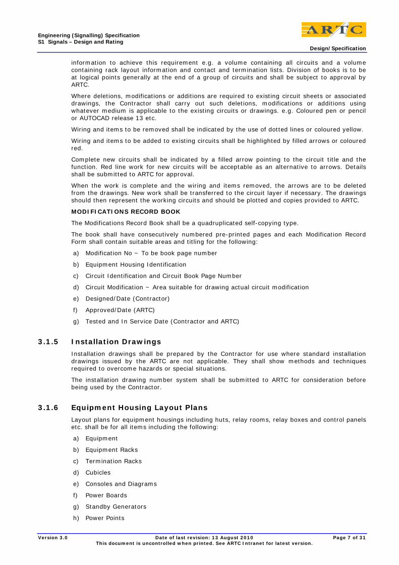
3.1.5 Installation Drawings
Installation drawings shall be prepared by the Contractor for use where standard installation drawings issued by the ARTC are not applicable. They shall show methods and techniques required to overcome hazards or special situations.
The installation drawing number system shall be submitted to ARTC for consideration before being used by the Contractor.
3.1.6 Equipment Housing Layout Plans
Layout plans for equipment housings including huts, relay rooms, relay boxes and control panels etc. shall be for all items including the following:
a) Equipment
b) Equipment Racks
c) Termination Racks
d) Cubicles
e) Consoles and Diagrams
f) Power Boards
g) Standby Generators
h) Power Points
Version 3.0 Date of last revision: 13 August 2010 Page 7 of 31 This document is uncontrolled when printed. See ARTC Intranet for latest version.
Engineering (Signalling) Specification S1 Signals – Design and Rating Design/Specification
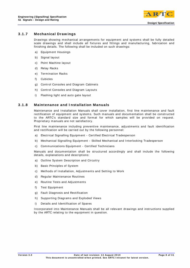
3.1.7 Mechanical Drawings
Drawings showing mechanical arrangements for equipment and systems shall be fully detailed scale drawings and shall include all fixtures and fittings and manufacturing, fabrication and finishing details. The following shall be included on such drawings:
a) Equipment Housings
b) Signal layout
c) Point Machine layout
d) Relay Racks
e) Termination Racks
f) Cubicles
g) Control Consoles and Diagram Cabinets
h) Control Consoles and Diagram Layouts
i) Flashing light and auto gate layout
3.1.8 Maintenance and Installation Manuals
Maintenance and Installation Manuals shall cover installation, first line maintenance and fault rectification of equipment and systems. Such manuals and documentation shall be constructed to the ARTC's standard size and format for which samples will be provided on request. Proprietary manuals are not satisfactory.
First line maintenance including preventive maintenance, adjustments and fault identification and rectification will be carried out by the following personnel:
a) Electrical Signalling Equipment - Certified Electrical Tradesperson
b) Mechanical Signalling Equipment - Skilled Mechanical and Interlocking Tradesperson
c) Communications Equipment - Certified Technicians
Manuals and documentation shall be structured accordingly and shall include the following details, explanations and descriptions:
a) Outline System Description and Circuitry
b) Basic Principles of System
c) Methods of Installation, Adjustments and Setting to Work
d) Regular Maintenance Routines
e) Routine Tests and Adjustments
f) Test Equipment
g) Fault Diagnosis and Rectification
h) Supporting Diagrams and Exploded Views
i) Details and Identification of Spares
Incorporated into Maintenance Manuals shall be all relevant drawings and instructions supplied by the ARTC relating to the equipment in question.
Version 3.0 Date of last revision: 13 August 2010 Page 8 of 31 This document is uncontrolled when printed. See ARTC Intranet for latest version.

Engineering (Signalling) Specification S1 Signals – Design and Rating Design/Specification
3.1.9 Engineering Manuals
Engineering Manuals are for the use of professional engineering personnel and shall include information, details, explanations, descriptions, drawings, charts etc. to cover all aspects of the equipment and systems including the following:
a) Theory and Principles
b) System Design and Circuitry
c) System Operation
d) Second Line Maintenance and Fault Rectification
e) Design and Implementation of System Modifications
3.1.10 Workshop Manuals
Workshops Manuals are for the use of workshops and laboratory based personnel and shall contain all information necessary to carry out workshop and laboratory activities including tests, investigations and repair work for equipment and systems. Full details, drawings, information etc. shall be included to cover equipment and systems including the following:
a) System Design and Circuitry Down to Component Level
b) Test Equipment
c) Testing Routines
d) Constructional Details
e) Manufacturing Drawings
f) Identification of Components and Parts
3.1.11 Operations Manuals
Operations Manuals are for the use of operations personnel and shall cover all aspects of the operator/system interface. They shall contain sufficient information, instruction, detail, drawings, charts etc. to enable an operator to use the system in all its modes.
3.1.12 Training Manuals and Documentation
Training Manuals and Documentation shall be structured in accordance with requirements for training of the following groups of employees:
a) Skilled Mechanical Interlocking Tradesperson
b) Certified Electrical Tradesperson
c) Certified Technicians
d) Professional Engineers
e) Operations Staff
Manuals and documentation shall cover all aspects of equipment and systems as detailed under the sections dealing with Maintenance and Installation, Engineering, Workshops and Operations Manuals included in this Specification.
Video recordings of technical courses shall be best quality colour and sound tapes to VHS format and shall be suitable for the training of additional staff as required by ARTC including appropriate titling.
3.1.13 Infrastructure Notices
Infrastructure Notice shall be issued containing all information regarding the infrastructure alterations to inform the train crew of the changes at least one week prior to commissioning date in accordance with General - Management- Infrastructure Notice.
Version 3.0 Date of last revision: 13 August 2010 Page 9 of 31 This document is uncontrolled when printed. See ARTC Intranet for latest version.

Engineering (Signalling) Specification S1 Signals – Design and Rating Design/Specification
3.1.14 Asset Register
The Asset Register shall include all new equipment and all existing equipment retained within the renewal area and shall include and show separately all new (or renamed) equipment outside the renewal area which was altered consequential to the work. Where existing equipment is renamed, or where new equipment replaces existing equipment, the list is to specifically show the old equipment which has been changed or deleted.
The Asset Register shall list the following items of equipment
a) Signals
b) Point machines
c) Relays
d) Chargers/Transformers
e) Batteries
f) Solar panels
g) Standby generator
h) Relay Rooms, Huts and Cupboards
i) Flashing lights
j) Gong
k) Gates and mechanism
l) Telemetry Units
m) Scada system
n) Cards
o) Enclosures
For each item the following details are to be recorded:
1) Corridor
2) Location
3) Equipment
4) Type
5) Make/Model (if applicable)
6) Version
7) Serial Number (if applicable)
8) In Service Date (month and year)
The file can be produced using a spreadsheet, data base, or word processor program provided the following criteria are met:
a) Each item of equipment is recorded on a separate line.
b) Each line is to start with a space character.
c) The following information is to be laid out in fields with the following data, order and size.
Corridor (6 character), Location (10 character), Equipment (10 character),Type (5 character) Make Model (6 character), Version (2 character), Serial Number (12 character), In Service Date (4 character)
d) Each field is to be separated by 2 spaces.
e) All fields are to left justified.
Version 3.0 Date of last revision: 13 August 2010 Page 10 of 31 This document is uncontrolled when printed. See ARTC Intranet for latest version.

Engineering (Signalling) Specification S1 Signals – Design and Rating Design/Specification
3.1.15 Symbols for Plans and Drawings
Symbols for Track Plan:
3 aspect Permissive semaphore signal normally 45°
3 aspect Permissive colour light signal normally yellow
3 aspect Permissive semaphore signal normally 90°
3 aspect Permissive colour light signal normally green
3 aspect Permissive semaphore signal normally 0°
3 aspect Permissive colour light signal normally red
2 aspect Absolute semaphore signal normally 0°
3 aspect Absolute semaphore signal normally 0°
Absolute semaphore signal fixed at 0°
Absolute colour light signal fixed at red
Power point machine Track circuit with relay/battery at the insulated joint location (thick line to denote positive of DC track)
Hand operated point machine
Single unit 3 aspect Absolute colour light signal No.4
Version 3.0 Date of last revision: 13 August 2010 Page 11 of 31 This document is uncontrolled when printed. See ARTC Intranet for latest version.

Engineering (Signalling) Specification S1 Signals – Design and Rating Design/Specification
Double unit with fixed A arm and 3 aspect B arm Absolute colour light signal No. 4 E
Circuit controller
3 aspect dwarf colour light signal
Outlying point lock No. 8
Single unit 3 aspect Permissive semaphore signal No. 93
Point indicator displaying yellow/white indications
Double unit with fixed red A arm and 3 aspect B arm Absolute semaphore signal No. 4 E
Derail No. 8A with circuit controller
3TR fibreglass 4 way relay box
Rod line compensator
3F fibreglass 2 way battery box
Simple turnout with insulated blades normally set for straight track
3c HR fibreglass 7 way relay box
228.400 km at centre line
7FZ fibreglass 2 way battery box
Underpass
20 way battery well half buried underground
Grade crossing
Version 3.0 Date of last revision: 13 August 2010 Page 12 of 31 This document is uncontrolled when printed. See ARTC Intranet for latest version.

Engineering (Signalling) Specification S1 Signals – Design and Rating Design/Specification
Cable junction pillar !1-2)J
Overpass
Control panel in a cabin (dot represents operator)
Cable pits with under road duct
Aluminium box at No. 3 signal location
Notice board
Back to back flashing lights
Lightning arrestor box mounted on line pole
Gong 4 way cross arm through aerial
Flashing lights with auto gate
4 way cross arm drop off with lightning arrestors
More symbols required
Drawings shall be drawn with AUTOCAD released 13
Version 3.0 Date of last revision: 13 August 2010 Page 13 of 31 This document is uncontrolled when printed. See ARTC Intranet for latest version.

Engineering (Signalling) Specification S1 Signals – Design and Rating Design/Specification
PCP files for the setup of pens as listed below
LAYER NAME ENTITY COLOUR PEN NUMBER PEN SIZE PEN SHADE %
2 1 Red
2 Yellow
3 Green
(1) 0.25 mm 100
3 4 Cyan
5 Blue
(2) 0.35 mm 100
5 6 Magenta
7 White
(3) 0.50 mm 100
7 8 Dark Grey
9 Light Grey
14
15
(4) 0.70 mm 100
10 (5) 0.25 mm 70
11 (6) 0.25 mm 50
12 (7) 0.25 mm 30
13 (8) 0.25 mm 10
3.1.16 Circuit Nomenclature
Power source
B Positive of dc
N Negative of dc
BL Positive side of batteries
NL Negative side of batteries
B12 12 volt dc positive
N12 12 volt dc negative
B24 24 volt dc positive
N24 24 volt dc negative
B50 50 volt dc positive
N50 50 volt dc negative
BX110 110 volt ac active
NX11o= 110 volt ac neutral
BX10 10 volt ac active
UBX Up 110 volt ac distribution
UNX Up 110 volt ac distribution
DBX Down 110 volt ac distribution
DNX Down 110 volt ac distribution
C Common
F Transformer
FZ Transformer rectifier
TFZ Track transformer rectifier
Version 3.0 Date of last revision: 13 August 2010 Page 14 of 31 This document is uncontrolled when printed. See ARTC Intranet for latest version.

Engineering (Signalling) Specification S1 Signals – Design and Rating Design/Specification
TZ Track rectifier
Track circuit related
TR Track relay
TP Track repeater
T1P Track second repeater
AP Approach repeater
TSP Track stick relay
BR Block relay
BP Block repeater
TB Track feed battery positive to track
TN Track feed battery negative to track
FB Track feed (no battery) positive to track
FN Track feed (no battery) negative to track
RB Relay positive to track
RN Relay negative to track
POR Power off relay
PONR Power off delay on relay
Signals related
R Signal reversal locking relay
HDR Signal detection proving relay
ALSR Signal approach locking stick relay
ALNR Signal approach locking timing relay
USR Rout locking relay
HR Caution aspect relay
DR Proceed aspect relay
GR Signal mechanism relay
NGR Signal at Stop detected relay
PCR Pole changing relay
RGR Signal at Caution or Proceed detected relay
NGE Colour light signal at Stop lighting
HGE Colour light signal at Caution lighting
DGE Colour light signal at Proceed lighting
GE Searchlight signal lighting
E Marker light
ANLR Power transfer relay
GNR Signal timer relay
Points related
IR Point isolating relay
IP Point isolating repeater
RLR Point reverse lock relay
NLR Point normal lock relay
Version 3.0 Date of last revision: 13 August 2010 Page 15 of 31 This document is uncontrolled when printed. See ARTC Intranet for latest version.

Engineering (Signalling) Specification S1 Signals – Design and Rating Design/Specification
WZR Crank handle relay
WCR Point correspondence relay
NWDR Point normal detection relay
RWDR Point reverse detection relay
NWDP Point normal detection repeater relay
RWDP Point reverse detection repeater relay
Level crossing related
UAP Up approach repeater relay
DAP Down approach repeater relay
UXAP Up extended approach repeater relay
DXAP Down extended approach repeater relay
UXSR Up approach stick relay
DXSR Down approach stick relay
XR Crossing control relay
XP Crossing control repeater relay
X Crossing gong
AE A unit of crossing flashing light
SE Strobe light
GR Auto gate control relay
NGR Auto gate up detected relay
RGR Auto gate down detected relay
AP Gate down slow release relay
A!P Gate down slow release repeater relay
GNR Gate down timer relay
XNR Crossing control timer relay
ZR Special purpose relay
Panel indication and other non-vital circuit related
K Indication
KE Indication light
RSR Reverse stick relay
NSR Normal stick relay
NCER Normal code execution relay
RCER Reverse code execution relay
3.1.17 Order of Book of Circuit and Details
The preferred order for a book of new design circuit is as follows:
1) Index
2) Track Plan
3) Control Table
4) Absolute signal circuits including ALSR with a separate sheet for each signal
5) Permissive signal circuits
Version 3.0 Date of last revision: 13 August 2010 Page 16 of 31 This document is uncontrolled when printed. See ARTC Intranet for latest version.

Engineering (Signalling) Specification S1 Signals – Design and Rating Design/Specification
6) Block or interface circuits
7) Point machine circuits
8) Outlying point lock circuits
9) Track repeater circuits
10) CTC indication circuits
11) Power distribution
12) Cable plans
The preferred order for a book of relay room details is as follows
1) Index
2) Relay rack layout
3) Cable terminal racks
4) Relay rack terminals
5) Power board
6) CTC cubicle details
The index for a crossing loop details of boxes to be in the order from left to right as located on the track plan
3.2 Design Requirement of Signalling System
3.2.1 Signalling Layout
Refer to ESD-05-01 Common Signal Design Principles.
3.2.2 Control Table – Locking Section
Refer to ESD-05-01 Common Signal Design Principles.
3.2.3 Control Table – Approach Locking Section
Refer to ESD-05-01 Common Signal Design Principles.
3.2.4 Control Table – Route Locking Section
Refer to ESD-05-01 Common Signal Design Principles.
3.2.5 Control Table – Track Circuits Detection and Pole Change Sections
For a main signal, all track circuits within the route of the signal, and the overlap, shall be clear, and all track circuits in alternative overlaps to be clear conditionally on the facing point settings.
For a low speed signal, which may be required for shunting purposes, detection of track circuit between two signals may not be required.
Advance signal shall be pole changed by the indication aspect of signal ahead, unless:
i. If the signal spacing is too close for a reasonable braking, it shall be a repeater of the signal ahead.
ii. In the absence of a signal ahead and in Train Order territory, the signal shall display a “Caution” aspect.
iii. For entrance into a yard working territory, low speed signal shall be used.
Version 3.0 Date of last revision: 13 August 2010 Page 17 of 31 This document is uncontrolled when printed. See ARTC Intranet for latest version.

Engineering (Signalling) Specification S1 Signals – Design and Rating Design/Specification
3.2.6 Control Table - Point Locking
Point shall be track locked by fouling track circuit.
Point shall be approach locked or route locked by signal reading directly on the route or for flank protection purposes.
3.2.7 Signal Circuit Design - General
Typical latest ARTC Book of Circuits and Circuit Plan may be used as a guide.
Signalling circuits shall, in general, be in accordance with the Association of American Railroads Signal section Recommended Functional/Operating Guidelines for Automatic Block Signal Circuits and Interlocking Part 2.2.3 and 2.2.10 of the A.A.R. Manual.
Circuit shall be designed on the fail-safe principle.
Vital circuits in multi-core cable shall be double cut. Local circuits may be single cut.
Control and power (lighting and motor) circuits shall be separately fused. Fuse shall be appropriately rated.
Vital relay shall be BRB specification 930 series in new installation. Relay bases and crimps shall be of Westinghouse design.
Twin relay of BRB specification 960 series are approved to be used for vital application.
In existing relay installation, matching relay may be used, e.g. BL1B plug in relay, DN series of shelf relay.
Unless the relay is inherently self-proving the restoration of all time element relays shall be proved de energised after every operation.
Track circuits shall, in general, be in accordance with the A.A.R. Signal Section requisites for Track Circuits, Section 6 of the A.A.R. Manual.
Track circuits shall be of the double rail type.
Track circuits shall be designed to prevent the track relay being falsely energised by insulated joint failure.
Insulated joints at signal location shall be located in line with signal or not exceeding 1.5 metre ahead of signal.
Derail shall be located within the point track circuit and 3 metre from encroaching fouling point.
Offset of staggered insulated joints shall not exceed 1.5 metre or minimum inner wheel base whichever is smallest.
Minimum length of a track circuit shall not be less than 20 metres.
Parallel bonding may be used for fouling track circuits on turnouts.
3.2.8 Signal Circuit Design - Power Supply and Circuit Protection
Power supply shall be rated accordingly with 20% spare capacity.
The signalling power and control circuits shall not be connected to earth. All circuits are to be kept earth free.
Non-vital equipment, in general, shall not be incorporated in or tapped off vital signalling circuits except where approved by the ARTC. In approved cases, the non-vital selection shall be arranged outside the vital selection in the circuits and in the negative leg of the supply. Non-vital cable shall not be connected directly to vital relays or vital power supply units and completely non-vital circuits shall be operated from a separate power supply unit where practical. Non vital equipment and cable shall be either isolated or double insulated from vital equipment racks and vital wiring.
240V power supplies shall be suitably protected and conspicuously labelled at all termination points. Rating for all transformers and charger shall be rated not less than 80% of the load requirements.
Version 3.0 Date of last revision: 13 August 2010 Page 18 of 31 This document is uncontrolled when printed. See ARTC Intranet for latest version.

Engineering (Signalling) Specification S1 Signals – Design and Rating Design/Specification
Circuit design shall take into account the effects of power supply interruptions and shall be designed to prevent incorrect energisation of relays on restoration of the supply. Any loss of supply shall not endanger the proper operation of safeworking circuitry.
The internal and external supplies for interlockings shall be capable of holding stick relays energised or power off delay relay shall be incorporated to prevent stick relay falsely energised during power supply changeover conditions. The unwanted released of approach or route locking shall be prevented in these situations. The signalling circuits shall be designed to avoid incorrect energisation of relays upon restoration of the signalling power supply rafter a shutdown of the supply or for any other reason.
Signalling control circuit overload protection shall be provided by a 10 amp fuses or circuit breakers of approved types. Vital circuits are not to be loaded above 50% fuse capacity.
Signal fuses shall be 10 amp rated and each mast shall be fused independently of one another.
The loading of point motor operating circuit fuses shall be 20 amp and not exceed 60% of their operating rating.
Fuses and Circuit Breakers are to be rated for proper discrimination as well as protection.
As far as practical control circuits shall be individually fused for each location box greater than 200 metres apart. Related circuits may be combined only to the extent that failure of a particular fuse or circuit breaker will not result in unnecessary loss of equipment that could delay or further delay train running and/or fault finding and rectification.
Diagram indication circuits may be connected together in groups using commoning blocks to load the group fuse (maximum four amps) or circuit breaker (maximum capacity five amps) to 75% capacity. The common side of the diagram relays shall also be to a commoning block.
For all signalling equipment, distribution of 110 volt 50Hz power supplies may be used at field location box.
Where CTC or remote event logging facility is available, power off, emergency generator on and battery low indications shall be provided.
3.2.9 Signal Circuit Design – Signal Controls
Automatic cancellation of controlled signal shall be applied by the passage of the train passed the signal.
Signal, except a low speed signal, shall require all track circuits in the route together with fouling track circuits for converging routes shall be clear up to the overlap point.
Normal speed aspect of signal applies to the movement on the track other than turnout.
Medium speed (35kph) aspect of signal applies to the entrance or departure from a turnout.
Normal and medium speed signal is required to detect that all track circuits, often including the overlap, on the route are clear.
Low speed (25kph) aspect is provided for any movement into non track circuit territory or shunt operation in which track circuits will not be detected.
The low speed lamp circuit shall be controlled through its own control relay.
Normal, medium and low speed signals on the mast shall be interlocked to prevent conflict display of the signal aspect.
Approach lighting of signal is preferred. When two or more signals are the same direction, they all need to be lit irrespective of whether the train is on the direct approach.
Approach locking or route locking shall be back proved to be locked before the signal can clear
The second movement into the crossing loop mainline or loop line shall not be permitted until the first movement has proceeded clear and has been proved to be at a stand-still by track circuits timing out arrangement.
Advance warning signal shall be pole-changed by signal ahead if available.
Reduced to medium speed indication aspect to be displayed by advanced signal if the signal ahead is displaying medium speed indication aspect.
Version 3.0 Date of last revision: 13 August 2010 Page 19 of 31 This document is uncontrolled when printed. See ARTC Intranet for latest version.

Engineering (Signalling) Specification S1 Signals – Design and Rating Design/Specification
Once entrance block signal is clear, opposing entrance block signal from the adjacent block shall not be able to clear.
Entrance block signal shall prove the single line clear of an opposing movement either in course or set from the adjacent loop.
Follow on movement in the same direction may be permissible once the first train has passed the intermediate permissive signal and its overlap is unoccupied.
3.2.10 Signal Circuit Design – Point Controls
Points lock relays to be latched, e.g. magnetically, to prevent unnecessary loss of conditions because of power failure.
Points machines shall be energised only for a fixed time after the points lock relays have changed.
Points shall be locked by occupancy of the fouling track circuits and such other tracks as required to provide continuity of locking between signals applying over the points themselves.
Proof of lever and point are in correspondence shall be incorporated to prevent pre-selection of point movement.
Point normal and reverse relays shall be electrically interlocked with each other for both locking and detection cases.
For a non-dual control switch machine, a local crank handle shall be provided for emergency use. The removal of crank handle from its enclosure shall put all relevant signals to stop.
3.2.11 Signal Circuit Design – CTC Controls
Each interlocking shall provide suitable means of local emergency operation in the case of failure of the CTC system.
The CTC equipment of the signalling shall be compatible with current ARTC Mile End Train Control system.
At least 10% spare inputs (indications) and 10% spare outputs (controls) at each of the field stations shall be provided.
Functional facilities available on existing workstation shall be maintained or enhanced.
3.2.12 Signal Circuit Design – Active Level Crossing
Typical latest ARTC Level Crossing Circuit Plan may be used as a guide.
Level Crossing Signals and Devices shall, in general, be in accordance with the Association of American Railroads Signal Section 3 of the A.A.R. Manual where applicable.
Active crossing protection layout consists of a relay box, a battery box complete with automatic battery charger, two masts each fitted with four lights and signs with additional lights and/or masts for side roads, bell, concrete foundations, cable pits, up and down approach and crossing track circuits (for single line operation) underground cabling and other associated equipment.
Unnecessary operation shall be prevented by controlling flashing light signals through controlled signals. Electric interlocking between the signals, and time delay relays where necessary shall be used to ensure that the minimum warning time is always obtained before the arrival of any train at the crossing.
Test switch shall be provided to break the crossing relay circuit for testing purposes unless it is a push button or two-way switch operated active crossing protection.
Flashing lights and bells shall be designed to operate for a period of 30 seconds for a new installation before the arrival of any train on the crossing. For an existing installation, a minimum of 20 seconds may be acceptable. They shall continue to operate until the rear of the train clears the crossing.
Auto gate shall be less than half-length across the road.
Version 3.0 Date of last revision: 13 August 2010 Page 20 of 31 This document is uncontrolled when printed. See ARTC Intranet for latest version.

Engineering (Signalling) Specification S1 Signals – Design and Rating Design/Specification
The commencement of the auto gate descend shall be 10 seconds normally and 15 seconds for road train route.
Extended approach shall be provided if there is a second train to arrive at the level crossing and the need to hold the auto gate down for this second train movement. The extended holding time shall be 10 second.
The lights shall be controlled by two flasher relays, one for each mast of the flashing lights. If there are more than two masts, the additional mast shall be controlled from the opposing flasher relay.
The flasher relay shall be either Static Flasher or PTF3 or ARTC approved type.
Voltage regulator shall be fitted in each individual lamp unit to regulate the voltage of the lamp. All wire sizes for light circuits shall be 2.5 mm2 minimum within the box and 16 mm2 minimum for underground cable so as to ensure that all lamps can operate with rated voltage at the lamp terminals.
Standby battery for grade crossing operation shall be of sufficient capacity to maintain the requirements of the system involved for 120 hours under normal train operations.
Flashing lights fuses shall be 10 amp rated if practicable and each mast shall be fused independently of one another.
The insulated joint of the island track and flashing light locations shall be installed in accordance with drawing number A3.94002. The edge of the road shall include the edge of the pedestrian crossing.
Mechanical interlocked relay shall not be used crossing operation.
XR relay shall be shelf type DN series.
Back proving of directional stick relay either in signal/block circuits or a crossing timer to operate the crossing after 15 minutes if practicable.
All mast outputs shall be individually fused.
Inverter track or Grade Crossing Predictor shall be independently fused and common with control fuse.
3.3 Point Machine
3.3.1 General Requirements
Point machines shall be specifically designed for use in the operation, locking and detection of movable apparatus such as points, derailers and movable diamonds.
The mechanism shall provide full lock rod protection whether operated in motor or hand mode.
The machine shall incorporate an operating bar, adjustable lock rods and single or dual detector rods, as required. These shall be provided with connections suitable for attaching bars and rods fixed to the movable apparatus.
3.3.2 Design and Functional Requirements
3.3.2.1 Operational Requirements
The mechanism shall operate the movable apparatus and perform functions, as follows:
Points and movable diamonds – operate to the normal or reverse position and lock and detect the movable apparatus in these positions.
Derailers – operate to the on or off position in relation to the rail and detect the derailer in these positions.
The mechanism shall operate in the following sequence:
• Open detection contacts.
• Unlock the movable apparatus.
Version 3.0 Date of last revision: 13 August 2010 Page 21 of 31 This document is uncontrolled when printed. See ARTC Intranet for latest version.

Engineering (Signalling) Specification S1 Signals – Design and Rating Design/Specification
• Operate the movable apparatus.
• Lock the movable apparatus.
• Close detection contacts.
An adjustable type clutch shall be provided to limit the motor current in the event of the movable apparatus being obstructed before completion of its travel.
A suitable overload protection device shall be fitted in each machine which will:
Cut power to motor after an overload condition has existed for 10 seconds.
Allow the machine to be restored to the previous position on actuation of the motor controller.
The actuating rod shall have a maximum stroke of 152mm.
The mechanism shall follow the movement of the motor controller and can be stopped, reversed or obstructed at any point of its movement without damage.
The detection circuit controlling device shall be so designed that its operation will be dependent upon and follow the travel of the movable apparatus. If the movable apparatus is more than 6mm from its final travel then the circuit controller contacts shall not assume the corresponding final position. Attached detection rods connected to the movable apparatus shall be adjustable for this purpose.
The machine shall be provided with dual detection capability, such that the option of single or dual detection of the movable apparatus is available. Dual detection shall be utilised to independently detect the position of both blades in a point layout.
The machine shall be designed to permit the use of a crank handle for emergency manual operation. A cut out feature shall be provided so that motor operation cannot occur once the hand crank is inserted in the opening provided until it has been removed and the latching contact reset.
As an alternative to crank handle operation, dual control machines can be used which are equipped with hand operating levers, as specified in the section titled “Dual Control Machines”.
3.3.2.2 Mechanical Requirements
The mechanism shall be easily converted from left to right hand operation and vice versa if required.
The mechanism and case shall be so designed that the lock rod may be easily removed.
Ends of plunger or locking dogs and holes or notches in lock rod shall have square edges. Such holes or notches shall be not more than 3mm wider than the plunger.
The locking dog of the switch and lock movement shall enter the lock rod 12mm or more before the circuit controller can indicate locked position and shall extend beyond the lock rod when the mechanism has completed its stroke in either normal or reverse position.
The lock clearance in both the N and R positions shall be capable of being adjusted to achieve required setting.
The circuit controller shall be actuated by a rack and pinion mechanism.
All bearings shall be of ample dimensions to ensure durability. Provision shall be made for proper and convenient lubrication of the mechanism.
The machine in locked position shall be capable of withstanding stress equivalent to a thrust of 90K Newtons, either on the actuating rod or lock rod.
The machine shall be designed to prevent movement due to vibration or external force applied to the connections. It will hold the movable apparatus in the locked position in the event of failure of the power supply.
3.3.2.3 Housing and Fittings
The mechanism shall be so designed that the motor, gears and circuit controller are housed in a substantial metal weatherproof compartment. The covering of the compartment shall be vandal proofed, removable and equipped with a suitable fastening for the application of a security padlock.
Version 3.0 Date of last revision: 13 August 2010 Page 22 of 31 This document is uncontrolled when printed. See ARTC Intranet for latest version.

Engineering (Signalling) Specification S1 Signals – Design and Rating Design/Specification
All components of the machine shall be mounted on a single cast iron base and all compartments are to be integrated with the base to form a sturdy, heavy duty machine.
Means for readily draining oil and water accumulation shall be provided.
The motor compartment shall be provided with a cable entrance of ample size conveniently located near the terminal posts.
The motor shall be designed to prevent oil from bearings getting on brushes, commutators or windings.
The circuit controller housing shall as far as practicable be non-sweating and dust-proof.
Point machines designed for emergency manual operation by a crank handle shall be provided with an opening in the motor compartment cover for the insertion of the hand crank. The opening shall be provided with a metallic weatherproof cover and suitable fastenings for the application of a security padlock.
Hoods shall be fitted over all external openings in the machine compartment provided for the entrance of rods and bars, to minimise the effects of the weather and environment on the interior of the machine.
The machine shall be securely bolted onto track sleepers therefore it must be provided with mounting feet to suit standard sleeper spacings.
3.3.2.4 Electrical Requirements
The circuit controller shall be provided with contacts required to control indicating relays.
The circuit controller contact members shall be of corrosion resisting metal of sufficient mechanical strength and current carrying capacity to satisfactorily operate in connection with the circuits used. The movement of the contact members shall be such as will ensure a wiping contact.
Internal wiring shall be neatly arranged and placed in ducts or channels of ample capacity, forming an integral part of the apparatus. Copper conductors used for internal wiring shall be stranded wire type of nominal 2.5mm2 cross sectional area to AS 1125 - 1993 Table 2.4. All terminations shall be secure and vibration proof using approved lugs and the wires clearly labelled using durable labels of the sleeve type.
Terminal posts, nuts and washers shall conform in general to approved rail industry standards and the thread shall be M6. Terminal posts shall be mounted so they cannot be turned in the bases or frame to which applied. They shall be properly insulated from each other and shall be spaced at not less than 25mm centres.
The motor controller shall be immune to 1000 volts AC and operate from 10, 24 or 50 volts DC, as required.
3.3.2.5 External Requirements
Metal parts shall be protected against corrosion except where such protection will interfere with proper functioning of that part. Zinc and Cadmium shall not be used on current carrying parts of the machine. Material used for protection against corrosion shall not soften or flake under normal conditions.
Cable feeding into detector boxes and machines shall be adequately protected mechanically, the cable entry designed to prevent ingress of moisture and anchoring arrangements shall be such that no stress is placed upon the wiring at the terminals.
3.3.3 Operating Voltages
Point machine motors shall be rated to operate with either 110 volt or 24 volt DC supplies ± 20%, which are AC immune to 1000 volts.
When the higher voltage machine is used, it shall be supplied from an external 110 volts 50 Hz AC supply fed to the main terminal board of the machine. In this case a full wave rectifier shall be incorporated within the machine.
Time of operation at these voltages and at a load of 230kg shall not exceed 5 seconds or 14 seconds, respectively.
Version 3.0 Date of last revision: 13 August 2010 Page 23 of 31 This document is uncontrolled when printed. See ARTC Intranet for latest version.

Engineering (Signalling) Specification S1 Signals – Design and Rating Design/Specification
3.3.4 Dual Control Machines
As an alternative to crank handle operation, machines can be equipped with hand operating levers for emergency manual operation, which shall comply with the following requirements:
The machine shall be fitted with a selector lever for the purpose of selecting operation by power or hand control The lever shall normally lie in the "motor" position in the horizontal plane and shall be interlocked with the hand throw lever so that it can only move from or be returned to the "motor" position when the hand throw lever is in the full normal position. The lever shall clearly display signs reading "MOTOR” and "HAND" to indicate the position of the lever.
When the selector lever is moved from the "motor" position, contacts shall be provided to open circuit the machine motor supply circuit and the corresponding external detection circuits.
The machine shall be fitted with a hand throw lever for the purpose of manually operating the point machine. This lever shall move through 180o between full normal (N) and full reverse (R) positions and shall normally lie in the horizontal plane. The lever shall clearly display signs reading "N" and "R" to indicate the position of the lever.
Suitable fastenings shall be provided to enable the application of security padlocks to both levers in the normal and reverse positions.
The mechanism shall be so designed that the hand operating crank is only engaged with the selector lever in the "hand" position.
The hand selector and hand operating levers shall be located on the side of the mechanism away from the track and shall be marked as previously specified by means of interchangeable indication plates.
3.3.5 Rods, Bars and Brackets
Rods, bars and associated brackets are external fittings which connect the point machine to the movable apparatus and also connect the blades together in a point layout. This allows the operation, locking and detection of movable apparatus such as points, derailers and movable diamonds. These fittings are manufactured and supplied independently of the point machine.
The Contractor shall ensure that the correct fittings are supplied to suit each particular application of the point machine and that sufficient spares are available for maintenance and emergency requirements.
The fittings shall be installed at ground level to form a layout with the associated rail tracks and point machine and consequently shall be subjected to and be able to withstand everyday weather conditions and train movement vibrations and stresses.
All rods, bars and brackets shall be insulated where appropriate to prevent the shorting out of associated track circuits.
All assembled rods and bars shall be capable of withstanding stress equivalent to a thrust of 90K Newtons with the machine in the locked position.
The rods, bars and brackets shall be manufactured and constructed using the best quality workmanship and materials possible and shall comply with the following requirements:
A standard general purpose steel must be used e.g. CS 1020 to AS 1443 – 1994, Table 1.
Washer plates and ferrules (bushes) which are used for insulating the point fittings shall be made from polyslip, which is a polyurethane based material, or approved equivalent and manufactured in accordance with the relevant plan details, as follows:
Washer Plate – T 78.307
Ferrule (Bush) – T 85.25
The point fittings shall be manufactured in accordance with the relevant plan details for each particular type.
All welding shall be in accordance with the relevant parts of AS 1554 and the weld test shall conform to approved current practice. The welds shall be inspected by magnetic particle crack detection, dye penetrant or other approved methods.
Version 3.0 Date of last revision: 13 August 2010 Page 24 of 31 This document is uncontrolled when printed. See ARTC Intranet for latest version.

Engineering (Signalling) Specification S1 Signals – Design and Rating Design/Specification
Hardened bushes used in jaws shall be suitable for fitting a standard pin, refer to plan E 78.221.
All switch fitting finishes shall be free of burrs and sharp edges with a protective coating of suitable paint (black) applied to all surfaces.
Each fitting shall be clearly and indelibly marked with the corresponding plan number in minimum 10mm high characters in a conspicuous position.
The following plans for the general layout of various switch fittings are provided for reference purposes and should not be used in manufacturing these items:
Point Layout – D 81.48
Derail layout – D 80.67
3.4 Cable
3.4.1 General Requirements
Multi - core cables used for railway signalling purposes shall be designed for working voltages up to and including 600 volts AC.
They are normally direct buried in the ground or installed in heavy duty underground conduits adjacent the rail track and exposed to atmospheric conditions at rail level or on telephone line poles at any location system wide. Therefore, the requirements are transportability and convenient handling, ease of identification, mechanical strength, termite proofing, good electrical insulation, moisture resistance and stabilisation against heat and light.
The cable conductors and lugs at the point of termination shall be vibration proof and secure.
3.4.2 Type and Application
Signalling cables and wires are of the following type and application:
2 cores 7/1.70mm - nominal cross sectional area of 16mm2 per conductor - point machines.
4 cores 7/1.70mm - nominal cross sectional area of 16mm2 per conductor - auto gate mechanism and flashing lights.
2 cores 7/1.04mm - nominal cross sectional area of 6mm2 per conductor - signal lighting, 110 volt AC power distribution and battery feeds.
4 cores 7/1.04mm - nominal cross sectional area of 6mm2 per conductor - Signal lighting and track connection from enclosure to bootleg.
7, 10, 15, 20 and 30 cores 1/1.78mm or 7/0.067mm - nominal cross sectional area of 2.5mm2 per conductor - Control circuits between enclosures or between enclosures and equipment.
Termination of stranded conductors shall be carried out using approved lugs as listed in the Wire for Signalling Applications specification.
3.4.3 Conductors
3.4.3.1 Composition
The conductors shall consist of soft – drawn annealed copper wire, manufactured from high conductivity copper complying with AS 1574 - 1984. The copper shall be CU - ETP alloy (or equivalent) as designated in AS 1279 - 1985, Refined Copper, Table 1.1. The copper wire shall be in the annealed (0) condition as specified in AS 1574 - 1984, Table 2.2.
3.4.3.2 Shape
Each wire forming the conductor shall be circular in section (non – compacted), uniform in quality, size and shape and clean, smooth and free from detrimental defects. The deviation from the nominal diameter of the individual wires shall not vary by more than that specified in AS 1125 - 1993.
Each conductor must be continuous, without weld, splice or joint throughout its entire length.
Version 3.0 Date of last revision: 13 August 2010 Page 25 of 31 This document is uncontrolled when printed. See ARTC Intranet for latest version.

Engineering (Signalling) Specification S1 Signals – Design and Rating Design/Specification
3.4.3.3 Test Compliance
The copper conductors shall comply with the requirements as specified in Table 2.2 of AS 1125 - 1993. The elongation of the individual wires of the stranded conductors shall be not less than the appropriate requirements in Column 2.
The individual wires of the stranded conductors shall be subjected to the wrapping test as given in AS 1574 - 1984, without showing any signs of cracking or breaking.
The DC electrical resistance of each conductor shall be measured together with the temperature of the cable at the time of measurement. The measured value of resistance shall be as specified in Table 2.3 of AS 1125 - 1993 for the relevant nominal cross - sectional area of conductor.
3.4.4 Insulation, Sheathing and Covering
3.4.4.1 Insulation
Each conductor shall be individually insulated. The material used shall be moisture resistant V 75 PVC, 0.611W grade, which shall be applied concentrically to the conductor to provide a circular cross – section, with the conductor uniformly centred throughout the entire length. The thickness of the insulation shall be in accordance with AS 3147 - 1992.
3.4.4.2 Binder Tape
A non – hygroscopic binder whose qualities are compatible with the insulation shall be helically applied with an overlap over the assembled conductors.
3.4.4.3 Sheathing
A continuous tubular sheath shall be tightly formed over the assembled cores and so formed as to fill the interstices in the outer layer. The thickness of the sheath shall be in accordance with AS 3147 - 1992.
The material used shall be 4V - 75 PVC and unless otherwise specified by ARTC the colour of the sheathing shall be black.
3.4.4.4 Covering
As a precaution against termites, a heat and light stabilised nylon covering is to be extruded over the PVC sheath. Type 11 or 12 nylon (polyamide) is to be used for the covering and unless otherwise specified by ARTC the colour of the covering shall be black.
The minimum average radial thickness of the nylon covering shall be 0.5mm and the radial thickness at any point shall not be less than 0.4mm.
3.4.4.5 Outer Sheath
The nylon is to be covered with an outer sacrificial sheath of 4V – 75 PVC for mechanical protection of the nylon. The radial thickness of the sheath shall not be less than 1.0mm at any point.
3.4.5 Construction
The cable shall be assembled such that the cores are laid helically into a tight cylindrical form with adjacent layers wound in opposite directions and the length of lay such as to ensure good construction. Any necessary filling shall consist of soft black PVC.
3.4.6 Cable and Core Identification
Each core of the cable will be consecutively numbered, starting from the centre of the cable in the inner layer and finishing at the outer layer. The numbering in each layer shall always be in the same rotational sequence. The printed numerals will appear at intervals not exceeding 100mm throughout the entire length of the core.
Version 3.0 Date of last revision: 13 August 2010 Page 26 of 31 This document is uncontrolled when printed. See ARTC Intranet for latest version.
Engineering (Signalling) Specification S1 Signals – Design and Rating Design/Specification
The cable shall be legibly and indelibly marked at regular intervals on the outer PVC sheath throughout its entire length, with the manufacturer's identification and date of manufacture, starting from the inner end of the drum. Extra information can also be included in accordance with the Contractors requirements, subject to approval from ARTC.
3.4.7 Cable Drum Requirements
The Contractor shall specify to the Manufacturer the requirements regarding cable drum construction, packaging, presentation, labelling and cable lengths subject to approval from ARTC.
3.4.8 Environmental Conditions
Cables shall be suitable to be used under the following environmental conditions:
• Relative Humidity up to 100%.
• Temperature Range from –10oC to +75oC.
• Direct exposure to UV radiation.
3.4.9 Cable Test Compliance and Certification
The Contractor shall ensure that the manufacturer complies with the following requirements:
3.4.9.1 Testing
The Manufacturer shall perform tests in accordance with AS 3147 and AS 3116, on samples of insulation material, and insulated core and sheath material as applicable. Test certificates from a NATA or equivalent laboratory approved to conduct such tests shall be available.
During the course of manufacture and/or final testing of the cable, all relevant tests specified as routine, in AS 3147, shall be performed on each length of cable. In addition, the special test “Insulation Resistance at 20º C” shall be performed as a routine test.
3.4.9.2 Test Certificates
Each drum of cable shall be delivered with a test certificate attached and copies provided to the purchaser.
The test certificate shall include at least the details shown below:
• Test certificate number.
• Cable drum identification number.
• Description of the cable.
• Conductor electrical resistance tested at 20ºC
• High voltage test and duration.
• High voltage spark – over test.
• Insulation resistance between cores and cores to earth.
• Core numbering test.
• Specification variations.
3.4.9.3 Manufacturer Quality Accreditation
The Manufacturer shall be quality accredited to produce cables under a Quality Assurance system which addresses the requirements of AS/NZS ISO 9001, or a recognised equivalent.
A nominated ARTC representative shall have such access to the works of the Manufacturer as is reasonable and necessary to enable him to determine the quality of the material and workmanship and to audit the Manufacturers Quality System.
Version 3.0 Date of last revision: 13 August 2010 Page 27 of 31 This document is uncontrolled when printed. See ARTC Intranet for latest version.
Engineering (Signalling) Specification S1 Signals – Design and Rating Design/Specification
Manufacturers shall supply the representative with complete details of the cable offered. Any component of the cable not mentioned in the Specification shall be fully detailed regarding type, composition, dimensions, tolerances and minimum thickness of materials used.
3.4.10 Wire for Signalling Applications
3.4.10.1 General Requirements
Wiring used for railway signalling applications shall be suitable for working voltages up to and including 50 volts DC and 240 volts AC and generally comply with the requirements of the Signalling Cable specification regarding conductors, insulation and environmental conditions, unless otherwise specified by ARTC.
All wiring covered in this specification shall, be insulated with V75 PVC or approved equivalent.
All wire sizes shall be such that the percentage voltage drop from any transformer or battery bus bar to the terminal of the furthest apparatus fed from them shall not exceed 10% under maximum operating load conditions. Exceptions, due to practical reasons, may be permitted, subject to approval by ARTC.
Where wires are subject to vibration, such as in wiring to rails or connections to some trackside apparatus, stranded wire shall be used between them and the nearest junction free from vibration.
Stranded conductor wires shall generally be used for most applications, terminated using the appropriate crimp lugs, as detailed below. However, in some applications solid copper conductor (single strand) wire, using wire wrap terminations may be used, subject to approval by ARTC.
3.4.11 Type and Application
All terminations shall be done above ground in accordance with the manufacturer’s instruction for terminals, lugs and jointing kits and shall be in a suitable enclosure, with the following exceptions:
• Track circuit connecting cables at the rail connection.
• Jointing conductors buried underground.
• Jointing conductors to pole line aerial wires.
Stranded conductors shall be fitted with Utilux “Supergrip” type crimp lugs as described below or other equivalent approved lugs unless otherwise stated in this specification.
16/0.20mm – nominal cross sectional area of 0.5mm2.
24/0.20mm – nominal cross sectional area of 0.75mm2:
Used for terminating on Siemens sub-miniature relays, utilising solder terminated plug bases. Illuminated mimic diagram internal wiring.
Terminated using green crimp lugs (H4278) or soldered terminations.
32/0.20mm – nominal cross sectional area of 1.0mm2:
For general usage, such as all internal wiring used in trackside housings.
Terminated using red crimp lugs (H421A) or relay base spring clips (B or Q type relays).
Conductors may be paralleled to reduce voltage drop where there is a restriction on cable size due to termination type i.e. PTF3 relays.
50/0.25mm – nominal cross sectional area of 2.5mm2:
Used in higher current applications or when internal wiring resistance must be kept to a low value i.e. RZ 42 output, Coded Track box wiring, signal and flashing light lamp circuits, point machine internal wiring.
Terminated using blue crimp type terminations (H4227).
Version 3.0 Date of last revision: 13 August 2010 Page 28 of 31 This document is uncontrolled when printed. See ARTC Intranet for latest version.

Engineering (Signalling) Specification S1 Signals – Design and Rating Design/Specification
7/1.04mm – nominal cross sectional area of 6.0mm2:
Used in higher current applications where extremely low resistance is required i.e. in trackside housings where connections between battery enclosure cable and fuses or load terminals are required.
Terminated using yellow crimp lugs (H4234).
511/0.20mm – nominal cross sectional area of 16.0mm2:
Used for track circuit connecting cables, between the trackside equipment terminals and the rail.
Each cable shall be fastened to the rail by a “Burndy” lug, type B25M6, or approved equivalent, connected to a bond pin terminal or alternatively Cadwelded to the rail. The other end of each cable shall be fed into a trackside location housing and terminated individually on a Weidmuller Klippon type SAK 16/35 feed through terminal, or approved equivalent.
3.5 Enclosure
3.5.1 Equipment Housing General Requirements
This specification covers the requirements of trackside equipment housings to enclose control apparatus such as sensitive electronic equipment, electro mechanical devices, batteries and standby generators for railway signalling purposes.
Equipment housings shall be sturdy and weatherproof, generally unpainted, built to last with a minimum of maintenance and shall incorporate features which will reduce corrosion to a minimum.
3.5.2 Environmental Requirements
Enclosures shall be constructed to withstand the following environmental conditions:
• Ambient temperature range from -50ºC to 65ºC.
• Relative humidity: 0 to 100%.
• Vibration caused by passing trains.
• Solar radiation.
• Wind loading complying to ASI - 170 Part 2 - Wind Forces.
• Dust and water ingress complying to AS 1939 - 1P54.
3.5.3 Detailed Requirements
3.5.3.1 Relay Hut
The walls, floor and roof of the hut are to be made of reinforced ferro cement construction. The reinforcing shall be of galvanised heavy gauge steel.
The walls and roof of the respective enclosures, as specified on plans No.A3.94089 and A3.94090, shall be appropriately "screened" against electrical and magnetic interference.
The internal dimensions of the equipment enclosures described herein together with the door position, layout, floor, cut out for cable duct entry, vent at the rear wall and exhaust pipe outlet are shown on the plans Nos.A3.94089 and A3.94090.
A metal weather proof door frame of standard dimensions cast into the concrete and welded securely to the reinforcement including a weatherproof sill shall be provided.
The door shall be of sound construction secured with strong hinges and shall have a vent measuring 110 x 665mm mounted in it at a position just above the floor level. All vents described herein shall be weather proof and proof against insect, bird and rodent entry.
Version 3.0 Date of last revision: 13 August 2010 Page 29 of 31 This document is uncontrolled when printed. See ARTC Intranet for latest version.

Engineering (Signalling) Specification S1 Signals – Design and Rating Design/Specification
Earth plugs securely welded to the reinforcement mesh shall be provided at each corner of the enclosure as close as possible to ground level and 51W UNC brass bolt or internal thread to be provided for connection to external earth grid.
A weatherproof roof ventilator suitable for the size of the hut shall be mounted in the centre of the roof.
The inside and outside of the enclosures shall be painted white with suitable weather resistant paint.
The internal temperature of the enclosure is to remain within the range 10oC – 50oC.
Lifting points are to be provided on the enclosures to facilitate easy loading and unloading of them using standard types of lifting equipment.
A door lock, keyed to the ARTC key K9800, shall be built into the door at a standard height above the floor level.
3.5.3.2 Relay Cabinet
The cabinet body shall be constructed of heavy duty corrosion proof metal sheeting of approved grade and constructed without a floor but able to be firmly bolted to a concrete slab base with adequate provision for cable entry from the ground.
The cabinet shall be fitted with full length doors at both the front and rear, providing convenient access to all the internal equipment, for maintenance and testing purposes. The doors shall be secured to the frame by strong and durable hinges which are tamper proof from the outside with the door shut.
A locking mechanism shall be fitted to the doors which when closed, securely anchors them to the frame, at both the top and bottom. The locking device shall be incorporated into the handle, located in a convenient position on the door, and shall be locked by a standard ARTC key.
The doors shall be totally weatherproof when closed, by the provision of an effective seal around the full perimeter of the door frame. The weatherproof seal shall be made of approved high quality durable material which will not readily deteriorate even in the most extreme climatic and environmental conditions found in the system.
The doors shall be fitted with automatically engaging holding devices which will stabilise and hold them securely when open in strong wind conditions.
The equipment mounting rack shall be constructed to independently fit within the cabinet and shall be designed so as to isolate the mounted equipment from damaging vibrations.
Relay cabinets shall be of standard sizing to suit the scale of application i.e. large or small. The internal dimensions of the cabinets shall be such that there is ample clearance from the largest standard items of apparatus which would possibly be mounted on the rack.
Weatherproof and insect proof vents shall be incorporated in the cabinet, to effectively inhibit condensation and to aid in the dissipation of heat from the enclosed apparatus, to prevent overheating. With the doors closed, the cabinet shall be as dust proof as possible without having a detrimental effect on the above mentioned requirements and also be bird, animal, and insect proof.
A holder shall be provided within the cabinet for the safe keeping of one complete set of maintenance prints and documents for that location.
The cabinet shall be mounted on a concrete slab base which supports the cabinet in an upright position at least 300mm above the surrounding ground level and provides an apron 500mm wide around the cabinet. The base shall allow adequate entry of underground cables into the interior of the cabinet and protect them from mechanical damage.
To comply with the requirements of protecting signalling apparatus against voltage surges caused by lightning and for electrical safety, an external earth rod shall be provided with each cabinet, which can be connected to a common internal earth busbar by means of a suitable earth wire.
3.5.3.3 Battery Well
The walls and floor of the well shall be made of reinforced ferro – cement construction and designed such as to prevent the ingress of rainwater.
Version 3.0 Date of last revision: 13 August 2010 Page 30 of 31 This document is uncontrolled when printed. See ARTC Intranet for latest version.

Engineering (Signalling) Specification S1 Signals – Design and Rating Validate and Verify
A lid, lined with timber panelling on the interior surface to provide rigidity and protection, shall be designed to fit snugly over the top of the battery well. The lid shall be constructed of heavy duty corrosion proof metal sheeting of approved grade.
The lid shall be suitably vented to allow for the escape of explosive gasses.
Suitable fastenings shall be provided on the sides of the battery well and the lid to enable the lid to be firmly secured to the sides with standard ARTC K9800 security padlocks.
The interior shall be fitted with a timber palate resting on the concrete bottom, for seating the required batteries in such a way that spilt fluids are drained away from the battery cases.
The battery well shall be of sufficient size and shape to comfortably house up to fourteen railway lead – acid secondary batteries together with associated cables and terminal panel.
3.6 Track Circuit To be written.
3.7 Active Level Crossing To be written.
4 Validate and Verify To be written.
5 Develop Standards To be written.
Version 3.0 Date of last revision: 13 August 2010 Page 31 of 31 This document is uncontrolled when printed. See ARTC Intranet for latest version.
Related Documents