Signalling & Control Metro Amsterdam Overview April 4 th , 2013 Ruud van Leijsen / Ronald Doeleman 1 of 66

Welcome message from author
This document is posted to help you gain knowledge. Please leave a comment to let me know what you think about it! Share it to your friends and learn new things together.
Transcript
Signalling & Control Metro Amsterdam
OverviewApril 4th, 2013
Ruud van Leijsen / Ronald Doeleman
1 of 66

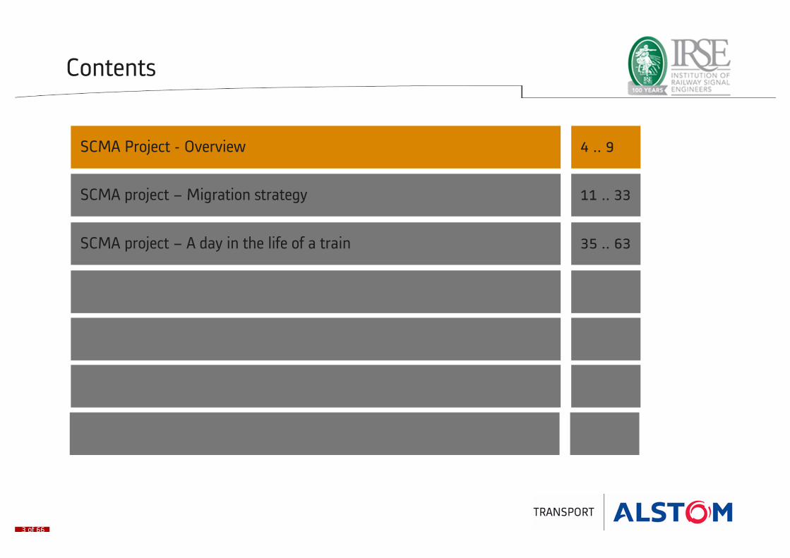
Contents
SCMA Project - Overview 4 .. 9
SCMA project – Migration strategy 11 .. 33
SCMA project – A day in the life of a train 35 .. 63
2 of 66
Contents
SCMA Project - Overview 4 .. 9
SCMA project – Migration strategy 11 .. 33
SCMA project – A day in the life of a train 35 .. 63
3 of 66

Project Scope SCMA
Opdrachtgever: Gemeente Amsterdam, Dienst Metro
Scope:
� resignaling van het bestaande netwerk
� signaling van nieuwe Noord/Zuidlijn
� nieuw bediensysteem voor hele netwerk
� breedband verbinding tussen wal en voertuig
4 of 66
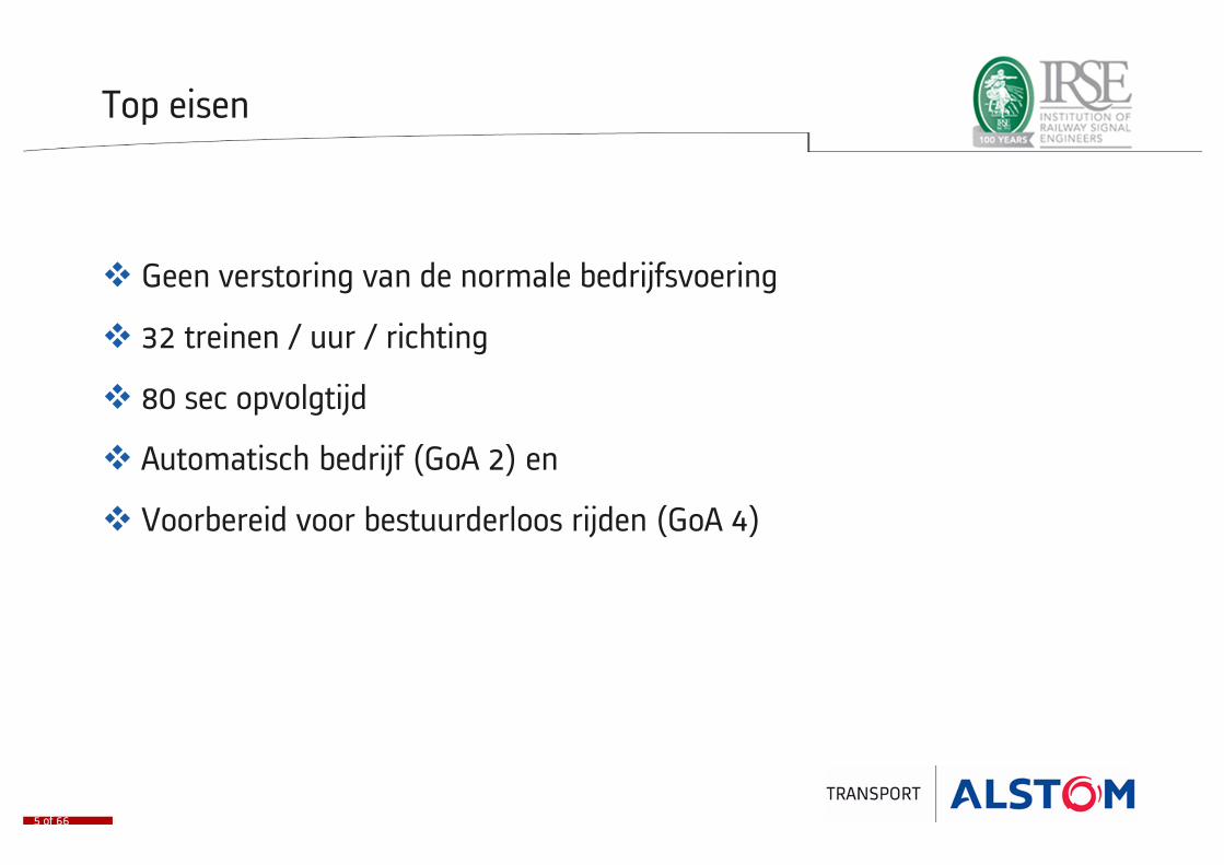
Top eisen
� Geen verstoring van de normale bedrijfsvoering
� 32 treinen / uur / richting
� 80 sec opvolgtijd
� Automatisch bedrijf (GoA 2) en
� Voorbereid voor bestuurderloos rijden (GoA 4)
5 of 66

Planning
• 05-04-2012 Contract getekend
• 01-10-2014 Functionaliteit aangetoond op test track
• 01-04-2015 start exploitatie op pilotlijnATS in service voor hele netwerk
• 01-07-2016 start testbedrijf op Noord/Zuidlijn
• 01-04-2017 start exploitatie op hele netwerk
Film URBALIS
6 of 66

Setting Train in Motion
GoA levels
7 of 66
Grade of Automation
Type of train
operation
Stopping Train
Door Closure
Operation in event of Disruption

Setting Train in Motion
GoA levels
7 of 66
Grade of Automation
GoA 1
Type of train
operation
ATP with Driver
Driver
Stopping Train
Driver
Door Closure
Driver
Operation in event of Disruption
Driver
Setting Train in Motion
GoA levels
7 of 66
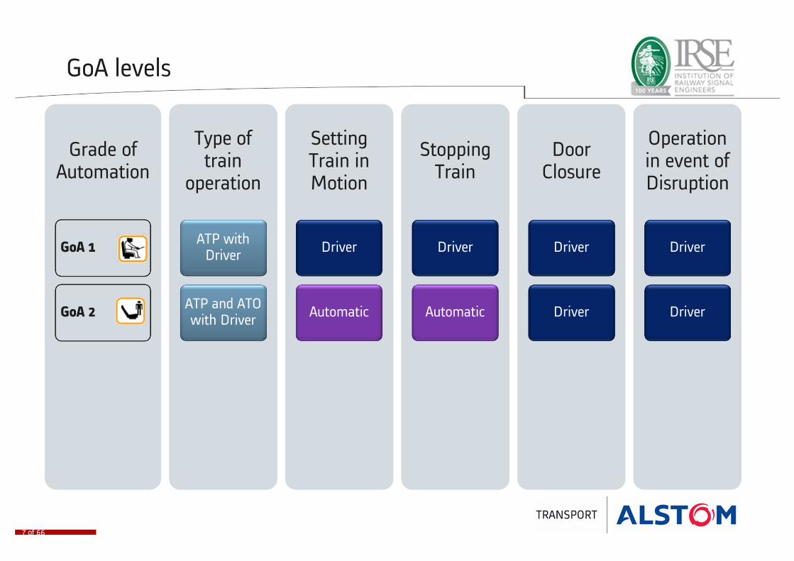
Grade of Automation
GoA 1
GoA 2
Type of train
operation
ATP with Driver
ATP and ATO with Driver
Driver
Automatic
Stopping Train
Driver
Automatic
Door Closure
Driver
Driver
Operation in event of Disruption
Driver
Driver
Setting Train in Motion
GoA levels
7 of 66
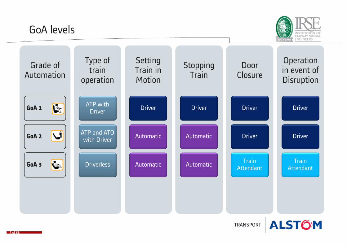
Grade of Automation
GoA 1
GoA 2
GoA 3
Type of train
operation
ATP with Driver
ATP and ATO with Driver
Driverless
Driver
Automatic
Automatic
Stopping Train
Driver
Automatic
Automatic
Door Closure
Driver
Driver
Train Attendant
Operation in event of Disruption
Driver
Driver
Train Attendant

Setting Train in Motion
GoA levels
7 of 66
Grade of Automation
GoA 1
GoA 2
GoA 3
GoA 4
Type of train
operation
ATP with Driver
ATP and ATO with Driver
Driverless
UTO
Driver
Automatic
Automatic
Automatic
Stopping Train
Driver
Automatic
Automatic
Automatic
Door Closure
Driver
Driver
Train Attendant
Automatic
Operation in event of Disruption
Driver
Driver
Train Attendant
Automatic

Treinen (1)
M5/M6 23+5
• GoA 4 voorbereid
• GoA 2
• GoA 1
S3/M4 3+34
• GoA 2
• GoA 1
8 of 66

Treinen (2)
S1/S2 12+13
• GoA 1
M2/M3
• Worden niet omgebouwd
9 of 66

Contents
SCMA Project - Overview 4 .. 9
SCMA project – Migration strategy 11 .. 33
SCMA project – A day in the life of a train 35 .. 63
10 of 66
Project Phasing
• 1 Test track existing network
• 2 Pilot line
• Connection of new line (Zuid)
• 3 NZL New line roll-out
• 4 Roll-out rest of network
• Full network operational
11 of 66

Start situation
• T0 = 05-04-2012
• Remarks
− LWP not in scope− Amstelveenlijn only to be
connected to new ATS, no CBTC
12 of 66
Start situation
• T0 = 05-04-2012
• Remarks
− LWP not in scope− Amstelveenlijn only to be
connected to new ATS, no CBTC
• OMA
12 of 66

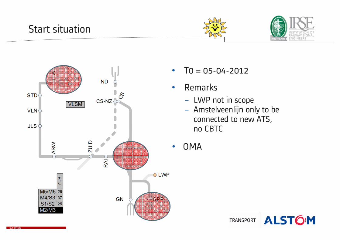
Start situation
• T0 = 05-04-2012
• Remarks
− LWP not in scope− Amstelveenlijn only to be
connected to new ATS, no CBTC
• Zuid
• OMA
12 of 66

Legenda
13 of 66

Phase 1 Installing ATS
• Installing ATS 1 (ATS2 will be installed later)
• Testing interfaces to existing network
• Shadow running on non-CBTC
• Remarks
− LWP not in scope− Amstelveenlijn only to be
connected to new ATS
14 of 66
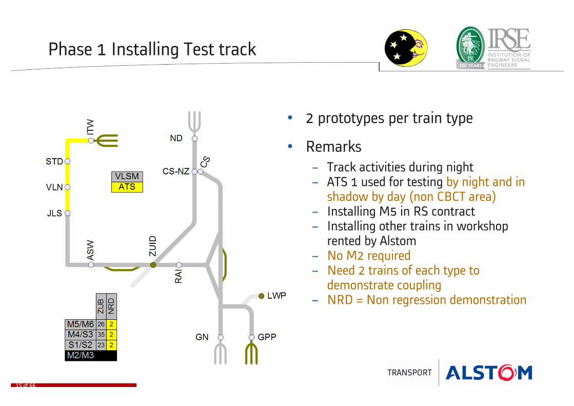
Phase 1 Installing Test track
• 2 prototypes per train type
• Remarks
− Track activities during night− ATS 1 used for testing by night and in
shadow by day (non CBCT area)− Installing M5 in RS contract− Installing other trains in workshop
rented by Alstom− No M2 required− Need 2 trains of each type to
demonstrate coupling− NRD = Non regression demonstration
15 of 66
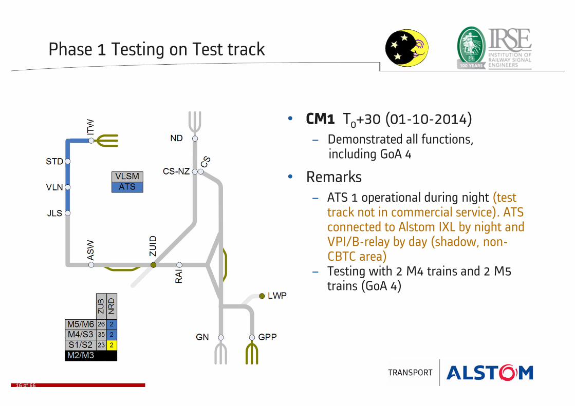
Phase 1 Testing on Test track
• CM1 T0+30 (01-10-2014)
− Demonstrated all functions,including GoA 4
• Remarks
− ATS 1 operational during night (test track not in commercial service). ATS connected to Alstom IXL by night and VPI/B-relay by day (shadow, non-CBTC area)
− Testing with 2 M4 trains and 2 M5 trains (GoA 4)
16 of 66
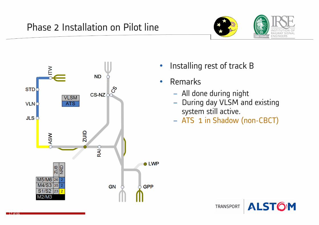
Phase 2 Installation on Pilot line
• Installing rest of track B
• Remarks
− All done during night− During day VLSM and existing
system still active.− ATS 1 in Shadow (non-CBCT)
17 of 66

Phase 2 Proefbedrijf on Pilot line
• Testing under operational conditions during night
• Installing ATS 2
• Remarks
− All done during night− During day VLSM and existing
system still active− ATS 1 in Shadow− Exact number of trains needed not
defined yet− ZUB transition @ ASW
18 of 66

Phase 2 Pilot Line (until ASW) operational
• CM2 (CM2A) T0+36 (01-04-2015)− Start of exploitation on pilot line in CBTC
(including ASW, excluding yard)− Track C1 installed − ZUB – CBTC transition at ASW
• Remarks
− Fall back to VLSM still possible− Zuid phase 4/5 layout− No connection yet with NZL− Trains with ZUB only can no longer enter
the pilot line− ATS 1 is interfaced with Alstom IXL on pilot
line and existing VPI/B-relay on rest of network
− ATS 2 used for tests during night
19 of 66
To be able to run exploitation GVB needs 14 trains,
where a train can be 3x M4 or 1x M5

Installation Zuid WTC station (VPI)
• ZUB – CBTC transition at ASW
• Summer 2015
• 7 weeks interruption of commercial traffic
• MANDATORY. IF MILESTONE NOT
REACHED NEED TO WAIT 1 YEAR
• Remarks
− Creation of connection between new line and existing network
20 of 66
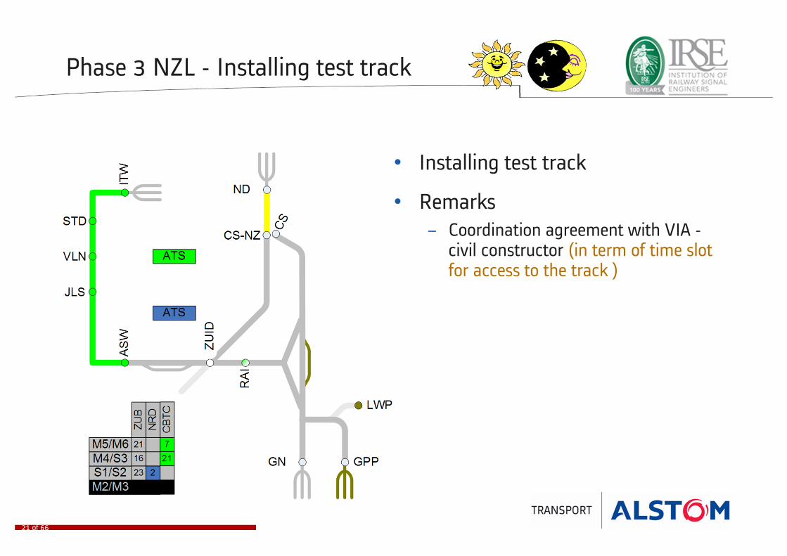
Phase 3 NZL - Installing test track
• Installing test track
• Remarks
− Coordination agreement with VIA -civil constructor (in term of time slot for access to the track )
21 of 66

Phase 3 NZL - Testing
• Testing on test track
• Installing rest of NZL
• Remarks
− Coordination agreement with VIA -civil constructor (in term of time slot for access to the track)
22 of 66
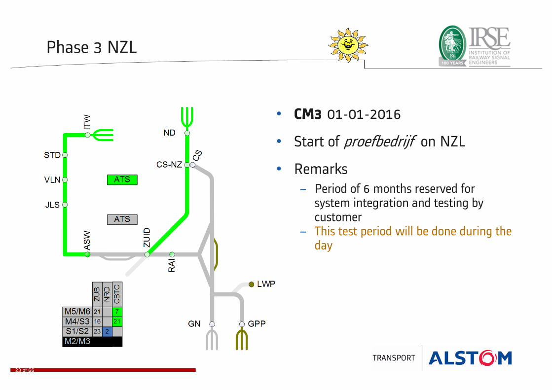
Phase 3 NZL
• CM3 01-01-2016
• Start of proefbedrijf on NZL
• Remarks
− Period of 6 months reserved for system integration and testing by customer
− This test period will be done during the day
23 of 66

Phase 4a Installation ASW - GN
• Installing track C
• Remarks
− Installation done during night− Testing with back-up ATS− Installation ASW-GN, MDW-CS and
MDW-GPP will be in parallel with the phase NZL
24 of 66

Phase 4b Installation MDW - CS
• Installing track D
• Remarks
− Installation done during night− Testing with back-up ATS− Will be simultaneous with the phase
NZL
25 of 66

Phase 4c Installation MDW - GPP
• Installing track E
• Remarks
− Installation done during night− Testing with back-up ATS− Will be simultaneous with the phase
NZL
26 of 66
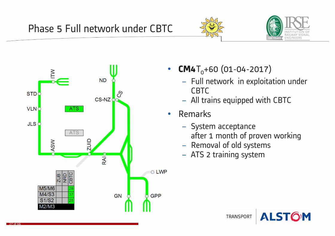
Phase 5 Full network under CBTC
• CM4T0+60 (01-04-2017)
− Full network in exploitation under CBTC
− All trains equipped with CBTC
• Remarks
− System acceptance after 1 month of proven working
− Removal of old systems − ATS 2 training system
27 of 66

28 of 66
29 of 66

Migration - Some examples - Vehicles
Before
migration
30 of 66
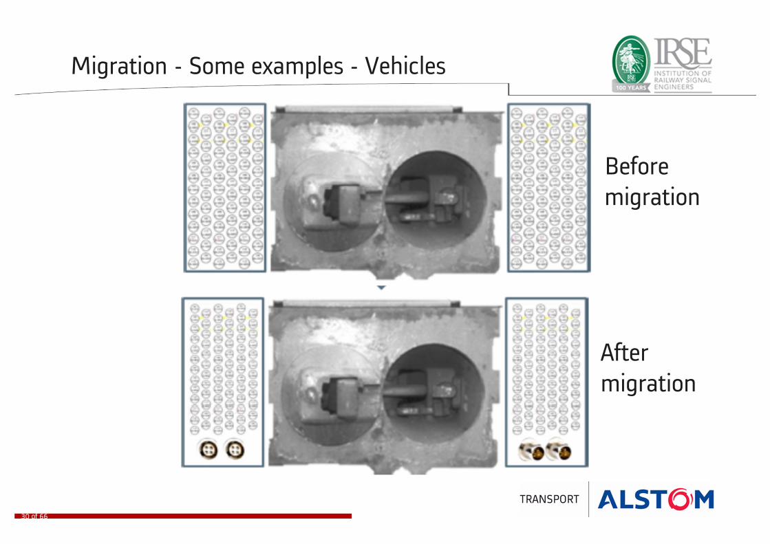
Migration - Some examples - Vehicles
Before
migration
After
migration
30 of 66

Migration - Some examples (Day / Night Switch)
31 of 66

Migration - Some examples (Day / Night Switch)
32 of 66
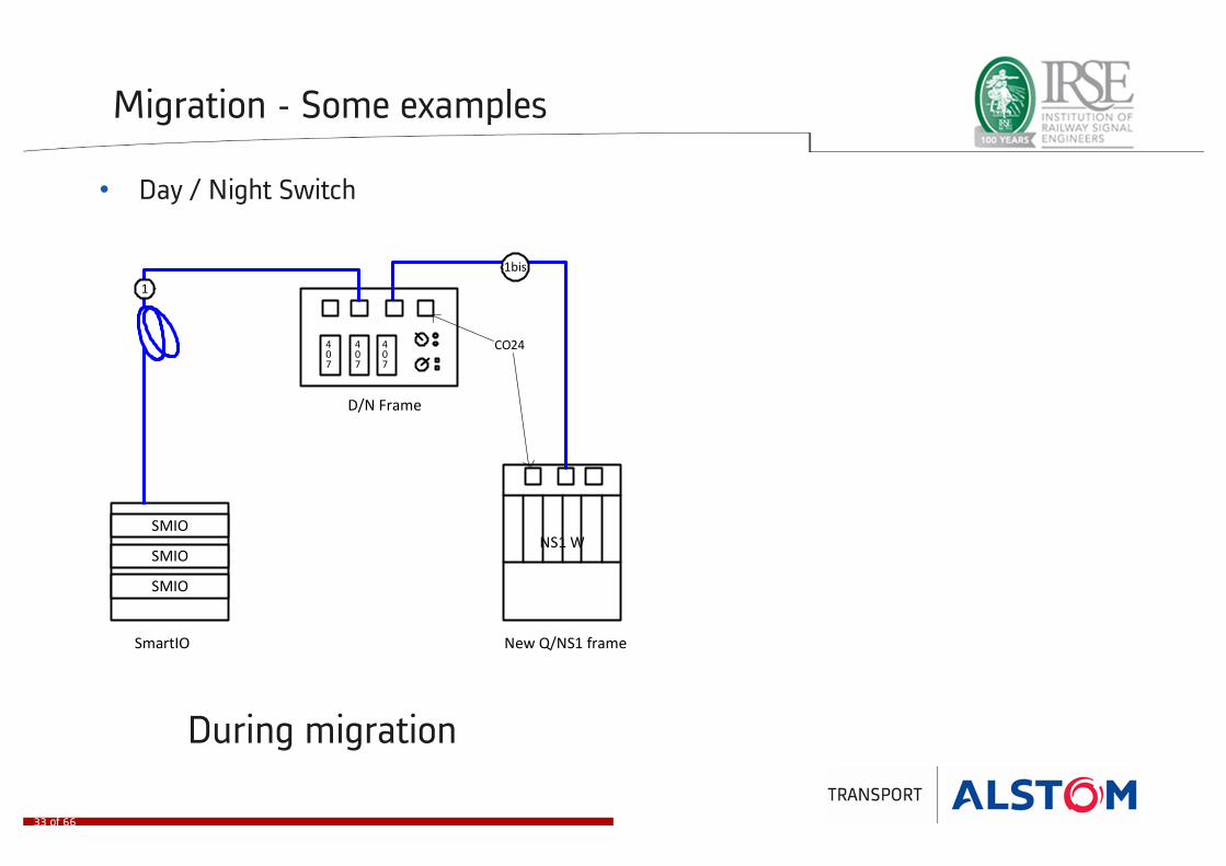
• Day / Night Switch
Migration - Some examples
407
SMIO
SMIO
SMIONS1 W
New Q/NS1 frame
407
407
1
1bis
SmartIO
D/N Frame
CO24
During migration
33 of 66

• Day / Night Switch
Migration - Some examples
407
SMIO
SMIO
SMIONS1 W
New Q/NS1 frame
407
407
1
1bis
SmartIO
D/N Frame
CO24
During migration
SMIO
SMIO
SMIONS1 W
New Q/NS1
FrameSmartIO
1
After migration
33 of 66

• Day / Night Switch
Migration - Some examples
407
SMIO
SMIO
SMIONS1 W
New Q/NS1 frame
407
407
1
1bis
SmartIO
D/N Frame
CO24
During migration
SMIO
SMIO
SMIONS1 W
New Q/NS1
FrameSmartIO
1
After migration
33 of 66

• Day / Night Switch
Migration - Some examples
407
SMIO
SMIO
SMIONS1 W
New Q/NS1 frame
407
407
1
1bis
SmartIO
D/N Frame
CO24
During migration
SMIO
SMIO
SMIONS1 W
New Q/NS1
FrameSmartIO
1
After migration
33 of 66

Contents
SCMA Project - Overview 4 .. 9
SCMA project – Migration strategy 11 .. 33
SCMA project – A day in the life of a train 35 .. 65
34 of 66

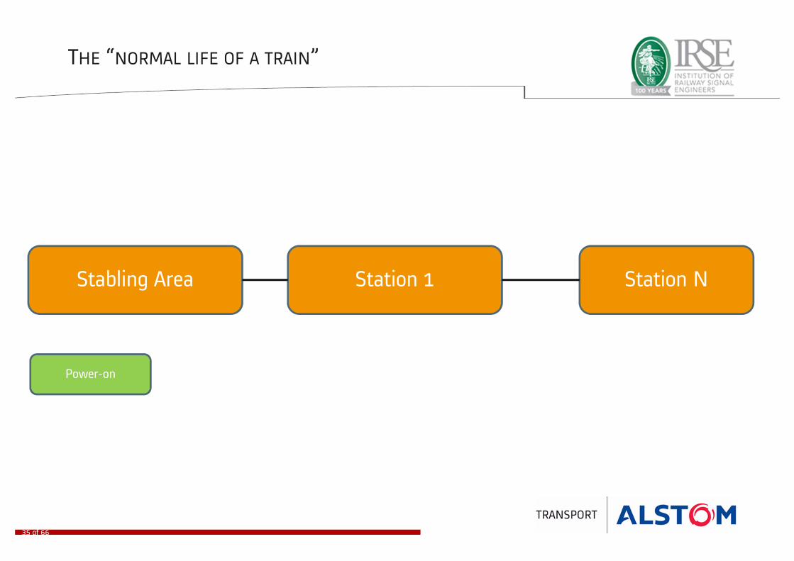
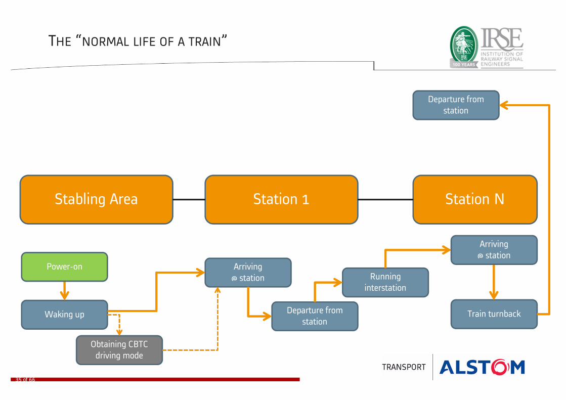
THE “NORMAL LIFE OF A TRAIN”
Stabling Area Station 1 Station N
35 of 66
THE “NORMAL LIFE OF A TRAIN”
Stabling Area Station 1 Station N
Power-on
35 of 66
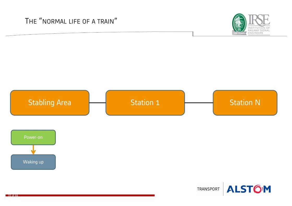
THE “NORMAL LIFE OF A TRAIN”
Stabling Area Station 1 Station N
Waking up
Power-on
35 of 66
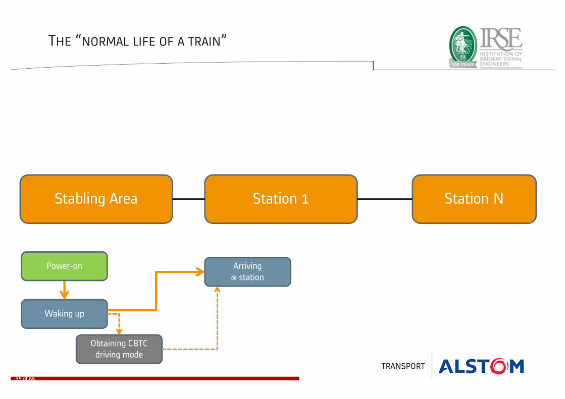
THE “NORMAL LIFE OF A TRAIN”
Stabling Area Station 1 Station N
Waking up
Obtaining CBTC
driving mode
Arriving
@ station
Power-on
35 of 66

THE “NORMAL LIFE OF A TRAIN”
Stabling Area Station 1 Station N
Waking up
Obtaining CBTC
driving mode
Arriving
@ station
Departure from
station
Power-on
35 of 66

THE “NORMAL LIFE OF A TRAIN”
Stabling Area Station 1 Station N
Waking up
Obtaining CBTC
driving mode
Running
interstation
Arriving
@ station
Departure from
station
Power-on
35 of 66

THE “NORMAL LIFE OF A TRAIN”
Stabling Area Station 1 Station N
Waking up
Obtaining CBTC
driving mode
Running
interstation
Arriving
@ station
Departure from
station
Power-on
35 of 66
Arriving
@ station

THE “NORMAL LIFE OF A TRAIN”
Stabling Area Station 1 Station N
Waking up
Obtaining CBTC
driving mode
Running
interstation
Arriving
@ station
Departure from
stationTrain turnback
Power-on
35 of 66
Arriving
@ station
THE “NORMAL LIFE OF A TRAIN”
Stabling Area Station 1 Station N
Waking up
Obtaining CBTC
driving mode
Running
interstation
Arriving
@ station
Departure from
stationTrain turnback
Departure from
station
Power-on
35 of 66
Arriving
@ station

THE “NORMAL LIFE OF A TRAIN”
Stabling Area Station 1 Station N
Waking up
Obtaining CBTC
driving mode
Running
interstation
Arriving
@ station
Departure from
stationTrain turnback
Running
interstation
Departure from
station
Power-on
35 of 66
Arriving
@ station

THE “NORMAL LIFE OF A TRAIN”
Stabling Area Station 1 Station N
Waking up
Obtaining CBTC
driving mode
Running
interstation
Arriving
@ station
Departure from
stationTrain turnback
Running
interstation
Departure from
station
Power-on
Arriving
@ terminal station
35 of 66
Arriving
@ station
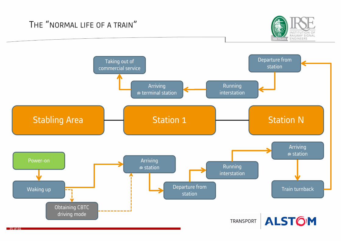
THE “NORMAL LIFE OF A TRAIN”
Stabling Area Station 1 Station N
Waking up
Obtaining CBTC
driving mode
Running
interstation
Arriving
@ station
Departure from
stationTrain turnback
Running
interstation
Departure from
station
Power-on
Taking out of
commercial service
Arriving
@ terminal station
35 of 66
Arriving
@ station

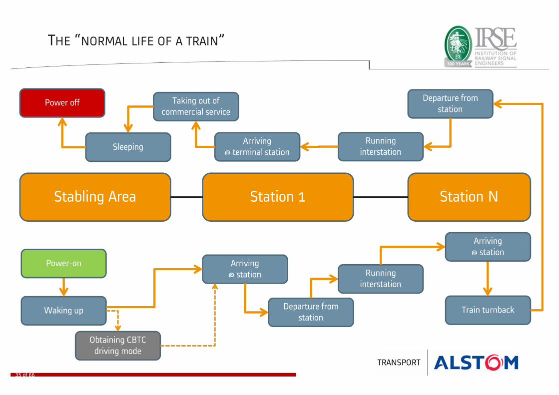
THE “NORMAL LIFE OF A TRAIN”
Stabling Area Station 1 Station N
Waking up
Obtaining CBTC
driving mode
Running
interstation
Arriving
@ station
Departure from
stationTrain turnback
SleepingRunning
interstation
Departure from
station
Power-on
Taking out of
commercial service
Arriving
@ terminal station
35 of 66
Arriving
@ station
THE “NORMAL LIFE OF A TRAIN”
Stabling Area Station 1 Station N
Waking up
Obtaining CBTC
driving mode
Running
interstation
Arriving
@ station
Departure from
stationTrain turnback
SleepingRunning
interstation
Departure from
stationPower off
Power-on
Taking out of
commercial service
Arriving
@ terminal station
35 of 66
Arriving
@ station

TRAIN DRIVING MODES
• Restricted Manual Reverse (RMR)
• Restricted Manual Forward (RMF)
• Protected Manual Forward (PMF) : GoA level 1
• Automatic Mode Forward (AMF) : GoA level 2
• Automatic Turnback without driver (ATB) : GoA level 2
• Driverless Mode Forward (DMF) : GoA level 4
Train Type
ModeM5 S1/S2 S3/M4
RMR X X X
RMF X X X
PMF X X X
AMF X X
ATB X
DMF X
In blue : CBTC modes
36 of 66
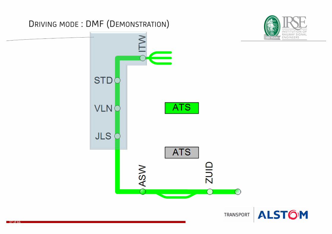
DRIVING MODE : DMF (DEMONSTRATION)
37 of 66
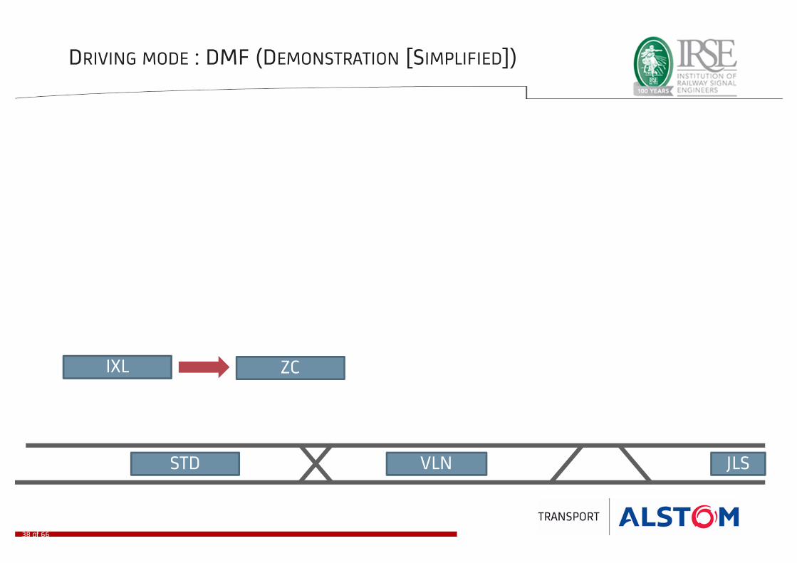
DRIVING MODE : DMF (DEMONSTRATION [SIMPLIFIED])
STD VLN JLS
ZCIXL
38 of 66
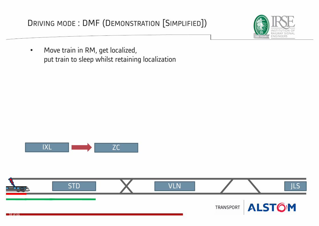
DRIVING MODE : DMF (DEMONSTRATION [SIMPLIFIED])
STD VLN
• Move train in RM, get localized,
put train to sleep whilst retaining localization
JLS
ZCIXL
38 of 66

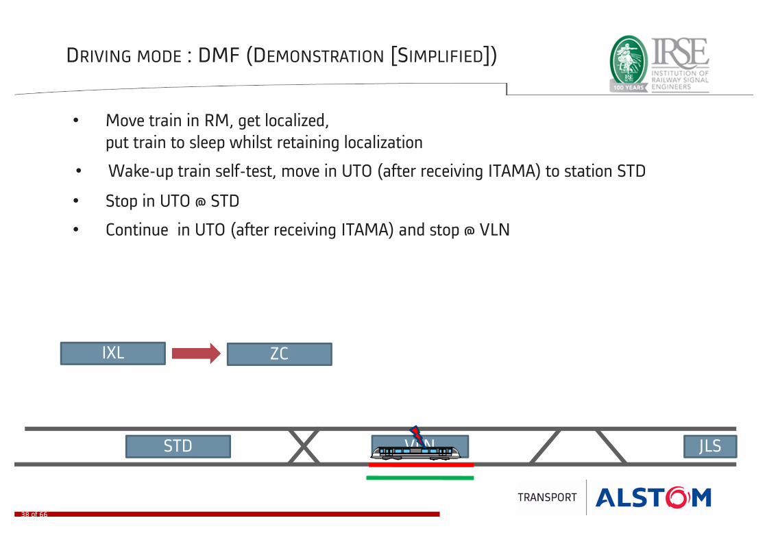
DRIVING MODE : DMF (DEMONSTRATION [SIMPLIFIED])
STD VLN
• Move train in RM, get localized,
put train to sleep whilst retaining localization
JLS
• Wake-up train self-test, move in UTO (after receiving ITAMA) to station STD
• Stop in UTO @ STD
ZCIXL
38 of 66
DRIVING MODE : DMF (DEMONSTRATION [SIMPLIFIED])
STD VLN
• Move train in RM, get localized,
put train to sleep whilst retaining localization
JLS
• Wake-up train self-test, move in UTO (after receiving ITAMA) to station STD
• Stop in UTO @ STD
• Continue in UTO (after receiving ITAMA) and stop @ VLN
ZCIXL
38 of 66

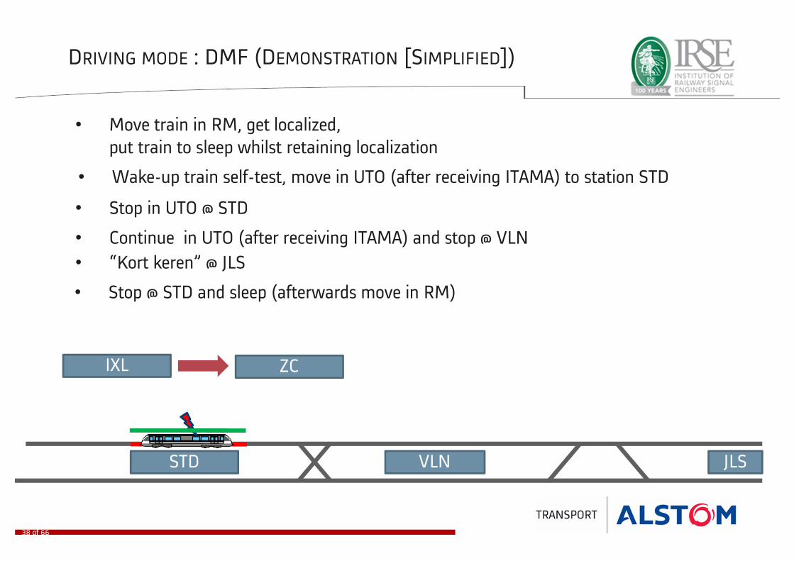
DRIVING MODE : DMF (DEMONSTRATION [SIMPLIFIED])
STD VLN
• Move train in RM, get localized,
put train to sleep whilst retaining localization
JLS
• Wake-up train self-test, move in UTO (after receiving ITAMA) to station STD
• Stop in UTO @ STD
• Continue in UTO (after receiving ITAMA) and stop @ VLN
• “Kort keren” @ JLS
ZCIXL
38 of 66
DRIVING MODE : DMF (DEMONSTRATION [SIMPLIFIED])
STD VLN
• Move train in RM, get localized,
put train to sleep whilst retaining localization
JLS
• Wake-up train self-test, move in UTO (after receiving ITAMA) to station STD
• Stop in UTO @ STD
• Continue in UTO (after receiving ITAMA) and stop @ VLN
• “Kort keren” @ JLS
• Stop @ STD and sleep (afterwards move in RM)
ZCIXL
38 of 66
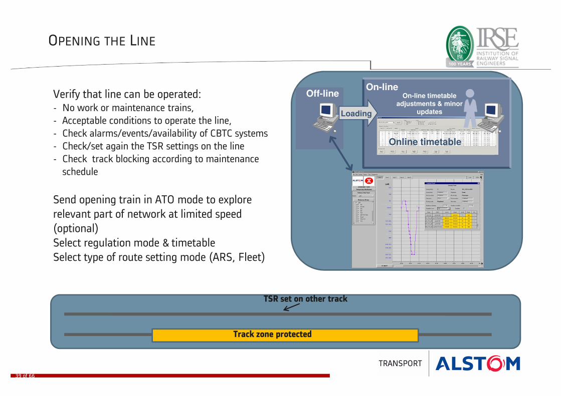
OPENING THE LINE
Verify that line can be operated:- No work or maintenance trains,
- Acceptable conditions to operate the line,
- Check alarms/events/availability of CBTC systems
- Check/set again the TSR settings on the line
- Check track blocking according to maintenance
schedule
Send opening train in ATO mode to explore
relevant part of network at limited speed
(optional)
Select regulation mode & timetable
Select type of route setting mode (ARS, Fleet)
HMI
Off-lineOn-line
Online timetable
Loading
On-line timetable
adjustments & minor
updates
Track zone protected
TSR set on other track
39 of 66
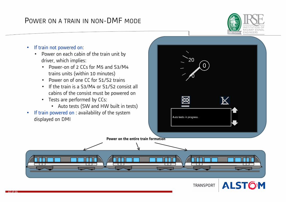
POWER ON A TRAIN IN NON-DMF MODE
• If train not powered on:
• Power on each cabin of the train unit by
driver, which implies:
• Power-on of 2 CCs for M5 and S3/M4
trains units (within 10 minutes)
• Power on of one CC for S1/S2 trains
• If the train is a S3/M4 or S1/S2 consist all
cabins of the consist must be powered on
• Tests are performed by CCs:
• Auto tests (SW and HW built in tests)
• If train powered on : availability of the system
displayed on DMI
Power on the entire train formation
40 of 66

WAKING UP A TRAIN IN NON-DMF MODE
HMI show driver interface
• In non DMF mode, the driver:
• Activates the cabin
• Selects an available driving mode (RMF,
PMF or AMF)
• Tests are performed by CC:
• Hw interface tests (HMI, EB)
• If localisation is memorised (PMF and AMF are
available), the driver:
• Waits for departure order from ATS
(displayed on HMI) based on regulation
• Runs the train in PMF or AMF driving
mode a few meters to confirm localisation
• Can proceed normally at first station after
the yard
Localisation confirmation beacons
41 of 66

OBTAIN CBTC PMF OR AMF DRIVING MODE (DEGRADED MODE)
The procedure is the following:• Verify with TCC that route is set (no signals) and
check time for departure
• Mode selector on RMF
• Drive train in RMF (25 kph max)
• Train localizes. Communication with ZC starts
• As soon as the train approaches the end of an
SDD
• Discrimination process is performed
• PMF and AMF become available
• Available CBTC modes are presented on driver
HMI
• Driver can switch to PMF or AMF while running
Localisation after reading 2 beacons
42 of 66

RECOVERING PMF MODE AT YARD EXIT
Train exits the yard in RMF mode
with head and tail NIAP
1
2
3
4
Platform SSP
Platform SSP
Platform SSP
As soon as the head NIAP becomes shorter
than the shortest train it is erased and
PMF mode is available but tail NIAP remains
Driver targets the station stopping point in PMF
Platform SSP
Train stopped at station : tail NIAP erased because
shorter than shortest train and adjacent block clear
43 of 66

TRAIN ARRIVAL IN STATION (PMF) : DOCKING AND DOOR OPENING
• Driver targets station stopping point according
to train type and mission
• Station CCTV cameras images are displayed in
TCC
• Driver brakes train to standstill at platform
• If correctly docked, icon is displayed
• Door opening authorization granted by ATP
• Driver opens doors
• Dwell time count down starts
Platform SSP
44 of 66

TRAIN ARRIVAL IN STATION (PMF) : DOCKING UNSUCCESSFUL
• Docking icon not displayed:
• In case of under-shoot : driver can creep in
PMF mode to the SSP
• In case of overshoot : driver needs to switch to
RMR and reverse at low speed
Platform SSP
45 of 66

TRAIN ARRIVAL IN STATION (PMF) : DWELL AND DOOR CLOSING
• Dwell time countdown continues
• Door closing reminder displayed to driver a
few seconds before dwell time is elapsed
(parameter)
• Driver requests door closing to rolling stock
• Door closing status displayed to driver
• PSD status will be displayed (provision)
Platform SSP
46 of 66

TRAIN ARRIVAL IN STATION (PMF) : DEPARTURE
• Door closed : the train is ready to depart
• Driver waits for dwell time to elapse and
display of departure order
• Driver can start traction
• If no movement is performed at dwell time
zero, the countdown continues with yellow
border
Platform SSP
47 of 66
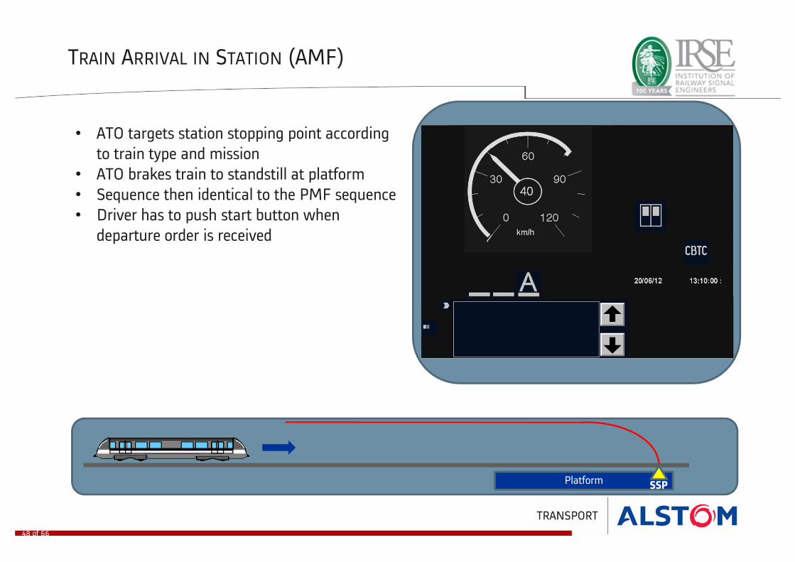
TRAIN ARRIVAL IN STATION (AMF)
• ATO targets station stopping point according
to train type and mission
• ATO brakes train to standstill at platform
• Sequence then identical to the PMF sequence
• Driver has to push start button when
departure order is received
Platform SSP
48 of 66
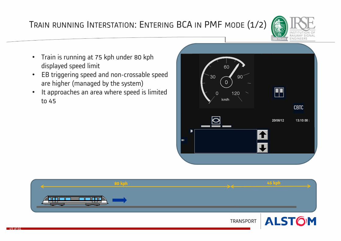
TRAIN RUNNING INTERSTATION: ENTERING BCA IN PMF MODE (1/2)
• Train is running at 75 kph under 80 kph
displayed speed limit
• EB triggering speed and non-crossable speed
are higher (managed by the system)
• It approaches an area where speed is limited
to 45
80 kph 45 kph
49 of 66
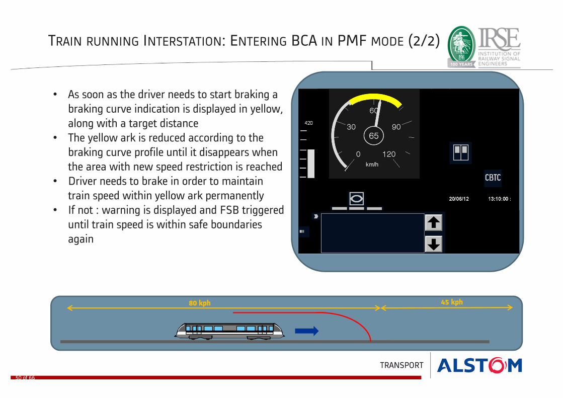
TRAIN RUNNING INTERSTATION: ENTERING BCA IN PMF MODE (2/2)
• As soon as the driver needs to start braking a
braking curve indication is displayed in yellow,
along with a target distance
• The yellow ark is reduced according to the
braking curve profile until it disappears when
the area with new speed restriction is reached
• Driver needs to brake in order to maintain
train speed within yellow ark permanently
• If not : warning is displayed and FSB triggered
until train speed is within safe boundaries
again
80 kph 45 kph
50 of 66
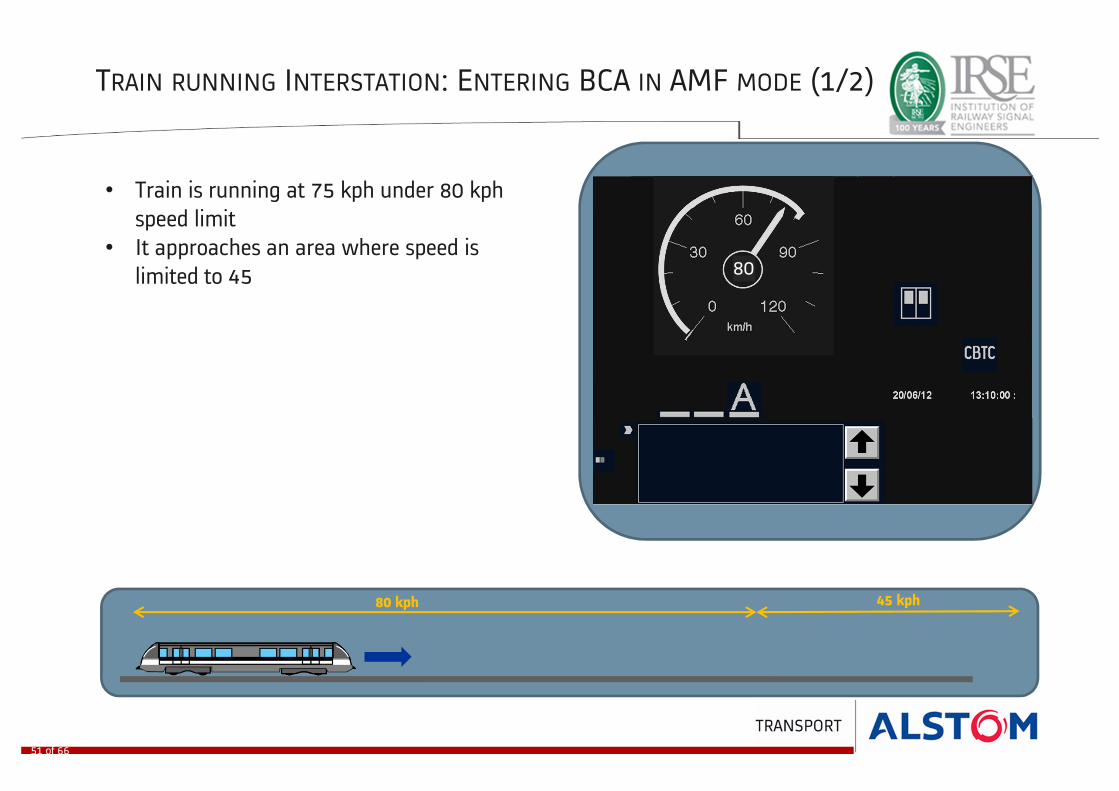
TRAIN RUNNING INTERSTATION: ENTERING BCA IN AMF MODE (1/2)
• Train is running at 75 kph under 80 kph
speed limit
• It approaches an area where speed is
limited to 45
80 kph 45 kph
51 of 66
80

TRAIN RUNNING INTERSTATION: ENTERING BCA IN PMF MODE (2/2)
• As soon as the train needs to start braking,
the ATO sends a braking command to the
rolling stock in order to reach the target
speed
• No yellow ark is displayed
• No target distance is displayed
• The maximum speed display changes as
soon as the train reaches the area with the
new speed limit
80 kph 45 kph
52 of 66
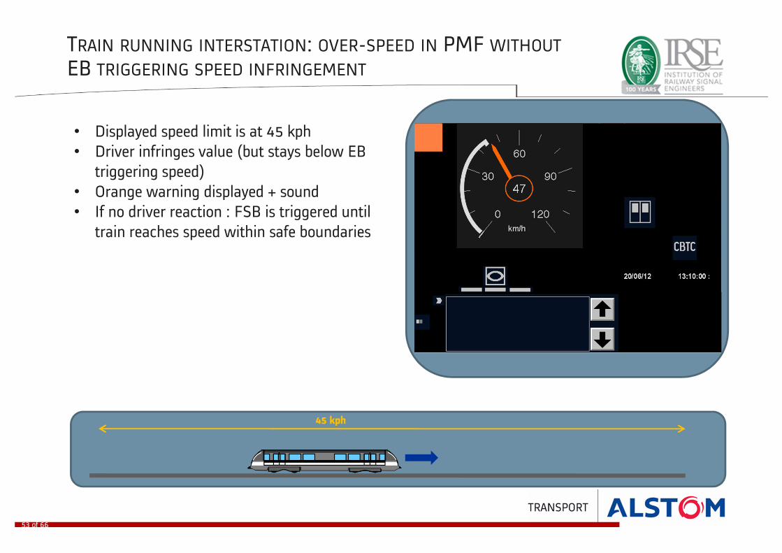
TRAIN RUNNING INTERSTATION: OVER-SPEED IN PMF WITHOUT
EB TRIGGERING SPEED INFRINGEMENT
• Displayed speed limit is at 45 kph
• Driver infringes value (but stays below EB
triggering speed)
• Orange warning displayed + sound
• If no driver reaction : FSB is triggered until
train reaches speed within safe boundaries
45 kph
53 of 66

TRAIN RUNNING INTERSTATION: OVER-SPEED IN PMF WITH
EB TRIGGERING SPEED INFRINGEMENT
• Displayed speed limit is at 45 kph
• Driver infringes value (and hits EB
triggering speed)
• FSB cannot be used by system as EB
triggering speed is reached
• Red display + sound
• ATP triggers EB
45 kph
54 of 66

TRAIN LOSS OF COMMUNICATION
APNIAP
Train 1 in PMF
Train 2 in PMF triggers EB to stop
Train 1 triggers EB to stop
Train 1 : switches to RM and moves
NTAP propagation : expands both directions
NTAP propagation : stops at block boundary and propagates to the rear
Train 2 switches to RM and moves
NTAP propagation : stops at train 2 AP and propagates in adjacent block
Train 2 sweeps NTAP in RM
NTAP propagation : reduced by train 2 AP and propagates in adjacent block
1
2
3
4
5
Train 2 can switch back to PMF
NTAP is cleared : train 2 distance to block < than shortest train and adjacent block cleared by train 1
6
55 of 66
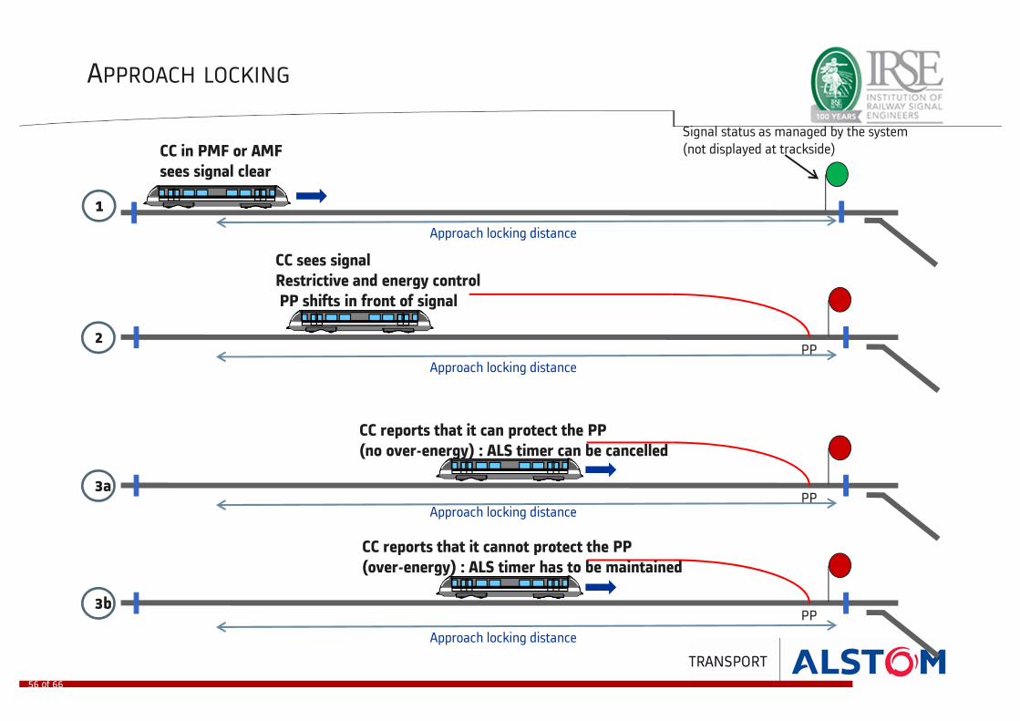
APPROACH LOCKING
CC in PMF or AMF
sees signal clear
CC sees signal
Restrictive and energy control
PP shifts in front of signal
1
2
Approach locking distance
Approach locking distance
Signal status as managed by the system
(not displayed at trackside)
PP
3a
Approach locking distancePP
CC reports that it can protect the PP
(no over-energy) : ALS timer can be cancelled
3b
Approach locking distance
PP
CC reports that it cannot protect the PP
(over-energy) : ALS timer has to be maintained
56 of 66

TRAIN REGULATION IN INTERSTATION: PMF MODE
• Displayed speed limit is at 80 kph
• ATS requests energy saving because of non-
peak hour according to time table or
applicable headway
• ATS sends an arrival time at next station
accordingly
• System displays an average regulation speed
(46 kph in this example) which is (always)
below the safe speed
• Driver needs to slow down the train to match
the requested regulation speed
80 kph
57 of 66

TRAIN REGULATION IN INTERSTATION: AMF MODE
• Displayed speed limit is at 80 kph
• ATS requests energy saving because of non-
peak hour according to time table or
applicable headway
• ATS sends an arrival time at next station
accordingly
• ATO monitors the train speed in order to meet
the arrival time precisely and respect
passenger comfort
80 kph
58 of 66
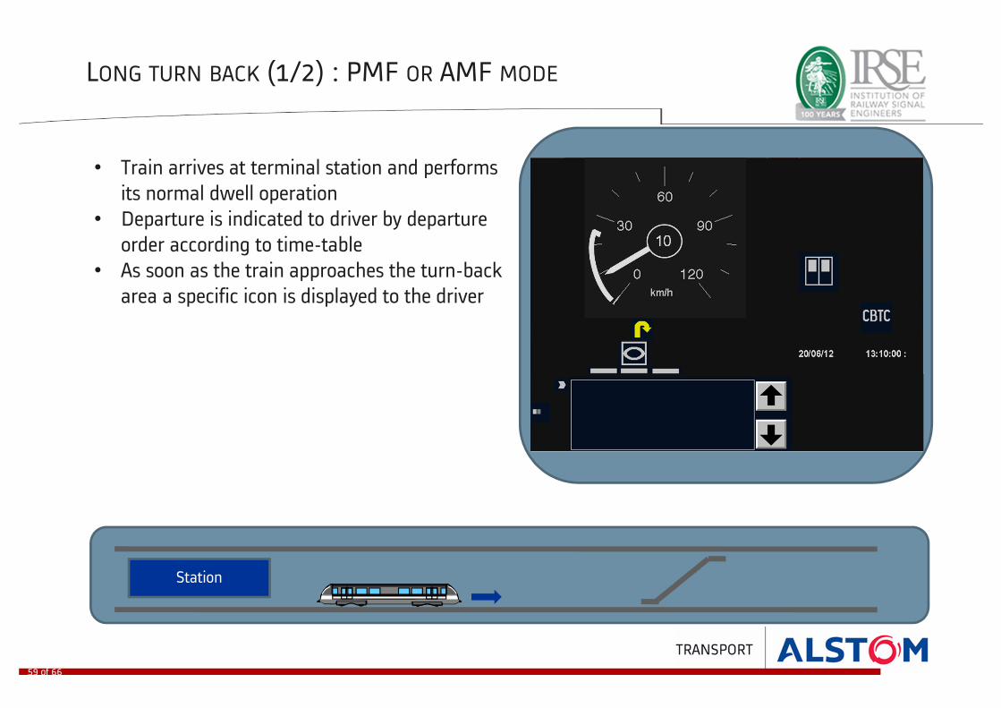
LONG TURN BACK (1/2) : PMF OR AMF MODE
• Train arrives at terminal station and performs
its normal dwell operation
• Departure is indicated to driver by departure
order according to time-table
• As soon as the train approaches the turn-back
area a specific icon is displayed to the driver
Station
59 of 66

LONG TURN BACK (2/2) : PMF OR AMF MODE
• Train arrives at change of end area and stops at
predefined stopping point (by driver or ATO)
• Once train is at standstill it declares NTM and IXL
can set the route in the opposite direction (after
safety timer is elapsed)
• Traffic direction is changed in the change of end
area (under the train) and in front of the train
(according to route setting)
• Train cannot move in the previous direction
anymore
• Driver deactivates the front cabin (cabin key off,
mode selector off) and goes to the rear cabin
• Driver activates the rear cabin (cabin key on) which
now becomes the front cabin
• Driver selects the appropriate driving mode (PMF or
AMF) and waits for departure order
Station
60 of 66

SHORT TURN BACK (1/2) : PMF OR AMF MODE
• At approach of terminal station driver is informed by
change of end icon that a turn-back is going to take place
• Train arrives at terminal station and docks in PMF or AMF
mode
• Once train is at standstill it declares NTM and IXL can set
the route in opposite direction (after safety timer is elapsed)
• Traffic direction is changed in the change of end area
(under the train) and in front of the train (according to
route setting)
• Train cannot move in previous direction anymore
• Driver can open the doors from the front cab
• Driver deactivates the front cabin (cabin key off, mode
selector on off) and goes to the rear cabin
• Driver activates the rear cabin (cabin key on) which now
becomes the front cabin
• Dwell operations continue from the new front cab
(including door closing)
• Departure is indicated to driver by departure order
according to time-table
Station
61 of 66

SHORT TURN BACK (2/2) : PMF OR AMF MODE
• Dwell operations continue from the new front cab
(including door closing)
• Departure is indicated to driver by departure order
according to time-table
Station
62 of 66

SLEEPING A TRAIN
As soon as the train arrives at its stabling point:• Driver deactivates the front cabin (cabin key off,
mode selector off)
• If power off requested, the driver powers off the
train and leaves
• If power off not requested an auto reset will be
triggered by the system during the night:
• Configurable sequence, based on timer:
• Train @ standstill in stabling area
• When timer elapsed, reset CC � all auto
tests will be performed
Stabling position
63 of 66

Interfaces
64 of 66

Interfaces
65 of 66

Interfaces
65 of 66

Interfaces
65 of 66

www.alstom.com
66 of 66
Related Documents