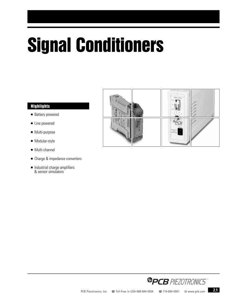
Signal Conditioners 2.1 PCB Piezotronics, Inc. Toll-Free in USA 888-684-0004 716-684-0001 www.pcb.com ■ Battery powered ■ Line powered ■ Multi-purpose ■ Modular-style ■ Multi-channel ■ Charge & impedance converters ■ Industrial charge amplifiers & sensor simulators Highlights

Welcome message from author
This document is posted to help you gain knowledge. Please leave a comment to let me know what you think about it! Share it to your friends and learn new things together.
Transcript
Signal Conditioners
2.1PCB Piezotronics, Inc. Toll-Free in USA 888-684-0004 716-684-0001 www.pcb.com
■ Battery powered
■ Line powered
■ Multi-purpose
■ Modular-style
■ Multi-channel
■ Charge & impedance converters
■ Industrial charge amplifiers & sensor simulators
Highlights
2.2 PCB Piezotronics, Inc. Toll-Free in USA 888-684-0004 716-684-0001 www.pcb.com
Battery Powered Signal Conditioners for ICP® Sensors
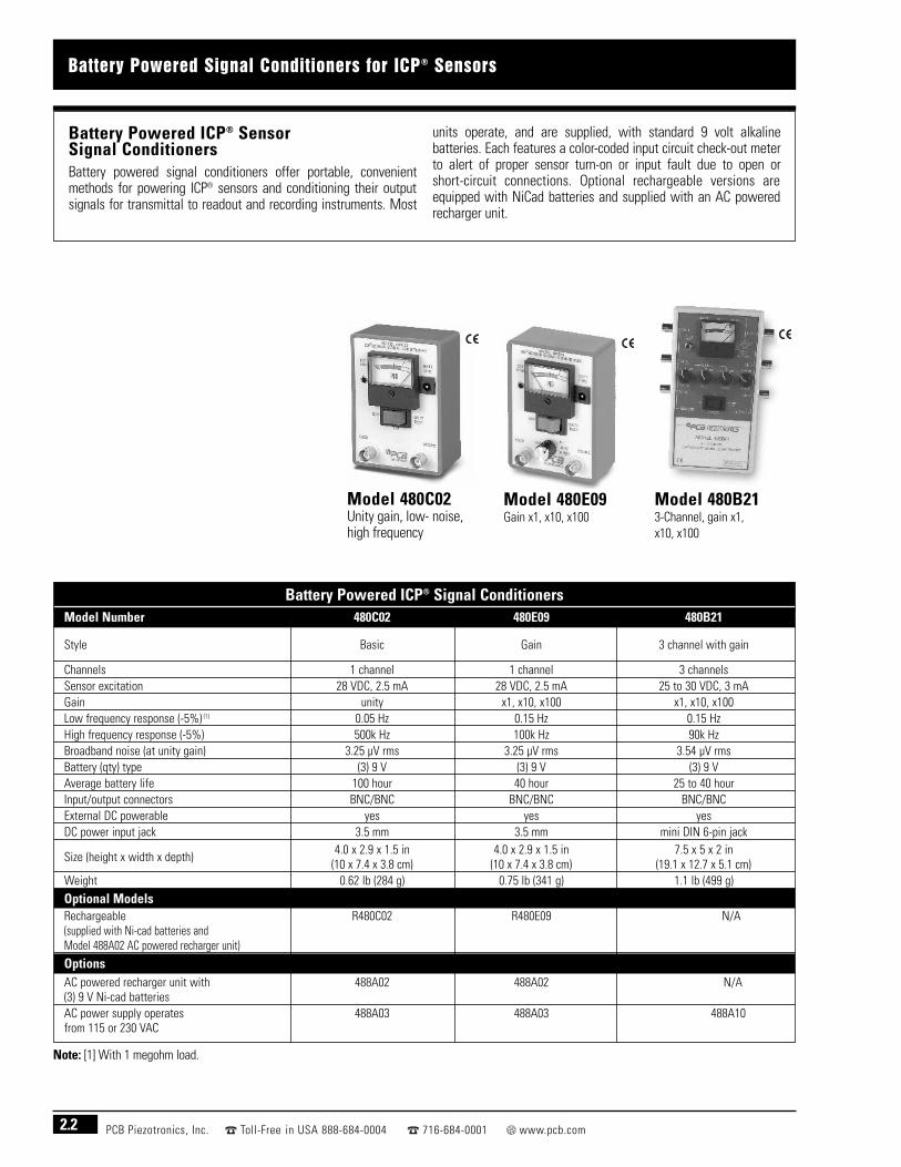
Battery Powered ICP® Sensor Signal ConditionersBattery powered signal conditioners offer portable, convenientmethods for powering ICP® sensors and conditioning their outputsignals for transmittal to readout and recording instruments. Most
units operate, and are supplied, with standard 9 volt alkalinebatteries. Each features a color-coded input circuit check-out meterto alert of proper sensor turn-on or input fault due to open or short-circuit connections. Optional rechargeable versions areequipped with NiCad batteries and supplied with an AC poweredrecharger unit.
Model 480C02Unity gain, low- noise, high frequency
Model 480E09Gain x1, x10, x100
Model 480B213-Channel, gain x1, x10, x100
Note: [1] With 1 megohm load.
Battery Powered ICP® Signal ConditionersModel Number 480C02 480E09 480B21
Style Basic Gain 3 channel with gain
Channels 1 channel 1 channel 3 channelsSensor excitation 28 VDC, 2.5 mA 28 VDC, 2.5 mA 25 to 30 VDC, 3 mAGain unity x1, x10, x100 x1, x10, x100Low frequency response (-5%) [1] 0.05 Hz 0.15 Hz 0.15 HzHigh frequency response (-5%) 500k Hz 100k Hz 90k HzBroadband noise (at unity gain) 3.25 µV rms 3.25 µV rms 3.54 µV rmsBattery (qty) type (3) 9 V (3) 9 V (3) 9 VAverage battery life 100 hour 40 hour 25 to 40 hourInput/output connectors BNC/BNC BNC/BNC BNC/BNCExternal DC powerable yes yes yesDC power input jack 3.5 mm 3.5 mm mini DIN 6-pin jack
Size (height x width x depth)4.0 x 2.9 x 1.5 in 4.0 x 2.9 x 1.5 in 7.5 x 5 x 2 in
(10 x 7.4 x 3.8 cm) (10 x 7.4 x 3.8 cm) (19.1 x 12.7 x 5.1 cm)Weight 0.62 lb (284 g) 0.75 lb (341 g) 1.1 lb (499 g)
Optional ModelsRechargeable R480C02 R480E09 N/A(supplied with Ni-cad batteries andModel 488A02 AC powered recharger unit)
OptionsAC powered recharger unit with 488A02 488A02 N/A(3) 9 V Ni-cad batteriesAC power supply operates 488A03 488A03 488A10from 115 or 230 VAC

Line Powered Signal Conditioners for ICP® Sensors
2.3PCB Piezotronics, Inc. Toll-Free in USA 888-684-0004 716-684-0001 www.pcb.com
Line Powered ICP® Sensor Signal ConditionersLine powered signal conditioners offer bench-top methods forpowering ICP® sensors in the laboratory and conditioning theiroutput signals for transmittal to readout and recording instruments.Each features a color-coded input circuit checkout meter to alert of
proper sensor turn-on or input fault due to open or short-circuitconnections. AC and DC powerable units can operate either withthe supplied AC powered transformer or optional external batterypack. AC/DC coupled outputs offer the ability to achieve true DCfrequency response in order to accurately condition very lowfrequency vibrations or long duration shock pulses.
Model 482A21Unity gain, low-noise,AC and DC powerable
Model 482A224-channel, unity gain,low-noise, AC and DCpowerable
Model 482B06Basic, unity gain
Model 482B11Gain x1, x10, x100
Model 484B02Clamped output, unity gain, AC/DC coupled output
Model 484B06Low frequency, unitygain, AC/DC coupledoutput
Model 484B11Low frequency, gain x1, x10, x100, AC/DC coupled output
Note: 1. Current is factory set at 4 mA but is user adjustable between 2 and 20 mA 2. With 1 megohm load 3. Supplied with Model 488A04 AC power adaptor(100 to 240 VAC, 50 to 60 Hz input; 36 VDC 120 mA output)
Line Powered ICP® Signal ConditionersModel Number 482A21 482A22 482B06 482B11 484B02 484B06 484B11
StyleLow-noise Low-noise
Basic GainClamped output Low frequency Low frequency
AC and DC power AC and DC power AC/DC coupled AC/DC coupled with gainChannels 1 channel 4 channels 1 channel 1 channel 1 channel 1 channel 1 channelSensor excitation [1] 26 volt, 2 to 20 mA 26 volt, 2 to 20 mA 24 volt, 2 to 20 mA 24 volt, 2 to 20 mA 24 volt, 2 to 20 mA 24 volt, 2 to 20 mA 24 volt, 2 to 20 mAGain unity unity unity x1, x10, x100 unity unity x1, x10, x100Low frequency response (-5%) <0.1 Hz [2] <0.1 Hz [2] <0.05 Hz 0.17 Hz DC DC DCHigh frequency response (-5%) >1M Hz >1M Hz 1M Hz 200k Hz 200k Hz 200k Hz 200k HzBroadband noise (at unity gain) <3.25 µV rms <3.25 µV rms <3.64 µV rms N/A 28.8 µV rms 28.8 µV rms 10 µV rms
Power required36 VDC 36 VDC 115 VAC 115 VAC 115 VAC 115 VAC 115 VAC
120 mA [3] 120 mA [3] 50 to 400 Hz 50 to 400 Hz 50 to 400 Hz 50 to 400 Hz 50 to 400 HzInput/output connectors BNC/BNC BNC/BNC BNC/BNC BNC/BNC BNC/BNC BNC/BNC BNC/BNCExternal DC powerable yes yes no no no no noDC power input jack DIN DIN — — — — —
Size (height x width x depth)6.3 x 2.4 x 11 in 6.3 x 2.4 x 11 in 4.3 x 1.8 x 6 in 4.3 x 1.8 x 6 in 5 x 2 x 10.5 in 4.3 x 1.8 x 6 in 4.3 x 1.8 x 6 in
(16 x 6 x 28 cm) (16 x 6 x 28 cm) (11 x 4.6 x 15 cm) (11 x 4.6 x 15 cm) (12.7 x 5.1 x 26.7 cm) (11 x 4.6 x 15 cm) (11 x 4.6 x 15 cm)Weight 1.51 lb (685 gm) 1.67 lb (756 gm) 1.2 lb (544 gm) 2 lb (907 gm) 2 lb (907 gm) 2 lb (907 gm) 2 lb (907 gm)
Optional Models210 to 250 VAC powerable standard standard F482B06 F482B11 F484B02 F484B06 F484B11
OptionsExternal 36 VDC battery pack 488B07 488B07 N/A N/A N/A N/A N/A

2.4 PCB Piezotronics, Inc. Toll-Free in USA 888-684-0004 716-684-0001 www.pcb.com
DIN Rail Signal Conditioners for ICP® Sensors
Model 410A01The Model 410A01 DIN rail mount, ICP® SensorSignal Conditioner, for piezoelectric force orstrain sensors, is ideally suited for monitoringmanufacturing forces experienced duringassembly & product testing. With its longdischarge time constant, and high frequencyresponse, both quasi-static and dynamicmeasurements up to 10 kHz are possible. The unit synchronizes with machine cycles through areset feature while analog and peak hold outputsallow for real-time monitoring with machinecontrol devices. Requires 24 VDC power.
Model 682A02The Model 682A02 DIN rail mount, ICP® SignalConditioner provides 18 VDC sensor excitationvoltage for dynamic measurements only. Internaljumpers select excitation current of 4 or 10 mAand voltage gain of x1, x10, or x100.
Model 682A0124 VDC Power Supply, 120 to 230 VAC powered,DIN rail mount, 3.75 kV isolation, 1,000 mAmaximum.
Model 682A06Programmable, universal transmitter withcurrent, voltage, and two relay outputs. AcceptsmA, VDC, RTD, TC, linear resistance, andpotentiometer inputs. Fully programmable viadetachable display (Model 070A80 soldseparately), and operates from 19.2 to 300 VDC,or 21.5 to 253 VAC power.
These products conform to applicable EuropeanDirectives for CE marking.
DIN rail mount signal conditioners offer a convenient mountingpackage for industrial applications. Signal conditioners may bemounted inside protected enclosures or in a control panel for easyaccess to sensor and power supply connections, and integrationwith machine controllers.
The signal conditioners are designed for operation with ICP® force orstrain sensors and are ideally suited for monitoring forcesexperienced during manufacturing, assembly, on-line processes,quality assurance, or end-of-line product testing.
DIN Rail Signal Conditioners for ICP® Sensors
2.5PCB Piezotronics, Inc. Toll-Free in USA 888-684-0004 716-684-0001 www.pcb.com
DIN Rail Signal Conditioners for ICP® Sensors
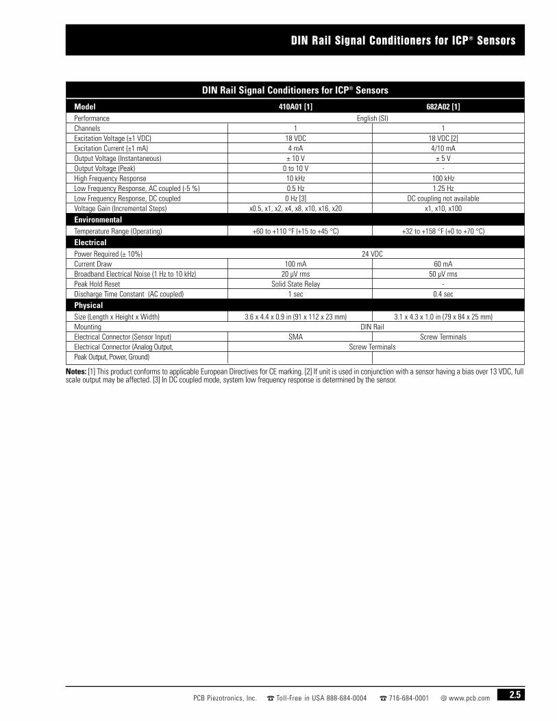
Model 410A01 [1] 682A02 [1]Performance English (SI)Channels 1 1Excitation Voltage (±1 VDC) 18 VDC 18 VDC [2]Excitation Current (±1 mA) 4 mA 4/10 mAOutput Voltage (Instantaneous) ± 10 V ± 5 VOutput Voltage (Peak) 0 to 10 V -High Frequency Response 10 kHz 100 kHzLow Frequency Response, AC coupled (-5 %) 0.5 Hz 1.25 HzLow Frequency Response, DC coupled 0 Hz [3] DC coupling not availableVoltage Gain (Incremental Steps) x0.5, x1, x2, x4, x8, x10, x16, x20 x1, x10, x100
EnvironmentalTemperature Range (Operating) +60 to +110 °F (+15 to +45 °C) +32 to +158 °F (+0 to +70 °C)
ElectricalPower Required (± 10%) 24 VDCCurrent Draw 100 mA 60 mABroadband Electrical Noise (1 Hz to 10 kHz) 20 µV rms 50 µV rmsPeak Hold Reset Solid State Relay -Discharge Time Constant (AC coupled) 1 sec 0.4 sec
PhysicalSize (Length x Height x Width) 3.6 x 4.4 x 0.9 in (91 x 112 x 23 mm) 3.1 x 4.3 x 1.0 in (79 x 84 x 25 mm)Mounting DIN RailElectrical Connector (Sensor Input) SMA Screw TerminalsElectrical Connector (Analog Output, Screw TerminalsPeak Output, Power, Ground)
Notes: [1] This product conforms to applicable European Directives for CE marking. [2] If unit is used in conjunction with a sensor having a bias over 13 VDC, fullscale output may be affected. [3] In DC coupled mode, system low frequency response is determined by the sensor.

2.6 PCB Piezotronics, Inc. Toll-Free in USA 888-684-0004 716-684-0001 www.pcb.com
Modular-Style Signal Conditioners
Modular signal conditioners are comprised of selected signal conditioning modules, andan AC power supply module, assembled into a 2-, 3-, 5-, or 9-slot chassis. Availablemodules condition ICP®, charge output, or capacitive sensor signals. The commonchassis backplane architecture permits mixing and matching of modules to achieve thedesired number of channels and signal conditioning features. Visit www.pcb.com for fulldetails of available items.
Modular-Style Signal Conditioners
Modular Signal Conditioning Systems
Modular-Style Signal Conditioners
Model 442B21616-channel, unity gain,with selectable ICP® orvoltage mode
Model 442B31616-channel, unity gain,with selectable ACcoupled ICP® or DCcoupled voltage mode
Model 442C044-channel, gain x1,x10, x100 for ICP®
sensors
Model 443B02Dual mode amplifierfor charge output andICP® sensors withshort, medium andlong discharge timeconstants
Modular-Style Signal ConditionersModel Number 442B216 442B316 442C04 443B02 [6]
Channels 16 channels 16 channels 4 channels 1 channelSensor excitation [1] 22 volt, 2 to 10 mA 22 volt, 2 to 10 mA 25.5 volt, 0.5 to 20 mA 24 volt, 0 to 20 mA [2]
Gain (each channel) x1 x1 x1, x10, x100 x0.1 to 1000Charge sensitivity N/A N/A N/A 0.0001 to 10 volts/pCLow frequency response (-5%) 0.125 Hz 0.125 Hz 0.05 Hz [3] 2, 0.2, 0.03, 0.003, ~0 Hz [4]
High frequency response (-5%) 30k Hz 30k Hz 100k Hz 0.1, 1, 3, 10, 100, >200k Hz [5]
Broadband noise (at unity gain) 100 µV rms 100 µV rms 10 µV rms 9 µV rms
Power required100 to 240 VAC 100 to 240 VAC 100 to 240 VAC 100 to 240 VAC
50 to 60 Hz 50 to 60 Hz 50 to 60 Hz 50 to 60 HzInput/output connectors DB-50 Female/Quad Agilent E1432 DB-50 Female/Quad Agilent E1432 BNC/BNC BNC/BNC
Size (height x width x depth)5.05 x 3.6 in [7] 5.05 x 3.6 in [7] 6.2 x 4.25 x 10.2 in 6.2 x 6.05 x 10.2 in
(128.3 x 91.4 mm) (128.3 x 91.4 mm) (15.7 x 10.8 x 26 cm) (15.7 x 15.4 x 26 cm)Weight 0.95 lb (0.43 kg) 0.95 lb (0.43 kg) 5.1 lb (2.3 kg) 6.4 lb (2.9 kg)
Notes: [1] Current is factory set at 4 mA but is user adjustable up to 20 mA. [2] Excitation is disabled for charge output sensor input. [3] With 1 megohmload. [4] Adjusted by discharge time constant and high-pass filter selection. [5] Adjusted by low-pass filter selection. [6] Charge input range for Model 443B02is limited to 100k pC. For high sensitivity charge output force sensors, use appropriate Series 472B charge attenuator to achieve desired full-scale force rangewhere necessary. See page 1.68. [7] Conforms to Series 440 Modular System.

2.7PCB Piezotronics, Inc. Toll-Free in USA 888-684-0004 716-684-0001 www.pcb.com
Multi-Channel Signal Conditioners
Modular-Style Signal Conditioners
Multi-Channel Signal ConditionersMulti-channel rack mount signal conditioners contain 8- or 16-channels of simultaneous signal conditioning and can be configuredfor multiple unit, daisy-linking with computerized set up and control.The building block-style architecture permits factory configuration toinclude characteristics which best tailor a unit for the specificapplication and data acquisition requirements. Standard featuresinclude ICP® sensor excitation and LED indicators for input faultmonitoring and overload detection. Optional features include
programmable gain, autoranging, filtering, output switching,integration, IEEE-488, RS-232, and RS-485 interface, and keypadcontrol with LCD display. Units are available to condition signalsfrom ICP® and charge output sensors, or can be set up to acceptvoltage input signals from other types of sensors. Pre-configuredmodels offer ease of ordering units possessing the most commonlyrequested features. Visit www.pcb.com for full details of availableitems.
All Models available in 8- or 16-channel custom configurations All Models available in 8- or 16-channel custom configurations
Model 481A0216-channel, gain x1,x10, x100 for ICP®
sensors
Model 481A0316-channel, continuousgain x0.1 to x200for ICP® sensors
Model 481A0116-channel, unity gainfor ICP® sensors
Model 481A2016-channel, unity gainfor ICP® sensors
Note: [1] Current is factory set at 4 mA but is user adjustable between 3 and 20 mA. [2] Attains 90k Hz with filter disabled. [3] Supplied with Windows®
based control software program.
Multi-Channel Signal ConditionersModel Number 481A01 481A02 481A03 481A20
Style unity gainselectable gain continuous gain adjust
unity gainwith keypad & display with keypad & displayChannels 8 or 16 8 or 16 8 or 16 8 or 16Sensor excitation [1] 24 volt, 3 to 20 mA 24 volt, 3 to 20 mA 24 volt, 3 to 20 mA 24 volt, 3 to 20 mA
Gain (each channel) unityautoranging continuous
unityx1, x10, x100 x0.1 to x200Frequency response (± 5%) 0.5 to 100k Hz 0.5 to 100k Hz 0.5 to 90k Hz [2] 0.05 to 1M HzBroadband noise (at unity gain) 11 µV rms 11 µV rms 4 mV 11 µV rms
Power required100 to 240 VAC 100 to 240 VAC 100 to 240 VAC 100 to 240 VAC
47 to 63 Hz 47 to 63 Hz 47 to 63 Hz 47 to 63 HzKeypad control no yes yes noComputer control no RS-232 and RS-485 [3] RS-232 and RS-485 [3] noInput connectors DB50 and BNC DB50 and BNC DB50 and BNC BNCOutput connectors DB37 and BNC DB37 and BNC DB37 and BNC BNC
Size (height x width x depth)3.5 x 19.0 x 16.25 in 3.5 x 19.0 x 16.25 in 3.5 x 19.0 x 16.25 in 3.5 x 19.0 x 16.25 in
(9 x 48 x 41 cm) (9 x 48 x 41 cm) (9 x 48 x 41 cm) (9 x 48 x 41 cm)Weight 15 lb (6.8 kg) 15 lb (6.8 kg) 15 lb (6.8 kg) 15 lb (6.8 kg)
2.8 PCB Piezotronics, Inc. Toll-Free in USA 888-684-0004 716-684-0001 www.pcb.com
Charge and Impedance Converters
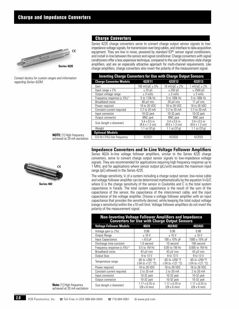
Series 422E charge converters serve to convert charge output sensor signals to low-impedance voltage signals, for transmission over long cables, and interface to data acquisitionequipment. They are low in noise, powered by standard ICP® sensor signal conditioners,and install in-line between the sensor and signal conditioner. Charge converters with signalconditioners offer a less expensive technique, compared to the use of laboratory-style chargeamplifiers, and are an especially attractive approach for multi-channel requirements. Likecharge amplifiers, charge converters also invert the polarity of the measurement signal.
Impedance Converters and In-Line Voltage Follower AmplifiersSeries 402A In-line voltage follower amplifiers, similar to the Series 422E chargeconverters, serve to convert charge output sensor signals to low-impedance voltagesignals. They are recommended for applications requiring high frequency response up to1 MHz, and for applications where sensor output (pC/unit) exceeds the maximum inputrange (pC) allowed in the Series 422E.The voltage sensitivity, V, of a system including a charge output sensor, low-noise cableand voltage follower amplifier can be determined mathematically by the equation V=Q/Cwhere Q is the charge sensitivity of the sensor in Coulombs and C is the total systemcapacitance in Farads. The total system capacitance is the result of the sum of thecapacitance of the sensor, the capacitance of the interconnect cable, and the inputcapacitance of the voltage amplifier. Choose a voltage follower amplifier with an inputcapacitance that provides the sensitivity desired, while keeping the total output voltage(range x sensitivity) within the ±10 volt limit. Voltage follower amplifiers do not invert thepolarity of the measurement signal.
Charge Converters
Series 422E
Contact factory for custom ranges and information regarding Series 422M.
Series 402
Note: [1] High frequencyachieved at 20 mA excitation
NOTE: [1] High frequencyachieved at 20 mA excitation
Inverting Charge Converters for Use with Charge Output SensorsCharge Converter Models 422E11 422E12 422E13Gain 100 mV/pC ± 5% 10 mV/pC ± 2% 1 mV/pC ± 2%Input range ± 2% ± 25 pC ± 250 pC ± 2500 pCOutput voltage range ± 3 volts ± 3 volts ± 3 voltsFrequency response (± 5%) [1] 5 to 110k Hz 5 to 100k Hz 5 to 100k HzBroadband noise 60 µV rms 20 µV rms 11 µV rmsPower required 18 to 28 VDC 18 to 28 VDC 18 to 28 VDCConstant current required 2.2 to 20 mA 2.2 to 20 mA 2.2 to 20 mAInput connector 10-32 jack 10-32 jack 10-32 jackOutput connector BNC jack BNC jack BNC jack
Size (length x diameter) 3.4 x 0.5 in 3.4 x 0.5 in 3.4 x 0.5 in(8.6 x 1.3 cm) (8.6 x 1.3 cm) (8.6 x 1.3 cm)
Weight 1.1 oz (31g) 1.1 oz (31g) 1.1 oz (31g)Optional Models0.5 Hz (-5%) low frequency 422E01 422E02 422E03
Non-Inverting Voltage Follower Amplifiers and Impedance Converters for Use with Charge Output Sensors
Voltage Follower Models 402A 402A02 402A03Voltage gain (± 2%) 0.98 0.98 0.98Output Range ± 10 V ± 10 V ± 10 VInput Capacitance < 8.0 pF 100 ± 10% pF 1000 ± 10% pFDischarge time constant 1.0 second 10 second 100 secondFrequency response (± 5%) [1] 0.5 to 1M Hz 0.05 to 1M Hz 0.005 to 1M HzBroadband noise 43 µV rms 43 µV rms 43 µV rmsOutput bias 9 to 13 V 9 to 13 V 9 to 13 V
Temperature range -65 to +250 °F -65 to +250 °F -65 to +250 °F(-54 to +121 °C) (-54 to +121 °C) (-54 to +121 °C)
Power required 18 to 28 VDC 18 to 28 VDC 18 to 28 VDCConstant current required 2 to 20 mA 2 to 20 mA 2 to 20 mAInput connector 10-32 jack 10-32 jack 10-32 jackOutput connector 10-32 jack 10-32 jack 10-32 jack
Size (length x diameter) 1.17 x 0.25 in 1.17 x 0.25 in 1.17 x 0.25 in(28 x 6 mm) (28 x 6 mm) (28 x 6 mm)

Industrial Charge Amplifiers
2.9PCB Piezotronics, Inc. Toll-Free in USA 888-684-0004 716-684-0001 www.pcb.com
Series 421A industrial charge amplifiers are designed for piezoelectric charge outputforce or strain sensors, and are ideally suited for monitoring manufacturing forcesexperienced during assembly, crimping, injection molding, stamping or product testing.With their long discharge time constant and high frequency response, both quasi-staticand dynamic measurements are possible. Each model synchronizes with machine cyclesthrough a reset feature while analog, peak or alarm outputs allow for real-time monitoring.
The single channel Model 421A11 and 3-channel Model 421A13 are packaged in arugged, surface mount, CE marked, sealed aluminum enclosure and are ideal for fixedinstallations in a factory environment. Set up via internal adjustments prohibits tamperingonce it is sealed and deployed. Additional features include electrical ground isolation,high vibration resistance, and a cord grip for securing the supplied, 10 ft (3 m) interfacingcable. The 3-channel Model 421A13 is a cost-effective configuration that supports usewith charge output, 3-component force sensors and force links.
Industrial Charge Amplifiers, Analog Output OnlyModel 421A11 421A13Channels 1 3
± 100 to 1000 pC (Range I) Input Ranges (selectable for each channel) ± 1000 to 10k pC (Range II)
± 10k to 100k pC (Range III) 5 mV/pC (Range I)
Sensitivity 0.50 mV/pC (Range II)0.05 mV/pC (Range III)
Maximum Output 5 VAC~ 0 to 4000 Hz (Range I)
Frequency range (-5%) ~ 0 to 10k Hz (Range II)~ 0 to 12k Hz (Range III)
Broadband noise [1] 11 µVTemperature Range (Operating) +23 to +140 °F (-5 to +60 °C)Power required 15 to 30 VDC, < 19 mA 15 to 30 VDC, < 37 mAInput connector [2] BNC jackOutput connector [3] Screw Terminal
Size4.89 x 1.18 x 2.52 in 6.95 x 1.18 x 2.52 in(124.2 x 30 x 64 mm) (176.5 x 30 x 64 mm)
Weight [4] 0.915 lb (415.04 gm) 1.320 lb (598.7 gm)
Notes: [1] Noise measurements performed at 10k-100k pC range. [2] Optional TNC jack on input,order as Model 421A11/A or 421A13/A. Optional 10-32 (micro) connector on input, order as Model 421A11/B or 421A13/B. [3] Supplied with 10 ft (3 m) multi-conductor cable & PG-9 cord grip. [4] Including multi-conductor cable.
Model 421A13
Model 421A11

2.10 PCB Piezotronics, Inc. Toll-Free in USA 888-684-0004 716-684-0001 www.pcb.com
Industrial Charge Amplifiers
Industrial Charge Amplifier, Analog, Peak and Alarm OutputsModel 421A25Channels 1Input Range (adjustable) ± 100 to ±1,000,000 pCOutput Voltage (Instantaneous) ± 10 VOutput Voltage (Peak) 0 to 10 VFrequency Response (-3 dB) (″ 100k pC) ~0 to 20 kHzFrequency Response (-3 dB) (< 100k pC) ~0 to >2 kHzAccuracy <± 1% FSNon-Linearity <0.02 % FSControl Input ± 5 to 45 VAlarm Output 45 V, 100mATemperature Range (Operating) +23 to +140 °F (-5 to +60 °C)Power Required 15 to 35 VDCCurrent Draw <70mABroadband Electrical Noise <20 mV ppOutput Resisitance 10 ohmDrift <0.03 pC/sDC Offset (max) ± 10 mVSize (l x w x h) – Overall 3.9 x 3.1 x 1.3 in (98 x 79 x 34 mm)Enclosure Material AluminumElectrical Connector (input) BNC JackElectrical Connector (output, setup,
25-Pin D-Subcontrol, power)OptionsInput/Output Connector, 25 pin D-Sub JCInput/Output Cable, 25 pin D-Sub to pigtails,
009M1465ft. (1.5m) length
Note: This product conforms to applicable European Directives for CE marking.
Model 421A25 features 13 fixed input ranges, 3 additional ranges with continuous gainadjustment, analog and peak hold outputs, and 2 adjustable set points that trigger digitalalarm outputs when levels are exceeded. An integral test function enables a check of themeasuring chain without a sensor being connected. All adjustments are set by eitherremote control or RS-232 interface, and the settings are maintained when the power isdisconnected. The RS-232 may also be used to transfer measurement data. The unit ispackaged in a rugged, CE marked aluminum enclosure, well suited for harsh industrialenvironments.
Model 421A25

Electronic Accessories
2.11PCB Piezotronics, Inc. Toll-Free in USA 888-684-0004 716-684-0001 www.pcb.com
Series 472B Charge AttentuatorsSeries 472B charge attenuators are used in conjunction with high-sensitivity chargeoutput force sensors when their full-scale output range exceeds the charge input limit ofthe charge amplifier or converter with which it is used. Series 472B charge attenuatorsserve to divide the output signal delivered by the force sensor by the factor indicated inthe table at left.
ICP® Sensor SimulatorModel 492B ICP® sensor simulator installs in place of an ICP® sensor and serves toverify signal conditioning settings, cable integrity, and tune long lines for optimumsystem performance. By use of an internal oscillator, the unit delivers a 100 Hz sine orsquare wave at a selectable peak to peak voltage. External test signals from a functiongenerator may also be inserted. This portable unit is battery powered.
Model 401A04 ICP® sensor simulator installs in place of an ICP® sensor and accepts test signals from a voltage function generator. The unit serves to verify signalconditioning settings, cable integrity, and tune long lines for optimum systemperformance. This unit requires power from an ICP® sensor signal conditioner.
Step Function GeneratorModel 492B03 generates a rapid charge or voltage step function from zero to a selectedpeak value between either 0 and 100k pC or 0 and 10 volts DC. The unit is useful forsetting trigger points in recording equipment and verifying charge amplifier and dataacquisition equipment setup. This unit is battery powered and portable.
DC Power ConditionerModel 485B serves to regulate available current from any conventional DC power supply or battery source to a constant value between 2 and 20 mA as required by ICP®
sensors. In addition, the unit decouples the sensor’s output bias voltage from themeasurement signal to enable zero-based measurements with any readout device.
Summing Block for Charge Output SensorsModel 070A15 Summing Block allows the addition of up to four charge inputs and sumsthem to provide one charge output. It is typically used to sum multiple force sensorinputs to allow use of a single channel charge amplifier.
Connectors: (4) 10-32 jack inputs(1) BNC jack output
Series 472B
Model 401A04
Model 492B03
Model Divided by472B01 10472B02 15472B03 50472B04 100
Model 492B
Model 485B
Model 070A15

2.12 PCB Piezotronics, Inc. Toll-Free in USA 888-684-0004 716-684-0001 www.pcb.com
PCB®’s in-house machining capabilities allow full control of the production of precision partsto insure quality and timely delivery. Capabilities including dual spindle CNC lathes, wireEDM machines, and injection molding machines fabricate in excess of 200,000 parts permonth to exacting standards.
Related Documents