21 Signal and Image Denoising Using Wavelet Transform Burhan Ergen Fırat University Turkey 1. Introduction The wavelet transform (WT) a powerful tool of signal and image processing that have been successfully used in many scientific fields such as signal processing, image compression, computer graphics, and pattern recognition (Daubechies 1990; Lewis and Knowles 1992; Do and Vetterli 2002; Meyer, Averbuch et al. 2002; Heric and Zazula 2007). On contrary the traditional Fourier Transform, the WT is particularly suitable for the applications of non- stationary signals which may instantaneous vary in time (Daubechies 1990; Mallat and Zhang 1993; Akay and Mello 1998). It is crucial to analyze the time-frequency characteristics of the signals which classified as non-stationary or transient signals in order to understand the exact features of such signals (Rioul and Vetterli 1991; Ergen, Tatar et al. 2010). For this reason, firstly, researchers has concentrated on continuous wavelet transform (CWT) that gives more reliable and detailed time-scale representation rather than the classical short time Fourier transform (STFT) giving a time-frequency representation (Jiang 1998; Qian and Chen 1999). The CWT technique expands the signal onto basis functions created by expanding, shrinking and shifting a single prototype function, which named as mother wavelet, specially selected for the signal under considerations. This transformation decomposes the signal into different scales with different levels of resolution. Since a scale parameter shrinking or expanding the mother wavelet in CWT, the result of the transform is time-scale representation. The scale parameter is indirectly related to frequency, when considered the center frequency of mother wavelet. A mother wavelet has satisfy that it has a zero mean value, which require that the transformation kernel of the wavelet transform compactly supports localization in time, thereby offering the potential to capture the spikes occurring instantly in a short period of time (Mallat 1989; Rioul and Vetterli 1991; Akay and Mello 1998). A wavelet expansion is representation of a signal in terms of an orthogonal collection of real-valued generated by applying suitable transformation to the original selected wavelet. The properties and advantages of a family of wavelets depend upon the mother wavelet features. The expansion is formed by two dimensional expansion of a signal and thus provides a time-frequency localization of the input signal. This implies that most of the energy of the signal will be captured a few coefficient. The basis functions in a wavelet www.intechopen.com

Welcome message from author
This document is posted to help you gain knowledge. Please leave a comment to let me know what you think about it! Share it to your friends and learn new things together.
Transcript

21
Signal and Image Denoising Using Wavelet Transform
Burhan Ergen Fırat University
Turkey
1. Introduction
The wavelet transform (WT) a powerful tool of signal and image processing that have been successfully used in many scientific fields such as signal processing, image compression, computer graphics, and pattern recognition (Daubechies 1990; Lewis and Knowles 1992; Do and Vetterli 2002; Meyer, Averbuch et al. 2002; Heric and Zazula 2007). On contrary the traditional Fourier Transform, the WT is particularly suitable for the applications of non-stationary signals which may instantaneous vary in time (Daubechies 1990; Mallat and Zhang 1993; Akay and Mello 1998). It is crucial to analyze the time-frequency characteristics of the signals which classified as non-stationary or transient signals in order to understand the exact features of such signals (Rioul and Vetterli 1991; Ergen, Tatar et al. 2010). For this reason, firstly, researchers has concentrated on continuous wavelet transform (CWT) that gives more reliable and detailed time-scale representation rather than the classical short time Fourier transform (STFT) giving a time-frequency representation (Jiang 1998; Qian and Chen 1999).
The CWT technique expands the signal onto basis functions created by expanding, shrinking and shifting a single prototype function, which named as mother wavelet, specially selected for the signal under considerations. This transformation decomposes the signal into different scales with different levels of resolution. Since a scale parameter shrinking or expanding the mother wavelet in CWT, the result of the transform is time-scale representation. The scale parameter is indirectly related to frequency, when considered the center frequency of mother wavelet.
A mother wavelet has satisfy that it has a zero mean value, which require that the transformation kernel of the wavelet transform compactly supports localization in time, thereby offering the potential to capture the spikes occurring instantly in a short period of time (Mallat 1989; Rioul and Vetterli 1991; Akay and Mello 1998).
A wavelet expansion is representation of a signal in terms of an orthogonal collection of real-valued generated by applying suitable transformation to the original selected wavelet. The properties and advantages of a family of wavelets depend upon the mother wavelet features. The expansion is formed by two dimensional expansion of a signal and thus provides a time-frequency localization of the input signal. This implies that most of the energy of the signal will be captured a few coefficient. The basis functions in a wavelet
www.intechopen.com
Advances in Wavelet Theory and Their Applications in Engineering, Physics and Technology
496
transform are produced from the mother wavelet by scaling and translation operations. When the scaling is chosen as power of two, this kind of wavelet transform is called dyadic-orthonormal wavelet transform, which makes a way for discrete wavelet transform (Zou and Tewfik 1993; Blu 1998) . If the chosen mother wavelet has orthonormal properties, there is no redundancy in the discrete wavelet transforms. In addition, this provides the multiresolution algorithm decomposing a signal into scales with different time and frequency resolution (Mallat 1989; Daubechies 1990).
The fundamental concept involved in mutiresolution is to find average features and details
of the signal via scalar products with scaling signals and wavelets. The spikes in signal are
typically of high frequency and it is possible discriminate the spikes with other noises
through the decomposition of multiresolution into different levels. The differences between
mother wavelet functions (e.g. Haar, Daubechies, Symlets, Coiflets, Biorthogonal and etc.)
consist in how these scaling signals and the wavelets are defined (Zou and Tewfik 1993; Blu
1998; Ergen, Tatar et al. 2010).
The continuous wavelet transform is computed by changing the scale of the mother wavelet,
shifting the scaled wavelet in time, multiplying by the signal, and integrating over all times.
When the signal to be analyzed and wavelet function are discredited, the CWT can be
realized on computer and the computation time can be significantly reduced if the
redundant samples removed respect to sampling theorem. This is not a true discrete wavelet
transform. The fundamentals of discrete wavelet transform goes back to sub-band coding
theorem (Fischer 1992; Vetterli and Kova evi 1995; Vetterli and Kovacevic 1995). The sub-
band coding encodes each part of the signal after separating into different bands of
frequencies. Some studies have made use of wavelet transform as a filter bank in order to
separate the signal.
After discovering the signal decomposition of a signal into frequency bands using discrete
wavelet transform, the DWT has found many application area, from signal analysis to signal
compression (Chang and Kuo 1993; Qu, Adam et al. 2003; He and Scordilis 2008).
The one of the first application of the DWT is the denoising process, which aims to remove
the small part of the signal assumed as noise (Lang, Guo et al. 1996; Simoncelli and Adelson
1996; Jansen 2001). All kind of the signal obtained from the physical environment has
contains more or less disturbing noise. Therefore, wavelet denoising procedure has applied
many one or two dimensional signal after particularly soft or hard thresholding methods
had proposed (Donoho and Johnstone 1994; Donoho 1995). Such signals some time are one-
dimensional simple power or control signals (Sen, Zhengxiang et al. 2002; Giaouris, Finch et
al. 2008) as well as more complex medical images (Wink and Roerdink 2004; Pizurica, Wink
et al. 2006). Especially, wavelet denoising has found an application field about image
processing recently (Nasri and Nezamabadi-pour 2009; Chen, Bui et al. 2010; Jovanov, Pi
urica et al. 2010).
2. Noise consideration
A signal or an image is unfortunately corrupted by various factors which effects as noise during acquisition or transmission. These noisy effects decrease the performance of visual and computerized analysis. It is clear that the removing of the noise from the signal facilitate
www.intechopen.com
Signal and Image Denoising Using Wavelet Transform
497
the processing. The denoising process can be described as to remove the noise while retaining and not distorting the quality of processed signal or image (Chen and Bui 2003; Portilla, Strela et al. 2003; Buades, Coll et al. 2006). The traditional way of denoising to remove the noise from a signal or an image is to use a low or band pass filter with cut off frequencies. However the traditional filtering techniques are able to remove a relevant of the noise, they are incapable if the noise in the band of the signal to be analyzed. Therefore, many denoising techniques are proposed to overcome this problem.
The algorithms and processing techniques used for signals can be also used for images
because an image can be considered as a two dimensional signal. Therefore, the digital
signal processing techniques for a one dimensional signal can be adapted to process two
dimensional signals or images.
Because the origin and nonstationarity of the noise infecting in the signal, it is difficult to model it. Nevertheless, if the noise assumed as stationary, an empirically recorded signal that is corrupted by additive noise can be represented as;
( ) ( ) ( )y i x i i , 0,1,..., 1i n (1)
Where ( )y i noisy signal, ( )x i is noise free actual signal and ( )i are independently normal
random variables and represents the intensity of the noise in ( )y i . The noise is usually
modeled as stationary independent zero-mean white Gaussian variables (Moulin and Liu
1999; Alfaouri and Daqrouq 2008).
When this model is used, the objective of noise removal is to reconstruct the original
signal ( )x i from a finite set of ( )y i values without assuming a particular structure for the
signal. The usual approach to noise removal models noise as high frequency signal added to
an original signal. These high frequencies can be bringing out using traditional Fourier
transform, ultimately removing them by adequate filtering. This noise removal technique
conceptually clear and efficient since depends only calculating DFT (Discrete Fourier
Transform)(Wachowiak, Rash et al. 2000).
However, there is some issue that must be under consideration. The most prominent having
same frequency as the noise has important information in the original signal. Filtering out
these frequency components will cause noticeable loss of information of the desired signal
when considered the frequency representation of the original signal. It is clear that a method
is required in order to conserve the prominent part of the signal having relatively high
frequencies as the noise has. The wavelet based noise removal techniques have provided
this conservation of the prominent part.
3. Discrete Wavelet Transform (DWT) and Wavelet Packet Decomposition
The wavelet transform has become an essential tool for many applications. However, the wavelet transform has been presented a method representing a time-frequency method, continuous wavelets transform (CWT), and the wavelet transform generally has used for the decomposition of the signal into high and low frequency components. The wavelet coefficient represents a measure of similarity in the frequency content between a signal and a chosen wavelet function. These coefficients are computed as a convolution of the signal
www.intechopen.com
Advances in Wavelet Theory and Their Applications in Engineering, Physics and Technology
498
and the scaled wavelet function, which can be interpreted as a dilated band-pass filter because of its band-pass like spectrum (Valens ; Rioul and Vetterli 1991) .
In practice, the wavelet transform is implemented with a perfect reconstruction filter bank
using orthogonal wavelet family. The idea is to decompose the signal into sub-signals
corresponding to different frequency contents. In the decomposition step, a signal is
decomposed on to a set of orthonormal wavelet function that constitutes a wavelet basis
(Misiti, Misiti et al.). The most common wavelets providing the ortogonality properties are
daubechies, symlets, coiflets and discrete meyer in order to provide reconstruction using the
fast algorithms (Beylkin, Coifman et al. 1991; Cohen, Daubechies et al. 1993).
The use of wavelet transform as filter bank called as DWT (Discrete Wavelet Transform).
The DWT of a signal produces a non-redundant restoration, which provides better spatial
and spectral localization of signal formation, compared with other multi-scale
representation such as Gaussian and Laplacian pyramid. The result of the DWT is a
multilevel decomposition, in which the signal is decomposed in ‘approximation’ and ‘detail’
coefficients at each level (Mallat 1989). This is made through a process that is equivalent to
low-pass and high passes filtering, respectively.
As stated previous section, the wavelet transform is firstly introduced for the time-
frequency analysis of transient continuous signals, and then extended to the theory of
multi-resolution wavelet transform using FIR filter approximation. This managed using
the dyadic form of CWT. In dyadic form, the scaling function is chosen as power of two.
And then, the discrete wavelets /2, ( ) 2 (2 )m m
m n t t n used in multi-resolution
analysis constituting an orthonormal basis for 2( )L (Vetterli and Herley 1992; Donoho
and Johnstone 1994).
If a signal, ( )x t , decomposed into low and high frequency components, that they are
respectively named as approximation coefficients and detail coefficients, ( )x t reconstructed as;
, ,1
( ) ( ) ( ) ( ) ( )L
m m k l l km k k
x t D k t A k t (2)
Where , ( )m k t is discrete analysis wavelet, and , ( )l k t is discrete scaling, ( )mD k is the
detailed signal at scale 2m , and ( )lA k is the approximated signal at scale 2l . ( )mD k and
( )lA k is obtained using the scaling and wavelet filters (Mallat 1999).
1/2
1/2
n
( ) 2 ( ), (2 )
( ) 2 ( ), (2 )
(-1) (1 )
h n t t n
g n t t n
h n
(3)
The wavelet coefficient can be computed by means of a pyramid transfer algorithm. The
algorithms refer to a FIR filter bank with low-pass filter h, high-pass filter g, and down
sampling by a factor 2 at each stage of the filter bank. Fig. 1 shows the tree structure of
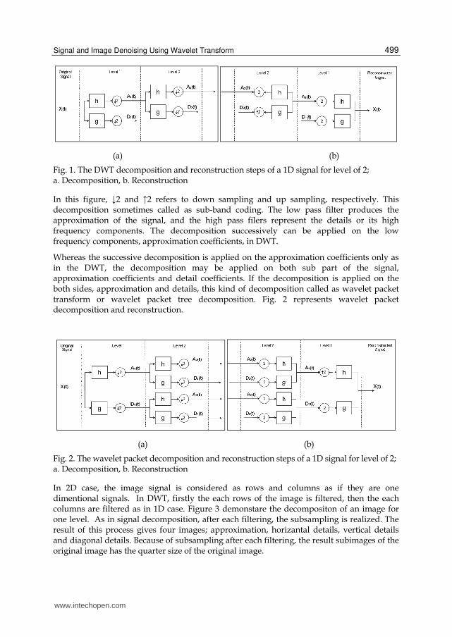
DWT decomposition for three levels. DWT decomposition leads to a tree structure as
shown in Fig. 1, where approximation and detail coefficients are presented.
www.intechopen.com
Signal and Image Denoising Using Wavelet Transform
499
(a) (b)
Fig. 1. The DWT decomposition and reconstruction steps of a 1D signal for level of 2; a. Decomposition, b. Reconstruction
In this figure, ↓2 and ↑2 refers to down sampling and up sampling, respectively. This decomposition sometimes called as sub-band coding. The low pass filter produces the approximation of the signal, and the high pass filers represent the details or its high frequency components. The decomposition successively can be applied on the low frequency components, approximation coefficients, in DWT.
Whereas the successive decomposition is applied on the approximation coefficients only as in the DWT, the decomposition may be applied on both sub part of the signal, approximation coefficients and detail coefficients. If the decomposition is applied on the both sides, approximation and details, this kind of decomposition called as wavelet packet transform or wavelet packet tree decomposition. Fig. 2 represents wavelet packet decomposition and reconstruction.
(a) (b)
Fig. 2. The wavelet packet decomposition and reconstruction steps of a 1D signal for level of 2; a. Decomposition, b. Reconstruction
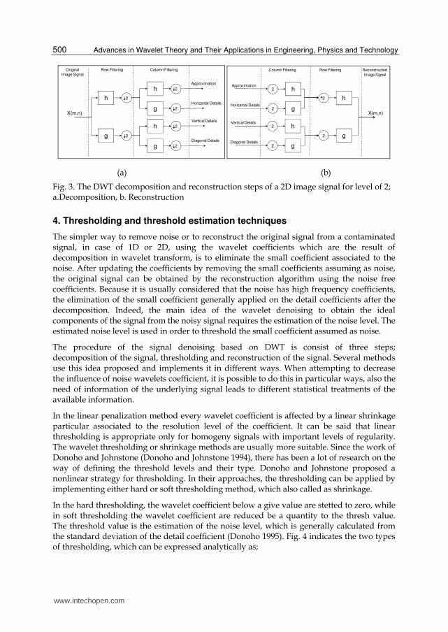
In 2D case, the image signal is considered as rows and columns as if they are one dimentional signals. In DWT, firstly the each rows of the image is filtered, then the each columns are filtered as in 1D case. Figure 3 demonstare the decompositon of an image for one level. As in signal decomposition, after each filtering, the subsampling is realized. The result of this process gives four images; approximation, horizantal details, vertical details and diagonal details. Because of subsampling after each filtering, the result subimages of the original image has the quarter size of the original image.
www.intechopen.com
Advances in Wavelet Theory and Their Applications in Engineering, Physics and Technology
500
h 2
X(m,n)
OriginalImage Signal
Row Filtering Column Filtering
g 2
g
h 2
2
g
h 2
2
Approximation
Horizantal Details
Vertical Details
Diagonal Details
h2
X(m,n)
Reconstructed
Image Signal
Row FilteringColumn Filtering
g2
g
h2
2
g
h2
2
Approximation
Horizantal Details
Vertical Details
Diagonal Details
(a) (b)
Fig. 3. The DWT decomposition and reconstruction steps of a 2D image signal for level of 2; a.Decomposition, b. Reconstruction
4. Thresholding and threshold estimation techniques
The simpler way to remove noise or to reconstruct the original signal from a contaminated signal, in case of 1D or 2D, using the wavelet coefficients which are the result of decomposition in wavelet transform, is to eliminate the small coefficient associated to the noise. After updating the coefficients by removing the small coefficients assuming as noise, the original signal can be obtained by the reconstruction algorithm using the noise free coefficients. Because it is usually considered that the noise has high frequency coefficients, the elimination of the small coefficient generally applied on the detail coefficients after the decomposition. Indeed, the main idea of the wavelet denoising to obtain the ideal components of the signal from the noisy signal requires the estimation of the noise level. The estimated noise level is used in order to threshold the small coefficient assumed as noise.
The procedure of the signal denoising based on DWT is consist of three steps; decomposition of the signal, thresholding and reconstruction of the signal. Several methods use this idea proposed and implements it in different ways. When attempting to decrease the influence of noise wavelets coefficient, it is possible to do this in particular ways, also the need of information of the underlying signal leads to different statistical treatments of the available information.
In the linear penalization method every wavelet coefficient is affected by a linear shrinkage particular associated to the resolution level of the coefficient. It can be said that linear thresholding is appropriate only for homogeny signals with important levels of regularity. The wavelet thresholding or shrinkage methods are usually more suitable. Since the work of Donoho and Johnstone (Donoho and Johnstone 1994), there has been a lot of research on the way of defining the threshold levels and their type. Donoho and Johnstone proposed a nonlinear strategy for thresholding. In their approaches, the thresholding can be applied by implementing either hard or soft thresholding method, which also called as shrinkage.
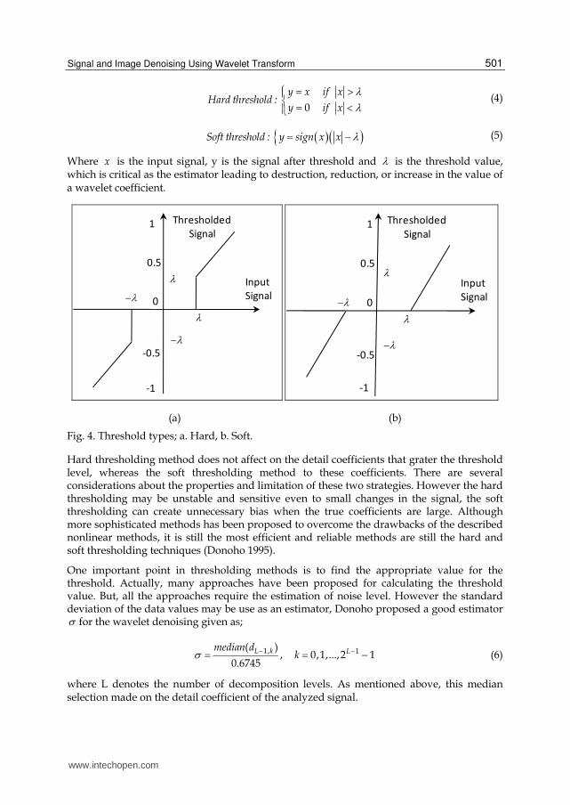
In the hard thresholding, the wavelet coefficient below a give value are stetted to zero, while in soft thresholding the wavelet coefficient are reduced be a quantity to the thresh value. The threshold value is the estimation of the noise level, which is generally calculated from the standard deviation of the detail coefficient (Donoho 1995). Fig. 4 indicates the two types of thresholding, which can be expressed analytically as;
www.intechopen.com
Signal and Image Denoising Using Wavelet Transform
501
0
y x if xHard threshold :
y if x
(4)
Soft threshold : y sign x x (5)
Where x is the input signal, y is the signal after threshold and is the threshold value, which is critical as the estimator leading to destruction, reduction, or increase in the value of a wavelet coefficient.
0
-1
-0.5
1
0.5
Input
Signal
Thresholded
Signal
0
-1
-0.5
1
0.5
Input
Signal
Thresholded
Signal
(a) (b)
Fig. 4. Threshold types; a. Hard, b. Soft.
Hard thresholding method does not affect on the detail coefficients that grater the threshold level, whereas the soft thresholding method to these coefficients. There are several considerations about the properties and limitation of these two strategies. However the hard thresholding may be unstable and sensitive even to small changes in the signal, the soft thresholding can create unnecessary bias when the true coefficients are large. Although more sophisticated methods has been proposed to overcome the drawbacks of the described nonlinear methods, it is still the most efficient and reliable methods are still the hard and soft thresholding techniques (Donoho 1995).
One important point in thresholding methods is to find the appropriate value for the threshold. Actually, many approaches have been proposed for calculating the threshold value. But, all the approaches require the estimation of noise level. However the standard deviation of the data values may be use as an estimator, Donoho proposed a good estimator for the wavelet denoising given as;
1, 1( ), 0,1,...,2 1
0.6745L k Lmedian d
k (6)
where L denotes the number of decomposition levels. As mentioned above, this median selection made on the detail coefficient of the analyzed signal.
www.intechopen.com
Advances in Wavelet Theory and Their Applications in Engineering, Physics and Technology
502
The most known threshold selection algorithms are minimax, universal and rigorous sure threshold estimation techniques (Donoho and Johnstone 1994; Donoho and Johnstone 1998).
The minimax threshold value M proposed by Donoho consists an optimal threshold that
derived from minimizing the constant term in an upper bound of the risk involved in the estimation. The proposed threshold depends of the available data and also takes into account the noise level contaminating the signal. The optimal threshold is defined as;
*M n (7)
where *n is defined as the value of and satisfying as;
*1
( )inf sup
( )n d
oracle
R d
n R d
(8)
where 2( ) ( ( ) )R d E d d and ( )oracleR d named as oracle used to account for the risk
associated to the modification of the value of a given wavelet coefficient. Two oracles are considered, the diagonal liner projection (DLP) and the diagonal linear shrinker (DLS)(Donoho and Johnstone 1994). The ideal risks for these oracles are given by
2( ) min( ,1)DLPoracleR d d (9)
2
2( )
1
DLSoracle
dR d
d (10)
The minimax method is used in statistics to design estimator. The minimax estimator is
realizes the minimum of the maximum mean square error, over a given set of functions.
Another proposed threshold estimator by Donoho is the universal threshold, or global
threshold, as an alternative to the minimax threshold, however it uses a fixed threshold
form given as;
2 log( )U n (11)
Where n denotes the length of the analyzed signal and is given by Eq. (6). The advantage
of this thresholding appears in software implementation due to easy to remember and
coding. Additionally, this threshold estimator ensures that every sample in the wavelet
transform in which the underlying function is exactly zero will be estimated as zero.
Again another common estimator is Rigorous Sure (rigresure) threshold proposed by
Donoho. This threshold describes a scheme which uses a threshold at each resolution
level l of the wavelet coeffient. The Rigorous Sure, also known as SureShrink, uses the Stein’s
Unbiased Risk Estimate criterion to obtain unbiased estimate. The threshold is given as
follows;
0
( , )arg min ,
US
S a bSure (12)
www.intechopen.com

Signal and Image Denoising Using Wavelet Transform
503
Where Sure is defined as
2( , ) 2 : min( ,i iSure X n i X X (13)
Where the operator ( ) returns the cardinality of the set : ii X , it is found that Sure is
an un biased estimate of the 2l risk .
5. Denoising application examples
5.1 Comparison assessments
The best way to test the effect of noise on a signal is to add a Gaussian white noise, in which
case its values independently and identically distributed (i.i.d) Gaussian real values. After
the denoising process, the performance can be measure by comparing the denoised signal
and the original signal. However, many methods have been proposed to measure the
performance of denoising algorithms, the signal to noise ratio (SNR) and peak signal to
noise ratio (PSNR) has generally accepted to measure the quality of signal and images,
respectively. For one dimensional signal, measuring the performance of the denoising
method by calculation of the residual SNR given as;
1 1 22
100 0
10log ( ) ( ) ( ])r
N N
n n
SNR x n x n x n
(14)
where ( )x n is the original signal, ( )rx n is the denoised signal and ( )x n refers to the mean
value of ( )x n .
In order to measure the quality of image, it is generally used PSNR, which given as;
1 1 2
100 0
10log ( , ) ( , )rN M
n m
PSNR L x n m x n m
(15)
where L denotes the quantized gray level of the images, ( )x n is original images, ( , )x n m is
the mean value of ( )x n , and ( , )rx n m refers to reconstructed image. In order to get visible
alteration on signal, the power of noise should be chosen adequately. Indeed, SNR is usually
the most important measure rather than the power of noise, when taking into consideration
that the power of the signal to denoise can be varied. When the SNR is chosen above 3dB, it
is generally enough to get the visible corruption.
5.2 Phonocardiogram denoising
The records of the acoustical vibrations produced by heart, acquired through microphones
from human chest, called phonocardiogram (PCG), consist of the heart sounds and the
murmurs. This records of acoustic signals are unfortunately disturbed by various factors
which effecting as noise. These effects decrease the performance of visual and computerized
analysis (Akay, Semmlow et al. 1990; Ergen, Tatar et al. 2010).
www.intechopen.com
Advances in Wavelet Theory and Their Applications in Engineering, Physics and Technology
504
The respiration sounds by lung mechanical actions, patient movement, and improper contacts of microphone to the skin, and external noises from the environments are added as noise signal into PCG records. The traditional method to remove the noise from a PCG signal is to use a low or band pass filter with cut off frequencies. However the filtering techniques are able to remove a relevant of the noise, they are incapable if the noise in the band of the signal to be analyzed.
The frequency components of a normal PCG signals can be rise up 200Hz, and the energy of
the most significant components concentrates around the frequency band 100-150Hz (Ergen,
Tatar et al. 2010). The frequency bands of the signal are very important when we use the
denoising technique using DWT approaches. Because the DWT approaches decomposes the
signal into frequency bands to eliminate the small detail components assumed as noise, the
decomposition level reflects directly on the frequency components that cause the smoothed
version of the signal.
As stated previous section, the most reasonable way to determine the effectiveness of
denoising method is to compare an original signal and the denoised signal obtained from its
noise added form. Therefore, here, we will use the noise added signal to examine the
effectiveness of wavelet denoising method through the comparison between the original
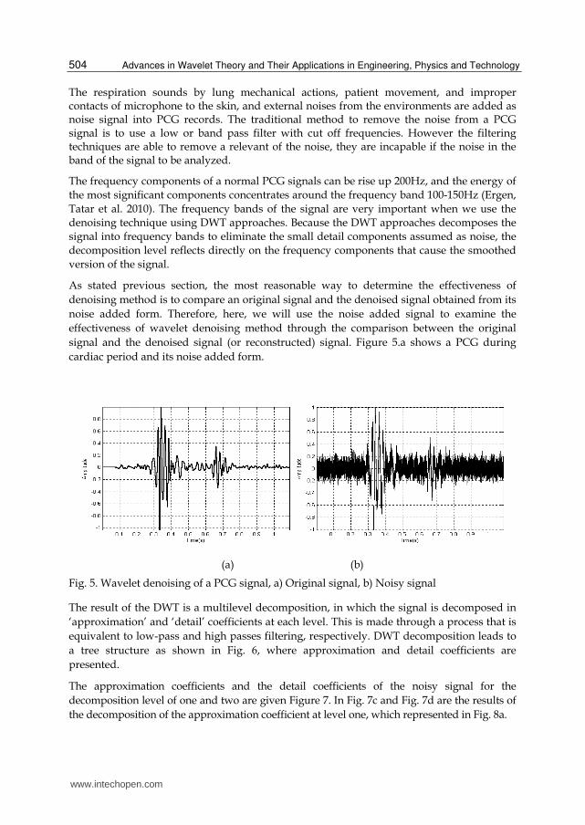
signal and the denoised signal (or reconstructed) signal. Figure 5.a shows a PCG during
cardiac period and its noise added form.
(a) (b)
Fig. 5. Wavelet denoising of a PCG signal, a) Original signal, b) Noisy signal
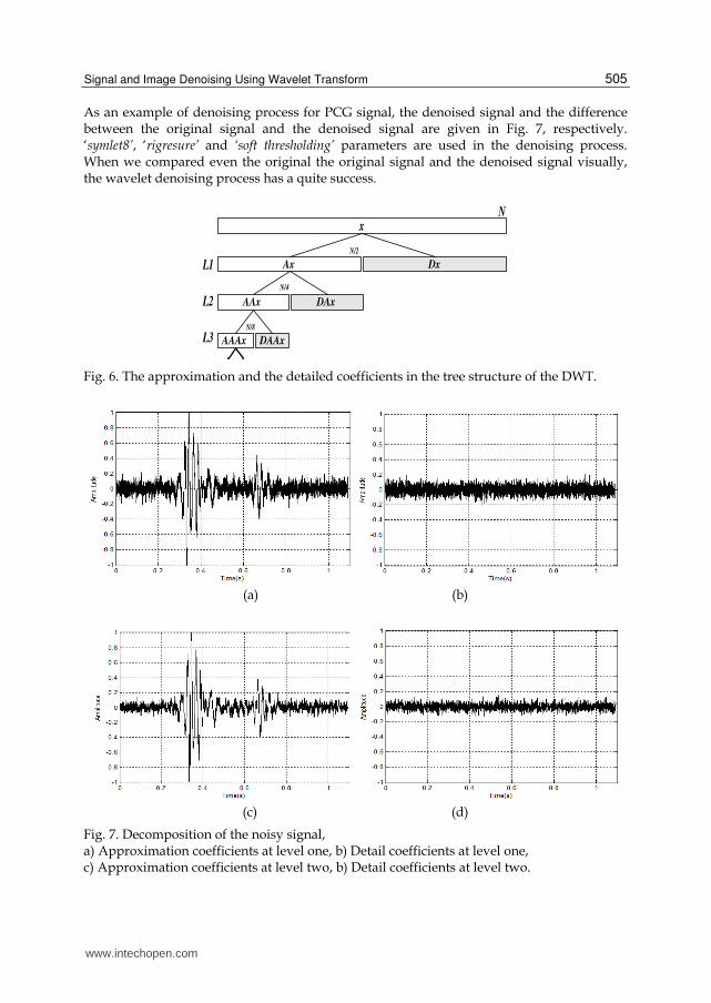
The result of the DWT is a multilevel decomposition, in which the signal is decomposed in
‘approximation’ and ‘detail’ coefficients at each level. This is made through a process that is
equivalent to low-pass and high passes filtering, respectively. DWT decomposition leads to
a tree structure as shown in Fig. 6, where approximation and detail coefficients are
presented.
The approximation coefficients and the detail coefficients of the noisy signal for the
decomposition level of one and two are given Figure 7. In Fig. 7c and Fig. 7d are the results of
the decomposition of the approximation coefficient at level one, which represented in Fig. 8a.
www.intechopen.com
Signal and Image Denoising Using Wavelet Transform
505
As an example of denoising process for PCG signal, the denoised signal and the difference between the original signal and the denoised signal are given in Fig. 7, respectively. ‘symlet8’, ‘rigresure’ and ‘soft thresholding’ parameters are used in the denoising process. When we compared even the original the original signal and the denoised signal visually, the wavelet denoising process has a quite success.
x
Ax
AAx
AAAx DAAx
DAx
DxL1
L2
L3
N
N/2
N/4
N/8
Fig. 6. The approximation and the detailed coefficients in the tree structure of the DWT.
(a) (b)
(c) (d)
Fig. 7. Decomposition of the noisy signal, a) Approximation coefficients at level one, b) Detail coefficients at level one, c) Approximation coefficients at level two, b) Detail coefficients at level two.
www.intechopen.com
Advances in Wavelet Theory and Their Applications in Engineering, Physics and Technology
506
(a) (b)
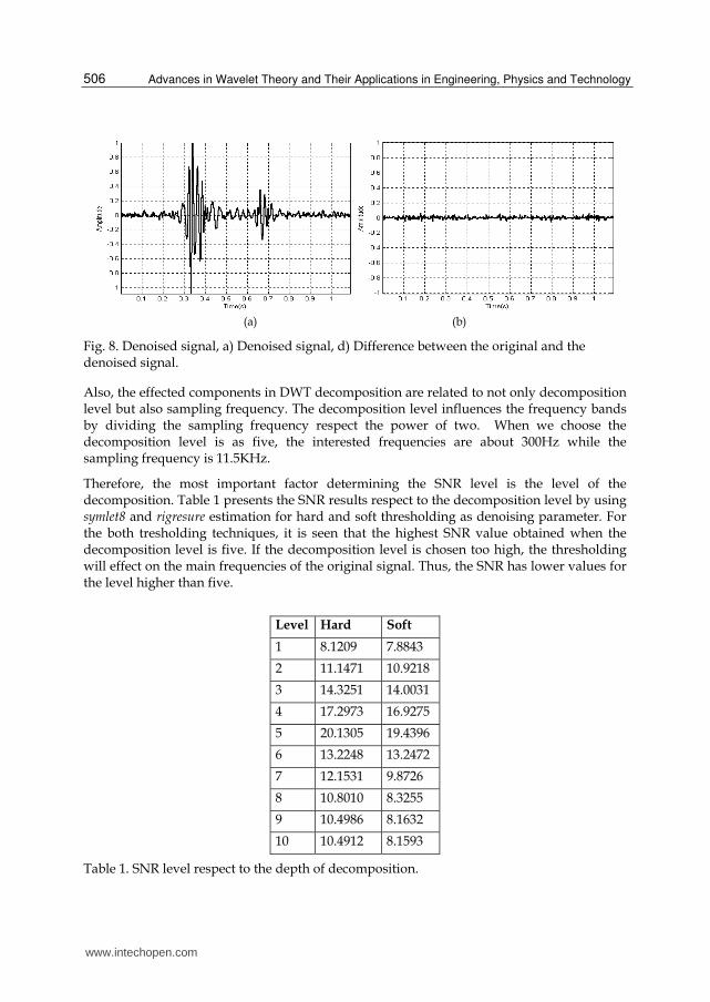
Fig. 8. Denoised signal, a) Denoised signal, d) Difference between the original and the denoised signal.
Also, the effected components in DWT decomposition are related to not only decomposition level but also sampling frequency. The decomposition level influences the frequency bands by dividing the sampling frequency respect the power of two. When we choose the decomposition level is as five, the interested frequencies are about 300Hz while the sampling frequency is 11.5KHz.
Therefore, the most important factor determining the SNR level is the level of the decomposition. Table 1 presents the SNR results respect to the decomposition level by using symlet8 and rigresure estimation for hard and soft thresholding as denoising parameter. For the both tresholding techniques, it is seen that the highest SNR value obtained when the decomposition level is five. If the decomposition level is chosen too high, the thresholding will effect on the main frequencies of the original signal. Thus, the SNR has lower values for the level higher than five.
Level Hard Soft
1 8.1209 7.8843
2 11.1471 10.9218
3 14.3251 14.0031
4 17.2973 16.9275
5 20.1305 19.4396
6 13.2248 13.2472
7 12.1531 9.8726
8 10.8010 8.3255
9 10.4986 8.1632
10 10.4912 8.1593
Table 1. SNR level respect to the depth of decomposition.
www.intechopen.com
Signal and Image Denoising Using Wavelet Transform
507
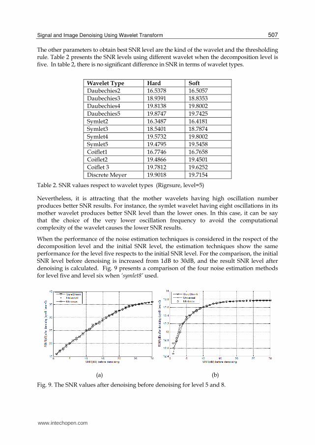
The other parameters to obtain best SNR level are the kind of the wavelet and the thresholding rule. Table 2 presents the SNR levels using different wavelet when the decomposition level is five. In table 2, there is no significant difference in SNR in terms of wavelet types.
Wavelet Type Hard Soft
Daubechies2 16.5378 16.5057
Daubechies3 18.9391 18.8353
Daubechies4 19.8138 19.8002
Daubechies5 19.8747 19.7425
Symlet2 16.3487 16.4181
Symlet3 18.5401 18.7874
Symlet4 19.5732 19.8002
Symlet5 19.4795 19.5458
Coiflet1 16.7746 16.7658
Coiflet2 19.4866 19.4501
Coiflet 3 19.7812 19.6252
Discrete Meyer 19.9018 19.7154
Table 2. SNR values respect to wavelet types (Rigrsure, level=5)
Nevertheless, it is attracting that the mother wavelets having high oscillation number produces better SNR results. For instance, the symlet wavelet having eight oscillations in its mother wavelet produces better SNR level than the lower ones. In this case, it can be say that the choice of the very lower oscillation frequency to avoid the computational complexity of the wavelet causes the lower SNR results.
When the performance of the noise estimation techniques is considered in the respect of the decomposition level and the initial SNR level, the estimation techniques show the same performance for the level five respects to the initial SNR level. For the comparison, the initial SNR level before denoising is increased from 1dB to 30dB, and the result SNR level after denoising is calculated. Fig. 9 presents a comparison of the four noise estimation methods for level five and level six when ‘symlet8’ used.
(a) (b)
Fig. 9. The SNR values after denoising before denoising for level 5 and 8.
www.intechopen.com
Advances in Wavelet Theory and Their Applications in Engineering, Physics and Technology
508
(a) (b)
(c)
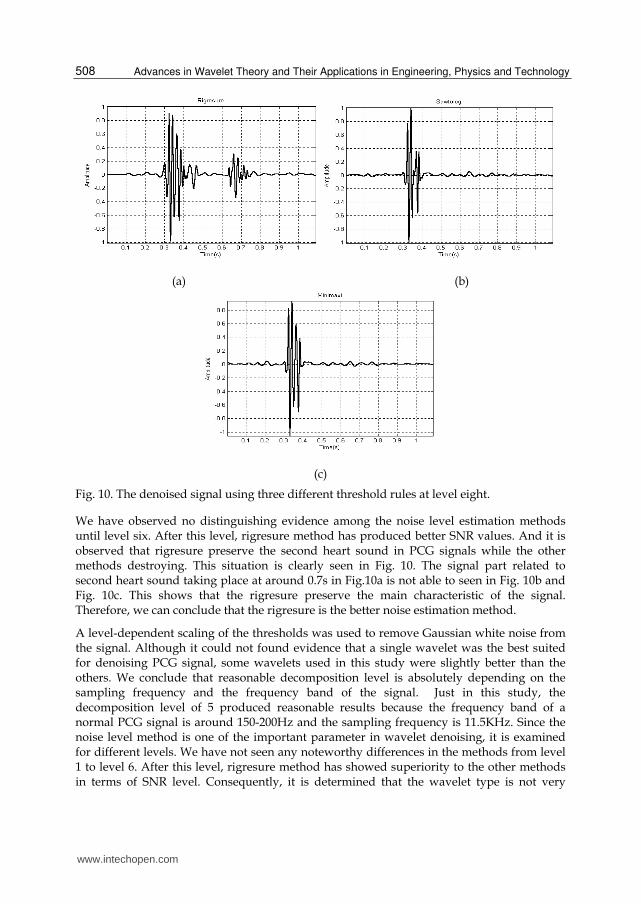
Fig. 10. The denoised signal using three different threshold rules at level eight.
We have observed no distinguishing evidence among the noise level estimation methods until level six. After this level, rigresure method has produced better SNR values. And it is observed that rigresure preserve the second heart sound in PCG signals while the other methods destroying. This situation is clearly seen in Fig. 10. The signal part related to second heart sound taking place at around 0.7s in Fig.10a is not able to seen in Fig. 10b and Fig. 10c. This shows that the rigresure preserve the main characteristic of the signal. Therefore, we can conclude that the rigresure is the better noise estimation method.
A level-dependent scaling of the thresholds was used to remove Gaussian white noise from the signal. Although it could not found evidence that a single wavelet was the best suited for denoising PCG signal, some wavelets used in this study were slightly better than the others. We conclude that reasonable decomposition level is absolutely depending on the sampling frequency and the frequency band of the signal. Just in this study, the decomposition level of 5 produced reasonable results because the frequency band of a normal PCG signal is around 150-200Hz and the sampling frequency is 11.5KHz. Since the noise level method is one of the important parameter in wavelet denoising, it is examined for different levels. We have not seen any noteworthy differences in the methods from level 1 to level 6. After this level, rigresure method has showed superiority to the other methods in terms of SNR level. Consequently, it is determined that the wavelet type is not very
www.intechopen.com

Signal and Image Denoising Using Wavelet Transform
509
important if the oscillation number is not very low, the decomposition level is absolutely depends on the frequency band of the PCG signal and its sampling frequency, and rigresure method is best of the noise estimation techniques.
5.3 Image denoising
All digital images contain some degree of noise due to the corruption in its acquisition and transmission by various effects. Particularly, medical image are likely disturbed by a complex type of addition noise depending on the devices which are used to capture or store them. No medical imaging devices are noise free. The most commonly used medical images are received from MRI (Magnetic Resonance Imaging) and CT (Computed Tomography) equipments. Usually, the addition noise into medical image reduces the visual quality that complicates diagnosis and treatment.
Because the wavelet transform has an ability to capture the energy of a signal in few energy transform values, the wavelet denoising technique is very effective as stated previous parts. As stated previous sections, when an image is decomposed using wavelet transform, the four sub-images are produced, approximation, horizontal details, vertical details and diagonal details. Fig. 11 represents a sample medical image which belongs to a patient having cranial trauma and its four subimages when decomposed for one level using DWT. This image has acquired from a BT device. A noise added MRI image and its denoised form using wavelet denoising procedure is given Fig. 12. The added noise has Gaussian distribution, and symlet6, decomposition level of two, hard thresholding are chosen as wavelet denoising parameters.
Fig. 11. Decomposition of a sample medical image; original, approximation, horizontal details, vertical details, and diagonal details in left to right.
Fig. 12. A noisy image having PSNR 62dB and its denoised version.
www.intechopen.com

Advances in Wavelet Theory and Their Applications in Engineering, Physics and Technology
510
Quantitatively assessing the performance in practical image application is complicated issue because the ideal image is normally unknown. Therefore the rational approach is to use known images for the tests, as in other image processing applications, in order to test the performance of the wavelet denoising methods like one dimensional signal denoising. Figure 13 represents the medical test images to be used.
Here, we use again a classical comparison receipt based on noise simulation. The comparison can be realized on the result reconstructed image and the original image after adding Gaussian white noise with known power to the original signal. Then it will be computed the best image recovered from the noisy one for each method. Firstly, we should determine the effective decomposition level because the most important factor in wavelet denoising is decomposition level. For this purpose, a noise added image will be used to obtain how the performance is changing respect to the decomposition level. The recovering process is made on the test image given in Fig 11, on which a Gaussian noise added to be PSNR is 62dB. The noisy image and a sample recovered or denoised is given Fig. 12a and Fig. 12b, respectively. The PSNR values after denosing process is given Table 3. In this denoising process, the symlet6 and universal thresholding is chosen as mother wavelet and noise level estimator.
Fig. 12. Medical test images.
Level PSNR
1 2 3 4 5 6 7 8 9 10
68.1196 69.3269 70.5006 70.7768 68.6232 68.8183 68.7272 69.8037 66.8912 66.3877
Table 3. PSNR values respect to decomposition level after DWT denoising.
www.intechopen.com
Signal and Image Denoising Using Wavelet Transform
511
The best PSNR is obtained at the decomposition level of two. As can be seen in Table 3, the
result PSNR value is decreasing if the decomposition level getting higher. The wavelet
transform concern the main component of the original signal when the decomposition level
is increased. If the higher decomposition level is used, the thresholding can eliminate some
coefficients of the original signal, as in 1D signal denoising process. Therefore, to increase
the decomposition level too high will decrease the PSNR after an optimal level and also
increase the complexity of decomposition. In further part of the study, the decomposition
level is chosen as two because the performance of the DWT denoising obtained at this level.
Another question about the performance of the wavelet denoising is if it is dependent on the
content or the distribution of the coefficient of the image. We can answer the question by
applying the denoising algorithm on different images. Table 4 represents the PSNR values
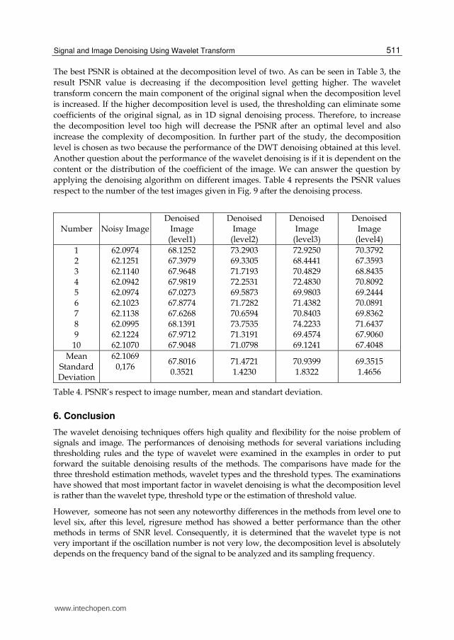
respect to the number of the test images given in Fig. 9 after the denoising process.
Number Noisy ImageDenoised
Image (level1)
Denoised Image
(level2)
Denoised Image
(level3)
Denoised Image
(level4)
1 2 3 4 5 6 7 8 9 10
62.0974 62.1251 62.1140 62.0942 62.0974 62.1023 62.1138 62.0995 62.1224 62.1070
68.1252 67.3979 67.9648 67.9819 67.0273 67.8774 67.6268 68.1391 67.9712 67.9048
73.2903 69.3305 71.7193 72.2531 69.5873 71.7282 70.6594 73.7535 71.3191 71.0798
72.9250 68.4441 70.4829 72.4830 69.9803 71.4382 70.8403 74.2233 69.4574 69.1241
70.3792 67.3593 68.8435 70.8092 69.2444 70.0891 69.8362 71.6437 67.9060 67.4048
Mean Standard Deviation
62.1069 0,176
67.8016 0.3521
71.4721 1.4230
70.9399 1.8322
69.3515 1.4656
Table 4. PSNR’s respect to image number, mean and standart deviation.
6. Conclusion
The wavelet denoising techniques offers high quality and flexibility for the noise problem of signals and image. The performances of denoising methods for several variations including thresholding rules and the type of wavelet were examined in the examples in order to put forward the suitable denoising results of the methods. The comparisons have made for the three threshold estimation methods, wavelet types and the threshold types. The examinations have showed that most important factor in wavelet denoising is what the decomposition level is rather than the wavelet type, threshold type or the estimation of threshold value.
However, someone has not seen any noteworthy differences in the methods from level one to level six, after this level, rigresure method has showed a better performance than the other methods in terms of SNR level. Consequently, it is determined that the wavelet type is not very important if the oscillation number is not very low, the decomposition level is absolutely depends on the frequency band of the signal to be analyzed and its sampling frequency.
www.intechopen.com

Advances in Wavelet Theory and Their Applications in Engineering, Physics and Technology
512
7. References
Akay, M. and C. Mello (1998). Wavelets for biomedical signal processing, IEEE. Akay, M., J. Semmlow, et al. (1990). "Detection of coronary occlusions using autoregressive
modeling of diastolic heart sounds." Biomedical Engineering, IEEE Transactions on 37(4): 366-373.
Alfaouri, M. and K. Daqrouq (2008). "ECG signal denoising by wavelet transform thresholding." American Journal of Applied Sciences 5(3): 276-281.
Beylkin, G., R. Coifman, et al. (1991). "Fast wavelet transforms and numerical algorithms I." Communications on pure and applied mathematics 44(2): 141-183.
Blu, T. (1998). "A new design algorithm for two-band orthonormal rational filter banks and orthonormal rational wavelets." Signal Processing, IEEE Transactions on 46(6): 1494-1504.
Buades, A., B. Coll, et al. (2006). "A review of image denoising algorithms, with a new one." Multiscale Modeling and Simulation 4(2): 490-530.
Chang, T. and C. C. J. Kuo (1993). "Texture analysis and classification with tree-structured wavelet transform." Image Processing, IEEE Transactions on 2(4): 429-441.
Chen, G. and T. Bui (2003). "Multiwavelets denoising using neighboring coefficients." Signal Processing Letters, IEEE 10(7): 211-214.
Chen, G., T. Bui, et al. (2010). "Denoising of three dimensional data cube using bivariate wavelet shrinking." Image Analysis and Recognition: 45-51.
Cohen, A., I. Daubechies, et al. (1993). "Wavelets on the interval and fast wavelet transforms." Applied and Computational Harmonic Analysis 1(1): 54-81.
Daubechies, I. (1990). "The wavelet transform, time-frequency localization and signal analysis." Information Theory, IEEE Transactions on 36(5): 961-1005.
Do, M. and M. Vetterli (2002). Texture similarity measurement using Kullback-Leibler distance on wavelet subbands, IEEE.
Donoho, D. L. (1995). "Denoising by soft-thresholding." IEEE Trans. Inform. Theory 41(3): 613-627.
Donoho, D. L. and I. M. Johnstone (1994). "Ideal spatial adaptation via wavelet shrinkage." Biometrika 81(3): 425-455.
Donoho, D. L. and I. M. Johnstone (1998). "Minimax estimation via wavelet shrinkage." Annals of statistics: 879-921.
Donoho, D. L. and J. M. Johnstone (1994). "Ideal spatial adaptation by wavelet shrinkage." Biometrika 81(3): 425.
Ergen, B., Y. Tatar, et al. (2010). "Time-frequency analysis of phonocardiogram signals using wavelet transform: a comparative study." Computer Methods in Biomechanics and Biomedical Engineering 99999(1): 1-1.
Fischer, T. R. (1992). "On the rate-distortion efficiency of subband coding." Information Theory, IEEE Transactions on 38(2): 426-428.
Giaouris, D., J. W. Finch, et al. (2008). "Wavelet denoising for electric drives." Industrial Electronics, IEEE Transactions on 55(2): 543-550.
He, X. and M. S. Scordilis (2008). "Psychoacoustic music analysis based on the discrete wavelet packet transform." Research Letters in Signal Processing 2008: 1-5.
Heric, D. and D. Zazula (2007). "Combined edge detection using wavelet transform and signal registration." Image and Vision Computing 25(5): 652-662.
Jansen, M. (2001). Noise reduction by wavelet thresholding, Springer USA.
www.intechopen.com
Signal and Image Denoising Using Wavelet Transform
513
Jiang, Q. (1998). "Orthogonal multiwavelets with optimum time-frequency resolution." Signal Processing, IEEE Transactions on 46(4): 830-844.
Jovanov, L., A. Pi urica, et al. (2010). "Fuzzy logic-based approach to wavelet denoising of 3D images produced by time-of-flight cameras." Optics Express 18(22): 22651-22676.
Lang, M., H. Guo, et al. (1996). "Noise reduction using an undecimated discrete wavelet transform." Signal Processing Letters, IEEE 3(1): 10-12.
Lewis, A. S. and G. Knowles (1992). "Image compression using the 2-D wavelet transform." Image Processing, IEEE Transactions on 1(2): 244-250.
Mallat, S. and Z. Zhang (1993). "Matching pursuits with time-frequency dictionaries." IEEE Transactions on signal processing 41(12): 3397-3415.
Mallat, S. G. (1989). "A theory for multiresolution signal decomposition: The wavelet representation." Pattern Analysis and Machine Intelligence, IEEE Transactions on 11(7): 674-693.
Mallat, S. G. (1999). A wavelet tour of signal processing, Academic Pr. Meyer, F., A. Averbuch, et al. (2002). "Fast adaptive wavelet packet image compression."
Image Processing, IEEE Transactions on 9(5): 792-800. Misiti, M., Y. Misiti, et al. "Wavelet Toolbox(tm) 4." Matlab User's Guide, Mathworks. Moulin, P. and J. Liu (1999). "Analysis of multiresolution image denoising schemes using
generalized Gaussian and complexity priors." Information Theory, IEEE Transactions on 45(3): 909-919.
Nasri, M. and H. Nezamabadi-pour (2009). "Image denoising in the wavelet domain using a new adaptive thresholding function." Neurocomputing 72(4-6): 1012-1025.
Pizurica, A., A. M. Wink, et al. (2006). "A review of wavelet denoising in MRI and ultrasound brain imaging." Current Medical Imaging Reviews 2(2): 247-260.
Portilla, J., V. Strela, et al. (2003). "Image denoising using scale mixtures of Gaussians in the wavelet domain." Image Processing, IEEE Transactions on 12(11): 1338-1351.
Qian, S. and D. Chen (1999). "Joint time-frequency analysis." Signal Processing Magazine, IEEE 16(2): 52-67.
Qu, Y., B. Adam, et al. (2003). "Data reduction using a discrete wavelet transform in discriminant analysis of very high dimensionality data." Biometrics 59(1): 143-151.
Rioul, O. and M. Vetterli (1991). "Wavelets and signal processing." Signal Processing Magazine, IEEE 8(4): 14-38.
Sen, O., S. Zhengxiang, et al. (2002). "Application of wavelet soft-threshold de-noising technique to power quality detection [J]." Automation of Electric Power Systems 19.
Simoncelli, E. P. and E. H. Adelson (1996). Noise removal via Bayesian wavelet coring, IEEE. Valens, C. "A Really Friendly Guide to Wavelets. 1999." URL: http://perso. orange. fr
/polyvalens/ clemens/ wavelets/ wavelets. html [Last accessed: 13 December 2007].
Vetterli, M. and C. Herley (1992). "Wavelets and filter banks: Theory and design." Signal Processing, IEEE Transactions on 40(9): 2207-2232.
Vetterli, M. and J. Kova evi (1995). Wavelets and subband coding, Citeseer. Vetterli, M. and J. Kovacevic (1995). Wavelets and Subband Coding. Englewood Clis, NJ:
Prentice-Hall.
www.intechopen.com
Advances in Wavelet Theory and Their Applications in Engineering, Physics and Technology
514
Wachowiak, M. P., G. S. Rash, et al. (2000). "Wavelet-based noise removal for biomechanical signals: A comparative study." Biomedical Engineering, IEEE Transactions on 47(3): 360-368.
Wink, A. M. and J. B. T. M. Roerdink (2004). "Denoising functional MR images: a comparison of wavelet denoising and Gaussian smoothing." Medical Imaging, IEEE Transactions on 23(3): 374-387.
Zou, H. and A. H. Tewfik (1993). "Parametrization of compactly supported orthonormal wavelets." Signal Processing, IEEE Transactions on 41(3): 1428-1431.
www.intechopen.com

Advances in Wavelet Theory and Their Applications inEngineering, Physics and TechnologyEdited by Dr. Dumitru Baleanu
ISBN 978-953-51-0494-0Hard cover, 634 pagesPublisher InTechPublished online 04, April, 2012Published in print edition April, 2012
InTech EuropeUniversity Campus STeP Ri Slavka Krautzeka 83/A 51000 Rijeka, Croatia Phone: +385 (51) 770 447 Fax: +385 (51) 686 166www.intechopen.com
InTech ChinaUnit 405, Office Block, Hotel Equatorial Shanghai No.65, Yan An Road (West), Shanghai, 200040, China
Phone: +86-21-62489820 Fax: +86-21-62489821
The use of the wavelet transform to analyze the behaviour of the complex systems from various fields startedto be widely recognized and applied successfully during the last few decades. In this book some advances inwavelet theory and their applications in engineering, physics and technology are presented. The applicationswere carefully selected and grouped in five main sections - Signal Processing, Electrical Systems, FaultDiagnosis and Monitoring, Image Processing and Applications in Engineering. One of the key features of thisbook is that the wavelet concepts have been described from a point of view that is familiar to researchers fromvarious branches of science and engineering. The content of the book is accessible to a large number ofreaders.
How to referenceIn order to correctly reference this scholarly work, feel free to copy and paste the following:
Burhan Ergen (2012). Signal and Image Denoising Using Wavelet Transform, Advances in Wavelet Theoryand Their Applications in Engineering, Physics and Technology, Dr. Dumitru Baleanu (Ed.), ISBN: 978-953-51-0494-0, InTech, Available from: http://www.intechopen.com/books/advances-in-wavelet-theory-and-their-applications-in-engineering-physics-and-technology/wavelet-signal-and-image-denoising
Related Documents