7 -1 Sight Glass Flow Meter 7

Welcome message from author
This document is posted to help you gain knowledge. Please leave a comment to let me know what you think about it! Share it to your friends and learn new things together.
Transcript

18-17 -1
Sight GlassFlow Meter
7

7 -2
Step 0 Type/Structure/Features
Please refer to this for structure and features of Sight Glasses.
Step 1 Selection
Please refer to the ID chart to select the right products depending on the intended of uses. Confirm the additional details in the main part.
Step 2 Sizing
Select sight glasses of same nominal size as that of the piping to which it will be connected.
Step 3 Attention for usage
Please check installation method for optimal usage of Sight Glasses.
Please note that products with the logo in this catalogue will not be the name
plate or label of Yoshitake, but will be the
original display of KAWAKI MEASURING
INSTRUMENT Co., LTD.

www.yoshitake.jp7 -3
Sig
ht
Gla
ss/F
low
Mete
r
7
Sight Glass/Flow Meter
Selection of Sight Glasses
Sight glasses are used as components for visually checking the flow of the fluid inside piping from outside.
Plain typ
eFlap
type
Flap typ
e (w
ith scale)B
all type
Spinner type
Impeller type
With protective w
ire mesh
(option)W
ith flapW
ith wip
er
For checking whether a fluid is present or how two fluids are mixed.
(KAWAKI PRODUCT)
(KAWAKI PRODUCT)
(KAWAKI PRODUCT)
(KAWAKI PRODUCT)
Be able to check the color of the fluid or an intermittent flow.The use of a mica plate makes this type of sight glass available for steam condensate.
For visually checking the variation in the flow rate of the fluid.
The rough flow rate can be identified from the position of the flap. For large flow rates.
It is possible to enter the scale as requested. The indication accuracy is about ± 10% of full scale.
The variation in the flow rate can be identified from the movement of the ball. For small to medium flow rates.
The variation in the flow rate can be identified from the rotation of the spinner. For very small flow rates.
Changes in flow rate can be confirmed by the rotation of the impeller.
Use to protect from glass scattering.
It can clean the glass from inside by wiper.
Use to protect from damage.

www.yoshitake.jp 7 -4
7
Sig
ht
Gla
ss/F
low
Mete
r
Sight Glass/Flow Meter
Nominal size150F SF SB 400
Flap type Ball type Spinner type 10A — — — 0.048 15A 1 1 0.6 0.060 20A 1 1 0.7 0.090 25A 1 1 0.8 0.138 32A 1.3 1.3 1.6 — 40A 1.3 1.3 2.0 — 50A 2 2 2.5 — 65A 4.4 — — — 80A 4.4 — — —100A 10 — — —125A 10 — — —150A 13 — — —
∙ The flow rate shown by the scale on the scale plate for a flap type sight glass is just for reference. It is not available to use as a flowmeter.
∙ Please refer to -14 and -18 for scale reading.∙ Sight glasses can be installed in any posture.
Nominal size
FS-B FSJ-B FS-Ⅱ-P FS-T
Ball Type Flap Type Impeller Type
screwed flanged screwed screwed flanged screwed flanged
10A 0.18 0.18 0.36 0.36 0.36 0.12 0.12
15A 0.18 0.18 0.36 0.36 0.36 0.12 0.12
20A 0.3 0.3 0.36 0.36 0.36 0.18 0.18
25A 0.6 0.6 0.36 0.6 0.6 0.18 0.18
32A 0.9 1.8 — 1.5 1.8 0.42 0.42
40A 2.4 1.8 — 1.5 1.8 0.42 0.42
50A 3.6 3 — 1.8 3 0.6 0.6
65A — 6 — — 6 — 1.3
80A — 9 — — 9 — 1.3
100A — — — — 12 — 1.8
125A — — — — 18 — 2.3
150A — — — — 30 — 3.2
∙ The maximum flow rate is 2 m/s.
Minimum flow rate of sight glasses
Minimum flow rate of sight flow
Normal glass Corrosion glass
Water: (m3/h)
Water: (m3/h)
Step
0Guidelines for the Installation of a Sight Glass
What is thermal shock temperature of glass?
Themperature at which glass can withstand rapid temperarure changes.
Glass part is consumable parts. Please check the condition of glass carefully such as corrosion or damage on glass. Please replace when the glass is abnormal.
∙ Use flap type, ball type, and spinner type sight glasses at a flow rate equal to or higher than the minimum flow rate.

www.yoshitake.jp7 -5
Sight Glass/Flow MeterSig
ht
Gla
ss/F
low
Mete
r
7
What is flow meter?
A device that measures the volume of fluid that passes through a section such as pipe line per unit time. The flow rate per unit is called the instaneous flow rate, and the flow rate that passes within a certain period of time is called the integrated flow rate.
Kinds and usage of flow meter
When a flapper is placed in the fluid, the plate receives a force proportional to the square of the flow velocity. The instantaneous flow rate is measured by balancing this force with elasticity of the spring. Because of its robustness, it exhibit stable performance even in harsh usage environments, and is used in wide range of industrial fields such as steel rolling lines and cooling devices.
A throttling mechanism is provided in the pipe, and the differetial pressure generated before and after it is measured according to the magnitude of the flow rate to determine the instantaneous flow rate. It has a simple structure and can be applied to liquids, gases, vapors, and is used in a wide range of fields as a factory flow meter.
It consist of a constant volume measuring chamber and a movable part that is automatically driven by the pressure of fluid. Each time, a constant volume of fluid passes through the flow chamber, the movable part is driven once and the number of times the movable parts is driven find the integrated flow rate or instantaneous flow rate. Because it is a measurement formula that directly measures the flow rate, it has very high accuracy and is widely used for petroleum trading.
When a float is placed in a vertical taper pipe and fluid is flowed from below the taper pipe, the float stops at a position where the fluid force applied to the float balances with the apparent mass of the float. The instantaneous flow rate is measured from the rest position of this float. It is used as a management flow meter at the low cost centering on the field indication type.
Mechanical type
Orifice type
Volume type
Area type
SF type series
ODF type series
RF type series
SR type series

www.yoshitake.jp 7 -6
7
Sig
ht
Gla
ss/F
low
Mete
r
Sight Glass/Flow Meter
Step
0Structure and principle of mechanical flow meter.
Flow meter quick reference selection guide
Mechanical type
Orifice type
Volume type
Area type
Guide
Flapper
Internal magnet
external magnet
The flow of fluid is measured by a flapper and the pointer. It is moved by a magnet tracking mechanism to indicate the flow rate.
SF series
SH-QP series
ODF type series
RF series
INF type series
TR type series
SR type series
SA series
FY series
KY series
*Only for oil.
Optimal Correspondence
Liquid
Gas
Steam
Micro flow
rate
Sm
all flow rate
Med
ium/Large flow
rate
Installation
Contact function
Signal outp
ut function
High tem
perature/
High P
ressure
Rem
arks
Free Large scale
Free Large scale
Free Large scale
Free Small scale
* Free Small scale
Horizontal Metal tube
Vertical Glass tube Acrylic tube
Vertical Glass tubeAcrylic tube
Free High pressure High precision
Free Digital scale

www.yoshitake.jp7 -7
7
Sig
ht
Gla
ss/F
low
Mete
rSIGHT GLASS, Flow Meter Control ID Charts
Sight Glass ID-Charts
Model Type Fluid MaterialMax.
Pressure (MPa)
Max. Temperature
(˚C)Connection Size Page
SB-1S Ball type Cold and hot water FCD450 1.0 85°C JIS Rc 15-50A -15
SB-1F Ball type Cold and hot water FCD450 1.0 85°C JIS 10KFF 15-50A -15
SF-1S
Flap typeCold and hot water,
OilFCD450 1.0 150°C
JIS Rc 15-50A -14
SF-1F JIS 10KFF 15-50A -14
SL-1S
Plain typeCold and hot water,
OilFCD450 1.0 150°C
JIS Rc 15-50A -13
SL-1F JIS 10KFF 15-50A -13
150F-F Flap typeCold and hot water,
OilFCD450 1.0 150°C JIS 10KFF 65-150A -17
150L-F Plain typeCold and hot water,
OilFCD450 1.0 150°C JIS 10KFF 65-150A -16
150F-13S
Flap typeCold and hot water,
OilSCS13 1.0 150°C
JIS Rc 15-50A -17
150F-13F JIS 10KFF 15-100A -17
150L-13S Plain typeCold and hot water,
OilSCS13 1.0 150°C JIS Rc 15-50A -16
150L-13F Plain typeCold and hot water,
OilSCS13 1.0 150°C JIS 10KFF 15-100A -16
400 Spinner type Cold and hot water CAC406 0.7 100°C JIS Rc 10-25A -19
SFM-1S
Flap type Steam condensate FCD450 0.6 150°C
JIS Rc 15-50A -14
SFM-1F JIS 10KFF 15-50A -14

www.yoshitake.jp 7 -8
7
Sig
ht
Gla
ss/F
low
Mete
r
Step
1Sight Glass for STEAM ID-Charts
Available with mica plate for steam condensate. (Model:150M-, SM-1S)
Model Type Fluid MaterialMax.
Pressure (MPa)
Max. Temperature
(˚C)Connection Size Page
SLM-1S
Plain type Steam condensate FCD450 0.6 150°C
JIS Rc 15-50A -13
SLM-1F JIS 10KFF 15-50A -13
150LM-F Plain type Steam condensate FCD450 0.6 150°C JIS 10KFF 65-150A -16
150FM-13S
Flap type Steam condensate SCS13 0.6 150°C
JIS Rc 15-50A -17
150FM-13F JIS 10KFF 15-50A -17
150LM-13S
Plain type Steam condensate SCS13 0.6 150°C
JIS Rc 15-50A -16
150LM-13F JIS 10KFF 15-100A -16
Model Type Fluid MaterialMax.
Pressure (MPa)
Max. Temperature
(˚C)Connection Size Feature Page
FS-B Ball type Cold and hot water
FCD450
0.7 60°C
JIS Rc 10-50A
∙ Technically operation for minimum flow rate
-20
FC250 JIS 10KFF 10-80A
SUS304 JIS Rc 10-40A
SUS304 JIS 10KFF 10-80A
FSJ-B Ball type Cold and hot water SUS304 0.7 60°C JIS Rc 10-25A
∙ Technically operation for minimum flow rate
∙ Compact type
-21
FS-Ⅱ Flap type Cold and hot water,
oil
FCD450
0.7 80°C
JIS Rc 10-50A
With flow scale (Option)Indication Accuracy is ±10% of full scale.
-22
JIS 10KFF 10-150A
SUS304 JIS Rc 10-40A
SUS304 JIS 10KFF 10-150A
Flow Sight ID-Charts <KAWAKI PRODUCT>
SIGHT GLASSES Control ID Charts

www.yoshitake.jp7 -9
7
Sig
ht
Gla
ss/F
low
Mete
r
Model Type Fluid MaterialMax.
Pressure (MPa)
Max. Temperature
(˚C)Connection Size Feature Page
FS-Ⅱ-P Flap typeCold and hot water,
Oil
FCD450
0.7
60°C
JIS Rc 10-50A
∙ With protective cover
-23
FC250 JIS 10KFF 10-150A
SUS304
80°C
JIS Rc 10-40A
SUS304 JIS 10KFF 10-25A
FS-W-Ⅱ Flap Type (With wiper)
Cold and hot water,
oil
FCD450
0.7 80°C
JIS Rc 10-50A
Available to clean the glass from inside by wiper.
-24
JIS 10KFF 10-150A
SUS304 JIS Rc 10-40A
SUS304 JIS 10KFF 10-150A
FS-Ⅰ-Z Plain typeCold and hot water,
Oil
FCD450
0.7 60°C
JIS Rc 10-50A ∙ With nozzle∙ Visible even
at minimum flow rate
-25
FC250 JIS 10KFF 10-50A
FS-M
Flap type, Magnet
compliance type
Cold and hot water,
Oil
FCD450
0.7
60°C
JIS Rc 10-50A
∙ Visible black oil by flap opening
-26
FC250 JIS 10KFF 10-150A
SUS304
80°C
JIS Rc 10-25A
SUS304 JIS 10KFF 10-150A
FS-ⅣFlap type,Reverse dual use
Cold and hot water,
Oil
FCD450
0.7
60°C
JIS Rc
8-50A∙ Reverse
dual use -28
SUS304 80°C 10-40A
FS-T Impeller type
Cold and hot water,
oilFCD450 1.0 60°C
JIS Rc 10-50AAvailable to check the small flow rate by rotating the impeller
-29
JIS 10KFF 10-150A
FI Series Plain Type Cold and hot water,
oilAC4BT6 1.0 80°C JIS Rc 8-25A
With needle to control the oil
-30
MFI Series Float Type Cold and hot water,
oilSS400 1.0 80°C JIS Rc 10-20A Multi-flo
sight -31
B-MFI Series Flap Type Cold and hot water,
oilSS400 1.0 80°C JIS Rc 15·20A
Black oil is visible by opening the flap
-32
Flow Sight ID-Charts <KAWAKI PRODUCT>
SIGHT GLASS,Flow Meter Control ID Charts

www.yoshitake.jp 7 -10
7
Sig
ht
Gla
ss/F
low
Mete
r
Step
1Model Type Kinds Pointing
accuracyPressure/
Temperature Power Output ConnectionSize Feature Page
SF-M
Mechanical
Instantaneous flow indicator
±3% of full scale
1.0 MPa80°C — —
JIS Rc: 10-40AJIS 10K: 10-300A
Flapper type flow meter/ Available to manufacture as special products for high-temperature (300˚C), High pressure (50MPa), Water-proof type, and Seismic type. SF-MA, SA-MAA type is micro switch built-in type.
-33
SF-MA
Instantaneous flow indicator with 1 contact point (Upper or Lower Limit) ±5% of
full scale
1.0 MPa80°C — — -33
SF-MAA
Instantaneous flow indicator with 2 contact point (Upper and Lower Limit)
1.0 MPa80°C — — -33
SH-QP Mechanical Instantaneous flow indiacator with transmitter
±3% of full scale
1.0 MPa80°C
AC100/200V
DC4-20mADC1-5V
JIS Rc: 10-40AJIS 10K: 10-300A
Transmitter built-in type of SF-M type
-36
SA-M
Mechanical
Instantaneous flow indicator
±3% of full scale
1.0 MPa80°C — —
JIS Rc: 10-25AJIS 10K: 10-25A
Small flow rate type of SF-M (SF-MA, SF-MAA)type. Water: Suitable to measure below 15L/min. SA-MA, SA-MAA are reedswitch built-in type
-38
SA-MA
Instantaneous flow indicator with 1 contact point (Upper or Lower Limit) ±5% of
full scale
1.0 MPa80°C — — -38
SA-MAA
Instantaneous flow indicator with 2 contact point (Upper and Lower Limit)
1.0 MPa80°C — — -38
FY-M
Mechanical
Instantaneous flow indicator
±3% of full scale
1.0 MPa80°C — —
JIS Rc: 10-40AJIS 10K: 10-125A
Small flow rate type of SF-M type. Micro switch built-in type.
-40
FY-MA
Instantaneous flow indicator with 1 contact point (Upper or Lower Limit)
±5% of full scale
1.0 MPa80°C — — -40
KY-M
Mechanical
Instantaneous flow indicator
±5% of full scale
1.0 MPa80°C — —
JIS Rc: 10-40AJIS 10K: 10-125A
Ideal for opaque liquids such as lubricants. Can be also used for mixed liquids such as iron powder.
-43
KY-MA
Instantaneous flow indicator with 1 contact point (Upper or Lower Limit)
±7% of full scale
1.0 MPa80°C — — -43
ODFDifferential pressure
type
orifice flow meter, instantaneous, total
±5% of full scale
2.0 MPa70°C DC24V
4-20mA 2 alarm output
JIS Rc: 10-25AJIS 10K: 50-400A
Can be used up to 300˚C by placing differential pressure gauge separately
-46
ODF (For steam)
Differential pressure
type
Orifice flow meter, instantaneous, total
±5% of full scale
2.0 MPa220°C DC24V
4-20mA 2 alarm output
JIS 10K: 15-400A
Optional automatic pressure compensation is also available.
-46
RF-Ⅱ
Volume type
Instantaneous flow indicator with 2 contact point (Upper and Lower Limit)
±1% of reading value
1.0 MPa80°C
AC85/264V
DC4-20mADC1-5VDC0-5VDC0-10V
JIS Rc: 6-10A
High accuracy small flow meter -50
RFHHigh pressure/High viscosity flow indicator
21 MPa80°C
JIS Rc: 8-15A
Ideal for measuring grease
-50
Flow meter ID-Charts <KAWAKI PRODUCT>

www.yoshitake.jp7 -11
7
Sig
ht
Gla
ss/F
low
Mete
r
Model Type Kinds Pointing accuracy
Pressure/Temperature Power Output Connection
Size Feature Page
INF-M
Area type
Instantaneous flow indicator
±2% of full scale
1.0 MPa80°C — —
JIS Rc: 10-50AJIS 10K: 10-80A
Horizontal piping. Available to manufacture as special products for high-temperature (200˚C), High pressure (30MPa), Water-proof type, and Seismic type.
-52
INF-MA
Instantaneous flow indicator with 1 contact point(Upper or Lower Limit)
±4% of full scale
1.0 MPa80°C — — -52
TR-Ⅰ
Area type Instantaneous flow indicator
±2% of full scale
1.0 MPa80°C — —
JIS Rc: 8-20A
Vertical piping. Glass taper tube. Low cost.
-54
TR-Ⅲ 1.0 MPa50°C — —
Vertical piping. Glass taper tube. Low cost.
-54
SR-Ⅱ
Area type Instantaneous flow indicator
±2% of full scale
0.7 MPa60°C — — JIS Rc:
10-40AJIS 10K: 10-80A
Vertical piping. Glass taper tube. Low cost.
-56
SR-Ⅲ 0.7 MPa50°C — —
Vertical piping. Glass taper tube. Low cost.
-56
Flow switch ID-Charts KAWAKI MEASURING INSTRUMENT MADE
Model Fluid MaterialTemp.Press.
Contact Connection Size Feature Page
NF-ICold and hot water,
oil
Cold and hot water: CAC406 Oil: FC250
1.0 MPa80°C Fixed
JIS Rc 10-50AAvailable to manufacture as special products for high-temperature (200˚C), High pressure (30MPa).
-59
JIS 10K 10-80A
NF-ⅡCold and hot water,
oil
Cold and hot water: CAC406 Oil: FC250
1.0 MPa80°C Variable
JIS Rc 10-50AVariable contact type. Available to manufacture as special products for high-temperature (200˚C), High pressure (30MPa).
-59
JIS 10K 10-80A
CY-1Cold and hot water,
Oil
Cold and hot water: SUS304 Oil:SS400
0.5 MPa80°C Variable JIS 10K 10-150A
For return oil and non-full oil. The set flow rate can be adjusted.
-61
Flow meter ID-Charts KAWAKI MEASURING INSTRUMENT MADE
Step
1
SIGHT GLASS, Flow Meter Control ID Charts

www.yoshitake.jp 7 -12
7
Sig
ht
Gla
ss/F
low
Mete
r
When ordering Kawaki products, please fill in the specifications for your use on this
specification sheet and contact to the service network listed on our homepage.
Date:
Flo-site, Flow meter specification sheet
Company name
Person in charge
Contact address Tel
Fax
Product name
Model
Nominal size A/( B)
Material
Body
Trim
Other conditions
Fluid conditions
Fluid name
Temperature
Viscosity*
Density
Flow condition
Minimum L/min
Normal L/min
Maximum L/min
Scale L/min
Pressure condition
Normal pressure MPa
Maximum pressure MPa
Hydraulic pressure MPa
Installation
Horizontal piping
Vertical piping
Fluid direction
Left to Right
Right to Left
Up to Down
Down to up
Contact
Lower limit
Upper limit
Capacity
Where to use
Indoor
Outdoor
Others
*Please indicate the viscosity for normal use of oil. If viscosity changes due to temperature change, flow error will occur.
Flow Sight, Flow Meter Specification Sheet

www.yoshitake.jp7 -13
7
Sig
ht
Gla
ss/F
low
Mete
rSight Glass
Features
1. Mixed state or color of two component fluid can be checked.2. Intermittent fluid flow can be checked.3. Can be connected to horizontal/vertical piping.4. Mica plate is required for steam condensate.
SpecificationsModel SL-1S SL-1F
Application Cold and hot water, Oil, Other non-dangerous fluidsMaximum working pressure 1.0 MPa
Max. temperature 150°CMax. thermal shock 100°C
MaterialBody Ductile cast ironGlass Hardened glass
Connection JIS Rc screwed JIS 10K FF flanged
∙ Available with mica plate for steam condensate (SLM-1S·1F).However, maximum allowable working pressure is 0.6 MPa.
∙ Glass part is consumable supply.
Dimensions (mm) and Weights (kg)∙ SL-1S
Nominal size d L W Weight15A Rc 1/2 80 35 0.720A Rc 3/4 90 35 0.825A Rc 1 115 44 1.432A Rc 1-1/4 127 57 2.140A Rc 1-1/2 140 57 2.750A Rc 2 162 73 5.2
∙ SL-1F
Nominal size d L W Weight15A 15 130 35 2.220A 20 130 35 2.625A 25 150 44 4.132A 32 160 57 5.740A 40 170 57 6.050A 50 200 73 9.3
SL-1S
SL-1F
SL-1SSL-1F
d
W
L
d
W
L
Plain
Stainless
Flap
Mica plate
Ball
Protective wire mesh
Spinner
With protective cover
SL-1S,SL-1F

www.yoshitake.jp 7 -14
7
Sig
ht
Gla
ss/F
low
Mete
r
SF-1S
SF-1F
∙ The flow characteristics shown in the charts above are just for reference and cannot be used for actual measurement.
Scale reading
Scale reading
SF-1S,SF-1F
Features
1. Variation in flow rate can be checked easily with flap and scale plates.2. Can be connected to horizontal/vertical piping.3. Mica plate is required for steam condensate.
SpecificationsModel SF-1S SF-1F
Application Cold and hot water, Oil, Other non-dangerous fluidsMaximum working pressure 1.0 MPa
Max. temperature 150°CMax. thermal shock 100°C
MaterialBody Ductile cast ironGlass Hardened glassFlap Stainless steel
Connection JIS Rc screwed JIS 10K FF flanged
∙ Available with mica plate for steam condensate (SFM-1S1F).However, maximum allowable working pressure is 0.6 MPa.
∙ Glass part is consumable supply.
Plain
Stainless
Flap
Mica plate
Ball
Protective wire mesh
Spinner
With protective cover
Flow Rate Characteristics Chart (For Water, Horizontal Piping)
∙ 15A-25A
∙ 32A-50A
0 1 2 3 4 5 6 7 8 9
6
5
4
3
2
1
0
25A
20A
15A
109876543210
0 1 2 3 4 5 6 7 8 9
50A
32, 40A
SF-1S
SF-1F
Dimensions (mm) and Weights (kg)∙ SF-1SNominal size d L W Weight
15A Rc 1/2 80 35 0.720A Rc 3/4 90 35 0.825A Rc 1 115 44 1.432A Rc 1-1/4 127 57 2.540A Rc 1-1/2 140 57 2.850A Rc 2 162 73 5.4
∙ SF-1FNominal size d L W Weight
15A 15 130 35 2.220A 20 130 35 2.625A 25 150 44 4.132A 32 160 57 5.940A 40 170 57 6.250A 50 200 73 9.5
Flo
w r
ate
m3 /h
Flo
w r
ate
m3 /h
Sight Glass

www.yoshitake.jp7 -15
7
Sig
ht
Gla
ss/F
low
Mete
rSight Glass
SB-1S
SB-1F
SB-1FSB-1S
SB-1S,SB-1F
Features
1. Flowing state of fluid can be checked with the movement of the balls inside the sight glass.
2. Compact, lightweight and space saving.3. Can be connected to horizontal/vertical piping
(but glass part should face sideways).
Plain
Stainless Protective wire mesh
Spinner
With protective cover
Flap
Mica plate
Ball
Specifications
Model SB-1S SB-1FApplication Cold and hot water
Maximum working pressure 1.0 MPaMax. temperature 85°C
MaterialBody Ductile cast ironGlass Hardened glassBall Synthetic resin
Connection JIS Rc screwed JIS 10K FF flanged
∙ Glass part and balls are consumable parts.
Dimensions (mm) and Weights (kg)∙ SB-1S
Nominal size d L W Weight15A Rc 1/2 80 35 0.720A Rc 3/4 90 35 0.825A Rc 1 115 44 1.432A Rc 1-1/4 127 57 2.540A Rc 1-1/2 140 57 2.850A Rc 2 162 73 5.4
∙ SB-1F
Nominal size d L W Weight15A 15 130 35 2.220A 20 130 35 2.625A 25 150 44 4.132A 32 160 57 5.940A 40 170 57 6.250A 50 200 73 9.5
d
L
W
d
L
W

www.yoshitake.jp 7 -16
7
Sig
ht
Gla
ss/F
low
Mete
r
150L
d
L
W
d
W
L
150L-13S
150L-F·150L-13F
Features
1. Mixed state or color of two component fluid can be checked.2. Intermittent fluid flow can be checked.3. Can be connected to horizontal/vertical piping.4. Mica plate is required for steam condensate.5. The 150L Series sight glass come in a variety of materials,
including ductile cast iron and cast stainless steel, which are available to choose from.
Dimensions (mm) and Weights (kg)∙ 150L-13S
Nominal size d L W Weight15A Rc 1/2 76 35 0.7320A Rc 3/4 89 35 0.8225A Rc 1 114 44 1.532A Rc 1-1/4 127 53 2.340A Rc 1-1/2 140 57 2.950A Rc 2 162 73 5.8
∙ 150L-F·150L-13F
Nominal size d L WWeight
150L-F 150L-13F 15A 15 130 35 - 2.12 20A 20 130 35 - 2.47 25A 25 150 44 - 4.1 32A 32 160 53 - 5.4 40A 40 170 57 - 5.6 50A 50 200 73 - 9.7 65A 65 235 97 14.7 16.0 80A 73 235 97 15.1 16.5100A 100 277 130 26.5 29.2125A 125 336 155 36.8 -150A 140 380 165 60.5 -
* For 150L-F, it is available from 65A to 150A. For 150L-13F, it is available from 15A to 100A.
Specifications
Model 150L-F 150L-13S 150L-13FApplication Cold and hot water, Oil, Other non-dangerous fluids
Nominal size 65A-150A 15A-50A 15A-100AMaximum working pressure 1.0 MPa
Max. temperature 150°CMax. thermal shock 100°C
MaterialBody Ductile cast iron Cast stainless steelGlass Hardened glass
Connection JIS 10K FF flanged JIS Rc screwed JIS 10K FF flanged
∙ Available with mica plate for steam condensate.However, maximum allowable working pressure is 0.6 MPa.
∙ Available with protector (150LP-S·F).∙ Glass part is consumable parts.
Plain
Stainless
Flap
Mica plate
Ball
Protective wire mesh
Spinner
With protective cover
Sight Glass

www.yoshitake.jp7 -17
7
Sig
ht
Gla
ss/F
low
Mete
rSight Glass
Protective wire meshStainless
150FMica plate
Ball Spinner
With protective cover
Features
1. Variation in flow rate can be checked easily with flap and scale plates.
2. Pressure loss caused by the fluid flow is as low as 0.01 MPa even when the flap shows the maximum flow rate, and does not affect the pressure of the fluid.
3. Can be connected to horizontal/vertical piping.4. Mica plate is required for steam condensate.5. The 150F Series sight glass come in a variety of materials,
including ductile cast iron and cast stainless steel, which are available to choose from.
Dimensions (mm) and Weights (kg)∙ 150F-13S
Nominal size d L W Weight15A Rc 1/2 76 35 0.7520A Rc 3/4 89 35 0.8425A Rc 1 114 44 1.632A Rc 1-1/4 127 53 2.440A Rc 1-1/2 140 57 3.050A Rc 2 162 73 5.9
∙ 150F-F·150F-13F
Nominal size d L WWeight
150F-F 150F-13F 15A 15 130 35 - 2.14 20A 20 130 35 - 2.49 25A 25 150 44 - 4.2 32A 32 160 53 - 5.5 40A 40 170 57 - 5.7 50A 50 200 73 - 9.8 65A 65 235 97 15.1 16.4 80A 73 235 97 15.5 16.9100A 100 277 130 27.0 29.7125A 125 336 155 37.3 -150A 140 380 165 62.0 -
* For 150F-F, it is available from 65A to 150A. For 150F-13F, it is available from 15A to 100A.
Specifications
Model 150F-F 150F-13S 150F-13FApplication Cold and hot water, Oil, Other non-dangerous fluids
Nominal size 65A-150A 15A-50A 15A-100AMaximum working pressure 1.0 MPa
Max. temperature 150°CMax. thermal shock 100°C
MaterialBody Ductile cast iron Cast stainless steelGlass Hardened glassFlap Stainless steel
Connection JIS 10K FF flanged JIS Rc screwed JIS 10K FF flanged
∙ Available with mica plate for steam condensate (150FM-13S, 150FM-13F from 15A to 50A).However, maximum allowable working pressure is 0.6 MPa.
∙ Available with protector (150FP-S·F).∙ Glass part is consumable parts.
Flap
d
L
W
d
W
L
150F-13S
150F-F·150F-13F
Plain

www.yoshitake.jp 7 -18
7
Sig
ht
Gla
ss/F
low
Mete
r
Flow Rate Characteristics Chart (For Water, Horizontal Piping)
Scale reading
Flo
w r
ate
m3 /h
∙ The flow characteristics shown in the chart are just for reference and cannot be used for actual measurement.
Sight glass model (type 150) code
S: Screwed
F: Flanged
13: SCS13
M: With mica plate
P: With protector
L: Plain type
F: Flap type
None: FCD450
150 Series
None: Without protector
Sight Glass

www.yoshitake.jp7 -19
7
Sig
ht
Gla
ss/F
low
Mete
rSight Glass
400Plain
Stainless Protective wire mesh With protective cover
Flap
Mica plate
Ball Spinner
Features1. Fluid flow can be detected from the rotation of the spinner,
and flow rate change is identified by its rotating speed.2. Easy to assemble and disassemble due to simple design.
Can be connected to horizontal/vertical piping.
D
d
L
H
H1
SpecificationsApplication Cold and hot water
Maximum working pressure 0.7 MPaMax. temperature 100°C
Max. thermal shock 40°C
MaterialBody Cast bronzeGlass Borosilicate glass
Spinner Special heat-resistant resinConnection JIS Rc screwed
∙ When using this sight glass at a temperature difference of 40˚C or more, note that the glass may get damaged if the temperature rapidly rises or the glass is cooled from outside.
∙ Glass part and spinner are consumable supply.
Dimensions (mm) and Weights (kg)
Nominal size d L H1 H D Weight10A Rc 3/8 76 12 67 54 0.4515A Rc 1/2 76 14.5 69.5 54 0.5020A Rc 3/4 83 17 76 54 0.6025A Rc 1 89 21.5 93.5 66.5 0.95
400 Pressure Loss Chart (For Water)
ΔP: Pressure loss MPa
V: F
low
rat
e L/
min
Min. & Max. Flow Rate (Water)
Nominal size Min. flow rate L/min Max. flow rate L/min10A 0.8 8.315A 1.0 1320A 1.5 1825A 2.3 30
∙ The minimum flow rate is the value required for the spinner to continuously rotate.
∙ The maximum flow rate is the value when pressure loss is approximately 0.02 MPa.For further information, see the pressure loss chart.

www.yoshitake.jp 7 -20
7
Sig
ht
Gla
ss/F
low
Mete
r
FS-BPlain
Protective wire mesh With protective cover
Flap
Mica plate
SpinnerBall
Stainless
PS
L
H5
PS
H5D C d
Ln h
Features
Fluid flow can be checked by the
movement of the ball inside the
product.
Specifications
Application Cold and hot water
Maximum working pressure 0.7 MPa
Max. temperature 60°C
Material
Body Ductile cast iron Stainless steel
Glass Hardened glass
Ball Polypropylene
Nominal size 10-50A 10-80A 10-40A 10-80A
Connection JIS Rc screwed JIS 10K FF flanged JIS Rc screwed JIS 10K FF flanged
Dimensions (mm) and Weights (kg)
Please fill in the usage conditions on the specification sheet on P. -12 when ordering.
∙ Screwed type
Nominal size L H S P Weight
10A 100 74 40 71 0.9
15A 100 74 40 71 1.0
20A 110 92 46 78 1.4
25A 120 94 52 84 1.8
32A 150 132 70 110 4.0
40A 150 132 70 110 4.0
50A 160 142 70 110 7.5
∙ Flanged type
Nominal size C D H S P L Weight
10A 65 90 80(82) 40 80 160 3.0
15A 70 95 80(82) 40 80 160 3.0
20A 75 100 100 46 88 180 3.9
25A 90 125 102 52 96 180 5.4
32A 100 135 140 75 120 180 8.0
40A 105 140 140 75 120 180(200) 8.0
50A 120 155 150 80 128 220(200) 11.0
65A 140 175 200 120 180 270 19.0
80A 150 185 200 120 180 270 21.0
* The values in parentheses are the dimensions of stainless steel made.
Flow Sight

www.yoshitake.jp7 -21
7
Sig
ht
Gla
ss/F
low
Mete
rFlow Sight
FSJ-BPlain
Protective wire mesh With protective cover
Flap
Mica plate
SpinnerBall
Stainless
Features
Compact type and even the small flow rate, it can be
checked by the movement of the ball inside the product.
Specifications
Application Cold and hot water
Maximum working pressure 0.7 MPa
Max. temperature 60°C
Material
Body Stainless steel
Glass Hardened glass
Ball Polypropylene
Connection JIS Rc screwed
∙ Glass part and balls are consumable parts.
Dimensions (mm) and Weights (kg)
Nominal size L1 L2 S A H
10A 55 55 30 63 74
15A 60 60 35 66 77
20A 65 65 40 72 87
25A 70 70 45 83 98
Please fill in the usage conditions on the specification sheet on P. -12 when ordering.

www.yoshitake.jp 7 -22
7
Sig
ht
Gla
ss/F
low
Mete
r
FS-Plain
Protective wire mesh With protective cover
Flap
Mica plate
SpinnerBall
Stainless
Features
1. This model can check the changing of flow rate depend on the angle of flapper.
2. Available to enter the specified flow scale on the transparent plate. Accuracy is ±10% of full scale.
Specifications
Application Cold and hot water, Oil
Maximum working pressure 0.7 MPa
Maximum temperature 80°C
Material
Body Ductile cast iron Stainless steel
Glass Hardened glass
Flap Brass Stainless steel
Size 10-50A 10-150A 10-40A 10-150A
Connection JIS Rc JIS 10KFF JIS Rc JIS 10KFF
Dimensions (mm) and Weights (kg)
∙ Screwed type
Size L H S P Weight (kg)
10A 100 74 40 71 0.9
15A 100 74 40 71 1.0
20A 110 92 46 78 1.4
25A 120 94 52 84 1.8
32A 150 132 70 110 4.0
40A 150 132 70 110 4.0
50A 160 142 70 110 7.5
∙ Flanged type
Size C D H S P L Weight (kg)
10A 65 90 80 40 80 160 3.0
15A 70 95 80 40 80 160 3.0
20A 75 100 100 46 88 180 3.9
25A 90 125 102 52 96 180 5.4
32A 100 135 140 75 120 180 8.0
40A 105 140 140 75 120 180 8.0
50A 120 155 150 80 128 220 11.0
65A 140 175 200 120 180 270 19.0
80A 150 185 200 120 180 270 21.0
100A 175 210 230 160 240 320 33.0
125A 210 250 270 180 260 380 43.0
150A 240 280 300 200 300 420 69.0
Scale description
S
PH
L
S
P
H
D C
Ln h
Scale description (option)
Sight Glass/Flow Meter
Please fill in the usage conditions on the specification sheet on P. -12 when ordering.

www.yoshitake.jp7 -23
7
Sig
ht
Gla
ss/F
low
Mete
rFlow Sight
FS- -PPlain
Protective wire mesh
Ball
Mica plate
Spinner
Features
1. To prevent danger, a protective cover is attached to a
glass window as standard.
2. Flow scale is also available (Option).
Specifications
Application Cold and hot water, Oil
Maximum working pressure 0.7 MPa
Max. temperature 80°C
Material
Body Ductile cast iron Stainless steel
Glass Hardened glass
Ball Brass Stainless steel
Nominal size 10-50A 10-150A 10-40A 10-150A
Connection JIS Rc screwed JIS 10K FF flanged JIS Rc screwed JIS 10K FF flanged
Dimensions (mm) and Weights (kg)
∙ Screwed type
Nominal size L H S P Weight
10A 100 74 40 71 0.9
15A 100 74 40 71 1.0
20A 110 92 46 78 1.4
25A 120 94 52 84 1.8
32A 150 132 70 110 4.0
40A 150 132 70 110 4.0
50A 160 142 70 110 7.5
∙ Flanged type
Nominal size C D H S P L Weight
10A 65 90 80 40 80 160 3.0
15A 70 95 80 40 80 160 3.0
20A 75 100 100 46 88 180 3.9
25A 90 125 102 52 96 180 5.4
32A 100 135 140 75 120 180 8.0
40A 105 140 140 75 120 180 8.0
50A 120 155 150 80 128 220 11.0
65A 140 175 200 120 180 270 19.0
80A 150 185 200 120 180 270 21.0
100A 175 210 230 160 240 320 33.0
125A 210 250 270 180 260 380 43.0
150A 240 280 300 200 300 420 69.0
Flap
With protective coverStainless
Please fill in the usage conditions on the specification sheet on P. -12 when ordering.
Scale description

www.yoshitake.jp 7 -24
7
Sig
ht
Gla
ss/F
low
Mete
r
FS-W-Plain
Protective wire mesh With protective cover
Flap
Mica plate
SpinnerBall
Stainless
Features
1. The dirt of the glass can be cleaned from inside with a wiper.
2. Available to enter the specified flow scale on the transparent plate.
Specifications
Application Cold and hot water, oil
Maximum working pressure 0.7 MPa
Maximum temperature 80°C
Material
Body Ductile cast iron Stainless steel
Glass Hardened glass
Rubber fixed plate NBR
Flap Stainless steel
Size 10-50A 10-150A 10-40A 10-150A
Connection JIS Rc JIS 10KFF Flanged JIS Rc JIS 10KFF Flanged
Dimensions (mm) and Weights (kg)
∙ Screwed type
Size L H S P M Weight (kg)
10A 100 74 40 71 100 1.4
15A 100 74 40 71 100 1.5
20A 110 92 46 78 111 2.0
25A 120 94 52 84 110 2.5
32A 150 132 70 110 129 4.6
40A 150 132 70 110 129 4.6
50A 160 132 70 110 124 8.5
∙ Flange type
Size L H S P M Weight (kg)
10A 160 82 40 80 100 3.5
15A 160 82 40 80 100 3.5
20A 180 100 46 88 111 4.5
25A 180 102 52 96 110 6.0
32A 180 140 75 120 129 9.0
40A 180 140 75 120 129 9.0
50A 220 150 80 128 124 12.0
65A 270 200 120 180 124 22.0
80A 270 200 120 180 124 24.0
100A 320 230 155 240 124 35.0
125A 380 270 175 260 124 46.0
150A 420 300 200 300 124 73.0
Scale description
Wiper
S
P
S
P
L
L
H
D C
M10
M10
H
With wiper
Sight Glass/Flow Meter
Please fill in the usage conditions on the specification sheet on P. -12 when ordering.

www.yoshitake.jp7 -25
7
Sig
ht
Gla
ss/F
low
Mete
rFlow Sight
Stainless
Plain
FS- -ZBall
Protective wire mesh With protective cover
Flap
Mica plate
Spinner
Features
1. The absence or presence of fluid or color of fluid can be checked due to the transparent plate on both sides.
2. Excellent visibility by internal nozzle structure at the time of vertical piping.
Specifications
Application Cold and hot water, Oil
Maximum working pressure 0.7 MPa
Max. temperature 60°C
Material
Body Ductile cast iron
Glass Hardened glass
Nozzle Brass
Connection JIS Rc screwed JIS 10K FF flanged
Dimensions (mm) and Weights (kg)
∙ Screwed type
Nominal size L H S P Weight
10A 100 74 40 71 0.9
15A 100 74 40 71 1.0
20A 110 92 46 78 1.4
25A 120 94 52 84 1.8
32A 150 132 70 110 4.0
40A 150 132 70 110 4.0
50A 160 142 70 110 7.5
∙ Flanged type
Nominal size C D H S P L Weight
10A 65 90 80 40 80 160 3.0
15A 70 95 80 40 80 160 3.0
20A 75 100 100 46 88 180 3.9
25A 90 125 102 52 96 180 5.4
32A 100 135 140 75 120 180 8.0
40A 105 140 140 75 120 180 8.0
50A 120 155 150 80 128 220 11.0
SP
SP
L
L
H
H5
D C
n h
Please fill in the usage conditions on the specification sheet on P. -12 when ordering.

www.yoshitake.jp 7 -26
7
Sig
ht
Gla
ss/F
low
Mete
r
Plain
Protective wire mesh
Ball SpinnerFlap
Mica plate
FS-M (Magnet following type)
Stainless With protective cover
Features
1. Flap opening can be seen clearly even in opaque fluid. Indicator on one side is outside the fluid with magnetic coupling, and the other side is the normal flow sight with which fluid state can be checked.
2. It can be used for low pressure piping making only low pressure loss because the main part is flap only.
3. Available with the flow rate scale on the guide plate. (option)
Specifications
Application Cold and hot water, Oil
Maximum working pressure 0.7 MPa
Max. temperature 60°C 80°C
Material
Body Ductile cast iron Stainless steel
Glass Hardened glass
Flap Brass Stainless steel
Nominal size 10-50A 10-150A 10-25A 10-150A
Connection JIS Rc screwed JIS 10K FF flanged JIS Rc screwed JIS 10K FF flanged
Please fill in the usage conditions on the specification sheet on P. -12 when ordering.
Flow Sight

www.yoshitake.jp7 -27
7
Sig
ht
Gla
ss/F
low
Mete
r
Dimensions (mm) and Weights (kg)
∙ Screwed type
Nominal size L H S Weight
10A 100 74 71 1.0 (0.8)
15A 100 74 71 1.1 (0.9)
20A 110 92 78 1.5 (1.2)
25A 120 94 84 1.8 (1.5)
32A 150 132 110 4.2
40A 150 132 110 4.2
50A 160 142 110 8.3
* The values in parentheses are the weights of stainless steel made.* Stainless steel made is only from 10A-25A.
∙ Flanged type
Nominal size C D H S P L Weight
10A 65 90 80 40 80 160 2.8 (2.3)
15A 70 95 80 40 80 160 3.0 (2.4)
20A 75 100 100 46 88 180 3.9 (3.2)
25A 90 125 102 52 96 180 5.4 (4.4)
32A 100 135 140 75 120 180 8.6 (6.9)
40A 105 140 140 75 120 180 8.6 (6.9)
50A 120 155 150 80 128 220 10.8 (8.7)
65A 140 175 200 120 180 270 19.0 (15.2)
80A 150 185 200 120 180 270 21.0 (16.8)
100A 175 210 230 160 240 320 33.0 (26.4)
125A 210 250 270 180 260 380 43.0 (34.4)
150A 240 280 300 200 300 420 69.0 (55.2)
* The values in parentheses are the weights of stainless steel made.
FS-M

www.yoshitake.jp 7 -28
7
Sig
ht
Gla
ss/F
low
Mete
r
Plain
Protective wire mesh
Ball SpinnerFlap
Mica plate
FS-Stainless With protective cover
PS
L
H
Features
This instrument is a flow sight for monitoring the direction of fluid in the condition of forward flow or reverse flow in the piping.Flapper of flow sight will swing to the left and right symmetry setting the middle to 0. In addition, the opening of the flapper will change by the flow rate.
Specifications
Application Cold and hot water, Oil
Maximum working pressure 0.7 MPa
Max. temperature 60°C 80°C
Material
Body Ductile cast iron Stainless steel
Glass Hardened glass
Flap Brass Stainless steel
Nominal size 8-50A 10-40A
Connection JIS Rc screwed
* Available with the Scale description for option.
Dimensions (mm) and Weights (kg)Nominal size S P H L Weight
8A 40 71 72 100 0.9
10A 40 71 72 100 0.9
15A 40 71 72 100 1.0
20A 46 78 90 110 1.4
25A 52 84 92 120 1.8
32A 70 110 130 150 4.0
40A 70 110 130 150 4.0
50A 70 110 140 160 7.5
Please fill in the usage conditions on the specification sheet on P. -12 when ordering.
Flow Sight
Scale description

www.yoshitake.jp7 -29
Sight Glass/Flow MeterSig
ht
Gla
ss/F
low
Mete
r
7
Plain
Protective wire mesh
Ball ImpellerFlap
Mica plate
FS-T(Impeller type)
Stainless With protective cover
Features
1. Fluid can be checked by the impeller even if it is small flow rate.2. It can be installed either vertically or horizontally.
Specifications
Applications Cold and hot water, Oil
Maximum working pressure 1.0 MPa
Maximum temperature 60°C
Material
Body Ductile cast iron
Glass Hardened glass
Rotor vane PVC
Size 10-50A 10-150A
Connection JIS Rc JIS 10KFF flanged
Dimensions (mm) and Weights (kg)
∙ Screwed type
Size L H S P Weight (kg) Minuimum working flow rate
10A 100 74 40 71 0.9 2 /min
15A 100 74 40 71 1.0 2 /min
20A 110 92 46 78 1.4 3 /min
25A 120 94 52 84 1.8 3 /min
32A 150 132 70 110 4.0 7 /min
40A 150 132 70 110 4.0 7 /min
50A 160 142 70 110 7.5 10 /min
∙ Flanged type
Size C D H S P L Weight (kg) Minimum working flow rate
10A 65 90 80 40 80 160 3.0 2 /min
15A 70 95 80 40 80 160 3.0 2 /min
20A 75 100 100 46 88 180 3.9 3 /min
25A 90 125 102 52 96 180 5.4 3 /min
32A 100 135 140 75 120 180 8.0 7 /min
40A 105 140 140 75 120 180 8.0 7 /min
50A 120 155 150 80 128 220 11.0 10 /min
65A 140 175 200 120 180 270 19.0 21 /min
80A 150 185 200 120 180 270 21.0 21 /min
100A 175 210 230 160 240 320 33.0 29 /min
125A 210 250 270 180 260 380 43.0 37 /min
150A 240 280 300 200 300 420 69.0 53 /min
SP
SP
L
L
D C
H5
H5
Please fill in the usage conditions on the specification sheet on P. -12 when ordering.

www.yoshitake.jp 7 -30
7
Sig
ht
Gla
ss/F
low
Mete
r
Please fill in the usage conditions on the specification sheet on P. -12 when ordering.
This flow sight adjust and monitor the oil supply to each lubricant systems.
Needle valve of inlet side enable to adjust the minute flow rate like 10 drops~
20drops per minutes.
SIGHT FEED INDICATOR
F type series
Features
1. Light weight with aluminum material. Excellent resistance to stress and corrosion cracking due to heat treatment.
2. No leakage and easy disassembling due to O-ring seal part is sealed with O-ring. 3. The amount of oil will not change even if it is used on vibrating place due to
needle has a lock nut.
Standard material chart
Standard material chart
Dimension
Specifications
Model F -1 F -2 F -3 F -4 F -5 F -6 F -7 F -8 F -9 F -10 F -11 F -12Pressure
ressistance 1.0 MPa
Maximum usage temperature 80°C
Inlet diameter Rc 1/4 Rc 3/8 Rc 1/2 Rc 1/4 Rc 3/8 Rc 1/2 Rc 3/4 Rc 1/4 Rc 3/8 Rc 1/2 Rc 3/4 Rc1
outlet diameter Rc 1/2 Rc 1/2 Rc 1/2 Rc 3/4 Rc 3/4 Rc 3/4 Rc 3/4 Rc1 Rc1 Rc1 Rc1 Rc1
Maximum flow rate 3 L/min 3 L/min 3 L/min 5 L/min 5 L/min 5 L/min 5 L/min 5 L/min 5 L/min 5 L/min 5 L/min 10 L/min
Remarks Steel protective cover is complied with the fire service act to prevent window glass damaged.
Parts name Material
Body AC4BT6
Cap AC4BT6Transparent plate Hardened glass
O-ring NBRNeedle SUS304
ModelFace to face
L Height H
mm mm
F -1 70 90
F -2 70 90
F -3 70 90
F -4 70 90
F -5 70 90
F -6 70 90
F -7 70 90
F -8 70 90
F -9 70 90
F -10 70 90
F -11 70 90
F -12 70 100
H
L
Sight Glass/Flow Meter

www.yoshitake.jp7 -31
Sight Glass/Flow MeterSig
ht
Gla
ss/F
low
Mete
r
7
Please fill in the usage conditions on the specification sheet on P. -12 when ordering.
Multi Flow sight
MF type seriesH
L
Scale description
Features
1. It can be used to monitor the oil adjustment and inspection of high place with back pressure and the place where difficult to close.
2. More accurate refueling management is available due to adopting 3 to 4 points on scale description. 3. In case of the oil is very dark, S type is an opaque liquid type for easy reading of float position.
(MFI-1~11-15(20)-S type)
Specifications Standard material chart
Standard material chartDimensions
Model MF -1-11
Inlet diameter JIS Rc 3/8~Rc 3/4
Outlet diameter JIS Rc 3/8
Pressure ressistance 1.0 MPaMaximum allowable
temperature 80°C
Parts name Material
Body SS400
Case SS400
Float C3604
ModelFace to face
LHeight H
Rc 1/2 Rc 3/4
mm mm mm
MF -1 70
127 135
MF -2 120
MF -3 150
MF -4 200
MF -5 250
MF -6 300
MF -7 350
MF -8 400
MF -9 450
MF -10 500
MF -11 550

www.yoshitake.jp 7 -32
7
Sig
ht
Gla
ss/F
low
Mete
r
Please fill in the usage conditions on the specification sheet on P. -12 when ordering.
Black multi flow sight
B-MF type seriesScale description
1. It can monitor the flow rate and see the index even the application is black oil. Changing of the amount of oil can be seen clearly since the index is indicated outside of wetted parts.
2. Rough flow mesurement is available (option). More accurate refueling management is available due to adopting 3 to 4 points on scale description.
3. It is available to monitor the oil adjustment and inspection of high place with back pressure and the place where difficult to close. This type can arrange from B-MFI-1(1 body) to B-MFI-10(10 bodies) so if there are many refueling points, it is convenient to install at 1 place.
Specifications Standard material chart
Model B-MF -1-10
Inlet diameter JIS Rc 1/2, Rc 3/4
Outlet diameter JIS Rc 3/8
Pressure ressistance 1.0 MPaMazimum allowable
temperature 80°C
Parts name Material
Body SS400
Flow Sight CAC406 / C3604
Needle valve CAC406 / C3604
Standard material chart
Dimensions ModelFace to face
LHeight H
Rc 1/2 Rc 3/4
mm mm mm
B-MF -1 80
185 190
B-MF -2 140
B-MF -3 200
B-MF -4 270
B-MF -5 340
B-MF -6 410
B-MF -7 480
B-MF -8 550
B-MF -9 620
B-MF -10 690
Sight Glass/Flow Meter

www.yoshitake.jp7 -33
Sig
ht
Gla
ss/F
low
Mete
r
7
Please fill in the usage conditions on the specification sheet on P. -12 when ordering.
Flow Meter
Instantaneous flow indicator Alarm output Vibration proof
SF type series flow meter Mechanical type
Gas
Volume type Area typeOrifice type
Oil, liquidCold and hot water Steam
Micro flow rate Midium flow rate Large flow ratesmall flow rate
Water-proof type
The SF type series is used in a wide range of fields such as lines that require flow monitoring, such as cooling lines, lubrication lines and various plants, because the scales are large and the flow rate indication value are easy to read.Product specifications can be adjusted according to the type of oil used.
Features<SF-M type flow meter>
The instantaneous flow meter displays the flow trate per unit time. Please specify the unit. · Special Specification products are compatible with high temperature and high pressure fluids.(Up to 21MPa, up to 300°C)
· The waterproof type can be used outdoors and in poor atmosphere condition. · Please select the model SF-M-V(earthquake -resistant) for locations with lots of vibration.
<SF-MA series, SF-MAA series flow switch>1 point (MA type) or 2 points (MAA type) can be added to the flow meter as an alarm output. When the contact reach to the specified flow rate, the reed switch is activated and the switch function is activated. In addition to the features of the SF-M type flow meter, it has the following features. · Contact operation is reliable. · The contact flow rate can be set arbitrarily (within the case) within the scale range. Please specify the external variable type when it is frequently variable.
· Large contact capacity · Intrinsically safe explosion-proof types are also available. (Safety cage is included upon request). · Please specify the earthquake-resistant SF-MA-V type or SF-MAA-V type for locations with a lot of vibration. However, the contact is reed switch.
SF-MA type
SF-MA type(Water-proof type)
Specifications
Model SF-M SF-MA SF-MAA SF-*-V (eathquake-resistant model )
Fluid Cold and hot water, oil, other non-dangerous fluids
Maximum operating pressure 1 MPa (Custom order ~21MPa)Maxiimum operating
temperature 80°C (Custom order~300°C)
Flow direction Right→Left, Left→Right, Up→Down, Down→Up
Size 10A (3/8")~300A (12")
Connection JIS Rc, JIS10K (Any other regulation)
Rangeability 10:2~3:1
Accuracy ±3%F.S. ±5%F.S
Alarm contact None 1 point 2 point 1 or 2 point
Dead band of alarm contact − ±10%F.S.
Contact −
Micro switch Parts name AC 5A-125, 250VACDC 0.5A-125VDC 0.25A-250V
Reed switch Maximum switching capacity 20WMaximum switching current 0.5AMaximum switching voltage AC 125V/DC 100V
*1 Flange 10A-150A: Casting products 200A-300A: welded structure products

www.yoshitake.jp 7 -34
7
Sig
ht
Gla
ss/F
low
Mete
r
Flow Meter
Please fill in the usage conditions on the specification sheet on P. -12 when ordering.
Standard material chart
Flow rate chart
<For water>
<For oil>
Parts name For water For oil For other liquidsBody FCD450 (Epoxy)*2 FCD450
Please specify the material such as SUS304, SUS316, and SUS316L.
Otherwise, specify at our side.
Cap C3604 SS400O-ring NBR NBRFlapper SUS304 C2801Spring SUS304 SUS304
Coupling SCS16 SCS16
*2 In case of size below 25A, body material will be CAC406.
Size UnitStandard scale for water usage [Minimum~Maximum]
1 2 3 4 5 6 7 8
10AL/min 0~(5)~20 0~(5)~25 0~(10)~30m3/h 0~(0.3)~1.2 0~(0.3)~1.5 0~(0.5)~2
15AL/min 0~(5)~20 0~(5)~25 0~(10)~30m3/h 0~(0.3)~1.2 0~(0.3)~1.5 0~(0.5)~2
20AL/min 0~(5)~25 0~(10)~30 0~(10)~40 0~(10)~50m3/h 0~(0.3)~1.5 0~(0.5)~2 0~(0.5)~2.5 0~(1)~3
25AL/min 0~(10)~30 0~(10)~40 0~(10)~50 0~(20)~60 0~(20)~70 0~(20)~80m3/h 0~(0.5)~2 0~(0.5)~2.5 0~(1)~3 0~(1)~4 0~(1)~5
32AL/min 0~(10)~50 0~(20)~60 0~(20)~70 0~(20)~80 0~(30)~90 0~(20)~100 0~(30)~120m3/h 0~(1)~3 0~(1)~4 0~(1)~5 0~(2)~6 0~(2)~7 0~(2)~8
40AL/min 0~(20)~80 0~(30)~90 0~(20)~100 0~(30)~120 0~(30)~150 0~(50)~200m3/h 0~(1)~5 0~(2)~6 0~(2)~7 0~(2)~8 0~(3)~9 0~(2)~10 0~(3)~12
50AL/min 0~(30)~120 0~(30)~150 0~(50)~200 0~(50)~250 0~(100)~300m3/h 0~(2)~8 0~(3)~9 0~(2)~10 0~(3)~12 0~(3)~15 0~(5)~20
65AL/min 0~(30)~150 0~(50)~200 0~(50)~250 0~(100)~300 0~(100)~400 0~(100)~500m3/h 0~(3)~9 0~(2)~10 0~(3)~12 0~(3)~15 0~(5)~20 0~(5)~25 0~(10)~30
80AL/min 0~(50)~200 0~(50)~250 0~(100)~300 0~(100)~400 0~(100)~500 0~(200)~600 0~(200)~700 0~(200)~800m3/h 0~(3)~12 0~(3)~15 0~(5)~20 0~(5)~25 0~(10)~30 0~(10)~40 0~(10)~50
100AL/min 0~(100)~400 0~(100)~500 0~(200)~600 0~(200)~700 0~(200)~800 0~(300)~900 0~(200)~1000 0~(300)~1200m3/h 0~(5)~25 0~(10)~30 0~(10)~40 0~(10)~50 0~(20)~60 0~(20)~70
125AL/min 0~(200)~800 0~(300)~900 0~(200)~1000 0~(300)~1200 0~(300)~1500 0~(500)~2000m3/h 0~(10)~50 0~(20)~60 0~(20)~70 0~(20)~80 0~(30)~90 0~(20)~100 0~(30)~120
150AL/min 0~(200)~1000 0~(300)~1200 0~(300)~1500 0~(500)~2000 0~(500)~2500 0~(1000)~3000m3/h 0~(20)~60 0~(20)~70 0~(20)~80 0~(30)~90 0~(20)~100 0~(30)~120 0~(30)~150
200AL/min 0~(300)~1500 0~(500)~2000 0~(500)~2500 0~(1000)~3000 0~(1000)~4000 0~(1000)~5000m3/h 0~(30)~90 0~(20)~100 0~(30)~120 0~(30)~150 0~(50)~200 0~(50)~250 0~(100)~300
250AL/min 0~(1000)~3000 0~(1000)~4000 0~(1000)~5000 0~(2000)~6000 0~(2000)~8000m3/h 0~(50)~200 0~(50)~250 0~(100)~300 0~(100)~400 0~(100)~500
300AL/min 0~(1000)~4000 0~(1000)~5000 0~(2000)~6000 0~(2000)~8000 0~(3000)~9000 0~(2000)~10000m3/h 0~(50)~250 0~(100)~300 0~(100)~400 0~(100)~500 0~(200)~600
Size Unit Standard scale for oil usage [Minimum~Maximum]
1 2 3 4 5
10AL/min 0~(3)~15 0~(5)~20 0~(5)~25 0~(10)~30m3/h 0~(0.3)~0.9 0~(0.2)~1 0~(0.3)~1.2 0~(0.3)~1.5 0~(0.5)~2
15AL/min 0~(3)~15 0~(5)~20 0~(5)~25 0~(10)~30m3/h 0~(0.3)~0.9 0~(0.2)~1 0~(0.3)~1.2 0~(0.3)~1.5 0~(0.5)~2
20AL/min 0~(5)~20 0~(5)~25 0~(10)~30 0~(10)~40 0~(10)~50m3/h 0~(0.3)~1.2 0~(0.3)~1.5 0~(0.5)~3 0~(0.5)~2.5 0~(1)~3
25A~300aL/min Same as water scale usage m3/h Same as water scale usage

www.yoshitake.jp7 -35
7
Sig
ht
Gla
ss/F
low
Mete
rFlow Meter
Dimensions
SF-M type screw type Water-proof SF-M type flange type SF-M type flange type
A
B
A
B
H
HL
L
H
L
150
Dimension table
SizeFace to face dimension L
Height HStandard case dimension SF-M standard type
ScrewedFlanged Screwed Flanged Standard Water proof A B Weight (Kg)
mm mm mm mm mm mm Screwed Flanged 10A 90 180 141 160 137 117 3.0 5.015A 90 180 141 160 137 117 3.0 5.020A 90 180 151 170 137 117 3.0 6.025A 100 180 156 175 137 117 4.0 7.032A 140 180 168 186 137 117 4.5 7.040A 140 180 168 186 137 117 5.0 8.050A - 240 198 224 142 152 - 14.065A - 250 233 259 142 152 - 25.080A - 280 237 263 142 152 - 27.0100A - 300 245 271 142 152 - 33.0125A - 400 252 278 142 152 - 53.0150A - 400 292 318 142 152 - 74.0200A - 555 425 451 142 152 - 131.0250A - 600 460 486 142 152 - 220.0300A - 650 500 526 142 152 - 252.0
When using
The SF type flow meter is a magnetic coupling type. If iron powder is expected to be mixed in the measured
fluid, remove it with a strainer. It may cause malfuncton.
Use in a direction other than the flow direction specified when ordering may cause a flow rate error. Do not
use it in a direction other than the specified flow direction.
Please fill in the usage conditions on the specification sheet on P. -12 when ordering.
www.yoshitake.jp 7 -36
7
Sig
ht
Gla
ss/F
low
Mete
r
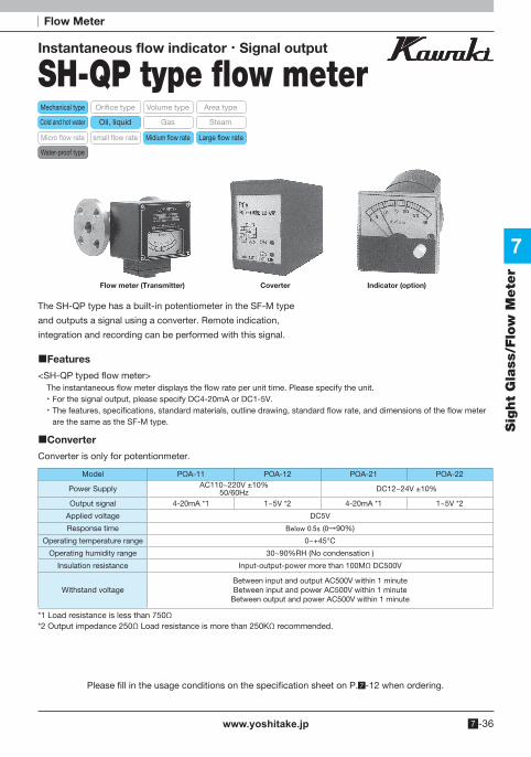
Instantaneous flow indicator Signal output
SH-QP type flow meter
The SH-QP type has a built-in potentiometer in the SF-M type
and outputs a signal using a converter. Remote indication,
integration and recording can be performed with this signal.
Converter is only for potentionmeter.
Features
<SH-QP typed flow meter>The instantaneous flow meter displays the flow rate per unit time. Please specify the unit. For the signal output, please specify DC4-20mA or DC1-5V. The features, specifications, standard materials, outline drawing, standard flow rate, and dimensions of the flow meter
are the same as the SF-M type.
Converter
Model POA-11 POA-12 POA-21 POA-22
Power Supply AC110~220V ±10%50/60Hz DC12~24V ±10%
Output signal 4-20mA *1 1~5V *2 4-20mA *1 1~5V *2
Applied voltage DC5V
Response time Below 0.5s (0→90%)
Operating temperature range 0~+45°C
Operating humidity range 30~90%RH (No condensation )
Insulation resistance Input-output-power more than 100MΩ DC500V
Withstand voltage Between input and output AC500V within 1 minuteBetween input and power AC500V within 1 minute
Between output and power AC500V within 1 minute
*1 Load resistance is less than 750Ω*2 Output impedance 250Ω Load resistance is more than 250KΩ recommended.
Flow meter (Transmitter) Indicator (option)Coverter
Please fill in the usage conditions on the specification sheet on P. -12 when ordering.
Flow Meter
Mechanical type
Gas
Volume type Area typeOrifice type
Oil, liquidCold and hot water Steam
Micro flow rate Midium flow rate Large flow ratesmall flow rate
Water-proof type

www.yoshitake.jp7 -37
7
Sig
ht
Gla
ss/F
low
Mete
r
Dimensions
50
80(82)
20101
122
2 4.5
7.8 0.2
40 0.2
40 0.2
51 MAX.
81M
AX
.
4.52-M48-M3.5 × 7
35.4
4
Mounting clamp for the body (TOP, BOTTOM)
Mounting hole
Mounting hole
Terminal connection diagram
Output signal
Power supply
or
When using
· The SH-QP type flow meter is a magnetic coupling type. If iron powder is expected to be mixed in the
measured fluid, remove it with a strainer. It may cause malfuncton.
· Use in a direction other than the flow direction specified when ordering may cause a flow rate error.
Do not use it in a direction other than the specified flow direction.
· The converter and potentionmeter are adjusted for each unit, so performance may not be achieved with
different combinations.
Flow Meter
Please fill in the usage conditions on the specification sheet on P. -12 when ordering.

www.yoshitake.jp 7 -38
7
Sig
ht
Gla
ss/F
low
Mete
r
Instantaneous flow indicator Alarm output
SA type series flow meter
The SA type series is a small flow rate type of SF-M. The principle and the size of the flow rate indicator are
the same as the SF type, but it is ideal for small flow rate.
Features
<SA-M type flow meter>The instantaneous flow meter displays the flow rate per unit time. Please specify the unit. ·Small flow rate measurement is possible.·Other features, drawing and dimensions are the same as SF-M type.
<SA-MA type, SA-MAA type flow switch.>1 point(MA type) or 2 points(MAA type) can be added to the flow meter as an alarm unit.When the contact reach to the specified flow rate, the reed switch is activated and the switch function is activated. In addition to the features of the SA-M type flow meter, it has the following features.
·Contact operation is reliable. · The contact flow rate can be set arbitrarily (in the case) within the scale range. Please specify the external variable type when it is frequently variable. ·Intrinsically safe explosion-proof types are also available. (Safety cage is included upon request).
SpecificationsModel SA-M SA-MA SA-MAA
Fluids Cold and hot water, oil, other non-dangerous fluids
Maximum operating pressure 1 MPa (Custom order~21MPa)Maximum operating
temperature 80°C (Custom order~300°C)
Flow direction Right→Left, Left→Right, Up→Down, Down→Up
Size 10A (3/8")~25A(1")
Connection JIS Rc, JIS 10K (Available with other standards)
Range Ability 10:2~3:1
Accuracy ±3%F.S. ±5%F.S.
Alarm contact None 1 point 2 point Alarm contact disconnection
difference − ±10%F.S.
Contact −
Reed switch Max switching capacity 50WMax switching current 0.5AMax switching voltage AC 125V/DC 100V
SA-M type flow meter SA-MA type(External variable type)
Please fill in the usage conditions on the specification sheet on P. -12 when ordering.
Flow Meter
Mechanical type
Gas
Volume type Area typeOrifice type
Oil, liquidCold and hot water Steam
Micro flow rate Midium flow rate Large flow rateSmall flow rate
Water-proof type

www.yoshitake.jp7 -39
7
Sig
ht
Gla
ss/F
low
Mete
r
Standard material chart
Standard flow rate chart
Parts For water For oil For other liquids Body CAC406 FCD450
Please specify the material such as SUS 304,SUS316, and SUS316L.
Otherwise, specify at our side.
Cap C3604 SS400O-ring NBR NBRFlapper SUS304 C2801Spring SUS304 SUS304
Coupling SUS304 SUS304
Size Unit Standard scale for water and oil [Minimum~Maximum]
1 2 3 4 5 6 7 8
10AL/min 0~(1)~5 0~(2)~6 0~(2)~7 0~(2)~8 0~(3)~9 0~(2)~10 0~(3)~12 0~(3)~15
m3/h 0~(0.1)~0.3 0~(0.1)~0.4 0~(0.1)~0.5 0~(0.2)~0.6 0~(0.2)~0.7 0~(0.2)~0.8 0~(0.3)~0.9
15AL/min 0~(1)~5 0~(2)~6 0~(2)~7 0~(2)~8 0~(3)~9 0~(2)~10 0~(3)~12 0~(3)~15
m3/h 0~(0.1)~0.3 0~(0.1)~0.4 0~(0.1)~0.5 0~(0.2)~0.6 0~(0.2)~0.7 0~(0.2)~0.8 0~(0.3)~0.9
20AL/min 0~(2)~10 0~(3)~12 0~(3)~15 0~(5)~20
m3/h 0~(0.2)~0.6 0~(0.2)~0.7 0~(0.2)~0.8 0~(0.3)~0.9 0~(0.2)~1 0~(0.3)~1.2
25AL/min 0~(2)~10 0~(3)~12 0~(3)~15 0~(5)~20 0~(5)~25
m3/h 0~(0.2)~0.6 0~(0.2)~0.7 0~(0.2)~0.8 0~(0.3)~0.9 0~(0.2)~1 0~(0.3)~1.2 0~(0.3)~1.5
When using
The SA type flow meter is a magnetic coupling type. If iron powder is expected to be mixed in the measured
fluid, remove it with a strainer. It may cause malfuncton.
Use in a direction other than the flow direction specified when ordering may cause a flow rate error. Do not
use it in a direction other than the specified flow direction.
Flow Meter
Please fill in the usage conditions on the specification sheet on P. -12 when ordering.

www.yoshitake.jp 7 -40
7
Sig
ht
Gla
ss/F
low
Mete
r
Please fill in the usage conditions on the specification sheet on P. -12 when ordering.
FY type is small flow rate indicator of SFM type. The principle is the same as SF type, but a side plate is provided in the measurement section, making it ideal for measuring small and medium flow rate.
Features
<FY-M type flow meter >The instantaneous flow meter displays the flow rate per unit time. Please specify the unit. · Small flow rate measurement is possible.· Compact compare to SF-M type
<FY-MA type flow switch >1 point can be added to the flow meter as an alarm unit. When the specified flow rate is reached, the micro switch is activated and the switch function is activated. In addition to the features of the FY-M type flow meter, it has the following features.
· Contact operation is reliable. · Contact capacity is large. · The contact flow rate can be set arbitrarily (in the case) within the scale range. Please specify the external variable type when it is frequently variable.
· Intrinsically safe explosion-proof types are also available. (Safety cage is included on request).
Specifications
Standard material chart
Model FY-M FY-MAA
Fluid Cold and hot water, oil, other non-dangerous fluid
Maximum pressure 1 MPa
Maximum temperature 80°C
Fluid direction Right→Left, Left→Right, Up→Down, Down→Up
Size 10A (3/8")~50A (2")
Connection JIS Rc, JIS 10K (Available with other standards)
Range ability 10:2~3:1
Accuracy ±3%F.S. ±5%F.S.
Alarm contact None 1 point Alarm contact disconnection
difference − ±10%F.S.
Contact point −
Micro switch Rating AC 5A-125, 250VACDC 0.5A-125VDC 0.25A-250V
Parts For water For oil For non-other dangerous fluid Body FCD450 (Epoxy)* FCD450
Please specify the material such as SUS 304,SUS316, and SUS316L. Otherwise, specify at our side.
Cap C3604 SS400O-ring NBR NBRFlapper SUS304 C2801Spring SUS304 SUS304
Coupling C3604 C3604
* In case of size below 25A, body material will be CAC406.
Instantaneous flow indicator Alarm output Compact case
FY series flow indicator
FY-MA type
Flow Meter
Mechanical type
Gas
Volume type Area typeOrifice type
Oil, liquidCold and hot water Steam
Micro flow rate Medium flow rate Large flow rateSmall flow rate
Water-proof type

www.yoshitake.jp7 -41
7
Sig
ht
Gla
ss/F
low
Mete
r
Please fill in the usage conditions on the specification sheet on P. -12 when ordering.
Flow Meter
Flow chart
<For water>
<For oil>
Dimension
Size UnitStandard scale for water [0~Minimum~Maximum]
1 2 3 4 5 6 7
10AL/min 0~(5)~20 0~(6)~26
m3/h 0~(0.3)~1.2 0~(0.3)~1.5
15AL/min 0~(5)~20 0~(6)~26 0~(6)~30
m3/h 0~(0.3)~1.2 0~(0.3)~1.5 0~(0.5)~2
20AL/min 0~(6)~26 0~(6)~30 0~(10)~36 0~(10)~40 0~(10)~50
m3/h 0~(0.3)~1.5 0~(0.5)~2 0~(0.5)~2.5 0~(1)~3
25AL/min 0~(6)~30 0~(10)~36 0~(10)~40 0~(10)~50 0~(20)~60
m3/h 0~(0.5)~2 0~(0.5)~2.5 0~(1)~3 0~(1)~4
32AL/min 0~(10)~50 0~(20)~60 0~(20)~70 0~(20)~80 0~(30)~90 0~(20)~100
m3/h 0~(1)~3 0~(1)~4 0~(1)~5 0~(2)~6
40AL/min 0~(20)~70 0~(20)~80 0~(30)~90 0~(20)~100 0~(30)~120 0~(30)~150
m3/h 0~(1)~5 0~(2)~6 0~(2)~7 0~(2)~8 0~(3)~9
50AL/min 0~(20)~100 0~(30)~120 0~(30)~150 0~(50)~200 0~(50)~250
m3/h 0~(2)~6 0~(2)~7 0~(2)~8 0~(3)~9 0~(2)~10 0~(3)~12 0~(3)~15
Size UnitStandard scale for oil [0~Minimum~Maximum]
1 2 3 4 5 6 7 8
10AL/min 0~(2)~10 0~(3)~12 0~(3)~15 0~(5)~20
m3/h 0~(0.2)~0.6 0~(0.2)~0.7 0~(0.2)~0.8 0~(0.3)~0.9 0~(0.2)~1 0~(0.3)~1.2
15AL/min 0~(2)~10 0~(3)~12 0~(3)~15 0~(5)~20 0~(6)~26
m3/h 0~(0.2)~0.6 0~(0.2)~0.7 0~(0.2)~0.8 0~(0.3)~0.9 0~(0.2)~1 0~(0.3)~1.2 0~(0.3)~1.5 0~(0.5)~2
20AL/min 0~(3)~15 0~(5)~20 0~(6)~26 0~(6)~30 0~(10)~36 0~(10)~40
m3/h 0~(0.3)~0.9 0~(0.2)~1 0~(0.3)~1.2 0~(0.3)~1.5 0~(0.5)~2 0~(0.5)~2.5 0~(1)~3
25AL/min 0~(5)~20 0~(6)~26 0~(6)~30 0~(10)~36 0~(10)~40 0~(10)~50 0~(20)~60
m3/h 0~(0.3)~1.2 0~(0.3)~1.5 0~(0.5)~2 0~(0.5)~2.5 0~(1)~3 0~(1)~4
32AL/min 0~(10)~40 0~(10)~50 0~(20)~60 0~(20)~70 0~(20)~80 0~(30)~90 0~(20)~100
m3/h 0~(0.5)~2.5 0~(1)~3 0~(1)~4 0~(1)~5 0~(2)~6
40AL/min 0~(10)~50 0~(20)~60 0~(20)~70 0~(20)~80 0~(30)~90 0~(20)~100 0~(30)~120 0~(30)~150
m3/h 0~(1)~3 0~(1)~4 0~(1)~5 0~(2)~6 0~(2)~7 0~(2)~8 0~(3)~9
50AL/min 0~(20)~100 0~(30)~120 0~(30)~150 0~(50)~200 0~(50)~250
m3/h 0~(2)~6 0~(2)~7 0~(2)~8 0~(3)~9 0~(2)~10 0~(3)~12 0~(3)~15
FY-M screw type FY-M flange type FY-M water proof flange type
H90
H H
90
90
90 140
FLOW SWITCH
L
L L

www.yoshitake.jp 7 -42
7
Sig
ht
Gla
ss/F
low
Mete
r
Please fill in the usage conditions on the specification sheet on P. -12 when ordering.
Standard flow rate chart dimension
Size
Face to Face dimension Height
Standard type Screwed Flange
Screwed Flange Standard Water-proof Approximate weight kg
mm mm mm mm Screwed Flange
10A 90 180 87 121 2.5 4.0
15A 90 180 87 121 2.5 4.0
20A 90 180 97 131 2.5 4.5
25A 100 180 102 136 3.0 5.0
32A 140 180 116 150 4.0 7.0
40A 140 180 116 150 4.5 7.0
50A - 240 158 192 - 14.0
* FY-MA type is 25mm higher than FY-M type.
When using
Since FY type series flowmeters are of magnetic coupling type, if it is expected
that iron powder will be mixed into the measured fluid, remove them with a
strainer. It may cause malfunction.
Use in direction other than the direction specified when ordering will cause flow
rate errors. Do not use in directions other than the specified direction.
Flow Meter

www.yoshitake.jp7 -43
7
Sig
ht
Gla
ss/F
low
Mete
r
Please fill in the usage conditions on the specification sheet on P. -12 when ordering.
Flow Meter
Instantaneous flow indicator Alarm output
KY series flow indicator
The KY series is a product developed for lubrication equipment and is ideal for low-cost and hard specification environments
Features
<KY-M type flow meter >The instantaneous flow meter displays the flow rate per unit time. Please specify the unit. Fast reaction speed due to direct acting type. Due to the structure that does not use magnets in the fluid, it is hardly
affected by iron powder. KY type is more compact compare to SF type.
<KY-MA type flow switch >1 point can be added to the flow meter as an alarm unit. When the specified flow rate is reached, the micro switch is activated and the switch function is activated. In addition to the features of the KY-M type flow meter, it has the following features. Contact operation is reliable. Contact capacity is large. The contact flow rate can be set arbitrarily (in the case) within the scale range. Please specify the external variable type when it is frequently variable. Intrinsically safe explosion-proof types are also available. (Safety cage is included upon request).
SpecificationsModel KY-M KY-MA
Application Oil
Maximum pressure 0.7 MPa
Maximum temperature 80°C
Flow direction Right→Left, Left→Right, Up→Down, Down→Up
Size 10A (3/8")~80A (3")
Connection JIS Rc, JIS10K (Available with other standards)
Range ability 10:2~3:1
Accuracy ±5%F.S. ±7%F.S.
Alarm contact None 1 pointAlarm contact disconnection
difference − ±12%F.S.
Contact point −
Micro SwitchRating AC 15A-125, 250, 480VACDC 0.5A-125VDC 0.25A-250V
KY-M type
KY-MA type
Mechanical type
Gas
Volume type Area typeOrifice type
Oil, liquidCold and hot water Steam
Micro flow rate Medium flow rate Large flow ratesmall flow rate
Water-proof type

www.yoshitake.jp 7 -44
7
Sig
ht
Gla
ss/F
low
Mete
r
Please fill in the usage conditions on the specification sheet on P. -12 when ordering.
Standard material chart
Dimension
Parts Oil Body FCD450Cap C3604
O-ring NBRFlapper C2801Spring SUS304
Mechanical seal NBR
<For oil>
Size Unit Standard scale for oil [0~Minimum~Maximum]
1 2 3 4 5 6 7
10AL/min 0~(6)~30
m3/h 0~(0.5)~2
15AL/min 0~(6)~30 0~(10)~36
m3/h 0~(0.5)~2
20AL/min 0~(10)~36 0~(10)~40
m3/h 0~(0.5)~2.5
25AL/min 0~(10)~40 0~(10)~50 0~(20)~60
m3/h 0~(0.5)~2.5 0~(1)~3
32AL/min 0~(20)~60 0~(20)~70 0~(20)~80 0~(20)90 0~(20)~100
m3/h 0~(1)~4 0~(1)~5 0~(2)~6
40AL/min 0~(20)~70 0~(20)~80 0~(30)~90 0~(20)~100 0~(30)~120 0~(30)~150
m3/h 0~(1)~5 0~(2)~6 0~(2)~7 0~(2)~8 0~(3)~9
50AL/min 0~(20)~100 0~(30)~120 0~(30)~150 0~(50)~200 0~(50)~250
m3/h 0~(2)~6 0~(2)~7 0~(2)~8 0~(3)~9 0~(2)~10 0~(3)~12 0~(3)~15
65AL/min 0~(50)~200 0~(60)~260 0~(60)~300 0~(100)~400
m3/h 0~(3)~12 0~(3)~15 0~(5)~20 0~(5)~25
80AL/min 0~(60)~260 0~(60)~300 0~(100)~4000~(100)~5000~(200)~600
m3/h 0~(5)~20 0~(5)~25 0~(10)~30
H
90
L
90
H
90
L
90
KY-M screw type KY-M flange type
Flow rate chart
Flow Meter

www.yoshitake.jp7 -45
7
Sig
ht
Gla
ss/F
low
Mete
r
Please fill in the usage conditions on the specification sheet on P. -12 when ordering.
Standard flow rate chart Dimensions
Size
Face to face dimension L
Height HSF-M standard type
Screwed Flanged
Screwed Flanged Standard type Approximate weight kg
mm mm mm Screwed Flanged
10A 80 150 98 1.5 3.0
15A 80 150 98 1.5 3.0
20A 90 150 106 1.5 3.5
25A 100 160 108 2.0 4.5
32A 120 160 116 3.5 5.5
40A 120 160 116 3.5 6.0
50A − 200 131 − 9.5
65A − 250 209 − 20.0
80A − 280 164 − 27.0
When using
Use in direction other than the direction specified when ordering will cause
flow rate errors. Do not use in directions other than the specified direction.
Flow Meter

www.yoshitake.jp 7 -46
7
Sig
ht
Gla
ss/F
low
Mete
r
Please fill in the usage conditions on the specification sheet on P. -12 when ordering.
For the ODF type series, the differential pressure is measured with a differential pressure gauge
before and after the orifice, and the flow rate is indicated.
An alarm contact can be attached to this differential pressure gauge, and it can also be transmitted
remotely by replacing the differential pressure gauge.
Specifications
Model ODF
Application Liquids and various gases Steam
Maximum pressure Standard 2.0MPa, High pressure type 13MPa Standard 2.0MPa, High pressure type 13MPa(Separate differential pressure gauge)
Maximum temperature 70°C (Separate differential pressure gauge, high temperature) 220°C
Flow direction Right→left, Left→Right, Up→Down, Down→Up
Size 10A (3/8")~400A (16") 15A (3/8”)~400A (16”)
Connection JIS 10K (Available with other standards)
Accuracy ±5%F.S.
*Manufacturing of only orifice is also available.
Instantaneous flow indicator Alarm output
ODF type series flow meter
Standard material chart
Material For water For other liquid and gases Steam Other liquid
Orifice ring SUS304 SS400 SS400 Please specify the material or it is selected according to the fluids.
Orifice plate SUS304 SUS304 SUS304
O-ring NBR NBR −
Flow Meter
Mechanical type
Gas
Volume type Area typeOrifice type
Oil, liquidCold and hot water Steam
Micro flow rate Medium flow rate Large flow rateSmall flow rate
Water-proof type
(For liquid, gas) (For steam)

www.yoshitake.jp7 -47
7
Sig
ht
Gla
ss/F
low
Mete
r
Please fill in the usage conditions on the specification sheet on P. -12 when ordering.
93
70
L
93
70
L
L
93
70
L
Flanged type Flange integrated type
Screwed type
WNRF Butt welding type
Dimensions (For liquid and gases)
Standard dimension chart
Size
Face to face dimension LApproximate weight
Flanged type
Flanged type
Flange integrated
type
Screwed type
WNRF Butt welding type ASME150LB
SS400 SUS304
mm mm mm mm Kg Kg
15A 60 60 100 158.4 3.1 3.1
20A 60 60 110 165.2 3.3 3.4
25A 60 60 120 168.2 5.2 5.3
32A 60 60 — 169.0 6.0 6.0
40A 60 60 — 173.8 6.2 6.2
50A 60 60 — 174.6 7.0 7.1
65A 90 60 — 180.2 13.0 13.0
80A 90 60 — 177.0 13.6 13.7
100A 90 60 — 191.0 16.2 16.3
125A 90 60 — 215.0 22.3 22.4
150A 90 60 — 211.8 26.1 26.3
200A 90 60 — 232.6 33.9 34.1
250A 90 — — 229.4 46.7 47.0
300A 90 — — 252.2 51.2 51.5
350A 90 — — 269.8 71.4 71.9
400A 90 — — 266.6 78.2 78.7
Flow Meter

www.yoshitake.jp 7 -48
7
Sig
ht
Gla
ss/F
low
Mete
r
Please fill in the usage conditions on the specification sheet on P. -12 when ordering.
Dimension (For steam)
Standard dimension chart
Size
Dimension Approximate weight Depth V Length W Height H
mm mm mm Kg
25A 118 220 362.0 4.0
32A 118 230 367.0 4.2
40A 118 235 369.5 4.5
50A 118 250 377.0 5.0
65A 118 270 387.0 6.2
80A 118 280 392.0 6.5
100A 118 305 404.5 7.5
125A 118 336 420.0 9.5
150A 118 366 435.0 11.5
200A 118 416 460.0 14.5
Flow Meter

www.yoshitake.jp7 -49
7
Sig
ht
Gla
ss/F
low
Mete
r
Please fill in the usage conditions on the specification sheet on P. -12 when ordering.
4- 5.5
25.4
50
93
8822
120
44
52.5
130
86 112
LOCK LOCK
113
FIELD
TER
MIN
ALS
192.
5
79.5
Separate type of differential pressure gauge
Standard type of differential pressure gauge (2.0MPa)
Differential pressure gauge for high pressure (13MPa)
Pressure port for low pressure side
Rc 1/4Pressure port for high pressure side
Rc 1/4
Classification Form
1 Battery type (No output)
2 Current output (2 wire- 4-20mA)
3 Alarm output+current output (4-20mA)
Classification Remark
Form Current output (2 wire- 4-20mA)
Display Instantaneous flow rate
Classification Display
1 Instantaneous flow rate
2 Instantaneous flow rate + Integrated flow rate*
* There are restrictions on the total display.
When using
Please contact us if pressure loss is a concern.
Available either vertical or horizontal piping.
Available to install drain plug for drainage.
Flow Meter

www.yoshitake.jp 7 -50
7
Sig
ht
Gla
ss/F
low
Mete
r
Flow Meter
Please fill in the usage conditions on the specification sheet on P. -12 when ordering.
Instantaneous flow indicator/Alarm output
RF type series flow meterMechanical type
Gas
Volume type Area typeOrifice type
Oil, liquidCold and hot water Steam
Micro flow rate Medium flow rate Large flow rateSmall flow rate
The RF type series is a compact and highly accurate flow meter that can measure water and oil as well as chemicals. The number of rotations of the two trilobe elliptical gears gives a signal that is directly proportional to the flow rate.In response to this signal, the instantaneous flow rate or integrated flow rate is displayed on the indicator.
Features
<RF- type electric transmission type >Various outputs are possible by using a converter (contact point signal output from the RF-Ⅰ type according to the application.
<For RFH type high pressure & high viscosity fluid > Accurate lubrication amount can be grasped and proper lubrication can be performed. Since it can be used for oil pressure 21MPa line, there is no restriction on the installation location on the
piping line. It can used to any grease of all consistency. Consistency 85-475, No.006~6 Instantaneous flow and integrated flow can be switched with a single touch, and the integrated display
can be reset. The indicator has dust proof/drip-proof structure. Various outputs are possible by using a pulse signal converter for the application. In that case, select from RF- type telemetry system No restrictions on flow direction. Up Down, Right Left, measurement is possible in any direction.
RF- type

www.yoshitake.jp7 -51
7
Sig
ht
Gla
ss/F
low
Mete
r
Please fill in the usage conditions on the specification sheet on P. -12 when ordering.
Specification
Model RF- RFH
Application Cold and hot water · Oil · Other non-dangerous fluids
Working pressure 1.0 MPa 21 MPa
Test pressure 1.5 MPa 31 MPa
Liquid viscosity Below 1,000mm2/s
Ambient temperature -5°C~40°C
Liquid temperature 0°C~80°C
Humidity 45~85% RH
Size 6A (1/8")~15A (1/2") 8A (1/4")~15A (1/2")
Connection JIS Rc screwed
Accuracy Within ±1%
DisplayInstantaneous flow rate indication 4 digit
Integrated flow rate indication 8 digit
Standard material chart Parts RF- RFHBody C3604 or AL S25C
Pressure lid C3604 or AL SUS304Bolt SUS304 SCM435
Dimension
RFH typeRF- type
Standard dimension chart
Nominal size
Face to face dimension L
RF-
mm
Rc 1/8 60
Rc 1/4 60
Rc 3/8 90
Rc 1/2 130
Flow Meter

www.yoshitake.jp 7 -52
7
Sig
ht
Gla
ss/F
low
Mete
r
Flow Meter
Please fill in the usage conditions on the specification sheet on P. -12 when ordering.
Shuttle type
INF series flow meter Mechanical type
Gas
Volume type Area typeOrifice type
Oil, liquid Cold and hot water Steam
Micro flow rate Middle flow rate Large flow rateSmall flow rate
Water-proof type
INF-MA type INF-MA type (water-proof)
The INF type series is a compact flow meter that can measure the flow rate of liquid and gas with horizontal
piping while being an area type flow meter.
Features
<INF-M type> Since it is shuttle type, it can be used for horizontal piping. An area type flow meter with a metal taper pipe has a flow direction for horizontal piping. High accuracy and wide scale range is possible.Accuracy, FS x within ±2%.Scale range, FS x 1/10 to FS (Example: 1L/min to 10L/min) Measurement of any fluid is possible. Liquid and gases can be measured, and products with excellent corrosion resistance can be manufactured by selecting the main body and the components required. Suitable for high temperature and high pressure fluids. Standard products have a heat resistance of 80 degrees, but can manufacture up to 300 degrees with special specifications. The standard pressure is 1.5MPa, but it can be manufactured up to 30MPa with special specification.
<INF-MA type > Contact operation is reliable. Since the micro switch is turned on and off with circular cam attached to the external magnet shaft, there is no miss shot. The contact is variable at full scale, and the contact operating point is indicated on the scale by the setting needle. Since the contact configuration is a micro switch, a differential is generated during ON/OFF operation of the setting. This differential value varies depending on the set flow rate and piping diameter. Please contact us each time. Large contact capacity Since the micro switch is used for the contact, the contact capacity is larger than that of a reed switch, and an auxiliary relay is not required. Use a waterproof type outdoors or in a poor atmosphere.
The waterproof structure of this device is JIS C 0920immersion type. (IEC IP67).

www.yoshitake.jp7 -53
7
Sig
ht
Gla
ss/F
low
Mete
r
Specifications
Model INF-M INF-MA
Application Cold and hot water, Oil, Other non-dangerous fluids
Size 10A (3/8")~80A (3")
Connection JIS Rc, JIS 10K (Apply to other standard)
Test pressure 1.0 MPa
Temperature Below 80°C
Alarm contact None 1 point
Contact capacity −5A: 125 or 250VAC
0.5A: 125VDC0.25A: 250VDC
Standard material chart Parts For water For oil Other fluidBody CAC406 FCD450
Please specify the material such as SUS 304,SUS316, and SUS316L.
Otherwise, specify at our side.
Middle lid C3604 C3604Upper lid C3604 C3604Lower lid C3604 C3604
O-ring NBR NBRFloat SUS304 SUS304
Dimension
H HH
L L L
INF-M screw type INF-M flange type INF-M water proof screw type
Standard flow rate dimension chart
Size
Face to face dimension L
Height H
Screwed·Flanged
Screwed Flanged Standard type
Water-proof type
mm mm mm mm
10A 85 120 194 211
15A 85 120 194 211
20A 85 120 194 211
25A 85 120 194 211
32A 120 150 215 232
40A 120 150 215 232
50A 120 150 215 232
65A − 180 220 237
80A − 200 230 241
Please fill in the usage conditions on the specification sheet on P. -12 when ordering.
Flow Meter

www.yoshitake.jp 7 -54
7
Sig
ht
Gla
ss/F
low
Mete
r
Flow Meter
Area type flow meter
TR type series flow meter Mechanical type
Gas
Volume type Area typeOrifice type
Oil, liquid Cold and hot water Steam
Micro flow rate Middle flow rate Large flow rateSmall flow rate
TR- type TR- type
Features
<TR- type flow meter>Connection standard is screwed type and there is also the type with needle valve is equipped on either inlet or outlet side.
<TR- type flow meter>Connection standard is screwed type and there is also the type with needle valve is equipped on either inlet or outlet side.
Specifications
Model TR- TR-
Application Liquid and Gases
Size Rc 1/4~Rc 3/4
Pressure resistance 1.0 MPa
Temperature Below 80°C Below 50°C
Accuracy ±2% F.S.
Standard material chart Materials TR- TR-
Up and bottom holder C3604 or SUS C3604 or SUSO-ring NBR NBRFloat SUS304 SUS304
Outer cylinder SGP SGPTaper tube CTE-33 ACRYL RESIN
Please fill in the usage conditions on the specification sheet on P. -12 when ordering.
How to read the flow rate scaleSR type series and TR type series uses float as shown in the figure below. Each reading position is indicated by an arrow.

www.yoshitake.jp7 -55
7
Sig
ht
Gla
ss/F
low
Mete
r
Standard flow rate chart
<TR- type><For water>
Size Unit Standard scale for liquid [0~Minimum~Maximum]1 2 3 4
Rc 1/4 cc/min 0~(5)~50 0~(10)~100 0~(20)~200 0~(30)~300Rc 3/8 L/min 0~(0.03)~0.3 0~(0.05)~0.5 0~(0.1)~1Rc 1/2 L/min 0~(0.1)~1 0~(0.15)~1.5 0~(0.2)~2 0~(0.3)~3Rc 3/4 L/min 0~(0.3)~3 0~(0.5)~5 0~(1)~10
<For air>
Size Unit Standard scale for air [0~Minimum~Maximum]1 2 3 4
Rc 1/4 NL/min 0~(0.1)~1 0~(10)~2 0~(0.5)~5 0~(1)~10Rc 3/8 NL/min 0~(1)~10 0~(0.05)~15 0~(2)~20 0~(3)~30Rc 1/2 NL/min 0~(3)~30 0~(0.15)~50 0~(8)~80 0~(10)~100Rc 3/4 NL/min 0~(10)~100 0~(0.5)~150 0~(20)~200 0~(30)~300
<TR- type>
<For water >
Size Unit Standard sacale for liquid [0~Minimum~Maximum]1 2 3 4
Rc 1/4 L/min 0~(0.1)~1 0~(0.5)~5Rc 3/8 L/min 0~(0.5)~5 0~(1)~10Rc 1/2 L/min 0~(1)~10 0~(1.2)~12 0~(1.5)~15Rc 3/4 L/min 0~(1.5)~15 0~(2)~20 0~(2.5)~25 0~(3)~30
<For air >
Size Unit Standard scale for air [0~Minimum~Maximum]
1 2 3 4
Rc 1/4 NL/min 0~(3)~30 0~(5)~50 0~(10)~100 0~(15)~150Rc 3/8 NL/min 0~(15)~150 0~(20)~200 0~(25)~250 0~(30)~300Rc 1/2 NL/min 0~(30)~300 0~(35)~350 0~(40)~400 0~(50)~500Rc 3/4 NL/min 0~(50)~500 0~(60)~600 0~(80)~800 0~(100)~1000
Dimensions
TR- type
LL
TR- type
Please fill in the usage conditions on the specification sheet on P. -12 when ordering.
Standard dimension chart
Size
Face to face dimensions L
TR- type TR- type
mm mm
Rc 1/8 190 -
Rc 1/4 190 150
Rc 1/4 230 200
Rc 3/8 230 200
Rc 1/2 190 200
Rc 1/2 230 230
Rc 3/4 230 230
Rc 1 230 230
Flow Meter

www.yoshitake.jp 7 -56
7
Sig
ht
Gla
ss/F
low
Mete
r
Flow Meter
Area type flow meter
SR type series flow meterMechanical type
Gas
Volume type Area typeOrifice type
Oil, liquid Cold and hot water Steam
Micro flow rate Middle flow rate Large flow rateSmall flow rate
SR- type SR- -P-N typeSR- type
The SR series is suitable for measuring the instantaneous flow rate of any fluids ( gas and liquids).
Easy disassembly and maintenance due to simple structure.
Features
<SR- type flow meter>This is general flow meter that moves up and down. The float is guided at center pole, with CTE-33 material for taper tube.
<SR- type flow meter>This is general flow meter that moves up and down.
The float is guided at center pole, with methacrylic resin material for taper tube.
<SR- -P type flow meter>Flow meter suitable for measuring micro flow rates, and is often use for experiment or panel mounting.
The outlet side or inlet side can also be equipped with a flow control needle valve (SR- -P-N) and a standard type
(SR- -P-S) is also available.
Specification
Model SR- SR- SR- -P
Application Liquids, Gases
Size 10A (3/8")~80A (3") 10A (3/8")~80A (3") Rc 1/4~Rc 1/2
Connection Rc, JIS 10K (Apply to other standard)
Pressure resistance 10A~20A: 1.0 MPa25A~80A: 0.7 MPa
10A~20A: 1.0 MPa25A~80A: 0.7 MPa 1.0 MPa
Temperature Below 60°C Below 50°C Below 60°C
Accuracy ±2% F.S. ±2% F.S.
Please fill in the usage conditions on the specification sheet on P. -12 when ordering.
How to read the flow rate scale SR type series and TR type series uses float as shown in the figure below. Each reading position is indicated by an arrow.
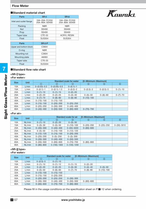
www.yoshitake.jp7 -57
7
Sig
ht
Gla
ss/F
low
Mete
r
Please fill in the usage conditions on the specification sheet on P. -12 when ordering.
Standard material chartParts SR- SR-
Inlet and outlet flange 10A~20A: FC25025A~80A: SS400
10A~20A: FC25025A~80A: SS400
Packing NBR NBRNut SS400 SS400Prop SS400 SS400
Taper tube CTE-33 ACRYL RESINFloat SUS304 SUS304
Parts SR- -P
Upper and bottom block C3604
O-ring NBR
Mounting nut C3604
Mounting plate A6063
Taper tube CTE-33
Float SUS304
Standard flow rate chart
<SR- type><For water>
Size UnitStandard scale for water [0~Minimum~Maximum]
1 2 3 4 5 6
10A L/min 0~(0.03)~0.3 0~(0.05)~0.5 0~(0.1)~115A L/min 0~(0.1)~1 0~(0.1)~1.5 0~(0.2)~2 0~(0.3)~3 0~(0.5)~5 0~(1)~1020A L/min 0~(1)~10 0~(1)~15 0~(2)~2025A L/min 0~(2)~20 0~(2)~25 0~(4)~40 0~(5)~50 0~(6)~60 0~(7)~7032A L/min 0~(7)~70 0~(8)~80 0~(9)~90 0~(10)~10040A L/min 0~(10)~100 0~(15)~15050A L/min 0~(15)~150 0~(20)~200 0~(25)~25065A L/min 0~(25)~250 0~(30)~300 0~(40)~40080A L/min 0~(40)~400 0~(50)~500 0~(60)~600 0~(70)~700
<For air>
Size UnitStandard scale for air [0~Minimum~Maximum]
1 2 3 4 5 6
10A NL/min 0~(1)~10 0~(2)~20 0~(3)~3015A NL/min 0~(3)~30 0~(5)~50 0~(10)~100 0~(20)~200 0~(25)~250 0~(30)~301020A NL/min 0~(30)~300 0~(40)~400 0~(50)~5020 0~(60)~60025A NL/min 0~(5)~50 0~(10)~100 0~(12)~12032A NL/min 0~(12)~120 0~(15)~150 0~(20)~20040A NL/min 0~(20)~200 0~(5)~250 0~(3)~30050A NL/min 0~(30)~300 0~(40)~400 0~(50)~50065A NL/min 0~(50)~500 0~(60)~600 0~(70)~700 0~(80)~80080A NL/min 0~(80)~800 0~(100)~1000 0~(120)~1200
<SR- type><For water>
Size UnitStandard scale for water [0~Minimum~Maximum]
1 2 3 4 5
10A L/min 0~(0.5)~5 0~(1)~1015A L/min 0~(1)~10 0~(1)~12 0~(1)~15 0~(2)~2020A L/min 0~(2)~20 0~(2)~25 0~(3)~30 0~(4)~40 0~(5)~5025A L/min 0~(5)~50 0~(6)~60 0~(7)~70 0~(8)~80 0~(10)~10032A L/min 0~(10)~100 0~(15)~15040A L/min 0~(15)~150 0~(20)~20050A L/min 0~(20)~200 0~(25)~250 0~(30)~30065A L/min 0~(30)~300 0~(40)~400 0~(50)~500 0~(60)~60080A L/min 0~(60)~600 0~(70)~700 0~(80)~800
Flow Meter

www.yoshitake.jp 7 -58
7
Sig
ht
Gla
ss/F
low
Mete
r
<SR- type><For air>
Size UnitStandard scale for air [0~Minimum~Maximum]
1 2 3 4 5
10A NL/min 0~(3)~30 0~(5)~50 0~(10)~100 0~(20)~200 0~(30)~30015A NL/min 0~(30)~300 0~(40)~400 0~(50)~500 0~(60)~60020A NL/min 0~(5)~50 0~(6)~60 0~(7)~70 0~(8)~80 0~(10)~10025A NL/min 0~(10)~100 0~(12)~120 0~(15)~150 0~(20)~20032A NL/min 0~(20)~200 0~(25)~250 0~(30)~30040A NL/min 0~(30)~300 0~(40)~40050A NL/min 0~(40)~400 0~(50)~500 0~(60)~60065A NL/min 0~(60)~600 0~(70)~700 0~(100)~1000 0~(120)~120080A NL/min 0~(120)~1200 0~(150)~1500
<SR- -P type><For water>
Size Unit Standard scale for water [0~Minimum~Maximum]1 2 3 4
Rc 1/4 cc/min 0~(5)~50 0~(10)~100 0~(20)~200 0~(30)~300Rc 3/8 L/min 0~(0.03)~0.3 0~(0.05)~0.5 0~(0.1)~1Rc 1/2 L/min 0~(0.1)~1 0~(0.15)~1.5 0~(0.2)~2 0~(0.3)~3Rc 3/4 L/min 0~(0.3)~3 0~(0.5)~5 0~(1)~10
<For air >
Size Unit Standard scale for air [0~Minimum~Maximum]1 2 3 4
Rc 1/4 NL/min 0~(0.1)~1 0~(0.2)~2 0~(0.5)~5 0~(1)~10Rc 3/8 NL/min 0~(1)~10 0~(1.5)~15 0~(2)~20 0~(3)~30Rc 1/2 NL/min 0~(3)~30 0~(4)~40 0~(5)~50 0~(10)~100Rc 3/4 NL/min 0~(10)~100 0~(15)~150 0~(20)~200 0~(30)~300
Dimensions
L L LH
SR- type
SR- -P type
SR- type
Standard dimension chart
SizeFace to face dimension L
SR- type SR- type SR- type mm mm mm
10A 300 400 280
15A 420 400 280
20A 520 400 300
25A 520 420 300
32A 560 420 350
40A 560 420 350
50A 560 500 400
65A − 620 500
80A − 620 500
Please fill in the usage conditions on the specification sheet on P. -12 when ordering.
SR- -P type
SizeHeight H Vertical
dimension L
mm mm
Rc 1/4 272 240
Rc 3/8 272 240
Rc 1/2 272 240
Flow Meter

www.yoshitake.jp7 -59
7
Sig
ht
Gla
ss/F
low
Mete
r
Shuttle type
NF type series flow switch
Small flow rate Water, oil, liquid Water proof type
This flow switch, working as a water (oil failure)/reduction relay, is used for detection and to
check the flow rate of cooling water, oil etc.
Standard material chart
NF- type Water proof NF- type
Parts For water For oil Other liquids Body CAC406 FC250
Please specify the material such as SUS 304, SUS316, and SUS316L.
Otherwise, specify at our side.
Upper coupling C3604 C3604Bottom coupling C3604 C3604
O-ring NBR NBRFloat C3604 SUS304
Spring SUS304 SUS304
Specifications
Model NF- NF-
Application Cold and hot water, oil, other non-dangerous fluids
Contact Fixed Variable
Pressure resistance 1.0 MPa (Special order ~30 MPa)
Temperature Below 80°C (Special order ~200°C)
Size 10A (3/8")~80A(3")
Connection JIS Rc, JIS 10K (Apply to other standard )
Contact capacity 15A: 125, 250 or 480VAC
0.5A: 125VDC0.25A: 250VDC
Please fill in the usage conditions on the specification sheet on P. -12 when ordering.
Flow Switch

www.yoshitake.jp 7 -60
7
Sig
ht
Gla
ss/F
low
Mete
r
Flow Switch
NF- screwed type * H3 is for NF- type.
NF- flange type Water proof NF- flange type
Dimensions H
3H
2H
1
H3
H2
H1
H3
H2
H1
L L L
Dimensions
Size
Face to face dimension L
Height H1 Dimension H2 Dimension H3 (Only for NF-Ⅱ)
Screw·Flange Screw·Flange Screw·Flange
Screwed Flanged Standard Water proof Standard·water proof Standard·water proof
mm mm mm mm mm mm
10A 85 120 108 217 60 133
15A 85 120 108 217 60 133
20A 85 120 108 217 60 133
25A 85 120 108 217 60 133
32A 120 150 129 238 71 144
40A 120 150 129 238 71 144
50A 120 150 129 238 71 144
65A − 180 134 243 78 151
80A − 200 143 253 94 167
Please fill in the usage conditions on the specification sheet on P. -12 when ordering.

www.yoshitake.jp7 -61
7
Sig
ht
Gla
ss/F
low
Mete
r
Return oil (or water), unfilled oil (or water)
CY type flow switch Water, oil Water proof type
This flow switch is most suitable for unfilled return oil (water) piping in which the piping is not filled with oil (water). This include a needle for variable contact, the adjustment of which allows variation of the set flow rate.
Specifications
Model CY-
Application Cold and hot water, oil, other non-corrosive fluids
Pressure resistance 0.5 MPa
Temperature Below 80°C
Size 10A (3/8")~150A (6")
Connection JIS 10K (Apply to other standard)
Contact capacity 15A: 125 or 250VAC
0.5A: 125VDC0.25A: 250VDC
Standard material chart
Dimensions
Standard type Water proof type
Standard dimension chart
Parts For water For oil Body SUS304 SS400
Pressure lid SUS304 SS400
O-ring NBR NBR
Spindle SUS304 SUS304
Spindle guide C3604 C3604
Spindle cover C3604 C3604
Float switch SUS316 SUS316
SizeDimension
L1 Dimension
L2 Height H1 Height H2
mm mm mm mm
15A 110 90 117 176
20A 110 90 117 176
25A 110 90 117 176
40A 110 95 122 181
50A 110 100 126 185
65A 120 120 136 195
80A 140 140 148 207
100A 160 160 172 231
Flow rate������
H1
H1
H2
L2
L2
L1L1
Please fill in the usage conditions on the specification sheet on P. -12 when ordering.
Flow Switch

www.yoshitake.jp 7 -62
MEMO
7
Sig
ht
Gla
ss/F
low
Mete
r
Related Documents