SIGGRAPH 2004 Course Notes Facial Modeling and Animation J¨ org Haber MPI Informatik Saarbr¨ ucken, Germany [email protected] Demetri Terzopoulos New York University New York, USA [email protected]

Welcome message from author
This document is posted to help you gain knowledge. Please leave a comment to let me know what you think about it! Share it to your friends and learn new things together.
Transcript

SIGGRAPH 2004 Course NotesFacial Modeling and Animation
Jorg HaberMPI Informatik
Saarbrucken, [email protected]
Demetri TerzopoulosNew York University
New York, [email protected]
1 Abstract
In this course we present an overview of the concepts and current techniques in facial modeling andanimation. We introduce this research area by its history and applications. As a necessary prerequisitefor facial modeling, data acquisition is discussed in detail. We describe basic concepts of facial an-imation and present different approaches including parametric models, performance-, physics-, andlearning-based methods. State-of-the-art techniques such as muscle-based facial animation, mass-spring networks for skin models, and morphable models are part of these approaches. We further-more discuss texturing of head models and rendering of skin, addressing problems related to texturesynthesis and bump mapping with graphics hardware. Typical applications for facial modeling andanimation such as medical and forensic applications (craniofacial surgery simulation, facial recon-struction from skull data, virtual aging) and animation techniques for movie production (case studyof The Matrix sequels) are presented and explained.
2 Syllabus
The course will be organized according to the following time schedule:
time length topic presenter
08:30–08:35 5 min outline of the tutorial
08:35–09:05 30 min history & applications F. Parke
09:05–09:20 15 min anatomy of the human head J. Haber
09:20–10:00 40 min data acquisition for facial modeling L. Williams
10:00–10:15 15 min overview: facial animation techniques V. Blanz
10:30–11:10 40 min parametric models F. Parke
11:10–11:35 25 min performance-based facial modeling/animation L. Williams
11:35–12:15 40 min physically based facial modeling/animation D. Terzopoulos
13:45–14:30 45 min learning-based approaches V. Blanz
14:30–15:00 30 min rendering techniques J. Haber
15:00–15:30 30 min forensic applications J. Haber
15:45–16:45 60 min movie production G. Borshukov
16:45–17:15 30 min medical applications and behavioral models D. Terzopoulos
17:15–17:30 15 min questions, discussion all
3 Contents
The tutorial notes contain both the slides from the tutorial presentation and some selected publica-tions, which serve as additional background information.
1. Slides: Facial Animation: History & Applications
2. Slides: Anatomy of the Human Head
3. Slides: Overview: Facial Animation Techniques
4. Slides: Parameterized Face Models
5. Slides: Facial Performance Capture (Data Acquisition + Performance-based Approaches)
6. Slides: Physically based Facial Modeling and Animation
7. Paper: Y. Lee, D. Terzopoulos, K. Waters: Realistic Modeling for Facial Animations, Proc.SIGGRAPH ’95, 55–62, Aug. 1995.
8. Slides: Learning-based Approaches
9. Paper: V. Blanz, T. Vetter: A Morphable Model for the Synthesis of 3D Faces, Proc. SIG-GRAPH ’99, 187–194, Aug. 1999.
10. Slides: Rendering Techniques for Facial Animation
11. Paper: M. Tarini, H. Yamauchi, J. Haber, H.-P. Seidel: Texturing Faces, Proc. Graphics Inter-face 2002, 89–98, May 2002.
12. Slides: Forensic Applications
13. Paper: K. Kahler, J. Haber, H. Yamauchi, H.-P. Seidel: Reanimating the Dead: Reconstructionof Expressive Faces from Skull Data, ACM Trans. Graphics (Proc. SIGGRAPH 2003), 22(3),554–561, July 2003.
14. Slides: Image-based Facial Animation and Rendering for The Matrix Sequels
15. Slides: Medical Applications & Behavioral Models

Facial Animation:History and Applications
Fred ParkeTexas A&M University
Fred ParkeFred ParkeTexas A&M UniversityTexas A&M University
Applications of Facial Modeling and Animation
Entertainment animation and VFXEntertainment animation and VFXInteractive gamesInteractive gamesHumanHuman--computer interfacescomputer interfaces
TelepresenceTelepresence
Perception researchPerception research
Medical and educationalMedical and educational
Facial Animation:History and Applications
A look back over the last 35 years A look back over the last 35 years
A Look Ahead A Look Ahead –– Future HistoryFuture History
Convincing ‘Realistic’ Faces
•• The challenge has been the synthesis The challenge has been the synthesis of artificial faces that look and act like of artificial faces that look and act like your mother, brother, friend, or some your mother, brother, friend, or some well know celebritywell know celebrity
•• A huge challenge because of A huge challenge because of familiarityfamiliarity
•• The ‘closer’ you get the harder it isThe ‘closer’ you get the harder it is
Facial Animation: Historical Perspective
Pre-history
Facial representation has been a major focus of art forms from ancient times up to the present
– archeological artifacts– sculpture– drawing – painting– and traditional animation
PrePre--historyhistory
Facial representation has been a major focus of art Facial representation has been a major focus of art forms from ancient times up to the presentforms from ancient times up to the present
–– archeological artifactsarcheological artifacts–– sculpturesculpture–– drawing drawing –– paintingpainting–– andand traditional animationtraditional animation
Facial Animation: Historical Perspective
1600’sFirst published investigations of facial expression
– John Bulwer, London, 1648 and 1649
1800’s‘The mechanism of human facial expression’
– G. Duchenne, Paris, 1862
‘Expression of the emotions in man and animals’– C. Darwin, London, 1872
1600’s1600’sFirst published investigations of facial expression First published investigations of facial expression
–– John Bulwer, London, 1648 and 1649John Bulwer, London, 1648 and 1649
1800’s1800’s‘The mechanism of human facial expression’‘The mechanism of human facial expression’
–– G.G. DuchenneDuchenne, Paris, 1862, Paris, 1862
‘Expression of the emotions in man and animals’‘Expression of the emotions in man and animals’–– C. Darwin, London, 1872C. Darwin, London, 1872
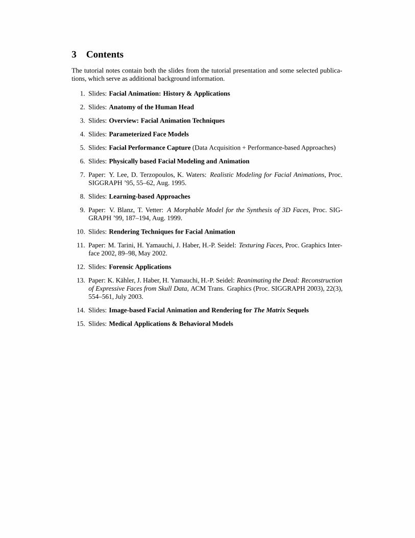
Broad Trends/Themes
• Exponential increase in computer power ~1000x every 15 years
• Steady development of new and refinement of existing techniques, interspersed with flashes of insight• Better and better tools• Ever increasing expectations
– speed, complexity, realism
•• Exponential increase in computer power Exponential increase in computer power ~1000x every 15 years~1000x every 15 years
•• Steady development of new and refinement Steady development of new and refinement of existing techniques, interspersed with of existing techniques, interspersed with flashes of insightflashes of insight•• Better and better toolsBetter and better tools•• Ever increasing expectations Ever increasing expectations
–– speed, complexity, realismspeed, complexity, realism
Technique Categories
• Sources of geometric data• Modeling primitives• Animation control• Rendering• Tools
•• Sources of geometric dataSources of geometric data•• Modeling primitivesModeling primitives•• Animation controlAnimation control•• RenderingRendering•• ToolsTools
Sources of Geometric Data
• Graph paper• Direct surface measurement• Photographic• Laser scanners• Structured light• Interactive surface ‘sculpting’ systems
•• Graph paperGraph paper•• Direct surface measurementDirect surface measurement•• PhotographicPhotographic•• Laser scannersLaser scanners•• Structured lightStructured light•• Interactive surface ‘sculpting’ systemsInteractive surface ‘sculpting’ systems
Geometric Modeling
• Vectors• Polygonal surfaces• Bi-cubic parametric surfaces
– B-Splines, NURBS, …
• Subdivision surfaces
Development of interactive modeling tools
•• VectorsVectors•• Polygonal surfacesPolygonal surfaces•• BiBi--cubic parametric surfacescubic parametric surfaces
–– BB--Splines, NURBS, …Splines, NURBS, …
•• Subdivision surfacesSubdivision surfaces
Development of interactive modeling toolsDevelopment of interactive modeling tools
Animation Control
• Shape interpolation• Direct parameterizations• Muscle-based parameterizations• Expression/Viseme level parameterizations• Dynamic simulations• Facial ‘rigs’ based on ‘skeletons’, deformers, blend shapes, …
•• Shape interpolationShape interpolation•• Direct parameterizationsDirect parameterizations•• MuscleMuscle--based parameterizationsbased parameterizations•• Expression/Viseme level parameterizationsExpression/Viseme level parameterizations•• Dynamic simulationsDynamic simulations•• Facial ‘rigs’ based on ‘skeletons’, Facial ‘rigs’ based on ‘skeletons’, deformers, blend shapes, …deformers, blend shapes, …
Animation Control Handles
Scripted or interactive control of: • Interpolation coefficients
• Interpolation of parameter values– direct or muscle based parameters
• Dynamic forces
• Facial rig ‘handles’
Key frame values, interactive curve editors
Scripted or interactive control of: Scripted or interactive control of: •• Interpolation coefficientsInterpolation coefficients
•• Interpolation of parameter valuesInterpolation of parameter values–– direct or muscle based parametersdirect or muscle based parameters
•• Dynamic forcesDynamic forces
•• Facial rig ‘handles’Facial rig ‘handles’
Key frame values, interactive curve editorsKey frame values, interactive curve editors
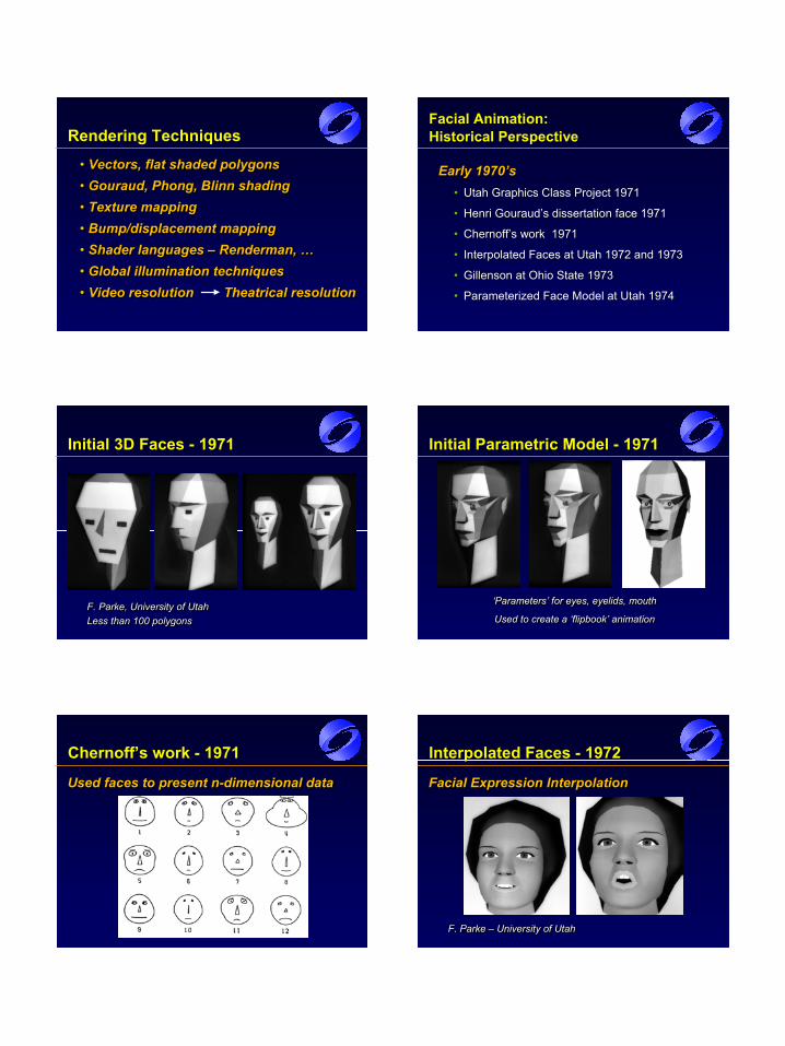
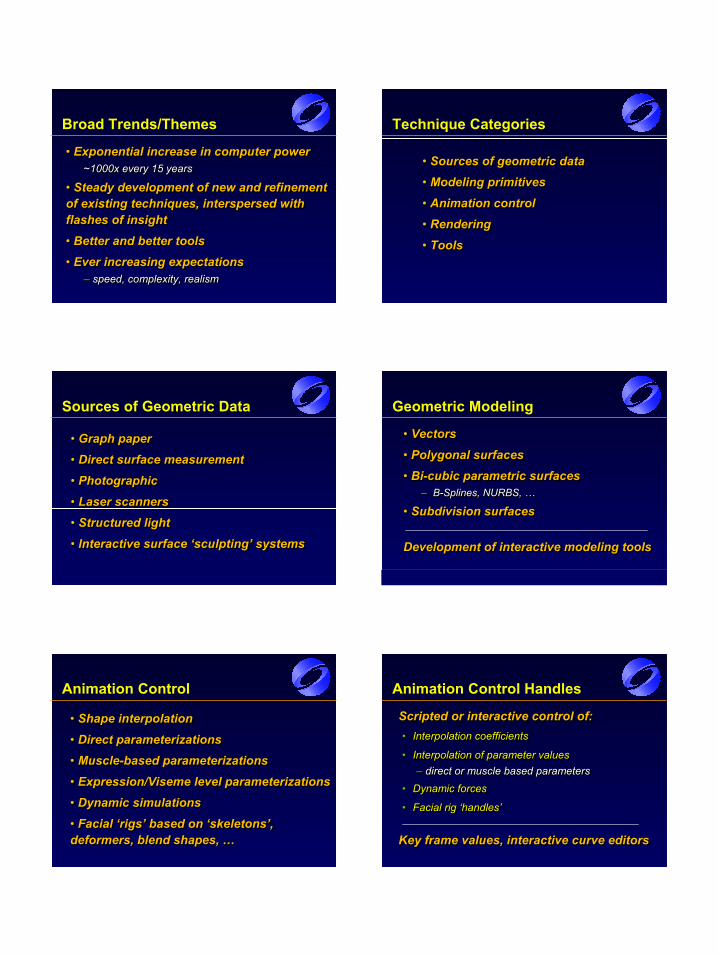
Rendering Techniques
• Vectors, flat shaded polygons• Gouraud, Phong, Blinn shading• Texture mapping• Bump/displacement mapping• Shader languages – Renderman, …• Global illumination techniques• Video resolution Theatrical resolution
•• Vectors, flat shaded polygonsVectors, flat shaded polygons•• Gouraud, Phong, Blinn shadingGouraud, Phong, Blinn shading•• Texture mappingTexture mapping•• Bump/displacement mappingBump/displacement mapping•• Shader languages Shader languages –– Renderman, …Renderman, …•• Global illumination techniquesGlobal illumination techniques•• Video resolution Theatrical resolutionVideo resolution Theatrical resolution
Facial Animation: Historical Perspective
Early 1970’sEarly 1970’s•• Utah Graphics Class Project 1971Utah Graphics Class Project 1971
•• Henri Gouraud’s dissertation face 1971Henri Gouraud’s dissertation face 1971
•• Chernoff’s work 1971 Chernoff’s work 1971
•• Interpolated Faces at Utah 1972 and 1973Interpolated Faces at Utah 1972 and 1973
•• Gillenson at Ohio State 1973Gillenson at Ohio State 1973
•• Parameterized Face Model at Utah 1974Parameterized Face Model at Utah 1974
Initial 3D Faces - 1971
F. Parke, University of UtahLess than 100 polygonsF. Parke, University of UtahF. Parke, University of UtahLess than 100 polygonsLess than 100 polygons
Initial Parametric Model - 1971
‘Parameters’ for eyes, eyelids, mouth
Used to create a ‘flipbook’ animation
‘Parameters’ for eyes, eyelids, mouth‘Parameters’ for eyes, eyelids, mouth
Used to create a ‘flipbook’ animationUsed to create a ‘flipbook’ animation
Chernoff’s work - 1971
Used faces to present n-dimensional dataUsed faces to present nUsed faces to present n--dimensional datadimensional data
Interpolated Faces - 1972
Facial Expression Interpolation
F. Parke – University of Utah
Facial Expression InterpolationFacial Expression Interpolation
F. Parke F. Parke –– University of UtahUniversity of Utah
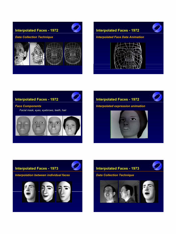
Interpolated Faces - 1972
Data Collection TechniqueData Collection TechniqueData Collection Technique
Interpolated Faces - 1972
Interpolated Face Data AnimationInterpolated Face Data AnimationInterpolated Face Data Animation
Interpolated Faces - 1972
Face ComponentsFacial mask, eyes, eyebrows, teeth, hair
Face ComponentsFace ComponentsFacial mask, eyes, eyebrows, teeth, hairFacial mask, eyes, eyebrows, teeth, hair
Interpolated Faces - 1972
Interpolated expression animationInterpolated expression animationInterpolated expression animation
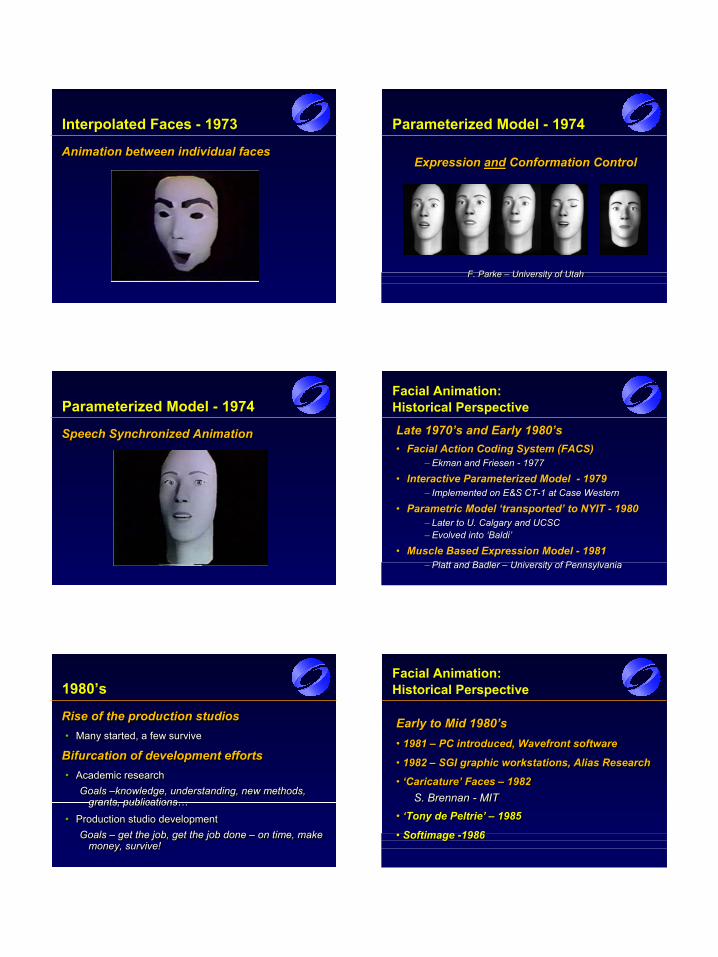
Interpolated Faces - 1973
Interpolation between individual facesInterpolation between individual facesInterpolation between individual faces
Interpolated Faces - 1973
Data Collection TechniqueData Collection TechniqueData Collection Technique
Interpolated Faces - 1973
Animation between individual facesAnimation between individual facesAnimation between individual faces
Parameterized Model - 1974
Expression and Conformation Control
F. Parke – University of Utah
Expression Expression andand Conformation ControlConformation Control
F. Parke F. Parke –– University of UtahUniversity of Utah
Parameterized Model - 1974
Speech Synchronized AnimationSpeech Synchronized AnimationSpeech Synchronized Animation
Facial Animation: Historical Perspective
Late 1970’s and Early 1980’sLate 1970’s and Early 1980’s•• Facial Action Coding System (FACS)Facial Action Coding System (FACS)
–– Ekman and Friesen Ekman and Friesen -- 19771977
•• Interactive Parameterized Model Interactive Parameterized Model -- 19791979–– Implemented on E&S CTImplemented on E&S CT--1 at Case Western1 at Case Western
•• Parametric Model ‘transported’ to NYIT Parametric Model ‘transported’ to NYIT -- 19801980–– Later to U. Calgary and UCSCLater to U. Calgary and UCSC–– Evolved into ‘Baldi’Evolved into ‘Baldi’
•• Muscle Based Expression Model Muscle Based Expression Model -- 19811981–– Platt and Badler Platt and Badler –– University of PennsylvaniaUniversity of Pennsylvania
1980’s
Rise of the production studios• Many started, a few survive
Bifurcation of development efforts• Academic research
Goals –knowledge, understanding, new methods, grants, publications…
• Production studio developmentGoals – get the job, get the job done – on time, make
money, survive!
Rise of the production studiosRise of the production studios•• Many started, a few surviveMany started, a few survive
Bifurcation of development effortsBifurcation of development efforts•• Academic researchAcademic research
Goals Goals ––knowledge, understanding, new methods, knowledge, understanding, new methods, grants, publications…grants, publications…
•• Production studio developmentProduction studio developmentGoals Goals –– get the job, get the job done get the job, get the job done –– on time, make on time, make
money, survive!money, survive!
Facial Animation: Historical Perspective
Early to Mid 1980’s• 1981 – PC introduced, Wavefront software
• 1982 – SGI graphic workstations, Alias Research
• ‘Caricature’ Faces – 1982S. Brennan - MIT
• ‘Tony de Peltrie’ – 1985
• Softimage -1986
Early to Mid 1980’sEarly to Mid 1980’s•• 1981 1981 –– PC introduced, Wavefront softwarePC introduced, Wavefront software
•• 1982 1982 –– SGI graphic workstations, Alias ResearchSGI graphic workstations, Alias Research
•• ‘Caricature’ Faces ‘Caricature’ Faces –– 19821982S. Brennan S. Brennan -- MITMIT
• ‘Tony de Peltrie’ – 1985
• Softimage -1986
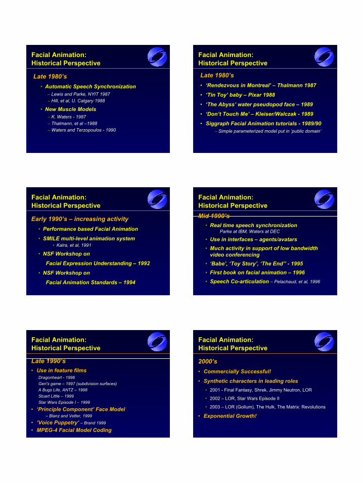
Facial Animation: Historical Perspective
Late 1980’sLate 1980’s•• Automatic Speech SynchronizationAutomatic Speech Synchronization
–– Lewis and Parke, NYIT 1987Lewis and Parke, NYIT 1987–– Hill, et al, U. Calgary 1988Hill, et al, U. Calgary 1988
•• New Muscle ModelsNew Muscle Models–– K. Waters K. Waters -- 19871987–– ThalmannThalmann, et al , et al ––19881988–– Waters andWaters and TerzopoulosTerzopoulos -- 19901990
Facial Animation: Historical Perspective
Late 1980’sLate 1980’s•• ‘Rendezvous in Montreal’ ‘Rendezvous in Montreal’ –– Thalmann 1987Thalmann 1987
•• ‘Tin Toy’ baby ‘Tin Toy’ baby –– Pixar 1988Pixar 1988
•• ‘The Abyss’ water pseudopod face ‘The Abyss’ water pseudopod face –– 19891989
•• ‘Don’t Touch Me’ ‘Don’t Touch Me’ –– Kleiser/Walczak Kleiser/Walczak -- 19891989
•• Siggraph Facial Animation tutorials Siggraph Facial Animation tutorials -- 1989/901989/90–– Simple parameterized model put in ‘public domain’Simple parameterized model put in ‘public domain’
Facial Animation: Historical Perspective
Early 1990’s Early 1990’s –– increasing activityincreasing activity•• Performance based Facial AnimationPerformance based Facial Animation
•• SMILE multiSMILE multi--level animation system level animation system •• KalraKalra, et al, 1991, et al, 1991
•• NSF Workshop on NSF Workshop on
Facial Expression Understanding Facial Expression Understanding –– 19921992
•• NSF Workshop on NSF Workshop on
Facial Animation Standards Facial Animation Standards –– 19941994
Facial Animation: Historical PerspectiveMid 1990’sMid 1990’s
•• Real time speech synchronizationReal time speech synchronizationParke at IBM, Waters at DECParke at IBM, Waters at DEC
•• Use in interfaces Use in interfaces –– agents/avatarsagents/avatars•• Much activity in support of low bandwidth Much activity in support of low bandwidth
video conferencing video conferencing •• ‘Babe’, ‘Toy Story’, ‘The End’’ ‘Babe’, ‘Toy Story’, ‘The End’’ -- 19951995•• First book on facial animation First book on facial animation –– 19961996•• Speech CoSpeech Co--articulation articulation –– PelachaudPelachaud, et al, 1996, et al, 1996
Facial Animation: Historical Perspective
Late 1990’sLate 1990’s•• Use in feature films Use in feature films
Dragonheart Dragonheart -- 19961996Geri’s game Geri’s game –– 1997 (subdivision surfaces)1997 (subdivision surfaces)A Bugs Life, ANTZ A Bugs Life, ANTZ –– 19981998Stuart Little Stuart Little –– 19991999Star Wars Episode I Star Wars Episode I –– 19991999
•• ‘Principle Component’ Face Model‘Principle Component’ Face Model–– BlanzBlanz and Vetter, 1999and Vetter, 1999
•• ‘Voice Puppetry’ ‘Voice Puppetry’ –– Brand 1999Brand 1999
•• MPEGMPEG--4 Facial Model Coding4 Facial Model Coding
Facial Animation: Historical Perspective
2000’s2000’s•• Commercially Successful!Commercially Successful!
•• Synthetic characters in leading rolesSynthetic characters in leading roles•• 2001 2001 -- Final Fantasy, Shrek, Jimmy Neutron, LORFinal Fantasy, Shrek, Jimmy Neutron, LOR
•• 2002 2002 –– LOR, Star Wars Episode IILOR, Star Wars Episode II
•• 2003 2003 –– LOR (Gollum), The Hulk, The Matrix: RevolutionsLOR (Gollum), The Hulk, The Matrix: Revolutions
•• Exponential Growth!Exponential Growth!
Applications of Facial Modeling and Animation
Entertainment animation and VFXEntertainment animation and VFXInteractive gamesInteractive gamesHumanHuman--computer interfacescomputer interfacesTelepresenceTelepresencePerception researchPerception researchMedical and educationalMedical and educational
Entertainment animation/VFX
• Currently the major application and driving force• Synthetic characters in leading and support roles• Digital stand-ins• Crowd simulation
•• Currently Currently thethe major application and major application and driving forcedriving force•• Synthetic characters in leading and Synthetic characters in leading and support rolessupport roles•• Digital standDigital stand--insins•• Crowd simulationCrowd simulation
Interactive games
• Another major application and driving force• Quality expectations approaching those for entertainment animation
• Real-time performance required
• ‘Behavior’ modeling important
•• Another major application and Another major application and driving forcedriving force•• Quality expectations approaching Quality expectations approaching those for entertainment animationthose for entertainment animation
•• RealReal--time performance requiredtime performance required
•• ‘Behavior’ modeling important‘Behavior’ modeling important
Human-computer interfaces
• Requires interactive models• Applications
– Software agents– Social agents– Conversational interfaces– Kiosks– Stage shows, …
•• Requires interactive modelsRequires interactive models•• ApplicationsApplications
–– Software agentsSoftware agents–– Social agentsSocial agents–– Conversational interfacesConversational interfaces–– KiosksKiosks–– Stage shows, …Stage shows, …
Agent Applications
• Provides screen presence for agent software•Provides an interaction ‘focus’•Conversational interfaces
– Two way speech– Speech recognition– Synchronized speech animation response
•• Provides screen presence for agent Provides screen presence for agent softwaresoftware••Provides an interaction ‘focus’Provides an interaction ‘focus’••Conversational interfacesConversational interfaces
–– Two way speechTwo way speech–– Speech recognitionSpeech recognition–– Synchronized speech animation responseSynchronized speech animation response
Kiosk Applications
Attracts attention• Initial ‘patter’
• Solicits user query interaction
Provides response information• Guides query interaction
• Spoken query feedback
Attracts attentionAttracts attention•• Initial ‘patter’Initial ‘patter’
•• Solicits user query interactionSolicits user query interaction
Provides response informationProvides response information•• Guides query interactionGuides query interaction
•• Spoken query feedbackSpoken query feedback
Stage Show Applications
• As emcee or host– Introduces show elements– Interacts with audience
• As ‘sidekick’ for a real host– Dialog with real host
•• As emcee or hostAs emcee or host–– Introduces show elementsIntroduces show elements–– Interacts with audienceInteracts with audience
•• As ‘sidekick’ for a real hostAs ‘sidekick’ for a real host–– Dialog with real hostDialog with real host
Interactive Model Attributes
• Expressive– able to assume an appropriate range of
expressions• Responsive and ‘alive’
– synchronized speech and expression• ‘Intelligent Behavior’
– ‘appropriate’ behaviors• Visual realism vs. behavioral realism?
– these need to ‘match’
•• ExpressiveExpressive–– able to assume an appropriate range of able to assume an appropriate range of
expressionsexpressions
•• Responsive and ‘alive’Responsive and ‘alive’–– synchronized speech and expressionsynchronized speech and expression
•• ‘Intelligent Behavior’‘Intelligent Behavior’–– ‘appropriate’ behaviors‘appropriate’ behaviors
•• Visual realism vs. behavioral realism?Visual realism vs. behavioral realism?–– these need to ‘match’these need to ‘match’
Need to keep it ‘Alive’
• Believable eyes and eye motion– Eyes are always moving, if just a little– Eye ‘tracking’– Eye ‘blinks’
• Head motion– Always moving, head ‘follows’ the eyes
• Appropriate expressions• ‘Good’ synchronized speech
•• Believable eyes and eye motionBelievable eyes and eye motion–– Eyes are always moving, if just a littleEyes are always moving, if just a little–– Eye ‘tracking’Eye ‘tracking’–– Eye ‘blinks’Eye ‘blinks’
•• Head motionHead motion–– Always moving, head ‘follows’ the eyesAlways moving, head ‘follows’ the eyes
•• Appropriate expressionsAppropriate expressions•• ‘Good’ synchronized speech‘Good’ synchronized speech
Real Time Model Screen shot - synchronized to real speech
Fred Parke ~ 1995
Screen shot Screen shot -- synchronized to real speechsynchronized to real speech
Fred Fred Parke Parke ~ 1995~ 1995
Telepresence
Low bandwidth ‘video’ conferencing• Model based compression
• Model parameters extracted for transmission
• Only parameters sent over communication channel
• For reception, parameters drive model to recreate the facial images
Part of the MPEG-4 standard
Low bandwidth ‘video’ conferencingLow bandwidth ‘video’ conferencing•• Model based compressionModel based compression
•• Model parameters extracted for transmissionModel parameters extracted for transmission
•• Only parameters sent over communication channelOnly parameters sent over communication channel
•• For reception, parameters drive model to recreate For reception, parameters drive model to recreate the facial imagesthe facial images
Part of the MPEGPart of the MPEG--4 standard4 standard
Perception Research
• Carefully controlled visual stimuli– must to be ‘correct’
• Bi-Modal visual speech exampleMassaro & Cohen, UCSC
– visual perception and aural perception work together
– conflicts in visual and aural can induce misperceptions – McGurk effect
– what you see can influence what you ‘hear’
•• Carefully controlled visual stimuliCarefully controlled visual stimuli–– must to be ‘correct’must to be ‘correct’
•• BiBi--Modal visual speech exampleModal visual speech exampleMassaro & Cohen, UCSCMassaro & Cohen, UCSC
–– visual perception and aural perception work visual perception and aural perception work togethertogether
–– conflicts in visual and aural can induce conflicts in visual and aural can induce misperceptions misperceptions –– McGurk effectMcGurk effect
–– what you see can influence what you ‘hear’what you see can influence what you ‘hear’
Medical and Educational
Medical• Teaching anatomy
• Surgical simulation
• Model must be physically correct
Educational• ‘Tutor’
• Face must be interactive and engaging
MedicalMedical•• Teaching anatomyTeaching anatomy
•• Surgical simulationSurgical simulation
•• Model must be physically correctModel must be physically correct
EducationalEducational•• ‘Tutor’‘Tutor’
•• Face must be interactive and engagingFace must be interactive and engaging
Good Enough?
When will facial animation be good enough?When will facial animation be good enough?•• Any face, any age, any expression, dramatic Any face, any age, any expression, dramatic
nuances, wide range of facial styles,’nuances, wide range of facial styles,’easyeasy’…’…•• Visual and behavioral realism balancedVisual and behavioral realism balanced
Appearance is getting very good, but not Appearance is getting very good, but not quite there yet quite there yet –– still hard to do wellstill hard to do well
Behavior modeling has a long way to goBehavior modeling has a long way to go
Facial ‘Turing’ testFacial ‘Turing’ test
Future History
Looking ahead…Looking ahead…Just the Beginning!Just the Beginning!
•• Animation only last 100 yearsAnimation only last 100 years•• Computer facial animation only last 35 yearsComputer facial animation only last 35 years•• Most work in the last 10 yearsMost work in the last 10 years
Computation CapabilitiesComputation Capabilities•• 1,000 fold increase every 15 years!1,000 fold increase every 15 years!
Directions
•• Much, much better models & toolsMuch, much better models & tools•• Subtle, more realistic detail and control Subtle, more realistic detail and control •• Behaviors, motivations Behaviors, motivations •• Idiosyncratic personality modelsIdiosyncratic personality models•• ‘Director’ level interfaces ‘Director’ level interfaces
•• Something new Something new –– unexpected!unexpected!
‘Motivated’ Facial Models
Action and expressions motivated by Action and expressions motivated by the character model, the situation, the character model, the situation, and the ‘director’ rather than and the ‘director’ rather than manipulated by an animatormanipulated by an animator
Fully Functional ‘Actors’
Facial animation fully integrated Facial animation fully integrated
Anatomically ‘correct’Anatomically ‘correct’Behavior drivenBehavior driven
with personality, motivationwith personality, motivation‘Directable’‘Directable’‘Easy’ to use‘Easy’ to use
Anatomy of the Human Head
Jörg HaberMPI Informatik
Jörg HaberJörg Haber
MPI InformatikMPI Informatik
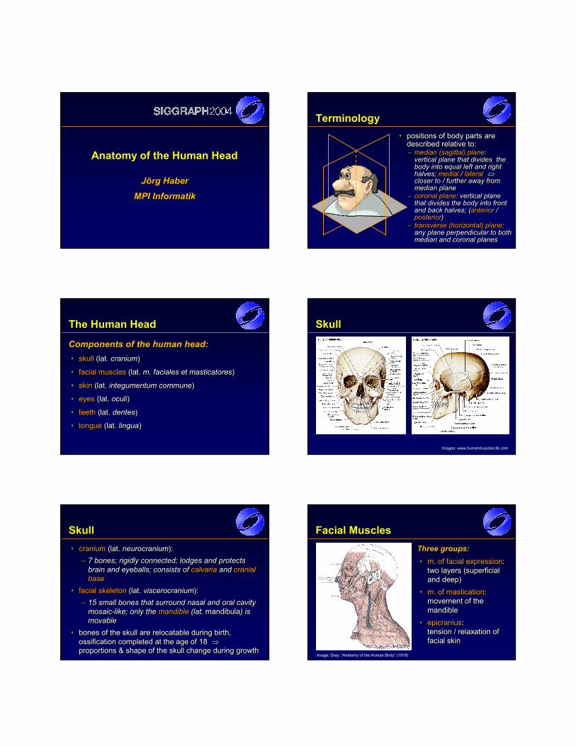
Terminology• positions of body parts are
described relative to:•• positions of body parts are positions of body parts are
described relative to:described relative to:– median (sagittal) plane:
vertical plane that divides the body into equal left and right halves; medial / lateral ⇔closer to / further away from median plane
–– median (sagittal) planemedian (sagittal) plane: : vertical plane that divides the vertical plane that divides the body into equal left and right body into equal left and right halves; halves; medialmedial / / laterallateral ⇔⇔closer to / further away from closer to / further away from median planemedian plane
– transverse (horizontal) plane: any plane perpendicular to both median and coronal planes
–– transverse (horizontal) planetransverse (horizontal) plane: : any plane perpendicular to both any plane perpendicular to both median and coronal planesmedian and coronal planes
– coronal plane: vertical plane that divides the body into front and back halves; (anterior / posterior)
–– coronal planecoronal plane: vertical plane : vertical plane that divides the body into front that divides the body into front and back halves; (and back halves; (anterioranterior / / posteriorposterior) )
The Human Head
Components of the human head:• skull (lat. cranium)
• facial muscles (lat. m. faciales et masticatores)
• skin (lat. integumentum commune)
• eyes (lat. oculi)
• teeth (lat. dentes)
• tongue (lat. lingua)
Components of the human head:Components of the human head:•• skullskull (lat. (lat. craniumcranium))
•• facial musclesfacial muscles (lat. (lat. m.m. facialesfaciales etet masticatoresmasticatores))
•• skinskin (lat.(lat. integumentumintegumentum communecommune))
•• eyeseyes (lat.(lat. oculioculi))
•• teethteeth (lat.(lat. dentesdentes))
•• tonguetongue (lat. (lat. lingualingua))
Skull
Images: www.humanmuscles.8k.com
Skull• cranium (lat. neurocranium):
– 7 bones; rigidly connected; lodges and protects brain and eyeballs; consists of calvaria and cranial base
• facial skeleton (lat. viscerocranium):– 15 small bones that surround nasal and oral cavity
mosaic-like; only the mandible (lat. mandibula) is movable
• bones of the skull are relocatable during birth, ossification completed at the age of 18 ⇒proportions & shape of the skull change during growth
•• craniumcranium (lat. (lat. neurocraniumneurocranium): ): –– 7 bones; rigidly connected; lodges and protects 7 bones; rigidly connected; lodges and protects
brain and brain and eyeballs; consistseyeballs; consists ofof calvariacalvaria and and cranial cranial basebase
•• facial skeletonfacial skeleton (lat. (lat. viscerocraniumviscerocranium):):–– 15 15 smallsmall bones that surround nasal and oral cavity bones that surround nasal and oral cavity
mosaicmosaic--like; only the like; only the mandiblemandible (lat. (lat. mandibulamandibula) is ) is movablemovable
•• bones of the skull are relocatable during birth, bones of the skull are relocatable during birth, ossification completed at the age of 18ossification completed at the age of 18 ⇒⇒proportions & shape of the skull change during growthproportions & shape of the skull change during growth
Facial MusclesThree groups:• m. of facial expression:
two layers (superficial and deep)
• m. of mastication: movement of the mandible
• epicranius: tension / relaxation of facial skin
Three groups:Three groups:•• m. of facial expressionm. of facial expression: :
two layers (superficial two layers (superficial and deep)and deep)
•• m. of masticationm. of mastication: : movement of the movement of the mandiblemandible
•• epicraniusepicranius: : tension / relaxation of tension / relaxation of facial skinfacial skin
Image: Gray: “Anatomy of the Human Body” (1918)
Facial Muscles
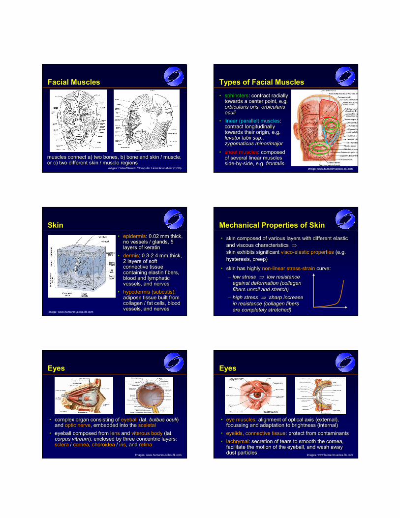
muscles connect a) two bones, b) bone and skin / muscle, or c) two different skin / muscle regionsmuscles connect a) two bones, b) bone and skin / muscle, muscles connect a) two bones, b) bone and skin / muscle, or c) two different skin / muscle regionsor c) two different skin / muscle regions
Images: Parke/Waters: “Computer Facial Animation” (1996)
Types of Facial Muscles
• sphincters: contract radially towards a center point, e.g. orbicularis oris, orbicularis oculi
•• sphincterssphincters: contract radially : contract radially towards a center point, e.g. towards a center point, e.g. orbicularis orisorbicularis oris, , orbicularis orbicularis oculioculi
Image: www.humanmuscles.8k.com
• sheet muscles: composed of several linear muscles side-by-side, e.g. frontalis
•• sheet musclessheet muscles: composed : composed of several linear muscles of several linear muscles sideside--byby--side, e.g. side, e.g. frontalisfrontalis
• linear (parallel) muscles: contract longitudinally towards their origin, e.g. levator labii sup., zygomaticus minor/major
•• linear (parallel) muscleslinear (parallel) muscles: : contract longitudinally contract longitudinally towards their origin, e.g. towards their origin, e.g. levator labii sup.levator labii sup., , zygomaticus minor/majorzygomaticus minor/major
Skin• epidermis: 0.02 mm thick,
no vessels / glands, 5 layers of keratin
• dermis: 0.3-2.4 mm thick, 2 layers of soft connective tissue containing elastin fibers, blood and lymphatic vessels, and nerves
• hypodermis (subcutis): adipose tissue built from collagen / fat cells, blood vessels, and nerves
•• epidermisepidermis: 0.02 mm thick, : 0.02 mm thick, no vessels / glands, 5 no vessels / glands, 5 layers of keratin layers of keratin
•• dermisdermis: 0.3: 0.3--2.4 mm thick, 2.4 mm thick, 2 layers of soft 2 layers of soft connective tissue connective tissue containing elastin fibers, containing elastin fibers, blood and lymphatic blood and lymphatic vessels, and nerves vessels, and nerves
•• hypodermis (subcutis)hypodermis (subcutis): : adipose tissue built from adipose tissue built from collagen / fat cells, blood collagen / fat cells, blood vessels, and nervesvessels, and nerves
Image: www.humanmuscles.8k.com
Mechanical Properties of Skin• skin composed of various layers with different elastic
and viscous characteristics ⇒skin exhibits significant visco-elastic properties (e.g. hysteresis, creep)
• skin has highly non-linear stress-strain curve: – low stress ⇒ low resistance
against deformation (collagen fibers unroll and stretch)
– high stress ⇒ sharp increase in resistance (collagen fibers are completely stretched)
•• skin composed of various layers with different elastic skin composed of various layers with different elastic and viscous characteristics and viscous characteristics ⇒⇒skin exhibits significant skin exhibits significant viscovisco--elastic propertieselastic properties (e.g. (e.g. hysteresis, creep)hysteresis, creep)
•• skin has highly skin has highly nonnon--linear stresslinear stress--strainstrain curve: curve: –– low stress low stress ⇒⇒ low resistance low resistance
against deformation (collagen against deformation (collagen fibers unroll and stretch)fibers unroll and stretch)
–– high stress high stress ⇒⇒ sharp increase sharp increase in resistance (collagen fibers in resistance (collagen fibers are completely stretched)are completely stretched)
Eyes
• complex organ consisting of eyeball (lat. bulbus oculi) and optic nerve, embedded into the sceletal
• eyeball composed from lens and viterous body (lat. corpus vitreum), enclosed by three concentric layers: sclera / cornea, choroidea / iris, and retina
•• complex organ consisting of complex organ consisting of eyeballeyeball (lat.(lat. bulbus oculibulbus oculi) ) and and optic nerveoptic nerve, embedded into the , embedded into the sceletal sceletal
•• eyeballeyeball composed from composed from lenslens andand viterous bodyviterous body (lat. (lat. corpuscorpus vitreumvitreum),), enclosed by three concentric layers: enclosed by three concentric layers: sclerasclera / / corneacornea, , choroideachoroidea / / irisiris,, andand retinaretina
Images: www.humanmuscles.8k.com
Eyes
• eye muscles: alignment of optical axis (external), focussing and adaptation to brightness (internal)
• eyelids, connective tissue: protect from contaminants• lachrymal: secretion of tears to smooth the cornea,
facilitate the motion of the eyeball, and wash away dust particles
•• eye muscleseye muscles: alignment of optical axis (external), : alignment of optical axis (external), focussing and adaptation to brightness (internal)focussing and adaptation to brightness (internal)
•• eyelids, connective tissueeyelids, connective tissue:: protect from contaminantsprotect from contaminants•• lachrymallachrymal:: secretion of tears to smooth the cornea, secretion of tears to smooth the cornea,
facilitate the motion of the eyeball, and wash away facilitate the motion of the eyeball, and wash away dust particlesdust particles Images: www.humanmuscles.8k.com
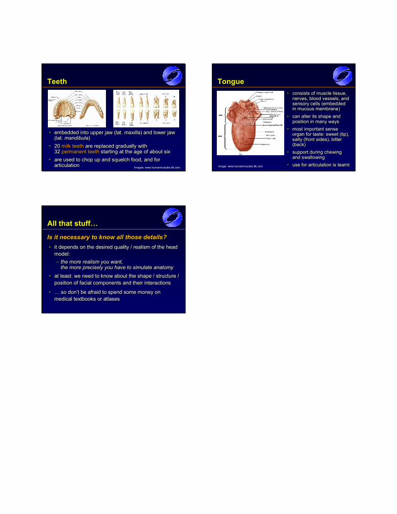
Teeth
• embedded into upper jaw (lat. maxilla) and lower jaw(lat. mandibula)
• 20 milk teeth are replaced gradually with 32 permanent teeth starting at the age of about six
• are used to chop up and squelch food, and for articulation
•• embedded into upper jawembedded into upper jaw (lat. (lat. maxillamaxilla) ) andand lower jawlower jaw(lat.(lat. mandibulamandibula))
•• 2020 milk teethmilk teeth are replaced gradually with are replaced gradually with 32 32 permanent teethpermanent teeth starting at the age of about six starting at the age of about six
•• are used to chop up and squelch food, and for are used to chop up and squelch food, and for articulationarticulation Images: www.humanmuscles.8k.com
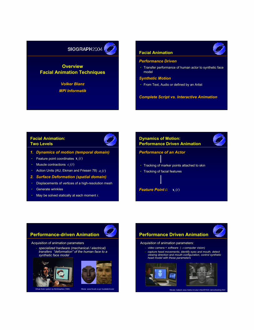
Tongue• consists of muscle tissue,
nerves, blood vessels, and sensory cells (embedded in mucous membrane)
• can alter its shape and position in many ways
• most important sense organ for taste: sweet (tip),salty (front sides), bitter (back)
• support during chewing and swallowing
• use for articulation is learnt
•• consists of muscle tissue, consists of muscle tissue, nerves, blood vessels, and nerves, blood vessels, and sensory cellssensory cells ((embedded embedded in mucous membrane)in mucous membrane)
•• can alter its shape and can alter its shape and position in many waysposition in many ways
•• most important sense most important sense organ for taste:organ for taste: sweetsweet ((tip),tip),saltysalty ((front sides),front sides), bitter bitter ((back)back)
•• support during chewing support during chewing and swallowingand swallowing
•• use for articulation is learntuse for articulation is learntImage: www.humanmuscles.8k.com
All that stuff…
Is it necessary to know all those details?• it depends on the desired quality / realism of the head
model:– the more realism you want,
the more precisely you have to simulate anatomy • at least: we need to know about the shape / structure /
position of facial components and their interactions
• … so don’t be afraid to spend some money on medical textbooks or atlases
Is it necessary to know all those details?Is it necessary to know all those details?•• it depends on the desired quality / realism of the head it depends on the desired quality / realism of the head
model:model:–– the more realism you want, the more realism you want,
the more precisely you have to simulate anatomy the more precisely you have to simulate anatomy •• at least: we need to know about the shape / structure / at least: we need to know about the shape / structure /
position of facial components and their interactionsposition of facial components and their interactions
•• … so don’t be afraid to spend some money on … so don’t be afraid to spend some money on medical textbooks or atlases medical textbooks or atlases
OverviewFacial Animation Techniques
Volker BlanzMPI InformatikVolker BlanzVolker Blanz
MPIMPI InformatikInformatik
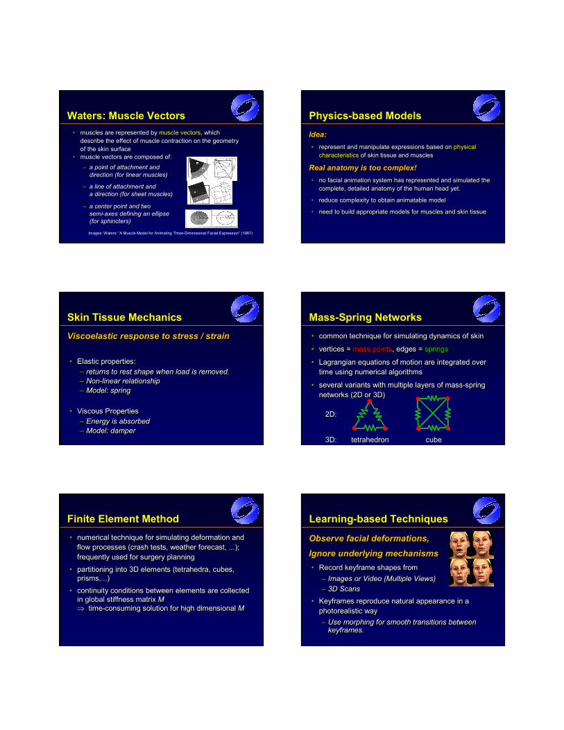
Facial Animation
Performance Driven• Transfer performance of human actor to synthetic face
model
Synthetic Motion• From Text, Audio or defined by an Artist
Complete Script vs. Interactive Animation
Performance DrivenPerformance Driven•• Transfer performance of human actor to synthetic face Transfer performance of human actor to synthetic face
modelmodel
Synthetic MotionSynthetic Motion•• From Text, Audio or defined by an ArtistFrom Text, Audio or defined by an Artist
Complete Script vs. Interactive AnimationComplete Script vs. Interactive Animation
Facial Animation:Two Levels
1. Dynamics of motion (temporal domain)• Feature point coordinates
• Muscle contractions
• Action Units (AU, Ekman and Friesen 78)
2. Surface Deformation (spatial domain)• Displacements of vertices of a high-resolution mesh
• Generate wrinkles
• May be solved statically at each moment t.
1.1. Dynamics of motion (temporal domain)Dynamics of motion (temporal domain)•• Feature point coordinatesFeature point coordinates
•• Muscle contractionsMuscle contractions
•• Action Units (AU, Action Units (AU, Ekman Ekman and Friesen 78)and Friesen 78)
2.2. Surface Deformation (spatial domain)Surface Deformation (spatial domain)•• Displacements of vertices of a highDisplacements of vertices of a high--resolution meshresolution mesh
•• Generate wrinklesGenerate wrinkles
•• May be solved statically at each moment May be solved statically at each moment t.t.
)(tix )(tix)(tci )(tci
)(tai )(tai
Performance of an Actor
• Tracking of marker points attached to skin
• Tracking of facial features
Feature Point i:
Performance of an ActorPerformance of an Actor
•• Tracking of marker points attached to skinTracking of marker points attached to skin
•• Tracking of facial featuresTracking of facial features
Feature Point Feature Point ii: :
Dynamics of Motion:Performance Driven Animation
)(tix )(tix
Performance-driven AnimationAcquisition of animation parameters
- specialized hardware (mechanical / electrical) transfers “deformation” of the human face to a synthetic face model
Acquisition of animation parametersAcquisition of animation parameters-- specialized hardware (mechanical / electrical) specialized hardware (mechanical / electrical)
transfers transfers “deformation” of the human face to a “deformation” of the human face to a synthetic face modelsynthetic face model
Movie: www.his.atr.co.jp/~kuratate/movie/Virtual Actor system by SimGraphics (1994)
Performance Driven AnimationAcquisition of animation parameters:
– video camera + software (→ computer vision)– capture head movements, identify eyes and mouth, detect
viewing direction and mouth configuration, control synthetic head model with these parameters
Acquisition of animation parameters:Acquisition of animation parameters:–– video camera + software (video camera + software (→→ computer visioncomputer vision))–– capture head movements, identify eyes and mouth, detect capture head movements, identify eyes and mouth, detect
viewing direction and mouth configuration, control synthetic viewing direction and mouth configuration, control synthetic head model with these parametershead model with these parameters
Movies: baback.www.media.mit.edu/~irfan/DFACE.demo/tracking.html

Dynamics of Motion:Voice Puppetry
Brand, Siggraph99
Audio
• Hidden Markov Model– Trained from Video & Audio data
26 Feature Points i:
Brand, SiggBrand, Siggraph99raph99
AudioAudio
•• Hidden Markov ModelHidden Markov Model–– Trained from Video & Audio dataTrained from Video & Audio data
26 Feature Points 26 Feature Points ii: : )(tix )(tix
Dynamics of Motion:Key-Frame Animation
Text-To-Speech Expression Models Artist
Key-Frames (Morph Targets)
Blending for Coarticulation Simple Linear Smooth
(Cohen, Massaro) Transition Trajectory
Feature points or Muscle contractions or AU
TextText--ToTo--Speech Expression Models ArtistSpeech Expression Models Artist
KeyKey--Frames (Morph Targets)Frames (Morph Targets)
Blending for Blending for Coarticulation Coarticulation Simple Linear SmoothSimple Linear Smooth
(Cohen, (Cohen, MassaroMassaro) ) Transition TrajectoryTransition Trajectory
Feature points or Muscle contractions or AUFeature points or Muscle contractions or AU
Key Frame Animation
Types of interpolation:• convex combination (linear int., blending, morphing):
v : scalar or vector (position, color,…)
• non-linear interpolation: e.g. trigonometric functions, splines, …; useful for displaying dynamics (acceleration, slow-down)
• segmental interpolation: different interpolation values / types for independent regions (e.g. eyes, mouth);
⇒ decoupling of emotion and speech animation
Types of interpolation:Types of interpolation:•• convex combinationconvex combination ((linear int., blendinglinear int., blending, , morphingmorphing): ):
vv : scalar or vector (position, color,…): scalar or vector (position, color,…)
•• nonnon--linear interpolationlinear interpolation: e.g. trigonometric functions, splines, …; : e.g. trigonometric functions, splines, …; useful for displaying dynamics (acceleration, slowuseful for displaying dynamics (acceleration, slow--down)down)
•• segmental interpolationsegmental interpolation: different interpolation values / types for : different interpolation values / types for independent regions (e.g. eyes, mouth);independent regions (e.g. eyes, mouth);
⇒⇒ decoupling of emotion and speech animationdecoupling of emotion and speech animation
)()( 101 21 ≤α≤⋅α−+⋅α= vvv )()( 101 21 ≤α≤⋅α−+⋅α= vvv
Surface DeformationsMain Approaches
1. Parametric Models
2. Physics-based Animation
3. Learning-Based Animation• Image-Based
• 3D Models
1.1. Parametric ModelsParametric Models
2.2. PhysicsPhysics--based Animationbased Animation
3.3. LearningLearning--Based AnimationBased Animation•• ImageImage--BasedBased
•• 3D Models3D Models
Direct Parameterization
Idea:• perform facial animation using a set of control
parameters that manipulate (local) regions / features
What parameterization should be used?• ideal universal parameterization:
– small set of intuitive control parameters– any possible face with any possible expression can
be specified
Idea:Idea:•• perform facial animation using a perform facial animation using a set of control set of control
parametersparameters that manipulate (local) regions / featuresthat manipulate (local) regions / features
What parameterization should be used?What parameterization should be used?•• ideal universal parameterization:ideal universal parameterization:
–– small set of intuitive control parameterssmall set of intuitive control parameters–– any possible face with any possible expression can any possible face with any possible expression can
be specified be specified
Parametric Models I• F. I. Parke: “Parameterized Models for Facial
Animation”, IEEE CGA, 2(9):61-68, Nov. 1982– 10 control parameters for facial expressions– ~20 parameters for definition of facial conformation
• K. Waters: “A Muscle Model for Animating Three-Dimensional Facial Expression”, SIGGRAPH ’87, pp. 17-24, July 1987– deforms skin using “muscle vectors”
•• F. I.F. I. ParkeParke: “: “Parameterized Models for Facial Parameterized Models for Facial AnimationAnimation”, IEEE CGA, 2(9):61”, IEEE CGA, 2(9):61--68, Nov. 198268, Nov. 1982–– 10 control parameters for facial expressions10 control parameters for facial expressions–– ~20 parameters for definition of facial conformation~20 parameters for definition of facial conformation
•• K. Waters: “K. Waters: “A Muscle Model for Animating ThreeA Muscle Model for Animating Three--Dimensional Facial ExpressionDimensional Facial Expression”, SIGGRAPH ’87, ”, SIGGRAPH ’87, pp. 17pp. 17--24, July 198724, July 1987–– deforms skin using “muscle vectors”deforms skin using “muscle vectors”
Parametric Models II• N. Magnenat-Thalmann et al.: “Abstract Muscle Action
Procedures for Human Face Animation”, The Visual Computer, 3(5):290-297, March 1988– pseudo muscles based on empirical models– muscle actions are (complex) combinations of
FACS action units
• J. E. Chadwick et al.: “Layered Construction for Deformable Animated Characters”, SIGGRAPH ‘89, pp. 243-252, July 1989– freeform deformations (FFD), pseudo muscles
•• N.N. MagnenatMagnenat--ThalmannThalmann et al.: “et al.: “Abstract Muscle Action Abstract Muscle Action Procedures for Human Face AnimationProcedures for Human Face Animation”, The Visual ”, The Visual Computer, 3(5):290Computer, 3(5):290--297, March 1988297, March 1988–– pseudo muscles based on empirical modelspseudo muscles based on empirical models–– muscle actions are (complex) combinations of muscle actions are (complex) combinations of
FACS action unitsFACS action units
•• J. E. Chadwick et al.: “J. E. Chadwick et al.: “Layered Construction for Layered Construction for Deformable Animated CharactersDeformable Animated Characters”, SIGGRAPH ‘89, ”, SIGGRAPH ‘89, pp. 243pp. 243--252, July 1989252, July 1989–– freeform deformations (FFD), pseudo muscles freeform deformations (FFD), pseudo muscles
Parke’s Parametric Face Model
•• polygonal face mesh (~300 polygonal face mesh (~300 triangles + quads), symmetrical, triangles + quads), symmetrical, edges aligned to facial feature edges aligned to facial feature lineslines
•• two types of parameters:two types of parameters:–– 10 expression parameters10 expression parameters–– about 20 conformation about 20 conformation
parametersparameters•• five different ways how five different ways how
parameters modify facial parameters modify facial geometrygeometry
Parke: Expression Parameters• eyes:
– dilation of pupils, opening / closing of eyelids, position and shape of eyebrows, viewing direction
• mouth:– rotation of mandible, width and shape of the mouth,
position of upper lip, position of mouth corners• additional parameters (suggested):
– head rotation, size of nostrils
•• eyes:eyes:–– dilation of pupilsdilation of pupils, opening / closing of eyelids, , opening / closing of eyelids,
position and shape of eyebrows, viewing directionposition and shape of eyebrows, viewing direction
•• mouth:mouth:–– rotation of mandible, width and shape of the mouth, rotation of mandible, width and shape of the mouth,
position of upper lip, position of mouth cornersposition of upper lip, position of mouth corners
•• additional parameters (suggested):additional parameters (suggested):–– head rotation, size of nostrilshead rotation, size of nostrils
Parke: Conformation Parameters• aspect ratio of the face
• length and shape of the neck
• shape (= relative position of assigned vertices) of chin, forehead, cheeks, and cheekbones
• size of eyelids, eyeballs, iris; position of the eyes
• jaw width
• length of the nose; width of nose bridge and nostril
• relative size of chin, forehead, and mouth-nose-eyes-part w.r.t. remaining face parts
• color of skin, eyebrows, iris, and lips
•• aspect ratio of the faceaspect ratio of the face
•• length and shape of the necklength and shape of the neck
•• shape (= relative position of assigned vertices) of chin, shape (= relative position of assigned vertices) of chin, forehead, cheeks, and cheekbonesforehead, cheeks, and cheekbones
•• size of eyelids, eyeballs, iris; position of the eyessize of eyelids, eyeballs, iris; position of the eyes
•• jaw widthjaw width
•• length of the nose; width of nose bridge and nostrillength of the nose; width of nose bridge and nostril
•• relative size of chin, forehead, and mouthrelative size of chin, forehead, and mouth--nosenose--eyeseyes--part w.r.t. part w.r.t. remaining face partsremaining face parts
•• color of skin, eyebrows, iris, and lipscolor of skin, eyebrows, iris, and lips
Parke:Results The Face Model by Waters
•• polygonal face mesh: polygonal face mesh:
•• 201 quads + 35 triangles201 quads + 35 triangles
•• 10 different muscles:10 different muscles:–– 9 linear muscles (symmetrical 9 linear muscles (symmetrical
left/right)left/right)–– 1 sphincter (1 sphincter (orbicularis orisorbicularis oris))
•• additional parameters:additional parameters:–– jaw rotationjaw rotation–– viewing directionviewing direction–– opening of eyelidsopening of eyelids
•• muscles are represented by muscles are represented by muscle vectorsmuscle vectors, which , which describe the effect of muscle contraction on the geometry describe the effect of muscle contraction on the geometry of the skin surfaceof the skin surface
Images: Waters: “A Muscle Model for Animating Three-Dimensional Facial Expression” (1987)
•• muscle vectors are composed of:muscle vectors are composed of:
–– a point of attachment and a point of attachment and a a direction (for linear muscles)direction (for linear muscles)
–– a line of attachment and a line of attachment and a direction (for sheet muscles)a direction (for sheet muscles)
–– a center point and two a center point and two semisemi--axes defining an ellipse axes defining an ellipse (for sphincters)(for sphincters)
Waters: Muscle Vectors Physics-based Models
Idea:• represent and manipulate expressions based on physical
characteristics of skin tissue and muscles
Real anatomy is too complex!• no facial animation system has represented and simulated the
complete, detailed anatomy of the human head yet.
• reduce complexity to obtain animatable model
• need to build appropriate models for muscles and skin tissue
Idea:Idea:•• represent and manipulate expressions based on represent and manipulate expressions based on physical physical
characteristicscharacteristics of skin tissue and musclesof skin tissue and muscles
Real anatomy is too complex!Real anatomy is too complex!•• no facial animation system has represented and simulated the no facial animation system has represented and simulated the
complete, detailed anatomy of the human head yet.complete, detailed anatomy of the human head yet.
•• reduce complexity to obtain animatable modelreduce complexity to obtain animatable model
•• need to build appropriate models for muscles and skin tissue need to build appropriate models for muscles and skin tissue
Skin Tissue Mechanics
Viscoelastic response to stress / strain
• Elastic properties: – returns to rest shape when load is removed. – Non-linear relationship– Model: spring
• Viscous Properties– Energy is absorbed– Model: damper
Viscoelastic Viscoelastic response to stress / strainresponse to stress / strain
•• Elastic properties: Elastic properties: –– returns to rest shape when load is removed. returns to rest shape when load is removed. –– NonNon--linear relationshiplinear relationship–– Model: springModel: spring
•• Viscous PropertiesViscous Properties–– Energy is absorbedEnergy is absorbed–– Model: damperModel: damper
Mass-Spring Networks• common technique for simulating dynamics of skin
• vertices = mass points, edges = springs
• Lagrangian equations of motion are integrated over time using numerical algorithms
• several variants with multiple layers of mass-spring networks (2D or 3D)
•• common technique for simulating dynamics of skincommon technique for simulating dynamics of skin
•• vertices = vertices = mass pointsmass points, edges = , edges = springssprings
•• Lagrangian equations of motion are integrated over Lagrangian equations of motion are integrated over time using numerical algorithmstime using numerical algorithms
•• several variants with multiple layers of massseveral variants with multiple layers of mass--spring spring networks (2D or 3D)networks (2D or 3D)
2D:2D:
3D: tetrahedron cube3D: tetrahedron cube
Finite Element Method• numerical technique for simulating deformation and
flow processes (crash tests, weather forecast, ...); frequently used for surgery planning
• partitioning into 3D elements (tetrahedra, cubes, prisms,...)
• continuity conditions between elements are collected in global stiffness matrix M⇒ time-consuming solution for high dimensional M
•• numerical technique for simulating deformation and numerical technique for simulating deformation and flow processes (crash tests, weather forecast, ...); flow processes (crash tests, weather forecast, ...); frequently used for surgery planningfrequently used for surgery planning
•• partitioning into 3D elements (tetrahedra, cubespartitioning into 3D elements (tetrahedra, cubes, , prisms,prisms,...)...)
•• continuity conditions between elementscontinuity conditions between elements are collected are collected in global stiffness matrix in global stiffness matrix MM⇒⇒ timetime--consuming solution for high dimensional consuming solution for high dimensional MM
Learning-based Techniques
Observe facial deformations, Ignore underlying mechanisms• Record keyframe shapes from
– Images or Video (Multiple Views)– 3D Scans
• Keyframes reproduce natural appearance in a photorealistic way– Use morphing for smooth transitions between
keyframes.
Observe facial deformations, Observe facial deformations,
Ignore underlying mechanismsIgnore underlying mechanisms•• Record Record keyframekeyframe shapes fromshapes from
–– Images or Video (Multiple Views)Images or Video (Multiple Views)–– 3D Scans3D Scans
•• Keyframes Keyframes reproduce natural appearance in a reproduce natural appearance in a photorealistic photorealistic wayway–– Use morphing for smooth transitions between Use morphing for smooth transitions between
keyframeskeyframes..
Parameterized Face Models
Fred ParkeTexas A&M University
Fred ParkeFred ParkeTexas A&M UniversityTexas A&M University
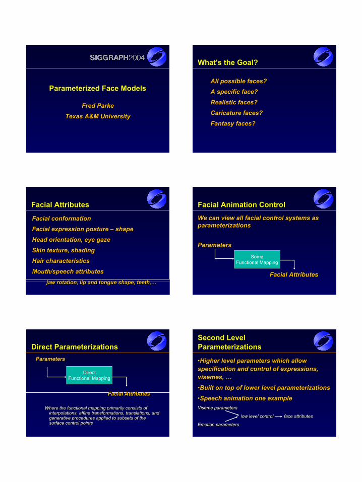
What's the Goal?
All possible faces?All possible faces?A specific face?A specific face?Realistic faces?Realistic faces?Caricature faces?Caricature faces?Fantasy faces?Fantasy faces?
Facial Attributes
Facial conformationFacial expression posture – shapeHead orientation, eye gazeSkin texture, shadingHair characteristicsMouth/speech attributes
jaw rotation, lip and tongue shape, teeth,…
Facial conformationFacial conformationFacial expression posture Facial expression posture –– shapeshapeHead orientation, eye gazeHead orientation, eye gazeSkin texture, shadingSkin texture, shadingHair characteristicsHair characteristicsMouth/speech attributesMouth/speech attributes
jaw rotation, lip and tongue shape, teeth,…jaw rotation, lip and tongue shape, teeth,…
Facial Animation Control
We can view all facial control systems as parameterizations
Parameters
Facial Attributes
We can view all facial control systems as We can view all facial control systems as parameterizationsparameterizations
ParametersParameters
Facial AttributesFacial Attributes
SomeFunctional Mapping
Direct ParameterizationsParameters
Facial Attributes
Where the functional mapping primarily consists of interpolations, affine transformations, translations, and generative procedures applied to subsets of the surface control points
ParametersParameters
Facial AttributesFacial Attributes
Where the functional mapping primarily consists of Where the functional mapping primarily consists of interpolations, affine transformations, translations, and interpolations, affine transformations, translations, and generative procedures applied to subsets of the generative procedures applied to subsets of the surface control pointssurface control points
DirectFunctional Mapping
Second Level Parameterizations
•Higher level parameters which allow specification and control of expressions, visemes, …•Built on top of lower level parameterizations•Speech animation one exampleViseme parameters
low level control face attributes
Emotion parameters
••Higher level parameters which allow Higher level parameters which allow specification and control of expressions, specification and control of expressions, visemes, …visemes, …••Built on top of lower level parameterizationsBuilt on top of lower level parameterizations••Speech animation one exampleSpeech animation one exampleViseme parametersViseme parameters
low level controllow level control face attributesface attributes
Emotion parametersEmotion parameters
Universal Parameterization
Allows specification of any expression and facial attribute set, for any possible faceDon’t exist yetA lot of work on expression parameters
– FACS provides one basis
Not much work on conformation parameters– Anthropometry, principle component analysis
Allows specification of any expression and Allows specification of any expression and facial attribute set, for any possible facefacial attribute set, for any possible faceDon’t exist yetDon’t exist yetA lot of work on expression parametersA lot of work on expression parameters
–– FACS provides one basisFACS provides one basis
Not much work on conformation parametersNot much work on conformation parameters–– Anthropometry, principle component analysisAnthropometry, principle component analysis
Parameter Orthogonality
Expression parameters control expression for a given face
Conformation parameters select or specify a specific face from the universe of possible face
Should be orthogonal • Manipulating expression should not effect conformation
• Manipulating conformation should not effect expression
Expression parameters control expression for a Expression parameters control expression for a given facegiven face
Conformation parameters select or specify a Conformation parameters select or specify a specific face from the universe of possible facespecific face from the universe of possible face
Should be orthogonal Should be orthogonal •• Manipulating expression should not effect conformationManipulating expression should not effect conformation
•• Manipulating conformation should not effect expressionManipulating conformation should not effect expression
Facial Expressions
Capable facial models allow wide range of Capable facial models allow wide range of expressionexpression
Including the universal expressionsIncluding the universal expressions•• anger, fear, surprise, disgust, happiness, anger, fear, surprise, disgust, happiness,
sadnesssadness
Capable facial animation are able to Capable facial animation are able to express and convey ‘emotion’express and convey ‘emotion’
Posture and expression display emotionPosture and expression display emotion
FACS
Facial Action Coding System
Developed by Ekman and Friesen to study and quantify facial expression across cultures
Consists of about 66 ‘facial actions’
While not intended, has been adopted by the facial animation community as an effective expression parameterization scheme
Facial Action Coding SystemFacial Action Coding System
Developed by Ekman and Friesen to study and Developed by Ekman and Friesen to study and quantify facial expression across culturesquantify facial expression across cultures
Consists of about 66 ‘facial actions’Consists of about 66 ‘facial actions’
While not intended, has been adopted by the facial While not intended, has been adopted by the facial animation community as an effective expression animation community as an effective expression parameterization schemeparameterization scheme
Animation Control Methods
•• Interpolation of expression posesInterpolation of expression poses•• Interpolation of control parameters to drive Interpolation of control parameters to drive
a parameterized modela parameterized model•• Emulation of muscle actions based on Emulation of muscle actions based on
interpolated muscle parametersinterpolated muscle parameters
Shape Interpolation
Earliest (simplest) Animation Technique Simple interpolation of entire face• earliest animation technique
Interpolation of ‘independent’ facial regions• upper face, lower face - Kleiser 1989
Interpolation in n-dimensional face spaces
Earliest (simplest) Animation Technique Earliest (simplest) Animation Technique Simple interpolation of entire faceSimple interpolation of entire face•• earliest animation techniqueearliest animation technique
Interpolation of ‘independent’ facial regionsInterpolation of ‘independent’ facial regions•• upper face, lower face upper face, lower face -- Kleiser 1989Kleiser 1989
Interpolation in nInterpolation in n--dimensional face spacesdimensional face spaces
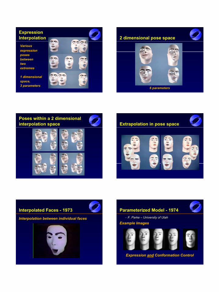
Expression Interpolation
Variousexpressionposesbetweentwoextremes
1 dimensionalspace,3 parameters
VariousVariousexpressionexpressionposesposesbetweenbetweentwotwoextremesextremes
1 dimensional1 dimensionalspace,space,3 parameters3 parameters
2 dimensional pose space
6 parameters6 parameters6 parameters
Poses within a 2 dimensional interpolation space Extrapolation in pose space
Interpolated Faces - 1973
Interpolation between individual facesInterpolation between individual facesInterpolation between individual faces
Parameterized Model - 1974– F. Parke – University of Utah
Example Images
Expression and Conformation Control
–– F. Parke F. Parke –– University of UtahUniversity of Utah
Example ImagesExample Images
Expression Expression andand Conformation ControlConformation Control
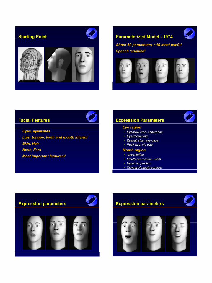
Starting Point Parameterized Model - 1974
About 50 parameters, ~10 most usefulSpeech ‘enabled’About 50 parameters, ~10 most usefulAbout 50 parameters, ~10 most usefulSpeech ‘enabled’Speech ‘enabled’
Facial Features
Eyes, eyelashesLips, tongue, teeth and mouth interiorSkin, HairNose, EarsMost important features?
Eyes, eyelashesEyes, eyelashesLips, tongue, teeth and mouth interiorLips, tongue, teeth and mouth interiorSkin, HairSkin, HairNose, EarsNose, EarsMost important features?Most important features?
Expression ParametersEye region• Eyebrow arch, separation• Eyelid opening• Eyeball size, eye gaze• Pupil size, iris size
Mouth region• Jaw rotation• Mouth expression, width• Upper lip position• Control of mouth corners
Eye regionEye region•• Eyebrow arch, separationEyebrow arch, separation•• Eyelid openingEyelid opening•• Eyeball size, eye gazeEyeball size, eye gaze•• Pupil size, iris sizePupil size, iris size
Mouth regionMouth region•• Jaw rotationJaw rotation•• Mouth expression, widthMouth expression, width•• Upper lip positionUpper lip position•• Control of mouth cornersControl of mouth corners
Expression parameters Expression parameters
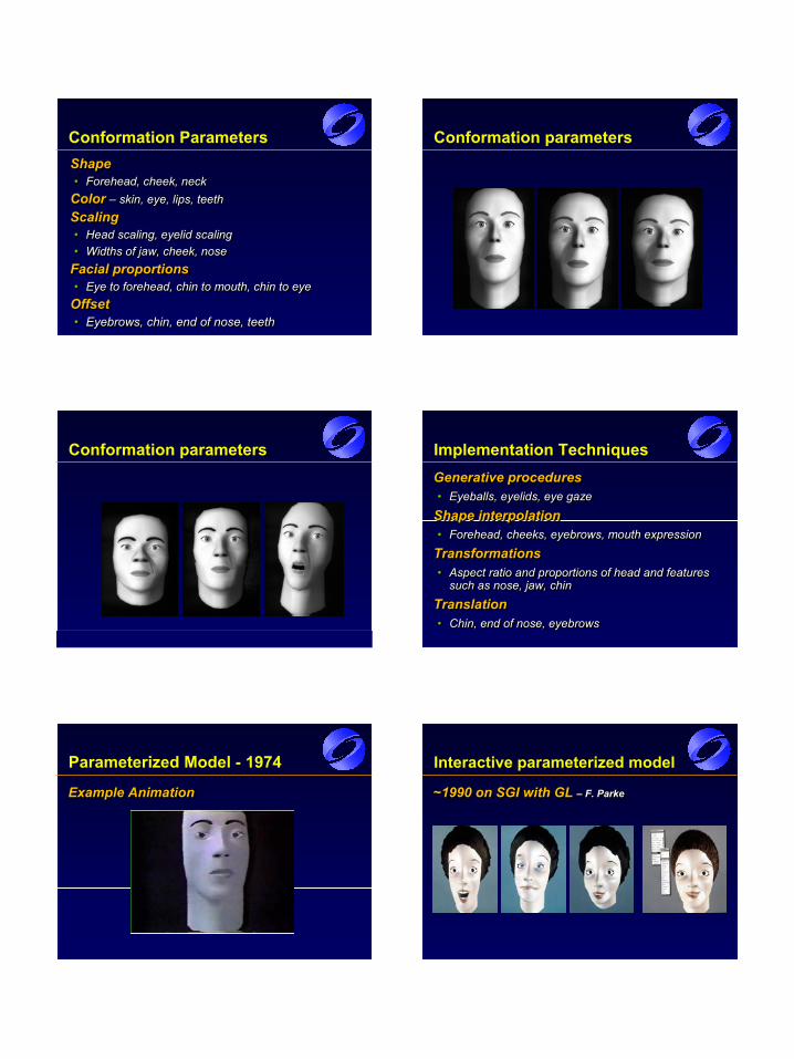
Conformation ParametersShape • Forehead, cheek, neck
Color – skin, eye, lips, teethScaling• Head scaling, eyelid scaling• Widths of jaw, cheek, nose
Facial proportions• Eye to forehead, chin to mouth, chin to eye
Offset • Eyebrows, chin, end of nose, teeth
Shape Shape •• Forehead, cheek, neckForehead, cheek, neck
Color Color –– skin, eye, lips, teethskin, eye, lips, teethScalingScaling•• Head scaling, eyelid scalingHead scaling, eyelid scaling•• Widths of jaw, cheek, noseWidths of jaw, cheek, nose
Facial proportionsFacial proportions•• Eye to forehead, chin to mouth, chin to eyeEye to forehead, chin to mouth, chin to eye
Offset Offset •• Eyebrows, chin, end of nose, teethEyebrows, chin, end of nose, teeth
Conformation parameters
Conformation parameters Implementation TechniquesGenerative procedures• Eyeballs, eyelids, eye gaze
Shape interpolation• Forehead, cheeks, eyebrows, mouth expression
Transformations• Aspect ratio and proportions of head and features
such as nose, jaw, chinTranslation• Chin, end of nose, eyebrows
Generative proceduresGenerative procedures•• Eyeballs, eyelids, eye gazeEyeballs, eyelids, eye gaze
Shape interpolationShape interpolation•• Forehead, cheeks, eyebrows, mouth expressionForehead, cheeks, eyebrows, mouth expression
TransformationsTransformations•• Aspect ratio and proportions of head and features Aspect ratio and proportions of head and features
such as nose, jaw, chinsuch as nose, jaw, chin
TranslationTranslation•• Chin, end of nose, eyebrowsChin, end of nose, eyebrows
Parameterized Model - 1974
Example AnimationExample AnimationExample Animation
Interactive parameterized model
~1990 on SGI with GL – F. Parke~1990 on SGI with GL ~1990 on SGI with GL –– F. ParkeF. Parke
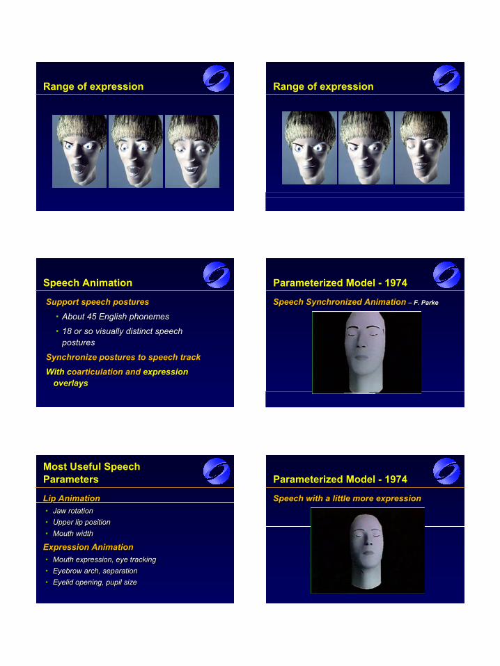
Range of expression Range of expression
Speech Animation
Support speech posturesSupport speech postures•• About 45 English phonemesAbout 45 English phonemes
•• 18 or so visually distinct speech 18 or so visually distinct speech posturespostures
Synchronize postures to speech trackSynchronize postures to speech trackWith With ccoarticulationoarticulation and and expression expression
overlaysoverlays
Parameterized Model - 1974
Speech Synchronized Animation – F. ParkeSpeech Synchronized Animation Speech Synchronized Animation –– F. ParkeF. Parke
Most Useful Speech Parameters
Lip Animation• Jaw rotation• Upper lip position• Mouth width
Expression Animation• Mouth expression, eye tracking• Eyebrow arch, separation• Eyelid opening, pupil size
Lip AnimationLip Animation•• Jaw rotationJaw rotation•• Upper lip positionUpper lip position•• Mouth widthMouth width
Expression AnimationExpression Animation•• Mouth expression, eye trackingMouth expression, eye tracking•• Eyebrow arch, separationEyebrow arch, separation•• Eyelid opening, pupil sizeEyelid opening, pupil size
Parameterized Model - 1974
Speech with a little more expressionSpeech with a little more expressionSpeech with a little more expression
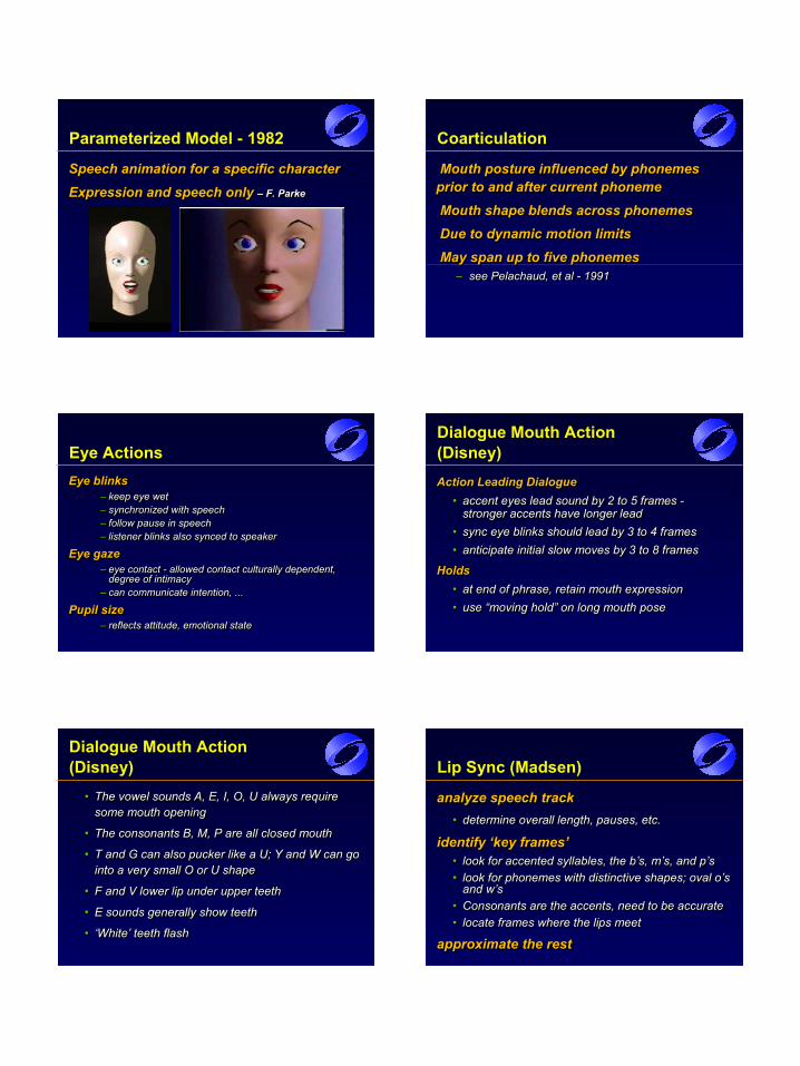
Parameterized Model - 1982
Speech animation for a specific characterExpression and speech only – F. Parke
Speech animation for a specific characterSpeech animation for a specific characterExpression and speech only Expression and speech only –– F. ParkeF. Parke
Coarticulation
Mouth posture influenced by phonemes prior to and after current phonemeMouth shape blends across phonemesDue to dynamic motion limitsMay span up to five phonemes
– see Pelachaud, et al - 1991
Mouth posture influenced by phonemes Mouth posture influenced by phonemes prior to and after current phonemeprior to and after current phonemeMouth shape blends across phonemesMouth shape blends across phonemesDue to dynamic motion limitsDue to dynamic motion limitsMay span up to five phonemesMay span up to five phonemes
–– see see PelachaudPelachaud, et al , et al -- 19911991
Eye ActionsEye blinks
– keep eye wet– synchronized with speech– follow pause in speech– listener blinks also synced to speaker
Eye gaze– eye contact - allowed contact culturally dependent,
degree of intimacy– can communicate intention, ...
Pupil size– reflects attitude, emotional state
Eye blinksEye blinks–– keep eye wetkeep eye wet–– synchronized with speechsynchronized with speech–– follow pause in speechfollow pause in speech–– listener blinks also synced to speakerlistener blinks also synced to speaker
Eye gazeEye gaze–– eye contact eye contact -- allowed contact culturally dependent, allowed contact culturally dependent,
degree of intimacydegree of intimacy–– can communicate intention, ...can communicate intention, ...
Pupil sizePupil size–– reflects attitude, emotional statereflects attitude, emotional state
Dialogue Mouth Action (Disney)
Action Leading Dialogue• accent eyes lead sound by 2 to 5 frames -
stronger accents have longer lead• sync eye blinks should lead by 3 to 4 frames• anticipate initial slow moves by 3 to 8 frames
Holds• at end of phrase, retain mouth expression• use “moving hold” on long mouth pose
Action Leading DialogueAction Leading Dialogue•• accent eyes lead sound by 2 to 5 frames accent eyes lead sound by 2 to 5 frames --
stronger accents have longer leadstronger accents have longer lead•• sync eye blinks should lead by 3 to 4 framessync eye blinks should lead by 3 to 4 frames•• anticipate initial slow moves by 3 to 8 framesanticipate initial slow moves by 3 to 8 frames
HoldsHolds•• at end of phrase, retain mouth expressionat end of phrase, retain mouth expression•• use “moving hold” on long mouth poseuse “moving hold” on long mouth pose
Dialogue Mouth Action (Disney)
• The vowel sounds A, E, I, O, U always require some mouth opening
• The consonants B, M, P are all closed mouth
• T and G can also pucker like a U; Y and W can go into a very small O or U shape
• F and V lower lip under upper teeth
• E sounds generally show teeth
• ‘White’ teeth flash
•• The vowel sounds A, E, I, O, U always require The vowel sounds A, E, I, O, U always require some mouth openingsome mouth opening
•• The consonants B, M, P are all closed mouthThe consonants B, M, P are all closed mouth
•• T and G can also pucker like a U; Y and W can go T and G can also pucker like a U; Y and W can go into a very small O or U shapeinto a very small O or U shape
•• F and V lower lip under upper teethF and V lower lip under upper teeth
•• E sounds generally show teethE sounds generally show teeth
•• ‘White’ teeth flash ‘White’ teeth flash
Lip Sync (Madsen)
analyze speech track• determine overall length, pauses, etc.
identify ‘key frames’• look for accented syllables, the b’s, m’s, and p’s• look for phonemes with distinctive shapes; oval o’s
and w’s• Consonants are the accents, need to be accurate• locate frames where the lips meet
approximate the rest
analyze speech trackanalyze speech track•• determine overall length, pauses, etc.determine overall length, pauses, etc.
identify ‘key frames’identify ‘key frames’•• look for accented syllables, the b’s, m’s, and p’slook for accented syllables, the b’s, m’s, and p’s•• look for phonemes with distinctive shapes; oval o’s look for phonemes with distinctive shapes; oval o’s
and w’sand w’s•• Consonants are the accents, need to be accurateConsonants are the accents, need to be accurate•• locate frames where the lips meetlocate frames where the lips meet
approximate the restapproximate the rest
Lip Movements (Madsen)
Realistic characters are the greatest challenge• invite comparison with real people
For cartoon characters• simplicity is secret of success
• attempts at extreme accuracy appear forced and unnatural
Realistic characters are the greatest Realistic characters are the greatest challengechallenge•• invite comparison with real peopleinvite comparison with real people
For cartoon charactersFor cartoon characters•• simplicity is secret of success simplicity is secret of success
•• attempts at extreme accuracy appear forced and attempts at extreme accuracy appear forced and unnaturalunnatural
Head Tilt Angle (Blair)
Head angle, direction of ‘look’, and head motion relative to body all contribute to expression
Example - a hand puppet depends mostly on head tilt and body posture without any phonetic mouthing or facial action
Changes in head tilt or head turns convey different emotions• affirmative ‘nod’, negative sideways shake, …
Head angle, direction of ‘look’, and head motion Head angle, direction of ‘look’, and head motion relative to body all contribute to expressionrelative to body all contribute to expression
Example Example -- a hand puppet depends mostly on head a hand puppet depends mostly on head tilt and body posture without any phonetic tilt and body posture without any phonetic mouthing or facial actionmouthing or facial action
Changes in head tilt or head turns convey different Changes in head tilt or head turns convey different emotionsemotions•• affirmative ‘nod’, negative sideways shake, …affirmative ‘nod’, negative sideways shake, …
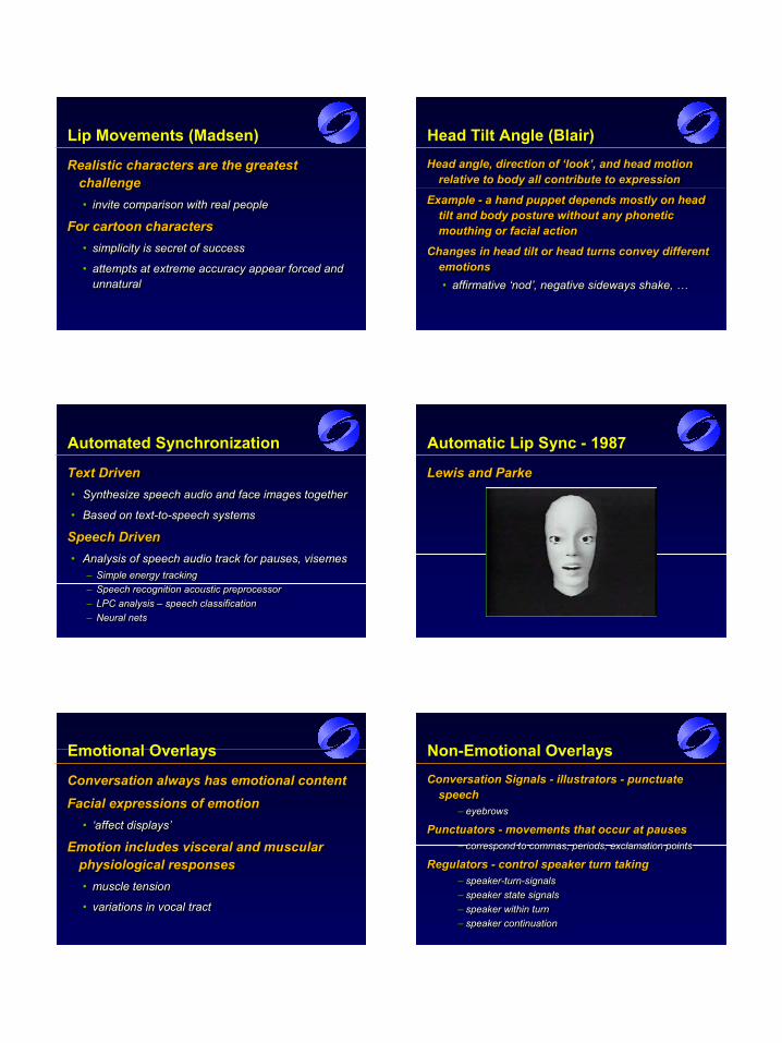
Automated Synchronization
Text Driven• Synthesize speech audio and face images together
• Based on text-to-speech systems
Speech Driven• Analysis of speech audio track for pauses, visemes
– Simple energy tracking– Speech recognition acoustic preprocessor– LPC analysis – speech classification– Neural nets
Text DrivenText Driven•• Synthesize speech audio and face images togetherSynthesize speech audio and face images together
•• Based on textBased on text--toto--speech systemsspeech systems
Speech DrivenSpeech Driven•• Analysis of speech audio track for pauses, visemesAnalysis of speech audio track for pauses, visemes
–– Simple energy trackingSimple energy tracking–– Speech recognition acoustic preprocessorSpeech recognition acoustic preprocessor–– LPC analysis LPC analysis –– speech classificationspeech classification–– Neural netsNeural nets
Automatic Lip Sync - 1987
Lewis and ParkeLewis and ParkeLewis and Parke
Emotional Overlays
Conversation always has emotional contentFacial expressions of emotion
• ‘affect displays’
Emotion includes visceral and muscular physiological responses• muscle tension
• variations in vocal tract
Conversation always has emotional contentConversation always has emotional contentFacial expressions of emotion Facial expressions of emotion
•• ‘affect displays’‘affect displays’
Emotion includes visceral and muscular Emotion includes visceral and muscular physiological responsesphysiological responses•• muscle tensionmuscle tension
•• variations in vocal tractvariations in vocal tract
Non-Emotional Overlays
Conversation Signals - illustrators - punctuate speech
– eyebrows
Punctuators - movements that occur at pauses– correspond to commas, periods, exclamation points
Regulators - control speaker turn taking– speaker-turn-signals– speaker state signals– speaker within turn– speaker continuation
Conversation Signals Conversation Signals -- illustrators illustrators -- punctuate punctuate speechspeech
–– eyebrowseyebrows
Punctuators Punctuators -- movements that occur at pausesmovements that occur at pauses–– correspond to commas, periods, exclamation pointscorrespond to commas, periods, exclamation points
Regulators Regulators -- control speaker turn takingcontrol speaker turn taking–– speakerspeaker--turnturn--signalssignals–– speaker state signalsspeaker state signals–– speaker within turnspeaker within turn–– speaker continuationspeaker continuation

Muscle Based Parameterizations
Parameters control the face through functions which emulate or simulate muscle actions
K. Waters – 1987Thalmann, et al – 1988
and many others since
Parameters control the face through Parameters control the face through functions which emulate or simulate functions which emulate or simulate muscle actionsmuscle actions
K. Waters K. Waters –– 19871987Thalmann, et al Thalmann, et al –– 19881988
and many others sinceand many others since
Waters’ Muscle Model - 1987
Models muscle induced displacement with geometric distortion functions which include first order elastic tissue propertiesThree kinds of muscle functions
– Linear, sphincter, and sheet
The muscle functions are located and aligned independently of the skin geometryThey have defined regions of influence
Models muscle induced displacement with Models muscle induced displacement with geometric distortion functions which include geometric distortion functions which include first order elastic tissue propertiesfirst order elastic tissue propertiesThree kinds of muscle functionsThree kinds of muscle functions
–– Linear, sphincter, and sheetLinear, sphincter, and sheet
The muscle functions are located and The muscle functions are located and aligned independently of the skin geometryaligned independently of the skin geometryThey have defined regions of influenceThey have defined regions of influence
Abstract Muscle Action Model– Thalmann, et al, 1988
Empirical pseudomuscle action proceduresEach works on a specific region of the faceEach emulates a muscle or group of closely related musclesLoosely patterned after FACS actionsGroups of ‘actions’ form ‘expressions’• such as ‘emotions’ and phonemes
–– Thalmann, et al, 1988Thalmann, et al, 1988
Empirical pseudomuscle action proceduresEmpirical pseudomuscle action proceduresEach works on a specific region of the faceEach works on a specific region of the faceEach emulates a muscle or group of closely Each emulates a muscle or group of closely related musclesrelated musclesLoosely patterned after FACS actionsLoosely patterned after FACS actionsGroups of ‘actions’ form ‘expressions’Groups of ‘actions’ form ‘expressions’•• such as ‘emotions’ and phonemessuch as ‘emotions’ and phonemes
Principle Component Analysis
Use of principle component analysis to extract ‘conformation parameters’ from a data base of digitized real faces.
– Blanz and Vetter – 1999
The principle components become the parameters to specify a specific face• Not an ‘intuitive’ parameter space
• Requires an optimizing search to match a face
Use of principle component analysis to Use of principle component analysis to extract ‘conformation parameters’ from a extract ‘conformation parameters’ from a data base of digitized real faces.data base of digitized real faces.
–– Blanz and Vetter Blanz and Vetter –– 19991999
The principle components become the The principle components become the parameters to specify a specific faceparameters to specify a specific face•• Not an ‘intuitive’ parameter spaceNot an ‘intuitive’ parameter space
•• Requires an optimizing search to match a faceRequires an optimizing search to match a face
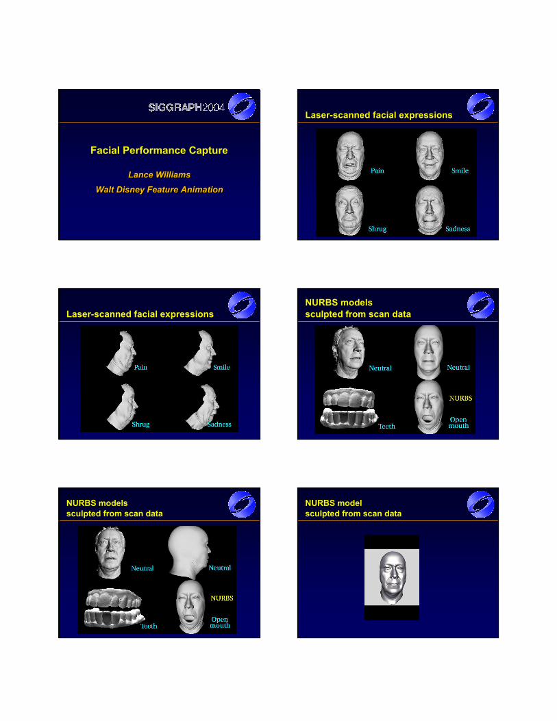
Facial Performance Capture
Lance WilliamsWalt Disney Feature Animation
Lance WilliamsLance Williams
Walt Disney Feature AnimationWalt Disney Feature Animation
Laser-scanned facial expressions
Laser-scanned facial expressionsNURBS modelssculpted from scan data
NURBS models sculpted from scan data
NURBS model sculpted from scan data
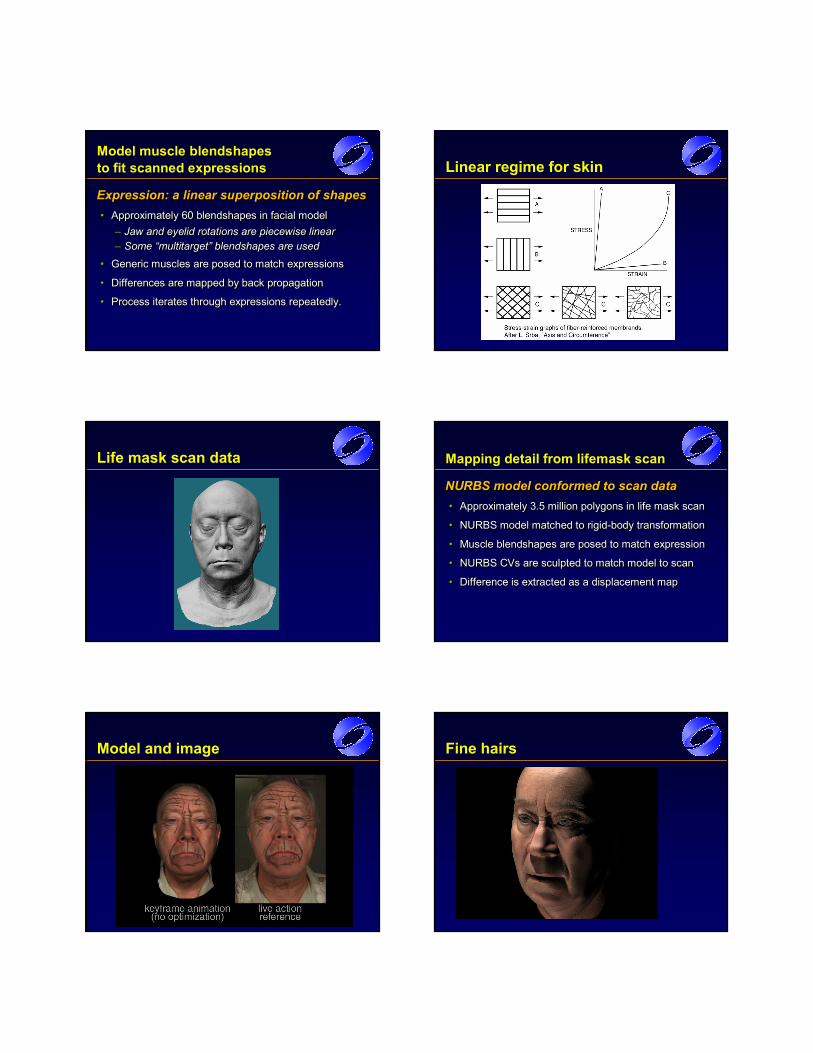
Model muscle blendshapesto fit scanned expressions
Expression: a linear superposition of shapes• Approximately 60 blendshapes in facial model
– Jaw and eyelid rotations are piecewise linear– Some “multitarget” blendshapes are used
• Generic muscles are posed to match expressions
• Differences are mapped by back propagation
• Process iterates through expressions repeatedly.
Expression: a linear superposition of shapesExpression: a linear superposition of shapes•• Approximately 60 Approximately 60 blendshapes blendshapes in facial modelin facial model
–– Jaw and eyelid rotations are piecewise linearJaw and eyelid rotations are piecewise linear–– Some “Some “multitargetmultitarget” ” blendshapes blendshapes are usedare used
•• Generic muscles are posed to match expressionsGeneric muscles are posed to match expressions
•• Differences are mapped by back propagationDifferences are mapped by back propagation
•• Process iterates through expressions repeatedly.Process iterates through expressions repeatedly.
Linear regime for skin
Life mask scan data Mapping detail from lifemask scan
NURBS model conformed to scan data• Approximately 3.5 million polygons in life mask scan
• NURBS model matched to rigid-body transformation
• Muscle blendshapes are posed to match expression
• NURBS CVs are sculpted to match model to scan
• Difference is extracted as a displacement map
NURBS model conformed to scan dataNURBS model conformed to scan data•• Approximately 3.5 million polygons in life mask scanApproximately 3.5 million polygons in life mask scan
•• NURBS model matched to rigidNURBS model matched to rigid--body transformationbody transformation
•• MuscleMuscle blendshapesblendshapes are posed to match expressionare posed to match expression
•• NURBS CVs are sculpted to match model to scanNURBS CVs are sculpted to match model to scan
•• Difference is extracted as a displacement mapDifference is extracted as a displacement map
Model and image Fine hairs
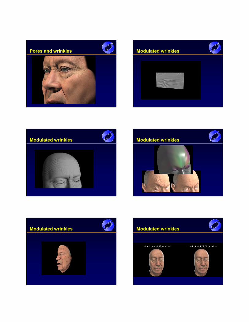
Pores and wrinkles Modulated wrinkles
Modulated wrinkles Modulated wrinkles
Modulated wrinkles Modulated wrinkles
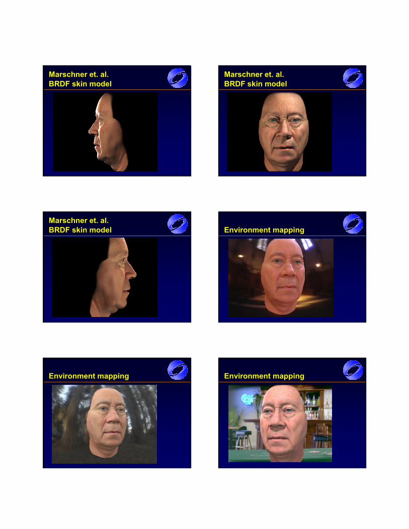
Marschner et. al. BRDF skin model
Marschner et. al. BRDF skin model
Marschner et. al. BRDF skin model Environment mapping
Environment mapping Environment mapping
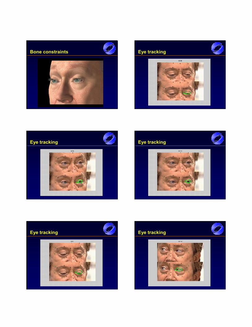
Bone constraints Eye tracking
Eye tracking Eye tracking
Eye tracking Eye tracking

Eye tracking Image and model
Model and image Tracking registration
Together at last Double take
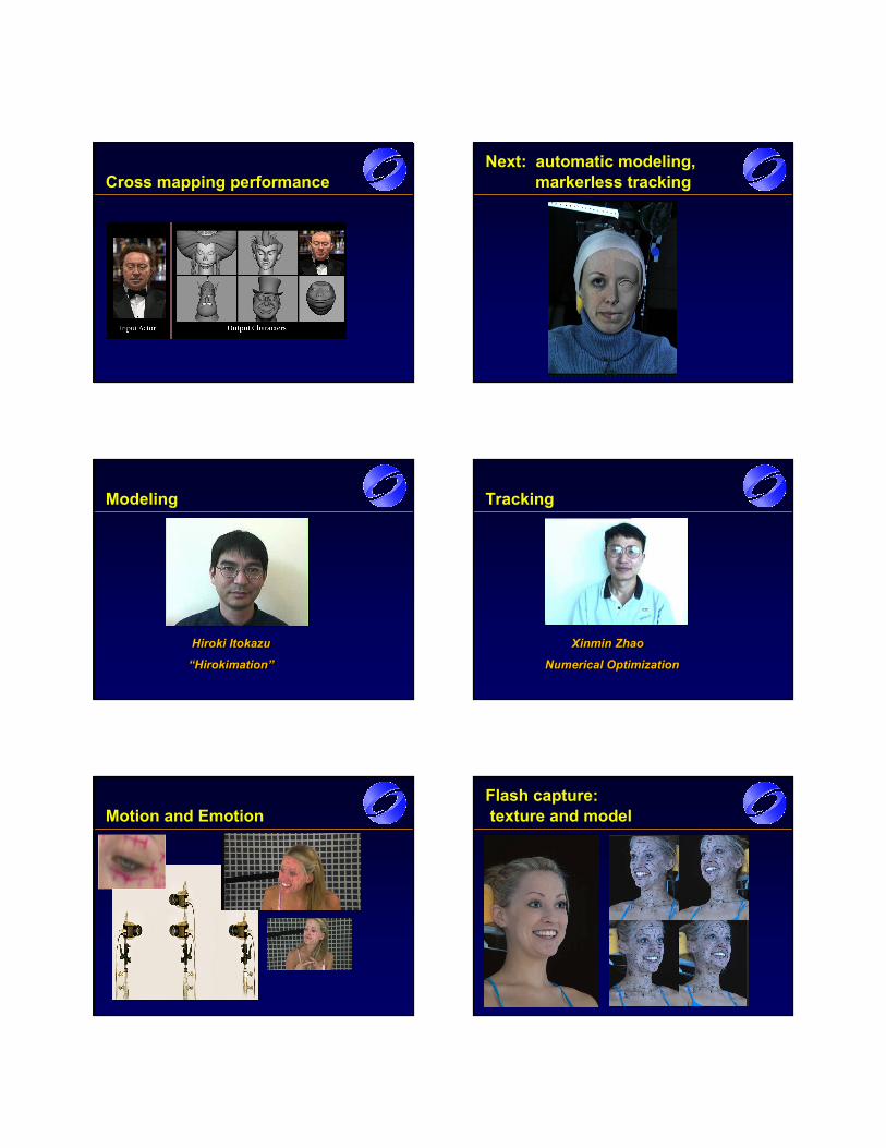
Cross mapping performanceNext: automatic modeling,
markerless tracking
Modeling
Hiroki Itokazu
“Hirokimation”
Hiroki Hiroki ItokazuItokazu
““HirokimationHirokimation” ”
Tracking
Xinmin Zhao
Numerical Optimization
Xinmin Xinmin ZhaoZhao
Numerical OptimizationNumerical Optimization
Motion and EmotionFlash capture:texture and model
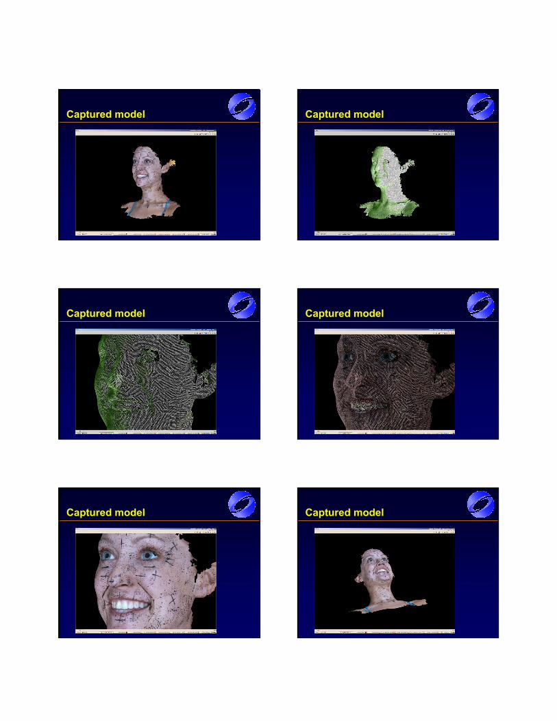
Captured model Captured model
Captured model Captured model
Captured model Captured model
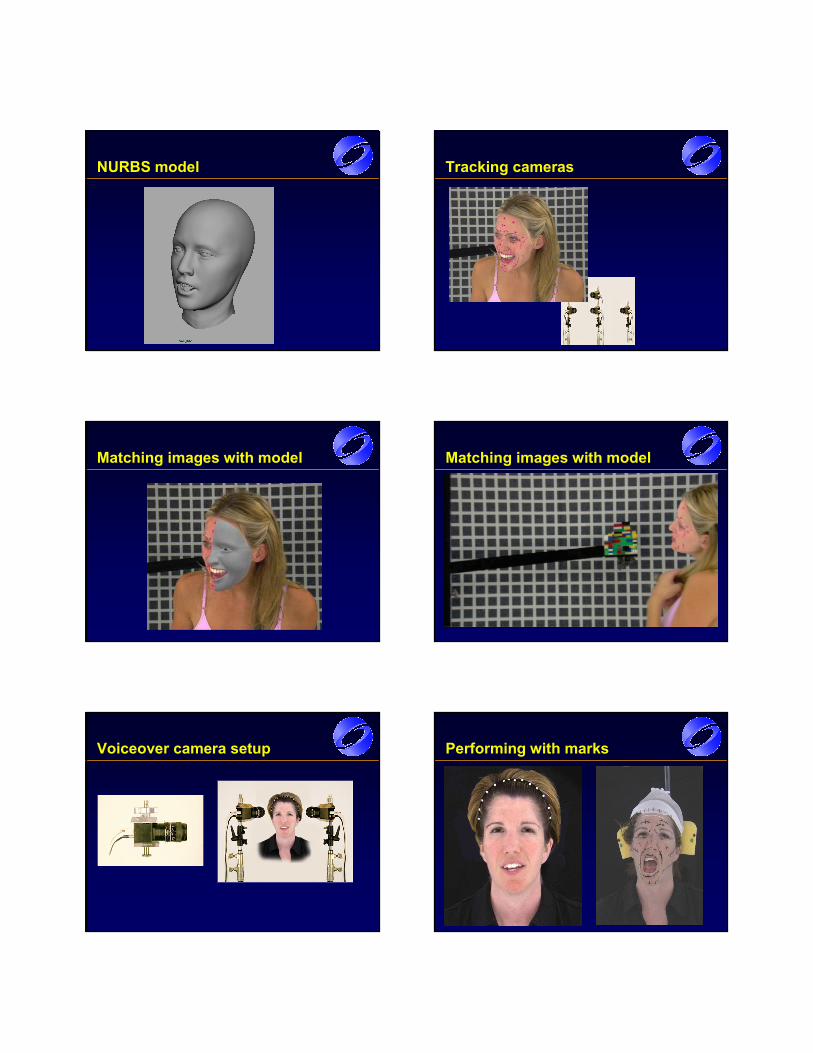
NURBS model Tracking cameras
Matching images with model Matching images with model
Voiceover camera setup Performing with marks
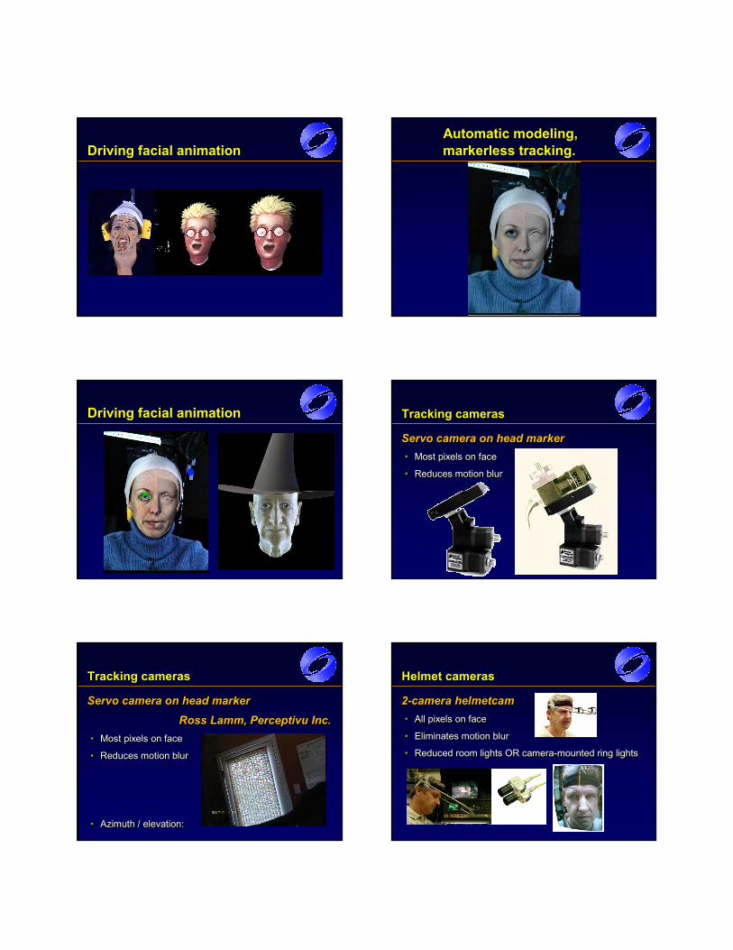
Driving facial animationAutomatic modeling, markerless tracking.
Driving facial animation Tracking cameras
Servo camera on head marker• Most pixels on face
• Reduces motion blur
Servo camera on head markerServo camera on head marker•• Most pixels on faceMost pixels on face
•• Reduces motion blurReduces motion blur
Tracking cameras
Servo camera on head marker Ross Lamm, Perceptivu Inc.
• Most pixels on face
• Reduces motion blur
• Azimuth / elevation:
Servo camera on head marker Servo camera on head marker
Ross Ross LammLamm, , Perceptivu Perceptivu Inc.Inc.•• Most pixels on faceMost pixels on face
•• Reduces motion blurReduces motion blur
•• Azimuth / elevation:Azimuth / elevation:
Helmet cameras
2-camera helmetcam• All pixels on face
• Eliminates motion blur
• Reduced room lights OR camera-mounted ring lights
22--camera camera helmetcamhelmetcam•• All pixels on faceAll pixels on face
•• Eliminates motion blurEliminates motion blur
•• Reduced room lights OR cameraReduced room lights OR camera--mounted ring lightsmounted ring lights
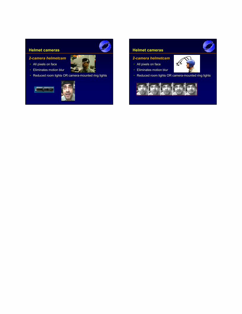
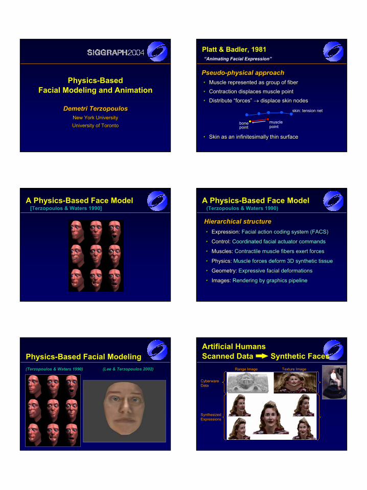
Demetri TerzopoulosNew York UniversityUniversity of Toronto
Demetri TerzopoulosDemetri TerzopoulosNew York UniversityNew York UniversityUniversity of TorontoUniversity of Toronto
Physics-Based Facial Modeling and Animation
Pseudo-physical approach• Muscle represented as group of fiber
• Contraction displaces muscle point
• Distribute “forces” → displace skin nodes
• Skin as an infinitesimally thin surface
PseudoPseudo--physical approachphysical approach•• Muscle represented as group of fiberMuscle represented as group of fiber
•• Contraction displaces muscle pointContraction displaces muscle point
•• Distribute “forces” Distribute “forces” →→ displace skin nodesdisplace skin nodes
•• Skin as an infinitesimally thin surfaceSkin as an infinitesimally thin surface
Platt & Badler, 1981“Animating Facial Expression”
bonebonepointpoint
musclepoint
skin: tension netskin: tension net
A Physics-Based Face Model[Terzopoulos & Waters 1990]
A Physics-Based Face Model(Terzopoulos & Waters 1990)
Hierarchical structure• Expression: Facial action coding system (FACS)
• Control: Coordinated facial actuator commands
• Muscles: Contractile muscle fibers exert forces
• Physics: Muscle forces deform 3D synthetic tissue
• Geometry: Expressive facial deformations
• Images: Rendering by graphics pipeline
Hierarchical structureHierarchical structure•• Expression: Expression: Facial action coding system (FACS)Facial action coding system (FACS)
•• Control: Control: Coordinated facial actuator commandsCoordinated facial actuator commands
•• Muscles: Muscles: Contractile muscle fibers exert forcesContractile muscle fibers exert forces
•• Physics: Physics: Muscle forces deform 3D synthetic tissueMuscle forces deform 3D synthetic tissue
•• Geometry: Geometry: Expressive facial deformationsExpressive facial deformations
•• Images: Images: Rendering by graphics pipelineRendering by graphics pipeline
Physics-Based Facial Modeling(Terzopoulos & Waters 1990) (Lee & Terzopoulos 2002)((TerzopoulosTerzopoulos & Waters 1990) (Lee & & Waters 1990) (Lee & TerzopoulosTerzopoulos 2002)2002)
Artificial Humans Scanned Data Synthetic Faces
CyberwareData
SynthesizedExpressions
Range Image Texture Image
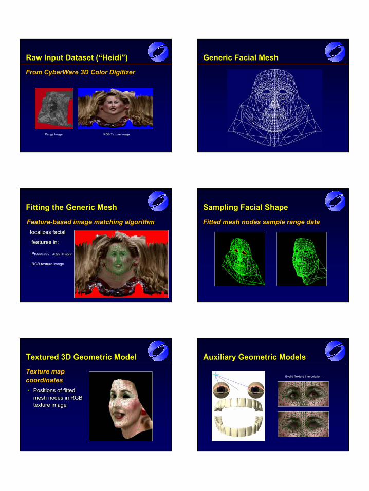
Raw Input Dataset (“Heidi”)
From CyberWare 3D Color DigitizerFrom From CyberWareCyberWare 3D Color Digitizer3D Color Digitizer
Range Image RGB Texture Image
Generic Facial Mesh
Processed range image
RGB texture image
Fitting the Generic Mesh
Feature-based image matching algorithmlocalizes facial
features in:
FeatureFeature--based image matching algorithmbased image matching algorithmlocalizes faciallocalizes facial
features in:features in:
Sampling Facial Shape
Fitted mesh nodes sample range dataFitted mesh nodes sample range dataFitted mesh nodes sample range data
Textured 3D Geometric Model
Texture map coordinates• Positions of fitted
mesh nodes in RGB texture image
Texture map Texture map coordinatescoordinates•• Positions of fitted Positions of fitted
mesh nodes in RGB mesh nodes in RGB texture imagetexture image
Auxiliary Geometric Models
Eyelid Texture Interpolation
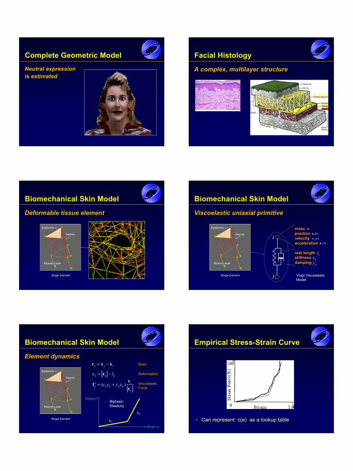
Complete Geometric Model
Neutral expression is estimatedNeutral expression Neutral expression is estimatedis estimated
Facial Histology
A complex, multilayer structureA complex, multilayer structureA complex, multilayer structure
Deformable tissue elementDeformable tissue elementDeformable tissue element
Biomechanical Skin Model
Epidermis
Dermis
Muscle Layer
Single Element
Viscoelastic uniaxial primitiveViscoelasticViscoelastic uniaxialuniaxial primitiveprimitive
Biomechanical Skin Model
Epidermis
Dermis
Muscle Layer
Single Element
mi
)(tia
)(tixmassmasspositionpositionvelocityvelocityaccelerationacceleration
)(tiv
rest lengthrest lengthstiffnessstiffnessdampingdamping
lijcij
i
γ ij
j Voigt ViscoelasticModel
Element dynamicsElement dynamicsElement dynamics
Biomechanical Skin Model
Epidermis
Dermis
Muscle Layer
Single Element
ij
ijijijijij
eij eec
rr
f )( &γ+=
ijij xxr −=
ijijij le −= r
Span
Deformation
ViscoelasticForce
Stress f
Strain e
BiphasicElasticity
c2
c1
Empirical Stress-Strain Curve
• Can represent c(e) as a lookup table•• Can represent Can represent c(ec(e) as a lookup table) as a lookup table
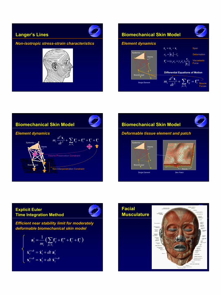
Langer’s Lines
Non-isotropic stress-strain characteristicsNonNon--isotropic stressisotropic stress--strain characteristicsstrain characteristics Element dynamicsElement dynamicsElement dynamics
Biomechanical Skin Model
Epidermis
Dermis
Muscle Layer
Single Elementmi
Nj
eij
ii
idtdm ffx
=+ ∑∈
2
2
Differential Equations of Motion
ij
ijijijijij
eij eec
rr
f )( &γ+=
ijij xxr −=
ijijij le −= r
Span
Deformation
ViscoelasticForce
MuscleForces
Element dynamicsElement dynamicsElement dynamics
Biomechanical Skin Model
Epidermis
Dermis
Muscle Layer
ci
vi
mi
Nj
eij
ii
idtdm ffffx
++=+ ∑∈
2
2
Volume Preservation Constraint
Non-Interpenetration Constraint
Deformable tissue element and patchDeformable tissue element and patchDeformable tissue element and patch
Biomechanical Skin Model
Epidermis
Dermis
Muscle Layer
Single Element
Muscle
Skin Patch
dtti
ti
dtti
ti
ti
dtti
dtdt
++
+
+=
+=
xxxaxx&
&&
)(1 ci
vi
mi
Nj
eij
i
ti
im
ffffa +++= ∑∈
Explicit Euler Time Integration Method
Efficient near stability limit for moderately deformable biomechanical skin modelEfficient near stability limit for moderately Efficient near stability limit for moderately deformable biomechanical skin modeldeformable biomechanical skin model
FacialMusculature
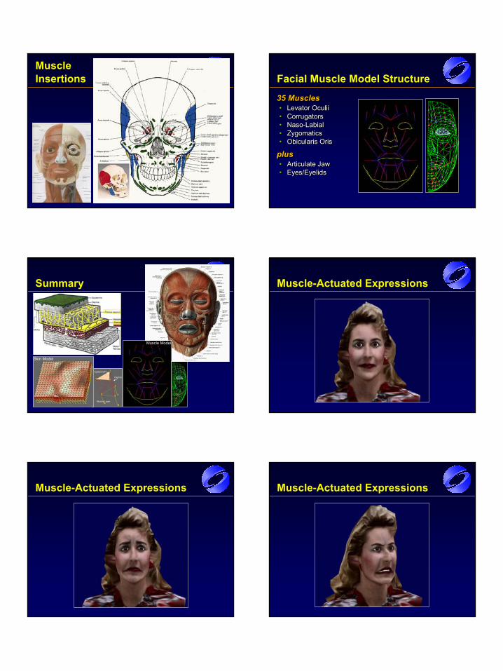
MuscleInsertions
35 Muscles• Levator Oculii• Corrugators• Naso-Labial• Zygomatics• Obicularis Oris
plus• Articulate Jaw• Eyes/Eyelids
35 Muscles35 Muscles•• LevatorLevator OculiiOculii•• CorrugatorsCorrugators•• NasoNaso--LabialLabial•• ZygomaticsZygomatics•• ObicularisObicularis OrisOris
plusplus•• Articulate JawArticulate Jaw•• Eyes/EyelidsEyes/Eyelids
Facial Muscle Model Structure
Epidermis
Dermis
Muscle Layer
Summary
Skin Model
Muscle Model
Muscle-Actuated Expressions
Muscle-Actuated Expressions Muscle-Actuated Expressions
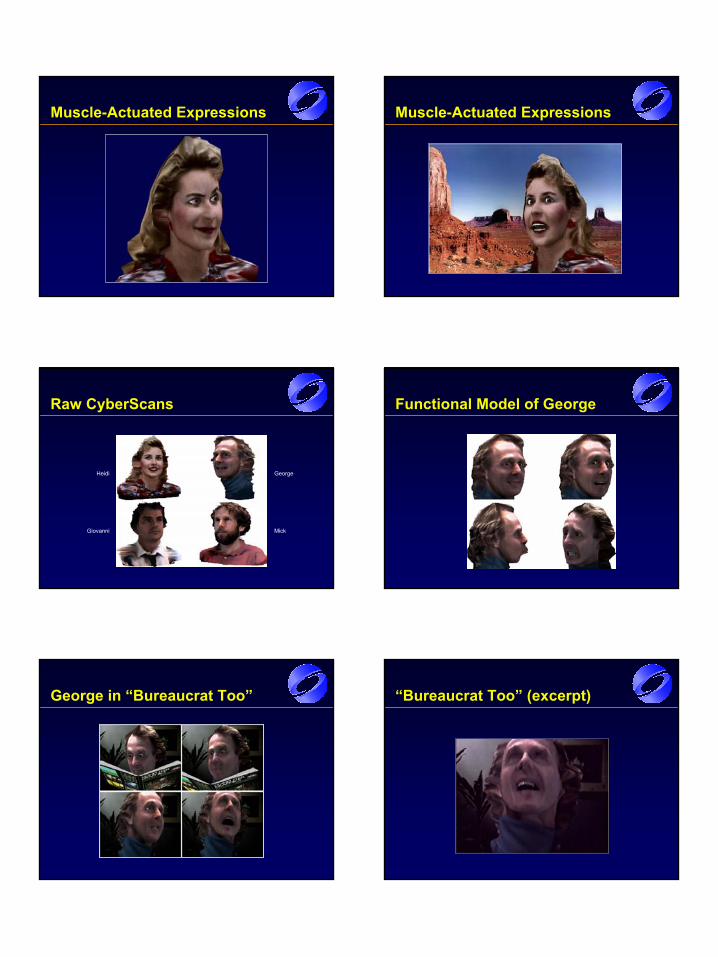
Muscle-Actuated Expressions Muscle-Actuated Expressions
Raw CyberScans
Heidi George
Giovanni Mick
Functional Model of George
George in “Bureaucrat Too” “Bureaucrat Too” (excerpt)
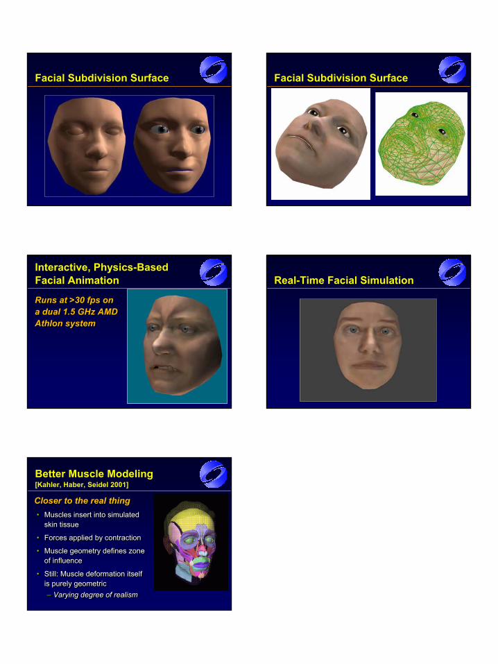
Facial Subdivision Surface Facial Subdivision Surface
Interactive, Physics-Based Facial Animation
Runs at >30 fps on a dual 1.5 GHz AMD Athlon system
Runs at >30 fps on Runs at >30 fps on a dual 1.5 GHz AMD a dual 1.5 GHz AMD AthlonAthlon systemsystem
Real-Time Facial Simulation
Better Muscle Modeling[Kahler, Haber, Seidel 2001]
Closer to the real thing• Muscles insert into simulated
skin tissue
• Forces applied by contraction
• Muscle geometry defines zone of influence
• Still: Muscle deformation itself is purely geometric– Varying degree of realism
Closer to the real thingCloser to the real thing•• Muscles insert into simulated Muscles insert into simulated
skin tissueskin tissue
•• Forces applied by contractionForces applied by contraction
•• Muscle geometry defines zone Muscle geometry defines zone of influenceof influence
•• Still: Muscle deformation itself Still: Muscle deformation itself is purely geometricis purely geometric–– Varying degree of realismVarying degree of realism
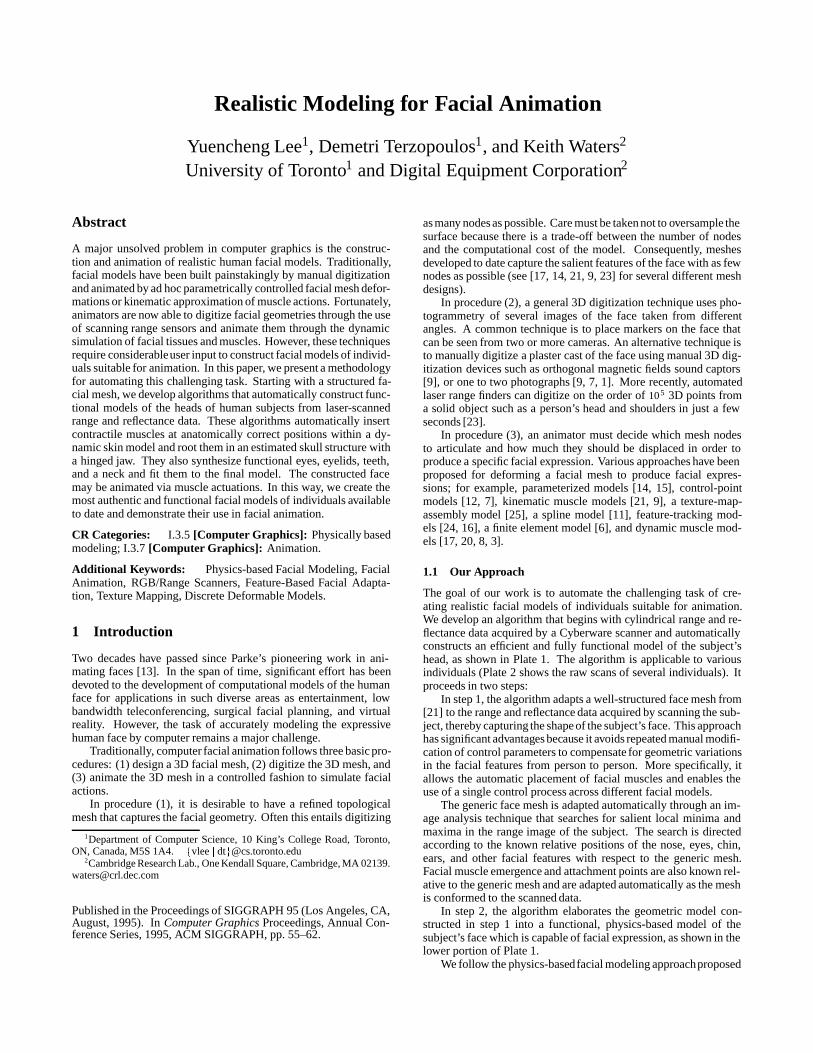
Realistic Modeling for Facial Animation
Yuencheng Lee1, Demetri Terzopoulos1, and Keith Waters2
University of Toronto1 and Digital Equipment Corporation2
Abstract
A major unsolved problem in computer graphics is the construc-tion and animation of realistic human facial models. Traditionally,facial models have been built painstakingly by manual digitizationand animated by ad hoc parametrically controlled facial mesh defor-mations or kinematic approximation of muscle actions. Fortunately,animators are now able to digitize facial geometries through the useof scanning range sensors and animate them through the dynamicsimulation of facial tissues and muscles. However, these techniquesrequire considerableuser input to construct facial models of individ-uals suitable for animation. In this paper, we present a methodologyfor automating this challenging task. Starting with a structured fa-cial mesh, we develop algorithms that automatically construct func-tional models of the heads of human subjects from laser-scannedrange and reflectance data. These algorithms automatically insertcontractile muscles at anatomically correct positions within a dy-namic skin model and root them in an estimated skull structure witha hinged jaw. They also synthesize functional eyes, eyelids, teeth,and a neck and fit them to the final model. The constructed facemay be animated via muscle actuations. In this way, we create themost authentic and functional facial models of individuals availableto date and demonstrate their use in facial animation.
CR Categories: I.3.5 [Computer Graphics]: Physically basedmodeling; I.3.7 [Computer Graphics]: Animation.
Additional Keywords: Physics-based Facial Modeling, FacialAnimation, RGB/Range Scanners, Feature-Based Facial Adapta-tion, Texture Mapping, Discrete Deformable Models.
1 Introduction
Two decades have passed since Parke’s pioneering work in ani-mating faces [13]. In the span of time, significant effort has beendevoted to the development of computational models of the humanface for applications in such diverse areas as entertainment, lowbandwidth teleconferencing, surgical facial planning, and virtualreality. However, the task of accurately modeling the expressivehuman face by computer remains a major challenge.
Traditionally, computer facial animation follows three basic pro-cedures: (1) design a 3D facial mesh, (2) digitize the 3D mesh, and(3) animate the 3D mesh in a controlled fashion to simulate facialactions.
In procedure (1), it is desirable to have a refined topologicalmesh that captures the facial geometry. Often this entails digitizing
1Department of Computer Science, 10 King’s College Road, Toronto,ON, Canada, M5S 1A4. fvlee j [email protected]
2Cambridge Research Lab., One Kendall Square, Cambridge, MA [email protected]
Published in the Proceedings of SIGGRAPH 95 (Los Angeles, CA,August, 1995). In Computer Graphics Proceedings, Annual Con-ference Series, 1995, ACM SIGGRAPH, pp. 55–62.
as many nodes as possible. Care must be taken not to oversample thesurface because there is a trade-off between the number of nodesand the computational cost of the model. Consequently, meshesdeveloped to date capture the salient features of the face with as fewnodes as possible (see [17, 14, 21, 9, 23] for several different meshdesigns).
In procedure (2), a general 3D digitization technique uses pho-togrammetry of several images of the face taken from differentangles. A common technique is to place markers on the face thatcan be seen from two or more cameras. An alternative technique isto manually digitize a plaster cast of the face using manual 3D dig-itization devices such as orthogonal magnetic fields sound captors[9], or one to two photographs [9, 7, 1]. More recently, automatedlaser range finders can digitize on the order of 105 3D points froma solid object such as a person’s head and shoulders in just a fewseconds [23].
In procedure (3), an animator must decide which mesh nodesto articulate and how much they should be displaced in order toproduce a specific facial expression. Various approaches have beenproposed for deforming a facial mesh to produce facial expres-sions; for example, parameterized models [14, 15], control-pointmodels [12, 7], kinematic muscle models [21, 9], a texture-map-assembly model [25], a spline model [11], feature-tracking mod-els [24, 16], a finite element model [6], and dynamic muscle mod-els [17, 20, 8, 3].
1.1 Our Approach
The goal of our work is to automate the challenging task of cre-ating realistic facial models of individuals suitable for animation.We develop an algorithm that begins with cylindrical range and re-flectance data acquired by a Cyberware scanner and automaticallyconstructs an efficient and fully functional model of the subject’shead, as shown in Plate 1. The algorithm is applicable to variousindividuals (Plate 2 shows the raw scans of several individuals). Itproceeds in two steps:
In step 1, the algorithm adapts a well-structured face mesh from[21] to the range and reflectance data acquired by scanning the sub-ject, thereby capturing the shape of the subject’s face. This approachhas significant advantages because it avoids repeated manual modifi-cation of control parameters to compensate for geometric variationsin the facial features from person to person. More specifically, itallows the automatic placement of facial muscles and enables theuse of a single control process across different facial models.
The generic face mesh is adapted automatically through an im-age analysis technique that searches for salient local minima andmaxima in the range image of the subject. The search is directedaccording to the known relative positions of the nose, eyes, chin,ears, and other facial features with respect to the generic mesh.Facial muscle emergence and attachment points are also known rel-ative to the generic mesh and are adapted automatically as the meshis conformed to the scanned data.
In step 2, the algorithm elaborates the geometric model con-structed in step 1 into a functional, physics-based model of thesubject’s face which is capable of facial expression, as shown in thelower portion of Plate 1.
We follow the physics-basedfacial modeling approachproposed
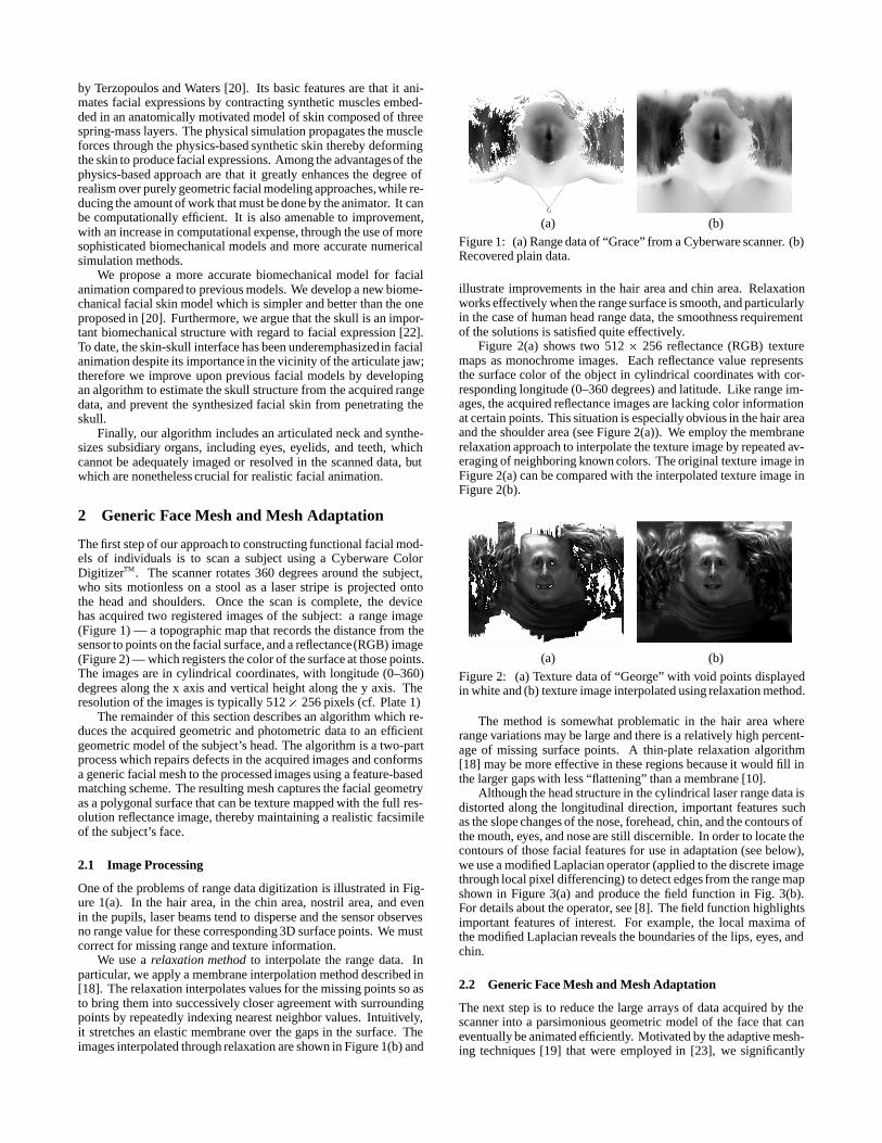
by Terzopoulos and Waters [20]. Its basic features are that it ani-mates facial expressions by contracting synthetic muscles embed-ded in an anatomically motivated model of skin composed of threespring-mass layers. The physical simulation propagates the muscleforces through the physics-based synthetic skin thereby deformingthe skin to produce facial expressions. Among the advantagesof thephysics-based approach are that it greatly enhances the degree ofrealism over purely geometric facial modeling approaches, while re-ducing the amount of work that must be done by the animator. It canbe computationally efficient. It is also amenable to improvement,with an increase in computational expense, through the use of moresophisticated biomechanical models and more accurate numericalsimulation methods.
We propose a more accurate biomechanical model for facialanimation compared to previous models. We develop a new biome-chanical facial skin model which is simpler and better than the oneproposed in [20]. Furthermore, we argue that the skull is an impor-tant biomechanical structure with regard to facial expression [22].To date, the skin-skull interface has been underemphasizedin facialanimation despite its importance in the vicinity of the articulate jaw;therefore we improve upon previous facial models by developingan algorithm to estimate the skull structure from the acquired rangedata, and prevent the synthesized facial skin from penetrating theskull.
Finally, our algorithm includes an articulated neck and synthe-sizes subsidiary organs, including eyes, eyelids, and teeth, whichcannot be adequately imaged or resolved in the scanned data, butwhich are nonetheless crucial for realistic facial animation.
2 Generic Face Mesh and Mesh Adaptation
The first step of our approach to constructing functional facial mod-els of individuals is to scan a subject using a Cyberware ColorDigitizerTM. The scanner rotates 360 degrees around the subject,who sits motionless on a stool as a laser stripe is projected ontothe head and shoulders. Once the scan is complete, the devicehas acquired two registered images of the subject: a range image(Figure 1) — a topographic map that records the distance from thesensor to points on the facial surface, and a reflectance(RGB) image(Figure 2) — which registers the color of the surface at those points.The images are in cylindrical coordinates, with longitude (0–360)degrees along the x axis and vertical height along the y axis. Theresolution of the images is typically 512� 256 pixels (cf. Plate 1)
The remainder of this section describes an algorithm which re-duces the acquired geometric and photometric data to an efficientgeometric model of the subject’s head. The algorithm is a two-partprocess which repairs defects in the acquired images and conformsa generic facial mesh to the processed images using a feature-basedmatching scheme. The resulting mesh captures the facial geometryas a polygonal surface that can be texture mapped with the full res-olution reflectance image, thereby maintaining a realistic facsimileof the subject’s face.
2.1 Image Processing
One of the problems of range data digitization is illustrated in Fig-ure 1(a). In the hair area, in the chin area, nostril area, and evenin the pupils, laser beams tend to disperse and the sensor observesno range value for these corresponding 3D surface points. We mustcorrect for missing range and texture information.
We use a relaxation method to interpolate the range data. Inparticular, we apply a membrane interpolation method described in[18]. The relaxation interpolates values for the missing points so asto bring them into successively closer agreement with surroundingpoints by repeatedly indexing nearest neighbor values. Intuitively,it stretches an elastic membrane over the gaps in the surface. Theimages interpolated through relaxation are shown in Figure 1(b) and
(a) (b)
Figure 1: (a) Range data of “Grace” from a Cyberware scanner. (b)Recovered plain data.
illustrate improvements in the hair area and chin area. Relaxationworks effectively when the range surface is smooth, and particularlyin the case of human head range data, the smoothness requirementof the solutions is satisfied quite effectively.
Figure 2(a) shows two 512 � 256 reflectance (RGB) texturemaps as monochrome images. Each reflectance value representsthe surface color of the object in cylindrical coordinates with cor-responding longitude (0–360 degrees) and latitude. Like range im-ages, the acquired reflectance images are lacking color informationat certain points. This situation is especially obvious in the hair areaand the shoulder area (see Figure 2(a)). We employ the membranerelaxation approach to interpolate the texture image by repeated av-eraging of neighboring known colors. The original texture image inFigure 2(a) can be compared with the interpolated texture image inFigure 2(b).
(a) (b)
Figure 2: (a) Texture data of “George” with void points displayedin white and (b) texture image interpolated using relaxation method.
The method is somewhat problematic in the hair area whererange variations may be large and there is a relatively high percent-age of missing surface points. A thin-plate relaxation algorithm[18] may be more effective in these regions because it would fill inthe larger gaps with less “flattening” than a membrane [10].
Although the head structure in the cylindrical laser range data isdistorted along the longitudinal direction, important features suchas the slope changes of the nose, forehead, chin, and the contours ofthe mouth, eyes, and nose are still discernible. In order to locate thecontours of those facial features for use in adaptation (see below),we use a modified Laplacian operator (applied to the discrete imagethrough local pixel differencing) to detect edges from the range mapshown in Figure 3(a) and produce the field function in Fig. 3(b).For details about the operator, see [8]. The field function highlightsimportant features of interest. For example, the local maxima ofthe modified Laplacian reveals the boundaries of the lips, eyes, andchin.
2.2 Generic Face Mesh and Mesh Adaptation
The next step is to reduce the large arrays of data acquired by thescanner into a parsimonious geometric model of the face that caneventually be animated efficiently. Motivated by the adaptive mesh-ing techniques [19] that were employed in [23], we significantly
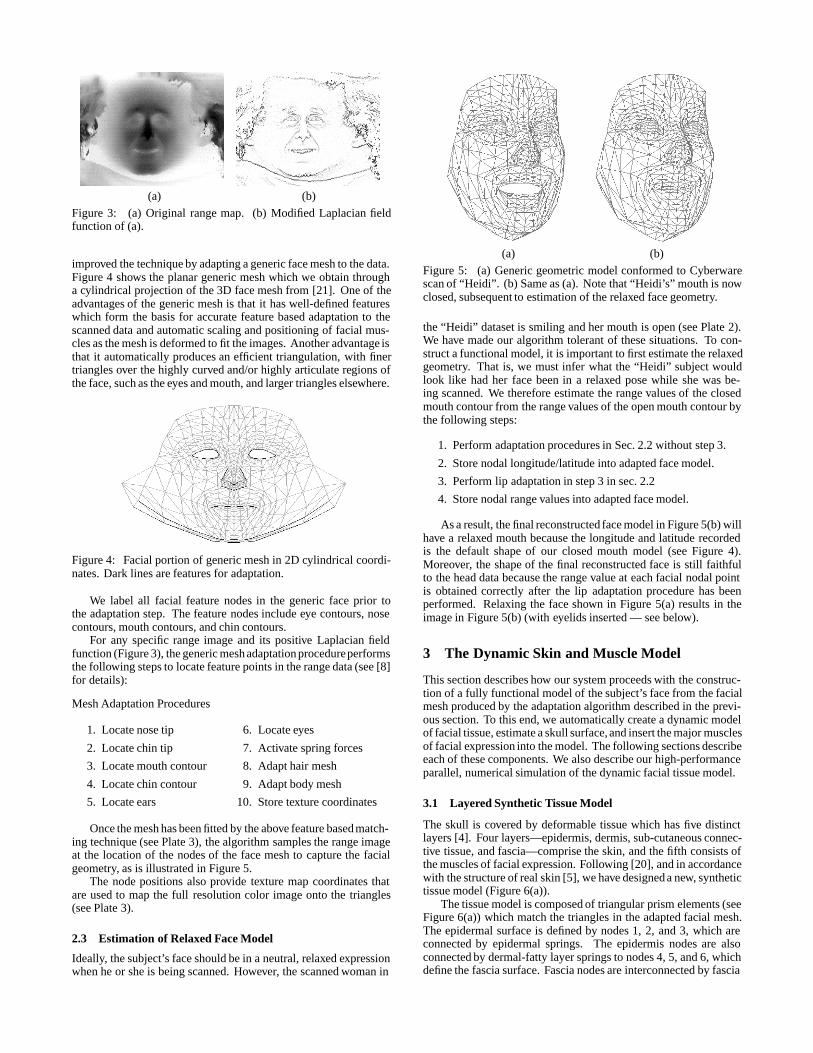
(a) (b)
Figure 3: (a) Original range map. (b) Modified Laplacian fieldfunction of (a).
improved the technique by adapting a generic face mesh to the data.Figure 4 shows the planar generic mesh which we obtain througha cylindrical projection of the 3D face mesh from [21]. One of theadvantages of the generic mesh is that it has well-defined featureswhich form the basis for accurate feature based adaptation to thescanned data and automatic scaling and positioning of facial mus-cles as the mesh is deformed to fit the images. Another advantage isthat it automatically produces an efficient triangulation, with finertriangles over the highly curved and/or highly articulate regions ofthe face, such as the eyes and mouth, and larger triangles elsewhere.
Figure 4: Facial portion of generic mesh in 2D cylindrical coordi-nates. Dark lines are features for adaptation.
We label all facial feature nodes in the generic face prior tothe adaptation step. The feature nodes include eye contours, nosecontours, mouth contours, and chin contours.
For any specific range image and its positive Laplacian fieldfunction (Figure 3), the generic mesh adaptation procedureperformsthe following steps to locate feature points in the range data (see [8]for details):
Mesh Adaptation Procedures
1. Locate nose tip
2. Locate chin tip
3. Locate mouth contour
4. Locate chin contour
5. Locate ears
6. Locate eyes
7. Activate spring forces
8. Adapt hair mesh
9. Adapt body mesh
10. Store texture coordinates
Once the mesh has been fitted by the above feature based match-ing technique (see Plate 3), the algorithm samples the range imageat the location of the nodes of the face mesh to capture the facialgeometry, as is illustrated in Figure 5.
The node positions also provide texture map coordinates thatare used to map the full resolution color image onto the triangles(see Plate 3).
2.3 Estimation of Relaxed Face Model
Ideally, the subject’s face should be in a neutral, relaxed expressionwhen he or she is being scanned. However, the scanned woman in
(a) (b)
Figure 5: (a) Generic geometric model conformed to Cyberwarescan of “Heidi”. (b) Same as (a). Note that “Heidi’s” mouth is nowclosed, subsequent to estimation of the relaxed face geometry.
the “Heidi” dataset is smiling and her mouth is open (see Plate 2).We have made our algorithm tolerant of these situations. To con-struct a functional model, it is important to first estimate the relaxedgeometry. That is, we must infer what the “Heidi” subject wouldlook like had her face been in a relaxed pose while she was be-ing scanned. We therefore estimate the range values of the closedmouth contour from the range values of the open mouth contour bythe following steps:
1. Perform adaptation procedures in Sec. 2.2 without step 3.
2. Store nodal longitude/latitude into adapted face model.
3. Perform lip adaptation in step 3 in sec. 2.2
4. Store nodal range values into adapted face model.
As a result, the final reconstructed face model in Figure 5(b) willhave a relaxed mouth because the longitude and latitude recordedis the default shape of our closed mouth model (see Figure 4).Moreover, the shape of the final reconstructed face is still faithfulto the head data because the range value at each facial nodal pointis obtained correctly after the lip adaptation procedure has beenperformed. Relaxing the face shown in Figure 5(a) results in theimage in Figure 5(b) (with eyelids inserted — see below).
3 The Dynamic Skin and Muscle Model
This section describes how our system proceeds with the construc-tion of a fully functional model of the subject’s face from the facialmesh produced by the adaptation algorithm described in the previ-ous section. To this end, we automatically create a dynamic modelof facial tissue, estimate a skull surface, and insert the major musclesof facial expression into the model. The following sections describeeach of these components. We also describe our high-performanceparallel, numerical simulation of the dynamic facial tissue model.
3.1 Layered Synthetic Tissue Model
The skull is covered by deformable tissue which has five distinctlayers [4]. Four layers—epidermis, dermis, sub-cutaneous connec-tive tissue, and fascia—comprise the skin, and the fifth consists ofthe muscles of facial expression. Following [20], and in accordancewith the structure of real skin [5], we have designed a new, synthetictissue model (Figure 6(a)).
The tissue model is composed of triangular prism elements (seeFigure 6(a)) which match the triangles in the adapted facial mesh.The epidermal surface is defined by nodes 1, 2, and 3, which areconnected by epidermal springs. The epidermis nodes are alsoconnected by dermal-fatty layer springs to nodes 4, 5, and 6, whichdefine the fascia surface. Fascia nodes are interconnected by fascia
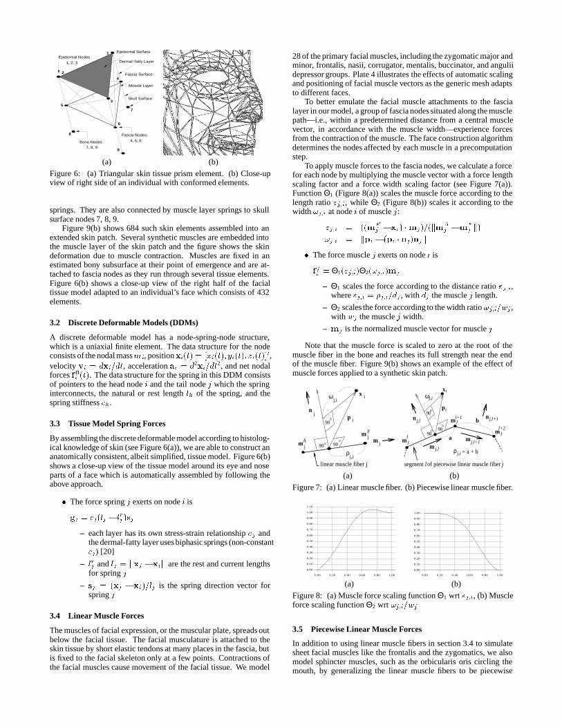
2
1
5
6
4
7
9
8
3
Epidermal Surface
Dermal−fatty Layer
Fascia Surface
Muscle Layer
Epidermal Nodes
Fascia Nodes
Bone Nodes
Skull Surface
1, 2, 3
7, 8, 9
4, 5, 6
(a) (b)
Figure 6: (a) Triangular skin tissue prism element. (b) Close-upview of right side of an individual with conformed elements.
springs. They are also connected by muscle layer springs to skullsurface nodes 7, 8, 9.
Figure 9(b) shows 684 such skin elements assembled into anextended skin patch. Several synthetic muscles are embedded intothe muscle layer of the skin patch and the figure shows the skindeformation due to muscle contraction. Muscles are fixed in anestimated bony subsurface at their point of emergence and are at-tached to fascia nodes as they run through several tissue elements.Figure 6(b) shows a close-up view of the right half of the facialtissue model adapted to an individual’s face which consists of 432elements.
3.2 Discrete Deformable Models (DDMs)
A discrete deformable model has a node-spring-node structure,which is a uniaxial finite element. The data structure for the nodeconsists of the nodal massmi, positionxi(t) = [xi(t); yi(t); zi(t)]0,velocity vi = dxi=dt, acceleration ai = d2xi=dt
2, and net nodalforces fn
i (t). The data structure for the spring in this DDM consistsof pointers to the head node i and the tail node j which the springinterconnects, the natural or rest length lk of the spring, and thespring stiffness ck.
3.3 Tissue Model Spring Forces
By assembling the discrete deformable model according to histolog-ical knowledge of skin (see Figure 6(a)), we are able to construct ananatomically consistent, albeit simplified, tissue model. Figure 6(b)shows a close-up view of the tissue model around its eye and noseparts of a face which is automatically assembled by following theabove approach.
� The force spring j exerts on node i is
gj = cj(lj � lrj )sj
– each layer has its own stress-strain relationship cj andthe dermal-fatty layer uses biphasic springs (non-constantcj) [20]
– lrj and lj = jjxj � xijj are the rest and current lengthsfor spring j
– sj = (xj � xi)=lj is the spring direction vector forspring j
3.4 Linear Muscle Forces
The muscles of facial expression, or the muscular plate, spreads outbelow the facial tissue. The facial musculature is attached to theskin tissue by short elastic tendons at many places in the fascia, butis fixed to the facial skeleton only at a few points. Contractions ofthe facial muscles cause movement of the facial tissue. We model
28 of the primary facial muscles, including the zygomatic major andminor, frontalis, nasii, corrugator, mentalis, buccinator, and anguliidepressor groups. Plate 4 illustrates the effects of automatic scalingand positioning of facial muscle vectors as the generic mesh adaptsto different faces.
To better emulate the facial muscle attachments to the fascialayer in our model, a group of fascia nodes situated along the musclepath—i.e., within a predetermined distance from a central musclevector, in accordance with the muscle width—experience forcesfrom the contraction of the muscle. The face construction algorithmdetermines the nodes affected by each muscle in a precomputationstep.
To apply muscle forces to the fascia nodes, we calculate a forcefor each node by multiplying the muscle vector with a force lengthscaling factor and a force width scaling factor (see Figure 7(a)).Function Θ1 (Figure 8(a)) scales the muscle force according to thelength ratio "j;i, while Θ2 (Figure 8(b)) scales it according to thewidth !j;i at node i of muscle j:
"j;i = ((mFj � xi) �mj)=(km
Aj �m
Fj k)
!j;i = kpi � (pi � nj)njk
� The force muscle j exerts on node i is
fji = Θ1("j;i)Θ2(!j;i)mj
– Θ1 scales the force according to the distance ratio "j;i,where "j;i = �j;i=dj , with dj the muscle j length.
– Θ2 scales the force according to the width ratio !j;i=wj ,with wj the muscle j width.
– mj is the normalized muscle vector for muscle j
Note that the muscle force is scaled to zero at the root of themuscle fiber in the bone and reaches its full strength near the endof the muscle fiber. Figure 9(b) shows an example of the effect ofmuscle forces applied to a synthetic skin patch.
x
pn
linear muscle fiber j
i
ji
j,i
j,iρ
ω
m jA
m jF
m j90
90
90
ω
p
mm
m90
9090
a
b
ρ = a + b
n n
x
l+1
j,lj,l+1
j,l+1j,l
ml+2j
j,i
j
j,i
i
i
jl
m
segment lof piecewise linear muscle fiber j
(a) (b)
Figure 7: (a) Linear muscle fiber. (b) Piecewise linear muscle fiber.
0.00
0.10
0.20
0.30
0.40
0.50
0.60
0.70
0.80
0.90
1.00
1.10
0.00 0.20 0.40 0.60 0.80 1.00
0.00
0.10
0.20
0.30
0.40
0.50
0.60
0.70
0.80
0.90
1.00
0.00 0.20 0.40 0.60 0.80 1.00
(a) (b)
Figure 8: (a) Muscle force scaling function Θ1 wrt "j;i, (b) Muscleforce scaling function Θ2 wrt !j;i=wj
3.5 Piecewise Linear Muscle Forces
In addition to using linear muscle fibers in section 3.4 to simulatesheet facial muscles like the frontalis and the zygomatics, we alsomodel sphincter muscles, such as the orbicularis oris circling themouth, by generalizing the linear muscle fibers to be piecewise
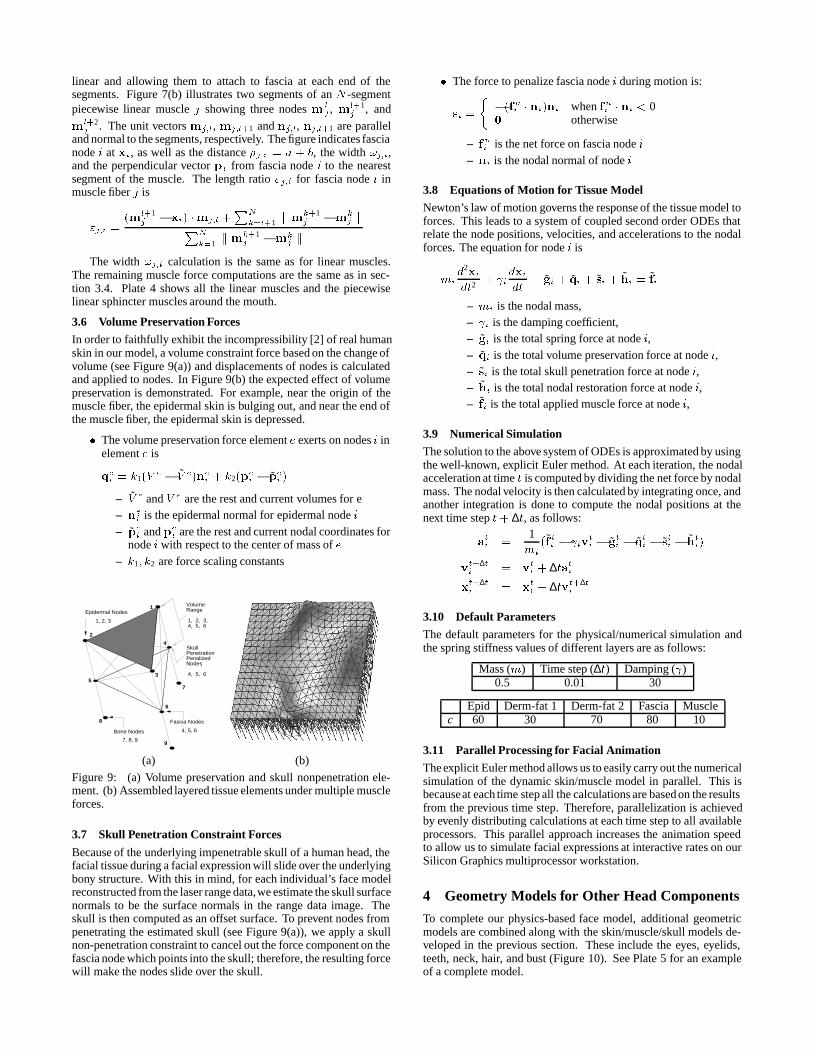
linear and allowing them to attach to fascia at each end of thesegments. Figure 7(b) illustrates two segments of an N -segmentpiecewise linear muscle j showing three nodes m l
j , ml+1j , and
ml+2j . The unit vectors mj;l, mj;l+1 and nj;l, nj;l+1 are parallel
and normal to the segments, respectively. The figure indicates fascianode i at xi , as well as the distance �j;i = a + b, the width !j;i,and the perpendicular vector pi from fascia node i to the nearestsegment of the muscle. The length ratio "j;i for fascia node i inmuscle fiber j is
"j;i =(ml+1
j � xi) �mj;l +PN
k=l+1 k mk+1j �mk
j kPN
k=1k mk+1
j �mkj k
The width !j;i calculation is the same as for linear muscles.The remaining muscle force computations are the same as in sec-tion 3.4. Plate 4 shows all the linear muscles and the piecewiselinear sphincter muscles around the mouth.
3.6 Volume Preservation Forces
In order to faithfully exhibit the incompressibility [2] of real humanskin in our model, a volume constraint force based on the change ofvolume (see Figure 9(a)) and displacements of nodes is calculatedand applied to nodes. In Figure 9(b) the expected effect of volumepreservation is demonstrated. For example, near the origin of themuscle fiber, the epidermal skin is bulging out, and near the end ofthe muscle fiber, the epidermal skin is depressed.
� The volume preservation force element e exerts on nodes i inelement e is
qei = k1(V e � V e)nei + k2(pei � pei )
– V e and V e are the rest and current volumes for e– ne
i is the epidermal normal for epidermal node i– pei and pe
i are the rest and current nodal coordinates fornode i with respect to the center of mass of e
– k1; k2 are force scaling constants
2
1
5
6
4
7
9
8
3
Fascia Nodes
Bone Nodes
1, 2, 3
7, 8, 9
4, 5, 6
Epidermal NodesVolumeRange
1, 2, 3, 4, 5, 6
Skull PenetrationPenalizedNodes
4, 5, 6
(a) (b)
Figure 9: (a) Volume preservation and skull nonpenetration ele-ment. (b) Assembled layered tissue elements under multiple muscleforces.
3.7 Skull Penetration Constraint Forces
Because of the underlying impenetrable skull of a human head, thefacial tissue during a facial expression will slide over the underlyingbony structure. With this in mind, for each individual’s face modelreconstructed from the laser range data,we estimate the skull surfacenormals to be the surface normals in the range data image. Theskull is then computed as an offset surface. To prevent nodes frompenetrating the estimated skull (see Figure 9(a)), we apply a skullnon-penetration constraint to cancel out the force component on thefascia node which points into the skull; therefore, the resulting forcewill make the nodes slide over the skull.
� The force to penalize fascia node i during motion is:
si =
��(fni � ni)ni when fni � ni < 00 otherwise
– fni is the net force on fascia node i– ni is the nodal normal of node i
3.8 Equations of Motion for Tissue Model
Newton’s law of motion governs the response of the tissue model toforces. This leads to a system of coupled second order ODEs thatrelate the node positions, velocities, and accelerations to the nodalforces. The equation for node i is
mid2xi
dt2+ i
dxidt
+ gi + qi + si + hi = fi
– mi is the nodal mass,– i is the damping coefficient,– gi is the total spring force at node i,– qi is the total volume preservation force at node i,– si is the total skull penetration force at node i,– hi is the total nodal restoration force at node i,– fi is the total applied muscle force at node i,
3.9 Numerical Simulation
The solution to the above system of ODEs is approximated by usingthe well-known, explicit Euler method. At each iteration, the nodalacceleration at time t is computed by dividing the net force by nodalmass. The nodal velocity is then calculated by integrating once, andanother integration is done to compute the nodal positions at thenext time step t+ ∆t, as follows:
ati =
1mi
(f ti � ivti � g
ti � q
ti � s
ti � h
ti)
vt+∆ti = v
ti + ∆tati
xt+∆ti = x
ti + ∆tvt+∆t
i
3.10 Default Parameters
The default parameters for the physical/numerical simulation andthe spring stiffness values of different layers are as follows:
Mass (m) Time step (∆t) Damping ( )0.5 0.01 30
Epid Derm-fat 1 Derm-fat 2 Fascia Musclec 60 30 70 80 10
3.11 Parallel Processing for Facial Animation
The explicit Euler method allows us to easily carry out the numericalsimulation of the dynamic skin/muscle model in parallel. This isbecauseat each time step all the calculations are based on the resultsfrom the previous time step. Therefore, parallelization is achievedby evenly distributing calculations at each time step to all availableprocessors. This parallel approach increases the animation speedto allow us to simulate facial expressions at interactive rates on ourSilicon Graphics multiprocessor workstation.
4 Geometry Models for Other Head Components
To complete our physics-based face model, additional geometricmodels are combined along with the skin/muscle/skull models de-veloped in the previous section. These include the eyes, eyelids,teeth, neck, hair, and bust (Figure 10). See Plate 5 for an exampleof a complete model.
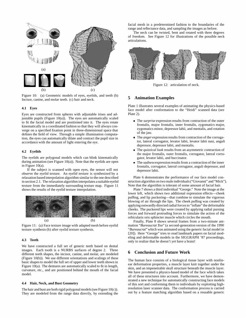
(a)
(b) (c)
Figure 10: (a) Geometric models of eyes, eyelids, and teeth (b)Incisor, canine, and molar teeth. (c) hair and neck.
4.1 Eyes
Eyes are constructed from spheres with adjustable irises and ad-justable pupils (Figure 10(a)). The eyes are automatically scaledto fit the facial model and are positioned into it. The eyes rotatekinematically in a coordinated fashion so that they will always con-verge on a specified fixation point in three-dimensional space thatdefines the field of view. Through a simple illumination computa-tion, the eyes can automatically dilate and contract the pupil size inaccordance with the amount of light entering the eye.
4.2 Eyelids
The eyelids are polygonal models which can blink kinematicallyduring animation (see Figure 10(a)). Note that the eyelids are openin Figure 10(a).
If the subject is scanned with open eyes, the sensor will notobserve the eyelid texture. An eyelid texture is synthesized by arelaxation based interpolation algorithm similar to the one describedin section 2.1. The relaxation algorithm interpolates a suitable eyelidtexture from the immediately surrounding texture map. Figure 11shows the results of the eyelid texture interpolation.
(a) (b)
Figure 11: (a) Face texture image with adapted mesh before eyelidtexture synthesis (b) after eyelid texture synthesis.
4.3 Teeth
We have constructed a full set of generic teeth based on dentalimages. Each tooth is a NURBS surfaces of degree 2. Threedifferent teeth shapes, the incisor, canine, and molar, are modeled(Figure 10(b)). We use different orientations and scalings of thesebasic shapes to model the full set of upper and lower teeth shown inFigure 10(a). The dentures are automatically scaled to fit in length,curvature, etc., and are positioned behind the mouth of the facialmodel.
4.4 Hair, Neck, and Bust Geometry
The hair and bust are both rigid polygonal models (see Figure 10(c)).They are modeled from the range data directly, by extending the
facial mesh in a predetermined fashion to the boundaries of therange and reflectance data, and sampling the images as before.
The neck can be twisted, bent and rotated with three degreesof freedom. See Figure 12 for illustrations of the possible neckarticulations.
Figure 12: articulation of neck.
5 Animation Examples
Plate 1 illustrates several examples of animating the physics-basedface model after conformation to the “Heidi” scanned data (seePlate 2).
� The surprise expression results from contraction of the outerfrontalis, major frontalis, inner frontalis, zygomatics major,zygomatics minor, depressor labii, and mentalis, and rotationof the jaw.
� The anger expression results from contraction of the corruga-tor, lateral corrugator, levator labii, levator labii nasi, angulidepressor, depressor labii, and mentalis.
� The quizzical look results from an asymmetric contraction ofthe major frontalis, outer frontalis, corrugator, lateral corru-gator, levator labii, and buccinator.
� The sadnessexpression results from a contraction of the innerfrontalis, corrugator, lateral corrugator, anguli depressor, anddepressor labii.
Plate 6 demonstrates the performance of our face model con-struction algorithm on two male individuals (“Giovanni” and “Mick”).Note that the algorithm is tolerant of some amount of facial hair.
Plate 7 shows a third individual “George.” Note the image at thelower left, which shows two additional expression effects—cheekpuffing, and lip puckering—that combine to simulate the vigorousblowing of air through the lips. The cheek puffing was created byapplying outwardly directed radial forces to “inflate” the deformablecheeks. The puckered lips were created by applying radial pursingforces and forward protruding forces to simulate the action of theorbicularis oris sphincter muscle which circles the mouth.
Finally, Plate 8 shows several frames from a two-minute ani-mation “Bureaucrat Too” (a second-generation version of the 1990“Bureaucrat” which was animated using the generic facial model in[20]). Here “George” tries to read landmark papers on facial mod-eling and deformable models in the SIGGRAPH ’87 proceedings,only to realize that he doesn’t yet have a brain!
6 Conclusion and Future Work
The human face consists of a biological tissue layer with nonlin-ear deformation properties, a muscle layer knit together under theskin, and an impenetrable skull structure beneath the muscle layer.We have presented a physics-based model of the face which takesall of these structures into account. Furthermore, we have demon-strated a new technique for automatically constructing face modelsof this sort and conforming them to individuals by exploiting high-resolution laser scanner data. The conformation process is carriedout by a feature matching algorithm based on a reusable generic
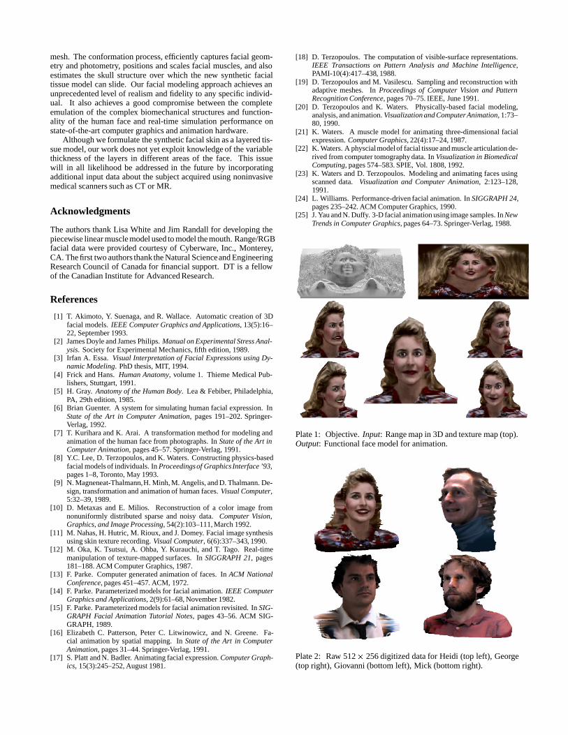
mesh. The conformation process, efficiently captures facial geom-etry and photometry, positions and scales facial muscles, and alsoestimates the skull structure over which the new synthetic facialtissue model can slide. Our facial modeling approach achieves anunprecedented level of realism and fidelity to any specific individ-ual. It also achieves a good compromise between the completeemulation of the complex biomechanical structures and function-ality of the human face and real-time simulation performance onstate-of-the-art computer graphics and animation hardware.
Although we formulate the synthetic facial skin as a layered tis-sue model, our work does not yet exploit knowledge of the variablethickness of the layers in different areas of the face. This issuewill in all likelihood be addressed in the future by incorporatingadditional input data about the subject acquired using noninvasivemedical scanners such as CT or MR.
Acknowledgments
The authors thank Lisa White and Jim Randall for developing thepiecewise linear muscle model used to model the mouth. Range/RGBfacial data were provided courtesy of Cyberware, Inc., Monterey,CA. The first two authors thank the Natural Scienceand EngineeringResearch Council of Canada for financial support. DT is a fellowof the Canadian Institute for Advanced Research.
References
[1] T. Akimoto, Y. Suenaga, and R. Wallace. Automatic creation of 3Dfacial models. IEEE Computer Graphics and Applications, 13(5):16–22, September 1993.
[2] James Doyle and James Philips. Manual on Experimental Stress Anal-ysis. Society for Experimental Mechanics, fifth edition, 1989.
[3] Irfan A. Essa. Visual Interpretation of Facial Expressions using Dy-namic Modeling. PhD thesis, MIT, 1994.
[4] Frick and Hans. Human Anatomy, volume 1. Thieme Medical Pub-lishers, Stuttgart, 1991.
[5] H. Gray. Anatomy of the Human Body. Lea & Febiber, Philadelphia,PA, 29th edition, 1985.
[6] Brian Guenter. A system for simulating human facial expression. InState of the Art in Computer Animation, pages 191–202. Springer-Verlag, 1992.
[7] T. Kurihara and K. Arai. A transformation method for modeling andanimation of the human face from photographs. In State of the Art inComputer Animation, pages 45–57. Springer-Verlag, 1991.
[8] Y.C. Lee, D. Terzopoulos, and K. Waters. Constructing physics-basedfacial models of individuals. In Proceedingsof Graphics Interface ’93,pages 1–8, Toronto, May 1993.
[9] N. Magneneat-Thalmann,H. Minh, M. Angelis, and D. Thalmann. De-sign, transformation and animation of human faces. Visual Computer,5:32–39, 1989.
[10] D. Metaxas and E. Milios. Reconstruction of a color image fromnonuniformly distributed sparse and noisy data. Computer Vision,Graphics, and Image Processing, 54(2):103–111, March 1992.
[11] M. Nahas, H. Hutric, M. Rioux, and J. Domey. Facial image synthesisusing skin texture recording. Visual Computer, 6(6):337–343, 1990.
[12] M. Oka, K. Tsutsui, A. Ohba, Y. Kurauchi, and T. Tago. Real-timemanipulation of texture-mapped surfaces. In SIGGRAPH 21, pages181–188. ACM Computer Graphics, 1987.
[13] F. Parke. Computer generated animation of faces. In ACM NationalConference, pages 451–457. ACM, 1972.
[14] F. Parke. Parameterized models for facial animation. IEEE ComputerGraphics and Applications, 2(9):61–68, November 1982.
[15] F. Parke. Parameterized models for facial animation revisited. In SIG-GRAPH Facial Animation Tutorial Notes, pages 43–56. ACM SIG-GRAPH, 1989.
[16] Elizabeth C. Patterson, Peter C. Litwinowicz, and N. Greene. Fa-cial animation by spatial mapping. In State of the Art in ComputerAnimation, pages 31–44. Springer-Verlag, 1991.
[17] S. Platt and N. Badler. Animating facial expression. Computer Graph-ics, 15(3):245–252, August 1981.
[18] D. Terzopoulos. The computation of visible-surface representations.IEEE Transactions on Pattern Analysis and Machine Intelligence,PAMI-10(4):417–438, 1988.
[19] D. Terzopoulos and M. Vasilescu. Sampling and reconstruction withadaptive meshes. In Proceedings of Computer Vision and PatternRecognition Conference, pages 70–75. IEEE, June 1991.
[20] D. Terzopoulos and K. Waters. Physically-based facial modeling,analysis, and animation. Visualization and ComputerAnimation, 1:73–80, 1990.
[21] K. Waters. A muscle model for animating three-dimensional facialexpression. Computer Graphics, 22(4):17–24, 1987.
[22] K. Waters. A physcialmodelof facial tissue and muscle articulation de-rived from computer tomography data. In Visualization in BiomedicalComputing, pages 574–583. SPIE, Vol. 1808, 1992.
[23] K. Waters and D. Terzopoulos. Modeling and animating faces usingscanned data. Visualization and Computer Animation, 2:123–128,1991.
[24] L. Williams. Performance-driven facial animation. In SIGGRAPH 24,pages 235–242. ACM Computer Graphics, 1990.
[25] J. Yau and N. Duffy. 3-D facial animation using image samples. In NewTrends in Computer Graphics, pages 64–73. Springer-Verlag, 1988.
Plate 1: Objective. Input: Range map in 3D and texture map (top).Output: Functional face model for animation.
Plate 2: Raw 512� 256 digitized data for Heidi (top left), George(top right), Giovanni (bottom left), Mick (bottom right).
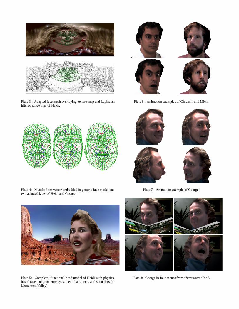
Plate 3: Adapted face mesh overlaying texture map and Laplacianfiltered range map of Heidi.
Plate 4: Muscle fiber vector embedded in generic face model andtwo adapted faces of Heidi and George.
Plate 5: Complete, functional head model of Heidi with physics-based face and geometric eyes, teeth, hair, neck, and shoulders (inMonument Valley).
Plate 6: Animation examples of Giovanni and Mick.
Plate 7: Animation example of George.
Plate 8: George in four scenes from “Bureaucrat Too”.
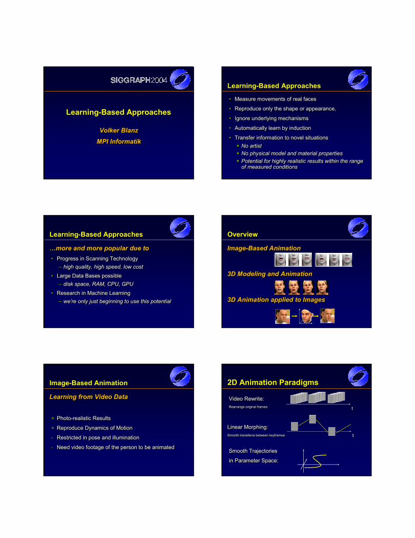
Learning-Based Approaches
Volker BlanzMPI InformatikVolker BlanzVolker Blanz
MPIMPI InformatikInformatik
Learning-Based Approaches
• Measure movements of real faces
• Reproduce only the shape or appearance,
• Ignore underlying mechanisms
• Automatically learn by induction
• Transfer information to novel situationsNo artistNo physical model and material propertiesPotential for highly realistic results within the range of measured conditions
•• Measure movements of real facesMeasure movements of real faces
•• Reproduce only the shape or appearance,Reproduce only the shape or appearance,
•• Ignore underlying mechanismsIgnore underlying mechanisms
•• Automatically learn by inductionAutomatically learn by induction
•• Transfer information to novel situationsTransfer information to novel situationsNo artistNo artistNo physical model and material propertiesNo physical model and material propertiesPotential for highly realistic results within the range Potential for highly realistic results within the range of measured conditionsof measured conditions
Learning-Based Approaches
…more and more popular due to• Progress in Scanning Technology
– high quality, high speed, low cost• Large Data Bases possible
– disk space, RAM, CPU, GPU• Research in Machine Learning
– we’re only just beginning to use this potential
……more and more popular due tomore and more popular due to•• Progress in Scanning TechnologyProgress in Scanning Technology
–– high quality, high speed, low costhigh quality, high speed, low cost•• Large Data Bases possible Large Data Bases possible
–– disk space, RAM, CPU, GPUdisk space, RAM, CPU, GPU•• Research in Machine LearningResearch in Machine Learning
–– we’re only just beginning to use this potentialwe’re only just beginning to use this potential
Overview
Image-Based Animation
3D Modeling and Animation
3D Animation applied to Images
ImageImage--Based AnimationBased Animation
3D Modeling and Animation3D Modeling and Animation
3D Animation applied to Images3D Animation applied to Images
Image-Based Animation
Learning from Video Data
+ Photo-realistic Results
+ Reproduce Dynamics of Motion
- Restricted in pose and illumination
- Need video footage of the person to be animated
Learning from Video DataLearning from Video Data
++ PhotoPhoto--realistic Resultsrealistic Results
++ Reproduce Dynamics of MotionReproduce Dynamics of Motion
-- Restricted in pose and illuminationRestricted in pose and illumination
-- Need video footage of the person to be animatedNeed video footage of the person to be animated
2D Animation Paradigms
tttVideo Rewrite:Rearrange original frames
Video Rewrite:Video Rewrite:Rearrange original framesRearrange original frames
tttLinear Morphing:Smooth transitions between keyframes
Linear Morphing:Linear Morphing:Smooth transitions between Smooth transitions between keyframeskeyframes
Smooth Trajectories
in Parameter Space:
Smooth TrajectoriesSmooth Trajectories
in Parameter Space:in Parameter Space:
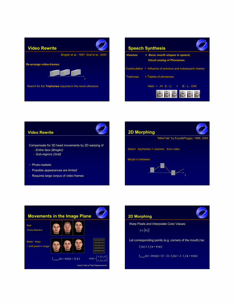
Video RewriteBregler et al., 1997, Graf et al., 2000
Re-arrange video-frames:
BreglerBregler et al., 1997, Graf et al., 2000et al., 1997, Graf et al., 2000
ReRe--arrange videoarrange video--frames:frames:
Search for the Triphones required in the novel utterance.Search for theSearch for the TriphonesTriphones required in the novel utterance.required in the novel utterance.
ttt
Speech SynthesisVisemes = Basic mouth shapes in speech,
Visual analog of Phonemes.
Visemes Visemes = Basic mouth shapes in speech,= Basic mouth shapes in speech,
Visual analog of Phonemes.Visual analog of Phonemes.
Triphones = Triplets of phonemesTriphones Triphones = Triplets of phonemes= Triplets of phonemes
Hello = /H - E - L/ + /E - L - OW/ Hello = /H Hello = /H -- E E -- L/ L/ + + /E /E -- L L -- OW/ OW/
Coarticulation = Influence of previous and subsequent viseme. Coarticulation Coarticulation = Influence of previous and subsequent = Influence of previous and subsequent visemeviseme. .
Video Rewrite
Compensate for 3D head movements by 2D warping of– Entire face (Bregler)– Sub-regions (Graf)
+ Photo-realistic
- Possible appearances are limited
- Requires large corpus of video frames
Compensate for 3D head movements by 2D warping ofCompensate for 3D head movements by 2D warping of–– Entire face (Entire face (BreglerBregler))–– SubSub--regions (Graf)regions (Graf)
++ PhotoPhoto--realisticrealistic
-- Possible appearances are limitedPossible appearances are limited
-- Requires large corpus of video framesRequires large corpus of video frames
2D Morphing
Select keyframes = visemes from video
Morph in between:
Select Select keyframeskeyframes = = visemes visemes from video from video
Morph in between:Morph in between:
“MikeTalk” by Ezzat&Poggio, 1998, 2000““MikeTalkMikeTalk” by” by EzzatEzzat&&PoggioPoggio, 1998, 2000, 1998, 2000
ttt
Movements in the Image Plane
Bad:
Cross-dissolve
Bad:Bad:
CrossCross--dissolvedissolve
Better: Warp
= shift pixels in image
Better: WarpBetter: Warp
= shift pixels in image= shift pixels in image
Vector Field of Pixel DisplacementsVector Field of Pixel DisplacementsVector Field of Pixel Displacements
)())(( xxvx IIwarped =+ )())(( xxvx IIwarped =+
=
),(),(
)(yxvyxv
y
xxv
=
),(),(
)(yxvyxv
y
xxv
2D Morphing
Warp Pixels and Interpolate Color Values:
Let corresponding points (e.g. corners of the mouth) be:
Warp Pixels and Interpolate Color Values:Warp Pixels and Interpolate Color Values:
Let corresponding points (e.g. corners of the mouth) be:Let corresponding points (e.g. corners of the mouth) be:
[ ]1,0∈λ [ ]1,0∈λ
))(()( 21 xvxx +≅ II ))(()( 21 xvxx +≅ II
))(()()1())(( 21 xvxxxvx +⋅+⋅−=+ IIImorph λλλ ))(()()1())(( 21 xvxxxvx +⋅+⋅−=+ IIImorph λλλ
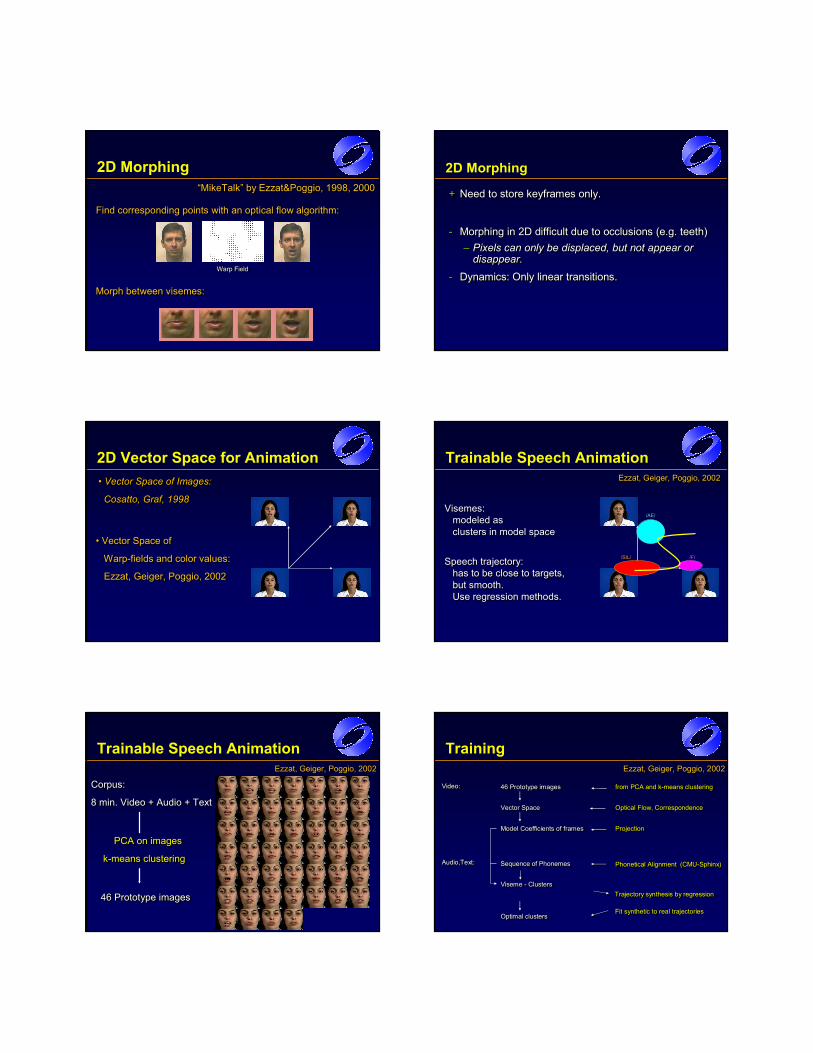
2D Morphing
Morph between visemes:Morph between Morph between visemesvisemes::
Find corresponding points with an optical flow algorithm:Find corresponding points with an optical flow algorithm:Find corresponding points with an optical flow algorithm:
Warp FieldWarp FieldWarp Field
“MikeTalk” by Ezzat&Poggio, 1998, 2000““MikeTalkMikeTalk” by” by EzzatEzzat&&PoggioPoggio, 1998, 2000, 1998, 2000
2D Morphing
+ Need to store keyframes only.
- Morphing in 2D difficult due to occlusions (e.g. teeth)– Pixels can only be displaced, but not appear or
disappear.- Dynamics: Only linear transitions.
++ Need to store Need to store keyframes keyframes only.only.
-- Morphing in 2D difficult due to occlusions (e.g. teeth)Morphing in 2D difficult due to occlusions (e.g. teeth)–– Pixels can only be displaced, but not appear or Pixels can only be displaced, but not appear or
disappear.disappear.-- Dynamics: Only linear transitions.Dynamics: Only linear transitions.
2D Vector Space for Animation• Vector Space of Images:
Cosatto, Graf, 1998
•• Vector Space of Images: Vector Space of Images:
CosattoCosatto, Graf, 1998, Graf, 1998
• Vector Space of
Warp-fields and color values:
Ezzat, Geiger, Poggio, 2002
•• Vector Space ofVector Space of
WarpWarp--fields and color values:fields and color values:
EzzatEzzat, Geiger, , Geiger, PoggioPoggio, 2002, 2002
Trainable Speech Animation
/SIL/ /F/
/AE/Visemes:
modeled as clusters in model space
Visemes:modeled as clusters in model space
Speech trajectory: has to be close to targets, but smooth. Use regression methods.
Speech trajectory: has to be close to targets, but smooth. Use regression methods.
Ezzat, Geiger, Poggio, 2002EzzatEzzat, Geiger, , Geiger, PoggioPoggio, 2002, 2002
Trainable Speech Animation
46 Prototype images46 Prototype images46 Prototype images
PCA on images
k-means clustering
PCA on imagesPCA on images
kk--means clusteringmeans clustering
Corpus:
8 min. Video + Audio + Text
Corpus:Corpus:
8 min. Video + Audio + Text8 min. Video + Audio + Text
Ezzat, Geiger, Poggio, 2002EzzatEzzat, Geiger, , Geiger, PoggioPoggio, 2002, 2002
Training
46 Prototype images46 Prototype images46 Prototype images from PCA and k-means clusteringfrom PCA and kfrom PCA and k--means clusteringmeans clusteringVideo:Video:Video:
Vector SpaceVector SpaceVector Space Optical Flow, CorrespondenceOptical Flow, CorrespondenceOptical Flow, Correspondence
Model Coefficients of framesModel Coefficients of framesModel Coefficients of frames ProjectionProjectionProjection
Viseme - ClustersVisemeViseme -- ClustersClusters
Sequence of PhonemesSequence of PhonemesSequence of Phonemes Phonetical Alignment (CMU-Sphinx)PhoneticalPhonetical Alignment (CMUAlignment (CMU--Sphinx)Sphinx)Audio,Text:Audio,Text:Audio,Text:
Optimal clustersOptimal clustersOptimal clusters Fit synthetic to real trajectoriesFit synthetic to real trajectoriesFit synthetic to real trajectories
Trajectory synthesis by regressionTrajectory synthesis by regressionTrajectory synthesis by regression
Ezzat, Geiger, Poggio, 2002EzzatEzzat, Geiger, , Geiger, PoggioPoggio, 2002, 2002
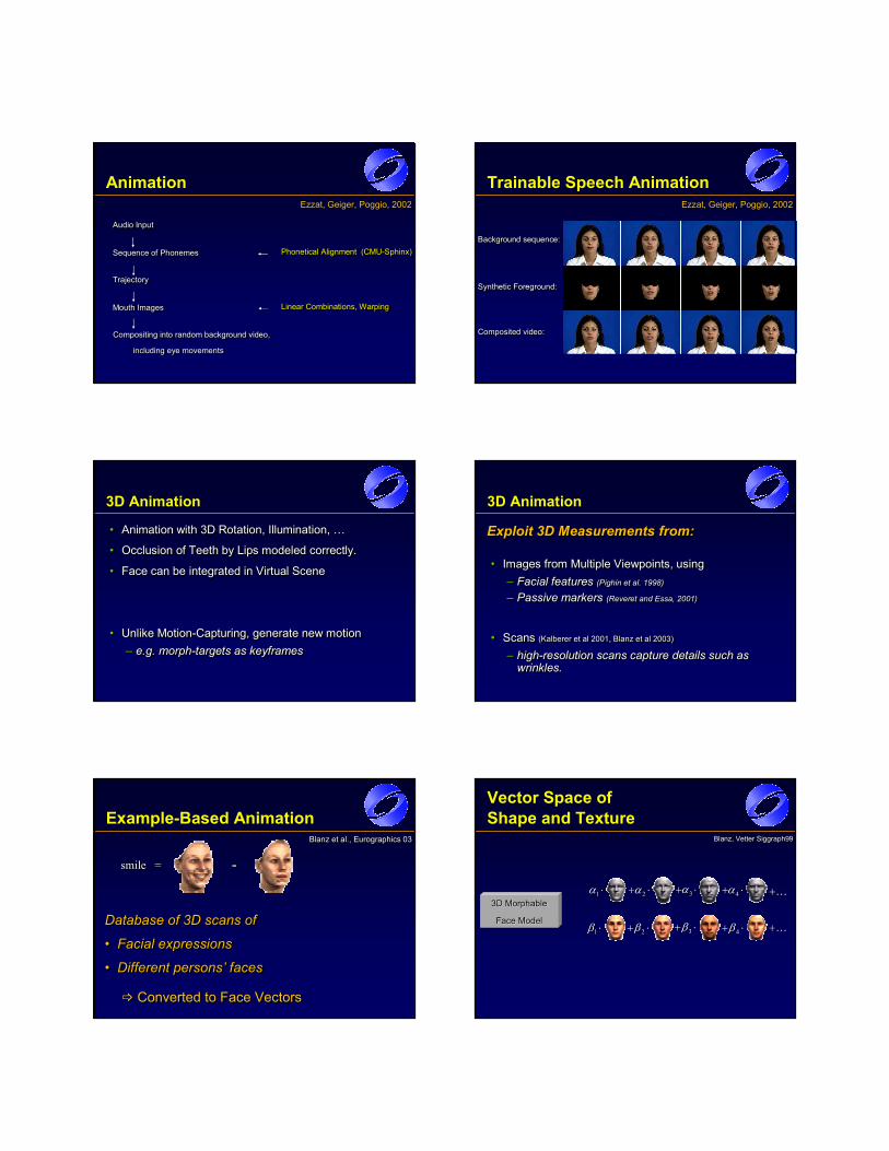
Animation
Audio InputAudio InputAudio Input
Sequence of PhonemesSequence of PhonemesSequence of Phonemes Phonetical Alignment (CMU-Sphinx)PhoneticalPhonetical Alignment (CMUAlignment (CMU--Sphinx)Sphinx)
TrajectoryTrajectoryTrajectory
Compositing into random background video,
including eye movements
Compositing Compositing into random background video, into random background video,
including eye movementsincluding eye movements
Mouth ImagesMouth ImagesMouth Images Linear Combinations, WarpingLinear Combinations, WarpingLinear Combinations, Warping
Ezzat, Geiger, Poggio, 2002EzzatEzzat, Geiger, , Geiger, PoggioPoggio, 2002, 2002
Trainable Speech Animation
Background sequence:Background sequence:Background sequence:
Synthetic Foreground:Synthetic Foreground:Synthetic Foreground:
Composited video:Composited Composited video:video:
Ezzat, Geiger, Poggio, 2002EzzatEzzat, Geiger, , Geiger, PoggioPoggio, 2002, 2002
3D Animation
• Animation with 3D Rotation, Illumination, …
• Occlusion of Teeth by Lips modeled correctly.
• Face can be integrated in Virtual Scene
• Unlike Motion-Capturing, generate new motion– e.g. morph-targets as keyframes
•• Animation with 3D Rotation, Illumination, …Animation with 3D Rotation, Illumination, …
•• Occlusion of Teeth by Lips modeled correctly.Occlusion of Teeth by Lips modeled correctly.
•• Face can be integrated in Virtual SceneFace can be integrated in Virtual Scene
•• Unlike MotionUnlike Motion--Capturing, generate new motionCapturing, generate new motion–– e.g. morphe.g. morph--targets astargets as keyframeskeyframes
3D Animation
Exploit 3D Measurements from:
• Images from Multiple Viewpoints, using– Facial features (Pighin et al. 1998)
– Passive markers (Reveret and Essa, 2001)
• Scans (Kalberer et al 2001, Blanz et al 2003)
– high-resolution scans capture details such as wrinkles.
Exploit 3D Measurements from:Exploit 3D Measurements from:
•• Images from Multiple Viewpoints, usingImages from Multiple Viewpoints, using–– Facial features Facial features ((PighinPighin et al. 1998)et al. 1998)
–– Passive markers Passive markers ((ReveretReveret andand EssaEssa, 2001), 2001)
•• Scans Scans ((KalbererKalberer et al 2001, et al 2001, BlanzBlanz et al 2003)et al 2003)
–– highhigh--resolution scans capture details such as resolution scans capture details such as wrinkles.wrinkles.
Example-Based Animation
Database of 3D scans of
• Facial expressions
• Different persons’ faces
Database of 3D scans ofDatabase of 3D scans of
•• Facial expressionsFacial expressions
•• Different persons’ facesDifferent persons’ faces
smile =smile =smile = ---
Converted to Face VectorsConverted to Face VectorsConverted to Face Vectors
Blanz et al., Eurographics 03BlanzBlanz et al., et al., Eurographics Eurographics 0303
Vector Space of Shape and Texture
4β+ ⋅4β+ ⋅
2α+ ⋅2α+ ⋅ 3α+ ⋅3α+ ⋅ 4α+ ⋅4α+ ⋅
3β+ ⋅3β+ ⋅2β+ ⋅2β+ ⋅1β ⋅1β ⋅
1α ⋅1α ⋅ +K+K
+K+K
3D 3D Morphable Morphable
Face ModelFace Model
Blanz, Vetter Siggraph99BlanzBlanz, Vetter Siggraph99, Vetter Siggraph99
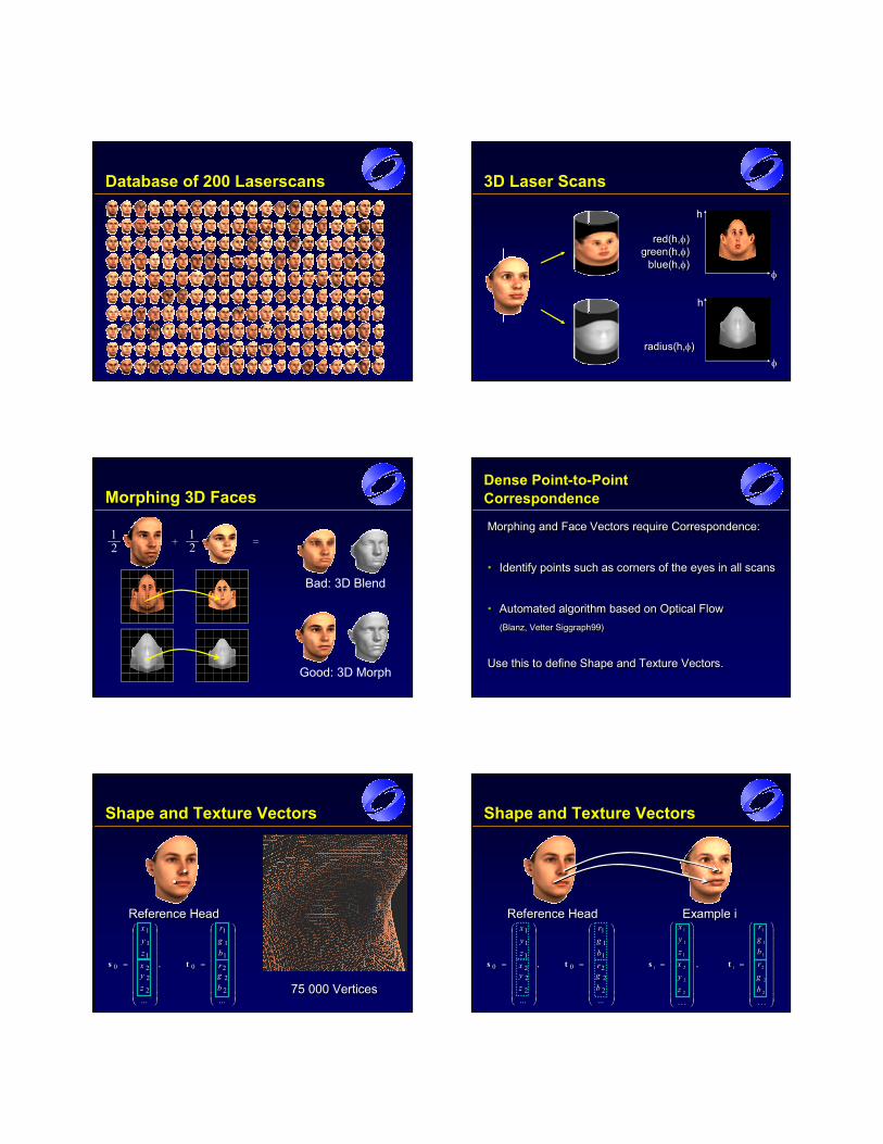
Database of 200 Laserscans 3D Laser Scans
red(h,φ)green(h,φ)
blue(h,φ)
red(h,φ)green(h,φ)
blue(h,φ)φ
h
radius(h,φ)radius(h,φ)
h
φ
Morphing 3D Faces
Bad: 3D Blend
Good: 3D Morph
1__2
1__2+ =
Dense Point-to-Point Correspondence
Morphing and Face Vectors require Correspondence:
• Identify points such as corners of the eyes in all scans
• Automated algorithm based on Optical Flow(Blanz, Vetter Siggraph99)
Use this to define Shape and Texture Vectors.
Morphing and Face Vectors require Correspondence:Morphing and Face Vectors require Correspondence:
•• Identify points such as corners of the eyes in all scansIdentify points such as corners of the eyes in all scans
•• Automated algorithm based on Optical FlowAutomated algorithm based on Optical Flow((BlanzBlanz, Vetter Siggraph99), Vetter Siggraph99)
Use this to define Shape and Texture Vectors.Use this to define Shape and Texture Vectors.
Shape and Texture Vectors
=
=
...
,
...2
22
1
1
1
0
2
22
1
1
1
0
bgrbgr
zyxzyx
ts
=
=
...
,
...2
22
1
1
1
0
2
22
1
1
1
0
bgrbgr
zyxzyx
ts
Reference HeadReference Head
75 000 Vertices75 000 Vertices
Shape and Texture Vectors
1 1
1 1
1 1
2 2
2 2
2 2
,
. . . . . .
i i
x ry gz bx ry gz b
= =
s t
1 1
1 1
1 1
2 2
2 2
2 2
,
. . . . . .
i i
x ry gz bx ry gz b
= =
s t
Example iExample i
=
=
...
,
...2
22
1
1
1
0
2
22
1
1
1
0
bgrbgr
zyxzyx
ts
=
=
...
,
...2
22
1
1
1
0
2
22
1
1
1
0
bgrbgr
zyxzyx
ts
Reference HeadReference Head
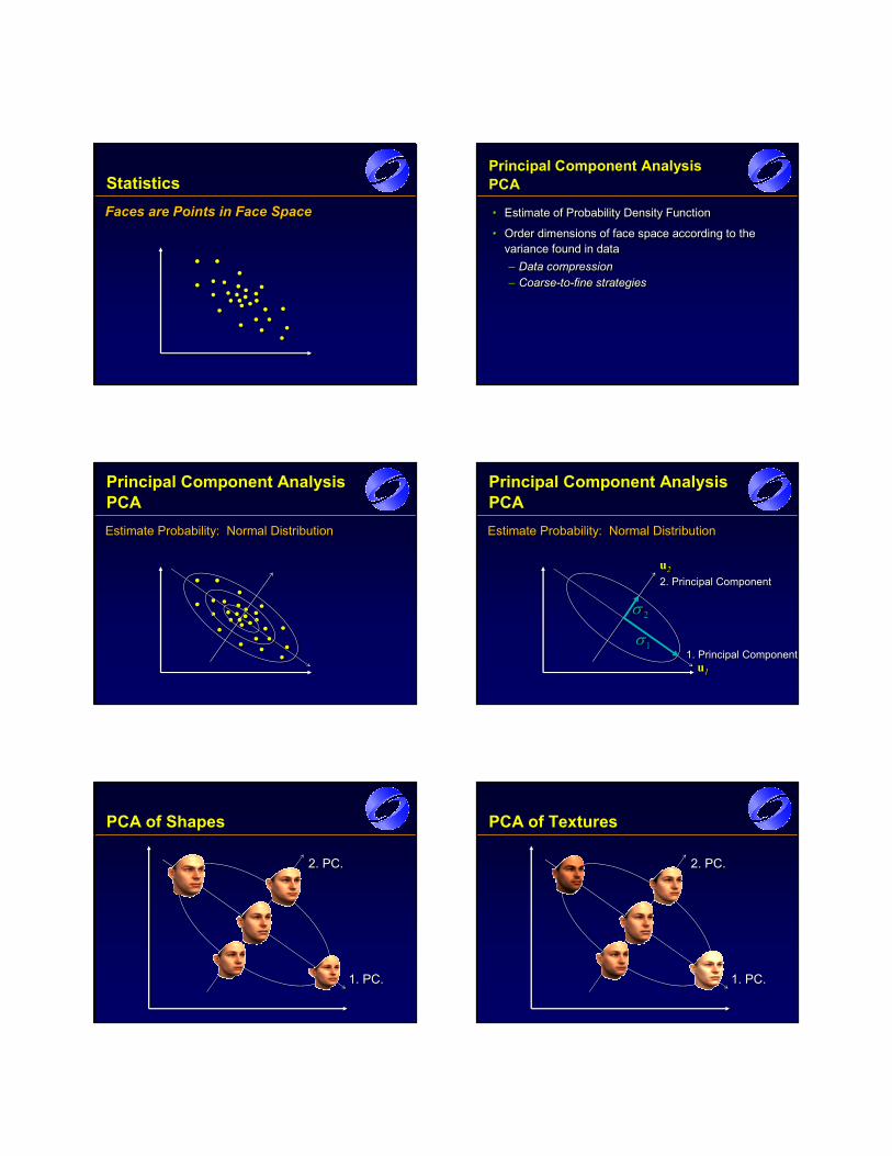
StatisticsFaces are Points in Face SpaceFaces are Points in Face SpaceFaces are Points in Face Space
Principal Component AnalysisPCA
• Estimate of Probability Density Function
• Order dimensions of face space according to the variance found in data – Data compression– Coarse-to-fine strategies
•• Estimate of Probability Density FunctionEstimate of Probability Density Function
•• Order dimensions of face space according to the Order dimensions of face space according to the variance found in data variance found in data –– Data compressionData compression–– CoarseCoarse--toto--fine strategiesfine strategies
Principal Component Analysis PCAEstimate Probability: Normal Distribution Estimate Probability: Normal Distribution
Principal Component AnalysisPCA
1. Principal Component1. Principal Component
2. Principal Component2. Principal Component
Estimate Probability: Normal Distribution Estimate Probability: Normal Distribution
u1uu11
u2uu22
1σ1σ2σ2σ
PCA of Shapes
1. PC.1. PC.
2. PC.2. PC.
PCA of Textures
1. PC.1. PC.
2. PC.2. PC.
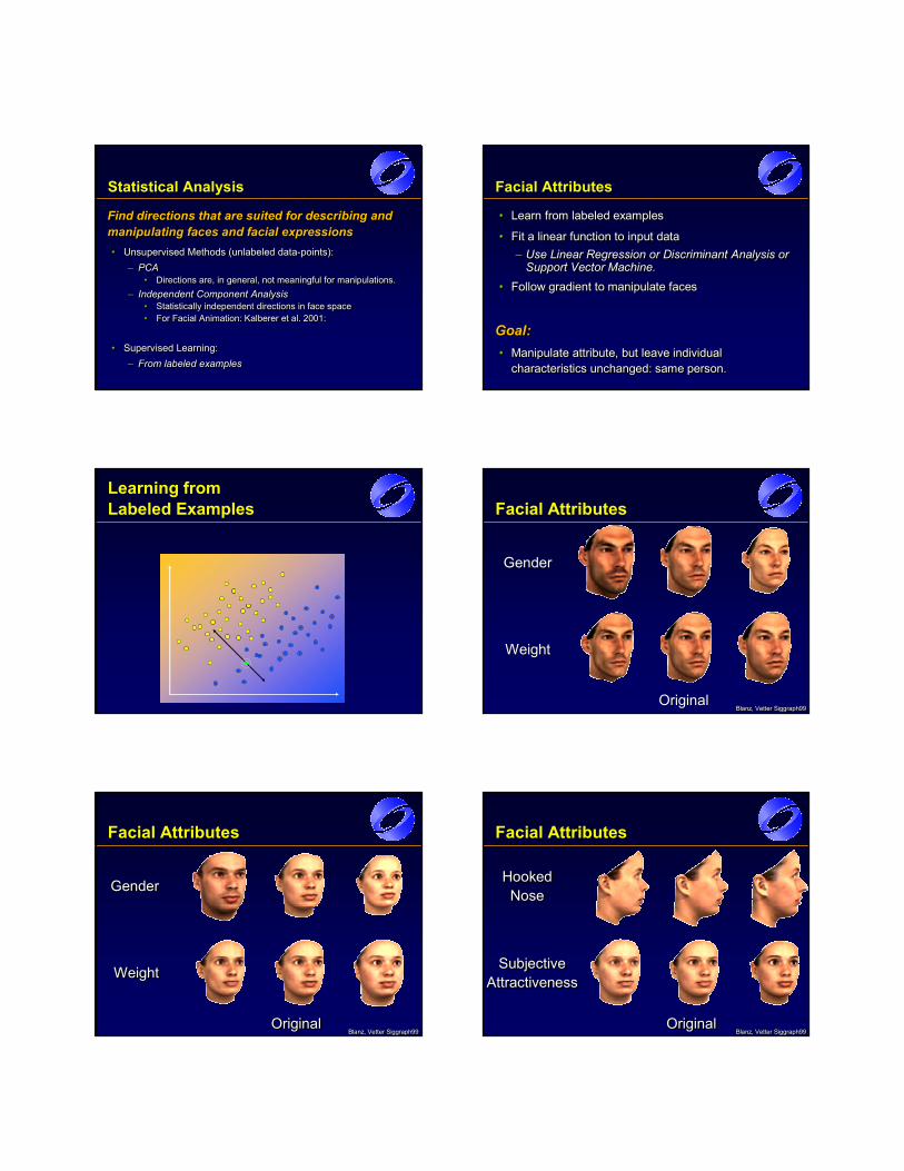
Statistical Analysis
Find directions that are suited for describing and manipulating faces and facial expressions• Unsupervised Methods (unlabeled data-points):
– PCA• Directions are, in general, not meaningful for manipulations.
– Independent Component Analysis• Statistically independent directions in face space• For Facial Animation: Kalberer et al. 2001:
• Supervised Learning:– From labeled examples
Find directions that are suited for describing and Find directions that are suited for describing and manipulating faces and facial expressionsmanipulating faces and facial expressions•• Unsupervised Methods (unlabeled dataUnsupervised Methods (unlabeled data--points):points):
–– PCAPCA•• Directions are, in general, not meaningful for manipulations.Directions are, in general, not meaningful for manipulations.
–– Independent Component AnalysisIndependent Component Analysis•• Statistically independent directions in face spaceStatistically independent directions in face space•• For Facial Animation: For Facial Animation: Kalberer Kalberer et al. 2001:et al. 2001:
•• Supervised Learning:Supervised Learning:–– From labeled examplesFrom labeled examples
Facial Attributes
• Learn from labeled examples
• Fit a linear function to input data– Use Linear Regression or Discriminant Analysis or
Support Vector Machine.• Follow gradient to manipulate faces
Goal:• Manipulate attribute, but leave individual
characteristics unchanged: same person.
•• Learn from labeled examplesLearn from labeled examples
•• Fit a linear function to input dataFit a linear function to input data–– Use Linear Regression or Use Linear Regression or DiscriminantDiscriminant Analysis or Analysis or
Support Vector Machine.Support Vector Machine.•• Follow gradient to manipulate facesFollow gradient to manipulate faces
Goal:Goal:•• Manipulate attribute, but leave individual Manipulate attribute, but leave individual
characteristics unchanged: same person.characteristics unchanged: same person.
Learning fromLabeled Examples Facial Attributes
OriginalOriginal
WeightWeight
GenderGender
Blanz, Vetter Siggraph99BlanzBlanz, Vetter Siggraph99, Vetter Siggraph99
Facial Attributes
WeightWeightWeight
GenderGenderGender
OriginalOriginalOriginalBlanz, Vetter Siggraph99BlanzBlanz, Vetter Siggraph99, Vetter Siggraph99
Facial Attributes
Subjective Attractiveness
Subjective Subjective AttractivenessAttractiveness
Hooked Nose
Hooked Hooked NoseNose
OriginalOriginalOriginalBlanz, Vetter Siggraph99BlanzBlanz, Vetter Siggraph99, Vetter Siggraph99
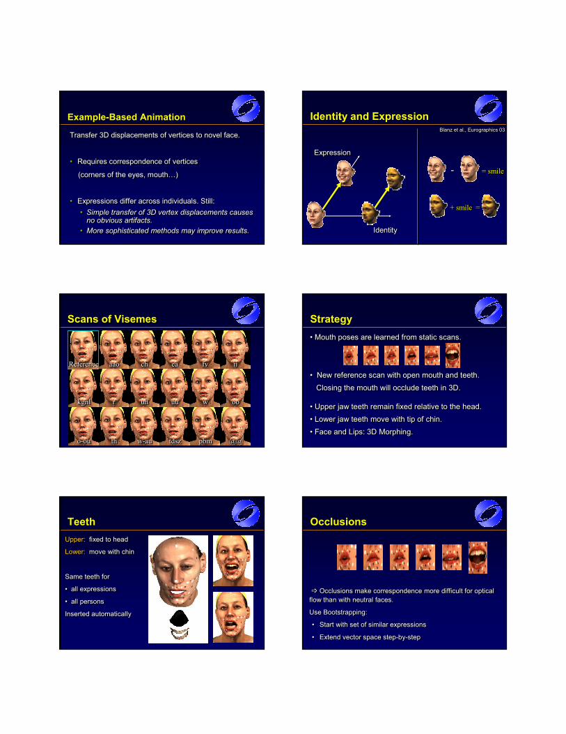
Example-Based Animation
Transfer 3D displacements of vertices to novel face.
• Requires correspondence of vertices
(corners of the eyes, mouth…)
• Expressions differ across individuals. Still:• Simple transfer of 3D vertex displacements causes
no obvious artifacts. • More sophisticated methods may improve results.
Transfer 3D displacements of vertices to novel face.Transfer 3D displacements of vertices to novel face.
•• Requires correspondence of vertices Requires correspondence of vertices
(corners of the eyes, mouth…)(corners of the eyes, mouth…)
•• Expressions differ across individuals. Still:Expressions differ across individuals. Still:•• Simple transfer of 3D vertex displacements causes Simple transfer of 3D vertex displacements causes
no obvious artifacts. no obvious artifacts. •• More sophisticated methods may improve results.More sophisticated methods may improve results.
Identity and Expression
IdentityIdentityIdentity
ExpressionExpressionExpression
= smile== smilesmile---
+ smile =+ + smilesmile ==
Blanz et al., Eurographics 03BlanzBlanz et al., et al., Eurographics Eurographics 0303
aaoaaoaao
rrr
ththth
eaeaea
@@@@@@
chchch fvfvfv iiiiii
kgnlkgnlkgnl oooooo
o-ouoo--ouou pbmpbmpbm
uhuhuh uuuuuu www
w-auww--auau tdsztdsztdsz
ReferenceReferenceReference
Scans of VisemesScans of Visemes Strategy• Mouth poses are learned from static scans.
• New reference scan with open mouth and teeth.Closing the mouth will occlude teeth in 3D.
• Upper jaw teeth remain fixed relative to the head.• Lower jaw teeth move with tip of chin.• Face and Lips: 3D Morphing.
•• Mouth poses are learned from static scans.Mouth poses are learned from static scans.
•• New reference scan with open mouth and teeth.New reference scan with open mouth and teeth.
Closing the mouth will occlude teeth in 3D.Closing the mouth will occlude teeth in 3D.
•• Upper jaw teeth remain fixed relative to the head.Upper jaw teeth remain fixed relative to the head.
•• Lower jaw teeth move with tip of chin.Lower jaw teeth move with tip of chin.
•• Face and Lips: 3D Morphing.Face and Lips: 3D Morphing.
TeethUpper: fixed to head
Lower: move with chin
Same teeth for
• all expressions
• all persons
Inserted automatically
Upper:Upper: fixed to headfixed to head
Lower:Lower: move with chinmove with chin
Same teeth for Same teeth for
•• all expressionsall expressions
•• all personsall persons
Inserted automaticallyInserted automatically
Occlusions
Occlusions make correspondence more difficult for optical flow than with neutral faces.
Use Bootstrapping:
• Start with set of similar expressions
• Extend vector space step-by-step
Occlusions make correspondence more difficult for optical Occlusions make correspondence more difficult for optical flow than with neutral faces.flow than with neutral faces.
Use Bootstrapping: Use Bootstrapping:
•• Start with set of similar expressionsStart with set of similar expressions
•• Extend vector space stepExtend vector space step--byby--stepstep
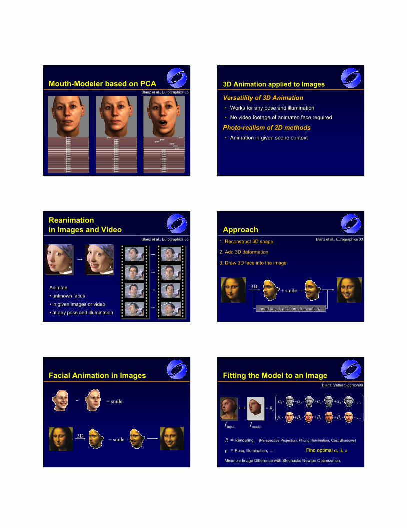
Mouth-Modeler based on PCABlanz et al., Eurographics 03BlanzBlanz et al., et al., Eurographics Eurographics 0303
3D Animation applied to Images
Versatility of 3D Animation• Works for any pose and illumination
• No video footage of animated face required
Photo-realism of 2D methods• Animation in given scene context
Versatility of 3D AnimationVersatility of 3D Animation•• Works for any pose and illuminationWorks for any pose and illumination
•• No video footage of animated face requiredNo video footage of animated face required
PhotoPhoto--realism of 2D methodsrealism of 2D methods•• Animation in given scene contextAnimation in given scene context
Reanimationin Images and Video
Animate
• unknown faces
• in given images or video
• at any pose and illumination
AnimateAnimate
•• unknown facesunknown faces
•• in given images or videoin given images or video
•• at any pose and illuminationat any pose and illumination
Blanz et al., Eurographics 03BlanzBlanz et al., et al., Eurographics Eurographics 0303
Approach1. Reconstruct 3D shape1. Reconstruct 3D shape1. Reconstruct 3D shape
3D3D3D+ smile =+ smile =+ smile =
2. Add 3D deformation2. Add 3D deformation2. Add 3D deformation
head angle, position, illumination, …head angle, position, illumination, …head angle, position, illumination, …
3. Draw 3D face into the image3. Draw 3D face into the image3. Draw 3D face into the image
Blanz et al., Eurographics 03BlanzBlanz et al., et al., Eurographics Eurographics 0303
Facial Animation in Images
= smile= smile= smile---
+ smile =+ smile =+ smile =3D3D3D
Fitting the Model to an Image
1β ⋅1β ⋅ 4β+ ⋅4β+ ⋅
2α+ ⋅2α+ ⋅ 3α+ ⋅3α+ ⋅ 4α+ ⋅4α+ ⋅
3β+ ⋅3β+ ⋅2β+ ⋅2β+ ⋅
1α ⋅1α ⋅ +K+K
+K+K
R = Rendering (Perspective Projection, Phong Illumination, Cast Shadows)
ρ = Pose, Illumination, ...
R = Rendering (Perspective Projection, Phong Illumination, Cast Shadows)
ρ = Pose, Illumination, ...
Rρ
=
Rρ
=
modelImodelIinputIinputI
Find optimal α, β, ρ Find optimal α, β, ρ
Minimize Image Difference with Stochastic Newton Optimization.Minimize Image Difference with Stochastic Newton Optimization.Minimize Image Difference with Stochastic Newton Optimization.
Blanz, Vetter Siggraph99BlanzBlanz, Vetter Siggraph99, Vetter Siggraph99
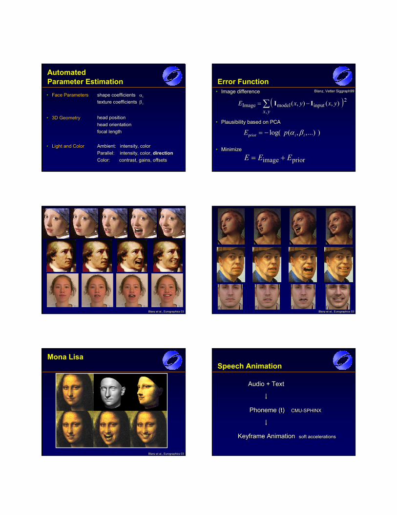
AutomatedParameter Estimation
Ambient: intensity, color Parallel: intensity, color, directionColor: contrast, gains, offsets
Ambient: intensity, color Ambient: intensity, color Parallel: intensity, color, Parallel: intensity, color, directiondirectionColor: contrast, gains, offsetsColor: contrast, gains, offsets
• Face Parameters•• Face ParametersFace Parameters
• Light and Color•• Light and ColorLight and Color
shape coefficients αi
texture coefficients βi
shape coefficients shape coefficients ααii
texture coefficients texture coefficients ββii
• 3D Geometry•• 3D Geometry3D Geometry head positionhead orientationfocal length
head positionhead positionhead orientationhead orientationfocal lengthfocal length
Error Function• Image difference•• Image differenceImage difference
( )2
,inputmodelImage ),(),(∑ −=
yxyxyxE II( )2
,inputmodelImage ),(),(∑ −=
yxyxyxE II
priorimage EEE += priorimage EEE +=• Minimize•• MinimizeMinimize
prior log( ( , ,...) )i iE p α β= −prior log( ( , ,...) )i iE p α β= −• Plausibility based on PCA•• Plausibility based on PCAPlausibility based on PCA
Blanz, Vetter Siggraph99BlanzBlanz, Vetter Siggraph99, Vetter Siggraph99
Blanz et al., Eurographics 03BlanzBlanz et al., et al., Eurographics Eurographics 0303 Blanz et al., Eurographics 03BlanzBlanz et al., et al., Eurographics Eurographics 0303
Mona Lisa
Blanz et al., Eurographics 03BlanzBlanz et al., et al., Eurographics Eurographics 0303
Speech Animation
Audio + TextAudio + TextAudio + Text
Phoneme (t) CMU-SPHINXPhoneme (t)Phoneme (t) CMUCMU--SPHINXSPHINX
Keyframe Animation soft accelerationsKeyframe Keyframe AnimationAnimation soft accelerationssoft accelerations
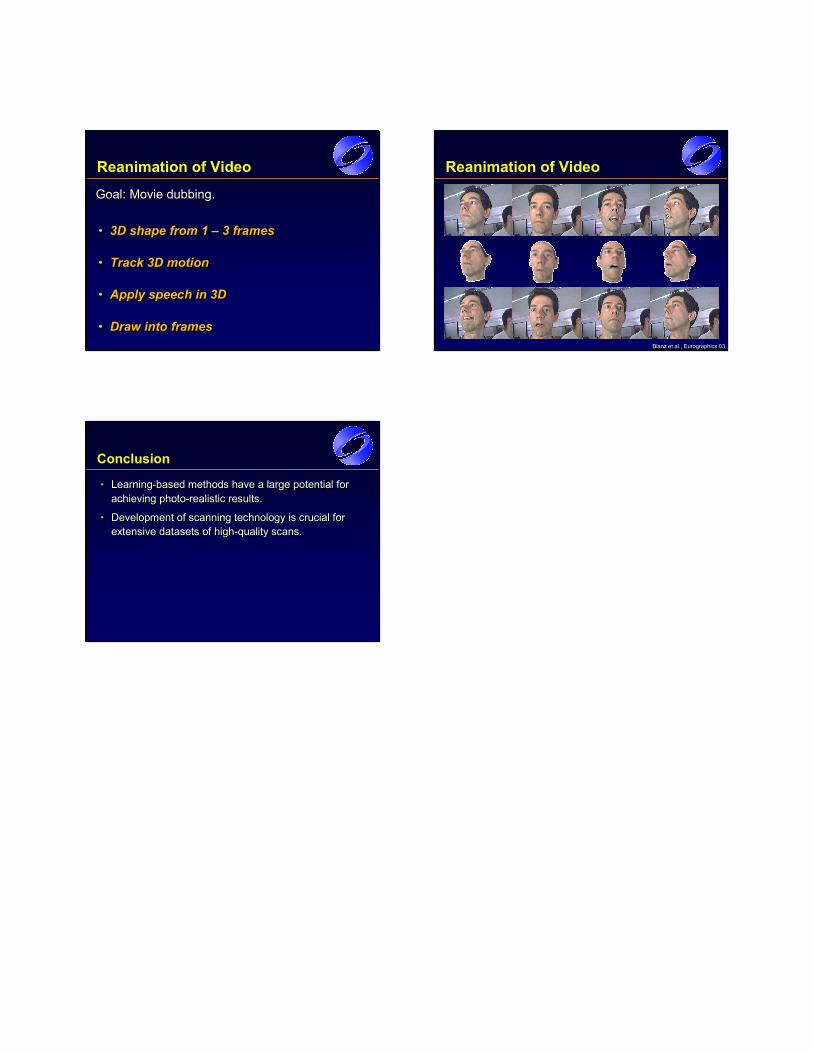
Reanimation of Video
• 3D shape from 1 – 3 frames
• Track 3D motion
• Apply speech in 3D
• Draw into frames
•• 3D shape from 1 3D shape from 1 –– 3 frames3 frames
•• Track 3D motionTrack 3D motion
•• Apply speech in 3DApply speech in 3D
•• Draw into frames Draw into frames
Goal: Movie dubbing. Goal: Movie dubbing. Goal: Movie dubbing.
Reanimation of Video
Blanz et al., Eurographics 03BlanzBlanz et al., et al., Eurographics Eurographics 0303
Conclusion
• Learning-based methods have a large potential for achieving photo-realistic results.
• Development of scanning technology is crucial for extensive datasets of high-quality scans.
•• LearningLearning--based methods have a large potential for based methods have a large potential for achieving photoachieving photo--realistic results.realistic results.
•• Development of scanning technology is crucial for Development of scanning technology is crucial for extensive datasets of highextensive datasets of high--quality scans. quality scans.
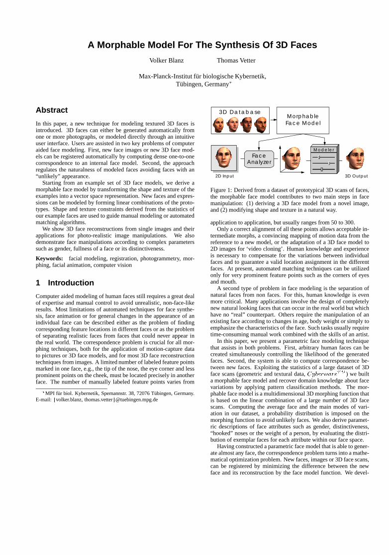
A Morphable Model For The Synthesis Of 3D Faces
Volker Blanz Thomas Vetter
Max-Planck-Institut f¨ur biologische Kybernetik,Tubingen, Germany�
Abstract
In this paper, a new technique for modeling textured 3D faces isintroduced. 3D faces can either be generated automatically fromone or more photographs, or modeled directly through an intuitiveuser interface. Users are assisted in two key problems of computeraided face modeling. First, new face images or new 3D face mod-els can be registered automatically by computing dense one-to-onecorrespondence to an internal face model. Second, the approachregulates the naturalness of modeled faces avoiding faces with an“unlikely” appearance.
Starting from an example set of 3D face models, we derive amorphable face model by transforming the shape and texture of theexamples into a vector space representation. New faces and expres-sions can be modeled by forming linear combinations of the proto-types. Shape and texture constraints derived from the statistics ofour example faces are used to guide manual modeling or automatedmatching algorithms.
We show 3D face reconstructions from single images and theirapplications for photo-realistic image manipulations. We alsodemonstrate face manipulations according to complex parameterssuch as gender, fullness of a face or its distinctiveness.
Keywords: facial modeling, registration, photogrammetry, mor-phing, facial animation, computer vision
1 Introduction
Computer aided modeling of human faces still requires a great dealof expertise and manual control to avoid unrealistic, non-face-likeresults. Most limitations of automated techniques for face synthe-sis, face animation or for general changes in the appearance of anindividual face can be described either as the problem of findingcorresponding feature locations in different faces or as the problemof separating realistic faces from faces that could never appear inthe real world. The correspondence problem is crucial for all mor-phing techniques, both for the application of motion-capture datato pictures or 3D face models, and for most 3D face reconstructiontechniques from images. A limited number of labeled feature pointsmarked in one face, e.g., the tip of the nose, the eye corner and lessprominent points on the cheek, must be located precisely in anotherface. The number of manually labeled feature points varies from
�MPI fur biol. Kybernetik, Spemannstr. 38, 72076 T¨ubingen, Germany.E-mail: fvolker.blanz, [email protected]
Modeler
Morphable Face Model
FaceAnalyzer
3D Database
2D Input 3D Output
Figure 1: Derived from a dataset of prototypical 3D scans of faces,the morphable face model contributes to two main steps in facemanipulation: (1) deriving a 3D face model from a novel image,and (2) modifying shape and texture in a natural way.
application to application, but usually ranges from 50 to 300.Only a correct alignment of all these points allows acceptable in-
termediate morphs, a convincing mapping of motion data from thereference to a new model, or the adaptation of a 3D face model to2D images for ‘video cloning’. Human knowledge and experienceis necessary to compensate for the variations between individualfaces and to guarantee a valid location assignment in the differentfaces. At present, automated matching techniques can be utilizedonly for very prominent feature points such as the corners of eyesand mouth.
A second type of problem in face modeling is the separation ofnatural faces from non faces. For this, human knowledge is evenmore critical. Many applications involve the design of completelynew natural looking faces that can occur in the real world but whichhave no “real” counterpart. Others require the manipulation of anexisting face according to changes in age, body weight or simply toemphasize the characteristics of the face. Such tasks usually requiretime-consuming manual work combined with the skills of an artist.
In this paper, we present a parametric face modeling techniquethat assists in both problems. First, arbitrary human faces can becreated simultaneously controlling the likelihood of the generatedfaces. Second, the system is able to compute correspondence be-tween new faces. Exploiting the statistics of a large dataset of 3Dface scans (geometric and textural data,CyberwareTM ) we builta morphable face model and recover domain knowledge about facevariations by applying pattern classification methods. The mor-phable face model is a multidimensional 3D morphing function thatis based on the linear combination of a large number of 3D facescans. Computing the average face and the main modes of vari-ation in our dataset, a probability distribution is imposed on themorphing function to avoid unlikely faces. We also derive paramet-ric descriptions of face attributes such as gender, distinctiveness,“hooked” noses or the weight of a person, by evaluating the distri-bution of exemplar faces for each attribute within our face space.
Having constructed a parametric face model that is able to gener-ate almost any face, the correspondence problem turns into a mathe-matical optimization problem. New faces, images or 3D face scans,can be registered by minimizing the difference between the newface and its reconstruction by the face model function. We devel-
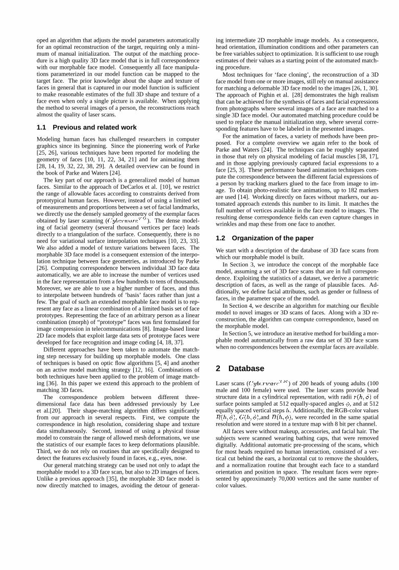
oped an algorithm that adjusts the model parameters automaticallyfor an optimal reconstruction of the target, requiring only a mini-mum of manual initialization. The output of the matching proce-dure is a high quality 3D face model that is in full correspondencewith our morphable face model. Consequently all face manipula-tions parameterized in our model function can be mapped to thetarget face. The prior knowledge about the shape and texture offaces in general that is captured in our model function is sufficientto make reasonable estimates of the full 3D shape and texture of aface even when only a single picture is available. When applyingthe method to several images of a person, the reconstructions reachalmost the quality of laser scans.
1.1 Previous and related work
Modeling human faces has challenged researchers in computergraphics since its beginning. Since the pioneering work of Parke[25, 26], various techniques have been reported for modeling thegeometry of faces [10, 11, 22, 34, 21] and for animating them[28, 14, 19, 32, 22, 38, 29]. A detailed overview can be found inthe book of Parke and Waters [24].
The key part of our approach is a generalized model of humanfaces. Similar to the approach of DeCarlos et al. [10], we restrictthe range of allowable faces according to constraints derived fromprototypical human faces. However, instead of using a limited setof measurements and proportions between a set of facial landmarks,we directly use the densely sampled geometry of the exemplar facesobtained by laser scanning (CyberwareTM ). The dense model-ing of facial geometry (several thousand vertices per face) leadsdirectly to a triangulation of the surface. Consequently, there is noneed for variational surface interpolation techniques [10, 23, 33].We also added a model of texture variations between faces. Themorphable 3D face model is a consequent extension of the interpo-lation technique between face geometries, as introduced by Parke[26]. Computing correspondence between individual 3D face dataautomatically, we are able to increase the number of vertices usedin the face representation from a few hundreds to tens of thousands.Moreover, we are able to use a higher number of faces, and thusto interpolate between hundreds of ’basis’ faces rather than just afew. The goal of such an extended morphable face model is to rep-resent any face as a linear combination of a limited basis set of faceprototypes. Representing the face of an arbitrary person as a linearcombination (morph) of “prototype” faces was first formulated forimage compression in telecommunications [8]. Image-based linear2D face models that exploit large data sets of prototype faces weredeveloped for face recognition and image coding [4, 18, 37].
Different approaches have been taken to automate the match-ing step necessary for building up morphable models. One classof techniques is based on optic flow algorithms [5, 4] and anotheron an active model matching strategy [12, 16]. Combinations ofboth techniques have been applied to the problem of image match-ing [36]. In this paper we extend this approach to the problem ofmatching 3D faces.
The correspondence problem between different three-dimensional face data has been addressed previously by Leeet al.[20]. Their shape-matching algorithm differs significantlyfrom our approach in several respects. First, we compute thecorrespondence in high resolution, considering shape and texturedata simultaneously. Second, instead of using a physical tissuemodel to constrain the range of allowed mesh deformations, we usethe statistics of our example faces to keep deformations plausible.Third, we do not rely on routines that are specifically designed todetect the features exclusively found in faces, e.g., eyes, nose.
Our general matching strategy can be used not only to adapt themorphable model to a 3D face scan, but also to 2D images of faces.Unlike a previous approach [35], the morphable 3D face model isnow directly matched to images, avoiding the detour of generat-
ing intermediate 2D morphable image models. As a consequence,head orientation, illumination conditions and other parameters canbe free variables subject to optimization. It is sufficient to use roughestimates of their values as a starting point of the automated match-ing procedure.
Most techniques for ‘face cloning’, the reconstruction of a 3Dface model from one or more images, still rely on manual assistancefor matching a deformable 3D face model to the images [26, 1, 30].The approach of Pighin et al. [28] demonstrates the high realismthat can be achieved for the synthesis of faces and facial expressionsfrom photographs where several images of a face are matched to asingle 3D face model. Our automated matching procedure could beused to replace the manual initialization step, where several corre-sponding features have to be labeled in the presented images.
For the animation of faces, a variety of methods have been pro-posed. For a complete overview we again refer to the book ofParke and Waters [24]. The techniques can be roughly separatedin those that rely on physical modeling of facial muscles [38, 17],and in those applying previously captured facial expressions to aface [25, 3]. These performance based animation techniques com-pute the correspondence between the different facial expressions ofa person by tracking markers glued to the face from image to im-age. To obtain photo-realistic face animations, up to 182 markersare used [14]. Working directly on faces without markers, our au-tomated approach extends this number to its limit. It matches thefull number of vertices available in the face model to images. Theresulting dense correspondence fields can even capture changes inwrinkles and map these from one face to another.
1.2 Organization of the paper
We start with a description of the database of 3D face scans fromwhich our morphable model is built.
In Section 3, we introduce the concept of the morphable facemodel, assuming a set of 3D face scans that are in full correspon-dence. Exploiting the statistics of a dataset, we derive a parametricdescription of faces, as well as the range of plausible faces. Ad-ditionally, we define facial attributes, such as gender or fullness offaces, in the parameter space of the model.
In Section 4, we describe an algorithm for matching our flexiblemodel to novel images or 3D scans of faces. Along with a 3D re-construction, the algorithm can compute correspondence, based onthe morphable model.
In Section 5, we introduce an iterative method for building a mor-phable model automatically from a raw data set of 3D face scanswhen no correspondences between the exemplar faces are available.
2 Database
Laser scans (CyberwareTM ) of 200 heads of young adults (100male and 100 female) were used. The laser scans provide headstructure data in a cylindrical representation, with radiir(h; �) ofsurface points sampled at 512 equally-spaced angles�, and at 512equally spaced vertical stepsh. Additionally, the RGB-color valuesR(h; �), G(h; �),andB(h; �), were recorded in the same spatialresolution and were stored in a texture map with 8 bit per channel.
All faces were without makeup, accessories, and facial hair. Thesubjects were scanned wearing bathing caps, that were removeddigitally. Additional automatic pre-processing of the scans, whichfor most heads required no human interaction, consisted of a ver-tical cut behind the ears, a horizontal cut to remove the shoulders,and a normalization routine that brought each face to a standardorientation and position in space. The resultant faces were repre-sented by approximately 70,000 vertices and the same number ofcolor values.
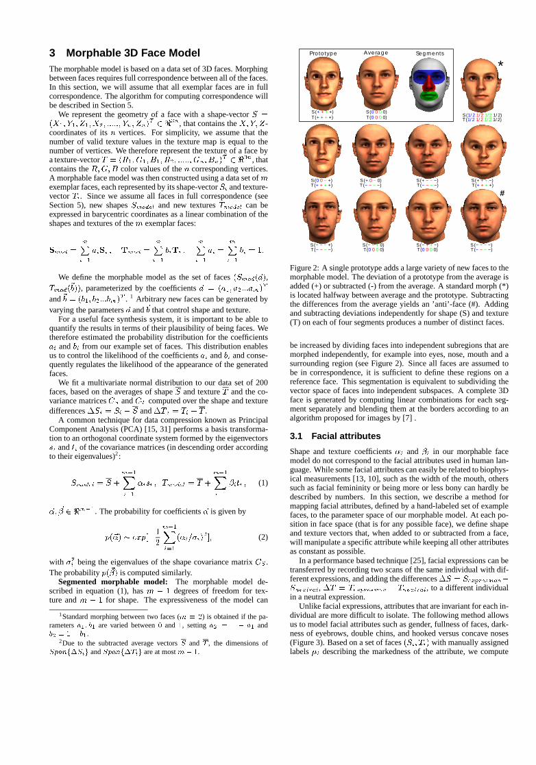
3 Morphable 3D Face ModelThe morphable model is based on a data set of 3D faces. Morphingbetween faces requires full correspondence between all of the faces.In this section, we will assume that all exemplar faces are in fullcorrespondence. The algorithm for computing correspondence willbe described in Section 5.
We represent the geometry of a face with a shape-vectorS =(X1; Y1; Z1; X2; :::::; Yn; Zn)
T 2 <3n, that contains theX;Y; Z-coordinates of itsn vertices. For simplicity, we assume that thenumber of valid texture values in the texture map is equal to thenumber of vertices. We therefore represent the texture of a face bya texture-vectorT = (R1; G1; B1; R2; :::::; Gn; Bn)
T 2 <3n, thatcontains theR;G;B color values of then corresponding vertices.A morphable face model was then constructed using a data set ofmexemplar faces, each represented by its shape-vectorSi and texture-vectorTi. Since we assume all faces in full correspondence (seeSection 5), new shapesSmodel and new texturesTmodel can beexpressed in barycentric coordinates as a linear combination of theshapes and textures of them exemplar faces:
Smod =mPi=1
aiSi ; Tmod =mPi=1
biTi ;mPi=1
ai =mPi=1
bi = 1:
We define the morphable model as the set of faces(Smod(~a),Tmod(~b)), parameterized by the coefficients~a = (a1; a2:::am)T
and~b = (b1; b2:::bm)T . 1 Arbitrary new faces can be generated byvarying the parameters~a and~b that control shape and texture.
For a useful face synthesis system, it is important to be able toquantify the results in terms of their plausibility of being faces. Wetherefore estimated the probability distribution for the coefficientsai andbi from our example set of faces. This distribution enablesus to control the likelihood of the coefficientsai andbi and conse-quently regulates the likelihood of the appearance of the generatedfaces.
We fit a multivariate normal distribution to our data set of 200faces, based on the averages of shapeS and textureT and the co-variance matricesCS andCT computed over the shape and texturedifferences�Si = Si � S and�T i = Ti � T .
A common technique for data compression known as PrincipalComponent Analysis (PCA) [15, 31] performs a basis transforma-tion to an orthogonal coordinate system formed by the eigenvectorssi andti of the covariance matrices (in descending order accordingto their eigenvalues)2:
Smodel = S +
m�1X
i=1
�isi ; Tmodel = T +
m�1X
i=1
�iti ; (1)
~�; ~� 2 <m�1. The probability for coefficients~� is given by
p(~�) � exp[�1
2
m�1X
i=1
(�i=�i)2]; (2)
with �2i being the eigenvalues of the shape covariance matrixCS .The probabilityp(~�) is computed similarly.
Segmented morphable model: The morphable model de-scribed in equation (1), hasm � 1 degrees of freedom for tex-ture andm � 1 for shape. The expressiveness of the model can
1Standard morphing between two faces (m = 2) is obtained if the pa-rametersa1; b1 are varied between0 and 1, settinga2 = 1 � a1 andb2 = 1� b1.
2Due to the subtracted average vectorsS and T , the dimensions ofSpanf�Sig andSpanf�Tig are at mostm� 1.
S (− − − +)T (− − − −)
S (0 0 − +)T (+ + + +)
S (+ + +.−)
AveragePrototype Segments
S (+ + + +)T (+ + + +)
S (0 0 0 0)T (0 0 0 0)
T (0 0 0 0)S (− + + −)
T (0 0 0 0)S (− − + 0)
S (1/2 1/2 1/2 1/2)T (1/2 1/2 1/2 1/2)
*
S (+ − − −)T (− − − −)
T (− − − −)S (− − − −)
#
S (+ 0 − 0)T (− − − −) T (+ + + +)
Figure 2: A single prototype adds a large variety of new faces to themorphable model. The deviation of a prototype from the average isadded (+) or subtracted (-) from the average. A standard morph (*)is located halfway between average and the prototype. Subtractingthe differences from the average yields an ’anti’-face (#). Addingand subtracting deviations independently for shape (S) and texture(T) on each of four segments produces a number of distinct faces.
be increased by dividing faces into independent subregions that aremorphed independently, for example into eyes, nose, mouth and asurrounding region (see Figure 2). Since all faces are assumed tobe in correspondence, it is sufficient to define these regions on areference face. This segmentation is equivalent to subdividing thevector space of faces into independent subspaces. A complete 3Dface is generated by computing linear combinations for each seg-ment separately and blending them at the borders according to analgorithm proposed for images by [7] .
3.1 Facial attributes
Shape and texture coefficients�i and �i in our morphable facemodel do not correspond to the facial attributes used in human lan-guage. While some facial attributes can easily be related to biophys-ical measurements [13, 10], such as the width of the mouth, otherssuch as facial femininity or being more or less bony can hardly bedescribed by numbers. In this section, we describe a method formapping facial attributes, defined by a hand-labeled set of examplefaces, to the parameter space of our morphable model. At each po-sition in face space (that is for any possible face), we define shapeand texture vectors that, when added to or subtracted from a face,will manipulate a specific attribute while keeping all other attributesas constant as possible.
In a performance based technique [25], facial expressions can betransferred by recording two scans of the same individual with dif-ferent expressions, and adding the differences�S = Sexpression�Sneutral, �T = Texpression � Tneutral, to a different individualin a neutral expression.
Unlike facial expressions, attributes that are invariant for each in-dividual are more difficult to isolate. The following method allowsus to model facial attributes such as gender, fullness of faces, dark-ness of eyebrows, double chins, and hooked versus concave noses(Figure 3). Based on a set of faces(Si; Ti) with manually assignedlabels�i describing the markedness of the attribute, we compute
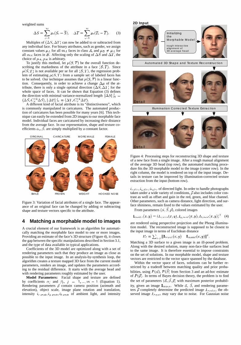
weighted sums
�S =
mX
i=1
�i(Si � S); �T =
mX
i=1
�i(Ti � T ): (3)
Multiples of (�S;�T ) can now be added to or subtracted fromany individual face. For binary attributes, such as gender, we assignconstant values�A for all mA faces in classA, and�B 6= �A forall mB faces inB. Affecting only the scaling of�S and�T , thechoice of�A, �B is arbitrary.
To justify this method, let�(S; T ) be the overall function de-scribing the markedness of the attribute in a face(S; T ). Since�(S; T ) is not available per se for all(S; T ), the regression prob-lem of estimating�(S; T ) from a sample set of labeled faces hasto be solved. Our technique assumes that�(S; T ) is a linear func-tion. Consequently, in order to achieve a change�� of the at-tribute, there is only a single optimal direction(�S;�T ) for thewhole space of faces. It can be shown that Equation (3) definesthe direction with minimal variance-normalized lengthk�Sk2M =h�S;C�1S �Si, k�Tk2M = h�T;C�1T �T i.
A different kind of facial attribute is its “distinctiveness”, whichis commonly manipulated in caricatures. The automated produc-tion of caricatures has been possible for many years [6]. This tech-nique can easily be extended from 2D images to our morphable facemodel. Individual faces are caricatured by increasing their distancefrom the average face. In our representation, shape and texture co-efficients�i; �i are simply multiplied by a constant factor.
ORIGINAL CARICATURE MORE MALE FEMALE
SMILE FROWN HOOKED NOSEWEIGHT
Figure 3: Variation of facial attributes of a single face. The appear-ance of an original face can be changed by adding or subtractingshape and texture vectors specific to the attribute.
4 Matching a morphable model to imagesA crucial element of our framework is an algorithm for automati-cally matching the morphable face model to one or more images.Providing an estimate of the face’s 3D structure (Figure 4), it closesthe gap between the specific manipulations described in Section 3.1,and the type of data available in typical applications.
Coefficients of the 3D model are optimized along with a set ofrendering parameters such that they produce an image as close aspossible to the input image. In an analysis-by-synthesis loop, thealgorithm creates a texture mapped 3D face from the current modelparameters, renders an image, and updates the parameters accord-ing to the residual difference. It starts with the average head andwith rendering parameters roughly estimated by the user.
Model Parameters: Facial shape and texture are definedby coefficients�j and �j , j = 1; :::; m � 1 (Equation 1).Rendering parameters~� contain camera position (azimuth andelevation), object scale, image plane rotation and translation,intensity ir;amb; ig;amb; ib;amb of ambient light, and intensity
Initializingthe Morphable Model
rough interactivealignment of 3D average head
Automated 3D Shape and Texture Reconstruction
Illumination Corrected Texture Extraction
Detail
Detail
2D Input
Figure 4: Processing steps for reconstructing 3D shape and textureof a new face from a single image. After a rough manual alignmentof the average 3D head (top row), the automated matching proce-dure fits the 3D morphable model to the image (center row). In theright column, the model is rendered on top of the input image. De-tails in texture can be improved by illumination-corrected textureextraction from the input (bottom row).
ir;dir; ig;dir; ib;dir of directed light. In order to handle photographstaken under a wide variety of conditions,~� also includes color con-trast as well as offset and gain in the red, green, and blue channel.Other parameters, such as camera distance, light direction, and sur-face shininess, remain fixed to the values estimated by the user.
From parameters(~�; ~�; ~�), colored images
Imodel(x; y) = (Ir;mod(x; y); Ig;mod(x; y); Ib;mod(x; y))T (4)
are rendered using perspective projection and the Phong illumina-tion model. The reconstructed image is supposed to be closest tothe input image in terms of Euclidean distance
EI =P
x;ykIinput(x; y)� Imodel(x; y)k
2:
Matching a 3D surface to a given image is an ill-posed problem.Along with the desired solution, many non-face-like surfaces leadto the same image. It is therefore essential to impose constraintson the set of solutions. In our morphable model, shape and texturevectors are restricted to the vector space spanned by the database.
Within the vector space of faces, solutions can be further re-stricted by a tradeoff between matching quality and prior proba-bilities, usingP (~�), P (~�) from Section 3 and an ad-hoc estimateof P (~�). In terms of Bayes decision theory, the problem is to findthe set of parameters(~�; ~�; ~�) with maximum posterior probabil-ity, given an imageIinput. While ~�, ~�, and rendering parame-ters ~� completely determine the predicted imageImodel, the ob-served imageIinput may vary due to noise. For Gaussian noise
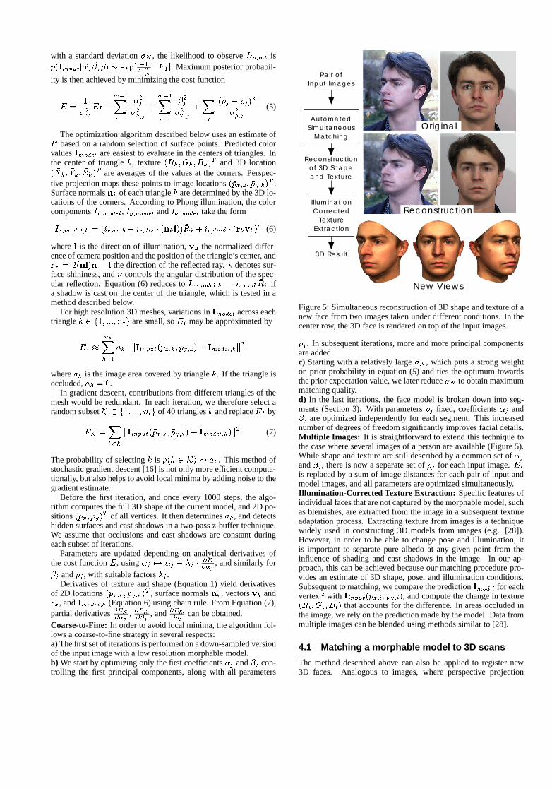
with a standard deviation�N , the likelihood to observeIinput isp(Iinputj~�; ~�; ~�) � exp[ �1
2�2N
� EI ]. Maximum posterior probabil-
ity is then achieved by minimizing the cost function
E =1
�2NEI +
m�1X
j=1
�2j�2S;j
+
m�1X
j=1
�2j�2T;j
+X
j
(�j � ��j)2
�2�;j(5)
The optimization algorithm described below uses an estimate ofE based on a random selection of surface points. Predicted colorvaluesImodel are easiest to evaluate in the centers of triangles. Inthe center of trianglek, texture( �Rk; �Gk; �Bk)
T and 3D location( �Xk; �Yk; �Zk)
T are averages of the values at the corners. Perspec-tive projection maps these points to image locations(�px;k; �py;k)
T .Surface normalsnk of each trianglek are determined by the 3D lo-cations of the corners. According to Phong illumination, the colorcomponentsIr;model, Ig;model andIb;model take the form
Ir;model;k = (ir;amb + ir;dir � (nkl)) �Rk + ir;dirs � (rkvk)� (6)
wherel is the direction of illumination,vk the normalized differ-ence of camera position and the position of the triangle’s center, andrk = 2(nl)n � l the direction of the reflected ray.s denotes sur-face shininess, and� controls the angular distribution of the spec-ular reflection. Equation (6) reduces toIr;model;k = ir;amb
�Rk ifa shadow is cast on the center of the triangle, which is tested in amethod described below.
For high resolution 3D meshes, variations inImodel across eachtrianglek 2 f1; :::; ntg are small, soEI may be approximated by
EI �
ntX
k=1
ak � kIinput(�px;k; �py;k)� Imodel;kk2;
whereak is the image area covered by trianglek. If the triangle isoccluded,ak = 0.
In gradient descent, contributions from different triangles of themesh would be redundant. In each iteration, we therefore select arandom subsetK � f1; :::; ntg of 40 trianglesk and replaceEI by
EK =X
k2K
kIinput(�px;k; �py;k)� Imodel;k)k2: (7)
The probability of selectingk is p(k 2 K) � ak. This method ofstochastic gradient descent [16] is not only more efficient computa-tionally, but also helps to avoid local minima by adding noise to thegradient estimate.
Before the first iteration, and once every 1000 steps, the algo-rithm computes the full 3D shape of the current model, and 2D po-sitions(px; py)T of all vertices. It then determinesak, and detectshidden surfaces and cast shadows in a two-pass z-buffer technique.We assume that occlusions and cast shadows are constant duringeach subset of iterations.
Parameters are updated depending on analytical derivatives ofthe cost functionE, using�j 7! �j � �j �
@E@�j
, and similarly for�j and�j , with suitable factors�j .
Derivatives of texture and shape (Equation 1) yield derivativesof 2D locations(�px;k; �py;k)T , surface normalsnk, vectorsvk andrk, andImodel;k (Equation 6) using chain rule. From Equation (7),partial derivatives@EK
@�j, @EK@�j
, and@EK@�j
can be obtained.Coarse-to-Fine: In order to avoid local minima, the algorithm fol-lows a coarse-to-fine strategy in several respects:a)The first set of iterations is performed on a down-sampled versionof the input image with a low resolution morphable model.b) We start by optimizing only the first coefficients�j and�j con-trolling the first principal components, along with all parameters
Automated Simultaneous
Matching
Reconstruction of 3D Shape and Texture
Pair ofInput Images
3D Result
IlluminationCorrected
TextureExtraction
New Views
Reconstruction
Original
Figure 5: Simultaneous reconstruction of 3D shape and texture of anew face from two images taken under different conditions. In thecenter row, the 3D face is rendered on top of the input images.
�j . In subsequent iterations, more and more principal componentsare added.c) Starting with a relatively large�N , which puts a strong weighton prior probability in equation (5) and ties the optimum towardsthe prior expectation value, we later reduce�N to obtain maximummatching quality.d) In the last iterations, the face model is broken down into seg-ments (Section 3). With parameters�j fixed, coefficients�j and�j are optimized independently for each segment. This increasednumber of degrees of freedom significantly improves facial details.Multiple Images: It is straightforward to extend this technique tothe case where several images of a person are available (Figure 5).While shape and texture are still described by a common set of�jand�j , there is now a separate set of�j for each input image.EI
is replaced by a sum of image distances for each pair of input andmodel images, and all parameters are optimized simultaneously.Illumination-Corrected Texture Extraction: Specific features ofindividual faces that are not captured by the morphable model, suchas blemishes, are extracted from the image in a subsequent textureadaptation process. Extracting texture from images is a techniquewidely used in constructing 3D models from images (e.g. [28]).However, in order to be able to change pose and illumination, itis important to separate pure albedo at any given point from theinfluence of shading and cast shadows in the image. In our ap-proach, this can be achieved because our matching procedure pro-vides an estimate of 3D shape, pose, and illumination conditions.Subsequent to matching, we compare the predictionImod;i for eachvertexi with Iinput(px;i; py;i), and compute the change in texture(Ri; Gi; Bi) that accounts for the difference. In areas occluded inthe image, we rely on the prediction made by the model. Data frommultiple images can be blended using methods similar to [28].
4.1 Matching a morphable model to 3D scans
The method described above can also be applied to register new3D faces. Analogous to images, where perspective projection
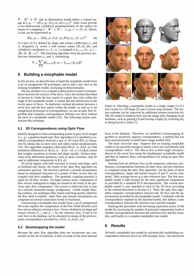
P : R3 ! R2 and an illumination model define a colored im-ageI(x; y) = (R(x; y); G(x; y); B(x; y))T , laser scans providea two-dimensional cylindrical parameterization of the surface bymeans of a mappingC : R3 ! R2; (x; y; z) 7! (h; �). Hence,a scan can be represented as
I(h; �) = (R(h; �); G(h; �); B(h; �); r(h; �))T : (8)
In a face (S,T ), defined by shape and texture coefficients�j and�j (Equation 1), vertexi with texture values(Ri; Gi; Bi) andcylindrical coordinates(ri; hi; �i) is mapped toImodel(hi; �i) =(Ri; Gi; Bi; ri)
T . The matching algorithm from the previous sec-tion now determines�j and�j minimizing
E =X
h;�
kIinput(h; �)� Imodel(h; �)k2:
5 Building a morphable model
In this section, we describe how to build the morphable model froma set of unregistered 3D prototypes, and to add a new face to theexisting morphable model, increasing its dimensionality.
The key problem is to compute a dense point-to-point correspon-dence between the vertices of the faces. Since the method describedin Section 4.1 finds the best match of a given face only within therange of the morphable model, it cannot add new dimensions to thevector space of faces. To determine residual deviations between anovel face and the best match within the model, as well as to setunregistered prototypes in correspondence, we use an optic flow al-gorithm that computes correspondence between two faces withoutthe need of a morphable model [35]. The following section sum-marizes this technique.
5.1 3D Correspondence using Optic Flow
Initially designed to find corresponding points in grey-level imagesI(x; y), a gradient-based optic flow algorithm [2] is modified to es-tablish correspondence between a pair of 3D scansI(h; �) (Equa-tion 8), taking into account color and radius values simultaneously[35]. The algorithm computes a flow field(�h(h; �); ��(h; �)) thatminimizes differences ofkI1(h; �)�I2(h+�h; �+��)k in a normthat weights variations in texture and shape equally. Surface prop-erties from differential geometry, such as mean curvature, may beused as additional components inI(h; �).
On facial regions with little structure in texture and shape, suchas forehead and cheeks, the results of the optic flow algorithm aresometimes spurious. We therefore perform a smooth interpolationbased on simulated relaxation of a system of flow vectors that arecoupled with their neighbors. The quadratic coupling potential isequal for all flow vectors. On high-contrast areas, components offlow vectors orthogonal to edges are bound to the result of the pre-vious optic flow computation. The system is otherwise free to takeon a smooth minimum-energy arrangement. Unlike simple filter-ing routines, our technique fully retains matching quality whereverthe flow field is reliable. Optic flow and smooth interpolation arecomputed on several consecutive levels of resolution.
Constructing a morphable face model from a set of unregistered3D scans requires the computation of the flow fields between eachface and an arbitrary reference face. Given a definition of shape andtexture vectorsSref andTref for the reference face,S andT foreach face in the database can be obtained by means of the point-to-point correspondence provided by(�h(h; �); ��(h; �)).
5.2 Bootstrapping the model
Because the optic flow algorithm does not incorporate any con-straints on the set of solutions, it fails on some of the more unusual
43
21
5 76
Figure 6: Matching a morphable model to a single image (1) of aface results in a 3D shape (2) and a texture map estimate. The tex-ture estimate can be improved by additional texture extraction (4).The 3D model is rendered back into the image after changing facialattributes, such as gaining (3) and loosing weight (5), frowning (6),or being forced to smile (7).
faces in the database. Therefore, we modified a bootstrapping al-gorithm to iteratively improve correspondence, a method that hasbeen used previously to build linear image models [36].
The basic recursive step:Suppose that an existing morphablemodel is not powerful enough to match a new face and thereby findcorrespondence with it. The idea is first to find rough correspon-dences to the novel face using the (inadequate) morphable modeland then to improve these correspondences by using an optic flowalgorithm.
Starting from an arbitrary face as the temporary reference, pre-liminary correspondence between all other faces and this referenceis computed using the optic flow algorithm. On the basis of thesecorrespondences, shape and texture vectorsS andT can be com-puted. Their average serves as a new reference face. The first mor-phable model is then formed by the most significant componentsas provided by a standard PCA decomposition. The current mor-phable model is now matched to each of the 3D faces accordingto the method described in Section 4.1. Then, the optic flow algo-rithm computes correspondence between the 3D face and the ap-proximation provided by the morphable model. Combined with thecorrespondence implied by the matched model, this defines a newcorrespondence between the reference face and the example.
Iterating this procedure with increasing expressive power of themodel (by increasing the number of principal components) leads toreliable correspondences between the reference face and the exam-ples, and finally to a complete morphable face model.
6 Results
We built a morphable face model by automatically establishing cor-respondence between all of our 200 exemplar faces. Our interactive
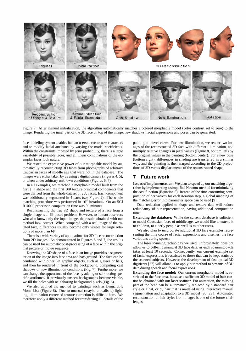
Texture Extraction& Facial Expression
Reconstructionof Shape & Texture Cast Shadow New Illumination Rotation
InitializationOriginal 3D Reconstruction
Figure 7: After manual initialization, the algorithm automatically matches a colored morphable model (color contrast set to zero) to theimage. Rendering the inner part of the 3D face on top of the image, new shadows, facial expressions and poses can be generated.
face modeling system enables human users to create new charactersand to modify facial attributes by varying the model coefficients.Within the constraints imposed by prior probability, there is a largevariability of possible faces, and all linear combinations of the ex-emplar faces look natural.
We tested the expressive power of our morphable model by au-tomatically reconstructing 3D faces from photographs of arbitraryCaucasian faces of middle age that were not in the database. Theimages were either taken by us using a digital camera (Figures 4, 5),or taken under arbitrary unknown conditions (Figures 6, 7).
In all examples, we matched a morphable model built from thefirst 100 shape and the first100 texture principal components thatwere derived from the whole dataset of200 faces. Each componentwas additionally segmented in 4 parts (see Figure 2). The wholematching procedure was performed in105 iterations. On an SGIR10000 processor, computation time was50 minutes.
Reconstructing the true 3D shape and texture of a face from asingle image is an ill-posed problem. However, to human observerswho also know only the input image, the results obtained with ourmethod look correct. When compared with a real image of the ro-tated face, differences usually become only visible for large rota-tions of more than60�.
There is a wide variety of applications for 3D face reconstructionfrom 2D images. As demonstrated in Figures 6 and 7, the resultscan be used for automatic post-processing of a face within the orig-inal picture or movie sequence.
Knowing the 3D shape of a face in an image provides a segmen-tation of the image into face area and background. The face can becombined with other 3D graphic objects, such as glasses or hats,and then be rendered in front of the background, computing castshadows or new illumination conditions (Fig. 7). Furthermore, wecan change the appearance of the face by adding or subtracting spe-cific attributes. If previously unseen backgrounds become visible,we fill the holes with neighboring background pixels (Fig. 6).
We also applied the method to paintings such as Leonardo’sMona Lisa (Figure 8). Due to unusual (maybe unrealistic) light-ing, illumination-corrected texture extraction is difficult here. Wetherefore apply a different method for transferring all details of the
painting to novel views. For new illumination, we render two im-ages of the reconstructed 3D face with different illumination, andmultiply relative changes in pixel values (Figure 8, bottom left) bythe original values in the painting (bottom center). For a new pose(bottom right), differences in shading are transferred in a similarway, and the painting is then warped according to the 2D projec-tions of 3D vertex displacements of the reconstructed shape.
7 Future workIssues of implementation:We plan to speed up our matching algo-rithm by implementing a simplified Newton-method for minimizingthe cost function (Equation 5). Instead of the time consuming com-putation of derivatives for each iteration step, a global mapping ofthe matching error into parameter space can be used [9].
Data reduction applied to shape and texture data will reduceredundancy of our representation, saving additional computationtime.Extending the database:While the current database is sufficientto model Caucasian faces of middle age, we would like to extend itto children, to elderly people as well as to other races.
We also plan to incorporate additional 3D face examples repre-senting the time course of facial expressions and visemes, the facevariations during speech.
The laser scanning technology we used, unfortunately, does notallow us to collect dynamical 3D face data, as each scanning cycletakes at least 10 seconds. Consequently, our current example setof facial expressions is restricted to those that can be kept static bythe scanned subjects. However, the development of fast optical 3Ddigitizers [27] will allow us to apply our method to streams of 3Ddata during speech and facial expressions.Extending the face model: Our current morphable model is re-stricted to the face area, because a sufficient 3D model of hair can-not be obtained with our laser scanner. For animation, the missingpart of the head can be automatically replaced by a standard hairstyle or a hat, or by hair that is modeled using interactive manualsegmentation and adaptation to a 3D model [30, 28]. Automatedreconstruction of hair styles from images is one of the future chal-lenges.
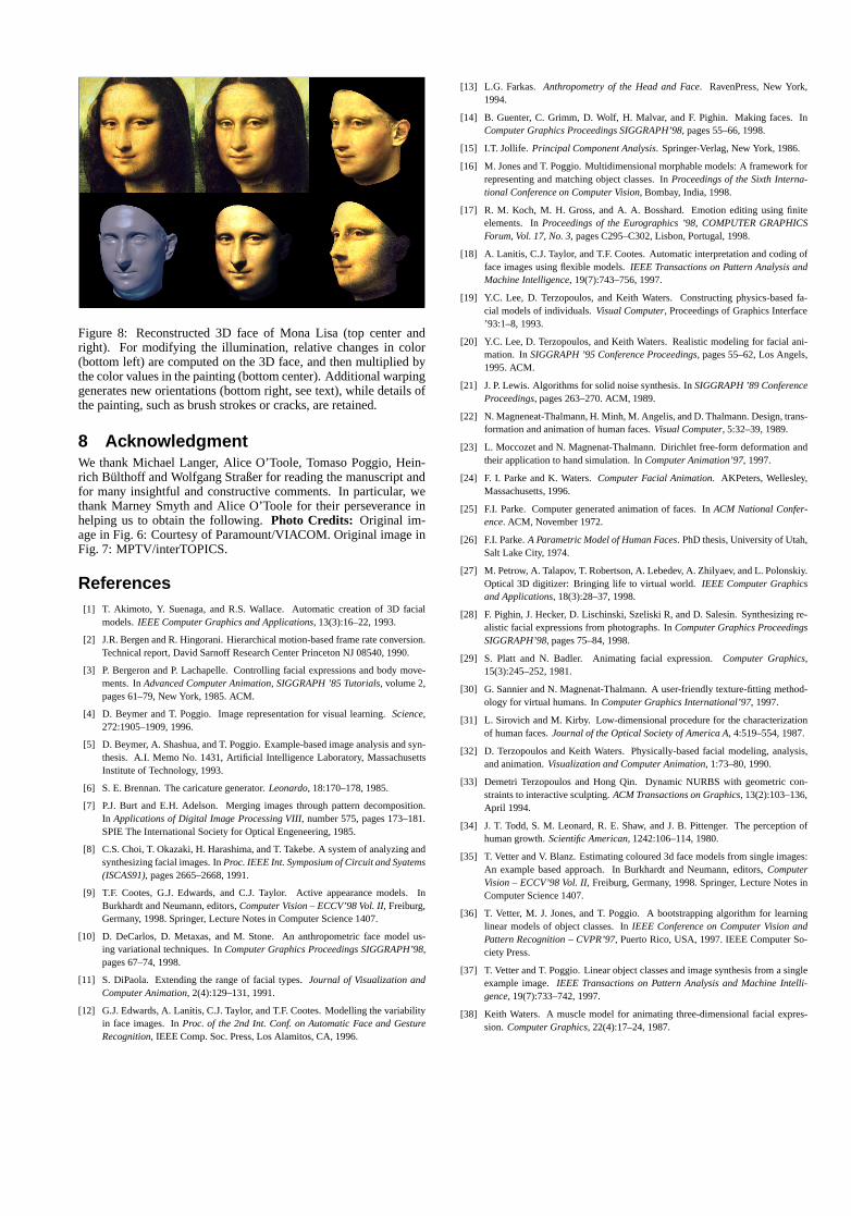
Figure 8: Reconstructed 3D face of Mona Lisa (top center andright). For modifying the illumination, relative changes in color(bottom left) are computed on the 3D face, and then multiplied bythe color values in the painting (bottom center). Additional warpinggenerates new orientations (bottom right, see text), while details ofthe painting, such as brush strokes or cracks, are retained.
8 AcknowledgmentWe thank Michael Langer, Alice O’Toole, Tomaso Poggio, Hein-rich Bulthoff and Wolfgang Straßer for reading the manuscript andfor many insightful and constructive comments. In particular, wethank Marney Smyth and Alice O’Toole for their perseverance inhelping us to obtain the following.Photo Credits: Original im-age in Fig. 6: Courtesy of Paramount/VIACOM. Original image inFig. 7: MPTV/interTOPICS.
References[1] T. Akimoto, Y. Suenaga, and R.S. Wallace. Automatic creation of 3D facial
models.IEEE Computer Graphics and Applications, 13(3):16–22, 1993.
[2] J.R. Bergen and R. Hingorani. Hierarchical motion-based frame rate conversion.Technical report, David Sarnoff Research Center Princeton NJ 08540, 1990.
[3] P. Bergeron and P. Lachapelle. Controlling facial expressions and body move-ments. InAdvanced Computer Animation, SIGGRAPH ’85 Tutorials, volume 2,pages 61–79, New York, 1985. ACM.
[4] D. Beymer and T. Poggio. Image representation for visual learning.Science,272:1905–1909, 1996.
[5] D. Beymer, A. Shashua, and T. Poggio. Example-based image analysis and syn-thesis. A.I. Memo No. 1431, Artificial Intelligence Laboratory, MassachusettsInstitute of Technology, 1993.
[6] S. E. Brennan. The caricature generator.Leonardo, 18:170–178, 1985.
[7] P.J. Burt and E.H. Adelson. Merging images through pattern decomposition.In Applications of Digital Image Processing VIII, number 575, pages 173–181.SPIE The International Society for Optical Engeneering, 1985.
[8] C.S. Choi, T. Okazaki, H. Harashima, and T. Takebe. A system of analyzing andsynthesizing facial images. InProc. IEEE Int. Symposium of Circuit and Syatems(ISCAS91), pages 2665–2668, 1991.
[9] T.F. Cootes, G.J. Edwards, and C.J. Taylor. Active appearance models. InBurkhardt and Neumann, editors,Computer Vision – ECCV’98 Vol. II, Freiburg,Germany, 1998. Springer, Lecture Notes in Computer Science 1407.
[10] D. DeCarlos, D. Metaxas, and M. Stone. An anthropometric face model us-ing variational techniques. InComputer Graphics Proceedings SIGGRAPH’98,pages 67–74, 1998.
[11] S. DiPaola. Extending the range of facial types.Journal of Visualization andComputer Animation, 2(4):129–131, 1991.
[12] G.J. Edwards, A. Lanitis, C.J. Taylor, and T.F. Cootes. Modelling the variabilityin face images. InProc. of the 2nd Int. Conf. on Automatic Face and GestureRecognition, IEEE Comp. Soc. Press, Los Alamitos, CA, 1996.
[13] L.G. Farkas. Anthropometry of the Head and Face. RavenPress, New York,1994.
[14] B. Guenter, C. Grimm, D. Wolf, H. Malvar, and F. Pighin. Making faces. InComputer Graphics Proceedings SIGGRAPH’98, pages 55–66, 1998.
[15] I.T. Jollife. Principal Component Analysis. Springer-Verlag, New York, 1986.
[16] M. Jones and T. Poggio. Multidimensional morphable models: A framework forrepresenting and matching object classes. InProceedings of the Sixth Interna-tional Conference on Computer Vision, Bombay, India, 1998.
[17] R. M. Koch, M. H. Gross, and A. A. Bosshard. Emotion editing using finiteelements. InProceedings of the Eurographics ’98, COMPUTER GRAPHICSForum, Vol. 17, No. 3, pages C295–C302, Lisbon, Portugal, 1998.
[18] A. Lanitis, C.J. Taylor, and T.F. Cootes. Automatic interpretation and coding offace images using flexible models.IEEE Transactions on Pattern Analysis andMachine Intelligence, 19(7):743–756, 1997.
[19] Y.C. Lee, D. Terzopoulos, and Keith Waters. Constructing physics-based fa-cial models of individuals.Visual Computer, Proceedings of Graphics Interface’93:1–8, 1993.
[20] Y.C. Lee, D. Terzopoulos, and Keith Waters. Realistic modeling for facial ani-mation. InSIGGRAPH ’95 Conference Proceedings, pages 55–62, Los Angels,1995. ACM.
[21] J. P. Lewis. Algorithms for solid noise synthesis. InSIGGRAPH ’89 ConferenceProceedings, pages 263–270. ACM, 1989.
[22] N. Magneneat-Thalmann, H. Minh, M. Angelis, and D. Thalmann. Design, trans-formation and animation of human faces.Visual Computer, 5:32–39, 1989.
[23] L. Moccozet and N. Magnenat-Thalmann. Dirichlet free-form deformation andtheir application to hand simulation. InComputer Animation’97, 1997.
[24] F. I. Parke and K. Waters.Computer Facial Animation. AKPeters, Wellesley,Massachusetts, 1996.
[25] F.I. Parke. Computer generated animation of faces. InACM National Confer-ence. ACM, November 1972.
[26] F.I. Parke.A Parametric Model of Human Faces. PhD thesis, University of Utah,Salt Lake City, 1974.
[27] M. Petrow, A. Talapov, T. Robertson, A. Lebedev, A. Zhilyaev, and L. Polonskiy.Optical 3D digitizer: Bringing life to virtual world.IEEE Computer Graphicsand Applications, 18(3):28–37, 1998.
[28] F. Pighin, J. Hecker, D. Lischinski, Szeliski R, and D. Salesin. Synthesizing re-alistic facial expressions from photographs. InComputer Graphics ProceedingsSIGGRAPH’98, pages 75–84, 1998.
[29] S. Platt and N. Badler. Animating facial expression.Computer Graphics,15(3):245–252, 1981.
[30] G. Sannier and N. Magnenat-Thalmann. A user-friendly texture-fitting method-ology for virtual humans. InComputer Graphics International’97, 1997.
[31] L. Sirovich and M. Kirby. Low-dimensional procedure for the characterizationof human faces.Journal of the Optical Society of America A, 4:519–554, 1987.
[32] D. Terzopoulos and Keith Waters. Physically-based facial modeling, analysis,and animation.Visualization and Computer Animation, 1:73–80, 1990.
[33] Demetri Terzopoulos and Hong Qin. Dynamic NURBS with geometric con-straints to interactive sculpting.ACM Transactions on Graphics, 13(2):103–136,April 1994.
[34] J. T. Todd, S. M. Leonard, R. E. Shaw, and J. B. Pittenger. The perception ofhuman growth.Scientific American, 1242:106–114, 1980.
[35] T. Vetter and V. Blanz. Estimating coloured 3d face models from single images:An example based approach. In Burkhardt and Neumann, editors,ComputerVision – ECCV’98 Vol. II, Freiburg, Germany, 1998. Springer, Lecture Notes inComputer Science 1407.
[36] T. Vetter, M. J. Jones, and T. Poggio. A bootstrapping algorithm for learninglinear models of object classes. InIEEE Conference on Computer Vision andPattern Recognition – CVPR’97, Puerto Rico, USA, 1997. IEEE Computer So-ciety Press.
[37] T. Vetter and T. Poggio. Linear object classes and image synthesis from a singleexample image.IEEE Transactions on Pattern Analysis and Machine Intelli-gence, 19(7):733–742, 1997.
[38] Keith Waters. A muscle model for animating three-dimensional facial expres-sion. Computer Graphics, 22(4):17–24, 1987.
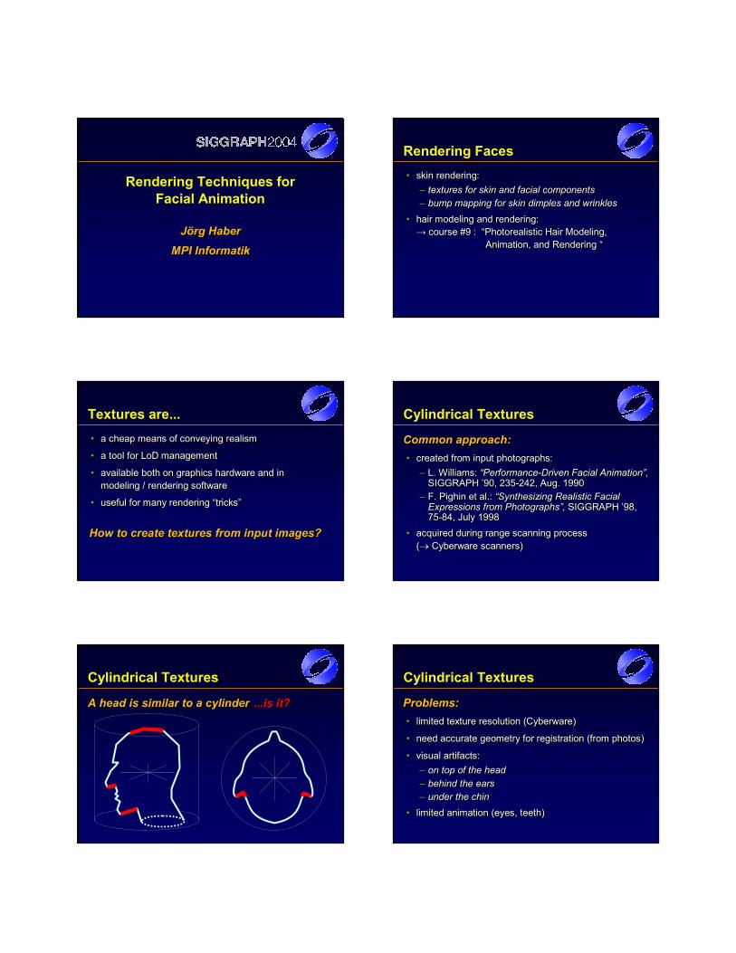
Rendering Techniques forFacial Animation
Jörg HaberMPI Informatik
Jörg HaberJörg Haber
MPI InformatikMPI Informatik
Rendering Faces• skin rendering:
– textures for skin and facial components– bump mapping for skin dimples and wrinkles
• hair modeling and rendering: → course #9 : “Photorealistic Hair Modeling,
Animation, and Rendering “
•• skin skin renderingrendering::–– textures for skin and facial componentstextures for skin and facial components–– bumpbump mapping for skin dimples and wrinklesmapping for skin dimples and wrinkles
•• hair modeling and rendering: hair modeling and rendering: →→ course #9 : “Photorealistic Hair Modeling, course #9 : “Photorealistic Hair Modeling,
Animation, and Rendering “Animation, and Rendering “
Textures are...• a cheap means of conveying realism
• a tool for LoD management
• available both on graphics hardware and in modeling / rendering software
• useful for many rendering “tricks”
•• a cheap means of conveying realisma cheap means of conveying realism
•• a tool for LoD managementa tool for LoD management
•• available both on graphics hardware and in available both on graphics hardware and in modeling / rendering softwaremodeling / rendering software
•• useful for many rendering “tricks”useful for many rendering “tricks”
How to create textures from input images?How to create textures from input images?How to create textures from input images?
Cylindrical Textures
Common approach:• created from input photographs:
– L. Williams: “Performance-Driven Facial Animation”, SIGGRAPH ’90, 235-242, Aug. 1990
– F. Pighin et al.: “Synthesizing Realistic Facial Expressions from Photographs”, SIGGRAPH ’98, 75-84, July 1998
• acquired during range scanning process (→ Cyberware scanners)
Common approach:Common approach:•• created from input photographs:created from input photographs:
–– L. Williams:L. Williams: “Performance“Performance--Driven Facial Animation”, Driven Facial Animation”, SIGGRAPH ’90, 235SIGGRAPH ’90, 235--242, Aug. 1990242, Aug. 1990
–– F. Pighin et al.:F. Pighin et al.: “Synthesizing Realistic Facial “Synthesizing Realistic Facial Expressions from Photographs”, Expressions from Photographs”, SIGGRAPH ’98, SIGGRAPH ’98, 7575--84, July 199884, July 1998
•• acquired during range scanning process acquired during range scanning process ((→→ Cyberware scanners)Cyberware scanners)
Cylindrical Textures
A head is similar to a cylinderAA head is similar to a cylinderhead is similar to a cylinder ...is it?...is it?
Cylindrical Textures
Problems:• limited texture resolution (Cyberware)
• need accurate geometry for registration (from photos)
• visual artifacts:– on top of the head– behind the ears– under the chin
• limited animation (eyes, teeth)
Problems:Problems:•• limited texture resolution (Cyberware)limited texture resolution (Cyberware)
•• need accurate geometry for registration (from photos)need accurate geometry for registration (from photos)
•• visual artifacts:visual artifacts:–– on top of the headon top of the head–– behind the earsbehind the ears–– under the chinunder the chin
•• limited animation (eyes, teeth)limited animation (eyes, teeth)
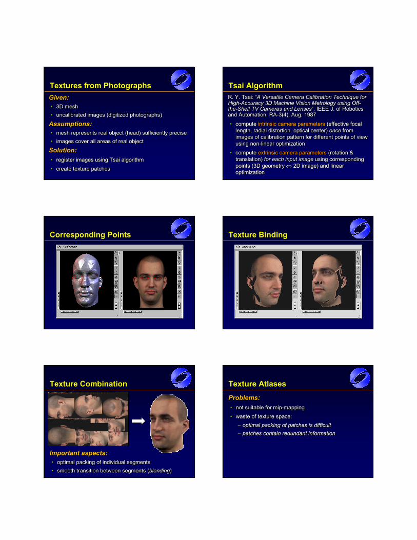
Textures from PhotographsGiven:• 3D mesh• uncalibrated images (digitized photographs)
Assumptions:• mesh represents real object (head) sufficiently precise• images cover all areas of real object
Solution:• register images using Tsai algorithm• create texture patches
Given:Given:•• 3D mesh3D mesh•• uncalibrated images (digitized photographs)uncalibrated images (digitized photographs)
Assumptions:Assumptions:•• mesh represents real object (head) sufficiently precisemesh represents real object (head) sufficiently precise•• images cover all areas of real object images cover all areas of real object
Solution:Solution:•• register images using Tsai algorithmregister images using Tsai algorithm
•• create texture patchescreate texture patches
Tsai Algorithm
• compute intrinsic camera parameters (effective focal length, radial distortion, optical center) once from images of calibration pattern for different points of view using non-linear optimization
• compute extrinsic camera parameters (rotation & translation) for each input image using corresponding points (3D geometry ⇔ 2D image) and linear optimization
•• compute compute intrinsic camera parametersintrinsic camera parameters (effective focal (effective focal length, radial distortion, optical center) length, radial distortion, optical center) onceonce from from images of calibration pattern for different points of view images of calibration pattern for different points of view using nonusing non--linear optimizationlinear optimization
•• compute compute extrinsic camera parametersextrinsic camera parameters (rotation & (rotation & translation) translation) for each input imagefor each input image using corresponding using corresponding points (3D geometry points (3D geometry ⇔⇔ 2D image) and linear 2D image) and linear optimizationoptimization
R. Y. Tsai: “A Versatile Camera Calibration Technique for High-Accuracy 3D Machine Vision Metrology using Off-the-Shelf TV Cameras and Lenses”, IEEE J. of Robotics and Automation, RA-3(4), Aug. 1987
R. Y. Tsai: “R. Y. Tsai: “A Versatile Camera Calibration Technique for A Versatile Camera Calibration Technique for HighHigh--Accuracy 3D Machine Vision Metrology using OffAccuracy 3D Machine Vision Metrology using Off--thethe--Shelf TV Cameras and LensesShelf TV Cameras and Lenses”, IEEE J. of Robotics ”, IEEE J. of Robotics and Automation, RAand Automation, RA--3(4), Aug. 19873(4), Aug. 1987
Corresponding Points Texture Binding
Texture Combination
Important aspects:• optimal packing of individual segments• smooth transition between segments (blending)
Important aspects:Important aspects:•• optimal packing of individual segmentsoptimal packing of individual segments•• smooth transition between segments (smooth transition between segments (blendingblending))
Texture Atlases
Problems:• not suitable for mip-mapping• waste of texture space:
– optimal packing of patches is difficult– patches contain redundant information
Problems:Problems:•• not suitable for mipnot suitable for mip--mappingmapping
•• waste ofwaste of texture space:texture space:–– optimal packing of patches is difficultoptimal packing of patches is difficult–– patches contain redundant information patches contain redundant information
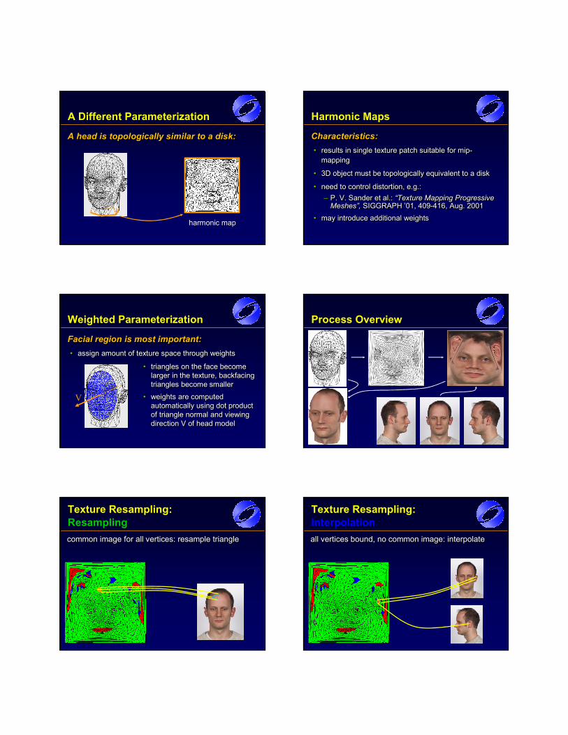
A Different Parameterization
A head is topologically similar to a disk:A headA head is is topologicallytopologically similar to a similar to a disk:disk:
harmonic mapharmonic map
Harmonic Maps
Characteristics:• results in single texture patch suitable for mip-
mapping
• 3D object must be topologically equivalent to a disk
• need to control distortion, e.g.:– P. V. Sander et al.: “Texture Mapping Progressive
Meshes”, SIGGRAPH ’01, 409-416, Aug. 2001• may introduce additional weights
Characteristics:Characteristics:•• results in single texture patch suitable for mipresults in single texture patch suitable for mip--
mappingmapping
•• 3D object must be topologically equivalent to a disk 3D object must be topologically equivalent to a disk
•• need to control distortion, e.g.:need to control distortion, e.g.:–– P. V. Sander et al.:P. V. Sander et al.: “Texture Mapping Progressive “Texture Mapping Progressive
Meshes”, Meshes”, SIGGRAPH ’01, 409SIGGRAPH ’01, 409--416, Aug. 2001416, Aug. 2001
•• may introduce additional weightsmay introduce additional weights
Weighted Parameterization
Facial region is most important:• assign amount of texture space through weights
Facial region is mostFacial region is most important:important:•• assign amount of texture space through weightsassign amount of texture space through weights
V
• triangles on the face become larger in the texture, backfacing triangles become smaller
• weights are computed automatically using dot product of triangle normal and viewing direction V of head model
•• triangles on the face become triangles on the face become larger in the texture, backfacing larger in the texture, backfacing triangles become smallertriangles become smaller
•• weights are computed weights are computed automatically using dot product automatically using dot product of triangle normal and viewing of triangle normal and viewing direction V of head modeldirection V of head model
Process Overview
Texture Resampling:Resamplingcommon image for all vertices: resample trianglecommoncommon image for all vertices: resample triangleimage for all vertices: resample triangle
Texture Resampling:Interpolationall vertices bound, no common image: interpolateall vertices bound, no common image: interpolateall vertices bound, no common image: interpolate
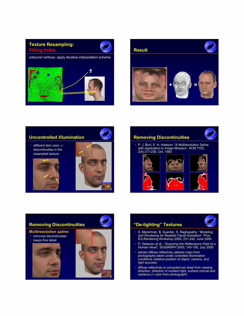
Texture Resampling:Filling holesunbound vertices: apply iterative interpolation schemeunboundunbound vertices: apply iterativevertices: apply iterative interpolation schemeinterpolation scheme
??
Result
++ ==
Uncontrolled Illumination
• different skin color ⇒discontinuities in the resampled texture
•• different skin color different skin color ⇒⇒discontinuities in the discontinuities in the resampled textureresampled texture
Removing Discontinuities• P. J. Burt, E. H. Adelson: “A Multiresolution Spline
with Application to Image Mosaics”, ACM TOG, 2(4):217-236, Oct. 1983
•• P. J. Burt, E. H. Adelson: “P. J. Burt, E. H. Adelson: “A Multiresolution Spline A Multiresolution Spline with Application to Image Mosaicswith Application to Image Mosaics”, ACM TOG, ”, ACM TOG, 2(4):2172(4):217--236, Oct. 1983236, Oct. 1983
Removing DiscontinuitiesMultiresolution spline:• removes discontinuities• keeps fine detail
Multiresolution spline:Multiresolution spline:•• removesremoves discontinuitiesdiscontinuities•• keeps fine detailkeeps fine detail
“De-lighting” Textures• S. Marschner, B. Guenter, S. Raghupathy: “Modeling
and Rendering for Realistic Facial Animation”, Proc. EG Rendering Workshop 2000, 231-242, June 2000
• P. Debevec et al.: “Acquiring the Reflectance Field of a Human Head”, SIGGRAPH 2000, 145-156, July 2000
• extract diffuse reflectivity (albedo map) from photographs taken under controlled illumination conditions (relative position of object, camera, and light sources)
• diffuse reflectivity is computed per texel from viewing direction, direction of incident light, surface normal and radiance (= color from photograph)
•• S.S. MarschnerMarschner, B., B. GuenterGuenter, S., S. RaghupathyRaghupathy: : “Modeling “Modeling and Rendering for Realistic Facial Animationand Rendering for Realistic Facial Animation””,, Proc. Proc. EG EG Rendering WorkshopRendering Workshop 20002000, , 231231--242, June 2000242, June 2000
•• P.P. DebevecDebevec et al.: et al.: “Acquiring the Reflectance Field of a “Acquiring the Reflectance Field of a Human HeadHuman Head””,, SIGGRAPH 2000, SIGGRAPH 2000, 145145--156, July 2000156, July 2000
•• extract diffuse reflectivity (albedo map) from extract diffuse reflectivity (albedo map) from photographs taken under controlled illumination photographs taken under controlled illumination conditions (relative position of object, camera, and conditions (relative position of object, camera, and light sources)light sources)
•• diffuse reflectivity is computed per texel from viewing diffuse reflectivity is computed per texel from viewing direction, direction of incident light, surface normal and direction, direction of incident light, surface normal and radiance (= color from photograph)radiance (= color from photograph)
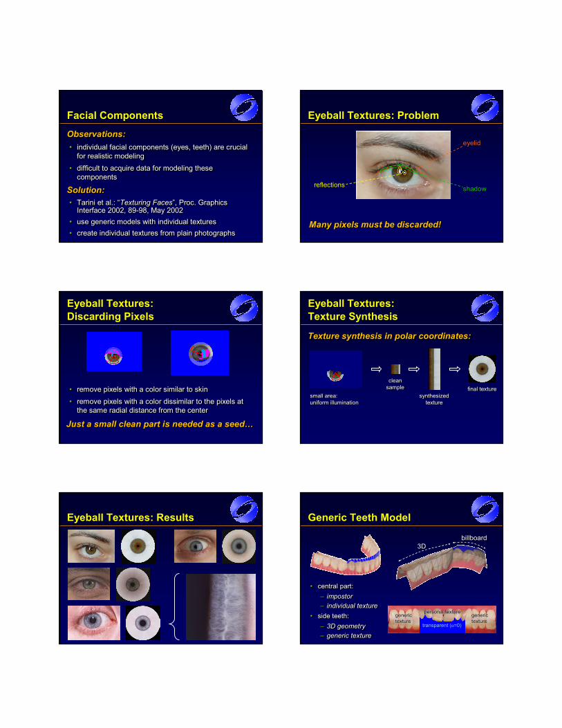
Facial Components
Observations:• individual facial components (eyes, teeth) are crucial
for realistic modeling• difficult to acquire data for modeling these
components
Solution:• Tarini et al.: “Texturing Faces”, Proc. Graphics
Interface 2002, 89-98, May 2002• use generic models with individual textures• create individual textures from plain photographs
Observations:Observations:•• individual facial components (eyes, teeth) are crucial individual facial components (eyes, teeth) are crucial
for realistic modelingfor realistic modeling
•• difficult to acquire data for modeling these difficult to acquire data for modeling these componentscomponents
Solution:Solution:•• Tarini et al.: “Tarini et al.: “Texturing FacesTexturing Faces”, Proc. Graphics ”, Proc. Graphics
Interface 2002, 89Interface 2002, 89--98, May 200298, May 2002•• use generic models with individual texturesuse generic models with individual textures•• create individual textures from plain photographscreate individual textures from plain photographs
Eyeball Textures: Problem
Many pixels must be discarded!ManyMany pixelspixels must be must be discarded!discarded!
eyelideyelid
reflectionsreflections shadowshadow
• remove pixels with a color similar to skin• remove pixels with a color dissimilar to the pixels at
the same radial distance from the center
•• remove pixels with a color similar to skinremove pixels with a color similar to skin
•• remove pixels with a color dissimilar to the pixels at remove pixels with a color dissimilar to the pixels at the same radial distance from the centerthe same radial distance from the center
Eyeball Textures:Discarding Pixels
Just a small clean part is needed as a seed…JustJust a small clean part is needed as a small clean part is needed as a seed…a seed…
Eyeball Textures:Texture Synthesis
Texture synthesis in polar coordinates:Texture synthesis in polar coordinates:Texture synthesis in polar coordinates:
small area:uniform illuminationsmall area:small area:uniform illuminationuniform illumination
clean sampleclean clean
samplesamplesynthesized
texture synthesized synthesized
texture texture
final texturefinalfinal texturetexture
Eyeball Textures: Results Generic Teeth Model
• central part:– impostor– individual texture
• side teeth:– 3D geometry– generic texture
•• central part:central part:–– impostorimpostor–– individual textureindividual texture
•• side teeth:side teeth:–– 3D geometry3D geometry–– generic texturegeneric texture
genericgenerictexturetexture
genericgenerictexturetexture
transparent (α=0)
personalpersonal texturetexture
3D3Dbillboardbillboard
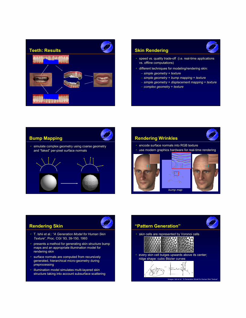
Teeth: Results Skin Rendering• speed vs. quality trade-off (i.e. real-time applications
vs. offline computations)
• different techniques for modeling/rendering skin:– simple geometry + texture– simple geometry + bump mapping + texture– simple geometry + displacement mapping + texture– complex geometry + texture
•• speed vs. quality tradespeed vs. quality trade--off (i.e. realoff (i.e. real--time applications time applications vs. offline computations)vs. offline computations)
•• different techniques for modeling/rendering skin:different techniques for modeling/rendering skin:–– simplesimple geometrygeometry ++ texturetexture–– simple geometrysimple geometry + bump mapping ++ bump mapping + texturetexture–– simplesimple geometrygeometry + displacement mapping ++ displacement mapping + texturetexture–– complex geometry + texturecomplex geometry + texture
Bump Mapping• simulate complex geometry using coarse geometry
and “faked” per-pixel surface normals•• simulate complex geometry using coarse geometry simulate complex geometry using coarse geometry
and “faked” perand “faked” per--pixel surface normalspixel surface normals
Rendering Wrinkles• encode surface normals into RGB texture• use modern graphics hardware for real-time rendering•• encode surface normals into RGB textureencode surface normals into RGB texture•• use modern graphics hardware for realuse modern graphics hardware for real--time renderingtime rendering
bump mapbump mapbump map
Rendering Skin• T. Ishii et al.: “A Generation Model for Human Skin
Texture”, Proc. CGI ‘93, 39-150, 1993
• presents a method for generating skin structure bump maps and an appropriate illumination model for rendering skin
• surface normals are computed from recursively generated, hierarchical micro-geometry during preprocessing
• illumination model simulates multi-layered skin structure taking into account subsurface scattering
•• T. T. Ishii et al.:Ishii et al.: ““A Generation Model for Human Skin A Generation Model for Human Skin TextureTexture”, Proc. CGI ‘93, ”, Proc. CGI ‘93, 3939--150, 1993150, 1993
•• presents a method for generating skin structure bump presents a method for generating skin structure bump maps and an appropriate illumination model for maps and an appropriate illumination model for rendering skinrendering skin
•• surface normals are computed from recursively surface normals are computed from recursively generated, hierarchical microgenerated, hierarchical micro--geometry during geometry during preprocessing preprocessing
•• illumination model simulates multiillumination model simulates multi--layered skin layered skin structure taking into account subsurface scatteringstructure taking into account subsurface scattering
“Pattern Generation”• skin cells are represented by Voronoi cells•• skin cells are represented by Voronoi cellsskin cells are represented by Voronoi cells
• every skin cell bulges upwards above its center; ridge shape: cubic Bézier curves
•• every skin cell bulges upwards above its center; every skin cell bulges upwards above its center; ridge shape: cubic Bézier curvesridge shape: cubic Bézier curves
Images: Ishii et al.: “A Generation Model for Human Skin Texture”

“Hierarchical Skin Structure”• recursive Voronoi subdivision of
skin cells (3 levels)•• recursive Voronoi subdivision of recursive Voronoi subdivision of
skinskin cells (3 levels)cells (3 levels)
Images: Ishii et al.: “A Generation Model for Human Skin Texture”
hierarchy levelhierarchy level
“Multiple Light Reflections”• multi-layered skin structure
results in complex light transport mechanisms
• model: parallel layers; reflection & transmission & scattering at each layer boundary
•• multimulti--layered skin structure layered skin structure results in complex light results in complex light transport mechanismstransport mechanisms
•• model: parallel layers; model: parallel layers; reflection & transmission & reflection & transmission & scatteringscattering at each layer at each layer boundaryboundary
Images: Parke/Waters: “Computer Facial Animation” (1996)
precompute lighting w.r.t. angle of incidenceat skin surface
precompute precompute lighting w.r.t. lighting w.r.t. angle of incidenceangle of incidenceat skin surfaceat skin surface
Ishii et al.: Results • generic model for rendering skin• orientation of skin cells can be aligned to wrinkles• anisotropic scaling of skin cells (→ wrist)• skin structure can be rendered in real-time using
graphics hardware bump mapping; illumination model not (yet) suitable for real-time rendering
•• generic model for rendering skingeneric model for rendering skin•• orientation of skin cells can be aligned to wrinklesorientation of skin cells can be aligned to wrinkles•• anisotropic scaling of skin cells anisotropic scaling of skin cells ((→→ wrist)wrist)•• skin structure can be rendered in realskin structure can be rendered in real--time using time using
graphics hardware bump mapping; illumination model graphics hardware bump mapping; illumination model not (yet) suitable for realnot (yet) suitable for real--time renderingtime rendering
Images: Ishii et al.: “A Generation Model for Human Skin Texture”
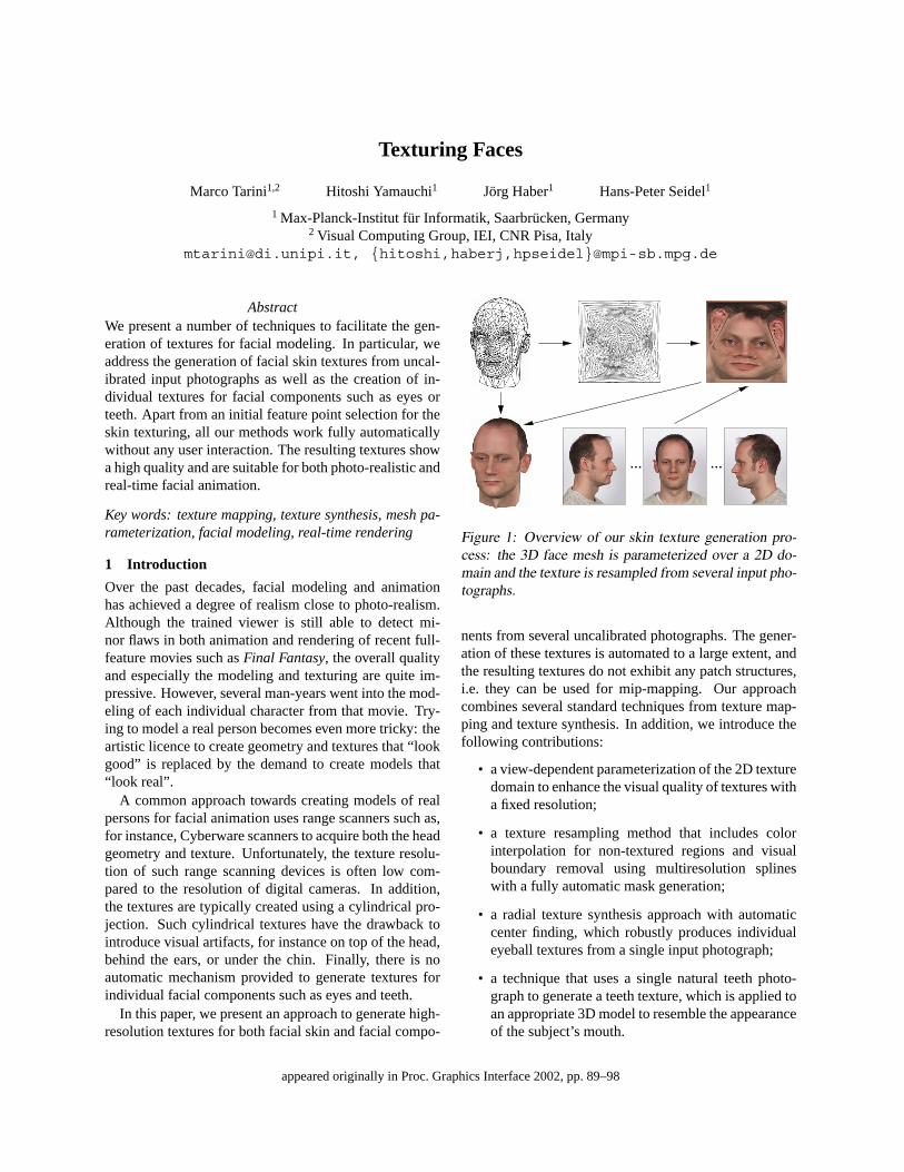
Texturing Faces
Marco Tarini1,2 Hitoshi Yamauchi1 Jorg Haber1 Hans-Peter Seidel1
1 Max-Planck-Institut fur Informatik, Saarbrucken, Germany2 Visual Computing Group, IEI, CNR Pisa, Italy
[email protected], {hitoshi,haberj,hpseidel}@mpi-sb.mpg.de
AbstractWe present a number of techniques to facilitate the gen-eration of textures for facial modeling. In particular, weaddress the generation of facial skin textures from uncal-ibrated input photographs as well as the creation of in-dividual textures for facial components such as eyes orteeth. Apart from an initial feature point selection for theskin texturing, all our methods work fully automaticallywithout any user interaction. The resulting textures showa high quality and are suitable for both photo-realistic andreal-time facial animation.
Key words: texture mapping, texture synthesis, mesh pa-rameterization, facial modeling, real-time rendering
1 Introduction
Over the past decades, facial modeling and animationhas achieved a degree of realism close to photo-realism.Although the trained viewer is still able to detect mi-nor flaws in both animation and rendering of recent full-feature movies such as Final Fantasy, the overall qualityand especially the modeling and texturing are quite im-pressive. However, several man-years went into the mod-eling of each individual character from that movie. Try-ing to model a real person becomes even more tricky: theartistic licence to create geometry and textures that “lookgood” is replaced by the demand to create models that“look real”.
A common approach towards creating models of realpersons for facial animation uses range scanners such as,for instance, Cyberware scanners to acquire both the headgeometry and texture. Unfortunately, the texture resolu-tion of such range scanning devices is often low com-pared to the resolution of digital cameras. In addition,the textures are typically created using a cylindrical pro-jection. Such cylindrical textures have the drawback tointroduce visual artifacts, for instance on top of the head,behind the ears, or under the chin. Finally, there is noautomatic mechanism provided to generate textures forindividual facial components such as eyes and teeth.
In this paper, we present an approach to generate high-resolution textures for both facial skin and facial compo-
... ...
Figure 1: Overview of our skin texture generation pro-cess: the 3D face mesh is parameterized over a 2D do-main and the texture is resampled from several input pho-tographs.
nents from several uncalibrated photographs. The gener-ation of these textures is automated to a large extent, andthe resulting textures do not exhibit any patch structures,i.e. they can be used for mip-mapping. Our approachcombines several standard techniques from texture map-ping and texture synthesis. In addition, we introduce thefollowing contributions:
• a view-dependent parameterization of the 2D texturedomain to enhance the visual quality of textures witha fixed resolution;
• a texture resampling method that includes colorinterpolation for non-textured regions and visualboundary removal using multiresolution splineswith a fully automatic mask generation;
• a radial texture synthesis approach with automaticcenter finding, which robustly produces individualeyeball textures from a single input photograph;
• a technique that uses a single natural teeth photo-graph to generate a teeth texture, which is applied toan appropriate 3D model to resemble the appearanceof the subject’s mouth.
appeared originally in Proc. Graphics Interface 2002, pp. 89–98
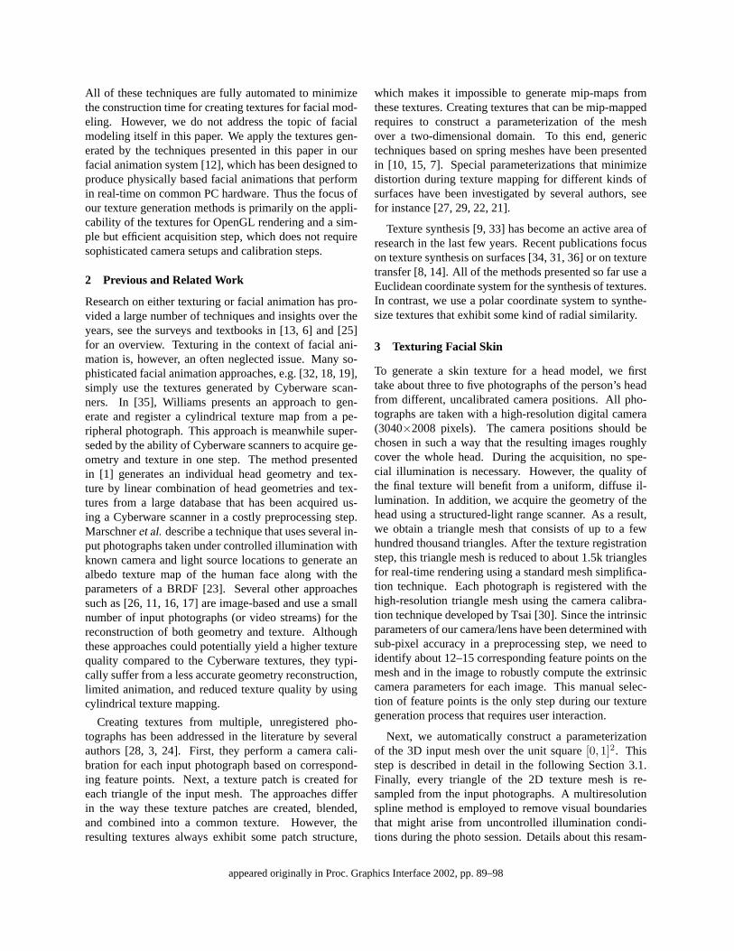
All of these techniques are fully automated to minimizethe construction time for creating textures for facial mod-eling. However, we do not address the topic of facialmodeling itself in this paper. We apply the textures gen-erated by the techniques presented in this paper in ourfacial animation system [12], which has been designed toproduce physically based facial animations that performin real-time on common PC hardware. Thus the focus ofour texture generation methods is primarily on the appli-cability of the textures for OpenGL rendering and a sim-ple but efficient acquisition step, which does not requiresophisticated camera setups and calibration steps.
2 Previous and Related Work
Research on either texturing or facial animation has pro-vided a large number of techniques and insights over theyears, see the surveys and textbooks in [13, 6] and [25]for an overview. Texturing in the context of facial ani-mation is, however, an often neglected issue. Many so-phisticated facial animation approaches, e.g. [32, 18, 19],simply use the textures generated by Cyberware scan-ners. In [35], Williams presents an approach to gen-erate and register a cylindrical texture map from a pe-ripheral photograph. This approach is meanwhile super-seded by the ability of Cyberware scanners to acquire ge-ometry and texture in one step. The method presentedin [1] generates an individual head geometry and tex-ture by linear combination of head geometries and tex-tures from a large database that has been acquired us-ing a Cyberware scanner in a costly preprocessing step.Marschner et al. describe a technique that uses several in-put photographs taken under controlled illumination withknown camera and light source locations to generate analbedo texture map of the human face along with theparameters of a BRDF [23]. Several other approachessuch as [26, 11, 16, 17] are image-based and use a smallnumber of input photographs (or video streams) for thereconstruction of both geometry and texture. Althoughthese approaches could potentially yield a higher texturequality compared to the Cyberware textures, they typi-cally suffer from a less accurate geometry reconstruction,limited animation, and reduced texture quality by usingcylindrical texture mapping.
Creating textures from multiple, unregistered pho-tographs has been addressed in the literature by severalauthors [28, 3, 24]. First, they perform a camera cali-bration for each input photograph based on correspond-ing feature points. Next, a texture patch is created foreach triangle of the input mesh. The approaches differin the way these texture patches are created, blended,and combined into a common texture. However, theresulting textures always exhibit some patch structure,
which makes it impossible to generate mip-maps fromthese textures. Creating textures that can be mip-mappedrequires to construct a parameterization of the meshover a two-dimensional domain. To this end, generictechniques based on spring meshes have been presentedin [10, 15, 7]. Special parameterizations that minimizedistortion during texture mapping for different kinds ofsurfaces have been investigated by several authors, seefor instance [27, 29, 22, 21].
Texture synthesis [9, 33] has become an active area ofresearch in the last few years. Recent publications focuson texture synthesis on surfaces [34, 31, 36] or on texturetransfer [8, 14]. All of the methods presented so far use aEuclidean coordinate system for the synthesis of textures.In contrast, we use a polar coordinate system to synthe-size textures that exhibit some kind of radial similarity.
3 Texturing Facial Skin
To generate a skin texture for a head model, we firsttake about three to five photographs of the person’s headfrom different, uncalibrated camera positions. All pho-tographs are taken with a high-resolution digital camera(3040×2008 pixels). The camera positions should bechosen in such a way that the resulting images roughlycover the whole head. During the acquisition, no spe-cial illumination is necessary. However, the quality ofthe final texture will benefit from a uniform, diffuse il-lumination. In addition, we acquire the geometry of thehead using a structured-light range scanner. As a result,we obtain a triangle mesh that consists of up to a fewhundred thousand triangles. After the texture registrationstep, this triangle mesh is reduced to about 1.5k trianglesfor real-time rendering using a standard mesh simplifica-tion technique. Each photograph is registered with thehigh-resolution triangle mesh using the camera calibra-tion technique developed by Tsai [30]. Since the intrinsicparameters of our camera/lens have been determined withsub-pixel accuracy in a preprocessing step, we need toidentify about 12–15 corresponding feature points on themesh and in the image to robustly compute the extrinsiccamera parameters for each image. This manual selec-tion of feature points is the only step during our texturegeneration process that requires user interaction.
Next, we automatically construct a parameterizationof the 3D input mesh over the unit square [0, 1]2. Thisstep is described in detail in the following Section 3.1.Finally, every triangle of the 2D texture mesh is re-sampled from the input photographs. A multiresolutionspline method is employed to remove visual boundariesthat might arise from uncontrolled illumination condi-tions during the photo session. Details about this resam-
appeared originally in Proc. Graphics Interface 2002, pp. 89–98
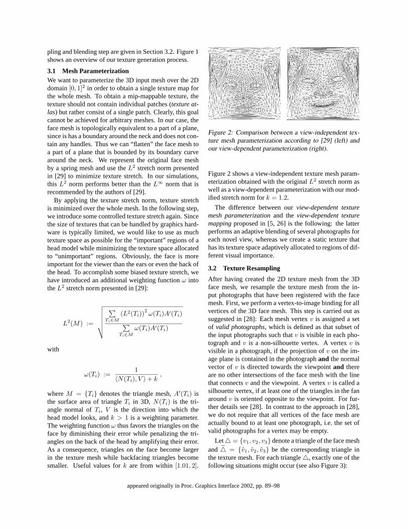
pling and blending step are given in Section 3.2. Figure 1shows an overview of our texture generation process.
3.1 Mesh ParameterizationWe want to parameterize the 3D input mesh over the 2Ddomain [0, 1]2 in order to obtain a single texture map forthe whole mesh. To obtain a mip-mappable texture, thetexture should not contain individual patches (texture at-las) but rather consist of a single patch. Clearly, this goalcannot be achieved for arbitrary meshes. In our case, theface mesh is topologically equivalent to a part of a plane,since is has a boundary around the neck and does not con-tain any handles. Thus we can “flatten” the face mesh toa part of a plane that is bounded by its boundary curvearound the neck. We represent the original face meshby a spring mesh and use the L2 stretch norm presentedin [29] to minimize texture stretch. In our simulations,this L2 norm performs better than the L∞ norm that isrecommended by the authors of [29].
By applying the texture stretch norm, texture stretchis minimized over the whole mesh. In the following step,we introduce some controlled texture stretch again. Sincethe size of textures that can be handled by graphics hard-ware is typically limited, we would like to use as muchtexture space as possible for the “important” regions of ahead model while minimizing the texture space allocatedto “unimportant” regions. Obviously, the face is moreimportant for the viewer than the ears or even the back ofthe head. To accomplish some biased texture stretch, wehave introduced an additional weighting function ω intothe L2 stretch norm presented in [29]:
L2(M) :=
√√√√√√∑
Ti∈M
(L2(Ti))2ω(Ti)A′(Ti)
∑Ti∈M
ω(Ti)A′(Ti)
with
ω(Ti) :=1
〈N(Ti), V 〉 + k,
where M = {Ti} denotes the triangle mesh, A′(Ti) isthe surface area of triangle Ti in 3D, N(Ti) is the tri-angle normal of Ti, V is the direction into which thehead model looks, and k > 1 is a weighting parameter.The weighting function ω thus favors the triangles on theface by diminishing their error while penalizing the tri-angles on the back of the head by amplifying their error.As a consequence, triangles on the face become largerin the texture mesh while backfacing triangles becomesmaller. Useful values for k are from within [1.01, 2].
Figure 2: Comparison between a view-independent tex-ture mesh parameterization according to [29] (left) andour view-dependent parameterization (right).
Figure 2 shows a view-independent texture mesh param-eterization obtained with the original L2 stretch norm aswell as a view-dependent parameterization with our mod-ified stretch norm for k = 1.2.
The difference between our view-dependent texturemesh parameterization and the view-dependent texturemapping proposed in [5, 26] is the following: the latterperforms an adaptive blending of several photographs foreach novel view, whereas we create a static texture thathas its texture space adaptively allocated to regions of dif-ferent visual importance.
3.2 Texture Resampling
After having created the 2D texture mesh from the 3Dface mesh, we resample the texture mesh from the in-put photographs that have been registered with the facemesh. First, we perform a vertex-to-image binding for allvertices of the 3D face mesh. This step is carried out assuggested in [28]: Each mesh vertex v is assigned a setof valid photographs, which is defined as that subset ofthe input photographs such that v is visible in each pho-tograph and v is a non-silhouette vertex. A vertex v isvisible in a photograph, if the projection of v on the im-age plane is contained in the photograph and the normalvector of v is directed towards the viewpoint and thereare no other intersections of the face mesh with the linethat connects v and the viewpoint. A vertex v is called asilhouette vertex, if at least one of the triangles in the fanaround v is oriented opposite to the viewpoint. For fur-ther details see [28]. In contrast to the approach in [28],we do not require that all vertices of the face mesh areactually bound to at least one photograph, i.e. the set ofvalid photographs for a vertex may be empty.
Let � = {v1, v2, v3} denote a triangle of the face meshand � = {v1, v2, v3} be the corresponding triangle inthe texture mesh. For each triangle �, exactly one of thefollowing situations might occur (see also Figure 3):
appeared originally in Proc. Graphics Interface 2002, pp. 89–98
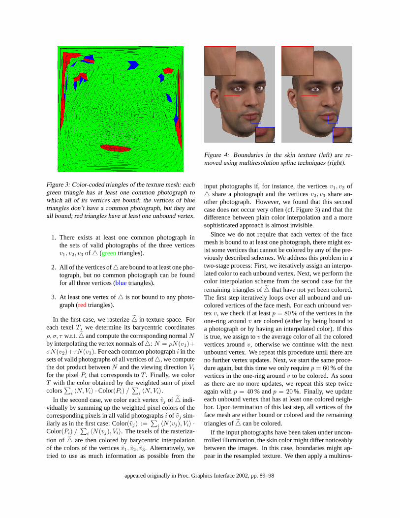
Figure 3: Color-coded triangles of the texture mesh: eachgreen triangle has at least one common photograph towhich all of its vertices are bound; the vertices of bluetriangles don’t have a common photograph, but they areall bound; red triangles have at least one unbound vertex.
1. There exists at least one common photograph inthe sets of valid photographs of the three verticesv1, v2, v3 of � (green triangles).
2. All of the vertices of � are bound to at least one pho-tograph, but no common photograph can be foundfor all three vertices (blue triangles).
3. At least one vertex of � is not bound to any photo-graph (red triangles).
In the first case, we rasterize � in texture space. Foreach texel T , we determine its barycentric coordinatesρ, σ, τ w.r.t. � and compute the corresponding normal Nby interpolating the vertex normals of �: N = ρN(v1)+σN(v2)+τN(v3). For each common photograph i in thesets of valid photographs of all vertices of �, we computethe dot product between N and the viewing direction Vi
for the pixel Pi that corresponds to T . Finally, we colorT with the color obtained by the weighted sum of pixelcolors
∑i 〈N,Vi〉 · Color(Pi) /
∑i 〈N,Vi〉.
In the second case, we color each vertex vj of � indi-vidually by summing up the weighted pixel colors of thecorresponding pixels in all valid photographs i of vj sim-ilarly as in the first case: Color(vj) :=
∑i 〈N(vj), Vi〉 ·
Color(Pi) /∑
i 〈N(vj), Vi〉. The texels of the rasteriza-tion of � are then colored by barycentric interpolationof the colors of the vertices v1, v2, v3. Alternatively, wetried to use as much information as possible from the
Figure 4: Boundaries in the skin texture (left) are re-moved using multiresolution spline techniques (right).
input photographs if, for instance, the vertices v1, v2 of� share a photograph and the vertices v2, v3 share an-other photograph. However, we found that this secondcase does not occur very often (cf. Figure 3) and that thedifference between plain color interpolation and a moresophisticated approach is almost invisible.
Since we do not require that each vertex of the facemesh is bound to at least one photograph, there might ex-ist some vertices that cannot be colored by any of the pre-viously described schemes. We address this problem in atwo-stage process: First, we iteratively assign an interpo-lated color to each unbound vertex. Next, we perform thecolor interpolation scheme from the second case for theremaining triangles of � that have not yet been colored.The first step iteratively loops over all unbound and un-colored vertices of the face mesh. For each unbound ver-tex v, we check if at least p = 80 % of the vertices in theone-ring around v are colored (either by being bound toa photograph or by having an interpolated color). If thisis true, we assign to v the average color of all the coloredvertices around v, otherwise we continue with the nextunbound vertex. We repeat this procedure until there areno further vertex updates. Next, we start the same proce-dure again, but this time we only require p = 60 % of thevertices in the one-ring around v to be colored. As soonas there are no more updates, we repeat this step twiceagain with p = 40 % and p = 20 %. Finally, we updateeach unbound vertex that has at least one colored neigh-bor. Upon termination of this last step, all vertices of theface mesh are either bound or colored and the remainingtriangles of � can be colored.
If the input photographs have been taken under uncon-trolled illumination, the skin color might differ noticeablybetween the images. In this case, boundaries might ap-pear in the resampled texture. We then apply a multires-
appeared originally in Proc. Graphics Interface 2002, pp. 89–98
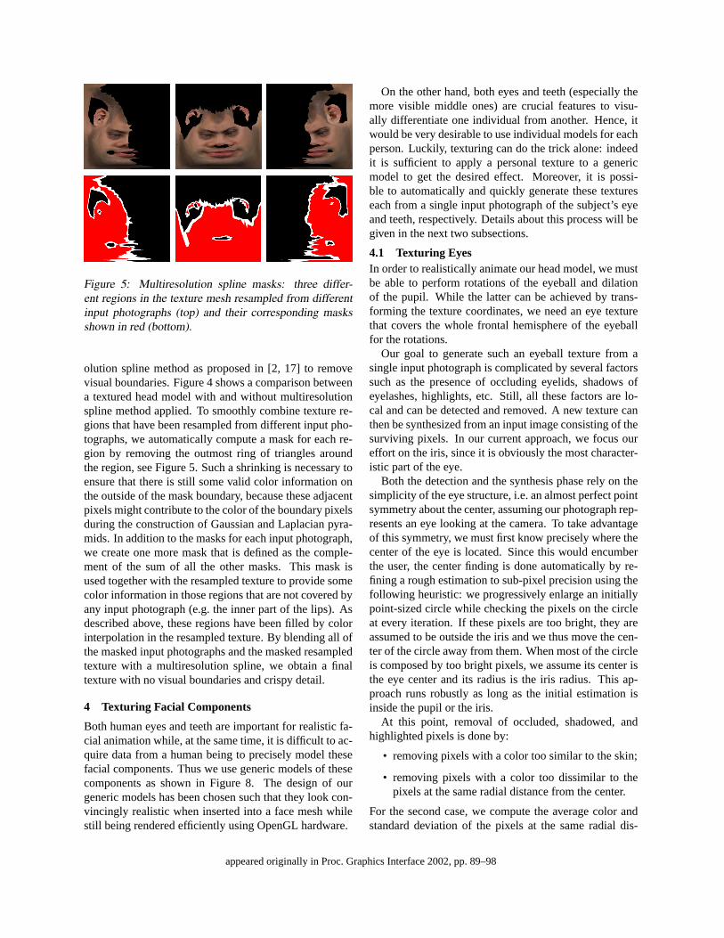
Figure 5: Multiresolution spline masks: three differ-ent regions in the texture mesh resampled from differentinput photographs (top) and their corresponding masksshown in red (bottom).
olution spline method as proposed in [2, 17] to removevisual boundaries. Figure 4 shows a comparison betweena textured head model with and without multiresolutionspline method applied. To smoothly combine texture re-gions that have been resampled from different input pho-tographs, we automatically compute a mask for each re-gion by removing the outmost ring of triangles aroundthe region, see Figure 5. Such a shrinking is necessary toensure that there is still some valid color information onthe outside of the mask boundary, because these adjacentpixels might contribute to the color of the boundary pixelsduring the construction of Gaussian and Laplacian pyra-mids. In addition to the masks for each input photograph,we create one more mask that is defined as the comple-ment of the sum of all the other masks. This mask isused together with the resampled texture to provide somecolor information in those regions that are not covered byany input photograph (e.g. the inner part of the lips). Asdescribed above, these regions have been filled by colorinterpolation in the resampled texture. By blending all ofthe masked input photographs and the masked resampledtexture with a multiresolution spline, we obtain a finaltexture with no visual boundaries and crispy detail.
4 Texturing Facial Components
Both human eyes and teeth are important for realistic fa-cial animation while, at the same time, it is difficult to ac-quire data from a human being to precisely model thesefacial components. Thus we use generic models of thesecomponents as shown in Figure 8. The design of ourgeneric models has been chosen such that they look con-vincingly realistic when inserted into a face mesh whilestill being rendered efficiently using OpenGL hardware.
On the other hand, both eyes and teeth (especially themore visible middle ones) are crucial features to visu-ally differentiate one individual from another. Hence, itwould be very desirable to use individual models for eachperson. Luckily, texturing can do the trick alone: indeedit is sufficient to apply a personal texture to a genericmodel to get the desired effect. Moreover, it is possi-ble to automatically and quickly generate these textureseach from a single input photograph of the subject’s eyeand teeth, respectively. Details about this process will begiven in the next two subsections.
4.1 Texturing EyesIn order to realistically animate our head model, we mustbe able to perform rotations of the eyeball and dilationof the pupil. While the latter can be achieved by trans-forming the texture coordinates, we need an eye texturethat covers the whole frontal hemisphere of the eyeballfor the rotations.
Our goal to generate such an eyeball texture from asingle input photograph is complicated by several factorssuch as the presence of occluding eyelids, shadows ofeyelashes, highlights, etc. Still, all these factors are lo-cal and can be detected and removed. A new texture canthen be synthesized from an input image consisting of thesurviving pixels. In our current approach, we focus oureffort on the iris, since it is obviously the most character-istic part of the eye.
Both the detection and the synthesis phase rely on thesimplicity of the eye structure, i.e. an almost perfect pointsymmetry about the center, assuming our photograph rep-resents an eye looking at the camera. To take advantageof this symmetry, we must first know precisely where thecenter of the eye is located. Since this would encumberthe user, the center finding is done automatically by re-fining a rough estimation to sub-pixel precision using thefollowing heuristic: we progressively enlarge an initiallypoint-sized circle while checking the pixels on the circleat every iteration. If these pixels are too bright, they areassumed to be outside the iris and we thus move the cen-ter of the circle away from them. When most of the circleis composed by too bright pixels, we assume its center isthe eye center and its radius is the iris radius. This ap-proach runs robustly as long as the initial estimation isinside the pupil or the iris.
At this point, removal of occluded, shadowed, andhighlighted pixels is done by:
• removing pixels with a color too similar to the skin;
• removing pixels with a color too dissimilar to thepixels at the same radial distance from the center.
For the second case, we compute the average color andstandard deviation of the pixels at the same radial dis-
appeared originally in Proc. Graphics Interface 2002, pp. 89–98
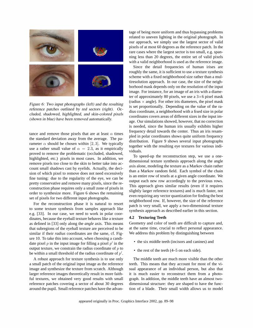
Figure 6: Two input photographs (left) and the resultingreference patches outlined by red sectors (right). Oc-cluded, shadowed, highlighted, and skin-colored pixels(shown in blue) have been removed automatically.
tance and remove those pixels that are at least α timesthe standard deviation away from the average. The pa-rameter α should be chosen within [2, 3]. We typicallyuse a rather small value of α = 2.3, as it empiricallyproved to remove the problematic (occluded, shadowed,highlighted, etc.) pixels in most cases. In addition, weremove pixels too close to the skin to better take into ac-count small shadows cast by eyelids. Actually, the deci-sion of which pixel to remove does not need excessivelyfine tuning: due to the regularity of the eye, we can bepretty conservative and remove many pixels, since the re-construction phase requires only a small zone of pixels inorder to synthesize more. Figure 6 shows the remainingset of pixels for two different input photographs.
For the reconstruction phase it is natural to resortto some texture synthesis from samples approach likee.g. [33]. In our case, we need to work in polar coor-dinates, because the eyeball texture behaves like a textureas defined in [33] only along the angle axis. This meansthat subregions of the eyeball texture are perceived to besimilar if their radius coordinates are the same, cf. Fig-ure 10. To take this into account, when choosing a candi-date pixel p in the input image for filling a pixel p′ in theoutput texture, we constrain the radius coordinate of p tobe within a small threshold of the radius coordinate of p′.
A robust approach for texture synthesis is to use onlya small patch of the original input image as the referenceimage and synthesize the texture from scratch. Althoughlarger reference images theoretically result in more faith-ful textures, we obtained very good results with smallreference patches covering a sector of about 30 degreesaround the pupil. Small reference patches have the advan-
tage of being more uniform and thus bypassing problemsrelated to uneven lighting in the original photograph. Inour approach, we simply use the largest sector of validpixels of at most 60 degrees as the reference patch. In therare cases where the largest sector is too small, e.g. span-ning less than 20 degrees, the entire set of valid pixelswith a valid neighborhood is used as the reference image.
Since the detail frequencies of human irises areroughly the same, it is sufficient to use a texture synthesisscheme with a fixed neighborhood size rather than a mul-tiresolution approach. In our case, the size of the neigh-borhood mask depends only on the resolution of the inputimage. For instance, for an image of an iris with a diame-ter of approximately 80 pixels, we use a 3×6 pixel mask(radius × angle). For other iris diameters, the pixel maskis set proportionally. Depending on the value of the ra-dius coordinate, a neighborhood with a fixed size in polarcoordinates covers areas of different sizes in the input im-age. Our simulations showed, however, that no correctionis needed, since the human iris usually exhibits higherfrequency detail towards the center. Thus an iris resam-pled in polar coordinates shows quite uniform frequencydistribution. Figure 9 shows several input photographstogether with the resulting eye textures for various indi-viduals.
To speed-up the reconstruction step, we use a one-dimensional texture synthesis approach along the angleaxis alone, modeling the texture as a Markov chain ratherthan a Markov random field. Each symbol of the chainis an entire row of texels at a given angle coordinate. Weoutput each new row accordingly to the previous rows.This approach gives similar results (even if it requiresslightly larger reference textures) and is much faster, noteven requiring any vector quantization for finding the bestneighborhood row. If, however, the size of the referencepatch is very small, we apply a two-dimensional texturesynthesis approach as described earlier in this section.
4.2 Texturing TeethGeometry and color of teeth are difficult to capture and,at the same time, crucial to reflect personal appearance.We address this problem by distinguishing between
• the six middle teeth (incisors and canines) and
• the rest of the teeth (4–5 on each side).
The middle teeth are much more visible than the otherteeth. This means that they account for most of the vi-sual appearance of an individual person, but also thatit is much easier to reconstruct them from a photo-graph. In addition, the middle teeth have an almost two-dimensional structure: they are shaped to have the func-tion of a blade. Their small width allows us to model
appeared originally in Proc. Graphics Interface 2002, pp. 89–98
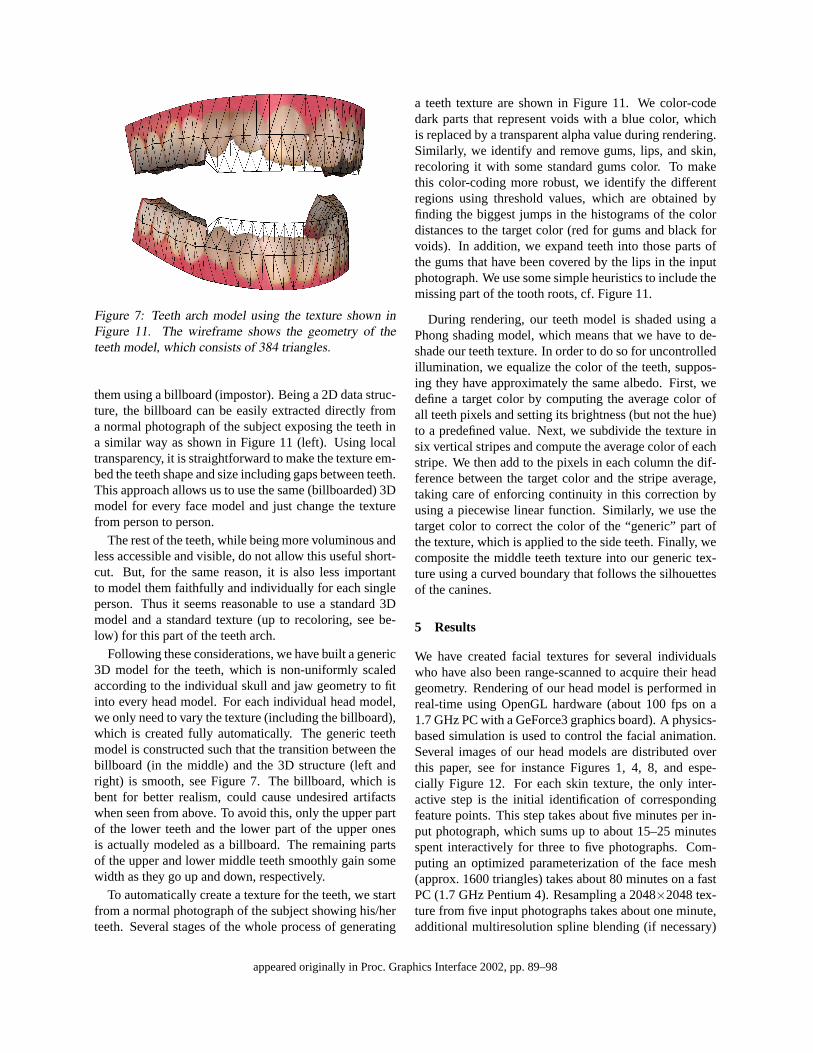
Figure 7: Teeth arch model using the texture shown inFigure 11. The wireframe shows the geometry of theteeth model, which consists of 384 triangles.
them using a billboard (impostor). Being a 2D data struc-ture, the billboard can be easily extracted directly froma normal photograph of the subject exposing the teeth ina similar way as shown in Figure 11 (left). Using localtransparency, it is straightforward to make the texture em-bed the teeth shape and size including gaps between teeth.This approach allows us to use the same (billboarded) 3Dmodel for every face model and just change the texturefrom person to person.
The rest of the teeth, while being more voluminous andless accessible and visible, do not allow this useful short-cut. But, for the same reason, it is also less importantto model them faithfully and individually for each singleperson. Thus it seems reasonable to use a standard 3Dmodel and a standard texture (up to recoloring, see be-low) for this part of the teeth arch.
Following these considerations, we have built a generic3D model for the teeth, which is non-uniformly scaledaccording to the individual skull and jaw geometry to fitinto every head model. For each individual head model,we only need to vary the texture (including the billboard),which is created fully automatically. The generic teethmodel is constructed such that the transition between thebillboard (in the middle) and the 3D structure (left andright) is smooth, see Figure 7. The billboard, which isbent for better realism, could cause undesired artifactswhen seen from above. To avoid this, only the upper partof the lower teeth and the lower part of the upper onesis actually modeled as a billboard. The remaining partsof the upper and lower middle teeth smoothly gain somewidth as they go up and down, respectively.
To automatically create a texture for the teeth, we startfrom a normal photograph of the subject showing his/herteeth. Several stages of the whole process of generating
a teeth texture are shown in Figure 11. We color-codedark parts that represent voids with a blue color, whichis replaced by a transparent alpha value during rendering.Similarly, we identify and remove gums, lips, and skin,recoloring it with some standard gums color. To makethis color-coding more robust, we identify the differentregions using threshold values, which are obtained byfinding the biggest jumps in the histograms of the colordistances to the target color (red for gums and black forvoids). In addition, we expand teeth into those parts ofthe gums that have been covered by the lips in the inputphotograph. We use some simple heuristics to include themissing part of the tooth roots, cf. Figure 11.
During rendering, our teeth model is shaded using aPhong shading model, which means that we have to de-shade our teeth texture. In order to do so for uncontrolledillumination, we equalize the color of the teeth, suppos-ing they have approximately the same albedo. First, wedefine a target color by computing the average color ofall teeth pixels and setting its brightness (but not the hue)to a predefined value. Next, we subdivide the texture insix vertical stripes and compute the average color of eachstripe. We then add to the pixels in each column the dif-ference between the target color and the stripe average,taking care of enforcing continuity in this correction byusing a piecewise linear function. Similarly, we use thetarget color to correct the color of the “generic” part ofthe texture, which is applied to the side teeth. Finally, wecomposite the middle teeth texture into our generic tex-ture using a curved boundary that follows the silhouettesof the canines.
5 Results
We have created facial textures for several individualswho have also been range-scanned to acquire their headgeometry. Rendering of our head model is performed inreal-time using OpenGL hardware (about 100 fps on a1.7 GHz PC with a GeForce3 graphics board). A physics-based simulation is used to control the facial animation.Several images of our head models are distributed overthis paper, see for instance Figures 1, 4, 8, and espe-cially Figure 12. For each skin texture, the only inter-active step is the initial identification of correspondingfeature points. This step takes about five minutes per in-put photograph, which sums up to about 15–25 minutesspent interactively for three to five photographs. Com-puting an optimized parameterization of the face mesh(approx. 1600 triangles) takes about 80 minutes on a fastPC (1.7 GHz Pentium 4). Resampling a 2048×2048 tex-ture from five input photographs takes about one minute,additional multiresolution spline blending (if necessary)
appeared originally in Proc. Graphics Interface 2002, pp. 89–98
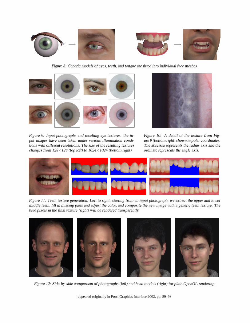
−→ −→
Figure 8: Generic models of eyes, teeth, and tongue are fitted into individual face meshes.
Figure 9: Input photographs and resulting eye textures: the in-put images have been taken under various illumination condi-tions with different resolutions. The size of the resulting textureschanges from 128×128 (top left) to 1024×1024 (bottom right).
Figure 10: A detail of the texture from Fig-ure 9 (bottom right) shown in polar coordinates.The abscissa represents the radius axis and theordinate represents the angle axis.
Figure 11: Teeth texture generation. Left to right: starting from an input photograph, we extract the upper and lowermiddle teeth, fill in missing parts and adjust the color, and composite the new image with a generic teeth texture. Theblue pixels in the final texture (right) will be rendered transparently.
Figure 12: Side-by-side comparison of photographs (left) and head models (right) for plain OpenGL rendering.
appeared originally in Proc. Graphics Interface 2002, pp. 89–98
takes about ten minutes. Currently, our algorithms areoptimized with respect to robustness but not to speed.
Generating the teeth and eye textures takes only a fewseconds even for large textures using the 1D Markovchain method for the texture synthesis. If a full Markovfield is used, construction time may go up to several min-utes, depending on the size of the texture being created.
6 Conclusion and Future Work
We have introduced a number of techniques that help tominimize the time and effort that goes into the creationof textures for facial modeling. With the exception of theinitial feature point selection for the skin texturing, ourmethods are fully automated and do not require any userinteraction.
For the generation of skin textures from uncalibratedinput photographs, we propose a view-dependent param-eterization of the texture domain and a texture resamplingmethod including color interpolation for non-textured re-gions and multiresolution splining for the removal of vi-sual boundaries. Using our methods, both eye and teethtextures can be created fully automatically from single in-put photographs, adding greatly to a realistic appearanceof individual subjects during facial animation.
One of the main goals of ongoing research is to getrid of the interactive camera calibration step for skin tex-turing. Given that the resulting texture should containfine detail, this is a tough problem, indeed. Automaticapproaches such as [20] fail simply due to the fact thatthe silhouette of a human head looks more or less iden-tical when viewed from within a cone of viewing direc-tions from the front or the back. Furthermore, it wouldbe desirable to account for lighting artifacts in the inputphotographs. Although a uniform, diffuse illuminationduring the photo session helps a lot, there are still con-tributions from diffuse and specular lighting in the pho-tographs. Approaches to overcome these problems havebeen suggested [4, 23], but they require sophisticatedcamera setups and calibration steps. Finally, it would bevery helpful to speed-up the computation time of the cur-rent bottleneck, namely the mesh parameterization, usinga hierarchical coarse-to-fine approach.
Acknowledgments
The authors would like to thank their models Letizia,Claudia, and Kolja for all the smiles during the photosessions. Many thanks also to our colleagues, who gavehelpful comments during the development of our tech-niques, and to the anonymous reviewers for their sugges-tions.
References[1] V. Blanz and T. Vetter. A Morphable Model for the Syn-
thesis of 3D Faces. In Computer Graphics (SIGGRAPH’99 Conf. Proc.), pages 187–194, August 1999.
[2] P. J. Burt and E. H. Adelson. A Multiresolution Splinewith Application to Image Mosaics. ACM Transactionson Graphics, 2(4):217–236, October 1983.
[3] P. Cignoni, C. Montani, C. Rocchini, R. Scopigno, andM. Tarini. Preserving Attribute Values on SimplifiedMeshes by Resampling Detail Textures. The Visual Com-puter, 15(10):519–539, 1999.
[4] P. E. Debevec, T. Hawkins, C. Tchou, H.-P. Duiker,W. Sarokin, and M. Sagar. Acquiring the ReflectanceField of a Human Face. In Computer Graphics (SIG-GRAPH ’00 Conf. Proc.), pages 145–156, July 2000.
[5] P. E. Debevec, C. J. Taylor, and J. Malik. Modelingand Rendering Architecture from Photographs: A Hy-brid Geometry- and Image-based Approach. In ComputerGraphics (SIGGRAPH ’96 Conf. Proc.), pages 11–20, Au-gust 1996.
[6] D. S. Ebert, F. K. Musgrave, D. Peachey, K. Perlin, andS. Worley. Texturing & Modeling: A Procedural Ap-proach. Academic Press, London, 2 edition, 1998.
[7] M. Eck, T. DeRose, T. Duchamp, H. Hoppe, M. Louns-bery, and W. Stuetzle. Multiresolution Analysis of Ar-bitrary Meshes. In Computer Graphics (SIGGRAPH ’95Conf. Proc.), pages 173–182, August 1995.
[8] A. A. Efros and W. T. Freeman. Image Quilting for Tex-ture Synthesis and Transfer. In Computer Graphics (SIG-GRAPH ’01 Conf. Proc.), pages 341–346, August 2001.
[9] A. A. Efros and T. K. Leung. Texture Synthesis by Non-parametric Sampling. In IEEE Int’l Conf. Computer Vi-sion, volume 2, pages 1033–1038, September 1999.
[10] M. S. Floater. Parametrization and Smooth Approxima-tion of Surface Triangulations. Computer Aided Geomet-ric Design, 14(3):231–250, 1997.
[11] B. Guenter, C. Grimm, D. Wood, H. Malvar, and F. Pighin.Making Faces. In Computer Graphics (SIGGRAPH ’98Conf. Proc.), pages 55–66, July 1998.
[12] J. Haber, K. Kahler, I. Albrecht, H. Yamauchi, and H.-P. Seidel. Face to Face: From Real Humans to RealisticFacial Animation. In Proc. Israel-Korea Binational Conf.on Geometrical Modeling and Computer Graphics, pages73–82, October 2001.
[13] P. S. Heckbert. Survey of Texture Mapping. IEEE Com-puter Graphics and Applications, 6(11):56–67, November1986.
[14] A. Hertzmann, Ch. E. Jacobs, N. Oliver, B. Curless, andD. H. Salesin. Image Analogies. In Computer Graph-ics (SIGGRAPH ’01 Conf. Proc.), pages 327–340, August2001.
[15] K. Hormann and G. Greiner. MIPS: An Efficient GlobalParametrization Method. In Curve and Surface Design:Saint-Malo 1999, pages 153–162. Vanderbilt UniversityPress, 2000.
appeared originally in Proc. Graphics Interface 2002, pp. 89–98
[16] W.-S. Lee, J. Gu, and N. Magnenat-Thalmann. Generat-ing Animatable 3D Virtual Humans from Photographs. InComputer Graphics Forum (Proc. EG 2000), volume 19,pages C1–C10, August 2000.
[17] W.-S. Lee and N. Magnenat-Thalmann. Fast Head Mod-eling for Animation. Image and Vision Computing,18(4):355–364, March 2000.
[18] Y. Lee, D. Terzopoulos, and K. Waters. ConstructingPhysics-based Facial Models of Individuals. In Proc.Graphics Interface ’93, pages 1–8, May 1993.
[19] Y. Lee, D. Terzopoulos, and K. Waters. Realistic Model-ing for Facial Animations. In Computer Graphics (SIG-GRAPH ’95 Conf. Proc.), pages 55–62, August 1995.
[20] H. P. A. Lensch, W. Heidrich, and H.-P. Seidel. AutomatedTexture Registration and Stitching for Real World Models.In Proc. Pacific Graphics 2000, pages 317–326, October2000.
[21] B. Levy. Constrained Texture Mapping for PolygonalMeshes. In Computer Graphics (SIGGRAPH ’01 Conf.Proc.), pages 417–424, August 2001.
[22] J. Maillot, H. Yahia, and A. Verroust. Interactive TextureMapping. In Computer Graphics (SIGGRAPH ’93 Conf.Proc.), pages 27–34, August 1993.
[23] S. R. Marschner, B. Guenter, and S. Raghupathy. Mod-eling and Rendering for Realistic Facial Animation. InRendering Techniques 2000 (Proc. 11th EG Workshop onRendering), pages 231–242, 2000.
[24] P. J. Neugebauer and K. Klein. Texturing 3D Models ofReal World Objects from Multiple Unregistered Photo-graphic Views. In Computer Graphics Forum (Proc. EG’99), volume 18, pages C245–C256, September 1999.
[25] F. I. Parke and K. Waters, editors. Computer Facial Ani-mation. A K Peters, Wellesley, MA, 1996.
[26] F. Pighin, J. Hecker, D. Lischinski, R. Szeliski, and D. H.Salesin. Synthesizing Realistic Facial Expressions fromPhotographs. In Computer Graphics (SIGGRAPH ’98Conf. Proc.), pages 75–84, July 1998.
[27] D. Piponi and G. D. Borshukov. Seamless Texture Map-ping of Subdivision Surfaces by Model Pelting and Tex-ture Blending. In Computer Graphics (SIGGRAPH ’00Conf. Proc.), pages 471–478, July 2000.
[28] C. Rocchini, P. Cignoni, C. Montani, and R. Scopigno.Multiple Textures Stitching and Blending on 3D Objects.In Rendering Techniques ’99 (Proc. 10th EG Workshop onRendering), pages 119–130, 1999.
[29] P. V. Sander, J. Snyder, S. J. Gortler, and H. Hoppe. Tex-ture Mapping Progressive Meshes. In Computer Graph-ics (SIGGRAPH ’01 Conf. Proc.), pages 409–416, August2001.
[30] R. Y. Tsai. An Efficient and Accurate Camera CalibrationTechnique for 3D Machine Vision. In Proc. IEEE Conf.on Computer Vision and Pattern Recognition, pages 364–374, June 1986.
[31] G. Turk. Texture Synthesis on Surfaces. In ComputerGraphics (SIGGRAPH ’01 Conf. Proc.), pages 347–354,August 2001.
[32] K. Waters and D. Terzopoulos. Modeling and AnimatingFaces Using Scanned Data. J. Visualization and ComputerAnimation, 2(4):123–128, October–December 1991.
[33] L.-Y. Wei and M. Levoy. Fast Texture Synthesis Us-ing Tree-Structured Vector Quantization. In ComputerGraphics (SIGGRAPH ’00 Conf. Proc.), pages 479–488,July 2000.
[34] L.-Y. Wei and M. Levoy. Texture Synthesis over ArbitraryManifold Surfaces. In Computer Graphics (SIGGRAPH’01 Conf. Proc.), pages 355–360, August 2001.
[35] L. Williams. Performance-Driven Facial Animation. InComputer Graphics (SIGGRAPH ’90 Conf. Proc.), vol-ume 24, pages 235–242, August 1990.
[36] L. Ying, A. Hertzmann, H. Biermann, and D. Zorin. Tex-ture and Shape Synthesis on Surfaces. In Rendering Tech-niques 2001 (Proc. 12th EG Workshop on Rendering),pages 301–312, 2001.
appeared originally in Proc. Graphics Interface 2002, pp. 89–98
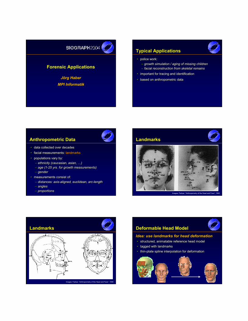
Forensic Applications
Jörg HaberMPI Informatik
Jörg HaberJörg Haber
MPI InformatikMPI Informatik
Typical Applications• police work:
– growth simulation / aging of missing children– facial reconstruction from skeletal remains
• important for tracing and identification
• based on anthropometric data
•• police work:police work:–– growth simulation / aging of missing childrengrowth simulation / aging of missing children–– facial reconstruction from skeletal remainsfacial reconstruction from skeletal remains
•• important for tracing and identificationimportant for tracing and identification
•• based on anthropometric databased on anthropometric data
Anthropometric Data• data collected over decades• facial measurements: landmarks• populations vary by:
– ethnicity (caucasian, asian, …)– age (1-25 yrs. for growth measurements)– gender
• measurements consist of:– distances: axis-aligned, euclidean, arc-length– angles– proportions
•• datadata collected over decadescollected over decades
•• facial measurementsfacial measurements: : landmarkslandmarks
•• populations vary bypopulations vary by::–– ethnicityethnicity ((caucasiancaucasian, , asianasian, …), …)–– age (1age (1--25 25 yrsyrs. . forfor growth growth measurementsmeasurements))–– gendergender
•• measurements consist measurements consist of:of:–– distancesdistances: : axisaxis--alignedaligned, , euclideaneuclidean, , arcarc--lengthlength–– anglesangles–– proportionsproportions
Landmarks
Images: Farkas: “Anthropometry of the Head and Face”, 1994
Landmarks
Images: Farkas: “Anthropometry of the Head and Face”, 1994
Deformable Head ModelIdea: use landmarks for head deformation• structured, animatable reference head model• tagged with landmarks• thin-plate spline interpolation for deformation
IdeaIdea: : use landmarks for head deformationuse landmarks for head deformation•• structuredstructured, , animatable animatable reference headreference head modelmodel•• tagged with landmarkstagged with landmarks•• thinthin--plate spline interpolation for deformationplate spline interpolation for deformation
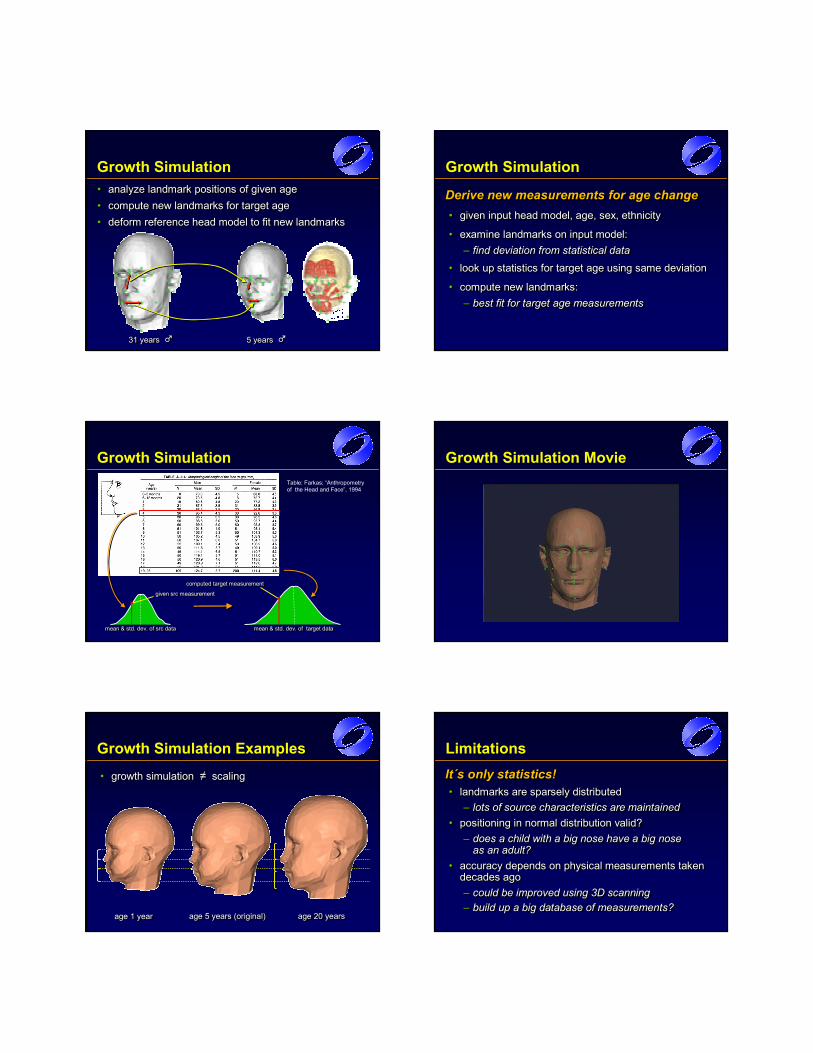
Growth Simulation• analyze landmark positions of given age• compute new landmarks for target age• deform reference head model to fit new landmarks
•• analyze landmark positions of given ageanalyze landmark positions of given age•• compute new landmarks for target agecompute new landmarks for target age•• deform reference head model to fit new landmarksdeform reference head model to fit new landmarks
31 years %31 years 31 years %% 5 years %5 years 5 years %%
Growth Simulation
Derive new measurements for age change• given input head model, age, sex, ethnicity
• examine landmarks on input model:– find deviation from statistical data
• look up statistics for target age using same deviation
• compute new landmarks:– best fit for target age measurements
Derive new measurements for Derive new measurements for age age changechange•• given input head modelgiven input head model, age, sex, , age, sex, ethnicityethnicity
•• examine landmarks examine landmarks on on input input model:model:–– find find deviation from statistical datadeviation from statistical data
•• look up look up statistics for target statistics for target age usingage using same same deviationdeviation
•• compute new landmarks:compute new landmarks:–– best fit for target age measurementsbest fit for target age measurements
mean & std. dev. of target datamean & std. dev. of target datamean & std. dev. of target datamean & std. dev. of src datamean & std. dev. of src datamean & std. dev. of src data
Growth SimulationTable: Farkas: “Anthropometryof the Head and Face”, 1994
given src measurementgiven src measurementgiven src measurementcomputed target measurementcomputed target measurementcomputed target measurement
Growth Simulation Movie
Growth Simulation Examples
age 1 yearage 1 age 1 yearyear age 5 years (original)age 5 age 5 yearsyears (original)(original) age 20 yearsage 20 age 20 yearsyears
• growth simulation ≠ scaling•• growth simulation growth simulation ≠≠ scalingscaling
LimitationsIt´s only statistics!• landmarks are sparsely distributed
– lots of source characteristics are maintained• positioning in normal distribution valid?
– does a child with a big nose have a big nose as an adult?
• accuracy depends on physical measurements taken decades ago– could be improved using 3D scanning– build up a big database of measurements?
ItIt´s ´s only statisticsonly statistics!!•• landmarks are sparsely distributedlandmarks are sparsely distributed
–– lots of lots of source characteristics are maintainedsource characteristics are maintained•• positioningpositioning in normal in normal distribution validdistribution valid??
–– doesdoes a a child with child with a a big nose have big nose have a a big nose big nose asas an an adultadult??
•• accuracy depends accuracy depends on on physical measurements taken physical measurements taken decades agodecades ago–– could be improved using could be improved using 3D 3D scanningscanning–– buildbuild up a up a big database big database of of measurementsmeasurements??
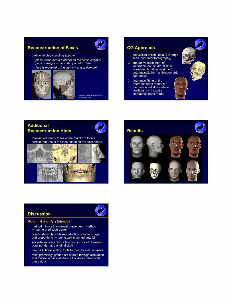
Reconstruction of Faces• traditional clay sculpting approach:
– place tissue depth markers on the skull; length of pegs corresponds to anthropometric data
– face is modeled using clay (→ artistic licence)
•• traditional clay sculpting approach: traditional clay sculpting approach: –– place tissue depth markers on the skull; length of place tissue depth markers on the skull; length of
pegs corresponds to anthropometric data pegs corresponds to anthropometric data –– face is modeled using clay (face is modeled using clay (→→ artistic licence)artistic licence)
Images: Taylor: “Forensic Art and Illustration”, 2001
CG Approach 1. acquisition of skull data (3D range
scan, computer tomography)2. interactive placement of
landmarks on the virtual skull; tissue depth values assigned automatically from anthropometric data tables
3. automatic fitting of the reference head model to the prescribed skin surface positions ⇒ instantly animatable head model
1.1. acquisition of skull data (3D range acquisition of skull data (3D range scan, computer tomography)scan, computer tomography)
2.2. interactive placement of interactive placement of landmarks on the virtual skull; landmarks on the virtual skull; tissue depth values assigned tissue depth values assigned automatically from anthropometric automatically from anthropometric data tablesdata tables
3.3. automatic fitting of the automatic fitting of the reference head model to reference head model to the prescribed skin surface the prescribed skin surface positions positions ⇒⇒ instantly instantly animatable head modelanimatable head model
Additional Reconstruction Hints• forensic art: many “rules of the thumb” to locate
certain features of the face based on the skull shape•• forensic art: many “rules of the thumb” to locate forensic art: many “rules of the thumb” to locate
certain features of the face based on the skull shapecertain features of the face based on the skull shape
Results
Again: it´s only statistics!• method mirrors the manual tissue depth method ⇒ same prediction power
• results show plausible reproduction of facial shape and proportions
• advantages: very fast (a few hours instead of weeks), does not damage original skull
• need additional editing tools for hair, beards, wrinkles• most promising: gather lots of data through simulation
and evaluation; update tissue thickness tables with these data
Again: it´s Again: it´s only statisticsonly statistics!!•• method mirrors the manual tissue depth method method mirrors the manual tissue depth method ⇒⇒ same prediction powersame prediction power
•• results show plausible reproduction of facial shape results show plausible reproduction of facial shape and proportionsand proportions
•• advantages: very fast (a few hours instead of weeks), advantages: very fast (a few hours instead of weeks), does not damage original skulldoes not damage original skull
•• need additional editing tools for hair, beards, wrinklesneed additional editing tools for hair, beards, wrinkles•• most promising: gather lots of data through simulation most promising: gather lots of data through simulation
and evaluation; update tissue thickness tables with and evaluation; update tissue thickness tables with these data these data
+ some well-matched details!+ some well+ some well--matched details!matched details!
Discussion
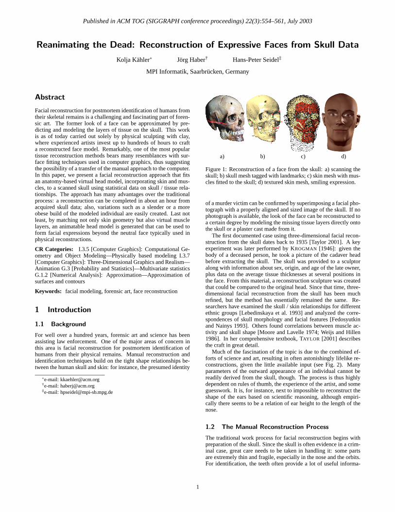
Published in ACM TOG (SIGGRAPH conference proceedings) 22(3):554–561, July 2003
Reanimating the Dead: Reconstruction of Expressive Faces from Skull Data
Kolja Kahler∗ Jorg Haber† Hans-Peter Seidel‡
MPI Informatik, Saarbrucken, Germany
Abstract
Facial reconstruction for postmortem identification of humans fromtheir skeletal remains is a challenging and fascinating part of foren-sic art. The former look of a face can be approximated by pre-dicting and modeling the layers of tissue on the skull. This workis as of today carried out solely by physical sculpting with clay,where experienced artists invest up to hundreds of hours to crafta reconstructed face model. Remarkably, one of the most populartissue reconstruction methods bears many resemblances with sur-face fitting techniques used in computer graphics, thus suggestingthe possibility of a transfer of the manual approach to the computer.In this paper, we present a facial reconstruction approach that fitsan anatomy-based virtual head model, incorporating skin and mus-cles, to a scanned skull using statistical data on skull / tissue rela-tionships. The approach has many advantages over the traditionalprocess: a reconstruction can be completed in about an hour fromacquired skull data; also, variations such as a slender or a moreobese build of the modeled individual are easily created. Last notleast, by matching not only skin geometry but also virtual musclelayers, an animatable head model is generated that can be used toform facial expressions beyond the neutral face typically used inphysical reconstructions.
CR Categories: I.3.5 [Computer Graphics]: Computational Ge-ometry and Object Modeling—Physically based modeling I.3.7[Computer Graphics]: Three-Dimensional Graphics and Realism—Animation G.3 [Probability and Statistics]—Multivariate statisticsG.1.2 [Numerical Analysis]: Approximation—Approximation ofsurfaces and contours
Keywords: facial modeling, forensic art, face reconstruction
1 Introduction
1.1 Background
For well over a hundred years, forensic art and science has beenassisting law enforcement. One of the major areas of concern inthis area is facial reconstruction for postmortem identification ofhumans from their physical remains. Manual reconstruction andidentification techniques build on the tight shape relationships be-tween the human skull and skin: for instance, the presumed identity
∗e-mail: [email protected]†e-mail: [email protected]‡e-mail: [email protected]
a) b) c) d)
Figure 1: Reconstruction of a face from the skull: a) scanning theskull; b) skull mesh tagged with landmarks; c) skin mesh with mus-cles fitted to the skull; d) textured skin mesh, smiling expression.
of a murder victim can be confirmed by superimposing a facial pho-tograph with a properly aligned and sized image of the skull. If nophotograph is available, the look of the face can be reconstructed toa certain degree by modeling the missing tissue layers directly ontothe skull or a plaster cast made from it.
The first documented case using three-dimensional facial recon-struction from the skull dates back to 1935 [Taylor 2001]. A keyexperiment was later performed by KROGMAN [1946]: given thebody of a deceased person, he took a picture of the cadaver headbefore extracting the skull. The skull was provided to a sculptoralong with information about sex, origin, and age of the late owner,plus data on the average tissue thicknesses at several positions inthe face. From this material, a reconstruction sculpture was createdthat could be compared to the original head. Since that time, three-dimensional facial reconstruction from the skull has been muchrefined, but the method has essentially remained the same. Re-searchers have examined the skull / skin relationships for differentethnic groups [Lebedinskaya et al. 1993] and analyzed the corre-spondences of skull morphology and facial features [Fedosyutkinand Nainys 1993]. Others found correlations between muscle ac-tivity and skull shape [Moore and Lavelle 1974; Weijs and Hillen1986]. In her comprehensive textbook, TAYLOR [2001] describesthe craft in great detail.
Much of the fascination of the topic is due to the combined ef-forts of science and art, resulting in often astonishingly lifelike re-constructions, given the little available input (see Fig. 2). Manyparameters of the outward appearance of an individual cannot bereadily derived from the skull, though. The process is thus highlydependent on rules of thumb, the experience of the artist, and someguesswork. It is, for instance, next to impossible to reconstruct theshape of the ears based on scientific reasoning, although empiri-cally there seems to be a relation of ear height to the length of thenose.
1.2 The Manual Reconstruction Process
The traditional work process for facial reconstruction begins withpreparation of the skull. Since the skull is often evidence in a crim-inal case, great care needs to be taken in handling it: some partsare extremely thin and fragile, especially in the nose and the orbits.For identification, the teeth often provide a lot of useful informa-
1
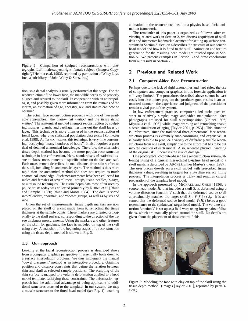
Published in ACM TOG (SIGGRAPH conference proceedings) 22(3):554–561, July 2003
Figure 2: Comparison of sculpted reconstructions with pho-tographs. Left: male subject; right: female subject. (Images: Copy-right c©[Helmer et al. 1993], reprinted by permission of Wiley-Liss,Inc., a subsidiary of John Wiley & Sons, Inc.)
tion, so a dental analysis is usually performed at this stage. For thereconstruction of the lower face, the mandible needs to be properlyaligned and secured to the skull. In cooperation with an anthropol-ogist, and possibly given more information from the remains of thevictim, an estimation of age, ancestry, sex, and stature can now beobtained.
The actual face reconstruction proceeds with one of two avail-able approaches: the anatomical method and the tissue depthmethod. The anatomical method attempts reconstruction by sculpt-ing muscles, glands, and cartilage, fleshing out the skull layer bylayer. This technique is more often used in the reconstruction offossil faces, where no statistical population data exists [Zollikoferet al. 1998]. As TAYLOR states, this technique is very time consum-ing, occupying “many hundreds of hours”. It also requires a greatdeal of detailed anatomical knowledge. Therefore, the alternativetissue depth method has become the more popular reconstructiontechnique in law enforcement. Here, standard sets of statistical tis-sue thickness measurements at specific points on the face are used.Each measurement describes the total distance from skin surface tothe skull, including fat and muscle layers. The method is thus morerapid than the anatomical method and does not require as muchanatomical knowledge. Such measurements have been collected formales and females of several racial groups, using needles, X-rays,or ultrasound techniques. The tissue depth data most often used bypolice artists today was collected primarily by RHINE et al. [Rhineand Campbell 1980; Rhine and Moore 1984]. The data is sortedinto “slender”, “normal”, and “obese” groups, as well as by sex andrace.
Given the set of measurements, tissue depth markers are nowplaced on the skull or a cast made from it, reflecting the tissuethickness at the sample points. These markers are oriented orthog-onally to the skull surface, corresponding to the direction of the tis-sue thickness measurements. Using the markers and other featureson the skull for guidance, the face is modeled on top of the skullusing clay. A snapshot of the beginning stages of a reconstructionusing the tissue depth method is shown in Fig. 3.
1.3 Our approach
Looking at the facial reconstruction process as described abovefrom a computer graphics perspective, it essentially boils down toa surface interpolation problem. We thus implement the manual“dowel placement” method as an interactive procedure, obtainingposition and distance constraints that define the relation betweenskin and skull at selected sample positions. The sculpting of theskin surface is mapped to a volume deformation applied to a headmodel template, satisfying these constraints. The deformation ap-proach has the additional advantage of being applicable to addi-tional structures attached to the template: in our system, we mapa muscle structure to the fitted head model (see Fig. 1), enabling
animation on the reconstructed head in a physics-based facial ani-mation framework.
The remainder of this paper is organized as follows: after re-viewing related work in Section 2, we discuss acquisition of skulldata and interactive landmark placement for setting up surface con-straints in Section 3. Section 4 describes the structure of our generichead model and how it is fitted to the skull. Animation and texturegeneration for the resulting head model are touched upon in Sec-tion 5. We present examples in Section 6 and draw conclusionsfrom our results in Section 7.
2 Previous and Related Work
2.1 Computer-Aided Face Reconstruction
Perhaps due to the lack of rigid taxonomies and hard rules, the useof computers and computer graphics in this forensic application isstill very limited. The procedures described above cannot be casteasily into a computer program that produces good results in an au-tomated manner—the experience and judgment of the practitionerremain a vital part of the system.
In law enforcement practice, computer-aided techniques re-strict to relatively simple image and video manipulation: facephotographs are used for skull superimposition [Gruner 1993;Miyasaka et al. 1995], while image warping and retouching enablea basic simulation of aging [Taylor 2001, p. 253]. This situationis unfortunate, since the traditional three-dimensional face recon-struction process is extremely time-consuming and expensive. Itis hardly feasible to produce a variety of different plausible recon-structions from one skull, simply due to the effort that has to be putinto the creation of each model. Also, repeated physical handlingof the original skull increases the risk of damage.
One prototypical computer-based face reconstruction system, al-lowing fitting of a generic hierarchical B-spline head model to askull mesh, is described by ARCHER in her Master’s thesis [1997].The user places dowels on a skull model with prescribed tissuethickness values, resulting in targets for a B-spline surface fittingprocess. The interpolation process is tricky and requires carefulpreparation of the template head model.
In the approach presented by MICHAEL and CHEN [1996], asource head model Hs that includes a skull Ss is deformed using avolume distortion function V such that the deformed source skullapproximately matches the target skull St : V (Ss) ≈ St . It is as-sumed that the deformed source head model V (Hs) bears a goodresemblance to the (unknown) target head model. The volume dis-tortion function V is set up as a field warp using fourty pairs of discfields, which are manually placed around the skull. No details aregiven about the placement of these control fields.
Figure 3: Modeling the face with clay on top of the skull using thetissue depth method. (Images [Taylor 2001], reprinted by permis-sion.)
2
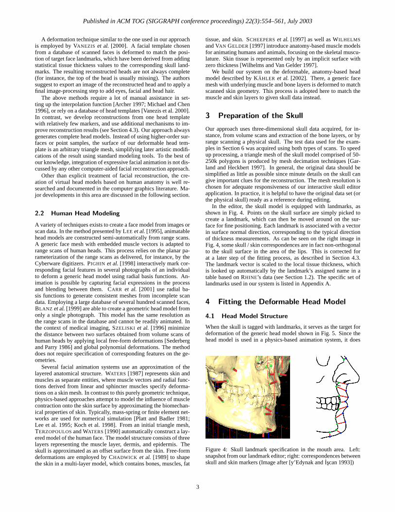
Published in ACM TOG (SIGGRAPH conference proceedings) 22(3):554–561, July 2003
A deformation technique similar to the one used in our approachis employed by VANEZIS et al. [2000]. A facial template chosenfrom a database of scanned faces is deformed to match the posi-tion of target face landmarks, which have been derived from addingstatistical tissue thickness values to the corresponding skull land-marks. The resulting reconstructed heads are not always complete(for instance, the top of the head is usually missing). The authorssuggest to export an image of the reconstructed head and to apply afinal image-processing step to add eyes, facial and head hair.
The above methods require a lot of manual assistance in set-ting up the interpolation function [Archer 1997; Michael and Chen1996], or rely on a database of head templates [Vanezis et al. 2000].In contrast, we develop reconstructions from one head templatewith relatively few markers, and use additional mechanisms to im-prove reconstruction results (see Section 4.3). Our approach alwaysgenerates complete head models. Instead of using higher-order sur-faces or point samples, the surface of our deformable head tem-plate is an arbitrary triangle mesh, simplifying later artistic modifi-cations of the result using standard modeling tools. To the best ofour knowledge, integration of expressive facial animation is not dis-cussed by any other computer-aided facial reconstruction approach.
Other than explicit treatment of facial reconstruction, the cre-ation of virtual head models based on human anatomy is well re-searched and documented in the computer graphics literature. Ma-jor developments in this area are discussed in the following section.
2.2 Human Head Modeling
A variety of techniques exists to create a face model from images orscan data. In the method presented by LEE et al. [1995], animatablehead models are constructed semi-automatically from range scans.A generic face mesh with embedded muscle vectors is adapted torange scans of human heads. This process relies on the planar pa-rameterization of the range scans as delivered, for instance, by theCyberware digitizers. PIGHIN et al. [1998] interactively mark cor-responding facial features in several photographs of an individualto deform a generic head model using radial basis functions. An-imation is possible by capturing facial expressions in the processand blending between them. CARR et al. [2001] use radial ba-sis functions to generate consistent meshes from incomplete scandata. Employing a large database of several hundred scanned faces,BLANZ et al. [1999] are able to create a geometric head model fromonly a single photograph. This model has the same resolution asthe range scans in the database and cannot be readily animated. Inthe context of medical imaging, SZELISKI et al. [1996] minimizethe distance between two surfaces obtained from volume scans ofhuman heads by applying local free-form deformations [Sederbergand Parry 1986] and global polynomial deformations. The methoddoes not require specification of corresponding features on the ge-ometries.
Several facial animation systems use an approximation of thelayered anatomical structure. WATERS [1987] represents skin andmuscles as separate entities, where muscle vectors and radial func-tions derived from linear and sphincter muscles specify deforma-tions on a skin mesh. In contrast to this purely geometric technique,physics-based approaches attempt to model the influence of musclecontraction onto the skin surface by approximating the biomechan-ical properties of skin. Typically, mass-spring or finite element net-works are used for numerical simulation [Platt and Badler 1981;Lee et al. 1995; Koch et al. 1998]. From an initial triangle mesh,TERZOPOULOS and WATERS [1990] automatically construct a lay-ered model of the human face. The model structure consists of threelayers representing the muscle layer, dermis, and epidermis. Theskull is approximated as an offset surface from the skin. Free-formdeformations are employed by CHADWICK et al. [1989] to shapethe skin in a multi-layer model, which contains bones, muscles, fat
tissue, and skin. SCHEEPERS et al. [1997] as well as WILHELMSand VAN GELDER [1997] introduce anatomy-based muscle modelsfor animating humans and animals, focusing on the skeletal muscu-lature. Skin tissue is represented only by an implicit surface withzero thickness [Wilhelms and Van Gelder 1997].
We build our system on the deformable, anatomy-based headmodel described by KAHLER et al. [2002]. There, a generic facemesh with underlying muscle and bone layers is deformed to matchscanned skin geometry. This process is adopted here to match themuscle and skin layers to given skull data instead.
3 Preparation of the Skull
Our approach uses three-dimensional skull data acquired, for in-stance, from volume scans and extraction of the bone layers, or byrange scanning a physical skull. The test data used for the exam-ples in Section 6 was acquired using both types of scans. To speedup processing, a triangle mesh of the skull model comprised of 50-250k polygons is produced by mesh decimation techniques [Gar-land and Heckbert 1997]. In general, the original data should besimplified as little as possible since minute details on the skull cangive important clues for the reconstruction. The mesh resolution ischosen for adequate responsiveness of our interactive skull editorapplication. In practice, it is helpful to have the original data set (orthe physical skull) ready as a reference during editing.
In the editor, the skull model is equipped with landmarks, asshown in Fig. 4. Points on the skull surface are simply picked tocreate a landmark, which can then be moved around on the sur-face for fine positioning. Each landmark is associated with a vectorin surface normal direction, corresponding to the typical directionof thickness measurements. As can be seen on the right image inFig. 4, some skull / skin correspondences are in fact non-orthogonalto the skull surface in the area of the lips. This is corrected forat a later step of the fitting process, as described in Section 4.3.The landmark vector is scaled to the local tissue thickness, whichis looked up automatically by the landmark’s assigned name in atable based on RHINE’s data (see Section 1.2). The specific set oflandmarks used in our system is listed in Appendix A.
4 Fitting the Deformable Head Model
4.1 Head Model Structure
When the skull is tagged with landmarks, it serves as the target fordeformation of the generic head model shown in Fig. 5. Since thehead model is used in a physics-based animation system, it does
Figure 4: Skull landmark specification in the mouth area. Left:snapshot from our landmark editor; right: correspondences betweenskull and skin markers (Image after [y’Edynak and Iscan 1993])
3
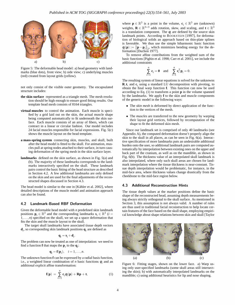
Published in ACM TOG (SIGGRAPH conference proceedings) 22(3):554–561, July 2003
a) b) c)
Figure 5: The deformable head model: a) head geometry with land-marks (blue dots), front view; b) side view; c) underlying muscles(red) created from layout grids (yellow).
not only consist of the visible outer geometry. The encapsulatedstructure includes:
the skin surface represented as a triangle mesh. The mesh resolu-tion should be high enough to ensure good fitting results. Ourtemplate head mesh consists of 8164 triangles.
virtual muscles to control the animation. Each muscle is speci-fied by a grid laid out on the skin, the actual muscle shapebeing computed automatically to fit underneath the skin sur-face. Each muscle consists of an array of fibers, which cancontract in a linear or circular fashion. Our model includes24 facial muscles responsible for facial expressions. Fig. 5(c)shows the muscle layout on the head template.
a mass-spring system connecting skin, muscles, and skull, builtafter the head model is fitted to the skull. For animation, mus-cles pull at spring nodes attached to their surface, in turn caus-ing deformation of the spring mesh in the skin surface layer.
landmarks defined on the skin surface, as shown in Fig. 5(a) and(b). The majority of these landmarks corresponds to the land-marks interactively specified on the skull. These landmarkpairs control the basic fitting of the head structure as describedin Section 4.2. A few additional landmarks are only definedon the skin and are used for the final adjustments of the recon-structed shapes discussed in Section 4.3.
The head model is similar to the one in [Kahler et al. 2002], wheredetailed descriptions of the muscle model and animation approachcan also be found.
4.2 Landmark-Based RBF Deformation
Given the deformable head model with n predefined skin landmarkpositions pi ∈ R
3 and the corresponding landmarks si ∈ R3 (i =
1, . . . ,n) specified on the skull, we set up a space deformation thatfits the skin and the muscle layout to the skull.
The target skull landmarks have associated tissue depth vectorsdi, so corresponding skin landmark positions qi are defined as
qi = si +di.
The problem can now be treated as one of interpolation: we need tofind a function f that maps the pi to the qi:
qi = f(pi), i = 1, . . . ,n.
The unknown function f can be expressed by a radial basis function,i.e., a weighted linear combination of n basic functions φi and anadditional explicit affine transformation:
f(p) =n
∑i=1
ciφi(p) + Rp + t, (1)
where p ∈ R3 is a point in the volume, ci ∈ R
3 are (unknown)weights, R ∈ R
3×3 adds rotation, skew, and scaling, and t ∈ R3
is a translation component. The φi are defined by the source skinlandmark points. According to BOOKSTEIN [1997], for deforma-tion of biological solids an approach based on thin-plate splinesis favorable. We thus use the simple biharmonic basic functionφi(p) :=
∥
∥p−pi
∥
∥
2, which minimizes bending energy for the de-formation [Duchon 1977].
To remove affine contributions from the weighted sum of thebasic functions [Pighin et al. 1998; Carr et al. 2001], we include theadditional constraints
n
∑i=1
ci = 0 andn
∑i=1
cTi pi = 0.
The resulting system of linear equations is solved for the unknownsR, t, and ci using a standard LU decomposition with pivoting, toobtain the final warp function f. This function can now be usedaccording to Eq. (1) to transform a point p in the volume spannedby the landmarks. We apply f to the skin and muscle componentsof the generic model in the following ways:
• The skin mesh is deformed by direct application of the func-tion to the vertices of the mesh.
• The muscles are transferred to the new geometry by warpingtheir layout grid vertices, followed by recomputation of theshape to fit the deformed skin mesh.
Since our landmark set is comprised of only 40 landmarks (seeAppendix A), the computed deformation doesn’t properly align theskin to the skull in all places, as can be seen in Fig. 6(a). Interac-tive specification of more landmarks puts an undesirable additionalburden onto the user, so additional landmark pairs are computed au-tomatically by interpolation between existing ones on the upper andback part of the cranium, as well as on the mandible, as shown inFig. 6(b). The thickness value of an interpolated skull landmark isalso interpolated, where only such skull areas are chosen for land-mark interpolation where the tissue thickness is near-constant. Tis-sue depth interpolation would be problematic, for instance, in themid-face area, where thickness values change drastically from thecheekbone to the mid-face region below.
4.3 Additional Reconstruction Hints
The tissue depth values at the marker positions define the basicshape of the reconstructed head, assuming depth measurements be-ing always strictly orthogonal to the skull surface. As mentioned inSection 3, this assumption is not always valid. A number of rulesare thus used in traditional facial reconstruction to help locate cer-tain features of the face based on the skull shape, employing empiri-cal knowledge about shape relations between skin and skull [Taylor
(a) (b) (c)
Figure 6: Fitting stages, shown on the lower face. a) Warp us-ing only user-specified landmarks (some skull areas still intersect-ing the skin); b) with automatically interpolated landmarks on themandible; c) using additional heuristics for lip and nose shaping.
4
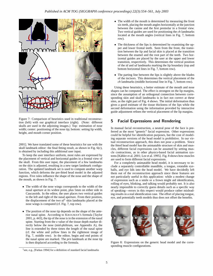
Published in ACM TOG (SIGGRAPH conference proceedings) 22(3):554–561, July 2003
Figure 7: Comparison of heuristics used in traditional reconstruc-tion (left) with our graphical interface (right). (Note: differentskulls are used in the adjoining images.) Top: estimation of nosewidth; center: positioning of the nose tip; bottom: setting lip width,height, and mouth corner position.
2001]. We have translated some of these heuristics for use with theskull landmark editor: the final fitting result, as shown in Fig. 6(c),is obtained by including this additional user input.
To keep the user interface uniform, most rules are expressed bythe placement of vertical and horizontal guides in a frontal view ofthe skull. From this user input, the placement of a few landmarkson the skin is adjusted, resulting in a new target landmark configu-ration. The updated landmark set is used to compute another warpfunction, which deforms the pre-fitted head model in the adjustedregions. Five rules influence the shape of the nose and the shape ofthe mouth, as shown in Fig. 7:
• The width of the nose wings corresponds to the width of thenasal aperture at its widest point, plus 5mm on either side inCaucasoids. In the editor, the user places two vertical guidesto the left and right of the nasal aperture. From their position,the displacement of the two al1 skin landmarks placed at thenose wings is computed (cf. Fig. 7, top row).
• The position of the nose tip depends on the shape of the ante-rior nasal spine. According to KROGMAN’s formula [Taylor2001, p. 443], the tip of the nose is in the extension of the nasalspine. Starting from the z value of the tissue depth marker di-rectly below the nose (mid-philtrum, see Appendix A), theline is extended by three times the length of the nasal spine(cf. the white and yellow lines in the rightmost image ofFig. 7, middle row). In the editor, begin and end points ofthe nasal spine are marked. The prn landmark at the nose tipis then displaced according to the formula.
1see, e.g., [Farkas 1994] for a definition of standard facial landmarks
• The width of the mouth is determined by measuring the frontsix teeth, placing the mouth angles horizontally at the junctionbetween the canine and the first premolar in a frontal view.Two vertical guides are used for positioning the ch landmarkslocated at the mouth angles (vertical lines in Fig. 7, bottomrow).
• The thickness of the lips is determined by examining the up-per and lower frontal teeth. Seen from the front, the transi-tion between the lip and facial skin is placed at the transitionbetween the enamel and the root part of the teeth. Two hor-izontal guides are placed by the user at the upper and lowertransition, respectively. This determines the vertical positionof the id and sd landmarks marking the lip boundary (top andbottom horizontal lines in Fig. 7, bottom row).
• The parting line between the lips is slightly above the bladesof the incisors. This determines the vertical placement of thech landmarks (middle horizontal line in Fig. 7, bottom row).
Using these heuristics, a better estimate of the mouth and noseshapes can be computed. The effect is strongest on the lip margins,since the assumption of an orthogonal connection between corre-sponding skin and skull landmarks is in fact not correct at thesesites, as the right part of Fig. 4 shows. The initial deformation thusgives a good estimate of the tissue thickness of the lips while thesecond deformation using the information provided by interactiveguide adjustment refines the vertical placement of the lip margins.
5 Facial Expressions and Rendering
In manual facial reconstruction, a neutral pose of the face is pre-ferred as the most “generic” facial expression. Other expressionscould be helpful for identification purposes, but the cost of model-ing separate versions of the head model is prohibitive. In our vir-tual reconstruction approach, this does not pose a problem. Sincethe fitted head model has the animatable structure of skin and mus-cles, different facial expressions can be assumed by setting mus-cle contractions, as in other physics-based facial animation sys-tems [Kahler et al. 2001; Lee et al. 1995]. Fig. 8 shows how musclesare used to form different facial expressions.
For a completely animatable head model, it is necessary to in-clude a separately controllable mandible, a tongue, rotatable eye-balls, and eye lids into the head model. We have decidedly leftthem out of the reconstruction approach since these features arenot particularly useful in this application: while a modest changeof expression such as a smile or a frown might aid identification,rolling of eyes, blinking, and talking would probably not. It is alsonearly impossible to correctly guess details such as a specific wayof speaking—errors in this respect would produce rather mislead-ing results in a real identification case. The effort of placing tongue,eye, and potentially teeth models thus does not offset the benefits.
Figure 8: Expressions on the generic head model and the corre-sponding muscle configurations.
5
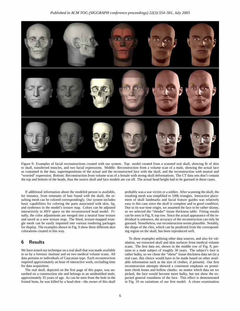
Published in ACM TOG (SIGGRAPH conference proceedings) 22(3):554–561, July 2003
Figure 9: Examples of facial reconstructions created with our system. Top: model created from a scanned real skull, showing fit of skinto skull, transferred muscles, and two facial expressions. Middle: Reconstruction from a volume scan of a male, showing the actual faceas contained in the data, superimpositions of the actual and the reconstructed face with the skull, and the reconstruction with neutral and“worried” expression. Bottom: Reconstruction from volume scan of a female with strong skull deformations. The CT data sets don’t containthe top and bottom of the heads, thus the source skull and face models are cut off. The actual head height had to be guessed in these cases.
If additional information about the modeled person is available,for instance, from remnants of hair found with the skull, the re-sulting mesh can be colored correspondingly. Our system includesbasic capabilities for coloring the parts associated with skin, lip,and eyebrows in the model’s texture map. Colors can be adjustedinteractively in HSV space on the reconstructed head model. Fi-nally, the color adjustments are merged into a neutral base textureand saved as a new texture map. The fitted, texture-mapped trian-gle mesh can be easily imported into various rendering packagesfor display. The examples shown in Fig. 9 show three different skincolorations created in this way.
6 Results
We have tested our technique on a real skull that was made availableto us by a forensic institute and on two medical volume scans. Alldata pertains to individuals of Caucasian type. Each reconstructionrequired approximately an hour of interactive work, excluding timefor data acquisition.
The real skull, depicted on the first page of this paper, was un-earthed on a construction site and belongs to an unidentified male,approximately 35 years of age. As can be seen from the hole in thefrontal bone, he was killed by a head shot—the owner of this skull
probably was a war victim or a soldier. After scanning the skull, theresulting mesh was simplified to 100k triangles. Interactive place-ment of skull landmarks and facial feature guides was relativelyeasy in this case since the skull is complete and in good condition.Due to its war-time origin, we assumed the face to be rather skinny,so we selected the “slender” tissue thickness table. Fitting resultscan be seen in Fig. 9, top row. Since the actual appearance of the in-dividual is unknown, the accuracy of the reconstruction can only beguessed. Nonetheless, our reconstruction seems plausible. Notably,the shape of the chin, which can be predicted from the correspond-ing region on the skull, has been reproduced well.
To show examples utilizing other data sources, and also for val-idation, we extracted skull and skin surfaces from medical volumescans. The first data set, shown in the middle row of Fig. 9, per-tains to a male subject of roughly 30 years. The subject’s face israther bulky, so we chose the “obese” tissue thickness data set (in areal case, this choice would have to be made based on other avail-able information such as the size of clothes, if present). Our firstreconstruction attempts showed a consistent emphasis on promi-nent cheek bones and hollow cheeks: no matter which data set wepicked, the face would become more bulky, but not show the ex-pected general roundness of the face. This effect is demonstratedin Fig. 10 on variations of our first model. A closer examination
6
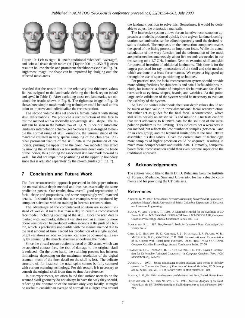
Published in ACM TOG (SIGGRAPH conference proceedings) 22(3):554–561, July 2003
Figure 10: Left to right: RHINE’s traditional “slender”, “average”,and “obese” tissue depth tables (cf. [Taylor 2001, p. 350 ff.]) oftenresult in hollow cheeks and prominent cheekbones (see also Fig. 9).Rightmost image: the shape can be improved by “bulging out” theaffected mesh areas.
revealed that the reason lies in the relatively low thickness valuesRHINE assigned to the landmarks defining the cheek region (sbm2and spm2 in Table 1). After excluding these two landmarks, we ob-tained the results shown in Fig. 9. The rightmost image in Fig. 10shows how simple mesh modeling techniques could be used at thispoint to improve and individualize the reconstruction.
The second volume data set shows a female patient with strongskull deformations. We produced a reconstruction of this face totest the method with a decidedly non-average skull shape. The re-sult can be seen in the bottom row of Fig. 9. Since our automaticlandmark interpolation scheme (see Section 4.2) is designed to han-dle the normal range of skull variations, the unusual shape of themandible resulted in very sparse sampling of the chin area. An-other prominent feature of the skull data is the protrusion of oneincisor, pushing the upper lip to the front. We modeled this effectby moving the sd landmark a few millimeters down onto the bladeof the incisor, thus pushing the associated skin landmark forward aswell. This did not impair the positioning of the upper lip boundarysince this is adjusted separately by the mouth guides (cf. Fig. 7).
7 Conclusion and Future Work
The face reconstruction approach presented in this paper mirrorsthe manual tissue depth method and thus has essentially the sameprediction power. Our results show overall good reproduction offacial shape and proportions, and some surprisingly well-matcheddetails. It should be noted that our examples were produced bycomputer scientists with no training in forensic reconstruction.
The advantages of the computerized solution are evident: in-stead of weeks, it takes less than a day to create a reconstructedface model, including scanning of the skull. Once the scan data ismarked with landmarks, different varieties such as slimmer or moreobese versions can be produced within seconds at the push of a but-ton, which is practically impossible with the manual method due tothe vast amount of time needed for production of a single model.Slight variations in facial expression can also be obtained quite eas-ily by animating the muscle structure underlying the model.
Since the virtual reconstruction is based on 3D scans, which canbe acquired contact-free, the risk of damage to the original skullis reduced. On the other hand, the scanning process has inherentlimitations: depending on the maximum resolution of the digitalscanner, much of the finer detail on the skull is lost. The delicatestructure of, for instance, the nasal spine cannot be fully capturedwith current scanning technology. For this reason, it is necessary toconsult the original skull from time to time for reference.
In our experiments, we often found that surface normals on thescanned skull geometry do not always behave the way they should,reflecting the orientation of the surface only very locally. It mightbe useful to consider an average of normals in a larger area around
the landmark position to solve this. Sometimes, it would be desir-able to adjust the orientation manually.
The interactive system allows for an iterative reconstruction ap-proach: a model is produced quickly from a given landmark config-uration, so landmarks can be edited repeatedly until the desired re-sult is obtained. The emphasis on the interaction component makesthe speed of the fitting process an important issue. While the actualcalculation of the warp function and the deformation of the meshare performed instantaneously, about five seconds are needed in ourtest setting on a 1.7 GHz Pentium Xeon to examine skull and skinfor potential insertion of additional landmarks. This time is for thelargest part used for ray intersections of the skull and skin meshes,which are done in a brute force manner. We expect a big speed-upthrough the use of space partitioning techniques.
For practical use, the facial reconstruction system should providemore editing facilities for skin details and hair. Useful additions in-clude, for instance, a choice of templates for haircuts and facial fea-tures such as eyebrow shapes, beards, and wrinkles. At this point,large-scale validation of the system would be necessary to evaluatethe usability of the system.
As TAYLOR writes in her book, the tissue depth values should notbe taken at face value in three-dimensional facial reconstruction,but rather act as guides for the final facial reconstruction, whichstill relies heavily on artistic skills and intuition. Our tests confirmthat strict adherance to RHINE’s data for the solution of the inter-polation problem is too limiting. This indicates not a weakness inour method, but reflects the low number of samples (between 3 and37 in each group) and the technical limitations at the time RHINEassembled his data tables. Given the current state of technology,more samples of higher precision could be acquired, resulting inmuch more comprehensive and usable data. Ultimately, computer-based facial reconstruction could then even become superior to thetraditional approach.
8 Acknowledgements
The authors would like to thank Dr. D. Buhmann from the Instituteof Forensic Medicine, Saarland University, for his valuable com-ments and for providing the CT data sets.
References
ARCHER, K. M. 1997. Craniofacial Reconstruction using hierarchical B-Spline Inter-polation. Master’s thesis, University of British Columbia, Department of Electricaland Computer Engineering.
BLANZ, V., AND VETTER, T. 1999. A Morphable Model for the Synthesis of 3DFaces. In Proc. ACM SIGGRAPH 1999, ACM Press / ACM SIGGRAPH, ComputerGraphics Proceedings, Annual Conference Series, 187–194.
BOOKSTEIN, F. L. 1997. Morphometric Tools for Landmark Data. Cambridge Uni-versity Press.
CARR, J. C., BEATSON, R. K., CHERRIE, J. B., MITCHELL, T. J., FRIGHT, W. R.,MCCALLUM, B. C., AND EVANS, T. R. 2001. Reconstruction and Representationof 3D Objects With Radial Basis Functions. ACM Press / ACM SIGGRAPH,Computer Graphics Proceedings, Annual Conference Series, 67–76.
CHADWICK, J. E., HAUMANN, D. R., AND PARENT, R. E. 1989. Layered Construc-tion for Deformable Animated Characters. In Computer Graphics (Proc. ACMSIGGRAPH 89), 243–252.
DUCHON, J. 1977. Spline minimizing rotation-invariant semi-norms in Sobolevspaces. In Constructive Theory of Functions of Several Variables, W. Schemppand K. Zeller, Eds., vol. 571 of Lecture Notes in Mathematics, 85–100.
FARKAS, L. G., Ed. 1994. Anthropometry of the Head and Face, 2nd ed. Raven Press.
FEDOSYUTKIN, B. A., AND NAINYS, J. V. 1993. Forensic Analysis of the Skull.Wiley-Liss, ch. 15: The Relationship of Skull Morphology to Facial Features, 199–213.
7
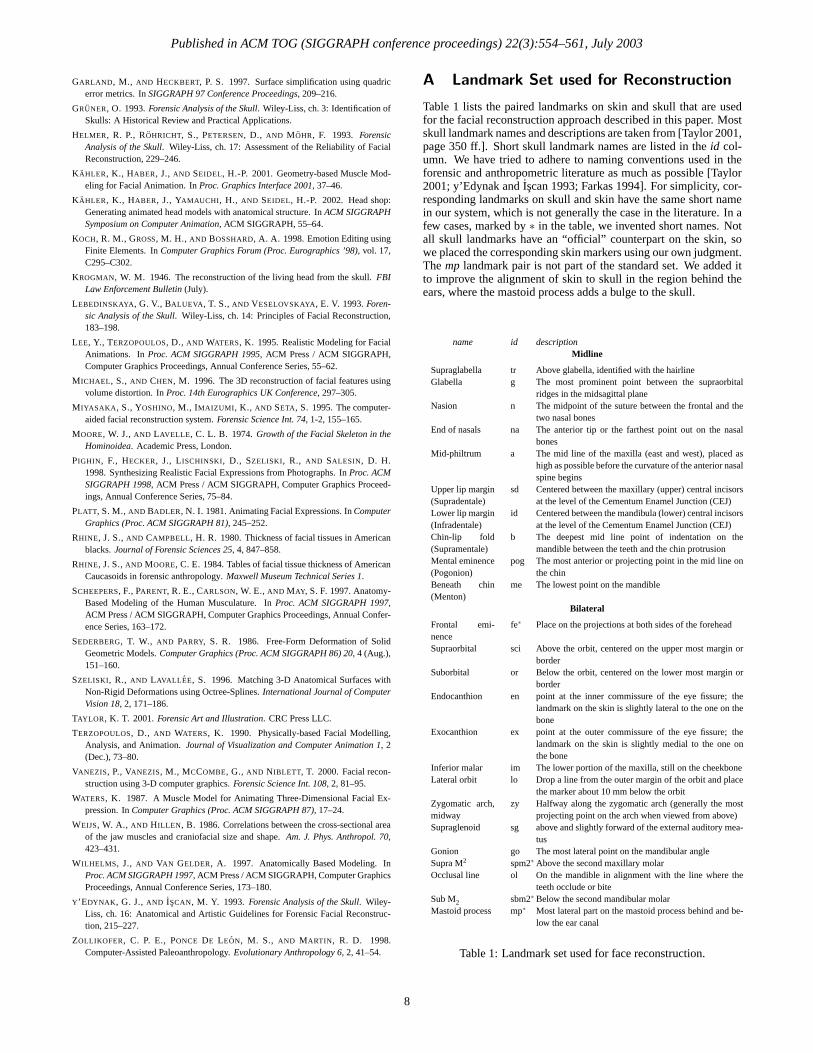
Published in ACM TOG (SIGGRAPH conference proceedings) 22(3):554–561, July 2003
GARLAND, M., AND HECKBERT, P. S. 1997. Surface simplification using quadricerror metrics. In SIGGRAPH 97 Conference Proceedings, 209–216.
GRUNER, O. 1993. Forensic Analysis of the Skull. Wiley-Liss, ch. 3: Identification ofSkulls: A Historical Review and Practical Applications.
HELMER, R. P., ROHRICHT, S., PETERSEN, D., AND MOHR, F. 1993. ForensicAnalysis of the Skull. Wiley-Liss, ch. 17: Assessment of the Reliability of FacialReconstruction, 229–246.
KAHLER, K., HABER, J., AND SEIDEL, H.-P. 2001. Geometry-based Muscle Mod-eling for Facial Animation. In Proc. Graphics Interface 2001, 37–46.
KAHLER, K., HABER, J., YAMAUCHI, H., AND SEIDEL, H.-P. 2002. Head shop:Generating animated head models with anatomical structure. In ACM SIGGRAPHSymposium on Computer Animation, ACM SIGGRAPH, 55–64.
KOCH, R. M., GROSS, M. H., AND BOSSHARD, A. A. 1998. Emotion Editing usingFinite Elements. In Computer Graphics Forum (Proc. Eurographics ’98), vol. 17,C295–C302.
KROGMAN, W. M. 1946. The reconstruction of the living head from the skull. FBILaw Enforcement Bulletin (July).
LEBEDINSKAYA, G. V., BALUEVA, T. S., AND VESELOVSKAYA, E. V. 1993. Foren-sic Analysis of the Skull. Wiley-Liss, ch. 14: Principles of Facial Reconstruction,183–198.
LEE, Y., TERZOPOULOS, D., AND WATERS, K. 1995. Realistic Modeling for FacialAnimations. In Proc. ACM SIGGRAPH 1995, ACM Press / ACM SIGGRAPH,Computer Graphics Proceedings, Annual Conference Series, 55–62.
MICHAEL, S., AND CHEN, M. 1996. The 3D reconstruction of facial features usingvolume distortion. In Proc. 14th Eurographics UK Conference, 297–305.
MIYASAKA, S., YOSHINO, M., IMAIZUMI, K., AND SETA, S. 1995. The computer-aided facial reconstruction system. Forensic Science Int. 74, 1-2, 155–165.
MOORE, W. J., AND LAVELLE, C. L. B. 1974. Growth of the Facial Skeleton in theHominoidea. Academic Press, London.
PIGHIN, F., HECKER, J., LISCHINSKI, D., SZELISKI, R., AND SALESIN, D. H.1998. Synthesizing Realistic Facial Expressions from Photographs. In Proc. ACMSIGGRAPH 1998, ACM Press / ACM SIGGRAPH, Computer Graphics Proceed-ings, Annual Conference Series, 75–84.
PLATT, S. M., AND BADLER, N. I. 1981. Animating Facial Expressions. In ComputerGraphics (Proc. ACM SIGGRAPH 81), 245–252.
RHINE, J. S., AND CAMPBELL, H. R. 1980. Thickness of facial tissues in Americanblacks. Journal of Forensic Sciences 25, 4, 847–858.
RHINE, J. S., AND MOORE, C. E. 1984. Tables of facial tissue thickness of AmericanCaucasoids in forensic anthropology. Maxwell Museum Technical Series 1.
SCHEEPERS, F., PARENT, R. E., CARLSON, W. E., AND MAY, S. F. 1997. Anatomy-Based Modeling of the Human Musculature. In Proc. ACM SIGGRAPH 1997,ACM Press / ACM SIGGRAPH, Computer Graphics Proceedings, Annual Confer-ence Series, 163–172.
SEDERBERG, T. W., AND PARRY, S. R. 1986. Free-Form Deformation of SolidGeometric Models. Computer Graphics (Proc. ACM SIGGRAPH 86) 20, 4 (Aug.),151–160.
SZELISKI, R., AND LAVALLEE, S. 1996. Matching 3-D Anatomical Surfaces withNon-Rigid Deformations using Octree-Splines. International Journal of ComputerVision 18, 2, 171–186.
TAYLOR, K. T. 2001. Forensic Art and Illustration. CRC Press LLC.
TERZOPOULOS, D., AND WATERS, K. 1990. Physically-based Facial Modelling,Analysis, and Animation. Journal of Visualization and Computer Animation 1, 2(Dec.), 73–80.
VANEZIS, P., VANEZIS, M., MCCOMBE, G., AND NIBLETT, T. 2000. Facial recon-struction using 3-D computer graphics. Forensic Science Int. 108, 2, 81–95.
WATERS, K. 1987. A Muscle Model for Animating Three-Dimensional Facial Ex-pression. In Computer Graphics (Proc. ACM SIGGRAPH 87), 17–24.
WEIJS, W. A., AND HILLEN, B. 1986. Correlations between the cross-sectional areaof the jaw muscles and craniofacial size and shape. Am. J. Phys. Anthropol. 70,423–431.
WILHELMS, J., AND VAN GELDER, A. 1997. Anatomically Based Modeling. InProc. ACM SIGGRAPH 1997, ACM Press / ACM SIGGRAPH, Computer GraphicsProceedings, Annual Conference Series, 173–180.
Y’EDYNAK, G. J., AND ISCAN, M. Y. 1993. Forensic Analysis of the Skull. Wiley-Liss, ch. 16: Anatomical and Artistic Guidelines for Forensic Facial Reconstruc-tion, 215–227.
ZOLLIKOFER, C. P. E., PONCE DE LEON, M. S., AND MARTIN, R. D. 1998.Computer-Assisted Paleoanthropology. Evolutionary Anthropology 6, 2, 41–54.
A Landmark Set used for Reconstruction
Table 1 lists the paired landmarks on skin and skull that are usedfor the facial reconstruction approach described in this paper. Mostskull landmark names and descriptions are taken from [Taylor 2001,page 350 ff.]. Short skull landmark names are listed in the id col-umn. We have tried to adhere to naming conventions used in theforensic and anthropometric literature as much as possible [Taylor2001; y’Edynak and Iscan 1993; Farkas 1994]. For simplicity, cor-responding landmarks on skull and skin have the same short namein our system, which is not generally the case in the literature. In afew cases, marked by ∗ in the table, we invented short names. Notall skull landmarks have an “official” counterpart on the skin, sowe placed the corresponding skin markers using our own judgment.The mp landmark pair is not part of the standard set. We added itto improve the alignment of skin to skull in the region behind theears, where the mastoid process adds a bulge to the skull.
name id descriptionMidline
Supraglabella tr Above glabella, identified with the hairlineGlabella g The most prominent point between the supraorbital
ridges in the midsagittal planeNasion n The midpoint of the suture between the frontal and the
two nasal bonesEnd of nasals na The anterior tip or the farthest point out on the nasal
bonesMid-philtrum a The mid line of the maxilla (east and west), placed as
high as possible before the curvature of the anterior nasalspine begins
Upper lip margin(Supradentale)
sd Centered between the maxillary (upper) central incisorsat the level of the Cementum Enamel Junction (CEJ)
Lower lip margin(Infradentale)
id Centered between the mandibula (lower) central incisorsat the level of the Cementum Enamel Junction (CEJ)
Chin-lip fold(Supramentale)
b The deepest mid line point of indentation on themandible between the teeth and the chin protrusion
Mental eminence(Pogonion)
pog The most anterior or projecting point in the mid line onthe chin
Beneath chin(Menton)
me The lowest point on the mandible
Bilateral
Frontal emi-nence
fe∗ Place on the projections at both sides of the forehead
Supraorbital sci Above the orbit, centered on the upper most margin orborder
Suborbital or Below the orbit, centered on the lower most margin orborder
Endocanthion en point at the inner commissure of the eye fissure; thelandmark on the skin is slightly lateral to the one on thebone
Exocanthion ex point at the outer commissure of the eye fissure; thelandmark on the skin is slightly medial to the one onthe bone
Inferior malar im The lower portion of the maxilla, still on the cheekboneLateral orbit lo Drop a line from the outer margin of the orbit and place
the marker about 10 mm below the orbitZygomatic arch,midway
zy Halfway along the zygomatic arch (generally the mostprojecting point on the arch when viewed from above)
Supraglenoid sg above and slightly forward of the external auditory mea-tus
Gonion go The most lateral point on the mandibular angleSupra M2 spm2∗ Above the second maxillary molarOcclusal line ol On the mandible in alignment with the line where the
teeth occlude or biteSub M2 sbm2∗ Below the second mandibular molarMastoid process mp∗ Most lateral part on the mastoid process behind and be-
low the ear canal
Table 1: Landmark set used for face reconstruction.
8
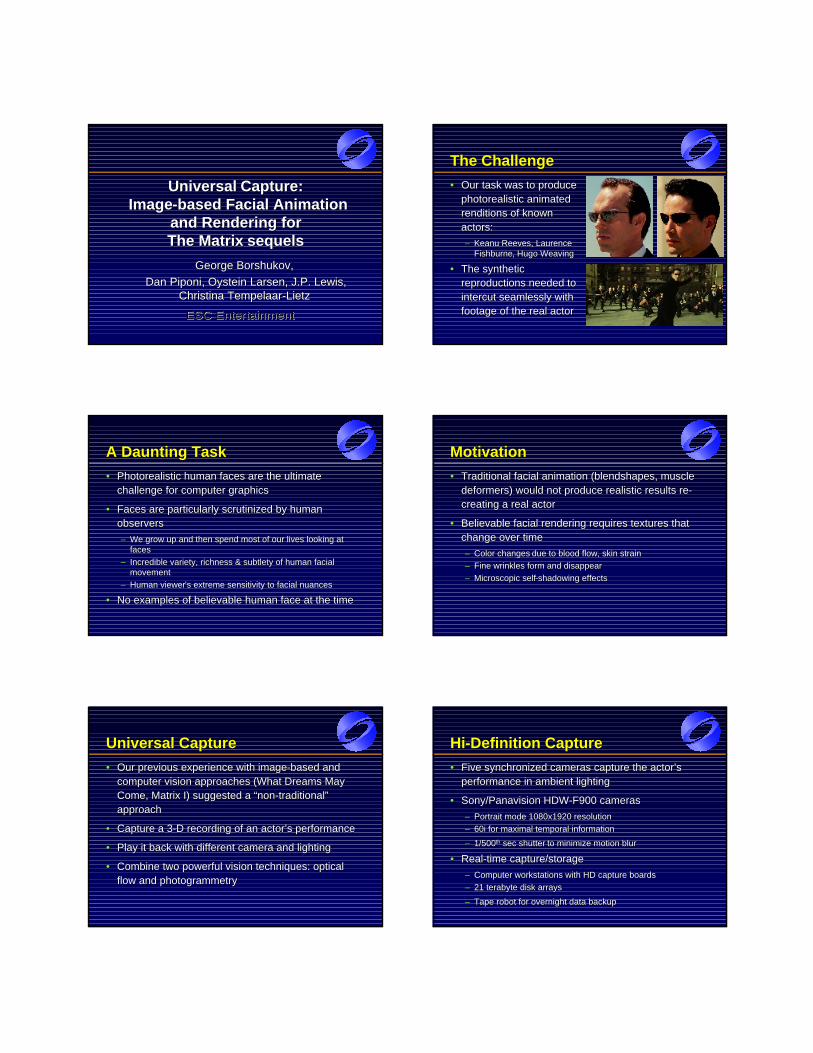
UniversalUniversal Capture:Capture:ImageImage--based Facial Animation based Facial Animation
and Rendering for and Rendering for The Matrix The Matrix sequelssequels
George Borshukov,George Borshukov,
DanDan PiponiPiponi, , OysteinOystein Larsen, J.P. Lewis, Larsen, J.P. Lewis, ChristinaChristina TempelaarTempelaar--LietzLietz
ESC EntertainmentESC Entertainment
TheThe ChallengeChallenge
•• Our task was to produce Our task was to produce photorealistic animated photorealistic animated renditions of known renditions of known actors:actors:
–– Keanu Reeves, Laurence Keanu Reeves, Laurence FishburneFishburne, Hugo Weaving, Hugo Weaving
•• The synthetic The synthetic reproductions needed to reproductions needed to intercut intercut seamlessly with seamlessly with footage of the real actorfootage of the real actor
A Daunting TaskA Daunting Task
•• Photorealistic human faces are the ultimate Photorealistic human faces are the ultimate challenge for computer graphicschallenge for computer graphics
•• Faces are particularly scrutinized by human Faces are particularly scrutinized by human observersobservers
–– We grow up and then spend most of our lives looking at We grow up and then spend most of our lives looking at facesfaces
–– Incredible variety, richness & subtlety of human facial Incredible variety, richness & subtlety of human facial movementmovement
–– Human viewerHuman viewer’’s extreme sensitivity to facial nuancess extreme sensitivity to facial nuances
•• No examples of believable human face at the timeNo examples of believable human face at the time
MotivationMotivation
•• Traditional facial animation (Traditional facial animation (blendshapesblendshapes, muscle , muscle deformers) would not produce realistic results redeformers) would not produce realistic results re--creating a real actorcreating a real actor
•• Believable facial rendering requires textures that Believable facial rendering requires textures that change over timechange over time
–– Color changesColor changes due to blood flow, skin straindue to blood flow, skin strain
–– Fine wrinkles form and disappearFine wrinkles form and disappear
–– Microscopic selfMicroscopic self--shadowing effectsshadowing effects
Universal CaptureUniversal Capture
•• Our previous experience with imageOur previous experience with image--based and based and computer vision approaches (computer vision approaches (What Dreams May What Dreams May Come, Matrix ICome, Matrix I) suggested a “non) suggested a “non--traditional” traditional” approachapproach
•• Capture a 3Capture a 3--D recording of an actor’s performanceD recording of an actor’s performance
•• Play it back with different camera and lightingPlay it back with different camera and lighting
•• Combine two powerful vision techniques: optical Combine two powerful vision techniques: optical flow and photogrammetryflow and photogrammetry
HiHi--Definition CaptureDefinition Capture
•• Five synchronized cameras capture the actor’s Five synchronized cameras capture the actor’s performance in ambient lightingperformance in ambient lighting
•• Sony/Sony/PanavisionPanavision HDWHDW--F900 camerasF900 cameras
–– Portrait mode 1080x1920 resolutionPortrait mode 1080x1920 resolution
–– 60i for maximal temporal information60i for maximal temporal information
–– 1/5001/500thth sec shutter sec shutter to minimize motion blurto minimize motion blur
•• RealReal--time capture/storagetime capture/storage
–– Computer workstations with HD capture boardsComputer workstations with HD capture boards
–– 21 terabyte disk arrays 21 terabyte disk arrays
–– Tape robot for overnight data backupTape robot for overnight data backup
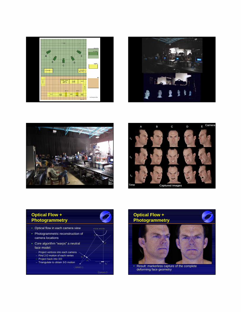
Floor Plan
A
B
A
CD
E
UCap Setup
UCap Crew Ucappics 1
CameraCamera
tt 11
tt 22
tt 33
AA BB CC DD EE
Captured ImagesCaptured ImagesTimeTime
OpticalOptical Flow + Flow + PhotogrammetryPhotogrammetry
•• Optical flow in each camera viewOptical flow in each camera view
•• PhotogrammetricPhotogrammetric reconstruction of reconstruction of camera locationscamera locations
•• Core algorithm “warps” a neutral Core algorithm “warps” a neutral face model:face model:–– Project vertices into each cameraProject vertices into each camera–– Find 2Find 2--D motion of each vertexD motion of each vertex–– Project back into 3Project back into 3--DD–– Triangulate to obtain 3Triangulate to obtain 3--D motionD motion
pp11
pp22
PP’’
PP
pp11’’
pp22’’
Camera 1Camera 1
Camera 2Camera 2
Face ModelFace Model
Optical Flow + Optical Flow + PhotogrammetryPhotogrammetry
•• Result: Result: markerlessmarkerless capture of the complete capture of the complete deforming face geometrydeforming face geometry
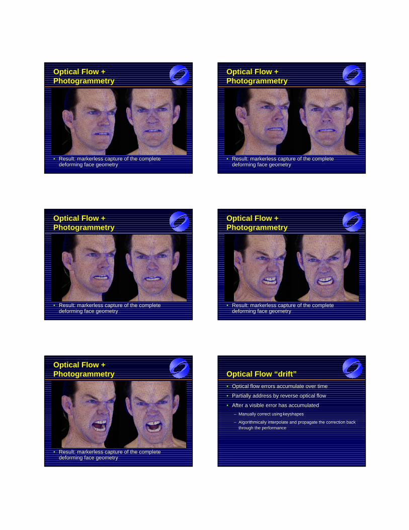
Optical Flow + Optical Flow + PhotogrammetryPhotogrammetry
•• Result: Result: markerlessmarkerless capture of the complete capture of the complete deforming face geometrydeforming face geometry
Optical Flow + Optical Flow + PhotogrammetryPhotogrammetry
•• Result: Result: markerlessmarkerless capture of the complete capture of the complete deforming face geometrydeforming face geometry
Optical Flow + Optical Flow + PhotogrammetryPhotogrammetry
•• Result: Result: markerlessmarkerless capture of the complete capture of the complete deforming face geometrydeforming face geometry
Optical Flow + Optical Flow + PhotogrammetryPhotogrammetry
•• Result: Result: markerlessmarkerless capture of the complete capture of the complete deforming face geometrydeforming face geometry
Optical Flow + Optical Flow + PhotogrammetryPhotogrammetry
•• Result: Result: markerlessmarkerless capture of the complete capture of the complete deforming face geometrydeforming face geometry
Optical Flow “drift”Optical Flow “drift”
•• Optical flow errors accumulate over timeOptical flow errors accumulate over time
•• Partially address by reverse optical flowPartially address by reverse optical flow
•• After a visible error has accumulatedAfter a visible error has accumulated
–– Manually correct using Manually correct using keyshapeskeyshapes
–– Algorithmically interpolate and propagate the correction back Algorithmically interpolate and propagate the correction back through the performancethrough the performance
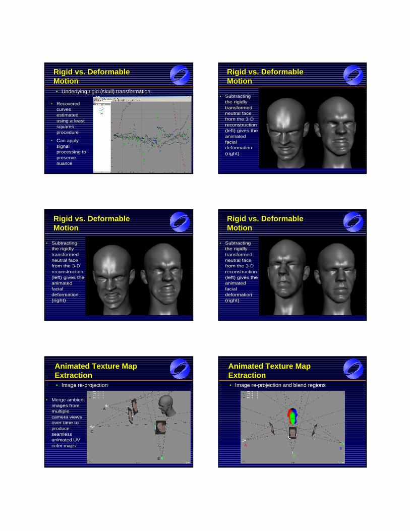
Rigid vs. Deformable Rigid vs. Deformable MotionMotion•• Underlying rigid (skull) transformationUnderlying rigid (skull) transformation
•• Recovered Recovered curves curves estimated estimated using a least using a least squares squares procedureprocedure
•• Can apply Can apply signal signal processing to processing to preserve preserve nuancenuance
Rigid vs. Deformable Rigid vs. Deformable MotionMotion
•• Subtracting Subtracting the rigidly the rigidly transformed transformed neutral face neutral face from the 3from the 3--D D reconstruction reconstruction (left) gives the (left) gives the animated animated facial facial deformation deformation (right)(right)
•• Image reImage re--projectionprojection
Animated Texture Map ExtractionAnimated Texture Map Animated Texture Map ExtractionExtraction
•• Merge ambient Merge ambient images from images from multiple multiple camera views camera views over time to over time to produce produce seamless seamless animated UV animated UV color mapscolor maps
A
C
E
•• Image reImage re--projection and blend regionsprojection and blend regions
Animated Texture Map ExtractionAnimated Texture Map Animated Texture Map ExtractionExtraction
A
C
E
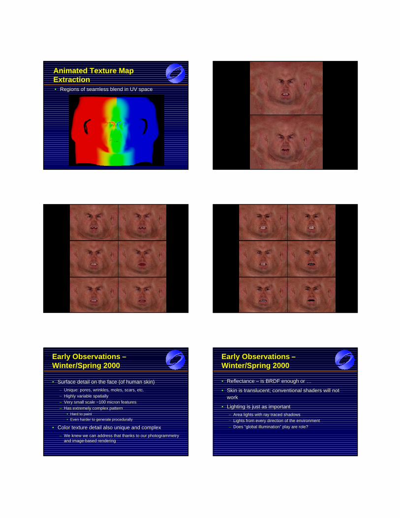
•• Regions of seamless blend in UV spaceRegions of seamless blend in UV space
Animated Texture Map ExtractionAnimated Texture Map Animated Texture Map ExtractionExtraction Color Map 1
Color Map 2 Color Map 3
EarlyEarly Observations Observations ––Winter/Spring 2000Winter/Spring 2000
•• Surface detail on the face (of human skin)Surface detail on the face (of human skin)
–– Unique: pores, wrinkles, moles, scars, etc.Unique: pores, wrinkles, moles, scars, etc.
–– Highly variable spatiallyHighly variable spatially
–– Very small scale ~100 micron featuresVery small scale ~100 micron features
–– Has extremely complex patternHas extremely complex pattern•• Hard to paintHard to paint
•• Even harder to generate procedurallyEven harder to generate procedurally
•• Color texture detail also unique and complexColor texture detail also unique and complex
–– We knew we can address that thanks to our photogrammetry We knew we can address that thanks to our photogrammetry and imageand image--based renderingbased rendering
Early Observations Early Observations ––Winter/Spring 2000Winter/Spring 2000
•• Reflectance Reflectance –– is BRDF enough or …is BRDF enough or …
•• Skin is Skin is translucenttranslucent; conventional shaders will not ; conventional shaders will not workwork
•• Lighting is just as important Lighting is just as important
–– Area lights with ray traced shadowsArea lights with ray traced shadows
–– Lights from every direction of the environmentLights from every direction of the environment
–– Does “global illumination” play are role? Does “global illumination” play are role?
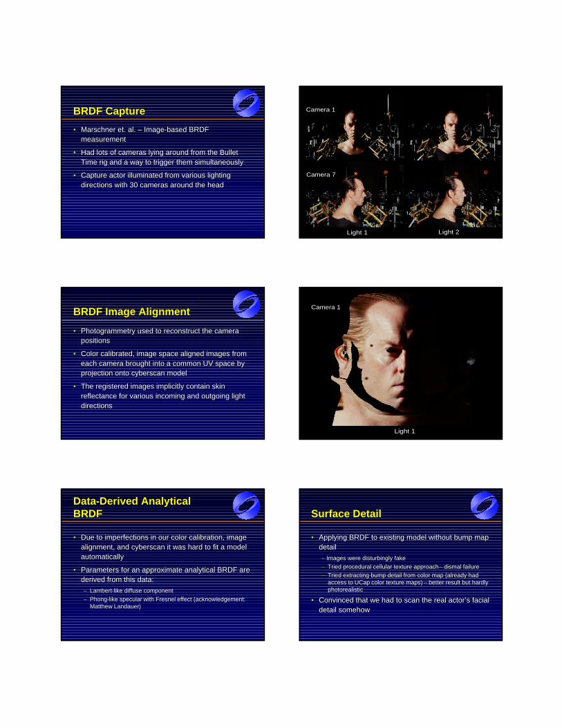
BRDF CaptureBRDF Capture
•• MarschnerMarschner et. al. et. al. –– ImageImage--based BRDF based BRDF measurementmeasurement
•• Had lots of cameras lying around from the Bullet Had lots of cameras lying around from the Bullet Time rig and a way to trigger them simultaneouslyTime rig and a way to trigger them simultaneously
•• Capture actor illuminated from various lighting Capture actor illuminated from various lighting directions with 30 cameras around the headdirections with 30 cameras around the head
BRDF Capture Collage 1
Light 1 Light 2
Camera 1
Camera 7
BRDFBRDF Image AlignmentImage Alignment
•• Photogrammetry used to reconstruct the camera Photogrammetry used to reconstruct the camera positionspositions
•• Color calibrated, image space aligned images from Color calibrated, image space aligned images from each camera brought into a common UV space by each camera brought into a common UV space by projection onto cyberscan modelprojection onto cyberscan model
•• The registered images implicitly contain skin The registered images implicitly contain skin reflectance for various incoming and outgoing light reflectance for various incoming and outgoing light directionsdirections
BRDF Capture Reprojection 1
Light 1
Camera 1
DataData--Derived Analytical Derived Analytical BRDFBRDF
•• Due to imperfections in our color calibration, image Due to imperfections in our color calibration, image alignment, and cyberscan it was hard to fit a model alignment, and cyberscan it was hard to fit a model automaticallyautomatically
•• Parameters for an approximate analytical BRDF are Parameters for an approximate analytical BRDF are derived from this data:derived from this data:
–– LambertLambert--like diffuse componentlike diffuse component
–– PhongPhong--like like specular specular with with FresnelFresnel effect (acknowledgement: effect (acknowledgement: MatthewMatthew LandauerLandauer))
Surface DetailSurface Detail
•• Applying BRDF to existing model without bump map Applying BRDF to existing model without bump map detail detail
–– Images were disturbingly fakeImages were disturbingly fake
–– Tried procedural cellular texture approach Tried procedural cellular texture approach –– dismal failuredismal failure
–– Tried extracting bump detail from color map (already had Tried extracting bump detail from color map (already had access to access to UCap UCap color texture maps) color texture maps) –– better result but hardly better result but hardly photorealisticphotorealistic
•• Convinced that we had to scan the real actor’s facial Convinced that we had to scan the real actor’s facial detail somehowdetail somehow
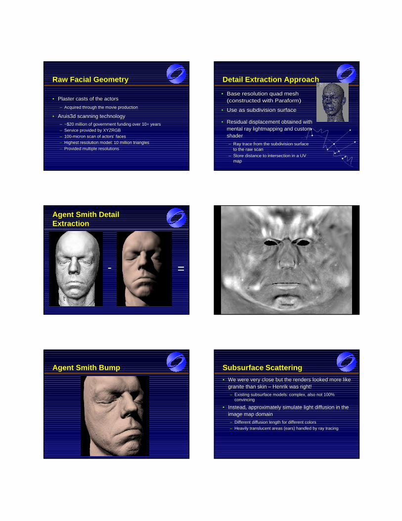
Raw Facial GeometryRaw Facial Geometry
•• Plaster casts of the actorsPlaster casts of the actors
–– Acquired through the movie productionAcquired through the movie production
•• Aruis3d scanning technologyAruis3d scanning technology
–– ~$20 million of government funding over 10+ years~$20 million of government funding over 10+ years
–– Service provided by XYZRGBService provided by XYZRGB
–– 100100--micron scan of actors’ faces micron scan of actors’ faces
–– Highest resolution model: 10 million trianglesHighest resolution model: 10 million triangles
–– Provided multiple resolutionsProvided multiple resolutions
DetailDetail Extraction ApproachExtraction Approach
•• Residual displacement obtained with Residual displacement obtained with mental ray mental ray lightmapping lightmapping and custom and custom shader shader
–– Ray trace from the subdivision surface Ray trace from the subdivision surface to the raw scanto the raw scan
–– Store distance to intersection in a UV Store distance to intersection in a UV mapmap
•• Base resolution quad mesh Base resolution quad mesh (constructed with (constructed with ParaformParaform) )
•• Use as subdivision surfaceUse as subdivision surface
Agent Smith Detail Agent Smith Detail ExtractionExtraction
- =
Smith Bump Map
Agent Smith BumpAgent Smith Bump SubsurfaceSubsurface ScatteringScattering
•• We were very close but the renders looked more like We were very close but the renders looked more like granite than skin granite than skin –– Henrik Henrik was right!was right!
–– Existing subsurface models: complex, also not 100% Existing subsurface models: complex, also not 100% convincingconvincing
•• Instead, approximately simulate light diffusion in the Instead, approximately simulate light diffusion in the image map domainimage map domain
–– Different diffusion length for different colorsDifferent diffusion length for different colors
–– Heavily translucent areas (ears) handled by ray tracingHeavily translucent areas (ears) handled by ray tracing
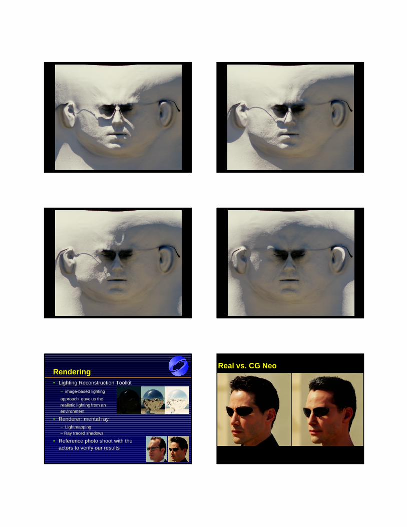
Light Map Diffusion 1 Light Map Diffusion 2
Light Map Diffusion 3 Light Map Diffusion 4
RenderingRendering•• LightingLighting ReconstructionReconstruction ToolkitToolkit
–– imageimage--based lighting based lighting
approach gaveapproach gave us the us the
realistic lightingrealistic lighting from an from an
environmentenvironment
•• Renderer: mentalRenderer: mental ray ray
–– LightmappingLightmapping
–– Ray traced shadowsRay traced shadows
•• Reference photo shoot Reference photo shoot withwith the the actors to verify actors to verify ourour resultsresults
Real vs. CG Neo
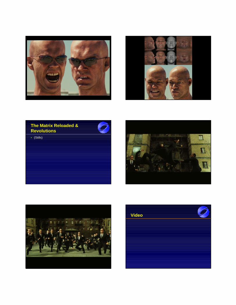
ucsm1040/1280 collage ucmo1050 collage
TheThe Matrix Matrix Reloaded & Reloaded & RevolutionsRevolutions•• (Stills)(Stills)
bb0625
bb1010 VideoVideo

AcknowledgementsAcknowledgements
•• Oystein LarsenOystein Larsen –– pipeline software design & implementationpipeline software design & implementation. .
Performance processing coPerformance processing co--supervisionsupervision
•• Dan PiponiDan Piponi –– optical flow & 3optical flow & 3--d motion reconstruction d motion reconstruction algorithmsalgorithms
•• J.P. LewisJ.P. Lewis –– subsurface scattering algorithmsubsurface scattering algorithm
•• Christina TempelaarChristina Tempelaar--LietzLietz –– additional software design & additional software design & implementationimplementation
AcknowledgementsAcknowledgements
•• Steve Steve Avoujageli Avoujageli –– additional pipeline tools developmentadditional pipeline tools development
•• KenKen FaimanFaiman, Steve , Steve RembuskosRembuskos, Mike Dalzell , Mike Dalzell –– for for their incredible artistry demonstrated during the their incredible artistry demonstrated during the keyshaping keyshaping
stage of performance processingstage of performance processing
•• Paul Ryan, John Paul Ryan, John LlewellynLlewellyn, and Ryan , and Ryan SchnizleinSchnizlein –– for for their work on the their work on the HiDef HiDef capture setupcapture setup
•• DanDan PiponiPiponi –– for suggesting the detail extraction approachfor suggesting the detail extraction approach
•• BrianBrian FreisingerFreisinger –– for modeling,for modeling, UVingUVing the headsthe heads
•• MatthewMatthew LandauerLandauer –– for his contributions to the imagefor his contributions to the image--based based skin shader derivationskin shader derivation
•• Rene Garcia Rene Garcia –– for his amazing paint workfor his amazing paint work
•• Ryan Todd (RT) Ryan Todd (RT) –– for tackling all the head replacement shots for tackling all the head replacement shots in the filmin the film
•• HaarmHaarm--PieterPieter Duiker,Duiker, Tadao MihashiTadao Mihashi, and Ben, and BenGunsbergerGunsberger
•• ThomasThomas DriemeyerDriemeyer/mental images /mental images –– for making for making important extensions to theirimportant extensions to their lightmappinglightmapping featurefeature
•• John Jack, KimJohn Jack, Kim LibreriLibreri, and John, and John GaetaGaeta –– for embracing for embracing and believing in this “unorthodox” approachand believing in this “unorthodox” approach
AcknowledgementsAcknowledgementsAcknowledgements
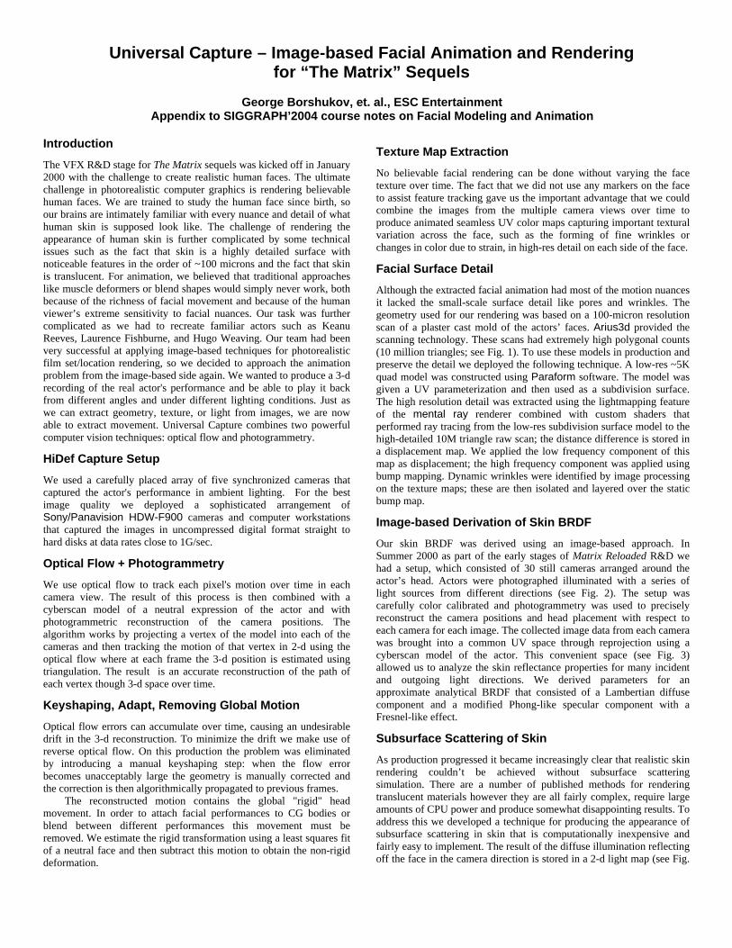
Universal Capture – Image-based Facial Animation and Rendering for “The Matrix” Sequels
George Borshukov, et. al., ESC Entertainment Appendix to SIGGRAPH’2004 course notes on Facial Modeling and Animation
Introduction The VFX R&D stage for The Matrix sequels was kicked off in January 2000 with the challenge to create realistic human faces. The ultimate challenge in photorealistic computer graphics is rendering believable human faces. We are trained to study the human face since birth, so our brains are intimately familiar with every nuance and detail of what human skin is supposed look like. The challenge of rendering the appearance of human skin is further complicated by some technical issues such as the fact that skin is a highly detailed surface with noticeable features in the order of ~100 microns and the fact that skin is translucent. For animation, we believed that traditional approaches like muscle deformers or blend shapes would simply never work, both because of the richness of facial movement and because of the human viewer’s extreme sensitivity to facial nuances. Our task was further complicated as we had to recreate familiar actors such as Keanu Reeves, Laurence Fishburne, and Hugo Weaving. Our team had been very successful at applying image-based techniques for photorealistic film set/location rendering, so we decided to approach the animation problem from the image-based side again. We wanted to produce a 3-d recording of the real actor's performance and be able to play it back from different angles and under different lighting conditions. Just as we can extract geometry, texture, or light from images, we are now able to extract movement. Universal Capture combines two powerful computer vision techniques: optical flow and photogrammetry.
HiDef Capture Setup We used a carefully placed array of five synchronized cameras that captured the actor's performance in ambient lighting. For the best image quality we deployed a sophisticated arrangement of Sony/Panavision HDW-F900 cameras and computer workstations that captured the images in uncompressed digital format straight to hard disks at data rates close to 1G/sec.
Optical Flow + Photogrammetry We use optical flow to track each pixel's motion over time in each camera view. The result of this process is then combined with a cyberscan model of a neutral expression of the actor and with photogrammetric reconstruction of the camera positions. The algorithm works by projecting a vertex of the model into each of the cameras and then tracking the motion of that vertex in 2-d using the optical flow where at each frame the 3-d position is estimated using triangulation. The result is an accurate reconstruction of the path of each vertex though 3-d space over time.
Keyshaping, Adapt, Removing Global Motion Optical flow errors can accumulate over time, causing an undesirable drift in the 3-d reconstruction. To minimize the drift we make use of reverse optical flow. On this production the problem was eliminated by introducing a manual keyshaping step: when the flow error becomes unacceptably large the geometry is manually corrected and the correction is then algorithmically propagated to previous frames.
The reconstructed motion contains the global "rigid" head movement. In order to attach facial performances to CG bodies or blend between different performances this movement must be removed. We estimate the rigid transformation using a least squares fit of a neutral face and then subtract this motion to obtain the non-rigid deformation.
Texture Map Extraction No believable facial rendering can be done without varying the face texture over time. The fact that we did not use any markers on the face to assist feature tracking gave us the important advantage that we could combine the images from the multiple camera views over time to produce animated seamless UV color maps capturing important textural variation across the face, such as the forming of fine wrinkles or changes in color due to strain, in high-res detail on each side of the face.
Facial Surface Detail Although the extracted facial animation had most of the motion nuances it lacked the small-scale surface detail like pores and wrinkles. The geometry used for our rendering was based on a 100-micron resolution scan of a plaster cast mold of the actors’ faces. Arius3d provided the scanning technology. These scans had extremely high polygonal counts (10 million triangles; see Fig. 1). To use these models in production and preserve the detail we deployed the following technique. A low-res ~5K quad model was constructed using Paraform software. The model was given a UV parameterization and then used as a subdivision surface. The high resolution detail was extracted using the lightmapping feature of the mental ray renderer combined with custom shaders that performed ray tracing from the low-res subdivision surface model to the high-detailed 10M triangle raw scan; the distance difference is stored in a displacement map. We applied the low frequency component of this map as displacement; the high frequency component was applied using bump mapping. Dynamic wrinkles were identified by image processing on the texture maps; these are then isolated and layered over the static bump map.
Image-based Derivation of Skin BRDF Our skin BRDF was derived using an image-based approach. In Summer 2000 as part of the early stages of Matrix Reloaded R&D we had a setup, which consisted of 30 still cameras arranged around the actor’s head. Actors were photographed illuminated with a series of light sources from different directions (see Fig. 2). The setup was carefully color calibrated and photogrammetry was used to precisely reconstruct the camera positions and head placement with respect to each camera for each image. The collected image data from each camera was brought into a common UV space through reprojection using a cyberscan model of the actor. This convenient space (see Fig. 3) allowed us to analyze the skin reflectance properties for many incident and outgoing light directions. We derived parameters for an approximate analytical BRDF that consisted of a Lambertian diffuse component and a modified Phong-like specular component with a Fresnel-like effect.
Subsurface Scattering of Skin As production progressed it became increasingly clear that realistic skin rendering couldn’t be achieved without subsurface scattering simulation. There are a number of published methods for rendering translucent materials however they are all fairly complex, require large amounts of CPU power and produce somewhat disappointing results. To address this we developed a technique for producing the appearance of subsurface scattering in skin that is computationally inexpensive and fairly easy to implement. The result of the diffuse illumination reflecting off the face in the camera direction is stored in a 2-d light map (see Fig.
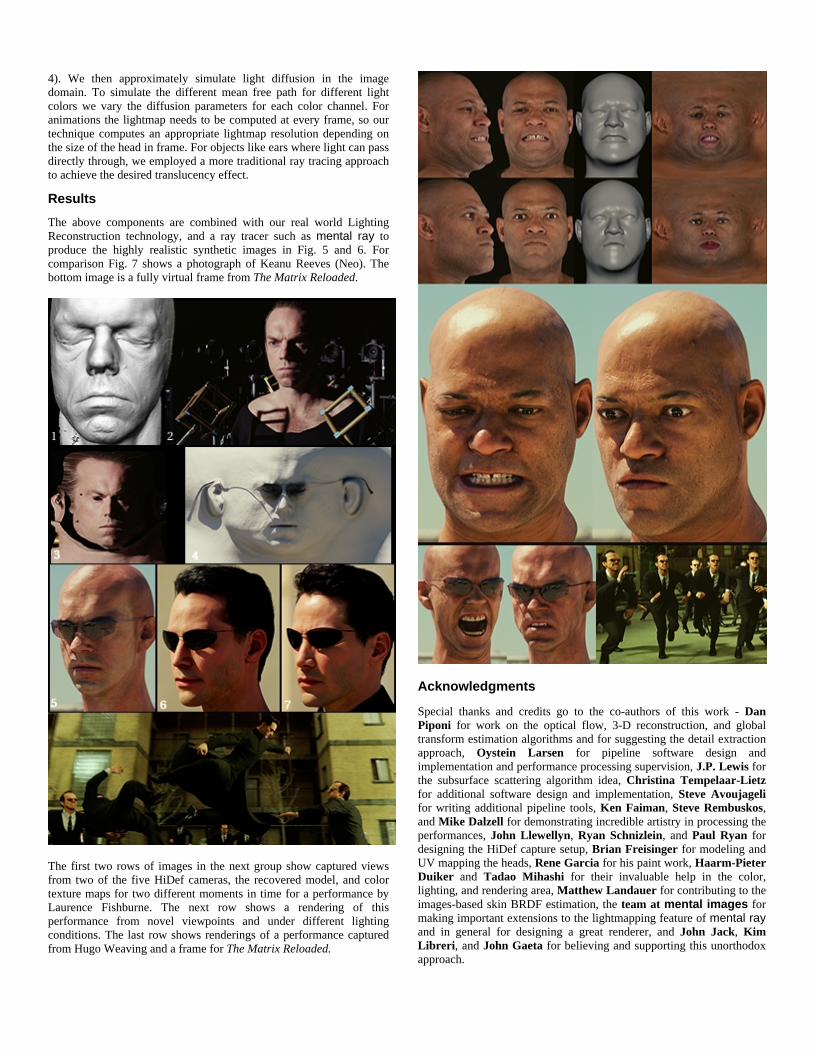
4). We then approximately simulate light diffusion in the image domain. To simulate the different mean free path for different light colors we vary the diffusion parameters for each color channel. For animations the lightmap needs to be computed at every frame, so our technique computes an appropriate lightmap resolution depending on the size of the head in frame. For objects like ears where light can pass directly through, we employed a more traditional ray tracing approach to achieve the desired translucency effect.
Results The above components are combined with our real world Lighting Reconstruction technology, and a ray tracer such as mental ray to produce the highly realistic synthetic images in Fig. 5 and 6. For comparison Fig. 7 shows a photograph of Keanu Reeves (Neo). The bottom image is a fully virtual frame from The Matrix Reloaded.
The first two rows of images in the next group show captured views from two of the five HiDef cameras, the recovered model, and color texture maps for two different moments in time for a performance by Laurence Fishburne. The next row shows a rendering of this performance from novel viewpoints and under different lighting conditions. The last row shows renderings of a performance captured from Hugo Weaving and a frame for The Matrix Reloaded.
Acknowledgments Special thanks and credits go to the co-authors of this work - Dan Piponi for work on the optical flow, 3-D reconstruction, and global transform estimation algorithms and for suggesting the detail extraction approach, Oystein Larsen for pipeline software design and implementation and performance processing supervision, J.P. Lewis for the subsurface scattering algorithm idea, Christina Tempelaar-Lietz for additional software design and implementation, Steve Avoujageli for writing additional pipeline tools, Ken Faiman, Steve Rembuskos, and Mike Dalzell for demonstrating incredible artistry in processing the performances, John Llewellyn, Ryan Schnizlein, and Paul Ryan for designing the HiDef capture setup, Brian Freisinger for modeling and UV mapping the heads, Rene Garcia for his paint work, Haarm-Pieter Duiker and Tadao Mihashi for their invaluable help in the color, lighting, and rendering area, Matthew Landauer for contributing to the images-based skin BRDF estimation, the team at mental images for making important extensions to the lightmapping feature of mental ray and in general for designing a great renderer, and John Jack, Kim Libreri, and John Gaeta for believing and supporting this unorthodox approach.
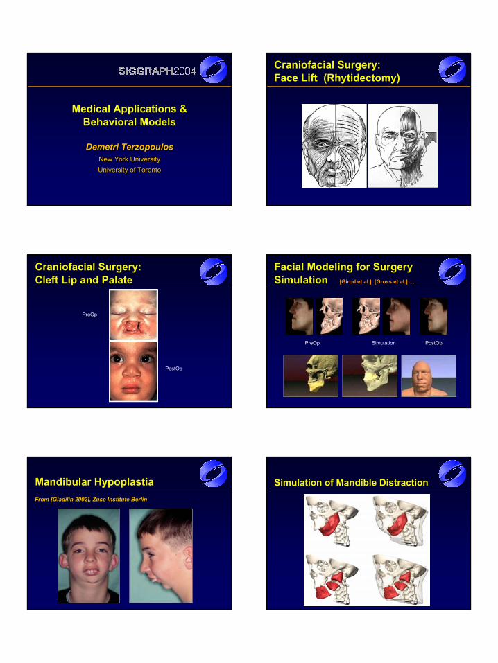
Demetri TerzopoulosNew York UniversityUniversity of Toronto
Demetri TerzopoulosDemetri TerzopoulosNew York UniversityNew York UniversityUniversity of TorontoUniversity of Toronto
Medical Applications & Behavioral Models
Craniofacial Surgery:Face Lift (Rhytidectomy)
Craniofacial Surgery:Cleft Lip and Palate
PreOp
PostOp
Facial Modeling for Surgery Simulation [Girod et al.] [Gross et al.] …
PreOp Simulation PostOp
Mandibular HypoplastiaFrom [Gladilin 2002], Zuse Institute BerlinFrom [From [GladilinGladilin 2002], 2002], ZuseZuse Institute BerlinInstitute Berlin
Simulation of Mandible Distraction
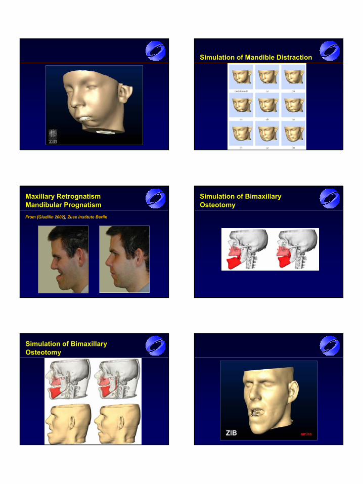
Simulation of Mandible Distraction
Maxillary RetrognatismMandibular PrognatismFrom [Gladilin 2002], Zuse Institute BerlinFrom [From [GladilinGladilin 2002], 2002], ZuseZuse Institute BerlinInstitute Berlin
Simulation of BimaxillaryOsteotomy
Simulation of BimaxillaryOsteotomy
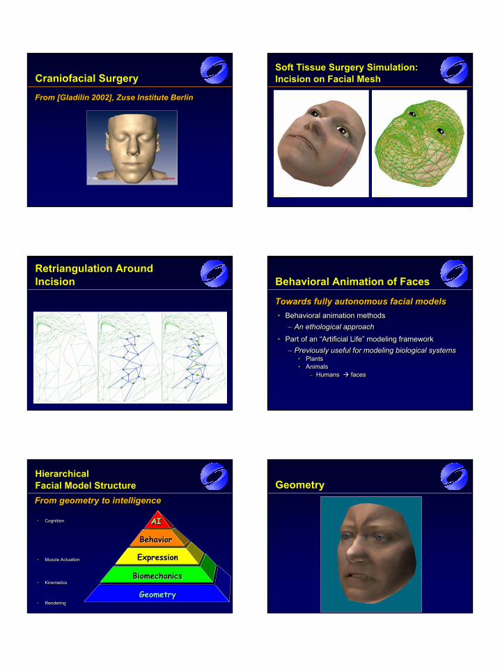
Craniofacial Surgery
From [Gladilin 2002], Zuse Institute BerlinFrom [From [GladilinGladilin 2002], 2002], ZuseZuse Institute BerlinInstitute Berlin
Soft Tissue Surgery Simulation: Incision on Facial Mesh
Retriangulation Around Incision Behavioral Animation of Faces
Towards fully autonomous facial models• Behavioral animation methods
– An ethological approach
• Part of an “Artificial Life” modeling framework– Previously useful for modeling biological systems
• Plants• Animals
– Humans faces
Towards fully autonomous facial modelsTowards fully autonomous facial models•• Behavioral animation methodsBehavioral animation methods
–– An ethological approachAn ethological approach
•• Part of an “Artificial Life” modeling frameworkPart of an “Artificial Life” modeling framework–– Previously useful for modeling biological systemsPreviously useful for modeling biological systems
•• PlantsPlants•• AnimalsAnimals
–– Humans Humans facesfaces
GeometryGeometry
Hierarchical Facial Model StructureFrom geometry to intelligence
• Cognition
• Muscle Actuation
• Kinematics
• Rendering
From geometry to intelligenceFrom geometry to intelligence
•• CognitionCognition
•• Muscle ActuationMuscle Actuation
•• KinematicsKinematics
•• RenderingRendering
BiomechanicsBiomechanics
ExpressionExpression
Behavior Behavior
AI AI AI
Geometry
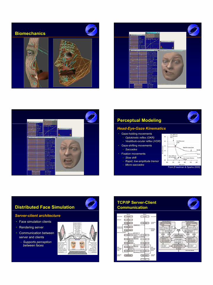
Biomechanics
Perceptual Modeling
Head-Eye-Gaze Kinematics• Gaze-holding movements
– Optokinetic reflex (OKR)– Vesitibulo-ocular reflex (VOR)
• Gaze-shifting movements– Saccades
• Fixation movements– Slow drift– Rapid, low-amplitude tremor– Micro-saccades
HeadHead--EyeEye--Gaze KinematicsGaze Kinematics•• GazeGaze--holding movementsholding movements
–– OptokineticOptokinetic reflex (OKR)reflex (OKR)–– VesitibuloVesitibulo--ocular reflex (VOR)ocular reflex (VOR)
•• GazeGaze--shifting movementsshifting movements–– SaccadesSaccades
•• Fixation movementsFixation movements–– Slow driftSlow drift–– Rapid, lowRapid, low--amplitude tremoramplitude tremor–– MicroMicro--saccadessaccades
From [Freedman & Sparks 2000]
Distributed Face Simulation
Server-client architecture• Face simulation clients
• Rendering server
• Communication between server and clients– Supports perception
between faces
ServerServer--client architectureclient architecture•• Face simulation clientsFace simulation clients
•• Rendering serverRendering server
•• Communication between Communication between server and clientsserver and clients–– Supports perception Supports perception
between facesbetween faces
TCP/IP Server-Client Communication
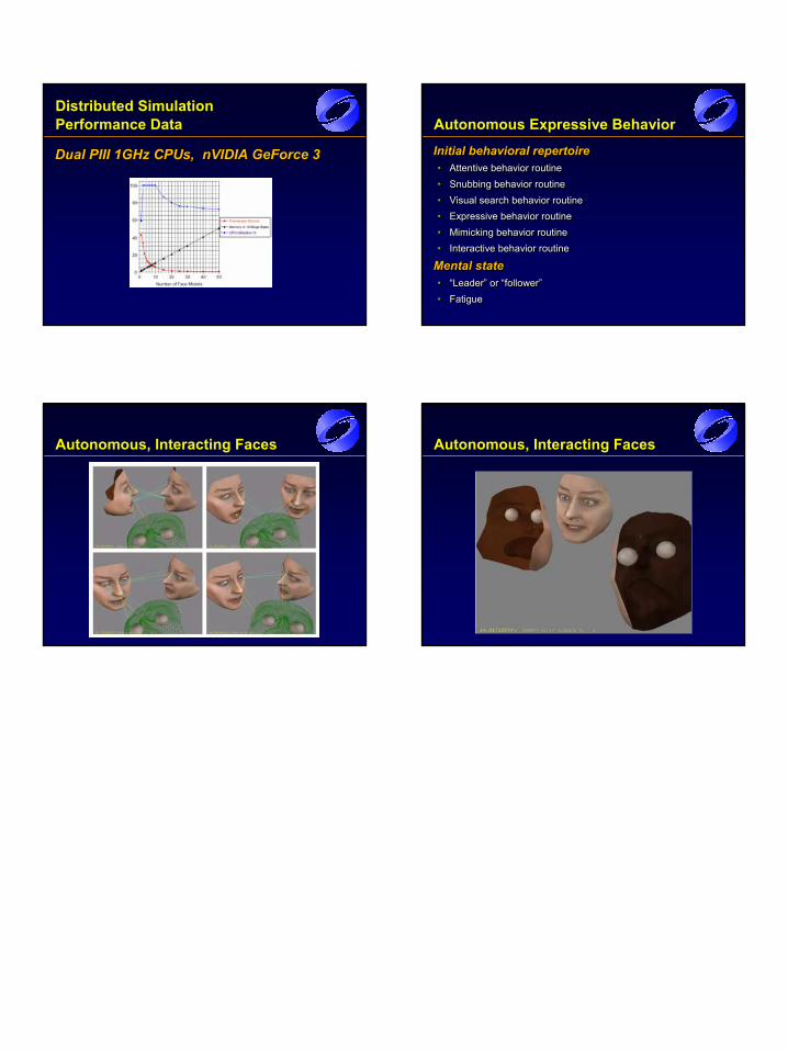
Distributed Simulation Performance Data
Dual PIII 1GHz CPUs, nVIDIA GeForce 3Dual PIII 1GHz CPUs, Dual PIII 1GHz CPUs, nVIDIAnVIDIA GeForceGeForce 33
Autonomous Expressive Behavior
Initial behavioral repertoire• Attentive behavior routine• Snubbing behavior routine• Visual search behavior routine• Expressive behavior routine• Mimicking behavior routine• Interactive behavior routine
Mental state• “Leader” or “follower”• Fatigue
Initial behavioral repertoireInitial behavioral repertoire•• Attentive behavior routineAttentive behavior routine•• Snubbing behavior routineSnubbing behavior routine•• Visual search behavior routineVisual search behavior routine•• Expressive behavior routineExpressive behavior routine•• Mimicking behavior routineMimicking behavior routine•• Interactive behavior routineInteractive behavior routine
Mental stateMental state•• “Leader” or “follower”“Leader” or “follower”•• FatigueFatigue
Autonomous, Interacting Faces Autonomous, Interacting Faces
SIGGRAPH Course Notes (2004)
Behavioral Animation of Faces:Parallel, Distributed, and Real-Time
Demetri Terzopoulos1,2 and Yuencheng Lee2,1
1 Courant Institute of Mathematical Sciences, New York University, New York, NY 10003, USA2 Department of Computer Science, University of Toronto, Toronto, ON M5S 3G4, Canada
AbstractFacial animation has a lengthy history in computer graphics. To date, most efforts have concentrated either onlabor-intensive keyframe schemes, on manually animated parameterized methods using FACS-inspired expressioncontrol schemes, or on performance-based animation where facial motions are captured from human actors. Asan alternative, we propose the fully automated animation of faces using behavioral animation methods. To thisend, we employ a physics-based model of the face, which includes synthetic facial soft tissues with embedded mus-cle actuators. Despite its technical sophistication, this biomechanical face model can nonetheless be simulatedin real time on a high-end personal computer. The model incorporates a motor control layer that automaticallycoordinates eye and head movements, as well as muscle contractions to produce natural expressions. Utilizingprinciples from artificial life, we augment the synthetic face with a perception model that affords it a visual aware-ness of its environment, and we provide a sensorimotor response mechanism that links percepts to meaningfulactions (i.e., head/eye movement and facial expression). The latter is implemented as an ethologically inspired be-havioral repertoire, which includes a rudimentary emotion model. We demonstrate a networked, multi-computerimplementation of our behavioral facial animation framework. Each of several faces is computed in real time by aseparate server PC which transmits its simulation results to a client PC dedicated to rendering the animated facesin a common virtual space. Performing the appropriate head/eye/face movements, the autonomous faces look atone another and respond in a natural manner to each other’s expressions.
Categories and Subject Descriptors (according to ACM CCS): I.3.7 [Three-Dimensional Graphics and Realism]:Animation I.3.5 [Computational Geometry and Object Modeling]: Physically based modeling
1. Introduction
Facial modeling and animation has a lengthy historyin computer graphics. The area was pioneered overthirty years ago by Frederic Parke at the Universityof Utah [Par72]. A survey of the field is presentedin the volume [PW96]. Briefly, realistic facial mod-els have progressed from keyframe (blend-shape) mod-els [Par72], to parameterized geometric models [Par74], tomuscle-based geometric models [Wat87], to anatomically-based biomechanical models [TW90, LTW95, KHYS02].In parallel with the model-based approaches, a varietyof successful facial data driven technologies have re-cently been developed for facial modeling and anima-tion [WT91, GGW∗98, PHL∗98, BV99, BBPV03]. To date,most efforts in production facial animation have con-
centrated either on labor-intensive (blendshape) keyframeschemes often involving manually-animated parameter-ized schemes [Pix88], or on performance-based anima-tion where facial motions are captured from human ac-tors [Wil90, fac04]. With regard to facial motion capture, itremains a challenge to modify the captured facial motions.
As an alternative, it would be desirable to have a fully au-tomated face/head model that can synthesize realistic facialanimation. Such a model would be of value both for the pro-duction animation and especially in the interactive computergames industries. Ultimately, this model should be an intel-ligent one, which would possess both nonverbal and verbalfacial communications skills and would be able to interactautonomously in a virtual environment with other such intel-ligent face/head models. To this end, we have been inspired
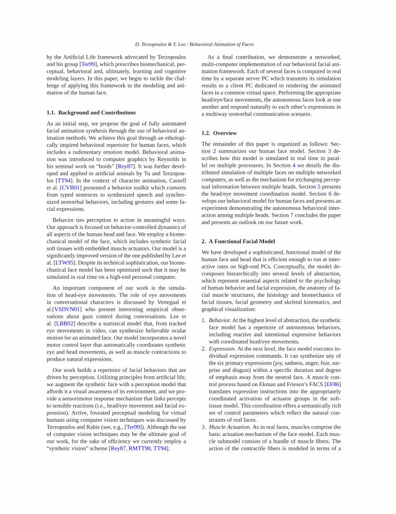
D. Terzopoulos & Y. Lee / Behavioral Animation of Faces
by the Artificial Life framework advocated by Terzopoulosand his group [Ter99], which prescribes biomechanical, per-ceptual, behavioral and, ultimately, learning and cognitivemodeling layers. In this paper, we begin to tackle the chal-lenge of applying this framework to the modeling and ani-mation of the human face.
1.1. Background and Contributions
As an initial step, we propose the goal of fully automatedfacial animation synthesis through the use of behavioral an-imation methods. We achieve this goal through an ethologi-cally inspired behavioral repertoire for human faces, whichincludes a rudimentary emotion model. Behavioral anima-tion was introduced to computer graphics by Reynolds inhis seminal work on “boids” [Rey87]. It was further devel-oped and applied to artificial animals by Tu and Terzopou-los [TT94]. In the context of character animation, Cassellet al. [CVB01] presented a behavior toolkit which convertsfrom typed sentences to synthesized speech and synchro-nized nonverbal behaviors, including gestures and some fa-cial expressions.
Behavior ties perception to action in meaningful ways.Our approach is focused on behavior-controlled dynamics ofall aspects of the human head and face. We employ a biome-chanical model of the face, which includes synthetic facialsoft tissues with embedded muscle actuators. Our model is asignificantly improved version of the one published by Lee etal. [LTW95]. Despite its technical sophistication, our biome-chanical face model has been optimized such that it may besimulated in real time on a high-end personal computer.
An important component of our work is the simula-tion of head-eye movements. The role of eye movementsin conversational characters is discussed by Vertegaal etal.[VSDVN01] who present interesting empirical obser-vations about gaze control during conversations. Lee etal. [LBB02] describe a statistical model that, from trackedeye movements in video, can synthesize believable ocularmotion for an animated face. Our model incorporates a novelmotor control layer that automatically coordinates syntheticeye and head movements, as well as muscle contractions toproduce natural expressions.
Our work builds a repertoire of facial behaviors that aredriven by perception. Utilizing principles from artificial life,we augment the synthetic face with a perception model thataffords it a visual awareness of its environment, and we pro-vide a sensorimotor response mechanism that links perceptsto sensible reactions (i.e., head/eye movement and facial ex-pression). Active, foveated perceptual modeling for virtualhumans using computer vision techniques was discussed byTerzopoulos and Rabie (see, e.g., [Ter99]). Although the useof computer vision techniques may be the ultimate goal ofour work, for the sake of efficiency we currently employ a“synthetic vision” scheme [Rey87, RMTT90, TT94].
As a final contribution, we demonstrate a networked,multi-computer implementation of our behavioral facial ani-mation framework. Each of several faces is computed in realtime by a separate server PC which transmits its simulationresults to a client PC dedicated to rendering the animatedfaces in a common virtual space. Performing the appropriatehead/eye/face movements, the autonomous faces look at oneanother and respond naturally to each other’s expressions ina multiway nonverbal communication scenario.
1.2. Overview
The remainder of this paper is organized as follows: Sec-tion 2 summarizes our human face model. Section 3 de-scribes how this model is simulated in real time in paral-lel on multiple processors. In Section 4 we details the dis-tributed simulation of multiple faces on multiple networkedcomputers, as well as the mechanism for exchanging percep-tual information between multiple heads. Section 5 presentsthe head/eye movement coordination model. Section 6 de-velops our behavioral model for human faces and presents anexperiment demonstrating the autonomous behavioral inter-action among multiple heads. Section 7 concludes the paperand presents an outlook on our future work.
2. A Functional Facial Model
We have developed a sophisticated, functional model of thehuman face and head that is efficient enough to run at inter-active rates on high-end PCs. Conceptually, the model de-composes hierarchically into several levels of abstraction,which represent essential aspects related to the psychologyof human behavior and facial expression, the anatomy of fa-cial muscle structures, the histology and biomechanics offacial tissues, facial geometry and skeletal kinematics, andgraphical visualization:
1. Behavior. At the highest level of abstraction, the syntheticface model has a repertoire of autonomous behaviors,including reactive and intentional expressive behaviorswith coordinated head/eye movements.
2. Expression. At the next level, the face model executes in-dividual expression commands. It can synthesize any ofthe six primary expressions (joy, sadness, anger, fear, sur-prise and disgust) within a specific duration and degreeof emphasis away from the neutral face. A muscle con-trol process based on Ekman and Friesen’s FACS [EF86]translates expression instructions into the appropriatelycoordinated activation of actuator groups in the soft-tissue model. This coordination offers a semantically richset of control parameters which reflect the natural con-straints of real faces.
3. Muscle Actuation. As in real faces, muscles comprise thebasic actuation mechanism of the face model. Each mus-cle submodel consists of a bundle of muscle fibers. Theaction of the contractile fibers is modeled in terms of a
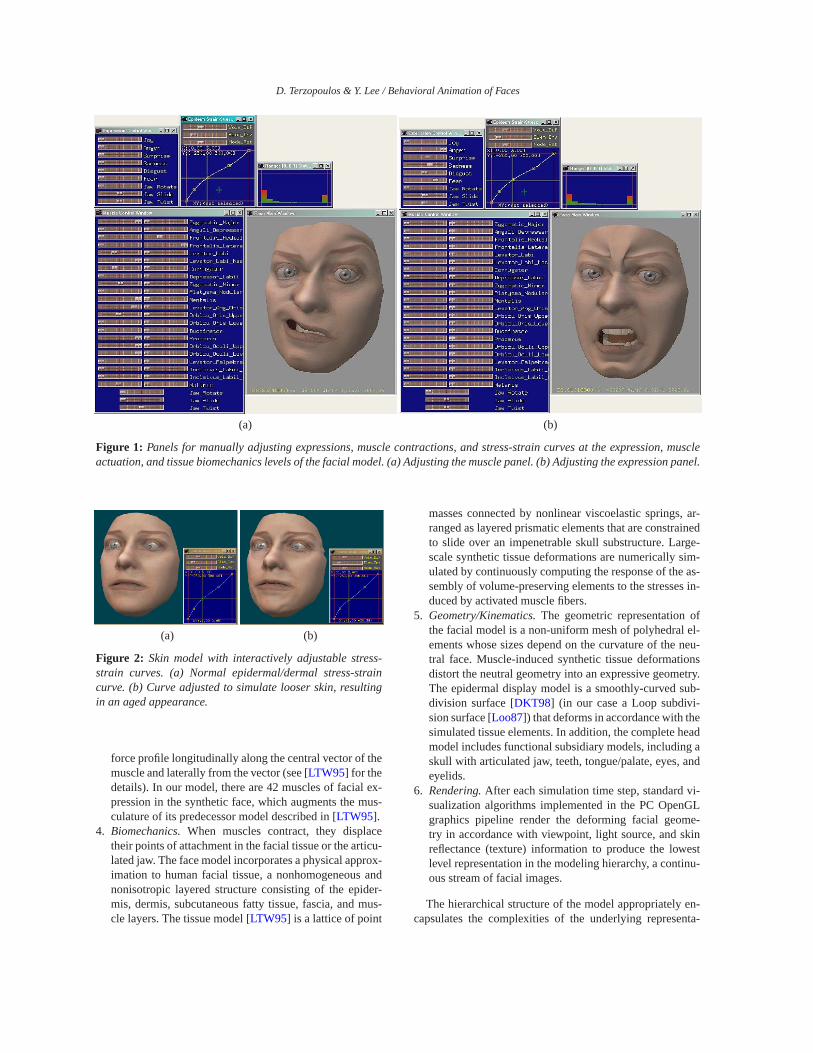
D. Terzopoulos & Y. Lee / Behavioral Animation of Faces
(a) (b)
Figure 1: Panels for manually adjusting expressions, muscle contractions, and stress-strain curves at the expression, muscleactuation, and tissue biomechanics levels of the facial model. (a) Adjusting the muscle panel. (b) Adjusting the expression panel.
(a) (b)
Figure 2: Skin model with interactively adjustable stress-strain curves. (a) Normal epidermal/dermal stress-straincurve. (b) Curve adjusted to simulate looser skin, resultingin an aged appearance.
force profile longitudinally along the central vector of themuscle and laterally from the vector (see [LTW95] for thedetails). In our model, there are 42 muscles of facial ex-pression in the synthetic face, which augments the mus-culature of its predecessor model described in [LTW95].
4. Biomechanics. When muscles contract, they displacetheir points of attachment in the facial tissue or the articu-lated jaw. The face model incorporates a physical approx-imation to human facial tissue, a nonhomogeneous andnonisotropic layered structure consisting of the epider-mis, dermis, subcutaneous fatty tissue, fascia, and mus-cle layers. The tissue model [LTW95] is a lattice of point
masses connected by nonlinear viscoelastic springs, ar-ranged as layered prismatic elements that are constrainedto slide over an impenetrable skull substructure. Large-scale synthetic tissue deformations are numerically sim-ulated by continuously computing the response of the as-sembly of volume-preserving elements to the stresses in-duced by activated muscle fibers.
5. Geometry/Kinematics. The geometric representation ofthe facial model is a non-uniform mesh of polyhedral el-ements whose sizes depend on the curvature of the neu-tral face. Muscle-induced synthetic tissue deformationsdistort the neutral geometry into an expressive geometry.The epidermal display model is a smoothly-curved sub-division surface [DKT98] (in our case a Loop subdivi-sion surface [Loo87]) that deforms in accordance with thesimulated tissue elements. In addition, the complete headmodel includes functional subsidiary models, including askull with articulated jaw, teeth, tongue/palate, eyes, andeyelids.
6. Rendering. After each simulation time step, standard vi-sualization algorithms implemented in the PC OpenGLgraphics pipeline render the deforming facial geome-try in accordance with viewpoint, light source, and skinreflectance (texture) information to produce the lowestlevel representation in the modeling hierarchy, a continu-ous stream of facial images.
The hierarchical structure of the model appropriately en-capsulates the complexities of the underlying representa-
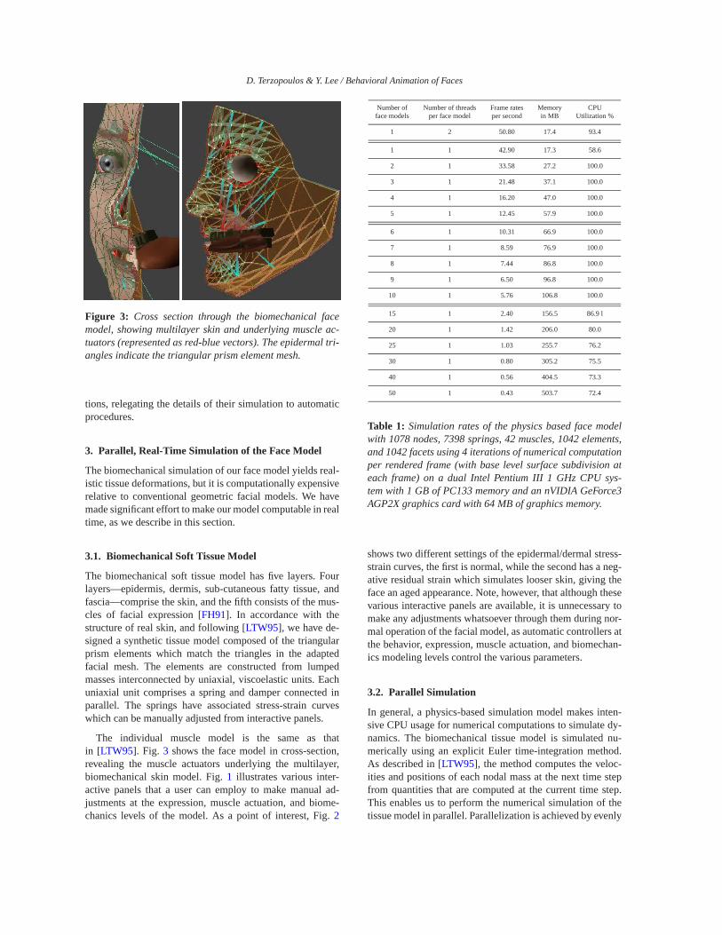
D. Terzopoulos & Y. Lee / Behavioral Animation of Faces
Figure 3: Cross section through the biomechanical facemodel, showing multilayer skin and underlying muscle ac-tuators (represented as red-blue vectors). The epidermal tri-angles indicate the triangular prism element mesh.
tions, relegating the details of their simulation to automaticprocedures.
3. Parallel, Real-Time Simulation of the Face Model
The biomechanical simulation of our face model yields real-istic tissue deformations, but it is computationally expensiverelative to conventional geometric facial models. We havemade significant effort to make our model computable in realtime, as we describe in this section.
3.1. Biomechanical Soft Tissue Model
The biomechanical soft tissue model has five layers. Fourlayers—epidermis, dermis, sub-cutaneous fatty tissue, andfascia—comprise the skin, and the fifth consists of the mus-cles of facial expression [FH91]. In accordance with thestructure of real skin, and following [LTW95], we have de-signed a synthetic tissue model composed of the triangularprism elements which match the triangles in the adaptedfacial mesh. The elements are constructed from lumpedmasses interconnected by uniaxial, viscoelastic units. Eachuniaxial unit comprises a spring and damper connected inparallel. The springs have associated stress-strain curveswhich can be manually adjusted from interactive panels.
The individual muscle model is the same as thatin [LTW95]. Fig. 3 shows the face model in cross-section,revealing the muscle actuators underlying the multilayer,biomechanical skin model. Fig. 1 illustrates various inter-active panels that a user can employ to make manual ad-justments at the expression, muscle actuation, and biome-chanics levels of the model. As a point of interest, Fig. 2
Number of Number of threads Frame rates Memory CPUface models per face model per second in MB Utilization %
1 2 50.80 17.4 93.4
1 1 42.90 17.3 58.6
2 1 33.58 27.2 100.0
3 1 21.48 37.1 100.0
4 1 16.20 47.0 100.0
5 1 12.45 57.9 100.0
6 1 10.31 66.9 100.0
7 1 8.59 76.9 100.0
8 1 7.44 86.8 100.0
9 1 6.50 96.8 100.0
10 1 5.76 106.8 100.0
15 1 2.40 156.5 86.9 l
20 1 1.42 206.0 80.0
25 1 1.03 255.7 76.2
30 1 0.80 305.2 75.5
40 1 0.56 404.5 73.3
50 1 0.43 503.7 72.4
Table 1: Simulation rates of the physics based face modelwith 1078 nodes, 7398 springs, 42 muscles, 1042 elements,and 1042 facets using 4 iterations of numerical computationper rendered frame (with base level surface subdivision ateach frame) on a dual Intel Pentium III 1 GHz CPU sys-tem with 1 GB of PC133 memory and an nVIDIA GeForce3AGP2X graphics card with 64 MB of graphics memory.
shows two different settings of the epidermal/dermal stress-strain curves, the first is normal, while the second has a neg-ative residual strain which simulates looser skin, giving theface an aged appearance. Note, however, that although thesevarious interactive panels are available, it is unnecessary tomake any adjustments whatsoever through them during nor-mal operation of the facial model, as automatic controllers atthe behavior, expression, muscle actuation, and biomechan-ics modeling levels control the various parameters.
3.2. Parallel Simulation
In general, a physics-based simulation model makes inten-sive CPU usage for numerical computations to simulate dy-namics. The biomechanical tissue model is simulated nu-merically using an explicit Euler time-integration method.As described in [LTW95], the method computes the veloc-ities and positions of each nodal mass at the next time stepfrom quantities that are computed at the current time step.This enables us to perform the numerical simulation of thetissue model in parallel. Parallelization is achieved by evenly
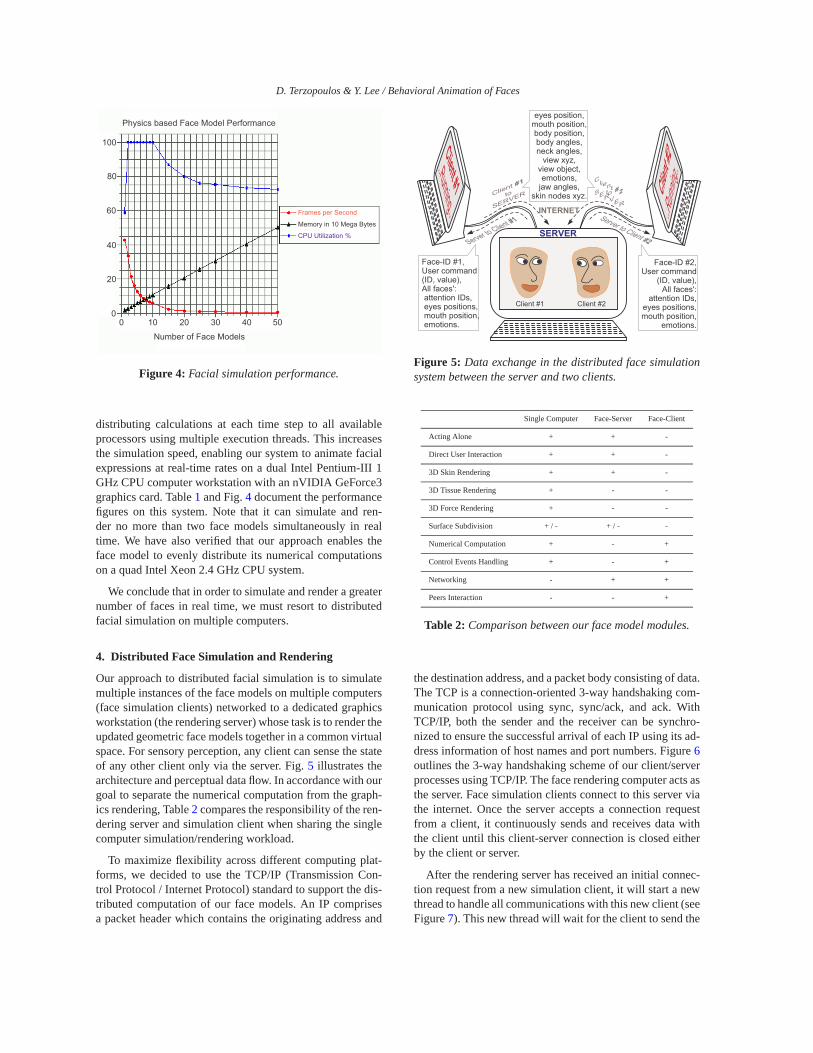
D. Terzopoulos & Y. Lee / Behavioral Animation of Faces
Memory in 10 Mega Bytes
Frames per Second
CPU Utilization %
Physics based Face Model Performance
Number of Face Models
100
0
20
40
60
80
0 10 20 30 40 50
Figure 4: Facial simulation performance.
distributing calculations at each time step to all availableprocessors using multiple execution threads. This increasesthe simulation speed, enabling our system to animate facialexpressions at real-time rates on a dual Intel Pentium-III 1GHz CPU computer workstation with an nVIDIA GeForce3graphics card. Table 1 and Fig. 4 document the performancefigures on this system. Note that it can simulate and ren-der no more than two face models simultaneously in realtime. We have also verified that our approach enables theface model to evenly distribute its numerical computationson a quad Intel Xeon 2.4 GHz CPU system.
We conclude that in order to simulate and render a greaternumber of faces in real time, we must resort to distributedfacial simulation on multiple computers.
4. Distributed Face Simulation and Rendering
Our approach to distributed facial simulation is to simulatemultiple instances of the face models on multiple computers(face simulation clients) networked to a dedicated graphicsworkstation (the rendering server) whose task is to render theupdated geometric face models together in a common virtualspace. For sensory perception, any client can sense the stateof any other client only via the server. Fig. 5 illustrates thearchitecture and perceptual data flow. In accordance with ourgoal to separate the numerical computation from the graph-ics rendering, Table 2 compares the responsibility of the ren-dering server and simulation client when sharing the singlecomputer simulation/rendering workload.
To maximize flexibility across different computing plat-forms, we decided to use the TCP/IP (Transmission Con-trol Protocol / Internet Protocol) standard to support the dis-tributed computation of our face models. An IP comprisesa packet header which contains the originating address and
Client #2
..Running..
eyes position,mouth position,body position,body angles,neck angles,
view xyz,view object,emotions,
jaw angles,skin nodes xyz.
Face-ID #1,User command(ID, value),All faces': attention IDs, eyes positions, mouth position, emotions.
Face-ID #2,User command
(ID, value),All faces':
attention IDs,eyes positions,mouth position,
emotions.
SERVER
Client #1
to
SERVER
Server to Client #1
Client #2toSERVER
Server to Client #2
INTERNET
Client #1..Running..
Client #1 Client #2
Figure 5: Data exchange in the distributed face simulationsystem between the server and two clients.
Single Computer Face-Server Face-Client
Acting Alone + + -
Direct User Interaction + + -
3D Skin Rendering + + -
3D Tissue Rendering + - -
3D Force Rendering + - -
Surface Subdivision + / - + / - -
Numerical Computation + - +
Control Events Handling + - +
Networking - + +
Peers Interaction - - +
Table 2: Comparison between our face model modules.
the destination address, and a packet body consisting of data.The TCP is a connection-oriented 3-way handshaking com-munication protocol using sync, sync/ack, and ack. WithTCP/IP, both the sender and the receiver can be synchro-nized to ensure the successful arrival of each IP using its ad-dress information of host names and port numbers. Figure 6outlines the 3-way handshaking scheme of our client/serverprocesses using TCP/IP. The face rendering computer acts asthe server. Face simulation clients connect to this server viathe internet. Once the server accepts a connection requestfrom a client, it continuously sends and receives data withthe client until this client-server connection is closed eitherby the client or server.
After the rendering server has received an initial connec-tion request from a new simulation client, it will start a newthread to handle all communications with this new client (seeFigure 7). This new thread will wait for the client to send the
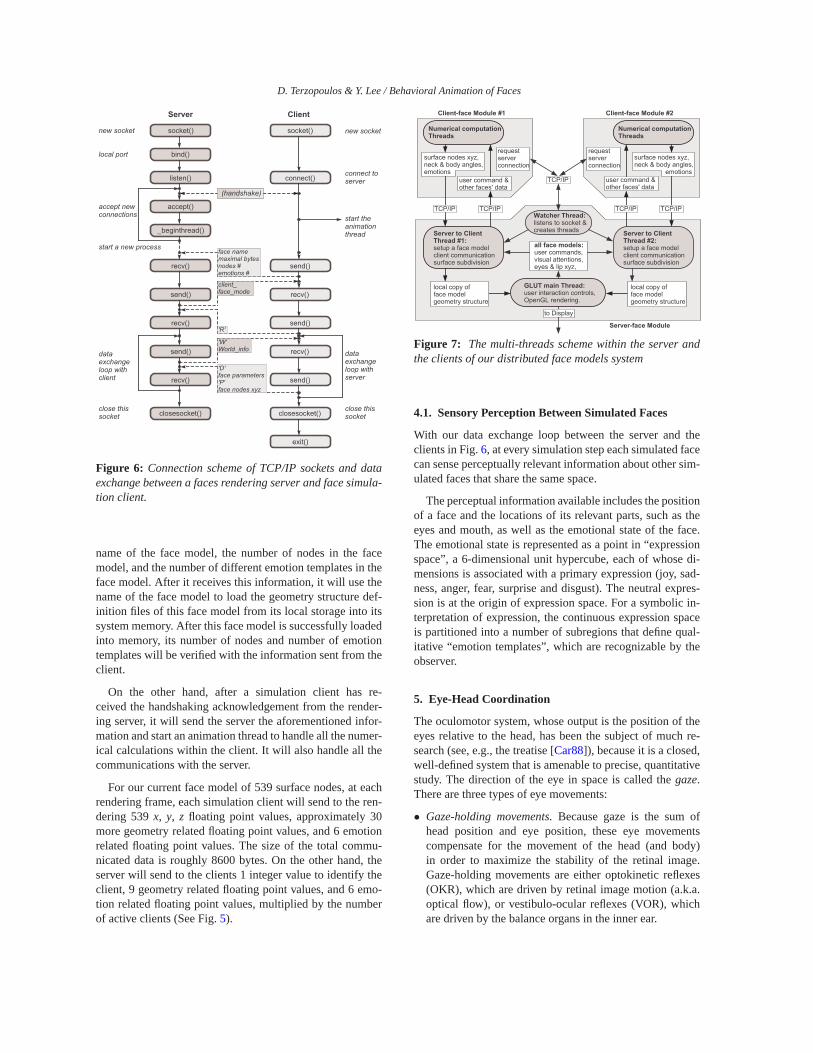
D. Terzopoulos & Y. Lee / Behavioral Animation of Faces
start a new process
'R'
'D'face parameters'P'face nodes xyz
face namemaximal bytesnodes #emotions #
client_face_mode
socket()
bind()
listen()
accept()
recv()
send()
_beginthread()
socket()
connect()
send()
recv()
Server Client
new socket
local port
connect toserver
accept newconnections
new socket
recv() send()
dataexchangeloop withserver
dataexchangeloop withclient
closesocket() closesocket()close thissocket
close thissocket
recv()
send()
send()
recv()'W'World_info
start theanimationthread
exit()
(handshake)
Figure 6: Connection scheme of TCP/IP sockets and dataexchange between a faces rendering server and face simula-tion client.
name of the face model, the number of nodes in the facemodel, and the number of different emotion templates in theface model. After it receives this information, it will use thename of the face model to load the geometry structure def-inition files of this face model from its local storage into itssystem memory. After this face model is successfully loadedinto memory, its number of nodes and number of emotiontemplates will be verified with the information sent from theclient.
On the other hand, after a simulation client has re-ceived the handshaking acknowledgement from the render-ing server, it will send the server the aforementioned infor-mation and start an animation thread to handle all the numer-ical calculations within the client. It will also handle all thecommunications with the server.
For our current face model of 539 surface nodes, at eachrendering frame, each simulation client will send to the ren-dering 539 x, y, z floating point values, approximately 30more geometry related floating point values, and 6 emotionrelated floating point values. The size of the total commu-nicated data is roughly 8600 bytes. On the other hand, theserver will send to the clients 1 integer value to identify theclient, 9 geometry related floating point values, and 6 emo-tion related floating point values, multiplied by the numberof active clients (See Fig. 5).
all face models:user commands,visual attentions, eyes & lip xyz,
user command &other faces' data
Numerical computationThreads
surface nodes xyz,neck & body angles,emotions
user command &other faces' data
Client-face Module #1
Server to ClientThread #1:setup a face modelclient communicationsurface subdivision
GLUT main Thread:user interaction controls,OpenGL rendering.
Server-face Module
local copy offace modelgeometry structure
local copy offace modelgeometry structure
Client-face Module #2
Numerical computationThreads
surface nodes xyz,neck & body angles, emotions
TCP/IP TCP/IP TCP/IPTCP/IP
to Display
Watcher Thread:listens to socket &creates threads Server to Client
Thread #2:setup a face modelclient communicationsurface subdivision
TCP/IP
requestserverconnection
requestserverconnection
Figure 7: The multi-threads scheme within the server andthe clients of our distributed face models system
4.1. Sensory Perception Between Simulated Faces
With our data exchange loop between the server and theclients in Fig. 6, at every simulation step each simulated facecan sense perceptually relevant information about other sim-ulated faces that share the same space.
The perceptual information available includes the positionof a face and the locations of its relevant parts, such as theeyes and mouth, as well as the emotional state of the face.The emotional state is represented as a point in “expressionspace”, a 6-dimensional unit hypercube, each of whose di-mensions is associated with a primary expression (joy, sad-ness, anger, fear, surprise and disgust). The neutral expres-sion is at the origin of expression space. For a symbolic in-terpretation of expression, the continuous expression spaceis partitioned into a number of subregions that define qual-itative “emotion templates”, which are recognizable by theobserver.
5. Eye-Head Coordination
The oculomotor system, whose output is the position of theeyes relative to the head, has been the subject of much re-search (see, e.g., the treatise [Car88]), because it is a closed,well-defined system that is amenable to precise, quantitativestudy. The direction of the eye in space is called the gaze.There are three types of eye movements:
• Gaze-holding movements. Because gaze is the sum ofhead position and eye position, these eye movementscompensate for the movement of the head (and body)in order to maximize the stability of the retinal image.Gaze-holding movements are either optokinetic reflexes(OKR), which are driven by retinal image motion (a.k.a.optical flow), or vestibulo-ocular reflexes (VOR), whichare driven by the balance organs in the inner ear.
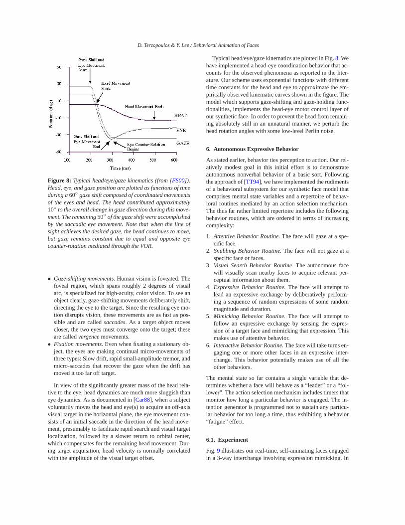
D. Terzopoulos & Y. Lee / Behavioral Animation of Faces
Figure 8: Typical head/eye/gaze kinematics (from [FS00]).Head, eye, and gaze position are plotted as functions of timeduring a 60◦ gaze shift composed of coordinated movementsof the eyes and head. The head contributed approximately10◦ to the overall change in gaze direction during this move-ment. The remaining 50◦ of the gaze shift were accomplishedby the saccadic eye movement. Note that when the line ofsight achieves the desired gaze, the head continues to move,but gaze remains constant due to equal and opposite eyecounter-rotation mediated through the VOR.
• Gaze-shifting movements. Human vision is foveated. Thefoveal region, which spans roughly 2 degrees of visualarc, is specialized for high-acuity, color vision. To see anobject clearly, gaze-shifting movements deliberately shift,directing the eye to the target. Since the resulting eye mo-tion disrupts vision, these movements are as fast as pos-sible and are called saccades. As a target object movescloser, the two eyes must converge onto the target; theseare called vergence movements.
• Fixation movements. Even when fixating a stationary ob-ject, the eyes are making continual micro-movements ofthree types: Slow drift, rapid small-amplitude tremor, andmicro-saccades that recover the gaze when the drift hasmoved it too far off target.
In view of the significantly greater mass of the head rela-tive to the eye, head dynamics are much more sluggish thaneye dynamics. As is documented in [Car88], when a subjectvoluntarily moves the head and eye(s) to acquire an off-axisvisual target in the horizontal plane, the eye movement con-sists of an initial saccade in the direction of the head move-ment, presumably to facilitate rapid search and visual targetlocalization, followed by a slower return to orbital center,which compensates for the remaining head movement. Dur-ing target acquisition, head velocity is normally correlatedwith the amplitude of the visual target offset.
Typical head/eye/gaze kinematics are plotted in Fig. 8. Wehave implemented a head-eye coordination behavior that ac-counts for the observed phenomena as reported in the liter-ature. Our scheme uses exponential functions with differenttime constants for the head and eye to approximate the em-pirically observed kinematic curves shown in the figure. Themodel which supports gaze-shifting and gaze-holding func-tionalities, implements the head-eye motor control layer ofour synthetic face. In order to prevent the head from remain-ing absolutely still in an unnatural manner, we perturb thehead rotation angles with some low-level Perlin noise.
6. Autonomous Expressive Behavior
As stated earlier, behavior ties perception to action. Our rel-atively modest goal in this initial effort is to demonstrateautonomous nonverbal behavior of a basic sort. Followingthe approach of [TT94], we have implemented the rudimentsof a behavioral subsystem for our synthetic face model thatcomprises mental state variables and a repertoire of behav-ioral routines mediated by an action selection mechanism.The thus far rather limited repertoire includes the followingbehavior routines, which are ordered in terms of increasingcomplexity:
1. Attentive Behavior Routine. The face will gaze at a spe-cific face.
2. Snubbing Behavior Routine. The face will not gaze at aspecific face or faces.
3. Visual Search Behavior Routine. The autonomous facewill visually scan nearby faces to acquire relevant per-ceptual information about them.
4. Expressive Behavior Routine. The face will attempt tolead an expressive exchange by deliberatively perform-ing a sequence of random expressions of some randommagnitude and duration.
5. Mimicking Behavior Routine. The face will attempt tofollow an expressive exchange by sensing the expres-sion of a target face and mimicking that expression. Thismakes use of attentive behavior.
6. Interactive Behavior Routine. The face will take turns en-gaging one or more other faces in an expressive inter-change. This behavior potentially makes use of all theother behaviors.
The mental state so far contains a single variable that de-termines whether a face will behave as a “leader” or a “fol-lower”. The action selection mechanism includes timers thatmonitor how long a particular behavior is engaged. The in-tention generator is programmed not to sustain any particu-lar behavior for too long a time, thus exhibiting a behavior“fatigue” effect.
6.1. Experiment
Fig. 9 illustrates our real-time, self-animating faces engagedin a 3-way interchange involving expression mimicking. In
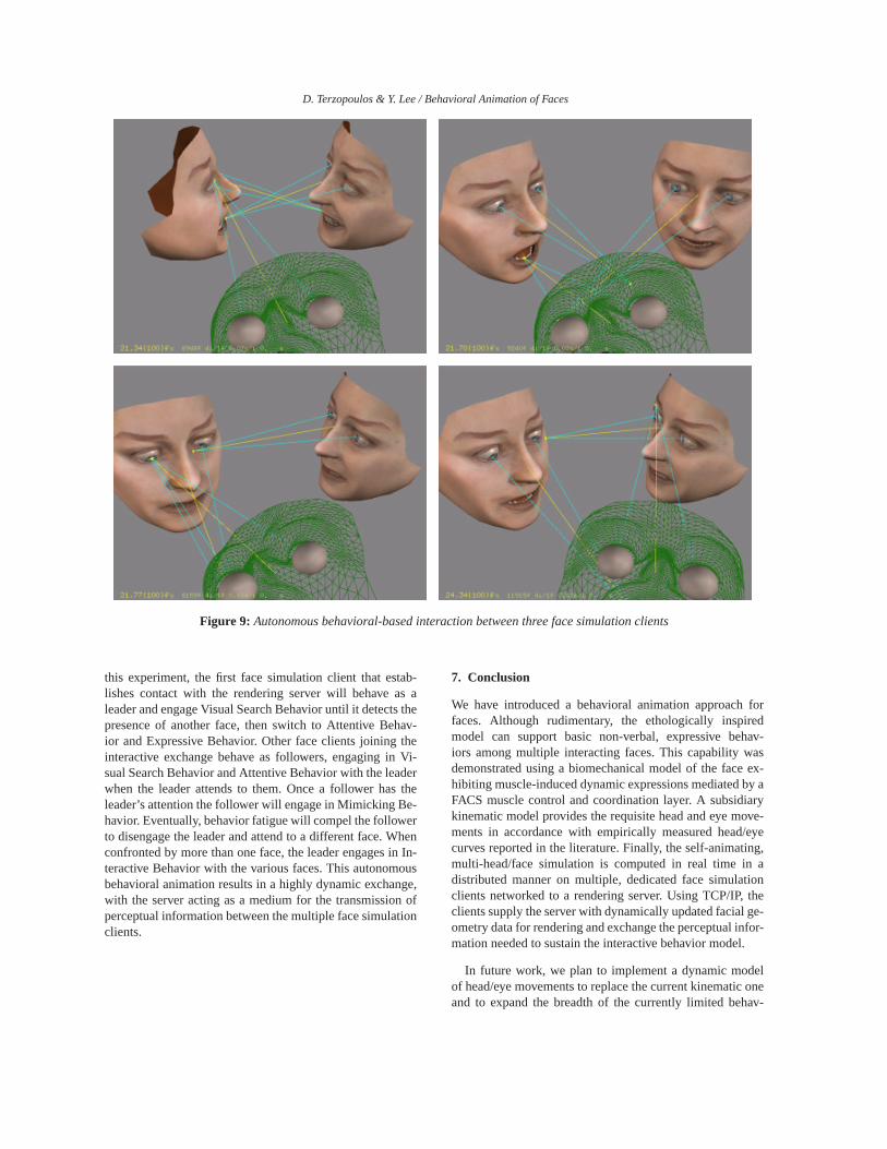
D. Terzopoulos & Y. Lee / Behavioral Animation of Faces
Figure 9: Autonomous behavioral-based interaction between three face simulation clients
this experiment, the first face simulation client that estab-lishes contact with the rendering server will behave as aleader and engage Visual Search Behavior until it detects thepresence of another face, then switch to Attentive Behav-ior and Expressive Behavior. Other face clients joining theinteractive exchange behave as followers, engaging in Vi-sual Search Behavior and Attentive Behavior with the leaderwhen the leader attends to them. Once a follower has theleader’s attention the follower will engage in Mimicking Be-havior. Eventually, behavior fatigue will compel the followerto disengage the leader and attend to a different face. Whenconfronted by more than one face, the leader engages in In-teractive Behavior with the various faces. This autonomousbehavioral animation results in a highly dynamic exchange,with the server acting as a medium for the transmission ofperceptual information between the multiple face simulationclients.
7. Conclusion
We have introduced a behavioral animation approach forfaces. Although rudimentary, the ethologically inspiredmodel can support basic non-verbal, expressive behav-iors among multiple interacting faces. This capability wasdemonstrated using a biomechanical model of the face ex-hibiting muscle-induced dynamic expressions mediated by aFACS muscle control and coordination layer. A subsidiarykinematic model provides the requisite head and eye move-ments in accordance with empirically measured head/eyecurves reported in the literature. Finally, the self-animating,multi-head/face simulation is computed in real time in adistributed manner on multiple, dedicated face simulationclients networked to a rendering server. Using TCP/IP, theclients supply the server with dynamically updated facial ge-ometry data for rendering and exchange the perceptual infor-mation needed to sustain the interactive behavior model.
In future work, we plan to implement a dynamic modelof head/eye movements to replace the current kinematic oneand to expand the breadth of the currently limited behav-
D. Terzopoulos & Y. Lee / Behavioral Animation of Faces
ioral repertoire. As was indicated in the introdution, our ul-timate goal is to implement learning and cognitive modelinglayers, thereby realizing an intelligent model of the humanface/head.
References
[BBPV03] BLANZ V., BASSO C., POGGIO T., VETTER
T.: Reanimating faces in images and video.In Proceedings of the EUROGRAPHICS 2003Conference (Granada, Spain, 2003), Brunet P.,Fellner D., (Eds.). 1
[BV99] BLANZ V., VETTER T.: A morphable modelfor the synthesis of 3D faces. In ComputerGraphics (SIGGRAPH ’99 Proceedings) (LosAngeles, CA, 1999), pp. 187–194. 1
[Car88] CARPENTER R.: Movements of the Eyes,2nd ed. Pion, London, 1988. 6, 7
[CVB01] CASSELL J., VILHJÁLMSSON H., BICK-MORE T.: Beat: The behavior expression ani-mation toolkit. In Proceedings of SIGGRAPH’01 (Los Angeles, CA, August 2001), pp. 477–486. 2
[DKT98] DEROSE T., KASS M., TRUONG T.: Subdivi-sion surfaces in character animation. In Com-puter Graphics (SIGGRAPH ’98 Proceedings)(Orlando, FL, 1998), pp. 85–94. 3
[EF86] EKMAN P., FRIESEN W.: Manual for the Fa-cial Action Coding System. Consulting Psy-chologists Press, Palo Alto, 1986. 2
[fac04] FACE2FACE I.: The art of performance anima-tion, 2004. www.f2f-inc.com. 1
[FH91] FRICK, HANS: Human Anatomy, vol. 1.Thieme Medical Publishers, Stuttgart, 1991. 4
[FS00] FREEDMAN E. G., SPARKS D. L.: Coordi-nation of the eyes and head: Movement kine-matics. Experimental Brain Research 131, 1(March 2000), 22–32. 7
[GGW∗98] GUENTER B., GRIMM C., WOOD D., MAL-VAR H., PIGHIN F.: Making faces. In Com-puter Graphics (SIGGRAPH ’98 Proceedings)(Orlando, FL, 1998), pp. 55–66. 1
[KHYS02] KAHLER K., HABER J., YAMAUCHI H., SEI-DEL H.-P.: Head shop: Generating animatedhead models with anatomical structure. InProceedings ACM SIGGRAPH Symposium onComputer Animation (SCA 2002) (July 2002),pp. 55–64. 1
[LBB02] LEE S. P., BADLER J. B., BADLER N. I.:Eyes alive. ACM Transactions on Graphics
3, 21 (2002), 637–644. Proceedings of ACMSIGGRAPH 2002 Conference. 2
[Loo87] LOOP C.: Smooth Subdivision Surfaces Basedon Triangles. PhD thesis, University of Utah,August 1987. 3
[LTW95] LEE Y., TERZOPOULOS D., WATERS K.: Re-alistic modeling for facial animation. In Com-puter Graphics (SIGGRAPH ’95 Proceedings)(July 1995), vol. 29, pp. 55–62. 1, 2, 3, 4
[Par72] PARKE F.: Computer generated animation offaces. In ACM National Conference (1972),ACM, pp. 451–457. 1
[Par74] PARKE F.: A Parametric Model for HumanFaces. PhD thesis, University of Utah, SaltLake City, Utah, 1974. 1
[PHL∗98] PIGHIN F., HECKER J., LISCHINSKI D.,SZELISKI R., SALESIN D. H.: Synthesizingrealistic facial expressions from photographs.In Computer Graphics (SIGGRAPH ’98 Pro-ceedings) (Orlando, FL, 1998), pp. 75–84. 1
[Pix88] PIXAR: Tin toy. Computer Animation, 1988.1
[PW96] PARKE F., WATERS K.: Computer Facial An-imation, 1 ed. A. K. Peters, Ltd., 1996. 1
[Rey87] REYNOLDS C. W.: Flocks, herds, andschools: A distributed behavioral model.Computer Graphics 21, 4 (July 1987), 25–34.2
[RMTT90] RENAULT O., MAGNENAT-THALMANN N.,THALMANN D.: A vision-based approachto behavioural animation. Visualization andComputer Animation 1 (1990), 18–21. 2
[Ter99] TERZOPOULOS D.: Artificial life for com-puter graphics. Communications of the ACM42, 8 (1999), 32–42. 2
[TT94] TU X., TERZOPOULOS D.: Artificialfishes: Physics, locomotion, perception, be-havior. In Computer Graphics Proceedings,Annual Conference Series (July 1994), Proc.SIGGRAPH ’94 (Orlando, FL), ACM SIG-GRAPH, pp. 43–50. 2, 7
[TW90] TERZOPOULOS D., WATERS K.: Physically-based facial modelling, analysis, and anima-tion. The Journal of Visualization and Com-puter Animation 1, 2 (1990), 73–80. 1
[VSDVN01] VERTEGAAL R., SLAGTER R., DER VEER
G. V., NIJHOLT A.: Eye gaze patterns inconversations: There is more to conversationalagents than meets the eyes. In Proceedings
D. Terzopoulos & Y. Lee / Behavioral Animation of Faces
of ACM CHI 2001 Conference (Seattle, WA,March 2001), pp. 301–308. 2
[Wat87] WATERS K.: A muscle model for ani-mating three-dimensional facial expression.Computer Graphics (Proceedings ACM SIG-GRAPH 87) 22, 4 (1987), 17–24. 1
[Wil90] WILLIAMS L.: Performance-driven facial ani-mation. In SIGGRAPH 24 (1990), ACM Com-puter Graphics, pp. 235–242. 1
[WT91] WATERS K., TERZOPOULOS D.: Modelingand animating faces using scanned data. TheJournal of Visualization and Computer Ani-mation 2, 4 (1991), 123–128. 1
4 References
This section contains a list of publications, which are useful to learn more about facial modeling andanimation. The selection of these publications represents the authors’ point of view and might not becomplete.
References[1] Irene Albrecht, Jorg Haber, Kolja Kahler, Marc Schroder, and Hans-Peter Seidel. “May I talk to you?
:-)” — Facial Animation from Text. In Sabine Coquillart, Heung-Yeung Shum, and Shi-Min Hu, editors,Proceedings of the Tenth Pacific Conference on Computer Graphics and Applications (Pacific Graphics2002), pages 77–86. IEEE Computer Society, October 2002.
[2] Irene Albrecht, Jorg Haber, and Hans-Peter Seidel. Automatic Generation of Non-Verbal Facial Expres-sions from Speech. In Proceedings of Computer Graphics International 2002 (CGI 2002), pages 283–293,July 2002.
[3] Irene Albrecht, Jorg Haber, and Hans-Peter Seidel. Speech Synchronization for Physics-based FacialAnimation. In Proceedings of WSCG 2002, pages 9–16, February 2002.
[4] J. Allen, M. S. Hunnicutt, and D. Klatt. From text to speech: The MITalk system. Cambridge UniversityPress, Cambridge, MA, 1987.
[5] Ken-ichi Anjyo, Yoshiaki Usami, and Tsuneya Kurihara. A Simple Method for Extracting the NaturalBeauty of Hair. In Edwin E. Catmull, editor, Computer Graphics (SIGGRAPH ’92 Conference Proceed-ings), volume 26, pages 111–120. ACM SIGGRAPH, July 1992.
[6] S. Arridge, J. P. Moss, A. D. Linney, and D. James. Three-dimensional digitization of the face and skull.Journal of Maxial Facial Surgery, 13:1396–143, 1985.
[7] B. Baumgart. A polyhedron representation for computer vision. In AFIPS National Conference Proceed-ings, volume 44, pages 589–596, 1975.
[8] P. Bergeron and P. Lachapelle. Controlling facial expressions and body movements. In Advanced Com-puter Animation, volume 2 of SIGGRAPH ‘85 Tutorials, pages 61–79. ACM, New York, 1985.
[9] E. Bizzi, W. Chapple, and N. Hogan. Mechanical properties of muscles. TINS, 5(11):395–398, November1982.
[10] M. J. Black and P. Anandan. The robust estimation of multiple motions: parametric and piecewise-smoothflow fields. Computer Vision and Image Understanding.
[11] Volker Blanz, Curzio Basso, Tomaso Poggio, and Thomas Vetter. Reanimating Faces in Images and Video.In Pere Brunet and Dieter Fellner, editors, Computer Graphics Forum (Proceedings of Eurographics2003), volume 22, pages 641–650, September 2003.
[12] Volker Blanz and Thomas Vetter. A Morphable Model for the Synthesis of 3D Faces. In Alyn Rock-wood, editor, Computer Graphics (SIGGRAPH ’99 Conference Proceedings), pages 187–194. ACM SIG-GRAPH, August 1999.
[13] J. D. Boucher and P. Ekman. Facial areas and emotional information. Journal of Communication,25(2):21–29, 1975.
[14] G. H. Bourne. Structure and function of muscle. In Physiology and Biochemistry, 2nd ed., volume III.Academic Press, New York, 1973.
[15] Matthew Brand. Voice Puppetry. In Alyn Rockwood, editor, Computer Graphics (SIGGRAPH ’99 Con-ference Proceedings), pages 21–28. ACM SIGGRAPH, August 1999.
[16] Christoph Bregler, Michele Covell, and Malcolm Slaney. Video Rewrite: Driving Visual Speech withAudio. In Turner Whitted, editor, Computer Graphics (SIGGRAPH ’97 Conference Proceedings), pages353–360. ACM SIGGRAPH, August 1997.
[17] Christoph Bregler, Lorie Loeb, Erika Chuang, and Hrishi Deshpande. Turning to the Masters: MotionCapturing Cartoons. In John F. Hughes, editor, ACM Transactions on Graphics (SIGGRAPH 2002 Con-ference Proceedings), pages 399–407. ACM SIGGRAPH, July 2002.
[18] S. E. Brennan. Caricature generator. Master’s thesis, Massachusetts Institute of Technology, Cambridge,MA, 1982.
[19] N. M. Brooke and E. D. Petajan. Seeing speech: Investigations into the synthesis and recognition ofvisible speech movements using automatic image processing and computer graphics. In Proceedingsof the International Conference on Speech Input/Output: Techniques and Applications, pages 104–109,1986.
[20] J. Bulwer. Philocopus, or the Deaf and Dumbe Mans Friend. Humphrey and Moseley, London, 1648.
[21] J. Bulwer. Pathomyotamia, or, A dissection of the significtive muscles of the affections of the minde.Humphrey and Moseley, London, 1649.
[22] N. Burtnyk and M. Wein. Computer generated key-frame animation. Journal of SMPTE, 80:149–153,1971.
[23] Justine Cassell, Catherine Pelachaud, Norman Badler, Mark Steedman, Brett Achorn, Tripp Bechet, BrettDouville, Scott Prevost, and Matthew Stone. Animated Conversation: Rule–Based Generation of FacialExpression Gesture and Spoken Intonation for Multiple Converstaional Agents. In Andrew Glassner, ed-itor, Computer Graphics (SIGGRAPH ’94 Conference Proceedings), pages 413–420. ACM SIGGRAPH,July 1994.
[24] Lieu-Hen Chen, Santi Saeyor, Hiroshi Dohi, and Mitsuru Ishizuka. A System of 3D Hair Style Synthesisbased on the Wisp Model. The Visual Computer, 15(4):159–170, 1999.
[25] H. Chernoff. The use of faces to represent points in n-dimensional space graphically. Technical ReportProject NR-042-993, Office of Naval Research, December 1971.
[26] H. Chernoff. The use of faces to represent points in k-dimensional space graphically. Journal of AmericanStatistical Association, page 361, 1973.
[27] M. Cohen and D. Massaro. Synthesis of visible speech. Behavioral Research Methods and Instrumenta-tion, 22(2):260–263, 1990.
[28] M. Cohen and D. Massaro. Development and experimentation with synthetic visual speech. BehavioralResearch Methods, Instrumentation, and Computers, pages 260–265, 1994.
[29] Michael M. Cohen and Dominic W. Massaro. Modeling Coarticulation in Synthetic Visual Speech. InNadia M. Magnenat-Thalmann and Daniel Thalmann, editors, Models and Techniques in Computer Ani-mation, pages 139–156. Springer–Verlag, 1993.
[30] Agnes Daldegan, Nadia M. Magnenat-Thalmann, Tsuneya Kurihara, and Daniel Thalmann. An IntegratedSystem for Modeling, Animating and Rendering Hair. In Roger J. Hubbold and Robert Juan, editors,Computer Graphics Forum (Proceedings of Eurographics ’93), volume 12, pages 211–221, September1993.
[31] Charles Darwin. Expression of the Emotions in Man and Animals. J. Murray, 1872.
[32] Paul E. Debevec, Tim Hawkins, Chris Tchou, Haarm-Pieter Duiker, Westley Sarokin, and Mark Sagar.Acquiring the Reflectance Field of a Human Face. In Kurt Akeley, editor, Computer Graphics (SIG-GRAPH 2000 Conference Proceedings), pages 145–156. ACM SIGGRAPH, July 2000.
[33] Paul E. Debevec and Jitendra Malik. Recovering High Dynamic Range Radiance Maps from Photographs.In Turner Whitted, editor, Computer Graphics (SIGGRAPH ’97 Conference Proceedings), pages 369–378. ACM SIGGRAPH, August 1997.
[34] Douglas DeCarlo, Dimitris Metaxas, and Matthew Stone. An Anthropometric Face Model using Varia-tional Techniques. In Michael F. Cohen, editor, Computer Graphics (SIGGRAPH ’98 Conference Pro-ceedings), pages 67–74. ACM SIGGRAPH, July 1998.
[35] B. deGraf. Notes on facial animation. In State of the Art in Facial Animation, volume 22 of SIGGRAPH‘89 Tutorials, pages 10–11. ACM, 1989.
[36] B. DeGraph and Wahrman. Mike, the talking head. Computer Graphics World, July 1988.
[37] A. K. Dewdney. The complete computer caricaturist and whimsical tour of face space. Scientific Ameri-can, 4(?):20–28, 1977.
[38] S. DiPaola. Implementation and use of a 3D parameterized facial modeling and animation system. InState of the Art in Facial Animation, volume 22 of SIGGRAPH ’89 Tutorials. ACM, 1989.
[39] S. DiPaola. Extending the range of facial types. J. of Visualization and Computer Animation, 2(4):129–131, October-December 1991.
[40] G. B. Duchenne. The Mechanism of Human Facial Expression. Jules Renard, Paris, 1862.
[41] Peter Eisert and Bernd Girod. Model-based Facial Expression Parameters from Image Sequences. InProceedings of the IEEE International Conference on Image Processing (ICIP-97, pages 418–421, 1997.
[42] P. Ekman. Darwin and Facial Expressions. Academic Press, New York, 1973.
[43] P. Ekman. The argument and evidence about universals in facial expressions of emotion. In Handbook ofSocial Psychophysiology. Wiley, New York, 1989.
[44] P. Ekman and W. V. Friesen. Manual for the Facial Action Coding System. Consulting PsychologistsPress, Palo Alto, 1978.
[45] P. Ekman, W. V. Friesen, and P. Ellsworth. Emotion in the Human Face: Guidelines for Research and aReview of Findings. Pergamon Press, New York, 1972.
[46] P. Ekman and H. Oster. Facial expressions of emotion. Annual Review of Psychology, 1979.
[47] M. Elson. Displacement facial animation techniques. In SIGGRAPH State of the Art in Facial Animation:Course #26 Notes, pages 21–42. ACM, Dallas, August 1990.
[48] I. Essa and A. Pentland. A vision system for observing and extracting facial action parameters. TechnicalReport 247, MIT Perceptual Computing Section, 1994.
[49] Tony Ezzat, Gadi Geiger, and Tomaso Poggio. Trainable Videorealistic Speech Animation. In John F.Hughes, editor, ACM Transactions on Graphics (SIGGRAPH 2002 Conference Proceedings), pages 388–398. ACM SIGGRAPH, July 2002.
[50] G. Faigin. The Artist’s Complete Guide to Facial Expressions. Watson-Guptill, New York, 1990.
[51] L. G. Farkas and I. R. Munro. Anthropometric Facial Proportions in Medicine. Charles C. Thomas,Springfield, Illinois, 1987.
[52] D. R. Forsey and R. H. Bartels. Hierarchical B-spline refinement. In Computer Graphics (SIGGRAPH’88), volume 22, pages 205–212, 1988.
[53] L. A. Fried. Anatomy of the Head, Neck, Face, and Jaws. Lea and Febiger, Philadelphia, 1976.
[54] M. Gillenson and B. Chandrasekaran. Whatisface: Human facial composition by computer graphics.ACM Annual Conference, 9(1), 1975.
[55] M. L. Gillenson. The Interactive Generation of Facial Images on a CRT Using a Heuristic Strategy. PhDthesis, Ohio State University, Computer Graphics Research Group, Columbus, Ohio, March 1974.
[56] Taro Goto, Marc Escher, Christian Zanardi, and Nadia Magnenat-Thalmann. MPEG-4 based Animationwith Face Feature Tracking. In Nadia Magnenat-Thalmann and Daniel Thalmann, editors, Proceedingsof the Eurographics Workshop on Computer Animation and Simulation ’99, pages 89–98, 1999.
[57] Hans Peter Graf, Eric Cosatto, and Tony Ezzat. Face Analysis for the Synthesis of Photo-Realistic TalkingHeads. In Proceedings 4th International Conference on Automatic Face and Gesture Recognition, pages189–194, 2000.
[58] B. Guenter. A System for simulating Human Facial Expression. PhD thesis, Ohio State University, 1989.
[59] Brian Guenter, Cindy Grimm, Daniel Wood, Henrique Malvar, and Frederic Pighin. Making Faces. InMichael F. Cohen, editor, Computer Graphics (SIGGRAPH ’98 Conference Proceedings), pages 55–66.ACM SIGGRAPH, July 1998.
[60] T. Guiard-Marigny, A. Adjoudani, and C. Benoit. A 3D model of the lips for visual speech synthesis. InProc. 2nd ETRW on Speech Synthesis, pages 49–52, New Platz, New York, 1994.
[61] Sunil Hadap and Nadia Magnenat-Thalmann. Modeling Dynamic Hair as a Continuum. In Alan Chalmersand Theresa-Marie Rhyne, editors, Computer Graphics Forum (Proceedings of Eurographics 2001), vol-ume 20, pages C329–C338, September 2001.
[62] U. Hadar, T. J. Steiner, E. C. Grant, and F. C. Rose. The timing of shifts in head postures during conver-sation. Human Movement Science, 3:237–245, 1984.
[63] P. Hanrahan. Reflection from layered surfaces due to subsurface scattering. Computer Graphics (SIG-GRAPH 93), 27:165–174, 1993.
[64] P. Hanrahan and D. Sturman. Interactive animation of parametric models. The Visual Computer, 1(4):260–266, 1985.
[65] Antonio Haro, Brian Guenter, and Irfan Essa. Real-time, Photo-realistic, Physically Based Renderingof Fine Scale Human Skin Structure. In Steven J. Gortler and Karol Myszkowski, editors, RenderingTechniques 2001 (Proceedings 12th Eurographics Workshop on Rendering), pages 53–62, 2001.
[66] C. Henton. Beyond visemes: Using disemes in synthetic speech with facial animation, May 1994.
[67] C. Henton and P.C. Litwinowicz. Saying and seeing it with feeling: techniques for synthesizing visible,emotional speech. In Computer Graphics Conference Proceedings of the 2nd ESCA/IEEE Workshop onSpeech Synthesis, pages 73–76, September 1994.
[68] E. H. Hess. The role of pupil size in communication. Scientific American, pages 113–119, Nov. 1975.
[69] D. R. Hill, A. Pearce, and B. Wyvill. Animating speech: An automated approach using speech synthesisby rules. The Visual Computer, 3:277–289, 1988.
[70] Carl-Herman Hjortsjo. Man’s Face and Mimic Language. Lund, Sweden, 1970.
[71] S. A. Hutchinson, G. D. Hager, and P. I. Corke. A tutorial on visual servo control. IEEE Transactions onRobotics and Automation, 12(5):651–670, October 1996.
[72] Horace H. S. Ip and C. S. Chan. Script-Based Facial Gesture and Speech Animation Using a NURBSBased Face Model. Computers & Graphics, 20(6):881–891, November 1996.
[73] Tomomi Ishii, Takami Yasuda, Shigeki Yokoi, and Jun-ichiro Toriwaki. A Generation Model for HumanSkin Texture. In Proceedings of Computer Graphics International ’93, pages 139–150. Springer–Verlag,1993.
[74] ISO/IEC. Overview of the MPEG-4 Standard. http://www.cselt.it/mpeg/standards/mpeg-4/mpeg-4.htm, July 2000.
[75] J. Jeffers and M. Barley. Speachreading (Lipreading). Charles C. Thomas, Springfield, Illinois, 1971.
[76] Won-Ki Jeong, Kolja Kahler, Jorg Haber, and Hans-Peter Seidel. Automatic Generation of SubdivisionSurface Head Models from Point Cloud Data. In Proceedings of Graphics Interface 2002, pages 181–188.Canadian Human-Computer Communications Society, May 2002.
[77] Kolja Kahler, Jorg Haber, and Hans-Peter Seidel. Geometry-based Muscle Modeling for Facial Anima-tion. In Proceedings of Graphics Interface 2001, pages 37–46. Canadian Human-Computer Communica-tions Society, June 2001.
[78] Kolja Kahler, Jorg Haber, and Hans-Peter Seidel. Dynamically refining animated triangle meshes forrendering. The Visual Computer, 19(5):310–318, August 2003.
[79] Kolja Kahler, Jorg Haber, and Hans-Peter Seidel. Reanimating the Dead: Reconstruction of ExpressiveFaces from Skull Data. ACM Transactions on Graphics (SIGGRAPH 2003 Conference Proceedings),22(3):554–561, July 2003.
[80] Kolja Kahler, Jorg Haber, Hitoshi Yamauchi, and Hans-Peter Seidel. Head shop: Generating animatedhead models with anatomical structure. In Proceedings ACM SIGGRAPH Symposium on Computer Ani-mation (SCA ’02), pages 55–64, July 2002.
[81] G. A. Kalberer, P. Mueller, and L. Van Gool. Biological Motion of Speech. In Biologically MotivatedComputer Vision, volume 2525 of Lecture Notes in Computer Science, pages 199–206. Springer, 2002.
[82] G. A. Kalberer and L. Van Gool. Face Animation Based on Observed 3D Speech Dynamics. In H-S. Ko,editor, Proceedings of The Fourteenth IEEE Conference on Computer Animation (CA’01), pages 20–27.IEEE Computer Society, 2001.
[83] P. Kalra and N. Magnenat-Thalmann. Modeling vascular expressions in facial animation. In ComputerAnimation ’94, pages 50–58, Geneva, May 1994. IEEE Computer Society Press.
[84] P. Kalra, A. Mangili, N. Magnenat-Thalmann, and D. Thalmann. Simulation of facial muscle actionsbased on rational free form deformations. In Proc. Eurographics 92, pages 59–69, Cambridge, 1992.
[85] Prem Kalra, Angelo Mangili, Nadia Magnenat-Thalmann, and Daniel Thalmann. SMILE: A MultilayeredFacial Animation System. In Proceedings IFIP WG 5.10, Tokyo, Japan, pages 189–198, 1991.
[86] A. Kendon, editor. Nonverbal Communication, Interaction, and Gesture: Selections from Semiotica.Mouton Publishers, New York, 1981.
[87] R. M. Kenedi, T. Gibson, J. H. Evans, and J. C. Barbenel. Tissue mechanics. Physics in Medicine andBiology, 20(5):699–717, Febuary 1975.
[88] J. Kleiser. A fast, efficient, accurate way to represent the human face. In State of the Art in FacialAnimation, volume 22 of SIGGRAPH ‘89 Tutorials, pages 37–40. ACM, 1989.
[89] K. Komatsu. Human skin capable of natural shape variation. The Visual Computer, 3(5):265–271, 1988.
[90] T. Kurihara and K. Arai. A transformation method for modeling and animation of the human face fromphotographs. In N. Magnenat-Thalmann and D. Thalmann, editors, Computer Animation ’91, pages 45–58. Springer-Verlag, 1991.
[91] W. Larrabee and J. A. Galt. A finite element model of skin deformation: The finite element model.Laryngoscope, 96:419–412, 1986.
[92] W. Larrabee and D. Sutton. A finite element model of skin deformation. an experimental model of skindeformation. Laryngoscope, 96:406–412, 1986.
[93] Won-Sok Lee and Nadia Magnenat-Thalmann. Fast Head Modeling for Animation. Image and VisionComputing, 18(4):355–364, March 2000.
[94] Yuencheng Lee, Demetri Terzopoulos, and Keith Waters. Constructing Physics-based Facial Models ofIndividuals. In Proceedings of Graphics Interface ’93, pages 1–8. Canadian Human-Computer Commu-nications Society, May 1993.
[95] Yuencheng Lee, Demetri Terzopoulos, and Keith Waters. Realistic Modeling for Facial Animations. InRobert Cook, editor, Computer Graphics (SIGGRAPH ’95 Conference Proceedings), pages 55–62. ACMSIGGRAPH, August 1995.
[96] B. LeGoff, T. Guiard-Marigny, M. Cohen, and C. Benoit. Real-time analysis-synthesis and intelligibilityof talking faces. In Proc. 2nd ETRW on Speech Synthesis, pages 53–56, New Platz, New York, 1994.
[97] J. P. Lewis. Automated lip-sync: Background and techniques. J. of Visualization and Computer Anima-tion, 2(4):118–122, October-December 1991.
[98] John P. Lewis and Frederic I. Parke. Automated Lip-Synch and Speech Synthesis for Character Ani-mation. In John M. Carroll and Peter P. Tanner, editors, Proceedings of Human Factors in ComputingSystems and Graphics Interface ’87, pages 143–147, April 1987.
[99] A. Lofqvist. Speech as audible gestures. In W.J. Hardcastle and A. Marchal, editors, Speech Productionand Speech Modeling, pages 289–322. Kluwer Academic Publishers, Dordrecht, 1990.
[100] D. Lowe. Fitting parametrized three-dimensional models to images. IEEE Transactions on Pattern Match-ing and Machine Intelligence, 13(5).
[101] D. Lowe. Solving for the parameters of object models from image descriptions. In Proceedings ofComputer Vision and Image Understanding Workshop, pages 121–127, College Park, MD, 1980.
[102] E. Luice-Smith. The Art of Caricature. Cornell University Press, Ithaca, 1981.
[103] N. Magnenat-Thalmann and Thalmann. D. Synthetic Actors in Computer Generated Three-DimensionalFilms. Springer Verlag, Tokyo, 1990.
[104] N. Magnenat-Thalmann and P. Kalra. A model for creating and visualizing speech and emotion. InAspects of Automatic Natural Language Generation, Trento, Italy, April 1992. Springer-Verlag.
[105] N. Magnenat-Thalmann, H. Minh, M. deAngelis, and D. Thalmann. Design, transformation and anima-tion of human faces. The Visual Computer, 5:32–39, 1989.
[106] N. Magnenat-Thalmann, N. E. Primeau, and D. Thalmann. Abstract muscle actions procedures for humanface animation. Visual Computer, 3(5):290–297, 1988.
[107] Stephen R. Marschner, Brian Guenter, and Sashi Raghupathy. Modeling and Rendering for RealisticFacial Animation. In Bernard Peroche and Holly Rushmeier, editors, Rendering Techniques 2000 (Pro-ceedings 11th Eurographics Workshop on Rendering), pages 231–242, 2000.
[108] Stephen R. Marschner, Stephen H. Westin, Eric P. F. Lafortune, Kenneth E. Torrance, and Donald P.Greenberg. Image-Based BRDF Measurement Including Human Skin. In Dani Lischinski and GregWard Larson, editors, Rendering Techniques ’99 (Proceedings 10th Eurographics Workshop on Render-ing), pages 131–144, 1999.
[109] K. Mase and A. Pentland. Automatic lipreading by optical-flow analysis. Systems and Computers inJapan, 22:N06, 1991.
[110] D. W. Massaro. Speech Perception by Ear and Eye: A Paradigm for Psychological Inquiry. L. ErlbaumAssociates, Hillsdale, NJ, 1987.
[111] D. W. Massaro. A precis of speech perception by ear and eye: A paradigm for psychological inquiry.Behavioral and Brain Sciences, 12:741–794, 1989.
[112] D. W. Massaro and M.M. Cohen. Perception of synthesized audible and visible speech. PsychologicalScience, 1:55–63, 1990.
[113] H. McGurk and J. MacDonald. Hearing lips and seeing voices. Nature, 264:126–130, 1986.
[114] S. Morishima. Synchronization of speech and facial expression. IPSJ 3-9-27, 91(4), 1991.
[115] S. Morishima, K. Aiwaza, and H. Harashima. An intelligent facial image coding driven by speech andphoneme. In Proc. IEEE ICASSP89, pages 1795–1798, 1989.
[116] S. Morishima and H. Harashima. Facial animation synthesis for human-machine communication system.In Proc. 5th International Conf. on Human-Computer Interaction, volume II, pages 1085–1090, Orlando,Aug. 1993.
[117] M. Nahas, H. Huitric, M. Rioux, and J. Domey. Facial image synthesis using texture recording. TheVisual Computer, 6(6):337–343, 1990.
[118] M. Nahas, H. Huitric, and M. Sanintourens. Animation of a B-spline figure. The Visual Computer,3(5):272–276, March 1988.
[119] E. B. Nitchie. How to Read Lips for Fun and Profit. Hawthorne Books, New York, 1979.
[120] Jun-yong Noh and Ulrich Neumann. A Survey of Facial Modeling and Animation Techniques. USCTechnical Report 99-705, University of Southern California, Los Angeles, CA, 1999.
[121] Jun-yong Noh and Ulrich Neumann. Expression Cloning. In Eugene Fiume, editor, Computer Graphics(SIGGRAPH 2001 Conference Proceedings), pages 277–288. ACM SIGGRAPH, August 2001.
[122] F. I. Parke. Computer generated animation of faces. ACM Nat’l Conference, 1:451–457, 1972.
[123] F. I. Parke. A Parameteric Model for Human Faces. PhD thesis, University of Utah, Salt Lake City, Utah,December 1974. UTEC-CSc-75-047.
[124] F. I. Parke. Measuring three-dimensional surfaces with a two-dimensional data tablet. Journal of Com-puters and Graphics, 1(1):5–7, 1975.
[125] F. I. Parke. A model of the face that allows speech synchronized speech. Journal of Computers andGraphics, 1(1):1–4, 1975.
[126] F. I. Parke, editor. Course notes 22: State of the Art in Facial Animation. ACM SIGGRAPH, July 1989.
[127] F. I. Parke, editor. Course Notes 26: State of the Art in Facial Animation. ACM SIGGRAPH, August1990.
[128] F. I. Parke. Control parameterization for facial animation. In N. Magnenat-Thalmann and D. Thalmann,editors, Computer Animation ’91, pages 3–14. Springer-Verlag, 1991.
[129] F. I. Parke. Techniques for facial animation. In N. Magnenat-Thalmann and D. Thalmann, editors, NewTrends in Animation and Visualization, pages 229–241. John Wiley, 1991.
[130] Frederic I. Parke. Parameterized Models for Facial Animation. IEEE Computer Graphics and Applica-tions, 2(9):61–68, November 1982.
[131] Frederic I. Parke and Keith Waters. Computer Facial Animation. A K Peters, Wellesley, MA, 1996.
[132] M. Patel. Making Faces. PhD thesis, School of Mathematics, University of Bath, UK, 1991. TechnicalReport 92-55.
[133] M. Patel and P. J. Willis. FACES: Facial animation, construction and editing system. In Proc. EURO-GRAPHICS ’91, pages 33–45. North-Holland, 1991.
[134] E. Patterson, P. Litwinowicz, and N. Greene. Facial animation by spatial mapping. In N. M. Thalmannand D. Thalmann, editors, Computer Animation ’91, pages 31–44. Springer-Verlag, Tokyo, 1991.
[135] E.C. Patterson, P.C. Litwinowicz, and N. Greene. Facial animation by spatial mapping. In Proceedingsof Computer Animation ’91, pages 31–44, 1991.
[136] A. Pearce, B. Wyvill, G. Wyvill, and D. Hill. Speech and expression: A computer solution to faceanimation. In Proc. Graphics Interface ’86, pages 136–140, 1986.
[137] A. Pearce and Y. H. Yen. A program for facial animation using computer graphics. Technical report,University of Calgary, Calgary, 1984.
[138] D. Pearson and J. Robinson. Visual communication at very low data rates. Proc. IEEE, 73:795–812, April1985.
[139] C. Pelachaud. Communication and Coarticulation in Facial Animation. PhD thesis, University of Penn-sylvania, Philadelphia, October 1991. Technical Report MS-CIS-91-77.
[140] C. Pelachaud, N. Badler, and M. Steedman. Issues in facial animation. Technical Report MS-CIS-90-88,University of Pennsylvania, November 1990.
[141] C. Pelachaud, N. I. Badler, and M. Steedman. Linguistic issues in facial animation. In N. Magnenat-Thalmann and D. Thalmann, editors, Computer Animation ’91, pages 15–30. Springer-Verlag, 1991.
[142] C. Pelachaud, N. I. Badler, and M. Steedman. Correlation of facial and vocal expressions in facial ani-mation. In Informatique ’92 - Interface to Real and Virtual Worlds, pages 95–110, Montpellier, France,March 1992.
[143] Catherine Pelachaud, Norman Badler, and Mark Steedman. Generating Facial Expressions for Speech.Cognitive Science, 20(1):1–46, 1996.
[144] A. Pentland and K. Mase. Lipreading: Automatic visual recognition of spoken words. In Proc. ImageUnderstanding and Machine Vision. Optical Society of America, June 12-14 1989.
[145] E. D. Petajan. Automatic lipreading to enhance speech recognition. In IEEE Computer society conferenceon computer vision and pattern recognition, June 1985.
[146] E. D. Petajan, B. Bischoff, D. Bodoff, and N. M. Brooke. An improved automatic lipreading system toenhance speech recognition. In Proceedings CHI 88, pages 19–25, 1988.
[147] S. D. Pieper. More than skin deep: Physical modeling of facial tissue. Master’s thesis, MassachusettsInstitute of Technology, Media Arts and Sciences, MIT, 1989.
[148] S. D. Pieper. CAPS: Computer-Aided Plastic Surgery. PhD thesis, Massachusetts Institute of Technology,Media Arts and Sciences, MIT, September 1991.
[149] Frederic Pighin, Jamie Hecker, Dani Lischinski, Richard Szeliski, and David H. Salesin. SynthesizingRealistic Facial Expressions from Photographs. In Michael F. Cohen, editor, Computer Graphics (SIG-GRAPH ’98 Conference Proceedings), pages 75–84. ACM SIGGRAPH, July 1998.
[150] Frederic Pighin, Richard Szeliski, and David H. Salesin. Resynthesizing Facial Animation through 3DModel-Based Tracking. In Seventh IEEE International Conference on Computer Vision (ICCV ’99), pages143–150, 1999.
[151] S. Platt, A. Smith, F. Azuola, N. Badler, and C. Pelachaud. Structure-based animation of the human face.Technical Report MS-CIS-91-15, University of Pennsylvania, Feb 1991.
[152] S. M. Platt. A system for computer simulation of the human face. Master’s thesis, The Moore School,University of Pennsylvania, Philadelphia, 1980.

[153] S. M. Platt. A Structural Model of the Human Face. PhD thesis, The Moore School, University ofPennsylvania, Philadelphia, 1985.
[154] Stephen M. Platt and Norman I. Badler. Animating Facial Expressions. In Computer Graphics (SIG-GRAPH ’81 Conference Proceedings), volume 15, pages 245–252. ACM SIGGRAPH, August 1981.
[155] W. T. Reeves. Simple and complex facial animation: Case studies. In SIGGRAPH State of the Art inFacial Animation: Course 26 Notes, pages 88–106. ACM, Dallas, August 1990.
[156] L. G. Roberts. Machine perception of three-dimensional solids. Technical Report 315, Lincoln Labora-tory, 1963.
[157] G. J. Romanes. Cunningham’s Manual of Practical Anatomy, Vol 3: Head, Neck, and Brain. OxfordMedical Publications, 1967.
[158] R. Rosenblum, W. Carlson, and E. Tripp. Simulating the structure and dynamics of human hair: Mod-elling, rendering and animation. J. Visualization and Computer Animation, 2(4):141–148, October-December 1991.
[159] M. A. Sagar, D. Bullivant, G. D. Mallinson, and P. J. Hunter. A virtual environment and model of the eyefor surgical simulation. Computer Graphics (SIGGRAPH ’94), 28(4):205–212, July 1994.
[160] T. W. Sederberg and S. R. Parry. Free-form deformation of solid geometry models. Computer Graphics(SIGGRAPH ’86), 20(4):151–160, 1986.
[161] Y. Takashima, H. Shimazu, and M. Tomono. Story driven animation. In CHI+CG ‘87, pages 149–153,Toronto, 1987.
[162] Marco Tarini, Hitoshi Yamauchi, Jorg Haber, and Hans-Peter Seidel. Texturing Faces. In Proceedings ofGraphics Interface 2002, pages 89–98. Canadian Human-Computer Communications Society, May 2002.
[163] Karen T. Taylor. Forensic Art and Illustration. CRC Press, 2000.
[164] D. Terzopoulos and K. Waters. Analysis and synthesis of facial image sequences using physical andanatomical models. IEEE Transactions on Pattern Analysis and Machine Intelligence, 15(6):569–579,1993.
[165] Demetri Terzopoulos and Keith Waters. Physically-based Facial Modelling, Analysis, and Animation.Journal of Visualization and Computer Animation, 1(2):73–80, December 1990.
[166] D. Terzopoulous and K. Waters. Techniques for realistic facial modeling and animation. In N. Magnenat-Thalmann and D. Thalmann, editors, Computer Animation ’91, pages 59–74, Tokyo, 1991. Springer-Verlag.
[167] K. Thorisson. Dialogue control in social interface agents. INTERCHI (Ajunct Proceedings), pages 139–140, April 1993.
[168] J. T. Todd and S. M. Leonard. Issues related to the predication of cranial facial growth. American Journalof Authodontics, 79(1):63–80, 1981.
[169] J. T. Todd, S. M. Leonard, R. E. Shaw, and J. B. Pittenger. The perception of human growth. ScientificAmerican, 242:106–114, 1980.
[170] Allen Van Gelder. Approximate Simulation of Elastic Membranes by Triangulated Spring Meshes. Jour-nal of Graphics Tools, 3(2):21–41, 1998.
[171] M. W. Vannier, J. F. Marsch, and J. O. Warren. Three-dimensional computer graphics for craniofacialsurgical planning and evaluation. Computer Graphics, 17, 1983.
[172] Thomas Vetter and Volker Blanz. Estimating Coloured 3D Face Models from Single Images: An ExampleBased Approach. Lecture Notes in Computer Science, 1407:499–513, 1998.
[173] M. L. Viaud and H. Yahia. Facial animation with wrinkles. Technical Report 1753, INRIA, LeChesnay,France, September 1992.
[174] C. T. Waite. The facial action control editor, face: A parametric facial expression editor for computergenerated animation. Master’s thesis, Massachusetts Institute of Technology, Media Arts and Sciences,Cambridge, MA., Febuary 1989.
[175] J. Walker, L. Sproull and R. Subramani. Using a human face in an interface. ACM CHI, pages 85–91,April 1994.
[176] E. F. Walther. Lipreading. Nelson-Hall Inc, chicago, 1982.
[177] C. L. Wang. Automating facial gestures and synthesized speech in human character animation. In Pro-ceedings of the Third Annual Western Computer Graphics Symposium, pages 39–40, Vernon, BC, April1991.
[178] C. L. Wang. Langwidere: Hierarchical spline based facial animation system with simulated muscles.Master’s thesis, University of Calgary, Calgary, Alberta, October 1993.
[179] T. Watanabe. Voice-responsive eye-blinking feedback for improved human-to-machine speech input. InProc. 5th International Conf. on Human-Computer Interaction, volume II, pages 1091–1096, Orlando,Aug. 1993.
[180] Y. Watanabe and Y. Suenaga. A trigonal prism-based method for hair image generation. IEEE ComputerGraphics and Applications, 12(1):47–53, January 1992.
[181] K. Waters. Expressive three-dimensional facial animation. Computer Animation (CG86), pages 49–56,October 1986.
[182] K. Waters. Animating human heads. Computer Animation (CG87), pages 89–97, October 1987.
[183] K. Waters. Towards autonomous control for three-dimensional facial animation. British Computer Soci-ety, pages 10–20, December 1987.
[184] K. Waters. The Computer Synthesis of Expressive Three-Dimensional Facial Character Animation. PhDthesis, Middlesex Polytechnic, Middlesex, June 1988. Faculty of Art and Design.
[185] K. Waters. Modeling 3D facial expression: Tutorial notes. In State of the Art in Facial Animation,SIGGRAPH ’89 Tutorial Notes, pages 127–152. ACM, Aug 1989.
[186] K. Waters. A physical model of facial tissue and muscle articulation derived from computer tomographydata. SPIE Proceedings of Visualization in Biomedical Computing, Chapel Hill, N.Carolina, 1808:574–583, Oct 1992.
[187] K. Waters and T. Levergood. An automatic lip-synchronization algorithm for synthetic faces. In Proceed-ings of the Multimedia Conference, pages 149–156, San Francisco, California, Sept 1994. ACM.
[188] K. Waters and T. M. Levergood. DECface: an automatic lip synchronization algorithm for synthetic faces.Technical Report CRL 93/4, DEC Cambridge Research Laboratory, Cambridge, MA., September 1993.
[189] K. Waters and D. Terzopoulos. A physical model of facial tissue and muscle articulation. Proceedings ofthe First Conference on Visualization in Biomedical Computing, pages 77–82, May 1990.
[190] K. Waters and D. Terzopoulos. The computer synthesis of expressive faces. Phil. Trans. R. Soc. Lond.,355(1273):87–93, Jan 1992.
[191] Keith Waters. A Muscle Model for Animating Three-Dimensional Facial Expression. In ComputerGraphics (SIGGRAPH ’87 Conference Proceedings), volume 21, pages 17–24. ACM SIGGRAPH, July1987.
[192] Keith Waters and Joe Frisbie. A Coordinated Muscle Model for Speech Animation. In Proceedingsof Graphics Interface ’95, pages 163–170. Canadian Human-Computer Communications Society, May1995.
[193] Keith Waters and Demetri Terzopoulos. Modeling and Animating Faces Using Scanned Data. Journal ofVisualization and Computer Animation, 2(4):123–128, October–December 1991.
[194] P. Weil. About face. Master’s thesis, Massachusetts Institute of Technology, Architecture Group, August1982.
[195] Lance Williams. Performance-Driven Facial Animation. In Forest Baskett, editor, Computer Graphics(SIGGRAPH ’90 Conference Proceedings), volume 24, pages 235–242. ACM SIGGRAPH, August 1990.
[196] V. Wright. Elasticity and deformation of the skin. In H. R. Elden, editor, Biophysical Properties of Skin.Wiley-Interscience, New York, 1977.

[197] Yin Wu, Prem Kalra, Laurent Moccozet, and Nadia Magnenat-Thalmann. Simulating Wrinkles and SkinAging. The Visual Computer, 15(4):183–198, 1999.
[198] Yin Wu, Nadia Magnenat-Thalmann, and Daniel Thalmann. A Plastic-Visco-Elastic Model for Wrinklesin Facial Animation and Skin Aging. In J. N. Chen, editor, Proceedings of the Second Pacific Conferenceon Computer Graphics and Applications (Pacific Graphics ’94), pages 201–214, August 1994.
[199] B. Wyvill. Expression control using synthetic speech. In State of the Art in Facial Animation, volume 22of SIGGRAPH ‘89 Tutorials, pages 163–175. ACM, 1989.
[200] B. Wyvill, D. R. Hill, and A. Pearce. Animating speech: An automated approach using speech synthesizedby rules. The Visual Computer, 3(5):277–289, March 1988.
[201] J. F. S. Yau and N. D. Duffy. A texture mapping approach to 3D facial image synthesis. In EurographicsUK, pages 17–30, April 1988.
5 Organizers and presenters
Jorg Haber is a senior researcher at the Max-Planck-Institute for Computer Sciences in Saarbrucken,Germany. He received his Master’s (1994) and PhD (1999) degrees in Mathematics from theTU Munchen, Germany. During the last seven years he did research in various fields of com-puter graphics and image processing, including global illumination and real-time renderingtechniques, physics-based simulation, scattered data approximation, and lossy image com-pression. For the last couple of years, his major research interests concentrate on modeling,animation, and rendering of human faces. He received the Heinz-Billing-Award 2001 of theMax-Planck-Society and the SaarLB Science Award 2001 for the design and implementationof a facial modeling and animation system. Last year, he presented a paper at SIGGRAPH onthe reconstruction of faces from skull data.
Demetri Terzopoulos holds the Lucy and Henry Moses Professorship in the Sciences at New YorkUniversity and is a professor of computer science and mathematics at NYU’s Courant Institute.He is also affiliated with the University of Toronto where he is Professor of Computer Scienceand Professor of Electrical and Computer Engineering. He graduated from McGill Universityand received the PhD in Electrical Engineering and Computer Science from the MassachusettsInstitute of Technology (MIT). His published work includes more than 200 technical articlesand several volumes, primarily in computer graphics and vision. He has given hundreds ofinvited talks around the world on these topics, among them numerous keynote and plenaryaddresses, including addresses at Eurographics, Graphics Interface, and Pacific Graphics. Ter-zopoulos is a Fellow of the IEEE. His many awards include computer graphics honors fromthe International Digital Media Foundation, Ars Electronica, and NICOGRAPH. The latterrecognized his research on human facial animation, which stems from his pioneering work onphysics-based human facial modeling and deformable models.
Frederic I. Parke is Professor of Architecture and Director of the Visualization Laboratory in theDepartment of Architecture at Texas A&M University. The Laboratory supports the multi-disciplinary graduate program in Visualization Sciences. Professor Parke received a PhD incomputer science from the University of Utah in 1974 for his pioneering work on facial mod-eling and animation. In 1996 he co-authored an authoritive volume on “Computer Facial An-imation”, published by AK Peters Ltd. He has interests in many aspects of computer basedsystems, computer graphics, and visualization. Recently his research has been in the area ofconversational interfaces which combines a long standing interest in facial animation with theuse of speech recognition and speech synthesis to support multi-modal user interfaces and lowbandwidth virtual video conferencing. Prior to joining TAMU, he was a senior member ofIBM’s Architecture and Technical Strategy group, Visual Systems, RS/6000 Divsion, and wasthe techical lead and chief architect of the Actor portion of IBM’s Human Centered technolo-gies. Previously, he was a professor of computer science and director of the Computer GraphicsLaboratory at the New York Institute of Technology.
Lance Williams worked for Robert Haralick at the University of Kansas, and studied computergraphics and animation under Ivan Sutherland, David Evans, and Steven Coons at the Univer-sity of Utah. He worked in the Computer Graphics Lab at the New York Institute of Technol-ogy (from 1976–1986) on research and commercial animation, and the development of shadowmapping and “mip” texture mapping. Subsequently Williams consulted for Jim Henson Asso-ciates, independently developed facial tracking for computer animation, worked for six yearsin Apple Computer’s Advanced Technology Group and for three years at DreamWorks SKG.He completed a long-deferred Ph.D. at the University of Utah in August 2000, and receivedSIGGRAPH’s Steven Anson Coons Award in 2001. In 2002, he received an honorary Doctor-
ate of Fine Arts from Columbus College of Art and Design, and a motion picture TechnicalAcademy Award. He is currently Chief Scientist at Walt Disney Feature Animation.
Volker Blanz studied Physics at University of Tubingen, Germany, and University of Sussex, Brighton,UK. At Max-Planck Institute for biological Cybernetics, Tubingen, he wrote both his Diplomathesis (1995) on image-based object recognition, and his PhD thesis (2000) on automated re-construction of 3D face models from images. In 1995, he worked on Multi-class Support VectorMachines at AT&T Bell Labs. In recent years, he has also worked for the Center for Biologicaland Computational Learning at MIT several times. From 2000 to 2003, he has been a researchassistant at University of Freiburg, and since 2003, he is a researcher at Max-Planck Institutefor Computer Sciences, Saarbrucken. His research interests are 3D face models, animation,face recognition, and learning theory. His Eurographics 2003 paper on facial animation inimages and video received the Best Paper Award 2003.
George Borshukov is a VFX Technology Supervisor at ESC Entertainment. His work has focusedon production techniques for photorealistic rendering and reality-based virtual cinematogra-phy, including human faces. He received an Academy Award for Scientific and TechnicalAchievement in 2000. Borshukov graduated from the University of Rochester and holds aMasters Degree from the University of California at Berkeley, where he specialized in com-puter graphics and computer vision. He is one of the creators of The Campanile Movie, shownat SIGGRAPH 1997, which presented a breakthrough in the field of image-based modelingand rendering. He entered the visual effects industry in 1997, joining the R&D team of theAcademy Award winning film What Dreams May Come at Manex Visual Effects. He served asthe Technical Designer for the “Bullet Time” sequences in The Matrix. At ESC Entertainmenthe recently completed work on The Matrix Reloaded and The Matrix Revolutions for sequenceslike the “Burly Brawl” and “The Superpunch”. His work has also been applied on key shots inDeep Blue Sea, Mission: Impossible 2, and the IMAX film Michael Jordan to the MAX.
Related Documents