Human-computer Interaction for Hybrid Carving Amit Zoran Responsive Environments MIT Media Lab [email protected] Roy Shilkrot Fluid Interfaces MIT Media Lab [email protected] Joseph Paradiso Responsive Environments MIT Media Lab [email protected] ABSTRACT In this paper we explore human-computer interaction for carving, building upon our previous work with the FreeD digital sculpting device. We contribute a new tool design (FreeD V2), with a novel set of interaction techniques for the fabrication of static models: personalized toolpaths, manual overriding, and physical merging of virtual models. We also present techniques for fabricating dynamic models, which may be altered directly or parametrically during fabrication. We demonstrate a semi-autonomous operation and evaluate the performance of the tool. We end by discussing synergistic cooperation between human and machine to ensure accuracy while preserving the expressiveness of manual practice. Author Keywords Computer-Aided Design (CAD); Craft; Digital Fabrication; Carving; Milling. ACM Classification Keywords H.5.2 Information interfaces and presentation: User Inter- faces; I.3.8 Computer Graphics: Applications INTRODUCTION This paper contributes an application of a digital sculpting de- vice for hybrid carving, using a revised version of the FreeD tool (FreeD V2), previously discussed in [21]. FreeD en- abled users to make physical artifacts with virtual control, and FreeD V2 adds manual and computational design modi- fication during fabrication, rendering a unique 3D model di- rectly in a physical material. Our intention is to explore a territory where artifacts are produced in a collaborative ef- fort between human and machine, incorporating subjective decision-making in the fabrication process and blurring the line between design and fabrication. In the course of our work, we discuss different hybrid in- teraction methodologies. Not only does the tool assist inex- perienced makers carving complex 3D objects (static-model mode, see Figure 1), it also enables personalizing and chang- ing of the underlying model (dynamic model mode). In the latter case, FreeD doubles as an input device, where the user moves and the computer reacts. We present several novel Permission to make digital or hard copies of all or part of this work for personal or classroom use is granted without fee provided that copies are not made or distributed for profit or commercial advantage and that copies bear this notice and the full cita- tion on the first page. Copyrights for components of this work owned by others than ACM must be honored. Abstracting with credit is permitted. To copy otherwise, or re- publish, to post on servers or to redistribute to lists, requires prior specific permission and/or a fee. Request permissions from [email protected]. UIST’13, October 08 - 11, 2013, St. Andrews, United Kingdom. Copyright c 2013 ACM 978-1-4503-2268-3/13/10...$15.00. http://dx.doi.org/10.1145/2501988.2502023 Figure 1. A gargoyle sculpture (with a wingspan of 280mm) made with the FreeD V2 (a) based on a complex CAD model (b). modes of interaction such as switching between virtual mod- els through the work; overriding the computer; deforming a virtual model while making it; or searching interactively for an optimal parametric model. In addition, the new tool can operate independently for tasks such as semi-automatic tex- ture rendering. In the next section, we discuss our previous efforts and related work, and in the subsequent section titled The FreeD V2 De- sign, we present the new version of the FreeD, focusing on re- visions from the early version. In Modes of collaboration and interaction, we present three operational modes: static (rigid) model, dynamic model (a computational virtual model that responds to the users actions), and a semi-autonomous mode of tool operation. Finally, in Performance and exploration, we discuss the experience of working with the tool. RELATED WORK Today, we tend to see design and fabrication as two distinct digital practices, where design is the creative stage and fabri- cation is the automatic production stage. Unlike in contempo- rary digital practice, in traditional craft, the intuitive engage- ment in fabrication directly influences the result [11]. Fol- lowing traditional craft practices and carving techniques, we presented the FreeD, a handheld digital milling device, mon- itored by a computer that controls the speed and alignment of the shaft while preserving the maker’s gestural freedom. In [21] we discussed our concept, compared traditional craft and modern processes, and reviewed related work in artistic expression and handheld digital fabrication tools. Relevant concepts in hybrid design and fabrication were pre- viously implemented by digitally monitored 3D clay sculpt- Tangible and Fabrication UIST’13, October 8–11, 2013, St. Andrews, UK 433

Welcome message from author
This document is posted to help you gain knowledge. Please leave a comment to let me know what you think about it! Share it to your friends and learn new things together.
Transcript
Human-computer Interaction for Hybrid CarvingAmit Zoran
Responsive EnvironmentsMIT Media Lab
Roy ShilkrotFluid InterfacesMIT Media Lab
Joseph ParadisoResponsive Environments
MIT Media [email protected]
ABSTRACTIn this paper we explore human-computer interaction forcarving, building upon our previous work with the FreeDdigital sculpting device. We contribute a new tool design(FreeD V2), with a novel set of interaction techniques for thefabrication of static models: personalized toolpaths, manualoverriding, and physical merging of virtual models. We alsopresent techniques for fabricating dynamic models, whichmay be altered directly or parametrically during fabrication.We demonstrate a semi-autonomous operation and evaluatethe performance of the tool. We end by discussing synergisticcooperation between human and machine to ensure accuracywhile preserving the expressiveness of manual practice.
Author KeywordsComputer-Aided Design (CAD); Craft; Digital Fabrication;Carving; Milling.
ACM Classification KeywordsH.5.2 Information interfaces and presentation: User Inter-faces; I.3.8 Computer Graphics: Applications
INTRODUCTIONThis paper contributes an application of a digital sculpting de-vice for hybrid carving, using a revised version of the FreeDtool (FreeD V2), previously discussed in [21]. FreeD en-abled users to make physical artifacts with virtual control,and FreeD V2 adds manual and computational design modi-fication during fabrication, rendering a unique 3D model di-rectly in a physical material. Our intention is to explore aterritory where artifacts are produced in a collaborative ef-fort between human and machine, incorporating subjectivedecision-making in the fabrication process and blurring theline between design and fabrication.
In the course of our work, we discuss different hybrid in-teraction methodologies. Not only does the tool assist inex-perienced makers carving complex 3D objects (static-modelmode, see Figure 1), it also enables personalizing and chang-ing of the underlying model (dynamic model mode). In thelatter case, FreeD doubles as an input device, where the usermoves and the computer reacts. We present several novel
Permission to make digital or hard copies of all or part of this work for personal orclassroom use is granted without fee provided that copies are not made or distributedfor profit or commercial advantage and that copies bear this notice and the full cita-tion on the first page. Copyrights for components of this work owned by others thanACM must be honored. Abstracting with credit is permitted. To copy otherwise, or re-publish, to post on servers or to redistribute to lists, requires prior specific permissionand/or a fee. Request permissions from [email protected]’13, October 08 - 11, 2013, St. Andrews, United Kingdom.Copyright c© 2013 ACM 978-1-4503-2268-3/13/10...$15.00.http://dx.doi.org/10.1145/2501988.2502023
Figure 1. A gargoyle sculpture (with a wingspan of 280mm) made withthe FreeD V2 (a) based on a complex CAD model (b).
modes of interaction such as switching between virtual mod-els through the work; overriding the computer; deforming avirtual model while making it; or searching interactively foran optimal parametric model. In addition, the new tool canoperate independently for tasks such as semi-automatic tex-ture rendering.
In the next section, we discuss our previous efforts and relatedwork, and in the subsequent section titled The FreeD V2 De-sign, we present the new version of the FreeD, focusing on re-visions from the early version. In Modes of collaboration andinteraction, we present three operational modes: static (rigid)model, dynamic model (a computational virtual model thatresponds to the users actions), and a semi-autonomous modeof tool operation. Finally, in Performance and exploration,we discuss the experience of working with the tool.
RELATED WORKToday, we tend to see design and fabrication as two distinctdigital practices, where design is the creative stage and fabri-cation is the automatic production stage. Unlike in contempo-rary digital practice, in traditional craft, the intuitive engage-ment in fabrication directly influences the result [11]. Fol-lowing traditional craft practices and carving techniques, wepresented the FreeD, a handheld digital milling device, mon-itored by a computer that controls the speed and alignmentof the shaft while preserving the maker’s gestural freedom.In [21] we discussed our concept, compared traditional craftand modern processes, and reviewed related work in artisticexpression and handheld digital fabrication tools.
Relevant concepts in hybrid design and fabrication were pre-viously implemented by digitally monitored 3D clay sculpt-
Tangible and Fabrication UIST’13, October 8–11, 2013, St. Andrews, UK
433

ing with bare hands or manual tools [16, 14]. We foundCopyCAD by Follmer et al. [7] especially interesting, as itallows users to copy 2D elements of physical objects, then re-assemble and re-fabricate these elements in a new 2D shape.
FreeD V2 can be used to modify the virtual model duringfabrication. Gustafson et al. studied the use of hand-gesturesin free-air as a control input for a virtual shape without vi-sual feedback [8], Song et al. [18] used annotation squiggleswith a pen, Arisandi et al. [3] employed specialized hand-held tools, and Cho et al. [5] used a depth camera to trackhand-gestures in shaping a virtual object using a virtual pot-tery wheel. Recently, similar ideas were integrated with fab-rication technologies, such as laser cutters [10, 12], a RepRap3D printer [13] and specialized fabricators [20].
THE FREED V2 DESIGNIn this section, we introduce the new design to readers un-familiar with our previous work and detail its additional ca-pabilities: an overriding button, LEDs, sonic control, and anaddition of two degrees of freedom (DOF) of shaft deflection,which allows additional semi-automatic movements. The de-vice is one element of a system (see Figure 2) that contains thehandheld tool, a magnetic motion tracking system (MMTS),the fabricated object, a computer, and software distributedover the laptop and the tool. The tool is usually held witha single hand, while the user is free to move it in 3D, limitedonly by the length of power cables and the MMTS.
Figure 2. The FreeD, work environment, computer, and MMTS.
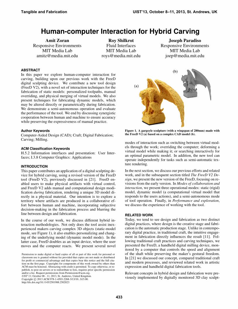
Tool design and motor controlThe FreeD V2 contains a custom milling mechanism (spin-dle) built on top of a long shaft ( Figure 4) with a 12V DC mo-tor (Micro-Drives M2232U12VCS with up to 10,000 RPMwith no load, and up to 5.2mNm torque). A custom 3Dbearing mechanism is located underneath the handle, sittingabove the titanium shaft and enabling three DOF movementsat an approximate spherical volume of 20 mm (see Figure 3).Three servomotors (MKS 6125 mini servos, with up to 5.8kg-cm for 6V), aligned perpendicular to the shaft near thespindle motor, determine the shaft’s position. An electroniccircuit on the PCB (with an ATmega328 microprocessor anda MC33926 motor driver, powered with 5V and 12V signals)communicates with the computer via Bluetooth to control theshaft movement and the spindle speed.
A force-sensing resistor (FSR) sensor is located on the han-dle, allowing the user to override the computer. The DC mo-tor speed (Sp, where 1 is the maximum value) is a functionof the pressure read from the FSR (Pr, where 1 is maximumvalue) and the risk to the model (Rs, 1 is maximal risk - see
Figure 3. The multiple-axis bearing allows the milling bit to move in3 degrees of freedom: 2 in the carving-plane, and a forward-backwardmotion.
Figure 5 (a)-(c)):
Sp = 1−Rs(1− Pr) (1)
Two LEDs are located on the tool to provide the user withvisual feedback. The first LED’s blinking frequency corre-lates to the pressure detected by the FSR. The second LEDcorresponds to the distance between the bit and the surface ofthe model (when the bit touches the model’s surface, the lightis constant). In addition, the operating frequency of the DCmotor (PWM), controlled by the motor-driver, changes fromultrasonic to an audible range (arround 2KHz) to give the useran alarm when the bit is within 4mm of the model surface.
The major part of the computation is done on a computer(Alienware M14x Laptop with i7-3740QM Intel core, 12GBDDR3, and 2GB NVIDIA GeForce GT 650M graphic card).The computer also provides the user with a visual feedbackon the screen (see Figure 5 (d-f)). For tracking (MMTS) weuse the Polhemus FASTRAK system, an AC 6D system thathas low latency (4ms), high static accuracy (position 0.76mm/ orientation 0.15◦ RMS), and high refresh rate (120Hz).
On the computer, where the virtual model resides, the soft-ware runs in Grasshopper and Rhino. The input is the 6Dlocation and orientation of the tool, and the outputs are com-mands to the control PCB on the FreeD. A prediction of thenext position of the bit is extrapolated by a spline of the 4th
order (using the current location and the 3 previous ones).The software calculates the distances (D) to the CAD model(using rhinoscript MeshCP()) from both the current locationand the predicted one, estimating which point puts the modelat higher risk (i.e., which is closer to the model). While theDC motor’s speed is calculated on the tool as a factor of Prand Rs, the latter is calculated by the main control software(values in mm):
Rs =
0 if D <= 100 and D > 4;D/8 if D <= 4 and D > 0;1 elsewhere.
(2)
The default shaft position is fully extended, with a 20mm po-tential to absorb the offset and retract. Unlike our early work,in the FreeD V2 we now use the servos for independent tooloperation rather than as a penetration protection mechanism.
Method of OperationOperation of the FreeD V2 is similar to that discussed ear-lier: the user sits in front of the material (Balsa foam), whichis attached to a wooden stand (see Figure 2). The physi-cal working area is calibrated to the virtual workspace. Sheis free to investigate any milling approach, such as millinglines, drilling holes, trimming surfaces, or using an arbitrary
Tangible and Fabrication UIST’13, October 8–11, 2013, St. Andrews, UK
434
Figure 4. FreeD V2 is a handheld digital milling tool: (a) a left view of the tool, with its main components, and (b) a right view of the opened device.
pattern. The computer slows down the spindle as the bit ap-proaches the model, stopping it completely before it pene-trates the virtual model (see Figure 5 (d-f)). This enables theuser to cut along the boundary of the virtual model wheredesired. She can leave parts of the model unfinished or over-ride the computer using the pressure sensor. Further, in somemodes of operation, the system can dynamically alter themodel based on user actions or operate autonomously.
Figure 5. Risk management with the FreeD. (a-c) Low, High and pene-tration level of risk. (d-f) Heatmap visualization of the risk zone.
MODES OF COLLABORATION AND INTERACTIONIn this section, we survey several original interaction modeswith FreeD V2: the static CAD model mode where the com-puter assists only by preventing the user from damaging themodel (the first part of this section, Toolpath personalization,was partially discussed in our early work); a dynamic modewhere the computer numerically controls the model, respond-ing to the user’s actions; and the autonomous mode where thecomputer can operate independently of the user for tasks suchas semi-automatic texture rendering. Together, these modesspan a new space, where both human and computer work insynergy and contribute to the final product.
Fabrication of static modelsIn the fabrication of a static model, the user cannot alter theCAD model, and the boundary of the virtual object remainsstatic. This approach resembles traditional digital fabricationtechnologies, where the virtual model is fixed and preparedbeforehand. Here however, the user (rather than an automaticprocess) determines the toolpath. This enables personaliza-tion of the work, and may also circumvent complicated CADchallenges such as merging 3D elements into a single object.
Figure 6. Sculpting a static model of a sabertooth tiger (80 min fabri-cation time, length 125mm). (a) The 3D model, (b) the end result of thesculping process, (c) and the toolpath projection. The tool is capable ofachieving a smoother surface (see Figure 16), with deliberate intent.
Toolpath personalizationAs discussed earlier, FreeD gives the user direct control overthe milling toolpath. The final surface smoothness and reso-lution are determined by the size and shape of the endmill and
Tangible and Fabrication UIST’13, October 8–11, 2013, St. Andrews, UK
435

the toolpath. Usually in fabrication, a manual process rendersa chaotic surface pattern whereas an automatic process ren-ders an organized network of marks. This is mainly becausein a manual toolpath, a product of the maker’s dexterity andpatience, the operation never repeats itself and evolves into aunique texture, for example in the fabrication of a saber-toothtiger model (Figure 6 (a)). The final texture (b) reflects theuser toolpath (c), properties of the material, milling bit size,and latency of the system. The parts left unfinished (the legs)demonstrate decisions made during the work.
Figure 7. Hybridization of meshes while sculpting (100 min fabricationtime, model length 120mm). The final 3D shape does not exist virtually;it only exists in the fabricated model.
Physical mergingAs FreeD encourages the user to work creatively and intu-itively, the user can manually switch between different ref-erence virtual models during the work. The fusion of thesemodels need not be determined numerically but physically,relinquishing the need to solve mesh intersection problems inmaking a single CAD model, as in the merging of a saber-tooth tiger with dragon wings and deer horns (Figure 7).
Figure 8. The result of overriding computer guidance is a completelydifferent design (90 min fabrication time, model length 120mm). Theartist takes risks and produces a unique artifact.
Manual overrideHere, we present an approach foreign to most digital fabri-cation methods: allowing intentional destruction of the fab-ricated model. By overwriting the computer, the user mini-mizes digital control on the shaft while keeping the advantage
of digital guidance with an aural alarm and LED. In additionto leaving parts unfinished, the maker can intentionally ”dam-age” the model, working around or inside the virtual shape,allowing for physical improvisation. Beyond Figure 6b, inFigure 8, the user continued to manually remove parts of themodel to achieve a unique artifact.
Fabrication of dynamic modelsToday, digital fabrication technologies require models to bedesigned beforehand and no changes can be made during fab-rication, as in the static approach presented in the last section.In contrast, craftpersons are free to deform the subject duringthe creation process, as long as the remaining material allows.Aiming to recreate this freedom, we present a novel capabil-ity to allow the modification of dynamic virtual models dur-ing fabrication, exploring three types of interaction with dy-namic models: Direct shape deformation, Volume occupancyoptimization, and Data-driven shape exploration.
Direct shape deformationThe first order dynamics in our interaction model is to al-low for direct deformation of a CAD model. Unlike manualoverriding of a static model, in direct shape deformation thecomputer keeps track of subtracted material: when the userpresses the override button and penetrates the virtual model,the computer deforms the mesh to ameliorate the penetration.
Recent related methods of mesh deformation [19] seek to pre-serve local features under deformation. Here, we used a sim-plified weighting scheme for local deformation with respectto the user’s action. As the weights for the offset vector ofvertices ( ~Ov , where v is the vertex index) we use a Gaussiandecay over the distance from the nearest vertex to the bit, tocreate an effect of a smooth deformation:
~Ov = ~Tv ∗ e−(dv/S)2
0.005(10−Pr)2 (3)
Where Pr is the value read from the override FSR button (0is no pressure and 1 is maximal pressure), ~T is the penetra-tion vector (the vector between the point of first contact to thedeepest bit position), dv is the distance from v to the penetra-tion point, and S is the number of affected vertices, a constantnumber that can be defined by the user (and thus define theaffected area). See Figure 9 for an example of deforming amesh while fabricating.
Volume occupancy optimizationFurther examining the art of carving, we face a common chal-lenge: fitting a shape to a given volume of material, for exam-ple in the case of an irregular piece of wood, where the artistmay try to maximize the volume of the shape while boundedby the material. FreeD allows the user to work in this fashion,using optimization of volume occupancy.
We illustrate the idea of volume occupancy optimizationthrough a simple parametric bowl with three parameters: in-ner and outer radii (ri, ro) and height (c). Let us denoteΘ = {ro, rin, c}. Spheres and cubes were used to create themodel of the bowl with constructive solid geometry (CSG)boolean operations (using the Carve CSG library [17]). SeeFigure 10 (e) for examples of parametic bowls.
Tangible and Fabrication UIST’13, October 8–11, 2013, St. Andrews, UK
436
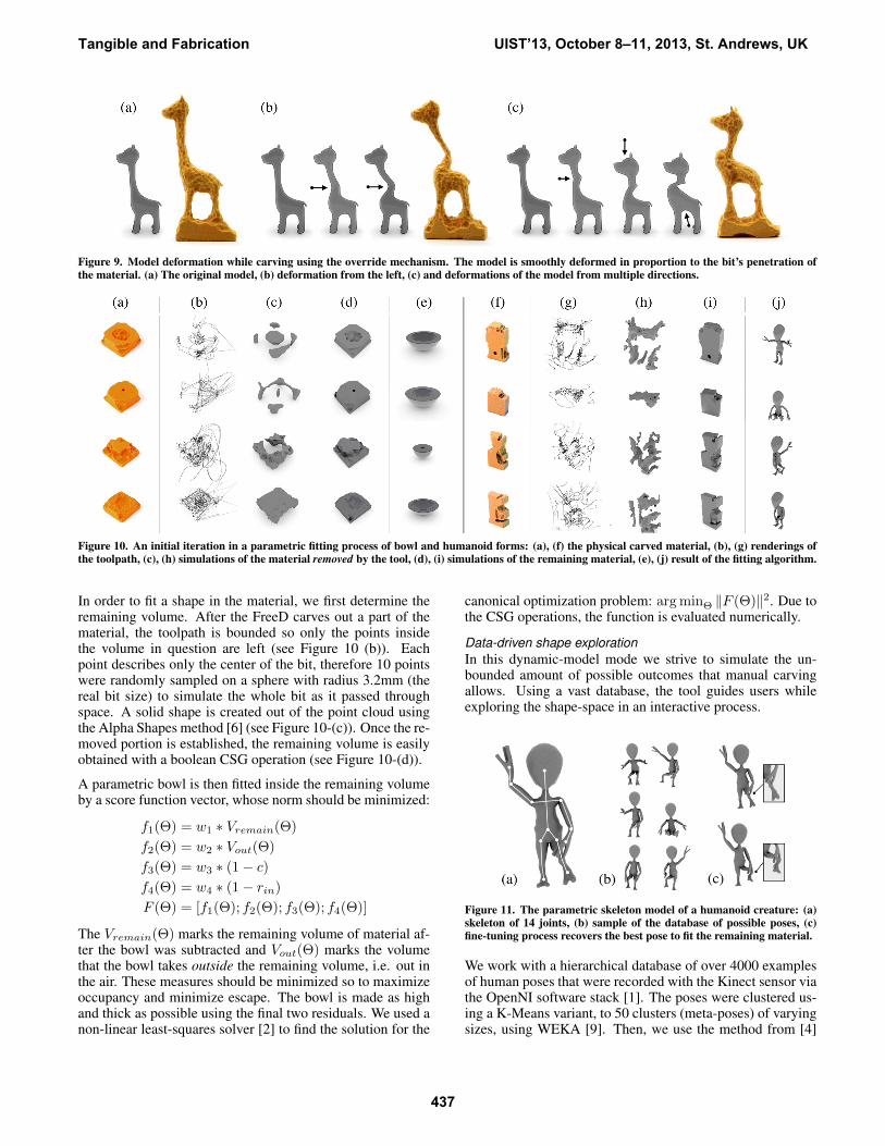
Figure 9. Model deformation while carving using the override mechanism. The model is smoothly deformed in proportion to the bit’s penetration ofthe material. (a) The original model, (b) deformation from the left, (c) and deformations of the model from multiple directions.
Figure 10. An initial iteration in a parametric fitting process of bowl and humanoid forms: (a), (f) the physical carved material, (b), (g) renderings ofthe toolpath, (c), (h) simulations of the material removed by the tool, (d), (i) simulations of the remaining material, (e), (j) result of the fitting algorithm.
In order to fit a shape in the material, we first determine theremaining volume. After the FreeD carves out a part of thematerial, the toolpath is bounded so only the points insidethe volume in question are left (see Figure 10 (b)). Eachpoint describes only the center of the bit, therefore 10 pointswere randomly sampled on a sphere with radius 3.2mm (thereal bit size) to simulate the whole bit as it passed throughspace. A solid shape is created out of the point cloud usingthe Alpha Shapes method [6] (see Figure 10-(c)). Once the re-moved portion is established, the remaining volume is easilyobtained with a boolean CSG operation (see Figure 10-(d)).
A parametric bowl is then fitted inside the remaining volumeby a score function vector, whose norm should be minimized:
f1(Θ) = w1 ∗ Vremain(Θ)
f2(Θ) = w2 ∗ Vout(Θ)
f3(Θ) = w3 ∗ (1− c)
f4(Θ) = w4 ∗ (1− rin)
F (Θ) = [f1(Θ); f2(Θ); f3(Θ); f4(Θ)]
The Vremain(Θ) marks the remaining volume of material af-ter the bowl was subtracted and Vout(Θ) marks the volumethat the bowl takes outside the remaining volume, i.e. out inthe air. These measures should be minimized so to maximizeoccupancy and minimize escape. The bowl is made as highand thick as possible using the final two residuals. We used anon-linear least-squares solver [2] to find the solution for the
canonical optimization problem: arg minΘ ‖F (Θ)‖2. Due tothe CSG operations, the function is evaluated numerically.
Data-driven shape explorationIn this dynamic-model mode we strive to simulate the un-bounded amount of possible outcomes that manual carvingallows. Using a vast database, the tool guides users whileexploring the shape-space in an interactive process.
Figure 11. The parametric skeleton model of a humanoid creature: (a)skeleton of 14 joints, (b) sample of the database of possible poses, (c)fine-tuning process recovers the best pose to fit the remaining material.
We work with a hierarchical database of over 4000 examplesof human poses that were recorded with the Kinect sensor viathe OpenNI software stack [1]. The poses were clustered us-ing a K-Means variant, to 50 clusters (meta-poses) of varyingsizes, using WEKA [9]. Then, we use the method from [4]
Tangible and Fabrication UIST’13, October 8–11, 2013, St. Andrews, UK
437

to auto-rig the humanoid alien model to a skeleton model thatcorresponds with the Kinect. For deformation of the mesh,we used the canonical Linear Blend Skinning method. Fig-ure 11-(a) and (b) illustrates the database of skeleton poses.
The process of finding the remaining volume (see the pre-vious section) is repeated. Then, an exhaustive search overthe database is performed to find the meta-pose that has theleast amount of escape from the remaining volume (Vout),followed by a search within the best-found cluster. Severaloptions for advancement are presented to the user to choosefrom in each iteration. After the database search, fine tuningensues, for the position of the limbs and for small translationsof the entire shape in respect to the volume. Figure 11-(c)shows an example of finely tuning the alien pose.
Figure 12. Automatic tool operation in a straight line. In (a) regionsthere is no autonomous movement, while in (b) regions the shaft pro-grammatically removes more material resulting in a bigger virtual bit.
Autonomous operation modeDigital fabrication technologies incorporate several degreesof automatic motion, while common hand-held devices do notautomatically move but are manually controlled. The use ofautomatic motion in hand-held devices is rarely considered.Lately this is changing, as was demonstrated by Rivers et al.[15], by integrating 2D actuation mechanism to correct theuser’s path, and in [21] , where shaft retraction prevents theuser from accidental penetration of the model.
An independent actuation of the shaft operates semi-autonomously: while the user holds FreeD and makes large-scale movements, the tool makes autonomous smaller-scalemovements. For example, the tool is operated as a semi-autonomous milling device (CNC, see Figure 12). In Fig-ure 13 we demonstrate a semi-autonomous texture rendering:when the bit is closer than 4mm to the fur segment, the servosoperate with a linear pecking movement (4Hz, 5mm move-ment range) to achieve a fur texture. The user continues tooperate the tool freely, unconstrained by the shaft actuation.
PERFORMANCE AND EXPLORATIONIn this section, we first present statistical performance mea-surements collected while working with the FreeD V2, beforediscussing our experience using the tool.
System performanceThe FreeD V2 system was used (mostly by us) in the fab-rication of 11 complete artifacts, in addition to several 3Dsketches and a few preliminary sculptures in our early stud-ies. We tested the tool with carving in both high and low
Figure 13. Teddy bear model (height 147mm) (a) embellished with furtextures. The mesh is encoded with a rough or smooth texture. Therough texture causes the shaft to move back and forth, creating dimplesin the material that simulate fur (b).
density balsa foams, basswood, and carving wax. All of thestudies presented in this paper were done in foam, since ittook up to 10 times longer to machine wax and wood. Thecontrol software updated at a frame rate varying between 10to 20 frames per second (FPS). We worked with mesh mod-els of 150 vertices (humanoid) to 5370 vertices (gargoyle),lengths between 120mm (giraffe) to 280mm (gargoyle), andwith production times of 40 minutes (giraffe) to 5 hours (gar-goyle). The static-bit accuracy (measured by holding the bitin one place while rotating the tool around it) varies between0.05 mm RMS (20cm from the magnetic field generator) to0.4mm RMS (70cm away).
While in our work we seek personalization of artifact ratherthan production accuracy, here we test how accurately theFreeD can reconstruct a predesigned virtual model. Thesurface accuracy depends on the frame rate, tool movementspeed, and material density. For example, with 15 FPS and350mm/sec attack speed, the bit penetrated 3.5mm in a densebalsa foam before the system shut down the spindle rotation.
To empirically evaluate the accuracy of FreeD V2 we de-signed a model with non-straight angles and a sphere (Fig-ure 14 (a)), fabricated it with FreeD, and then scanned it withKonica Minolta VIVID 910 scanner so to computationally es-
Tangible and Fabrication UIST’13, October 8–11, 2013, St. Andrews, UK
438

Figure 14. An examination of the FreeD V2’s accuracy measure. (a) thevirtual model (53mm length) , (b) the model fabricated with FreeD, (c) a3D scanning of the fabrication. The RMS error is less than 0.5mm.
timate the error. We present the following results only to givea general sense of accuracy, as the adherence of the resultingsurface to the virtual model is greatly a factor of the maker’sdexterity and patience, a complex concept to quantify. The re-sulting error was smaller than 0.5mm RMS (samples for thismeasurement were taken within a grid of less than 1mm res-olution). As expected because of the bit size, FreeD fails toclear out material from sharp corners; however all subtractivefabrication methods suffer from this drawback.
ExperimentationHere we discuss the making of a larger-scale model that in-corporates most of the functionalities of the tool. We made ahumanoid model, an alien figure, which features a large headand elongated arms. The work began by interactively explor-ing the skeleton database in the same manner we discussedearlier (see section ). Figure 15 (b-d) shows the differentposes fetched from the database while carving out material.When a satisfying pose was found, we began removing largerchunks of material. Using the shape deformation method de-scribed earlier, we created a dent in the model to emphasizethe sideways motion of the hips (see Figure 15-(e)). We thenkept removing material until the general form was fleshed out(see Figure 15-(f) for an illustration) and moved on to textur-ing and decorating. On the computer we set the alien’s headto have a rough texture that will resemble hair. Finally, weused the override mechanism to create completely unguidedcarvings of the mouth and navel, and decided to leave part ofthe model unfinished.
DiscussionExtended user studies will be conducted to validate the tool’scapabilities in supporting creative processes. Yet, using thetool ourselves and allowing five other participants to collab-orate on single carving (see Figure 16), we have a few initialreflections. In projects presented in this paper, the tool wasguided along lines away from the object, removing materialfrom one side to another. When the model becomes recogniz-able, the operation changed to tracking the surface manifolds.Changes in spindle speed, when the bit approaches the modelsurface, inform the users on the relative location of the toolwith respect to the model and help build intuition. Severalparticipants noted it took them a while to trust the tool in pro-tecting the object from a wrong movement.
On the screen, a virtual mark represents the current positionof the FreeDs milling bit (see Figure 5 (d)-(f)). Occasionally,we relied on this mark in the initial stage where the virtualshape is not yet revealed in the raw material. However, the
Figure 15. Fabrication of a humanoid model (height 222mm) illustrat-ing all methods. (a) The final artifact. (b-d) Evolution of the model asmaterial is removed. (e) Smooth deformation. (f) Texturing hair anddeliberate penetration of the model to carve a mouth and navel.
main limitation of the FreeD, as indicated by several users, isa lack in visual feedback of the virtual model projected on thematerial. On the other hand, this drawback helped develop aphysical intuition for the digital guidance. Nevertheless wefind there is a place to consider such a visualization methodin a future work.
Figure 16. Collaborative effort (a), (b) in creating (c) a deer artifact.
CONCLUSIONWe propose a new technique where digital capabilities in-tegrate with handheld carving tools to assist inexperiencedmakers in carving complex 3D objects, as well as to enableinterpretation and modification of a virtual model while fab-ricating it. The FreeD keeps the user’s subjective toolpath asa signature embedded in the texture. In addition, it is capableof completing tasks in a semi-automatic mode, generating aphysical texture independently of the user. Since design ma-nipulation is integrated within a tangible carving experience,the nature of this work resembles the process of traditionalcraft, while allowing risk management and quality assurance.
Tangible and Fabrication UIST’13, October 8–11, 2013, St. Andrews, UK
439

We wish FreeD to enable creative work in a domain yet un-explored, a new hybrid territory of artifacts produced by bothmachine and man, fusing automated production with humansubjectivity. Blending design with fabrication and automaticprocess with manual control, we believe the collaborativetechnology presented here has the potential to alter someof the dominant paradigms in contemporary digital fabrica-tion processes. By introducing traditional approaches to thedigital making of artifacts, we hope this intimate collabora-tion between man and machine will pave the path for a newparadigm in human-computer interaction.
AcknowledgementsMany thanks to our collegues and friends who supported usduring the work: T. Rucham, J. Steimle, A. von Kapri, D.Mellis, NW Gong, P. Schmitt, C. Xia, K. Ran, M. Feldmeier,A. Petron, B. Mayton, M. Levin, S. Follmer, Y. Sterman, G.Dublon, N. Gershenfeld, F. Durand, Y. Gingold, L. Liu, M.Gharbi, K. Bala, R. Jaroensri, H.V. Shin, S. Nanayakkara,K.P. Yeo, D. Cohen-Or, and all the craftspersons who sharedtheir knowledge. The CAD models were purchased from tur-bosquid.com, and the renderings were made with VRay.
REFERENCES1. Openni user guide.
http://www.openni.org/documentation, November2010. Last Checked December 14, 2012.
2. Agarwal, S., and Mierle, K. Ceres solver: Tutorial &reference. http://code.google.com/p/ceres-solver,2012. Last Checked December 14, 2012.
3. Arisandi, R., Takami, Y., Otsuki, M., Kimura, A.,Shibata, F., and Tamura, H. Enjoying virtualhandcrafting with tooldevice. In Adjunct proceedings ofthe 25th annual ACM symposium on User interfacesoftware and technology, ACM (2012), 17–18.
4. Baran, I., and Popovic, J. Automatic rigging andanimation of 3d characters. In ACM Transactions onGraphics (TOG), vol. 26, ACM (2007), 72.
5. Cho, S., Heo, Y., and Bang, H. Turn: a virtual pottery byreal spinning wheel. In ACM SIGGRAPH 2012Emerging Technologies, SIGGRAPH ’12, ACM (NewYork, NY, USA, 2012), 25:1–25:1.
6. Edelsbrunner, H., and Mucke, E. P. Three-dimensionalalpha shapes. ACM Trans. Graph. 13, 1 (Jan. 1994),43–72.
7. Follmer, S., Carr, D., Lovell, E., and Ishii, H. Copycad:remixing physical objects with copy and paste from thereal world. In Adjunct proceedings of the 23nd annualACM symposium on User interface software andtechnology, UIST ’10, ACM (New York, NY, USA,2010), 381–382.
8. Gustafson, S., Bierwirth, D., and Baudisch, P. Imaginaryinterfaces: spatial interaction with empty hands andwithout visual feedback. In Proceedings of the 23ndannual ACM symposium on User interface software andtechnology, UIST ’10, ACM (New York, NY, USA,2010), 3–12.
9. Hall, M., Frank, E., Holmes, G., Pfahringer, B.,Reutemann, P., and Witten, I. H. The weka data miningsoftware: an update. SIGKDD Explor. Newsl. 11, 1(Nov. 2009), 10–18.
10. Johnson, G., Gross, M., Do, E. Y.-L., and Hong, J.Sketch it, make it: sketching precise drawings for lasercutting. In Proceedings of the 2012 ACM annualconference extended abstracts on Human Factors inComputing Systems Extended Abstracts, CHI EA ’12,ACM (New York, NY, USA, 2012), 1079–1082.
11. McCullough, M. Abstracting Craft: The PracticedDigital Hand. MIT Press, Cambridge, MA, USA, 1998.
12. Mueller, S., Lopes, P., and Baudisch, P. Interactiveconstruction: interactive fabrication of functionalmechanical devices. In Proceedings of the 25th annualACM symposium on User interface software andtechnology, UIST ’12, ACM (New York, NY, USA,2012), 599–606.
13. Patel, N. Gestural printing: Jumping the shark on kinecthacks. http://bit.ly/dLiheh, 2011. Last checked 11December, 2012.
14. Rivers, A., Adams, A., and Durand, F. Sculpting bynumbers. ACM Trans. Graph. 31, 6 (Nov. 2012),157:1–157:7.
15. Rivers, A., Moyer, I. E., and Durand, F.Position-correcting tools for 2d digital fabrication. ACMTrans. Graph. 31, 4 (July 2012), 88:1–88:7.
16. S., C., and Rehg, J. M. Shapeshift: A projector-guidedsculpture system. In Adjunct proceedings of the 20ndannual ACM symposium on User interface software andtechnology, UIST ’07, ACM (Newport, Rhode Island,USA, October 2007).
17. Sargeant, T. carve.http://code.google.com/p/carve/, 2012. LastChecked December 14, 2012.
18. Song, H., Guimbretiere, F., Hu, C., and Lipson, H.Modelcraft: capturing freehand annotations and edits onphysical 3d models. In Proceedings of the 19th annualACM symposium on User interface software andtechnology, UIST ’06, ACM (New York, NY, USA,2006), 13–22.
19. Sorkine, O., Cohen-Or, D., Lipman, Y., Alexa, M.,Rossl, C., and Seidel, H. Laplacian surface editing. InProceedings of the 2004 Eurographics/ACMSIGGRAPH symposium on Geometry processing, ACM(2004), 175–184.
20. Willis, K. D., Xu, C., Wu, K.-J., Levin, G., and Gross,M. D. Interactive fabrication: new interfaces for digitalfabrication. In Proceedings of the fifth internationalconference on Tangible, embedded, and embodiedinteraction, TEI ’11, ACM (New York, NY, USA,2011), 69–72.
21. Zoran, A., and Paradiso, J. A. Freed – a freehand digitalsculpting tool. In Proceedings of the 2013 ACM annualconference on Human Factors in Computing Systems,CHI EA ’13 (Paris, 2013).
Tangible and Fabrication UIST’13, October 8–11, 2013, St. Andrews, UK
440
Related Documents