National Fire Protection Association 1 Batterymarch Park, Quincy, MA 02169-7471 Phone: 617-770-3000 • Fax: 617-770-0700 • www.nfpa.org AGENDA NFPA TECHNICAL COMMITTEE ON PROTECTED PREMISES FIRE ALARM SYSTEMS (SIG-PRO) Report on Comments Meeting, October 10-12, 2011 Richmond Marriott, Richmond, VA Item No. Subject 11-10 -1 Call to Order and Welcome (8:00 AM) 11-10-2 NFPA staff review of fire alarm and exit procedures 11-10-3 Introduction of Members and Guests 11-10-4 Review of Meeting Procedures and Revision Schedule 11-10-5 Comments/Questions from Committee Members and/or Guests 11-10-6 Approval of Prior Meeting Minutes [Enclosure] 11-10-7 Task Group Reports a. ITM (Elvove) b. Circuits and Pathways (Horon) c. Control Functions (Leszczak) d. ECS (Kern) e. Releasing Systems ( f. FCC (Dix) g. 720 vs 72 (Belliveau) h. Editorial (Hammerberg) 11-10-8 Processing of Comments [Enclosure] 11-10-9 Correlation Issues [Enclosure] 11-10-10 Fire Protection Research Foundation Requests 11-10-11 Old Business 11-10-12 New Business 11-10-13 Adjournment

Welcome message from author
This document is posted to help you gain knowledge. Please leave a comment to let me know what you think about it! Share it to your friends and learn new things together.
Transcript

National Fire Protection Association 1 Batterymarch Park, Quincy, MA 02169-7471 Phone: 617-770-3000 • Fax: 617-770-0700 • www.nfpa.org
AGENDA
NFPA TECHNICAL COMMITTEE ON PROTECTED PREMISES FIRE ALARM SYSTEMS (SIG-PRO)
Report on Comments Meeting, October 10-12, 2011
Richmond Marriott, Richmond, VA
Item No. Subject 11-10 -1 Call to Order and Welcome (8:00 AM) 11-10-2 NFPA staff review of fire alarm and exit procedures 11-10-3 Introduction of Members and Guests 11-10-4 Review of Meeting Procedures and Revision Schedule 11-10-5 Comments/Questions from Committee Members and/or Guests
11-10-6 Approval of Prior Meeting Minutes [Enclosure] 11-10-7 Task Group Reports
a. ITM (Elvove) b. Circuits and Pathways (Horon) c. Control Functions (Leszczak) d. ECS (Kern) e. Releasing Systems ( f. FCC (Dix) g. 720 vs 72 (Belliveau) h. Editorial (Hammerberg)
11-10-8 Processing of Comments [Enclosure] 11-10-9 Correlation Issues [Enclosure] 11-10-10 Fire Protection Research Foundation Requests 11-10-11 Old Business 11-10-12 New Business 11-10-13 Adjournment


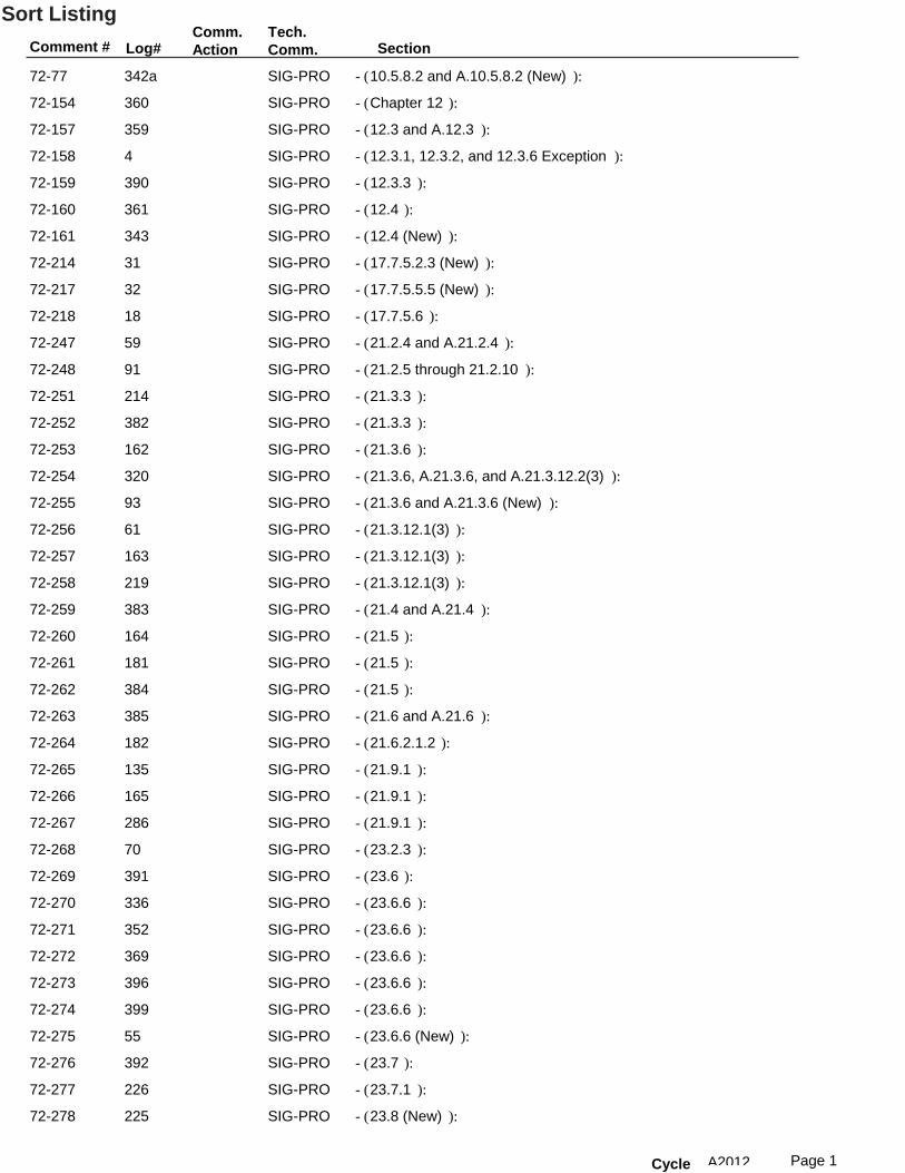
Comment # Log#Comm.Action
Tech.Comm. Section
Sort Listing
342a 10.5.8.2 and A.10.5.8.2 (New)- ( ):72-77 SIG-PRO
360 Chapter 12- ( ):72-154 SIG-PRO
359 12.3 and A.12.3- ( ):72-157 SIG-PRO
4 12.3.1, 12.3.2, and 12.3.6 Exception- ( ):72-158 SIG-PRO
390 12.3.3- ( ):72-159 SIG-PRO
361 12.4- ( ):72-160 SIG-PRO
343 12.4 (New)- ( ):72-161 SIG-PRO
31 17.7.5.2.3 (New)- ( ):72-214 SIG-PRO
32 17.7.5.5.5 (New)- ( ):72-217 SIG-PRO
18 17.7.5.6- ( ):72-218 SIG-PRO
59 21.2.4 and A.21.2.4- ( ):72-247 SIG-PRO
91 21.2.5 through 21.2.10- ( ):72-248 SIG-PRO
214 21.3.3- ( ):72-251 SIG-PRO
382 21.3.3- ( ):72-252 SIG-PRO
162 21.3.6- ( ):72-253 SIG-PRO
320 21.3.6, A.21.3.6, and A.21.3.12.2(3)- ( ):72-254 SIG-PRO
93 21.3.6 and A.21.3.6 (New)- ( ):72-255 SIG-PRO
61 21.3.12.1(3)- ( ):72-256 SIG-PRO
163 21.3.12.1(3)- ( ):72-257 SIG-PRO
219 21.3.12.1(3)- ( ):72-258 SIG-PRO
383 21.4 and A.21.4- ( ):72-259 SIG-PRO
164 21.5- ( ):72-260 SIG-PRO
181 21.5- ( ):72-261 SIG-PRO
384 21.5- ( ):72-262 SIG-PRO
385 21.6 and A.21.6- ( ):72-263 SIG-PRO
182 21.6.2.1.2- ( ):72-264 SIG-PRO
135 21.9.1- ( ):72-265 SIG-PRO
165 21.9.1- ( ):72-266 SIG-PRO
286 21.9.1- ( ):72-267 SIG-PRO
70 23.2.3- ( ):72-268 SIG-PRO
391 23.6- ( ):72-269 SIG-PRO
336 23.6.6- ( ):72-270 SIG-PRO
352 23.6.6- ( ):72-271 SIG-PRO
369 23.6.6- ( ):72-272 SIG-PRO
396 23.6.6- ( ):72-273 SIG-PRO
399 23.6.6- ( ):72-274 SIG-PRO
55 23.6.6 (New)- ( ):72-275 SIG-PRO
392 23.7- ( ):72-276 SIG-PRO
226 23.7.1- ( ):72-277 SIG-PRO
225 23.8 (New)- ( ):72-278 SIG-PRO
Page 1A2012Cycle

Comment # Log#Comm.Action
Tech.Comm. Section
Sort Listing
287 23.8.2.7- ( ):72-279 SIG-PRO
331 23.8.2.8- ( ):72-280 SIG-PRO
288 23.8.3.2.1- ( ):72-281 SIG-PRO
393 23.8.4.3- ( ):72-282 SIG-PRO
394 23.8.4.3- ( ):72-283 SIG-PRO
227 23.8.4.3.1.3 and 23.8.4.3.2.2- ( ):72-284 SIG-PRO
166 23.8.5.5.2- ( ):72-285 SIG-PRO
332 23.8.5.5.2 and 23.8.5.6.2- ( ):72-286 SIG-PRO
14 23.8.5.5.3- ( ):72-287 SIG-PRO
13 23.8.5.6.3- ( ):72-288 SIG-PRO
12 23.8.5.6.4- ( ):72-289 SIG-PRO
11 23.8.5.7.3- ( ):72-290 SIG-PRO
10 23.8.5.7.4- ( ):72-291 SIG-PRO
9 23.8.5.8.3- ( ):72-292 SIG-PRO
8 23.8.5.8.4- ( ):72-293 SIG-PRO
7 23.8.5.9.3- ( ):72-294 SIG-PRO
6 23.8.5.9.4- ( ):72-295 SIG-PRO
333 23.12.1- ( ):72-298 SIG-PRO
51 24.3- ( ):72-301 SIG-PRO
1 A.21.4.2- ( ):72-440 SIG-PRO
173 A.21.4.2- ( ):72-441 SIG-PRO
174 A.23.3.3.1 (New)- ( ):72-442 SIG-PRO
408 A.23.7.x (New)- ( ):72-443 SIG-PRO
407 A.23.7.4, A.23.7.4.1, A.23.7.4.2, and A.23.7.4.3- ( ):72-444 SIG-PRO
252 A.23.8.5.1.2- ( ):72-445 SIG-PRO
404 A.23.8.6.3.2 (New)- ( ):72-446 SIG-PRO
Page 2A2012Cycle

Report on Comments – June 2012 NFPA 72_______________________________________________________________________________________________72-77 Log #342a SIG-PRO
_______________________________________________________________________________________________Denise L. Pappas, Valcom, Inc.
72-338Insert Text into Power Supply for Remotely Located Control Equipment. Section 10.5.8 and
renumber subsequent sections, instead of Chapter 24.Power over ethernet (PoE), where provided for control units. circuit interfaces, or other equipment essential
to system operation, and located remotely from the main control unit. shall be comprised of a primary and secondarysupply that shall meet the same requirements as those of 10.5.1 throuqh 10.5.7 and 10.17.3.
Power over ethernet will be a power supply for remotely located equipment. The POE switch shall meet therequirements of section 10.5.1 throuqh 10.5.7 and 10.17.3.
This section was originally submitted to Chapter 24, Emergency Communication Systems; however, itshould have been submitted to Chapter 10, Fundamentals.
During technical committee discussions it was stated that there is nothing in the current standards that prevent PowerOver Ethernet (POE) from being used. However, current Nationally Recognized Testing Labs (NRTLs) perform teststhat would not allow this technology to be utilized (specifically UL S64, Section 71.4 and upcoming proposed UL 2572,Section 5S.4). The testing for this technology is currently regulated by the Institute of Electrical and ElectronicsEngineers (IEEE) Standard 802. Furthermore, 802 is highly regulated.
Power Backup - When proposing POE in this section, the power backup would be the same as those powerrequirements that currently exist.
Reliability - Another issue discussed was the reliability of the network. The telecommunications industry works closelywith the Electronic Industries Alliance (EIA) (which is an international industry association that is best known forpublishing electrical wiring and transmission standards) under the auspices of the Telecommunications IndustryAssociation (TIA) which is responsible for developing communications standards. Since communications, wiring, andtransmission are all related, and since the TIA and EIA organizations are also related, standards produced by the EIA orTIA are often labeled with the combined prefixes EIA/TIA or TIA/EIA.
The telecommunications and cloud computing industries strive for 5-nines reliability (which translated means 99.999%uptime or less than 5 minutes downtime in a year). When talking about reliability, persons are often confused whentalking about a local area network (LAN) versus the world wide web internet. A LAN backbone is always working, even ifyou cannot get to your e-mail or other applications on the network. End to end monitoring is done on the networks andwhen/if something goes down on the network, whether it is a piece of equipment or a break in the wire, notificationoccurs within seconds.
Additionally, there is inherent redundancy built into networks. When moving data/information from point A to point B, ifthere is a break, it automatically reroutes that information from A to C to B or from A to 0 to B, etc. The "packets ofinformation" are not lost, just rerouted to their proper end point. When taking this information into account, life safetysystems built on an IP backbone are inherently more reliable than any fire alarm system currently on the market today.
When working with end users that are looking for solutions, they have been turning to IP based solutions. Thesesolutions are currently being implemented in the field with fire alarm systems as well as communication systems. IfNFPA wants to continue to influence the installation of these systems, it is imperative to make allowances to accept thiswidely regulated and accepted IP technology used throughout the world. While many think by allowing this technology,we are lowering the standards, it is just the opposite. We are raising the standard to accept an inherently proven reliabletechnology.
Bibliography: The TCP/IP Guide, Copyright 2005 by Charles M. Kozierok.
1Printed on 9/20/2011

Report on Comments – June 2012 NFPA 72_______________________________________________________________________________________________72-154 Log #360 SIG-PRO
_______________________________________________________________________________________________Daniel J. Horon, Cadgraphics
72-166Revise Chapter 12 as follows:Wiring methods permitted by other sections of this Code to resist attack by fire shall be installed in
accordance with manufacturer’s published instructions and the requirements of , Article 760. (SIG-FUN)
All fire alarm systems shall test free of grounds.
On conductive pathways, operational capability shall be maintained during the application of a single groundconnection.
Technologies that do not use metallic conductors (e.g. wireless or optical fiber) are not affected by groundconnections.
On conductive pathways, with conductors not galvanically isolated from ground, a single ground connectionshall annunciate a trouble signal.
Metallic conductors that have a potential path to ground through other components may cause acatastrophic system failure when a second ground is applied. Alarm systems with IDCs may cause a false alarmcondition to occur when a second ground is connected. For these reasons, a single ground connection is required toindicate a trouble to forewarn of these potential problems. Technologies that do not use metallic conductors (e.g.wireless or optical fiber) are not affected by ground connections, and are not required to report a ground connection as atrouble. Technologies that isolate all conductors from ground, such as the IEEE specifications for Ethernet, operatenormally during a single ground connection, and are not required to report a single ground connection. When twoconductors in a matched pair both connect to ground, a short is reported as a trouble on the alarm system, and theisolation protects other components from the shorted conductors.
Galvanic isolation prevents electric current transfer directly from one section to another, but allows power orinformation to be exchanged between the sections by other means. Technologies that can transfer power orinformation, without current, use capacitance, induction or electromagnetic waves, or an optical, acoustic or mechanicalmeans.
Pathways shall be designated as Class A, Class B, Class C, Class D, Class E, orClass X, depending on their performance.
A pathway shall be designated as Class A when it performs as follows:(1) It includes a redundant path.(2) Operational capability continues past a single open.(3) Conditions that affect the intended operation of the paths are annunciated.
The Class A reference s for initiating device circuit and notification appliance circuit performance have hadbeen changed to eliminate the need for alarm receipt capability during a single ground or annunciation of a singleground fault. The signal line circuit performance has changed to provide a clear separation between the Class A Style 6and Class A Style 7 performance. The Class A Style 7 performance is now defined as Class X. That was intended toallow for the fact that building communication systems use technology that is isolated from ground. This Edition of theCode has added 12.2.5.2 and 12.2.5.3 to clarify the intent. Note that Class A was designated as Style 6 in earliereditions of this Code.
A pathway shall be designated as Class B when it performs as follows:(1) It does not include a redundant path.(2) Operational capability stops at a single open.(3) Conditions that affect the intended operation of the path are annunciated.
The Class B reference s for initiating device circuit, signal line circuit, and notification appliance circuitperformance have had been changed to eliminate the need for alarm receipt capability during a single ground orannunciation of a single ground fault. Users of the code are advised that fire alarm circuits still require alarm receiptcapability during a single ground. That was intended to allow for the fact that building communicationsystems use technology that is isolated from ground. This Edition of the Code has added 12.2.5.2 and 12.2.5.3 to clarifythe intent.
2Printed on 9/20/2011
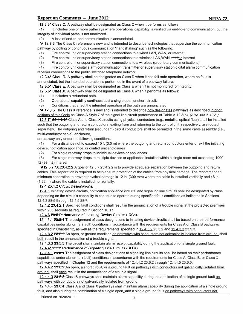
Report on Comments – June 2012 NFPA 72A pathway shall be designated as Class C when it performs as follows:
(1) It includes one or more pathways where operational capability is verified via end-to-end communication, but theintegrity of individual paths is not monitored.
(2) A loss of end-to-end communication is annunciated.The Class C reference is new and is intended to describe technologies that supervise the communication
pathway by polling or continuous communication “handshaking” such as the following:(1) Fire control unit or supervisory station connections to a wired LAN, WAN, or Internet(2) Fire control unit or supervisory station connections to a wireless LAN,WAN, and or Internet(3) Fire control unit or supervisory station connections to a wireless (proprietary communications)(4) Fire control unit digital alarm communication transmitter or supervisory station digital alarm communication
receiver connections to the public switched telephone networkA pathway shall be designated as Class D when it has fail-safe operation, where no fault is
annunciated, but the intended operation is performed in the event of a pathway failure.A pathway shall be designated as Class E when it is not monitored for integrity.A pathway shall be designated as Class X when it performs as follows:
(1) It includes a redundant path.(2) Operational capability continues past a single open or short-circuit.(3) Conditions that affect the intended operation of the path are annunciated.
The Class X reference is new and is intended to describe now designates pathways as described in prioreditions of this Code as Class A Style 7 of the signal line circuit performance of Table A.12.3(b).
Class A and Class X circuits using physical conductors (e.g., metallic, optical fiber) shall be installedsuch that the outgoing and return conductors, exiting from and returning to the control unit, respectively, are routedseparately. The outgoing and return (redundant) circuit conductors shall be permitted in the same cable assembly (i.e.,multi-conductor cable), enclosure,or raceway only under the following conditions:
(1) For a distance not to exceed 10 ft (3.0 m) where the outgoing and return conductors enter or exit the initiatingdevice, notification appliance, or control unit enclosures
(2) For single raceway drops to individual devices or appliances(3) For single raceway drops to multiple devices or appliances installed within a single room not exceeding 1000
ft2 (93 m2) in areaA goal of 12.3.7 23.4.2.2 is to provide adequate separation between the outgoing and return
cables. This separation is required to help ensure protection of the cables from physical damage. The recommendedminimum separation to prevent physical damage is 12 in. (300 mm) where the cable is installed vertically and 48 in.(1.22 m) where the cable is installed horizontally.
Initiating device circuits, notification appliance circuits, and signaling line circuits shall be designated by class,depending on the circuit’s capability to continue to operate during specified fault conditions as indicated in Sections12.4.3 23.5 through 12.4.5 23.7.
Specified fault conditions shall result in the annunciation of a trouble signal at the protected premiseswithin 200 seconds as required in Section 10.17.
The assignment of class designations to initiating device circuits shall be based on their performancecapabilities under abnormal (fault) conditions in accordance with the requirements for Class A or Class B pathwaysspecified in Chapter 12, as well as the requirements specified in 12.4.3.2 23.5.2 and 12.4.3.3 23.5.3.
An open, or ground condition on pathways with conductors not galvanically isolated from ground, shallboth result in the annunciation of a trouble signal.
The circuit shall maintain alarm receipt capability during the application of a single ground fault.
The assignment of class designations to signaling line circuits shall be based on their performancecapabilities under abnormal (fault) conditions in accordance with the requirements for Class A, Class B, or Class Xpathways specified in Chapter 12 and the requirements of 12.4.4.2 23.6.2 through 12.4.4.5 23.6.5.
An open, a short circuit, or a ground fault on pathways with conductors not galvanically isolated fromground, shall each result in the annunciation of a trouble signal.
Class B pathways shall maintain alarm capability during the application of a single ground fault onpathways with conductors not galvanically isolated from ground.
Class A and Class X pathways shall maintain alarm capability during the application of a single groundfault, and also during the combination of a single open, and a single ground fault on pathways with conductors not
3Printed on 9/20/2011

Report on Comments – June 2012 NFPA 72galvanically isolated from ground.
Where digital communications are used, inability to send or receive digital signals over a signaling linecircuit shall be indicated by a trouble signal.
The assignment of class designations to notification appliance circuits shall be based on theirperformance capabilities under abnormal (fault) conditions in accordance with the requirements for Class A or Class Bpathways specified in Chapter 12, as well as the requirements specified in 12.4.5.2 23.7.2 and 12.4.5.3 23.7.3.
An open, or a ground condition on pathways with conductors not galvanically isolated from ground,shall both result in the annunciation of a trouble signal.
The circuit shall maintain alarm capability during the application of a single ground fault.
Note: Members of the Circuits and Pathways Task Group included Scott Barrett, A.J. Capowski, JasonDamori, Dan Decker, Tom Hammerberg, Dan Horon, Vic Humm, Jebedia Novak, Larry Shudak, Aviv Siegel, and DougWoosley. Of those members, Larry Shudak and A.J. Capowski are not in agreement with this Comment.
We request that NFPA forward a copy of this entire Comment to the SIG-FUN and SIG-TMS committees.These changes are necessary to:● Move Performance of Circuits (for IDCs, SLCs, and NACs) to Chapter 12, as directed by the TCC.● Address confusion about the intent of removing the ground fault requirements● Address the concern that copper-based circuits abruptly eliminated the ground fault reporting● Address the concern that prescriptive Code language prohibits new and advanced technologies● Improve readability and ease of use● Reduce exceptions as required by NFPA Manual of StyleFurthermore, IEEE requires isolation on all conductors for the common Ethernet specifications. Being galvanically
isolated, a single connection to earth ground has no effect. A second ground could be the same as a short, but on agalvanically isolated circuit, there is no direct connection that would transfer the ground to other equipment. Adouble-ground condition, when specifically on the two conductors of a matched pair, annunciates a trouble ascommunication stops.
The majority of the Task Group concludes that it is essential for the Code to clearly identify and also to allowgalvanically isolated network systems. Emergency Communication Systems, including a requirement by all U.S. militarybranches, and also building control systems, have come to use these galvanically isolated communication circuitswithout regard to the prescriptive ground-fault reporting requirement. The requirement was in the Code before 1964, andthe original documentation with the original intent is not available. The new advancements in technology allow for evenbetter fire protection, provided we keep our requirements performance-based rather than outdated prescriptivelanguage.
The Circuits and Pathways Task Group further notes that UL currently performs an electrical protection strength testinvolving 1 joule at 2400 Volts that we cannot find in any codes or standards outside of UL864. We feel that the specialUL test should be one of the possible tests (a fourth option) added to the IEEE tests for isolation.
An example IEEE document can be downloaded from this link:http://standards.ieee.org/getieee802/download/802.3-2008_section2.pdf
After the following definitions is an excerpt from the 790-page document describes the isolation requirement:
PMD = Physical Medium Dependent sublayerNID = Network Interface DevicesUTP = Unshielded Twisted PairSTP = Shielded Twisted PairMDI = Media Dependent InterfacePI = Power InterfacePD = Powered DevicePSE = Power Sourcing Equipment
25. Physical Medium Dependent (PMD) sublayer and baseband medium, type 100BASE-TX25.2 Functional specificationsThe 100BASE-TX PMD (and MDI) is specified by incorporating the FDDI TP-PMD standard, ANSI X3.263: 1995
(TP-PMD), by reference, with the modifications noted below. This standard provides support for Category 5 unshieldedtwisted pair (UTP) and shielded twisted pair (STP). For improved legibility in this clause, ANSI X3.263: 1995 (TP-PMD),will henceforth be referred to as TP-PMD.
25.4.5 Replacement of 8.4.1, “UTP isolation requirements”
4Printed on 9/20/2011

Report on Comments – June 2012 NFPA 72A PMD with a MDI that is a PI (see 33.1.3) shall meet the isolation requirements defined in 33.4.1.A PMD with a MDI that is not a PI shall provide isolation between frame ground and all MDI leads including those not
used by the 100BASE-TX PMD.This electrical isolation shall withstand at least one of the following electrical strength tests.a) 1500 V rms at 50 Hz to 60 Hz for 60 s, applied as specified in subclause 5.2.2 of IEC 60950-1:2001.b) 2250 V dc for 60 s, applied as specified in subclause 5.2.2 of IEC 60950-1:2001.c) A sequence of ten 2400 V impulses of alternating polarity, applied at intervals of not less than 1 s.
The shape of the impulses shall be 1.2/50 μs (1.2 μs virtual front time, 50 μs virtual time of half value), as defined inIEC 60950-1:2001 Annex N.
There shall be no insulation breakdown, as defined in subclause 5.2.2 of IEC 60950-1:2001, during the test. Theresistance after the test shall be at least 2 MÙ, measured at 500 V dc.
33.4.1 IsolationPDs and PSEs shall provide isolation between all accessible external conductors, including frame ground (if any), and
all MDI leads including those not used by the PD or PSE. Any equipment that can be connected to a PSE or PD througha non-MDI connector that is not isolated from the MDI leads needs to provide isolation between all accessible externalconductors, including frame ground (if any), and the non-MDI connector. Accessible external conductors are specified insubclause 6.2.1 b) of IEC 60950-1:2001.
This electrical isolation shall withstand at least one of the following electrical strength tests.a) 1500 V rms at 50 Hz to 60 Hz for 60 s, applied as specified in subclause 5.2.2 of IEC 60950-1:2001.b) 2250 V dc for 60 s, applied as specified in subclause 5.2.2 of IEC 60950-1:2001.c) An impulse test consisting of a 1500 V, 10/700 μs waveform, applied 10 times, with a 60 s interval between pulses.
The shape of the impulses shall be 10/700 μs (10 μs virtual front time, 700 μs virtual time of half value), as defined inIEC 60950-1:2001 Annex N.
There shall be no insulation breakdown, as defined in subclause 5.2.2 of IEC 60950-1:2001, during the test. Theresistance after the test shall be at least 2 M●, measured at 500 V dc.Conductive link segments that have differing isolation and grounding requirements shall have those requirements
provided by the port-to-port isolation of network interface devices (NID).
5Printed on 9/20/2011

Report on Comments – June 2012 NFPA 72_______________________________________________________________________________________________72-157 Log #359 SIG-PRO
_______________________________________________________________________________________________Daniel J. Horon, Cadgraphics
72-166Revise Chapter 12 as follows:
A pathway shall be designated as Class A when it performs as follows:(1) It includes a redundant path.(2) Operational capability continues past a single open.(3) Conditions that affect the intended operation of the paths are annunciated.
The Class A path designation is to be used only when all paths, whether primary or redundant, aremonitored for integrity.
The Class A reference s for initiating device circuit and notification appliance circuit performance have had beenchanged to eliminate the need for alarm receipt capability during a single ground or annunciation of a single groundfault. The signal line circuit performance has changed to provide a clear separation between the Class A Style 6 andClass A Style 7 performance. The Class A Style 7 performance is now defined as Class X. That was intended to allowfor the fact that building communication systems use technology that is isolated from ground. This Edition of the Codehas added 12.2.5.2 and 12.2.5.3 to clarify the intent. Note that Class A was designated as Style 6 in earlier editions ofthis Code.
A pathway shall be designated as Class B when it performs as follows:(1) It does not include a redundant path, or has a redundant path that does not annunciate faults while the path is
latent.(2) Operational capability stops at a single open, or continues to function as intended by secondary means.(3) Conditions that affect the intended operation of the path are annunciated.
The Class B designation may be used when a design includes multiple paths, but the paths that are notrequired to be monitored for integrity. Therefore, a single open might not cause operational capability to stop withoutannunciating.
Listed technologies exist that provide a means to function as intended, reporting alarms and faults even while an openexists in a path. In some cases, the intended functionality relies on secondary power when an open, ground, or both hasaffected the primary power.
The Class B reference s for initiating device circuit, signal line circuit, and notification appliance circuit performancehave had been changed to eliminate the need for alarm receipt capability during a single ground or annunciation of asingle ground fault. Users of the code are advised that fire alarm circuits still require alarm receipt capability during asingle ground. That was intended to allow for the fact that building communication systems usetechnology that is isolated from ground. This Edition of the Code has added 12.2.5.2 and 12.2.5.3 to clarify the intent.
Note: Members of the Circuits and Pathways Task Group included Scott Barrett, A.J. Capowski, JasonDamori, Dan Decker, Tom Hammerberg, Dan Horon, Vic Humm, Jebedia Novak, Larry Shudak, Aviv Siegel, and DougWoosley.
Of those members, Scott Barrett, A.J. Capowski, Dan Decker, Tom Hammerberg, and, Larry Shudak are not inagreement with this Comment.
These changes are necessary to address the concern that prescriptive Code language prohibits new and advancedtechnologies, and to inform users of those technologies the intent of redundant pathways that monitor for integrity.
6Printed on 9/20/2011
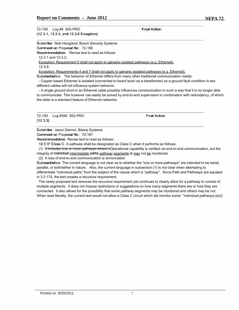
Report on Comments – June 2012 NFPA 72_______________________________________________________________________________________________72-158 Log #4 SIG-PRO
_______________________________________________________________________________________________Nick Hoogland, Bosch Security Systems
72-166Revise text to read as follows:
12.3.1 and 12.3.2:Exception: Requirement 5 shall not apply to galvanic isolated pathways (e.g. Ethernet).12.3.6:Exception: Requirements 4 and 7 shall not apply to galvanic isolated pathways (e.g. Ethernet).
The behavior of Ethernet differs from many other traditional communication media:- Copper based Ethernet is isolated (connected to board level via a transformer) so a ground fault condition in two
different cables will not influence system behavior.- A single ground short in an Ethernet cable possibly influences communication in such a way that it is no longer able
to communicate. This however can easily be solved by end-to-end supervision in combination with redundancy, of whichthe latter is a standard feature of Ethernet networks.
_______________________________________________________________________________________________72-159 Log #390 SIG-PRO
_______________________________________________________________________________________________Jason Damori, Biamp Systems
72-167Revise text to read as follows:
A pathway shall be designated as Class C when it performs as follows:(1) It includes one or more pathways where oOperational capability is verified via end-to-end communication, but the
integrity of individual intermediate paths pathway segments is may not be monitored.(2) A loss of end-to-end communication is annunciated
The current language is not clear as to whether the "one or more pathways" are intended to be serial,parallel, or both/either in nature. Also, the current language in subsection (1) is not clear when attempting todifferentiate “individual paths” from the subject of the clause which is “pathway”. Since Path and Pathways are equatedin 3.3.174, the text creates a recursive requirement.
The newly proposed text removes the recursive requirement yet continues to clearly allow for a pathway to consist ofmultiple segments. It does not impose restrictions or suggestions on how many segments there are or how they areconnected. It also allows for the possibility that some pathway segments may be monitored and others may be not.When read literally, the current text would not allow a Class C circuit which did monitor some` “individual pathways [sic]”.
7Printed on 9/20/2011
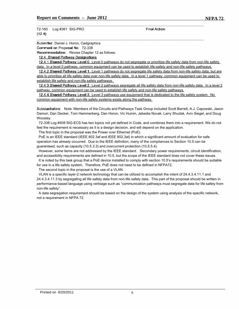
Report on Comments – June 2012 NFPA 72_______________________________________________________________________________________________72-160 Log #361 SIG-PRO
_______________________________________________________________________________________________Daniel J. Horon, Cadgraphics
72-338Revise Chapter 12 as follows:
Level 0 pathways do not segregate or prioritize life safety data from non-life safetydata. In a level 0 pathway, common equipment can be used to establish life-safety and non-life safety pathways.
Level 1 pathways do not segregate life safety data from non-life safety data, but areable to prioritize all life safety data over non-life safety data. In a level 1 pathway, common equipment can be used toestablish life safety and non-life safety pathways.
Level 2 pathways segregate all life safety data from non-life safety data. In a level 2pathway, common equipment can be used to establish life safety and non-life safety pathways.
Level 3 pathways use equipment that is dedicated to the life safety system. Nocommon equipment with non-life safety systems exists along the pathway.
Note: Members of the Circuits and Pathways Task Group included Scott Barrett, A.J. Capowski, JasonDamori, Dan Decker, Tom Hammerberg, Dan Horon, Vic Humm, Jebedia Novak, Larry Shudak, Aviv Siegel, and DougWoosley.
72-338 Log #408 SIG-ECS has two topics not yet defined in Code, and combines them into a requirement. We do notfeel the requirement is necessary as it is a design decision, and will depend on the application.
The first topic in the proposal was the Power over Ethernet (PoE).PoE is an IEEE standard (IEEE 802.3af and IEEE 802.3at) in which a significant amount of evaluation for safe
operation has already occurred. Due to the IEEE definition, many of the compliances to Section 10.5 can beguaranteed, such as capacity (10.5.3.3) and overcurrent protection (10.5.5.4).
However, some items are not addressed by the IEEE standard. Secondary power requirements, circuit identification,and accessibility requirements are defined in 10.5, but the scope of the IEEE standard does not cover these issues.
It is noted by this task group that a PoE device installed to comply with section 10.5’s requirements should be suitablefor use in a life safety system. Therefore, PoE does not need to be defined in NFPA72.
The second topic in the proposal is the use of a VLAN.VLAN is a specific layer-2 network technology that can be utilized to accomplish the intent of 24.4.3.4.11.1 and
24.4.3.4.11.3 by segregating all life safety data from non-life safety data. This part of the proposal should be written inperformance-based language using verbiage such as “communication pathways must segregate data for life safety fromnon-life safety”.
A data segregation requirement should be based on the design of the system using analysis of the specific network,not a requirement in NFPA 72.
8Printed on 9/20/2011

Report on Comments – June 2012 NFPA 72_______________________________________________________________________________________________72-161 Log #343 SIG-PRO
_______________________________________________________________________________________________Denise L. Pappas, Valcom, Inc.
72-338Add new text to read as follows:
- Level 0 pathways do not segregate or prioritize life safety data from non-life safetydata. In a level 0 pathway, common equipment can be used to establish life-safety and non-life safety pathways.
- Level 1 pathways do not segregate life safety data from non-life safety data. but areable to prioritize aU life safety data over non-life safety data. In a level 1 pathway, common equipment can be used toestablish life safety and non-life safety pathways.
- Level 2 pathways segregate all life safety data from non-life safety data. In a level 2pathway. common equipment can be used to establish life safety and non-life safety pathways.
- Level 3 pathways use eguipment that is dedicated to the life safety system. Nocommon equipment with non-life safety systems exists along the pathway.
- It is recommended that a VLAN utilized for life safety systems should be at aminimum a Shared Pathway Level 2 or a Shared Pathway Level 3. The higher levels guarantee the bandwidth requiredis dedicated to life safety pathways.
This proposal was originally submitted to Chapter 24, Emergency Communication Systems; however,it should have been submitted to Chapter 12, Circuits and Pathways.When designing a system, the specific layer-2 network technology known as a Virtual Local Area Network (VLAN) canbe utilized; however, the original language submitted was not written in performance based language. The proposedlanguage change is written in performance-based language. A data segregation requirement should be based on thedesign of the system using analysis of the specific network for the required application.
_______________________________________________________________________________________________72-214 Log #31 SIG-PRO
_______________________________________________________________________________________________Technical Correlating Committee on Signaling Systems for the Protection of Life and Property,
72-241The TCC makes reference to the recommendation to the TCC in the committee statement and
directs that this proposal be referred to the SIG-PRO committee for action. This shall be considered as a publiccomment.
This is a direction from the Technical Correlating Committee on Signaling Systems for the Protectionof Life and Property in accordance with 3.4.2 and 3.4.3 of the Regulations Governing Committee Projects.
_______________________________________________________________________________________________72-217 Log #32 SIG-PRO
_______________________________________________________________________________________________Technical Correlating Committee on Signaling Systems for the Protection of Life and Property,
72-243The TCC makes reference to the recommendation to the TCC in the committee statement and
directs that this proposal be referred to the SIG-PRO committee for action. This shall be considered as a publiccomment.
This is a direction from the Technical Correlating Committee on Signaling Systems for the Protectionof Life and Property in accordance with 3.4.2 and 3.4.3 of the Regulations Governing Committee Projects.
1Printed on 9/20/2011

Report on Comments – June 2012 NFPA 72_______________________________________________________________________________________________72-218 Log #18 SIG-PRO
_______________________________________________________________________________________________Technical Correlating Committee on Signaling Systems for the Protection of Life and Property,
72-244The TCC makes reference to the committee statement and the TCC directs that this proposal be
referred to the SIG-PRO committee for action.This is a direction from the Technical Correlating Committee on Signaling Systems for the Protection
of Life and Property in accordance with 3.4.2 and 3.4.3 of the Regulations Governing Committee Projects.
2Printed on 9/20/2011

Report on Comments – June 2012 NFPA 72_______________________________________________________________________________________________72-247 Log #59 SIG-PRO
_______________________________________________________________________________________________Technical Correlating Committee on Signaling Systems for the Protection of Life and Property,
72-270The TCC makes reference to the phrase “component servicing the emergency control function” used
in proposed 21.2.4 and in the definition for “emergency control function interface” added by Proposal 72-43 and advisesthat the phrase is not clear. The TCC directs the committee to reconsider the action on this proposal to better define the“component servicing …,” or add annex material to explain it.
This is a direction from the Technical Correlating Committee on Signaling Systems for the Protectionof Life and Property in accordance with 3.4.2 and 3.4.3 of the Regulations Governing Committee Projects.
_______________________________________________________________________________________________72-248 Log #91 SIG-PRO
_______________________________________________________________________________________________Technical Correlating Committee on Signaling Systems for the Protection of Life and Property,
72-271With regard to the phrase “component servicing the emergency control function” in proposed 21.2.9
and 21.2.10, the TCC makes reference to the TCC Action on Proposal 72-270 and directs the committee to reconsiderthe action on this proposal to provide clarity.
This is a direction from the Technical Correlating Committee on Signaling Systems for the Protectionof Life and Property in accordance with 3.4.2 and 3.4.3 of the Regulations Governing Committee Projects.
_______________________________________________________________________________________________72-251 Log #214 SIG-PRO
_______________________________________________________________________________________________Joshua Elvove, U.S. General Services Administration
72-279Revise so 21.3.3 reads as follows:.
21.3.3 Unless otherwise required by the authority having jurisdiction, only the elevator lobby, elevator hoistway, andelevator machine room smoke detectors, or other automatic fire detection as permitted by 21.3.7.
The action taken during ROP eliminated the option of using a waterflow switch to initiate elevatorrecall. Though waterflow switches are (rightfully) not permitted to initiate recall where sprinklers are installed at the top ofthe shaft, there’s no reason to prohibit using waterflow switches to initiate elevator recall where sprinklers are installed inthe pit, since there’s no need to shunt trip power to the elevator (there’s no risk of water affecting the elevator brakes orcontrols when a pit sprinkler activates). This change is needed to correlate with the change made by ROP-281 whichremoved the requirement for a detector in the pit.
10Printed on 9/20/2011

Report on Comments – June 2012 NFPA 72_______________________________________________________________________________________________72-252 Log #382 SIG-PRO
_______________________________________________________________________________________________David W. Frable, US General Services Administration
72-279Revise text to read as follows:
Unless otherwise required by the authority having jurisdiction, only the elevator lobby, elevator hoistway, andelevator machine room smoke detectors, or other automatic fire detection as permitted by 21.3.7, and initiating devicesused to initiate shutdown of elevator power in accordance with Section 21.4 shall be used to recall elevators for firefighters’ service.
The intent of this code change is to add the specific text that was deleted during the ROP. It should benoted that no technical substantiation was provided or were any examples provided that explained any problemsassociated with having the subject text remain. On the contrary, we believe that where elevator pit sprinklers areinstalled and elevator recall is required, an allowance should be made to permit a water flow switch to substitute for adetector as the means to initiate elevator recall (to the alternate floor), provided the waterflow switch and pit sprinkler areinstalled on a separately valved sprinkler line dedicated solely for protecting the elevator pit. Note: water flow from a pitsprinkler activation would NOT shunt power to the elevator because there is no concern that water flow in the pit willcause a problem to the elevator machine breaks.
_______________________________________________________________________________________________72-253 Log #162 SIG-PRO
_______________________________________________________________________________________________Thomas P. Hammerberg, Automatic Fire Alarm Association
72-280Change TC action to Reject.
Presently there are many smoke detectors located in elevator pits that are operating properly andwithout nuisance trip problems. Also, for those harsher pit environments, there are currently smoke detection productsspecifically made for that application. Some of these products also address the “difficult to access” issues.
11Printed on 9/20/2011

Report on Comments – June 2012 NFPA 72_______________________________________________________________________________________________72-254 Log #320 SIG-PRO
_______________________________________________________________________________________________Bruce Fraser, Fraser Fire Protection Services
72-280(1) Replace the text added by Proposal 280 with the following:
When sprinklers are installed in elevator pits, automatic fire detection shall be installed to initiate elevator recallin accordance with 2.27.3.2.1(c) of ANSI/ASME A.17.1/CSA B44, Safety Code for Elevators and Escalators.
Automatic fire detection can include smoke detectors, heat detectors, or sprinkler waterflow detection. Notethat the sprinkler waterflow detection should be without a delay similar to the requirement in 21.4.3. The location ofsmoke or heat detectors will, most likely, require special consideration in order to provide the intended response of earlydetection of fire in the elevator pit. The location of these detectors will likely need to be below the lowest level of recall inorder to provide an adequate response. Since there is no real ceiling at this location to allow installation using the usuallocation and spacing provisions of Chapter 17, the provisions of 17.7.3.1.3 and 17.7.3.1.4 should be considered whichallows detectors to be placed closer to the hazard in a position where the detector can intercept the smoke or heat. Alsorefer to A.21.3.12.2(3).It should be noted that smoke detectors installed in hoistways can be a source of nuisance activation. Hoistways willvary, so some hoistways could need smoke detectors specifically intended for those types of spaces (environments).
(2) Delete 2nd paragraph in A.21.3.12.2(3)Smoke detectors designed for installation in harsh environments and spaces such as elevator
hoistways (including elevator pits) are available. The revised subsection and related annex material will raise awarenessof the requirements of A17/B44 to install fire alarm initiating devices when sprinklers are installed at the bottom ofelevator hoistways. Guidance is provided for the location of smoke and heat detectors. This has previously been a greatsource of confusion for code users and these changes should bring clarity to this issue.
_______________________________________________________________________________________________72-255 Log #93 SIG-PRO
_______________________________________________________________________________________________Bruce Fraser, Fraser Fire Protection Services
72-280Change TC action to Reject Proposal 72-280.
Add new 21.3.6 and Annex A.21.3.6 to read as follows:21.3.6* When fire alarm initiating devices used to initiate elevator recall are installed in elevator hoistways as required
in 2.27.3.2.1(c) of ANSI/ASME A17.1/CSA B44, , because sprinklers arelocated in those hoistways, the following shall apply:
(1) Where sprinklers are located above the lowest level of recall, the fire alarm initiating device shall be located at thetop of the hoistway.
(2) Where sprinklers are located in the bottom of the hoistway (the pit), fire alarm initiating device(s) shall be installed inthe pit in accordance with Chapter 17.
(3) Outputs to the elevator controller(s) shall comply with 21.3.12.A.21.3.6 The use of smoke detection in elevator hoistways is not always appropriate, mostly because some hoistways
contain environments that are unsuitable for traditional smoke detectors. Smoke detection is the preferred detectionmethod as it provides the earliest initiation of recall. However, if smoke detection cannot be used, 21.3.7 permits otherdetection methods (usually heat detectors) to be used. It is worthwhile noting that the application of smoke or heatdetection in elevator hoistways should consider paragraphs 17.3.1.3 and 17.3.1.4* and associated Annex material whenlocating the devices.
● Today, thousands of smoke detectors are successfully used in elevator pits without experiencingnuisance recalls.
● Not all elevator pits are unsuitable for smoke detectors and are difficult to access.● Where environmental conditions are such that smoke detection should not be used, 21.3.7 permits other automatic
fire detection (such as heat detectors).● There are smoke detection products on the market today that are applied to harsh environments.● New Annex material provides clarification and advice on the subject of device location.
12Printed on 9/20/2011
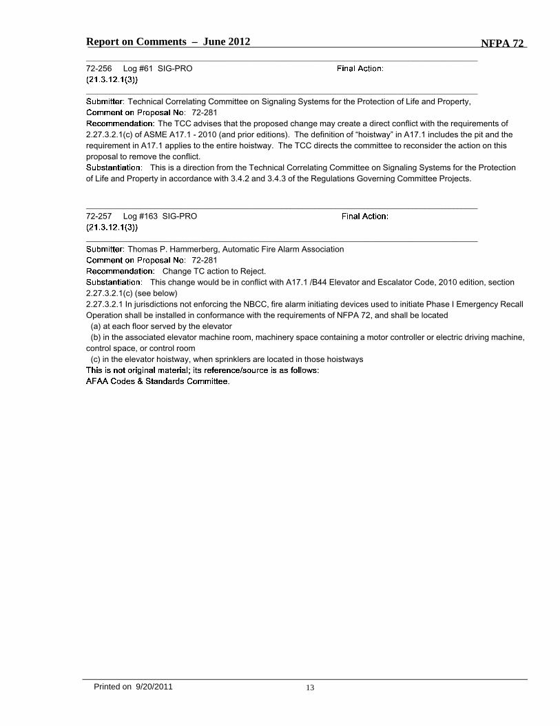
Report on Comments – June 2012 NFPA 72_______________________________________________________________________________________________72-256 Log #61 SIG-PRO
_______________________________________________________________________________________________Technical Correlating Committee on Signaling Systems for the Protection of Life and Property,
72-281The TCC advises that the proposed change may create a direct conflict with the requirements of
2.27.3.2.1(c) of ASME A17.1 - 2010 (and prior editions). The definition of “hoistway” in A17.1 includes the pit and therequirement in A17.1 applies to the entire hoistway. The TCC directs the committee to reconsider the action on thisproposal to remove the conflict.
This is a direction from the Technical Correlating Committee on Signaling Systems for the Protectionof Life and Property in accordance with 3.4.2 and 3.4.3 of the Regulations Governing Committee Projects.
_______________________________________________________________________________________________72-257 Log #163 SIG-PRO
_______________________________________________________________________________________________Thomas P. Hammerberg, Automatic Fire Alarm Association
72-281Change TC action to Reject.
This change would be in conflict with A17.1 /B44 Elevator and Escalator Code, 2010 edition, section2.27.3.2.1(c) (see below)2.27.3.2.1 In jurisdictions not enforcing the NBCC, fire alarm initiating devices used to initiate Phase I Emergency RecallOperation shall be installed in conformance with the requirements of NFPA 72, and shall be located
(a) at each floor served by the elevator(b) in the associated elevator machine room, machinery space containing a motor controller or electric driving machine,
control space, or control room(c) in the elevator hoistway, when sprinklers are located in those hoistways
13Printed on 9/20/2011
Report on Comments – June 2012 NFPA 72_______________________________________________________________________________________________72-258 Log #219 SIG-PRO
_______________________________________________________________________________________________Peter A. Larrimer, US Department of Veterans Affairs
72-281Retain the new verbiage. There should be no requirement for any fire alarm device in the pit, even
when sprinklers are installed per NFPA 13.I do not believe that there was intent to install a smoke detector just because a sprinkler was installed
in the bottom of the elevator pit.NFPA 13 indicates that a sprinkler is to be installed within 2 feet of the floor of the pit and ANSI indicates that the intentis to install a smoke detector when a sprinkler is installed above the two foot level.
NFPA 13 (2010) 8.15.5.1* Sidewall spray sprinklers shall be installed at the bottom of each elevator hoistway not morethan 2 ft (0.61 m) above the floor of the pit.A.8.15.5.1 The sprinklers in the pit are intended to protect against fires caused by debris, which can accumulate overtime. Ideally, the sprinklers should be located near the side of the pit below the elevator doors, where most debrisaccumulates. However, care should be taken that the sprinkler location does not interfere with the elevator toe guard,which extends below the face of the door opening.ASME A17.1, Safety Code for Elevators and Escalators, allows the sprinklers within 2 ft (0.65 m) of the bottom of the pitto be exempted from the special arrangements of inhibiting waterflow until elevator recall has occurred.
The ASME A17. Interpretation Inquiry: 05-39 shows that the intent is only when the sprinkler is installed above alevel 2 feet above the floor of the pit. See Underlined Text.
1Printed on 9/20/2011

Report on Comments – June 2012 NFPA 72_______________________________________________________________________________________________72-259 Log #383 SIG-PRO
_______________________________________________________________________________________________David W. Frable, US General Services Administration
72-282Revise text to read as follows:
Where heat detectors are used to shut down elevator power prior to sprinkler operation, the detector shall haveboth a lower temperature rating and a higher sensitivity as compared to the sprinkler.
When determining desired performance, consideration should be given to the temperature and time lagcharacteristics of both the sprinkler head and the heat detector to ensure as much as possible that the heat detector willoperate prior to the sprinkler head, because a lower temperature rating alone might not provide earlier response. Thelisted spacing rating of the heat detector should be 25 ft (7.6 m) or greater.
If heat detectors are used to shut down elevator power prior to sprinkler operation, they shall be placed within24 in. (610 mm) of each sprinkler head and be installed in accordance with the requirements of Chapter 17.Alternatively, engineering methods, such as those specified in Annex B,shall be permitted to be used to select and place heat detectors to ensure response prior to any sprinkler head operationunder a variety of fire growth rate scenarios.
Upon activation of the heat detector used for elevator power shutdown, there should be a delay in theactivation of the power shunt trip. This delay should be the time that it takes the elevator cab to travel from the top of thehoistway to the lowest recall level.
If pressure or waterflow switches are used to shut down elevator power immediately upon, or prior to, thedischarge of water from sprinklers, the use of devices with time-delay switches or time-delay capability shall not bepermitted.
Care should be taken to ensure that elevator power cannot be interrupted due to water pressure surges in thesprinkler system. The intent of the Code is to ensure that the switch and the system as a whole do not have thecapability of introducing a time delay into the sequence. The use of a switch with a time delay mechanism set to zerodoes not meet the intent of the Code, because it is possible to introduce a time delay after the system has beenaccepted. This might occur in response to unwanted alarms caused by surges or water movement, rather thanaddressing the underlying cause of the surges or water movement (often due to air in the piping). Permanently disablingthe delay in accordance with the manufacturer’s printed instructions should be considered acceptable. Systems thathave software that can introduce a delay in the sequence should be programmed to require a security password tomake such a change.
Control circuits to shut down elevator power shall be monitored for the presence of operating voltage. Loss ofvoltage to the control circuit for the disconnecting means shall cause a supervisory signal to be indicated at the controlunit and required remote annunciators.
Figure A.21.4.4 illustrates one method of monitoring elevator shunt trip control power for integrity.The initiating devices described in 21.4.2 and 21.4.3 shall be monitored for integrity by the fire alarm control unit
required in 21.3.1 and 21.3.2.The provisions of Section 21.4 shall apply where elevator equipment is located such that the application of
water from automatic fire sprinklers could cause unsafe elevator operation. The methods described below shalldisconnect the main line power supply to the affected elevator and any other power supplies used to move the elevatorprior to the application of water.
Heat detectors shall be configured to initiate the shut down elevator power prior to sprinkler operation.Each heat detector shall have both a lower temperature rating and a higher sensitivity as compared to the
sprinkler.When determining desired performance, consideration should be given to the temperature and time lag
characteristics of both the sprinkler and the heat detector to ensure as much as possible that the heat detector willoperate prior to the sprinkler, because a lower temperature rating alone might not provide earlier response. The listedspacing rating of the heat detector should be 25 ft (7.6 m) or greater.
Each heat detector shall be placed within 24 in. (610 mm) of each sprinkler and be installed in accordancewith the requirements of Chapter 17.
Alternatively, engineering methods, such as those specified in Annex B, shall be permitted to be used toselect and place heat detectors to ensure response prior to any sprinkler operation under a variety of fire growth ratescenarios.
Activation of the heat detector(s) shall meet the criteria stated either in 21.4.2.3.1 or 21.4.2.3.2.
15Printed on 9/20/2011

Report on Comments – June 2012 NFPA 72Activation of the heat detector(s) shall disconnect the main line power supply to the affected elevator(s)
immediately upon, or prior to, the discharge of water from sprinklers.Upon the activation of the heat detector used for elevator power shutdown, there should be no time delay.
The use of devices and time delay switches or a time-delay capability shall not be permitted. Any delay disconnectingthe power supply until the elevator is recalled to the lowest recall level may result in unintended consequences to theoccupants or fire fighters within the elevator cars should the automatic sprinklers operate prior to the elevators returningto the lowest recall level.
Activation of the heat detector(s) shall provide a signal to the elevator controller and the following sequenceof events shall occur:
(1)* The elevator controller shall automatically signal the elevator cars to proceed to the next closest landing.(2) The elevator car(s) SHALL park with the doors open(3) Main power to the affected elevator(s) is disconnected.
Upon activation of the heat detector used for elevator power shutdown, there should be a short delayin the activation of the power shunt trip. This delay should be the time that it takes the elevator cab to travel to the nextclosest landing.
If pressure switches and waterflow switches are used for disconnecting the main line power supply to theaffected elevator(s) immediately upon, or prior to, the discharge of water from sprinklers, the use of devices and timedelay switches or a time-delay capability shall not be permitted.
System designers and building maintenance personnel should be cautioned that the use of pressure switchesand waterflow switches to disconnect the main power supply may result in unwanted alarms and unwanted elevatorpower shutdowns resulting from pressure surges in the sprinkler systems.
Control circuits to shut down elevator power shall be monitored for the presence of operating voltage. Loss ofvoltage to the control circuit for the disconnecting means shall cause a supervisory signal to be indicated at the controlunit and required remote annunciators.
Figure A.21.4.4 illustrates one method of monitoring elevator shunt trip control power for integrity.The initiating devices described in 21.4.2 shall be monitored for integrity by the fire alarm control unit required in
21.3.1 and 21.3.2.The intent of this code change is to revise this Section to ensure that the main power supply to the
affected elevators is disconnected prior to the discharge of water from the automatic sprinkler system installed in themachine room. The current language permits the use of a heat detector utilizing a device having the capability to delaydisconnecting the power supply until the elevator is recalled to the lowest recall level; however, this may result inunintended consequences to the occupants or fire fighters within the elevator cars should the automatic sprinklersoperate prior to the elevators returning to the lowest recall level. In addition, currently the Code does not provide anyguidance regarding what the maximum timeframe for the time delay is acceptable.
In addition, I have proposed annex material when using a pressure switch and water flow switch as the sole method todisconnect power, since it is not reasonable to expect system designers and building maintenance personnel to take allrequired actions necessary to eliminate unwanted alarms resulting from pressure surges in a majority of sprinklersystems.
The new language proposed provides a safe and effective means to disconnect the main power supply to the affectedelevators by using heat detectors. If the heat detectors activate prior to the elevators being recalled to the lowest floorlevel, the new proposed text still permits a short time-delay for the affected elevators to travel to the next closest landingprior to disconnect the main power (e.g., earthquake mode software concept). The subject short time delay for elevatorcar travel should not be considered a major factor for occupant entrapment in the affected elevator cars, since theaffected elevator cars should only a short distance prior to being parked with doors open for the occupants to leave. Thisaction should occur well in advance of sprinkler operation.
16Printed on 9/20/2011

Report on Comments – June 2012 NFPA 72_______________________________________________________________________________________________72-260 Log #164 SIG-PRO
_______________________________________________________________________________________________Thomas P. Hammerberg, Automatic Fire Alarm Association
72-283Change TC action to Accept in Principle. Accept the original proposal, but accept the TC’s change
in the Annex material … “must” to “should”.Agree with explanation of negative by Josh Elvove. This application is specifically a fire service
requirement and should be designated as such. The IBC and NFPA Building and Construction codes now use theterminology “Fire Service Access Elevators”. NFPA 72 should correlate the terminology.
ELVOVE, J.: I do not concur with the action taken by the Technical Committee (TC) as the proposed use of the term“Fire Service Access Elevators”in lieu of “First Responders Use Elevators” correlates with both the 2012 edition of NFPA 5000 and the 2009 and 2012editions of the InternationalBuilding Code (IBC). In addition, conversely to what's stated in the Committee statement, the intent of these elevators
is to ensure that when thefire service arrives at the scene, they (the fire service) have a minimum number of elevator(s) at their disposal for
staging fire fighters and fire fightingequipment in tall buildings. Hence the terminology designated in both NFPA 5000 and the IBC. Note: the 2012 edition
of NFPA 5000 will be votedon by the membership at the NFPA Conference in June 2011.
_______________________________________________________________________________________________72-261 Log #181 SIG-PRO
_______________________________________________________________________________________________Brian D. Black, BDBlack Codes, Inc.
72-2831) Modify 21.5 in the committee action on Proposal 72-283 to use the term “fire service access
elevators” as originally recommended and shown below:
Where one or more elevators are specifically designated and marked as fire service access elevators for use by firstresponders during fires, the conditions specified in 21.5.1 for the elevators, associated lobbies, and machine rooms shallbe continuously monitored and displayed during any such use.
2) Retain the changes to 21.5.1 and 21.5.2 shown in the committee action on Proposal 72-283.3) Modify A.21.5.1(2) in the committee action on Proposal 72-283 as follows:
The information provided on Signals to the standard emergency service interface providing the status ofthe elevator(s), including location within the hoistway, direction of travel, and whether they are occupied should beprovided by the elevator management system.
1) The recommendation in Proposal 72-283 to use the term “fire service access elevators” should beaccepted. NFPA 5000 now uses the term “Fire Service Access Elevators” and IBC uses the term “Fire Service AccessElevators”. The features of the Fire Service Access Elevators were developed for the fire service and not for EMS orother emergency responders.
2) (Acceptance of changes to 21.5.1 and 21.5.2 is reaffirmed.)3) A.21.5.1(2) is revised to clarify that the information would be provided in the form of a signal from the elevator
management system, not in the form of a display.
17Printed on 9/20/2011
Report on Comments – June 2012 NFPA 72_______________________________________________________________________________________________72-262 Log #384 SIG-PRO
_______________________________________________________________________________________________David W. Frable, US General Services Administration
72-283Revise text to read as follows:
Where one or more elevators are specifically designated and marked as fire service access elevators for use by firstresponders during fires, the conditions specified in 21.5.1 for the elevators, associated lobbies, and machine rooms shallbe continuously monitored and displayed during any such use.
The conditions monitored and displayed shall include, but are not limited to, the following:(1) Availability of main and emergency power to operate the elevator(s), elevator controller(s), and machine room (if
provided) ventilation(2)* Status of the elevator(s), including location within the hoistway, direction of travel, position of landing doors, and
whether they are occupied(3) Temperature and presence of smoke in associated lobbies and machine room (if provided)
The conditions shall be displayed on a standard emergency services interface complying with Section 18.11.Add new annex text as follows:
The information provided on the status of the elevator(s), including location within the hoistway, directionof travel, and whether they are occupied should be provided by the elevator management system.
The revisions proposed for 21.5 are made to correlate terminology used for fire service accesselevators in the 2012 edition of NFPA 5000 and the IBC. The “position of landing doors” is deleted because it isunnecessary and is not required in NFPA 5000 or the IBC.
18Printed on 9/20/2011
Report on Comments – June 2012 NFPA 72_______________________________________________________________________________________________72-263 Log #385 SIG-PRO
_______________________________________________________________________________________________David W. Frable, US General Services Administration
72-284Revise text to read as follows:
Where one or more elevators are specifically designated and marked for use by occupants forevacuation during fires, they shall comply with all of the provisions of Sections 21.5 and 21.6.
The lobbies of elevators required by other governing codes or standards for use by occupants for evacuation infires shall be provided with a status indicator complying with Chapter 18.
The required status indicator shall display an illuminated green light and the message “Elevators available foroccupant evacuation” while the elevators are operating under normal service and the fire alarm system is in an alarmcondition, but before Phase I Emergency Recall Operation in accordance with ANSI/ASME A17.1a/CSA B44a,
, has been initiated.The required status indicator shall display an illuminated red light and the message “Elevators out of service,
use exit stairs” once the elevators are under Phase I or Phase II operation in accordance with ANSI/ASME A17.1a/CSAB44a, .
Outputs from the fire alarm system to the elevatorcontroller(s) shall be provided to implement elevator Occupant Evacuation Operation in accordance with Section 2.27 ofASME A17.1/CSA B44 (2013), , as required in 21.6.2.1 and 21.6.2.2.
Where an elevator or group of elevators is designated for use by occupants forevacuation, the provisions of 21.6.2.1.1 through 21.6.2.1.4 shall apply for partial evacuation.
Output signal(s) shall be provided to initiate elevator occupant evacuation operation uponautomatic or manual detection of a fire on a specific floor or floors as a result of either or both of the following:
(1) Activation of any automatic fire alarm initiating device in the building, other than an initiating device used forelevator Phase I Emergency Recall Operation in accordance with 21.3.12
(2)* Activation of manual means at the fire command center by authorized or emergency personnel.The manual means is intended in lieu of automatic initiating devices that are impaired or out of service
and would otherwise have actuated to provide automatic initiation in accordance with 21.6.2.1.1(2). Manual fire alarmboxes location throughout the building are not included because they are typically activated at locations remote from thefire and could lead to misinformation about the location of the fire.
(A) The output signal(s) shall identify each floor to be evacuated.(B) The identified floors shall be a contiguous block of floors including the following:(1) The floor with the first activated automatic initiating device.(2) Floors with any subsequently activated automatic initiating device(s).(3) Floors identified by manual means from the fire command center.(4) Two floors above the highest floor identified by 21.6.2.1.2(B)(1) through 21.6.2.1.2(B)(3).(5) Two floors below the lowest floor identified by 21.6.2.1.2(B)(1) through 21.6.2.1.2(B)(3).
The fire alarm system uses the floor identification to automatically establish a contiguous block of floors tobe evacuated consistent with 21.6.2.1.2(B). The established block of floors is updated to reflect changing conditions asindicated by the output signal(s). This information is sent to the elevator system and also used for occupant notification.The output signals from the fire alarm system can be in the form of contact closures or serial communications.Coordination needs to be provided between the fire alarm system installer and the elevator system installer.
.(A) A means shall be provided at the fire command center to allow the manual selection of floors.(B) The floors shall be selected on the basis of information from authorized or emergency personnel.
The in-building fire emergency voice/alarm communications system shall transmitcoordinated messages throughout the building.
(A) Voice evacuation messages shall be transmitted to the floors identified in 21.6.2.1.2 to indicate the need toevacuate.
(B) Messages shall be transmitted to the floors not being evacuated to inform occupants of evacuation status and shallinclude an indication that elevator service is not available.
Messages need to be coordinated with the operation of the elevators so that occupants understand what
19Printed on 9/20/2011

Report on Comments – June 2012 NFPA 72to expect and how to react. Additional visual information will be provided in each elevator lobby to further informoccupants of the status of the elevators.
Where an elevator or group of elevators is designated for use by occupants for evacuation,the provisions of 21.6.2.2.1 through 21.6.2.2.3 shall apply for complete evacuation.
Output(s) to signal elevator occupant evacuation operation for total evacuation shall be manually activatedfrom the fire command center by a means labeled “ ”.
The output(s) shall identify that all floors are to be evacuated.The in-building fire emergency voice/alarm communications system shall transmit an evacuation message
throughout the building to indicate the need to evacuate.The material being deleted from 21.6.2 is included in the more detailed requirements for elevator
status information included in the proposed Occupant Evacuation Operation (OEO) for A17.1/B44. The information willbe provided by the elevator system instead of the fire alarm system. The revisions being provided by new 21.6.2 forOEO are being made to correlate with the changes proposed for OEO in A17.1/B44. The proposed revisions have beendeveloped by the ASME A17 Task Group on Use of Elevators for Occupant Egress. The terminology used alsocorrelates with NFPA 101 and the IBC.
20Printed on 9/20/2011
Report on Comments – June 2012 NFPA 72_______________________________________________________________________________________________72-264 Log #182 SIG-PRO
_______________________________________________________________________________________________Brian D. Black, BDBlack Codes, Inc.
72-284Accept the changes shown in the recommendation of Proposal 72-284 as modified below:
1) Add 21.6.2.1.2(C) to read as follows:The identified floors shall be displayed on a standard emergency services interface along with the other elevator
status information required by 21.6.1.2) Modify 21.6.2.1.4 of the recommendation as follows:
The in-building fire emergency voice/alarm communications system shall transmitcoordinated messages throughout the building.
Automatic V voice evacuation messages shall be transmitted to the floors identified in 21.6.2.1.2 to indicate theneed to evacuate, and that elevator service is available.
Automatic voice Mmessages shall be transmitted to the floors not being evacuated to inform occupants ofevacuation status and shall include an indication that elevator service is not available.
Automatic voice messages shall be transmitted to the floors identified in 21.6.2.1.2 to indicate that elevator serviceis not available when all elevators have been recalled on Phase I Emergency Recall Operation.
All automatic voice messages shall be coordinated with the text displays provided separately by the elevatormanagement system.
3) Modify A.21.6.2.1.4 of the recommendation as follows:Messages need to be coordinated with the operation of the elevators so that occupants understand what
to expect and how to react. Additional visual information will be provided in each elevator lobby by the elevatormanagement system to further inform occupants of the status of the elevators.
4) Add A.21.6.2.1.4(C) to read as follows:This new message will require a signal from the elevator management system to the fire alarm
system.5) Modify 21.6.2.2 of the recommendation as follows:
Where an elevator or group of elevators is designated for use by occupants forevacuation, the provisions of 21.6.2.2.1 through 21.6.2.2.3 shall apply for total complete evacuation.
Output(s) to signal elevator occupant evacuation operation for total complete evacuation shall be manuallyactivated from the fire command center by a means labeled “ELEVATOR TOTAL FULL BUILDING EVACUATION”.
The output(s) shall identify that all floors are to be evacuated.The in-building fire emergency voice/alarm communications system shall transmit an evacuation message
throughout the building to indicate the need to evacuate.The changes recommended by Proposal 72-284 are intended to correlate with changes approved in
September 2011 for ANSI/ASME A17.1/B44 to address elevator Occupant Evacuation Operation.1 ) New 21.6.2.1.2(C): Addition of the floor identification zone to the status information display at the fire command
center is needed to keep fire service responders aware of the evacuation conditions.2) Revised 21.6.2.1.4: Changes have been provided to require that the voice message indicate availability of the
elevators and to clarify that the voice messages are automatic. Requirements have been added to include informationwhen the elevators are no longer available due to being recalled. Provisions were also added to ensure coordinationbetween text displays provided by the elevator management system and the voice messages provided by the fire alarmsystem.
3) Revised A.21.6.2.1.4: Changes are made to correlate with those in 21.6.2.1.4.4) New A.21.6.2.1.4(C): Addition of this annex material explains the interaction with the elevator management system.5) Revised 21.6.2.2: Changes are made to provide terminology. The use of the term “total” is consistent with
terminology used in NFPA 101, is one of the two terms used in NFPA 72, and is consistent with A17.1/B44 revisions.
21Printed on 9/20/2011

Report on Comments – June 2012 NFPA 72_______________________________________________________________________________________________72-265 Log #135 SIG-PRO
_______________________________________________________________________________________________Vince Baclawski, National Electrical Manufacturers Association (NEMA)
72-287Reject original proposal.
The acceptance of this proposal drastically changed the requirements of backup batteries for doorspowered by the fire alarm control unit. Before this proposed change, there was a requirement to power doors for 10minutes during a power loss. This requirement has been removed. This could mean that batteries in a fire alarm controlunit would be undersized and not able to perform as intended during a power failure when doors need to be powered bythe fire alarm.
With all of the talk of additional documentation to ensure a system performs as designed how can we accept thisproposal and delete minimum requirements for powering doors during a power failure. This also is a security matter, aswe sometimes want doors to remain locked during a power failure and not allow intruders into a facility during a powerfailure.
_______________________________________________________________________________________________72-266 Log #165 SIG-PRO
_______________________________________________________________________________________________Thomas P. Hammerberg, Automatic Fire Alarm Association
72-287Reword paragraph 21.9.1 as follows:
Any device or system intended to electrically lock a required means of egress door in the direction of egressshall be connected to interfaced with the fire alarm system serving the protected premises for the purpose of receivingan unlocking control signal.
Assign paragraph number to the following and renumber associated Annex A.21.9.3 to stay with it:Fire alarm control unit batteries shall not be utilized to maintain means of egress doors in the locked condition
unless the fire alarm control unit is arranged with circuitry and sufficient secondary power to ensure the means of egressdoors will unlock within 10 minutes of loss of primary power.
In revising this section, it appears important requirements were left out.Paragraph 21.9.1 addresses the important requirement of the fire alarm system providing unlocking information to the
means of egress doors under a fire condition.Paragraph 21.9.3 addresses an important requirement for the batteries that is not covered under 10.5.6 and appears
was inadvertently deleted.
22Printed on 9/20/2011

Report on Comments – June 2012 NFPA 72_______________________________________________________________________________________________72-267 Log #286 SIG-PRO
_______________________________________________________________________________________________Howard Sanders, Electronic Security Association
72-287Reject original proposal.
The acceptance of this proposal drastically changed the requirements of backup batteries for doorspowered by the fire alarm control unit. Before this proposed change, there was a requirement to power doors for 10minutes during a power loss. This requirement has been removed. This could mean that batteries in a fire alarm controlunit would be undersized and not able to perform as intended during a power failure when doors need to be powered bythe fire alarm.
With all of the talk of additional documentation to ensure a system performs as designed how can we accept thisproposal and delete minimum requirements for powering doors during a power failure. This also is a security matter, aswe sometimes want doors to remain locked during a power failure and not allow intruders into a facility during a powerfailure.
_______________________________________________________________________________________________72-268 Log #70 SIG-PRO
_______________________________________________________________________________________________Technical Correlating Committee on Signaling Systems for the Protection of Life and Property,
72-287aThe TCC advises that the annex material related to deleted 23.2.3 has not been addressed and
directs the committee to reconsider the action on this proposal to clarify the disposition of A.23.2.3.This is a direction from the Technical Correlating Committee on Signaling Systems for the Protection
of Life and Property in accordance with 3.4.2 and 3.4.3 of the Regulations Governing Committee Projects.
23Printed on 9/20/2011

Report on Comments – June 2012 NFPA 72_______________________________________________________________________________________________72-269 Log #391 SIG-PRO
_______________________________________________________________________________________________Jason Damori, Biamp Systems
72-292Revise text to read as follows:
The assignment of class designations to signaling line circuits shall be based on their performance capabilitiesunder abnormal (fault) conditions in accordance with the requirements for Class A, Class B, Class C, or Class Xpathways specified in Chapter 12 and the requirements of 23.6.2 through 23.6.5.
Faults, including but not limited to, An open circuits, short circuits, or ground faults, which affect the requiredoperation of the circuit shall result in the annunciation of a trouble signal.
Class B and Class C pathways shall maintain alarm capability during the application of a single ground fault.Class A and Class X pathways shall maintain alarm capability during the application of a single ground fault and
also during the application of a single open and a single ground fault.Where digital communications are used, inability to send or receive digital signals over a signaling line circuit
shall be indicated by a trouble signal.This comment confirms agreement with committee member Kern’s negative ballot vote explanation and
suggests alternate language to achieve the spirit of this proposal and that of 72-291. Current Code allows SLCs to beimplemented only with Class A, B, or X pathways, but should allow Class C as well.
The proposed language for 23.6.1 still presumes SLC pathways will be classified appropriately per Code requirementsin 23.4.3, yet limits SLCs from being classified with pathways which either don’t annunciate faults (Class D) or are notmonitored at all (Class E). There is little difference in the minimum performance specifications between Class B andClass C circuits in NFPA 72-2010, and because of the allowance for multiple pathways in Class C, Class C circuits canbe made more survivable than Class B; hence they should be allowed in SLCs.
The proposed language for 23.6.2 codifies the importance that anything (not just opens, shorts and grounds) thataffects the required behavior of the circuit should trigger a trouble signal.
The exception recognizes that systems with circuits which do not have galvanic isolation may need special treatment,but circuits with galvanic isolation are not prone to interfere in unusual ways with other circuits during fault conditions.
23.6.5 is stricken as it is redundant with the new language “which affect the required operation of the circuit” suggestedin 23.6.2.
_______________________________________________________________________________________________72-270 Log #336 SIG-PRO
_______________________________________________________________________________________________Carl F. Willms, Fire Security Technologies, Inc.
72-293Recommend the committee revert to my original proposal as I submitted.
Since 1898 NFPA signaling standards have continuously evolved to produce the current NFPA-72 thatestablishes the minimum required levels of performance, extent of redundancy, and quality of installation for fire alarmand signaling systems. Throughout the development of the code extensive efforts have been made to define theminimum requirements for reliability that have enhanced the protection of life and property.
However, with the technological advancements in communications technology, the code has not addressed the factthat a single short on a metallic SLC can completely disable an entire fire and life safety system placing lives at risk. Ibelieve my original proposal based on a concept of "SLC Zoning" provides the most flexible and cost effective means toprevent catastrophic system failures from SLC shorts.
24Printed on 9/20/2011

Report on Comments – June 2012 NFPA 72_______________________________________________________________________________________________72-271 Log #352 SIG-PRO
_______________________________________________________________________________________________Michael A. Anthony, University of Michigan / Rep. APPA.ORG - Leadership in Education | Association of
Education Facility Executives72-293
Accept the original proposal as written.How does the committee come up with a 50 percent criterion in the first place? "Balance", as used in
the committee statement may not reflect total owning cost of a fire protection system set against the risk of life andproperty.
Arbitrarily limiting the number of devices on an SLC is prohibitive and approaches the realm of restraint of trade. SLCZoning is not the first choice of fire alarm system designers in our industry but where budgets are grim it may be the onlychoice. The prospect of a fire-induced single short on a metallic SLC pathway totally disabling an entire fire alarm andlife safety system is an outcome we want to avoid -- preferably with a first-cost product solution suggested by theproposer. The additional cost of isolation modules (about $200 per floor) is a significant and least-cost approach forensuring fire safety in the protected premises.
_______________________________________________________________________________________________72-272 Log #369 SIG-PRO
_______________________________________________________________________________________________Harry M. Corson, IV, Siemens Industry
72-293Delete the following text:
23.6.6* No single pathway fault shall cause the loss of more than 50 addressable devices on a signaling line circuitWhile it is good practice to limit the extent of a single SLC it should not be accomplished in a
prescriptive manner through the use of arbitrary numbers that have no technical justification. The limits to which an SLCshould be subjected should be determined through the use of a Fire Risk Analysis and appropriate system design. Thefire and life safety of the building occupants would be better accomplished through the use of performance basedlanguage and engineering guidance.Also, as worded all network wiring on a large system would have to be installed as Class X. If any limitations are goingto be mandated it should specify signaling circuits made up of initiating devices not all SLCs.
_______________________________________________________________________________________________72-273 Log #396 SIG-PRO
_______________________________________________________________________________________________Donald Struck, Siemens Industry
72-293Delete text as follows:
23.6.6* No single pathway fault shall cause the loss of more than 50 addressable devices on a signaling line circuit.I do agree this is a good design practice, but this would require all signaling circuits with over 50 devices
to be installed as a Class A or Class X circuit. This would also apply to Master/Slave configurations which communicateusing Signaling Line Circuits that may be capable of operating in a degraded mode if the circuit has a fault. Reviewingmany of the site wiring topologies I have visited, this would be a huge financial burden. This proposal should bepermissible by code but not mandatory. I move to reject this proposal.
25Printed on 9/20/2011

Report on Comments – June 2012 NFPA 72_______________________________________________________________________________________________72-274 Log #399 SIG-PRO
_______________________________________________________________________________________________Paul R. Strelecki, Siemens Industry
72-293Delete text as follows:
No single pathway fault shall cause the loss of more than 50 addressable devices on a signaling line circuitRecommendation: Delete all of paragraph 23.6.6
Substantiation: While it is good practice to limit the extent of a single SLC it should not be accomplished in aprescriptive manner through the use of arbitrary numbers that have no technical justification. The limits to which anSLC should be subjected should be determined through the use of a Fire Risk Analysis and appropriate system design.The fire and life safety of the building occupants would be better accomplished through the use of performance basedlanguage and engineering guidance.Also, as worded all network wiring on a large system would have to be installed as Class X. If any limitations are goingto be mandated it should specify signaling circuits made up of initiating devices not all SLCs.
_______________________________________________________________________________________________72-275 Log #55 SIG-PRO
_______________________________________________________________________________________________Technical Correlating Committee on Signaling Systems for the Protection of Life and Property,
72-293The TCC advises that other subparagraphs of 23.6 have been deleted through the action on
Proposal 72-166 and incorporated in subparagraphs of 12.3. The TCC directs the committee to reconsider the action onthis proposal and consider whether proposed new 23.6.6 and A.23.6.6 should be correlated with Proposal 72-166 andmoved to 12.3.
This is a direction from the Technical Correlating Committee on Signaling Systems for the Protectionof Life and Property in accordance with 3.4.2 and 3.4.3 of the Regulations Governing Committee Projects.
26Printed on 9/20/2011

Report on Comments – June 2012 NFPA 72_______________________________________________________________________________________________72-276 Log #392 SIG-PRO
_______________________________________________________________________________________________Jason Damori, Biamp Systems
72-296Revise text to read as follows:
The assignment of class designations to notification appliance circuits shall be based on their performancecapabilities under abnormal (fault) conditions in accordance with the requirements for Class A, or Class B, Class C, orClass X, pathways specified in Chapter 12, as well as the requirements specified in 23.7.2 and 23.7.3.
An open or ground condition which affects the required operation of the circuit shall result in the annunciationof a trouble signal.
The circuit shall maintain alarm capability during the application of a single ground fault.This comment confirms agreement with committee member Kern’s negative ballot vote explanation and
suggests alternate language to achieve the spirit of this proposal and that of 72-295. Current Code allows NACs to beimplemented with Class A or B pathways, but should allow Class C and Class X pathways as well.
The proposed language for 23.7.1 still presumes NAC pathways will be classified appropriately per Code requirementsin 23.4.3, yet limits NACs from being classified with pathways which either don’t annunciate faults (Class D) or are notmonitored at all (Class E). There is little difference in the minimum performance specifications between Class B andClass C circuits in NFPA 72-2010, and because of the allowance for multiple pathways in Class C, Class C circuits canbe made more survivable than Class B; hence they should be allowed in NACs.
Perhaps a Class X circuit would be deemed as an expensive way of implementing a NAC, but the Code shouldn’tdisallow it due to its potential expense.
The proposed language for 23.7.2 clarifies that faults are a concern when they prevent the circuit from performing itsduty.
The exception recognizes that systems with circuits which do not have galvanic isolation may need special treatment,but circuits with galvanic isolation are not prone to interfere in unusual ways with other circuits during fault conditions.
_______________________________________________________________________________________________72-277 Log #226 SIG-PRO
_______________________________________________________________________________________________Doug Woosley, Valcom, Inc.
72-295Revise text to read as follows:
23.7.1 The assignment of class designations to notification appliance circuits shall be based on their performancecapabilities under abnormal (fault) conditions in accordance with the requirements for Class A, Class B, or Class Xpathways specified in Chapter 12, as well as the requirements specified in 23.7.2 and 23.7.3.
Although this proposal attempts to allow a viable technology for a NAC circuit, it does not describe theallowance in terms of performance, rather than exempting a specific technology. It does, however, bring up the fact thatshould such technology be used, there would be the ability to accomplish additional pathway classes for this circuit type.
Traditionally, the power on a NAC circuit is used to communicate special signals to an appliance. Voltage waveformshave been used in some cases to accomplish features such as strobe sync and selective appliance silence. There is notechnological reason why these circuit types could not also be accomplished with redundancy that meets thequalifications for a Class X pathway.
27Printed on 9/20/2011

Report on Comments – June 2012 NFPA 72_______________________________________________________________________________________________72-278 Log #225 SIG-PRO
_______________________________________________________________________________________________Doug Woosley, Valcom, Inc.
72-292Add a new circuit description type by inserting the following at 23.8 and renumbering appropriately:
23.8.1 The assignment of class designations to communication interconnect circuits shall be based on theirperformance capabilities under abnormal (fault) conditions in accordance with the requirements for Class A, Class B,Class C, or Class X pathways specified in Chapter 12 and the requirements of 23.8.2 through 23.8.3. Communicationinterconnect circuits can be comprised of segments that are different Class pathways. The pathways classrequirements shall be designated as part of the system design.
23.8.2 Communication interconnect circuits must maintain alarm capability during the application of a single groundfault in addition to the designated pathway class requirements.
23.8.3 Communication interconnect circuits must report changes in the communication pathway to maintainfunctionality due to fault conditions on Class A and Class X pathways.
A.23.8.3 This requirement is meant to describe performance of the circuit rather than to specify the types of faultconditions that could cause loss of a portion of the communication circuit. Class A and X pathways incorporateredundant pathways, but must report a fault condition when one exists on a damaged portion of the pathway.Traditionally, short circuits and open circuits are the typical causes of faults on the circuit, but modern equipment iscapable of evaluating degraded pathways that are not due to an electrically a short or open. A fault conditionencompasses anything that prevents the operation of that pathway.
This proposal should have been accept in principle. It brings up a need to uniquely identify the circuitsbetween two control units. Generally, most people perceive that the SLC only exists between a control unit and thedevices (i.e. IDCs, smoke detectors, contact monitors, emergency control function interface device, etc.). Thistraditional definition has been expanded to describe control unit to control unit communication. Therefore, it isimperative to create a control unit to control unit circuit definition to accommodate for this connection in terms ofperformance rather than a specific technology as originally proposed. The type of information and usage of circuits fromloop devices to control unit is considerably different than between control units. The inclusion and subsequent definitionof this new circuit should also replace the “communication link” that the SIG-ECS committee was forced to create sincethere was no applicable circuit type to describe the pathway to an MNS in 24.4.3.4.11.
Additionally, several proposals in this cycle propose different restrictions for particular circuit types (see 72-55, 72-293,72-294, etc.). Some of these include SLC restrictions and it was evident that the proposal was not meant to includecircuits between control units, further showing the need for a new circuit designation. This requested change allows fora comprehensive performance based circuit to support modern communication technologies and not on electricaldiagnostics.
_______________________________________________________________________________________________72-279 Log #287 SIG-PRO
_______________________________________________________________________________________________Howard Sanders, Electronic Security Association
72-302Add new text to read as follows:
23.8.2.7 Each interconnected fire alarm control unit shall be separately monitored for alarm, supervisory, and troubleconditions by Point ID and or by unique separate zones.
Interconnected devices should transmit a signal either unique or by a zone descriptor.
28Printed on 9/20/2011

Report on Comments – June 2012 NFPA 72_______________________________________________________________________________________________72-280 Log #331 SIG-PRO
_______________________________________________________________________________________________Jack Parow, International Association of Fire Chiefs (IAFC)
72-303Accept the proposal:
Interconnected fire alarm control unit alarm signals shall be permitted to be monitored by zone or bycombined common signals.
The purpose of this comment is to recommend that this code addition be approved as submitted. IfPoint Id throughout is approved, there is no longer a need to have zones or combined common signals. The purpose ofthis addition to the code is to reduce nuisance and unwanted fire alarms thereby reducing injury or loss of life to FirstResponders and/or to the public. Point ID increases the accuracy and reliability of the fire alarm system to enable themonitoring station to quickly determine if a fire exists and the magnitude of the fire. Having a more reliable alarm systemwill reduce the chance of loss of life. If there is a fire, the occupants should start evacuation before the First Respondersarrive. One of the positive net effects is emergency runs could be avoided.
_______________________________________________________________________________________________72-281 Log #288 SIG-PRO
_______________________________________________________________________________________________Howard Sanders, Electronic Security Association
72-303aRevise text to read as follows:
23.8.3.2.1. The actuation of a dwelling unit smoke alarm shall initiate a supervisory a fire warning signal at theprotected premises control unit and/or annunciator.
Section 23.8.3 addresses household fire alarm system. A smoke alarm is defined in section 3.3.251 asresponsive to smoke. A fire alarm signal in section 3.3.240.4 is defined as a signal initiated by a fire alarm initiatingdevice such as automatic fire detector or other device in which activation is indicative of the presence of fire or firesignature.
This submitter’s concern is household fire warning systems and questions whether 23.8.3.1 should be removed fromsig-pro. 23.8.3.5. does not allow the activation of an alarm at the protected premise however smoke alarms activate toissue a sound of warning so the code is not clear of the intent of the smoke alarm once it is connected to a protectedpremise household system.
29Printed on 9/20/2011

Report on Comments – June 2012 NFPA 72_______________________________________________________________________________________________72-282 Log #393 SIG-PRO
_______________________________________________________________________________________________Jason Damori, Biamp Systems
72-306Add new text to read as follows:
* For non-fire alarm equipment attached to a fire alarm circuit, either among the fire alarm devices or as abranch extension of the fire alarm pathways, requirements 23.8.4.3.1.1 through 23.8.4.3.1.7 shall apply
All the equipment and pathways shall meet the monitoring for integrity requirements of Section 10.17.All the equipment and pathways shall be maintained by a single service organization.All the equipment and pathways shall be installed in accordance with the requirements of this Code.All the equipment shall be listed as compatible with the fire alarm equipment or shall have a contact
closure interface listed for the connected load.The equipment shall be listed to the performance requirements specified in 10.14.1.Short circuits or open circuits in this equipment, or between this equipment and the fire alarm system
pathways, shall not impede or impair the monitoring for integrity of the fire alarm system or prevent alarm, supervisory,or fire safety control signals.
Ground faults in this equipment shall cause behavior consistent with the class of circuit to which theequipment is connected.
For non-fire alarm equipment attached to a fire alarm circuit via separate pathways, the requirements of23.8.4.3.2.1 through 23.8.4.3.2.2 shall apply.
Faults in this equipment shall not impede or impair the monitoring for integrity of the fire alarm system orprevent alarm, supervisory, or fire safety control signals.
Removal, replacement, failure, maintenance procedures, or ground on this hardware, software, or circuitsshall not impair the required operation of the fire alarm system.
This comment and substantiation applies to proposals 72-306 and 72-307 and is repeated in each.The justification for the original proposal did not sufficiently describe the multitude of issues with the current text and
wrongly concentrated on some implementation difficulties.The proposed text in this comment heavily borrows from the existing text. One major organization change is to
differentiate the two major clauses by whether the non-fire alarm equipment is connected to fire alarm pathways or not.The listing requirement then comes underneath the connected pathways clause.The intention of 23.8.4.3 is to ensure that non-fire alarm equipment attached to fire alarm system pathways doesn’taffect the performance of the fire alarm system. There are multiple problems with the current text in attempting toachieve that end.
(1) This section of the Code specifically allows non-fire alarm equipment listed for the voltage, temperature, andhumidity variations specified in 10.14.1 to be attached to fire alarm circuits, yet it leaves a loophole for equipment notlisted to those requirements. The clause used for non-listed equipment has no requirements for what the performanceshould be when attached to fire alarm circuits, nor does it explicitly disallow equipment which is not listed to thoserequirements.
(2) This section of the Code gives special allowances for certain kinds of faults (short circuits, open circuits) when thenon-fire alarm equipment is attached via separate pathways but not for other faults (ground faults). The special call-outfor grounds is unnecessary if grounds in the non-fire alarm equipment and pathways have no potential to affect the firealarm system.
(3) In the current 23.8.4.3.1.3 and 23.8.4.3.2.2, the requirement to handle grounds “in the same manner as grounds inthe rest of the fire alarm system” is too vague. Depending on the circuit or pathway in question, grounds may now or inthe future have different handling requirements in the rest of the fire alarm system. It is also unnecessary to requirestrict handling of grounds in non-fire alarm equipment if they have no potential to affect the fire alarm system equipmentand pathways.
(4) Being a little pedantic, but…In the current text of 23.8.4.3.1.3 and 23.8.4.3.2.2, grounds “between this equipmentand …” doesn’t make sense. For purposes of this Code, grounds don’t exist between two or more pieces of equipment(well, I suppose you could call a ground rod a piece of equipment) or between equipment and pathways. They existbetween one of those things and ground. Two pieces of equipment can be grounded, but that doesn’t mean they aregrounded together, it means they are grounded.
30Printed on 9/20/2011

Report on Comments – June 2012 NFPA 72_______________________________________________________________________________________________72-283 Log #394 SIG-PRO
_______________________________________________________________________________________________Jason Damori, Biamp Systems
72-307Add new text to read as follows:
Non-Fire Alarm Equipment.For non-fire alarm equipment attached to a fire alarm circuit, either among the fire alarm devices or as a
branch extension of the fire alarm pathways, requirements 23.8.4.3.1.1 through 23.8.4.3.1.7 shall applyAll the equipment and pathways shall meet the monitoring for integrity requirements of Section 10.17.All the equipment and pathways shall be maintained by a single service organization.All the equipment and pathways shall be installed in accordance with the requirements of this Code.All the equipment shall be listed as compatible with the fire alarm equipment or shall have a contact
closure interface listed for the connected load.The equipment shall be listed to the performance requirements specified in 10.14.1.Short circuits or open circuits in this equipment, or between this equipment and the fire alarm system
pathways, shall not impede or impair the monitoring for integrity of the fire alarm system or prevent alarm, supervisory,or fire safety control signals.
Ground faults in this equipment shall cause behavior consistent with the class of circuit to which theequipment is connected.
For non-fire alarm equipment attached to a fire alarm circuit via separate pathways, the requirements of23.8.4.3.2.1 through 23.8.4.3.2.2 shall apply.
Faults in this equipment shall not impede or impair the monitoring for integrity of the fire alarm system orprevent alarm, supervisory, or fire safety control signals.
Removal, replacement, failure, maintenance procedures, or ground on this hardware, software, or circuitsshall not impair the required operation of the fire alarm system.
This comment and substantiation applies to proposals 72-306 and 72-307 and is repeated in each.The justification for the original proposal did not sufficiently describe the multitude of issues with the current text and
wrongly concentrated on some implementation difficulties.The proposed text in this comment heavily borrows from the existing text. One major organization change is to
differentiate the two major clauses by whether the non-fire alarm equipment is connected to fire alarm pathways or not.The listing requirement then comes underneath the connected pathways clause.
The intention of 23.8.4.3 is to ensure that non-fire alarm equipment attached to fire alarm system pathways doesn’taffect the performance of the fire alarm system. There are multiple problems with the current text in attempting toachieve that end.
(1) This section of the Code specifically allows non-fire alarm equipment listed for the voltage, temperature, andhumidity variations specified in 10.14.1 to be attached to fire alarm circuits, yet it leaves a loophole for equipment notlisted to those requirements. The clause used for non-listed equipment has no requirements for what the performanceshould be when attached to fire alarm circuits, nor does it explicitly disallow equipment which is not listed to thoserequirements.
(2) This section of the Code gives special allowances for certain kinds of faults (short circuits, open circuits) when thenon-fire alarm equipment is attached via separate pathways but not for other faults (ground faults). The special call-outfor grounds is unnecessary if grounds in the non-fire alarm equipment and pathways have no potential to affect the firealarm system.
(3) In the current 23.8.4.3.1.3 and 23.8.4.3.2.2, the requirement to handle grounds “in the same manner as grounds inthe rest of the fire alarm system” is too vague. Depending on the circuit or pathway in question, grounds may now or inthe future have different handling requirements in the rest of the fire alarm system. It is also unnecessary to requirestrict handling of grounds in non-fire alarm equipment if they have no potential to affect the fire alarm system equipmentand pathways.
(4) Being a little pedantic, but…In the current text of 23.8.4.3.1.3 and 23.8.4.3.2.2, grounds “between this equipmentand …” doesn’t make sense. For purposes of this Code, grounds don’t exist between two or more pieces of equipment(well, I suppose you could call a ground rod a piece of equipment) or between equipment and pathways. They existbetween one of those things and ground. Two pieces of equipment can be grounded, but that doesn’t mean they aregrounded together, it means they are grounded.
31Printed on 9/20/2011

Report on Comments – June 2012 NFPA 72_______________________________________________________________________________________________72-284 Log #227 SIG-PRO
_______________________________________________________________________________________________Doug Woosley, Valcom, Inc.
72-306, 72-307Remove 23.8.4.3.1.3 and 23.8.4.3.2.2 or change to the following:
23.8.4.3.1.3 Ground in this equipment, or between this equipment and the fire alarm systems pathways, shall bereported, annunciated, and corrected in the same manner as grounds in the reset of the fire alarm system.
23.8.4.3.1.3 Pathways that are common to this equipment and the fire system shall monitor for integrity as described insection 10.17.
23.8.4.3.2.2 Ground in this equipment, or between this equipment and the fire alarm systems pathways, shall bereported, annunciated, and corrected in the same manner as grounds in the reset of the fire alarm system.
23.8.4.3.2.2 Pathways that are common to this equipment and the fire system shall monitor for integrity as described insection 10.17.
Ground fault detection on common wiring is already monitored for integrity as described in section10.17 as it is part of the fire system. It is not necessary to redefine it in this section. Currently 23.8.4.3.1.3 and23.8.4.3.2.2 reads, “Ground in this equipment…”. The literal translation of this passage would mean “any groundpresent in the equipment”. Nearly all non-fire equipment used in a combination system will have an earth groundpresent in the equipment for safety reasons. This should have read “Any ground fault in this equipment…”
Even if the passage read, “Any ground fault in this equipment…” it would require EVERY piece of non-fire equipmentused in a combination system to require ground fault detection system wide, not just on the common circuits. Thiswould span into many other market segments imposing new equipment requirements on security, HVAC, pagingsystems, lighting systems, and more.
In the 2010 NFPA 72 updates, this section was altered and the scope increased to impose more requirements onnon-fire equipment. In NFPA 72 2007 this section read as follows:
6.8.4.3* Short circuits, open circuits, or grounds in this equipment or between this equipment and the fire alarm systemwiring shall not interfere with the monitoring for integrity of the fire alarm system or prevent alarm, supervisory, or firesafety control signal transmissions.
To my knowledge, these systems have not incorporated ground fault detection in response to the 2010 changes. Theprior intent of this section was not to impose ground fault detection requirements on non-common pathways, but tomaintain the integrity of the life safety system. This is already accomplished in 10.17 and does not need to be redefinedfor combination systems. Furthermore, this moves the monitoring for integrity requirements to chapter 10, an initiativedirected by the TCC.
_______________________________________________________________________________________________72-285 Log #166 SIG-PRO
_______________________________________________________________________________________________Thomas P. Hammerberg, Automatic Fire Alarm Association
72-313Revise text to read as follows:
23.8.5.5.2 The number of waterflow alarm-initiating devices permitted to be connected to a single initiating devicecircuit shall be one not exceed five.
The combination of the fire sprinkler waterflow switch and fire alarm system is primarily to provideannunciation and location of the fire to responding fire departments, as referenced in the NFPA Fire ProtectionHandbook 20th edition. By having one waterflow switch per initiating circuit, will provide clear information for the firstresponders of the fire location. With today’s fire system technologies, this does not represent a cost impact, and doesrepresent the best minimum standard for life safety for occupants and first responders.
32Printed on 9/20/2011

Report on Comments – June 2012 NFPA 72_______________________________________________________________________________________________72-286 Log #332 SIG-PRO
_______________________________________________________________________________________________Jack Parow, International Association of Fire Chiefs (IAFC)
72-313 and 72-315Accept the proposal.
The number of waterflow alarm-initiating devices permitted to be connected to a single initiating devicecircuit shall be one not exceed five. And,
The number of supervisory signal-initiating devices permitted to be connected to a single initiating devicecircuit shall be one not exceed 20.
While this is not a cause on unwanted alarms, it is viewed as an operational issue. This is not aretroactive requirement and will only be for new systems.
The present language within the Standard allows for up to twenty supervisory devices to be placed on a single circuitor zone. This requirement came from a time in which this was the “State of the Art.” This is no longer the case.
From an operational perspective, if a fire protection supply valve is closed, a device as a single address can be easilyidentified and acted on. If a second valve is closed, a second signal will be initiated. For systems that have up to twentydevices on a single circuit, after the first activation, there would be no further activations in the event that other valvesare shut.
The single address also provides the location of which device has been actuated, as opposed to attempting to locate asingle device within a business park, large retail complex and so forth.
_______________________________________________________________________________________________72-287 Log #14 SIG-PRO
_______________________________________________________________________________________________Merton W. Bunker, Jr., US Department of State
72-314Accept Proposal 72-314, which results in new Section 23.8.5.5.3 to read as follows:
23.8.5.5.3 If a valve is installed in the connection between a suppression system and an initiating device, the valveshall be supervised in accordance with Chapter 17.
The TC statement is correct in stating that NFPA 13 does permit (but does not require) the supervisionof sprinkler system control valves by a fire alarm system. However, NFPA 13 is primarily concerned with the availabilityof the water supply to the sprinkler system. The text in NFPA 13, Section 8.16.1.1.2 confirms this statement:
" Valves on connections to water supplies, sectional control and isolation valves, and other valves insupply pipes to sprinklers and other fixed water-based fire suppression systems shall be supervised by one of thefollowing methods…”
Fire alarm system initiating devices installed on sprinkler systems are installed for the purposes of alarm initiation orsprinkler system supervision. Not all fire alarm attachments are installed for water supply supervision, as covered byNFPA 13, Section 8.16.1.1.2.1. Others may be provided to ensure essential to the correct operation of the fire alarmsystem or to provide alarm signal initiation. It is understood that valves are in the piping to allow servicing and repairs ofthe initiating devices.
The issue at hand is the security of the proper functionality of the fire alarm system initiating device. NFPA 72 has thescope to require functionality from the initiating device to occupant notification, to include a supervising station signaltransmission. It is possible that the closure of an isolation valve to an alarm initiating device that prevents initiation of asupervisory signal or an alarm signal constitutes a very serious risk. NFPA 13 does not address this issue, which isclearly under the scope of NFPA 72.
Closure of these valves will render the initiating device inoperative and may result in the loss of occupant notification ina fire, or operator notification that a suppression system is impaired. Therefore, it is imperative these valves besupervised by the fire alarm system.
33Printed on 9/20/2011

Report on Comments – June 2012 NFPA 72_______________________________________________________________________________________________72-288 Log #13 SIG-PRO
_______________________________________________________________________________________________Merton W. Bunker, Jr., US Department of State
72-316Accept Proposal 72-316, which results in new Section 23.8.5.6.3 to read as follows:
23.8.5.6.3 If a valve is installed in the connection between a suppression system and an initiating device, the valveshall be supervised in accordance with Chapter 17.
The TC statement is correct in stating that NFPA 13 does permit (but does not require) the supervisionof sprinkler system control valves by a fire alarm system. However, NFPA 13 is primarily concerned with the availabilityof the water supply to the sprinkler system. The text in NFPA 13, Section 8.16.1.1.2 confirms this statement:
" Valves on connections to water supplies, sectional control and isolation valves, and other valves insupply pipes to sprinklers and other fixed water-based fire suppression systems shall be supervised by one of thefollowing methods…”
Fire alarm system initiating devices installed on sprinkler systems are installed for the purposes of alarm initiation orsprinkler system supervision. Not all fire alarm attachments are installed for water supply supervision, as covered byNFPA 13, Section 8.16.1.1.2.1. Others may be provided to ensure essential to the correct operation of the fire alarmsystem or to provide alarm signal initiation. It is understood that valves are in the piping to allow servicing and repairs ofthe initiating devices.
The issue at hand is the security of the proper functionality of the fire alarm system initiating device. NFPA 72 has thescope to require functionality from the initiating device to occupant notification, to include a supervising station signaltransmission. It is possible that the closure of an isolation valve to an alarm initiating device that prevents initiation of asupervisory signal or an alarm signal constitutes a very serious risk. NFPA 13 does not address this issue, which isclearly under the scope of NFPA 72.
Closure of these valves will render the initiating device inoperative and may result in the loss of occupant notification ina fire, or operator notification that a suppression system is impaired. Therefore, it is imperative these valves besupervised by the fire alarm system.
34Printed on 9/20/2011

Report on Comments – June 2012 NFPA 72_______________________________________________________________________________________________72-289 Log #12 SIG-PRO
_______________________________________________________________________________________________Merton W. Bunker, Jr., US Department of State
72-317Accept Proposal 72-317, which results in new Section 23.8.5.6.4 to read as follows:
23.8.5.6.4 Supervisory signals shall distinctively indicate the particular function (e.g., valve position, temperature, orpressure) of the system that is off-normal and also indicate its restoration to normal.
The TC statement is correct in stating that NFPA 13 does permit (but does not require) the supervisionof sprinkler system control valves by a fire alarm system. However, NFPA 13 is primarily concerned with the availabilityof the water supply to the sprinkler system. The text in NFPA 13, Section 8.16.1.1.2 confirms this statement:
" Valves on connections to water supplies, sectional control and isolation valves, and other valves insupply pipes to sprinklers and other fixed water-based fire suppression systems shall be supervised by one of thefollowing methods…”
Fire alarm system initiating devices installed on sprinkler systems are installed for the purposes of alarm initiation orsprinkler system supervision. Not all fire alarm attachments are installed for water supply supervision, as covered byNFPA 13, Section 8.16.1.1.2.1. Others may be provided to ensure essential to the correct operation of the fire alarmsystem or to provide alarm signal initiation. It is understood that valves are in the piping to allow servicing and repairs ofthe initiating devices.
The issue at hand is the security of the proper functionality of the fire alarm system initiating device. NFPA 72 has thescope to require functionality from the initiating device to occupant notification, to include a supervising station signaltransmission. It is possible that the closure of an isolation valve to an alarm initiating device that prevents initiation of asupervisory signal or an alarm signal constitutes a very serious risk. NFPA 13 does not address this issue, which isclearly under the scope of NFPA 72.
Closure of these valves will render the initiating device inoperative and may result in the loss of occupant notification ina fire, or operator notification that a suppression system is impaired. Therefore, it is imperative these valves besupervised by the fire alarm system.
35Printed on 9/20/2011

Report on Comments – June 2012 NFPA 72_______________________________________________________________________________________________72-290 Log #11 SIG-PRO
_______________________________________________________________________________________________Merton W. Bunker, Jr., US Department of State
72-318Accept Proposal 72-317, which results in new Section 23.8.5.6.4 to read as follows:
23.8.5.6.4 Supervisory signals shall distinctively indicate the particular function (e.g., valve position, temperature, orpressure) of the system that is off-normal and also indicate its restoration to normal.
The TC statement is correct in stating that NFPA 13 does permit (but does not require) the supervisionof sprinkler system control valves by a fire alarm system. However, NFPA 13 is primarily concerned with the availabilityof the water supply to the sprinkler system. The text in NFPA 13, Section 8.16.1.1.2 confirms this statement:
" Valves on connections to water supplies, sectional control and isolation valves, and other valves insupply pipes to sprinklers and other fixed water-based fire suppression systems shall be supervised by one of thefollowing methods…”
Fire alarm system initiating devices installed on sprinkler systems are installed for the purposes of alarm initiation orsprinkler system supervision. Not all fire alarm attachments are installed for water supply supervision, as covered byNFPA 13, Section 8.16.1.1.2.1. Others may be provided to ensure essential to the correct operation of the fire alarmsystem or to provide alarm signal initiation. It is understood that valves are in the piping to allow servicing and repairs ofthe initiating devices.
The issue at hand is the security of the proper functionality of the fire alarm system initiating device. NFPA 72 has thescope to require functionality from the initiating device to occupant notification, to include a supervising station signaltransmission. It is possible that the closure of an isolation valve to an alarm initiating device that prevents initiation of asupervisory signal or an alarm signal constitutes a very serious risk. NFPA 13 does not address this issue, which isclearly under the scope of NFPA 72.
Closure of these valves will render the initiating device inoperative and may result in the loss of occupant notification ina fire, or operator notification that a suppression system is impaired. Therefore, it is imperative these valves besupervised by the fire alarm system.
36Printed on 9/20/2011
Report on Comments – June 2012 NFPA 72_______________________________________________________________________________________________72-291 Log #10 SIG-PRO
_______________________________________________________________________________________________Merton W. Bunker, Jr., US Department of State
72-319Accept Proposal 72-319, which results in new Section 23.8.5.7.4 to read as follows:
23.8.5.7.4 Supervisory signals shall distinctively indicate the particular function (e.g., valve position, temperature, orpressure) of the system that is off-normal and also indicate its restoration to normal.
The TC statement is correct in stating that NFPA 13 does permit (but does not require) the supervisionof sprinkler system control valves by a fire alarm system. However, NFPA 13 is primarily concerned with the availabilityof the water supply to the sprinkler system. The text in NFPA 13, Section 8.16.1.1.2 confirms this statement:
" Valves on connections to water supplies, sectional control and isolation valves, and other valves insupply pipes to sprinklers and other fixed water-based fire suppression systems shall be supervised by one of thefollowing methods…”
Fire alarm system initiating devices installed on sprinkler systems are installed for the purposes of alarm initiation orsprinkler system supervision. Not all fire alarm attachments are installed for water supply supervision, as covered byNFPA 13, Section 8.16.1.1.2.1. Others may be provided to ensure essential to the correct operation of the fire alarmsystem or to provide alarm signal initiation. It is understood that valves are in the piping to allow servicing and repairs ofthe initiating devices.
The issue at hand is the security of the proper functionality of the fire alarm system initiating device. NFPA 72 has thescope to require functionality from the initiating device to occupant notification, to include a supervising station signaltransmission. It is possible that the closure of an isolation valve to an alarm initiating device that prevents initiation of asupervisory signal or an alarm signal constitutes a very serious risk. NFPA 13 does not address this issue, which isclearly under the scope of NFPA 72.
Closure of these valves will render the initiating device inoperative and may result in the loss of occupant notification ina fire, or operator notification that a suppression system is impaired. Therefore, it is imperative these valves besupervised by the fire alarm system.
37Printed on 9/20/2011

Report on Comments – June 2012 NFPA 72_______________________________________________________________________________________________72-292 Log #9 SIG-PRO
_______________________________________________________________________________________________Merton W. Bunker, Jr., US Department of State
72-320Accept Proposal 72-320, which results in new Section 23.8.5.8.3 to read as follows:
23.8.5.8.3 If a valve is installed in the connection between a suppression system and an initiating device, the valveshall be supervised in accordance with Chapter 17.
The TC statement is correct in stating that NFPA 13 does permit (but does not require) the supervisionof sprinkler system control valves by a fire alarm system. However, NFPA 13 is primarily concerned with the availabilityof the water supply to the sprinkler system. The text in NFPA 13, Section 8.16.1.1.2 confirms this statement:" Valves on connections to water supplies, sectional control and isolation valves, and other valves in
supply pipes to sprinklers and other fixed water-based fire suppression systems shall be supervised by one of thefollowing methods…”.
Fire alarm system initiating devices installed on sprinkler systems are installed for the purposes of alarm initiation orsprinkler system supervision. Not all fire alarm attachments are installed for water supply supervision, as covered byNFPA 13, Section 8.16.1.1.2.1. Others may be provided to ensure essential to the correct operation of the fire alarmsystem or to provide alarm signal initiation. It is understood that valves are in the piping to allow servicing and repairs ofthe initiating devices.
The issue at hand is the security of the proper functionality of the fire alarm system initiating device. NFPA 72 has thescope to require functionality from the initiating device to occupant notification, to include a supervising station signaltransmission. It is possible that the closure of an isolation valve to an alarm initiating device that prevents initiation of asupervisory signal or an alarm signal constitutes a very serious risk. NFPA 13 does not address this issue, which isclearly under the scope of NFPA 72.
Closure of these valves will render the initiating device inoperative and may result in the loss of occupant notification ina fire, or operator notification that a suppression system is impaired. Therefore, it is imperative these valves besupervised by the fire alarm system.
38Printed on 9/20/2011

Report on Comments – June 2012 NFPA 72_______________________________________________________________________________________________72-293 Log #8 SIG-PRO
_______________________________________________________________________________________________Merton W. Bunker, Jr., US Department of State
72-321Accept Proposal 72-321, which results in new Section 23.8.5.8.4 to read as follows:
23.8.5.8.4 Supervisory signals shall distinctively indicate the particular function (e.g., valve position, temperature, orpressure) of the system that is off-normal and also indicate its restoration to normal.
The TC statement is correct in stating that NFPA 13 does permit (but does not require) the supervisionof sprinkler system control valves by a fire alarm system. However, NFPA 13 is primarily concerned with the availabilityof the water supply to the sprinkler system. The text in NFPA 13, Section 8.16.1.1.2 confirms this statement:
" Valves on connections to water supplies, sectional control and isolation valves, and other valves insupply pipes to sprinklers and other fixed water-based fire suppression systems shall be supervised by one of thefollowing methods…"
Fire alarm system initiating devices installed on sprinkler systems are installed for the purposes of alarm initiation orsprinkler system supervision. Not all fire alarm attachments are installed for water supply supervision, as covered byNFPA 13, Section 8.16.1.1.2.1. Others may be provided to ensure essential to the correct operation of the fire alarmsystem or to provide alarm signal initiation. It is understood that valves are in the piping to allow servicing and repairs ofthe initiating devices.
The issue at hand is the security of the proper functionality of the fire alarm system initiating device. NFPA 72 has thescope to require functionality from the initiating device to occupant notification, to include a supervising station signaltransmission. It is possible that the closure of an isolation valve to an alarm initiating device that prevents initiation of asupervisory signal or an alarm signal constitutes a very serious risk. NFPA 13 does not address this issue, which isclearly under the scope of NFPA 72.
Closure of these valves will render the initiating device inoperative and may result in the loss of occupant notification ina fire, or operator notification that a suppression system is impaired. Therefore, it is imperative these valves besupervised by the fire alarm system.
39Printed on 9/20/2011
Report on Comments – June 2012 NFPA 72_______________________________________________________________________________________________72-294 Log #7 SIG-PRO
_______________________________________________________________________________________________Merton W. Bunker, Jr., US Department of State
72-322Accept Proposal 72-322, which results in new Section 23.8.5.9.3 to read as follows:
23.8.5.9.3 If a valve is installed in the connection between a suppression system and an initiating device, the valveshall be supervised in accordance with Chapter 17.
The TC statement is correct in stating that NFPA 13 does permit (but does not require) the supervisionof sprinkler system control valves by a fire alarm system. However, NFPA 13 is primarily concerned with the availabilityof the water supply to the sprinkler system. The text in NFPA 13, Section 8.16.1.1.2 confirms this statement:" Valves on connections to water supplies, sectional control and isolation valves, and other valves in
supply pipes to sprinklers and other fixed water-based fire suppression systems shall be supervised by one of thefollowing methods…”
Fire alarm system initiating devices installed on sprinkler systems are installed for the purposes of alarm initiation orsprinkler system supervision. Not all fire alarm attachments are installed for water supply supervision, as covered byNFPA 13, Section 8.16.1.1.2.1. Others may be provided to ensure essential to the correct operation of the fire alarmsystem or to provide alarm signal initiation. It is understood that valves are in the piping to allow servicing and repairs ofthe initiating devices.
The issue at hand is the security of the proper functionality of the fire alarm system initiating device. NFPA 72 has thescope to require functionality from the initiating device to occupant notification, to include a supervising station signaltransmission. It is possible that the closure of an isolation valve to an alarm initiating device that prevents initiation of asupervisory signal or an alarm signal constitutes a very serious risk. NFPA 13 does not address this issue, which isclearly under the scope of NFPA 72.
Closure of these valves will render the initiating device inoperative and may result in the loss of occupant notification ina fire, or operator notification that a suppression system is impaired. Therefore, it is imperative these valves besupervised by the fire alarm system.
40Printed on 9/20/2011
Report on Comments – June 2012 NFPA 72_______________________________________________________________________________________________72-295 Log #6 SIG-PRO
_______________________________________________________________________________________________Merton W. Bunker, Jr., US Department of State
72-324Accept Proposal 72-324, which results in new Section 23.8.5.9.4 to read as follows:
23.8.5.9.4 Supervisory signals shall distinctively indicate the particular function (e.g., valve position, temperature, orpressure) of the system that is off-normal and also indicate its restoration to normal.
The TC statement is correct in stating that NFPA 13 does permit (but does not require) the supervisionof sprinkler system control valves by a fire alarm system. However, NFPA 13 is primarily concerned with the availabilityof the water supply to the sprinkler system. The text in NFPA 13, Section 8.16.1.1.2 confirms this statement:
" Valves on connections to water supplies, sectional control and isolation valves, and other valves insupply pipes to sprinklers and other fixed water-based fire suppression systems shall be supervised by one of thefollowing methods."
Fire alarm system initiating devices installed on sprinkler systems are installed for the purposes of alarm initiation orsprinkler system supervision. Not all fire alarm attachments are installed for water supply supervision, as covered byNFPA 13, Section 8.16.1.1.2.1. Others may be provided to ensure essential to the correct operation of the fire alarmsystem or to provide alarm signal initiation. It is understood that valves are in the piping to allow servicing and repairs ofthe initiating devices.
The issue at hand is the security of the proper functionality of the fire alarm system initiating device. NFPA 72 has thescope to require functionality from the initiating device to occupant notification, to include a supervising station signaltransmission. It is possible that the closure of an isolation valve to an alarm initiating device that prevents initiation of asupervisory signal or an alarm signal constitutes a very serious risk. NFPA 13 does not address this issue, which isclearly under the scope of NFPA 72.
Closure of these valves will render the initiating device inoperative and may result in the loss of occupant notification ina fire, or operator notification that a suppression system is impaired. Therefore, it is imperative these valves besupervised by the fire alarm system.
_______________________________________________________________________________________________72-298 Log #333 SIG-PRO
_______________________________________________________________________________________________Jack Parow, International Association of Fire Chiefs (IAFC)
72-331Accept the proposal:
23.12.1 Protected premises fire alarm systems shall be arranged to annunciate alarm, supervisory, and trouble signalsby Point ID in accordance with Section 10.16.
The purpose of this comment is to recommend that this code addition be approved as submitted. Theremay be a negligible increase in costs by using Point ID throughout. Point ID takes advantage of current technology andmakes the alarm system truly intelligent and addressable. Each initiating device will cover its own little zone and allowbetter tracking by location of which devices are activated. This should result in earlier and more accurate detection,thereby, reducing the number of nuisance or unwanted fire alarm calls.
41Printed on 9/20/2011

Report on Comments – June 2012 NFPA 72_______________________________________________________________________________________________72-301 Log #51 SIG-PRO
_______________________________________________________________________________________________Technical Correlating Committee on Signaling Systems for the Protection of Life and Property,
72-338The TCC makes reference to the suggestion in the committee statement and advises that proposals
on the use of the Ethernet fall under the purview of the SIG-PRO committee (not SIG-FUN) and directs that thisproposal be referred to the SIG-PRO committee for action.
This is a direction from the Technical Correlating Committee on Signaling Systems for the Protectionof Life and Property in accordance with 3.4.2 and 3.4.3 of the Regulations Governing Committee Projects.
_______________________________________________________________________________________________72-440 Log #1 SIG-PRO
_______________________________________________________________________________________________Daniel Winslow, CNY Elevator Consultants
72-587Revise text to read as follows:
A.21.4.2 Upon Activation the heat detector used for elevator power shutdown, the relay activation must be immediateto establish a beginning timeline for any jurisdiction, elevator vendor or code requiring delay. there should be a delay inthe activation of shunt trip. This delay should be the time what it takes the elevator cab to travel from the top of thehoistway to the lowest recall level.
Calculation of the time required to permit recall as an engineered option is clearly permitted in 21.4.2and should be permitted (where preaction sprinkler systems are used for example.) Clearly the intent of 21.4.2 is topermit an engineered solution which could include delaying shunt trip "prior to application of water." The elevator codeonly requires that shunt trip take place prior to upon application of water, there is no reason to arbitrarily prevent delayafter heat detector activation under every circumstance. The current wording was consistent with 20-years of code intentand should have been maintained.
(NOTE: The suggested inserted text above is the existing wording.)
_______________________________________________________________________________________________72-441 Log #173 SIG-PRO
_______________________________________________________________________________________________Thomas P. Hammerberg, Automatic Fire Alarm Association
72-587Modify the original A.21.4.2 to read as follows:
Upon activation of the heat detector used for elevator power shutdown, there should can be a delay in theactivation of the power shunt trip. When such a delay is used, it is recommended that the This delay should beapproximately the time that it takes the elevator cab car to travel from the top of the hoistway to the lowest recall level.The purpose of the delay of the shunt trip is to increase the potential for elevators to complete their travel to the recalllevel. It is important to be aware that the requirements of A17.1/B44 Safety Code for Elevators and Escalators relative tosprinkler water release and power shut-down would still apply.
This wording more clearly reflects the original intent of this Annex material. Thepresumptions/assumptions in the original proposal and TC action appear to be questionable. The “delay strategy” hasbeen used for years and often the delay is initiated and controlled by the fire alarm system. Many systems are alreadyutilizing the delay function. Additionally, there are products specifically designed for the delay application. The delay isinitiated by the actuation of the first fire alarm initiating device that initiates recall.
42Printed on 9/20/2011

Report on Comments – June 2012 NFPA 72_______________________________________________________________________________________________72-442 Log #174 SIG-PRO
_______________________________________________________________________________________________Thomas P. Hammerberg, Automatic Fire Alarm Association
72-600aAdd new text to read as follows:
Protected premises fire alarm systems that serve the general fire alarmneeds of a building or buildings shall include one or more of the following systems or functions:
(1) Manual fire alarm signal initiation(2) Automatic fire alarm and supervisory signal initiation(3) Monitoring of abnormal conditions in fire suppression systems(4) Activation of fire suppression systems(5) Activation of fire safety functions(6) Activation of fire alarm notification appliances(7) In-building fire emergency voice/alarm communications(8) Guard’s tour supervisory service(9) Process monitoring supervisory systems(10) Activation of off-premises signals(11) Combination systemsA.23.3.3.1 The following functions are included in Annex A to provide guidelines for utilizing building systems and
equipment in addition to proprietary fire alarm equipment in order to provide life safety and property protection.Buildingfunctions that should be initiated or controlled during a fire alarm condition include, but should not be limited to, thefollowing:
(1) Elevator operation consistent with ANSI/ASME A17.1a/CSA B44a,(2) Unlocking of stairwell and exit doors NFPA 80,
NFPA 101,(3) Release of fire and smoke dampers NFPA 90A,
, and NFPA 90B,(4) Monitoring and initiating of self-contained automatic fire extinguishing system(s) or suppression system(s) and
equipment NFPA11, ; NFPA 12,; NFPA 12A, NFPA 13,
NFPA14, NFPA15, NFPA 17,
NFPA 17A, NFPA 750,
My original proposal (72-600a, Log #607 (SIG-SSS) to revise paragraph A.26.4.2.4 was rejected dueto the previous deletion of paragraph 26.4.2.4 in the body of the standard and that annex paragraph during the ROPprocess (See Committee Action Proposal 72-474a, Log #616 (SIG-SSS) (Accepted).
In the rejection of my proposal, the Technical Committee stated…”The proposed references as well as thosecontained in the deleted annex section are important references that do not belong in Chapter 26 but should be retainedperhaps in the annex material associated with another chapter of the code (such as Chapter 23). The submitter isencouraged to provide public comments to accomplish this”. This amended Proposal/Comment contains the steps toaccomplish that suggestion.
Paragraph 23.3.3.1 now has an asterisk * reference added to it directing the user to a new Annex entry A.23.3.3.1incorporating the text from the former Annex (now deleted) paragraph A.26.4.2.4 as recommended by the committee.The addition of NFPA 750, Standard on Water Mist Fire Protection Systems has also been added to the original annextext. Since all other forms of fire suppression systems are listed in Line #4 of the original text “except” NFPA 750, it’sbeen added to provide a complete list of references. NFPA 750 Standard on Water Mist Fire Protection Systems fallinto the same category of Monitoring and Initiating as the others listed.
Since Water Mist fire suppression systems have been approved and installed in a wide range of sprinkler applicationsglobally and their monitoring, initiating, alarm and detection devices and installation must adhere to NFPA 72requirements, the NFPA 750 Standard on Water Mist Fire Protection Systems should be included in NFPA 72 as aReferenced Publication. NFPA 72 is referenced in Chapter 2 of NFPA 750 and they should complement one another asreference documents.
Also, since there is a generic reference in NFPA 72 to “Fire Suppression System Other Than Sprinklers” in sections
43Printed on 9/20/2011

Report on Comments – June 2012 NFPA 72such as 23.8.5.7 and 23.8.5.8 and Water Mist Systems may satisfy that requirement on a job, NFPA 750 should beincluded as a document of reference in the Annex. For installations of water mist fire suppression systems, design andinstallation requirements shall be determined by NFPA 750 Standard on Water Mist Fire Protection Systems. Thischange is proposed for avoidance of confusion by AHJs in reviewing plans and installations for water mist. Theaddition of the wording will direct AHJs to the correct standard when a Water Mist System and its equipment are usedas the automatic fire extinguishing or suppression system.
_______________________________________________________________________________________________72-443 Log #408 SIG-PRO
_______________________________________________________________________________________________Lynn Nielson, City of Henderson
72-294Add text to read as follows:
Distributed emergency voice/alarm communication notification appliance circuits power tap settings should be selectedto keep the sum of the taps below 80% of the power amplifiers rating.
Using this design method the individual transformer impedance does not need to be considered by theAHJ.
_______________________________________________________________________________________________72-444 Log #407 SIG-PRO
_______________________________________________________________________________________________Lynn Nielson, City of Henderson
72-297
****Insert Include 72_L407_R Here****
System design and installation literature often directs system installers to contact or consult with theauthority having jurisdiction for specific requirements related to line loss. The methods presented herein provide ameans for the authority having jurisdiction to judge the suitability of the line loss. Keeping the line loss below12.5%provides for consistency of the speaker output throughout the circuit.
44Printed on 9/20/2011

1 NFPA 72 Log #407 Rec A2012 ROC
Add text to read as follows: A23.7.4 Emergency Voice/Alarm Communication Notification Appliance Circuits. Emergency voice/alarm communication notification appliance circuits should be capable of full-load operation with a wiring power loss not to exceed 12.5% (0.5dB) as determined in accordance with Sections 23.7.4.1, 23.7.4.2 or 23.7.4.3. A23.7.4.1 Power Loss Calculations. A calculation for each circuit shouldl be provided to the authority having jurisdiction demonstrating simultaneous full-load operation with a wiring power loss not to exceed 12.5% (0.5dB). Power loss calculations similar to the following couldl be used: Note: The calculations that follow are based on two conductors.
PLoss = 10 * Log [1 - ((2 * RL) / (2 * RL + (VLine squared / PRated))] RL = (RRef / 1000) * D With variables defined as follows: D = length of wire used (in feet) PLoss = power loss (in dB) PRated = power driven on line from the amplifier (in watts) RL = wire gauge resistance (in ohms) RRef = wire resistance based on gauge of wire used (in ohms/1000 ft.) VLine = voltage on line (typically 25 volts or 70 volts) Alternatively the distance may be calculated using a calculation similar to: D = (61 / RRef) * (VLine squared / PRated)
A23.7.4.2 Power Loss Tables. To ensure circuits are capable of simultaneous full-load operation with a wiring power loss not to exceed 12.5% (0.5dB), wiring shouldl be limited to the distance allowed in Tables A23.7.4.2.a and A23.7.4.2.b. Table A23.7.4.2.a, 25 V Circuit Loudspeaker Distribution Cable Length (in feet) and Gauge for 0.5-dB Loss Wire Gauge (AWG) 18 16 14 12 10 Cable Ohms* 7.77 4.89 3.07 1.93 1.21 Circuit Power 200 25 39 62 99 158 150 33 52 83 132 210 100 49 78 124 198 315 75 65 104 166 263 420 60 82 130 207 329 525
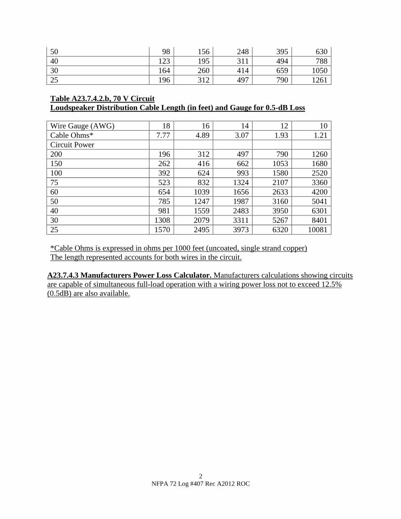
2 NFPA 72 Log #407 Rec A2012 ROC
50 98 156 248 395 630 40 123 195 311 494 788 30 164 260 414 659 1050 25 196 312 497 790 1261 Table A23.7.4.2.b, 70 V Circuit Loudspeaker Distribution Cable Length (in feet) and Gauge for 0.5-dB Loss Wire Gauge (AWG) 18 16 14 12 10 Cable Ohms* 7.77 4.89 3.07 1.93 1.21 Circuit Power 200 196 312 497 790 1260 150 262 416 662 1053 1680 100 392 624 993 1580 2520 75 523 832 1324 2107 3360 60 654 1039 1656 2633 4200 50 785 1247 1987 3160 5041 40 981 1559 2483 3950 6301 30 1308 2079 3311 5267 8401 25 1570 2495 3973 6320 10081 *Cable Ohms is expressed in ohms per 1000 feet (uncoated, single strand copper) The length represented accounts for both wires in the circuit.
A23.7.4.3 Manufacturers Power Loss Calculator. Manufacturers calculations showing circuits are capable of simultaneous full-load operation with a wiring power loss not to exceed 12.5% (0.5dB) are also available.
Report on Comments – June 2012 NFPA 72_______________________________________________________________________________________________72-445 Log #252 SIG-PRO
_______________________________________________________________________________________________Joe Scibetta, BuildingReports
72-589Accept Proposal 72.589 as written.
While the committee may agree that the pull station on a dedicated function fire alarm system shouldbe tested in compliance with Chapter 14 requirements for test frequency, the wording of A.23.8.5.1.2 does not agreewith the committee's view. The first paragraph states that the pull station for such a system is to be used to activate analarm if an emergency arises during maintenance or testing. The second paragraph states that the pull station is not tobe be placed "on test". Therefore, given that wording, if a pull station on such a system were to be tested annually perChapter 14, it would result in fire service dispatch because the device should not be placed "on test" according to thisAnnex note. The committee states in its response to the proposal that the intent of the current annex note is to "requirethe pull station to remain in service during testing." Again, though, you can't test a pull station that is in service withoutdispatching the fire service. The device must be placed "on test" in order to be tested without dispatch taking place.
In contrast to this confusing language, Proposal 72.589, as written, makes it clear that only when the system is out ofservice due to maintenance, should the pull station not be placed "on test" and thereby set aside for emergencypurposes only. It is made equally clear that during testing, all devices are, in fact, placed "on test" including the pullstation so that all devices can be tested for functionality without fire service dispatch. Again, if the current wording of thisAnnex note remains intact, it could be interpreted that the pull station on a dedicated function fire alarm system shouldnever be tested, but is only activated during a fire emergency, thus, creating the possibility that a critical device maynever be tested for functionality during system testing.
The committee has rejected a proposal that makes the Annex note clearer to the reader and that eliminates any doubtregarding the inspection and testing of the pull station on a dedicated function fire alarm system.
_______________________________________________________________________________________________72-446 Log #404 SIG-PRO
_______________________________________________________________________________________________Lynn Nielson, City of Henderson
72-327Add annex material to 23.8.6.3.2 to read as follows:
Other fire safety subdivisions can include fire areas bounded by fire walls, fire barriers, or fire-resistancerated horizontal assemblies, or other fire safety subdivisions.
These changes are intended to clarify what constitutes a notification zone boundary and wherenotification appliances are required to operate.
45Printed on 9/20/2011
SIG-PRO Additional Correlation Issues for ROC
1.) ROP 166: The committee action deletes current section 23.6.5. Section 23.6 remains but the associate annex material relates directly to 23.6.5. The committee needs to take action to clarify the disposition of the annex material.
2.) ROP 267 Additional to TCC Action: Consider dropping “in accordance with this chapter” at the end of 21.1. It is redundant and awkward. (This was not picked-up in the TCC Action but seems to make sense.)
3.) ROP 588: The change shows added “carbon monoxide alarm signals” but does not address the disposition of existing “holdup alarm signals.” This needs to be addressed.
Related Documents