T H E S I E M O N . C O M PA N Y 12•0 Work Area Shielded Products Modular Patching Racks and Cable Management Patch Cords, Plugs and Cable S210 Products S110 Products S66 Products Protection Tools and Testers Standards Overview Application Guide Installation Practices Glossary Index Fiber Products SIEMON GUIDELINES TO INDUSTRY STANDARDS Since the first release of the Commercial Building Telecommunications Cabling Standard (ANSI/TIA/EIA-568 in 1991), the volume of standards information available to the end-user community has increased substantially. As a result, The Siemon Company has focused efforts on educating our customers on the importance of generic, standards-based components and system requirements. The following information has been condensed from a compilation of relevant national and international telecommunications standards and provides a reference to the most commonly used information. Our active involvement in standards development provides us with advance information on emerging standards requirements for both the premises cabling and the applications that the cabling is intended to support. We have also included a preview of pending standards projects. STANDARDS SECTION CONTENTS OVERVIEW . . . . . . . . . . . . . . . . . . . . . . . . . . . . . . . . . . . . . . . . . . . . . . . . . . . . . . . . . . . . . . . . . . . . . . . . . . . . . . . . . . . . . . . 12.2 Horizontal Cabling System Structure . . . . . . . . . . . . . . . . . . . . . . . . . . . . . . . . . . . . . . . . . . . . . . . . . . . . . . . . . . . . . . . . . . 12.4 Backbone Cabling System Structure . . . . . . . . . . . . . . . . . . . . . . . . . . . . . . . . . . . . . . . . . . . . . . . . . . . . . . . . . . . . . . . . . . . 12.5 Work Area . . . . . . . . . . . . . . . . . . . . . . . . . . . . . . . . . . . . . . . . . . . . . . . . . . . . . . . . . . . . . . . . . . . . . . . . . . . . . . . . . . . . . . 12.6 Open Office . . . . . . . . . . . . . . . . . . . . . . . . . . . . . . . . . . . . . . . . . . . . . . . . . . . . . . . . . . . . . . . . . . . . . . . . . . . . . . . . . . . . . .12.7 Horizontal Distances of Copper Links (Open Office) . . . . . . . . . . . . . . . . . . . . . . . . . . . . . . . . . . . . . . . . . . . . . . . . . . . . . . . 12.8 Horizontal Distances of Optical Fiber Links (Long Work Area Cables) . . . . . . . . . . . . . . . . . . . . . . . . . . . . . . . . . . . . . . . . . . 12.8 TELECOMMUNICATIONS ROOM . . . . . . . . . . . . . . . . . . . . . . . . . . . . . . . . . . . . . . . . . . . . . . . . . . . . . . . . . . . . . . . . . . . . 12.9 TWISTED PAIR (BALANCED) CABLING . . . . . . . . . . . . . . . . . . . . . . . . . . . . . . . . . . . . . . . . . . . . . . . . . . . . . . . . . . . . . . 12.10 UTP Telecommunications Outlet/Connector . . . . . . . . . . . . . . . . . . . . . . . . . . . . . . . . . . . . . . . . . . . . . . . . . . . . . . . . . . . . 12.11 Fully Shielded Telecommunications Outlet/Connector . . . . . . . . . . . . . . . . . . . . . . . . . . . . . . . . . . . . . . . . . . . . . . . . . . . . 12.11 Twisted-Pair Connecting Hardware vs. Cable Next Performance . . . . . . . . . . . . . . . . . . . . . . . . . . . . . . . . . . . . . . . . . . . . 12.11 Link Performance Marking and Identification . . . . . . . . . . . . . . . . . . . . . . . . . . . . . . . . . . . . . . . . . . . . . . . . . . . . . . . . . . . 12.11 Screened Cabling (ScTP) . . . . . . . . . . . . . . . . . . . . . . . . . . . . . . . . . . . . . . . . . . . . . . . . . . . . . . . . . . . . . . . . . . . . . . . . . . 12.12 Fully Shielded Cabling (SSTP) . . . . . . . . . . . . . . . . . . . . . . . . . . . . . . . . . . . . . . . . . . . . . . . . . . . . . . . . . . . . . . . . . . . . . . . 12.12 FIELD TESTING (B.1) . . . . . . . . . . . . . . . . . . . . . . . . . . . . . . . . . . . . . . . . . . . . . . . . . . . . . . . . . . . . . . . . . . . . . . . . . . . . . 12.13 OPTICAL FIBER CABLING . . . . . . . . . . . . . . . . . . . . . . . . . . . . . . . . . . . . . . . . . . . . . . . . . . . . . . . . . . . . . . . . . . . . . . . . . 12.14 CENTRALIZED OPTICAL FIBER CABLING . . . . . . . . . . . . . . . . . . . . . . . . . . . . . . . . . . . . . . . . . . . . . . . . . . . . . . . . . . . . 12.15 PROPAGATION DELAY AND DELAY SKEW . . . . . . . . . . . . . . . . . . . . . . . . . . . . . . . . . . . . . . . . . . . . . . . . . . . . . . . . . . . 12.16 ADDITIONS TO TIA/EIA-568-B.1, B.2, & B.3 . . . . . . . . . . . . . . . . . . . . . . . . . . . . . . . . . . . . . . . . . . . . . . . . . . . . . . . . . . . 12.16 HYBRID AND BUNDLED CABLES . . . . . . . . . . . . . . . . . . . . . . . . . . . . . . . . . . . . . . . . . . . . . . . . . . . . . . . . . . . . . . . . . . . 12.16

Welcome message from author
This document is posted to help you gain knowledge. Please leave a comment to let me know what you think about it! Share it to your friends and learn new things together.
Transcript

T H E S I E M O N . C O M P A N Y12•0
Wor
k Ar
eaSh
ield
edPr
oduc
tsM
odul
arPa
tchi
ng
Rack
s an
dCa
ble
Man
agem
ent
Patc
h Co
rds,
Plug
s an
dCa
ble
S210
Prod
ucts
S110
Prod
ucts
S66
Prod
ucts
Prot
ection
Tool
san
dTe
ster
s
Stan
dard
sOve
rvie
wAp
plic
atio
nGui
deIn
stal
lation
Prac
tice
sGlo
ssar
yIn
dex
Fibe
rPr
oduc
ts
SIEMON GUIDELINES TO INDUSTRY STANDARDSSince the first release of the Commercial Building Telecommunications Cabling Standard (ANSI/TIA/EIA-568 in 1991), the volume
of standards information available to the end-user community has increased substantially. As a result, The Siemon Company has
focused efforts on educating our customers on the importance of generic, standards-based components and system requirements.
The following information has been condensed from a compilation of relevant national and international telecommunications
standards and provides a reference to the most commonly used information. Our active involvement in standards development
provides us with advance information on emerging standards requirements for both the premises cabling and the applications that
the cabling is intended to support. We have also included a preview of pending standards projects.
STANDARDS
SECTION CONTENTS
OVERVIEW . . . . . . . . . . . . . . . . . . . . . . . . . . . . . . . . . . . . . . . . . . . . . . . . . . . . . . . . . . . . . . . . . . . . . . . . . . . . . . . . . . . . . . . 12.2Horizontal Cabling System Structure . . . . . . . . . . . . . . . . . . . . . . . . . . . . . . . . . . . . . . . . . . . . . . . . . . . . . . . . . . . . . . . . . . 12.4Backbone Cabling System Structure . . . . . . . . . . . . . . . . . . . . . . . . . . . . . . . . . . . . . . . . . . . . . . . . . . . . . . . . . . . . . . . . . . . 12.5Work Area . . . . . . . . . . . . . . . . . . . . . . . . . . . . . . . . . . . . . . . . . . . . . . . . . . . . . . . . . . . . . . . . . . . . . . . . . . . . . . . . . . . . . . 12.6Open Office . . . . . . . . . . . . . . . . . . . . . . . . . . . . . . . . . . . . . . . . . . . . . . . . . . . . . . . . . . . . . . . . . . . . . . . . . . . . . . . . . . . . . .12.7Horizontal Distances of Copper Links (Open Office) . . . . . . . . . . . . . . . . . . . . . . . . . . . . . . . . . . . . . . . . . . . . . . . . . . . . . . . 12.8Horizontal Distances of Optical Fiber Links (Long Work Area Cables) . . . . . . . . . . . . . . . . . . . . . . . . . . . . . . . . . . . . . . . . . . 12.8
TELECOMMUNICATIONS ROOM . . . . . . . . . . . . . . . . . . . . . . . . . . . . . . . . . . . . . . . . . . . . . . . . . . . . . . . . . . . . . . . . . . . . 12.9
TWISTED PAIR (BALANCED) CABLING . . . . . . . . . . . . . . . . . . . . . . . . . . . . . . . . . . . . . . . . . . . . . . . . . . . . . . . . . . . . . . 12.10UTP Telecommunications Outlet/Connector . . . . . . . . . . . . . . . . . . . . . . . . . . . . . . . . . . . . . . . . . . . . . . . . . . . . . . . . . . . . 12.11Fully Shielded Telecommunications Outlet/Connector . . . . . . . . . . . . . . . . . . . . . . . . . . . . . . . . . . . . . . . . . . . . . . . . . . . . 12.11Twisted-Pair Connecting Hardware vs. Cable Next Performance . . . . . . . . . . . . . . . . . . . . . . . . . . . . . . . . . . . . . . . . . . . . 12.11Link Performance Marking and Identification . . . . . . . . . . . . . . . . . . . . . . . . . . . . . . . . . . . . . . . . . . . . . . . . . . . . . . . . . . . 12.11Screened Cabling (ScTP) . . . . . . . . . . . . . . . . . . . . . . . . . . . . . . . . . . . . . . . . . . . . . . . . . . . . . . . . . . . . . . . . . . . . . . . . . . 12.12Fully Shielded Cabling (SSTP) . . . . . . . . . . . . . . . . . . . . . . . . . . . . . . . . . . . . . . . . . . . . . . . . . . . . . . . . . . . . . . . . . . . . . . . 12.12
FIELD TESTING (B.1) . . . . . . . . . . . . . . . . . . . . . . . . . . . . . . . . . . . . . . . . . . . . . . . . . . . . . . . . . . . . . . . . . . . . . . . . . . . . . 12.13
OPTICAL FIBER CABLING . . . . . . . . . . . . . . . . . . . . . . . . . . . . . . . . . . . . . . . . . . . . . . . . . . . . . . . . . . . . . . . . . . . . . . . . . 12.14
CENTRALIZED OPTICAL FIBER CABLING . . . . . . . . . . . . . . . . . . . . . . . . . . . . . . . . . . . . . . . . . . . . . . . . . . . . . . . . . . . . 12.15
PROPAGATION DELAY AND DELAY SKEW . . . . . . . . . . . . . . . . . . . . . . . . . . . . . . . . . . . . . . . . . . . . . . . . . . . . . . . . . . . 12.16
ADDITIONS TO TIA/EIA-568-B.1, B.2, & B.3 . . . . . . . . . . . . . . . . . . . . . . . . . . . . . . . . . . . . . . . . . . . . . . . . . . . . . . . . . . . 12.16
HYBRID AND BUNDLED CABLES . . . . . . . . . . . . . . . . . . . . . . . . . . . . . . . . . . . . . . . . . . . . . . . . . . . . . . . . . . . . . . . . . . . 12.16
12 00-31 12/15/00 7:36 PM Page A2
T H E S I E M O N . C O M P A N Y12•1
Wor
k Ar
eaSh
ield
edPr
oduc
tsM
odul
arPa
tchi
ng
Rack
s an
dCa
ble
Man
agem
ent
Patc
h Co
rds,
Plug
s an
dCa
ble
S210
Prod
ucts
S110
Prod
ucts
S66
Prod
ucts
Prot
ection
Tool
san
dTe
ster
s
Stan
dard
sOve
rvie
wAp
plic
atio
nGui
deIn
stal
lation
Prac
tice
sGlo
ssar
yIn
dex
Fibe
rPr
oduc
ts
SECTION CONTENTS
PRODUCTION MODULAR CORD NEXT LOSS TEST METHOD AND REQUIREMENTS FOR UNSHIELDED TWISTED PAIR CABLING . . . . . . . . . . . . . . . . . . . . . . . . . . . . . . . . . . . . . . . . . . . 12.17
TRANSMISSION PERFORMANCE SPECIFICATIONS FOR 4-PAIR 100 Ω ENHANCED CATEGORY 5E CABLING . . . . . . . . . . . . . . . . . . . . . . . . . . . . . . . . . . . . . . . . . . . . . . . . . . . . 12.17
ADDITIONAL TRANSMISSION PERFORMANCE GUIDELINES FOR 100 Ω 4-PAIR CATEGORY 5 CABLING . . . . . . . . . . . . . . . . . . . . . . . . . . . . . . . . . . . . . . . . . . . . . . . . . . . . . . . . . . . . . . . . 12.17
TECHNICAL SPECIFICATIONS FOR 100 Ω SCREENED TWISTED PAIR CABLING INCLUDED IN B.1 & B.2 . . . . . . . . . . . . . . . . . . . . . . . . . . . . . . . . . . . . . . . . . . . . . . . . . . . . . . . . . . . . . . . . . . 12.17
ISO/IEC 11801:2000 EDITION 1.2 . . . . . . . . . . . . . . . . . . . . . . . . . . . . . . . . . . . . . . . . . . . . . . . . . . . . . . . . . . . . . . . . . . . . 12.18
ISO/IEC 11801 SECOND EDITION (CATEGORY 6 & CATEGORY 7) . . . . . . . . . . . . . . . . . . . . . . . . . . . . . . . . . . . . . . . . . 12.18
COMPARISON OF ‘568-B.3 VERSUS PROPOSED ‘11801 2ND EDITION FIBER CABLING PERFORMANCE SPECIFICATIONS . . . . . . . . . . . . . . . . . . . . . . . . . . . . . . . . . . . 12.19
CABLING SPECIFICATIONS CROSS-REFERENCE CHART . . . . . . . . . . . . . . . . . . . . . . . . . . . . . . . . . . . . . . . . . . . . . . . . . . .12.20CABLES, MEDIA AND CABLING
Horizontal Twisted-Pair Cable . . . . . . . . . . . . . . . . . . . . . . . . . . . . . . . . . . . . . . . . . . . . . . . . . . . . . . . . . . . . . . . . . . . . . . 12.22Hybrid and Bundled Cables . . . . . . . . . . . . . . . . . . . . . . . . . . . . . . . . . . . . . . . . . . . . . . . . . . . . . . . . . . . . . . . . . . . . . . . . 12.22Twisted-Pair Patch Cords and Cross-Connect Jumpers . . . . . . . . . . . . . . . . . . . . . . . . . . . . . . . . . . . . . . . . . . . . . . . . . . . . 12.22Backbone Twisted-Pair Cable . . . . . . . . . . . . . . . . . . . . . . . . . . . . . . . . . . . . . . . . . . . . . . . . . . . . . . . . . . . . . . . . . . . . . . . 12.22Modular Wiring Reference . . . . . . . . . . . . . . . . . . . . . . . . . . . . . . . . . . . . . . . . . . . . . . . . . . . . . . . . . . . . . . . . . . . . . . . . . 12.23Modular Plug Pair Configurations . . . . . . . . . . . . . . . . . . . . . . . . . . . . . . . . . . . . . . . . . . . . . . . . . . . . . . . . . . . . . . . . . . . . 12.23Straight Through or Reversed? . . . . . . . . . . . . . . . . . . . . . . . . . . . . . . . . . . . . . . . . . . . . . . . . . . . . . . . . . . . . . . . . . . . . . . 12.23How to Read a Modular Cord . . . . . . . . . . . . . . . . . . . . . . . . . . . . . . . . . . . . . . . . . . . . . . . . . . . . . . . . . . . . . . . . . . . . . . . 12.23Common Outlet Configurations . . . . . . . . . . . . . . . . . . . . . . . . . . . . . . . . . . . . . . . . . . . . . . . . . . . . . . . . . . . . . . . . . . . . . 12.24Recommended Cabling Practices . . . . . . . . . . . . . . . . . . . . . . . . . . . . . . . . . . . . . . . . . . . . . . . . . . . . . . . . . . . . . . . . . . . . 12.25Twisted-Pair Connector Terminations . . . . . . . . . . . . . . . . . . . . . . . . . . . . . . . . . . . . . . . . . . . . . . . . . . . . . . . . . . . . . . . . . 12.25 Application-Specific Pair Assignments for the 100 Ω Cabling . . . . . . . . . . . . . . . . . . . . . . . . . . . . . . . . . . . . . . . . . . . . . . 12.25Recommended Color-Coding Scheme . . . . . . . . . . . . . . . . . . . . . . . . . . . . . . . . . . . . . . . . . . . . . . . . . . . . . . . . . . . . . . . . . 12.25Twisted-Pair Cabling Installation Practices . . . . . . . . . . . . . . . . . . . . . . . . . . . . . . . . . . . . . . . . . . . . . . . . . . . . . . . . . . . . .12.25
ANSI/TIA/EIA-569-A . . . . . . . . . . . . . . . . . . . . . . . . . . . . . . . . . . . . . . . . . . . . . . . . . . . . . . . . . . . . . . . . . . . . . . . . . . . . . . 12.26Horizontal . . . . . . . . . . . . . . . . . . . . . . . . . . . . . . . . . . . . . . . . . . . . . . . . . . . . . . . . . . . . . . . . . . . . . . . . . . . . . . . . . . . . . . 12.27Backbone . . . . . . . . . . . . . . . . . . . . . . . . . . . . . . . . . . . . . . . . . . . . . . . . . . . . . . . . . . . . . . . . . . . . . . . . . . . . . . . . . . . . . . 12.27Work Area . . . . . . . . . . . . . . . . . . . . . . . . . . . . . . . . . . . . . . . . . . . . . . . . . . . . . . . . . . . . . . . . . . . . . . . . . . . . . . . . . . . . . 12.28Telecommunications Room . . . . . . . . . . . . . . . . . . . . . . . . . . . . . . . . . . . . . . . . . . . . . . . . . . . . . . . . . . . . . . . . . . . . . . . . . 12.29Equipment Room . . . . . . . . . . . . . . . . . . . . . . . . . . . . . . . . . . . . . . . . . . . . . . . . . . . . . . . . . . . . . . . . . . . . . . . . . . . . . . . . 12.30Main Terminal Space . . . . . . . . . . . . . . . . . . . . . . . . . . . . . . . . . . . . . . . . . . . . . . . . . . . . . . . . . . . . . . . . . . . . . . . . . . . . . 12.30Entrance Facility . . . . . . . . . . . . . . . . . . . . . . . . . . . . . . . . . . . . . . . . . . . . . . . . . . . . . . . . . . . . . . . . . . . . . . . . . . . . . . . . . 12.30Miscellaneous . . . . . . . . . . . . . . . . . . . . . . . . . . . . . . . . . . . . . . . . . . . . . . . . . . . . . . . . . . . . . . . . . . . . . . . . . . . . . . . . . . 12.30
ADDENDUMS: TIA/EIA-569-A-1, TIA/EIA-569-A-2, TIA/EIA-569-A-3, TIA/EIA-569-A-4, TIA/EIA-569-A-5 . . . . . . . . 12.31
12 00-31 12/15/00 7:36 PM Page A3
T H E S I E M O N . C O M P A N Y12•2
Wor
k Ar
eaSh
ield
edPr
oduc
tsM
odul
arPa
tchi
ng
Rack
s an
dCa
ble
Man
agem
ent
Patc
h Co
rds,
Plug
s an
dCa
ble
S210
Prod
ucts
S110
Prod
ucts
S66
Prod
ucts
Prot
ection
Tool
san
dTe
ster
s
Stan
dard
sOve
rvie
wAp
plic
atio
nGui
deIn
stal
lation
Prac
tice
sGlo
ssar
yIn
dex
Fibe
rPr
oduc
ts
AN OVERVIEW OF CABLING STANDARDS
ANSI/TIA/EIA-568-B and ISO/IEC 11801 2nd Edition
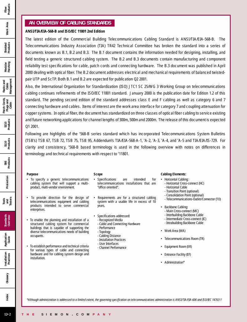
The latest edition of the Commercial Building Telecommunications Cabling Standard is ANSI/TIA/EIA-568-B. The
Telecommunications Industry Association (TIA) TR42 Technical Committee has broken the standard into a series of
documents known as B.1, B.2 and B.3. The B.1 document contains the information needed for designing, installing, and
field testing a generic structured cabling system. The B.2 and B.3 documents contain manufacturing and component
reliability test specifications for cable, patch cords and connecting hardware. The B.3 document was published in April
2000 dealing with optical fiber. The B.2 document addresses electrical and mechanical requirements of balanced twisted-
pair UTP and ScTP. Both B.1 and B.2 are expected for publication Q2 2001.
Also, the International Organization for Standardization (ISO) JTC1 SC 25/WG 3 Working Group on telecommunications
cabling continues refinements of the ISO/IEC 11801 standard. January 2000 is the publication date for Edition 1.2 of this
standard. The pending second edition of the standard addresses class E and F cabling as well as category 6 and 7
connecting hardware and cables. Items of interest are the work area interface for category 7 and coupling attenuation for
copper systems. In optical fiber, the document has standardized on three classes of optical fiber cabling to service existing
and future networking applications for channel lengths of 300m, 500m and 2000m. The release of this document is expected
Q1 2001.
Following are highlights of the ’568-B series standard which has incorporated Telecommunications System Bulletins
(TSB’s) TSB 67, TSB 72, TSB 75, TSB 95, Addendum’s TIA/EIA-568-A-1, ’A-2, ’A-3, ’A-4, and ’A-5 and TIA/EIA/IS-729. For
clarity and consistency, ’568-B based terminology is used in the following overview with notes on differences in
terminology and technical requirements with respect to ’11801.
Purpose• To specify a generic telecommunications
cabling system that will support a multi-product, multi-vendor environment.
• To provide direction for the design oftelecommunications equipment and cablingproducts intended to serve commercialenterprises.
• To enable the planning and installation of astructured cabling system for commercialbuildings that is capable of supporting thediverse telecommunications needs of buildingoccupants.
• To establish performance and technical criteriafor various types of cable and connectinghardware and for cabling system design andinstallation.
Scope• Specifications are intended for
telecommunications installations that are"office oriented".
• Requirements are for a structured cablingsystem with a usable life in excess of 10years.
• Specifications addressed:- Recognized Media- Cable and Connecting Hardware- Performance- Topology- Cabling Distance- Installation Practices- User Interfaces- Channel Performance
Cabling Elements:• Horizontal Cabling:
- Horizontal Cross-connect (HC)- Horizontal Cable- Transition Point (optional)- Consolidation Point (optional)- Telecommunications-Outlet/Connector (TO)
• Backbone Cabling:- Main Cross-connect (MC)- Interbuilding Backbone Cable- Intermediate Cross-connect (IC)- Intrabuilding Backbone Cable
• Work Area (WA)
• Telecommunications Room (TR)
• Equipment Room (ER)
• Entrance Facility (EF)
• Administration*
*Although administration is addressed to a limited extent, the governing specification on telecommunications administration is ANSI/TIA/EIA-606 and ISO/IEC 14763-1
12 00-31 12/15/00 7:36 PM Page 2
T H E S I E M O N . C O M P A N Y12•3
Wor
k Ar
eaSh
ield
edPr
oduc
tsM
odul
arPa
tchi
ng
Rack
s an
dCa
ble
Man
agem
ent
Patc
h Co
rds,
Plug
s an
dCa
ble
S210
Prod
ucts
S110
Prod
ucts
S66
Prod
ucts
Prot
ection
Tool
san
dTe
ster
s
Stan
dard
sOve
rvie
wAp
plic
atio
nGui
deIn
stal
lation
Prac
tice
sGlo
ssar
yIn
dex
Fibe
rPr
oduc
ts
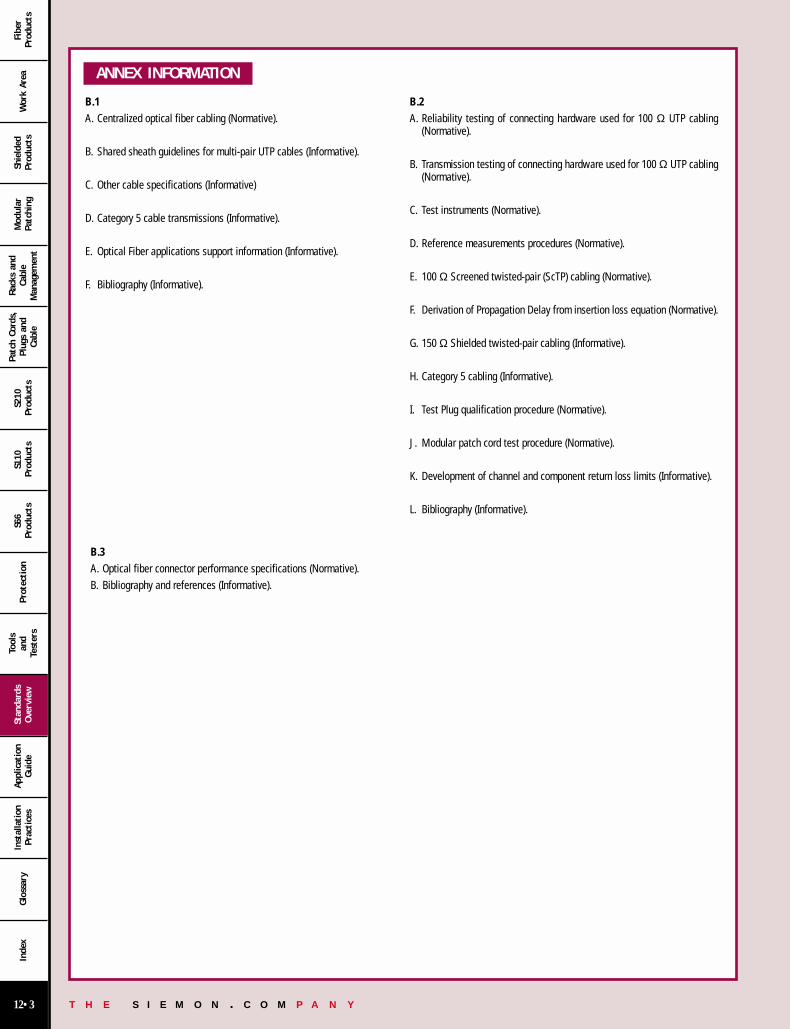
B.1A. Centralized optical fiber cabling (Normative).
B. Shared sheath guidelines for multi-pair UTP cables (Informative).
C. Other cable specifications (Informative)
D. Category 5 cable transmissions (Informative).
E. Optical Fiber applications support information (Informative).
F. Bibliography (Informative).
B.2A. Reliability testing of connecting hardware used for 100 Ω UTP cabling
(Normative).
B. Transmission testing of connecting hardware used for 100 Ω UTP cabling(Normative).
C. Test instruments (Normative).
D. Reference measurements procedures (Normative).
E. 100 Ω Screened twisted-pair (ScTP) cabling (Normative).
F. Derivation of Propagation Delay from insertion loss equation (Normative).
G. 150 Ω Shielded twisted-pair cabling (Informative).
H. Category 5 cabling (Informative).
I. Test Plug qualification procedure (Normative).
J. Modular patch cord test procedure (Normative).
K. Development of channel and component return loss limits (Informative).
L. Bibliography (Informative).
ANNEX INFORMATION
B.3A. Optical fiber connector performance specifications (Normative).B. Bibliography and references (Informative).
12 00-31 12/15/00 7:36 PM Page 3
T H E S I E M O N . C O M P A N Y12•4
Wor
k Ar
eaSh
ield
edPr
oduc
tsM
odul
arPa
tchi
ng
Rack
s an
dCa
ble
Man
agem
ent
Patc
h Co
rds,
Plug
s an
dCa
ble
S210
Prod
ucts
S110
Prod
ucts
S66
Prod
ucts
Prot
ection
Tool
san
dTe
ster
s
Stan
dard
sOve
rvie
wAp
plic
atio
nGui
deIn
stal
lation
Prac
tice
sGlo
ssar
yIn
dex
Fibe
rPr
oduc
ts
HORIZONTAL CABLING SYSTEM STRUCTURE
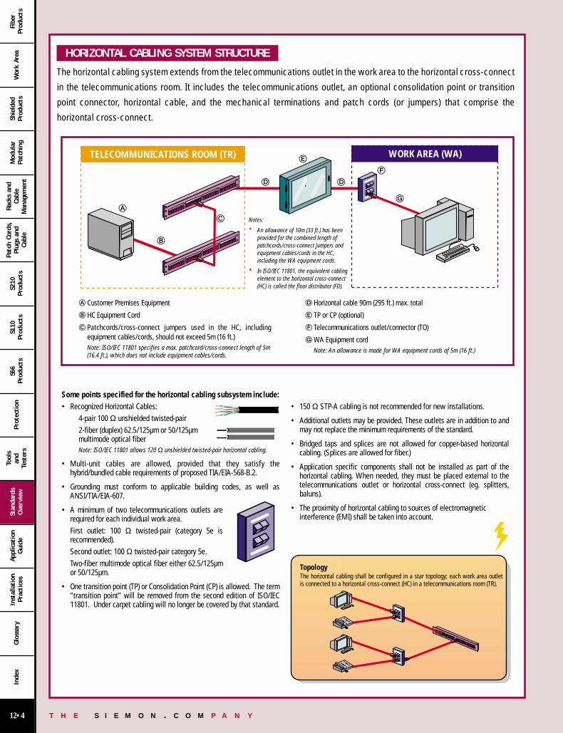
The horizontal cabling system extends from the telecommunications outlet in the work area to the horizontal cross-connect
in the telecommunications room. It includes the telecommunications outlet, an optional consolidation point or transition
point connector, horizontal cable, and the mechanical terminations and patch cords (or jumpers) that comprise the
horizontal cross-connect.
TELECOMMUNICATIONS ROOM (TR) WORK AREA (WA)
Notes:
* An allowance of 10m (33 ft.) has beenprovided for the combined length ofpatchcords/cross-connect jumpers andequipment cables/cords in the HC, including the WA equipment cords.
* In ISO/IEC 11801, the equivalent cablingelement to the horizontal cross-connect(HC) is called the floor distributor (FD).
Customer Premises Equipment
HC Equipment Cord
Patchcords/cross-connect jumpers used in the HC, includingequipment cables/cords, should not exceed 5m (16 ft.)Note: ISO/IEC 11801 specifies a max. patchcord/cross-connect length of 5m(16.4 ft.), which does not include equipment cables/cords.
Horizontal cable 90m (295 ft.) max. total
TP or CP (optional)
Telecommunications outlet/connector (TO)
WA Equipment cordNote: An allowance is made for WA equipment cords of 5m (16 ft.)
Some points specified for the horizontal cabling subsystem include:• Recognized Horizontal Cables:
4-pair 100 Ω unshielded twisted-pair2-fiber (duplex) 62.5/125µm or 50/125µm multimode optical fiber Note: ISO/IEC 11801 allows 120 Ω unshielded twisted-pair horizontal cabling.
• Multi-unit cables are allowed, provided that they satisfy thehybrid/bundled cable requirements of proposed TIA/EIA-568-B.2.
• Grounding must conform to applicable building codes, as well asANSI/TIA/EIA-607.
• A minimum of two telecommunications outlets arerequired for each individual work area.First outlet: 100 Ω twisted-pair (category 5e isrecommended).Second outlet: 100 Ω twisted-pair category 5e.Two-fiber multimode optical fiber either 62.5/125µmor 50/125µm.
• One transition point (TP) or Consolidation Point (CP) is allowed. The term“transition point” will be removed from the second edition of ISO/IEC11801. Under carpet cabling will no longer be covered by that standard.
• 150 Ω STP-A cabling is not recommended for new installations.
• Additional outlets may be provided. These outlets are in addition to andmay not replace the minimum requirements of the standard.
• Bridged taps and splices are not allowed for copper-based horizontalcabling. (Splices are allowed for fiber.)
• Application specific components shall not be installed as part of thehorizontal cabling. When needed, they must be placed external to thetelecommunications outlet or horizontal cross-connect (eg. splitters,baluns).
• The proximity of horizontal cabling to sources of electromagneticinterference (EMI) shall be taken into account.
TopologyThe horizontal cabling shall be configured in a star topology; each work area outlet is connected to a horizontal cross-connect (HC) in a telecommunications room (TR).
12 00-31 12/15/00 7:36 PM Page 4
T H E S I E M O N . C O M P A N Y12•5
Wor
k Ar
eaSh
ield
edPr
oduc
tsM
odul
arPa
tchi
ng
Rack
s an
dCa
ble
Man
agem
ent
Patc
h Co
rds,
Plug
s an
dCa
ble
S210
Prod
ucts
S110
Prod
ucts
S66
Prod
ucts
Prot
ection
Tool
san
dTe
ster
s
Stan
dard
sOve
rvie
wAp
plic
atio
nGui
deIn
stal
lation
Prac
tice
sGlo
ssar
yIn
dex
Fibe
rPr
oduc
ts
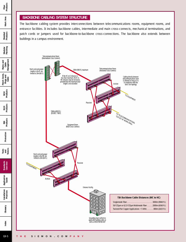
BACKBONE CABLING SYSTEM STRUCTURE
The backbone cabling system provides interconnections between telecommunications rooms, equipment rooms, and
entrance facilities. It includes backbone cables, intermediate and main cross-connects, mechanical terminations, and
patch cords or jumpers used for backbone-to-backbone cross-connections. The backbone also extends between
buildings in a campus environment.
Telecommunications Room(Intermediate Cross-Connect)
Patch cord and jumperlengths in the MC are limited to 20m (66 ft.)
1500m (4920 ft.) (ISO/IEC 11801)
300m (984 ft.) maximum
If the HC to IC distance is less than maximum, the IC to
MC distance may be increased, provided that the maximum total
length is not exceeded
Equipment Room(Main Cross-Connect)
Entrance Facility
Telecommunications Room(Horizontal Cross-Connect)
Cabling directly betweentelecommunications roomis allowed as long as it is
in compliance with thebasic star topology
Grounding must conform toapplicable building codes aswell as ANSI/TIA/EIA-607
Patch cord and jumper lengths in the IC are limited to 20m (66 ft.)
Active
Passive
Passive
Active
TIA Backbone Cable Distances (MC to HC)
Singlemode Fiber . . . . . . . . . . . . . . . . . . . . . . . . . 3000m (9840 ft.)
50/125µm or 62.5/125µm Multimode Fiber . . . . . 2000m (6560 ft.)
Twisted-Pair Copper Applications < 5 MHz . . . . . . 800m (2625 ft.)
12 00-31 12/15/00 7:37 PM Page 5
T H E S I E M O N . C O M P A N Y12•6
Wor
k Ar
eaSh
ield
edPr
oduc
tsM
odul
arPa
tchi
ng
Rack
s an
dCa
ble
Man
agem
ent
Patc
h Co
rds,
Plug
s an
dCa
ble
S210
Prod
ucts
S110
Prod
ucts
S66
Prod
ucts
Prot
ection
Tool
san
dTe
ster
s
Stan
dard
sOve
rvie
wAp
plic
atio
nGui
deIn
stal
lation
Prac
tice
sGlo
ssar
yIn
dex
Fibe
rPr
oduc
ts
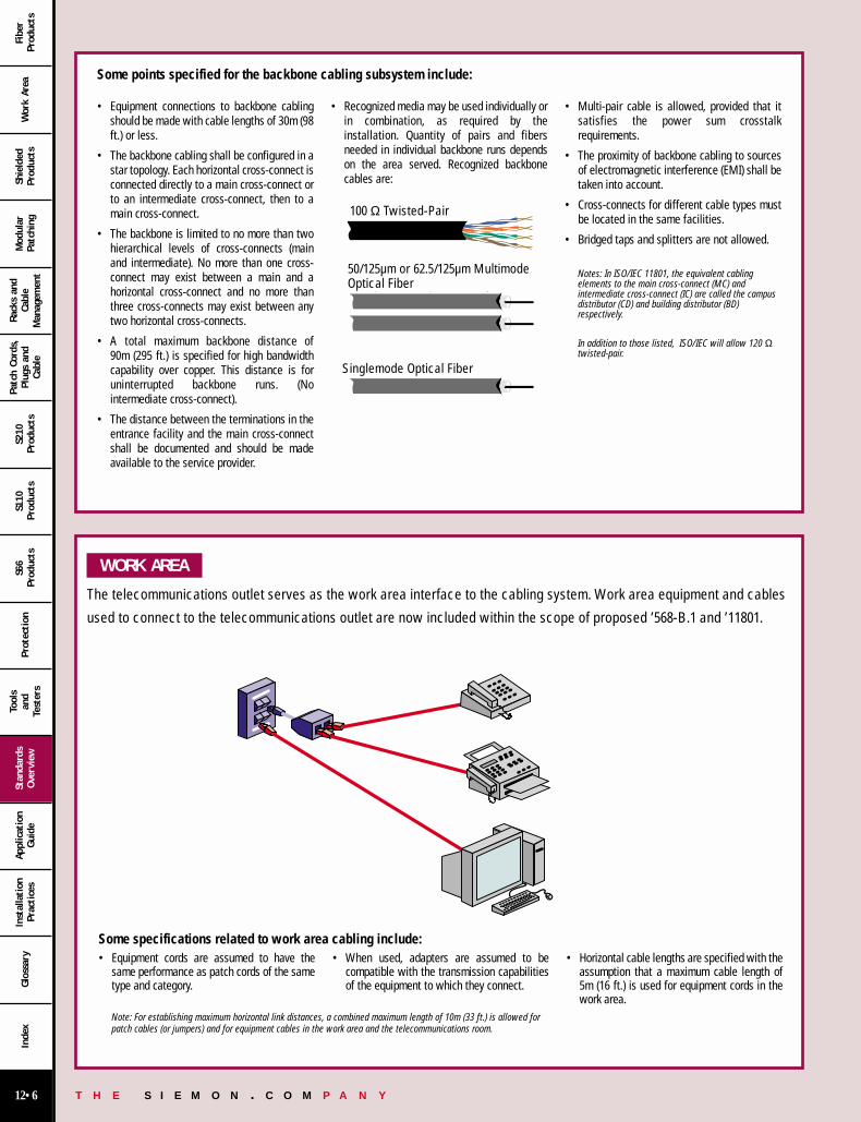
WORK AREA
The telecommunications outlet serves as the work area interface to the cabling system. Work area equipment and cables
used to connect to the telecommunications outlet are now included within the scope of proposed ’568-B.1 and ’11801.
Some points specified for the backbone cabling subsystem include:
• Equipment connections to backbone cablingshould be made with cable lengths of 30m (98ft.) or less.
• The backbone cabling shall be configured in astar topology. Each horizontal cross-connect isconnected directly to a main cross-connect orto an intermediate cross-connect, then to amain cross-connect.
• The backbone is limited to no more than twohierarchical levels of cross-connects (mainand intermediate). No more than one cross-connect may exist between a main and ahorizontal cross-connect and no more thanthree cross-connects may exist between anytwo horizontal cross-connects.
• A total maximum backbone distance of 90m (295 ft.) is specified for high bandwidthcapability over copper. This distance is foruninterrupted backbone runs. (Nointermediate cross-connect).
• The distance between the terminations in theentrance facility and the main cross-connectshall be documented and should be madeavailable to the service provider.
• Recognized media may be used individually orin combination, as required by theinstallation. Quantity of pairs and fibersneeded in individual backbone runs dependson the area served. Recognized backbonecables are:
• Multi-pair cable is allowed, provided that itsatisfies the power sum crosstalkrequirements.
• The proximity of backbone cabling to sourcesof electromagnetic interference (EMI) shall betaken into account.
• Cross-connects for different cable types mustbe located in the same facilities.
• Bridged taps and splitters are not allowed.
Notes: In ISO/IEC 11801, the equivalent cablingelements to the main cross-connect (MC) andintermediate cross-connect (IC) are called the campusdistributor (CD) and building distributor (BD)respectively.
In addition to those listed, ISO/IEC will allow 120 Ωtwisted-pair.
Single-mode Optical Fiber
50/125 µm or 62.5/125 µm Multimode Optical Fiber
100 Ω UTP
• Equipment cords are assumed to have thesame performance as patch cords of the sametype and category.
• When used, adapters are assumed to becompatible with the transmission capabilitiesof the equipment to which they connect.
• Horizontal cable lengths are specified with theassumption that a maximum cable length of5m (16 ft.) is used for equipment cords in thework area.
Some specifications related to work area cabling include:
Note: For establishing maximum horizontal link distances, a combined maximum length of 10m (33 ft.) is allowed forpatch cables (or jumpers) and for equipment cables in the work area and the telecommunications room.
100 Ω Twisted-Pair
50/125µm or 62.5/125µm MultimodeOptical Fiber
Singlemode Optical Fiber
12 00-31 12/15/00 7:37 PM Page 6

T H E S I E M O N . C O M P A N Y12•7
Wor
k Ar
eaSh
ield
edPr
oduc
tsM
odul
arPa
tchi
ng
Rack
s an
dCa
ble
Man
agem
ent
Patc
h Co
rds,
Plug
s an
dCa
ble
S210
Prod
ucts
S110
Prod
ucts
S66
Prod
ucts
Prot
ection
Tool
san
dTe
ster
s
Stan
dard
sOve
rvie
wAp
plic
atio
nGui
deIn
stal
lation
Prac
tice
sGlo
ssar
yIn
dex
Fibe
rPr
oduc
ts
OPEN OFFICE CABLING
Additional specifications for horizontal cabling in areas with moveable furniture and partitions have been included in
proposed TIA/EIA-568-B.1. Horizontal cabling methodologies are specified for “open office” environments by means of
multi-user telecommunications outlet assemblies and consolidation points. These methodologies are intended to provide
increased flexibility and economy for installations with open office work spaces that require frequent reconfiguration.
Telecommunications Room
Horizontal Cross-connect
Work AreaCables
HorizontalCables
Open OfficeSpace
MuTOA
Work AreaThis is an example of Open Office Implementationusing the MuTOA — Multi-user TelecommunicationsOutlet AssemblyMuTOA: A telecommunications outlet scheme intended toserve multiple work areas in an open office environment.
Telecommunications Room
Horizontal Cross-connect
Work AreaCables
HorizontalCables
HorizontalCables
Open OfficeSpace
Consolidation Point
This is an example of Open Office Implementationusing a Consolidation Point ConnectorConsolidation Point: An interconnectionscheme that connects horizontal cables frombuilding pathways to cables that extend toTOs through open office pathways.
Note: To reduce the effects of multiple connections in close proximity,the CP should be located at least 15 meters from the HC (FD).
12 00-31 12/15/00 7:37 PM Page 7
T H E S I E M O N . C O M P A N Y12•8
Wor
k Ar
eaSh
ield
edPr
oduc
tsM
odul
arPa
tchi
ng
Rack
s an
dCa
ble
Man
agem
ent
Patc
h Co
rds,
Plug
s an
dCa
ble
S210
Prod
ucts
S110
Prod
ucts
S66
Prod
ucts
Prot
ection
Tool
san
dTe
ster
s
Stan
dard
sOve
rvie
wAp
plic
atio
nGui
deIn
stal
lation
Prac
tice
sGlo
ssar
yIn
dex
Fibe
rPr
oduc
ts
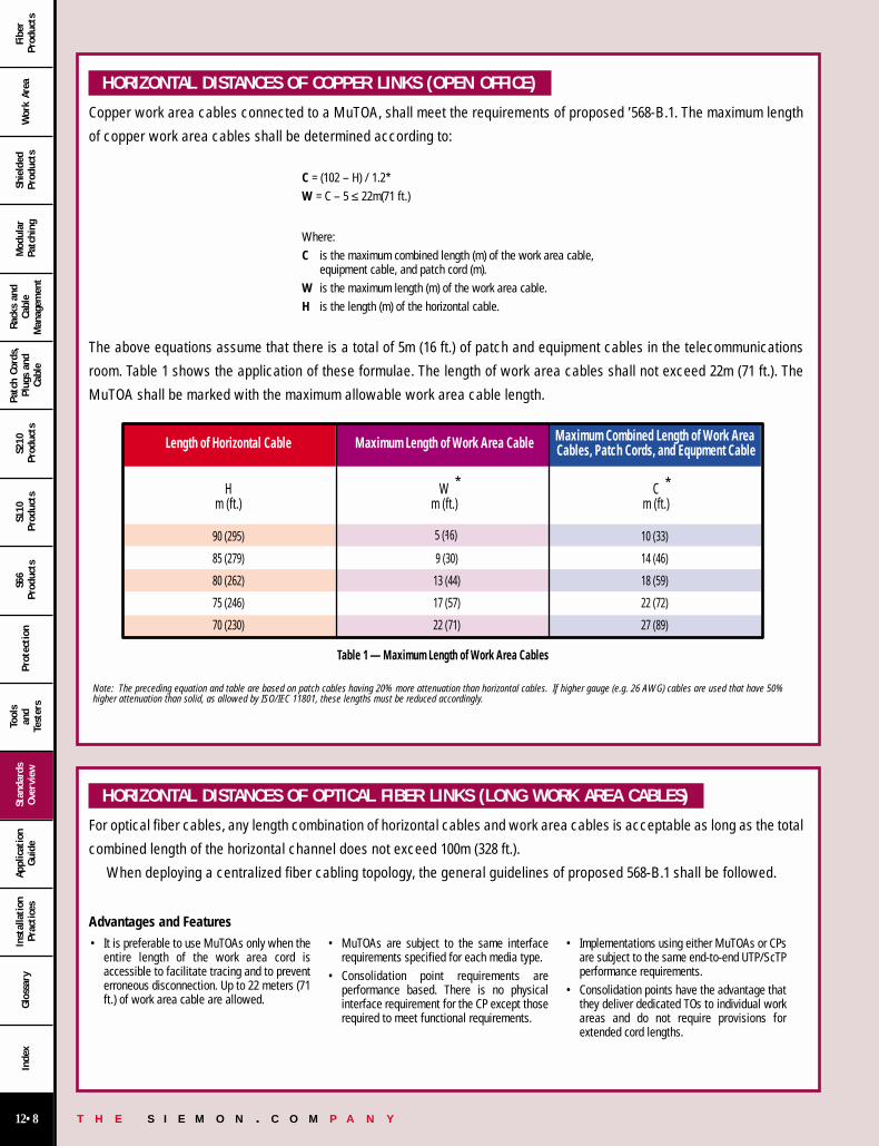
HORIZONTAL DISTANCES OF COPPER LINKS (OPEN OFFICE)
Copper work area cables connected to a MuTOA, shall meet the requirements of proposed ’568-B.1. The maximum length
of copper work area cables shall be determined according to:
C = (102 – H) / 1.2*W = C – 5 ≤ 22m(71 ft.)
Where:C is the maximum combined length (m) of the work area cable,
equipment cable, and patch cord (m).W is the maximum length (m) of the work area cable.H is the length (m) of the horizontal cable.
The above equations assume that there is a total of 5m (16 ft.) of patch and equipment cables in the telecommunications
room. Table 1 shows the application of these formulae. The length of work area cables shall not exceed 22m (71 ft.). The
MuTOA shall be marked with the maximum allowable work area cable length.
HORIZONTAL DISTANCES OF OPTICAL FIBER LINKS (LONG WORK AREA CABLES)
For optical fiber cables, any length combination of horizontal cables and work area cables is acceptable as long as the total
combined length of the horizontal channel does not exceed 100m (328 ft.).
When deploying a centralized fiber cabling topology, the general guidelines of proposed 568-B.1 shall be followed.
Advantages and Features
9 (30)
13 (44)
17 (57)
22 (71)
10 (33)
14 (46)
18 (59)
22 (72)
27 (89)
Length of Horizontal Cable Maximum Combined Length of Work Area Cables, Patch Cords, and Equpment CableMaximum Length of Work Area Cable
Hm (ft.)
Cm (ft.)
Wm (ft.)
90 (295)
85 (279)
80 (262)
75 (246)
70 (230)
Table 1 — Maximum Length of Work Area Cables
5 (16)
• It is preferable to use MuTOAs only when theentire length of the work area cord isaccessible to facilitate tracing and to preventerroneous disconnection. Up to 22 meters (71ft.) of work area cable are allowed.
• MuTOAs are subject to the same interfacerequirements specified for each media type.
• Consolidation point requirements areperformance based. There is no physicalinterface requirement for the CP except thoserequired to meet functional requirements.
• Implementations using either MuTOAs or CPsare subject to the same end-to-end UTP/ScTPperformance requirements.
• Consolidation points have the advantage thatthey deliver dedicated TOs to individual workareas and do not require provisions forextended cord lengths.
Note: The preceding equation and table are based on patch cables having 20% more attenuation than horizontal cables. If higher gauge (e.g. 26 AWG) cables are used that have 50%higher attenuation than solid, as allowed by ISO/IEC 11801, these lengths must be reduced accordingly.
* *
12 00-31 12/15/00 7:37 PM Page 8
T H E S I E M O N . C O M P A N Y12•9
Wor
k Ar
eaSh
ield
edPr
oduc
tsM
odul
arPa
tchi
ng
Rack
s an
dCa
ble
Man
agem
ent
Patc
h Co
rds,
Plug
s an
dCa
ble
S210
Prod
ucts
S110
Prod
ucts
S66
Prod
ucts
Prot
ection
Tool
san
dTe
ster
s
Stan
dard
sOve
rvie
wAp
plic
atio
nGui
deIn
stal
lation
Prac
tice
sGlo
ssar
yIn
dex
Fibe
rPr
oduc
ts
TELECOMMUNICATIONS ROOM
Telecommunications rooms (TR) are generally considered to be floor serving facilities for horizontal cable distribution.
They may also be used for intermediate and main cross-connects.
Some specifications related to the telecommunications room:
• (TR’s) shall be designed and equipped inaccordance with ANSI/TIA/EIA-569-A.
• Cable stress from tight bends, cable ties,staples, and tension should be avoided bywell-designed cable management.
• Only standards-compliant connectinghardware shall be used.
• Application-specific electrical componentsshall not be installed as part of the horizontalcabling.
• Horizontal cable terminations shall not be usedto administer cabling system changes. Instead,jumpers patch cords, or equipment cords arerequired for re-configuring cablingconnections.
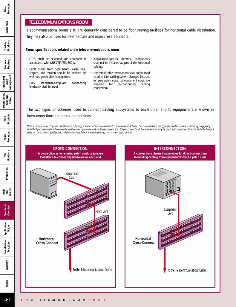
The two types of schemes used to connect cabling subsystems to each other and to equipment are known as
interconnections and cross-connections.
Note: A “cross-connect” (a.k.a. distributor) is a facility, whereas a “cross-connection” is a connection scheme. Cross-connections are typically used to provide a means of configuringindividual port connections between the cabling and equipment with multiport outputs (i.e., 25-pair connectors). Interconnections may be used with equipment that has individual outputports. A cross-connect facility (a.k.a. distributor) may house interconnections, cross-connections, or both.
To the Telecommunications Outlet
Patch Cord
EquipmentCord
Horizontal Cross-Connect
CROSS-CONNECTION:A connection scheme using patch cords or jumpers
that attach to connecting hardware on each end.
To the Telecommunications Outlet
EquipmentCord
Horizontal Cross-Connect
INTERCONNECTION:A connection scheme that provides for direct connections to building cabling from equipment without a patch cord.
12 00-31 12/15/00 7:37 PM Page 9

T H E S I E M O N . C O M P A N Y12•10
Wor
k Ar
eaSh
ield
edPr
oduc
tsM
odul
arPa
tchi
ng
Rack
s an
dCa
ble
Man
agem
ent
Patc
h Co
rds,
Plug
s an
dCa
ble
S210
Prod
ucts
S110
Prod
ucts
S66
Prod
ucts
Prot
ection
Tool
san
dTe
ster
s
Stan
dard
sOve
rvie
wAp
plic
atio
nGui
deIn
stal
lation
Prac
tice
sGlo
ssar
yIn
dex
Fibe
rPr
oduc
ts
TWISTED-PAIR (BALANCED) CABLING
* Category 6 and 7 industry standards are currently under development. Current drafts at date of publication are TIA PN-3737 draft 7 and ISO/IEC JTC 1/SC 25 N 655.
The categories of transmission performance specified by Siemon for cables, connecting hardware links and channels
are:
Designation Transmission Characteristics Description
Transmission characteristics are specified up to 16 MHz. Meets applicable category 3 and class C requirements of ISO/IEC11801 2000, ANSI/TIA/EIA-568-B.1 & B.2. Requirements are specifiedto an upper frequency limit of 16 MHz.
Transmission characteristics are specified up to 100 MHz. Performs to category 5e of ’568-B.1 & B.2 and additional class Drequirements of ISO/IEC 11801. Requirements are specified to anupper frequency limit of 100 MHz. This classification is a superset ofcategory 5 and class D.
Transmission characteristics will be specified up to 250 MHz. Performs to category 6* and class E requirements under developmentby ISO/IEC and TIA. Requirements are expected to be specified to anupper frequency limit of at least 250 MHz. This classification is asuperset of .
Transmission characteristics will be specified up to 600 MHz. Performs to category 7* and class F requirements under developmentby ISO/IEC. Requirements are expected to be specified to an upperfrequency limit of at least 600 MHz. This classification is an electricalsuperset of .
Notes:
Terminology and classifications specified in ISO/IEC 11801 for cabling links differ slightly from TIA categories (See page 12.20 in this catalog). UTP categories 1, 2 and 4 are not specified.
Components and installation practices are subject to all applicable building and safety codes that may be in effect
Category 4 and 5 are no longer recognized by TIA or ISO/IEC for new installations
12 00-31 12/15/00 7:37 PM Page 10

T H E S I E M O N . C O M P A N Y12•11
Wor
k Ar
eaSh
ield
edPr
oduc
tsM
odul
arPa
tchi
ng
Rack
s an
dCa
ble
Man
agem
ent
Patc
h Co
rds,
Plug
s an
dCa
ble
S210
Prod
ucts
S110
Prod
ucts
S66
Prod
ucts
Prot
ection
Tool
san
dTe
ster
s
Stan
dard
sOve
rvie
wAp
plic
atio
nGui
deIn
stal
lation
Prac
tice
sGlo
ssar
yIn
dex
Fibe
rPr
oduc
ts
UTP TELECOMMUNICATIONS OUTLET/CONNECTOR
FULLY SHIELDED TELECOMMUNICATIONS OUTLET/CONNECTOR
UTP CONNECTING HARDWARE VS CABLE NEXT PERFORMANCE
• 8-position modular jack per IEC 60603-7 (proposed ’568-B.1 statesthat all 4 pairs must be connected).
• Pin/pair assignment: T568A (US federal government publicationNCS, FTR 1090-1997 recognizes designation T568A only).
• Optional assignment to accommodate certain systems: T568B.• Durability rating 750 mating cycles minimum.• Backward compatibility and interoperability is required.
• Entirely new interface design to support class F cabling.• Will require a new wiring pin/pair assignment.• Transmission measurement methods for category 7 are under study.• Durability rating 1000 mating cycles minimum.
• Specifications cover all types of connectors used in the cabling system including the telecommunications outlet/connector.
• Does not cover work area adapters, baluns, protection, MAUs, filters,or other application-specific devices.
• Temperature range - 10°C (14°F) to 60°C (140°F).• Outlets shall be securely mounted. Outlet boxes with unterminated
cables must be covered and marked.• Transmission requirements are much more severe than cable of a
corresponding category. (See graph)• Performance markings should be provided to show the applicable
transmission category and should be visible during installation (forexample ) in addition to safety markings.
• Installed connectors shall be protected from physical damage andmoisture.
80706050403020100
Connecting Hardware Cable
DEC
IBEL
S (d
B)
NEXT LOSS @ 100 MHZ
UTP LINK PERFORMANCE MARKING AND IDENTIFICATION • Link category marking should be clearly visible on both ends (component markings are not sufficient).• Labeling, markings, and color-coding shall be provided in accordance with ANSI/TIA/EIA-606.
12 00-31 12/15/00 7:37 PM Page 11

T H E S I E M O N . C O M P A N Y12•12
Wor
k Ar
eaSh
ield
edPr
oduc
tsM
odul
arPa
tchi
ng
Rack
s an
dCa
ble
Man
agem
ent
Patc
h Co
rds,
Plug
s an
dCa
ble
S210
Prod
ucts
S110
Prod
ucts
S66
Prod
ucts
Prot
ection
Tool
san
dTe
ster
s
Stan
dard
sOve
rvie
wAp
plic
atio
nGui
deIn
stal
lation
Prac
tice
sGlo
ssar
yIn
dex
Fibe
rPr
oduc
ts
SCREENED CABLING (ScTP)
As a result of the release of TIA/EIA/IS-729 and the maturity of the ’568-B and ’11801 standards, telecommunications groups
recognize the presence of an overall shield over four twisted-pairs; a media termed Screened Twisted-Pair or ScTP cabling.
ScTP Cable:• Color-coding:
Pair 1 = White/Blue – BluePair 2 = White/Orange – OrangePair 3 = White/Green – GreenPair 4 = White Brown – Brown
• 0.51mm (24 AWG) 100 Ω 4-pair enclosed by a foil shield.• A copper conductor drain wire of .040mm (26 AWG) or larger shall be
provided.• Should be marked “100 Ω ScTP”, in addition to any safety markings
required by local or national codes.• Same mechanical and transmission requirements apply to backbone and
horizontal cables.• Additional performance requirements, including surface transfer
impedance, is specified in the IS-729 standard entitled, “TechnicalSpecifications for 100 Ω Screened Twisted-Pair Cabling”.
ScTP Connectors:• Interface and pair assignments same as IEC 60603-7 (Proposed ’568-B.1
states that all 4 pairs must be connected).• Additional transfer impedance and shield mating interface requirements
specified in the IS-729 standard entitled, “Technical Specifications for100 Ω Screened Twisted-Pair Cabling”.
ScTP Patch Cords:• Specifications call for 26 AWG (7 strands @ 0.15mm) or 24 AWG
(7 strands @ 0.20mm) stranded conductors.• Allows for an overall shield.• Allows for 50% more attenuation than horizontal cable.
ScTP Installation Practices:• Shield shall be bonded at both ends at the “Telecommunication
Grounding Busbar”.• The difference between the two grounds shall be no more than 1.0 V
RMS.
FULLY SHIELDED CABLING (SSTP)
Fully shielded cabling requirements are under development by ISO. Cable and connector specification will extend to at
least 600 MHz and are intended to support the pending class F cabling requirements. .
Fully Shielded Cable:• Color-coding:
Pair 1 = White/Blue – BluePair 2 = White/Orange – OrangePair 3 = White/Green – GreenPair 4 = White/Brown – Brown
• Four 0.51mm (24 AWG) or larger 100 Ω twisted-pairs each enclosed by an individual foil shield with an overall shield provided over the four-pairs.
• Mechanical and transmission requirements are under development by ISO.
Fully Shielded Connectors:• Interface and pair assignments are under development by ISO. • Mechanical and transmission requirements are under development
by IEC SC 46 A.
Fully Shielded Patch Cables:• Mechanical and transmission requirements are under development
by IEC SC 48 B..
Fully Shielded Installation Practices:• Installation Practices are under development by ISO/IEC.
12 00-31 12/15/00 7:37 PM Page 12
T H E S I E M O N . C O M P A N Y12•13
Wor
k Ar
eaSh
ield
edPr
oduc
tsM
odul
arPa
tchi
ng
Rack
s an
dCa
ble
Man
agem
ent
Patc
h Co
rds,
Plug
s an
dCa
ble
S210
Prod
ucts
S110
Prod
ucts
S66
Prod
ucts
Prot
ection
Tool
san
dTe
ster
s
Stan
dard
sOve
rvie
wAp
plic
atio
nGui
deIn
stal
lation
Prac
tice
sGlo
ssar
yIn
dex
Fibe
rPr
oduc
ts
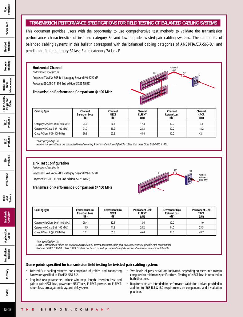
TRANSMISSION PERFORMANCE SPECIFICATIONS FOR FIELD TESTING OF BALANCED CABLING SYSTEMS
This document provides users with the opportunity to use comprehensive test methods to validate the transmission
performance characteristics of installed category 5e and lower grade twisted-pair cabling systems. The categories of
balanced cabling systems in this bulletin correspond with the balanced cabling categories of ANSI/TIA/EIA-568-B.1 and
pending drafts for category 6/class E and category 7/class F.
Some points specified for transmission field testing for twisted-pair cabling systems
• Twisted-Pair cabling systems are comprised of cables and connectinghardware specified in TIA/EIA-568-B.2.
• Required test parameters include wire-map, length, insertion loss, andpair-to-pair NEXT loss, powersum NEXT loss, ELFEXT, powersum. ELFEXT,return loss, propagation delay, and delay skew.
• Two levels of pass or fail are indicated, depending on measured margincompared to minimum specifications. Testing of NEXT loss is required inboth directions.
• Requirements are intended for performance validation and are provided inaddition to ’568-B.1 & B.2 requirements on components and installationpractices.
Horizontal Channel Performance Specified in:
Proposed TIA/EIA-568-B.1 (category 5e) and PN-3727 d7
Proposed ISO/IEC 11801 2nd edition (SC25 N655)
Transmission Performance Comparison @ 100 MHz
*Not specified by TIANumbers in parenthesis are calculated based on using 5 meters of additional flexible cables that meet Class D ISO/IEC 11801.
Cabling Type Channel Channel Channel Channel ChannelInsertion Loss NEXT ELFEXT Return Loss *ACR
(dB) (dB) (dB) (dB) (dB)
Category 5e/Class D (@ 100 MHz) 24.0 30.1 17.4 10.0 6.1
Category 6 Class E (@ 100 MHz) 21.7 39.9 23.3 12.0 18.2
Class 7/Class F (@ 100 MHz) 20.8 62.9 44.4 12.0 42.1
TO2 m field test cord(BLTC only)
HCCP
Link Test Configuration Performance Specified in:
Proposed TIA/EIA-568-B.1 (category 5e) and PN-3727 d7
Proposed ISO/IEC 11801 2nd edition (SC25 N655)
Transmission Performance Comparison @ 100 MHz
*Not specified by TIAClass D attenuation values are calculated based on 90 meters horizontal cable plus two connectors (no flexible cord contribution) that meet ISO/IEC 11801. Class D NEXT values are based on voltage summation of the near-end connector and horizontal cable.
Cabling Type Permanent Link Permanent Link Permanent Link Permanent Link Permanent LinkInsertion Loss NEXT ELFEXT Return Loss *ACR
(dB) (dB) (dB) (dB) (dB)
Category 5e/Class D (@ 100 MHz) 20.4 32.3 18.6 12.0 11.9
Category 6 Class E (@ 100 MHz) 18.5 41.8 24.2 14.0 23.3
Class 7/Class F (@ 100 MHz) 17.1 65.0 46.0 14.0 48.7
TOCP
HorizontalCable
HC
12 00-31 12/15/00 7:37 PM Page 13

T H E S I E M O N . C O M P A N Y12•14
Wor
k Ar
eaSh
ield
edPr
oduc
tsM
odul
arPa
tchi
ng
Rack
s an
dCa
ble
Man
agem
ent
Patc
h Co
rds,
Plug
s an
dCa
ble
S210
Prod
ucts
S110
Prod
ucts
S66
Prod
ucts
Prot
ection
Tool
san
dTe
ster
s
Stan
dard
sOve
rvie
wAp
plic
atio
nGui
deIn
stal
lation
Prac
tice
sGlo
ssar
yIn
dex
Fibe
rPr
oduc
ts
OPTICAL FIBER CABLING
The ’568-B.3 specification on optical fiber cabling consists of one recognized cable type for horizontal subsystems and two
cable types for backbone subsystems:
Horizontal – 50/125µm or 62.5/125µm multimode (two fibers per outlet).
Backbone – 50/125µm or 62.5/125µm multimode or singlemode.
All optical fiber components and installation practices shall meet applicable building and safety codes.
Optical Fiber Patch Cords:
• Shall be a two-fiber (duplex) cable of the same type as the cables towhich they connect.
• Shall be configured so that “A” connects to “B” and “B” connects to “A”.
Installation of Optical Fiber Connecting Hardware:
• Connectors shall be protected from physical damage and moisture.• Optical fiber cable connecting hardware should incorporate high-density
termination to conserve space and provide for ease of optical fiber cableand patch cord management upon installation.
• Optical fiber cable connecting hardware should be designed to provideflexibility for mounting on walls, in racks, or on other types of distributionframes and standard mounting hardware.
Optical Fiber Cabling Installation:
• The Siemon Company recommends that a minimum of 1m (3.28 ft.) of two-fiber cable (or two buffered fibers) be accessible for termination purposes.
• Testing is recommended to assure correct polarity and acceptable linkperformance. Clause II of ”568 B.1 provides recommended optical fiberlink performance testing criteria.
Optical Fiber Connections:
• Connector designs shall meet the requirements of the corresponding TIAFOCIS documents
• Telecommunications outlet/connector boxes shall be securely mounted atplanned locations.
• The telecommunications outlet/connector box shall have: - Cable management means to assure a minimum bend radius of
25mm (1.00 in.) and should have slack storage capability.- Provisions for terminating and housing a minimum of two optical fibers.
• Identification of fiber types: - Multimode connectors or a visible portion of it and adapters shall be
identified with the color beige.- Singlemode connectors or a visible portion of it and adapters shall be
identified with the color blue.• The two positions in a duplex connector are referred to as “position A”
and “position B”.
Small Form Factor (SFF) Connectors:
• Qualified SFF duplex and multi-fiber connector designs may be used in themain cross-connect, intermediate cross-connect, horizontal cross-connect, consolidation points and work area.
• A TIA Fiber Optic Connect Intermateability Standard (FOCIS) shall describeeach SFF design.
• The SFF design shall satisfy the requirements specified in Annex A of the’568-B.3 standard.
• Some advantages of SFF connectors include compact size, modularcompatibility with the eight position modular copper interface, andadaptability to high-density network electronics.
A
AB
B
Duplex Connectors
Simplex or Duplex Connectors
Example568SC Connections
USER SIDE
CABLING SIDE
12 00-31 12/15/00 7:38 PM Page 14
T H E S I E M O N . C O M P A N Y12•15
Wor
k Ar
eaSh
ield
edPr
oduc
tsM
odul
arPa
tchi
ng
Rack
s an
dCa
ble
Man
agem
ent
Patc
h Co
rds,
Plug
s an
dCa
ble
S210
Prod
ucts
S110
Prod
ucts
S66
Prod
ucts
Prot
ection
Tool
san
dTe
ster
s
Stan
dard
sOve
rvie
wAp
plic
atio
nGui
deIn
stal
lation
Prac
tice
sGlo
ssar
yIn
dex
Fibe
rPr
oduc
ts
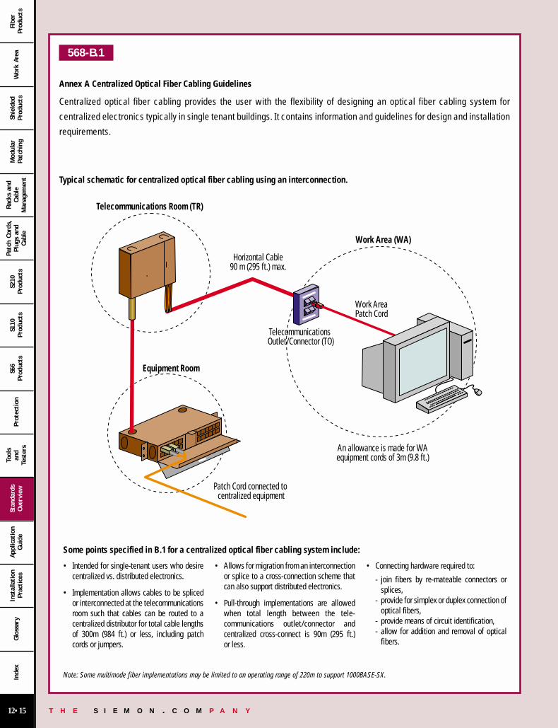
568-B.1
Annex A Centralized Optical Fiber Cabling Guidelines
Centralized optical fiber cabling provides the user with the flexibility of designing an optical fiber cabling system for
centralized electronics typically in single tenant buildings. It contains information and guidelines for design and installation
requirements.
Typical schematic for centralized optical fiber cabling using an interconnection.
• Intended for single-tenant users who desirecentralized vs. distributed electronics.
• Implementation allows cables to be splicedor interconnected at the telecommunicationsroom such that cables can be routed to acentralized distributor for total cable lengthsof 300m (984 ft.) or less, including patchcords or jumpers.
• Allows for migration from an interconnectionor splice to a cross-connection scheme thatcan also support distributed electronics.
• Pull-through implementations are allowedwhen total length between the tele-communications outlet/connector and centralized cross-connect is 90m (295 ft.) or less.
• Connecting hardware required to:
- join fibers by re-mateable connectors orsplices,
- provide for simplex or duplex connection ofoptical fibers,
- provide means of circuit identification,- allow for addition and removal of optical
fibers.
Horizontal Cable90 m (295 ft.) max.
Telecommunications Room (TR)
Work AreaPatch Cord
Telecommunications Outlet/Connector (TO)
Patch Cord connected to centralized equipment
An allowance is made for WAequipment cords of 3m (9.8 ft.)
Equipment Room
Work Area (WA)
Some points specified in B.1 for a centralized optical fiber cabling system include:
Note: Some multimode fiber implementations may be limited to an operating range of 220m to support 1000BASE-SX.
12 00-31 12/15/00 7:38 PM Page 15

T H E S I E M O N . C O M P A N Y12•16
Wor
k Ar
eaSh
ield
edPr
oduc
tsM
odul
arPa
tchi
ng
Rack
s an
dCa
ble
Man
agem
ent
Patc
h Co
rds,
Plug
s an
dCa
ble
S210
Prod
ucts
S110
Prod
ucts
S66
Prod
ucts
Prot
ection
Tool
san
dTe
ster
s
Stan
dard
sOve
rvie
wAp
plic
atio
nGui
deIn
stal
lation
Prac
tice
sGlo
ssar
yIn
dex
Fibe
rPr
oduc
ts
PROPAGATION DELAY AND DELAY SKEW
ADDITIONS TO TIA/EIA-568-B.1, B.2, AND B.3
HYBRID AND BUNDLED CABLES
Propagation delay and delay skew requirements for all compliant 4-pair 100Ω cables have been added for testing category 5e cable. Propagation delayand delay skew requirements of multipair cables are subject to additionalstudy.
Propagation delay is equivalent to the amount of time that passesbetween when a signal is transmitted and when it is received at the otherend of a cabling channel. Delay skew is the difference between the pairwith the least delay and the pair with the most delay. Transmission errorsthat are associated with excessive delay and delay skew include increasedjitter and bit error rates.
The maximum propagation delay skew requirement for 4-pair 100 Ωcables is frequency dependent and is specified by the following equation:
Cable delay skew shall not exceed 45 ns/100m between 1 MHz and thehighest referenced frequency for a given category.
It is anticipated that the requirements of propagation delay and delayskew will also be applicable to pending category 6 cable specificationswhile more stringent performance criteria will be specified for pendingcategory 7 cables.
1. TIA/EIA TSB72 centralized optical fiber cabling is incorporated as analternative to the optical cross-connection located in thetelecommunications room when deploying 62.5/125µm and 50/215µmoptical fiber cable in the horizontal.
2. ANSI/ICEA S-90-661-1994 for specifying the physical and mechanicalrequirements of recognized cables was updated.
3. The 568SC optical fiber connector axial pull off strength requirementwas decreased to 19.4 N (4.4 lbƒ).
4. Globally, the word “polarization” was replaced with “polarity”.
5. A provision for common mode terminations for testing connectinghardware was incorporated. This revision accommodatestelecommunications networking implementations that may employcommon mode terminations in the active equipment.
As a result of the demand for open office architecture and the need tosupport multiple telecommunications applications in a shared sheath,performance specifications for hybrid cables have been revised. A new termcalled “bundled cables” has been introduced to describe 4-pair cableassemblies that are not covered by an overall sheath (as specified for hybridcables), but by any generic binding method such as “speed-wrap” or “cable-ties”
The new hybrid and bundled cable requirements state that power sumNEXT loss between all non-fiber cable types within the cable shall be 3 dBbetter than the specified pair-to-pair NEXT loss for each cable type. Seefigure 1.
Figure 1: Pair-to-Pair measurements required to calculate power sum NEXT for pair 1 of a 24-pair cable.
12 00-31 12/15/00 7:38 PM Page 16

T H E S I E M O N . C O M P A N Y12•17
Wor
k Ar
eaSh
ield
edPr
oduc
tsM
odul
arPa
tchi
ng
Rack
s an
dCa
ble
Man
agem
ent
Patc
h Co
rds,
Plug
s an
dCa
ble
S210
Prod
ucts
S110
Prod
ucts
S66
Prod
ucts
Prot
ection
Tool
san
dTe
ster
s
Stan
dard
sOve
rvie
wAp
plic
atio
nGui
deIn
stal
lation
Prac
tice
sGlo
ssar
yIn
dex
Fibe
rPr
oduc
ts
’568-B.1 & B.2 specifies enhanced category 5 (category 5e) performance requirements. Category 5e has become become the de facto minimum standard forcabling. These documents addresses the minimum equal level far-end crosstalk (ELFEXT) and return loss requirements necessary to support developments inapplications technology and defines the minimum performance needed for a worst case four-connector channel to support applications that utilize full-duplextransmission schemes, such as Gigabit Ethernet. To ensure additional crosstalk headroom for robust applications support, this document also specifies powersum performance requirements for category 5e cables and cabling.
Annex “D” of TIA/EIA-568-B.1 outlines minimum recommendations for the new channel parameters of return loss and equal level far-end crosstalk (ELFEXT).These return loss and ELFEXT recommendations are specified to ensure the support of Gigabit Ethernet over installed or “legacy” category 5 cabling and werederived from worst case performance of channels with only two connection points. The two-connector channel topology is consistent with the IEEE committee’sassumption that cabling used to support Gigabit Ethernet systems will most likely utilize an interconnect instead of a cross-connect field and will not includea consolidation or transition point connection. Existing installed category 5 cabling should be verified to ensure that performance meets the minimumrecommendations of this document. Channel configurations with three or four connectors that meet the specified ELFEXT and return loss recommendations willalso support Gigabit Ethernet. The specifications of this Annex are applicable for the qualification of existing installed cabling only.
Screened twisted-pair cabling specifications have additional technical requirements on the outlet interface, shield effectiveness, installation practices, andperformance relative to ScTP links and components.
x x
-A-
-B-
5.31mm (0.209 in.) min.
5.80mm (0.228 in.) max.
4.90mm (0.193 in.)
max.
6.71mm (0.264 in.) min.
2.16mm (0.085 in.)
max.
6.85mm (0.270 in.) min.
4.22mm (0.166 in.) max.2.11mm (0.083 in.)
min.
4.95mm (0.195 in.)
min.
- A -
- B -
ScTP OUTLETScTP PLUG
TIA/EIA-568-B-2 defines a generic and non-destructive methodology for NEXT loss testing of modular plug cords.NEXT loss performance requirements for category 5e modular plug cords, when measured with the particular testhead specified in the Standard, are provided. Note that, although the methodology may be used as the basis fordetermining the minimum NEXT loss performance requirements of other categories of modular plug cords, atpresent. The methodology described in the Standard contains the detailed NEXT loss calculations (which are basedupon patch cable NEXT loss, test head NEXT loss, and cable and connector attenuation contributions) for thedetermination of the NEXT loss limits for any category patch cord and suitably designed test head.
PRODUCTION MODULAR CORD NEXT LOSS TEST METHOD ANDREQUIREMENTS FOR UNSHIELDED TWISTED PAIR CABLING
TRANSMISSION PERFORMANCE SPECIFICATIONS FOR 4-PAIR 100 Ω ENHANCED CATEGORY 5e CABLING
ADDITIONAL TRANSMISSION PERFORMANCE GUIDELINES FOR 4-PAIR 100 Ω CATEGORY 5 CABLING
TECHNICAL SPECIFICATIONS FOR 100 Ω SCREENED TWISTEDPAIR CABLING INCLUDED IN B.1 AND B.2
12 00-31 12/15/00 7:38 PM Page 17
T H E S I E M O N . C O M P A N Y12•18
Wor
k Ar
eaSh
ield
edPr
oduc
tsM
odul
arPa
tchi
ng
Rack
s an
dCa
ble
Man
agem
ent
Patc
h Co
rds,
Plug
s an
dCa
ble
S210
Prod
ucts
S110
Prod
ucts
S66
Prod
ucts
Prot
ection
Tool
san
dTe
ster
s
Stan
dard
sOve
rvie
wAp
plic
atio
nGui
deIn
stal
lation
Prac
tice
sGlo
ssar
yIn
dex
Fibe
rPr
oduc
ts
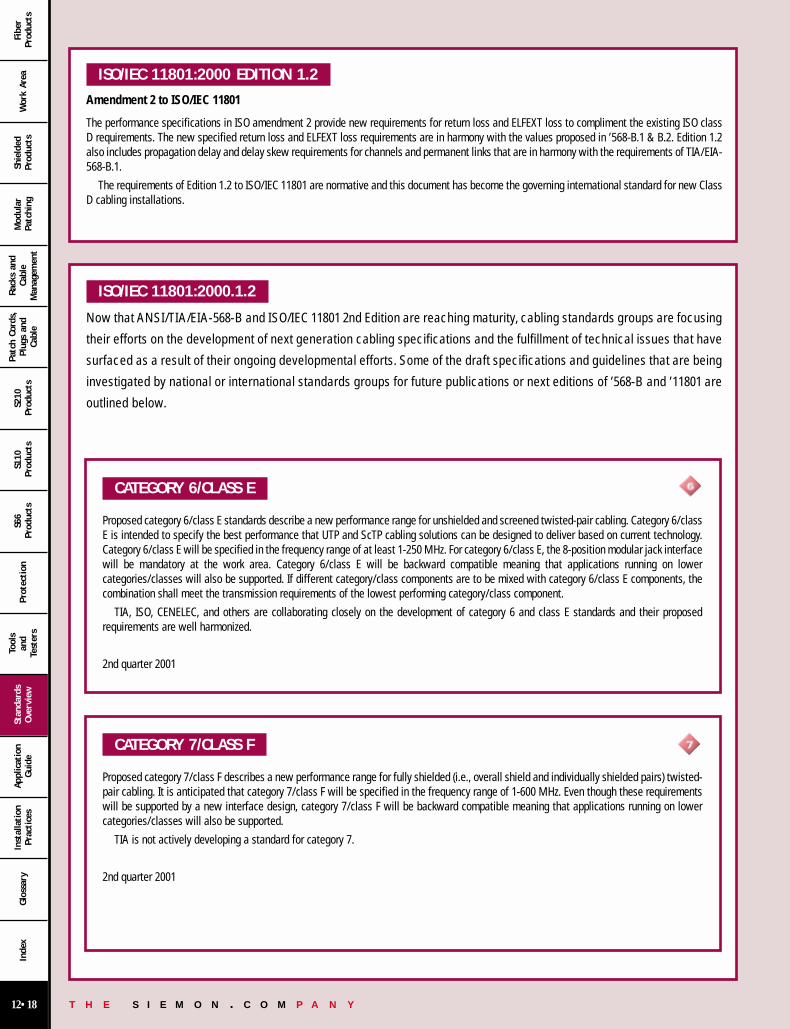
ISO/IEC 11801:2000 EDITION 1.2
Amendment 2 to ISO/IEC 11801
The performance specifications in ISO amendment 2 provide new requirements for return loss and ELFEXT loss to compliment the existing ISO classD requirements. The new specified return loss and ELFEXT loss requirements are in harmony with the values proposed in ’568-B.1 & B.2. Edition 1.2also includes propagation delay and delay skew requirements for channels and permanent links that are in harmony with the requirements of TIA/EIA-568-B.1.
The requirements of Edition 1.2 to ISO/IEC 11801 are normative and this document has become the governing international standard for new ClassD cabling installations.
ISO/IEC 11801:2000.1.2
Now that ANSI/TIA/EIA-568-B and ISO/IEC 11801 2nd Edition are reaching maturity, cabling standards groups are focusing
their efforts on the development of next generation cabling specifications and the fulfillment of technical issues that have
surfaced as a result of their ongoing developmental efforts. Some of the draft specifications and guidelines that are being
investigated by national or international standards groups for future publications or next editions of ’568-B and ’11801 are
outlined below.
CATEGORY 6/CLASS E
Proposed category 6/class E standards describe a new performance range for unshielded and screened twisted-pair cabling. Category 6/classE is intended to specify the best performance that UTP and ScTP cabling solutions can be designed to deliver based on current technology.Category 6/class E will be specified in the frequency range of at least 1-250 MHz. For category 6/class E, the 8-position modular jack interfacewill be mandatory at the work area. Category 6/class E will be backward compatible meaning that applications running on lowercategories/classes will also be supported. If different category/class components are to be mixed with category 6/class E components, thecombination shall meet the transmission requirements of the lowest performing category/class component.
TIA, ISO, CENELEC, and others are collaborating closely on the development of category 6 and class E standards and their proposedrequirements are well harmonized.
2nd quarter 2001
CATEGORY 7/CLASS F
Proposed category 7/class F describes a new performance range for fully shielded (i.e., overall shield and individually shielded pairs) twisted-pair cabling. It is anticipated that category 7/class F will be specified in the frequency range of 1-600 MHz. Even though these requirementswill be supported by a new interface design, category 7/class F will be backward compatible meaning that applications running on lowercategories/classes will also be supported.
TIA is not actively developing a standard for category 7.
2nd quarter 2001
12 00-31 12/15/00 7:38 PM Page 18
T H E S I E M O N . C O M P A N Y12•19
Wor
k Ar
eaSh
ield
edPr
oduc
tsM
odul
arPa
tchi
ng
Rack
s an
dCa
ble
Man
agem
ent
Patc
h Co
rds,
Plug
s an
dCa
ble
S210
Prod
ucts
S110
Prod
ucts
S66
Prod
ucts
Prot
ection
Tool
san
dTe
ster
s
Stan
dard
sOve
rvie
wAp
plic
atio
nGui
deIn
stal
lation
Prac
tice
sGlo
ssar
yIn
dex
Fibe
rPr
oduc
ts
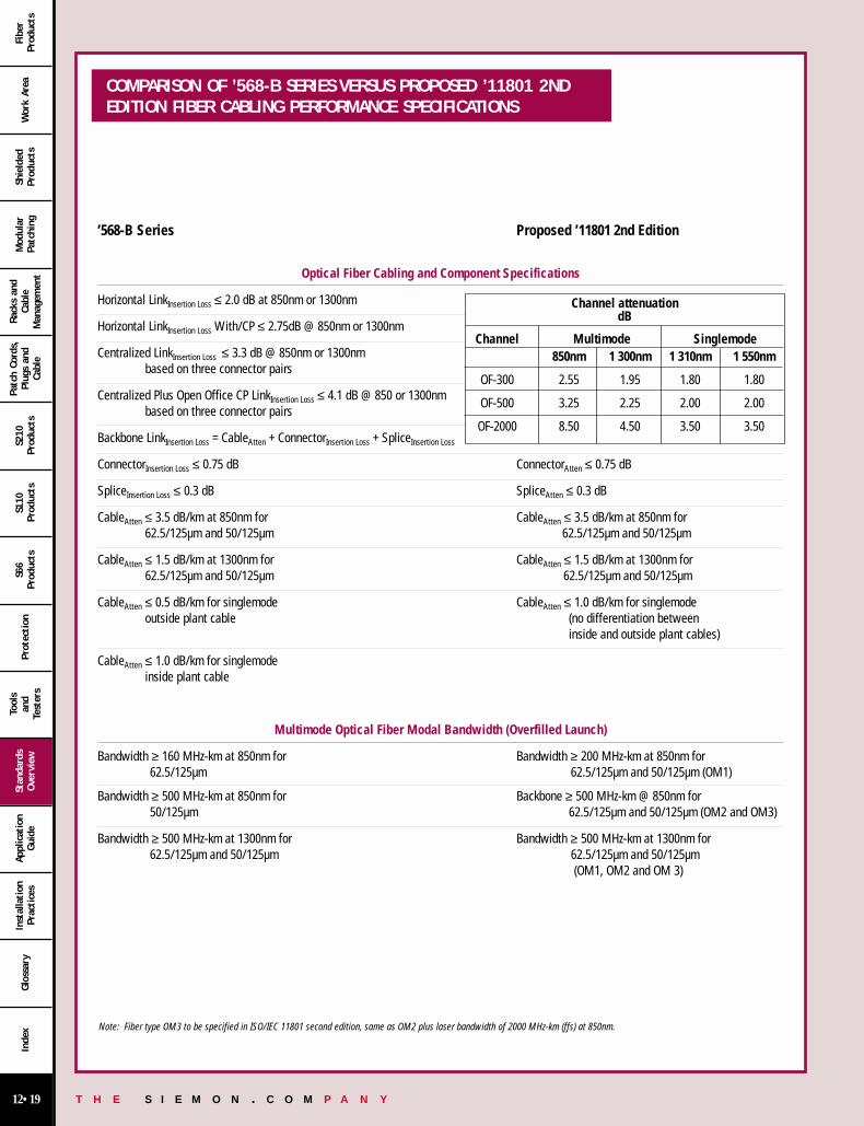
’568-B Series Proposed ’11801 2nd Edition
Optical Fiber Cabling and Component Specifications
Horizontal LinkInsertion Loss ≤ 2.0 dB at 850nm or 1300nm
Horizontal LinkInsertion Loss With/CP ≤ 2.75dB @ 850nm or 1300nm
Centralized LinkInsertion Loss ≤ 3.3 dB @ 850nm or 1300nm based on three connector pairs
Centralized Plus Open Office CP LinkInsertion Loss ≤ 4.1 dB @ 850 or 1300nmbased on three connector pairs
Backbone LinkInsertion Loss = CableAtten + ConnectorInsertion Loss + SpliceInsertion Loss
ConnectorInsertion Loss ≤ 0.75 dB ConnectorAtten ≤ 0.75 dB
SpliceInsertion Loss ≤ 0.3 dB SpliceAtten ≤ 0.3 dB
CableAtten ≤ 3.5 dB/km at 850nm for CableAtten ≤ 3.5 dB/km at 850nm for 62.5/125µm and 50/125µm 62.5/125µm and 50/125µm
CableAtten ≤ 1.5 dB/km at 1300nm for CableAtten ≤ 1.5 dB/km at 1300nm for62.5/125µm and 50/125µm 62.5/125µm and 50/125µm
CableAtten ≤ 0.5 dB/km for singlemode CableAtten ≤ 1.0 dB/km for singlemodeoutside plant cable (no differentiation between
inside and outside plant cables)
CableAtten ≤ 1.0 dB/km for singlemodeinside plant cable
Multimode Optical Fiber Modal Bandwidth (Overfilled Launch)
Bandwidth ≥ 160 MHz-km at 850nm for Bandwidth ≥ 200 MHz-km at 850nm for 62.5/125µm 62.5/125µm and 50/125µm (OM1)
Bandwidth ≥ 500 MHz-km at 850nm for Backbone ≥ 500 MHz-km @ 850nm for50/125µm 62.5/125µm and 50/125µm (OM2 and OM3)
Bandwidth ≥ 500 MHz-km at 1300nm for Bandwidth ≥ 500 MHz-km at 1300nm for62.5/125µm and 50/125µm 62.5/125µm and 50/125µm
(OM1, OM2 and OM 3)
Note: Fiber type OM3 to be specified in ISO/IEC 11801 second edition, same as OM2 plus laser bandwidth of 2000 MHz-km (ffs) at 850nm.
Channel attenuationdB
Channel Multimode Singlemode850nm 1 300nm 1 310nm 1 550nm
OF-300 2.55 1.95 1.80 1.80
OF-500 3.25 2.25 2.00 2.00
OF-2000 8.50 4.50 3.50 3.50
COMPARISON OF ’568-B SERIES VERSUS PROPOSED ’11801 2NDEDITION FIBER CABLING PERFORMANCE SPECIFICATIONS
12 00-31 12/15/00 7:38 PM Page 19

T H E S I E M O N . C O M P A N Y12•20
Wor
k Ar
eaSh
ield
edPr
oduc
tsM
odul
arPa
tchi
ng
Rack
s an
dCa
ble
Man
agem
ent
Patc
h Co
rds,
Plug
s an
dCa
ble
S210
Prod
ucts
S110
Prod
ucts
S66
Prod
ucts
Prot
ection
Tool
san
dTe
ster
s
Stan
dard
sOve
rvie
wAp
plic
atio
nGui
deIn
stal
lation
Prac
tice
sGlo
ssar
yIn
dex
Fibe
rPr
oduc
ts
ANSI/TIA/EIA-568-B Series ISO/IEC 11801 2nd EditionCommercial Building Telecommunications Cabling Standard Generic Cabling for Customer Premises
Terminology
Cross-connect (a facility enabling the termination of cable Distributor (a facility enabling the termination of cable
elements and their connection by patch cord or jumper). elements and their connection by patch cord or jumper).
MC (Main Cross-connect) CD (Campus Distributor)
IC (Intermediate Cross-connect) BD (Building Distributor)
HC (Horizontal Cross-connect) FD (Floor Distributor)
TO (Telecommunications Outlet/connector) TO (Telecommunications Outlet)
CP (Consolidation Point) An interconnection scheme that Consolidation Point, a location in the horizontal cabling
connects horizontal cables that extend from building pathways where a cable may end, which is not subject to moves and
to horizontal cables that extend into work area pathways. changes, and another cable starts leading to the TO which adapts to changes
- or-
a location for interconnection between horizontal cables extending from building pathways and horizontal cablesextending into furniture pathways
Interbuilding Backbone Campus Backbone
Intrabuilding Backbone Building Backbone
Horizontal Media Choices
4-pair 100 Ω unshielded twisted-pair/ScTP *4-pair (or 2-pair) *100 Ω (or 120 Ω) balanced cable
Two fiber, 50/125µm or 62.5/125µm optical fiber *62.5/125µm (or 50/125µm) optical fiber
*indicates preferred media choices.
Backbone Media Choices
100 Ω unshielded twisted-pair/ScTP 100 Ω (or 120 Ω) balanced cable
50/125µm or 62.5/125µm optical fiber 62.5/125µm or 50/125µm optical fiber
Singlemode optical fiber Singlemode optical fiber
150 Ω shielded twisted-pair
Bend Radius
Horizontal ≥ 4 times cable O.D. no load, For UTP 8 times cable OD load, For ScTP no load Horizontal ≥ 4 times cable O.D.
Backbone ≥ 10 times cable O.D. Backbone ≥ 6 times cable O.D.
≥ 8 times cable O.D. while pulling cables
CABLING SPECIFICATIONS CROSS-REFERENCE CHART(ANSI/TIA/EIA-568-B SERIES AND ISO/IEC 11801) 2ND EDITION
12 00-31 12/15/00 7:38 PM Page 20

T H E S I E M O N . C O M P A N Y12•21
Wor
k Ar
eaSh
ield
edPr
oduc
tsM
odul
arPa
tchi
ng
Rack
s an
dCa
ble
Man
agem
ent
Patc
h Co
rds,
Plug
s an
dCa
ble
S210
Prod
ucts
S110
Prod
ucts
S66
Prod
ucts
Prot
ection
Tool
san
dTe
ster
s
Stan
dard
sOve
rvie
wAp
plic
atio
nGui
deIn
stal
lation
Prac
tice
sGlo
ssar
yIn
dex
Fibe
rPr
oduc
ts
ANSI/TIA/EIA-568-B Series ISO/IEC 11801 2nd EditionCommercial Building Telecommunications Cabling Standard Generic Cabling for Customer Premises
Engineering Approach
Not applicable. Field testing for verification only. Link performance determines compliance.
Design Approach
Design constraints, component specifications, and Design constraints, component specifications, and
installation methods determine compliance. installation methods determine compliance.
Connector Termination
All pairs shall be terminated at the outlet. Partial termination at the 100 Ω or 120 Ω outlet is permitted.
Pair untwist shall not exceed 13mm (0.5 in) for category 5 or higher cables. Pair untwist should not exceed 13mm (0.5 in.) for Pair-untwist for category 3 shall be within 75mm (3 in.) from the point of termination category 5 cables
Categories of Cabling Performance
Category 3 is specified to 16 MHz. Class C is specified to 16 MHz.
Category 5 and 5e is specified to 100 MHz. Class D is specified to 100 MHz.
An Optical Class is also specified.
Category 6 to be specified to 250 MHz. Class E to be specified to 250 MHz.
Category 7 to be specified to 600 MHz. Class F to be specified to 600 MHz.
Note: For TIA standards, the term “category” is used to specify both components and cabling performance. For ISO/IEC and CENELEC standards, the term “category” is usedto describe component performance (i.e., cable and connecting hardware). The term “class” is used to describe cabling (i.e., link and channel performance).
Performance Specification
Stranded Cable Attenuation = 20% margin Stranded Cable Attenuation = 50% margin over solid requirements. over solid requirements.
Curve fit evaluation of impedance Curve fit evaluation of impedance performance allowed. performance not allowed.
Hybrid requirements are applicable to the total number of (non-fiber) units Hybrid requirements based upon adjacent non-fiber units within a cable. (Power sum margin + 3dB over pair-to-pair limit.) within a cable.
12 00-31 12/15/00 7:38 PM Page 21

T H E S I E M O N . C O M P A N Y12•22
Wor
k Ar
eaSh
ield
edPr
oduc
tsM
odul
arPa
tchi
ng
Rack
s an
dCa
ble
Man
agem
ent
Patc
h Co
rds,
Plug
s an
dCa
ble
S210
Prod
ucts
S110
Prod
ucts
S66
Prod
ucts
Prot
ection
Tool
san
dTe
ster
s
Stan
dard
sOve
rvie
wAp
plic
atio
nGui
deIn
stal
lation
Prac
tice
sGlo
ssar
yIn
dex
Fibe
rPr
oduc
ts
HYBRID AND BUNDLED CABLES
Hybrid/Bundled Cables:
• Hybrid/bundled cables that contain multiple units of recognized horizontalcopper cables are subject to additional NEXT loss requirements betweencable units. These requirements assure a minimum of 3 dB additionalpower sum crosstalk isolation between applications that may operate onadjacent binder groups.
• All detailed specifications for the individual cable units used in the hybridassembly still apply.
• Hybrid bundled cables shall meet the transmission requirements specifiedin TIA/EIA-B.2.
TWISTED-PAIR PATCH CORDS AND CROSS-CONNECT JUMPERS
• Patch cords must use stranded cable foradequate flex-life.
• Stranded cables must meet the minimumperformance requirements for horizontal cableexcept that 20 percent more attenuation isallowed by ’568-B.2 and 50 percent moreattenuation is allowed by ’11801.
• Color-code for cross-connect jumpers: Oneconductor white, the other a visibly distinctcolor such as red or blue.
• Performance markings should be provided toshow the applicable transmission category inaddition to safety markings.
• Insulated O.D. of stranded wires should be0.8mm (0.032 in.) to 1mm (0.039 in.) to fit intoa modular plug.
• Production performance specifications for plugcord assemblies are addressed in B.2.
• Color Codes for Stranded, 100 Ω UTP PatchCord:
OPTION 1 OPTION 2white/blue–blue PAIR 1 green–redwhite/orange–orange PAIR 2 black–yellowwhite/green–green PAIR 3 blue–orangewhite/brown–brown PAIR 4 brown–slate
Note: Because of their identical pair groupings, patch cords terminated with either T568A or T568B pair assignmentsmay be used interchangeably, provided that both ends are terminated with the same pin/pair scheme.
• Performance markings should be provided to show the applicableperformance category. These markings do not replace safety markings.
• Services with incompatible signal levels should be partitioned intoseparate binder groups. Guidelines for shared sheaths are provided inAnnex B of ’568-B.1.
• Transmission requirements are equivalent to horizontal cables exceptthat NEXT loss performance is based on power-sum rather than worst-pair characterization to allow for multiple disturbing signals (of the sametype) in the same sheath.
• Note: Tip conductors have colored insulation that corresponds to that ofthe binder group. Ring conductors have colored insulation thatcorresponds to that of the pair.
• Backbone twisted-pair cables consist of solid 0.51mm (24 AWG) cablesthat contain more than four pairs (typically multiples of 25-pairs areused). An overall shield is optional.
• Color-coding (specified by reference to ICEA: see chart to right).
white/bluewhite/orange
white/greenwhite/brown
white/slatered/blue
red/orangered/green
red/brownred/slate
black/blueblack/orange
black/greenblack/brown
black/slateyellow/blue
yellow/orangeyellow/green
yellow/brownyellow/slate
violet/blueviolet/orange
violet/greenviolet/brown
violet/slate
blue/whiteorange/whitegreen/whitebrown/whiteslate/whiteblue/redorange/redgreen/redbrown/redslate/redblue/blackorange/blackgreen/blackbrown/blackslate/blackblue/yelloworange/yellowgreen/yellowbrown/yellowslate/yellowblue/violetorange/violetgreen/violetbrown/violetslate/violet
pair 1pair 2pair 3pair 4pair 5pair 6pair 7pair 8pair 9
pair 10pair 11pair 12pair 13pair 14pair 15pair 16pair 17pair 18pair 19pair 20pair 21pair 22pair 23pair 24pair 25
TIP RING
Color-coding (specified by reference to ICEA)
HORIZONTAL TWISTED-PAIR CABLE • Solid 4-pair 0.51mm (24 AWG) specified [0.64mm
(22 AWG) solid also allowed]. An overall shield(ScTP) is optional.
• Performance marking should be provided to show the applicableperformance category. These markings do not replace safety markings.
• Color-coding:white/blue – bluewhite/orange – orangewhite/green – greenwhite/brown – brown
TWISTED-PAIR PATCH CORDS AND CROSS-CONNECT JUMPERS
12 00-31 12/15/00 7:38 PM Page 22
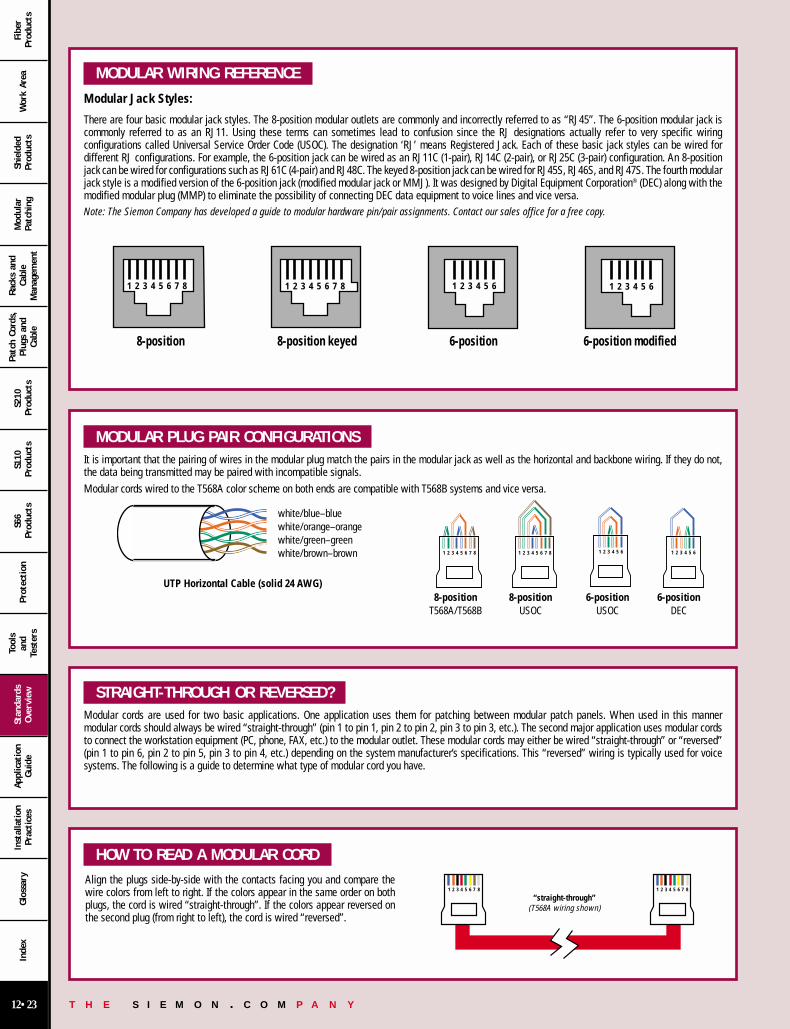
T H E S I E M O N . C O M P A N Y12•23
Wor
k Ar
eaSh
ield
edPr
oduc
tsM
odul
arPa
tchi
ng
Rack
s an
dCa
ble
Man
agem
ent
Patc
h Co
rds,
Plug
s an
dCa
ble
S210
Prod
ucts
S110
Prod
ucts
S66
Prod
ucts
Prot
ection
Tool
san
dTe
ster
s
Stan
dard
sOve
rvie
wAp
plic
atio
nGui
deIn
stal
lation
Prac
tice
sGlo
ssar
yIn
dex
Fibe
rPr
oduc
ts
MODULAR WIRING REFERENCE
Modular Jack Styles:
There are four basic modular jack styles. The 8-position modular outlets are commonly and incorrectly referred to as “RJ45”. The 6-position modular jack iscommonly referred to as an RJ11. Using these terms can sometimes lead to confusion since the RJ designations actually refer to very specific wiringconfigurations called Universal Service Order Code (USOC). The designation ‘RJ’ means Registered Jack. Each of these basic jack styles can be wired fordifferent RJ configurations. For example, the 6-position jack can be wired as an RJ11C (1-pair), RJ14C (2-pair), or RJ25C (3-pair) configuration. An 8-positionjack can be wired for configurations such as RJ61C (4-pair) and RJ48C. The keyed 8-position jack can be wired for RJ45S, RJ46S, and RJ47S. The fourth modularjack style is a modified version of the 6-position jack (modified modular jack or MMJ). It was designed by Digital Equipment Corporation® (DEC) along with themodified modular plug (MMP) to eliminate the possibility of connecting DEC data equipment to voice lines and vice versa.Note: The Siemon Company has developed a guide to modular hardware pin/pair assignments. Contact our sales office for a free copy.
1 82 3 4 5 6 7
8-position 8-position keyed 6-position 6-position modified
1 82 3 4 5 6 7 1 2 3 4 5 6 1 2 3 4 5 6
MODULAR PLUG PAIR CONFIGURATIONS It is important that the pairing of wires in the modular plug match the pairs in the modular jack as well as the horizontal and backbone wiring. If they do not,the data being transmitted may be paired with incompatible signals.Modular cords wired to the T568A color scheme on both ends are compatible with T568B systems and vice versa.
STRAIGHT-THROUGH OR REVERSED? Modular cords are used for two basic applications. One application uses them for patching between modular patch panels. When used in this manner modular cords should always be wired “straight-through” (pin 1 to pin 1, pin 2 to pin 2, pin 3 to pin 3, etc.). The second major application uses modular cordsto connect the workstation equipment (PC, phone, FAX, etc.) to the modular outlet. These modular cords may either be wired “straight-through” or “reversed”(pin 1 to pin 6, pin 2 to pin 5, pin 3 to pin 4, etc.) depending on the system manufacturer’s specifications. This “reversed” wiring is typically used for voice systems. The following is a guide to determine what type of modular cord you have.
white/blue–bluewhite/orange–orangewhite/green–greenwhite/brown–brown 1 82 3 4 5 6 7 1 82 3 4 5 6 7 1 2 3 4 5 6 1 2 3 4 5 6
8-position 8-position 6-position 6-positionT568A/T568B USOC USOC DEC
UTP Horizontal Cable (solid 24 AWG)
Align the plugs side-by-side with the contacts facing you and compare thewire colors from left to right. If the colors appear in the same order on bothplugs, the cord is wired “straight-through”. If the colors appear reversed onthe second plug (from right to left), the cord is wired “reversed”.
HOW TO READ A MODULAR CORD
1 82 3 4 5 6 7 1 82 3 4 5 6 7
“straight-through”(T568A wiring shown)
12 00-31 12/15/00 7:39 PM Page 23

T H E S I E M O N . C O M P A N Y12•24
Wor
k Ar
eaSh
ield
edPr
oduc
tsM
odul
arPa
tchi
ng
Rack
s an
dCa
ble
Man
agem
ent
Patc
h Co
rds,
Plug
s an
dCa
ble
S210
Prod
ucts
S110
Prod
ucts
S66
Prod
ucts
Prot
ection
Tool
san
dTe
ster
s
Stan
dard
sOve
rvie
wAp
plic
atio
nGui
deIn
stal
lation
Prac
tice
sGlo
ssar
yIn
dex
Fibe
rPr
oduc
ts
Two wiring schemes have been adopted by the’568-B.1 and ’11801 standards. They are nearlyidentical except that pairs two and three arereversed. T568A is the preferred schemebecause it is compatible with 1 or 2-pair USOCsystems. Either configuration can be used forIntegrated Services Digital Network (ISDN) andhigh speed data applications. Transmissioncategories 3, 5, 5e, and 6 are only applicable tothis type of pair grouping.
Pair 3 Pair 1 Pair 4
Pair 2
1 82 3 4 5 6 7
T568A
1 82 3 4 5 6 7
Pair 2 Pair 1 Pair 4
Pair 3
T568B
Pair PINID #
T1 5R1 4T2 3R2 6T3 1R3 2T4 7R4 8
Pair PINID #
T1 5R1 4T2 1R2 2T3 3R3 6T4 7R4 8
USOC wiring is available for 1-, 2-, 3-, or 4-pairsystems. Pair 1 occupies the center conductors,pair 2 occupies the next two contacts out, etc.One advantage to this scheme is that a 6-position plug configured with 1, 2, or 3 pairs canbe inserted into an 8-position jack and stillmaintain pair continuity. A note of warningthough, pins 1 and 8 on the jack may becomedamaged from this practice. A disadvantage isthe poor transmission performance associatedwith this type of pair sequence. None of thesepair schemes is cabling standard compliant.
Pair 3
Pair 1
Pair 4
Pair 2
1 82 3 4 5 6 7
USOC 4-pair
Pair 3
Pair 1
Pair 2
1 2 3 4 5 6
USOC 1-, 2- or 3-pair
Pair PINID #
T1 5R1 4T2 3R2 6T3 2R3 7T4 1R4 8
Pair PINID #
T1 4R1 3T2 2R2 5T3 1R3 6
10BASE-T wiringspecifies an 8-positionjack but uses only twopairs. These are pairstwo and three ofT568A and T568Bschemes.
Token Ring wiring useseither an 8-position or 6-position jack. The 8-position format iscompatible withT568A, T568B, andUSOC wiring schemes.The 6-position iscompatible with 1- or2-pair USOC wiring.
1 82 3 4 5 6 7
Pair 1
Pair 2
10BASE-T (802.3)
Pair PINID #
T1 1R1 2T2 3R2 6
1 82 3 4 5 6 7
Pair 1
Pair 2
Token Ring (802.5)
Pair PINID #
T1 5R1 4T2 3R2 6
The MMJ is a uniquewiring scheme forDEC® equipment.
ANSI X3T9.5 TP-PMDuses the two outerpairs of an 8-position jack. Thesepositions aredesignated as pair 3and pair 4 of the T568Awiring scheme. Thiswiring scheme is alsoused for ATM.
Pair 3
Pair 1 Pair 2
1 2 3 4 5 6
3-Pair MMJ
Pair PINID #
T1 3R1 2T2 4R2 5T3 1R3 6
Pair 1 Pair 2
1 82 3 4 5 6 7
TP-PMD (X3T9.5) and ATM
Pair PINID #
T1 1R1 2T2 7R2 8
COMMON OUTLET CONFIGURATIONS
12 00-31 12/15/00 7:39 PM Page 24
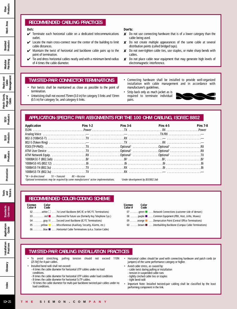
T H E S I E M O N . C O M P A N Y12•25
Wor
k Ar
eaSh
ield
edPr
oduc
tsM
odul
arPa
tchi
ng
Rack
s an
dCa
ble
Man
agem
ent
Patc
h Co
rds,
Plug
s an
dCa
ble
S210
Prod
ucts
S110
Prod
ucts
S66
Prod
ucts
Prot
ection
Tool
san
dTe
ster
s
Stan
dard
sOve
rvie
wAp
plic
atio
nGui
deIn
stal
lation
Prac
tice
sGlo
ssar
yIn
dex
Fibe
rPr
oduc
ts
RECOMMENDED CABLING PRACTICES Do’s: Terminate each horizontal cable on a dedicated telecommunications
outlet. Locate the main cross-connect near the center of the building to limit
cable distances. Maintain the twist of horizontal and backbone cable pairs up to the
point of termination. Tie and dress horizontal cables neatly and with a minimum bend radius
of 4 times the cable diameter.
Don’ts: Do not use connecting hardware that is of a lower category than the
cable being used. Do not create multiple appearances of the same cable at several
distribution points (called bridged taps). Do not over-tighten cable ties, use staples, or make sharp bends with
cables. Do not place cable near equipment that may generate high levels of
electromagnetic interference.
TWISTED-PAIR CONNECTOR TERMINATIONS • Pair twists shall be maintained as close as possible to the point of
termination.• Untwisting shall not exceed 75mm (3.0 in) for category 3 links and 13mm
(0.5 in) for category 5e, and category 6 links.
• Connecting hardware shall be installed to provide well-organizedinstallation with cable management and in accordance withmanufacturer’s guidelines.
• Strip back only as much jacket as isrequired to terminate individualpairs.
APPLICATION-SPECIFIC PAIR ASSIGNMENTS FOR THE 100 OHM CABLING, ISO/IEC 8802
Application Pins 1-2 Pins 3-6 Pins 4-5 Pins 7-8ISDN . . . . . . . . . . . . . . . . . . . . . . . . . . . . . . . . .Power . . . . . . . . . . . . . . . . . . . . .TX . . . . . . . . . . . . . . . . . . . . . .RX . . . . . . . . . . . . . . . . . . . . .PowerAnalog Voice . . . . . . . . . . . . . . . . . . . . . . . . . . . .— . . . . . . . . . . . . . . . . . . . . . .— . . . . . . . . . . . . . . . . . . . . .TX/RX . . . . . . . . . . . . . . . . . . . . .—802-3 (10BASE-T) . . . . . . . . . . . . . . . . . . . . . . . . .TX . . . . . . . . . . . . . . . . . . . . . .RX . . . . . . . . . . . . . . . . . . . . . .— . . . . . . . . . . . . . . . . . . . . . .—802-5 (Token Ring) . . . . . . . . . . . . . . . . . . . . . . . .— . . . . . . . . . . . . . . . . . . . . . .TX . . . . . . . . . . . . . . . . . . . . . .RX . . . . . . . . . . . . . . . . . . . . . .—FDDI (TP-PMD) . . . . . . . . . . . . . . . . . . . . . . . . . . .TX . . . . . . . . . . . . . . . . . . . .Optional1 . . . . . . . . . . . . . . . . .Optional1 . . . . . . . . . . . . . . . . . . . .RXATM User Device . . . . . . . . . . . . . . . . . . . . . . . . .TX . . . . . . . . . . . . . . . . . . . .Optional1 . . . . . . . . . . . . . . . . .Optional1 . . . . . . . . . . . . . . . . . . . .RXATM Network Equip. . . . . . . . . . . . . . . . . . . . . . .RX . . . . . . . . . . . . . . . . . . . .Optional1 . . . . . . . . . . . . . . . . .Optional1 . . . . . . . . . . . . . . . . . . . .TX1000BASE-T (802.3ab) . . . . . . . . . . . . . . . . . . . . .Bi2 . . . . . . . . . . . . . . . . . . . . . .Bi2 . . . . . . . . . . . . . . . . . . . . . .Bi2, . . . . . . . . . . . . . . . . . . . . . .Bi2
100BASE-VG (802.12) . . . . . . . . . . . . . . . . . . . . . .Bi . . . . . . . . . . . . . . . . . . . . . . .Bi . . . . . . . . . . . . . . . . . . . . . . .Bi . . . . . . . . . . . . . . . . . . . . . . .Bi100BASE-T4 (802.3u) . . . . . . . . . . . . . . . . . . . . . .TX . . . . . . . . . . . . . . . . . . . . . .RX . . . . . . . . . . . . . . . . . . . . . .Bi . . . . . . . . . . . . . . . . . . . . . . .Bi100BASE-TX (802.3u) . . . . . . . . . . . . . . . . . . . . . .TX . . . . . . . . . . . . . . . . . . . . . .RX . . . . . . . . . . . . . . . . . . . . . .— . . . . . . . . . . . . . . . . . . . . . .—*Bi = bi-directional TX = Transmit RX = Receive 1Optional terminations may be required by some manufacturers’ active implementations. 2Under development by IEEE802.3ab
RECOMMENDED COLOR-CODING SCHEME Siemon Color Color # Code
02 . . . . . . .white . . . .1st Level Backbone (MC/IC or MC/TC Terminations)
03 . . . . . . . . .red . . . .Reserved for future use (formerly Key Telephone Sys.)
04 . . . . . . . .gray . . . .Second Level Backbone (IC/TC Terminations)
05 . . . . . .yellow . . . .Miscellaneous (Auxiliary, Security, Alarms, etc.)
06 . . . . . . . .blue . . . .Horizontal Cable Terminations (a.k.a. Station Cable)
Siemon Color Color # Code
07 . . . . . . .green . . . .Network Connections (customer side of demarc)
08 . . . . . .purple . . . .Common Equipment (PBX, Host, LANs, Muxes)
09 . . . . . .orange . . . .Demarcation Point (Central Office Terminations)
60 . . . . . .brown . . . .Interbuilding Backbone (Campus Cable Terminations)
TWISTED-PAIR CABLING INSTALLATION PRACTICES • To avoid stretching, pulling tension should not exceed 110N
(25 lbƒ) for 4-pair cables.• Installed bend radii shall not exceed:
- 4 times the cable diameter for horizontal UTP cables under no load conditions.
- 8 times the cable diameter for horizontal UTP cables under load conditions- 8 times the cable diameter for horizontal ScTP cables.- 10 times the cable diameter for multi-pair backbone twisted-pair cables under no
load conditions.
• Horizontal cables should be used with connecting hardware and patch cords (orjumpers) of the same performance category or higher.
• Avoid cable stress, as caused by: - cable twist during pulling or installation - tension in suspended cable runs - tightly cinched cable ties or staples - tight bend radii
• Important Note: Installed twisted-pair cabling shall be classified by the leastperforming component in the link.
12 00-31 12/15/00 7:39 PM Page 25

T H E S I E M O N . C O M P A N Y12•26
Wor
k Ar
eaSh
ield
edPr
oduc
tsM
odul
arPa
tchi
ng
Rack
s an
dCa
ble
Man
agem
ent
Patc
h Co
rds,
Plug
s an
dCa
ble
S210
Prod
ucts
S110
Prod
ucts
S66
Prod
ucts
Prot
ection
Tool
san
dTe
ster
s
Stan
dard
sOve
rvie
wAp
plic
atio
nGui
deIn
stal
lation
Prac
tice
sGlo
ssar
yIn
dex
Fibe
rPr
oduc
ts
ANSI/TIA/EIA-569-A
Commercial Building Standard for Telecommunications Pathways and SpacesThe TIA TR42.3 (formerly TR41.8.3) Working Group on Telecommunications Pathways & Spaces published the ANSI/TIA/EIA-569-A (’569-A) Standard in 1998.
Following are highlights of the ’569-A Standard:
Purpose• Standardize design and construction practices.• Provides a telecommunications support system
that is adaptable to change during the life of thefacility.
Scope• Pathways and spaces in which telecommuni-
cations media are placed and terminated.• Telecommunications pathways and spaces within
and between buildings.• Commercial building design for both single and
multi-tenant buildings.
Elements• Horizontal• Backbone• Work Area• Telecommunications Room• Equipment Room• Main Terminal Space• Entrance Facility
Annex InformationThe following normative and informative annexesare provided in ANSI/TIA/EIA-569-A:A. Firestopping (Normative)B. Additional section information (Informative)C. Interbuilding Backbone Pathways and Related
Spaces (Normative)D. References (Informative)
Tie Pathway
Service Entrance
Antenna Entrance
Telecommunications Room
Backbone Pathways
Backbone Pathways
Horizontal Pathways
Equipment Room
Entrance Room/MainTerminal Space
InterbuildingBackbone
Alternate Entrance
Work Area
Telecommunications Outlet Box
Horizontal Pathways
Telecommunications Room
12 00-31 12/15/00 7:39 PM Page 26

T H E S I E M O N . C O M P A N Y12•27
Wor
k Ar
eaSh
ield
edPr
oduc
tsM
odul
arPa
tchi
ng
Rack
s an
dCa
ble
Man
agem
ent
Patc
h Co
rds,
Plug
s an
dCa
ble
S210
Prod
ucts
S110
Prod
ucts
S66
Prod
ucts
Prot
ection
Tool
san
dTe
ster
s
Stan
dard
sOve
rvie
wAp
plic
atio
nGui
deIn
stal
lation
Prac
tice
sGlo
ssar
yIn
dex
Fibe
rPr
oduc
ts
HORIZONTAL
Pathways from telecommunications room to work area.
Includes:
BACKBONE
Pathways routed from closet-to-closet.
Pathway Types:• Underfloor — Network of raceways embedded in concrete consisting of
distribution and header ducts, trenches, and cellular systems.• Access Floor — Raised modular floor tile supported by pedestals, with
or without lateral bracing or stringers.• Conduit — Metallic and nonmetallic tubing of rigid or flexible
construction permitted by applicable electrical code. • Tray & Wireway — Prefabricated rigid structures for pulling or placing
cable.• Ceiling — Open environment above accessible ceiling tiles and frame
work.• Perimeter- Surface, recessed, molding, and multi-channel raceway
systems for wall mounting around rooms or along hallways.
Space Types:• Pull Boxes — Used in conjunction with conduit pathway systems to
assist in the fishing and pulling of cable.• Splice Boxes — A box, located in a pathway run, intended to hold a cable
splice.• Outlet Boxes — Device for mounting faceplates, housing terminated
outlet/connectors, or transition devices.
Design Considerations:• Grounded per code and ANSI/TIA/EIA-607 (’607)• Designed to handle recognized media as specified in ANSI/TIA/EIA-568-
B series• Not allowed in elevator shafts• Accommodate seismic zone requirements• Installed in dry locations
1st Floor
2nd Floor
3rd Floor
4th Floor
103mm (tradesize 4) conduits
78mm (tradesize 3) conduit
103 mm (4 in.) sleeves
103mm (trade size 4)conduits
103mm (tradesize 4) conduitsMain terminal/
equipment roomEntrance
room/space
Design Considerations:
• Grounded per code and ’607• Accommodate seismic zone requirements
• Water should not penetrate the pathwaysystem
• Tray, conduits, sleeves, slots penetrate closetsminimum 25mm (1 in.)
• Designed to handle all recognized media (asspecified in ’568-A)
• Integrity of all fire stop assemblies shall bemaintained
Typically the most convenient and cost effective backbone pathway design in multi-story buildings, is to have stacked closets located one above the other,connected by sleeves or slots.
Building Backbone Types:• Ceiling• Conduit
• Sleeves — An opening, usually circular,through the wall, ceiling, or floor.
• Slots — An opening, usually rectangular,through the wall, ceiling, or floor.
• Trays
12 00-31 12/15/00 7:39 PM Page 27

T H E S I E M O N . C O M P A N Y12•28
Wor
k Ar
eaSh
ield
edPr
oduc
tsM
odul
arPa
tchi
ng
Rack
s an
dCa
ble
Man
agem
ent
Patc
h Co
rds,
Plug
s an
dCa
ble
S210
Prod
ucts
S110
Prod
ucts
S66
Prod
ucts
Prot
ection
Tool
san
dTe
ster
s
Stan
dard
sOve
rvie
wAp
plic
atio
nGui
deIn
stal
lation
Prac
tice
sGlo
ssar
yIn
dex
Fibe
rPr
oduc
ts
Primary location where the building occupants interact with dedicated telecommunications equipment.
Design Considerations:
• At least one telecommunication outlet box location shall be planned for each work area.
• This location should be coordinated with the furniture plan. A power outlet should be nearby.
• Control center, attendant, and reception areas shall have direct and independent pathways to the serving telecommunications room.
• Furniture System Design:
– Cable access via walls, columns, ceilings, or floors. Fittings that transition between building and furniture pathways require special planning.
– Furniture pathway fill capacity is effectively reduced by furniture corners, and connectors mounted within the furniture pathway systems.
– Furniture pathways bend radius shall not force the installed cable to a bend radius of less than 25mm (1 in.).
– Furniture spaces designed to house slack storage, consolidation points, or multi-user telecommunications outlet assemblies shall provide space forstrain relieving, terminating, and storing slack for the horizontal cables.
– Slack storage and furniture pathway fill, shall not affect the bend radius and termination of the cable to the connector.
– Furniture pathway openings shall comply with either of two sizes:
• Standard NEMA opening (NEMA OS 1 [Ref D.14], WD-6 [Ref D.15])
• Alternate opening:
– Power/telecommunication separation requirements is governed by applicable electrical code for safety. Minimum separation requirements of Article800-52 of ANSI/NFPA 70 (National Electric Code) shall be applied.
C
H
L
T
R
First Obstruction
Dimension ToleranceL (length) . . . . . . . . . . . . . . . . . . . . . 68.8mm (2.71 in.) . . . . . . . . . . 1.02mm (0.040 in.)
H (height) . . . . . . . . . . . . . . . . . . . . 35.1mm (1.38 in.) . . . . . . . . . . 0.90mm (0.035 in.)
T (depth) . . . . . . . . . . . . . . . . . . . . . 1.40mm (0.055 in.) . . . . . . . . . . 0.64mm (0.025 in.)
R (corner radius) . . . . . . . . . . . . 4.06mm (0.160 in.) max . . . . . . . . . . . . . . —
C (distance to 1st obstruction) . . . 30.5mm (1.2 in.) min . . . . . . . . . . . . . . . —
WORK AREA
12 00-31 12/15/00 7:39 PM Page 28
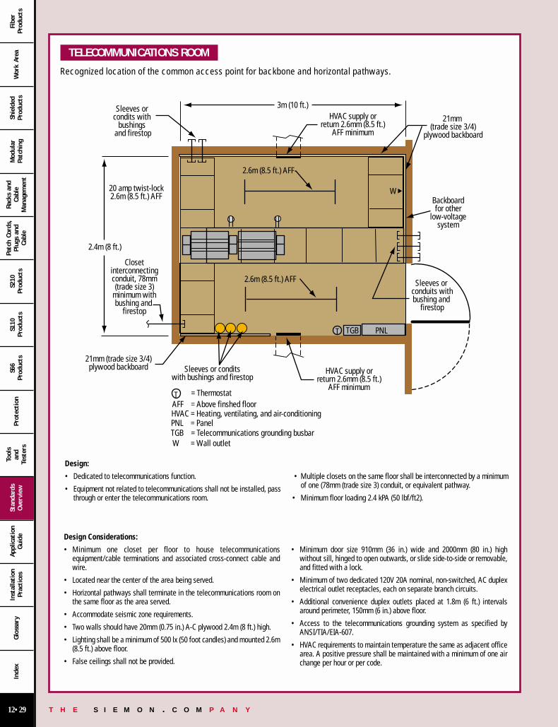
T H E S I E M O N . C O M P A N Y12•29
Wor
k Ar
eaSh
ield
edPr
oduc
tsM
odul
arPa
tchi
ng
Rack
s an
dCa
ble
Man
agem
ent
Patc
h Co
rds,
Plug
s an
dCa
ble
S210
Prod
ucts
S110
Prod
ucts
S66
Prod
ucts
Prot
ection
Tool
san
dTe
ster
s
Stan
dard
sOve
rvie
wAp
plic
atio
nGui
deIn
stal
lation
Prac
tice
sGlo
ssar
yIn
dex
Fibe
rPr
oduc
ts
TELECOMMUNICATIONS ROOM
Recognized location of the common access point for backbone and horizontal pathways.
Design:
• Dedicated to telecommunications function.
• Equipment not related to telecommunications shall not be installed, passthrough or enter the telecommunications room.
• Multiple closets on the same floor shall be interconnected by a minimumof one (78mm (trade size 3) conduit, or equivalent pathway.
• Minimum floor loading 2.4 kPA (50 lbf/ft2).
21mm (trade size 3/4)plywood backboard
TGB PNLT
Closetinterconnectingconduit, 78mm(trade size 3)
minimum withbushing and
firestop
2.4m (8 ft.)
20 amp twist-lock2.6m (8.5 ft.) AFF
Sleeves or conditswith bushings and firestop
HVAC supply orreturn 2.6mm (8.5 ft.)
AFF minimum
HVAC supply orreturn 2.6mm (8.5 ft.)
AFF minimum
3m (10 ft.)
21mm (trade size 3/4)
plywood backboard
Backboardfor other
low-voltagesystem
Sleeves or conduits withbushing and
firestop
= ThermostatTAFF = Above finshed floorHVAC = Heating, ventilating, and air-conditioningPNL = PanelTGB = Telecommunications grounding busbarW = Wall outlet
2.6m (8.5 ft.) AFF
2.6m (8.5 ft.) AFF
Sleeves or condits with
bushings and firestop
W
Design Considerations:
• Minimum one closet per floor to house telecommunicationsequipment/cable terminations and associated cross-connect cable andwire.
• Located near the center of the area being served.
• Horizontal pathways shall terminate in the telecommunications room onthe same floor as the area served.
• Accommodate seismic zone requirements.
• Two walls should have 20mm (0.75 in.) A-C plywood 2.4m (8 ft.) high.
• Lighting shall be a minimum of 500 lx (50 foot candles) and mounted 2.6m(8.5 ft.) above floor.
• False ceilings shall not be provided.
• Minimum door size 910mm (36 in.) wide and 2000mm (80 in.) highwithout sill, hinged to open outwards, or slide side-to-side or removable,and fitted with a lock.
• Minimum of two dedicated 120V 20A nominal, non-switched, AC duplexelectrical outlet receptacles, each on separate branch circuits.
• Additional convenience duplex outlets placed at 1.8m (6 ft.) intervalsaround perimeter, 150mm (6 in.) above floor.
• Access to the telecommunications grounding system as specified byANSI/TIA/EIA-607.
• HVAC requirements to maintain temperature the same as adjacent officearea. A positive pressure shall be maintained with a minimum of one airchange per hour or per code.
12 00-31 12/15/00 7:39 PM Page 29

T H E S I E M O N . C O M P A N Y12•30
Wor
k Ar
eaSh
ield
edPr
oduc
tsM
odul
arPa
tchi
ng
Rack
s an
dCa
ble
Man
agem
ent
Patc
h Co
rds,
Plug
s an
dCa
ble
S210
Prod
ucts
S110
Prod
ucts
S66
Prod
ucts
Prot
ection
Tool
san
dTe
ster
s
Stan
dard
sOve
rvie
wAp
plic
atio
nGui
deIn
stal
lation
Prac
tice
sGlo
ssar
yIn
dex
Fibe
rPr
oduc
ts
EQUIPMENT ROOM A centralized space for telecommunications equipment that serves specific occupants of the building.Any or all of the functions of a telecommunications room or entrance facility may alternately be provided by an equipment room.
Location• Site locations should allow for expansion.• Accessible to the delivery of large equipment.• Not located below water level.• Away from sources of EMI.
• Safeguards against excessive vibration.• Sizing shall include projected future as well as present requirement.• Equipment not related to the support of the equipment room shall not be
installed in, pass through, or enter the equipment room.
Design Considerations• Minimum clear height of 2.4m (8 ft.) without obstruction.• Protected from contaminants and pollutants.• Access to backbone pathways.• HVAC provided on a 24 hours-per-day, 365 days-per-year basis.• Temperature and humidity controlled range 18° C (64° F) to 24°C (75° F)
with 30% to 55% relative humidity measured 1.5m (5 ft.) above floorlevel.
• Separate power supply circuit shall be provided and terminated in its ownelectrical panel.
• Minimum lighting 500 lx (50 foot candles). Switch location shall be nearentrance door to room.
• Minimum door same as telecommunications room. Double doors withoutcenter post or sill is recommended.
• Access to ground per ANSI/TIA/EIA-607.
MAIN TERMINAL SPACE Centralized space that houses the main cross-connect. Commonly used as a separate space in multi-tenant buildings to serve all tenants.
• Location considerations are as specified for equipment room. • Provisioning area as specified for telecommunications closets exceptpower is reduced to convenience receptacles.
ENTRANCE FACILITY Consists of the telecommunications service entrance to the building and backbone pathways between buildings.
Location• Providers of all telecommunications services shall be contacted to
establish requirements.• Location of other utilities shall be considered in locating the entrance
facility.• Alternate entrance facility should be provided where security, continuity
or other special needs exist.
• Equipment not related to the support of the entrance facility should notbe installed in, pass through, or enter the telecommunications entrancefacility.
• Dry location not subject to flooding and close as practicable to buildingentrance point and electrical service room.
Design Considerations• Accommodate the applicable seismic zone requirements.• A service entrance pathway shall be provided via one of the following
entrance types: Underground, Buried, Aerial, Tunnel.• Minimum one wall should be covered with rigidly fixed 20mm
(0.75 in.) A-C plywood.• Minimum lighting same as telecommunication room.
• False ceilings shall not be provided.• Minimum door same as telecommunications room.• Electrical power same as telecommunications room. No convenience
receptacles mentioned.• Grounding same as telecommunications room.
MISCELLANEOUS • Fire stopping per applicable code• Horizontal pathway separation from Electromagnetic interference (EMI)
sources:– Separation between telecommunications and power cables (Article
800.52 of ANSI/NFPA 70)– Building protected from lightning (ANSI/NFPA 780 (Ref D.4)– Surge protection (Article 280 of ANSI/NFPA 70 and 9.11 of ANSI/IEEE
1100 [Ref D.1])– Grounding (ANSI/TIA/EIA-607)– Corrected faulty wiring (Section 7.5 of ANSI/IEEE 1100)
• Reducing noise coupling:– Increase separation from noise sources– Electrical branch circuit line, neutral, and grounding conductors should
be maintained close together– Use of surge protectors in branch circuits– Use fully enclosed grounded metallic raceway or locate cabling near
grounded metallic surface
12 00-31 12/15/00 7:39 PM Page 30
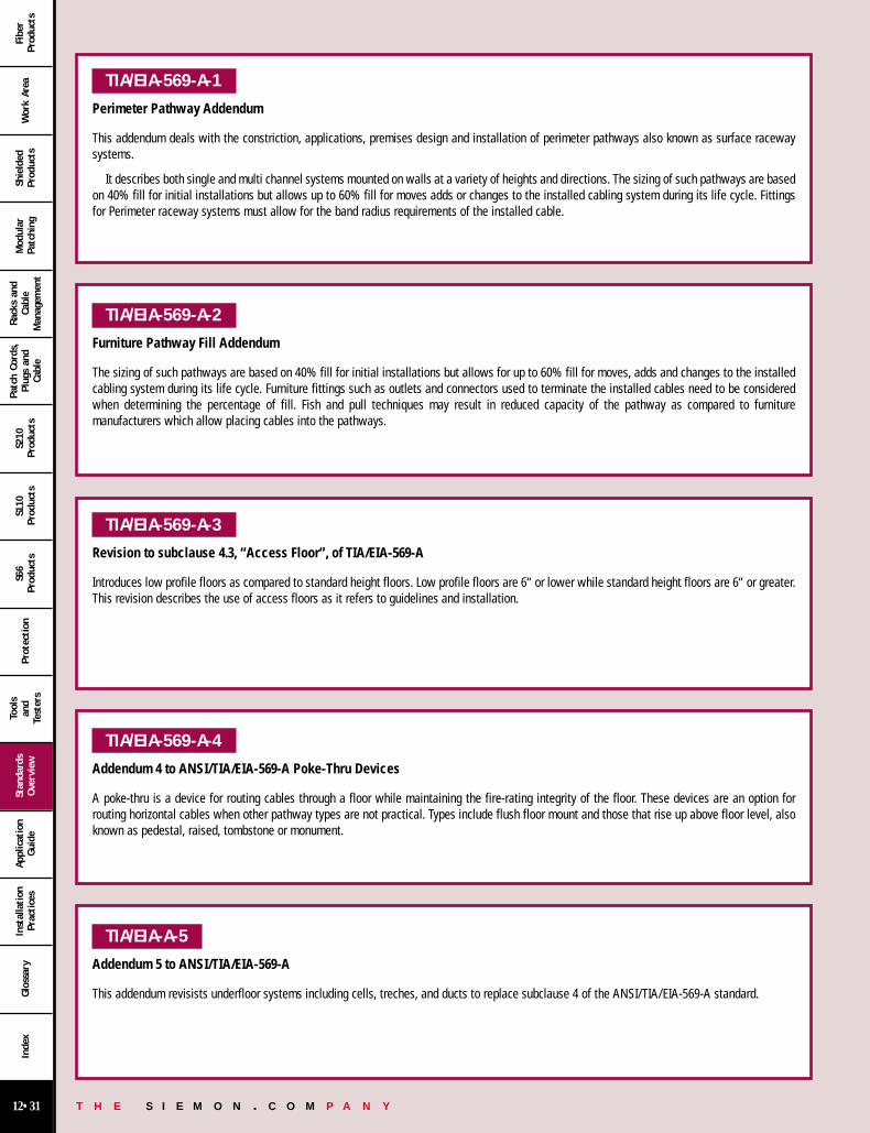
T H E S I E M O N . C O M P A N Y12•31
Wor
k Ar
eaSh
ield
edPr
oduc
tsM
odul
arPa
tchi
ng
Rack
s an
dCa
ble
Man
agem
ent
Patc
h Co
rds,
Plug
s an
dCa
ble
S210
Prod
ucts
S110
Prod
ucts
S66
Prod
ucts
Prot
ection
Tool
san
dTe
ster
s
Stan
dard
sOve
rvie
wAp
plic
atio
nGui
deIn
stal
lation
Prac
tice
sGlo
ssar
yIn
dex
Fibe
rPr
oduc
ts
TIA/EIA-569-A-1
Perimeter Pathway Addendum
This addendum deals with the constriction, applications, premises design and installation of perimeter pathways also known as surface racewaysystems.
It describes both single and multi channel systems mounted on walls at a variety of heights and directions. The sizing of such pathways are basedon 40% fill for initial installations but allows up to 60% fill for moves adds or changes to the installed cabling system during its life cycle. Fittingsfor Perimeter raceway systems must allow for the band radius requirements of the installed cable.
TIA/EIA-569-A-2
Furniture Pathway Fill Addendum
The sizing of such pathways are based on 40% fill for initial installations but allows for up to 60% fill for moves, adds and changes to the installedcabling system during its life cycle. Furniture fittings such as outlets and connectors used to terminate the installed cables need to be consideredwhen determining the percentage of fill. Fish and pull techniques may result in reduced capacity of the pathway as compared to furnituremanufacturers which allow placing cables into the pathways.
TIA/EIA-569-A-3
Revision to subclause 4.3, “Access Floor”, of TIA/EIA-569-A
Introduces low profile floors as compared to standard height floors. Low profile floors are 6“ or lower while standard height floors are 6“ or greater.This revision describes the use of access floors as it refers to guidelines and installation.
TIA/EIA-569-A-4
Addendum 4 to ANSI/TIA/EIA-569-A Poke-Thru Devices
A poke-thru is a device for routing cables through a floor while maintaining the fire-rating integrity of the floor. These devices are an option forrouting horizontal cables when other pathway types are not practical. Types include flush floor mount and those that rise up above floor level, alsoknown as pedestal, raised, tombstone or monument.
TIA/EIA-A-5
Addendum 5 to ANSI/TIA/EIA-569-A
This addendum revisists underfloor systems including cells, treches, and ducts to replace subclause 4 of the ANSI/TIA/EIA-569-A standard.
12 00-31 12/15/00 7:40 PM Page 31
Related Documents