Siemens Standard Drives Application Handbook Martin Brown Siemens Standard Drives Congleton December 1997

Welcome message from author
This document is posted to help you gain knowledge. Please leave a comment to let me know what you think about it! Share it to your friends and learn new things together.
Transcript

Siemens Standard Drives
Application Handbook
Martin BrownSiemens Standard Drives
Congleton December 1997
2
1. Introduction. ..........................................................................................41.1 What is a Variable Speed Drive? ...........................................................41.2 The Variable Frequency Inverter. ...........................................................7
2. Siemens Standard Drives Product Range. ...........................................92.1 Product Range......................................................................................10
3. Selecting a Drive.................................................................................113.1 Overall Considerations. ........................................................................113.2 Supply Side Requirements ...................................................................123.3 Motor limitations. ..................................................................................153.4 Load Considerations.............................................................................173.5 Acceleration and Braking requirements................................................203.6 Environmental Considerations..............................................................20
4. Installing and Getting Started with an Inverter. ...................................214.1 Mounting the MICROMASTER.............................................................214.2 Cooling. ................................................................................................214.3 Wiring up the MICROMASTER. ...........................................................224.4 First Switch On. ....................................................................................254.5 If the motor does not start. ...................................................................26
5. Some Simple Applications and Possibilities .......................................265.1 Using a Potentiometer with the Analog Input. ......................................275.2 Using a Digital Input. ............................................................................275.3 Using the Fixed Frequencies. ...............................................................285.4 Using other digital input features. .........................................................295.5 Using the control outputs......................................................................305.6 Current Limit and Protection Systems ..................................................305.7 Other Protection Features ....................................................................325.8 Some Additional Features ....................................................................33
6. Electromagnetic Compatibility (EMC) .................................................386.1 What is EMC? ......................................................................................386.2 Minimising the problem of EMI. ............................................................386.3 EMC Rules and Regulations. ...............................................................42
7. Some Real Applications......................................................................437.1 A simple Fan Application ......................................................................437.2 A Closed Loop Controller using a Fan..................................................457.3 Controlling Lift Door Operation. ............................................................477.4 A Lift system for Industrial Applications................................................497.5 A Conveyer Application using several MICROMASTERs.....................527.6 A Material Handling Application............................................................547.7 An Industrial Washing Machine............................................................567.8 An Exercise Machine Application. ........................................................59
8. Advanced Applications Information.....................................................618.1 Using Closed Loop Control...................................................................618.2 Braking and Slowing down using Inverters. ..........................................668.3 Using the Serial Interface .....................................................................698.4 Using PROFIBUS .................................................................................708.5 Vector and FCC Control .......................................................................71
9. Options for Siemens Standard Drives.................................................739.1 Introduction...........................................................................................739.2 Clear Text Operating Panel OPm2.......................................................73
3
9.3 Braking Modules and Braking Resistors..............................................749.4 RFI Suppression Filters. .......................................................................759.5 PROFIBUS Module. .............................................................................759.6 Input and Output Chokes. ....................................................................75
10. APPENDIX 1: Using the USS Protocol .........................................7610.1 Introduction.........................................................................................7610.2 Overview.............................................................................................7610.3 Hardware Connection.........................................................................7610.4 Overview of the USS Protocol ............................................................7710.5 Message Timeout ...............................................................................7710.6 Detailed Description of the USS Protocol Message ...........................7810.7 Examples of using the USS Protocol..................................................85
11. APPENDIX 2: Environmental Protection Levels (IP rating)...............8612. APPENDIX 3: Some Useful Formulae. .............................................87
4
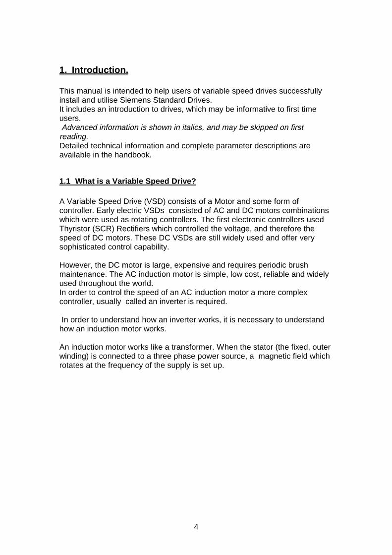
1. Introduction.
This manual is intended to help users of variable speed drives successfullyinstall and utilise Siemens Standard Drives.It includes an introduction to drives, which may be informative to first timeusers. Advanced information is shown in italics, and may be skipped on firstreading.Detailed technical information and complete parameter descriptions areavailable in the handbook.
1.1 What is a Variable Speed Drive?
A Variable Speed Drive (VSD) consists of a Motor and some form ofcontroller. Early electric VSDs consisted of AC and DC motors combinationswhich were used as rotating controllers. The first electronic controllers usedThyristor (SCR) Rectifiers which controlled the voltage, and therefore thespeed of DC motors. These DC VSDs are still widely used and offer verysophisticated control capability.
However, the DC motor is large, expensive and requires periodic brushmaintenance. The AC induction motor is simple, low cost, reliable and widelyused throughout the world.In order to control the speed of an AC induction motor a more complexcontroller, usually called an inverter is required.
In order to understand how an inverter works, it is necessary to understandhow an induction motor works.
An induction motor works like a transformer. When the stator (the fixed, outerwinding) is connected to a three phase power source, a magnetic field whichrotates at the frequency of the supply is set up.
5
2 1
321
3
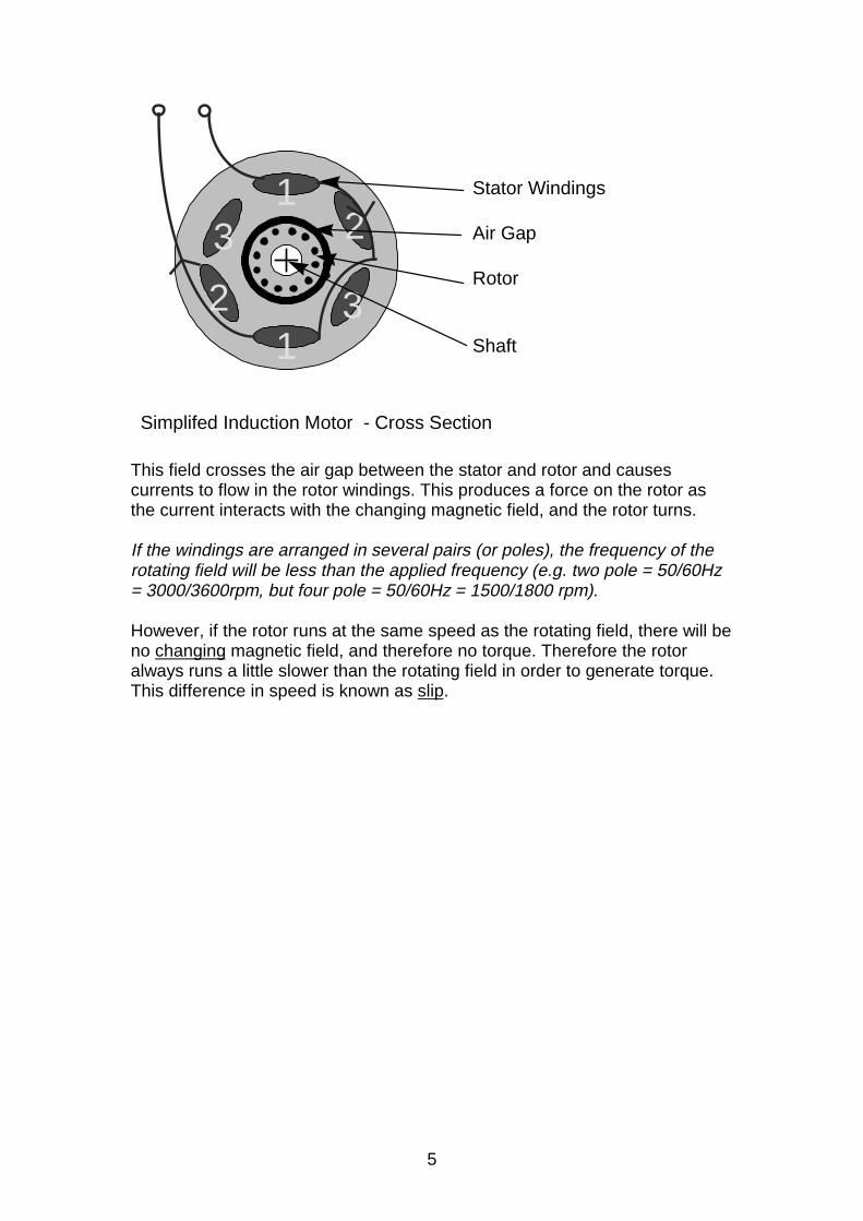
Simplifed Induction Motor - Cross Section
Stator Windings
Air Gap
Rotor
Shaft
This field crosses the air gap between the stator and rotor and causescurrents to flow in the rotor windings. This produces a force on the rotor asthe current interacts with the changing magnetic field, and the rotor turns.
If the windings are arranged in several pairs (or poles), the frequency of therotating field will be less than the applied frequency (e.g. two pole = 50/60Hz= 3000/3600rpm, but four pole = 50/60Hz = 1500/1800 rpm).
However, if the rotor runs at the same speed as the rotating field, there will beno changing magnetic field, and therefore no torque. Therefore the rotoralways runs a little slower than the rotating field in order to generate torque.This difference in speed is known as slip.
6
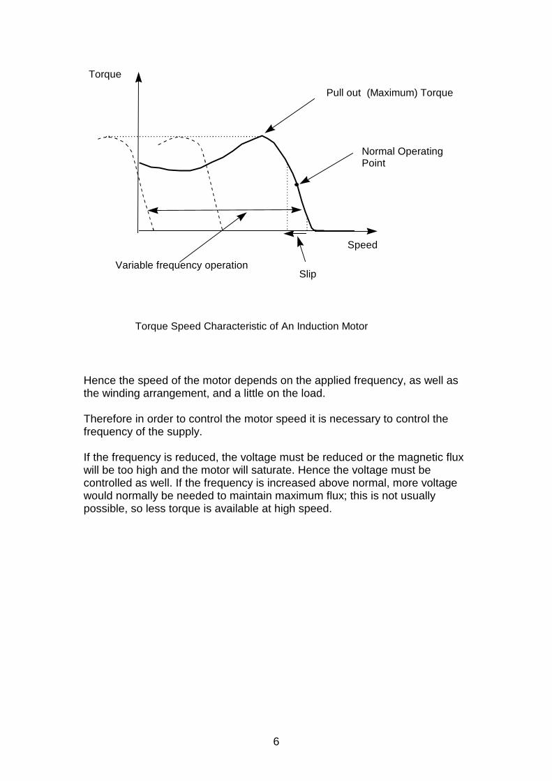
Speed
Normal OperatingPoint
Torque Speed Characteristic of An Induction Motor
Slip
Pull out (Maximum) Torque
Torque
Variable frequency operation
Hence the speed of the motor depends on the applied frequency, as well asthe winding arrangement, and a little on the load.
Therefore in order to control the motor speed it is necessary to control thefrequency of the supply.
If the frequency is reduced, the voltage must be reduced or the magnetic fluxwill be too high and the motor will saturate. Hence the voltage must becontrolled as well. If the frequency is increased above normal, more voltagewould normally be needed to maintain maximum flux; this is not usuallypossible, so less torque is available at high speed.
7
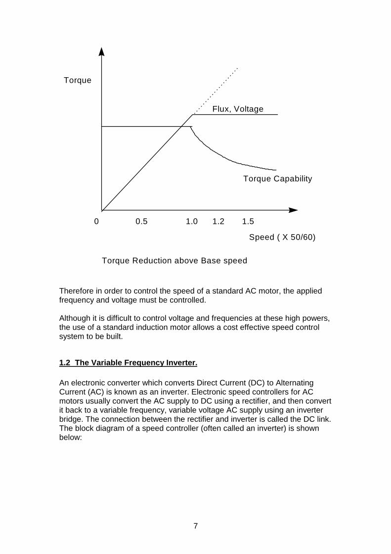
0 0.5 1.0 1.2 1.5
Torque
Flux, Voltage
Speed ( X 50/60)
Torque Reduction above Base speed
Torque Capability
Therefore in order to control the speed of a standard AC motor, the appliedfrequency and voltage must be controlled.
Although it is difficult to control voltage and frequencies at these high powers,the use of a standard induction motor allows a cost effective speed controlsystem to be built.
1.2 The Variable Frequency Inverter.
An electronic converter which converts Direct Current (DC) to AlternatingCurrent (AC) is known as an inverter. Electronic speed controllers for ACmotors usually convert the AC supply to DC using a rectifier, and then convertit back to a variable frequency, variable voltage AC supply using an inverterbridge. The connection between the rectifier and inverter is called the DC link.The block diagram of a speed controller (often called an inverter) is shownbelow:
8
Rectifer DC Link Inverter
Supply
C
+
-
C
Inverter Block Diagram
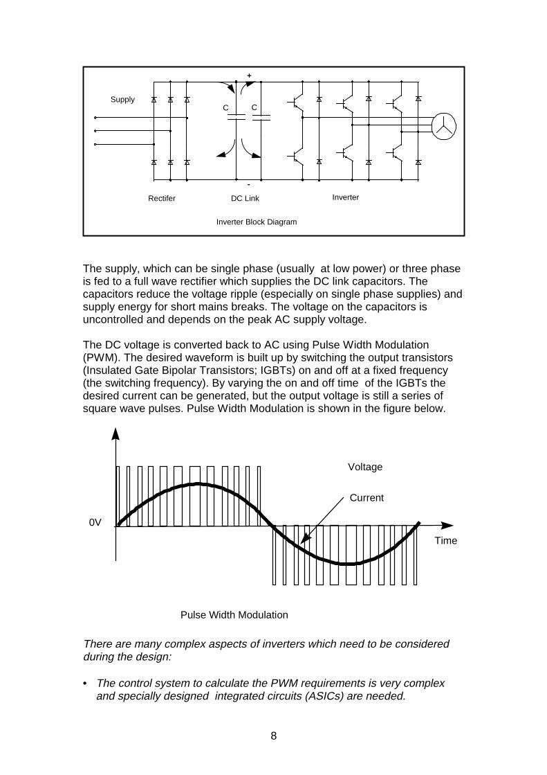
The supply, which can be single phase (usually at low power) or three phaseis fed to a full wave rectifier which supplies the DC link capacitors. Thecapacitors reduce the voltage ripple (especially on single phase supplies) andsupply energy for short mains breaks. The voltage on the capacitors isuncontrolled and depends on the peak AC supply voltage.
The DC voltage is converted back to AC using Pulse Width Modulation(PWM). The desired waveform is built up by switching the output transistors(Insulated Gate Bipolar Transistors; IGBTs) on and off at a fixed frequency(the switching frequency). By varying the on and off time of the IGBTs thedesired current can be generated, but the output voltage is still a series ofsquare wave pulses. Pulse Width Modulation is shown in the figure below.
0V
Time
Pulse Width Modulation
Voltage
Current
There are many complex aspects of inverters which need to be consideredduring the design:
• The control system to calculate the PWM requirements is very complexand specially designed integrated circuits (ASICs) are needed.
9
• The control electronics are often connected to the DC link, which isconnected to the supply, so the customer connections, display etc. must besafely isolated from this.
• The output current must be carefully monitored to protect the inverter andthe motor during overload and short circuit.
• At first switch on the DC link capacitors are discharged, and the inrushcurrent must be limited, usually using a resistor which is bypassed by arelay after a few seconds.
• All connections to the inverter, especially the supply and controlconnections, may carry a lot of interference and must be fitted with suitableprotection components.
• An internal power supply with several different output voltages is neededfor the to supply the control electronics.
• The inverter, especially the IGBTs and rectifier diodes, produce heat whichmust be dissipated using a fan and heatsink.
• The PWM output voltage contains many high frequency harmonics(because of the fast switching) and can be a major source of EMI.
• The input rectifier draws current only at the peak of the supply waveform,so the input currents have a poor form factor ( i.e. the RMS value can bequite high - this does not mean the inverter is inefficient!)
A practical inverter needs to be designed for ease of use and installation.Large inverters are often specially designed or engineered for eachapplication; smaller inverters are designed for general purpose use and are ofstandard design. Siemens Standard Drives division manufacture standardinverters up to 90kW for this purpose.
2. Siemens Standard Drives Product Range.
The current product range consists of four different product types:
The MICROMASTER Vector. A VSD high performance inverter for generalpurpose applications available in various voltage ranges and power up to7.5kW.
The MICROMASTER. A similar range with fewer features for simpleapplications.
The MIDIMASTER Vector. A higher power version of the MICROMASTERVector with output capability of up to 90kW.
The COMBIMASTER. An induction motor with an inverter mounted in place ofthe terminal box.
The following information refers to the operation of the MICRO andMIDIMASTER Vector products, but may prove useful with reference toCOMBIMASTER as well.
10
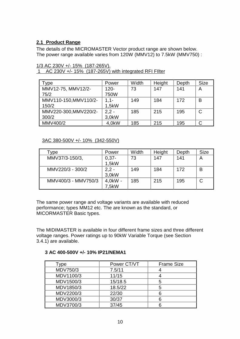
2.1 Product RangeThe details of the MICROMASTER Vector product range are shown below.The power range available varies from 120W (MMV12) to 7.5kW (MMV750) :
1/3 AC 230V +/- 15% (187-265V). 1 AC 230V +/- 15% (187-265V) with integrated RFI FIlter
Type Power Width Height Depth SizeMMV12-75, MMV12/2-75/2
120-750W
73 147 141 A
MMV110-150,MMV110/2-150/2
1,1-1,5kW
149 184 172 B
MMV220-300,MMV220/2-300/2
2,2 -3,0kW
185 215 195 C
MMV400/2 4,0kW 185 215 195 C
3AC 380-500V +/- 10% (342-550V)
Type Power Width Height Depth SizeMMV37/3-150/3, 0,37-
1,5kW73 147 141 A
MMV220/3 - 300/2 2,2 -3,0kW
149 184 172 B
MMV400/3 - MMV750/3 4,0kW -7,5kW
185 215 195 C
The same power range and voltage variants are available with reducedperformance; types MM12 etc. The are known as the standard, orMICORMASTER Basic types.
The MIDIMASTER is available in four different frame sizes and three differentvoltage ranges. Power ratings up to 90kW Variable Torque (see Section3.4.1) are available.
3 AC 400-500V +/- 10% IP21/NEMA1
Type Power CT/VT Frame SizeMDV750/3 7.5/11 4MDV1100/3 11/15 4MDV1500/3 15/18.5 5MDV1850/3 18.5/22 5MDV2200/3 22/30 6MDV3000/3 30/37 6MDV3700/3 37/45 6
11
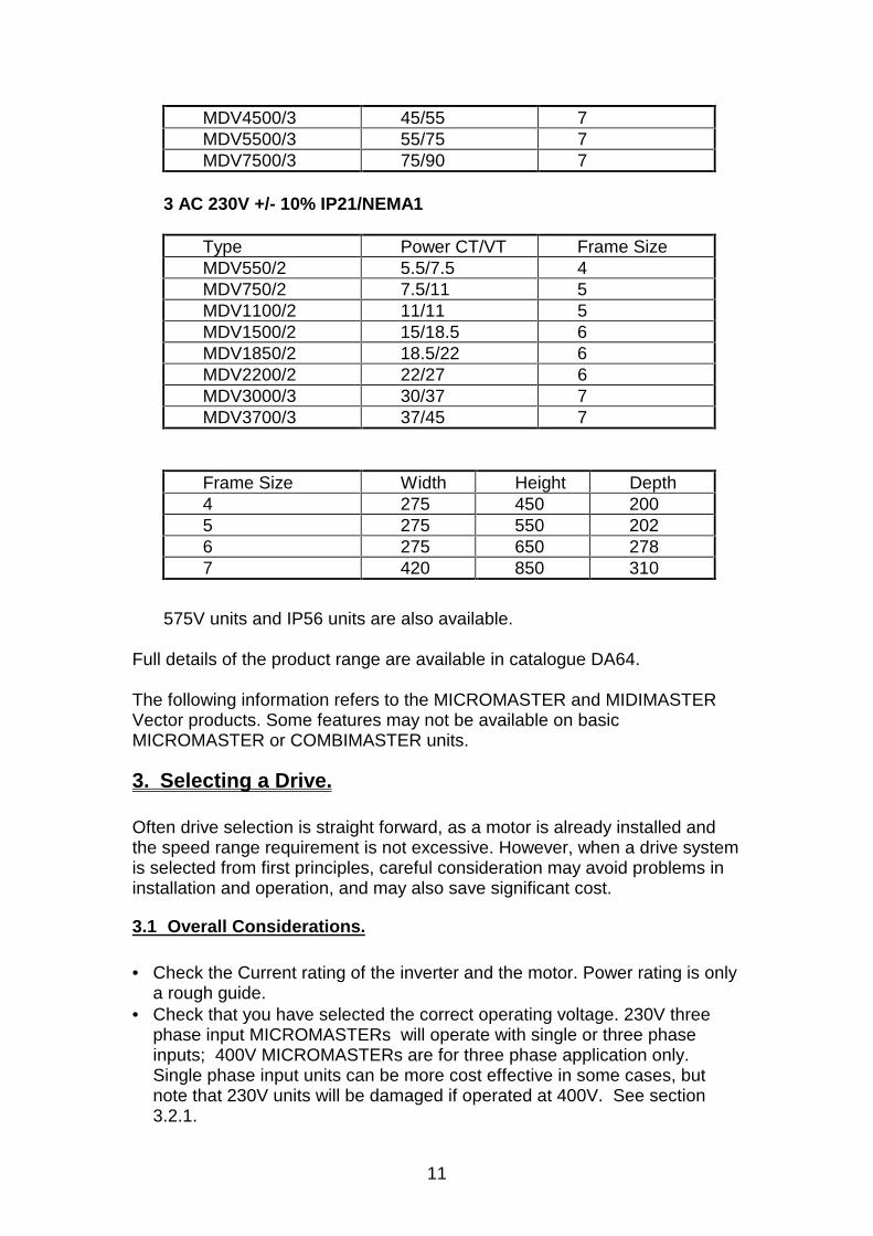
MDV4500/3 45/55 7MDV5500/3 55/75 7MDV7500/3 75/90 7
3 AC 230V +/- 10% IP21/NEMA1
Type Power CT/VT Frame SizeMDV550/2 5.5/7.5 4MDV750/2 7.5/11 5MDV1100/2 11/11 5MDV1500/2 15/18.5 6MDV1850/2 18.5/22 6MDV2200/2 22/27 6MDV3000/3 30/37 7MDV3700/3 37/45 7
Frame Size Width Height Depth4 275 450 2005 275 550 2026 275 650 2787 420 850 310
575V units and IP56 units are also available.
Full details of the product range are available in catalogue DA64.
The following information refers to the MICROMASTER and MIDIMASTERVector products. Some features may not be available on basicMICROMASTER or COMBIMASTER units.
3. Selecting a Drive.
Often drive selection is straight forward, as a motor is already installed andthe speed range requirement is not excessive. However, when a drive systemis selected from first principles, careful consideration may avoid problems ininstallation and operation, and may also save significant cost.
3.1 Overall Considerations.
• Check the Current rating of the inverter and the motor. Power rating is onlya rough guide.
• Check that you have selected the correct operating voltage. 230V threephase input MICROMASTERs will operate with single or three phaseinputs; 400V MICROMASTERs are for three phase application only.Single phase input units can be more cost effective in some cases, butnote that 230V units will be damaged if operated at 400V. See section3.2.1.
12
• MIDIMASTERs will operate with three phase only, and are available for230V, 400V or 575V supplies.
• Check the speed range you require. Operation above normal supplyfrequency (50 or 60Hz) is usually only possible at reduced power.Operation at low frequency and high torque can cause the motor tooverheat due to lack of cooling.
• Synchronous motors require de-rating, typically by 2-3 times. This isbecause the power factor, and hence the current, can be very high at lowfrequency.
• Check overload performance. The inverter will limit current to 150 or 200 %of full current very quickly - a standard, fixed speed motor will toleratethese overloads.
• Do you need to stop quickly? If so, consider using a braking resistor(braking unit on MIDIMASTERs) to absorb the energy.
• Do you need to operate with cables longer than 50m, or screened orarmoured cables longer than 25m? If so, it may be necessary to de-rate, orfit a choke to compensate for the cable capacitance.
3.2 Supply Side Requirements
In order to achieve reliable operation, the main power supply to the invertersystem must be suited to the inverter and the anticipated power supplied. Thefollowing points should be considered:
3.2.1 Supply Tolerance.
The inverters are designed to operate on a wide range of supply voltages asfollows:
Low Voltage units 208 - 240 V +/- 10% i.e. 187-264VHigh Voltage units 380 - 500 V +/- 10% i.e. 342-550VVery high Voltage units 525 - 575 V +/- 10% i.e. 472-633V
Inverters will operate over a supply frequency of 47 - 63 Hz
Many supplies vary outside these levels. For example:• Supplies at the end of long power lines in remote areas can rise
excessively in the evening and weekends when large loads are no longerpresent.
• Industries with locally controlled and generated supplies can have poorregulation and control.
• Power systems in certain parts of the world may not meet expectedtolerances.
In all installations, check that the supply will remain within the tolerancesstated above. Operation outside of the stated supply levels will probablycause damage.
13
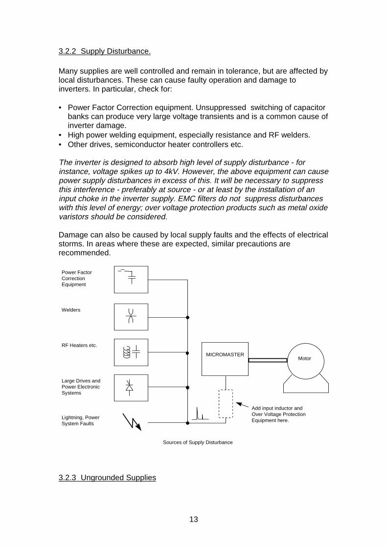
3.2.2 Supply Disturbance.
Many supplies are well controlled and remain in tolerance, but are affected bylocal disturbances. These can cause faulty operation and damage toinverters. In particular, check for:
• Power Factor Correction equipment. Unsuppressed switching of capacitorbanks can produce very large voltage transients and is a common cause ofinverter damage.
• High power welding equipment, especially resistance and RF welders.• Other drives, semiconductor heater controllers etc.
The inverter is designed to absorb high level of supply disturbance - forinstance, voltage spikes up to 4kV. However, the above equipment can causepower supply disturbances in excess of this. It will be necessary to suppressthis interference - preferably at source - or at least by the installation of aninput choke in the inverter supply. EMC filters do not suppress disturbanceswith this level of energy; over voltage protection products such as metal oxidevaristors should be considered.
Damage can also be caused by local supply faults and the effects of electricalstorms. In areas where these are expected, similar precautions arerecommended.
MICROMASTERMotor
Power Factor Correction Equipment
Welders
RF Heaters etc.
Large Drives andPower ElectronicSystems
Lightning, PowerSystem Faults
Sources of Supply Disturbance
Add input inductor and Over Voltage ProtectionEquipment here.
3.2.3 Ungrounded Supplies
14
Certain industrial installations operate with supplies that are isolated from theprotective earth (IT supply). This permits equipment to continue to runfollowing an earth fault. However, MICROMASTERs and MIDIMASTERs aredesigned to operate on grounded supplies and are fitted with interferencesuppression capacitors between the supply and ground. Hence operation onungrounded supplies must be restricted. Please consult Siemens forclarification.
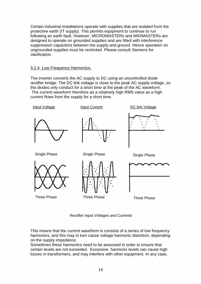
3.2.4 Low Frequency Harmonics.
The inverter converts the AC supply to DC using an uncontrolled dioderectifier bridge. The DC link voltage is close to the peak AC supply voltage, sothe diodes only conduct for a short time at the peak of the AC waveform. The current waveform therefore as a relatively high RMS value as a highcurrent flows from the supply for a short time.
Input Voltage
Single Phase
Three Phase
DC link Voltage
Single Phase
Three Phase
Input Current
Single Phase
Three Phase
Rectifier Input Voltages and Currents
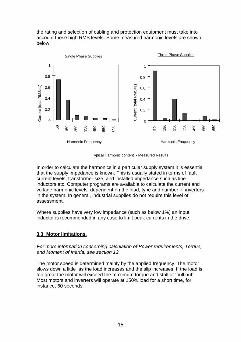
This means that the current waveform is consists of a series of low frequencyharmonics, and this may in turn cause voltage harmonic distortion, dependingon the supply impedance.Sometimes these harmonics need to be assessed in order to ensure thatcertain levels are not exceeded. Excessive harmonic levels can cause highlosses in transformers, and may interfere with other equipment. In any case,
15
the rating and selection of cabling and protection equipment must take intoaccount these high RMS levels. Some measured harmonic levels are shownbelow.
0
0.2
0.4
0.6
0.8
1
50 150
250
350
450
550
650
Harmonic Frequency
Three Phase Supplies
0
0.2
0.4
0.6
0.8
1
50
150
250
350
450
550
650
Harmonic Frequency
Single Phase Supplies
Cur
rent
(to
tal R
MS
=1)
Cur
rent
(to
tal R
MS
=1)
Typical Harmonic content - Measured Results
In order to calculate the harmonics in a particular supply system it is essentialthat the supply impedance is known. This is usually stated in terms of faultcurrent levels, transformer size, and installed impedance such as lineinductors etc. Computer programs are available to calculate the current andvoltage harmonic levels, dependent on the load, type and number of invertersin the system. In general, industrial supplies do not require this level ofassessment.
Where supplies have very low impedance (such as below 1%) an inputinductor is recommended in any case to limit peak currents in the drive.
3.3 Motor limitations.
For more information concerning calculation of Power requirements, Torque,and Moment of Inertia, see section 12.
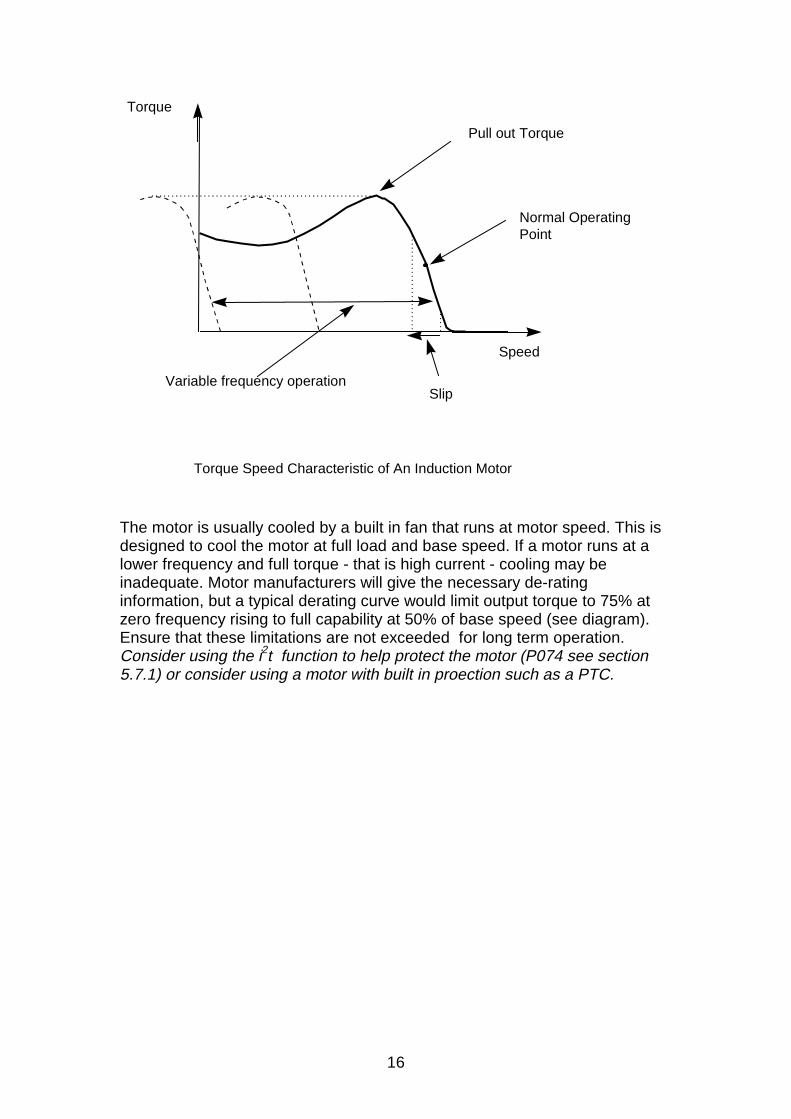
The motor speed is determined mainly by the applied frequency. The motorslows down a little as the load increases and the slip increases. If the load istoo great the motor will exceed the maximum torque and stall or ‘pull out’.Most motors and inverters will operate at 150% load for a short time, forinstance, 60 seconds.
16
Speed
Normal OperatingPoint
Torque Speed Characteristic of An Induction Motor
Slip
Pull out Torque
Torque
Variable frequency operation
The motor is usually cooled by a built in fan that runs at motor speed. This isdesigned to cool the motor at full load and base speed. If a motor runs at alower frequency and full torque - that is high current - cooling may beinadequate. Motor manufacturers will give the necessary de-ratinginformation, but a typical derating curve would limit output torque to 75% atzero frequency rising to full capability at 50% of base speed (see diagram).Ensure that these limitations are not exceeded for long term operation.Consider using the i2t function to help protect the motor (P074 see section5.7.1) or consider using a motor with built in proection such as a PTC.
17
0 0.5 1.0 1.2 1.5
Torque
150%
100%
Short term overloadCapability (60sec)
Speed ( X 50/60)
Possible limited operation due to motor cooling
Continuous Operating Area
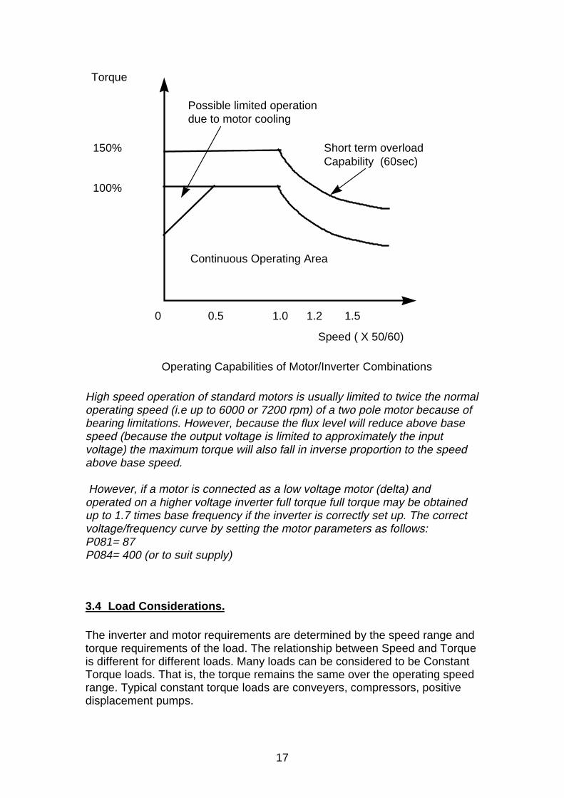
Operating Capabilities of Motor/Inverter Combinations
High speed operation of standard motors is usually limited to twice the normaloperating speed (i.e up to 6000 or 7200 rpm) of a two pole motor because ofbearing limitations. However, because the flux level will reduce above basespeed (because the output voltage is limited to approximately the inputvoltage) the maximum torque will also fall in inverse proportion to the speedabove base speed.
However, if a motor is connected as a low voltage motor (delta) andoperated on a higher voltage inverter full torque full torque may be obtainedup to 1.7 times base frequency if the inverter is correctly set up. The correctvoltage/frequency curve by setting the motor parameters as follows:P081= 87P084= 400 (or to suit supply)
3.4 Load Considerations.
The inverter and motor requirements are determined by the speed range andtorque requirements of the load. The relationship between Speed and Torqueis different for different loads. Many loads can be considered to be ConstantTorque loads. That is, the torque remains the same over the operating speedrange. Typical constant torque loads are conveyers, compressors, positivedisplacement pumps.
18
Speed
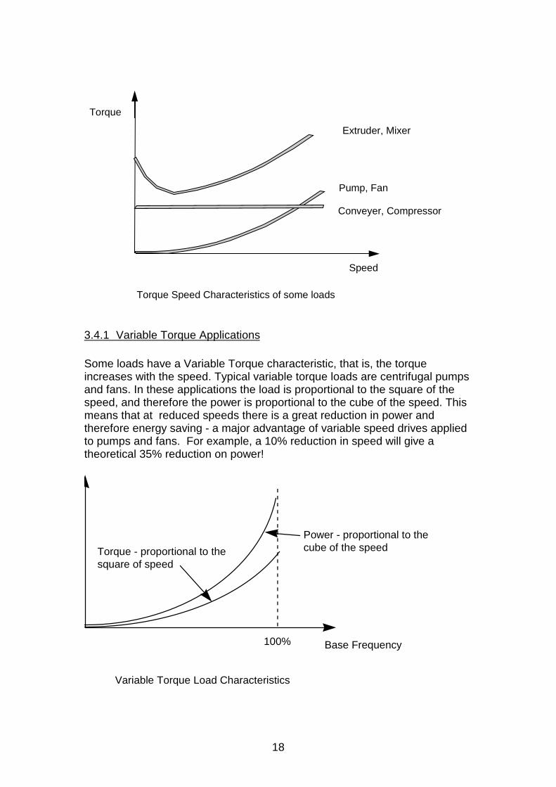
Torque Speed Characteristics of some loads
Pump, Fan
Extruder, Mixer
Conveyer, Compressor
Torque
3.4.1 Variable Torque Applications
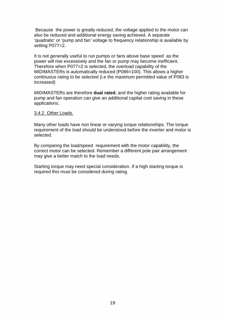
Some loads have a Variable Torque characteristic, that is, the torqueincreases with the speed. Typical variable torque loads are centrifugal pumpsand fans. In these applications the load is proportional to the square of thespeed, and therefore the power is proportional to the cube of the speed. Thismeans that at reduced speeds there is a great reduction in power andtherefore energy saving - a major advantage of variable speed drives appliedto pumps and fans. For example, a 10% reduction in speed will give atheoretical 35% reduction on power!
Variable Torque Load Characteristics
100% Base Frequency
Torque - proportional to the square of speed
Power - proportional to the cube of the speed
19
Because the power is greatly reduced, the voltage applied to the motor canalso be reduced and additional energy saving achieved. A separate‘quadratic’ or ‘pump and fan’ voltage to frequency relationship is available bysetting P077=2.
It is not generally useful to run pumps or fans above base speed as thepower will rise excessively and the fan or pump may become inefficient.Therefore when P077=2 is selected, the overload capability of theMIDIMASTERs is automatically reduced (P086=100). This allows a highercontinuous rating to be selected (i.e the maximum permitted value of P083 isincreased)
MIDIMASTERs are therefore dual rated, and the higher rating available forpump and fan operation can give an additional capital cost saving in theseapplications.
3.4.2 Other Loads.
Many other loads have non linear or varying torque relationships. The torquerequirement of the load should be understood before the inverter and motor isselected.
By comparing the load/speed requirement with the motor capability, thecorrect motor can be selected. Remember a different pole pair arrangementmay give a better match to the load needs.
Starting torque may need special consideration. If a high starting torque isrequired this must be considered during rating.
20
0 0.5 1.0 1.2 1.5
Torque
150%
100%
Speed ( X 50/60)
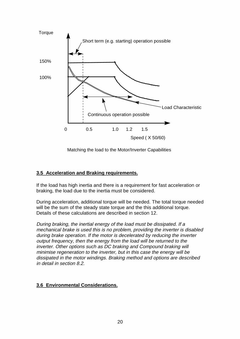
Matching the load to the Motor/Inverter Capabilities
Continuous operation possible
Load Characteristic
Short term (e.g. starting) operation possible
3.5 Acceleration and Braking requirements.
If the load has high inertia and there is a requirement for fast acceleration orbraking, the load due to the inertia must be considered.
During acceleration, additional torque will be needed. The total torque neededwill be the sum of the steady state torque and the this additional torque.Details of these calculations are described in section 12.
During braking, the inertial energy of the load must be dissipated. If amechanical brake is used this is no problem, providing the inverter is disabledduring brake operation. If the motor is decelerated by reducing the inverteroutput frequency, then the energy from the load will be returned to theinverter. Other options such as DC braking and Compound braking willminimise regeneration to the inverter, but in this case the energy will bedissipated in the motor windings. Braking method and options are describedin detail in section 8.2.
3.6 Environmental Considerations.
21
The inverter is designed for operation in an industrial environment. Howeverthere are certain limitations which must be considered; the following check listshould help:
• Check that the airflow through the inverter will not be blocked by wiring etc.• Make sure the temperature of the air does not exceed 50°C. Remember to
allow for any temperature rise inside the box or cubicle.• The inverters are available with protection levels of IP20
(MICROMASTER), IP21 or IP56 (MIDIMASTER). IP20 and IP21 units needadditional protection against dust , dirt, and water. For a detaileddescription of IP rating see section 11.
• The inverter is designed for fixed installation and is not designed towithstand excessive shock and vibration.
• The inverter will be damaged by corrosive atmospheres.• Protect the unit from dust; dust can build up inside the unit, damage the
fans, and prevent proper cooling. Conductive dust, such as metal dust, willdamage the unit.
• Give due consideration to Electromagnetic Compatibility (EMC), such as:Will the inverter be protected from the effects of power equipment suchas Power Factor Correction equipment, Resistance WeldingEquipment etc.?Will the inverter be well grounded?How will the inverter and any control equipment ( contactors, PLCs,relays sensors etc.) interact?
IF IN DOUBT, consult the guidelines and specification information inthe handbook, or see section 6.1.
4. Installing and Getting Started with an Inverter.
4.1 Mounting the MICROMASTER.
• Mount the MICROMASTER using the mounting holes provided asdescribed in the handbook. Ensure the correct torque ratings for the fixingbolts are not exceeded.
• The unit may be mounted horizontally, vertically, or sideways withoutderating. Do not mount the units upside down, as the fan cooling willoppose natural convection cooling.
4.2 Cooling.
• The MICROMASTER will operate in a temperature of 50°C without de-rating.
• The MIDIMASTER’s maximum temperature is 40°C.• Make sure that the inlet and outlet ducts are not blocked, for example by
cable ducts.
22
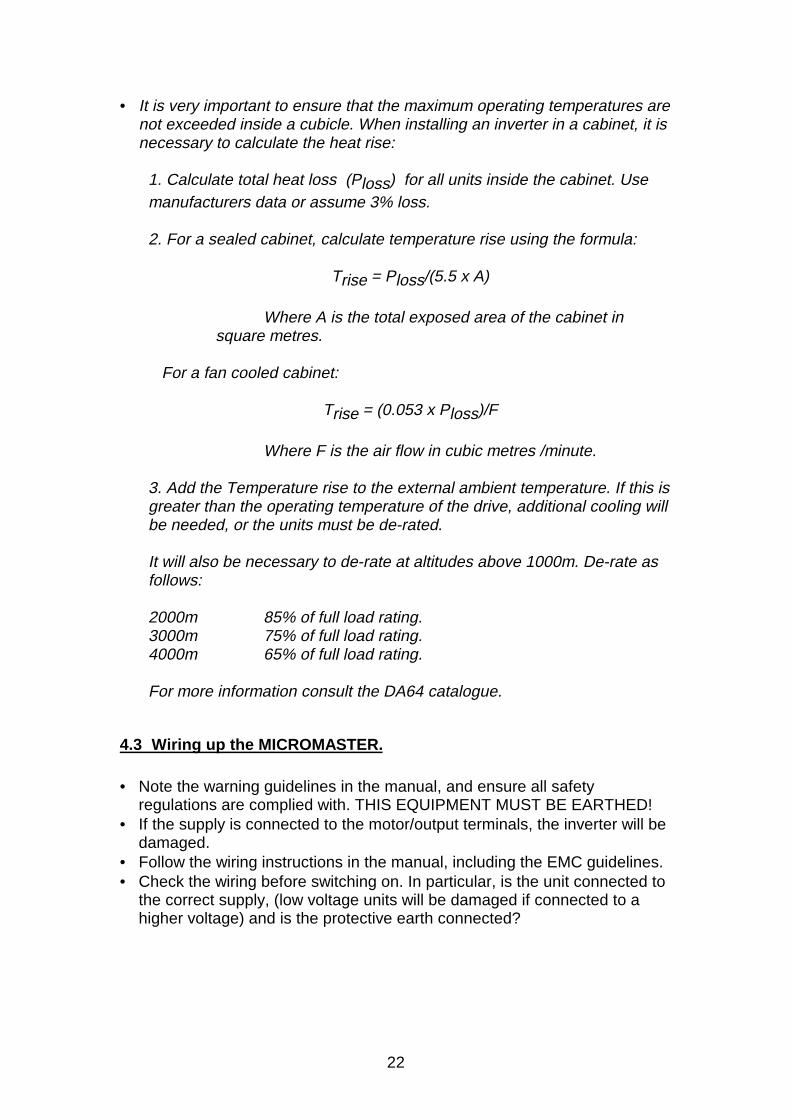
• It is very important to ensure that the maximum operating temperatures arenot exceeded inside a cubicle. When installing an inverter in a cabinet, it isnecessary to calculate the heat rise:
1. Calculate total heat loss (Ploss) for all units inside the cabinet. Usemanufacturers data or assume 3% loss.
2. For a sealed cabinet, calculate temperature rise using the formula:
Trise = Ploss/(5.5 x A)
Where A is the total exposed area of the cabinet in square metres.
For a fan cooled cabinet:
Trise = (0.053 x Ploss)/F
Where F is the air flow in cubic metres /minute.
3. Add the Temperature rise to the external ambient temperature. If this isgreater than the operating temperature of the drive, additional cooling willbe needed, or the units must be de-rated.
It will also be necessary to de-rate at altitudes above 1000m. De-rate asfollows:
2000m 85% of full load rating.3000m 75% of full load rating.4000m 65% of full load rating.
For more information consult the DA64 catalogue.
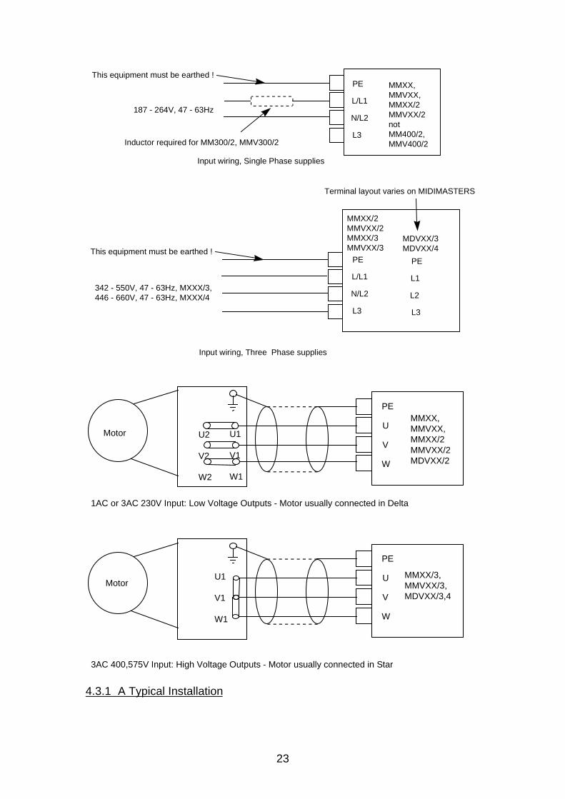
4.3 Wiring up the MICROMASTER.
• Note the warning guidelines in the manual, and ensure all safetyregulations are complied with. THIS EQUIPMENT MUST BE EARTHED!
• If the supply is connected to the motor/output terminals, the inverter will bedamaged.
• Follow the wiring instructions in the manual, including the EMC guidelines.• Check the wiring before switching on. In particular, is the unit connected to
the correct supply, (low voltage units will be damaged if connected to ahigher voltage) and is the protective earth connected?
23
PE
L/L1
N/L2
L3
MMXX,MMVXX,MMXX/2MMVXX/2not MM400/2,MMV400/2
This equipment must be earthed !
187 - 264V, 47 - 63Hz
Inductor required for MM300/2, MMV300/2
Input wiring, Single Phase supplies
PE
L1
L2
L3
MDVXX/3MDVXX/4This equipment must be earthed !
342 - 550V, 47 - 63Hz, MXXX/3,446 - 660V, 47 - 63Hz, MXXX/4
Input wiring, Three Phase supplies
MMXX/2MMVXX/2MMXX/3MMVXX/3
PE
L/L1
N/L2
L3
Terminal layout varies on MIDIMASTERS
PE
W
V
U
PE
W
V
U
1AC or 3AC 230V Input: Low Voltage Outputs - Motor usually connected in Delta
MMXX,MMVXX,MMXX/2MMVXX/2MDVXX/2
3AC 400,575V Input: High Voltage Outputs - Motor usually connected in Star
MMXX/3,MMVXX/3,MDVXX/3,4
U1
V1
W1
U1
V1
W1
U2
V2
W2
Motor
Motor
4.3.1 A Typical Installation
24
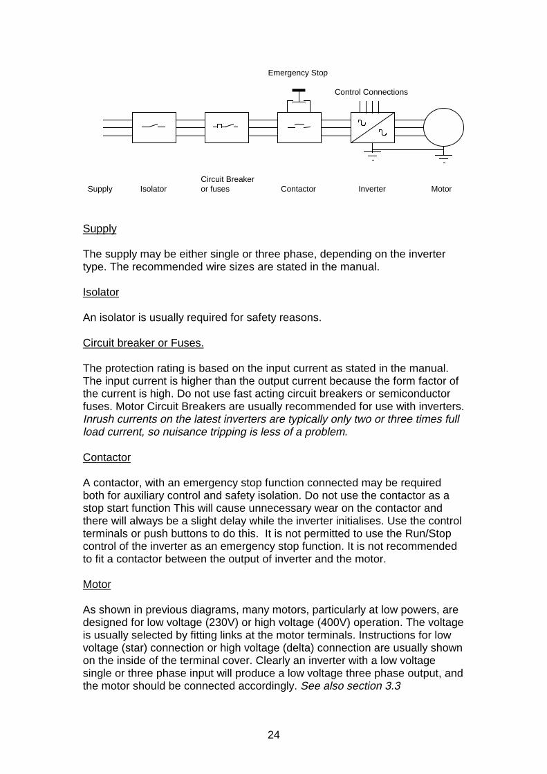
SupplyCircuit Breaker or fusesIsolator Contactor Inverter Motor
Emergency Stop
Control Connections
Supply
The supply may be either single or three phase, depending on the invertertype. The recommended wire sizes are stated in the manual.
Isolator
An isolator is usually required for safety reasons.
Circuit breaker or Fuses.
The protection rating is based on the input current as stated in the manual.The input current is higher than the output current because the form factor ofthe current is high. Do not use fast acting circuit breakers or semiconductorfuses. Motor Circuit Breakers are usually recommended for use with inverters.Inrush currents on the latest inverters are typically only two or three times fullload current, so nuisance tripping is less of a problem.
Contactor
A contactor, with an emergency stop function connected may be requiredboth for auxiliary control and safety isolation. Do not use the contactor as astop start function This will cause unnecessary wear on the contactor andthere will always be a slight delay while the inverter initialises. Use the controlterminals or push buttons to do this. It is not permitted to use the Run/Stopcontrol of the inverter as an emergency stop function. It is not recommendedto fit a contactor between the output of inverter and the motor.
Motor
As shown in previous diagrams, many motors, particularly at low powers, aredesigned for low voltage (230V) or high voltage (400V) operation. The voltageis usually selected by fitting links at the motor terminals. Instructions for lowvoltage (star) connection or high voltage (delta) connection are usually shownon the inside of the terminal cover. Clearly an inverter with a low voltagesingle or three phase input will produce a low voltage three phase output, andthe motor should be connected accordingly. See also section 3.3
25
4.4 First Switch On.
• Apply power to the unit. The display should light up and flash 0.0, 5.0.When the inverter is stopped it flashes between 0.0 and the frequency itwill run to when started (The set point).
• Changing Parameters. The correct parameters can now be set for themotor. Parameters P080 to P085 should be changed as described in thehandbook to suit the motor. To change a parameter, proceed as follows:
Press P Display shows P000Press up or down arrow Display scrolls.When desired parameter shows…Stop, press P again Display shows parameter valuePress up or down arrow Display scrolls.When desired value shows…Press P to set value.Press up or down arrow to return to P000Press P again Display flashes as before.
Remember that to access parameter greater than P009, P009 must be set to3.
If the display flashes instead of changing, the parameter cannot bechanged, either because it is fixed, or the inverter is running and theparameter cannot be changed during running.
• If the unit does not show the expected display, it may be that parametershave been changed for some reason. To change them back to the factorysettings, set parameter 941 to 1.
Press P display shows P000Press down arrow display scrolls P971, P944 etc.When P944 shows…Press P display shows 0000Press up arrow display shows 0001Press P display shows P000Press P display shows 0.0/5.0
Always reset to factory defaults if unsure what parameters have beenchanged and set.• Now press the green button on the front panel. The motor should turn as
the inverter outputs 5.0Hz.• If the motor goes in the wrong direction, switch off at the supply, wait five
minutes for the internal capacitors to discharge, and swap any two motorconnections. Of course, the motor can also be reversed using the frontpanel controls, digital inputs etc.
• If the motor is heavily loaded, or if the parameters have not been correctlyset it may not turn. Set the motor parameters as described in thehandbook.
26
4.5 If the motor does not start.
Check through the following table. In general, if the inverter operates withoutthe motor and load connected, it is probable the inverter is undamaged andthe fault is in the load. Remember, if in doubt, reset parameters to Factorydefaults and start again.
Trouble Shooting SummaryAction Display Possible Cause Remedy; stop and …Apply Power no
displayno Power, lowsupply, faulty unit
Check supply is intolerance. Check fuses etc.
Apply Power - - - -,8888
Low supply, faultyunit
Check supply is intolerance.
Apply Power FXXX Faulty parametersettings, internalfault
Switch off, Switch on,disconnect load.Try again. Check fault typein Manual.
Run Command Flashes overload or similarwarning.
Check warning type inManual. Reset parameters,check load and reduce ifnecessary.Try again.
Run Command F002 overload, faultyunit.
Reset Fault (Press Pbutton twice). Resetparameters, disconnectload and motor if needed.Try again.
Run Command 000.0 Run command notreceived or SetPoint equal to000.0
Reset parameters, Tryusing front panel controls,check set point setting e.g.P005.
Run Command FXXX Other Fault Reset fault, Resetparameters, disconnectload.Try again.
5. Some Simple Applications and PossibilitiesMost inverters used in industry are controlled via the control terminals, not thefront panel as described above. This section describes some simple controlpossibilities using these inputs, and some of the programmable features thatmay prove useful. The following descriptions include terminal numbers andparameter values which are valid for MICROMASTER Vector andMIDIMASTER Vector inverters; if other products are used please check theterminal numbers in the handbook.
27
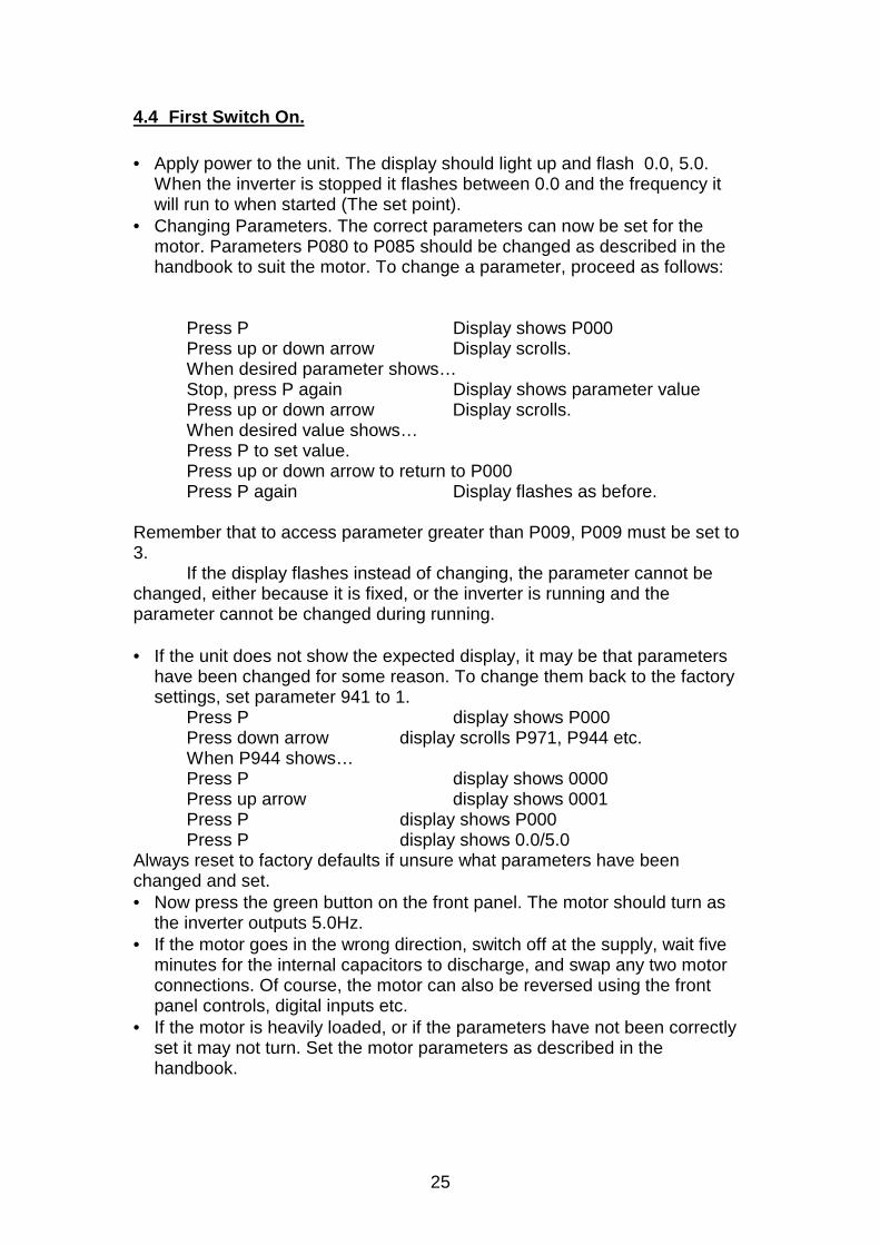
5.1 Using a Potentiometer with the Analog Input.
Set Parameter P006 = 001 and connect a potentiometer (between 5kohmand 100kohm) to the analog input as shown in the handbook. ThePotentiometer is wired as shown:
1
2
3
4
Potentiometer Connection
MICROMASTER
The inverter can be started using the front panel controls, and the outputfrequency adjusted using the potentiometer.The default maximum and minimum settings for the analog input are 50(P022) and 0Hz (P021) respectively, so the inverter will run at a frequencysomewhere between this frequencies, depending on the potentiometerposition.
Changing P021 and P022 will change the range of the potentiometeraccordingly, but remember the absolute maximum and minimum settings areset by parameters P012 and P013. Note that many parameters cannot bechanged while the inverter is running. The display will flash if this isattempted.
Note that the Run and Stop control is still via the front panel buttons.
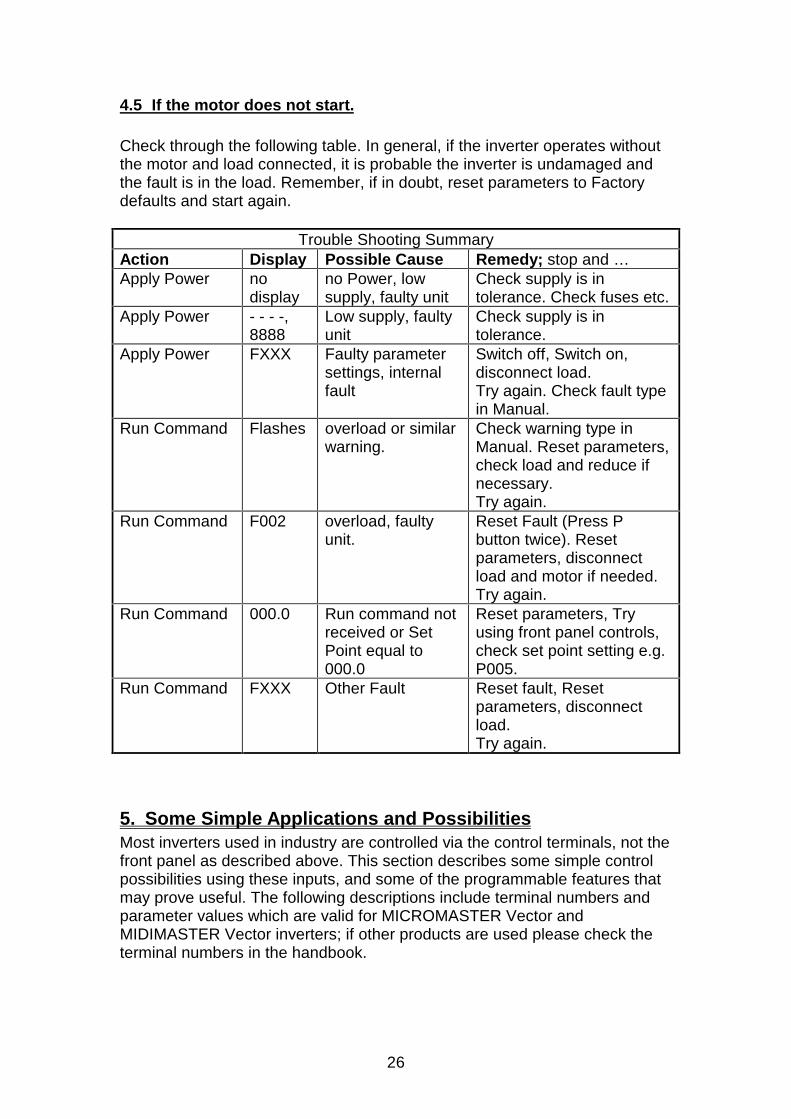
5.2 Using a Digital Input.
The digital inputs on the inverter are programmable and many differentfunctions can be selected. The digital inputs have default settings which areused below, but can be easily changed.
With the potentiometer still connected, set parameter P007 to 0 to disable thefront panel controls, and connect a switch between terminals 5 (digital input 1,default function ON right) and 9 (15V supply for this purpose). Closing theswitch should start the inverter, which will run at a frequency set by thepotentiometer as before.
28
9
5
7
8
MICROMASTER
16
Digital inputs
+15V Output
DIN 3
DIN 1
DIN 4
DIN 5
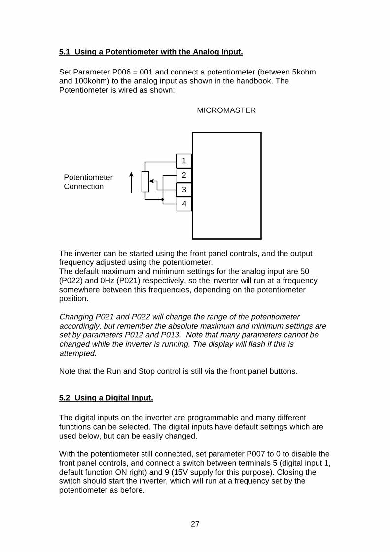
5.3 Using the Fixed Frequencies.
Fixed Frequencies can be selected using digital inputs. Set parameter P006to 2 (select fixed frequency operation), and connect additional switches fromterminal 5 to terminals 7,8,16 (digital inputs 3,4 and 5). These switches cannow be used to select fixed frequencies 1,4 and 5 (default values 5,20,25 Hz).A separate Run and Stop signal is still needed using the existing switchconnected to terminal 5.
Closing more than one switch will simply add the two fixed frequenciestogether.
Forward and reverse functions can be implemented using parameter P045and 50. Changing Parameter P045 to 7 will reverse the direction of fixedfrequencies 1 and 4. Again, closing more than one switch will add or subtractfixed frequency values.
In Summary:P006=2 selects fixed frequenciesP053,54,55 etc = 6 selects digital inputs to fixed frequency controlP045,50 selects run direction options.
More Complex Uses of Fixed frequencies.
If the corresponding digital inputs are reprogrammed from 6 to 17, the inputswill selected fixed frequencies in binary coding, allowing the three inputs toselect up to 8 digital inputs.
Setting the digital inputs to 18 will allow Run/Stop control via these digitalinputs as well, so a separate Run/Stop control is not needed. I.e the inverterwill start when any input is enabled.
The Fixed frequencies can be added or scaled to the fixed frequencies bychanging parameter P024.
29
Please consult the handbook for additional details.
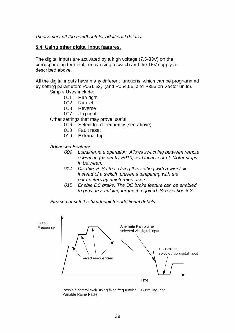
5.4 Using other digital input features.
The digital inputs are activated by a high voltage (7.5-33V) on thecorresponding terminal, or by using a switch and the 15V supply asdescribed above. All the digital inputs have many different functions, which can be programmedby setting parameters P051-53, (and P054,55, and P356 on Vector units).
Simple Uses include:001 Run right002 Run left003 Reverse007 Jog right
Other settings that may prove useful:006 Select fixed frequency (see above)010 Fault reset019 External trip
Advanced Features:009 Local/remote operation. Allows switching between remote
operation (as set by P910) and local control. Motor stopsin between.
014 Disable ‘P’ Button. Using this setting with a wire linkinstead of a switch prevents tampering with theparameters by uninformed users.
015 Enable DC brake. The DC brake feature can be enabledto provide a holding torque if required. See section 8.2.
Please consult the handbook for additional details.
Time
Possible control cycle using fixed frequencies, DC Braking, and Variable Ramp Rates
Output Frequency
Fixed Frequencies
Alternate Ramp time selected via digital input
DC Braking selected via digital input
30
5.5 Using the control outputs.
There are several control outputs which can be used to control externalindicators or warn of potential problems.
Analog Output (Vector units only). The Analog output may be set to giveseveral different indications as described in parameter P025. The output is0/4-20mA, but can be easily converted to a voltage by fitting a resistor (500ohms for 0-10V for instance). The MIDIMASTER Vector has two Analogoutputs.
Relays. An indicator relay ( two on Vector Units) is provided which maybeprogrammed to give a variety of indications using parameter P061. The relayis often used to indicate set point reached (P061=7) warning active (P061=8)output current exceeding a set value (P061=9).
The relays can be used to control an external brake. In this case, a timerfunction can be used to start the inverter and release the brake as describedin parameter P063. In this case, the relay must be suppressed and acontactor used to switch the brake itself. See section 5.8.6.
The relay contacts should be suppressed where inductive loads suchas contactor coils or electromagnetic brakes are switched.
5.6 Current Limit and Protection Systems
The inverter must protect itself, the motor and system from overload andpossible damage. Current limit now operates very rapidly, limiting the currentand preventing a trip occurring.
The inverter has several levels of current limiting:
31
Electronic Limit 300%
Overload level:P083*P086; Max. 150%
Nominal Current
Maximum Continuous Current 100%
3s60s depending
on P083*P086 360s 420s
Output Current
Instantaneous level: (P186) up to 200%
Nominal Current
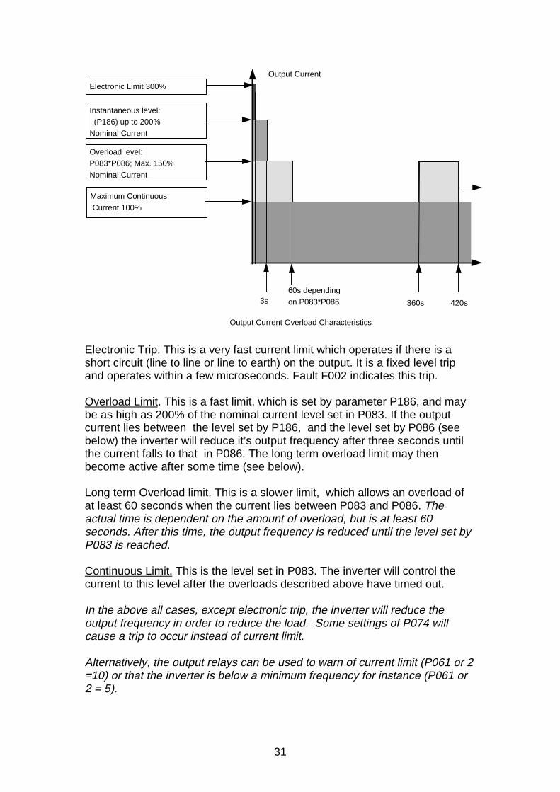
Output Current Overload Characteristics
Electronic Trip. This is a very fast current limit which operates if there is ashort circuit (line to line or line to earth) on the output. It is a fixed level tripand operates within a few microseconds. Fault F002 indicates this trip.
Overload Limit. This is a fast limit, which is set by parameter P186, and maybe as high as 200% of the nominal current level set in P083. If the outputcurrent lies between the level set by P186, and the level set by P086 (seebelow) the inverter will reduce it’s output frequency after three seconds untilthe current falls to that in P086. The long term overload limit may thenbecome active after some time (see below).
Long term Overload limit. This is a slower limit, which allows an overload ofat least 60 seconds when the current lies between P083 and P086. Theactual time is dependent on the amount of overload, but is at least 60seconds. After this time, the output frequency is reduced until the level set byP083 is reached.
Continuous Limit. This is the level set in P083. The inverter will control thecurrent to this level after the overloads described above have timed out.
In the above all cases, except electronic trip, the inverter will reduce theoutput frequency in order to reduce the load. Some settings of P074 willcause a trip to occur instead of current limit.
Alternatively, the output relays can be used to warn of current limit (P061 or 2=10) or that the inverter is below a minimum frequency for instance (P061 or2 = 5).
32
If P086 and P186 are set to 100%, then the current limit set in P083 willoperate instantly.If P083 is set lower than the nominal value then P086 can be set higher - e.g.up to 250%, representing the capability of the inverter, but not necessarily themotor or load. I.e. the maximum permitted value P083 X P086 is constant forany one inverter type.When Vector operation (P077=3) is selected, the current limit effectivelyoperates as a torque limit between 5 and 50Hz.If the Current limit is active the display flashes and the warning code 002 iswritten to parameter P931 (most recent warning).The current is limited by reducing the output frequency; fast current limit - forinstance during ramping - is controlled by reducing output voltage.
5.7 Other Protection Features
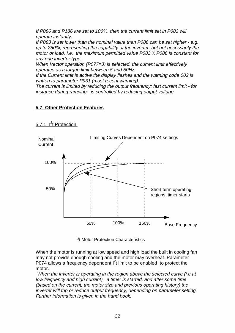
5.7.1 I2t Protection.
i2t Motor Protection Characteristics
50% 100% 150% Base Frequency
Nominal Current
100%
50%
Limiting Curves Dependent on P074 settings
Short term operatingregions; timer starts
When the motor is running at low speed and high load the built in cooling fanmay not provide enough cooling and the motor may overheat. ParameterP074 allows a frequency dependent I2t limit to be enabled to protect themotor. When the inverter is operating in the region above the selected curve (i.e atlow frequency and high current), a timer is started, and after some time(based on the current, the motor size and previous operating history) theinverter will trip or reduce output frequency, depending on parameter setting.Further information is given in the hand book.
33
5.7.2 PTC Resistor Protection.
Many motors are available with a PTC ( Positive Temperature Coefficient )resistor built into the windings. The resistance of the PTC rises rapidly at aparticular temperature, and this change can be detected by the inverter. If thePTC is connected to terminals 14 and 15, and the PTC input enabled bysetting parameter P087=001, then if the PTC resistance rises above 2kohm,the inverter will trip and F004 displayed.
Most Motor Protection PTCs have a resistance of 2-300 ohms when cold.This value rises rapidly at the ‘knee point’ to typically 10kohms and greater.The PTC input is set so that it will operate at 1kohm minimum, 1.5kohmnominal, and 2kohm maximum. The input has considerable filtering becausethe PTC connection usually carries considerable EMI. On this basis tow orthree PTCs may be connected in series when a motor has more than onePTC built in, or if two or three motors are connected to the inverter output andrequire individual protection.
5.7.3 Overvoltage
If the inverter is connected to a high voltage, or if the internal voltage is forcedhigh by energy from an external load, then the inverter will trip and F001 willbe displayed. Overvoltage usually occurs as a result of a braking orregenerative load, see section 8.2.
If the supply voltage is too high the inverter may be damaged even if it trips.
5.7.4 Internal Overtemperture
The inverter is protected from overheating. The heatsink temperature ismonitored using a PTC and if the maximum temperature exceeded theinverter will trip. F005 will be displayed.
Overtemperature in the inverter is usually caused by a high ambienttemperature, a faulty or blocked fan, or blocked air inlet or outlet.
5.8 Some Additional Features
The MICROMASTER has many useful features built into the software andavailable for the user. Some of these are briefly described below; the manualgives details of how to select and use these features. Advanced featuressuch as Serial Interface, Closed loop Control, Braking operation etc. aredescribed section 8.
34
5.8.1 Display Mode P001.The display normally shows the output frequency, but output current, motorspeed etc. can be selected instead.
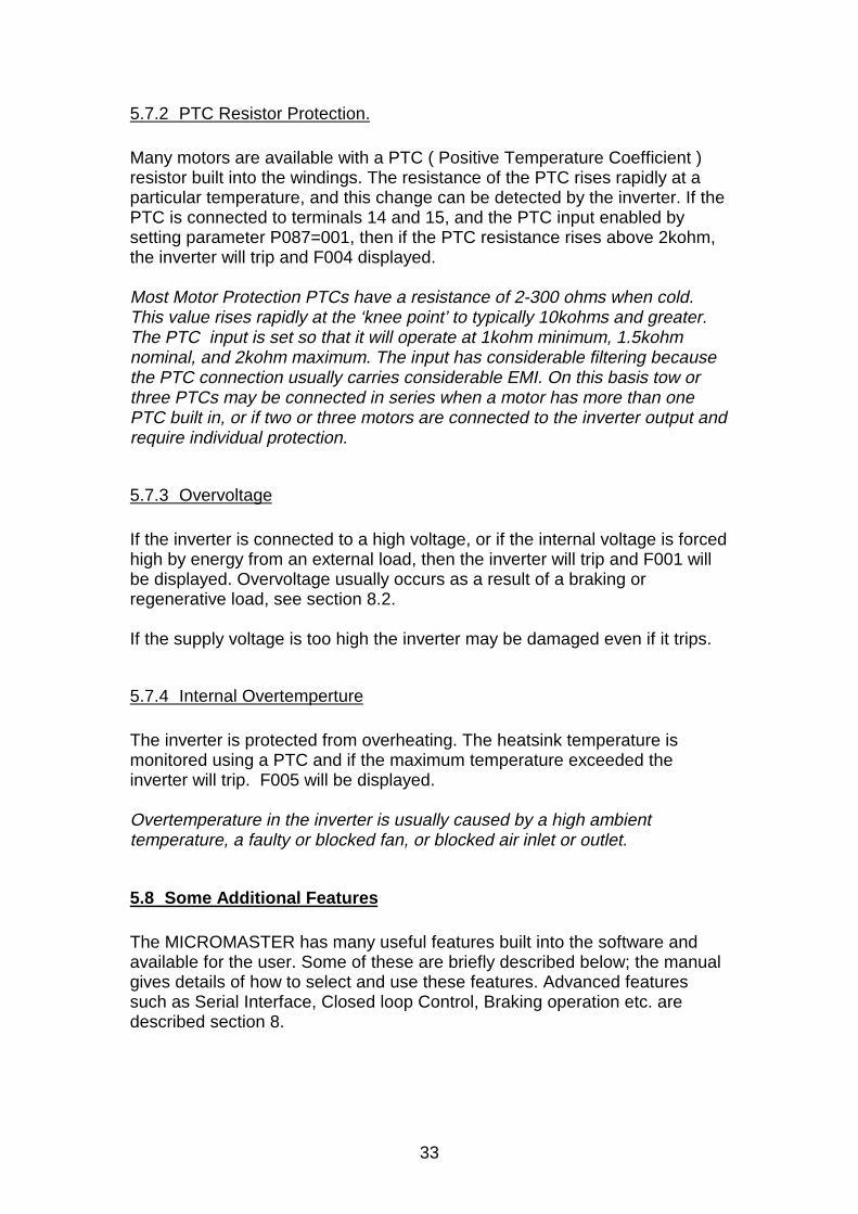
5.8.2 Ramp Smoothing P004.The rate of change of ramp can be limited to limit ‘jerk’. The smoothing iscalculated from the Ramp up time, so if the ramp down time is very differentsmoothing will not be so effective during ramp down. Smoothing is noteffective at ramp rates of less than 0.3 seconds. Smoothing has the effectthat if the inverter is ramping up and a stop signal given, there will be a delaybefore the inverter begins to ramp down again. This effect can be optionallydisabled using parameter P017 .
Time
Frequency
Normal Ramping
Ramping with smoothing
Smoothing applied to up and down Ramps.
5.8.3 Display Scaling P010. The value in display can be scaled to match the process and show ‘Litres perminute’ or ‘Metres per second’ etc.
5.8.4 Skip Frequencies. P014 etc. If these frequencies are set, the inverter will not run at these outputfrequencies; resonance problems can be avoided using this feature.The bandwidth can be adjusted by setting parameter P019. That is, if P019 isset to 2, and P014 set to 15, the inverter will not run between 13 and 17Hz.However, during ramping the inverter will ramp through these frequenciesnormally to avoid a ‘step’.
35
5.8.5 Start on the Fly P016. Normally if the inverter attempts to start on a motor that is already rotating itwill current limit, stall or slow the motor down. If Start on the Fly is selected itwill sense the speed of the motor and ramp the motor from that speed back tothe set point. This is useful if the motor is already turning for some reason,such as following a short mains break.Start on the fly can operate when the load is rotating in the reverse direction,for instance when a fan is rotating due to reverse pressure. In this case, themotor direction is tested at low torque in forward and reverse directions. Thiscan have the undesirable effect that the motor rotates in both directions atstart up. Parameter P016 offers options to test operation in one direction onlyto prevent this.
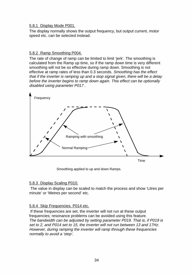
5.8.6 Electro-Mechanical Brake Control P063, P064. The relays can be programmed to control a separate brake (P061 or 62 = 4)and a delay set (P063, P064) so the motor can be energised prior to relayrelease. During the time set in P063 and P064 the inverter runs at it’sminimum frequency while the brake is energised, so that when the brake isreleased the motor will move immediately.
Time
Possible control cycle using brake control relay and times
Output Frequency
Minimum Frequency
Time set by P063
Time set by P064
Relay can be used to controlexternal brake during these tmes
Even if no brake is connected, this timer feature can prove useful if operationat low speed, or even zero speed ( which has the same effect as DC braking -see section 8.2.2) is required for a defined time (P063,P064) at the beginningor end of a sequence.
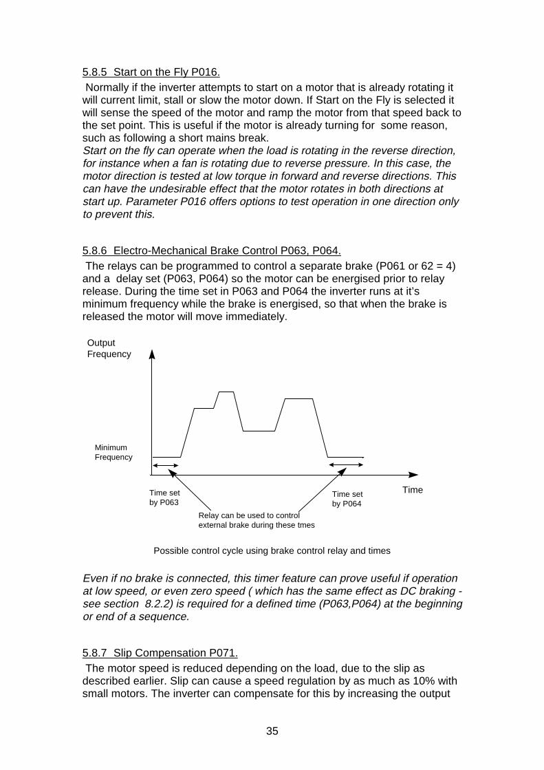
5.8.7 Slip Compensation P071. The motor speed is reduced depending on the load, due to the slip asdescribed earlier. Slip can cause a speed regulation by as much as 10% withsmall motors. The inverter can compensate for this by increasing the output
36
frequency slightly as the load increases. The inverter measures the currentand increases the output frequency to compensate for the expected slip.Thiscan give speed holding of better than 1%.Slip compensation has no effect during Sensorless Vector Operation ascompensation is inherent.Slip compensation is a positive feedback effect (increasing load increasesoutput frequency), and too much compensation may cause slight instability. Itis set up on a trial and error basis.
Load Change
Speed Changewithout slip
compensation
Tor
que/
Cur
rent
Speed
5.8.8 Pulse Frequency selection P076.The switching, or pulse width modulation frequency does not change withoutput frequency (see section1.2); it is set by P076.The switching frequencyof the inverter can be selected between 2 and 16kHz. A high switchingfrequency has higher losses and produces more Electromagnetic Interference(EMI). A lower switching frequency may produce audible noise. The switchingfrequency can be changed to suit the application, but some derating (asdescribed in the handbook) may be necessary on certain units. The acoustic noise generated has a frequency of twice the switchingfrequency, except at light loads, where there is some fundamental frequencycontent. Therefore a switching frequency of 8kHz will often be inaudible.
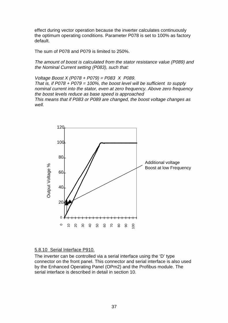
5.8.9 Boost. P078 and P079. At low output frequencies the output voltage is low to keep the flux levelconstant, as described earlier. However, the voltage may be too low toovercome losses in the system. The voltage can be increased usingparameter P078. Parameter P079 will only produce boost during ramping,and is therefore useful for additional torque during starting. Boost has no
37
effect during vector operation because the inverter calculates continuouslythe optimum operating conditions. Parameter P078 is set to 100% as factorydefault.
The sum of P078 and P079 is limited to 250%.
The amount of boost is calculated from the stator resistance value (P089) andthe Nominal Current setting (P083), such that:
Voltage Boost X (P078 + P079) = P083 X P089.That is, if P078 + P079 = 100%, the boost level will be sufficient to supplynominal current into the stator, even at zero frequency. Above zero frequencythe boost levels reduce as base speed is approachedThis means that if P083 or P089 are changed, the boost voltage changes aswell.
0
20
40
60
80
100
120
0 10 20 30 40 50 60 70 80 90 100
Additional voltage Boost at low Frequency
Out
put V
olta
ge %
5.8.10 Serial Interface P910.The inverter can be controlled via a serial interface using the ‘D’ typeconnector on the front panel. This connector and serial interface is also usedby the Enhanced Operating Panel (OPm2) and the Profibus module. Theserial interface is described in detail in section 10.
38
6. Electromagnetic Compatibility (EMC)
6.1 What is EMC?
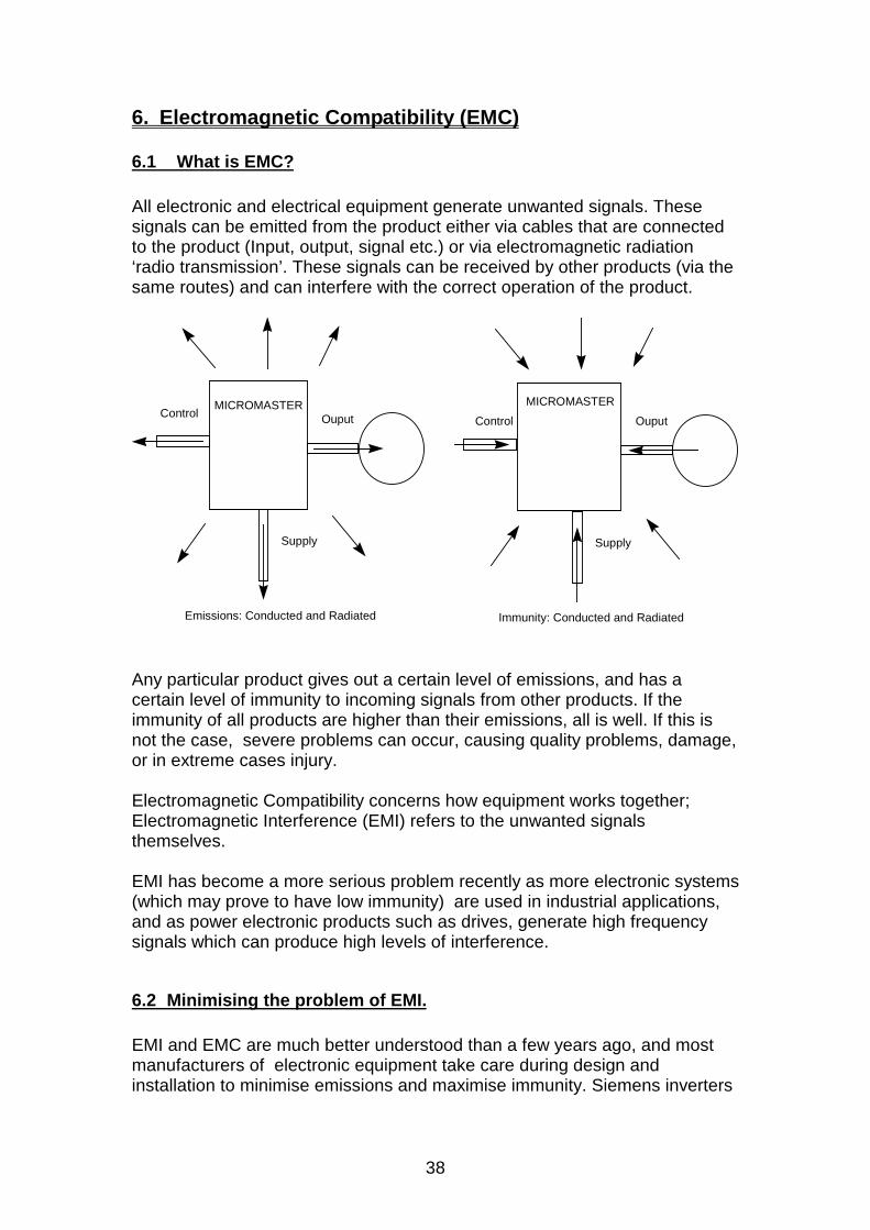
All electronic and electrical equipment generate unwanted signals. Thesesignals can be emitted from the product either via cables that are connectedto the product (Input, output, signal etc.) or via electromagnetic radiation‘radio transmission’. These signals can be received by other products (via thesame routes) and can interfere with the correct operation of the product.
Control Ouput
Supply
Emissions: Conducted and Radiated
Control Ouput
Supply
Immunity: Conducted and Radiated
MICROMASTER MICROMASTER
Any particular product gives out a certain level of emissions, and has acertain level of immunity to incoming signals from other products. If theimmunity of all products are higher than their emissions, all is well. If this isnot the case, severe problems can occur, causing quality problems, damage,or in extreme cases injury.
Electromagnetic Compatibility concerns how equipment works together;Electromagnetic Interference (EMI) refers to the unwanted signalsthemselves.
EMI has become a more serious problem recently as more electronic systems(which may prove to have low immunity) are used in industrial applications,and as power electronic products such as drives, generate high frequencysignals which can produce high levels of interference.
6.2 Minimising the problem of EMI.
EMI and EMC are much better understood than a few years ago, and mostmanufacturers of electronic equipment take care during design andinstallation to minimise emissions and maximise immunity. Siemens inverters
39
are carefully designed with this in mind, and optional filters can be specified(either built in or as an external option) to reduce the emissions in the supply.
Before describing the practical solutions to EMI, it is important to understandthe practical problems associated with EMC and inverters.
• The output of all inverters generates high frequency, high voltageswitching waveforms in the output cables between the motor and inverter.
• A lot of EMI occurs at high frequency. At high frequencies the shape andlength of the cable has a big effect on it’s impedance. Therefore short,thick, braided leads will be most effective in grounding, and high qualityscreened cable, grounded at both ends, will be needed to limit effects onsignal leads.
• If equipment is badly grounded high levels of EMI may connect from thepower part of equipment into the control connections. Similar effects canoccur when badly grounded equipment is connected together and EMI isconducted via the control cables.
• Particular care is needed when equipment is used with low signal sensorssuch as load cells and capacitive sensors.
• Conducted interference is more likely to cause problems than radiatedinterference.
• The signal and control leads in any electronic system are generally lowvoltage, high impedance, and are therefore particularly sensitive to thehigh level of EMI present in industrial systems.
• Switching inductive loads, such as electro-mechanical brakes, relay andcontactor coils generate severe EMI.
6.2.1 Immunity and Immunity testing
Immunity is very important as damage and nuisance tripping will cause failureand service costs irrespective of where the fault lies. Therefore the testscarried out during product development are quite severe, and representconditions encountered in industry.Tests include:• Electrostatic Discharge testing of all exposed surfaces, terminal and
buttons using high voltage discharge gun. This simulates the effect ofdischarge from a human body electrostatically charged from a carpet forexample.
• High voltage very high frequency discharges capacitively coupled into thecontrol lines. This simulates the interference that couples from powerswitching (contactors etc.) into control leads.
• Similar discharges directly into the supply leads, line to line and line toground. This simulates conducted interference from arcing contacts inother equipment.
• High energy, lower frequency interference in the supply leads, line to lineand line to earth. This simulates lightning strike interference and similarsupply disturbance.
40
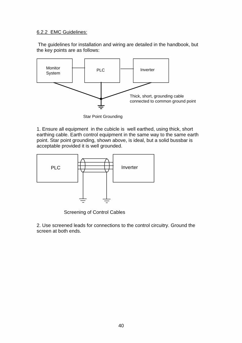
6.2.2 EMC Guidelines:
The guidelines for installation and wiring are detailed in the handbook, butthe key points are as follows:
MonitorSystem
PLC Inverter
Thick, short, grounding cableconnected to common ground point
Star Point Grounding
1. Ensure all equipment in the cubicle is well earthed, using thick, shortearthing cable. Earth control equipment in the same way to the same earthpoint. Star point grounding, shown above, is ideal, but a solid bussbar isacceptable provided it is well grounded.
PLC Inverter
Screening of Control Cables
2. Use screened leads for connections to the control circuitry. Ground thescreen at both ends.
41
MM
MMInput (Supply) Connections
Output (Motor) Connections
Control Connections
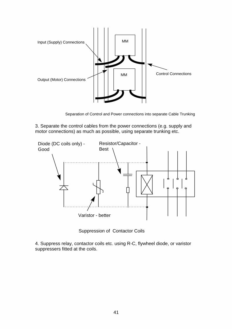
Separation of Control and Power connections into separate Cable Trunking
3. Separate the control cables from the power connections (e.g. supply andmotor connections) as much as possible, using separate trunking etc.
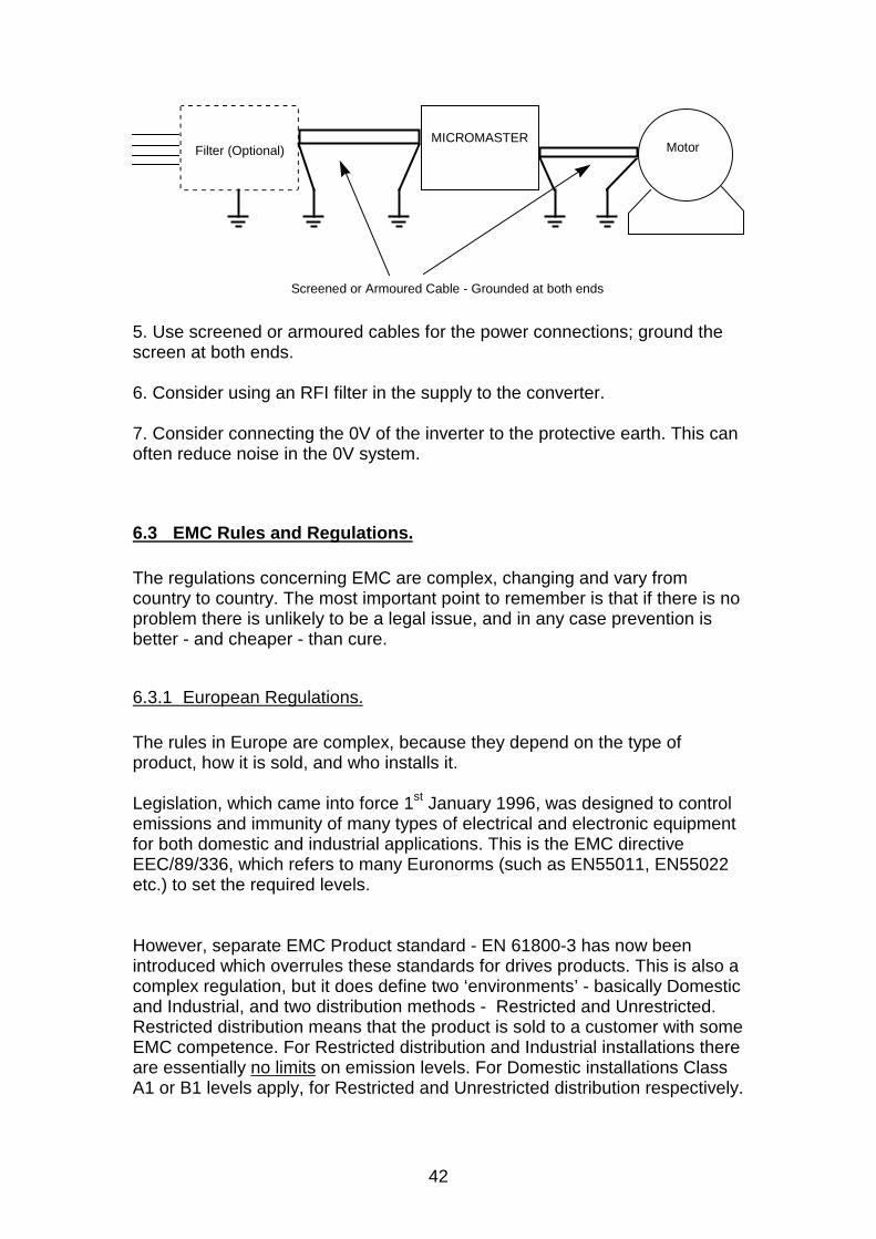
Suppression of Contactor Coils
Diode (DC coils only) - Good
Resistor/Capacitor -Best
Varistor - better
4. Suppress relay, contactor coils etc. using R-C, flywheel diode, or varistorsuppressers fitted at the coils.
42
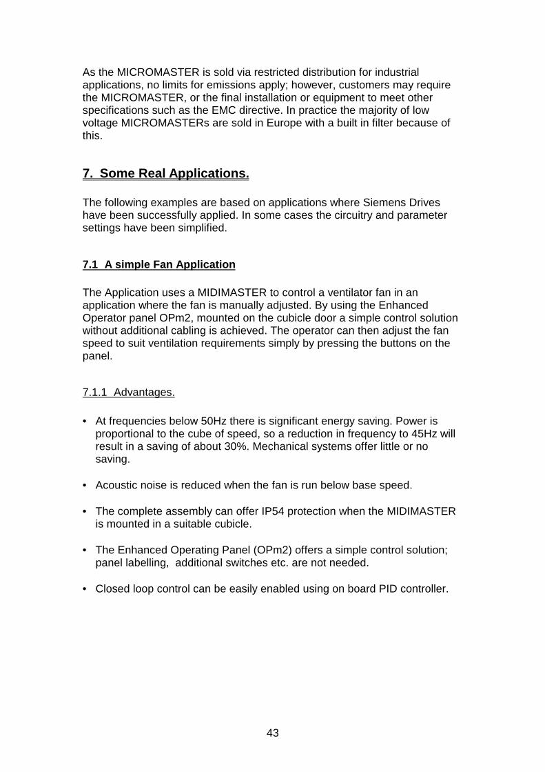
Filter (Optional)MICROMASTER
Screened or Armoured Cable - Grounded at both ends
Motor
5. Use screened or armoured cables for the power connections; ground thescreen at both ends.
6. Consider using an RFI filter in the supply to the converter.
7. Consider connecting the 0V of the inverter to the protective earth. This canoften reduce noise in the 0V system.
6.3 EMC Rules and Regulations.
The regulations concerning EMC are complex, changing and vary fromcountry to country. The most important point to remember is that if there is noproblem there is unlikely to be a legal issue, and in any case prevention isbetter - and cheaper - than cure.
6.3.1 European Regulations.
The rules in Europe are complex, because they depend on the type ofproduct, how it is sold, and who installs it.
Legislation, which came into force 1st January 1996, was designed to controlemissions and immunity of many types of electrical and electronic equipmentfor both domestic and industrial applications. This is the EMC directiveEEC/89/336, which refers to many Euronorms (such as EN55011, EN55022etc.) to set the required levels.
However, separate EMC Product standard - EN 61800-3 has now beenintroduced which overrules these standards for drives products. This is also acomplex regulation, but it does define two ‘environments’ - basically Domesticand Industrial, and two distribution methods - Restricted and Unrestricted.Restricted distribution means that the product is sold to a customer with someEMC competence. For Restricted distribution and Industrial installations thereare essentially no limits on emission levels. For Domestic installations ClassA1 or B1 levels apply, for Restricted and Unrestricted distribution respectively.
43
As the MICROMASTER is sold via restricted distribution for industrialapplications, no limits for emissions apply; however, customers may requirethe MICROMASTER, or the final installation or equipment to meet otherspecifications such as the EMC directive. In practice the majority of lowvoltage MICROMASTERs are sold in Europe with a built in filter because ofthis.
7. Some Real Applications.
The following examples are based on applications where Siemens Driveshave been successfully applied. In some cases the circuitry and parametersettings have been simplified.
7.1 A simple Fan Application
The Application uses a MIDIMASTER to control a ventilator fan in anapplication where the fan is manually adjusted. By using the EnhancedOperator panel OPm2, mounted on the cubicle door a simple control solutionwithout additional cabling is achieved. The operator can then adjust the fanspeed to suit ventilation requirements simply by pressing the buttons on thepanel.
7.1.1 Advantages.
• At frequencies below 50Hz there is significant energy saving. Power isproportional to the cube of speed, so a reduction in frequency to 45Hz willresult in a saving of about 30%. Mechanical systems offer little or nosaving.
• Acoustic noise is reduced when the fan is run below base speed.
• The complete assembly can offer IP54 protection when the MIDIMASTERis mounted in a suitable cubicle.
• The Enhanced Operating Panel (OPm2) offers a simple control solution;panel labelling, additional switches etc. are not needed.
• Closed loop control can be easily enabled using on board PID controller.
44
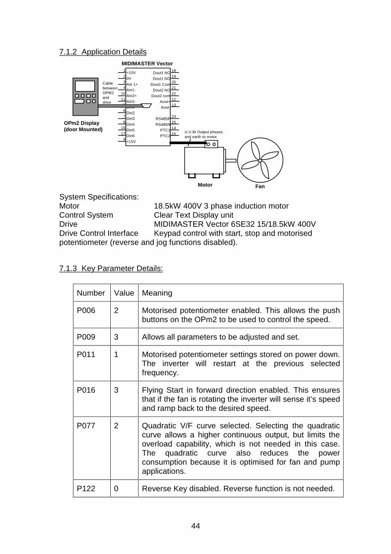
7.1.2 Application Details
1
2
3
4
10
11
5
6
7
8
16
17
9
MIDIMASTER Vector
Dout1 NC
Dout1 NO
Dout1 Com
Dout2 NO
Dout2 com
Aout+
Aout-
RS485P
RS485N
PTC1
PTC2
+10V
0V
Ain 1+
Ain1-
Ain2+
Ain2-
Din1
Din2
Din3
Din4
Din5
Din6
+15V
18
19
20
21
22
12
13
24
25
14
15
Motor Fan
U,V,W Output phasesand earth to motor
OPm2 Display(door Mounted)
CablebetweenOPM2anddrive
System Specifications:Motor 18.5kW 400V 3 phase induction motorControl System Clear Text Display unitDrive MIDIMASTER Vector 6SE32 15/18.5kW 400VDrive Control Interface Keypad control with start, stop and motorisedpotentiometer (reverse and jog functions disabled).
7.1.3 Key Parameter Details:
Number Value Meaning
P006 2 Motorised potentiometer enabled. This allows the pushbuttons on the OPm2 to be used to control the speed.
P009 3 Allows all parameters to be adjusted and set.
P011 1 Motorised potentiometer settings stored on power down.The inverter will restart at the previous selectedfrequency.
P016 3 Flying Start in forward direction enabled. This ensuresthat if the fan is rotating the inverter will sense it’s speedand ramp back to the desired speed.
P077 2 Quadratic V/F curve selected. Selecting the quadraticcurve allows a higher continuous output, but limits theoverload capability, which is not needed in this case.The quadratic curve also reduces the powerconsumption because it is optimised for fan and pumpapplications.
P122 0 Reverse Key disabled. Reverse function is not needed.
45
P123 0 Jog Key disabled
P125 0 Reverse direction disabled
Note that the default settings of minimum and maximum speeds (0 - 50Hz)are used in this case.
All required information such as speed, current and drive status is on thedisplay.
If resonance is experienced in the system these can be suppressed by usingthe skip frequency bands P014, P027, P028 and P029.
7.2 A Closed Loop Controller using a Fan.
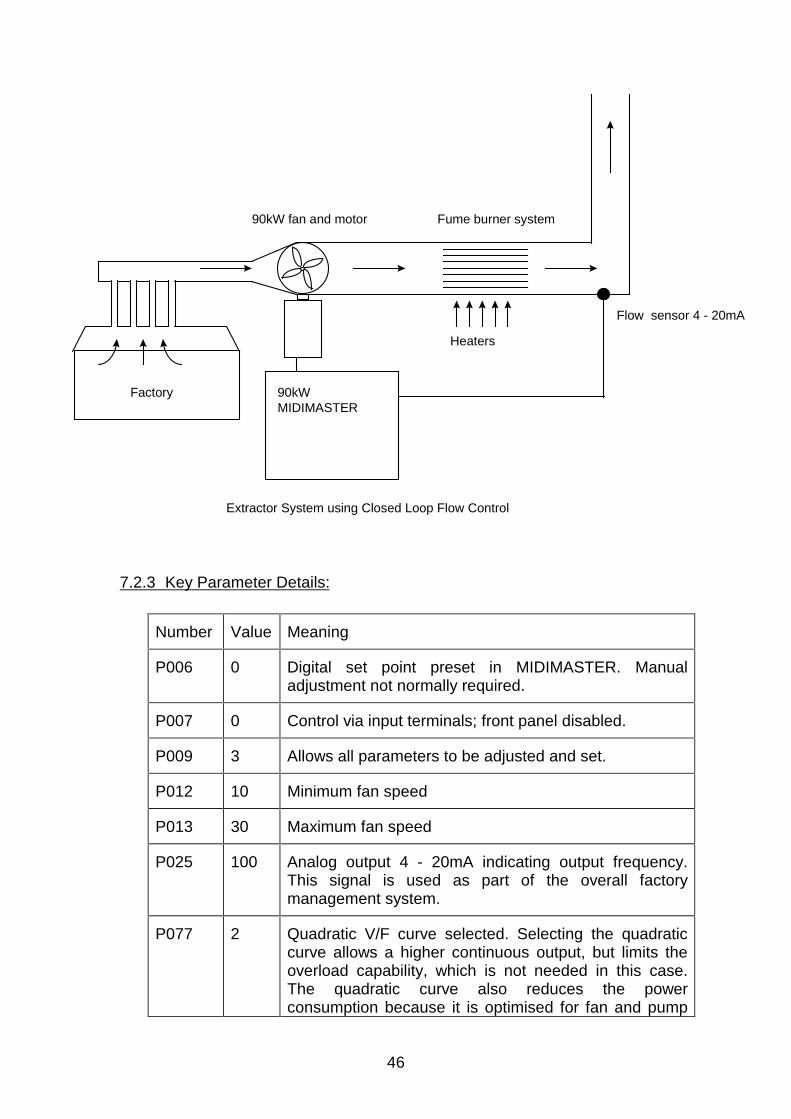
The application uses a 75/90kW MIDIMASTER driving a 90kW motor whichoperates the main extractor fan in a chemical plant. The extractor maintains aconstant flow rate by measuring flow downstream of a burner system. TheMIDIMASTER is installed in a cubicle close to the fan system, and a simplerun/ stop signal used for control.
7.2.1 Advantages
• Very significant energy savings compared with fixed speed running.
• Improved process control - in this case, reduced pollution as burneroperates at maximum efficiency.
• Built in PID means no additional controllers etc.
• No manual adjustment needed; simple run/stop commands
7.2.2 System Specifications:
Motor 4 pole 90kW 420V 3 phase induction motorControl System Closed loop PID systemSensor 4 -20mA flow rate sensorDrive MIDIMASTER Vector 6SE32 75/90kW 400V
46
Factory
Fume burner system90kW fan and motor
Heaters
90kW MIDIMASTER
Flow sensor 4 - 20mA
Extractor System using Closed Loop Flow Control
7.2.3 Key Parameter Details:
Number Value Meaning
P006 0 Digital set point preset in MIDIMASTER. Manualadjustment not normally required.
P007 0 Control via input terminals; front panel disabled.
P009 3 Allows all parameters to be adjusted and set.
P012 10 Minimum fan speed
P013 30 Maximum fan speed
P025 100 Analog output 4 - 20mA indicating output frequency.This signal is used as part of the overall factorymanagement system.
P077 2 Quadratic V/F curve selected. Selecting the quadraticcurve allows a higher continuous output, but limits theoverload capability, which is not needed in this case.The quadratic curve also reduces the powerconsumption because it is optimised for fan and pump
47
applications.
P080-85 *** Settings to suit motor
P089 0.06 Stator resistance - large motor, low resistance.
P201 1 PID enabled. The following parameters give the bestoverall stability in this particular application.
P202 0.3 P Gain
P203 0.06 I Gain
P204 0 D Gain
P205 1 Sample Interval
P206 0 Sensor Filtering
P207 100 Integral capture range
P208 1 Sensor type
P211 25 0% set point
P212 80 100% set point
P220 1 Switch off at minimum frequency
P323 1 PID (analog input 2) 4 -20mA to suit flow transducer
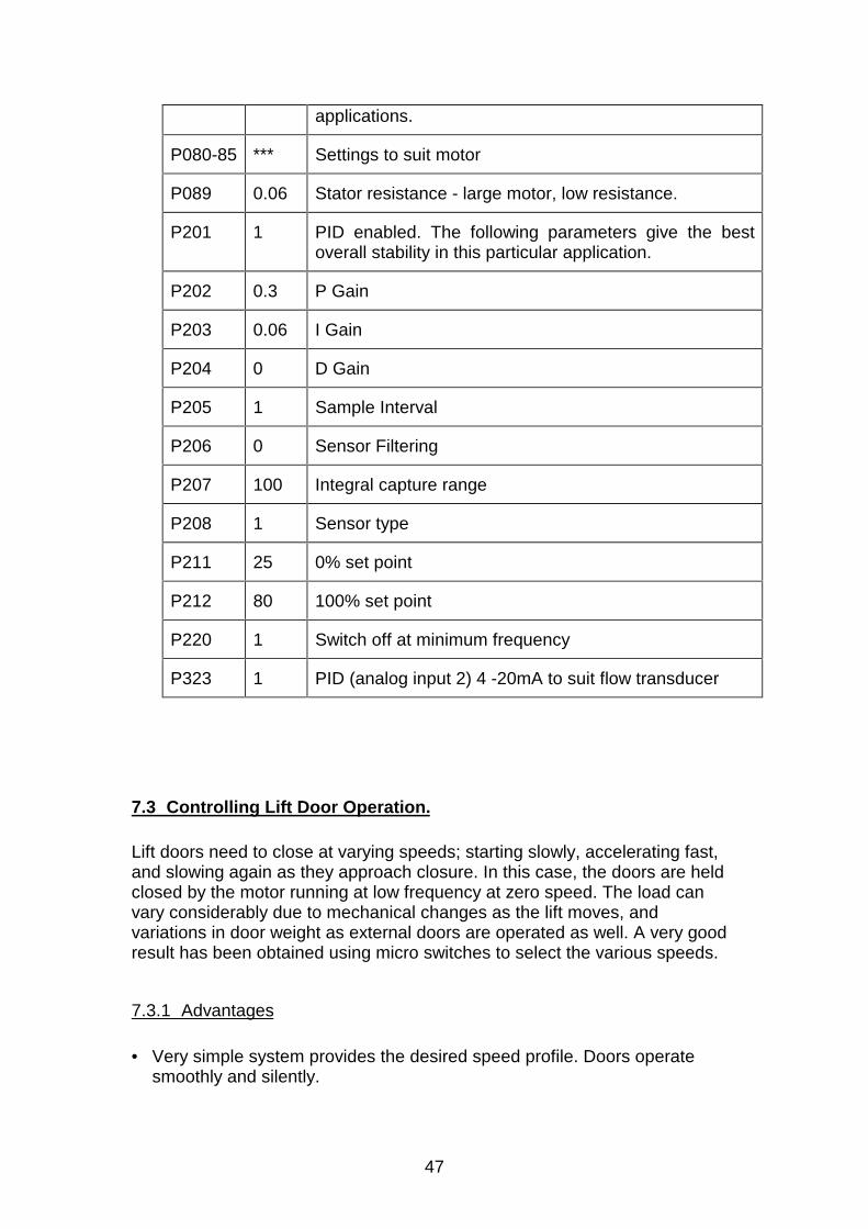
7.3 Controlling Lift Door Operation.
Lift doors need to close at varying speeds; starting slowly, accelerating fast,and slowing again as they approach closure. In this case, the doors are heldclosed by the motor running at low frequency at zero speed. The load canvary considerably due to mechanical changes as the lift moves, andvariations in door weight as external doors are operated as well. A very goodresult has been obtained using micro switches to select the various speeds.
7.3.1 Advantages
• Very simple system provides the desired speed profile. Doors operatesmoothly and silently.
48
• Torque at zero speed holds doors closed.
• Speed profile can be easily adjusted.
7.3.2 System Specification
Motor 4 pole 80W 230V 3 phase induction motor.Oversize with no external cooling fan - allowingzero speed operation
Control System Two Microswitches selecting fixed frequencies;open/close signal on third digital input
Drive MICROMASTER 6SE92 750W 230V
Note : The following diagrams and tables refer to Settings and parametersused on MICROMASTER; settings for MICROMASTER Vector may bedifferent.
Sensors
Door to close
Door closes fast
Door slows
Door closed
DIN 1 DIN 2 DIN 3 Output Function
Sensor 1 Sensor 2 Open/Close
0 0 1 5Hz Close slow
1 0 1 25Hz Close fast
1 1 1 10Hz slow down
0 1 1 2Hz hold Closed
0 1 0 - 6Hz Open slow
1 1 0 -15Hz Open fast
1 0 0 - 5Hz slow down
0 0 0 stop Stop open
Lift Door Operation
7.3.3 Key Parameter Details:
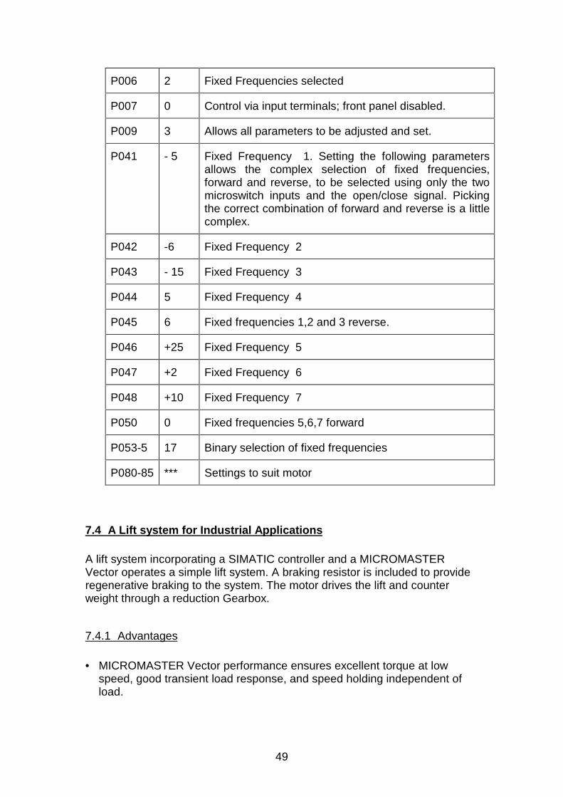
Note that careful selection of the inputs is needed to ensure the correctcombination of forward and reverse frequencies is possible.
Number Value Meaning
49
P006 2 Fixed Frequencies selected
P007 0 Control via input terminals; front panel disabled.
P009 3 Allows all parameters to be adjusted and set.
P041 - 5 Fixed Frequency 1. Setting the following parametersallows the complex selection of fixed frequencies,forward and reverse, to be selected using only the twomicroswitch inputs and the open/close signal. Pickingthe correct combination of forward and reverse is a littlecomplex.
P042 -6 Fixed Frequency 2
P043 - 15 Fixed Frequency 3
P044 5 Fixed Frequency 4
P045 6 Fixed frequencies 1,2 and 3 reverse.
P046 +25 Fixed Frequency 5
P047 +2 Fixed Frequency 6
P048 +10 Fixed Frequency 7
P050 0 Fixed frequencies 5,6,7 forward
P053-5 17 Binary selection of fixed frequencies
P080-85 *** Settings to suit motor
7.4 A Lift system for Industrial Applications
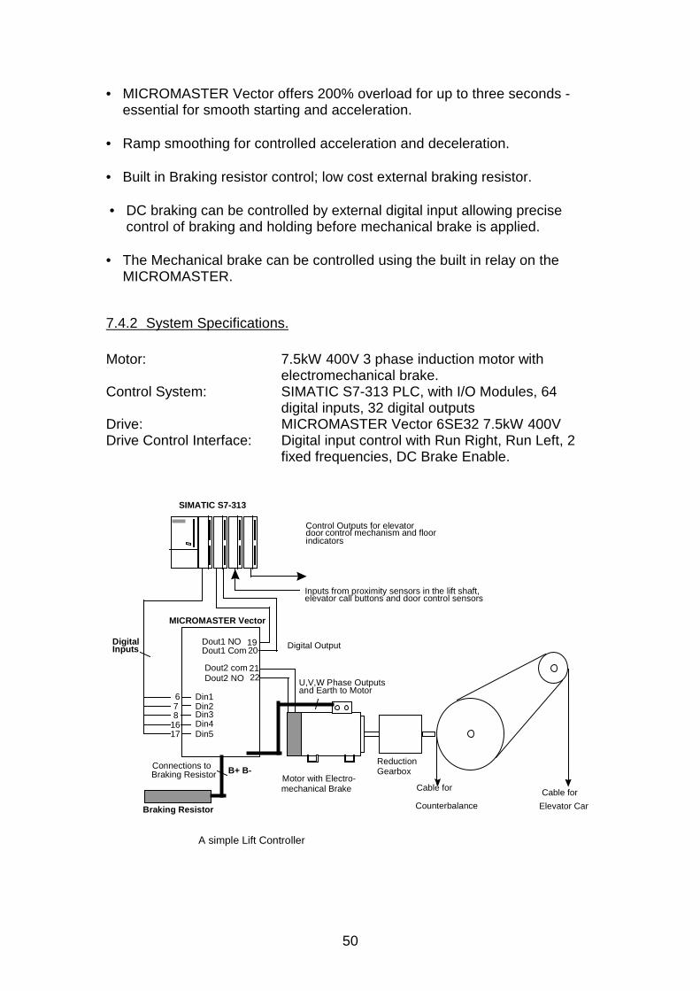
A lift system incorporating a SIMATIC controller and a MICROMASTERVector operates a simple lift system. A braking resistor is included to provideregenerative braking to the system. The motor drives the lift and counterweight through a reduction Gearbox.
7.4.1 Advantages
• MICROMASTER Vector performance ensures excellent torque at lowspeed, good transient load response, and speed holding independent ofload.
50
• MICROMASTER Vector offers 200% overload for up to three seconds -essential for smooth starting and acceleration.
• Ramp smoothing for controlled acceleration and deceleration.
• Built in Braking resistor control; low cost external braking resistor.
• DC braking can be controlled by external digital input allowing precisecontrol of braking and holding before mechanical brake is applied.
• The Mechanical brake can be controlled using the built in relay on theMICROMASTER.
7.4.2 System Specifications.
Motor: 7.5kW 400V 3 phase induction motor withelectromechanical brake.
Control System: SIMATIC S7-313 PLC, with I/O Modules, 64digital inputs, 32 digital outputs
Drive: MICROMASTER Vector 6SE32 7.5kW 400VDrive Control Interface: Digital input control with Run Right, Run Left, 2
fixed frequencies, DC Brake Enable.
678
1617
MICROMASTER Vector
Dout1 NODout1 Com
Dout2 comDout2 NO
Din1Din2Din3Din4Din5
1920
2122
SIMATIC S7-313
Connections toBraking Resistor
U,V,W Phase Outputsand Earth to Motor
Motor with Electro-mechanical Brake
Braking Resistor
ReductionGearbox
Cable for
Elevator Car
Cable for
Counterbalance
control mechanism and floorControl Outputs for elevatordoorindicators
Inputs from proximity sensors in the lift shaft,elevator call buttons and door control sensors
B+ B-
DigitalInputs Digital Output
A simple Lift Controller
51
In the example shown, a MICROMASTER Vector is used in a small (3 floor)lift system. A braking resistor is used to enhance the stopping performance ofthe elevator system. There are 2 fixed frequencies, 15Hz equating to 1m/sand 3.5Hz for when the lift is approaching a stop. The ramp times are 3seconds with 0.7 seconds of ramp smoothing. Control is over the digitalinputs which are used to select run direction (Din1, Din2), fixed frequency(Din4, Din5) and in this case, DC injection brake enable (Din3). One outputrelay is used for operating the motor brake, the other is configured to reportfaults to the lift controller.After releasing the motor brake, the DC brake is released and the lift isaccelerated along the shaft, reaching its 15Hz operating speed. There areproximity sensors in the lift shaft which are connected to the PLC and whichinform the system that the elevator car is approaching a floor and that itshould slow down and then stop. When the car passes the first proximitysensor, the lift is decelerated to its lower speed. When the second is passed,the lift stops and the motor brake is reapplied.A SIMATIC S7-313 was selected as a controller with the performance andexpansion capability to handle all the I/O from proximity sensors, requestswitches in the lift and floors, indicators, etc.
The motor brake should be fitted with a suitable suppressor, or the brakecontrolled via a contactor, in which case both should be suppressed.
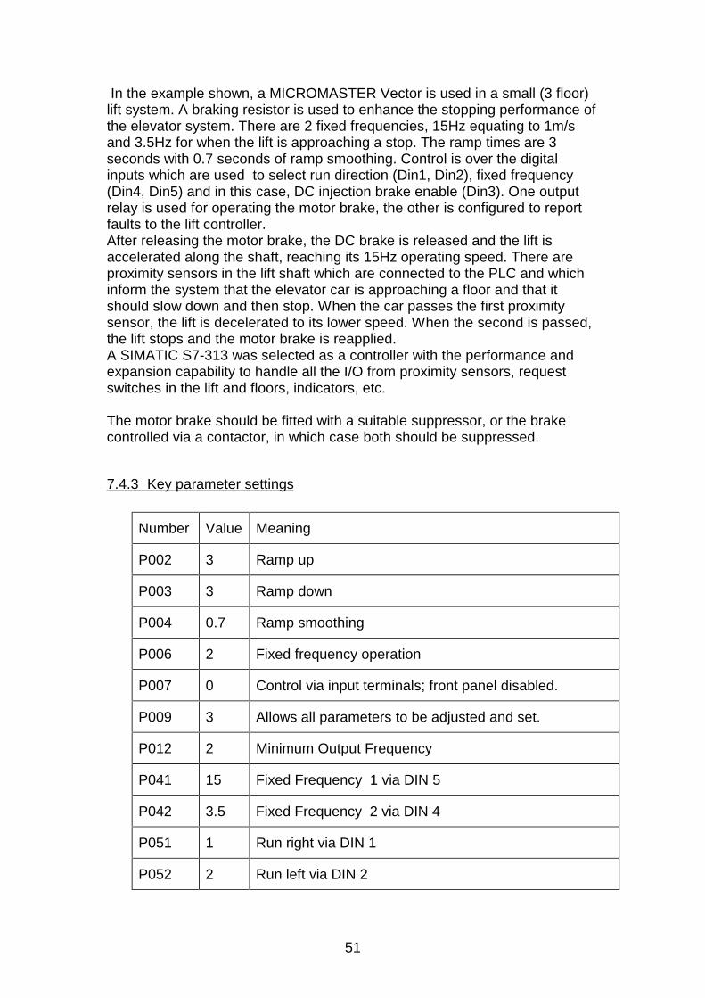
7.4.3 Key parameter settings
Number Value Meaning
P002 3 Ramp up
P003 3 Ramp down
P004 0.7 Ramp smoothing
P006 2 Fixed frequency operation
P007 0 Control via input terminals; front panel disabled.
P009 3 Allows all parameters to be adjusted and set.
P012 2 Minimum Output Frequency
P041 15 Fixed Frequency 1 via DIN 5
P042 3.5 Fixed Frequency 2 via DIN 4
P051 1 Run right via DIN 1
P052 2 Run left via DIN 2
52
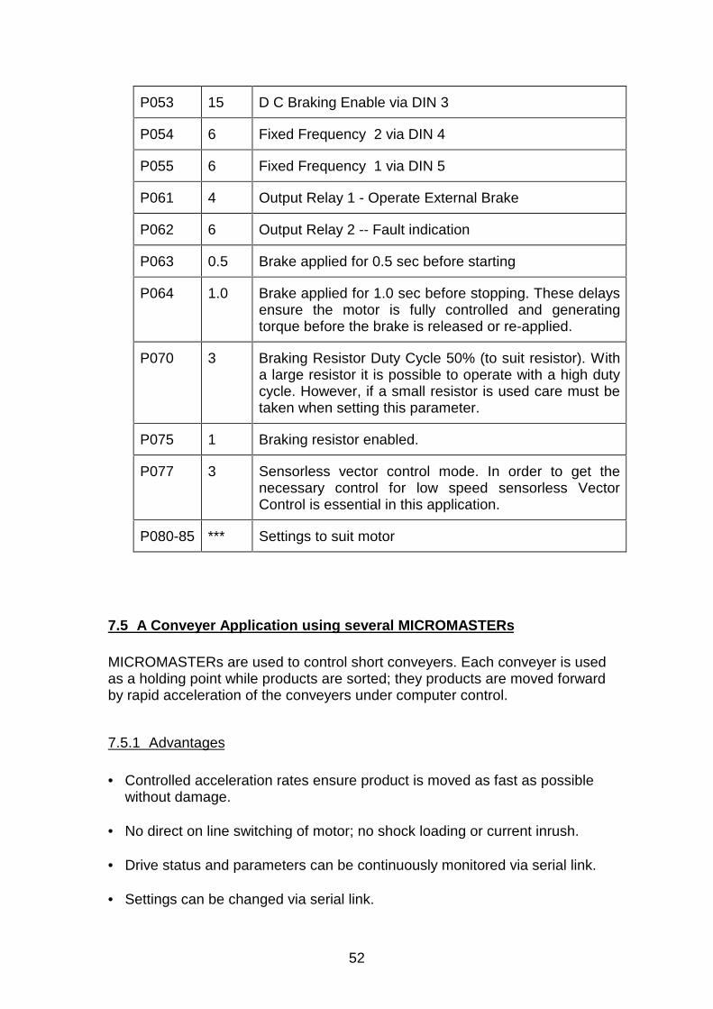
P053 15 D C Braking Enable via DIN 3
P054 6 Fixed Frequency 2 via DIN 4
P055 6 Fixed Frequency 1 via DIN 5
P061 4 Output Relay 1 - Operate External Brake
P062 6 Output Relay 2 -- Fault indication
P063 0.5 Brake applied for 0.5 sec before starting
P064 1.0 Brake applied for 1.0 sec before stopping. These delaysensure the motor is fully controlled and generatingtorque before the brake is released or re-applied.
P070 3 Braking Resistor Duty Cycle 50% (to suit resistor). Witha large resistor it is possible to operate with a high dutycycle. However, if a small resistor is used care must betaken when setting this parameter.
P075 1 Braking resistor enabled.
P077 3 Sensorless vector control mode. In order to get thenecessary control for low speed sensorless VectorControl is essential in this application.
P080-85 *** Settings to suit motor
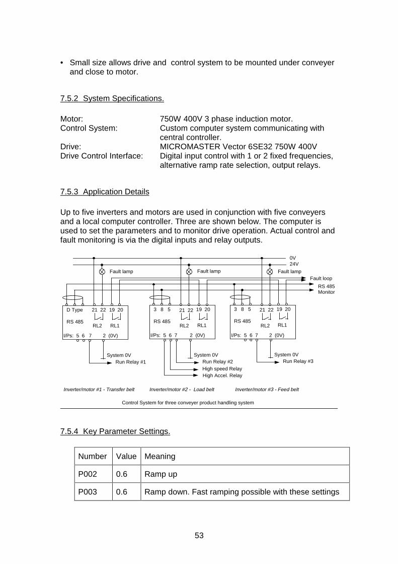
7.5 A Conveyer Application using several MICROMASTERs
MICROMASTERs are used to control short conveyers. Each conveyer is usedas a holding point while products are sorted; they products are moved forwardby rapid acceleration of the conveyers under computer control.
7.5.1 Advantages
• Controlled acceleration rates ensure product is moved as fast as possiblewithout damage.
• No direct on line switching of motor; no shock loading or current inrush.
• Drive status and parameters can be continuously monitored via serial link.
• Settings can be changed via serial link.
53
• Small size allows drive and control system to be mounted under conveyerand close to motor.
7.5.2 System Specifications.
Motor: 750W 400V 3 phase induction motor.Control System: Custom computer system communicating with
central controller.Drive: MICROMASTER Vector 6SE32 750W 400VDrive Control Interface: Digital input control with 1 or 2 fixed frequencies,
alternative ramp rate selection, output relays.
7.5.3 Application Details
Up to five inverters and motors are used in conjunction with five conveyersand a local computer controller. Three are shown below. The computer isused to set the parameters and to monitor drive operation. Actual control andfault monitoring is via the digital inputs and relay outputs.
RS 485
D Type 19 20
RL1
I/Ps: 5 6 7 2 (0V)
System 0VRun Relay #1
RS 485
3 8 5 19 20
RL1
System 0VRun Relay #2
RS 485
3 8 5 19 20
RL1
System 0VRun Relay #3
Fault loop
RS 485Monitor
High speed Relay High Accel. Relay
I/Ps: 5 6 7 2 (0V)I/Ps: 5 6 7 2 (0V)
Inverter/motor #1 - Transfer belt Inverter/motor #2 - Load belt Inverter/motor #3 - Feed belt
Control System for three conveyer product handling system
RL2
21 22
RL2 RL2
Fault lamp
0V24V
Fault lamp Fault lamp
21 22 21 22
7.5.4 Key Parameter Settings.
Number Value Meaning
P002 0.6 Ramp up
P003 0.6 Ramp down. Fast ramping possible with these settings
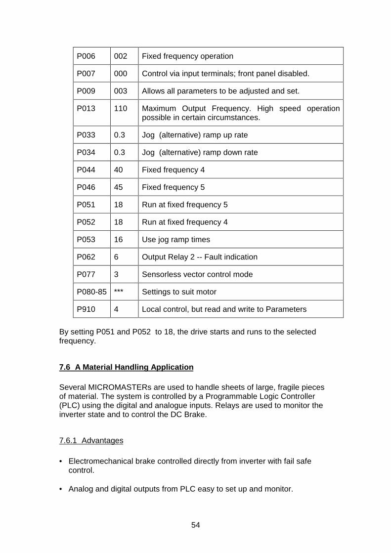
54
P006 002 Fixed frequency operation
P007 000 Control via input terminals; front panel disabled.
P009 003 Allows all parameters to be adjusted and set.
P013 110 Maximum Output Frequency. High speed operationpossible in certain circumstances.
P033 0.3 Jog (alternative) ramp up rate
P034 0.3 Jog (alternative) ramp down rate
P044 40 Fixed frequency 4
P046 45 Fixed frequency 5
P051 18 Run at fixed frequency 5
P052 18 Run at fixed frequency 4
P053 16 Use jog ramp times
P062 6 Output Relay 2 -- Fault indication
P077 3 Sensorless vector control mode
P080-85 *** Settings to suit motor
P910 4 Local control, but read and write to Parameters
By setting P051 and P052 to 18, the drive starts and runs to the selectedfrequency.
7.6 A Material Handling Application
Several MICROMASTERs are used to handle sheets of large, fragile piecesof material. The system is controlled by a Programmable Logic Controller(PLC) using the digital and analogue inputs. Relays are used to monitor theinverter state and to control the DC Brake.
7.6.1 Advantages
• Electromechanical brake controlled directly from inverter with fail safecontrol.
• Analog and digital outputs from PLC easy to set up and monitor.
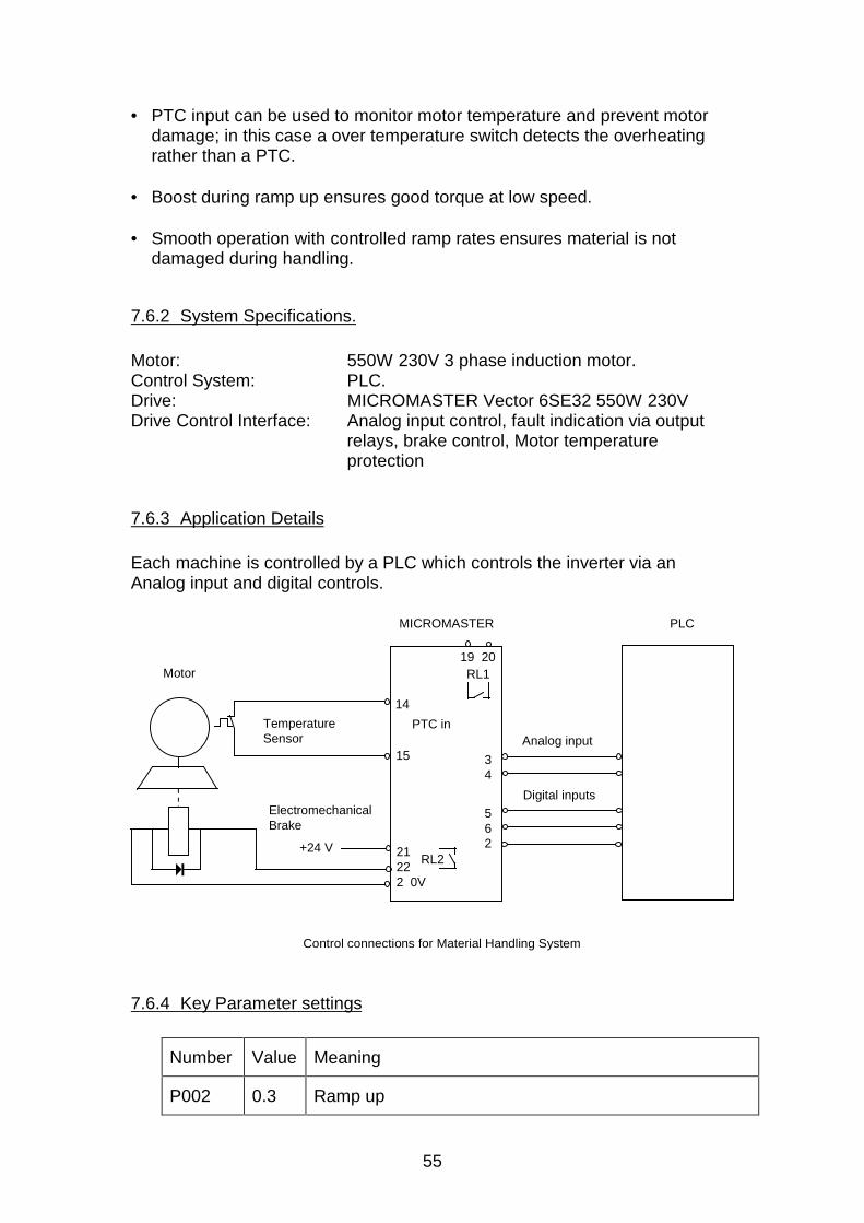
55
• PTC input can be used to monitor motor temperature and prevent motordamage; in this case a over temperature switch detects the overheatingrather than a PTC.
• Boost during ramp up ensures good torque at low speed.
• Smooth operation with controlled ramp rates ensures material is notdamaged during handling.
7.6.2 System Specifications.
Motor: 550W 230V 3 phase induction motor.Control System: PLC.Drive: MICROMASTER Vector 6SE32 550W 230VDrive Control Interface: Analog input control, fault indication via output
relays, brake control, Motor temperatureprotection
7.6.3 Application Details
Each machine is controlled by a PLC which controls the inverter via anAnalog input and digital controls.
RL2
Control connections for Material Handling System
RL1
+24 V
ElectromechanicalBrake
Temperature Sensor
Motor
PLCMICROMASTER
Analog input
Digital inputs
34
14
15
21222 0V
562
PTC in
19 20
7.6.4 Key Parameter settings
Number Value Meaning
P002 0.3 Ramp up
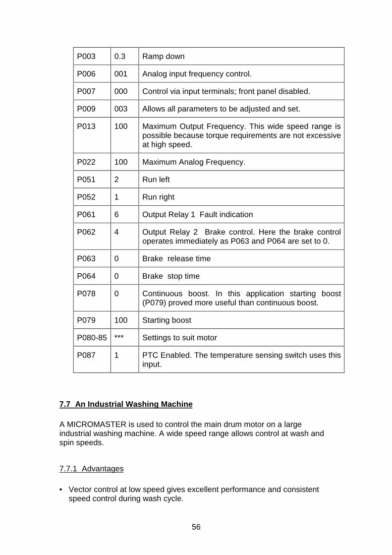
56
P003 0.3 Ramp down
P006 001 Analog input frequency control.
P007 000 Control via input terminals; front panel disabled.
P009 003 Allows all parameters to be adjusted and set.
P013 100 Maximum Output Frequency. This wide speed range ispossible because torque requirements are not excessiveat high speed.
P022 100 Maximum Analog Frequency.
P051 2 Run left
P052 1 Run right
P061 6 Output Relay 1 Fault indication
P062 4 Output Relay 2 Brake control. Here the brake controloperates immediately as P063 and P064 are set to 0.
P063 0 Brake release time
P064 0 Brake stop time
P078 0 Continuous boost. In this application starting boost(P079) proved more useful than continuous boost.
P079 100 Starting boost
P080-85 *** Settings to suit motor
P087 1 PTC Enabled. The temperature sensing switch uses thisinput.
7.7 An Industrial Washing Machine
A MICROMASTER is used to control the main drum motor on a largeindustrial washing machine. A wide speed range allows control at wash andspin speeds.
7.7.1 Advantages
• Vector control at low speed gives excellent performance and consistentspeed control during wash cycle.
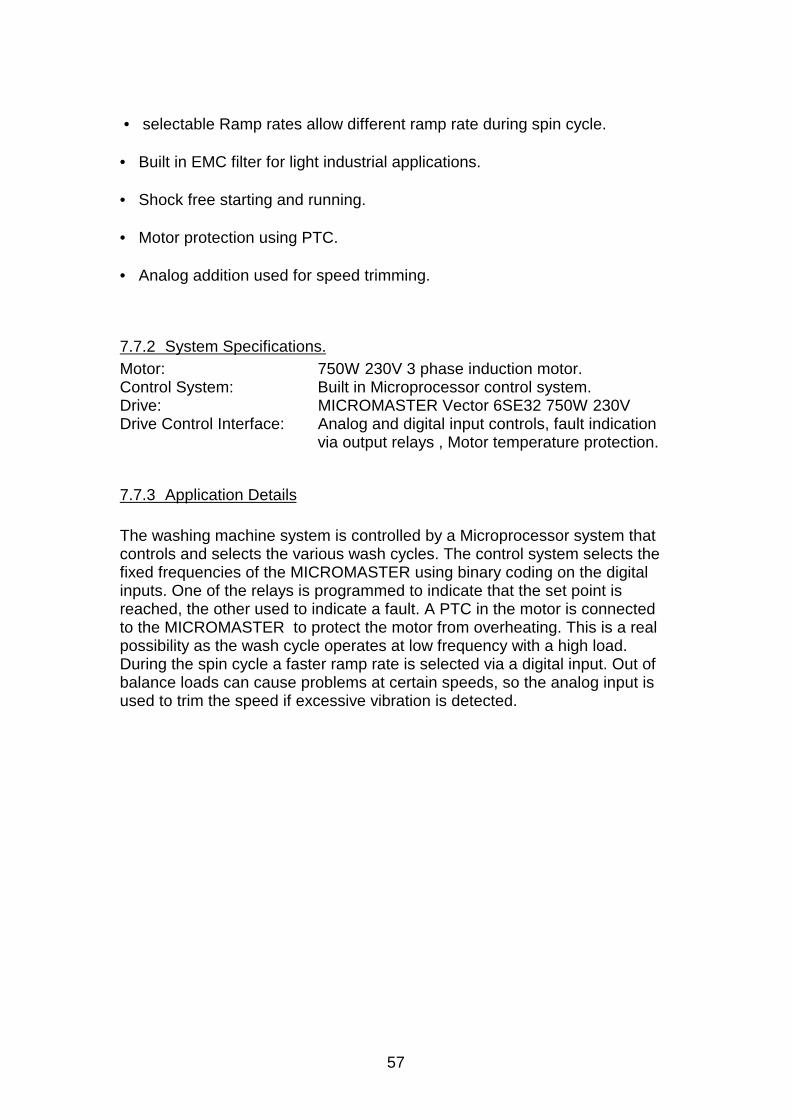
57
• selectable Ramp rates allow different ramp rate during spin cycle.
• Built in EMC filter for light industrial applications.
• Shock free starting and running.
• Motor protection using PTC.
• Analog addition used for speed trimming.
7.7.2 System Specifications.Motor: 750W 230V 3 phase induction motor.Control System: Built in Microprocessor control system.Drive: MICROMASTER Vector 6SE32 750W 230VDrive Control Interface: Analog and digital input controls, fault indication
via output relays , Motor temperature protection.
7.7.3 Application Details
The washing machine system is controlled by a Microprocessor system thatcontrols and selects the various wash cycles. The control system selects thefixed frequencies of the MICROMASTER using binary coding on the digitalinputs. One of the relays is programmed to indicate that the set point isreached, the other used to indicate a fault. A PTC in the motor is connectedto the MICROMASTER to protect the motor from overheating. This is a realpossibility as the wash cycle operates at low frequency with a high load.During the spin cycle a faster ramp rate is selected via a digital input. Out ofbalance loads can cause problems at certain speeds, so the analog input isused to trim the speed if excessive vibration is detected.
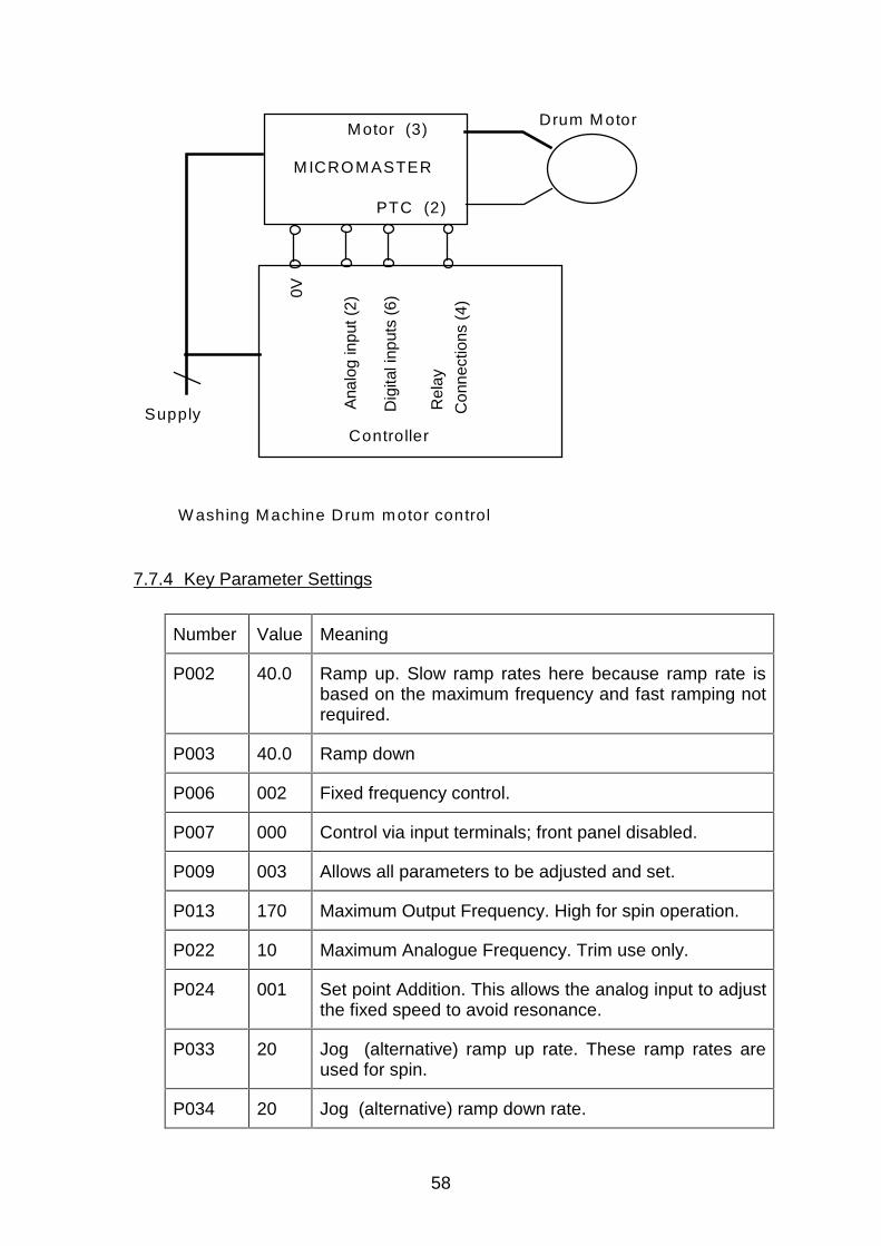
58
Supply
Motor (3)
PTC (2)
Rel
ay
Con
nect
ions
(4)
Dig
ital i
nput
s (6
)
Ana
log
inpu
t (2)
0V
M ICROMASTER
Controller
Drum M otor
W ashing Machine Drum motor control
7.7.4 Key Parameter Settings
Number Value Meaning
P002 40.0 Ramp up. Slow ramp rates here because ramp rate isbased on the maximum frequency and fast ramping notrequired.
P003 40.0 Ramp down
P006 002 Fixed frequency control.
P007 000 Control via input terminals; front panel disabled.
P009 003 Allows all parameters to be adjusted and set.
P013 170 Maximum Output Frequency. High for spin operation.
P022 10 Maximum Analogue Frequency. Trim use only.
P024 001 Set point Addition. This allows the analog input to adjustthe fixed speed to avoid resonance.
P033 20 Jog (alternative) ramp up rate. These ramp rates areused for spin.
P034 20 Jog (alternative) ramp down rate.
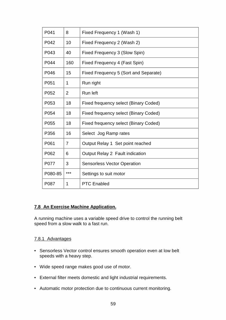
59
P041 8 Fixed Frequency 1 (Wash 1)
P042 10 Fixed Frequency 2 (Wash 2)
P043 40 Fixed Frequency 3 (Slow Spin)
P044 160 Fixed Frequency 4 (Fast Spin)
P046 15 Fixed Frequency 5 (Sort and Separate)
P051 1 Run right
P052 2 Run left
P053 18 Fixed frequency select (Binary Coded)
P054 18 Fixed frequency select (Binary Coded)
P055 18 Fixed frequency select (Binary Coded)
P356 16 Select Jog Ramp rates
P061 7 Output Relay 1 Set point reached
P062 6 Output Relay 2 Fault indication
P077 3 Sensorless Vector Operation
P080-85 *** Settings to suit motor
P087 1 PTC Enabled
7.8 An Exercise Machine Application.
A running machine uses a variable speed drive to control the running beltspeed from a slow walk to a fast run.
7.8.1 Advantages
• Sensorless Vector control ensures smooth operation even at low beltspeeds with a heavy step.
• Wide speed range makes good use of motor.
• External filter meets domestic and light industrial requirements.
• Automatic motor protection due to continuous current monitoring.
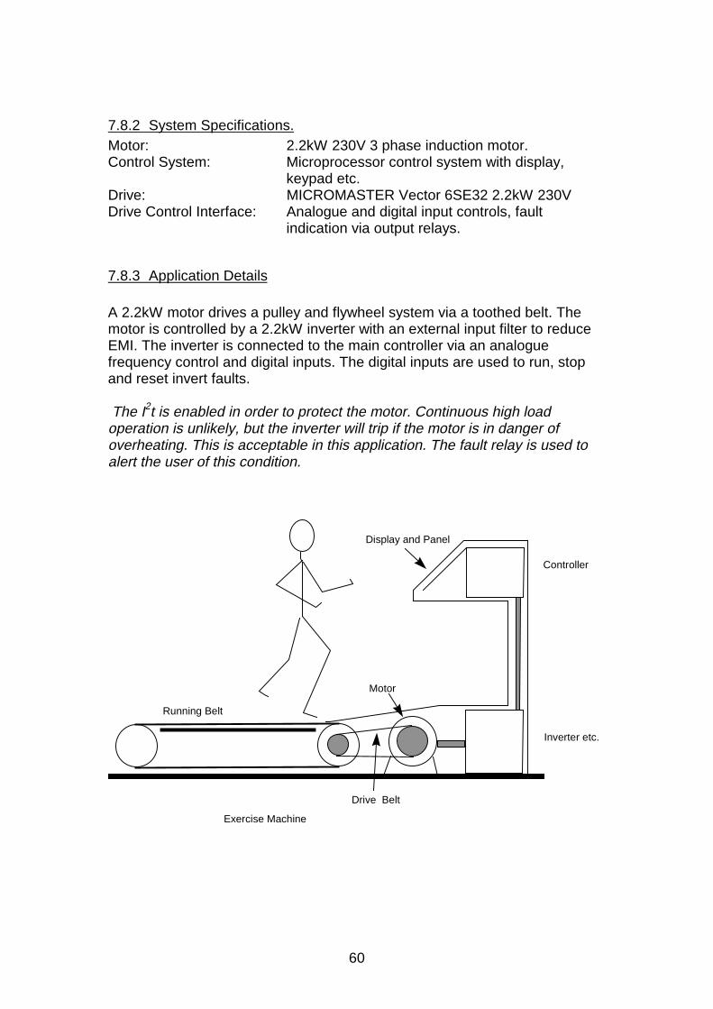
60
7.8.2 System Specifications.Motor: 2.2kW 230V 3 phase induction motor.Control System: Microprocessor control system with display,
keypad etc.Drive: MICROMASTER Vector 6SE32 2.2kW 230VDrive Control Interface: Analogue and digital input controls, fault
indication via output relays.
7.8.3 Application Details
A 2.2kW motor drives a pulley and flywheel system via a toothed belt. Themotor is controlled by a 2.2kW inverter with an external input filter to reduceEMI. The inverter is connected to the main controller via an analoguefrequency control and digital inputs. The digital inputs are used to run, stopand reset invert faults.
The I2t is enabled in order to protect the motor. Continuous high loadoperation is unlikely, but the inverter will trip if the motor is in danger ofoverheating. This is acceptable in this application. The fault relay is used toalert the user of this condition.
Running Belt
Drive Belt
Motor
Display and Panel
Controller
Inverter etc.
Exercise Machine
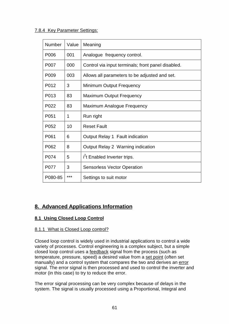
61
7.8.4 Key Parameter Settings:
Number Value Meaning
P006 001 Analogue frequency control.
P007 000 Control via input terminals; front panel disabled.
P009 003 Allows all parameters to be adjusted and set.
P012 3 Minimum Output Frequency
P013 83 Maximum Output Frequency
P022 83 Maximum Analogue Frequency
P051 1 Run right
P052 10 Reset Fault
P061 6 Output Relay 1 Fault indication
P062 8 Output Relay 2 Warning indication
P074 5 i2t Enabled Inverter trips.
P077 3 Sensorless Vector Operation
P080-85 *** Settings to suit motor
8. Advanced Applications Information
8.1 Using Closed Loop Control
8.1.1 What is Closed Loop control?
Closed loop control is widely used in industrial applications to control a widevariety of processes. Control engineering is a complex subject, but a simpleclosed loop control uses a feedback signal from the process (such astemperature, pressure, speed) a desired value from a set point (often setmanually) and a control system that compares the two and derives an errorsignal. The error signal is then processed and used to control the inverter andmotor (in this case) to try to reduce the error.
The error signal processing can be very complex because of delays in thesystem. The signal is usually processed using a Proportional, Integral and
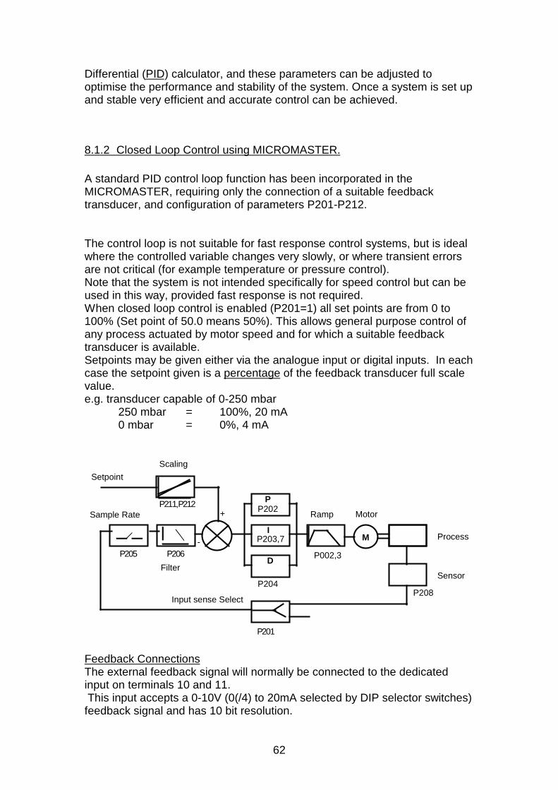
62
Differential (PID) calculator, and these parameters can be adjusted tooptimise the performance and stability of the system. Once a system is set upand stable very efficient and accurate control can be achieved.
8.1.2 Closed Loop Control using MICROMASTER.
A standard PID control loop function has been incorporated in theMICROMASTER, requiring only the connection of a suitable feedbacktransducer, and configuration of parameters P201-P212.
The control loop is not suitable for fast response control systems, but is idealwhere the controlled variable changes very slowly, or where transient errorsare not critical (for example temperature or pressure control).Note that the system is not intended specifically for speed control but can beused in this way, provided fast response is not required.When closed loop control is enabled (P201=1) all set points are from 0 to100% (Set point of 50.0 means 50%). This allows general purpose control ofany process actuated by motor speed and for which a suitable feedbacktransducer is available.Setpoints may be given either via the analogue input or digital inputs. In eachcase the setpoint given is a percentage of the feedback transducer full scalevalue.e.g. transducer capable of 0-250 mbar
250 mbar = 100%, 20 mA0 mbar = 0%, 4 mA
P
I
D
M
Ramp
-
+P211,P212
P205 P206
P201
Motor
Process
SensorP204
P202
P203,7
P208
P002,3
Setpoint
Sample Rate
Scaling
Filter
Input sense Select
Feedback ConnectionsThe external feedback signal will normally be connected to the dedicatedinput on terminals 10 and 11. This input accepts a 0-10V (0(/4) to 20mA selected by DIP selector switches)feedback signal and has 10 bit resolution.
63
On standard MICROMASTER (e.g. non Vector units) it is possible to connectthe feedback signal to X501 terminals 3 and 4 (P201 = 2). If this option isused, then all ‘analogue’ options of P006. P023 and P024 become invalid andshould not be used.
Setting UpSee parameter list P201 to P212 for description of the parameters for settingup the PID system. In addition P000, P010, and P220 provide functionsuseful in closed loop applications.
Typical Procedure:Remember that once you have enabled Closed Loop Operation values suchas the setpoint are now displayed in percent of full scale.• If possible run the drive open loop first, to check, in particular, the sensor
feedback voltage or current.• Check P208 value for the correct ‘sense’ operation. Set P208 according to
the sensor/actuator types; if the feedback signal reduces as the motorspeed increases, select P208=1. Otherwise, use P208=0.
• Set P206 to zero; this display should not flicker too much. Slow responsesystems benefit from a longer time interval between feedback signalreadings if D-gain is applied. This interval can be adjusted in steps of 25msec up to 1 minute via P205.
• Start with the PID gains still on their factory settings - P gain =1, no integralor differential action.
• Set P001 to 7 to display %. Enable the closed loop operation by settingP201.
• Select fast ramp up and down times (P002, P003), as otherwise these willlimit closed loop performance. Try 1 second.
Check P210 to confirm the feedback value is within reasonable scaling limits.Use P211 and P212 to set the scaling. Note that offsets can beaccommodated using P211 (e.g. feedback is 4-20mA for 0 - 100% setpointvariation; P211= 20(%), P212 = 100(%) i.e of 20mA. If no sensible valuesappear in P210, try reversing the feedback signal connections, andrepeating the above process.
Further detail is shown in the following example: Consider an application using a temperature sensor. Sensor output is 0-10 V
from 30 oC - 150 o C, i.e. a 120 oC range. We want to control thetemperature in the range 50 oC to 80 oC . This means that 50 oC issetpoint 0%, and 80 oC is setpoint 100%.
Now P211 is calculated (50-30) = 16,6% (Min. - Sensor Min.)
(150-30) Sensor Range
P212 is calculated
(80-30) = 41,6% (Max. - Sensor Min.)(150-30) Sensor Range
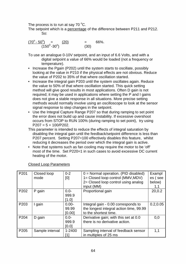
64
The process is to run at say 70 oC. The setpoint which is a percentage of the difference between P211 and P212.
So: (70o - 50o) = (20) = 66%.
(1500 -30o) (30) To use an analogue 0-10V setpoint, and an input of 6.6 Volts, and with a
digital setpoint a value of 66% would be loaded (not a frequency ortemperature).
• Increase the Pgain (P202) until the system starts to oscillate, possiblylooking at the value in P210 if the physical effects are not obvious. Reducethe value of P202 to 35% of that where oscillation started.
• Increase the integral gain P203 until the system oscillates again. Reducethe value to 50% of that where oscillation started. This quick settingmethod will give good results in most applications. Often D gain is notrequired; it may be used in applications where setting the P and I gainsdoes not give a stable response in all situations. More precise settingmethods would normally involve using an oscilloscope to look at the sensorsignal response to step changes in the setpoint.
• Use the Integral Capture Range P207 so that during ramping to set pointthe error does not build up and cause instability. If excessive overshootoccurs from STOP to RUN 100% (during ramping to set point), try usingP207 = 5 + 100/P202.
This parameter is intended to reduce the effects of integral saturation bydisabling the integral gain until the feedback/setpoint difference is less thanP207 percent. Setting P207=100 effectively disables this feature, whilstreducing it decreases the period over which the integral gain is active.
• Note that systems such as fan cooling may require the motor to be ‘off’most of the time. Set P220=1 in such cases to avoid excessive DC currentheating of the motor.
Closed Loop Parameters
P201 Closed loopmode
0-2[0]
0 = Normal operation. (PID disabled)1= Closed loop control (MMV,MDV)2= Closed loop control using analoginput (MM)
Examples ( seebelow)
1,1P202 P gain 0.0-
999.9[1.0]
Proportional gain 20,0.2
P203 I gain 0.00-99.99[0.00]
Integral gain - 0.00 corresponds tothe longest integral action time, 99.99to the shortest time.
0.2,0.05
P204 D gain 0.0-999.9[0.0]
Derivative gain; with this set at 0.0there is no derivative action.
0,0
P205 Sample interval 1-2400[1]
Sampling interval of feedback sensorin multiples of 25 ms
1,1
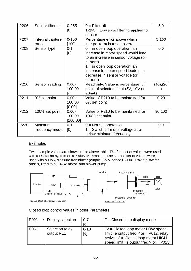
65
P206 Sensor filtering 0-255[0]
0 = Filter off1-255 = Low pass filtering applied tosensor
5,0
P207 Integral capturerange
0-100[100]
Percentage error above whichintegral term is reset to zero
5,100
P208 Sensor type 0-1[0]
0 = in open loop operation, anincrease in motor speed would leadto an increase in sensor voltage (orcurrent)1 = in open loop operation, anincrease in motor speed leads to adecrease in sensor voltage (orcurrent)
0,0
P210 Sensor reading 0.00-100.00[-]
Read only. Value is percentage fullscale of selected input (5V, 10V or20mA)
(40),(20)
P211 0% set point 0.00-100.00[0.00]
Value of P210 to be maintained for0% set point
0,20
P212 100% set point 0.00-100.00[100.00]
Value of P210 to be maintained for100% set point
80,100
P220 Minimumfrequency mode
0-1[0]
0 = Normal operation1 = Switch off motor voltage at orbelow minimum frequency
0,0
Examples
Two example values are shown in the above table. The first set of values were usedwith a DC tacho system on a 7.5kW MIDImaster. The second set of values wereused with a Flow/pressure transducer (output 1 -5 V hence P211= 20% to allow foroffset), fitted to a 0.4kW motor and blower pump.
Inverter AC MotorTacho
Speed Feedback
Speed Controller (slow response)
Inverter
Pressure Feedback
pipe
Valve
Motor and Fan
PressureTransducer
Pressure Controller
Closed loop control values in other Parameters
P001 * Display selection 0-7[0]
7 = Closed loop display mode
P061 Selection relayoutput RL1
0-13[6]
12 = Closed loop motor LOW speedlimit i.e output freq < or = P012, relayactive 13 = Closed loop motor HIGHspeed limit i.e output freq > or = P013,
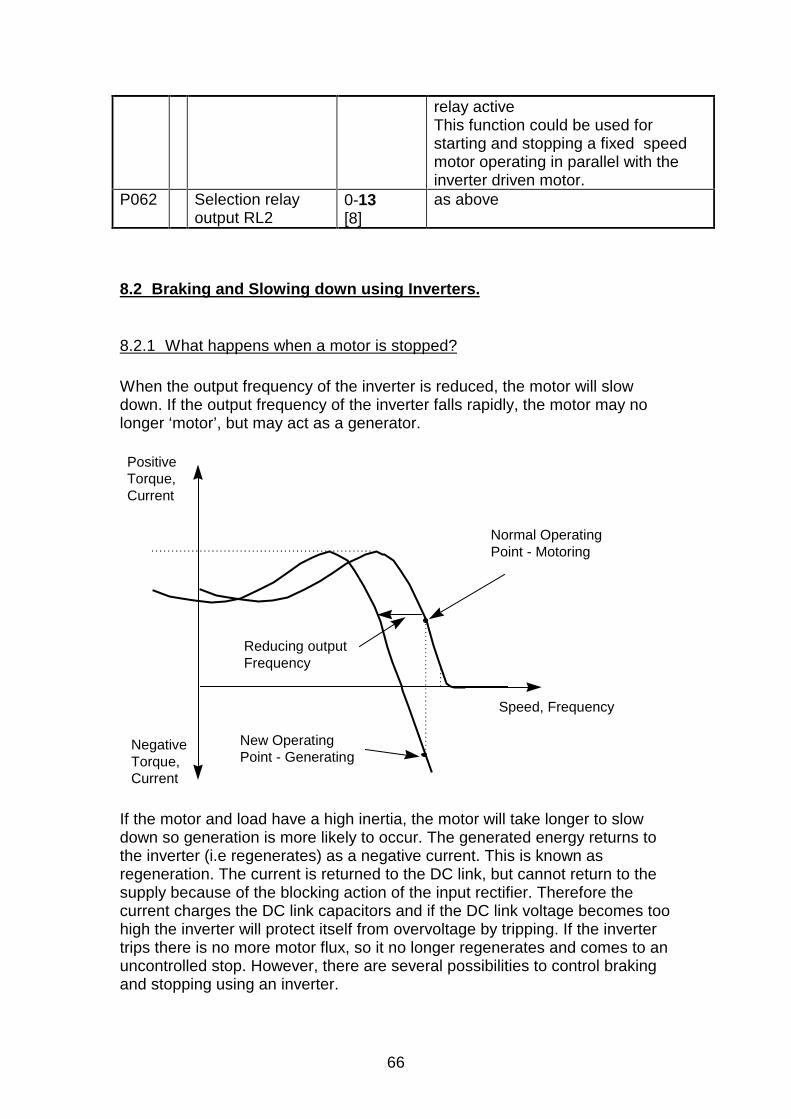
66
relay activeThis function could be used forstarting and stopping a fixed speedmotor operating in parallel with theinverter driven motor.
P062 Selection relayoutput RL2
0-13[8]
as above
8.2 Braking and Slowing down using Inverters.
8.2.1 What happens when a motor is stopped?
When the output frequency of the inverter is reduced, the motor will slowdown. If the output frequency of the inverter falls rapidly, the motor may nolonger ‘motor’, but may act as a generator.
Speed, Frequency
New OperatingPoint - Generating
PositiveTorque,Current
Reducing output Frequency
NegativeTorque,Current
Normal OperatingPoint - Motoring
If the motor and load have a high inertia, the motor will take longer to slowdown so generation is more likely to occur. The generated energy returns tothe inverter (i.e regenerates) as a negative current. This is known asregeneration. The current is returned to the DC link, but cannot return to thesupply because of the blocking action of the input rectifier. Therefore thecurrent charges the DC link capacitors and if the DC link voltage becomes toohigh the inverter will protect itself from overvoltage by tripping. If the invertertrips there is no more motor flux, so it no longer regenerates and comes to anuncontrolled stop. However, there are several possibilities to control brakingand stopping using an inverter.
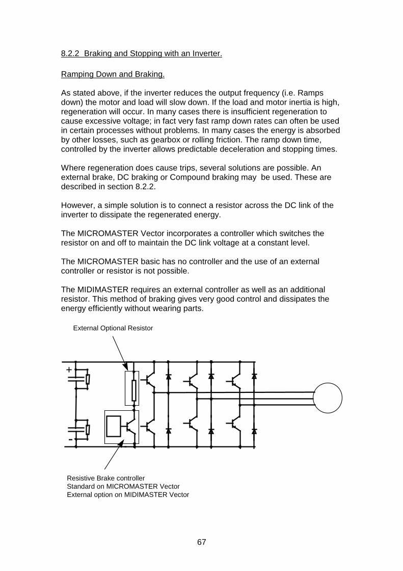
67
8.2.2 Braking and Stopping with an Inverter.
Ramping Down and Braking.
As stated above, if the inverter reduces the output frequency (i.e. Rampsdown) the motor and load will slow down. If the load and motor inertia is high,regeneration will occur. In many cases there is insufficient regeneration tocause excessive voltage; in fact very fast ramp down rates can often be usedin certain processes without problems. In many cases the energy is absorbedby other losses, such as gearbox or rolling friction. The ramp down time,controlled by the inverter allows predictable deceleration and stopping times.
Where regeneration does cause trips, several solutions are possible. Anexternal brake, DC braking or Compound braking may be used. These aredescribed in section 8.2.2.
However, a simple solution is to connect a resistor across the DC link of theinverter to dissipate the regenerated energy.
The MICROMASTER Vector incorporates a controller which switches theresistor on and off to maintain the DC link voltage at a constant level.
The MICROMASTER basic has no controller and the use of an externalcontroller or resistor is not possible.
The MIDIMASTER requires an external controller as well as an additionalresistor. This method of braking gives very good control and dissipates theenergy efficiently without wearing parts.
+
-
External Optional Resistor
Resistive Brake controllerStandard on MICROMASTER VectorExternal option on MIDIMASTER Vector
68
It is sometimes necessary to calculate the resistor power rating based on thebraking duty cycle and the amount of energy to be dissipated. Optionalbraking resistors, designed to operate with the MICROMASTER, will dissipatethe full power of the drive on a 5% duty rating. That is , a 750W inverter fittedwith a standard resistor will dissipate 750W for (say ) 10seconds in200seconds, or 37W continuous. In order to prevent damage to theseresistors the duty cycle of the resistor is limited in software, controlled byparameter P070. Parameter P070 is set to 5% to suit the standard resistor,but can be adjusted if bigger duty cycles are needed and larger resistorsused.In practice, because of system losses and short duty cycle, the resistors areusually operated well within their rating.
DC Braking.
If a controlled DC voltage is applied to the motor, a braking and holdingtorque is produced in the rotor. During DC braking the stored energy of themotor and load is dissipated in the rotor itself, so there is no regenerationback to the inverter. However, because no frequency is applied, there is nocontrol over motor speed, and it is not possible to predict the stopping time ofthe motor and load. The torque on the rotor is maintained even at standstill,so DC braking can be used to hold the rotor and load for short periods ifrequired.
Parameter P073 sets the DC Braking level, and braking will be applied for theramp down time irrespective of the motor speed. The parameter valuecorresponds to a percentage of the voltage needed to generate full loadcurrent in the motor windings. In practice it is not possible to calculate thebraking torque this will produce. Continuous use of the DC braking will causeoverheating in the motor and suitable protection systems must be considered.The braking can also be activated by an external switch.
Compound Braking
If DC braking and regenerative braking are combined, braking with minimalregeneration but with controlled motor speed is possible. This consists of areducing frequency with DC component added to it. This braking system,developed by Siemens for the MICROMASTER and MIDIMASTER, is knownas Compound braking. Compound braking can prove very effective,combining the best of DC braking and Regenerative braking. As with DCbraking, the load energy is dissipated in the motor, and therefore excessive,frequent braking can lead to overheating.
The above braking methods are summarised in the diagram below.
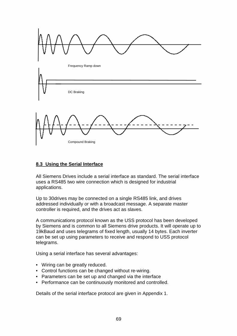
69
Frequency Ramp down
DC Braking
Compound Braking
8.3 Using the Serial Interface
All Siemens Drives include a serial interface as standard. The serial interfaceuses a RS485 two wire connection which is designed for industrialapplications.
Up to 30drives may be connected on a single RS485 link, and drivesaddressed individually or with a broadcast message. A separate mastercontroller is required, and the drives act as slaves.
A communications protocol known as the USS protocol has been developedby Siemens and is common to all Siemens drive products. It will operate up to19kBaud and uses telegrams of fixed length, usually 14 bytes. Each invertercan be set up using parameters to receive and respond to USS protocoltelegrams.
Using a serial interface has several advantages:
• Wiring can be greatly reduced.• Control functions can be changed without re-wiring.• Parameters can be set up and changed via the interface• Performance can be continuously monitored and controlled.
Details of the serial interface protocol are given in Appendix 1.
70
8.4 Using PROFIBUS
8.4.1 What is PROFIBUS?
PROFIBUS is an open standard communication protocol which has beendesigned and developed for use in general industrial applications. Thestandard is defined in EN50170 (volume 2) and has been developed, agreedand adopted by many manufacturers worldwide.
PROFIBUS control is now available for a wide variety of products, from manydifferent companies such as drives, actuators, valves, as well asprogrammable logic controllers (PLCs) and other system controllers.PROFIBUS operates over a variety of hardware interconnections such asfibre optics and RS 485.
There are three versions of PROFIBUS: FMS, DP and PA; these versions willwork together. The most commonly used version is the DP version, intendedfor general industrial applications. This is the version supported by SiemensDrives.
8.4.2 Using PROFIBUS with Siemens Standard Drives
In order to connect to a PROFIBUS system a PROFIUS adapter module isrequired. This module mounts on the front of the drive in the same way as theOPm2, and uses the RS485 serial port to communicate to the drive.
A nine way ‘D type’ connector, which is a PROFIBUS standard, isincorporated into the front of the module.
The drive may be controlled and monitored via the main PROFIBUS systemin a similar way to the USS. The PROFIBUS protocol is more complex thanthe USS protocol (in fact, the USS is a simplified version) and controlprogrammes are best developed using proprietary software.
Although a PROFIBUS system is more complex than for instance, the USSProtocol, it offers the following advantages:
• Open, clearly defined system.• Many different products from many different manufacturers.• Well proven in many industrial applications.• Reduced wiring; easy set up re-programming, monitor and control.• Very fast; up to 12Mbaud..• Up to 125 slaves on one DP system• Single or Multi-master operation possible.• One to one or braodcast communications• Support and development software available.
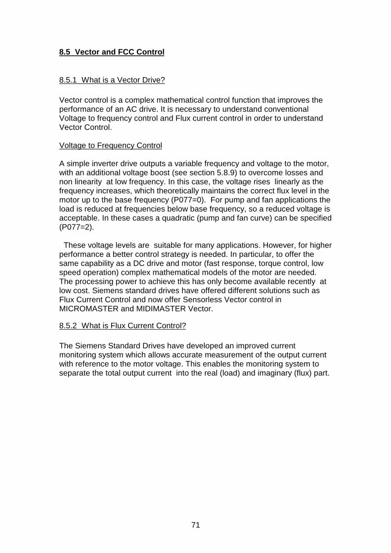
71
8.5 Vector and FCC Control
8.5.1 What is a Vector Drive?
Vector control is a complex mathematical control function that improves theperformance of an AC drive. It is necessary to understand conventionalVoltage to frequency control and Flux current control in order to understandVector Control.
Voltage to Frequency Control
A simple inverter drive outputs a variable frequency and voltage to the motor,with an additional voltage boost (see section 5.8.9) to overcome losses andnon linearity at low frequency. In this case, the voltage rises linearly as thefrequency increases, which theoretically maintains the correct flux level in themotor up to the base frequency (P077=0). For pump and fan applications theload is reduced at frequencies below base frequency, so a reduced voltage isacceptable. In these cases a quadratic (pump and fan curve) can be specified(P077=2).
These voltage levels are suitable for many applications. However, for higherperformance a better control strategy is needed. In particular, to offer thesame capability as a DC drive and motor (fast response, torque control, lowspeed operation) complex mathematical models of the motor are needed.The processing power to achieve this has only become available recently atlow cost. Siemens standard drives have offered different solutions such asFlux Current Control and now offer Sensorless Vector control inMICROMASTER and MIDIMASTER Vector.
8.5.2 What is Flux Current Control?
The Siemens Standard Drives have developed an improved currentmonitoring system which allows accurate measurement of the output currentwith reference to the motor voltage. This enables the monitoring system toseparate the total output current into the real (load) and imaginary (flux) part.
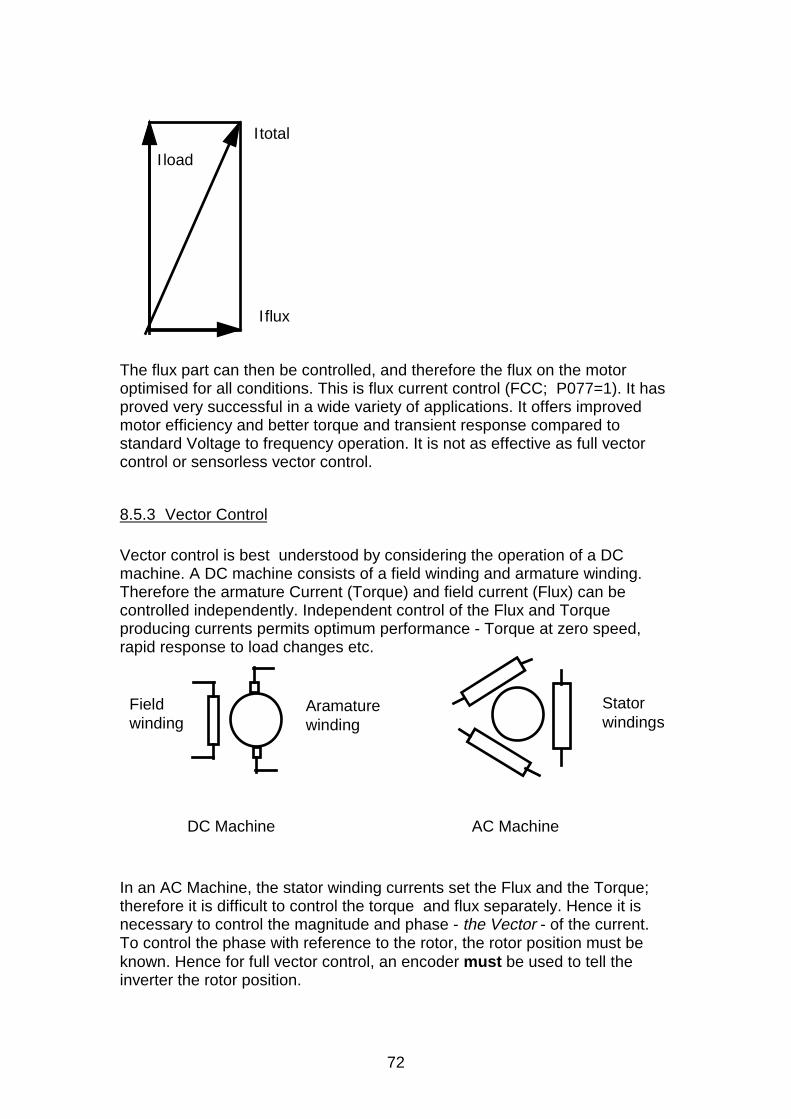
72
I load
Iflux
Itotal
The flux part can then be controlled, and therefore the flux on the motoroptimised for all conditions. This is flux current control (FCC; P077=1). It hasproved very successful in a wide variety of applications. It offers improvedmotor efficiency and better torque and transient response compared tostandard Voltage to frequency operation. It is not as effective as full vectorcontrol or sensorless vector control.
8.5.3 Vector Control
Vector control is best understood by considering the operation of a DCmachine. A DC machine consists of a field winding and armature winding.Therefore the armature Current (Torque) and field current (Flux) can becontrolled independently. Independent control of the Flux and Torqueproducing currents permits optimum performance - Torque at zero speed,rapid response to load changes etc.
Field winding
Aramature winding
DC Machine AC Machine
Stator windings
In an AC Machine, the stator winding currents set the Flux and the Torque;therefore it is difficult to control the torque and flux separately. Hence it isnecessary to control the magnitude and phase - the Vector - of the current.To control the phase with reference to the rotor, the rotor position must beknown. Hence for full vector control, an encoder must be used to tell theinverter the rotor position.
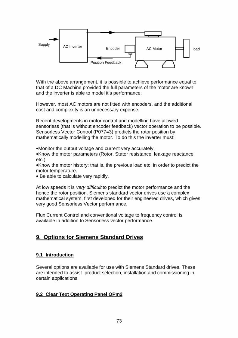
73
AC Inverter AC MotorEncoder loadSupply
Position Feedback
With the above arrangement, it is possible to achieve performance equal tothat of a DC Machine provided the full parameters of the motor are knownand the inverter is able to model it’s performance.
However, most AC motors are not fitted with encoders, and the additionalcost and complexity is an unnecessary expense.
Recent developments in motor control and modelling have allowedsensorless (that is without encoder feedback) vector operation to be possible.Sensorless Vector Control (P077=3) predicts the rotor position bymathematically modelling the motor. To do this the inverter must:
q Monitor the output voltage and current very accurately.q Know the motor parameters (Rotor, Stator resistance, leakage reactanceetc.)q Know the motor history; that is, the previous load etc. in order to predict themotor temperature.q Be able to calculate very rapidly.
At low speeds it is very difficult to predict the motor performance and thehence the rotor position. Siemens standard vector drives use a complexmathematical system, first developed for their engineered drives, which givesvery good Sensorless Vector performance.
Flux Current Control and conventional voltage to frequency control isavailable in addition to Sensorless vector performance.
9. Options for Siemens Standard Drives
9.1 Introduction
Several options are available for use with Siemens Standard drives. Theseare intended to assist product selection, installation and commissioning incertain applications.
9.2 Clear Text Operating Panel OPm2
74
The clear text operating panel consists of a control and display unit that fitsdirectly on top of the MICROMASTER or MIDIMASTER Control panel. A DType socket connects directly onto the D type on the front of the unit, so theOPm2 can take power from and communicate with the drive via the RS485interface. The OPm2 offers the following features:
q Seven language ( English, German, French, Italian, Spanish, Dutch,Danish) text operation with explanation of parameters, faults etc.
q Diagnostics - help with fault finding.q Upread/download up to 9 parameter sets from units to OPm and back. This
allows fast, reliable programming and copying of parameter sets.q OPm2 mounts directly on MICROMASTER and MIDIMASTER.q Door mounting kit with IP54 protection included.q Built in RS232 to RS485 Converter for simple connection to computer.q External supply connector for remote operation and off line programming.
The OPm2 has several practical uses; for example:
• The OPm2 may be mounted directly onto the inverter and used to controlthe drive directly.
• The OPm2 can be mounted on a separate panel (using an optional cableof up to 5m) to enable remote control and monitoring of the drive.
• If an external power supply is connected to the OPm2, remote control overdistances greater than 5m is permissible
• The built in RS232 to RS485 connector can be used to allowcommunication between a PC and the drive.
• Parameter sets can be stored in the OPm2 and uploaded or downloadedas required. This is particularly useful where many inverters requireprogramming in production.
9.3 Braking Modules and Braking Resistors.
During regeneration (see section 8.2.2) it may be necessary to dissipate theenergy that is returned to the inverter. MICROMASTER basic units do nothave the capability to dissipate regenerated energy.
MICROMASTER Vector units have a built in ‘braking chopper’ and requireonly an external resistor to allow controlled dissipation. The resistors can besupplied as optional parts to the inverters, and fit alongside the inverters.They are specially designed to operate with the high voltages present in theDC link, and are of metalclad, IP54 design. Braking resistors for operationwith earlier MICROMASTERs were designed to mount underneath theinverters. Other resistors can also be used, but care must be taken to ensurethey are of adequate voltage and power rating.
MIDIMASTERs require a External Braking Unit (EBU) and an externalresistor. The external braking unit requires connection to the mains supply as
75
well as connection to the DC link of the MIDIMASTER. 240V and 400Vversions are available. 575V MIDIMASTERs are operated withMASTERDRIVE braking units. External braking resistors (in this case IP00)may be purchased with the EBU or suitable units selected by the customer.
9.4 RFI Suppression Filters.
MICROMASTER and MIDIMASTER inverters are designed to minimiseconducted and radiated interference. However, they are power electronicproducts and generate significant levels of interference over a wideelectromagnetic spectrum.In many applications it is possible to operate without filters or with the built infilter. However, in order to achieve higher levels of attenuation an externalfilter may be required. In particular, in order to meet residential, commercialand light industrial levels, an external filter will be needed.
The purpose of RFI filters is to reduce the conducted levels of interferencefrom the inverter to the supply. It is not intended to reduce radiatedinterference or attenuate interference into the inverter. It should be fitted tothe mains input to the inverter and will be damaged if installed in the inverteroutput.
The filters are designed to mount underneath the MICROMASTER tominimise space requirements. MIDIMASTERs have external separate filters;units are also available with built in filters. Full installation instructions andinformation concerning the appropriate filters are given in the handbook.
9.5 PROFIBUS Module.
Siemens Standard Drives incorporate an RS485 serial interface as standard.In order to operate on a PROFIBUS system a separate conversion module isrequired. The PROFIBUS module, and the PROFIBUS system is describedin section 8.4.2.
9.6 Input and Output Chokes.
Chokes can be fitted to the input of the inverter to reduce harmonic distortionand to reduce the effect of supply disturbance on the inverter. Chokes arealso recommended where supply impedance are less than 1%.
Chokes are fitted to the output of the inverter to allow operation with longcables. The choke compensates for the stray capacitance of the cables.Recommended chokes for different cable lengths and inverters are available.
76
10. APPENDIX 1: Using the USS Protocol
10.1 Introduction
This document describes how to connect and communicate with theMICROMASTER range of Inverters.
10.2 Overview
The Inverter can be fully controlled via the serial link including on/off,frequency demand, parameterisation, etc.
Up to 30 MICROMASTERs may be connected together on the serial link.These can then be controlled from a Master device such as a PC orSIMATIC.
The communication system is the SIEMENS USS Protocol which is acommunications protocol common to all of Siemens Drives Products.
Each drive on the link is given a unique slave number ( set in a parameter )which is used by the Master to identify each Inverter.
The protocol has a Master-Slave system, whereby the Slave Inverter willonly send a message in reply to a message received from the Master.
A broadcast facility exists, whereby one message can be sent to allInverters simultaneously,
10.3 Hardware Connection
The MICROMASTER has a RS485 interface using a D type connector
If the master unit has a four wire connection, connect the positive receiveand the positive transmit together, and the negative receive and negativetransmit together.
In order to reduce noise on the serial link it is advisable to tie the positiveand negative lines to 10V and 0V respectively on the last Inverter in thechain.
This can be achieved by connecting a 1k ohm resistor between 10V and Aand a 1k ohm resistor between 0V and B. Additionally, a 120 ohm resistorshould be connected between the two terminals. This is illustrated below.
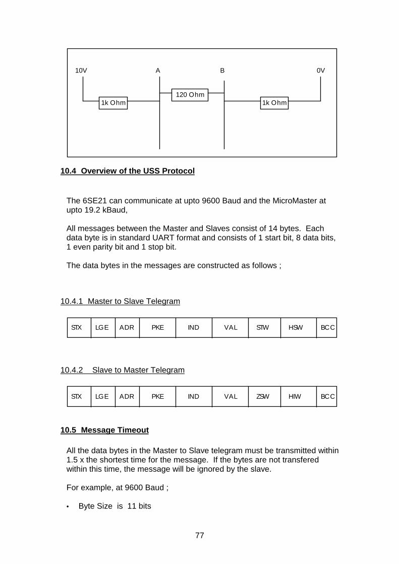
77
A B
120 Ohm
10V
1k Ohm 1k Ohm
0V
10.4 Overview of the USS Protocol
The 6SE21 can communicate at upto 9600 Baud and the MicroMaster atupto 19.2 kBaud,
All messages between the Master and Slaves consist of 14 bytes. Eachdata byte is in standard UART format and consists of 1 start bit, 8 data bits,1 even parity bit and 1 stop bit.
The data bytes in the messages are constructed as follows ;
10.4.1 Master to Slave Telegram
STX LGE ADR PKE IND VAL STW HSW BCC
10.4.2 Slave to Master Telegram
STX LGE ADR PKE IND VAL ZSW HIW BCC
10.5 Message Timeout
All the data bytes in the Master to Slave telegram must be transmitted within1.5 x the shortest time for the message. If the bytes are not transferedwithin this time, the message will be ignored by the slave.
For example, at 9600 Baud ;
• Byte Size is 11 bits
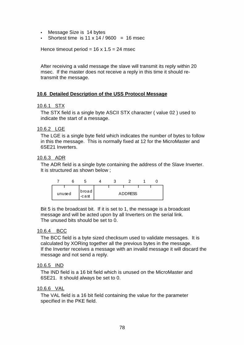
78
• Message Size is 14 bytes• Shortest time is 11 x 14 / 9600 = 16 msec
Hence timeout period = 16 x 1.5 = 24 msec
After receiving a valid message the slave will transmit its reply within 20msec. If the master does not receive a reply in this time it should re-transmit the message.
10.6 Detailed Description of the USS Protocol Message
10.6.1 STXThe STX field is a single byte ASCII STX character ( value 02 ) used toindicate the start of a message.
10.6.2 LGEThe LGE is a single byte field which indicates the number of bytes to followin this the message. This is normally fixed at 12 for the MicroMaster and6SE21 Inverters.
10.6.3 ADRThe ADR field is a single byte containing the address of the Slave Inverter.It is structured as shown below ;
01234567
ADDRESSunused broad -cast
Bit 5 is the broadcast bit. If it is set to 1, the message is a broadcastmessage and will be acted upon by all Inverters on the serial link.The unused bits should be set to 0.
10.6.4 BCCThe BCC field is a byte sized checksum used to validate messages. It iscalculated by XORing together all the previous bytes in the message.If the Inverter receives a message with an invalid message it will discard themessage and not send a reply.
10.6.5 INDThe IND field is a 16 bit field which is unused on the MicroMaster and6SE21. It should always be set to 0.
10.6.6 VALThe VAL field is a 16 bit field containing the value for the parameterspecified in the PKE field.
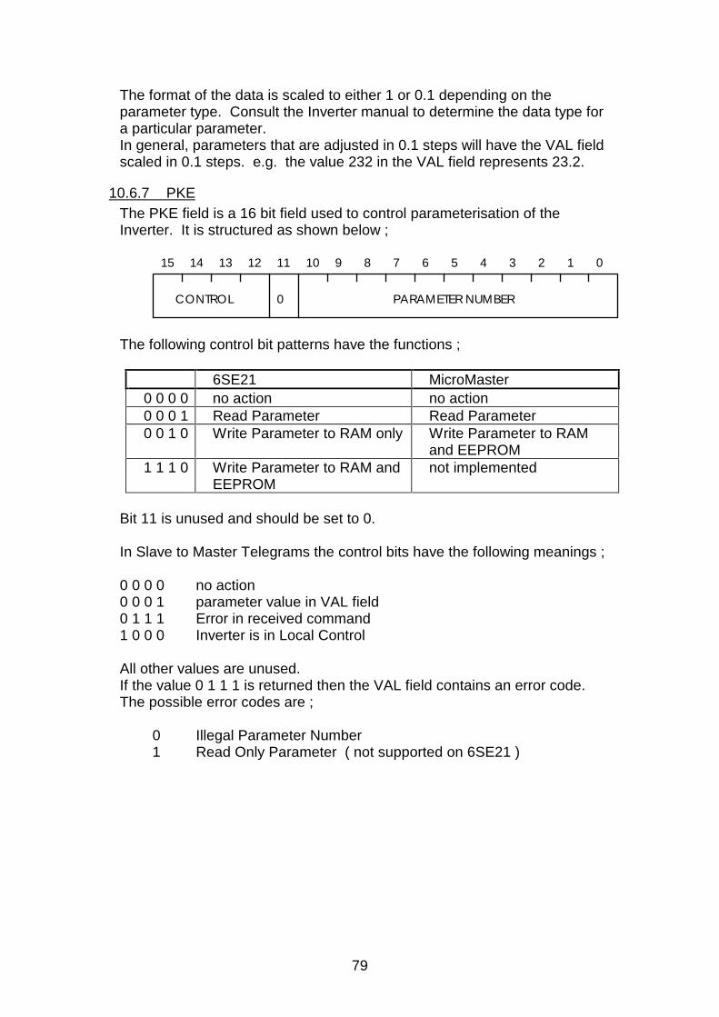
79
The format of the data is scaled to either 1 or 0.1 depending on theparameter type. Consult the Inverter manual to determine the data type fora particular parameter.In general, parameters that are adjusted in 0.1 steps will have the VAL fieldscaled in 0.1 steps. e.g. the value 232 in the VAL field represents 23.2.
10.6.7 PKEThe PKE field is a 16 bit field used to control parameterisation of theInverter. It is structured as shown below ;
01234567
PARAMETER NUMBER
89101112131415
0CONTROL
The following control bit patterns have the functions ;
6SE21 MicroMaster0 0 0 0 no action no action0 0 0 1 Read Parameter Read Parameter0 0 1 0 Write Parameter to RAM only Write Parameter to RAM
and EEPROM1 1 1 0 Write Parameter to RAM and
EEPROMnot implemented
Bit 11 is unused and should be set to 0.
In Slave to Master Telegrams the control bits have the following meanings ;
0 0 0 0 no action0 0 0 1 parameter value in VAL field0 1 1 1 Error in received command1 0 0 0 Inverter is in Local Control
All other values are unused.If the value 0 1 1 1 is returned then the VAL field contains an error code.The possible error codes are ;
0 Illegal Parameter Number1 Read Only Parameter ( not supported on 6SE21 )
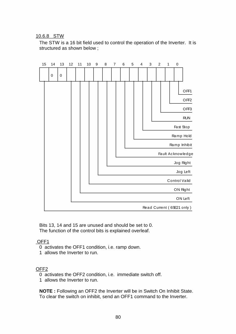
80
10.6.8 STWThe STW is a 16 bit field used to control the operation of the Inverter. It isstructured as shown below ;
0123456789101112131415
OFF1
OFF2
OFF3
RUN
Fast Stop
Ramp Hold
Ramp Inhibit
Fault Acknowledge
Jog Right
Jog Left
Control Valid
ON Right
ON Left
0 0
Read Current ( 6SE21 only )
Bits 13, 14 and 15 are unused and should be set to 0.The function of the control bits is explained overleaf.
OFF10 activates the OFF1 condition, i.e. ramp down.1 allows the Inverter to run.
OFF20 activates the OFF2 condition, i.e. immediate switch off.1 allows the Inverter to run.
NOTE : Following an OFF2 the Inverter will be in Switch On Inhibit State.To clear the switch on inhibit, send an OFF1 command to the Inverter.
81
OFF30 activates the OFF3 condition, i.e. fast ramp down with DC Link Voltage.1 allows the Inverter to run.
NOTE : Following an OFF2 the Inverter will be in Switch On Inhibit State.To clear the switch on inhibit, send an OFF1 command to the Inverter.
This function is not implemented on the 6SE21 and returns the code 0 1 1 1in PKE and the value 101 in the VAL field.
RUN0 switches the Inverter output off immediately.1 allows the Inverter to run.
Note: The 6SE21 requires either bit 11 or bit 12 to be set to specifydirection. The MicroMaster has a default direction of On Right.
Fast Stop0 Decelerates the Inverter as fast as possible along the DC Link Voltage.1 allows the Inverter to run.
Ramp Hold0 Holds the ramp rate generator at its present frequency.1 Allows the Inverter to ramp normally.
Ramp Inhibit0 Ramp to 0.0 Hz.1 Ramp normally.
Fault AcknowledgeA 0 to 1 transition of this bit between two consecutive messages will clearthe Inverter from a TRIPPED or FAULT state.
Jog Right0 no action.1 Jog Right.
NOTE : On 6SE21 this bit means JOG, with the direction selected in bits 11and 12.
Jog Left0 no action.1 Jog Left.
NOTE : On 6SE21, this bit means JOG, with the direction selected in bits11 and 12.
82
Control Valid0 Ignore control bits.1 Control Bits are valid.
On Right0 no action1 Requested direction is right.
On Left0 no action.1 Requested direction is left.
Read Current ( 6SE21 Only )On the 6SE21, if this bit is set to 1, then the value returned in HIW will bethe current scaled to 0.1 Amps.
To read the current on the MicroMaster, set parameter 1 to Current Displayand do a parameter read of Parameter 0.
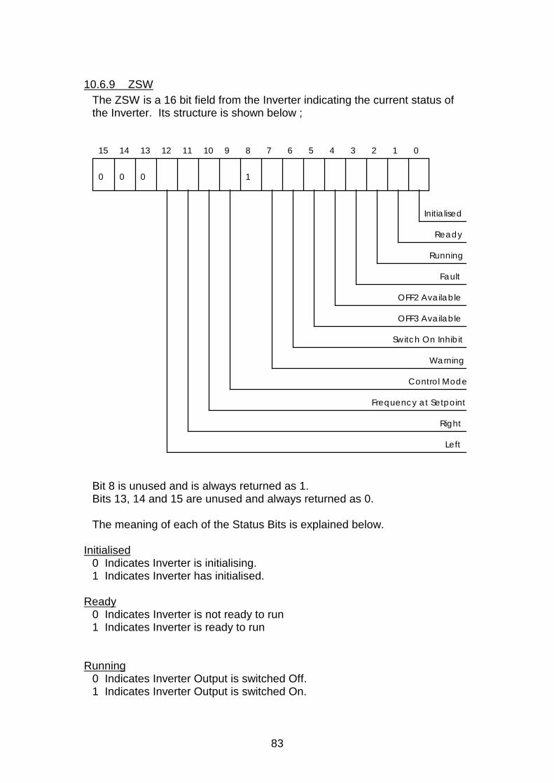
83
10.6.9 ZSWThe ZSW is a 16 bit field from the Inverter indicating the current status ofthe Inverter. Its structure is shown below ;
0123456789101112131415
0
Initialised
Ready
Running
Fault
OFF2 Available
OFF3 Available
Switch On Inhibit
Warning
Control Mode
Frequency at Setpoint
Right
Left
0 0 1
Bit 8 is unused and is always returned as 1.Bits 13, 14 and 15 are unused and always returned as 0.
The meaning of each of the Status Bits is explained below.
Initialised0 Indicates Inverter is initialising.1 Indicates Inverter has initialised.
Ready0 Indicates Inverter is not ready to run1 Indicates Inverter is ready to run
Running0 Indicates Inverter Output is switched Off.1 Indicates Inverter Output is switched On.
84
Fault0 Indicates no Fault.1 Indicates Inverter has a fault condition.
OFF2 Available0 Indicates OFF2 is available.1 Indicates OFF2 is not available.
Note : 6SE21 implementation indicates OFF2 active or not active.
OFF3 Available0 Indicates OFF3 is available.1 Indicates OFF3 is not available.
Note : 6SE21 implementation indicates OFF3 active or not active.
Switch On Inhibit0 Indicates Inverter is not in switch on inhibit state.1 Indicates Inverter is in switch on inhibit state.
Following an OFF2, OFF3, or trip, the Inverter will enter Switch On Inhibitstate. This prevents the Inverter from running.
Switch On Inhibit state is cleared by sending an OFF1 command to theInverter.
Warning0 No warning.1 Inverter Warning, e.g. over current.
NOTE : Not supported on 6SE21.
Control Mode0 Inverter is under Local Control.1 Inverter is under Remote Control.
Frequency at Setpoint0 Inverter Output Frequency is less than the requested setpoint.1 Inverter Output Frequency is at or greater than the requested setpoint.
Right0 Output direction is not right.1 Output direction is right.
Left0 Output direction is not left.1 Output direction is left.
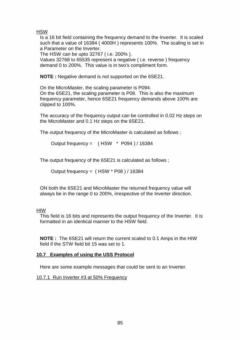
85
HSWIs a 16 bit field containing the frequency demand to the Inverter. It is scaledsuch that a value of 16384 ( 4000H ) represents 100%. The scaling is set ina Parameter on the Inverter.The HSW can be upto 32767 ( i.e. 200% ).Values 32768 to 65535 represent a negative ( i.e. reverse ) frequencydemand 0 to 200%. This value is in two’s compliment form.
NOTE : Negative demand is not supported on the 6SE21.
On the MicroMaster, the scaling parameter is P094.On the 6SE21, the scaling parameter is P08. This is also the maximumfrequency parameter, hence 6SE21 frequency demands above 100% areclipped to 100%.
The accuracy of the frequency output can be controlled in 0.02 Hz steps onthe MicroMaster and 0.1 Hz steps on the 6SE21.
The output frequency of the MicroMaster is calculated as follows ;
Output frequency = ( HSW * P094 ) / 16384
The output frequency of the 6SE21 is calculated as follows ;
Output frequency = ( HSW * P08 ) / 16384
ON both the 6SE21 and MicroMaster the returned frequency value willalways be in the range 0 to 200%, irrespective of the Inverter direction.
HIWThis field is 16 bits and represents the output frequency of the Inverter. It isformatted in an identical manner to the HSW field.
NOTE : The 6SE21 will return the current scaled to 0.1 Amps in the HIWfield if the STW field bit 15 was set to 1.
10.7 Examples of using the USS Protocol
Here are some example messages that could be sent to an Inverter.
10.7.1 Run Inverter #3 at 50% Frequency
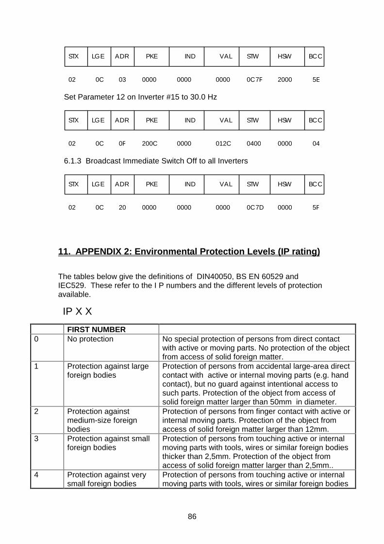
86
STX LGE ADR PKE IND VAL STW HSW BCC
02 0C 03 0000 0000 0000 0C7F 2000 5E
Set Parameter 12 on Inverter #15 to 30.0 Hz
STX LGE ADR PKE IND VAL STW HSW BCC
02 0C 0F 200C 0000 012C 0000 040400
6.1.3 Broadcast Immediate Switch Off to all Inverters
STX LGE ADR PKE IND VAL STW HSW BCC
02 0C 20 0000 0000 0000 0C7D 0000 5F
11. APPENDIX 2: Environmental Protection Levels (IP rating)
The tables below give the definitions of DIN40050, BS EN 60529 andIEC529. These refer to the I P numbers and the different levels of protectionavailable.
IP X X
FIRST NUMBER0 No protection No special protection of persons from direct contact
with active or moving parts. No protection of the objectfrom access of solid foreign matter.
1 Protection against largeforeign bodies
Protection of persons from accidental large-area directcontact with active or internal moving parts (e.g. handcontact), but no guard against intentional access tosuch parts. Protection of the object from access ofsolid foreign matter larger than 50mm in diameter.
2 Protection againstmedium-size foreignbodies
Protection of persons from finger contact with active orinternal moving parts. Protection of the object fromaccess of solid foreign matter larger than 12mm.
3 Protection against smallforeign bodies
Protection of persons from touching active or internalmoving parts with tools, wires or similar foreign bodiesthicker than 2,5mm. Protection of the object fromaccess of solid foreign matter larger than 2,5mm..
4 Protection against verysmall foreign bodies
Protection of persons from touching active or internalmoving parts with tools, wires or similar foreign bodies

87
thicker than l mm.5 Limitation of ingress of
dustTotal protection of persons from touching voltage-carrying or internal moving parts.Protection of theobject from harmful deposit of dust. Although ingress isnot completely prevented, dust will not enter insufficient quantity to impair the operation or safety ofthe apparatus.
6 Prevention of ingress ofdust
Total protection of persons from contacting voltage-carrying or internal moving parts.Total protection of theobject from ingress of dust.
SECOND NUMBER0 No protection No special protection.1 Protection against water
dripping verticallyWater drops falling vertically must not have anyharmful effect.
2 Protection against waterdripping non-vertically
Water drops failing at any angle up to 15’ with thevertical must not have any harmful effect.
3 Protection against spraywater
Water hitting the object at any angle up to 600 with thevertical must not have any harmful effect.
4 Protection against splashwater
Water splashing against the object from all directionsmust not have any harmful effect.
5 Protection against jetwater
A jet of water projected from a standard nozzle at 12.5litres per minute against the object from all directionsmust not have any harmful effect.
6 Protection againstpowerful water jets
A water jet projected at 1 00 litres per minute from alldirections shall have no harmful effect.
7 Protection againsttemporary submersion
If the enclosure is immersed between 0. 1 5 and 1 m inwater for 30 minutes, water must not enter it in anyharmful quantity.
8 Protection againstcontinuous submersion
If the enclosure remains submerged in water, underagreed conditions which are more severe than those ofIPX7, water must not enter it in any harmful quantity.
12. APPENDIX 3: Some Useful Formulae.
12.1.1 Torque and Power Relationships
If the steady state torque is known, the power requirement can be calculated:
Power [kW] = (Torque [Nm] X Speed [rev/min])/ 9550
or
Torque [Nm] = (9550 X Power [kW])/ Speed [rev/min]
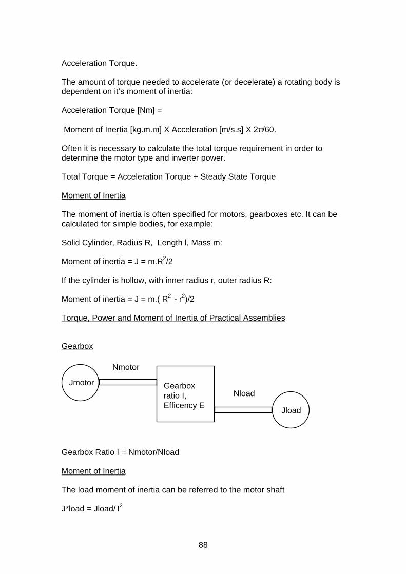
88
Acceleration Torque.
The amount of torque needed to accelerate (or decelerate) a rotating body isdependent on it’s moment of inertia:
Acceleration Torque [Nm] =
Moment of Inertia [kg.m.m] X Acceleration [m/s.s] X 2π/60.
Often it is necessary to calculate the total torque requirement in order todetermine the motor type and inverter power.
Total Torque = Acceleration Torque + Steady State Torque
Moment of Inertia
The moment of inertia is often specified for motors, gearboxes etc. It can becalculated for simple bodies, for example:
Solid Cylinder, Radius R, Length l, Mass m:
Moment of inertia = J = m.R2/2
If the cylinder is hollow, with inner radius r, outer radius R:
Moment of inertia = J = m.( R2 - r
2)/2
Torque, Power and Moment of Inertia of Practical Assemblies
Gearbox
Jmotor
Jload
Nload
Nmotor
Gearboxratio I,Efficency E
Gearbox Ratio I = Nmotor/Nload
Moment of Inertia
The load moment of inertia can be referred to the motor shaft
J*load = Jload/ I2
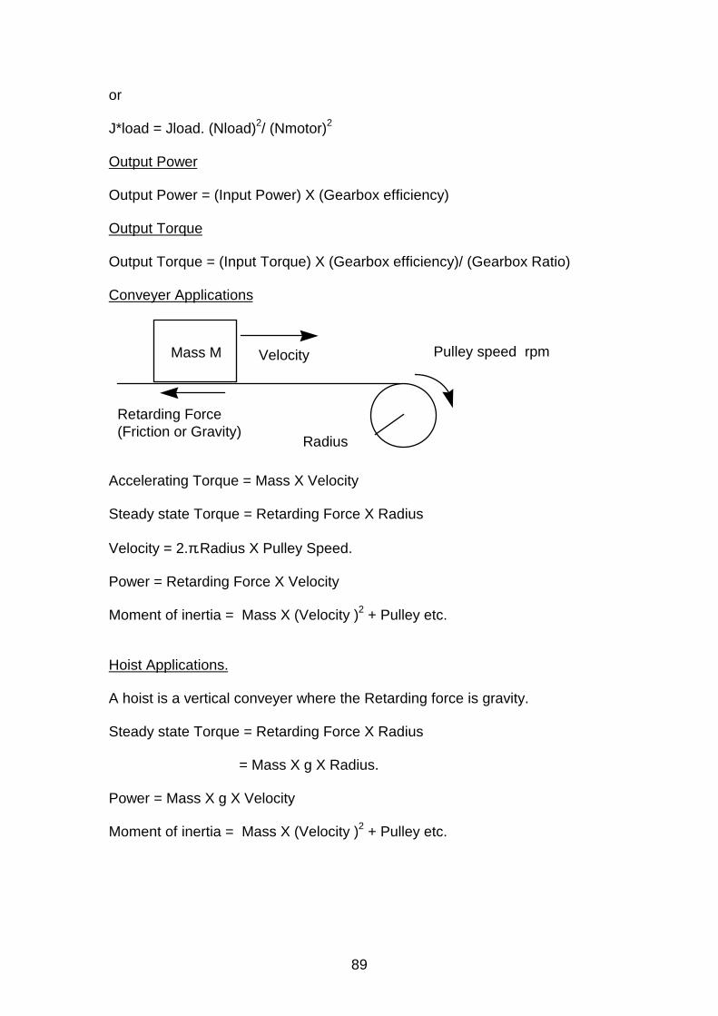
89
or
J*load = Jload. (Nload)2/ (Nmotor)2
Output Power
Output Power = (Input Power) X (Gearbox efficiency)
Output Torque
Output Torque = (Input Torque) X (Gearbox efficiency)/ (Gearbox Ratio)
Conveyer Applications
Pulley speed rpmMass M Velocity
Radius
Retarding Force (Friction or Gravity)
Accelerating Torque = Mass X Velocity
Steady state Torque = Retarding Force X Radius
Velocity = 2.π.Radius X Pulley Speed.
Power = Retarding Force X Velocity
Moment of inertia = Mass X (Velocity )2 + Pulley etc.
Hoist Applications.
A hoist is a vertical conveyer where the Retarding force is gravity.
Steady state Torque = Retarding Force X Radius
= Mass X g X Radius.
Power = Mass X g X Velocity
Moment of inertia = Mass X (Velocity )2 + Pulley etc.
Related Documents