SIEMENS DIGITAL INDUSTRIES SOFTWARE Understanding formal methods for use in DO-254 programs Executive summary This paper seeks to take the mystery out of the use of formal methods for hardware verification. In this discussion, we will first explain formal methods as clearly and concisely as possible. We will then look at the state of the industry and the changes over the last decade or so that have enabled the widespread use of formal methods for hardware verification. With this knowledge in-hand, we will examine and explain the contents of DO-254 Appendix B 3.3.3 “Formal Methods.” Finally, we will bring this information together and provide recommendations for using formal methods on a DO- 254 project. Harry Foster, Mark Eslinger and David Landoll Siemens EDA siemens.com/software

Welcome message from author
This document is posted to help you gain knowledge. Please leave a comment to let me know what you think about it! Share it to your friends and learn new things together.
Transcript

SIEMENS DIGITAL INDUSTRIES SOFTWARE
Understanding formal methods for use in DO-254 programs
Executive summaryThis paper seeks to take the mystery out of the use of formal methods for hardware verification. In this discussion, we will first explain formal methods as clearly and concisely as possible. We will then look at the state of the industry and the changes over the last decade or so that have enabled the widespread use of formal methods for hardware verification. With this knowledge in-hand, we will examine and explain the contents of DO-254 Appendix B 3.3.3 “Formal Methods.” Finally, we will bring this information together and provide recommendations for using formal methods on a DO- 254 project.
Harry Foster, Mark Eslinger and David Landoll Siemens EDA
siemens.com/software

Contents
Introduction 3
Formal methods overview 3
What are “Formal Methods”? 3
Formal methods value for DO-254 4
Inputs to formal 5
Why the confusion and why don’t more people use formal
methods? 5
How formal methods find bugs 5
DO-254 Appendix B 3.3.3 Formal methods explained 8
Formal methods definition 8
Two types of formal 8
Value of formal 9
Formal approaches for design assurance 9
Early stages of design 9
Entire design, specific components, and other uses 9
All functions, important properties, unintended behavior 10
Formal tools and tool assessment 10
Independent output assessment 11
Qualification kits 11
Requirements, properties, and assertions 11
Formal model and analysis 12
Todays use of formal 18
A bit of tool history 18
Industry data 18
Why people are using formal 18
Conclusion 24
SIEMENS DIGITAL INDUSTRIES SOFTWARE 2
White Paper – Understanding formal methods for use in DO-254 Programs

Formal Verification is one of the most misunder-
stood areas of DO-254. It is one of the few actual
design or verification methods named in the RTCA/
DO-254 document (Appendix B) and is in fact listed
as an appropriate method for the “Advanced
Verification” requirements for Level A/B designs.
The problem is that the content of Appendix B is
extremely difficult to understand. The text in this
section was largely taken from texts or papers on
formal methods intended more for the academic
rather than today’s typical user. In addition, it is
also too oriented towards formal verification for
software. Add to this, the information is over 20
years old. This has resulted in fear (in the minds of
the project team who wants to use it on their
DO-254 programs but don’t want to increase their
project’s scrutiny) and unease (for the certification
authority who sees its use called out on a DO-254
program but does not really understand this use or
its purpose).
This paper seeks to take the mystery out of the use
of formal methods for hardware verification. In this
discussion, we will first explain formal methods as
clearly and concisely as possible. We will then look
at the state of the industry and the changes over
the last decade or so that have enabled the wide-
spread use of formal methods for hardware verifica-
tion. With this knowledge in-hand, we will examine
and explain the contents of DO-254 Appendix B
3.3.3 “Formal Methods.” Finally, we will bring this
information together and provide recommendations
for using formal methods on a DO- 254 project.
Introduction
Formal methods overview
Even though the practical application of formal
methods was in its infancy during the original
writing of DO-254, the authors of DO-254 certainly
understood the potential of formal methods in
terms of enhancing design assurance. This section
provides some foundational information that can
help you understand why the DO-254 authors felt
formal methods were pertinent and useful in terms
of aiding design assurance.
What are “Formal Methods”?Formal methods make use of exhaustive mathemat-
ical algorithms to verify the functional correctness
of a design against its requirements. Because the
process is exhaustive, the verification answer to the
question “does this design meet this requirement”
is guaranteed to be complete. That is, if design can
exhibit any undesirable behavior, formal methods
will point them out. On the other hand, if formal can
prove that no such undesirable behavior exists, then
formal methods will say so.
SIEMENS DIGITAL INDUSTRIES SOFTWARE 3
White Paper – Understanding formal methods for use in DO-254 Programs
Contrast this with commonly used simulation
techniques, which is considered a “probabilistic”
approach. This means the tool itself cannot guar-
antee that all undesirable behavior will be identified.
It’s entirely up to the user to think of all possible
undesirable behavior and test each one individually.
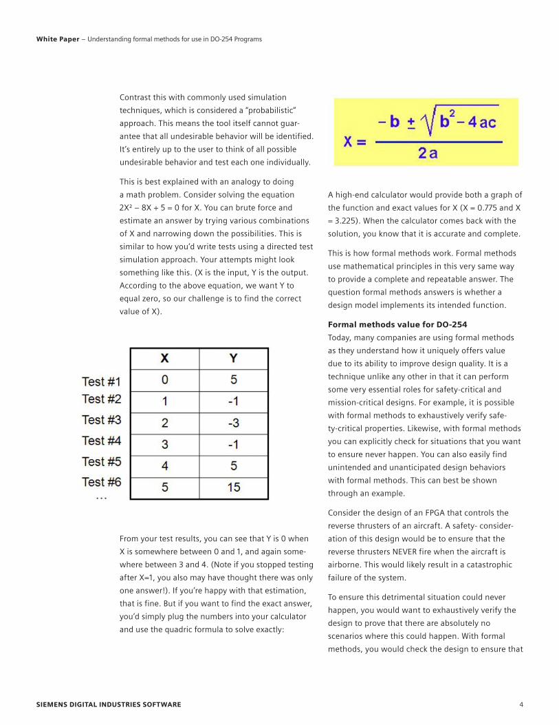
This is best explained with an analogy to doing
a math problem. Consider solving the equation
2X² – 8X + 5 = 0 for X. You can brute force and
estimate an answer by trying various combinations
of X and narrowing down the possibilities. This is
similar to how you’d write tests using a directed test
simulation approach. Your attempts might look
something like this. (X is the input, Y is the output.
According to the above equation, we want Y to
equal zero, so our challenge is to find the correct
value of X).
From your test results, you can see that Y is 0 when
X is somewhere between 0 and 1, and again some-
where between 3 and 4. (Note if you stopped testing
after X=1, you also may have thought there was only
one answer!). If you’re happy with that estimation,
that is fine. But if you want to find the exact answer,
you’d simply plug the numbers into your calculator
and use the quadric formula to solve exactly:
A high-end calculator would provide both a graph of
the function and exact values for X (X = 0.775 and X
= 3.225). When the calculator comes back with the
solution, you know that it is accurate and complete.
This is how formal methods work. Formal methods
use mathematical principles in this very same way
to provide a complete and repeatable answer. The
question formal methods answers is whether a
design model implements its intended function.
Formal methods value for DO-254Today, many companies are using formal methods
as they understand how it uniquely offers value
due to its ability to improve design quality. It is a
technique unlike any other in that it can perform
some very essential roles for safety-critical and
mission-critical designs. For example, it is possible
with formal methods to exhaustively verify safe-
ty-critical properties. Likewise, with formal methods
you can explicitly check for situations that you want
to ensure never happen. You can also easily find
unintended and unanticipated design behaviors
with formal methods. This can best be shown
through an example.
Consider the design of an FPGA that controls the
reverse thrusters of an aircraft. A safety- consider-
ation of this design would be to ensure that the
reverse thrusters NEVER fire when the aircraft is
airborne. This would likely result in a catastrophic
failure of the system.
To ensure this detrimental situation could never
happen, you would want to exhaustively verify the
design to prove that there are absolutely no
scenarios where this could happen. With formal
methods, you would check the design to ensure that
SIEMENS DIGITAL INDUSTRIES SOFTWARE 4
White Paper – Understanding formal methods for use in DO-254 Programs

the property “the reverse thrusters can never fire
while in mid-air” always held true. Formal methods
would tell you all the scenarios that violate that
property. This is the true power of formal methods.
With simulation you can verify expected behavior
given defined circumstances, but you can never
fully verify unexpected conditions. Yet simulation
has been the perfectly acceptable approach to
verification. By augmenting traditional simulation
approaches with formal methods, confidence that
the design performs its intended function (a.k.a.,
design assurance) improves.
Inputs to formalAchieving design assurance as demonstrated above
using formal methods is much easier than most
people realize. All it takes is a formal engine (that
runs mathematical analysis), the design model, and
the requirement. The design model itself is just the
standard RTL model (typically VHDL) that is devel-
oped during the “detailed design” phase, simulated,
and then synthesized. This model requires no addi-
tional work to be used with formal methods.
The requirement would normally be stated in
English (or the natural language used in the project)
where it is captured and traced throughout the
process. In order to use this requirement with
formal methods, the requirement would need to be
written in a formal property specification language.
(You can think of a property as the same thing as
a requirements).
Today there are several industry standard property
languages, which are commonplace and well-under-
stood. Once this formal property description is
written, it should be reviewed against the original
requirement for accuracy. (In fact, this provides
another layer of design assurance in the flow, as
translating a requirement to a formal language is a
very good exercise in requirements validation, as
the translated property must be unambiguous and
verifiable. Going through this process is an excellent
double-check on the validity of the requirement).
Once you have your RTL coded and your require-
ment written as a formal property, you can run
formal. This is really all it takes to exhaustively verify
a safety-critical property. Every violation of the
property identifies unexpected behavior of the
design that must be fixed.
Why the confusion and why don’t more people use formal methods?Many people are very intimidated by the thought of
formal methods. They may have learned a little bit
about it in their college days in a very academic
sense only. At the same time, they’ve been using
simulation for many years. How to run simulation is
well understood.
However, if you stepped back and really examined
how a simulator works alongside how a formal
methods engine works, formal methods actually are
simpler in concept.
However, formal methods often suffer from a legacy
stigma as being a method only suitable for those
who have a Ph.D., or at least a propensity for math.
While this may have been true 20+ years ago, before
commercial tools, RTL coding standards, and prop-
erty specification languages, today it is simply an
artifact of a time gone by. The creation of intuitive
user apps leveraging sophisticated formal engines
has drastically lowered the barrier of entry to use
formal methods.
How formal methods find bugsIt’s perhaps natural that some misconceptions about
formal methods remain. After all, the very idea that
a commercially available tool can readily take a RTL
design and a simple-to- specify property and
exhaustively verify its functional correctness sounds
impossible. Simply put: It sounds too good to be
true. As a result, many people are skeptical that it
really does exist. With that in mind, let’s try to
explore how a formal tool can find bugs in a design.
SIEMENS DIGITAL INDUSTRIES SOFTWARE 5
White Paper – Understanding formal methods for use in DO-254 Programs

First, think of a design as a collection of registers
and input pins. For standard digital designs, when
you change the input stimulus and apply a single
clock, the state of the design will change. That is,
the design will change its behavior and do some-
thing different. Change the inputs, give another
clock, and the design state will change again. As
long as the design keeps doing things that are
expected and meeting its requirements, it’s oper-
ating within its “legal state space.”
On the other hand, if the design ever does some-
thing illegal that violates its requirements, we can
say the design has moved into “illegal state space,”
and the design has a bug.
Simulation works fairly intuitively. It walks through
the design’s behavior changing input signals, giving
a clock, changing input signals, giving a clock, etc.
Repeat this process until the simulation test reaches
its end, where some output value is typically
compared against an expected value. If the output
value matches its expected value, the test is said to
“PASS.” If not, then the test “FAILED.” It makes perfect
sense. One can even perform this task manually by
tediously propagating values through the design to
determine what the design will do next.
The key problem to this approach is obvious to
anyone that has functionally verified a design of any
complexity. If the collection of simulation tests fails
to exercise some portion of the design, then a bug
may exist that was previously unknown. In some
cases, this could be an unexpected combination of
conditions that is difficult to predict.
Formal verification does things a bit differently. Formal
flips the entire problem on its head. By using a property
to directly define legal vs. illegal state behavior, formal
asks the question: “Is there any possible way to get from
a legal state to an illegal state.”
To perform this analysis, formal starts with a single
state, which is typically the “reset state” (the state
reached after the reset signal is applied). Formal
then thinks about all the possible behavior, all the
combinations and permutations of 1s and 0s across
all input signals. It calculates how the design will
behave as a result of each and every one of these
inputs and remembers the result. Then for each one
of these results, formal again considers each and
every possible input combination and permutation,
and how the design will respond, again remem-
bering all results.
SIEMENS DIGITAL INDUSTRIES SOFTWARE 6
White Paper – Understanding formal methods for use in DO-254 Programs

At each result, formal asks itself, “is this result illegal
with respect to the specified property?” If so, then
the tool has found a way that the design doesn’t
meet its requirement, and it is reported to the user.
If not, the procedure continues. Eventually, formal
will realize that it has examined all possible results,
indicating there is no illegal behavior possible, and a
“proof” of correctness results.
For the example requirement below, the property
simply states that “if we currently see activate_rev_
thrusters, then it implies that we must already have
weight_on-wheels.” If not, then we’ve reached an
“illegal state space.” This is using the IEEE industry
standard SystemVerilog Assertion language.
As you can imagine, the number of results the tool
needs to compute and remember grows exponen-
tially. It’s only in the past 10 years that very clever
formal algorithms, combined with very fast
computers, have allowed formal methods to be
applied in practical ways.
Hopefully this has somewhat de-mystified the
formal methods process. With this basic
understanding in mind, we can now move on to
explore the DO-254 spec related to this topic.
SIEMENS DIGITAL INDUSTRIES SOFTWARE 7
White Paper – Understanding formal methods for use in DO-254 Programs
This section examines the actual text of Appendix B,
3.3.3, looking at exactly what is written, in the order
it is written, and explaining it one small piece at a
time. Information that is pulled directly from DO-254
is highlighted in blue text for clarity.
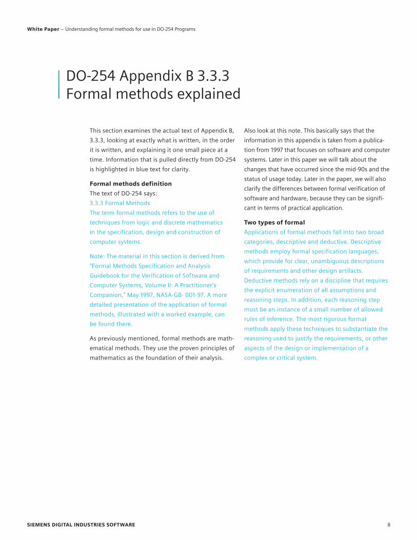
Formal methods definition The text of DO-254 says:
3.3.3 Formal Methods
The term formal methods refers to the use of
techniques from logic and discrete mathematics
in the specification, design and construction of
computer systems.
Note: The material in this section is derived from
“Formal Methods Specification and Analysis
Guidebook for the Verification of Software and
Computer Systems, Volume II: A Practitioner’s
Companion,” May 1997, NASA-GB- 001-97. A more
detailed presentation of the application of formal
methods, illustrated with a worked example, can
be found there.
As previously mentioned, formal methods are math-
ematical methods. They use the proven principles of
mathematics as the foundation of their analysis.
Also look at this note. This basically says that the
information in this appendix is taken from a publica-
tion from 1997 that focuses on software and computer
systems. Later in this paper we will talk about the
changes that have occurred since the mid-90s and the
status of usage today. Later in the paper, we will also
clarify the differences between formal verification of
software and hardware, because they can be signifi-
cant in terms of practical application.
Two types of formalApplications of formal methods fall into two broad
categories, descriptive and deductive. Descriptive
methods employ formal specification languages,
which provide for clear, unambiguous descriptions
of requirements and other design artifacts.
Deductive methods rely on a discipline that requires
the explicit enumeration of all assumptions and
reasoning steps. In addition, each reasoning step
must be an instance of a small number of allowed
rules of inference. The most rigorous formal
methods apply these techniques to substantiate the
reasoning used to justify the requirements, or other
aspects of the design or implementation of a
complex or critical system.
DO-254 Appendix B 3.3.3 Formal methods explained
SIEMENS DIGITAL INDUSTRIES SOFTWARE 8
White Paper – Understanding formal methods for use in DO-254 Programs
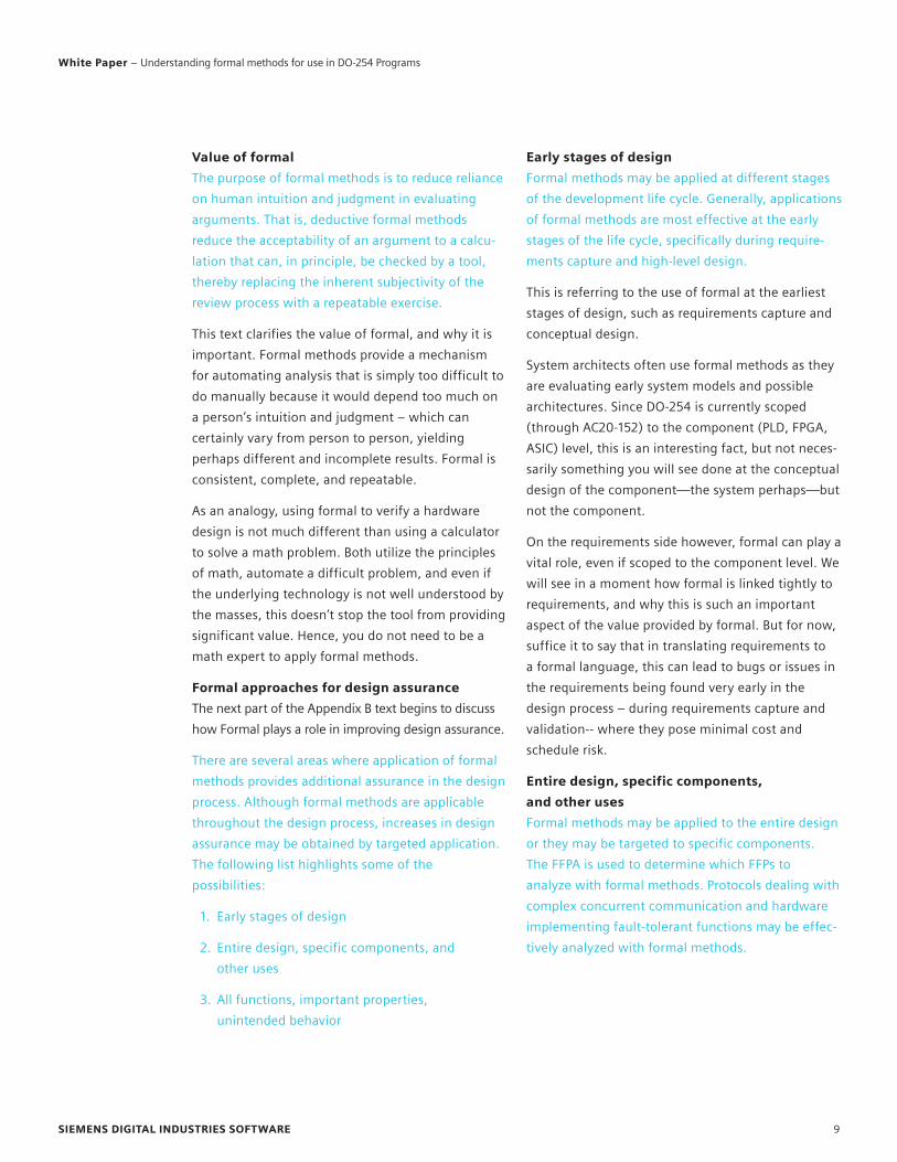
Value of formalThe purpose of formal methods is to reduce reliance
on human intuition and judgment in evaluating
arguments. That is, deductive formal methods
reduce the acceptability of an argument to a calcu-
lation that can, in principle, be checked by a tool,
thereby replacing the inherent subjectivity of the
review process with a repeatable exercise.
This text clarifies the value of formal, and why it is
important. Formal methods provide a mechanism
for automating analysis that is simply too difficult to
do manually because it would depend too much on
a person’s intuition and judgment – which can
certainly vary from person to person, yielding
perhaps different and incomplete results. Formal is
consistent, complete, and repeatable.
As an analogy, using formal to verify a hardware
design is not much different than using a calculator
to solve a math problem. Both utilize the principles
of math, automate a difficult problem, and even if
the underlying technology is not well understood by
the masses, this doesn’t stop the tool from providing
significant value. Hence, you do not need to be a
math expert to apply formal methods.
Formal approaches for design assuranceThe next part of the Appendix B text begins to discuss
how Formal plays a role in improving design assurance.
There are several areas where application of formal
methods provides additional assurance in the design
process. Although formal methods are applicable
throughout the design process, increases in design
assurance may be obtained by targeted application.
The following list highlights some of the
possibilities:
1. Early stages of design
2. Entire design, specific components, and
other uses
3. All functions, important properties,
unintended behavior
Early stages of designFormal methods may be applied at different stages
of the development life cycle. Generally, applications
of formal methods are most effective at the early
stages of the life cycle, specifically during require-
ments capture and high-level design.
This is referring to the use of formal at the earliest
stages of design, such as requirements capture and
conceptual design.
System architects often use formal methods as they
are evaluating early system models and possible
architectures. Since DO-254 is currently scoped
(through AC20-152) to the component (PLD, FPGA,
ASIC) level, this is an interesting fact, but not neces-
sarily something you will see done at the conceptual
design of the component—the system perhaps—but
not the component.
On the requirements side however, formal can play a
vital role, even if scoped to the component level. We
will see in a moment how formal is linked tightly to
requirements, and why this is such an important
aspect of the value provided by formal. But for now,
suffice it to say that in translating requirements to
a formal language, this can lead to bugs or issues in
the requirements being found very early in the
design process – during requirements capture and
validation-- where they pose minimal cost and
schedule risk.
Entire design, specific components, and other usesFormal methods may be applied to the entire design
or they may be targeted to specific components.
The FFPA is used to determine which FFPs to
analyze with formal methods. Protocols dealing with
complex concurrent communication and hardware
implementing fault-tolerant functions may be effec-
tively analyzed with formal methods.
SIEMENS DIGITAL INDUSTRIES SOFTWARE 9
White Paper – Understanding formal methods for use in DO-254 Programs
Formal methods may be applied to the entire design
or they may be targeted to specific components.
The FFPA is used to determine which FFPs to analyze
with formal methods. Protocols dealing with
complex concurrent communication and hardware
implementing fault-tolerant functions may be
effectively analyzed with formal methods.
In theory, formal can be applied to the entire
design. However, a reality of design complexity and
tool capacity is that unless the design is fairly small,
applying formal to the whole design is not generally
practical. Today, it is far more common to see formal
applied to specific components, or rather, blocks of
the design. Here the problem space is much more
conducive to an exhaustive verification approach.
Another interesting approach to using formal would
be to provide added assurance (verification) to the
safety-specific aspects of the design, such as the
functional failure paths and safety-critical functions.
Another sweet spot for formal use today is in veri-
fying very complex hardware, especially with
concurrent functions. Likewise, formal could be
used to validate the correct operation of fault-tol-
erant functions, ensuring it is indeed completely
resistant to fault conditions.
All functions, important properties, unin-tended behaviorFormal methods may be applied to verify system
functionality, or they may be used to establish
specific properties. Although formal methods have
traditionally been associated with “proof-of-correct-
ness,” that is, ensuring that a component meets its
functional specification, they can also be applied to
only the most important properties. Often, it is
more important to confirm that a design does not
exhibit certain undesirable properties, rather than
to prove that it has full functionality.
This indicates that formal can be used to verify all
system functions or just some of them, perhaps
only the most important. Again, this goes back to
scoping how formal is being used. Will it be used
for all properties, to exhaustively verify the entire
design? This is possible, but as mentioned before,
it’s generally not a practical approach. More likely,
formal will be used to verify a select set of proper-
ties, usually those of most concern.
During the course of verifying properties, formal
also provides a unique side benefit – it finds unin-
tended behavior. This is something very difficult to
achieve with a simulation-only approach. This is
where “reliance on human intuition and judgment”
is not good practice. Instead, using an exhaustive
mathematical analysis can provide tremendous
value in safety- critical designs. We will talk more
about how this is done in future sections.
Formal tools and tool assessmentPractical application of formal methods typically
requires tool support. Tools used should be assessed
and, if necessary, qualified as described in Section
11.4.
This should come as no surprise to anyone. You
need tools to run formal analysis. These tools should
not be treated any differently than any other verifi-
cation tools used in the design flow.
It is not uncommon to hear the objection “How can
we trust the results, if we don’t understand how the
tool works?” But think about it. How many people
really understand how simulator algorithms work,
or the circuitry within a calculator for that matter?
Very intelligent people, who do understand how
these things work, have engineered these products
for the benefit of the masses.
Now, this does not mean they should simply be
trusted. There should be no “trust” in a DO- 254
program. No two tools, just like no two people,
are alike. That is why all work must be reviewed,
double-checked, or proven worthy of the task.
SIEMENS DIGITAL INDUSTRIES SOFTWARE 10
White Paper – Understanding formal methods for use in DO-254 Programs

Two main approaches can be used for assessing
formal tools.
1) Independent output assessmentAs we will see in a bit, simulation and formal
methods are complimentary. They are generally
used together in a flow. In many ways, they
approach the verification problem very differently
and, in this regard, provide different ways of looking
at the verification problem. Verification flows that
use both typically have some amount of overlap and
double-checking. This double-checking can also be
explicitly done if there are concerns about the tool
outputs.
In addition, throughout a DO-254, each stage
of design requires additional verification. Formal
methods are usually done early in the design
process. Numerous other verification methods and
techniques will also be run later in the process, on
models of lower abstraction levels, on the HW item
itself, and with the HW item in the target system.
Each of these additional verification methods and
processes should be verifying previous verification
work. A good DO-254 flow will automatically have
these checks and balances (that support indepen-
dent output assessment) built in. This is the best
approach.
2) Qualification kitsIt would also be possible to provide a set of test
cases that could ship with the tool. These test cases
could run in both simulation and formal to explicitly
force both types of tools to verify the cases. The
results of both should match.
While this is certainly just a tiny fraction of the sort
of testing that is done on these tools by their devel-
opers, and therefore the value of this sort of process
is highly questionable, if certification authorities
required it, it could be done. Tool vendors or the
hardware applicant could come up with such a test
suite.
Requirements, properties, and assertions3.3.3.1 The Methodology of Formal Methods
The application of formal methods begins by
expressing the requirements using a formal
language. The requirement specification serves an
important descriptive function. It provides a basis
for documenting, communicating, and prototyping
the behavior and properties of a system using an
unambiguous notation.
Finally, we are able to tie formal methods to a
requirements-based design process. We start by
defining some terms to so we can see how formal
methods works and how it can truly be a require-
ments-based verification approach.
A requirement is a description of design intent/
behavior. The customer, architect, or designer (all
the people who may have a hand in writing require-
ments) usually writes requirements in their native
language (such as English). The problem with this is
that native languages like English are very ambig-
uous, and prone to various interpretations. Even
though requirements are reviewed and validated,
oftentimes, bugs later in the process tie back to
misinterpretation or misunderstandings of the
actual intent of a requirement.
With formal methods, an engineer must translate
the native language requirement into a formal
language description of this requirement. The
formal description of a requirement is called a
property. A property specifies a requirement unam-
biguously in a formal language that enables tool
use. Because the formal language is unambiguous,
the tool can interpret the property only one way.
One of the major barriers to adoption of formal
methods prior to the year 2000, was the lack of
standardization of these formal languages. Today,
the industry has adopted two languages for the
specification of properties: PSL (Property
Specification Language, IEEE 1850) and SVA
(SystemVerilog Assertions, IEEE 1800). As IEEE
standards, this ensures that a whole industry
SIEMENS DIGITAL INDUSTRIES SOFTWARE 11
White Paper – Understanding formal methods for use in DO-254 Programs

infrastructure exists for their support (documenta-
tion, libraries, tools, training, etc.).
The property is merely a mechanism to formally
capture design intent. In order to tell a tool that you
want to do something with a property, such as
monitor it during simulation, and check it with
formal verification, you must assert it. Thus, an
assertion is a tool directive to “turn on” a property
for verification.
An example can make this more concrete. Suppose
you have the following design requirement from our
earlier example.
An example can make this more concrete. Suppose
you have the following design requirement from our
earlier example.
“The reverse thrusters shall never deploy in flight.”
This can be formally described as a property (in this
case, using SVA) as follows:
property REVERSE_THRUSTERS_001;
@(posedge clk)
activate_rev_thrusters |->
weight_on_wheels_notification;
endproperty
This description will passively sit in the code (i.e.,
the design code or a separate verification file) doing
nothing until you decide to use it in verification. You
do this through an assertion as follows:
property REVERSE_THRUSTERS_001;
@(posedge clk)
activate_rev_thrusters |->
weight_on_wheels_notification;
endproperty
assert property REVERSE_THRUSTERS_001;
The “assert” keyword triggers the simulator to
monitor the property during simulation. Likewise,
all asserted properties are checked when formal
runs.
Formal model and analysisIn addition, the requirements specification serves as
a basis for calculating or formally predicting system
behavior. A formal model of the component to be
analyzed is constructed using a formal language.
The model is analyzed with respect to the formal
statement of requirements using the rules of the
selected formal logic. The characteristics of the
model are determined by the style of formal analysis
to be performed.
As we have just demonstrated, requirements
become a key aspect of formal analysis when they
are written as properties and asserted. Next you
need a formal model.
This is another key area of misunderstanding with
regards to formal use in hardware. You do not need
a separate model to be used for formal analysis. The
formal model is simply the RTL model, which in the
military/aerospace industry is typically VHDL code
(or Verilog, SystemVerilog, mixed languages).
How or why can the RTL be used as the formal
model? Consider this. To simulate the model, you
have to compile the VHDL code into a set of primi-
tives or C code that is executed by the simulator.
This is the same with synthesis – the RTL model is
compiled into a gate-level model. Similarly, with
Formal, the RTL model is compiled into a mathemat-
ical model. They all start from the same RTL model
and translate it to the internal model appropriate to
fulfill their task.
The formal analysis process compares the model
(e.g., the VHDL) to the requirement (via the asser-
tion), calculating whether the requirement is true
within the model.
SIEMENS DIGITAL INDUSTRIES SOFTWARE 12
White Paper – Understanding formal methods for use in DO-254 Programs

The level of detail in the component model is deter-
mined by the goal of the chosen formal analysis
technique. Some approaches are tailored to finding
design errors that may have eluded testing, while
other approaches seek to guarantee the absence of
certain classes of design errors.
For use in DO-254 projects, the formal model is the
RTL model (e.g., the VHDL code). A number of
formal techniques can be used on this model,
including searching for bugs (i.e., bug hunting)
versus trying to exhaustively prove no bugs exist
(i.e., assurance). Both find bugs, but the goals are
different. The first approach attempts to quickly
identify bugs in a non-systematic fashion using
formal techniques. The second approach is a
comprehensive and systematic methodology to
achieving assurance, at a potential cost of more
effort and time.
(Formal) model checking1. Error-Detection. The most common formal tech-
nique for error detection is called model checking.
Here the requirements are expressed as formula
in a decidable temporal logic. The model of the
component is an abstract state machine designed
so that the property to be tested is preserved.
The proof procedure is automatic. A failed proof
attempt indicates a design error in the modeled
component. The result of failed proof is a
sequence of input stimuli that demonstrate
specifically how the component does not satisfy
the stated requirement.
Formal model checking, or simply model checking,
is the formal analysis process we just introduced.
In this common use of formal methods, a formal
analysis tool checks a design model against its
requirements. The output of model checking
includes proofs or failed proofs. We will talk about
this more in section “Outcomes of Formal Model
Checking.”
Model checking compliments simulationSomething that is important to understand about
model checking is that it should generally not take
the place of simulation, but rather be used along-
side of it.
In the early days of commercial formal tools, compa-
nies that sold these tools believed so strongly in
their verification abilities that they often promoted
these solutions as the replacement for simulation.
However, as the use of formal has become more
common place, it has also become more and more
apparent that both simulation and formal analysis
are necessary to ensure a design is thoroughly
verified. Thus, the vast majority of companies who
use formal today do so in a manner that is comple-
mentary with simulation. This is because both
simulation and formal analysis have their sweet
spots, and pitfalls.
Simulation allows you to create and verify just about
any type of circuitry or situation that you are
creative enough to think of. It operates with a
model of the design environment (called the test-
bench) sending stimulus (or test cases) to the model
of the design (called the device under test, or DUT),
and checking the model’s response. The simulation
test environment is typically developed by one or
more verification specialists. Simulation is very
flexible, but the tests are only as good as the skill of
the verification team creating them.
Simulation is rarely, if ever, exhaustive (except for
the most simplistic of circuitry). For today’s large
designs, simulation might demonstrate the pres-
ence of a bug, but unlike formal, it can never prove
the absence of a bug.
SIEMENS DIGITAL INDUSTRIES SOFTWARE 13
White Paper – Understanding formal methods for use in DO-254 Programs

Formal model checking does not require a testbench
or any input stimulus. The test cases are simply the
assertions that are written from the requirements.
This enables testing to start much earlier in the
process because far less infrastructure is needed.
Often (but not always) this early testing is done by
the designer himself. In this regard, the designer is
checking his code (part of the model) a bit at a time,
against the pertinent requirements. The assertions
can be reused for official verification work done
independently by verification team. These asser-
tions can also be used during the simulation activi-
ties that are done by this team (note that this is a
very common practice, but somewhat beyond the
scope of this specific paper). The drawback with
formal is that it is a highly intensive computational
process that consumes huge amount of memory
and computing power. For this reason, it is best
used at the block level of design, is best suited for
certain types of circuitry (this is elaborated in
“Where to Use and Not Use Formal”) and may
benefit from requirements being broken down into
multiple, smaller assertions. If scoped and used
appropriately, formal provides exhaustive analysis.
Formal also runs much more quickly than
simulation.
The following table summarizes the use of simula-
tion and formal methods (including how they are
different, and how they complement each other)
for verification:
Issue Simulation FormalModel (DUT) RTL (e.g., VHDL) RTL (e.g., VHDL)
Testbench Required None
Test cases Usually hand created Automatic (via assertions)
Types of Circuitry Supported Just about all Some better than others
Design Level Block or Top Level Block Better
Exhaustive No Yes
Linked to Requirements Depends on testcasesYes, requirements-based assertions
Support Assertions Yes Yes, required
Used for Early VerificationProhibitive (infrastructure needed)
Well suited
Theorem proving2. Error Preclusion. Formal methods targeted to
prevention of errors are generally based upon
an expressive specification language with a
supporting proof theory. With the increased
expressiveness, more complicated requirements
may be stated, and more detailed models of the
component may be constructed. However, the
proof procedure may only be partially automated.
An appropriate level of detail for the component
model may be a synthesizable HDL description. In
some cases, the same model may be used both for
simulation and formal analysis. A completed proof
is evidence that the component is logically correct
with respect to the stated requirements for the
analyzed input space.
This section of DO-254 is admittedly quite
confusing. It is talking about a formal methods
technique called Theorem Proving. While theorem
proving is not uncommon for academics and Ph.D.
types who focus on systems analysis and architec-
tures (in fact “error preclusion” means trying to find
bugs in the architecture upfront, prior to RTL devel-
opment), it is unlikely to be used today on compo-
nent level development in DO-254 compliant
programs. Therefore, at this time, for the current
scope of DO-254, this text is something that is not
relevant.
SIEMENS DIGITAL INDUSTRIES SOFTWARE 14
White Paper – Understanding formal methods for use in DO-254 Programs

Outcomes of formal model checking3.3.3.2 Formal Methods Resolution
There are three possible outcomes of a deductive
formal analysis:
1. If the proof attempt is successful, the verification
activity is complete. The level of design assurance
depends upon the fidelity of the models
employed. For example, if the model of the
hardware item corresponds to a detailed design,
the proof provides assurance of functional correct-
ness equivalent to that of exhaustive testing.
2. In some cases, a failed proof results in an explicit
counter-example; that is, it identifies a test
scenario to illustrate specifically how the design
does not meet the stated requirements. This may
indicate either a deficiency in the design or a
deficiency in the requirements. Such deficiencies
may be resolved by correcting the design, revising
the requirements, shown to not be a physically
realizable condition or using another method. All
counter-examples should be identified so that
they can be resolved. Changes to the design or
requirements need to be reflected back to the
appropriate process.
a. After a design or requirement has been modified
to address a deficiency identified by a failed
proof attempt, the proof should be attempted
again to confirm that the modification has
successfully addressed the identified problems.
This cycle is repeated until a successful proof is
achieved.
b. In cases where a counter-example is considered
resolved without requirement or design changes
but the tool identifies only one counter-
example, that is, the resolved counter-example,
the process should be modified so that it can
identify all other counter-examples.
3. The most difficult case to resolve is when a proof
cannot be produced and a counterexample cannot
be identified. One possible option is to revise the
design in order to simplify the verification effort.
Alternatively, the verification activity may be
decomposed with a clear delineation between the
cases addressed by proof and those cases where
the requirement needs to be addressed by some
other means. Changes to the design and derived
requirements should be reflected back to the
FFPA.
This is a lot of text to say something rather simple.
Basically, model checking produces one of three
outputs as follows:
• Proof
A proof provides evidence that exhaustive analysis
reveals that a model will always operate according
to the requirement (no exceptions).
• Counter-example
An exception is found. Each counter-example
provides a waveform (that can be used in
simulation) that demonstrates a condition
where a model violates a property.
Usually a counter-example indicates unintended
behavior of the design.
• Inconclusive
This situation indicates that given the current
conditions, a tool is unable to come up with one
of the previous options. Thus, more verification
work must be done. This typically involves
breaking down the problem to something simpler,
either by scoping the amount of circuitry being
analyzed or breaking the requirement down into
multiple smaller requirements.
If you would like a better understanding of how
model checking works, and the algorithms
employed to come up these results, numerous
papers and publications are available that describe
this. For example, Siemens EDA has lots of content
and webinars related to formal verification at:
https://eda.sw.siemens.com/en-US/ic/questa/
formal-verification/ .
SIEMENS DIGITAL INDUSTRIES SOFTWARE 15
White Paper – Understanding formal methods for use in DO-254 Programs
Formal methods data3.3.3.3 Formal Methods Data The data developed
during the application of formal methods includes:
1. Description of the specific formal methods
approach to be used and the components or FFPs
to which formal methods will be applied.
2. Formal statement of requirements.
3. Formal models of the component.
4. Proof, or sufficiently detailed script to generate
proof, relating the models of the component to
the formal statement of requirements and
including correlation in the traceability data.
5. Identification of tools employed and tool assess-
ment results.
6. Identification of the verification test cases and
requirements added or modified as a result of the
analysis.
7. Statement of the level of the verification
completeness achieved for the FFPs addressed by
analysis. Include a list of the analysis discrepan-
cies not resolved by modification to verification
test cases or requirements and their rationale for
acceptability of the discrepancies.
This text tries to clarify the types of data that must
be created and reviewed if formal methods are to be
used in a DO-254 project.
Formal Data ChecklistThe following list explains this in more detail. You
can use this list a checklist for the data that should
be used and review when formal methods are used
on a DO-254 program.
1. Description of the formal methods approach
The section entitled “Formal Use Models”
describes some of the ways that people are using
formal methods today. In terms of the DO-254
project, the Verification and Validation Plan docu-
ment should capture a description of how specifi-
cally formal is being used on the project. It should
cover who is using formal methods, at what stage
of design, on which blocks/circuitry/properties
and for what purpose.
2. Formal statement of requirements
(i.e., properties)
The formal descriptions of requirements are the
design properties, written in an industry standard
property language, such as the IEEE-1850 PSL or
the IEEE-1800 SVA. The property should be thor-
oughly reviewed (alongside the requirement),
documented and linked to its corresponding
requirement. Note that in some cases, a require-
ment may have more than one corresponding
property.
3. Formal model
The formal model is just the VHDL (or Verilog, or
SystemVerilog) design code. No modifications are
necessary. This model is already part of the design
flow and should not be treated any differently as
it would be for simulation or other verification
activities.
4. Proofs, results, traceability
Proofs, along with the repeatable scripts/methods
that generate the proofs, should be captured in
documentation, reviewed, and perhaps even
demonstrated during reviews or audits. The
proofs are considered the verification results and
thus complete the traceability loop from require-
ment to property to process (script) to results
(proof).
5. Tools and assessment
Just as any other design or verification process,
the tools and assessment methods must be docu-
mented in the PHAC or V&V Plan. Since formal
methods will typically be used alongside simula-
tion, and in fact the formal methods tool produces
test cases (in the form of counter-examples for
simulation) for simulation, a typical approach may
be independent output assessment via simulation.
SIEMENS DIGITAL INDUSTRIES SOFTWARE 16
White Paper – Understanding formal methods for use in DO-254 Programs

6. Counter-examples, new tests, new properties
Achieving a full proof may not occur on the first
try. For example, when the formal tool discovers
design behavior that violates a property, the tool
produces a counter- example (i.e., a waveform)
that demonstrates the unintended behavior. This
counter- example can and should be run in simu-
lation, and in fact can be added to the simulation
test suite as a new test for regressions. These
sorts of new tests should be documented and
treated the same as other simulation tests (i.e.,
reviewed, traced, etc.). At other times, a property
may be too difficult to verify as it stands (e.g., the
tool may run out of memory trying). In these
situations, the property may need to be broken
down into multiple properties, or similarly, a
property may need to be run first within smaller
portions of the design. When these situations
occur, they should be documented and reviewed.
7. Formal methods results
The V&V Plan stated the intent of formal methods,
including the use model and goals. Perhaps the
intent was to exhaustively verify a handful of
safety-critical properties. When formal methods
analysis is complete, the results (in this case,
formal proofs) should be reviewed against the
goal to ensure the goals were met. In this
example, if a proof was achieved for each safe-
ty-critical property, then the goal was met. If not,
most likely steps were taken as described in step
6, which should all be documented. If a targeted
property (or block or structure) has not been
thoroughly verified via formal methods as per the
plan, justification should be made as to why it is
not necessary, or which alternative verification
methods will be employed to ensure an appro-
priate level of testing.
Summary of Appendix B, 3.3.3 Formal MethodsFormal methods is a mathematical analysis
approach. Model checking (a common type of
deductive formal analysis) automatically verifies a
design model against requirements. Model checking
can improve design assurance by exhaustively
verifying circuitry and finding unintentional
behavior. Note that model checking is compli-
mentary to simulation.
The following figure provides a visual summary of
the model checking process:
SIEMENS DIGITAL INDUSTRIES SOFTWARE 17
White Paper – Understanding formal methods for use in DO-254 Programs

Today’s use of formal
This section examines the state of the industry
today, including the evolution of formal methods for
hardware over the last 20+ years, who is using it
today, how are they using it, and why.
A bit of tool historyThe development of commercial formal methods
tools for hardware began in the late 1990’s. Prior to
this, the only tools available for formal model
checking were developed in academia and never
commercialized due to numerous impracticalities
and inadequacies (such as user interfaces, integra-
tion with existing flows, standards, use models,
marketing and support).
One of the first companies to focus on developing
commercial formal model checking tools was 0-In
(acquired by Mentor Graphics and now part of
Siemens EDA). By early 2000, 0-In had launched
several commercial model checking products, and
since that time numerous products and apps have
been produced along with quantum leaps in solver
technology capabilities. Around this same time,
several other companies (Cadence, Synopsys,
Averant, Real Intent, OneSpin) followed suit. Since
then, the market has grown from virtually nothing
to around $300M.
Industry dataThe Wilson Group Survey is done every two years
and reveals significant growth in formal. The 2020
analysis of the ASIC and FPGA markets reported
significant growth for both property checking and
formal apps. For the ASIC markets, property
checking has a four year CAGR of over 8%, and the
formal apps over this same period has a 19% CAGR.
The FPGA market for property checking has a four
year CAGR of 5% for property checking and a four
year CAGR of 12% for the formal apps. This indicates
that people are using formal methods today, often
as plan of record, and usage is on the rise.
As a commercial vendor of formal analysis tools,
Siemens EDA has witnessed these same trends.
Today we have a large number of formal model
checking tool customers, many of whom are
currently using these tools on DO-254 programs.
Why people are using formalRegardless of the particular use model or method-
ology, by far the number one reason people use
formal is for improved quality. Improved quality
means more assurance that the design operates as
it should. Thus, formal is primarily used today to
improve design assurance, which is the driving force
behind DO-254 compliance.
Another benefit of formal is that it’s much easier to
tie formal verification activities to design require-
ments – after all, that is what model checking does.
It checks a model against requirements for that
model. With simulation this is harder. You can
certainly write tests that map to requirements, but
it’s much more difficult to ensure you have thor-
oughly tested a requirement with simulation. With
formal, you exhaustively test a requirement, or you
find situations where the requirement is violated.
These examples of violations demonstrate unin-
tended behaviors of the design, which is again
difficult to find with simulation. Certainly, you
might get lucky and find these things with simula-
tion, but formal provides conclusive, exhaustive
evidence of these behaviors (and waveforms
demonstrating the behavior that you can double-
check in simulation).
People are using formal more and more these days
because the majority of barriers have been broken
down. Previously, no standard assertion languages
existed. Today we have IEEE- 1850 (PSL) standard
and the IEEE-1800 (SVA) standard. A whole industry
infrastructure now supports these standards,
SIEMENS DIGITAL INDUSTRIES SOFTWARE 18
White Paper – Understanding formal methods for use in DO-254 Programs

including tools, support, consulting, documented
use models, etc. There are even standard libraries
of pre-written and verified assertions that use these
languages, so even the learning curve has been
tremendously minimized.
Best of all, people are using formal methods today
because finally, it does not take someone with a
Ph.D. in mathematics who understands the under-
lying algorithms of the tools to reap the benefits of
these tools!
Formal use modelsThrough working with many customers over the
years at Siemens EDA, we’ve seen over 17 use cases
of formal! This demonstrates that companies have
found a lot of interesting ways that formal model
checking can add value to their verification method-
ologies. However, 17 is a lot to digest. In this paper,
we will consider two main categories of formal
model checking usage, and then list six main use
models, describing what they are and identifying
some of the companies that use formal in these
ways.
Bug hunting and assuranceFormal model checking can be broken down into
two main categories: bug hunting, and exhaustive
proof for design assurance (referred to from this
point on as simply assurance). These categories
were briefly introduced in the section entitled
“Formal Model and Analysis.” Here we will describe
them in a bit more detail.
The following picture visually conveys various facets
of these two approaches.
The X-axis depicts time, or more precisely, the
design schedule, with earlier design activities
happening on the left and later activities on the
right. The Y-axis represents the bug rate on a
project.
For example, bug hunting is an approach that can
occur from the early stages of RTL development.
Designers can use assertions to test their code
(usually at the block or sub- block level) very early
on in the process. This will be an early and highly
iterative process to ensure high quality code is
developed from the start. Many (typically low level)
assertions will be used and will find many bugs.
The focus of this approach is on productivity; that
is, finding as many bugs as possible as quickly as
possible.
SIEMENS DIGITAL INDUSTRIES SOFTWARE 19
White Paper – Understanding formal methods for use in DO-254 Programs

On the other hand, as the code firms up and the
design comes together, the verification team may
want to verify the design’s behavior by exhaustively
checking important properties (usually at the design
level). This method will require more focused atten-
tion, and catch fewer bugs, but these sorts of bugs
can be very serious in nature. The focus of this
approach is on assuring that the design meets the
specification and is thus, of high quality.
Most of the formal use models lean more towards
one of these approaches than the other.
Six primary use modelsThe following list describes today’s six most
common formal use models:
• Architectural verification
As previously mentioned, this is usually done by a
formal verification expert, very early on in the
design’s conceptual development (usually at the
system level model), and generally uses theorem
proving techniques. Thus, this use model is not
commonly found (or at least, not commonly
visible) in DO-254 programs.
• White-box sanity checking
White-box test refers to the idea that you can see
inside the design code as you’re testing it. Thus, it
is usually the designer himself that uses formal in
this way as a method to do early analysis of the
RTL code. The designer would create a number of
assertions (or use assertion libraries) that test his
code (and the complex structures within it) and
ensure it operates as he thinks they should.
This usage model is similar to early sandbox testing
with simulation. As such, this method would likely
be considered as per Note 2 in DO-254 6.2:
“Informal testing outside the documented verification process is recommended. The procedures and results, however, are not necessarily maintained under configuration management control but are highly effective in the detection and elimination of design errors early in the design process. Verification credit can be taken for this testing only if it is formalized.”
So while generally not part of the official DO-254
verification activities, this use model can be an
essential part of ensuring that the early code is
verified as it is developed and thus comes together
clean and bug-free at integration. Companies such
as Siemens, Sun (formerly), Qualcomm, Dice, SLE,
and Alcatel-Lucent are known to use formal
methods in this way.
• Implementation Protocol Verification
Today’s designs often contain components that
utilize and support complex protocols, such as
PCI express, USB, AMBA, SATA, DDR, and so on.
Because these are commonly used, companies
(such as Siemens EDA, and other suppliers of
verification tools or services) have created pre-de-
signed and verified packages of assertions that
can be used directly to verify these complex
protocols. (This model is similar to design intellec-
tual property, but these pre-packaged assertions
are called verification intellectual property, or VIP)
This use of formal can be done by either the
designer or the verification engineer. In either case,
it requires little to no knowledge of assertions,
languages, or formal methods. It is all very auto-
mated. It also has elements of both assurance and
bug hunting, depending on who is running the
testing and at what stage of design. A large number
of companies use formal in this way, including
Infineon, Saab, National Semiconductor, MediaTek,
Brocade, Evatronics and ARM. This use of formal
would be visible as part of the verification process
(most likely, for credit) in a DO-254 project.
• Black-box (or Grey-box) Testing
This method is predominantly an assurance
approach, where there is a formal test plan that
identifies the properties that will be verified, and
the goal is exhaustive proof attainment. A verifi-
cation engineer (and typically one that is experi-
enced in formal methods) will be the main person
running formal model checking in this way.
SIEMENS DIGITAL INDUSTRIES SOFTWARE 20
White Paper – Understanding formal methods for use in DO-254 Programs

Companies known to use this approach include DE
Shaw, SLE, nVidia, AMD, IBM, ST and Infineon.
This use of formal would be visible as part of the
verification process (definitely for credit) in a
DO-254 project.
• Coverage Analysis
In some cases, it can be very difficult to set up all
the conditions to stimulate a design and examine
the response – especially in test complex circuitry.
When these situations are known, then formal is a
good alternative to simulation to verify these
parts of the design. Typically, it is the verification
team who understands this and opts for this use
model of formal to augment and assist in closing
the coverage holes of simulation. Formal can
generate simulation scenarios that can be
captured and used as tests in the simulation test
suite. Companies that use formal in this way
include Sun (formerly), Tensilica, Alcatel-Lucent,
Azul, MetaRam, AMD and Hewlett-Packard. This
use of formal would be visible as part of the
verification process (most likely, for credit) in a
DO-254 project.
• Post-silicon debug
Formal can also be used late in the process to
assist in silicon debug. When bugs are found in
the lab, they can be extremely difficult and
time-consuming to debug.
However, it can sometimes be fairly easy to write
an assertion to mimic the behavior seen in the lab
and then run formal verification to flag what is
causing it. Either the designer or verification
engineer may become involved to write the asser-
tion and debug the RTL design. At Siemens EDA,
we know that a number of companies use formal
in this way, but most do not want to publicly
acknowledge it (since having bugs escape verifica-
tion and not be caught until silicon is not the ideal
situation). This use of formal would likely not be
visible and not used for verification credit in a
DO-254 project.
Where to use and not use formalIt was once thought that formal would replace
simulation. After years of pushing this message and
learning where formal was strong and where it was
weak, the industry (and most commercial tool
vendors) now concede that formal methods have
strengths and weaknesses in terms of where they
should be used.
A key paper that identified these suggested areas in
which to use or not use formal methods was
“Guidelines for creating a formal verification test-
plan,” by Harry Foster, Lawrence Loh, Bahman Rabii,
and Vigyan Singhal at DVCon 2006.
What follows is a summary of the ideas presented in
this paper.
When and where to use formal methods:Control or datapath circuitry with high concurrency
(and no data transformations)
• Arbiters
• On-chip bus bridges
• Power management units
• DMA, interrupt, memory controllers
• Bus interfaces
• Schedulers
• Standard interfaces
When and where to avoid formal methods:Datapaths with data transformations
• Floating point units
• MPEG decoder
• Convolution unit in DSP
• Graphics shading unit
In general, formal model checking works best on
control circuitry, datapath circuitry (unless it
involves data transformations), and circuitry with
complexity due to concurrency. These are areas that
are particularly difficult to write tests for simulation.
SIEMENS DIGITAL INDUSTRIES SOFTWARE 21
White Paper – Understanding formal methods for use in DO-254 Programs

These types of circuits also tend to harbor complex,
corner-case behaviors. Formal is especially useful in
these situations.
On the other hand, formal is not good in dealing
with circuitry that is “often sequential in nature” or
“potentially involves some type of data transforma-
tion” such as floating point units and MPEG
decoders.
Formal in software vs. hardwareMany people confuse the formal methods for
hardware with formal methods for software. This is
understandable. The principles are identical. What
differs is in the practical application.
Using formal methods in software is more chal-
lenging and less practical than in hardware for
several reasons.
First, the software side offers no “formal friendly”
coding standards. On the contrary, in hardware the
industry has been forced to come out with standard
ways of writing VHDL (Verilog and SystemVerilog)
code that must be followed for synthesis.
This same subset of these languages (referred to as
RTL coding) is not only formal friendly, but it is the
way that people have to design to use other tools in
the flow. Thus, the same design model developed
in “Detailed Design” and simulated can be used for
formal. In the software domain, typically a whole
new model is created and then this model has to
be verified against the “real” model, just adding
woe to the design process.
Second, in hardware we are dealing with simpler
static models (finite state machines) while software
must deal with dynamic structures and more
complex infinite state models.
Software can expand and contract on-the-fly,
creating new structures that require verification
within the scope of their parent process. Hardware,
by its very nature, is a fixed number of transistors
connected in a fixed manner. As a result, the hard-
ware being verified is fixed and static, and the
application of formal verification is greatly
simplified.
Finally, formal methods have been used to some
extent on hardware for 30+ years. The algorithms
to do the mathematical analysis of the hardware
models are well understood, and today’s tools
contain many self-checks within them.
Thankfully, formal methods in hardware is an easier
problem to solve and a much more practical meth-
odology to employ than in the software domain.
Still, despite these challenges on the software side,
the value of formal methods is understood well
enough that some government programs are now
requiring secure software applications to be
formally verified. Similarly, Microsoft formally
verifies all its device drivers3. Also, some of the
higher-level systems design analysis tools (such as
Mathworks4) commonly use formal analysis in the
verification of their models. This is common practice
and in fact many DO-254 projects use Mathworks as
the front-end of their design flows, so knowingly or
not, they are likely using formal methods.
SIEMENS DIGITAL INDUSTRIES SOFTWARE 22
White Paper – Understanding formal methods for use in DO-254 Programs

Misconceptions and objectionsThis paper should have cleared up the vast majority
of these misconceptions. However, to summarize,
here are a number of the common misconceptions
and objections to the use of formal methods for
DO-254 programs.
• Formal replaces simulation (a proven method)
On the contrary, in nearly all applicants, formal
compliments simulation. Only in very rare circum-
stances would it replace simulation entirely.
• You have to use formal on all properties
You can use formal on any properties you want,
some or all. We recommend that formal be used
on the most critical properties and/or those that
are difficult to fully verify using simulation.
• Formal algorithms are not well understood and
can’t be trusted
Most people don’t understand simulator algo-
rithms either, and yet, simulation is widely used
and accepted.
• Since they can’t be understood, Formal tools must
be qualified
Formal tools could be qualified if that’s what the
applicant chooses. However, the usage model is
generally such that other verification at other
stages of design will certainly catch any issues
possibly missed by formal. Also, it is possible to
have a flow where formal and simulation directly
double-check each other.
• If designers create assertions, this violates inde-
pendence
Assertions state what needs to be verified, not
who or how it is to be verified. Independence can
be achieved via review or by someone else actu-
ally running and reviewing the results of verifica-
tion. Assertions that map to functional
requirements should be reviewed alongside these
requirements by the team validating the require-
ments. If a designer creates additional structural
assertions that are reused in verification, someone
else runs this verification and checks the results.
• With formal, you have to create a whole new
model and that model must be verified This is not
true. The formal model IS the VHDL (or Verilog or
SV) design with no modification. This is the same
as simulation.
Recommendations• ALLOW applicants to use “Formal Methods” for
DO-254 projects
Hopefully it is now obvious that “Formal Methods”
definitely has a place verifying DO-254 Level A/B
designs.
• Avoid tools that encourage a user to guide the
tool toward a proof
This is mainly intended to ensure caution when
applicants select a commercial tool. Some tools
encourage an extreme amount of user interven-
tion. This will make repeatable results more
difficult to achieve and increase the possibility of
user error.
• Before running model checking (for credit)
○Decide up-front where formal will be used, and
why
○Requirements & associated properties should be
reviewed (this includes properties used as
constraints)
○ “sanity check” properties in functional simula-
tion, paying special attention to constraints
• During model checking tool usage
○Re-run formal after design or property changes
○Be mindful of the “starting state” (typically reset)
○Use as few constraints as possible
○Note: The best proofs are obtained without
constraints, but this may be unrealistic
• During certification, use the Formal Verification
Checklist presented earlier in this paper
SIEMENS DIGITAL INDUSTRIES SOFTWARE 23
White Paper – Understanding formal methods for use in DO-254 Programs

Formal methods offer a very powerful verification
technique that can go a long way towards improving
design assurance. Unfortunately, the description of
formal methods included in the DO-254 document
serves to confuse rather than clarify how and when
formal methods should be used in the context of a
DO-254 project. This has not served the DO-254
community well as it has both discouraged appli-
cants from its use for fear of the certification
process and confused certification authorities who
do not understand how or why it can be used and
therefore are likely to discourage its use.
This paper clarified the content of DO-254 Appendix
B, providing both applicants and certification
authorities with understandable information
regarding formal methods operation, usage, and
usefulness. It described the value of formal and its
support of design assurance. It discussed industry
use of formal, citing recent industry studies and
articles, and elaborated on some of today’s usage
models for formal model checking. And finally, this
paper offered encouragement about the promise of
using formal methods to improve the quality of
DO-254 compliant designs.
Conclusion
SIEMENS DIGITAL INDUSTRIES SOFTWARE 24
White Paper – Understanding formal methods for use in DO-254 Programs

About Siemens Digital Industries Software
Siemens Digital Industries Software is driving transformation to
enable a digital enterprise where engineering, manufacturing
and electronics design meet tomorrow. Xcelerator, the compre-
hensive and integrated portfolio of software and services from
Siemens Digital Industries Software, helps companies of all sizes
create and leverage a comprehensive digital twin that provides
organizations with new insights, opportunities and levels of
automation to drive innovation. For more information on
Siemens Digital Industries Software products and services, visit
siemens.com/software or follow us on LinkedIn, Twitter,
Facebook and Instagram. Siemens Digital Industries Software –
Where today meets tomorrow.
siemens.com/software© 2021 Siemens. A list of relevant Siemens trademarks can be found here. Other trademarks belong to their respective owners.
83783-D3 7/21 K-TGB
Siemens Digital Industries Software
Americas: 1 800 498 5351
EMEA: 00 800 70002222
Asia-Pacific: 001 800 03061910
For additional numbers, click here.
Related Documents