Executive summary This paper describes the challenges and considerations which go into developing the electrical and electronic (E/E) architectures of today’s sophisticated, highly connected, road and off-road vehicles. The inter- dependent design objectives which have to be considered are discussed, along with the technologies that can be used to reduce the risk and time taken in resolving these complexities. When the E/E Architecture is defined, requirements are cascaded out into the functional software design, network design and software implemen- tation and verification. This paper examines one of these development flows. We will discuss how, once these requirements have been defined, they are implemented, and how technology can assist in ensuring this is achieved in a manner that is both timely and correct. Brendan Morris Siemens Digital Industries Software Siemens Digital Industries Software siemens.com/capital Real-world considerations for vehicle E/E architecture design

Welcome message from author
This document is posted to help you gain knowledge. Please leave a comment to let me know what you think about it! Share it to your friends and learn new things together.
Transcript
Executive summaryThis paper describes the challenges and considerations which go into developing the electrical and electronic (E/E) architectures of today’s sophisticated, highly connected, road and off-road vehicles. The inter-dependent design objectives which have to be considered are discussed, along with the technologies that can be used to reduce the risk and time taken in resolving these complexities.
When the E/E Architecture is defined, requirements are cascaded out into the functional software design, network design and software implemen-tation and verification. This paper examines one of these development flows. We will discuss how, once these requirements have been defined, they are implemented, and how technology can assist in ensuring this is achieved in a manner that is both timely and correct.
Brendan Morris Siemens Digital Industries Software
Siemens Digital Industries Software
siemens.com/capital
Real-world considerations for vehicle E/E architecture design
Siemens Digital Industries Software
White paper | Real-world considerations for vehicle E/E architecture design
2
Contents
Abstract ................................................................... 3
Topology .................................................................. 4
Functional safety ..................................................... 5
Cyber security .......................................................... 7
Power modes ........................................................... 8
Processor, network and gateway loads .................. 10
Input/output (I/O) connectivity – ECU/sensor/actuator ............................................... 12
Re-use .................................................................... 13
Conclusion ............................................................. 14
Siemens Digital Industries Software
White paper | Real-world considerations for vehicle E/E architecture design
3
Abstract
The increasing complexity of today’s road vehicles is a well-proven trend. Electrical and electronic (E/E) con-tent is growing particularly rapidly. Connected vehicle features are seeing increased adoption in all categories and segments, while more powerful smart features are becoming available through the integration of underly-ing functions. All of these advanced capabilities rely on electrical wiring and electronic components to function. Cost and time pressures on automotive original equip-ment manufacturers (OEMs) and systems integrators, however, are unrelenting. In fact, the pressure on OEMs and integrators to have the right products at the right time has only increased. These companies need modern solutions to keep up with the combined pressures of increasing vehicle complexity and shortening timelines for product development.
A key challenge in this process is the decomposition of E/E requirements from a high-level multi-domain vehicle model. Multi-domain modelling at the top level will cover mechanical, E/E, software, thermal and other
domains that make up the final vehicle. Engineers can extract E/E aspects from this model to drive the con-struction of an E/E architecture and further processes downstream. Throughout this process, the various engineers concerned with definition, design and deliv-ery of modern E/E architectures must balance many interdependent requirements. In this paper, we analyze these interdependent requirements and discuss design technologies that can assist engineers at each stage. These requirements include:
• Topology
• Functional safety
• Cyber security
• Power modes
• Processor, network and gateway loadings
• Component and software re-use
Siemens Digital Industries Software
White paper | Real-world considerations for vehicle E/E architecture design
4
Topology
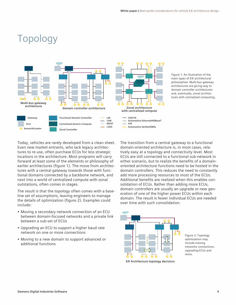
Today, vehicles are rarely developed from a clean sheet. Even new market entrants, who lack legacy architec-tures to re-use, often purchase ECUs for less strategic locations in the architecture. Most programs will carry forward at least some of the elements or philosophy of earlier architectures (figure 1). The move from architec-tures with a central gateway towards those with func-tional domains connected by a backbone network, and next into a world of centralized compute with zonal outstations, often comes in stages.
The result is that the topology often comes with a base-line set of assumptions, leaving engineers to manage the details of optimization (figure 2). Examples could include:
• Moving a secondary network connection of an ECU between domain-focused networks and a private link between a sub-set of ECUs
• Upgrading an ECU to support a higher baud rate network on one or more connections
• Moving to a new domain to support advanced or additional functions
The transition from a central gateway to a functional domain-oriented architecture is, in most cases, rela-tively easy at a topology and connectivity level. Most ECUs are still connected to a functional sub-network in either scenario, but to realize the benefits of a domain-oriented architecture functions need to be hosted in the domain controllers. This reduces the need to constantly add more processing resources to most of the ECUs. Additional benefits are realized when this enables con-solidation of ECUs. Rather than adding more ECUs, domain controllers are usually an upgrade or new gen-eration of one of the higher power ECUs within each domain. The result is fewer individual ECUs are needed over time with such consolidation.
Figure 2: Topology optimization may include moving networks connections, upgrading ECUs and more.
E/E Architecture topology decisions
Figure 1: An illustration of the main types of E/E architectural philosophies. Multi-bus gateway architectures are giving way to domain controller architectures and, eventually, zonal architec-tures with centralized computing.
Domain controller architecture Zonal architecture with centralized compute
Multi-bus gateway architecture
Sensor/Actuator
ECU
Gateway LINCANMOSTLVDS
CAN FDAutomotive Ethernet/HDBaseTA2BAutomotive SerDes/GMSL
Functional Domain Controller
Centralized Generic Compute
Zonal Controller
Siemens Digital Industries Software
White paper | Real-world considerations for vehicle E/E architecture design
5
Functional safety of an overall system can often be achieved several ways. For instance, functions in mod-ern vehicles are usually enabled by various components from multiple domains. Some of these may need to be allocated to hardware or software platforms developed to a specific level of integrity to ensure the safety of the function. Another method is to add redundant parts to the system. Instead of trying to enhance one sensor system to support an ASIL D function, it is generally easier to use two sensors of a lower integrity level as, together, they can still support an ASIL D function (figure 4). Yet, even two sensors may only allow for fail-safe functionality, which only requires that the system remains safe, if non-operational, in the event of a failure.
To achieve the more rigorous fail-functional functional-ity (systems remain functional despite failure), a third sensor, two higher-integrity sensors, or another redun-dant system or model based calculation that fuses data from other sources may be necessary. An additional functional safety consideration may be a redundant power supply for critical components. Dual batteries, dual power circuits and independent fusing all need to be considered.
Figure 4: The combination of two ASIL B(D) sensors can support ASIL D functions.
Functional safety
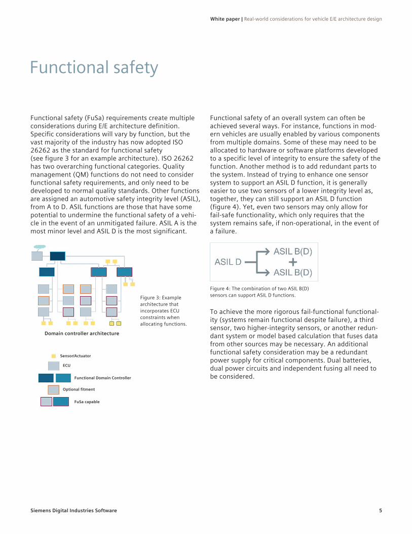
Functional safety (FuSa) requirements create multiple considerations during E/E architecture definition. Specific considerations will vary by function, but the vast majority of the industry has now adopted ISO 26262 as the standard for functional safety (see figure 3 for an example architecture). ISO 26262 has two overarching functional categories. Quality management (QM) functions do not need to consider functional safety requirements, and only need to be developed to normal quality standards. Other functions are assigned an automotive safety integrity level (ASIL), from A to D. ASIL functions are those that have some potential to undermine the functional safety of a vehi-cle in the event of an unmitigated failure. ASIL A is the most minor level and ASIL D is the most significant.
Figure 3: Example architecture that incorporates ECU constraints when allocating functions.
Domain controller architecture
Sensor/Actuator
ECU
Optional fitment
Functional Domain Controller
FuSa capable
Siemens Digital Industries Software
White paper | Real-world considerations for vehicle E/E architecture design
6
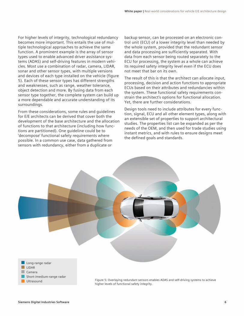
For higher levels of integrity, technological redundancy becomes more important. This entails the use of mul-tiple technological approaches to achieve the same function. A prominent example is the array of sensor types used to enable advanced driver assistance sys-tems (ADAS) and self-driving features in modern vehi-cles. Most use a combination of radar, camera, LIDAR, sonar and other sensor types, with multiple versions and devices of each type installed on the vehicle (figure 5). Each of these sensor types has different strengths and weaknesses, such as range, weather tolerance, object detection and more. By fusing data from each sensor type together, the complete system can build up a more dependable and accurate understanding of its surroundings.
From these considerations, some rules and guidelines for E/E architects can be derived that cover both the development of the base architecture and the allocation of functions to that architecture (including how func-tions are partitioned). One guideline could be to ‘decompose’ functional safety requirements where possible. In a common use case, data gathered from sensors with redundancy, either from a duplicate or
backup sensor, can be processed on an electronic con-trol unit (ECU) of a lower integrity level than needed by the whole system, provided that the redundant sensor and data processing are sufficiently separated. With data from each sensor being routed separately to the ECU for processing, the system as a whole can achieve its required safety integrity level even if the ECU does not meet that bar on its own.
The result of this is that the architect can allocate input, processing, decision and action functions to appropriate ECUs based on their attributes and redundancies within the system. These functional safety requirements con-strain the architect’s options for functional allocation. Yet, there are further considerations.
Design tools need to include attributes for every func-tion, signal, ECU and all other element types, along with an extensible set of properties to support architectural studies. The properties list can be expanded as per the needs of the OEM, and then used for trade studies using instant metrics, and with rules to ensure designs meet the defined goals and standards.
Figure 5: Overlaying redundant sensors enables ADAS and self-driving systems to achieve higher levels of functional safety integrity.
Long-range radarLIDARCameraShort-/medium-range radarUltrasound
Siemens Digital Industries Software
White paper | Real-world considerations for vehicle E/E architecture design
7
Cyber security
Functional safety and cyber security share some surface similarities: both concern the correct functionality of vehicle systems. But while functional safety is mostly concerned with the reliability of systems, and the con-sequences of failures, cyber security must account for malicious attacks against vehicle systems. As a result, cyber security has distinct requirements aimed at defending against such attacks.
Modern vehicles have multiple potential vulnerabilities, known as attack surfaces. Integrated Wi-Fi, cellular, Bluetooth®, on-board diagnostics (OBD), USB and other connection points all provide potential routes into the vehicle communication systems. Even network bus circuits have been accessed as entry points, usually for theft purposes. These attack surfaces can be considered in architecting of the anti-theft systems. Some systems can be made physically inaccessible to malfeasants, while others may use extra software authentication checks to prevent unauthorized access, however, it is strongly desirable to have both. The choices made on cyber security and anti-theft systems cascade require-ments out to the 3D electrical system design via the logical systems containing security functions.
Design solutions that can link the 3D and electrical worlds with rich data, and can differentiate the types of signals and their physical manifestations, are vitally useful both in the early concept stages, and later on to verify designs.
Cyber security is achieved with a layered approach. Some mechanisms are repeated at key points in the architecture, and different mixtures of mechanisms are applied at each level in the system. The placement of firewalls, or of connections of interfaces on ECU’s which feature firewalls, needs to be considered with respect to the various entry routes that an attack could use to gain access to the vehicle. ECU’s hosting specific functions may also be required to contain integrated hardware security modules (HSM). Through careful selection of the integrated circuit (IC) at the heart of the ECU, it is possible to emulate an HSM in software. Such emula-tion is very demanding of processing resources, so hardware-based security measures are increasingly common. Data classified as cyber security related can also be designed with specific protections to add further layers to the overall cyber security system. Such protec-tions will be covered further down in the paper.
Similar to functional safety, software tools that use attributes and properties enable designs to include security functions and requirements. Design rule checks (DRC) enable checking of the design against defined rules, and styling of the diagrams enables easy visual understanding and auditing of those details.

Siemens Digital Industries Software
White paper | Real-world considerations for vehicle E/E architecture design
8
Power modes
Modern road vehicles often have multiple power modes, some visible to the user, others relatively hid-den. These reflect the functions active in the vehicle, and govern what is powered and/or awake. A vehicle with a traditional key will usually have 4 positions on the ignition switch, translating to 4-6 power modes, from off and locked through to cranking (table 1).
Many OEM’s use terms such as KL15 (also known as Contact 15) and KL30 associated with tables 1 and 2, at the right and below. Derived from DIN 72552, some OEMs use many more power modes while others have their own specific terminology. Some use several state tables that merge, for example, a basic power mode with a second state machine to handle the activation and de-activation of the powertrain. This arrangement is increasingly likely in an electric vehicle, as the above basic table does not include electric powertrain-specific power modes, such as a charging mode.
Power mode Body Chassis Powertrain Telematics Charging Software update
Off locked Off Off Off Off Possible NoOff locked
(software update) Off Off Off On Possible Possible
Off unlocked On Off Off Off Possible NoAccessory On Off Off On Possible User permissionIgnition
(powertrain inactive)
On On Awake On No* User permission
Ignition (powertrain
active)On On On On No** No
Table 2: An expanded summary typical for vehicles with electrified powertrains.1
1. Table 2 shows a simple example. In practice, there is more to resolve, such as: • Software updates that require selective update of target networks and ECUs. • Software updates of charging ECUs require interlock and handover logic. • *Regional differences in the nature of interactions between charging and powertrain activation. • ** Some regions require blocking of powertrain activation while on charge. Others call for charging to be suspended in the event of powertrain
activation. Also, further refinement is needed for inductive charging where no disconnect is needed.
Power mode Body Chassis Powertrain
Off locked Off Off OffOff unlocked On Off Off
Accessory On Off OffIgnition
(powertrain inactive)
On On Awake
Ignition (powertrain
active)On On On
Cranking Off Off On
Table 1: A summary of typical basic power modes.
Siemens Digital Industries Software
White paper | Real-world considerations for vehicle E/E architecture design
9
In modern vehicles, functions need to be hosted on ECU’s that are powered up when the function is needed. As a result, the functions hosted on an ECU can influ-ence when the ECU needs to be powered or awake. This second point is increasingly important: if a function is needed during charging of an electric vehicle, the ECU that hosts the charging-related function will need to remain reliable over a life up to 10x longer than that of an ECU only used when the vehicle is in motion.
This extends further when service and diagnostic func-tions are considered, such as software updates to the vehicle. Software over the air (SOTA) updates will be increasingly common, rather than the service center
update that has become practically universal in recent years. Over the air updates require another partial awake mode. When the vehicle is powered off or asleep, waking a domain or network at a time will be enough to perform the update. In other cases, such as on vehicles which are not plugged in to charge, a more cautious approach in which the software is downloaded in the background when the vehicle has signal may be better. At the start or end of a drive-cycle, the vehicle can request user permission to perform the update. The architect may need to consider these low-power mode states, and certainly needs to consider which module will host downloaded updates prior to deployment.
Siemens Digital Industries Software
White paper | Real-world considerations for vehicle E/E architecture design
10
Processor, network and gateway loads
Another important architectural consideration is the relative loadings on each ECU processor, network or network branch and the gateways between networks. As functions are allocated to specific ECUs, their associ-ated signals will place additional load on the networks connected to the ECU. If direct connections do not exist between the signals’ respective sources and destina-tions, then a gateway is needed to make the connec-tion. Each new gateway increases the gateway load and the frequency with which signals must be sent to deliver a given timing. Further, it is worth considering that in a functionally-oriented domain architecture, it’s likely that the routing of status and mode information signals may need to travel across the network back-bone, potentially resulting in two gateways. Cross-linking between networks is increasingly undesirable as
this makes functions critical to cyber-security much harder to defend as more routes around the architec-ture become available for malicious actors to traverse. As a consequence, the E/E architect benefits from an understanding of each of the functions planned for the architecture when optimizing the networks and domains to which each ECU is connected.
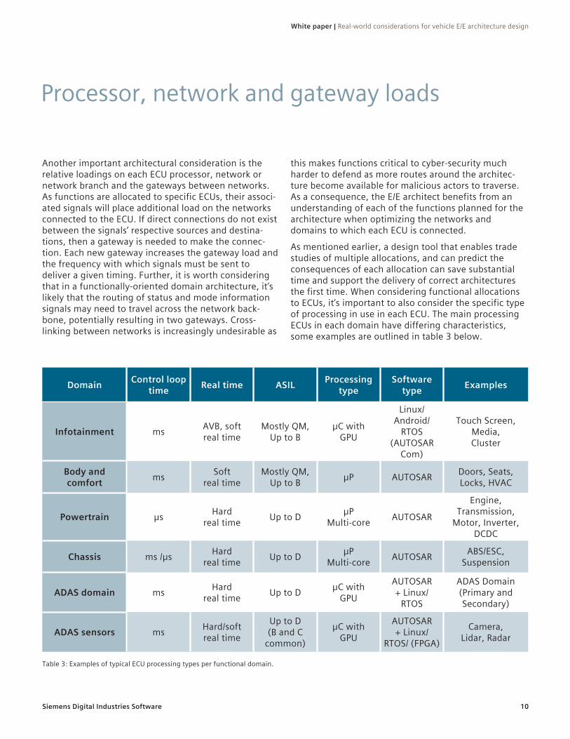
As mentioned earlier, a design tool that enables trade studies of multiple allocations, and can predict the consequences of each allocation can save substantial time and support the delivery of correct architectures the first time. When considering functional allocations to ECUs, it’s important to also consider the specific type of processing in use in each ECU. The main processing ECUs in each domain have differing characteristics, some examples are outlined in table 3 below.
Domain Control loop time Real time ASIL Processing
typeSoftware
type Examples
Infotainment ms AVB, soft real time
Mostly QM, Up to B
µC with GPU
Linux/ Android/
RTOS (AUTOSAR
Com)
Touch Screen, Media, Cluster
Body and comfort ms Soft
real timeMostly QM,
Up to B µP AUTOSAR Doors, Seats, Locks, HVAC
Powertrain µs Hard real time Up to D µP
Multi-core AUTOSAR
Engine, Transmission,
Motor, Inverter, DCDC
Chassis ms /µs Hard real time Up to D µP
Multi-core AUTOSAR ABS/ESC, Suspension
ADAS domain ms Hard real time Up to D µC with
GPU
AUTOSAR + Linux/
RTOS
ADAS Domain (Primary and Secondary)
ADAS sensors ms Hard/soft real time
Up to D (B and C
common)
µC with GPU
AUTOSAR + Linux/
RTOS/ (FPGA)
Camera, Lidar, Radar
Table 3: Examples of typical ECU processing types per functional domain.
Siemens Digital Industries Software
White paper | Real-world considerations for vehicle E/E architecture design
11
When functions are added to an architecture during an update, they need to be split and assigned appropriately to ECUs suitable for running each type of function.
Image processing has very different needs to decision making and control outputs. Image and radar process-ing are soft real-time processes, where the series of images are processed into objects, cars, cyclists, road signs, road markings and so forth. Trajectories will also be processed where relevant. Soft real-time processes have a deadline by which time the data must be pro-cessed to enable accurate control decisions. The actual processing time has variation, thus high-power com-pute results in a more consistent delivery. Control and output decisions, on the other hand, are often hard real-time processes, requiring much less processing power.
Hard real-time processes are extremely time-sensitive and must execute within a small time window, usually with a regular processing period. This kind of process may be scheduled at a high frequency, but could also be triggered by, for example, engine crank angle, or motor rotor position. Examples range from the control of fuel injection on direct injection petrol and diesel engines, to the control of active suspension components, anti-roll and anti-sway bars, dampers and more.
Typical body functions, such as lowering a window, can respond in some 10’s of milliseconds and provide a satisfactory user experience. However, certain functions can introduce an ASIL and hard real-time requirement into these body functions. An anti-trap function on an automatic window close feature, for example, uses a closed-loop control with sensor feedback to stop and
reverse the motion of the automatic (or one-touch) window in the event of a detected blockage, such as an arm or finger. With the anti-trap function, the feature operation of the windows is considered to include safety related functions. Therefore, consideration must be given to the appropriate hosting of the automatic or one-touch window feature in parts of the architecture with sufficient integrity and timing capability.
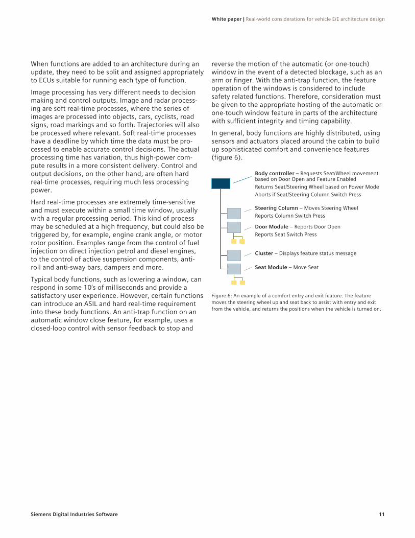
In general, body functions are highly distributed, using sensors and actuators placed around the cabin to build up sophisticated comfort and convenience features (figure 6).
Figure 6: An example of a comfort entry and exit feature. The feature moves the steering wheel up and seat back to assist with entry and exit from the vehicle, and returns the positions when the vehicle is turned on.
Body controller – Requests Seat/Wheel movement based on Door Open and Feature EnabledReturns Seat/Steering Wheel based on Power ModeAborts if Seat/Steering Column Switch Press
Steering Column – Moves Steering WheelReports Column Switch Press
Seat Module – Move Seat
Cluster – Displays feature status message
Door Module – Reports Door OpenReports Seat Switch Press
Siemens Digital Industries Software
White paper | Real-world considerations for vehicle E/E architecture design
12
Input/output (I/O) connectivity – ECU/sensor/actuatorNew custom ECUs are sometimes, cost permitting, able to be specified exactly as needed. More commonly, new ECUs are derived from a platform design, limiting the capabilities of the ECU, and both the type and total number of connections to the vehicle networks and other inputs or outputs. Conversely, carry-over and purchased ECUs bring in constraints that define how parts of the architecture can work.
ECUs normally have a fixed count of I/O once in produc-tion. In development, they are constrained by the selected silicon, available space on the PCB and by the
desired connectors. During development there may also be scope to convert certain pins from inputs to outputs, analogue to digital or to data buses. Opportunities for such conversions must be frozen at some stage, after which connections can only be made to the I/O the ECU has already. It is often possible to process a sensor value in the ECU that the sensor is connected to, and monitor for hardware faults and other errors. The decision function(s) utilizing the sensor data, however, may be elsewhere on the vehicle due to other requirements.

Siemens Digital Industries Software
White paper | Real-world considerations for vehicle E/E architecture design
13
Re-use
It is not practical to develop every vehicle from a clean sheet. Re-usability of vehicle features, functions and systems, which was once desirable, is now essential. E/E architecture optimization and effective systems design are critical to maximizing re-usability, reducing the number of vehicle variants and improving the ability of companies to deliver the right vehicle, on time.
Commonly, when a new or updated vehicle line is being developed, there are constraints established around the re-use of vehicle content. Some of these constraints are firm, while others need to be evaluated in consideration of the relative costs associated. Traditionally, ECUs sourced from Tier 1 suppliers have limited scope to add functions unless the supplier is contracted to develop such functions. OEMs are taking more responsibility in
developing ECUs, software models and sometimes even full software. Today, this even extends into the hard-ware for strategic modules and into designing the silicon.
When the architect considers where functions can be allocated, the type of ECU, installed software and its source are thus a consideration. It’s also important to consider if the ECU is already planned for modification for the vehicle program. Ideally, these considerations are accounted for when the OEM is deciding which ECUs are strategically important. This will help provide the scope for functional allocations over the life of the ECU and architecture.

Siemens Digital Industries Software
White paper | Real-world considerations for vehicle E/E architecture design
14
Conclusion
The challenges facing OEMs developing E/E systems are numerous, varied and only increasing in complexity. These challenges are particularly acute at the stage where E/E architectures are being defined and evalu-ated. There are many considerations that E/E system architects must include when developing, updating and optimizing vehicle architectures. These can typically be characterized as attributes or properties of the function, ECU, signal, port and so on. Therefore it becomes absolutely necessary to use advanced tools such as Capital Systems Architect from Siemens Digital Industries Software to both plan and check the architec-ture against a set of rules and guidelines defined by the engineers. Furthermore, with extensible rules, it is desirable to automate assignments and allocations,
according to the rules defined. Insight metrics enable trade-studies between topological changes, functional allocations, signal assignments and more, supporting early optimizations of the E/E architecture before detailed design work begins. Taking advantage of inno-vative tools enables engineers to be more innovative, whilst also ensuring early verification of architectural decisions. This is increasingly critical as competition in automotive becomes more intense and E/E architectures become ever more important in delivering products that delight consumers
Find out more at siemens.com/capital.

siemens.com/software© Siemens 2021. A list of relevant Siemens trademarks can be found here. Other trademarks belong to their respective owners.
83230-C3 1/21 C
About Siemens Digital Industries SoftwareSiemens Digital Industries Software is driving transformation to enable a digital enterprise where engineering, manufacturing and electronics design meet tomorrow. The Xcelerator portfolio, a comprehensive and integrated portfolio of software and services from Siemens Digital Industries Software, helps companies of all sizes create and leverage a comprehensive digital twin that provides organizations with new insights, opportunities and levels of auto-mation to drive innovation. For more information on Siemens Digital Industries Software products and services, visit siemens.com/software or follow us on LinkedIn, Twitter, Facebook and Instagram. Siemens Digital Industries Software – Where today meets tomorrow.
Siemens Digital Industries Software
HeadquartersGranite Park One 5800 Granite Parkway Suite 600 Plano, TX 75024 USA +1 972 987 3000
AmericasGranite Park One 5800 Granite Parkway Suite 600 Plano, TX 75024 USA +1 314 264 8499
EuropeStephenson House Sir William Siemens Square Frimley, Camberley Surrey, GU16 8QD +44 (0) 1276 413200
Asia-PacificUnit 901-902, 9/FTower B, Manulife Financial Centre223-231 Wai Yip Street, Kwun TongKowloon, Hong Kong +852 2230 3333
Related Documents