2014-09-08 X40010 Rev. J Caution: Do not tamper with the unit or its controls. Call a qualified service technician. Save these instructions for future reference. Printed in Canada Printed on 100% recycled paper SIDEWALL VENTER Models : SMH-1-DE SMH-6-DE SMH-3-DE SMH-4-DE SMH-5-DE SMH-1-BR SMH-4-BR Manufactured by: DETTSON Industries Dettson Inc. 3400 Industrial Boulevard Sherbrooke, Quebec - Canada J1L 1V8

Welcome message from author
This document is posted to help you gain knowledge. Please leave a comment to let me know what you think about it! Share it to your friends and learn new things together.
Transcript

2014-09-08 X40010 Rev. J
Caution: Do not tamper with the unit or its controls.Call a qualified service technician.
Save these instructions for future reference.
Printed in CanadaPrinted on 100% recycled paper
SIDEWALL VENTER Models :
SMH-1-DE
SMH-6-DE
SMH-3-DESMH-4-DESMH-5-DE
SMH-1-BRSMH-4-BR
Manufactured by:
DETTSONIndustries Dettson Inc.3400 Industrial BoulevardSherbrooke, Quebec - CanadaJ1L 1V8


3
PART 1 INSTALLATION
1.1) DANGER, WARNING AND CAUTION The words DANGER, WARNING and CAUTION are used to identify levels of seriousness of certain hazards. It is important that you understand their meaning. You will find those words in the manual as follows:
DANGER
Immediate hazards which WILL result in death or serious injury.
WARNING
Hazards or unsafe practices which CAN result in death or injury.
CAUTION Hazards or unsafe practices which CAN result in personal injury or product or property damage.
ATTENTION PLEASE ENSURE THAT THE AREA AROUND THE VENT TERMINAL IS KEPT CLEAR OF SNOW, ICE, DEBRIS, ETC..
NOTICE TO THE INSTALLER
The minimum measured length of vent pipe is 30 inches with the draft-regulator located 18 inches from the unit outlet. This distance is the linear sum of all horizontal and vertical connecting pipes with a maximum of two 90o elbows. See Figure 1. Therefore, the minimum equivalent length is 22.5 feet (a 90o elbow is equivalent to 10 feet of flue-pipe and a 45o elbow is equivalent to 5 feet). The maximum measured length of vent pipe is 20 feet from the breech of the heating unit and the power venter inlet. This distance is the linear sum of all vertical and horizontal connecting pipes with a maximum of 4, 90o elbows. See Figure 1. Therefore, the maximum equivalent length is 60 feet. When all adjustments are completed in accordance with this manual and the boiler or furnace Installation and Operation manual, it is recommended that you ensure that the inlet temperature at the power venter is at least 200o F (93o C). In the event that you are not able to reach this temperature within 5 minutes from a cold start, it is recommended that you increase it by using one or a combination of the following options:
• Relocate the furnace or boiler to shorten the flue-pipe length;
• Use a type "L" vent upstream of the power venter;
• Insulate the flue-pipe upstream of the power venter. To do so, use 1 inch Microlite FSK insulation by John Mansville or an equivalent. Wrap the insulation around the flue-pipe and use high temperature aluminium tape to secure it. Leave the outlet of the draft-regulator free of obstructions.
After the modifications are completed, wait 30 minutes to let the system cool down and then retest the temperature at the inlet of the power venter after 5 minutes of operation. The temperature must then be over 200o F (93o C).
!
!

4
1.2) INSTALLATION This unit must be installed by a qualified, professional installer in accordance with these instructions and CSA B139 section 4.3. If improperly installed, a hazardous condition could result. The power venter shall not be installed on incinerators, incinerating toilets, condensing type appliances or solid fuel burning appliances. The installation shall be in accordance with the existing codes and regulations established by the authorities having jurisdiction. The venting unit may be installed through a combustible wall with a maximum thickness of 8 inches or through a non-combustible wall of 16 inches including a combustible exterior wall of no more than 8 inches. The minimum wall thickness is 2 inches. A type B vent shall not be used in the venting system. 1.2.1) General installation guidelines
The first step in installing the power venter is to find the location that is in accordance with the following criteria:
• The flue discharge terminal of the venting system shall be installed not less than 7 feet above any paved driveway or paved walkway;
• A power venting system shall not terminate within 6 feet of a mechanical air supply inlet to any building including soffit opening or within 6 feet of a window, door or property line;
• The flue discharge terminal shall not be installed within 3 feet horizontally of the vertical center-line above a gas meter/regulator assembly;
• The venting system discharge terminal shall not be installed less than 1 foot above grade level;
• The discharge of the flue gases shall not be above a paved sidewalk or paved driveway which is located between two buildings where their use is common to both buildings;
• The vent terminal shall be installed such a way that the flue gases do not jeopardize people, overheat combustible structures or enter any openings of surrounding building within 6 feet;
• The vent terminal shall not be within 6 feet of any gas service regulator vent outlet or within 3 feet of any oil tank vent or oil tank fill inlet;
• The vent terminal shall not be less than 6 feet from an adjacent building or closer than 3 feet to an inside corner of an L shaped structure;
• The vent terminal shall not be less than 6 feet from another combustion appliance air intake;
• The bottom of the vent termination shall not be installed less than 1 foot above any surface where snow, ice or debris may accumulate;
• The vent termination shall not be located such a way that damage is caused to the brick work, mortar, wood or other components of the con-struction by flue gas condensate or temperature;
• The vent termination shall not be located underneath a veranda, porch or deck.
1.3) List of components Please consult Figure 1. The parts being shipped with the power venter are:
a. The "Fan-motor" assembly (stainless steel casing). Part number SWV-1M-2S or SWV-2M-2S;
b. A junction box with a pressure switch, factory mounted. Part number R99F001;
c. A 3 to 6 inch flue-pipe reducer with integrated back-flow damper. Part number FD-02;
d. A 6 to 5 inch fitting; for SMH-3 kit only. Part number Z07F010;
e. A 6 to 8 inch fitting; for SMH-5 kit only. Part number Z07F005.
1.4) Power venter installation Verify if the power venter is correctly sized according to Table 1. All appliances must enter the vent system on the inlet side of the power venter. You must install a barometric draft regulator in accordance with your heating unit instruction manual. See Figure 1.

5
TABLE 1 Sidewall venting selection chart
Heating unit MODEL
Connecting pipe ( " )
Input (USGPH)
Sidewall venter Reducer ( " )
Package number
Burner
AM(i)-076 to 110 6 0.65 to 0.92 SWV-1M-2S SMH-1-DE Beckett or Riello
AM(i)-120 to 140 6 1.00 to1.20 SWV-2M-2S SMH-4-DE Beckett or Riello
AME-15 to 25 6 0.65 to 0.85 SWV-1M-2S SMH-1-DE Beckett or Riello
AM(i)T-075 to 105 5 0.50 to 0.75 SWV-1M-2S 6 - 5 SMH-3-DE Beckett or Riello
AM(i)T-120 to 155 6 0.85 to 1.10 SWV-2M-2S SMH-4-DE Beckett or Riello
HM(R)-080 to 121 5 0.75 to 1.00 SWV-1M-2S 6 - 5 SMH-3-DE Beckett or Riello
HM(i)-103 to 159 6 0.85 to 1.35 SWV-2M-2S SMH-4-DE Beckett or Riello
HM-185 to 212 8 1.50 to 1.75 SWV-2M-2S 6 - 8 SMH-5-DE Beckett or Riello
HMD-124 to 208 7 1.00 to 1.50 SWV-2M-2S 6 - 7 SMH-6-DE Beckett or Riello
HME-15 to 20 6 0.65 to 0.75 SWV-1M-2S SMH-1-DE Beckett or Riello
HME-23 to 25 6 0.85 to 1.10 SWV-2M-2S SMH-4-DE Beckett or Riello
HML-115 to 175 6 1.00 to 1.50 SWV-2M-2S SMH-4-DE Beckett or Riello
HMT-012 to 018 6 1.00 to 1.50 SWV-2M-2S SMH-4-DE Beckett or Riello
HMS-027 to 035 6 0.65 to 0.85 SWV-1M-2S SMH-1-DE Beckett or Riello
HMS-041 to 062 6 1.00 to 1.50 SWV-2M-2S SMH-4-DE Beckett or Riello
AMP-075 to 105 5 0.50 to 0.75 SWV-1M-2S 6 – 5 SMH-3-DE Beckett or Riello
AMP-120 to 155 6 0.85 to 1.10 SWV-2M-2S SMH-4-DE Beckett or Riello
LO-1MQH-3M* 5 0.65 to 1.00 SWV-1M-2S 6 – 5* SMH-1-BR Brock or Riello
FBR-1* 5 0.65 to 1.00 SWV-1M-2S 7 – 5* SMH-1-BR Brock
MBP* 5 0.65 to 1.00 SWV-1M-2S 6 – 5* SMH-1-BR Brock, Beckett or Riello
MBP-U* 5 0.65 to 0.85 SWV-1M-2S 6 – 5* SMH-1-BR Beckett
MBP-F* 5 0.65 to 1.00 SWV-2M-2S 6 – 5* SMH-4-BR Brock or Beckett
CCC* 5 0.50 to 0.85 SWV-1M-2S SMH-1-BR Brock or Beckett
LO-2M* 5 1.10 & 1.25 SWV-2M-2S 7 – 5* SMH-4-BR Brock
MBP-2* 5 1.10 & 1.25 SWV-2M-2S 6 – 5* SMH-4-BR Brock
IB30 / IB32-R* 5 0.65 to 0.75 SWV-1M-2S 6 – 5* SMH-1-BR Beckett or Riello
30-RB* 5 0.65 SWV-1M-2S 6 – 5* SMH-1-BR Beckett or Riello
32E2* 5 0.75 SWV-1M-2S 6 – 5* SMH-1-BR Brock
50E2 / IB50-O* 5 0.65 to 0.75 SWV-1M-2S 6 – 5* SMH-1-BR Brock or Riello
* Sidewall vent kit does not include the reducer for the appliances using a 5 inch connecting pipe.
6
1.4.1) Preparation & Requirements Find a location on an outside wall that meets all the conditions stated in section 1.1. Consult Figure 2 for the main dimensions of the system components. Find the best location suitable inside the building for the pressure switch junction box. See Figure 3. Using the mounting template supplied with the venter box, drill all necessary holes (flue-pipe hole, mounting hole, etc.) on the outside wall, at the desired location.
WARNING
The fan-motor assembly and the pressure switch junction box must be mounted vertically to ensure proper operation of the fan proving switch and to prevent motor bearing wear. 1.4.2) Installation on a COMBUSTIBLE
wall
WARNING
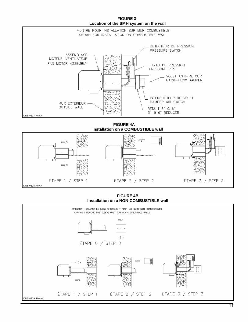
Do not remove the exterior sleeve in the case of combustible walls. This sleeve is necessary for combustible walls. At this point, the unit is ready to be installed on the exterior wall. To do so, take the assembled unit outside and insert the vent pipe into the opening from outside and bring the wall plate assembly flush with the exterior wall. Secure with four screws. If the wall is made of cement, brick or concrete, cement anchors should be used. Step figure 4A. 1.4.3) Installation on a
NON-COMBUSTIBLE wall Remove the exterior sleeve as shown on figure 4B. To remove this part, simply unhook its retaining clips. At this point, the unit is ready to be installed on the exterior wall. To do so, take the assembled unit outside and insert the vent pipe into the hole from outside and bring the wall plate assembly flush with the exterior wall. Secure with four screws. If the wall is made of cement, brick or concrete, cement anchors should be used. See Figure 4B.
1.4.4) Connection to the junction box The only two non-electrical steps to perform, as far as the installation is concerned, are the installation of the pressure switch junction box and the connection of the pressure sensing pipe to this junction box. Install the junction box on the inside wall, as closely as possible to the location where the vent pipe enters this wall. Secure the junction box to the wall with two screws, ensuring that the pressure switch is vertical. If the wall is made of cement, brick or concrete cement anchors should be used. See Figures 3 and 4. Connect the pressure tube on the side of the proving switch. When connecting this line make sure that any bends in the line are smooth and the line is not obstructed by a sharp 90o turn. Also make sure that the connection to the proving switch is tight enough so as to prevent leaks and not too tight so as to damage the compression fitting. Teflon tape should not be used on this fitting. 1.5) Connecting the heating unit
to the SWV Determine the required vent pipe diameter from Table 1. Install properly sized vent pipe sections from the power venter inlet to appliance outlet. Package SMH-3 requires the installation of a 6 to 5 inch fitting for the transition between the back-flow damper inlet and the connecting pipe outlet. Package SMH-5 requires the installation of a 6 to 8 inch fitting for the transition between the back-flow damper inlet and the connecting pipe outlet. 1.6) Back-flow damper installation The sidewall venting system must absolutely be fitted with the back-flow damper that is included in the shipment. This damper prevents the back-flow of cold air when the system is off cycle and all problems associated with this phenomenon. Before installing the back-flow damper, install the 6 to 3 inch reducer on the 3 inch venter pipe. Depending on the model, this reducer might already be installed. The damper must be installed with the arrow pointing in the direction of the flue gas that is toward the venter. Furthermore, the damper must be resting on its fixed stopper when the unit is not functioning. To achieve this, the damper must be installed in the HORIZONTAL POSITION with the arrow at the top of the damper. Level the back-flow damper on both the horizontal and vertical axes. THIS DAMPER MUST BE INSTALLED WITHOUT ALTERATION. If this condition is not respected unpredictable and erratic operation may result.
!
!
7
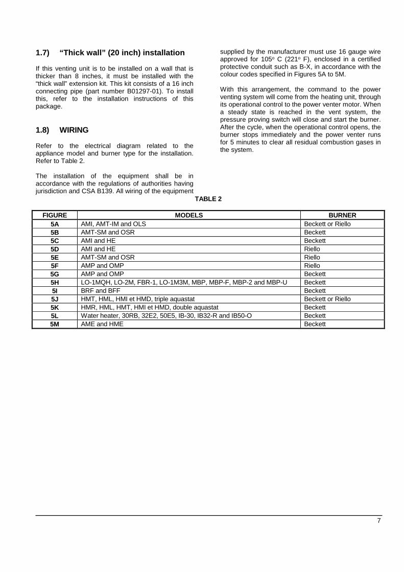
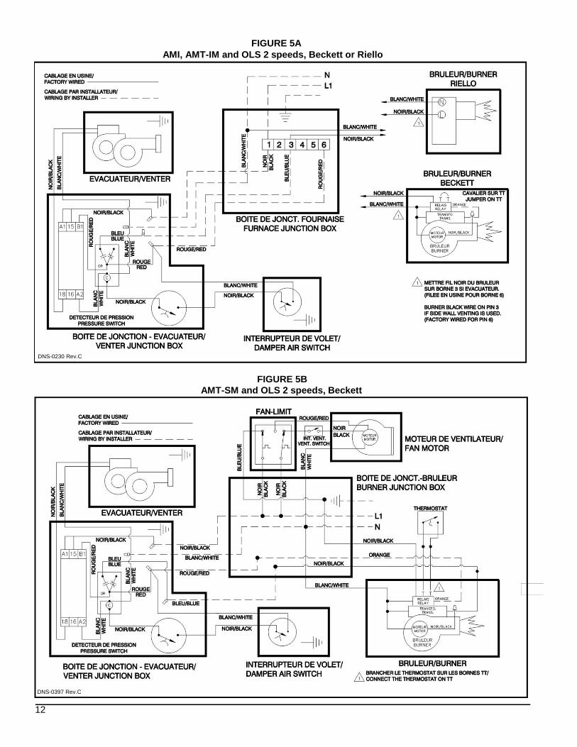
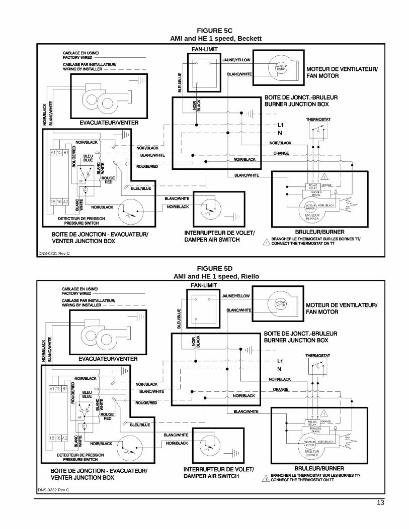
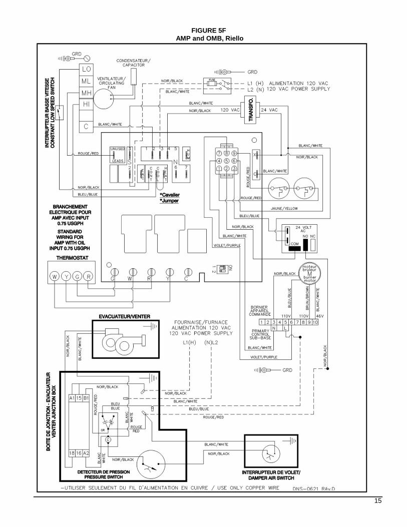
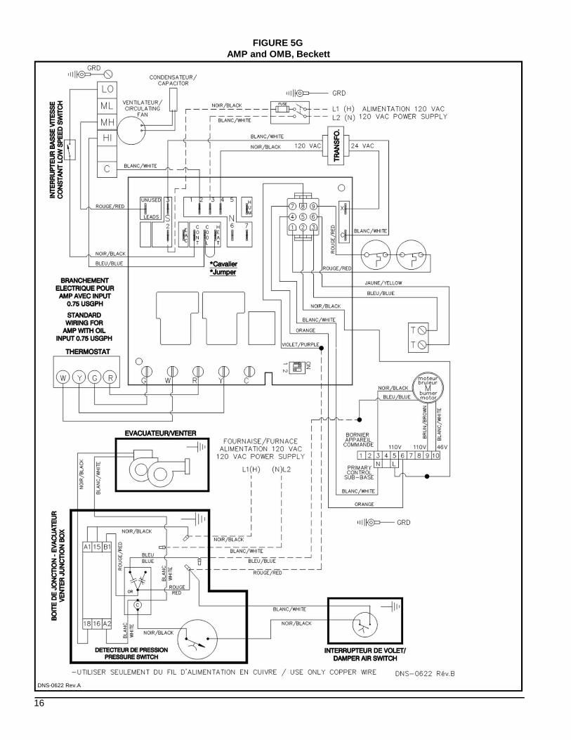
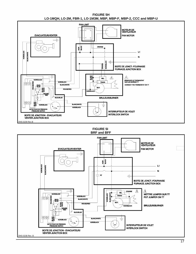
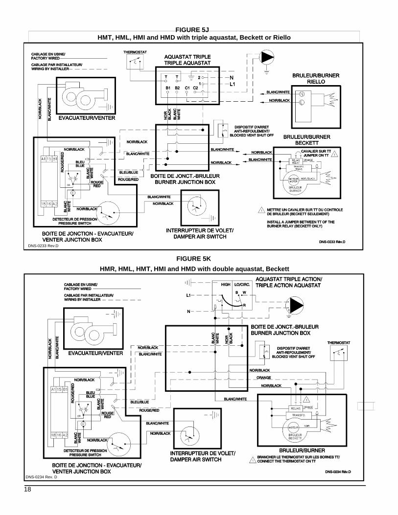
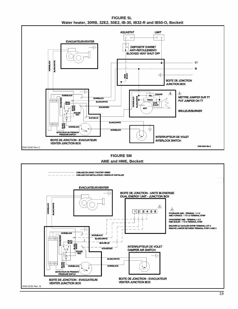
1.7) “Thick wall” (20 inch) installation If this venting unit is to be installed on a wall that is thicker than 8 inches, it must be installed with the “thick wall” extension kit. This kit consists of a 16 inch connecting pipe (part number B01297-01). To install this, refer to the installation instructions of this package. 1.8) WIRING Refer to the electrical diagram related to the appliance model and burner type for the installation. Refer to Table 2. The installation of the equipment shall be in accordance with the regulations of authorities having jurisdiction and CSA B139. All wiring of the equipment
supplied by the manufacturer must use 16 gauge wire approved for 105o C (221o F), enclosed in a certified protective conduit such as B-X, in accordance with the colour codes specified in Figures 5A to 5M. With this arrangement, the command to the power venting system will come from the heating unit, through its operational control to the power venter motor. When a steady state is reached in the vent system, the pressure proving switch will close and start the burner. After the cycle, when the operational control opens, the burner stops immediately and the power venter runs for 5 minutes to clear all residual combustion gases in the system.
TABLE 2
FIGURE MODELS BURNER 5A AMI, AMT-IM and OLS Beckett or Riello 5B AMT-SM and OSR Beckett 5C AMI and HE Beckett 5D AMI and HE Riello 5E AMT-SM and OSR Riello 5F AMP and OMP Riello 5G AMP and OMP Beckett 5H LO-1MQH, LO-2M, FBR-1, LO-1M3M, MBP, MBP-F, MBP-2 and MBP-U Beckett 5I BRF and BFF Beckett 5J HMT, HML, HMI et HMD, triple aquastat Beckett or Riello 5K HMR, HML, HMT, HMI et HMD, double aquastat Beckett 5L Water heater, 30RB, 32E2, 50E5, IB-30, IB32-R and IB50-O Beckett 5M AME and HME Beckett
8
PART 2 OPERATION
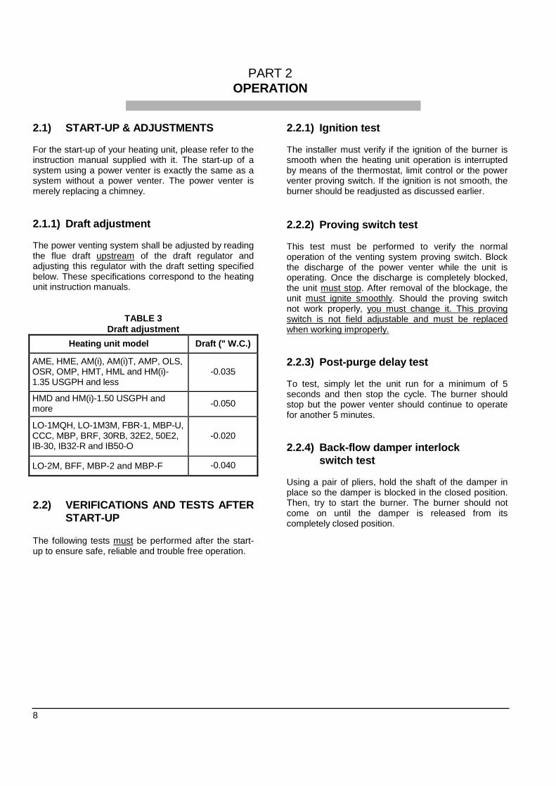
2.1) START-UP & ADJUSTMENTS For the start-up of your heating unit, please refer to the instruction manual supplied with it. The start-up of a system using a power venter is exactly the same as a system without a power venter. The power venter is merely replacing a chimney. 2.1.1) Draft adjustment The power venting system shall be adjusted by reading the flue draft upstream of the draft regulator and adjusting this regulator with the draft setting specified below. These specifications correspond to the heating unit instruction manuals.
TABLE 3 Draft adjustment
Heating unit model Draft (" W.C.)
AME, HME, AM(i), AM(i)T, AMP, OLS, OSR, OMP, HMT, HML and HM(i)-1.35 USGPH and less
-0.035
HMD and HM(i)-1.50 USGPH and more -0.050
LO-1MQH, LO-1M3M, FBR-1, MBP-U, CCC, MBP, BRF, 30RB, 32E2, 50E2, IB-30, IB32-R and IB50-O
-0.020
LO-2M, BFF, MBP-2 and MBP-F -0.040
2.2) VERIFICATIONS AND TESTS AFTER
START-UP
The following tests must be performed after the start-up to ensure safe, reliable and trouble free operation.
2.2.1) Ignition test The installer must verify if the ignition of the burner is smooth when the heating unit operation is interrupted by means of the thermostat, limit control or the power venter proving switch. If the ignition is not smooth, the burner should be readjusted as discussed earlier.
2.2.2) Proving switch test This test must be performed to verify the normal operation of the venting system proving switch. Block the discharge of the power venter while the unit is operating. Once the discharge is completely blocked, the unit must stop. After removal of the blockage, the unit must ignite smoothly. Should the proving switch not work properly, you must change it. This proving switch is not field adjustable and must be replaced when working improperly. 2.2.3) Post-purge delay test To test, simply let the unit run for a minimum of 5 seconds and then stop the cycle. The burner should stop but the power venter should continue to operate for another 5 minutes. 2.2.4) Back-flow damper interlock
switch test Using a pair of pliers, hold the shaft of the damper in place so the damper is blocked in the closed position. Then, try to start the burner. The burner should not come on until the damper is released from its completely closed position.
9
PART 3 MAINTENANCE
3.1) MAINTENANCE
The power venter must be inspected bi-annually by a qualified technician. The points of inspection are listed below. 3.1.1) Motors Both motors must rotate freely. Oil at the beginning and the middle of the heating season with four drops of special exterior oil suitable for –35o C (-30o F). To access the motor, remove the cover of the fan-motor assembly. 3.1.2) Blower wheel Both blower wheels must be clean of soot, ash or any other coating which might inhibit the flow of air. Remove all foreign material from the vent before operation. To access the blower wheels, remove the fan-motor assembly cover and remove the blower wheels by unscrewing the attachment to the blower.
3.1.3) Pressure switch The pressure switch must operate freely. Ensure that the thermostat is on and the oil burner is running. Block the outlet of the vent-hood and check if the burner stops immediately. If not, the proving switch is defective and should be replaced. See Section 2.2.2. 3.1.4) Back-flow damper The back-flow damper must be clean of soot, ash or any coating which might inhibit the flow of air. Remove all foreign material from the damper before operation. To access the damper, simply remove it from the connecting pipe. Be sure to replace it in the proper position.

DNS-0225 Rev.A
DNS-0226 Rev.A
10
FIGURE 1SMH system - General arrangement
FIGURE 2Main system dimensions
11
DNS-0229 Rev.A
DNS-0227 Rev.A
DNS-0228 Rev.A
FIGURE 3Location of the SMH system on the wall
Installation on a COMBUSTIBLE wallFIGURE 4A
Installation on a NON-COMBUSTIBLE wallFIGURE 4B
12
DNS-0230 Rev.C
DNS-0397 Rev.C
FIGURE 5AAMI, AMT-IM and OLS 2 speeds, Beckett or Riello
AMT-SM and OLS 2 speeds, BeckettFIGURE 5B
13
DNS-0231 Rev.C
DNS-0232 Rev.C
FIGURE 5CAMI and HE 1 speed, Beckett
FIGURE 5DAMI and HE 1 speed, Riello

14
DNS-0407 Rev.C
FIGURE 5EAMT-SM and OSR 2 speeds, Riello
15
FIGURE 5FAMP and OMB, Riello
16
FIGURE 5GAMP and OMB, Beckett
DNS-0622 Rev.A
17
FIGURE 5H
FIGURE 5I
DNS-0238 Rev. B
LO-1MQH, LO-2M, FBR-1, LO-1M3M, MBP, MBP-F, MBP-2, CCC and MBP-U
BRF and BFF
DNS-0239 Rev.B
18
FIGURE 5J
FIGURE 5K
DNS-0233 Rev.D
DNS-0234 Rev. D
FIGURE 5J HMT, HML, HMI and HMD with triple aquastat, Beckett or Riello
HMR, HML, HMT, HMI and HMD with double aquastat, Beckett
19
FIGURE 5L
DNS-0235 Rev. B
DNS-0240 Rev.C
AME and HME, BeckettFIGURE 5M
Water heater, 30RB, 32E2, 50E2, IB-30, IB32-R and IB50-O, Beckett

20
DNS-0385 Rev. D
ITEM DESCRIPTION PARTS COMMENTS1A Blower housing ass'y B01391-01 For SMH-1 and SMH-31B Blower housing ass'y B01391-02 For SMH-4, SMH-5 and SMH-62 Outlet blower insulation B00732-023 Inlet blower insulation B00732-01
4A Motor ass'y, SMH-1 and SMH-3 B01231-01 Includes motor, blower wheel4B Motor ass'y, SMH-4, SMH-5 and SMH-6 B01231-02 Includes motor, blower wheel5 Cover B01233-026 Motor junction box B008267 Junction box cover B00827
8A Outlet strip B01388-01 For SMH-1 and SMH-38B Outlet strip B01388-02 For SMH-4, SMH-5 and SMH-69A Outlet housing insulation B00619-04 For SMH-1 and SMH-39B Outlet housing insulation B00619-39 For SMH-4, SMH-5 and SMH-6
10A Inlet strip B01388-03 For SMH-1 and SMH-310B Inlet strip B01388-04 For SMH-4, SMH-5 and SMH-611A Intlet housing insulation B00619-05 For SMH-1 and SMH-311B Intlet housing insulation B00619-40 For SMH-4, SMH-5 and SMH-612 Cover support insulation B00733
13A Cover support B00705 For SMH-1 and SMH-313B Cover support B01074 For SMH-4, SMH-5 and SMH-614 Gasket, outlet pipe B01150 Brown, 1"15 Gasket, outlet pipe B01044 White, 1/2"16 Mounting plate ass'y B0123217 Shield pipe insulation B00621-6518 6" - 3 1/16" reducer B0129819 Back flow damper ass'y B01002 Includes switch, cover and electrical wire20 Limit switch SPDT A0024921 Junction box divider plate, back flow damper B0131422 Main junction box B0082823 Main junction box cover B0082924 Time delay relay B0113125 Pressure raccording tube ass'y B02075 Includes tube and union26 Pressure switch R99F04627 Junction box ass'y B01228-01 Includes box, relay and pressure switch28 1/25 HP blower motor L06J00129 Spacers kit K07004 Kit of 630 Motor plates kit K07005 Kit of 2
31A Blower wheel 3.812 x 1.50 Z01G001 For SMH-1 and SMH-331B Blower wheel 3.812 x 2.50 Z01G002 For SMH-4, SMH-5 and SMH-632 Synthetic oil Z99F01933 Conversion kit B04236 Includes support, relay and electrical wire
PARTS LISTModel : SMH
Related Documents