2-1069 Catalyst Supervisor Engine 32 PISA Cisco IOS Software Command Reference OL-11437-03 Chapter 2 Cisco IOS Commands for the Catalyst 6500 Series Switches with the Supervisor Engine 32 PISA show queueing interface show queueing interface To display queueing information, use the show queueing interface command. show queueing interface {{interface interface-number} | {null interface-number} | {vlan vlan-id}} Syntax Description Command Default This command has no default settings. Command Modes EXEC (>) Command History Usage Guidelines The interface-number argument designates the module and port number. Valid values for interface-number depend on the specified interface type and the chassis and module that are used. For example, if you specify a Gigabit Ethernet interface and have a 48-port 10/100BASE-T Ethernet module that is installed in a 13-slot chassis, valid values for the module number are from 1 to 13 and valid values for the port number are from 1 to 48. The show queueing interface command does not display the absolute values that are programmed in the hardware. Enter the show qm-sp port-data command to verify the values that are programmed in the hardware. Examples This example shows how to display queueing information: Router# show queueing interface fastethernet 5/1 Interface FastEthernet5/1 queueing strategy: Weighted Round-Robin Port QoS is enabled Port is untrusted Extend trust state: trusted Default COS is 0 Transmit queues [type = 2q2t]: Queue Id Scheduling Num of thresholds ----------------------------------------- 1 WRR low 2 2 WRR high 2 interface Interface type; possible valid values are ethernet, fastethernet, gigabitethernet, tengigabitethernet, pos, atm, and ge-wan. interface-number Module and port number; see the “Usage Guidelines” section for valid values. null interface-number Specifies the null interface; the valid value is 0. vlan vlan-id Specifies the VLAN ID; valid values are from 1 to 4094. Release Modification 12.2(18)ZY Support for this command was introduced.

Welcome message from author
This document is posted to help you gain knowledge. Please leave a comment to let me know what you think about it! Share it to your friends and learn new things together.
Transcript

Chapter 2 Cisco IOS Commands for the Catalyst 6500 Series Switches with the Supervisor Engine 32 PISAshow queueing interface
show queueing interfaceTo display queueing information, use the show queueing interface command.
show queueing interface {{interface interface-number} | {null interface-number} | {vlan vlan-id}}
Syntax Description
Command Default This command has no default settings.
Command Modes EXEC (>)
Command History
Usage Guidelines The interface-number argument designates the module and port number. Valid values for interface-number depend on the specified interface type and the chassis and module that are used. For example, if you specify a Gigabit Ethernet interface and have a 48-port 10/100BASE-T Ethernet module that is installed in a 13-slot chassis, valid values for the module number are from 1 to 13 and valid values for the port number are from 1 to 48.
The show queueing interface command does not display the absolute values that are programmed in the hardware. Enter the show qm-sp port-data command to verify the values that are programmed in the hardware.
Examples This example shows how to display queueing information:
Router# show queueing interface fastethernet 5/1Interface FastEthernet5/1 queueing strategy: Weighted Round-Robin Port QoS is enabled Port is untrusted Extend trust state: trusted Default COS is 0 Transmit queues [type = 2q2t]: Queue Id Scheduling Num of thresholds ----------------------------------------- 1 WRR low 2 2 WRR high 2
interface Interface type; possible valid values are ethernet, fastethernet, gigabitethernet, tengigabitethernet, pos, atm, and ge-wan.
interface-number Module and port number; see the “Usage Guidelines” section for valid values.
null interface-number
Specifies the null interface; the valid value is 0.
vlan vlan-id Specifies the VLAN ID; valid values are from 1 to 4094.
Release Modification
12.2(18)ZY Support for this command was introduced.
2-1069Catalyst Supervisor Engine 32 PISA Cisco IOS Software Command Reference
OL-11437-03
Chapter 2 Cisco IOS Commands for the Catalyst 6500 Series Switches with the Supervisor Engine 32 PISAshow queueing interface
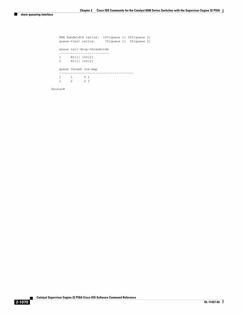
WRR bandwidth ratios: 100[queue 1] 255[queue 2] queue-limit ratios: 70[queue 1] 30[queue 2]
queue tail-drop-thresholds -------------------------- 1 80[1] 100[2] 2 80[1] 100[2]
queue thresh cos-map --------------------------------------- 1 1 0 1 1 2 2 3
Router#
2-1070Catalyst Supervisor Engine 32 PISA Cisco IOS Software Command Reference
OL-11437-03

Chapter 2 Cisco IOS Commands for the Catalyst 6500 Series Switches with the Supervisor Engine 32 PISAshow redundancy
show redundancyTo display RF information, use the show redundancy command.
show redundancy {clients | counters | history | states | switchover}
Syntax Description
Command Default This command has no default settings.
Command Modes EXEC (>)
Command History
Examples This example shows how to display information about the RF client:
Router# show redundancy clients clientID = 0 clientSeq = 0 RF_INTERNAL_MSG clientID = 25 clientSeq = 130 CHKPT RF clientID = 5026 clientSeq = 130 CHKPT RF clientID = 5029 clientSeq = 135 Redundancy Mode RF clientID = 5006 clientSeq = 170 RFS client clientID = 6 clientSeq = 180 Const OIR Client clientID = 7 clientSeq = 190 PF Client clientID = 5008 clientSeq = 190 PF Client clientID = 28 clientSeq = 330 Const Startup Config clientID = 29 clientSeq = 340 Const IDPROM Client clientID = 65000 clientSeq = 65000 RF_LAST_CLIENTRouter#
The output displays the following information:
• clientID displays the client’s ID number.
• clientSeq displays the client’s notification sequence number.
• Current RF state.
clients Displays information about the RF client.
counters Displays information about the RF counter.
history Displays a log of past status for the RF.
states Displays information about the RF state.
switchover Displays the switchover counts, the uptime since active, and the total system uptime.
Release Modification
12.2(18)ZY Support for this command was introduced.
2-1071Catalyst Supervisor Engine 32 PISA Cisco IOS Software Command Reference
OL-11437-03

Chapter 2 Cisco IOS Commands for the Catalyst 6500 Series Switches with the Supervisor Engine 32 PISAshow redundancy
This example shows how to display information about the RF counters:
Router# show redundancy countersRedundancy Facility OMs comm link up = 0 comm link down down = 0
invalid client tx = 0 null tx by client = 0 tx failures = 0 tx msg length invalid = 0
client not rxing msgs = 0 rx peer msg routing errors = 0 null peer msg rx = 0 errored peer msg rx = 0
buffers tx = 0 tx buffers unavailable = 0 buffers rx = 0 buffer release errors = 0
duplicate client registers = 0 failed to register client = 0 Invalid client syncs = 0Router#
This example shows how to display information about the RF history:
Router# show redundancy history00:00:00 client added: RF_INTERNAL_MSG(0) seq=000:00:00 client added: RF_LAST_CLIENT(65000) seq=6500000:00:02 client added: Const Startup Config Sync Clien(28) seq=33000:00:02 client added: CHKPT RF(25) seq=13000:00:02 client added: PF Client(7) seq=19000:00:02 client added: Const OIR Client(6) seq=18000:00:02 client added: Const IDPROM Client(29) seq=34000:00:02 *my state = INITIALIZATION(2) *peer state = DISABLED(1)00:00:02 RF_PROG_INITIALIZATION(100) RF_INTERNAL_MSG(0) op=0 rc=1100:00:02 RF_PROG_INITIALIZATION(100) CHKPT RF(25) op=0 rc=1100:00:02 RF_PROG_INITIALIZATION(100) Const OIR Client(6) op=0 rc=1100:00:02 RF_PROG_INITIALIZATION(100) PF Client(7) op=0 rc=11...
This example shows how to display information about the RF state:
Router# show redundancy states my state = 13 -ACTIVE peer state = 1 -DISABLED Mode = Simplex Unit = Primary Unit ID = 1
Redundancy Mode (Operational) = Route Processor RedundancyRedundancy Mode (Configured) = Route Processor Redundancy Split Mode = Disabled Manual Swact = Disabled Reason: Simplex mode Communications = Down Reason: Simplex mode
2-1072Catalyst Supervisor Engine 32 PISA Cisco IOS Software Command Reference
OL-11437-03

Chapter 2 Cisco IOS Commands for the Catalyst 6500 Series Switches with the Supervisor Engine 32 PISAshow redundancy
client count = 11 client_notification_TMR = 30000 milliseconds keep_alive TMR = 4000 milliseconds keep_alive count = 0 keep_alive threshold = 7 RF debug mask = 0x0
Router#
If you enter the show redundancy states command with SSO configured, the Redundancy Mode (Operational) and the Redundancy Mode (Configured) fields display Stateful Switchover.
This example shows how to display the switchover counts, the uptime since active, and the total system uptime:
Router# show redundancy switchoverSwitchovers this system has experienced : 1Uptime since this supervisor switched to active : 1 minuteTotal system uptime from reload : 2 hours, 47 minutes
Router#
Related Commands Command Description
mode Sets the redundancy mode.
redundancy Enters redundancy configuration mode.
redundancy force-switchover
Forces a switchover from the active to the standby supervisor engine.
2-1073Catalyst Supervisor Engine 32 PISA Cisco IOS Software Command Reference
OL-11437-03
Chapter 2 Cisco IOS Commands for the Catalyst 6500 Series Switches with the Supervisor Engine 32 PISAshow rom-monitor
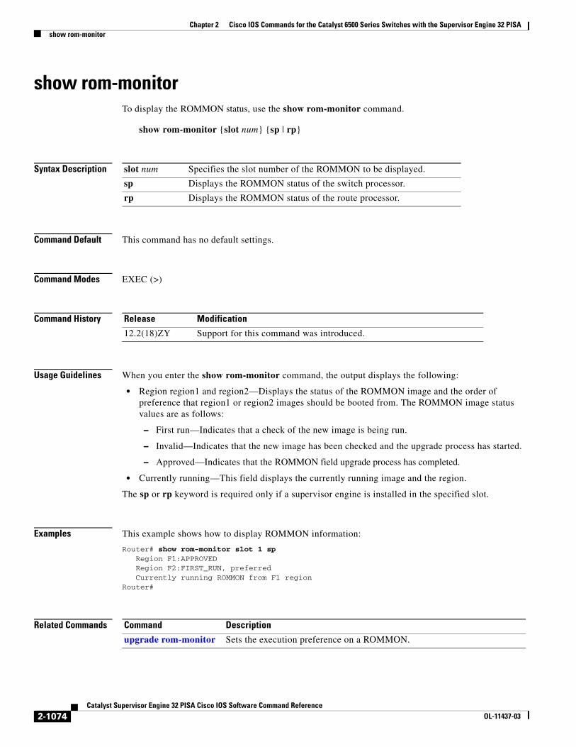
show rom-monitorTo display the ROMMON status, use the show rom-monitor command.
show rom-monitor {slot num} {sp | rp}
Syntax Description
Command Default This command has no default settings.
Command Modes EXEC (>)
Command History
Usage Guidelines When you enter the show rom-monitor command, the output displays the following:
• Region region1 and region2—Displays the status of the ROMMON image and the order of preference that region1 or region2 images should be booted from. The ROMMON image status values are as follows:
– First run—Indicates that a check of the new image is being run.
– Invalid—Indicates that the new image has been checked and the upgrade process has started.
– Approved—Indicates that the ROMMON field upgrade process has completed.
• Currently running—This field displays the currently running image and the region.
The sp or rp keyword is required only if a supervisor engine is installed in the specified slot.
Examples This example shows how to display ROMMON information:
Router# show rom-monitor slot 1 sp Region F1:APPROVED Region F2:FIRST_RUN, preferred Currently running ROMMON from F1 region Router#
Related Commands
slot num Specifies the slot number of the ROMMON to be displayed.
sp Displays the ROMMON status of the switch processor.
rp Displays the ROMMON status of the route processor.
Release Modification
12.2(18)ZY Support for this command was introduced.
Command Description
upgrade rom-monitor Sets the execution preference on a ROMMON.
2-1074Catalyst Supervisor Engine 32 PISA Cisco IOS Software Command Reference
OL-11437-03
Chapter 2 Cisco IOS Commands for the Catalyst 6500 Series Switches with the Supervisor Engine 32 PISAshow rpc
show rpcTo display RPC information, use the show rpc command.
show rpc {applications | counters | status}
Syntax Description
Command Default This command has no default settings.
Command Modes EXEC (>)
Command History
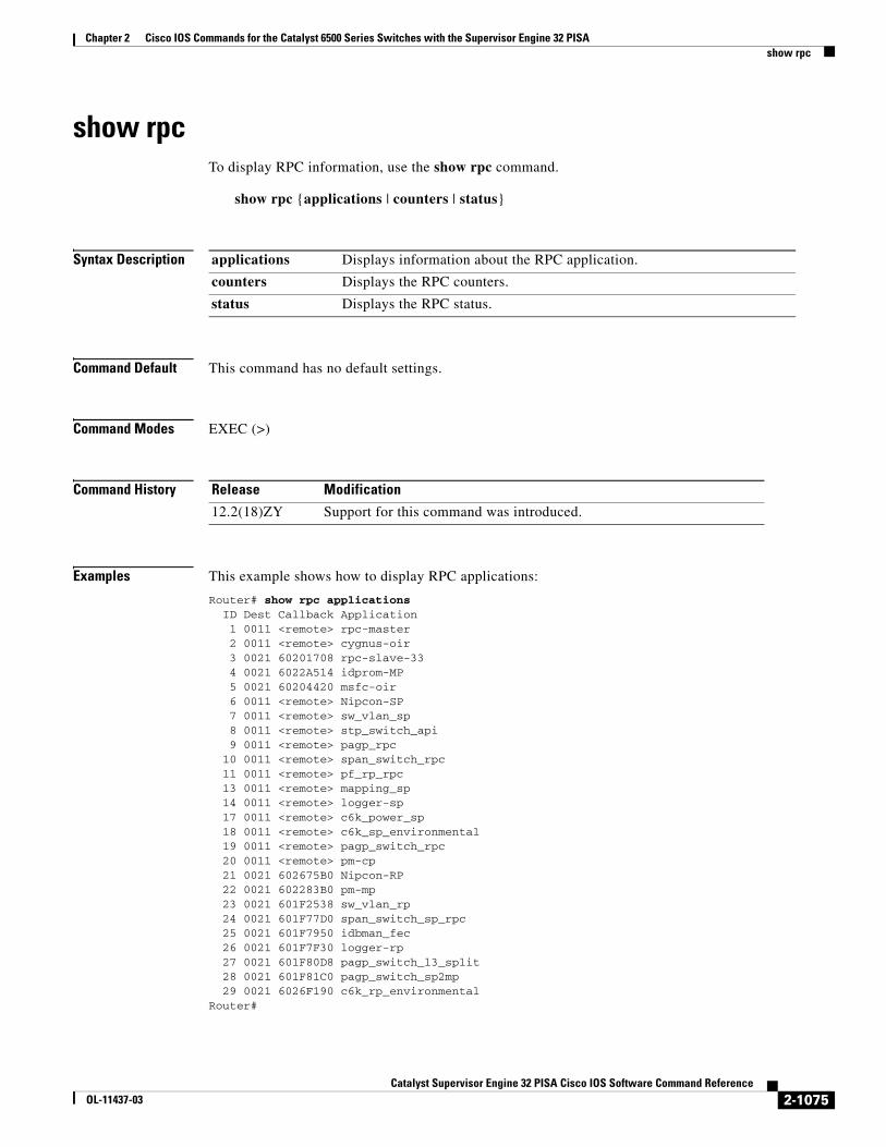
Examples This example shows how to display RPC applications:
Router# show rpc applications ID Dest Callback Application 1 0011 <remote> rpc-master 2 0011 <remote> cygnus-oir 3 0021 60201708 rpc-slave-33 4 0021 6022A514 idprom-MP 5 0021 60204420 msfc-oir 6 0011 <remote> Nipcon-SP 7 0011 <remote> sw_vlan_sp 8 0011 <remote> stp_switch_api 9 0011 <remote> pagp_rpc 10 0011 <remote> span_switch_rpc 11 0011 <remote> pf_rp_rpc 13 0011 <remote> mapping_sp 14 0011 <remote> logger-sp 17 0011 <remote> c6k_power_sp 18 0011 <remote> c6k_sp_environmental 19 0011 <remote> pagp_switch_rpc 20 0011 <remote> pm-cp 21 0021 602675B0 Nipcon-RP 22 0021 602283B0 pm-mp 23 0021 601F2538 sw_vlan_rp 24 0021 601F77D0 span_switch_sp_rpc 25 0021 601F7950 idbman_fec 26 0021 601F7F30 logger-rp 27 0021 601F80D8 pagp_switch_l3_split 28 0021 601F81C0 pagp_switch_sp2mp 29 0021 6026F190 c6k_rp_environmental Router#
applications Displays information about the RPC application.
counters Displays the RPC counters.
status Displays the RPC status.
Release Modification
12.2(18)ZY Support for this command was introduced.
2-1075Catalyst Supervisor Engine 32 PISA Cisco IOS Software Command Reference
OL-11437-03

Chapter 2 Cisco IOS Commands for the Catalyst 6500 Series Switches with the Supervisor Engine 32 PISAshow rpc
This example shows how to display information about the RPC counters:
Router# show rpc counters ID Dest Rcv-req Xmt-req Q size Application 1 0011 0 26 0 rpc-master 2 0011 0 6221 0 cygnus-oir 4 0021 15 0 0 idprom-MP 5 0021 6222 0 0 msfc-oir 7 0011 0 2024 0 sw_vlan_sp 8 0011 0 3 0 stp_switch_api 9 0011 0 188 0 pagp_rpc 11 0011 0 4 0 pf_rp_rpc 13 0011 0 2 0 mapping_sp 14 0011 0 3 0 logger-sp 17 0011 0 2 0 c6k_power_sp 18 0011 0 66 0 c6k_sp_environmental 19 0011 0 109 0 pagp_switch_rpc 20 0011 0 33 0 pm-cp 22 0021 126 0 0 pm-mp 23 0021 5 0 0 sw_vlan_rp 24 0021 14 0 0 span_switch_sp_rpc 25 0021 22 0 0 idbman_fec 26 0021 8 0 0 logger-rp 27 0021 3 0 0 pagp_switch_l3_split 28 0021 3 0 0 pagp_switch_sp2mpRouter#
2-1076Catalyst Supervisor Engine 32 PISA Cisco IOS Software Command Reference
OL-11437-03
Chapter 2 Cisco IOS Commands for the Catalyst 6500 Series Switches with the Supervisor Engine 32 PISAshow running-config
show running-configTo display the status and configuration of the module, Layer 2 VLAN, or interface, use the show running-config command.
show running-config [{interface interface } | {module number} | {vlan vlan-id} ]
Syntax Description
Command Default This command has no default settings.
Command Modes EXEC (>)
Command History
Usage Guidelines In some cases, you might see a difference in the duplex mode that is displayed between the show interfaces command and the show running-config command. In this case, the duplex mode that is displayed in the show interfaces command is the actual duplex mode that the interface is running. The show interfaces command shows the operating mode for an interface, while the show running-config command shows the configured mode for an interface.
The show running-config command output for an interface might display the duplex mode but no configuration for the speed. This output indicates that the interface speed is configured as auto and that the duplex mode shown becomes the operational setting once the speed is configured to something other than auto. With this configuration, it is possible that the operating duplex mode for that interface does not match the duplex mode that is shown with the show running-config command.
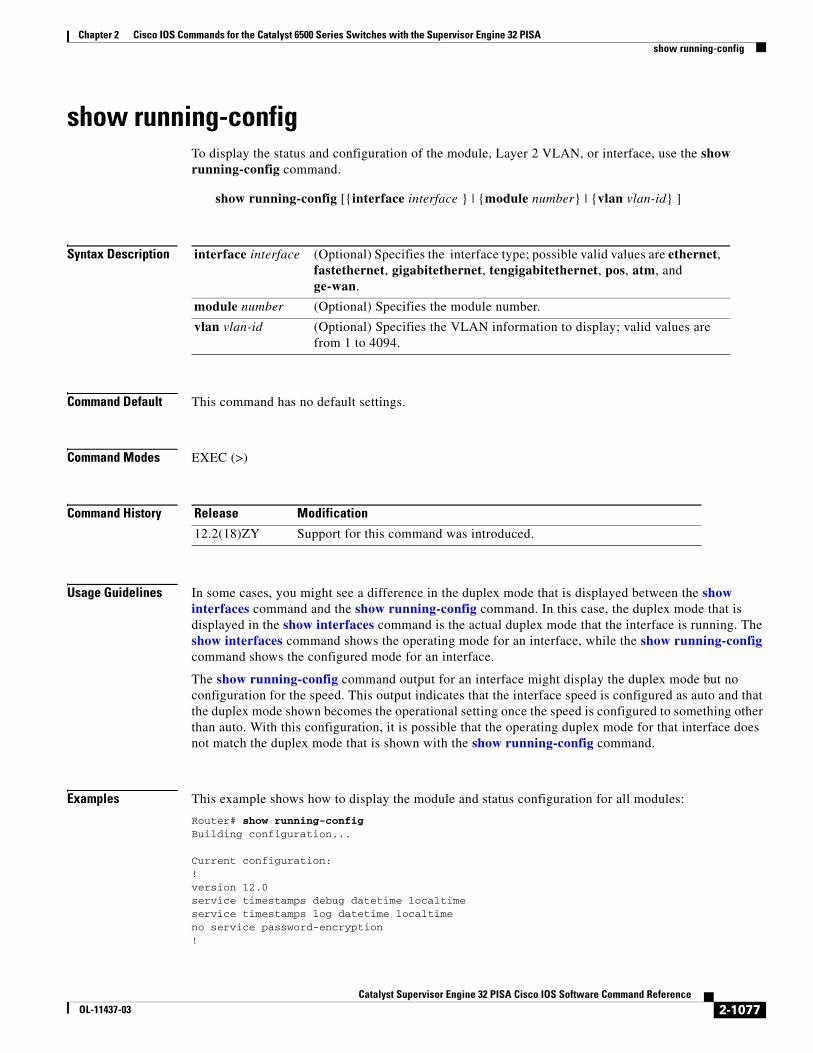
Examples This example shows how to display the module and status configuration for all modules:
Router# show running-configBuilding configuration...
Current configuration:!version 12.0service timestamps debug datetime localtimeservice timestamps log datetime localtimeno service password-encryption!
interface interface (Optional) Specifies the interface type; possible valid values are ethernet, fastethernet, gigabitethernet, tengigabitethernet, pos, atm, and ge-wan.
module number (Optional) Specifies the module number.
vlan vlan-id (Optional) Specifies the VLAN information to display; valid values are from 1 to 4094.
Release Modification
12.2(18)ZY Support for this command was introduced.
2-1077Catalyst Supervisor Engine 32 PISA Cisco IOS Software Command Reference
OL-11437-03

Chapter 2 Cisco IOS Commands for the Catalyst 6500 Series Switches with the Supervisor Engine 32 PISAshow running-config
hostname Router!boot buffersize 126968boot system flash slot0:halleyboot bootldr bootflash:c6msfc-boot-mz.120-6.5T.XE1.0.83.binenable password lab!clock timezone Pacific -8clock summer-time Daylight recurringredundancy main-cpu auto-sync standard! ip subnet-zero!ip multicast-routingip dvmrp route-limit 20000ip cefmls flow ip destinationmls flow ipx destinationcns event-service server!spanning-tree portfast bpdu-guardspanning-tree uplinkfastspanning-tree vlan 200 forward-time 21port-channel load-balance sdip!!! shutdown!!...
2-1078Catalyst Supervisor Engine 32 PISA Cisco IOS Software Command Reference
OL-11437-03
Chapter 2 Cisco IOS Commands for the Catalyst 6500 Series Switches with the Supervisor Engine 32 PISAshow scp
show scpTo display SCP information, use the show scp command.
show scp {accounting | counters | {{mcast [group group-id} | inst]} | {process id} | status}
Syntax Description
Command Default This command has no default settings.
Command Modes EXEC (>)
Command History
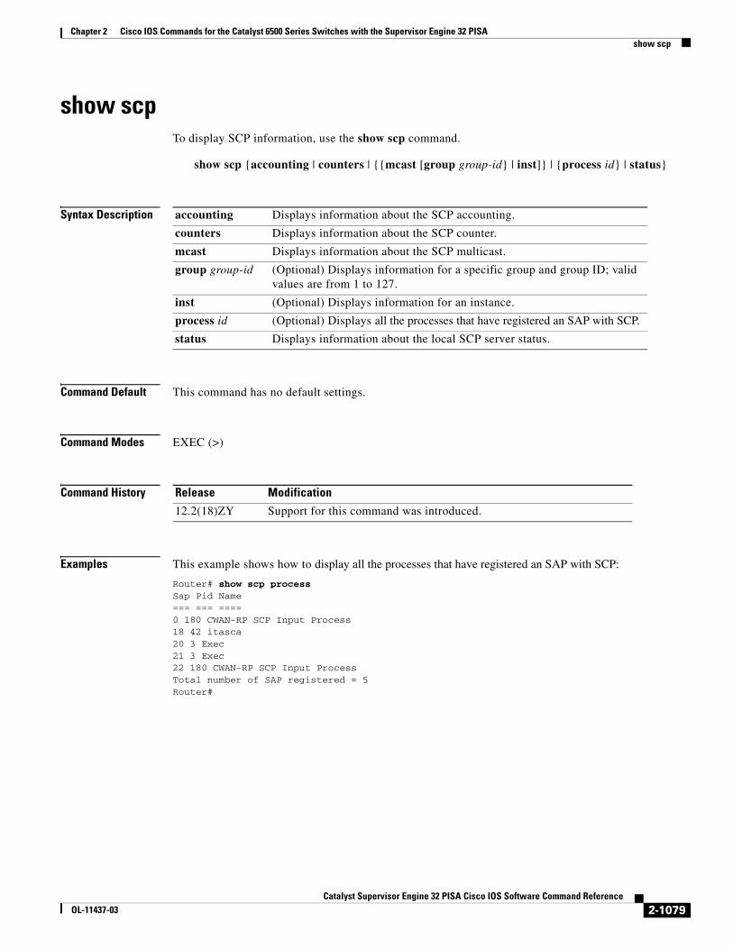
Examples This example shows how to display all the processes that have registered an SAP with SCP:
Router# show scp processSap Pid Name === === ==== 0 180 CWAN-RP SCP Input Process 18 42 itasca 20 3 Exec 21 3 Exec 22 180 CWAN-RP SCP Input ProcessTotal number of SAP registered = 5Router#
accounting Displays information about the SCP accounting.
counters Displays information about the SCP counter.
mcast Displays information about the SCP multicast.
group group-id (Optional) Displays information for a specific group and group ID; valid values are from 1 to 127.
inst (Optional) Displays information for an instance.
process id (Optional) Displays all the processes that have registered an SAP with SCP.
status Displays information about the local SCP server status.
Release Modification
12.2(18)ZY Support for this command was introduced.
2-1079Catalyst Supervisor Engine 32 PISA Cisco IOS Software Command Reference
OL-11437-03

Chapter 2 Cisco IOS Commands for the Catalyst 6500 Series Switches with the Supervisor Engine 32 PISAshow snmp mib ifmib ifindex
show snmp mib ifmib ifindexTo display the SNMP interface index identification numbers (ifIndex values) for all the system interfaces or the specified system interface, use the show snmp mib ifmib ifindex command.
show snmp mib ifmib ifindex [interface interface-number][:subinterface][.subinterface][port]
Syntax Description
Command Default The ifIndex values for all the interfaces are displayed.
Command Modes EXEC (>)
Command History
Usage Guidelines The show snmp mib ifmib ifindex command allows you to display SNMP interface index identification numbers (ifIndex values) that are assigned to interfaces and subinterfaces using the CLI. This command allows you to view these values without using a Network Management Station.
If a specific interface is not specified using the optional interface-type, slot, port-adapter, and port arguments, the ifDescr and ifIndex pairs of all interfaces and subinterfaces present on the system are shown.
Use the show snmp mib ifmib ifindex ? command to determine the options available on your system. Typical interface-types values include async, dialer, ethernet, fastEthernet, and serial.
Examples This example shows how to display the ifIndex for a specific interface:
Router# show snmp mib ifmib ifIndex Ethernet2/0Ethernet2/0: Ifindex = 2
This example shows how to display the ifIndex for all interfaces:
Router# show snmp mib ifmib ifindex
ATM1/0: Ifindex = 1ATM1/0-aal5 layer: Ifindex = 12ATM1/0-atm layer: Ifindex = 10ATM1/0.0-aal5 layer: Ifindex = 13ATM1/0.0-atm subif: Ifindex = 11
interface (Optional) Interface type; possible valid values for type are ethernet, fastethernet, gigabitethernet, tengigabitethernet, pos, atm, and ge-wan.
interface-number Module and port number; see the “Usage Guidelines” section for valid values.
:subinterface (Optional) Subinterface number; the valid value is 0.
.subinterface (Optional) Subinterface number; valid values are from 0 to 4294967295.
port (Optional) Interface number.
Release Modification
12.2(18)ZY Support for this command was introduced.
2-1080Catalyst Supervisor Engine 32 PISA Cisco IOS Software Command Reference
OL-11437-03

Chapter 2 Cisco IOS Commands for the Catalyst 6500 Series Switches with the Supervisor Engine 32 PISAshow snmp mib ifmib ifindex
ATM1/0.9-aal5 layer: Ifindex = 32ATM1/0.9-atm subif: Ifindex = 31ATM1/0.99-aal5 layer: Ifindex = 36ATM1/0.99-atm subif: Ifindex = 35Ethernet2/0: Ifindex = 2Ethernet2/1: Ifindex = 3Ethernet2/2: Ifindex = 4Ethernet2/3: Ifindex = 5Null0: Ifindex = 14Serial3/0: Ifindex = 6Serial3/1: Ifindex = 7Serial3/2: Ifindex = 8Serial3/3: Ifindex = 9
Related Commands Command Description
snmp ifindex persist Enables ifIndex values in the Interfaces MIB (IF-MIB) that persist across reboots (ifIndex persistence) only on a specific interface.
snmp-server ifindex persist
Enables ifIndex values globally so that they will remain constant across reboots for use by SNMP.
2-1081Catalyst Supervisor Engine 32 PISA Cisco IOS Software Command Reference
OL-11437-03

Chapter 2 Cisco IOS Commands for the Catalyst 6500 Series Switches with the Supervisor Engine 32 PISAshow spanning-tree
show spanning-treeTo display information about the spanning-tree state, use the show spanning-tree command.
show spanning-tree [bridge-group | active | backbonefast | {bridge [id]} | detail | inconsistentports | {interface interface interface-number} | root | summary [total] | uplinkfast | {vlan vlan-id} | {port-channel number} | pathcost-method]
Syntax Description
Command Default This command has no default settings.
Command Modes Privileged EXEC (#)
Command History
Usage Guidelines The pos, atm, and ge-wan keywords are supported on Catalyst 6500 series switches that are configured with a Supervisor Engine 2 only.
The port-channel number values from 257 to 282 are supported on the CSM and the FWSM only.
bridge-group (Optional) Bridge-group number; valid values are from 1 to 255.
active (Optional) Displays information about the spanning tree on active interfaces only.
backbonefast (Optional) Displays information about the spanning-tree BackboneFast status.
bridge (Optional) Displays information about the bridge status and configuration.
id (Optional) Displays the bridge identifier.
detail (Optional) Displays detailed information about the spanning-tree state.
inconsistentports (Optional) Displays information about the root-inconsistency state.
interface interface (Optional) Displays the interface type and number; possible valid values for type are ethernet, fastethernet, gigabitethernet, tengigabitethernet, pos, atm, and ge-wan.
interface-number (Optional) Module and port number; see the “Usage Guidelines” section for valid values.
root (Optional) Displays the status and configuration of the root bridge.
summary (Optional) Displays a summary of port states.
total (Optional) Displays the total lines of the spanning-tree state section.
uplinkfast (Optional) Displays the status of the spanning-tree UplinkFast.
vlan vlan-id (Optional) Specifies the VLAN ID; valid values are from 1 to 4094.
port-channel number
(Optional) Specifies the channel interface; valid values are a maximum of 64 values ranging from 1 to 282.
pathcost-method (Optional) Displays the default path-cost calculation method that is used.
Release Modification
12.2(18)ZY Support for this command was introduced.
2-1082Catalyst Supervisor Engine 32 PISA Cisco IOS Software Command Reference
OL-11437-03

Chapter 2 Cisco IOS Commands for the Catalyst 6500 Series Switches with the Supervisor Engine 32 PISAshow spanning-tree
The interface-number argument designates the module and port number. Valid values for interface-number depend on the specified interface type and the chassis and module that are used. For example, if you specify a Gigabit Ethernet interface and have a 48-port 10/100BASE-T Ethernet module that is installed in a 13-slot chassis, valid values for the module number are from 2 to 13 and valid values for the port number are from 1 to 48.
When checking spanning tree-active states and you have a large number of VLANs, you can enter the show spanning-tree summary total command. You can display the total number of VLANs without having to scroll through the list of VLANs.
Examples This example shows how to display a summary of interface information:
Router# show spanning-tree
VLAN0001 Spanning tree enabled protocol ieee Root ID Priority 4097 Address 0004.9b78.0800 This bridge is the root Hello Time 2 sec Max Age 20 sec Forward Delay 15 sec
Bridge ID Priority 4097 (priority 4096 sys-id-ext 1) Address 0004.9b78.0800 Hello Time 2 sec Max Age 20 sec Forward Delay 15 sec Aging Time 15
Interface Port ID Designated Port IDName Prio.Nbr Cost Sts Cost Bridge ID Prio.Nbr---------------- -------- --------- --- --------- -------------------- --------Gi2/1 128.65 4 LIS 0 4097 0004.9b78.0800 128.65 Gi2/2 128.66 4 LIS 0 4097 0004.9b78.0800 128.66 Fa4/3 128.195 19 LIS 0 4097 0004.9b78.0800 128.195 Fa4/4 128.196 19 BLK 0 4097 0004.9b78.0800 128.195
Router#
Table 2-85 describes the fields that are shown in the example.
This example shows how to display information about the spanning tree on active interfaces only:
Router# show spanning-tree activeUplinkFast is disabledBackboneFast is disabled
VLAN1 is executing the ieee compatible Spanning Tree protocol Bridge Identifier has priority 32768, address 0050.3e8d.6401 Configured hello time 2, max age 20, forward delay 15 Current root has priority 16384, address 0060.704c.7000 Root port is 265 (FastEthernet5/9), cost of root path is 38 Topology change flag not set, detected flag not set
Table 2-85 show spanning-tree Command Output Fields
Field Definition
Port ID Prio.Nbr Port ID and priority number.
Cost Port cost.
Sts Status information.
2-1083Catalyst Supervisor Engine 32 PISA Cisco IOS Software Command Reference
OL-11437-03

Chapter 2 Cisco IOS Commands for the Catalyst 6500 Series Switches with the Supervisor Engine 32 PISAshow spanning-tree
Number of topology changes 0 last change occurred 18:13:54 ago Times: hold 1, topology change 24, notification 2 hello 2, max age 14, forward delay 10 Timers: hello 0, topology change 0, notification 0...Router#
This example shows how to display the status of spanning-tree BackboneFast:
Router# show spanning-tree backbonefastBackboneFast is enabled BackboneFast statistics-----------------------Number of transition via backboneFast (all VLANs) : 0Number of inferior BPDUs received (all VLANs) : 0Number of RLQ request PDUs received (all VLANs) : 0Number of RLQ response PDUs received (all VLANs) : 0Number of RLQ request PDUs sent (all VLANs) : 0Number of RLQ response PDUs sent (all VLANs) : 0Router#
This example shows how to display information about the spanning tree for this bridge only:
Router# show spanning-tree bridgeVLAN1 Bridge ID Priority 32768 Address 0050.3e8d.6401 Hello Time 2 sec Max Age 20 sec Forward Delay 15 sec...Router#
This example shows how to display detailed information about the interface:
Router# show spanning-tree detail
VLAN1 is executing the ieee compatible Spanning Tree protocol Bridge Identifier has priority 4096, address 00d0.00b8.1401 Configured hello time 2, max age 20, forward delay 15 We are the root of the spanning tree Topology change flag not set, detected flag not set Number of topology changes 9 last change occurred 02:41:34 ago from FastEthernet4/21 Times: hold 1, topology change 35, notification 2 hello 2, max age 20, forward delay 15 Timers: hello 1, topology change 0, notification 0, aging 300
Port 213 (FastEthernet4/21) of VLAN1 is forwarding Port path cost 19, Port priority 128, Port Identifier 128.213. Designated root has priority 4096, address 00d0.00b8.1401 Designated bridge has priority 4096, address 00d0.00b8.1401 Designated port id is 128.213, designated path cost 0 Timers: message age 0, forward delay 0, hold 0 Number of transitions to forwarding state: 1 BPDU: sent 4845, received 1 Router#
2-1084Catalyst Supervisor Engine 32 PISA Cisco IOS Software Command Reference
OL-11437-03
Chapter 2 Cisco IOS Commands for the Catalyst 6500 Series Switches with the Supervisor Engine 32 PISAshow spanning-tree
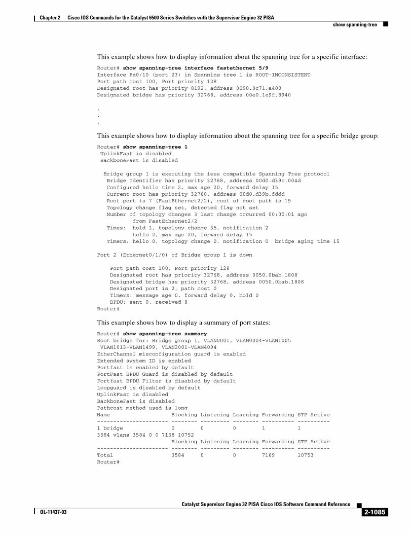
This example shows how to display information about the spanning tree for a specific interface:
Router# show spanning-tree interface fastethernet 5/9Interface Fa0/10 (port 23) in Spanning tree 1 is ROOT-INCONSISTENTPort path cost 100, Port priority 128Designated root has priority 8192, address 0090.0c71.a400Designated bridge has priority 32768, address 00e0.1e9f.8940
.
.
.
This example shows how to display information about the spanning tree for a specific bridge group:
Router# show spanning-tree 1 UplinkFast is disabled BackboneFast is disabled Bridge group 1 is executing the ieee compatible Spanning Tree protocol Bridge Identifier has priority 32768, address 00d0.d39c.004d Configured hello time 2, max age 20, forward delay 15 Current root has priority 32768, address 00d0.d39b.fddd Root port is 7 (FastEthernet2/2), cost of root path is 19 Topology change flag set, detected flag not set Number of topology changes 3 last change occurred 00:00:01 ago from FastEthernet2/2 Times: hold 1, topology change 35, notification 2 hello 2, max age 20, forward delay 15 Timers: hello 0, topology change 0, notification 0 bridge aging time 15 Port 2 (Ethernet0/1/0) of Bridge group 1 is down Port path cost 100, Port priority 128 Designated root has priority 32768, address 0050.0bab.1808 Designated bridge has priority 32768, address 0050.0bab.1808 Designated port is 2, path cost 0 Timers: message age 0, forward delay 0, hold 0 BPDU: sent 0, received 0 Router#
This example shows how to display a summary of port states:
Router# show spanning-tree summary Root bridge for: Bridge group 1, VLAN0001, VLAN0004-VLAN1005 VLAN1013-VLAN1499, VLAN2001-VLAN4094 EtherChannel misconfiguration guard is enabled Extended system ID is enabled Portfast is enabled by default PortFast BPDU Guard is disabled by default Portfast BPDU Filter is disabled by default Loopguard is disabled by default UplinkFast is disabled BackboneFast is disabled Pathcost method used is longName Blocking Listening Learning Forwarding STP Active ---------------------- -------- --------- -------- ---------- ---------- 1 bridge 0 0 0 1 1 3584 vlans 3584 0 0 7168 10752 Blocking Listening Learning Forwarding STP Active ---------------------- -------- --------- -------- ---------- ---------- Total 3584 0 0 7169 10753 Router#
2-1085Catalyst Supervisor Engine 32 PISA Cisco IOS Software Command Reference
OL-11437-03

Chapter 2 Cisco IOS Commands for the Catalyst 6500 Series Switches with the Supervisor Engine 32 PISAshow spanning-tree
This example shows how to display the total lines of the spanning-tree state section:
Router# show spanning-tree summary total Root bridge for:Bridge group 10, VLAN1, VLAN6, VLAN1000.Extended system ID is enabled.PortFast BPDU Guard is disabledEtherChannel misconfiguration guard is enabledUplinkFast is disabledBackboneFast is disabledDefault pathcost method used is long
Name Blocking Listening Learning Forwarding STP Active-------------------- -------- --------- -------- ---------- ---------- 105 VLANs 3433 0 0 105 3538 BackboneFast statistics-----------------------Number of transition via backboneFast (all VLANs) :0Number of inferior BPDUs received (all VLANs) :0Number of RLQ request PDUs received (all VLANs) :0Number of RLQ response PDUs received (all VLANs) :0Number of RLQ request PDUs sent (all VLANs) :0Number of RLQ response PDUs sent (all VLANs) :0Router#
This example shows how to display information about the spanning tree for a specific VLAN:
Router# show spanning-tree vlan 200VLAN0200 Spanning tree enabled protocol ieee Root ID Priority 32768 Address 00d0.00b8.14c8 This bridge is the root Hello Time 2 sec Max Age 20 sec Forward Delay 15 sec Bridge ID Priority 32768 Address 00d0.00b8.14c8 Hello Time 2 sec Max Age 20 sec Forward Delay 15 sec Aging Time 300Interface Role Sts Cost Prio.Nbr Status ---------------- ---- --- --------- -------- -------------------------------- Fa4/4 Desg FWD 200000 128.196 P2p Fa4/5 Back BLK 200000 128.197 P2pRouter#
Table 2-86 describes the fields that are shown in the example.
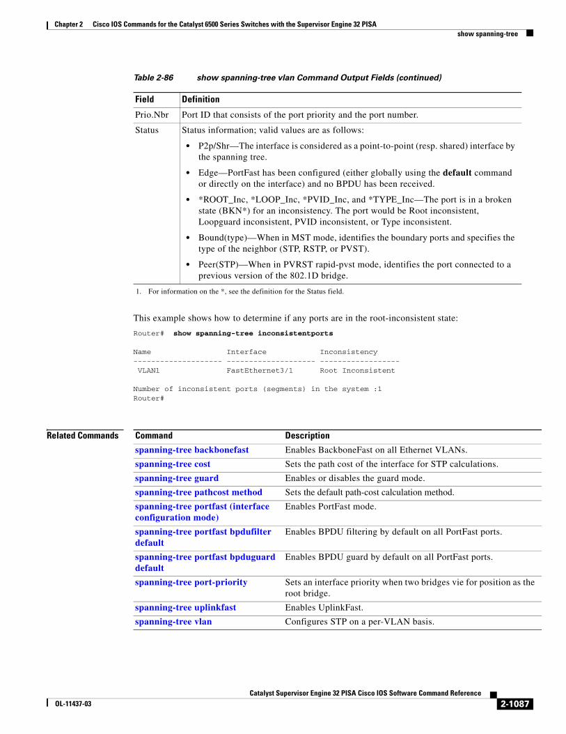
Table 2-86 show spanning-tree vlan Command Output Fields
Field Definition
Role Current 802.1w role; valid values are Boun (boundary), Desg (designated), Root, Altn (alternate), and Back (backup).
Sts Spanning-tree states; valid values are BKN* (broken)1, BLK (blocking), DWN (down), LTN (listening), LBK (loopback), LRN (learning), and FWD (forwarding).
Cost Port cost.
2-1086Catalyst Supervisor Engine 32 PISA Cisco IOS Software Command Reference
OL-11437-03
Chapter 2 Cisco IOS Commands for the Catalyst 6500 Series Switches with the Supervisor Engine 32 PISAshow spanning-tree
This example shows how to determine if any ports are in the root-inconsistent state:
Router# show spanning-tree inconsistentports Name Interface Inconsistency-------------------- -------------------- ------------------ VLAN1 FastEthernet3/1 Root Inconsistent
Number of inconsistent ports (segments) in the system :1Router#
Related Commands
Prio.Nbr Port ID that consists of the port priority and the port number.
Status Status information; valid values are as follows:
• P2p/Shr—The interface is considered as a point-to-point (resp. shared) interface by the spanning tree.
• Edge—PortFast has been configured (either globally using the default command or directly on the interface) and no BPDU has been received.
• *ROOT_Inc, *LOOP_Inc, *PVID_Inc, and *TYPE_Inc—The port is in a broken state (BKN*) for an inconsistency. The port would be Root inconsistent, Loopguard inconsistent, PVID inconsistent, or Type inconsistent.
• Bound(type)—When in MST mode, identifies the boundary ports and specifies the type of the neighbor (STP, RSTP, or PVST).
• Peer(STP)—When in PVRST rapid-pvst mode, identifies the port connected to a previous version of the 802.1D bridge.
1. For information on the *, see the definition for the Status field.
Table 2-86 show spanning-tree vlan Command Output Fields (continued)
Field Definition
Command Description
spanning-tree backbonefast Enables BackboneFast on all Ethernet VLANs.
spanning-tree cost Sets the path cost of the interface for STP calculations.
spanning-tree guard Enables or disables the guard mode.
spanning-tree pathcost method Sets the default path-cost calculation method.
spanning-tree portfast (interface configuration mode)
Enables PortFast mode.
spanning-tree portfast bpdufilter default
Enables BPDU filtering by default on all PortFast ports.
spanning-tree portfast bpduguard default
Enables BPDU guard by default on all PortFast ports.
spanning-tree port-priority Sets an interface priority when two bridges vie for position as the root bridge.
spanning-tree uplinkfast Enables UplinkFast.
spanning-tree vlan Configures STP on a per-VLAN basis.
2-1087Catalyst Supervisor Engine 32 PISA Cisco IOS Software Command Reference
OL-11437-03
Chapter 2 Cisco IOS Commands for the Catalyst 6500 Series Switches with the Supervisor Engine 32 PISAshow spanning-tree mst
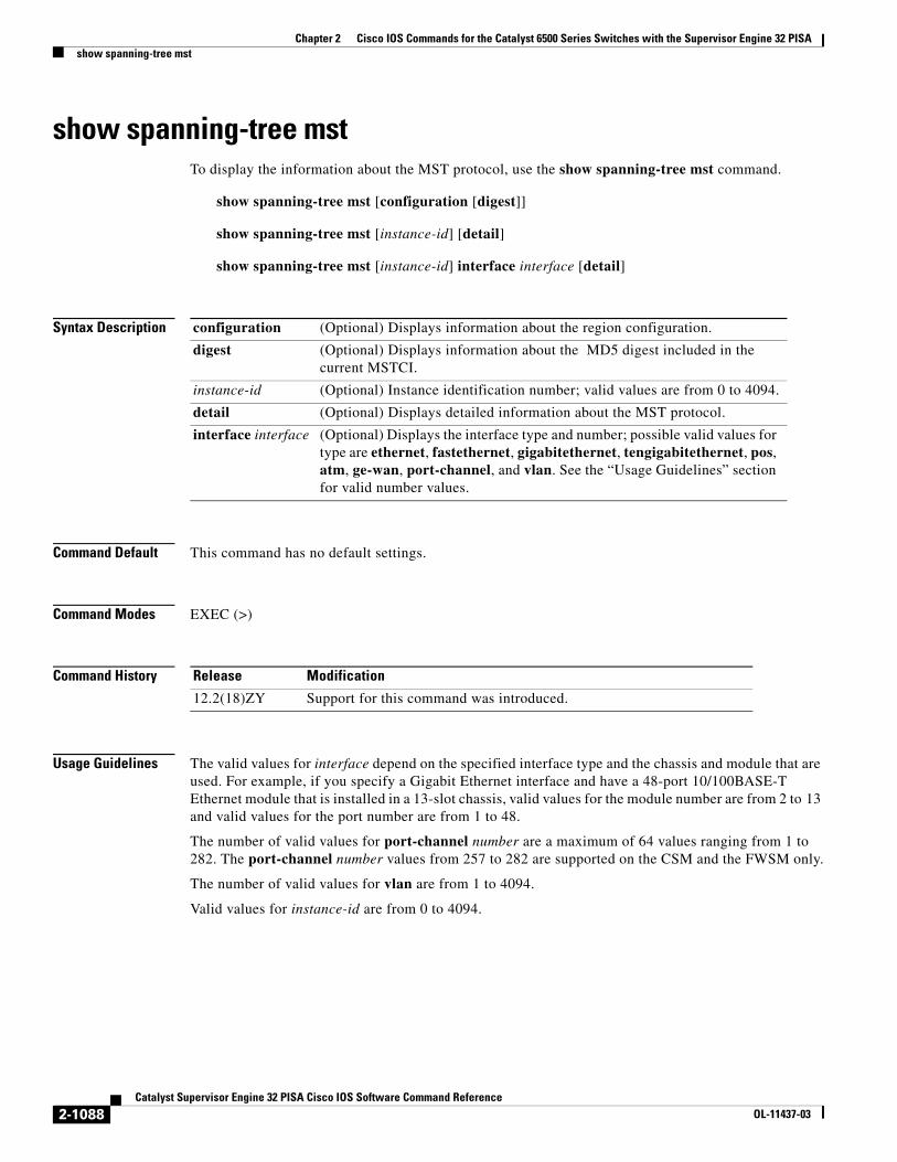
show spanning-tree mstTo display the information about the MST protocol, use the show spanning-tree mst command.
show spanning-tree mst [configuration [digest]]
show spanning-tree mst [instance-id] [detail]
show spanning-tree mst [instance-id] interface interface [detail]
Syntax Description
Command Default This command has no default settings.
Command Modes EXEC (>)
Command History
Usage Guidelines The valid values for interface depend on the specified interface type and the chassis and module that are used. For example, if you specify a Gigabit Ethernet interface and have a 48-port 10/100BASE-T Ethernet module that is installed in a 13-slot chassis, valid values for the module number are from 2 to 13 and valid values for the port number are from 1 to 48.
The number of valid values for port-channel number are a maximum of 64 values ranging from 1 to 282. The port-channel number values from 257 to 282 are supported on the CSM and the FWSM only.
The number of valid values for vlan are from 1 to 4094.
Valid values for instance-id are from 0 to 4094.
configuration (Optional) Displays information about the region configuration.
digest (Optional) Displays information about the MD5 digest included in the current MSTCI.
instance-id (Optional) Instance identification number; valid values are from 0 to 4094.
detail (Optional) Displays detailed information about the MST protocol.
interface interface (Optional) Displays the interface type and number; possible valid values for type are ethernet, fastethernet, gigabitethernet, tengigabitethernet, pos, atm, ge-wan, port-channel, and vlan. See the “Usage Guidelines” section for valid number values.
Release Modification
12.2(18)ZY Support for this command was introduced.
2-1088Catalyst Supervisor Engine 32 PISA Cisco IOS Software Command Reference
OL-11437-03

Chapter 2 Cisco IOS Commands for the Catalyst 6500 Series Switches with the Supervisor Engine 32 PISAshow spanning-tree mst
In the output display of the show spanning-tree mst configuration command, a warning message may display. This message appears if you do not map secondary VLANs to the same instance as the associated primary VLAN. The display includes a list of the secondary VLANs that are not mapped to the same instance as the associated primary VLAN. The warning message is as follows:
These secondary vlans are not mapped to the same instance as their primary:-> 3
In the output display of the show spanning-tree mst configuration digest command, if the output applies to both standard and prestandard bridges at the same time on a per-port basis, two different digests are displayed.
If you configure a port to transmit prestandard BPDUs only, the prestandard flag displays in the show spanning-tree commands. The variations of the prestandard flag are as follows:
• Pre-STD (or prestandard in long format)—This flag displays if the port is configured to transmit prestandard BPDUs and if a prestandard neighbor bridge has been detected on this interface.
• Pre-STD-Cf (or prestandard (config) in long format)—This flag displays if the port is configured to transmit prestandard BPDUs but a prestandard BPDU has not been received on the port, the autodetection mechanism has failed, or a misconfiguration, if there is no prestandard neighbor, has occurred.
• Pre-STD-Rx (or prestandard (rcvd) in long format)—This flag displays when a prestandard BPDU has been received on the port but it has not been configured to send prestandard BPDUs. The port will send prestandard BPDUs, but we recommend that you change the port configuration so that the interaction with the prestandard neighbor does not rely only on the autodetection mechanism.
If the configuration is not prestandard compliant (for example, a single MST instance has an ID that is greater than or equal to 16), the prestandard digest is not computed and the following output is displayed:
Router# show spanning-tree mst configuration digest Name [region1]Revision 2 Instances configured 3Digest 0x3C60DBF24B03EBF09C5922F456D18A03Pre-std Digest N/A, configuration not pre-standard compatibleRouter#
MST BPDUs include an MST configuration identifier (MSTCI) that consists of the region name, region revision, and an MD5 digest of the VLAN-to-instance mapping of the MST configuration.
See the show spanning-tree command for output definitions.
Examples This example shows how to display information about the region configuration:
Router> show spanning-tree mst configuration Name [leo]Revision 2702Instance Vlans mapped-------- ---------------------------------------------------------------------0 1-9,11-19,21-29,31-39,41-40941 10,20,30,40-------------------------------------------------------------------------------
This example shows how to display additional MST-protocol values:
Router# show spanning-tree mst 3 detail ###### MST03 vlans mapped: 3,3000-3999 Bridge address 0002.172c.f400 priority 32771 (32768 sysid 3) Root this switch for MST03
2-1089Catalyst Supervisor Engine 32 PISA Cisco IOS Software Command Reference
OL-11437-03

Chapter 2 Cisco IOS Commands for the Catalyst 6500 Series Switches with the Supervisor Engine 32 PISAshow spanning-tree mst
GigabitEthernet1/1 of MST03 is boundary forwarding Port info port id 128.1 priority 128 cost 20000 Designated root address 0002.172c.f400 priority 32771 cost 0 Designated bridge address 0002.172c.f400 priority 32771 port id 128.1 Timers: message expires in 0 sec, forward delay 0, forward transitions 1 Bpdus (MRecords) sent 4, received 0
FastEthernet4/1 of MST03 is designated forwarding Port info port id 128.193 priority 128 cost 200000 Designated root address 0002.172c.f400 priority 32771 cost 0 Designated bridge address 0002.172c.f400 priority 32771 port id 128.193 Timers: message expires in 0 sec, forward delay 0, forward transitions 1 Bpdus (MRecords) sent 254, received 1
FastEthernet4/2 of MST03 is backup blocking Port info port id 128.194 priority 128 cost 200000 Designated root address 0002.172c.f400 priority 32771 cost 0 Designated bridge address 0002.172c.f400 priority 32771 port id 128.193 Timers: message expires in 2 sec, forward delay 0, forward transitions 1 Bpdus (MRecords) sent 3, received 252Router#
This example shows how to display MST information for a specific interface:
Router# show spanning-tree mst 0 interface fastethernet 4/1 detail Edge port: no (trunk) port guard : none (default) Link type: point-to-point (point-to-point) bpdu filter: disable (default) Boundary : internal bpdu guard : disable (default)FastEthernet4/1 of MST00 is designated forwarding Vlans mapped to MST00 1-2,4-2999,4000-4094 Port info port id 128.193 priority 128 cost 200000 Designated root address 0050.3e66.d000 priority 8193 cost 20004 Designated ist master address 0002.172c.f400 priority 49152 cost 0 Designated bridge address 0002.172c.f400 priority 49152 port id 128.193 Timers: message expires in 0 sec, forward delay 0, forward transitions 1 Bpdus sent 492, received 3Router#
This example shows how to display the MD5 digest included in the current MSTCI:
Router# show spanning-tree mst configuration digest Name [mst-config]Revision 10 Instances configured 25Digest 0x40D5ECA178C657835C83BBCB16723192Pre-std Digest 0x27BF112A75B72781ED928D9EC5BB4251Router#
2-1090Catalyst Supervisor Engine 32 PISA Cisco IOS Software Command Reference
OL-11437-03

Chapter 2 Cisco IOS Commands for the Catalyst 6500 Series Switches with the Supervisor Engine 32 PISAshow spanning-tree mst
This example displays the new master role for all MST instances at the boundary of the region on the port that is a CIST root port:
Router# show spanning-tree mst interface fastethernet4/9
FastEthernet4/9 of MST00 is root forwarding Edge port: no (default) port guard : none (default)Link type: point-to-point (auto) bpdu filter: disable (default)Boundary : boundary (RSTP) bpdu guard : disable (default)Bpdus sent 3428, received 6771
Instance Role Sts Cost Prio.Nbr Vlans mapped-------- ---- --- --------- -------- -------------------------------0 Root FWD 200000 128.201 2-7,10,12-99,101-999,2001-3999,4001-40948 Mstr FWD 200000 128.201 8,40009 Mstr FWD 200000 128.201 1,9,10011 Mstr FWD 200000 128.201 11,1000-2000Router#
Related Commands Command Description
spanning-tree mst Sets the path cost and port-priority parameters for any MST instance.
spanning-tree mst forward-time
Sets the forward-delay timer for all the instances on the Catalyst 6500 series switch.
spanning-tree mst hello-time
Sets the hello-time delay timer for all the instances on the Catalyst 6500 series switch.
spanning-tree mst max-hops
Specifies the number of possible hops in the region before a BPDU is discarded.
spanning-tree mst root Designates the primary and secondary root, sets the bridge priority, and sets the timer value for an instance.
2-1091Catalyst Supervisor Engine 32 PISA Cisco IOS Software Command Reference
OL-11437-03
Chapter 2 Cisco IOS Commands for the Catalyst 6500 Series Switches with the Supervisor Engine 32 PISAshow standby delay
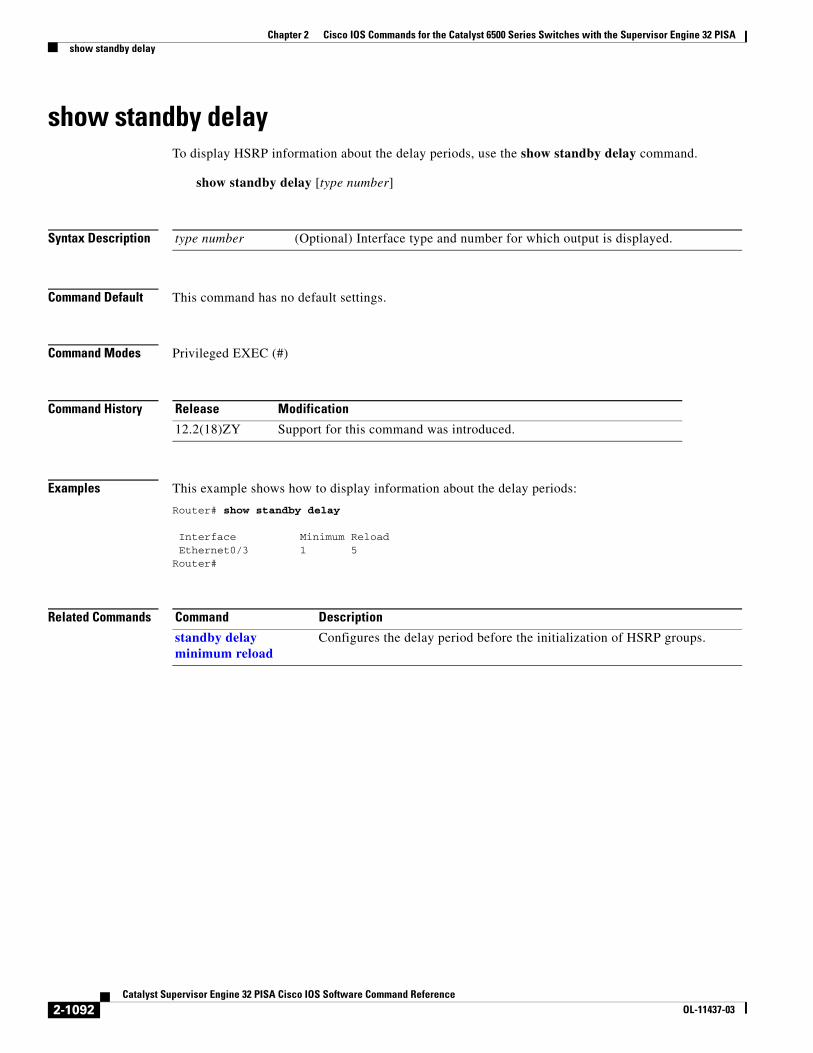
show standby delayTo display HSRP information about the delay periods, use the show standby delay command.
show standby delay [type number]
Syntax Description
Command Default This command has no default settings.
Command Modes Privileged EXEC (#)
Command History
Examples This example shows how to display information about the delay periods:
Router# show standby delay
Interface Minimum Reload Ethernet0/3 1 5
Router#
Related Commands
type number (Optional) Interface type and number for which output is displayed.
Release Modification
12.2(18)ZY Support for this command was introduced.
Command Description
standby delay minimum reload
Configures the delay period before the initialization of HSRP groups.
2-1092Catalyst Supervisor Engine 32 PISA Cisco IOS Software Command Reference
OL-11437-03

Chapter 2 Cisco IOS Commands for the Catalyst 6500 Series Switches with the Supervisor Engine 32 PISAshow sup-bootflash
show sup-bootflashTo display information about the sup-bootflash file system, use the show sup-bootflash command.
show sup-bootflash [all | chips | filesys]
Syntax Description
Command Default This command has no default settings.
Command Modes Privileged EXEC (#)
Command History
Examples This example shows how to display a summary of bootflash information:
Router# show sup-bootflash-#- ED --type-- --crc--- -seek-- nlen -length- -----date/time------ name1 .. image EBC8FC4D A7487C 6 10700796 Nov 19 1999 07:07:37 halley2 .. unknown C7EB077D EE2620 25 4644130 Nov 19 1999 07:50:44 cat6000-sup_5-3-3-CSX.bin
645600 bytes available (15345184 bytes used)Router#
This example shows how to display all bootflash information:
Router# show sup-bootflash all-#- ED --type-- --crc--- -seek-- nlen -length- -----date/time------ name1 .. image EBC8FC4D A7487C 6 10700796 Nov 19 1999 07:07:37 halley2 .. unknown C7EB077D EE2620 25 4644130 Nov 19 1999 07:50:44 cat6000-sup_5-3-3-CSX.bin
645600 bytes available (15345184 bytes used)
-------- F I L E S Y S T E M S T A T U S -------- Device Number = 2DEVICE INFO BLOCK: bootflash Magic Number = 6887635 File System Vers = 10000 (1.0) Length = 1000000 Sector Size = 40000 Programming Algorithm = 19 Erased State = FFFFFFFF File System Offset = 40000 Length = F40000 MONLIB Offset = 100 Length = F568 Bad Sector Map Offset = 3FFF8 Length = 8 Squeeze Log Offset = F80000 Length = 40000 Squeeze Buffer Offset = FC0000 Length = 40000 Num Spare Sectors = 0
all (Optional) Displays all possible flash information.
chips (Optional) Displays information about the flash chip.
filesys (Optional) Displays information about the file system.
Release Modification
12.2(18)ZY Support for this command was introduced.
2-1093Catalyst Supervisor Engine 32 PISA Cisco IOS Software Command Reference
OL-11437-03

Chapter 2 Cisco IOS Commands for the Catalyst 6500 Series Switches with the Supervisor Engine 32 PISAshow sup-bootflash
Spares:STATUS INFO: Writable NO File Open for Write Complete Stats No Unrecovered Errors No Squeeze in progressUSAGE INFO: Bytes Used = EA2620 Bytes Available = 9D9E0 Bad Sectors = 0 Spared Sectors = 0 OK Files = 2 Bytes = EA2520 Deleted Files = 0 Bytes = 0 Files w/Errors = 0 Bytes = 0
******** Intel SCS Status/Register Dump ********
COMMON MEMORY REGISTERS: Bank 0 Intelligent ID Code : 890089 Compatible Status Reg: 800080
DEVICE TYPE: Layout : Paired x16 Mode Write Queue Size : 64 Queued Erase Supported : No
Router#
This example shows how to display information about the flash chip:
Router# show sup-bootflash chips
******** Intel SCS Status/Register Dump ********
COMMON MEMORY REGISTERS: Bank 0 Intelligent ID Code : 890089 Compatible Status Reg: 800080
DEVICE TYPE: Layout : Paired x16 Mode Write Queue Size : 64 Queued Erase Supported : No
Router#
This example shows how to display information about the file system:
Router# show sup-bootflash filesys
-------- F I L E S Y S T E M S T A T U S -------- Device Number = 2DEVICE INFO BLOCK: bootflash Magic Number = 6887635 File System Vers = 10000 (1.0) Length = 1000000 Sector Size = 40000 Programming Algorithm = 19 Erased State = FFFFFFFF File System Offset = 40000 Length = F40000 MONLIB Offset = 100 Length = F568 Bad Sector Map Offset = 3FFF8 Length = 8 Squeeze Log Offset = F80000 Length = 40000 Squeeze Buffer Offset = FC0000 Length = 40000 Num Spare Sectors = 0 Spares:STATUS INFO: Writable NO File Open for Write
2-1094Catalyst Supervisor Engine 32 PISA Cisco IOS Software Command Reference
OL-11437-03

Chapter 2 Cisco IOS Commands for the Catalyst 6500 Series Switches with the Supervisor Engine 32 PISAshow sup-bootflash
Complete Stats No Unrecovered Errors No Squeeze in progressUSAGE INFO: Bytes Used = EA2620 Bytes Available = 9D9E0 Bad Sectors = 0 Spared Sectors = 0 OK Files = 2 Bytes = EA2520 Deleted Files = 0 Bytes = 0 Files w/Errors = 0 Bytes = 0
Router#
2-1095Catalyst Supervisor Engine 32 PISA Cisco IOS Software Command Reference
OL-11437-03

Chapter 2 Cisco IOS Commands for the Catalyst 6500 Series Switches with the Supervisor Engine 32 PISAshow system jumbomtu
show system jumbomtuTo display the global MTU setting, use the show system jumbomtu command.
show system jumbomtu
Syntax Description This command has no arguments or keywords.
Command Default This command has no default settings.
Command Modes Privileged EXEC (#)
Command History
Examples This example shows how to display the global MTU setting:
Router# show system jumbomtuGlobal Ethernet MTU is 1550 bytes.Router#
Related Commands
Release Modification
12.2(18)ZY Support for this command was introduced.
Command Description
system jumbomtu Sets the maximum size of the Layer 2 and Layer 3 packets.
2-1096Catalyst Supervisor Engine 32 PISA Cisco IOS Software Command Reference
OL-11437-03
Chapter 2 Cisco IOS Commands for the Catalyst 6500 Series Switches with the Supervisor Engine 32 PISAshow tcam counts
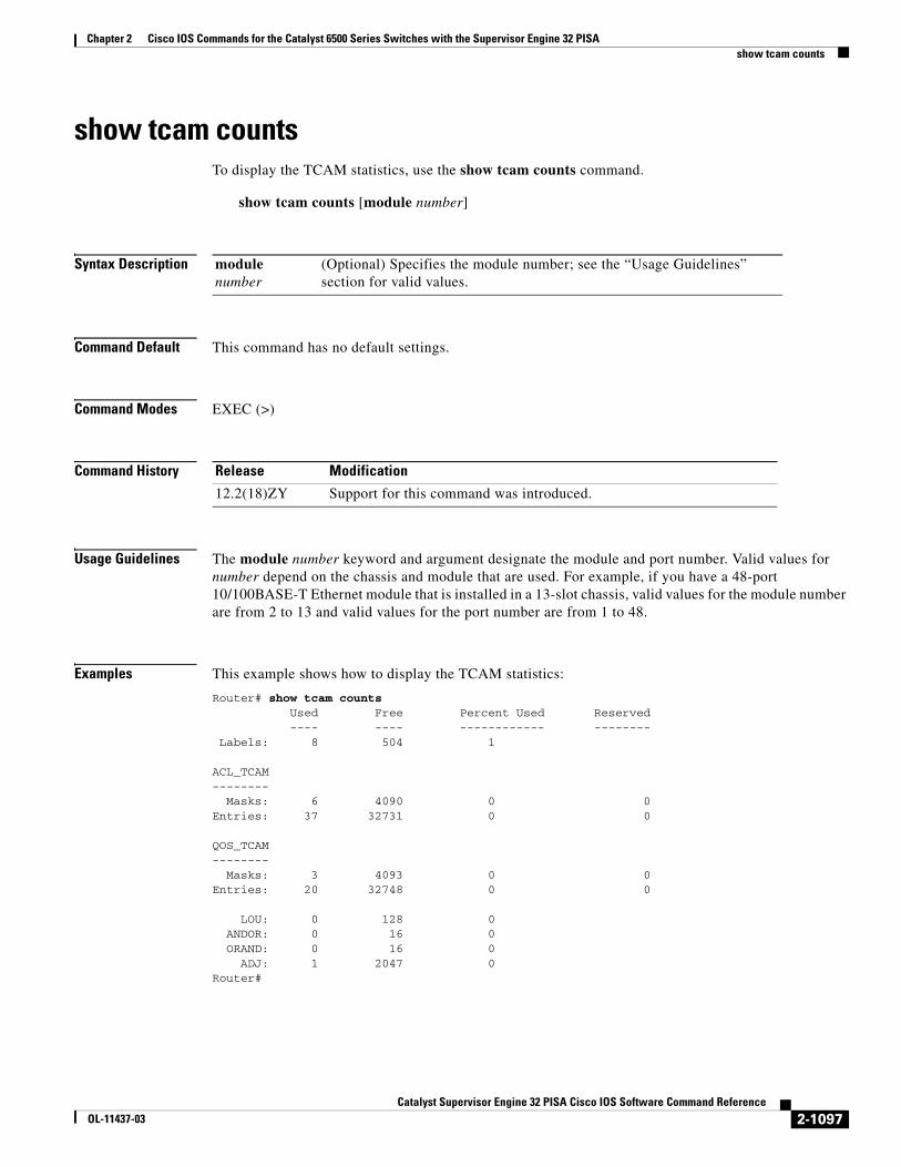
show tcam countsTo display the TCAM statistics, use the show tcam counts command.
show tcam counts [module number]
Syntax Description
Command Default This command has no default settings.
Command Modes EXEC (>)
Command History
Usage Guidelines The module number keyword and argument designate the module and port number. Valid values for number depend on the chassis and module that are used. For example, if you have a 48-port 10/100BASE-T Ethernet module that is installed in a 13-slot chassis, valid values for the module number are from 2 to 13 and valid values for the port number are from 1 to 48.
Examples This example shows how to display the TCAM statistics:
Router# show tcam counts Used Free Percent Used Reserved ---- ---- ------------ -------- Labels: 8 504 1
ACL_TCAM-------- Masks: 6 4090 0 0Entries: 37 32731 0 0
QOS_TCAM-------- Masks: 3 4093 0 0Entries: 20 32748 0 0
LOU: 0 128 0 ANDOR: 0 16 0 ORAND: 0 16 0 ADJ: 1 2047 0Router#
module number
(Optional) Specifies the module number; see the “Usage Guidelines” section for valid values.
Release Modification
12.2(18)ZY Support for this command was introduced.
2-1097Catalyst Supervisor Engine 32 PISA Cisco IOS Software Command Reference
OL-11437-03

Chapter 2 Cisco IOS Commands for the Catalyst 6500 Series Switches with the Supervisor Engine 32 PISAshow tcam counts
Table 2-87 describes the fields that are shown in the example.
Table 2-87 show tcam counts Command Output Fields
Field Description
Labels Used Number of labels that are used (maximum of 512).
Labels Free Number of free labels remaining.
Labels Percent Used Percentage of labels that are used.
Masks Used Number of masks that are used (maximum of 4096).
Masks Free Number of free labels remaining.
Masks Percent Used Percentage of masks that are used.
Entries Used Number of labels that are used (maximum of 32767).
Entries Free Number of free labels that are remaining.
Entries Percent Used Percentage of entries that are used.
2-1098Catalyst Supervisor Engine 32 PISA Cisco IOS Software Command Reference
OL-11437-03
Chapter 2 Cisco IOS Commands for the Catalyst 6500 Series Switches with the Supervisor Engine 32 PISAshow tcam interface
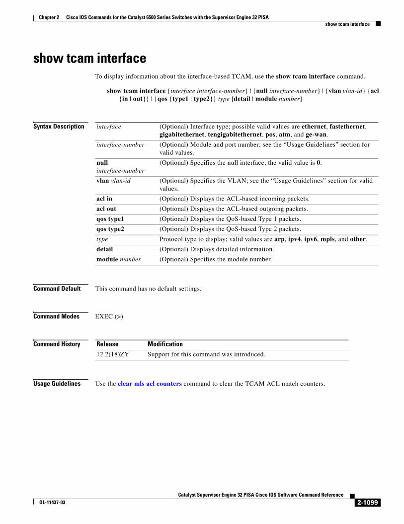
show tcam interfaceTo display information about the interface-based TCAM, use the show tcam interface command.
show tcam interface {interface interface-number} | {null interface-number} | {vlan vlan-id} {acl {in | out}} | {qos {type1 | type2}} type [detail | module number]
Syntax Description
Command Default This command has no default settings.
Command Modes EXEC (>)
Command History
Usage Guidelines Use the clear mls acl counters command to clear the TCAM ACL match counters.
interface (Optional) Interface type; possible valid values are ethernet, fastethernet, gigabitethernet, tengigabitethernet, pos, atm, and ge-wan.
interface-number (Optional) Module and port number; see the “Usage Guidelines” section for valid values.
null interface-number
(Optional) Specifies the null interface; the valid value is 0.
vlan vlan-id (Optional) Specifies the VLAN; see the “Usage Guidelines” section for valid values.
acl in (Optional) Displays the ACL-based incoming packets.
acl out (Optional) Displays the ACL-based outgoing packets.
qos type1 (Optional) Displays the QoS-based Type 1 packets.
qos type2 (Optional) Displays the QoS-based Type 2 packets.
type Protocol type to display; valid values are arp, ipv4, ipv6, mpls, and other.
detail (Optional) Displays detailed information.
module number (Optional) Specifies the module number.
Release Modification
12.2(18)ZY Support for this command was introduced.
2-1099Catalyst Supervisor Engine 32 PISA Cisco IOS Software Command Reference
OL-11437-03

Chapter 2 Cisco IOS Commands for the Catalyst 6500 Series Switches with the Supervisor Engine 32 PISAshow tcam interface
Examples This example shows how to display interface-based TCAM information:
Router# show tcam interface vlan 7 acl in ipdeny ip any any permit ip 20.20.0.0 0.0.255.255 22.22.0.0 0.0.255.255 redirect ip 20.21.0.0 0.0.255.255 22.23.0.0 0.0.255.255 permit tcp 24.24.0.0 0.0.255.255 30.30.0.0 0.0.255.255 Fragments (1 match) permit tcp 25.25.0.0 0.0.255.255 31.31.0.0 0.0.255.255 fragments permit tcp 25.25.0.0 0.0.255.255 range 30000 30020 31.31.0.0 0.0.255.255 range 10000 10010 (102 matches) permit tcp 24.24.0.0 0.0.255.255 eq 9000 30.30.0.0 0.0.255.255 eq telnet deny ip any any deny ip any anyRouter#
This example shows how to display detailed TCAM information:
Router# show tcam interface fa5/2 acl in ip detail
-------------------------------------------------------------------------------------------------------------------DPort - Destination Port SPort - Source Port TCP-F - U -URG Pro - ProtocolI - Inverted LOU TOS - TOS Value - A -ACK rtr - RouterMRFM - M -MPLS Packet TN - T -Tcp Control - P -PSH COD - C -Bank Care Flag - R -Recirc. Flag - N -Non-cachable - R -RST - I -OrdIndep. Flag - F -Fragment Flag CAP - Capture Flag - S -SYN - D -Dynamic Flag - M -More Fragments F-P - FlowMask-Prior. - F -FIN T - V(Value)/M(Mask)/R(Result)X - XTAG (*) - Bank Priority-------------------------------------------------------------------------------------------------------------------
Interface: 1018 label: 1 lookup_type: 0protocol: IP packet-type: 0
+-+-----+---------------+---------------+---------------+---------------+-------+---+----+-+---+--+---+---+|T|Index| Dest Ip Addr | Source Ip Addr| DPort | SPort | TCP-F|Pro|MRFM|X|TOS|TN|COD|F-P|+-+-----+---------------+---------------+---------------+---------------+-------+---+----+-+---+--+---+---+ V 18396 0.0.0.0 0.0.0.0 P=0 P=0 ------ 0 ---- 0 0 -- --- 0-0 M 18404 0.0.0.0 0.0.0.0 0 0
2-1100Catalyst Supervisor Engine 32 PISA Cisco IOS Software Command Reference
OL-11437-03

Chapter 2 Cisco IOS Commands for the Catalyst 6500 Series Switches with the Supervisor Engine 32 PISAshow tcam interface
0 ---- 0 0 R rslt: L3_DENY_RESULT rtr_rslt: L3_DENY_RESULT
V 36828 0.0.0.0 0.0.0.0 P=0 P=0 ------ 0 ---- 0 0 -- --- 0-0 M 36836 0.0.0.0 0.0.0.0 0 0 0 ---- 0 0 R rslt: L3_DENY_RESULT (*) rtr_rslt: L3_DENY_RESULT (*)Router#
Related Commands Command Description
clear mls acl counters Clears the MLS ACL counters.
2-1101Catalyst Supervisor Engine 32 PISA Cisco IOS Software Command Reference
OL-11437-03

Chapter 2 Cisco IOS Commands for the Catalyst 6500 Series Switches with the Supervisor Engine 32 PISAshow tech-support
show tech-supportTo display information that is useful to Cisco TAC when reporting a problem, use the show tech-support command.
show tech-support [cef | ipmulticast [vrf instance-number] | isis | password [page] | platform | page | rsvp]
Syntax Description
Command Default The defaults are as follows:
• Outputs are displayed without page breaks.
• Passwords and other security information are removed from the output.
Command Modes Privileged EXEC (#)
Command History
Usage Guidelines To interrupt and terminate the show tech-support output, simultaneously press and release the CTRL, ALT, and 6 keys.
Press the Return key to display the next line of output, or press the Space bar to display the next page of information. If you do not enter the page keyword, the output scrolls (that is, it does not stop for page breaks).
If you do not enter the password keyword, passwords and other security-sensitive information in the output are replaced with the label “<removed>.”
The show tech-support commands are a compilation of several show commands and can be lengthy. For a sample display of the output of the show tech-support command, see the individual show command listed.
If you enter the show tech-support command without arguments, the output displays, but is not limited to, the equivalent of these show commands:
cef (Optional) Displays CEF-related TAC information.
ipmulticast (Optional) Displays IP multicast-related TAC information.
vrf instance-number
(Optional) Specifies an VRF instance number.
isis (Optional) Displays CLNS- and ISIS-related TAC information.
password (Optional) Removes passwords and other security information in the output.
page (Optional) Causes the output to display a page of information at a time.
platform (Optional) Displays platform-specific TAC information.
rsvp (Optional) Displays IP RSVP-related TAC information.
Release Modification
12.2(18)ZY Support for this command was introduced.
2-1102Catalyst Supervisor Engine 32 PISA Cisco IOS Software Command Reference
OL-11437-03
Chapter 2 Cisco IOS Commands for the Catalyst 6500 Series Switches with the Supervisor Engine 32 PISAshow tech-support
• show version
• show running-config
• show stacks
• show interfaces
• show controllers
• show process memory
• show process cpu
• show buffers
• show logging
• show module
• show power
• show environment
• show interfaces switchport
• show interfaces trunk
• show vlan
• show mac-address-table
• show spanning-tree
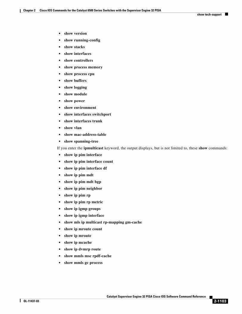
If you enter the ipmulticast keyword, the output displays, but is not limited to, these show commands:
• show ip pim interface
• show ip pim interface count
• show ip pim interface df
• show ip pim mdt
• show ip pim mdt bgp
• show ip pim neighbor
• show ip pim rp
• show ip pim rp metric
• show ip igmp groups
• show ip igmp interface
• show mls ip multicast rp-mapping gm-cache
• show ip mroute count
• show ip mroute
• show ip mcache
• show ip dvmrp route
• show mmls msc rpdf-cache
• show mmls gc process
2-1103Catalyst Supervisor Engine 32 PISA Cisco IOS Software Command Reference
OL-11437-03

Chapter 2 Cisco IOS Commands for the Catalyst 6500 Series Switches with the Supervisor Engine 32 PISAshow tech-support
If you enter the isis keyword, the output displays the equivalent of the show isis commands.
If you enter the rsvp keyword, the output displays the equivalent of the show ip rsvp commands.
Examples For a sample display of the show tech-support command output, see the commands that are listed in the “Usage Guidelines” section.
2-1104Catalyst Supervisor Engine 32 PISA Cisco IOS Software Command Reference
OL-11437-03

Chapter 2 Cisco IOS Commands for the Catalyst 6500 Series Switches with the Supervisor Engine 32 PISAshow top counters interface report
show top counters interface reportTo display TopN reports and information, use the show top counters interface report command.
show top counters interface report [number]
Syntax Description
Command Default This command has no default settings.
Command Modes EXEC (>)
Command History
Usage Guidelines This command is supported on Fast Ethernet, Gigabit Ethernet, and 10-Gigabit Ethernet ports only.
When you enter a TopN request, a round of polling is performed, the counters for all the applicable ports in the Catalyst 6500 series switch are read, and the information is saved. The TopN process then sleeps for the specified interval. After wakeup, another round of polling is performed and the counter information from the ports is read. The difference between the two sets of data is stored. The ports are then sorted, the ports choose from one of the seven types of statistics information, and a TopN report is generated.
The port statistics will not be displayed in the following cases:
• If a port is not present during the first poll.
• If a port is not present during the second poll.
• If a port’s speed or duplex changes during the polling interval.
• If a port’s type changes from Layer 2 to Layer 3 or Layer 3 to Layer 2 during the polling interval.
Note For the report display format, due to the 80 characters per line limitation, only 10 spaces are reserved for the Tx/Rx-okts, Tx/Rx-bcst, and Tx/Rx-mcst columns. When these columns are larger than 10 digits, the display wraps around to the next line.
When you start the TopN processes from a Telnet session and the Telnet session is terminated before the TopN processes are completed, all the backgound TopN processes continue and generate the TopN reports, but the foreground TopN processes are terminated once the Telnet session is terminated.
When the TopN report is being generated against a large number of ports (for example, 13 slot x 96 ports/slot) in a very short interval (10 seconds), the actual interval time between the first and second polling may be longer than the specified interval time because polling takes time.
number (Optional) Number of the report to be displayed; valid values are from 1 to 5.
Release Modification
12.2(18)ZY Support for this command was introduced.
2-1105Catalyst Supervisor Engine 32 PISA Cisco IOS Software Command Reference
OL-11437-03

Chapter 2 Cisco IOS Commands for the Catalyst 6500 Series Switches with the Supervisor Engine 32 PISAshow top counters interface report
Examples This example shows how to display TopN reports and information:
Router# show top counters interface reportId Start Time Int N Sort-By Status Owner-- ---------------------------- --- --- --------- ------- ----------------------1 08:18:25 UTC Tue Nov 23 2004 76 20 util done console2 08:19:54 UTC Tue Nov 23 2004 76 20 util done console3 08:21:34 UTC Tue Nov 23 2004 76 20 util done console4 08:26:50 UTC Tue Nov 23 2004 90 20 util done bambam onvty0 (9.10.69.13)Router#
This example shows how to display TopN reports and information for a specific report:
Router# show top counters interface report 1Started By : consoleStart Time : 08:18:25 UTC Tue Nov 23 2004End Time : 08:19:42 UTC Tue Nov 23 2004Port Type : AllSort By : utilInterval : 76 secondsPort Band Util Bytes Packets Broadcast Multicast In- Buf- width (Tx + Rx) (Tx + Rx) (Tx + Rx) (Tx + Rx) err ovflw------- ----- ---- ----------- ----------- ---------- ---------- ---- -----
Fa2/5 100 50 726047564 11344488 11344487 1 0 0 Fa2/48 100 35 508018905 7937789 0 43 0 0 Fa2/46 100 25 362860697 5669693 0 43 0 0 Fa2/47 100 22 323852889 4762539 4762495 43 0 0 Fa2/6 100 15 217815835 3403372 0 39 21 0 Fa2/44 100 10 145146009 2267900 0 43 0 0 Gi4/15 1000 0 0 0 0 0 0 0 Gi4/14 1000 0 0 0 0 0 0 0 Gi4/13 1000 0 0 0 0 0 0 0 Gi4/12 1000 0 0 0 0 0 0 0 Gi4/11 1000 0 0 0 0 0 0 0 Gi4/10 1000 0 0 0 0 0 0 0 Gi4/9 1000 0 0 0 0 0 0 0 Gi4/8 1000 0 776 2 0 2 0 0 Gi4/7 1000 0 0 0 0 0 0 0 Gi4/6 1000 0 0 0 0 0 0 0 Gi4/5 1000 0 0 0 0 0 0 0 Gi4/4 1000 0 0 0 0 0 0 0 Gi4/3 1000 0 776 2 0 2 0 0 Gi4/2 1000 0 0 0 0 0 0 0 Router#
This example shows the display if you request a TopN report that is still in pending status:
Router# show top counters interface report 4Id Start time Int N Sort-by Status Owner (type/machine/user)--- ------------------- --- --- ---------- -------- ------------------------- 4 1/24/2004,11:34:26 30 20 In-Errors pending Console//Router#
Related Commands Command Description
clear top counters interface report
Clears the TopN reports.
collect top counters interface
Lists the TopN processes and specific TopN reports.
2-1106Catalyst Supervisor Engine 32 PISA Cisco IOS Software Command Reference
OL-11437-03
Chapter 2 Cisco IOS Commands for the Catalyst 6500 Series Switches with the Supervisor Engine 32 PISAshow udld
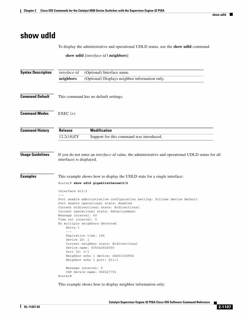
show udldTo display the administrative and operational UDLD status, use the show udld command.
show udld [interface-id | neighbors]
Syntax Description
Command Default This command has no default settings.
Command Modes EXEC (>)
Command History
Usage Guidelines If you do not enter an interface-id value, the administrative and operational UDLD status for all interfaces is displayed.
Examples This example shows how to display the UDLD state for a single interface:
Router# show udld gigabitethernet2/2
Interface Gi2/2---Port enable administrative configuration setting: Follows device defaultPort enable operational state: EnabledCurrent bidirectional state: BidirectionalCurrent operational state: AdvertisementMessage interval: 60Time out interval: 5No multiple neighbors detected Entry 1 --- Expiration time: 146 Device ID: 1 Current neighbor state: Bidirectional Device name: 0050e2826000 Port ID: 2/1 Neighbor echo 1 device: SAD03160954 Neighbor echo 1 port: Gi1/1
Message interval: 5 CDP Device name: 066527791 Router#
This example shows how to display neighbor information only:
interface-id (Optional) Interface name.
neighbors (Optional) Displays neighbor information only.
Release Modification
12.2(18)ZY Support for this command was introduced.
2-1107Catalyst Supervisor Engine 32 PISA Cisco IOS Software Command Reference
OL-11437-03

Chapter 2 Cisco IOS Commands for the Catalyst 6500 Series Switches with the Supervisor Engine 32 PISAshow udld
Router# show udld neighborsPort Device Name Device ID Port-ID OperState-------- ------------------------------ ------------ ------- --------------Gi3/1 SAL0734K5R2 1 Gi4/1 BidirectionalGi4/1 SAL0734K5R2 1 Gi3/1 BidirectionalRouter#
Related Commands Command Description
udld Enables aggressive or normal mode in UDLD and sets the configurable message time.
udld port Enables UDLD on the interface or enables UDLD in aggressive mode on the interface.
2-1108Catalyst Supervisor Engine 32 PISA Cisco IOS Software Command Reference
OL-11437-03

Chapter 2 Cisco IOS Commands for the Catalyst 6500 Series Switches with the Supervisor Engine 32 PISAshow version
show versionTo display the configuration of the system hardware, the software version, the names and sources of configuration files, and the boot images, use the show version command.
show version
Syntax Description This command has no arguments or keywords.
Command Default This command has no default settings.
Command Modes EXEC (>)
Command History
Examples This example shows how to display the configuration of the system hardware, the software version, the names and sources of configuration files, and the boot images:
Router# show versionCisco Internetwork Operating System SoftwareIOS (tm) c6sup2_rp Software (c6sup2_rp-JSV-M), Version 12.1(nightly.E020626) NIGHTLY BUILDCopyright (c) 1986-2002 by cisco Systems, Inc.Compiled Wed 26-Jun-02 06:20 byImage text-base: 0x40008BF0, data-base: 0x419BA000
ROM: System Bootstrap, Version 12.1(11r)E1, RELEASE SOFTWARE (fc1)
Router uptime is 2 weeks, 8 hours, 48 minutesTime since Router switched to active is 1 minuteSystem returned to ROM by power-on (SP by power-on)System image file is "sup-bootflash:c6sup22-jsv-mz"
cisco Catalyst 6000 (R7000) processor with 112640K/18432K bytes of memory.Processor board ID SAD06210067R7000 CPU at 300Mhz, Implementation 39, Rev 3.3, 256KB L2, 1024KB L3 CacheLast reset from power-onBridging software.X.25 software, Version 3.0.0.SuperLAT software (copyright 1990 by Meridian Technology Corp).TN3270 Emulation software.3 Virtual Ethernet/IEEE 802.3 interface(s)48 FastEthernet/IEEE 802.3 interface(s)381K bytes of non-volatile configuration memory.
16384K bytes of Flash internal SIMM (Sector size 512K).Configuration register is 0x2102Router#
Release Modification
12.2(18)ZY Support for this command was introduced.
2-1109Catalyst Supervisor Engine 32 PISA Cisco IOS Software Command Reference
OL-11437-03

Chapter 2 Cisco IOS Commands for the Catalyst 6500 Series Switches with the Supervisor Engine 32 PISAshow version
Table 2-88 describes the fields that are shown in the example.
The output of the show version EXEC command can provide certain messages, such as bus error messages. If such error messages appear, report the complete text of this message to your technical support specialist.
Table 2-88 show version Field Descriptions
Field Description
IOS (tm) c6sup2_rp Software (c6sup2_rp-JSV-M), Version 12.1(nightly.E020626) NIGHTLY BUILD
Version number. Always specify the complete version number when reporting a possible software problem. In the example output, the version number is 12.1.
ROM: System Bootstrap, Version 12.1(11r)E1, RELEASE SOFTWARE (fc1)
Bootstrap version string.
BOOTFLASH: 7200 Software (C7200-BOOT-M), Version 11.1(472), RELEASE SOFTWARE
Boot version string.
Router uptime is Amount of time that the system has been up and running.
Time since Router switched to active
Amount of time since switchover occurred.
System restarted by Log of how the system was last booted, both as a result of normal system startup and of system error. For example, information can be displayed to indicate a bus error that is typically the result of an attempt to access a nonexistent address, as follows:
System restarted by bus error at PC 0xC4CA, address 0x210C0C0
System image file is If the software was booted over the network, the Internet address of the boot host is shown. If the software was loaded from onboard ROM, this line reads “running default software.”
cisco Catalyst 6000 (R7000) processor with 112640K/18432K bytes of memory.
Remaining output in each display that shows the hardware configuration and any nonstandard software options.
Configuration register is Configuration register contents that are displayed in hexadecimal notation.
2-1110Catalyst Supervisor Engine 32 PISA Cisco IOS Software Command Reference
OL-11437-03

Chapter 2 Cisco IOS Commands for the Catalyst 6500 Series Switches with the Supervisor Engine 32 PISAshow vlan
show vlanTo display VLAN information, use the show vlan command.
show vlan [{brief | {id vlan-id} | {name name} [ifindex]} | ifindex]
Syntax Description
Command Default This command has no default settings.
Command Modes EXEC (>)
Command History
Usage Guidelines Each Ethernet switch port and Ethernet repeater group belong to only one VLAN. Trunk ports can be on multiple VLANs.
If you shut down a VLAN using the state suspend or the state active command, these values appear in the Status field:
• suspended—VLAN is suspended.
• active—VLAN is active.
If you shut down a VLAN using the shutdown command, these values appear in the Status field:
• act/lshut—VLAN status is active but shut down locally.
• sus/lshut—VLAN status is suspended but shut down locally.
If a VLAN is shut down internally, these values appear in the Status field:
• act/ishut—VLAN status is active but shut down internally.
• sus/ishut—VLAN status is suspended but shut down internally.
If a VLAN is shut down locally and internally, the value that is displayed in the Status field is act/ishut or sus/ishut. If a VLAN is shut down locally only, the value that is displayed in the Status field is act/lshut or sus/lshut.
Separate VLAN ranges with a hyphen, and separate VLANs with a comma and no spaces in between. For example, you can enter the following:
Router# show vlan id 1-4,3,7,5-20
brief (Optional) Displays only a single line for each VLAN, naming the VLAN, status, and ports.
id vlan-id (Optional) Displays information about a single VLAN that is identified by a VLAN ID number; valid values are from 1 to 4094.
name name (Optional) Displays information about a single VLAN that is identified by VLAN name; valid values are an ASCII string from 1 to 32 characters.
ifindex (Optional) Displays the VLAN’s ifIndex number.
Release Modification
12.2(18)ZY Support for this command was introduced.
2-1111Catalyst Supervisor Engine 32 PISA Cisco IOS Software Command Reference
OL-11437-03

Chapter 2 Cisco IOS Commands for the Catalyst 6500 Series Switches with the Supervisor Engine 32 PISAshow vlan
Examples This example shows the ouput for a VLAN (VLAN0002) that is active but shut down internally:
Router# show vlanVLAN Name Status Ports---- -------------------------------- --------- -------------------------------1 default active Fa5/92 VLAN0002 act/ishut Fa5/9<...Output truncated...>
This example shows the ouput for a VLAN (VLAN0002) that is active but shut down locally:
Router# show vlanVLAN Name Status Ports---- -------------------------------- --------- -------------------------------1 default active Fa5/92 VLAN0002 act/lshut Fa5/9<...Output truncated...>
This example shows how to display the VLAN parameters for all VLANs within the administrative domain:
Router# show vlanVLAN Name Status Ports---- -------------------------------- --------- -------------------------------1 default active Fa5/92 VLAN0002 active Fa5/93 VLAN0003 active Fa5/94 VLAN0004 active Fa5/95 VLAN0005 active Fa5/96 VLAN0006 active Fa5/9<...Output truncated...>
1004 fddinet-default active Fa5/91005 trbrf-default active Fa5/9
VLAN Type SAID MTU Parent RingNo BridgeNo Stp BrdgMode Trans1 Trans2---- ----- ---------- ----- ------ ------ -------- ---- -------- ------ ------1 enet 100001 1500 - - - - - 0 02 enet 100002 1500 - - - - - 0 03 enet 100003 1500 - - - - - 303 04 enet 100004 1500 - - - - - 304 05 enet 100005 1500 - - - - - 305 06 enet 100006 1500 - - - - - 0 010 enet 100010 1500 - - - - - 0 0
<...Output truncated...>
Remote SPAN VLANs-----------------2, 20
Primary Secondary Type Ports------- --------- ----------------- ------------------------------------------Router#
This example shows how to display the VLAN name, status, and associated ports only:
Router# show vlan briefVLAN Name Status Ports---- -------------------------------- --------- -------------------------------1 default active Fa5/92 VLAN0002 active Fa5/93 VLAN0003 act/lshut Fa5/94 VLAN0004 act/lshut Fa5/9
2-1112Catalyst Supervisor Engine 32 PISA Cisco IOS Software Command Reference
OL-11437-03
Chapter 2 Cisco IOS Commands for the Catalyst 6500 Series Switches with the Supervisor Engine 32 PISAshow vlan
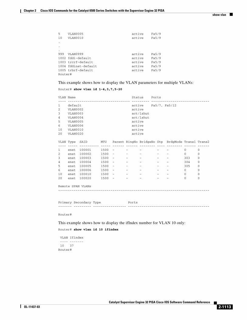
5 VLAN0005 active Fa5/910 VLAN0010 active Fa5/9...999 VLAN0999 active Fa5/91002 fddi-default active Fa5/91003 trcrf-default active Fa5/91004 fddinet-default active Fa5/91005 trbrf-default active Fa5/9Router#
This example shows how to display the VLAN parameters for multiple VLANs:
Router# show vlan id 1-4,3,7,5-20
VLAN Name Status Ports---- -------------------------------- --------- ------------------------------1 default active Fa5/7, Fa5/122 VLAN0002 active3 VLAN0003 act/lshut4 VLAN0004 act/lshut5 VLAN0005 active6 VLAN0006 active10 VLAN0010 active20 VLAN0020 active
VLAN Type SAID MTU Parent RingNo BridgeNo Stp BrdgMode Trans1 Trans2---- ----- ---------- ----- ------ ------ -------- ---- -------- ------ ------1 enet 100001 1500 - - - - - 0 02 enet 100002 1500 - - - - - 0 03 enet 100003 1500 - - - - - 303 04 enet 100004 1500 - - - - - 304 05 enet 100005 1500 - - - - - 305 06 enet 100006 1500 - - - - - 0 010 enet 100010 1500 - - - - - 0 020 enet 100020 1500 - - - - - 0 0
Remote SPAN VLANs------------------------------------------------------------------------------
Primary Secondary Type Ports------- --------- ----------------- ------------------------------------------
Router#
This example shows how to display the ifIndex number for VLAN 10 only:
Router# show vlan id 10 ifindex VLAN Ifindex ---- ------- 10 37 Router#
2-1113Catalyst Supervisor Engine 32 PISA Cisco IOS Software Command Reference
OL-11437-03

Chapter 2 Cisco IOS Commands for the Catalyst 6500 Series Switches with the Supervisor Engine 32 PISAshow vlan
Table 2-89 describes the fields that are shown in the example.
Related Commands
Table 2-89 show vlan Command Output Fields
Field Description
VLAN VLAN number.
Name Name, if configured, of the VLAN.
Status Status of the VLAN (active or suspend, act/lshut or sus/lshut, or act/ishut or sus/ishut).
Ports Ports that belong to the VLAN.
Type Media type of the VLAN.
SAID Security association ID value for the VLAN.
MTU Maximum transmission unit size for the VLAN.
Parent Parent VLAN, if one exists.
RingNo Ring number for the VLAN, if applicable.
BrdgNo Bridge number for the VLAN, if applicable.
Stp Spanning Tree Protocol type that is used on the VLAN.
BrdgMode Bridging mode for this VLAN—possible values are SRB and SRT; the default is SRB.
AREHops Maximum number of hops for All-Routes Explorer frames—possible values are 1 through 13; the default is 7.
STEHops Maximum number of hops for Spanning Tree Explorer frames—possible values are 1 through 13; the default is 7.
Backup CRF Status of whether the TrCRF is a backup path for traffic.
Ifindex Number of the ifIndex.
Remote SPAN VLAN RSPAN status.
Primary Number of the primary VLAN.
Secondary Number of the secondary VLAN.
Ports Indicates the ports within a VLAN.
Type Type of VLAN—Possible values are primary, isolated, community, nonoperation, or normal.
Command Description
show vlan private-vlan Displays PVLAN information.
vlan (config-VLAN submode)
Configures a specific VLAN.
vtp Configures the global VTP state.
2-1114Catalyst Supervisor Engine 32 PISA Cisco IOS Software Command Reference
OL-11437-03

Chapter 2 Cisco IOS Commands for the Catalyst 6500 Series Switches with the Supervisor Engine 32 PISAshow vlan access-log
show vlan access-logTo display information about the VACL logging including the configured logging properties, flow table contents, and statistics, use the show vlan access-log command.
show vlan access-log config
show vlan access-log flow protocol {{src-addr src-mask} | any | {host {hostname | host-ip}}} {{dst-addr dst-mask} | any | {host {hostname | host-ip}}} [vlan vlan-id]
show vlan access-log statistics
Syntax Description
Command Default This command has no default settings.
Command Modes Privileged EXEC (#)
Command History
Examples This command shows how to display the configured VACL-logging properties:
Router# show vlan access-log configVACL Logging Configuration: max log table size :500 log threshold :4000 rate limiter :3000Router#
config Displays the configured VACL-logging properties.
flow Displays the contents of the VACL-flow table.
protocol Protocol name or number; valid values are icmp, igmp, ip, tcp, udp, or numbers from 0 to 255 to designate a protocol.
src-addr src-mask Source address and mask.
any Displays information for any host.
host hostname Displays information for a hostname.
host host-ip Displays information for an IP address.
dst-addr dst-mask Destination address and mask.
vlan vlan-id (Optional) Displays information for a specific VLAN; valid values are from 1 to 4094.
statistics Displays packet and message counts and other statistics.
Release Modification
12.2(18)ZY Support for this command was introduced.
2-1115Catalyst Supervisor Engine 32 PISA Cisco IOS Software Command Reference
OL-11437-03

Chapter 2 Cisco IOS Commands for the Catalyst 6500 Series Switches with the Supervisor Engine 32 PISAshow vlan access-log
This example shows how to display the VACL statistics:
Router# show vlan access-log statisticsVACL Logging Statistics: total packets :0 logged :0 dropped :0Dropped Packets Statistics: unsupported protocol :0 no packet buffer :0 hash queue full :0 flow table full :0Misc Information: VACL Logging LTL Index :0x7E02 free packet buffers :8192 log messages sent :0 log table size :0Router#
Related Commands Command Description
vlan access-log Configures the VACL-logging properties, including the log-table size, redirect-packet rate, and logging threshold.
2-1116Catalyst Supervisor Engine 32 PISA Cisco IOS Software Command Reference
OL-11437-03

Chapter 2 Cisco IOS Commands for the Catalyst 6500 Series Switches with the Supervisor Engine 32 PISAshow vlan access-map
show vlan access-mapTo display the contents of a VLAN-access map, use the show vlan access-map command.
show vlan access-map [map-name]
Syntax Description
Command Default This command has no default settings.
Command Modes Privileged EXEC (#)
Command History
Examples This command shows how to display the contents of a VLAN-access map:
Router# show vlan access-map mordred Vlan access-map "mordred" 1 match: ip address 13 action: forward captureRouter#show vlan counters
Related Commands
map-name (Optional) VLAN access-map name.
Release Modification
12.2(18)ZY Support for this command was introduced.
Command Description
action Sets the packet action clause.
match Specifies the match clause by selecting one or more ACLs for a VLAN access-map sequence.
vlan access-map Creates a VLAN access map or enters VLAN access-map command mode.
2-1117Catalyst Supervisor Engine 32 PISA Cisco IOS Software Command Reference
OL-11437-03

Chapter 2 Cisco IOS Commands for the Catalyst 6500 Series Switches with the Supervisor Engine 32 PISAshow vlan counters
show vlan countersTo display the software-cached counter values, use the show vlan counters command.
show vlan [id vlanid] counters
Syntax Description
Command Default This command has no default settings.
Command Modes Privileged EXEC (#)
Command History
Usage Guidelines The show vlan id counters command is not supported on SVIs.
For Layer 2 and Layer 3 VLAN interfaces and router ports, per-interface switching statistics and VLAN-counter information to the PISA are exported approximately every 3 minutes.
If you enter the show vlan counters command with no arguments, the software-cached counter values for all VLANs are displayed.
Examples This example shows how to display the software-cached counter values for a specific VLAN:
Router> show vlan id 205 countersVLAN vlanid 205 L2-Unicast-Pkts 10L3-In-Unicast-Pkts 0L3-Out-Unicast-Pkts 0L2-NonUnicast-Pkts + L3-In-NonUnicast-Pkts 5L3-Out-NonUnicast-Pkts 6L2-Unicast-Octets 6L3-In-Unicast-Octets 6L3-Out-Unicast-Octets 6L2-NonUnicast-Octets + L3-In-NonUnicast-Octets 6L3-Out-NonUnicast-Octets 6
Related Commands
id vlanid (Optional) Displays the software-cached counter values for a specific VLAN; valid values are from 1 to 4094.
Release Modification
12.2(18)ZY Support for this command was introduced.
Command Description
clear vlan counters Clears the software-cached counter values to zero for a specified VLAN or all existing VLANs.
2-1118Catalyst Supervisor Engine 32 PISA Cisco IOS Software Command Reference
OL-11437-03

Chapter 2 Cisco IOS Commands for the Catalyst 6500 Series Switches with the Supervisor Engine 32 PISAshow vlan dot1q tag native
show vlan dot1q tag nativeTo display native VLAN-tagging information, use the show vlan dot1q tag native command.
show vlan dot1q tag native
Syntax Description This command has no arguments or keywords.
Command Default This command has no default settings.
Command Modes Privileged EXEC (#)
Command History
Examples This example shows how to display native VLAN-tagging information:
Router# show vlan dot1q tag nativedot1q native vlan tagging is enabledInternal dot1q native vlan: 1015
Router#
Related Commands
Release Modification
12.2(18)ZY Support for this command was introduced.
Command Description
vlan dot1q tag native Enables 802.1Q tagging for all VLANs in a trunk.
2-1119Catalyst Supervisor Engine 32 PISA Cisco IOS Software Command Reference
OL-11437-03

Chapter 2 Cisco IOS Commands for the Catalyst 6500 Series Switches with the Supervisor Engine 32 PISAshow vlan filter
show vlan filterTo display information about the VLAN filter, use the show vlan filter command.
show vlan filter [{access-map map-name} | {vlan vlan-id} | {interface interface interface-number}]
Syntax Description
Command Default This command has no default settings.
Command Modes Privileged EXEC (#)
Command History
Usage Guidelines The show vlan filter map-name interface command accepts only ATM, POS, or serial interface types. If your system is not configured with any of these interface types, the interface interface interface-number keyword and arguments are not provided.
The interface-number argument designates the module and port number. Valid values for interface-number depend on the specified interface type and the chassis and module that are used. For example, if you specify a Gigabit Ethernet interface and have a 48-port 10/100BASE-T Ethernet module that is installed in a 13-slot chassis, valid values for the module number are from 2 to 13 and valid values for the port number are from 1 to 48.
If you do not specify an optional keyword and argument, all mappings are displayed. If you enter access-map map_name, all the VLANs and interfaces that are associated with the specified map are shown. If you enter vlan vlan-id or interface interface interface-number, its associated access map, if existing, is shown.
In the output for VACLs on VLANs, the following applies:
• Configured on VLANs—User configured
• Active on VLANs—VLAN list on which the VACL is active
access-map map-name
(Optional) Displays the VLANs that are filtered by the specified map.
vlan vlan-id (Optional) Displays the filter for the specified VLAN; valid values are from 1 to 4094.
interface interface
Specifies the interface type; valid values are pos, atm, or serial. See the “Usage Guidelines” section for additional information.
interface-number Interface number; see the “Usage Guidelines” section for additional information.
Release Modification
12.2(18)ZY Support for this command was introduced.
2-1120Catalyst Supervisor Engine 32 PISA Cisco IOS Software Command Reference
OL-11437-03
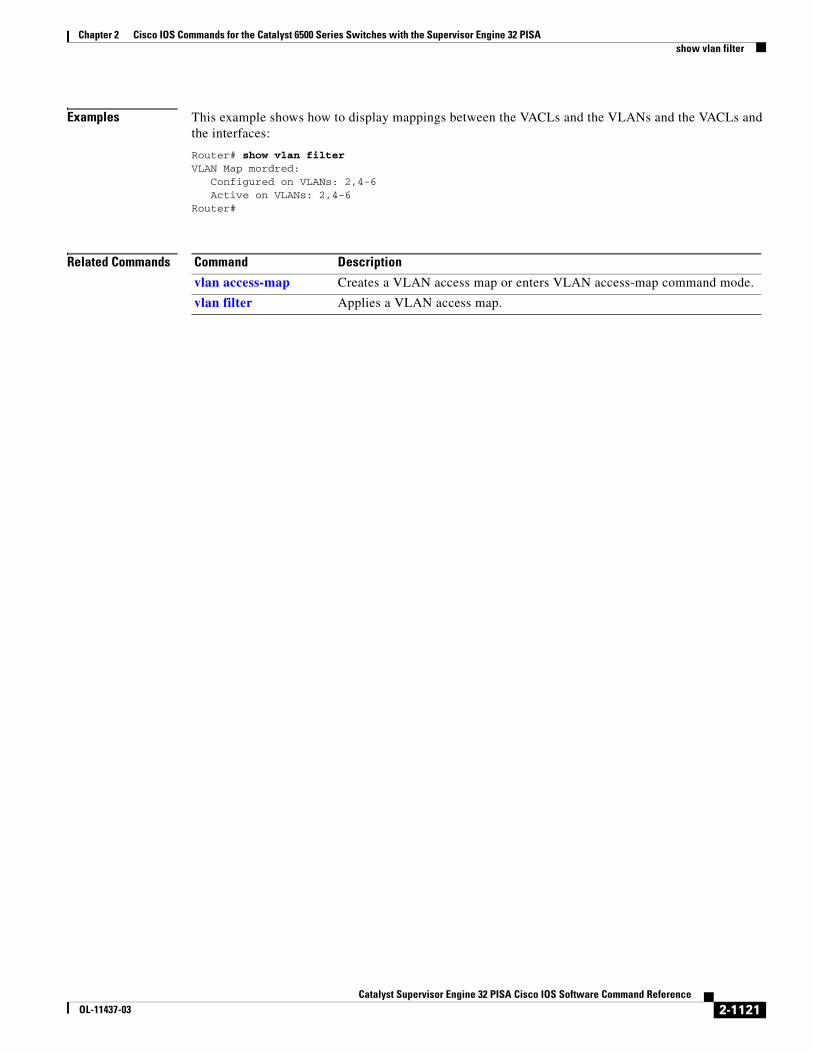
Chapter 2 Cisco IOS Commands for the Catalyst 6500 Series Switches with the Supervisor Engine 32 PISAshow vlan filter
Examples This example shows how to display mappings between the VACLs and the VLANs and the VACLs and the interfaces:
Router# show vlan filter VLAN Map mordred: Configured on VLANs: 2,4-6 Active on VLANs: 2,4-6 Router#
Related Commands
Command Description
vlan access-map Creates a VLAN access map or enters VLAN access-map command mode.
vlan filter Applies a VLAN access map.
2-1121Catalyst Supervisor Engine 32 PISA Cisco IOS Software Command Reference
OL-11437-03
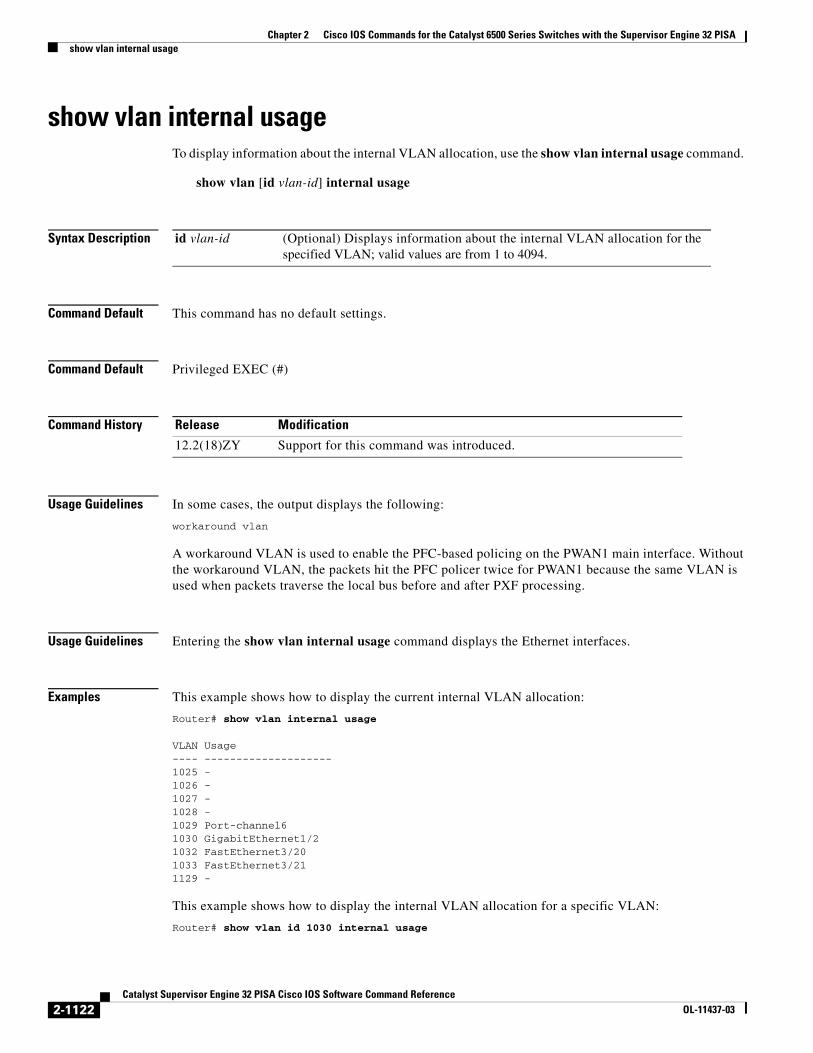
Chapter 2 Cisco IOS Commands for the Catalyst 6500 Series Switches with the Supervisor Engine 32 PISAshow vlan internal usage
show vlan internal usageTo display information about the internal VLAN allocation, use the show vlan internal usage command.
show vlan [id vlan-id] internal usage
Syntax Description
Command Default This command has no default settings.
Command Default Privileged EXEC (#)
Command History
Usage Guidelines In some cases, the output displays the following:
workaround vlan
A workaround VLAN is used to enable the PFC-based policing on the PWAN1 main interface. Without the workaround VLAN, the packets hit the PFC policer twice for PWAN1 because the same VLAN is used when packets traverse the local bus before and after PXF processing.
Usage Guidelines Entering the show vlan internal usage command displays the Ethernet interfaces.
Examples This example shows how to display the current internal VLAN allocation:
Router# show vlan internal usage
VLAN Usage---- --------------------1025 -1026 -1027 -1028 -1029 Port-channel61030 GigabitEthernet1/21032 FastEthernet3/201033 FastEthernet3/211129 -
This example shows how to display the internal VLAN allocation for a specific VLAN:
Router# show vlan id 1030 internal usage
id vlan-id (Optional) Displays information about the internal VLAN allocation for the specified VLAN; valid values are from 1 to 4094.
Release Modification
12.2(18)ZY Support for this command was introduced.
2-1122Catalyst Supervisor Engine 32 PISA Cisco IOS Software Command Reference
OL-11437-03

Chapter 2 Cisco IOS Commands for the Catalyst 6500 Series Switches with the Supervisor Engine 32 PISAshow vlan internal usage
VLAN Usage---- --------------------1030 GigabitEthernet1/2
2-1123Catalyst Supervisor Engine 32 PISA Cisco IOS Software Command Reference
OL-11437-03
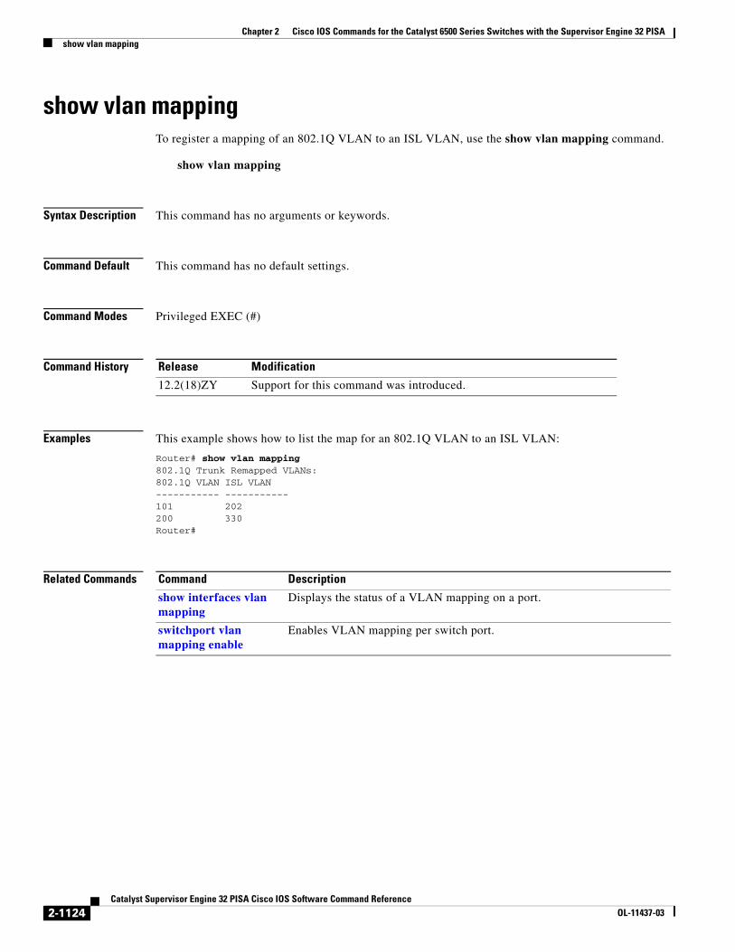
Chapter 2 Cisco IOS Commands for the Catalyst 6500 Series Switches with the Supervisor Engine 32 PISAshow vlan mapping
show vlan mappingTo register a mapping of an 802.1Q VLAN to an ISL VLAN, use the show vlan mapping command.
show vlan mapping
Syntax Description This command has no arguments or keywords.
Command Default This command has no default settings.
Command Modes Privileged EXEC (#)
Command History
Examples This example shows how to list the map for an 802.1Q VLAN to an ISL VLAN:
Router# show vlan mapping802.1Q Trunk Remapped VLANs: 802.1Q VLAN ISL VLAN ----------- ----------- 101 202200 330Router#
Related Commands
Release Modification
12.2(18)ZY Support for this command was introduced.
Command Description
show interfaces vlan mapping
Displays the status of a VLAN mapping on a port.
switchport vlan mapping enable
Enables VLAN mapping per switch port.
2-1124Catalyst Supervisor Engine 32 PISA Cisco IOS Software Command Reference
OL-11437-03
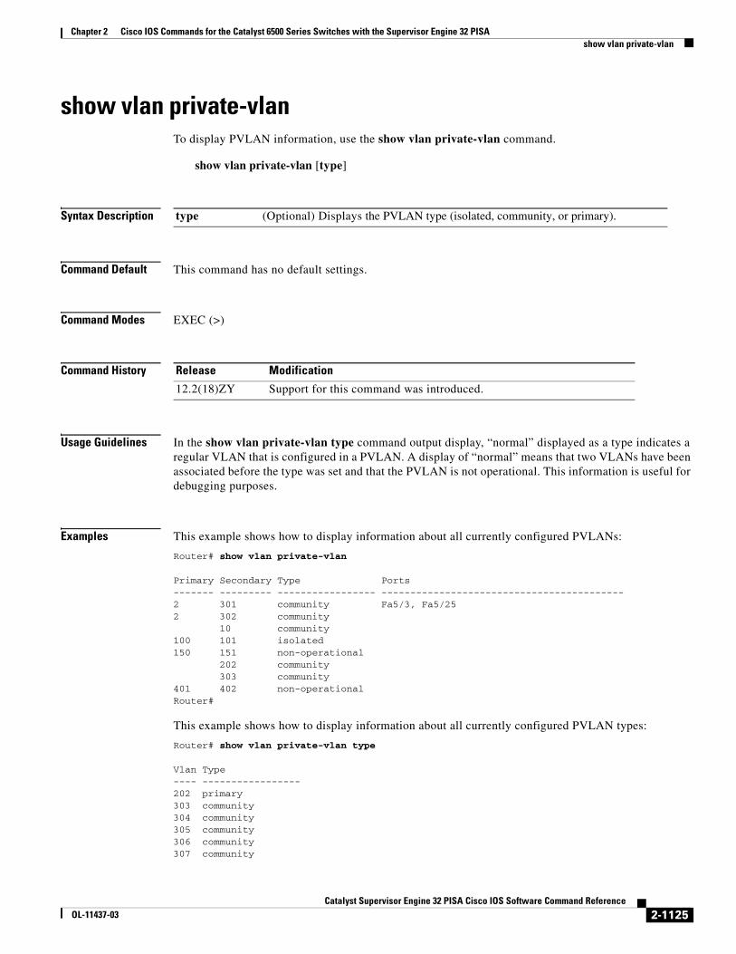
Chapter 2 Cisco IOS Commands for the Catalyst 6500 Series Switches with the Supervisor Engine 32 PISAshow vlan private-vlan
show vlan private-vlanTo display PVLAN information, use the show vlan private-vlan command.
show vlan private-vlan [type]
Syntax Description
Command Default This command has no default settings.
Command Modes EXEC (>)
Command History
Usage Guidelines In the show vlan private-vlan type command output display, “normal” displayed as a type indicates a regular VLAN that is configured in a PVLAN. A display of “normal” means that two VLANs have been associated before the type was set and that the PVLAN is not operational. This information is useful for debugging purposes.
Examples This example shows how to display information about all currently configured PVLANs:
Router# show vlan private-vlan
Primary Secondary Type Ports------- --------- ----------------- ------------------------------------------2 301 community Fa5/3, Fa5/252 302 community 10 community100 101 isolated150 151 non-operational 202 community 303 community401 402 non-operationalRouter#
This example shows how to display information about all currently configured PVLAN types:
Router# show vlan private-vlan type
Vlan Type---- -----------------202 primary303 community304 community305 community306 community307 community
type (Optional) Displays the PVLAN type (isolated, community, or primary).
Release Modification
12.2(18)ZY Support for this command was introduced.
2-1125Catalyst Supervisor Engine 32 PISA Cisco IOS Software Command Reference
OL-11437-03

Chapter 2 Cisco IOS Commands for the Catalyst 6500 Series Switches with the Supervisor Engine 32 PISAshow vlan private-vlan
308 normal309 community440 isolatedRouter#
Table 2-90 describes the fields that are shown in the example.
Related Commands
Table 2-90 show vlan private-vlan Command Output Fields
Field Description
Primary Number of the primary VLAN.
Secondary Number of the secondary VLAN.
Secondary-Type Secondary VLAN type—Possible values are isolated or community.
Ports Indicates the ports within a VLAN.
Type Type of VLAN—Possible values are primary, isolated, community, nonoperation, or normal.
Command Description
private-vlan mapping Creates a mapping between the primary and the secondary VLANs so that both VLANs share the same primary VLAN SVI.
private-vlan Configures PVLANs and the association between a PVLAN and a secondary VLAN.
2-1126Catalyst Supervisor Engine 32 PISA Cisco IOS Software Command Reference
OL-11437-03

Chapter 2 Cisco IOS Commands for the Catalyst 6500 Series Switches with the Supervisor Engine 32 PISAshow vlan remote-span
show vlan remote-spanTo display a list of RSPAN VLANs, use the show vlan remote-span command.
show vlan remote-span
Syntax Description This command has no arguments or keywords.
Command Default This command has no default settings.
Command Modes EXEC (>)
Command History
Examples This example shows how to display a list of remote SPAN VLANs:
Router# show vlan remote-spanRemote SPAN VLANs------------------------------------------------------------------------------2,20
Related Commands
Release Modification
12.2(18)ZY Support for this command was introduced.
Command Description
remote-span Configures a VLAN as an RSPAN VLAN.
vlan (config-VLAN submode)
Configures a specific VLAN.
2-1127Catalyst Supervisor Engine 32 PISA Cisco IOS Software Command Reference
OL-11437-03

Chapter 2 Cisco IOS Commands for the Catalyst 6500 Series Switches with the Supervisor Engine 32 PISAshow vlans
show vlansTo display information about the Cisco IOS VLAN subinterfaces, use the show vlans command.
show vlans [vlan]
Syntax Description
Command Default This command has no default settings.
Command Modes Privileged EXEC (#)
Command History
Usage Guidelines The EXEC show vlan command displays information about the Layer 2 VLAN. The privileged EXEC show vlans command displays information about the VLAN subinterface in Layer 3.
When entering the show vlans command, you cannot shorten the vlans keyword.
Examples This example shows how to display information about the Cisco IOS VLAN subinterfaces:
Router# show vlansVirtual LAN ID: 122 (Inter Switch Link Encapsulation)VLAN Trunk Interface: GE-WAN9/1.1 Protocols Configured: Address: Received: Transmitted: IP 10.122.0.2 18 16Virtual LAN ID: 123 (Inter Switch Link Encapsulation)VLAN Trunk Interface: GE-WAN9/1.2 Protocols Configured: Address: Received: Transmitted: IP 10.123.0.2 13 16Virtual LAN ID: 124 (Inter Switch Link Encapsulation)VLAN Trunk Interface: GE-WAN9/1.3 Protocols Configured: Address: Received: Transmitted: IP 10.124.0.2 0 17Virtual LAN ID: 133 (Inter Switch Link Encapsulation)VLAN Trunk Interface: GE-WAN9/3.1 Protocols Configured: Address: Received: Transmitted: IP 11.133.0.1 0 1Virtual LAN ID: 134 (Inter Switch Link Encapsulation)VLAN Trunk Interface: GE-WAN9/3.2 Protocols Configured: Address: Received: Transmitted: IP 11.134.0.1 0 1Router#
vlan (Optional) VLAN ID number; valid values are from 1 to 4094.
Release Modification
12.2(18)ZY Support for this command was introduced.
2-1128Catalyst Supervisor Engine 32 PISA Cisco IOS Software Command Reference
OL-11437-03

Chapter 2 Cisco IOS Commands for the Catalyst 6500 Series Switches with the Supervisor Engine 32 PISAshow vlans
Table 2-91 describes the fields that are shown in the example.
Table 2-91 show vlans Command Output Fields
Field Description
Virtual LAN ID Domain number of the VLAN.
VLAN Trunk Interface Subinterface carrying the VLAN traffic.
Protocols Configured Protocols that are configured on the VLAN.
Address Network address.
Received Number of packets that are received.
Transmitted Number of packets that are transmitted.
2-1129Catalyst Supervisor Engine 32 PISA Cisco IOS Software Command Reference
OL-11437-03

Chapter 2 Cisco IOS Commands for the Catalyst 6500 Series Switches with the Supervisor Engine 32 PISAshow vlan virtual-port
show vlan virtual-portTo display the number of logical virtual ports required, use the show vlan virtual-port command.
show vlan virtual-port [slot num]
Syntax Description
Command Default This command has no default settings.
Command Modes EXEC (>)
Command History
Examples This example shows how to display the number of logical virtual ports that are required for a specific slot:
Router# show vlan virtual-port slot 3Slot 3 Port Virtual-ports ------------------------- Fa3/1 1 Fa3/2 1 Fa3/3 1 Fa3/4 1 Fa3/5 1 Fa3/6 1 Fa3/7 1 Fa3/8 1 Fa3/11 1 Fa3/12 1 Fa3/13 1 ...Fa3/33 4 Fa3/34 4 Fa3/35 4 Fa3/36 4Fa3/37 4 Fa3/38 4Fa3/39 4Fa3/40 4Total virtual ports:82 Router#
slot num (Optional) Specifies the slot number of which status is to be displayed.
Release Modification
12.2(18)ZY Support for this command was introduced.
2-1130Catalyst Supervisor Engine 32 PISA Cisco IOS Software Command Reference
OL-11437-03

Chapter 2 Cisco IOS Commands for the Catalyst 6500 Series Switches with the Supervisor Engine 32 PISAshow vlan virtual-port
This example shows how to display the number of logical virtual ports that are required for all slots:
Router# show vlan virtual-portSlot 1 ------- Total slot virtual ports 1Slot 3 ------- Total slot virtual ports 82Slot 4 ------- Total slot virtual ports 4Total chassis virtual ports 87Router#
2-1131Catalyst Supervisor Engine 32 PISA Cisco IOS Software Command Reference
OL-11437-03

Chapter 2 Cisco IOS Commands for the Catalyst 6500 Series Switches with the Supervisor Engine 32 PISAshow vtp
show vtpTo display the VTP statistics and domain information, use the show vtp command.
show vtp {counters | status}
Syntax Description
Command Default This command has no default settings.
Command Modes EXEC (>)
Command History
Usage Guidelines In the output of the show vtp status command, the last modified time is of the modifier itself, for example, the time displayed in the line “Configuration last modified by 7.0.22.11 at 5-5-06 05:51:49”, is the time that the modifier (7.0.22.11) last modified the VLAN configuration.
Examples This example shows how to display the VTP statistics:
Router# show vtp countersVTP statistics:Summary advertisements received : 1Subset advertisements received : 1Request advertisements received : 0Summary advertisements transmitted : 31Subset advertisements transmitted : 1Request advertisements transmitted : 0Number of config revision errors : 0Number of config digest errors : 0Number of V1 summary errors : 0
VTP pruning statistics:
Trunk Join Transmitted Join Received Summary advts received from non-pruning-capable device---------------- ---------------- ---------------- ---------------------------Fa5/9 1555 1564 0 Router#
This example shows how to display the status of the VTP domain:
Router# show vtp statusVTP Version : 2Configuration Revision : 250Maximum VLANs supported locally : 1005
counters Displays information about the VTP statistics.
status Displays information about the VTP domain status.
Release Modification
12.2(18)ZY Support for this command was introduced.
2-1132Catalyst Supervisor Engine 32 PISA Cisco IOS Software Command Reference
OL-11437-03
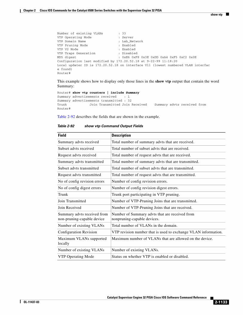
Chapter 2 Cisco IOS Commands for the Catalyst 6500 Series Switches with the Supervisor Engine 32 PISAshow vtp
Number of existing VLANs : 33VTP Operating Mode : ServerVTP Domain Name : Lab_NetworkVTP Pruning Mode : EnabledVTP V2 Mode : EnabledVTP Traps Generation : DisabledMD5 digest : 0xE6 0xF8 0x3E 0xDD 0xA4 0xF5 0xC2 0x0EConfiguration last modified by 172.20.52.18 at 9-22-99 11:18:20Local updater ID is 172.20.52.18 on interface Vl1 (lowest numbered VLAN interface found) Router#
This example shows how to display only those lines in the show vtp output that contain the word Summary:
Router# show vtp counters | include SummarySummary advertisements received : 1Summary advertisements transmitted : 32Trunk Join Transmitted Join Received Summary advts received fromRouter#
Table 2-92 describes the fields that are shown in the example.
Table 2-92 show vtp Command Output Fields
Field Description
Summary advts received Total number of summary advts that are received.
Subset advts received Total number of subset advts that are received.
Request advts received Total number of request advts that are received.
Summary advts transmitted Total number of summary advts that are transmitted.
Subset advts transmitted Total number of subset advts that are transmitted.
Request advts transmitted Total number of request advts that are transmitted.
No of config revision errors Number of config revision errors.
No of config digest errors Number of config revision digest errors.
Trunk Trunk port participating in VTP pruning.
Join Transmitted Number of VTP-Pruning Joins that are transmitted.
Join Received Number of VTP-Pruning Joins that are received.
Summary advts received from non-pruning-capable device
Number of Summary advts that are received from nonpruning-capable devices.
Number of existing VLANs Total number of VLANs in the domain.
Configuration Revision VTP revision number that is used to exchange VLAN information.
Maximum VLANs supported locally
Maximum number of VLANs that are allowed on the device.
Number of existing VLANs Number of existing VLANs.
VTP Operating Mode Status on whether VTP is enabled or disabled.
2-1133Catalyst Supervisor Engine 32 PISA Cisco IOS Software Command Reference
OL-11437-03

Chapter 2 Cisco IOS Commands for the Catalyst 6500 Series Switches with the Supervisor Engine 32 PISAshow vtp
Related Commands
VTP Domain Name Name of the VTP domain.
VTP Pruning Mode Status on whether VTP pruning is enabled or disabled.
VTP V2 Mode Status of the VTP V2 mode as server, client, or transparent.
VTP Traps Generation Status on whether VTP-trap generation mode is enabled or disabled.
MD5 digest Checksum values.
Table 2-92 show vtp Command Output Fields (continued)
Field Description
Command Description
vtp Configures the global VTP state.
2-1134Catalyst Supervisor Engine 32 PISA Cisco IOS Software Command Reference
OL-11437-03
Related Documents