~ Pergamon Acta metall, mater. Vol. 42, No. 3, pp. 701-714, 1994 Copyright© 1994ElsevierScience Ltd Printed in Great Britain.All rights reserved 0956-7151/94 $6.00+ 0.00 SHOCK SYNTHESIS OF SILICIDES--I. EXPERIMENTATION AND MICROSTRUCTURAL EVOLUTION K. S. VECCHIO, LI-HSING YU and M. A. MEYERS Department of Applied Mechanics and Engineering Sciences, University of California, San Diego, La Jolla, CA 92093-0411, U.S.A. (Received 16 September 1992; in revised form 23 July 1993) Abstract--Niobium and molybdenum silicides were synthesized by the passage of high-amplitude shock waves through elemental powder mixtures. These shock waves were generated by planar parallel impact of explosively-accelerated flyer plates on momentum-trapped capsules containing the powders. Recovery of the specimens revealed unreacted, partially-reacted, and fully-reacted regions, in accord with shock energy levels experienced by the powder. Electron microscopy was employed to characterize the partially- and fully-reacted regions for the Mo-Si and Nb-Si systems, and revealed only equilibrium phases. Selected-area and convergent beam electron diffraction combined with X-ray microanalysis verified the crystal structure and compositions of the reacted products. Diffusion couples between Nb and Si were fabricated for the purpose of measuring static diffusion rates and determining the phases produced under non-shock condition. Comparison of these non-shock diffusion results with the shock synthesis results indicates that a new mechanism is responsible for the production of the NbSi2 and MoSi2 phases under shock compression. At the local level the reaction can be rationalized, for example, in the Nb-Si system under shock compression, through the production of a liquid-phase reaction product (NbSi2) at the Nb-particle/Si-liquid interface, the formation of spherical nodules (~2/zm diameter) of this product through interfacial tension, and their subsequent solidification. 1. INTRODUCTION Shock-induced reactions (or shock synthesis) have been studied since the 1960s but are still poorly understood, partly due to the fact that the reaction kinetics are very fast making experimental analysis of the reaction difficult. Shock-induced reactions are quite distinct from shock-induced phase transform- ations, such as the synthesis of diamond from graph- ite which is a diffusionless phase transformation. Shock-induced reactions also differ from detonations because only condensed products are formed, in the former. Shock synthesis is closely related to combus- tion synthesis, and occurs in the same systems that undergo exothermic gasless combustion reactions. The thermite reaction (Fe203 + 2A1--*2Fe + A1203) is prototypical of this class of reactions. The first report of these shock-induced reactions is due to Batsanov et al. [1]. This initial discovery was followed by activity in Japan [2, 3] and the USSR [4-8]. In the U.S., the pioneering work of Graham and co-workers [9-11] was followed by investigations by Vreeland and co-workers [12,13], Horie et al. [14,15], Boslough [16], Thadhani and co-workers [17, 18], and Yu et al. [19, 20]. Shock-wave propagation through materials gener- ates significant structural changes; these effects have been the object of extensive studies, that were in- itiated with the Manhattan project in the 1940's and continue to this day. Analytical investigations coupled with experimental studies have yielded mechanisms rationalizing the production of dislo- cations and point defects due to shock-wave passage through solid materials. The first mechanism was proposed by Smith [21], followed bY Hornbogen [22] and later modified by Meyers [23], and Weertman [24]. The effects of shock-wave passage through porous (powder) materials are considerably more complex, because intense and non-uniform plastic deformation is coupled with the shock-wave effects. Thus, the particle interiors experience primarily the effects of shock waves, while the surfaces undergo intense plastic deformation which can often result in interfacial melting. This localized melting leads to the bonding of the powder, and this gave rise to the research field of shock-wave compaction. Quantitat- be, predictive models have been developed by Gourdin [25] and Schwarz et al. [26]. Shock synthesis of compounds from powders is triggered by the extraordinarily high energy depo- sition rate at the surfaces of the powders, thereby changing their configuration, forcing them in close contact, activating them by introducing large den- sities of defects, and heating them close to or even above their melting temperatures [8-11]. Some funda- mental questions regarding these reactions remain unanswered. Prominent among them are the follow- ing: (1) How can the extraordinarily high reaction rates encountered in shock compression be explained? 701

Welcome message from author
This document is posted to help you gain knowledge. Please leave a comment to let me know what you think about it! Share it to your friends and learn new things together.
Transcript

~ Pergamon Acta metall, mater. Vol. 42, No. 3, pp. 701-714, 1994
Copyright © 1994 Elsevier Science Ltd Printed in Great Britain. All rights reserved
0956-7151/94 $6.00 + 0.00
SHOCK SYNTHESIS OF SILICIDES--I. EXPERIMENTATION AND MICROSTRUCTURAL
EVOLUTION
K. S. VECCHIO, LI-HSING YU and M. A. MEYERS Department of Applied Mechanics and Engineering Sciences, University of California, San Diego,
La Jolla, CA 92093-0411, U.S.A.
(Received 16 September 1992; in revised form 23 July 1993)
Abstract--Niobium and molybdenum silicides were synthesized by the passage of high-amplitude shock waves through elemental powder mixtures. These shock waves were generated by planar parallel impact of explosively-accelerated flyer plates on momentum-trapped capsules containing the powders. Recovery of the specimens revealed unreacted, partially-reacted, and fully-reacted regions, in accord with shock energy levels experienced by the powder. Electron microscopy was employed to characterize the partially- and fully-reacted regions for the Mo-Si and Nb-Si systems, and revealed only equilibrium phases. Selected-area and convergent beam electron diffraction combined with X-ray microanalysis verified the crystal structure and compositions of the reacted products. Diffusion couples between Nb and Si were fabricated for the purpose of measuring static diffusion rates and determining the phases produced under non-shock condition. Comparison of these non-shock diffusion results with the shock synthesis results indicates that a new mechanism is responsible for the production of the NbSi2 and MoSi2 phases under shock compression. At the local level the reaction can be rationalized, for example, in the Nb-Si system under shock compression, through the production of a liquid-phase reaction product (NbSi2) at the Nb-particle/Si-liquid interface, the formation of spherical nodules (~2/zm diameter) of this product through interfacial tension, and their subsequent solidification.
1. INTRODUCTION
Shock-induced reactions (or shock synthesis) have been studied since the 1960s but are still poorly understood, partly due to the fact that the reaction kinetics are very fast making experimental analysis of the reaction difficult. Shock-induced reactions are quite distinct from shock-induced phase transform- ations, such as the synthesis of diamond from graph- ite which is a diffusionless phase transformation. Shock-induced reactions also differ from detonations because only condensed products are formed, in the former. Shock synthesis is closely related to combus- tion synthesis, and occurs in the same systems that undergo exothermic gasless combustion reactions. The thermite reaction (Fe203 + 2A1--*2Fe + A1203) is prototypical of this class of reactions. The first report of these shock-induced reactions is due to Batsanov et al. [1]. This initial discovery was followed by activity in Japan [2, 3] and the USSR [4-8]. In the U.S., the pioneering work of Graham and co-workers [9-11] was followed by investigations by Vreeland and co-workers [12,13], Horie et al. [14,15], Boslough [16], Thadhani and co-workers [17, 18], and Yu et al. [19, 20].
Shock-wave propagation through materials gener- ates significant structural changes; these effects have been the object of extensive studies, that were in- itiated with the Manhattan project in the 1940's and continue to this day. Analytical investigations
coupled with experimental studies have yielded mechanisms rationalizing the production of dislo- cations and point defects due to shock-wave passage through solid materials. The first mechanism was proposed by Smith [21], followed bY Hornbogen [22] and later modified by Meyers [23], and Weertman [24]. The effects of shock-wave passage through porous (powder) materials are considerably more complex, because intense and non-uniform plastic deformation is coupled with the shock-wave effects. Thus, the particle interiors experience primarily the effects of shock waves, while the surfaces undergo intense plastic deformation which can often result in interfacial melting. This localized melting leads to the bonding of the powder, and this gave rise to the research field of shock-wave compaction. Quantitat- be , predictive models have been developed by Gourdin [25] and Schwarz et al. [26].
Shock synthesis of compounds from powders is triggered by the extraordinarily high energy depo- sition rate at the surfaces of the powders, thereby changing their configuration, forcing them in close contact, activating them by introducing large den- sities of defects, and heating them close to or even above their melting temperatures [8-11]. Some funda- mental questions regarding these reactions remain unanswered. Prominent among them are the follow- ing: (1) How can the extraordinarily high reaction rates encountered in shock compression be explained?
701

702 VECCHIO et al.: SHOCK SYNTHESIS OF SILICIDES--I
(2) Are the phases formed under shock-synthesis conditions unique and/or non-equilibrium?
This paper (in conjunction with its companion paper [27]) presents experimental results coupled with characterization and analysis of two metal sili- cides formed by shock synthesis directed at providing an answer to these questions. It is shown that the mechanism of shock-induced reaction is quite differ- ent than conventional solid-state reaction mechan- isms for the silicides. The high thermal gradients imparted by the effect of shock compression, com- bined with the high pressures and material flux, enable a reaction mechanism unique to shock com- pression; however, only equilibrium phases and structures were found for the systems investigated.
2. EXPERIMENTAL PROCEDURES
Two elemental powder mixtures were used in this investigation: Nb-Si and Mo-Si. The powders, pro- duced by CERAC, had irregular shapes, and sizes smaller than 44 #m ( - 3 2 5 mesh). The purity levels were 99.9% for Nb, Mo and Si. The powders were mixed in the proportions to provide, upon reaction, the intermetallic compounds NbSi2 and MoSi2, for each system respectively. These powders were encap- sulated under controlled argon atmosphere in stain- less steel capsules (internal dimensions of 15 mm diameter and 5 mm height). These capsules were subjected to shock compression in a Sawaoka fixture; this fixture is described in detail elsewhere [e.g. 28]; the system (cross-section) is shown in Fig. 1. Each system contains 12 capsules; four sectioned capsules are shown in this figure. A flyer plate is accelerated downwards by an explosive system consisting of a main charge (PBX 9404 explosive) initiated simul- taneously along its top surface by an explosive lens consisting of two explosives with different detonation velocities. Impact velocities of 1.2 and 1.9 km/s were achieved by varying the quantity and type of explo- sive accelerating the flyer plate. Shock experiments were conducted on capsules at room temperature and others preheated to 773 K.
The high-temperature shock fixture is shown in Fig. l(b). The capsules and momentum traps are heated in a discardable furnace, with the explosive system at a safe distance. When the temperature reaches the desired value, the furnace top is removed and the explosive assembly, together with the flyer plate, roll down a 4 ° inclined ramp until they are properly positioned above the capsule; the system is then electrically detonated. Solenoid 1 ensured re- mote activation and enabled the flyer plate/explosive system to roll down at the desired time. In case of misfire or any other unexpected event, the explosive system could be withdrawn from above the furnace by the activation of solenoid 2.
After shock processing, the specimen capsules were sectioned and analyzed by scanning and transmission electron microscopy. Scanning electron microscopy
(SEM) was conducted on a Cambridge $360 electron microscope equipped with a LINK Analytical energy dispersive X-ray spectrometer (EDS). Compositional measurements of individual phases were conducted using the ZAF correction procedure with unreacted powder regions used for standards. Since the shock experiment is very rapid, and the resultant thermal excursion short lived, the unreacted powder regions were considered chemically unchanged and sub- sequently used as pure elemental standards. Stan- dardless quantification was also conducted on both the unreacted powders, and the reaction products,
(a)
Electrically-detonated High-speed blastir . . . . " . . . .
Thin r flyer 1
12 ste capsul holdit sampl
(b)
Capsule container
I ~ L Detonator
omentum trap \
E x p l o s i v e ~
Solenoid 1 \
' T~rack ~ F~Yter
\ \ \ Heating unit
Insulator
Solenoid 2
Weight
Fig. 1. Schematic illustration of planar impact (Sawaoka) system: (a) room temperature fixture, (b) elevated tempera-
ture shock fixture.

VECCHIO et al.: SHOCK SYNTHESIS OF SILICIDES--I 703
and the results were consistent with the standards- based quantification results.
Static reaction experiments (i.e. non-shock exper- iments) were conducted by annealing Nb--Si diffusion couples for different times at 1200°C and recovering the specimens for observation. The identification of reaction products and their thicknesses in these diffusion couples was established by SEM and quantitative EDS X-ray microanalysis using the specimen regions well away from the interface as pure elemental standards.
Transmission electron microscopy (TEM) was car- ried out in a Philips CM30 electron microscope equipped with a LINK Analytical AN1085 ultra-thin window (UTW) energy dispersive X-ray spectrometer (EDS) system. The TEM work was conducted at an accelerating voltage of 300 kV, with the exception of both the X-ray microanalysis and convergent beam electron diffraction work which were each conducted at 100 kV.
The pressure and temperatures induced by shock waves in the capsules were obtained from computer
simulations, conducted by Norwood and Graham [29]. Two-dimensional effects are very important since the shock waves travel faster in the capsule than in the powder. Thus, the shock waves enter the capsules laterally, as well as at their top surface, generating highly inhomogeneous pressure and tem- perature regimes. This inhomogeneity in both press- ures and temperatures was readily apparent within the recovered capsules, and was actually a highly useful effect since it enabled the analysis of unreacted, partially-reacted, and fully-reacted regions within the same specimen.
3. EXPERIMENTAL RESULTS AND DISCUSSION
3.1. Shock recovery experiments
Figure 2 shows reaction maps of the cross-sections for the recovered capsules for the Nb-Si and Mo-Si samples; fully-reacted, partially-reacted, and unre- acted regions are evident. Upon recovery, the speci- mens were considerably cracked, and portions of the specimens were lost during sectioning.
[ ] Unreacte~ SHOCK W A V E [ ] Partially reacted | • Fully reacted ~[~
impucl Velocity 1.9 km/s al Rmnn Temp.
Impact Velocity 1.2 kmls at Room Temp.
I'~ u . r~ct~ S H O C K W A V E [] Partially reacted | [] Fully reacted
Impact Velocity 1.9 km/s ul Ro,m Temp.
lmlmct Velocity 1.2 kmls al Room Temp.
a Impact Velocily 1.2 kmls at 500 ° (3
b Impact Velocity 1.2 km/s at 5000 C
Fig. 2. Maps showing fully-reacted, partially-reacted, and unreacted regions for (a) NI~Si system and (b) Mo-Si system. Impact velocity and temperature marked below each plot. Black regions represent fully-reacted, hatched regions-partially-reacted, dotted region-unreacted, and white represents voids
and/or cracks.

704 VECCHIO et al.: SHOCK SYNTHESIS OF SILICIDES---I
3.1.1. Scanning electron microscopy and micro- analysis. Backscattered electron micrographs of a polished section of the Nb-Si sample shocked at room temperature and low velocity (1.2km/s) are shown in Fig. 3. Figure 3(a) shows the unreacted but compacted region taken from near the top of the capsule. Figure 3(b) shows the transition region between unreacted and partially-reacted material, with the reacted material being the small gray nodules identified as NbSi2 (Nb-38 wt% Si via X-ray micro-
analysis); the identification of the crystal structure of this phase will be discussed in detail later. Figure 3(c) shows the partially-reacted region which made up the majority of the sample and consisted of Nb particles surrounded by a reaction layer of NbSi2 nodules and embedded within a two-phase matrix of NbSi2 nod- ules and silicon. Figure 3(d) shows the transition region from the partially-reacted to fully-reacted material located near the bottom of the capsule. Within this transition region an additional interfacial
Fig. 3. Backscattered electron micrographs of (a) the unreacted but compacted region taken from near the top of the capsule, (b) the transition region between unreacted and partially-reacted material, with the reacted material being the small gray nodules identified as NbSi 2, (c) the partially-reacted region which makes up the majority of the sample and consists of Nb particles surrounded by a reaction layer of NbSi 2 nodules and embedded within a two-phase matrix of NbSi2 nodules and silicon, (d) the transition region from the partially-reacted to fully-reacted material located near the bottom of the capsule; within this transition region an addition interfacial reaction product could be observed as shown in (e) which was
identified by X-ray microanalysis as NbsSi 3.

VECCHIO et aL: SHOCK SYNTHESIS OF SILICIDES--I 705
reaction product could be observed as shown in Fig. 3(e) which was identified by X-ray microanalysis as NbsSi3 (Nb-15wt% Si). Some NbsSi3 reaction product could be found between the NbSi2 phase and the Nb particles within the partially-reacted region; however, the thickness of the NbsSi3 layer, in this region, never exceeded 100nm. In the transition region, the NbsSi 3 layer exceeded 1 #m in thickness. In the unreacted region, the niobium particles retain their original powder configuration (i.e. undeformed, irregularly shaped particles), whereas the silicon par- ticles have been deformed and compacted around the
Fig. 4. Backscattered electron micrographs of the micro- structure of (a) the partially-reacted region in the low velocity (1.2 km/s) and elevated temperature (773 K) shock experiment, (b, c) the partially-reacted region of the speci- men shocked at higher velocity (1.9 km/s) and room tem-
perature.
niobium particles. Figure 4(a) shows a backscattered electron micrograph of the microstructure of the partially-reacted region in the low velocity (1.2 km/s) and elevated temperature (773 K) shock experiment. The most notable feature that differentiates this sample from the room temperature, low velocity experiment is the significantly increased amount of reacted product NbSi 2. Comparison between Fig. 3(c) and Fig. 4(a) indicates that a greater volume fraction of NbSi2 was formed as a result of capsule preheating. This is expected since a higher temperature will be achieved in the capsule as a result of the shock, plus preheating, and the capsule will remain hotter for a longer time following the shock since the shock fixture is no longer an efficient quenching medium.
Figure 4(b, c) show the partially-reacted region of the specimen shocked at higher velocity (1.9 km/s) and room temperature. In this sample less nodular NbS% was observed; however, a significant amount of NbSi2 was also found present as a lamellar eutectic structure within the silicon rich matrix, as shown in Fig. 4(c). Under these shock conditions, the molten silicon matrix becomes enriched with niobium, and subsequently solidifies at 1300°C via a eutectic reac- tion between Si and NbSi 2. A small amount of this eutectic reaction was evident in the other two Nb--Si samples; however, in those samples the volume frac- tion was very insignificant compared to the amount of nodular NbSi2 that was found.
This result suggests that the temperature through- out the molten Si exceeded the melting temperature of the NbSi2 phase (~ 1940°C) causing the nodular NbSi2 to dissolve in Si and to subsequently resolidify through the eutectic reaction. Incontrovertible proof that silicon was molten in the partially-reacted region of even the low velocity, room temperature exper- iment is provided by the observation of a fine eutectic structure of lamellar NbSi 2 and Si. This eutectic structure formed last as the molten, Nb-enriched silicon solidified. The higher shock energies achieved in the 1.9 km/s sample result in significantly higher temperatures within the powders. A greater fraction of this shock energy is deposited in the silicon powder compared to the Nb powder as evidenced by the considerable plastic deformation of the silicon par- ticles in the unreacted region, and the extremely high temperature achieved in the molten silicon in the partially-reacted region. In addition, the higher shock energy is likely to result in increased turbulence in the molten Si which will aid in homogenizing the melt (i.e. dissolve the NbSi2 nodules) through a stirring action. Clearly, the reaction mechanism associated with the formation of the nodular NbS% is distinct from the eutectic reaction observed in Fig. 4(b, c).
Comparison of the low velocity (1.2 km/s), elevated temperature (773 K) experiment with the room tem- perature, high velocity (1.9 km/s) experiment reveals several interesting observations regarding the nature and extent of t ~ shock reaction. First, the extent of reaction (i.e. the amount of reaction product formed)
706 VECCHIO et al.: SHOCK SYNTHESIS OF SILICIDES--I
was greater for the low velocity (1.2 km/s), elevated temperature experiment than the high velocity (1.9 km/s) experiment, even though the high velocity experiment creates a higher temperature within the capsule compared to the low velocity, elevated tem- perature experiment after the preheat temperature is added to the calculated temperatures (as based on the calculations of Norwood and Graham [29] also shown as Fig. 2 in the companion paper to this work [27]). The preheating is more effective for promoting the reaction because the temperature is uniform throughout the powders, heating up both the Nb and Si particles relatively evenly, whereas the-shock en- ergy (i.e. heat) is preferentially deposited in the softer Si particles. As such, a larger fraction of shock energy can contribute to the reaction in the preheated sample, rather than heating of the powders in the high velocity experiment. Secondly, the morphology of the NbSi2 phase differs between the high velocity experiment and the elevated temperature experiment. In the high velocity experiment the NbSi2 exists both as a lamellar eutectic structure within the Si regions, as well as nodules along the Nb-Si interface. In contrast, the NbSi2 phase exists as nodules
surrounding a thick layer of NbSi2 which encapsu- lates the Nb particles, as shown in Fig. 4(a). Since the preheating raises the temperature of both the pow- ders and the whole fixture itself, the cooling rate in this experiment is considerably lower than in either of the other two (low velocity-room temperature and high velocity-room temperature) experiments. The morphology of the thick NbSi2 reaction layer sur- rounding the Nb particles suggests that this layer: (1) forms through solid-state diffusion, (2) occurs subsequent to the nodule reaction mech- anism, and (3) is not directly associated with shock- wave passage.
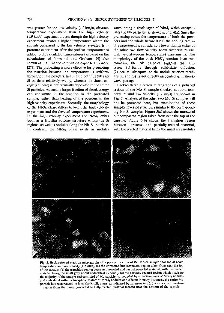
Backscattered electron micrographs of a polished section of the Mo--Si sample shocked at room tem- perature and low velocity (1.2 km/s) are shown in Fig. 5. Analysis of the other two Mo-Si samples will not be presented here, but examination of these samples revealed structures similar to the correspond- ing Nb-Si samples. Figure 5(a) shows the unreacted but compacted region taken from near the top of the capsule. Figure 5(b) shows the transition region between unreacted and partially-reacted material, with the reacted material being the small gray nodules
Fig. 5. Backscattered electron micrographs of a polished section of the Mo-Si sample shocked at room temperature and low velocity (1.2 km/s), (a) the unreacted but compacted region taken from near the top of the capsule, (b) the transition region between unreacted and partially-reacted material, with the reacted material being the small gray nodules identified as MoSi 2, (c) the partially-reacted region which made up the majority of the sample and consisted of Mo particles surrounded by a reaction layer of MoSi2 nodules and embedded within a two-phase matrix of MoSi 2 nodules and silicon; in many instances, the entire Mo particle has been reacted to form the MoSi 2 phase, as indicated by an arrow in (c); (d) shows the transition
region from the partially-reacted to fully-reacted material located near the bottom of the capsule.

VECCHIO et al.: SHOCK SYNTHESIS OF SILICIDES--I 707
identified as MoSi: (Mo-37 wt% Si via X-ray micro- analysis); the identification of the crystal structure of this phase will be presented later. Figure 5(c) shows the partially-reacted region which made up the ma- jority of the sample and consisted of Mo particles surrounded by a reaction layer of MoSi 2 nodules and embedded within a two-phase matrix of MoSi 2 nod- ules and silicon. In many instances, the entire Mo particle has been reacted to form the MoSi2 phase, as indicated by an arrow in Fig. 5(c). Figure 5(d) shows the transition region from the partially-reacted to fully-reacted material located near the bottom of the capsule. No additional interfacial reaction product could be observed in this sample, unlike the Nb-Si samples. In the unreacted region, the Mo particles appear to fragment along grain boundaries within the particles, while the silicon particles seem to have undergone intense plastic deformation.
The fully-reacted regions for the Nb-Si and Mo-Si samples were essentially identical in term of macro- scopic morphology. Voids were present throughout, resulting from either solidification shrinkage, gases evolved during the reaction, or tensile stresses im- posed on the compact prior to solidification. The presence of spherical voids, as well as dendritic structures observed are evidence of melting and
2 ~ . •
18~ b 161 t4"~ ;~ 12!
8i 6i 4i
~ , . ~ ,,~ : ,,,,~ . , . 2 4 6 8 10
(keV) 20 . . . . . . . . . . . . . . . . . . . 18' C 16 14
12' r , . j ~ z ,Z 10'
8'
6 4' ~
0 2 4 6 8 10 (keV)
Fig. 7. (a) Backscattered electron micrograph of the fully- reacted region of the Mo-Si capsule which contains primarily MoSi: [labeled A in this figure]; (b) shows a typical EDS spectrum from this phase. A second phase [labeled B in (a)] had a composition close to MosSi3, but also contained small amounts of Fe, Cr and Ni, as shown in the
EDS spectrum of (c).
Fig. 6. Backscattered electron micrographs of fully-reacted regions of the Nb-Si capsules tested at (a) elevated tempera- ture (773 K) and (b) high velocity (1.9km/s) and room temperature. Microvoids are marked by arrows and several different phases are present marked A, B, C and D in (a).
re-solidification. Figure 6(a) and (b) show the micro- structure in the fully-reacted regions of the Nb-Si capsules tested at elevated temperature (773 K) and high velocity (1.9 km/s), respectively; the microvoids are marked by arrows and several different phases are present. Energy dispersive X-ray analysis of these distinct phases [marked A, B, C and D in Fig. 6(a) for example] reveals Fe, Ni and Cr peaks, in addition to differences in the relative intensities of the much larger Nb and Si peaks. The presence of Fe, Ni and Cr is evidence for melting of the capsule (which is stainless steel) and subsequent contamination of spec- imen. This is a post-shock effect, since there would be no time for diffusion of these elements during shock- wave passage. The phases which contained the Fe, Cr and Ni to varying amounts also had an overall Nb-Si ratio close to the composition of NbsSi 3. Figure 7(a) shows the fully-reacted region of the Mo-Si capsule

708 VECCHIO et al.: SHOCK SYNTHESIS OF SILICIDES--I
which contains primarily MoSi2 [labeled A in this figure]; Fig. 7(b) shows a typical EDS spectrum from this phase. A second phase [labeled B in Fig. 7(a)] had a composition close to MosSi3, but also con- tained small amounts of Fe, Cr and Ni, as shown in the EDS spectrum of Fig. 7(c). This result, in con- junction with similar findings for the Nb-Si system suggest that the NbsSi3 and MosSia phases have a greater solubility for Fe, Cr, and Ni compared to the corresponding disilicide phases.
3.1.2. Transmission electron microscopy and diffraction analysis. Figure 8 shows transmission elec- tron micrographs of the partially-reacted region of the low impact velocity, room temperature Nb-Si
Fig. 8. Transmission electron micrographs of the partially- reacted region of the low velocity, room temperature Nb-Si sample. (a, b) reveal the structure of the nodules and of the surrounding silicon matrix. The silicon surrounding these reacted regions generally shows an annealed structure with a profusion of annealing twins. (c) Electron diffraction
pattern from twins in (b).
Fig. 9. [0001] zone axis CBED pattern obtained from the NbSi 2 nodules, (a) shows the zero-order Laue layer pattern which possesses 6 mm projection diffraction symmetry, (b) shows the whole pattern revealing only 6-fold rotational symmetry; no mirror planes exist in this pattern, and (c) shows an enlarged view of the black rectangle outlining a
small portion of the second-order Laue ring in (b).
sample. Figure 8(a) and (b) reveal the structure of the nodules and of the surrounding silicon matrix. The NbSi 2 nodules are monocrystalline, approx. 1-2 #m in diameter, and have facets. They do not show any marked internal structure, such as dislocations, stack- ing faults, or twins. The silicon surrounding these reacted regions generally shows an annealed structure with a profusion of annealing twins, as shown in Fig. 8(b). A few silicon regions exhibit a micro- crystalline structure. These regions were either subjected to intense plastic deformation and recrys- tallized (statically or dynamically) or were molten and rapidly re-solidified. This microstructure is in stark contrast with the previous silicon regions [Fig. 8(b)] which suggested melting followed by slow re-solidification.
The crystal structure of the NbSi2 nodules was determined by convergent beam electron diffraction (CBED) analysis. Figure 9 shows the [0001] zone axis CBED pattern obtained from the NbSi2 nodules. Figure 9(a) shows the zero-order Laue layer pattern

VECCHIO et al.: SHOCK SYNTHESIS OF SILICIDES--I 709
Fig. 11. Transmission electron micrograph of the partially- reacted region of the low velocity, room temperature Mo~i sample revealing the internal structure of the MoSi 2 nodules
including dislocations and twins.
here, displayed only 2-fold whole-pattern symmetry consistent with the point group 622. The established crystal structure for the NbSi2 phase is the C40 hexagonal structure (space group P6222 and point group 622) [30]. No attempt was made here to determine the space group of this phase; however there is no reason to suspect any other space group.
Fig. 10. Transmission electron micrographs of the partially- reacted region of the low velocity, room temperature Mo-Si sample, (a) and (b) reveal the structure of the MoSi 2 nodules and the surrounding silicon matrix, respectively. The silicon surrounding these reacted regions generally shows an an-
nealed structure with a profusion of annealing twins.
which possesses 6 m m projection-diffractiont sym- metry. Figure 9(b) shows the whole pat ternt reveal- ing only 6-fold rotational symmetry; no mirror planes exist in this pattern. Figure 9(c) shows an enlarged view of the black rectangle outlining a small port ion of the second-order Laue ring in Fig. 9(b). Careful examination of Fig. 9(c) reveals that the reflections indicated by the arrows [(7 19 12 2) and (12 19 7 2)] do not mirror to each other. This lack of mirror symmetry reduces the whole pattern symmetry from 6 m m to 6 in the [0001] zone axis orientation. As such, the diffraction group for this symmetry is 6mrm r and the ~point group_is 622. CBED analysis of both the (1120) and (1100) type orientations, not shown
tThe terms projection-diffraction symmetry and whole pat- tern symmetry have the same meanings as in Buxton et al. [31]. Projection-diffraction symmetry corresponds to the symmetry of the diffraction disks and diffuse intensity within diffraction disks of the zero-order Laue layer. Whole pattern symmetry refers to the symmetry of the higher-order Laue zone (HOLZ) reflections and HOLZ Kikuchi lines seen in low camera length patterns such as Fig. 9(b).
Fig. 12. [001] zone axis CBED pattern obtained from the MoSi 2 nodules, (a) shows the zero-order Laue layer pattern which possesses 4 m m projection-diffraction symmetry, and (b) shows the whole-pattern symmetry revealing 4 m m sym-
metry as well.

710 VECCHIO et al.: SHOCK SYNTHESIS OF SILICIDES--I
Figures 10 and 11 show transmission electron micrographs of the partially-reacted region of the low impact velocity, room temperature Mo-Si sample. Figure 10(a) and (b) reveal the structure of the MoSi2 nodules and the surrounding silicon matrix, respect- ively. The MoSi2 nodules are monocrystalline, ap- prox. l - 2 # m in diameter, and have facets. They show significant internal structure, including dislo- cations and twins, as shown in Figure 11. The silicon surrounding these reacted regions generally shows an annealed structure with a profusion of annealing twins, as shown in Fig. 10(b). This microstructure suggested melting followed by slow re-solidification.
The crystal structure of the MoSi 2 nodules was determined by CBED analysis. Figure 12 shows the [001] zone axis CBED pattern obtained from the
MoSi2 nodules. Figure 12(a) shows the zero-order Laue layer pattern which possesses 4 m m projection- diffraction symmetry; Fig. 12(b) shows the whole- pattern symmetry revealing 4 m m symmetry as well. Examination of both the [100] and [110] orientations, not shown here, displayed 2 m m whole-pattern sym- metries. These symmetries, in conjunction with the 4 m m symmetry of the [001] orientation, are consist- ent with a point group of 4 / m m m . From the whole pattern shown in Fig. 12(b) the centering of the structure was determined to be body-centered (I). Since no dynamical absences could be located in any orientations, the space group was determined to be I 4 / m m m . MoSi 2 has been reported to exist as two different crystal structures, C40 hexagonal (fl-MoSi2) above 1900°C and as C1 lb (body-centered tetragonal
i~iii j
© ©
11~" 11-'2" 1TO 11"2 1T4 • • • • • o~. 2o_!
00~- 00~- 000 oo2 oo4 ® • • • • 112 _ _ 112
101 011
~14- 11"~ ~10 "~12 "114 • • • • • 2o_! o=.~2
© © d
Fig. 13. (a) [110] microdiffraction pattern from one side of the twin plane in a MoSi 2 nodule and (b) shows a [111] selected area diffraction pattern (SADP) from the other side, (c) shows a composite SADP across both sides of the twin, and (d) shows the indexing of the composite pattern. The solid circles indicate the first variant pattern shown in (a), the open circles represent the reflections from the second variant shown
in (b), and a solid circle inside an open circle indicates overlapping reflections.

VECCHIO et al.: SHOCK SYNTHESIS OF SILICIDES--I 711
ct-MoSi2) below 1900°C [32]. Boettinger et al. [33] have reported that pure MoSi2 exists only as the C1 lb structure, and that the C40 is only metastable at high temperatures as a result of other solutes stabilizing this phase. In addition, they point out that in rapid liquid quenching operations, such as plasma-spray- ing, and we propose here for the conditions of this reaction mechanism, that "the formation of a metastable MoSi2 C40 phase can occur directly from the melt if the undercooling takes the melt below the metastable melting point of the C40 phase. This melting point may be only a few degrees Ceicius below the melting point of the Gl l b phase." The MoSi 2 phase observed here is consistent with the low temperature tetragonal phase (C1 lb) suggesting that either this phase formed via solid-state below 1900°C,
in contradiction to the mechanism being proposed herein, or was formed from the liquid state (consist- ent with the mechanism proposed here) first as the high-temperature C40 structure which subsequently transformed during cooling to the low-temperature C 11 b phase.
Mitchell et al. [34] have examined the (C40) hexag- onal-to-(C 11 b) tetragonal transformation of MoSi2 in plasma-sprayed processing in which the MoSi 2 phase starts to form in the liquid state. Their results indicate that a hexagonal-to-tetragonal phase transformation does occur in their experiments even for the very rapid solidification rates of the plasma-spray process- ing. During the transformation the stacking is changed from ABC in the hexagonal phase to AB in the tetragonal phase, and three different stacking
• •
020 0Zl3 1-10 i03 200 o • o • o • o •
2~o 1io ooo ~1o ~2~ • • • •
200 10-3 110 01-3 020 • O • o • o • o •
d
Fig. 14. (a) [001] selected area diffraction pattern from one side of the twin plane in a MoSi 2 nodule and (b) shows a [331] selected area diffraction pattern from the other side, (c) shows a composite SADP across both sides of the twin, and (d) shows the indexing of the composite pattern. The solid circles indicate the first variant pattern shown in (a), the open circles represent the reflections from the second variant shown
in (b), and a solid circle inside an open circle indicates overlapping reflections.

712 VECCHIO et al.: SHOCK SYNTHESIS OF SILICIDES--I
variants are possible within a given hexagonal grain: AB, BC and CA. If two different variants form within a given grain they will possess a twin relationship with each other. Mitchell et al. [34] suggest that their observation of {ll0} twins in the tetragonal MoSi 2 phase is a direct consequence of the hexagonal-to- tetragonal phase transformation. Figure 11 shows a nodule of MoSi 2 containing a twin; each MoSi 2 nodule examined, when suitably oriented, displayed twins. Figure 13(a) shows a [ll0] microdiffraction pattern from one side of the twin plane and Fig. 13(b) shows a [l 1 l] selected area diffraction pattern (SADP) from the other side. Figure 13(c) shows a composite SADP across both sides of the twin, and Fig. 13(d) shows the indexing of the composite pattern; the twin boundary is parallel to (110) which is common to both sides of the twin, and the (004) plane of one variant is parallel to the (112) plane of the other. The crystallographic nature of the twin was further analyzed by tilting one variant into the [001] orientation, shown in Fig. 14(a), and the other vari- ant was oriented along the [331] axis [Fig. 14(b)]. Figure 14(c) shows the combined SADP taken across the twin in this orientation, and Fig. 14(d) shows the indexing of_Fig. 14(c). The twin boundary is still parallel to (110) and common to both variants, while (130) of one variant is parallel to (013) of the other. These results are consistent with the analysis of Mitchell et al. [34] and suggest here that the nodules of MoSi 2 were formed from the liquid state, solidified as hexagonal, fl-MoSiz which subsequently trans- formed to the low-temperature, tetragonal, ~t-MoSi2. In addition, these results are consistent with the phase equilibria discussed by Boettinger et al. [33] for MoSi2, particularly with regard to the C40 to C1 lb polymorphic transformation.
3.2. Stat ic synthesis (diffusion couple) experiments
The morphologies of the partially-reacted regions in the Nb-Si and Mo-Si systems have unique features that are indicative of the mechanisms operating. The profuse presence of NbSi2 and MoSiz nodules at the Nb-Si and Mo-Si interfaces, and, more importantly, interspersed in the silicon are a unique aspect of shock-induced chemical reactions. In order to both compare reaction mechanisms and assess the kinetics of reaction under conventional heat treatment, in the solid state, pieces of niobium and silicon were pol- ished flat, clamped together, and then encapsulated. These diffusion couples were annealed at 1200°C for different times, sectioned, and analyzed. Figure 15(a) shows typical reaction layers that formed as a result of solid-state diffusion (in this example the couple was annealed at 1200°C for 2 h). The interdiffusion resulted in the formation of a thick layer of NbSi2, adjacent to the silicon sample, followed by a lamellar eutectic structure of NbsSi3 in NbSi2, growing from a layer of NbsSi 3 adjacent to the pure Nb sample. These reaction products and morphologies are consistent and predictable from the Nb-Si phase diagram. The
thicknesses of the product layers (excluding the eutec- tic region) as a function of time for each of the diffusion couples fabricated are plotted in Fig. 15(b). The data can be easily rationalized in terms of a simple diffusion equation
x = k ~ (1)
where x is the thickness of the reaction layer, D is the diffusion coefficient, t is the time, and k is a parameter that is a function of the geometry, phases formed, etc. The activation energy for diffusion for these materials varies from 200 to 400 kJ/mol. Taking a weighted average (among the available data) between the activation energies for self-diffusion of silicon and niobium, a value of 350 k J/tool is obtained. Hence
I A 1 x = KD~o(e - O/Rrt)2. (2)
By grouping the two unknown parameters k and D~ and fitting equation (2) to the experimental results of Fig. 15(b), it is possible to predict reaction layer thicknesses as a function of time for both NbsSi 3 and NbSi 2. These predicted thicknesses, for a range of temperatures below the melting point of silicon, are plotted in Fig. 15(c). The effect of temperature on the product layer thickness is very small, in the scale of Fig. 15(c). The usefulness of this plot is that it enables comparison of the amount of expected reaction product on the time scale of the shock experiments. The predicted reaction layer thicknesses, for a time of 5ps (maximum duration of stress pulse within shocked specimens) and a temperature of 1673 K [the maximum admissible temperature for solid-state process (the melting temperature of silicon= 1687 K)] are 10 -7 and 10 -9/tin for NbSi 2 and NbsSi3, respectively. Under shock compression, the reaction front advances by a dimension on the order of the radius of the nodules (~ 1 #m) within this same time span (5/~s). Thus, the reaction rates under shock compression are 107-109 times higher than under static, solid-solid conditions.
3.3. Proposed reaction mechanism
The analysis of the partially-reacted regions in the Nb-Si and Mo-Si shock experiments revealed the detailed nature of the reaction sequence and mechan- isms (for the sake of brevity only the Nb-Si system will be discussed below, however this analysis applies equally well to the Mo-Si system). A thermodynamic treatment of the reaction mechanism proposed below is given in a companion paper [27]. The preponder- ance of small NbSi2 particles surrounded by silicon, as well as the existence of NbSiz particles attached to the niobium particles (Figs 3 and 4) are evidence for a reaction mechanism in which the NbSi 2 or MoSi: particles are continuously being generated at the interface and ejected into the (molten) silicon. Thus, no permanent diffusion barrier that would slow down the reaction process is formed, and reaction can proceed at a constant rate until the entire metal

VECCHIO et al.: SHOCK SYNTHESIS OF SILICIDES---I 713
b
70
o 60
"~ 50
~ 40
~ 30 -r. ~ 20
o o
f t
f N b S i
/ 0 2
/ o / e
/ N b Si ~. S 3 0
) o I i I
0 20 40 60 80 100 H o l d i n g T i m e ( h o u r )
120
C
~ O] i 0 0 0 . 1400o c
~ -~o .~ . , . . . . . . . . . . . .
-7 -6 -s -4 -3 -2 -1 0 1 Holding Time (Log Sec.)
Fig. 15. (a) Backscattered electron micrograph of typical reaction layers that formed as a result of solid-state diffusion (in this example the couple was annealed at 1200°C for 2 h). The interdiffusion resulted in the formation of a thick layer of NbSi 2, adjacent to the silicon sample, followed by a lamellar eutectic structure of NbsSi 3 in NbSi2, growing from a layer of NbsSi3 adjacent to the pure Nb sample. (b) a plot of the measured thicknesses of the product layers (excluding the eutectic region) as a function of time for each of the diffusion couples fabricated, the dashed and solid lines represent best fit curves. (c) is a plot of the predicted thicknesses, based on equation (2), for a range of tempera-
tures below the melting point of silicon.
(Nb or Mo) or silicon is consumed. The shock-in- duced reaction is initiated along the solid metal-molten Si interface. After reaction has pro- ceeded to a certain extent, surface (interfacial) forces become dominant, and the liquid reaction product agglomerates, forming a spherule. At this point,
reaction kinetics are drastically decreased, due to the reduction in the Nb-Si interfacial area, and solidifica- tion of the disilicide sphere starts. As the sphere solidifies, new nuclei form along the Nb-Si interface. The new nuclei grow, agglomerate into spheres when they reach a critical size, and thereby form neighbor- ing spheres. As these neighboring spheres solidify, they exert forces on the first sphere, expelling it into the molten silicon, and thus exposing fresh surfaces. This reaction process can continue unimpeded, until the reactants are consumed. In addition, turbulent flow of the liquid silicon under shock can also contribute to the detachment of the spherules from the interface. The companion paper (Part II; [27]) presents this mechanism in detail.
4. CONCLUSIONS
1. It was possible to successfully initiate and prop- agate shock-induced reactions for the two systems investigated (Nb-Si and Mo-Si), and the extent of reaction was found to increase with shock energy, shock temperature, and the energy of reaction.
2. The following qualitative statements can be made: (a) as the heat of reaction increases, the shock pressure/temperature necessary for full reaction de- creases, and (b) the extent of shock-induced reaction increases with shock energy, at a constant tempera- ture, and with temperature, at a constant shock energy.
3. Electron microscopy observations reveal that the main reaction product in the partially-reacted regions is the disilicide formed from the molten state as spherules with radii of approx. 1-2/zm. These spherules are formed at the metal-Si interface and are expelled into the silicon.
4. There is clear indication that silicon melting is a prerequisite for shock-induced reactions.
5. The kinetics in static solid-state reactions were established and found to be lower, by ~ 108 com- pared to the kinetics in shock compression.
6. A reaction mechanism under shock com- pression for the metal-Si interface is proposed involv- ing the dissolution of Nb or Mo into molten Si, producing the molten intermetallic, with its sub- sequent spheroidization, solidification, and expulsion into the surrounding liquid silicon melt. In this reaction mechanism a fresh solid (Nb or Mo)-liquid (Si) interface is continuously maintained, enabling a high reaction rate.
Acknowledgements--This research was supported by National Science Foundation Grant DMR 8713258 (Materials Processing Initiative), and by McDonnell- Douglas Research Laboratory. We thank the support provided by Dr B. McDonald (NSF) and by Drs C. Whitsett and P. Meschter (MDRL). The help of Dr N. N. Thadhani and of the Center of Explosives Technology Research (New Mexico Institute of Mining and Technology) Field Laboratory technicians in the execution of the experiments is gratefully acknowledged.
AMM42/3--1

714 VECCHIO et al: SHOCK SYNTHESIS OF SILICIDES---I
REFERENCES
I. S. S. Batsanov, A. A. Deribas, E. V. Dulepov, M. G. Ermakov, and V. M. Kudinov, Combust. Explos. Shock Waves (USSR)I, 47 (1965).
2. Y. Horiguchu and Y. Nomura, Carbon 2, 436 (1965). 3. Y. Horiguchu and Y. Nomura, Chem. Inds, Lond.,
p. 1791 (1965). 4. G. A. Adadurov, V. I. Gold'anskii, and P. A.
Yampol'skii, Mandeleev Chem. J. 18, 92 (1973). 5. G. A. Adadurov, and V. I. Gold'anskii, Russ. chem.
Revs 50, 948 (1981). 6. A. N. Dremin and O. N. Breusov, Russ. chem. Revs 37,
392 (1968). 7. S. S. Batsanov, Russ. chem. Revs 37, 197 (1968). 8. S. S. Batsanov, G. S. Doronin, S. V. Klochdov and A.
I. Tent, Combust. Explos. Shock Waves (USSR) 22, 765 (1986).
9. R. Graham, B. Morosin, E. L. Venturini and M. J. Carr, Ann. Rev. Mater. Sci. 16, 315 (1986).
10. W. F. Hammetter, R. A. Graham, B. Morosin, and Y. Horie, in Shock Waves in Condensed Matter (edited by S. C. Schmidt and N. C. Holmes), p. 431. Elsevier Science, Amsterdam (1988).
11. B. Morosin, R. A. Graham, E. L. Venturini, M. J. Carr and D. L. Williamson, in Shock Waves in Condensed Matter (edited by S. C. Schmidt and N. C. Holmes), p. 435. Elsevier Science, Amsterdam (1988).
12. B. R. Krueger and T. Vreeland Jr, in Shock-Wave and High-Strain-Rate Phenomena in Materials (edited by M. A. Meyers, L. E. Murr and K. P. Staudhammer), p. 245. Marcel Dekker, New York (1992).
13. B. Krueger, A. Mutz and T. Vreeland Jr, Metall. Trans. 23A, 55 (1991).
14. Y. Horie, R. A. Graham, and I. K. Simonsen, Mater. Lett. 3, 354 (1985).
15. Y. Horie and M. J. Kipp, J. appl. Phys. 63, 5718 (1988). 16. M. B. Boslough, J. chem. Phys. 92, 1839 (1990). 17. Z. Iqbal, N. N. Thadhani, N. Chawla, B. L. Ramakr-
ishna, R. Sharma, S. Skumeyev, F. Reidinger and H. Eckhardt, Appl. Phys. Lett. 55, 2339 (1989).
18. N. N. Thadhani, A. Advani, I. Song, E. Dunbar, A. Grebe and R. A. Graham, in Shock-Wave and High-Strain-Rate Phenomena in Materials (edited by M. A. Meyers, L. E. Murr and K. P. Staudhammer), p. 271. Marcel Dekker, New York (1992).
19. L. H. Yu and M. A. Meyers, J. Mater. Sci. 26, 601 (1991).
20. M. A. Meyers, L. H. Yu and K. S. Vecchio, in Shock Compression o f Condensed Matter--1991, (edited by S. C. Schmidt, R. D. Dick, J. W. Forbes and D. G. Tasker), p. 629. North Holland, Amsterdam (1992).
21. C. S. Smith, Trans. Am. Inst. Min. Engrs 212, 574 (1958).
22. E. Hornbogen, Trans. Am. Inst. Min. Engrs 221, 721 (1961).
23. M. A. Meyers, Scripta metall. 12, 21 (1978). 24. J. Weertman, in Shock-Wave and High-Strain-Rate
Phenomena in Metals (edited by M. A. Meyers and L. E. Murr), p. 469. Plenum Press, New York (1981).
25. W. Gourdin, J. appl. Phys. 55, 172 (1984). 26. R. B. Schwarz, P. Kasiraj, T. Vreeland Jr, and T. J.
Ahrens, Acta metall. 32, 1243 (1984). 27. M.A. Meyers, L.-H. Yu and K. S. Vecchio, Acta metall.
mater. 42, 715 (1994). 28. A. B. Sawaoka and T. Akashi, U. S. Patent 4655830
(1987). 29. F. R. Norwood and R. A. Graham, in Shock-Wave and
High-Strain-Rate Phenomena in Materials, p. 989. Marcel Dekker, New York (1992).
30. R.P. Elliot and F. A. Shunk (contributing editors), Bull. Alloy Phase Diagr. 2, (1981).
31. B. F. Buxton, J. A. Fades, J. W. Steeds and G. M. Rackman, Phil. Trans. R. Soc. 281, A1301, 171 (1976).
32. P. Villars, Pearson's Handbook of Crystallographic Data for Intermetallic Phases (edited by P. Villars and L. D. Calvert), Am. Soc. Metals, Metals Park, Ohio (1985).
33. W. J. Boettinger, J. H. Perepezko and P. S. Frankwicz, Mater. Sci. Eng. A155, 33 (1992).
34. T. E. Mitchell, R. G. Castro and M. M. Chadwick, Phil. Mag. A65, 1339 (1992).
Related Documents