SHOCK ABSORBERS INDUCTION HEAT TREATMENT TRATAMIENTO TÉRMICO DE AMORTIGUADORES

Shock absorbers
Mar 06, 2016
Shock absorbers induction heat treatment
Welcome message from author
This document is posted to help you gain knowledge. Please leave a comment to let me know what you think about it! Share it to your friends and learn new things together.
Transcript
SHOCK ABSORBERS INDUCTION HEAT TREATMENT
TRATAMIENTO TÉRMICO DE AMORTIGUADORES
INDEX
SHOCK ABSORBERS INDUCTION HEAT TREATMENT
TRATAMIENTO TÉRMICO DE AMORTIGUADORES
2 ÍNDEX
3 1. A long experience 4-5 2. Shock absorbers induction heat treatment
2.1. Introduction
8-9 2.2. TSR Installation
10-11 2.3. TCE Installation
12-13 2.4. TCT Installation
14-15 2.5. TRE Installation
16-17 2.6. FST Installation
ÍNDICE
1. Una larga experiencia 2. Tratamiento térmico de amortiguadores
2.1. Introducción
2.2. Instalación TSR
2.3. Instalación TCE
2.4. Instalación TCT
2.5. Instalación TRE
2.6. Instalación FST
GH GROUP has worked for more than 40 years in the shock absorber heat treatment sector all around the world.
During all this time, many installations have been provided to the best shock absorbers manufacturers, including:
This document summarizes the experience acquired by GH Group in order to show diff erent solutions that have been developed for diff erent needs. It can be used by engineering and purchasing staff to choose the solution that best suits their production.
The experience and know-how of GH Group, is a guarantee to obtain the process which best suits the production requirements.
GH GROUP ha trabajado durante más de 40 años en el tratamiento térmico de amortiguadores en todo el mundo.
Durante este tiempo, GH ha suministrado a los mejores fabricantes numerosas instalaciones específi cas para el tratamiento térmico de amortiguadores. Entre nuestros clientes se encuentran:
Este documento resume la experiencia adquirida por GH Group, con el fi n de mostrar diferentes soluciones que han sido desarrolladas para necesidades diferentes. Este documento va dirigido a los responsables de ingeniería y compras para ayudar en la elección más adecuada a los requerimientos del cliente.
La experiencia y know-how de GH Group garantizan la obtención del mejor proceso adaptado a las necesidades de producción.
AK AUTOMATICARALMEXCITROENCYCDELPHI
DAEWOODANA NAKATAFAWGMHYUNDAI
KIAKYB SUSPENSIONSMONROEPEUGEOTTENNECO
1 A long experienceUUUUUUUUUUUUUUUnnnnnnnnnnnnnnnnnna llaarrggaa eexxpperiencccccccccccccciiiiiaaaaUUUnnnaa larga experiencccccccciiiaaaaUUUUUUUUUnnaa larga experiencccccccciiaaaUUUUUUUUUUnnnnnnnnnnna laarrggaa eexxppeerriieencccccccccccccciiiaaaaaaUUUU g p cccccc aaag
ppgggg pg pg p

2.1. Introduction
There are three operations where induction heating is commonly used for heating shock absorber parts:
A) Hardening and/or tempering of shock absorber rods B) Chromed rod dehydrogenization C) Tube forming/closing
Shock absorber rods hardening Shock absorber rods need to be hardened, generally with a hardening depth from 0,8 to 2 mm. This operation is performed on high production lines. This document shows three diff erent solutions for rod hardening.
Skew rollers installations (TSR class)This system is composed of two heads, each of one has rollers with diff erent angle inclination related to the advance axle in order to transfer an turning-advance helicoidal movement. The inductor and the quench are placed between these two heads. This class of machine is the fastest and the one that produces less defl ection on the rods.
Centerless with pusher installations (TCE class)In this kind of machine the turning movement is transferred by two parallel turning rollers. A servocontrolled pusher transmits the linear movement. This class of machine off ers the best hardening precision and is the easiest to adjust in case of multiple rod kinds manufacturing.
Installations advanced by rollers conveyor (TCT class)This machine is a variation of the TCE one in which two roller trains transmit the linear movement to the rod. The part on which the movement is transmitted, push the precedent parts. This machine represents a good compromise between speed (it is faster than the TCE class) and the precision (it is more precise than the TSR class) with fast confi guration for changing the kind of production.
In all cases, typical speeds are between 2m/min and 8 m/min. Power installed is typically contained between 50 KW and 200 KW and the frequencies between 70 kHz to 160 kHz. .
Induction tempering After the hardening it is usually performed a rod induction tempering, being possible to use any of the precedent solutions (TCE with a second pusher, TSR with a second double head, and TCT). Installed capacities are 25-50 KW using 4-10 kHz frequencies. There is also the possibility to use a TRE heating tunnel, a compact and high production solution.
Rod dehydrogenization After chroming the rods, they are usually heated in order to perform a dehydrogenization process. GH Group TRE induction heating tunnels are a compact and high production solution.
Closing of the outer tube The operation consists of induction heating one end of a tube, which is then sealed in a spinning operation.The great advantage of induction in this process is its heating speed and the control of the process.
Shock absorber parts Shock absorber parts induction heating induction heating
2
CLASS OF MACHINE
HAR
DEN
ING
AND
/OR
TEM
PERI
NG
TSR
Type: Skew rollers
Pages: 8-9
TCE
Type: centerless with pusher
Pages: 10-11
TCT
Type: centerless with rollers conveyor
Pages: 12-13
TEM
PERI
NG
OR
DEH
YDRO
GEN
ISAT
ION
TRE
Type: Tunnel
Pages: 14-15
FORM
ING
MAC
HIN
ES
FST
Type: Tube locking
Pages: 16-17
SHOCK ABSORBERS INDUCTION HEAT TREATMENT TRATAMIENTO TÉRMICO DE AMORTIGUADORES4

2.1. Introducción
Existen tres operaciones en las que se emplea la inducción para calentar piezas de amortiguadores:
A) El temple y revenido de los vástagos de amortiguadorB) El deshidrogenado de vástagos de amortiguadores cromadosC) El cerrado de los tubos externos
Temple de vástagos de amortiguadorLos vástagos de amortiguador necesitan ser templados superfi cialmente, generalmente con una profundidad de 0,8 hasta 2 mm. Esta operación suele realizarse en líneas automáticas de alta producción. En el presente documento se muestran tres soluciones distintas:
Equipos de rodillos oblicuos (clase TSR)Este sistema está basado en dos cabezales equipados con rodillos dispuestos en triángulo con inclinación respecto del eje de avance para establecer un movimiento helicoidal de rotación - avance. El inductor y la ducha quedan entre ambos cabezales. Esta clase de máquina es la más rápida y la que produce un menor nivel de deformación de las piezas.
Equipos centerless con empujador (clase TCE)En este tipo de máquina, la pieza es sometida a rotación mediante un par de rodillos paralelos. El avance es producido por un empujador accionado por un servomotor. Esta clase de máquina ofrece la mejor precisión en el control del perfi l de temple y es la más fácil de ajustar en el caso de fabricación de múltiples referencias.
Equipos centerless con tanqueta (clase TCT)Esta máquina es una variante de la anterior en la que el avance es producido por un par de correas en forma de tanqueta que arrastran las piezas de manera que la que está bajo la acción de la tanqueta empuja a las precedentes. Esta máquina representa un compromiso entre la velocidad (es más rápida que la centerless de empujador) y la precisión (es más precisa que la de rodillos oblicuos) con una rápida confi guración en el caso de cambio de producto.
Para todos los casos, las velocidades típicas de temple van desde 2 m/min a 8 m/min. La potencia instalada suele ir de 50 KW a 200 KW y las frecuencias entre 70-160 kHz.
Revenido por inducciónEn general, después del temple se realiza el revenido de piezas, también por inducción, pudiéndose utilizar cualquiera de los sistemas anteriores (TCE con un segundo empujador, TSR con un segundo doble cabezal de rodillos oblicuos y TCT). Las potencias típicas instaladas son 25-50 KW y las frecuencias 4-10 kHz.
Existe también la posibilidad de utilizar un túnel de calentamiento de la clase TRE, una solución compacta y de alta producción.
Deshidrogenado de vástagosLos vástagos de amortiguadores, después de cromados, se someten a un proceso de calentamiento para su deshidrogenado.Para dicho proceso, los túneles de revenido TRE del Grupo GH son una solución compacta y de producción elevada.
Cerrado del tubo exteriorPartiendo de un tubo, se calienta por inducción su extremo que se cierra en una operación de repulsado.La ventaja principal de este sistema es la rapidez de calentamiento y el control de proceso repetitivo.
Calentamiento de piezas de Calentamiento de piezas de amortiguadores por inducciónamortiguadores por inducción
2
CLASE DE MÁQUINA
TEM
PLE
Y/O
REV
ENID
OTSR
Tipo: Rodillos oblicuos
Páginas: 8-9
TCE
Tipo: centerless con empujador
Páginas: 10-11
TCT
Tipo: centerless de tanqueta
Páginas: 12-13
REVE
NID
O O
DES
HID
ROGE
NAD
O TRE
Tipo: Tunel
Páginas: 14-15
MÁQ
UIN
AS D
E
CON
FORM
ADO FST
Tipo: cerrado de tubo
Páginas: 16-17
5

Shock absorbers induction Shock absorbers induction heat treatment machinesheat treatment machines
SHOCK ABSORBERS INDUCTION HEAT TREATMENT TRATAMIENTO TÉRMICO DE AMORTIGUADORES6

Máquinas para el tratamiento Máquinas para el tratamiento térmico de amortiguadorestérmico de amortiguadores
Shock absorbers induction heat treatment machines
7

TSRTSR
> Hardening detail
> Detalles de temple
> TSR Overall view
> Vista general TSR
SHOCK ABSORBERS INDUCTION HEAT TREATMENT TRATAMIENTO TÉRMICO DE AMORTIGUADORES8
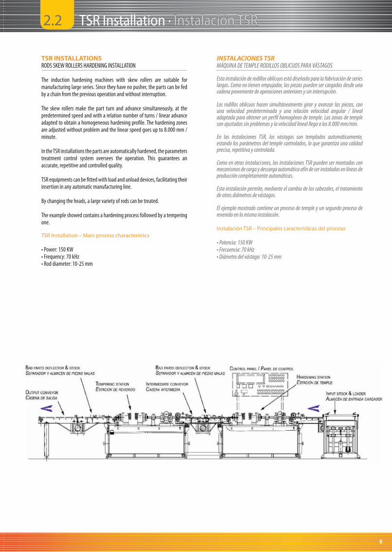
TSR INSTALLATIONSRODS SKEW ROLLERS HARDENING INSTALLATION
The induction hardening machines with skew rollers are suitable for manufacturing large series. Since they have no pusher, the parts can be fed by a chain from the previous operation and without interruption.
The skew rollers make the part turn and advance simultaneously, at the predetermined speed and with a relation number of turns / linear advance adapted to obtain a homogeneous hardening profi le. The hardening zones are adjusted without problem and the linear speed goes up to 8.000 mm / minute.
In the TSR installations the parts are automatically hardened, the parameters treatment control system oversees the operation. This guarantees an accurate, repetitive and controlled quality.
TSR equipments can be fi tted with load and unload devices, facilitating their insertion in any automatic manufacturing line.
By changing the heads, a large variety of rods can be treated.
The example showed contains a hardening process followed by a tempering one.
TSR Installation – Main process characteristics
• Power: 150 KW• Frequency: 70 kHz • Rod diameter: 10-25 mm
INSTALACIONES TSRMÁQUINA DE TEMPLE RODILLOS OBLICUOS PARA VÁSTAGOS
Esta instalación de rodillos oblicuos está diseñada para la fabricación de series largas. Como no tienen empujador, las piezas pueden ser cargadas desde una cadena proveniente de operaciones anteriores y sin interrupción.
Los rodillos oblicuos hacen simultáneamente girar y avanzar las piezas, con una velocidad predeterminada y una relación velocidad angular / lineal adaptada para obtener un perfi l homogéneo de temple. Las zonas de temple son ajustadas sin problemas y la velocidad lineal llega a los 8.000 mm/min.
En las instalaciones TSR, los vástagos son templados automáticamente, estando los parámetros del temple controlados, lo que garantiza una calidad precisa, repetitiva y controlada.
Como en otras instalaci ones, las instalaciones TSR pueden ser montadas con mecanismos de carga y descarga automática afín de ser instaladas en líneas de producción completamente automáticas.
Esta instalación permite, mediante el cambio de los cabezales, el tratamiento de otros diámetros de vástagos.
El ejemplo mostrado contiene un proceso de temple y un segundo proceso de revenido en la misma instalación.
Instalación TSR – Principales características del proceso
• Potencia: 150 KW • Frecuencia: 70 kHz • Diámetro del vástago: 10-25 mm
2.2 TSR Installation · TSR Installation · Instalación TSRInstalación TSR
9
TCETCE
> TCE Overall view
> Vista general TCE
> Automatic loader
> Cargador automático
> Pusher
> Empujador
> Hardening station with inductor checking
> Estación de temple con comprovador de inductor
SHOCK ABSORBERS INDUCTION HEAT TREATMENT TRATAMIENTO TÉRMICO DE AMORTIGUADORES10

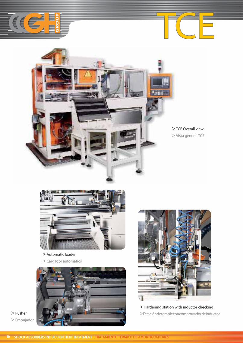
TCE INSTALLATIONSROD CENTERLESS HARDENING INSTALLATION WITH PUSHER
TCE installations are well suited for shock absorbers rods. It consists on a centerless with pusher, a mechanism that allows reaching an homogeneous hardening and/or tempering.
In this kind of machine the turning movement is transferred by two parallel turning rollers. A servocontrolled pusher transmits the linear movement. This class of machine off ers the best hardening precision and is the easiest to adjust in case of multiple rod kinds manufacturing.
TCE equipments can be fi tted with load and unload devices, facilitating their insertion in automatic manufacturing line.
TCE Installation – Main process characteristics
• Power: 200 KW• Frequency: 100 kHz • Shaft diameter: 18-32 mm
2.3 TCE Installation · TCE Installation · Instalación TCEInstalación TCE
INSTALACIONES TCEMÁQUINA DE TEMPLE CENTERLESS CON EMPUJADOR PARA VÁSTAGOS
Las instalaciones TCE están perfectamente adaptadas para el tratamiento térmico vástagos de amortiguador. Consiste en un sistema centerless con empujador, un sistema que permite obtener un temple y/o revenido homogéneo.
En este tipo de máquina, la pieza es sometida a rotación mediante un par de rodillos paralelos. El avance es producido por un empujador accionado por un servomotor. Esta clase de máquina ofrece la mejor precisión en el control del perfi l de temple y es la más fácil de ajustar en el caso de fabricación de múltiples referencias.
En las instalaciones TCE, las piezas se templan automáticamente, estando los parámetros del procesos controlados, lo que garantiza igualmente a las otras máquinas una calidad precisa, repetitiva y controlada.
Instalación TCE – Principales características del proceso
• Potencia: 200 KW • Frecuencia: 100 kHz• Diámetro de eje: 18-32 mm
11
TCTTCT
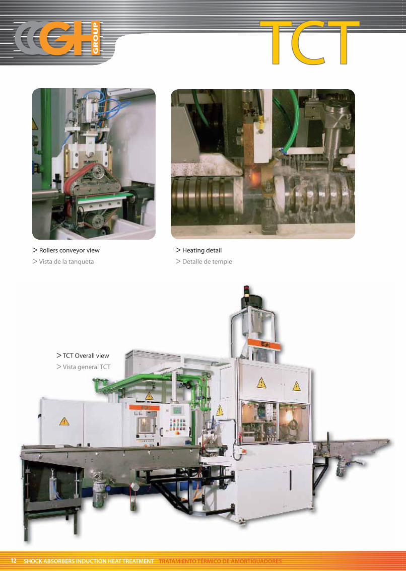
> Rollers conveyor view
> Vista de la tanqueta
> Heating detail
> Detalle de temple
> TCT Overall view
> Vista general TCT
SHOCK ABSORBERS INDUCTION HEAT TREATMENT TRATAMIENTO TÉRMICO DE AMORTIGUADORES12
2.4 TCT Installation · TCT Installation · Instalación TCTInstalación TCT
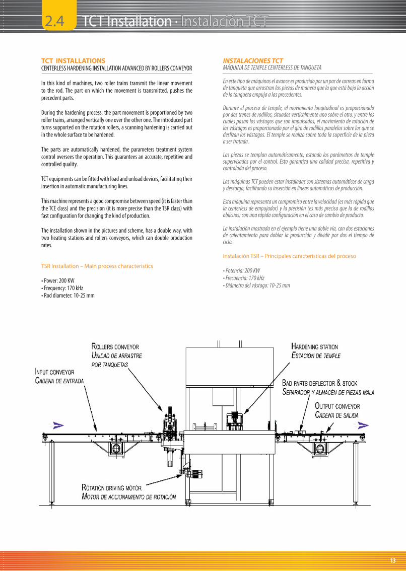
TCT INSTALLATIONSCENTERLESS HARDENING INSTALLATION ADVANCED BY ROLLERS CONVEYOR
In this kind of machines, two roller trains transmit the linear movement to the rod. The part on which the movement is transmitted, pushes the precedent parts.
During the hardening process, the part movement is proportioned by two roller trains, arranged vertically one over the other one. The introduced part turns supported on the rotation rollers, a scanning hardening is carried out in the whole surface to be hardened.
The parts are automatically hardened, the parameters treatment system control oversees the operation. This guarantees an accurate, repetitive and controlled quality.
TCT equipments can be fi tted with load and unload devices, facilitating their insertion in automatic manufacturing lines.
This machine represents a good compromise between speed (it is faster than the TCE class) and the precision (it is more precise than the TSR class) with fast confi guration for changing the kind of production.
The installation shown in the pictures and scheme, has a double way, with two heating stations and rollers conveyors, which can double production rates.
TSR Installation – Main process characteristics
• Power: 200 KW• Frequency: 170 kHz • Rod diameter: 10-25 mm
INSTALACIONES TCTMÁQUINA DE TEMPLE CENTERLESS DE TANQUETA
En este tipo de máquinas el avance es producido por un par de correas en forma de tanqueta que arrastran las piezas de manera que la que está bajo la acción de la tanqueta empuja a las precedentes.
Durante el proceso de temple, el movimiento longitudinal es proporcionado por dos trenes de rodillos, situados verticalmente uno sobre el otro, y entre los cuales pasan los vástagos que son impulsados, el movimiento de rotación de los vástagos es proporcionado por el giro de rodillos paralelos sobre los que se deslizan los vástagos. El temple se realiza sobre toda la superfi cie de la pieza a ser tratada.
Las piezas se templan automáticamente, estando los parámetros de temple supervisados por el control. Esto garantiza una calidad precisa, repetitiva y controlada del proceso.
Las máquinas TCT pueden estar instaladas con sistemas automáticos de carga y descarga, facilitando su inserción en líneas automáticas de producción.
Esta máquina representa un compromiso entre la velocidad (es más rápida que la centerless de empujador) y la precisión (es más precisa que la de rodillos oblicuos) con una rápida confi guración en el caso de cambio de producto.
La instalación mostrada en el ejemplo tiene una doble vía, con dos estaciones de calentamiento para doblar la producción y dividir por dos el tiempo de ciclo.
Instalación TSR – Principales características del proceso
• Potencia: 200 KW • Frecuencia: 170 kHz • Diámetro del vástago: 10-25 mm
13

TRETRE
> TRE-126 overall view
> Vista general de la TRE-126
> TRE-114 and TRE-112 overall view
> Vista general de la TRE-114 y TRE-112
SHOCK ABSORBERS INDUCTION HEAT TREATMENT TRATAMIENTO TÉRMICO DE AMORTIGUADORES14

TRE INSTALLATIONSINDUCTION HEATING TUNNEL FOR DEHYDROGENISATION / TEMPERING
TRE induction heating tunnels is a compact and high production solution to perform rods dehydrogenization or tempering process.
With an induction furnace 1500 mm lengthed, a treating of similar quality as the one obtained in a conventional furnace, much larger in size, can be obtained.
The main advantages of this installation compared to a conventional furnace are the following ones:
- no need of preheating time- part by part control- lower quantity of parts simultaneously in process- easier automation- immediate part availabilityIn TRE machines, the rods are placed on the input ramp coming from
the previous operation. A walking beam system, composed of two fi xed and two mobile guides, takes the pieces from the ramp and pass them through the inductor inside.
The last step of the mobile guides stands the pieces already tempered on the chain of the cooling tank.
In the installation shown in the drawings below, the cooling chains, loaded with heated pieces, which pass below a quenching for their cooling, advance slowly. After the quenching, the parts pass under an air blow for their drying. At the cooling tank output, the chains place the pieces on the output ramps. The cooling can also be performed by immersion, as shown on the picture on the left.
Before the cooling tank, an infrared pyrometer performs the temperature control.
At the end of the process, a mechanism separates the parts marked as non OK by the parameters control.
TRE-114 Installation – Main process characteristics
• Power: 50 KW• Frequency: 4-10 KHz• Production: 300 parts/h (12 s/part)• Rod diameter: 10-35 mm• Part length: 100-600 mm
2.5 TRE Installation · TRE Installation · Instalación TREInstalación TRE
INSTALACIONES TRETUNEL DE CALENTAMIENTO POR INDUCCIÓN PARADESHIDROGENADO / REVENIDO
Los túneles de calentamiento TRE son una solución compacta y de alta producción para procesos de deshidrogenado o de revenido de vástagos
Con un horno de 1500 mm de largo se puede obtener un tratamiento de calidad similar al obtenido en los hornos convencionales, los cuales tienen mucho mayor tamaño.
Las principales ventajas del revenido por inducción frente a los hornos convencionales son las siguientes:
- ausencia de tiempo de precalentamiento- control del proceso pieza a pieza- menor cantidad de piezas en proceso simultáneo- mayor facilidad de automatización- disponibilidad inmediata de las piezasEn las máquinas TRE, los ejes se colocan en la rampa de entrada,
provenientes del proceso anterior. Un sistema de paso peregrino compuesto de dos guías móviles y otras dos fi jas se encarga de trasladar los ejes a lo largo del túnel.
El paso fi nal del paso peregrino sitúa las piezas ya revenidas en la cadena del tanque de enfriamiento.
En la máquina mostrada en el plano inferior, la cadena de enfriamiento, cargada con las piezas calientes, pasa bajo una ducha para su enfriamiento, por donde avanza lentamente. Después de la ducha, las piezas pasan bajo un chorro de aire para su secado. A la salida del tanque de enfriamiento, las cadenas sitúan las piezas en la rampa de salida. El enfriamiento puede ser realizado igualmente por inmersión, como muestra la foto de la izquierda.
Antes del enfriamiento, la temperatura de las piezas son controladas por medio de un pirómetro de radiación infrarroja.
Al fi nal del proceso, un mecanismo discrimina las piezas que han sido señaladas como malas por el control de parámetros.
Instalación TRE-114 – Principales características del proceso
• Potencia: 50 KW• Frecuencia: 4-10 KHz• Producción: 300 pieza/h (12 s/pieza)• Diámetro del vástago: 10-35 mm• Longitud de pieza: 100-600 mm
15
FSTFST
> Automatic loader
> Cargador automático
> FST Overall view
> Vista general FST
> Heating and forming station
> Estación de calentamiento y conformado
SHOCK ABSORBERS INDUCTION HEAT TREATMENT TRATAMIENTO TÉRMICO DE AMORTIGUADORES16

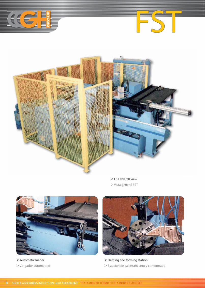
FST InstallationSHOCK ABSORBER PIPE LOCKING INSTALLATION
Another common Induction technology application is heating before forming.
In the example showed, the installation is able to lock and shape a tube for shock absorber tube forming
This installation is composed by a heating station with inductor, and a mechanical shaping device, which is able to shape and lock the tube heated.
The installation is able to produce more than 200 shock absorber tubes per hour.
FST Installations.Main process characteristics
• Power: 10 KW• Frequency: 10 KHz• Production: 225 parts/h (16 s/part)• Tube diameter: 43-66 mm
2.6 FST Installation· FST Installation· Instalación FSTInstalación FST
Instalación FSTINSTALACIÓN DE CERRADO DE TUBOS DE AMORTIGUADOR
Otra aplicación común de uso de la inducción, es el calentamiento previo al conformado.
En el ejemplo expuesto, la instalación es capaz de cerrar y conformar tubos de amortiguador.
Esta instalación se compone de una estación de calentamiento con su correspondiente inductor, y un dispositivo de conformado, que es capaz de conformar y cerrar el tubo calentado.
La instalación es capaz de producir más de 200 amortiguadores por hora.
Instalación FSTPrincipales características del proceso
• Potencia: 10 KW• Frecuencia: 10 KHz• Producción: 225 piezas/h (16 s/pieza)• Diámetros de tubo: 43-66 mm
17

Notes Notes NotasNotas
SHOCK ABSORBERS INDUCTION HEAT TREATMENT TRATAMIENTO TÉRMICO DE AMORTIGUADORES18

Notes Notes NotasNotas
19

GermanyGH INDUCTION DEUTSCHLAND GmbH.e-mail: [email protected]
FranceGH ELECTROTHERMIE S.A.S.e-mail: [email protected]
BrazilGH INDUÇAO DO BRASIL LTDA.e-mail: [email protected]
IndiaGH INDUCTION INDIA Pvt. Ltd.e-mail: [email protected]
China – BeijingGH OFFICE Email: [email protected]
MéxicoGH MEXICANA S.A. de C.V.e-mail: [email protected]
USAGH INDUCTION ATMOSPHERES LLCEmail: [email protected]
ArgentinaTATRA S.A.I.C.e-mail: [email protected]
SpainGH ELECTROTERMIA S.A.Vereda Real s/n - San Antonio de BenagéberP.O. Box 8056 – 46018 VALENCIATel: +34 961 352 020 Fax: +34 961 352 171e-mail: [email protected]: www.ghe.es
SALES AGENTS
USA
INDUCTION HEATING CONSULTATIONS
e-mail: [email protected]
TURKEY
EKONOMAK Co Ltd.
e-mail: [email protected]
SWEDEN
EXPORTREFORM
e-mail: [email protected]
SLOVAKIA
INDUSTRIA SLOVAKIA, s.r.o.
e-mail: [email protected]
RUSSIA
THERMOEXPORT
e-mail: [email protected]
POLONIA
IRENEUSZ ROLL
e-mail: [email protected]
MALAYSIA
INDUCTTION HEATING FAR
e-mail: [email protected]
IRAN
SPEED CHEMTECH Co.
e-mail: [email protected]
ITALIA
B STUDIO SAS
e-mail: [email protected]
BELGIQUE
DE RIDDER TDR B.V.B.A.
e-mail: [email protected]
Related Documents


