Ship resistance in confined water
Jul 18, 2015
Welcome message from author
This document is posted to help you gain knowledge. Please leave a comment to let me know what you think about it! Share it to your friends and learn new things together.
Transcript


Shallow water, restricted water and confined water
Effect on a ship moving in confined water :
sinkage and trim
increase in resistance
other effects : propulsion, manoeuvrability, vibration

Sinkage and trim : Restricted cross-section for displacement flow under
the ship Increased relative velocity of water Decrease in pressure Sinkage Effect of boundary layers on ship and ground With level ground, pressures are lower towards aft
and hence the ship trims aft Forward trim may occur if the ship is heading into
shallower water

Combined sinkage and trim due to shipmoving in shallow water is called squat
Change of pressure in shallow water of givendepth is proportional to V 2
Squat increases sharply with speed
Excessive speed in shallow water may causethe bottom of the ship to touch the ground
Shallow water effects become morepronounced if the water is also restricted inwidth, since more displacement flow has to gounder the ship

Empirical formulas to estimate squat
Barrass formula for squat in a canal :
= squat in m, CB = block coefficient
S = midship area / canal cross-section area
V = ship speed in knots
0.81 2.08
20
BC S V

For shallow water of unrestricted breadth, an equivalent breadth b may be used to calculate the effective canal cross-section area :
where B is the breadth of the ship.
0.85
7.04
B
b BC

Barrass has also given simpler formulas :
In unrestricted shallow water with h/T between 1.1 and 1.4 (h = depth of water, T = draught of the ship)
In a canal for which S lies between 0.1 and 0.266,
Ships with CB > 0.7 trim forward, ships with CB < 0.7 trim aft according to Barrass.
2
100
BC V
2
50
BC V

Confined water affects ship resistance mainly in two ways :
The increased displacement flow velocity increases the viscous resistance
The waves generated by the ship are different in shallow water than in deep water. Waves of a given speed are longer in shallow water and have sharper crests than in deep water. This causes a change in wave resistance
In water of depth h, wave speed (celerity) and wave length are related as follows :
As , , and the familiar relation between wave speed and wave length in deep water is obtained :
2 2tanh
2
g hc
22 c
g
h tanh (2 / ) 1h

As , and the wave speed is given by :
This is the limiting speed of a wave in water of depth h and is called the critical wave speed.
/ 0,h tanh (2 / ) 2 /h h
2c g h
The waves generated by a moving pressure point in shallow water give guidance on the effect of shallow water on the waves generated by a ship : At speeds V well below , the waves generated by
the pressure point in water of depth h are the same as in deep water : diverging waves and transverse waves of wave length lying between lines making an angle of 19o 28’ with the direction of motion (i.e. the Kelvin wave pattern)
g h
22 /V g

As the speed V increases beyond 0.4 , the wave length starts being affected by the depth of water h and the angle between which the wave pattern is contained starts increasing from 19o 28’
As V approaches , this angle approaches 90o, the wave length increases indefinitely
g h
g h
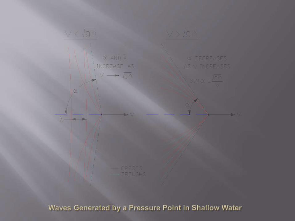

As the speed V increases beyond the critical wave speed, a new wave system forms consisting only of diverging waves emanating from the pressure point, convex forward. These diverging waves are contained within two lines making an angle
with the direction of motion. The angle
decreases as V increases
sinV g h
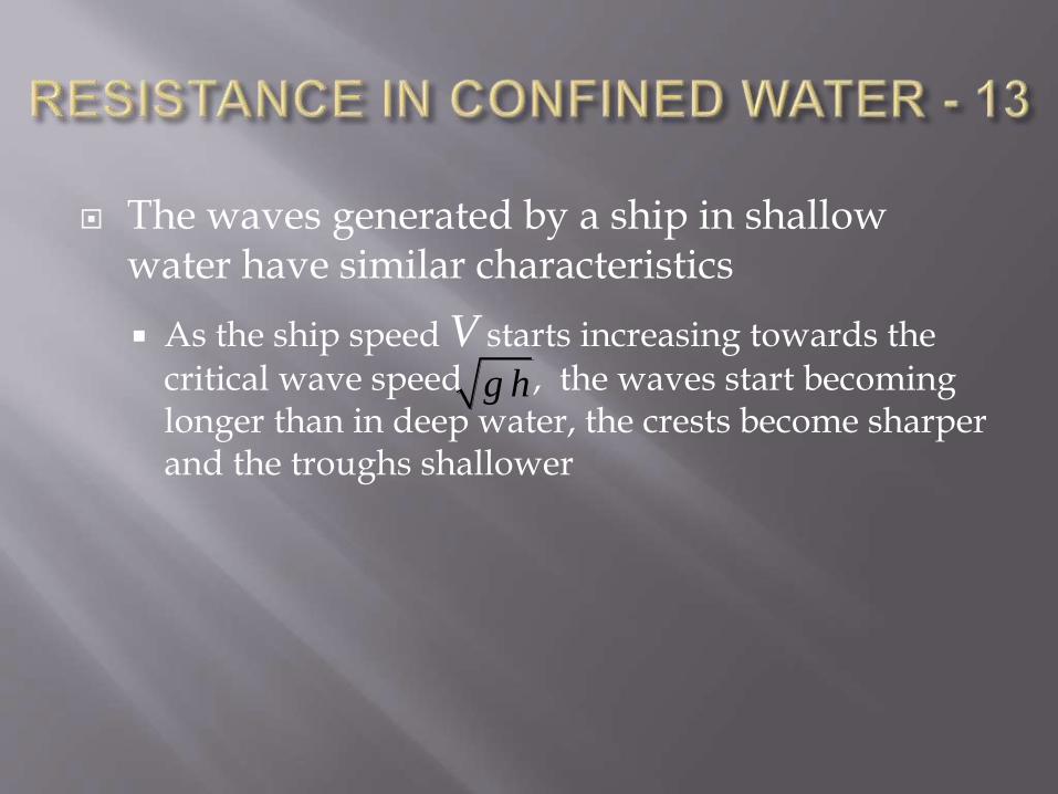
The waves generated by a ship in shallow water have similar characteristics
As the ship speed V starts increasing towards the critical wave speed , the waves start becoming longer than in deep water, the crests become sharper and the troughs shallower
g h
When the wave length starts becoming more than the length of the ship, sinkage and trim by stern start increasing and the resistance also increases.
The maximum values are reached at or just before the ship speed becomes equal to the critical wave speed
As the ship speed becomes supercritical, a new wave system consisting of only diverging waves is formed.

These observations are mostly based on model experiments since ships can rarely be made to go at speeds approaching or exceeding the critical wave speed.
Ships do operate at subcritical speeds in shallow water, and it is necessary to calculate the effect of shallow water on their resistance.
A method due to O. Schlichting is widely used for this purpose.
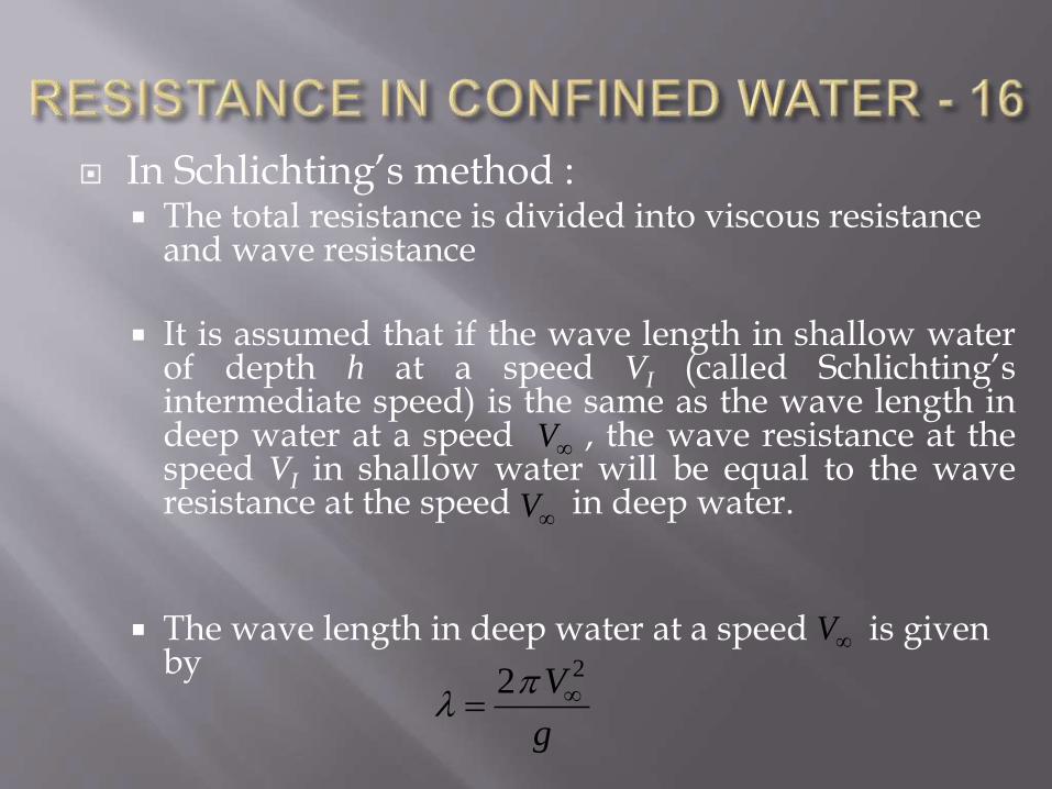
In Schlichting’s method : The total resistance is divided into viscous resistance
and wave resistance
It is assumed that if the wave length in shallow waterof depth h at a speed VI (called Schlichting’sintermediate speed) is the same as the wave length indeep water at a speed , the wave resistance at thespeed VI in shallow water will be equal to the waveresistance at the speed in deep water.
The wave length in deep water at a speed is given by
V
V
V
22 V
g
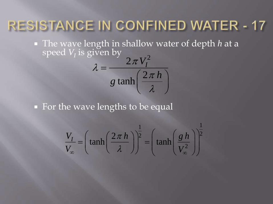
The wave length in shallow water of depth h at a speed VI is given by
For the wave lengths to be equal
22
2tanh
IV
hg
1122
2
2tanh tanhIV h g h
V V
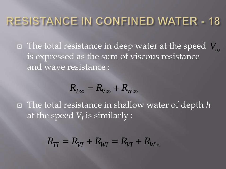
The total resistance in deep water at the speed is expressed as the sum of viscous resistance and wave resistance :
The total resistance in shallow water of depth hat the speed VI is similarly :
T V WR R R
V
TI VI WI VI WR R R R R

The value of RVI for shallow water cannot be determined. However, RVI can be determined at the speed VI for deep water by the same method as used to determine at the speed in deep water.
Schlichting experimentally determined a speed Vh in shallow water at which the measured total resistance RTh is equal to the sum of RVI at the speed VI in deep water and .
VR V
WR

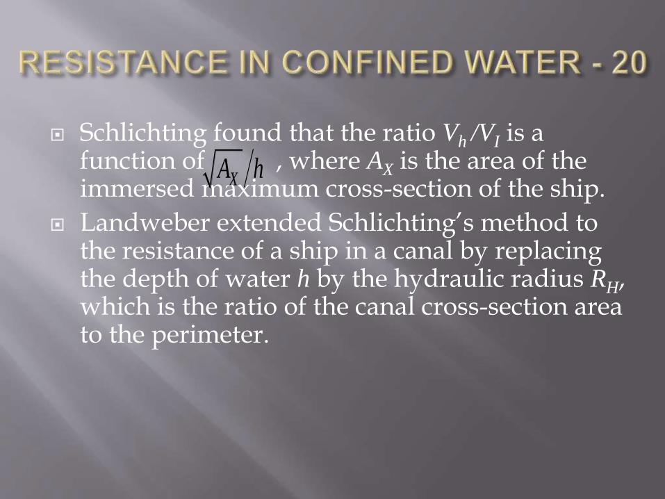
Schlichting found that the ratio Vh /VI is a function of , where AX is the area of the immersed maximum cross-section of the ship.
Landweber extended Schlichting’s method to the resistance of a ship in a canal by replacing the depth of water h by the hydraulic radius RH, which is the ratio of the canal cross-section area to the perimeter.
XA h
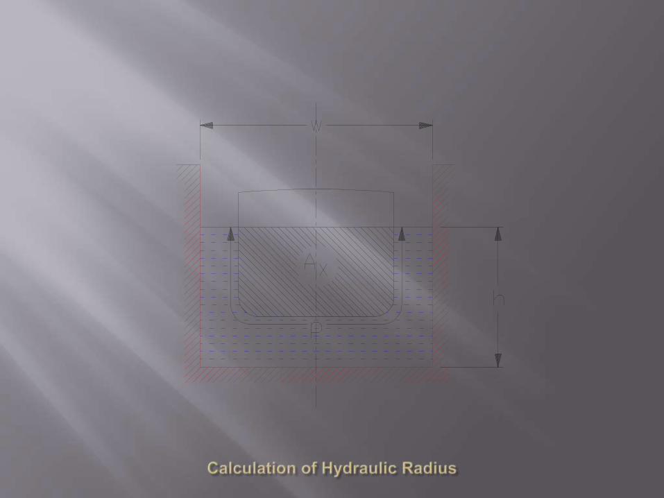

For a rectangular canal of breadth b and depth of water h, the hydraulic radius is
where p is the perimeter (girth) of the maximum immersed section of the ship.
As , so that in shallow water of unrestricted breadth, the hydraulic radius becomes equal to the depth of water.
2
XH
b h AR
b h p
, Hb R h

and are given in the following tables :
0.0 1.0000 0.6 0.99610.1 1.0000 0.7 0.98330.2 1.0000 0.8 0.95700.3 1.0000 0.9 0.91860.4 1.0000 1.0 0.87270.5 0.9997
IV V h IV V
V
g h
V
g h
IV
V
IV
V

0.0 1.0000 0.6 0.9712 1.1 0.8923
0.1 1.0000 0.7 0.9584 1.2 0.8726
0.2 0.9995 0.8 0.9430 1.3 0.8536
0.3 0.9964 0.9 0.9274 1.4 0.8329
0.4 0.9911 1.0 0.9087 1.5 0.8132
0.5 0.9825
These are Landweber’s values.
X
H
A
R
X
H
A
RX
H
A
R
h
I
V
V
h
I
V
Vh
I
V
V


Long but checkered history
Reliable results from time of W. Froude
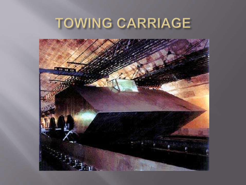
Model experiments in modern times Long, narrow towing tank
Towing carriage with instrumentation
Variety of experiments : resistance, propulsion, manoeuvring, seakeeping
Other types of facilities
ITTC


Materials : wood, wax, fibre-glass, polyurethane foam
Model size Equipment limitations : speed, resistance
Accuracy of small models – model propellers
Accuracy of measurements : small forces
Turbulent flow : large models for high Reynolds number, artificial turbulence stimulation

Upper limit on model size – tank wall interference or blockage
Increased displacement flow
Shallow water effects on waves
Interference of reflected waves
Criteria to avoid blockage effects :
not more than 1/200
not more than 0.7
LM not more than 0.5 b
XA b h
MV g h
Geometrically similar model ballasted to correct draught and trim
Attached to towing carriage through resistance dynamometer : Model free to sink and trim
No trimming moment due to tow force
Resistance measured at steady model speed by resistance dynamometer
Test over range of speeds
Wave profiles, flow lines

Basic procedure as discussed earlier
Additional considerations
Roughness allowance
Correlation allowance
Ship correlation factor
ITTC’s standard method

ITTC 1978 Ship Performance Prediction Method : standardized method for prediction of ship power from model tests
Basic procedure (as discussed earlier) :
RTM measured at VM
1 2
2
TMTM
M M M
RC
S V
M M
nM
M
V LR
2
100.075 log 2FM nMC R

1WM TM FMC C k C SS M
M
LV V
L
S SnS
S
V LR
2
100.075 log 2FS nSC R
WS WMC C (by the Froude law)
1TS FS WSC k C C

Three corrections to this basic procedure in ITTC method : Roughness allowance added to viscous
resistance coefficient where :
Bilge keels cannot be reproduced in model. Resistance of bilge keels allowed for by increasing hull wetted surface SS by bilge keel surface area SBK
1 FSk CFC
3105 0.64 10SF
S
LC
k

Air and wind resistance calculated by
After making these corrections, the total resistance coefficient of the ship is obtained as :
This gives the total resistance of the ship in ideal conditions.
1 2
2
0.001AA TAA
SS S S
R AC
SS V
1S BKTS FS F WS AA
S
S SC k C C C C
S
To allow for the differences between these ideal conditions and the actual conditions on ship trials or in service, CTS is multiplied by a load factor (1+x).
The overload fraction x corresponds to a trial allowance or a service allowance, and is based on experience with previous ships
Service allowances may range from 10 to 40 per cent, depending on type of ship and service route.
Related Documents