Shifting Up for Heavy Duty Transmission and hybrid systems development

Welcome message from author
This document is posted to help you gain knowledge. Please leave a comment to let me know what you think about it! Share it to your friends and learn new things together.
Transcript

Shifting Up for Heavy DutyTransmission and hybrid systems development

Transmission and hybrid systemdevelopment from concept to startof productionThe automotive transmission has gainedmuch significance in recent years and is akey component in the modern powertrain.Modern commercial vehicle transmissionssatisfy exacting demands on drivingdynamics as well as ride comfort, and theyreduce fuel consumption and emissions.Hybridizing the powertrain provides thecapability of utilizing further potential.
IAV specialists make an important contri-bution to achieving these ambitious goalswith unique synthesis programs for new,optimized transmission structures, aperfected development process, efficientmethods, the systematic use of simulationtools, an automated calibration process anda broad range of measuring and testingequipment.
At IAV, more than 300 experiencedengineers – all with excellent qualifications –design, develop, test, integrate and calibratetransmissions and their complex controlsystems on all continents – from the initialidea to the perfected and efficient volumeproduct.
More than twenty-five years of worldwidedevelopment projects with prominentmanufacturers and component suppliers,along with innovations, and expertise inmass production development aretestimony to our expertise. IAV's know-howcovers all transmission types on the marketfrom manual, automated manual and hybridtransmissions to transfer cases in all-wheel-drive applications.
Our German operations:BerlinChemnitzDresdenFriedrichshafenGifhornIngolstadtKasselLudwigsburgMunichNeckarsulmNeustadtNurembergRegensburgRostockRuesselsheimWeissach
Detroit
Shanghai
Seoul
São Paulo
Germany
Tokyo
London
Modena
Pune
Beijing
Mexico City
MoscowParis
Palo Alto
Contents
Sub
ject
to c
hang
e w
itho
ut n
otic
e, e
ffec
tive
D 0
7/2
01
4
Systematic, Computer-Aided Transmission Synthesis 4
Advanced transmissions for Commercial Vehicles 5
Physically Based Universal Clutch Characteristic 6
IAV Automatic Transmission Prototype Software 7
Automated Transmission Calibration 8
Multi-Criteria Optimization of Electric Machine 10
InDrive-Simulator© 11
Analysis and Simulation 12
IAV Virtual Drive Simulation 13
IAV Velodyn 13
Benchmarking 14
Transmission Design 15
System Integration 16
Software and Algorithm Development 18
Functional Safety 20
Diagnostics / OBD 20
Transmission Software Testing 21
Calibration 22
Testing 24
Test Benches 26
Hybrid and E-Testing 28
Special Test Tools 28
Prototyping 30
Prototype Manufacturing 31
Project Management 32
Development Process 34
Cost Engineering 35

Systematic, Computer-AidedTransmission SynthesisTailor-made solutions for your future powertrains
T o develop future transmissionsystems, IAV uses unique,computer-based synthesis
programs that generate all conventionaland hybrid transmission structures.Independently from the target application,may it be a an On-Road or Off-RoadCommercial Vehicle or a Passenger Car,the flexibility of the tools enables IAV tofind the best solutions. That’s why thissystematic process is requested byOEM's and TIER1 suppliers all around the
world. We provide our clients with new,optimized transmission structures forextremely compact, low-loaded transmis-sions with high ratio spread, very goodgear stepping, simple shift logic forflexible shift strategies and maximumlevels of efficiency. Generated usingclearly defined methods, the transmis-sions we give our customers guaranteethe basis for innovative and competitivevolume products.
Flexible use for different transmission technologies:• Manual transmissions (MT) with spur gears• Automated manual transmissions (AMT)
with spur gears• Dual-clutch transmissions (DCT) with
spur gears• Automatic transmissions (AT) with
planetary gears• Continuously variable transmissions with
conventional (CVT), hydrostatic (hCVT) orelectric variator (eCVT)
Generating all possible combinationsof transmission variants+
Analyzing and evaluating conven-tional and hybrid transmissionproperties+
Selecting the best transmission for our customer
AT DCT
eDriveeCVT
Sequence of transmission synthesisfor versatile transmission technologies
4

Automatic transmission for Commer cial Vehicles: 9-AT3000• Simple layout with 4 planetary gear sets
and 6 shift elements• 3,000 Nm / 2,000 rpm input torque /
speed• Size comparable to current AT‘s for
commercial vehicles• Flexible series of ratios with starting
ratios between 5.3 and 8.6 for differenttransmission variants
• Low loaded shift elements for lowactuation energy and low drag losses
IAV concepts with an innovative edge • 9-AT3000: 9-speed AT with 3000 Nm
input torque for inline application• 8H+-eCVT: 8 ICE speeds with electric
CVT functionality• 9-DCT: 9-speed DCT with dry dual clutch
for inline application
5
F uture power trains for commercialvehicles will be facing tough challen -ges with sometimes contrary require-
ments. The various transmission systemsharbor different potentials to optimize thewhole power train – may it be a highlyefficient DCT with its similarity to MT’s andAMT’s, an AT with its high power density ora CVT with its freedom to set the ratio forany desired speed of the vehicle. Hybridi za -tion makes the assessment of the optimalpower train configuration even more com -plex. That’s why IAV’s experts use uniquetools to generate and evaluate new trans-missions. IAV’s transmission concepts arecharacterized by a higher functionality thanthe state of the art with at the same time alow number of components. Low loads onthe mechanical elements are essential for acompact design. High efficiency of the gearset and the actuation system contribute toreducing the life cycle costs.
Advanced transmissionsfor Commercial VehiclesIncreasing functionality and reducing life cycle costs
Flexible series of ratios for planetary ATswith ratio spreads from 10.0 up to 16.0
8-speed hybrideCVT
Low torque loads on closed shift elements(cSE) in IAV’s 9-speed AT
9-AT3000: 9-speed concept for input torques up to 3.000 Nm
9-speed DCT with dry dual clutch
Ste
p [-
]
Ratio [-]
2.0
1.8
1.6
1.4
1.2
1.00 1 2 3 4 5 6 7 8 9
No
rmal
ized
torq
ue [-
]
6.0
5.0
4.0
3.0
2.0
1.0
0.0
Speed [-]1 2 3 4 5 6 7 8 9 R
cSE 1 cSE 2 cSE 3

Unlike conventional adaptation processes,using the algorithm involves no interventionin the clutch control system. It is a purelyobservational process that can be used inany slip situation and ensures a high level oftolerance toward dynamic, noisy and imper-fectly synchronized signals. Performingapproximately 200 computing operationsper adaptation step, the algorithm can beused in a production-level automotivecontrol unit.
6
M odern dual-clutch transmissionssatisfy the most exacting ofconsumer demands in terms of
shift time and comfort. Most concepts forcontrolling power transmission make itnecessary to know the clutch characteristic(i.e. ratio of controlled variable to transferredtorque) inside out. Identifying bothpermanent and temporary changes in the clutch characteristic is one of thechallenges a transmission control systemneeds to master.
IAV employs a progressive and innovativeprocess for correcting friction clutch errorduring operation. Following a purelyphysical approach, the process centersaround an algorithm that estimates thecharacteristic curve. For the first time, thisnew model is being used as part of asystem for controlling a dual clutch.
The newly developed equation can be usedfor describing both wet and dry dual clutchsystems. The parameters can be inter-preted and tolerated in a way that makesphysical sense, providing the capability ofderiving and diagnosing limits and startingvalues of control parameters entirely fromknowing the clutch system under obser-vation.
Offering various options, the algorithm canbe controlled in a flexible manner. This, forexample, not only makes it suitable for rapid,short-term correction within a drive-offcycle but also for long-term adaptation.Algorithm control also permits partialestimates, reducing computing effort andspeeding up the estimation process.Preferred learning situations can also bedefined.
Physically Based UniversalClutch CharacteristicReal-time estimation for short and long-term adaptation
neng, Meng
Mcl_KKL
Mcl_“ACTUAL“ (computed)
Error e
p1, p2, p3
scl
Vehicle Estimated torque
Identification algorithmOffline (Levenberg Marquardt method)Online (Prediction Error method)
+-
1
p3( )
0
250
200
150
100
50
010 20
scl in [mm]
Mcl
in [N
m]
CLC_CL1 at 120s after start
Example of an estimated clutch characteristicafter 120 seconds
30
Block diagram showingestimation process
Universal clutch characteristic
MKup(s) = p1 s–p2 – ––– (1–e-p3(s-p2))1p3( )
Mcl computed
CLCstart
CLCestimated

We have many years of experiencein constructing demonstratorvehicles in the transmission
segment. Examples include the conversionand sport-tuning of a production vehiclewith IAV’s prototype transmission controlsystem.
The entire software is implemented on amodel basis in Matlab/Simulink. Everythingis computed in floating point arithmetic inline with prototyping level. The strategylevels are based on torque matched totransmission input, producing simple,generic gearshift handling. Actuator controlemploys physical plant parameters whichsignificantly reduces calibration work.
IAV has designed the transmission controlsoftware to manage any AT transmissionand perform all gear shifts to give optimumride comfort. This covers all the mainfunctionalities required by modern trans-mission software.
Gear speed is selected on the upper layerof the driving strategy, either automaticallyin line with the chosen gearshift concept(comfort/sport) or manually after tappingthe gear lever. Fast-off and dynamic shiftpoint adaptation functionality is supported.The individual shift phases are coordinatedby the shifting strategy, with shift abortsand shift modifications also being handled.The clutch strategy controls the actualshifting phases, e.g. speed synchronizationand torque processing. Another softwarelayer provides the basis for controlling the
actuators as well as basic signal and power-train CAN handling. A diagnostics modulemonitors and checks fundamental controlconstraints.
Expertise:• Construction of transmission demon-
strators for in-vehicle use• Rapid prototyping for all-encompassing
transmission software• Model based transmission control
algorithm development
IAV Automatic TransmissionPrototype SoftwareGetting ideas into the prototype vehicle
BIOS
(Diagnostics)
Driving strategy - Selector lever, Driving strategy, Error identification
Signal layer - CAN communication, Combination display, Shift lock
Actuator control - Hydraulics manager, Engine torque manager
Clutch strategy - Shift clutches,
Torque converter lockup clutch, Adaptations
Gearbox strategy - Gearshift process control

Simulations
Measurements
IAV Optishift
Calibration engineerSensitivity analysisDesign of Experiments (DoE)Optimization
IAV Evalshift
Objective shift qualityevaluation
Simulation
Test bench
Vehicle
8
Optishift provides interfaces to thecommonly used INCA, CANape orControlDesk calibration tools, making itpossible to monitor the measurementprocess and adjust parameters fullyautomatically. The results of measurementdata analysis – in the form of an objectiveassessment of the results to be calibrated –can then be used for multi-criteriaparameter optimization. Optishift is suitablefor use in the vehicle as well as in simulationenvironments and on the test bench.Compared with calibrating the shifting
process manually, it produces similar orbetter results for standard shifting opera-tions. The outcome remains virtuallyunaffected by the engineer’s personal fontof experience, and parameter sets can bedefined for any shift time to provide thebest possible level of ride comfort.
The Velodyn simulation environment can beused for generating initial calibrations aswell as for validating parameter sets.Various detailed model approaches areavailable that give the engineer optimum
T he increasingly complex andinvolved process of calibratingtransmissions means it must
undergo further systemization andautomation to meet the challenges that lie ahead. Optishift provides anenvironment for calibrating the trans-mission all automatically. It initially usessensitivity analyses for identifying theparameters with the most influence ontransmission control as a way of helpingthe calibration engineer select the param-eters for calibration.
Automated Transmission CalibrationOptimization process: Optishift and Evalshift
Measured data Measured data
Parameterization Optimization
Optimization Optimization
Parameter
Velodyn
Simulation• LoD I• MiL / SiL
Velodyn
Simulation• LoD III-IV• MiL / SiL / HiL
Velodyn
Simulation• LoD III-IV• MiL / SiL / HiL / CiL
Max. comfort
Reference
Min
. shi
ft ti
me
Optishift
Criteria
Optishift
Tool-assisted calibration process
Validation/Optimization
Bench -alyzer Evalshift
Initialization• Parameter definition• Sensitivity analysis• Status documentation
Requirements • Project targetdefinition
Preliminary design• Sensitivity analysis• Offline calibration
Calibration• Data management• Documentation of project status andcalibration quality
Calibration• Data management• Data release• Release documentation
Evalshift CaltetOptishift CalGuide
Transmission
• Test bench• Road testing
Target vehicle
• Initial analysis
Benchmark vehicle
• Competitor vehicles• Reference vehicles
Target vehicle• Fine tuning• Robustness analysis
CalguideBenchalyzerCaltet Evalshift Autoshift Evalshift
Optishift Caltet
9
support at all stages of the calibrationprocess. For instance, models of the rest ofthe vehicle are used on the test bench forlacking components, allowing a variety ofcalibration activities to be performed beforeprototype vehicles even exist.
Objective evaluation of the events beingoptimized is an important part of automatedcalibration. Unlike subjective assessment, it provides the basis for guaranteeingjudgment reproducibility and granularity ofthe type required for automating thecalibration process. Evalshift then evaluatesdrivability using the laws of physics foraspects such as the shift process. Relevant
criteria are extracted from the signal curvesand passed on to the optimizing engineer.
By visualizing time characteristics and criteria, Evalshift permits direct comparison of results at manual calibration level. The vehicle database tool Benchalyzer provides an easy touse interface to compare different vehiclesby driveability or even performance criteria.The calibration testing tool Caltet supportsthe subjective evaluation process in thevehicle by guiding the user and storing dataautomatically. Based on these tools adocumentation can be created to monitorthe project status, the calibration progress.These documents can be used for releasing
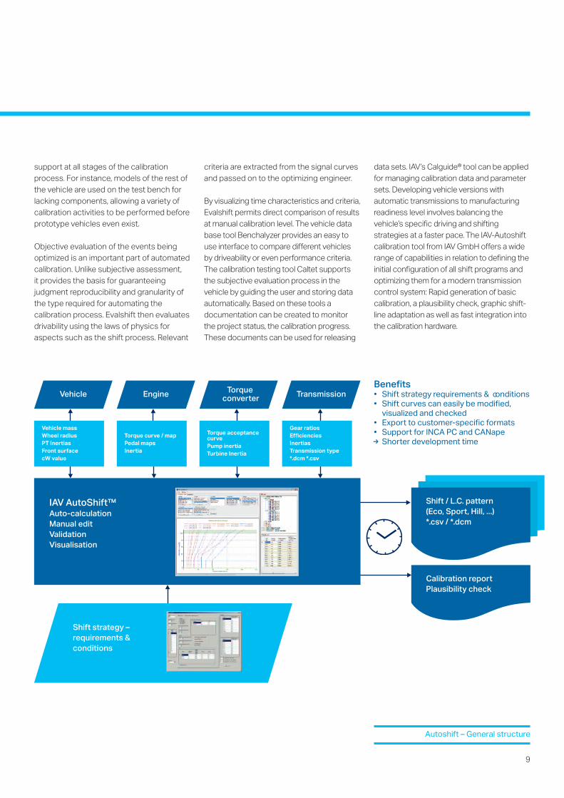
data sets. IAV’s Calguide® tool can be appliedfor managing calibration data and parametersets. Developing vehicle versions withautomatic transmissions to manufacturingreadiness level involves balancing thevehicle’s specific driving and shiftingstrategies at a faster pace. The IAV-Autoshiftcalibration tool from IAV GmbH offers a widerange of capabilities in relation to defining theinitial configuration of all shift programs and optimizing them for a modern transmission control system: Rapid generation of basic calibration, a plausibility check, graphic shift- line adaptation as well as fast integration intothe calibration hardware.
Benefits• Shift strategy requirements & conditions• Shift curves can easily be modified,
visualized and checked• Export to customer-specific formats• Support for INCA PC and CANapeR Shorter development time
Vehicle massWheel radiusPT InertiasFront surfacecW value
Shift / L.C. pattern(Eco, Sport, Hill, ...)*.csv / *.dcm
Calibration reportPlausibility check
Vehicle
Shift strategy –requirements & conditions
Torque curve / mapPedal mapsInertia
Engine
Torque acceptance curvePump inertiaTurbine Inertia
Torqueconverter
Gear ratiosEfficienciesInertiasTransmission type*.dcm *.csv
Transmission
IAV AutoShift™Auto-calculationManual editValidationVisualisation
Autoshift – General structure

10
Without optimization With optimization
Speed [rpm] Speed [rpm]
To
rque
[Nm
]
To
rque
[Nm
]
Effi
cien
cy [%
]
100
50
70
80
90
60
200
100
0
50
150
200
100
0
50
150
10,0005,000 10,0005,000
Flux
den
sity
[T]
2.4
0
1.2
With powertrain electrification onthe increase, new electricmachines are needed that
provide greater efficiency at lower cost. Forthis reason, IAV experts have developed aninnovative method that provides thecapability of optimizing various types ofelectric machines, e.g. induction machines,permanent-magnet machines and switchedreluctance machines, in relation to a widerange of different criteria. Computationuses finite element analysis of magneticfield density with subsequent calculation of
relevant losses. Modern computationclusters make it possible to analyze andevaluate extensive parameter variations in avery short time.
Optimization parameters• Machine type• Slot and tooth layout of the metal sheet• Integration and size of air chamber• Arrangement and geometry of magnets• Diameter and length of air gap• Winding design• Material of iron sheet and magnet
Optimization targets• High efficiency and torque capacity at
typical operating points• Engine speed strength• Good performance in field-weakening
range• Low cyclic irregularity• Ease of control• Low material and production costs
Efficiency map of a synchronous machine – Potential from optimization
Finite element calculation of the magnetic flux density for different machine types
Multi-Criteria Optimization of Electric MachineOptimized electric machines for optimized drives

11
T he InDrive-Simulator is an innovativedevelopment tool for simulating anddesigning complex vehicle and
powertrain systems under real driving condi-tions. It combines the advantages of offlinesimulation with the experience of driving areal prototype. As such, the InDrive-Simulatorbridges the gap between simulating the firstconcept draft and testing the real-lifeprototype. The system consists of severalmain components. These are the basicvehicle with its interfaces, the real-timesimulation computer with models andacceleration controller together with adataset and visualization system.
At the heart of it is IAV’s tried and provenVelodyn simulation tool with the real-timesystem for computing vehicle dynamics.Based on current vehicle speed, position ofthe accelerator, brake pedal, gear, currentslope and cornering radius, the systemuses mathematical models of thepowertrain components to calculate thevirtual prototype’s expected acceleration.Depending on the level of model detailingused, it also computes other targetvariables like energy demand, SOC of thebattery or component temperatures.
An acceleration controller in the vehicleoperates the test mule in a way thataccurately reproduces the virtual proto-type’s setpoint acceleration computed onthe real-time system. To do this, thecontroller sends its output signal to theengine and transmission control unit. Inaddition, the onboard ACC system activelycontrols any required deceleration by thebrake system.
The InDrive-Simulator• Helps developers to design new hybrid
or electric concepts and assess theirmarket relevance
• Provides ongoing support in thedevelopment process from the earlydesign phase
• Can be used for developing andstudying any powertrain topology
• Makes it possible to compare andoptimize components and target vehicle
• Gives clients the possibility of trying outconcepts within their own operatingconditions
• Can be used in the early developmentphase to feel what a design is like todrive before setting up hardware prototypes
The InDrive-Simulator is adevelopment tool that covers allrelevant influencing variables:• Driver-specific responses • Vehicle application and mode of
operation • Driving cycle / route including its
topography• Environmental and traffic conditions
Benefits of the InDrive-Simulator forthe combustion engine:• Low-cost integration • Wide range of appropriate base vehicles
available• Hardly any constraints from simulating
the longitudinal dynamics of conventionalpowertrains
InDrive-Simulator©
Feeling what virtual prototypes are like to drive
+ ++ =IAV Velodyn
12
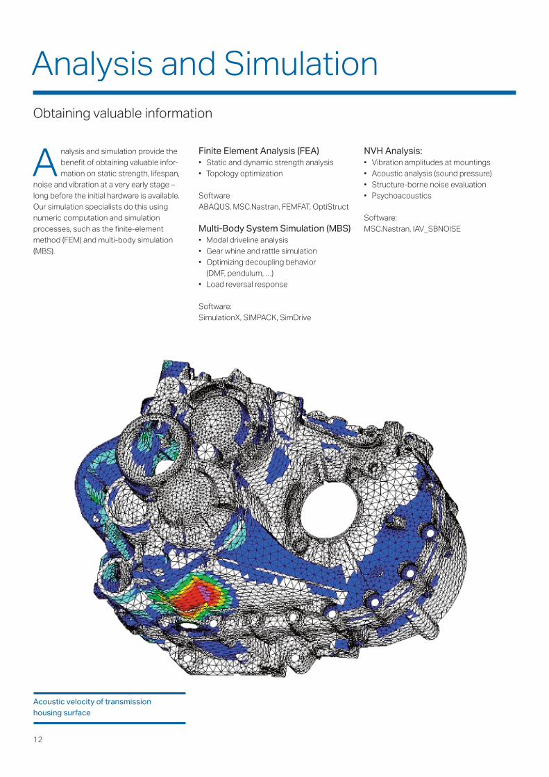
A nalysis and simulation provide thebenefit of obtaining valuable infor-mation on static strength, lifespan,
noise and vibration at a very early stage –long before the initial hardware is available.Our simulation specialists do this usingnumeric computation and simulationprocesses, such as the finite-elementmethod (FEM) and multi-body simulation(MBS).
NVH Analysis:• Vibration amplitudes at mountings• Acoustic analysis (sound pressure)• Structure-borne noise evaluation• Psychoacoustics
Software: MSC.Nastran, IAV_SBNOISE
Finite Element Analysis (FEA)• Static and dynamic strength analysis• Topology optimization
SoftwareABAQUS, MSC.Nastran, FEMFAT, OptiStruct
Multi-Body System Simulation (MBS)• Modal driveline analysis• Gear whine and rattle simulation• Optimizing decoupling behavior
(DMF, pendulum, …)• Load reversal response
Software:SimulationX, SIMPACK, SimDrive
Acoustic velocity of transmissionhousing surface
Analysis and SimulationObtaining valuable information
IAV Velodyn An innovative tool for simulating longitudinal powertrain dynamics
13
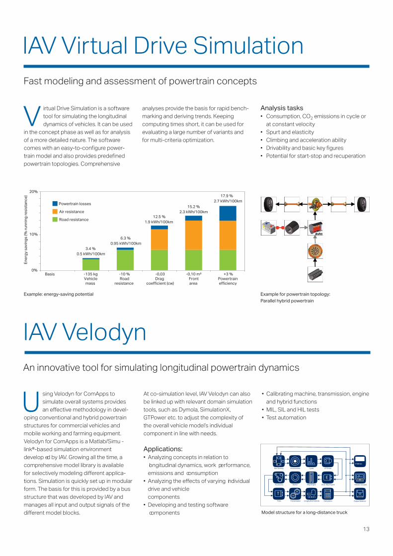
Basis -135 kgVehiclemass
-10 %Road
resistance
-0,03Drag
coefficient (cw)
-0,10 m²Frontarea
+3 %Powertrainefficiency
Ene
rgy
savi
ngs
(% r
unni
ng r
esis
tanc
e)
3.4 %0.5 kWh/100km
6.3 %0.95 kWh/100km
12.5 %1.9 kWh/100km
15.2 %2.3 kWh/100km
17.9 %2.7 kWh/100km
Powertrain losses
Air resistance
Road resistance
0%
10%
20%
Example: energy-saving potential Example for powertrain topology:Parallel hybrid powertrain
U sing Velodyn for ComApps tosimulate overall systems providesan effective methodology in devel-
oping conventional and hybrid powertrainstructures for commercial vehicles andmobile working and farming equipment.Velodyn for ComApps is a Matlab/Simu -link®-based simulation environmentdevelop ed by IAV. Growing all the time, acomprehensive model library is available for selectively modeling different applica-tions. Simulation is quickly set up in modularform. The basis for this is provided by a busstructure that was developed by IAV andmanages all input and output signals of thedifferent model blocks.
• Calibrating machine, transmission, engineand hybrid functions
• MIL, SIL and HIL tests• Test automation
At co-simulation level, IAV Velodyn can alsobe linked up with relevant domain simulationtools, such as Dymola, SimulationX,GTPower etc. to adjust the complexity ofthe overall vehicle model’s individualcomponent in line with needs.
Applications:• Analyzing concepts in relation to
longitudinal dynamics, work performance,emissions and consumption
• Analyzing the effects of varying individualdrive and vehicle components
• Developing and testing software components Model structure for a long-distance truck
l/100 km
Bus Dummy Environment Cycle AT Driver
Velodyn ScopesECU: Map EngineMap EngineStarterAccessory
TCUv Transmission Longitudinal Vehicle Calculation Output Selector
V irtual Drive Simulation is a softwaretool for simulating the longitudinaldynamics of vehicles. It can be used
in the concept phase as well as for analysisof a more detailed nature. The softwarecomes with an easy-to-configure power-train model and also provides predefinedpowertrain topologies. Comprehensive
Analysis tasks• Consumption, CO2 emissions in cycle or
at constant velocity• Spurt and elasticity• Climbing and acceleration ability• Drivability and basic key figures• Potential for start-stop and recuperation
analyses provide the basis for rapid bench-marking and deriving trends. Keepingcomputing times short, it can be used forevaluating a large number of variants andfor multi-criteria optimization.
IAV Virtual Drive SimulationFast modeling and assessment of powertrain concepts
14
IAV Knowledge Database is a datamanagement and analysis tool forcompiling vehicle and powertrain specifica-tions. The system offers a platform forglobal benchmarking. Modular in form, itcan be adapted to any specific applicationarea. The IAV Knowledge Database isavailable for our development partners andcustomers to purchase and use.
Fields of knowledge come from tradejournals, conferences, online/websites,trade and consumer publications fromEurope, Asia and North America. It is alsopossible to store a customer‘s internal dataand compare them with the external dataprovided. The IAV Knowledge Databaseincludes information on vehicles propelledby conventional and alternative drives.
Data security is guaranteed by means of theauthorization concept. Using authority
groups, it is possible to control data accessand protect confidential data.
Methods of analysis can be set up to suitany specific inquiry task. Selected vehicles,engines, transmission etc. are displayed in atable. Technical parameters are presentedin graphic form as point charts (e.g. scatterbands), bar charts or spider charts. Charac-teristic curves and maps can be overlaid toevaluate and visualize the differences.
Data communication is available forimporting and exporting data from and toMicrosoft Excel spreadsheets making iteasy to continue processing all search andinquiry results. External data sources can beimported (e.g. EPA).
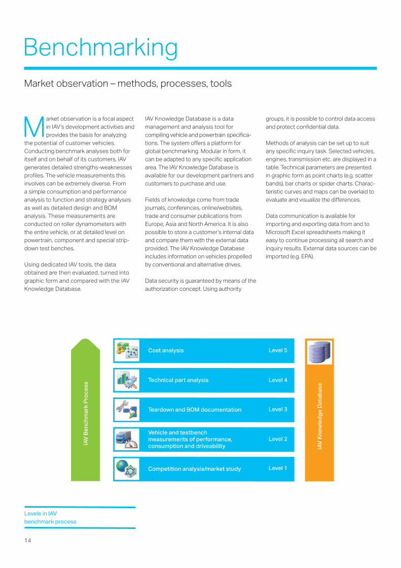
Market observation is a focal aspectin IAV’s development activities andprovides the basis for analyzing
the potential of customer vehicles.Conducting benchmark analyses both foritself and on behalf of its customers, IAVgenerates detailed strengths-weaknessesprofiles. The vehicle measurements thisinvolves can be extremely diverse. From a simple consumption and performanceanalysis to function and strategy analysesas well as detailed design and BOManalysis. These measurements areconducted on roller dynamometers withthe entire vehicle, or at detailed level onpowertrain, component and special strip-down test benches.
Using dedicated IAV tools, the dataobtained are then evaluated, turned intographic form and compared with the IAVKnowledge Database.
BenchmarkingMarket observation – methods, processes, tools
Competition analysis/market study
Vehicle and testbench measurements of performance,consumption and driveability
Teardown and BOM documentation
Technical part analysis
Cost analysis
IAV Benchmark Process
IAV Knowledge Database
Level 5
Level 4
Level 3
Level 2
Level 1
Levels in IAV benchmark process

15
W e meet the increasingly complexdemands on the functionalityand efficiency of powertrains
using an effective, perfected and start-to-finish design process for developing trans-missions and hybrid systems. Our attentionis focused on designing all types of newand derivative transmissions to the point ofmass production. We use our particularstrengths in optimizing transmission design:Close cooperation with all of the devel-opment and production departmentsinvolved as well as our vast experience inproduct-range and vendor management.
With our many years of experience, exper -tise and process-related knowledge indeveloping components, function assem-blies, complete transmission and hybridsystems to the point at mass production,we are the right address for your trans-mission development projects. Our expertsin designing transmission mechanics,hydraulics and electro-mechanics employstate-of-the-art design and simulation tools– some developed in-house – as well as awide range of CAD and PDM systems.
IAVs highly efficient 9-DCT
Transmission DesignFull range of transmission applications
Selection of design activities:• Definition of requirements and product
specifications• Systematic dimensioning of mechanical
elements based on load spectrum• Layout, design (3D) and derivation of
production drawings (2D) • 1D, 2D, 3D tolerance simulation
(statistical, cross-assembly)• Product data management and
competence in CAD methodology • D-FMEA • Vendor and product range management
Mechanical transmission systemsToday, the need to reduce the time and costfactor in designing and developing transmis-sions makes it essential to adapt durabilitysimulation.
IAV uses computation software andprocesses to predict the life of the entiretransmission system on the basis of loadspectra that can be generated by simulationor measurement. This permits comparison of several concepts at an early stage of thedesign process with a view to optimizing thepreferred solution. The influence of deriv-ative applications can also be analyzed, e.g.,for hybridizing a conventional powertrain. Inaddition, dimensioning the mechanical ele -ments with greater precision helps to speedup and cut the costs involved in testing.
Hydraulic components and control unitsHydraulic systems are used when forces andmovements need to be transferred with ahigh level of precision, speed and efficiency.In automotive hydraulics, other demandsinclude functional intelligence coupled withmaximum efficiency and minimum package.
Our hydraulic systems – used in controllingtransmissions for example – meet all ofthese requirements. Whether it is electro-hydraulic pressure supply systems withmulti-stage pumps, solenoid valves orintegrating all components into a singletransmission control module, we will find thebest possible solution for your specific app -lication in terms of performance, comfortand durability – and all at an attractive price.
We are equally at home with other hydraulicactuation systems, such as parking-locksystems or torque vectoring modules. Our portfolio covers all aspects fromconcept definition, simulation, prototyping to testing all disciplines. With our state-of-the-art in-house testing, analysis andlaboratory equipment, we are also yourexpert partner in the field of competitorbenchmarks, durability tests, failure analysisand optimization.

16
System IntegrationMore than the sum of its parts
T he growing number of autonomoussub-functions in commercialvehicles along with increasing
pressure from policymakers and industryfor safe, efficient and low-emission vehicleis ultimately leading to a huge rise in thecomplexity of control systems, particularlyin the powertrain.
With many years of experience in drivelineintegration, IAV’s system engineers work inline with the SIMILAR* process.
Stating the problem is the most importantsystem engineering task (identifying/under-standing customer needs; establishing theneed for change, discovering requirements;defining system functions).
Investigate alternatives and evaluate thembased on performance, cost and risk.
Model the system, running model clarifiesrequirements, reveals bottlenecks andfragmented activities, reduces cost andexposes duplication of efforts.
Integrate the systems by designing inter-faces and bringing system elementstogether so that they work as a whole. Thisrequires extensive communication andcoordination.
Launch the system, making the system dowhat it was intended to do.
Assess performance by using evaluationcriteria, technical performance measuresand metric. measurement is the key. Nomeasure, no control. No control, no improvement.
Re-evaluation should be a continual anditerative process with many loops.
As a competent development partner, IAVmeets these requirements and is at yourdisposal every step of the way through theproduct generation process.
Integrating sub-systemsThe complexity of modern powertraincomponents is growing all the time andhybridization is bringing new distributedfunctions. IAV tests new functions for sub-systems using rapid prototyping as early asthe offline simulation stage with IAVVeloDyn closed loop before integrationtakes place. State-of-the-art measurementtechnology and testing facilities areavailable for conducting error responsetests on the individual component as wellas for testing components in an integratedway. The basis for functional validation isprovided by ISO 61508 or ISO 26262.Interface checks, function analyses as wellas cyclic conformity and software testingensure smooth integration. Automating andre-using subsystems, interfaces and tests isthe aim wherever it makes sense.
Integrating the overall systemIntegrating new component types into newor existing systems is a challenge on itsown. With a view to system architecture,competent engineers define and developthe interfaces and analyze the interactionof distributed systems. Particularly in thelight of green technology (hybrid),innovative integration strategies /approaches are needed for integrating newand existing components. Coordinatingthe project partners, the hardware and thesoftware as well as the mechanical systemis just as much at the focus as validatingthe overall system and verifying thedistributed systems (integration test).Starting up the vehicle complements theportfolio.
IAV’s system engineering goal is to satisfyour costumers’ needs, to increase theprobability of system success, to reducethe risks and total life-cycle cost. We haveproved this in many projects – do it in theSIMILAR way!
* The Systems Engineering Process from A. T. Bahilland B. Gissing, Re-evaluating systems engineeringconcepts using systems thinking, IEEE Transactionon Systems, Man and Cybernetics, Part C: Applica-tions and Reviews, 28 (4), 516-527, 1998.

18
Software and AlgorithmDevelopmentMany years of experience in professional software development for various transmissions
W e are your expert provider fordeveloping complex controlsystems for transmission,
hybrid and electric drive applications. Our expertise centers on developingproduction-ready as well as prototypeopen and closed-loop control strategiesfor all contemporary automatic transmis-sions, such as dual-clutch transmissions(wet and dry), automated manual andplanetary automatic transmissions withconverter.
Automatic transmissions are employed inconventional and hybrid powertrains. It is in this context that our efforts focus onaspects, such as controlling the gearshiftprocess in dual-clutch transmissions andplanetary automatic transmissions, ondeveloping diagnostic and safetystrategies as well as on additionalfunctions such as start/stop, coasting andactivating additional torque in hybridpowertrains. The customer alone decideswhether the development process followsa model-based or conventional approach.
Our development activities are alwaysintegrated in clearly defined processes
from the aspect of requirements, testing andquality management.
Assisting the process of algorithm devel-opment, we utilize the benefits of earlyclosed-loop simulation at model-in-the-loopor software-in-the-loop level.
IAV uses standard as well as customizedtools and development environments fordeveloping prototype software in theshortest time possible.
No rapid prototyping without prototypecontrol unit: We use our own control unit toavoid any compromises in controlling proto-types. In addition to the computer core, ofcourse, it integrates all requisite input andoutput stages that bring new hybrid or trans-mission concepts to life. Its robust configu-ration, also for accommodation in the enginecompartment, automotive-type plugconnectors, calibration access via XCP-over-Ethernet, flexibility of the numerous outputdrivers and the full tool chain for automati-cally generating code from TargetLink,including integration with existing or newlydeveloped C Code, enable us to commissionprototype transmissions in next to no time.
Competencies in control systemDevelopment• Production-ready development of entire
transmission control systems for AMTsand DCTs
• Development of entire transmissioncontrol systems for planetary automatictransmissions with converter
• Clutch control for wet and dry systems• Hydraulic and electromechanical
actuators• Safety-relevant systems and diagnostics• Powertrain management• Requirements management• Model-based software development• Tool chain for autocoding• Software development for production
software to SPICE• Software quality management• Closed-loop simulation (MiL, SiL)• HiL systems and software validation• Configuring and integrating embedded
software

19

20
T he vehicle of tomorrow is definedby complex and diverse powertrainconcepts. From the conventional
drive to hybrid concepts and the electricvehicle. System diversity and complexitygo hand in hand with ever more effortinvolved in coordinating torque. And thedemands on functional safety areincreasing in the same proportion as well.
The aim of functional safety is to identifyand evaluate hazards inherent in thesystem and then counteract them system-atically by applying appropriate measuresto reduce them to an acceptable level.This is the basis on which our experts
specify, realize, test and validate safetyconcepts that reflect the state of the art.
IAV has been developing vehicle powertrainsto the level of manufacturing readiness onbehalf of many different customers for over25 years – also providing support in creatingrelevant safety concepts, such as the triedand proven three-level EGAS concept forengine control units and its adaptation toinnovative transmission and e-mobilityconcepts.
All this puts us in a position to developeffective and also efficient technicalsolutions for our customers.
What we do• Manage and provide assistance with the
safety process• Analyze and realize safety concepts
relating to all aspects of the powertrain• Provide consulting in relation to applying
ISO 61508 or ISO 26262• Provide independent reviews and
assessments
Functional SafetyEnsuring functional safety under ISO 61508 or ISO 26262 in developing powertrains – is part of our daily routine
D iagnostics are gaining more andmore significance in the context ofall-round consumer satisfaction.
Our current focus is on electronic trans-mission management. In general, this isdivided into functional diagnostics anddiagnostics required by law (OBD). Ourexperts have over a decade of experiencein all relevant subject areas.
Functional diagnostics• Analysis and creation of functional
diagnostic concepts at system level• Defining specifications for and imple-
menting diagnostic functions at (sub-)system level
• Defining specifications for and imple-menting fault management (fault handler)
• Verification and testing / validation on HiLsystems and in the vehicle
• Calibration and adjustment to differentvehicle versions / platforms
• Support in customer service at the OEM
On-board diagnosis (OBD)• Evaluation and definition of the OBD
relevance of parts and components of theelectronic transmission control system
• Planning and configuration of OBD-specific functions and software modules,such as the fault manager or in-usemonitoring performance ratio
• Planning, performance and evaluation ofOBD approval and acceptance testsrequired by law
• Advice on generating as well asproducing the approval documentationrequired
• Definition and coordination of interfaceswith the control units involved
• Definition and selection of fault codesrequired by law
• Definition, generation and implemen-tation of test automation in the field ofOBD
Diagnostics / OBDSatisfying the specific demands of diagnostics in electronic transmission control systems – is an elementary key aspect of what we do

I n addition to the all-encompassingprocess of software and algorithm devel-opment, IAV provides support in testing
for assessing changed and/or new sourcesjust in time. This involves several efficient,fast and lean test stages.
White-box tests have the purpose offormally verifying software quality. We notonly examine software metrics, MISRA rulesand observance of project-related guide-lines but also perform the classic codecoverage tests for locating numericallyproblematical calibrations and operations.The latter are conducted both in the form ofreviews as well as semi-automatically.
We take care of formal and functional verifi-cation for model-driven software devel-opment where model testing,
model-in-loop and back-to-back tests areour everyday work tools. Automaticallygenerated (structure-based) test vectorsprovide the necessary code coveragewhereas functional testing of the modeledfunctions verifies implementation in linewith requirements.
HiL simulators are used for automaticallyexamining the resultant software for itsanticipated behavior on the target hardware.Beside the obligatory diagnostic tests, wealso analyze and evaluate all aspects oftransmission functions.
Moving extensive test scenarios from thevehicle onto the HiL (test automation)produces huge time savings in testing andalso improves the reproducibility of results.Automated evaluation provides further
benefits. For example, the data measuredduring testing can be scanned automati-cally for defined criteria, resulting inadditional test coverage.
Competencies:• Test management for production-level
projects• Verification of production-level software• White-box testing• Black-box testing• Test automation• Carrying out TPI (Test Process
Improvement)
Transmission Software TestingSystematic validation at all test stages from the outset –being sure to develop the right solution

Fault handlerTrigger
Reset
Status
Control unit
Loca
l dia
gno
sis
22
CalibrationCalibration service portfolio
D rivability – is a term that covers bothsubjective as well as objective fac -tors. Jerky clutch engagement, for
example, is evaluated subjectively whereasobjective measurements record acceleration,vibration or acoustics. Modeling and simu -lation methods are used for examining physi -cal processes to improve the calibrationprocess. Modern powertrain concepts withautomated gear selection need to meet evertighter legislation while also taking account of the consumer’s personal driving style andproviding contemporary ride comfort. Thistrade-off can only be resolved by taking anintegrated approach to the powertrain. This is why modern powertrain concepts only use transmission control systems that workon an interconnected basis.
Our engineers develop calibration solutionsin accordance with generally acknowledgedcriteria or criteria agreed with the client andensure constant high quality for volumepro duction. Everything is then balanced and validated in test drives under all climaticand country-specific conditions.
For many years, IAV has been a strategicpartner to customers across the globe inthe field of transmission calibration. In thecourse of key or vehicle derivative projects
this involves all-embracing developmentactivities to manufacturing readiness level.The range of services we provide in thisdomain is extremely broad and covers thefollowing aspects:
Shift Quality (SQ)• Configuration and optimization of clutch
actuation and the gearshift process• Gear engagement / start / drive-off cycle• Limit sample calibration
(tolerances / wear)
• Optimization of comfort and acoustics• Calibration under all climatic conditions • Calibration of WSC (wet starting clutch) /
TCLC (torque converter lockup clutch)control and strategy
• Neutral idle control• Clutch adaptation
Three-level concept
Level 1 OBD module(OBDII)(MY2005 ff.)
Diagnosis tester(external)
Level 2
Level 2’
Level 3
Next milestone
SOPnth Integration milestone
(n-1)th Integration milestone
Scan ToolComm.
VAS-Comm.
INIT Basic cali-bration
Initialstart up Review Application Review Accep tance
drive Vali dation Release
CAL1 CAL2 CAL3 CAL4 CAL5 CAL6 CAL7 CAL8 CAL9
CAL5 CAL6 CAL7 CAL8 CAL9
CAL5 CAL6 CAL7 CAL8 CAL9
Diagram of calibration process phases
23
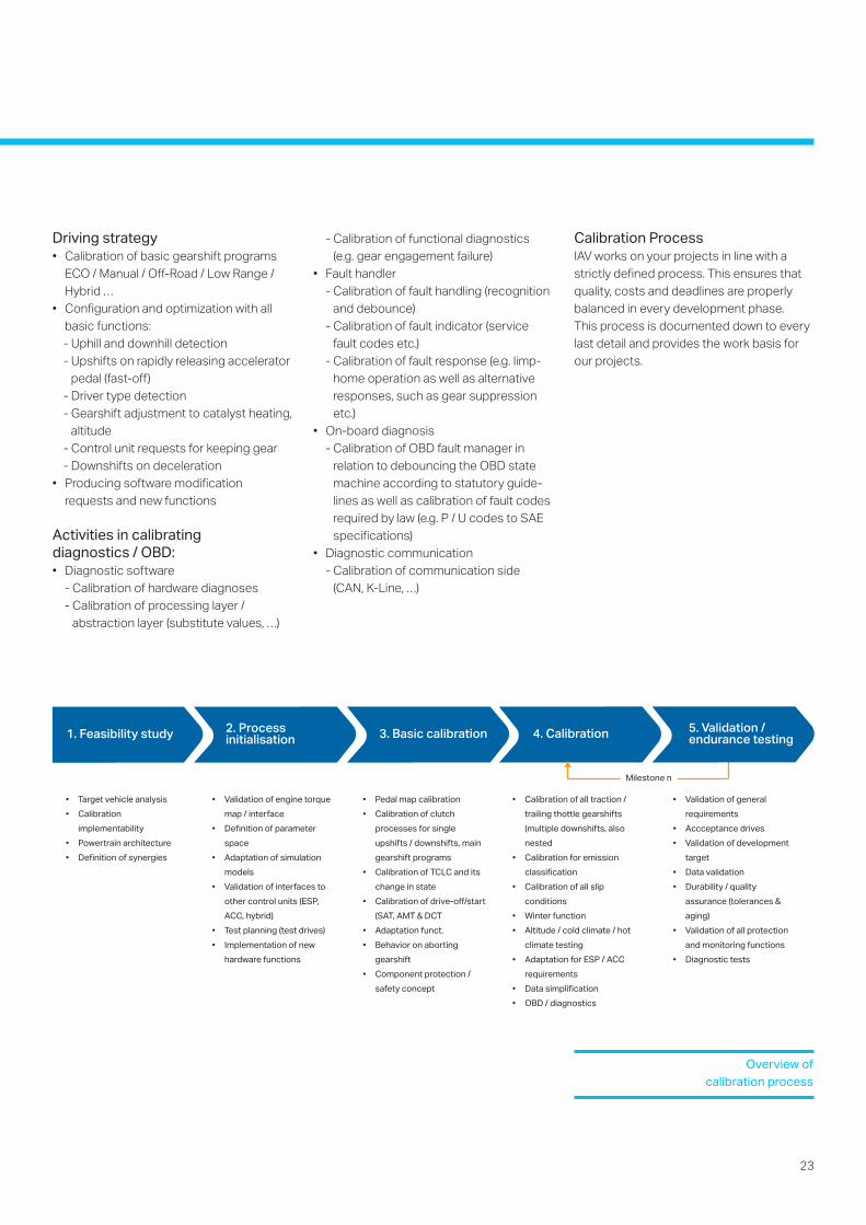
Driving strategy• Calibration of basic gearshift programs
ECO / Manual / Off-Road / Low Range /Hybrid …
• Configuration and optimization with allbasic functions: - Uphill and downhill detection - Upshifts on rapidly releasing accelerator
pedal (fast-off) - Driver type detection- Gearshift adjustment to catalyst heating,
altitude- Control unit requests for keeping gear- Downshifts on deceleration
• Producing software modificationrequests and new functions
Activities in calibrating diagnostics / OBD:• Diagnostic software
- Calibration of hardware diagnoses - Calibration of processing layer /
abstraction layer (substitute values, …)
1. Feasibility study 2. Processinitialisation
• Target vehicle analysis
• Calibration
implementability
• Powertrain architecture
• Definition of synergies
• Validation of engine torque
map / interface
• Definition of parameter
space
• Adaptation of simulation
models
• Validation of interfaces to
other control units (ESP,
ACC, hybrid)
• Test planning (test drives)
• Implementation of new
hardware functions
• Pedal map calibration
• Calibration of clutch
processes for single
upshifts / downshifts, main
gearshift programs
• Calibration of TCLC and its
change in state
• Calibration of drive-off/start
(SAT, AMT & DCT
• Adaptation funct.
• Behavior on aborting
gearshift
• Component protection /
safety concept
• Calibration of all traction /
trailing thottle gearshifts
(multiple downshifts, also
nested
• Calibration for emission
classification
• Calibration of all slip
conditions
• Winter function
• Altitude / cold climate / hot
climate testing
• Adaptation for ESP / ACC
requirements
• Data simplification
• OBD / diagnostics
• Validation of general
requirements
• Accceptance drives
• Validation of development
target
• Data validation
• Durability / quality
assurance (tolerances &
aging)
• Validation of all protection
and monitoring functions
• Diagnostic tests
Milestone n
3. Basic calibration 5. Validation /endurance testing4. Calibration
Overview of calibration process
- Calibration of functional diagnostics (e.g. gear engagement failure)
• Fault handler- Calibration of fault handling (recognition
and debounce)- Calibration of fault indicator (service
fault codes etc.)- Calibration of fault response (e.g. limp-
home operation as well as alternativeresponses, such as gear suppressionetc.)
• On-board diagnosis- Calibration of OBD fault manager in
relation to debouncing the OBD statemachine according to statutory guide-lines as well as calibration of fault codesrequired by law (e.g. P / U codes to SAEspecifications)
• Diagnostic communication- Calibration of communication side
(CAN, K-Line, …)
Calibration ProcessIAV works on your projects in line with astrictly defined process. This ensures thatquality, costs and deadlines are properlybalanced in every development phase. This process is documented down to everylast detail and provides the work basis forour projects.
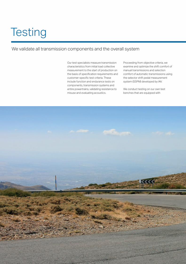
TestingWe validate all transmission components and the overall system
Our test specialists measure transmissioncharacteristics from initial load collectivemeasurement to the start of production onthe basis of specification requirements andcustomer-specific test criteria. Theseinclude function and endurance tests oncomponents, transmission systems andentire powertrains, validating resistance tomisuse and evaluating acoustics.
Proceeding from objective criteria, weexamine and optimize the shift comfort ofmanual transmissions and selectioncomfort of automatic transmissions usingthe selector shift pedal measurementsystem (SSPM) developed by IAV.
We conduct testing on our own testbenches that are equipped with

state-of-the-art measurement systems.Validation drives carried out under extremeconditions (summer, winter, altitude)complement the test series. Our clients canbuild on our engineers’ many years ofexperience with all transmission types –particularly in analyzing roller bearings,gearings and synchronizers.
27
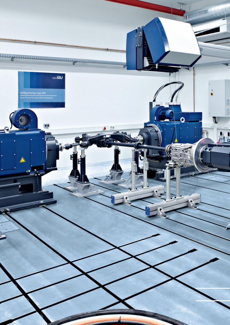
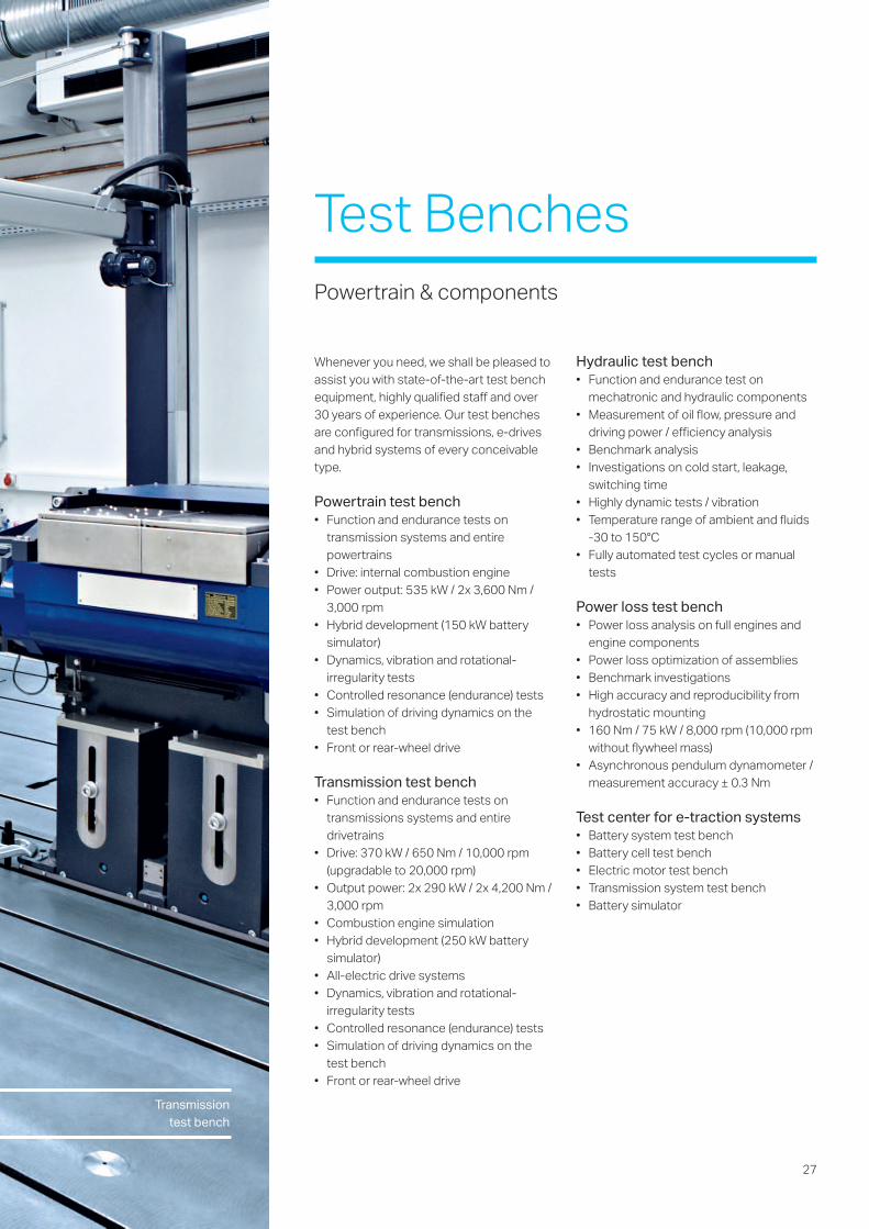
Whenever you need, we shall be pleased toassist you with state-of-the-art test benchequipment, highly qualified staff and over30 years of experience. Our test benchesare configured for transmissions, e-drivesand hybrid systems of every conceivabletype.
Powertrain test bench• Function and endurance tests on
transmission systems and entirepowertrains
• Drive: internal combustion engine• Power output: 535 kW / 2x 3,600 Nm /
3,000 rpm• Hybrid development (150 kW battery
simulator)• Dynamics, vibration and rotational-
irregularity tests• Controlled resonance (endurance) tests• Simulation of driving dynamics on the
test bench• Front or rear-wheel drive
Transmission test bench• Function and endurance tests on
transmissions systems and entiredrivetrains
• Drive: 370 kW / 650 Nm / 10,000 rpm(upgradable to 20,000 rpm)
• Output power: 2x 290 kW / 2x 4,200 Nm /3,000 rpm
• Combustion engine simulation• Hybrid development (250 kW battery
simulator)• All-electric drive systems• Dynamics, vibration and rotational-
irregularity tests• Controlled resonance (endurance) tests• Simulation of driving dynamics on the
test bench• Front or rear-wheel drive
Hydraulic test bench• Function and endurance test on
mechatronic and hydraulic components• Measurement of oil flow, pressure and
driving power / efficiency analysis• Benchmark analysis• Investigations on cold start, leakage,
switching time• Highly dynamic tests / vibration• Temperature range of ambient and fluids
-30 to 150°C• Fully automated test cycles or manual
tests
Power loss test bench• Power loss analysis on full engines and
engine components• Power loss optimization of assemblies• Benchmark investigations• High accuracy and reproducibility from
hydrostatic mounting• 160 Nm / 75 kW / 8,000 rpm (10,000 rpm
without flywheel mass)• Asynchronous pendulum dynamometer /
measurement accuracy ± 0.3 Nm
Test center for e-traction systems• Battery system test bench• Battery cell test bench• Electric motor test bench• Transmission system test bench• Battery simulator
Test BenchesPowertrain & components
Transmissiontest bench
28
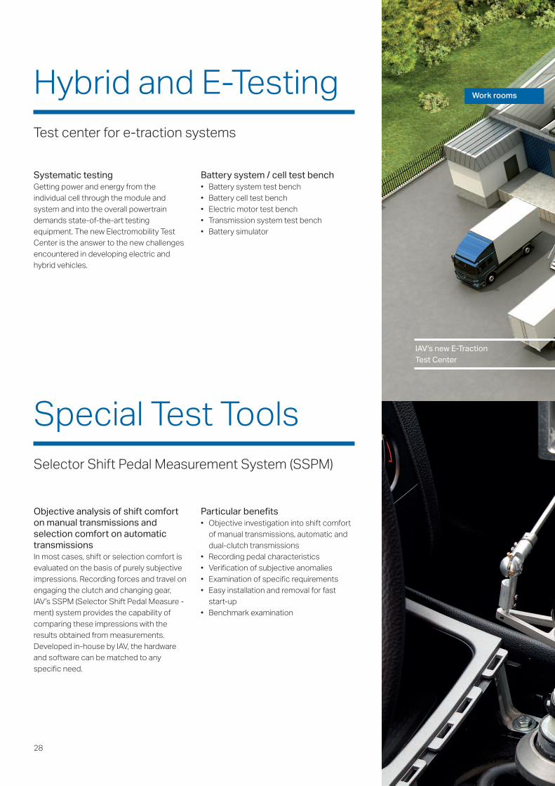
Work roomsHybrid and E-TestingTest center for e-traction systems
IAV’s new E-Traction Test Center
Objective analysis of shift comforton manual transmissions andselection comfort on automatictransmissions In most cases, shift or selection comfort isevaluated on the basis of purely subjectiveimpressions. Recording forces and travel onengaging the clutch and changing gear,IAV’s SSPM (Selector Shift Pedal Measure -ment) system provides the capability ofcomparing these impressions with theresults obtained from measurements.Developed in-house by IAV, the hardwareand software can be matched to anyspecific need.
Particular benefits• Objective investigation into shift comfort
of manual transmissions, automatic anddual-clutch transmissions
• Recording pedal characteristics• Verification of subjective anomalies• Examination of specific requirements• Easy installation and removal for fast
start-up• Benchmark examination
Systematic testingGetting power and energy from theindividual cell through the module andsystem and into the overall powertraindemands state-of-the-art testingequipment. The new Electromobility TestCenter is the answer to the new challengesencountered in developing electric andhybrid vehicles.
Battery system / cell test bench• Battery system test bench• Battery cell test bench• Electric motor test bench• Transmission system test bench• Battery simulator
Special Test ToolsSelector Shift Pedal Measurement System (SSPM)
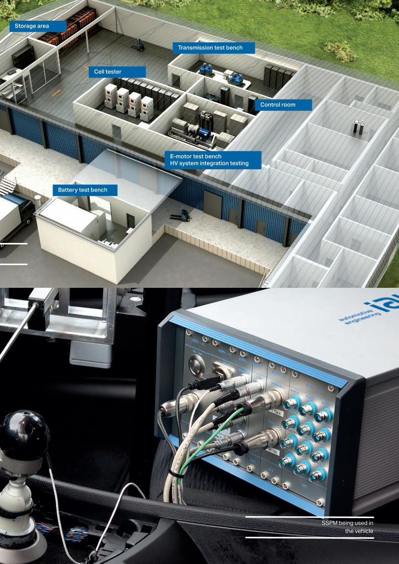
Storage area
Cell tester
Control room
E-motor test benchHV system integration testing
Battery test bench
Transmission test bench
SSPM being used inthe vehicle
30
PrototypingFlexible and fast, production-ready solution always at the focus
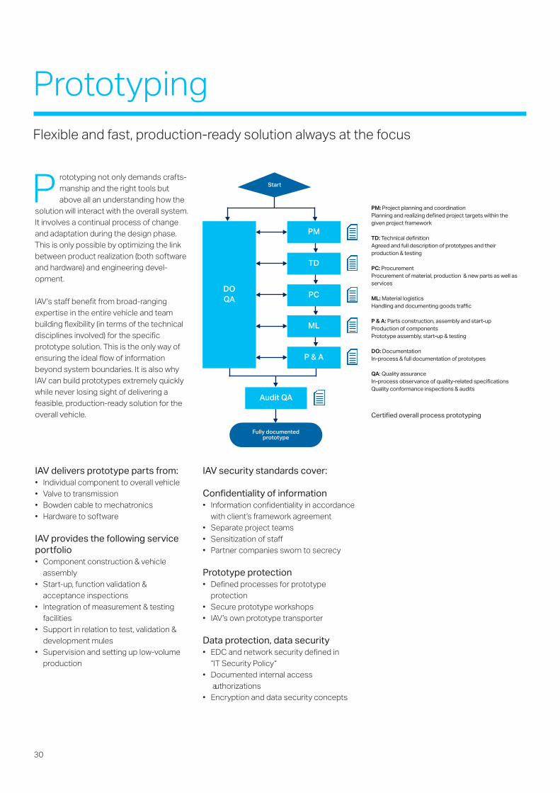
P rototyping not only demands crafts-manship and the right tools butabove all an understanding how the
solution will interact with the overall system.It involves a continual process of changeand adaptation during the design phase.This is only possible by optimizing the linkbetween product realization (both softwareand hardware) and engineering devel-opment.
IAV‘s staff benefit from broad-rangingexpertise in the entire vehicle and teambuilding flexibility (in terms of the technicaldisciplines involved) for the specificprototype solution. This is the only way ofensuring the ideal flow of informationbeyond system boundaries. It is also whyIAV can build prototypes extremely quicklywhile never losing sight of delivering afeasible, production-ready solution for theoverall vehicle.
IAV delivers prototype parts from:• Individual component to overall vehicle• Valve to transmission• Bowden cable to mechatronics• Hardware to software
IAV provides the following serviceportfolio• Component construction & vehicle
assembly• Start-up, function validation &
acceptance inspections• Integration of measurement & testing
facilities• Support in relation to test, validation &
development mules• Supervision and setting up low-volume
production
IAV security standards cover:
Confidentiality of information• Information confidentiality in accordance
with client’s framework agreement• Separate project teams• Sensitization of staff• Partner companies sworn to secrecy
Prototype protection• Defined processes for prototype
protection• Secure prototype workshops• IAV’s own prototype transporter
Data protection, data security• EDC and network security defined in
“IT Security Policy“• Documented internal access
authorizations• Encryption and data security concepts
PM: Project planning and coordinationPlanning and realizing defined project targets within thegiven project framework
TD: Technical definitionAgreed and full description of prototypes and theirproduction & testing
PC: ProcurementProcurement of material, production & new parts as well asservices
ML: Material logisticsHandling and documenting goods traffic
P & A: Parts construction, assembly and start-upProduction of componentsPrototype assembly, start-up & testing
DO: DocumentationIn-process & full documentation of prototypes
QA: Quality assuranceIn-process observance of quality-related specificationsQuality conformance inspections & audits
DOQA
PM
TD
PC
ML
P & A
Audit QA
Fully documentedprototype
Start
Certified overall process prototyping
31
Prototype ManufacturingService Portfolio
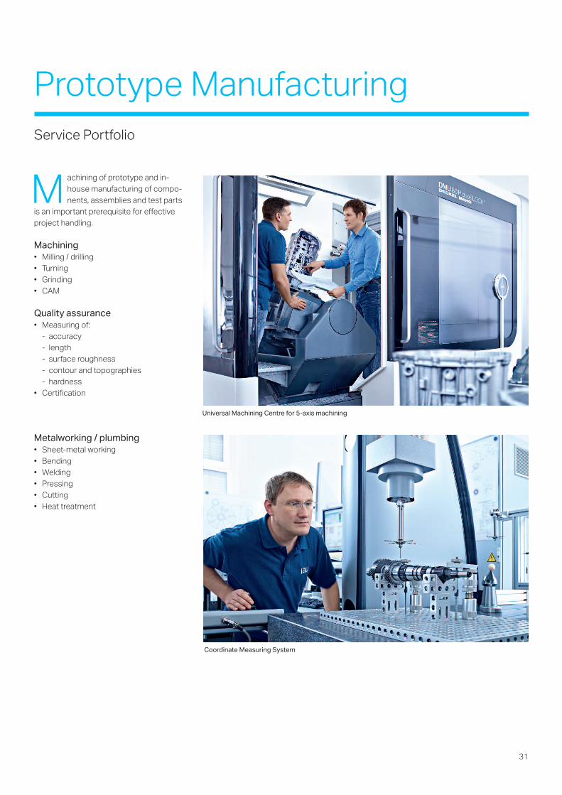
M achining of prototype and in-house manufacturing of compo-nents, assemblies and test parts
is an important prerequisite for effectiveproject handling.
Machining• Milling / drilling• Turning• Grinding• CAM
Quality assurance• Measuring of:
- accuracy- length- surface roughness- contour and topographies- hardness
• Certification
Metalworking / plumbing• Sheet-metal working• Bending• Welding• Pressing• Cutting• Heat treatment
Universal Machining Centre for 5-axis machining
Coordinate Measuring System
32
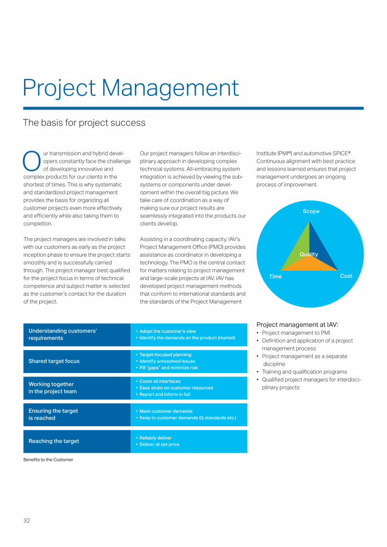
Our project managers follow an interdisci-plinary approach in developing complextechnical systems. All-embracing systemintegration is achieved by viewing the sub-systems or components under devel-opment within the overall big picture. Wetake care of coordination as a way ofmaking sure our project results areseamlessly integrated into the products ourclients develop.
Assisting in a coordinating capacity, IAV‘sProject Management Office (PMO) providesassistance as coordinator in developing atechnology. The PMO is the central contactfor matters relating to project managementand large-scale projects at IAV. IAV hasdeveloped project management methodsthat conform to international standards andthe standards of the Project Management
Institute (PMI®) and automotive SPICE®.Continuous alignment with best practiceand lessons learned ensures that projectmanagement undergoes an ongoingprocess of improvement.
Project management at IAV: • Project management to PMI• Definition and application of a project
management process• Project management as a separate
discipline• Training and qualification programs• Qualified project managers for interdisci-
plinary projects
Our transmission and hybrid devel-opers constantly face the challengeof developing innovative and
complex products for our clients in theshortest of times. This is why systematicand standardized project managementprovides the basis for organizing allcustomer projects even more effectivelyand efficiently while also taking them tocompletion.
The project managers are involved in talkswith our customers as early as the projectinception phase to ensure the project startssmoothly and is successfully carriedthrough. The project manager best qualifiedfor the project focus in terms of technicalcompetence and subject matter is selectedas the customer’s contact for the durationof the project.
Project ManagementThe basis for project success
Scope
Quality
Time Cost
Understanding customers’requirements
• Adopt the customer’s view• Identify the demands on the product (market)
Shared target focus• Target-focused planning• Identify unresolved issues• Fill “gaps” and minimize risk
Working together in the project team
• Cover all interfaces• Ease strain on customer resources• Report and inform in full
Ensuring the targetis reached
• Meet customer demands• Keep to customer demands (Q standards etc.)
Reaching the target• Reliably deliver• Deliver at set price
Benefits to the Customer

33
34
W e meet the increasingly complexdemands on the functionalityand efficiency of powertrains
using an effective, perfected and start-to-finish process for developing transmissionsand hybrid systems. Our attention is alsofocused on developing new and derivativetransmissions to the point of massproduction. To do this, our experiencedexperts in developing transmissionmechanics, hydraulics and software andhardware for electronic control units employstate-of-the-art design, simulation anddevelopment tools – some developed in-house – as well as a wide range of CAD andPDM systems. We use our particular
• High level of flexibility in the type and sizeof work packages using the option withthe best possible prospects of successin terms of development objective,budget and time schedule
• Interdisciplinary product developmentwith a high level of direct responsibility
• Hardware solutions and algorithm development on a one-stop shop basis
• Our development activities are in line withprocess models such as AutomotiveSpice and CMMI
• Test process with high-level and low-leveltesting embedded in the developmentprocess, including test management
strengths in optimizing product design andalgorithm development: close cooperationwith all of the development and productiondepartments involved as well as our vastexperience in product range and suppliermanagement.
• Powertrain development from theadvance-engineering stage to start ofmass production
• Efficient project handling by experiencedspecialists, proven process tool chainand methods, extensive infrastructureand competent project management
• Personal responsibility for engineering,schedule and quality at component andsystem level with IAV System Respon-sible Persons (SRP) and IAV ComponentResponsible Persons (CRP)
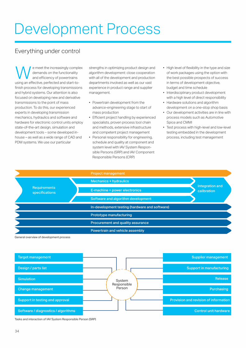
SystemResponsible
Person
Target management
Design / parts list
Simulation
Change management
Support in testing and approval
Supplier management
Support in manufacturing
Release
Purchasing
Provision and revision of information
Software / diagnostics / algorithms Control unit hardware
Tasks and interaction of IAV System Responsible Person (SRP)
General overview of development process
Mechanics + hydraulics
E-machine + power electronicsRequirementsspecifications
Integration andcalibration
Software and algorithm development
Development ProcessEverything under control
Project management
Prototype manufacturing
In-development testing (hardware and software)
Procurement and quality assurance
Powertrain and vehicle assembly
35
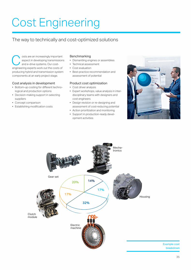
Gear set
20% 14%
17%17%
32%
Clutchmodule
Housing
Mecha-tronics
Electricmachine
C osts are an increasingly importantaspect in developing transmissionsand e-drive systems. Our cost-
engineering experts work out the costs ofproducing hybrid and transmission systemcomponents at an early project stage.
Cost analysis in development• Bottom-up costing for different techno-
logical and production options• Decision-making support in selecting
suppliers• Concept comparison• Establishing modification costs
Benchmarking• Dismantling engines or assemblies• Technical assessment• Cost evaluation• Best-practice recommendation and
assessment of potential
Product cost optimization• Cost driver analysis• Expert workshops, value analysis in inter-
disciplinary teams with designers andcost engineers
• Design revision or re-designing andassessment of cost-reducing potential
• Action prioritization and monitoring• Support in production-ready devel-
opment activities
Cost EngineeringThe way to technically and cost-optimized solutions
Example costbreakdown

Related Documents