The Shell Gasification Process Uhde tk A company of ThyssenKrupp Technologies

Shell Gasification Process
Sep 30, 2014
Welcome message from author
This document is posted to help you gain knowledge. Please leave a comment to let me know what you think about it! Share it to your friends and learn new things together.
Transcript
The Shell Gasification Process
Uhde
tk
A companyof ThyssenKrupp
Technologies
Shell Gasification Process Brosch re_2003.qxd 26.02.04 10:07 Seite 3
The Shell Gasification Process
Contents
1. Company Profile
2. Introduction
3. Process Configuration3.1 Basic Reactions3.2 Main Technology Steps3.3 Advantages of the Shell Gasification Process (SGP)3.4 Reliability Data
4. Gasification Process Flexibility4.1 SGP and Integrated Gasification Combined Cycle (IGCC)4.2 SGP and Chemical Products
5. Shell Pernis – World’s First Oil Based IGCC / H2 Plant
6. Uhde and Gasification
7. Reference List Shell Gasification Process
... / 1
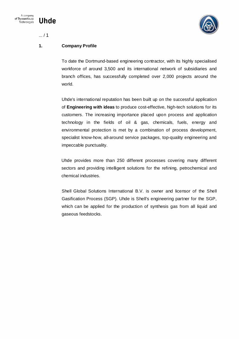
1. Company Profile
To date the Dortmund-based engineering contractor, with its highly specialised
workforce of around 3,500 and its international network of subsidiaries and
branch offices, has successfully completed over 2,000 projects around the
world.
Uhde's international reputation has been built up on the successful application
of Engineering with ideas to produce cost-effective, high-tech solutions for its
customers. The increasing importance placed upon process and application
technology in the fields of oil & gas, chemicals, fuels, energy and
environmental protection is met by a combination of process development,specialist know-how, all-around service packages, top-quality engineering and
impeccable punctuality.
Uhde provides more than 250 different processes covering many different
sectors and providing intelligent solutions for the refining, petrochemical and
chemical industries.
Shell Global Solutions International B.V. is owner and licensor of the Shell
Gasification Process (SGP). Uhde is Shell’s engineering partner for the SGP,
which can be applied for the production of synthesis gas from all liquid and
gaseous feedstocks.

... / 2
2. Introduction
The growing demand for lighter and cleaner fuel products, the heavier crude oil
sources for the refineries and the economical situation inside the refineries to
downgrade the bottom more and more are changing the configuration of the
refineries.
The introduction of stringent environmental legislation in the United States and in
Europe, coupled with global restrictions on the level of aromatics and sulphur
permitted in automotive fuels, will change the internal hydrogen balance in
refineries. New developments in fuel cell technology will also lead to future market
opportunities for hydrogen. But whilst refineries work to satisfy the increasingdemand for hydrogen worldwide, they are also looking to find the best technological
and most cost-effective way to dispose of their final residues.
Refineries are also searching for a global solution to their emission problems and
are gradually replacing the old furnaces used for the production of power, steam
and heat.
Off-gases, such as those produced in catalytic reformers, have traditionally been
the principal source of hydrogen in refineries. However, the compulsory
reformulation of gasoline has limited the level of aromatic constituents permitted.
This change has reduced catalytic severity leading to an increase in the liquid yield,
but a decrease in the hydrogen yield.
The bulk of hydrogen produced today is generated when light hydrocarbons,
particularly natural gas or LPG, undergo a steam reforming process.
During the refining stages, heavy metals – in particular, vanadium, iron and nickel,
which are present in all crude oils – are accumulated in the bottom products. Infact, these residues, which have the highest metal concentration, are the cheapest
feedstocks for gasification units.
... / 3
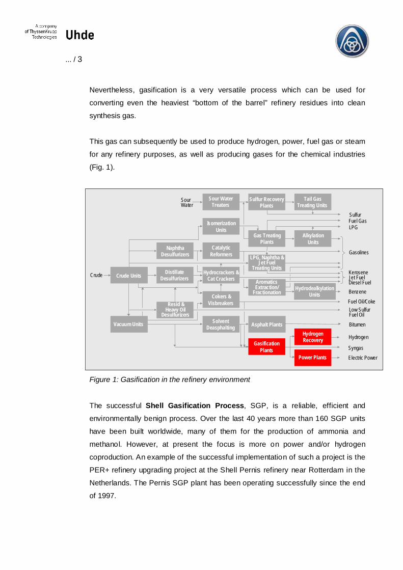
Nevertheless, gasification is a very versatile process which can be used for
converting even the heaviest “bottom of the barrel” refinery residues into clean
synthesis gas.
This gas can subsequently be used to produce hydrogen, power, fuel gas or steam
for any refinery purposes, as well as producing gases for the chemical industries
(Fig. 1).
Fuel Oil/Coke
Asphalt Plants
AlkylationUnits
NaphthaDesulfurizers
DistillateDesulfurizersCrude Units
Vacuum Units SolventDeasphalting
Cokers &Visbreakers
Hydrocrackers &Cat Crackers
CatalyticReformers
Sour WaterTreaters
Sulfur RecoveryPlants
Tail GasTreating Units
IsomerizationUnits
Gas TreatingPlants
LPG, Naphtha &Jet Fuel
Treating Units
HydrodealkylationUnits
Resid &Heavy Oil
Desulfurizers
SourWater
Crude
SulfurFuel GasLPG
Gasolines
KeroseneJet FuelDiesel FuelBenzene
Low SulfurFuel Oil
Bitumen
Hydrogen
Syngas
Electric Power
GasificationPlants
HydrogenRecovery
Power Plants
AromaticsExtraction/
Fractionation
Figure 1: Gasification in the refinery environment
The successful Shell Gasification Process, SGP, is a reliable, efficient and
environmentally benign process. Over the last 40 years more than 160 SGP units
have been built worldwide, many of them for the production of ammonia and
methanol. However, at present the focus is more on power and/or hydrogen
coproduction. An example of the successful implementation of such a project is the
PER+ refinery upgrading project at the Shell Pernis refinery near Rotterdam in the
Netherlands. The Pernis SGP plant has been operating successfully since the end
of 1997.
... / 4
As a technology-oriented company, Uhde can rely on its extensive experience in
the development, design and construction of oil and coal conversion plants. To date
Uhde has designed and built almost 100 gasifiers around the world based on 5
different gasification technologies catering to all types of feedstock – solid, liquid
and gaseous. These technologies include upstream and downstream processes
such as heat recovery, gas treatment (including sulphur recovery), waste water
treatment, and subsequent processes for the production of methanol, ammonia,
hydrogen, oxo-chemicals and electrical power.
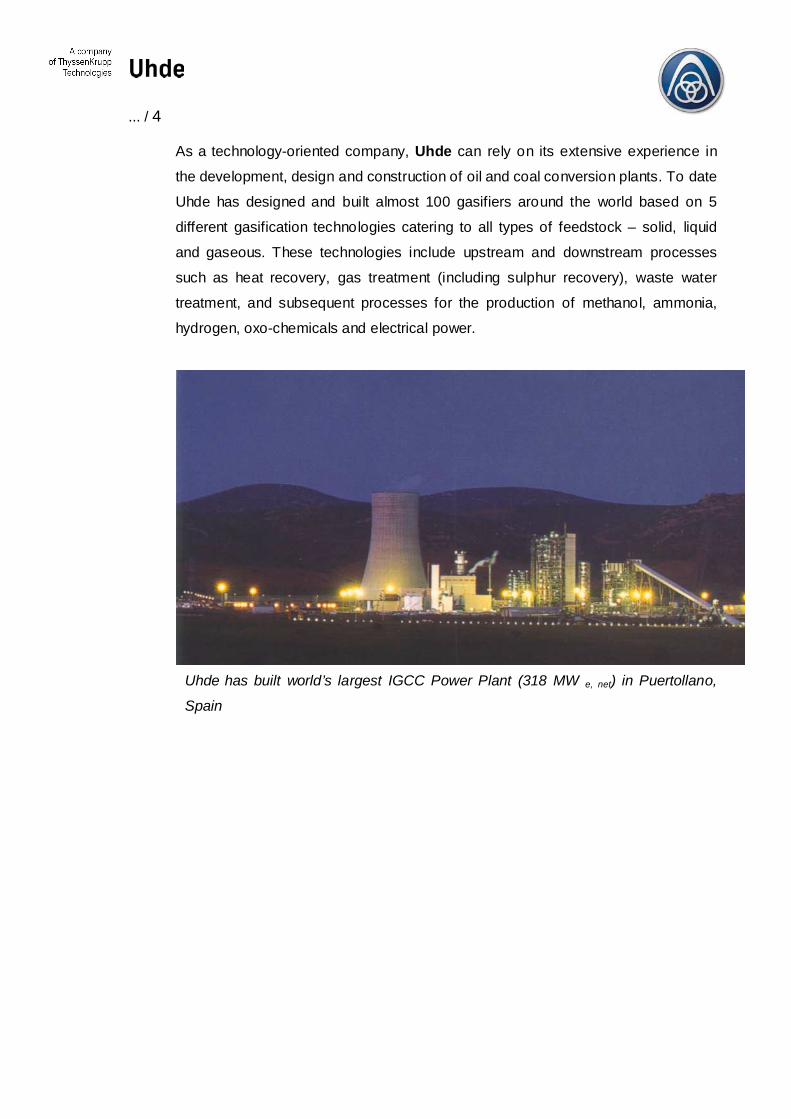
Uhde has built world’s largest IGCC Power Plant (318 MW e, net) in Puertollano,
Spain

... / 5
3. Process Configuration
The Shell Gasification Process has a long track record of optimum performance
over many years of operation.
The SGP process, initially developed in the 1950s, was primarily used with fuel oil
and bunker C oil as feedstocks. By the 1970s vacuum (short) residue had become
the standard feed. In the 1980s vacuum residues were concentrated even further
by visbreaking and C4/C5 deasphalting. Over time, the feed became heavier and
more viscous, and contained higher levels of sulphur and heavy metals. Shell’s
continuous developments in this field over the years underpin its dedication to this
particular technology.
3.1 Basic Reactions
Gasification or partial oxidation is a non-catalytic process; a combination of
exothermic and endothermic reactions, thermal cracking, steam reforming etc.
The net reaction
2CHn + O2 � 2 CO + nH2 (1 < n < 4)
is exothermic and produces a gas which containing mainly CO and H2. The raw
synthesis gas (or syngas) contains small quantities of CO2, H2O and H2S and
impurities, such as CH4, NH3, COS, HCN, N2, Ar and ash, the quantities being
determined by the composition of the feedstock, the oxidant and the actual
gasification temperature (1300 – 1400 °C). A small amount of unconverted carbon
is also present and ranges from 0.5 to 1.0 %wt in liquid feedstocks or 50 – 200 ppm
wt in gaseous feedstocks.
Hydrocarbon fuels, such as natural gas, refinery gas, bunker C-oil, vacuum residue,
vacuum-flashed cracked residue, asphalt, liquid waste and orimulsion can all be
used as feedstock for the gasification process.
... / 6
Operating pressures ranging from atmospheric pressure to 65 bar can easily be
accommodated but depend upon the desired application of the syngas.
3.2 Main Technology Steps
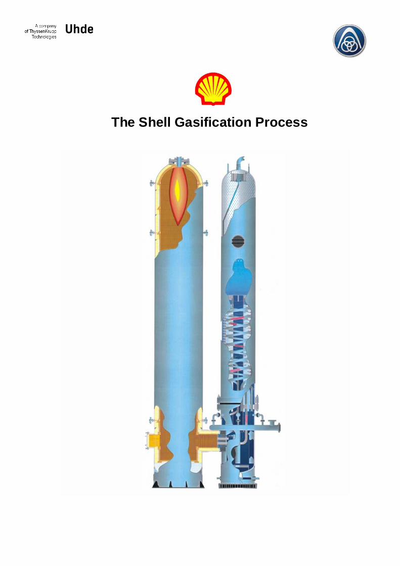
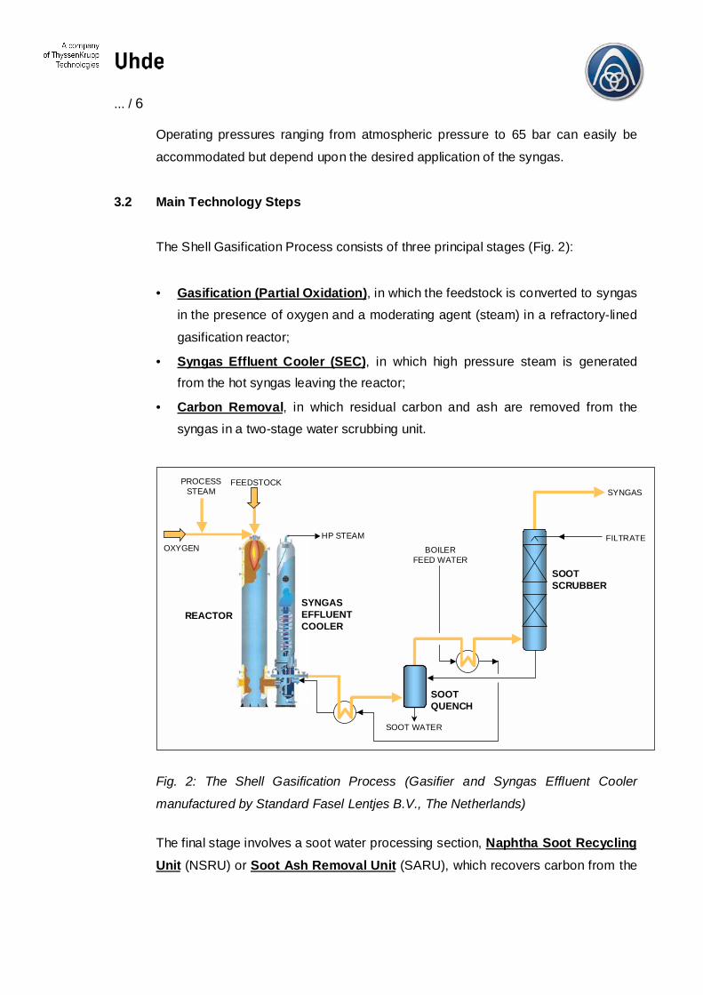
The Shell Gasification Process consists of three principal stages (Fig. 2):
• Gasification (Partial Oxidation), in which the feedstock is converted to syngasin the presence of oxygen and a moderating agent (steam) in a refractory-lined
gasification reactor;
• Syngas Effluent Cooler (SEC), in which high pressure steam is generatedfrom the hot syngas leaving the reactor;
• Carbon Removal, in which residual carbon and ash are removed from thesyngas in a two-stage water scrubbing unit.
FEEDSTOCK
OXYGEN
PROCESSSTEAM
REACTOR
HP STEAM
SYNGASEFFLUENTCOOLER
BOILERFEED WATER
SOOTQUENCH
SOOTSCRUBBER
SYNGAS
SOOT WATER
FILTRATE
Fig. 2: The Shell Gasification Process (Gasifier and Syngas Effluent Cooler
manufactured by Standard Fasel Lentjes B.V., The Netherlands)
The final stage involves a soot water processing section, Naphtha Soot RecyclingUnit (NSRU) or Soot Ash Removal Unit (SARU), which recovers carbon from the
... / 7
wash water and separates the metal ash from the carbon to yield a valuable
product.
Both the feedstock and the gasification agent, oxygen, are preheated prior to being
fed to the burner which is a proprietary co-annular burner specially designed for
viscous feedstocks.
The reactor’s optimal design allows for complete gasification reactions. The burner
is controlled by a managing system which includes a safeguarding system and a
sequence logic block to enable fully automated start and stops and normal
operation during all plant operating conditions.
The recovery of sensible heat from the syngas is an integral feature of the SGP
process. Primary heat recovery takes place in the Syngas Effluent Cooler (SEC)
where high-pressure saturated steam is generated. Secondary heat recovery
occurs in a boiler feed water economiser immediately downstream of the SEC.
The SGP process suspends the carbon (soot) produced by the partial oxidation of
hydrocarbons in the gasifier, in a carbon slurry, which is an aqueous suspension
containing up to 20 g/l of soot and ash. The soot particles and the ash are removed
from the gas in the two-stage water scrubber, comprising:
• a quench pipe and soot separator and
• a soot scrubber.
About 95% of the soot is removed by a direct water spray in the quench pipe.
The gas then enters the scrubber where it is scrubbed in counter-current flow in a
packed bed using condensate return water and the filtrate from the soot water
processing section. After leaving the scrubber the syngas has a residual sootcontent of less than 4 mg/Nm³.
The heavy metals and alkaline-earth metals entering the reactor are transformed
into oxides, sulphides and carbonates, and because these compounds are only
slightly soluble the ash follows the soot water process flow.
... / 8
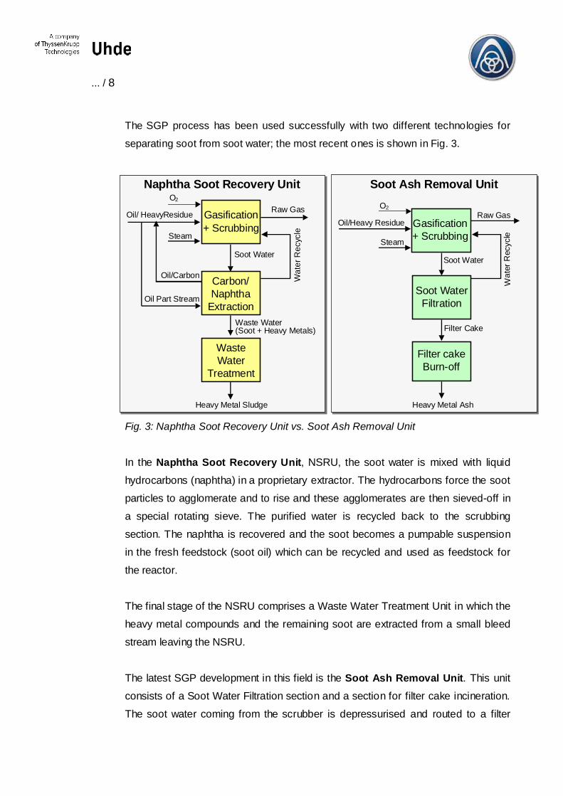
The SGP process has been used successfully with two different technologies for
separating soot from soot water; the most recent ones is shown in Fig. 3.
Heavy Metal Ash
Steam
O2
Soot WaterFiltration
Raw Gas
SteamOil/Heavy Residue
Oil/ Heavy Residue
O2
Oil/Carbon Carbon/Naphtha
Extraction
Raw Gas
Oil Part Stream
Filter Cake
Wat
er R
ecyc
le
Wat
er R
ecyc
le
Naphtha Soot Recovery Unit Soot Ash Removal Unit
WasteWater
Treatment
Heavy Metal Sludge
Waste Water(Soot + Heavy Metals)
Soot WaterSoot Water
Filter cakeBurn-off
Gasification+ Scrubbing
Gasification+ Scrubbing
Fig. 3: Naphtha Soot Recovery Unit vs. Soot Ash Removal Unit
In the Naphtha Soot Recovery Unit, NSRU, the soot water is mixed with liquidhydrocarbons (naphtha) in a proprietary extractor. The hydrocarbons force the sootparticles to agglomerate and to rise and these agglomerates are then sieved-off ina special rotating sieve. The purified water is recycled back to the scrubbingsection. The naphtha is recovered and the soot becomes a pumpable suspensionin the fresh feedstock (soot oil) which can be recycled and used as feedstock forthe reactor.
The final stage of the NSRU comprises a Waste Water Treatment Unit in which theheavy metal compounds and the remaining soot are extracted from a small bleedstream leaving the NSRU.
The latest SGP development in this field is the Soot Ash Removal Unit. This unitconsists of a Soot Water Filtration section and a section for filter cake incineration.The soot water coming from the scrubber is depressurised and routed to a filter
... / 9
press. Filter cakes with a solid content of approx. 17 – 20 %wt can be attained. Thefilter cake is dried in a special incineration section and the remaining carbon isburnt off. The final product is a highly valuable heavy metal ash, which is sold to themetal reclaimer market.
3.3 Advantages of the Shell Gasification Process
The SGP process is a proven technology which is being utilised in a variety ofcommercial applications around the world. The benefits to our customers can besummarised as:
• maximum reliability
• broad fuel flexibility
• optimum efficiency
• high operational flexibility
• broad product flexibility
• flexibility with regard to integration into existing and new plants
• excellent environmental performance
• standardisation based on years of experience.
One criteria is essential in ensuring the profitability of the gasification units:
RREE LLIIAABB IILL IITT YY..
SGP’s optimum process availability and reliability is the result of more than 40years’ experience in the design and operation of gasification units and a dedicationto continuous technological developments.
Key developments in the SGP process have resulted in high on-stream factorswhich are now routine in a variety of services.
The optimised SGP reactor design allows relatively moderate processtemperatures (1300 – 1350 °C). The relatively low gasification temperature isaccompanied by minimal heavy metal eutectic formation. There is also very little
... / 10
soot formation and consequently there are fewer deposits on the refractory of thereactor and less fouling in the SEC. Another result of the moderate gasificationtemperature is the comparably low oxygen consumption. Furthermore, the superiorefficiency of the SGP process results in a high CO content and a low CO2 content.
The development of a new generation of burners – the co-annular burner – haspaved the way for the gasification of highly viscous feedstocks. The inspection ofthe burner at high temperatures, a special safeguarding and control system and theintegrated heat-up auxiliary burner have resulted in both very long operatingperiods (over 9000 hours) and easy maintenance. The special design allows partswhich are subject to wear and tear to be repaired on site. The normal turn-downratio of the burner is lower than 70%; lower is possible with special design. For theinitial phase of the reactor heat-up an auxiliary burner is used. This burner isintegrated with main burner, its insertion and removal is quick and simple.
One of the key elements of the SGP process is the Syngas Effluent Cooler (SEC)which produces high-pressure steam (Fig. 4).

... / 11
REACTORSYNGASEFFLUENTCOOLER
The SEC equipment operates with low fouling and high feedstock flexibility. In fact,intensive investigations were carried out to ascertain the current availabilities of thecooler, e.g. the special design of the inlet section of the cooler. Efficiency forelectric power generation increases by approx. 5 percentage points, if an SEC isused instead of a gasifier operated with a direct water quench. The entire design ofthe cooler is extremely cost effective, e. g. there is no additional steam drum. Theuse of low-alloy steels combined with special design makes the investment costsfor the SEC very low and the return on investment therefore extremely good. As aconsequence, the SEC usually pays for itself within two years. Low maintenancecosts are achieved since the standard maintenance and cleam-outs usually arerequired only after two years.
The soot separation/handling system is a deciding factor in the trouble-freeoperation of the gasification plant. Over the last few years the development of theplant configuration has favoured the Soot Ash Removal Unit (SARU). Shell hasdeveloped a proprietary continuous dewatering process for soot and ash. The
Fig. 4.:SGP Reactor withSyngas Effluent Cooler(manufatured by StandardFasel Lentjes B.V., TheNetherlands)

... / 12
process uses a filter press and a carbon burn-off process which is completelyreliable and which does not affect the availability of the gasification unit. The SootAsh Removal Unit has the following advantages over a Naphtha Soot RecoveryUnit:
� The SARU is a typical once-through system with spare capacity in cheap tanksrather than in expensive filtering systems.
� Lower capital requirements and operating costs (automated operation, no useof naphtha)
� Hardly any heavy metals in the waste water� No accumulation of heavy metals in the gasification feed. This prevents heavy
metals from attacking the refractory of the reactor. It also prevents increases inthe viscosity of the feedstock and creates less fouling of the Syngas EffluentCooler.
� The final product (metal ash) is a valuable product which is sold to metalreclaimers.
The latest development to the SGP process is the standardised Safeguarding andControl System. This system includes all the safety measures, which have beenimplemented during the development of gasification technology. The specialmodular structure means that the commissioning and start-up of the gasificationplant is extremely efficient. The highly automated control system supports theoperator in all aspects of plant operation (start-up, shutdown, stand-by) and avoidstrips of non-safety nature. In fact, this system enables the plant to be startedautomatically within 10 minutes and also minimises flaring of the gases producedduring the initial phase of plant operation.
It is even possible to replace the conventional blast burner with a co-annular burnerin existing SGP plants. The Safeguarding and Control System can be easilyadapted to the old plant configuration thanks to its unique modular structure.
... / 13
3.4 SGP and IGCC
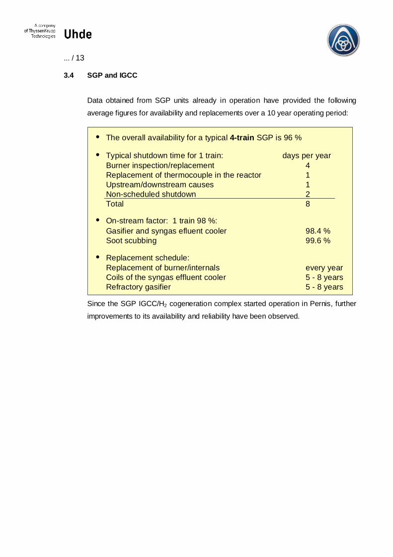
Data obtained from SGP units already in operation have provided the followingaverage figures for availability and replacements over a 10 year operating period:
• The overall availability for a typical 4-train SGP is 96 %
• Typical shutdown time for 1 train: days per yearBurner inspection/replacement 4Replacement of thermocouple in the reactor 1Upstream/downstream causes 1Non-scheduled shutdown 2Total 8
• On-stream factor: 1 train 98 %:Gasifier and syngas efluent cooler 98.4 %Soot scubbing 99.6 %
• Replacement schedule:Replacement of burner/internals every yearCoils of the syngas effluent cooler 5 - 8 yearsRefractory gasifier 5 - 8 years
Since the SGP IGCC/H2 cogeneration complex started operation in Pernis, furtherimprovements to its availability and reliability have been observed.
... / 14
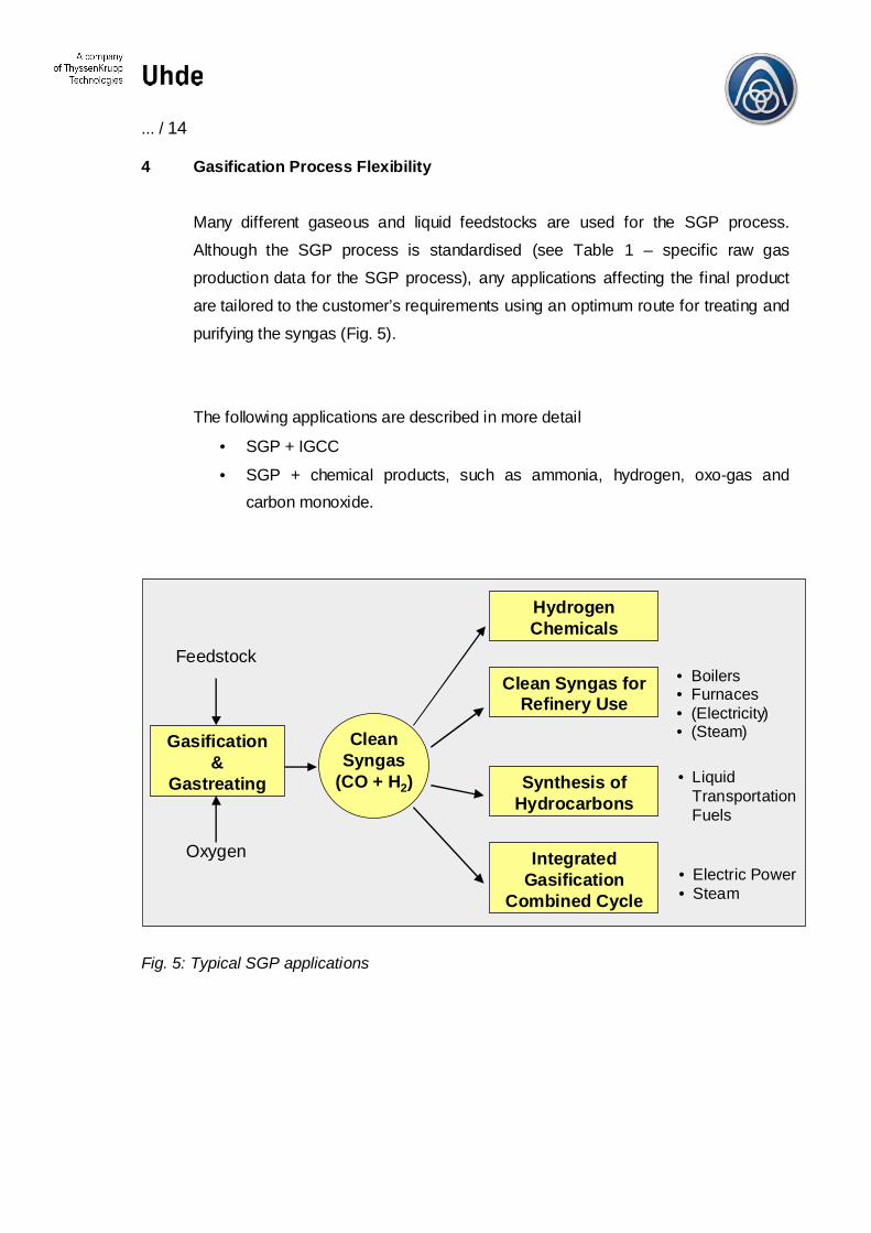
4 Gasification Process Flexibility
Many different gaseous and liquid feedstocks are used for the SGP process.Although the SGP process is standardised (see Table 1 – specific raw gasproduction data for the SGP process), any applications affecting the final productare tailored to the customer’s requirements using an optimum route for treating andpurifying the syngas (Fig. 5).
The following applications are described in more detail
• SGP + IGCC
• SGP + chemical products, such as ammonia, hydrogen, oxo-gas andcarbon monoxide.
HydrogenChemicals
Clean Syngas forRefinery Use
Synthesis ofHydrocarbons
IntegratedGasification
Combined Cycle
Gasification&
Gastreating
Feedstock
Oxygen
• Boilers• Furnaces• (Electricity)• (Steam)Clean
Syngas(CO + H2) • Liquid
TransportationFuels
• Electric Power• Steam
Fig. 5: Typical SGP applications
... / 15
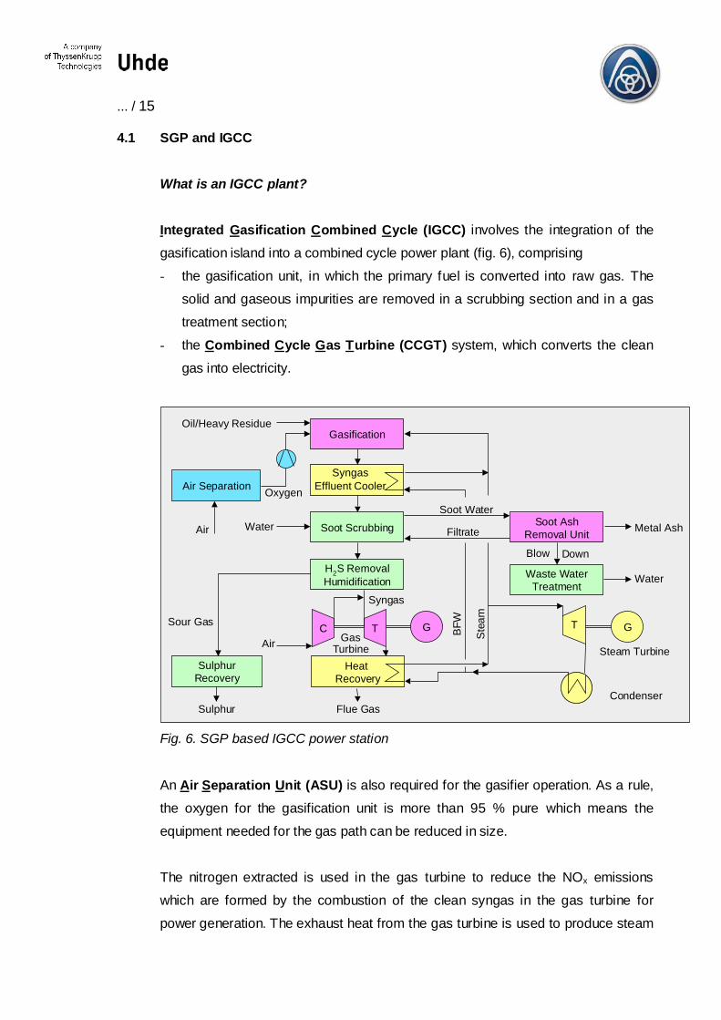
4.1 SGP and IGCC
What is an IGCC plant?
Integrated Gasification Combined Cycle (IGCC) involves the integration of thegasification island into a combined cycle power plant (fig. 6), comprising- the gasification unit, in which the primary fuel is converted into raw gas. The
solid and gaseous impurities are removed in a scrubbing section and in a gastreatment section;
- the Combined Cycle Gas Turbine (CCGT) system, which converts the cleangas into electricity.
Gasification
Soot Scrubbing
H2S RemovalHumidification
C T G
Soot AshRemoval Unit
Waste WaterTreatment
T G
Air Separation
SulphurRecovery
Heat Recovery
Oil/Heavy Residue
WaterAir
Sour Gas
Sulphur Flue GasCondenser
Steam Turbine
Water
Metal Ash
Blow Down
Soot Water
Filtrate
GasTurbineAir
SyngasEffluent Cooler
Syngas
Oxygen
BFW
Stea
m
Fig. 6. SGP based IGCC power station
An Air Separation Unit (ASU) is also required for the gasifier operation. As a rule,the oxygen for the gasification unit is more than 95 % pure which means theequipment needed for the gas path can be reduced in size.
The nitrogen extracted is used in the gas turbine to reduce the NOx emissionswhich are formed by the combustion of the clean syngas in the gas turbine forpower generation. The exhaust heat from the gas turbine is used to produce steam
... / 16
in a heat recovery steam generator, which, together with the steam generated inthe Syngas Effluent Cooler of the gasification section, is routed to a steam turbineused to generate more power.
This approach has the potential to raise the conversion efficiency above that of theconventional steam cycle if all elements of the plant are integrated optimally, that is:
• integration of extracted air for the Air Separation Unit from the gas turbine aircompressor for reducing internal power consumption
• integration of nitrogen as a by-product for reducing the NOx emissions
• integration of the heat from the steam produced in the Syngas Effluent Coolerinto the CCGT steam cycle for increasing conversion efficiency
• optimum use of low-level heat from both the CCGT and the gas treatmentsection for preheating and saturation (moisturing) of the syngas for increasingconversion efficiency.
This optimum integration of the major elements in the power station results in high-level efficiency (approx. 45 %, LHV-based). As far as environmental acceptability isconcerned, this type of power station can compete with the most efficientconventional power stations based on other fuels (e.g. coal-fired power stations).
The power station’s ability to supply clean gas for a number of applications(hydrogen, oxo-gas, carbon monoxide etc.), as well as the low-value feedstockused (high in sulphur and heavy metals), provides the plants with a much strongermarket potential than cheap natural gas power generation.The integration of the IGCC into refineries leads to additional synergies for bothplants – less emissions and lower investment cost by optimum integration of steam,power and fuel gas produced by the IGCC.
The following atmospheric emissions recorded for an IGCC with the SGP processemphasise its environmental advantages:
... / 17
NOx – 25 mg/Nm³ (dry – 15 % O2)SO2 – 10 mg/Nm³ (dry – 15 % O2)CO < 10 mg/Nm³ (dry – 15 % O2)Particulates < 1 mg/Nm³ (dry – 15 % O2).
Despite the poor quality feedstocks, the emissions are still extremely low. Thesulphur recovery efficiency, defined as a ratio between the liquid sulphur recoveredand the sulphur in the feedstock, is > 99.5 %.
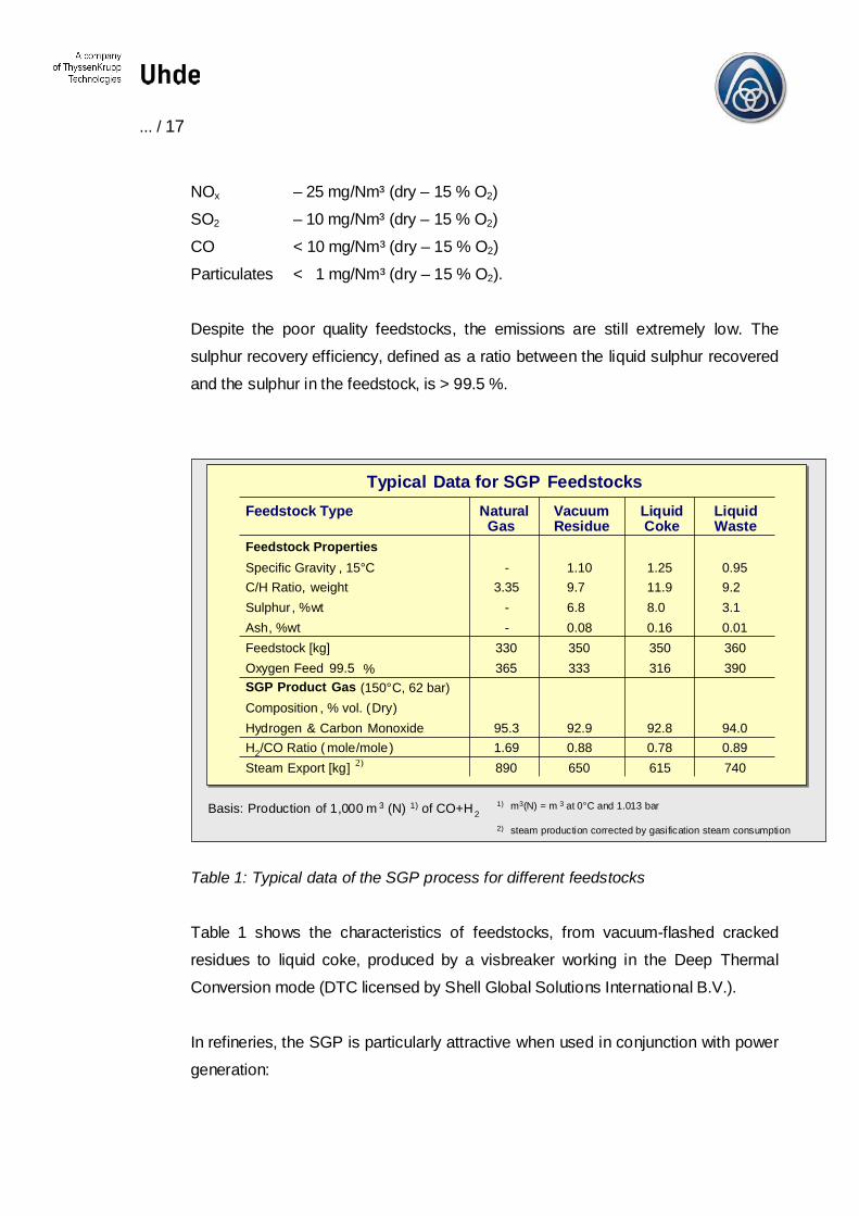
Typical Data for SGP FeedstocksFeedstock Type Natural Vacuum Liquid Liquid
Gas Residue Coke WasteFeedstock PropertiesSpecific Gravity , 15°CC/H Ratio, weightSulphur , %wtAsh, %wtFeedstock [kg]Oxygen Feed 99.5 %SGP Product Gas (150°C, 62 bar)Composition , % vol. (Dry)Hydrogen & Carbon MonoxideH2/CO Ratio ( mole/mole)Steam Export [kg] 2)
-3.35
--
330365
95.31.69890
1.109.76.80.08350333
92.90.88650
1.2511.98.00.16350316
92.80.78615
0.959.23.10.01360390
94.00.89740
Basis: Production of 1,000 m 3 (N) 1) of CO+H21) m3(N) = m 3 at 0°C and 1.013 bar
2) steam production corrected by gasification steam consumption
Table 1: Typical data of the SGP process for different feedstocks
Table 1 shows the characteristics of feedstocks, from vacuum-flashed crackedresidues to liquid coke, produced by a visbreaker working in the Deep ThermalConversion mode (DTC licensed by Shell Global Solutions International B.V.).
In refineries, the SGP is particularly attractive when used in conjunction with powergeneration:
... / 18
- Refineries which are under pressure to invest mainly in SO2 and NOx reductionmay find that the use of clean syngas in furnaces or boilers is a very cost-effective way to avoid having to make investments for environmental reasons.
- A key factor in solving the global CO2 problem in the future will be linked to trueenergy pricing and competition. Improved efficiencies, closed product cyclesand cogeneration are just some of the solutions to this problem. Cogenerationof Power and Hydrogen should be a must for any refinery wishing to solvefuture problems with heavy crude wastes, cleaner automotive fuels andemission reduction.
- Refinery heat is often distributed at the level of MP steam. This heat can besupplied from the steam turbine process either directly from the heat recoverysteam generator or by extracting heat from the steam turbine.
- The SGP can handle any heavy feedstock. Consequently the refineries canutilise deeper conversion (see DTC) which leaves a residue that can yet beprocessed by SGP. It is possible for the refineries to increase their profits byusing heavier sulphur and, consequently, cheaper crude.
4.2 SGP and Chemical Products
The SGP process was first used for the production of syngases used in thechemical industry (primarily ammonia and methanol). The following examples ofvarious SGP process applications demonstrate its versatility:
- SGP for ammoniaThe total production capacity of the SGP-based ammonia plants around theworld is over 35 million Nm³ (H2+CO) per day. Ammonia is one of the mostpopular gasification products.
- SGP for hydrogenHydrogen will be in huge demand as a fuel in the future, either in fuel cells or inthe automotive industry. The hydrogen demand in refineries is growingconstantly as attempts are made to comply with global legislation dictating lowsulphur contents.
- SGP for methanol
... / 19
The advantage of using the SGP for methanol production is that the gas can beproduced at a pressure level suitable for modern low pressure synthesisprocesses without requiring further compression. The total production capacityof SGP-based methanol plants around the world exceeds 10 million Nm³(H2+CO) per day.
- SGP for CO and Oxo-GasThe high CO content (approx. 45 %) in raw synthesis gas makes the SGP anatural choice for the production of oxo-syngas and pure CO. The totalproduction capacity of SGP based oxo-syngas and CO production plants is over5 million Nm³ (H2+CO) per day.
Which gas treatment and purification systems are to be used depends on the purityrequirements and the economics of the particular application.
The SGP process provides an excellent opportunity for turning low-value liquidresidues into high-value products by cogenerating electrical power and gaseousproducts. The use of syngas for refinery-based power generation increases thesynergy with other refinery needs. In general, less than 10 % of refinery fuel isrequired to cover the hydrogen and energy demand of a typical refinery when usingthe SGP process.
... / 20
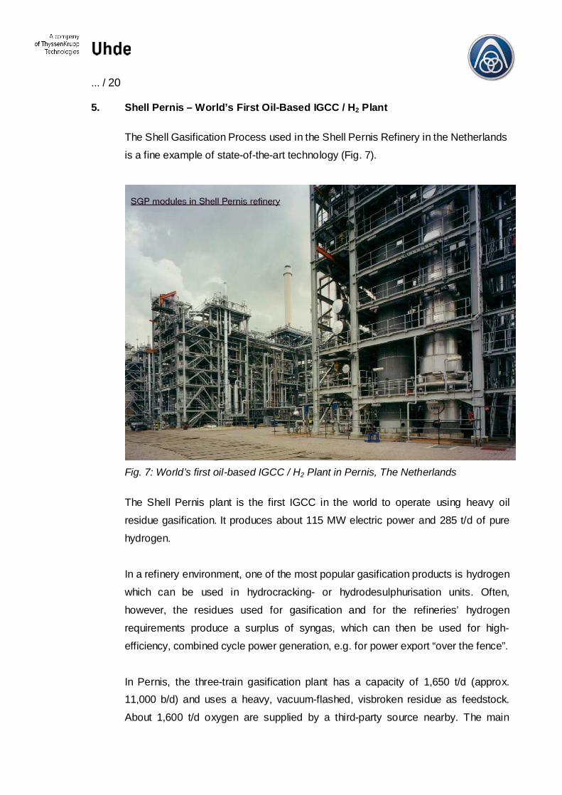
5. Shell Pernis – World’s First Oil-Based IGCC / H2 Plant
The Shell Gasification Process used in the Shell Pernis Refinery in the Netherlandsis a fine example of state-of-the-art technology (Fig. 7).
Fig. 7: World’s first oil-based IGCC / H2 Plant in Pernis, The Netherlands
The Shell Pernis plant is the first IGCC in the world to operate using heavy oilresidue gasification. It produces about 115 MW electric power and 285 t/d of purehydrogen.
In a refinery environment, one of the most popular gasification products is hydrogenwhich can be used in hydrocracking- or hydrodesulphurisation units. Often,however, the residues used for gasification and for the refineries’ hydrogenrequirements produce a surplus of syngas, which can then be used for high-efficiency, combined cycle power generation, e.g. for power export “over the fence”.
In Pernis, the three-train gasification plant has a capacity of 1,650 t/d (approx.11,000 b/d) and uses a heavy, vacuum-flashed, visbroken residue as feedstock.About 1,600 t/d oxygen are supplied by a third-party source nearby. The main
... / 21
reason for having three gasification trains is that if one gasifier needs to be takenoff-line, the hydrogen requirement for the hydrocracker can still be provided by thetwo remaining trains.
The hydrocracker requires up to approximately 285 t/d hydrogen. In a normal three-train operation, the syngas, which exceeds the requirements for hydrogenproduction, will be used as gas turbine fuel.
The hydrogen plant consists of a two-stage CO shift (high temperature/lowtemperature), carbon dioxide removal and a methanation stage. A highly integratedgas treatment unit (Rectisol) was selected for removing H2S from the syngas andfor removing CO2 downstream of the low-temperature CO shift.
The scrubber water (containing soot and ash) from the three trains is filtered andreturned to the scrubber. Excess water is fed to water treatment facilities and thefilter cake is processed for metal recovery.
The Pernis SGP plant has been in operation since the end of 1997 and has beenextremely successful in using the latest technological developments in the ShellGasification Process, which are:
1. The development of the co-annular gasification burner enabling the processingof more viscous feedstocks.
2. The combination of the specific SGP reactor design with the co-annular burnerpermits the operation of the gasification unit with low soot make and relativelylow operating temperatures resulting in a relatively low oxygen demand and CO2
production.
3. The development of an “open loop” soot/ash removal. This enables theproduction of a marketable, concentrated, high-value vanadium/nickel ash andprevents the problems associated with heavy metal enrichment and increasedfeedstock viscosity.
... / 22
K T - 1 9 5 1M a z in g a rb e , F
K T - 1 9 4 1D e v e lo p m e n t
K T - 1 9 5 7P u e n t e s , S p a in
W i n k le r1 9 2 6
K T (o il) - 1 9 5 7Z a n d vo o rd e , B
K T (o il) - 1 9 5 2O u lu , F in la n d
K T (o il) - 1 9 5 8E s ta rre ja , P o rt .
K T (g a s ) - 1 9 6 5T a lk h a , E g yp t
K T - 1 9 6 5M a e M o h , T h a i l.
K T (o il) - 1 9 6 8Z e it z , G e rm a n y
K T - 1 9 6 8K ü t a h ya , T u r ke y
K T - 1 9 6 2P t o le m a is , G r.
K T - 1 9 7 5M o d d e r f o n t e in
K T - 1 9 7 6Za m b ia
K T - 1 9 7 8Ta lch e r, In d ia
K T - 1 9 7 8R a m a g u n d a m , I .
K T - 1 9 8 4K ü t a h ya , T u r ke y
K T - 1 9 8 6Z e it z , G e rm a n y
K T - 1 9 8 8I n d e co , Z a m b ia
H T W - 1 9 7 3D e ve lo p m e n t
H T W - 1 9 7 8F re c h e n
H T W - 1 9 8 5B e rre n ra th
H T W - 1 9 8 8O u lu , F in la n d
H T W - 1 9 8 9W e s se l in g
H T W - 1 9 9 3K o B ra ( n o t re a l. )
H T W - 2 0 0 0S H I , J a p a n
H T W - 2 0 0 2V re s o v a , C z .
T e x a c o - 1 9 5 3T G P L ic e n s e
T e x a c o - 1 9 5 9L a s P a lm a s , S p a in
T e x a c o - 1 9 6 0L isb o n , P o rt u g a l
T e x a c o - 1 9 7 1L a ve r a , F ra n c e
T e x a c o - 1 9 7 1R h o d e s , A u s t r a l ia
T e x a c o - 1 9 9 1O b e r h a u se n , D
T C G P - 1 9 7 3D e ve lo p m e n t
T C G P - 1 9 7 8D e m o H o lt e n , D
T C G P - 1 9 8 6O b e rh a u s e n , D
T e x a c o - 1 9 9 8B h a r u ch , I n d ia
S h e ll - 1 9 5 3S G P ( O i l)
S G P - 1 9 6 4K U ’s f i rs t S G P
S G P - 1 9 9 7P e rn is , N L
S h e ll -K o p p e r s - 1 9 7 4S t a rt o f D e v e lo p m e n t
S C G P - 1 9 9 9R e - u n if ie d C o o p e r a t io n
S h e l l / K U
P R E N F L O - 1 9 8 6F ü r s t e n h a u s e n , D
S C G P -1 9 8 5H o u s t o n , U S A
P R E N F L O - 1 9 9 7P u e rt o l la n o , S p a in
S C G P -1 9 9 4B u g g e n u m , N L
S h e ll -K o p p e r s - 1 9 8 0D e m o H a m b u rg , D
168
SGP
Rea
ctor
s (S
hell
refe
renc
e)
S G P - 1 9 9 8S G P C o o p e ra tio n
S h e ll / K U
K T - 1 9 5 6T o ky o , J a p a n
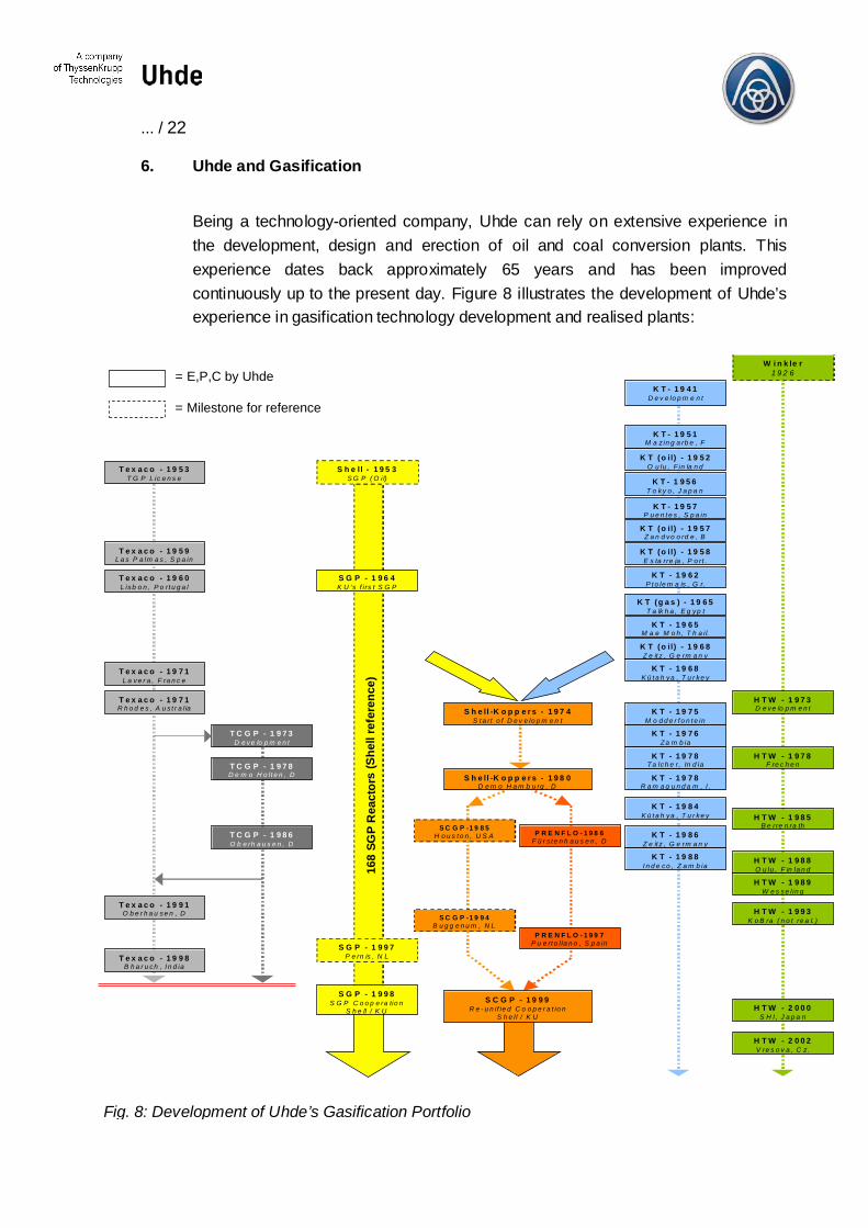
6. Uhde and Gasification
Being a technology-oriented company, Uhde can rely on extensive experience inthe development, design and erection of oil and coal conversion plants. Thisexperience dates back approximately 65 years and has been improvedcontinuously up to the present day. Figure 8 illustrates the development of Uhde’sexperience in gasification technology development and realised plants:
= E,P,C by Uhde
= Milestone for reference
Fig. 8: Development of Uhde’s Gasification Portfolio

... / 23
As shown in Fig. 8, Uhde has designed and built about 100 gasifiers worldwidebased on 5 different gasification technologies (Shell, PRENFLO®, Koppers-Totzek,High-Temperature Winkler, Texaco) catering to almost all feedstocks - solid, liquidand gaseous. These technologies include upstream and downstream processes,such as heat recovery, gas treatment, waste water treatment, and subsequentprocesses for the production of methanol, ammonia, hydrogen, oxo-chemicals andelectrical power.
Shell Global Solutions International B.V.
Shell’s expertise in refinery processes is unbeaten and the company can providein-depth assistance throughout the project cycle, from the design studies to after-sales service.
Synergies: Uhde and the Shell Gasification Process
Both Shell Global Solutions International B.V. and Uhde are world leaders in thedevelopment, design, construction and commissioning of their gasificationtechnologies. Both companies have been involved not only in the technologydevelopment and front-end basic design of the plants, but also in the detailedengineering, commissioning, start-up and operation of gasification facilities fordecades.
This unique set-up ensures that the feedback essential for further processimprovements and developments is readily available. This is further supported byextensive research and development work on all components in the gasification,gas treatment, refinery and chemical plants.
Uhde’s Affiliated Services
Uhde is dedicated to providing its customers with a wide range of services and tosupporting them in their efforts to succeed in business.
With our worldwide network of subsidiaries, affiliated companies, experienced localrepresentatives and first-class backing from our headoffice, Uhde has the idealqualifications to achieve this goal.
... / 24
Uhde places particular importance in interacting with the customers at an earlystage to combine their ambition with our experience. We always aim to givepotential customers the opportunity to visit operating plants and to personallyevaluate such matters as process operability; maintenance and on-stream time. Weaim to build our future business on the confidence our customers place in us.
Uhde provides the entire spectrum of services associated with a technology-oriented engineering contractor. These range from the initial feasibility study, tofinancing and project management right up to the commissioning of units andgrass-root plants.
Our broad portfolio of services includes:
• feasibility studies / technology selection,
• project management,
• arranging financing schemes,
• financial guidance based on extensive knowledge of local laws, regulations andtax procedures,
• environmental studies,
• basic / detail engineering,
• utilities / offsites / infrastructure,
• procurement / inspection / transportation services,
• civil works and erection,
• commissioning,
• training of operating personnel,
• plant operation / plant maintenance
• R&D
The policy of the Uhde group and its subsidiaries is to ensure utmost quality in theimplementation of our projects. Our head office and subsidiaries worldwide work tothe same quality standard, certified DIN / ISO 9001 / EN29001.
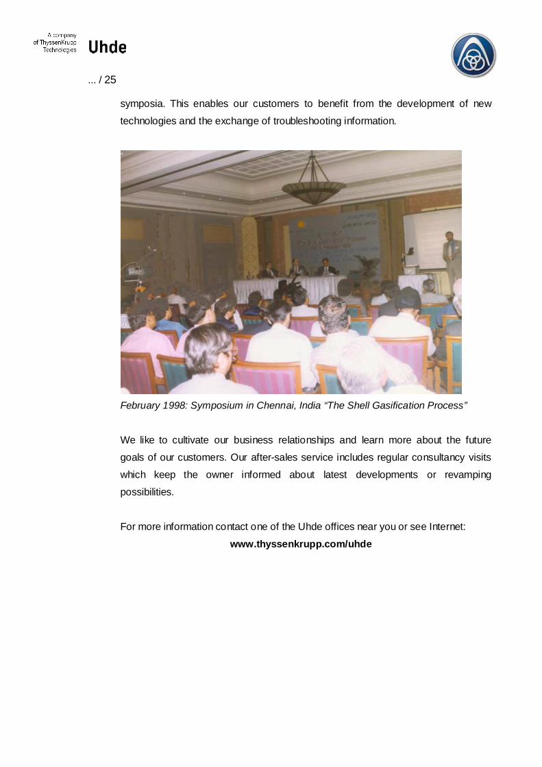
We remain in contact with our customers even after project completion. Partneringis our byword. We promote active communication between customers, licensors,partners, operators and our specialists by organising and supporting technical
... / 25
symposia. This enables our customers to benefit from the development of newtechnologies and the exchange of troubleshooting information.
February 1998: Symposium in Chennai, India “The Shell Gasification Process”
We like to cultivate our business relationships and learn more about the futuregoals of our customers. Our after-sales service includes regular consultancy visitswhich keep the owner informed about latest developments or revampingpossibilities.
For more information contact one of the Uhde offices near you or see Internet: www.thyssenkrupp.com/uhde

... / 26
7. Reference List Shell Gasification Process
The following list summarises all plants applying the Shell Gasification Process currently inoperation. The total amount of SGP gasifiers licensed amounts to over 160.
Licenced ShellGasification Process inoperation at Companies
Location Feedstock Product TotalH2+CO
Nm³/day
Numberof
reactors
Started
MitsubishiPetrochemicals
Yokkaichi, Japan bunker C oil syngas 400,000 2 1961
Kemira Chemicals Oy Oulu, Finland bunker C oil specialities 300,000 1 1965
DEA Mineraloel AG Wesseling, Germany crackedresidue
methanol 1,300,000 2 1969
Lucky GoldstarChemical Ltd.
Naju, S. Korea bunker C oil ammonia 500,000 1 1969
Falconbridge Santo Domingo, Dom.Rep.
bunker C oil reducinggas
1,440,000 12 1971
Chemopetrol a.s. Litvinov, Czech Republic vacuumresidue
methanol,ammonia
3,600,000 6 1971
Ruhr Oel GmbH Gelsenkirchen,Germany
vacuumresidue
ammonia +methanol
4,300,000 4 1973
Hoechst Celanese Ltd. Houston, USA natural gas oxo 2,100,000 3 1977
Fertiliser Corp. of IndiaLtd.
Sindri, New Delhi, India heavy fuel oil ammonia 2,100,000 3 1977
National Fertiliser Ltd. Nangai, New Delhi,India
bunker C oil ammonia 2,100,000 3 1978
Hindustan FertiliserCorp. Ltd.
Haldia, New Delhi, India bunker C oil ammonia +methanol
2,100,000 3 1978
Hydro Agri Brunsbüttel, Germany vacuumresidue
ammonia 4,500,000 4 1978
Exxon ChemicalCompany
Baton Rouge, USA heavy fuel oil oxo 570,000 3 1978
National Fertiliser Ltd. Bathinda, India bunker C oil ammonia 2,100,000 3 1978
Ultrafertil S.A. Araucária, Brasil asphaltresidue
ammonia 3,300,000 3 1979
National Fertiliser Ltd. Bathinda, India bunker C oil ammonia 2,100,000 3 1979
Neyvell Lignite Corp.Ltd.
Neyvell, Tamil Nadu,India
bunker C oil syngas 800,000 2 1979
Quimigal Adubos Lavradio, Portugal vacuumresidue
ammonia 2,400,000 2 1984

... / 27
Licenced ShellGasification Process inoperation at Companies
Location Feedstock Product TotalH2+CO
Nm³/day
Numberof
reactors
Started
Leuna Methanolanlage(MIDER)
Leuna, Germany heavy residue methanol 7,200,000 6 1985
Qilu Petrochemical Ind. Zibu, Shandong, China vacuumresidue
methanol +oxo
715,000 2 1987
Fushun DetergentChemical Plant
Fushun, Liaoning, China vacuumresidue
oxo 60,000 1 1991
Shell MDS (Malaysia) Bintulu, Malaysia natural gas middledistilates
7,552,000 6 1993
JiuJiang Petr. Chem.Fertil. Comp.
JiuJiang City, Jiangxi,China
vacuumresidue
ammonia 2,100,000 2 1996
Inner Mongolia Chem.Fertiliser Plant
Hohot, Inner Mongolia,China
vacuumresidue
ammonia 2,100,000 2 1996
Lucky GoldstarChemical Ltd
Yochon-City, S. Korea bunker C oil oxo 384,000 1 1996
Shell NederlandRaffinaderij B.V.
Pernis, Netherlands heavy residue H2 + el.power
4,662,200 3 1997
Lanzhou Chem. IndustryCo.
Lanzhou, Gansu, China vacuumresidue
ammonia 2,100,000 2 1997
Further SGP licenses have been granted since 1997. These have not yet been addedto the reference list. These plants are in various phases of realisation.

Uhde GmbHFriedrich-Uhde-Strasse 15D-44141 DortmundTel.: +49 2 31 5 47-0Fax: +49 2 31 5473032www.thyssenkrupp.com/uhde
A company of ThyssenKrupp Technologies
Design and construction of chemical and other industrial plants
Fields of activity:
RefineriesGas generationGas treatmentSynthesis processesAmmonia, methanol, hydrogenFertilisersPlastics and synthetic fibresOrganic chemicalsAromaticsElectrochemicalsBleaching chemicals (H2O2,CIO2 )Oil and coal gasificationEnergy technologyPharmaceuticalsInfrastructuresGeneral ContractingServices
Related Documents