Welcome message from author
This document is posted to help you gain knowledge. Please leave a comment to let me know what you think about it! Share it to your friends and learn new things together.
Transcript


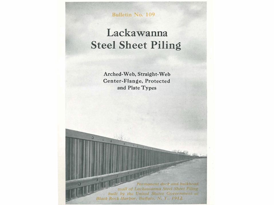
Sheet Piling –Past, Present, and Future
Richard J. Hartman, PhD, PEHartman Engineering

Steel Sheet PilingThe Early Years
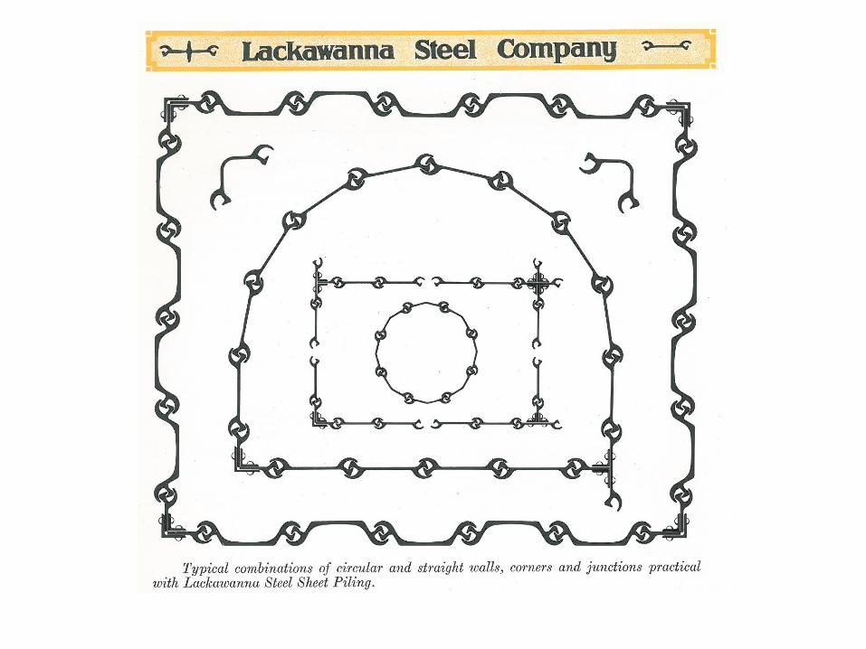


Currently Available Steel Sheet Piling
Flat Web
Hot rolled
Cold formed
Z-Piles

Manual Calculations Evolved intoComputer Analysis
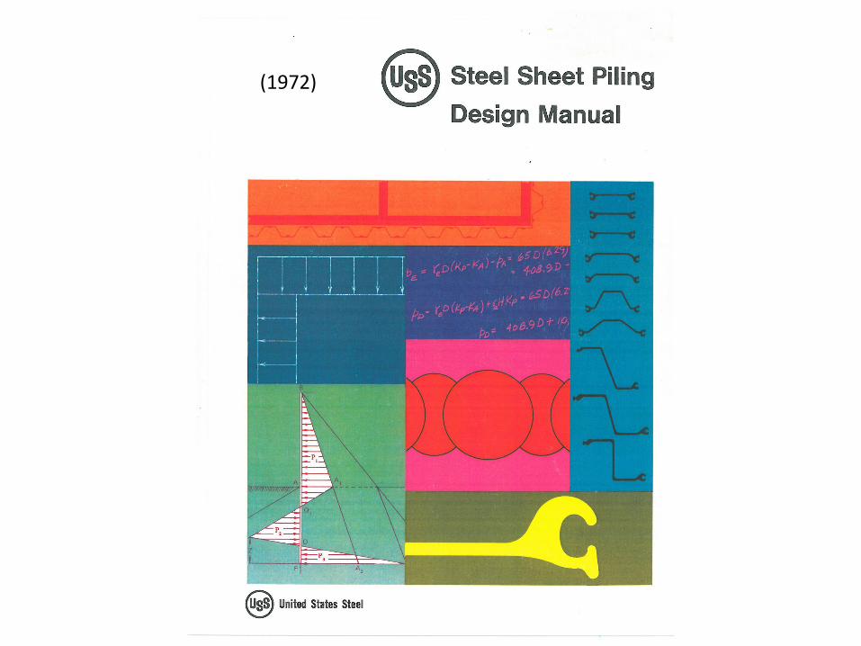
(1972)


Pressure Envelope Originally Developed by Terzaghi and Peck in 1965
For wall with 2 or more brace levels
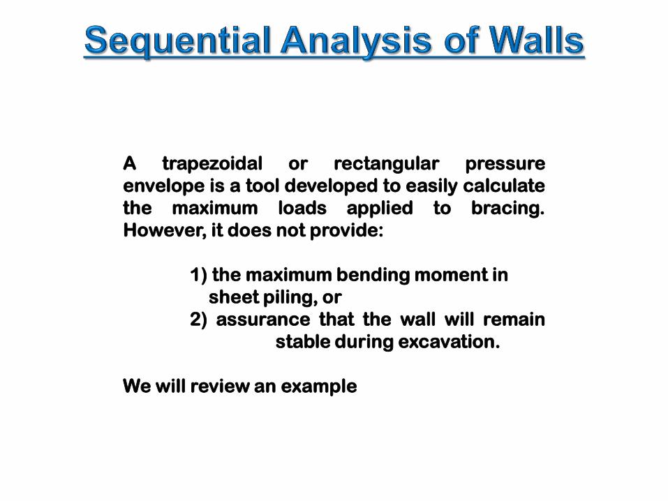
A trapezoidal or rectangular pressureenvelope is a tool developed to easily calculatethe maximum loads applied to bracing.However, it does not provide:
1) the maximum bending moment insheet piling, or
2) assurance that the wall will remainstable during excavation.
We will review an example


SAMPLE

SAMPLE
SAMPLE

8.5 k/ft

Seepage forces can cause pipingand destabilize the soil in the bottomof a cofferdam
Analysis can be performed manuallyusing flow nets. This method hasbeen available for more than 60years.


Water Surface
Water LevelLoose Fill
Silty Sand
Weathered Rock
Groundwater

500
500
1,0001,000
1,000
1,500
1,500
1,500
500
2,000
2,000
2,500

Item Traditional (Allowable Stress) LRFD
Toe FS LF x active pressureRF x passive pressure
Sheet StrengthBrace Strength
LF x active pressureRF x strength of member
Allowable Stress – LRFD (Load and Resistance Factor Design)
f= FyFS

Item Traditional (Allowable Stress)
LRFDAASHTO
Toe FS (1.5-2.0) (1.5) LF x active pressure(0.5) RF x passive pressure
Sheet StrengthBrace Strength
(1.5) LF x active pressure(0.9) RF x strength of member
Allowable Stress – LRFD (Load and Resistance Factor Design)
f= FyFS (1.5)

What’s in the Future for the Product?
• New metallurgy?• Higher strength?
• Maintain ductility• Maintain weldability
• New shapes?• Deeper and thinner
• Maintain drivability • Recognize stability issues

What’s in the Future for the Design Process?
• Software to integrate the steps?• Develop pressure diagram• Perform sequential load analysis• Check seepage• Check heave• Check global stability
• Will we lose the ability to think the process through?

List of Resources:1.) U.S. Army Corps of Engineers
Design of Sheet Pile WallsEm 1110-2-2504
2.) U.S. Army Corps of EngineersDesign of Sheet Pile Cellular Structures, Cofferdams, and Retaining Structures
EM-1110-2-2503
3.) Naval Facilities Engineering CommandFoundations and Earth Structures
Design Manual 7.02
4.) Federal Highway Administration GeoTechTools
Geotechnical Publications
5.) American Association of State Highway and Transportation OfficialsLRFD Bridge Design Specifications
Section 11 – Abutments, Piers, and Walls
6.) American Association of State Highway and Transportation OfficialsGuide Design Specifications for Bridge Temporary Works
Related Documents