Shear Force and Bending Moment Dr. Vishesh Ranjan Kar Assistant Professor Department of Mechanical Engineering NIT Jamshedpur

Welcome message from author
This document is posted to help you gain knowledge. Please leave a comment to let me know what you think about it! Share it to your friends and learn new things together.
Transcript
Shear Force and Bending Moment
Dr. Vishesh Ranjan Kar Assistant Professor Department of Mechanical Engineering NIT Jamshedpur
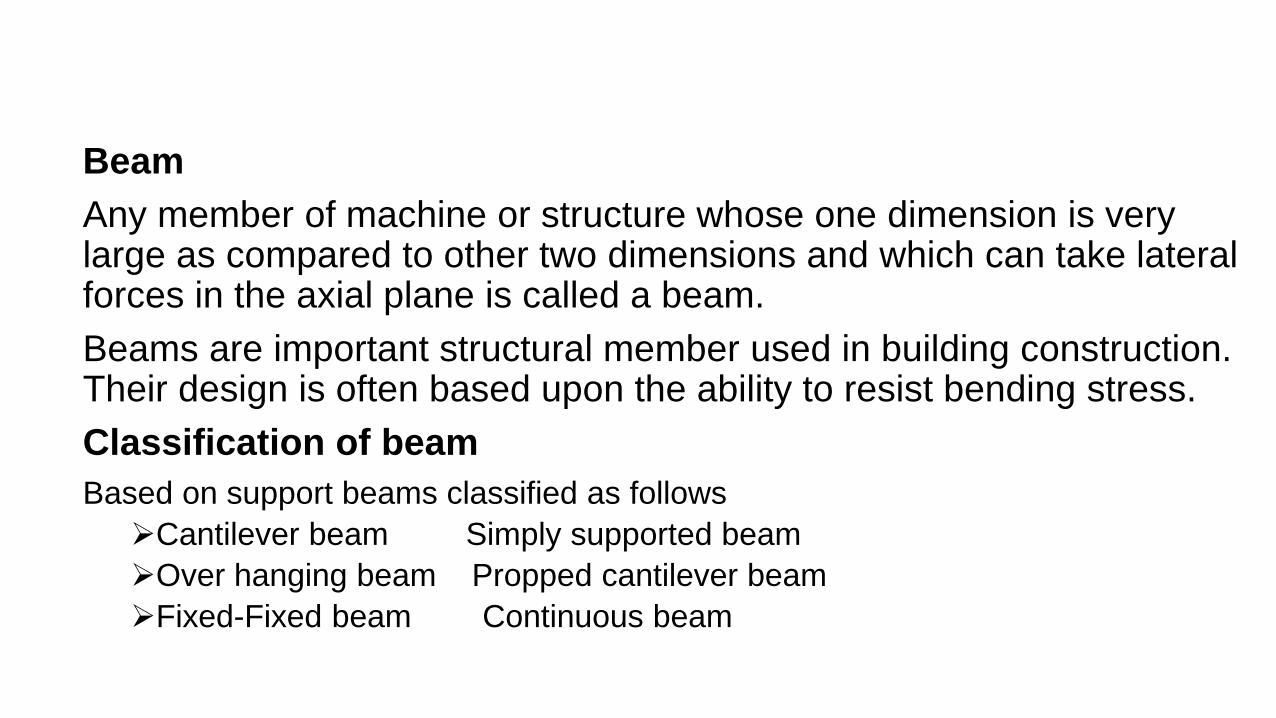
Beam Any member of machine or structure whose one dimension is very large as compared to other two dimensions and which can take lateral forces in the axial plane is called a beam. Beams are important structural member used in building construction. Their design is often based upon the ability to resist bending stress. Classification of beam Based on support beams classified as follows Cantilever beam Simply supported beam Over hanging beam Propped cantilever beam Fixed-Fixed beam Continuous beam
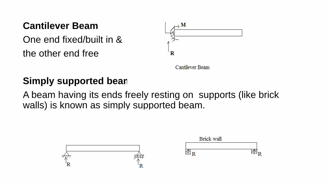
Cantilever Beam One end fixed/built in & the other end free Simply supported beam A beam having its ends freely resting on supports (like brick walls) is known as simply supported beam.
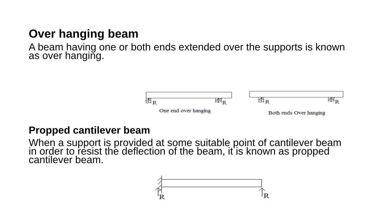
Over hanging beam A beam having one or both ends extended over the supports is known as over hanging. Propped cantilever beam When a support is provided at some suitable point of cantilever beam in order to resist the deflection of the beam, it is known as propped cantilever beam.
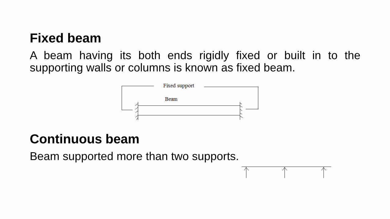
Fixed beam A beam having its both ends rigidly fixed or built in to the supporting walls or columns is known as fixed beam. Continuous beam Beam supported more than two supports.
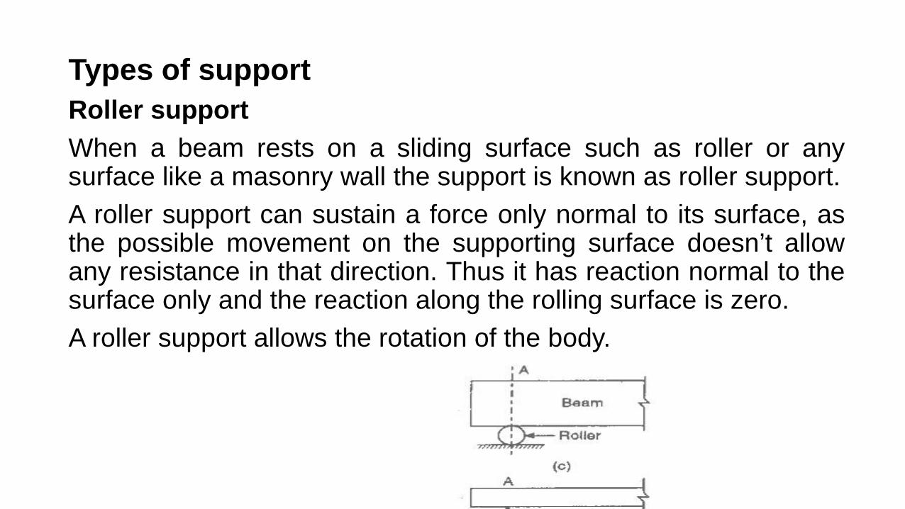
Types of support Roller support When a beam rests on a sliding surface such as roller or any surface like a masonry wall the support is known as roller support. A roller support can sustain a force only normal to its surface, as the possible movement on the supporting surface doesn’t allow any resistance in that direction. Thus it has reaction normal to the surface only and the reaction along the rolling surface is zero. A roller support allows the rotation of the body.
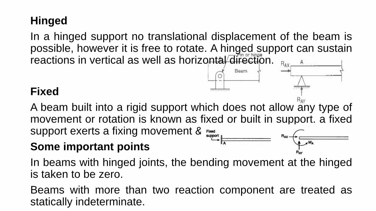
Hinged In a hinged support no translational displacement of the beam is possible, however it is free to rotate. A hinged support can sustain reactions in vertical as well as horizontal direction. Fixed A beam built into a rigid support which does not allow any type of movement or rotation is known as fixed or built in support. a fixed support exerts a fixing movement & a reaction on the beam. Some important points In beams with hinged joints, the bending movement at the hinged is taken to be zero. Beams with more than two reaction component are treated as statically indeterminate.
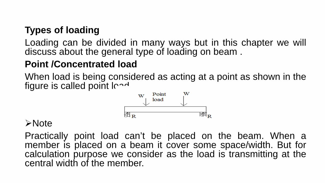
Types of loading Loading can be divided in many ways but in this chapter we will discuss about the general type of loading on beam . Point /Concentrated load When load is being considered as acting at a point as shown in the figure is called point load. Note Practically point load can’t be placed on the beam. When a member is placed on a beam it cover some space/width. But for calculation purpose we consider as the load is transmitting at the central width of the member.
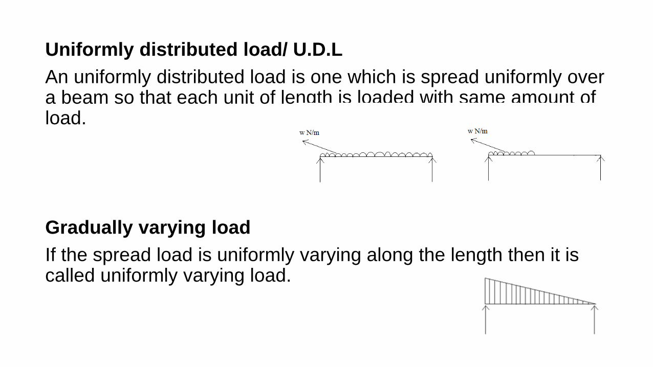
Uniformly distributed load/ U.D.L An uniformly distributed load is one which is spread uniformly over a beam so that each unit of length is loaded with same amount of load. Gradually varying load If the spread load is uniformly varying along the length then it is called uniformly varying load.

Span Span may be of two type say clear span and effective span. But when simply span is written this means it is effective span. Clear span Horizontal distance between two support.(1) Effective span This is the center line to center line distance between two supports.(2)
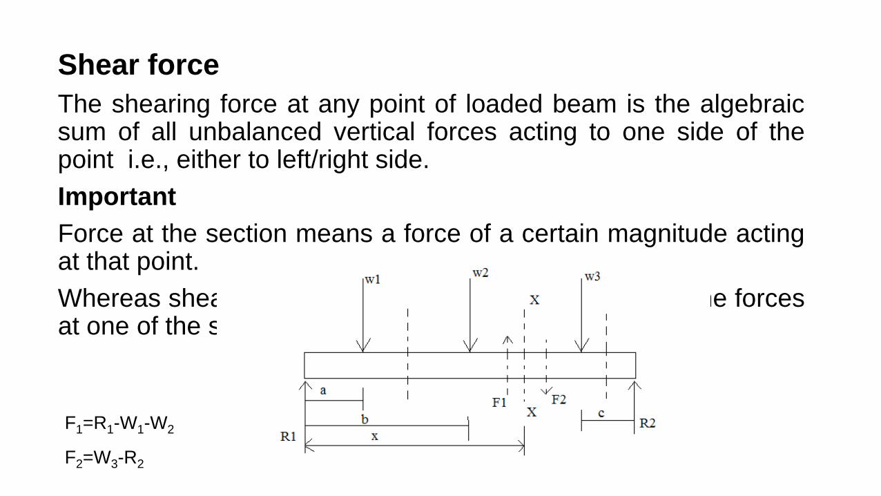
Shear force The shearing force at any point of loaded beam is the algebraic sum of all unbalanced vertical forces acting to one side of the point i.e., either to left/right side. Important Force at the section means a force of a certain magnitude acting at that point. Whereas shear force at a section means the sum of all the forces at one of the sides of that section.
F1=R1-W1-W2
F2=W3-R2
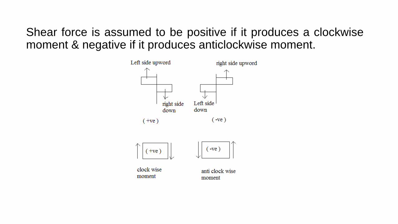
Shear force is assumed to be positive if it produces a clockwise moment & negative if it produces anticlockwise moment.
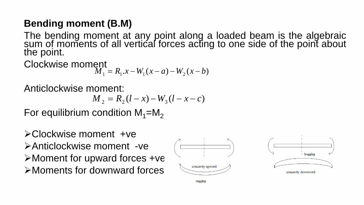
Bending moment (B.M) The bending moment at any point along a loaded beam is the algebraic sum of moments of all vertical forces acting to one side of the point about the point. Clockwise moment Anticlockwise moment: For equilibrium condition M1=M2 Clockwise moment +ve Anticlockwise moment -ve Moment for upward forces +ve moment Moments for downward forces –ve moment
)()(. 2111 bxWaxWxRM −−−−=
)()( 322 cxlWxlRM −−−−=
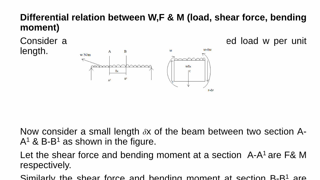
Differential relation between W,F & M (load, shear force, bending moment) Consider a beam carrying an uniformly distributed load w per unit length. Now consider a small length δx of the beam between two section A-A1 & B-B1 as shown in the figure. Let the shear force and bending moment at a section A-A1 are F& M respectively. Similarly the shear force and bending moment at section B-B1 are
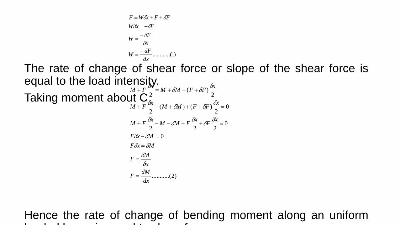
The rate of change of shear force or slope of the shear force is equal to the load intensity. Taking moment about C Hence the rate of change of bending moment along an uniform l d d b i l t h f
)2.(..........
0
0222
02
)()(2
2)(
2
dxdMF
xMF
MxFMxF
xFxFMMxFM
xFFMMxFM
xFFMMxFM
=
=
==−
=++−−+
=+++−+
+−+=+
δδδδδδ
δδδδδ
δδδδ
δδδδ
)1..(..........dxdFW
xFW
FxWFFxWF
−=
−=
−=++=
δδδδ
δδ
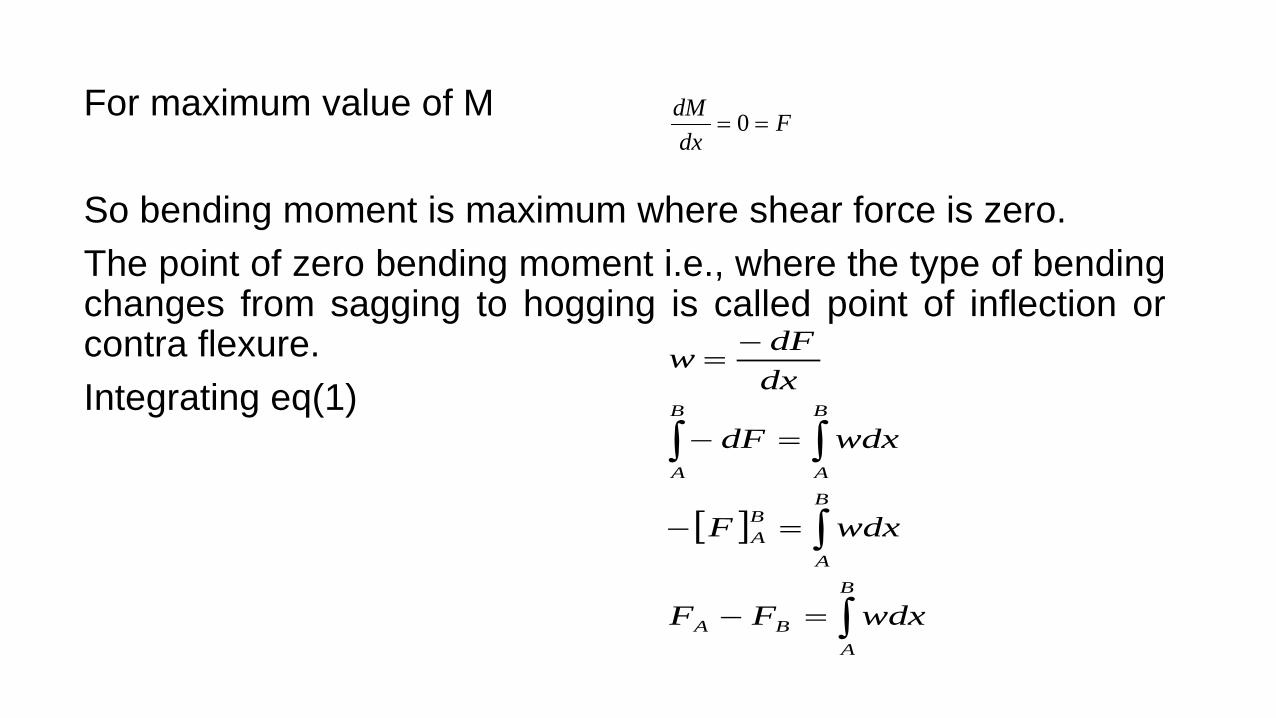
For maximum value of M So bending moment is maximum where shear force is zero. The point of zero bending moment i.e., where the type of bending changes from sagging to hogging is called point of inflection or contra flexure. Integrating eq(1)
Fdx
dM== 0
[ ]
∫
∫
∫∫
=−
=−
=−
−=
B
ABA
B
A
BA
B
A
B
A
wdxFF
wdxF
wdxdF
dxdFw

Which is the area under the load distribution diagram Similarly integrating eq (2) Area under the shear force diagram
∫=−B
AAB FdxMM
2
2
dxMd
dxdM
dxd
dxdFw −=
−=
−=
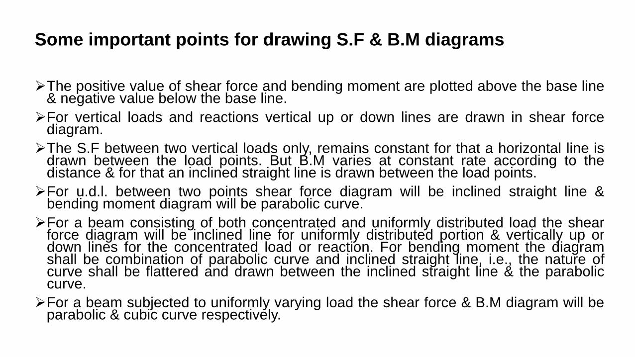
Some important points for drawing S.F & B.M diagrams The positive value of shear force and bending moment are plotted above the base line
& negative value below the base line. For vertical loads and reactions vertical up or down lines are drawn in shear force
diagram. The S.F between two vertical loads only, remains constant for that a horizontal line is
drawn between the load points. But B.M varies at constant rate according to the distance & for that an inclined straight line is drawn between the load points. For u.d.l. between two points shear force diagram will be inclined straight line &
bending moment diagram will be parabolic curve. For a beam consisting of both concentrated and uniformly distributed load the shear
force diagram will be inclined line for uniformly distributed portion & vertically up or down lines for the concentrated load or reaction. For bending moment the diagram shall be combination of parabolic curve and inclined straight line, i.e., the nature of curve shall be flattered and drawn between the inclined straight line & the parabolic curve. For a beam subjected to uniformly varying load the shear force & B.M diagram will be
parabolic & cubic curve respectively.
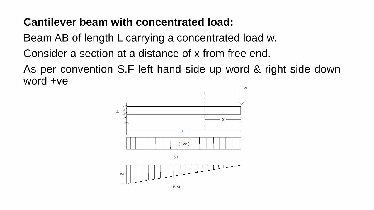
Cantilever beam with concentrated load: Beam AB of length L carrying a concentrated load w. Consider a section at a distance of x from free end. As per convention S.F left hand side up word & right side down word +ve
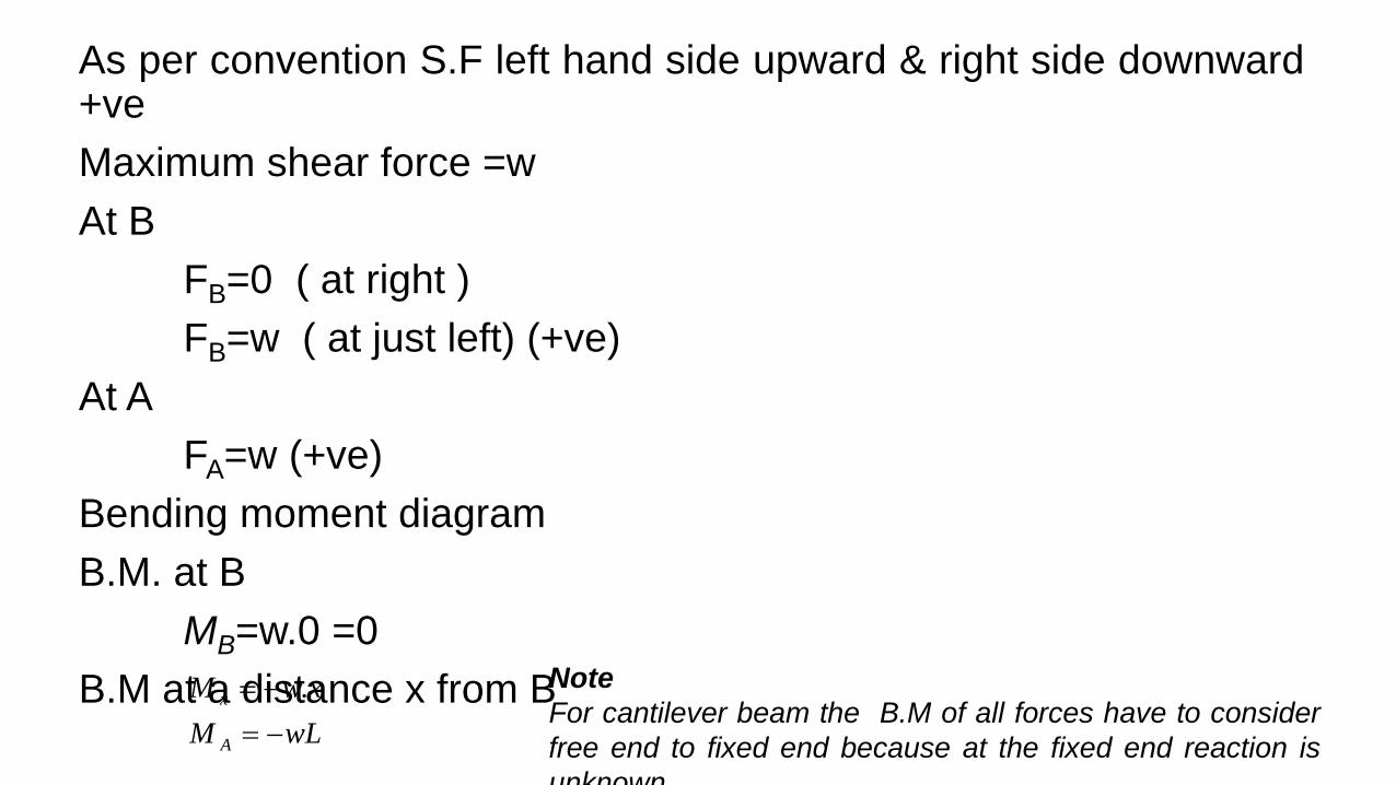
As per convention S.F left hand side upward & right side downward +ve Maximum shear force =w At B FB=0 ( at right ) FB=w ( at just left) (+ve) At A FA=w (+ve) Bending moment diagram B.M. at B MB=w.0 =0 B.M at a distance x from B wLM
xwM
A
x
−=−= . Note
For cantilever beam the B.M of all forces have to consider free end to fixed end because at the fixed end reaction is unknown
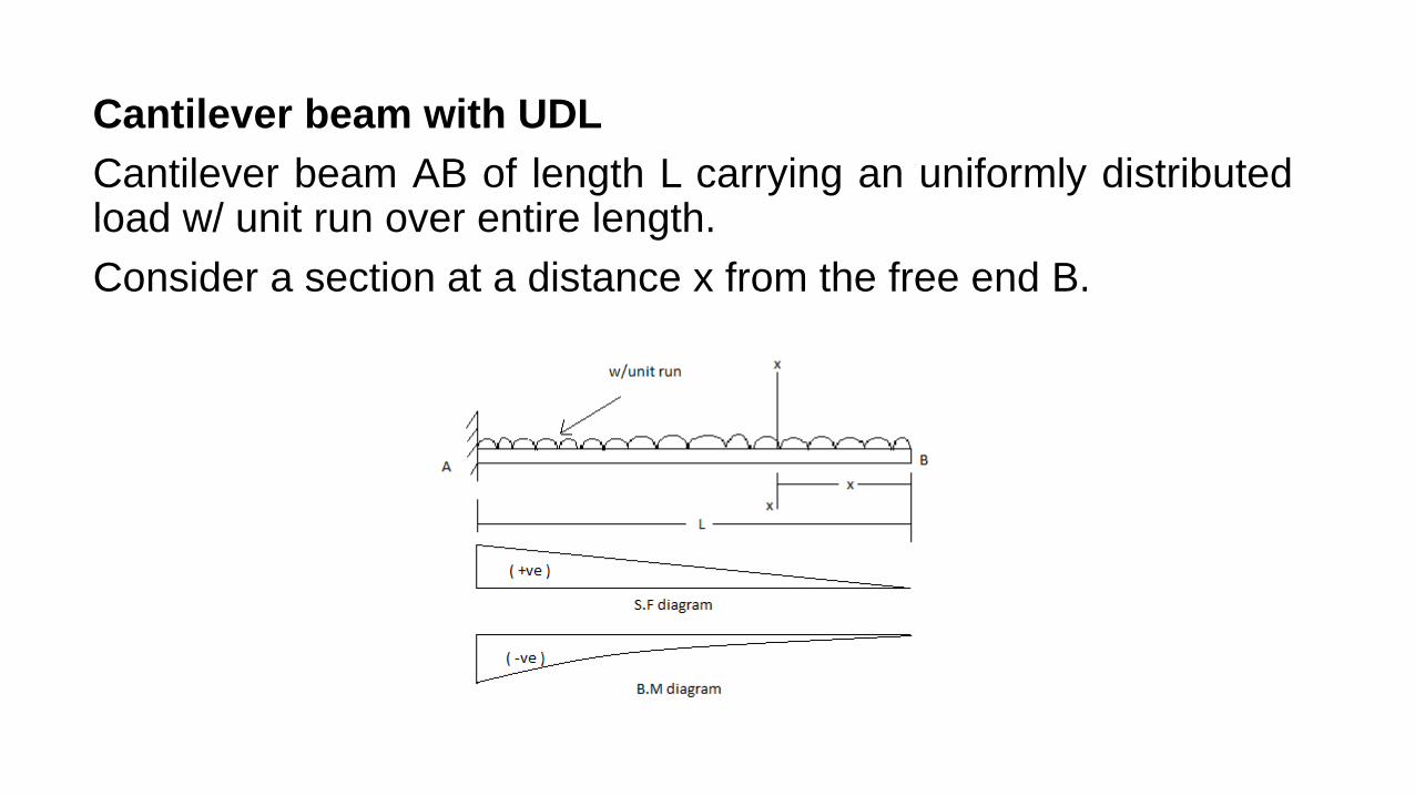
Cantilever beam with UDL Cantilever beam AB of length L carrying an uniformly distributed load w/ unit run over entire length. Consider a section at a distance x from the free end B.
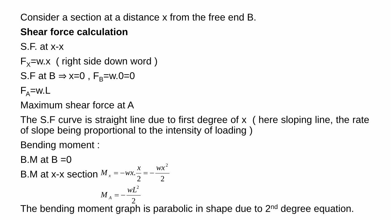
Consider a section at a distance x from the free end B. Shear force calculation S.F. at x-x FX=w.x ( right side down word ) S.F at B ⇒ x=0 , FB=w.0=0 FA=w.L Maximum shear force at A The S.F curve is straight line due to first degree of x ( here sloping line, the rate of slope being proportional to the intensity of loading ) Bending moment : B.M at B =0 B.M at x-x section
2
22.
2
2
wLM
wxxwxM
A
x
−=
−=−=
The bending moment graph is parabolic in shape due to 2nd degree equation.
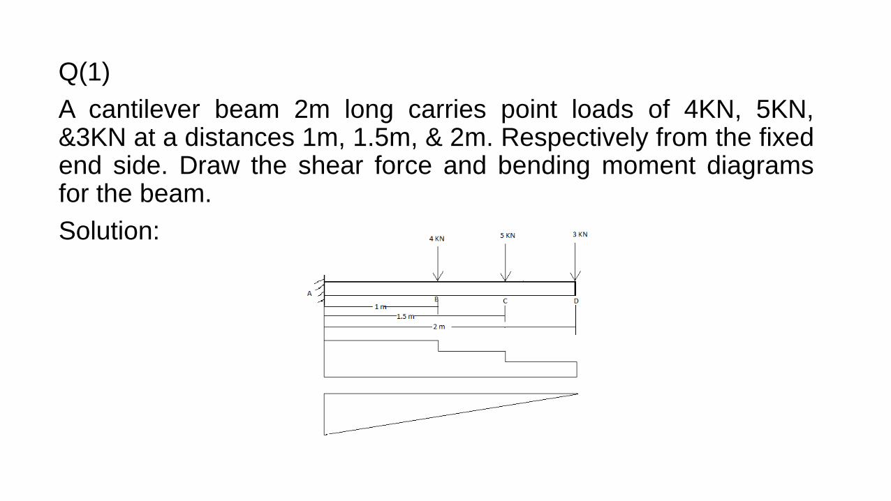
Q(1) A cantilever beam 2m long carries point loads of 4KN, 5KN, &3KN at a distances 1m, 1.5m, & 2m. Respectively from the fixed end side. Draw the shear force and bending moment diagrams for the beam. Solution:
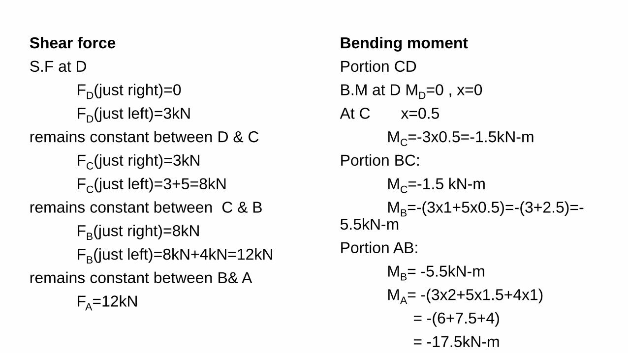
Shear force S.F at D FD(just right)=0 FD(just left)=3kN remains constant between D & C FC(just right)=3kN FC(just left)=3+5=8kN remains constant between C & B FB(just right)=8kN FB(just left)=8kN+4kN=12kN remains constant between B& A FA=12kN
Bending moment Portion CD B.M at D MD=0 , x=0 At C x=0.5 MC=-3x0.5=-1.5kN-m Portion BC: MC=-1.5 kN-m MB=-(3x1+5x0.5)=-(3+2.5)=-5.5kN-m Portion AB: MB= -5.5kN-m MA= -(3x2+5x1.5+4x1) = -(6+7.5+4) = -17.5kN-m
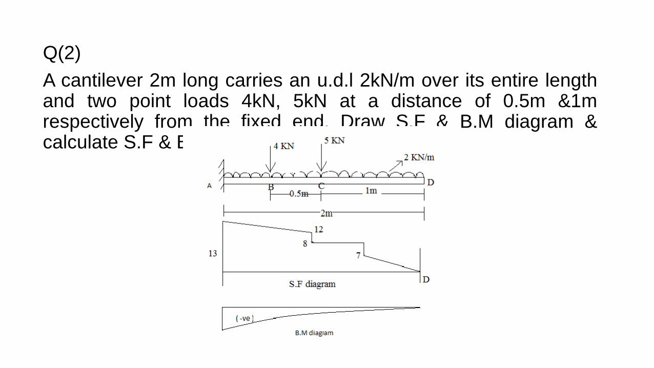
Q(2) A cantilever 2m long carries an u.d.l 2kN/m over its entire length and two point loads 4kN, 5kN at a distance of 0.5m &1m respectively from the fixed end. Draw S.F & B.M diagram & calculate S.F & B. M.
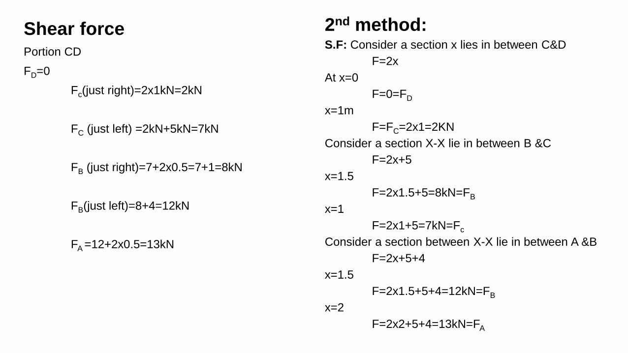
Shear force Portion CD FD=0 Fc(just right)=2x1kN=2kN FC (just left) =2kN+5kN=7kN FB (just right)=7+2x0.5=7+1=8kN FB(just left)=8+4=12kN FA =12+2x0.5=13kN
2nd method: S.F: Consider a section x lies in between C&D F=2x At x=0 F=0=FD x=1m F=FC=2x1=2KN Consider a section X-X lie in between B &C F=2x+5 x=1.5 F=2x1.5+5=8kN=FB x=1 F=2x1+5=7kN=Fc Consider a section between X-X lie in between A &B F=2x+5+4 x=1.5 F=2x1.5+5+4=12kN=FB x=2 F=2x2+5+4=13kN=FA
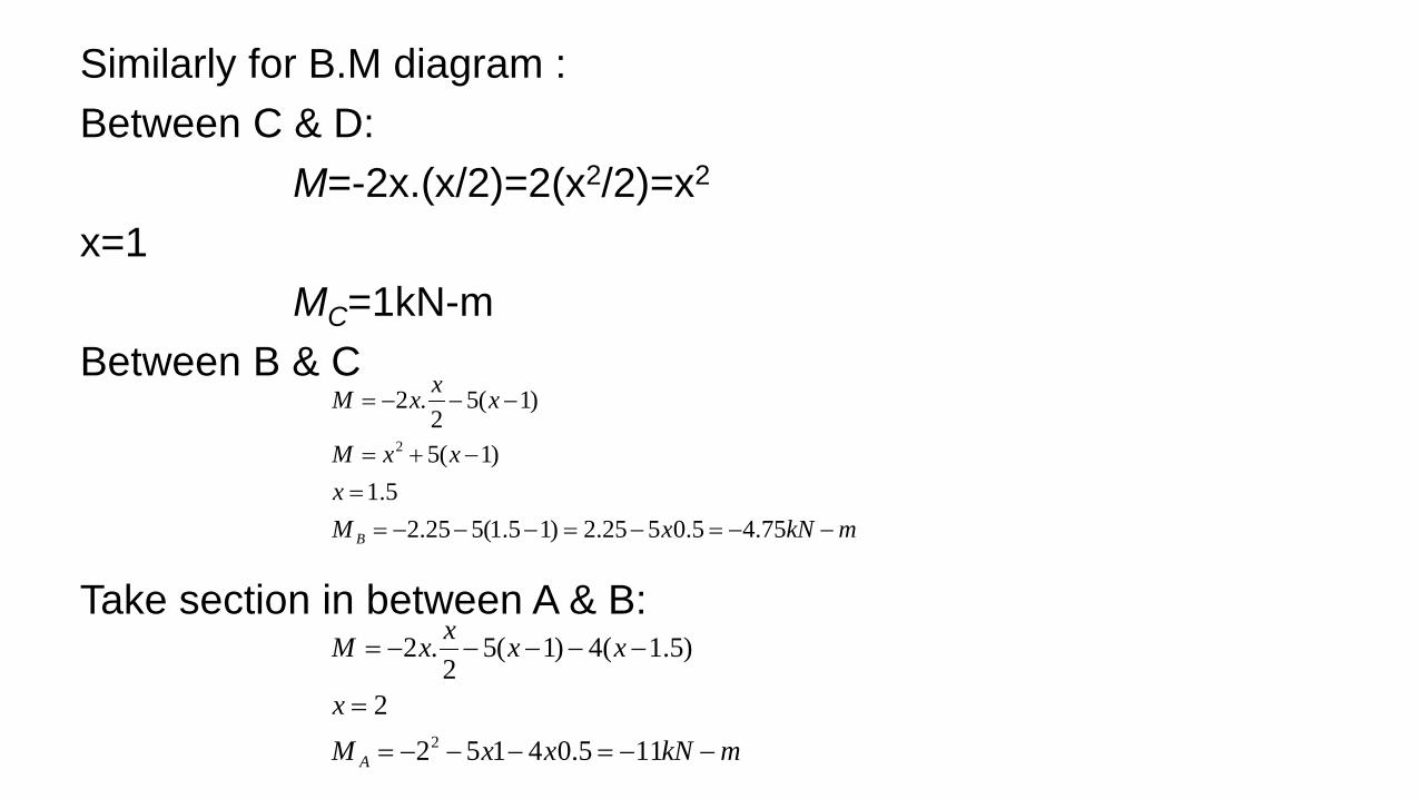
Similarly for B.M diagram : Between C & D: M=-2x.(x/2)=2(x2/2)=x2 x=1 MC=1kN-m Between B & C Take section in between A & B:
mkNxMx
xxM
xxxM
B −−=−=−−−==
−+=
−−−=
75.45.0525.2)15.1(525.25.1
)1(5
)1(52
.2
2
mkNxxMx
xxxxM
A −−=−−−=
=
−−−−−=
115.041522
)5.1(4)1(52
.2
2

Q(3) A cantilever ABCD, 7m long is fixed at A , such that AB=BC=2m. and CD=3m. It carries loads 5t, 3t, 2t at B,C&D respectively in addition to u.d.l of 1 t/m run between A&B, and 2t/m between C&D. draw shear force & bending moment diagram & the salient values. Solution:
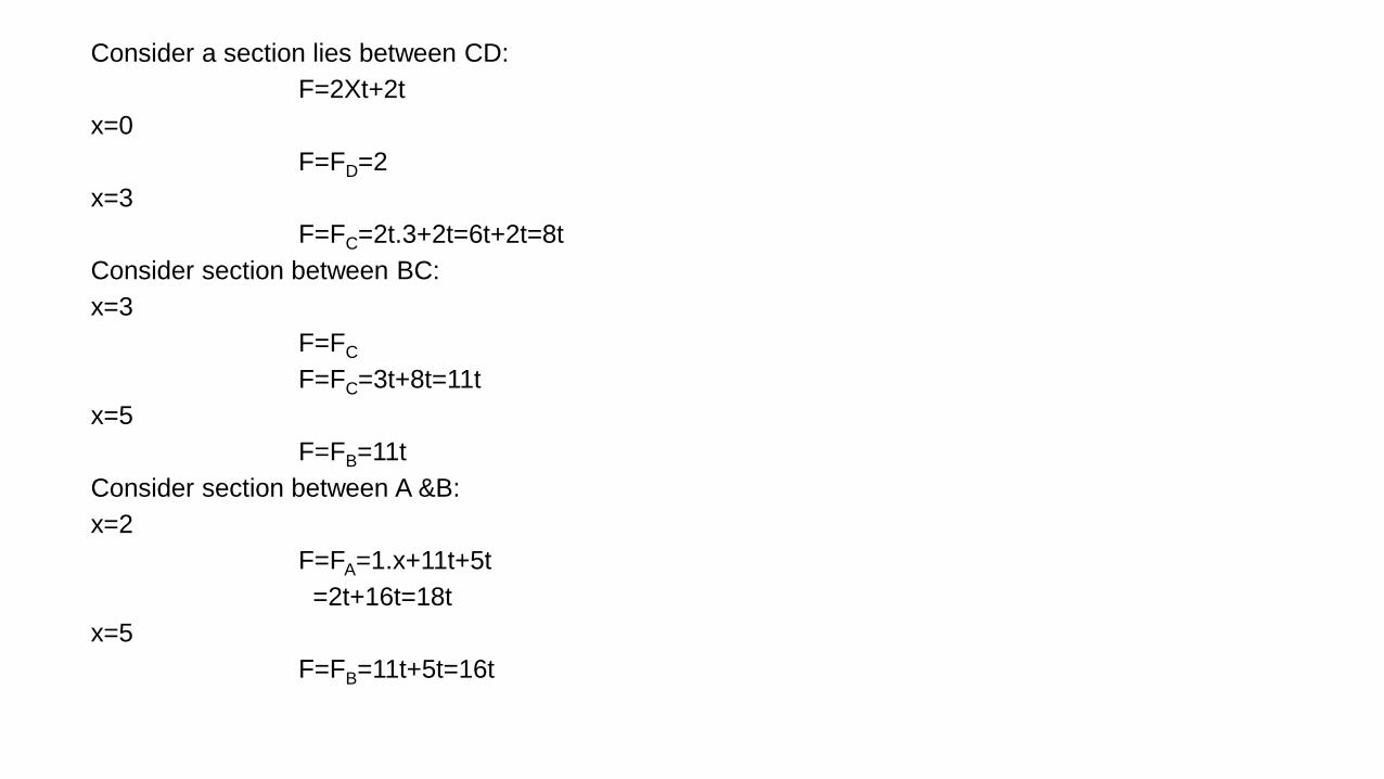
Consider a section lies between CD: F=2Xt+2t x=0 F=FD=2 x=3 F=FC=2t.3+2t=6t+2t=8t Consider section between BC: x=3 F=FC F=FC=3t+8t=11t x=5 F=FB=11t Consider section between A &B: x=2 F=FA=1.x+11t+5t =2t+16t=18t x=5 F=FB=11t+5t=16t

B.M at section X-X in between C-D B.M at section X-X in between B-C
ttt
ttMM
xMM
x
xxmtxtM
C
D
15962323.2
30
02
..2.2
2
=−−=
−−==
===
=
−−=
tttttttt
tttttM
ttt
ttt
tttM
A
B
7133382)5.5(6101214
222)
2322(32254372
372116
)5.3(6610232322352
−=−−=−−−−−=
××−++××−×−×−×−=
−=−−=
−−−=
+××−×−×−=

Cantilever carrying Gradually varying load Consider a cantilever of length L carrying a gradually varying load as shown
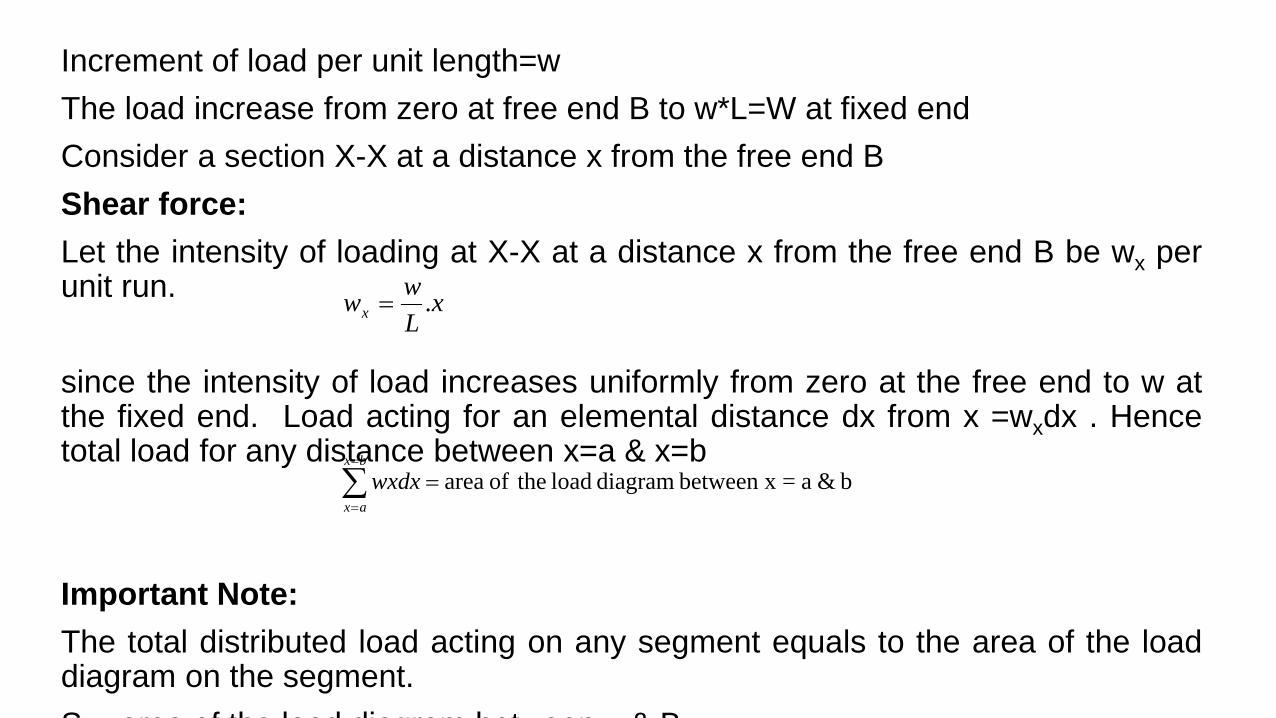
Increment of load per unit length=w The load increase from zero at free end B to w*L=W at fixed end Consider a section X-X at a distance x from the free end B Shear force: Let the intensity of loading at X-X at a distance x from the free end B be wx per unit run. since the intensity of load increases uniformly from zero at the free end to w at the fixed end. Load acting for an elemental distance dx from x =wxdx . Hence total load for any distance between x=a & x=b Important Note: The total distributed load acting on any segment equals to the area of the load diagram on the segment. S area of the load diagram bet een & B
xLwwx .=
b & a=between x diagram load theof area=∑=
=
bx
axwxdx
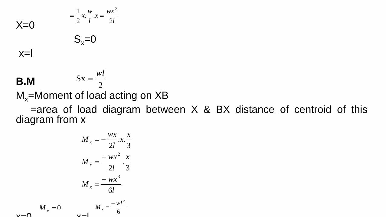
X=0 Sx=0 x=l B.M Mx=Moment of load acting on XB =area of load diagram between X & BX distance of centroid of this diagram from x x=0 x=l
2Sx wl
=
lwxM
xl
wxM
xxl
wxM
x
x
x
6
3.
2
3..
2
3
2
−=
−=
−=
lwxx
lwx
2..
21 2
==
0=xM 6
2wlM x−
=
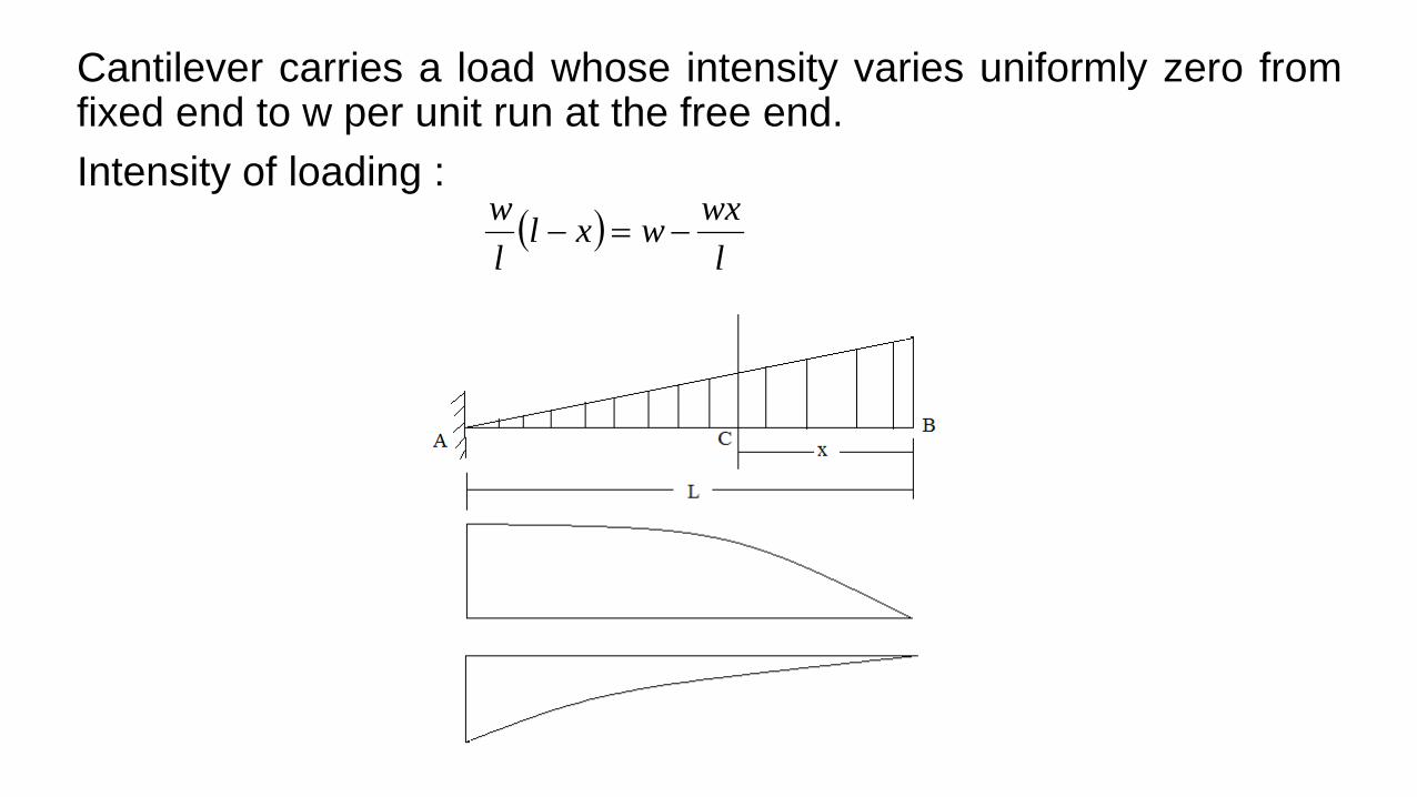
Cantilever carries a load whose intensity varies uniformly zero from fixed end to w per unit run at the free end. Intensity of loading : ( )
lwxwxl
lw
−=−
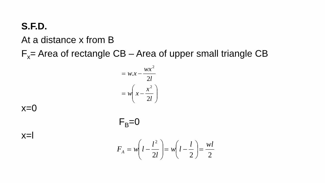
S.F.D. At a distance x from B Fx= Area of rectangle CB – Area of upper small triangle CB x=0 FB=0 x=l
−=
−=
lxxw
lwxxw
2
2.
2
2
222
2 wlllwl
llwFA =
−=
−=
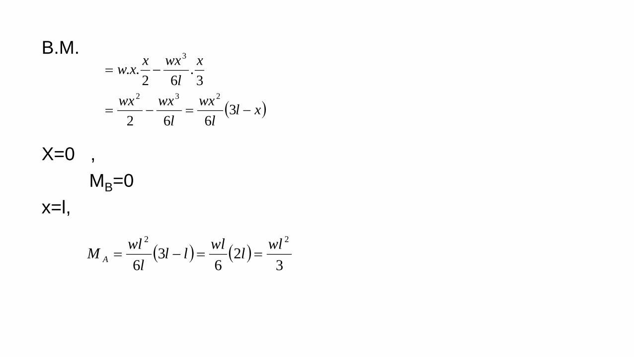
B.M. X=0 , MB=0 x=l,
( )xll
wxl
wxwx
xl
wxxxw
−=−=
−=
3662
3.
62..
232
3
( ) ( )3
26
36
22 wllwllll
wlM A ==−=
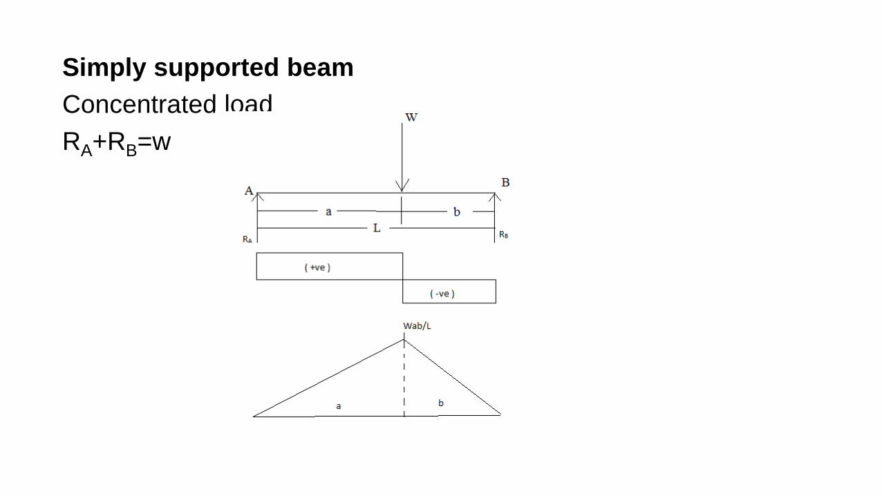
Simply supported beam Concentrated load RA+RB=w
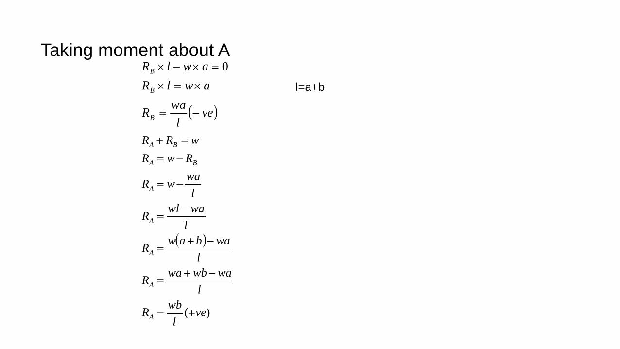
Taking moment about A ( )ve
lwaR
awlRawlR
B
B
B
−=
×=×=×−× 0
( )
)( vel
wbR
lwawbwaR
lwabawR
lwawlR
lwawR
RwRwRR
A
A
A
A
A
BA
BA
+=
−+=
−+=
−=
−=
−==+
l=a+b
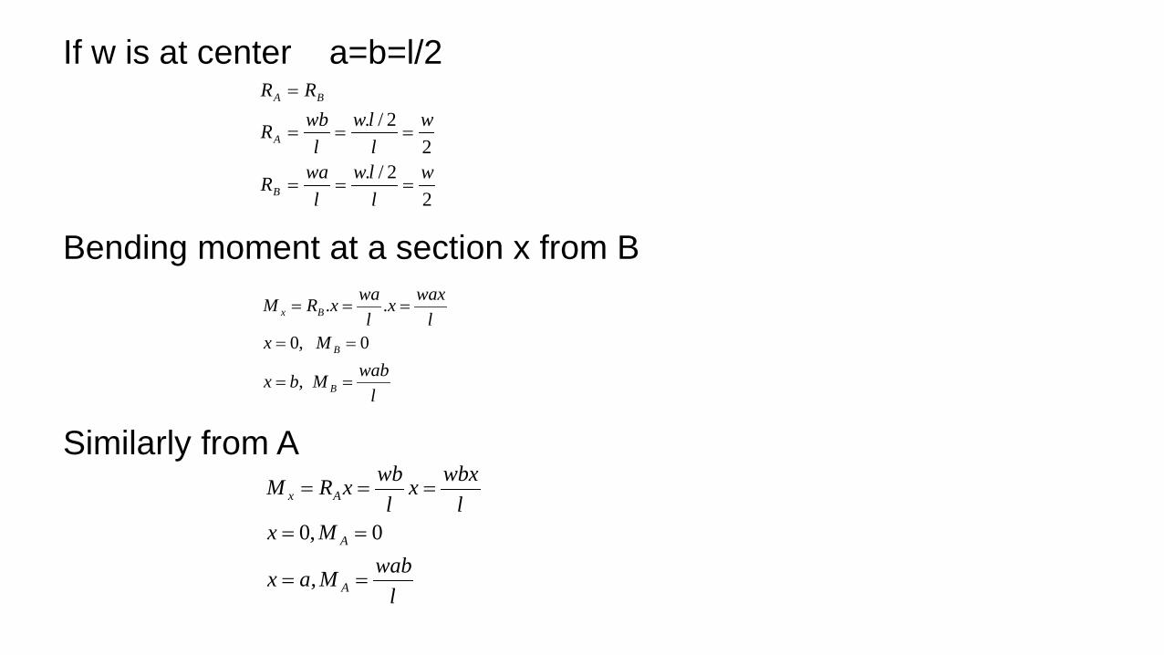
If w is at center a=b=l/2 Bending moment at a section x from B Similarly from A
22/.
22/.
wllw
lwaR
wllw
lwbR
RR
B
A
BA
===
===
=
lwabMbx
Mxl
waxxl
waxRM
B
B
Bx
==
==
===
,
0,0
..
lwabMax
Mxl
wbxxl
wbxRM
A
A
Ax
==
==
===
,
0,0

If load is at mid span a=b=l/2
422wlll
lwM =
=

Simply supported beam with udl loading Total load =wl Take a section at X-X from the end A
2wlRR
wlRR
ba
ba
==
=+
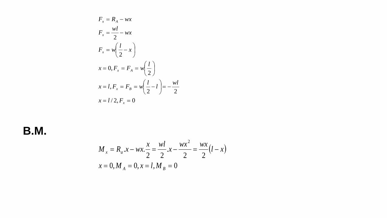
B.M.
0,2/22
,
2,0
2
2
==
−=
−===
===
−=
−=
−=
x
Bx
Ax
x
x
Ax
Flx
wlllwFFlx
lwFFx
xlwF
wxwlF
wxRF
( )
0,,0,022
.22
..2
====
−=−=−=
BA
ax
MlxMx
xlwxwxxwlxwxxRM

For maximum value of B.M
−===
220
2wxwldxdF
dxdM
02
222
=−=
−=
wxwl
xwwl
( )
( )
x
2
wlwx2
x l / 2wxM l x2
wl l l / 24wl8
=
=
= −
= −
=

Q. A beam AB 10m long has supports at its ends A&B. it carries a point load of 5KN at 3m from A and a point load of 5KN at 7m from A & uniformly distributed load of 1KN/m between the point loads. Draw SF & BM Solution:
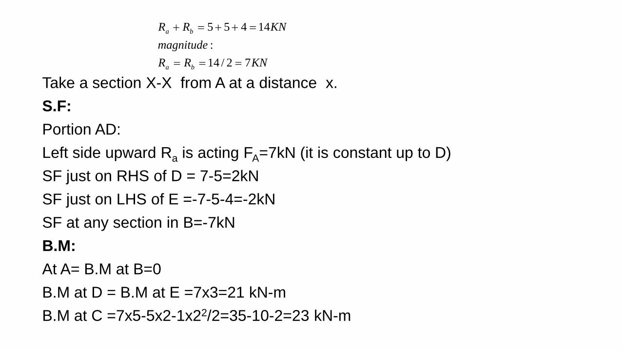
Take a section X-X from A at a distance x. S.F: Portion AD: Left side upward Ra is acting FA=7kN (it is constant up to D) SF just on RHS of D = 7-5=2kN SF just on LHS of E =-7-5-4=-2kN SF at any section in B=-7kN B.M: At A= B.M at B=0 B.M at D = B.M at E =7x3=21 kN-m B.M at C =7x5-5x2-1x22/2=35-10-2=23 kN-m
KNRRmagnitude
KNRR
ba
ba
72/14:
14455
===
=++=+

Gradually varying load 1st type: Cantilever beam carrying distributed load with intensity varying from zero at free end to w at fixed end.
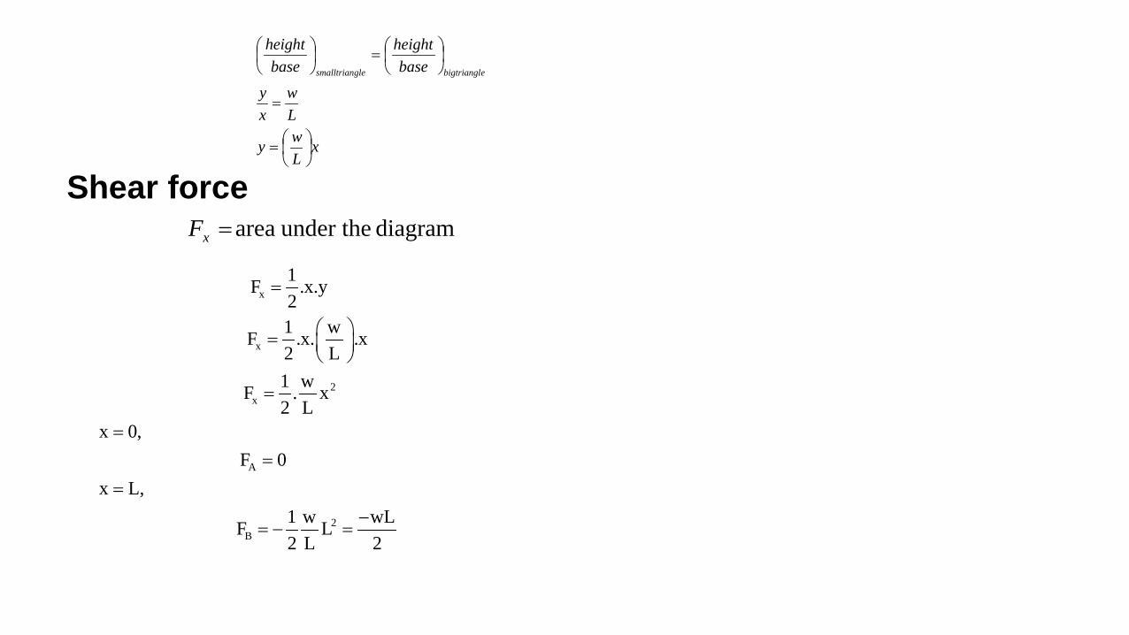
Shear force
xLwy
Lw
xy
baseheight
baseheight
ebigtrianglglesmalltrian
=
=
=
diagram under the area=xF
x
x
2x
A
2B
1F .x.y21 wF .x. .x2 L1 wF . x2 L
x 0,F 0
x L,1 w wLF L2 L 2
=
=
=
==
=−
= − =
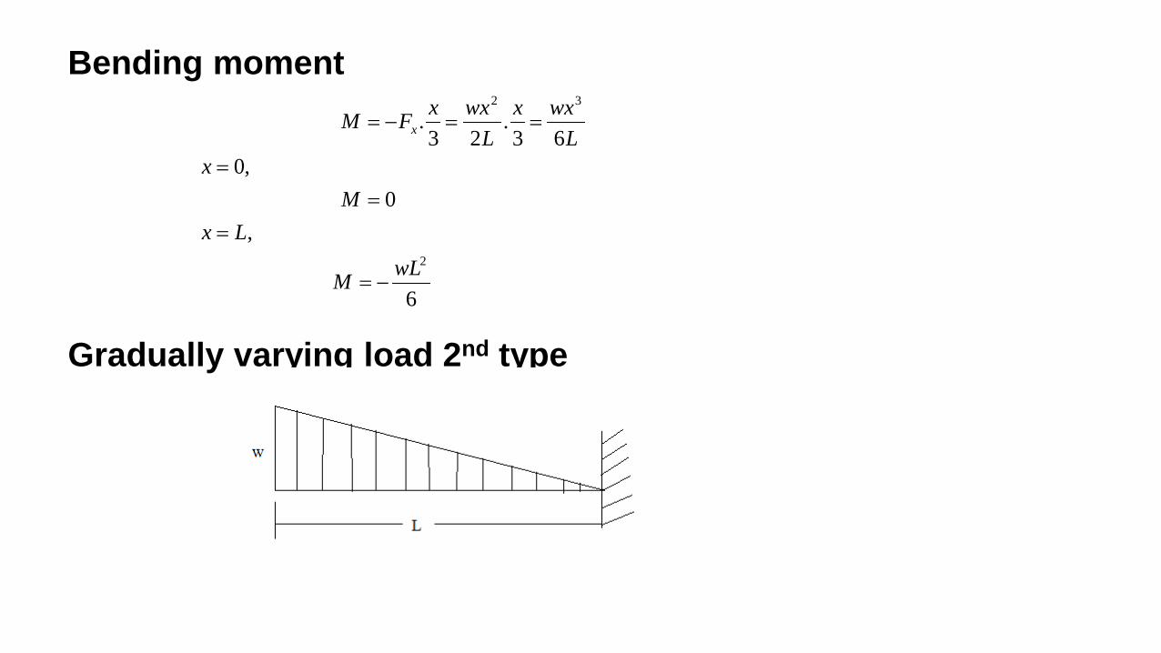
Bending moment Gradually varying load 2nd type
6
,0
,063
.23
.
2
32
wLM
LxM
xL
wxxL
wxxFM x
−=
==
=
==−=
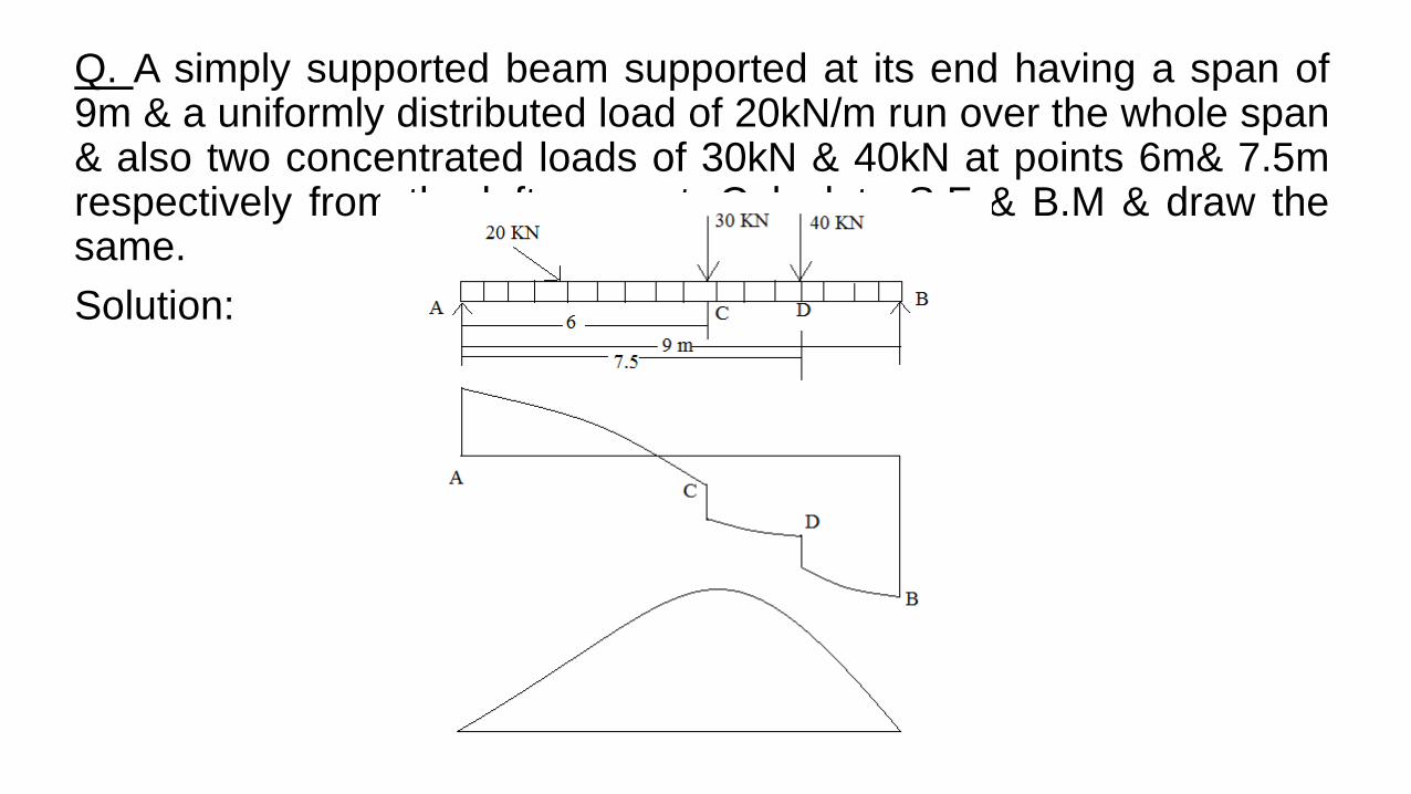
Q. A simply supported beam supported at its end having a span of 9m & a uniformly distributed load of 20kN/m run over the whole span & also two concentrated loads of 30kN & 40kN at points 6m& 7.5m respectively from the left support. Calculate S.F & B.M & draw the same. Solution:
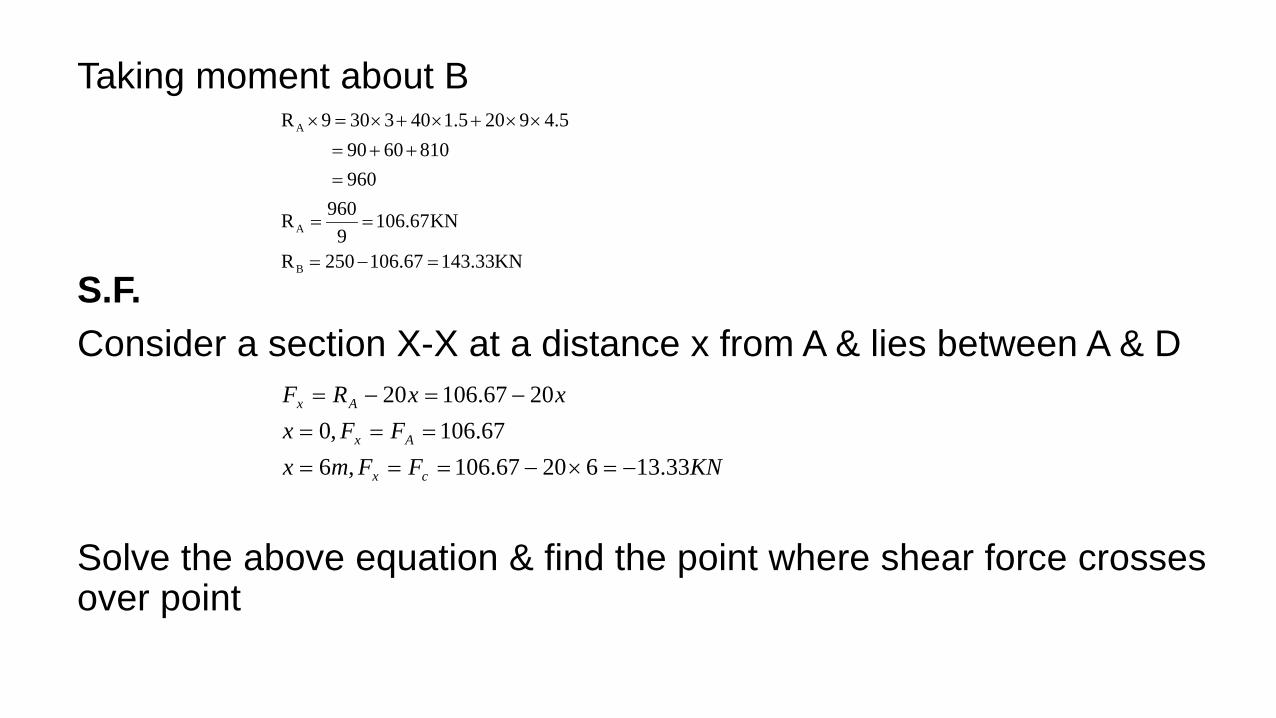
Taking moment about B S.F. Consider a section X-X at a distance x from A & lies between A & D Solve the above equation & find the point where shear force crosses over point
KNFFmxFFx
xxRF
cx
Ax
Ax
33.1362067.106,667.106,0
2067.10620
−=×−======
−=−=
A
A
B
R 9 30 3 40 1.5 20 9 4.590 60 810960
960R 106.67KN9
R 250 106.67 143.33KN
× = × + × + × ×= + +=
= =
= − =

Consider a section lies in between C & D X lies in between D & B
KNFFmx
KNFFmx
xxRF
Dx
cx
A
33.733015067.106,5.7
33.433062067.106,6
2067.1063020
−=−−===
−=−×−===
−=−−=
KNRFFx
KNRFFx
xxRF
ABx
ADx
A
33.14370180,9
33.11340305.720,5.7
40302067.106403020
−=−−===
−=−−×−===
−−−=−−−=

B.M. Between A & C Between C & D Between D & B
mKMMxmKNMMx
Mx
xxxxxRM
x
Cx
A
Ax
−==−=×−×===
==
−=−×=
4.284,33.5280610667.106,6
0,0
1067.1062
.20
2
2
( )
75.192455.562025.8005.7
63010 2
=−−==
−−−×=
x
Ax
Mx
xxxRM
( ) ( )
30036018027081063.960,9
5.74063010 2
+−+−−==
−−−−−×=
x
Ax
Mx
xxxxRM
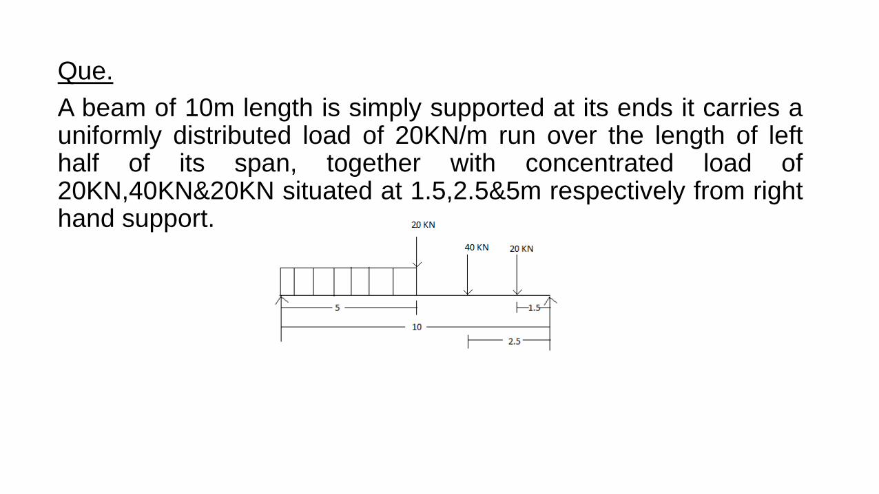
Que. A beam of 10m length is simply supported at its ends it carries a uniformly distributed load of 20KN/m run over the length of left half of its span, together with concentrated load of 20KN,40KN&20KN situated at 1.5,2.5&5m respectively from right hand support.

Simply supported beam subjected to couple
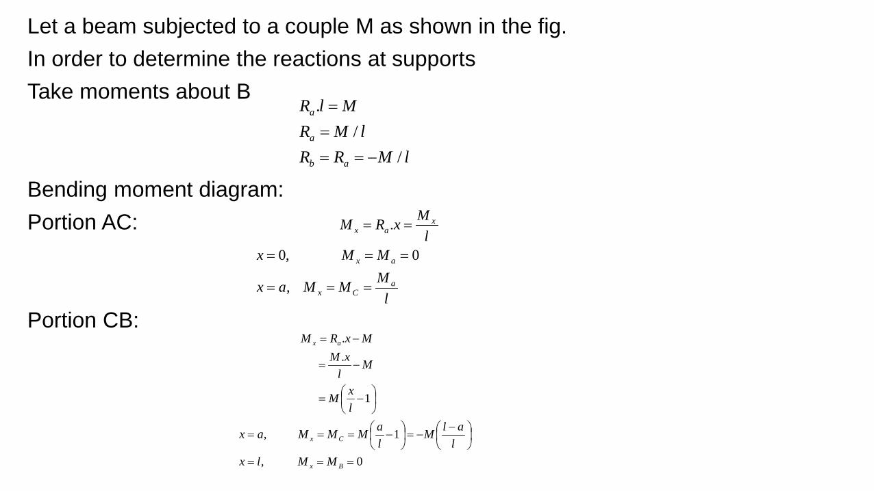
Let a beam subjected to a couple M as shown in the fig. In order to determine the reactions at supports Take moments about B Bending moment diagram: Portion AC: Portion CB:
lMRRlMR
MlR
ab
a
a
//
.
−====
lMMMax
MMxl
MxRM
aCx
ax
xax
===
===
==
,
0,0
.
0,
1,
1
.
.
===
−
−=
−===
−=
−=
−=
Bx
Cx
ax
MMlxl
alMlaMMMax
lxM
Ml
xMMxRM
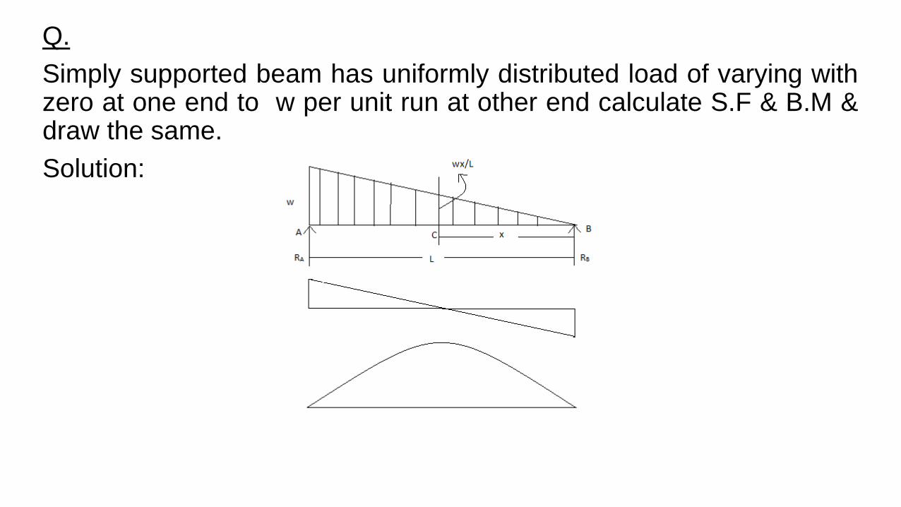
Q. Simply supported beam has uniformly distributed load of varying with zero at one end to w per unit run at other end calculate S.F & B.M & draw the same. Solution:

Taking moment about B
632
3
..21
32.
2.
wlwlwlR
wlR
lwlwllR
b
a
a
=−=
=
==
xlw . B end from x of distance aat intensity Load =
321
621
6
,6
,0
.21
6
.21
...21
2
2
2
wlwlwll
wlwlFF
lx
wlFF
xl
wxwll
wxR
xxlwRF
ax
bx
b
bx
=+−
=+−
==
=
−==
=
+−
=
+−=
+−=

Shear force is zero at B.M.
31
0.21
6
2
=
=+−
=
x
lwxwlFx
0,0
.61
6
3..
21.
63
2
===
−=
−=
ax
x
MMx
lwxwlx
xl
wxxwlM
Related Documents