AASHTO CFRP- Prestressed Concrete Design Training Course

Welcome message from author
This document is posted to help you gain knowledge. Please leave a comment to let me know what you think about it! Share it to your friends and learn new things together.
Transcript

AASHTO CFRP-
Prestressed Concrete Design
Training Course

Design of Pretensioned Concrete
Bridge Beams with Carbon Fiber-
Reinforced Polymer (CFRP) Systems
3
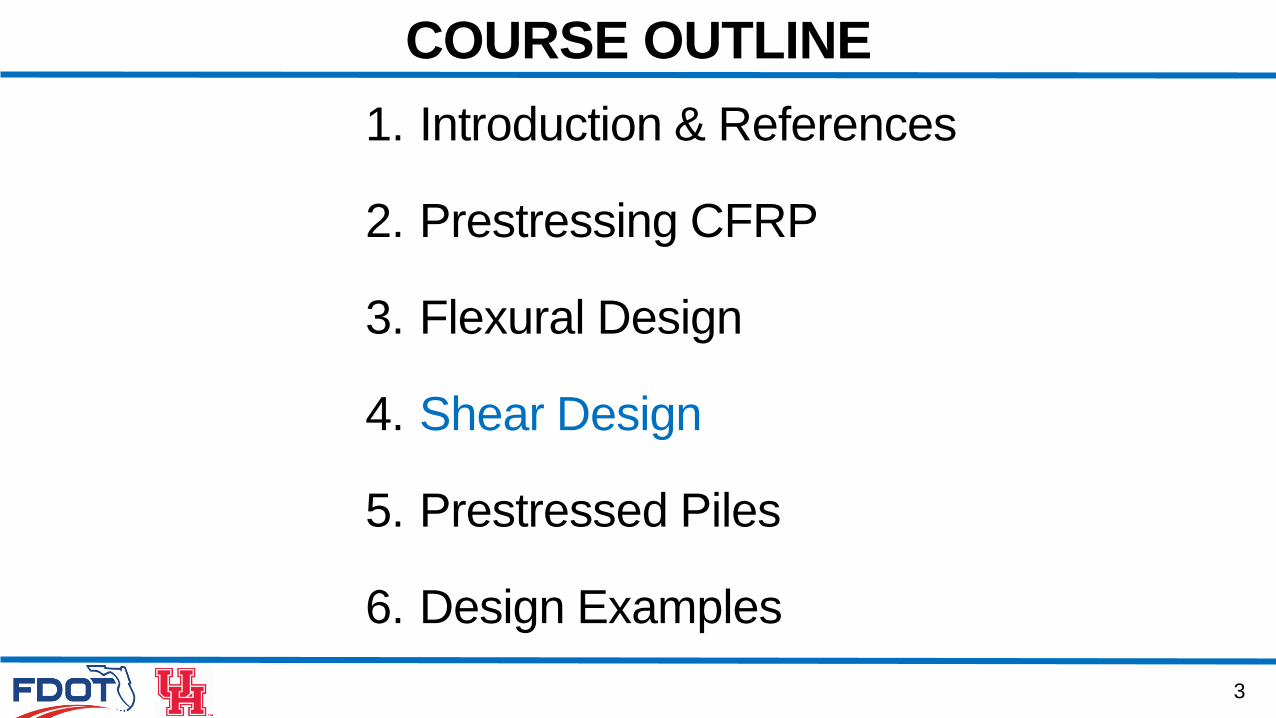
1. Introduction & References
2. Prestressing CFRP
3. Flexural Design
4. Shear Design
5. Prestressed Piles
6. Design Examples
COURSE OUTLINE

4. SHEAR DESIGN
5
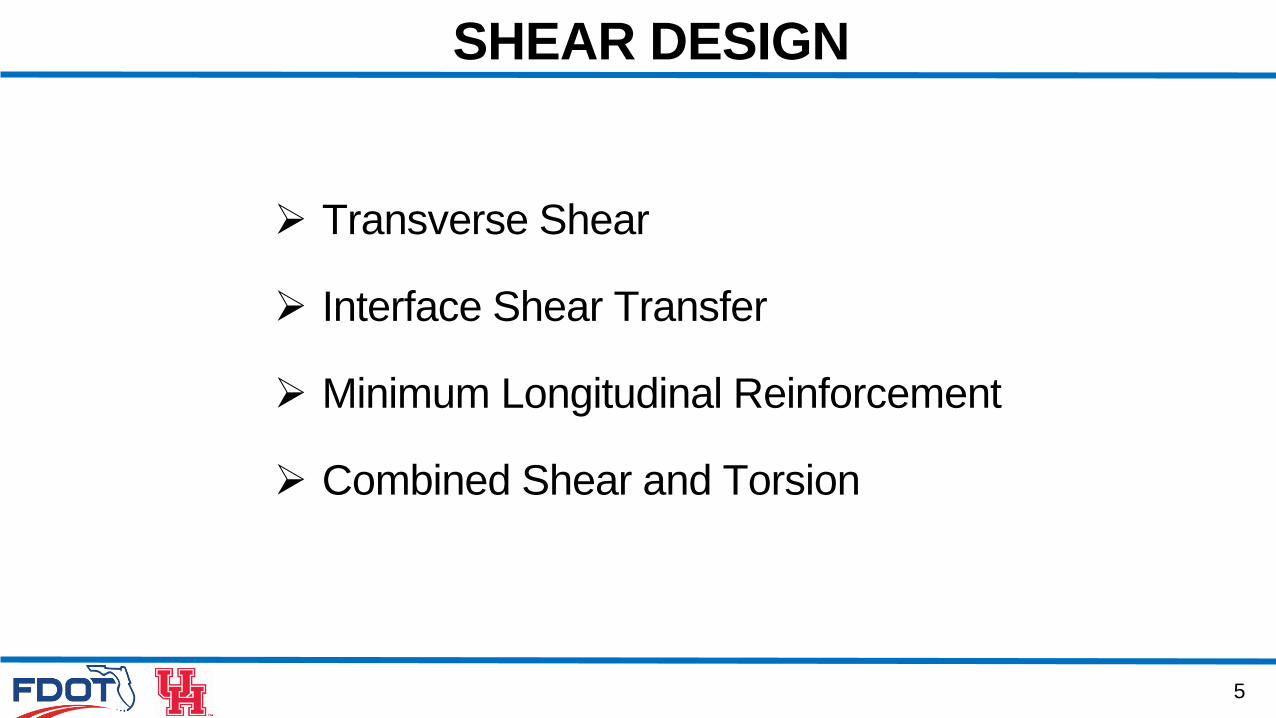
SHEAR DESIGN
Transverse Shear
Interface Shear Transfer
Minimum Longitudinal Reinforcement
Combined Shear and Torsion
6
SHEAR DESIGN
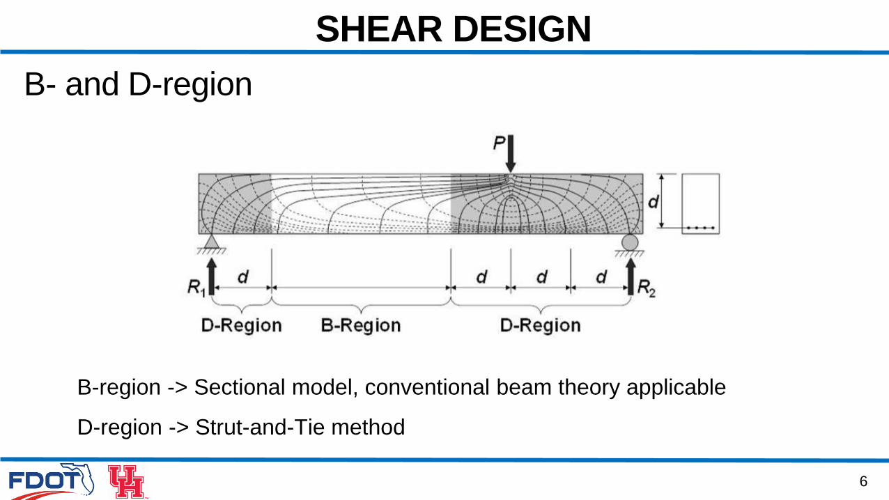
B- and D-region
B-region -> Sectional model, conventional beam theory applicable
D-region -> Strut-and-Tie method
7
SHEAR DESIGN
Transverse Shear Design
• Regions Requiring Transverse Reinforcement
• Shear Resistance
• Minimum Transverse Reinforcement
• Maximum Spacing of Transverse Reinforcement
• Deep Component
8
SHEAR DESIGN
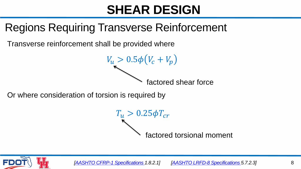
Regions Requiring Transverse Reinforcement
[AASHTO CFRP-1 Specifications 1.8.2.1]
𝑉𝑢 > 0.5𝜙 𝑉𝑐 + 𝑉𝑝
factored shear force
Transverse reinforcement shall be provided where
[AASHTO LRFD-8 Specifications 5.7.2.3]
Or where consideration of torsion is required by
factored torsional moment
𝑇𝑢 > 0.25𝜙𝑇𝑐𝑟
9
SHEAR DESIGN
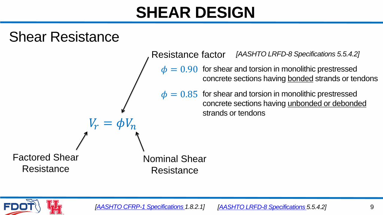
Shear Resistance
[AASHTO CFRP-1 Specifications 1.8.2.1]
𝑉𝑟 = 𝜙𝑉𝑛
Nominal Shear
Resistance
Factored Shear
Resistance
Resistance factor [AASHTO LRFD-8 Specifications 5.5.4.2]
for shear and torsion in monolithic prestressed
concrete sections having bonded strands or tendons𝜙 = 0.90
for shear and torsion in monolithic prestressed
concrete sections having unbonded or debonded
strands or tendons
𝜙 = 0.85
[AASHTO LRFD-8 Specifications 5.5.4.2]
10
SHEAR DESIGN
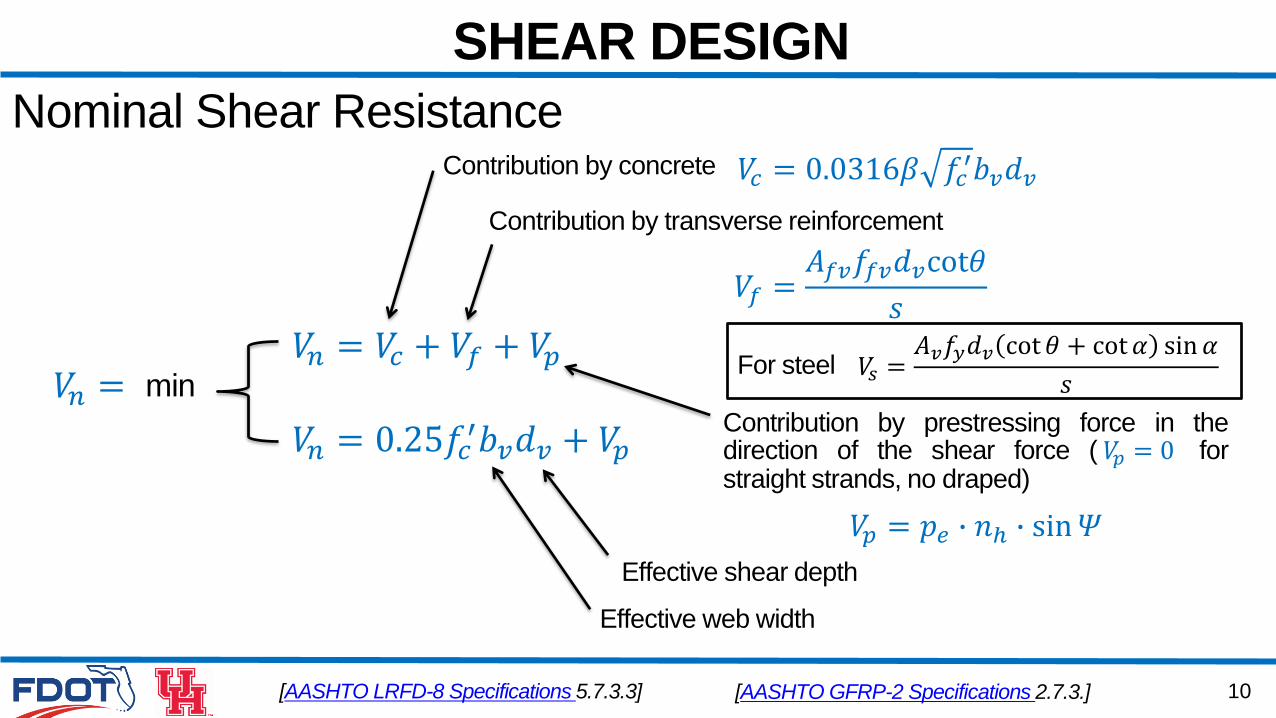
[AASHTO LRFD-8 Specifications 5.7.3.3]
𝑉𝑛 = 𝑉𝑐 + 𝑉𝑓 + 𝑉𝑝𝑉𝑛 = min
𝑉𝑛 = 0.25𝑓𝑐′𝑏𝑣𝑑𝑣 + 𝑉𝑝
Contribution by concrete
Contribution by transverse reinforcement
𝑉𝑓 =𝐴𝑓𝑣𝑓𝑓𝑣𝑑𝑣cot𝜃
𝑠
Contribution by prestressing force in thedirection of the shear force ( 𝑉𝑝 = 0 forstraight strands, no draped)
𝑉𝑝 = 𝑝𝑒 ∙ 𝑛ℎ ∙ sin𝛹
Effective shear depth
Effective web width
Nominal Shear Resistance𝑉𝑐 = 0.0316𝛽 𝑓𝑐
′𝑏𝑣𝑑𝑣
[AASHTO GFRP-2 Specifications 2.7.3.]
𝑉𝑠 =𝐴𝑣𝑓𝑦𝑑𝑣 cot 𝜃 + cot 𝛼 sin𝛼
𝑠For steel
11
SHEAR DESIGN
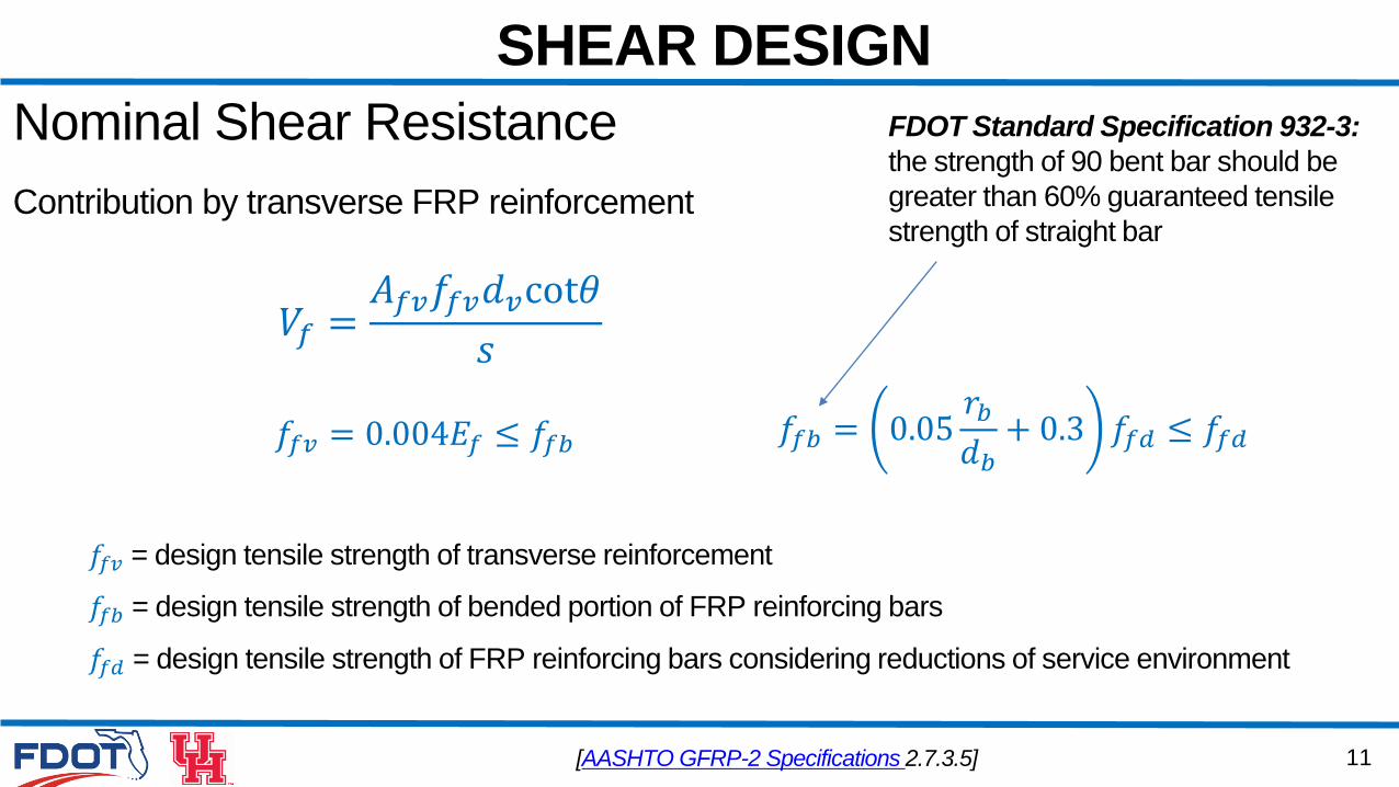
Contribution by transverse FRP reinforcement
𝑉𝑓 =𝐴𝑓𝑣𝑓𝑓𝑣𝑑𝑣cot𝜃
𝑠
Nominal Shear Resistance
𝑓𝑓𝑏 = 0.05𝑟𝑏𝑑𝑏+ 0.3 𝑓𝑓𝑑 ≤ 𝑓𝑓𝑑𝑓𝑓𝑣 = 0.004𝐸𝑓 ≤ 𝑓𝑓𝑏
[AASHTO GFRP-2 Specifications 2.7.3.5]
𝑓𝑓𝑣 = design tensile strength of transverse reinforcement
𝑓𝑓𝑑 = design tensile strength of FRP reinforcing bars considering reductions of service environment
𝑓𝑓𝑏 = design tensile strength of bended portion of FRP reinforcing bars
FDOT Standard Specification 932-3:
the strength of 90 bent bar should be
greater than 60% guaranteed tensile
strength of straight bar
12
SHEAR DESIGN
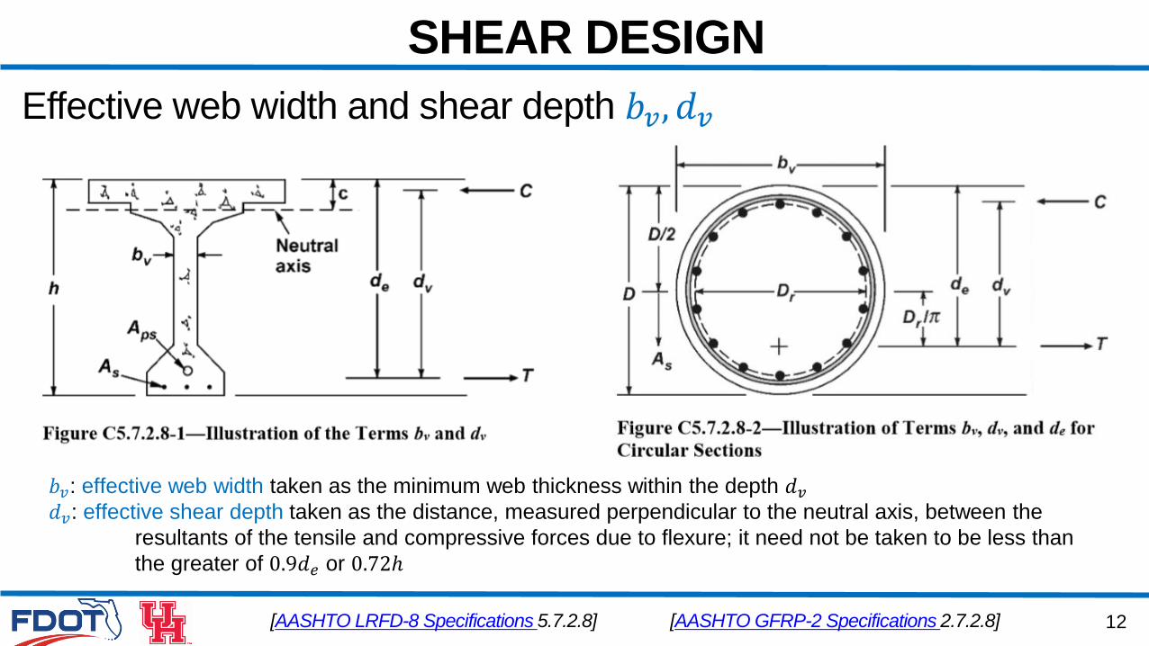
Effective web width and shear depth 𝑏𝑣, 𝑑𝑣
[AASHTO LRFD-8 Specifications 5.7.2.8]
𝑏𝑣: effective web width taken as the minimum web thickness within the depth 𝑑𝑣𝑑𝑣: effective shear depth taken as the distance, measured perpendicular to the neutral axis, between the
resultants of the tensile and compressive forces due to flexure; it need not be taken to be less than
the greater of 0.9𝑑𝑒 or 0.72ℎ
[AASHTO GFRP-2 Specifications 2.7.2.8]
13
SHEAR DESIGN
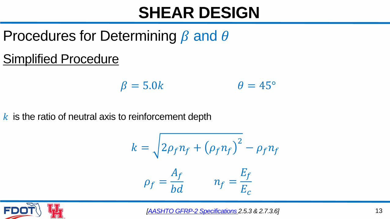
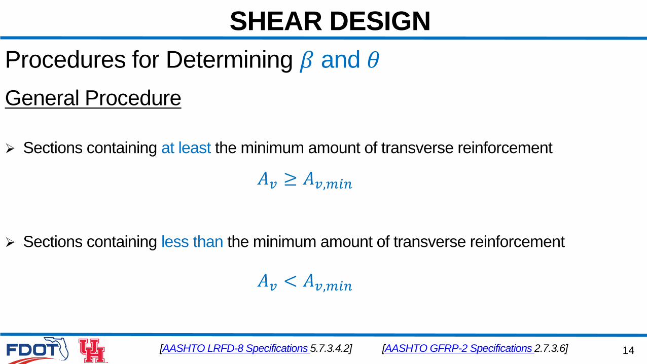
Procedures for Determining 𝛽 and 𝜃
Simplified Procedure
𝜃 = 45°𝛽 = 5.0𝑘
[AASHTO GFRP-2 Specifications 2.5.3 & 2.7.3.6]
𝑘 is the ratio of neutral axis to reinforcement depth
𝑘 = 2𝜌𝑓𝑛𝑓 + 𝜌𝑓𝑛𝑓2− 𝜌𝑓𝑛𝑓
𝜌𝑓 =𝐴𝑓
𝑏𝑑𝑛𝑓 =𝐸𝑓
𝐸𝑐
14
SHEAR DESIGN
Procedures for Determining 𝛽 and 𝜃
[AASHTO LRFD-8 Specifications 5.7.3.4.2]
Sections containing at least the minimum amount of transverse reinforcement
Sections containing less than the minimum amount of transverse reinforcement
𝐴𝑣 < 𝐴𝑣,𝑚𝑖𝑛
𝐴𝑣 ≥ 𝐴𝑣,𝑚𝑖𝑛
[AASHTO GFRP-2 Specifications 2.7.3.6]
General Procedure
15
SHEAR DESIGN
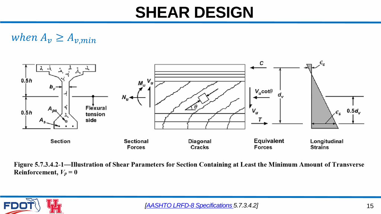
[AASHTO LRFD-8 Specifications 5.7.3.4.2]
𝑤ℎ𝑒𝑛 𝐴𝑣 ≥ 𝐴𝑣,𝑚𝑖𝑛
16
SHEAR DESIGN
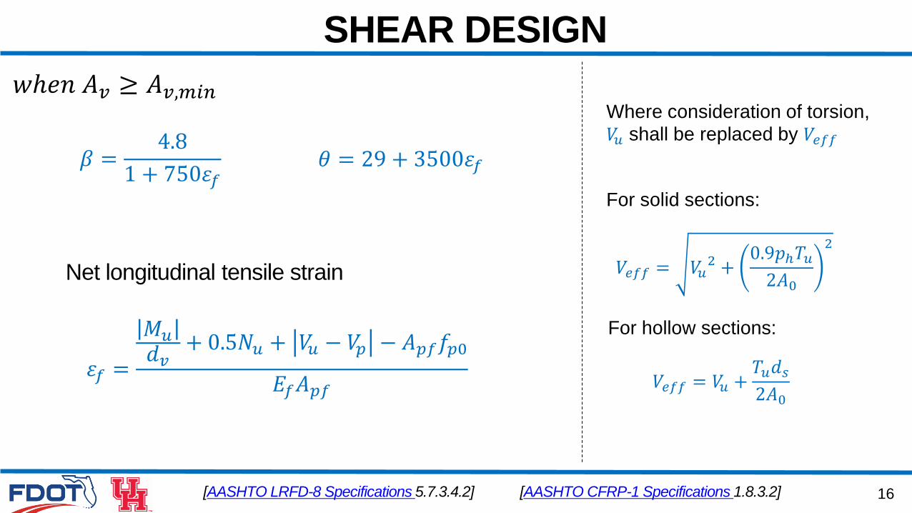
[AASHTO LRFD-8 Specifications 5.7.3.4.2]
𝑤ℎ𝑒𝑛 𝐴𝑣 ≥ 𝐴𝑣,𝑚𝑖𝑛
𝛽 =4.8
1 + 750𝜀𝑓
[AASHTO CFRP-1 Specifications 1.8.3.2]
𝜃 = 29 + 3500𝜀𝑓
Net longitudinal tensile strain
𝜀𝑓 =
𝑀𝑢𝑑𝑣+ 0.5𝑁𝑢 + 𝑉𝑢 − 𝑉𝑝 − 𝐴𝑝𝑓𝑓𝑝0
𝐸𝑓𝐴𝑝𝑓
Where consideration of torsion,
𝑉𝑢 shall be replaced by 𝑉𝑒𝑓𝑓
For solid sections:
𝑉𝑒𝑓𝑓 = 𝑉𝑢2 +0.9𝑝ℎ𝑇𝑢2𝐴0
2
For hollow sections:
𝑉𝑒𝑓𝑓 = 𝑉𝑢 +𝑇𝑢𝑑𝑠2𝐴0
17
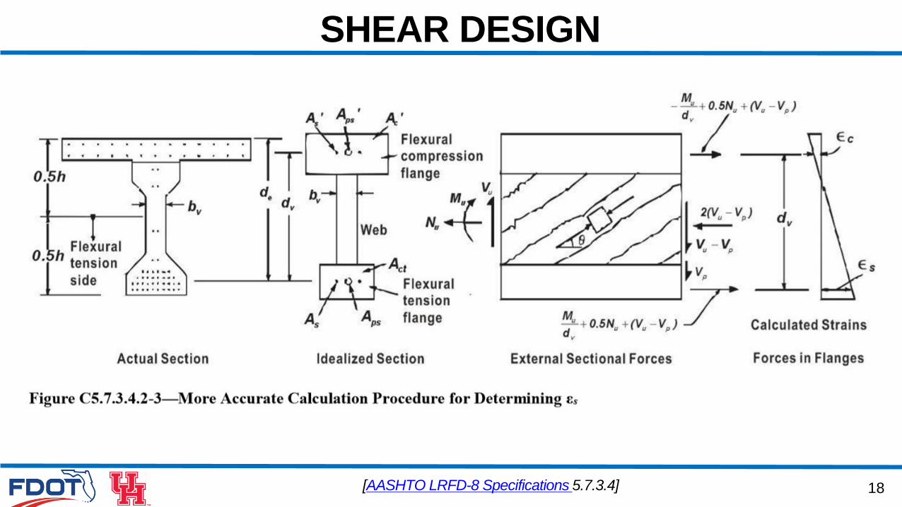
SHEAR DESIGN
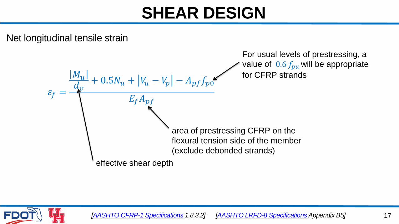
[AASHTO CFRP-1 Specifications 1.8.3.2]
Net longitudinal tensile strain
𝜀𝑓 =
𝑀𝑢𝑑𝑣+ 0.5𝑁𝑢 + 𝑉𝑢 − 𝑉𝑝 − 𝐴𝑝𝑓𝑓𝑝0
𝐸𝑓𝐴𝑝𝑓
For usual levels of prestressing, a
value of 0.6 𝑓𝑝𝑢 will be appropriate
for CFRP strands
area of prestressing CFRP on the
flexural tension side of the member
(exclude debonded strands)
effective shear depth
[AASHTO LRFD-8 Specifications Appendix B5]
18
SHEAR DESIGN
[AASHTO LRFD-8 Specifications 5.7.3.4]
19
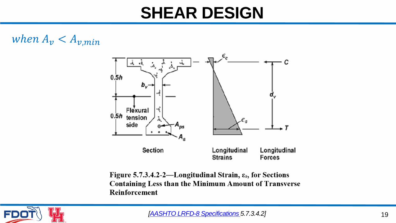
SHEAR DESIGN
[AASHTO LRFD-8 Specifications 5.7.3.4.2]
𝑤ℎ𝑒𝑛 𝐴𝑣 < 𝐴𝑣,𝑚𝑖𝑛
20
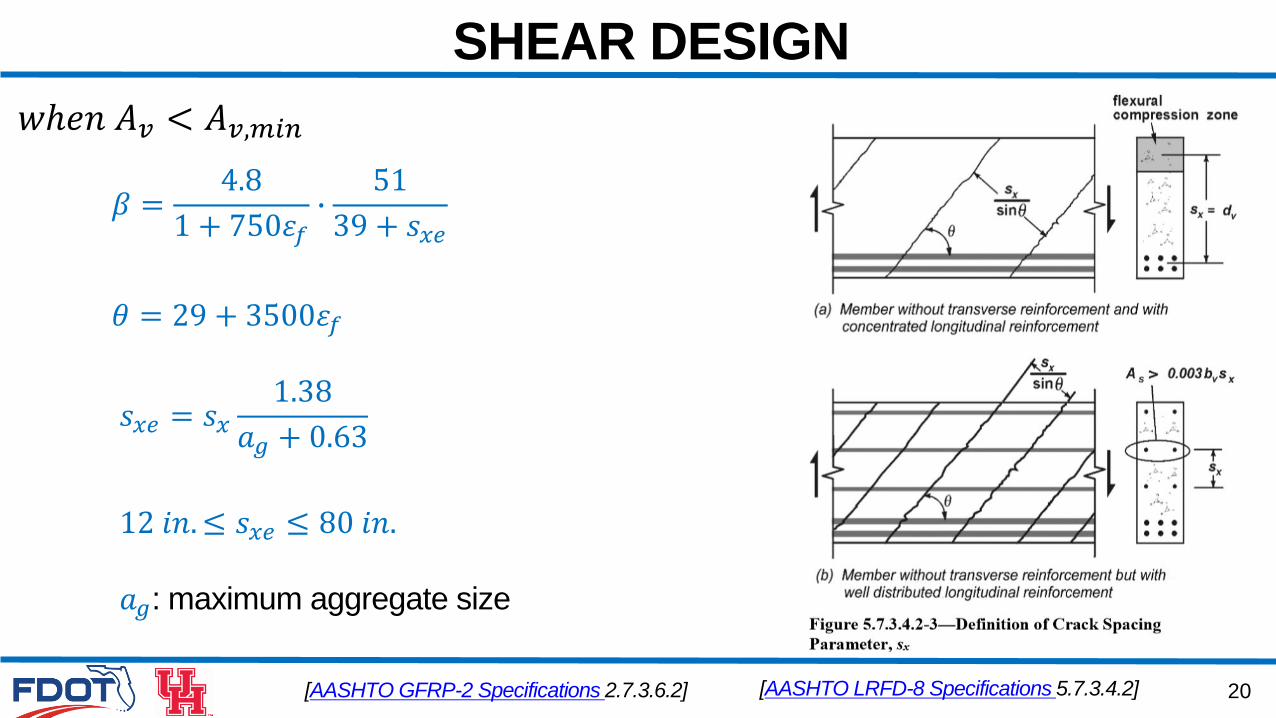
SHEAR DESIGN
[AASHTO LRFD-8 Specifications 5.7.3.4.2]
𝑤ℎ𝑒𝑛 𝐴𝑣 < 𝐴𝑣,𝑚𝑖𝑛
𝛽 =4.8
1 + 750𝜀𝑓∙51
39 + 𝑠𝑥𝑒
𝜃 = 29 + 3500𝜀𝑓
𝑠𝑥𝑒 = 𝑠𝑥1.38
𝑎𝑔 + 0.63
12 𝑖𝑛.≤ 𝑠𝑥𝑒 ≤ 80 𝑖𝑛.
𝑎𝑔: maximum aggregate size
[AASHTO GFRP-2 Specifications 2.7.3.6.2]
21
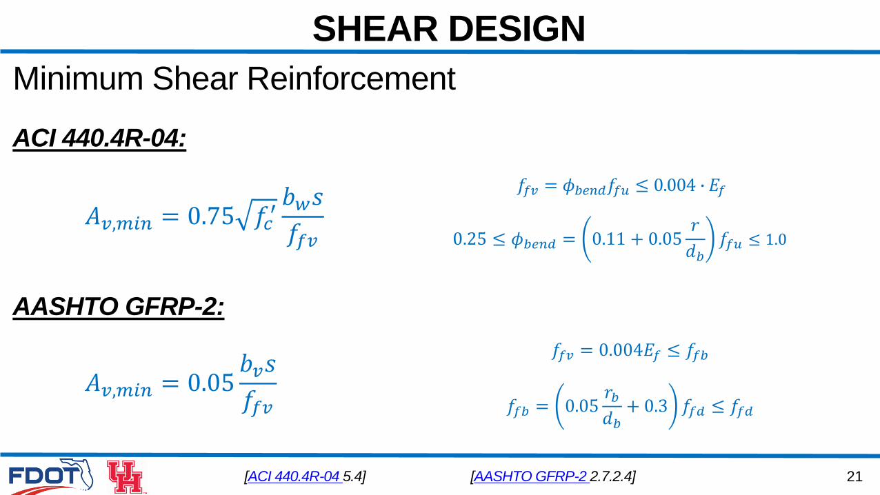
SHEAR DESIGN
Minimum Shear Reinforcement
[ACI 440.4R-04 5.4]
𝐴𝑣,𝑚𝑖𝑛 = 0.75 𝑓𝑐′𝑏𝑤𝑠
𝑓𝑓𝑣
𝑓𝑓𝑣 = 𝜙𝑏𝑒𝑛𝑑𝑓𝑓𝑢 ≤ 0.004 ∙ 𝐸𝑓
0.25 ≤ 𝜙𝑏𝑒𝑛𝑑 = 0.11 + 0.05𝑟
𝑑𝑏𝑓𝑓𝑢 ≤ 1.0
𝐴𝑣,𝑚𝑖𝑛 = 0.05𝑏𝑣𝑠
𝑓𝑓𝑣
[AASHTO GFRP-2 2.7.2.4]
𝑓𝑓𝑏 = 0.05𝑟𝑏𝑑𝑏+ 0.3 𝑓𝑓𝑑 ≤ 𝑓𝑓𝑑
𝑓𝑓𝑣 = 0.004𝐸𝑓 ≤ 𝑓𝑓𝑏
ACI 440.4R-04:
AASHTO GFRP-2:
22
SHEAR DESIGN
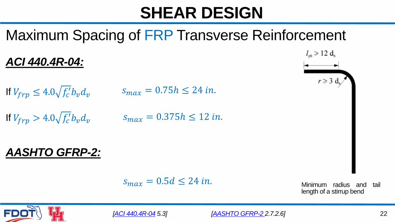
Maximum Spacing of FRP Transverse Reinforcement
[ACI 440.4R-04 5.3]
𝑠𝑚𝑎𝑥 = 0.75ℎ ≤ 24 𝑖𝑛.
𝑠𝑚𝑎𝑥 = 0.375ℎ ≤ 12 𝑖𝑛.If 𝑉𝑓𝑟𝑝 > 4.0 𝑓𝑐′𝑏𝑣𝑑𝑣
If 𝑉𝑓𝑟𝑝 ≤ 4.0 𝑓𝑐′𝑏𝑣𝑑𝑣
Minimum radius and taillength of a stirrup bend
ACI 440.4R-04:
AASHTO GFRP-2:
𝑠𝑚𝑎𝑥 = 0.5𝑑 ≤ 24 𝑖𝑛.
[AASHTO GFRP-2 2.7.2.6]
23
SHEAR DESIGN
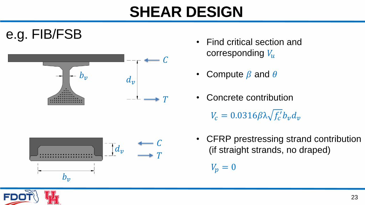
e.g. FIB/FSB
𝐶
𝑇
𝐶
𝑇
𝑑𝑣
𝑑𝑣
𝑏𝑣
𝑏𝑣
𝑉𝑐 = 0.0316𝛽λ 𝑓𝑐′𝑏𝑣𝑑𝑣
• Concrete contribution
• CFRP prestressing strand contribution
(if straight strands, no draped)
𝑉𝑝 = 0
• Compute 𝛽 and 𝜃
• Find critical section and
corresponding 𝑉𝑢
24
SHEAR DESIGN
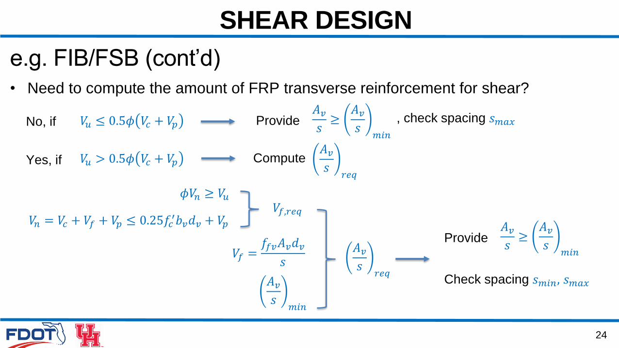
e.g. FIB/FSB (cont’d)
• Need to compute the amount of FRP transverse reinforcement for shear?
No, if 𝑉𝑢 ≤ 0.5𝜙 𝑉𝑐 + 𝑉𝑝
𝑉𝑢 > 0.5𝜙 𝑉𝑐 + 𝑉𝑝
Provide
Compute
𝑉𝑛 = 𝑉𝑐 + 𝑉𝑓 + 𝑉𝑝 ≤ 0.25𝑓𝑐′𝑏𝑣𝑑𝑣 + 𝑉𝑝
𝑉𝑓 =𝑓𝑓𝑣𝐴𝑣𝑑𝑣
𝑠
𝜙𝑉𝑛 ≥ 𝑉𝑢𝑉𝑓,𝑟𝑒𝑞
𝐴𝑣𝑠𝑟𝑒𝑞
𝐴𝑣𝑠𝑚𝑖𝑛
𝐴𝑣𝑠≥𝐴𝑣𝑠𝑚𝑖𝑛
, check spacing 𝑠𝑚𝑎𝑥
𝐴𝑣𝑠𝑟𝑒𝑞
Yes, if
Provide𝐴𝑣𝑠≥𝐴𝑣𝑠𝑚𝑖𝑛
Check spacing 𝑠𝑚𝑖𝑛, 𝑠𝑚𝑎𝑥
25
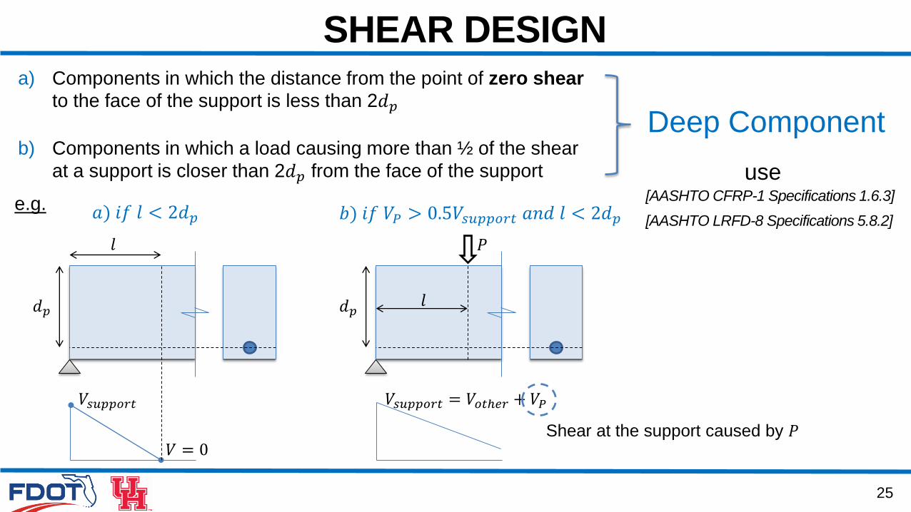
SHEAR DESIGNa) Components in which the distance from the point of zero shear
to the face of the support is less than 2𝑑𝑝
b) Components in which a load causing more than ½ of the shear
at a support is closer than 2𝑑𝑝 from the face of the support
[AASHTO CFRP-1 Specifications 1.6.3]
Deep Component
[AASHTO LRFD-8 Specifications 5.8.2]
use
𝑑𝑝
𝑉 = 0
𝑉𝑠𝑢𝑝𝑝𝑜𝑟𝑡
𝑙
𝑎) 𝑖𝑓 𝑙 < 2𝑑𝑝
𝑑𝑝
𝑉𝑠𝑢𝑝𝑝𝑜𝑟𝑡 = 𝑉𝑜𝑡ℎ𝑒𝑟 + 𝑉𝑃
𝑏) 𝑖𝑓 𝑉𝑃 > 0.5𝑉𝑠𝑢𝑝𝑝𝑜𝑟𝑡 𝑎𝑛𝑑 𝑙 < 2𝑑𝑝
𝑙
𝑃
Shear at the support caused by 𝑃
e.g.
26
SHEAR DESIGN
Interface Shear Transfer
• Interface shear resistance
• Cohesion and friction factors
• Interface shear force for girder/slab bridges
• Interface shear in box girder bridges
• Minimum area of interface shear reinforcement
27
SHEAR DESIGN
Interface shear transfer shall be considered across a given plane at:
An existing or potential crack
An interface between dissimilar materials
An interface between two concretes cast at different time
The interface between different elements of the cross-section
[AASHTO LRFD-8 Specifications 5.7.4]
28
SHEAR DESIGN
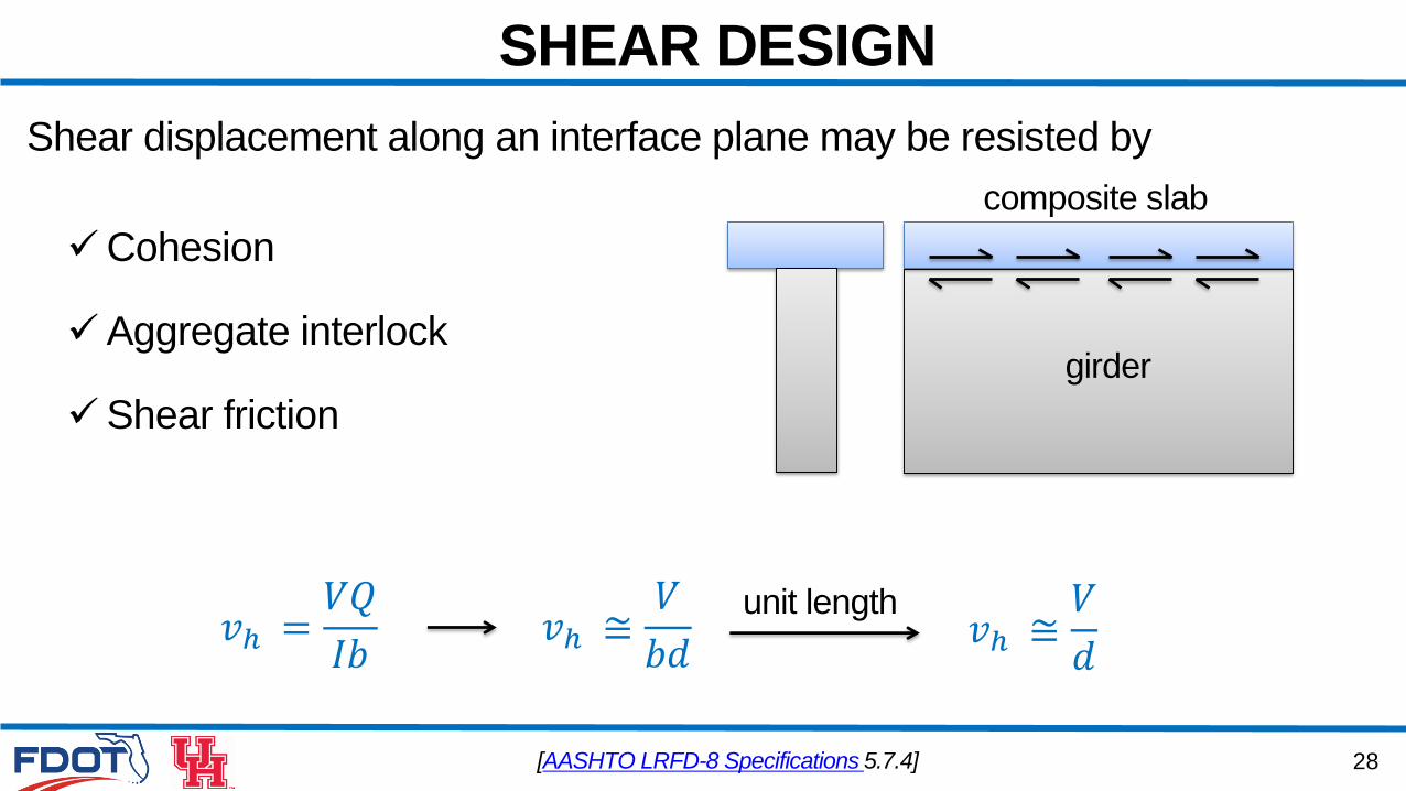
Shear displacement along an interface plane may be resisted by
Cohesion
Aggregate interlock
Shear friction
[AASHTO LRFD-8 Specifications 5.7.4]
girder
composite slab
𝑣ℎ =𝑉𝑄
𝐼𝑏𝑣ℎ ≅
𝑉
𝑏𝑑𝑣ℎ ≅𝑉
𝑑
unit length
29
SHEAR DESIGN
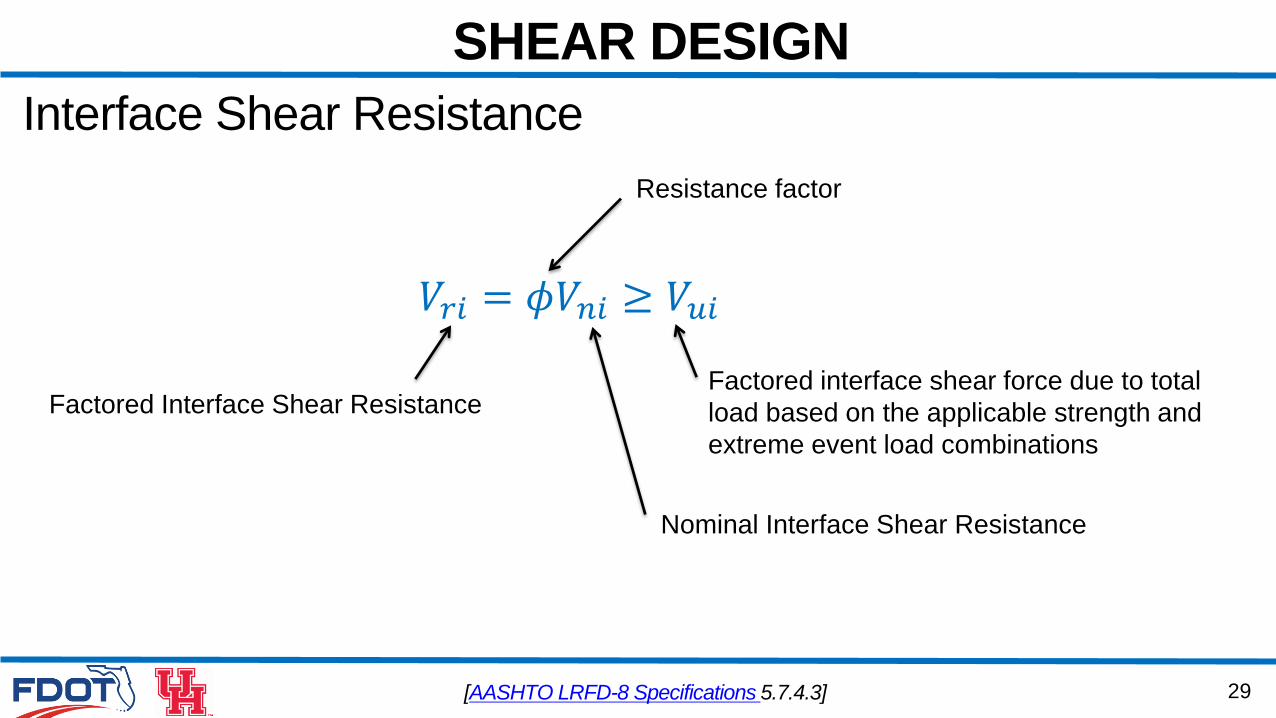
Interface Shear Resistance
[AASHTO LRFD-8 Specifications 5.7.4.3]
𝑉𝑟𝑖 = 𝜙𝑉𝑛𝑖 ≥ 𝑉𝑢𝑖
Nominal Interface Shear Resistance
Factored Interface Shear Resistance
Resistance factor
Factored interface shear force due to total
load based on the applicable strength and
extreme event load combinations
30
SHEAR DESIGN
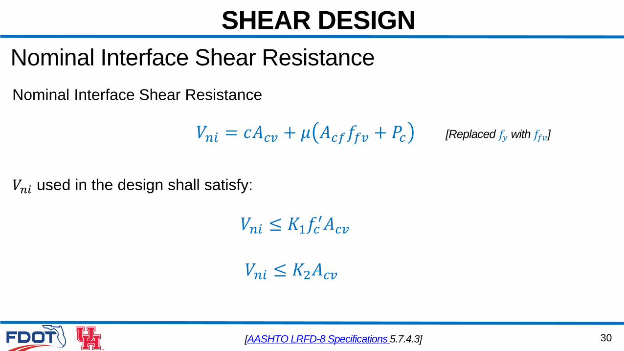
Nominal Interface Shear Resistance
[AASHTO LRFD-8 Specifications 5.7.4.3]
𝑉𝑛𝑖 = 𝑐𝐴𝑐𝑣 + 𝜇 𝐴𝑐𝑓𝑓𝑓𝑣 + 𝑃𝑐
𝑉𝑛𝑖 ≤ 𝐾1𝑓𝑐′𝐴𝑐𝑣
𝑉𝑛𝑖 used in the design shall satisfy:
𝑉𝑛𝑖 ≤ 𝐾2𝐴𝑐𝑣
Nominal Interface Shear Resistance
[Replaced 𝑓𝑦 with 𝑓𝑓𝑣]
31
SHEAR DESIGN
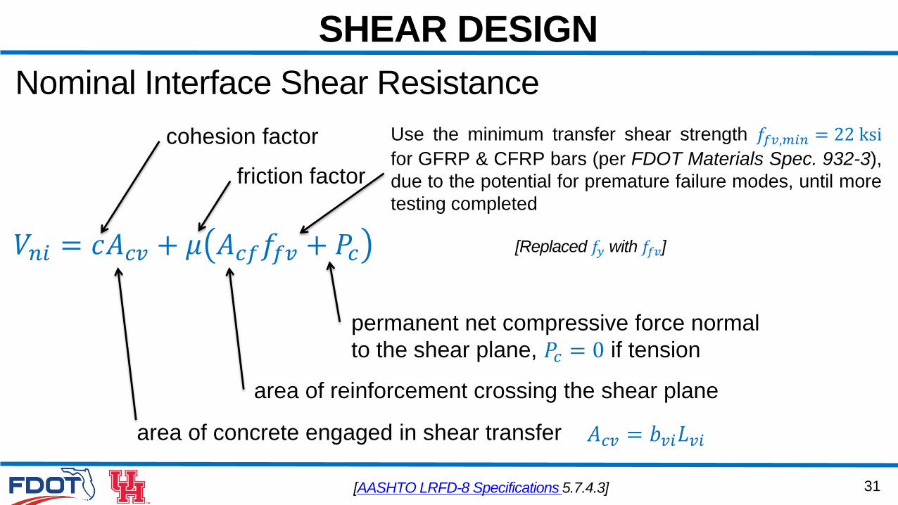
Nominal Interface Shear Resistance
[AASHTO LRFD-8 Specifications 5.7.4.3]
𝑉𝑛𝑖 = 𝑐𝐴𝑐𝑣 + 𝜇 𝐴𝑐𝑓𝑓𝑓𝑣 + 𝑃𝑐
cohesion factor
friction factor
area of concrete engaged in shear transfer 𝐴𝑐𝑣 = 𝑏𝑣𝑖𝐿𝑣𝑖
area of reinforcement crossing the shear plane
permanent net compressive force normal
to the shear plane, 𝑃𝑐 = 0 if tension
[Replaced 𝑓𝑦 with 𝑓𝑓𝑣]
Use the minimum transfer shear strength 𝑓𝑓𝑣,𝑚𝑖𝑛 = 22 ksi
for GFRP & CFRP bars (per FDOT Materials Spec. 932-3),
due to the potential for premature failure modes, until more
testing completed
32
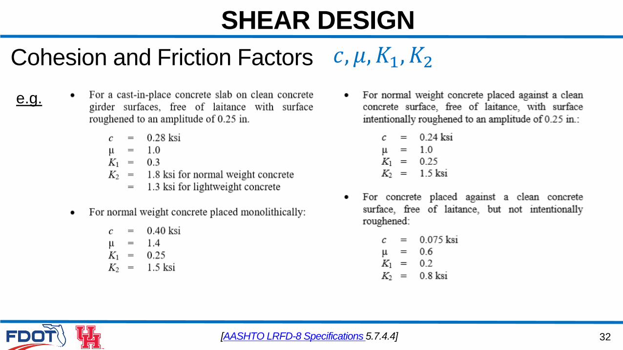
SHEAR DESIGN
𝑐, 𝜇, 𝐾1, 𝐾2
e.g.
[AASHTO LRFD-8 Specifications 5.7.4.4]
Cohesion and Friction Factors
33
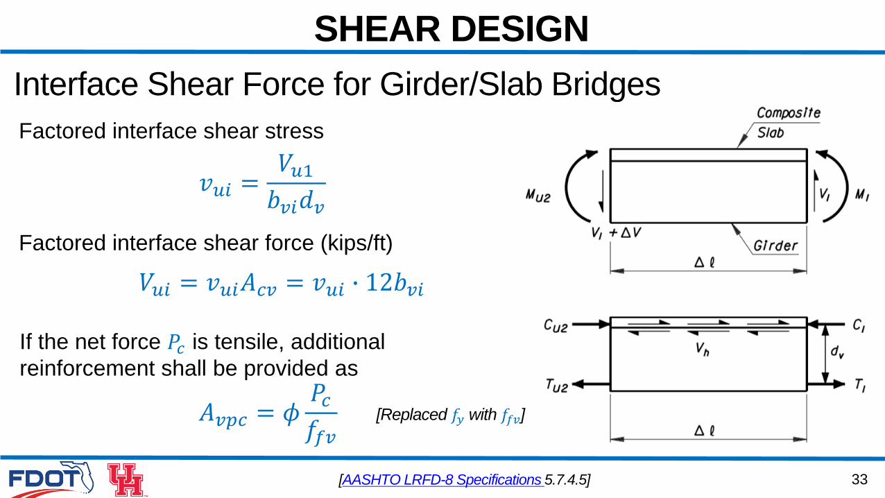
SHEAR DESIGN
Interface Shear Force for Girder/Slab Bridges
𝑣𝑢𝑖 =𝑉𝑢1𝑏𝑣𝑖𝑑𝑣
Factored interface shear stress
Factored interface shear force (kips/ft)
𝑉𝑢𝑖 = 𝑣𝑢𝑖𝐴𝑐𝑣 = 𝑣𝑢𝑖 ∙ 12𝑏𝑣𝑖
[AASHTO LRFD-8 Specifications 5.7.4.5]
If the net force 𝑃𝑐 is tensile, additional
reinforcement shall be provided as
𝐴𝑣𝑝𝑐 = 𝜙𝑃𝑐𝑓𝑓𝑣
[Replaced 𝑓𝑦 with 𝑓𝑓𝑣]
34
SHEAR DESIGN
Interface Shear in Box Girder Bridges
[AASHTO LRFD-8 Specifications 5.7.4.6]
Adequate shear transfer reinforcement shall be provided at the web/flange in
box girders to transfer flange longitudinal forces at the strength limit state
35
SHEAR DESIGN
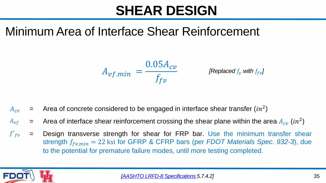
Minimum Area of Interface Shear Reinforcement
[AASHTO LRFD-8 Specifications 5.7.4.2]
𝐴𝑣𝑓.𝑚𝑖𝑛 =0.05𝐴𝑐𝑣𝑓𝑓𝑣
𝐴𝑐𝑣 = Area of concrete considered to be engaged in interface shear transfer (𝑖𝑛2)
𝐴𝑣𝑓 = Area of interface shear reinforcement crossing the shear plane within the area 𝐴𝑐𝑣 (𝑖𝑛2)
𝑓′𝑓𝑣 = Design transverse strength for shear for FRP bar. Use the minimum transfer shear
strength 𝑓𝑓𝑣,𝑚𝑖𝑛 = 22 ksi for GFRP & CFRP bars (per FDOT Materials Spec. 932-3), due
to the potential for premature failure modes, until more testing completed.
[Replaced 𝑓𝑦 with 𝑓𝑓𝑣]
36
SHEAR DESIGN
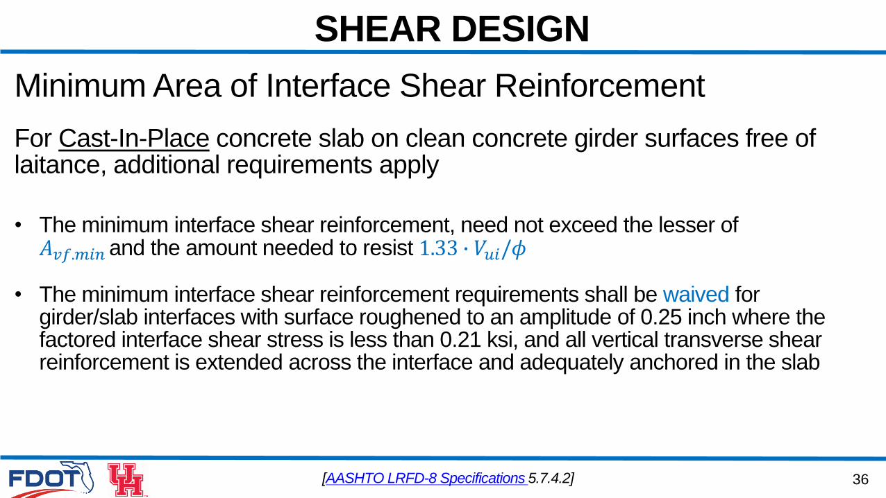
Minimum Area of Interface Shear Reinforcement
For Cast-In-Place concrete slab on clean concrete girder surfaces free of laitance, additional requirements apply
[AASHTO LRFD-8 Specifications 5.7.4.2]
• The minimum interface shear reinforcement, need not exceed the lesser of 𝐴𝑣𝑓.𝑚𝑖𝑛 and the amount needed to resist 1.33 ∙ 𝑉𝑢𝑖/𝜙
• The minimum interface shear reinforcement requirements shall be waived for girder/slab interfaces with surface roughened to an amplitude of 0.25 inch where the factored interface shear stress is less than 0.21 ksi, and all vertical transverse shear reinforcement is extended across the interface and adequately anchored in the slab
37
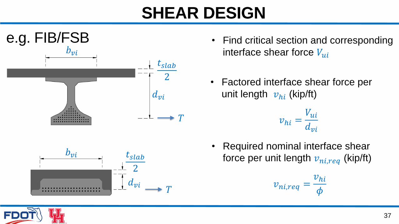
SHEAR DESIGN
e.g. FIB/FSB
• Required nominal interface shear
force per unit length 𝑣𝑛𝑖,𝑟𝑒𝑞 (kip/ft)
• Find critical section and corresponding
interface shear force 𝑉𝑢𝑖
𝑇
𝑇
𝑏𝑣𝑖
𝑏𝑣𝑖
𝑑𝑣𝑖
𝑑𝑣𝑖
𝑡𝑠𝑙𝑎𝑏2
𝑡𝑠𝑙𝑎𝑏2
𝑣ℎ𝑖 =𝑉𝑢𝑖𝑑𝑣𝑖
• Factored interface shear force per
unit length 𝑣ℎ𝑖 (kip/ft)
𝑣𝑛𝑖,𝑟𝑒𝑞 =𝑣ℎ𝑖𝜙
38
SHEAR DESIGN
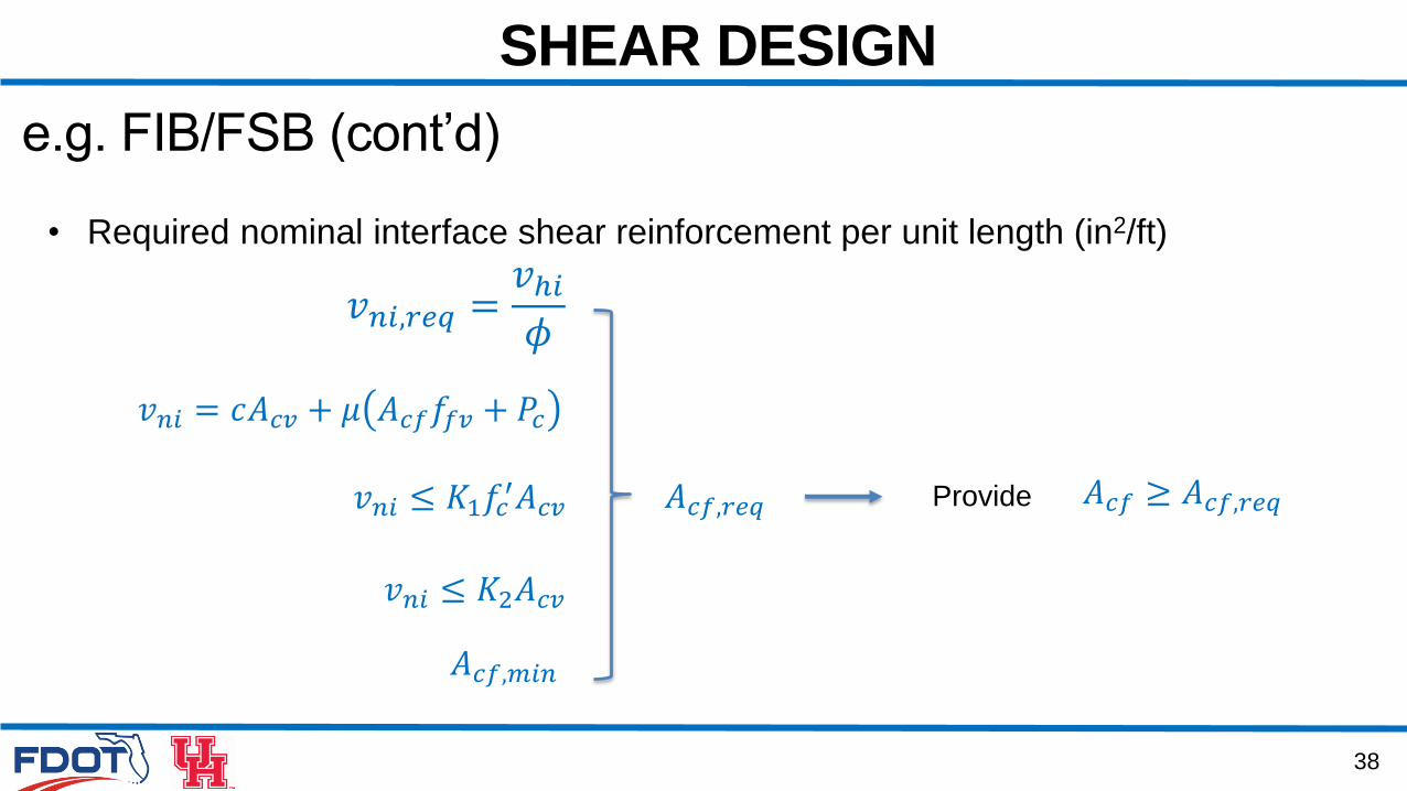
e.g. FIB/FSB (cont’d)
𝑣𝑛𝑖 = 𝑐𝐴𝑐𝑣 + 𝜇 𝐴𝑐𝑓𝑓𝑓𝑣 + 𝑃𝑐
𝑣𝑛𝑖,𝑟𝑒𝑞 =𝑣ℎ𝑖𝜙
𝐴𝑐𝑓,𝑟𝑒𝑞
𝐴𝑐𝑓,𝑚𝑖𝑛
Provide 𝐴𝑐𝑓 ≥ 𝐴𝑐𝑓,𝑟𝑒𝑞
• Required nominal interface shear reinforcement per unit length (in2/ft)
𝑣𝑛𝑖 ≤ 𝐾1𝑓𝑐′𝐴𝑐𝑣
𝑣𝑛𝑖 ≤ 𝐾2𝐴𝑐𝑣
39
SHEAR DESIGN
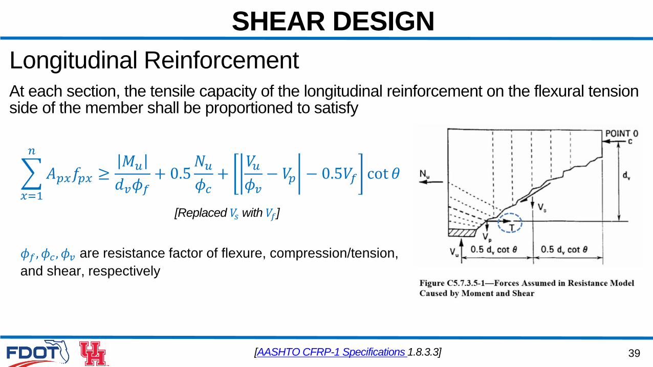
Longitudinal ReinforcementAt each section, the tensile capacity of the longitudinal reinforcement on the flexural tensionside of the member shall be proportioned to satisfy
𝑥=1
𝑛
𝐴𝑝𝑥𝑓𝑝𝑥 ≥𝑀𝑢𝑑𝑣𝜙𝑓+ 0.5𝑁𝑢𝜙𝑐+𝑉𝑢𝜙𝑣− 𝑉𝑝 − 0.5𝑉𝑓 cot 𝜃
[AASHTO CFRP-1 Specifications 1.8.3.3]
𝜙𝑓, 𝜙𝑐 , 𝜙𝑣 are resistance factor of flexure, compression/tension,
and shear, respectively
[Replaced 𝑉𝑠 with 𝑉𝑓]
40
SHEAR DESIGN
Combined Shear and Torsion
• Transverse Reinforcement
• Torsion Resistance
• Longitudinal Reinforcement
41
SHEAR DESIGN
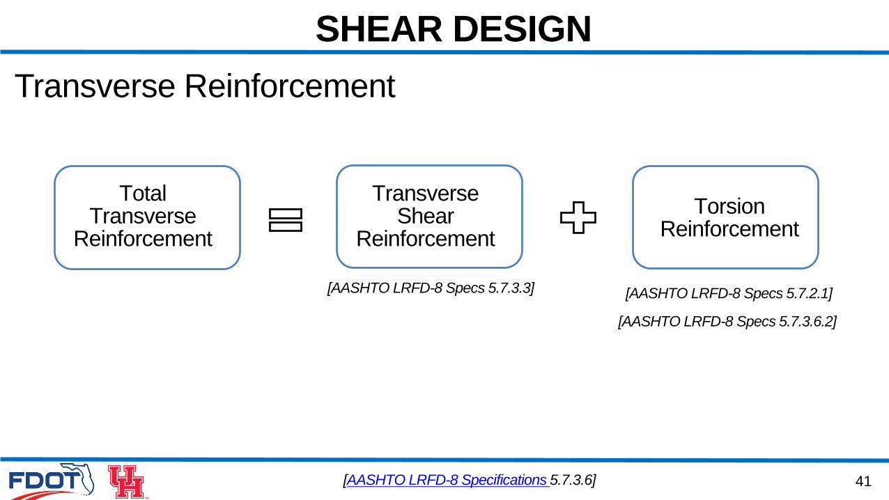
Transverse Reinforcement
TotalTransverse
Reinforcement
TransverseShear
Reinforcement
TorsionReinforcement
[AASHTO LRFD-8 Specs 5.7.3.3] [AASHTO LRFD-8 Specs 5.7.2.1]
[AASHTO LRFD-8 Specs 5.7.3.6.2]
[AASHTO LRFD-8 Specifications 5.7.3.6]
42
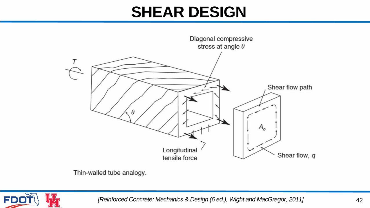
SHEAR DESIGN
[Reinforced Concrete: Mechanics & Design (6 ed.), Wight and MacGregor, 2011]
43
SHEAR DESIGN
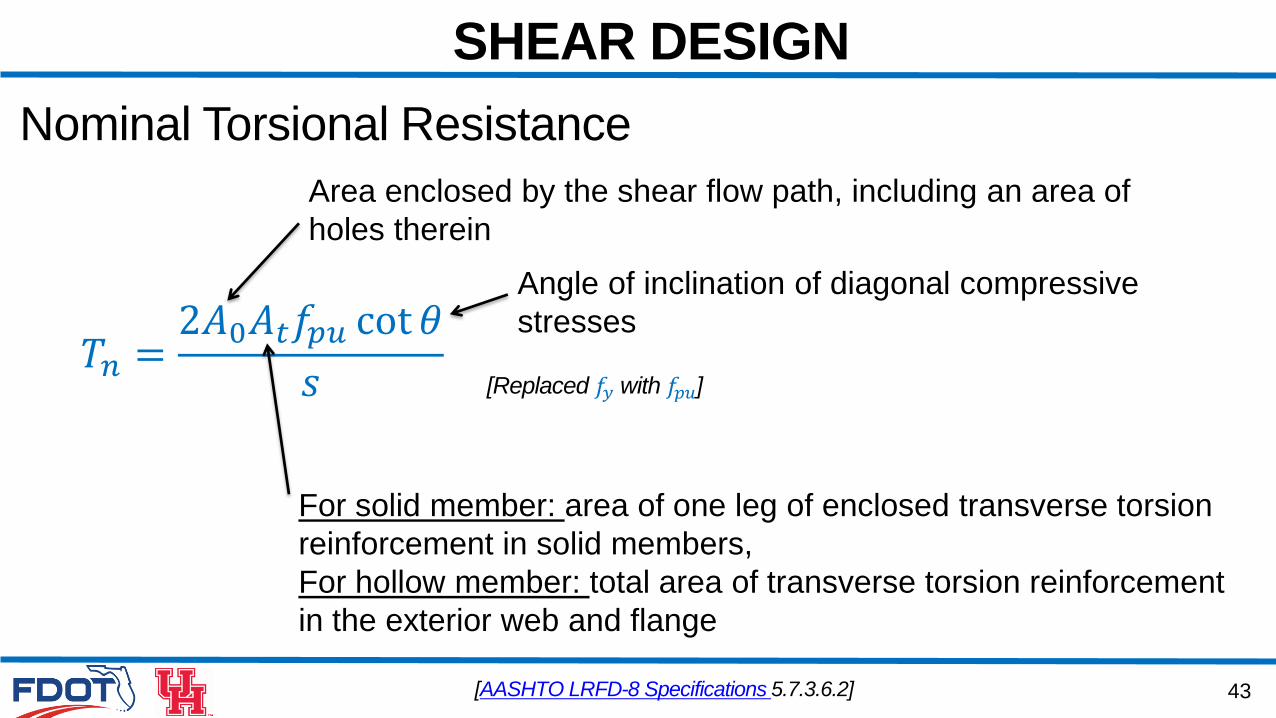
Nominal Torsional Resistance
𝑇𝑛 =2𝐴0𝐴𝑡𝑓𝑝𝑢 cot 𝜃
𝑠
[AASHTO LRFD-8 Specifications 5.7.3.6.2]
Area enclosed by the shear flow path, including an area of
holes therein
For solid member: area of one leg of enclosed transverse torsion
reinforcement in solid members,
For hollow member: total area of transverse torsion reinforcement
in the exterior web and flange
Angle of inclination of diagonal compressive
stresses
[Replaced 𝑓𝑦 with 𝑓𝑝𝑢]
44
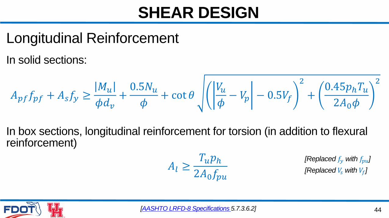
SHEAR DESIGN
Longitudinal Reinforcement
In solid sections:
𝐴𝑝𝑓𝑓𝑝𝑓 + 𝐴𝑠𝑓𝑦 ≥𝑀𝑢𝜙𝑑𝑣+0.5𝑁𝑢𝜙+ cot 𝜃
𝑉𝑢𝜙− 𝑉𝑝 − 0.5𝑉𝑓
2
+0.45𝑝ℎ𝑇𝑢2𝐴0𝜙
2
In box sections, longitudinal reinforcement for torsion (in addition to flexural reinforcement)
𝐴𝑙 ≥𝑇𝑢𝑝ℎ2𝐴0𝑓𝑝𝑢
[AASHTO LRFD-8 Specifications 5.7.3.6.2]
[Replaced 𝑓𝑦 with 𝑓𝑝𝑢]
[Replaced 𝑉𝑠 with 𝑉𝑓]

Questions?

4. SHEAR DESIGN
4.1 Review Questions: Fundamentals
47
REVIEW QUESTIONS
4.1.1) For GFRP transverse reinforcements, does the maximum
amount of transverse reinforcement requirement similar to steel
transverse reinforcements still apply:_____
a. True
b. False
48
REVIEW QUESTIONS
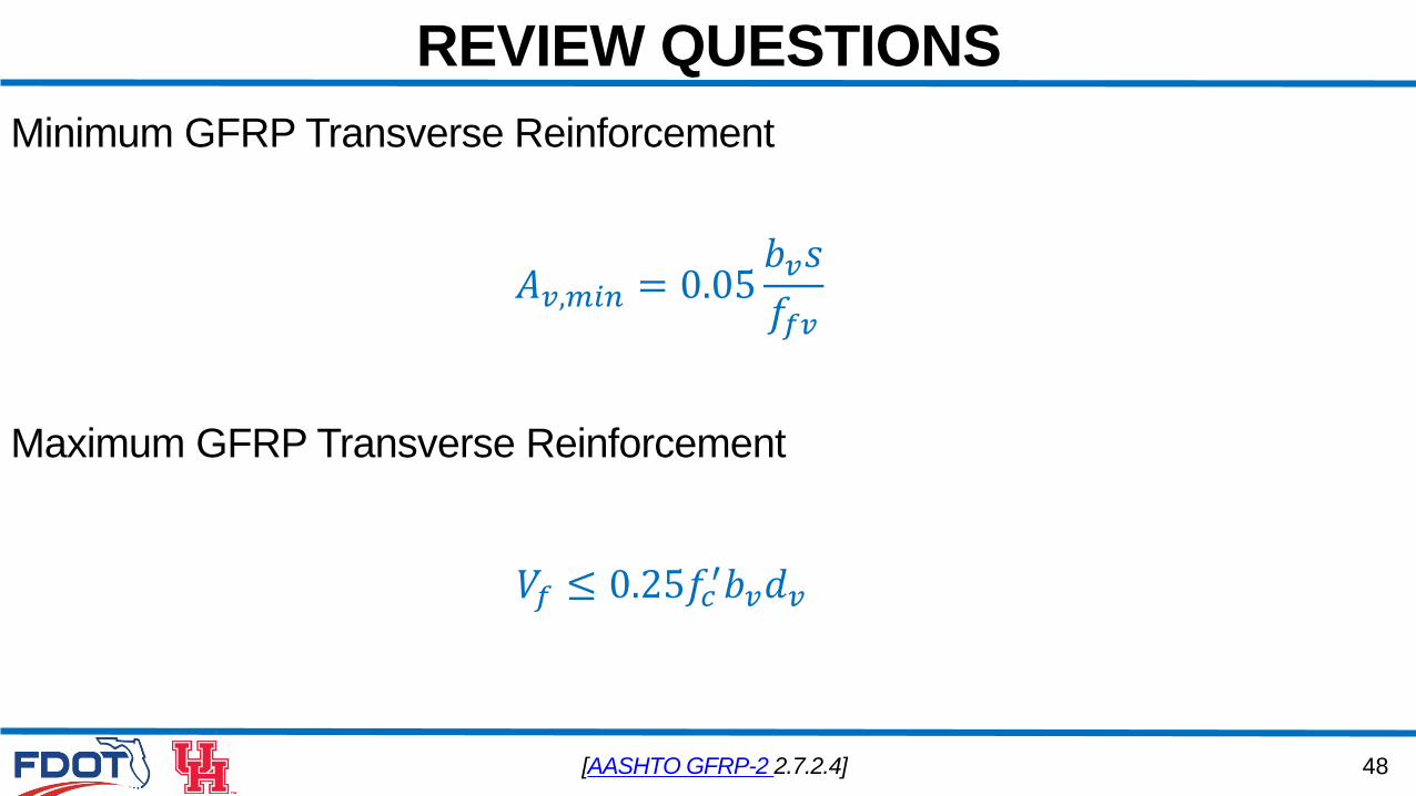
Minimum GFRP Transverse Reinforcement
𝐴𝑣,𝑚𝑖𝑛 = 0.05𝑏𝑣𝑠
𝑓𝑓𝑣
[AASHTO GFRP-2 2.7.2.4]
Maximum GFRP Transverse Reinforcement
𝑉𝑓 ≤ 0.25𝑓𝑐′𝑏𝑣𝑑𝑣
49
REVIEW QUESTIONS
4.1.1) For GFRP transverse reinforcements, does the maximum
amount of transverse reinforcement requirement similar to steel
transverse reinforcements still apply:_____
a. True
b. False
50
REVIEW QUESTIONS
4.1.2) The shear strength of PC members with GFRP transverse
reinforcements_____
a. Is comparable to the shear strength of PC members with steel transverse
reinforcements
b. Is lower than the shear strength of PC members with steel transverse
reinforcements
c. Is higher than to the shear strength of PC members with steel transverse
reinforcements
a. Cannot be compared to the shear strength of PC members with steel transverse
reinforcements
51
REVIEW QUESTIONS
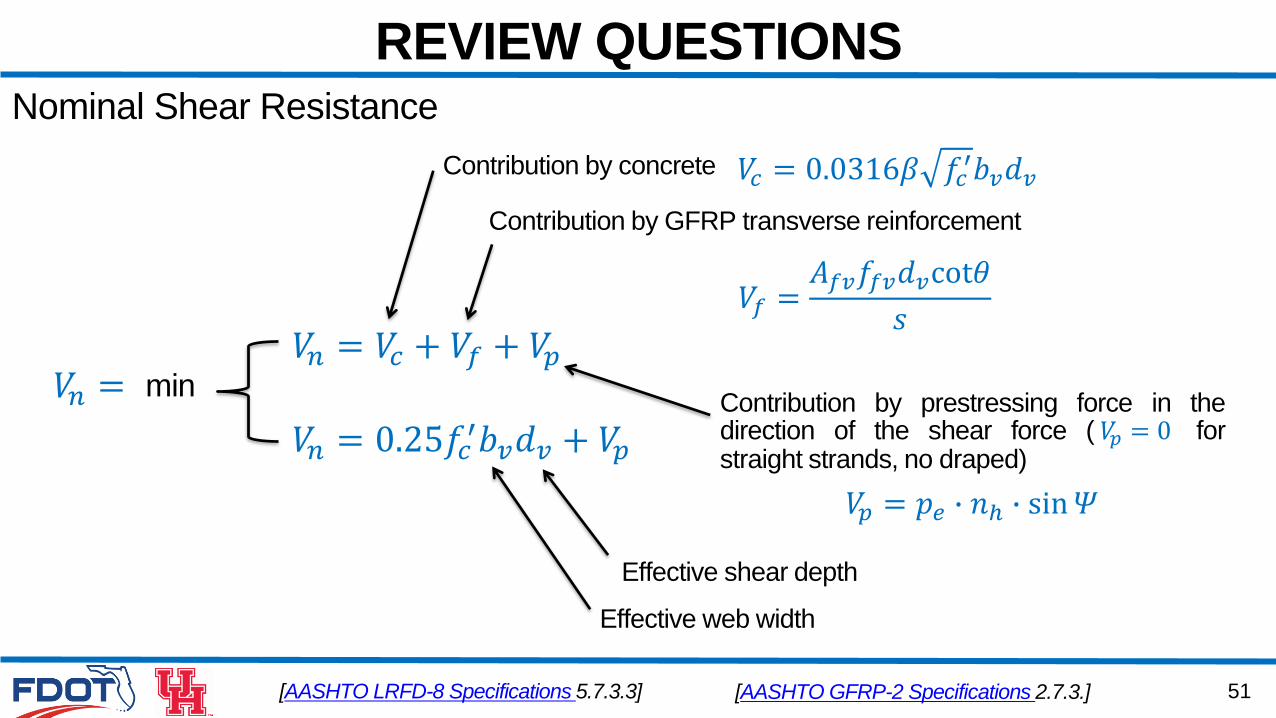
[AASHTO LRFD-8 Specifications 5.7.3.3]
𝑉𝑛 = 𝑉𝑐 + 𝑉𝑓 + 𝑉𝑝𝑉𝑛 = min
𝑉𝑛 = 0.25𝑓𝑐′𝑏𝑣𝑑𝑣 + 𝑉𝑝
Contribution by concrete
Contribution by GFRP transverse reinforcement
𝑉𝑓 =𝐴𝑓𝑣𝑓𝑓𝑣𝑑𝑣cot𝜃
𝑠
Contribution by prestressing force in thedirection of the shear force ( 𝑉𝑝 = 0 forstraight strands, no draped)
𝑉𝑝 = 𝑝𝑒 ∙ 𝑛ℎ ∙ sin𝛹
Effective shear depth
Effective web width
Nominal Shear Resistance
𝑉𝑐 = 0.0316𝛽 𝑓𝑐′𝑏𝑣𝑑𝑣
[AASHTO GFRP-2 Specifications 2.7.3.]
52
REVIEW QUESTIONS
4.1.2) The shear strength of PC members with GFRP transverse
reinforcements_____
a. Is comparable to the shear strength of PC members with steel transverse
reinforcements
b. Is lower than the shear strength of PC members with steel transverse
reinforcements
c. Is higher than to the shear strength of PC members with steel transverse
reinforcements
a. Cannot be compared to the shear strength of PC members with steel transverse
reinforcements
53
REVIEW QUESTIONS
4.1.3) The required tail length of FRP stirrups is at least equal to or
more than _____ times the bar diameter
a. 4
b. 8
c. 12
a. 16
54
REVIEW QUESTIONS
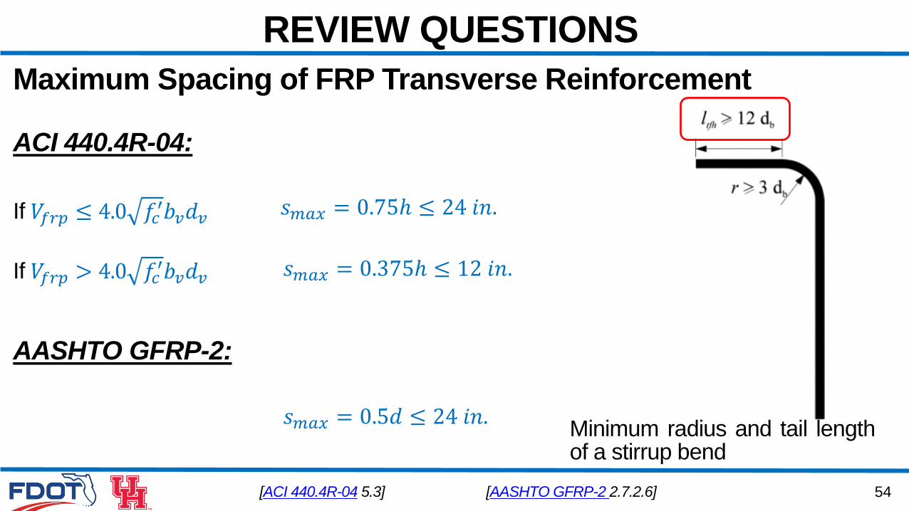
Maximum Spacing of FRP Transverse Reinforcement
[ACI 440.4R-04 5.3]
𝑠𝑚𝑎𝑥 = 0.75ℎ ≤ 24 𝑖𝑛.
𝑠𝑚𝑎𝑥 = 0.375ℎ ≤ 12 𝑖𝑛.If 𝑉𝑓𝑟𝑝 > 4.0 𝑓𝑐′𝑏𝑣𝑑𝑣
If 𝑉𝑓𝑟𝑝 ≤ 4.0 𝑓𝑐′𝑏𝑣𝑑𝑣
Minimum radius and tail lengthof a stirrup bend
ACI 440.4R-04:
AASHTO GFRP-2:
𝑠𝑚𝑎𝑥 = 0.5𝑑 ≤ 24 𝑖𝑛.
[AASHTO GFRP-2 2.7.2.6]
55
REVIEW QUESTIONS
4.1.3) The required tail length of GFRP stirrups is at least equal to or
more than _____ times the bar diameter
a. 4
b. 8
c. 12
a. 16
56
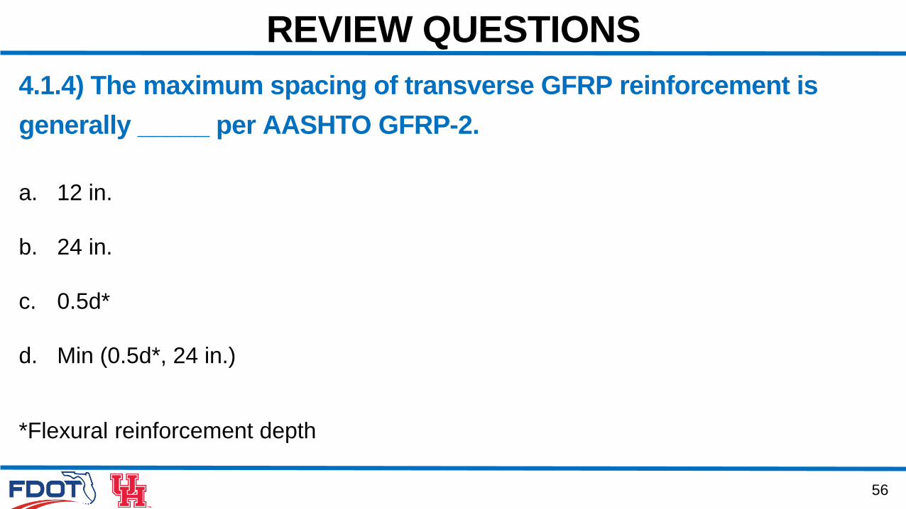
REVIEW QUESTIONS
4.1.4) The maximum spacing of transverse GFRP reinforcement is
generally _____ per AASHTO GFRP-2.
a. 12 in.
b. 24 in.
c. 0.5d*
d. Min (0.5d*, 24 in.)
*Flexural reinforcement depth
57
REVIEW QUESTIONS
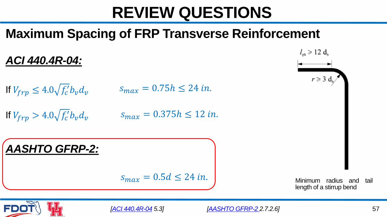
Maximum Spacing of FRP Transverse Reinforcement
[ACI 440.4R-04 5.3]
𝑠𝑚𝑎𝑥 = 0.75ℎ ≤ 24 𝑖𝑛.
𝑠𝑚𝑎𝑥 = 0.375ℎ ≤ 12 𝑖𝑛.If 𝑉𝑓𝑟𝑝 > 4.0 𝑓𝑐′𝑏𝑣𝑑𝑣
If 𝑉𝑓𝑟𝑝 ≤ 4.0 𝑓𝑐′𝑏𝑣𝑑𝑣
Minimum radius and taillength of a stirrup bend
ACI 440.4R-04:
AASHTO GFRP-2:
𝑠𝑚𝑎𝑥 = 0.5𝑑 ≤ 24 𝑖𝑛.
[AASHTO GFRP-2 2.7.2.6]
58
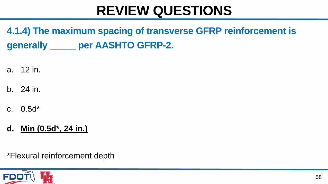
REVIEW QUESTIONS
4.1.4) The maximum spacing of transverse GFRP reinforcement is
generally _____ per AASHTO GFRP-2.
a. 12 in.
b. 24 in.
c. 0.5d*
d. Min (0.5d*, 24 in.)
*Flexural reinforcement depth
59
REVIEW QUESTIONS
4.1.5) GFRP stirrups can be bent on site with EOR approval?
a. True
b. False
60
REVIEW QUESTIONS
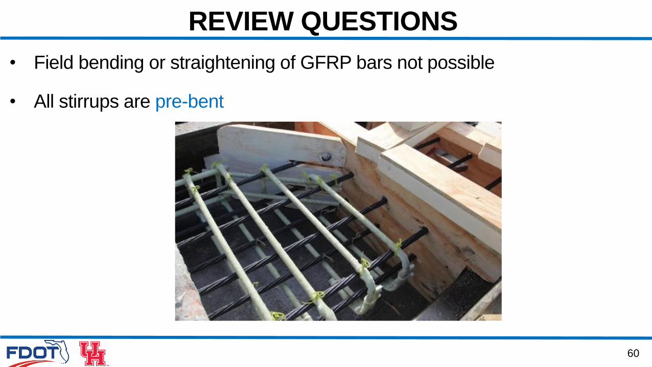
• Field bending or straightening of GFRP bars not possible
• All stirrups are pre-bent

61
REVIEW QUESTIONS
4.1.5) GFRP stirrups can be bent on site with EOR approval?
a. True
b. False

4. SHEAR DESIGN
4.2 Design Example: FIB 36
63
DESIGN EXAMPLE: FIB
Transverse Shear
Interface Shear Transfer
Minimum Longitudinal Reinforcement
64
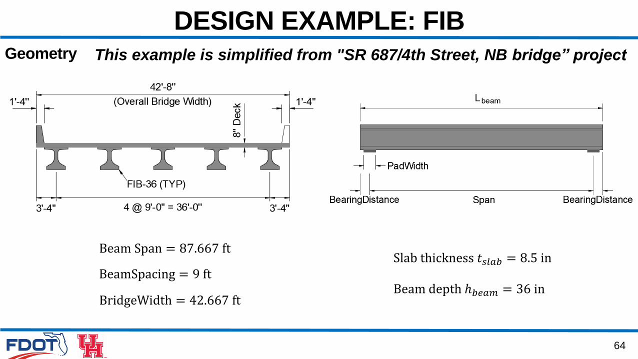
DESIGN EXAMPLE: FIBGeometry
Beam Span = 87.667 ft
BeamSpacing = 9 ft
BridgeWidth = 42.667 ft
Slab thickness 𝑡𝑠𝑙𝑎𝑏 = 8.5 in
Beam depth ℎ𝑏𝑒𝑎𝑚 = 36 in
This example is simplified from "SR 687/4th Street, NB bridge” project
65
DESIGN EXAMPLE: FIB
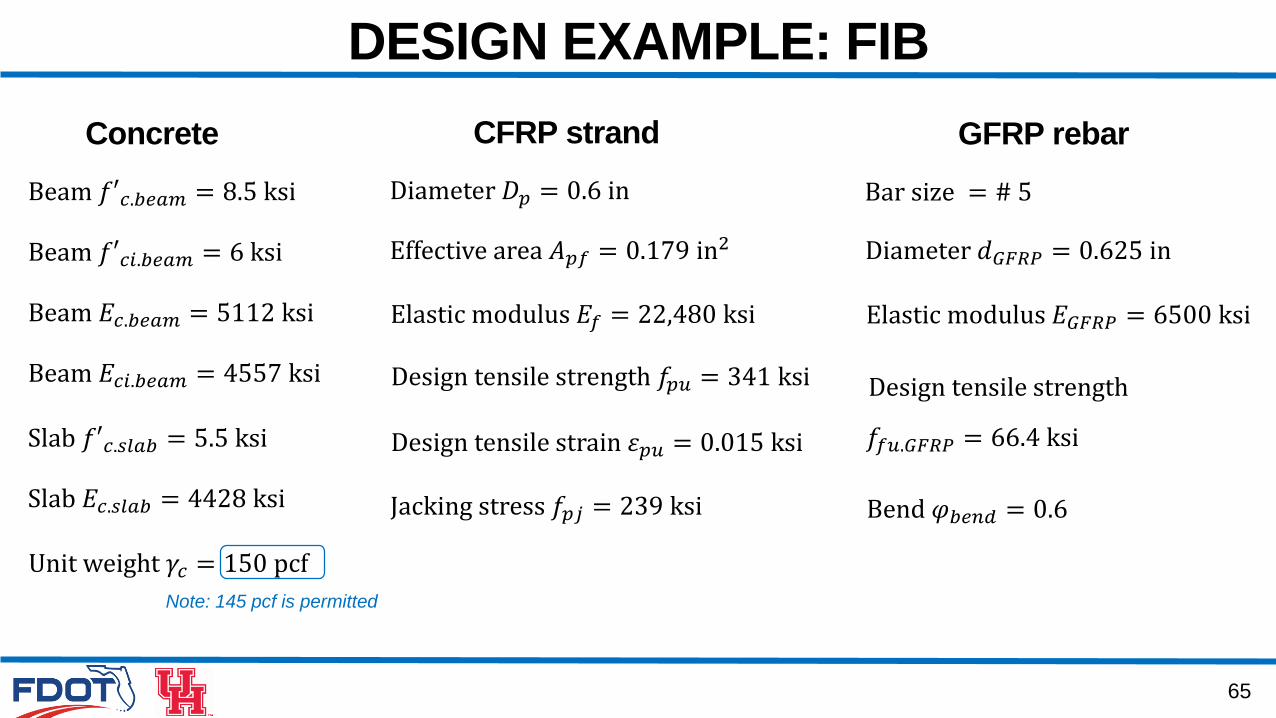
Concrete
Beam 𝑓′𝑐.𝑏𝑒𝑎𝑚 = 8.5 ksi
Beam 𝑓′𝑐𝑖.𝑏𝑒𝑎𝑚 = 6 ksi
Beam 𝐸𝑐.𝑏𝑒𝑎𝑚 = 5112 ksi
Beam 𝐸𝑐𝑖.𝑏𝑒𝑎𝑚 = 4557 ksi
Slab 𝑓′𝑐.𝑠𝑙𝑎𝑏 = 5.5 ksi
Slab 𝐸𝑐.𝑠𝑙𝑎𝑏 = 4428 ksi
CFRP strand
Diameter 𝐷𝑝 = 0.6 in
Effective area 𝐴𝑝𝑓 = 0.179 in2
Elastic modulus 𝐸𝑓 = 22,480 ksi
Design tensile strength 𝑓𝑝𝑢 = 341 ksi
Design tensile strain 𝜀𝑝𝑢 = 0.015 ksi
GFRP rebar
Bar size = # 5
Diameter 𝑑𝐺𝐹𝑅𝑃 = 0.625 in
Elastic modulus 𝐸𝐺𝐹𝑅𝑃 = 6500 ksi
Design tensile strength
𝑓𝑓𝑢.𝐺𝐹𝑅𝑃 = 66.4 ksi
Bend 𝜑𝑏𝑒𝑛𝑑 = 0.6
Unit weight 𝛾𝑐 = 150 pcf
Jacking stress 𝑓𝑝𝑗 = 239 ksi
Note: 145 pcf is permitted
66
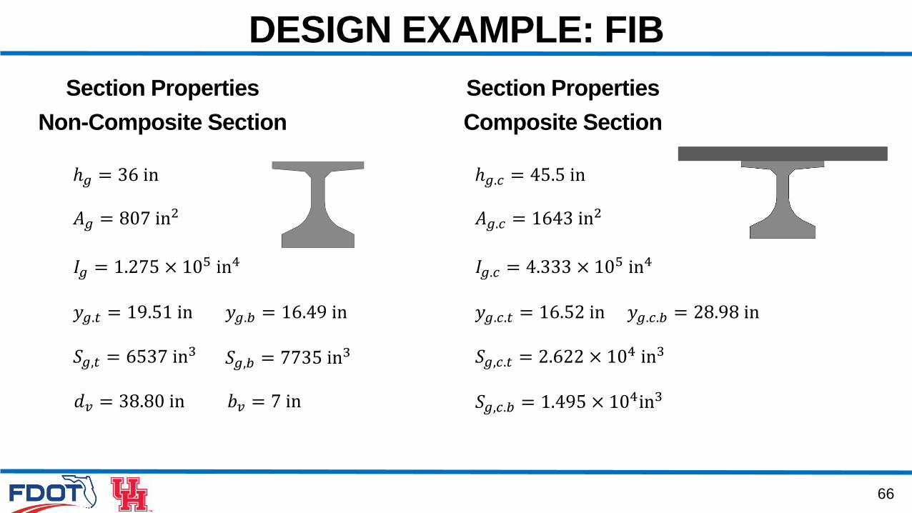
DESIGN EXAMPLE: FIB
Section Properties
Non-Composite Section
ℎ𝑔 = 36 in
𝐴𝑔 = 807 in2
Section Properties
Composite Section
𝐼𝑔 = 1.275 × 10⁵ in4
𝑦𝑔.𝑡 = 19.51 in 𝑦𝑔.𝑏 = 16.49 in
𝑆𝑔,𝑡 = 6537 in3 𝑆𝑔,𝑏 = 7735 in
3
ℎ𝑔.𝑐 = 45.5 in
𝐴𝑔.𝑐 = 1643 in2
𝐼𝑔.𝑐 = 4.333 × 10⁵ in4
𝑦𝑔.𝑐.𝑡 = 16.52 in 𝑦𝑔.𝑐.𝑏 = 28.98 in
𝑆𝑔,𝑐.𝑡 = 2.622 × 10⁴ in3
𝑆𝑔,𝑐.𝑏 = 1.495 × 10⁴in3𝑑𝑣 = 38.80 in 𝑏𝑣 = 7 in
67
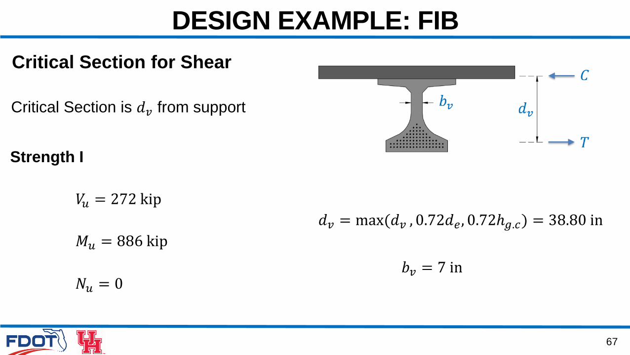
DESIGN EXAMPLE: FIB
𝑑𝑣 = max(𝑑𝑣 , 0.72𝑑𝑒, 0.72ℎ𝑔.𝑐) = 38.80 in
𝑏𝑣 = 7 in
Critical Section is 𝑑𝑣 from support
𝑉𝑢 = 272 kip
Strength I
𝑀𝑢 = 886 kip
Critical Section for Shear
𝑁𝑢 = 0
68
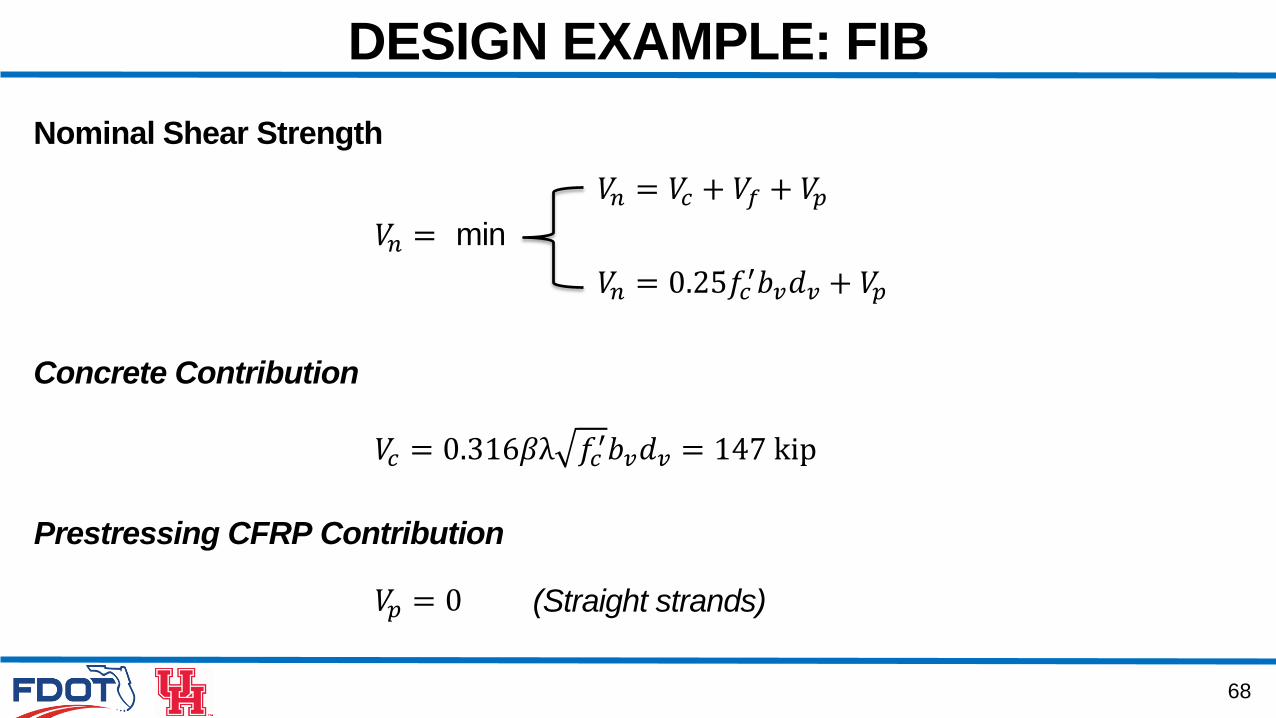
DESIGN EXAMPLE: FIB
Nominal Shear Strength
𝑉𝑐 = 0.316𝛽λ 𝑓𝑐′𝑏𝑣𝑑𝑣 = 147 kip
Prestressing CFRP Contribution
𝑉𝑝 = 0
𝑉𝑛 = 𝑉𝑐 + 𝑉𝑓 + 𝑉𝑝𝑉𝑛 = min
𝑉𝑛 = 0.25𝑓𝑐′𝑏𝑣𝑑𝑣 + 𝑉𝑝
Concrete Contribution
(Straight strands)
69
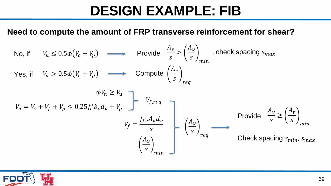
DESIGN EXAMPLE: FIB
Need to compute the amount of FRP transverse reinforcement for shear?
No, if 𝑉𝑢 ≤ 0.5𝜙 𝑉𝑐 + 𝑉𝑝
𝑉𝑢 > 0.5𝜙 𝑉𝑐 + 𝑉𝑝
Provide
Compute
𝑉𝑛 = 𝑉𝑐 + 𝑉𝑓 + 𝑉𝑝 ≤ 0.25𝑓𝑐′𝑏𝑣𝑑𝑣 + 𝑉𝑝
𝑉𝑓 =𝑓𝑓𝑣𝐴𝑣𝑑𝑣
𝑠
𝜙𝑉𝑛 ≥ 𝑉𝑢𝑉𝑓,𝑟𝑒𝑞
𝐴𝑣𝑠𝑟𝑒𝑞
𝐴𝑣𝑠𝑚𝑖𝑛
𝐴𝑣𝑠≥𝐴𝑣𝑠𝑚𝑖𝑛
, check spacing 𝑠𝑚𝑎𝑥
𝐴𝑣𝑠𝑟𝑒𝑞
Yes, if
Provide𝐴𝑣𝑠≥𝐴𝑣𝑠𝑚𝑖𝑛
Check spacing 𝑠𝑚𝑖𝑛, 𝑠𝑚𝑎𝑥
70
DESIGN EXAMPLE: FIB
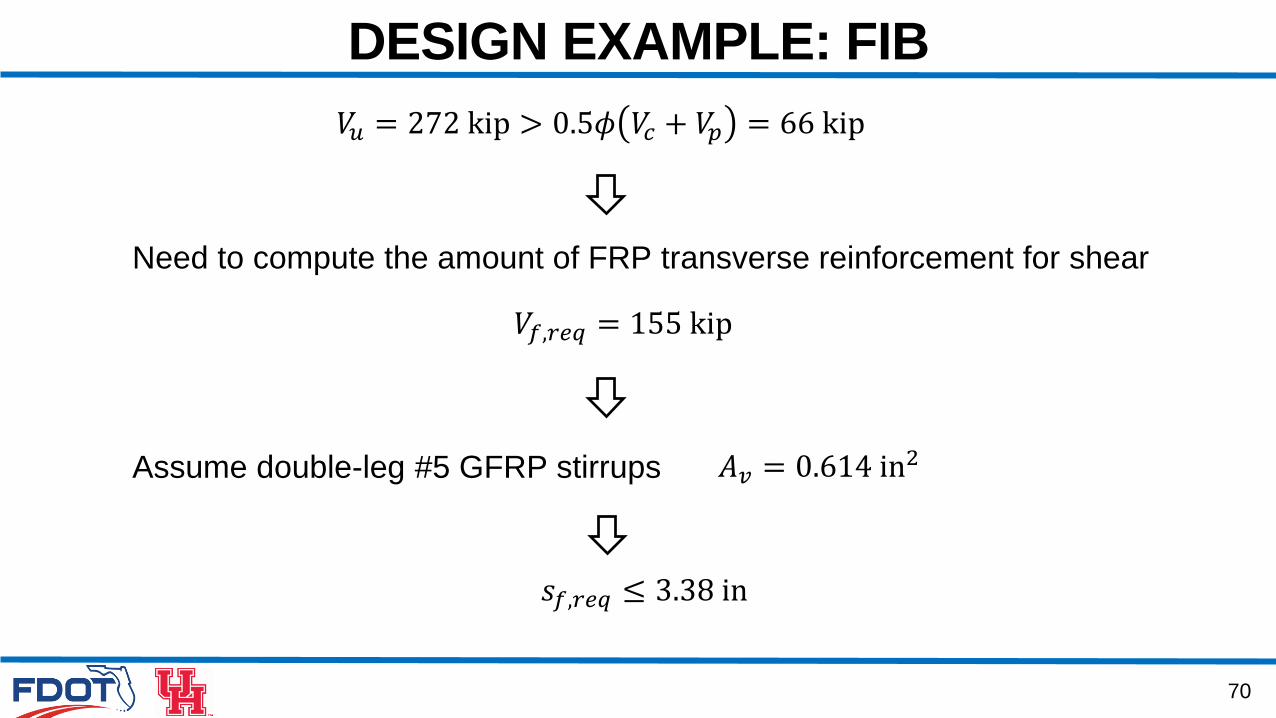
𝑉𝑢 = 272 kip > 0.5𝜙 𝑉𝑐 + 𝑉𝑝 = 66 kip
𝑉𝑓,𝑟𝑒𝑞 = 155 kip
Need to compute the amount of FRP transverse reinforcement for shear
Assume double-leg #5 GFRP stirrups
𝑠𝑓,𝑟𝑒𝑞 ≤ 3.38 in
𝐴𝑣 = 0.614 in2
71
DESIGN EXAMPLE: FIB
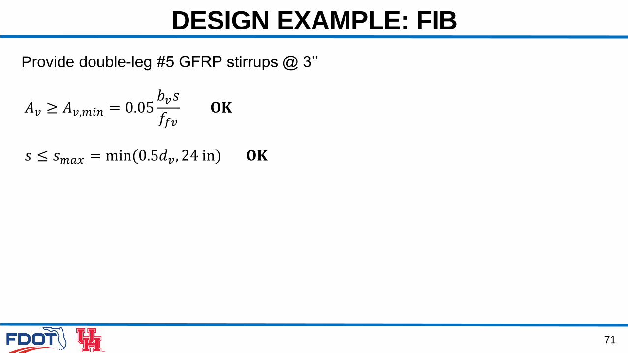
Provide double-leg #5 GFRP stirrups @ 3’’
𝐴𝑣 ≥ 𝐴𝑣,𝑚𝑖𝑛 = 0.05𝑏𝑣𝑠
𝑓𝑓𝑣𝐎𝐊
𝑠 ≤ 𝑠𝑚𝑎𝑥 = min(0.5𝑑𝑣, 24 in) 𝐎𝐊
72
DESIGN EXAMPLE: FIB
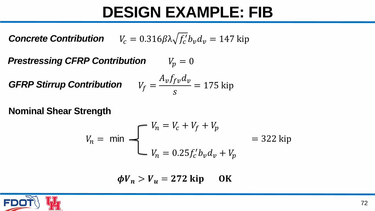
Nominal Shear Strength
𝑉𝑐 = 0.316𝛽λ 𝑓𝑐′𝑏𝑣𝑑𝑣 = 147 kip
Prestressing CFRP Contribution 𝑉𝑝 = 0
𝑉𝑛 = 𝑉𝑐 + 𝑉𝑓 + 𝑉𝑝𝑉𝑛 = min
𝑉𝑛 = 0.25𝑓𝑐′𝑏𝑣𝑑𝑣 + 𝑉𝑝
Concrete Contribution
GFRP Stirrup Contribution 𝑉𝑓 =𝐴𝑣𝑓𝑓𝑣𝑑𝑣𝑠= 175 kip
= 322 kip
𝝓𝑽𝒏 > 𝑽𝒖 = 𝟐𝟕𝟐 𝐤𝐢𝐩 𝐎𝐊

73
DESIGN EXAMPLE: FIB
Interface Shear 𝜙𝑉𝑛𝑖 ≥ 𝑉𝑢𝑖
𝑣𝑛𝑖 = 𝑐𝐴𝑐𝑣 + 𝜇 𝐴𝑐𝑓𝑓𝑓𝑣 + 𝑃𝑐
𝑣𝑛𝑖,𝑟𝑒𝑞 =𝑣ℎ𝑖𝜙
𝐴𝑐𝑓,𝑟𝑒𝑞
𝐴𝑐𝑓,𝑚𝑖𝑛
Provide 𝐴𝑐𝑓 ≥ 𝐴𝑐𝑓,𝑟𝑒𝑞𝑣𝑛𝑖 ≤ 𝐾1𝑓𝑐′𝐴𝑐𝑣
𝑣𝑛𝑖 ≤ 𝐾2𝐴𝑐𝑣
74
DESIGN EXAMPLE: FIB
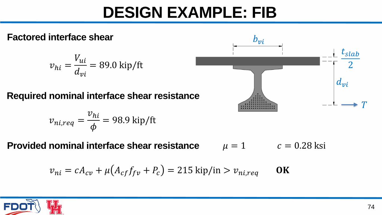
𝑣𝑛𝑖,𝑟𝑒𝑞 =𝑣ℎ𝑖𝜙= 98.9 kip/ft
Factored interface shear
𝑣ℎ𝑖 =𝑉𝑢𝑖𝑑𝑣𝑖= 89.0 kip/ft
Required nominal interface shear resistance
Provided nominal interface shear resistance
𝑣𝑛𝑖 = 𝑐𝐴𝑐𝑣 + 𝜇 𝐴𝑐𝑓𝑓𝑓𝑣 + 𝑃𝑐 = 215 kip/in > 𝑣𝑛𝑖,𝑟𝑒𝑞 𝐎𝐊
𝜇 = 1 𝑐 = 0.28 ksi
75
DESIGN EXAMPLE: FIB
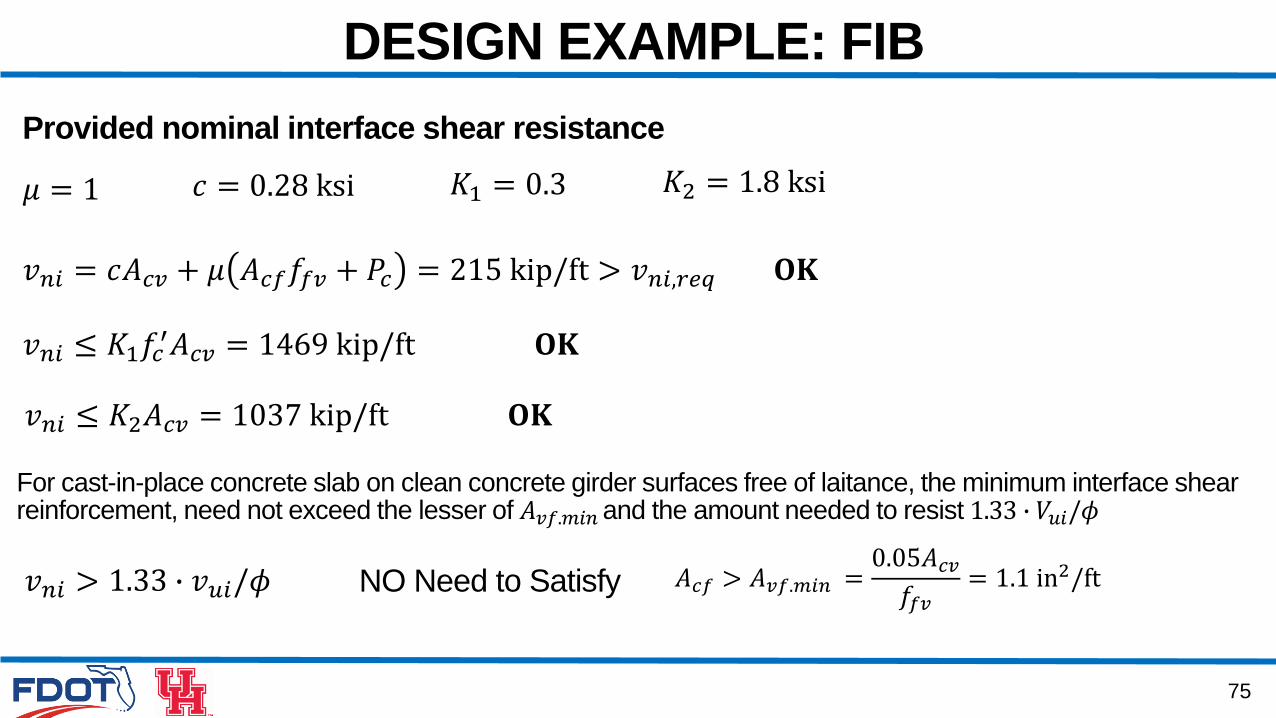
Provided nominal interface shear resistance
𝑣𝑛𝑖 = 𝑐𝐴𝑐𝑣 + 𝜇 𝐴𝑐𝑓𝑓𝑓𝑣 + 𝑃𝑐 = 215 kip/ft > 𝑣𝑛𝑖,𝑟𝑒𝑞 𝐎𝐊
𝜇 = 1 𝑐 = 0.28 ksi 𝐾1 = 0.3 𝐾2 = 1.8 ksi
𝑣𝑛𝑖 ≤ 𝐾1𝑓𝑐′𝐴𝑐𝑣 = 1469 kip/ft 𝐎𝐊
𝑣𝑛𝑖 ≤ 𝐾2𝐴𝑐𝑣 = 1037 kip/ft 𝐎𝐊
𝐴𝑐𝑓 > 𝐴𝑣𝑓.𝑚𝑖𝑛 =0.05𝐴𝑐𝑣𝑓𝑓𝑣= 1.1 in2/ft
For cast-in-place concrete slab on clean concrete girder surfaces free of laitance, the minimum interface shear reinforcement, need not exceed the lesser of 𝐴𝑣𝑓.𝑚𝑖𝑛 and the amount needed to resist 1.33 ∙ 𝑉𝑢𝑖/𝜙
𝑣𝑛𝑖 > 1.33 ∙ 𝑣𝑢𝑖/𝜙 NO Need to Satisfy

76
DESIGN EXAMPLE: FIB
Longitudinal Reinforcement
At each section, the tensile capacity of the longitudinal reinforcement on the flexural tensionside of the member shall be proportioned to satisfy
𝑥=1
𝑛
𝐴𝑝𝑥𝑓𝑝𝑥 ≥𝑀𝑢𝑑𝑣𝜙𝑓+ 0.5𝑁𝑢𝜙𝑐+𝑉𝑢𝜙𝑣− 𝑉𝑝 − 0.5𝑉𝑓 cot 𝜃
563 kip ≥ 442 kip 𝐎𝐊
For example, at support location
No Additional Longitudinal Reinforcement is Required

4. SHEAR DESIGN
4.3 Design Example: FSB 12x57
78
DESIGN EXAMPLE: FSBUS 1 Over Cow Key Channel, Key West, Florida
79
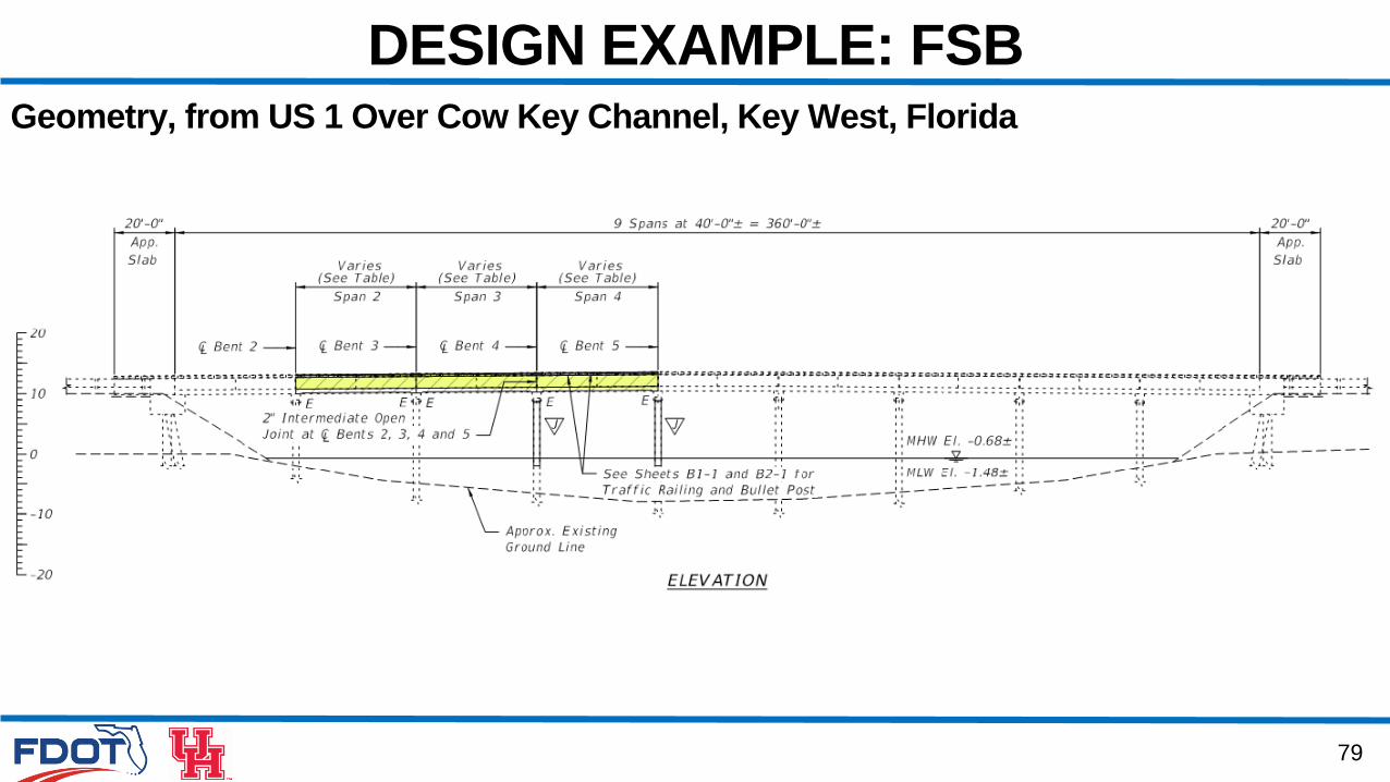
DESIGN EXAMPLE: FSBGeometry, from US 1 Over Cow Key Channel, Key West, Florida
80
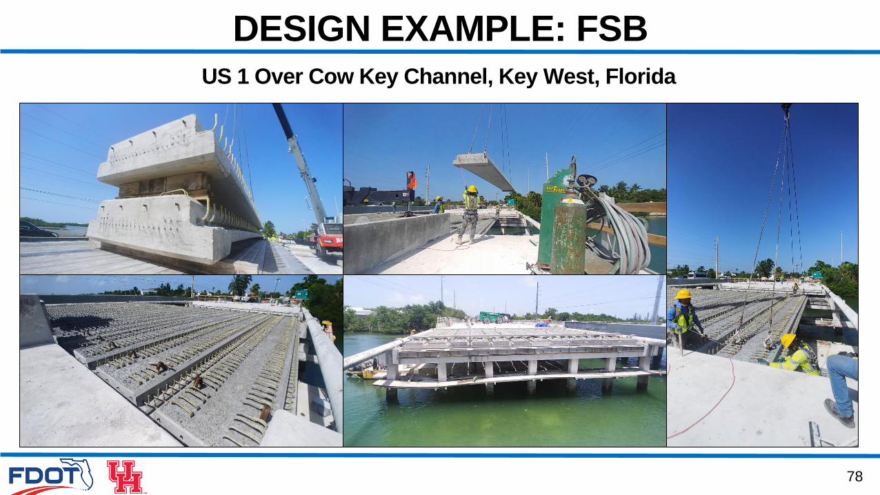
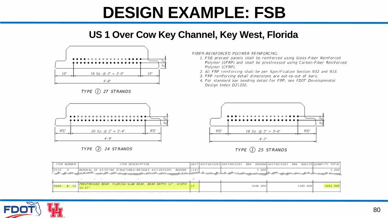
DESIGN EXAMPLE: FSB
US 1 Over Cow Key Channel, Key West, Florida
81
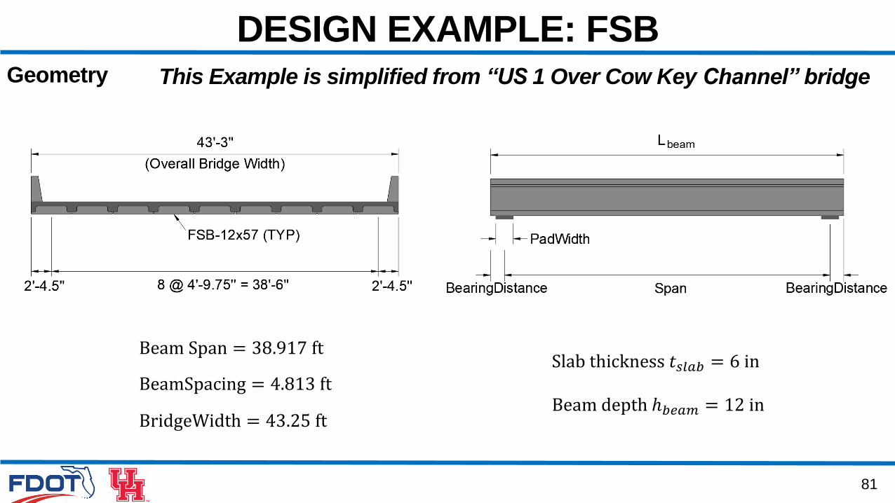
DESIGN EXAMPLE: FSBGeometry
Beam Span = 38.917 ft
BeamSpacing = 4.813 ft
BridgeWidth = 43.25 ft
Slab thickness 𝑡𝑠𝑙𝑎𝑏 = 6 in
Beam depth ℎ𝑏𝑒𝑎𝑚 = 12 in
This Example is simplified from “US 1 Over Cow Key Channel” bridge
82
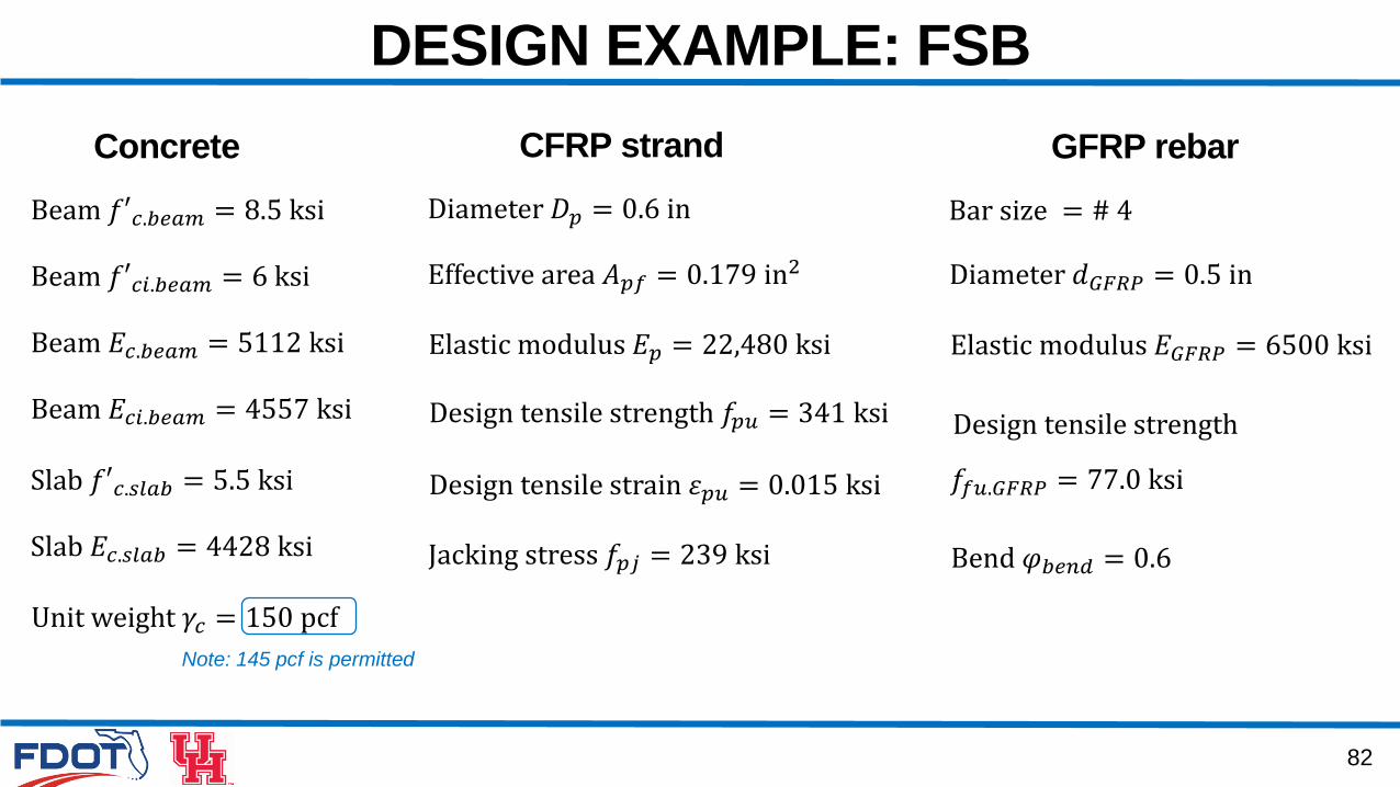
DESIGN EXAMPLE: FSB
Concrete
Beam 𝑓′𝑐.𝑏𝑒𝑎𝑚 = 8.5 ksi
Beam 𝑓′𝑐𝑖.𝑏𝑒𝑎𝑚 = 6 ksi
Beam 𝐸𝑐.𝑏𝑒𝑎𝑚 = 5112 ksi
Beam 𝐸𝑐𝑖.𝑏𝑒𝑎𝑚 = 4557 ksi
Slab 𝑓′𝑐.𝑠𝑙𝑎𝑏 = 5.5 ksi
Slab 𝐸𝑐.𝑠𝑙𝑎𝑏 = 4428 ksi
CFRP strand
Diameter 𝐷𝑝 = 0.6 in
Effective area 𝐴𝑝𝑓 = 0.179 in2
Elastic modulus 𝐸𝑝 = 22,480 ksi
Design tensile strength 𝑓𝑝𝑢 = 341 ksi
Design tensile strain 𝜀𝑝𝑢 = 0.015 ksi
GFRP rebar
Bar size = # 4
Diameter 𝑑𝐺𝐹𝑅𝑃 = 0.5 in
Elastic modulus 𝐸𝐺𝐹𝑅𝑃 = 6500 ksi
Design tensile strength
𝑓𝑓𝑢.𝐺𝐹𝑅𝑃 = 77.0 ksi
Bend 𝜑𝑏𝑒𝑛𝑑 = 0.6
Unit weight 𝛾𝑐 = 150 pcf
Jacking stress 𝑓𝑝𝑗 = 239 ksi
Note: 145 pcf is permitted
83
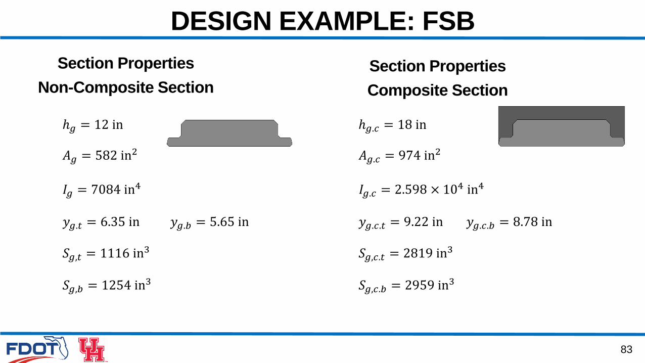
DESIGN EXAMPLE: FSB
Section Properties
Non-Composite Section
ℎ𝑔 = 12 in
𝐴𝑔 = 582 in2
Section Properties
Composite Section
𝐼𝑔 = 7084 in4
𝑦𝑔.𝑡 = 6.35 in 𝑦𝑔.𝑏 = 5.65 in
𝑆𝑔,𝑡 = 1116 in3
𝑆𝑔,𝑏 = 1254 in3
ℎ𝑔.𝑐 = 18 in
𝐴𝑔.𝑐 = 974 in2
𝐼𝑔.𝑐 = 2.598 × 10⁴ in4
𝑦𝑔.𝑐.𝑡 = 9.22 in 𝑦𝑔.𝑐.𝑏 = 8.78 in
𝑆𝑔,𝑐.𝑡 = 2819 in3
𝑆𝑔,𝑐.𝑏 = 2959 in3
84
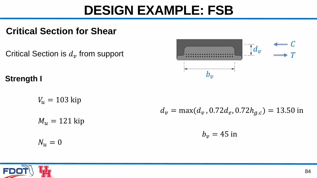
DESIGN EXAMPLE: FSB
𝑑𝑣 = max(𝑑𝑣 , 0.72𝑑𝑒, 0.72ℎ𝑔.𝑐) = 13.50 in
𝑏𝑣 = 45 in
Critical Section is 𝑑𝑣 from support
𝑉𝑢 = 103 kip
Strength I
𝑀𝑢 = 121 kip
Critical Section for Shear
𝑁𝑢 = 0
85
DESIGN EXAMPLE: FSB
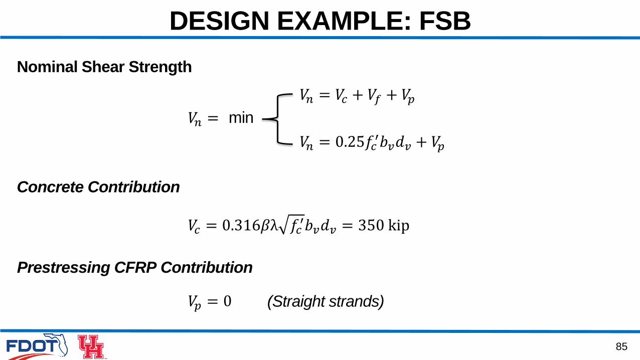
Nominal Shear Strength
𝑉𝑐 = 0.316𝛽λ 𝑓𝑐′𝑏𝑣𝑑𝑣 = 350 kip
Prestressing CFRP Contribution
𝑉𝑝 = 0
𝑉𝑛 = 𝑉𝑐 + 𝑉𝑓 + 𝑉𝑝𝑉𝑛 = min
𝑉𝑛 = 0.25𝑓𝑐′𝑏𝑣𝑑𝑣 + 𝑉𝑝
Concrete Contribution
(Straight strands)

86
DESIGN EXAMPLE: FSB
Need to compute the amount of FRP transverse reinforcement for shear?
No, if 𝑉𝑢 ≤ 0.5𝜙 𝑉𝑐 + 𝑉𝑝
𝑉𝑢 > 0.5𝜙 𝑉𝑐 + 𝑉𝑝
Provide
Compute
𝑉𝑛 = 𝑉𝑐 + 𝑉𝑓 + 𝑉𝑝 ≤ 0.25𝑓𝑐′𝑏𝑣𝑑𝑣 + 𝑉𝑝
𝑉𝑓 =𝑓𝑓𝑣𝐴𝑣𝑑𝑣
𝑠
𝑉𝑛 ≥ 𝜙𝑉𝑢𝑉𝑓,𝑟𝑒𝑞
𝐴𝑣𝑠𝑟𝑒𝑞
𝐴𝑣𝑠𝑚𝑖𝑛
𝐴𝑣𝑠≥𝐴𝑣𝑠𝑚𝑖𝑛
, check spacing 𝑠𝑚𝑎𝑥
𝐴𝑣𝑠𝑟𝑒𝑞
Yes, if
Provide𝐴𝑣𝑠≥𝐴𝑣𝑠𝑚𝑖𝑛
Check spacing 𝑠𝑚𝑖𝑛, 𝑠𝑚𝑎𝑥
87
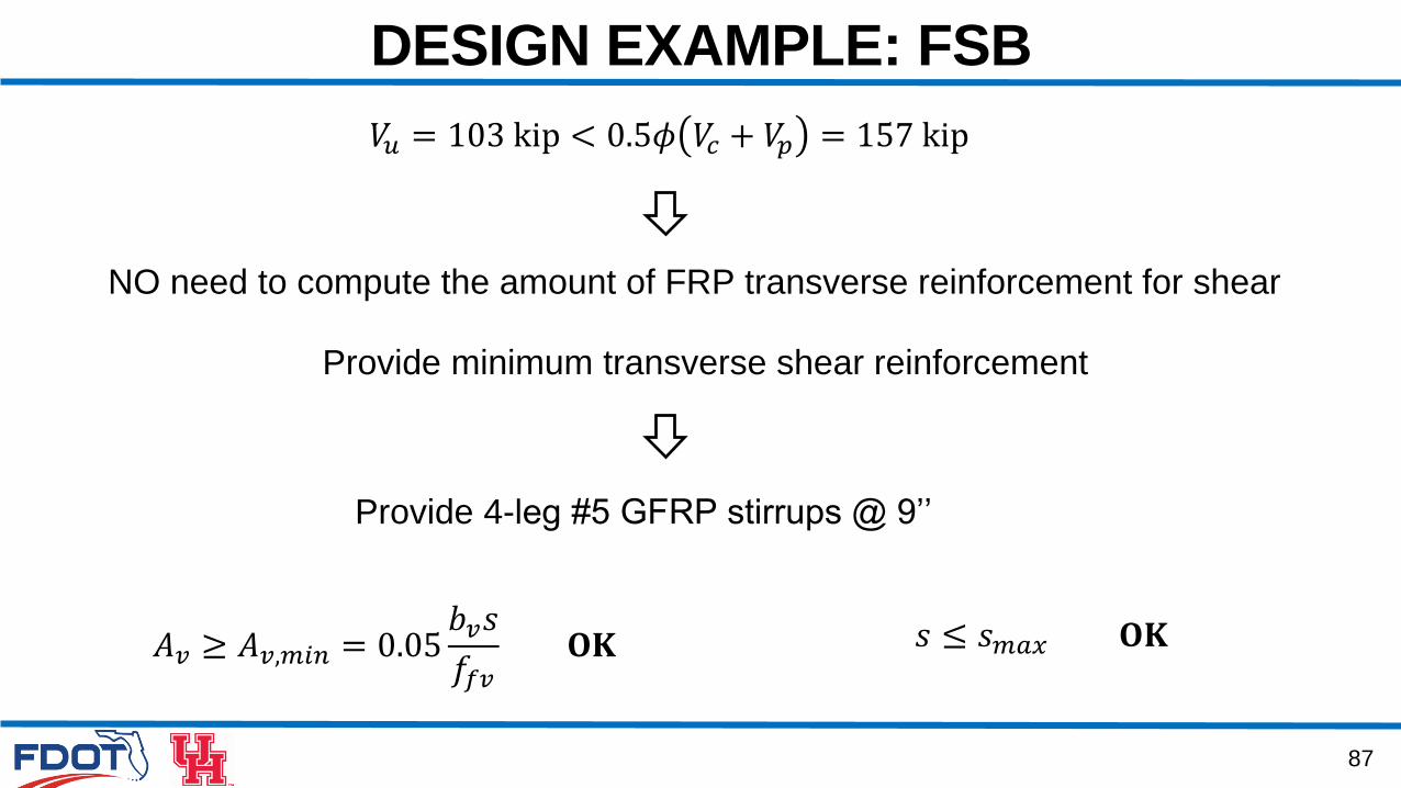
DESIGN EXAMPLE: FSB
𝑉𝑢 = 103 kip < 0.5𝜙 𝑉𝑐 + 𝑉𝑝 = 157 kip
NO need to compute the amount of FRP transverse reinforcement for shear
Provide minimum transverse shear reinforcement
Provide 4-leg #5 GFRP stirrups @ 9’’
𝐴𝑣 ≥ 𝐴𝑣,𝑚𝑖𝑛 = 0.05𝑏𝑣𝑠
𝑓𝑓𝑣𝐎𝐊 𝑠 ≤ 𝑠𝑚𝑎𝑥 𝐎𝐊
88
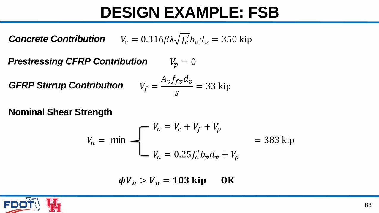
DESIGN EXAMPLE: FSB
Nominal Shear Strength
𝑉𝑐 = 0.316𝛽λ 𝑓𝑐′𝑏𝑣𝑑𝑣 = 350 kip
Prestressing CFRP Contribution 𝑉𝑝 = 0
𝑉𝑛 = 𝑉𝑐 + 𝑉𝑓 + 𝑉𝑝𝑉𝑛 = min
𝑉𝑛 = 0.25𝑓𝑐′𝑏𝑣𝑑𝑣 + 𝑉𝑝
Concrete Contribution
GFRP Stirrup Contribution 𝑉𝑓 =𝐴𝑣𝑓𝑓𝑣𝑑𝑣𝑠= 33 kip
= 383 kip
𝝓𝑽𝒏 > 𝑽𝒖 = 𝟏𝟎𝟑 𝐤𝐢𝐩 𝐎𝐊
89
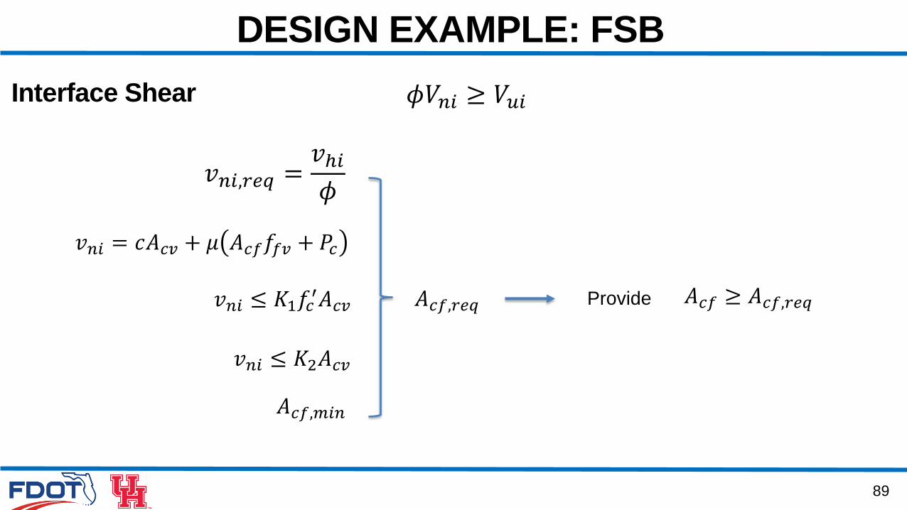
DESIGN EXAMPLE: FSB
Interface Shear 𝜙𝑉𝑛𝑖 ≥ 𝑉𝑢𝑖
𝑣𝑛𝑖 = 𝑐𝐴𝑐𝑣 + 𝜇 𝐴𝑐𝑓𝑓𝑓𝑣 + 𝑃𝑐
𝑣𝑛𝑖,𝑟𝑒𝑞 =𝑣ℎ𝑖𝜙
𝐴𝑐𝑓,𝑟𝑒𝑞
𝐴𝑐𝑓,𝑚𝑖𝑛
Provide 𝐴𝑐𝑓 ≥ 𝐴𝑐𝑓,𝑟𝑒𝑞𝑣𝑛𝑖 ≤ 𝐾1𝑓𝑐′𝐴𝑐𝑣
𝑣𝑛𝑖 ≤ 𝐾2𝐴𝑐𝑣
90
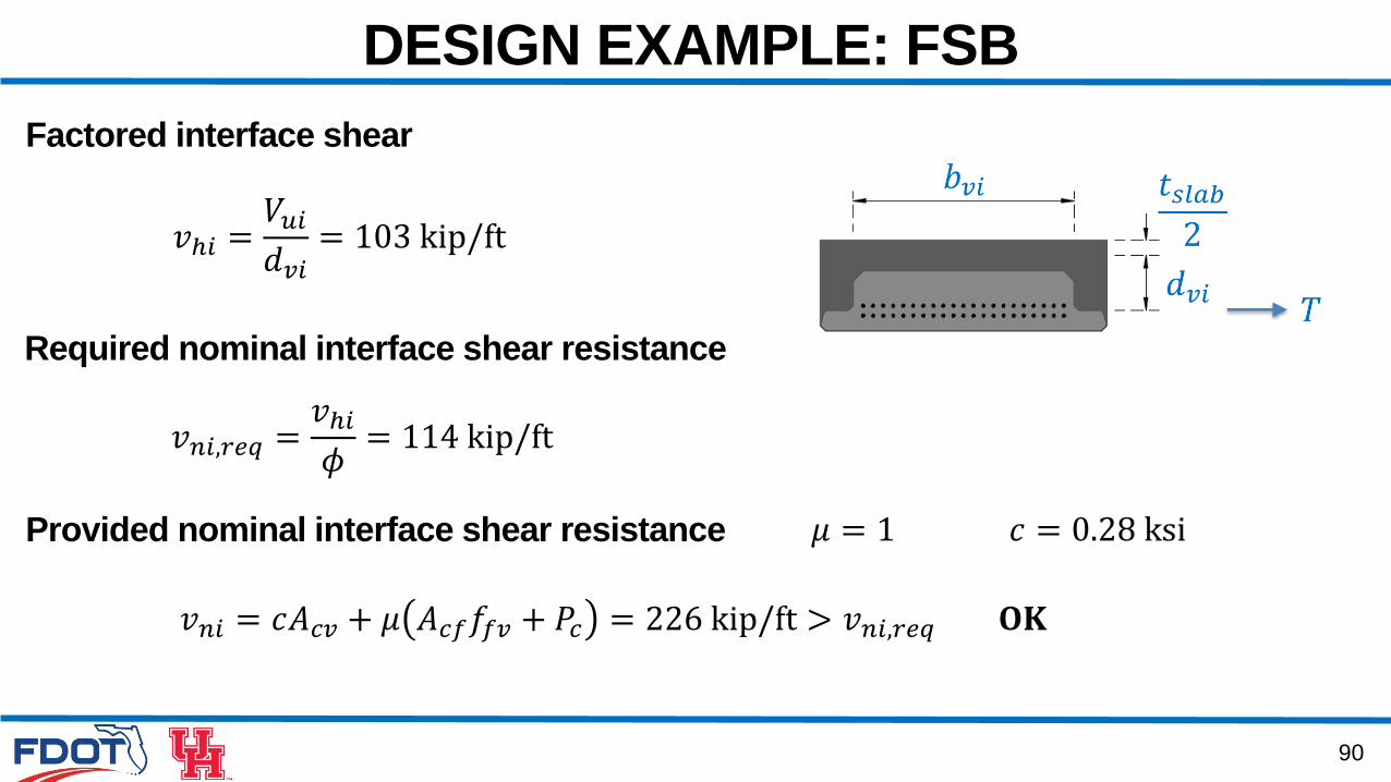
DESIGN EXAMPLE: FSB
𝑣𝑛𝑖,𝑟𝑒𝑞 =𝑣ℎ𝑖𝜙= 114 kip/ft
Factored interface shear
𝑣ℎ𝑖 =𝑉𝑢𝑖𝑑𝑣𝑖= 103 kip/ft
Required nominal interface shear resistance
Provided nominal interface shear resistance
𝑣𝑛𝑖 = 𝑐𝐴𝑐𝑣 + 𝜇 𝐴𝑐𝑓𝑓𝑓𝑣 + 𝑃𝑐 = 226 kip/ft > 𝑣𝑛𝑖,𝑟𝑒𝑞 𝐎𝐊
𝜇 = 1 𝑐 = 0.28 ksi
91
DESIGN EXAMPLE: FSB
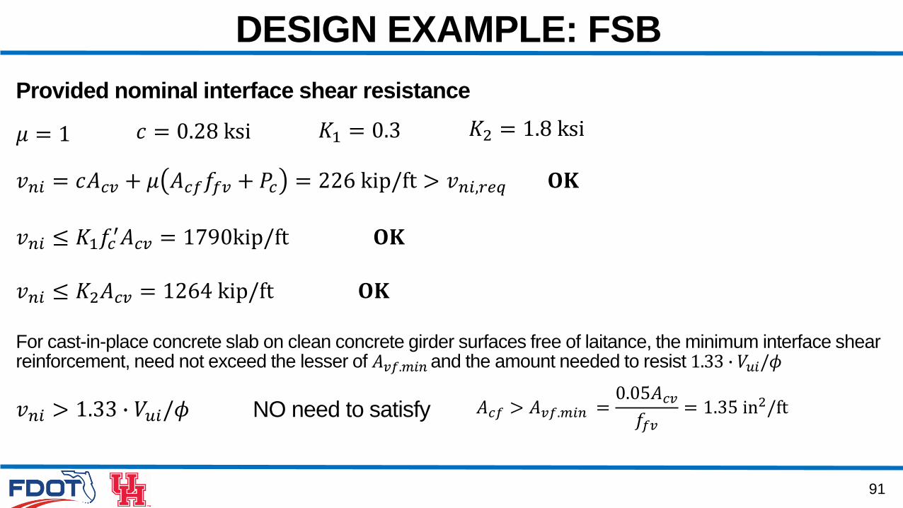
Provided nominal interface shear resistance
𝑣𝑛𝑖 = 𝑐𝐴𝑐𝑣 + 𝜇 𝐴𝑐𝑓𝑓𝑓𝑣 + 𝑃𝑐 = 226 kip/ft > 𝑣𝑛𝑖,𝑟𝑒𝑞 𝐎𝐊
𝜇 = 1 𝑐 = 0.28 ksi 𝐾1 = 0.3 𝐾2 = 1.8 ksi
𝑣𝑛𝑖 ≤ 𝐾1𝑓𝑐′𝐴𝑐𝑣 = 1790kip/ft 𝐎𝐊
𝑣𝑛𝑖 ≤ 𝐾2𝐴𝑐𝑣 = 1264 kip/ft 𝐎𝐊
𝐴𝑐𝑓 > 𝐴𝑣𝑓.𝑚𝑖𝑛 =0.05𝐴𝑐𝑣𝑓𝑓𝑣= 1.35 in2/ft
For cast-in-place concrete slab on clean concrete girder surfaces free of laitance, the minimum interface shear reinforcement, need not exceed the lesser of 𝐴𝑣𝑓.𝑚𝑖𝑛 and the amount needed to resist 1.33 ∙ 𝑉𝑢𝑖/𝜙
𝑣𝑛𝑖 > 1.33 ∙ 𝑉𝑢𝑖/𝜙 NO need to satisfy
92
DESIGN EXAMPLE: FSB
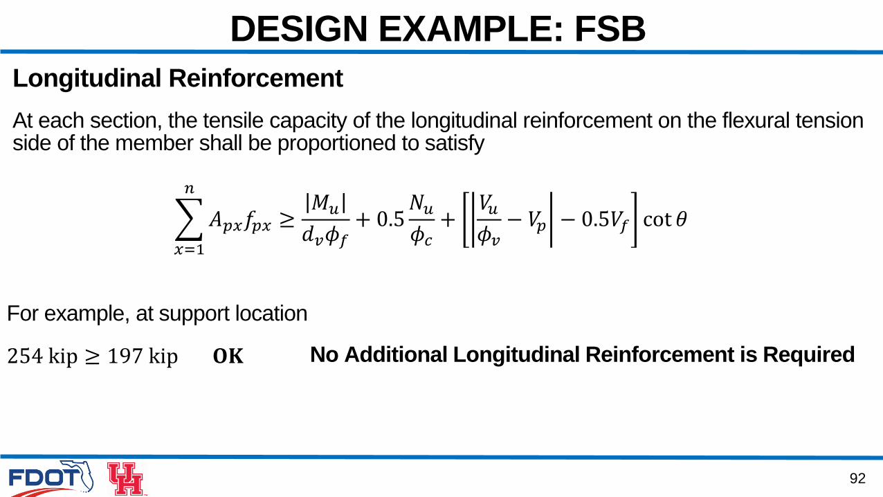
Longitudinal Reinforcement
At each section, the tensile capacity of the longitudinal reinforcement on the flexural tensionside of the member shall be proportioned to satisfy
𝑥=1
𝑛
𝐴𝑝𝑥𝑓𝑝𝑥 ≥𝑀𝑢𝑑𝑣𝜙𝑓+ 0.5𝑁𝑢𝜙𝑐+𝑉𝑢𝜙𝑣− 𝑉𝑝 − 0.5𝑉𝑓 cot 𝜃
254 kip ≥ 197 kip 𝐎𝐊
For example, at support location
No Additional Longitudinal Reinforcement is Required

AASHTO CFRP-
Prestressed Concrete Design
Training Course
Related Documents