Synway CTI Series SHD-240/480A-CT/cPCI SHD-240/480S-CT/cPCI Digital Trunk Voice Board Version 2.1 Synway Information Engineering Co., Ltd www.synway.net

Welcome message from author
This document is posted to help you gain knowledge. Please leave a comment to let me know what you think about it! Share it to your friends and learn new things together.
Transcript

Synway CTI Series
SHD-240/480A-CT/cPCI SHD-240/480S-CT/cPCI
Digital Trunk Voice Board
Version 2.1
Synway Information Engineering Co., Ltd www.synway.net

Synway Information Engineering Co., Ltd
Contents
Contents ...........................................................................................i
Copyright Declaration ....................................................................ii
Revision History ............................................................................iii
Chapter 1 Overview ........................................................................1
1.1 Functions .................................................................................................. 1 1.2 Features ................................................................................................... 1 1.3 Operation Principle ................................................................................... 3
Chapter 2 Installation .....................................................................4
2.1 Hardware Structure................................................................................... 4 2.2 System Requirements............................................................................. 10 2.3 Installation Procedure ............................................................................. 11 2.4 Precaution on Hot-swap Operation at Runtime....................................... 15
Appendix A Technical Specifications..........................................16
Appendix B Technical/sales Support..........................................17
SHD-240/480A-CT/cPCI, SHD-240/480S-CT/cPCI Hardware Manual (Version 2.1) Page i

Synway Information Engineering Co., Ltd
Copyright Declaration
All rights reserved; no part of this document may be reproduced or transmitted in any form or by any means, electronic or mechanical, without prior written permission from Synway Information Engineering Co., Ltd (hereinafter referred to as ‘Synway’).
Synway reserves all rights to modify this document without prior notice. Please contact Synway for the latest version of this document before placing an order.
Synway has made every effort to ensure the accuracy of this document but does not guarantee the absence of errors. Moreover, Synway assumes no responsibility in obtaining permission and authorization of any third party patent, copyright or product involved in relation to the use of this document.
SHD-240/480A-CT/cPCI, SHD-240/480S-CT/cPCI Hardware Manual (Version 2.1) Page ii
Synway Information Engineering Co., Ltd
Revision History
Version Date Comments
Version 1.0 Initial publication
Version 2.0 2007-12 Changes: made hardware improvement, added board illustrations for better understanding.
Version 2.1 Changes: added the CT_EN jumper and the description on it.
2009-06
Note: Please visit our website http://www.synway.net to obtain the latest version of this document.
SHD-240/480A-CT/cPCI, SHD-240/480S-CT/cPCI Hardware Manual (Version 2.1) Page iii

Synway Information Engineering Co., Ltd
Chapter 1 Overview
The Synway CTI Series SHD-240/480A-CT/cPCI and SHD-240/480S-CT/cPCI are huge-capacity digital trunk voice boards with CompactPCI bus, and have almost all functions required by call/voice processing systems that connect with E1 trunks.
1.1 Functions
16 E1 per board; 4 boards, 64 E1, 1920 voice channels per system
Supports full-duplex recording and playback simultaneously on all channels, each with a different format
Support of DSP-based ADPCM voice compression
A single board, with all necessary resources for signaling processing, can complete both SS7 and ISDN connections
Allows DTMF transmission and detection during voice recording or playback
Automatic Gain Control (AGC) support in recording operation
Support of self-adaptive echo cancellation and Barge-in features
Includes H.110 bus, facilitating smooth connectivity to third-party boards with H.110 bus for the exchange of voice signals and the share of resources, without the need for extra bus cables installed between boards
The flexible distributed conferencing system sets no limit on the number of simultaneous conferences and participants in each conference, allows monitoring and recording of the whole conference and each individual speaker
The on-board lightning-proof circuit reaches the telecom standard and eliminates the damage caused by the lightning
Each board has a unique hardware serial number and an authorization code identification circuit, designed for hardware identification and software safety
1.2 Features
CompactPCI 2.1 Bus Support
Includes CompactPCI 2.1 bus with burst data transmission rate up to 133 MB/s (the CPU cost for data transmission is only 1/15 of that on voice boards with ISA bus); PNP (plug and play) feature eliminates the need for jumper leads; supports hot swap while running the application software (most advanced hot-swap operation for CompactPCI system).
SHD-240/480A-CT/cPCI, SHD-240/480S-CT/cPCI Hardware Manual (Version 2.1) Page 1

Synway Information Engineering Co., Ltd
Signaling Interface
SS7 provides two levels of interfaces: MTP and TUP, meeting various customer requirements.
Signaling Processing
Installed with loadable signaling processing module, each board supports SS7 and ISDN, eliminating the need for extra signaling boards. The singling can be upgraded via a simple software configuration, without having to change the hardware.
Signaling Links
Each board supports 1 to 8 SS7 links, 4 signaling link sets, multiple OPC and DPC. The signaling hot-backup feature, i.e. signaling messages can be processed by the standby server at any time when something is wrong with the links being used, greatly increases the flexibility and reliability. All the timeslots ranging from 1 to 31, not only the 16th one, can be used as SS7 or ISDN signaling links.
Terminal Matching Method
Offers easy connection of such interfaces that support either of the two terminal matching methods - use of the unbalanced 75Ω E1 cable and use of the 120Ω balanced E1 cable - with a variety of PBXs and optical transceivers via RJ48T connectors. Besides, we provide several kinds of interface converters for your choice.
Various CODECs Support
Offers a large selection of voice CODECs, including hardware-based A-Law (G.711), μ-Law, IMA-ADPCM, and software-based VOX.
Supports WAV File
The recorded voice files can be edited and played by audio tools such as Cooledit.
Synway’s Unified SynCTI Driver Development Platform
Synway owns the intellectual property rights for the unified high-intelligence SynCTI driver development platform. Each system supports up to 1920 channels. The complex call procedures can be analyzed and controlled through simple function calls on the driver platform, without having to understand details.
SHD-240/480A-CT/cPCI, SHD-240/480S-CT/cPCI Hardware Manual (Version 2.1) Page 2

Synway Information Engineering Co., Ltd
1.3 Operation Principle
Figure 1-1 Operation Principle
E1/T1 Interface
∑
∑AGC
TDM Bus Switch
Switch and Conference
Inbound Voice
∑
∑
AGCPlayback to Bus
AGC
DecoderDTMF/Tone Generator Encoder
EchoCanceler
Outbound Voice
Recording Buffer
PlaybackBuffer
K1
K3K4
K5
ToneDetector
DTMFDetector
Host Computer Interface (cPCI )
V1 V2
HDLC ABCD Signaling
SS7-MTP2
LIU Framer
Barge inDetector
V3 K6 K2
ECEnhance
SHD-240/480A-CT/cPCI, SHD-240/480S-CT/cPCI Hardware Manual (Version 2.1) Page 3
Synway Information Engineering Co., Ltd
Chapter 2 Installation
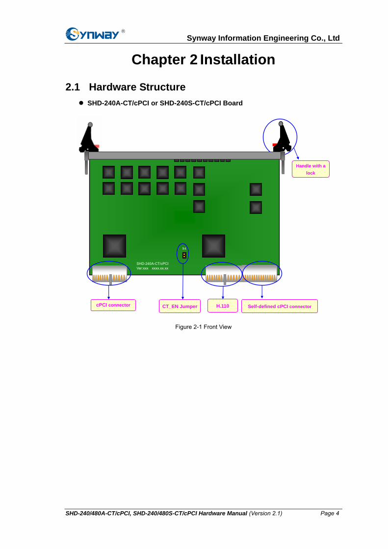
2.1 Hardware Structure SHD-240A-CT/cPCI or SHD-240S-CT/cPCI Board
cPCI connector H.110 Self-defined cPCI connector
Handle with a lock
SHD-240A-CT/cPCI Ver:xxx xxxx.xx.xx
S4
CT_EN Jumper
Figure 2-1 Front View
SHD-240/480A-CT/cPCI, SHD-240/480S-CT/cPCI Hardware Manual (Version 2.1) Page 4

Synway Information Engineering Co., Ltd
SHD-480A-CT/cPCI or SHD-480S-CT/cPCI Board
SHD-480A-CT/cPCI Ver:xxx xxxx.xx.xx
cPCI connector H.110 Self-defined cPCI connector
Handle with a lock
S4
CT_EN Jumper
Figure 2-2 Front View
SHD-240/480A-CT/cPCI or SHD-240/480S-CT/cPCI Board (Rear View)
Serial Number GXXXXXXX
Board Model SHD-XXXX-CT/cPCI
Figure 2-3 Rear View
SHD-240/480A-CT/cPCI, SHD-240/480S-CT/cPCI Hardware Manual (Version 2.1) Page 5

Synway Information Engineering Co., Ltd
SHD-240A-B/cPCI Rear Connection Panel
Figure 2-4 Front View
SHD-480A-B/cPCI Rear Connection Panel
Figure 2-5 Front View
D
Self-defined cPCI connector
RJ48T
1st pair of grounding jumpers at the transmit end1st pair of grounding jumpers at the receive end
: :
16th pair of grounding jumpers at the transmit end 16th pair of grounding jumpers at the receive end
(from left to right)
Self-defined cPCI connector
RJ48T
1st pair of grounding jumpers at the transmit end 1st pair of grounding jumpers at the receive end
: :
8th pair of grounding jumpers at the transmit end 8th pair of grounding jumpers at the receive end
(from left to right)
SHD-240/480A-CT/cPCI, SHD-240/480S-CT/cPCI Hardware Manual (Version 2.1) Page 6

Synway Information Engineering Co., Ltd
SHD-240/480A-CT/cPCI or SHD-240/480S-CT/cPCI Board (Left View)
HOTSWAP
8 7 6 5 4 3 2 1
ERR RUN
SH
D- 240A
-CT/cP
CI
HOT SWAP
16 15 14 13 12 11 10 9 8 7 6 5 4 3 2 1
ERR RUN Run Indicator
Error Indicator
Hot-swap Indicator
SH
D-480A
-CT/cP
CI
Synchro Indicators
SynchroIndicators
Run IndicatorError Indicator
Hot-swap Indicator
Figure 2-6 SHD-480A-CT/cPCI or SHD-480S-CT/cPCI (Left) and
SHD-240A-CT/cPCI or SHD-240S-CT/cPCI (Right)
SHD-240/480A-CT/cPCI, SHD-240/480S-CT/cPCI Hardware Manual (Version 2.1) Page 7

Synway Information Engineering Co., Ltd
SHD-240A-B/cPCI or SHD-480A-B/cPCI Rear Connection Panel (Left View)
9 ~ 16
1 ~8
SHD
-480
A-B
/cPC
I
RJ48T
1~8
SHD
-240
A-B
/cPC
I
RJ48T
Figure 2-7 SHD-480A-B/cPCI (Left) and SHD-240A-B/cPCI (Right)
SHD-240A-JB/BNC Interface Converter (Optional)
RJ48T (Each pin corresponds to a jack on the rear connection panel)
Figure 2-8 Front View
Note: Each port in the figure above includes an RJ48C jack and two BNC connectors. See
Table 2-1 below for which BNC connector transmits signals and which receives signals.
No. Line Status Meaning
OUT Transmit 1 1st Port
IN Receive
OUT Transmit 2 2nd Port
IN Receive
1st port…8th port
1 2 3 4 5 6 7 8
OUT IN OUT IN OUT IN OUT IN OUT IN OUT IN IN IN OUT OUT
SHD-240/480A-CT/cPCI, SHD-240/480S-CT/cPCI Hardware Manual (Version 2.1) Page 8

Synway Information Engineering Co., Ltd
OUT Transmit 3 3rd Port
IN Receive
OUT Transmit 4 4th Port
IN Receive
OUT Transmit 5 5th Port
IN Receive
OUT Transmit 6 6th Port
IN Receive
OUT Transmit 7 7th Port
IN Receive
OUT Transmit 8 8th Port
IN Receive
Table 2-1 BNC Connector
SHD-240/480A-JB/S Interface Converter (Optional)
1 2 3 4 5 6 7 8
RJ48T(Each pin corresponds to a jack on the rear connection panel)
1st port…8th port
SHD-240/480A-JB/S
Figure 2-9 Front View
Notes:
The indicators illustrated in Figure 2-6 are described below:
Synchro Indicator Definition Lamp Status Implication
ON synchronous
OFF asynchronous Green Lamps Sync
Flash synchronous but unsteady
Table 2-2 E1 Synchronization Indicators
RUN Indicator Lamp Status Runtime Status
ON not running
OFF not running Green Lamp
FLASH running
Table 2-3 RUN Indicator
Lamp Status Runtime Status Hot-swap Indicator
in the course of hot swap Blue Lamp ON
SHD-240/480A-CT/cPCI, SHD-240/480S-CT/cPCI Hardware Manual (Version 2.1) Page 9

Synway Information Engineering Co., Ltd
OFF normal
Table 2-4 Hot-swap Indicator
This file illustrates the A- and S-type boards with cPCI bus from Synway. Please check the label on the board to get the exact board model before your use. See below for all models this file is applicable to.
Voice Rear Connection Conferencing No. Board Model E1 SS7/ISDN/SS1 ECCODEC Panel 1 SHD-240A-CT/cPCI 8 √ √ √ √ SHD-240A-B/cPCI
2 SHD-480A-CT/cPCI 16 √ √ √ √ SHD-240A-B/cPCI
3 SHD-240S-CT/cPCI 8 √ √ √ - SHD-480A-B/cPCI
4 SHD-480S-CT/cPCI 16 √ √ √ - SHD-480A-B/cPCI
Table 2-5 List of A- and S-type boards with cPCI bus
2.2 System Requirements
Host System Requirements
CPU: 300MHz Intel® Pentium® or aboveⅡ
Memory: 256M or more
HD: Depends on individual requirements
Supported Operating Systems
Refer to SynCTI Programmer’s Manual.pdf.
SHD-240/480A-CT/cPCI, SHD-240/480S-CT/cPCI Hardware Manual (Version 2.1) Page 10

Synway Information Engineering Co., Ltd
2.3 Installation Procedure
Step1: Select a proper terminal-matching method.
In consideration of various line conditions, this series boards are equipped with two grounding jumpers for each PCM which respectively control the grounding of the transmit end and the receive end.
In use of the balanced 120Ω E1 cable, disconnect all grounding jumpers.
In use of the unbalanced 75Ω E1 cable mode, the grounding jumpers at the receive end should be disconnected and the ones at the transmit end be short-circuited, provided that the PC is properly grounded. This configuration is the factory default setting and applicable to most situations so that there is usually no need to change it.
If there is difficulty in grounding of the PC at the local terminal, you may short-circuit the on-board grounding jumper at the receive end and use the transmit end at the opposite terminal for grounding.
If the receive end at the opposite terminal is grounded (improper operation), the on-board grounding jumper at the transmit end must be disconnected. Refer to Table 2-6 for details.
Generally speaking, in the case of proper grounding at both terminals, only the external layer of the E1 cable at the transmit end is allowed to be grounded. The grounding of both transmit and receive ends may result in a current loop with ground wires, bringing signal instability. Therefore, such grounding must be strictly avoided.
Table 2-6 Configuration of Grounding Jumpers in Use of 75Ω E1 Cable
Step2: Configure the CT_EN jumper.
Short-circuit the CT_EN jumper if the cPCI industrial computer has no CT-BUS slot on the backboard, or, the indicator will be on blue all the time and the board can not work normally; disconnect the CT_EN jumper if the cPCI industrial computer has a CT-BUS slot on the
Transmit End grounded grounded non-grounded non-grounded Opposite
Terminal
Local
Terminal non-grounded grounded non-grounded grounded Receive End
Transmit End short-circuited disconnected short-circuited disconnected PC
grounded Receive End disconnected disconnected short-circuited short-circuited
Transmit End short-circuited short-circuited short-circuited manage to
make the PC
grounded
PC not
grounded Receive End short-circuited short-circuited disconnected
SHD-240/480A-CT/cPCI, SHD-240/480S-CT/cPCI Hardware Manual (Version 2.1) Page 11

Synway Information Engineering Co., Ltd
backboard, or, the hot-swap operation may bring a damage to the computer or the board.
Step3: Fit the required digital trunk board onto the CompactPCI chassis.
Fit both the board and the rear connection panel into a pair of empty slots on the CompactPCI chassis.
With the board completely inserted, push the upper and bottom handles inwards at the same time until a ‘click’ sound is heard and the red locks flip into position. The board is now properly fitted. The voice board can be further fastened with screws (on the outside of the upper and bottom handles) for extended use and prevention of accidental removal.
Note:
① Due to the structural design of the cPCI IPC, it is necessary to push the board home into the slot until it can go no further, and ensure that it is not inclined at an angle before applying lever action on the handles to secure it. Connecting parts on the mainboard of the IPC may be damaged if:
(I) Handles are used too early (II) Handles are used while the board is inclined (III) Force on handles is not applied evenly.
② Board insertion is allowed when computer is powered on. However, as strong static electricity may lead to damages, the operator should touch a grounded conductor to discharge the static electricity on him before inserting the board.
Step4: Connect to digital trunks.
The rear connection panels provided with this series boards use the RJ48T jack to connect with digital trunks, or directly connect with various PBXs and optical transceivers. The SHD-480A-B/cPCI rear connection panel has two RJ48T jacks, one above another, while the SHD-240A-B/cPCI rear connection panel has only one RJ48T jack. The pin layout for RJ48T is shown in Figure 2-10.
SHD-240/480A-CT/cPCI, SHD-240/480S-CT/cPCI Hardware Manual (Version 2.1) Page 12
Synway Information Engineering Co., Ltd
Tx-1Rx-1
Tx-2Rx-2
Tx-3Rx-3
Rx-4Tx-4
Tx-5Rx-5
Tx-6Rx-6
Tx-7Rx-7
Rx-8Tx-8
Tx+1Rx+1
Tx+2Rx+2
Tx+3Rx+3
Rx+4Tx+4
Tx+5Rx+5
Tx+6Rx+6
Tx+7Rx+7
Rx+8Tx+8
50
26
25
1
Tx-9Rx-9
Tx-10Rx-10
Tx-11Rx-11
Rx-12Tx-12
Tx-13Rx-13
Tx-14Rx-14
Tx-15Rx-15
Rx-16Tx-16
Tx+9 Rx+9
Tx+10 Rx+10
Tx+11 Rx+11
Rx+12 Tx+12
Tx+13 Rx+13
Tx+14 Rx+14
Tx+15 Rx+15
Rx+16 Tx+16
50
26
25
1
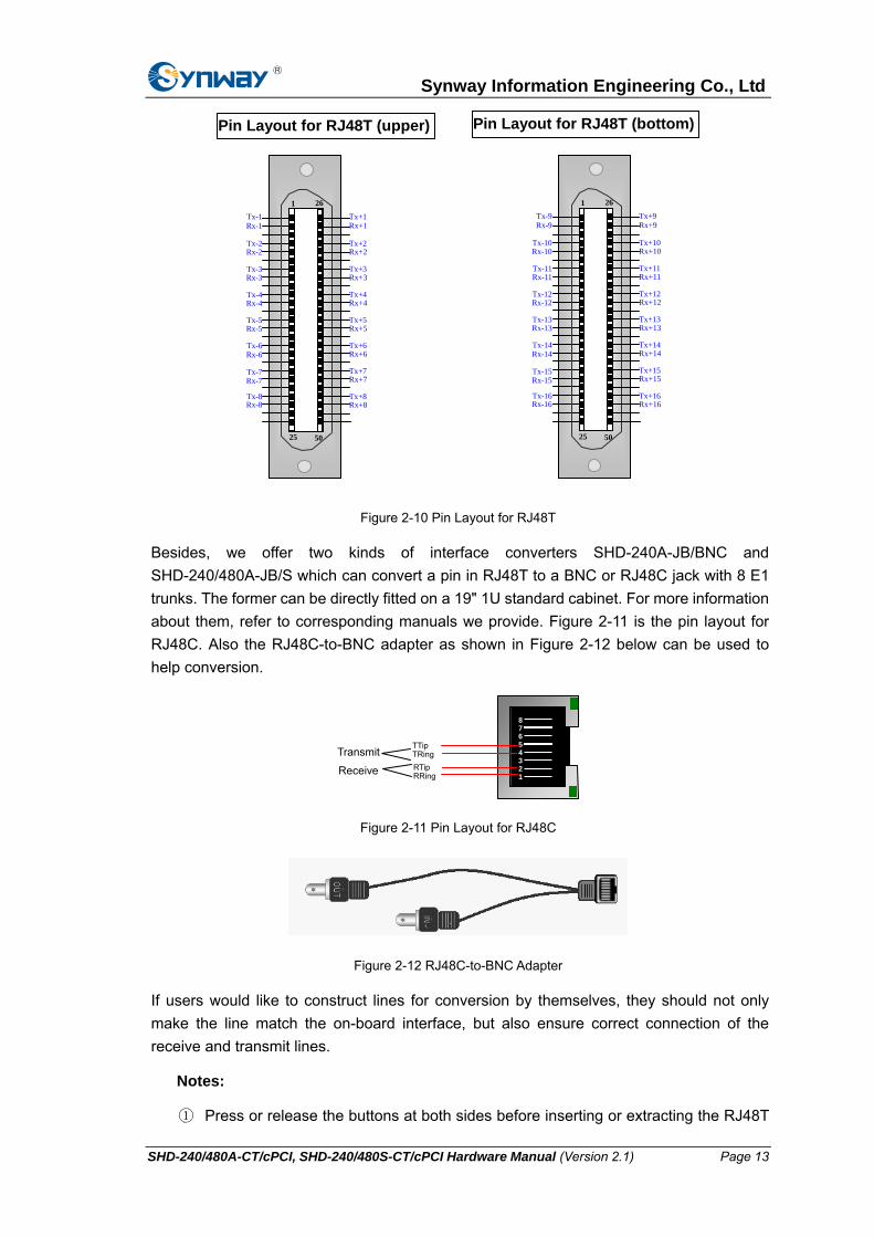
Pin Layout for RJ48T (bottom) Pin Layout for RJ48T (upper)
Figure 2-10 Pin Layout for RJ48T
Besides, we offer two kinds of interface converters SHD-240A-JB/BNC and SHD-240/480A-JB/S which can convert a pin in RJ48T to a BNC or RJ48C jack with 8 E1 trunks. The former can be directly fitted on a 19" 1U standard cabinet. For more information about them, refer to corresponding manuals we provide. Figure 2-11 is the pin layout for RJ48C. Also the RJ48C-to-BNC adapter as shown in Figure 2-12 below can be used to help conversion.
87654321
RTipRRingReceive
TTipTRingTransmit
Figure 2-11 Pin Layout for RJ48C
Figure 2-12 RJ48C-to-BNC Adapter
If users would like to construct lines for conversion by themselves, they should not only make the line match the on-board interface, but also ensure correct connection of the receive and transmit lines.
Notes:
① Press or release the buttons at both sides before inserting or extracting the RJ48T
SHD-240/480A-CT/cPCI, SHD-240/480S-CT/cPCI Hardware Manual (Version 2.1) Page 13

Synway Information Engineering Co., Ltd
connector.
② Prevent the cross connection of transmit and receive lines. Such mistake can be found out by observing the on-board synchronization indicators. If the indicator is on, that means the receive line is in a normal state; if the indicator is off or flashing, that means the receive line goes abnormal (probably due to the cross connection).
③ On-board synchronization indicators start working only after the PC is powered on and the board is successfully initialized. The state of transmit lines can not be judged via synchronization indicators but should be examined by the opposite terminal or a self-loop testing.
④ When you use the unbalanced 75Ω coaxial cables, make sure to connect the outer shielding layer with the negative pole (-) and the leads inside with the positive pole (+).
Step5: Connect H.110 bus.
Skip this step if there is no need for bus exchange between boards.
The IPC has H.110 slots on the chassis and connecting lines already fixed on them. By installing all the necessary boards, the H.110 bus would have already been inter-connected. Hence, users need not do any additional actions provided each board is correctly and properly installed.
Step6: Boot your computer and install the driver.
Regarding driver installation, refer to the driver installation manual SynCti_InstManual_cn.
Step7: Configure the operating parameters for the board.
Refer to SynCTI Programmer's Manual for details.
Key Tips:
As the system is expected to run for long hours unmanned, ‘energy-saving’ mode should be turned off for both the CPU and the HD in CMOS or WINDOWS operating system. This is to ensure full-speed operation of the computer, or it may lead to a drop in performance or unexpected errors after running for some time.
A chassis installed with voice boards must be grounded for safety reasons, according to standard industry requirements. A simple way is earthing with the third pin on the plug. No or improper grounding may cause instability in operation as well as decrease in lightning resistance.
SHD-240/480A-CT/cPCI, SHD-240/480S-CT/cPCI Hardware Manual (Version 2.1) Page 14

Synway Information Engineering Co., Ltd
2.4 Precaution on Hot-swap Operation at Runtime
The board should not be removed while user applications are running, or it may cause instability problems such as system halt or application failure. The correct way is to release the bottom handle (by the red lock on the handle) and notify the application to stop operations on the board, i.e. upon releasing the board, wait for the hot-swap blue lamp to light up before pulling it out from the slot.
Also note to never remove the board when it is being initialized. You must end the application before performing a proper board insertion or extraction following the above steps.
This restriction however, applies only when the board is under operation by a user application.
During software runtime, the RUN indicator blinks at 1-second intervals if the board is working properly, or, it will go on and off at irregular intervals if the driver software detects abnormal behavior by the board and prompts users to replace the existing board. The new board should be of the same model and placed in the same slot as the previous, or software parameters will have to be reconfigured. If the rear connection panel is used, remember to move it along with the voice board. The rear connection panel can be hot-swapped at anytime without interrupting runtime.
Note: Releasing the bottom handle at runtime will cause your board to stop operating!
SHD-240/480A-CT/cPCI, SHD-240/480S-CT/cPCI Hardware Manual (Version 2.1) Page 15

Synway Information Engineering Co., Ltd
Appendix A Technical Specifications Dimensions (excluding handles) Enhanced Echo Cancellation
Board: 233(6U)×162.5mm2 SHD-240/480A-CT/cPCI: 8ms
Rear Connection Panel: 233×82mm2 SHD-240/480S-CT/cPCI: 8ms
Weight Power Requirements
Board: ≈300g Maximum power consumption: ≤25W
Signaling Rear Connection Panel: ≈200g
Environment SS1: Compliant with DL and MFC standards
stipulated in GF002-9002, supports
SS1 with D4, ESF frame structure Operating temperature: 0—55
Storage temperature: -20—85 SS7: Compliant with related provisions stated
in Q771-Q795 Humidity: 8%—90% non-condensing
DSS1: Compliant with Q.933 Storage humidity: 8%—90% non-condensing
Input/output Interface Audio Encoding & Decoding
E1 interface: Compliant with G.703, including
unbalanced 75Ω interface and
balanced 120Ω interface
16Bit PCM 128kbps
8Bit PCM 64kbps
A-Law 64kbps Audio Specifications
μ-Law 64kbps CODEC: CCITT A/µ-Law 64kbps,
IMA ADPCM 32kbps IMA ADPCM 32kbps
Distortion: ≤3% GSM 13.6kbps
Frequency response: 300-3400Hz (±3dB) MP3 8kbps
Safety Signal-to-noise ratio: ≥38dB
Echo suppression: ≥40dB Lightning Resistance: Level 4
Maximum System Capacity
Up to 4 digital trunk boards concurrently per
system; up to 480 channels per board
SHD-240/480A-CT/cPCI, SHD-240/480S-CT/cPCI Hardware Manual (Version 2.1) Page 16

Synway Information Engineering Co., Ltd
Appendix B Technical/sales Support
Thank you for choosing Synway. Please contact us should you have
any inquiry regarding our products. We shall do our best to help you.
Headquarters
Synway Information Engineering Co., Ltd
http://www.synway.net/
9F, Synway D&R Center, No.3756, Nanhuan Road, Binjiang District, Hangzhou, P.R.China, 310053
Tel: +86-571-88860561
Fax: +86-571-88850923
Technical Support
Tel: +86-571-88864579
Mobile: +86-13735549651
Email: [email protected]
Email: [email protected]
MSN: [email protected]
Sales Department
Tel: +86-571-88860561
Tel: +86-571-88864579
Fax: +86-571-88850923
Email: [email protected]
SHD-240/480A-CT/cPCI, SHD-240/480S-CT/cPCI Hardware Manual (Version 2.1) Page 17
Related Documents